
Easergy Sepam series 60
486
Electrical network protection User’s manual Easergy Sepam series 60 02/2017
-
Upload
khangminh22 -
Category
Documents
-
view
2 -
download
0
Transcript of Easergy Sepam series 60

Electrical network protection
User’s manual
Easergy Sepam series 60
02/2017

1
SEPED310017EN
Safety instructions 0
Safety symbols and messagesRead these instructions carefully and look at the equipment to become familiar with the device before trying to install, operate, service or maintain it. The following special messages may appear throughout this bulletin or on the equipment to warn of potential hazards or to call attention to information that clarifies or simplifies a procedure.
Risk of electric shockThe addition of either symbol to a Danger or Warning safety label indicates that an electrical hazard exists, which will result in personal injury if the instructions are not followed.
ANSI symbol. IEC symbol.
Safety alertThis is the safety alert symbol. It is used to alert you to potential personal injury hazards. Obey all safety messages that follow this symbol to avoid possible injury or death.
Safety messages
DANGERDANGER indicates an imminently hazardous situation which, if not avoided, will result in death or serious injury.
WARNINGWARNING indicates a potentially hazardous situation which, if not avoided, can result in death or serious injury.
CAUTIONCAUTION indicates a potentially hazardous situation which, if not avoided, can result in minor or moderate injury.
NOTICENOTICE is used to address practices not related to physical injury.
Important notesRestricted liabilityElectrical equipment should be serviced and maintained only by qualified personnel. No responsibility is assumed by Schneider Electric for any consequences arising out of the use of this manual. This document is not intended as an instruction manual for untrained persons.
Device operationThe user is responsible for checking that the rated characteristics of the device are suitable for its application. The user is responsible for reading and following the device’s operating and installation instructions before attempting to commission or maintain it. Failure to follow these instructions can affect device operation and constitute a hazard for people and property.
Protective groundingThe user is responsible for compliance with all the existing international and national electrical codes concerning protective grounding of any device.

Easergy Sepam series 60 General contents
1
2
3
4
5
6
7
Introduction
Metering functions
Protection functions
Control and monitoring functions
Modbus communication
Installation
Use
1SEPED310017EN

Easergy Sepam series 60 General contents
General contents 2
Introduction 7Selection guide by application 8Protection functions suitable for low voltage 10Presentation 12Modular architecture 13Selection table 14Technical characteristics 16Environmental characteristics 17General settings 22Characteristics 23Processing of measured signals 24Phase currentResidual current 26Demand current and peak demand currents 27Phase-to-phase voltagePhase-to-neutral voltage 28Residual voltageNeutral point voltage 29Positive sequence voltageNegative sequence voltage 30Frequency 31Active, reactiveand apparent power 32Peak demand active and reactive powerPower factor (cos ϕ) 34Active and reactive energy 35Temperature 36Rotation speed 37Phasor diagram 38
Network diagnosis functions 39Tripping contextTripping current 39Number of phase fault tripsNumber of earth fault trips 40Negative sequence / unbalance 41Current total harmonic distortionVoltage total harmonic distortion 42Phase displacement ϕ0, ϕ0SPhase displacement ϕ1, ϕ2, ϕ3 43Disturbance recording 44Data log (DLG) 45Synchro-check:voltage comparison andout-of-sync context 50
2 SEPED310017EN

Easergy Sepam series 60 General contents
1
Machine operation assistance functions 51Thermal capacity usedCooling time constant 51Operating time before trippingWaiting time after tripping 52Running hours and operating time counterStarting current and starting time 53Number of starts before inhibitionStart inhibit time 54Apparent positive sequence impedanceApparent phase-to-phase impedances 55Capacitance 56Capacitor unbalance current 57Motor start report (MSR) 58Motor start trend (MST) 60Switchgear diagnosis functions 63VT supervision 63CT supervision 65Trip circuit and open/closed matching supervision 66Closing circuit and open/close orders supervision 67Cumulative breaking currentNumber of operations 68Operating timeCharging time 69Number of racking out operations 70
Protection functions 72Setting ranges 74Overspeed 79Underspeed 80Underimpedance 81Synchro-check 82Undervoltage (L-L or L-N) 84Positive sequence undervoltage and phase rotation direction check 85Remanent undervoltage 86Directional active overpower 87Directional reactive overpower 88Phase undercurrent 89Directional active underpower 91Temperature monitoring 92Field loss 93Negative sequence / unbalance 96Negative sequence overvoltage 99
3SEPED310017EN

Easergy Sepam series 60 General contents
Excessive starting time, locked rotor 100Thermal overload for cables 102Thermal overload for capacitors 107Thermal overload for motors 121Thermal overload for machines 135Breaker failure 146Phase overcurrent 148Earth fault 150Voltage-restrained overcurrent 153Overvoltage (L-L or L-N) 155Neutral voltage displacement 157Restricted earth fault differential 158Starts per hour 161Directional phase overcurrent 165Directional earth fault 168Recloser 175Overfrequency 179Underfrequency 180Rate of change of frequency 181General 184
Control and monitoring functions 191Description 192Definition of symbols 193Logic input / output assignment 194Switchgear control 197Latching / acknowledgement 203TC / switchgear position discrepancyTripping 204Disturbance-recording trigger 205Switching of groups of settings 206Logic discrimination 207Load shedding 222Restart 223Generator shutdown and tripping 225Automatic transfer 229Automatic "one out of two" transfer 231Automatic "two out of three" transfer 239Triggering the Motor start report (MSR) 249Activating / Deactivating the Data log function (DLG) 250Change of phase rotation direction 251Local indication 252
4 SEPED310017EN

Easergy Sepam series 60 General contents
1
Local control 255Control matrix 258Logic equations 260Self-tests and fail-safe position 264Modbus Communication 271Presentation 272Managing the Modbus protocol 273Configuring the communication interfaces 274Commissioning and diagnosis 280Data addresses and coding 287Addresses in direct-access mode 289Time-setting and synchronization 308Time-tagged events 310Transferring records 312Access to remote settings 315Customized table 317Security 318Reading Sepam identification 319Appendix 1. Modbus protocol 320Appendix 2. Function settings 325
Installation 337Precautions 339Equipment identification 340List of Sepam series 60 references 342Base unit 3441 A/5 A current transformers 358LPCT type current sensors 361CSH120 and CSH200 Core balance CTs 364CSH30 interposing ring CT 366ACE990 Core balance CT interface 368Voltage transformers 370MES120, MES120G, MES120H 14 input / 6 output modules 371Remote modules 374MET148-2 Temperature sensor module 376MSA141 Analog output module 378DSM303 Remote advanced UMI module 380MCS025 Synchro-check module 382Communication accessory selection guide 386Connection of communication interfaces 387ACE949-2 2-wire RS 485 network interface 389ACE959 4-wire RS 485 network interface 390
5SEPED310017EN

Easergy Sepam series 60 General contents
ACE937 fiber optic interface 391ACE969TP-2 and ACE969FO-2 Multi-protocol interfaces 392ACE850TP and ACE850FO Multi-protocol interfaces 398ACE909-2 RS 232/RS 485 converter 404ACE919CA and ACE919CC RS 485/RS 485 converters 406ECI850IEC 61850 Sepam server 408
Use 413User-machine interfaces 414Description of the advanced UMI 416Description of the mimic-based UMI 417Local operation on the UMI 418SFT2841 setting and operating software 426SFT2841 software Mimic-diagram editor 443
Commissioning 453Principles 453Methods 454Testing and metering equipment required 455General examination and preliminary actions 456Checking of phase current and voltage input connections 457Checking of residual currentand residual voltage input connections 462Checking of residual current input connection 463Checking of residual voltage input connection 464Checking of Sepam C60 unbalance current input connections 466Checking of logic input and output connections 467Checking of GOOSE logic input connections 468Checking of optional module connections 469Validation of the complete protection chain 470Test sheet 471
Maintenance 473Troubleshooting assistance 473Replacing the base unitReplacing the battery 477Maintenance tests 478Firmware modifications 479
6 SEPED310017EN

Introduction Contents
1
Selection guide by application 8Protection functions suitable for low voltage 10Presentation 12Modular architecture 13Selection table 14Technical characteristics 16Environmental characteristics 177 SEPED310017EN
1
Sepam range Selection guide by application
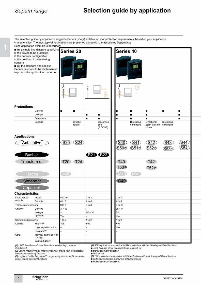
The selection guide by application suggests Sepam type(s) suitable for your protection requirements, based on your application characteristics. The most typical applications are presented along with the associated Sepam type.Each application example is described:b By a single-line diagram specifying:v the device to be protectedv the network configuration v the position of the metering sensorsb By the standard and specific Sepam functions to be implemented to protect the application concerned.Series 20 Series 40
ProtectionsCurrent b b b b b b bVoltage b b b b b bFrequency b b b b b bSpecific Breaker
failureDisconnec-tion (ROCOF)
Directional earth fault
Directional earth fault and phase
Directional earth fault
Applications
CharacteristicsLogic inputs/outputs
Inputs 0 to 10 0 to 10 0 to 10Outputs 4 to 8 4 to 8 4 to 8
Temperature sensors 0 to 8 0 to 8 0 to 16Channel Current 3I + I0 – 3I + I0
Voltage – 3V + V0 3VLPCT (1) Yes – Yes
Communication ports 1 to 2 1 to 2 1 to 2Control Matrix (2) Yes Yes Yes
Logic equation editor – – YesLogipam (3) – – –
Other Memory cartridge with settings
– – –
Backup battery – – –
(1) LPCT: Low-Power Current Transducer conforming to standard IEC 60044-8.(2) Control matrix used for simple assignment of data from the protection, control and monitoring functions.(3) Logipam: Ladder language PC programming environment for extended use of Sepam series 80 functions.
(4) S5X applications are identical to S4X applications with the following additional functions:b earth fault and phase overcurrent cold load pick-upb broken conductor detectionb fault locator(5) T5X applications are identical to T4X applications with the following additional functions:b earth fault and phase overcurrent cold load pick-upb broken conductor detection
8 SEPED310017EN

9
1
SEPED303017EN
11
Sepam range Selection guide by application
The list of protection functions is given for information only.Direct earthing or impedance earthing have been represented by the same pictogram, i.e. by a direct earthing system.
Series 60 Series 80
b b b b b b b b b b bb b b b b b b b b b bb b b b b b b b b b b
Direc-tional earth fault
Directional earth fault and phase
Directional earth fault
Directional earth fault and phase
Disconnection (ROCOF)
Transformer or machine-transformer unit differential
Machine differential
Busbar voltage and frequency protection
Capacitor bank unbalance
0 to 28 0 to 42 0 to 42 0 to 42 0 to 42
4 to 16 5 to 23 5 to 23 5 to 23 5 to 23
0 to 16 0 to 16 0 to 16 0 to 16 0 to 16
3I + I0 3I + 2 x I0 2 x 3I + 2 x I0 3I + I0 2 x 3I + 2 x I0
3V, 2U + V0 or Vnt 3V + V0 3V + V0 2 x 3V + 2 x V0 3V + V0
Yes Yes Yes Yes Yes
1 to 2 2 to 4 2 to 4 2 to 4 2 to 4
Yes Yes Yes Yes Yes
Yes Yes Yes Yes Yes
– Yes Yes Yes Yes
Yes Yes Yes Yes Yes
Yes Yes Yes Yes Yes
All the information relating to the Sepam range can be found in the following documents:b Sepam catalog, reference SEPED303005ENb Sepam series 20 user's manual, reference PCRED301005ENb Sepam series 40 user's manual, reference PCRED301006ENb Easergy Sepam series 60 user's manual, reference SEPED310017ENb Easergy Sepam series 80 functions user's manual, reference SEPED303001ENb Easergy Sepam series 80 Modbus communication user's manual, reference SEPED303002EN
b Easergy Sepam series 80 operation manual, reference SEPED303003ENb Sepam DNP3 communication user's manual, reference SEPED305001ENb Sepam IEC 60870-5-103 communication user's manual, reference SEPED305002ENb Sepam IEC 61850 communication user's manual, reference SEPED306024EN
M

1
Sepam range Protection functions suitable for low voltage
Low voltage earthing systemsThere are 4 low voltage (LV) earthing systems designated by a 2 or 3-letter acronym:b TN-Sb TN-Cb TTb IT
The letters making up the acronym have the following meanings:Letter MeaningFirst letter Transformer neutral point
I Earthed with an impedanceT Directly earthed
Second letter Electrical exposed conductive parts of the consumerT EarthedN Connected to the neutral conductor
Third letter (optional) Protective Earth conductorS Separate N neutral conductor and PE Protective Earth conductorC Combined N neutral conductor and PE Protective Earth conductor
(PEN)
10 SEPED310017EN
Sepam range Protection functions suitable for low voltage
11
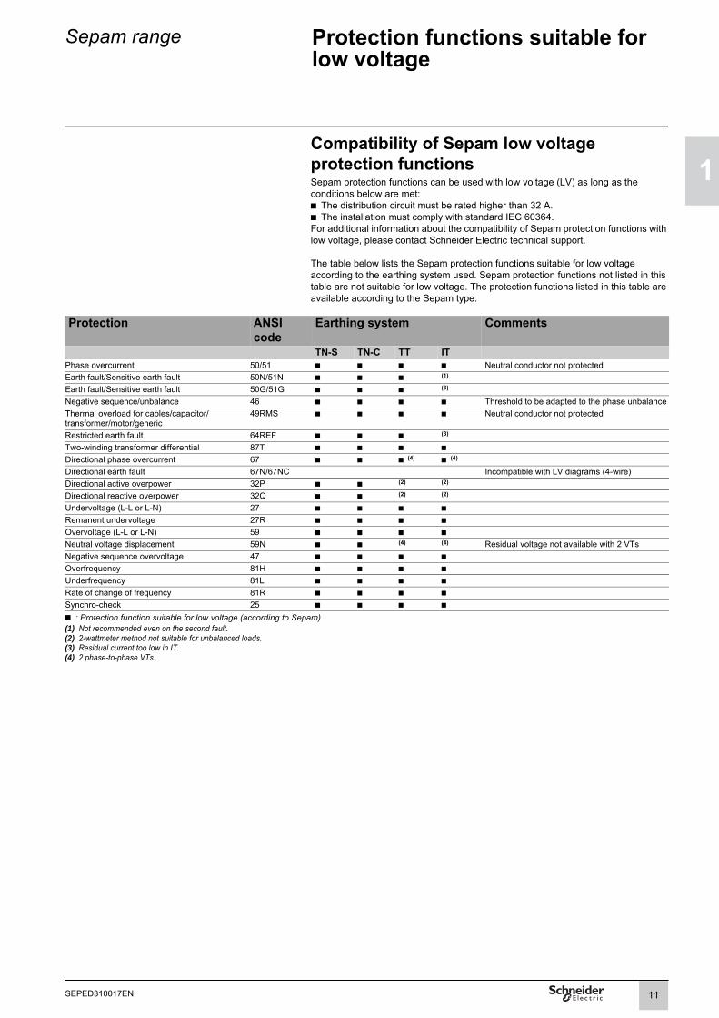
Compatibility of Sepam low voltage protection functionsSepam protection functions can be used with low voltage (LV) as long as the conditions below are met:b The distribution circuit must be rated higher than 32 A.b The installation must comply with standard IEC 60364.For additional information about the compatibility of Sepam protection functions with low voltage, please contact Schneider Electric technical support.The table below lists the Sepam protection functions suitable for low voltage according to the earthing system used. Sepam protection functions not listed in this table are not suitable for low voltage. The protection functions listed in this table are available according to the Sepam type.
Protection ANSI code
Earthing system Comments
TN-S TN-C TT ITPhase overcurrent 50/51 b b b b Neutral conductor not protectedEarth fault/Sensitive earth fault 50N/51N b b b (1)
Earth fault/Sensitive earth fault 50G/51G b b b (3)
Negative sequence/unbalance 46 b b b b Threshold to be adapted to the phase unbalanceThermal overload for cables/capacitor/transformer/motor/generic
49RMS b b b b Neutral conductor not protected
Restricted earth fault 64REF b b b (3)
Two-winding transformer differential 87T b b b bDirectional phase overcurrent 67 b b b (4) b (4) Directional earth fault 67N/67NC Incompatible with LV diagrams (4-wire)Directional active overpower 32P b b (2) (2)
Directional reactive overpower 32Q b b (2) (2)
Undervoltage (L-L or L-N) 27 b b b bRemanent undervoltage 27R b b b bOvervoltage (L-L or L-N) 59 b b b bNeutral voltage displacement 59N b b (4) (4) Residual voltage not available with 2 VTsNegative sequence overvoltage 47 b b b bOverfrequency 81H b b b bUnderfrequency 81L b b b bRate of change of frequency 81R b b b bSynchro-check 25 b b b b
b : Protection function suitable for low voltage (according to Sepam)(1) Not recommended even on the second fault.(2) 2-wattmeter method not suitable for unbalanced loads.(3) Residual current too low in IT.(4) 2 phase-to-phase VTs.
11SEPED310017EN
1
Introduction Presentation
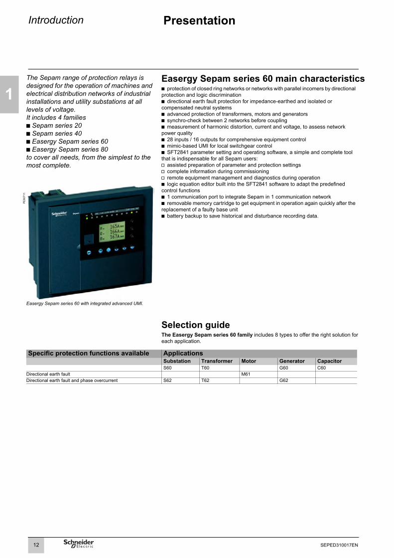
The Sepam range of protection relays is designed for the operation of machines and electrical distribution networks of industrial installations and utility substations at all levels of voltage.It includes 4 families b Sepam series 20b Sepam series 40b Easergy Sepam series 60b Easergy Sepam series 80to cover all needs, from the simplest to the most complete.
Easergy Sepam series 60 main characteristicsb protection of closed ring networks or networks with parallel incomers by directional protection and logic discrimination b directional earth fault protection for impedance-earthed and isolated or compensated neutral systemsb advanced protection of transformers, motors and generatorsb synchro-check between 2 networks before couplingb measurement of harmonic distortion, current and voltage, to assess network power quality b 28 inputs / 16 outputs for comprehensive equipment controlb mimic-based UMI for local switchgear controlb SFT2841 parameter setting and operating software, a simple and complete tool that is indispensable for all Sepam users:v assisted preparation of parameter and protection settingsv complete information during commissioningv remote equipment management and diagnostics during operationb logic equation editor built into the SFT2841 software to adapt the predefined control functionsb 1 communication port to integrate Sepam in 1 communication networkb removable memory cartridge to get equipment in operation again quickly after the replacement of a faulty base unit b battery backup to save historical and disturbance recording data.
PE
8071
1
Easergy Sepam series 60 with integrated advanced UMI.
Selection guideThe Easergy Sepam series 60 family includes 8 types to offer the right solution foreach application.
Specific protection functions available ApplicationsSubstation Transformer Motor Generator CapacitorS60 T60 G60 C60
Directional earth fault M61Directional earth fault and phase overcurrent S62 T62 G62
12 SEPED310017EN

Introduction Modular architecture
1
Flexibility and upgrading capabilityTo adapt to as many situations as possible, and allow for future installation upgrading, optional modules may be added to Sepam at any time for new functions.1 Base unit, with different types of User-Machine Interface (UMI):b Integrated mimic-based UMIb Integrated or remote advanced UMI
PE
8071
2
2 Parameter and protection settings saved on removable memory cartridge
3 28 logic inputs and 16 relay outputswith 2 optional modules providing 14 inputs and 6 outputs
4 1 communication portb Connection:v direct, to 2-wire RS 485, 4-wire RS 485 or fiber optic networksv to Ethernet TCP/IP network via PowerLogic Ethernet server (Transparent ReadyTM)b Protocols:v DNP3 and IEC 60870-5-103 with ACE969 communication interfacev IEC 61850 and Modbus TCP with ACE850 communication interface
5 Processing of data from 16 temperature sensorsPt100, Ni100 or Ni120
6 1 low level analog output 0-1 mA, 0-10 mA, 4-20 mA or 0-20 mA
7 Synchro-check module
8 Software tools:b Sepam parameter and protection setting and adaptation of the predefined functionsb Local or remote installation operationb Retrieval and display of disturbance recording data
Ease of installationb Light, compact base unitb Easy to integrate due to Sepam’s adaptation capabilities:v universal supply voltage for Sepam and its logic inputs: 24 to 250 V DCv phase currents can be measured by 1 A or 5 A current transformers, or LPCT (Low Power Current Transducer) type sensorsv residual current calculated or measured by a choice of methods to fit requirementsb The same, easy-to-install remote modules for all Sepam units:v mounted on DIN railv connected to the Sepam base unit by prefabricated cords
Commissioning assistanceb Predefined functions implemented by simple parameter settingb User-friendly, powerful SFT2841 PC setting software tool used on all Sepam unitsto provide users with all the possibilities offered by Sepam
Intuitive useb Integrated or remote advanced User Machine Interface (UMI) installed in the most convenient place for the facility managerb Integrated mimic-based User Machine Interface for local control of switchgearb User-friendly User Machine Interface, with direct access to datab Clear graphic LCD display of all data required for local operation and installation diagnosisb Working language can be customized to be understood by all users.
13 SEPED310017EN

1
Introduction Selection table
Substation Transformer Motor Generator Cap.Protection ANSI code S60 S62 T60 T62 M61 G60 G62 C60
Phase overcurrent (1) 50/51 4 4 4 4 4 4 4 4Earth fault / Sensitive earth fault (1) 50N/51N
50G/51G4 4 4 4 4 4 4 4
Breaker failure 50BF 1 1 1 1 1 1 1 1Negative sequence / unbalance 46 2 2 2 2 2 2 2 2Thermal overload for cables 49RMS 1Generic thermal overload (1) or 49RMS 2 2 2 2 2Thermal overload formotors/transformers
2 2 1
Thermal overload for capacitors 49RMS 1Restricted earth fault 64REF 2 2Directional phase overcurrent (1) 67 2 2 2Directional earth fault (1) 67N/67NC 2 2 2 2Directional active overpower 32P 2 2 2 2 2Directional reactive overpower 32Q 1 1 1Directional active underpower 37P 2 2Phase undercurrent 37 1Excessive starting time, locked rotor 48/51LR 1Starts per hour 66 1Field loss (underimpedance) 40 1 1 1Overspeed (2 set points) (2) 12 v v v Underspeed (2 set points) (2) 14 v v v Voltage-restrained overcurrent 50V/51V 1 1Underimpedance 21B 1 1Undervoltage (L-L or L-N) 27 2 2 2 2 2 2 2 2Positive sequence undervoltage 27D 2 2 2 2 2 2 2 2Remanent undervoltage 27R 2 2 2 2 2 2 2 2Overvoltage (L-L or L-N) 59 2 2 2 2 2 2 2 2Neutral voltage displacement 59N 2 2 2 2 2 2 2 2Negative sequence overvoltage 47 2 2 2 2 2 2 2 2Overfrequency 81H 2 2 2 2 2 2 2 2Underfrequency 81L 4 4 4 4 4 4 4 4Rate of change of frequency 81R 2 2 2 2Recloser (4 cycles) (2) 79 v vThermostat / Buchholz (2) 26/63 v v v v vTemperature monitoring (16 RTDs) (3)
38/49T v v v v v v
Synchro-check (4) 25 v v v v v v
Control and monitoringCircuit breaker / contactor control 94/69 v v v v v v v vAutomatic transfer (AT) (2) v v v v v vLoad shedding / automatic restart bDe-excitation b bGenset shutdown b bLogic discrimination (2) 68 v v v v v v v vLatching / acknowledgement 86 b b b b b b b bAnnunciation 30 b b b b b b b bTriggering a Motor start report b b b b b b b bActivating/Deactivating a Data log b b b b b b b bChange of phase rotation direction b b b b b b b bSwitching of groups of settings b b b b b b b bAdaptation using logic equations b b b b b b b bThe figures indicate the number of relays available for each protection function.b standard, v optional(1) Protection functions with 2 groups of settings(2) According to parameter setting and optional MES120 input/output modules(3) With optional MET148-2 temperature input module(4) With optional MCS025 synchro-check module
14 SEPED310017EN

Introduction Selection table
1
Substation Transformer Motor Generator Cap.Metering S60 S62 T60 T62 M61 G60 G62 C60Phase current I1, I2, I3 RMSMeasured residual current I0, calculated I0ΣDemand current I1, I2, I3Peak demand current IM1, IM2, IM3
bbbb
bbbb
bbbb
bbbb
bbbb
bbbb
bbbb
bbbb
Voltage U21, U32, U13, V1, V2, V3Residual voltage V0Positive sequence voltage Vd / rotation directionNegative sequence voltage ViFrequency
bbbbb
bbbbb
bbbbb
bbbbb
bbbbb
bbbbb
bbbbb
bbbbb
Active power P, P1, P2, P3Reactive power Q, Q1, Q2, Q3Apparent power S, S1, S2, S3Peak demand power PM, QMPower factor
bbbbb
bbbbb
bbbbb
bbbbb
bbbbb
bbbbb
bbbbb
bbbbb
Calculated active and reactive energy (±Wh, ±VARh) b b b b b b b bActive and reactive energy by pulse counting (1) (± Wh, ± VARh) v v v v v v v vTemperature (16 RTDs) (3) v v v v vRotation speed (2) v v v Neutral point voltage Vnt b b b
Network and machine diagnosisTripping contextTripping current TripI1, TripI2, TripI3
bb
bb
bb
bb
bb
bb
bb
bb
Phase fault and earth fault trip counters b b b b b b b bUnbalance ratio / negative sequence current Ii b b b b b b b bHarmonic distortion (THD), current and voltage Ithd, Uthd b b b b b b b bPhase displacement ϕ0, ϕ0ΣPhase displacement ϕ1, ϕ2, ϕ3
bb
bb
bb
bb
bb
bb
bb
bb
Disturbance recording b b b b b b b bMotor start report (MSR) bMotor start trend (MST) bData log (DLG) b b b b b b b bThermal capacity used b b b b b b bRemaining operating time before overload trippingWaiting time after overload tripping
bb
bb
bb
bb
bb
bb
bb
Running hours counter / operating time b b b b b bStarting current and time bStart inhibit timeNumber of starts before inhibition
bb
Apparent positive sequence impedance Zd Apparent phase-to-phase impedances Z21, Z32, Z13
bb
bb
bb
bb
bb
bb
bb
bb
Third harmonic voltage, neutral point or residual b bDifference in amplitude, frequency and phase of voltages compared for synchro-check (4) v v v v v vCapacitor unbalance current and capacitance b
Switchgear diagnosis ANSI codeCT / VT supervision 60/60FL b b b b b b b bTrip circuit supervision (2) 74 v v v v v v v v Cumulative breaking current b b b b b b b bNumber of operations, operating time, charging time, number of racking out operations (2) v v v v v v v v
Modbus, IEC 60870-5-103, DNP3 communication or IEC 61850 (Editions 1 and 2)Measurement readout (5) (6)
Remote indication and time tagging of events (5) (6)
Remote control orders (5) (6)
Remote protection setting (5) (6)
Transfer of disturbance recording data (5) (6)
IEC 61850 GOOSE message(6)
vvvvvv
vvvvvv
vvvvvv
vvvvvv
vvvvvv
vvvvvv
vvvvvv
vvvvvv
b standard, v optional(1) Protection functions with 2 groups of settings(2) According to parameter setting and optional MES120 input/output modules(3) With optional MET148-2 temperature input module(4) With optional MCS025 synchro-check module(5) With ACE949-2, ACE959, ACE937, ACE969TP-2 or ACE969FO-2 communication interface(6) With ACE850TP or ACE850FO communication interface
15 SEPED310017EN

1
Installation Technical characteristics
WeightBase unit with advanced UMI Base unit with mimic-based UMI
Minimum weight (base unit without MES120) 2.4 kg (5.29 lb) 3.0 kg (6.61 lb)Maximum weight (base unit with 2 MES120) 3.5 kg (7.72 lb) 4.0 kg (8.82 lb)
Sensor inputsPhase current inputs 1 A or 5 A CT
Input impedance < 0.02 ΩConsumption < 0.02 VA (1 A CT)
< 0.5 VA (5 A CT)Continuous thermal withstand 4 In1 second overload 100 In (500 A)Voltage inputs Phase Residual
Input impedance > 100 kΩ > 100 kΩConsumption < 0.015 VA (100 V VT) < 0.015 VA (100 V VT)Continuous thermal withstand 240 V 240 V1-second overload 480 V 480 VIsolation of inputs from other isolated groups
Enhanced Enhanced
Relay outputsControl relay outputs O1 to O3 and Ox01 (1)
Voltage DC 24/48 V DC 127 V DC 220 V DC 250 V DC -AC (47.5 to 63 Hz) - - - - 100 to 240 V AC
Continuous current 8 A 8 A 8 A 8 A 8 ABreaking capacity Resistive load 8 A / 4 A 0.7 A 0.3 A 0.2 A -
L/R Load < 20 6 A / 2 A 0.5 A 0.2 A - -L/R Load < 40 ms 4 A / 1 A 0.2 A 0.1 A - -Resistive load - - - - 8 Ap.f. load > 0.3 - - - - 5 A
Making capacity < 15 A for 200 msIsolation of outputs from other isolated groups
Enhanced
Annunciation relay output O5 and Ox02 to Ox06Voltage DC 24/48 V DC 127 V DC 220 V DC 250 V DC -
AC (47.5 to 63 Hz) - - - - 100 to 240 V ACContinuous current 2 A 2 A 2 A 2 A 2 ABreaking capacity Resistive load 2 A / 1 A 0.6 A 0.3 A 0.2 A -
L/R Load < 20 ms 2 A / 1 A 0.5 A 0.15 A - -p.f. load > 0.3 - - - - 1 A
Isolation of outputs from other isolated groups
Enhanced
Power supplyVoltage 24 to 250 V DC -20 % / +10 %Maximum consumption < 16 WInrush current < 10 A 10 msAcceptable ripple content 12%Acceptable momentary outages 20 ms
Battery Format 1/2 AA lithium 3.6 VService life 10 years Sepam energized
Minimum 3 years, typical 6 years
Analog output (MSA141 module)Current 4 - 20 mA, 0 - 20 mA, 0 - 10 mA, 0 - 1 mALoad impedance < 600 Ω (wiring included)Accuracy 0.50 % full scale or 0.01 mA(1) Relay outputs complying with clause 6.7 of standard C37.90 (30 A, 200 ms, 2000 operations).
16 SEPED310017EN

Installation Environmental characteristics
1
Electromagnetic compatibility Standard Level/Class ValueEmission testsDisturbing field emission CISPR 22EN 55022 A
Conducted disturbance emission CISPR 22EN 55022 A
Immunity tests - Radiated disturbancesImmunity to radiated fields IEC 60255-22-3 10 V/m; 80 MHz - 1 GHz
IEC 61000-4-3 III 10 V/m; 80 MHz - 2 GHz30 V/m non-modulated; 800MHz - 2GHz (1)
ANSI C37.90.2 20 V/m; 80 MHz - 1 GHzElectrostatic discharge IEC 61000-4-2 (1) IV 15 kV air ; 8 kV contact
IEC 60255-22-2 8 kV air; 6 kV contactANSI C37.90.3 15 kV air; 8 kV contact
Immunity to magnetic fields at network frequency (2) IEC 61000-4-8 4 30 A/m (continuous) - 300 A/m (1-3 s)Immunity to pulsed magnetic fields (1) IEC 61000-4-9 IV 600 A/mImmunity to magnetic fields with damped oscillating waves (1) IIEC 61000-4-10 5 100 A/mImmunity tests - Conducted disturbances
Immunity to conducted RF disturbances IEC 61000-4-6 III 10 VElectrical fast transients/burst IEC 61000-4-4 IV 4 kV; 2.5 kHz
ANSI C37.90.1 4 kV; 5 kHz1 MHz damped oscillating wave ANSI C37.90.1 2.5 kV CM; 2.5 kV DM100 kHz damped sinusoidal wave IEC 61000-4-12 III 2 kV MC
IV (1) 4 kV MC ; 2,5 kV DMSlow damped oscillating wave (100 kHz to 1 MHz) IEC 61000-4-18 IIIFast damped oscillating wave (3 MHz, 10 MHz, 30 MHz) IEC 61000-4-18 IIISurges IEC 61000-4-5 III 2 kV CM; 1 kV DM
GOST R 50746-2000 (1) 4 200 AImmunity to conducted disturbances in common mode from 0 Hz to 150 kHz
IEC 61000-4-16 III
Voltage interruptions IEC 60255-11 100% for 100 msMechanical robustness Standard Level/Class ValueEnergized
Vibrations IEC 60255-21-1 2 1 Gn; 10 Hz - 150 HzIEC 60068-2-6 Fc 3 Hz - 13.2 Hz; a = ±1 mmIEC 60068-2-64 2M1
Shocks IEC 60255-21-2 2 10 Gn/11 msEarthquakes IEC 60255-21-3 2 2 Gn (horizontal)
1 Gn (vertical)De-energized
Vibrations IEC 60255-21-1 2 2 Gn; 10 Hz - 150 HzShocks IEC 60255-21-2 2 27 Gn/11 msJolts IEC 60255-21-2 2 20 Gn/16 ms(1) Test conducted with a mimic-based HMI in the case of GOST performance testing.(2) When protection functions 50N/51N or 67N are used and I0 is calculated on the sum of the phase currents, Is0 must be higher than 0.1In0.
17 SEPED310017EN

1
Installation Environmental characteristics
Climatic withstand Standard Level/Class ValueDuring operation
Exposure to cold IEC 60068-2-1 Ad -25°C (-13°F)Exposure to dry heat IEC 60068-2-2 Bd +70°C (+158°F)Continuous exposure to damp heat IEC 60068-2-78 Cab 10 days; 93% RH; 40°C (104°F)Salt mist IEC 60068-2-52 Kb/2 3 daysInfluence of corrosion/2-gas test IEC 60068-2-60 21 days; 75% RH; 25°C (77°F);
0.1 ppm H2S; 0.5 ppm SO2Influence of corrosion/4-gas test IEC 60068-2-60 Method 4
Method 1
21 days; 70% RH; 25°C (77°F); 0.01 ppm H2S; 0.2 ppm SO2; 0.2 ppm NO2; 0.01 ppm Cl2
EIA 364-65A IIIA 42 days ; 75% RH ; 30 °C (86 °F) ;0.1 ppm H2S ; 0.2 ppm SO2 ; 0.2 ppm NO2 ; 0.02 ppm Cl2
In storage (1)
Temperature variation with specified variation rate IEC 60068-2-14 Nb -25°C to +70°C (-13°F to +158°F) 5°C/min Exposure to cold IEC 60068-2-1 Ab -25°C (-13°F)Exposure to dry heat IEC 60068-2-2 Bb +70°C (+158°F)Continuous exposure to damp heat IEC 60068-2-78 Cab 56 days; 93% RH; 40°C (104°F)
IEC 60068-2-30 Db 6 days; 95% RH; 55°C (131°F)Safety Standard Level/Class ValueEnclosure safety tests
Front panel tightness IEC 60529 IP52 Other panels IP20NEMA Type 12
Fire withstand IEC 60695-2-11 650°C (1200°F) with glow wireElectrical safety tests
1.2/50 µ 5 kV (2)
Ps impulse wave
ower frequency dielectric withstand IEC 60255-5IEC 60255-5
2 kV 1min (3)
ANSI C37.90 1 kV 1 min (annunciation output)1.5 kV 1 min (control output)
Certification
ULCSA
File E212533File 210625
IEC60255-26ha
UL508-CSA C22.2 no. 14-95CSA C22.2 no. 14-95/no. 0.17-00
rmonized standardEuropean directives:
EMC European Directive CEM 2014/30/EULow Voltage European Directive 2014/35/EU
(1) Sepam must be stored in its original packaging.(2) Except for communication: 3 kV in common mode and 1 kV in differential mode.(3) Except for communication: 1 kVrms.(4) See the appendix in “Installation and operation” manual SEPED303003EN, “Functional Safety” section
18 SEPED310017EN

1
19 SEPED310017EN

2
Metering functions Contents
General settings 22
Characteristics 23
Processing of measured signals 24
Phase currentResidual current 26
Demand current and peak demand currents 27
Phase-to-phase voltagePhase-to-neutral voltage 28
Residual voltageNeutral point voltage 29
Positive sequence voltageNegative sequence voltage 30
Frequency 31
Active, reactive and apparent power 32
Peak demand active and reactive powerPower factor (cos ϕ) 34
Active and reactive energy 35
Temperature 36
Rotation speed 37
Phasor diagram 38
Tripping contextTripping current 39
Number of phase fault tripsNumber of earth fault trips 40
Negative sequence / unbalance 41
Current total harmonic distortionVoltage total harmonic distortion 42
Phase displacement ϕ0, ϕ0SPhase displacement ϕ1, ϕ2, ϕ3 43
Disturbance recording 44
Data log (DLG) 45
Synchro-check:voltage comparison and out-of-sync context 50
Thermal capacity usedCooling time constant 51
Operating time before trippingWaiting time after tripping 52
Running hours andoperating time counterStarting current and starting time 53
Number of starts before inhibitionStart inhibit time 54
Apparent positive sequence impedanceApparent phase-to-phase impedances 55
20 SEPED310017EN
Metering functions Contents
2
Capacitance 56
Capacitor unbalance current 57
Motor start report (MSR) 58
Motor start trend (MST) 60
VT supervision 63ANSI code 60FL 63
CT supervision 65ANSI code 60 65
Trip circuit and open/closed matching supervision 66ANSI code 74 66
Closing circuit and open/close orders supervision 67ANSI code 74 67
Cumulative breaking currentNumber of operations 68
Operating timeCharging time 69
Number of racking out operations 70
21SEPED310017EN
22
2
SEPED310017EN
Metering functions General settings
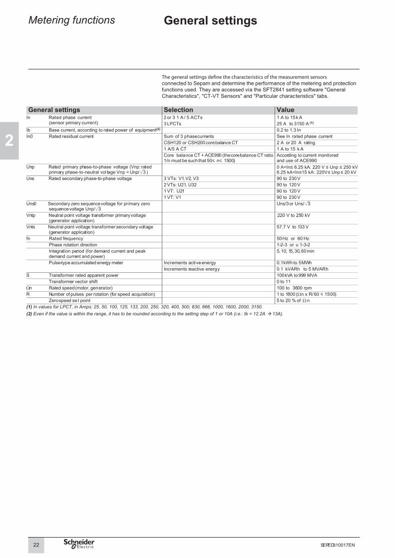
connected to Sepam and determine the performance of the metering and protection functions used. They are accessed via the SFT2841 setting software "General Characteristics", "CT-VT Sensors" and "Particular characteristics" tabs.
General settings Selection ValueIn Rated phase current
(sensor primary current)2 or 3 1 A / 5 A CTs 1 A to 15 k A3 LPCTs 25 A to 3150 A (1)
(2)Ib Base current, according to rated power of equipment 0.2 to 1.3 InIn0 Rated residual current Sum of 3 phase currents See In rated phase current
CSH120 or CSH200 core balance CT 2 A or 20 A rating1 A/5 A CT 1 A to 15 k ACore balance CT + ACE990 (the core balance CT ratio 1/n must be such that 50 n 1500)
According to current monitoredand use of ACE990
Unp Rated primary phase-to-phase voltage (Vnp: rated primary phase-to-neutral vol tage Vnp = Unp/ 3 )
Uns Rated secondary phase-to-phase voltage 3 VTs: V1, V2, V3 90 to 230 V2 VTs: U21, U32 90 to 120 V1 VT: U21 90 to 120 V1 VT: V1 90 to 230 V
Uns0 Secondary zero sequence voltage for primary zero sequence voltage Unp/ 3
Uns/3 or Uns/ 3
Vntp Neutral point voltage transformer primary voltage (generator application)
220 V to 250 kV
Vnts Neutral point voltage transformer secondary voltage (generator application)
57.7 V to 133 V
fn Rated frequency 50 Hz or 60 HzPhase rotation direction 1-2-3 or u 1-3-2Integration period (for demand current and peak demand current and power)
5, 10, 15, 30, 60 min
Pulse-type accumulated energy meter Increments active energy 0.1 kWh to 5 MWhIncrements reactive energy 0.1 kVARh to 5 MVARh
S Transformer rated apparent power 100 kVA to 999 MVATransformer vector shift 0 to 11
Ωn Rated speed (motor, generator) 100 to 3600 rpmR Number of pulses per rotation (for speed acquisition) 1 to 1800 (Ωn x R/ 60 1500)
Zero speed se t point 5 to 20 % of Ωn(1) In va(2) Even if the value is within the range, it has to be rounded according to the setting step of 1 or 10A (i.e.: Ib = 12.2A 13A).
lues for LPCT, in Amps: 25, 50, 100, 125, 133, 200, 250, 320, 400, 500, 630, 666, 1000, 1600, 2000, 3150.
0 A<In≤ 6.25 kA: 220 V ≤ Unp ≤ 250 kV6.25 kA<In≤15 kA: 220V≤ Unp ≤ 20 kV

Metering functions Characteristics
2
Functions Measurement range Accuracy (1) MSA141 SavingMetering
Phase current 0.02 to 40 In ±0.5 % bResidual current Calculated 0.005 to 40 In ±1 % b
Measured 0.005 to 20 In0 ±1 % bDemand current 0.02 to 40 In ±0.5 %Peak demand current 0.02 to 40 In ±0.5 % vPhase-to-phase voltage 0.06 to 1.2 Unp ±0.5 % bPhase-to-neutral voltage 0.06 to 1.2 Vnp ±0.5 % bResidual voltage 0.04 to 3 Vnp ±1 %Neutral point voltage 0.04 to 3 Vntp ±1 %Positive sequence voltage 0.05 to 1.2 Vnp ±2 %Negative sequence voltage 0.05 to 1.2 Vnp ±2 %Frequency 25 to 65 Hz ±0.01 Hz bActive power (total or per phase) 0.015 Sn to 999 MW ±1 % bReactive power (total or per phase) 0.015 Sn to 999 MVAR ±1 % bApparent power (total or per phase) 0.015 Sn to 999 MVA ±1 % bPeak demand active power 0.015 Sn to 999 MW ±1 % vPeak demand reactive power 0.015 Sn to 999 MVAR ±1 % vPower factor -1 to + 1 (CAP/IND) ±0.01 bCalculated active energy 0 to 2.1 x 10⁸ MWh ±1 % ±1 digit v vCalculated reactive energy 0 to 2.1 x 10⁸ MVARh ±1 % ±1 digit v vTemperature -30 °C to +200 °C or -22 °F to +392 °F ±1 °C from +20 to +140 °C bRotation speed 0 to 7200 rpm ±1 rpmNetwork diagnosis assistance
Tripping context vTripping current 0.02 to 40 In ±5 % vNumber of trips 0 to 65535 - v vNegative sequence / unbalance 1 to 500 % of Ib ±2 %Total harmonic distortion, current 0 to 100 % ±1 %Total harmonic distortion, voltage 0 to 100 % ±1 %Phase displacement ϕ0 (between V0 and I0) 0 to 359° ±2°Phase displacement ϕ1, ϕ2, ϕ3 (between V and I) 0 to 359° ±2°Disturbance recording vAmplitude difference 0 to 1.2 Usync1 ±1 %Frequency difference 0 to 10 Hz ±0.5 HzPhase difference 0 to 359° ±2°Out-of-sync context v
Machine operating assistanceThermal capacity used 0 to 800 % (100 % for phase I = Ib) ±1 % b v vRemaining operating time before overload tripping 0 to 999 min ±1 minWaiting time after overload tripping 0 to 999 min ±1 minRunning hours counter / operating time 0 to 65535 hours ±1 % or ±0.5 h v vStarting current 1.2 Ib to 40 In ±5 % vStarting time 0 to 300 s ±300 ms vNumber of starts before inhibition 0 to 60Start inhibit time 0 to 360 min ±1 minApparent impedance Zd, Z21, Z32, Z13 0 to 200 kΩ ±5 %Capacitance 0 to 30 F ±5 %Capacitor unbalance current 0.02 to 40 I0 ±5 %Switchgear diagnosis assistance
Cumulative breaking current 0 to 65535 kA² ±10 % v vNumber of operations 0 to 4 x 10⁹ - v vOperating time 20 to 100 ms ±1 ms v vCharging time 1 to 20 s ±0.5 s v vNumber of rackouts 0 to 65535 - v vb available on MSA141 analog output module, according to setupv v saved in the event of auxiliary supply outage, even without batteryv saved by battery in the event of auxiliary supply outage.(1) Typical accuracy, see details on subsequent pages.
23SEPED310017EN

2
Metering functions Processing of measured signals
Measured physical values
DE
8085
8
Sepam measures the following physical values:b phase currents (3I)b residual current (I0)b phase voltages (3V)b residual voltage (V0).Each measured signal is processed by Sepam to produce all the values necessary for the metering, diagnosis and protection functions.
The charts below indicate, for the various functions, the values produced from the signals measured, with:b RMS = RMS value up to the 13th harmonicb H1 = fundamental 50 Hz or 60 Hz componentb ΣH1 = vector sum of the fundamental components of the three phases
Values produced by Sepam from the signals measured.
Values used by the metering and diagnosis functions3I I0 3V V0
Metering RMS H1 ΣH1 H1 RMS H1 ΣH1 H1RMS phase current I1, I2, I3 bCalculated residual current I0Σ bDemand current I1, I2, I3 bPeak demand current IM1, IM2, IM3 bMeasured residual current I0 bVoltage U21, U32, U13, V1, V2, V3 bResidual voltage V0 v vPositive sequence voltage Vd / rotation direction bNegative sequence voltage Vi bFrequency f bActive power P, P1, P2, P3 b bReactive power Q, Q1, Q2, Q3 b bApparent power S, S1, S2, S3 b bPeak demand power PM, QM b bPower factor b bCalculated active and reactive energy (± Wh, ± VARh) b bNeutral point voltage Vnt b
Network and machine diagnosisTripping current TripI1, TripI2, TripI3 bUnbalance ratio / negative sequence current Ii bHarmonic distortion (THD), current Ithd b bHarmonic distortion (THD), voltage Uthd b bPhase displacement ϕ0, ϕ0Σ b b v vPhase displacement ϕ1, ϕ2, ϕ3 b bThermal capacity used bStarting current b
Switchgear diagnosis ANSI codeCT / VT supervision 60/60FL b bCumulative breaking current bb standardv according to measurement sensors connected.
24 SEPED310017EN

Metering functions Processing of measured signals
2
Values used by the protection functions3I I0 3V V0
Protections ANSI code RMS H1 ΣH1 H1 RMS H1 ΣH1 H1Phase overcurrent 50/51 bEarth faultSensitive earth fault
50N/51N50G/51G
v v
Breaker failure 50BF bNegative sequence / unbalance 46 bThermal overload for cables 49RMS bGeneric thermal overload 49RMS bThermal overload for capacitors 49RMS bThermal overload for motors 49RMS bThermal overload for transformers 49RMS bRestricted earth fault 64REF b bDirectional phase overcurrent 67 b bDirectional earth fault 67N/67NC v v v vDirectional active overpower 32P b bDirectional reactive overpower 32Q b bDirectional active underpower 37P b bPhase undercurrent 37 bExcessive starting time, locked rotor 48/51LR bStarts per hour 66 bField loss (underimpedance) 40 b bVoltage-restrained overcurrent 50V/51V b bUnderimpedance 21B b bPositive sequence undercurrent 27D bRemanent undervoltage 27R bUndervoltage (L-L or L-N) 27 bOvervoltage (L-L or L-N) 59 bNeutral voltage displacement 59N v vNegative sequence overvoltage 47 bOverfrequency 81H bUnderfrequency 81L bRate of change of frequency 81R bb standardv according to measurement sensors connected.
Phase rotation direction
DE
5033
3
The rotation direction of the 3 phases of the network may be 1-2-3, or 1-3-2, the phase order in the trigonometric (counter-clockwise) direction.The phase rotation direction needs to be set for correct calculation of the symmetrical components (Vd, Vi, V0Σ, Id, Ii, I0Σ).The phase rotation direction directly affects:b the direction of energy flow measured in the Sepam relayb the sign and calculation of the powers and directional functions.
Phase rotation direction 1-2-3.
DE
5010
9
Phase rotation direction 1-3-2.
25SEPED310017EN

2
Metering functions Phase currentResidual current
Phase currentOperationThis function gives the RMS value of the phase currents:b I1: phase 1 current,b I2: phase 2 current,b I3: phase 3 current,It is based on RMS current measurement and takes into account harmonics up to the 13th.Different types of sensors may be used to meter phase current:b 1 A or 5 A current transformersb LPCT (Low Power Current Transducer) type current sensors.
ReadoutThe measurements may be accessed via:b the Sepam display via the keyb the display of a PC with the SFT2841 softwareb the communication linkb an analog converter with the MSA141 option.
CharacteristicsMeasurement range 0.02 to 40 In (1)
Units A or kAResolution 0.1 AAccuracy ±0.5 % typical (2)
±1 % from 0.3 to 1.5 In±2 % from 0.1 to 0.3 In
Display format 3 significant digitsRefresh interval 1 second (typical)(1) In rated current set in the general settings.(2) At In, under reference conditions (IEC 60255-6).
Residual currentOperationThis operation gives the RMS value of the residual current.It is based on measurement of the fundamental component.2 types of residual current values are available depending on the type of Sepam and sensors connected to it:b the residual currents I0Σ, calculated by the vector sum of the 3 phase currents b the measured residual currents I0.Different types of sensors may be used to measure residual current:b CSH120 or CSH200 specific core balance CT b conventional 1 A or 5 A current transformerb any core balance CT with an ACE990 interface.
ReadoutThe measurements may be accessed via:b the Sepam display via the keyb the display of a PC with the SFT2841 softwareb the communication linkb an analog converter with the MSA141 option.
CharacteristicsMeasurement range I0Σ 0.005 to 40 In (1)
I0 measured by CSH core balance CT Rating In0 = 2 A 0.005 to 20 In0 (1)
In0 = 20 A 0.005 to 20 In0 (1)
I0 measured by core balance CT with ACE990 0.005 to 20 In0 (1)
I0 measured by CT 0.005 to 20 In0 (1)
Units A or kAResolution 0.1 A or 1 digitAccuracy (2) ±1 % typical at In0
±2 % from 0.3 to 1.5 In0±5 % from 0.1 to 0.3 In0
Display format 3 significant digitsRefresh interval 1 second (typical)(1) In, In0: nominal rating set in the general settings.(2) Under reference conditions (IEC 60255-6), excluding sensor accuracy.
26 SEPED310017EN

Metering functions Demand current and peak demand currents
2
OperationDemand current and peak demand currents are calculated according to the 3 phase currents I1, I2 and I3:b demand current is calculated over an adjustable period of 5 to 60 minutesb peak demand current is the greatest demand current and indicates the current drawn by peak loads.Peak demand currents may be cleared. They are saved in the event of a power failure.
ReadoutThe measurements may be accessed via:b the Sepam display via the keyb the display of a PC with the SFT2841 softwareb the communication link.
Resetting to zerob via the key on the Sepam display if a peak demand is displayed b via the clear command in the SFT2841 softwareb via the communication link (remote control order TC4).
CharacteristicsMeasurement range 0.02 to 40 In (1)
Units A or kAResolution 0.1 AAccuracy ±0.5 % typical (2)
±1 % from 0.3 to 1.5 In±2 % from 0.1 to 0.3 In
Display format 3 significant digitsIntegration period 5, 10, 15, 30, 60 min(1) In rated current set in the general settings.(2) At In, under reference conditions (IEC 60255-6).
TS/TC equivalence for each protocolModbus DNP3 IEC 60870-5-103 IEC 61850TC Binary Output ASDU, FUN, INF LN.DO.DA
TC4 BO12 - MSTA1.RsMaxA.ctlVal
clear
27SEPED310017EN

2
Metering functions Phase-to-phase voltagePhase-to-neutral voltage
Phase-to-phase voltageOperation
DE
5033
4
This function gives the RMS value of the fundamental 50 Hz or 60 Hz component of the phase-to-phase voltages:
v , voltage between phases 2 and 1
v , voltage between phases 3 and 2
v , voltage between phases 1 and 3.
ReadoutThe measurements may be accessed via:b the Sepam display via the keyb the display of a PC with the SFT2841 softwareb the communication linkb an analog converter with the MSA141 option.
Characteristics
1-2-3 network: phase-to-neutral and phase-to-phase voltages.
DE
5033
3
Measurement range 0.06 to 1.2 Unp (1)
Units V or kVResolution 1 VAccuracy ±0.5 % typical (2)
±1 % from 0.5 to 1.2 Unp±2 % from 0.06 to 0.5 Unp
Display format 3 significant digits1-3-2 network: phase-to-neutral and phase-to-phase voltages. Refresh interval 1 second (typical)
(1) Un rated current set in the general settings.(2) At Unp, under reference conditions (IEC 60255-6).
Phase-to-neutral voltageOperationThis function gives the RMS value of the fundamental 50 Hz or 60 Hz component of the phase-to-neutral voltages V1, V2, V3 measured on phases 1, 2 and 3.
ReadoutThe measurements may be accessed via:b the Sepam display via the keyb the display of a PC with the SFT2841 softwareb the communication linkb an analog converter with the MSA141 option.
CharacteristicsMeasurement range 0.06 to 1.2 Vnp (1)
Units V or kVResolution 1 VAccuracy ±0.5 % typical (2)
±1 % from 0.5 to 1.2 Vnp±2 % from 0.06 to 0.5 Vnp
Display format 3 significant digitsRefresh interval 1 second (typical)(1) Vnp: primary rated phase-to-neutral voltage (Vnp = Unp/3).(2) At Vnp, under reference conditions (IEC 60255-6).
U21 V1 V2–=( )
U32 V2 V3–=( )
U13 V3 V1–=( )
28 SEPED310017EN

Metering functions Residual voltageNeutral point voltage
2
Residual voltageOperationThis function gives the value of the residual voltage :
The residual voltage value may be:b calculated by an open star/delta VTb or calculated by taking the internal sum of the 3 phase voltages.It is based on the measurement of the fundamental 50 Hz or 60 Hz component of the voltages.
ReadoutThe measurements may be accessed via:b the Sepam display via the keyb the display of a PC with the SFT2841 softwareb the communication link.
CharacteristicsMeasurement range 0.04 to 3 Vnp (1)
Units V or kVResolution 1 VAccuracy ±1 % from 0.5 to 3 Vnp
±2 % from 0.05 to 0.5 Vnp±5 % from 0.04 to 0.05 Vnp
Display format 3 significant digitsRefresh interval 1 second (typical)(1) Vnp: primary rated phase-to-neutral voltage (Vnp = Unp/3).
Neutral point voltageOperationThis function gives the value of the zero sequence voltage Vnt, measured at the neutral point of a generator or motor by a dedicated VT:
ReadoutThe measurements may be accessed via:b the Sepam display via the keyb the display of a PC with the SFT2841 softwareb the communication link.
CharacteristicsMeasurement range 0.04 Vnp to 3 Vntp (1)
Units V or kVResolution 1 VAccuracy ±1 % from 0.5 to 3 Vntp
±2 % from 0.05 to 0.5 Vntp±5 % from 0.04 to 0.05 Vntp
Display format 3 significant digitsRefresh interval 1 second (typical)(1) Vntp: neutral point voltage transformer primary voltage.
V0 V1 V2 V3+ +=
Vnt V1 V2 V3+ +( ) 3⁄=
29SEPED310017EN

2
Metering functions Positive sequence voltageNegative sequence voltage
Positive sequence voltageOperationThis function calculates the value of the positive sequence voltage Vd:b from the 3 phase-to-neutral voltages:
v phase rotation direction 1-2-3:
v phase rotation direction 1-3-2:
b or from the 2 phase-to-phase voltages:
v phase rotation direction 1-2-3:
v phase rotation direction 1-3-2:
with
ReadoutThe measurements may be accessed via:b the Sepam display via the keyb the display of a PC with the SFT2841 softwareb the communication link.
CharacteristicsMeasurement range 0.05 to 1.2 Vnp (1)
Units V or kVResolution 1 VAccuracy ±2 % at VnpDisplay format 3 significant digitsRefresh interval 1 second (typical)(1) Vnp: primary rated phase-to-neutral voltage (Vnp = Unp/3).
Negative sequence voltageOperationThis function calculates the value of the negative sequence voltage Vi:b from the 3 phase-to-neutral voltages:
v phase rotation direction 1-2-3:
v phase rotation direction 1-3-2:
b or from the 2 phase-to-phase voltages: v phase rotation direction 1-2-3:
v phase rotation direction 1-3-2:
with
ReadoutThe measurements may be accessed via:b the Sepam display via the keyb the display of a PC with the SFT2841 softwareb the communication link.
CharacteristicsMeasurement range 0.05 to 1.2 Vnp (1)
Units V or kVResolution 1 VAccuracy ±2 % at VnpDisplay format 3 significant digitsRefresh interval 1 second (typical)(1) Vnp: primary rated phase-to-neutral voltage (Vnp = Unp/3).
Vd 13--- V1 aV2 a2V3+ +( )×=
Vd 13--- V1 a2V2 aV3+ +( )×=
Vd 13--- U21 a2U32–( )×=
Vd 13--- U21 aU32–( )×=
a ej2π
3------
=
Vi 13--- V1 a2V2 aV3+ +( )×=
Vi 13--- V1 aV2 a2V3+ +( )×=
Vi 13--- U21 aU32–( )×=
Vi 13--- U21 a2U32–( )×=
a ej2π
3------
=
30 SEPED310017EN

Metering functions Frequency
2
OperationThis function gives the frequency value.Frequency is measured via the following:b based on U21 or V1, if only one phase-to-phase voltage is connected to the Sepamb based on positive sequence voltage in other cases.Frequency is not measured if:b the voltage U21 (or V1) or positive sequence voltage Vd is less than 40 % of Unb the frequency f is outside the measurment range.
ReadoutThe measurements may be accessed via:b the Sepam display via the keyb the display of a PC with the SFT2841 softwareb the communication linkb an analog converter with the MSA141 option.
CharacteristicsRated frequency 50 Hz, 60 HzRange 25 to 65 HzResolution (1) 0.01 Hz
Accuracy (2) ±0.01 HzDisplay format 3 significant digitsRefresh interval 1 second (typical)(1) On SFT2841.(2) At Unp, under reference conditions (IEC 60255-6).
31SEPED310017EN

2
Metering functions Active, reactiveand apparent power
OperationPower values are calculated from the phase currents I1, I2 and I3:b active power = 3.U.I cos ϕb reactive power = 3.U.I.sin ϕb apparent power = 3.U.I.According to the sensors used, power calculations may be based on the 2 or 3 wattmeter method (see table below).The 2 wattmeter method is only accurate when there is no residual current, but it is not applicable if the neutral is distributed.The 3 wattmeter method gives an accurate calculation of 3-phase and phase by phase powers in all cases, regardless of whether or not the neutral is distributed.
Connection of voltage channels
Connection of current channels
P, Q, S calculation method Power per phaseP1, P2, P3Q1, Q2, Q3S1, S2, S3
3 V I1, I2, I3 3 wattmeters AvailableI1, I3 2 wattmeters Not available
U32, U21 + V0 I1, I2, I3 3 wattmeters AvailableI1, I3 2 wattmeters Not available
U32, U21 without V0 I1, I2, I3 or I1, I3 2 wattmeters Not availableU21 I1, I2, I3 or I1, I3 2 wattmeters
The system voltage is considered to be balancedNot available
V1 I1, I2, I3 or I1, I3 No calculation P1, Q1, S1 only
Power calculationb by 3 wattmeter method:
b by 2 wattmeter method:
b .
According to standard practice, it is considered that:b for the outgoing circuit (1):v power supplied by the busbars is positivev power supplied to the busbars is negative
DE
5064
6
b for the incoming circuit (1):v power supplied to the busbars is positivev power supplied by the busbars is negative.
DE
5064
7
(1) Choice to be set in the general settings.
P V1 I1 V1 I1( , )cos V2 I2 V2 I2( , )cos V3 I3 V3 I3( , )cos+ +=
Q V1 I1 V1 I1( , )sin V2 I2 V2 I2( , )sin V3 I3 V3 I3( , )sin+ +=
P U21 I1 U21 I1( , )cos U32 I3 U32 I3( , )cos–=
Q U21 I1 U21 I1( , )sin U32 I3 U32 I3( , )sin–=
S P2 Q2+=
32 SEPED310017EN

Metering functions Active, reactiveand apparent power
2
ReadoutThe measurements may be accessed via:b the Sepam display via the keyb the display of a PC with the SFT2841 softwareb the communication linkb an analog converter with the MSA141 option.
Characteristics Active powerP, P1, P2, P3
Reactive powerQ, Q1, Q2, Q3
Apparent powerS, S1, S2, S3
Measurement range ±(1.5 % Sn at 999 MW) (1) ±(1.5 % Sn at 999 Mvar) (1) 1.5 % Sn at 999 MVA (1)
Units kW, MW kvar, Mvar kVA, MVAResolution 0.1 kW 0.1 kvar 0.1 kVAAccuracy ±1 % from 0.3 to 1.5 Sn
±3 % from 0.1 to 0.3 Sn (2)±1 % from 0.3 to 1.5 Sn
±3 % from 0.1 to 0.3 Sn (3)±1 % from 0.3 to 1.5 Sn±3 % from 0.1 to 0.3 Sn
Display format 3 significant digits 3 significant digits 3 significant digitsRefresh interval 1 second (typical) 1 second (typical) 1 second (typical)(1) Sn = 3Unp.In.(2) Cos ϕ > 0.8 under reference conditions (IEC 60255-6).(3) Cos ϕ < 0.6 under reference conditions (IEC 60255-6).
33SEPED310017EN

2
Metering functions Peak demand active and reactive powerPower factor (cos ϕ)
Peak demand active and reactive powerOperationThis function gives the greatest demand active or reactive power value since the last reset.The values are refreshed after each "integration interval", an interval that may be set from 5 to 60 min (common interval with peak demand phase currents). The values are saved in the event of a power failure.
ReadoutThe measurements may be accessed via:b the Sepam display via the keyb the display of a PC with the SFT2841 softwareb the communication link.
Resetting to zerob via the key on the Sepam display if a peak demand is displayed b via the clear command in the SFT2841 softwareb via the communication link (remote control order TC5).
CharacteristicsDemand active power Demand reactive power
Measurement range ±(1.5 % Sn at 999 MW) (1) ±(1.5 % Sn at 999 Mvar) (1)
Units kW, MW kvar, MvarResolution 0.1 kW 0.1 kvarAccuracy ±1 %, typical (2) ±1 % typical (3)
Display format 3 significant digits 3 significant digitsIntegration period 5, 10, 15, 30, 60 min 5, 10, 15, 30, 60 min(1) Sn = 3Unp.In.(2) At In, Unp, cos ϕ > 0.8 under reference conditions (IEC 60255-6).(3) At In, Unp, cos ϕ < 0.6 under reference conditions (IEC 60255-6).
TS/TC equivalence for each protocolModbus DNP3 IEC 60870-5-103 IEC 61850TC Binary Output ASDU, FUN, INF LN.DO.DA
TC5 BO14 - MSTA1.RsMaxPwr.ctlVal
Power factor (cos ϕ)OperationThe power factor is defined by: .It expresses the phase displacement between the phase currents and phase-to-neutral voltages.The + and - signs and IND (inductive) and CAP (capacitive) indications give the direction of power flow and the type of load.
ReadoutThe measurements may be accessed via:b the Sepam display via the keyb the display of a PC with the SFT2841 softwareb the communication link.
Characteristics
MT1
0257
MT1
0258
Measurement range -1 at 1 IND/CAPResolution 0.01
IEC convention Accuracy (1) 0.01 typicalDisplay format 3 significant digitsRefresh interval 1 second (typical)(1) At In, Unp, cos ϕ > 0.8 under reference conditions (IEC 60255-6).
clear
ϕcos P P2 Q2+⁄=
34 SEPED310017EN

Metering functions Active and reactive energy
2
Accumulated active and reactive energyOperationThis function gives the following for the active and reactive energy values, calculated according to voltages and phase currents I1, I2 and I3:b accumulated energy conveyed in one directionb accumulated energy conveyed in the other direction.It is based on measurement of the fundamental component.The accumulated energy values are saved in the event of a power failure.
ReadoutThe measurements may be accessed via:b the Sepam display via the keyb the display of a PC with the SFT2841 softwareb the communication link.
CharacteristicsActive energy Reactive energy
Metering capacity 0 to 2.1 108 MW.h 0 to 2.1 108 Mvar.hUnits MW.h Mvar.hResolution 0.1 MW.h 0.1 Mvar.hAccuracy ±1 % typical (1) ±1 % typical (1)
Display format 10 significant digits 10 significant digits(1) At In, Unp, cos ϕ > 0.8 under reference conditions (IEC 60255-6).
Accumulated active and reactive energyby pulse meteringOperationThis function is used for energy metering via logic inputs. Energy incrementing is associated with each input (one of the general parameters to be set). Each input pulse increments the meter. 4 inputs and 4 accumulated energy metering options are available:b positive and negative active energyb positive and negative reactive energy.The accumulated active and reactive energy values are saved in the event of a power failure.
Readoutb the display of a PC with the SFT2841 softwareb the communication link.
CharacteristicsActive energy Reactive energy
Metering capacity 0 to 2.1 108 MW.h 0 to 2.1 108 Mvar.hUnits MW.h Mvar.hResolution 0.1 MW.h 0.1 Mvar.hDisplay format 10 significant digits 10 significant digitsIncrement 0.1 kW.h to 5 MW 0.1 kvar.h to 5 Mvar.hPulse 15 ms min. 15 ms min.
35SEPED310017EN

2
Metering functions Temperature
OperationThis function gives the temperature value measured by resistance temperature detectors (RTDs):b platinum Pt100 (100 Ω at 0 °C or 32 °F) in accordance with the IEC 60751 and DIN 43760 standardsb nickel 100 Ω or 120 Ω (at 0 °C or 32 °F).Each RTD channel gives one measurement:tx = RTD x temperature.The function also indicates RTD faults:b RTD disconnected (t > 205 °C or t > 401 °F)b RTD shorted (t < -35 °C or t < -31 °F).In the event of a fault, display of the value is inhibited. The associated monitoring function generates a maintenance alarm.
ReadoutThe measurements may be accessed via:b the Sepam display via the key, in °C or °Fb the display of a PC with the SFT2841 softwareb the communication linkb an analog converter with the MSA141 option.
Characteristics Range -30 °C to +200 °C -22 °F to +392 °FResolution 1 °C 1 °FAccuracy ±1 °C from +20 °C to +140 °C
±2 °C from -30 °C to +20 °C±2 °C from +140 °C to +200 °C
±1.8 °F from +68 °F to +284 °F±3.6 °F from -22 °F to +68 °F±3.6 °F from +284 °F to +392 °F
Refresh interval 5 seconds (typical)
Accuracy derating according to wiringb connection in 3-wire mode: the error Δt is proportional to the length of the connector and inversely proportional to the connector cross-section:
v ±2.1 °C/km for a cross-section of 0.93 mm2 (AWG 18)v ±1 °C/km for a cross-section of 1.92 mm2 (AWG 14).
Δt ° C( ) 2 I km( )S mm2( )----------------------×=
36 SEPED310017EN

Metering functions Rotation speed
2
OperationThis function gives the rotation speed of a motor or generator rotor. It is calculated by measurement of the time between two pulses transmitted by a proximity sensor at each passage of a cam driven by the rotation of the motor or generator shaft. The number of pulses per rotation is set in the "particular characteristics" screen of the SFT2841 software. The proximity sensor is connected to logic input I104.
DE
1035
9
1 Rotor with 2 cams.2 Proximity sensor.
ReadoutThe measurements may be accessed via:b the display of a PC with the SFT2841 softwareb the communication link.
CharacteristicsRange 0 to 7200 rpmResolution 1 rpmAccuracy ±1 rpmRefresh interval 1 second (typical)Pulses per rotation (R) 1 to 1800 with Ωn R/60 y1500
(Ωn: rated speed in rpm)Proximity sensor Pass-band (in Hz) > 2.Ωn R/60
Output 24 to 250 V DC, 3 mA minimumLeakage current in open status
< 0.5 mA
Voltage dip in closed status < 4 V (with 24 V DC power supply)Pulse duration 0 status > 120 μs
1 status > 200 μs
37SEPED310017EN

2
Metering functions Phasor diagram
OperationThis function displays a phasor diagram of the fundamental component of the current and voltage measurements as acquired by Sepam without any correction. It provides effective assistance in the checking of cables and the implementation of directional protection functions. It is fully parameterizable and the following choices are proposed to adapt the phasor diagram according to requirements:b choice of measurements to be displayed in the phasor diagramb choice of reference phasorb choice of display mode.
Measurements to be displayedb phase currentsb residual currents measured or with sumb symmetrical components of current Id, Ii, I0Σ/3b phase-to-neutral voltagesb phase-to-phase voltagesb residual voltagesb symmetrical components of voltage Vd, Vi, V0/3.
Reference phasorThe reference phasor according to which the phase shifts of the other phasors displayed are calculated may be chosen from the phase or residual current or voltage phasors. When the reference phasor is too small (< 2 % In for currents or 5 % Un for voltages), display is impossible.
Display mode b Display as true values: the measurements are displayed without any modification in a scale chosen in relation to the respective rated values:v 0 to 2 Max (In) for currentsv 0 to 2 Max (Unp) for voltages.b Display as values normalized in relation to the maximum, i.e. the measurements are normalized in relation to the greatest measurement of the same type. The greatest measurement is displayed full scale with a modulus equal to 1, and the others are displayed as relative values compared to the modulus 1 value. This display provides maximum angular resolution, regardless of the measured values, while maintaining the relative values between measurements.b Display as values normalized to 1: all the measurements are normalized in relation to themselves and displayed with a modulus of 1, equal to full scale. This mode provides optimal display of the angles between phasors but does not allow moduli to be compared.b Display of phase-to-phase voltage values in a triangle arrangement: for a more common display of phase-to-phase voltage phasors.b Display / elimination of the scale: for more convenient reading of the displayed phasors.
PE
8075
3
Phasor diagram on SFT2841
CharacteristicsDiagram display options of an SFT2841 phasor diagramMeasurements to be displayed
Multiple selection from: I1, I2, I3, I0, I0Σ, Id, Ii, I0Σ/3V1, V2, V3, V0, U21, U32, U13, Vd, Vi, V0/3
Reference phasorSingle choice from: I1, I2, I3, I0, I0Σ
V1, V2, V3, V0, U21, U32, U13Display mode
Current display true (true value)/ max (value normalized in relation to maximum) = 1 (normalized to 1)
Voltage display true (true value)/ max (value normalized in relation to maximum) = 1 (normalized to 1)
Phase-to-phase voltage star/deltaDisplay of scale yes/no
38 SEPED310017EN

Network diagnosis functions
Tripping contextTripping current
2
Tripping contextOperationThis function gives the values at the time of tripping (activation of the tripping contact on output O1) to enable analysis of the cause of the fault.Values available on the Sepam display:b tripping currentsb residual currents I0, I0Σb phase-to-phase voltagesb residual voltageb neutral point voltageb frequencyb active powerb reactive powerb apparent poweb phase rotation direction 1-2-3/1-3-2In addition to the values available on the Sepam display, the following values are available with the SFT2841 software:b phase-to-neutral voltagesb negative sequence voltageb positive sequence voltage.The values for the last five trips are stored with the date and time of tripping. They are saved in the event of a power failure. Once 5 tripping contexts have been stored, the following new tripping value overwrites the oldest tripping context in the memory.
ReadoutThe measurements may be accessed via:b the Sepam display via the keyb the display of a PC with the SFT2841 softwareb the communication link.
MT1
0180
Tripping currentOperationThis function gives the RMS value of currents at the prospective time of the last trip:b TRIPI1: phase 1 currentb TRIPI2: phase 2 currentb TRIPI3: phase 3 currentIt is based on measurement of the fundamental component.This measurement is defined as the maximum RMS value measured during a 30 ms interval after the activation of the tripping contact on output O1.
ReadoutThe measurements may be accessed via:b the Sepam display via the keyb the display of a PC with the SFT2841 softwareb the communication link.
Characteristics
Tripping current (TRIPI1) acquisition.
Measurement range 0.1 to 40 In (1)
Units A or kAResolution 0.1 AAccuracy ±5 % ±1 digitDisplay format 3 significant digits(1) In, rated current set in the general settings.
tT0
30 ms
TRIP 1I
tripping order
39SEPED310017EN

2
Network diagnosis functions
Number of phase fault tripsNumber of earth fault trips
Number of phase fault tripsOperationThis function counts the network phase faults that have caused circuit breaker tripping. It counts only trips triggered by protection functions 50/51, 50V/51V and 67, when the circuit breaker is closed.If there is discrimination between several circuit breakers, the fault is only counted by the Sepam that issues the trip order.Transient faults cleared by the recloser are counted.
The number of phase fault trips is saved in the event of an auxiliary power failure. It may be reinitialized using the SFT2841 software.
ReadoutThe measurements may be accessed via:b the Sepam display via the keyb the display of a PC with the SFT2841 softwareb the communication link.
CharacteristicsMeasurement range 0 to 65535Units NoneResolution 1Refresh interval 1 second (typical)
Number of earth fault tripsOperationThis function counts earth faults on the network that have caused circuit breaker tripping. It counts only trips triggered by protection functions 50N/51N and 67N when the circuit breaker is closed.If there is discrimination between several circuit breakers, the fault is only counted by the Sepam that issues the trip order.Transient faults cleared by the recloser are counted.
The number of earth fault trips is saved in the event of an auxiliary power failure. It may be reinitialized using the SFT2841 software.
ReadoutThe measurements may be accessed via:b the Sepam display via the keyb the display of a PC with the SFT2841 softwareb the communication link.
CharacteristicsMeasurement range 0 to 65535Units NoneResolution 1Refresh interval 1 second (typical)
40 SEPED310017EN

Network diagnosis functions
Negative sequence / unbalance
2
OperationThis function gives the negative sequence component: T = Ii/Ib.The negative sequence current is determined based on the phase currents:b 3 phases:v phase rotation direction 1-2-3:
v phase rotation direction 1-3-2:
b 2 phases:v phase rotation direction 1-2-3:
v phase rotation direction 1-3-2:
with
When there are no earth faults, the formulas for 2 phase currents are equivalent to those for 3 phase currents.
ReadoutThe measurements may be accessed via:b the Sepam display via the keyb the display of a PC with the SFT2841 softwareb the communication link.
CharacteristicsMeasurement range 10 to 500 %Units % IbResolution 1 %Accuracy ±2 % Display format 3 significant digitsRefresh interval 1 second (typical)
Ii 13--- I1 a2I2 aI3+ +( )×=
Ii 13--- I1 aI2 a2I3+ +( )×=
I i 13
------- I1 a2I3–×=
I i 13
------- I1 aI3–×=
a ej2π
3------
=
41SEPED310017EN

2
Network diagnosis functions
Current total harmonic distortionVoltage total harmonic distortion
Current total harmonic distortionOperationCurrent total harmonic distortion Ithd may be used to assess the quality of the current. It is calculated based on phase I1, taking into account harmonics up to the 13th.
Ithd is calculated over 50 periods using the following formula:
Ithd = 100 %
with: RMS = RMS value of current I1 up to the 13th harmonicH1 = value of the fundamental of current I1
ReadoutThe measurements may be accessed via:b the Sepam display via the keyb the display of a PC with the SFT2841 softwareb the communication link.
CharacteristicsMeasurement range 0 to 100 %Units %Resolution 0.1 %Display format 3 significant digitsRefresh interval 1 second (typical)
Voltage total harmonic distortionOperationVoltage total harmonic distortion Uthd may be used to assess the quality of the voltage. It is calculated based on the measurement of U21 or V1 according to the configuration, taking into account harmonics up to the 9th.
Uthd is calculated over 50 periods using the following formula:
Uthd = 100 %
with: RMS = RMS value of voltage U21 or V1 up to the 9th harmonicH1 = value of the fundamental of voltage U21 or V1
ReadoutThe measurements may be accessed via:b the Sepam display via the keyb the display of a PC with the SFT2841 softwareb the communication link.
CharacteristicsMeasurement range 0 to 100 %Units %Resolution 0.1 %Display format 3 significant digitsRefresh interval 1 second (typical)
RMSH1
--------------⎝ ⎠⎛ ⎞2
1–
RMSH1
--------------⎝ ⎠⎛ ⎞2
1–
42 SEPED310017EN

Network diagnosis functions
Phase displacement ϕ0, ϕ0ΣPhase displacement ϕ1, ϕ2, ϕ3
2
Phase displacement ϕ0, ϕ0ΣOperationThis function gives the phase displacement measured between the residual voltage and residual current in the trigonometric (counter-clockwise) direction (see diagram).The measurement is useful during commissioning to check that the directional earth fault protection unit is connected correctly.Three values are available:b ϕ0, angle between V0 and measured I0b ϕ0Σ, angle between V0 and I0Σ calculated as the sum of the phase currents.
ReadoutThe measurements may be accessed via:b the Sepam display via the keyb the display of a PC with the SFT2841 softwareb the communication link.
Characteristics
DE
5041
2
Phase displacement ϕo.
Measurement range 0 to 359°Resolution 1°Accuracy ±2°Refresh interval 2 seconds (typical)
Phase displacement ϕ1, ϕ2, ϕ3OperationThis function gives the phase displacement between the V1, V2, V3 voltagesand I1, I2, I3 currents respectively, in the trigonometric (counter-clockwise) direction (see diagram). The measurements are used when Sepam is commissioned to check that the voltage and current inputs are wired correctly. When the phase-to-phase voltages U21 and U32 are connected to Sepam and there is no measurement of residual voltage V0, the residual voltage is presumed to be zero. The function does not operate when only the voltage U21 or V1 is connected to Sepam.This function takes into account the convention regarding the direction of flow of energy in the outgoing and incoming circuits (see "Power measurements"). Therefore, the angles ϕ1, ϕ2 and ϕ3 are adjusted by 180° with respect to the values acquired by Sepam for the incoming circuits.
ReadoutThe measurements may be accessed via:b the Sepam display via the keyb the display of a PC with the SFT2841 softwareb the communication link.
Characteristics
MT1
1029
Phase displacement ϕ1.
Measurement range 0 to 359°Resolution 1°Accuracy ±2°Refresh interval 2 seconds (typical)
V1
I1
1
43SEPED310017EN

2
Network diagnosis functions
Disturbance recording
OperationThis function is used to record analog signals and logical states.The storage of recordings is activated by one or more events set using the SFT2841 software.The stored event begins before the event and continues afterwards.Recordings comprise the following information:b values sampled from the different signalsb dateb characteristics of the recorded channels.The duration and number of recordings may be set using the SFT2841 software tool.The files are recorded in FIFO (First In First Out) type shift storage: when the maximum number of recordings is reached, the oldest recording is erased when a new recording is triggered.TransferFiles may be transferred locally or remotely:b locally: using a PC which is connected to the front panel and includes the SFT2841 software toolb remotely: using a software tool specific to the remote monitoring and control system.RecoveryThe signals are recovered from a recording by means of the software tool compatible with COMTRADE format.
Block diagram
MT1
0181
Characteristics Recording content Set-up file:
date, channel characteristics, measuring chain transformer ratioSample file:recorded signals
Sampling frequency (1) 12 or 36 samples per network periodAnalog signals recorded (2) I1, I2, I3, I0 current channels
V1, V2, V3 or U21, U32, phase voltage channelsV0 or Vnt residual voltage channels
Logical states recorded (1) (3) Some or all of the following data is recorded:b all logic inputs / outputsb all GOOSE logic inputs G401 to G416 and G501 to G516 (if recording configured in SFT2841 software disturbance recording screen)b pick-up signalb 1 data item configurable by the logic equation editor (V_FLAGREC)
Number of recordings stored (1) 1 to 19Total duration of a recording (1) 1 s to 20 sMaximum recording capacity(dist. rec. memory usage = 100 %)
22 s at 50 Hz, 12 samples per period18 s at 60 Hz, 12 samples per period7 s at 50 Hz, 36 samples per period6 s at 60 Hz, 36 samples per period
Periods recorded before triggering event (1)
0 to 99 periods
File format COMTRADE - IEC60255-24 Ed 1 - 2001(1) To be set using the SFT2841 software.(2) According to type and connection of sensors.(3) According to Sepam hardware configuration.
triggering event
time
stored record
44 SEPED310017EN

Network diagnosis functions
Data log (DLG)
2
Operation
Back up any existing files before changing the DLG function parameter settings as this will result in loss of the existing files.
Any change to the Sepam time affects the Data logs because the time system in which they operate will have changed. If a Data log (in Circular or Limited mode) is in progress, the corresponding operating mode is as follows:
the Data log is stoppedthe user must explicitly reset the command he has
triggered before being able to trigger another one.
This function is used to record and back up a set of measurements available in the Sepam relay, in the form of a COMTRADE file. The number of backed-up files and the number of measurements per file depend on the type of cartridge installed. The recording mode and selection of measurements can be configured by the user via the SFT2841 software.The files are saved in a FIFO memory (First In First Out): when the maximum number of files is reached, a new file replaces the oldest.Using the DLG function does not affect the quality of service of Sepam's activeprotection functions.
TransferThe files can be retrieved on a medium external to the Sepam locally or remotely:
Locally: using a PC connected to the programming port and running the SFT2841 software
Remotely: when the Sepam has the ACE850 and ACE969 communication modules (TP and FO) and a dedicated supervision system program.Only completed files can be transferred. A remote indication data item is created at the end of recording.
ReadThe files can be viewed after being transferred to a PC using software compatiblewith the COMTRADE format.
Operating modesAfter starting up the DLG function, the measurements are captured continuously. The stop condition and file management differ according to which of the following 2 modes is used:
Limited (default mode): the DLG function stops automatically when the end of recording time is reached or on receipt of an external event (a logic input for example). However, the method used to stop must be the same as that used for startup. Thus, it is not possible to start a Data log using the SFT2841 software and stop it with a remote control order (TC)
Circular: the file content is managed in a FIFO memory: when the file is full, the write operation continues and starts again at the start of the file. Stopping the write operation only results from an external event. In the absence of the stop command, recording is continuous.
These 2 modes are exclusive: it is not possible to have a Data log configured in Limited mode simultaneously with a Data log configured in Circular mode.
DE8
1242
Data log in Limited mode.
STAR
T
STAR
T
STAR
T
file2file1 file3 file4
Space not used in the file
1 2
3
4
STOP
Space available
45SEPED310017EN

2
Network diagnosis functions
Data log (DLG)
DE
8124
3
The figure below illustrates the principle of padding on a short-lived interruption and a prolonged interruption for a Data log configured in Circular mode.
DE
8124
4
Circular mode: stopping recording
Downgraded operationIn the event of loss of the power supply during execution of the Data log function, storage is interrupted then automatically restarted when the power supply returns. In both Limited and Circular configuration modes, on restarting the value 0x8000 is recorded in the file as a padding value for the period of non-operation. The figure below illustrates the principle of padding on a short-lived interruption and a prolonged interruption for a Data log configured in Limited mode. The principle of padding does not apply to a Data log configured in Limited mode and deliberately stopped by the user prior to completion.
DE
8124
5
Limited mode: padding after interruption of the recording.
2file1
Triggering event
file2 file3 file4 file5 file6 file7
1
2Oldest dataMost recent data
STOP
A B(most recent data) (oldest data)
1
Loss of power supply
Programmed end of Case 1
Programmed end of Case 2
Case 2
Case 1 “Limited” data log no. 1
“Limited” data log no. 2 End of data log
Padding
Padding
46 SEPED310017EN

Network diagnosis functions
Data log (DLG)
2
DE81
246
DE
8124
7
Circular mode: padding after interruption of the recording.
CharacteristicsConfiguration parametersContent of a COMTRADE file Configuration file (*.CFG):
date, variable characteristics, transformation ratio of the selected variable valuesSamples file (*.DAT):recorded variables
Total file duration 1 s to 30 daysSampling period 1 s to 24 hoursVariables available for recording See the table of available data below.Number of files 1 to 20Number of variables per file 1 to 15Source of starting and stopping b SFT 2841 software
b Logic equationb Remote communicationb Logic or GOOSE input
File format COMTRADE - IEC60255-24 Ed 1 - 2001Nota : These parameters are configured with the SFT2841 software.
The following measurements, when available in the Sepam relay, can be selected using the SFT2841 software.Available measurements Designation UnitsCurrentPhase current(main inputs)
I1 AI2I3
Measured residual current I0m ACalculated residual current I0c ADemand current I1ave A
I2aveI3ave
Peak demand current I1max AI2maxI3max
LOSS OF POWER SUPPLY
Resumption2
1
Padding
LOSS OF POWER SUPPLY
Resumption2
1
PaddingPadding
47SEPED310017EN

2
Network diagnosis functions
Data log (DLG)
Available data Designation UnitsVoltage
Phase-to-neutral voltages(main inputs)
V1V2V3
V
Phase-to-phase voltages(main inputs)
U21U32U13
V
Residual voltage V0V’0
V
Neutral-point voltage Vnt VPositive-sequence voltage Vd VNegative-sequence voltage Vi VFrequency F HzEnergy
Active power P MWActive peak demand power Pmax MWActive power per phase P1
P2P3
MW
Reactive power Q MvarReactive peak demand power Qmax MvarReactive power per phase Q1
Q2Q3
Mvar
Apparent power S MVAApparent power per phase S1
S2S3
MVA
Power factor (cos ϕ) cosPhi MVAActive energy meter (+ and -) Eam+
Eam-MW.h
Calculated active energy meter (+ and -)
Eac+Eac-
MW.h
Reactive energy meter (+ and -) Erm+Erm-
Mvar.h
Calculated reactive energy meter (+ and -)
Erc+Erc-
Mvar.h
OtherRotor speed of rotation meas.speed rpmTemperature T1 to T16 ° C /° FNetwork diagnosis
Unbalance ratio Ii / Ib % Ib Current THD Ithd %Voltage THD Uthd %Phase displacement ϕ0, ϕ0Σ ϕ0, ϕ0Σ °Phase displacement ϕ1, ϕ2, ϕ3 ϕ1, ϕ2, ϕ3 °
48 SEPED310017EN

Network diagnosis functions
Data log (DLG)
2
Available data Designation UnitsAssistance with maintenance
Thermal capacity used Ech %Running hours counter Ch hoursPositive-sequence and phase-to-earth apparent impedances
ZdZ21Z32Z13
Ω
Breaking current monitoring S(kA)2 (kA)2
Capacitive current unbalance Ir’0 AInputDesignation Syntax Equations
Triggering DLG V_DLG_START b
OutputDesignation Syntax Equations Matrix
Recording in progress V_DLG_TRIGGED b
49SEPED310017EN

2
Network diagnosis functions
Synchro-check:voltage comparison andout-of-sync context
OperationVoltage comparisonFor the synchro-check function, the MCS025 module continuously measures the amplitude, frequency and phase differences between the 2 voltages to be checked, Usynch1 and Usynch2.The measurement of the differences between the 2 voltages is useful to implement the function and identify the value that is impeding synchronization. The differences are calculated in the following order: amplitude, frequency and phase. As soon as a difference is greater than the threshold set in the synchro-check function, the following differences are not calculated.
Out-of-sync contextOut-of-sync context gives a precise indication of the cause of the failure of a synchronization request.It is only provided when the switchgear control function with the "closing with synchro-check" option is activated.
When a synchronization request fails, the amplitude, frequency and phase differences of the Usynch1 and Usynch2 voltages measured by the MCS025 module are recorded, with the date and time, at the end of the switchgear control function "closing request time" delay.
ReadoutThe amplitude, frequency and phase differences and out-of-sync context may be accessed via:b the Sepam display via the keyb the display of a PC with the SFT2841 softwareb the communication link.
CharacteristicsAmplitude difference
Measurement range 0 to 120 % of Usynch1 (or Vsynch1)Unit % of Usynch1 (or Vsynch1)Resolution 0.1 %Accuracy ±2 %Refresh interval 1 second (typical)Frequency difference
Measurement range 0 to 10 HzUnit HzResolution 0.01 HzAccuracy 0.05 HzRefresh interval 1 second (typical)Phase difference
Measurement range 0 to 359°Unit °Resolution 1°Accuracy ±2°Refresh interval 1 second (typical)
50 SEPED310017EN

Machine operation assistance functions
Thermal capacity usedCooling time constant
2
Thermal capacity usedOperationThe thermal capacity used is calculated by the thermal overload protection function for cables, capacitors or machines. The thermal capacity used is related to the load. The thermal capacity used measurement is given as a percentage of the rated thermal capacity.
Saving of thermal capacity usedThe thermal capacity used is saved in the event of a Sepam power outage. The saved value is used again after the outage.
ReadoutThe measurements may be accessed via:b the Sepam display via the keyb the display of a PC with the SFT2841 softwareb the communication linkb an analog converter with the MSA141 option.
Resetting to zeroThe thermal capacity used may be reset to zero, after entry of a password, on:b the Sepam display via the keyb the display of a PC with the SFT2841 software.
CharacteristicsMeasurement range 0 to 800 %Units %Display format 3 significant digitsResolution 1 %Refresh interval 1 second (typical)
Cooling time constantOperationThe machine thermal overload protection function (49 RMS machine) uses a cooling time constant (T2) that may be entered by the user, according to the data given by the machine manufacturer or automatically learnt by Sepam.T2 is estimated:b after a heating/cooling sequence:v heating period detected by ES > 70 %v followed by a shutdown detected by I < 10 % of Ibb when the machine temperature is measured by RTDs connected to MET148-2 module no. 1:v RTD 1, 2 or 3 assigned to motor/generator stator temperature measurementv RTD 1, 3 or 5 assigned to transformer temperature measurement. After each new heating/cooling sequence is detected, a new T2 value is estimated and displayed in the related SFT2841 screen. Measurement accuracy may be improved by using RTD 8 to measure the ambient temperature.The machine thermal overload function has 2 groups of thermal settings for cases such as natural or forced ventilation or 2-speed motors. A time constant is estimated for each group of thermal settings.
ReadoutThe measurements may be accessed via:b the Sepam display via the keyb the display of a PC with the SFT2841 softwareb the communication link.
CharacteristicsMeasurement range 5 to 600 minUnits minResolution 1 minAccuracy ±5 %Display format 3 significant digits
clear
51SEPED310017EN

2
Machine operation assistance functions
Operating time before trippingWaiting time after tripping
Remaining operating time before overload trippingOperationThe thermal capacity used is calculated by the thermal overload protection function for cables, capacitors or machines. The time depends on the thermal capacity used.
ReadoutThe measurements may be accessed via:b the Sepam display via the keyb the display of a PC with the SFT2841 softwareb the communication link.
CharacteristicsMeasurement range 0 to 999 minUnits minDisplay format 3 significant digitsResolution 1 minRefresh interval 1 second (typical)
Waiting time before authorization of overload closingOperationThis period corresponds to the time it takes the motor to have cooled down enough to allow restarting without tripping again.
ReadoutThe measurements may be accessed via:b the Sepam display via the keyb the display of a PC with the SFT2841 softwareb the communication link.
CharacteristicsMeasurement range 0 to 999 minUnits minDisplay format 3 significant digitsResolution 1 minRefresh interval 1 second (typical)
52 SEPED310017EN

Machine operation assistance functions
Running hours andoperating time counterStarting current and starting time
2
Running hours and operating time counterThe counter gives the running total time during which the protected device (motor, generator or transformer) has been operating, i.e. whenever a phase current is over 10% Ib. The initial counter value may be modified using the SFT2841 software.The counters are saved in the event of an auxiliary power failure.
ReadoutThe measurements may be accessed via:b the Sepam display via the keyb the display of a PC with the SFT2841 softwareb the communication link.
CharacteristicsRange 0 to 65535Units hours
Starting current and starting time
DE
8023
7
OperationThe starting time is defined as follows:b If the locked rotor/excessive starting time protection (ANSI code 48/51LR) is active, the starting time is the time separating the moment when one of the 3 phase currents exceeds Is and the moment when the 3 currents drop back below Is, Is being the value of the current set point for protection function 48/51LR.b If the locked rotor/excessive starting time protection (ANSI code 48/51LR) is not active, the starting time is the time separating the moment when one of the 3 phase currents exceeds 1.2 Ib and the moment when the 3 currents drop back below 1.2 Ib.The maximum phase current obtained during this time corresponds to the starting current.Both values are saved in the event of an auxiliary power failure.
ReadoutThe measurements may be accessed via:b the Sepam display via the keyb the display of a PC with the SFT2841 softwareb the communication link.
CharacteristicsStarting time
Measurement range 0 to 300 sUnits s or msDisplay format 3 significant digitsResolution 10 ms or 1 digitRefresh interval 1 second (typical)Starting current
Measurement range 48/51LR active Is to 24 In (1)
48/51LR inactive 1.2 Ib to 24 In (1)
Units A or kADisplay format 3 significant digitsResolution 0.1 A or 1 digitRefresh interval 1 second (typical)(1) Or 65.5 kA.
or Is
53SEPED310017EN

2
Machine operation assistance functions
Number of starts before inhibitionStart inhibit time
Number of starts before inhibitionOperationThe number of starts allowed before inhibition is calculated by the number of starts protection function (ANSI code 66).The number of starts depends on the thermal state of the motor.
ReadoutThe measurement may be accessed via:b the Sepam display via the keyb the display of a PC with the SFT2841 softwareb the communication link.
Resetting to zeroThe number of starts counters may be reset to zero, after entry of a password, on:b the Sepam display via the keyb the display of a PC with the SFT2841 software.
CharacteristicsMeasurement range 0 to 60 Units NoneDisplay format 3 significant digitsResolution 1 Refresh interval 1 second (typical)
Start inhibit timeOperationThe start inhibit time only applies to the motor application M61. It depends on both the starts per hour protection (ANSI code 66) and the machine thermal overload protection (ANSI code 49RMS) if they have been activated. This time expresses the waiting time until another start is allowed.
If at least one of these functions picks up, a "START INHIBIT" message informs the user that starting is not allowed.
ReadoutThe number of starts and waiting time may be accessed via:b the Sepam display via the keyb the display of a PC with the SFT2841 softwareb the communication link.
CharacteristicsMeasurement range 0 to 360 min Units minDisplay format 3 significant digitsResolution 1 minRefresh interval 1 second (typical)
clear
54 SEPED310017EN
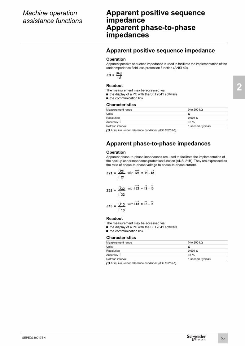
Machine operation assistance functions
Apparent positive sequence impedanceApparent phase-to-phase impedances
2
Apparent positive sequence impedanceOperationApparent positive sequence impedance is used to facilitate the implementation of the underimpedance field loss protection function (ANSI 40).
ReadoutThe measurement may be accessed via:b the display of a PC with the SFT2841 softwareb the communication link.
CharacteristicsMeasurement range 0 to 200 kΩUnits ΩResolution 0.001 ΩAccuracy (1) ±5 %Refresh interval 1 second (typical)(1) At In, Un, under reference conditions (IEC 60255-6).
Apparent phase-to-phase impedancesOperationApparent phase-to-phase impedances are used to facilitate the implementation of the backup underimpedance protection function (ANSI 21B). They are expressed as the ratio of phase-to-phase voltage to phase-to-phase current.
with
with
with
ReadoutThe measurement may be accessed via:b the display of a PC with the SFT2841 softwareb the communication link.
CharacteristicsMeasurement range 0 to 200 kΩUnits ΩResolution 0.001 ΩAccuracy (1) ±5 %Refresh interval 1 second (typical)(1) At In, Un, under reference conditions (IEC 60255-6).
Zd VdId
-----------=
Z21 U21
I 21--------------= I21 I1 I2–=
Z32 U32
I 32--------------= I32 I2 I3–=
Z13 U13
I 13--------------= I13 I3 I1–=
55SEPED310017EN

2
Machine operation assistance functions
Capacitance
OperationThis operation gives the total capacitance for each phase of the connected capacitor to allow the condition of the capacitors to be monitored.It covers star and delta connections (parameter set in the "Particular characteristics" screen of the SFT2841 setting and operating software). For this measurement, the installation is considered a perfect capacitance, without any consideration of the resistances added by the connection of the capacitors.b Capacitances measured for star-connected capacitors:v C1: total capacitance phase 1v C2: total capacitance phase 2v C3: total capacitance phase 3b Capacitances measured for delta-connected capacitors:v C21: total capacitance between phases 1 and 2v C32: total capacitance between phases 2 and 3v C13: total capacitance between phases 3 and 1.
ReadoutThe capacitance measurements may be accessed via:b the display of a PC with the SFT2841 softwareb the communication link.
CharacteristicsMeasurement range 0 to 30 FUnit µF, mF or FResolution 0.1 µFAccuracy ±5 %Refresh interval 1 second (typical)
AccuracyThe measurement accuracy is valid if the resistance and inductance per phase of the capacitor bank connecting cable (cable between the Sepam CT and the capacitors) respect the following conditions:b for a star-connected bank:
where R is the resistance per phase in ΩL is the inductance per phase in Hω is the angular frequency in radians/sC is the total capacitance per phase in F
b for a delta-connected bank:where R is the resistance per phase in Ω
L is the inductance per phase in Hω is the angular frequency in radians/sC is the total capacitance between phases in F
Lω 0.05 1Cω-------×<
R 0.027 1Cω-------×<
Lω 0.017 1Cω-------×<
R 0.009 1Cω-------×<
56 SEPED310017EN

Machine operation assistance functions
Capacitor unbalance current
2
DE
8094
4
OperationThis function measures the unbalance current of double star-connected capacitors. This type of current is characteristic of capacitor module damage.The measurement is carried out via the residual current input I0.
ReadoutThe measurements may be accessed via:b the Sepam display via the keyb the screen of a PC with the SFT2841 softwareb the communication link.
CharacteristicsMeasurement range 0.02 to 20 I0Unit AResolution 0.1 AAccuracy ±5 %Refresh interval 1 second (typical)
C60
I0
57SEPED310017EN

2
Machine operation help function
Motor start report (MSR)
Back up any existing files before changing the MSR function parameter settings as this will result in loss of the existing files.
OperationThis Data log function, available only in motor applications, is used to view in the form of curves how some measurements change during motor starting.The number of measurements and recording duration can be configured using the SFT2841 software.The files are saved in a FIFO memory (First In First Out): when the maximum number of files is reached, a new file replaces the oldest.Using the Motor start report function does not affect the quality of service of Sepam's active protection functions.
A Motor start report in progress cannot be interrupted by another motor start.In the event of loss of the power supply or changes to parameters apart from the duration, the sampling frequency and/or the selected variables, the file currently being recorded is still saved (it is however ignored when calculating the MST), but the completed files are backed up using the battery.
TransferThe files are transferred locally or remotely:b Locally: using a PC connected to the programming port and running the SFT2841 softwareb Remotely: using a ACE850 and ACE969 communication module (TP and FO) and a dedicated supervision system program.Only completed files can be transferred.
ReadThe files can be viewed:b after downloading, on a PC screen, using the WaveWin softwareb on the Sepam display using the key then the Diagnosis menu.
In the latter case, depending on the type of Sepam display (integrated advanced UMI or integrated mimic-based UMI), up to three graphics can be viewed. Each graphic is used to display 2 curves corresponding to the selected variables using the SFT2841 software.
1 Time tagging of the selected file and file selection zone
2 Name of the 1st variable associated with the Y-axis3 Selection zone for the variable to be associated
with the Y-axis4 Maximum value observed for the recorded variable5 Duration of read time
DE
8116
4
View of 3 graphics relating to 1 MSR on an integrated mimic-based UMI.
MSR 2001/01/01 00:59:00.364
RemoteLocalTest
0.00x1 0.00x14
1
0.00rpm 447A
5
447A 11.7kV
2 3Id fund Vd fund<2s>
Rotor temp C<2s>
calc. speed Id fund<2s>
58 SEPED310017EN

Machine operation help functions
Motor start report (MSR)
2
Configuring the display1 To select the MSR file to be viewed:
Press the key as many times as necessary, with the current file selection zone active (item 1). The file number in the series is briefly displayed before giving way to the time-tagged data.
2 To associate one of the selected variables with each Y-axis:b Select the axis to be configured by moving to the symbol using the (go to the previous axis) and (go to the next axis) keys.b Once the axis has been selected, use the key to modify the variable to be used. The screen is automatically refreshed.Pressing the key can briefly hide the values appearing on the graphics. This option is only found on the integrated advanced UMI.Note: The curve display on Sepam should be used with caution because it does not achieve the accuracy obtained with COMTRADE file viewing software.
CharacteristicsConfiguration parameters
Content of a COMTRADE file Configuration file (*.CFG):date, variable characteristics, transformation ratio of the selected variable valuesSamples file (*.DAT):recorded variables
Total file duration 2 s to 144 sSampling frequency Depends on the configured duration (144 s maximum).
Example: For a duration of 144 s the frequency is 1 Hz, for a duration of 2 s the frequency is 72 Hz.
Variables available for recording See the table of available data below.Number of files 1 to 5 with standard cartridgeNumber of variables per file 1 to 5 with standard cartridgeFile format COMTRADE - IEC60255-24 Ed 1 - 2001Note: These parameters are configured with the SFT 2841 software.
Available data Designation UnitsPhase-to-phase voltages U21, U32, U13
u21_fundu32_fundu13_fund
V
I1, I2, I3 i1_fundi2_fundi3_fund
A
Temperature T1_to_T16 ° C / ° FRotor speed of rotation (1) calc.speed rpmRotor speed of rotation (2) meas.speed rpmRotor resistance (3) Rr+ ΩRotor thermal capacity used (3) Rotor_temp puStator resistance (4) Rs ΩStator thermal capacity used (3) Stator_temp puMotor thermal capacity used (3) Motor_temp puPositive-sequence current Id_fund A
(1) The value used is that provided by the 49RMS motor thermal overload protection if this has been activated.(2) The value used is that for input I104 if the 49RMS generic thermal overload protection has been activated.(3) The value used is that provided by the 49RMS motor thermal overload protection if this has been activated. The value is 0 if the 49RMS generic thermal overload protection has been activated.(4) The value used is that for the active 49RMS protection: motor thermal overload or generic thermal overload.(5) Only available for the main voltage channels.
Negative-sequence current Ii_fund APositive-sequence voltage Vd_fund VNegative-sequence voltage Vi_fund VMeasured residual current Io_fund ACalculated residual current Sum_Io AResidual voltage Vo_fund VMotor torque (3) C puSlip (1) g puFrequency (5) F Hz
InputDesignation Syntax Equations
Triggering MSR V_MSR_START b
OutputDesignation Syntax Equations Matrix
MSR in progress V_MSR_TRIGGED b
59SEPED310017EN

2
Machine operation help functions
Motor start trend (MST)
OperationThis function, only available for motor applications, is related to the Motor start trend function. It is used to calculate and display in the form of curves the minimum, demand and maximum values for each value recorded by the Motor start report function (MSR).These recalculated values which are stored in a file of 144 samples covering a 30-day period, can be viewed on the Sepam screen. When the current 30-day period has ended, it is automatically archived in COMTRADE format and will no longer be able to be viewed on the Sepam display (see the Read section).The files are saved in a FIFO memory (First In First Out): when the maximum number of files is reached, a new file replaces the oldest. The number of files available is 12. The trends are only recalculated at the end of each Motor start report.
DE
8124
8
Calculating an MST using the available MSRs.
A Motor start report interrupted prior to completion is not taken into account when calculating the Motor start trend function.Using the Motor start report function does not affect the quality of service of Sepam's active protection functions.Comment on managing date changes:On changing to a date prior to the start date of the current MST, this MST is not closed and any new MSR will be taken into account in its calculation.On changing to a date after the end date of the current MST, this MST is closed and a new MST is created.TransferThe files are transferred locally or remotely:b Locally: using a PC connected to the programming port and running the SFT2841 softwareb Remotely: using a ACE850 and ACE969 communication module (TP and FO) and a dedicated supervision system program.Only completed files can be transferred.
Downloading an MST file for the current period is automatically cancelled in the following cases:b Triggering an MSRb Triggering calculation of an MST at the end of an MSR.Downloading an MST file for another period is automatically cancelled when this file is the oldest and needs to be replaced by a new file due to the FIFO memory being full.
MSR
MSR1
MSR2
MSR3
10
20
90
90
52.5
10
...
...
...
...
...
...
Maximum
Demand
Minimum
1 2 3 144 Samples
MST
60 SEPED310017EN

Machine operation help functions
Motor start trend (MST)
2
Readb The current file and all completed files can be downloaded and viewed on a PC screen, using software compatible with the COMTRADE format.b Only the current file can be viewed on the Sepam display:
1 Press the key2 Select the Diagnosis menu3 Press the keyDepending on the type of Sepam display (integrated advanced UMI or integrated mimic-based UMI), 1 to 3 graphics can be viewed simultaneously. Each graphic can be used to restore curves representing the change in the minimum, demand and maximum values for the values recorded by the Motor start report function (MSR).Note: The curve display on Sepam should be used with caution because it does not achieve the accuracy obtained with COMTRADE file viewing software.
1 Time tagging of the current file2 Selection of the variable to be associated with the
Y-axis3 Name of the analyzed variable4 Duration of read time for each file
DE
8116
5
View of 3 graphics relating to an MST on an integrated mimic-based UMI.
Block diagrams
DE
8124
9
Taking account of the MSRs when calculating an MST.
The current MST file is only refreshed when recording of the MSR file is complete. The current MST file is archived 30 days after its creation. A new MST file is initiated after the 1st restart in the following period.
RemoteLocalTest
MST 2001/01/01 00:00:10.036
2.56 kA
Id fund
Vd fund
Rotor temp
2 <2s>
<2s>
<2s>
11.7kV
0.00x13
1
4
maxdemand
min
MST – month n MST – month n+1
30-day period 30-day period
MST calculatedon a base of 4 MSRs
MST calculated on a base of 2 MSRs, one of which is incomplete
MSR6MSR1 MSR2 MSR3 MSR4
MSR no. 5 is incomplete and is not included in the MST calculation
61SEPED310017EN

2
Machine operation help functions
Motor start trend (MST)
DE
8125
0
Evolution of an MST file during the operating time of the observed motor starts.
CharacteristicsContent of a COMTRADE file Configuration file (*.CFG):
date, variable characteristics, transformation ratio of the selected variable valuesSamples file (*.DAT):recorded variables
Total file duration 30 days/144 samplesSampling period 5 hoursVariables available for recording See table of available data for the MST function.Number of files 1 to 12 with standard cartridgeFile format COMTRADE - IEC60255-24 Ed 1 - 2001Note: These parameters are configured with the SFT 2841 software.
MSR1
max
max
Trigger MST calculation
MSR2
MSR4
MSR 3incomplete
min
min de
man
d
dem
and
min
max
dem
and
62 SEPED310017EN

Switchgear diagnosis functions
VT supervisionANSI code 60FL
2
lt
”
OperationThe VT (Voltage Transformer) supervision function is used to supervise the complete phase and residual voltage measurement chain:b voltage transformersb VT connection to Sepamb Sepam voltage analog inputs.
The function processes the following failures:b partial loss of phase voltages, detected by:v presence of negative sequence voltage v and absence of negative sequence current b loss of all phase voltages, detected by:v presence of current on one of the three phases v and absence of all measured voltagesb tripping of the phase VT (and/or residual VT) protection relay, detected by the acquisition on a logic input of the fuse blown contact or auxiliary contact of the circuit breaker protecting the VTs b other types of failures may be processed using the logic equation editor.
The "Phase voltage fault" and "Residual voltage fault" information disappears automatically when the situation returns to normal, i.e. as soon as:b the cause of the fault has disappeared b and all of the measured voltages are present.Use of circuit breaker closed informationThe "circuit breaker closed" information is used to detect the loss of one, two or three voltages, if it is connected to a logic input.In certain applications, the position of the circuit breaker is not sufficient to determine the presence of voltages. In such cases, the equation editor can be used to precisely define the conditions for voltage presence.
Block diagram: phase voltage fault detection.
DE
8099
6
Block diagram: residual voltage fault detection.
DE
8099
8
Consequences of a VT fault on protection functionsA "Phase voltage fault" affects the following protection functions:b 21B, 27, 27D, 32P, 32Q, 37P, 40, 47, 51Vb 59, only in cases where the protection function is set up for phase-to-neutral overvoltage, when the voltages are measured by two phase VTs + V0VTsb 67.
A "residual voltage fault" affects the following protection functions:b 59Nb 67N/67NC.
The behavior of the protection functions in the event of a "Phase voltage fault" or Residual voltage fault" is to be set up and the following choices are proposed: b for protection functions 21B, 27, 27D, 32P, 32Q, 37P, 40, 47, 51V, 59N, 59: inhibition or no inhibition b for protection function 67: inhibition or non-directional operation (50/51) b for protection function 67N/67NC: inhibition or non-directional operation (50N/ 51N).
Partial loss of phase voltages
circuit breaker closed
Loss of all phase voltages
max (voltages measured)< 10 % Unp
max (I1, I2, I3)> 10 % In
circuit breaker closedvoltage presencePVTS_1_117
phase VT fuse blown
phase VT fusePVTS_1_103
phase voltage fauPVTS_1_3and“VT fault message
min. (voltages measured) > 40% Unp
IiIi
Vi Vi Vsi
< Isi
>& T1 0
T2 0&1
10
phase voltage faultPVTS_1_3V0
&1
V0 VT fuse blown(no residual VT)
“V0 VT fault” message
residual voltage fault
63SEPED310017EN

2
Switchgear diagnosis functions
VT supervisionANSI code 60FL
Setting adviceThe partial loss of voltages is based on the detection of the presence of negative sequence voltage and the absence of negative sequence current.By default:b the presence of negative sequence voltage is detected when: Vi > 10 % Vnp (Vsi)b the absence of negative sequence current is detected when: Ii < 5 % In (Isi)b time delay T1 is 1 s.These default settings ensure the stability of the VT supervision function in the event of short-circuits or transient phenomena on the network.The Isi set point may be raised for highly unbalanced networks.Time delay T1 is to be set shorter than the voltage and power protection function tripping times.Time delay T2 for the detection of the loss of all voltages must be longer than the time it takes for a short-circuit to be cleared by the protection function 50/51 or 67, to avoid the detection of a VT loss of voltage fault triggered by a 3-phase short-circuit.The time delay for the 51V protection function must be longer than the T1 and T2 time delays used for the detection of voltage losses.
Characteristics Validation of the detection of partial loss of phase voltages
Setting Yes / NoVsi set point
Setting 10 % to 100 % of VnpAccuracy ±5 %Resolution 1 %Pick-up / drop-out ratio 95 % ±2.5 %Isi set point
Setting 5 % to 100 % of InAccuracy ±5 % Resolution 1 %Pick-up / drop-out ratio 105 % ±2.5 % or > (1 + 0.01 In/Isi) x 100 %Time delay T1 (partial loss of phase voltages)
Setting 0.1 s to 300 sAccuracy ±2 % or ±25 ms Resolution 10 msValidation of the detection of the loss of all phase voltages
Setting Yes / NoDetection of the loss of all voltages with verification of the presence of current
Setting Yes / NoVoltage presence detected by
Setting Breaker closed / Logic equationTime delay T2 (loss of all voltages)
Setting 0.1 s to 300 sAccuracy ±2 % or ±25 ms Resolution 10 msVoltage and power protection behavior
Setting No action / inhibitionProtection 67 behavior
Setting Non-directional / inhibitionProtection 67N/67NC behavior
Setting Non-directional / inhibitionInputsDesignation Syntax Equations
Phase VT fault PVTS_1_103 bInhibition of function PVTS_1_113 bVoltage presence PVTS_1_117 b
OutputsDesignation Syntax Equations Matrix
Function output PVTS_1_3 b bFunction inhibited PVTS_1_16 b
64 SEPED310017EN

Switchgear diagnosis functions
CT supervisionANSI code 60
2
OperationThe CT (Current Transformer) supervision function is used to supervise the complete phase current measurement chain:b phase current sensors (1 A/5 A CTs or LPCTs)b phase current sensor connection to Sepamb Sepam phase current analog inputs.The function is inactive if only 2 phase current sensors are connected.The "CT fault" information disappears automatically when the situation returns to normal, i.e. as soon as the 3 phase currents are measured and have values greater than 10 % of In.In the event of the loss of a phase current, the following protection functions may be inhibited to avoid nuisance tripping:b 21B, 46, 40, 32P, 37P, 32Q, 64REFb 51N and 67N, if I0 is calculated by the sum of the phase currents.
Block diagram
DE
8099
7
CharacteristicsTime delay
Setting 0.15 s to 300 sAccuracy ±2 % or ± 25 ms Resolution 10 msInhibition of protection functions 21B, 32P, 32Q, 37P, 40, 46, 51N, 64REF, 67N
Setting No action / inhibitionInputsDesignation Syntax Equations
Inhibition of function PCTS_x_113 b
OutputsDesignation Syntax Equations Matrix
Delayed output PCTS_1_3 b bPhase 1 fault PCTS_1_7 bPhase 2 fault PCTS_1_8 bPhase 3 fault PCTS_1_9 bFunction inhibited PCTS_1_16 b
I1
I2
I3
I2
I3
< 1 % In
> 5 % In
> 5 % In&
< 1,2 In
< 1,2 In
I2 130< angle (I3,110° ) < °
loss of phase 1
loss of phase 2
loss of phase 3
CT fault PCTS_1_3
1 T1 0
65SEPED310017EN
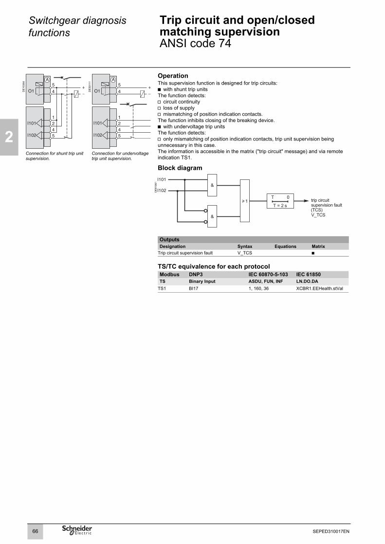
2
Switchgear diagnosis functions
Trip circuit and open/closed matching supervisionANSI code 74
DE
1036
4
DE
5011
1
OperationThis supervision function is designed for trip circuits:b with shunt trip unitsThe function detects:v circuit continuityv loss of supplyv mismatching of position indication contacts.The function inhibits closing of the breaking device.b with undervoltage trip unitsThe function detects:v only mismatching of position indication contacts, trip unit supervision being unnecessary in this case.The information is accessible in the matrix ("trip circuit" message) and via remote indication TS1.
Block diagram
Connection for shunt trip unit supervision.
Connection for undervoltage trip unit supervision.
DE
8106
1
OutputsDesignation Syntax Equations Matrix
Trip circuit supervision fault V_TCS b
TS/TC equivalence for each protocolModbus DNP3 IEC 60870-5-103 IEC 61850TS Binary Input ASDU, FUN, INF LN.DO.DA
TS1 BI17 1, 160, 36 XCBR1.EEHealth.stVal
66 SEPED310017EN

Switchgear diagnosis functions
Closing circuit and open/close orders supervisionANSI code 74
2
DE
1036
5
Closing circuit supervisionOperationThis function monitors closing coil continuity. It calls for the wiring diagram opposite, connected to a logic input configured with the "Closing coil supervision" function. The information is accessible in the matrix ("closing circuit" message) and via remote indication TS234.
Block diagram
DE
1041
7
Connection for closing circuit supervision.
OutputsDesignation Syntax Equations Matrix
Closing circuit supervision fault V_CCS b
TS/TC equivalence for each protocolModbus DNP3 IEC 60870-5-103 IEC 61850TS Binary Input ASDU, FUN, INF LN.DO.DA
TS234 BI121 2, 21, 23 XCBR1.EEHealth.stVal
Open/close orders supervisionOperationFollowing a circuit breaker open or close order, the system checks whether, after a 200 ms time delay, the circuit breaker has actually changed status.If the circuit breaker status does not match the last order sent, a "Control fault" message and remote indication TS2 are generated.
OutputsDesignation Syntax Equations Matrix
Control fault (circuit breaker monitoring)
V_CTRLFAUT b
TS/TC equivalence for each protocolModbus DNP3 IEC 60870-5-103 IEC 61850TS Binary Input ASDU, FUN, INF LN.DO.DA
TS2 BI16 1, 20, 5 Command Termination -
67SEPED310017EN

2
Switchgear diagnosis functions
Cumulative breaking currentNumber of operations
Cumulative breaking current monitoringOperationThis function gives the cumulative breaking current in (kA)2 for five current ranges.It is based on measurement of the fundamental component on current channels (I).The current ranges displayed are:b 0 < I < 2 Inb 2 In < I < 5 Inb 5 In < I < 10 Inb 10 In < I < 40 Inb I > 40 In.This function gives the cumulative breaking current in (kA)² for five current ranges.This value is monitored by an adjustable set point. When the set point is overrun, an alarm is sent and is available in the matrix and via remote indication TS235.Each value is saved in the event of an auxiliary power failure.The initial values may be introduced using the SFT2841 software tool to take into account the real state of a breaking device used.Refer to switchgear documentation for use of this information.
ReadoutThe measurements may be accessed via:b the Sepam display via the keyb the display of a PC with the SFT2841 softwareb the communication link.
Characteristics Cumulative breaking current measured
Range 0 to 65535 (kA)2
Units primary (kA)2
Resolution 1(kA)2
Accuracy (1) ±10 % ±1 digitAlarm set point
Setting 0 to 65535 (kA)2
Resolution 1(kA)2Accuracy (1) ±10 % ±1 digitOutputsDesignation Syntax Equations Matrix
Cumulative breaking current threshold overrun
V_MAXBRKCUR b
(1) At In, under reference conditions (IEC 60255-6).
TS/TC equivalence for each protocolModbus DNP3 IEC 60870-5-103 IEC 61850TS Binary Input ASDU, FUN, INF LN.DO.DA
TS235 BI135 2, 21, 40 XCBR1.SumSwAAlm.stVal
Number of operationsOperationThe function also gives the total number of breaking device operations.It is activated by tripping orders (O1 relay).The number of operations is saved in the event of an auxiliary power failure.It may be reinitialized using the SFT2841 software.
ReadoutThe measurements may be accessed via:b the Sepam display via the keyb the display of a PC with the SFT2841 softwareb the communication link.
Characteristics Range 0 to 4.109
Units NoneResolution 1Refresh interval 1 second (typical)
68 SEPED310017EN

Switchgear diagnosis functions
Operating timeCharging time
2
Operating timeOperationThis function gives the value of the opening operating time of a breaking device (1)
and change of status of the device open position contact connected to the I102 input (2)
The value is saved in the event of an auxiliary power failure.
ReadoutThe measurements may be accessed via:b the Sepam display via the keyb the display of a PC with the SFT2841 softwareb the communication link.(1) Refer to switchgear documentation for use of this information. (2) Optional MES module.
Characteristics Measurement range 20 to 300Units msResolution 1 msAccuracy ±2 ms typicalDisplay format 3 significant digits
Charging timeOperationThis function gives the value of the breaking device (1) operating mechanism charging time, determined according to the device closed position status change contact and the end of charging contact connected to the Sepam logic inputs (2).The value is saved in the event of an auxiliary power failure.
ReadoutThe measurements may be accessed via:b the Sepam display via the keyb the display of a PC with the SFT2841 softwareb the communication link.(1) Refer to switchgear documentation for use of this information.(2) Optional MES module.
Characteristics Measurement range 1 to 20Units sResolution 1sAccuracy ±0.5 sDisplay format 3 significant digits
69SEPED310017EN

2
Switchgear diagnosis functions
Number of racking out operations
OperationThis function keeps a count of circuit breaker or contactor rackouts. The information may be used for breaking device maintenance.The breaking device "racked out" or "disconnected" position must be wired to a logic input and set up in the SFT2841 software in order for rackouts to be counted.The number of rackouts is saved in the event of an auxiliary power failure. It may be reinitialized using the SFT2841 software.
ReadoutThe measurements may be accessed via:b the display of a PC with the SFT2841 softwareb the communication link.
CharacteristicsMeasurement range 0 to 65535Units NoneResolution 1Refresh interval 1 second (typical)
70 SEPED310017EN

2
71SEPED310017EN

3
Protection functions Contents
Setting ranges 74Overspeed 79ANSI code 12 79Underspeed 80ANSI code 14 80Underimpedance 81ANSI code 21B 81Synchro-check 82ANSI code 25 82Undervoltage (L-L or L-N) 84ANSI code 27 84Positive sequence undervoltage and phase rotation direction check 85ANSI code 27D 85Remanent undervoltage 86ANSI code 27R 86Directional active overpower 87ANSI code 32P 87Directional reactive overpower 88ANSI code 32Q 88Phase undercurrent 89ANSI code 37 89Directional active underpower 91ANSI code 37P 91Temperature monitoring 92ANSI code 38/49T 92Field loss 93ANSI code 40 93Negative sequence / unbalance 96ANSI code 46 96Negative sequence overvoltage 99ANSI code 47 99Excessive starting time, locked rotor 100ANSI code 48/51LR 100Thermal overload for cables 102ANSI code 49RMS 102Thermal overload for capacitors 107ANSI code 49RMS 107Thermal overload for motors 121ANSI code 49RMS 121Thermal overload for machines 135ANSI code 49RMS 135Breaker failure 146ANSI code 50BF 146Phase overcurrent 148ANSI code 50/51 148Earth fault 150ANSI code 50N/51N or 50G/51G 150Voltage-restrained overcurrent 153ANSI code 50V/51V 153
72 SEPED310017EN
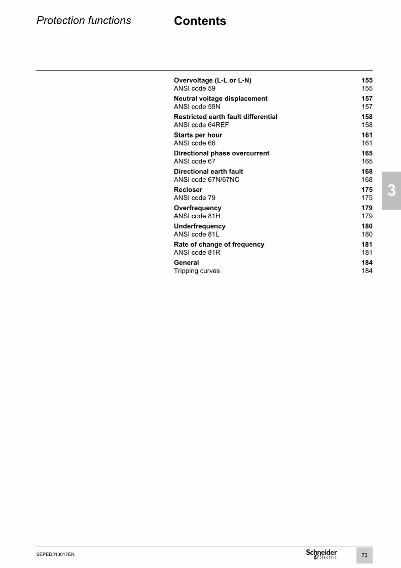
Protection functions Contents
3
Overvoltage (L-L or L-N) 155ANSI code 59 155Neutral voltage displacement 157ANSI code 59N 157Restricted earth fault differential 158ANSI code 64REF 158Starts per hour 161ANSI code 66 161Directional phase overcurrent 165ANSI code 67 165Directional earth fault 168ANSI code 67N/67NC 168Recloser 175ANSI code 79 175Overfrequency 179ANSI code 81H 179Underfrequency 180ANSI code 81L 180Rate of change of frequency 181ANSI code 81R 181General 184Tripping curves 184
73SEPED310017EN

3
Protection functions Setting ranges
Functions Settings Time delaysANSI 12 - Overspeed
100 to 160 % of Ωn 1 to 300 sANSI 14 - Underspeed
10 to 100 % of Ωn 1 to 300 sANSI 21B - Underimpedance
Impedance Zs 0.05 to 2.00 Vn/IbANSI 25 - Synchro-check
Measured voltages Phase-to-phase Phase-to-neutralRated primary phase-to-phase voltage
Unp sync1 (Vnp sync1 = Unp sync1/3) 220 V to 250 kV 220 V to 250 kVUnp sync2 (Vnp sync2 = Unp sync2/3) 220 V to 250 kV 220 V to 250 kVRated secondary phase-to-phase voltage
Uns sync1 90 V to 120 V 90 V to 230 VUns sync2 90 V to 120 V 90 V to 230 VSynchro-check setpoints
dUs set point 3 % to 30 % of Unp sync1 3 % to 30 % of Vnp sync1dfs set point 0.05 to 0.5 Hz 0.05 to 0.5 HzdPhi set point 5 to 80° 5 to 80°Us high set point 70 % to 110 % Unp sync1 70 % to 110 % Vnp sync1Us low set point 10 % to 70 % Unp sync1 10 % to 70 % Vnp sync1Other settings
Lead time 0 to 0.5 s 0 to 0.5 sOperating modes: no-voltage conditions for which coupling is allowed
Dead1 AND Live2 Dead1 AND Live2Live1 AND Dead2 Live1 AND Dead2Dead1 XOR Dead2 Dead1 XOR Dead2Dead1 OR Dead2 Dead1 OR Dead2Dead1 AND Dead2 Dead1 AND Dead2
ANSI 27 - Undervoltage (L-L) or (L-N)Tripping curve Definite time
IDMT Definite time with a curve that can be customized
Set point 5 to 100 % of Unp 0.05 to 300 sANSI 27D - Positive sequence undervoltage
Set point and time delay 15 to 60 % of Unp 0.05 to 300 sANSI 27R - Remanent undervoltage
Set point and time delay 5 to 100 % of Unp 0.05 to 300 sANSI 32P - Directional active overpower
1 to 120 % of Sn (1) 0.1 s to 300 sANSI 32Q - Directional reactive overpower
5 to 120 % of Sn (1) 0.1 s to 300 sANSI 37 - Phase undercurrent
0.05 to 1 Ib 0.05 s to 300 sANSI 37P - Directional active underpower
5 to 100 % of Sn (1) 0.1 s to 300 sANSI 38/49T - Temperature monitoring
Alarm set point TS1 0 °C to 180 °C or 32 °F to 356 °FTrip set point TS2 0 °C to 180 °C or 32 °F to 356 °FANSI 40 - Field loss (underimpedance)
Common point: Xa 0.02 Vn/Ib to 0.2 Vn/Ib + 187.5 kΩCircle 1: Xb 0.2 Vn/Ib to 1.4 Vn/Ib + 187.5 kΩ 0.05 to 300 sCircle 2: Xc 0.6 Vn/Ib to 3 Vn/Ib + 187.5 kΩ 0.1 to 300 s(1) Sn = √3.In.Unp.
74 SEPED310017EN

Protection functions Setting ranges
3
Functions Settings Time delaysANSI 46 - Negative sequence / unbalance
Tripping curve Definite timeSchneider ElectricIEC: SIT/A, LTI/B, VIT/B, EIT/CIEEE: MI (D), VI (E), EI (F)RI² (setting constant from 1 to 100)
Is set point 0.1 to 5 Ib Definite time 0.1 to 300 s0.1 to 0.5 Ib (Schneider Electric) IDMT 0.1 to 1s0.1 to 1 Ib (IEC, IEEE)0.03 to 0.2 Ib (RI²)
ANSI 47 - Negative sequence overvoltageSet point and time delay 1 to 50 % of Unp 0.05 to 300 sANSI 48/51LR - Locked rotor / excessive starting time
Is set point 0.5 Ib to 5 Ib ST starting time 0.5 s to 300 sLT and LTS time delays 0.05 s to 300 s
ANSI 49RMS - Thermal overload for cablesAdmissible current 1 to 1.73 IbTime constant T1 1 to 600 minANSI 49RMS - Thermal overload for capacitors
Alarm current 1.05 Ib to 1.70 IbTrip current 1.05 Ib to 1.70 IbPositioning of the hot tripping curve Current setting 1.02 x trip current to 2 Ib
Time setting 1 to 2000 minutes (variable range depending on the trip current and current setting)
ANSI 49RMS - Generic thermal overload Mode 1 Mode 2Accounting for negative sequence component 0 - 2.25 - 4.5 - 9Time constant Heating T1: 1 to 600 min T1: 1 to 600 min
Cooling T2: 5 to 600 min T2: 5 to 600 minAlarm and tripping set points (Es1 and Es2) 0 to 300 % of rated thermal capacityInitial thermal capacity used (Es0) 0 to 100 %Switching of thermal settings condition by logic input
by Is set point adjustable from 0.25 to 8 IbMaximum equipment temperature 60 to 200 °C (140 °F to 392 °F) ANSI 49RMS - Motor thermal overload
Measurement origin I1, I2, I3 Choice of thermal model 2 time constants/generic (see settings associated with generic thermal overload)Current set point - change of thermal settings
1 to 10 pu of lb (± 0.1 pu of lb)
Characteristic times Operating time accuracy ± 2 % or ±1 sStator thermal settings
Time constants Motor thermal capacity used (τ long) 1 to 600 mn ± 1 mnStator thermal capacity used (τ short) 1 to 60 mn ± 0.1 mnCooling (τ cool) 5 to 600 mn ± 1 mn
Tripping current set point (K) 50 to 173 % of Ib (± 1 % of Ib)Alarm current set point 50 to 173 % of Ib (± 1 % of Ib)Thermal exchange coefficient between the stator and the motor (α)
0 to 1 (± 0.01)
Current characterizing hot state 0.5 to 1 pu of Ib (± 0.1 pu of lb)Accounting for ambient temperature yes / noMaximum equipment temperature (Tmax) 70 to 250 °C (± 1 °C) or 158 to 482 °F (± 1 °F)Rotor thermal settings
Locked rotor amperes (IL) 1 to 10 pu of Ib (± 0.01 pu of lb)Locked rotor torque (LRT) 0.2 to 2 pu of nominal torque (+/- 0.01 pu of nominal torque)Locked rotor cold limit time (Tc) 1 to 300 s (± 0.1 s)Locked rotor hot limit time (Th) 1 to 300 s (± 0.1 s)
75SEPED310017EN

3
Protection functions Setting ranges
Functions Settings Time delaysANSI 49RMS - Transformer thermal overload
Choice of thermal model Dry-type transformer Immersed transformer Generic
Measurement origin I1, I2, I3 Type of dry-type transformer Natural ventilation (AN) / Forced ventilation (AF)Type of oil-filled transformer Distribution ONAN / Power ONAN / ONAF / OF / ODAlarm set point (θ alarm) Immersed transformer: 98 to 160 °C (± 1 °C) or 208 to 320 °F (± 1 °F)
Dry-type transformer: 95 to 245 °C (± 1 °C) or 203 to 473 °F (± 1 °F)Tripping set point (θ trip) Immersed transformer: 98 to 160 °C (± 1 °C) or 208 to 320 °F (± 1 °F)
Dry-type transformer: 95 to 245 °C (± 1 °C) or 203 to 473 °F (± 1 °F)Time constant for dry-type transfo (τ ) 1 to 600 mn ± 1 mnTime constant for oil-filled transfo winding (τ wdg) 1 to 600 mn ± 1 mn
oil (τ oil) 5 to 600 mn ± 1 mnANSI 50BF - Breaker failure
Presence of current 0.2 to 2 InOperating time 0.05 s to 3 sANSI 50/51 - Phase overcurrent
Tripping time delay Timer holdTripping curve Definite time DT
SIT, LTI, VIT, EIT, UIT (1) DTRI DTIEC: SIT/A, LTI/B, VIT/B, EIT/C DT or IDMTIEEE: MI (D), VI (E), EI (F) DT or IDMTIAC: I, VI, EI DT or IDMTCustomized DT
Is set point 0.05 to 24 In Definite time Inst; 0.05 s to 300 s0.05 to 2.4 In IDMT 0.1 s to 12.5 s at 10 Is
Timer hold Definite time (DT; timer hold) Inst; 0.05 s to 300 sIDMT (IDMT; reset time) 0.5 s to 20 s
Measurement origin Main channels (I)Harmonic 2 restraint 5 to 50 %Min short-circuit current Isc In to 999 kAConfirmation None
By negative sequence overvoltageBy phase-to-phase undervoltage
(1) Tripping as of 1.2 Is.
76 SEPED310017EN

Protection functions Setting ranges
3
Functions Settings Time delaysANSI 50N/51N or 50G/51G - Earth fault
Tripping time delay Timer holdTripping curve Definite time DT
SIT, LTI, VIT, EIT, UIT (1) DTRI DTCEI: SIT/A,LTI/B, VIT/B, EIT/C DT or IDMTIEEE: MI (D), VI (E), EI (F) DT or IDMTIAC: I, VI, EI DT or IDMTEPATR-B, EPATR-C DTCustomized DT
Is0 set point 0.01 to 15 In0 (min. 0.1 A) Definite time Inst; 0.05 s to 300 s0.01 to 1 In0 (min. 0.1 A) IDMT 0.1 s to 12.5 s at 10 Is00.6 to 5 A EPATR-B 0.5 to 1 s0.6 to 5 A EPATR-C 0.1 to 3 s
Timer hold Definite time (DT; timer hold) Inst; 0.05 s to 300 sIDMT (IDMT; reset time) 0.5 s to 20 s
Measurement origin I0 input or sum of phase currents I0ΣANSI 50V/51V - Voltage-restrained overcurrent
Tripping time delay Timer holdTripping curve Definite time DT
SIT, LTI, VIT, EIT, UIT (1) DTRI DTIEC: SIT/A, LTI/B, VIT/B, EIT/C DT or IDMTIEEE: MI (D), VI (E), EI (F) DT or IDMTIAC: I, VI, EI DT or IDMTCustomized DT
Is set point 0.5 to 24 In Definite time Inst; 0.05 s to 300 s0.5 to 2.4 In IDMT 0.1 s to 12.5 s at 10 Is
Timer hold Definite time (DT; timer hold) Inst; 0.05 s to 300 sIDMT (IDMT; reset time) 0.5 s to 20 s
ANSI 59 - Overvoltage (L-L) or (L-N)Set point and time delay 50 to 150 % of Unp or Vnp 0.05 to 300 sANSI 59N - Neutral voltage displacement
Tripping curve Definite timeIDMT
Set point 2 to 80 % of Unp Definite time 0.05 to 300 s2 to 10 % of Unp IDMT 0.1 to 100 s
ANSI 64REF - Restricted earth fault differentialIs0 set point 0.05 to 0.8 In (In u 20 A)
0.1 to 0.8 In (In < 20 A)ANSI 66 - Starts per hour
Permitted number of consecutive cold starts (Nc)
1 to 5 Time delay consecutive starts 1 to 90 min
Permitted number of consecutive hot starts (Nh)
1 to (Nc - 1) Time delay stop/start 0 to 90 min
(1) Tripping as of 1.2 Is.
77SEPED310017EN

3
Protection functions Setting ranges
Functions Settings Time delaysANSI 67 - Directional phase overcurrent
Characteristic angle 30°, 45°, 60°Tripping time delay Timer hold delay
Tripping curve Definite time DTSIT, LTI, VIT, EIT, UIT (1) DTRI DTIEC: SIT/A, LTI/B, VIT/B, EIT/C DT or IDMTIEEE: MI (D), VI (E), EI (F) DT or IDMTIAC: I, VI, EI DT or IDMTCustomized DT
Is set point 0.1 to 24 In Definite time Inst; 0.05 s to 300 s0.1 to 2.4 In IDMT 0.1 s to 12.5 s at 10 Is
Timer hold Definite time (DT; timer hold) Inst; 0.05 s to 300 sIDMT (IDMT; reset time) 0.5 s to 20 s
ANSI 67N/67NC type 1 - Directional earth fault, according to I0 projectionCharacteristic angle -45°, 0°, 15°, 30°, 45°, 60°, 90°Is0 set point 0.01 to 15 In0 (mini. 0,1 A) Definite time Inst; 0.05 s to 300 sVs0 set point 2 to 80 % of UnpMemory time T0mem time 0; 0.05 s to 300 s
V0mem validity set point 0; 2 to 80 % of UnpANSI 67N/67NC type 2 - Directional earth fault, according to I0 vector magnitude directionalized on a tripping half-plane
Characteristic angle -45°, 0°, 15°, 30°, 45°, 60°, 90°Tripping time delay Timer hold delay
Tripping curve Definite time DTSIT, LTI, VIT, EIT, UIT (1) DTRI DTIEC: SIT/A,LTI/B, VIT/B, EIT/C DT or IDMTIEEE: MI (D), VI (E), EI (F) DT or IDMTIAC: I, VI, EI DT or IDMTCustomized DT
Is0 set point 0.01 to 15 In0 (min. 0.1 A) Definite time Inst; 0.05 s to 300 s0.01 to 1 In0 (min. 0.1 A) IDMT 0.1 s to 12.5 s at 10 Is0
Vs0 set point 2 to 80 % of UnpTimer hold Definite time (DT; timer hold) Inst; 0.05 s to 300 s
IDMT (IDMT; reset time) 0.5 s to 20 sMeasurement origin I0 input or sum of phase currents I0ΣANSI 67N/67NC type 3 - Directional earth fault, according to I0 vector magnitude directionalized on a tripping sector
Tripping sector start angle 0° to 359°Tripping sector end angle 0° to 359°Is0 set point CSH core balance CT (2 A rating) 0.1 A to 30 A Definite time Inst; 0.05 to 300 s
1 A CT 0.005 to 15 In0 (min. 0.1 A)Core balance CT + ACE990 (range 1) 0.01 to 15 In0 (min. 0.1 A)
Vs0 set point Calculated V0 (sum of 3 voltages) 2 to 80% of UnpMeasured V0 (external VT) 0.6 to 80% of Unp
Measurement origin I0 input or sum of phase currents I0ΣANSI 81H - Overfrequency
Set point and time delay 49 to 55 Hz or 59 to 65 Hz 0.1 to 300 sMeasurement origin Main channels (U)ANSI 81L - Underfrequency
Set point and time delay 40 to 51 Hz or 50 to 61 Hz 0.1 to 300 sMeasurement origin Main channels (U)ANSI 81R - Rate of change of frequency
0.1 to 10 Hz/s 0.15 to 300 s(1) Tripping from 1.2 Is.
78 SEPED310017EN

Protection functions OverspeedANSI code 12
3
Detection of excessive machine speeds to protect generators and processes.
DescriptionDetection of machine overspeed to detect synchronous generator racing due to loss of synchronism, or for process monitoring, for example. The rotation speed is calculated by measuring the time between pulses transmitted by a proximity sensor at each passage of one or more cams driven by the rotation of the motor or generator shaft (see a more in-depth description in the "Metering functions" chapter).The speed acquisition parameters must be set on the "Particular characteristics" screen of the SFT2841 software.The "Rotor speed measurement" function must be assigned to logic input I104 for the function to work.The protection picks up if the speed measured exceeds the speed set point.The protection includes a definite time delay T.
Block diagramD
E50
764
CharacteristicsSettingsSet point Ωs
Setting range 100 to 160 % of ΩnAccuracy (1) ±2 %Resolution 1 %Drop out/pick up ratio 95 %Time delay T
Setting range 1 s to 300 sAccuracy (1) ±25 ms or ±(60000/(Ωs (2) x R (3))) msResolution 1 sInputs Designation Syntax Equations
Protection reset P12_x_101 bProtection inhibition P12_x_113 b
Outputs Designation Syntax Equations Matrix
Instantaneous output (pick-up) P12_x_1 bDelayed output P12_x_3 b bProtection inhibited P12_x_16 bx: unit number.(1) Under reference conditions (IEC 60255-6).(2) Ωs in rpm.(3) R: Number of pulses (cam) per rotation.
79SEPED310017EN
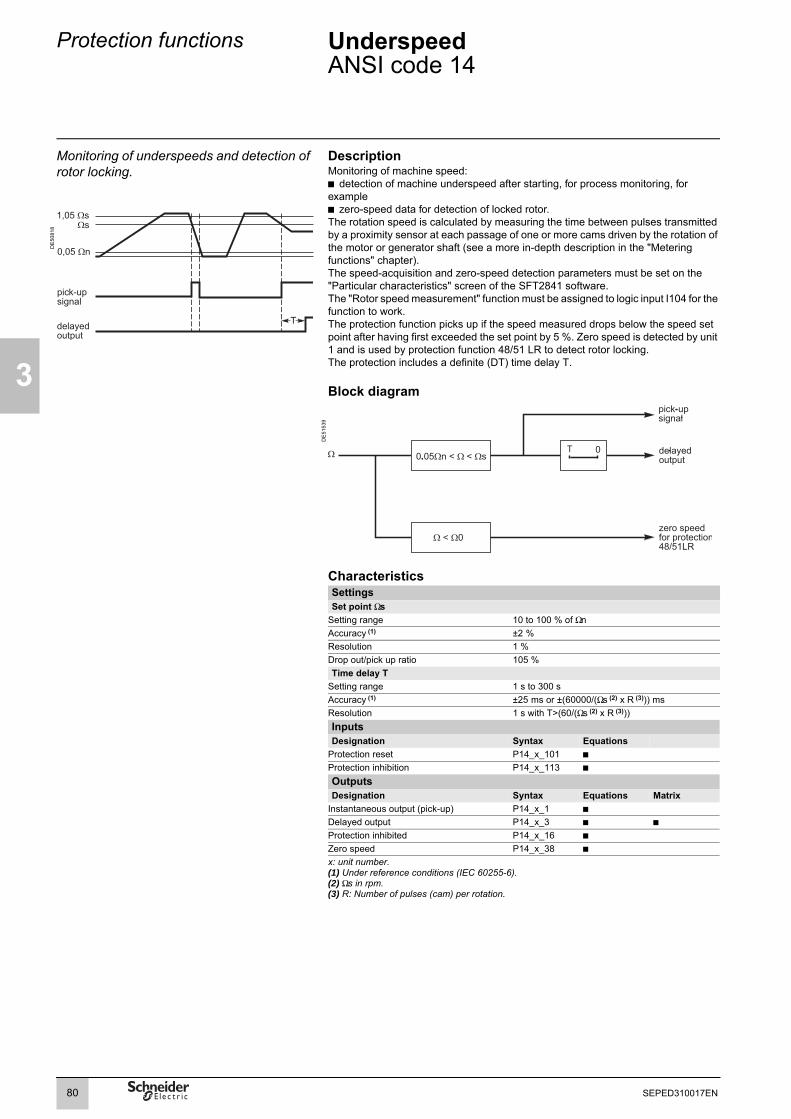
3
Protection functions UnderspeedANSI code 14
Monitoring of underspeeds and detection of rotor locking.
DescriptionMonitoring of machine speed:b detection of machine underspeed after starting, for process monitoring, for exampleb zero-speed data for detection of locked rotor. The rotation speed is calculated by measuring the time between pulses transmitted by a proximity sensor at each passage of one or more cams driven by the rotation of the motor or generator shaft (see a more in-depth description in the "Metering functions" chapter).The speed-acquisition and zero-speed detection parameters must be set on the "Particular characteristics" screen of the SFT2841 software.The "Rotor speed measurement" function must be assigned to logic input I104 for the function to work.The protection function picks up if the speed measured drops below the speed set point after having first exceeded the set point by 5 %. Zero speed is detected by unit 1 and is used by protection function 48/51 LR to detect rotor locking.The protection includes a definite (DT) time delay T.
DE
5081
8
Block diagram
DE
5153
9
CharacteristicsSettingsSet point Ωs
Setting range 10 to 100 % of ΩnAccuracy (1) ±2 %Resolution 1 %Drop out/pick up ratio 105 %Time delay T
Setting range 1 s to 300 sAccuracy (1) ±25 ms or ±(60000/(Ωs (2) x R (3))) msResolution 1 s with T>(60/(Ωs (2) x R (3)))Inputs Designation Syntax Equations
Protection reset P14_x_101 bProtection inhibition P14_x_113 b
Outputs Designation Syntax Equations Matrix
Instantaneous output (pick-up) P14_x_1 bDelayed output P14_x_3 b bProtection inhibited P14_x_16 bZero speed P14_x_38 bx: unit number.(1) Under reference conditions (IEC 60255-6).(2) Ωs in rpm.(3) R: Number of pulses (cam) per rotation.
80 SEPED310017EN

Protection functions UnderimpedanceANSI code 21B
3
Phase-to-phase short-circuit protection for generators.
DescriptionThe protection function is made up of a circular tripping characteristic on the impedance plane (R, X), with a definite time delay.It picks up when one of the apparent, phase-to-phase impedances enters the circular tripping characteristic.Apparent impedances:
, , .DE
5031
7
Block diagram
DE
5154
0
CharacteristicsSettingsSet point Ωs
Setting range 0.05Vn/Ib y Zs y 2 Vn/Ib or 0.001 ΩAccuracy (1) ±2 %Resolution 0.001 Ω or 1 digitDrop out/pick up ratio 105 %Time delay T
Setting range 200 ms y T y 300 sAccuracy (1) ±2 % or from -10 ms to +25 msResolution 10 ms or 1 digitCharacteristic times (1)
Operation time pick-up < 35 ms from infinite to Zs/2 (typically 25 ms)Overshoot time < 40 msReset time < 50 msInputs Designation Syntax Equations
Protection reset P21B_1_101 bProtection inhibition P21B_1_113 b
Outputs Designation Syntax Equations Matrix
Instantaneous output (pick-up) P21B_1_1 bDelayed output P21B_1_3 b bProtection inhibited P21B_1_16 b(1) Under reference conditions (IEC 60255-6).
Example: synchronous generatorSynchronous generator data:b S = 3.15 MVAb Un1 = 6.3 kVb Xd = 233 %b X'd = 21 %
Protection settingTo set the protection function, it is necessary to calculate the rated generator impedance:b Ib = S/(3Un1) = 289 Ab Zn = Un1/ (3Ib) = 12.59 Ω.The tripping parameter is typically set to 30 % of the rated generator impedance:Zs = 0.30 x Zn = 3.77 Ω.This protection function is used to back up other protection functions. Its setting must therefore ensure discrimination with the other protection functions. T = 0.9 s, for example, for a network where faults are cleared in 0.6 s.
Z21U21
I1 I2–----------------= Z32
U32
I2 I3–----------------= Z13
U13
I3 I1–----------------=
81SEPED310017EN

3
Protection functions Synchro-checkANSI code 25
Protection function which checks the synchronization of the electrical networks upstream and downstream of a circuit breaker and allows closing when the differences in voltage, frequency and phase are within authorized limits.
OperationThe synchro-check function is designed to allow circuit breaker closing without any risk of dangerous coupling between two voltages Usync1 and Usync2. The voltages compared may be two phase-to-phase voltages or two phase-to-neutral voltages.
The function is activated when there is a phase, frequency or amplitude difference, within set limits, between the voltages that are compared.
The function is available in the optional MCS025 module. The "Close enable" logic data must be cabled to a logic input on the Sepam. All other data and measurements are transmitted to the Sepam base unit via the CCA785 connection cord.
Block diagram
DE
8023
8
AnticipationIt is possible to anticipate the function by a time Ta, taking into account the frequency difference and the circuit breaker closing time, in order for the voltages to be synchronized at the time of coupling.
Voltage checkingWhen one of the two voltages is absent, coupling may be authorized according to one of five voltage checking modes.b Usync1 absent and Usync2 present (Dead1 AND Live2)b Usync1 present and Usync2 absent (Live1 AND Dead2)b One voltage is present and the other is absent (Dead1 XOR Dead2)b One or both of the two voltages are absent (Dead1 OR Dead2)b Both voltages are absent (Dead1 AND Dead2).The presence of each of the voltages is detected by comparing the voltage to the high set point (Us high set point). The absence of either of the voltages is detected by comparing the voltage to the low set point (Us low set point).
U
dfs
82 SEPED310017EN
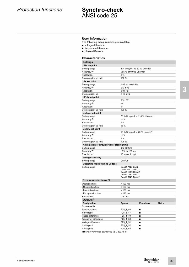
Protection functions Synchro-checkANSI code 25
3
User informationThe following measurements are available: b voltage differenceb frequency differenceb phase difference.
CharacteristicsSettingsdUs set point
Setting range 3 % Unsync1 to 30 % Unsync1Accuracy (1) ±2.5 % or 0,003 Unsync1Resolution 1 %Drop out/pick up ratio 106 %dfs set point
Setting range 0.05 Hz to 0.5 HzAccuracy (1) ±10 mHzResolution 0.01 HzDrop out/pick up < 15 mHzdPhis set point
Setting range 5° to 50°Accuracy (1) ±2°Resolution 1°Drop out/pick up ratio 120 % Us high set point
Setting range 70 % Unsync1 to 110 % Unsync1Accuracy (1) ±1 %Resolution 1 %Drop out/pick up ratio 93 %Us low set point
Setting range 10 % Unsync1 to 70 % Unsync1Accuracy (1) ±1 %Resolution 1 %Drop out/pick up ratio 106 %Anticipation of circuit breaker closing time
Setting range 0 to 500 msAccuracy (1) ±2 % or ±25 msResolution 10 ms or 1 digitVoltage checking
Setting range On / OffOperating mode with no voltage
Setting range Dead1 AND Live2Live1 AND Dead2Dead1 XOR Dead2Dead1 OR Dead2Dead1 AND Dead2
Characteristic times (1)
Operation time < 190 msdU operation time < 120 msdf operation time < 190 msdPhi operation time < 190 msReset time < 50 msOutputs (1)
Designation Syntax Equations MatrixClose enableSynchro-check P25_1_46 bNo voltage P25_1_47 bPhase difference P25_1_49 bFrequency difference P25_1_50 bVoltage difference P25_1_51 bNo Usync1 P25_1_52 bNo Usync2 P25_1_53 b(1) Under reference conditions (IEC 60255-6).
83SEPED310017EN

3
Protection functions Undervoltage (L-L or L-N)ANSI code 27
Protection against phase-to-neutral orphase-to-phase voltage dips.
Block diagram
DE
5154
3
OperationProtection against voltage dips or detection of abnormally low voltage in order to:b Trigger automatic load sheddingb Trigger a source transferb Disconnect a generator, in conformity with a "Grid code".It includes a time delay T with:b definite time (DT)b inverse definite minimum time (see the tripping curve equation on page 185)b definite time with a curve T(U/Un) that can be customized point by point. Whether operation is phase-to-neutral or phase-to-phase voltage depends on the connection chosen for the voltage inputs.
Custom "Grid code" curveProduction installations must stay connected to the grid whenever the voltage is higher than that defined by the "Grid code" curve. The custom curve is defined point by point, with the disconnection time Tc in seconds on the X-axis and the voltage U/Un in pu on the Y-axis.
CharacteristicsSettingsVoltage mode
Setting range Phase-to-phase voltage / Phase-to-neutral voltageTripping curve
DE
8125
2
Setting range Definite / IDMT / customizableUs (or Vs) set point
Setting range 5 % of Unp (or Vnp) to 100 % of Unp (or Vnp)Accuracy (1) ±2 % or ±0.005 UnpResolution 1 %Drop out/pick up ratio 103 % ±2 %Time delay T (tripping time for zero voltage)
Setting range 50 ms to 300 sAccuracy (1) ±2 % or ±25 ms on the effective range [0-0.8]*UsResolution 10 ms or 1 digitCharacteristic times
Operation time Pick-up < 40 ms from 1.1 Us (Vs) to 0.9 Us (Vs)(typically 25 ms)
Grid code" curve. Overshoot time < 40 ms from 1.1 Us (Vs) to 0.9 Us (Vs)Reset time < 50 ms from 0.9 Us (Vs) to 1.1 Us (Vs)
Connection conditions Inputs Type of connection V1, V2, V3 (1) U21, U32
+ V0U21, U32
Designation Syntax Equations
Phase-to-neutral operation YES YES NO Protection reset P27_x_101 bPhase-to-phase operation YES YES YES Protection inhibition P27_x_113 b
Outputs Type of connection U21 (1) V1 (1) Designation Syntax Equations MatrixPhase-to-neutral operation NO On V1 only Instantaneous output (pick-up) P27_x_1 bPhase-to-phase operation On U21 only NO Delayed output P27_x_3 b b
1) With or without V0. Fault phase 1 (2) P27_x_7 bFault phase 2 (2) P27_x_8 bFault phase 3 (2) P27_x_9 bProtection inhibited P27_x_16 bInstantaneous output V1 or U21 P27_x_23 bInstantaneous output V2 or U32 P27_x_24 bInstantaneous output V3 or U13 P27_x_25 bDelayed output V1 or U21 P27_x_26 bDelayed output V2 or U32 P27_x_27 bDelayed output V3 or U13 P27_x_28 bx: unit number.(1) Under reference conditions (IEC 60255-6).(2)When the protection function is used for phase-to-neutral voltage.
00 0.5 1.51
0.10.20.30.40.50.60.70.80.9
1
Tc in sec
U/U
n
84 SEPED310017EN

Protection functions Positive sequence undervoltage and phase rotation direction checkANSI code 27D
3
Motor protection against incorrect voltages. DescriptionProtection of motors against faulty operation due to insufficient or unbalanced network voltage. It is based on measurement of the positive sequence voltage Vd.It includes a definite time delay T.It does not operate when only a single phase-to-neutral or phase-to-phase voltage is connected.This protection also detects the phase rotation direction. The protection function considers that the phase rotation direction is reversed when the positive sequence voltage is less than 10 % of Unp and when the phase-to-phase voltage is greater than 80 % of Unp. When this is the case, the alarm message "ROTATION –" is generated.
Block diagramD
E51
544
CharacteristicsSettingsVsd set point
Setting range 15 % Unp to 60 % UnpAccuracy (1) ±2 % or ±0.005 UnpResolution 1 %Drop out/pick up ratio 103 % ±2 %Time delay T
Setting range 50 ms to 300 sAccuracy (1) ±2 % or ±25 ms on the effective range [0-0.8]*UsResolution 10 ms or 1 digitCharacteristic times
Operation time Pick-up < 40 ms from1.1 Vsd to 0.9 VsdOvershoot time < 40 ms from1.1 Vsd to 0.9 VsdReset time < 50 ms from 0.9 Vsd to 1.1 VsdInputs Designation Syntax Equations
Protection reset P27D_x_101 bProtection inhibition P27D_x_113 b
Outputs Designation Syntax Equations Matrix
Instantaneous output (pick-up) P27D_x_1 bDelayed output P27D_x_3 b bProtection inhibited P27D_x_16 bx: unit number.(1) Under reference conditions (IEC 60255-6).
85SEPED310017EN

3
Protection functions Remanent undervoltageANSI code 27R
Detection of the remanent voltage sustained by rotating machines.
DescriptionProtection used to check that remanent voltage sustained by rotating machines has been cleared before allowing the busbars supplying the machines to be re-energized, to avoid electrical and mechanical transients.This protection is single-phase. It picks up when the U21 or V1 voltage is less than the Us set point. The protection includes a definite time delay.
Block diagram
DE
5076
8
CharacteristicsSettingsUs set point
Setting range 5 % Unp to 100 % UnpAccuracy (1) ±5 % or 0.005 UnpResolution 1 %Drop out/pick up ratio 103 % ±2 %Time delay T
Setting range 50 ms to 300 sAccuracy (1) ±2 % or ±25 ms on the effective range [0-0.8]*UsResolution 10 ms or 1 digitCharacteristic times
Operation time Pick-up < 45 ms from 1.1 Us to 0.9 UsOvershoot time < 35 ms from 1.1 Us to 0.9 UsReset time < 35 ms from 0.9 Us to 1.1 UsInputs Designation Syntax Equations
Protection reset P27R_x_101 bProtection inhibition P27R_x_113 b
Outputs Designation Syntax Equations Matrix
Instantaneous output (pick-up) P27R_x_1 bDelayed output P27R_x_3 b bProtection inhibited P27R_x_16 bx: unit number.(1) Under reference conditions (IEC 60255-6).
86 SEPED310017EN
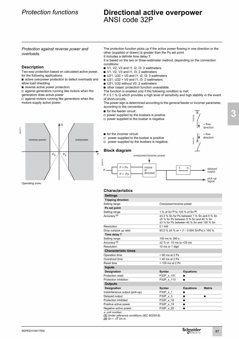
Protection functions Directional active overpowerANSI code 32P
3
Protection against reverse power and overloads.
The protection function picks up if the active power flowing in one direction or the other (supplied or drawn) is greater than the Ps set point.It includes a definite time delay T.It is based on the two or three-wattmeter method, depending on the connection conditions:b V1, V2, V3 and I1, I2, I3: 3 wattmetersb V1, V2, V3 and I1, I3: 2 wattmetersb U21, U32 + V0 and I1, I2, I3: 3 wattmetersb U21, U32 + V0 and I1, I3: 2 wattmetersb U21, U32 without V0: 2 wattmetersb other cases: protection function unavailable.The function is enabled only if the following condition is met:P u 3.1 % Q which provides a high level of sensitivity and high stability in the event of short-circuits.The power sign is determined according to the general feeder or incomer parameter, according to the convention:
DescriptionTwo-way protection based on calculated active power, for the following applications:b active overpower protection to detect overloads and allow load sheddingb reverse active power protection:v against generators running like motors when the generators draw active powerv against motors running like generators when the motors supply active power.
b for the feeder circuit:v power supplied by the busbars is positivev power supplied to the busbar is negative
DE
5076
9
DE
5077
1
Operating zone.
b for the incomer circuit:v power supplied to the busbar is positivev power supplied by the busbars is negative.
DE
5077
0
Block diagram
DE
5077
2
CharacteristicsSettingsTripping direction
Setting range Overpower/reverse powerPs set point
Setting range 1 % of Sn (2) to 120 % of Sn (2)
Accuracy (1) ±0.3 % Sn for Ps between 1 % Sn and 5 % Sn±5 % for Ps between 5 % Sn and 40 % Sn±3 % for Ps between 40 % Sn and 120 % Sn
Resolution 0.1 kWDrop out/pick up ratio 93.5 % ±5 % or > (1 - 0.004 Sn/Ps) x 100 %Time delay T
Setting range 100 ms to 300 sAccuracy (1) ±2 % or -10 ms to +25 msResolution 10 ms or 1 digitCharacteristic times
Operation time < 90 ms at 2 PsOvershoot time < 40 ms at 2 PsReset time < 105 ms at 2 PsInputsDesignation Syntax Equations
Protection reset P32P_x_101 bProtection inhibition P32P_x_113 b
OutputsDesignation Syntax Equations Matrix
Instantaneous output (pick-up) P32P_x_1 bDelayed output P32P_x_3 b bProtection inhibited P32P_x_16 bPositive active power P32P_x_19 bNegative active power P32P_x_20 bx: unit number.(1) Under reference conditions (IEC 60255-6).(2) Sn = 3 Un In.
87SEPED310017EN

3
Protection functions Directional reactive overpowerANSI code 32Q
Protection against field loss on synchronous machines.
The protection function picks up if the reactive power flowing in one direction or the other (supplied or drawn) is greater than the Qs set point.It includes a definite time delay T.It is based on the two or three-wattmeter method, depending on the connection conditions:b V1, V2, V3 and I1, I2, I3: 3 wattmetersb V1, V2, V3 and I1, I3: 2 wattmetersb U21, U32 + V0 and I1, I2, I3: 3 wattmetersb U21, U32 + V0 and I1, I3: 2 wattmetersb U21, U32 without V0: 2 wattmetersb other cases: protection function unavailable.The function is enabled only if the following condition is met:Q u 3.1 % P which provides a high level of sensitivity and high stability in the event of short-circuits.The power sign is determined according to the general feeder or incomer parameter, according to the convention:
DescriptionTwo-way protection based on calculated reactive power to detect field loss on synchronous machines:b reactive overpower protection for motors which consume more reactive power following field lossb reverse reactive overpower protection for generators which consume reactive power following field loss.
b for the feeder circuit:v power supplied by the busbars is positivev power supplied to the busbar is negative
DE
5076
9
DE
5077
3
Operating zone.
b for the incomer circuit:v power supplied to the busbar is positivev power supplied by the busbars is negative.
DE
5077
0
Block diagram
DE
5077
4
CharacteristicsSettingsTripping direction
Setting range Overpower/reverse powerQs set point
Setting range 5 % of Sn (2) to 120 % of Sn (2)
Accuracy (1) ±5 % for Qs between 5 % Sn and 40 % Sn±3 % for Qs between 40 % Sn and 120 % Sn
Resolution 0.1 kWDrop out/pick up ratio 93.5 % ±5 % or > (1- 0.004 Sn/Qs) x 100 %Time delay T
Setting range 100 ms to 300 sAccuracy (1) ±2 % or -10 ms to +25 msResolution 10 ms or 1 digitCharacteristic times
Operation time < 90 ms at 2 QsOvershoot time < 95 ms at 2 QsReset time < 95 ms at 2 QsInputsDesignation Syntax Equations
Protection reset P32Q_1_101 bProtection inhibition P32Q_1_113 b
OutputsDesignation Syntax Equations Matrix
Instantaneous output (pick-up) P32Q_1_1 bDelayed output P32Q_1_3 b bProtection inhibited P32Q_1_16 bPositive reactive power P32Q_1_54 bNegative reactive power P32Q_1_55 b(1) Under reference conditions (IEC 60255-6).(2) Sn = 3 Un In.
88 SEPED310017EN

Protection functions Phase undercurrentANSI code 37
3
Protection for pumps. This protection is single-phase.b it picks up when phase 1 current (I1) drops below the Is set point.
DE
5077
5
Current sag.
DescriptionProtection of pumps against the consequences of a loss of priming by detection of motor no-load operation.
b it is inactive when the current is less than 1.5 % of In.b it is insensitive to current drops due to circuit breaker tripping.
DE
5077
6
Circuit breaker tripping.
b the protection function includes a definite time delay.
DE
5052
9
This protection function may be inhibited by a logic input. It can be remotely reset by a remote control order (TC32).
Block diagram
DE
5077
7
89SEPED310017EN

3
Protection functions Phase undercurrentANSI code 37
CharacteristicsSettingsIs set point
Setting range 5 % Ib to 100 % IbAccuracy (1) ±5 %Resolution 1 %Drop out/pick up ratio 106 % ±3 %Time delay T
Setting range 50 ms to 300 sAccuracy (1) ±2 % or ±25 msResolution 10 ms or 1 digitCharacteristic times
Operation time pick-up < 55 ms from 2 Is to 0.02 InOvershoot time < 40 ms from 2 Is to 0.02 InReset time < 45 ms from 0.02 In to 2 IsInputsDesignation Syntax Equations
Protection reset P37_1_101 bProtection inhibition P37_1_113 bOutputsDesignation Syntax Equations Matrix
Instantaneous output (pick-up) P37_1_1 bDelayed output P37_1_3 b bProtection inhibited P37_1_16 b(1) Under reference conditions (IEC 60255-6).
TS/TC equivalence for each protocolModbus DNP3 IEC 60870-5-103 IEC 61850TC Binary Output ASDU, FUN, INF LN.DO.DA
TC32 BO13 20, 105, 101 A37_PTUC.ProRs.ctlVal
90 SEPED310017EN

Protection functions Directional active underpowerANSI code 37P
3
Check on active power flow. DescriptionTwo-way protection based on active power. The function monitors the calculated active power flows:b to adapt the number of parallel sources to fit the network load power demandb to create an isolated system in an installation with its own generating unit.The protection function picks up if the active power flowing in one direction or the other (supplied or drawn) is less than the Ps set point.It includes a definite (DT) time delay T.It is based on the two or three-wattmeter method, depending on the connection conditions:b V1, V2, V3 and I1, I2, I3: 3 wattmetersb V1, V2, V3 and I1, I3: 2 wattmetersb U21, U32 + V0 and I1, I2, I3: 3 wattmetersb U21, U32 + V0 and I1, I3: 2 wattmetersb U21, U32 without V0: 2 wattmetersb other cases: protection function unavailable.The power sign is determined according to the general feeder or incomer parameter, according to the convention:
DE
5138
2
Tripping zone (normal direction).
DE
5138
3 b for the feeder circuit:v power supplied by the busbars is positive (normal direction)v power supplied to the busbars is negative
DE
5076
9
b for the incomer circuit:v power supplied to the busbar is positive (normal direction)v power supplied by the busbars is negative.
DE
5077
0
Tripping zone (reverse direction).
Block diagram
DE
5082
4
CharacteristicsSettingsTripping direction
Setting range Normal / reversePs set point
Setting range 5 % of Sn (2) to 100 % of Sn (2)
Accuracy (1) ±5 % for Ps between 5 % Sn and 40 % Sn±3 % for Ps between 40 % Sn and 120 % Sn
Resolution 0.1 kWDrop out/pick up ratio 106 %Time delay T
Setting range 100 ms to 300 sAccuracy (1) ±2 % or -10 ms to +25 msResolution 10 ms or 1 digitCharacteristic times
Operation time < 120 msOvershoot time < 65 msReset time < 60 msInputsDesignation Syntax Equations
Protection reset P37P_x_101 bProtection inhibition P37P_x_113 bOutputsDesignation Syntax Equations Matrix
Instantaneous output (pick-up) P37P_x_1 bDelayed output P37P_x_3 b bProtection inhibited P37P_x_16 bx: unit number.(1) Under reference conditions (IEC 60255-6).(2) Sn = 3.Un In.
91SEPED310017EN
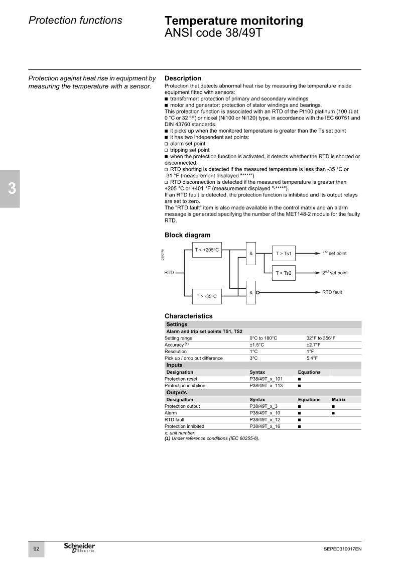
3
Protection functions Temperature monitoringANSI code 38/49T
Protection against heat rise in equipment by measuring the temperature with a sensor.
DescriptionProtection that detects abnormal heat rise by measuring the temperature inside equipment fitted with sensors:b transformer: protection of primary and secondary windingsb motor and generator: protection of stator windings and bearings.This protection function is associated with an RTD of the Pt100 platinum (100 Ω at 0 °C or 32 °F) or nickel (Ni100 or Ni120) type, in accordance with the IEC 60751 and DIN 43760 standards.b it picks up when the monitored temperature is greater than the Ts set pointb it has two independent set points:v alarm set pointv tripping set pointb when the protection function is activated, it detects whether the RTD is shorted or disconnected: v RTD shorting is detected if the measured temperature is less than -35 °C or -31 °F (measurement displayed "****")v RTD disconnection is detected if the measured temperature is greater than +205 °C or +401 °F (measurement displayed "-****").If an RTD fault is detected, the protection function is inhibited and its output relays are set to zero.The "RTD fault" item is also made available in the control matrix and an alarm message is generated specifying the number of the MET148-2 module for the faulty RTD.
Block diagram
DE
5077
8
CharacteristicsSettingsAlarm and trip set points TS1, TS2
Setting range 0°C to 180°C 32°F to 356°FAccuracy (1) ±1.5°C ±2.7°FResolution 1°C 1°FPick up / drop out difference 3°C 5.4°FInputsDesignation Syntax Equations
Protection reset P38/49T_x_101 bProtection inhibition P38/49T_x_113 b
OutputsDesignation Syntax Equations Matrix
Protection output P38/49T_x_3 b bAlarm P38/49T_x_10 b bRTD fault P38/49T_x_12 bProtection inhibited P38/49T_x_16 bx: unit number.(1) Under reference conditions (IEC 60255-6).
92 SEPED310017EN

Protection functions Field lossANSI code 40
3
Protection against field loss on synchronous machines or generators.
DescriptionThe protection function is made up of two circular tripping characteristics on the impedance plane (R, X). It picks up when the positive sequence impedance Zd enters one of the circular tripping characteristics.
DE
5030
6
Circular tripping characteristicsb Case of a generator incomer or motor feeder
Circle 1 Circle 2Centre C1 = -(Xa + Xb)/2 C2 = -(Xa + Xc)/2Radius R1 = (Xb - Xa)/2 R2 = (Xc - Xa)/2
b Case of a generator feeder or motor incomer: the tripping characteristics are symmetrical with respect to the R axis
Circle 1 Circle 2Centre C1 = (Xa + Xb)/2 C2 = (Xa + Xc)/2Radius R1 = (Xb - Xa)/2 R2 = (Xc - Xa)/2
Block diagram
DE
5082
5
Zd VdId--------=
93SEPED310017EN

3
Protection functions Field lossANSI code 40
PE
5014
8
SFT2841 setting helpThe SFT2841 software includes a setting assistance function to calculate the values of Xa, Xb and Xc according to the electrical characteristics of the machine (and transformer, when applicable).Data used:b synchronous machine:v synchronous reactance Xd in %v transient synchronous reactance X'd in %b transformer:v winding 1 voltage Un1 in V/kVv short-circuit voltage Usc in %v rated power in kVA/MVAv copper losses in kΩ/MΩ.The proposed settings are circle 1 with a diameter Zn if Xd u 200 % or a diameterXd/2 in all other cases, and circle 2 with a diameter Xd.The two circles are offset from zero by -X'd/2.Zn = the rated machine impedance:
.
CharacteristicsSettingsCommon point: Xa
Setting range 0.02Vn/Ib y Xa y 0.20Vn/Ib + 187.5 kΩ or 0.001 ΩAccuracy (1) ±5 %Resolution 1 %Circle 1: Xb
Setting range 0.20Vn/Ib y Xb y 1.40Vn/Ib + 187.5 kΩAccuracy (1) ±5 %Resolution 0.001 Ω or 1 digitDrop out/pick up ratio 105 % ±3 % of circle 1 diameterCircle 2: Xc
Setting range 0.60Vn/Ib y Xc y 3Vn/Ib + 187.5 kΩAccuracy (1) ±5 %Resolution 0.001 Ω or 1 digitDrop out/pick up ratio 105 % ±3 % of circle 2 diameterT1 time: tripping time delay circle 1
Setting range 50 ms y T y 300 sAccuracy (1) ±2 % or from -10 ms to +25 msResolution 10 ms or 1 digitT2 time: tripping time delay circle 2
Setting range 100 ms y T y 300 sAccuracy (1) ±2 % or from -10 ms to +25 msResolution 10 ms or 1 digitCharacteristic times (1)
Operation time Pick-up < 40 ms from 0 to C1 (typically 25 ms)Pick-up < 40 ms from 0 to C2 (typically 25 ms)
Overshoot time < 50 msReset time < 50 ms (for T1 = 0)Inputs Designation Syntax Equations
Protection reset P40_1_101 bProtection inhibition P40_1_113 b
Outputs Designation Syntax Equations Matrix
Instantaneous output (pick-up) P40_1_1 bDelayed output P40_1_3 b bProtection inhibited P40_1_16 bInstantaneous protection 1 (circle 1) P40_1_23 b(1) Under reference conditions (IEC 60255-6).
Zn Un13Ib
-------------=
94 SEPED310017EN

Protection functions Field lossANSI code 40
3
Example 1. Synchronous generatorSynchronous generator datab S = 3.15 MVAb Un1 = 6.3 kVb Xd = 233 %b X'd = 21 %Protection settingTo set the protection function, it is necessary to calculate the rated generator impedance Zn:b Ib = S/(3.Un1) = 289 Ab Zn = Un1/ (3.Ib) = 12.586 Ω.Generally speaking, circle 1 is set with a diameter Zn, offset by -X'd/2, and circle 2 is set with a diameter Xd, offset by -X'd/2:b Xa = (X'd(%)/200)Zn = 1.321 Ωb Xb = (X'd(%)/200 + min(1,Xd/200))×Zn = 13.907 Ωb Xc = (X'd(%)/200 + Xd/100)Zn = 30.646 Ω.The faults detected in circle 1 are violent field-loss faults that must be cleared rapidly. Circle 2 may concern faults other than field-loss faults and its tripping time is longer:b T1 = 70 msb T2 = 500 ms.
Example 2. Generator-transformer unit applicationsSynchronous generator datab Sg = 19 MVA b Un2 = 5.5 kV b Xd = 257 %b X'd = 30 %Transformer datab St = 30 MVA b Un1 = 20 kV / Un2 = 5.5 kV b Usc = 7 % b Pcu = 191 kW Protection settingTo set the protection function, it is necessary to calculate the rated generator impedance at voltage Un1:b Ib = Sg/(3Un1) = 548 Ab Zn = Un1/ (3.Ib) = 21.071 Ω.The transformer impedance at voltage Un1 is:Zt = Usc/100.(Un1)²/St = 0.933 Ω.The transformer resistance at voltage Un1 is:Rt = Pcu.(Un1/St)² = 0.085 Ω.The transformer reactance at voltage Un1 is:
.Circle 1 is set with a diameter Zn, offset by -X'd/2 and the transformer reactance. Circle 2 is set with a diameter Xd, offset by -X'd/2 and the transformer reactance.b Xa = (X'd(%)/200)Zn + Xt = 4.09 Ωb Xb = (X'd(%)/200 + 1)Zn + Xt = 25.161 Ωb Xc = (X'd(%)/200 + Xd(%)/100)Zn + Xt = 58.243 Ω.The faults detected in circle 1 are violent field-loss faults that must be cleared rapidly. Circle 2 may concern faults other than field-loss faults and its tripping time is longer:b T1 = 70 msb T2 = 500 ms.
Xt Zt2 Rt2– 0 929 Ω,= =
95SEPED310017EN

3
Protection functions Negative sequence / unbalanceANSI code 46
Phase unbalance protection for lines and equipment.
DescriptionProtection against phase unbalance, detected by the measurement of negative sequence current:b sensitive protection to detect 2-phase faults at the ends of long linesb protection of equipment against temperature rise, caused by an unbalanced power supply, phase inversion or loss of phase, and against phase current unbalance.This function picks up if the negative sequence component of phase currents is greater than the operation set point.It is time-delayed. The time delay may be definite time or IDMT according to a standardized curve, a specially adapted Schneider curve or an RI2 curve for generator protection.
Tripping curveSchneider IDMTIEC inverse time SIT / AIEC very inverse time VIT or LTI / BIEC extremely inverse time EIT / CIEEE moderately inverse (IEC / D)IEEE very inverse (IEC / E)IEEE extremely inverse (IEC / F)RI2 curve
Block diagram
DE
5083
9
CharacteristicsSettingsTripping curve
Setting range See list aboveIs set point
Setting range definite time 10 % to 500 % of IbSchneider IDMT 10 % to 50 % of IbIEC or IEEE IDMT 10 % to 100 % of IbRI2 curve 3 % to 20 % of Ib
Accuracy (1) ±5 % or ±0.004 InResolution 1 %Drop out/pick up ratio 93.5 % ±5 % or > (1 - 0.005 In/Is) x 100 %Time delay T
Setting range definite time 100 ms y T y 300 sIDMT 100 ms y T y 1 s or TMS (2)
Accuracy (1) definite time ±2 % or ±25 msIDMT ±5 % or ±35 ms
Resolution 10 ms or 1 digitK (RI2 curve only)
Setting range 1 to 100Resolution 1Characteristic times
Operation time Pick-up < 55 ms at 2 IsOvershoot time < 50 ms at 2 IsReset time < 55 ms at 2 Is
x: unit number.(1) Under reference conditions (IEC 60255-6).(2) Setting ranges in TMS (Time Multiplier Setting) mode:
Inverse (SIT) and IEC SIT/A: 0.034 to 0.336 Very inverse (VIT) and IEC VIT/B: 0.067 to 0.666Very inverse (LTI) and IEC LTI/B: 0.008 to 0.075Ext. inverse (EIT) and IEC EIT/C: 0.124 to 1.237IEEE moderately inverse: 0.415 to 4.142IEEE very inverse: 0.726 to 7.255IEEE extremely inverse: 1.231 to 12.30.
Inputs Designation Syntax Equations
Protection reset P46_x_101 bProtection inhibition P46_x_113 b
Outputs Designation Syntax Equations Matrix
Instantaneous output (pick-up) P46_x_1 bDelayed output P46_x_3 b bProtection inhibited P46_x_16 b
96 SEPED310017EN

Protection functions Negative sequence / unbalanceANSI code 46
3
DE
5071
5
Setting example for RI2 curvesA generator can handle a certain level of negative sequence current on a continuous basis. The Is continuous level, indicated by the manufacturer, is generally between 5 and 10 % of the base current Ib.Typical values are:
Type of generator Ii permissible (% Ib)Salient poles with amortisseur windings 10
without amortisseur windings 5Cylindrical rotors Indirectly cooled 10
Sn y 960 MVA 8960 MVA < Sn y 1200 MVA 6
RI2 curve. 1200 MVA < Sn 5Reference IEEE C37.102-1987.
When this current level is exceeded, the generator can handle a negative sequence current Ii for a time td, corresponding to the following equation:
The K value is an adjustable constant that depends on the type of generator, generally between 1 and 40. Typical values of K are:
Type of generator KSalient poles 40Synchronous condenser 30Cylindrical rotors Indirectly cooled 20
Sn y 800 MVA 10800 MVA < Sn y 1600 MVA 10 - 0.00625.(MVA - 800)
Reference IEEE C37.102-1987.
DE
5071
6
Schneider IDMT curveFor Ii > Is, the time delay depends on the value of Ii/Ib (Ib: base current of the protected equipment defined when the general parameters are set).T corresponds to the time delay for Ii/Ib = 5.The tripping curve is defined according to the following equations:
b for Is/Ib y Ii/Ib y 0.5
b for 0.5 y Ii/Ib y 5
b for Ii/Ib > 0.5t = T.
Schneider curve.
.
td KI iIb
---------⎝ ⎠⎛ ⎞
2-----------------=
t 3.19Ii Ib⁄( )1.5--------------------------- T×=
t 4.64Ii Ib⁄( )0.96----------------------------- T×=
97SEPED310017EN

3
Protection functions Negative sequence / unbalanceANSI code 46
Determination of tripping time for different negative sequence current values for a given Schneider curveUse the table to find the value of X that corresponds to the required negative sequence current. The tripping time is equal to XT.Examplegiven a tripping curve with the setting T = 0.5 s.What is the tripping time at 0.6 Ib?Use the table to find the value of X that corresponds to 60 % of Ib. The table indicates X = 7.55. The tripping time is equal to: 0.5 x 7.55 = 3.755 s.
Schneider IDMT tripping curve
li (% lb) 10 15 20 25 30 33.33 35 40 45 50 55 57.7 60 65 70 75X 99.95 54.50 35.44 25.38 19.32 16.51 15.34 12.56 10.53 9.00 8.21 7.84 7.55 7.00 6.52 6.11
li (% lb) cont. 80 85 90 95 100 110 120 130 140 150 160 170 180 190 200 210X cont. 5.74 5.42 5.13 4.87 4.64 4.24 3.90 3.61 3.37 3.15 2.96 2.80 2.65 2.52 2.40 2.29
li (% lb) cont. 220 230 240 250 260 270 280 290 300 310 320 330 340 350 360 370X cont. 2.14 2.10 2.01 1.94 1.86 1.80 1.74 1.68 1.627 1.577 1.53 1.485 1.444 1.404 1.367 1.332
li (% lb) cont. 380 390 400 410 420 430 440 450 460 470 480 490 u 500X cont. 1.298 1.267 1.236 1.18 1.167 1.154 1.13 1.105 1.082 1.06 1.04 1.02 1
0.05 0.1 0.2 0.5 1 3
I/Ib
0.3 0.7 2 5 7 10 20
0.001
0.002
0.005
0.01
0.02
0.05
0,1
0.2
0.5
1
2
5
10
20
50
100
200
500
1000
2000
5000
10000
t(s)
max. curve (T=1s)
min. curve (T=0,1s)
98 SEPED310017EN

Protection functions Negative sequence overvoltageANSI code 47
3
Phase unbalance protection. DescriptionProtection against phase unbalance resulting from phase inversion, unbalanced supply or distant fault, detected by the measurement of negative sequence voltage Vi.It includes a definite time delay T.It does not operate when only one voltage is connected to Sepam.
Block diagram
DE
5077
9
CharacteristicsSettingsVsi set point
Setting range 1 % Unp to 50 % UnpAccuracy (1) ±2 % or 0.005 UnpResolution 1 %Drop out/pick up ratio 97 % ±1 % or > (1 - 0.006 Unp/Vsi) x 100 %Time delay T
Setting range 50 ms to 300 sAccuracy (1) ±2 % or ±25 msResolution 10 ms or 1 digitCharacteristic times
Operation time Pick-up < 40 ms at 2 VsiOvershoot time < 50 ms at 2 VsiReset time < 50 ms at 2 VsiInputs Designation Syntax Equations
Protection reset P47_x_101 bProtection inhibition P47_x_113 b
Outputs Designation Syntax Equations Matrix
Instantaneous output (pick-up) P47_x_1 bDelayed output P47_x_3 b bProtection inhibited P47_x_16 bx: unit number.(1) Under reference conditions (IEC 60255-6).
99SEPED310017EN

3
Protection functions Excessive starting time, locked rotorANSI code 48/51LR
Detection of excessive starting time and locked rotors for motor protection.
DescriptionProtection against motor overheating caused by:b excessive motor starting time due to overloads (e.g. conveyor) or insufficient supply voltageb locked rotor due to motor load (e.g. crusher):v during normal operation, after a normal startv directly at motor start, before detection of an excessive starting time. This function is three-phase.Starting is detected when the current drawn is greater than 5 % of current Ib.This function comprises two parts:b excessive starting time: during starting, the protection picks up when one of the 3 phase currents is greater than the set point Is for a longer period of time than the ST time delay (normal starting time)b locked rotor: v during normal operation (after starting), the protection picks up when one of the 3 phase currents is greater than the set point Is for a longer period of time than the LT time delay (DT).v locked on start: large motors may have very long starting times, due to their inertia or a reduction in the voltage. This starting time may be longer than the permissible rotor locking time. To protect such a motor against rotor locking, an LTS time may be set to initiate tripping if a start is detected (I > Is) and if the motor speed is zero.Zero motor speed is detected by one of the three following options:b Rotor rotation detection logic input from a zero speed sensorb minimum speed function (ANSI 14)b motor thermal overload function (ANSI 49)Motor re-accelerationDuring re-acceleration, the motor draws a level of current similar to the start-up current (> Is), but in this case the current did not first drop to a level under 5 % of Ib. The ST time delay, which corresponds to the normal starting time, can be reinitialised by a logic input or information from a logic equation ("motor re-acceleration" input) and enables the user to:b reinitialize the excessive starting time protectionb set the locked rotor protection LT time delay to a low value.
DE
5082
6
Case of normal starting.
DE
5082
7
Case of excessive starting time.Block diagram
DE
5082
9
DE
5082
8
Case of locked rotor.
DE
5085
1
Case of locked rotor at start.
100 SEPED310017EN

Protection functions Excessive starting time, locked rotorANSI code 48/51LR
3
CharacteristicsSettingsIs set point
Setting range 50 % to 500 % of Ib
Accuracy (1) ±5 % Resolution 1 %Drop out/pick up ratio 93.5 % ±5 %Time delay T
Setting range ST 500 ms to 300 sLT 50 ms to 300 sLTS 50 ms to 300 s
Accuracy (1) ±2 % or ±25 ms at 2 IsResolution 10 msInputs Designation Syntax Equations
Protection reset P48/51LR_1_101 bMotor re-acceleration P48/51LR_1_102 bProtection inhibition P48/51LR_1_113 bOutputs Designation Syntax Equations Matrix
Protection output P48/51LR_1_3 b bLocked rotor P48/51LR_1_13 b bExcessive starting time P48/51LR_1_14 b bLocked rotor at start-up P48/51LR_1_15 b bProtection inhibited P48/51LR_1_16 bStarting in progress P48/51LR_1_22 b(1) Under reference conditions (IEC 60255-6).
101SEPED310017EN
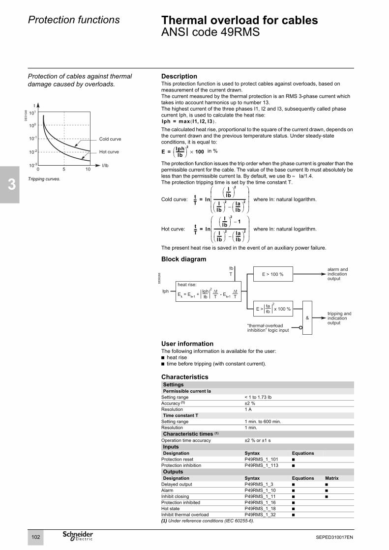
3
Protection functions Thermal overload for cablesANSI code 49RMS
Protection of cables against thermal damage caused by overloads.
DescriptionThis protection function is used to protect cables against overloads, based on measurement of the current drawn. The current measured by the thermal protection is an RMS 3-phase current which takes into account harmonics up to number 13.The highest current of the three phases I1, I2 and I3, subsequently called phase current Iph, is used to calculate the heat rise:
.The calculated heat rise, proportional to the square of the current drawn, depends on the current drawn and the previous temperature status. Under steady-state conditions, it is equal to:
in %
The protection function issues the trip order when the phase current is greater than the permissible current for the cable. The value of the base current Ib must absolutely be less than the permissible current Ia. By default, we use Ib ≈ Ia/1.4.The protection tripping time is set by the time constant T.
Cold curve: where ln: natural logarithm.
Hot curve: where ln: natural logarithm.
The present heat rise is saved in the event of an auxiliary power failure.
DE
5154
8
Tripping curves.
Block diagram
DE
8026
8
User informationThe following information is available for the user:b heat riseb time before tripping (with constant current).
CharacteristicsSettingsPermissible current Ia
Setting range < 1 to 1.73 IbAccuracy (1) ±2 %Resolution 1 ATime constant T
Setting range 1 min. to 600 min.Resolution 1 min.Characteristic times (1)
Operation time accuracy ±2 % or ±1 sInputs Designation Syntax Equations
Protection reset P49RMS_1_101 bProtection inhibition P49RMS_1_113 bOutputs Designation Syntax Equations Matrix
Delayed output P49RMS_1_3 b bAlarm P49RMS_1_10 b bInhibit closing P49RMS_1_11 b bProtection inhibited P49RMS_1_16 bHot state P49RMS_1_18 bInhibit thermal overload P49RMS_1_32 b(1) Under reference conditions (IEC 60255-6).
Iph max I1 I2 I3, ,( )=
E IphIb
---------⎝ ⎠⎛ ⎞
2100×=
tT--- In
IIb-----⎝ ⎠
⎛ ⎞2
IIb-----⎝ ⎠
⎛ ⎞2 Ia
Ib-----⎝ ⎠
⎛ ⎞2
–
-------------------------------------
⎠⎟⎟⎟⎞
⎝⎜⎜⎜⎛
=
tT--- In
IIb-----⎝ ⎠
⎛ ⎞2
1–
IIb-----⎝ ⎠
⎛ ⎞2 Ia
Ib-----⎝ ⎠
⎛ ⎞2
–
-------------------------------------
⎠⎟⎟⎟⎞
⎝⎜⎜⎜⎛
=
102 SEPED310017EN

Protection functions Thermal overload for cablesANSI code 49RMS
3
DE
5084
0
ExampleConsider a copper cable, 185 mm2, with a permissible current Ia = 485 A and a 1- second thermal withstand Ith_1 s = 22.4 kA.The thermal time constant of a cable depends in its installation method. Typical time-constant values are between 10 and 60 minutes. For buried cables, the time constant is between 20 and 60 minutes, for non-buried cables, it is between 10 and 40 minutes.For the cable in question, the selected values are T = 30 minutes and Ib = 350 A. Check on compatibility between the 49RMS curve and the adiabatic thermal withstand.Conditions are correct at 10 Ib.In the range of currents close to the permissible current, the 1-second thermal withstand is used to estimate maximum thermal withstand for the cable, assuming there are no heat exchanges. The maximum tripping time is calculated as:I2 x tmax = constant = (Ith_1 s)2 x 1.For the cable in question and at 10 Ib:tmax = (Ith_1 s/ I0Ib)2 = (22400 / 3500)2 = 41 s.For I = 10 Ib = 3500 A and Ia/Ib = 1.38, the value of k in the cold tripping curve table is k ≈ 0.0184.The tripping time at 10 Ib is therefore:t = k x T x 60 = 0.0184 x 30 x 60 = 35.6s < tmax.For a 10 Ib fault occuring after a rated operation phase, with 100 % heat rise, the value of k is: k ≈ 0,0097.The tripping time is:t = k x T x 60 = 0.0097 x 30 x 60 = 17.5 s Check on discriminationDiscrimination between 49RMS for the cable and the downstream protection curves, including 49RMS protection functions, must be checked to avoid any risk of nuisance tripping.
103SEPED310017EN

3
Protection functions Thermal overload for cablesANSI code 49RMSTripping curves
Curves for initial heat rise = 0 %Iph/Ib 0.55 0.60 0.65 0.70 0.75 0.80 0.85 0.90 0.95 1.00 1.05 1.10 1.15 1.20 1.25 1.30Ia/Ib
0.50 1.7513 1.1856 0.8958 0.7138 0.5878 0.4953 0.4247 0.3691 0.3244 0.2877 0.2572 0.2314 0.2095 0.1907 0.1744 0.16010.55 1.8343 1.2587 0.9606 0.7717 0.6399 0.5425 0.4675 0.4082 0.3603 0.3207 0.2877 0.2597 0.2358 0.2152 0.19720.60 1.9110 1.3269 1.0217 0.8267 0.6897 0.5878 0.5090 0.4463 0.3953 0.3531 0.3178 0.2877 0.2619 0.23960.65 1.9823 1.3907 1.0793 0.8789 0.7373 0.6314 0.5491 0.4832 0.4295 0.3849 0.3473 0.3153 0.28770.70 2.0488 1.4508 1.1338 0.9287 0.7829 0.6733 0.5878 0.5191 0.4629 0.4159 0.3763 0.34240.75 2.1112 1.5075 1.1856 0.9762 0.8267 0.7138 0.6253 0.5540 0.4953 0.4463 0.40470.80 2.1699 1.5612 1.2349 1.0217 0.8687 0.7527 0.6615 0.5878 0.5270 0.47590.85 2.2254 1.6122 1.2819 1.0652 0.9091 0.7904 0.6966 0.6206 0.55780.90 2.2780 1.6607 1.3269 1.1069 0.9480 0.8267 0.7306 0.65260.95 2.3279 1.7070 1.3699 1.1470 0.9855 0.8618 0.76361.00 2.3755 1.7513 1.4112 1.1856 1.0217 0.89581.05 2.4209 1.7937 1.4508 1.2228 1.05661.10 2.4643 1.8343 1.4890 1.25871.15 2.5060 1.8734 1.52581.20 2.5459 1.91101.25 2.5844
Iph/Ib 1.35 1.40 1.45 1.50 1.55 1.60 1.65 1.70 1.75 1.80 1.85 1.90 1.95 2.00 2.20 2.40Ia/Ib
0.50 0.1475 0.1365 0.1266 0.1178 0.1099 0.1028 0.0963 0.0905 0.0852 0.0803 0.0759 0.0718 0.0680 0.0645 0.0530 0.04440.55 0.1815 0.1676 0.1553 0.1444 0.1346 0.1258 0.1178 0.1106 0.1040 0.0980 0.0925 0.0875 0.0829 0.0786 0.0645 0.05390.60 0.2201 0.2029 0.1878 0.1744 0.1623 0.1516 0.1418 0.1330 0.1251 0.1178 0.1111 0.1051 0.0995 0.0943 0.0773 0.06450.65 0.2637 0.2428 0.2243 0.2080 0.1934 0.1804 0.1686 0.1581 0.1485 0.1397 0.1318 0.1245 0.1178 0.1116 0.0913 0.07620.70 0.3132 0.2877 0.2653 0.2456 0.2281 0.2125 0.1984 0.1858 0.1744 0.1640 0.1545 0.1459 0.1380 0.1307 0.1067 0.08890.75 0.3691 0.3383 0.3113 0.2877 0.2667 0.2481 0.2314 0.2165 0.2029 0.1907 0.1796 0.1694 0.1601 0.1516 0.1236 0.10280.80 0.4326 0.3953 0.3630 0.3347 0.3098 0.2877 0.2680 0.2503 0.2344 0.2201 0.2070 0.1952 0.1843 0.1744 0.1418 0.11780.85 0.5049 0.4599 0.4210 0.3873 0.3577 0.3316 0.3084 0.2877 0.2691 0.2523 0.2371 0.2233 0.2107 0.1992 0.1617 0.13400.90 0.5878 0.5332 0.4866 0.4463 0.4112 0.3804 0.3531 0.3289 0.3072 0.2877 0.2701 0.2541 0.2396 0.2263 0.1832 0.15160.95 0.6836 0.6170 0.5608 0.5127 0.4710 0.4347 0.4027 0.3744 0.3491 0.3265 0.3061 0.2877 0.2710 0.2557 0.2064 0.17041.00 0.7956 0.7138 0.6456 0.5878 0.5383 0.4953 0.4578 0.4247 0.3953 0.3691 0.3456 0.3244 0.3052 0.2877 0.2314 0.19071.05 0.9287 0.8267 0.7431 0.6733 0.6142 0.5633 0.5191 0.4804 0.4463 0.4159 0.3888 0.3644 0.3424 0.3225 0.2585 0.21251.10 1.0904 0.9606 0.8569 0.7717 0.7005 0.6399 0.5878 0.5425 0.5027 0.4675 0.4363 0.4082 0.3830 0.3603 0.2877 0.23581.15 1.2934 1.1231 0.9916 0.8862 0.7996 0.7269 0.6651 0.6118 0.5654 0.5246 0.4884 0.4563 0.4274 0.4014 0.3192 0.26091.20 1.5612 1.3269 1.1549 1.0217 0.9147 0.8267 0.7527 0.6897 0.6353 0.5878 0.5460 0.5090 0.4759 0.4463 0.3531 0.28771.25 1.9473 1.5955 1.3593 1.1856 1.0509 0.9425 0.8531 0.7780 0.7138 0.6583 0.6098 0.5671 0.5292 0.4953 0.3898 0.31651.30 2.6214 1.9823 1.6286 1.3907 1.2155 1.0793 0.9696 0.8789 0.8026 0.7373 0.6808 0.6314 0.5878 0.5491 0.4295 0.34731.35 2.6571 2.0161 1.6607 1.4212 1.2445 1.1069 0.9959 0.9041 0.8267 0.7604 0.7029 0.6526 0.6081 0.4725 0.38041.40 2.6915 2.0488 1.6918 1.4508 1.2727 1.1338 1.0217 0.9287 0.8502 0.7829 0.7245 0.6733 0.5191 0.41591.45 2.7249 2.0805 1.7220 1.4796 1.3001 1.1601 1.0467 0.9527 0.8733 0.8050 0.7458 0.5699 0.45421.50 2.7571 2.1112 1.7513 1.5075 1.3269 1.1856 1.0712 0.9762 0.8958 0.8267 0.6253 0.49531.55 2.7883 2.1410 1.7797 1.5347 1.3529 1.2106 1.0952 0.9992 0.9179 0.6859 0.53971.60 2.8186 2.1699 1.8074 1.5612 1.3783 1.2349 1.1185 1.0217 0.7527 0.58781.65 2.8480 2.1980 1.8343 1.5870 1.4031 1.2587 1.1414 0.8267 0.63991.70 2.8766 2.2254 1.8605 1.6122 1.4272 1.2819 0.9091 0.6966
104 SEPED310017EN

Protection functions Thermal overload for cablesANSI code 49RMSTripping curves
3
Curves for initial heat rise = 0 %Iph/Ib 2.60 2.80 3.00 3.20 3.40 3.60 3.80 4.00 4.20 4.40 4.60 4.80 5.00 5.50 6.00 6.50Ia/Ib
0,50 0.0377 0.0324 0.0282 0.0247 0.0219 0.0195 0.0175 0.0157 0.0143 0.0130 0.0119 0.0109 0.0101 0.0083 0.0070 0.00590.55 0.0458 0.0393 0.0342 0.0300 0.0265 0.0236 0.0212 0.0191 0.0173 0.0157 0.0144 0.0132 0.0122 0.0101 0.0084 0.00720.60 0.0547 0.0470 0.0408 0.0358 0.0316 0.0282 0.0252 0.0228 0.0206 0.0188 0.0172 0.0157 0.0145 0.0120 0.0101 0.00860.65 0.0645 0.0554 0.0481 0.0421 0.0372 0.0331 0.0297 0.0268 0.0242 0.0221 0.0202 0.0185 0.0170 0.0141 0.0118 0.01010.70 0.0752 0.0645 0.0560 0.0490 0.0433 0.0385 0.0345 0.0311 0.0282 0.0256 0.0234 0.0215 0.0198 0.0163 0.0137 0.01170.75 0.0869 0.0745 0.0645 0.0565 0.0499 0.0444 0.0397 0.0358 0.0324 0.0295 0.0269 0.0247 0.0228 0.0188 0.0157 0.01340.80 0.0995 0.0852 0.0738 0.0645 0.0570 0.0506 0.0453 0.0408 0.0370 0.0336 0.0307 0.0282 0.0259 0.0214 0.0179 0.01530.85 0.1130 0.0967 0.0837 0.0732 0.0645 0.0574 0.0513 0.0462 0.0418 0.0380 0.0347 0.0319 0.0293 0.0242 0.0203 0.01720.90 0.1276 0.1091 0.0943 0.0824 0.0726 0.0645 0.0577 0.0520 0.0470 0.0427 0.0390 0.0358 0.0329 0.0271 0.0228 0.01940.95 0.1433 0.1223 0.1057 0.0923 0.0813 0.0722 0.0645 0.0581 0.0525 0.0477 0.0436 0.0400 0.0368 0.0303 0.0254 0.02161.00 0.1601 0.1365 0.1178 0.1028 0.0905 0.0803 0.0718 0.0645 0.0584 0.0530 0.0484 0.0444 0.0408 0.0336 0.0282 0.02401.05 0.1780 0.1516 0.1307 0.1139 0.1002 0.0889 0.0794 0.0714 0.0645 0.0586 0.0535 0.0490 0.0451 0.0371 0.0311 0.02641.10 0.1972 0.1676 0.1444 0.1258 0.1106 0.0980 0.0875 0.0786 0.0711 0.0645 0.0589 0.0539 0.0496 0.0408 0.0342 0.02911.15 0.2177 0.1848 0.1589 0.1383 0.1215 0.1076 0.0961 0.0863 0.0779 0.0708 0.0645 0.0591 0.0544 0.0447 0.0374 0.03181.20 0.2396 0.2029 0.1744 0.1516 0.1330 0.1178 0.1051 0.0943 0.0852 0.0773 0.0705 0.0645 0.0593 0.0488 0.0408 0.03471.25 0.2629 0.2223 0.1907 0.1656 0.1452 0.1285 0.1145 0.1028 0.0927 0.0842 0.0767 0.0702 0.0645 0.0530 0.0444 0.03771.30 0.2877 0.2428 0.2080 0.1804 0.1581 0.1397 0.1245 0.1116 0.1007 0.0913 0.0832 0.0762 0.0700 0.0575 0.0481 0.04081.35 0.3142 0.2646 0.2263 0.1960 0.1716 0.1516 0.1349 0.1209 0.1091 0.0989 0.0901 0.0824 0.0757 0.0621 0.0520 0.04411.40 0.3424 0.2877 0.2456 0.2125 0.1858 0.1640 0.1459 0.1307 0.1178 0.1067 0.0972 0.0889 0.0816 0.0670 0.0560 0.04751.45 0.3725 0.3122 0.2661 0.2298 0.2007 0.1770 0.1574 0.1409 0.1269 0.1150 0.1047 0.0957 0.0878 0.0720 0.0602 0.05101.50 0.4047 0.3383 0.2877 0.2481 0.2165 0.1907 0.1694 0.1516 0.1365 0.1236 0.1124 0.1028 0.0943 0.0773 0.0645 0.05471.55 0.4391 0.3659 0.3105 0.2674 0.2330 0.2050 0.1820 0.1627 0.1464 0.1325 0.1205 0.1101 0.1010 0.0828 0.0691 0.05851.60 0.4759 0.3953 0.3347 0.2877 0.2503 0.2201 0.1952 0.1744 0.1568 0.1418 0.1290 0.1178 0.1080 0.0884 0.0738 0.06251.65 0.5154 0.4266 0.3603 0.3091 0.2686 0.2358 0.2089 0.1865 0.1676 0.1516 0.1377 0.1258 0.1153 0.0943 0.0786 0.06661.70 0.5578 0.4599 0.3873 0.3316 0.2877 0.2523 0.2233 0.1992 0.1789 0.1617 0.1469 0.1340 0.1229 0.1004 0.0837 0.0709
Iph/Ib 7.00 7.50 8.00 8.50 9.00 9.50 10.00 12.50 15.00 17.50 20.00Ia/Ib
0.50 0.0051 0.0045 0.0039 0.0035 0.0031 0.0028 0.0025 0.0016 0.0011 0.0008 0.00060.55 0.0062 0.0054 0.0047 0.0042 0.0037 0.0034 0.0030 0.0019 0.0013 0.0010 0.00080.60 0.0074 0.0064 0.0056 0.0050 0.0045 0.0040 0.0036 0.0023 0.0016 0.0012 0.00090.65 0.0087 0.0075 0.0066 0.0059 0.0052 0.0047 0.0042 0.0027 0.0019 0.0014 0.00110.70 0.0101 0.0087 0.0077 0.0068 0.0061 0.0054 0.0049 0.0031 0.0022 0.0016 0.00120.75 0.0115 0.0101 0.0088 0.0078 0.0070 0.0063 0.0056 0.0036 0.0025 0.0018 0.00140.80 0.0131 0.0114 0.0101 0.0089 0.0079 0.0071 0.0064 0.0041 0.0028 0.0021 0.00160.85 0.0149 0.0129 0.0114 0.0101 0.0090 0.0080 0.0073 0.0046 0.0032 0.0024 0.00180.90 0.0167 0.0145 0.0127 0.0113 0.0101 0.0090 0.0081 0.0052 0.0036 0.0026 0.00200.95 0.0186 0.0162 0.0142 0.0126 0.0112 0.0101 0.0091 0.0058 0.0040 0.0030 0.00231.00 0.0206 0.0179 0.0157 0.0139 0.0124 0.0111 0.0101 0.0064 0.0045 0.0033 0.00251.05 0.0228 0.0198 0.0174 0.0154 0.0137 0.0123 0.0111 0.0071 0.0049 0.0036 0.00281.10 0.0250 0.0217 0.0191 0.0169 0.0151 0.0135 0.0122 0.0078 0.0054 0.0040 0.00301.15 0.0274 0.0238 0.0209 0.0185 0.0165 0.0148 0.0133 0.0085 0.0059 0.0043 0.00331.20 0.0298 0.0259 0.0228 0.0201 0.0179 0.0161 0.0145 0.0093 0.0064 0.0047 0.00361.25 0.0324 0.0282 0.0247 0.0219 0.0195 0.0175 0.0157 0.0101 0.0070 0.0051 0.00391.30 0.0351 0.0305 0.0268 0.0237 0.0211 0.0189 0.0170 0.0109 0.0075 0.0055 0.00421.35 0.0379 0.0329 0.0289 0.0255 0.0228 0.0204 0.0184 0.0117 0.0081 0.0060 0.00461.40 0.0408 0.0355 0.0311 0.0275 0.0245 0.0220 0.0198 0.0126 0.0087 0.0064 0.00491.45 0.0439 0.0381 0.0334 0.0295 0.0263 0.0236 0.0212 0.0135 0.0094 0.0069 0.00531.50 0.0470 0.0408 0.0358 0.0316 0.0282 0.0252 0.0228 0.0145 0.0101 0.0074 0.00561.55 0.0503 0.0437 0.0383 0.0338 0.0301 0.0270 0.0243 0.0155 0.0107 0.0079 0.00601.60 0.0537 0.0466 0.0408 0.0361 0.0321 0.0288 0.0259 0.0165 0.0114 0.0084 0.00641.65 0.0572 0.0496 0.0435 0.0384 0.0342 0.0306 0.0276 0.0176 0.0122 0.0089 0.00681.70 0.0608 0.0527 0.0462 0.0408 0.0363 0.0325 0.0293 0.0187 0.0129 0.0095 0.0073
105SEPED310017EN

3
Protection functions Thermal overload for cablesANSI code 49RMSTripping curves
Curves for initial heat rise = 100 %Iph/Ib 1.15 1.20 1.25 1.30 1.35 1.40 1.45 1.50 1.55 1.60 1.65 1.70 1.75 1.80 1.85 1.90Ia/Ib
1.10 1.0531 0.6487 0.4673 0.3629 0.2948 0.2469 0.2113 0.1839 0.1622 0.1446 0.1300 0.1178 0.1074 0.0984 0.0907 0.08391.15 1.3203 0.8518 0.6300 0.4977 0.4094 0.3460 0.2984 0.2613 0.2316 0.2073 0.1871 0.1700 0.1555 0.1429 0.13191.20 1.5243 1.0152 0.7656 0.6131 0.5093 0.4339 0.3765 0.3314 0.2950 0.2650 0.2400 0.2187 0.2004 0.18461.25 1.6886 1.1517 0.8817 0.7138 0.5978 0.5126 0.4472 0.3954 0.3533 0.3185 0.2892 0.2642 0.24271.30 1.8258 1.2685 0.9831 0.8030 0.6772 0.5840 0.5118 0.4543 0.4073 0.3682 0.3352 0.30701.35 1.9433 1.3705 1.0729 0.8830 0.7492 0.6491 0.5713 0.5088 0.4576 0.4148 0.37851.40 2.0460 1.4610 1.1536 0.9555 0.8149 0.7092 0.6263 0.5596 0.5047 0.45861.45 2.1371 1.5422 1.2267 1.0218 0.8755 0.7647 0.6776 0.6072 0.54891.50 2.2188 1.6159 1.2935 1.0829 0.9316 0.8165 0.7257 0.65191.55 2.2930 1.6832 1.3550 1.1394 0.9838 0.8650 0.77081.60 2.3609 1.7452 1.4121 1.1921 1.0327 0.91061.65 2.4233 1.8027 1.4652 1.2415 1.07871.70 2.4813 1.8563 1.5150 1.2879
Iph/Ib 1.95 2.00 2.20 2.40 2.60 2.80 3.00 3.20 3.40 3.60 3.80 4.00 4.20 4.40 4.60 4.80Ia/Ib
1.10 0.0779 0.0726 0.0562 0.0451 0.0371 0.0312 0.0266 0.0230 0.0201 0.0177 0.0157 0.0141 0.0127 0.0115 0.0105 0.00961.15 0.1223 0.1137 0.0877 0.0702 0.0576 0.0483 0.0411 0.0355 0.0310 0.0273 0.0243 0.0217 0.0196 0.0177 0.0161 0.01471.20 0.1708 0.1586 0.1217 0.0970 0.0795 0.0665 0.0566 0.0488 0.0426 0.0375 0.0333 0.0298 0.0268 0.0243 0.0221 0.02021.25 0.2240 0.2076 0.1584 0.1258 0.1028 0.0858 0.0729 0.0628 0.0547 0.0482 0.0428 0.0382 0.0344 0.0311 0.0283 0.02591.30 0.2826 0.2614 0.1981 0.1566 0.1276 0.1063 0.0902 0.0776 0.0676 0.0594 0.0527 0.0471 0.0424 0.0383 0.0348 0.03181.35 0.3474 0.3204 0.2410 0.1897 0.1541 0.1281 0.1085 0.0932 0.0811 0.0713 0.0632 0.0564 0.0507 0.0458 0.0417 0.03801.40 0.4194 0.3857 0.2877 0.2253 0.1823 0.1512 0.1278 0.1097 0.0953 0.0837 0.0741 0.0661 0.0594 0.0537 0.0488 0.04451.45 0.4999 0.4581 0.3384 0.2635 0.2125 0.1758 0.1483 0.1271 0.1103 0.0967 0.0856 0.0763 0.0686 0.0619 0.0562 0.05131.50 0.5907 0.5390 0.3938 0.3046 0.2446 0.2018 0.1699 0.1454 0.1260 0.1104 0.0976 0.0870 0.0781 0.0705 0.0640 0.05841.55 0.6940 0.6302 0.4545 0.3491 0.2790 0.2295 0.1928 0.1646 0.1425 0.1247 0.1102 0.0982 0.0881 0.0795 0.0721 0.06571.60 0.8134 0.7340 0.5213 0.3971 0.3159 0.2589 0.2169 0.1849 0.1599 0.1398 0.1234 0.1098 0.0984 0.0888 0.0805 0.07341.65 0.9536 0.8537 0.5952 0.4492 0.3553 0.2901 0.2425 0.2063 0.1781 0.1555 0.1372 0.1220 0.1093 0.0985 0.0893 0.08141.70 1.1221 0.9943 0.6776 0.5059 0.3977 0.3234 0.2695 0.2288 0.1972 0.1720 0.1516 0.1347 0.1206 0.1086 0.0984 0.0897
Iph/Ib 5.00 5.50 6.00 6.50 7.00 7.50 8.00 8.50 9.00 9.50 10.00 12.50 15.00 17.50 20.00Ia/Ib
1.10 0.0088 0.0072 0.0060 0.0051 0.0044 0.0038 0.0033 0.0030 0.0026 0.0024 0.0021 0.0014 0.0009 0.0007 0.00051.15 0.0135 0.0111 0.0093 0.0078 0.0067 0.0059 0.0051 0.0045 0.0040 0.0036 0.0033 0.0021 0.0014 0.0011 0.00081.20 0.0185 0.0152 0.0127 0.0107 0.0092 0.0080 0.0070 0.0062 0.0055 0.0049 0.0045 0.0028 0.0020 0.0014 0.00111.25 0.0237 0.0194 0.0162 0.0137 0.0118 0.0102 0.0090 0.0079 0.0071 0.0063 0.0057 0.0036 0.0025 0.0018 0.00141.30 0.0292 0.0239 0.0199 0.0169 0.0145 0.0126 0.0110 0.0097 0.0087 0.0078 0.0070 0.0045 0.0031 0.0023 0.00171.35 0.0349 0.0285 0.0238 0.0201 0.0173 0.0150 0.0131 0.0116 0.0103 0.0093 0.0083 0.0053 0.0037 0.0027 0.00211.40 0.0408 0.0334 0.0278 0.0235 0.0202 0.0175 0.0154 0.0136 0.0121 0.0108 0.0097 0.0062 0.0043 0.0031 0.00241.45 0.0470 0.0384 0.0320 0.0271 0.0232 0.0202 0.0177 0.0156 0.0139 0.0124 0.0112 0.0071 0.0049 0.0036 0.00281.50 0.0535 0.0437 0.0364 0.0308 0.0264 0.0229 0.0200 0.0177 0.0157 0.0141 0.0127 0.0081 0.0056 0.0041 0.00311.55 0.0602 0.0491 0.0409 0.0346 0.0297 0.0257 0.0225 0.0199 0.0177 0.0158 0.0143 0.0091 0.0063 0.0046 0.00351.60 0.0672 0.0548 0.0456 0.0386 0.0330 0.0286 0.0251 0.0221 0.0197 0.0176 0.0159 0.0101 0.0070 0.0051 0.00391.65 0.0745 0.0607 0.0505 0.0427 0.0365 0.0317 0.0277 0.0245 0.0218 0.0195 0.0176 0.0112 0.0077 0.0057 0.00431.70 0.0820 0.0668 0.0555 0.0469 0.0402 0.0348 0.0305 0.0269 0.0239 0.0214 0.0193 0.0122 0.0085 0.0062 0.0047
106 SEPED310017EN

Protection functions Thermal overload for capacitorsANSI code 49RMS
3
Protection of equipment against thermal damage due to overloads.
DescriptionThis function is used to protect capacitor banks with or without anti-harmonic inductors against overloads, based on the measurement of the current drawn.
The current measured by the thermal protection is an RMS 3-phase current which takes into account harmonics up to number 13.The highest current of the three phases I1, I2 and I3, subsequently called phase current Iph, is used to calculate the heat rise:
Operation curveThe protection function gives a tripping order when the current drawn is greater than the overload current, with respect to the rated current of the sequence.The tripping time is set by assigning a hot tripping time to a setting current. This setting is used to calculate a time factor:
DE
5160
6
Tripping curves.
where In: natural logarithm.
The tripping time with an initial heat rise of 0 % is then given by:
where In: natural logarithm.
= k x Ts
The tripping time with an intial heat rise of 100 % is then given by:
where In: natural logarithm.
= k x Ts
The tripping curve tables give the values of k for an inital heat rise from 0 % to 100 %.The current heat rise is saved in the event of an auxiliary power failure.
Block diagram
DE
8100
4
Iph max I1 I2 I3,,( )=
50 10
10-1
10-2
10-3
100
101
C 1
In
IsIb-----⎝ ⎠
⎛ ⎞2 1–
IsIb-----⎝ ⎠
⎛ ⎞2 ItripIb
-------------⎝ ⎠⎛ ⎞2
–------------------------------------
⎠⎟⎟⎟⎞
⎝⎜⎜⎜⎛
------------------------------------------------=
t C In
IphIb
---------⎝ ⎠⎛ ⎞2
IphIb
---------⎝ ⎠⎛ ⎞2 Itrip
Ib-------------⎝ ⎠
⎛ ⎞2–
--------------------------------------------
⎠⎟⎟⎟⎞
⎝⎜⎜⎜⎛
Ts××=
t C In
IphIb
---------⎝ ⎠⎛ ⎞2
1–
IphIb
---------⎝ ⎠⎛ ⎞2 Itrip
Ib-------------⎝ ⎠
⎛ ⎞2–
--------------------------------------------
⎠⎟⎟⎟⎞
⎝⎜⎜⎜⎛
Ts××=
107SEPED310017EN

3
Protection functions Thermal overload for capacitorsANSI code 49RMS
User informationThe following information is available for the user:b heat riseb time before tripping (with constant current).
CharacteristicsSettingsAlarm current Ialarm
Setting range 1.05 to 1.70 IbAccuracy (1) ±2 %Resolution 1 ATripping current Itrip
Setting range 1.05 to 1.70 IbAccuracy (1) ±2 %Resolution 1 ASetting current Is
Setting range 1.02 Itrip to 2 IbAccuracy (1) ±2 %Resolution 1 ASetting time Ts
Setting range 1 to 2000 minutes (range varies depending on the tripping and setting currents)
Resolution 1 mnCharacteristic times
Operation time accuracy ±2 % or ±2 sInputs Designation Syntax Equations
Protection reset P49RMS_1_101 bProtection inhibition P49RMS_1_113 bOutputs Designation Syntax Equations Matrix
Delayed output P49RMS _1_3 b bAlarm P49RMS _1_10 b bInhibit closing P49RMS _1_11 b bProtection inhibited P49RMS _1_16 bHot state P49RMS _1_18 b(1) Under reference conditions (IEC 60255-6).
108 SEPED310017EN

Protection functions Thermal overload for capacitorsANSI code 49RMS
3
Curves for initial heat rise = 0 % Is = 1.2 IbIph/Ibseq 1.10 1.15 1.20 1.25 1.30 1.35 1.40 1.45 1.50 1.55 1.60 1.65 1.70 1.75 1.80Itrip/Ibseq
1.05 9.1282 6.7632 5.4705 4.6108 3.9841 3.5018 3.1171 2.8020 2.5389 2.3157 2.1239 1.9574 1.8115 1.6828 1.56831.10 3.7989 2.8277 2.2954 1.9404 1.6809 1.4809 1.3209 1.1896 1.0798 0.9865 0.9061 0.8362 0.7749 0.72071.15 1.8980 1.4189 1.1556 0.9796 0.8507 0.7510 0.6712 0.6056 0.5506 0.5037 0.4634 0.4282 0.3973
Is = 1.2 IbIph/Ibseq 1.85 1.90 1.95 2.00 2.20 2.40 2.60 2.80 3.00 3.20 3.40 3.60 3.80 4.00Itrip/Ibseq
1.05 1.4660 1.3741 1.2911 1.2158 0.9747 0.8011 0.6713 0.5714 0.4927 0.4295 0.3779 0.3352 0.2995 0.26921.10 0.6725 0.6293 0.5905 0.5554 0.4435 0.3635 0.3040 0.2584 0.2226 0.1939 0.1704 0.1511 0.1349 0.12121.15 0.3699 0.3456 0.3237 0.3040 0.2417 0.1976 0.1649 0.1399 0.1204 0.1047 0.0920 0.0815 0.0728 0.0653
Is = 1.3 IbIph/Ibseq 1.10 1.15 1.20 1.25 1.30 1.35 1.40 1.45 1.50 1.55 1.60 1.65 1.70 1.75 1.80Itrip/Ibseq
1.05 15.0540 11.1530 9.0217 7.6039 6.5703 5.7750 5.1405 4.6210 4.1871 3.8189 3.5027 3.2281 2.9875 2.7752 2.58641.10 6.7905 5.0545 4.1030 3.4684 3.0047 2.6470 2.3611 2.1265 1.9301 1.7633 1.6197 1.4948 1.3852 1.28831.15 3.9779 2.9738 2.4220 2.0530 1.7829 1.5740 1.4067 1.2692 1.1539 1.0557 0.9711 0.8974 0.83271.20 2.5077 1.8824 1.5378 1.3070 1.1375 1.0063 0.9010 0.8143 0.7415 0.6794 0.6257 0.57901.25 1.5305 1.1532 0.9449 0.8050 0.7021 0.6223 0.5582 0.5052 0.4607 0.4227 0.3898
Is = 1.3 IbIph/Ibseq 1.85 1.90 1.95 2.00 2.20 2.40 2.60 2.80 3.00 3.20 3.40 3.60 3.80 4.00Itrip/Ibseq
1.05 2.4177 2.2661 2.1292 2.0051 1.6074 1.3211 1.1071 0.9424 0.8126 0.7084 0.6233 0.5529 0.4939 0.44401.10 1.2021 1.1249 1.0555 0.9927 0.7927 0.6498 0.5435 0.4619 0.3979 0.3465 0.3047 0.2701 0.2412 0.21671.15 0.7753 0.7242 0.6785 0.6372 0.5066 0.4141 0.3456 0.2933 0.2523 0.2195 0.1929 0.1709 0.1525 0.13701.20 0.5378 0.5013 0.4688 0.4396 0.3478 0.2834 0.2360 0.1999 0.1717 0.1493 0.1310 0.1160 0.1035 0.09291.25 0.3611 0.3358 0.3134 0.2933 0.2309 0.1874 0.1557 0.1316 0.1129 0.0981 0.0860 0.0761 0.0678 0.0609
Is = 1.4 IbIph/Ibseq 1.10 1.15 1.20 1.25 1.30 1.35 1.40 1.45 1.50 1.55 1.60 1.65 1.70 1.75 1.80Itrip/Ibseq
1.05 21.4400 15.8850 12.8490 10.8300 9.3578 8.2251 7.3214 6.5815 5.9634 5.4391 4.9887 4.5976 4.2550 3.9525 3.68371.10 9.9827 7.4306 6.0317 5.0988 4.4171 3.8914 3.4710 3.1261 2.8375 2.5922 2.3811 2.1975 2.0364 1.89391.15 6.1214 4.5762 3.7270 3.1593 2.7435 2.4222 2.1647 1.9531 1.7757 1.6246 1.4944 1.3810 1.28131.20 4.1525 3.1170 2.5464 2.1642 1.8836 1.6664 1.4920 1.3483 1.2278 1.1249 1.0361 0.95871.25 2.9310 2.2085 1.8095 1.5416 1.3446 1.1918 1.0689 0.9676 0.8823 0.8095 0.74661.30 2.0665 1.5627 1.2839 1.0964 0.9582 0.8508 0.7643 0.6929 0.6327 0.58131.35 1.3673 1.0375 0.8546 0.7314 0.6404 0.5696 0.5125 0.4653 0.4254
Is = 1.4 IbIph/Ibseq 1.85 1.90 1.95 2.00 2.20 2.40 2.60 2.80 3.00 3.20 3.40 3.60 3.80 4.00Itrip/Ibseq
1.05 3.4434 3.2275 3.0325 2.8557 2.2894 1.8816 1.5768 1.3422 1.1573 1.0089 0.8877 0.7874 0.7034 0.63231.10 1.7672 1.6537 1.5516 1.4593 1.1654 0.9552 0.7989 0.6791 0.5849 0.5094 0.4479 0.3970 0.3545 0.31861.15 1.1931 1.1145 1.0440 0.9805 0.7796 0.6372 0.5318 0.4513 0.3882 0.3378 0.2968 0.2629 0.2346 0.21071.20 0.8906 0.8302 0.7763 0.7279 0.5760 0.4692 0.3907 0.3310 0.2844 0.2472 0.2170 0.1921 0.1714 0.15381.25 0.6916 0.6432 0.6002 0.5618 0.4421 0.3589 0.2981 0.2521 0.2163 0.1878 0.1647 0.1457 0.1299 0.11651.30 0.5367 0.4977 0.4634 0.4328 0.3386 0.2738 0.2268 0.1914 0.1640 0.1422 0.1246 0.1102 0.0981 0.08801.35 0.3913 0.3617 0.3358 0.3129 0.2431 0.1957 0.1617 0.1361 0.1164 0.1009 0.0883 0.0780 0.0694 0.0622
109SEPED310017EN

3
Protection functions Thermal overload for capacitorsANSI code 49RMS
Curves for initial heat rise = 0 % Is = 2 IbIph/Ibseq 1.10 1.15 1.20 1.25 1.30 1.35 1.40 1.45 1.50 1.55 1.60 1.65 1.70 1.75 1.80Itrip/Ibseq1.05 69.6380 51.5950 41.7340 35.1750 30.3940 26.7150 23.7800 21.3760 19.3690 17.6660 16.2030 14.9330 13.8200 12.8380 11.96501.10 33.9580 25.2760 20.5180 17.3440 15.0260 13.2370 11.8070 10.6340 9.6521 8.8176 8.0995 7.4750 6.9270 6.44251.15 22.0350 16.4730 13.4160 11.3720 9.8756 8.7189 7.7922 7.0303 6.3916 5.8479 5.3792 4.9710 4.61231.20 16.0520 12.0490 9.8435 8.3659 7.2814 6.4415 5.7674 5.2122 4.7460 4.3485 4.0053 3.70601.25 12.4460 9.3782 7.6840 6.5465 5.7100 5.0610 4.5392 4.1087 3.7467 3.4375 3.17031.30 10.0300 7.5843 6.2313 5.3211 4.6505 4.1294 3.7096 3.3629 3.0708 2.82101.35 8.2921 6.2917 5.1827 4.4353 3.8838 3.4544 3.1081 2.8215 2.57991.40 6.9790 5.3124 4.3868 3.7619 3.3000 2.9399 2.6491 2.40811.50 5.1152 3.9169 3.2491 2.7969 2.4617 2.19971.60 3.8403 2.9564 2.4625 2.12711.70 2.8932 2.2383
Is = 2 IbIph/Ibseq 1.85 1.90 1.95 2.00 2.20 2.40 2.60 2.80 3.00 3.20 3.40 3.60 3.80 4.00Itrip/Ibseq
1.05 11.1840 10.4830 9.8495 9.2753 7.4358 6.1115 5.1214 4.3594 3.7590 3.2768 2.8832 2.5574 2.2846 2.05371.10 6.0114 5.6254 5.2781 4.9642 3.9642 3.2494 2.7177 2.3099 1.9896 1.7328 1.5235 1.3506 1.2059 1.08361.15 4.2947 4.0117 3.7581 3.5295 2.8064 2.2936 1.9142 1.6245 1.3975 1.2159 1.0683 0.9464 0.8446 0.75861.20 3.4426 3.2091 3.0008 2.8138 2.2265 1.8138 1.5104 1.2795 1.0993 0.9555 0.8388 0.7426 0.6624 0.59461.25 2.9368 2.7311 2.5486 2.3855 1.8775 1.5240 1.2659 1.0704 0.9184 0.7974 0.6994 0.6187 0.5515 0.49491.30 2.6048 2.4157 2.2489 2.1007 1.6433 1.3288 1.1007 0.9289 0.7958 0.6901 0.6047 0.5346 0.4762 0.42711.35 2.3729 2.1935 2.0365 1.8978 1.4745 1.1871 0.9804 0.8257 0.7061 0.6116 0.5354 0.4730 0.4210 0.37741.40 2.2046 2.0301 1.8787 1.7459 1.3461 1.0785 0.8878 0.7459 0.6369 0.5509 0.4817 0.4252 0.3782 0.33881.50 1.9875 1.8112 1.6620 1.5337 1.1600 0.9190 0.7509 0.6276 0.5337 0.4603 0.4016 0.3538 0.3143 0.28121.60 1.8779 1.6825 1.5240 1.3920 1.0256 0.8008 0.6484 0.5386 0.4560 0.3920 0.3411 0.2998 0.2659 0.23761.70 1.8713 1.6215 1.4355 1.2893 0.9143 0.7007 0.5610 0.4625 0.3895 0.3335 0.2894 0.2538 0.2246 0.2004
110 SEPED310017EN

Protection functions Thermal overload for capacitorsANSI code 49RMS
3
Curves for initial heat rise = 100 % Is = 1.2 IbIph/Ibseq 1.10 1.15 1.20 1.25 1.30 1.35 1.40 1.45 1.50 1.55 1.60 1.65 1.70 1.75 1.80Itrip/Ibseq
1.05 2.5249 1.4422 1.0000 0.7585 0.6064 0.5019 0.4258 0.3679 0.3226 0.2862 0.2563 0.2313 0.2102 0.1922 0.17661.10 1.624 1.000 0.720 0.559 0.454 0.381 0.3257 0.2835 0.2501 0.2229 0.2004 0.1816 0.1655 0.15181.15 1.000 0.645 0.477 0.377 0.310 0.2621 0.2260 0.1979 0.1754 0.1570 0.1417 0.1288 0.1177
Is = 1.2 IbIph/Ibseq 1.85 1.90 1.95 2.00 2.20 2.40 2.60 2.80 3.00 3.20 3.40 3.60 3.80 4.00Itrip/Ibseq
1.05 0.1630 0.1511 0.1405 0.1311 0.1020 0.0821 0.0677 0.0569 0.0486 0.0421 0.0368 0.0325 0.0289 0.02591.10 0.1398 0.1293 0.1201 0.1119 0.0867 0.0696 0.0573 0.0481 0.0410 0.0354 0.0310 0.0273 0.0243 0.02171.15 0.1082 0.0999 0.0926 0.0861 0.0664 0.0531 0.0436 0.0366 0.0312 0.0269 0.0235 0.0207 0.0184 0.0165
Is = 1.3 IbIph/Ibseq 1.10 1.15 1.20 1.25 1.30 1.35 1.40 1.45 1.50 1.55 1.60 1.65 1.70 1.75 1.80Itrip/Ibseq
1.05 4.1639 2.3784 1.6492 1.2509 1.0000 0.8276 0.7021 0.6068 0.5320 0.4719 0.4226 0.3815 0.3467 0.3170 0.29131.10 2.9020 1.7875 1.2878 1.0000 0.8123 0.6802 0.5823 0.5068 0.4470 0.3984 0.3583 0.3246 0.2959 0.27131.15 2.0959 1.3521 1.0000 0.7901 0.6498 0.5493 0.4737 0.4148 0.3676 0.3291 0.2970 0.2699 0.24681.20 1.5014 1.0000 0.7541 0.6039 0.5017 0.4274 0.3708 0.3264 0.2905 0.2610 0.2364 0.21541.25 1.0000 0.6820 0.5222 0.4227 0.3541 0.3036 0.2648 0.2341 0.2092 0.1886 0.1713
Is = 1.3 IbIph/Ibseq 1.85 1.90 1.95 2.00 2.20 2.40 2.60 2.80 3.00 3.20 3.40 3.60 3.80 4.00Itrip/Ibseq
1.05 0.2688 0.2491 0.2317 0.2162 0.1682 0.1354 0.1117 0.0939 0.0802 0.0694 0.0607 0.0535 0.0476 0.04261.10 0.2499 0.2311 0.2146 0.2000 0.1550 0.1243 0.1023 0.0859 0.0733 0.0633 0.0554 0.0488 0.0434 0.03891.15 0.2268 0.2094 0.1941 0.1805 0.1393 0.1114 0.0915 0.0767 0.0653 0.0564 0.0492 0.0434 0.0386 0.03451.20 0.1974 0.1819 0.1682 0.1562 0.1199 0.0955 0.0783 0.0655 0.0557 0.0481 0.0419 0.0369 0.0328 0.02931.25 0.1565 0.1438 0.1327 0.1230 0.0938 0.0745 0.0609 0.0508 0.0432 0.0372 0.0324 0.0285 0.0253 0.0226
Is = 1.4 IbIph/Ibseq 1.10 1.15 1.20 1.25 1.30 1.35 1.40 1.45 1.50 1.55 1.60 1.65 1.70 1.75 1.80Itrip/Ibseq
1.05 5.9304 3.3874 2.3488 1.7816 1.4243 1.1788 1.0000 0.8642 0.7577 0.6721 0.6019 0.5434 0.4938 0.4515 0.41481.10 4.2662 2.6278 1.8931 1.4701 1.1942 1.0000 0.8560 0.7451 0.6571 0.5857 0.5267 0.4771 0.4350 0.39881.15 3.2252 2.0806 1.5388 1.2158 1.0000 0.8453 0.7289 0.6383 0.5657 0.5064 0.4570 0.4154 0.37971.20 2.4862 1.6559 1.2488 1.0000 0.8307 0.7077 0.6141 0.5405 0.4811 0.4323 0.3914 0.35671.25 1.9151 1.3061 1.0000 0.8095 0.6780 0.5814 0.5072 0.4484 0.4007 0.3612 0.32801.30 1.4393 1.0000 0.7750 0.6330 0.5339 0.4603 0.4035 0.3581 0.3211 0.29031.35 1.0000 0.7053 0.5521 0.4544 0.3855 0.3340 0.2940 0.2618 0.2355
Is = 1.4 IbIph/Ibseq 1.85 1.90 1.95 2.00 2.20 2.40 2.60 2.80 3.00 3.20 3.40 3.60 3.80 4.00Itrip/Ibseq
1.05 0.3829 0.3548 0.3300 0.3079 0.2396 0.1928 0.1590 0.1337 0.1142 0.0988 0.0864 0.0762 0.0678 0.06071.10 0.3673 0.3398 0.3155 0.2940 0.2278 0.1828 0.1505 0.1263 0.1078 0.0931 0.0814 0.0718 0.0638 0.05711.15 0.3490 0.3222 0.2986 0.2778 0.2143 0.1714 0.1408 0.1180 0.1005 0.0868 0.0758 0.0668 0.0593 0.05311.20 0.3269 0.3011 0.2786 0.2587 0.1985 0.1582 0.1296 0.1085 0.0923 0.0796 0.0694 0.0611 0.0543 0.04861.25 0.2997 0.2753 0.2541 0.2355 0.1796 0.1426 0.1165 0.0973 0.0827 0.0712 0.0621 0.0546 0.0485 0.04331.30 0.2643 0.2420 0.2228 0.2060 0.1561 0.1235 0.1006 0.0838 0.0711 0.0612 0.0533 0.0468 0.0415 0.03711.35 0.2135 0.1948 0.1788 0.1649 0.1240 0.0976 0.0793 0.0659 0.0558 0.0480 0.0417 0.0367 0.0325 0.0290
111SEPED310017EN

3
Protection functions Thermal overload for capacitorsANSI code 49RMS
Curves for initial heat rise = 100 % Is = 2 IbIph/Ibseq 1.10 1.15 1.20 1.25 1.30 1.35 1.40 1.45 1.50 1.55 1.60 1.65 1.70 1.75 1.80Itrip/Ibseq
1.05 19.2620 11.0020 7.6288 5.7866 4.6259 3.8286 3.2480 2.8069 2.4611 2.1831 1.9550 1.7648 1.6039 1.4663 1.34731.10 14.5120 8.9388 6.4398 5.0007 4.0622 3.4016 2.9118 2.5344 2.2351 1.9923 1.7915 1.6230 1.4797 1.35651.15 11.6100 7.4893 5.5392 4.3766 3.5996 3.0427 2.6238 2.2975 2.0364 1.8228 1.6451 1.4951 1.36691.20 9.6105 6.4010 4.8272 3.8656 3.2112 2.7355 2.3737 2.0892 1.8597 1.6709 1.5129 1.37881.25 8.1323 5.5465 4.2465 3.4375 2.8792 2.4688 2.1537 1.9041 1.7014 1.5337 1.39271.30 6.9855 4.8534 3.7614 3.0722 2.5911 2.2342 1.9582 1.7380 1.5583 1.40881.35 6.0646 4.2771 3.3484 2.7556 2.3380 2.0258 1.7828 1.5879 1.42801.40 5.3051 3.7883 2.9911 2.4776 2.1131 1.8388 1.6241 1.45111.50 4.1166 2.9979 2.3998 2.0090 1.7283 1.51491.60 3.2166 2.3778 1.9239 1.62421.70 2.4956 1.8670
Is = 2 IbIph/Ibseq 1.85 1.90 1.95 2.00 2.20 2.40 2.60 2.80 3.00 3.20 3.40 3.60 3.80 4.00Itrip/Ibseq
1.05 1.2436 1.1525 1.0718 1.0000 0.7783 0.6262 0.5165 0.4343 0.3709 0.3209 0.2806 0.2476 0.2202 0.19721.10 1.2495 1.1559 1.0733 1.0000 0.7750 0.6217 0.5118 0.4297 0.3666 0.3168 0.2768 0.2441 0.2170 0.19431.15 1.2562 1.1597 1.0750 1.0000 0.7713 0.6169 0.5066 0.4247 0.3618 0.3124 0.2727 0.2404 0.2136 0.19111.20 1.2638 1.1640 1.0768 1.0000 0.7673 0.6115 0.5010 0.4192 0.3567 0.3076 0.2683 0.2363 0.2099 0.18771.25 1.2725 1.1690 1.0790 1.0000 0.7628 0.6057 0.4949 0.4133 0.3511 0.3025 0.2636 0.2320 0.2059 0.18411.30 1.2826 1.1747 1.0814 1.0000 0.7578 0.5992 0.4882 0.4069 0.3451 0.2969 0.2585 0.2274 0.2017 0.18021.35 1.2945 1.1813 1.0842 1.0000 0.7522 0.5920 0.4808 0.3998 0.3386 0.2910 0.2531 0.2224 0.1971 0.17601.40 1.3085 1.1891 1.0874 1.0000 0.7459 0.5841 0.4728 0.3921 0.3315 0.2844 0.2471 0.2170 0.1922 0.17151.50 1.3463 1.2094 1.0958 1.0000 0.7306 0.5652 0.4539 0.3744 0.3152 0.2697 0.2337 0.2048 0.1811 0.16141.60 1.4070 1.2406 1.1082 1.0000 0.7102 0.5410 0.4303 0.3527 0.2955 0.2520 0.2178 0.1904 0.1681 0.14961.70 1.5237 1.2953 1.1286 1.0000 0.6816 0.5089 0.4000 0.3253 0.2711 0.2302 0.1983 0.1730 0.1524 0.1355
112 SEPED310017EN

Protection functions Thermal overload for machinesANSI code 49RMS
3
OperationThis function is used to protect a transformer against overloads, based on the measurement of the current taken.IEC standard 60076-2 proposes 2 thermal models for evaluating the winding thermal capacity used during an overload, depending on whether the transformer is dry-type or immersed.Taking account of harmonicsThe equivalent current Ieq measured by the transformer thermal overload protection is the highest of the phase rms currents (the rms current takes account of harmonic numbers up to 13).Taking account of 2 operating conditionsThe choice between thermal sets 1 and 2 is made by the "switching of thermal settings" logic input. This means you can have thermal set 1 for normal transformer operation and thermal set 2 for unusual transformer operation.
Dry-type transformerFor dry-type transformers, the thermal model used in the Sepam relay conforms to standard IEC 60076-12 (with 1 time constant).Block diagram
DE
8125
3
Dry-type transformer thermal modelThe thermal limit for dry-type transformers is determined by the thermal limit for insulating components in order to avoid damaging them. The table below defines the maximum permissible temperature and the winding temperature gradient according to the insulation class:
Insulation class (°C) Gradient Maximum permissible winding temperature
105 (A) 75 °C (67 °F) 130 °C (266 °F)120 (E) 90 °C (194 °F) 145 °C (293 °F)130 (B) 100 °C (212 °F) 155 °C (311 °F)155 (F) 125 °C (257 °F) 180 °C (356 °F)180 (H) 150 °C (302 °F) 205 °C (401 °F)200 170 °C (338 °F) 225 °C (437 °F)220 190 °C (374 °F) 245 °C (473 °F)
The winding maximum permissible thermal capacity used equals:
Where: : ambient temperature (rated value equals 20 °C or 68 °F) : temperature gradient at rated current lb : insulating component maximum permissible temperature according to the insulation class
Ieq
AN / AF Insulation class Switching
of thermalsettings
Insulation class
Dry-type transformer
thermal modelAlarm
δθ
Trip
Inhibition by logic input or TC
20 C
Use of temperature sensor
+
+Max
θa
I1 rms
I2 rms
I3 rms
Ambient θ sensor
θ > θ trip
θ > θ alarm
Δθnθmax
θmax θ–a
θa
Δθnθmax
113SEPED310017EN

3
Protection functions Thermal overload for transformersANSI code 49RMS
The temperature build-up in the dry-type transformer winding is calculated as follows:
% Ib:
% Ib:
Where: : dry-type transformer time constant : equals 1.6 for transformers with natural cooling (AN) equals 2 for transformers with forced cooling (AF)
The protection trips when the temperature build-up in the winding reaches .
Evaluating the time constantThe thermal protection function protects the MV winding as well as the LV winding. Therefore the time constant corresponds to the lowest value of the MV winding and LV winding time constants.
The time constant is evaluated, for each winding, according to standard IEC 60076-12 as follows:
Where: : total winding loss in Watts : winding thermal capacity in Watts min, given by the winding material:
b Aluminum: 15 times weight of Al conductor (kg) + 24.5 times weight of epoxy and other insulating component (kg)b Copper: 6.42 times weight of Cu conductor (kg) + 24.5 times weight of epoxy and other insulating component (kg)
: contribution of the core to the thermal capacity used:
b 5 °C (41 °F) for MV windingb 25 °C (77 °F) for LV winding
δθ
Ieq 5≥ δθn δθn 1– ΔθnIeqIb
---------⎝ ⎠⎛ ⎞
qδθn 1––⋅ dt
τ------⋅+=
Ieq 5< δθn δθn 1– 1 dtτ------–⎝ ⎠
⎛ ⎞⋅=
τq
δθθmax θ–
a
τ
τC Δθn θe–( )⋅
Pr-------------------------------------=
PrC
θe
114 SEPED310017EN

Protection functions Thermal overload for transformersANSI code 49RMS
3
Example of a class B dry-type transformer:Regardless of the winding material, the LV winding has the lowest time constant.The following graph gives the values of the time constant for different 20 kV / 410 V dry-type transformer power ratings:
DE
8125
4
20 kV / 410 V dry-type transformer time constant.
Saving the thermal capacity usedOn loss of the auxiliary power supply, the winding thermal capacity used is saved.
Operating informationThe following information is available to the operator:b the winding relative thermal capacity used E as a %:
b the time before tripping in minutes (at constant current)
Accounting for ambient temperatureThe characteristics of dry-type transformers are defined for an ambient temperature of 20 °C (68 °F). When the Sepam is equipped with the temperature sensor module option, the ambient temperature is measured by sensor no. 8 and added to the winding temperature.
τ
0
10
20
30
40
50
60
70
80
Power (in kVA)
Tim
e co
nsta
nt (i
n m
n)
Cu
Alu
0 500 1000 1500 2000 2500 3000
Ek 100θk θa–
Δθn------------------⋅=
115SEPED310017EN

3
Protection functions Thermal overload for transformersANSI code 49RMS
CharacteristicsSettingsMeasurement origin
Setting range I1, I2, I3 Choice of transformer or thermal model
Setting range Dry-type transformer Generic model(1)
Choice of transformer typeSetting range Natural ventilation (AN)
Forced ventilation (AF)Insulation class
Setting range 105 (A)120 (E)130 (B)155 (F)180 (H)200220
Alarm set point ( alarm)Setting range class 105: 95 °C to 130 °C (203 °F to 266 °F)
class 120: 110 °C to 145 °C (230 °F to 293 °F)class 130: 120 °C to 155 °C (248 °F to 311 °F)class 155: 145 °C to 180 °C (293 °F to 356 °F)
class 200: 190 °C to 225 °C (374 °F to 437 °F)class 220: 210 °C to 245 °C (410 °F to 473 °F)
Resolution 1 °C (1 °F)Tripping set point ( trip)
Setting range class 105: 95 °C to 130 °C (203 °F to 266 °F)class 120: 110 °C to 145 °C (230 °F to 293 °F)class 130: 120 °C to 155 °C (248 °F to 311 °F)class 155: 145 °C to 180 °C (293 °F to 356 °F)
class 200: 190 °C to 225 °C (374 °F to 437 °F)class 220: 210 °C to 245 °C (410 °F to 473 °F)
Resolution 1 °C (1 °F)Transformer time constant ( )
Setting range 1 min to 600 minnim 1noituloseR
Accounting for ambient temperatureSetting range yes / noCharacteristic times
Operating time accuracy ±2 % or ±1 sInputs Designation Syntax Equations
Reset protection P49RMS_1_101Inhibit protection P49RMS_1_113Outputs Designation Syntax Equations Matrix
Time-delayed output P49RMS _1_301_1_ SMR94PmralA
Inhibit closing P49RMS _1_11Protection inhibited P49RMS _1_16Hot state P49RMS _1_18Thermal overload inhibited P49RMS_1_32Zero speed P49RMS_1_38(1) See settings associated with generic thermal overload.
class 180: 170 °C to 205 °C (338 °F to 401 °F)
class 180: 170 °C to 205 °C (338 °F to 401 °F)
θ
θ
τ
116 SEPED310017EN

Protection functions Thermal overload for transformersCode ANSI 49RMS
3
Immersed transformerFor immersed transformers, the thermal model used in the Sepam relay conforms to standard IEC 60076-7 (with 2 time constants).The thermal limit for immersed transformers is determined by the thermal limit for the oil, to avoid the formation of bubbles that could damage the dielectric strength of the oil.Block diagram
DE
8125
5
Immersed transformer thermal modelThe immersed transformer thermal model takes account of thermal exchanges between the winding and the oil. To this end IEC standard 60076-7 proposes a model for each of the transformer components: b a thermal model with 2 time constants for the windingb a thermal model with 1 time constant for the oil.
The winding thermal model transfer function is as follows:
DE
8125
6
Where : winding temperature gradient at current Ib : winding thermal capacity used exponent : thermal exchange coefficient between the winding and the oil : multiplying factor applied to the time constants : winding time constant : oil time constant
θ > θ trip
θ > θ alarmIeq
Use oftemperaturesensor
Max
I1 rms
I2 rms
I3 rms
Winding thermal model
Change ofthermalsettings
Alarm
Trip
Inhibition bylogic input or TC
20°C Oil thermal model
+
+
δθ wdg
θ oil
θ ambient
θ oil
τwdg τoil Transformertype restricted
Ieq y
IbIeqθ wdg∆ p
k21 -1
+1
k21
k22
− δθwdg
Δθenry
κ21κ22τ enr
τ huile
117SEPED310017EN

3
Protection functions Thermal overload for transformersANSI code 49RMS
IEC standard 60076-7 proposes, depending on the nature of the immersed transformer, the following values:Transformer
ONAN (distribution) 1 2 23 °C 1,6 4 min 180 minONAN (power) 2 2 26 °C 1,3 10 min 210 minONAF 2 2 26 °C 1,3 7 min 150 minOF 1.3 1 22 °C 1,3 7 min 90 minOD 1 1 29 °C 2 7 min 90 minNote: For distribution ONAN and OD transformers, the winding thermal model only reacts with the winding time constant.
When the winding and oil time constants are given by the immersed transformer manufacturer, the user can enter them in place of the default values proposed by the standard.For transformers in which the oil flow can be restricted, exchanges between the winding and the oil are worse, so the winding thermal capacity used values are exceeded. In this case coefficient takes the following values:Transformer Restricted flow
OFF ONONAN (power) 2 3ONAF 2 3OF 1,3 1,45
Accounting for ambient temperatureThe characteristics of immersed transformers are defined for an ambient temperature of 20 °C (68 °F). When the Sepam is equipped with the temperature sensor module option, the ambient temperature is measured by sensor no. 8 and added to the oil temperature rise.
The oil thermal model transfer function is as follows:
DE
8125
7
Where : oil temperature gradient at current Ib : ratio between the on-load losses and the no-load losses : oil thermal capacity used exponent : multiplying factor applied to the oil time constant
κ21
κ22Δθenr y τ enr τ huile
κ21
Ieq 1 δθ oilθho∆
1 + R
x
ΔθhoRx
κ11
118 SEPED310017EN

Protection functions Thermal overload for transformersANSI code 49RMS
3
IEC standard 60076-7 proposes, depending on the nature of the immersed transformer, the following values:Transformer
ONAN (distribution) 1 55 °C 0,8 5ONAN (power) 0,5 52 °C 0,8 6ONAF 0,5 52 °C 0,8 6OF 1 56 °C 1 6OD 1 49 °C 1 6
Taking account of the oil temperatureWhen the Sepam is equipped with the temperature sensor module option, sensor no. 8 can be assigned to the oil temperature measurement. In this case the oil temperature measurement is substituted for the oil thermal model. The measured oil temperature θoil is added to the winding temperature rise.
Saving the thermal capacity usedOn loss of the auxiliary power supply, both the winding and oil thermal capacity used are saved.
Operating informationThe following information is available to the operator:b the time before tripping in minutes (at constant current)b the relative thermal capacity used of the transformer expressed as a %:v when the oil temperature is estimated by a calculation:
v when the oil temperature is measured:
κ11 Δθho x R
Ek
Ek 100θk θambiant–
Δθenr Δθho+--------------------------------------⋅=
Ek 100θk θhuile–
Δθenr----------------------------⋅=
119SEPED310017EN

3
Protection functions Thermal overload for transformersANSI code 49RMS
CharacteristicsSettingsMeasurement origin
Setting range I1, I2, I3 Choice of transformer or thermal model
Setting range Immersed transformer ONAN (distribution)ONAN (power)ONAFODOFGeneric model(1)
Alarm set point ( alarm)Setting range Immersed transfo: 98 °C to 160
°C (208 °F to 320 °F)
Dry-type transfo: 95 °C to 245 °C (203 °F to 473 °F)
Resolution 1 °C (1 °F)Tripping set point ( trip)
Setting range Immersed transfo: 98 °C to 160 °C (208 °F to 320 °F)
Dry-type transfo: 95 °C to 245 °C (203 °F to 473 °F)
Resolution 1 °C (1 °F)Winding time constant ( )
Setting range 1 mn to 600 mnResolution 1 minOil time constant ( )
Setting range 5 mn to 600 mnResolution 1 minAccounting for ambient temperature
Setting range yes / noAccounting for oil temperature
Setting range yes / noRestricted oil flow
Setting range on / offCharacteristic times
Operating time accuracy ±2 % or ±1 sInputs Designation Syntax Equations
Reset protection P49RMS_1_101 bInhibit protection P49RMS_1_113 bOutputs Designation Syntax Equations Matrix
Time-delayed output P49RMS _1_3 b bAlarm P49RMS _1_10 b bInhibit closing P49RMS _1_11 b bProtection inhibited P49RMS _1_16 bHot state P49RMS _1_18 bThermal overload inhibited P49RMS_1_32 bZero speed P49RMS_1_38 b(1) See settings associated with generic thermal overload.
Glossary of transformer type abbreviations:b AN: air-cooled transformer with natural ventilationb AF: air-cooled transformer with forced ventilationb ONAN: transformer immersed in mineral oil, cooled by natural air convectionb ONAF: transformer immersed in oil with forced circulationb OD: transformer immersed in oil with forced circulation, directed into the windingsb OF: transformer immersed in oil with forced circulation
θ
θ
τ enr
τ huile
120 SEPED310017EN

Protection functions Thermal overload for motorsANSI code 49RMS
3
OperationThis function is used to protect the stator and the rotor of an asynchronous motor.
Block diagramThe stator thermal overload protection is provided by a thermal model with 2 time constants (τ long and τ short).The rotor excessive starting time thermal protection is provided by an adiabatic thermal model.
DE
8125
8
maxT
fcorr
I alarm
I trip
Ambient temperature
Correction by the ambient temperature
IdId > Is_therm
Is_therm
&
≥1&
lnhibit thermal overloadP49RMS_1_32
Hot state set point
M > (Hot state set point)2
g > 0.95g
Start inhibit
coolshortlong
LRT
Id
li
Calculation of Ieq
IL gn
Metal frame thermal capacity used
Stator thermalcapacity used
E
M
WW > 1
Rotor thermalcapacity used
&
ILTcTh
≥1
≥1
“Inhibit thermal overload” TC
logic input “Inhibit thermal overload”
“Authorize emergency restart” logic input
49 RMS “on”
“Inhibit protection” logic equationP49RMS_1_113
τ τ τ
&
Exfcorr > I trip2
Exfcorr > I alarm2
AlarmAnnunciationP49RMS_1_10
TrippingAnnunciationP49RMS_1_3
InhibitClosingAnnunciationP49RMS_1_11
Zero rotor speedP49RMS_1_38
Hot stateP49RMS_1_18
Protection inhibitedP49RMS_1_16
121SEPED310017EN

3
Protection functions Motor thermal overloadANSI code 49RMS
Blocking of tripping and closing inhibitionThe protection tripping and inhibit closing outputs can be inhibited by:b an "Inhibit thermal overload" latched logic inputb an "Authorize emergency restart" latched logic inputb an "Inhibit thermal overload" remote control order (TC).
Start inhibitWhen the protection trips, circuit breaker closing is inhibited until the rotor thermal capacity used allows another motor start.This inhibit is grouped together with the "Starts per hour" protection function, and signaled by the message "INHIBIT START".The inhibit time before starting is authorized can be accessed from:b the "Machine diagnosis" tab in the SFT2841 softwareb the Sepam front panel.
"Hot state" set pointThe thermal overload function provides a "hot state" data item used by the starts per hour function (ANSI code 66). It is used to distinguish between cold starts and hot starts. The number of consecutive starts per hour is stated by the motor manufacturer.Depending on the manufacturer, the previous load current defining hot state varies between 0.6 Ib and Ib. Hence the "hot state" set point can be adjusted to suit the motor characteristics.
Saving the thermal capacity usedOn loss of the auxiliary power supply, the thermal capacity used of the rotor W, the stator E and the metal frame M are saved and reused in their current state until the relay is re-energized.
Operating informationThe following information can be accessed from the "Machine diagnosis" tab in the SFT2841 software and the Sepam front panel:b the stator thermal capacity usedb the time before the stator protection trips (at constant current)b the time before restarting is authorized.
122 SEPED310017EN

Protection functions Thermal overload for motorsANSI code 49RMS
3
CharacteristicsSettingsMeasurement origin
Setting range I1, I2, I3Choice of thermal model
Setting range 2 ConstantGeneric(1)
Thermal model switching threshold Is_thermSetting range 1 to 10 pu of IbResolution 0.1 pu of IbStator thermal settingsMotor thermal capacity used time constant τ long
Setting range 1 mn to 600 mnResolution 1 mnStator thermal capacity used time constant τ short
Setting range 1 mn to 60 mnResolution 1 mnCooling time constant τ cool
Setting range 5 mn to 600 mnResolution 1 mnTripping current set point Itrip
Setting range 50 % to 173 % of IbResolution 1 % of IbAlarm current set point Ialarm
Setting range 50 % to 173 % of IbResolution 1 % of IbThermal exchange coefficient between the stator and the motor
α
Setting range 0 to 1Resolution 0.01Hot state set point
Setting range 0.5 to 1 pu of IbResolution 0.01 pu of IbAccounting for ambient temperature
Setting range Yes / NoMaximum equipment temperature (insulation class)
Tmax
Setting range 70 °C to 250 °C or 158 °F to 482 °F
Resolution 1 °C or 1 °FRotor thermal settingsLocked rotor amperes IL
Setting range 1 to 10 pu of IbResolution 0.01 pu of IbLocked rotor torque LRT
Setting range 0.2 to 2 pu of IbResolution 0.01 pu of IbLocked cold rotor limit time Tc
Setting range 1 s to 300 sResolution 0.1 sLocked hot rotor limit time Th
Setting range 1 s to 300 sResolution 0.1 sCharacteristic times
Operating time accuracy
±2 % or ±1 s
(1) See settings associated with generic thermal overload.
Inputs Designation Syntax Equations
Reset protection P49RMS_1_101 bInhibit protection P49RMS_1_113 b
Outputs Designation Syntax Equations Matrix
Time-delayed output P49RMS_1_3 b bAlarm P49RMS_1_10 b bInhibit closing P49RMS_1_11 b bProtection inhibited P49RMS_1_16 bHot state P49RMS_1_18 bThermal overload inhibited P49RMS_1_32 bZero speed P49RMS_1_38 b
123SEPED310017EN

3
Protection functions Thermal overload for motorsANSI code 49RMS
Help with parameter settingThe function parameters are set using the motor manufacturer data and the SFT2841 software (49RMS tab in the protection functions).
1 Selection of the motor / generic thermal overload protection function
2 Switching threshold between the stator and rotor thermal models (Is_therm)
3 Rotor thermal model parameters4 Stator thermal model parameters5 Calculated stator thermal model parameters
DE
8119
7
SFT2841 software: 49RMS protection parameter-setting screen for a motor application.
Parameter-setting procedure1. Select the thermal overload protection function by choosing the "2 Time constants" value from the "Thermal Model" drop-down list.Note: The "Generic" value selects the generic thermal overload protection function (see page 135 to set the parameters for this protection function).
2. Enter the rotor and stator parameters using the motor manufacturer data.b Rotor parameters:v Locked cold rotor limit time (Tc)v Locked hot rotor limit time (Th)v Locked rotor torque (LRT)v Starting current (IL)b Stator parameters:v Heating time constant: τ longv Cooling time constant: τcool
3. Determine in graphic form the switching threshold between the stator and rotor thermal models (Is_therm).Depending on the manufacturer curves, there are 2 possible scenarios:b If there is any discontinuity between the manufacturer curves (see example on next page), choose Is_therm at the stator breaking point.b If there is no discontinuity: v Plot the locked cold rotor thermal model curve, between IL and Ib, using the equation below in order to determine Is_therm:W(I) = Tc x (IL / I)2 v Determine the value of Is_therm for which the rotor thermal model (adiabatic) no longer corresponds to the manufacturer's locked cold rotor curve.
1
2
3
4
5
124 SEPED310017EN

Protection functions Thermal overload for motorsANSI code 49RMS
3
DE81
259
Determination of Is_therm in the case of discontinuous manufacturer curves.
Itrip: permissible continuous current and tripping set point in pu of IbIL: starting current in pu of IbTc: Locked cold rotor limit timeTh: Locked hot rotor limit time
4. Determine the following stator parameters:b Tripping current set point Itripb Stator thermal capacity used time constant τ shortb Thermal exchange coefficient α
If these parameters are not available, proceed as follows to calculate them using the SFT2841 software:4.1. Press the "Use Genetic Algorithm" button which can be accessed from the 49RMS tab in the protection functions.
4.2. Enter 4 typical points found on the manufacturer's cold stator curve.
4.3. Press the "Use Genetic Algorithm" button: the SFT2841 software calculates all 3 parameters.
Perm
issi
ble
oper
atin
g tim
e [s
]
I/IbItrip IL
Is_therm
10000
1000
100
10
0 1 2 3 4 5 6
Motor running
Cold curve
Hot curve
Locked rotor
Tc
Th
Stator Rotor
125SEPED310017EN

3
Protection functions Thermal overload for motorsCode ANSI 49RMS
Example of parameter setting no. 1: 3100 kW / 6.3 kV motorWe have the following manufacturer data:Parameter Name Value Rotor / stator
insulation class F -rated current Ib 320 A -starting current IL 5.6 Ib rotorrated torque Tn 19,884 Nm rotorstarting torque LRT 0.7 Tn rotormotor time constant τ long 90 minutes statorcooling constant τ cool 300 minutes statorlocked cold / hot rotor limit time Tc / Th 29 s / 16.5 s rotorstarting time 2.3 s -number of consecutive cold (hot) starts
3 (2) -
Setting the function parameters1. Selection of "2 Time constants" from the "Thermal Model" drop-down list to select the motor thermal overload protection function.
2. Set the rotor and stator model parameters using the manufacturer data:
Rotor parameter Name ValueLocked cold rotor limit time Tc 29 sLocked hot rotor limit time Th 16.5 sLocked rotor torque LRT 0.7 pu rated torqueStarting current IL 5.6 IbStator parameter Name Value
Alarm current set point Ialarm < ItripHeating time constant τ long 90 minutesCooling time constant τ cool 300 minutes
3. Determination of Is_therm switching threshold between the 2 models:In this example there is a clear distinction between the rotor and stator manufacturer curves.Therefore the Is_therm switching threshold at the rotor curve breaking point is selected.Hence Is_therm = 2.8 Ib
DE
8126
0
10
100
1000
10000
Ttrip
in s
ec
l/lb654321
Stator RotorIs_therm
1.4
250
400
1500
6000
1.8 2.4 2.8
Cold curve
Hot curve
126 SEPED310017EN

Protection functions Thermal overload for motorsANSI code 49RMS
3
4. Determination of the stator parameters:For example on the cold stator curve (previous graphic) the following 4 points are selected, spread between Ib and Is_therm:
I/Ib Ttrip1.4 6000 s1.8 1500 s2.4 400 s2.8 250 s
The SFT2841 software calculates the missing stator parameters on the basis of these 4 points:
Calculated stator parameter Name ValueTripping current set point Itrip 1.2 IbStator heating time constant τ short 5.5 mnThermal exchange coefficient between stator and motor α 0.7
The function parameter setting is complete:
On the graphic below the manufacturer curves are bold lines, whereas the curves generated from the configured model are fine lines. The function protects the motor beyond its stated characteristics.
DE
8126
1
Comparison of the manufacturer curves and the configured model.
10
100
1000
10000
Ttrip
in s
ec
l/lb654321
Stator RotorIs_therm
127SEPED310017EN

3
Protection functions Thermal overload for motorsANSI code 49RMS
Example of parameter setting no. 2: 600 kW / 6 kV motorWe have the following manufacturer data:Parameter Name Value Rotor / stator
insulation class F -rated current Ib 69.9 A -starting current IL 6 Ib rotorrated torque Tn 392.2 kgm rotorstarting torque LRT 0.9 Tn rotormotor time constant τ long 60 minutes statorcooling constant τ cool 180 minutes statorlocked cold / hot rotor limit time Tc / Th 33.5 s / 25 s rotorstarting time 1.2 s -number of consecutive cold (hot) starts
2 (1) -
Setting the function parameters1. Selection of the "2 Time constants" value from the "Thermal Model" drop-down list to select the motor thermal overload protection function.
2. Set the rotor and stator parameters using the manufacturer data:
Rotor parameter Name ValueLocked cold rotor limit time Tc 33.5 sLocked hot rotor limit time Th 25 sLocked rotor torque LRT 0.9 pu rated torqueStarting current IL 6 IbStator parameter Name Value
Alarm current set point Ialarm < ItripHeating time constant τ long 60 minutesCooling time constant τ cool 180 minutes
3. Determination of Is_therm switching threshold between the 2 models.
DE
8126
2
In this example the rotor and stator manufacturer curves (in bold lines) merge into one another. We therefore plot the rotor model curves (in fine lines) defined by:b cold curve
b hot curve
We can see that the rotor model curve coincides with the manufacturer curve over the whole current range I/Ib. We therefore select the Is_therm switching threshold = 1.01 Ib. The rotor model thus protects the motor over its whole operating range.
10
100
1000
Ttrip
in s
ec
l/lb654321
Is_therm
W I( ) 33,5 6 I⁄( )2⋅=
W I( ) 25 6 I⁄( )2⋅=
128 SEPED310017EN

Protection functions Thermal overload for motorsANSI code 49RMS
3
4. Determination of the stator parameters:The SFT2841 software calculates the following stator parameters:Calculated stator parameter Name Value
Tripping current set point Itrip 1.01 IbStator heating time constant τ short 60 MinutesThermal exchange coefficient between stator and motor α 1
In this example, the stator thermal overload protection is only used to define the thermal state of the motor, in order to be able to:b change the locked cold rotor limit time value to its corresponding hot valueb define the hot / cold thermal state of the motor.
The function parameter setting is complete.
129SEPED310017EN

3
Protection functions Thermal overload for motorsANSI code 49RMSAdditional information about the models
DE
8117
7
Stator thermal modelThe stator thermal model takes account of thermal exchanges between the stator winding and the motor metal frames using 2 time constants.
Having used α to designate the ratio R2/(R1+R2), the stator winding relative thermal capacity used E transfer function is expressed as follows:
where 0 < α < 1.The thermal model time response with two time constants is proportional to the square of the current.
The stator thermal overload protection trips when E(Ieq,t) = K², K being the permissible continuous current in pu of Ib.For α = 0, there is no thermal exchange between the stator and the metal frame since the motor thermal resistance R2 is zero. Thus the stator heats up with the lowest time constant τ short.
Stator thermal model.
rIeq² : heat generated by the copper losses at equivalent current IeqC1 : stator thermal capacityR1 : thermal resistance between the stator and the motor metal frameC2 : motor thermal capacityR2 : motor thermal resistanceθa : ambient temperatureθcu : stator winding temperatureθfe : motor metal frame temperatureτ short = R1C1: stator winding time constantτ long = R2C2 : motor metal frame time constant
Conversely for α = 1, the thermal exchange between the stator and the metal frame is perfect, therefore the stator and the metal frame only make one, resulting in the stator heating up with a time constant close to that of the metal frame τ long.For 0 < α < 1, thermal management with 2 time constants makes it possible:b to protect the stator winding correctly against strong overloads, since the resulting time constant is close to the stator time constantb for the motor to run at low overload as close as possible to the limits defined by the manufacturer data, since the resulting time constant is close to that of the metal frame.
Illustration of the influence of the α coefficient on a motor whose time constants are as follows:b stator winding: τ short = 4 mnb metal frame: τ long = 60 mn.
DE
8126
3
Influence of the α coefficient on a motor.
R2
R1
C2C1
θcu θfe
θa
rleq2
E p( ) 1 α–( )1 pτ short+( )
--------------------------------------- α1 pτ long+( )
------------------------------------+=
E Ieq t( , ) 1 α–( ) 1 e
tτ short--------------------–
–
⎝ ⎠⎜ ⎟⎜ ⎟⎜ ⎟⎛ ⎞
⋅ α 1 e
tτ long-----------------–
–
⎝ ⎠⎜ ⎟⎜ ⎟⎜ ⎟⎛ ⎞
⋅+ Ieq2⋅=
Ttrip in sec
100000
10000
1000
100
10
1 1.5 2 2.5 l/lb 3
Maximum thermal exchange
No thermal exchange
0
0.4
0.6
1
α
130 SEPED310017EN

Protection functions Thermal overload for motorsANSI code 49RMSAdditional information about the models
3
Stator thermal model (continued)Equivalent current Ieq
The presence of a negative sequence component accelerates the motor temperature build-up. The current negative sequence component is taken into account in the protection function by the equation
where Id is the current positive sequence component Ii is the current negative sequence component Ib is the motor rated current Ki is the negative sequence component coefficient.
For an asynchronous motor, Ki is calculated using the following parameters:b LRT: locked rotor torque in pu of the rated torqueb IL: starting current in pu of the rated current Ibb N: rated speed in rpm.The number of pairs of poles np is defined by the expression:
The rated slip gn is defined by the expression:
where fn is the network frequency in Hz.
The coefficient Ki is defined by the expression:
Accounting for ambient temperatureAsynchronous motors are designed to run at a maximum ambient temperature of 40 °C (104 °F). Where Sepam is equipped with the temperature sensor module option (with sensor no. 8 assigned to measuring the ambient temperature), the stator thermal capacity used is multiplied by the correction factor fcorr, from the time when the ambient temperature is higher than 40 °C.
where Tmax is the maximum temperature in the thermal class for the motor insulating components defined in accordance with standard 60085.
Class 70 Y A E B F H 200 220 250Tmax in °C 70 90 105 120 130 155 180 200 220 250Tmax in °F 158 194 221 248 266 311 356 392 428 482
IeqIdIb-----⎝ ⎠
⎛ ⎞ 2Ki Ii
Ib-----⎝ ⎠
⎛ ⎞ 2⋅+=
np int 60 fn⋅N
--------------------⎝ ⎠⎛ ⎞=
gn 1 N np⋅60 fn⋅------------------–=
Ki 2 LRT
gn IL2⋅
------------------ 1–=
fcorrTmax 40–
Tmax Tambiant–----------------------------------------------------=
131SEPED310017EN

3
Protection functions Thermal overload for motorsANSI code 49RMSAdditional information about the models
Stator thermal model (continued)Metal frame thermal capacity used Having used β to designate the ratio
the motor metal frame relative thermal capacity used M transfer function is expressed as follows:
where β > 1.
Example: Starting with a zero initial thermal capacity used and applying a current the same as the rated current Ib, the stator and metal frame relative thermal capacity used reach 100 %.
Initially, the metal frame thermal capacity used has a zero slope, until the heat transfer is established between the stator and the metal frame.
DE
8126
2
Stator and metal frame thermal capacity used for a load current Ib.
The metal frame relative thermal capacity used is used to:b adapt the rotor protection rotor limit timeb define the hot state of the motor.
Cooling time constantWhen the current Ieq is less than 5 % of Ib, the motor is deemed to have stopped. In this case it is the cooling time constant τ cool of the metal frame that is taken into account to estimate stator cooling.
τ longτ long τ short–--------------------------------------------
M p( ) 1 β–( )1 pτ short+( )
--------------------------------------- β1 pτ long+( )
------------------------------------+=
Ther
mal
cap
acity
use
d
StatorMetal frame
0 5000 10000 15000 20000t(s)0
0.91
0.80.70.60.50.40.30.20.1
132 SEPED310017EN

Protection functions Thermal overload for motorsANSI code 49RMSAdditional information about the models
3
DE
8118
0
Rotor thermal modelFor the rotor, guide IEEE C37.96-2000 on protection of asynchronous motors defines an adiabatic thermal model, dependent on the slip, which is based on the equivalent Steinmetz diagram.
During the asynchronous motor starting phase, rotoric currents travel across the rotor conductors to a depth that depends on the slip.Therefore the rotor inductance Xr and the rotor resistance Rr vary as a function of the slip g as follows:Rr = Kr g + RoXr = Kx g + Xo
Kr: coefficient taking account of the increase in the rotor resistanceKx: coefficient taking account of the decrease in the rotor reactance
Steinmetz diagram.
Rs: stator resistanceXs: stator reactanceRr: rotor resistanceXr: rotor reactanceRm: magnetic lossXm: magnetizing reactanceg: slip
DE
8118
1
Coefficients Kr and Kx as a function of the slip.
Assuming that the positive sequence rotor resistance Rr+ varies almost linearly between Ro and R1:
The proportion of negative sequence current can be high during the motor starting phase. As a result the negative sequence rotor resistance Rr- is high in order to evaluate the rotor thermal capacity used.It is obtained by replacing the slip g with the negative slip sequence (2 - g). Thus:
The thermal model used in the Sepam relay measures the active part of the positive sequence impedance during the motor starting phase to evaluate the slip g.
Depending on the motor status, the positive and negative sequence rotor resistances are as follows:
Motor status Rr+ Rr-Stop (g=1) R1 R1
Rated speed (g ≈ 0) R0 2 R1 - R0
RrRs Xs Xr
Rm Xm Rr(1-g)/g
Kr2.5
3
3.5
4
2
1.5
1
0.5
00 0.2 0.4 0.6 0.8 1
g
R0
R1
Kx
Rr+ R1 R0–( ) g R0+⋅=
Rr- R1 R0–( ) 2 g–( ) R0+⋅=
133SEPED310017EN

3
Protection functions Thermal overload for motorsANSI code 49RMSAdditional information about the models
Rotor thermal model (continued)The mechanical power developed by the motor equals the electrical power drawn in the resistance Rr (1 - g) / g.The torque Q equals:
Thus:
When the motor has stopped, g = 1. We can therefore deduce that: (in pu of Zn)
Where LRT: locked rotor torque in pu of the rated torque IL: locked rotor current in pu of Ib
When the motor is at rated speed, the torque Q equals the rated torque Qn and the current equals the rated current In, thus R0 = gn (in pu of Zn).Where:
gn: rated slip
When the motor is at its rated speed of rotation, the ratio between the positive and negative sequence resistances is:
During the starting phase the rotor thermal capacity used W is defined by the following expression:
Where T(M): locked rotor limit time depends on the thermal state of the motor M: T(M) = Tc - (Tc - Th) x M, where 0 ≤ M ≤ 1. Tc: locked cold rotor limit time at the starting current IL Th: locked hot rotor limit time at the starting current IL.
Example for a motor whose starting time is 5 s and the locked cold rotor limit time is 20 s.b When the rotor is locked, the slip g = 1, as a result Rr+ = R1. Thus the thermal capacity used is 5/20 = 25 %.b When the slip g changes from 1 to 0 in 5 s, the rotor thermal capacity used is 17 %.
DE
8126
5
Comparison of the rotor thermal capacity used during normal starting with locked rotor.
Q Pw---- P
1 g–-------------
Rr g( ) 1 g–( )⋅g
----------------------------------------- IL2⋅
1 g–-------------------------------------------------------- IL
2Rr g( )
g---------------⋅= = = =
Rr g( ) QIL2
----- g⋅=
R1LRT
IL2
------------=
Zn Un3Ib
-------------=
2R1R0------- 1– 2 LRT
gn IL2⋅
--------------------- 1–=
Wn Wn 1–
Rr+R1---------- Id
IL-----⎝ ⎠
⎛ ⎞ 2 Rr-R1--------- Ii
IL-----⎝ ⎠
⎛ ⎞ 2+ dt
T M( )-------------⋅+=
S=1
S#1
0.3
0.25
0.2
0.15
0.1
0.05
0
0 1 2 3 4 5
Starting time (in sec)
Rot
or th
erm
al c
apac
ity u
sed
(in p
u)
134 SEPED310017EN

Protection functions Thermal overload for machinesANSI code 49RMS
3
Protection of equipment against thermal damage caused by overloads.
DescriptionThis function is used to protect equipment (motors, transformers, generators) against overloads, based on measurement of the current drawn.
Operation curveThe protection issues a trip order when the heat rise E, calculated according to the measurement of an equivalent current Ieq, is greater than the set point Es.The greatest permissible continuous current is
The protection tripping time is set by the time constant T.b the calculated heat rise depends on the current drawn and the previous heat riseb the cold curve defines the protection tripping time based on zero heat riseb the hot curve defines the protection tripping time based on 100 % rated heat rise.
DE
5080
8
ln: natural logarithm.
Alarm set point, tripping set pointTwo set points are available for heat rise:b Es1: alarmb Es2: tripping.
"Hot state" set pointWhen the function is used to protect a motor, this fixed set point is designed for detection of the hot state used by the number of starts function. The value of the fixed set point is 50 %.
Heat rise and cooling time constants
MT1
0419
MT1
0420
Heat rise time constant. Cooling time constant.
For self-ventilated rotating machines, cooling is more effective when the machine is running than when it is stopped. Running and stopping of the equipment are calculated based on the value of the current:b running if I > 0.1 Ibb stopped if I < 0.1 Ib.
Two time constants may be set:b T1: heat rise time constant: concerns equipment that is runningb T2: cooling time constant: concerns equipment that is stopped.
Taking into account harmonicsThe current measured by the thermal protection is an RMS 3-phase current which takes into account harmonics up to number 13.
I Ib Es=
50 10
10-1
10-2
10-3
100
101
tT--- ln
leqlb
---------⎝ ⎠⎛ ⎞
2
leqlb
---------⎝ ⎠⎛ ⎞
2Es–
-------------------------------=
tT--- ln
leqlb
---------⎝ ⎠⎛ ⎞
21–
leqlb
---------⎝ ⎠⎛ ⎞
2Es–
-------------------------------=
t
E
T1
0,63
1
0t
E
T2
0,36
1
0
135SEPED310017EN

3
Protection functions Thermal overload for machinesANSI code 49RMS
Taking into account ambient temperatureMost machines are designed to operate at a maximum ambient temperature of 40°C (104°F). The thermal overload function takes into account the ambient temperature (Sepam equipped with the temperature sensor option with sensor 8 assigned to ambient temperature metering ) to increase the calculated heat rise value when the temperature measured exceeds 40°C (104°F).
Increase factor:
where T max is the equipment maximum temperature (according to insulation class)T ambient is the measured temperature.
Table of insulation classesClass Y A E B F H 200 220 250
Tmax 90 °C 105 °C 120 °C 130 °C 155 °C 180 °C 200 °C 220 °C 250 °CTmax 194 °F 221 °F 248 °F 266 °F 311 °F 356 °F 392 °F 428 °F 482 °FReference IEC 60085 (1984).
Adaptation of the protection to motor thermal withstandMotor thermal protection is often set based on the hot and cold curves supplied by the machine manufacturer.To fully comply with these experimental curves, additional parameters must be set:b initial heat rise, Es0, is used to reduce the cold tripping time.
modified cold curve: where ln: natural logarithm
b a second group of parameters (time constants and set points) is used to take into account thermal withstand with locked rotors. This second set of parameters is taken into account when the current is greater than an adjustable set point Is.
Taking into account the negative sequence componentIn the case of motors with coiled rotors, the presence of a negative sequence component increases the heat rise in the motor. The negative sequence component of the current is taken into account in the protection function by the equation.
where Iph is the largest phase currentIi is the negative sequence component of the currentK is a adjustable coefficient
K may have the following values: 0 - 2.25 - 4.5 - 9For an asynchronous motor, K is determined as follows:
where Cn, Cd: rated torque and starting torqueIb, Id: base current and starting currentg: rated slip
Learning of the cooling time constant T2The time constant T2 may be learnt according to the temperatures measured in the equipment by temperature sensors connected to the MET148-2 module number 1.T2 is estimated:b after a heating/cooling sequence:v heating period detected by ES > 70 %v followed by a shutdown detected by Ieq < 10 % of Ibb when the machine temperature is measured by RTDs connected to MET148-2 module number 1:v RTD 1, 2 or 3 assigned to motor/generator stator temperature measurementv RTD 1, 3 or 5 assigned to transformer temperature measurement.After each new heating/cooling sequence is detected, a new T2 value is estimated.Following estimation, T2 can be used in two manners:b automatically, in which case each new calculated value updates the T2 constant usedb or manually by entering the value for the T2 parameter.Measurement accuracy may be improved by using RTD 8 to measure the ambient temperature.Because the function has two operating modes, a time constant is estimated for each mode.For generator-transformer unit or motor-transformer unit applications, it is advised to connect the rotating machine RTDs to MET148-2 module number 1 to take advantage of T2 learning on the rotating machine rather than on the transformer.
fa Tmax 40° C–Tmax Tambiant–-----------------------------------------------------=
tT--- ln
leqlb
---------⎝ ⎠⎛ ⎞
2Es0–
leqlb
---------⎝ ⎠⎛ ⎞
2Es–
-----------------------------------=
leq lph2 K li2×+=
K 2 CdCn-------- 1
g ldlb-----⎝ ⎠
⎛ ⎞2
×--------------------------- 1–××=
136 SEPED310017EN

Protection functions Thermal overload for machinesANSI code 49RMS
3
Start inhibitThe thermal overload protection can inhibit the closing of the motor control device until the heat rise drops back down below a value that allows restarting.This value takes into account the heat rise produced by the motor when starting. The inhibition function is grouped together with the starts per hour protection function and the indication START INHIBIT informs the user.
Saving the heat rise informationThe current heat rise is saved in the event of an auxiliary power failure.
Inhibition of trippingTripping of the thermal overload protection may be inhibited by the logic input "Inhibit thermal overload" when required by the process.
Use of two operating modesThe thermal overload protection function may be used to protect equipment with two operating modes, for example:b transformers with two ventilation modes, with or without forced ventilation (ONAN / ONAF)b two-speed motors.The protection function comprises two groups of settings, and each group is suitable for equipment protection in one of the two operating modes.Switching from one group of thermal settings to the other is done without losing the heat rise information. It is controlled:b either via a logic input, assigned to the "switching of thermal settings" functionb or when the phase current reaches an adjustable Is set point (to be used for switching of thermal settings of a motor with locked rotor).The base current of the equipment, used to calculate heat rise, also depends on the operating mode:b for logic input switching in mode 2, the base current Ib-mode 2, a specific thermal overload protection setting, is used to calculate the heat rise in the equipmentb in all other cases, the base current Ib, defined as a general Sepam parameter, is used to calculate the heat rise in the equipment.
User informationThe following information is available for the user:b heat riseb learnt cooling time constant T2b time before restart enabled (in case of inhibition of starting)b time before tripping (with constant current).See the section on measurement and machine operation assistance functions.
Block diagram
DE
5163
6
137SEPED310017EN
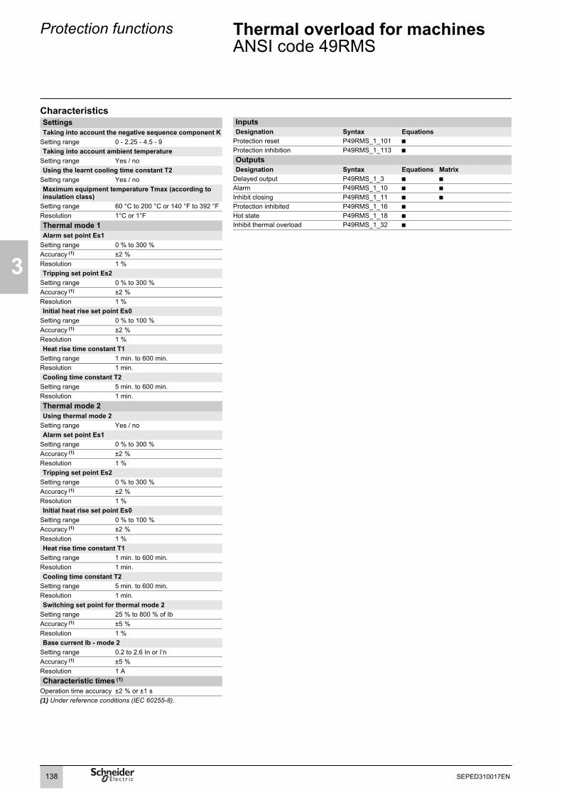
3
Protection functions
Thermal overload for machinesANSI code 49RMS
CharacteristicsSettingsTaking into account the negative sequence component K
Setting range 0 - 2.25 - 4.5 - 9Taking into account ambient temperature
Setting range Yes / noUsing the learnt cooling time constant T2
Setting range Yes / noMaximum equipment temperature Tmax (according to insulation class)
Setting range 60 °C to 200 °C or 140 °F to 392 °FResolution 1°C or 1°FThermal mode 1Alarm set point Es1
Setting range 0 % to 300 %Accuracy (1) ±2 %Resolution 1 %Tripping set point Es2
Setting range 0 % to 300 %Accuracy (1) ±2 %Resolution 1 %Initial heat rise set point Es0
Setting range 0 % to 100 %Accuracy (1) ±2 %Resolution 1 %Heat rise time constant T1
Setting range 1 min. to 600 min.Resolution 1 min.Cooling time constant T2
Setting range 5 min. to 600 min.Resolution 1 min.Thermal mode 2Using thermal mode 2
Setting range Yes / noAlarm set point Es1
Setting range 0 % to 300 %Accuracy (1) ±2 %Resolution 1 %Tripping set point Es2
Setting range 0 % to 300 %Accuracy (1) ±2 %Resolution 1 %Initial heat rise set point Es0
Setting range 0 % to 100 %Accuracy (1) ±2 %Resolution 1 %Heat rise time constant T1
Setting range 1 min. to 600 min.Resolution 1 min.Cooling time constant T2
Setting range 5 min. to 600 min.Resolution 1 min.Switching set point for thermal mode 2
Setting range 25 % to 800 % of IbAccuracy (1) ±5 %Resolution 1 %Base current Ib - mode 2
Setting range 0.2 to 2.6 In or I’nAccuracy (1) ±5 %Resolution 1 ACharacteristic times (1)
Operation time accuracy ±2 % or ±1 s(1) Under reference conditions (IEC 60255-8).
Inputs Designation Syntax Equations
Protection reset P49RMS_1_101 bProtection inhibition P49RMS_1_113 b
Outputs Designation Syntax Equations Matrix
Delayed output P49RMS_1_3 b bAlarm P49RMS_1_10 b bInhibit closing P49RMS_1_11 b bProtection inhibited P49RMS_1_16 bHot state P49RMS_1_18 bInhibit thermal overload P49RMS_1_32 b
138 SEPED310017EN

Protection functions Thermal overload for machinesANSI code 49RMSSetting examples
3
Example 1: motorThe following data are available:b time constants for on operation T1 and off operation T2:v T1 = 25 min.v T2 = 70 min.b maximum steady state current:Imax/Ib = 1.05.Setting of tripping set point Es2Es2 = (Imax/Ib)2 = 110 %Note. If the motor draws a current of 1.05 Ib continuously, the heat rise calculated by the thermal overload protection will reach 110 %.Setting of alarm set point Es1Es1 = 90 % (I/Ib = 0.95).Knegative: 4.5 (usual value)The other thermal overload parameters do not need to be set. They are not taken into account by default.
Example 2: motorThe following data are available:b motor thermal withstand in the form of hot and cold curves (see solid line curves in Figure 1)b cooling time constant T2b maximum steady state current:Imax/Ib = 1.05.Setting of tripping set point Es2Es2 = (Imax/Ib)2 = 110 %Setting of alarm set point Es1:Es1 = 90 % (I/Ib = 0.95).The manufacturer's hot/cold curves (1) may be used to determine the heating time constant T1.The method consists of placing the Sepam hot/cold curves below those of the motor.
For an overload of 2Ib, the value t/T1 = 0.0339 (2).In order for Sepam to trip at point 1 (t = 70 s), T1 is equal to 2065 sec ≈ 34 min.With a setting of T1 = 34 min., the tripping time is obtained based on a cold state (point 2). In this case, it is equal to t/T1 = 0.3216 ⇒ t = 665 sec, i.e. ≈ 11 min., which is compatible with the motor thermal withstand when it is cold.The negative sequence factor K is calculated using the equation defined on page 136.The parameters of the 2nd thermal overload relay do not need to be set. They are not taken into account by default.
Example 3: motorThe following data are available:b motor thermal withstand in the form of hot and cold curves (see solid line curves in Figure 2)b cooling time constant T2b maximum steady state current: Imax/Ib = 1.1.The thermal overload parameters are determined in the same way as in the previous example.Setting of tripping set point Es2Es2 = (Imax/Ib)2 = 120 %Setting of alarm set point Es1Es1 = 90 % (I/Ib = 0.95).The time constant T1 is calculated so that the thermal overload protection trips after 100 seconds (point 1).With t/T1 = 0.069 (I/Ib = 2 and Es2 = 120 %):⇒ T1 = 100 sec / 0.069 = 1449 sec ≈ 24 min.The tripping time starting from the cold state is equal to:t/T1 = 0.3567 ⇒ t = 24 min. x 0.3567 = 513 sec (point 2’).This tripping time is too long since the limit for this overload current is 400 sec (point 2).If the time constant T1 is lowered, the thermal overload protection will trip earlier, below point 2.The risk that motor starting when hot will not be possible also exists in this case (see Figure 2 in which a lower Sepam hot curve would intersect the starting curve with U = 0.9 Un).The Es0 parameter is a setting that is used to solve these differences by lowering the Sepam cold curve without moving the hot curve. In this example, the thermal overload protection should trip after 400 sec starting from the cold state.The following equation is used to obtain the Es0 value:
Figure 1. Motor thermal withstand and thermal overload tripping curves.
MT1
0860
where:t necessary : tripping time necessary starting from a cold state.I processed : equipment current.
(1) When the machine manufacturer provides both a time constant T1 and the machine hot/cold curves, the use of the curves is recommended since they are more accurate.(2) It is possible to use the charts containing the numerical values of the Sepam hot curve or the equation of the curve which is given on page 135.
Es0 lprocessed
lb----------------------
2
e
tnecessaryT1
----------------------–= lprocessed
lb----------------------
2
Es2–×665
70
1.05 2
motor cold curve
Sepam cold curve
motor hot curve
Sepam hot curve
time
befo
re tr
ippi
ng/s
I/Ib
2
1
139SEPED310017EN

3
Protection functions Thermal overload for machinesANSI code 49RMSSetting examples
In numerical values, the following is obtained:
By setting Es0 = 31 %, point 2’ is moved downward to obtain a shorter tripping time that is compatible with the motor thermal withstand when cold (see Figure 3).Note. A setting Es0 = 100 % therefore means that the hot and cold curves are the same.
Use of the additional setting groupWhen a motor rotor is locked or is turning very slowly, its thermal behavior is different from that with the rated load.In such conditions, the motor is damaged by overheating of the rotor or stator. For high power motors, rotor overheating is most often a limiting factor.The thermal overload parameters chosen for operation with a low overload are no longer valid.In order to protect the motor in this case, "excessive starting time" protection may be used.Nevertheless, motor manufacturers provide the thermal withstand curves when the rotor is locked, for different voltages at the time of starting.
Figure 2. Hot/cold curves not compatible with the motor thermal withstand.
Figure 4. Locked rotor thermal withstand.
MT1
0861
MT1
0863
Figure 3. Hot/cold curves compatible with the motor thermal withstand via the setting of an initial heat rise Es0.
thermal withstand, motor running
thermal withstand, motor stopped
Sepam tripping curve
starting at 65 % Un
starting at 80 % Un
starting at 100 % Un
MT1
0862
In order to take these curves into account, the 2nd thermal overload relay may be used.The time constant in this case is, in theory, shorter, however, it should be determined in the same way as that of the 1st relay.The thermal overload protection switches between the first and second relay if the equivalent current Ieq exceeds the Is value (set point current).
Example 4. transformer with 2 ventilation modesThe following data are available:The rated current of a transformer with 2 ventilation modes is:b Ib = 200 A without forced ventilation (ONAN mode), the main operating mode of the transformerb Ib = 240 A with forced ventilation (ONAF mode), a temporary operating mode, to have 20 % more power available
Setting of the base current for ventilation operating mode 1: Ib = 200 A(to be set in the Sepam general parameters).Setting of the base current for ventilation operating mode 2: Ib2 = 240 A(to be set among the specific thermal overload protection settings).Switching of thermal settings via logic input, to be assigned to the "switching of thermal settings" function and to be connected to the transformer ventilation control unit.The settings related to each ventilation operating mode (Es set points, time constants, etc.) are to be determined according to the transformer characteristics provided by the manufacturer.
Es0 4 e 400 s24 60 s×------------------------
–= 4 1.2( )–× 0.3035 31 %( )≈=
400
100
1.05 2
motor cold curve
Sepam cold curve
motor hot curve
Sepam hot curve
time
befo
re tr
ippi
ng/s
I/Ib
2
2’513
starting at Un
starting at 0.9 Un
1
1.1 2
locked rotortim
es /
s
I/Ib
1
Is
motor running
32
4 5 6
1
2
3
4
5
6
400
100
1.1 2
motor cold curve
adjusted Sepamcold curve
motor hot curve
Sepam hot curve
time
befo
re tr
ippi
ng/s
I/Ib
2
starting at Un
starting at 0.9 Un
1
140 SEPED310017EN

Protection functions Thermal overload for machinesANSI code 49RMSTripping curves
3
Cold curves for Es0 = 0 %l/Ib 1.00 1.05 1.10 1.15 1.20 1.25 1.30 1.35 1.40 1.45 1.50 1.55 1.60 1.65 1.70 1.75 1.80Es (%)
50 0.6931 0.6042 0.5331 0.4749 0.4265 0.3857 0.3508 0.3207 0.2945 0.2716 0.2513 0.2333 0.2173 0.2029 0.1900 0.1782 0.167655 0.7985 0.6909 0.6061 0.5376 0.4812 0.4339 0.3937 0.3592 0.3294 0.3033 0.2803 0.2600 0.2419 0.2257 0.2111 0.1980 0.186060 0.9163 0.7857 0.6849 0.6046 0.5390 0.4845 0.4386 0.3993 0.3655 0.3360 0.3102 0.2873 0.2671 0.2490 0.2327 0.2181 0.204865 1.0498 0.8905 0.7704 0.6763 0.6004 0.5379 0.4855 0.4411 0.4029 0.3698 0.3409 0.3155 0.2929 0.2728 0.2548 0.2386 0.223970 1.2040 1.0076 0.8640 0.7535 0.6657 0.5942 0.5348 0.4847 0.4418 0.4049 0.3727 0.3444 0.3194 0.2972 0.2774 0.2595 0.243475 1.3863 1.1403 0.9671 0.8373 0.7357 0.6539 0.5866 0.5302 0.4823 0.4412 0.4055 0.3742 0.3467 0.3222 0.3005 0.2809 0.263380 1.6094 1.2933 1.0822 0.9287 0.8109 0.7174 0.6413 0.5780 0.5245 0.4788 0.4394 0.4049 0.3747 0.3479 0.3241 0.3028 0.283685 1.8971 1.4739 1.2123 1.0292 0.8923 0.7853 0.6991 0.6281 0.5686 0.5180 0.4745 0.4366 0.4035 0.3743 0.3483 0.3251 0.304390 2.3026 1.6946 1.3618 1.1411 0.9808 0.8580 0.7605 0.6809 0.6147 0.5587 0.5108 0.4694 0.4332 0.4013 0.3731 0.3480 0.325495 1.9782 1.5377 1.2670 1.0780 0.9365 0.8258 0.7366 0.6630 0.6012 0.5486 0.5032 0.4638 0.4292 0.3986 0.3714 0.3470100 2.3755 1.7513 1.4112 1.1856 1.0217 0.8958 0.7956 0.7138 0.6455 0.5878 0.5383 0.4953 0.4578 0.4247 0.3953 0.3691105 3.0445 2.0232 1.5796 1.3063 1.1147 0.9710 0.8583 0.7673 0.6920 0.6286 0.5746 0.5279 0.4872 0.4515 0.4199 0.3917110 2.3979 1.7824 1.4435 1.2174 1.0524 0.9252 0.8238 0.7406 0.6712 0.6122 0.5616 0.5176 0.4790 0.4450 0.4148115 3.0040 2.0369 1.6025 1.3318 1.1409 0.9970 0.8837 0.7918 0.7156 0.6514 0.5964 0.5489 0.5074 0.4708 0.4384120 2.3792 1.7918 1.4610 1.2381 1.0742 0.9474 0.8457 0.7621 0.6921 0.6325 0.5812 0.5365 0.4973 0.4626125 2.9037 2.0254 1.6094 1.3457 1.1580 1.0154 0.9027 0.8109 0.7346 0.6700 0.6146 0.5666 0.5245 0.4874130 2.3308 1.7838 1.4663 1.2493 1.0885 0.9632 0.8622 0.7789 0.7089 0.6491 0.5975 0.5525 0.5129135 2.7726 1.9951 1.6035 1.3499 1.1672 1.0275 0.9163 0.8253 0.7494 0.6849 0.6295 0.5813 0.5390140 2.2634 1.7626 1.4618 1.2528 1.0962 0.9734 0.8740 0.7916 0.7220 0.6625 0.6109 0.5658145 2.6311 1.9518 1.5877 1.3463 1.1701 1.0341 0.9252 0.8356 0.7606 0.6966 0.6414 0.5934150 3.2189 2.1855 1.7319 1.4495 1.2498 1.0986 0.9791 0.8817 0.8007 0.7320 0.6729 0.6217155 2.4908 1.9003 1.5645 1.3364 1.1676 1.0361 0.9301 0.8424 0.7686 0.7055 0.6508160 2.9327 2.1030 1.6946 1.4313 1.2417 1.0965 0.9808 0.8860 0.8066 0.7391 0.6809165 2.3576 1.8441 1.5361 1.3218 1.1609 1.0343 0.9316 0.8461 0.7739 0.7118170 2.6999 2.0200 1.6532 1.4088 1.2296 1.0908 0.9793 0.8873 0.8099 0.7438175 3.2244 2.2336 1.7858 1.5041 1.3035 1.1507 1.0294 0.9302 0.8473 0.7768180 2.5055 1.9388 1.6094 1.3832 1.2144 1.0822 0.9751 0.8861 0.8109185 2.8802 2.1195 1.7272 1.4698 1.2825 1.1379 1.0220 0.9265 0.8463190 3.4864 2.3401 1.8608 1.5647 1.3555 1.1970 1.0713 0.9687 0.8829195 2.6237 2.0149 1.6695 1.4343 1.2597 1.1231 1.0126 0.9209200 3.0210 2.1972 1.7866 1.5198 1.3266 1.1778 1.0586 0.9605
141SEPED310017EN

3
Protection functions Thermal overload for machinesANSI code 49RMSTripping curves
Cold curves for Es0 = 0 %I/Ib 1.85 1.90 1.95 2.00 2.20 2.40 2.60 2.80 3.00 3.20 3.40 3.60 3.80 4.00 4.20 4.40 4.60Es (%)
50 0.1579 0.1491 0.1410 0.1335 0.1090 0.0908 0.0768 0.0659 0.0572 0.0501 0.0442 0.0393 0.0352 0.0317 0.0288 0.0262 0.023955 0.1752 0.1653 0.1562 0.1479 0.1206 0.1004 0.0849 0.0727 0.0631 0.0552 0.0487 0.0434 0.0388 0.0350 0.0317 0.0288 0.026360 0.1927 0.1818 0.1717 0.1625 0.1324 0.1100 0.0929 0.0796 0.069 0.0604 0.0533 0.0474 0.0424 0.0382 0.0346 0.0315 0.028865 0.2106 0.1985 0.1875 0.1773 0.1442 0.1197 0.1011 0.0865 0.075 0.0656 0.0579 0.0515 0.0461 0.0415 0.0375 0.0342 0.031270 0.2288 0.2156 0.2035 0.1924 0.1562 0.1296 0.1093 0.0935 0.081 0.0708 0.0625 0.0555 0.0497 0.0447 0.0405 0.0368 0.033675 0.2474 0.2329 0.2197 0.2076 0.1684 0.1395 0.1176 0.1006 0.087 0.0761 0.0671 0.0596 0.0533 0.0480 0.0434 0.0395 0.036180 0.2662 0.2505 0.2362 0.2231 0.1807 0.1495 0.1260 0.1076 0.0931 0.0813 0.0717 0.0637 0.0570 0.0513 0.0464 0.0422 0.038585 0.2855 0.2685 0.2530 0.2389 0.1931 0.1597 0.1344 0.1148 0.0992 0.0867 0.0764 0.0678 0.0607 0.0546 0.0494 0.0449 0.041090 0.3051 0.2868 0.2701 0.2549 0.2057 0.1699 0.1429 0.1219 0.1054 0.092 0.0811 0.0720 0.0644 0.0579 0.0524 0.0476 0.043595 0.3251 0.3054 0.2875 0.2712 0.2185 0.1802 0.1514 0.1292 0.1116 0.0974 0.0858 0.0761 0.0681 0.0612 0.0554 0.0503 0.0459100 0.3456 0.3244 0.3051 0.2877 0.2314 0.1907 0.1601 0.1365 0.1178 0.1028 0.0905 0.0803 0.0718 0.0645 0.0584 0.0530 0.0484105 0.3664 0.3437 0.3231 0.3045 0.2445 0.2012 0.1688 0.1438 0.1241 0.1082 0.0952 0.0845 0.0755 0.0679 0.0614 0.0558 0.0509110 0.3877 0.3634 0.3415 0.3216 0.2578 0.2119 0.1776 0.1512 0.1304 0.1136 0.1000 0.0887 0.0792 0.0712 0.0644 0.0585 0.0534115 0.4095 0.3835 0.3602 0.3390 0.2713 0.2227 0.1865 0.1586 0.1367 0.1191 0.1048 0.0929 0.0830 0.0746 0.0674 0.0612 0.0559120 0.4317 0.4041 0.3792 0.3567 0.2849 0.2336 0.1954 0.1661 0.1431 0.1246 0.1096 0.0972 0.0868 0.0780 0.0705 0.0640 0.0584125 0.4545 0.4250 0.3986 0.3747 0.2988 0.2446 0.2045 0.1737 0.1495 0.1302 0.1144 0.1014 0.0905 0.0813 0.0735 0.0667 0.0609130 0.4778 0.4465 0.4184 0.3930 0.3128 0.2558 0.2136 0.1813 0.156 0.1358 0.1193 0.1057 0.0943 0.0847 0.0766 0.0695 0.0634135 0.5016 0.4683 0.4386 0.4117 0.3270 0.2671 0.2228 0.1890 0.1625 0.1414 0.1242 0.1100 0.0982 0.0881 0.0796 0.0723 0.0659140 0.5260 0.4907 0.4591 0.4308 0.3414 0.2785 0.2321 0.1967 0.1691 0.147 0.1291 0.1143 0.1020 0.0916 0.0827 0.0751 0.0685145 0.5511 0.5136 0.4802 0.4502 0.3561 0.2900 0.2414 0.2045 0.1757 0.1527 0.1340 0.1187 0.1058 0.0950 0.0858 0.0778 0.0710150 0.5767 0.5370 0.5017 0.4700 0.3709 0.3017 0.2509 0.2124 0.1823 0.1584 0.1390 0.1230 0.1097 0.0984 0.0889 0.0806 0.0735155 0.6031 0.5610 0.5236 0.4902 0.3860 0.3135 0.2604 0.2203 0.189 0.1641 0.1440 0.1274 0.1136 0.1019 0.0920 0.0834 0.0761160 0.6302 0.5856 0.5461 0.5108 0.4013 0.3254 0.2701 0.2283 0.1957 0.1699 0.1490 0.1318 0.1174 0.1054 0.0951 0.0863 0.0786165 0.6580 0.6108 0.5690 0.5319 0.4169 0.3375 0.2798 0.2363 0.2025 0.1757 0.1540 0.1362 0.1213 0.1088 0.0982 0.0891 0.0812170 0.6866 0.6366 0.5925 0.5534 0.4327 0.3498 0.2897 0.2444 0.2094 0.1815 0.1591 0.1406 0.1253 0.1123 0.1013 0.0919 0.0838175 0.7161 0.6631 0.6166 0.5754 0.4487 0.3621 0.2996 0.2526 0.2162 0.1874 0.1641 0.1451 0.1292 0.1158 0.1045 0.0947 0.0863180 0.7464 0.6904 0.6413 0.5978 0.4651 0.3747 0.3096 0.2608 0.2231 0.1933 0.1693 0.1495 0.1331 0.1193 0.1076 0.0976 0.0889185 0.7777 0.7184 0.6665 0.6208 0.4816 0.3874 0.3197 0.2691 0.2301 0.1993 0.1744 0.1540 0.1371 0.1229 0.1108 0.1004 0.0915190 0.8100 0.7472 0.6925 0.6444 0.4985 0.4003 0.3300 0.2775 0.2371 0.2052 0.1796 0.1585 0.1411 0.1264 0.1140 0.1033 0.0941195 0.8434 0.7769 0.7191 0.6685 0.5157 0.4133 0.3403 0.2860 0.2442 0.2113 0.1847 0.1631 0.1451 0.1300 0.1171 0.1062 0.0967200 0.8780 0.8075 0.7465 0.6931 0.5331 0.4265 0.3508 0.2945 0.2513 0.2173 0.1900 0.1676 0.1491 0.1335 0.1203 0.1090 0.0993
142 SEPED310017EN

Protection functions Thermal overload for machinesANSI code 49RMSTripping curves
3
Cold curves for Es0 = 0 %I/Ib 4.80 5.00 5.50 6.00 6.50 7.00 7.50 8.00 8.50 9.00 9.50 10.00 12.50 15.00 17.50 20.00Es (%)
50 0.0219 0.0202 0.0167 0.0140 0.0119 0.0103 0.0089 0.0078 0.0069 0.0062 0.0056 0.0050 0.0032 0.0022 0.0016 0.001355 0.0242 0.0222 0.0183 0.0154 0.0131 0.0113 0.0098 0.0086 0.0076 0.0068 0.0061 0.0055 0.0035 0.0024 0.0018 0.001460 0.0264 0.0243 0.0200 0.0168 0.0143 0.0123 0.0107 0.0094 0.0083 0.0074 0.0067 0.0060 0.0038 0.0027 0.0020 0.001565 0.0286 0.0263 0.0217 0.0182 0.0155 0.0134 0.0116 0.0102 0.0090 0.0081 0.0072 0.0065 0.0042 0.0029 0.0021 0.001670 0.0309 0.0284 0.0234 0.0196 0.0167 0.0144 0.0125 0.0110 0.0097 0.0087 0.0078 0.0070 0.0045 0.0031 0.0023 0.001875 0.0331 0.0305 0.0251 0.0211 0.0179 0.0154 0.0134 0.0118 0.0104 0.0093 0.0083 0.0075 0.0048 0.0033 0.0025 0.001980 0.0353 0.0325 0.0268 0.0225 0.0191 0.0165 0.0143 0.0126 0.0111 0.0099 0.0089 0.0080 0.0051 0.0036 0.0026 0.002085 0.0376 0.0346 0.0285 0.0239 0.0203 0.0175 0.0152 0.0134 0.0118 0.0105 0.0095 0.0085 0.0055 0.0038 0.0028 0.002190 0.0398 0.0367 0.0302 0.0253 0.0215 0.0185 0.0161 0.0142 0.0125 0.0112 0.0100 0.0090 0.0058 0.0040 0.0029 0.002395 0.0421 0.0387 0.0319 0.0267 0.0227 0.0196 0.0170 0.0150 0.0132 0.0118 0.0106 0.0095 0.0061 0.0042 0.0031 0.0024100 0.0444 0.0408 0.0336 0.0282 0.0240 0.0206 0.0179 0.0157 0.0139 0.0124 0.0111 0.0101 0.0064 0.0045 0.0033 0.0025105 0.0466 0.0429 0.0353 0.0296 0.0252 0.0217 0.0188 0.0165 0.0146 0.0130 0.0117 0.0106 0.0067 0.0047 0.0034 0.0026110 0.0489 0.0450 0.0370 0.0310 0.0264 0.0227 0.0197 0.0173 0.0153 0.0137 0.0123 0.0111 0.0071 0.0049 0.0036 0.0028115 0.0512 0.0471 0.0388 0.0325 0.0276 0.0237 0.0207 0.0181 0.0160 0.0143 0.0128 0.0116 0.0074 0.0051 0.0038 0.0029120 0.0535 0.0492 0.0405 0.0339 0.0288 0.0248 0.0216 0.0189 0.0167 0.0149 0.0134 0.0121 0.0077 0.0053 0.0039 0.0030125 0.0558 0.0513 0.0422 0.0353 0.0300 0.0258 0.0225 0.0197 0.0175 0.0156 0.0139 0.0126 0.0080 0.0056 0.0041 0.0031130 0.0581 0.0534 0.0439 0.0368 0.0313 0.0269 0.0234 0.0205 0.0182 0.0162 0.0145 0.0131 0.0084 0.0058 0.0043 0.0033135 0.0604 0.0555 0.0457 0.0382 0.0325 0.0279 0.0243 0.0213 0.0189 0.0168 0.0151 0.0136 0.0087 0.0060 0.0044 0.0034140 0.0627 0.0576 0.0474 0.0397 0.0337 0.0290 0.0252 0.0221 0.0196 0.0174 0.0156 0.0141 0.0090 0.0062 0.0046 0.0035145 0.0650 0.0598 0.0491 0.0411 0.0349 0.0300 0.0261 0.0229 0.0203 0.0181 0.0162 0.0146 0.0093 0.0065 0.0047 0.0036150 0.0673 0.0619 0.0509 0.0426 0.0361 0.0311 0.0270 0.0237 0.0210 0.0187 0.0168 0.0151 0.0096 0.0067 0.0049 0.0038155 0.0696 0.0640 0.0526 0.0440 0.0374 0.0321 0.0279 0.0245 0.0217 0.0193 0.0173 0.0156 0.0100 0.0069 0.0051 0.0039160 0.0720 0.0661 0.0543 0.0455 0.0386 0.0332 0.0289 0.0253 0.0224 0.0200 0.0179 0.0161 0.0103 0.0071 0.0052 0.0040165 0.0743 0.0683 0.0561 0.0469 0.0398 0.0343 0.0298 0.0261 0.0231 0.0206 0.0185 0.0166 0.0106 0.0074 0.0054 0.0041170 0.0766 0.0704 0.0578 0.0484 0.0411 0.0353 0.0307 0.0269 0.0238 0.0212 0.0190 0.0171 0.0109 0.0076 0.0056 0.0043175 0.0790 0.0726 0.0596 0.0498 0.0423 0.0364 0.0316 0.0277 0.0245 0.0218 0.0196 0.0177 0.0113 0.0078 0.0057 0.0044180 0.0813 0.0747 0.0613 0.0513 0.0435 0.0374 0.0325 0.0285 0.0252 0.0225 0.0201 0.0182 0.0116 0.0080 0.0059 0.0045185 0.0837 0.0769 0.0631 0.0528 0.0448 0.0385 0.0334 0.0293 0.0259 0.0231 0.0207 0.0187 0.0119 0.0083 0.0061 0.0046190 0.0861 0.0790 0.0649 0.0542 0.0460 0.0395 0.0344 0.0301 0.0266 0.0237 0.0213 0.0192 0.0122 0.0085 0.0062 0.0048195 0.0884 0.0812 0.0666 0.0557 0.0473 0.0406 0.0353 0.0309 0.0274 0.0244 0.0218 0.0197 0.0126 0.0087 0.0064 0.0049200 0.0908 0.0834 0.0684 0.0572 0.0485 0.0417 0.0362 0.0317 0.0281 0.0250 0.0224 0.0202 0.0129 0.0089 0.0066 0.0050
143SEPED310017EN

3
Protection functions Thermal overload for machinesANSI code 49RMSTripping curves
Hot curves I/Ib 1.00 1.05 1.10 1.15 1.20 1.25 1.30 1.35 1.40 1.45 1.50 1.55 1.60 1.65 1.70 1.75 1.80Es (%)
105 0.6690 0.2719 0.1685 0.1206 0.0931 0.0752 0.0627 0.0535 0.0464 0.0408 0.0363 0.0326 0.0295 0.0268 0.0245 0.0226110 3.7136 0.6466 0.3712 0.2578 0.1957 0.1566 0.1296 0.1100 0.0951 0.0834 0.0740 0.0662 0.0598 0.0544 0.0497 0.0457115 1.2528 0.6257 0.4169 0.3102 0.2451 0.2013 0.1699 0.1462 0.1278 0.1131 0.1011 0.0911 0.0827 0.0755 0.0693120 3.0445 0.9680 0.6061 0.4394 0.3423 0.2786 0.2336 0.2002 0.1744 0.1539 0.1372 0.1234 0.1118 0.1020 0.0935125 1.4925 0.8398 0.5878 0.4499 0.3623 0.3017 0.2572 0.2231 0.1963 0.1747 0.1568 0.1419 0.1292 0.1183130 2.6626 1.1451 0.7621 0.5705 0.4537 0.3747 0.3176 0.2744 0.2407 0.2136 0.1914 0.1728 0.1572 0.1438135 1.5870 0.9734 0.7077 0.5543 0.4535 0.3819 0.3285 0.2871 0.2541 0.2271 0.2048 0.1860 0.1699140 2.3979 1.2417 0.8668 0.6662 0.5390 0.4507 0.3857 0.3358 0.2963 0.2643 0.2378 0.2156 0.1967145 1.6094 1.0561 0.7921 0.6325 0.5245 0.4463 0.3869 0.3403 0.3028 0.2719 0.2461 0.2243150 2.1972 1.2897 0.9362 0.7357 0.6042 0.5108 0.4408 0.3864 0.3429 0.3073 0.2776 0.2526155 3.8067 1.5950 1.1047 0.8508 0.6909 0.5798 0.4978 0.4347 0.3846 0.3439 0.3102 0.2817160 2.0369 1.3074 0.9808 0.7857 0.6539 0.5583 0.4855 0.4282 0.3819 0.3438 0.3118165 2.8478 1.5620 1.1304 0.8905 0.7340 0.6226 0.5390 0.4738 0.4215 0.3786 0.3427170 1.9042 1.3063 1.0076 0.8210 0.6914 0.5955 0.5215 0.4626 0.4146 0.3747175 2.4288 1.5198 1.1403 0.9163 0.7652 0.6554 0.5717 0.5055 0.4520 0.4077180 3.5988 1.7918 1.2933 1.0217 0.8449 0.7191 0.6244 0.5504 0.4908 0.4418185 2.1665 1.4739 1.1394 0.9316 0.7872 0.6802 0.5974 0.5312 0.4772190 2.7726 1.6946 1.2730 1.0264 0.8602 0.7392 0.6466 0.5733 0.5138195 4.5643 1.9782 1.4271 1.1312 0.9390 0.8019 0.6985 0.6173 0.5518200 2.3755 1.6094 1.2483 1.0245 0.8688 0.7531 0.6633 0.5914
I/Ib 1.85 1.90 1.95 2.00 2.20 2.40 2.60 2.80 3.00 3.20 3.40 3.60 3.80 4.00 4.20 4.40 4.60Es (%)
105 0.0209 0.0193 0.0180 0.0168 0.0131 0.0106 0.0087 0.0073 0.0063 0.0054 0.0047 0.0042 0.0037 0.0033 0.0030 0.0027 0.0025110 0.0422 0.0391 0.0363 0.0339 0.0264 0.0212 0.0175 0.0147 0.0126 0.0109 0.0095 0.0084 0.0075 0.0067 0.0060 0.0055 0.0050115 0.0639 0.0592 0.0550 0.0513 0.0398 0.0320 0.0264 0.0222 0.0189 0.0164 0.0143 0.0126 0.0112 0.0101 0.0091 0.0082 0.0075120 0.0862 0.0797 0.0740 0.0690 0.0535 0.0429 0.0353 0.0297 0.0253 0.0219 0.0191 0.0169 0.0150 0.0134 0.0121 0.0110 0.0100125 0.1089 0.1007 0.0934 0.0870 0.0673 0.0540 0.0444 0.0372 0.0317 0.0274 0.0240 0.0211 0.0188 0.0168 0.0151 0.0137 0.0125130 0.1322 0.1221 0.1132 0.1054 0.0813 0.0651 0.0535 0.0449 0.0382 0.0330 0.0288 0.0254 0.0226 0.0202 0.0182 0.0165 0.0150135 0.1560 0.1440 0.1334 0.1241 0.0956 0.0764 0.0627 0.0525 0.0447 0.0386 0.0337 0.0297 0.0264 0.0236 0.0213 0.0192 0.0175140 0.1805 0.1664 0.1540 0.1431 0.1100 0.0878 0.0720 0.0603 0.0513 0.0443 0.0386 0.0340 0.0302 0.0270 0.0243 0.0220 0.0200145 0.2055 0.1892 0.1750 0.1625 0.1246 0.0993 0.0813 0.0681 0.0579 0.0499 0.0435 0.0384 0.0341 0.0305 0.0274 0.0248 0.0226150 0.2312 0.2127 0.1965 0.1823 0.1395 0.1110 0.0908 0.0759 0.0645 0.0556 0.0485 0.0427 0.0379 0.0339 0.0305 0.0276 0.0251155 0.2575 0.2366 0.2185 0.2025 0.1546 0.1228 0.1004 0.0838 0.0712 0.0614 0.0535 0.0471 0.0418 0.0374 0.0336 0.0304 0.0277160 0.2846 0.2612 0.2409 0.2231 0.1699 0.1347 0.1100 0.0918 0.0780 0.0671 0.0585 0.0515 0.0457 0.0408 0.0367 0.0332 0.0302165 0.3124 0.2864 0.2639 0.2442 0.1855 0.1468 0.1197 0.0999 0.0847 0.0729 0.0635 0.0559 0.0496 0.0443 0.0398 0.0360 0.0328170 0.3410 0.3122 0.2874 0.2657 0.2012 0.1591 0.1296 0.1080 0.0916 0.0788 0.0686 0.0603 0.0535 0.0478 0.0430 0.0389 0.0353175 0.3705 0.3388 0.3115 0.2877 0.2173 0.1715 0.1395 0.1161 0.0984 0.0847 0.0737 0.0648 0.0574 0.0513 0.0461 0.0417 0.0379180 0.4008 0.3660 0.3361 0.3102 0.2336 0.1840 0.1495 0.1244 0.1054 0.0906 0.0788 0.0692 0.0614 0.0548 0.0493 0.0446 0.0405185 0.4321 0.3940 0.3614 0.3331 0.2502 0.1967 0.1597 0.1327 0.1123 0.0965 0.0839 0.0737 0.0653 0.0583 0.0524 0.0474 0.0431190 0.4644 0.4229 0.3873 0.3567 0.2671 0.2096 0.1699 0.1411 0.1193 0.1025 0.0891 0.0782 0.0693 0.0619 0.0556 0.0503 0.0457195 0.4978 0.4525 0.4140 0.3808 0.2842 0.2226 0.1802 0.1495 0.1264 0.1085 0.0943 0.0828 0.0733 0.0654 0.0588 0.0531 0.0483200 0.5324 0.4831 0.4413 0.4055 0.3017 0.2358 0.1907 0.1581 0.1335 0.1145 0.0995 0.0873 0.0773 0.0690 0.0620 0.0560 0.0509
144 SEPED310017EN

Protection functions Thermal overload for machinesANSI code 49RMSTripping curves
3
Hot curves I/Ib 4.80 5.00 5.50 6.00 6.50 7.00 7.50 8.00 8.50 9.00 9.50 10.00 12.50 15.00 17.50 20.00Es (%)
105 0.0023 0.0021 0.0017 0.0014 0.0012 0.0010 0.0009 0.0008 0.0007 0.0006 0.0006 0.0005 0.0003 0.0002 0.0002 0.0001110 0.0045 0.0042 0.0034 0.0029 0.0024 0.0021 0.0018 0.0016 0.0014 0.0013 0.0011 0.0010 0.0006 0.0004 0.0003 0.0003115 0.0068 0.0063 0.0051 0.0043 0.0036 0.0031 0.0027 0.0024 0.0021 0.0019 0.0017 0.0015 0.0010 0.0007 0.0005 0.0004120 0.0091 0.0084 0.0069 0.0057 0.0049 0.0042 0.0036 0.0032 0.0028 0.0025 0.0022 0.0020 0.0013 0.0009 0.0007 0.0005125 0.0114 0.0105 0.0086 0.0072 0.0061 0.0052 0.0045 0.0040 0.0035 0.0031 0.0028 0.0025 0.0016 0.0011 0.0008 0.0006130 0.0137 0.0126 0.0103 0.0086 0.0073 0.0063 0.0054 0.0048 0.0042 0.0038 0.0034 0.0030 0.0019 0.0013 0.0010 0.0008135 0.0160 0.0147 0.0120 0.0101 0.0085 0.0073 0.0064 0.0056 0.0049 0.0044 0.0039 0.0035 0.0023 0.0016 0.0011 0.0009140 0.0183 0.0168 0.0138 0.0115 0.0097 0.0084 0.0073 0.0064 0.0056 0.0050 0.0045 0.0040 0.0026 0.0018 0.0013 0.0010145 0.0206 0.0189 0.0155 0.0129 0.0110 0.0094 0.0082 0.0072 0.0063 0.0056 0.0051 0.0046 0.0029 0.0020 0.0015 0.0011150 0.0229 0.0211 0.0172 0.0144 0.0122 0.0105 0.0091 0.0080 0.0070 0.0063 0.0056 0.0051 0.0032 0.0022 0.0016 0.0013155 0.0253 0.0232 0.0190 0.0158 0.0134 0.0115 0.0100 0.0088 0.0077 0.0069 0.0062 0.0056 0.0035 0.0025 0.0018 0.0014160 0.0276 0.0253 0.0207 0.0173 0.0147 0.0126 0.0109 0.0096 0.0085 0.0075 0.0067 0.0061 0.0039 0.0027 0.0020 0.0015165 0.0299 0.0275 0.0225 0.0187 0.0159 0.0136 0.0118 0.0104 0.0092 0.0082 0.0073 0.0066 0.0042 0.0029 0.0021 0.0016170 0.0323 0.0296 0.0242 0.0202 0.0171 0.0147 0.0128 0.0112 0.0099 0.0088 0.0079 0.0071 0.0045 0.0031 0.0023 0.0018175 0.0346 0.0317 0.0260 0.0217 0.0183 0.0157 0.0137 0.0120 0.0106 0.0094 0.0084 0.0076 0.0048 0.0034 0.0025 0.0019180 0.0370 0.0339 0.0277 0.0231 0.0196 0.0168 0.0146 0.0128 0.0113 0.0101 0.0090 0.0081 0.0052 0.0036 0.0026 0.0020185 0.0393 0.0361 0.0295 0.0246 0.0208 0.0179 0.0155 0.0136 0.0120 0.0107 0.0096 0.0086 0.0055 0.0038 0.0028 0.0021190 0.0417 0.0382 0.0313 0.0261 0.0221 0.0189 0.0164 0.0144 0.0127 0.0113 0.0101 0.0091 0.0058 0.0040 0.0030 0.0023195 0.0441 0.0404 0.0330 0.0275 0.0233 0.0200 0.0173 0.0152 0.0134 0.0119 0.0107 0.0096 0.0061 0.0043 0.0031 0.0024200 0.0464 0.0426 0.0348 0.0290 0.0245 0.0211 0.0183 0.0160 0.0141 0.0126 0.0113 0.0102 0.0065 0.0045 0.0033 0.0025
145SEPED310017EN

3
Protection functions Breaker failureANSI code 50BF
Backup protection if the circuit breaker does not trip.
DescriptionIf a breaker fails to open following a tripping order (detected by the non-extinction of the fault current), this backup protection sends a tripping order to the upstream or adjacent breakers.The "breaker failure" protection function is activated by an O1 output tripping order received from the overcurrent protection functions which trip the circuit breaker (50/51, 50N/51N, 46, 67N, 67, 64REF). It checks for the disappearance of current during the time interval specified by the time delay T. It may also take into account the position of the circuit breaker, read on the logic inputs to determine the actual opening of the breaker. Wiring a volt-free closed circuit breaker position contact on the "breaker closed" equation editor input can ensure that the protection is effective in the following situations:b When 50BF is activated by protection function 50N/51N (set point Is0 < 0.2 In), detection of the 50BF current set point can possibly not be operational.b When trip circuit supervision (TCS) is used, the closed circuit breaker contact is short-circuited. Logic input I101 is therefore no longer operational.Automatic activation of this protection function requires the use of the circuit breaker control function in the control logic. A specific input may also be used to activate the protection by logic equation. That option is useful for adding special cases of activation (e.g. tripping by an external protection unit).The time-delayed output of the protection function should be assigned to a logic output via the control matrix.Starting and stopping of the time delay T counter are conditioned by the presence of a current above the set point (I > Is).
Block diagram
DE
8012
75
activation by 50/51,50N/51N, 46, 67N, 67,64REF
"breaker closed" logic input
"breaker closed" logic equation or Logipam
delayedoutput
pick-upsignal
activation by logic equation or by Logipam
Setting: Not accounting for the circuit breaker position
Accounting for the circuit breaker position
146 SEPED310017EN

Protection functions Breaker failureANSI code 50BF
3
CharacteristicsSettingsIs set point
Setting range 0.2 In to 2 InAccuracy (1) ±5 %Resolution 0.1 ADrop out/pick up ratio 87.5 % ±2 %Time delay T
Setting range 50 ms to 3 sAccuracy (1) ±2 % or -10 ms to +15 msResolution 10 ms or 1 digitTaking into account circuit breaker position
Setting range With / withoutCharacteristic times
Overshoot time < 35 ms at 2 IsInputs Designation Syntax Equations
Protection reset P50BF_1_101 bStart 50BF P50BF_1_107 bProtection inhibition P50BF_1_113 bBreaker closed P50BF_1_119 b
Outputs Designation Syntax Equations Matrix
Instantaneous output (pick-up) P50BF_1_1 bDelayed output P50BF_1_3 b bProtection inhibited P50BF_1_16 b(1) Under reference conditions (IEC 60255-6).
Example of settingBelow is a case that may be used to determine the time-delay setting of the breaker failure function: b overcurrent protection setting: T = instb circuit breaker operating time: 60 msb auxiliary relay operating time to open the upstream breaker(s): 10 ms.
DE
5224
9
The breaker failure function time delay is the sum of the following times:b Sepam O1 output relay pick-up time = 10 msb circuit breaker opening time = 60 msb Breaker failure function overshoot time = 35 ms.To avoid unwanted tripping of the upstream breakers, add a margin of approximately 20 ms.The time delay is 125 ms minimum, set at 130 ms.
147SEPED310017EN

3
Protection functions Phase overcurrentANSI code 50/51
Protection against overcurrents and overloads.
OperationProtection against overcurrents or overloads:b It is three-phase and includes a time delay, which is either definite or IDMT.b Each of the 8 relays has 2 groups of settings. The setting group A or B can be switched by a logic input or a remote control order depending on the parameter setting.b For better detection of faraway faults, protection can be confirmed by unit 1 of one of the following protections:v undervoltagev negative sequence overvoltage.b The custom curve, defined point by point, can be used with this protection.b An adjustable timer hold delay, either definite or IDMT, allows coordination with electromechanical relays and detection of reboot faults.b The protection incorporates a harmonic 2 restraint which can be used to set the protection Is set point close to the rated current of the device to be protected, for example to avoid transformer inrush currents.This harmonic 2 restraint, which can be selected by parameter setting, is active as long as the current is less than half the minimum short-circuit current of the network downstream of the device to be protected.
Tripping curve Timer holdDefinite time (DT) Definite timeStandard inverse time (SIT) Definite timeVery inverse time (VIT or LTI) Definite timeExtremely inverse time (EIT) Definite timeUltra inverse time (UIT) Definite timeRI curve Definite timeIEC inverse time SIT / A Definite time or IDMTIEC very inverse time VIT or LTI / B Definite time or IDMTIEC extremely inverse time EIT / C Definite time or IDMTIEEE moderately inverse (IEC / D) Definite time or IDMTIEEE very inverse (IEC / E) Definite time or IDMTIEEE extremely inverse (IEC / F) Definite time or IDMTIAC inverse Definite time or IDMTIAC very inverse Definite time or IDMTIAC extremely inverse Definite time or IDMTCustomized Definite time
Block diagram
DE
8127
0
I > Is I1 I2 I3
&
&
&
T 0
Pick-up output and to logic discrimination
Delayed output
Confirmation (optional)
I<Isc min /2
H2 restraint
148 SEPED310017EN

Protection functions Phase overcurrentANSI code 50/51
3
CharacteristicsSettingsTripping curve
Setting range See previous pageIs set point
Setting range Definite time 0.05 In y Is y 24 In expressed in amperes
IDMT 0.05 In y Is y 2.4 In expressed in amperes
Accuracy (1) ±5 % or ±0.01 InResolution 1 A or 1 digitDrop out/pick up ratio 93.5 % ±5 % or > (1 - 0.015 In/Is) x 100 %Time delay T (operation time at 10 Is)
Setting range Definite time Inst, 50 ms y T y 300 sIDMT 100 ms y T y 12.5 s or TMS (2)
Accuracy (1) Definite time ±2 % or from -10 ms to +25 msIDMT Class 5 or from -10 ms to +25 ms
Resolution 10 ms or 1 digitAdvanced settingsConfirmation
Setting range By undervoltage (unit 1)By negative sequence overvoltage (unit 1)None, no confirmation
Timer hold T1Setting range Definite time 0; 0.05 to 300 s
IDMT (3) 0.5 to 20 sResolution 10 ms or 1 digitHarmonic 2 restraint
Setting range 5 to 50 %Resolution 1 %Minimum short-circuit current Isc
Setting range In to 999 kAResolution de 1 to 9.99
de 10 to 99.9 de 100 to 999Minimum interval
0.010.110.1A
Characteristic timesOperation time pick-up < 40 ms at 2 Is (typically 25 ms)
confirmed instantaneous:b inst. < 55 ms at 2 Is for Is u 0.3 In (typically 35 ms)b inst. < 70 ms at 2 Is for Is < 0.3 In (typically 50 ms)
Overshoot time < 50 ms at 2 IsReset time < 50 ms at 2 Is (for T1 = 0)InputsDesignation Syntax Equations
Protection reset P50/51_x_101 bProtection inhibition P50/51_x_113 b
OutputsDesignation Syntax Equations Matrix
Instantaneous output (pick-up) P50/51_x_1 bDelayed output P50/51_x_3 b bDrop out P50/51_x_4 bPhase 1 fault P50/51_x_7 bPhase 2 fault P50/51_x_8 bPhase 3 fault P50/51_x_9 bProtection inhibited P50/51_x_16 bx: unit number.(1) Under reference conditions (IEC 60255-6).(2) Setting ranges in TMS (Time Multiplier Setting) modeb Inverse (SIT) and IEC SIT/A: 0.04 to 4.20 b Very inverse (VIT) and IEC VIT/B: 0.07 to 8.33 b Very inverse (LTI) and IEC LTI/B: 0.01 to 0.93 b Ext. inverse (EIT) and IEC EIT/C: 0.13 to 15.47 b IEEE moderately inverse: 0.42 to 51.86 b IEEE very inverse: 0.73 to 90.57 b IEEE extremely inverse: 1.24 to 154.32 b IAC inverse: 0.34 to 42.08 b IAC very inverse: 0.61 to 75.75 b IAC extremely inverse: 1.08 to 134.4. (3) Only for standardized tripping curves of the IEC, IEEE and IAC types.
149SEPED310017EN

3
Protection functions Earth faultANSI code 50N/51N or 50G/51G
Protection against earth faults. DescriptionEarth fault protection based on measured neutral, zero sequence or earth fault (tank earth leakage protection) current:b the protection function has a definite or IDMT time delay.b each of the eight units has two groups of settings. Switching to setting group A or B can be carried out by a logic input or a remote control order, depending on the settings.b The protection function includes a harmonic 2 restraint which can be set to provide greater saturation stability of the CT phases when transformers are energized.When the residual current measurement is done by adding up to 3 TC phases or by an intermediate TC located in the common point of the 3 TC phases, the harmonic 2 restraint must be active with:v Iso > 10 % of In TC, if the protection is time-dependant (DT),v Iso > 5 % of IN TC, if the protection is IDMT.b the customized curve, defined point by point, can be used with this protection function.b an adjustable timer hold, definite or IDMT, can be used for coordination with electromagnetic relays and to detect restriking faults.b each unit can be independently set to one of the two measurement channels I0 or I'0 or to the sum of the phase currents on the main or additional channels. By mixing the possibilities on the different units, it is possible to have:v different dynamic set pointsv different applications, e.g. zero sequence and tank earth leakage protection.
Tripping curve Timer hold curveDefinite time (DT) Definite timeStandard inverse time (SIT) Definite timeVery inverse time (VIT or LTI) Definite timeExtremely inverse time (EIT) Definite timeUltra inverse time (UIT) Definite timeRI curve Definite timeIEC inverse time SIT / A Definite time or IDMTIEC very inverse time VIT or LTI / B Definite time or IDMTIEC extremely inverse time EIT / C Definite time or IDMTIEEE moderately inverse (IEC / D) Definite time or IDMTIEEE very inverse (IEC / E) Definite time or IDMTIEEE extremely inverse (IEC / F) Definite time or IDMTIAC inverse Definite time or IDMTIAC very inverse Definite time or IDMTIAC extremely inverse Definite time or IDMTEPATR-B Definite timeEPATR-C Definite timeCustomized Definite time
Block diagram
DE
8127
1
I0 > 15 A 15 A set point output (EPATR curves only)
Input I0pick-up signaland to logic discrimination
delayed output
150 SEPED310017EN

Protection functions Earth faultANSI code 50N/51N or 50G/51G
3
CharacteristicsSettingsMeasurement origin
Setting range I0I0Σ
Tripping curveSetting range See previous pageIs0 setting
Definite timesetting range
0.01 In0 y Is0 y 15 In0 (min. 0.1 A) expressed in amperesSum of CTs 0.01 In y Is0 y 15 In (min. 0.1 A)With CSH sensor2 A rating20 A rating
0.1 to 30 A0.2 to 300 A
CT 0.01 In0 y Is0 y 15 In0 (min. 0.1 A)Core balance CT+ ACE990
0.01 In0 y Is0 y 15 In0 (min. 0.1 A)
IDMTsetting range
0.01 In0 y Is0 y In0 (min. 0.1 A) expressed in amperesSum of CTs 0.01 In y Is0 y In (min. 0.1 A)With CSH sensor2 A rating20 A rating
0.1 to 2 A0.2 to 20 A
CT 0.01 In0 y Is0 y In0 (min. 0.1 A)Core balance CT+ ACE990
0.01 In0 y Is0 y In0 (min. 0.1 A)
EPATRSetting range
CSH sensor20 A rating
0.6 to 5 A
Core balance CTwith ACE990and 15 A y In0 y 50 A
0.6 to 5 A
Accuracy (1) ±5 % or ±0.004 In0Resolution 1 A or 1 digitDrop out/pick up ratio 93.5 % ±5 % or > (1 - 0.005 In0/Is0) x 100 %Time delay T (operation time at 10 Is0)
Setting range Definite time Inst, 50 ms y T y 300 sIDMT 100 ms y T y 12.5 s or TMS (2)
EPATR-B 0.5 to 1 sEPATR-C 0.1 to 3 s
Accuracy (1) Definite time ±2 % or from -10 ms to +25 msIDMT Class 5 or from -10 ms to +25 ms
Resolution 10 ms or 1 digitAdvanced settingsHarmonic 2 restraint
Fixed threshold 17 % ±3 %Timer hold T1
Setting range Definite time 0; 0.05 to 300 sIDMT (3) 0.5 to 20 s
Resolution 10 ms or 1 digitOvershoot time < 40 ms at 2 Is0 Reset time < 50 ms at 2 Is0 (for T1 = 0)Characteristic times
Operation time Pick-up < 40 ms at 2 Is0 (typically 25 ms)Confirmed instantaneous:b inst < 55 ms at 2 Is0 for Is u 0.3 In0 (typically 35 ms)b inst < 70 ms at 2 Is0 for Is < 0.3 In0 (typically 50 ms)
Overshoot time < 40 ms at 2 Is0 Reset time < 50 ms at 2 Is0 (for T1 = 0)
x: unit number.(1) Under reference conditions (IEC 60255-6).(2) Setting ranges in TMS (Time Multiplier Setting) modeb Inverse (SIT) and IEC SIT/A: 0.04 to 4.20 b Very inverse (VIT) and IEC VIT/B: 0.07 to 8.33 b Very inverse (LTI) and IEC LTI/B: 0.01 to 0.93 b Ext. inverse (EIT) and IEC EIT/C: 0.13 to 15.47 b IEEE moderately inverse: 0.42 to 51.86 b IEEE very inverse: 0.73 to 90.57 b IEEE extremely inverse: 1.24 to 154.32 b IAC inverse: 0.34 to 42.08 b IAC very inverse: 0.61 to 75.75 b IAC extremely inverse: 1.08 to 134.4.
InputsDesignation Syntax Equations
Protection reset P50N/51N_x_101 bProtection inhibition P50N/51N_x_113 b
OutputsDesignation Syntax Equations Matrix
Instantaneous output (pick-up) P50N/51N_x_1 bDelayed output P50N/51N_x_3 b bDrop out P50N/51N_x_4 bProtection inhibited P50N/51N_x_16 b15 A set point output P50N/51N_x_56 b
(3) Only for standardized tripping curves of the IEC, IEEE and IAC types.
151SEPED310017EN

3
Protection functions Earth faultANSI code 50N/51N or 50G/51G
EPATR-B curves
DE
8021
3
EPATR-B tripping curves are defined from the following equations:
b for Is0 y I0 y 6.4 A
b for 6.4 A y I0 y 200 A
b for I0 > 200 A
EPATR-B standard curve (log scales) Curve : Is0 = 5 A and T = 1 sCurve : Is0 = 0.6 A and T = 0.5 sCurve : Is0 and T
EPATR-C curves
DE
8007
1
EPATR-C tripping curves are defined from the following equations:
b for Is0 y I0 y 200 A
b for I0 > 200 A
EPATR-C standard curve (log scales)
Curve : Is0 = 5 A and T = 3 sCurve : Is0 = 0.6 A and T = 0.1 sCurve : Is0 and T
t 85,386I00, 708( )---------------- T
0,8--------×=
t 140,213I00,975--------------------- T
0,8--------×=
t T=
1
2
3
0,6 Is0 5
T
3
0,10,1 200
1
23
t
I0
t 72I02 3/----------- T
2,10-----------×=
t T=
1
2
3
152 SEPED310017EN

Protection functions Voltage-restrained overcurrentANSI code 50V/51V
3
Generator protection against close short-circuits.
DescriptionThe voltage-restrained overcurrent protection function is used to protect generators. The operation set point is adjusted according to the voltage to take into account cases of faults close to the generator which cause voltage dips and short-circuit current:b the protection function is three-phase and has a definite or IDMT time delayb the customized curve, defined point by point, may be used with this protection functionb an adjustable timer hold, definite time or IDMT, can be used for coordination with electromagnetic relays and to detect restriking faultsb the set point is adjusted according to the lowest of the phase-to-phase voltages measured. The adjusted set point I*s is defined by the following equation:
I*s =
DE
5074
6
Tripping curve Timer holdDefinite time (DT) Definite timeStandard inverse time (SIT) Definite timeVery inverse time (VIT or LTI) Definite timeExtremely inverse time (EIT) Definite timeUltra inverse time (UIT) Definite time
Set point adjustment. RI curve Definite timeIEC inverse time SIT / A Definite time or IDMTIEC very inverse time VIT or LTI / B Definite time or IDMTIEC extremely inverse time EIT / C Definite time or IDMTIEEE moderately inverse (IEC / D) Definite time or IDMTIEEE very inverse (IEC / E) Definite time or IDMTIEEE extremely inverse (IEC / F) Definite time or IDMTIAC inverse Definite time or IDMTIAC very inverse Definite time or IDMTIAC extremely inverse Definite time or IDMTCustomized Definite time
Block diagram
DE
8127
2
Is3----- 4 U
Un-------- 0.2–⎝ ⎠
⎛ ⎞×
153SEPED310017EN

3
Protection functions Voltage-restrained overcurrentANSI code 50V/51V
CharacteristicsSettingsTripping curve
Setting range See previous pageIs set point
Setting range Definite time 0.5 In y Is y 24 In expressed in amperesIDMT 0.5 In y Is y 2.4 In expressed in amperes
Accuracy (1) ±5 %Resolution 1 A or 1 digitDrop out/pick up ratio 93.5 % (with min. reset variance of 0.015 In)Time delay T (operation time at 10 Is)
Setting range Definite time Inst, 50 ms y T y 300 sIDMT 100 ms y T y 12.5 s or TMS (2)
Accuracy (1) Definite time ±2 % or from -10 ms to +25 msIDMT Class 5 or from -10 ms to +25 ms
Resolution 10 ms or 1 digitAdvanced settingsTimer hold T1
Setting range Definite time 0; 0.05 to 300 sIDMT time (3) 0.5 to 20 s
Resolution 10 ms or 1 digitCharacteristic times
Operation time pick-up < 35 ms at 2 Is (typically 25 ms)Inst. < 50 ms at 2 Is (confirmed instantaneous) (typically 35 ms)
Overshoot time < 50 msReset time < 50 ms (for T1 = 0)InputsDesignation Syntax Equations
Protection reset P50V/51V_x_101 b bProtection inhibition P50V/51V_x_113 b b
OutputsDesignation Syntax Equations Matrix
Instantaneous output (pick-up) P50V/51V_x_1 bDelayed output P50V/51V_x_3 b bDrop out P50V/51V_x_4 bPhase 1 fault P50V/51V_x_7 bPhase 2 fault P50V/51V_x_8 bPhase 3 fault P50V/51V_x_9 bProtection inhibited P50V/51V_x_16 bx: unit number.(1) Under reference conditions (IEC 60255-6).(2) Setting ranges in TMS (Time Multiplier Setting) modeb Inverse (SIT) and IEC SIT/A: 0.04 to 4.20 b Very inverse (VIT) and IEC VIT/B: 0.07 to 8.33b Very inverse (LTI) and IEC LTI/B: 0.01 to 0.93b Ext. inverse (EIT) and IEC EIT/C: 0.13 to 15.47 b IEEE moderately inverse: 0.42 to 51.86b IEEE very inverse: 0.73 to 90.57 b IEEE extremely inverse: 1.24 to 154.32b IAC inverse: 0.34 to 42.08 b IAC very inverse: 0.61 to 75.75 b IAC extremely inverse: 1.08 to 134.4. (3) Only for standardized tripping curves of the IEC, IEEE and IAC types.
154 SEPED310017EN
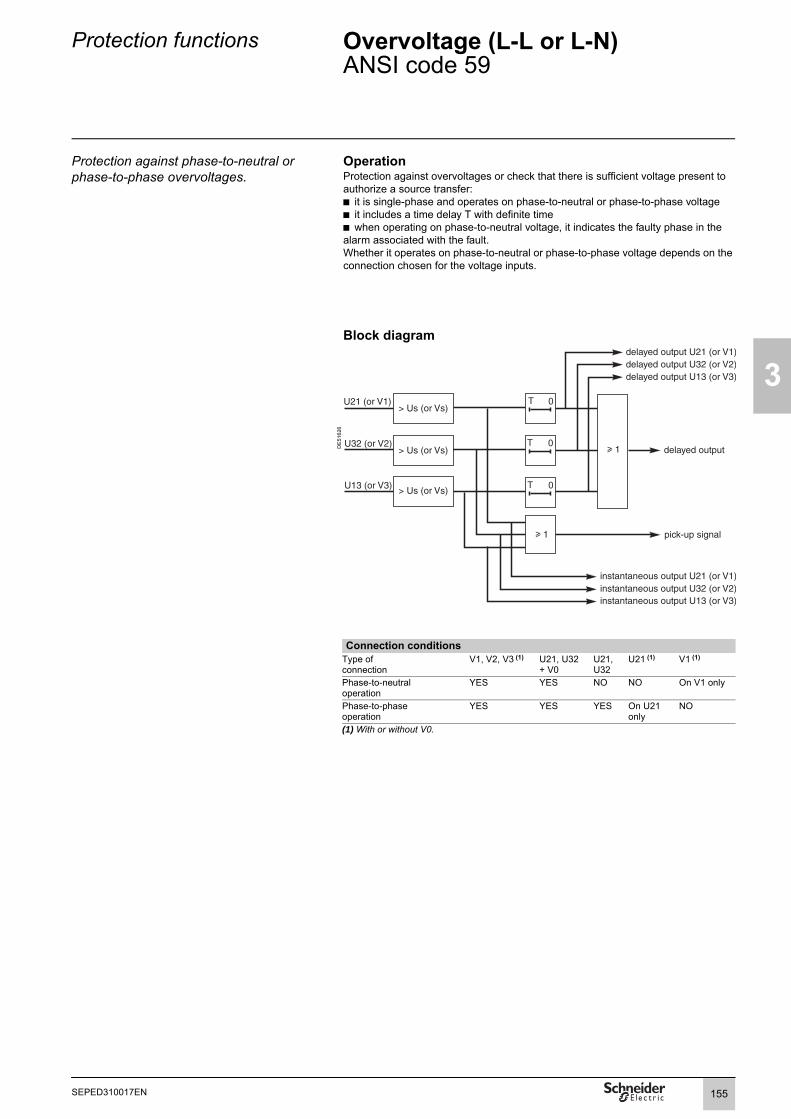
Protection functions Overvoltage (L-L or L-N)ANSI code 59
3
Protection against phase-to-neutral or phase-to-phase overvoltages.
OperationProtection against overvoltages or check that there is sufficient voltage present to authorize a source transfer:b it is single-phase and operates on phase-to-neutral or phase-to-phase voltageb it includes a time delay T with definite timeb when operating on phase-to-neutral voltage, it indicates the faulty phase in the alarm associated with the fault. Whether it operates on phase-to-neutral or phase-to-phase voltage depends on the connection chosen for the voltage inputs.
Block diagramD
E51
626
Connection conditionsType of connection
V1, V2, V3 (1) U21, U32+ V0
U21, U32
U21 (1) V1 (1)
Phase-to-neutraloperation
YES YES NO NO On V1 only
Phase-to-phaseoperation
YES YES YES On U21 only
NO
(1) With or without V0.
155SEPED310017EN

3
Protection functions Overvoltage (L-L or L-N)ANSI code 59
CharacteristicsSettingsVoltage mode
Setting range Phase-to-phase voltage / Phase-to-neutral voltageUs (or Vs) set point
Setting range 50 % to 150 % of Unp (or Vnp) if Uns < 208 V50 % to 135 % of Unp (or Vnp) if Uns u 208 V
Accuracy (1) ±2 %Resolution 1 %Drop out/pick up ratio 97 % ±1 %Drop-out/pick-up ratio
Setting range 97 % to 99 %Accuracy 1 % Resolution 0,1 %Time delay T
Setting range 50 ms to 300 sAccuracy (1) ±2 % or ±25 msResolution 10 ms or 1 digitCharacteristic times
Operation time Pick-up < 40 ms from 0.9 Us (Vs) to 1.1 Us (Vs) (typically 25 ms)
Overshoot time < 40 ms from 0.9 Us (Vs) to 1.1 Us (Vs)Reset time < 50 ms from 1.1 Us (Vs) to 0.9 Us (Vs)InputsDesignation Syntax Equations
Protection reset P59_x_101 bProtection inhibition P59_x_113 bOutputs Designation Syntax Equations Matrix
Instantaneous output (pick-up) P59_x_1 bDelayed output P59_x_3 b bFault phase 1 (2) P59_x_7 bFault phase 2 (2) P59_x_8 bFault phase 3 (2) P59_x_9 bProtection inhibited P59_x_16 bInstantaneous output V1 or U21 P59_x_23 bInstantaneous output V2 or U32 P59_x_24 bInstantaneous output V3 or U13 P59_x_25 bDelayed output V1 or U21 P59_x_26 bDelayed output V2 or U32 P59_x_27 bDelayed output V3 or U13 P59_x_28 bx: unit number.(1) Under reference conditions (IEC 60255-6).(2)When the protection function is used for phase-to-neutral voltage.
156 SEPED310017EN

Protection functions Neutral voltage displacementANSI code 59N
3
Protection against insulation faults DescriptionProtection against insulation faults by measuring the residual voltage V0 or the neutral point voltage Vnt for generators and motors.The residual voltage is obtained by the vector sum of the phase voltages or by measurements using delta connected VTs.The neutral point voltage is measured by a VT inserted in the neutral point of the generator or the motor.The protection function includes a time delay T, either definite or IDMT (dependent on the residual voltage V0) (see tripping curve equation on page 185).It operates only when a residual or neutral point voltage is available, by connecting V1V2V3, V0 or Vnt.
Block diagramD
E50
785
CharacteristicsSettingsMeasurement origin
Setting range Main channels (V0) Neutral-point voltage (Vnt)
Tripping curveSetting range Definite time
IDMT (dependent on the residual voltage V0)Vs0 set point
Definite time setting range 2 % Unp to 80 % Unp (for residual voltage V0)2 % Vntp to 80 % Vntp (for neutral point voltage Vnt)
IDMT setting range 2 % Unp to 10 % Unp (for residual voltage V0)2 % Vntp to 10 % Vntp (for neutral point voltage Vnt)
Accuracy (1) ±2 % or 0.005 UnpResolution 1 %Drop out/pick up ratio 97 % ±2 % or > (1 - 0.006 Unp/Vs0) x 100 %Time delay T (tripping time at 2 Vs0)
Definite time setting range 50 ms to 300 sIDMT setting range 100 ms to 10 sAccuracy (1) ±5 % or ±25 msResolution 10 ms or 1 digitCharacteristic times
Operation time pick-up < 45 ms (typically 25 ms) at 2 Vs0Overshoot time < 40 ms at 2 Vs0Reset time < 40 ms at 2 Vs0InputsDesignation Syntax Equations
Protection reset P59N_x_101 bProtection inhibition P59N_x_113 b
Outputs Designation Syntax Equations Matrix
Instantaneous output (pick-up) P59N_x_1 bDelayed output P59N_x_3 b bProtection inhibited P59N_x_16 bx: unit number.(1) Under reference conditions (IEC 60255-6).
157SEPED310017EN

3
Protection functions Restricted earth fault differentialANSI code 64REF
Protection of three-phase windings against phase-to-earth faults.
DescriptionThe restricted earth fault protection function detects phase-to-earth faults on three-phase windings with earthed neutral. This function protects generators and transformers.The protected zone is between the 3 phases CTs I1, I2, I3 and the neutral point current measurement I0.The vector associated with the current sensors determines the conventional direction of connection.
DE
8016
6
DE
8077
4
DE
8079
1
PrincipleProtection is activated if the following 3 conditions are met:bbb
With:b Id0: differential residual currentb Is0: adjustable trip set point of the protection functionb Istab: stabilization currentb ΔI0: variation of the neutral point current b I0min: nominal current of the neutral point:v I0min = 0.05 x In0 si In0 > 20 Av I0min = 0.10 x In0 si In0 ≤ 20 A
Differential residual current Id0
With:b : neutral point currentb : residuel current calculated using the sum of the 3 phase currents
Stabilization current Istab
With:b k: present momentb k-1: previous moment in the 64REF protective processing cycleb α: time constant adaptation coefficient of the time memory to cover dips in the through current It, when the CTs are saturated, on an external multi-phase faultb It: through current
Through current ItThe through current It provides the protection with discrimination and rendered immunity in relation to external multi-phase faults. With:
b : residual component sensitive to single-phase faultsb : component sensitive to multi-phase faultsb β : coefficient depending on the nature of the external fault:v for two-phase/earth or three-phase/earth faultsv β = 0 for single-phase faults
Variation of the neutral point current ΔI0The neutral point current variation is the difference in the absolute value between the neutral point current before and after the fault has been detected.
P2 P1
S1S2
I0
I1 I2 I3
Istab / In
Is0 max.
Is0 min.
120 %Istab
Tripping zone
Is0 setting range
0.8
0.05
Id0 Is0>Id0 1.2 Istab×>ΔI0 min Is0/4 I0min,( )>
Id0 I0Σ I0–=
I0I0Σ
Istab k( ) max It k( ) α Istab k 1–( )⋅,( )=
It max IR0 β IR1⋅,( )=
IR0 I0Σ I0+ 2⁄=IR1 Id Ii–=
β max 2 Id Ib⁄,( )=
158 SEPED310017EN

Protection functions Restricted earth fault differentialANSI code 64REF
3
Block diagram
DE
8127
3
Additional protection on multi-phase faultsWhen multi-phase/internal earth faults occur, the 64REF protection may experience downgraded operation. The table below defines the usual additional protection for protecting the installation in the event of multi-phase/internal earth faults.
Application Network diagram Additional protections
Protection of an incomer on a:b Directly earthed, resistive or inductive MV network (1000 V < MV < 50 kV)b TN or TT type LV network (< 1000 V)
ANSI 50/51 at the primary
Protection of parallel incomers on a:b HV distribution network b Directly earthed, resistive or inductive MV networkb TN or TT type LV network
ANSI 67
Protection of a feeder on an HV(> 50 kV) distribution network
ANSI 50/51N at the neutral point
Protection of zero sequence generator on an MV network
b ANSI 50/51 orb ANSI 50N/51N
Generator protection, in which the neutral is earthed across a low impedance
ANSI 50N/51N at the neutral point
Machine-transformer unit protection, in which the neutral is earthed across a low impedance
ANSI 50N/51N at the neutral point
&
I0Σ+I0 2
Ii
Id
I0 variation calculation
ΔI0 > Min(Is0/4, I0 min)
Stabilization current calculation
Id0 > Is0
β.( Id Ii- )
Id0 > 1.2 Istab
ΔI0
βIR1
IR0
Id0
IstabβIR1 =
IR0 =
Id0 =
Tripping output
I0 input
I0 input
G
G
159SEPED310017EN

3
Protection functions Restricted earth fault differentialANSI code 64REF
Dimensioning current sensorsb The primary current of the neutral point current transformer must comply with the following rule:In0 u 0.1 x I1P, where I1P is the phase-to-earth short-circuit current.
b Neutral current transformer must be:
v type 5P20 with an accuracy burden VACT u Rw.in0²
v or defined by a knee-point voltage Vk u (RCT + Rw).20.in0.
b Phase current transformers must be:
v type 5P, with an accuracy-limit factor FLP u max
and an accuracy burden VACT u Rw.in²
v or defined by a knee-point voltage Vk u (RCT + Rw) max in.
b Formula legend:in: phase CT rated secondary currentin0: neutral point CT rated secondary currentRCT: phase CT or neutral CT internal resistance Rw: resistance of the CT load and wiringIn: phase CT rated primary currentIn0: neutral point CT rated primary currentI3P: three-phase short-circuit currentI1P: phase-to-earth short-circuit current
CharacteristicsSettingsIs0
Setting range 0.05 In to 0.8 In for In u 20 A0.1 In to 0.8 In for In < 20 A
Accuracy (1) 5 %Resolution 1 A or 1 digitDrop out/pick up ratio 93 % ±2 %Characteristic times
Operation time < 55 ms at Id0 = 2.4 IstabOvershoot time < 35 ms at Id0 = 2.4 IstabReset time < 45 ms at Id0 = 2.4 IstabInputsDesignation Syntax Equations
Protection reset P64REF_x_101 bProtection inhibition P64REF_x_113 b
Outputs Designation Syntax Equations Matrix
Protection output P64REF_x_3 b bProtection inhibited P64REF_x_16 bx: unit number.(1) Under reference conditions (IEC 60255-6).
20 1.6 I3PIn-------- 2.4 I1P
In--------, ,⎝
⎛
20 1.6 I3PIn-------- 2.4I1P
In--------, ,⎝
⎛
160 SEPED310017EN

Protection functions Starts per hourANSI code 66
3
Protection of motors against mechanical stress caused by starts that are too close together.
OperationThe number of starts is incremented if:
The current taken exceeds 5 % of the current Ib after circuit breaker closing (and the circuit breaker position is hard-wired on inputs I101 and I102).
The current taken exceeds 5 % of the current Ib after re-acceleration.
The number of starts over the period Tcons is limited by: the permitted number of consecutive cold starts (Nc)the permitted number of successive hot starts (Nh).
The "stop/start" time delay is used to impose a minimum stopping time between each start.
The motor "hot state" data item is determined by the 49RMS motor thermal overload protection. A "hot state" set point can also be configured using this protection function (see page 122).Note: When the 49RMS generic thermal overload protection is used, if ES0 is different from 0%, the ANSI 66 protection function may not work properly.As the "hot state" set point is fixed at 50% in the ANSI 66 protection function, accordingto ES0 setting value, the cold state for the 66 protection function may be reduced or not exist. So the number of starts will be limited by the number of consecutive hot starts, with no impact of number of consecutive cold starts setting.When the motor curves imply to use ES0 setting to move the "cold curve", it is highly adviced to use the thermal model based on two time constants, that avoid this setting difficulty.
Block diagram
DE
8126
6
Operating informationThe following information is available to the operator:
the number of starts before inhibitionstart inhibit time
(See machine operation help functions on page 51).
0 Tcons
Clear
Adjustable delay between consecutive starts
1
&
"Hot state" P49RMS_1_18
&
&
Reset counters
Adjustable delaybetween stop/start
&
Logic input Authorize emergency restart
Inhibit closing
Clear
Ix > 0.05 IbI1I2I3
&
1
Logic inputmotor re-acceleration
T = 100 ms
&
Clear
&
T = 100 ms
Closed circuit breaker
Closed circuit breaker position not read
T = 100 msMotor re-acceleration logic equation ≥
1≥
≥
K2 Nh≥
1≥
K1 Nc≥
Confirmation of counting by circuit breaker position
1≥
0 T0 T
0 T
0 T
161SEPED310017EN

162
3
SEPED303017EN
Protection functions Starts per hourANSI code 66
CharacteristicsSettingsDelay between consecutive starts (Tcons)
nm 09 ot nm 1egnar gnitteSnm 1noituloseR
Permitted number of consecutive cold starts (Nc)Setting range 1 to 5Resolution 1Permitted number of consecutive hot starts (Nh)
)1- cN( ot 1egnar gnitteSResolution 1Delay between stop/start
)yaled emit on 0( nm 09 ot 0egnar gnitteSResolution 1 mnInputs Designation Syntax Equations Logipam
Reset protection P66_1_101 b bMotor re-acceleration P66_1_102 b bInhibit protection P66_1_113 b bOutputs Designation Syntax Equations Logipam Matrix
Protection output P66_1_3 b b bProtection inhibited P66_1_16 b bStop/start inhibit P66_1_29 b bStartup total reached P66_1_30 b bConsecutive startups reached P66_1_31 b b
Help with parameter settingNumber of consecutive startsMotor manufacturers state the permitted number of consecutive cold (Nc) and hot (Nh) starts in the technical data.Delay between consecutive startsConsecutive starts are starts that are sufficiently close in relation to the rotor cooling time constant.The delay between consecutive starts (Tcons) must be set to the value of the rotor cooling time constant:τ = (Tc - Th) . LRT / gnWhere:Tc: locked cold rotor limit time in secondsTh: locked hot rotor limit time in secondsLRT: locked rotor torque in pugn: rated slip in pu Motor hot state set pointThe motor thermal capacity used varies from 0 to Itrip2 (Itrip being the motor thermal overload protection tripping current).In order to be able to perform a hot start without tripping the thermal overload protection, the motor hot state set point must be configured.There are 2 different scenarios:b The motor starting time (tstg) is close to the locked hot rotor limit time (Th). This scenario corresponds to a motor on which the load's moment of inertia is high, such as a fan. The hot state set point is configured as follows:
b The motor starting time (tstg) is short compared to the locked hot rotor limit time (Th). The hot state set point is configured as follows:
In this scenario, the ANSI 66 protection function is fully involved in limiting the number of starts, because the thermal protection is well below its tripping current set point (Itrip).
Shot Itrip22
Shot 2<
<
<
tstgTh
-----------–
Nc tstgTc
----------- ⋅ Itrip2 Nh tstg
Th-----------⋅
–

Protection functions Starts per hourANSI code 66
3
Example 1: 2350 kW / 6 kV motorManufacturer data:
Locked cold rotor limit time Tc 13 sLocked hot rotor limit time Th 9 sNumber of consecutive cold starts Nc 3Number of consecutive hot starts Nh 2Starting time tstg 4 sRated speed N 2980 rpmLocked rotor torque LRT 0.7 puLocked rotor current Il 6 puContinuous permissible current Itrip 1.2 pu
Calculating the rotor time constantThe rated slip is given by:
Where:np: number of polesfn: network frequency
The number of poles is given by:
hence np = int (60. 50 / 2980) = 1
Therefore:
The rotor constant is given by:τ = (Tc - Th) . LRT / gnHence:τ = (13 - 9) . 0.7 / 0.0067 = 420 s, or 7 mn
Calculating the hot state set pointThe hot state set point is given by:
Hence:
Or 0.92 Ib < Shot 2 < 0.56 Ib which is impossible.Therefore a more restrictive hot state set point is selected, allowing 1 hot start and 3 cold starts.Hence:
Or 92.30% < Shot² < 99.55 %Or for the "hot state" set point: 0.96 Ib < Shot < 0.99 Ib
gn 1 N np⋅60 fn⋅------------------–=
np int 60 fn⋅N
--------------------⎝ ⎠⎛ ⎞=
gn 1 298060 50⋅------------------ 0,0067=–=
Nc tdemTc
---------------⎝ ⎠⎛ ⎞⋅ Shot 2 Itrip2< < Nh tdem
Th---------------⋅⎝ ⎠
⎛ ⎞–
3 413------⎝ ⎠
⎛ ⎞⋅ Shot 2 1 2, 2< < 2 49---⋅⎝ ⎠
⎛ ⎞–
3 413------⎝ ⎠
⎛ ⎞⋅ Shot 2 1 2, 2< < 1 49---⋅⎝ ⎠
⎛ ⎞–
163SEPED310017EN

3
Protection functions Starts per hourANSI code 66
Example 2: 506 kW / 10 kV motorManufacturer data:
Locked cold rotor limit time Tc 60 sLocked hot rotor limit time Th 29 sNumber of consecutive cold starts Nc 2Number of consecutive hot starts Nh 1Starting time tstg 21 sRated speed N 993 rpmLocked rotor torque LRT 0.6 puLocked rotor current Il 5.3 puContinuous permissible current Itrip 1.25 pu
Calculating the rotor time constantThe number of poles equals:np = int (60. 50 / 993) = 3
We can therefore deduce the rated slip:
and the rotor cooling constant:τ = (60 - 29) . 0.6 / 0.007 = 2657 s, or 44 mnCalculating the hot state set pointThe hot state set point is given by:
Or 70 % < Shot² < 83.83 %Or for the "hot state" set point: 0.83 Ib < Shot < 0.91 Ib
This setting allows 1 hot start and 3 cold starts.
gn 1 993 3⋅60 50⋅------------------- 0,007=–=
2 2160------⎝ ⎠
⎛ ⎞⋅ Shot 2 1 25, 2< < 1 2129------⋅⎝ ⎠
⎛ ⎞–
164 SEPED310017EN

Protection functions Directional phase overcurrentANSI code 67
3
Phase-to-phase short-circuit protection, with selective tripping according to fault current direction. M
T111
28
DescriptionThis function comprises a phase overcurrent function associated with direction detection and picks up if the phase overcurrent function in the chosen direction (line or busbar) is activated for at least one of the 3 phases (or two of the three phases, depending on the settings).b the protection function is three-phase and has a definite or IDMT time delay.b each of the two units has two groups of settings. Switching to setting group A or B can be carried out by a logic input or a remote control order, depending on the settings.b the customized curve, defined point by point, may be used with this protection function.b an adjustable timer hold, definite time or IDMT, can be used for coordination with electromagnetic relays and to detect restriking faults.b the alarm linked to the protection function indicates the faulty phase or phases.Tripping directionThe direction of the current is determined according to the measurement of the phase in relation to a polarization value. It is qualified as busbar direction or line direction according to the following convention:
DE
5066
7
Fault tripping in line zone with θ = 30°.
DE
5066
8
DE
5155
7
The tripping zone is set for tripping in busbar zone or tripping in line zone.The reverse zone is the zone for which the protection function does not trip. The detection of current in the reverse zone is used for indication.Polarization valueThe polarization value is the phase-to-phase value in quadrature with the current for cosθ = 1 (90° connection angle). A phase current vector plane is divided into two half-planes that correspond to the line zone and busbar zone. The characteristic angle θ is the angle of the perpendicular to the boundary line between the 2 zones and the polarization value.Voltage memoryShould all the voltages disappear during a 3-phase fault near the busbars, the voltage level may be insufficient for the fault direction to be detected (< 1.5 % Unp). The protection function therefore uses a voltage memory to reliably determine the direction. The fault direction is saved as long as the voltage level is too low and the current is above the Is set point.Closing on a pre-existing faultIf the circuit breaker is closed when there is a pre-existing 3-phase fault on the busbars, the voltage memory is blank. As a result, the direction cannot be determined and the protection does not trip.In such cases, a backup 50/51 protection function should be used.
Fault tripping in line zone with θ = 45°.
DE
5066
9
Fault tripping in line zone with θ = 60°.
Tripping logicIn certain cases, it is wise to select the "two out of three phases" tripping logic. Such cases may occur when two parallel transformers (Dy) must be protected. For a 2-phase fault on a transformer primary winding, there is a 2-1-1 current distribution at the secondary end. The highest current is in the expected zone (operation zone for the faulty incomer, no operation zone for the fault-free incomer).One of the lowest currents is at the edge of the zone. According to the line parameters, it may even be in the wrong zone.There is therefore a risk of tripping both incomers.
165SEPED310017EN

3
Protection functions Directional phase overcurrentANSI code 67
Block diagramD
E52
315
DE
5084
9
DE
8013
9
DE
5162
8
DE
5231
6
Tripping logic parameter setting:
one out of three
two out of three
Grouping of output data.
phase 1 instantaneousphase 2 instantaneousphase 3 instantaneous
1
2
166 SEPED310017EN
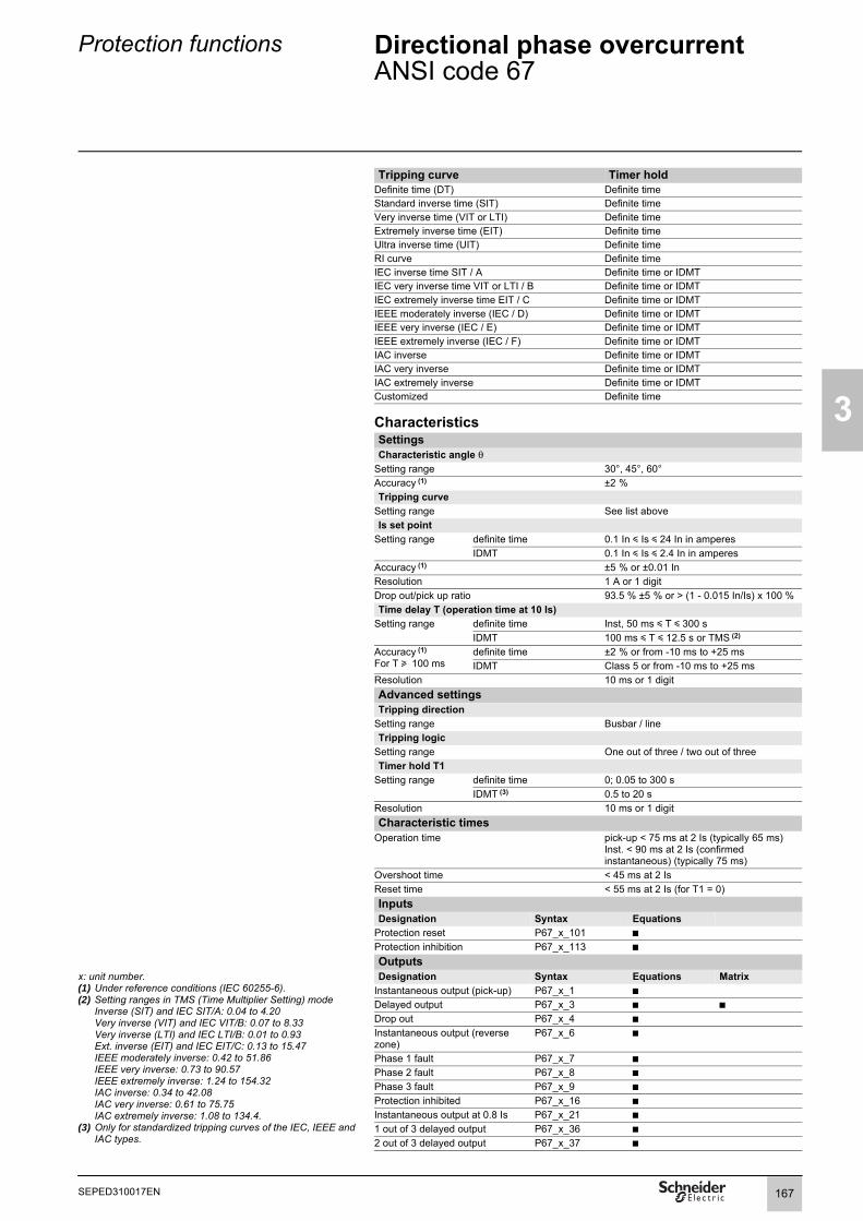
Protection functions Directional phase overcurrentANSI code 67
3
Tripping curve Timer holdDefinite time (DT) Definite timeStandard inverse time (SIT) Definite timeVery inverse time (VIT or LTI) Definite timeExtremely inverse time (EIT) Definite timeUltra inverse time (UIT) Definite timeRI curve Definite timeIEC inverse time SIT / A Definite time or IDMTIEC very inverse time VIT or LTI / B Definite time or IDMTIEC extremely inverse time EIT / C Definite time or IDMTIEEE moderately inverse (IEC / D) Definite time or IDMTIEEE very inverse (IEC / E) Definite time or IDMTIEEE extremely inverse (IEC / F) Definite time or IDMTIAC inverse Definite time or IDMTIAC very inverse Definite time or IDMTIAC extremely inverse Definite time or IDMTCustomized Definite time
CharacteristicsSettingsCharacteristic angle θ
Setting range 30°, 45°, 60°Accuracy (1) ±2 %Tripping curve
Setting range See list aboveIs set point
Setting range definite time 0.1 In y Is y 24 In in amperesIDMT 0.1 In y Is y 2.4 In in amperes
Accuracy (1) ±5 % or ±0.01 InResolution 1 A or 1 digitDrop out/pick up ratio 93.5 % ±5 % or > (1 - 0.015 In/Is) x 100 %Time delay T (operation time at 10 Is)
Setting range definite time Inst, 50 ms y T y 300 sIDMT 100 ms y T y 12.5 s or TMS (2)
Accuracy (1)
For T u 100 msdefinite time ±2 % or from -10 ms to +25 msIDMT Class 5 or from -10 ms to +25 ms
Resolution 10 ms or 1 digitAdvanced settingsTripping direction
Setting range Busbar / lineTripping logic
Setting range One out of three / two out of threeTimer hold T1
Setting range definite time 0; 0.05 to 300 sIDMT (3) 0.5 to 20 s
Resolution 10 ms or 1 digitCharacteristic times
Operation time pick-up < 75 ms at 2 Is (typically 65 ms)Inst. < 90 ms at 2 Is (confirmed instantaneous) (typically 75 ms)
Overshoot time < 45 ms at 2 IsReset time < 55 ms at 2 Is (for T1 = 0)Inputs Designation Syntax Equations
Protection reset P67_x_101 bProtection inhibition P67_x_113 b
Outputs x: unit number.(1) Under reference conditions (IEC 60255-6).(2) Setting ranges in TMS (Time Multiplier Setting) mode
Inverse (SIT) and IEC SIT/A: 0.04 to 4.20Very inverse (VIT) and IEC VIT/B: 0.07 to 8.33Very inverse (LTI) and IEC LTI/B: 0.01 to 0.93Ext. inverse (EIT) and IEC EIT/C: 0.13 to 15.47IEEE moderately inverse: 0.42 to 51.86IEEE very inverse: 0.73 to 90.57IEEE extremely inverse: 1.24 to 154.32IAC inverse: 0.34 to 42.08IAC very inverse: 0.61 to 75.75IAC extremely inverse: 1.08 to 134.4.
(3) Only for standardized tripping curves of the IEC, IEEE and IAC types.
Designation Syntax Equations MatrixInstantaneous output (pick-up) P67_x_1 bDelayed output P67_x_3 b bDrop out P67_x_4 bInstantaneous output (reverse zone)
P67_x_6 b
Phase 1 fault P67_x_7 bPhase 2 fault P67_x_8 bPhase 3 fault P67_x_9 bProtection inhibited P67_x_16 bInstantaneous output at 0.8 Is P67_x_21 b1 out of 3 delayed output P67_x_36 b2 out of 3 delayed output P67_x_37 b
167SEPED310017EN

3
Protection functions Directional earth faultANSI code 67N/67NC
Earth fault protection, with selective tripping according to fault current direction.
DescriptionTo adapt to all types of applications and all earthing systems, the protection function operates according to two different types of characteristics, i.e. a choice of:b type 1: the protection function uses I0 vector projection.This projection method is suitable for radial feeders in resistive, isolated or compensated neutral systems.b type 2: the protection function uses the I0 vector magnitude and operates like an earth fault protection function with an added direction criterion.This projection method is suitable for closed ring distribution networks with directly earthed neutral.b type 3: the protection function uses the I0 vector magnitude and complies with Italian specification ENEL DK5600. It operates like an earth fault protection function with an added angular direction criterion Lim.1, Lim.2.This protection method is suitable for distribution networks in which the neutral earthing system varies according to the operational mode.Tripping directionThe direction of the residual current is qualified as busbar direction or line direction according to the following convention:
DE
5155
7
The tripping zone is set for tripping in busbar zone or tripping in line zone.The reverse zone is the zone for which the protection function does not trip. The detection of current in the reverse zone is used for indication.
168 SEPED310017EN

Protection functions Directional earth fault - Type 1ANSI code 67N/67NC
3
Earth fault protection for impedant or compensated neutral systems.
DescriptionThe function determines the projection of the residual current I0 on the characteristic line, the position of which is determined by the setting of characteristic angle θ0 in relation to the residual voltage. The projection value is compared to the Is0 set point. This protection function is suitable for radial feeders in resistive, isolated or compensated neutral systems.With compensated neutral systems, it is characterized by its capacity to detect very brief, repetitive faults (recurrent faults). In the case of Petersen coils with no additional resistance, fault detection under steady state conditions is not possible due to the absence of active zero sequence current. The protection function uses the transient current at the beginning of the fault to ensure tripping. The θ0 = 0° setting is suitable for compensated or impedant neutral systems. When this setting is selected, the parameter setting of the sector is used to reduce the protection tripping zone to ensure its stability on fault-free feeders.The protection function operates with the residual current measured at one of the relay I0 inputs (operation with sum of three currents impossible). The protection function is inhibited for residual voltages below the Vs0 set point.It implements a definite time (DT) delay.The tripping direction may be set at the busbar end or line end.Each of the two units has two groups of settings. Switching to setting group A or B can be carried out by a logic input or a remote control order, depending on the settings.MemoryThe detection of recurrent faults is controlled by the time delay T0mem which extends the transient pick-up information, thereby enabling the operation of the definite time delay even with faults that are rapidly extinguished (≈ 2 ms) and restrike periodically. Even when a Petersen coil with no additional resistance is used, tripping is ensured due to fault detection during the transient fault appearance. Detection is extended throughout the duration of the fault based on the criterion V0 u V0mem, within the limit of T0mem. With this type of application, T0mem must be greater than T (definite time delay).
DE
5085
3
Tripping characteristic of ANSI 67N/67NC type 1 protection (characteristic angle θ0 ≠ 0°).
DE
5045
5
Tripping characteristic of ANSI 67N/67NC type 1 protection (characteristic angle θ0 = 0°).
Block diagram
DE
8014
0
characteristic angle:θ0 = 0°
sector
Is0 set point
tripping zone
V0
169SEPED310017EN
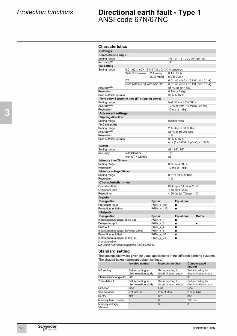
3
Protection functions Directional earth fault - Type 1ANSI code 67N/67NC
CharacteristicsSettingsCharacteristic angle θ
Setting range -45°, 0°, 15°, 30°, 45°, 60°, 90°Accuracy (1) ±2°Is0 setting
Setting range 0.01 In0 y Is0 y 15 In0 (min. 0.1 A) in amperesWith CSH sensor 2 A rating 0.1 to 30 A
20 A rating 0.2 to 300 ACT 0.01 In0 y Is0 y 15 In0 (min. 0.1 A)Core balance CT with ACE990 0.01 In0 y Is0 y 15 In0 (min. 0.1 A)
Accuracy (1) ±5 % (at ϕ0 = 180°)Resolution 0.1 A or 1 digitDrop out/pick up ratio 93.5 % ±5 %Time delay T (definite time (DT) tripping curve)
Setting range Inst, 50 ms y T y 300 sAccuracy (1) ±2 % or from -10 ms to +25 msResolution 10 ms or 1 digitAdvanced settingsTripping direction
Setting range Busbar / lineVs0 set point
Setting range 2 % Unp to 80 % UnpAccuracy (1) ±5 % or ±0.005 UnpResolution 1 %Drop out/pick up ratio 93.5 % ±5 %
or > (1 - 0.006 Unp/Vs0) x 100 %Sector
Setting range 86°, 83°, 76°Accuracy with CCA634 ±2°
with CT + CSH30 ±3°Memory time T0mem
Setting range 0; 0.05 to 300 sResolution 10 ms or 1 digitMemory voltage V0mem
Setting range 0; 2 to 80 % of UnpResolution 1 %Characteristic times
Operation time Pick-up < 55 ms at 2 Is0Overshoot time < 45 ms at 2 Is0Reset time < 50 ms (at T0mem = 0)Inputs Designation Syntax Equations
Protection reset P67N_x_101 bProtection inhibition P67N_x_113 bOutputs Designation Syntax Equations Matrix
Instantaneous output (pick-up) P67N_x_1 bDelayed output P67N_x_3 b bDrop-out P67N_x_4 bInstantaneous output (reverse zone) P67N_x_6 bProtection inhibited P67N_x_16 bInstantaneous output at 0.8 Is0 P67N_x_21 bx: unit number.(1) Under reference conditions (IEC 60255-6).
Standard settingThe settings below are given for usual applications in the different earthing systems.The shaded boxes represent default settings.
Isolated neutral Impedant neutral Compensated neutral
Is0 setting Set according to discrimination study
Set according to discrimination study
Set according to discrimination study
Characteristic angle θ0 90° 0° 0°Time delay T Set according to
discrimination studySet according to discrimination study
Set according to discrimination study
Direction Line Line LineVs0 set point 2 % of Uns 2 % of Uns 2 % of UnsSector N/A 86° 86°Memory time T0mem 0 0 200 msMemory voltage V0mem
0 0 0
170 SEPED310017EN

Protection functions Directional earth fault - Type 2ANSI code 67N/67NC
3
Earth fault protection for impedant or solidly earthed systems.
DescriptionThe protection function operates like an earth fault protection function with an added direction criterion.It is suitable for closed ring distribution networks with directly earthed neutral. It has all the characteristics of an earth fault protection function (50N/51N) and can therefore be easily coordinated with that function.The residual current is the current measured at one of the Sepam I0 inputs or calculated using the sum of the phase currents (I), according to the parameter setting.The tripping direction may be set at the busbar end or line end.The protection function has a definite or IDMT time delay.Each of the two units has two groups of settings. Switching to setting group A or B can be carried out by a logic input or a remote control order, depending on the settings.The customized curve, defined point by point, may be used with this protection function.An adjustable timer hold, definite time or IDMT, can be used for coordination with electromagnetic relays and to detect restriking faults.
DE
8035
8
Tripping curve Timer holdDefinite time (DT) Definite timeStandard inverse time (SIT) Definite time
Example of phase 1 to earth fault - Measurement of the 3 phase voltages.
Very inverse time (VIT or LTI) Definite timeExtremely inverse time (EIT) Definite timeUltra inverse time (UIT) Definite time
DE
8035
7
RI curve Definite timeIEC inverse time SIT / A Definite time or IDMTIEC very inverse time VIT or LTI / B Definite time or IDMTIEC extremely inverse time EIT / C Definite time or IDMTIEEE moderately inverse (IEC / D) Definite time or IDMTIEEE very inverse (IEC / E) Definite time or IDMTIEEE extremely inverse (IEC / F) Definite time or IDMTIAC inverse Definite time or IDMTIAC very inverse Definite time or IDMTIAC extremely inverse Definite time or IDMTCustomized Definite time
Tripping characteristic of ANSI 67N/67NC - type 2 protection function.
Block diagram
DE
8014
1
V1
V0
V2 V3
I0
Tripping zone
V1 before fault
Tripping zone
Is0
I0
V0
171SEPED310017EN

3
Protection functions Directional earth fault - Type 2ANSI code 67N/67NC
CharacteristicsSettingsMeasurement origin
Setting range I0I0Σ
Characteristic angle θSetting range -45°, 0°, 15°, 30°, 45°, 60°, 90°Accuracy (1) ±2°Tripping curve
Setting range See previous pageIs0 setting
Definite timesetting range
0.01 In0 y Is0 y 15 In0 (min. 0.1 A)in amperes
Sum of CTs 0.01 In y Is0 y 15 In (min. 0.1 A)With CSH sensor 2 A rating 0.1 to 30 A
20 A rating 0.2 to 300 ACT 0.01 In0 y Is0 y 15 In0 (min. 0.1 A)Core balance CT with ACE990 0.01 In0 y Is0 y 15 In0 (min. 0.1 A)
IDMTsetting range
0.01 In0 y Is0 y In0 (mini 0.1 A)in amperes
Sum of CTs 0.01 In y Is0 y In (min. 0.1 A)With CSH sensor 2 A rating 0.1 to 2 A
20 A rating 0.2 to 20 ACT 0.01 In0 y Is0 y In0 (min. 0.1 A)Core balance CT with ACE990 0.01 In0 y Is0 y In0 (min. 0.1 A)
Accuracy (1) ±5 % or ±0.004 In0Resolution 0.1 A or 1 digitDrop out/pick up ratio 93.5 % ±5 %
or > (1 - 0.005 In0/Is0) x 100 %Time delay T (operation time at 10 Is0)
Setting range definite time Inst, 50 ms y T y 300 sIDMT 100 ms y T y 12.5 s or TMS (2)
Accuracy (1) definite time ±2 % or from -10 ms to +25 msIDMT Class 5 or from -10 ms to +25 ms
Resolution 10 ms or 1 digitAdvanced settingsTripping direction
Setting range Busbar / lineVs0 set point
Setting range 2 % Unp to 80 % UnpAccuracy (1) ±5 % or ±0.005 UnpResolution 1 %Drop out/pick up ratio 93 % ±5 %
or > (1 - 0.006 Unp/Vs0) x 100 %Timer hold T1
Setting range definite time 0; 0.05 to 300 sIDMT (3) 0.5 to 20 s
Resolution 10 ms or 1 digitCharacteristic times
Operation time Pick-up < 40 ms at 2 Is0(typically 25 ms)Inst. < 55 ms at 2 Is0 (confirmed instantaneous) (typically 35 ms)
Overshoot time < 35 ms at 2 Is0Reset time < 50 ms at 2 Is0 (for T1 = 0)
x: unit number.(1) Under reference conditions (IEC 60255-6).(2) Setting ranges in TMS (Time Multiplier Setting) mode
Inverse (SIT) and IEC SIT/A: 0.04 to 4.20Very inverse (VIT) and IEC VIT/B: 0.07 to 8.33Very inverse (LTI) and IEC LTI/B: 0.01 to 0.93Ext. inverse (EIT) and IEC EIT/C: 0.13 to 15.47IEEE moderately inverse: 0.42 to 51.86IEEE very inverse: 0.73 to 90.57IEEE extremely inverse: 1.24 to 154.32IAC inverse: 0.34 to 42.08IAC very inverse: 0.61 to 75.75IAC extremely inverse: 1.08 to 134.4.
(3) Only for standardized tripping curves of the IEC, IEEE and IAC types.
Inputs Designation Syntax Equations
Protection reset P67N_x_101 bProtection inhibition P67N_x_113 bOutputs Designation Syntax Equations Matrix
Instantaneous output (pick-up) P67N_x_1 bDelayed output P67N_x_3 b bDrop out P67N_x_4 bInstantaneous output (reverse zone) P67N_x_6 bProtection inhibited P67N_x_16 bInstantaneous output at 0.8 Is0 P67N_x_21 b
172 SEPED310017EN

Protection functions Directional earth fault - Type 3ANSI Code 67N/67NC
3
DE
5117
3
Type 3 operationThis protection operates like an earth fault protection function (ANSI 50N/51N) with an added angular direction criterion Lim.1, Lim.2.It is suitable for distribution networks in which the neutral earthing system varies according to the operational mode.The tripping direction may be set at the busbar end or line end.The residual current is the current measured at the Sepam I0 input.It has a definite time delay (DT constant).By choosing an Is0 set point of 0, the protection function behaves like a neutral voltage displacement protection function (ANSI 59N).
Simplified schematicD
E80
142
Definite time operationIs0 corresponds to the operating set point expressed in amps, and T corresponds to the protection operating delay.
DE
5039
8
Definite time protection principle.
I0
t
Is0
T
173SEPED310017EN

3
Protection functions Directional earth fault - Type 3ANSI Code 67N/67NC
Type 3 characteristicsMeasurement origin
Setting range I0I0Σ
Tripping zone start angle Lim.1Setting 0° to 359°Resolution 1°Accuracy ±3°Tripping zone end angle Lim.2
Setting 0° to 359° (1)
Resolution 1°Accuracy ±3°Tripping direction
Setting Line/busbarIs0 set point
Setting (2) With CSH core balance CT 0.1 A to 30 A(2 A rating)With 1 A CT 0.005 In0 y Is0 y 15 In0 (min. 0.1 A)With core balance CT + ACE990 (range 1)
0.01 In0 y Is0 y 15 In0 (min. 0.1 A) (3)
Resolution 0.1 A or 1 digitAccuracy ±5%Drop-out/pick-up ratio u 95%Vs0 set point
Setting On sum of 3 Vs 2% Unp y Vs0 y 80% UnpOn external VT 0.6 % Unp y Vs0 y 80% Unp
Resolution 0.1% for Vs0 < 10%1% for Vs0 u 10%
Accuracy ±5%Drop-out/pick-up ratio u 95%Time delay T
Setting instantaneous, 50 ms y T y 300 sResolution 10 ms or 1 digitAccuracy y 3% or ±20 ms at 2 Is0Characteristic times
Operation time pick-up < 40 ms at 2 Is0 instantaneous < 55 ms at 2 Is0
Overshoot time < 40 msReset time < 50 msInputsDesignation Syntax Equations
Reset protection P67N_x_101 bInhibit protection P67N_x_113 bOutputsDesignation Syntax Equations Matrix
Instantaneous output (pick-up) P67N_x_1 bDelayed output P67N_x_3 b bDrop-out P67N_x_4 bInstantaneous output (reverse zone) P67N_x_6 bProtection inhibited P67N_x_16 bInstantaneous output at 0.8 Is0 P67N_x_21 b(1) Tripping zone Lim.2-Lim.1 should be 10° or more.(2) For Is0 = 0, the protection function behaves like a neutral voltage displacement protection function (59N).(3) In0 = k . n where n = the core balance CT ratio and k = coefficient to be determined according to the wiring of the ACE990 (0.00578 y k y 0.04).
Standard tripping zone setting (line end)The settings below are given for the usual applications in different types of neutral earthing system.The shaded boxes represent default settings.
Isolatedneutral
Impedantneutral
Directly earthed neutral
Lim.1 angle 190° 100° 100°Lim.2 angle 350° 280° 280°
174 SEPED310017EN

Protection functions RecloserANSI code 79
3
Recloser with 1 to 4 cycles to clear transients or semi-permanent faults on overhead lines.
DescriptionAutomation device used to limit down time after tripping due to transient or semi-permanent faults on overhead lines. The recloser orders automatic reclosing of the breaking device after the time delay required to restore the insulation. Recloser operation is easy to adapt for different operating modes by parameter setting.Initialization of the recloserThe recloser is ready to operate if all of the following conditions are met:b "switchgear control" function activated and recloser in service (not inhibited by the recloser inhibition logic input)b circuit breaker closedb the safety time is not runningb none of the recloser inhibition conditions is true (e.g. trip circuit fault, control fault, SF6 pressure drop).Recloser cyclesb case of a fault that is not cleared: following instantaneous or time-delayed tripping by the protection unit, activation of the dead time associated with the first active cycle. At the end of the dead time, a closing order is given, which activates the reclaim time. If the protection unit detects the fault before the end of the time delay, a tripping order is given and the following reclosing cycle is activated. after all the active cycles have been run, if the fault still persists, a final trip order is given, a message appears on the display.b case of a cleared fault: Following a reclosing order, if the fault does not appear after the reclaim time has run out, the recloser reinitializes and a message appears on the display (see example 1).b closing on a fault.If the circuit breaker closes on a fault, or if the fault appears before the end of the safety time delay, the recloser is inhibited. A final trip message is issued.Recloser inhibition conditionsThe recloser is inhibited according to the following conditions:b voluntary open or close orderb recloser put out of serviceb receipt of a inhibition order on the logic inputb activation of the breaker failure, such as trip circuit fault, control fault, SF6 pressure dropb opening of the circuit breaker by a protection unit that does not run reclosing cycles (e.g. frequency protection), by external tripping or by a function set up not to activate reclosing cycles.In such cases, a final trip message appears.Extension of the dead timeIf, during a reclosing cycle, reclosing of the circuit breaker is impossible because breaker recharging is not finished (following a drop in auxiliary voltage, recharging time is longer), the dead time may be extended up to the time at which the circuit breaker is ready to carry out an "Open-Close-Open" cycle. The maximum time added to the dead time is adjustable (Twait_max). If, at the end of the maximum waiting time, the circuit breaker is still not ready, the recloser is inhibited (see example 5).
DefinitionReclaim timeThe reclaim time is activated by a circuit breaker closing order given by the recloser.If no faults are detected before the end of the reclaim time, the initial fault is considered to have been cleared.Otherwise a new reclosing cycle is initiated.The delay must be longer than the longest reclosing cycle activation condition.Safety time until readyThe safety time is activated by a manual circuit breaker closing order. The recloser is inhibited for the duration of the time.If a fault occurs during this time, no reclosing cycles are initiated and the circuit breaker remains permanently open.Dead timeCycle n dead time is launched bybreaking device tripping ordergiven by the recloser during cycle n.The breaking device remains open throughout the time.At the end of the cycle n dead time, the n+1 cycle begins, and the recloser orders the closing of the circuit breaker.
175SEPED310017EN

3
Protection functions RecloserANSI code 79
CharacteristicsSettingsNumber of cycles
Setting range 1 to 4Activation of cycle 1
Protection 50/51 units 1 to 4 inst. / delayed / no activationProtection 50N/51N units 1 to 4 inst. / delayed / no activationProtection 67 units 1 to 2 inst. / delayed / no activationProtection 67N/67NC units 1 to 2 inst. / delayed / no activationLogic equations output V_TRIPCB active/inactiveActivation of cycles 2, 3 and 4
Protection 50/51 units 1 to 4 inst. / delayed / no activationProtection 50N/51N units 1 to 4 inst. / delayed / no activationProtection 67 units 1 to 2 inst. / delayed / no activationProtection 67N/67NC units 1 to 2 inst. / delayed / no activationLogic equations output V_TRIPCB active/inactiveTime delays
Reclaim time 0.1 to 300 sDead time Cycle 1 0.1 to 300 s
Cycle 2 0.1 to 300 sCycle 3 0.1 to 300 sCycle 4 0.1 to 300 s
Safety time until ready 0 to 60 sMaximum additional dead time 0.1 to 60 sAccuracy (1) ±2 % or ±25 msResolution 10 msInputs Designation Syntax Equations
Protection inhibition P79_1_113 b
Outputs Designation Syntax Equations Matrix
Recloser in service P79 _1_201 b bRecloser ready P79 _1_202 b bCleared fault P79 _1_203 b bFinal trip P79 _1_204 b bClosing by recloser P79 _1_205 bReclosing cycle 1 P79 _1_211 b bReclosing cycle 2 P79 _1_212 b bReclosing cycle 3 P79 _1_213 b bReclosing cycle 4 P79 _1_214 b b(1) Under reference conditions (IEC 60255-6).
176 SEPED310017EN

Protection functions RecloserANSI code 79
3
Example 1. Fault cleared after the second cycle
DE
5078
6
Example 2. Fault not cleared
DE
5078
7
177SEPED310017EN

3
Protection functions RecloserANSI code 79
Example 3. Closing on a fault
DE
5078
8
Example 4. No extension of dead time
DE
5078
9
Example 5. Extension of dead time
DE
5079
0
178 SEPED310017EN

Protection functions OverfrequencyANSI code 81H
3
Detection of abnormally high frequencies. DescriptionDetection of abnormally high frequency compared to the rated frequency, to monitor power supply quality or protect a generator against overspeeds.The frequency is calculated using voltage V1 or U21 when only one voltage is connected, otherwise the positive sequence voltage is used to procure greater stability. It is compared to the Fs set point. The protection function is inhibited if the voltage used for calculations is under the adjustable set point Vs.The protection includes a definite time delay T.
Block diagram
DE
5079
1
(1) Or U21, or 3.V1 > Vs if only one TP.
CharacteristicsSettingsFs set point
Setting range 50 to 55 Hz or 60 to 65 HzAccuracy (1) ±0.01 HzResolution 0.01Pick up / drop out difference 0.25 Hz ± 0.015 HzTime delay T
Setting range 100 ms to 300 sAccuracy (1) ±2 % or ±25 msResolution 10 ms or 1 digitAdvanced settingsVs set point
Setting range 20 % Un to 50 % UnAccuracy (1) 2 % Resolution 1 %Characteristic times
Operation time Pick-up < 90 ms from Fs -0.5 Hz to Fs +0.5 HzOvershoot time < 50 ms from Fs -0.5 Hz to Fs +0.5 HzReset time < 55 ms from Fs +0.5 Hz to Fs -0.5 HzInputs Designation Syntax Equations
Protection reset P81H_x_101 bProtection inhibition P81H_x_113 b
Outputs Designation Syntax Equations Matrix
Instantaneous output (pick-up) P81H_x_1 bDelayed output P81H_x_3 b bProtection inhibited P81H_x_16 bx: unit number.(1) Under reference conditions (IEC 60255-6) and df/dt < 3 Hz/s.
179SEPED310017EN

3
Protection functions UnderfrequencyANSI code 81L
Detection of abnormally low frequency for load shedding using a metric frequency criterion.
DescriptionDetection of abnormally low frequency compared to the rated frequency, to monitor power supply quality. The protection may be used for overall tripping or load shedding.The frequency is calculated using voltage V1 or U21 when only one voltage is connected, otherwise the positive sequence voltage is used to procure greater stability. It is compared to the Fs set point. The protection function is inhibited if the voltage used for calculations is under the adjustable set point Vs.Protection stability is ensured in the event of the loss of the main source and presence of remanent voltage by a restraint in the event of a continuous decrease of the frequency.The protection includes a definite (DT) time delay T.
Block diagramD
E50
861
(1) Or U21, or 3.V1 > Vs if only one TP.
CharacteristicsSettingsMeasurement origin
Setting range Main channels (U)Fs set point
Setting range 40 to 51 Hz or 50 to 1 HzAccuracy (1) ±0.01 HzResolution 0.01Pick up / drop out difference 0.05 Hz ± 0.015 HzTime delay T
Setting range 100 ms to 300 sAccuracy (1) ±2 % or ±25 msResolution 10 ms or 1 digitAdvanced settingsVs set point
Setting range 20 % Un to 90 % UnAccuracy (1) 2 % Resolution 1 %Restraint on frequency variation
Setting With / withoutdFs/dt set point 1 Hz/s to 15 Hz/sAccuracy (1) ±1 Hz/sResolution ±1 Hz/sCharacteristic times
Operation time Pick-up < 90 ms from Fs +0.5 Hz to Fs -0.5 HzOvershoot time < 50 ms from Fs +0.5 Hz to Fs -0.5 HzReset time < 55 ms from Fs -0.5 Hz to Fs +0.5 HzInputs Designation Syntax Equations
Protection reset P81L_x_101 bProtection inhibition P81L_x_113 b
Outputs Designation Syntax Equations Matrix
Instantaneous output (pick-up) P81L_x_1 bDelayed output P81L_x_3 b bProtection inhibited P81L_x_16 bx: unit number.(1) Under reference conditions (IEC 60255-6) and df/dt < 3 Hz/s.
180 SEPED310017EN

Protection functions Rate of change of frequencyANSI code 81R
3
Protection function based on the calculation of the frequency variation, used to rapidly disconnect a source supplying a network or to control load shedding.
OperationThe rate of change of frequency protection function is complementary to the under and overfrequency protection functions in detecting network configurations that require load shedding or disconnection.
The function is activated when the "rate of change of frequency" df/dt of the positive sequence voltage is higher than a set point. It includes a definite (DT) time delay.
The protection function operates if:b the positive sequence voltage is greater than 50 % of the rated phase-to-neutral voltageb the network frequency is between 42.2 Hz and 56.2 Hz for 50 Hz networks and between 51.3 Hz and 65 Hz for 60 Hz networks.
Block diagramde
5155
4
CharacteristicsSettingsdfs/dt set point
Setting range 0.1 to 10 Hz/sAccuracy (1) ±5 % or ±0,1 HzResolution 0.01 HzDrop out/pick up ratio 93 %Temporisation
Setting range 0.15 to 300 sAccuracy (1) ±2 % or -10 at +25 msResolution 10 ms or 1 digitCharacteristic times (1)
Operation time Pick-up < 150 ms (typically 130 ms)Overshoot time < 100 msReset time < 100 msInputs Designation Syntax Equations
Protection reset P81R_x_101 bProtection inhibition P81R_x_113 b
Outputs Designation Syntax Equations Matrix
Instantaneous output (pick-up) P81R_x_1 bTripping output P81R_x_3 b bProtection inhibited P81R_x_16 bInvalid voltage P81R_x_42 bInvalid frequency P81R_x_43 bPositive df/dt P81R_x_44 bNegative df/dt P81R_x_45 bx: unit number.(1) Under reference conditions (IEC 60255-6) and df/dt < 3 Hz/s.
181SEPED310017EN

3
Protection functions Rate of change of frequencyANSI code 81R
Disconnection applicationThis function is used on incomers of installations that include generators that can operate in parallel with the distribution network.The role of the function is to detect utility failures, i.e. operation of the generator as an autonomous isolated system. If the power flow from the utility prior to autonomous generator operation was not zero, the generator frequency changes. The rate of change of frequency protection function detects autonomous generator operation more rapidly than conventional frequency protection functions.
Other disturbances such as short-circuits, load fluctuations and switching may cause changes of frequency. The low set point may be reached temporarily due to these disturbances and a time delay is necessary. In order to maintain the advantage of the speed of the rate of change of frequency protection in comparison to conventional frequency protection functions, a second, higher set point with a short time delay may be added.
The rate of change of frequency is actually not constant. Often, the rate of change of frequency is at its highest at the beginning of the disturbance after which it decreases. This extends the tripping time of frequency protection functions but does not affect the tripping time of the rate of change of frequency protection function. Low set pointb Follow the utility's instructions, if there are any. b If there are no utility instructions, proceed as follows:v if the maximum rate of change of frequency on the network under normal conditions is known, dfs/dt should be set above it.v if no information on the network is available, the low set point may be set according to generator data. A good approximation of the rate of change of frequency after a utility failure resulting in a load variation ΔP is:
where Sn: rated power fn: rated frequency H: inertia constant
Typical value of the inertia constant (in MWs/MVA):0.5 y H y 1.5 for diesel and low-power generators (y 2 MVA)2 y H y 5 for gas turbines and medium-power generators (y 40 MVA)
where J: moment of inertia Ω: machine speed
ExamplesRated power 2 MVA 20 MVAInertia constant 0.5 MWs/MVA 2 MWs/MVAPower variation 0.1 MVA 1 MVAdf/dt -2.5 Hz/s -0.6 Hz/s
Low set point delay settingFor good protection stability during short-circuits or transient disturbances, the recommended time delay is 300 ms or more. If an automatic recloser is in service upstream of the installation, the detection of autonomous generator operation and the opening of the coupling circuit breaker must take place during the recloser isolation time.High set pointThe second set point may be chosen so that the rate of change of frequency tripping curve remains below the under and overfrequency protection curves.If the frequency protection units are set to fn±0.5Hz and the low set point of the rate of change of frequency is T, the high set point may be set to 0.5/T.High set point delay setting No particular recommendantions.Setting recommendations when no other information is available
Generator power 2 to 10 MVA > 10 MVASettings
Low set point dfs/dt 0.5 Hz/s 0.2 Hz/sT 500 ms 500 ms
High set point dfs/dt 2.5 Hz/s 1 Hz/sT 150 ms 150 ms
dfdt------ ΔP fn×
2 Sn× H×------------------------------=
H J Ω2×2 Sn×------------------=
182 SEPED310017EN

Protection functions Rate of change of frequencyANSI code 81R
3
Operating precautions:When the generator connects to the network, power oscillations may occur until the generator becomes fully synchronized. The rate of change of frequency protection function is sensitive to this phenomenon, so it is advisable to inhibit the protection unit for a few seconds after circuit breaker closing.
Load shedding applicationThe rate of change of frequency protection function may also be used for load shedding in combination with underfrequency protection. In such cases, it is used on the installation busbars. Only negative frequency derivatives are to be used.
Two principles are available:b acceleration of load shedding:The rate of change of frequency protection functions controls load shedding. It acts faster than underfrequency protection functions and the value measured (df/dt) is directly proportional to the load to be shedb load shedding inhibition:This principle is included in underfrequency protection functions. It consists of activating the frequency variation restraint and does not call for implementation of the rate of change of frequency protection function.
183SEPED310017EN

3
Protection functions GeneralTripping curves
Presentation of tripping curve operation and settings for protection functions using:b definite timeb IDMTb timer hold.
Definite time protectionThe tripping time is constant. The time delay is started when the set point is overrun.
MT1
0911
Definite time protection principle.
IDMT protectionThe operation time depends on the protected value (phase current, earth fault current, etc.) in accordance with standards IEC 60255-3, BS 142 and IEEE C-37112.Operation is represented by a characteristic curve, e.g.:b t = f(I) curve for the phase overcurrent functionb t = f(I0) curve for the earth fault function.The rest of the document is based on t = f(I); the reasoning may be extended to other variables I0, etc.The curve is defined by:b its type (standard inverse, very inverse, extremely inverse, etc.)b current setting Is which corresponds to the vertical asymptote of the curveb time delay T which corresponds to the operation time for I = 10 Is.These 3 settings are made chronologically in the following order: type, Is current, time delay T.Changing the time delay T setting by x % changes all of the operation times in the curve by x %.
DE
5066
6
IDMT protection principle.
The tripping time for I/Is values less than 1.2 depends onthe type of curve selected.
Name of curve TypeStandard inverse time (SIT) 1, 2Very inverse time (VIT or LTI) 1, 2Extremely inverse time (EIT) 1, 2Ultra inverse time (UIT) 1, 2RI curve 1IEC inverse time SIT / A 1IEC very inverse time VIT or LTI / B 1IEC extremely inverse time EIT / C 1IEEE moderately inverse (IEC / D) 1IEEE very inverse (IEC / E) 1IEEE extremely inverse (IEC / F) 1IAC inverse 1IAC very inverse 1IAC extremely inverse 1
b when the monitored value is more than 20 times the set point, the tripping time is limited to the value corresponding to 20 times the set point.b if the monitored value exceeds the measurement capacity of Sepam (40 In for the phase current channels, 20 In0 for the residual current channels), the tripping time is limited to the value corresponding to the largest measurable value (40 In or 20 In0).
I
t
Is
T
1,2 I/Is
t
1
T
10 20
type 1,2
type 1
184 SEPED310017EN

Protection functions GeneralTripping curves
3
Current IDMT tripping curvesMultiple IDMT tripping curves are offered, to cover most applications:b IEC curves (SIT, VIT/LTI, EIT)b IEEE curves (MI, VI, EI)b commonly used curves (UIT, RI, IAC).IEC curves
Equation Curve type Coefficient valuesk α β
Standard inverse / A 0.14 0.02 2.97Very inverse / B 13.5 1 1.50Long time inverse / B 120 1 13.33Extremely inverse / C 80 2 0.808Ultra inverse 315.2 2.5 1
RI curveEquation:
IEEE curvesEquation Curve type Coefficient values
A B p βModerately inverse 0.010 0.023 0.02 0.241Very inverse 3.922 0.098 2 0.138Extremely inverse 5.64 0.0243 2 0.081
IAC curvesEquation Curve type Coefficient values
A B C D E βInverse 0.208 0.863 0.800 -0.418 0.195 0.297Very inverse 0.090 0.795 0.100 -1.288 7.958 0.165Extremely inverse 0.004 0.638 0.620 1.787 0.246 0.092
Voltage IDMT tripping curvesEquation for ANSI 27 - Undervoltage Equation for ANSI 59N - Neutral voltage displacement
td I( ) kIIs----⎝ ⎠
⎛ ⎞ α1–
-------------------- Tβ---×=
td I( ) 1
0.339 0.236 IIs----⎝ ⎠
⎛ ⎞ 1––
----------------------------------------------------- T3.1706------------------×=
td I( ) AIIs----⎝ ⎠
⎛ ⎞ p1–
---------------------- B+
⎝ ⎠⎜ ⎟⎜ ⎟⎜ ⎟⎛ ⎞
Tβ---×=
td I( ) A BIIs---- C–⎝ ⎠
⎛ ⎞------------------- D
IIs---- C–⎝ ⎠
⎛ ⎞ 2---------------------- EIIs---- C–⎝ ⎠
⎛ ⎞ 3----------------------+ + +
⎝ ⎠⎜ ⎟⎜ ⎟⎜ ⎟⎛ ⎞
x T β-----=
td V( ) T
1 VVs------⎝ ⎠
⎛ ⎞–---------------------=
td V( ) TV
Vs-------⎝ ⎠
⎛ ⎞ 1–----------------------=
185SEPED310017EN

3
Protection functions GeneralTripping curves
Setting of IDMT tripping curves, time delay T or TMS factorThe time delays of current IDMT tripping curves (except for customized and RI curves) may be set as follows:b time T, operating time at 10 x Isb TMS factor, factor shown as T/β in the equations on the left.
Example: where .
The IEC curve of the VIT type is positioned so as to be the same with TMS = 1 or T = 1.5 s.
DE
5162
9
Example.
Timer holdThe adjustable timer hold T1 is used for:b detection of restriking faults (DT curve)b coordination with electromechanical relays (IDMT curve).b Timer hold may be inhibited if necessary.Equation for IDMT timer hold curveEquation: where .
T1 = timer hold setting (timer hold for I reset = 0 and TMS = 1)T = tripping time delay setting (at 10 Is)
β = basic tripping curve value at .
DE
5163
0
Detection of restriking faults with adjustable timer hold.
DE
5075
5
DE
5075
4
Timer hold dependent on current I. Constant timer hold.
Customized tripping curveDefined point by point using the SFT2841 setting and operating software tool (application menu), this curve may be used to solve all special cases involving protection coordination or installation renovation.It offers between 2 and 30 points whose coordinates must be:b increasing on the I/Is axisb decreasing on the t axis.The two end points define the curve asymptotes.There must be at least one point on the horizontal coordinate 10 I/Is. It serves as a reference point to set the function time delay by curve shifting.
PE
5015
7
Customized tripping curve set using SFT2841 software.
t I( ) 13.5I
Is----- 1–--------------- TMS×= TMS T
1.5--------=
tr I( ) T1
1 IIs-----⎝ ⎠
⎛ ⎞2
–
---------------------- Tβ---×= T
β--- TMS=
k10α 1–------------------
186 SEPED310017EN

Protection functions GeneralTripping curves
3
Implementing IDMT curves: examples of problems to be solved.Problem 1.Given the type of IDMT, determine the Is current and time delay T settings.Theoretically, the Is current setting corresponds to the maximum continuous current: it is generally the rated current of the protected equipment (cable, transformer).The time delay T corresponds to operation at 10 Is on the curve. This setting is determined taking into account the constraints involved in discrimination with the upstream and downstream protection devices.The discrimination constraint leads to the definition of point A on the operation curve (IA, tA), e.g. the point that corresponds to the maximum fault current for the downstream protection device.
Problem 2.Given the type of IDMT, the Is current setting and a point k (Ik, tk) on the operation curve, determine the time delay setting T.On the standard curve of the same type, read the operation time tsk that corresponds to the relative current Ik/Is and the operation time Ts10 that corresponds to the relative current I/Is = 10.
The time delay setting to be used so that the operation curve passes through the point k (Ik, tk) is:
MT1
0215
Another practical method:the table below gives the values of K = ts/ts10 as a function of I/Is.In the column that corresponds to the type of time delay, read the value K = tsk/Ts10on the line for Ik/Is.The time delay setting to be used so that the operation curvepasses through point k (Ik, tk) is: T = tk/k.
ExampleData:b type of time delay: standard inverse time (SIT) b set point: Isb a point k on the operation curve: k (3.5 Is; 4 s)Question: What is the time delay T setting (operation time at 10 Is)?Reading the table: SIT column, line I/Is = 3.5 therefore K = 1.858Answer: The time delay setting is T = 4/1.858 = 2.15 s
T Ts10 tktsk---------×=
I/Is
ts
Ts10
1 Ik/Is 10
tk
tsk
k
187SEPED310017EN

3
Protection functions GeneralTripping curves
Problem 3.Given the Is current and time delay T settings for a type of time delay (standard inverse, very inverse, extremely inverse), find the operation time for a current value IA.On the standard curve of the same type, read the operation time tsA that corresponds to the relative current IA/Is and the operation time Ts10 that corresponds to the relative current I/Is = 10.The operation time tA for the current IA with the Is and T settings is tA = tsA x T/Ts10.
Another practical method: the table below gives the values of K = ts/Ts10 as a function of I/Is.In the column that corresponds to the type of time delay, read the value K = tsA/Ts10on the line for IA/Is, the operation time tA for the current IA with the Is and T settings is tA = K . T.ExampleData:
type of time delay: very inverse time (VIT) set point: Istime delay T = 0.8 s.
Question: What is the operation time for the current IA = 6 Is?Reading the table: VIT column, line I/Is = 6, therefore k = 1.8
Answer: The operation time for the current IA is t = 1.80 x 0.8 = 1.44 s.
Table of K valuesI/Is SIT VIT, LTI EIT UIT RI IEEE MI IEEE VI IEEE EI IAC I IAC VI IAC EI
and IEC/A and IEC/B and IEC/C (IEC/D) (IEC/E) (IEC/F)1.0 — 3.062 62.005 62.272 200.2261.1 24.700 (1) 90.000 (1) 471.429 (1) — 2.534 22.461 136.228 330.606 19.033 45.678 122.1721.2 12.901 45.000 225.000 545.905 2.216 11.777 65.390 157.946 9.413 34.628 82.8991.5 5.788 18.000 79.200 179.548 1.736 5.336 23.479 55.791 3.891 17.539 36.6872.0 3.376 9.000 33.000 67.691 1.427 3.152 10.199 23.421 2.524 7.932 16.1782.5 2.548 6.000 18.857 35.490 1.290 2.402 6.133 13.512 2.056 4.676 9.5663.0 2.121 4.500 12.375 21.608 1.212 2.016 4.270 8.970 1.792 3.249 6.5413.5 1.858 3.600 8.800 14.382 1.161 1.777 3.242 6.465 1.617 2.509 4.8724.0 1.676 3.000 6.600 10.169 1.126 1.613 2.610 4.924 1.491 2.076 3.8394.5 1.543 2.571 5.143 7.513 1.101 1.492 2.191 3.903 1.396 1.800 3.1465.0 1.441 2.250 4.125 5.742 1.081 1.399 1.898 3.190 1.321 1.610 2.6535.5 1.359 2.000 3.385 4.507 1.065 1.325 1.686 2.671 1.261 1.473 2.2886.0 1.292 1.800 2.829 3.616 1.053 1.264 1.526 2.281 1.211 1.370 2.0076.5 1.236 1.636 2.400 2.954 1.042 1.213 1.402 1.981 1.170 1.289 1.7867.0 1.188 1.500 2.063 2.450 1.033 1.170 1.305 1.744 1.135 1.224 1.6077.5 1.146 1.385 1.792 2.060 1.026 1.132 1.228 1.555 1.105 1.171 1.4608.0 1.110 1.286 1.571 1.751 1.019 1.099 1.164 1.400 1.078 1.126 1.3378.5 1.078 1.200 1.390 1.504 1.013 1.070 1.112 1.273 1.055 1.087 1.2339.0 1.049 1.125 1.238 1.303 1.008 1.044 1.068 1.166 1.035 1.054 1.1449.5 1.023 1.059 1.109 1.137 1.004 1.021 1.031 1.077 1.016 1.026 1.06710.0 1.000 1.000 1.000 1.000 1.000 1.000 1.000 1.000 1.000 1.000 1.00010.5 0.979 0.947 0.906 0.885 0.996 0.981 0.973 0.934 0.985 0.977 0.94111.0 0.959 0.900 0.825 0.787 0.993 0.963 0.950 0.877 0.972 0.957 0.88811.5 0.941 0.857 0.754 0.704 0.990 0.947 0.929 0.828 0.960 0.939 0.84112.0 0.925 0.818 0.692 0.633 0.988 0.932 0.912 0.784 0.949 0.922 0.79912.5 0.910 0.783 0.638 0.572 0.985 0.918 0.896 0.746 0.938 0.907 0.76113.0 0.895 0.750 0.589 0.518 0.983 0.905 0.882 0.712 0.929 0.893 0.72713.5 0.882 0.720 0.546 0.471 0.981 0.893 0.870 0.682 0.920 0.880 0.69514.0 0.870 0.692 0.508 0.430 0.979 0.882 0.858 0.655 0.912 0.868 0.66714.5 0.858 0.667 0.473 0.394 0.977 0.871 0.849 0.631 0.905 0.857 0.64115.0 0.847 0.643 0.442 0.362 0.976 0.861 0.840 0.609 0.898 0.846 0.61615.5 0.836 0.621 0.414 0.334 0.974 0.852 0.831 0.589 0.891 0.837 0.59416.0 0.827 0.600 0.388 0.308 0.973 0.843 0.824 0.571 0.885 0.828 0.57316.5 0.817 0.581 0.365 0.285 0.971 0.834 0.817 0.555 0.879 0.819 0.55417.0 0.808 0.563 0.344 0.265 0.970 0.826 0.811 0.540 0.874 0.811 0.53617.5 0.800 0.545 0.324 0.246 0.969 0.819 0.806 0.527 0.869 0.804 0.51918.0 0.792 0.529 0.307 0.229 0.968 0.812 0.801 0.514 0.864 0.797 0.50418.5 0.784 0.514 0.290 0.214 0.967 0.805 0.796 0.503 0.860 0.790 0.48919.0 0.777 0.500 0.275 0.200 0.966 0.798 0.792 0.492 0.855 0.784 0.47519.5 0.770 0.486 0.261 0.188 0.965 0.792 0.788 0.482 0.851 0.778 0.46320.0 0.763 0.474 0.248 0.176 0.964 0.786 0.784 0.473 0.848 0.772 0.450(1) Values suitable only for IEC A, B and C curves.
I/Is
ts
Ts10
1 IA/Is 10
tA
tsAT
∞ ∞ ∞ ∞ ∞ ∞(1) (1) (1)
188 SEPED310017EN

Protection functions GeneralTripping curves
3
Standard inverse time SIT curveVery inverse time VIT or LTI curveRI curve
Extremely inverse time EIT curveUltra inverse time UIT curve
DE
5086
9
DE
5087
0
IEEE curves IAC curves
MT1
0206
MT1
0207
t (s)10000,00
1000,00
100,00
10,00
1,00
0,101 10 100
I/Is
MI
VI
EI
t (s)
0,10
1,00
10,00
100,00
1 000,00
1 10
I/Is
100
I
VI
EI
189SEPED310017EN

3
190 SEPED310017EN

Control and monitoring functions
Contents
4
Description 192
Definition of symbols 193
Logic input / output assignment 194
Switchgear control 197ANSI code 94/69 197
Latching / acknowledgement 203
TC / switchgear position discrepancyTripping 204
Disturbance-recording trigger 205
Switching of groups of settings 206
Logic discrimination 207Principle 207S60, T60, and G60 applications 210M61 and C60 applications 211S62, T62 and G62 applications 212Example of setting: radial network 214Example of setting: parallel incomers 216Example of setting: closed ring network 218
Load shedding 222
Restart 223
Generator shutdown and tripping 225Genset shutdown 226De-excitation 227Example 228
Automatic transfer 229
Automatic "one out of two" transfer 231Operation 231Implementation 235Characteristics 238
Automatic "two out of three" transfer 239Operation 239Implementation 244Characteristics 248
Triggering the Motor start report (MSR) 249
Activating / Deactivating the Data log function (DLG) 250
Change of phase rotation direction 251
Local indication 252ANSI code 30 252
Local control 255
Control matrix 258
Logic equations 260
Self-tests and fail-safe position 264
191SEPED310017EN

4
Control and monitoring functions
Description
Sepam performs all the control and monitoring functions required for electrical network operation:b the main control and monitoring functions are predefined and fit the most frequent cases of use. They are ready to use and are implemented by simple parameter setting after the necessary logic inputs / outputs are assigned.b the predefined control and monitoring functions can be adapted for particular needs using the SFT2841 software, which offers the following customization options:v logic equation editor, to adapt and complete the predefined control and monitoring functionsv creation of personalized messages for local annunciationv creation of personalized mimic diagrams corresponding to the controlled devicesv customization of the control matrix by changing the assignment of output relays, LEDs and annunciation messages
Operating principleThe processing of each control and monitoring function may be broken down into 3 phases:b acquisition of input data:v results of protection function processingv external logic data, connected to the logic inputs of an optional MES120 input / output modulev local control orders transmitted by the mimic-based UMIv remote control orders (TC) received via the communication linkb actual processing of the control and monitoring functionb utilization of the processing results: v activation of output relays to control a devicev information sent to the facility manager:- by message and/or LED on the Sepam display and SFT2841 software- by remote indication (TS) via the communication link- by real-time indications on device status on the animated mimic diagram.
Wired logic inputs and outputs
PE
8074
3
The number of Sepam inputs / outputs must be adapted to fit the control and monitoring functions used.The 4 outputs included in the Easergy Sepam series 60 base unit may be extendedby adding 1 or 2 MES120 modules with 14 logic inputs and 6 output relays. After the number of MES120 modules required for the needs of an application is set, the logic inputs are assigned to functions. The functions are chosen from a list which covers the whole range of possible uses. The functions are adapted to meet needs within the limits of the logic inputs available. The inputs may also be inverted for undervoltage type operation. A default input / output assignment is proposed for the most frequent uses.
Maximum Easergy Sepam series 60 configuration with 2 MES120 modules: 28 inputs and 16 outputs.
GOOSE logic inputs and outputsGOOSE logic inputs are used with the IEC 61850 communication protocol.The GOOSE inputs are divided between the 2 GSE virtual modules with 16 logic inputs.An example of implementing logic discrimination with GOOSE logic inputs is given on page 209.
192 SEPED310017EN
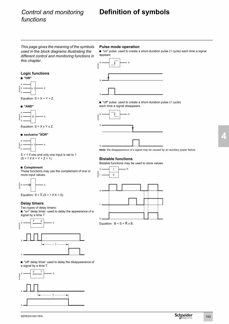
Control and monitoring functions
Definition of symbols
4
This page gives the meaning of the symbols used in the block diagrams illustrating the different control and monitoring functions in this chapter.
Pulse mode operationb "on" pulse: used to create a short-duration pulse (1 cycle) each time a signal appears
DE
5068
1
Logic functionsb "OR"
DE
5067
5
Equation: S = X + Y + Z.b "off" pulse: used to create a short-duration pulse (1 cycle)each time a signal disappears.b "AND"
DE
5067
6
DE
5068
2
Equation: S = X x Y x Z.
b exclusive "XOR"
DE
5067
7
Note: the disappearance of a signal may be caused by an auxiliary power failure.
S = 1 if one and only one input is set to 1(S = 1 if X + Y + Z = 1). Bistable functions
Bistable functions may be used to store values.b ComplementThese functions may use the complement of one or more input values.
DE
5068
3
DE
5067
8
Equation: S = X (S = 1 if X = 0).
Delay timersTwo types of delay timers:b "on" delay timer: used to delay the appearance of a signal by a time T
DE
5067
9 Equation: B = S + R x B.
b "off" delay timer: used to delay the disappearance of a signal by a time T.
DE
5068
0
193SEPED310017EN

4
Control and monitoring functions
Logic input / output assignment
Inputs and outputs may be assigned to predefined control and monitoring functions using the SFT2841 software, according to the uses listed in the table below.The control logic of each input may be inverted for undervoltage type operation.All the logic inputs, whether or not assigned to predefined functions, may be used for the customization functions according to specific application needs:b in the control matrix (SFT2841 software), to connect an input to a logic output, a LED on the front of Sepam or a message for local indication on the displayb in the logic equation editor (SFT2841 software), as logic equation variables.
Logic output (Ox) assignment tableFunctions S60 S62 T60 T62 M61 G60 G62 C60 Assignment
Tripping / contactor control b b b b b b b b O1Inhibit closing b b b b b b b b O2 by defaultClosing b b b b b b b b O3 by defaultWatchdog b b b b b b b b O5Logic discrimination, blocking send 1 b b b b b b b b O102 by defaultLogic discrimination, blocking send 2 b b b O103 by defaultGenset shutdown b b FreeDe-excitation b b FreeLoad shedding b FreeAT, closing of NO circuit breaker b b b b b b FreeAT, closing of coupling b b b b b b FreeAT, opening of coupling b b b b b b Free
Note: The logic outputs assigned by default may be freely reassigned.
Assignment table for logic inputs (Ix) common to all applications
Functions S60 S62 T60 T62 M61 G60 G62 C60 AssignmentClosed circuit breaker b b b b b b b b I101Open circuit breaker b b b b b b b b I102Synchronization of Sepam internal clock via external pulse
b b b b b b b b I103
Switching of groups of settings A/B b b b b b b b b FreeExternal reset b b b b b b b b FreeEarthing switch closed b b b b b b b b FreeEarthing switch open b b b b b b b b FreeExternal trip 1 b b b b b b b b FreeExternal trip 2 b b b b b b b b FreeExternal trip 3 b b b b b b b b FreeEnd of charging position b b b b b b b b FreeInhibit remote control (Local) b b b b b b b b FreeSF6 pressure default b b b b b b b b FreeInhibit closing b b b b b b b b FreeOpen order b b b b b b b b FreeClose order b b b b b b b b FreePhase VT fuse blown b b b b b b b b FreeV0 VT fuse blown b b b b b b b b FreeExternal positive active energy meter b b b b b b b b FreeExternal negative active energy meter b b b b b b b b FreeExternal positive reactive energy meter b b b b b b b b FreeExternal negative reactive energy meter b b b b b b b b FreeRacked out circuit breaker b b b b b b b b FreeSwitch A closed b b b b b b b b FreeSwitch A open b b b b b b b b FreeSwitch B closed b b b b b b b b FreeSwitch B open b b b b b b b b FreeClosing-coil monitoring b b b b b b b b FreePhase rotation direction 123 b b b b b b b b FreePhase rotation direction 132 b b b b b b b b FreeData log activation b b b b b b b b Free
194 SEPED310017EN

Control and monitoring functions
Logic input / output assignment
4
Assignment table for logic inputs (Ix) by applicationFunctions S60 S62 T60 T62 M61 G60 G62 C60 Assignment
Inhibit recloser b b FreeInhibit thermal overload b b b b b b b FreeSwitching of thermal settings b b b b b FreeBlocking reception 1 b b b b b b FreeBlocking reception 2 b b b FreeBuchholz trip b b b b b FreeThermostat trip b b b b b FreePressure trip b b b b b FreeThermistor trip b b b b b FreeBuchholz alarm b b b b b FreeThermostat alarm b b b b b FreePressure alarm b b b b b FreeThermistor alarm b b b b b FreeRotor speed measurement b b b I104Rotor rotation detection b FreeMotor re-acceleration b FreeLoad shedding request b FreeInhibit undercurrent b FreeTrigger Motor start report FreeAuthorize emergency restart FreePriority genset shutdown b b FreeDe-excitation b b FreeClose enable (ANSI 25) b b b b b b FreeInhibit opposite-side remote control (local) b b b b b b FreeInhibit remote-control coupling (local) b b b b b b FreeCoupling open b b b b b b FreeCoupling closed b b b b b b FreeOpposite side open b b b b b b FreeOpposite side closed b b b b b b FreeSelector set to Manual (ANSI 43) b b b b b b FreeSelector set to Auto (ANSI 43) b b b b b b FreeSelector set to Circuit breaker (ANSI 10) b b b b b b FreeSelector set to Coupling (ANSI 10) b b b b b b FreeOpposite-side circuit breaker disconnected b b b b b b FreeCoupling circuit breaker disconnected b b b b b b FreeCoupling close order b b b b b b FreeOpposite-side voltage OK b b b b b b FreeInhibit closing of coupling b b b b b b FreeAutomatic closing order b b b b b b Free
Assignment table for logic GOOSE inputs Gx (IEC 61850) by application
Functions S60 S62 T60 T62 M61 G60 G62 C60 AssignmentBlocking reception 1 b b b b b b FreeBlocking reception 2 b b b FreeExternal trip 2 b b b b b b b b FreeInhibit closing b b b b b b b b FreeGOOSE reception fault b b b b b b b b FreeGOOSE reception indicator b b b b b b b b FreeOther use b b b b b b b b FreeACE850 presence b b b b b b b b G516Load shedding request b FreeData log activation b b b b b b b b FreePhase rotation direction 123 b b b b b b b b FreePhase rotation direction 132 b b b b b b b b FreeData log activation b b b b b b b b Free
Note: GOOSE IEC 61850 logic inputs/outputs can only be used with the ACE850TP or ACE850FO communication interface, and only with Easergy Sepam series 60 or series 80.
195SEPED310017EN

4
Control and monitoring functions
Logic input / output assignment
Standard logic input (Ix) assignmentThe table below lists the logic input (Ix) assignments obtained with the SFT2841 configuration software by clicking on the "standard assignment" button.
Functions Standard assignment
Application
Closed circuit breaker I101 AllOpen circuit breaker I102 AllBlocking reception 1 I103 All except M61 and C60Blocking reception 2 I104 S62, T62 and G62Close enable (ANSI 25) I104 All except M61 and C60SF6 pressure default I105 AllOpen order I106 AllClose order I107 AllInhibit recloser I108 S60 and S62Buchholz trip I108 T60, T62Thermostat trip I109 T60, T62Pressure trip I110 T60, T62Thermistor trip I111 T60, T62Buchholz alarm I112 T60, T62Thermostat alarm I113 T60, T62Pressure alarm I114 T60, T62Selector set to Circuit Breaker (ANSI 10) I201 S60, S62, T60, T62, G60, G62Selector set to Coupling (ANSI 10) I202 S60, S62, T60, T62, G60, G62Selector set to Auto (ANSI 43) I203 S60, S62, T60, T62, G60, G62Selector set to Manual (ANSI 43) I204 S60, S62, T60, T62, G60, G62Opposite side closed I205 S60, S62, T60, T62, G60, G62Opposite side open I206 S60, S62, T60, T62, G60, G62Opposite-side voltage OK I207 S60, S62, T60, T62, G60, G62Inhibit opposite side remote control (local) I208 S60, S62, T60, T62, G60, G62Automatic closing order I209 S60, S62, T60, T62, G60, G62Coupling open I210 S60, S62, T60, T62, G60, G62Coupling closed I211 S60, S62, T60, T62, G60, G62Inhibit closing of coupling I212 S60, S62, T60, T62, G60, G62Coupling close order I213 S60, S62, T60, T62, G60, G62Inhibit remote-control coupling (local) I214 S60, S62, T60, T62, G60, G62
Standard GOOSE logic input (Gx) assignmentThe table below lists the GOOSE logic input (Gx) assignments obtained with the SFT2841 configuration software by clicking on the "standard assignment" button.Functions Standard assignment Application
Blocking reception 1 G401 AllBlocking reception 2 G402 S62, T62, G62External trip 2 G403 AllInhibit closing G404 AllAny of 31 GOOSE logic inputs can be selected, from G401 to G416 and G501 to G515.
196 SEPED310017EN

Control and monitoring functions
Switchgear controlANSI code 94/69
4
Predefined circuit breaker or contactor control function.
Anti-pumping functionTo prevent simultaneous breaking device open and close orders and to give priority to open orders, breaker device close orders are of the pulse type.
Switchgear control with lockout function (ANSI 86)The ANSI 86 function traditionally performed by lockout relays may be ensured by Sepam using the Switchgear control function, with latching of all the tripping conditions (protection function outputs and logic inputs).Sepam performs:b grouping of all the tripping conditions and breaking device controlb latching of the tripping order, with inhibition of closing, until the cause of tripping disappears and is acknowledged by the user (see Latching / acknowledgement function) b indication of the cause of tripping:v locally by LEDs (Trip and others) and by messages on the displayv remotely by remote indications (see Indications function).
Closing with synchro-check The Synchro-check function checks the voltages upstream and downstream of a circuit breaker to ensure safe closing. It is put into service by parameter setting.For it to operate, one of the “Close enable” logic outputs of an MCS025 remote module must be connected to a Sepam logic input assigned to the Close enable function.If it is necessary to close the circuit breaker without taking into account the synchronization conditions, this may be done by a logic equation or via the V_CLOSE_NOCTRL input.
Control of logic outputsLogic orders from the Switchgear control function are used to control the Sepam logic outputs that control breaking device opening and closing.Logic output control is set up to match the device to be controlled, i.e. a circuit breaker or contactor.
OperationThe Switchgear control function can control the following types of breaking device:b circuit breakers with shunt trip or undervoltage coilsb latching contactors with shunt trip coilsb contactors with latched orders.
This function comprises two parts:b processing of internal switchgear control orders:v open , , v close with or without synchro-check , , v inhibit closing , b execution of internal orders by control logic outputs according to the type of device to be controlled.
Processing of internal switchgear control ordersThe Switchgear control function processes all breaking device closing and tripping conditions, based on:b protection functions (configured to trip the breaking device)b breaking device status datab remote control via the communication linkb local control orders by logic input (Ix or Gx), or by mimic-based UMI b internal control orders created by logic equationb specific predefined control functions for each application:v recloserv genset shutdown, de-excitationv load sheddingv synchro-checkv automatic transfer.The function also inhibits breaking device closing, according to the operating conditions.
9
1 2 36 7 8
4 5
197SEPED310017EN

4
Control and monitoring functions
Switchgear controlANSI code 94/69
Block diagram
DE
8100
5
Control of logic outputsControl of a circuit breaker or contactor with mechanical latchingThe block diagram below represents the following parameter setting: b type of switchgear = Circuit Breakerb output O1 = tripb output O2 = close inhibitb output O3 = close.
DE
5158
0
Control of a contactor without mechanical latchingThe block diagram below represents the following parameter setting:b type of switchgear = Contactorb output O1 = open / close.
DE
5158
1
Internal trip orderV_TRIPPED
Internal close inhibitV_CLOSE_INHIBITED
Control oflogic inputs
Internal close orderV_CLOSED
Switchgear closed
Synchro-check
Closing withoutsynchro-check
External close orders:b by logic inputs
Internal close orders:b predefined control functionsb programmed functions(logic equations)
Voluntary close orders:b by logic inputsb by remote controlb by mimic-based HMI
Internal close inhibit:b by logic inputs Ix or Gx
Internal close inhibits:b protection functionsb predefined control functionsb programmed functions(logic equations)
External trip orders:b by logic inputs Ix or Gx
Internal trip orders:b protection functionsb predefined control functionsb programmed functions(logic equations)
Voluntary open orders:b by logic inputb by remote controlb by mimic-based HMI
198 SEPED310017EN

4
Internal trip orderV_TRIPPED
Tripping due toprotection TS233
Internal close inhibitV_CLOSE_INHIBITED
Internal close orderV_CLOSED
Ready to close(for ATS)
V_CLOSE_EN
Breakerclosed (I101)
Closing withoutsynchro-check
Synchro-check
50N/51N, 50V/51V, 59, 59N,64REF, 67, 67N, 81H, 81L, 81R
47, 48/51LR, 49RMS, 50/51, 32Q, 37, 37P, 38/49T, 40, 46,
ANSI 12, 14, 21B, 27, 27D, 32P,
equations
Equations
equations
199SEPED310017EN x)

4
Control and monitoring functions
Switchgear controlANSI code 94/69
Close enable by the Synchro-check functionOperationThe close request, made locally or remotely, is maintained by Sepam during the close request delay and triggers the appearance of a "SYNC.IN PROCESS" message. It is deactivated when a tripping order or circuit breaker inhibition order is received and triggers the "STOP SYNC." message.
The closing order is given if the close enable is received before the close request delay runs out. When this is the case, the message "SYNC. OK" is displayed.
If the close enable is not received, the message "SYNC. FAILURE" is displayed. When possible and if the MCS025 remote module is connected by the CCA785 cord to the Sepam to which the close request has been made, an additional message indicates the type of synchronization failure: b "SYNC. FAILED dU" for too high a voltage differenceb "SYNC. FAILED DF" for too high a frequency differenceb "SYNC. FAILED dPhi" for too high a phase difference.
An additional delay is used to confirm the close enable to guarantee that the closing conditions last long enough.
Block diagram
DE
5227
3
200 SEPED310017EN

Control and monitoring functions
Switchgear controlANSI code 94/69
4
Parameter settingThe Switchgear control function is set up and adapted to match the type of breaking device to be controlled using the SFT2841 software.
PE
5045
4
"Control logic" tabb activation of the Switchgear control functionb choice of the type of breaking device to be controlled: circuit breaker (by default) or contactorb activation of the Synchro-check function, if necessary.
"Logic I/Os" tabb assignment of the logic inputs requiredb definition of logic output behavior.
By default, the following outputs are used:
Logic output Associated internal order Circuit breaker coilO1 Trip
(V_TRIPPED)Shunt trip coil
O2 Close inhibit (V_CLOSE_INHIBITED)
Undervoltage coil
SFT2841: parameter setting of Switchgear control.O3 Close
(V_CLOSED)Shunt trip coil
b the Trip order is always associated with output O1.If output O1 is set up for pulse type operation, the pulse order duration may be set up b the optional Close inhibit and Close orders may be assigned to any logic output.
"Matrix" screen, "Logic" buttonModification of the default internal order assignment to outputs O2 and O3, if necessary.
PE
8075
4
SFT2841: default parameter setting of the logic outputs assigned to Switchgear control.
201SEPED310017EN

4
Control and monitoring functions
Switchgear controlANSI code 94/69
CharacteristicsSettingsSwitchgear control
Setting range On / OffType of device
Setting range Circuit breaker / ContactorTripping pulse duration (output O1)
Setting range 200 ms to 300 sAccuracy (1) ±2 % or from -10 ms to +25 msResolution 10 ms or 1 digitClosing with synchro-check
Setting range On / OffClose request time delay Tdf
Setting range 0 to 300 sAccuracy (1) ±2 % or from -10 ms to +25 msResolution 10 ms or 1 digitSynchro confirmation time delay Tcs
Setting range 0 to 300 sAccuracy (1) ±2 % or from -10 ms to +25 msResolution 10 ms or 1 digitInputsDesignation Syntax Equations
Tripping, opening V_TRIPCB bInhibit closing V_INHIBECLOSE bClosing V_CLOSECB bClosing without synchro-check V_CLOSE_NOCTRL b
OutputsDesignation Syntax Equations Matrix
Tripping, opening V_TRIPPED b bInhibit closing V_CLOSE_INHIBITED b bClosing V_CLOSED b bContactor control V_CONTACTOR bSynchro-check on V_SYNC_ON bSychrochecked close request in process V_SYNC_INPROC bSynchrochecked close request stop V_SYNC_STOP bSynchrochecked close request successful V_SYNC_OK bSynchrochecked close request failure V_NOSYNC bSynchrochecked close request failure - Voltage difference too high
V_NOSYNC_DU b
Synchrochecked close request failure - Frequency difference too high
V_NOSYNC_DF b
Synchrochecked close request failure - Phase difference too high
V_NOSYNC_DPHI b
(1) Under reference conditions (IEC 60255-6).
TS/TC equivalence for each protocolModbus DNP3 IEC 60870-5-103 IEC 61850TC Binary Output ASDU, FUN, INF LN.DO.DA
TC1 BO0 20, 21, 1 (OFF) CSWI1.Pos.ctlValTC2 BO1 20, 21, 1 (ON) CSWI1.Pos.ctlValTS Binary Input ASDU, FUN, INF LN.DO.DA
TS233 BI334 2, 160, 68
202 SEPED310017EN

Control and monitoring functions
Latching / acknowledgement
4
OperationThe tripping outputs of all the protection functions and all the logic inputs (Ix) may be latched individually.Logic outputs may not be latched. Logic outputs set up as pulse-type outputs maintain pulse-type operation even when they are linked to latched data. Latched data are saved in the event of an auxiliary power failure.All latched data are acknowledged together, at the same time. Acknowledgement is done:b locally on the UMI using the keyb or remotely via a logic input, the SFT2841 software or via the communication linkb or by logic equation.The remote indication TS5 remains present after latching operations until acknowledgement has taken place.The Latching/acknowledgement function associated with the Switchgear control function may be used to perform the ANSI 86 Lockout relay function.
Block diagram
DE
8055
7
CharacteristicsInputsDesignation Syntax Equations
Inhibition of UMI Reset key V_INHIB_RESET_LOCAL bAcknowledgement by logic equation V_RESET b
TS/TC equivalence for each protocolModbus DNP3 IEC 60870-5-103 IEC 61850TS Binary Input ASDU, FUN, INF LN.DO.DA
TS5 BI0 1, 160, 19 LLN0.LEDRs.stValTC Binary Output ASDU, FUN, INF LN.DO.DA
TC3 BO2 20, 160, 19 LLN0.LEDRs.ctlVal
Acknowledgementby UMI Reset key
Reset by remote control (TC3)Inhibit remote controlReset by SFT2841External resetby logic input
V-RESET
Acknowledgementby UMI Reset key V_KEY_RESET
Reset requested V_RESETORD
203SEPED310017EN
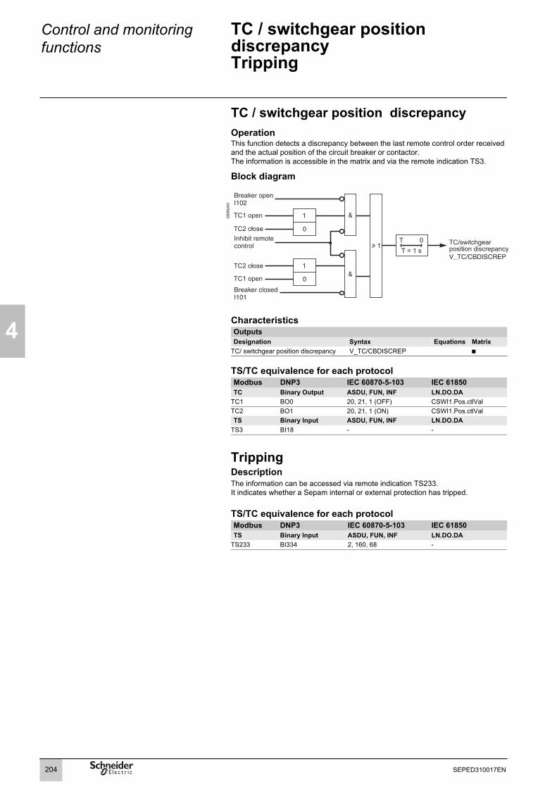
4
Control and monitoring functions
TC / switchgear position discrepancyTripping
TC / switchgear position discrepancyOperationThis function detects a discrepancy between the last remote control order received and the actual position of the circuit breaker or contactor.The information is accessible in the matrix and via the remote indication TS3.
Block diagram
DE
8024
3
CharacteristicsOutputs Designation Syntax Equations Matrix
TC/ switchgear position discrepancy V_TC/CBDISCREP b
TS/TC equivalence for each protocolModbus DNP3 IEC 60870-5-103 IEC 61850TC Binary Output ASDU, FUN, INF LN.DO.DA
TC1 BO0 20, 21, 1 (OFF) CSWI1.Pos.ctlValTC2 BO1 20, 21, 1 (ON) CSWI1.Pos.ctlValTS Binary Input ASDU, FUN, INF LN.DO.DA
TS3 BI18 - -
TrippingDescriptionThe information can be accessed via remote indication TS233.It indicates whether a Sepam internal or external protection has tripped.
TS/TC equivalence for each protocolModbus DNP3 IEC 60870-5-103 IEC 61850TS Binary Input ASDU, FUN, INF LN.DO.DA
TS233 BI334 2, 160, 68 -
204 SEPED310017EN

Control and monitoring functions
Disturbance-recording trigger
4
OperationThe recording of analog and logic signals may be triggered by different events, dependent on the control matrix parameter setting or manual action:b triggering by the grouping of all pick-up signals of the protection functions in service b triggering by the delayed outputs of selected protection functionsb triggering by selected logic inputsb triggering by selected Vx outputs (logic equations)b manual triggering by a remote control order (TC20)b manual triggering via the SFT2841 software toolb triggering by selected logic inputs (Gx) (if recording configured in SFT2841 software disturbance recording screen). Disturbance recording may be:b inhibited via the SFT2841 software or by remote control order (TC18)b validated via the SFT2841 software or by remote control order (TC19).
Block diagram
DE
8100
7
CharacteristicsOutputsDesignation Syntax Equations Matrix
Disturbance recording function triggered V_OPG_TRIGGED b
TS/TC equivalence for each protocolModbus DNP3 IEC 60870-5-103 IEC 61850TC Binary Output ASDU, FUN, INF LN.DO.DA
TC18 BO3 - RDRE1.RcdInh.ctlValTC19 BO4 - RDRE1.RcdInh.ctlValTC20 BO5 - RDRE1.RcdTrg.ctlVal
Disturbance recording triggeraccording to protection functionsconfigured in matrix (delayed outputs)
Pickup
Disturbance recording triggerby logic inputs Ix
Disturbance recording triggerby selected logic inputs Gxif configured by SFT2841Disturbance recording triggerby selected outputs(logic equations)
Manualdisturbancerecording trigger
Inhibition ofdisturbancerecording trigger
Validation ofdisturbancerecording trigger
Manualdisturbancerecording trigger
DisturbancerecordingtriggerV_OPG_TRIGGED
Disturbancerecordingtrigger inhibitedV_OPG_INHIBITED
205SEPED310017EN

4
Control and monitoring functions
Switching of groups of settings
OperationThere are two groups of settings, group A / group B, for the phase overcurrent, earth fault, directional phase overcurrent and directional earth fault protection functions. Switching from one group of settings to another makes it possible to adapt the protection characteristics to suit the electrical environment of the application (change of earthing system, changeover to local power generation, ...). The switching of settings is global and therefore applies to all the units of the protection functions mentioned above.The groups of settings switching mode is determined by parameter setting:b switching according to the position of a logic input (0 = group A, 1 = group B)b switching by remote control order (TC33, TC34)b forced group A or group B.
Block diagramD
E50
807
TS/TC equivalence for each protocolModbus DNP3 IEC 60870-5-103 IEC 61850TC Binary Output ASDU, FUN, INF LN.DO.DA
TC33 BO8 20, 160, 23 LLN0.SGCBTC34 BO9 20, 160, 24 LLN0.SGCB
206 SEPED310017EN

Control and monitoring functions
Logic discriminationPrinciple
4
OperationThis function considerably reduces the tripping time of the circuit breakers closest to the source and may be used for logic discrimination in closed ring networks. It applies to the phase 50/51, directional phase overcurrent 67, earth fault 50N/51N and directional earth fault 67N overcurrent protections, definite time and IDMT.
Easergy Sepam series 60 discrimination logic comprises 2 discrimination groups.Each group includes:b logic thresholds: protection units that send blocking signals (BSIG) and that may be prevented from tripping by the reception of blocking signals. b time-based thresholds: protection units that may not be prevented from tripping by blocking signals and that do not send blocking signals. They are used as backup for the logic thresholds.
When a fault occurs:b the logic thresholds detecting the fault send blocking signalsb the logic thresholds detecting the fault send a tripping order if they are not inhibited by blocking signalsb the time-based (backup) thresholds detecting the fault send a tripping order.
The sending of blocking signals lasts as long as it takes to clear the fault. If Sepam gives a tripping order, they are interrupted after a time delay that takes account of the breaking device operating time and the protection unit reset time. This system guarantees safety in downgraded operating situations (faulty wiring or switchgear).
Example: Radial distribution with use of time-based discrimination
Example: Radial distribution with use of logic discrimination
DE
5062
3
DE
5080
9
T: protection setting time. As an approximation for definite time curves, this is assumed to be equal to the protection tripping time.
The upstream protection units are typically delayed by 0.3 s to give the downstream protection units time to trip. When there are many levels of discrimination, the fault clearing time at the source is long. In this example, if the fault clearing time for the protection unit furthest downstream is Xs = 0.2 s, the fault clearing time at the source is T = Xs + 0.9 s = 1.1 s.
T: protection setting time. As an approximation for definite time curves, this is assumed to be equal to the protection tripping time.
When a fault appears, the protection units that detect it inhibit the upstream protection units. The protection unit furthest downstream trips since it is not blocked by another protection unit. The delays are to be set in accordance with the device to be protected. In this example, if the fault clearing time for the protection unit furthest downstream is Xs = 0.2 s, the fault clearing time at the source is T = Xs - 0.1 s = 0.1 s.
207SEPED310017EN

4
Control and monitoring functions
Logic discriminationPrinciple
Operation with logic inputs/outputs (Ix/Ox)The assignment of protection devices between logic thresholds and time-based thresholds depends on the application and the logic input/output settings. The first logic group is active if one of the following two conditions is fulfilled:b blocking reception 1 is assigned to a logic input (Ix) except for motors where this input does not existb blocking send 1 is assigned to an output (O102 by default).The second logic group, when present in the application, is active if one of the following two conditions is fulfilled:b blocking reception 2 is assigned to a logic input (Ix)b blocking send 2 is assigned to an output (O103 by default).
The SFT2841 software indicates the type of thresholds, logic or time-based, according to the input/output settings.
DE
8055
9
Logic discrimination using wired logic inputs and outputs (Ix and Ox)
The assignment of protection devices between the two discrimination groups is fixed and cannot be modified. When logic discrimination is used, it is important to check the concordance between the origin of the measurement and the logic discrimination group to which the unit is assigned.Pilot wire testThe pilot wires may be tested using the output relay test function in the SFT2841 software.
Level Sepam
Send
Reception
Level SepamSend BSIG1 outputto other level Sepam
Reception
Send BSIG2 outputto other level Sepam
BSIG1 BSIG2
BSIG1 BSIG2
Send
"n+1"
"n"
"n" "n"
208 SEPED310017EN

Control and monitoring functions
Logic discriminationPrinciple
4
Operation with GOOSE messages and logic inputs (Gx)Equipped with the ACE850 interface, Easergy Sepam series 60 can be used for logic discrimination with GOOSE logic inputs and the IEC 61850 protocol on Ethernet TCP/IP.
The first logic group is active if one of the following two conditions is fulfilled:b blocking reception 1 is assigned to a GOOSE logic input (G401 by default), except for Sepams used in motor applications where this input does not existb blocking send 1 is created by sending a GOOSE logic discrimination blocking message over the Ethernet network.The second logic group, when present in the application, is active if one of the following two conditions is fulfilled:b blocking reception 2 is assigned to a GOOSE logic input (G402 by default)b blocking send 2 is created by sending a GOOSE logic discrimination blocking message over the Ethernet network.
DE
8056
0
Logic discrimination using the IEC 61850 protocol and GOOSE logic inputs (Gx)
ACE850
ACE850
Ethernet TCP/IP
Level Sepam
Reception
Send
BSIG1 BSIG2
BSIG1 BSIG2
Send BSIG1 output to other level Sepam
Send BSIG2 output
Level Sepam"n+1"
"n"
"n"
to other level Sepam"n"
209SEPED310017EN

210
4
SEPED310017EN
Control and monitoring functions
Logic discriminationS60, T60, and G60 applications Threshold assignment
Type of protection
Unit numberTime-based Send logic Reception logic
Group 1 Group 2 Group 1 Group 250/51 3, 4 1, 2 - 1, 2 -50N/51N 3, 4 1, 2 - 1, 2 -
CharacteristicsSettingsActivity
Setting rangeOutputs Designation Syntax Equations Matrix
Logic discrimination trip V_LOGDSC_TRIP (1)
Blocking send 1 V_LOGDSC_BL1(1) Only if switchgear control is not in service.
Block diagram
DE8
1008
(1) By default.(2) If using the ACE850 communication interface and a GOOSE logic input (IEC 61850).
Blockingsend 1
Logic thresholds
unit 1 inst.unit 2 inst.
earth fault
unit 1 inst.unit 2 inst.
overcurrent
Blockingreception 1
overcurrentunit 1 delayedunit 2 delayed
earth faultunit 1 delayedunit 2 delayed
(logic input lx) blocking reception 1
(GOOSElogic input Gx)
blocking reception 1 (2)
Time-based thresholdsovercurrentunit 3 delayedunit 4 delayed
earth faultunit 3 delayedunit 4 delayed
logic discriminationtripV_LOGDSC_TRIP
output O102 (1)
blocking send 1inhibit blocking sendif fault not cleared
BSIG1
Circuit Breaker closed (3)
(3) Condition ignored (always = 1) if no input is assigned to Circuit Breaker closed.

Control and monitoring functions
Logic discriminationM61 and C60 applications
4
Threshold assignmentType of protection
Unit numberTime-based Send logic Reception logic
Group 1 Group 2 Group 1 Group 250/51 3, 4 1, 2 - - -50N/51N 3, 4 1, 2 - - -67N (1) 2 1 - - -
(1) For M61 application only.
CharacteristicsSettingsActivity
Setting range On / OffOutputs Designation Syntax Equations Matrix
Logic discrimination trip V_LOGDSC_TRIP b (1)
Blocking send 1 V_LOGDSC_BL1 b(1) Only if switchgear control is not in service.
Block diagram
DE
8100
9
(1) For M61 application only.
Is
(1)
(1)
(1)
211SEPED310017EN

212
4
SEPED310017EN
Control and monitoring functions
Logic discriminationS62, T62 and G62 applications
Block diagram
DE8
1010
(1) By default.(2) If using the ACE850 communication interface and a GOOSE logic input (IEC 61850).
Logic thresholds
Time-based thresholdsovercurrentunit 3 delayedunit 4 delayed
earth faultunit 3 delayedunit 4 delayed
logic discriminationtripV_LOGDSC_TRIP
output O102 (1)
blocking send 1
output O103 (1)
blocking send 2inhibit blocking sendif fault not cleared
BSIG2
BSIG1
Blockingsend 1 and 2
overcurrentunit 1 inst.unit 2 inst.
earth faultunit 1 inst.unit 2 inst.
directional overcurrentunit 1 inst. 0.8 Is
directional earth faultunit 1 inst. Is
directional overcurrentunit 2 inst. 0.8 Is
directional earth faultunit 2 inst. Is
Blockingreception 1 and 2
overcurrentunit 1 delayedunit 2 delayed
earth faultunit 1 delayedunit 2 delayed
directional earth faultunit 1 delayed
directional overcurrentunit 1 delayed
blocking reception 1 (2)
(GOOSElogic input Gx)
blocking reception 1(logic input Ix)
directional earth faultunit 2 delayed
directional overcurrentunit 2 delayed
blocking reception 2 (2)
(GOOSElogic input Gx)blocking reception 2(logic input Ix)
Circuit Breaker closed (3)
Circuit Breaker closed(3)
(3) Condition ignored (always = 1) if no input is assigned to Circuit Breaker closed.

Control and monitoring functions
Logic discriminationS62, T62 and G62 applications
4
Threshold assignmentType of protection
Unit numberTime-based Send logic Reception logic
Group 1 Group 2 Group 1 Group 250/51 3, 4 1, 2 - 1, 2 -50N/51N 3, 4 1, 2 - 1, 2 -67 (1) - 1 2 1 267N (1) - 1 2 1 2
(1) According to application.
CharacteristicsSettingsActivity
Setting range On / OffOutputs Designation Syntax Equations Matrix
Logic discrimination trip V_LOGDSC_TRIP b (1)
Blocking send 1 V_LOGDSC_BL1 bBlocking send 2 V_LOGDSC_BL2 b(1) Only if switchgear control is not in service.
213SEPED310017EN

4
Control and monitoring functions
Logic discriminationExample of setting: radial network
When a fault occurs in a radial network, the fault current flows through the circuit between the source and the location of the fault:b the protection units upstream from the fault are triggeredb the protection units downstream from the fault are not triggeredb only the first protection unit upstream from the fault should trip.Example of settingA 20 kV installation, supplied by a transformer, comprises the main busbars which in turn supply a feeder to a motor substation and a long feeder to a distant MV/LV transformer. The installation is earthed via a resistor at the incoming transformer neutral point, which limits to the current to about 10 Amps.
DE
8101
1
T60
S60 S62
T60M61M61
BSIG1 order
Longcable
Motor substation
Motor Motor
direction of blocking signal orders
BSIG1 order
BSIG1 order
: detected fault direction according to the directional protections
214 SEPED310017EN

Control and monitoring functions
Logic discriminationExample of setting: radial network
4
Protection settingsBased on a network coordination study, the installation relay settings are as follows:b incomer: Sepam T60 (relay A)v busbar fault thresholds 50/51, 50N/51N: T = 0.1 s (DT)Logic discrimination group 1:- blocked by relays B and D - blocking send 1 to high voltage relaysv backup thresholds50/51, 50N/51N: T = 0.7 s (DT) Time-based thresholdsb feeder to motor substation: Sepam S62 (relay B)v busbar fault thresholds50/51, 50N/51N: T = 0.1 s (DT)Logic discrimination group 1:- blocked by relays C1 and C2- blocking send 1 to relay Av backup thresholds50/51, 50N/51N: T = 0.4 s (DT)Time-based thresholdsb motor feeders:v motor 1: Sepam M61 (relay C1)motor fault thresholds50/51, 50N/51N: T = 0.1 s (DT) Logic discrimination group 1: - blocking send 1 to relay Bv motor 2: Sepam M61 (relay C2)motor fault thresholds- 50N/51N: T = 0.1 s (DT)- 50/51 self-balancing differential scheme: T = 0 s (DT)
Logic discrimination group 1: blocking send 1 to relay Bb substation feeder: Sepam S62 (relay D)v cable fault thresholds50/51, 67N: T = 0.4 s (DT)v these thresholds are set time-wise (0.4 s) in relation to Sepam T60 (0.1 s) (relay E)v blocking send 1 to Sepam T60 (relay A)b T60 transformer protection (relay E): settings which can be coordinated with the secondary.
The logic input and output settings for all the relays concerned are:b blocking reception 1 on I103b blocking send 1 on O102
Parameter setting using GOOSE dataWhen using GOOSE logic inputs (IEC 61850), the input and output parameters are:b blocking reception 1: Each Sepam should subscribe to the GOOSE blocking message 1 gcbBasicGse (LD0/PTRC1/blklnd1) concerning it and then assign this blocking GOOSE message to a GOOSE logic input (G401 by default for BSIG1).b blocking send 1: Each Sepam should generate a GOOSE blocking message called GOOSE Control Block standard which contains BSIG1 (gcbBasicGse (LD0/PTRC1/blklnd1)).
For more information, refer to the Sepam IEC 61850 communication user's manual, reference SEPED306024EN.
215SEPED310017EN

4
Control and monitoring functions
Logic discriminationExample of setting: parallel incomers
Substations supplied by 2 (or more) parallel incomers may be protected using Sepam S62, T62 or G62, by a combination of directional phase (67) and earth fault (67N) protection functions, with the logic discrimination function.
DE
8101
5
To avoid both incomers tripping when a fault occurs upstream from one incomer, the incomer protection devices must operate as follows:b protection function 67 of the faulty incomer detects the fault current in the line direction, the protection tripping direction:v sends a blocking signal to inhibit the phase overcurrent protection functions (50/ 51) of both incomersv and initiates tripping of the incomer circuit breakerb protection function 67 of the fault-free incomer is insensitive to fault current in the busbar direction.
Example of cablingb Feeder Sepam: blocking send 1 blocks the Incomer Sepam 50/51 and 50N/51N functions. By default, outputs O102 (blocking send 1) on the Feeder Sepams should be connected to the I103 inputs (blocking reception 1) on both Incomer Sepams.b Directional protection function 67 unit 2 on each Incomer Sepam should be set to detect a fault on the line side. Thus the blocking send 2 output (by default O103) which is connected to input I103 can be used to inhibit the 50/51, 50N and 51N protection functions of both incomers so as to leave protection 67 unit 2 with the responsibility for tripping the incomer, the only one affected by the fault upstream.
Incomer 1 Incomer 2
BSIG1 BSIG1
Feeders
direction of blocking signal orders
BSIG1 BSIG2
Busbar
BSIG1BSIG2
: detected fault direction according to the directional protections
216 SEPED310017EN

Control and monitoring functions
Logic discriminationExample of setting: parallel incomers
4
Example of setting with IEC 61850 GOOSE dataSetting the GOOSE data parametersThe following operations are performed using SFT850 and SFT2841 software:b In the event of a fault on the cables, Feeder Sepams should send a blocking input order in the form of a GOOSE (blocking send 1= LDO.PTRC1.BlkInd1) from the thresholds of units 1 and 2 of 50/51 or 50N/51N functions. b Incomer Sepams should also send a blocking signal when the directional protection functions detect a fault on the line. To do this, the thresholds of units 2 of protection functions 67 and 67N set for a line fault, which send the blocking signal (blocking send 2 = LDO.PTRC1.BlkInd2), can block the 50/51 and 50N/51N protection functions of the opposite incomer and their own thresholds respectively.b Both Incomer Sepams must subscribe to this GOOSE to receive the GOOSE blocking send 1 data item issued by the feeders and also to the GOOSE blocking send 2 data item issued by the opposite incomer and its own GOOSE.b A logical OR between the GOOSE sent by the feeder and the GOOSE sent by the opposite incomer is created by assigning the LDO.PTRC1.BlkInd1 and LDO.PTRC1.BlkInd2 data items to the same GOOSE input (for example G401). b This GOOSE input (G401) is assigned to the function BSIG1,receive,blocking input of each Incomer Sepam using the SFT2841 software.Protection settingsThe protection settings are the same as for hard-wired cabling:b When a fault occurs upstream of the incomer circuit breakers, the incomer concerned is tripped by the delayed directional threshold of unit 2 of the 67 or 67N protection functions.b When a fault occurs on the busbars, no blocking input is sent and therefore the 50/51 or 50N/51N protection functions quickly send a tripping order.The thresholds of units 3 and 4 set using time discrimination provide backup tripping.b Units 1 of the 67 and 67N functions are not used.
217SEPED310017EN

4
Control and monitoring function
Logic discriminationExample of setting: closed ring network
Closed ring network protection may be provided by Sepam S62 or T62, which include the following functions:b 2 units of directional phase (67) and earth fault (67N) protection functions:v unit 2 to detect faults in the line directionv unit 1 to detect faults in the busbar directionb 2 discrimination groups:v sending of 2 blocking signals, sent in the opposite direction of the detected faults. For example, a Sepam which detects a fault on its line side sends a blocking signal to the Sepam located upstream, i.e. on its busbar side.v reception of 2 blocking signals, to block the directional protection relays according to the detection direction.
DE
8101
6
With the combination of directional protection functions and the logic discrimination function, the faulty section may be isolated with a minimal delay by tripping of the circuit breakers on either side of the fault.Blocking signals are initiated by both protection functions 67 and 67N. Priority is given to protection function 67: when protection functions 67 and 67N detect faults in opposite directions at the same time, the blocking signal sent is determined by the direction of the fault detected by protection function 67.The instantaneous output of protection functions 67 and 67N, activated at 80% of the Is threshold, is used to send blocking signals. This avoids uncertainty when the fault current is close to the Is threshold.
(I103)
(O102)
67/1 67/2
(I103)
(O103)
BSIG1
BSIG1
BSIG2
BSIG1
BSIG2 BSIG1 BSIG2
BSIG1 BSIG1
BSIG2 BSIG1
BSIG1
BSIG1
BSIG1
BSIG1
BSIG1
(I103)(O102)
(I103)(O102)
67/1 67/2
(I103)
(O102)(I103)
(O103)
(I104) (O102 )(I104)(O102)
67/1 67/2 67/1 67/2
: detected fault direction according to the directional protections
218 SEPED310017EN

Control and monitoring functions
Logic discriminationExample of setting: closed ring network
4
Example of cablingTo simplify on-site cabling the following rules must be observed.General rulesb The cabling for CTs and VTs is identical on all cubicles and conforms to the connection diagrams in the Sepam documentation. This allows a predefined fault detection direction to be associated with each directional protection function unit. b The association of logic inputs and standard functions simplifies this implementation and cabling is therefore identical on all Sepams on all substations.For each substationb The protection 67 unit 1 threshold is set for fault detection on the busbars, and the unit 2 threshold for a fault on the line.The settings can be identical (thresholds, time delay, angle). b The delayed thresholds on both units are used to trip the circuit breaker associated with the Sepam relay.b The blocking send 2 (O103) outputs on the substation Sepams are connected to the blocking reception 1 inputs (I103) on the opposite Sepam.Between 2 substationsThe blocking send 1 (O102) output on the substation Line feeder Sepam is connected to the input (I104) on its Sepam which corresponds to the other end of the line in the other substation.Remarksb In the event of a fault in the substation, a logic discrimination order can be hard-wired on the blocking inputs (I103) of both Sepams in the ring so as to block the directional 67 and 67N function units oriented towards the busbars.In this case 2 separate contacts must be used to decouple the simultaneous blocking send command from the protection function in the substation to both Ring feeder Sepams.b Particular care must be given to managing the polarity of commands between the various substations in the ring.
219SEPED310017EN

4
Control and monitoring functions
Logic discriminationExample of setting: closed ring network
Example of setting with IEC 61850 GOOSE messagesCase of a ring consisting of 2 substations containing 2 S62 Ring feeder Sepams and a User T60 transformer Sepam. This example is given with the directional phase protection function (ANSI 67) but the same reasoning applies for the directional earth fault protection function (ANSI 67N).
DE
8101
7
Example of associated Ethernet network
DE
8101
9
Protection settingsThe protection settings are the same as for hard-wired cabling:To simplify on-site cabling the following rules must be observed.General rulesb The cabling for CTs and VTs is identical on all cubicles and conforms to the connection diagrams in the Sepam documentation. This allows a predefined fault detection direction to be associated with each directional protection function unit. b The association of GOOSE inputs and standard functions simplifies the implementation of GOOSE messages.For each substationb The protection 67 unit 1 threshold is set for fault detection on the busbars, and the unit 2 protection threshold for a fault on the line.The settings can be identical (thresholds, time delay, angle). b The delayed thresholds on both units are used to trip the circuit breaker associated with the Sepam relay.
Sourcesubstation
67/1 67/1
67/2 67/2
A B
BC
51
C D E
F
DE
51
Sourcesubstati
: detected fault direction according to the directional protections
A
Ethernet
F
B C BC
D E DE
Source substation
Substation 1
Substation 2
S60 S60
S62
S62
S62 T60
T60S62
220 SEPED310017EN

Control and monitoring functions
Logic discriminationExample of setting: closed ring network
4
Setting the GOOSE data parametersPublishing GOOSE messagesb Each S62 Ring feeder Sepam (B, C, D, E) publishes a GOOSE message consisting of several data items, especially those concerning blocking inputs and network connection tests:v LDO.PTRC1.BlkInd1 created by the BSIG1 function (67, 67N unit 1) when there is a fault on the busbarsv LDO.PTRC1.BlkInd2 created by the BSIG2 function (67, 67N unit 2) when there is a fault on the linev LDO.GSE_GGIO1.Test1 which can be activated using the SFT2841 software connected to the Sepam in order to manually test the connection and parameter settings of the Sepam relays subscribed to GOOSE messages for this Sepam.In this example,b the T60 Ring feeder (A and F) Sepams on the source substation do not publish GOOSE messagesb User T60 Sepam publish a blocking input GOOSE message consisting of the following 2 data items:v LDO.PTRC1.BlkInd1 created by the BSIG1 function (50/51, 50N/51N)v LDO.GSE_GGIO1.Test1 to test the Ethernet connectionSubscribing to GOOSE messagesEach S62 Ring feeder Sepam subscribes to GOOSE messages containing blocking data items from the following Sepam relays:b Sepam (T60) Userb Sepam (S62) Ring feeder from its substationb Sepam (S62) Ring feeder from the substation at the other end of the line.
GOOSE data between Sepam relays in the closed ringThe table below contains all the information needed to create the GOOSE messages exchanged between all Sepam relays in the closed ring.In this example, LED 5 on the Sepam front face which is, depending on where it comes from, assigned to G411, G412 or G413 in the SFT2841 matrix, allows the user to check visually that the GOOSE message has been receiving during a manual test.
Preparing GOOSE messages using the SFT850 softwareSepam A (S60) Sepam B (S62) Sepam BC (T60) Sepam C (S62) Sepam D (S62) Sepam DE (T60) Sepam E (S62) Sepam F (S60)
GOOSE publication
BlkInd1(B) BlkInd1(BC) BlkInd1(C) BlkInd1(D) BlkInd1(DE) BlkInd1(E)BlkInd2(B) BlkInd2(C) BlkInd2(D) BlkInd2(E)Test1(B) Test1(BC) Test1(C) Test1(D) Test1(DE) Test1(E)
GOOSE subscription
BlkInd1(B) BlkInd1(BC) BlkInd1(BC) BlkInd1(DE) BlkInd1(DE) BlkInd1(E)BlkInd2(C) BlkInd2(B) BlkInd1(C) BlkInd2(D)
BlkInd1(D) BlkInd2(E)Test1(BC) Test1(BC) Test1(DE) Test1(DE)
Test1(B) Test1(B) Test1(C)Test1(C) Test1(D) Test1(E) Test1(D) Test1(E)
Association of GOOSE data items with GOOSE inputs (Gxxx) using the SFT850 softwareG401 BlkInd1(B) BlkInd1(BC) BlkInd1(BC) BlkInd1(DE) BlkInd1(DE)
BlkInd2(C) BlkInd2(B) BlkInd2(E) BlkInd2(D)G402 BlkInd1(D) BlkInd1(C)G411 Test1(BC) Test1(BC) Test1(DE) Test1(DE)G412 Test1(C) Test1(B) Test1(E) Test1(D)G413 Test1(B) Test1(D) Test1(C) Test1(E)
Associating GOOSE inputs with Sepam logic functions using the SFT2841 softwareG401 BSIG1 BSIG1 BSIG1 BSIG1 BSIG1 BSIG1G402 BSIG2 BSIG2 BSIG2 BSIG2G411 LED 5 LED 5 LED 5 LED 5G412 LED 5 LED 5 LED 5 LED 5G413 LED 5 LED 5 LED 5 LED 5
BlkInd1 (C) = LDO.PTRC1.BlkInd1.stVal issued by the Sepam (C)BlkInd2 (C) = LDO.PTRC1.BlkInd2.stVal issued by the Sepam (C) Test1 (C) = LDO.GSE_GGIO1.Test1.stVal issued by the Sepam (C)
221SEPED310017EN

4
Control and monitoring functions
Load shedding
OperationMotor load shedding is done to reduce the load on the electrical network so as to keep the voltage within an acceptable range.Load shedding may be triggered:b by an order from outside Sepam in the presence of a logic input assigned for the reception of load shedding orders. Orders may be delayedb by a voltage dip detected by the delayed output of Sepam 27D protection unit 1 (typical setting 40% Un).Load shedding triggers:b tripping by the switchgear control functionb inhibition of closing as long as the load shedding order is maintained.The load shedding order is maintained as long as one of the following three conditions is present:b external order via logic input (Ix or Gx)b positive sequence voltage less than load shedding voltage detected by 27D unit 1 thresholdb insufficient positive sequence voltage for a restart order to be given and detected by the delayed 27D unit 2 threshold. The time delay for the detection of correct voltage recovery must be shorter than the load shedding delay (27D unit 1) in order for the load shedding order to be maintained correctly. This unit is also used by the restart function.The function may be validated by the switchgear closed and not racked out conditions.
Block diagram
DE
8056
3
CharacteristicsSettingsActivity
Setting range On / OffDelay before load shedding
Setting range 0 to 300 sAccuracy (1) ±2 % or from -10 ms to +25 msResolution 10 ms or 1 digitOutputs Designation Syntax Equations Matrix
Load shedding order V_LOADSH_ORD b(1) Under reference conditions (IEC 60255-6).
Circuit breaker closed
Racked out circuit breaker
GOOSE logic input (Gx)load shedding request
Logic input (lx)load shedding request27D unit 1, delayed(load shedding threshold)27D unit 2, delayed(voltage correct)
Delay before load shedding
Load sheddingV_LOADSH_ORD
222 SEPED310017EN

Control and monitoring functions
Restart
4
OperationWith this function, motors can be automatically restarted after a shutdown triggered by a voltage dip (load shedding).The restart function is to be associated with the load shedding function It allows staggered restarting of process motors, as long as the voltage dip that caused load shedding was brief.When tripping occurs due to a dip in the network supply voltage detected by 27D protection unit 1, two situations are possible:b the voltage dip lasts for a period longer than the maximum voltage dip duration: tripping is final. External action is required for restart.b the voltage dip lasts for a period shorter than the maximum dip duration: a restart order is given. Delayed restart allows motor restart orders to be staggered to avoid network overload.The enabling of restart is detected after the delayed output of protection 27D unit 2 drops out. This threshold allows the return of voltage to be detected independently with respect to the load shedding threshold. The typical setting is 50 % Un.The restart order is given by the switchgear control function.
Block diagram
DE
5160
8
CharacteristicsSettingsActivity
Setting range On / OffMaximum voltage dip duration
Setting range 0 to 300 sAccuracy (1) ±2 % or from -10 ms to +25 msResolution 10 ms or 1 digitRestart delay
Setting range 0 to 300 sAccuracy (1) ±2 % or from -10 ms to +25 msResolution 10 ms or 1 digit(1) Under reference conditions (IEC 60255-6).
223SEPED310017EN

4
Control and monitoring functions
Restart
Example 1: Voltage dip with restart order
DE
8024
1
Example 2: Voltage dip without restart order
DE
8024
2
224 SEPED310017EN

Control and monitoring functions
Generator shutdown and tripping
4
OperationThis function controls shutdown of the driving machine, tripping of the breaking device and interruption of the generator excitation supply in case of:b detection of an internal generator faultb receipt of a genset shutdown order on a logic input or via the communication link.
Generator separationThis type of control function gives the following order:b a trip order to the generator coupling circuit breaker.The machine remains excited and the prime mover is not shut down. This mode is used to the isolate the machine from a network which no longer meets the coupling conditions (voltage, frequency, loss of power network). The generator may continue to supply loads locally.
Sequential trippingThis type of control function gives the following orders on after the other:b a trip order to the generator coupling circuit breakerb a delayed trip order to the excitation circuit breakerb a delayed shutdown order to the prime mover.This mode is reserved for certain machines. Sepam enables these operating modes by combining:b switchgear control for tripping of the generator coupling circuit breakerb de-excitation function for tripping of the excitation circuit breakerb genset shutdown function to order the shutdown of the prime mover. Function output delays are used for sequential tripping.
Typical parameter setting for industrial network generators
DE
5063
6
Generator shutdown and tripping involve:tripping of the circuit breaker connecting the
machine to the networktripping of the excitation circuit breakershutdown of the prime mover.
The combination of these three orders determines four types of shutdown and tripping orders:b total shutdown (simultaneous tripping)b generator trippingb generator separationb sequential tripping.
Total shutdownThis type of control function gives the following orders at the same time:b a trip order to the generator coupling circuit breakerb a trip order to the excitation circuit breakerb a shutdown order to the prime mover.This mode is reserved for internal faults in generators and transformers of generator-transformer units.
Generator trippingThis type of control function gives the following orders:b a trip order to the generator coupling circuit breakerb a trip order to the excitation circuit breaker. The prime mover is not shut down. This mode is reserved for power network faults and allows the generator to be quickly reconnected after the fault is cleared.
Protectionfunctions
Circuit breaker tripping
Genset shutdown De-excitation
12 b21B b27 b32Q b b b37P b40 b b b46 b47 b49RMS b50/51 b50N/51N50G/51G
b b b
50V/51V b59 b59N b b b64REF b b b67 b b b67N/NC b b b81H b81L b81R b
1
23
225SEPED310017EN
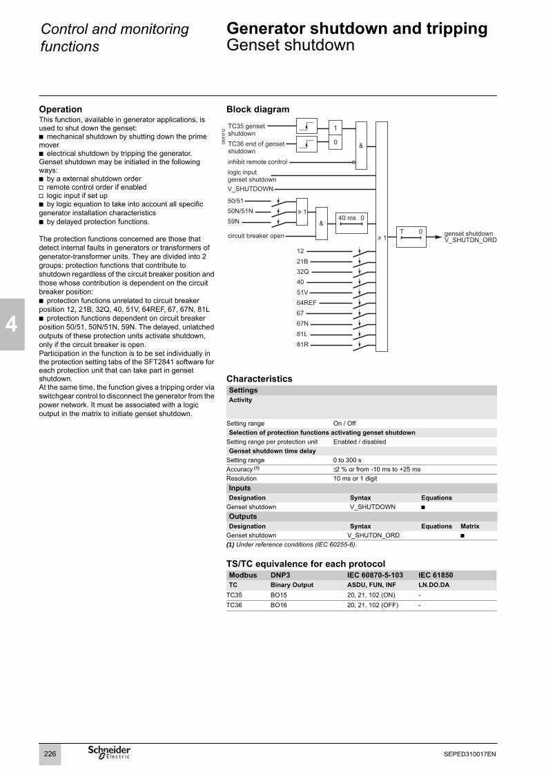
4
Control and monitoring functions
Generator shutdown and trippingGenset shutdown
OperationThis function, available in generator applications, is used to shut down the genset:b mechanical shutdown by shutting down the prime moverb electrical shutdown by tripping the generator.Genset shutdown may be initiated in the following ways:b by a external shutdown orderv remote control order if enabledv logic input if set upb by logic equation to take into account all specific generator installation characteristicsb by delayed protection functions.
The protection functions concerned are those that detect internal faults in generators or transformers of generator-transformer units. They are divided into 2 groups: protection functions that contribute to shutdown regardless of the circuit breaker position and those whose contribution is dependent on the circuit breaker position:b protection functions unrelated to circuit breaker position 12, 21B, 32Q, 40, 51V, 64REF, 67, 67N, 81Lb protection functions dependent on circuit breaker position 50/51, 50N/51N, 59N. The delayed, unlatched outputs of these protection units activate shutdown, only if the circuit breaker is open.Participation in the function is to be set individually in the protection setting tabs of the SFT2841 software for each protection unit that can take part in genset shutdown.At the same time, the function gives a tripping order via switchgear control to disconnect the generator from the power network. It must be associated with a logic output in the matrix to initiate genset shutdown.
Block diagram
DE
8101
2
CharacteristicsSettingsActivity
Setting range On / OffSelection of protection functions activating genset shutdown
Setting range per protection unit Enabled / disabledGenset shutdown time delay
Setting range 0 to 300 sAccuracy (1) ±2 % or from -10 ms to +25 msResolution 10 ms or 1 digitInputsDesignation Syntax Equations
Genset shutdown V_SHUTDOWN b
Outputs Designation Syntax Equations Matrix
Genset shutdown V_SHUTDN_ORD b(1) Under reference conditions (IEC 60255-6).
TS/TC equivalence for each protocolModbus DNP3 IEC 60870-5-103 IEC 61850TC Binary Output ASDU, FUN, INF LN.DO.DA
TC35 BO15 20, 21, 102 (ON) -TC36 BO16 20, 21, 102 (OFF) -
226 SEPED310017EN
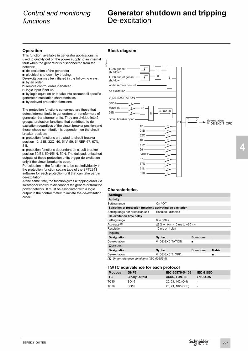
Control and monitoring functions
Generator shutdown and trippingDe-excitation
4
OperationThis function, available in generator applications, is used to quickly cut off the power supply to an internal fault when the generator is disconnected from the network:b de-excitation of the generatorb electrical shutdown by tripping.De-excitation may be initiated in the following ways:b by an orderv remote control order if enabledv logic input if set upb by logic equation or to take into account all specific generator installation characteristicsb by delayed protection functions.
The protection functions concerned are those that detect internal faults in generators or transformers of generator-transformer units. They are divided into 2 groups: protection functions that contribute to de-excitation regardless of the circuit breaker position and those whose contribution is dependent on the circuit breaker position:b protection functions unrelated to circuit breaker position 12, 21B, 32Q, 40, 51V, 59, 64REF, 67, 67N, 81Lb protection functions dependent on circuit breaker position 50/51, 50N/51N, 59N. The delayed, unlatched outputs of these protection units trigger de-excitation only if the circuit breaker is open.Participation in the function is to be set individually in the protection function setting tabs of the SFT2841 software for each protection unit that can take part in de-excitation.At the same time, the function gives a tripping order via switchgear control to disconnect the generator from the power network. It must be associated with a logic output in the control matrix to initiate the de-excitation order.
Block diagram
DE
8101
3
CharacteristicsSettingsActivity
Setting range On / OffSelection of protection functions activating de-excitation
Setting range per protection unit Enabled / disabledDe-excitation time delay
Setting range 0 to 300 sAccuracy (1) ±2 % or from -10 ms to +25 msResolution 10 ms or 1 digitInputsDesignation Syntax Equations
De-excitation V_DE-EXCITATION b
Outputs Designation Syntax Equations Matrix
De-excitation V_DE-EXCIT_ORD b(1) Under reference conditions (IEC 60255-6).
TS/TC equivalence for each protocolModbus DNP3 IEC 60870-5-103 IEC 61850TC Binary Output ASDU, FUN, INF LN.DO.DA
TC35 BO15 20, 21, 102 (ON) -TC36 BO16 20, 21, 102 (OFF) -
227SEPED310017EN

4
Control and monitoring functions
Generator shutdown and trippingExample
Installation descriptionThe electrical installation consists of busbars to which the following are connected:b an incomer supplied by a 10 MVA transformerb a 3.15 MVA power generator
DE
8088
8
In normal operation, the generator and transformer are coupled to the busbars. The generator provides backup power to the installation in the absence of the transformer power supply. The installation is earthed by a neutral point coil connected to the busbars. When the generator is not coupled to the network, its neutral is isolated. When faults occur, the generator is over-excited for 3 seconds. Its fault current is equal to 3 times its rated current. After the 3 seconds have elapsed, the fault current drops to 0.5 times the rated current.The generator is protected:b against network electrical short-circuits by a phase overcurrent protection function 50/51 and a backup protection function 50V/51Vb against earth faults by an earth fault protection function 50N/51N when the generator is coupled to the busbars and by a neutral voltage displacement protection function when it is not coupledb against overloads by a thermal overload protection function 49RMSb against unbalance by a negative sequence / unbalance protection function 46b against frequency variations by underfrequency and overfrequency protection functions 81L and 81Hb against voltage variations by undervoltage and overvoltage protection functions 27 and 59b against field loss by a protection function 40.
Setting of genset shutdown and de-excitationThe participation of these protection functions in circuit breaker tripping, genset shutdown and de-excitation depends on the type of faults detected:b circuit breaker tripping against network faults:50/51, 50V/51V, 50N/51N, 49RMS, 46, 81L, 81H, 27, 59b genset shutdown for prime mover faults and internal faults:50/51, 59N, 40b de-excitation for internal faults: 50/51, 59N, 40.Shutdown is total and not sequential. The genset shutdown and de-excitation time delays are zero.
228 SEPED310017EN

Control and monitoring functions
Automatic transfer
4
DE
5149
8
DescriptionThe automatic transfer function is used to transfer busbar supply from one source to another. The function reduces busbar supply interruptions, thereby increasing the service continuity of the network supplied by the busbars.
Automatic transfer performs:b automatic transfer with interruption if there is a loss of voltage or a fault upstreamb manual transfer and return to normal operation without interruption, with or without synchro-checkb control of the coupling circuit breaker (optional)b selection of the normal operating modeb the necessary logic to ensure that at the end of the sequence, only 1 circuit breaker out of 2 or 2 out of 3 are closed.
Automatic "one out of two" transfer.
DE
5162
2
Automatic "one out of two" or "two out of three" transferThe operation and implementation of the automatic transfer function depend on the type of substation:b automatic "one out of two" transfer is suitable for dual-incomer substations without couplingb automatic "two out of three" transfer is suitable for dual-incomer substations with coupling.These two applications are described separately to make them easier to understand.
The automatic transfer function is symmetrical:b hardware symmetry: dual-incomer substations, with 2 incoming circuit breakers, and each incomer is protected by an Easergy Sepam series 60 unitb functional symmetry: automatic transfer is distributed between the two Easergy Sepam series 60 units protecting the two incomers.Each of the functions is therefore described from the viewpoint of one of the two incomers, the other incomer being referred to as the "opposite side" incomer.
Automatic "two out of three" transfer with synchro-check managed by Easergy Sepam series 60.
229SEPED310017EN

4
Control and monitoring functions
Automatic transfer
DE
8088
9
Equipment usedSepam protection relayEach incomer is protected by an Easergy Sepam series 60 unit.At least two MES120 modules need to be added to each Sepam.The synchro-check function (ANSI 25) is performed by an optional MCS025 module connected to one of the 2 Sepam units.
For busbars with motors, it is necessary to check the remanent voltage on the busbars during automatic transfer using a Sepam B21.
Local control of automatic transferLocal control of automatic transfer requires the following components:b 1 "NO circuit breaker" selector (ANSI 10), 2 or 3-position selector which designates the circuit breaker that remains open at the end of voluntary transfer without interruptionb 1 optional "Manual / Auto" selector (ANSI 43)v in Auto mode, automatic transfer is enabledv in Manual mode, automatic transfer is disabledv when this optional selector is not included, all the automatic transfer functions are enabled.b 1, 2 or 3 optional "Local / Remote" selectors (one selector for the function or one selector per circuit breaker) v in Remote mode, automatic transfer on voltage loss is enabled and the other functions are disabledv in Local mode, automatic transfer on voltage loss is disabled and the other functions are enabledv when these optional selectors are not included, all the automatic transfer functions are enabled.b 2 or 3 optional pushbuttons with LEDs (one pushbutton per circuit breaker):v "Breaker closing" pushbuttonv "Closing ready" LED.
Automatic "two out of three" transfer with synchro-check managed by Sepam.
B21 B21
230 SEPED310017EN

Control and monitoring functions
Automatic "one out of two" transferOperation
4
DefinitionAutomatic "one out of two" transfer is suitable for substations with busbars supplied by two incomers with no coupling.Automatic transfer comprises two functions: b automatic transfer with busbar supply interruptionb voluntary return to normal without busbar supply interruption.The 2 functions are described separately below.
DE
5101
7
Automatic transfer with supply interruptionDescriptionThe function is used to transfer busbar supply from one source to the other, after the detection of voltage loss or a fault upstream of the source.
Automatic source transfer takes place in two steps:b tripping of the circuit breaker triggered by the detection of the loss of voltage or an external trip order (trip order from upstream protection units): loss of busbar supplyb closing of the opposite side circuit breaker to resupply the busbars (when motors are connected to the busbars, it is necessary to check for remanent voltage on the busbars using the ANSI 27R Remanent undervoltage function).Compulsory transfer conditionsThese conditions are always required to enable transfer: b the incoming circuit breaker is closedb no phase-to-phase fault detected by the incomer on the busbars or downstreamb no phase-to-earth fault detected by the incomer on the busbars or downstreamb voltage OK on the opposite incomer.Optional transfer conditionsThese conditions are required when the associated optional functions are enabled: b the "Auto / Manual" selector is in the Auto positionb the 2 "Local / Remote" selectors are in the Remote positionb the 2 incoming circuit breakers are racked inb no VT fault detected by the VT Supervision function (ANSI 60FL), to avoid transfer on the loss of voltage transformersb no inhibition of transfer by V_TRANS_STOP by logic equations.Initialization of transferThree events may trigger automatic transfer:b loss of voltage detected on the incomer by the Phase undervoltage function (ANSI 27)b or detection of a fault by the protection units upstream of the incomer, with intertripping order on the "External tripping 1" logic input b or V_TRANS_ON_FLT, initialization of transfer by logic equations.
231SEPED310017EN

4
Control and monitoring functions
Automatic "one out of two" transferOperation
Block diagram
DE
5158
4
Closing of opposite side circuit breakerThe following conditions are required to order the closing of the opposite side circuit breaker:b the circuit breaker is openb no opposite side circuit breaker inhibit close conditionsb no remanent voltage on the busbars (checking necessary when motors are connected to the busbars).The opposite side circuit breaker closing order is transmitted by a Sepam logic output to a logic input of the opposite side Sepam. It is taken into account by the Switchgear control function of the opposite side Sepam.
Block diagram (Opposite side Sepam)
DE
5225
4
232 SEPED310017EN

Control and monitoring functions
Automatic "one out of two" transferOperation
4
DE
5101
7
Voluntary return to normal without interruptionDescriptionThe voluntary return to normal without interruption involves two separate control functions:b closing of the open incoming circuit breaker, with or without synchro-check: the two incoming circuit breakers are closedb then opening of the normally open circuit breaker, designated by the "NO circuit breaker" selector.These two functions may also be used to transfer the busbar supply source without any interruption.
Compulsory transfer conditionsThese conditions are always required to enable transfer: b the incoming circuit breaker is openb the voltage is OK upstream of the incoming circuit breaker.
Optional transfer conditionsThese conditions are required when the associated optional functions are enabled: b the "Auto / Manual" selector is in the Manual positionb the 2 "Local / Remote" selectors are in the Local positionb the 2 incomer circuit breakers are racked inb no VT fault detected by the VT Supervision function (ANSI 60FL), to avoid transfer on the loss of voltage transformersb no inhibition of transfer by V_TRANS_STOP by logic equations.
Initialization of the return to normalb voluntary incoming circuit breaker close order.
DE
5150
9
Closing of the open circuit breakerDescriptionCircuit breaker closing is ensured by the Switchgear control function, with or without synchro-check.
The AT function checks that all the required conditions are met and indicates to the user that the return to normal is possible.
Block diagram
DE
5225
3
233SEPED310017EN

4
Control and monitoring functions
Automatic "one out of two" transferOperation
DE
5151
0
Opening of the normally open circuit breakerDescriptionThis function controls the opening of the circuit breaker designated as being normally open by the position of the "NO circuit breaker" selector, when the two incomer circuit breakers are closed.It guarantees, for all the automatic control sequences that put the two sources in parallel, that at the end of the transfer, only one circuit breaker out of the two is closed.The open order is taken into account by the Switchgear control function.
Block diagram
DE
5158
6
234 SEPED310017EN

Control and monitoring functions
Automatic "one out of two" transferImplementation
4
Connection
DE
5160
0
: optional wiring.
235SEPED310017EN

4
Control and monitoring functions
Automatic "one out of two" transferImplementation
PE
8077
5
Parameter setting of predefined control functionsThe Automatic transfer function is set up at the same time as the Switchgear control function in the "Control logic" tab of the SFT2841 software.
Switchgear control functionb activation of the Switchgear control functionb activation of the Synchro-check function if necessary.
Automatic transfer functionb activation of the Automatic transfer function and adjustment of associated parameters:v voltage return time Tr (typically 3 s) v normal coupling position: no coupling.
VT supervision functionThe VT supervision (ANSI 60FL) is to be activated if necessary.
SFT2841: parameter setting of predefined control logic.
Protection function setting
Protection functions Use Setting informationPhase undervoltage (ANSI 27)Unit 1
Initialization of automatic transfer on detection of voltage loss.
Voltage set point: 60% Unp Delay: 300 ms
Phase overcurrent (ANSI 50/51)Unit 1, instantaneous output
Detection of downstream phase fault, to inhibit automatic transfer.
To be set according to discrimination study (the most sensitive set point).
Earth fault (ANSI 50N/51N)Unit 1, instantaneous output
Detection of downstream earth fault, to inhibit automatic transfer.
To be set according to discrimination study (the most sensitive set point).
Phase overvoltage (ANSI 59)Unit 1
Detection of phase voltage upstream of the circuit breaker. To be assigned to a Sepam logic output in the control matrix.
Voltage set point: 90% Unp Delay: 3 s
Optionalprotection functions
Use Setting information
Remanent undervoltage(ANSI 27R)Unit 1
Detection of no remanent voltage on the busbars to which the motors are connected.
Voltage set point: 30% Unp Delay: 100 ms
236 SEPED310017EN

Control and monitoring functions
Automatic "one out of two" transferImplementation
4
PE
8075
5
Logic input assignmentThe logic inputs required for the AT function are to be assigned in the SFT2841 "Logic I/Os" screen.The "Standard assignments" button proposes an assignment of the main inputs required for the AT function. The other inputs are to be assigned manually.
Logic output assignment in the control matrixThe assignment of the logic outputs required for the AT function takes place in 2 steps: b declaration of the required logic outputs "Used", indicating the control mode of each output, in the SFT2841 "Logic I/Os" screenb assignment of each predefined output associated with the AT function to a Sepam logic output in the SFT2841 "Control matrix" screen.
The predefined outputs associated with the AT function are as follows:SFT2841: standard assignment of the inputs required for the AT function.
"Protection" button Description Use59 - 1 Delayed output of the Phase
overvoltage function (ANSI 59)Unit 1
Indication for the opposite side Sepam: the voltage is OK upstream of the incoming circuit breaker.
"Logic" button Description UseNO circuit breaker closing Predefined output
V_CLOSE_NO_ORD of the AT function
Automatic closing order of opposite side circuit breaker.
Breaker closing ready Predefined output V_CLOSE_EN of the AT function
LED indication: the return to normal conditions are met (neglecting the synchro-check)
237SEPED310017EN

4
Control and monitoring functions
Automatic "one out of two" transferCharacteristics
SettingActivity
Setting range On / OffVoltage return time
Setting range 0 to 300 sAccuracy (1) ±2 % or from -10 ms to +25 msResolution 10 ms or 1 digitNormal coupling position
Setting range No coupling / Normally open / Normally closedInputsDesignation Syntax Equations
Transfer order on fault V_TRANS_ON_FLT bTransfer off order V_TRANS_STOP b
OutputsDesignation Syntax Equations Matrix
Automatic transfer on V_TRANSF_ON bTripping by 2/3 or 1/2 logic V_2/3_TRIPPING bTripping by automatic transfer V_AT_TRIPPING bNO circuit breaker closing V_CLOSE_NO_ORD bBreaker closing ready V_CLOSE_EN b(1) Under reference conditions (IEC 60255-6).
238 SEPED310017EN

Control and monitoring functions
Automatic "two out of three" transferOperation
4
DefinitionAutomatic "two out of three" transfer is suitable for substations with busbars supplied by two incomers and with coupling.Automatic transfer comprises two functions: b automatic transfer with busbar supply interruptionb voluntary return to normal without busbar supply interruption.The 2 functions are described separately below.
DE
5151
1
Automatic transfer with supply interruptionDescriptionThe function is used to transfer busbar supply from one source to the other, after the detection of voltage loss or a fault upstream of the source.
Automatic source transfer takes place in two steps:b tripping of the circuit breaker triggered by the detection of the loss of voltage or an external trip order (trip order from upstream protection units): loss of busbar supplyb closing of the normally open circuit breaker to resupply the busbars. According to the parameter setting, the normally open circuit breaker may be one of the following:v the coupling circuit breaker, when coupling is normally openv the opposite side circuit breaker, when coupling is normally closed. When motors are connected to the busbars, it is necessary to check for remanent voltage on the busbars using the Remanent undervoltage function (ANSI 27R).
Compulsory transfer conditionsThese conditions are always required to enable transfer: b the incoming circuit breaker is closedb according to the coupling setup:v the opposite side circuit breaker is closed and the coupling circuit breaker is open, when coupling is normally open (NO coupling)v or the opposite side circuit breaker is open and the coupling circuit breaker is closed, when coupling is normally closed (NC coupling)b no phase-to-phase fault detected by the incomer on the busbars or downstreamb no phase-to-earth fault detected by the incomer on the busbars or downstreamb voltage OK on the opposite incomer.
Optional transfer conditionsThese conditions are required when the associated optional functions are enabled: b the "Auto / Manual" selector is in the Auto positionb the 3 "Local / Remote" selectors are in the Remote positionb the 3 circuit breakers are racked inb no VT fault detected by the VT Supervision function (ANSI 60FL), to avoid transfer on the loss of voltage transformersb no inhibition of transfer by V_TRANS_STOP by logic equations.
Initialization of transferThree events may trigger automatic transfer:b loss of voltage detected on the incomer by the Phase undervoltage function (ANSI 27)b or the detection of a fault by the protection units upstream of the incomer, with intertripping order on the "External tripping 1" logic input b or V_TRANS_ON_FLT, initialization of transfer by logic equations.
Automatic transfer with normally open coupling.
DE
5151
4
Automatic transfer with normally closed coupling.
239SEPED310017EN

4
Control and monitoring functions
Automatic "two out of three" transferOperation
Block diagram
DE
5228
9
Closing of the normally open circuit breakerThe following conditions are required to order the closing of the normally open circuit breaker:b the incoming circuit breaker is openb no normally open circuit breaker inhibit close conditionsb no remanent voltage on the busbars (checking necessary when motors are connected to the busbars.)If the normally open circuit breaker is the opposite side circuit breaker:the NO circuit breaker closing order is transmitted by a Sepam logic output to a logic input of the opposite side Sepam where it is taken into account by the Switchgear control function (see block diagram below).If the normally open circuit breaker is the coupling circuit breaker:the NO circuit breaker closing order is transmitted by a Sepam logic output to close the circuit breaker directly, without any intermediary.
Block diagram (Opposite side Sepam)
DE
5225
5
240 SEPED310017EN

Control and monitoring functions
Automatic "two out of three" transferOperation
4
DE
5151
2
Voluntary return to normal without interruptionDescriptionThe voluntary return to normal without interruption involves two separate control functions:b closing of the open circuit breaker, with or without synchro-check: the 3 circuit breakers are closedb then opening of the normally open circuit breaker, designated by the "NO circuit breaker" selector.These two functions may also be used to transfer the busbar supply source without any interruption.
Voluntary return to normal with normally closed coupling.
DE
5163
1
Compulsory transfer conditionsThese conditions are always required to enable transfer: b the incoming circuit breaker is openb the opposite side circuit breaker and the coupling circuit breaker are closedb The voltage is OK upstream of the incoming circuit breaker. This voltage is detected by function ANSI 59.
Optional transfer conditionsThese conditions are required when the associated optional functions are enabled: b the "Auto / Manual" selector is in the Manual positionb the 3 "Local / Remote" selectors are in the Local positionb the 3 circuit breakers are racked inb no VT fault detected by the VT Supervision function (ANSI 60FL), to avoid transfer on the loss of voltage transformersb no inhibition of transfer by V_TRANS_STOP by logic equations.
Initialization of the return to normalb voluntary incoming circuit breaker close order.
Voluntary return to normal with normally open coupling.
DE
5151
3
Closing of the open circuit breakerDescriptionCircuit breaker closing is ensured by the Switchgear control function, with or without synchro-check.
The AT function checks that all the required conditions are met and indicates to the user that the return to normal is possible.
Block diagram
DE
8101
4
ayedU del,
241SEPED310017EN

4
Control and monitoring functions
Automatic "two out of three" transferOperation
DE
5152
9
Opening of the normally open circuit breakerDescriptionThis function controls the opening of the circuit breaker designated as being normally open by the position of the "NO circuit breaker" selector, when the three circuit breakers are closed.It guarantees, for all the automatic control sequences that put the two sources in parallel, that at the end of the transfer, only two circuit breakers out of the three are closed.The open order is taken into account by the Switchgear control function.
Block diagramNormally open coupling.
DE
5158
9
Normally closed coupling.
242 SEPED310017EN

Control and monitoring functions
Automatic "two out of three" transferOperation
4
Coupling closingDescriptionThe voluntary closing of the coupling circuit breaker without interruption involves two separate control functions:b closing of the coupling circuit breaker, with or without synchro-check: the 3 circuit breakers are closedb then opening of the normally open circuit breaker, designated by the "NO circuit breaker" selector.
Compulsory transfer conditionsThese conditions are always required to enable transfer: b the opposite side voltage is OKb the 3 following conditions are not fulfilled simultaneously:v the incoming circuit breaker is closedv the opposite side circuit breaker is closedv the coupling circuit breaker is the normally open circuit breaker (NO coupling).Optional transfer conditionsThese conditions are required when the associated optional functions are enabled: b the "Auto / Manual" selector is in the Manual positionb the 3 "Local / Remote" selectors are in the Local positionb the 3 circuit breakers are racked inb no VT fault detected by the VT Supervision function (ANSI 60FL), to avoid transfer on the loss of voltage transformersb no inhibition of transfer by V_TRANS_STOP by logic equations.
Initialization of coupling closingVoluntary coupling circuit breaker close order.
Block diagram
DE
5225
7
243SEPED310017EN

4
Control and monitoring functions
Automatic "two out of three" transferImplementation
Connection for normally open coupling
DE
5159
9
: optional wiring.
244 SEPED310017EN

Control and monitoring functions
Automatic "two out of three" transferImplementation
4
Connection for normally closed coupling
DE
5159
8
: optional wiring.
245SEPED310017EN

4
Control and monitoring functions
Automatic "two out of three" transferImplementation
PE
8077
5
Parameter setting of predefined control functionsThe Automatic transfer function is set up at the same time as the Switchgear control function in the "Control logic" tab of the SFT2841 software.
Switchgear control functionb activation of the Switchgear control functionb activation of the Synchro-check function if necessary.
Automatic transfer functionb activation of the Automatic transfer function and adjustment of associated parameters:v voltage return time Tr (typically 3 s)v normal coupling position: normally open or normally closed, according to the network operating mode.
VT supervision functionThe VT supervision (ANSI 60FL) is to be activated if necessary.
SFT2841: parameter setting of predefined control logic.
Protection function setting
Protection functions Use Setting informationPhase undervoltage (ANSI 27)Unit 1
Initialization of automatic transfer on detection of voltage loss.
Voltage set point: 60% Unp Delay: 300 ms
Phase overcurrent (ANSI 50/51)Unit 1, instantaneous output
Detection of downstream phase fault, to inhibit automatic transfer.
To be set according to discrimination study (the most sensitive set point).
Earth fault (ANSI 50N/51N)Unit 1, instantaneous output
Detection of downstream earth fault, to inhibit automatic transfer.
To be set according to discrimination study (the most sensitive set point).
Phase overvoltage (ANSI 59)Unit 1
Detection of phase voltage upstream of the circuit breaker. To be assigned to a Sepam logic output in the control matrix.
Voltage set point: 90% Unp Delay: 3 s
Optionalprotection functions
Use Setting information
Remanent undervoltage (ANSI 27R)Unit 1
Detection of no remanent voltage on the busbars to which the motors are connected.
Voltage set point: 30% Unp Delay: 100 ms
246 SEPED310017EN

Control and monitoring functions
Automatic "two out of three" transferImplementation
4
PE
8075
5
Logic input assignmentThe logic inputs required for the AT function are to be assigned in the SFT2841 "Logic I/Os" screen.The "Standard assignments" button proposes an assignment of the main inputs required for the AT function. The other inputs are to be assigned manually.
Logic output assignment in the control matrixThe assignment of the logic outputs required for the AT function takes place in 2 steps: b declaration of the required logic outputs "Used", indicating the control mode of each output, in the SFT2841 "Logic I/Os" screenb assignment of each predefined output associated with the AT function to a Sepam logic output in the SFT2841 "Control matrix" screen.
The predefined outputs associated with the AT function are as follows:SFT2841: standard assignment of the inputs required for the AT function.
"Protection" button Description Use59 - 1 Delayed output of the Phase
overvoltage function (ANSI 59)Unit 1
Indication for the opposite side Sepam: voltage OK upstream of the incoming circuit breaker.
"Logic" button Description UseNO circuit breaker closing Predefined output
V_CLOSE_NO_ORD of the AT function
Automatic closing order of normally open circuit breaker.
Coupling closing Predefined output V_TIE_CLOSING of the AT function
Coupling circuit breaker close order.
Coupling tripping Predefined output V_TIE_OPENING of the AT function
Coupling circuit breaker open order.
Breaker closing ready Predefined output V_CLOSE_EN of the AT function
LED indication: the return to normal conditions are met. (neglecting the synchro-check)
Coupling closing ready Predefined output V_TIE_CLOSE_EN of the AT function
LED indication: the coupling close conditions are met. (neglecting the synchro-check)
247SEPED310017EN

4
Control and monitoring functions
Automatic "two out of three" transferCharacteristics
SettingActivity
Setting range On / OffVoltage return time
Setting range 0 to 300 sAccuracy (1) ±2 % or from -10 ms to +25 msResolution 10 ms or 1 digitNormal coupling position
Setting range No coupling / Normally open / Normally closedInputsDesignation Syntax Equations
Transfer order on fault V_TRANS_ON_FLT bTransfer off order V_TRANS_STOP b
OutputsDesignation Syntax Equations Matrix
Tripping by 2/3 or 1/2 logic V_2/3_TRIPPING bTripping by automatic transfer V_AT_TRIPPING bNO circuit breaker closing V_CLOSE_NO_ORD bBreaker closing ready V_CLOSE_EN bCoupling tripping V_TIE_OPENING bCoupling closing ready V_TIE_CLOSE_EN bCoupling closing V_TIE_CLOSING bCoupling closing with synchro-check failed
V_TIESYNCFAIL b
(1) Under reference conditions (IEC 60255-6).
248 SEPED310017EN

Control and monitoring functions
Triggering the Motor start report (MSR)
4
OperationThis function is only found in motor applications. It is used to record values specific to motors, during the starting phase.While there is no recording in progress, recording can be triggered by:b the "starting in progress" output of the 48/51LR protection functionb the V_MSR_START output from the logic equation editorb the remote control order TC51b the "Trigger MSR" logic inputb the "Trigger MSR" GOOSE logic input
Recording can be conditional upon the closed circuit breaker position.
Block diagramD
E81
267
CharacteristicsInputsDesignation Syntax Equations Matrix
Trigger MSR V_MSR_START b
OutputsDesignation Syntax Equations Matrix
MSR triggered V_MSR_TRIGGED b
MSR on
Closed circuit breaker position
Starting in progressP48/51LR_1_22
Trigger MSRV_MSR_START
MSR in progressV_MSR_TRIGGED
TS1280
0
1
T
&
&≥1
GOOSE GxxxTrigger MSR
Logic input IxxxTrigger MSR
Inhibit TC
TC 51 / trigg. MSR
249SEPED310017EN
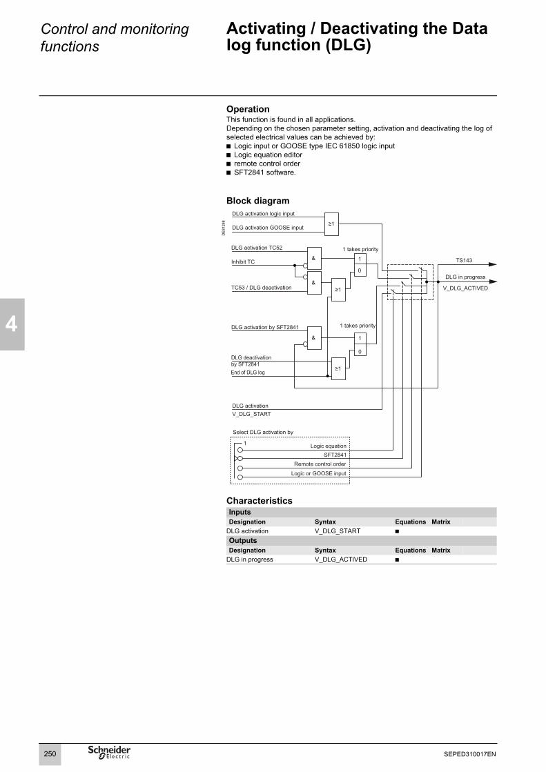
4
Control and monitoring functions
Activating / Deactivating the Data log function (DLG)
OperationThis function is found in all applications.Depending on the chosen parameter setting, activation and deactivating the log of selected electrical values can be achieved by:b Logic input or GOOSE type IEC 61850 logic inputb Logic equation editorb remote control orderb SFT2841 software.
Block diagram
DE
8126
8
CharacteristicsInputsDesignation Syntax Equations Matrix
DLG activation V_DLG_START b
OutputsDesignation Syntax Equations Matrix
DLG in progress V_DLG_ACTIVED b
Select DLG activation by
Logic equationSFT2841
Logic or GOOSE input
Remote control order
1
DLG activation GOOSE input
DLG activation logic input
TC53 / DLG deactivation
1
0
&
DLG activation TC52
&
Inhibit TC
DLG in progress
V_DLG_ACTIVED
1 takes priority
1
0
&
1 takes priority
End of DLG log
DLG activation by SFT2841
DLG deactivation by SFT2841
DLG activation V_DLG_START
TS143
≥1
≥1
≥1
250 SEPED310017EN

Control and monitoring functions
Change of phase rotation direction
4
OperationThis function is found in all applications.The change of phase rotation direction can be triggered by:b logic input or GOOSE type IEC 61850 logic inputb remote control order (TC)The phase rotation direction can be defined as:b positive sequence (123)b negative sequence (132)
Block diagram
DE
8126
9
CharacteristicsOutputsDesignation Syntax Equations Matrix
Discrepancy in the phase rotation direction
V_PHASE_DISC b
Phase rotation direction 123 activated
V_PHASE_DIR b
Phase rotation direction 132 activated
V_PHASE_INV b
Phase rotation direction active V_PHASE_ACTIVE b
WARNINGWARNING: protection functions inhibited for 350 ms.Form the time it receives the change phase rotation direction request, Sepam cannot protect the electrical network for 350 ms.This inhibition of protection functions can result in death or serious injury.
rotation direction 123
rotation direction 132
rotation direction by logic or GOOSE input
rotation direction by TC
0 1
0 1
SFT2841 selection
1
Rotation direction 123 TC54
1
0
&
Rotation direction 132 TC55
&
Inhibit TC
Logic inputRotation direction 132
GOOSE inputrotation direction 132
≥1
≥1
≥1
GOOSE inputRotation direction 123
Logic input Rotation direction 123
Rotation direction 132 TC55
1 0
&
Rotation direction 123 TC54
&
Inhibit TC
Rotation direction 132 activated
V_PHASE_INV
&
&
T 0
T = 2 s
V_PHASE_DISC
TS239
1 takes priority
1 takes priority
Logic & GOOSE inputs Rotation direction 1xx not assigned
Rotation direction 123 activated
V_PHASE_DIR
&
&
1
0
0 takes priority
Phase rotation direction active
V_PHASE_ACTIVE
Discrepancy in the phase rotation direction command
251SEPED310017EN

4
Control and monitoring functions
Local indicationANSI code 30
OperationEvents may be indicated locally on the front panel of Sepam by:b appearance of a message on the displayb switching on of one of the 9 yellow LEDs.
Message type indicationPredefined messagesAll the messages connected to the standard Sepam functions are predefined and available in two language versions:b in English, factory-set messages, not modifiableb in the local language, according to the version delivered.The language version is chosen at the time of Sepam parameter setting.The messages are visible on the Sepam display and on the SFT2841 Alarms screen.The number and type of predefined messages depend on the type of Sepam. The table below gives the complete list of all predefined messages.
Functions English Local language(e.g. French)
Control and monitoring ANSI codeExternal trip (1 to 3) EXT. TRIP (1 to 3) DECLT.EXT. (1 à 3)Buchholz trip BUCHH/GAS TRIP BUCHH/GAZ DECLT
Buchholz alarm BUCHHOLZ ALARM BUCHH ALARMEThermostat trip THERMOST. TRIP THERMOST.DECLT.Thermostat alarm THERMOST. ALARM THERMOT.ALARMEPressure trip PRESSURE TRIP PRESSION DECLT
Pressure alarm PRESSURE ALARM PRESSION ALARMEThermistor trip THERMISTOR TRIP THERMISTOR DECL.Thermistor alarm THERMISTOR AL. THERMISTOR AL.Control fault CONTROL FAULT DEFAUT COMMANDELoad shedding LOAD SHEDDING DÉLESTAGEGenset shutdown GENSET SHUTDOWN ARRÊT GROUPEDe-excitation DE-EXCITATION DÉSEXCITATIONTripping order by automatic transfer AUTO TRANSFER AUTO TRANSFERPhase rotation direction command complementarity fault
ROTATION DISC CMD DISC CDE ROTATION
Diagnosis ANSI codeSF6 fault SF6 LOW BAISSE SF6MET148-2 No 1 RTD fault RTD’S FAULT MET1 (1) DEF SONDE MET1 (1)
MET148-2 No 2 RTD fault RTD’S FAULT MET2 (1) DEF. SONDE MET2 (1)
VT supervision 60FL Phase VT supervision VT FAULT DEFAUT TPResidual VT supervision VT FAULT Vo DEFAUT TP Vo
CT supervision 60 Main CT supervision CT FAULT DEFAUT TCTrip circuit supervision (TCS) fault or mismatching of open/closed position contacts
74 TRIP CIRCUIT CIRCUIT DECLT
Closing circuit fault CLOSE CIRCUIT CIRCUIT ENCLT
Cumulative breaking current monitoring ΣI²BREAKING >> ΣI² COUPESBattery monitoring BATTERY LOW (1) PILE FAIBLE (1)
(1) RTD FAULT, BATTERY LOW messages: refer to the maintenance chapter.
252 SEPED310017EN

Control and monitoring functions
Local indicationANSI code 30
4
Functions English Local language(e.g. French)
Protection ANSI codeOverspeed 12 OVERSPEED VITESSE >> Underspeed 14 UNDERSPEED VITESSE << Underimpedance 21B UNDERIMPEDANCE IMPEDANCE <<Synchro-check 25 Synchrochecked close request in
processSYNC.IN PROCESS SYNC. EN COURS
Synchrochecked close request successful
SYNC. OK SYNC. REUSSIE
Closing failed, out-of-sync
SYNC. FAILURE ECHEC SYNC.
Closing failed, out-of-sync, cause dU
SYNC. FAILED dU ECHEC SYNC. dU
Closing failed, out-of-sync, cause dPHI
SYNC. FAILED dPhi ECHEC SYNC. dPhi
Closing failed, out-of-sync, cause dF
SYNC. FAILED dF ECHEC SYNC. dF
Stop closing with synchro-check
STOP SYNC. STOP SYNC.
Coupling closing with synchro-check failed
TIE SYNC. FAILED ECHEC COUPLAGE
Undervoltage 27 UNDERVOLTAGE (1) TENSION << (1)
Positive sequence undervoltage 27D Positive sequence undervoltage UNDERVOLTAGE.PS TENSION Vd << Reverse rotation ROTATION - ROTATION -
Active overpower 32P OVER P P >> Reactive overpower 32Q OVER Q Q >> Phase undercurrent 37 UNDER CURRENT COURANT <<Phase underpower 37P UNDER POWER P << Temperature monitoring 38/49T Alarm OVER TEMP. ALM T° ALARME
Tripping OVER TEMP. TRIP T° DECLT
Field loss 40 FIELD LOSS PERTE EXCITATIONNegative sequence / unbalance 46 UNBALANCE I DESEQUILIBRE I Negative sequence overvoltage 47 UNBALANCE U DESEQUILIBRE U Excessive starting time, locked rotor 48/51LR Excessive starting time LONG START DEMARRAGE LONG
Locked rotor in normal operation ROTOR BLOCKING BLOCAGE ROTORLocked rotor on start STRT LOCKED ROTR BLOC ROTOR DEM
Thermal overload 49RMS Alarm THERMAL ALARM ECHAUFT.ALARME Tripping THERMAL TRIP ECHAUFT.DECLT.
Inhibit closing START INHIBIT DEMARRAGE INHIBEBreaker failure 50BF BREAKER FAILURE DEF. DISJONCT.Phase overcurrent 50/51 PHASE FAULT (2) DEFAUT PHASE (2)
Earth fault 50N/51N EARTH FAULT DEFAUT TERRE Voltage-restrained overcurrent 50V/51V O/C V REST (2) DEF. PHASE RET. U (2)
Overvoltage 59 OVERVOLTAGE (1) TENSION >> (1)
Neutral voltage displacement 59N Vo FAULT DEFAUT Vo Restricted earth fault 64REF RESTRIC. EARTH
FAULT TERRE RESTREINTE
Starts per hour 66 START INHIBIT DEMARRAGE INHIBEDirectional phase overcurrent 67 DIR. PHASE FAULT (2) DEFAUT PHASE DIR. (2)
Directional earth fault 67N/67NC DIR. EARTH FAULT DEFAUT TERRE DIR. Recloser 79 Cycle x CYCLE (1 to 4) (3) CYCLE (1 à 4) (3)
Reclosing successful CLEARED FAULT DEFAUT ELIMINEPermanent trip FINAL TRIP DECLT DEFINITIF
Overfrequency 81H OVER FREQ. FREQUENCE >> Underfrequency 81L UNDER FREQ. FREQUENCE << Rate of change of frequency 81R ROCOF DERIV. FREQ
(1) With indication of the faulty phase, when used with phase-to-neutral voltage.(2) With indication of the faulty phase.(3) With indication of the protection unit that has initiated the cycle (phase fault, earth fault, ...).
253SEPED310017EN

4
Control and monitoring functions
Local indicationANSI code 30
Personalized user messages100 additional messages may be created using the SFT2841 software to link a message to a logic input or the result of a logic equation, for example, or to replace a predefined message by a user message.User message editor in SFT2841The user message editor is included in the SFT2841 software and may be accessed in connected or disconnected mode from the control matrix screen:b display the "Event" tab on the screen: the user messages appearb double-click on one of the messages displayed to activate the user message editor.User message editor functionsb creation and modification of user messages:v in English and the local languagev by text input or importing of an existing bitmap file (*.bmp) or by point to point drawingb deletion of user messagesb assignment of predefined or user messages to an event defined in the control matrix:v from the control matrix screen, "Events" tab, double-click on the event to be linked to a new messagev select the new predefined or user message from the messages presentedv "assign" it to the event.The same message may be assigned to several events, with no limitations.
Message display in SFT2841b The predefined messages are stored in Sepam’s memory and are displayed in connected mode. In disconnected mode, the last messages stored in Sepam connected mode are displayed.b The user messages are saved with the other Sepam parameters and protection settings and are displayed in connected and disconnected modes.
Message processing on the Sepam displayWhen an event occurs, the related message appears on the Sepam display. The user presses the key to clear the message and enable normal consultation of all the display.The user must press the key to acknowledge latched events (e.g. protection outputs).The list of messages remains accessible in the alarm history ( key), in which the last 16 messages are stored. The last 250 messages may be consulted with the SFT2841 software.To delete the messages stored in the alarm history:b display the alarm history on the displayb press the key.
LED indicationThe 9 yellow LEDs on the front of Sepam are assigned by default to the following events:LED Event Name on label
on front panelLED 1 Tripping of protection 50/51 unit 1 I>51LED 2 Tripping of protection 50/51 unit 2 I>>51LED 3 Tripping of protection 50N/51N unit 1 Io > 51NLED 4 Tripping of protection 50N/51N unit 2 Io >> 51NLED 5 ExtLED 6LED 7 Circuit breaker open (I102) 0 OffLED 8 Circuit breaker closed (I101) I OnLED 9 Tripping by circuit breaker control Trip
The default parameter setting may be personalized using the SFT2841 software:b LEDs are assigned to events in the "LEDs" tab of the control matrix screenb editing and printing of personalized labels are proposed in the general characteristics screen.
254 SEPED310017EN

Control and monitoring functions
Local control
4
PE
8033
0
DescriptionSwitchgear may be controlled locally using Easergy Sepam series 60 units equipped with the mimic-based UMI. The control functions available are:b selection of the Sepam control modeb viewing of device status on the animated mimic diagramb local control of the opening and closing of all the devices controlled by Sepam
Selection of the Sepam control modeA key-switch on the front of the mimic-based UMI is used to select theSepam control mode. Three modes are available: Remote, Local or Test.
In Remote mode:b remote control orders are taken into accountb local control orders are disabled, with the exception of the circuit breaker open order.Remote mode is indicated by the variable V_MIMIC_REMOTE = 1.
In Local mode:b remote control orders are disabled, with the exception of the circuit breaker open order.b local control orders are enabled.Local mode is indicated by the variable V_MIMIC_LOCAL = 1.
Test mode should be selected for tests on equipment, e.g. during preventive maintenance operations:b all functions enabled in Local mode are available in Test modeb no time-tagged events are sent by the communication link.Test mode is indicated by the variable V_MIMIC_TEST = 1.
Mimic diagram and symbolsA mimic diagram or single-line diagram is a simplified diagram of an electrical installation. It is made up of a fixed background on which symbols and measurements are placed.The mimic diagram editor integrated in the SFT2841 software may be used to personalize and setup mimic diagrams.
The symbols making up the mimic-diagram constitute the interface between the mimic-based UMI and the other Sepam control functions.There are three types of symbols:b fixed symbol: represents the electrotechnical devices that are neither animated or controlled, e.g. a transformerb animated symbol with one or two inputs: represents the electrotechnical devices that change on the mimic diagram, depending on the symbol inputs, but cannot be controlled via the Sepam mimic-based UMI. This type of symbol is used for switch-disconnectors without remote control, for example.b controlled symbol with one or two inputs/outputs: represents the electrotechnical devices that change on the mimic diagram, depending on the symbol inputs, and can be controlled via the Sepam mimic-based UMI. This type of symbol is used for circuit breakers, for example.The symbol outputs are used to control the electrotechnical device:v directly via the Sepam logic outputsv by the switchgear control functionv by logic equation.
Local control using the mimic-based UMI
255SEPED310017EN

4
Control and monitoring functions
Local control
Symbol animationDepending on the value of their inputs, symbols change. A graphic representation corresponds to each state. Animation is carried out automatically by changing the symbol each time the state changes.The symbol inputs must be assigned directly to the Sepam inputs indicating the position of the symbolized switchgear.
Animated symbols with one input"Animated -1 input" and "Controlled -1 input/output" symbols are animated symbols with one input. The value of the input determines the state of the symbol:b input set to 0 = inactiveb input set to 1 = active This type of symbol is used for simple presentation of information, for example the racked out position of a circuit breaker.
Symbol inputs Symbol state Graphic representation (example)
Input = 0 Inactive
Input = 1 Active
Animated symbols with two inputs"Animated - 2 inputs" and "Controlled - 2 inputs/outputs" symbols are animated symbols with two inputs, one open and the other closed. This is the most common situation in representing switchgear positions. The symbol has three states, i.e. three graphic representations: open, closed and unknown. The latter is obtained when the inputs are not matched, in which case it is impossible to determine the position of the switchgear.
Symbol inputs Symbol state Graphic representation (example)
Input 1 (open) = 1Input 2 (closed) = 0
Open
Input 1 (open) = 0Input 2 (closed) = 1
Closed
Input 1 (open) = 0Input 2 (closed) = 0
Unknown
Input 1 (open) = 1Input 2 (closed) = 1
Unknown
Local control using a symbol"Controlled - 1 input/output" and "Controlled - 2 inputs/outputs" symbols are used to control the switchgear corresponding to the symbol via the Sepam mimic-based UMI.
Control symbols with two outputs"Controlled - 2 inputs/outputs" symbols have two control outputs for opening and closing of the symbolized device.An order on the mimic-based UMI sends a 300 ms pulse on the controlled output.
Control symbols with one output"Controlled - 1 input/output" symbols have one control output. The output remains in the last state to which it was ordered. A new order results in a change in the output state.
Inhibition of orders"Controlled - 1 input/output" and "Controlled - 2 inputs/outputs" symbols have two inhibition inputs that, when set to 1, block opening and closing orders. This makes it possible to create interlocking systems or other order-disabling systems that are taken into account by the UMI.
256 SEPED310017EN
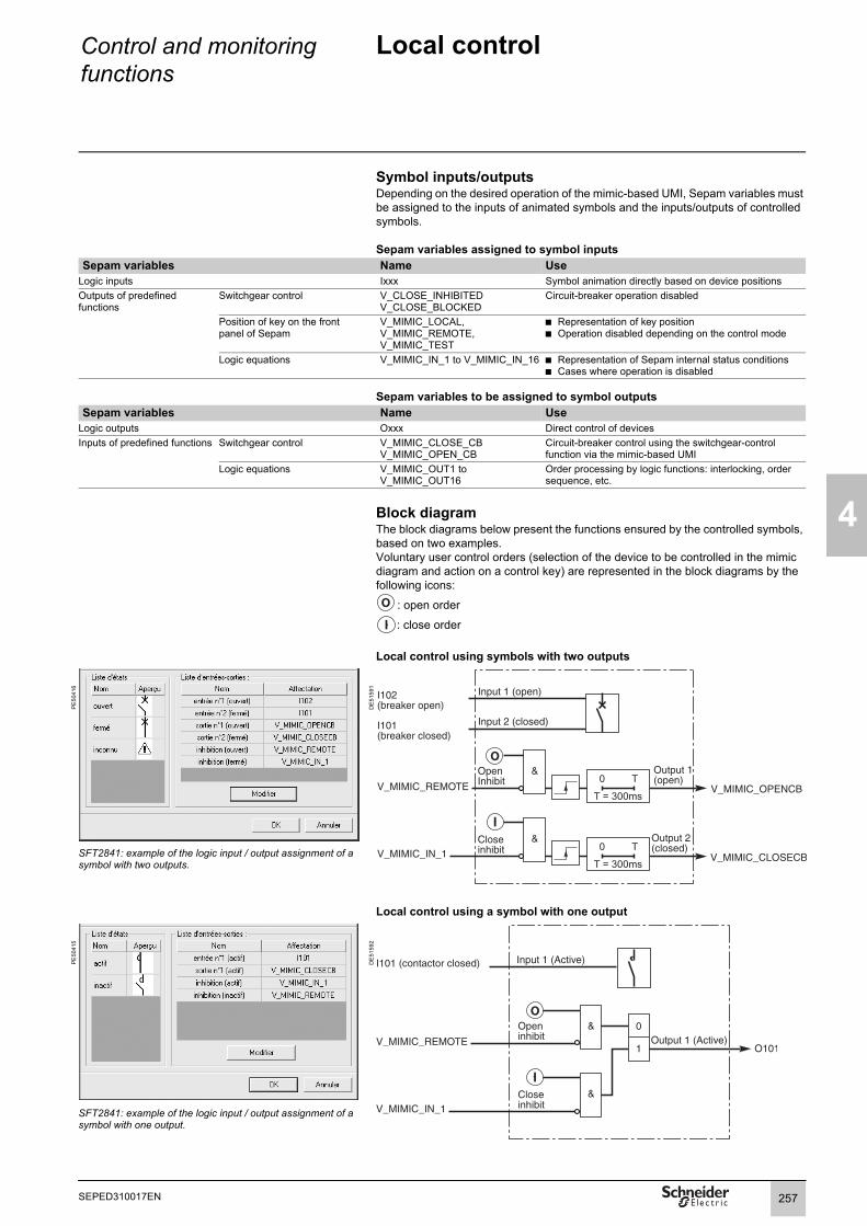
Control and monitoring functions
Local control
4
Symbol inputs/outputsDepending on the desired operation of the mimic-based UMI, Sepam variables must be assigned to the inputs of animated symbols and the inputs/outputs of controlled symbols.
Sepam variables assigned to symbol inputsSepam variables Name Use
Logic inputs Ixxx Symbol animation directly based on device positionsOutputs of predefined functions
Switchgear control V_CLOSE_INHIBITEDV_CLOSE_BLOCKED
Circuit-breaker operation disabled
Position of key on the front panel of Sepam
V_MIMIC_LOCAL, V_MIMIC_REMOTE, V_MIMIC_TEST
b Representation of key position b Operation disabled depending on the control mode
Logic equations V_MIMIC_IN_1 to V_MIMIC_IN_16 b Representation of Sepam internal status conditionsb Cases where operation is disabled
Sepam variables to be assigned to symbol outputsSepam variables Name Use
Logic outputs Oxxx Direct control of devicesInputs of predefined functions Switchgear control V_MIMIC_CLOSE_CB
V_MIMIC_OPEN_CBCircuit-breaker control using the switchgear-control function via the mimic-based UMI
Logic equations V_MIMIC_OUT1 to V_MIMIC_OUT16
Order processing by logic functions: interlocking, order sequence, etc.
Block diagramThe block diagrams below present the functions ensured by the controlled symbols, based on two examples.Voluntary user control orders (selection of the device to be controlled in the mimic diagram and action on a control key) are represented in the block diagrams by the following icons:
: open order
: close order
Local control using symbols with two outputs
PE
5041
6
DE
5159
1
SFT2841: example of the logic input / output assignment of a symbol with two outputs.
Local control using a symbol with one output
PE
5041
5
DE
5159
2
SFT2841: example of the logic input / output assignment of a symbol with one output.
257SEPED310017EN

4
Control and monitoring functions
Control matrix
DescriptionThe control matrix is used for simple assignment of the logic outputs and LEDs to data produced by the protection functions, control logic and logic inputs. Each column creates a logic OR between all the lines selected.The matrix may also be used to display the alarms associated with the data. It guarantees the consistency of the parameter setting with the predefined functions.The following data are managed in the control matrix and may be set using the SFT2841 software tool.
Control matrix inputs
"Protection" button Meaning CommentsAll application protection functions Protection tripping output and additional
outputs when applicable"Inputs" button
Logic inputs I101 to I114 According to configuration If first MES120 module is configuredLogic inputs I201 to I214 According to configuration If second MES120 module is configured"Equations" button Meaning Comments
V1 to V20 Logic equation editor outputs"Logic" button Meaning CommentsSwitchgear control
Closing Closing by switchgear control function By default on O3. Only available if switchgear control is in circuit breaker mode
Tripping Tripping by switchgear control function Forced on O1, if switchgear control is in circuit breaker mode
Inhibit closing Inhibition by switchgear control function By default on O2. Only available if switchgear control is in circuit breaker mode
Contactor control Contactor control Forced on O1, if switchgear control is in circuit breaker mode
Pick-up Logic OR of the instantaneous output of all protection units with the exception of protection units 38/49T, 48/51LR, 49RMS, 66.
Drop-out A protection unit time delay counter has not yet gone back to 0.
Logic discriminationLogic discrimination trip Tripping order sent by logic discrimination
functionOnly when logic discrimination function is used without switchgear control function
Blocking send 1 Sending of blocking signal to next Sepam in logic discrimination chain 1
By default on O102.
Blocking send 2 Sending of blocking signal to next Sepam in logic discrimination chain 2
By default on O103
Motor/generator controlLoad shedding Sending of a load shedding order Motor applicationGenset shutdown Sending of a prime mover shutdown order Generator applicationDe-excitation Sending of a de-excitation order Generator applicationRecloser
Recloser in service The recloser is in serviceReclosing successful The recloser has successfuly reclosed Pulse type outputPermanent trip The circuit breaker is permanently open
after the reclosing cyclesPulse type output
Recloser ready The recloser is ready to operateRecloser cycle 1 Cycle 1 in progressRecloser cycle 2 Cycle 2 in progressRecloser cycle 3 Cycle 3 in progressRecloser cycle 4 Cycle 4 in progressClosing by recloser A closing order is given by the recloser"GOOSE" button Meaning Comments
Logic inputs G401 to G416 and G501 to G516 According to configuration Only with ACE850 configured
258 SEPED310017EN

Control and monitoring functions
Control matrix
4
"Logic" button Meaning CommentsDiagnosis
TCS fault Trip circuit faultCCS fault Closing circuit faultTC / breaker position discrepancy Discrepancy between the last state ordered by the
remote monitoring and control system and the position of the circuit breaker
Breaker monitoring A circuit breaker or contactor open or close orderhas not been executed
Reverse phase rotation Reverse voltage rotation due to a wiring errorAdditional-phase reverse rotation Reverse rotation of additional phase voltages due to a
wiring errorDisturbance recording inhibited Disturbance recording inhibitedCumulative breaking current monitoring Overshooting of the cumulative breaking current set
pointLow battery fault Battery low or absentMET148-2 No 1 faultMET148-2 No 2 fault
Hardware problem on an MET 148-2 module(module 1 or 2) or on an RTD
Watchdog Monitoring of Sepam operation Always on O5 if usedCT supervision
CT fault I current input CT faultVT supervision
VT fault, phase channel V voltage input phase VT faultVT fault, residual channel V0 voltage input residual VT faultSynchro-check
Closing with synchro-check Circuit breaker close request with synchro-check by the ANSI 25 function has been initiated
Switchgear control with synchro-check function
Closing with synchro-check completed Breaker closing with synchro-check by the ANSI 25 function successful
Switchgear control with synchro-check function
Closing failed, out-of-sync Synchronism conditions too short to enable breaker closing
Switchgear control with synchro-check function
Closing failed, out-of-sync, cause dU Breaker closing inhibited because sources are out-of-sync due to an excessive voltage difference
Switchgear control with synchro-check function
Closing failed, out-of-sync, cause dPHI Breaker closing inhibited because sources are out-of-sync due to an excessive phase difference
Switchgear control with synchro-check function
Closing failed, out-of-sync, cause dF Breaker closing inhibited because sources are out-of-sync due to an excessive frequency difference
Switchgear control with synchro-check function
Stop closing with synchro-check A synchrochecked circuit breaker close request has been interrupted
Switchgear control with synchro-check function
Automatic transferCoupling closing with synchro-check failed The coupling close request initiated by automatic
transfer has failed because the sources are out-of-syncTripping by automatic transfer Breaker tripping initiated by automatic transfer (tripping
is performed by the switchgear control function)Tripping by 2/3 or 1/2 logic Breaker tripping initiated by 2/3 or 1/2 logic (tripping is
performed by the switchgear control function)NO circuit breaker closing Normally open circuit breaker close order for automatic
transfer functionBreaker closing ready Indication that breaker closing is possible to return to
normal operationCoupling closing Coupling closing order for automatic transfer functionCoupling closing ready Indication that coupling closing is possible to return to
normal operationCoupling tripping Coupling tripping order for automatic transfer function
259SEPED310017EN

4
Control and monitoring functions
Logic equations
Adaptation of the predefined control and monitoring functions by the addition of simple logic functions.
UseThis function may be used to configure simple logic functions by combining data received from the protection functions, logic inputs, remote control orders or the mimic-based UMI.GOOSE logic inputs (Gx) available with the IEC 61850 protocol are not managed.By using logic operators (AND, OR, XOR, NOT) and timers, new processing operations and indications may be added to the existing ones.The logic functions produce outputs that may be used:b in the matrix to control output relays, switch on a LED or display new messagesb in the protection functions to create, for example, new inhibit or reset conditionsb in the main predefined control and monitoring functions to complete processing operations or add new cases of tripping or genset shutdown, for exampleb for mimic diagram animation.
DE
8101
8
Logic function configurationLogic functions are entered in text format in the SFT2841 equation editor. Each line includes a logic operation, the result of which is assigned to a variable. Example:V1 = P5051_2_3 OR I102.The variable V1 is assigned the result of the logic OR operation involving the value from protection function 50/51 and logic input I102. The variables may be used for other operations or as outputs to produce actions in the control matrix, protection functions or predefined control and monitoring functions.A program is a series of lines executed sequentially every 14 ms.A data input assistance tool provides quick access to each of the equation editor operators and variables.
PE
5046
0
Description of operationsOperatorsb =: assignment of a resultV2 = VL3 //V2 is assigned the value of VL3b NOT: logic inversionVL1 = NOT VL2 // VL1 is assigned the opposite logic state of VL2b OR: logic ORV1 = VL3 OR I103 // V1 is assigned state 1 if VL3 or I03 are in state 1b AND: logic ANDVV3 = VL2 AND VV1 // VV3 is assigned state 1 if VL2 and VV3 are in state 1b XOR: exclusive ORV3 = VL1 XOR VL2 // V3 is assigned state 1 if only one of the variables VL1 or VL2 is in state 1. This is equivalent to V3 = (V1 AND (NOT V2)) OR (V2 AND (NOT V1))b //: commentaryThe characters on the right are not processedb (,): the operations may be grouped between brackets to indicate the order in which they are carried outV1 = (VL3 OR VL2) AND I213.
SFT2841: logic equation editor.
PE
5046
1
SFT2841: data input assistance tool.
260 SEPED310017EN
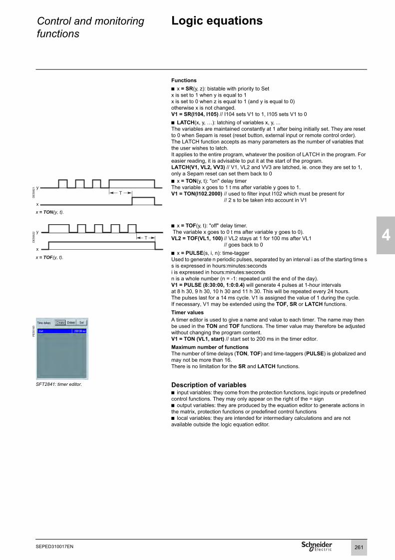
Control and monitoring functions
Logic equations
4
Functionsb x = SR(y, z): bistable with priority to Setx is set to 1 when y is equal to 1x is set to 0 when z is equal to 1 (and y is equal to 0)otherwise x is not changed.V1 = SR(I104, I105) // I104 sets V1 to 1, I105 sets V1 to 0b LATCH(x, y, …): latching of variables x, y, ...The variables are maintained constantly at 1 after being initially set. They are reset to 0 when Sepam is reset (reset button, external input or remote control order).The LATCH function accepts as many parameters as the number of variables that the user wishes to latch.It applies to the entire program, whatever the position of LATCH in the program. For easier reading, it is advisable to put it at the start of the program.LATCH(V1, VL2, VV3) // V1, VL2 and VV3 are latched, ie. once they are set to 1, only a Sepam reset can set them back to 0
DE
5062
1
b x = TON(y, t): "on" delay timerThe variable x goes to 1 t ms after variable y goes to 1.V1 = TON(I102.2000) // used to filter input I102 which must be present for
// 2 s to be taken into account in V1
x = TON(y, t).
DE
5062
2
b x = TOF(y, t): "off" delay timer. The variable x goes to 0 t ms after variable y goes to 0).VL2 = TOF(VL1, 100) // VL2 stays at 1 for 100 ms after VL1
// goes back to 0b x = PULSE(s, i, n): time-taggerUsed to generate n periodic pulses, separated by an interval i as of the starting time ss is expressed in hours:minutes:secondsi is expressed in hours:minutes:secondsn is a whole number (n = -1: repeated until the end of the day).V1 = PULSE (8:30:00, 1:0:0.4) will generate 4 pulses at 1-hour intervalsat 8 h 30, 9 h 30, 10 h 30 and 11 h 30. This will be repeated every 24 hours.The pulses last for a 14 ms cycle. V1 is assigned the value of 1 during the cycle.If necessary, V1 may be extended using the TOF, SR or LATCH functions.Timer values
x = TOF(y, t).
PE
5016
0
A timer editor is used to give a name and value to each timer. The name may then be used in the TON and TOF functions. The timer value may therefore be adjusted without changing the program content.V1 = TON (VL1, start) // start set to 200 ms in the timer editor.Maximum number of functionsThe number of time delays (TON, TOF) and time-taggers (PULSE) is globalized and may not be more than 16.There is no limitation for the SR and LATCH functions.
SFT2841: timer editor. Description of variablesb input variables: they come from the protection functions, logic inputs or predefined control functions. They may only appear on the right of the = signb output variables: they are produced by the equation editor to generate actions in the matrix, protection functions or predefined control functionsb local variables: they are intended for intermediary calculations and are not available outside the logic equation editor.
261SEPED310017EN
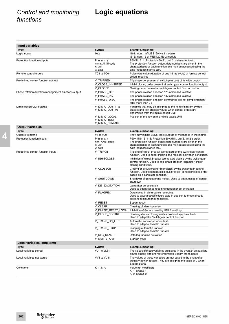
4
Control and monitoring functions
Logic equations
Input variablesType Syntax Example, meaning
Logic inputs Ixxx I101: input 1 of MES120 No 1 moduleI212: input 12 of MES120 No 2 module
Protection function outputs Pnnnn_x_ynnnn: ANSI codex: unity: data
P50/51_2_1: Protection 50/51, unit 2, delayed output.The protection function output data numbers are given in the characteristics of each function and may be accessed using the data input assistance tool.
Remote control orders TC1 to TC64 Pulse type value (duration of one 14 ms cycle) of remote control orders received
Predefined control function outputs V_TRIPPED Tripping order present at switchgear control function outputV_CLOSE_INHIBITED Inhibit closing order present at switchgear control function outputV_CLOSED Closing order present at switchgear control function output
Phase rotation direction management functions output V_PHASE_DIR The phase rotation direction 123 command is activeV_PHASE_INV The phase rotation direction 132 command is activeV_PHASE_DISC The phase rotation direction commands are not complementary
after more than 2 sMimic-based UMI outputs V_MIMIC_OUT_1 to
V_MIMIC_OUT_16Variables that may be assigned to the mimic diagram symbol outputs and that change values when control orders are transmitted from the mimic-based UMI
V_MIMIC_LOCALV_MIMIC_TEST,V_MIMIC_REMOTE
Position of the key on the mimic-based UMI
Output variablesType Syntax Example, meaning
Outputs to matrix V1 to V20 They may initiate LEDs, logic outputs or messages in the matrix. Protection function inputs Pnnnn_x_y
nnn: ANSI codex: unity: data
P50N/51N_6_113: Protection 50N/51N, unit 6, inhibit order.The protection function output data numbers are given in the characteristics of each function and may be accessed using the data input assistance tool.
Predefined control function inputs V_TRIPCB Tripping of circuit breaker (contactor) by the switchgear control function. Used to adapt tripping and recloser activation conditions.
V_INHIBCLOSE Inhibition of circuit breaker (contactor) closing by the switchgear control function. Used to add circuit breaker (contactor) inhibit closing conditions.
V_CLOSECB Closing of circuit breaker (contactor) by the switchgear control function. Used to generate a circuit breaker (contactor) close order based on a particular condition.
V_SHUTDOWN Shutdown of genset prime mover. Used to adapt cases of genset shutdown
V_DE_EXCITATION Generator de-excitation Used to adapt cases requiring generator de-excitation
V_FLAGREC Data saved in disturbance recording.Used to save a specific logic state in addition to those already present in disturbance recording.
V_RESET Sepam resetV_CLEAR Clearing of alarms presentV_INHIBIT_RESET_LOCAL Inhibition of Sepam reset by UMI Reset key.V_CLOSE_NOCTRL Breaking device closing enabled without synchro-check.
Used to adapt the Switchgear control functionV_TRANS_ON_FLT Automatic transfer order on fault.
Used to adapt automatic transferV_TRANS_STOP Stopping automatic transfer
Used to adapt automatic transferV_DLG_START Data log function activationV_MSR_START Start an MSR
Local variables, constantsType Syntax Example, meaning
Local variables stored VL1 to VL31 The values of these variables are saved in the event of an auxiliary power outage and are restored when Sepam starts again.
Local variables not stored VV1 to VV31 The values of these variables are not saved in the event of an auxiliary power outage. They are assigned the value of 0 when Sepam starts.
Constants K_1, K_0 Value not modifiableK_1: always 1K_0: always 0
262 SEPED310017EN

Control and monitoring functions
Logic equations
4
Processing in the event of auxiliary power outageAll the variables, with the exception of the variables VVx, are saved in the event of a Sepam auxiliary power outage. The states of the variables are restored when the power is recovered, allowing the states produced by LATCH, SR or PULSE type memory operators to be saved.Special casesb brackets must be used in expressions that comprise different OR, AND, XOR or NOT operators:v V1 = VL1 AND I12 OR P27/27S_1_1. // expression incorrectv V1 = (VL1 AND I12) OR P27/27S_1_1. // expression correctv V1 = VL1 OR I12 OR P27/27S_1_1. // expression correctb protection input/output variables (Pnnn_x_y) may not be used in the LATCH functionb function parameters may not be expressions:v VL3 = TON ((V1 AND V3), 300) // expression incorrectv VL4 = V1 AND V3v VL3 = TON (VL4, 300) // correct.Use limitThe number of operators and functions (OR, AND, XOR, NOT, =, TON, TOF, SR,PULSE is limited to 200.
Examples of applicationsb latching of recloser permanent trip signalBy default, this signal is of the pulse type at the recloser output. If required by operating conditions, it may be latched as follows:LATCH (V1) // V1 may be latchedV1 = P79_1_204 // recloser "permanent trip" output.V1 may then control a LED or output relay in the matrix.b latching of a LED without latching the protection functionCertain operating conditions call for the latching of indications on the front panel of Sepam, without latching of the tripping output O1.LATCH (V1, V2) // V1 and V2 may be latchedV1 = P50/51_1_1 OR P50/51_3_1 // tripping, units 1 and 3 of protection 50/51V2 = P50/51_2_1 OR P50/51_4_1 // tripping, units 2 and 4 of protection 50/51V1 and V2 must be configured in the matrix to control 2 front panel LEDs.b circuit breaker tripping if input I113 is present for more than 300 msV_TRIPCB = TON (I113, 300).b live line work (example 1)If work is underway with power on (indicated by input I205), the relay behavior is to be changed as follows:1 – circuit breaker tripping by the instantaneous output of protection 50/51 unit 1 or 50N/51N unit 1 AND if input I205 is present:V_TRIPCB = (P50/51_1_1 OR P50N/51N_1_1) AND I2052 – Inhibit recloser:P79_1_113 = I205b live line work (example 2)The user wishes to inhibit protection functions 50N/51N and 46 by an input I204:P50N/51N_1_113 = I204P46_1_113 = I204b validation of a 50N/51N protection function by logic input I210A 50N/51N protection function with a very low threshold must only initiate tripping of the circuit breaker if it is validated by an input. The input comes from a relay which gives a very accurate measurement of the neutral point current:V_TRIPCB = P50N/51N_1_3 AND I210b inhibition of circuit breaker closing if thermal alarm thresholds are overrunThe temperature protection function 38/49T supplies 16 alarm bits. If one of the first three bits is activated (1 state), the user wishes to inhibit circuit breaker closingV_INHIBCLOSE = P38/49T_1_10 OR P38/49T_2_10 OR P38/49T_3_10b remote control order to inhibit protection 50/51 unit 1VL1=SR(TC63,TC64) // TC63 set inhibition, TC64 reset inhibitionP50/51_1_113 = VL1 // VL1 is stored in the event of an auxiliary power outage.
263SEPED310017EN

4
Control and monitoring functions
Self-tests and fail-safe position
PresentationThe reliability of a device is the property that allows its users to have well-placed confidence in the service it delivers.For a Sepam protection relay, operational reliability consists of ensuring the safety and availability of the installation. This means avoiding the following 2 situations:b Nuisance tripping of the protectionContinuity of the electrical power supply is as vital for a manufacturer as it is for an electricity distribution company. Nuisance tripping caused by the protection can result in considerable financial losses. This situation affects the availability of the installation.b Failure of the protection to tripThe consequences of a fault that is not eliminated can be catastrophic. For safety of operation, the protection relay must detect faults in the power supply as quickly as possible, using discrimination. This situation affects the safety of the installation.
Self-tests and monitoring functionsOn initialization and cyclically during operation, Sepam runs a series of self-tests. These self-tests are designed to detect any failure in its internal and external circuits so as to ensure Sepam's reliability. These failures are classified into 2 categories, major failures and minor failures:b A major failure reaches the hardware resources used by the protection functions (program memory and analog input for example).This type of failure risks resulting in failure to trip on a fault or nuisance tripping. In this case, Sepam must go into the fail-safe position as quickly as possible.b A minor failure affects Sepam's peripheral functions (display, communication except for ACE969-2 and ACE850).This type of failure does not prevent Sepam from protecting the installation and providing continuity of service. Sepam then operates in downgraded mode.The classification of failures into 2 categories improves both safety and availability of the installation.
The possibility of a Sepam major failure must be taken into account when selecting the trip command type to maximize availability or safety of the installation (see "Selecting the trip command" page 267).
In addition to the self-tests, the user can activate monitoring functions to improve the installation monitoring:b VT supervision (ANSI code 60FL)b CT supervision (ANSI code 60)b Trip circuit and closing circuit supervision (ANSI code 74).
264 SEPED310017EN

Control and monitoring functions
Self-tests and fail-safe position
4
Self-testsThe self-tests are run when Sepam is initialized and/or during its operation.
List of self-tests which place Sepam in the fail-safe positionFailures which have caused this are deemed to be major ones.Function Test type Execution periodPower supply
Power supply presence During operationCPU
Embedded software During operationProcessor On initialization and during operationRAM memories On initialization and during operation
Program memoryChecksum On initialization and during operation
Parameter memoryChecksum On initialization
Analog inputsAcquisition consistency During operationInfinite gain During operation
Logic outputsRelay driver On initialization and during operation
ConnectionCCA630, CCA634, CCA671
On initialization and during operation
MES120 On initialization and during operationE Connector (phase voltage inputs, residual voltage and current inputs)
On initialization and during operation
List of self-tests which do not place Sepam in the fail-safe positionFailures which have caused this are deemed to be minor ones.Function Test type Execution periodUMI
Module presence On initialization and during operationMemory On initializationSoftware During operation
Analog outputModule presence On initialization and during operation
Temperature inputsModule presence On initialization and during operation
Battery voltageMinimum value check
During operation
265SEPED310017EN

4
Control and monitoring functions
Self-tests and fail-safe position
Fail-safe positionWhen Sepam is in working order, it runs self-tests continuously. Detection of a major failure places Sepam in the fail-safe position.
State of Sepam in the fail-safe positionb All the output relays are forced to the idle stateb All protection functions are inhibitedb The watchdog output indicates failure (output in the idle state)b A red LED on the Sepam front panel is on and a diagnostic message appears on the Sepam display unit (see "Local indication" page 252).
How Sepam deals with failures
DE
8025
1
b Minor failure: Sepam switches to downgraded operation. The failure is indicated on the Sepam display unit and also by the communication. Sepam continues to protect the installation.b Major failure: Sepam switches to the fail-safe position and attempts a restart during which it again runs its self-tests. There are 2 possible scenarios:v The internal failure is still present. It is a permanent failure. Intervention on Sepam is required. Only removing the cause of the failure, followed by de-energizing and then energizing Sepam, will allow the unit to exit the fail-safe position.v The internal failure is no longer present. It is a transient failure. Sepam restarts so that it can continue to protect the installation. Sepam has been in the fail-safe position for 5 to 7 s.
Permanent internal failure.
DE
8025
2
Transient internal failure.
DE
8025
3
Limiting the number of transient failure detectionsEach time a transient internal failure appears, Sepam increments an internal counter. The fifth time the failure occurs, Sepam is placed in the fail-safe position. De-energizing Sepam reinitializes the failure counter. This mechanism can be used to avoid keeping a Sepam running that is subject to repeated transient failures.
Repeated transient internal failures.
Relay output
Watchdog
Relay output
Watchdog5 to 7 seconds
Relay output
Watchdog
Counter 0 1 2 0 1 2 3 4 5
Sepamde-energized
266 SEPED310017EN

Control and monitoring functions
Self-tests and fail-safe position
4
Selecting the trip command and examples of useAn analysis of the operational reliability of the whole installation should determine whether availability or safety of this installation should be prioritized if Sepam is in the fail-safe position. This information is used to determine the choice of trip command as outlined in the table below.
NOTICE Selecting the trip commandRISK OF UNPROTECTED INSTALLATIONAlways connect the watchdog output to a monitoring device when the selected trip command does not result in the installation tripping when Sepam fails.Failure to follow these instructions can result in equipment damage.
Diagram Control Event Trip Advantage Disadvantage1 Shunt trip breaker
or mechanical latching contactor
Sepam failure or loss of the auxiliary power supply
No Availability of the installation
Installation not protected until remedial intervention (1)
2 Breaker with undervoltage trip coil (fail-safe)
Sepam failure or loss of the auxiliary power supply
Yes Safety of the installation
Installation not available until remedial intervention
3 Breaker with undervoltage trip coil (not fail-safe)
Sepam failure No Availability of the installation
Installation not protected until remedial intervention (1)
Loss of auxiliary power supply
Yes Safety of the installation
Installation not available until remedial intervention
4 Contactor without coil latching (permanent order)
Sepam failure or loss of the auxiliary power supply
Yes Safety of the installation
Installation not available until remedial intervention
(1) It is essential to use the watchdog, see the warning notice opposite.
Example of use with shunt trip coil (diagram 1)
DE
8025
4
O2
O311
10
O112 I101
45 I102
closingN/O
coiltripShunt
coil
Breaker closed Breaker openTrip
Inhibit closing
Closing
54
87
Setting the Sepam output parameters:O1: N/OO2: N/CO3: N/O
H H
267SEPED310017EN
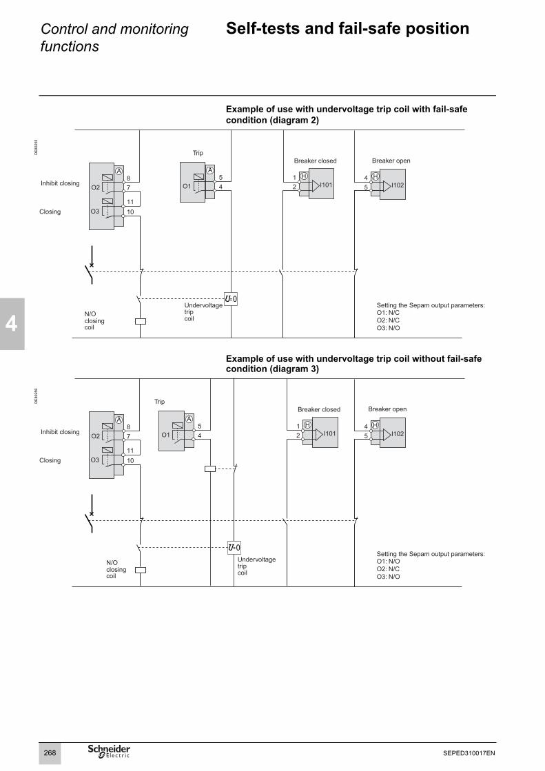
4
Control and monitoring functions
Self-tests and fail-safe position
Example of use with undervoltage trip coil with fail-safe condition (diagram 2)
DE
8025
5
Example of use with undervoltage trip coil without fail-safe condition (diagram 3)
DE
8025
6
O2
O31110
O112 I101
45 I102
closingN/O
coil
tripUndervoltage
coil
Breaker closed Breaker openTrip
Inhibit closing
Closing
= 0Setting the Sepam output parameters:O1: N/CO2: N/CO3: N/O
54
87
H H
O2
O31110
O112 I101
45 I102
closingN/O
coiltripUndervoltage
coil
Breaker closed Breaker openTrip
Inhibit closing
Closing
Setting the Sepam output parameters:O1: N/OO2: N/CO3: N/O
54
87
H H
= 0
268 SEPED310017EN

Control and monitoring functions
Self-tests and fail-safe position
4
Example of use with contactor under permanent order command (diagram 4)
DE
8025
8
(1) Standard assignments, can be modified.
Using the watchdogThe watchdog is extremely important in the monitoring system, as it indicates to the user that the Sepam protection functions are working correctly. When Sepam detects an internal failure, an LED flashes automatically on the Sepam front panel regardless of whether the watchdog output is connected correctly. If the watchdog output is not correctly connected to the system, this LED is the only way of knowing that Sepam has failed. We therefore strongly recommend connecting the watchdog output at the highest level of the installation so that an effective alarm is generated when necessary. For example, an audible alarm or flashing alarm lamp can be used to warn the operator.
Watchdog output status
No failure detected Failure detected
Watchdog output connected correctly to the control system
The protection functions arein working order
b The protection functions are not working.b Sepam is in the fail-safe position.b The Sepam alarm LED flashes.b The watchdog output activates a system alarm.b The operator is warned that he needs to intervene.
Watchdog output not connected
The protection functions arein working order
b The protection functions are not working.b Sepam is in the fail-safe position.b The Sepam alarm LED flashes.b The need of maintenance is detected only if an operator controls the front panel of the digital relay.
O112 I101
45 I102
Breaker closed Breaker open
Setting the Sepam output parametersO1: N/O
54
H H
1813
H 1713
H
Closing Trip
I107(1) I106(1)
Contactor
Shunttrip coil
269SEPED310017EN

4
270 SEPED310017EN

Modbus Communication Contents
5
Presentation 272Managing the Modbus protocol 273Configuring the communication interfaces 274Serial line communication 274Ethernet communication 276Commissioning and diagnosis 280Serial line communication 280Ethernet communication 282Data addresses and coding 287Addresses in direct-access mode 289Time-setting and synchronization 308Time-tagged events 310Transferring records 312Access to remote settings 315Customized table 317Security 318Reading Sepam identification 319Appendix 1. Modbus protocol 320Appendix 2. Function settings 325
271SEPED310017EN

5
Modbus communication Presentation
GeneralModbus communication allows Sepam to be connected to a supervisor or any other device with a master Modbus communication channel.Sepam is always a slave station.
Easergy Sepam series 60 is equipped with:b 1 port C1 (COM1) to connect the serial communication interfaces,b 1 port F to connect the Ethernet communication interfaces.
The interfaces to connect Sepam to a single serial network are the following:b ACE949-2, for connection to a 2-wire RS 485 networkb ACE959, for connection to a 4-wire RS 485 networkb ACE937, for connection to a fiber-optic star network
The interfaces to connect Sepam to 2 serial networks are the following:b ACE969TP-2, for connection to:v one 2-wire RS 485 Modbus S-LAN supervision communication networkv one 2-wire RS 485 E-LAN engineering communication networkb ACE969FO-2, for connection to:v one fiber-optic Modbus S-LAN supervision communication networkv one 2-wire RS 485 E-LAN engineering communication network
The interfaces to connect Sepam to an Ethernet network are the following:b ACE850TP for copper electrical connection to the networkb ACE850FO for optical connection to the network.
Accessing Sepam dataData availableModbus communication provides access to many different functions, including:b reading of metering and diagnosis informationb reading of status conditions and remote indicationsb transfer of time-tagged eventsb transfer of files such as disturbance recordings and tripping contexts and, for Easergy Sepam series 60, out-of-sync contexts, motor start reports, motor start trendsand data logsb viewing of protection settingsb reading of Sepam configuration and identificationb remote control of the analog outputb time-setting and synchronization.The actual list depends on the application, the type of Sepam and the enabled functions.
Modbus communication also offers a number of additional functions (when enabled):b transmission of remote controlsb modification of protection settings.A password may be set up to protect access to these two functions.
Access modesDepending on the data, two access modes are used:b direct access - the data may be accessed directly in a single read or write operationb indirect access - access requires a number of read and write operations, using a protocol that is specific to the data accessed.
Customized tableWith Sepam, it is possible to set up for each Modbus port a customized sub-group of data for quick reading of the most significant information on the user application.
Compatibility with Sepam 2000Even though Easergy Sepam series 60 offers many additional functions, it remains compatible with Sepam 2000 addresses and formats for most information.
272 SEPED310017EN

Modbus communication Managing the Modbus protocol
5
Protocol operationModbus is used to exchange information between a master and one or more slave units, identified by a number. It implements request-reply dialog, where requests are always initiated by the master. Modbus exists in ASCII and binary (RTU mode) formats.
Data is exchanged in the form of 16-bit words (also called registers) or simply bits. Each piece of information (bit or register) has a 16-bit address.
A detailed description of the protocol is provided in the appendix. It may also be found at www.modbus.org.
Modbus functions The Modbus protocol used by Easergy Sepam series 60 is a compatible sub-group of the RTU Modbus protocol.The functions listed below are handled by Easergy Sepam series 60:b basic functions (data access):v function 1: reading of n output or internal bitsv function 2: reading of n input bitsv function 3: reading of n output or internal wordsv function 4: reading of n input wordsv function 5: writing of 1 bitv function 6: writing of 1 wordv function 7: high-speed reading of 8 bitsv function 15: writing of n bitsv function 16: writing of n words.b communication-management functions:v function 8: Modbus diagnosisv function 11: reading of Modbus event counterv function 43: sub-function 14: reading of identification.b enhanced functions:v function 102: secure access.
The following exception codes are supported:b 1: unknown function codeb 2: incorrect addressb 3: incorrect datab 4: not ready (cannot process request)b 7: not acknowledged (remote reading and setting in particular).
Multi-master operation Serial line Modbus operationWhen Sepam units are connected via a gateway to a multiple-access network (Ethernet, Modbus+, etc.), a number of masters may address the same unit via the serial communication port.The serial line Modbus protocol cannot manage this type of architecture. The network designer is responsible for avoiding collisions.b For direct-access data, in general, no particular precautions must be taken.b For indirect-access data, Sepam provides two exchange zones, making possible 2 simultaneous, independent accesses by 2 different masters.
Modbus over TCP/IP operationThe ACE850 accepts up to 8 simultaneous Modbus/TCP connections.Sepam accepts the Unit-Id 255 or any value in the range 1-247.If several clients are accessing indirect-access data, they must make proper use of the two exchange zones provided. No access synchronization is provided by Sepam units.
PerformanceThe typical response time (time between the end of request reception and sending the reply) is less than 10 milliseconds for 90% of exchanges. It may occasionally be longer, but not exceed 150 ms.In indirect mode, the time needed between the request (or an acknowledgment) and the availability of the corresponding data is linked to the Sepam low-priority cycle time and may vary from a few dozen to several hundred milliseconds.
273SEPED310017EN

5
Modbus communication Configuring the communication interfacesSerial line communication
PE
8077
6
Access to configuration parametersThe Sepam communication interfaces must be configured using SFT2841 software.The configuration parameters can be accessed from the Communication configuration window in the SFT2841 software.To access this window:b open the Sepam configuration window in SFT2841b check the COM1 boxb click on the relevant button : the Communication configuration window appearsb select the type of interface used: ACE949/ACE959/ACE937, ACE969TP or ACE969FOb select the Modbus communication protocol.
The configuration parameters will vary depending on the communication interface selected: ACE949/ACE959/ACE937, ACE969TP or ACE969FO. The table below specifies the parameters to be configured depending on the communication interface chosen.
SFT2841: Sepam configuration screen.
Parameters to be configured ACE949ACE959ACE937
ACE969TP ACE969FO
Physical layer parameters b b bFiber-optic parameters bAdvanced Modbus parameters b b bE-LAN parameters b b
PE
5056
1
SFT2841: communication configuration window for ACE949.
Configuring the physical layer of the Modbus portAsynchronous serial transmission is used with the following character format:b 1 start bitb 8 data bitsb 1 stop bitb parity according to parameter setting.The number of stop bits is always fixed at 1.If a configuration with parity has been selected, each character will contain 11 bits: 1 start bit + 8 data bits + 1 parity bit + 1 stop bit.If a no parity configuration has been selected, each character will contain 10 bits: 1 start bit + 8 data bits + 1 stop bit.
The configuration parameters for the physical layer of the Modbus port are as follows:b slave number (Sepam address)b transmission speedb parity check type. Parameters Authorized values Default value
Sepam address 1 to 247 1Speed 4800, 9600, 19200
or 38400 bps19200 bps
Parity No parity, even or odd
Even
Configuring the ACE969FO-2 fiber-optic portThe configuration for the physical layer of the ACE969FO-2 fiber-optic port is completed with the following 2 parameters:b link idle state: light-on or light-offb echo mode: with or without.
Fiber-optic parameters Authorized values Default valueLink idle state Light Off or Light On Light OffEcho mode Yes (fiber-optic ring)
or No (fiber-optic star)No
Note: in echo mode, the Modbus master will receive the echo of its own request before the slave's reply. The Modbus master must be able to disregard this echo. Otherwise, it is impossible to create a Modbus fiber-optic ring.
274 SEPED310017EN

Modbus communication Configuring the communication interfacesSerial line communication
5
PE
5055
9
Configuring Modbus advanced parametersWith Easergy Sepam series 60, remote controls and remote settings can beprotected by a password.Advanced parameters can be used to configure the security function by:b activating the functionb entering the password for the remote controlsb entering the password for the remote settings.
Advanced parameters Authorized values Default valueSecurity function On/Off OffRemote controls password 4-digit code 0000Remote settings password 4-digit code 0000
Modbus Advanced parameters window.
PE
5056
0
Configuring the physical layer of the ACE969-2 E-LAN portThe E-LAN port on the ACE969TP-2 and ACE969FO-2 communication interfaces is a 2-wire RS 485 port. The configuration parameters for the physical layer of the E-LAN port are:b Sepam addressb transmission speedb parity check type. The number of stop bits is always fixed at 1.If a configuration with parity has been selected, each character will contain 11 bits: 1 start bit + 8 data bits + 1 parity bit + 1 stop bit.If a no parity configuration has been selected, each character will contain 10 bits: 1 start bit + 8 data bits + 1 stop bit.
Parameters Authorized values Default valueSepam address 1 to 247 1Speed 4800, 9600, 19200
or 38400 bps38400 bps
Parity No parity, even or odd
Odd
Configuration tipsb The Sepam address MUST be assigned before Sepam is connected to the communication network.b You are also strongly advised to set the other physical layer configuration parameters before connecting to the communication network.b Modifying the configuration parameters during normal operation will not disturb Sepam but will reset the communication port.
Communication configuration window for ACE969FO.
275SEPED310017EN

5
Modbus communication Configuring the communication interfacesEthernet communication
Access to configuration parameters
PE
8077
6
The Sepam communication interfaces must be configured using SFT2841 software.The configuration parameters can be accessed from the Communication configuration window in the SFT2841 software.To access this window:b open the Sepam configuration window in SFT2841b select the Ethernet communication portb click on the relevant button : the Communication configuration window appearsb select the type of interface used: ACE850TP or ACE850FO.
Configuring an ACE850 involves:b configuring the standard Ethernet parameters (mandatory)b configuring one or more of the following sets of advanced optional parameters:v SNMP: Ethernet network managementv SNTP: time synchronizationv IP filtering: access controlv RSTP: Ethernet ring managementv User accounts: access control.
SFT2841: Sepam configuration screen.
Ethernet and TCP/IP configurationBefore configuring the ACE850, obtain a unique static IP address, subnet mask, and default gateway address from the network administrator. See the section on IP address and parameter guidelines, page 279.P
E80
395
Parameters Description Authorized valuesFrame format Used to select the format for data sent over
an Ethernet connection.Ethernet II, 802.3, AutoDefault: Ethernet II
Media type Used to define the physical Ethernet connection.
ACE850TPb 10T/100Tx Autob 10BaseT-HDb 10BaseT-FDb 100BaseTX-HDb 100BaseTX-FDDefault: 10T/100Tx AutoACE850FOb 100BaseFX-HDb 100BaseFX-FDDefault: 100BaseFX-FD
IP address Used to enter the static IP address of the ACE850.
0.0.0.0 to 255.255.255.255Default: 169.254.0.10
Subnet mask Used to enter the subnet mask of your network.
0.0.0.0 to 255.255.255.255Default: 255.255.0.0
Default gateway Used to enter the default gateway (router) IP address used for wide area network (WAN) communications.
0.0.0.0 to 255.255.255.255Default: 0.0.0.0
SFT2841 : Ethernet and TCP/IP communication configuration screen.
Allow CID file tooverride IP parameters
This option is irrelevant when only Modbus communication is used.
Default: not checked
Keep alive Timeout value used to test for session disconnection.
1 to 60 secondsDefault: 30 seconds
FTP session inactivity timeout
Timeout value used to force disconnection of an inactive FTP session
30 to 900 secondsDefault: 30 seconds
Duplicate IP address detectionThe ACE850 IP address must be unique in the network. If it is not unique, the Status LED repeats a four blink-pause pattern and a new IP address must be assigned to the ACE850 or to the conflicting device.
276 SEPED310017EN

Modbus communication Configuring the communication interfacesEthernet communication
5
SNMP configurationThe ACE850 supports SNMP V1, allowing a network administrator to remotely access it with an SNMP manager and view the network status and diagnostics in the MIB2 format (only a subset of MIB2 is implemented).Additionally, the ACE850 may be configured to send SNMP traps in the following cases:b ACE850 start/restartb Link upb Link downb Authentication failure.
PE
8039
6
Parameters Description Authorized valuesSystem Name This parameter is the same as the Sepam
label. Not modifiable from this screen.
System Contact Name of the administrative contact String (< 16 characters) Default: empty string
SFT2841: SNMP configuration. System Location Location of the Sepam/ACE850 String (< 16 characters)Default: empty string
Read-onlyCommunity Name
SNMP community that has read-onlyaccess to the MIB. Acts as a password.
String (< 16 characters)Default: "public"
Read-writeCommunity Name
SNMP community that has read-writeaccess to the MIB. Acts as a password.
String (< 16 characters)Default: "private"
Enable traps Checking this check box enables SNMP to send traps.
Default: "not checked"
TrapsCommunity Name
SNMP community that is used with traps. String (< 16 characters)Default: "public"
Manager 1 IP address
IP address of the SNMP manager to which traps are sent.
0.0.0.0 to 255.255.255.255Default: 0.0.0.0
Manager 2 IP address
IP address of a second SNMP manager to which traps are sent.
0.0.0.0 to 255.255.255.255Default: 0.0.0.0
SNTP configurationSNTP is a time synchronization protocol that can be used to synchronize the Sepam. SNTP is used in mode 3-4 (unicast mode).b If SNTP is used, the synchronization source for Sepam must be defined as Ethernet.b If SNTP is not used, the Sepam synchronization must be ensured by other means (Modbus frames, synchronization tops).
PE
8039
7
Parameters Description Authorized valuesEnable SNTP Enables the time and date of the Sepam to
be set by the Simple Network Time Protocol (SNTP) server.
Default: not enabled
Time Zone Offset Determines the difference between local time and Coordinated Universal Time (UTC) (same as GMT).
UTC-12 to UTC+14Default: UTC
Enable DaylightSaving Time
Enables the use of Daylight Saving Time (Summer time).
Default: not enabled
SFT2841: SNTP configuration. DST offset Difference between standard time andDaylight Saving Time.
+ 30 or + 60 minutesDefault: + 60 minutes
DST starts If enabled, DST starts on the selected date.
Default: last Sunday of March
DST ends If enabled, DST ends on the selected date. Default: last Sunday of October
Primary Server IP Address
The IP address of the SNTP server the ACE850 contacts to get the time message.
0.0.0.0 to 255.255.255.255Default: 0.0.0.0
Secondary Server IP Address
The IP address of another SNTP server the ACE850 contacts in case the primary server is down.
0.0.0.0 to 255.255.255.255Default: 0.0.0.0
Poll Interval Controls how often the ACE850 contacts the SNTP server for the correct time.
1 to 300 minutesDefault: 60 minutes
277SEPED310017EN

5
Modbus communication Configuring the communication interfacesEthernet communication
IP filtering configurationThe IP filtering function allows the administrator to specify which Modbus/TCP clients and which IEC 61850 clients have access to the ACE850 services.Note: if IP filtering is enabled, access is forbidden to any client not in the filtered list. P
E80
398
Parameters Description Authorized valuesEnable filtering Check this box to activate filtering based
on IP addresses.Default: not enabled
IP address The IP address of a client for which filtering options are defined.
0.0.0.0 to 255.255.255.255Default: 0.0.0.0
IEC 61850 Check this box to grant IEC 61850 access to the given IP address.
Default: not checked
Modbus Check this box to grant Modbus/TCP access to the given IP address.
Default: not checked
SFT2841: IP filtering configuration.
RSTP configurationThe RSTP protocol enables the use of redundant Ethernet architectures such as rings.It must be enabled each time the ACE850 is included in a loop. It may be disabled in other cases.Changing the default settings is normally not required and should be performed with extreme care as it could jeopardize the stability of the Ethernet network.If in doubt, it is always possible to revert to the default values using the Default settings button.
PE
8039
9
Parameters Description Authorized valuesEnable RSTP Check this box to activate the use of the
RSTP protocol.Default: enabled
RSTP bridge priority Priority of the RSTP bridge. The bridge with the lowest priority becomes root.
0 - 61440, by steps of 4096Default: 61440
Hello time Amount of time between the transmission of configuration messages
1 to 10 secondsDefault: 2 seconds
SFT2841: RSTP configuration. Forward delay time Time value to control how fast a port changes its spanning state when moving towards the forwarding state
4 to 30 secondsDefault: 21 seconds
Max age time Valid duration of configuration message once sent by the root bridge
6 to 40 secondsDefault: 40 seconds
Max transmit count Maximum BPDUs that can be transmitted by the Port Transmit state machine in any Hello time. This value limits the maximum transmission rate.
3 to 100Default: 32
RSTP cost style RSTP (32 bits) or STP (16 bits) cost style selection
Default: RSTP
Note: RSTP parameters must verify the following relationships:b 2 x (Forward_delay_time - 1 second) u Max_age_timeb Max_age_time u 2 x (Hello_time + 1 second).
278 SEPED310017EN

Modbus communication Configuring the communication interfacesEthernet communication
5
User accounts configurationACE850 users are assigned usernames and passwords used to gain access to the FTP or WEB servers. Each user belongs to a group which determines the user’s access rights:b Administrator: read-write access to the FTP server, access to the WEB serverb Operator: read-only access to the FTP server, access to the WEB serverb Guest: no access to the FTP server, access to the WEB server
Up to 4 user accounts can be defined.
PE
8040
0
Parameters Description Authorized valuesUser control enable Check this box to enable the configuration
of users account. Currently, the ACE850 will not operate if this box is not checked. Ensure that this box is always checked.
Default: enabled
User n Check this box to create this user account. Uncheck it to delete the account (only the last account in the list can be deleted).
Default: user 1 enabledUsers 2 to 4 disabled
SFT2841: User accounts configuration. Name User name String (1 to 8 characters)Password User password String (4 to 8 characters)Group Group to which the user belongs Administrator, Operator,
Guest
The following account is always created by default as user 1:b Name: Adminb Password: ACE850b Group: Administrator
IP address and parameter guidelinesIP addressesSeveral configuration parameters are IP addresses. These addresses must follow precise rules which are enforced by SFT2841 and ACE850. These rules are:b Every IP address is made of 4 fields separated by dots: x . y . z . tb Each field is a decimal value coded on 8 bits (range [0..255]).b The first field (x) must be in the range [1..224] but must not be 127.b Intermediate fields can cover the full range [0..255].b The last field must not be 0 (range [0..255]).
IP subnet maskThe IP subnet mask is also made of 4 dot separated fields:b The binary representation of the subnet mask is made of a set of 8 to 30 contiguous ones in the most significant part, followed by a set of contiguous zeroes (255.0.0.0 to 255.255.255.252).b For a class A IP address (x y 126), the number of ones in the subnet mask must be at least 8 (255.y.z.t).b For a class B IP address (128 y x y 191), the number of ones in the subnet mask must be at least 16 (255.255.z.t).b For a class C IP address (192 y x y 223), the number of ones in the subnet mask must be at least 24 (255.255.255.t).b The subnet part of the device IP address, obtained when applying the subnet mask, must not be 0.
IP default gatewayb An IP address of 0.0.0.0 means no gateway.b If a gateway is defined, it must belong to the same subnet as the device.
279SEPED310017EN

5
Modbus communication Commissioning and diagnosisSerial line communication
Installing the communication networkPreliminary studyAccording to the installation characteristics and constraints, a technical study must first determine the communication network requirements, including: b the type of medium (electrical or fiber optic)b the number of Sepam units per networkb the transmission speedb the ACE interfaces configurationb the Sepam parameter settings.
Sepam operating instructionsCommunication interfaces must be installed and connected in accordance with the Installation chapter of this manual.
Preliminary checksPerform the following:b check the CCA612 cord connection between the ACE interface and the Sepam base unitb check the ACE Modbus communication port connectionb check the complete configuration of the ACEb for the ACE969, check the auxiliary power supply connection.
PE
8077
7
Checking the operation of the ACE interfaceYou can use the following to check that an ACE interface is operating correctly:b the indicator LEDs on the front panel of the ACEb the information provided by the SFT2841 software connected to Sepam:v on the Diagnosis screenv on the Communication configuration screens.
Link activity LED for ACE949-2, ACE959 and ACE937The link activity LED for ACE949-2, ACE959 and ACE937 interfaces flashes when Sepam transmission or reception is active.
Indicator LEDs on the ACE969b green "on" LED: ACE969 energizedb red "key" LED: ACE969 interface status:v LED off: ACE969 configured and communication operationalv LED flashing: ACE969 configuration error or ACE969 not configuredv LED on: ACE969 errorb S-LAN and E-LAN Tx/Rx LEDs:v Tx flashing: Sepam transmittingv Rx flashing: Sepam receivingv Tx and Rx off: RS 485 communication is idlev Tx or Rx LED on while the RS485 communication network is idle: the idle state voltage of the RS485 network is incorrect.
SFT2841: Easergy Sepam series 60 diagnosis screen.
PE
8041
7
Diagnosis using SFT2841 softwareSepam diagnosis screenWhen connected to Sepam, the SFT2841 software informs the operator of the general Sepam status and of the Sepam communication status in particular.The Sepam diagnosis screen displays Sepam status information. You can get detailed status information about each communication channel using buttons on the screen.Sepam communication diagnosisThe operator is provided with the following information to assist with identifying and resolving communication problems:b name of the protocol configuredb Modbus interface version numberb number of valid frames received (CPT9)b number of invalid (mistaken) frames received (CPT2).
SFT2841: Communication diagnosis.
280 SEPED310017EN

Modbus communication Commissioning and diagnosisSerial line communication
5
Link activity LEDThe ACE interface link activity LEDs are activated by variations in the signal on the Modbus network. When the supervisor communicates with Sepam (during transmission or reception), these LEDs flash.After wiring, check the information given by the link activity LEDs when the supervisor operates.Note: flashing indicates that there is traffic passing to or from Sepam; it does not mean that the exchanges are valid.
Functional testIf there is any doubt about correct operation of the link:b run read/write cycles in the test zoneb use Modbus diagnosis function 8 (sub-code 0, echo mode).The Modbus frames below, transmitted or received by a supervisor, are an example of a test performed when communication is implemented.
Modbus diagnosis countersCounter definitionSepam manages the Modbus diagnosis counters. These are:b CPT1: Number of valid frames received, whether the slave is involved or notb CPT2: Number of frames received with a CRC error or physical error (frames with more than 255 bytes, frames received with at least one parity, overrun, framing or line-break error)b CPT3: Number of exception responses generated (even if not transmitted, due to receipt of a broadcast request)b CPT4: Number of frames specifically addressed to the station (excluding broadcasting)b CPT5: Number of valid broadcast frames receivedb CPT6: Not significantb CPT7: Not significantb CPT8: Number of frames received with at least one character having a physical error (parity, overrun, framing or line break)b CPT9: Number of valid requests received and correctly executed.Counter resetThe counters are reset to 0:b when they reach the maximum value FFFFh (65535)b when they are reset by a Modbus command (function 8)b when Sepam auxiliary power is lostb when communication parameters are modified.Using the countersModbus diagnosis counters help to detect and resolve communications problems.They can be accessed by the dedicated read functions (Modbus protocol functions 8 and 11).The CPT2 and CPT9 counters can be displayed on SFT2841 ("Sepam Diagnosis" screen).An incorrect speed (or parity) increments CPT2.Non-reception is signaled by the lack of change on CPT9.
Operating anomaliesIt is advisable to connect the Sepam units to the Modbus network one by one.Make sure that the supervisor is sending frames to the relevant Sepam by checking the activity on the RS 232 - RS 485 converter or the fiber-optic converter if there is one, and on the ACE module.RS 485 networkb check the wiring on each ACE moduleb check the tightness of the screw terminals on each ACE moduleb check the connection of the CCA612 cord linking the ACE module to the Sepam base unitb check that polarization is only at one point and that impedance matching is at both ends of the RS 485 networkb check the auxiliary power supply connection to the ACE969TP-2b check that the ACE909-2 or ACE919 converter used is connected, powered and set up correctly.Fiber-optic networkb check the connections on the ACE moduleb check the connection of the CCA612 cord linking the ACE module to the Sepam base unitb check the auxiliary power supply connection to the ACE969FO-2b check that the converter or fiber-optic star used is correctly connected, powered and configuredb for a fiber-optic ring, check that the Modbus master can correctly handle the echo of its requests.In all casesb check all the ACE configuration parameters on SFT2841b check the CPT2 and CPT9 diagnostic counters on SFT2841 ("Sepam Diagnosis" screen).
Test zoneRead Transmission 01 03 0C00 0002 C75B
Reception 01 03 04 0000 0000 FA33Write Transmission 01 10 0C00 0001 02 1234 6727
Reception 01 10 0C00 0001 0299Read Transmission 01 03 0C00 0001 B75A
Reception 01 03 02 1234 B539
Function 8 - Modbus diagnosis, echo modeTransmission 01 08 0000 1234 ED7CReception 01 08 0000 1234 ED7C
Even in echo mode, Sepam recalculates and checks the CRC sent by the master:b if the CRC received is valid, Sepam repliesb if the CRC received is invalid, Sepam does not reply.
281SEPED310017EN

5
Modbus communication Commissioning and diagnosisEthernet communication
Installing the Ethernet networkPreliminary studyAccording to the installation characteristics and constraints, a technical study must first determine the Ethernet network requirements, including:b the network topologyb the various subnets (if any) and their interconnectionsb the IP addressing scheme
Sepam operating instructionsCommunication interfaces must be installed and connected in accordance with the instructions of the Installation chapter of this manual and with the instruction sheet delivered with each ACE850 communication interface (reference BBV35290).
Preliminary checksPerform the following actions:b check the CCA614 cord connection between the ACE850 interface and the Sepam base unitb check the connection of the ACE850 to the Ethernet networkb check the auxiliary power supply connectionb check the complete configuration of the ACE850.
Checking the operation of the ACE850 interfaceYou can use the following to check that an ACE850 interface is operating correctly:b the indicator LEDs on the front panel of the ACE850b the information provided by the SFT2841 software connected to Sepamb the Web pages embedded inside the ACE850.
Basic diagnosticsDiagnosis using indicator LEDs on the ACE8501 On/fault indicator. This indicator has the following states:b Off: the ACE850 interface is not poweredb steady red: the ACE850 is initializing or is faultyb blinking red: the ACE850 is unable to establish communication with the Sepam base unit, or the ACE850 is not properly configuredb steady green: the ACE850 is operating correctlyb fast blinking green: indicates a transient state which occurs at startup when IEC 61850 communication is also usedb steady green and blinking red: communication with the base unit has been lost. This can indicate a normal situation due to a restart of the Sepam after parameters have been downloaded. The ACE850 automatically resumes normal operation in a few seconds. This status can also indicate an error condition, in which case, ACE850 restarts automatically within 15 seconds and try to re-establish connection.
2 Status indicator. This indicator has the following states:b Off: the Ethernet communication is not startedb steady green: the Ethernet communication is correctly operatingb three blinks pattern: no logical Ethernet linkb four blinks pattern: duplicate IP addressb six blinks pattern: invalid IP configuration.
3 and 5 Speed indicators. These indicators have the following states:b Off: the corresponding physical link is down or the port speed is 10Mbpsb On: the corresponding port operates at 100Mbps.
4 and 6 Link/Activity indicators. These indicators have the following states:b Off: the corresponding physical link is not establishedb On: the corresponding physical link is establishedb blinking: the indicator blinks with the activity on the link.
DE
8043
2
ACE850 communication interface.
ACE850FO
FS80
100BASE- FX
CS40
P2 P1100
BASE- FXTx Rx Tx Rx
Sepam
123456
282 SEPED310017EN

Modbus communication Commissioning and diagnosisEthernet communication
5
Diagnosis using SFT2841 softwareWhen connected to Sepam, the SFT2841 software informs the operator of the general Sepam status and of the Sepam communication status in particular.Sepam status information appears on the Sepam diagnosis screen on which buttons can be used to obtain detailed status information on each communication channel.The Sepam diagnosis screen can be used to check that the Sepam base unit and the ACE850 interface are correctly connected:
PE
8077
7
PE
8040
5
PE
8040
6
Diagnosis screen detail:ACE850 not or improperly connected.
Diagnosis screen detail:ACE850 connected properly.
SFT2841: Sepam diagnosis screen.
PE
8040
2
The Ethernet diagnosis screen can be used to check:b the ACE850 module status. The ACE850 status is OK if the ACE850 validates its configuration.b the communication ports statusb the current ACE850 IP address. If the current IP address is different from the one configured, this could mean that the configured address is not valid, unless the IEC 61850 protocol is also being used.
PE
8064
5
SFT2841: Ethernet diagnosis screen.
Advanced diagnostics using the embedded Web serverThe advanced diagnostics feature is only available when it is possible to establish an Ethernet connection with the ACE850. If not, the basic diagnostics must be used to solve the problems.Accessing the ACE850 Web server1. Start your web browser (Internet explorer 6.0 or higher, Mozilla Firefox for example).2. In the address text box, type the address of the ACE850 (169.254.0.10 is the default), then press Enter.3. In the login window, type your username and password (default is Admin, ACE850).4. From the left side menu, choose the language for the current session.5. From the menu, click Diagnostics to access the diagnostics menu.Diagnostics Web pagesThere are two general diagnostics pages dealing with Ethernet operation:b Ethernet global statisticsb Ethernet port statisticsThere is also a set of protocol dedicated diagnostic pages:b Modbus statisticsb IEC 61850 statistics (not covered in this manual)b SNMP statisticsb SNTP statisticsb RSTP statisticsDiagnostic pages are automatically refreshed every 5 seconds (approximately).
PE
8040
3
ACE850 home page.
283SEPED310017EN

5
Modbus communication Commissioning and diagnosisEthernet communication
Ethernet TCP/IP statistics
PE
8040
4
Item DescriptionMac address Unique Ethernet hardware address of the ACE850Frame type Value of the frame type configured with SFT2841TCP/IP parameters Parameter values configured with SFT2841Frames received Total number of received Ethernet frames, regardless of port or
protocolFrames transmitted Total number of transmitted Ethernet frames, regardless of port or
protocolReset Counters button Button to reset the Ethernet counters
ACE850 Ethernet TCP/IP statistics.
Ethernet port statistics
PE
8040
7
Item DescriptionPort P1/P2 buttons Selection of the port of which statistics are displayedFrames transmitted OK A counter that increments each time a frame is successfully
transmitted.Collisions A counter that increments each time a frame is retransmitted due to
collision detection.Excessive collisions A counter that increments each time a frame cannot be sent
because it has reached the maximum collision status based on the Truncated Binary Exponential Backoff algorithm.
Carrier sense errors A counter that increments each time there is a collision because carrier sense is disabled.
ACE850 Ethernet port statistics. Internal MAC Tx errors A counter that increments for every transmission error that is not caused by late, excessive, or carrier sense collisions.
Link speed Actual link speedFrames received OK A counter that increments each time a frame is successfully
received.Alignment errors A counter that increments each time a received frame has an FCS
error and does not end on an 8-bit frame boundary.CRC errors A counter that increments each time a received frame has a CRC
or an alignment error.FCS errors A counter that increments each time a received frame has a FCS or
an alignment error.Late collisions A counter that increments each time a collision occurs after the slot
time (512 bits starting at the preamble).Reset counters button Button to reset the port counters
284 SEPED310017EN

Modbus communication Commissioning and diagnosis Ethernet communication
5
Modbus/TCP server statistics
PE
8040
8
Item DescriptionPort status Modbus port statusOpened TCP connections Number of Modbus clients currently connectedReceived messages Total number of Modbus requestsTransmitted messages Total number of Modbus responsesReset counters button Button to reset the messages countersNote: the Web interface uses one Modbus connection to operate.
ACE850 Modbus/TCP server statistics.
Modbus/TCP connections statistics
PP
E80
409
Item DescriptionIndex Connection numberRemote IP IP address of the Modbus clientRemote port TCP port number on the client sideLocal port TCP port number on the server sideTransmitted messages Number of Modbus requests for this connectionReceived messages Number of Modbus normal responses for this connectionSent errors Number of Modbus exception responses for this connectionReset counters button Button to reset the messages counters
ACE850 Modbus/TCP connections statistics.
SNMP statistics
PE
8041
0
Item DescriptionSNMP agent status Status of the SNMP agentBad Community usages Number of requests with invalid communityReceived messages Total number of SNMP requestsTransmitted messages Total number of SNMP responsesReset counters button Button to reset the messages counters
ACE850 SNMP statistics.
285SEPED310017EN

5
Modbus communication Commissioning and diagnosisEthernet communication
SNTP statistics
PE
8041
1
Item DescriptionSNTP Client status Value configured for the parameter in SFT2841Active SNTP server IP address Address of the server currently answering SNTP requests
(0.0.0.0 if no server answer)Poll interval Value configured for the parameter in SFT2841Round trip delay Total time for SNMP request and response messagesLocal offset Difference between SNTP time and ACE timeDaylight saving time Value configured for the parameter in SFT2841Last Successful Time Synchronization (UTC)
Last time the ACE850 successfully contacted the SNTP server (UTC time)
Device Date and Time (UTC) Current time and date of the ACE850 (UTC time)Device Date and Time (local) Current time and date of the ACE850 (local time)
ACE850 SNTP statistics.
RSTP bridge statistics
PE
8041
2
Item DescriptionBridge status RSTP status of the bridgeBridge ID Bridge vector (Bridge priority/Bridge Mac address)Designated Root ID Bridge vector of the RSTP root bridgeDesignated Root Port Identifier of the root port (priority/number)Rootpath cost Path cost to the rootTotal topology changes Topology change counter (as defined by 802.1D-2004)Configured hello time Value of the configured hello timeLearned hello time Operational value for hello timeConfigured forward delay Reminder of the configured forward delayLearned forward delay Operational value for forward delayConfigured max age Value of the configured max ageLearned max age Operational value for max age
ACE850 RSTP bridge statistics.
RSTP port statistics
PE
8041
3
Item DescriptionPort P1 / P2 buttons Selection of the port of which statistics are displayedStatus RSTP status for the selected portRole RSTP role for the selected portPriority Port priorityPort path cost Port contribution to root path costDesignated port ID Identifier of the link partner port (priority/number)Received RSTs Number of RST BPDUs received (RSTP)Transmitted RSTs Number of RST BPDUs sent (RSTP)Received configure Number of Configuration BPDUs received (STP)Transmitted configure Number of Configuration BPDUs sent (STP)Received TCNs Number of Topology change BPDUs received (STP)Transmitted TCNs Number of Topology change BPDUs sent (STP)
ACE850 RSTP port statistics.
286 SEPED310017EN

Modbus communication Data addresses and coding
5
PresentationWord addressesAll Sepam information accessible via Modbus communication is organized in 16-bit words. Each word is identified by its address coded on 16 bits, i.e. from 0 to 65535 (FFFFh).However, to remain compatible with older equipment, the essential information has addresses coded from 0 to 9999 (270Fh).In the following pages of this document, all addresses are expressed in hexadecimal (xxxxh).Data which is similar from the control-monitoring application and the coding viewpoint is grouped in adjacent address zones.
Bit addressesSome information is also available in bit form. The bit address is derived from the word address, where:bit address = (word address x 16) + bit rank (0 to 15).Example: word 0C00 bit 0 = C000, word 0C00 bit 14 = C00E.
Non-defined addressesOnly the addresses defined in this document should be used.If other addresses are used, Sepam may return an exception message or data that is not significant.
Direct-access dataThis data is permanently identified by its Modbus address. It may be accessed by a single read or write operation, addressing a part of or the entire zone in question.
Indirect-access dataIn this case, the Modbus addresses indicated make up an exchange zone occupied by different data, depending on the context. At least two operations are required for each exchange. The necessary protocol is indicated for each zone.
Data codingExcept where mentioned in the text, Sepam data is coded in one of the formats below:b 32S: 32-bit signed 2's complement valueb 32NS: 32-bit non-signed valueb 16S: 16-bit signed 2's complement valueb 16NS: 16-bit non-signed valueb 16O: 16-bit signed value, coded with a shift of 8000h (-32768 is coded 0, 0 is coded 8000h, 32767 is coded FFFFh)b B: bit or set of bitsb IEC: time coding format using four words as per IEC 60870-5-4:
32-bit formatsFor these data, the most-significant word is sent first.SaturationIn all formats, if a datum overruns the maximum permissible value for the related format, the value read for the datum is the maximum permissible value for the format.The maximum value can also indicate a non-calculable value. Bit 15 14 13 12 11 10 9 8 7 6 5 4 3 2 1 0
Word 1 reserved year (0 to 99)Word 2 0 0 0 0 month (1 to 12) 0 0 0 day (1 to 31)Word 3 0 0 0 hour (0 to 23) 0 0 minute (0 to 59)Word 4 millisecond (0 to 59999)Bits set to 0 correspond to format fields not used by Sepam. They are always read as 0 and are not taken into account during writing.The reserved field is read as 0 and may receive different values during writing.
b ASCII: character string in ASCII code, the number of characters is indicated. When ASCII strings do not completely fill the field, zero bytes are added. The order of characters in Modbus words is the following:v character n in the LSB positionv character n+1 in the MSB positionb MMmm: coding of a version number on 16 bits (major index in the MSB position, minor index in LSB position)
For 16 and 32 bits values, the following letter may follow the format code:b A: an out of range or not computable value is indicated by 7FFFh (16-bit) or 00007FFFh (32-bit)b B: an out of range or not computable value is indicated by 7FFFFFFFh (32-bit)
287SEPED310017EN

5
Modbus communication Data addresses and coding
List of address zonesStartingaddress
Endingaddress
Accessmode
Accesstype
Time management and Sepam (compatible with Sepam 2000)Synchronization zone 0002 0005 direct wordIdentification zone 0006 000F direct wordEvent table (first table compatible with Sepam 2000)
First table 0040 0060 indirect wordSecond table 0070 0090 indirect wordApplication management
Application zone 0180 01BF direct wordMetering and diagnosis
32-bit metering and diagnosis 0200 02B1 direct word16-bit metering and diagnosis 0300 0339 direct wordDirectories
Disturbance recordings 0400 044F direct wordTripping context 0480 0497 direct wordOut-of-sync context 0500 0507 direct wordData log (DLG) 0600 067C direct wordMotor start report (MSR) 0680 06FC direct wordMotor start trend (MST) 0700 077C direct wordTest
Test zone 0C00 0C0F direct word / bitStatus conditions and controls (compatible with Sepam 2000)
Logic/GOOSE inputs and logic equations 0C10 0C19 direct word / bitLogic outputs 0C20 0C23 direct word / bitAnalog-output control 0C30 0C30 direct wordRemote-control orders 0C84 0C8B direct word / bit
NOTICE Remote indications 0C8F 0C9E direct word / bitFirst access zone to settings
RISK OF DATA CORRUPTIONWhen using an ACE850 communication interface with IEC 61850 communication enabled, do not use the following address zones for Modbus/TCP (see the list address zone table):b first access zone to settingsb first zone for recording-data transferFailure to follow these instructions can result in equipment damage.
Read settings 2000 207C indirect wordRead request 2080 2080 indirect wordRemote setting 2100 217A indirect wordFirst zone for recording-data transfer
Selection 2200 2203 indirect wordRead 2300 237C indirect wordCustomized table
Data table 2600 267C direct wordConfiguration table 2680 26FC direct wordSecond access zone to settings (compatible with Sepam 2000)
Read settings D000 D07C indirect wordRead request D080 D080 indirect wordRemote setting D100 D17A indirect wordSecond zone for recording-data transfer (compatible with Sepam 2000)
Selection D200 D203 indirect wordRead D300 D37C indirect wordMetering and miscellaneous for Sepam 2000 compatibility
Disturb. rec. identification zone D204 D210 direct wordMeasurements x 1 FA00 FA2F direct wordMeasurements x 10 FB00 FB24 direct wordCompact zone FB80 FB8F direct wordConfiguration zone FC00 FC03 direct word
288 SEPED310017EN

Modbus communication Addresses in direct-access mode
5
PresentationFor each zone, the following data is provided:b each Modbus address for the zoneb the Modbus function codes available for readingb the Modbus function codes available for writingb data formats, values and unitsb whether the data can be included in a customized table ("config").The indicated addresses are always word addresses. For bit access, the bit address must be used (see above).
Synchronization zoneThe synchronization zone is a data structure containing the absolute data and time used by Sepam to time-tag its various recordings (events, disturbance recording, etc.).Synchronization zone Address Read Write Format Config.
Absolute time (year) 0002 3 16 IEC -Absolute time (month + day) 0003 3 16 IEC -Absolute time (hours + minutes) 0004 3 16 IEC -
The zone should be written in a single block containing 4 words, using function 16 (write word).
Absolute time (milliseconds) 0005 3 16 IEC -
Identification zoneThe identification zone contains system information pertaining to the identification of the Sepam equipment.Synchronization zone Address Read Write Value/
FormatConfig.
Manufacturer identification 0006 3 - 0100 -Equipment identification 0007 3 - 0 -Marking + equipment type 0008 3 - 1300 -Modbus version 0009 3 - MMmm -Application technical level 000A 3 - 1 to n -
version 000B 3 - MMmm -Sepam check-word 000C 3 - idem 0C8F -Summary zone 000D 3 - 0 (not mngd) -Command 000E 3 16 0 (not mngd) -Extension address 000F 3 - 180 -
This zone is provided to ensure compatibility with existing equipment. A more complete description is available starting at address 0180 in the application zone or using the identification read function.
289SEPED310017EN

5
Modbus communication Addresses in direct-access mode
Application zoneThe application zone contains a set of information on the contents of Sepam. Some of the information is reserved.Application zone Address Read Write Format Config.
Reserved 0180 3 - - -Reserved 0181 3 - - -Reserved 0182 3 - - -Application abbreviation 0183/0185 3 - ASCII 6c -Application name 0186/018F 3 - ASCII 20c -Sepam marking 0190/0199 3 - ASCII 20c -Application version 019A/019C 3 - ASCII 6c -Local-language name 019D/01A6 3 - ASCII 12c -Technical level 01A7 3 - 16NS -UV number 01A8 3 - 16NS -Reserved 01A9 3 - - -Reserved 01AA 3 - - -Reserved 01AB 3 - - -Reserved 01AC 3 - - -Reserved 01AD 3 - - -Reserved 01AE 3 - - -Local-language version 01AF 3 - MMmm -English-language version 01B0 3 - MMmm -Boot version 01B1 3 - MMmm -Base version 01B2 3 - MMmm -Communication version 01B3 3 - MMmm -DSM-module version 01B4/01B6 3 - ASCII 6c -MET148-2 n° 1 module version 01B7/01B9 3 - ASCII 6c -MET148-2 n° 2 module version 01BA/01BC 3 - ASCII 6c -MSA141 module version 01BD/01BF 3 - ASCII 6c -Reserved 01C0/01C2 3 - ASCII 6c -Mimic-based UMI version 01C3/01C5 3 - ASCII 6c -MCS025 module version 01C6/01C8 3 - ASCII 6c -ACE969 COM1 module version 01C9/01CB 3 - ASCII 6c -ACE969 COM2 module version 01CC/01CE 3 - ASCII 6c -ACE850 module version 01CF/01D1 3 - ASCII 6c -
290 SEPED310017EN

Modbus communication Addresses in direct-access mode
5
32-bit metering and diagnosis zoneThis zone contains all Sepam metering and diagnosis information, coded on 32 bits. Zone size exceeds the capacity of a frame, i.e. at least two requests are required to read it in full. Depending on the application and the parameter settings, some information is not significant.32-bit metering and diagnosis zone
Address Read Write Format Unit Config.
Phase current I1 0200/0201 3, 4 - 32NS 0.1 A yesPhase current I2 0202/0203 3, 4 - 32NS 0.1 A yesPhase current I3 0204/0205 3, 4 - 32NS 0.1 A yesResidual current I0Σ 0206/0207 3, 4 - 32NS 0.1 A yesResidual current I0 0208/0209 3, 4 - 32NS 0.1 A yesDemand current Im1 020A/020B 3, 4 - 32NS 0.1 A yesDemand current Im2 020C/020D 3, 4 - 32NS 0.1 A yesDemand current Im3 020E/020F 3, 4 - 32NS 0.1 A yesPeak demand current IM1 0210/0211 3, 4 - 32NS 0.1 A yesPeak demand current IM2 0212/0213 3, 4 - 32NS 0.1 A yesPeak demand current IM3 0214/0215 3, 4 - 32NS 0.1 A yesPhase-to-phase voltage U21 0216/0217 3, 4 - 32NS 1 V yesPhase-to-phase voltage U32 0218/0219 3, 4 - 32NS 1 V yesPhase-to-phase voltage U13 021A/021B 3, 4 - 32NS 1 V yesPhase-to-neutral voltage V1 021C/021D 3, 4 - 32NS 1 V yesPhase-to-neutral voltage V2 021E/021F 3, 4 - 32NS 1 V yesPhase-to-neutral voltage V3 0220/0221 3, 4 - 32NS 1 V yesResidual voltage V0 0222/0223 3, 4 - 32NS 1 V yesPositive sequence voltage Vd 0224/0225 3, 4 - 32NS 1 V yesNegative-sequence voltage Vi 0226/0227 3, 4 - 32NS 1 V yesFrequency f 0228/0229 3, 4 - 32NSA 0.01 Hz yesActive power P 022A/022B 3, 4 - 32SB 0.1 kW yesReactive power Q 022C/022D 3, 4 - 32SB 0.1 kvar yesApparent power S 022E/022F 3, 4 - 32SB 0.1 kVA yesPower factor cos ϕ 0230/0231 3, 4 - 32SA 0.01 yesPeak demand active power PM 0232/0233 3, 4 - 32S 0.1 kW yesPeak demand reactive power QM 0234/0235 3, 4 - 32S 0.1 kvar yesActive power P phase 1 0236/0237 3, 4 - 32SB 0.1 kW yesActive power P phase 2 0238/0239 3, 4 - 32SB 0.1 kW yesActive power P phase 3 023A/023B 3, 4 - 32SB 0.1 kW yesReactive power Q phase 1 023C/023D 3, 4 - 32SB 0.1 kvar yesReactive power Q phase 2 023E/023F 3, 4 - 32SB 0.1 kvar yesReactive power Q phase 3 0240/0241 3, 4 - 32SB 0.1 kvar yesApparent power S phase 1 0242/0243 3, 4 - 32SB 0.1 kVA yesApparent power S phase 2 0244/0245 3, 4 - 32SB 0.1 kVA yesApparent power S phase 3 0246/0247 3, 4 - 32SB 0.1 kVA yesPositive active energy Ea+ 0248/0249 3, 4 - 32NS 100 kWh yesNegative active energy Ea- 024A/024B 3, 4 - 32NS 100 kWh yesPositive reactive energy Er+ 024C/024D 3, 4 - 32NS 100 kvarh yesNegative reactive energy Er- 024E/024F 3, 4 - 32NS 100 kvarh yesExt. positive active energy Ea+ 0250/0251 3, 4 - 32NS 100 kWh yesExt. negative active energy Ea- 0252/0253 3, 4 - 32NS 100 kWh yesExt. positive reactive energy Er+ 0254/0255 3, 4 - 32NS 100 kvarh yesExt. negative reactive energy Er- 0256/0257 3, 4 - 32NS 100 kvarh yesNeutral-point voltage Vnt 0258/0259 3, 4 - 32NS 1 V yesReserved 025A/025F 3, 4 - - - yes
291SEPED310017EN

5
Modbus communication Addresses in direct-access mode
32-bit metering and diagnosis zone (cont.)32-bit metering and diagnosis zone
Address Read Write Format Unit Config.
Reserved 0260/0267 3, 4 - - - yesNumber of operations 0268/0269 3, 4 - 32NS 1 yesTripping current phase 1 Itrip1 026A/026B 3, 4 - 32NS 0.1 A yesTripping current phase 2 Itrip2 026C/026D 3, 4 - 32NS 0.1 A yesTripping current phase 3 Itrip3 026E/026F 3, 4 - 32NS 0.1 A yesTripping current calculated I0 Itrip0 0270/0271 3, 4 - 32NS 0.1 A yesReserved 0272/027B 3, 4 - - - yesNumber of operations 027C/027D 3, 4 - 32NS 1 yesReserved 027E/027F 3, 4 - - - yesReserved 0280/0289 3, 4 - - - yesImpedance Zd 028A/028B 3, 4 - 32NSB 1 mΩ yesImpedance Z21 028C/028D 3, 4 - 32NSB 1 mΩ yesImpedance Z32 028E/028F 3, 4 - 32NSB 1 mΩ yesImpedance Z13 0290/0291 3, 4 - 32NSB 1 mΩ yesReserved 0292/029F 3, 4 - - - yesReserved 02A0/02A5 3, 4 - - - yesVoltage difference dU (synchro-check)
02A6/02A7 3, 4 - 32NSB 0,1 % of Uns Sync1
yes
Frequency difference df (synchro-check)
02A8/02A9 3, 4 - 32NSA 0.001 Hz yes
Phase difference dPhi (synchro-check)
02AA/02AB 3, 4 - 32NSA 0.1° yes
Capacitor capacitance C1(or C21)
02AC/02AD 3, 4 - 32NSB 0.1 μF yes
Capacitor capacitance C2(or C32)
02AE/02AF 3, 4 - 32NSB 0.1 μF yes
Capacitor capacitance C3(or C13)
02B0/02B1 3, 4 - 32NSB 0.1 μF yes
Effective rotation direction 02B2/02B3 3, 4 - 32NSB 0=123 ou 1=132
yes
Reserved 02B4/02FF -
292 SEPED310017EN

Modbus communication Addresses in direct-access mode
5
16-bit metering and diagnosis zoneThis zone contains all Sepam metering and diagnosis information, coded on 16 bits. Depending on the application and the parameter settings, some information is not significant.16-bit metering and diagnosis zone Address Read Write Format Unit Config.
Temperature 1 MET148-2 n° 1 0300 3, 4 - 16SA 1°C yesTemperature 2 MET148-2 n° 1 0301 3, 4 - 16SA 1°C yesTemperature 3 MET148-2 n° 1 0302 3, 4 - 16SA 1°C yesTemperature 4 MET148-2 n° 1 0303 3, 4 - 16SA 1°C yesTemperature 5 MET148-2 n° 1 0304 3, 4 - 16SA 1°C yesTemperature 6 MET148-2 n° 1 0305 3, 4 - 16SA 1°C yesTemperature 7 MET148-2 n° 1 0306 3, 4 - 16SA 1°C yesTemperature 8 MET148-2 n° 1 0307 3, 4 - 16SA 1°C yesTemperature 1 MET148-2 n° 2 0308 3, 4 - 16SA 1°C yesTemperature 2 MET148-2 n° 2 0309 3, 4 - 16SA 1°C yesTemperature 3 MET148-2 n° 2 030A 3, 4 - 16SA 1°C yesTemperature 4 MET148-2 n° 2 030B 3, 4 - 16SA 1°C yesTemperature 5 MET148-2 n° 2 030C 3, 4 - 16SA 1°C yesTemperature 6 MET148-2 n° 2 030D 3, 4 - 16SA 1°C yesTemperature 7 MET148-2 n° 2 030E 3, 4 - 16SA 1°C yesTemperature 8 MET148-2 n° 2 030F 3, 4 - 16SA 1°C yesTotal harmonic distortion Uthd 0310 3, 4 - 16NS 0.1% yesTotal harmonic distortion Ithd 0311 3, 4 - 16NS 0.1% yesAngle ϕ0Σ 0312 3, 4 - 16NSA 1° yesReserved 0313 3, 4 - - - yesAngle ϕ0 0314 3, 4 - 16NSA 1° yesReserved 0315 3, 4 - - - yesAngle ϕ1 0316 3, 4 - 16NSA 1° yesAngle ϕ2 0317 3, 4 - 16NSA 1° yesAngle ϕ3 0318 3, 4 - 16NSA 1° yesNegative sequence / unbalance 0319 3, 4 - 16NS % Ib yesReserved 031A 3, 4 - - - yesMachine rotation speed 031B 3, 4 - 16NS rpm yesThermal capacity used 031C 3, 4 - 16NS % yesRunning hours counter 031D 3, 4 - 16NS 1 hr yesTime before tripping 031E 3, 4 - 16NS 1 min yesTime before closing 031F 3, 4 - 16NS 1 min yesStarting time / overload 0320 3, 4 - 16NS 0.01 s yesStart inhibit time 0321 3, 4 - 16NS 1 min yesNumber of starts allowed 0322 3, 4 - 16NS 1 yesLearnt cooling time constant T2 (49 RMS) thermal rate 1
0323 3, 4 - 16NS 1 min yes
Learnt cooling time constant T2 (49 RMS) thermal rate 2
0324 3, 4 - 16NS 1 min yes
Total cumulative breaking current 0325 3, 4 - 16NS 1(kA)² yesCumulative breaking current (0 < I < 2 In) 0326 3, 4 - 16NS 1(kA)² yesCum. breaking current (2 In < I < 5 In) 0327 3, 4 - 16NS 1(kA)² yesCum. breaking current (5 In < I< 10 In) 0328 3, 4 - 16NS 1(kA)² yesCum. breaking current (10 In < I < 40 In) 0329 3, 4 - 16NS 1(kA)² yesCumulative breaking current (I > 40 In) 032A 3, 4 - 16NS 1(kA)² yesInitial value of cumulative breaking current
032B 3, 4 - 16NS 1(kA)² yes
Starting/overload current 032C 3, 4 - 16NS 1 A yesOperating time 032D 3, 4 - 16NS 1 ms yesCharging time 032E 3, 4 - 16NSA 1 ms yesNumber of racking out operations 032F 3, 4 - 16NS 1 yesReserved 0330 3, 4 - - - yesNumber of trips on phase current 0331 3, 4 - 16NS 1 yesNumber of trips on earth-fault current 0332 3, 4 - 16NS 1 yesReserved 0333/0339 3, 4 - - - yes
293SEPED310017EN

5
Modbus communication Addresses in direct-access mode
Directory zonesThese zones indicate the recordings available in Sepam for the given data category. They have a similar structure.
Disturbance-recording directoryDisturbance-recording directory Address Read Write Format Unit Config.
Size of set-up files 0400 3 - 16NS bytes -Size of data files 0401/0402 3 - 32NS bytes -Number of records available 0403 3 - 16NS 1 -Date of record 1 (most recent) 0404/0407 3 - IEC - -Date of record 2 0408/040B 3 - IEC - -... ... ... ...Date of record 20 (oldest) 044C/044F 3 - IEC - -
Tripping-context directoryContext directory Address Read Write Format Unit Config.
Context size 0480 3 - 16NS bytes -Not used 0481/0482 3 - - - -Number of records available 0483 3 - 16NS 1 -Date of record 1 (most recent) 0484/0487 3 - IEC - -Date of record 2 0488/048B 3 - IEC - -... ... ... ...Date of record 5 (least recent) 0494/0497 3 - IEC - -
Out-of-sync context directoryContext directory Address Read Write Format Unit Config.
Context size 0500 3 - 16NS bytes -Not used 0501/0502 3 - - - -Number of records available 0503 3 - 16NS 1 -Date of record 0504 3 - IEC - -
Data log (DLG) directoryContext directory Address Read Write Format Unit Config.
Number of files available 0600 3 - 16NS 1 -Size of configuration file for all files 0601 3 - 16NS bytes -Size of data file 1 (most recent) 0602/0603 3 - 32NS bytes -Size of data file 2 0604/0605 3 - 32NS bytes -... ... ... ...Size of data file 20 (oldest) 0628/0629 3 - 32NS bytes -Date of file 1 (most recent) 062A/062D 3 - IEC - -Date of file 2 062E/0631 3 - IEC - -... ... ... ...Date of file 20 (oldest) 0676/0679 3 - IEC - -Not used 067A/067C 3 - - - -
294 SEPED310017EN

Modbus communication Addresses in direct-access mode
5
Directory zones (cont.)Motor start report (MSR) directoryContext directory Address Read Write Format Unit Config.
Number of files available 0680 3 - 16NS 1 -Size of configuration file for all files 0681 3 - 16NS bytes -Size of data file 1 (most recent) 0682/0683 3 - 32NS bytes -Size of data file 2 0684/0685 3 - 32NS bytes -... ... ... ... ... ... ...Size of data file 20 (oldest) 06A8/06A9 3 - 32NS bytes -Date of file 1 (most recent) 06AA/06AD 3 - IEC - -Date of file 2 06AE/06B1 3 - IEC - -... ... ... ... ... ...Date of file 20 (oldest) 06F6/06F9 3 - IEC - -Not used 06FA/06FC 3 - - - -
Motor start trend (MST) directoryContext directory Address Read Write Format Unit Config.
Number of files available 0700 3 - 16NS 1 -Size of configuration file for all files 0701 3 - 16NS bytes -Size of all files 0702/0703 3 - 32NS bytes -Not used 0704/0729 3 - - - -Date of file 1 (most recent) 072A/072D 3 - IEC - -Date of file 2 072E/0731 3 - IEC - -... ... ... ...Date of file 20 (oldest) 0776/0779 3 - IEC - -Not used 077A/077C 3 - - - -
Test zoneThe test zone is a 16-word zone that may be accessed via the communication link by all functions, in both read and write modes, to facilitate communication testing at the time of commissioning or to test the link.These words are set to zero when Sepam starts.Test zone Address Bit addresses Read Write Config.
Test word 1 0C00 C000/C00F 1, 2, 3, 4 5, 6, 15, 16 -Test word 2 0C01 C010/C01F 1, 2, 3, 4 5, 6, 15, 16 -... ... ... ... ...Test word 16 0C0F C0F0/C0FF 1, 2, 3, 4 5, 6, 15, 16 -
295SEPED310017EN

5
Modbus communication Addresses in direct-access mode
Status-condition and control zonesLogic input / logic equation / GOOSE inputs zoneInput / equation zone Address Bit addresses Read Write Format Config.
Logic inputs I101 to I114 (MES120 n° 1)
0C10 C100/C10F 1, 2, 3, 4 - B yes
Logic inputs I201 to I214 (MES120 n° 2)
0C11 C110/C11F 1, 2, 3, 4 - B yes
Reserved 0C12 C120/C12F - - - yesLogic equation bits(1st word)
0C13 C130/C13F 1, 2, 3, 4 - B yes
Logic equation bits(2nd word)
0C14 C140/C14F 1, 2, 3, 4 - B yes
Logic equation bits(3rd word)
0C15 C150/C15F 1, 2, 3, 4 - B yes
Logic equation bits(4th word)
0C16 C160/C16F 1, 2, 3, 4 - B yes
GOOSE inputsG401 to G416 (1st word)
0C17 C170/C18F 1, 2, 3, 4 - B yes
GOOSE inputsG501 to G516 (2nd word)
0C18 C180/C18F 1, 2, 3, 4 - B yes
States of GOOSE emissions tests
0C19 C191/C193 1, 2, 3, 4 - B yes
Bits of logic inputs15 14 13 12 11 10 9 8 7 6 5 4 3 2 1 0- - Ix14 Ix13 Ix12 Ix11 Ix10 Ix09 Ix08 Ix07 Ix06 Ix05 Ix04 Ix03 Ix02 Ix01
Logic equation bits1st word 0C13
2nd word0C14
3rd word0C15
4th word0C16
Bit 00 V1 V17 V_TRIP_STP3 V_MIMIC_IN_9Bit 01 V2 V18 V_TRIP_STP4 V_MIMIC_IN_10Bit 02 V3 V19 V_CLOSE_STP1 V_MIMIC_IN_11Bit 03 V4 V20 V_CLOSE_STP2 V_MIMIC_IN_12Bit 04 V5 V_INHIBCLOSE V_CLOSE_STP3 V_MIMIC_IN_13Bit 05 V6 V_FLAGREC V_CLOSE_STP4 V_MIMIC_IN_14Bit 06 V7 V_TRIPCB V_TRANS_ON_FLT V_MIMIC_IN_15Bit 07 V8 V_CLOSECB V_TRANS_STOP V_MIMIC_IN_16Bit 08 V9 V_RESET V_MIMIC_IN_1 V_TRANS_V_ENBit 09 V10 V_CLEAR V_MIMIC_IN_2 V_MSR_STARTBit 10 V11 V_INHIBIT_RESET_LOCAL V_MIMIC_IN_3 V_DLG_STARTBit 11 V12 V_SHUTDOWN V_MIMIC_IN_4 ReservedBit 12 V13 V_DE-EXCITATION V_MIMIC_IN_5 ReservedBit 13 V14 V_CLOSE_NOCTRL V_MIMIC_IN_6 ReservedBit 14 V15 V_TRIP_STP1 V_MIMIC_IN_7 ReservedBit 15 V16 V_TRIP_STP2 V_MIMIC_IN_8 Reserved
GOOSE input bits and status bits of GOOSE emission testsGOOSE Inputs Status bits of GOOSE emission tests1st word 0C17
2nd word0C18
OC19
Bit 00 G401 G501 GOOSE test n°1Bit 01 G402 G502 GOOSE test n°2Bit 02 G403 G503 GOOSE test n°3Bit 03 G404 G504 GOOSE test n°4Bit 04 G405 G505 ReservedBit 05 G406 G506 ReservedBit 06 G407 G507 ReservedBit 07 G408 G508 ReservedBit 08 G409 G509 ReservedBit 09 G410 G510 ReservedBit 10 G411 G511 ReservedBit 11 G412 G512 ReservedBit 12 G413 G513 ReservedBit 13 G414 G514 ReservedBit 14 G415 G515 ReservedBit 15 G416 G516 Reserved
296 SEPED310017EN

Modbus communication Addresses in direct-access mode
5
Logic-output zoneThis zone indicates the status of the logic outputs and the LEDs on the front panel.Logic-output zone Address Bit addresses Read Write Format Config.
Logic outputs O1 to O3 and O5 (base)
0C20 C200/C10F 1, 2, 3, 4 - B yes
Logic outputs O101 to O106 (MES120 n° 1)
0C21 C210/C21F 1, 2, 3, 4 - B yes
Logic outputs O201 to O206 (MES120 n° 2)
0C22 C220/C22F 1, 2, 3, 4 - B yes
Reserved 0C23 C230/C23F - - - yesLED status 0C24 C240/C24F 1, 2, 3, 4 - B yes
Bits of logic outputs15 14 13 12 11 10 9 8 7 6 5 4 3 2 1 0- - - - - - - - - - - O5 - O3 O2 O1
Bits of LEDs15 14 13 12 11 10 9 8 7 6 5 4 3 2 1 0- - - - - - L9 L8 L7 L6 L5 L4 L3 L2 L1 LD
LD: red "Sepam unavailable" LED.
Analog-output control zoneAnalog-output zone Address Read Write Format Config.
MSA141 0C30 3 6, 16 16S/16NS (1) -(1) As per MSA141 parameter settings (option).
Remote control of the analog outputThe analog output of the MSA141 module may be set up for remote control via the Modbus communication link. The usable range of the numerical value transmitted is defined by the "min. value" and "max. value" settings of the analog output (SFT2841).
297SEPED310017EN

5
Modbus communication Addresses in direct-access mode
Remote-control zoneRemote-control zone Address Bit addresses Read Write Format Config.
STC1 to STC16 0C84 C840/C84F 1, 2, 3, 4 5, 6, 15, 16 B -STC17 to STC32 0C85 C850/C85F 1, 2, 3, 4 5, 6, 15, 16 B -STC33 to STC48 0C86 C860/C86F 1, 2, 3, 4 5, 6, 15, 16 B -STC49 to STC64 0C87 C870/C87F 1, 2, 3, 4 5, 6, 15, 16 B -TC1 to TC16 0C88 C880/C88F 1, 2, 3, 4 5, 6, 15, 16 B -TC17 to TC32 0C89 C890/C89F 1, 2, 3, 4 5, 6, 15, 16 B -TC33 to TC48 0C8A C8A0/C8AF 1, 2, 3, 4 5, 6, 15, 16 B -TC49 to TC64 0C8B C8B0/C8BF 1, 2, 3, 4 5, 6, 15, 16 B -
Use of remote-control orders64 bits of pulse-type remote-control orders (TC) are available on Easergy Sepamseries 60. According to the configuration chosen, the TC can be executed in either ofthe following modes:b direct modeb confirmed SBO (Select Before Operate) mode
Remote-control orders in direct modeThe remote-control order is executed when it is written in the remote-control word. The program logic resets it to zero after the remote-control order is acknowledged.
Remote-control orders (TC) in confirmed SBO modeRemote-control orders involve two steps:b selection by the master of the order to be sent by writing the bit in the STC word and checking of the selection by rereading the wordb execution of the order to be sent by writing the bit in the TC word.The remote-control order is executed if the bit in the STC word and the bit in the associated TC word are set. The program logic resets the STC and TC bits to zero after the remote-control order is acknowledged.Deselection of the STC bit takes place:b if the master deselects it by writing in the STC wordb if the master selects (write bit) a bit other than the one already selectedb if the master sets a bit in the TC word which does not match the selection. In this case, no remote-control order is executed.b if the related order is not given within 30 seconds.
Inhibiting predefined remote-control ordersPredefined processing of remote-control orders may be inhibited, except for the tripping remote-control order TC1 which may be activated at any time: b by choosing Local or Test control mode via the key-switch on Sepam relays with mimic-based UMIsb by assigning a logic input to the "Inhibit remote control" function.The parameter setting of the logic input may be done in two modes:b inhibition if the input is set to 1b inhibition if the input is set to 0 (negative input).
SecurityIt is possible to protect the remote-control zone against writing, see the section on security.
The choice between direct mode or confirmed SBO mode for remote control orders is made in the Sepam General characteristics configuration screen. This is a global parameter that applies to:b COM1 Sepam communication port, b Ethernet communication port.
298 SEPED310017EN

Modbus communication Addresses in direct-access mode
5
Remote-control zone (cont'd)Pulse-type remote-control orders are pre-assigned to protection, control and metering functions.The assignment of the remote-control orders is given in the tables below.Depending on the applications and functions in operation, certain remote-control orders may not be applicable and will produce no effect.If the switchgear function is enabled (or running), the following remote-control orders are acknowledged:b device tripping and closingb recloser enabling and disabling.The corresponding value for Sepam 2000 is indicated. This value corresponds to the address, not the role (roles are not static in Sepam 2000).Word 0C88: TC1 to TC16 Sepam 2000
Bit 00: TC1 Trip / open KTC33Bit 01: TC2 Closing KTC34Bit 02: TC3 Sepam reset KTC35Bit 03: TC4 Peak demand current reset KTC36Bit 04: TC5 Peak demand power reset KTC37Bit 05: TC6 Reserved KTC38Bit 06: TC7 Reserved KTC39Bit 07: TC8 Enable recloser KTC40Bit 08: TC9 Disable recloser KTC41Bit 09: TC10 Free KTC42Bit 10: TC11 Free KTC43Bit 11: TC12 Free KTC44Bit 12: TC13 Free KTC45Bit 13: TC14 Free KTC46Bit 14: TC15 Free KTC47Bit 15: TC16 Free KTC48Word 0C89: TC17 to TC32 Sepam 2000
Bit 00: TC17 Reserved KTC49Bit 01: TC18 Inhibit disturbance-recording triggering (OPG) KTC50Bit 02: TC19 Confirm disturbance-recording triggering (OPG) KTC51Bit 03: TC20 Manual disturbance-recording triggering (OPG) KTC52Bit 04: TC21 Free KTC53toBit 12: TC29 Free KTC61Bit 13: TC30 Inhibit thermal protection KTC62Bit 14: TC31 Confirm thermal protection KTC63Bit 15: TC32 Reset undercurrent protection KTC64Word 0C8A: TC33 to TC48 Sepam 2000
Bit 00: TC33 Switching to setting group A -Bit 01: TC34 Switching to setting group B -Bit 02: TC35 Priority group shutdown -Bit 03: TC36 Cancel priority group shutdownBit 04: TC37 Enable synchro-check -Bit 05: TC38 Disable synchro-check -Bit 06: TC39 Enable voltage check -Bit 07: TC40 Disable voltage check -Bit 08: TC41 Reserved -Bit 09: TC42 Reserved -Bit 10: TC43 Reserved -Bit 11: TC44 Reserved -Bit 12: TC45 Reserved -Bit 13: TC46 Reserved -Bit 14: TC47 Reserved -Bit 15: TC48 Reserved -(1)The maximum number of remote controls is limited to 1,000,000 over the life of the product.
(1)
(1)
(1)
(1)
(1)
(1)
(1)
(1)
(1)
(1)
(1)
(1)
(1)
299SEPED310017EN

5
Modbus communication Addresses in direct-access mode
Zone télécommandes (cont.)Word 0C8B: TC49 to TC64 Sepam 2000
Bit 00: TC49 Inhibit TS8 (Inductive) and TS9 (Capacitive) -Bit 01: TC50 Confirm TS8 (Inductive) and TS9 (Capacitive) -Bit 02: TC51 Trigger Motor start report -Bit 03: TC52 Trigger data log -Bit 04: TC53 Stop data log (Circular mode) -Bit 05: TC54 123 phase rotation direction -Bit 06: TC55 132 phase rotation direction -Bit 07: TC56 Free -toBit 15: TC64 Free -
(1)The maximum number of remote controls is limited to 1,000,000 over the life of the product.
(1)
(1)
(1)
(1)
300 SEPED310017EN

Modbus communication Addresses in direct-access mode
5
Remote-indications zoneRemote-indications zone
Address Bit addresses Read Write Format Config.
Sepam check-word 0C8F C8F0/C8FF 1, 2, 3, 4 - B yesTS1-TS16 0C90 C900/C90F 1, 2, 3, 4 - B yesTS17-TS32 0C91 C910/C91F 1, 2, 3, 4 - B yesTS33-TS48 0C92 C920/C92F 1, 2, 3, 4 - B yesTS49-TS64 0C93 C930/C93F 1, 2, 3, 4 - B yesTS65-TS80 0C94 C940/C94F 1, 2, 3, 4 - B yesTS81-TS96 0C95 C950/C95F 1, 2, 3, 4 - B yesTS97-TS112 0C96 C960/C96F 1, 2, 3, 4 - B yesTS113-TS128 0C97 C970/C97F 1, 2, 3, 4 - B yesTS129-TS144 0C98 C980/C98F 1, 2, 3, 4 - B yesTS145-TS160 0C99 C990/C99F 1, 2, 3, 4 - B yesTS161-TS176 0C9A C9A0/C9AF 1, 2, 3, 4 - B yesTS177-TS192 0C9B C9B0/C9BF 1, 2, 3, 4 - B yesTS193-TS208 0C9C C9C0/C9CF 1, 2, 3, 4 - B yesTS209-TS224 0C9D C9D0/C9DF 1, 2, 3, 4 - B yesTS225-TS240 0C9E C9E0/C9EF 1, 2, 3, 4 - B yes
The check work comprises a set of information on Sepam status.The "high-speed reading" function (function 7) is used to access the most-significant byte in the check word (bits 15 to 8).Word 0C8F: Sepam check-word Notes
Bit 00 ReservedBit 01 Modbus Security function enabled (1)
Bit 02 ReservedBit 03 Sepam in “data loss” status in 2nd event zone (1) (2)
Bit 04 Event in 2nd event zone (1)
Bit 05 Setting group A in service (2)
Bit 06 Setting group B in service (2)
Bit 07 Sepam time not correct (2)
Bit 08 Sepam partial fault (2)
Bit 09 Sepam major faultBit 10 Sepam in parameter setting mode (2)
Bit 11 Remote setting inhibitedBit 12 Inductive network (1)/capacitive (0)Bit 13 Sepam not synchronous (2)
Bit 14 Sepam in “data loss” status in 1st event zone (1) (2)
Bit 15 Event in 1st event zone (1)
(1) This information is specific to each communication port.(2) Status changes of bits 3, 5, 6, 7, 8, 10, 13, 14 trigger sending of a time-tagged event (see the section on time-tagged events).
Remote-indication bits (TS) are pre-assigned to protection, control and metering functions.The tables below present each remote-indication bit. Depending on the applications and functions in operation, certain remote-indication bits may not be applicable.The corresponding value for Sepam 2000 is indicated. This value corresponds to the address, not the meaning (meanings are not static in Sepam 2000).Word 0C90: TS1 to TS16 Sepam 2000
Bit 00: TS1 Matching fault or Trip Circuit Supervision KTS1Bit 01: TS2 Control fault KTS2Bit 02: TS3 TC / position discrepancy KTS3Bit 03: TS4 External tripping 1 KTS4Bit 04: TS5 Sepam not reset after fault KTS5Bit 05: TS6 External tripping 2 KTS6Bit 06: TS7 External tripping 3 KTS7Bit 07: TS8 Cos ϕ inductive (1) KTS8Bit 08: TS9 Cos ϕ capacitive (1) KTS9Bit 09: TS10 Closed position KTS10Bit 10: TS11 Device racked out KTS11Bit 11: TS12 SF6 alarm KTS12Bit 12: TS13 Earthing switch closed KTS13Bit 13: TS14 Remote-control enabled KTS14Bit 14: TS15 Overcurrent protection (summary) KTS15Bit 15: TS16 Free KTS16(1) TC49 can be used to inhibit this TS.
301SEPED310017EN

5
Modbus communication Addresses in direct-access mode
Word 0C91: TS17 to TS32 Sepam 2000Bit 00: TS17 Free KTS17toBit 14: TS31 Free KTS31Bit 15: TS32 Send blocking signal 1 KTS32Word 0C92: TS33 to TS48 Sepam 2000
Bit 00: TS33 Free KTS33toBit 15: TS48 Free KTS48Word 0C93: TS49 to TS64 Sepam 2000
Bit 00: TS49 A new disturbance recording is available (TS maintained for 28 ms)
KTS49
Bit 01: TS50 Disturbance recording inhibited KTS50Bit 02: TS51 Remote setting inhibited KTS51Bit 03: TS52 Free KTS52toBit 15: TS64 Free KTS64Word 0C94: TS65 to TS80
Bit 00: TS65 Protection 50/51 unit 1Bit 01: TS66 Protection 50/51 unit 2Bit 02: TS67 Protection 50/51 unit 3Bit 03: TS68 Protection 50/51 unit 4Bit 04: TS69 ReservedBit 05: TS70 ReservedBit 06: TS71 ReservedBit 07: TS72 ReservedBit 08: TS73 Protection 50N/51N unit 1Bit 09: TS74 Protection 50N/51N unit 2Bit 10: TS75 Protection 50N/51N unit 3Bit 11: TS76 Protection 50N/51N unit 4Bit 12: TS77 ReservedBit 13: TS78 ReservedBit 14: TS79 ReservedBit 15: TS80 ReservedWord 0C95: TS81 to TS96
Bit 00: TS81 Protection 27 unit 1Bit 01: TS82 Protection 27 unit 2Bit 02: TS83 ReservedBit 03: TS84 ReservedBit 04: TS85 Protection 27D unit 1Bit 05: TS86 Protection 27D unit 2Bit 06: TS87 Protection 27R unit 1Bit 07: TS88 Protection 27R unit 2Bit 08: TS89 Protection 59 unit 1Bit 09: TS90 Protection 59 unit 2Bit 10: TS91 ReservedBit 11: TS92 ReservedBit 12: TS93 Protection 59N unit 1Bit 13: TS94 Protection 59N unit 2Bit 14: TS95 Protection 51V unit 1Bit 15: TS96 ReservedWord 0C96: TS97 to TS112
Bit 00: TS97 Protection 67 unit 1Bit 01: TS98 Protection 67 unit 2Bit 02: TS99 Protection 67N unit 1Bit 03: TS100 Protection 67N unit 2Bit 04: TS101 Protection 46 unit 1Bit 05: TS102 Protection 46 unit 2Bit 06: TS103 Protection 47 unit 1Bit 07: TS104 Protection 47 unit 2Bit 08: TS105 Protection 32P unit 1Bit 09: TS106 Protection 32P unit 2Bit 10: TS107 Protection 32QBit 11: TS108 Protection 37Bit 12: TS109 Protection 37P unit 1Bit 13: TS110 Protection 37P unit 2Bit 14: TS111 Protection 40Bit 15: TS112 Protection 50BF
302 SEPED310017EN

Modbus communication Addresses in direct-access mode
5
Word 0C97: TS113 to TS128Bit 00: TS113 Protection 49RMS – alarm set pointBit 01: TS114 Protection 49RMS – tripping set pointBit 02: TS115 Protection 48/51LR (locked rotor)Bit 03: TS116 Protection 48/51LR (locked rotor at start-up)Bit 04: TS117 Protection 48/51LR (excessive starting time)Bit 05: TS118 Protection 66Bit 06: TS119 Protection 21BBit 07: TS120 ReservedBit 08: TS121 ReservedBit 09: TS122 ReservedBit 10: TS123 ReservedBit 11: TS124 Protection 64REF unit 1Bit 12: TS125 Protection 64REF unit 2Bit 13: TS126 ReservedBit 14: TS127 ReservedBit 15: TS128 An MSR is currently being recordedWord 0C98: TS129 to TS144
Bit 00: TS129 Protection 81H unit 1Bit 01: TS130 Protection 81H unit 2Bit 02: TS131 Protection 81L unit 1Bit 03: TS132 Protection 81L unit 2Bit 04: TS133 Protection 81L unit 3Bit 05: TS134 Protection 81L unit 4Bit 06: TS135 Protection 81R unit 1Bit 07: TS136 Protection 81R unit 2Bit 08: TS137 Protection 12 unit 1Bit 09: TS138 Protection 12 unit 2Bit 10: TS139 Protection 14 unit 1Bit 11: TS140 Protection 14 unit 2Bit 12: TS141 ReservedBit 13: TS142 ReservedBit 14: TS143 A data log is in progressBit 15: TS144 A new Data log file is available
(TS maintained for 28 ms)Word 0C99: TS145 to TS160
Bit 00: TS145 Protection 38/49T alarm sensor 1 MET148 n° 1Bit 01: TS146 Protection 38/49T tripping sensor 1 MET148 n° 1Bit 02: TS147 Protection 38/49T alarm sensor 2 MET148 n° 1Bit 03: TS148 Protection 38/49T tripping sensor 2 MET148 n° 1Bit 04: TS149 Protection 38/49T alarm sensor 3 MET148 n° 1Bit 05: TS150 Protection 38/49T tripping sensor 3 MET148 n° 1Bit 06: TS151 Protection 38/49T alarm sensor 4 MET148 n° 1Bit 07: TS152 Protection 38/49T tripping sensor 4 MET148 n° 1Bit 08: TS153 Protection 38/49T alarm sensor 5 MET148 n° 1Bit 09: TS154 Protection 38/49T tripping sensor 5 MET148 n° 1Bit 10: TS155 Protection 38/49T alarm sensor 6 MET148 n° 1Bit 11: TS156 Protection 38/49T tripping sensor 6 MET148 n° 1Bit 12: TS157 Protection 38/49T alarm sensor 7 MET148 n° 1Bit 13: TS158 Protection 38/49T tripping sensor 7 MET148 n° 1Bit 14: TS159 Protection 38/49T alarm sensor 8 MET148 n° 1Bit 15: TS160 Protection 38/49T tripping sensor 8 MET148 n° 1Word 0C9A: TS161 to TS176
Bit 00: TS161 Protection 38/49T alarm sensor 1 MET148 n° 2Bit 01: TS162 Protection 38/49T tripping sensor 1 MET148 n° 2Bit 02: TS163 Protection 38/49T alarm sensor 2 MET148 n° 2Bit 03: TS164 Protection 38/49T tripping sensor 2 MET148 n° 2Bit 04: TS165 Protection 38/49T alarm sensor 3 MET148 n° 2Bit 05: TS166 Protection 38/49T tripping sensor 3 MET148 n° 2Bit 06: TS167 Protection 38/49T alarm sensor 4 MET148 n° 2Bit 07: TS168 Protection 38/49T tripping sensor 4 MET148 n° 2Bit 08: TS169 Protection 38/49T alarm sensor 5 MET148 n° 2Bit 09: TS170 Protection 38/49T tripping sensor 5 MET148 n° 2Bit 10: TS171 Protection 38/49T alarm sensor 6 MET148 n° 2Bit 11: TS172 Protection 38/49T tripping sensor 6 MET148 n° 2Bit 12: TS173 Protection 38/49T alarm sensor 7 MET148 n° 2Bit 13: TS174 Protection 38/49T tripping sensor 7 MET148 n° 2Bit 14: TS175 Protection 38/49T alarm sensor 8 MET148 n° 2Bit 15: TS176 Protection 38/49T tripping sensor 8 MET148 n° 2
303SEPED310017EN

5
Modbus communication Addresses in direct-access mode
Word 0C9B: TS177 to TS192Bit 00: TS177 ReservedBit 01: TS178 ReservedBit 02: TS179 ReservedBit 03: TS180 ReservedBit 04: TS181 ReservedBit 05: TS182 ReservedBit 06: TS183 ReservedBit 07: TS184 ReservedBit 08: TS185 Thermistor alarmBit 09: TS186 Thermistor trippingBit 10: TS187 Buchholz alarmBit 11: TS188 Buchholz trippingBit 12: TS189 Thermostat alarmBit 13: TS190 Thermostat trippingBit 14: TS191 Pressure alarmBit 15: TS192 Pressure trippingWord 0C9C: TS193 to TS208
Bit 00: TS193 MET148-1 module sensor faultBit 01: TS194 MET148-2 module sensor faultBit 02: TS195 Inhibit thermal protection trippingBit 03: TS196 Main-phase reverse rotationBit 04: TS197 ReservedBit 05: TS198 Send blocking signal 2Bit 06: TS199 Recloser: OnBit 07: TS200 Recloser: readyBit 08: TS201 Recloser: final tripBit 09: TS202 Recloser: reclosing successfulBit 10: TS203 Recloser: cycle 1 in progressBit 11: TS204 Recloser: cycle 2 in progressBit 12: TS205 Recloser: cycle 3 in progressBit 13: TS206 Recloser: cycle 4 in progressBit 14: TS207 Recloser: closing by recloserBit 15: TS208 Test modeWord 0C9D: TS209 to TS224
Bit 00: TS209 Phase CT faultBit 01: TS210 Phase VT faultBit 02: TS211 Residual VT faultBit 03: TS212 ReservedBit 04: TS213 ReservedBit 05: TS214 ReservedBit 06: TS215 Load sheddingBit 07: TS216 RestartBit 08: TS217 Min. V_auxBit 09: TS218 Max. V_auxBit 10: TS219 Battery low or absentBit 11: TS220 Request for synchro-checked closingBit 12: TS221 dU synchronization failureBit 13: TS222 dPhi synchronization failureBit 14: TS223 dF synchronization failureBit 15: TS224 Synchronization stopWord 0C9E: TS225 to TS240
Bit 00: TS225 Synchronization failureBit 01: TS226 Synchronization succesfulBit 02: TS227 ReservedBit 03: TS228 ReservedBit 04: TS229 ReservedBit 05: TS230 ReservedBit 06: TS231 ReservedBit 07: TS232 ReservedBit 08: TS233 TrippingBit 09: TS234 Closing coil monitoringBit 10: TS235 Cumulative breaking current monitoringBit 11: TS236 Coupling closing orderBit 12: TS237 Coupling synchronization failureBit 13: TS238 Tripping by automatic transfer (AT)Bit 14: TS239 Discrepancy in the phase rotation directionBit 15: TS240 Ethernet communication fault
304 SEPED310017EN

Modbus communication Addresses in direct-access mode
5
Zones for Sepam 2000 compatibilityDisturb. rec. identification zoneThis zone exists exclusively for address and format compatibility with Sepam 2000. When compatibility is not required, use the directory zone (address 400).Disturb. rec. identification zone Address Read Write Format Unit Config.
Reserved D204 3 - - - -Reserved D205 3 - - - -Size of set-up files D206 3 - 16NS bytes -
If data files are larger than 64 Kbytes, the number of records is forced to zero. Only the last two records are provided.
Size of data files D207 3 - 16NS bytes -Number of records available D208 3 - 16NS 1 -Date of record 1 (most recent) D209/D20C 3 - IEC -Date of record 2 D20D/D210 3 - IEC -
Configuration zoneThis zone exists exclusively for address and format compatibility with Sepam 2000. It is static and does not depend on the real configuration of the Easergy Sepamseries 60 relay.Configuration zone Address Read Write Value Config.
Not used FC00 3 - 0 -Easergy Sepam series 60 FC01 3 - 1300 h -Not managed FC02 3 - 0 -Not managed FC03 3 - 0 -
305SEPED310017EN

5
Modbus communication Addresses in direct-access mode
Metering zone x 1Metering zone x 1 Address Read Write Format Unit Config.Phase current I1 FA00 3, 4 - 16NS 0.1 A yesPhase current I2 FA01 3, 4 - 16NS 0.1 A yesPhase current I3 FA02 3, 4 - 16NS 0.1 A yes
Residual currentOn Sepam 2000, measured and calculated residual currents are exclusive, i.e. they have the same Modbus address. On Easergy Sepam series 60, the two values may both exist: the compatible address is used for the calculated value and the new address is used for the measured value.Number of starts / Inhibit timeOn Sepam 2000, these two values are exclusive and use the same Modbus address. They are differentiated by the sign. On Easergy Sepam series 60, the two values may both exist, the compatible address is used for the number of starts and the new address is usedfor the inhibit time.
Peak demand current IM1 FA03 3, 4 - 16NS 0.1 A yesPeak demand current IM2 FA04 3, 4 - 16NS 0.1 A yesPeak demand current IM3 FA05 3, 4 - 16NS 0.1 A yesPhase-to-phase voltage U21 FA06 3, 4 - 16NS 1 V yesPhase-to-phase voltage U32 FA07 3, 4 - 16NS 1 V yesPhase-to-phase voltage U13 FA08 3, 4 - 16NS 1 V yesFrequency f FA09 3, 4 - 16NSA 0.01 Hz yesActive power P FA0A 3, 4 - 16O 1 kW yesReactive power Q FA0B 3, 4 - 16O 1 kvar yesPower factor cos ϕ FA0C 3, 4 - 16O 0.01 yesPeak demand active power PM FA0D 3, 4 - 16NS 1 kW yesPeak demand reactive power QM FA0E 3, 4 - 16NS 1 kvar yesResidual current I0Σ FA0F 3, 4 - 16NS 0.1 A yesT1: temperature 1 MET n° 1 FA10 3, 4 - 16O 1°C yesT2: temperature 2 MET n° 1 FA11 3, 4 - 16O 1°C yesT3: temperature 3 MET n° 1 FA12 3, 4 - 16O 1°C yesT4: temperature 4 MET n° 1 FA13 3, 4 - 16O 1°C yesT5: temperature 5 MET n° 1 FA14 3, 4 - 16O 1°C yesT6: temperature 6 MET n° 1 FA15 3, 4 - 16O 1°C yesT7: temperature 7 MET n° 1 FA16 3, 4 - 16O 1°C yesT8: temperature 8 MET n° 1 FA17 3, 4 - 16O 1°C yesT9: temperature 1 MET n° 2 FA18 3, 4 - 16O 1°C yesT10: temperature 2 MET n° 2 FA19 3, 4 - 16O 1°C yesT11: temperature 3 MET n° 2 FA1A 3, 4 - 16O 1°C yesT12: temperature 4 MET n° 2 FA1B 3, 4 - 16O 1°C yesThermal capacity used FA1C 3, 4 - 16NS % yesNumber of starts FA1D 3, 4 - 16NS 1 yesReserved FA1E 3, 4 - - - -Reserved FA1F 3, 4 - - - -Reserved FA20 3, 4 - - - -Reserved FA21 3, 4 - - - -Phase-to-neutral voltage V1 FA22 3, 4 - 16NS 1 V yesPhase-to-neutral voltage V2 FA23 3, 4 - 16NS 1 V yesPhase-to-neutral voltage V3 FA24 3, 4 - 16NS 1 V yesResidual voltage V0 FA25 3, 4 - 16NS 1 V yesResidual current I0 FA26 3, 4 - 16NS 0.1 A yesReserved FA27 3, 4 - - - -Reserved FA28 3, 4 - - - -Reserved FA29 3, 4 - - - -Reserved FA2A 3, 4 - - - -Reserved FA2B 3, 4 - - - -Reserved FA2C 3, 4 - - - -Reserved FA2D 3, 4 - - - -Reserved FA2E 3, 4 - - - -Inhibit time FA2F 3, 4 - 16NS 1 min. yes
306 SEPED310017EN

Modbus communication Addresses in direct-access mode
5
Metering zone x 10Metering zone x 10 Address Read Write Format Unit Config.
Phase current I1 FB00 3, 4 - 16NS 1 A yesPhase current I2 FB01 3, 4 - 16NS 1 A yesPhase current I3 FB02 3, 4 - 16NS 1 A yes
Residual currentOn Sepam 2000, measured and calculated residual currents are exclusive, i.e. they have the same Modbus address. On Easergy Sepam series 60, the two values may bothexist: the compatible address is used for the calculated value and the new address is used for the measured value.
Peak demand current IM1 FB03 3, 4 - 16NS 1 A yesPeak demand current IM2 FB04 3, 4 - 16NS 1 A yesPeak demand current IM3 FB05 3, 4 - 16NS 1 A yesPhase-to-phase voltage U21 FB06 3, 4 - 16NS 10 V yesPhase-to-phase voltage U32 FB07 3, 4 - 16NS 10 V yesPhase-to-phase voltage U13 FB08 3, 4 - 16NS 10 V yesFrequency f FB09 3, 4 - 16NSA 0.1 Hz yesActive power P FB0A 3, 4 - 16O 10 kW yesReactive power Q FB0B 3, 4 - 16O 10 kvar yesPower factor cos ϕ FB0C 3, 4 - 16O 0.01 yesPeak demand active power PM FB0D 3, 4 - 16NS 10 kW yesPeak demand reactive power QM FB0E 3, 4 - 16NS 10 kvar yesResidual current I0Σ FB0F 3, 4 - 16NS 1 A yesLast tripping current Itrip1 FB10 3, 4 - 16NS 10 A yesLast tripping current Itrip2 FB11 3, 4 - 16NS 10 A yesLast tripping current Itrip3 FB12 3, 4 - 16NS 10 A yesLast tripping current Itrip0 FB13 3, 4 - 16NS 1 A yesReserved FB14 3, 4 - - - -Reserved FB15 3, 4 - - - -Reserved FB16 3, 4 - - - -Phase-to-neutral voltage V1 FB17 3, 4 - 16NS 10 V yesPhase-to-neutral voltage V2 FB18 3, 4 - 16NS 10 V yesPhase-to-neutral voltage V3 FB19 3, 4 - 16NS 10 V yesReserved FB1A 3, 4 - - - -Reserved FB1B 3, 4 - - - -Reserved FB1C 3, 4 - - - -Residual voltage V0 FB1D 3, 4 - 16NS 10 V yesReserved FB1E 3, 4 - - - -Reserved FB1F 3, 4 - - -Reserved FB20 3, 4 - - -Reserved FB21 3, 4 - - -Reserved FB22 3, 4 - - -Residual current I0 FB23 3, 4 - 16NS 1 A yesReserved FB24 3, 4 - - - -
Compact zoneCompact zone Address Read Write Format Unit Config.
Phase current I1 (x 1) FB80 3, 4 - 16NS 0.1 A -Phase-to-phase voltage U21 (x 1) FB81 3, 4 - 16NS 1 V -Active power P (x 1) FB82 3, 4 - 16O 1 kW -Reactive power Q (x 1) FB83 3, 4 - 16O 1 kvar -Sepam check-word (copy) FB84 3, 4 - B - -TS1-TS16 FB85 3, 4 - B - -TS17-TS32 FB86 3, 4 - B - -TS33-TS48 FB87 3, 4 - B - -TS49-TS64 FB88 3, 4 - B - -Logic inputs I101 to I114 FB89 3, 4 - B - -Logic inputs I201 to I214 FB8A 3, 4 - B - -Reserved FB8B 3, 4 - - - -Reserved FB8C 3, 4 - - - -Reserved FB8D 3, 4 - - - -Reserved FB8E 3, 4 - - - -Reserved FB8F 3, 4 - - - -
307SEPED310017EN

5
Modbus communication Time-setting and synchronization
Presentation
PE
5058
1
Sepam manages the date and time internally. If auxiliary power is lost, the date and time function continues to operate, on the condition that a charged battery was installed.The Sepam internal time function is used in particular to date alarms and other records.Sepam time can be viewed:
with SFT2841, "Sepam diagnosis" screenon the Sepam displayby a Modbus read of the synchronization zone.
Sepam also supplies in the check-word the indication "Sepam time not correct" if it is necessary to reset the time (often the case when the battery is low or absent). This information can also be viewed with SFT2841, on the "Sepam diagnosis" screen.
Time settingWhen Sepam is energized, the time is automatically set using the clock powered by the backup battery, if the battery is charged.When necessary, it is possible to set the time on the Sepam using:
SFT2841 ("Sepam diagnosis" screen)Sepam User Machine InterfaceSerial Modbus communication (COM1)Modbus/TCP or SNTP (Ethernet)
Modbus time is set by writing, in a single block, the new value for the date and time in the synchronization zone (time frame).
SFT2841: date and time on the "Sepam diagnosis" screen.
Synchronization
DE
8102
0
To ensure long-term time stability or to coordinate a number of devices, it is possible to synchronize Sepam relays.A number of synchronization sources are accepted:
none (synchronization inhibited)a pulse to logic input I103 (minimum duration: 15 ms)Modbus communication on COM1Ethernet (Modbus or SNTP)
The source is selected using the SFT2841 software, on the "General characteristics" screen.Non-synchronous status is indicated in the check-word. This information can also be viewed with SFT2841, on the "Sepam diagnosis" screen.When Sepam is synchronized, time setting is authorized only by sources that are compatible with the synchronization.
Time setting Synchronization sourceNone COM1 Ethernet I103
LocalVia COM1Via Ethernet
Synchronization by the Modbus communication linkThe time frame is used for both time setting and synchronization of Sepam. In this case, it must be regularly sent at brief intervals (between 10 and 60 seconds) to maintain synchronous time.It is generally broadcast (slave number = 0).The Sepam internal clock is reset each time a new time frame is received. Synchronization is maintained if the reseIf the reset amplitude is higher for 3 consecutive frames or if a single frame is received with a reset amplitude higher than 4 seconds then Sepam will switch to loss of synchronism status.
t amplitude is less than 100 milliseconds.
With synchronization via the Modbus network, accuracy depends on the master and its control over frame transmission time on the communication network. Sepam is synchronized without delay at the end of the receipt of the frame.Time changes are made by sending a frame to Sepam with the new date and time. Sepam then switches to a transitional non-synchronous status.In synchronous status, non-reception of a time frame for over 200 seconds results in the loss of synchronization.
Synchronization of the Sepam clock by the communication network.
Remote monitoringand control
Sepam series 20
Sepam series 40
Easergy Sepam series 60
Easergy Sepam series 80
308 SEPED310017EN

Modbus communication Time-setting and synchronization
5
309SEPED310017EN
DE
8102
1
Pulse synchronizationSepam can be synchronized externally by sending a periodic pulse (synchronization pulse) to logic input I103 (the MES120 module is required).The pulse is used to reset the Sepam internal clock. Synchronization is carried out on the rising edge of the logic input.Sepam adapts to synchronization periods from 10 to 60 seconds, in 10-second steps. The shorter the period, the more accurate the time setting.When energized (or following a loss of synchronization), Sepam is in "non-synchronous" mode. The resetting process (switching of Sepam to "synchronous" mode) is based on a measurement of the difference between Sepam current time and the nearest ten-second period. This measurement is taken when the pulse is received following time setting. Resetting is authorized if the difference is less than or equal to 4 seconds. In this case, Sepam shifts to "synchronous" mode.Subsequently (after switching to "synchronous" mode), the resetting process is based on the measurement of a difference (between Sepam current time and the nearest ten second period when the pulse is received), which is adapted to match the pulse period.The pulse period is determined automatically by Sepam when it is energized, based on the first two pulses received. The pulse must be operational before Sepam is energized.Synchronization operates only after Sepam has been time-set, i.e. after the "incorrect time" end event.
Any time changes greater than ± 4 seconds are made by sending a new time frame. The switch from summer time to winter time (and back) is made in this way as well.There is a temporary loss of synchronization when the time is changed.Synchronization is lost if:b the difference in synchronization between the closest 10-second period and pulse reception is greater than the synchronization error for two consecutive pulsesb the pulse is not received for a period longer than 200 seconds.
Synchronization-pulse characteristicsElectrical characteristicsThey are identical to those for MES120 module inputs.Time characteristicsPeriod: 10 to 60 seconds, in 10-second stepsState 1 minimum duration: 100 msState 0 minimum duration: 100 ms
Synchronization clockThe external synchronization mode requires additional equipment, a "synchronization clock " to generate a precise periodic synchronization time pulse.Schneider Electric has tested the following products:Gorgy Timing, part no. RT3000, equipped with the M540 module
External synchronization of the Sepam clock by sending a synchronization pulse to a logic input.
Sepam series 20
Sepam series 40
Easergy Sepam series 60
Easergy Sepam series 80
Remote monitoringand control
Clock
Synchronizationlink

5
Modbus communication Time-tagged events
PresentationThe time-tagging function assigns a date and precise time to status changes (events) so that they can be accurately organized over time.Time-tagging is systematic and concerns:b logic inputsb remote indicationsb certain information pertaining to Sepam equipment (see Sepam check-word).Events may be used by a remote monitoring and control system for data logging and histories, for example.The remote monitoring and control system provides a chronological display of the time-tagged data.
DescriptionTime-taggingEvent time-tagging uses the Sepam internal clock. When an event is detected, it is tagged with the current Sepam time.Time-tagging accuracy depends essentially on how well the Sepam internal clock is synchronized (see the section on time setting and synchronization).
Inhibition in Test modeTest mode may be used to temporarily stop the transmission of all time-tagged events when remote operation of the installation is not to be disturbed by maintenance operations carried out on the electrical equipment. This mode may be accessed via mimic-based UMIs by turning the key-switch.
When Sepam enters Test mode, it:b transmits remote-indication TS208 "Test mode" with a value of 1b interrupts the transmission of all time-tagged events.When Sepam leaves Test mode, it transmits remote-indication TS208 "Test mode" with a value of 0.Time-tagged events can be transmitted again. Status changes that take place in Test mode are permanently lost.
Event queuesSepam has four internal storage queues (two per communication port) with a capacity of 64 events. Each queue is independent.If one queue is full (63 events already recorded), a "data loss" event is generated in the 64th position and the queue no longer receives event data. The other queues are not affected and continue to receive any new detected events.When a queue in "data loss" status is completely emptied, a "data loss" end event is generated and the queue then receives any detected events.
For each event queue of a Modbus port, the check-work contains certain information:b presence of an event: indicates that there is at least one event that has not been read in the corresponding queueb data loss: indicates that the queue is in "data loss" status (full).
InitializationEach time Sepam is initialized (energized), events are generated in the following order:b "data loss"b "not synchronous"b end of "data loss".The "time not correct" event may also appear if there is no battery.The function is initialized with the current values of the remote indication and logic input status without creating any events related to those data. After the initialization phase, event detection is activated.
310 SEPED310017EN

Modbus communication Time-tagged events
5
Reading of eventsTwo Modbus tables are used to read the corresponding queues of events, in groups of four maximum, using a specific protocol to make sure no events are lost, even if communication problems occur.Event tables Addr. table 1 Addr. table 2 Read Write Config.
Exchange word 0040 0070 3 6, 16 -Event 1 0041/0048 0071/0078 3 - -Event 2 0049/0050 0079/0080 3 - -
Reading must address only the exchange word, or the entire table.
Event 3 0051/0058 0081/0088 3 - -Event 4 0059/0060 0089/0090 3 - -
Exchange wordIt is used to check event reading. It consists of the elements below.Bit 15 14 13 12 11 10 9 8 7 6 5 4 3 2 1 0
Exchange number 0…255 Event number 0…4
The exchange number is initialized to zero when Sepam is energized and is incremented for each transfer of a new set of events. When it reaches its maximum value (FFh), it automatically goes back to zero.Sepam numbers the exchanges and the master acknowledges the numbering.The event number indicates the number of significant events are truly present in the table. The remainder of the table is less significant.
Event table acknowledgmentFollowing correct reception of the set of events, the master must acknowledge the exchange by writing an exchange word with:b "Exchange number" field: number of the last exchange carried outb "Event number" field: set to zero.The acknowledged events are then cleared from the Sepam queue. If there are other events, they are made available in the table and the exchange number is incremented.As long as an exchange is not acknowledged, the table remains as is and it is possible to read it again.If acknowledgment is incorrect (incorrect value for the exchange word), it is not taken into account and the table remains as is.
Clearing an event queueWriting a value "xxFFh" in the exchange word (any exchange number, event number = FFh) reinitializes the corresponding event queue (all stored events not yet transmitted are deleted).
Description of event codingAn event is coded in 8 words with the following structure:Word Information Coding
1 Type of event 0800 h2 Event address Bit address (see inputs, TS, check-word)3 Reserved 04 Event direction 0: falling edge
1: rising edge5 to 8 Event time IEC
311SEPED310017EN

5
Modbus communication Transferring records
PresentationSepam records different types of data:b disturbance recordingb tripping contextsb out-of-sync contextb data logb motor start reportb motor start trendThe list of available records may be read in the corresponding directory zones.Two Modbus transfer zones per port recover records using a specific protocol ensuring correct transfer, even if communication problems occur.
TransferTransfer is carried out in the same manner for all types of records. Given the volume of data, it is transferred in blocks that are compatible in size with Modbus frames.To make a transfer, the master:b determines the list of available records by reading the directory zoneb selects the desired recordb waits until it is available and recovers the first block of data, using the exchange word to ensure correct synchronizationb acknowledges block transferb repeats reading and acknowledgment until all the blocks have been receivedb reads the directory zone again to check that the record was not overwritten during transfer.A record may be transferred as many times as desired, until it is overwritten by a new record. If a record is made by Sepam while the oldest record is being transferred, the oldest record is overwritten.Selection of a new record while a transfer is in progress interrupts the transfer.
Transfer zonesEach transfer zone comprises a zone for record selection and a zone reading record data.
Selection zoneRecord transfer is initiated by writing the record identifier to this zone.Selection Addr. zone 1 Addr. zone 2 Read Write Config.
Word 1 2200 D200 3 16 -Word 2 2201 D201 3 16 -Word 3 2202 D202 3 16 -
The zone should be written in a single block containing 4 words, using function 16 (write word).Sepam capacity for simultaneous transfers is limited. If Sepam cannot handle the request, a type 07 exception reply is sent. In this case, a new request must be made later.
Word 4 2203 D203 3 16 -
Record identifierThe records to be transferred are identified by their date as indicated in the directory zone, with an indicator in the most-significant byte of word 1:0: disturbance recording1: tripping contexts2: out-of-sync context.3: data log4: motor start report5: motor start trend.Bit 15 14 13 12 11 10 9 8 7 6 5 4 3 2 1 0
Word 1 Type of recordWord 2 Date of recordWord 3 (IEC)Word 4
312 SEPED310017EN

Modbus communication Transferring records
5
Data read zoneRecord data are made available in this zone.
The record transfer is reset if more than 2 seconds elapse between consecutive data read operations.
Data reading Addr. zone 1 Addr. zone 2 Read Write Config.Exchange word 2300 D300 3 6, 16 -Data word 1 2301 D301 3 - -Data word 2 2302 D302 3 - -... ... ... 3 - -Data word 124 237C D37C 3 - -
Reading must always begin at the beginning of the zone (exchange word). The data bytes not included in the significant information (see the section on the exchange word) do not contain significant values.Exchange wordIt is used to check data reading. It consists of the elements below.Bit 15 14 13 12 11 10 9 8 7 6 5 4 3 2 1 0
Exchange number 0…255 Number of usable bytes 0…248
The exchange number is initialized to zero when Sepam is energized and is incremented for each transfer of a new block of data. When it reaches its maximum value (FFh), it automatically goes back to zero.Sepam numbers the exchanges and the master acknowledges the numbering.The number of bytes indicates the usable size of the data zone. It is initialized to zero after an energizing operation and varies between 0 and 248 (F8h).The exchange word may also have the following values:b 0000h: no "read request" has yet been made. This is especially the case when Sepam is energized. The other data words are not significant.b FFFFh: the "read request" has been processed, but the results are not yet available in the read zone. It is necessary to read again later.b xxFEh: the transfer has been cancelled or the record number is not known.Reading acknowledgmentFollowing correct reception of the block of data, the master must acknowledge reading by writing an exchange word with:b "Exchange number" field: number of the last exchange carried outb "Number of bytes" field: set to zero.If transfer of the record is not finished, the exchange word is reset to FFFFh while the next block of data is prepared, otherwise the exchange word is not modified.As long as a read has not been acknowledged, the zone remains as is and it is possible to read it again.If acknowledgment is incorrect (incorrect value for the exchange word), it is not taken into account and the zone remains as is.Note: It is not necessary to acknowledge tripping contexts or out-of-sync contexts which are contained in a single block.
Data codingDisturbance recordingEach record comprises two files as defined by the COMTRADE standard:b configuration file (.CFG)b data file (.DAT) in binary mode.Because the configuration and data files are transferred together, a block may contain the end of the configuration file and the beginning of the data file of a record.It is up to the remote monitoring and control system to reconstruct the files in accordance with the transmitted number of usable bytes and the size of the files indicated in the directory zone.
313SEPED310017EN

5
Modbus communication Transferring records
Tripping contextsWord Information Format Unit
00 (exchange word)01 to 04 Context date IEC -05/06 Tripping current phase 1 Itrip1 32NS 0.1 A07/08 Tripping current phase 2 Itrip2 32NS 0.1 A09/0A Tripping current phase 3 Itrip3 32NS 0.1 A0B/0C Residual current I0Σ 32NS 0.1 A0D/0E Residual current I0 32NS 0.1 A0F/10 Negative-sequence current Ii 32NS 0.1 A11/12 Phase-to-phase voltage U21 32NS 1 V13/14 Phase-to-phase voltage U32 32NS 1 V15/16 Phase-to-phase voltage U13 32NS 1 V17/18 Phase-to-neutral voltage V1 32NS 1 V19/1A Phase-to-neutral voltage V2 32NS 1 V1B/1C Phase-to-neutral voltage V3 32NS 1 V1D/1E Residual voltage V0 32NS 1 V1F/20 Positive sequence voltage Vd 32NS 1 V21/22 Negative-sequence voltage Vi 32NS 1 V23/24 Frequency f 32NS 0.01 Hz25/26 Active power P 32S 1 kW27/28 Reactive power Q 32S 1 kvar29/2A Apparent power S 32S 1 kVA2B/4A Reserved - -4B/4C Neutral point voltage Vnt 32NS 1 V4D/5C Reserved - -5D/5E Phase rotation direction 32NS 0 = 123
1 = 132
Out-of-sync contextWord Information Format Unit
00 (exchange word)01 to 04 Context date IEC -05/06 Voltage difference dU 32NS 0,1 % de Uns
Sync107 Frequency difference df 16NS 0.001 Hz08 Phase difference dϕ 16NS 0.1°
314 SEPED310017EN

Modbus communication Access to remote settings
5
PresentationAccess to Sepam settings via Modbus communication allows the user to remotely:b read settings remotely (remote reading)b modify settings remotely (remote setting), if it has been authorized.Two Modbus zones per port offer access to the settings, using a specific protocol.
Accessible functionsRemote reading of settings concerns:b all protection and similar functionsb the main Sepam general parameters.Remote setting concerns exclusively the protection and similar functions.
Inhibiting remote settingIt is possible to inhibit the remote-setting function using a configuration parameter accessible via SFT2841. In the default set-up (factory settings), the remote-setting function is inhibited.
SecurityIt is possible to protect the remote-setting zone against writing, see the section on security.
Operating principleRemote setting readingFor remote setting reading, the master:b selects the function whose settings are requested (write in the request zone)b waits until it is available and recovers the setting values, using the exchange word to ensure correct synchronization (read the setting read zone).
Remote settingFor remote setting, the master:b selects the function whose settings are to be modified remotely and provides the list of new settings (write in the remote-setting zone)b waits until processing is finished and recovers the accepted setting values, using the exchange word to ensure correct synchronization (read the setting read zone)b checks that the settings have been accepted and processes any refusals.It is necessary to make all the settings for the function concerned, even if some of them have not changed.
Setting access zonesEach setting-access zone includes a zone to select the function whose settings are requested, a zone to read the settings of the selected function and a zone to write the settings.
Selection zone for setting requestsA setting read is initiated by writing the function identifier to this zone.
Inhibition of remote setting also concerns the SFT2841 connected to Modbus communication ports. When remote setting
is inhibited, only the SFT2841 locally connected to Sepam can modify settings and parameters.
NOTICEHAZARD OF IMPROPER OPERATIONb The device must only be configured and set by qualified personnel, using the results of the installation protection system study.b During commissioning of the installation and after any modification, check that the Sepam configuration and protection function settings are consistent with the results of this study.Failure to follow these instructions can result in equipment damage
Setting request Addr. zone 1 Addr. zone 2 Read Write Config.Function identifier 2080 D080 3 6, 16 -
Function identificationEach function is identified by a function code, with a unit number (protection) or a subcode (other functions). A list of the function codes is provided in the appendices, no other values are valid.Bit 15 14 13 12 11 10 9 8 7 6 5 4 3 2 1 0
Function code Unit number or subcode
Exception repliesIn addition to the usual cases, Sepam can send Modbus type 07 exception replies (not acknowledged) if another remote reading (or remote setting) request is being processed.
315SEPED310017EN

5
Modbus communication Access to remote settings
Setting read zoneSetting values are made available in this zone.Writing settings Addr. zone 1 Addr. zone 2 Read Write Config.
Function reference 2000 D000 3 - -Setting 1 2001/2002 D001/D002 3 - -Setting 2 2003/2004 D003/D004 3 - -... ... ... 3 - -Setting 62 207B/207C D07B/D07C 3 - -Reading must always begin at the beginning of the zone (exchange word). The length of the exchange may concern:b the exchange word only (validity test)b the maximum size of the zone (125 words)b the usable size of the zone (determined by the function being addressed).Exchange wordIt is used to check the reading of the settings and can have the following values:b xxyy: wherev function code xx is not 00 or FFhv unit number or subcode yy is not FFh.The requested settings are available in the words below. The word is a copy of the request. The zone contents remain valid until the next request is made.b FFFFh: the request has been processed, but the results are not yet available. It is necessary to read again later. The other words are not significant.b xxFFh: where the function code xx is not 00 or FFh. The read request for the settings of the designated function is not valid. The function (or the unit) does not exist for this Sepam.b 0000h: no "request frame" has yet been formulated. This is especially the case when Sepam is energized. The other words are not significant.SettingsAll settings are 32 bits in length (two Modbus words). They are specific to each function and are described in the appendices.
Remote-setting zoneThe new setting values are written in this zone.Read settings Addr. zone 1 Addr. zone 2 Read Write Config.
Function identifier 2100 D100 3 16 -Setting 1 2101/2102 D101/D102 3 16 -Setting 2 2103/2004 D103/D104 3 16 -... ... ... 3 16 -Setting 61 2179/217A D179/D17A 3 16 -
Writing must always begin at the beginning of the zone.Function identifierIt is identical to that used to read the settings.SettingsAll settings are 32 bits in length (two Modbus words). They are specific to each function and are described in the appendices.Exception replyIn addition to the usual cases, Sepam can send type 07 exception replies (not acknowledged) if:b another remote reading or setting request is being processedb the remote setting function is inhibitedb Sepam is being set locally (SFT2841 or UMI).Check on setting acceptanceAfter processing the remote-setting zone, Sepam updates the read zone with the current function settings. In this case, the exchange word may also have another value:b FFFEh meaning that the settings have been refused. Certain values are incorrect and are replaced by 7FFFFFFFh in the read zone.
316 SEPED310017EN

Modbus communication Customized table
5
60.
PresentationTo reduce the number of Modbus exchanges required by the master to collect the most frequently used information (and the bandwidth used on the network), a customized table can be set up on each communication port of Easergy Sepam seriesThis table is defined via Modbus, using a configuration table.
UseConfiguration tableConfiguration table Address Read Write Config.
Identifier 2680 3 16 -Address datum 1 2681 3 16 -Address datum 2 2682 3 16 -... ... 3 16 -Address datum 124 26FC 3 16 -
DE
5074
2
Writing the configuration tableThis function is used to configure the data table. The first word in the configuration table is used as the configuration identifier. It is copied as is in the first word of the data table. The identifier can have any value, except 0. If the identifier is set to 0, table configuration is cancelled.The identifier enables masters to generate a number of typical configurations and to check which is active. It is also the means to check that no other master has modified the active configuration. This requires concerted management between the masters.Each other word in the table contains the Modbus address of the datum that should be set up in the corresponding spot in the data table (0 if the position is not used).Only certain Modbus addresses can be set up in these tables. The valid addresses are indicated in this document by "yes" in the "Config." column in the descriptions.It is possible to write the table in part or in whole from any address. When 125 words are used (the maximum size of the data table), at least two writings are required to fill the configuration table because the maximum size of a Modbus write is 123 words.Reading the configuration tableThis function is used to read and check the configuration of the data table. Each address word can have one of the following values:b 0000: position not usedb FFFFh: invalid addressb Address: address correctly configured.It is possible to read the zone in part or in whole from any address.
Example: by writing 0C8F to 268C, the result at 260C is a copy of the contents at address 0C8F (check-word).
Data tableData table Address Read Write Config.
Identifier 2600 3 - -Datum 1 2601 3 - -Datum 2 2602 3 - -
Caution: configuration takes place one Modbus word after the other. For a 32-bit value, it is necessary to provide the two successive addresses of the value. (This characteristic may be used to switch the order of words if there is a compatibility problem with the 32-bit format. It is also possible to use only the least-significant part of the 32-bit values if the range is sufficient for the given application.)
... ... 3 - -Datum 124 267C 3 - -
Reading the data tableThis function is used to read the data set up at the corresponding position. The validity of the datum is indicated in the configuration table.It is possible to read the table in part or in whole from any address.Exception repliesSepam sends a Modbus type 07 exception reply (not acknowledged) if the data table has not been set up. This may occur in the following cases:b the table was never set upb the table was set up, but one or more addresses are incorrect The configuration table can be read again to identify the addresses in question;b the configuration was cancelled (the identifier was set to 0)b the configuration was lost (Sepam de-energized). In this case, it must be reloaded.
317SEPED310017EN
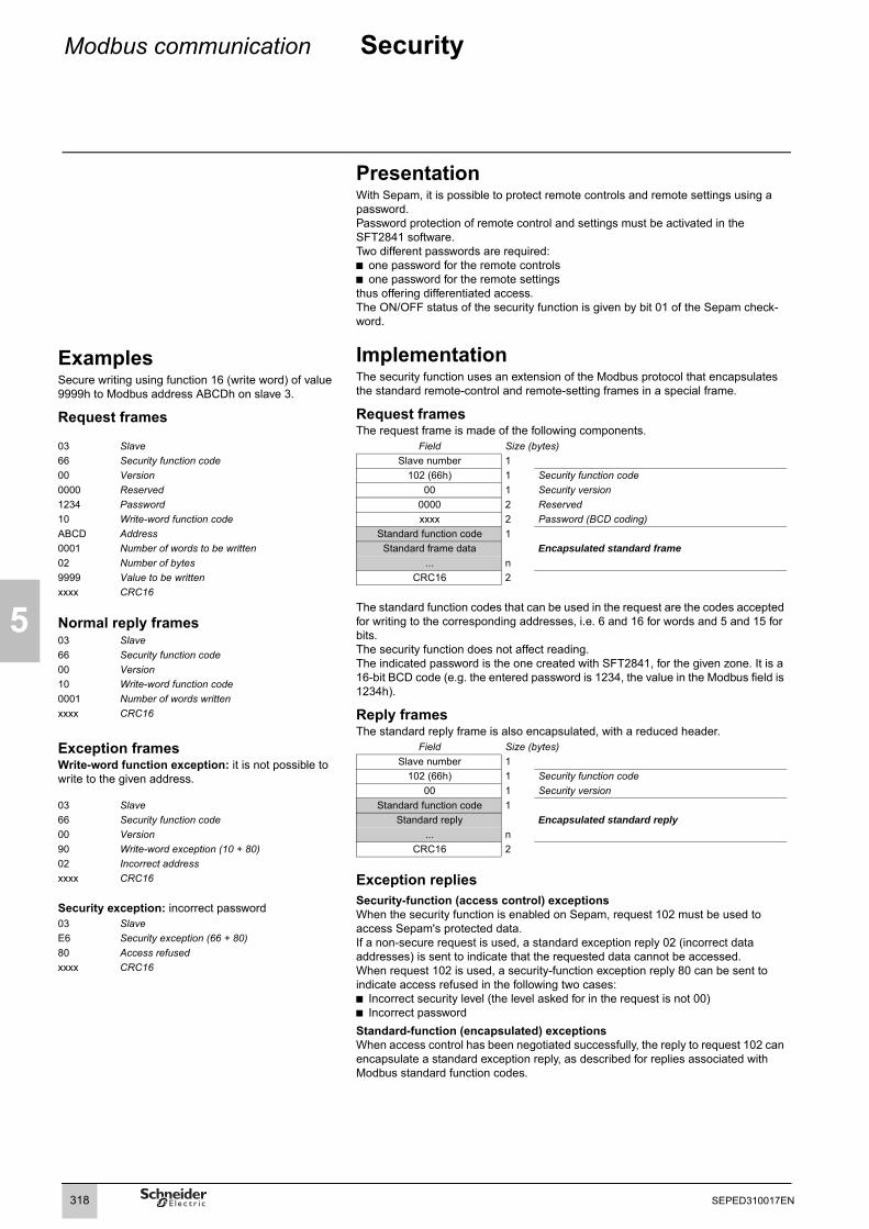
5
Modbus communication Security
ExamplesSecure writing using function 16 (write word) of value 9999h to Modbus address ABCDh on slave 3.
Request frames
PresentationWith Sepam, it is possible to protect remote controls and remote settings using a password.Password protection of remote control and settings must be activated in the SFT2841 software.Two different passwords are required:b one password for the remote controlsb one password for the remote settings thus offering differentiated access.The ON/OFF status of the security function is given by bit 01 of the Sepam check-word.
ImplementationThe security function uses an extension of the Modbus protocol that encapsulates the standard remote-control and remote-setting frames in a special frame.
Request framesThe request frame is made of the following components.
03 Slave Field Size (bytes)66 Security function code Slave number 100 Version 102 (66h) 1 Security function code0000 Reserved 00 1 Security version1234 Password 0000 2 Reserved10 Write-word function code xxxx 2 Password (BCD coding)ABCD Address Standard function code 10001 Number of words to be written Standard frame data Encapsulated standard frame02 Number of bytes ... n9999 Value to be written CRC16 2xxxx CRC16
The standard function codes that can be used in the request are the codes accepted for writing to the corresponding addresses, i.e. 6 and 16 for words and 5 and 15 for bits.The security function does not affect reading.The indicated password is the one created with SFT2841, for the given zone. It is a 16-bit BCD code (e.g. the entered password is 1234, the value in the Modbus field is 1234h).
Reply framesThe standard reply frame is also encapsulated, with a reduced header.
Normal reply frames03 Slave66 Security function code00 Version10 Write-word function code0001 Number of words writtenxxxx CRC16
Exception framesWrite-word function exception: it is not possible to write to the given address.
Field Size (bytes)Slave number 1
102 (66h) 1 Security function code00 1 Security version
03 Slave Standard function code 166 Security function code Standard reply Encapsulated standard reply00 Version ... n90 Write-word exception (10 + 80) CRC16 202 Incorrect addressxxxx CRC16 Exception replies
Security-function (access control) exceptionsWhen the security function is enabled on Sepam, request 102 must be used to access Sepam's protected data.If a non-secure request is used, a standard exception reply 02 (incorrect data addresses) is sent to indicate that the requested data cannot be accessed.When request 102 is used, a security-function exception reply 80 can be sent to indicate access refused in the following two cases: b Incorrect security level (the level asked for in the request is not 00)b Incorrect passwordStandard-function (encapsulated) exceptionsWhen access control has been negotiated successfully, the reply to request 102 can encapsulate a standard exception reply, as described for replies associated with Modbus standard function codes.
Security exception: incorrect password03 SlaveE6 Security exception (66 + 80)80 Access refusedxxxx CRC16
318 SEPED310017EN

Modbus communication Reading Sepam identification
5
).
.
PresentationThe "Read Device Identification" function provides standardized access to the information required to clearly identify a device.The description is made up of a set of objects (ASCII character strings).Easergy Sepam series 60 accepts the "read identification" function (conformity level 02For a complete description of the function, refer to www.modbus.org. The description below covers a subset of the function, adapted to Easergy Sepam series 60
ImplementationRequest frameThe request frame is made of the following components.
Field Size (bytes)Slave number 1
43 (2Bh) 1 Generic access function code14 (0Eh) 1 Read device identification01 or 02 1 Type of read
00 1 Object numberCRC16 2
Easergy Sepam series 60 identificationThe objects making up the Easergy Sepam series 60 identification are listed below.
The type of read is used to select a simplified (01) or a standard (02) description.
Reply frameThe reply frame is made of the following components:
Number Type Value Field Size (bytes)0: VendorName "Merlin Gerin" or
"Schneider Electric"Slave number 1
43 (2Bh) 1 Generic access function code1: ProductCode Application EAN13 code 14 (0Eh) 1 Read device identification2: MajorMinorRevision Application version number
(Vx.yy)01 or 02 1 Type of read
02 1 Conformity level3: VendorURL "www.schneider-electric.com" 00 1 Continuation-frame flag (none for Sepam)4: ProductName "Easergy Sepam series 60 00 1 Reserved5: ModelName Application name
(e.g. "M61 Motor")n 1 Number of objects (according to read type)
0bj1 1 Number of first object6: UserAppName Sepam marking lg1 1 Length first objectThe simplified description includes only objects 0 to 2. txt1 lg1 ASCII string of first object
..... ...objn 1 Number nth objectlgn 1 Length nth objecttxtn Ign ASCII string of nth object
CRC16 2
Exception frameIf an error occurs during request processing, a special exception frame is sent.
Field Size (bytes)Slave number 1
171 (ABh) 1 Generic access exception (2Bh + 80h)14 (0Eh) 1 Read device identification
01 1 Type of errorCRC16 2
319SEPED310017EN
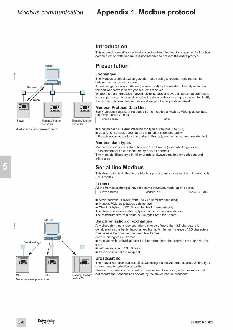
5
Modbus communication Appendix 1. Modbus protocol
IntroductionThis appendix describes the Modbus protocol and the functions required for Modbus communication with Sepam. It is not intended to present the entire protocol.
PresentationExchangesThe Modbus protocol exchanges information using a request-reply mechanism between a master and a slave.An exchange is always initiated (request sent) by the master. The only action onthe part of a slave is to reply to requests received.Where the communication network permits, several slaves units can be connected to a single master. A request contains the slave address (a unique number) to identify the recipient. Non-addressed slaves disregard the requests received.
Modbus Protocol Data UnitEvery Modbus request or response frame includes a Modbus PDU (protocol data unit) made up of 2 fields.
DE
8102
2
Function code Data
Modbus is a master-slave network. b function code (1 byte): indicates the type of request (1 to 127)b data (0 to n bytes): depends on the function code, see below.If there is no error, the function codes in the reply and in the request are identical.
Modbus data typesModbus uses 2 types of data: bits and 16-bit words (also called registers). Each element of data is identified by a 16-bit address.The most-significant byte in 16-bit words is always sent first, for both data and addresses.
Serial line ModbusThis description is limited to the Modbus protocol using a serial link in binary mode (RTU mode).
FramesAll the frames exchanged have the same structure, made up of 3 parts.
Slave address Modbus PDU Check (CRC16)
b Slave address (1 byte): from 1 to 247 (0 for broadcasting)b Modbus PDU: as previously describedb Check (2 bytes): CRC16 used to check frame integrity.The slave addresses in the reply and in the request are identical.The maximum size of a frame is 256 bytes (255 for Sepam).
Synchronization of exchangesAny character that is received after a silence of more than 3.5 characters is considered as the beginning of a new frame. A minimum silence of 3.5 characters must always be observed between two frames.A slave disregards all frames:b received with a physical error for 1 or more characters (format error, parity error, etc.)b with an incorrect CRC16 resultb for which it is not the recipient.
BroadcastingThe master can also address all slaves using the conventional address 0. This type of exchange is called broadcasting.Slaves do not respond to broadcast messages. As a result, only messages that do not require the transmission of data by the slaves can be broadcast.
DE
8033
0
The broadcasting technique.
Easergy Sepam series 60
Master
Request
Reply
Slave Easergy Sepam series 80
Easergy Sepam series 80
320 SEPED310017EN

Modbus communication Appendix 1. Modbus protocol
5
Modbus over TCP/IPRequests and replies are exchanged as TCP/IP messages over a TCP connection. The slave address is therefore its IP address.
FramesThe application layer part of a Modbus/TCP frame is made up of 2 fields:
MBAP Header Modbus PDU
b MBAP (Modbus Application) Header (7 bytes): identifies the frameb Modbus PDU: as previously described.
Modbus Application headerIt contains the following fields:
Field Length Description Request ResponseTransaction identifier
2 bytes Identification of a Modbus request/response transaction
Initialized by the client
Copied by the server from the received request
Protocol identifier 2 bytes 0 = Modbus protocol Initialized by the client
Copied by the server from the received request
Length 2 bytes Number of following bytes (including unit identifier)
Initialized by the client
Initialized by the server
Unit identifier 1 byte In case of gateways, identifies a remote slave device connected on a serial line. Should be 255 in other cases.
Initialized by the client
Copied by the server from the received request
321SEPED310017EN

5
Modbus communication Appendix 1. Modbus protocol
Modbus protocol data unitsTypes of functionsThe Modbus protocol provides read and write functions as well as network-management and diagnostics functions.
Read N bits functions (1 and 2)Request
1 or 2 Address of first bit to be read Number of bits N to be read1 byte 2 bytes 2 bytes
Reply1 or 2 Number of bytes read Data1 byte 1 byte (N + 7)/8 bytes
byte 1 byte 2 Function codeb 1 for internal or output bitsb 2 for input bits.DataThe first bit sent is the LSB in the first byte and the subsequent bits follow in that order. Any excess bits in the last byte are set to 0.
Read N words functions (3 and 4)Request
7 6 5 4 3 2 1 0 7 6 5 4 3 2 1 01 1 1 1 1 1 1 1 0 0 0 1 1 1 1 11 1 0 0 0 0 0 0 2 1 1 1 1B A 9 8 7 6 5 4 0 F E D C
Example: coding of the data field for reading 13 bits, starting at address 104h, with two reply bytes (the vertical numbers indicate the Modbus address of the bit in the corresponding position in the reply).
3 or 4 Address of first word to be read Number of words N to be read1 byte 2 bytes 2 bytes
Reply3 or 4 Number of bytes read Data1 byte 1 byte 2N bytes
Function codeb 3 for internal or output wordsb 4 for input words.DataWords are sent in the order of increasing addresses.
Write bit function (5)Request
5 Bit address Bit value 0: bit set to 0FFh: bit set to 1
0
1 byte 2 bytes 1 byte 1 byte
ReplyIt is identical to the request.
Write word function (6)Request
6 Word address Word value1 byte 2 bytes 2 bytes
ReplyIt is identical to the request.
Write N consecutive bits function (15)Request
0Fh Address of 1st bit Number of bits Number of bytes Data1 byte 2 bytes 2 bytes 1 byte (N + 7)/8 bytes
DataBits are coded similar to the Read bits function.Reply
0Fh Address of 1st bit written Number of bits written1 byte 2 bytes 2 bytes
322 SEPED310017EN

Modbus communication Appendix 1. Modbus protocol
5
Write N consecutive words function (16)Request
10h Address of 1st word Number of words Number of bytes Data1 byte 2 bytes 2 bytes 1 byte 2N bytes
DataWords are sent in the order of increasing addresses.Reply
10h Address of 1st word written Number of words written1 byte 2 bytes 2 bytes
High-speed reading of 8 bits function (7)Request
71 byte
Reply7 Status byte
1 byte 1 byte
For Sepam, the status byte is the most-significant byte in the Sepam check-word (address 0C8Fh), i.e. the bits C8F8h to C8FFh.
Diagnosis function (8)Request
8 Subcode Data1 byte 2 bytes 2 bytes
Reply8 Subcode Data
1 byte 2 bytes 2 bytes
Subcodes for function 8Sub-code
Use Request ReplyDatum Datum
0000h Echo mode Any Datum received000Ah Reset counters CPT1 to CPT9 0000 0000000Bh Read CPT1 (frames without errors) 0000 CPT1000Ch Read CPT2 (frames with errors) 0000 CPT2000Dh Read CPT3 (exception replies) 0000 CPT3000Eh Read CPT4 (frames sent to station) 0000 CPT4000Fh Read CPT5 (frames broadcast) 0000 CPT50010h Read CPT6 (not managed by Sepam) 0000 CPT60011h Read CPT7 (not managed by Sepam) 0000 CPT70012h Read CPT8 (frames with physical errors) 0000 CPT8
Read event counter function (11)For Sepam, the event counter is CPT9 (number of correct requests received and correctly executed).Request
0Bh1 byte
Reply0Bh 0000 Counter CPT9
1 byte 2 bytes 2 bytes
Exception repliesEach time a slave station receives a frame without errors that it cannot process, it sends an exception reply with the elements below.
Request function code + 80h Type of exception1 byte 1 byte
Type of exception Meaning01 Unknown function code02 Incorrect address03 Incorrect datum04 Device not ready07 Negative acknowledgment
323SEPED310017EN

5
Modbus communication Appendix 1. Modbus protocol
Calculation of the CRC16The CRC16 is calculated by the station sending the frame. On reception, the CRC16 is recalculated and compared to the received value. If the two values are not the same, the frame is rejected.The CRC16 uses two bytes. Contrary to the general Modbus rule, the least-significant byte is sent first. It is the product of the polynomial division of the frame by the generating polynomial X16 + X15 + X2 + 1.A number of methods may be used to calculate it. The table method is often used because it is very effective. The program below, written in the C language, is an example of this method.
Example of calculation in the C languageThe function uses two parameters:b unsigned char *puchMsg: points to the frame for CRC calculationb unsigned short usDataLen: number of bytes in the frame.The function returns the CRC as an unsigned short type. All possible CRC values are listed in two tables indexed according to the value of the successive bytes in the frame. One table contains the 256 possible values for the most-significant byte in the CRC and the other table contains the 256 possible values for the least-significant byte in the CRC.Note: the result is ready to be inserted in the frame, the order of the bytes has already been reversed.
unsigned short CRC16(puchMsg, usDataLen) unsigned char *puchMsg ; /* message to calculate CRC upon */unsigned short usDataLen ; /* quantity of bytes in message */
unsigned char uchCRCHi = 0xFF ; /* high byte of CRC initialized */unsigned char uchCRCLo = 0xFF ; /* low byte of CRC initialized */unsigned uIndex ; /* will index into CRC lookup table */while (usDataLen––) /* pass through message buffer */
uIndex = uchCRCHi ^ *puchMsgg++ ; /* calculate the CRC */uchCRCHi = uchCRCLo ^ auchCRCHi[uIndex] ;uchCRCLo = auchCRCLo[uIndex] ;
return (uchCRCHi << 8 | uchCRCLo) ;
/* Table of CRC values for high–order byte */static unsigned char auchCRCHi[] = 0x00, 0xC1, 0x81, 0x40, 0x01, 0xC0, 0x80, 0x41, 0x01, 0xC0, 0x80, 0x41, 0x00, 0xC1, 0x81, 0x40,0x01, 0xC0, 0x80, 0x41, 0x00, 0xC1, 0x81, 0x40, 0x00, 0xC1, 0x81, 0x40, 0x01, 0xC0, 0x80, 0x41,0x01, 0xC0, 0x80, 0x41, 0x00, 0xC1, 0x81, 0x40, 0x00, 0xC1, 0x81, 0x40, 0x01, 0xC0, 0x80, 0x41,0x00, 0xC1, 0x81, 0x40, 0x01, 0xC0, 0x80, 0x41, 0x01, 0xC0, 0x80, 0x41, 0x00, 0xC1, 0x81, 0x40,0x01, 0xC0, 0x80, 0x41, 0x00, 0xC1, 0x81, 0x40, 0x00, 0xC1, 0x81, 0x40, 0x01, 0xC0, 0x80, 0x41,0x00, 0xC1, 0x81, 0x40, 0x01, 0xC0, 0x80, 0x41, 0x01, 0xC0, 0x80, 0x41, 0x00, 0xC1, 0x81, 0x40,0x00, 0xC1, 0x81, 0x40, 0x01, 0xC0, 0x80, 0x41, 0x01, 0xC0, 0x80, 0x41, 0x00, 0xC1, 0x81, 0x40,0x01, 0xC0, 0x80, 0x41, 0x00, 0xC1, 0x81, 0x40, 0x00, 0xC1, 0x81, 0x40, 0x01, 0xC0, 0x80, 0x41,0x01, 0xC0, 0x80, 0x41, 0x00, 0xC1, 0x81, 0x40, 0x00, 0xC1, 0x81, 0x40, 0x01, 0xC0, 0x80, 0x41,0x00, 0xC1, 0x81, 0x40, 0x01, 0xC0, 0x80, 0x41, 0x01, 0xC0, 0x80, 0x41, 0x00, 0xC1, 0x81, 0x40,0x00, 0xC1, 0x81, 0x40, 0x01, 0xC0, 0x80, 0x41, 0x01, 0xC0, 0x80, 0x41, 0x00, 0xC1, 0x81, 0x40,0x01, 0xC0, 0x80, 0x41, 0x00, 0xC1, 0x81, 0x40, 0x00, 0xC1, 0x81, 0x40, 0x01, 0xC0, 0x80, 0x41,0x00, 0xC1, 0x81, 0x40, 0x01, 0xC0, 0x80, 0x41, 0x01, 0xC0, 0x80, 0x41, 0x00, 0xC1, 0x81, 0x40,0x01, 0xC0, 0x80, 0x41, 0x00, 0xC1, 0x81, 0x40, 0x00, 0xC1, 0x81, 0x40, 0x01, 0xC0, 0x80, 0x41,0x01, 0xC0, 0x80, 0x41, 0x00, 0xC1, 0x81, 0x40, 0x00, 0xC1, 0x81, 0x40, 0x01, 0xC0, 0x80, 0x41,0x00, 0xC1, 0x81, 0x40, 0x01, 0xC0, 0x80, 0x41, 0x01, 0xC0, 0x80, 0x41, 0x00, 0xC1, 0x81, 0x40 ;
/* Table of CRC values for low–order byte */static char auchCRCLo[] = 0x00, 0xC0, 0xC1, 0x01, 0xC3, 0x03, 0x02, 0xC2, 0xC6, 0x06, 0x07, 0xC7, 0x05, 0xC5, 0xC4, 0x04,0xCC, 0x0C, 0x0D, 0xCD, 0x0F, 0xCF, 0xCE, 0x0E, 0x0A, 0xCA, 0xCB, 0x0B, 0xC9, 0x09, 0x08, 0xC8,0xD8, 0x18, 0x19, 0xD9, 0x1B, 0xDB, 0xDA, 0x1A, 0x1E, 0xDE, 0xDF, 0x1F, 0xDD, 0x1D, 0x1C, 0xDC,0x14, 0xD4, 0xD5, 0x15, 0xD7, 0x17, 0x16, 0xD6, 0xD2, 0x12, 0x13, 0xD3, 0x11, 0xD1, 0xD0, 0x10,0xF0, 0x30, 0x31, 0xF1, 0x33, 0xF3, 0xF2, 0x32, 0x36, 0xF6, 0xF7, 0x37, 0xF5, 0x35, 0x34, 0xF4,0x3C, 0xFC, 0xFD, 0x3D, 0xFF, 0x3F, 0x3E, 0xFE, 0xFA, 0x3A, 0x3B, 0xFB, 0x39, 0xF9, 0xF8, 0x38,0x28, 0xE8, 0xE9, 0x29, 0xEB, 0x2B, 0x2A, 0xEA, 0xEE, 0x2E, 0x2F, 0xEF, 0x2D, 0xED, 0xEC, 0x2C,0xE4, 0x24, 0x25, 0xE5, 0x27, 0xE7, 0xE6, 0x26, 0x22, 0xE2, 0xE3, 0x23, 0xE1, 0x21, 0x20, 0xE0,0xA0, 0x60, 0x61, 0xA1, 0x63, 0xA3, 0xA2, 0x62, 0x66, 0xA6, 0xA7, 0x67, 0xA5, 0x65, 0x64, 0xA4,0x6C, 0xAC, 0xAD, 0x6D, 0xAF, 0x6F, 0x6E, 0xAE, 0xAA, 0x6A, 0x6B, 0xAB, 0x69, 0xA9, 0xA8, 0x68,0x78, 0xB8, 0xB9, 0x79, 0xBB, 0x7B, 0x7A, 0xBA, 0xBE, 0x7E, 0x7F, 0xBF, 0x7D, 0xBD, 0xBC, 0x7C,0xB4, 0x74, 0x75, 0xB5, 0x77, 0xB7, 0xB6, 0x76, 0x72, 0xB2, 0xB3, 0x73, 0xB1, 0x71, 0x70, 0xB0,0x50, 0x90, 0x91, 0x51, 0x93, 0x53, 0x52, 0x92, 0x96, 0x56, 0x57, 0x97, 0x55, 0x95, 0x94, 0x54,0x9C, 0x5C, 0x5D, 0x9D, 0x5F, 0x9F, 0x9E, 0x5E, 0x5A, 0x9A, 0x9B, 0x5B, 0x99, 0x59, 0x58, 0x98,0x88, 0x48, 0x49, 0x89, 0x4B, 0x8B, 0x8A, 0x4A, 0x4E, 0x8E, 0x8F, 0x4F, 0x8D, 0x4D, 0x4C, 0x8C,0x44, 0x84, 0x85, 0x45, 0x87, 0x47, 0x46, 0x86, 0x82, 0x42, 0x43, 0x83, 0x41, 0x81, 0x80, 0x40 ;
324 EPED310017EN

Modbus communication Appendix 2. Function settings
5
Setting codingData formatAll the settings are transmitted in 32-bit signed 2's complement integer format.
Coding of tripping and timer hold curvesThe numbers correspond to the setting columns in the lists of settings.
Tripping curves0 = definite time1 = inverse 9 = IEC very inverse / B2 = long time inverse 10 = IEC extremely inverse / C3 = very inverse 11 = IEEE moderately inverse4 = extremely inverse 12 = IEEE very inverse5 = ultra inverse 13 = IEEE extremely inverse6 = RI 14 = IAC inverse7 = IEC inverse / A 15 = IAC very inverse8 = IEC long time inverse / B 16 = IAC extr. inverse24 = Customized curve25 = EPATR-B26 = EPATR-C
Tripping curves0 = definite time 11 = IEEE moderately inverse7 = IEC inverse / A 12 = IEEE very inverse8 = IEC long time inverse / B 13 = IEEE extremely inverse9 = IEC very inverse / B 17 = Specific Schneider curve10 = IEC extremely inverse / C 20 = RI²
Timer hold curves0 = definite time1 = IDMT
Common protection settingsAll protection functions have the following settings at the head of the table.Setting Data Format/Unit1 Latching 0: no
1: yes2 Program logic see below3 Activity 0: Off
1: On4 Measurement origin see below
Details on program-logic fieldBit 31 30 .... 4 3 2 1 0
DES AGR CDC
CDC = 1: the protection function takes part in circuit-breaker/contactor control= 0: the protection function does not take part
AGR = 1: the protection function takes part in genset shutdown (generator application)= 0: the protection function does not take part
DES = 1: the protection function takes part in de-excitation(generator application)= 0: the protection function does not take part
When a common protection setting is not applicable to a particular protection function, it is signaled "reserved" in the table for the function.
Measurement originA few special cases of coding for the measurement-origin field, for the ANSI 50N/51 N, ANSI 67N/67NC and ANSI 59N protection functions, are indicated in the table below:
Value 50N/51N 67N/67NC 59N0 I0Σ I0Σ V01 I0 I0 Vnt
1
2
3
325SEPED310017EN

5
Modbus communication Appendix 2. Function settings
Protection settingsThey are organized according to increasing ANSI codes.
ANSI 12 - OverspeedFunction number: 72xxUnit 1: xx = 01, unit 2: xx = 02Setting Data Format/Unit
1 to 3 Common settings4 Reserved5 Set point %6 Tripping time delay 10 ms
ANSI 14 - UnderspeedFunction number: 77xxUnit 1: xx = 01, unit 2: xx = 02Setting Data Format/Unit
1 to 3 Common settings4 Reserved5 Set point %6 Tripping time delay 10 ms
ANSI 21B - UnderimpedanceFunction number: 7401Setting Data Format/Unit
1 to 3 Common settings4 Reserved5 Zs set point mΩ6 Tripping time delay 10 ms
ANSI 25 – Synchro-checkFunction number: 1801Setting Data Format/Unit
1 Reserved2 Reserved3 Activity 0: off
1: on4 dUs set point % Vnp sync1 or % Unp sync15 dFs set point 0.01 Hz6 dPhis set point °7 Us high set point % Vnp sync1 or % Unp sync18 Us low set point % Vnp sync1 or % Unp sync19 Operating modes
(no-voltage conditions for which coupling is allowed)1: Dead1 AND Live22: Live1 AND Dead23: Dead1 XOR Dead24: Dead1 OR Dead25: Dead1 AND Dead2
10 Lead time 10 ms11 Use of voltage check for coupling authorization 0: no
1: yes
326 SEPED310017EN

Modbus communication Appendix 2. Function settings
5
ANSI 27 - UndervoltageFunction number: 32xxUnit 1: xx = 01 to unit 4: xx = 04Setting Data Format/Unit
1 to 4 Common settings5 Tripping curve 0: definite
19: IDMT27: customized
6 Voltage mode 0: phase-to-neutral1: phase-to-phase
7 Us set point % Unp8 Tripping time delay DT: 0.05 to 300 s
IDMT: See note belowCustomized: range = 1 (TMS = 1)
9 DT of 1st point on the curve 10 ms10 U/Un of 1st point on the curve %11 DT of 2nd point on the curve 10 ms12 U/Un of 2nd point on the curve %13 DT of 3rd point on the curve N/A14 U/Un of 3rd point on the curve N/A...29 DT of 11th point on the curve N/A30 U/Un of of 11th point on the curve N/A
Note setting 8b For a setting mode with 10 I/IS: the range varies from 0.05 s to 300 s.b For a setting in TMS (Time Multiplier Setting) mode, the range depends on the selected curve and varies as follows:v inverse (SIT) and IEC SIT/A: 0.04 to 4.20 v very inverse (VIT) and IEC VIT/B: 0.07 to 8.33 v long time inverse (LTI) and IEC LTI/B: 0.01 to 0.93 v extremely inverse (EIT) and IEC EIT/C: 0.13 to 15.47 v IEEE moderately inverse: 0.42 to 51.86 v IEEE very inverse: 0.73 to 90.57 v IEEE extremely inverse: 1.24 to 154.32 v IAC inverse: 0.34 to 42.08 v IAC very inverse: 0.61 to 75.75 v IAC extremely inverse: 1.08 to 134.4Notes settings 9 to 30The customized curve is unique and only concerns unit 1. However, to retain consistency with the Sepam software architecture, the same frame format is used for all units. Unused points are set to (-1, -1). This is the case for the points for unit 2 and above. It is also the case for additional points for unit 1. For example, if the curve is defined by 6 points, the last 5 are set to (-1, -1). There is no "Number of points" setting in the frame.For each useful point, the value of T must be greater than or equal to that of the previous point. The first point must be 0 (rising or falling operations are allowed).The value of U/Un for the last useful point must be greater than all the other values of U/Un.
ANSI 27D - Positive sequence undervoltageFunction number: 38xxUnit 1: xx = 01, unit 2: xx = 02Setting Data Format/Unit
1 to 4 Common settings5 Vds set point % Unp6 Tripping time delay 10 ms
ANSI 27R - Remanent undervoltageFunction number: 35xxUnit 1: xx = 01, unit 2: xx = 02Setting Data Format/Unit
1 to 4 Common settings5 Us set point % Unp6 Tripping time delay 10 ms
327SEPED310017EN

5
Modbus communication Appendix 2. Function settings
ANSI 32P - Directional active overpowerFunction number: 53xxUnit 1: xx = 01, unit 2: xx = 02Setting Data Format/Unit1 to 3 Common settings4 Reserved5 Access 0: reverse power
1: overpower6 Ps set point 100 W7 Tripping time delay 10 ms
ANSI 32Q - Directional reactive overpowerFunction number: 5401Setting Data Format/Unit
1 to 3 Common settings4 Reserved5 Access 0: reverse power
1: overpower6 Qs set point 100 var7 Tripping time delay 10 ms
ANSI 37 - Phase undercurrentFunction number: 2201Setting Data Format/Unit
1 to 3 Common settings4 Reserved5 Is set point % Ib6 Tripping time delay 10 ms
ANSI 37P - Directional active underpowerFunction number: 55xxUnit 1: xx = 01, unit 2: xx = 02Setting Data Format/Unit
1 to 3 Common settings4 Reserved5 Access 0: drawn
1: supplied6 Ps set point 100 W7 Tripping time delay 10 ms
ANSI 38/49T - Temperature monitoringFunction number: 46xxUnit 1: xx = 01 to unit 16: xx = 10hSetting Data Format/Unit
1 to 3 Common settings4 Reserved5 Ts1 alarm set point °C6 Ts2 alarm set point °C
ANSI 40 - Field loss (underimpedance)Function number: 7001 Setting Data Format/Unit
1 to 3 Common settings4 Reserved5 Xa resistance 1 mΩ6 Xb resistance 1 mΩ7 Xc resistance 1 mΩ8 Tripping time delay circle 1 10 ms9 Tripping time delay circle Xd 10 ms
328 SEPED310017EN

Modbus communication Appendix 2. Function settings
5
ANSI 46 - Negative sequence / unbalanceFunction number: 45xxUnit 1: xx = 01, unit 2: xx = 02Setting Data Format/Unit
1 to 4 Common settings5 Tripping curve6 Is set point % Ib7 Tripping time delay 10 ms8 K setting 1 to 100
ANSI 47 - Negative sequence overvoltageFunction number: 40xxUnit 1: xx = 01, unit 2: xx = 02Setting Data Format/Unit
1 to 4 Common settings5 Vis set point % Unp6 Tripping time delay 10 ms
ANSI 48/51LR - Locked rotor / excessive starting timeFunction number: 4401 Setting Data Format/Unit
1 to 3 Common settings4 Reserved5 Is set point % Ib6 ST excessive starting time 10 ms7 LT locked rotor time 10 ms8 LTS locked on start time 10 ms
ANSI 49RMS - Thermal overloadFunction number: 4301Thermal overloadSetting Data Format/Unit
1 to 4 Common settings5 Negative sequence factor (K) 0: none (0) 1: low (2.25)
2: medium (4.5) 3: high (9)6 Is set point (shift group 1/group 2) % Ib7 Ambient temperature taken into account 0: no
1: yes8 Maximum equipment temperature °C9 Additional settings taken into account (group 2) 0: no
1: yes10 Learnt cooling time constant (T2 learnt) taken into
account0: no1: yes
11 Group 1 - thermal alarm set point %12 Group 1 - thermal tripping set point %13 Group 1 - heating time constant14 Group 1 - cooling time constant min.15 Group 1 - initial heat rise %16 Group 2 - thermal alarm set point %17 Group 2 - thermal tripping set point %18 Group 2 - heating time constant min.19 Group 2 - cooling time constant min.20 Group 2 - initial heat rise %21 Group 2 - base current for group 2 0.1 A22 49RMS cable - admissible current 0.1 A
49RMS capacitor - tripping current 0.1 A23 Associated time constant min.24 Current setting 0.1 A25 Alarm current 0.1 A26 Type of thermal model 0: genericNote: b thermal overload for machines: parameters 1 to 21
b thermal overload for cables: parameters 1 to 4 and 22 to 23b thermal overload for capacitors: parameters 1 to 4 and 22 to 25
2
329SEPED310017EN

5
Modbus communication Appendix 2. Function settings
ANSI 49RMS - Thermal overload (cont.)Function number: 4301Motor thermal overloadSetting Data Format/Unit
1 Latching 0: no, 1: yes2 Circuit breaker control 0: no, 1: yes3 Activity 0: off
1: on4 Ialarm = current alarm set point %5 Itrip = current tripping set point %6 Tlong = motor heating time constant min.
7 Tshort = stator heating time constant min.
8 Tcool = cooling time constant min.9 Alpha = rotor/stator exchange coefficient %10 IL = locked rotor current %11 LRT = locked rotor torque %12 Idem = starting current set point %13 Ambient T taken into account by sensor 8 0: no, 1: yes14 Tmax = max. stator temperature constant °C15 Tc = locked rotor cold limit time seconds16 Th = locked rotor hot limit time seconds17 Sh = Heat rise set point for hot state bit %... Reserved25 Reserved26 Type of thermal model (1) 1: Motor(1) This setting is always at 1 for the motor thermal overload model.
Transformer thermal overloadSetting Data Format/Unit
1 Latching 0: no, 1: yes2 Circuit breaker control 0: no, 1: yes3 Activity 0: off
1: on4 Measurement origin 0: primary
1: secondary5 Type of transformer 0: AN dry-type
1: AF dry-type2: distribution ONAN immersed3: High and medium power ONAN immersed4: ONAF5: OF6: OD
6 Insulation class (1) b Dry-type transformer: 105, 120, 130, 135, 180, 200 or 220°b Immersed transformer: 0 (not significant)Unit = °
7 Alarm temperature (group 1) (2) b Dry-type transformer:Class 105: 95 to 130°Class 120: 110 to 145°Class 130: 120 to 155°Class 180: 170 to 205°Class 200: 190 to 225°Class 220: 210 to 245°b Immersed transformer: 98 to 160 °Unit = °
8 Tripping temperature (group 1) Same as alarm temperature9 Alarm temperature (group 2) (2) Same as group 110 Tripping temperature (group 2) Same as group 111 Transformer time constant 1 to 600
Unit = minutes(1) This setting only applies to dry-type transformers. Value 0 accepted for an immersed transformer.(2) Alarm temperature must be less than the tripping temperature.(3) This parameter only applies to immersed transformers. Value 0 accepted for a dry-type transformer.(4) This setting is always at 1 for the transformer thermal overload model.
12 Oil time constant (3) 5 to 600 Unit = minutes
13 Ambient T taken into account by sensor 8 0: no, 1: yes14 Oil T taken into account by sensor 8 (3) 0: no, 1: yes15 Additional settings taken into account
(group 2) (3)0: no, 1: yes
16 Restricted oil flow 0: no, 1: yes17 ... 25 Reserved26 Type of thermal model (4) 2: Transformer
330 SEPED310017EN

Modbus communication Appendix 2. Function settings
5
ANSI 50BF - Breaker failureFunction number: 9801 Setting Data Format/Unit
1 Common settings2 Reserved3 Common settings4 Reserved5 Use of breaker closed input 0: no
1: yes6 Is set point 0.1 A7 Time 10 ms
ANSI 50/51 - Phase overcurrentFunction number: 01xxUnit 1: xx = 01 to unit 4: xx = 04Setting Data Format/Unit
1 to 4 Common settings5 Confirmation 0 = none
1 = neg. seq. overvoltage2 = undervoltage
6 Group A - tripping curve7 Group A - Is set point 0.1 A8 Group A - tripping time delay 10 ms9 Group A - timer hold curve10 Group A - timer hold 10 ms11 Group B - tripping curve12 Group B - Is set point 0.1 A13 Group B - tripping time delay 10 ms14 Group B - timer hold curve15 Group B - timer hold 10 ms16 Group A - harmonic 2 restraint 0: active, 1: inactive17 Group A - Isc min 0.1 A18 Group B - harmonic 2 restraint 0: active, 1: inactive19 Group B - Isc min 0.1 A20 H2 restraint set point (1) %(1) Parameter common to all groups and all units.
ANSI 50N/51N - Earth faultFunction number: 06xxUnit 1: xx = 01 to unit 4: xx = 04Setting Data Format/Unit
1 to 4 Common settings5 Group A - tripping curve6 Group A - Is0 set point 0.1 A7 Group A - tripping time delay 10 ms8 Group A - timer hold curve9 Group A - timer hold 10 ms10 Group A - H2 restraint 0: yes
1: no11 Group B - tripping curve12 Group B - Is0 set point 0.1 A13 Group B - tripping time delay 10 ms14 Group B - timer hold curve15 Group B - timer hold 10 ms16 Group B - H2 restraint 0: yes
1: no
ANSI 50V/51V - Voltage-restrained phase overcurrentFunction number: 1901Setting Data Format/Unit
1 to 4 Common settings5 Tripping curve6 Is set point 0.1 A7 Tripping time delay 10 ms8 Timer hold curve9 Timer hold 10 ms
1
3
1
3
1
3
1
3
1
3
331SEPED310017EN

5
Modbus communication Appendix 2. Function settings
ANSI 59 - OvervoltageFunction number: 28xxUnit 1: xx = 01, unit 2: xx = 02Setting Data Format/Unit1 to 4 Common settings5 Voltage mode 0: phase-to-neutral
1: phase-to-phase6 Us set point % Unp7 Tripping time delay 10 ms
ANSI 59N - Neutral voltage displacementFunction number: 39xxUnit 1: xx = 01, unit 2: xx = 02Setting Data Format/Unit
1 to 4 Common settings5 Tripping curve 0: definite
18: IDMT6 Vs0 set point % Unp7 Tripping time delay 10 ms
ANSI 64 REF - Restricted earth fault differentialFunction number: 64xxUnit 1: xx = 01, unit 2: xx = 02Setting Data Format/Unit
1 to 4 Common settings5 Is0 set point 0.1 A
ANSI 66 - Starts per hourFunction number: 4201 Setting Data Format/Unit
1 Common settings2 Reserved3 Common settings4 Reserved5 Period of time Hours6 Total number of starts 17 Number of consecutive hot starts 18 Number of consecutive cold starts 19 Delay between stop/start min.10 Delay between consecutive starts min.
ANSI 67 - Directional phase overcurrentFunction number: 52xxUnit 1: xx = 01, unit 2: xx = 02Setting Data Format/Unit
1 to 3 Common settings4 Reserved5 Group A - direction 0: line 1: busbar6 Group A - characteristic angle 3: 30° 4: 45° 5: 60°7 Group A - tripping logic 0: 1/3 1: 2/38 Group A - tripping curve9 Group A - Is set point 0.1 A10 Group A - tripping time delay 10 ms11 Group A - timer hold curve12 Group A - timer hold 10 ms13 Group B - direction 0: line 1: busbar14 Group B - characteristic angle 3: 30° 4: 45° 5: 60°15 Group B - tripping logic 0: 1/3 1: 2/316 Group B - tripping curve17 Group B - Is set point 0.1 A18 Group B - tripping time delay 10 ms19 Group B - timer hold curve20 Group B - timer hold 10 ms
1
3
1
3
332 SEPED310017EN
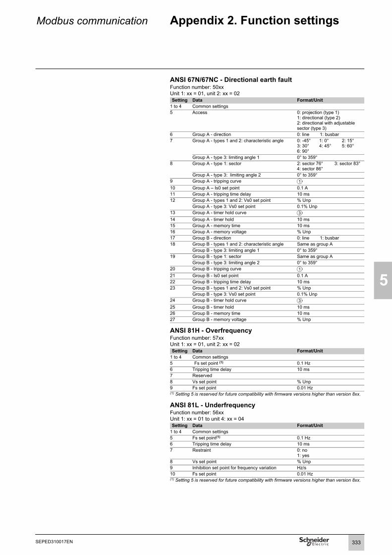
Modbus communication Appendix 2. Function settings
5
ANSI 67N/67NC - Directional earth faultFunction number: 50xxUnit 1: xx = 01, unit 2: xx = 02Setting Data Format/Unit
1 to 4 Common settings5 Access 0: projection (type 1)
1: directional (type 2)2: directional with adjustable sector (type 3)
6 Group A - direction 0: line 1: busbar7 Group A - types 1 and 2: characteristic angle 0: -45° 1: 0° 2: 15°
3: 30° 4: 45° 5: 60°6: 90°
Group A - type 3: limiting angle 1 0° to 359°8 Group A - type 1: sector 2: sector 76° 3: sector 83°
4: sector 86°Group A - type 3: limiting angle 2 0° to 359°
9 Group A - tripping curve10 Group A – Is0 set point 0.1 A11 Group A - tripping time delay 10 ms12 Group A - types 1 and 2: Vs0 set point % Unp
Group A - type 3: Vs0 set point 0.1% Unp13 Group A - timer hold curve14 Group A - timer hold 10 ms15 Group A - memory time 10 ms16 Group A - memory voltage % Unp17 Group B - direction 0: line 1: busbar18 Group B - types 1 and 2: characteristic angle Same as group A
Group B - type 3: limiting angle 1 0° to 359°19 Group B - type 1: sector Same as group A
Group B - type 3: limiting angle 2 0° to 359°20 Group B - tripping curve21 Group B - Is0 set point 0.1 A22 Group B - tripping time delay 10 ms23 Group B - types 1 and 2: Vs0 set point % Unp
Group B - type 3: Vs0 set point 0.1% Unp24 Group B - timer hold curve25 Group B - timer hold 10 ms26 Group B - memory time 10 ms27 Group B - memory voltage % Unp
ANSI 81H - OverfrequencyFunction number: 57xxUnit 1: xx = 01, unit 2: xx = 02Setting Data Format/Unit
1 to 4 Common settings5 Fs set point (1) 0.1 Hz6 Tripping time delay 10 ms7 Reserved8 Vs set point % Unp9 Fs set point 0.01 Hz(1) Setting 5 is reserved for future compatibility with firmware versions higher than version 8xx.
ANSI 81L - UnderfrequencyFunction number: 56xxUnit 1: xx = 01 to unit 4: xx = 04Setting Data Format/Unit
1 to 4 Common settings5 Fs set point(1) 0.1 Hz6 Tripping time delay 10 ms7 Restraint 0: no
1: yes8 Vs set point % Unp9 Inhibition set point for frequency variation Hz/s10 Fs set point 0.01 Hz(1) Setting 5 is reserved for future compatibility with firmware versions higher than version 8xx.
1
3
1
3
333SEPED310017EN

5
Modbus communication Appendix 2. Function settings
ANSI 81R – Rate of change of frequencyFunction number: 58xxUnit: 1 xx = 01, unit 2: xx = 02Setting Data Format/Unit
1 Latching 0: no1: yes
2 Switchgear control 0: no1: yes
3 Activity 0: off1: on
4 Reserved5 dfs/dt set point 0.01 Hz/s6 Tripping time delay 10 ms
Other function settingsANSI 60 - CT supervisionFunction number: 2601Setting Data Format/Unit
1 Reserved2 Reserved3 Common settings4 Reserved5 Action on 21G, 46, 40, 51N, 32P, 37P, 32Q, and
64REF protections0: none1: inhibition
6 Tripping time delay 10 ms
ANSI 60FL - VT supervisionFunction number: 2701Setting Data Format/Unit
1 Reserved2 Reserved3 Common settings4 Reserved5 Use breaker-position or voltage-presence criterion 0: circuit breaker
1: voltage6 Check loss of 3 V/2 U 0: no
1: yes7 Test current 0: no
1: yes8 Use Vi, Ii criterion 0: no
1: yes9 Action on 21G, 27, 27D, 32P, 32Q, 37P, 40, 47,
51V, 59, 59N protections0: none1: inhibition
10 Action on 67 protection 0: non directional1: inhibition
11 Action on 67N protection 0: non directional1: inhibition
12 Vi tripping set point %13 Ii tripping set point %14 3 V/ 2 U loss time 10 ms15 Vi, Ii criterion time 10 ms
334 SEPED310017EN

Modbus communication Appendix 2. Function settings
5
ANSI 79 - RecloserFunction number: 1701Setting Data Format/Unit
1 Reserved2 Reserved3 Common settings4 Reserved5 Number of cycles 1 to 46 Reclaim time 10 ms7 Safety time until ready 10 ms8 Maximum additional dead time 0: no
1: yes9 Maximum wait time 10 ms10 Cycle 1 activation mode see below11 Cycle 2, 3, 4 activation mode see below12 Cycle 1 dead time 10 ms13 Cycle 2 dead time 10 ms14 Cycle 3 dead time 10 ms15 Cycle 4 dead time 10 ms
Cycle activation modeThe activation mode of each cycle is coded as follows:Bit Activation by (if bit set to 1) / Non activation by (if bit set to 0)
0 Instantaneous protection 50/51 unit 11 Delayed protection 50/51 unit 12 Instantaneous protection 50/51 unit 23 Delayed protection 50/51 unit 24 Instantaneous protection 50/51 unit 35 Delayed protection 50/51 unit 36 Instantaneous protection 50/51 unit 47 Delayed protection 50/51 unit 48 Instantaneous protection 50N/51N unit 19 Delayed protection 50N/51N unit 110 Instantaneous protection 50N/51N unit 211 Delayed protection 50N/51N unit 212 Instantaneous protection 50N/51N unit 313 Delayed protection 50N/51N unit 314 Instantaneous protection 50N/51N unit 415 Delayed protection 50N/51N unit 416 Instantaneous protection 67N unit 117 Delayed protection 67N unit 118 Instantaneous protection 67N unit 219 Delayed protection 67N unit 220 Instantaneous protection 67 unit 121 Delayed protection 67 unit 122 Instantaneous protection 67 unit 223 Delayed protection 67 unit 224 Instantaneous V_DECL logic equation
335SEPED310017EN

336
5
SEPED310017EN
Modbus communication Appendix 2. Function settings
General parametersThese settings are read accessible only.Function number: D002Setting Data Format/Unit
1 Working language 1: English 2 Rated frequency 50, 60 (Hz)3 Active group of settings 1: group A
3: selection by logic input4: selection by remote control
4 Demand-value integration period 5, 10, 15, 30, 60 minutes5 Type of cubicle 1: incomer6 Active-energy increment 100 to 5000000 (W)7 Reactive-energy increment 100 to 5000000 (var)8 Phase-rotation direction 1: direction 1239 Temperature unit 1: °C 2: °F10 Remote-setting authorization 1: no 2: yes11 Time synchronization mode 1: COM1 port
5: none12 Remote-control mode13 Reserved14 Reserved15 Rated auxiliary voltage 24 to 250 (V DC)16 Aux. voltage alarm low set point % rated Vaux, min. 20 V17 Aux. voltage alarm high set point % rated Vaux, max. 275 V18 Logic inputs ignored on loss of Vaux 1: inactive 2: active19 Base current Ib 0.2 to 1.3 In (A)20 Rated current In 1 to 15 kA21 Number of phase CTs 1: 2 CTs22 Phase CT rating 1: 1 A 2: 5 A 3: LPCT23 Rated residual current In0 10 to 150000 (0.1 A)
8: ACE990 range 19: ACE990 range 211: not measured
25 Reserved26 Rated primary voltage Unp 27 Rated secondary voltage Uns 90 to 230 (V)28 VT wiring 1: 3 V, 2: 2 U, 3: 1 U, 4: 1 V29 Residual voltage mode 1: none 2: Σ3V
3: VT Uns/ 3 4: VT Uns/3
31 Neutral-point rated voltage Unp 220 to 250000 (V)32 Neutral-point rated voltage Uns 57 V to 133 V33-48 Reserved
Application-specific parametersThese settings are read accessible only.Function number: D003Setting Data Format/Unit
1 Transformer presence 1: no2: yes
2 Voltage winding 1 Un1 220 to 250000 V3 Voltage winding 2 Un2 220 to 440000 V4 Power S 100 to 999000 kVA5 Vector shift 0 to 116 Rated motor speed 100 to 3000 rpm (1)
100 to 3600 rpm (2)
7 Number of pulses per rotation 1 to 18008 Zero speed threshold 5 to 20%15 Rated power kW16 Synchronous reactance of d axis 0,1 %17 Transient reactance of d axis 0,1 %18 Synchronous reactance of q axis 0,1 %19 Moment of inertia for turbine + generator or
motor + loadKg.m 2
(1) For a frequency of 50 Hz.(2) For a frequency of 60 Hz.
24 Residual current measurement mode 1: CSH 2 A 3: CSH 20 A4: 1 A CT 6: 5 A CT
30 Neutral-point residual voltage measurement 1: none 2: present
0 A<In≤6.25 kA: 220 V ≤ Unp ≤ 250 kV6.25 kA<In≤15 kA: 220V≤ Unp ≤ 20 kV
1: SBO mode 2: direct mode
3: input I103 6: Ethernet port
2: direction 132
2: other2: group B
2: feeder
2: 3 CTs

Installation Contents
1
6
Safety instructions 338Precautions 339Equipment identification 340List of Sepam series 60 references 342Base unit 344Dimensions 344Mounting 345Connection 346Connection of Sepam C60 348Connection of phase current inputs 349Connection of residual current inputs 350Connection of low voltage residual current inputs 352Connection of low voltage current inputs for restricted earth protec-tion (ANSI 64REF) 354Connection of low voltage phase voltage inputs 356Functions available according to connected voltage inputs 3571 A/5 A current transformers 358LPCT type current sensors 361CSH120 and CSH200Core balance CTs 364CSH30 interposing ring CT 366ACE990 Core balance CT interface 368Voltage transformers 370MES120, MES120G, MES120H 14 input / 6 output modules 371Presentation 371Installation 372Optional remote modules 374Selection guide 374MET148-2 Temperature sensor module 376MSA141 Analog output module 378DSM303 Remote advanced UMI module 380MCS025 Synchro-check module 382Communication accessory selection guide 386Connection of communication interfaces 387Connection cords 387Characteristics of communication networks 388ACE949-2 2-wire RS 485 network interface 389ACE959 4-wire RS 485 network interface 390ACE937 fiber optic interface 391ACE969TP-2 and ACE969FO-2 Multi-protocol interfaces 392Description 394Connection 395ACE850TP and ACE850FO Multi-protocol interfaces 398Description 400Connection 401ACE909-2 RS 232/RS 485 converter 404ACE919CA and ACE919CC RS 485/RS 485 converters 406ECI850 IEC 61850 Sepam server 408
337SEPED310017EN

6
Installation Safety instructions
This page contains important safety instructions that must be followed precisely before attempting to install, repair, service or maintain electrical equipment. Carefully read and follow the safety instructions described below.
DANGERHAZARD OF ELECTRIC SHOCK, ELECTRIC ARC, BURNS OR EXPLOSIONb Only qualified personnel should install this equipment. Such work should be performed only after reading this entire set of instructions.b NEVER work alone. b Turn off all power supplying this equipment before working on or inside it.b Always use a properly rated voltage sensing device to confirm that all power is off.b Before performing visual inspections, tests, or maintenance on this equipment, disconnect all sources of electric power. Assume that all circuits are live until they have been completely de-energized, tested and tagged. Pay particular attention to the design of the power system. Consider all sources of power, including the possibility of backfeeding.b Beware of potential hazards, wear personal protective equipment, carefully inspect the work area for tools and objects that may have been left inside the equipment.b The successful operation of this equipment depends upon proper handling, installation, and operation. Neglecting fundamental installation requirements can lead to personal injury as well as damage to electrical equipment or other property.b Handling this product requires relevant expertise in the field of protection of electrical networks. Only competent people who have this expertise are allowed to configure and set up this product.b Before performing Dielectric (Hi-Pot) or Megger testing on any equipment in which the relay is installed, disconnect all input and output wires to the relay. High voltage testing can damage electronic components contained in the Sepam unit.Failure to follow these instructions will result in death or serious injury.
338 SEPED310017EN

Installation Precautions
1
6
We recommend that you follow the instructions given in this document for quick, correct installation of your Sepam unit:b Equipment identificationb Assemblyb Connection of inputs, current, voltage and sensorsb Connection of power supplyb Checking prior to commissioning
Transport, handling and storageSepam in its original packagingTransport:Sepam can be shipped to any destination by all usual means of transport without taking any additional precautions.Handling:Sepam can be handled without any particular care and can even withstand being dropped by a person standing at floor-level.Storage:Sepam can be stored in its original packaging, in an appropriate location for several years:b Temperature between -25°C and +70°C (between -13°F and +158°F)b Humidity y 90%.Periodic, yearly checking of the environment and the packaging condition is recommended.Energize the Sepam for 1 hour:b every 5 years for a storage temperature < 30 ° C (86 ° F)b every 3 years for a storage temperature u 30 ° C (86 ° F)b every 2 years for a storage temperature u 50 ° C (122 ° F)Once Sepam has been unpacked, it should be energized as soon as possible.
Sepam installed in a cubicleTransport:Sepam can be transported by all usual means of transport in the customary conditions used for cubicles. Storage conditions should be taken into consideration for a long period of transport.Handling:Should the Sepam fall out of a cubicle, check its condition by visual inspection and energizing.Storage:Keep the cubicle protection packing for as long as possible. Sepam, like all electronic units, should not be stored in a damp environment for more than a month. Sepam should be energized as quickly as possible. If this is not possible, the cubicle reheating system should be activated.
Environment of the installed SepamOperation in a damp environmentThe temperature/relative humidity factors must be compatible with the unit’s environmental withstand characteristics.If the use conditions are outside the normal zone, special arrangements should be made before commissioning, such as air conditioning of the premises.Operation in a polluted atmosphereA contaminated industrial atmosphere (such as the presence of chlorine, hydrofluoric acid, sulfur, solvents, etc.) can cause corrosion of the electronic components, in which case environmental control arrangements should be made (such as pressurized premises with filtered air, etc.) before commissioning.The effect of corrosion on Sepam has been tested according to theIEC 60068-2-60 and EIA 364-65A (See "Environmental Characteristic", page 17).
If the storage time has been longer than 2 years, it is advisable to activate each of the output relays 5 times during commissioning (see procedure in chapter “Commissioning - Checking the connection of the logic outputs”, page 467)
339SEPED310017EN

6
Installation Equipment identification
Identification of the base unitEach Sepam is delivered in a separate package containing:b 1 Easergy Sepam series 60 base unit, with its memory cartridge and the connector
tightenedb 8 spring clipsb 1 terminal block identification labelb 2 keys (mimic-based UMI only)b 1 Quick Start and a certificate of complianceThe other optional accessories such as modules, current input connectors and cords are delivered in separate packages.To identify a Sepam, inspect the 3 labels which are visible when the door on the front panel is opened:b label with base unit hardware reference, stuck on the back of the door on the front panel:
DE
8084
1
b 2 labels stuck on the cartridge:
DE
8079
6
Cartridge hardware reference.
DE
8079
7
Reference of software loaded in the cartridge:b applicationb working language.
A
Test PASS: 12/14/2011Operator: C99
Serial n°
Reference n°
Commercial name
Final testing:date and operator code
59836Series 60/advanced UMI/24-250VSérie 60/IHM avancée/24-250V
SEP363
11500002
59836 11500002
Memory cartridge series 60 & 80Cartouche mémoire série 60 & 80
11490004
11490004
S60S6059787
606059846
5978759846
340 SEPED310017EN

Installation Equipment identification
1
6
Identification of accessoriesThe accessories such as optional modules, current or voltage connectors and connection cords come in separate packages, identified by labels.
b Example of MSA141 module identification label:
DE
8020
9
341SEPED310017EN

6
Installation List of Easergy Sepam series 60
references
Reference Description59608 DSM303, remote advanced UMI module
59629 CCA634 connector for 1 A/5 A CT + I0 current sensors59630 CCA630 connector for 1 A/5 A CT current sensors
59634 CSH30 interposing ring CT for I0 input59635 CSH120 residual current sensor, diameter 120 mm (4.75 in)59636 CSH200 residual current sensor, diameter 200 mm (7.87 in)
59638 ECI850 IEC 61850 Sepam server with PRI voltage surge arrester59639 AMT852 lead sealing accessory
59641 MET148-2 8-temperature sensor module59642 ACE949-2 2-wire RS 485 network interface59643 ACE959 4-wire RS 485 network interface59644 ACE937 fiber-optic interface
59647 MSA141 1 analog output module59648 ACE909-2 RS 485/RS 232 converter59649 ACE919 AC RS 485/RS 485 interface (AC power supply)59650 ACE919 DC RS 485/RS 485 interface (DC power supply)
59658 ACE850TP RJ45 Ethernet multi-protocol interface (IEC 61850, Modbus TCP/IP)
59659 ACE850FO fiber-optic Ethernet multi-protocol interface (IEC 61850, Modbus TCP/IP)
59660 CCA770 remote module connection cord, L = 0.6 m (2 ft)59661 CCA772 remote module connection cord, L = 2 m (6.6 ft)59662 CCA774 remote module connection cord, L = 4 m (13.1 ft)59663 CCA612 communication interface connection cord (except ACE850),
L = 3 m (9.8 ft)59664 CCA783 PC RS 232 port connection cord59665 CCA785 MCS025 module connection cord59666 CCA613 LPCT test plug59667 ACE917 LPCT injection adapter59668 CCA620 20-pin screw type connector59669 CCA622 20-pin ring lug connector59670 AMT840 MCS025 mounting plate59671 CCA784 PC USB port connection cord59672 ACE990 core balance CT interface for I0 input
59676 Kit 2640 2 sets of spare connectors for MES114
59679 SFT2841 CD-ROM with SFT2841 without CCA783 or CCA784 cord
59699 ATM820 blanking plate
342 SEPED310017EN

Installation List of Easergy Sepam series 60
references
1
6
Reference Designation59702 CCA671 connector for LPCT current sensors59706 AMT880 Easergy Sepam series 60 and series 80 mounting plate59707 MMS020 memory cartridge
59712 MCS025 synchro-check module
59715 MES120 14 input + 6 output module / 24-250 V DC59716 MES120G 14 input + 6 output module / 220-250 V DC
59722 MES120H 14 input + 6 output module / 110-125 V DC59723 ACE969TP-2(1) 2-wire RS 485 multi-protocol interface
(Modbus, DNP3 or IEC 60870-5-103)59724 ACE969FO-2(1) fiber-optic multi-protocol interface
(Modbus, DNP3 or IEC 60870-5-103)
59726 CD SFT850 CD-ROM with IEC 61850 configuration software
59751 CCA614 ACE850 communication interface connection cord, L = 3 m (9.8 ft)
59754 TCP/IP firmware option (mandatory for using ACE850 multi-protocol communication interfaces with Sepam series 40, Easergy Sepam series 60 and Easergy Sepam series 80).
59787 Substation application type S6059789 Substation application type S6259790 Transformer application type T6059791 Transformer application type T6259792 Motor application type M6159793 Generator application type G6059794 Generator application type G6259795 Capacitor application type C60
59835 SEP060, base unit without UMI, 24-250 V DC power supply59836 SEP363, base unit with advanced UMI, 24-250 V DC power supply59837 SEP666 base unit with mimic-based UMI, 24-250 V DC power supply
59846 Operation language English/French59847 Operation language English/Spanish
TCSEAK0100 Ethernet configuration kit for ECI850(1) Reference 59720 ACE969TP cancelled and replaced by 59723, reference 59721 ACE969FO cancelled and replaced by 59724.
343SEPED310017EN
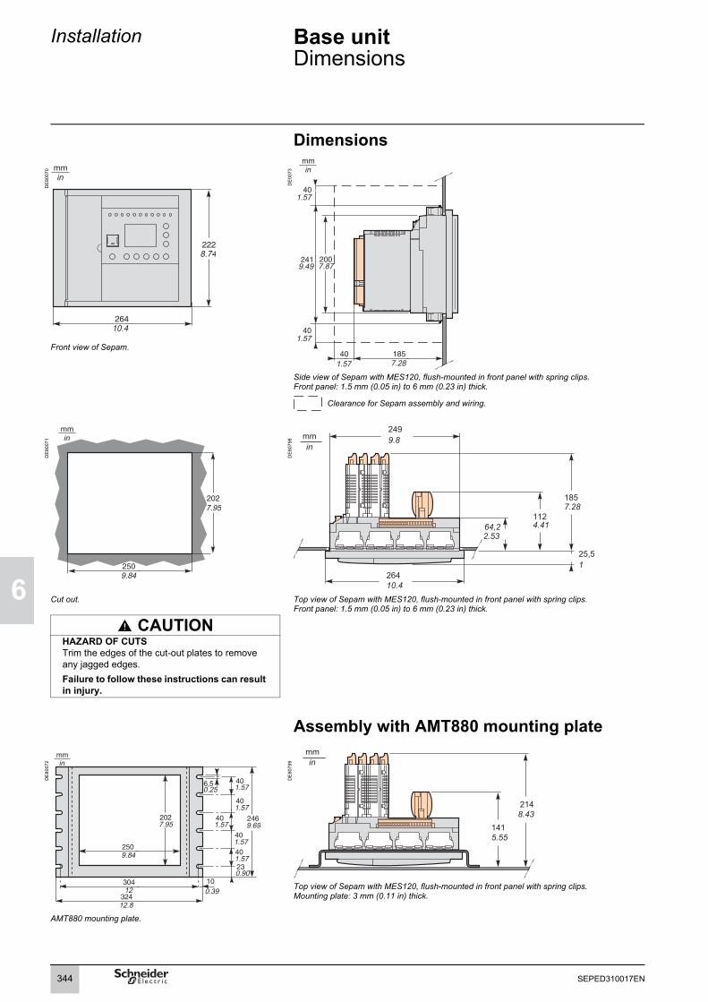
6
Installation Base unitDimensions
Dimensions
DE
8007
0
DE
0073
Front view of Sepam.
Side view of Sepam with MES120, flush-mounted in front panel with spring clips.Front panel: 1.5 mm (0.05 in) to 6 mm (0.23 in) thick.
Clearance for Sepam assembly and wiring.
DE
8007
1
DE
8079
8
Cut out. Top view of Sepam with MES120, flush-mounted in front panel with spring clips.Front panel: 1.5 mm (0.05 in) to 6 mm (0.23 in) thick.
CAUTIONHAZARD OF CUTSTrim the edges of the cut-out plates to remove any jagged edges.Failure to follow these instructions can result in injury.
Assembly with AMT880 mounting plate
DE
8007
2
DE
8079
9
Top view of Sepam with MES120, flush-mounted in front panel with spring clips.Mounting plate: 3 mm (0.11 in) thick.
AMT880 mounting plate.
mmin
8.74
10.4
mmin
1.57
1.57
1.57
7.879.49
7.28
mmin
7.95
9.84
mmin
249
264
185
25,5
11264,2
9.8
7.28
1
4.412.53
10.4
mmin
9.697.95
9.84
12
12.8
0.39
0.25 1.57
1.57
1.57
1.57
1.57
0.90
mmin
214
1418.43
5.55
344 SEPED310017EN

Installation Base unitMounting
1
6
Spring clip mounting directionThe direction in which the spring clips are mounted depends on the thickness of the mounting frame.The top clips are mounted in the opposite direction to the bottom clips.
Base unit flush-mountingSepam is mounted on the mounting frame by 8 spring clips.The mounting surface must be flat and stiff to guarantee tightness.
DANGER
DE
8010
1
HAZARD OF ELECTRIC SHOCK, ELECTRIC ARC OR BURNSb Only qualified personnel should install this equipment. Such work should be performed only after reading this entire set of instructions.b NEVER work alone. b Turn off all power supplying this equipment before working on or inside it. Consider all sources of power, including the possibility of backfeeding.b Always use a properly rated voltage sensing device to confirm that all power is off.Failure to follow these instructions will result in death or serious injury.
DE
8080
0D
E50
727
Fixing points Spring clips Setting Positioning Locking Unlocking
DE
8080
2
Installing the terminal block identification labelA sticker showing the rear panel of Sepam and terminal assignments is supplied with each base unit to facilitate the installation and connection of Sepam and the MES120 input/output modules.You may stick it in the location of your choice, e.g. on the side of an MES120 module or on the right-hand side panel of Sepam.
Terminal block identification label
0.06 in 0.16 in
0.06 in 0.16 in
CLIC !
6
123456
345SEPED310017EN
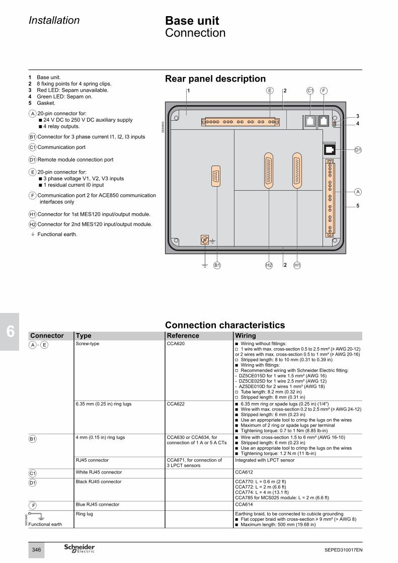
6
Installation Base unitConnection
1 Base unit.2 8 fixing points for 4 spring clips.3 Red LED: Sepam unavailable.4 Green LED: Sepam on.5 Gasket.
20-pin connector for:b 24 V DC to 250 V DC auxiliary supply b 4 relay outputs.
Connector for 3 phase current I1, I2, I3 inputs
Communication port
Remote module connection port
20-pin connector for:b 3 phase voltage V1, V2, V3 inputsb 1 residual current I0 input
Communication port 2 for ACE850 communication interfaces only
Connector for 1st MES120 input/output module.
Connector for 2nd MES120 input/output module.
Functional earth.
Rear panel description
DE
8080
3
Connection characteristicsConnector Type Reference Wiring
, Screw-type CCA620 b Wiring without fittings:v 1 wire with max. cross-section 0.5 to 2.5 mm² (u AWG 20-12) or 2 wires with max. cross-section 0.5 to 1 mm² (u AWG 20-16)v Stripped length: 8 to 10 mm (0.31 to 0.39 in)b Wiring with fittings:v Recommended wiring with Schneider Electric fitting:- DZ5CE015D for 1 wire 1.5 mm² (AWG 16)- DZ5CE025D for 1 wire 2.5 mm² (AWG 12)- AZ5DE010D for 2 wires 1 mm² (AWG 18)v Tube length: 8.2 mm (0.32 in)v Stripped length: 8 mm (0.31 in)
6.35 mm (0.25 in) ring lugs CCA622 b 6.35 mm ring or spade lugs (0.25 in) (1/4")b Wire with max. cross-section 0.2 to 2.5 mm² (u AWG 24-12)b Stripped length: 6 mm (0.23 in)b Use an appropriate tool to crimp the lugs on the wiresb Maximum of 2 ring or spade lugs per terminalb Tightening torque: 0.7 to 1 Nm (8.85 lb-in)
4 mm (0.15 in) ring lugs CCA630 or CCA634, for connection of 1 A or 5 A CTs
b Wire with cross-section 1.5 to 6 mm² (AWG 16-10)b Stripped length: 6 mm (0.23 in)b Use an appropriate tool to crimp the lugs on the wiresb Tightening torque: 1.2 N.m (11 lb-in)
RJ45 connector CCA671, for connection of 3 LPCT sensors
Integrated with LPCT sensor
White RJ45 connector CCA612
Black RJ45 connector CCA770: L = 0.6 m (2 ft)CCA772: L = 2 m (6.6 ft)CCA774: L = 4 m (13.1 ft)CCA785 for MCS025 module: L = 2 m (6.6 ft)
Blue RJ45 connector CCA614
DE
5184
5
Functional earth
Ring lug Earthing braid, to be connected to cubicle groundingb Flat copper braid with cross-section u 9 mm² (> AWG 8)b Maximum length: 500 mm (19.68 in)
A
B1
C1
D1
E
F
H1
H2
t
A E
B1
C1
D1
F
346 SEPED310017EN

Installation Base unitConnection
1
6
DE
8102
5
Note: See connection characteristics page 346
NOTICE DANGERLOSS OF PROTECTION OR RISK OF NUISANCE TRIPPINGIf the Sepam is no longer supplied with power or is in fail-safe position, the protection functions are no longer active and all the Sepam output relays are dropped out. Check that this operating mode and the watchdog relay wiring are compatible with your installation.Failure to follow these instructions can result in equipment damage and unwanted shutdown of the electrical installation.
HAZARD OF ELECTRIC SHOCK, ELECTRIC ARC OR BURNSOnly qualified personnel should install this equipment. Such work should be
performed only after reading this entire set of instructions.NEVER work alone. Turn off all power supplying this equipment before working on or inside it.
Consider all sources of power, including the possibility of backfeeding.Always use a properly rated voltage sensing device to confirm that all power
is off.Start by connecting the device to the protective earth and to the functional
earth.Screw tight all terminals, even those not in use.
Failure to follow these instructions will result in death or serious injury.
NOTICERISK OF DESTRUCTION OF THE SEPAMDo not invert the connectors and .
Failure to follow these instructions can result in equipment damage.
A E
347SEPED310017EN

6
Installation Base unitConnection of Sepam C60
DE
8102
9
Connector Type Reference Wiring4 mm (0.15 in) ring lugs CCA630 or CCA634, for connection
of 1 A or 5 A CTswire with cross-section 1.5 to 6 mm² (AWG 16-10)stripped length: 6 mm (0.236 in)use an appropriate tool to crimp the lugs on the wirestightening torque: 1.2 N.m (11 lb-in)
RJ45 connector CCA671, for connection of 3 LPCT sensors
Integrated with LPCT sensor
DE
5184
5
Functional earth
:gnidnuorg elcibuc ot detcennoc eb ot ,diarb gnihtraEgul gniRflat copper braid with cross-section u 9 mm² (> AWG 8)maximum length: 500 mm (19.68 in)
Connection characteristics of connectors , , , : see page 346
Functionalearth
CSH30(Sepam - CSH30 link lessthan 2 meters long)1 A CT : 2 turns5 A CT : 4 turns
B1
A E C1 D1
348 SEPED310017EN

Installation Base unitConnection of phase current inputs
1
6
Variant 1: phase current measurement by 3 x 1 A or 5 A CTs (standard connection)
DE
8082
5
DescriptionConnection of 3 x 1 A or 5 A sensors to the CCA630 or CCA634 connector.The measurement of the 3 phase currents allows the calculation of residual current.
ParametersSensor type 5 A CT or 1 A CTNumber of CTs I1, I2, I3Rated current (In) 1 A to 15 kA
Variant 2: phase current measurement by 2 x 1 A or 5 A CTs
DE
8008
8
DescriptionConnection of 2 x 1 A or 5 A sensors to the CCA630 or CCA634 connector.Measurement of phase 1 and 3 currents is sufficient for all protection functions based on phase current.The phase current I2 is only assessed for metering functions, assuming that I0 = 0.This connection diagram does not allow the measurement of the residual current.
ParamètresSensor type 5 A CT or 1 A CTNumber of CTs I1, I3Rated current (In) 1 A to 15 kA
Variant 3: phase current measurement by 3 LPCT type sensors
DE
8082
6
DescriptionConnection of 3 Low Power Current Transducer (LPCT) type sensors to the CCA671 connector. It is necessary to connect 3 sensors; if only one or two sensors are connected, Sepam goes into fail-safe position.Measurement of the 3 phase currents allows the calculation of residual current.
ParametersSensor type LPCTNumber of CTs I1, I2, I3Rated current (In) 25, 50, 100, 125, 133, 200, 250, 320, 400, 500, 630, 666, 1000,
1600, 2000 or 3150 ANote: Parameter In must be set twice:b Software parameter setting using the advanced UMI or the SFT2841 software toolb Hardware parameter setting using microswitches on the CCA671 connector
CCA630/CCA634
CCA630/CCA634
349SEPED310017EN

6
Installation Base unitConnection of residual current inputs
Variant 1: residual current calculation by sum of 3 phase currents
DE
8082
5
DescriptionResidual current is calculated by the vector sum of the 3 phase currents I1, I2 and I3, measured by 3 x 1 A or 5 A CTs or by 3 LPCT type sensors.See current input connection diagrams.
ParametersResidual current Rated residual current Measuring range
Sum of 3 Is In0 = In, CT primary current 0.01 to 40 In0 (minimum 0.1 A)
Variant 2: residual current measurement by CSH120 or CSH200 core balance CT (standard connection)
DE
8082
7
DescriptionArrangement recommended for the protection of isolated or compensated neutral systems, in which very low fault currents need to be detected.
ParametersResidual current Rated residual current Measuring range
2 A rating CSH In0 = 2 A 0.1 to 40 A20 A rating CSH In0 = 20 A 0.2 to 400 A
Variant 3: residual current measurement by 1 A or 5 A CTs and CCA634
DE
8082
8
DescriptionResidual current measurement by 1 A or 5 A CTs
Terminal 7: 1 A CTTerminal 8: 5 A CT
ParametersResidual current Rated residual current Measuring range
1 A CT In0 = In, CT primary current 0.01 to 20 In0 (minimum 0.1 A)5 A CT In0 = In, CT primary current 0.01 to 20 In0 (minimum 0.1 A)
DE
8082
9
CCA630/CCA634
350 SEPED310017EN

Installation Base unitConnection of residual current inputs
1
6
Variant 4: residual current measurement by 1 A or 5 A CTs and CSH30 interposing ring CT
DE
8106
6
DescriptionThe CSH30 interposing ring CT is used to connect 1 A or 5 A CTs to Sepam to measure residual current:b CSH30 interposing ring CT connected to 1 A CT: make 2 turns through CSH primaryb CSH30 interposing ring CT connected to 5 A CT: make 4 turns through CSH primary.
ParamètresResidual current Rated residual current Measuring range
1 A CT In0 = In, CT primary current 0.01 to 20 In0 (minimum 0.1 A)5 A CT In0 = In, CT primary current 0.01 to 20 In0 (minimum 0.1 A)
DE
8106
7
Variant 5: residual current measurement by core balance CT with ratio of 1/n (n between 50 and 1500)
DE
8010
2
DescriptionThe ACE990 is used as an interface between a MV core balance CT with a ratio of 1/n (50 y n y 1500) and the Sepam residual current input.This arrangement allows the continued use of existing core balance CTs on the installation.
ParametersResidual current Rated residual current Measuring range
ACE990 - range 1 In0 = Ik.n(1) 0.01 to 20 In0 (minimum 0.1 A)(0.00578 y k y 0.04)ACE990 - range 2 In0 = Ik.n(1) 0.01 to 20 In0 (minimum 0.1 A)(0.0578 y k y 0.26316)(1) n = number of core balance CT turnsk = factor to be determined according to ACE990 wiring and setting range used by Sepam
Variant 6: neutral point current measurement for the restricted earth protection (ANSI 64REF) and for a network where the neutral is not distributed
DE
8098
4
DescriptionThe residual current is measured by taking the sum of the 3 phase currents using the CT whose secondary current is 1 A or 5 A.The neutral point current is measured using the CT whose secondary current is 1 A or 5 A:b Terminal 7: 1 A CTb Terminal 8: 5 A CT
ParametersSecondary current Rated residual current Measuring range
1 A CT In0 = phase CT primary current In 0.01 to 20 In0 (0.1 A minimum)5 A CT In0 = phase CT primary current In 0.01 to 20 In0 (0.1 A minimum)
1 A CT: 2 turns5 A CT: 4 turns
1 A CT: 2 turns5 A CT: 4 turns
351SEPED310017EN

6
Installation Base unitConnection of low voltage residual current inputs
Variant 1: residual current measurement by CTs on the neutral earthing link (with or without CSH30 interposing ring CT)
DescriptionResidual current is measured with a 1 A or 5 A CT on the neutral point.These connection diagrams are incompatible with those for the ANSI 64REF function.
ParametersResidual current Rated residual current Measuring range
1 A CT In0 = neutral point CT In 0.01 to 20 In05 A CT In0 = neutral point CT In 0.01 to 20 In0
DE
8086
7
DE
8086
8
DE
8106
4
Connection on TN-S network. Connection on TT network. Connection with CSH30.
Variant 2: residual current measurement by CSH120 or CSH200 core balance CT on the neutral earthing link
DescriptionResidual current is measured with a core balance CT on the neutral point. Core balance CTs are recommended for measuring very low fault currents provided that the earth fault current remains below 2 kA. Above this value it is advisable to use the standard variant 1.These connection diagrams are incompatible with those for the ANSI 64REF function.
ParametersResidual current Rated residual current Measuring range
2 A rating CSH In0 = 2 A 0.1 to 40 A20 A rating CSH In0 = 20 A 0.2 to 400 A
DE
8086
9
DE
8087
0
Connection on TN-S network. Connection on TT network.
N PE N
1 A CT: 2 turns5 A CT: 4 turns
PEN N
352 SEPED310017EN

Installation Base unitConnection of low voltage residual current inputs
1
6
Variant 3: residual current measurement by sum of 3 phase currents and neutral current measurement by CSH120 or CSH200 core balance CT
DE
8087
1
DescriptionMeasurement by core balance CT is recommended for measuring very low fault currents.This connection diagram is incompatible with the ANSI 64REF function.
ParametersResidual current Rated residual current Measuring range
2 A rating CSH In0 = 2 A 0.1 to 40 A20 A rating CSH In0 = 20 A 0.2 to 400 A
Connection on TN-S and TT networks.
Variant 4: residual current measurement by sum of 3 phase currents and neutral current measurement by 1 A or 5 A CTs and CSH30 interposing ring CT
DE
8106
5
DescriptionThe phase and neutral CTs should have the same primary and secondary currents. The CSH30 interposing ring CT is used to connect 1 A or 5 A CTs to Sepam to measure residual current:b Connection of CSH30 interposing ring CT to 1 A CT: make 2 turns through CSH primaryb Connection of CSH30 interposing ring CT to 5 A CT: make 4 turns through CSH primary. According to the connection between the neutral point and earth, this connection diagram is incompatible with the ANSI 64REF function.
ParametersResidual current Rated residual current Measuring range
1 A CT In0 = phase CT primary current In 0.01 to 20 In05 A CT In0 = phase CT primary current In 0.01 to 20 In0
Connection on TN-S and TT networks.
Variant 5: residual current measurement by sum of 3 phase currents and neutral current measurement by 1 A or 5 A CTs and CCA634 connector
DE
8099
5
DescriptionThe phase and neutral CTs should have the same primary and secondary currents. Residual current measurement by 1 A or 5 A CTs.b Terminal 7: 1 A CTb Terminal 8: 5 A CT According to the connection between the neutral point and earth, this connection diagram is incompatible with the ANSI 64REF function.
ParametersResidual current Rated residual current Measuring range
1 A CT In0 = phase CT primary current In 0.01 to 20 In0
Connection on TN-S and TT networks. 5 A CT In0 = phase CT primary current In 0.01 to 20 In0
N
N
1 A CT: 2 turns5 A CT: 4 turns
N
353SEPED310017EN

6
Installation Base unitConnection of low voltage current inputs for restricted earth protection (ANSI 64REF)
DE
8087
8
DescriptionThese 3 diagrams correspond to the connections as found in the various low voltage diagrams where the neutral is distributed.They are used to work out the residual current (taking the sum of the 3 phase currents) and the transformer neutral point current for operation of the restricted earth protection function (ANSI 64 REF). The residual current is measured by taking the sum of the 3 phase currents using the CT whose secondary current is 1 A or 5 A.The neutral point current is measured using the CT whose secondary current is 1 A or 5 A:b Terminal 7: 1 A CTb Terminal 8: 5 A CT
Parameters
Secondary current Rated residual current Measuring range1 A CT In0 = phase CT primary current In 0.01 to 20 In05 A CT In0 = phase CT primary current In 0.01 to 20 In0
Connection on TT network.
DE
8087
6
DE
8087
7
Connection on TN-S network. Connection on TN-C network.
N
N PE PEN
354 SEPED310017EN
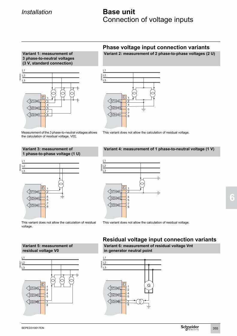
Installation Base unitConnection of voltage inputs
1
6
Phase voltage input connection variantsVariant 1: measurement of 3 phase-to-neutral voltages (3 V, standard connection)
Variant 2: measurement of 2 phase-to-phase voltages (2 U)
DE
8083
3
DE
8083
4
Measurement of the 3 phase-to-neutral voltages allows the calculation of residual voltage, V0Σ.
This variant does not allow the calculation of residual voltage.
Variant 3: measurement of 1 phase-to-phase voltage (1 U)
Variant 4: measurement of 1 phase-to-neutral voltage (1 V)
DE
8083
5
DE
8083
6
This variant does not allow the calculation of residual voltage.
This variant does not allow the calculation of residual voltage.
Residual voltage input connection variantsVariant 5: measurement of residual voltage V0
Variant 6: measurement of residual voltage Vnt in generator neutral point
DE
8083
7
DE
8083
8
355SEPED310017EN

6
Installation Base unitConnection of low voltage phase voltage inputs
Variant 1: TN-S and TN-C networks Variant 2: TT and IT networks
DE
8098
2
DE
8098
3
When a ground fault occurs on a TN-S or TN-C network, the neutral potential is not affected: the neutral can act as a reference for the VTs.
When a ground fault occurs on a TT or IT network, the neutral potential is affected: the neutral cannot act as a reference for the VTs, phase-to-phase voltages must be used on both phases.
N N
356 SEPED310017EN

Installation Base unitFunctions available according to connected voltage inputs
1
6
The availability of certain protection and metering functions depend on the phase and residual voltages measured by Sepam.
The table below gives the voltage input connection variants for which for each protection and metering function dependent on measured voltages is available.Example:The directional overcurrent protection function (ANSI 67N/67NC) uses residual voltage V0 as a polarization value.It is therefore operational in the following cases:b measurement of the 3 phase-to-neutral voltages and calculation of V0Σ (3 V + V0Σ, variant 1)b measurement of residual voltage V0 (variant 5).The protection and metering functions which do not appear in the table below are available regardless of the voltages measured.
Phase voltages measured(connection variant)
3 V + V0Σ(var. 1)
2 U(var. 2)
1 U(var. 3)
1 V(var. 4)
Residual voltage measured(connection variant)
– V0(v. 5)
Vnt(v. 6)
– V0(v. 5)
Vnt(v. 6)
– V0(v. 5)
Vnt(v. 6)
– V0(v. 5)
Vnt(v. 6)
Protection functions dependent on voltages measuredDirectional phase overcurrent 67 b b b b b bDirectional earth fault 67N/67NC b b b b b bDirectional active overpower 32P b b b b b bDirectional reactive active overpower 32Q b b b b b bDirectional active underpower 37P b b b b b bField loss (underimpedance) 40 b b b b b bVoltage-restrained overcurrent 50V/51V b b b b b bUnderimpedance 21B b b b b b bPositive sequence undervoltage 27D b b b b b bRemanent undervoltage 27R b b b b b b b b b b b bUndervoltage (L-L or L-N) 27 b b b b b b b b b b b bOvervoltage (L-L or L-N) 59 b b b b b b b b b b b bNeutral voltage displacement 59N b b b b b b b b bNegative sequence overvoltage 47 b b b b b b bOverfrequency 81H b b b b b b b b b b b bUnderfrequency 81L b b b b b b b b b b b bRate of change of frequency 81R b b b b b bMeasurements dependent on voltages measured
Phase-to-phase voltage U21, U32, U13 b b b b b b U21 U21 U21Phase-to-neutral voltage V1, V2, V3 b b b b V1 V1 V1Residual voltage V0 b b b b b bNeutral point voltage Vnt b b b bPositive sequence voltage Vd / negative sequence voltage Vi
b b b b b b
Frequency b b b b b b b b b b b bActive / reactive / apparent power: P, Q, S b b b b b b b b bPeak demand power PM, QM b b b b b b b b bActive / reactive / apparent power per phase:P1/P2/P3, Q1/Q2/Q3, S1/S2/S3
b (1) b (1) b (1) b (1) P1/Q1/S1
P1/Q1/S1
P1/Q1/S1
Power factor b b b b b b b b bCalculated active and reactive energy (±Wh, ±VARh) b b b b b b b b bTotal harmonic distortion, voltage Uthd b b b b b b b b bPhase displacement ϕ0 b b b b b bPhase displacement ϕ1, ϕ2, ϕ3 b b b b b bApparent positive sequence impedance Zd b b b b b bApparent phase-to-phase impedances Z21, Z32, Z13 b b b b b bb Function available(1) If all 3 phase currents are measured.
357SEPED310017EN

6
Installation 1 A/5 A current transformers
Function
0587
31N
ARJA1.
0587
33N
ARJP3.
Sepam may be connected to any standard 1 A or 5 A current transformer.Schneider Electric offers a range of current transformers to measure primary currents from 50 A to 2500 A. Consult us for more information.
Sizing of current transformersCurrent transformers are sized so as not to be saturated by the current values they are required to measure accurately (minimum 5 In).
Overcurrent protection functionsb with DT tripping curve: the saturation current must be 1.5 times greater than the settingb with IDMT tripping curve:the saturation current must be 1.5 times greater than the highest working value on the curve.Practical solution when there is no information on the settingsRated secondary current (in)
Accuracy burden
Accuracy class
CT secondary resistance RCT
Wiring resistance Rf
1 A 2.5 VA 5P 20 < 3 Ω < 0.075 Ω5 A 7.5 VA 5P 20 < 0.2 Ω < 0.075 Ω
Restricted earth fault differential protection (ANSI 64REF)b The primary current of the neutral point current transformer must comply with the following rule:In0 u 0.1 x I1P, where I1P is the phase-to-earth short-circuit current.
b Neutral current transformer must be:
v type 5P20 with an accuracy burden VACT u Rw.in0²
v or defined by a knee-point voltage Vk u (RCT + Rw).20.in0.
b Phase current transformers must be:
v type 5P, with an accuracy-limit factor FLP u max
and an accuracy burden VACT u Rw.in²
v or defined by a knee-point voltage Vk u (RCT + Rw) max in.
b Formula legend:in: phase CT rated secondary currentin0: neutral point CT rated secondary currentRCT: phase CT or neutral CT internal resistance Rw: resistance of the CT load and wiringIn: phase CT rated primary currentIn0: neutral point CT rated primary currentI3P: three-phase short-circuit currentI1P: phase-to-earth short-circuit current
20 1.6 I3PIn-------- 2.4 I1P
In--------, ,⎝ ⎠
⎛ ⎞
20 1.6 I3PIn-------- 2.4I1P
In--------, ,⎝
⎛
358 SEPED310017EN

Installation 1 A/5 A current transformers
1
6
CCA630/CCA634 connector
DE
8005
1
FunctionThe current transformers (1 A or 5 A) are connected to the CCA630 or CCA634 connector on the rear panel of Sepam:b The CCA630 connector is used to connect three phase current transformers to Sepam.b The CCA634 connector is used to connect three phase current transformers and one residual current transformer to Sepam.The CCA630 and CCA634 connectors contain interposing ring CTs with through primaries, which ensure impedance matching and isolation between the 1 A or 5 A circuits and Sepam when measuring phase and residual currents.The connectors can be disconnected with the power on since disconnection does not open the CT secondary circuit.
DE
8005
9
DANGERHAZARD OF ELECTRIC SHOCK, ELECTRIC ARC OR BURNSb Only qualified personnel should install this equipment. Such work should be performed only after reading this entire set of instructions and checking the technical characteristics of the device.b NEVER work alone. b Turn off all power supplying this equipment before working on or inside it. Consider all sources of power, including the possibility of backfeeding.b Always use a properly rated voltage sensing device to confirm that all power is off.b To disconnect the Sepam unit current inputs, unplug the CCA630 or CCA634 connector without disconnecting the wires from it. The CCA630 and CCA634 connectors ensure continuity of the current transformer secondary circuits.b Before disconnecting the wires connected to the CCA630 or CCA634 connector, short-circuit the current transformer secondary circuits.Failure to follow these instructions will result in death or serious injury.
CCA634
359SEPED310017EN

6
Installation 1 A/5 A Current transformers
MT1
0490
Connecting and assembling the CCA630 connector1. Open the 2 side shields for access to the connection terminals. The shields can be removed, if necessary, to make wiring easier. If removed, they must be replaced after wiring.2. If necessary, remove the bridging strap linking terminals 1, 2 and 3. This strap is supplied with the CCA630.3. Connect the wires using 4 mm (0.16 in) ring lugs and check the tightness of the 6 screws that guarantee the continuity of the CT secondary circuits. The connector accommodates wires with cross-sections of 1.5 to 6 mm² (AWG 16-10).4. Close the side shields.5. Plug the connector into the 9-pin inlet on the rear panel (item ).6. Tighten the 2 CCA630 connector fastening screws on the rear panel of Sepam..
DE
8006
8
DE
8006
9
Connecting and assembling the CCA634 connector1. Open the 2 side shields for access to the connection terminals. The shields can be removed, if necessary, to make wiring easier. If removed, they must be replaced after wiring.2. According to the wiring required, remove or reverse the bridging strap. This is used to link either terminals 1, 2 and 3, or terminals 1, 2, 3 and 9 (see picture opposite).3. Use terminal 7 (1 A) or 8 (5 A) to measure the residual current according to the CT secondary.4. Connect the wires using 4 mm (0.16 in) ring lugs and check the tightness of the 6 screws that guarantee the continuity of the CT secondary circuits.The connector accommodates wires with cross-sections of 1.5 to 6 mm² (AWG 16-10).The wires only exit from the base.5. Close the side shields.6. Insert the connector pins into the slots on the base unit.7. Flatten the connector against the unit to plug it into the 9-pin SUB-D connector (principle similar to that of the MES module).8. Tighten the mounting screw.
Bridging of terminals1, 2, 3 and 9
Bridging of terminals1, 2 and 3
NOTICEHAZARD OF IMPROPER OPERATIONDo not use a CCA634 on connector B1 and residual current input I0 on connector E (terminals 14 and 15) simultaneously.Even if it is not connected to a sensor, a CCA634 on connector B1 will disturb input I0 on connector E.Failure to follow these instructions can result in equipment damage.
B
360 SEPED310017EN

Installation LPCT type current sensors
1
6
Function
PE
5003
1
Low Power Current Transducer (LPCT) type sensors are voltage-output sensors, which are compliant with the IEC 60044-8 standard. The Schneider Electric range of LPCTs includes the following sensors: CLP1, CLP2, CLP3, TLP130, TLP160 and TLP190.
CLP1 LPCT sensor
CCA670/CCA671 connector
DE
5167
4
FunctionThe 3 LPCT sensors are connected to the CCA670 or CCA671 connector on the rear panel of Sepam.The connection of only one or two LPCT sensors is not allowed andcauses Sepam to go into fail-safe position.The two CCA670 and CCA671 interface connectors serve the same purpose,the difference being the position of the LPCT sensor plugs:b CCA670: lateral plugs, for Sepam series 20 and Sepam series 40b CCA671: radial plugs, for Easergy Sepam series 60 and Easergy Sepam series 80.
Description1 3 RJ45 plugs to connect the LPCT sensors.2 3 blocks of microswitches to set the CCA670/CCA671 to the rated phase current
value.3 Microswitch setting/selected rated current equivalency table (2 In values per
position). 4 9-pin sub-D connector to connect test equipment (ACE917 for direct connector or
via CCA613).
Rating of CCA670/CCA671 connectorsThe CCA670/CCA671 connector must be rated according to the rated primary current In measured by the LPCT sensors. In is the current value that corresponds to the rated secondary current of 22.5 mV. The possible settings for In are (in A): 25, 50, 100, 125, 133, 200, 250, 320, 400, 500, 630, 666, 1000, 1600, 2000, 3150.The selected In value should be:b entered as a Sepam general settingb configured by microswitch on the CCA670/CCA671 connector.
Operating mode:1. Use a screwdriver to remove the shield located in the "LPCT settings" zone; the shield protects 3 blocks of 8 microswitches marked L1, L2, L3.2. On the L1 block, set the microswitch for the selected rated current to "1" (2 In values per microswitch).b The table of equivalencies between the microswitch settings and the selected rated current In is printed on the connectorb Leave the 7 other microswitches set to "0".3. Set the other 2 blocks of switches L2 and L3 to the same position as the L1 block and close the shield.
NOTICEHAZARD OF NON-OPERATIONb Set the microswitches for the CCA670/CCA671 connector before commissioning the device.b Check that only one microswitch is in position 1 for each block L1, L2, L3 and that no microswitch is in the center position.b Check that the microswitch settings on all 3 blocks are identical. Failure to follow these instructions can result in equipment damage.
361SEPED310017EN

6
Installation LPCT type current sensorsTest accessories
.
Accessory connection principle DANGER
HAZARD OF ELECTRIC SHOCK, ELECTRIC ARC OR BURNSb Only qualified personnel should install this equipment. Such work should be performed only after reading this entire set of instructions.b NEVER work alone. b Turn off all power supplying this equipment before working on or inside it. Consider all sources of power, including the possibility of backfeeding.b Always use a properly rated voltage sensing device to confirm that all power is off.Failure to follow these instructions will result in death or serious injury.
DE
5167
5 1 LPCT sensor, equipped with a shielded cable fitted with a yellow RJ 45 plug which is plugged directly into the CCA670/CCA671 connector.
2 Sepam protection unit.3 CCA670/CCA671 connector, LPCT voltage interface, with microswitch setting of
rated current:b CCA670: lateral plugs for Sepam series 20 and Sepam series 40b CCA671: radial plugs for Sepam Easergy series 60 and Easergy Sepam series 80
4 CCA613 remote test plug, flush-mounted on the front of the cubicle and equipped with a 3-meter (9.8 ft) cord to be plugged into the test plug of the CCA670/CCA671 interface connector (9-pin sub-D).
5 ACE917 injection adapter, to test the LPCT protection chain with a standard injection box.
6 Standard injection box.
362 SEPED310017EN

Installation LPCT type current sensorsTest accessories
1
6
ACE917 injection adapterFunctionThe ACE917 adapter is used to test the protection chain with a standard injection box, when Sepam is connected to LPCT sensors.The ACE917 adapter is inserted between:b The standard injection boxb The LPCT test plug:v integrated in the Sepam CCA670/CCA671 interface connectorv or transferred by means of the CCA613 accessory.The following are supplied with the ACE917 injection adapter:b Power supply cordb 3-meter (9.8 ft) cord to connect the ACE917 to the LPCT test plug on CCA670/CCA671 or CCA613.
DE
8032
2
CharacteristicsPower supply 115/230 V AC Protection by time-delayed fuse 5 mm x 20 mm(0.2 x 0.79 in)
0.25 A rating
CCA613 remote test plugFunctionThe CCA613 test plug, flush-mounted on the front of the cubicle, is equipped with a 3-meter (9.8 ft) cord to transfer data from the test plug integrated in the CCA670/CCA671 interface connector on the rear panel of Sepam.
Dimensions
DE
8004
5
DE
8127
0
Front view with cover lifted. Right side view.
CAUTION
DE
8004
7
HAZARD OF CUTSTrim the edges of the cut-out plates to remove any jagged edges.Failure to follow these instructions can result in injury.
Cut-out.
mmin
10.2
6.69
2.76
67,5
44
mmin
1.73
2.66
6
Lock
67,5
13 50
80
Cable
0.51 1.97
3.15
2.66
mmin
69
461.81
2.72
mmin
363SEPED310017EN

6
Installation CSH120 and CSH200Core balance CTs
Function
PE
5003
2
The specifically designed CSH120 and CSH200 core balance CTs are for direct residual current measurement. The only difference between them is the diameter. Due to their low voltage insulation, they can only be used on cables.Note:
You must use an interface ACE990 with a core balance CT other than a CSH120,
or a CSH200, even if this core balance CT has the same transformation ratio than a CSH120, or CSH200.
CharacteristicsCSH120 CSH200
Inner diameter 120 mm (4.7 in) 196 mm (7.72 in)Weight 0.6 kg (1.32 lb) 1.4 kg (3.09 lb)
CSH120 and CSH200 core balance CTs. Accuracy 1 CT ±5% at 20°C (68°F)±6% max. from -25°C to 70°C (-13°F to +158°F)
2 CTs in parallel - ±10%Transformation ratio 1/470Maximum permissible current 1 CT 20 kA - 1 s
2 CTs in parallel - 6 kA - 1 sOperating temperature -25°C to +70°C (-13°F to +158°F)Storage temperature -40°C to +85°C (-40°F to +185°F)
Dimensions
DE
8024
9
Dimensions A B D E F H J K LCSH120(in)
120 (4.75)
164 (6.46)
44 (1.73)
190 (7.48)
80 (3.15)
40 (1.57)
166 (6.54)
65 (2.56)
35 (1.38)
CSH200(in)
196 (7.72)
256 (10.1)
46 (1.81)
274 (10.8)
120 (4.72)
60 (2.36)
254 (10)
104 (4.09)
37 (1.46)
6 mm (0.236 in) 5 mm (0.197 in)
364 SEPED310017EN

365
1
SEPED310017EN
6
Installation CSH120 and CSH200Core balance CTs
DANGER Assembly
DE
5167
8
HAZARD OF ELECTRIC SHOCK, ELECTRIC ARC OR BURNSb Only qualified personnel should install this equipment. Such work should be performed only after reading this entire set of instructions and checking the technical characteristics of the device.b NEVER work alone. b Turn off all power supplying this equipment before working on or inside it. Consider all sources of power, including the possibility of backfeeding.b Always use a properly rated voltage sensing device to confirm that all power is off.b Only CSH120 and CSH200 core balance CTs can be used for direct residual current measurement. Other residual current sensors require the use of an intermediate device, CSH30, ACE990 or CCA634.b Install the core balance CTs on insulated cables.b Cables with a rated voltage of more than 1000 V must also have an earthed shielding.
Failure to follow these instructions will result in death or serious injury.
Group the MV cable (or cables) in the middle of the core balance CT.Use non-conductive binding to hold the cables.Remember to insert the 3 medium voltage cable shielding earthing cablesthrough the core balance.
E40
465
E40
466
Assembly on MV cables. Assembly on mounting plate.
NOTICE ConnectionHAZARD OF NON-OPERATIONDo not connect the secondary circuit of the CSH core balance CTs to earth. This connection is made in Sepam.
Failure to follow these instructions can result in equipment damage.
Connection to Sepam series 20 and Sepam series 40
To residual current I0 input, on connector , terminals 19 and 18 (shielding).
Connection to Easergy Sepam series 60
To residual current I0 input, on connector , terminals 15 and 14 (shielding).
Connection to Easergy Sepam series 80b To residual current I0 input, on connector , terminals 15 and 14 (shielding)
b To residual current I'0 input, on connector , terminals 18 and 17 (shielding).
Recommended cableb Sheathed cable, shielded by tinned copper braidb Minimum cable cross-section 0.93 mm² (AWG 18)b Resistance per unit length < 100 mΩ/m (30.5 mΩ/ft)b Minimum dielectric strength: 1000 V (700 Vrms)b Connect the cable shielding in the shortest manner possible to Sepamb Flatten the connection cable against the metal frames of the cubicle.The connection cable shielding is grounded in Sepam. Do not ground the cable by any other means.The maximum resistance of the Sepam connection wiring must not exceed 4 Ω (i.e. 20 m maximum for 100 mΩ/m or 66 ft maximum for 30.5 mΩ/ft).
DE
8023
1D
E80
206
Connecting 2 CSH200 CTs in parallel
It is possible to connect 2 CSH200 CTs in parallel if the cables will not fit through a single CT, by following the instructions below:b Fit one CT per set of cables.b Make sure the wiring polarity is correct. The maximum permissible current at the primary is limited to 6 kA - 1 s for all cables.
A
E
E
E

6
Installation CSH30 interposing ring CT
Function
E40
468
E44
717
The CSH30 interposing ring CT is used as an interface when the residual current is measured using 1 A or 5 A current transformers.
Characteristics
Weight 0.12 kg (0.265 lb)Vertical assembly of CSH30 interposing ring CT.
Horizontal assembly of CSH30 interposing ring CT.
Assembly On symmetrical DIN railIn vertical or horizontal position
DimensionsD
E80
023
3.23
mmin
1.18
0.2
0.18
1.97
0.315
2.36
0.16
0.63
0.18
1.14
366 SEPED310017EN

Installation CSH30 interposing ring CT
1
6
ConnectionThe CSH30 is adapted for the type of current transformer, 1 A or 5 A, by the number of turns of the secondary wiring through the CSH30 interposing ring CT:b 5 A rating - 4 turnsb 1 A rating - 2 turns
Connection to 5 A secondary circuit Connection to 1 A secondary circuit
PE
5003
3
PE
5003
4
1. Plug into the connector.2. Insert the transformer secondary wire through the CSH30 interposing ring CT 4 times.
1. Plug into the connector.2. Insert the transformer secondary wire through the CSH30 interposing ring CT twice.
DE
8012
5
Connection to Sepam series 20 and Sepam series 40To residual current I0 input, on connector , terminals 19 and 18 (shielding).Connection to Easergy Sepam series 60To residual current I0 input, on connector terminals 15 and 14 (shielding).Connection to Easergy Sepam series 80b To residual current I0 input, on connector , terminals 15 and 14 (shielding)b To residual current I'0 input, on connector , terminals 18 and 17 (shielding).Recommended cableb Sheathed cable, shielded by tinned copper braidb Minimum cable cross-section 0.93 mm² (AWG 18) (max. 2.5 mm², AWG 12)b Resistance per unit length < 100 mΩ/m (30.5 mΩ/ft)b Minimum dielectric strength: 1000 V (700 Vrms)b Maximum length: 2 m (6.6 ft).It is essential for the CSH30 interposing ring CT to be installed near Sepam (Sepam - CSH30 link less than 2 m (6.6 ft) long).Flatten the connection cable against the metal frames of the cubicle.The connection cable shielding is grounded in Sepam. Do not ground the cable by any other means.
DE
8012
6
turnsturns
1S1
S2
2
A
E
E
E
turnsturns
1
S1
S2
2
367SEPED310017EN

6
Installation ACE990 Core balance CT interface
Function
PE
8031
8
The ACE990 is used to adapt measurements between an MV core balance CT with a ratio of 1/n (50 y n y 1500), and the Sepam residual current input.Note: You must use an interface ACE990 with a core balance CT other than a CSH120 or a CSH200, even if this core balance CT has the same transformation ratio than a CSH120 or CSH200.
Characteristics
Weight 0.64 kg (1.41 lb)Assembly Mounted on symmetrical DIN railAmplitude accuracy ±1%Phase accuracy < 2°
ACE990 core balance CT interface. Maximum permissible current 20 kA - 1 s(on the primary winding of an MV core balance CT with a ratio of 1/50 that does not saturate)
Operating temperature -25°C to +70°C (-13°F to +158°F)Storage temperature -25°C to +70°C (-13°F to +158°F)
Description and dimensionsACE990 input terminal block, for connection of the core balance CT.ACE990 output terminal block, for connection of the Sepam residual current.
DE
8119
6
ES
E1
S1ACE990
E2 E3 E4 E5
mmin.
S2
78 maxi3.07 maxi
501.97
110.43
200.78
39 1.53
522.05
100
max
i3.
94 m
axi
96 maxi3.78 maxi
E
S11
0.43
368 SEPED310017EN

Installation ACE990 Core balance CT interface
1
6
Connection
DE
5168
2
Connection of core balance CTOnly one core balance CT can be connected to the ACE990 interface.The secondary circuit of the MV core balance CT is connected to 2 of the 5 ACE990 interface input terminals. To define the 2 input terminals, it is necessary to know the following:
Core balance CT ratio (1/n)Core balance CT powerClose approximation of rated current In0
(In0 is a general setting in Sepam and defines the earth fault protection setting range between 0.1 In0 and 15 In0).
The table below can be used to determine:The 2 ACE990 input terminals to be connected to the MV core balance CT
secondaryThe type of residual current sensor to set The exact value of the rated residual current In0 setting, given by the following
formula: In0 = k x number of core balance CT turns with k the factor defined in the table below.
The core balance CT must be connected to the interface in the right direction for correct operation: the MV core balance CT secondary output terminal S1 must be connected to the terminal with the lowest index (Ex).
K value ACE990 input terminals to be connected
Residual current sensor setting
Min. MV core balance CT power
Example: Given a core balance CT with a ratio of 1/400 2 VA, used within a measurement range of 0.5 A to 60 A.How should it be connected to Sepam via the ACE990?1. Choose a close approximation of the rated current In0, i.e. 5 A.2. Calculate the ratio: approx. In0/number of turns = 5/400 = 0.0125.3. Find the closest value of k in the table opposite to k = 0.01136.4. Check the mininum power required for the core balance CT: 2 VA core balance CT > 0.1 VA V OK.5. Connect the core balance CT secondary to ACE990 input terminals E2 and E4.6. Set Sepam up with: In0 = 0.01136 x 400 = 4.544 A. Select the closest value rounded to a single decimal (example: 4.544 A rounded to 4.5 A)
This value of In0 can be used to monitor current between 0.45 A and 67.5 A.
Wiring of MV core balance CT secondary circuit:MV core balance CT S1 output to ACE990 E2 input terminal
MV core balance CT S2 output to ACE990 E4 input terminal.
0.00578 E1 - E5 ACE990 - range 1 0.1 VA0.00676 E2 - E5 ACE990 - range 1 0.1 VA0.00885 E1 - E4 ACE990 - range 1 0.1 VA0.00909 E3 - E5 ACE990 - range 1 0.1 VA0.01136 E2 - E4 ACE990 - range 1 0.1 VA0.01587 E1 - E3 ACE990 - range 1 0.1 VA0.01667 E4 - E5 ACE990 - range 1 0.1 VA0.02000 E3 - E4 ACE990 - range 1 0.1 VA0.02632 E2 - E3 ACE990 - range 1 0.1 VA0.04000 E1 - E2 ACE990 - range 1 0.2 VA
0.05780 E1 - E5 ACE990 - range 2 2.5 VA0.06757 E2 - E5 ACE990 - range 2 2.5 VA0.08850 E1 - E4 ACE990 - range 2 3.0 VA0.09091 E3 - E5 ACE990 - range 2 3.0 VA0.11364 E2 - E4 ACE990 - range 2 3.0 VA0.15873 E1 - E3 ACE990 - range 2 4.5 VA0.16667 E4 - E5 ACE990 - range 2 4.5 VA0.20000 E3 - E4 ACE990 - range 2 5.5 VA0.26316 E2 - E3 ACE990 - range 2 7.5 VA
Connection to Sepam series 20 and Sepam series 40To residual current I0 input, on connector , terminals 19 and 18 (shielding).Connection to Easergy Sepam series 60To residual current I0 input, on connector , terminals 15 and 14 (shielding).Connection to Easergy Sepam series 80
To residual current I0 input, on connector , terminals 15 and 14 (shielding)To residual current I'0 input, on connector , terminals 18 and 17 (shielding).
Recommended cablesCable between core balance CT and ACE990: less than 50 m (160 ft) longSheathed cable, shielded by tinned copper braid between the ACE990 and
Sepam, maximum length 2 m (6.6 ft)Cable cross-section between 0.93 mm² (AWG 18) and 2.5 mm² (AWG 12)Resistance per unit length less than 100 mΩ/m (30.5 mΩ/ft)Minimum dielectric strength: 100 Vrms.
Connect the connection cable shielding in the shortest manner possible (2 cm or 5.08 in maximum) to the shielding terminal on the Sepam connector.Flatten the connection cable against the metal frames of the cubicle.The connection cable shielding is grounded in Sepam. Do not ground the cable by any other means.
A
E
E
E
369SEPED310017EN

6
Installation Voltage transformers
Function
0587
34N
0587
35N
Sepam may be connected to any standard voltage transformer with a rated secondary voltage of 100 V to 220 V.Schneider Electric offers a range of voltage transformers b to measure phase-to-neutral voltages: voltage transformers with one insulated MV terminalb to measure phase-to-phase voltages: voltage transformers with two insulated MV terminalsb with or without integrated protection fuses.
Consult us for more information.VRQ3 without fuses. VRQ3 with fuses.
DANGER ConnectionHAZARD OF ELECTRIC SHOCK, ELECTRIC ARC OR BURNSb Only qualified personnel should install this equipment. Such work should be performed only after reading this entire set of instructions and checking the technical characteristics of the device.b NEVER work alone. b Turn off all power supplying this equipment before working on or inside it. Consider all sources of power, including the possibility of backfeeding.b Always use a properly rated voltage sensing device to confirm that all power is off.b Start by connecting the device to the protective earth and to the functional earth.b Screw tight all terminals, even those not in use.Failure to follow these instructions will result in death or serious injury.
All Easergy Sepam series 60 units have 4 voltage inputs to measure the 3 phase voltages and the residual voltage.b The voltage measurement VTs are connected to the Sepam connector .b 4 transformers integrated in the Sepam base unit provide the required impedance matching and isolation between the VTs and the Sepam input circuits.
E
370 SEPED310017EN

Installation MES120, MES120G, MES120H 14 input / 6 output modulesPresentation
1
6
Function
PE
5002
0
MES120 14 input / 6 output module.
The extension of the output relays included on the Easergy Sepam series 60 and Easergy Sepam series 80 base unit is done by the add of MES120 modules:b On Easergy Sepam series 60, it is possible to add 2 MES120 modules (H1 andH2 connectors).b On Easergy Sepam series 80, it is possible to add 3 MES120 modules (H1, H2and H3 connectors).
A MES120 module is composed of:b 14 logical inputsb 6 relays outputs included 1 control relays input and 5 signalisation relays outputs.
Three modules are available for the different input supply voltage ranges and offer different switching thresholds:b MES120, 14 inputs 24 V DC to 250 V DC with a typical switching threshold of 14 V DCb MES120G, 14 inputs 220 V DC to 250 V DC with a typical switching threshold of 155 V DC.b MES120H, 14 inputs 110 V DC to 125 V DC with a typical switching threshold of 82 V DC
CharacteristicsMES120/MES120G/MES120H modules
Weight 0.38 kg (0.83 lb)Operating temperature -25°C to +70°C (-13°F to +158°F)Environmental characteristics Same characteristics as Sepam base units
Logic inputs MES120 MES120G MES120HVoltage 24 to 250 V DC 220 to 250 V DC 110 to 125 V DCRange 19.2 to 275 V DC 170 to 275 V DC 88 to 150 V DCTypical consumption 3 mA 3 mA 3 mATypical switching threshold 14 V DC 155 V DC 82 V DCInput limit voltage At state 0 < 6 V DC < 144 V DC < 75 V DC
At state 1 > 19 V DC > 170 V DC > 88 V DCIsolation of inputs from other isolated groups Enhanced Enhanced Enhanced
Control relay output Ox01Voltage DC 24/48 V DC 127 V DC 220 V DC 250 V DC -
AC (47.5 to 63 Hz) - - - - 100 to 240 V ACContinuous current 8 A 8 A 8 A 8 A 8 ABreaking capacity Resistive load 8/4 A 0.7 A 0.3 A 0.2 A 8 A
L/R load < 20 ms 6/2 A 0.5 A 0.2 A - -L/R load < 40 ms 4/1 A 0.2 A 0.1 A - -p.f. load > 0.3 - - - - 5 A
Making capacity < 15 A for 200 msIsolation of outputs from other isolated groups Enhanced
Annunciation relay output Ox02 to Ox06Voltage DC 24/48 V DC 127 V DC 220 V DC 250 V DC -
AC (47.5 to 63 Hz) - - - - 100 to 240 V ACContinuous current 2 A 2 A 2 A 2 A 2 ABreaking capacity Resistive load 2/1 A 0.6 A 0.3 A 0.2 A -
L/R load < 20 ms 2/1 A 0.5 A 0.15 A - -p.f. load > 0.3 - - - - 1 A
Isolation of outputs from other isolated groups Enhanced
371SEPED310017EN

6
Installation MES120, MES120G, MES120H 14 input / 6 output modulesInstallation
DE
8007
8
Description3 lockable screw-type, removable, connectors.1 20-pin connector for 9 logic inputs:
b Ix01 to Ix04: 4 independent logic inputsb Ix05 to Ix09: 5 common point logic inputs.
2 7-pin connector for 5 common point logic inputs Ix10 to Ix14.3 17-pin connector for 6 relay outputs:
b Ox01: 1 control relay outputb Ox02 to Ox06: 5 annunciation relay outputs.
Addressing of MES120 module inputs/outputs:b x = 1 for the module connected to H1b x = 2 for the module connected to H2b x = 3 for the module connected to H3 (Easergy Sepam series 80 only).
4 MES120G, MES120H identification label (MES120 modules have no labels).
Assembly
PE
5002
6
Installation of an MES120 module on the base unitb insert the 2 pins on the MES module into the slots 1 on the base unitb push the module flat up against the base unit to plug it into the connector H2b partially tighten the two mounting screws 2 before locking them.MES120 modules must be mounted in the following order:b if only one module is required, connect it to connector H1b if 2 modules are required, connect them to connectors H1 and H2 (maximum configuration of Easergy Sepam series 60).b if 3 modules are required, they have to be connected to the H1, H2 and H3 connectors (maximum configuration of Easergy Sepam series 80).
Installation of the second MES120 module, connected to base unit connector H2.
mmin
6.69
1.57
4.72
372 SEPED310017EN

Installation MES120, MES120G, MES120H 14 input / 6 output modulesInstallation
1
6
ConnectionThe inputs are potential-free and the DC power supply source is external.
DANGERHAZARD OF ELECTRIC SHOCK, ELECTRIC ARC OR BURNSb Only qualified personnel should install this equipment. Such work should be performed only after reading this entire set of instructions and checking the technical characteristics of the device.b NEVER work alone. b Turn off all power supplying this equipment before working on or inside it. Consider all sources of power, including the possibility of backfeeding.b Always use a properly rated voltage sensing device to confirm that all power is off.b Screw tight all terminals, even those not in use.Failure to follow these instructions will result in death or serious injury.
DE
5164
5 Wiring of connectorsb wiring without fittings:v 1 wire with maximum cross-section 0.2 to 2.5 mm² (u AWG 24-12) or 2 wires with maximum cross-section 0.2 to 1 mm² (u AWG 24-16)v stripped length: 8 to 10 mm (0.31 to 0.39 in)b wiring with fittings:v recommended wiring with Schneider Electric fittings:- DZ5CE015D for one 1.5 mm² wire (AWG 16)- DZ5CE025D for one 2.5 mm² wire (AWG 12)- AZ5DE010D for two 1 mm² wires (AWG 18)v tube length: 8.2 mm (0.32 in)v stripped length: 8 mm (0.31 in).
373SEPED310017EN

6
Installation Optional remote modulesSelection guide
4 remote modules are proposed as options to enhance the Sepam base unit functions:b the number and type of remote modules compatible with the base unit depend on the Sepam applicationb the DSM303 remote advanced UMI module is only compatible with base units that do not have integrated advanced UMIs.b the DSM303 advanced UMI module and the MCS025 synchro-check module must not be connected to Easergy Sepam series 60 at the same time.
Sepam series 20
Sepam series 40
Easergy Sepam series 60
Easergy Sepam series 80
S2x, B2x
T2x, M2x
S4x T4x, M4x, G4x
S6x T6x, G6x
M6x, C6x
S8x, B8x
T8x, G8x
M8x C8x
MET148-2 Temperature sensor module See page 376 0 1 0 2 0 2 2 0 2 2MSA141 Analog output module See page 378 1 1 1 1 1 1 1 1 1 1DSM303 Remote advanced UMI module See page 380 1 1 1 1 1 1 1 1 1 1MCS025 Synchro-check module See page 382 0 0 0 0 1 1 0 1 1 0Number of sets of interlinked modules/maximum number of remote modules
1 set of 3 interlinked modules
1 set of 3 interlinked modules
1 set of 3 interlinked modules
5 modules split between 2 sets of interlinked modules
374 SEPED310017EN

Installation Optional remote modulesConnection
1
6
NOTICE Connection cordsDifferent combinations of modules can be connected using cords fitted with 2 black RJ45 connectors, which come in 3 lengths:b CCA770: length = 0.6 m (2 ft)b CCA772: length = 2 m (6.6 ft)b CCA774: length = 4 m (13.1 ft).The modules are linked by cords which provide the power supply and act as functional links with the Sepam unit (connector to connector ,
to , …).
HAZARD OF NON-OPERATIONThe MCS025 module must ALWAYS be connected with the special CCA785 prefabricated cord, supplied with the module and equipped with an orange RJ45 connector and a black RJ45 connector.Failure to follow these instructions can result in equipment damage.
Rules on inter-module linkingb linking of 3 modules maximumb DSM303 and MCS025 modules can only be connected at the end of the link.
Maximum recommended configurationsSepam series 20, Sepam series 40 and Easergy Sepam series 60: only 1 set of interlinked modules
DE
5164
6
Base Cord Module 1 Cord Module 2 Cord Module 3
DE
8032
3
series 20/40/60 CCA772 MSA141 CCA770 MET148-2 CCA774 DSM303series 40/60 CCA772 MSA141 CCA770 MET148-2 CCA772 MET148-2series 40/60 CCA772 MET148-2 CCA770 MET148-2 CCA774 DSM303series 60 CCA772 MSA141 CCA770 MET148-2 CCA785 MCS025series 60 CCA772 MET148-2 CCA770 MET148-2 CCA785 MCS025
Easergy Sepam series 80: 2 sets of interlinked modulesEasergy Sepam series 80 has 2 connection ports for remote modules, and .Modules may be connected to either port.Base Cord Module 1 Cord Module 2 Cord Module 3
Set 1 CCA772 MET148-2 CCA770 MET148-2 CCA774 DSM303
DE
8032
4
- -
Set 2 CCA772 MSA141 CCA785 MCS025 - -
Example of inter-module linking on Sepam series 20.
D DaDd Da
D1 D2
D1
D2
375SEPED310017EN

6
Installation MET148-2 Temperature sensor module
Function
PE
5002
1
The MET148-2 module can be used to connect 8 temperature sensors (RTDs)of the same type:b Pt100, Ni100 or Ni120 type RTDs, according to parameter settingb 3-wire temperature sensorsb A single module for each Sepam series 20 base unit, to be connected by one of the CCA770 (0.6 or 2 ft), CCA772 (2 m or 6.6 ft) or CCA774 (4 m or 13.1 ft) cordsb 2 modules for each Sepam series 40, Easergy Sepam series 60 or series 80 base unit, to be connected by CCA770 (0.6 or 2 ft), CCA772 (2 m or 6.6 ft) or CCA774 (4 m or 13.1 ft) cordsThe temperature measurement (e.g. in a transformer or motor winding) is utilized by the following protection functions:b Thermal overload (to take ambient temperature into account)b Temperature monitoring.
CharacteristicsMET148-2 module
Weight 0.2 kg (0.441 lb)Assembly On symmetrical DIN railOperating temperature -25°C to +70°C (-13°F to +158°F)Environmental characteristics Same characteristics as Sepam base units
Temperature sensors Pt100 Ni100/Ni120Isolation from earth None NoneCurrent injected in RTD 4 mA 4 mA
DE
8003
1
Description and dimensionsTerminal block for RTDs 1 to 4Terminal block for RTDs 5 to 8RJ45 connector to connect the module to the base unit with a CCA77x cordRJ45 connector to link up the next remote module with a CCA77x cord (according to application)
Grounding/earthing terminal
1 Jumper for impedance matching with load resistor (Rc), to be set to:b , if the module is not the last interlinked module (default position)b Rc, if the module is the last interlinked module.
2 Jumper used to select module number, to be set to:b MET1: 1st MET148-2 module, to measure temperatures T1 to T8 (default position)b MET2: 2nd MET148-2 module, to measure temperatures T9 to T16(for Sepam series 40, Easergy Sepam series 60 and series 80 only).
(1) 70 mm (2.8 in) with CCA77x cord connected.
5.67
3.46
1.81
mmin
A
B
Da
Dd
t
Rc
376 SEPED310017EN
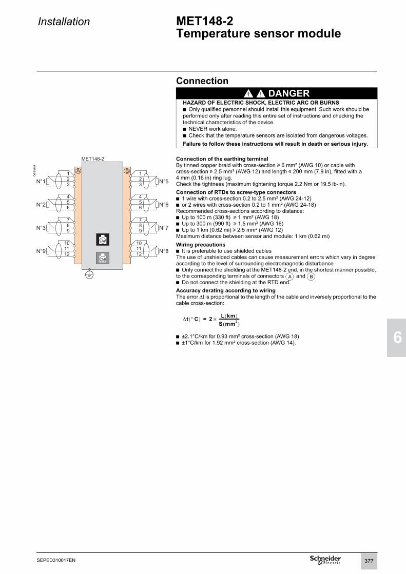
Installation MET148-2 Temperature sensor module
1
6
Connection DANGER
HAZARD OF ELECTRIC SHOCK, ELECTRIC ARC OR BURNSb Only qualified personnel should install this equipment. Such work should be performed only after reading this entire set of instructions and checking the technical characteristics of the device.b NEVER work alone. b Check that the temperature sensors are isolated from dangerous voltages.Failure to follow these instructions will result in death or serious injury.
DE
5164
9
Connection of the earthing terminalBy tinned copper braid with cross-section u 6 mm² (AWG 10) or cable with cross-section u 2.5 mm² (AWG 12) and length y 200 mm (7.9 in), fitted with a 4 mm (0.16 in) ring lug.Check the tightness (maximum tightening torque 2.2 Nm or 19.5 lb-in).Connection of RTDs to screw-type connectorsb 1 wire with cross-section 0.2 to 2.5 mm² (AWG 24-12)b or 2 wires with cross-section 0.2 to 1 mm² (AWG 24-18)Recommended cross-sections according to distance:b Up to 100 m (330 ft) u 1 mm² (AWG 18)b Up to 300 m (990 ft) u 1.5 mm² (AWG 16)b Up to 1 km (0.62 mi) u 2.5 mm² (AWG 12)Maximum distance between sensor and module: 1 km (0.62 mi)Wiring precautionsb It is preferable to use shielded cablesThe use of unshielded cables can cause measurement errors which vary in degree according to the level of surrounding electromagnetic disturbanceb Only connect the shielding at the MET148-2 end, in the shortest manner possible, to the corresponding terminals of connectors and b Do not connect the shielding at the RTD end.Accuracy derating according to wiringThe error Δt is proportional to the length of the cable and inversely proportional to the cable cross-section:
b ±2.1°C/km for 0.93 mm² cross-section (AWG 18)b ±1°C/km for 1.92 mm² cross-section (AWG 14).
A B
Δt ° C( ) 2 L km( )S mm2( )----------------------×=
377SEPED310017EN

6
Installation MSA141 Analog output module
Function
PE
8074
8 The MSA141 module converts one of the Sepam measurements into an analog signal:b Selection of the measurement to be converted by parameter settingb 0-1 mA, 0-10 mA, 4-20 mA, 0-20 mA analog signal according to parameter settingb Scaling of the analog signal by setting minimum and maximum values of the converted measurement.Example: the setting used to have phase current 1 as a 0-10 mA analog output with a dynamic range of 0 to 300 A is:v minimum value = 0v maximum value = 3000b A single module for each Sepam base unit, to be connected by one of the CCA770 (0.6m or 2 ft), CCA772 (2m or 6.6 ft) or CCA774 (4m or 13.1 ft) cords.The analog output can also be remotely managed via the communication network.
MSA141 analog output module.
CharacteristicsMSA141 module
Weight 0.2 kg (0.441 lb)Assembly On symmetrical DIN railOperating temperature -25°C to +70°C (-13°F to +158°F)Environmental characteristics Same characteristics as Sepam base units
Analog outputCurrent 4 -20 mA, 0-20 mA, 0-10 mA, 0-1 mAScaling(no data input checking)
Minimum valueMaximum value
Load impedance < 600 Ω (including wiring)Accuracy 0.5% full scale or 0,01 mA
Measurements available
Unit Series 20 Series 40 Series 60/Series 80
Phase and residual currents 0.1 A b b bPhase-to-neutral and phase-to-phase voltages
1 V b b b
Frequency 0.01 Hz b b bThermal capacity used 1% b b bTemperatures 1°C (1°F) b b bActive power 0.1 kW b bReactive power 0.1 kvar b bApparent power 0.1 kVA b bPower factor 0.01 bRemote setting via communication link
b b b
378 SEPED310017EN

Installation MSA141 Analog output module
1
6
DE8
0907
Description and dimensionsTerminal block for analog output RJ45 socket to connect the module to the base unit with a CCA77x cord RJ45 socket to link up the next remote module with a CCA77x cord (according to application)Earthing terminal
1 Jumper for impedance matching with load resistor (Rc),to be set to:
, if the module is not the last interlinked module (default position) Rc, if the module is the last interlinked module.
2 Micro-switches to set the analog output type: Micro-switches Position Output type
low (default position) 0-20 mA4-20 mA0-10 mA
high 0-1 mA
(1) 70 mm (2.8 in) with CCA77x cord connected.
PE8
0758
Output SettingThe analog output type is configured in 2 steps: 1. Hardware setting: set the 2 micro-switches:
on low position for a 0-20 mA, 4-20 mA or 0-10 mA output type on high position for a 0-1 mA output type.
2. Software configuration: select the desired output type in the SFT2841 setting software Analog output module (MSA141) setting window and validate by pressing the OK button.Note : The 0-1 mA output works only if the 0-20 mA or 0-1 mA depending on switch output type has been set in the SFT2841 setting software (step 2).
Analog output module (MSA141) setting window.
ConnectionConnection of the earthing terminalBy tinned copper braid with cross-section 6 mm² (AWG 10) or cable withcross-section 2.5 mm² (AWG 12) and length 200 mm (7.9 in), equipped with a 4 mm (0.16 in) ring lug.Check the tightness (maximum tightening torque 2.2 Nm or 19.5 lb-in).Connection of analog output to screw-type connector
1 wire with cross-section 0.2 to 2.5 mm² (AWG 24-12)or 2 wires with cross-section 0.2 to 1 mm² (AWG 24-18).
Wiring precautionsIt is preferable to use shielded cablesUse tinned copper braid to connect the shielding at least at the MSA141 end.
PE8
0908
3.46
5.671.81
mmin
2
2
1 1 2 3
1mA
orØ 20mA
A
Da
Dd
Rc
1 2
1 2
123
1
379SEPED310017EN

6
Installation DSM303 Remote advanced UMI module
Function
PE
5012
7
DSM303 remote advanced UMI module.
When associated with a Sepam that does not have its own advanced user-machine interface, the DSM303 offers all the functions available on a Sepam integrated advanced UMI.It can be installed on the front panel of the cubicle in the most suitable operating location:b Reduced depth < 30 mm (1.2 in)b A single module for each Sepam, to be connected by one of the CCA772 (2 m or 6.6 ft) or CCA774 (4 m or 13.1 ft) cords.
The module cannot be connected to Sepam units with integrated advanced UMIs.
CharacteristicsDSM303 module
Weight 0.3 kg (0.661 lb)Assembly Flush-mountedOperating temperature -25°C to +70°C (-13°F to +158°F)Environmental characteristics Same characteristics as Sepam base units
380 SEPED310017EN

Installation DSM303 Remote advanced UMI module
1
6
Description and dimensionsThe module is simply flush-mounted and secured by its clips. No additional screw-type fastening is required.
Front view Side view
DE
8003
3
DE
8003
4
1 Green LED: Sepam on2 Red LED:
- steadily on: module unavailable- flashing: Sepam link unavailable
3 9 yellow LEDs4 Label identifying the LEDs5 Graphic LCD screen6 Display of measurements7 Display of switchgear, network and machine diagnosis data8 Display of alarm messages9 Sepam reset (or confirm data entry)10 Alarm acknowledgment and clearing (or move cursor up)11 LED test (or move cursor down)12 Access to protection settings13 Access to Sepam parameters14 Entry of 2 passwords15 PC connection port16 Mounting clip17 Gasket to ensure NEMA 12 tightness
(gasket supplied with the DSM303 module, to be installed if necessary)
RJ45 lateral output connector to connect the module to the base unitwith a CCA77x cord.
CAUTION Cut-out for flush-mounting (mounting plate thickness < 3 mm or 0.12 in)
HAZARD OF CUTSTrim the edges of the cut-out plates to remove any jagged edges.
Failure to follow these instructions can result in injury.
DE
8006
0
Connection
MT1
0151
RJ45 socket to connector the module to the base unit with a CCA77x cord.The DSM303 module is always the last interlinked remote module and it systematically ensures impedance matching by load resistor (Rc).
5.99
4.6
mmin
3.78
0.98
0.6
mmin
16 17
Da
5.67
3.8898.5 0,5
mmin
Da
381SEPED310017EN

6
Installation MCS025Synchro-check module
PE
5028
5
FunctionThe MCS025 module is used with Easergy Sepam series 60 and series 80.The MCS025 module checks the voltages upstream and downstream of a circuit breaker to ensure safe closing (ANSI 25). It checks the differences in amplitude, frequency and phase between the two measured voltages, taking into account voltage abscence. Three relay outputs may be used to send the close enable to several Sepam units.The circuit-breaker control function of each Sepam unit will take this close enable into account.
The settings for the synchro-check function and the measurements carried out by the module may be accessed by the SFT2841 setting and operating software, similar to the other settings and measurements for the Sepam.
The MCS025 module is supplied ready for operation with:b the CCA620 connector for connection of the relay outputs and the power supplyb the CCT640 connector for voltage connectionb the CCA785 cord for connection between the module and the Sepam base unit.
MCS025 synchro-check module.
CharacteristicsMCS025 module
Weight 1.35 kg (2.98 lb)Assembly With the AMT840 accessoryOperating temperature -25°C to +70°C (-13°F to +158°F)Environmental characteristics Same characteristics as Sepam base units
Voltage inputsInput impedance > 100 kΩConsumption < 0.015 VA (VT 100 V)Continuous thermal withstand 240 V1-second overload 480 V
Relay outputsRelay outputs O1 and O2
Voltage DC 24/48 V DC 127 V DC 220 V DCAC (47.5 to 63 Hz) 100 to 240 V AC
Continuous current 8 A 8 A 8 A 8 ABreaking capacity Resistive load 8 A / 4 A 0.7 A 0.3 A
Load L/R < 20 ms 6 A / 2 A 0.5 A 0.2 ALoad L/R < 40 ms 4 A / 1 A 0.2 A 0.1 AResistive load 8 ALoad p.f. > 0.3 5 A
Making capacity < 15 ms for 200 msIsolation of outputs from other isolated groups
Enhanced
Relay outputs O3 and O4 (O4 not used)Voltage DC 24 / 48 V DC 127 V DC 220 V DC
AC (47.5 to 63 Hz) 100 to 240 V ACContinuous current 2 A 2 A 2 A 2 ABreaking capacity Load L/R < 20 ms 2 A / 1 A 0.5 A 0.15 A
Load p.f. > 0.3 5 AIsolation of outputs from other isolated groups
Enhanced
Power supplyVoltage 24 to 250 V DC, -20 % / +10 % 110 to 240 V AC, -20 % / +10 %
47.5 to 63 HzMaximum consumption 6 W 9 VAInrush current < 10 A for 10 ms < 15 A for one half periodAcceptable momentary outages 10 ms 10 ms
382 SEPED310017EN

Installation MCS025Synchro-check module
1
6
Description1 MCS025 module
CCA620 20-pin connector for:b auxiliary power supplyb 4 relay outputs:v O1, O2, O3: close enable. v O4: not used
CCT640 connector (phase-to-neutral or phase-to-phase) for the two input voltages to be synchronized
RJ45 connector, not used
RJ45 connector for module connection to the Sepam base unit, either directly or via another remote module.
2 Two mounting clips
3 Two holding pins for the flush-mount position
4 CCA785 connection cord
DE
5165
4
A
B
C
D
383SEPED310017EN

6
Installation MCS025Synchro-check module
Dimensions
DE
8007
9
DE
8013
2
MCS025.
Assembly with AMT840 mounting plateThe MCS025 module should be mounted at the back of the compartment using the AMT840 mounting plate.
DE
8002
9
DE
8008
1
AMT840 mounting plate.
Connection characteristicsConnector Type Reference Wiring
Screw-type CCA620 b wiring with no fittings:v 1 wire with maximum cross-section 0.2 to 2.5 mm² (> AWG 24-12) or 2 wires with cross-section 0.2 to 1 mm² (>AWG 24-16)v stripped length: 8 to 10 mm (0.31 to 0.39 in)b wiring with fittings:v recommended wiring with Schneider Electric fittings:- DZ5CE015D for 1 wire 1.5 mm² (AWG 16)- DZ5CE025D for 1 wire 2.5 mm² (AWG 12)- AZ5DE010D for 2 x 1 mm² wires (AWG 18)v tube length: 8.2 mm (0.32 in)v stripped length: 8 mm (0.32 in)
Screw-type CCT640 VT wiring: same as wiring of the CCA620Earthing connection: by 4 mm (0.15 mm) ring lug
Orange RJ45 connector CCA785, special prefabricated cord supplied with the MCS025 module:b orange RJ45 connector for connection to port on the MCS025 moduleb black RJ45 connector for connection to the Sepam base unit, either directly or via another remote module.
mmin
6.93
8.74
mmin
8.74
1.57
1.57
1.57
7.72
3.86 0.9
Gasket to ensureNEMA 12 tighteness
Mountingclip
7.95
mmin
6.38
8.5
9.23
0.4
9.05
0.25 1.58
1.58
1.58
1.58
1.58
0.60
4.84
mmin
A
B
D
D
384 SEPED310017EN

Installation MCS025Synchro-check module
1
6
Connection diagram
DE
8103
0
(1) Phase-to-phase or phase-to-neutral connection.
NOTICE DANGERHAZARD OF NON-OPERATIONThe MCS025 module must ALWAYS be connected with the special CCA785 cord, supplied with the module and equipped with an orange RJ45 plug and a black RJ45 plug.Failure to follow these instructions can result in equipment damage.
HAZARD OF ELECTRIC SHOCK, ELECTRIC ARC OR BURNSb Only qualified personnel should install this equipment. Such work should be performed only after reading this entire set of instructions and checking the technical characteristics of the device.b NEVER work alone. b Check that the temperature sensors are isolated from dangerous voltages.b Always use a properly rated voltage sensing device to confirm that all power is off.b Start by connecting the device to the protective earth and to the functional earth.b Terminal 17 (PE) on connector (A) of the MCS025 module and the functional earth terminal on the Sepam unit must be connected locally to the cubicle grounding circuit.The two connection points should be as close as possible to one another.b Screw tight all terminals, even those not in use.Failure to follow these instructions will result in death or serious injury.
385SEPED310017EN

6
Installation Communication accessory selection guide
There are 2 types of Sepam communication accessory:b Communication interfaces, which are essential for connecting Sepam to the communication networkb Converters and other accessories, as options, which are used for complete implementation of the communication network.Communication-interface selection guideACE949-2 ACE959 ACE937 ACE969TP-2 ACE969FO-2 ACE850TP ACE850FO
Type of SepamSepam series 20 b b b b b b b
Sepam series 40/60/80 b b b b b b b b b
Type of networkS-LAN or E-LAN (1)
S-LAN or E-LAN (1)
S-LAN or E-LAN (1)
S-LAN E-LAN S-LAN E-LAN S-LAN and E-LAN S-LAN and E-LAN
ProtocolModbus RTU b b b b (3) b b (3) b
DNP3 b (3) b (3)
IEC 60870-5-103 b (3) b (3)
Modbus TCP/IP b b IEC 61850 b b Physical interface
RS 485 2-wire b b b b4-wire b
Fiber optic ST Star b bRing b (2)
10/100 base Tx 2 ports b100 base Fx 2 ports b
Power supplyDC Supplied by
SepamSupplied by Sepam
Supplied by Sepam
24 to 250 V 24 to 250 V 24 to 250 V 24 to 250 VAC 110 to 240 V 110 to 240 V 110 to 240 V 110 to 240 VSee details on page page 389 page 390 page 391 page 392 page 392 page 398 page 398
(1) Only one connection possible, S-LAN or E-LAN.(2) Use of Echo mode is mandatory, see manual SEPED303002, SEPED305001 or SEPED305002.(3) Not supported simultaneously (1 protocol per application).
Converter selection guideACE909-2 ACE919CA ACE919CC EGX100 EGX300 ECI850
To supervisorPhysical interface 1 RS 232 port 1 port
2-wire RS 4851 port 2-wire RS 485
1 Ethernet port10/100 base T
1 Ethernet port10/100 base T
1 Ethernet port10/100 base T
Modbus RTU b (1) b (1) b (1)
IEC 60870-5-103 b (1) b (1) b (1)
DNP3 b (1) b (1) b (1)
Modbus TCP/IP b bIEC 61850 b
To SepamPhysical interface 1 port
2-wire RS 4851 port 2-wire RS 485
1 port 2-wire RS 485
1 port RS 485 2-wire or 4-wire
1 portRS 485 2-wire or 4-wire
1 port RS 485 2-wire or 4-wire
RS 485 distributed power supply
b b b
Modbus RTU b (1) b (1) b (1) b b bIEC 60870-5-103 b (1) b (1) b (1)
DNP3 b (1) b (1) b (1)
Power supply DC 24 to 48 V 24 V 24 V 24 VAC 110 to 220 V 110 to 220 V
See details on page page 405 page 406 page 406 See EGX100 manual
See EGX300 manual
page 408
(1) The supervisor protocol is the same as for Sepam.Note: All these interfaces support the E-LAN protocol.
386 SEPED310017EN

Installation Connection of communication interfacesConnection cords
1
6
CCA612 connection cordFunctionThe CCA612 prefabricated cord is used to connect ACE949-2, ACE959, ACE937, ACE969TP-2 and ACE969FO-2 communication interfaces:b To the white communication port on a Sepam series 20 or series 40 base unit
b To the white communication port on an Easergy Sepam series 60 base unit.
b To the whbase unit.
ite communication ports or on an Easergy Sepam series 80
Characteristicsb Length = 3 m (9.8 ft)b Fitted with 2 white RJ45 connectors.
Sepam series 20 and Sepam series 40 Easergy Sepam series 60 Easergy Sepam series 80
DE
8084
2
DE
8084
4
CCA614 connection cordFunctionThe CCA614 prefabricated cord is used to connect ACE850TP and ACE850FO communication interfaces:b To the white communication port on a Sepam series 40 base unitb To the blue communication port on an Easergy Sepam series 60 or Sepam series 80 base unit.
Characteristicsb Length = 3 m (9.8 ft)b Fitted with 2 blue RJ45 connectorsb Minimum curvature radius = 50 mm (1.97 in)
NOTICEHAZARD OF DEFECTIVE COMMUNICATION
b Never use the and communication ports on an Easergy Sepam series 80 simultaneously.
b The only communication ports on an EasergySepam series 80 unit that can be used simultaneouslyare ports and or ports and .Failure to follow these instructions can result in equipment damage.
Sepam series 40 Easergy Sepam series 60 and Easergy Sepam series 80
DE
8043
9
DE
8044
0
C
C1
C1 C2
C
F
C2 F
C1 C2 C1 F
ACE850
CCA614
C
F
ACE850
ACE937
CCA614
CCA612
387SEPED310017EN

6
Installation Connection of communication interfacesCharacteristics of communication networks
RS 485 network for ACE949-2, ACE959 and ACE969TP-2 interfaces
RS 485 network cable 2-wire 4-wireRS 485 medium 1 shielded twisted pair 2 shielded twisted pairsDistributed power supply 1 shielded twisted pair 1 shielded twisted pairShielding Tinned copper braid, coverage > 65%Characteristic impedance 120 ΩGauge AWG 24Resistance per unit length < 100 Ω/km (62.1 Ω/mi) Capacitance between conductors < 60 pF/m (18.3 pF/ft)Capacitance between conductor and shielding < 100 pF/m (30.5 pF/ft)Maximum length 1300 m (4270 ft)
Fiber-optic network for ACE937 and ACE969FO-2 interfaces
Fiber-optic communication portFiber type Graded-index multimode silicaWavelength 820 nm (invisible infra-red)Type of connector ST (BFOC bayonet fiber optic connector)Fiber optic diameter (µm) Numerical aperture (NA) Maximum attenuation
(dBm/km)Minimum optical power available (dBm)
Maximum fiber length
50/125 0.2 2.7 5.6 700 m (2300 ft)62.5/125 0.275 3.2 9.4 1800 m (5900 ft)100/140 0.3 4 14.9 2800 m (9200 ft)200 (HCS) 0.37 6 19.2 2600 m (8500 ft)
Fiber-optic Ethernet network for the ACE850FO communication interface
Fiber-optic communication portFiber type MultimodeWavelength 1300 nm Type of connector SCFiber optic diameter (µm) TX minimum optical
power (dBm)TX maximum optical power (dBm)
RX sensitivity (dBm)
RX saturation (dBm)
Maximum distance
50/125 -22.5 -14 -33.9 -14 2 km (1.24 mi)62.5/125 -19 -14 -33.9 -14 2 km (1.24 mi)
Wired Ethernet network for the ACE850TP communication interface
Wired communication portConnector type Data Medium Maximum distance
RJ45 10/100 Mbps Cat 5 STP or FTP or SFTP 100 m (328 ft)
388 SEPED310017EN

Installation ACE949-22-wire RS 485 network interface
1
6
Function
PE
8032
1
The ACE949-2 interface performs 2 functions:b Electrical interface between Sepam and a 2-wire RS 485 communicationnetworkb Main network cable branching box for the connection of a Sepam witha CCA612 cord.
CharacteristicsACE949-2 module
Weight 0.1 kg (0.22 lb)ACE949-2 2-wire RS 485 network connection interface. Assembly On symmetrical DIN rail
Operating temperature -25°C to +70°C (-13°F to +158°F)Environmental characteristics Same characteristics as Sepam base units
2-wire RS 485 electrical interfaceStandard EIA 2-wire RS 485 differentialDistributed power supply External, 12 V DC or 24 V DC ±10%Power consumption 16 mA in receiving mode
40 mA maximum in sending mode
Maximum length of 2-wire RS 485 networkwith standard cable
DE
8003
5
Number of Sepam units
Maximum length with 12 V DC power supply
Maximum length with 24 V DC power supply
5 320 m (1000 ft) 1000 m (3300 ft)10 180 m (590 ft) 750 m (2500 ft)20 160 m (520 ft) 450 m (1500 ft)25 125 m (410 ft) 375 m (1200 ft)
Description and dimensionsand Terminal blocks for network cable RJ45 socket to connect the interface to the base unit with a CCA612 cordGrounding/earthing terminal
1 Link activity LED, flashes when communication is active (sending or receiving in progress).
2 Jumper for RS 485 network line-end impedance matching with load resistor (Rc = 150 Ω) , to be set to:b , if the module is not at one end of the network (default position)b Rc, if the module is at one end of the network.
3 Network cable clamps (inner diameter of clamp = 6 mm or 0.24 in).
(1) 70 mm (2.8 in) with CCA612 cord connected.
DE
8012
7
Connectionb Connection of network cable to screw-type terminal blocks and b Connection of the earthing terminal by tinned copper braid with cross-section u 6 mm² (AWG 10) or cable with cross-section u 2.5 mm² (AWG 12) and length y 200 mm (7.9 in), fitted with a 4 mm (0.16 in) ring lug. Check the tightness (maximum tightening torque 2.2 Nm or 19.5 lb-in).b The interfaces are fitted with clamps to hold the network cable and recovershielding at the incoming and outgoing points of the network cable: v the network cable must be strippedv the cable shielding braid must be around and in contact with the clampb The interface is to be connected to connector on the base unit using a CCA612 cord (length = 3 m or 9.8 ft, white fittings)b The interfaces are to be supplied with 12 V DC or 24 V DC.
1.812.83
3.46
mmin
A B
C
tt
Rc2-wire
2-wire
network
network
Power supply
Power supply
or
or
24 V DC
24 V DC
A B
C
389SEPED310017EN

6
Installation ACE959 4-wire RS 485 network interface
Function
PE
8032
2
The ACE959 interface performs 2 functions:b Electrical interface between Sepam and a 4-wire RS 485 communication networkb Main network cable branching box for the connection of a Sepam with a CCA612 cord.
CharacteristicsACE959 module
Weight 0.2 kg (0.441 lb)
ACE959 4-wire RS 485 network connection interface. Assembly On symmetrical DIN railOperating temperature -25°C to +70°C (-13°F to +158°F)Environmental characteristics Same characteristics as Sepam base units
4-wire RS 485 electrical interfaceStandard EIA 4-wire RS 485 differential
DE
8003
6
Distributed power supply External, 12 V DC or 24 V DC ±10%Power consumption 16 mA in receiving mode
40 mA maximum in sending mode
Maximum length of 4-wire RS 485 networkwith standard cableNumber of Sepam units
Maximum length with 12 V DC power supply
Maximum length with 24 V DC power supply
5 320 m (1000 ft) 1000 m (3300 ft)10 180 m (590 ft) 750 m (2500 ft)20 160 m (520 ft) 450 m (1500 ft)25 125 m (410 ft) 375 m (1200 ft)
Description and dimensions(1) 70 mm (2.8 in) with CCA612 cord connected. and Terminal blocks for network cable
RJ45 socket to connect the interface to the base unit with a CCA612 cordTerminal block for a separate auxiliary power supply (12 V DC or 24 V DC)Grounding/earthing terminal
1 Link activity LED, flashes when communication is active (sending or receiving in progress).
2 Jumper for 4-wire RS 485 network line-end impedance matching with load resistor (Rc = 150 Ω) , to be set to:b , if the module is not at one end of the network (default position)b Rc, if the module is at one end of the network.
3 Network cable clamps (inner diameter of clamp = 6 mm or 0.24 in).
DE
8012
9
Connectionb Connection of network cable to screw-type terminal blocks and b Connection of the earthing terminal by tinned copper braid with cross-section u 6 mm² (AWG 10) or cable with cross-section u 2.5 mm² (AWG 12) and length y 200 mm (7.9 in), fitted with a 4 mm (0.16 in) ring lug. Check the tightness (maximum tightening torque 2.2 Nm or 19.5 lb-in).b The interfaces are fitted with clamps to hold the network cable and recover shielding at the incoming and outgoing points of the network cable: v the network cable must be strippedv the cable shielding braid must be around and in contact with the clampb The interface is to be connected to connector on the base unit using a CCA612 cord (length = 3 m or 9.8 ft, white fittings)b The interfaces are to be supplied with 12 V DC or 24 V DCb The ACE959 can be connected to a separate distributed power supply (not included in shielded cable). Terminal block is used to connect the distributed power supply module.
(1) Distributed power supply with separate wiring or included in the shielded cable (3 pairs).(2) Terminal block for connection of the distributed power supply module.
1.81
5.67
3.46
mmin
A B
C
D
t
Rc
-wire
-wire
network
network
Power supplyor
Power supplyor
Power supplyor
24 V DC
24 V DC
24 V DC
A B
C
D
390 SEPED310017EN

Installation ACE937 fiber optic interface
1
6
Function
PE
5002
4
The ACE937 interface is used to connect Sepam to a fiber optic communication star system.This remote module is connected to the Sepam base unit by a CCA612 cord.
CharacteristicsACE937 module
Weight 0.1 kg (0.22 lb)Assembly On symmetrical DIN railPower supply Supplied by SepamOperating temperature -25°C to +70°C (-13°F to +158°F)
ACE937 fiber optic connection interface. Environmental characteristics Same characteristics as Sepam base units
Fiber optic interfaceFiber type Graded-index multimode silicaWavelength 820 nm (invisible infra-red)Type of connector ST (BFOC bayonet fiber optic connector)
CAUTION Fiber optic diameter (µm)
Numerical aperture (NA)
Maximum attenuation (dBm/km)
Minimum optical power available (dBm)
Maximum fiber length
HAZARD OF BLINDINGNever look directly into the end of the fiber optic.Failure to follow these instructions can result in serious injury.
50/125 0.2 2.7 5.6 700 m (2300 ft)62.5/125 0.275 3.2 9.4 1800 m (5900 ft)100/140 0.3 4 14.9 2800 m (9200 ft)200 (HCS) 0.37 6 19.2 2600 m (8500 ft)
Maximum length calculated with:b Minimum optical power availableb Maximum fiber attenuationb Losses in 2 ST connectors: 0.6 dBmb Optical power margin: 3 dBm (according to IEC 60870 standard).Example for a 62.5/125 µm fiberLmax = (9.4 - 3 - 0.6)/3.2 = 1.8 km (1.12 mi)
Description and dimensions
DE
8003
7
RJ45 socket to connect the interface to the base unit with a CCA612 cord.
1 Link activity LED, flashes when communication is active(sending or receiving in progress).
2 Rx, female ST type connector (Sepam receiving).3 Tx, female ST type connector (Sepam sending).
(1) 70 mm (2.8 in) with CCA612 cord connected.
DE
5166
6
Connectionb The sending and receiving fiber optic fibers must be equipped with male ST type connectorsb Fiber optics screw-locked to Rx and Tx connectors.b The interface is to be connected to connector on the base unit using a CCA612 cord (length = 3 m or 9.8 ft, white fittings).
1.81
mmin
3.46
2.83
C
C
391SEPED310017EN

6
Installation ACE969TP-2 and ACE969FO-2 Multi-protocol interfaces
PB
1034
54
FunctionThe ACE969 multi-protocol communication interfaces are for Sepam series 20, Sepam series 40, Easergy Sepam series 60 and Easergy Sepam series 80.They have two communication ports to connect a Sepam to two independent communication networks:b The S-LAN (Supervisory Local Area Network) port is used to connect Sepam to a communication network dedicated to supervision, using one of the three following protocols:v IEC 60870-5-103v DNP3v Modbus RTU.The communication protocol is selected at the time of Sepam parameter setting.b The E-LAN (Engineering Local Area Network) port, reserved for Sepam remote parameter setting and operation using the SFT2841 software.
There are two versions of the ACE969 interfaces, which are identical except for the S-LAN port:b ACE969TP-2 (Twisted Pair), for connection to an S-LAN network using a 2-wire RS 485 serial linkb ACE969FO-2 (Fiber Optic), for connection to an S-LAN network using a fiber-optic connection (star or ring).The E-LAN port is always a 2-wire RS 485 type port.
Compatible SepamThe ACE969TP-2 and ACE969FO-2 multi-protocol interfaces are compatible with the following Sepam:b Sepam series 20 version u V0526b Sepam series 40 version u V3.00b Easergy Sepam series 60 all versionsb Easergy Sepam series 80 base version and application version u V3.00.
ACE969TP-2 communication interface.
PB
1034
53
ACE969FO-2 communication interface.
392 SEPED310017EN

Installation ACE969TP-2 and ACE969FO-2 Multi-protocol interfaces
1
6
CharacteristicsACE969TP-2 and ACE969FO-2 moduleTechnical characteristics
Weight 0.285 kg (0.628 lb)Assembly On symmetrical DIN railOperating temperature -25°C to +70°C (-13°F to +158°F)Environmental characteristics Same characteristics as Sepam base unitsPower supply
Voltage 24 to 250 V DC 110 to 240 V ACRange -20%/+10% -20%/+10%Maximum consumption 2 W 3 VAInrush current < 10 A 100 μsAcceptable ripple content 12%Acceptable momentary outages 20 ms
2-wire RS 485 communication portsElectrical interface
Standard EIA 2-wire RS 485 differentialDistributed power supply ACE969-2 not required (built-in)
Fiber optic communication portFiber optic interface
Fiber type Graded-index multimode silicaWavelength 820 nm (invisible infra-red)Type of connector ST (BFOC bayonet fiber optic connector)Maximum length of fiber optic networkFiber diameter(µm)
Numerical aperture(NA)
Attenuation(dBm/km)
Minimum optical power available(dBm)
Maximum fiber length
50/125 0.2 2.7 5.6 700 m (2300 ft)62.5/125 0.275 3.2 9.4 1800 m (5900 ft)100/140 0.3 4 14.9 2800 m (9200 ft)200 (HCS) 0.37 6 19.2 2600 m (8500 ft)Maximum length calculated with:b Minimum optical power availableb Maximum fiber attenuationb Losses in 2 ST connectors: 0.6 dBmb Optical power margin: 3 dBm (according to IEC 60870 standard).Example for a 62.5/125 µm fiberLmax = (9.4 - 3 - 0.6)/3.2 = 1.8 km (1.12 mi).
Dimensions
DB
1148
80
51.22.0
ACE969TP-2Rx
e1 e2
Tx on Rx Tx
serv
ice
V+V-AB1 22 3 4 5
V+V-AB1 2 3 4 5
S-LAN E-LAN
1 2 3 4 5
E-LAN
RcRc
RcRc
1 2 3 4 5
mmin
943.70
1445.67
393SEPED310017EN

6
Installation ACE969TP-2 and ACE969FO-2 Multi-protocol interfacesDescription
ACE969-2 communication interfacesACE969TP-2 ACE969FO-2
1 Grounding/earthing terminal using supplied braid2 Power-supply terminal block3 RJ45 socket to connect the interface to
the base unit with a CCA612 cord4 Green LED: ACE969-2 energized5 Red LED: ACE969-2 interface status
b LED off = ACE969-2 set up and communication operationalb LED flashing = ACE969-2 not set up or setup incorrectb LED remains on = ACE969-2 has faulted
6 Service connector: reserved for software upgrades7 E-LAN 2-wire RS 485 communication port
(ACE969TP-2 and ACE969FO-2)8 S-LAN 2-wire RS 485 communication port
(ACE969TP-2)9 S-LAN fiber-optic communication port
(ACE969FO-2).
DB
1146
28
DB
1146
29
2-wire RS 485 communication ports1 Draw-out terminal block, with two rows of
connections to the RS 485 2-wire network:b 2 black terminals: connection of RS 485 twisted-pair (2 wires) b 2 green terminals: connection of twisted pair for distributed power supply
2 Indication LEDs:b flashing Tx LED: Sepam sendingb flashing Rx LED: Sepam receiving
3 Jumper for RS 485 network line-end impedance matching with load resistor (Rc = 150 Ω), to be set to:b , if the interface is not at the line end (default position)b Rc, if the interface is at the line end.
S-LAN port (ACE969TP-2) E-LAN port (ACE969TP-2 or ACE969FO-2)
DB
1146
30
DB
1146
31
Fiber optic communication port1 Indication LEDs:
b flashing Tx LED: Sepam sendingb flashing Rx LED: Sepam receiving
2 Rx, female ST-type connector (Sepam receiving)3 Tx, female ST-type connector (Sepam sending).
S-LAN port (ACE969FO-2)
DB
1146
32
ACE969TP-2
Rx Tx onRx Tx
B AV- V+
54321
4 5
S-LANE-LAN
S E N S D E L E C T U R E
1 2 3
1 2 3 4 5
1 8 72
3 4 5 6
ACE969FO-2
Rx Tx onRx Tx
B AV- V+
54321
1 2 3 4 5
S-LANE-LAN
S E N S D E L E C T U R E
1 9 72
3 4 5 6
Rc
Rx Tx on Rx Tx
s
V+V-AB1 22 3 4 5
S-LAN E-LAN
1 2 3 4 5
E-LAN
RcRc
RcRc
1 2 3 4 5
12
3
Rx Tx on Rx Tx
s
V+V-AB1 22 3 4 5
LAN E-LAN
1 2 3 4 5
E-LAN
RcRc
12
3
Rx Tx on Rx Tx
V+AB1 22 3 4 5
S-LAN E-LAN
1 2 3 4 5
E-LAN
RcRc
1
23
394 SEPED310017EN
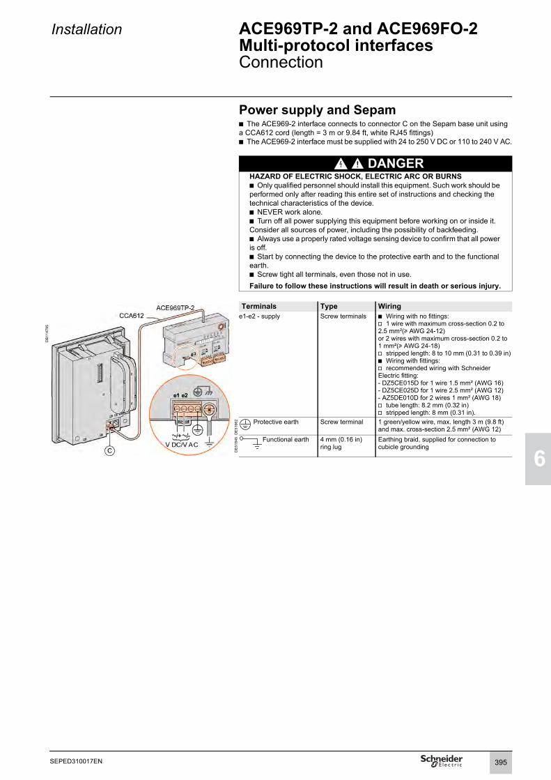
Installation ACE969TP-2 and ACE969FO-2 Multi-protocol interfacesConnection
1
6
Power supply and Sepamb The ACE969-2 interface connects to connector C on the Sepam base unit using a CCA612 cord (length = 3 m or 9.84 ft, white RJ45 fittings)b The ACE969-2 interface must be supplied with 24 to 250 V DC or 110 to 240 V AC.
DANGERHAZARD OF ELECTRIC SHOCK, ELECTRIC ARC OR BURNSb Only qualified personnel should install this equipment. Such work should be performed only after reading this entire set of instructions and checking the technical characteristics of the device.b NEVER work alone. b Turn off all power supplying this equipment before working on or inside it. Consider all sources of power, including the possibility of backfeeding.b Always use a properly rated voltage sensing device to confirm that all power is off.b Start by connecting the device to the protective earth and to the functional earth.b Screw tight all terminals, even those not in use.Failure to follow these instructions will result in death or serious injury.
Terminals Type Wiring
DB
1147
95
e1-e2 - supply Screw terminals b Wiring with no fittings:v 1 wire with maximum cross-section 0.2 to 2.5 mm²(u AWG 24-12)or 2 wires with maximum cross-section 0.2 to 1 mm²(u AWG 24-18)v stripped length: 8 to 10 mm (0.31 to 0.39 in)b Wiring with fittings:v recommended wiring with Schneider Electric fitting:- DZ5CE015D for 1 wire 1.5 mm² (AWG 16)- DZ5CE025D for 1 wire 2.5 mm² (AWG 12)- AZ5DE010D for 2 wires 1 mm² (AWG 18)v tube length: 8.2 mm (0.32 in)v stripped length: 8 mm (0.31 in).
DE
5196
2 Protective earth Screw terminal 1 green/yellow wire, max. length 3 m (9.8 ft)and max. cross-section 2.5 mm² (AWG 12)
DE
5184
5 Functional earth 4 mm (0.16 in) ring lug
Earthing braid, supplied for connection to cubicle grounding
395SEPED310017EN

6
Installation ACE969TP-2 and ACE969FO-2 Multi-protocol interfacesConnection
DB
1152
65
2-wire RS 485 communication ports (S-LAN or E-LAN)b Connection of the RS 485 twisted pair (S-LAN or E-LAN) to terminals A and Bb In case of ACE 969TP wired with ACE969TP-2:v connection of twisted pair for distributed power supply to terminals 5(V+) et 4(V-)b In case of ACE969TP-2 only:v connection only on the terminal 4(V-) ( ground continuity)v no need of external power supplyb The cable shields must be connected to the terminals marked 3(.) on the connection terminal blocks.b Terminal marked 3(.) are linked by an internal connection to the earthing terminals of the ACE969TP interface (protective an functional earthing): Ie the shielding of the RS 485 cables is earthed as well.b On the ACE969TP-2 interface, the cable clamps for the S-LAN and E-LAN RS 485 networks are earthed by the terminal 3.
If ACE969TP and ACE969TP-2 are used together, the external power supply is required.
DB
1152
63
If ACE969TP-2 is used alone, the external power supply is not required. The Reference V- must be connected between the modules.
396 SEPED310017EN
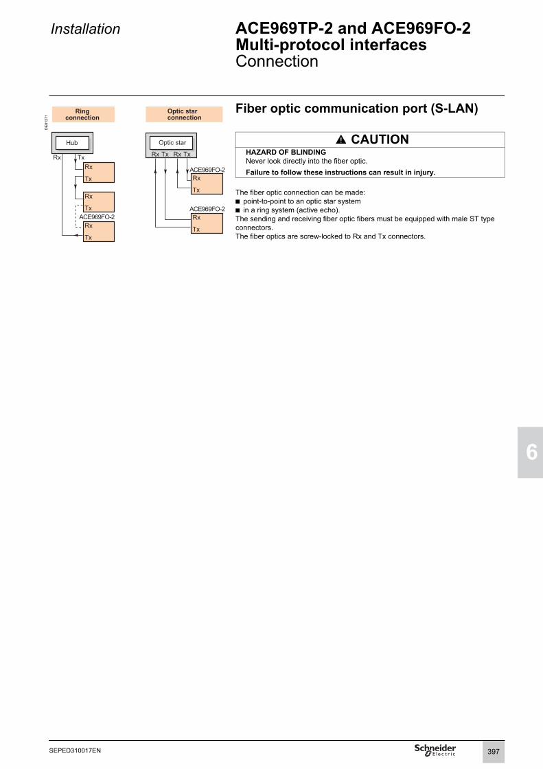
Installation ACE969TP-2 and ACE969FO-2 Multi-protocol interfacesConnection
1
6
DE
8127
1
Fiber optic communication port (S-LAN)
CAUTIONHAZARD OF BLINDINGNever look directly into the fiber optic.Failure to follow these instructions can result in injury.
The fiber optic connection can be made:b point-to-point to an optic star systemb in a ring system (active echo).The sending and receiving fiber optic fibers must be equipped with male ST type connectors.The fiber optics are screw-locked to Rx and Tx connectors.
Optic starconnection
Ringconnection
Optic star
ACE969FO-2
ACE969FO-2ACE969FO-2
397SEPED310017EN
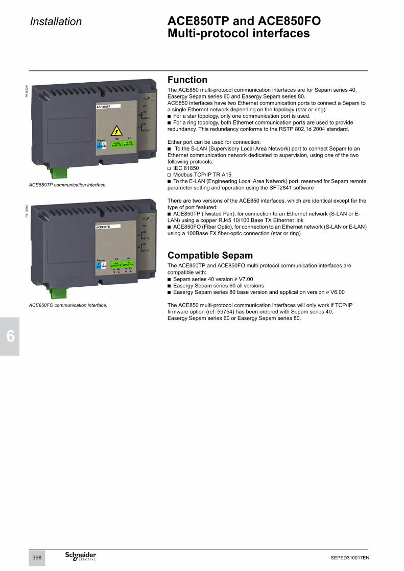
6
Installation ACE850TP and ACE850FO Multi-protocol interfaces
PB
1053
01
FunctionThe ACE850 multi-protocol communication interfaces are for Sepam series 40, Easergy Sepam series 60 and Easergy Sepam series 80.ACE850 interfaces have two Ethernet communication ports to connect a Sepam to a single Ethernet network depending on the topology (star or ring):b For a star topology, only one communication port is used.b For a ring topology, both Ethernet communication ports are used to provide redundancy. This redundancy conforms to the RSTP 802.1d 2004 standard.
Either port can be used for connection: b To the S-LAN (Supervisory Local Area Network) port to connect Sepam to an Ethernet communication network dedicated to supervision, using one of the two following protocols:v IEC 61850v Modbus TCP/IP TR A15b To the E-LAN (Engineering Local Area Network) port, reserved for Sepam remote parameter setting and operation using the SFT2841 software
There are two versions of the ACE850 interfaces, which are identical except for the type of port featured:b ACE850TP (Twisted Pair), for connection to an Ethernet network (S-LAN or E-LAN) using a copper RJ45 10/100 Base TX Ethernet linkb ACE850FO (Fiber Optic), for connection to an Ethernet network (S-LAN or E-LAN) using a 100Base FX fiber-optic connection (star or ring)
Compatible SepamThe ACE850TP and ACE850FO multi-protocol communication interfaces are compatible with:b Sepam series 40 version u V7.00b Easergy Sepam series 60 all versionsb Easergy Sepam series 80 base version and application version u V6.00
The ACE850 multi-protocol communication interfaces will only work if TCP/IP firmware option (ref. 59754) has been ordered with Sepam series 40, Easergy Sepam series 60 or Easergy Sepam series 80.
ACE850TP communication interface.
PB
1053
00
ACE850FO communication interface.
398 SEPED310017EN

Installation ACE850TP and ACE850FO Multi-protocol interfaces
1
6
CharacteristicsACE850TP and ACE850FO moduleTechnical characteristics
Weight 0.4 kg (0.88 lb)Assembly On symmetrical DIN railOperating temperature -25°C to +70°C (-13°F to +158°F)Environmental characteristics Same characteristics as Sepam base unitsPower supply
Voltage 24 to 250 V DC 110 to 240 V ACRange -20%/+10% -20%/+10%Maximum consumption ACE850TP 3.5 W in DC 1.5 VA in AC
ACE850FO 6.5 W in DC 2.5 VA in ACInrush current < 10 A 10 ms in DC < 15 A 10 ms in ACAcceptable ripple content 12%Acceptable momentary outages 100 ms
Wired Ethernet communication ports (ACE850TP)Number of ports 2 x RJ45 portsType of port 10/100 Base TXProtocols HTTP, FTP, SNMP, SNTP, ARP, SFT, IEC 61850, TCP/IP, RSTP 801.1d 2004Baud rate 10 or 100 MbpsMedium Cat 5 STP or FTP or SFTPMaximum distance 100 m (328 ft)
Fiber-optic Ethernet communication ports (ACE850FO)Number of ports 2Type of port 100 Base FXProtocols HTTP, FTP, SNMP, SNTP, ARP, SFT, IEC 61850, TCP/IP, RSTP 801.1d 2004Baud rate 100 MbpsFiber type MultimodeWavelength 1300 nm Type of connector SCFiber optic diameter (µm) Tx minimum optical power
(dBm)Tx maximum optical power (dBm)
RX sensitivity (dBm) RX saturation (dBm) Maximum distance
50/125 -22.5 -14 -33.9 -14 2 km (1.24 mi)62.5/125 -19 -14 -33.9 -14 2 km (1.24 mi)
Dimensions
DE
8044
1D
E80
403
mmin
ACE850FO
FS80
100BASE- FX
CS40
P2 P1100
BASE- FXTx Rx Tx Rx
Sepam
1234
1084.25
127,25
582.28
582.28
171,26.74
mmin
399SEPED310017EN

6
Installation ACE850TP and ACE850FO Multi-protocol interfacesDescription
ACE850TP communication interface
DE
8043
0
1 ACE850 communication interface status LEDb LED off = ACE850 de-energizedb Green LED permanently on = ACE850 energized and operationalb Red LED flashing = ACE850 not configured and/or not connected to the base unitb Red LED permanently on = ACE850 not operational (initialization in progress or failed)
2 STS LED: communication status: green permanently on = OK3 Ethernet Port 2 100 green LED: off = 10 Mbps, permanently on = 100 Mbps4 Ethernet Port 2 activity LED: flashing on transmission/reception5 Ethernet Port 1 100 green LED: off = 10 Mbps, permanently on = 100 Mbps6 Ethernet Port 1 activity LED: flashing on transmission/reception
ACE850TP: Front view.
DE
8043
1
7 Power-supply terminal block8 Grounding/earthing terminal using supplied braid9 RJ45 socket to connect the interface to the Sepam base unit with the CCA614
cord: b Sepam series 40: communication port (identified by a white label on the Sepam unit)b Easergy Sepam series 60 and series 80: communication port (identified by a blue label on the Sepam unit)
10 RJ45 10/100 Base TX Ethernet communication port P2 (E-LAN or S-LAN)11 RJ45 10/100 Base TX Ethernet communication port P1 (E-LAN or S-LAN)ACE850TP: View of underside.
ACE850FO communication interface
DE
8043
2
1 ACE850 communication interface status LEDb LED off = ACE850 de-energizedb Green LED permanently on = ACE850 energized and operationalb Red LED flashing = ACE850 not configured and/or not connected to the base unitb Red LED permanently on = ACE850 not operational (initialization in progress or failed)
2 STS LED: communication status: green permanently on = OK3 Ethernet Port 2 100 green LED: permanently on = 100 Mbps4 Ethernet Port 2 activity LED: flashing on transmission/reception5 Ethernet Port 1 100 green LED: permanently on = 100 Mbps6 Ethernet Port 1 activity LED: flashing on transmission/reception
ACE850FO: Front view.
DE
8043
3
7 Power-supply terminal block8 Grounding/earthing terminal using supplied braid9 RJ45 socket to connect the interface to the Sepam base unit with a CCA614 cord:
b Sepam series 40: communication port (identified by a white label on the Sepam unit)b Easergy Sepam series 60 and series 80: communication port (identified by a blue label on the Sepam unit)
12 Tx fiber of 100 Base FX SC connector for Ethernet communication port P2 (E-LAN or S-LAN)
13 Rx fiber of 100 Base FX SC connector for Ethernet communication port P2 (E-LAN or S-LAN)
14 Tx fiber of 100 Base FX SC connector for Ethernet communication port P1 (E-LAN or S-LAN)
15 Rx fiber of 100 Base FX SC connector for Ethernet communication port P1 (E-LAN or S-LAN)
ACE850FO: View of underside.
CAUTIONHAZARD OF BLINDINGNever look directly into the end of the fiber optic.Failure to follow these instructions can result in injury.
FS80
10/100BASE-TX
CS40
P2 P110/100
BASE-TX
Sepam
ACE850TP 12
54
6
3
7 8 11109
C
F
ACE850FO
FS80
100BASE- FX
CS40
P2 P1100
BASE- FXTx Rx Tx Rx
Sepam
123456
7 8 1421 319 15
C
F
400 SEPED310017EN

Installation ACE850TP and ACE850FO Multi-protocol interfacesConnection
1
6
DE
8044
4
Connection to Sepamb The ACE850 communication interface should only be connected to Sepam series 40, Easergy Sepam series 60 or 80 base units using a CCA614 prefabricated cord (length = 3 m or 9.8 ft, blue RJ45 fittings).b Sepam series 40: Connect the CCA614 cord to connector on the Sepam base unit (white label).b Easergy Sepam series 60 or series 80: Connect the CCA614 cord to connector
on the Sepam base unit (blue label).
Connection of power supplyThe ACE850 interfaces must be supplied with 24 to 250 V DC or 110 to 240 V AC.
DANGERHAZARD OF ELECTRIC SHOCK, ELECTRIC ARC OR BURNSb Only qualified personnel should install this equipment. Such work should be performed only after reading this entire set of instructions and checking the technical characteristics of the device.b NEVER work alone. b Turn off all power supplying this equipment before working on or inside it. Consider all sources of power, including the possibility of backfeeding.b Always use a properly rated voltage sensing device to confirm that all power is off.b Start by connecting the device to the protective ground and to the functional ground.b Screw tight all terminals, even those not in use.Failure to follow these instructions will result in death or serious injury.
Connecting the ACE850 to Sepam series 40.
DE
8044
5
Terminal Assignment Type Wiring34
-/~+/~
Screw terminals b Wiring without fittings:v 1 wire with maximum cross-section 0.5 to 2.5 mm² (u AWG 20-12) or 2 wires with maximum cross-section 0.5 to 1 mm² (u AWG 20-18)v Stripped length: 8 to 10 mm (0.31 to 0.39 in)b Wiring with fittings:v Recommended wiring with Schneider Electric fitting:- DZ5CE015D for 1 wire 1.5 mm² (AWG 16)- DZ5CE025D for 1 wire 2.5 mm² (AWG 12)- AZ5DE010D for 2 wires 1 mm² (AWG 18)v Tube length: 8.2 mm (0.32 in)v Stripped length: 8 mm (0.31 in)
DE
5196
2 1 Protective earth
Screw terminal 1 green/yellow wire, max. length 3 m (9.8 ft) and max. cross-section 2.5 mm² (AWG 12)
DE
5184
5 Functional earth
4 mm (0.16 in) ring lug
Earthing braid (supplied) for connection to cubicle grounding
Connecting the ACE850 to Easergy Sepam series 60 or series 80.
ACE850
C D
CCA614
4 3 2 1
CCA614
CCA614
C
F
4 3 2 1
CCA614
CCA614
ACE850
C1C2
D1D2
F
CCA614
401SEPED310017EN
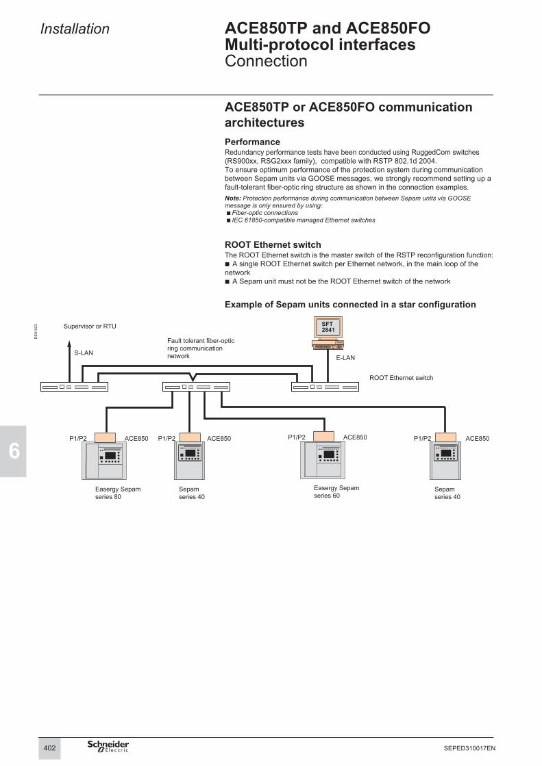
6
Installation ACE850TP and ACE850FO Multi-protocol interfacesConnection
ACE850TP or ACE850FO communication architecturesPerformanceRedundancy performance tests have been conducted using RuggedCom switches (RS900xx, RSG2xxx family), compatible with RSTP 802.1d 2004.To ensure optimum performance of the protection system during communication between Sepam units via GOOSE messages, we strongly recommend setting up a fault-tolerant fiber-optic ring structure as shown in the connection examples.Note: Protection performance during communication between Sepam units via GOOSE message is only ensured by using: b Fiber-optic connections b IEC 61850-compatible managed Ethernet switches
ROOT Ethernet switchThe ROOT Ethernet switch is the master switch of the RSTP reconfiguration function:b A single ROOT Ethernet switch per Ethernet network, in the main loop of the networkb A Sepam unit must not be the ROOT Ethernet switch of the network
Example of Sepam units connected in a star configuration
DE
8102
3
ACE850 ACE850
E-LANS-LAN
P1/P2 P1/P2 ACE850P1/P2ACE850P1/P2
ROOT Ethernet switch
Easergy Sepamseries 80
Sepamseries 40
Easergy Sepamseries 60
Sepamseries 40
Fault tolerant fiber-opticring communicationnetwork
Supervisor or RTU
402 SEPED310017EN

Installation ACE850TP and ACE850FO Multi-protocol interfacesConnection
1
6
Example of Sepam units connected in a ring configuration
DE
8102
4
Recommendations for connecting Sepam units in ring configurationWhen connecting Sepam units in the same ring configuration, the ACE850 interfaces must be of the same type (either ACE850TP or ACE850FO).In the worst-case scenario, each Sepam unit must not be separated by more than 30 communicating devices connected to the network (other Sepam units or Ethernet switches) from the ROOT Ethernet switch.A worst-case analysis must be performed for all the Sepam units in each network topology.Example:b In the best-case scenario, Sepam 2 of ring 1 is separated from the ROOT Ethernet switch by 2 devices: switch 2 and Sepam 1.b In the worst-case scenario, i.e. if the connections between switches 1 and 2 and between Sepam units 1 and 2 of ring 1 are broken, Sepam 2 of ring 1 will be separated from the ROOT Ethernet switch by 4 devices: switch 3, switch 2, Sepam 4 and Sepam 3.
E-LANS-LAN
Ethernet switch 1
(ROOT)
P1 P2 P1 P2 P1 P2ACE850
P1 P2 P1 P2 P1 P2ACE850
Ring 1 Ring 2
TP TP TPP1 P2
TP FO FO FO
Ethernetswitch 2
Ethernetswitch 3
Supervisor or RTUFault tolerant fiber-opticring communicationnetwork
Sepam 1series 40
Sepam 2series 40
Sepam 3series 40
Easergy Sepam 4series 60
Sepam 5series 40
Sepam 6series 40
Easergy Sepam nseries 80
403SEPED310017EN

6
Installation ACE909-2 RS 232/RS 485 converter
Function
PE
8031
7
The ACE909-2 converter is used to connect a master/central computer equipped with a V24/RS 232 type serial port as a standard feature to stations connectedto a 2-wire RS 485 network.Without requiring any flow control signals, after the parameters are set, the ACE909-2 converter performs conversion, network polarization and automatic dispatching of frames between the master and the stations by two-way simplex (half-duplex, single-pair) transmission.The ACE909-2 converter also provides a 12 V DC or 24 V DC supply for thedistributed power supply of the Sepam ACE949-2, ACE959 or ACE969-2 interfaces.The communication settings should be the same as the Sepam and supervisor communication settings.
ACE909-2 RS 232/RS 485 converter.
Characteristics DANGER Mechanical characteristics
HAZARD OF ELECTRIC SHOCK, ELECTRIC ARC OR BURNSb Only qualified personnel should install this equipment. Such work should be performed only after reading this entire set of instructions and checking the technical characteristics of the device.b NEVER work alone. b Turn off all power supplying this equipment before working on or inside it. Consider all sources of power, including the possibility of backfeeding.b Always use a properly rated voltage sensing device to confirm that all power is off.b Start by connecting the device to the protective earth and to the functional earth.b Screw tight all terminals, even those not in use.Failure to follow these instructions will result in death or serious injury.
Weight 0.280 kg (0.617 lb)Assembly On symmetrical or asymmetrical DIN rail
Electrical characteristicsPower supply 110 to 220 V AC ± 10%, 47 to 63 HzGalvanic isolation between ACE power supplyand frame, and between ACE power supplyand interface supply
2000 Vrms, 50 Hz, 1 min
Galvanic isolationbetween RS 232 and RS 485 interfaces
1000 Vrms, 50 Hz, 1 min
Protection by time-delayed fuse 5 mm x 20 mm (0.2 in x 0.79 in)
1 A rating
Communication and Sepam interface distributed supplyData format 11 bits: 1 start, 8 data, 1 parity, 1 stopTransmission delay < 100 nsDistributed power supply for Sepaminterfaces
12 V DC or 24 V CC, 250 mA max.
Maximum number of Sepam interfaces withdistributed supply
12
Environmental characteristics
Operating temperature -5°C to +55°C (+23°F to +131°F)
Electromagnetic compatibility IEC standard
Value
Fast transient bursts, 5 ns 60255-22-4 4 kV with capacitive couplingin common mode2 kV with direct couplingin common mode1 kV with direct couplingin differential mode
1 MHz damped oscillating wave 60255-22-1 1 kV common mode0.5 kV differential mode
1.2/50 µs impulse waves 60255-5 3 kV common mode1 kV differential mode
404 SEPED310017EN

Installation ACE909-2 RS 232/RS 485 converter
1
6
Description and dimensions
DE
8030
6
Terminal block for RS 232 link limited to 10 m (33 ft).
Female 9-pin sub-D connector to connect to the 2-wire RS 485 network, with distributed power supply.1 screw-type male 9-pin sub-D connector is supplied with the converter.Power-supply terminal block
1 Distributed power supply voltage selector switch, 12 V DC or 24 V DC.2 Protection fuse, unlocked by a 1/4 turn.3 LEDs:
b ON/OFF: on if ACE909-2 is energizedb Tx: on if RS 232 sending by ACE909-2 is activeb Rx: on if RS 232 receiving by ACE909-2 is active.
4 SW1, parameter setting of 2-wire RS 485 network polarization andline impedance matching resistors.
Function SW1/1 SW1/2 SW1/3Polarization at 0 V via Rp -470 Ω ON
DE
8002
2
Polarization at 5 V via Rp +470 Ω ON2-wire RS 485 network impedance matching by 150 Ω resistor
ON
5 SW2, parameter setting of asynchronous data transmission rate and format (same parameters as for RS 232 link and 2-wire RS 485 network).
Rate (bauds) SW2/1 SW2/2 SW2/31200 1 1 12400 0 1 14800 1 0 19600 0 0 119200 1 1 038400 0 1 0
Male 9-pin sub-D connector supplied with the ACE909-2. Format SW2/4 SW2/5With parity check 0
DE
8052
9
Without parity check 11 stop bit (compulsory for Sepam) 12 stop bits 0
Converter configuration when deliveredb 12 V DC distributed power supplyb 11-bit format, with parity checkb 2-wire RS 485 network polarization and impedance matching resistors activated.
ConnectionRS 232 linkb To 2.5 mm² (AWG 12) screw type terminal block b Maximum length 10 m (33 ft)b Rx/Tx: RS 232 receiving/sending by ACE909-2b 0V: Rx/Tx common, do not earth.2-wire RS 485 link with distributed power supplyb To connector female 9-pin sub-Db 2-wire RS 485 signals: L+, L-b Distributed power supply: V+ = 12 V DC or 24 V DC, V- = 0 V.Power supplyb To 2.5 mm² (AWG 12) screw type terminal block b Reversible phase and neutralb Earthed via terminal block and metal case (ring lug on back of case).
mmin
4.13 2.56
1.77
3.344.13
A
B
C
2.22
0.63
1.42
1.75
mmin
A
B
C
405SEPED310017EN

6
Installation ACE919CA and ACE919CC RS 485/RS 485 converters
Function
PE
8031
6
The ACE919 converters are used to connect a master/central computer equipped with an RS 485 type serial port as a standard feature to stations connected to a 2-wire RS 485 network.Without requiring any flow control signals, the ACE919 converters perform network polarization and impedance matching.The ACE919 converters also provide a 12 V DC or 24 V DC supply for the distributed power supply of the Sepam ACE949-2, ACE959 or ACE969-2 interfaces.There are 2 types of ACE919 converter:b ACE919CC, DC-poweredb ACE919CA, AC-powered.
ACE919CC RS 485/RS 485 converter.
Characteristics DANGER Mechanical characteristics
HAZARD OF ELECTRIC SHOCK, ELECTRIC ARC OR BURNSb Only qualified personnel should install this equipment. Such work should be performed only after reading this entire set of instructions and checking the technical characteristics of the device.b NEVER work alone. b Turn off all power supplying this equipment before working on or inside it. Consider all sources of power, including the possibility of backfeeding.b Always use a properly rated voltage sensing device to confirm that all power is off.b Start by connecting the device to the protective earth and to the functional earth.b Screw tight all terminals, even those not in use.Failure to follow these instructions will result in death or serious injury.
Weight 0.280 kg (0.617 lb)Assembly On symmetrical or asymmetrical DIN rail
Electrical characteristics ACE919CA ACE919CCPower supply 110 to 220 V AC
±10%, 47 to 63 Hz24 to 48 V DC ±20%
Protection by time-delayed fuse 5 mm x 20 mm (0.2 in x 0.79 in)
1 A rating 1 A rating
Galvanic isolation between ACE power supplyand frame, and between ACE power supplyand interface supply
2000 Vrms, 50 Hz, 1 min
Communication and Sepam interface distributed supplyData format 11 bits: 1 start, 8 data, 1 parity, 1 stopTransmission delay < 100 nsDistributed power supply for Sepaminterfaces
12 V DC or 24 V CC, 250 mA max.
Maximum number of Sepam interfaces withdistributed supply
12
Environmental characteristicsOperating temperature -5°C to +55°C (+23°F to +131°F)
Electromagnetic compatibility IEC standard ValueFast transient bursts, 5 ns 60255-22-4 4 kV with capacitive
couplingin common mode2 kV with direct couplingin common mode1 kV with direct couplingin differential mode
1 MHz damped oscillating wave 60255-22-1 1 kV common mode0.5 kV differential mode
1.2/50 µs impulse waves 60255-5 3 kV common mode1 kV differential mode
406 SEPED310017EN

Installation ACE919CA and ACE919CC RS 485/RS 485 converters
1
6
Description and dimensions
DE8
0307
Terminal block for 2-wire RS 485 link without distributed power supply.Female 9-pin sub-D connector to connect to the 2-wire RS 485 network, with distributed power supply.1 screw-type male 9-pin sub-D connector is supplied with the converter.Power supply terminal block.
1 Distributed power supply voltage selector switch, 12 V DC or 24 V DC.2 Protection fuse, unlocked by a 1/4 turn.3 ON/OFF LED: on if ACE919 is energized.4 SW1, parameter setting of 2-wire RS 485 network polarization and
line impedance matching resistors.Function SW1/1 SW1/2 SW1/3
Polarization at 0 V via Rp -470 Ω ONPolarization at 5 V via Rp +470 Ω ON
DE
8002
2
2-wire RS 485 network impedance matching by 150 Ω resistor
ON
Converter configuration when delivered12 V DC distributed power supply2-wire RS 485 network polarization and impedance matching resistors activated.
Male 9-pin sub-D connector supplied with the ACE919.
Connection
DE5
1670
2-wire RS 485 link without distributed power supplyTo 2.5 mm² (AWG 12) screw type terminal block L+, L-: 2-wire RS 485 signals
Shielding.2-wire RS 485 link with distributed power supply
To connector female 9-pin sub-D2-wire RS 485 signals: L+, L-Distributed power supply: V+ = 12 V DC or 24 V DC, V- = 0 V.
Power supply To 2.5 mm² (AWG 12) screw type terminal block Reversible phase and neutral (ACE919CA)Earthed via terminal block and metal case (ring lug on back of case).
4.13 2.56
1.77
4.133.34
mmin
AB
C
2.22
0.63
1.42
1.75
mmin
A
B
C
407SEPED310017EN
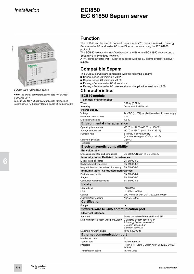
6
Installation ECI850IEC 61850 Sepam server
Function
PE
8031
9
The ECI850 can be used to connect Sepam series 20, Sepam series 40, Easergy Sepam series 60 and series 80 to an Ethernet network using the IEC 61850 protocol.The ECI850 creates the interface between the Ethernet/IEC 61850 network and a Sepam RS 485/Modbus network.A PRI surge arrester (ref. 16339) is supplied with the ECI850 to protect its power supply.
Compatible Sepam The ECI850 servers are compatible with the following Sepam:b Sepam series 20 version u V0526b Sepam series 40 version u V3.00b Easergy Sepam series 60 all versionsb Easergy Sepam series 80 base version and application version u V3.00.
ECI850: IEC 61850 Sepam server. CharacteristicsECI850 moduleTechnical characteristics
Weight 0.17 kg (0.37 lb)Assembly On symmetrical DIN railPower supply
Voltage 24 V DC (± 10%) supplied by a class 2 power supplyMaximum consumption 4 WDielectric withstand 1.5 kV
Environmental characteristicsOperating temperature -25 °C to +70 °C (-13 °F to +158 °F)Storage temperature -40 °C to +85 °C (- 40 °F to +185 °F)Humidity ratio 5 to 95% relative humidity
(non condensing) at +55 °C (131 °F)Degree of pollution Class 2Tightness IP30
Electromagnetic compatibilityEmission tests
Emissions (radiated and conducted) EN 55022/EN 55011/FCC Class AImmunity tests - Radiated disturbances
Electrostatic discharge EN 61000-4-2Radiated radiofrequencies EN 61000-4-3Magnetic fields at the network frequency EN 61000-4-8Immunity tests - Conducted disturbances
Fast transient bursts EN 61000-4-4Surges EN 61000-4-5Conducted radiofrequencies EN 61000-4-6
SafetyInternational IEC 60950USA UL 508/UL 60950Canada cUL (complies with CSA C22.2, no. 60950)Australia/New Zealand AS/NZS 60950
CertificationEurope e
2-wire/4-wire RS 485 communication portElectrical interface
Standard 2-wire or 4-wire differential RS 485 EIAMax. number of Sepam units per ECI850 2 Easergy Sepam series 80 or
2 Easergy Sepam series 60 or3 Sepam series 40 or 5 Sepam series 20
Maximum network length 1000 m (3300 ft)
Ethernet communication portNumber of ports 1Type of port 10/100 Base TxProtocols HTTP, FTP, SNMP, SNTP, ARP, SFT, IEC 61850
TCP/IPTransmission speed 10/100 Mbps
Note: The end of commercialization date for ECI850 is 30 June 2017. You can use the ACE850 communication interface on Sepam series 40, Easergy Sepam series 60 and series 80.
408 SEPED310017EN

Installation ECI850IEC 61850 Sepam server
1
6
Characteristics (cont’d)PRI surge arresterElectrical characteristics
Nominal operating voltage 48 V DCMaximum discharge current 10 kA (8/20 μs wave)Nominal discharge current 5 kA (8/20 μs wave) Protection level 70 VResponse time 1 nsConnection
With cage terminals Cables with cross-section 2.5 to 4 mm2 (AWG 12-10)
Description12
LED: power-up/maintenanceStandard LEDs:
PE
8006
3
b RS 485 LED: network link activev On: RS 485 modev Off: RS 232 modeb Flashing green Tx LED: ECI850 transmission activeb Flashing green Rx LED: ECI850 reception active
3
4
56789
Ethernet LEDs:b LK green LED on: network link activeb Flashing green Tx LED: ECI850 transmission activeb Flashing green Rx LED: ECI850 reception activeb 100 green LED:v On: 100 Mbps network speedv Off: 10 Mbps network speed10/100 Base Tx port for Ethernet connectionby RJ45 connectorConnection of the 24 V DC supplyReset buttonRS 485 connectionRS 485 parameter-setting selector switchesRS 232 connection
Setting the RS 485 network parameters
DE
8026
2
The network polarization and line impedance matching resistors and type of 2-wire/4-wire RS 485 network are selected by means of the RS 485 parameter-setting selector switches. These selector switches are configured by default for a 2-wire RS 485 network with network polarization and line impedance matching resistors.
Network line impedance matching with resistor
SW1 SW2 SW3 SW4 SW5 SW6
2-wire RS 485 OFF ON4-wire RS 485 ON ON
Network polarization SW1 SW2 SW3 SW4 SW5 SW6at the 0 V ONat the 5 V ON
Setting the RS 485 network parameters. Selecting the RS 485 network SW1 SW2 SW3 SW4 SW5 SW62-wire network ON ON4-wire network OFF OFF
Setting the Ethernet link parametersThe TCSEAK0100 configuration kit can be used to connect a PC to the ECI850 to set the Ethernet link parameters.
2 3 4 5 61
2 3 4 5 61
4-wire
2-wire (by default)
Recommended settings
409SEPED310017EN

6
Installation ECI850IEC 61850 Sepam server
Dimensions
DE
8026
3
NOTICE ConnectionRISK OF DESTRUCTION OF THE ECI850 b Connect the PRI surge arrester in accordance with the wiring diagrams below.b Check the quality of the earth connected to the surge arrester.Failure to follow these instructions can result in equipment damage.
b Connect the power supply and RS 485 twisted pair using cable with cross-section y 2.5 mm2 (uAWG 12)b Connect the 24 V DC power supply and the earth to inputs (1), (5) and (3) of the PRI surge arrester (ref. 16339) supplied with the ECI850b Connect outputs (2), (8) and (6), (12) of the PRI surge arrester to the - and + terminals of the black screen terminal blockb Connect the RS 485 twisted pair (2-wire or 4-wire) to the (RX+ RX- or RX+ RX- TX+ TX-) terminals of the black screw terminal blockb Connect the RS 485 twisted pair shielding to the terminal of the black screw terminal blockb Connect the Ethernet cable to the green RJ45 connector
2-wire RS 485 network
DE
8044
7
4-wire RS 485 network
DE
8044
8
3557.9
1.382.28 80.8
3.18
722.83
90.73.57
mmin
65.82.59
45.21.78
2.50.1049.5
1.9568.32.69
Rx+Rx-
ECI850 ACE949-2
L-
V-V+
(4)
(7)(6)
(5)
A
(3)
+24 V
B
ACE949-2
L-
V-
L+ L+
V+A BA
(1) (3)(7)
(2) (8)
(5) (11)
(6) (12)
V+V-
+-
PRIRef : 16339
Rx+Rx-
ECI850 ACE959
Tx+Tx-
V-V+
(4)
(1)Tx+Tx-
Rx+Rx-(2)
(5)
A
V-V+
(3)
B
ACE959
Tx+Tx-
V-V+
Rx+Rx-
A BA(7)(6)
+24 V (1) (3)(7)
(2) (8)
(5) (11)
(6) (12)
+-
PRIRef : 16339
410 SEPED310017EN

Installation ECI850IEC 61850 Sepam server
1
6
Example of architectureThe diagram below shows an example of the communication architecture with ECI850 IEC 61850 Sepam servers.Note: Rc, line impedance matching resistor
DE
8102
8
Maximum Advised ConfigurationThe maximum configuration of Sepam for an ECI850 IEC 61850 Sepam server of level 1 is to be choosen between the following configurations:b 5 Sepam series 20,b 3 Sepam series 40,b 2 Easergy Sepam series 60,b 2 Easergy Sepam series 80.
ECI850 ECI850
ACE949-2Rc ACE949-2Rc ACE949-2Rc
ACE949-2Rc
ECI850
ACE949-2Rc
ACE949-2Rc ACE949-2Rc ACE949-2Rc ACE949-2Rc ACE949-2Rc
ACE949-2Rc
ECI850
ACE949-2Rc
Easergy Sepamseries 80
Easergy Sepamseries 80
Easergy Sepamseries 60
Easergy Sepamseries 60
Sepamseries 40
Sepamseries 40
Sepamseries 40
Sepamseries 20
Sepamseries 20
Sepamseries 20
Sepamseries 20
Sepamseries 20
Supervisoror RTU
RS 485/Modbus
RS 485/Modbus
RS 485/Modbus
RS 485/Modbus
Ethernet TCP/IP/IEC 61850
S-LANand E-LAN
S-LANand E-LAN
S-LANand E-LAN
S-LANand E-LAN
411SEPED310017EN

6
412 SEPED310017EN

Use Contents
7
471
User-machine interfaces 414Presentation 414Selection guide 415
Description of the advanced UMI 416
Description of the mimic-based UMI 417
Local operation on the UMI 418Types of operations and passwords 418Display of operating information 419Operating functions not requiring a password 421Operating functions requiring a password 422Entry of parameter and protection settings 423Local control using the mimic-based UMI 425
SFT2841 setting and operating software 426Welcome window 426Presentation 427General screen organization 428Use of the software 430Creation of user messages 431Disturbance recording 432Implementing the Motor start report and trend functions 433Logic-equation editing 435Default settings 436Configuration of a Sepam network 438
SFT2841 software Mimic-diagram editor 443Presentation 443General screen organization 445Use 447
Principles 453
Methods 454
Testing and metering equipment required 455
General examination and preliminary actions 456
Checking of phase current and voltage input connections 457With 3-phase generator 457With single-phase generator and voltages delivered by 3 VTs 459With single-phase generator and voltages delivered by 2 VTs 460LPCT type current sensors 461
Checking of residual currentand residual voltage input connections 462
Checking of residual current input connection 463
Checking of residual voltage input connection 464With voltage delivered by 3 VTs in open delta arrangement 464With voltage delivered by 1 neutral point VT 465
Checking of Sepam C60 unbalance current input connections 466
Checking of logic input and output connections 467
Checking of GOOSE logic input connections 468
Checking of optional module connections 469
Validation of the complete protection chain 470
Test sheet 471Easergy Sepam series 60
Troubleshooting assistance 473
Replacing the base unitReplacing the battery 477
Maintenance tests 478
Firmware modifications 479Application cartridge firmware 479Base firmware 480Cartridge and base firmware compatibility table 481
413SEPED310017EN

7
Use User-machine interfacesPresentation
Two types of User-Machine Interfaces (UMI) are available for Sepam base units:b mimic-based UMIb advanced UMI.The advanced UMI can be integrated in the base unit or installed remotely on the cubicle. Integrated and remote advanced UMIs offer the same functions.
A Sepam with a remote advanced UMI is made up of:b a bare base unit without any UMI, for mounting inside the LV compartmentb a remote advanced UMI (DSM303)v for flush mounting on the front panel of the cubicle in the location most suitable for the facility managerv for connection to the Sepam base unit using a prefabricated CCA77x cord.The characteristics of the remote advanced UMI module DSM303 are presented on page 380.
PE
8071
1
Comprehensive data for facility managersAll the data required for local equipment operation may be displayed on demand:b display of all measurement and diagnosis data in numerical format with units and/or in bar graphsb display of operating and alarm messages, with alarm acknowledgment and Sepam resettingb display of the list of activated protection functions and the main settings of major protection functionsb adaptation of activated protection function set points or time delays in response to new operating constraintsb display of Sepam and remote module versionsb output testing and logic input status displayb entry of 2 passwords to protect parameter and protection settings.
Sepam base unit with integrated advanced UMI.
PE
8073
3
Local control of devices using the mimic-based UMIThe mimic-based UMI provides the same functions as the advanced UMI as well as local control of devices:b selection of the Sepam control modeb view device status on the animated mimic diagramb local opening and closing of all the devices controlled by Sepam.
Ergonomic data presentationb keypad keys identified by pictograms for intuitive navigation b menu-guided access to datab graphical LCD screen to display any character or symbolb excellent display quality under all lighting conditions : automatic contrast setting and backlit screen (user activated).
Sepam base unit with mimic-based UMI.
PE
5047
4
Working languageAll the texts and messages displayed on the advanced UMI or on the mimic-based UMI are available in 2 languages:b English, the default working languageb and a second language, which may bev Frenchv Spanish v another "local" language.Please contact us regarding local language customization.
Connection of Sepam to the parameter setting toolThe SFT2841 parameter setting tool is required for Sepam protection and parameter setting. A PC containing the SFT2841 software is connected to the RS 232 communication port on the front of the unit.
Customized Chinese advanced UMI.
414 SEPED310017EN

Use User-machine interfacesSelection guide
7
Base unit With remote advanced UMI
With integrated advanced UMI
With mimic-based UMI
PE
8073
4
PE
8073
5
PE
8073
6
FunctionsLocal indication
Metering and diagnosis data b b bAlarms and operating messages b b bList of activated protection functions b b bMain protection settings b b bVersion of Sepam and remote modules b b bStatus of logic inputs b b bSwitchgear status on the animated mimic diagram
b
Phasor diagram of currents or voltages bLocal control
Alarm acknowledgement b b bSepam reset b b bOutput testing b b bSelection of Sepam control mode bDevice open/close order b
CharacteristicsScreen
Size 128 x 64 pixels 128 x 64 pixels 128 x 240 pixelsAutomatic contrast setting b b bBacklit screen b b bKeypad
Number of keys 9 9 14 Control-mode switch Remote / Local / TestLEDs
Sepam operating status b base unit: 2 LEDs visible on backb remote advanced UMI: 2 LEDs visible on front
2 LEDs, visible from front and back 2 LEDs, visible from front and back
Indication LEDs 9 LEDs on remote advanced UMI 9 LEDs on front 9 LEDs on frontMounting
b bare base unit, mounted at the back of the compartment using the AMT880 mounting plateb DSM303 remote advanced UMI module , flush mounted on the front of the cubicle and connected to the base unit with the CCA77x prefabricated cord
Flush mounted on front of cubicle Flush mounted on front of cubicle
415SEPED310017EN

7
Use Description of the advanced UMI
Integrated advanced UMIIdentifi-cation
Picto Description
DE
8009
4
1 Green LED: Sepam on.2 Red LED: Sepam unavailable.3 9 yellow indication LEDs
(L1 to L9 from left to right).4 Label identifying the indication LEDs5 Graphical LCD screen.6 Display of measurements.
7 Display of switchgear, network and machine diagnosis data.
8 Display the alarm history.
9 Two-function key, depending on the screen displayed:b "Confirm" function for the entered values and selection.
10 Two-function key, depending on the screen displayed:b "Clear" function used to:v acknowledge the active alarmv reset the peak demand measurements and diagnosis informationv clear the alarm historyb "Cursor up" function.
11 Two-function key:b key pressed for five seconds: LED and display test
b key pressed briefly: Cursor down
12 Display of Sepam data. NOTICE13 Display and adaptation of the settings of
active protection functions. DAMAGE TO CARTRIDGEDo not install or remove the memory cartridge with the power on.Failure to follow these instructions can result in equipment damage.14 Access to screen for password entry.
15 PC connection port.16 Backup battery.17 Protective battery cover.18 Memory cartridge.19 Door.
DSM303 remote advanced UMI module
DE
8012
8
19
416 SEPED310017EN

Use Description of the mimic-based UMI
7
Identifi-cation
Picto Description
DE
8009
5
1 Graphical LCD screen.2 Green LED: Sepam on.3 Red LED: Sepam unavailable.4 Local closing of devices selected on the
mimic-based UMI.5 Local opening of devices selected on the
mimic-based UMI.6 Allocation label of leds.7 7 yellow leds,
1 red led (I),1 green led (O),(L1 to L9 upwards)
8 Move cursor up.
9 Confirm data entry.
10 Move cursor down.
11 PC connection port.12 Transparent door.13 Access to screen for password entry.
14 Display the mimic-diagram.
15 Reset the latched information.
16 Display the alarm history.
17 Key used to:b acknowledge the active alarmb reset the peak demand measurements and diagnosis informationb clear the alarm history.
18 Two-function key:b key pressed briefly: display of switchgear, network and machine diagnosis data.b key pressed for five seconds: LED and display test. NOTICE
19 Display and adaptation of the settings of active protection functions. DAMAGE TO CARTRIDGE
Do not install or remove the memory cartridge with the power on.Failure to follow these instructions can result in equipment damage.20 Display of measurements and phasor
diagram.21 Display of Sepam data.
22 Three-position key switch to select Sepam control mode: Remote, Local or Test.
23 Backup battery.24 Protective battery cover.25 Memory cartridge.26 Door.
26
417SEPED310017EN
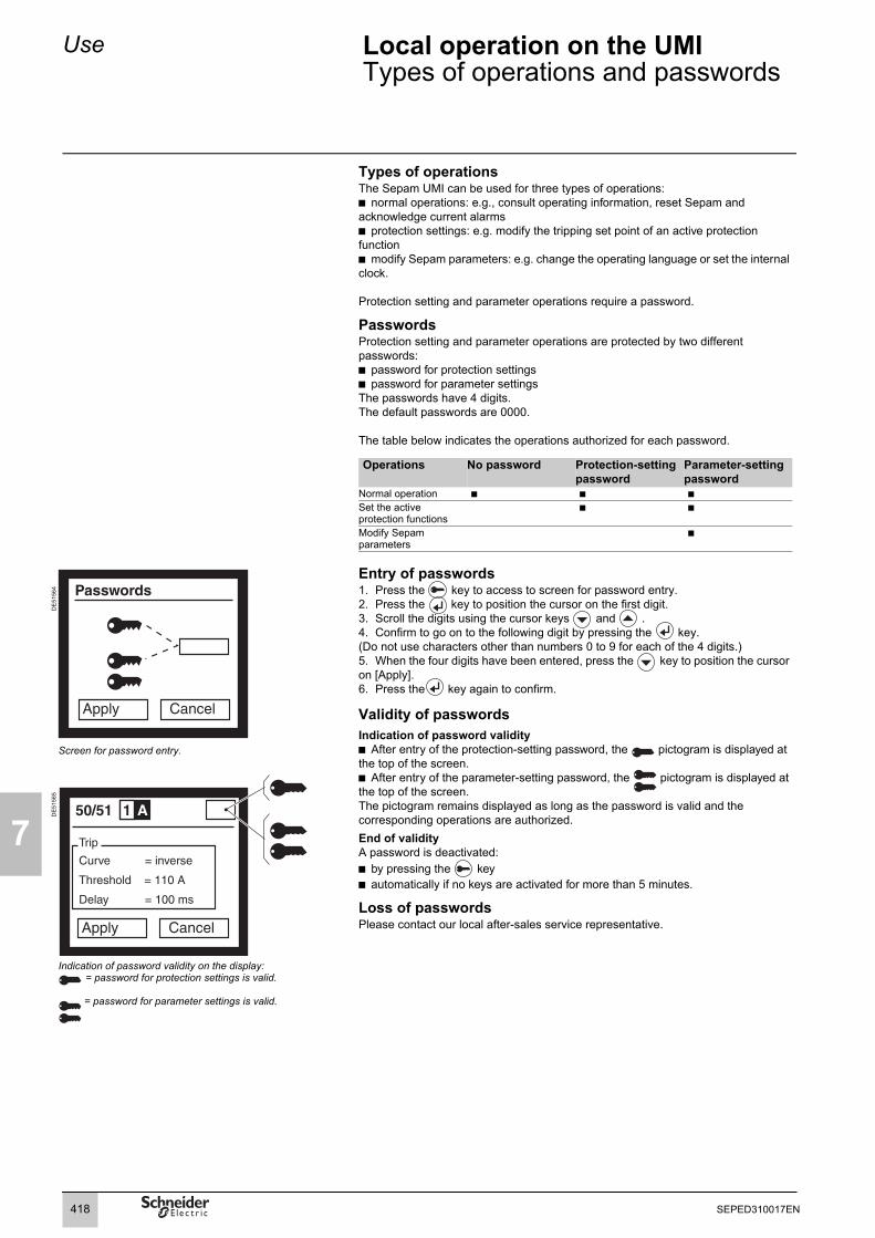
7
Use Local operation on the UMITypes of operations and passwords
Types of operationsThe Sepam UMI can be used for three types of operations:b normal operations: e.g., consult operating information, reset Sepam and acknowledge current alarmsb protection settings: e.g. modify the tripping set point of an active protection functionb modify Sepam parameters: e.g. change the operating language or set the internal clock.
Protection setting and parameter operations require a password.
PasswordsProtection setting and parameter operations are protected by two different passwords:b password for protection settingsb password for parameter settingsThe passwords have 4 digits.The default passwords are 0000.
The table below indicates the operations authorized for each password.
Operations No password Protection-setting password
Parameter-setting password
Normal operation b b bSet the active protection functions
b b
Modify Sepam parameters
b
DE
5156
4
Entry of passwords1. Press the key to access to screen for password entry.2. Press the key to position the cursor on the first digit.3. Scroll the digits using the cursor keys and .4. Confirm to go on to the following digit by pressing the key.(Do not use characters other than numbers 0 to 9 for each of the 4 digits.)5. When the four digits have been entered, press the key to position the cursor on [Apply].6. Press the key again to confirm.
Validity of passwordsIndication of password validityb After entry of the protection-setting password, the pictogram is displayed at the top of the screen.b After entry of the parameter-setting password, the pictogram is displayed at the top of the screen.The pictogram remains displayed as long as the password is valid and the corresponding operations are authorized.End of validityA password is deactivated:b by pressing the keyb automatically if no keys are activated for more than 5 minutes.
Loss of passwordsPlease contact our local after-sales service representative.
Screen for password entry.
DE
5156
5
Indication of password validity on the display: = password for protection settings is valid.
= password for parameter settings is valid.
418 SEPED310017EN

Use Local operation on the UMIDisplay of operating information
7
Categories of operating informationSepam operating information is grouped in four categories:b measurements, accessed via the key
b diagnosis data, accessed via the key
b the alarm history, accessed via the key
b the settings of active protection functions, accessed via the key.
These five categories for the operating information are divided into subcategories to facilitate access to the desired information.
DE
5156
6
Key Category of information Sub-categoryMeasurements b Current
b Voltageb Frequencyb Powerb Energyb Phasor (on mimic-based UMI only)
Switchgear, network and machine diagnosis
b Diagnosticb Tripping context 0 (last recorded tripping context)b Tripping context -1 (next to last recorded tripping context)b Tripping context -2b Tripping context -3b Tripping context -4b Out-of-sync contextSelection screen for measurements.
Alarm history(16 last recorded alarms)
b List of alarms in sets of fourb Detailed information on individual alarms
DE
5156
7
Sepam data b General information:v identification of the base unitv minimum required version of SFT2841 softwarev general parametersv Sepam internal clockb Remote modules:v module identificationb Inputs/outputs:v status and test of logic outputsv status of logic inputs
Settings of active protection functions
Access to each individual protection function, by selecting its ANSI code
Selection screen for active protection functions.
419SEPED310017EN

7
Use Local operation on the UMIDisplay of operating information
Example: measurement loop Access to operating informationb After selecting a category by pressing the corresponding key, a selection screen displays the subcategories.b Select the subcategory with the cursor, using the and keys (the selected subcategory is displayed in inverse video).b When the selection is validated by the key, the system displays the first screenpresenting the operating information of the selected subcategory.b Press again the key of the category displayed to go on to the next screen.b The diagram opposite shows the progression in a given subcategory.b When a screen cannot be completely displayed, use the and keys.
DE
5156
8
420 SEPED310017EN

Use Local operation on the UMIOperating functions not requiring a password
7
Reset the latched informationThe key is used to reset latched information. Sepam resetting must be confirmed.The alarm messages are not erased.
Acknowledge the active alarmWhen Sepam displays an alarm, the key is used to return to the screendisplayed prior to the alarm or to a less recent unacknowledged alarm. The key does not reset the latched information.
Reset the peak demand measurementsThe following measurement and diagnosis information can be reset using the Sepam UMI:b demand currentb peak demand currentb peak demand power.
Proceed as follows to reset the information:1. Display the screen showing the information to be reset.2. Press the key.
Clear the alarm historyThe alarm history (last 16 alarms) stored by Sepam can be cleared as follows:1. Press the key to display the alarm history.
2. Press the key.
Test the LEDs and the displayThe test on the LEDs and the display checks each LED and each pixel in the display.
Proceed as follows to run the test:1. Press the key for five seconds.2. The nine LEDs go on successively in a predefined sequence.3. Then the pixels in the display go on successively in a predefined sequence.
421SEPED310017EN

7
Use Local operation on the UMIOperating functions requiring a password
Reset the diagnosis informationThe diagnosis information for certain protection functions can be reset using the Sepam UMI, after entering the parameter-setting password. The information is listed below: b the number of starts before inhibition, linked with the "Starts per hour" function (ANSI 66)b heat rise calculated by the "Thermal overload" function (ANSI 49RMS).
Proceed as follows to reset the information:1. Enter the password for parameter settings.2. Display the screen showing the information to be reset.3. Press the key.
DE
8104
3
Test the logic outputsIt is possible to change the status of each logic output for five seconds. The check on logic-output connections and switchgear operation is thus simplified.
The screens on the logic outputs may be accessed in the "Sepam information" category, then in the "Inputs/outputs" subcategory.The first screen presents the logic outputs of the base unit and up to three additional screens present the logic outputs of the additional MES120 modules. A "Logic outputs" screen presents the status of all the logic outputs for a module and can be used, following entry of the parameter-setting password, to change the status of each output to check its operation.
Proceed as follows to test a logic output:1. Enter the password for parameter settings.2. Display the screen showing the logic output to be tested.3. Go to the selection field for the output to be tested by pressing the key4.4. Scroll the addresses of the logic outputs in the module using the cursor keys
and to select the desired logic output. 5. Confirm the selected output by pressing the key.6. Press the or key to go on to the [Test] box.7. Press the key to change the status of the logic output for five seconds.
Screen presenting the logic outputs of the base unit and the status of each output, with the possibility of testing each output.
422 SEPED310017EN

Use Local operation on the UMIEntry of parameter and protection settings
7
DE
5157
0
Data entry principlesThe principles behind the entry of parameter and protection settings are identical.
There are four steps in modifying parameter or protection settings using the Sepam UMI:1. Enter the suitable password for either the protection or the parameter settings (see "Entry of passwords", page 418).2. Display the screen with the value to be modified (see "Display of operating information", page 419).3. Modify the values using one of the three entry methods offered, depending on the type of parameter or protection settings:b entry of Boolean valuesb selection of a value among a number of optionsb entry of numerical values4. Final confirmation of all the new parameter or protection settings for use by Sepam.
"General parameters" screen.
DE
5157
1
Entry of Boolean valuesBoolean parameters and protection settings are shown on the Sepam display as two buttons, representing the two status conditions of Boolean data.For example, the language used for the operating texts on the Sepam UMI is a Boolean parameter that can have one of two states: b Englishb a local language (e.g. French).
To modify the value of a Boolean parameter or protection setting, proceed as follows:1. Position the cursor using the and keys.2. Confirm the selection using the key.
Selection of a value among a number of optionsCertain parameters and protection settings must be selected from a finite number of possibilities. For example, the type of tripping curve for the "phase overcurrent" protection function is selected from among 16 predefined curves (DT, SIT, VIT, EIT, etc.).
To select the desired parameter or protection setting, proceed as follows:1. Position the cursor on the value to be modified using the and keys.2. Confirm using the key.3. Scroll the possibilities using the and keys.4. Confirm the new value by pressing the key.
Entry of numerical valuesNumerical parameters and protection settings are shown on the Sepam display as three digits, with or without the decimal point and the unit symbol.
To modify the value of a numerical parameter or protection setting, proceed as follows:1. Position the cursor on the value to be modified using the and keys.2. Confirm by pressing the key to position the cursor on the first digit.3. Scroll the characters using the cursor keys and : the available charactersare the digits from 0 to 9, the decimal point and a space.4. Confirm to go on to the following digit by pressing the key.5. After confirming the third digit, the cursor is positioned on the unit symbol. 6. Scroll the available units using the and keys and confirm the selected unit by pressing the .
Setting screen for the "phase overcurrent" protection function (ANSI 50/51).
1. Boolean setting.2. Selection of a value among a number of options. 3. Numerical value.4. Boxes for final validation (Apply) or to cancel (Cancel) the procedure.5. Pictogram indicating that the user is authorized to modify parameters and protection settings (after entry of the parameter-setting password).
423SEPED310017EN

7
Use Local operation on the UMIEntry of parameter and protection settings
Final confirmation of modificationsAfter modifying one or more parameters or protection settings on a screen, confirmation is required before Sepam takes the modifications into account.
To confirm all the parameter and protection settings modified on a screen, proceed as follows:1. Position the cursor on the [Apply] box at the bottom of the screen using the key.2. Confirm using the key.The new parameter or protection settings are taken into account by Sepam.
424 SEPED310017EN

Use Local operation on the UMILocal control using the mimic-based UMI
7
PE
8033
0
Sepam control modeA key-switch on the mimic-based UMI is used to select the Sepam control mode. Three modes are available: Remote, Local or Test.In Remote mode: b remote control orders are taken into accountb local control orders are disabled, with the exception of the circuit-breaker open order.In Local mode: b remote control orders are disabled, with the exception of the circuit-breaker open orderb local control orders are enabled.Test mode should be selected for tests on equipment, e.g. during preventive-maintenance operations:b all functions enabled in Local mode are available in Test modeb no remote indications (TS) are sent via the communication link.
View device status on the animated mimic diagramFor safe local control of devices, all information required by operators can be displayed simultaneously on the mimic-based UMI:b single-line diagram of the equipment controlled by Sepam, with an animated, graphic indication of device status in real timeb the desired current, voltage and power measurements.The local-control mimic diagram can be customized by adapting one of the supplied, predefined diagrams or by creating a diagram from scratch.
Local control of devicesAll the devices for which opening and closing are controlled by Sepam can be controlled locally using the mimic-based UMI.The most common interlock conditions can be defined by logic equations.
The sure and simple operating procedure is the following:b select the Local or Test control modeb select the device to be controlled by moving the selection window using the keys
or . Sepam checks whether local control of the selected device isauthorized and informs the operator (selection window with a solid line).b selection confirmation for the device to be controlled by pressing the key (the selection window flashes).b device control by pressing:v key : open orderv or key : close order.
Local control using the mimic-based UMI.
425SEPED310017EN

7
Use SFT2841 setting and operating softwareWelcome window
PE
8075
9
DescriptionThe SFT2841 welcome window opens when the program is launched. It lets you choose the language for the SFT2841 screens, and provides access to the Sepam parameter and protection setting files: b In disconnected mode, you can open or create a parameter and protection setting file for a Sepamb When connected to a single Sepam unit, you can access the parameter and protection setting file for the Sepam unit connected to the PCb When connected to a Sepam network, you can access the parameter and protection setting files for a group of Sepam units connected to the PC via a communication network.
Language of SFT2841 screensSFT2841 software can be used in English, French or Spanish. The language is selected at the top of the window.
Using SFT2841 in disconnected modeDisconnected mode allows you to prepare parameters and settings files for Sepam prior to commissioning. The parameter and protection setting files prepared in disconnected mode will be downloaded later to the Sepam units in connected mode.b To create a new parameter and protection setting file, click on the icon for the relevant Sepam family.b To open an existing parameter and protection setting file, click on the icon for the relevant Sepam family.
Welcome window.
DE
8104
4 Using SFT2841 connected to a single Sepam unitConnected to a single Sepam unit mode is used during commissioning: b To upload, download and modify Sepam parameters and settingsb To have all the measurements and supporting data available for commissioning.The PC fitted with the SFT2841 software is connected to the port on the front panel of the Sepam via an RS 232 port using the CCA783 cord or via an USB port using the CCA784 cord.To open the parameter and protection setting file on the Sepam once it is connected to the PC, click on the icon.
SFT2841 connected to a single Sepam unit with the serial port.
DE
8104
5
SFT2841 connected to a single Sepam unit with the USB port.
Using SFT2841 connected to a Sepam networkConnected to a Sepam network mode is used during operation:b To manage the protection systemb To check the status of the power supplyb To diagnose any incident occurring on the power supply.The PC fitted with the SFT2841 software is connected to a group of Sepam units via a communication network (connection via serial link, telephone line or Ethernet). This network forms the E-LAN engineering network.
The connection window allows configuration of the Sepam network, and provides access to the parameter and protection setting files of the Sepam units on the network.
To open the connection window, click on the icon.
See “Configuration of a Sepam network” page 441 for details of how to configure the E-LAN engineering network from the connection window.
DE
8104
6
SFT2841 connected to a Sepam network.
Easergy Sepam series 60
RS 232
Easergy Sepam series 60
CCA784
SFT2841
Tosupervisor
Easergy Sepam series 60
Sepam series 40
Sepam series 20
426 SEPED310017EN

Use SFT2841 setting and operating softwarePresentation
7
The SFT2841 software is used to set up and operate Sepam units. It operates in the Windows environment (XP or Vista).All the data used for the same task are grouped in the same screen to facilitate operation. Menus and icons are used for fast, direct access to the data required.
Normal operationb display of all metering and operation datab display of alarm messages with the time of appearance (date, hour, min, s, ms)b display of diagnosis data such as tripping current, number of switchgear operations and cumulative breaking currentb display of all protection and parameter settingsb display of the logic status of inputs, outputs and LEDs.The SFT2841 software is the solution suited to occasional local operation, for demanding personnel who require fast access to all the information.
PE
8076
0
Example of a measurement display screen.
Parameter and protection settings (1)
b display and setting of all the parameters of each protection function on the same pageb set-up of general settings and Sepam datab set-up of control and monitoring functionsb input data may be prepared ahead of time and transferred into the Sepam in a single operation (loading function).Main functions performed by SFT2841b changing of passwordsb entry of general settings (ratings, integration period, …)b entry of protection settingsb modification of assignments for control and monitoring functionsb enabling/disabling of functionsb entry of mimic-based UMI parametersb saving of files.
Savingb protection and parameter setting data may be savedb printing of reports is possible as well.The SFT2841 software may also be used to retrieve disturbance recording files and display them using the SFT2826 software tool.
Operating assistanceAccess from all screens to a help section containing all the technical information needed to use and commission Sepam.
(1) Modes accessed via 2 passwords (protection setting level, parameter setting level).
PE
8076
1
Example of a directional earth fault protection setting screen.
427SEPED310017EN

7
Use SFT2841 setting and operating softwareGeneral screen organization
A Sepam document is displayed on the screen via a graphic interface that has the conventional Windows features. All the SFT2841 software screens are set up in the same way. They include:1 The title bar, with:
b name of the application (SFT2841)b identification of the Sepam document displayedb corner symbols for window adjustments
2 The menu bar, for access to all the SFT2841 software functions (unavailable functions are dimmed).
3 The toolbar, a group of contextual icons for quick access to the main functions (also accessed via the menu bar).
4 The work zone available to the user, presented in the form of tab boxes.
5 The status bar, with the following information relating to the active document:b alarm onb identification of the connection windowb SFT2841 operating mode, connected or not connectedb type of Sepamb identification of Sepam editedb identification levelb Sepam operating modeb PC date and time.
PE
8071
8
Example of hardware configuration screen.
PE
8076
3
Guided navigationA guided navigation mode is proposed to make it easier to enter all of the Sepam parameter and protection settings. It guides users through all data input screens in the natural order.The sequencing of the screens in guided mode is controlled by clicking on 2 icons in the toolbar 3:b : to go back to the previous screenb : to go to the next screen.
The screens are linked up in the following order:1 Sepam hardware configuration2 General characteristics3 CT/VT sensors4 CT/VT circuit supervision5 Particular characteristics6 Control logic7 Logic input/output assignments8 Assignment of GOOSE logic inputs9 Setting screens for the protection functions
available, according to the type of Sepam10 Logic equation editor11 Various tabs of the control matrix12 Parameter setting of the disturbance recording
function13 Set-up of the mimic-based UMI
Example of general characteristics screen.
On-line helpThe operator may look up on-line help at any time via the "?" command in the menu bar.Acrobat Reader is required for on-line help. It is provided on the CD.
123
4
5
428 SEPED310017EN

Use SFT2841 setting and operating softwareGeneral screen organization
7
Details of the different screens
b identification: entry of the password gives the user access rights to the parameter and protection setting mode (valid for 5 minutes)
b selection of a new application from a list of application files with factory settings. The file suffix identifies the application. e.g.: "appli.G62" is for a Generator 62 application
b opening of an existing application which, in principle, should be located in the "Sepam" sub-directory of the "SFT2841" directory. A type of application may be selected by choosing the type of file (e.g.: file type *.S60, or *. G62 or *.* to obtain the complete list of files)
b saving of an application: go to the "Sepam" sub-directory of the "SFT2841" directory, and name the file. The application suffix is updated automatically
b configuration and complete or partial printing of the current configuration file
b print preview of the configuration file
b hard-copy of the current screen
b Sepam parameter setting:v "Sepam hardware" tab: hardware configuration.v "General characteristics" tab: setting of the network, remote control and monitoring, password management and Sepam label printing parameterv "CT/VT sensors" tab: configuration of current and voltage sensorsv "CT/VT supervision" tab: implementation and configuration of CT and VT sensor supervisionv "Particular characteristics" tab: parameter setting of transformer, motor/generator rotation speedv "Control logic" tab: parameter setting of the switchgear control, logic discrimination, genset shutdown, de-excitation, load shedding and restart functionsv "Logic I/Os" tab: management of logic input and output assignment
b protection functions:v "Application" tab: overview of the protection functions available in the application with graphical view of the single-line diagram. A double click on a protection function label gives quick access to the setting tabv 1 tab per protection function: setting of the parameters of each protection function, with a mini-matrix for setting of the outputs, LEDs and disturbance recording
b creation of logic equations: see description in "Control and monitoring functions" chapter
PE
8076
4
Example of tripping contexts screen.
b control matrix: used to assign logic outputs, LEDs and messages to information produced by the protection units, logic inputs and logic equations.This function may also be used to create messages. See "Creation of user messages".
b special functions: v "Rec" tab: parameter setting of the disturbance-recording functionv -based UMI" tab: parameter setting of the mimic-based UMI
b (1) Sepam diagnosis:v "Diagnosis" tab: general characteristics, software version, fault indicator and Sepam time-settingv "Input, output and LED status" tab: gives status and proposes an output testv "Remote indication status" tab: remote indication status
b (1) main measurements:v "UIF" tab: voltage, current and frequency valuesv "Other" tab: power, energy and rotation speed valuesv "Temperatures" tab
b (1) diagnosis:v "Network" tab: unbalance / negative sequence, V-I phase displacement, number of phase and earth trips and total harmonic distortion valuesv "Machine" tab: running hours counter, impedance and thermal overload valuesv "Tripping context" tab: gives the last 5 tripping contexts
b (1) switchgear diagnosis: cumulative breaking current, auxiliary voltage and circuit breaker data
b (1) management of alarms with history and time-tagging
b (1) disturbance recording: this function is used to record analog signals and logical states. See "Disturbance recording".
b guided navigation: see previous page
b on-line help: see previous page
(1) These icons are only accessible in "connected to Sepam" mode.
429SEPED310017EN

7
Use SFT2841 setting and operating softwareUse of the software
Disconnected mode Connected modeSepam parameter and protection settingSepam parameter and protection setting using SFT2841 consists of preparing the Sepam file containing all the characteristics that are specific to the application, a file that is then loaded into Sepam at the time of commissioning.
PrecautionWhen a laptop is used, given the risks inherent to the accumulation of static electricity, the customary precaution consists of discharging in contact with an earthed metal frame before physically connecting the CCA783 cord.Note : If you are unable to connect to Sepam, check that the SFT2841 software version used is actually compatible with your Sepam. See “Compatibility of Sepam version/SFT2841 version” on page 473.
Plugging into Sepamb plugging of the 9-pin connector (SUB-D type) into one of the PC communication ports.Configuration of the PC communication port via the "Communication port" function in the "Options" menu. Connection to a USB port on the PC is possible using the CCA784 cable.b plugging of the 6-pin connector into the connector (round MiniDin type) situated behind the blanking plate on the front panel of Sepam or the DSM303 module.Connection to Sepam2 possibilities for setting up the connection between SFT2841 and Sepam:b "Connection" function in the "File" menub choice of "connect to the Sepam" at the start-up of SFT2841.Once the connection with Sepam has been established, "Connected" appears in the status bar, and the Sepam connection window may be accessed in the work zone.User identificationThe window intended for the entry of the 4-digit password is activated:b via the "General characteristics" tab, "Passwords" button…b via the "Identification" function in the "Sepam" menu.The "Return to Operating mode" function in the "Passwords" tab withdraws access rights to the parameter and protection setting mode.Loading of parameters and protection settingsParameter and protection setting files may only be loaded in the connected Sepam in Parameter setting mode.Once the connection has been established, the procedure for loading a parameter and protection setting file is as follows:1. Activate the "Load Sepam" function in the "Sepam" menu2. Select the file (*.S60, *.S62, *.T60, *.T62, *.M61, *.G60, *.G62, *.C60, according to the type of application) which contains the data to be loaded.Return to factory settingsThis operation is only possible in Parameter setting mode, via the "Sepam" menu. All of the Sepam general settings, protection settings and the control matrix go back to the default values.The return to factory settings does not erase the logic equations. The logic equation editor must be used to delete them.Unloading of parameter and protection settingsThe connected Sepam parameter and protection setting file may only be unloaded in Operating mode.Once the connection has been established, the procedure for unloading a parameter and protection setting file is as follows:1. Activate the "Unload Sepam" function in the "Sepam" menu2. Select the *.rpg file that is to contain the unloaded data3. Acknowledge the end of operation report.Local operation of SepamConnected to Sepam, SFT2841 offers all the local operating functions available in the advanced UMI screen, plus the following functions:b setting of Sepam’s internal clock, via the "Sepam diagnosis" tabb implementation of the disturbance recording function: enabling/disabling of the function, retrieval of Sepam files, start-up of Wavewin-SEb consultation of the history of the last 250 Sepam alarms, with time-taggingb access to Sepam diagnostic data, in the "Sepam" tab box, included in "Sepam diagnosis"b in Parameter setting mode, switchgear diagnosis values may be modified: operation counter and cumulative breaking current to reset the values after a breaking device is changed.
NOTICERISK OF UNINTENDED OPERATIONb The device must only be configured and set by qualified personnel, using the results of the installation protection system study.b During commissioning of the installation and following any modification, check that the Sepam configuration and protection function settings are consistent with the results of this study.Failure to follow these instructions can result in equipment damage.
Operating procedure:1. Create a Sepam file for the type of Sepam to be set up (the newly created file contains the factory settings of the Sepam parameters and protection functions).2. Modify the Sepam general settings and protection function settings:b all the data relating to the same function are grouped together in the same screenb it is advisable to enter all the parameters and protection settings in the natural order of the screens proposed by the guided navigation mode.Entry of parameter and protection settingsb the parameter and protection setting input fields are suited to the type of value:v choice buttonsv numerical value input fieldsv dialogue box (Combo box)b the user must "Apply" or "Cancel" the new values entered before going on to the following screen b the consistency of the new values applied is checked:v an explicit message identifies inconsistent values and specifies the allowable valuesv values that have become inconsistent following a parameter modification are adjusted to the closest consistent value.
430 SEPED310017EN

Use SFT2841 setting and operating softwareCreation of user messages
7
This operation is carried out using the control matrix ( icon or "Application / Set control matrix" menu).When the matrix is displayed, select the "Events" tab, double-click on the empty box of the message to be created, or on an existing message to modify it. A new screen may be used to:b create a new user message:click on the "Create messages" buttonb modify the message you have created or an existing user message:1. Select the message number in the "No." column.2. Click on the "Modify" button.3. An editing or bitmap window may be used to create text or drawings.b assign the message to the line in the control matrix:1. Select "message" if it has not already been selected.2. Select the new predefined or user message in the corresponding "No." column.3. Click on "Assign".4. Confirm your choice by clicking on the "OK" button.
PE
8076
5
Example of message creation screen.
431SEPED310017EN

7
Use SFT2841 setting and operating softwareDisturbance recording
Disturbance recording is configured from the icon.1. Check the "On" option.2. Set:b the recording numberb the duration of each recordingb the number of samples stored per periodb the number of Pretrig periods (number of periods stored before the event triggering disturbance recording).3. Then draw up the list of logic I/O that need to appear in the disturbance recording.If one of the parameters is modified: recording number, recording duration, number of Pretrig periods, all the recordings already made will be deleted (warning message displayed).A change in the list of logic I/O does not affect existing recordings.4. Click on the "Apply" button.
The Disturbance recording function is operated from the icon, then via the Disturbance recording tab.Each recording is identified in the list by its date.
Manual disturbance recording: click on the "New recording" button: this causes a new time-tagged item to appear in the list.
Viewing a recordingSelect one or more disturbance recordings then click on
.
The "Start Record Viewer" button is used to launch the viewing software (compatible with the COMTRADE format) in order to read the selected files.
DE
8123
0
Example of disturbance recording configuration screen.
DE
8123
1
Example of disturbance recording display screen.
432 SEPED310017EN

Use SFT2841 setting and operating softwareImplementing the Motor start report and trend functions
7
The Motor start report (MSR) function is configured from the icon .1. Check the "On" option.2. Set:b the trip confirmation (optional)v circuit breakerv protection 48/51b the duration of a recording, either using a duration expressed in seconds, or using the sampling frequency3. Then draw up the list of variables that need to appear in the Motor start report (up to 5 variables in the case of a normal cartridge and up to 10 variables in the case of an extended cartridge).The outlined parameters in the figure opposite are deemed to be critical. If one of these pa-rameters is modified, all the recordings already made will be deleted (warning message displayed).The critical parameters are as follows:b recording duration in secondsb sampling frequencyb selected point list4. Click on the "Apply" button.
DE
8123
2
Example of a Motor start report configuration screen.
The Motor start report (MSR) and Motor start trend (MST) functions are operated from the icon then via the "MSR and MST" tab.An MST is created when the 1st MSR in a 30-day peri-od ends.Downloading / Viewing filesEach recording is identified in the list by its creation date. The MSR and MST files are sorted from the most recent to the oldest.Select one or more MSR and/or MST files then click on
.
For each Data log file, a binary file in COMTRADE for-mat is downloaded.
The "Start Record Viewer" button is used to launch the viewing software (compatible with the COMTRADE for-mat) in order to read the selected files.
DE
8123
3
Example of a Motor start report and trend (MSR and MST) runtime screen.
Characteristics of MSR and MST functions depending on the type of cartridge usedMaximum number of selectable variables Maximum number of MSR files Maximum number of MST files
Standard cartridge 5 5 12Extended cartridge 10 20 18
433SEPED310017EN

7
Use SFT2841 setting and operating softwareMise en œuvre de la fonction Enregistrement de données (DLG)
The Data log (DLG) function is configured from the icon .1. Select the tripping source from the following values:b Logic equationb SFT2841 (by default)b Remote control orderb Logic or GOOSE input2. Select the type of recording:b Circularb Limited3. Select:b the total number of filesb the duration common to each fileb the sampling frequency.The outlined parameters in the figure opposite are deemed to be critical. If one of the parameters is modi-fied, all the recordings already made will be deleted (warning message displayed).The critical parameters are as follows:b type of recordingb total number of filesb file durationb sampling frequencyb selected point list
DE
8123
4
Example of Data log configuration screen.
The Data log (DLG) function is operated from the icon then via the "Data log" tab.This screen is dual-purpose. It can be used to:b download/view one or more available Data log filesb trigger recording of Data log files.Downloading / Viewing filesEach recording is identified in the list by its creation date. The DLG files are sorted from the most recent to the oldest.Select one or more DLG files then click on .For each Data log, a binary file in COMTRADE format is downloaded.The "Start Record Viewer" button is used to launch the viewing software (compatible with the COMTRADE for-mat) in order to read the selected files.Triggering a Data logProvided that the SFT2841 software has been config-ured as a tripping source in the configuration screen, it is possible to start and stop a Data log by clicking on the "Start" and "Stop" buttons in the Data log runtime screen.
In the case of a Data log in "Limited" mode, the "Stop" button can be used to stop a recording prematurely.
DE
8123
5
Example of Data log runtime screen.
434 SEPED310017EN

Use SFT2841 setting and operating softwareLogic-equation editing
7
PE
8076
8
PresentationLogic-equation editing consists of:b entry and checks on logic equationsb setting the delays used in the logic equationsb loading the logic equations in Sepam.
The logic-equation editor of the SFT2841 software is accessed via the icon.
The logic-equation editor includes:1 a zone to enter and display the logic equations2 an editing assistance tool3 a tool for setting time delays.
Logic-equation editor screen.
Entry of logic equationsThe syntax required for logic equations is presented in the "Control and monitoring functions" chapter. Logic equations are entered in text:b directly in the equation entry zoneb or using the editing assistance tool. The editing assistance tool offers guided access to variables, operators and functions. Via the tab sheets and tree structures, the user can select program elements and then click the "Add" button. The selected element is placed in the entry zone.
Check on the logic equationsThe syntax of logic equations can be checked by clicking:b the "Equation check" button during entry of logic equationsb the "Apply" button during final confirmation of the logic equations entered.An error message is displayed if the check detects an error. The message indicates the type of error and the line containing the error.
Setting time delaysTime delays can be entered directly in a logic equation. Example: V1= TON(VL1, 100), "On" time delay, set to delay the shift to 1 of variable VL1 by 100 ms.
To improve equation legibility and facilitate time delay settings, it is preferable to use the time delay editor to:b create a time delay, indicating its duration and name (used in writing the logic equation)b delete a time delayb adjust a time delay by modifying its duration without having to make changes in the equation entry zoneb display the list of delays used in the logic equations, with their names and durations.Example:Create SwitchOnDelay with a duration of 100 ms.In the entry zone, use the time delay: V1=TON(VL1, SwitchOnDelay).
Load the logic equations in SepamLogic equations are transferred to Sepam in connected mode:b directly by clicking the "Apply" buttonb when a configuration file containing logic equations entered in disconnected mode is loaded.In both cases, loading results in a short interruption in Sepam operation and automatic restart at the end of loading.
PE
5042
7
Editing assistance tool.
PE
5042
8
Time delay editor.
435SEPED310017EN

7
Use SFT2841 setting and operating softwareDefault settings
The default settings (or factory settings) are present in Sepam the first time it is used. It is possible to go back to the Sepam default settings at any time by using the "Factory settings" function in the SFT2841 software. These settings are also used to initialize the SFT2841 software setting files.Parameter Default valueHardware configuration
Model Integrated UMIIdentification Sepam xxxCOM1, Ethernet OffMET148-2 No. 1, 2 OffMSA141 OffMES120 No. 1, 2 OffMCS025 OffGeneral characteristics
Frequency 50 HzIncomer/feeder S60, S62, M61, C60 applications: feeder
G60, G62, T60, T62 applications: incomerPhase rotation direction 1_2_3Group of settings Group ARemote protection setting enabled OffRemote control with select before operate (SBO)
Off
Integration period 5 minActive-energy increment 0.1 kWhReactive-energy increment 0.1 kVAR.hTemperature °CSepam working language EnglishTime synchronization mode NoneProtection setting password 0000Parameter setting password 0000Cumulative breaking current alarm threshold
65535 kA²
CT-VT sensorsSingle-line type 1I - CT rating 5 AI - Number of CTs I1, I2, I3I – Rated current (In) 630 AI - Base current (Ib) 630 AI0 – Residual current NoneV – Number of VTs V1, V2, V3V - Rated primary voltage (Unp) 20 kVV - Rated secondary voltage (Uns) 100 VV0 - Residual voltage 3V sumVnt - Neutral point voltage NoneParticular characteristics
Rated voltage Un1 20 kVRated voltage Un2 20 kVRated power 30 MVAVector shift 0Rated speed 3000 rpmZero speed threshold 5 %Number of capacitor steps 1
436 SEPED310017EN

Use SFT2841 setting and operating softwareDefault settings
7
Parameter Default valueControl logic
Switchgear control On, circuit breakerLogic discrimination OffGenset shutdown OffDe-excitation OffLoad shedding OffRestart OffAutomatic transfer OffLogic I/O assignment
O1, O3 On, NO, permanentO2, O5 On, NC, permanentProtection
Activity All protection functions are "off"Latching 21B, 27D, 32P, 32Q, 38/49T, 40, 46, 48/51LR, 49RMS,
50BF, 50/51, 50N/51N, 50V/51V, 64REF, 67, 67NParticipation in switchgear control 21B, 32P, 32Q, 37, 38/49T, 40, 46, 48/51LR, 49RMS,
50/51, 50N/51N, 50V/51V, 64REF, 67, 67NGenset shutdown 12, 40, 50/51 (units 6, 7), 50N/51N (units 6, 7), 59N,
64REF, 67, 67NDe-excitation 12, 40, 50/51 (units 6, 7), 50N/51N (units 6, 7), 59N,
64REF, 67, 67NSetting Approximate values consistent with general
characteristics by defaultMatrix
LED According to front panel markingDisturbance recording Pick-up
All protection functions except for 14, 27R, 38/49T, 48/51LR, 49RMS, 50BF, 51C, 66
Logic outputs O1: trippingO2: inhibit closingO3: closingO5: watchdog
Disturbance recordingActivity OnNumber of recordings 6Duration of a recording 3Number of samples per period 12Number of Pretrig periods 36
437SEPED310017EN

7
Use SFT2841 setting and operating softwareConfiguration of a Sepam network
Connection windowThe SFT2841 software connection window is used:b To select an existing Sepam network or configure a new oneb To set up the connection to the selected Sepam networkb To select one Sepam unit from the network and access its parameters, settings, and operation and maintenance information.
Configuration of a Sepam networkSeveral configurations can be defined for the various Sepam installations.A Sepam network configuration is identified by a name. It is saved on the SFT2841 PC in a file in the SFT2841 installation directory (default: C:\Program Files\Schneider\SFT2841\Net).
Configuration of a Sepam network is in 2 parts:b Configuration of the communication networkb Configuration of the Sepam units.
Configuration of the communication networkTo configure the communication network, first define:b The type of link between the PC and the Sepam networkb The communication parameters, according to the type of link selected:v direct serial linkv link via Ethernet TCP/IPv link via telephone modem.
PE
8042
1
Configuration windows for the communication network, according to the type of link: serial link, modem link (STN) or Ethernet link (TCP).
438 SEPED310017EN

Use SFT2841 setting and operating softwareConfiguration of a Sepam network
7
PE
8042
2
Direct serial linkThe Sepam units are connected to an RS 485 (or fiber-optic) multidrop network. Depending on the serial link interfaces available on the PC, the PC itself will be connected either directly to the RS 485 network (or fiber-optic HUB), or via an RS 232/RS 485 converter (or fiber-optic converter).
The communication parameters to be defined are:b port: communication port used on the PCb speed: 4800, 9600, 19200 or 38400 baudsb parity: None, Even or Oddb handshake: None, RTS or RTS-CTSb time-out: from 100 to 3000 msb number of retries: from 1 to 6.
Configuration window for the serial link communication network.
PE
8042
3
Link via Ethernet TCP/IPThe ACE850 communication interface can be used to connect a Sepam series 40, Easergy Sepam series 60 or series 80 unit directly to an Ethernet network.All the Sepam units can also be connected to an RS 485 multidrop network over one or more Ethernet Modbus TCP/IP gateways (for example: EGX gateways or ECI850 servers that act as Modbus TCP/IP gateways for the link with the SFT2841 software).Use on an IEC 61850 networkSFT2841 can be used on an IEC 61850 network. In this case, it can be used to define the IEC 61850 configuration of Sepams connected to this network. See the Sepam IEC 61850 Communication user's manual (reference SEPED306024EN) for more information.Configuration of the Modbus TCP/IP gatewaySee the setup manual for the gateway used.In general, the gateway should be assigned an IP address.The configuration parameters for the gateway’s RS 485 interface must be defined in accordance with the Sepam communication interface configuration:b speed: 4800, 9600, 19200 or 38400 baudsb character format: 8 data bits + 1 stop bit + parity (none, even, odd).Configuration of communication on SFT2841When configuring a Sepam network on SFT2841, the following communication parameters must be defined:b type of device: Modbus gateway, ECI850 or Sepamb IP address: IP address for the connected remote equipmentb time-out: from 100 to 3000 ms.A time-out of between 800 ms and 1000 ms is sufficient in most installations. Communication via the TCP/IP gateway may, however, be slowed down if other applications want Modbus TCP/IP or IEC 61850 access at the same time.The time-out value should then be increased (2 to 3 seconds).b number of retries: from 1 to 6.Note 1: SFT2841 uses the Modbus TCP/IP communication protocol. Although communication is IP-based, use of SFT2841 is restricted to a local installation network based on an Ethernet network (LAN – Local Area Network). The operation of SFT2841 over a WAN (Wide Area Network) cannot be guaranteed because of the presence of some routers or firewalls that may reject the Modbus protocol, causing communication times that would be incompatible with Sepam.Note 2: SFT2841 allows Sepam protection settings to be modified, and direct activation of the outputs. These operations, which could involve the operation of electrical switchgear (opening and closing), and thus risk the safety of people and installations, are protected by the Sepam password. In addition to this protection, the E-LANs and S-LANs must be designed as private networks, protected from external actions by all suitable methods.
Configuration window for the Ethernet TCP/IP communication network.
439SEPED310017EN

7
Use SFT2841 setting and operating softwareConfiguration of a Sepam network
PE
8042
4
Link via telephone modemThe Sepam units are connected to an RS 485 multidrop network using an industrial STN modem.This modem is the called modem. It must first be configured, either via AT commands from a PC using HyperTerminal or the configuration tool that may have been supplied with the modem, or by setting switches (see the modem manufacturer’s manual).
The PC may use an internal or an external modem. This modem on the PC side is always the calling modem. It must be installed and configured in accordance with the Windows modem installation procedure.
Configuration window for the communication network via telephone modem.
Configuration of the calling modem in SFT2841When configuring a Sepam network, SFT2841 displays the list of all the modems installed on the PC.The communication parameters to be defined are:b modem: select one of the modems listed by SFT2841b telephone no.: no. of the remote modem to be calledb speed: 4800, 9600, 19200 or 38400 baudsb parity: none (not adjustable)b handshake: none, RTS or RTS-CTSb time-out: from 100 to 3000 ms.Communication via modem and telephone network is slowed considerably because of the transit time through the modems. A time-out of between 800 ms and 1000 ms is sufficient in most 38400 baud installations. In some cases, the poor quality of the telephone network may require a slower speed (9600 or 4800 bauds). The time-out value should then be increased (2 to 3 seconds).b number of retries: from 1 to 6.Note: the speed and parity of the calling modem must be configured under Windows with the same values as for SFT2841.
440 SEPED310017EN

Use SFT2841 setting and operating softwareConfiguration of a Sepam network
7
PE
8042
4
Configuration of called modemThe modem on the Sepam side is the called modem. It must first be configured, either via AT commands from a PC using HyperTerminal or the configuration tool that may have been supplied with the modem, or by setting switches (see the modem manufacturer’s manual).Modem RS 485 interfaceIn general, the configuration parameters for the modem’s RS 485 interface must be defined in accordance with the Sepam communication interface configuration:b speed: 4800, 9600, 19200 or 38400 baudsb character format: 8 data bits + 1 stop bit + parity (none, even, odd).Telephone network interfaceModern modems offer sophisticated features such as checking the quality of the telephone line, error correction and data compression. These options are not appropriate for communication between SFT2841 and Sepam, which is based on the Modbus RTU protocol. Their effect on communication performance may be the opposite of the expected result.
It is therefore highly advisable to:b Invalidate the error correction, data compression and telephone line quality monitoring optionsb Use the same end-to-end communication speed between:v the Sepam network and the called modemv the called modem (Sepam side) and the calling modem (PC side)v the PC and the calling modem (see recommended configurations table).
Configuration window for the communication network via telephone modem.
Sepam network Telephone network PC modem interface38400 bauds V34 modulation, 33600 bauds 38400 bauds19200 bauds V34 modulation, 19200 bauds 19200 bauds9600 bauds V32 modulation, 9600 bauds 9600 bauds
Industrial configuration profileThe following table shows the main characteristics of the modem on the Sepam side. These characteristics match a configuration profile commonly known as an "industrial profile", as opposed to the configuration of modems used in offices.
Depending on the type of modem used, the configuration will either be via AT commands from a PC using HyperTerminal or the configuration tool that may have been supplied with the modem, or by setting switches (see the modem manufacturer’s manual).
Characteristics of the "industrial profile" configuration AT commandTransmission in buffered mode, without error correction \N0 (force &Q6)Data compression deactivated %C0Line quality monitoring deactivated %E0DTR signal assumed to be permanently off (allows the modem connection to be established automatically on an incoming call)
&D0
CD signal off when carrier is present &C1All reports made to Sepam blocked Q1Character echo suppression E0No flow control &K0
441SEPED310017EN

7
Use SFT2841 setting and operating softwareConfiguration of a Sepam network
PE
8042
5
Identification of Sepam units connected to the communication networkThe Sepam units connected to the communication network are identified by either:b Their Modbus addressb Their IP addressb The IP address for their gateway and their Modbus addressThese addresses can be configured in either of the following ways:b Manually, one by one:v the "Add" button is used to define a new devicev the "Edit" button is used to modify the Modbus address if necessaryv the "Delete" button removes a device from the configurationb Or automatically for Modbus addresses, by running an automatic search of the Sepam units connected:v the "Automatic search"/"Stop search" button starts or interrupts the searchv when SFT2841 recognizes a Sepam unit, its Modbus address and type are shown on screenv when a Modbus device other than Sepam responds to SFT2841, its Modbus address is displayed. The text "???" indicates that the device is not a Sepam.
The Sepam network configuration is saved in a file when the UMI window closes, by pressing the "OK" button.
Sepam network connected to SFT2841.
PE
8076
9
Access to Sepam informationTo establish communication between SFT2841 and a Sepam network, select the Sepam network configuration you want, select the device connected to the TCP/IP network and press "Connect".The Sepam network is displayed in the connection window. SFT2841 polls all the equipment defined in the selected configuration. Each Sepam queried is represented by an icon:
b Sepam series 20 or Sepam series 40 actually connected to the network
b Easergy Sepam series 60 or series 80 actually connected to the network
b Sepam configured but not connected to the network
b Device other than Sepam connected to the network.
A summary report of each Sepam detected as present is also displayed:b Sepam Modbus addressb Type of application and Sepam identificationb Any alarms presentb Any minor/major faults present.
To access parameters, settings and operation and maintenance information for a particular Sepam, click on the icon for that Sepam. SFT2841 then establishes a point-to-point connection with the selected Sepam.
Access to parameters and settings for a Easergy Sepam series 60 connected to a communication network.
442 SEPED310017EN

Use SFT2841 software Mimic-diagram editorPresentation
7
DescriptionSFT2841 Sepam setting and operating software includes a mimic-diagram editor that can be used to personalize the mimic diagram for local control on the mimic-based UMI of Easergy Sepam series 60 or Easergy Sepam series 80 units.A mimic-diagram or single-line diagram is a simplified diagram of an electrical installation. It is made up of a fixed background on which symbols and measurements are placed.
The mimic-diagram editor can be used to:b create a fixed, bitmap background (128 x 240 pixels) using standard drawing softwareb create animated symbols or use predefined animated symbols to represent the electrotechnical devices or other objectsb assign the logic inputs or internal status conditions that modify the animated symbols. For example, the logic inputs for the circuit-breaker position must be assigned to the circuit-breaker symbol to enable the display of the open and closed conditionsb assign the logic outputs or internal status conditions that are activated when an opening or closing order are issued for the symbolb display the current, voltage and power measurements on the mimic diagram.
Mimic-diagram and symbolsThe symbols making up the mimic-diagram constitute the interface between the mimic-based UMI and the other Sepam control functions.There are three types of symbols:b Fixed symbol: represents the electrotechnical devices that are neither animated or controlled, e.g. a transformerb Animated symbol with one or two inputs: represents the electrotechnical devices that change on the mimic diagram, depending on the symbol inputs, but cannot be controlled via the Sepam mimic-based UMI. This type of symbol is used for switch-disconnectors without remote control, for example.b Controlled symbol with one or two inputs/outputs: represents the electrotechnical devices that change on the mimic diagram, depending on the symbol inputs, and can be controlled via the Sepam mimic-based UMI. This type of symbol is used for circuit breakers, for example.The symbol outputs are used to control the electrotechnical device:v directly via the Sepam logic outputsv by the switchgear control functionv by logic equations.
Local control using a symbol"Controlled - 1 input/output" and "Controlled - 2 inputs/outputs" symbols are used to control the switchgear corresponding to the symbol via the Sepam mimic-based UMI.Control symbols with two outputs"Controlled - 2 inputs/outputs" symbols have two control outputs for opening and closing of the symbolized device.An order on the mimic-based UMI sends a 300 ms pulse on the controlled output.Control symbols with one output"Controlled - 1 input/output" symbols have one control output. The output remains in the last state to which it was ordered. A new order results in a change in the output state.Inhibition of orders"Controlled - 1 input/output" and "Controlled - 2 inputs/outputs" symbols have two inhibition inputs that, when set to 1, block opening and closing orders. This makes it possible to create interlocking systems or other order-disabling systems that are taken into account by the UMI.
443SEPED310017EN

7
Use SFT2841 software Mimic-diagram editorPresentation
Symbol animationDepending on the value of their inputs, symbols change. A graphic representation corresponds to each state. Animation is carried out automatically by changing the symbol each time the state changes.The symbol inputs must be assigned directly to the Sepam inputs indicating the position of the symbolized switchgear.Animated symbols with two inputs"Animated - 2 inputs" and "Controlled - 2 inputs/outputs" symbols are animated symbols with two inputs, one open and the other closed. This is the most common situation in representing switchgear positions. The symbol has three states, i.e. three graphic representations: open, closed and unknown. The latter is obtained when the inputs are not matched, in which case it is impossible to determine the position of the switchgear.
Symbol inputs Symbol state Graphic representation (example)
Input 1 (open) = 1Input 2 (closed) = 0
Open
Input 1 (open) = 0Input 2 (closed) = 1
Closed
Input 1 (open) = 0Input 2 (closed) = 0
Unknown
Input 1 (open) = 1Input 2 (closed) = 1
Unknown
Animated symbols with one input"Animated -1 input" and "Controlled -1 input/output" symbols are animated symbols with one input. The value of the input determines the state of the symbol:b input set to 0 = inactiveb input set to 1 = active This type of symbol is used for simple presentation of information, for example the racked out position of a circuit breaker.
Symbol inputs Symbol state Graphic representation (example)
Input = 0 Inactive
Input = 1 Active
Symbol inputs/outputsDepending on the desired operation of the mimic-based UMI, Sepam variables must be assigned to the inputs of animated symbols and the inputs/outputs of controlled symbols.
Sepam variables assigned to symbol inputsSepam variables Name Use
Logic inputs Ixxx Symbol animation directly based on device positionsOutputs of predefined functions
Switchgear control V_CLOSE_INHIBITED Circuit-breaker operation disabledPosition of key on the front panel of Sepam
V_MIMIC_LOCAL, V_MIMIC_REMOTE, V_MIMIC_TEST
b Representation of key position b Operation disabled depending on the control mode
Logic equations V_MIMIC_IN_1 to V_MIMIC_IN_16
b Representation of Sepam internal status conditionsb Cases where operation is disabled
Sepam variables to be assigned to symbol outputsSepam variables Name Use
Logic outputs Oxxx Direct control of devicesInputs of predefined functions Switchgear control V_MIMIC_CLOSE_CB
V_MIMIC_OPEN_CBCircuit-breaker control using the switchgear-control function via the mimic-based UMI
Logic equations V_MIMIC_OUT1 to V_MIMIC_OUT16
Order processing by logic functions: interlocking, order sequence, etc.
444 SEPED310017EN

Use SFT2841 software Mimic-diagram editorGeneral screen organization
7
Main screen of the mimic-diagram editorThe main screen of the mimic-diagram editor is, by default, organized as presented below.
1 The title bar, with:b the name of the applicationb identification of the documentb handles for window adjustments
2 The menu bar for access to all functions3 The main toolbar, a group of contextual icons for
quick access to the main functions4 The mimic-diagram explorer, with the list of
symbols and measurements in the current mimic diagram.A toolbar specific to this zone.
5 A drawing zone showing the diagram displayed on the mimic-based UMI.This is the work zone where the user can place symbols and measurements.
6 The symbol library containing the symbols used in the mimic diagram.A toolbar specific to this zone.
PE
8077
0
Icons in the main toolbar Select a new diagram in the library of existing diagrams
Open an existing diagram
Open a symbol library
Save a diagram
Zoom forward and back
Display the value of the zoom in %. The value of the zoom can also be entered directly
On-line help
123
4
5
6
445SEPED310017EN

7
Use SFT2841 software Mimic-diagram editorGeneral screen organization
Pe5
0379
Mimic-diagram explorer Mimic-diagram editor Symbol libraryDescription Description Description
A1 List of symbols contained in the mimic diagram
B1 Mimic diagram. Double-click the diagram to open the drawing software
C1 Tabs to select a symbol library
A2 List of measurements contained in the mimic diagram
B2 Symbol contained in the mimic diagram C2 Symbols in the library
Double-click a symbol or measurement to open the "Symbol properties" window.
B3 Measurements contained in the mimic diagram
Double-click a symbol to open the "Symbol properties" window.
Icons in the toolbar Double-click a symbol or measurement to open the "Symbol properties" window.Click and hold to move a symbol or a measurement in the diagram.
Icons in the toolbarRead or modify diagram properties Create a new symbol library
Copy a symbol from the library Open a symbol library
Delete a symbol Close a symbol library
B4 Coordinates of the selected symbol or measurement in pixels
Save the symbol library to the same file or a different file
B5 Dimensions of the selected symbol or measurement in pixels
Read or modify symbol-library properties
Create a new symbol
Delete a symbol
A1
A2
B2 B1 B3 B4 B5 C1 C2
446 SEPED310017EN

Use SFT2841 software Mimic-diagram editorUse
7
UseThe mimic-diagram editor can be used on three different levels, depending on the degree to which the diagram is personalized:b simple use, e.g. to adapt a predefined diagramb advanced use, e.g. to complete a predefined diagramb expert use, e.g. to create a new diagram.
Simple useThis level is the least complicated and should be used first.To adapt a predefined diagram, proceed as follows:1. Select a predefined diagram template in the IEC or ANSI libraries.2. Set up the diagram properties: b finish the diagramb assign the symbol inputs and outputs, if necessary3. Save the diagram.4. Quit the mimic-diagram editor.
Advanced useTo complete a predefined diagram, proceed as follows:1. Select a predefined diagram template in the IEC or ANSI libraries.2. Add an existing symbol or measurement to the diagram.3. Set up the diagram properties: b finish the diagramb select the new measurements to be displayedb assign the symbol inputs and outputs, if necessary4. Save the diagram.5. Quit the mimic-diagram editor.
Expert useCreation of a completely new diagram requires in-depth knowledge of all the functions offered by the mimic-diagram editor.To create a new diagram, proceed as follows:1. Create new symbols in the symbol library.2. Set up the properties of the new symbols.3. If applicable, create new diagram templates on the main window.4. Create the new diagram: b add the symbolsb add the measurementsb draw the background of the diagram5. Set up the diagram properties: b select the new measurements to be displayedb assign the symbol inputs and outputs, if necessary6. Save the diagram.7. Quit the mimic-diagram editor.
447SEPED310017EN

7
Use SFT2841 software Mimic-diagram editorUse
et
PE
8077
1
Run the mimic-diagram editorThe mimic-diagram editor can be accessed only if the Easergy Sepam series 60 was sup with a mimic-based UMI on the "Hardware set-up" screen in the SFT2841 software.The mimic-diagram editor of the SFT2841 software is accessed via the icon and the "Mimic-based UMI" tab.Click the [Edit] button to run the mimic-diagram editor. Simply close or reduce the mimic-diagram editor to return to the setting and operating screens in the SFT2841 software.
When the mimic-diagram editor is run:b if a diagram is already linked to the Sepam, the editor displays the diagramb if a diagram is not linked to the Sepam, a window opens for selection of a predefined diagram template in one of the two diagram libraries supplied:v diagrams complying with standard IEC 60617v diagrams complying with standard ANSI Y32.2-1975.
Access to the mimic-diagram editor.
PE
5043
2
Select a predefined diagram templateThe window used to select a predefined diagram template is displayed: b when the mimic-diagram editor is opened for the first timeb when the File/New command is clickedb when the icon is clicked.
Two libraries of predefined diagrams are supplied:b diagrams complying with standard IEC 60617b diagrams complying with standard ANSI Y32.2-1975.For each Sepam application, each library contains a number of predefined diagram templates corresponding to the most frequently encountered single-line diagrams.
Other diagram templates can be managed by clicking the [Browse the templates] button.
To see the available diagrams, select a subcategory (e.g. substations).A number of diagrams are then displayed in the "Template of mimic diagram" window.
To select a diagram template, click the drawing and immediately confirm by clicking [OK].
Selection of a predefined diagram template.
448 SEPED310017EN

Use SFT2841 softwareMimic-diagram editorUse
7
PE
5043
3
Set up the diagram propertiesOperation of a mimic-diagram can be completely personalized.The icon in the toolbar of the diagram explorer provides access to the "Properties of the mimic diagram" window.
Personalization of diagram properties is broken down into four operations:1. Indication of the general diagram properties: diagram name, description and version.2. Modifications in the diagram.3. Checks on the measurements displayed in the predefined fields based on the list of values measured by Sepam.4. Assignment of inputs/outputs to the animated/controlled symbols making up the diagram.Modifications in the diagramClick the [Modify] button for the drawing to run the drawing software on the PC(MS Paint by default). The background is displayed, without the symbols or the fields reserved for the measurements.The drawing software can be used to rework the diagram, e.g. by adding text or modifying the title. Check on diagram measurementsEach "Measurement" symbol in the diagram is linked by default to the corresponding Sepam measurement.For example, the "I1" symbol is linked to the value of current I1, the phase 1 current measured by Sepam.It is possible to display additional measurement values that can be selected in the "Measurements" list.
Personalization of diagram properties.
PE
5043
4
Logic input/output assignmentThe [Modify] button for input/output assignment opens the "I/O assignment" window used to check and modify the Sepam variables assigned to each input and output of each symbol. Proceed as follows to modify the symbol inputs and outputs in a mimic-diagram: 1. Select a symbol.2. Select an input to be modified, if applicable.3. Select the desired Sepam input variable among the available inputs (it is not possible to assign a Sepam output variable to a symbol input)b click the [Assign] button to link the Sepam variable to the symbol inputb click the [Delete] button to release the symbol input.4. Proceed in the same manner to modify the assignment of a symbol output, if applicable.5. Confirm the modifications by clicking [OK].6. Celect the next symbol and proceed in the same manner.
Logic input/output assignment.
PE
5038
4
Modify the background of the diagramThe background is the drawing, without the symbols or the fields reserved for the measurements.The background can be modified using the drawing software on the PC (MS Paint by default):b to add text or modify the title of the diagramb to add descriptions for new measurementsb to complete the single-line diagram and add new symbols to the diagram.
The drawing software can be run:b via the "Diagram properties" windowb by double-clicking the diagram on the main editor window.It is necessary to save the new drawing and quit the drawing software before returning to the mimic-diagram editor.
Drawing of the background of the diagram.
449SEPED310017EN

7
Use SFT2841 software Mimic-diagram editorUse
Add an existing symbol to the diagramProceed as follows to add an existing symbol to a diagram: 1. Select an existing symbol in one of the symbol libraries.2. Add the symbol to those already in the diagram by clicking the icon in the diagram explorer.The new symbol is displayed in the upper left-hand corner of the diagram. 3. Modify the drawing by adding the graphic elements required to connect the new symbol in the mimic-diagram.4. Correctly position the new symbol in the diagram: b select the new symbol with a click on the left mouse buttonb hold and drag the symbol to the desired position in the diagram.To precisely position the symbol, it is possible to indicate the desired coordinates:b open the "Symbol properties" windowb modify the symbol coordinates (X, Y) in the "Specific" zoneb confirm the new position by clicking [OK].5. Test the animation of the new symbol: b open the "Symbol properties" windowb modify symbol state: modify the data in the "VALUE" field in the "Specific" zoneb confirm the new state by clicking [OK] and check the new graphic representation of the symbol in the diagram.
PE
5043
3
Add a measurement to a diagramThe following measurements can be shown on a diagram:b current: I1, I2, I3, I0, I0Σb voltage: V1, V2, V3, V0, U21, U32, U13b power: P, Q, S, Cos ϕ.
Proceed as follows to add a measurement to a diagram: 1. Display diagram properties by clicking the icon in the diagram explorer.2. In the "Measurements" list, click the box for the measurement to be added and confirm by clicking [OK].3. The new measurement is displayed in the upper left-hand corner of the diagram.modify the drawing by adding the description of the new measurement, e.g. "I0 =".4. Correctly position the new measurement in the diagram:b select the new measurement with a click on the left mouse buttonb hold and drag the measurement to the desired position in the diagram.To precisely position the new measurement, it is possible to indicate the desired coordinates:b open the "Symbol properties" windowb modify the measurement coordinates (X, Y) in the "Specific" zoneb confirm the new position by clicking [OK].5. Modify the display size of the new measurement:b open the "Symbol properties" windowb modify the display size of the measurement by changing the value in the "Size" field in the "Specific" zone b confirm the new size by clicking [OK] and check the new graphic representation of the measurement in the diagram.
Delete a symbol or measurement in the diagramProceed as follows to delete a symbol or measurement in the diagram:1. Select the symbol or measurement to be deleted in the diagram explorer.2. Delete the symbol or the measurement by clicking the icon in the diagram explorer.
Personalization of diagram properties.
450 SEPED310017EN

Use SFT2841 softwareMimic-diagram editorUse
7
PE
5043
5
Create a new symbolTwo libraries of predefined diagrams are supplied in the "Symbol library" window:b a set of diagrams complying with the IEC standardb a set of diagrams complying with the ANSI standard. It is not possible to create new symbols in the two libraries. Each symbol is represented by an icon.
Proceed as follows to create a new symbol:1. Create a new library by clicking the icon or select a previously created library.2. Create a symbol in the library by clicking the icon.3. Select the type of symbol in the "New symbol" window among the five types of symbols available. The five types are presented in the section below.The symbol is displayed in the library with a default icon. 4. Set up the symbol properties by double-clicking the symbol. The "Symbol properties" window is displayed to personalize the graphic representation of the symbol and assign the inputs and outputs.See the section on "Definition of symbol properties".
Five types of symbols
Creation of new symbols. Symbol type Default icon
Inputs Example of IEC symbol
Outputs
Animated - 1 input
Animated - 2 inputs
Controlled - 1 input/output
Controlled - 2 inputs/outputs
Fixed
451SEPED310017EN

7
Use SFT2841 softwareMimic-diagram editorUse
PE
5044
0
Set up the symbol propertiesThe properties of a symbol can be personalized in the "Symbol properties" window.
Personalization of symbol properties is broken down into four operations:1. Indication of the general symbol properties: name and description.2. Modification of the symbol icon.3. Modification of the graphic representations of symbol states.4. Assignment of the inputs/outputs linked to the symbol.
Modify the symbol iconThe icon represents the symbol in the library of symbols.Click the [Modify] button "3" to run the drawing software. The icon is displayed and can be modified as desired, as long as the format (32 x 32 pixels) is maintained.It is necessary to save the new icon and quit the drawing software before going on to the next step.
Modify the graphic representations of symbol statesThe animated or controlled symbols are represented in the diagram in two or three different states.A graphic representation corresponds to each state.Click the [Modify] button "4" to run the drawing software. The graphic representation of a symbol state is displayed and can be freely modified. It is necessary to save the new representation and quit the drawing software before going on to the next step.
Assign the inputs/outputs linked to the symbol.The [Modify] button "5" opens the "I/O assignment" window used to assign a Sepam variable to each input and output of the symbol.
Proceed as follows to assign a symbol input: 1. Select a symbol input.2. Select a Sepam input variable among the available inputs (it is not possible to assign a Sepam output variable to a symbol input).3. Click the [Assign] button to link the Sepam variable to the symbol input.
Proceed in the same manner to assign a symbol output.
Definition of symbol properties:1 Symbol name2 Symbol description3 Modify the icon4 Modify the graphic representations of symbol states5 Modify input/output assignments6 Position and test the symbol in the diagram
PE
5043
6
Input/output assignment. Create a new predefined diagram templateA personalized mimic-diagram can be saved as a template for later use, similar to the predefined diagram templates in the IEC and ANSI diagram libraries.
Proceed as follows to save a personalized diagram as a diagram template: 1. Select the command File / Save as…2. Open the directory \SDSMStudio\Template.3. If necessary, create a personalized directory in addition to the existing \IEC and \ANSI directories.4. Indicate the name of the diagram file with the .sst extension.5. Set the type of file as "Document template (*.sst)".6. Save the mimic diagram. When the mimic-diagram editor is run, the new predefined diagram templates are proposed in the personalized directory or in the "Others" directory.
452 SEPED310017EN

Commissioning Principles
7
DANGER Protection relay testingProtection relays are tested prior to commissioning, with the dual aim of maximizing availability and minimizing the risk of malfunctioning of the assembly being commissioned. The problem consists of defining the consistency of the appropriate tests, keeping in mind that the relay is always involved as the main link in the protection chain.Therefore, protection relays based on electromechanical and static technologies, the performances of which are not totally reproducible, must be systematically submitted to detailed testing, not only to qualify relay commissioning, but also to check that they actually are in good operating order and maintain the required level of performance.The Sepam concept makes it possible to do away with such testing, since:b the use of digital technology guarantees the reproducibility of the performances announcedb each of the Sepam functions has undergone full factory-qualificationb an internal self-testing system provides continuous information on the state of the electronic components and the integrity of the functions (e.g. automatic tests diagnose the level of component polarization voltages, the continuity of the analog value acquisition chain, non-alteration of RAM memory, absence of settings outside the tolerance range) and thereby guarantees a high level of availability
Sepam is therefore ready to operate without requiring any additional qualification testing that concerns it directly.
Sepam commissioning testsThe preliminary Sepam commissioning tests may be limited to a commissioning check, i.e.:b checking of compliance with BOMs and hardware installation diagrams and rules during a preliminary general checkb checking of the compliance of the general settings and protection settings entered with the setting sheetsb checking of current or voltage input connections by secondary injection testsb checking of logic input and output connections by simulation of input data and forcing of output statusb validation of the complete protection chain (possible customized logical functions included)b checking of the connection of the optional MET148-2, MSA141 and MSC025 modules.The various checks are described on the next page.
HAZARD OF ELECTRIC SHOCK, ELECTRIC ARC OR BURNSb Only qualified personnel should commission this equipment. Such work should be performed only after reading this entire set of instructions.b NEVER work alone.b Obey all existing safety instructions when commissioning and maintaining high-voltage equipment.b Beware of potential hazards and wear personal protective equipment.Failure to follow these instructions will result in death or serious injury.
453SEPED310017EN
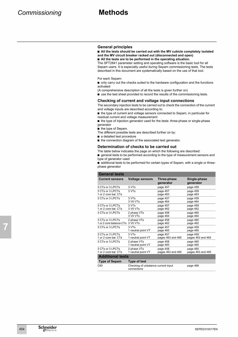
7
Commissioning Methods
General principles b All the tests should be carried out with the MV cubicle completely isolated and the MV circuit breaker racked out (disconnected and open)b All the tests are to be performed in the operating situation.The SFT2841 parameter setting and operating software is the basic tool for all Sepam users. It is especially useful during Sepam commissioning tests. The tests described in this document are systematically based on the use of that tool.
For each Sepam:b only carry out the checks suited to the hardware configuration and the functions activated(A comprehensive description of all the tests is given further on)b use the test sheet provided to record the results of the commissioning tests.
Checking of current and voltage input connectionsThe secondary injection tests to be carried out to check the connection of the current and voltage inputs are described according to:b the type of current and voltage sensors connected to Sepam, in particular for residual current and voltage measurementb the type of injection generator used for the tests: three-phase or single-phase generatorb the type of Sepam.The different possible tests are described further on by:b a detailed test procedureb the connection diagram of the associated test generator.
Determination of checks to be carried outThe table below indicates the page on which the following are described:b general tests to be performed according to the type of measurement sensors and type of generator usedb additional tests to be performed for certain types of Sepam, with a single or three-phase generator
General testsCurrent sensors Voltage sensors Three-phase
generatorSingle-phase generator
3 CTs or 3 LPCTs 3 VTs page 457 page 4593 CTs or 3 LPCTs1 or 2 core bal. CTs
3 VTs page 457page 463
page 459page 463
3 CTs or 3 LPCTs 3 VTs 3 V0 VTs
page 457page 464
page 459page 464
3 CTs or 3 LPCTs1 or 2 core bal. CTs
3 VTs 3 V0 VTs
page 457page 462
page 459page 462
3 CTs or 3 LPCTs 2 phase VTs3 V0 VTs
page 458page 464
page 460page 464
3 CTs or 3 LPCTs1 or 2 core balance CTs
2 phase VTs3 V0 VTs
page 458page 462
page 460page 462
3 CTs or 3 LPCTs 3 VTs 1 neutral point VT
page 457page 465
page 459page 465
3 CTs or 3 LPCTs1 or 2 core bal. CTs
3 VTs 1 neutral point VT
page 457pages 463 and 465
page 459pages 463 and 465
3 CTs or 3 LPCTs 2 phase VTs1 neutral point VT
page 458page 465
page 460page 465
3 CTs or 3 LPCTs1 or 2 core bal. CTs
2 phase VTs1 neutral point VT
page 458pages 463 and 465
page 460pages 463 and 465
Additional testsType of Sepam Type of test
C60 Checking of unbalance current input connections
page 466
454 SEPED310017EN

Commissioning Testing and metering equipment required
7
Generatorsb dual sinusoidal AC current and voltage generator:v 50 or 60 Hz frequency (according to the country)v current adjustable up to at least 5 A rmsv adjustable up to the rated secondary phase-to-phase voltage of the VTsv adjustable relative phase displacement (V, I)v three-phase or single-phase typeb DC voltage generator:v adjustable from 48 to 250 V DC, for adaptation to the voltage level of the logic input being tested.
Accessoriesb plug with cord to match the "current" test terminal box installedb plug with cord to match the "voltage" test terminal box installedb electric cord with clamps, wire grip or touch probes.
Metering devices (built into the generator or separate)b 1 ammeter, 0 to 5 A rmsb 1 voltmeter, 0 to 230 V rmsb 1 phasemeter (if phase displacement (V, I) is not identified on the voltage and current generator).
Computer equipmentb PC with minimal configuration: v Microsoft Windows XP or Vistav 400 MHz Pentium processorv 64 MB of RAMv 200 MB free on hard diskv CD-ROM driveb SFT2841 softwareb CCA783 serial connection cord or CCA784 USB connection cord between the PC and Sepam.
Documentsb complete connection diagram of Sepam and additional modules, with: v phase current input connections to the corresponding CTs via the test terminal boxv residual current input connectionv phase voltage input connections to the corresponding VTs via the test terminal boxv residual voltage input connection to the corresponding VTs via the test terminal boxv logic input and output connectionsv temperature sensor connectionsv analog output connectionv connection of the synchro-check moduleb hardware BOMs and installation rulesb group of Sepam parameter and protection settings, available in paper format.
455SEPED310017EN

7
Commissioning General examination and preliminary actions
Checking to be done prior to energizingApart from the mechanical state of the equipment, use the diagrams and BOMs provided by the contractor to check:b identification of Sepam and accessories determined by the contractorb correct earthing of Sepam (via terminal 13 of the 20-pin connector and the functional earthing terminal located on the back of the Sepam unit)b correct connection of auxiliary voltage (terminal 1: positive polarity; terminal 2: negative polarity)b presence of the DPC (detection of plugged connectors) bridge on terminals 19-20 of the 20-pin connector .b presence of a residual current measurement core balance CT and/or additional modules connected to Sepam, when applicableb presence of test terminal boxes upstream from the current inputs and voltage inputsb conformity of connections between Sepam terminals and the test terminal boxes.
ConnectionsCheck that the connections are tightened (with equipment non-energized).The Sepam connectors must be correctly plugged in and locked.
Energizing Switch on the auxiliary power supply. Check that Sepam performs the following initialization sequence, which lasts approximately 6 seconds:b green ON and red indicators onb red indicator offb pick-up of "watchdog" contact.The first screen displayed is the phase current measurement screen.
Implementation of the SFT2841 software for PC1. Start up the PC.2. Connect either the PC RS 232 serial port or the USB port to the communication port on the front panel of Sepam using either the CCA783 cord or the CCA784 cord.3. Start up the SFT2841 software, by clicking on the related icon.4. Choose to connect to the Sepam to be checked.
Identification of Sepam 1. Note the Sepam serial number given on the label stuck to the right side plate of the base unit.2. Note the references defining the type of application indicated on the adhesive label on the Sepam cartridge.3. Note the Sepam type and software version using the SFT2841 software, "Sepam Diagnosis" screen.4. Enter them in the test sheet.
Determination of parameter and protection settingsAll of the Sepam parameter and protection settings are determined ahead of time by the design department in charge of the application, and should be approved by the customer.It is presumed that the study has been carried out with all the attention necessary, or even consolidated by a network coordination study. All of the Sepam parameter and protection settings should be available at the time of commissioning:b in paper file format (with the SFT2841 software, the parameter and protection setting file for a Sepam may be printed directly) b and, when applicable, in the format of a file to be downloaded into Sepam using the SFT2841 software.
Checking of parameters and protection settingsCheck to be made when the Sepam parameter and protection settings have not been entered or downloaded during commissioning testing, to confirm the conformity of the parameter and protection settings entered with the values determined during the study. The aim of this check is not to confirm the relevance of the parameter and protection settings.1. Go through all the parameter and protection setting screens in the SFT2841 software, in the order proposed in guided mode2. For each screen, compare the values entered in the Sepam with the values recorded in the parameter and protection setting file3. Correct any parameter and protection settings that have not been entered correctly, proceeding as indicated in the SFT2841 section of the Use chapter of this manual.
ConclusionOnce the checking has been done and proven to be conclusive, as of that phase, the parameter and protection settings should not be changed any further and are considered to be final.In order to be conclusive, the tests which follow must be performed with these parameter and protection settings.
E
E
456 SEPED310017EN

Commissioning Checking of phase current and voltage input connectionsWith 3-phase generator
7
Procedure 1. Connect the 3-phase voltage and current generator to the corresponding test terminal boxes, using the plugs provided, according to the appropriate diagram in terms of the number of VTs connected to Sepam.
Block diagram with 3 VTs connected to Sepam
DE
8104
2
L1L2L3
Current testterminal box
Easergy Sepam series 60 Voltage testterminal box
3-phasegenerator
41
B1I1
I2
I3
V1
V2
V3
E 124578
20
13
DPC 19
1514
A A A
I1 I2 I3 N
V
V
V
V1
V1 V2 V3 N
VA
V2
V3
I0
E
5263
457SEPED310017EN

7
Commissioning Checking of phase currentand voltage input connectionsWith 3-phase generator
Block diagram with 2 VTs connected to Sepam
DE
8104
1
2. Turn the generator on.3. Apply the 3 generator voltages V1-N, V2-N and V3-N, balanced and set to the rated secondary phase-to-neutral voltage of the VTs (i.e. Vns = Uns/3).4. Inject the 3 generator currents I1, I2 and I3, balanced and set to the rated secondary current of the CTs (i.e. 1 A or 5 A) and in phase with the voltages applied (i.e. generator phase displacement:α1(V1-N, I1) = α2(V2-N, I2) = α3(V3-N, I3) = 0°). 5. Use the SFT2841 software to check the following:b the value indicated for each of the phase currents I1, I2 and I3 is approximately equal to the rated primary current of the CTsb the value indicated for each of the phase-to-neutral voltages V1, V2 and V3 is approximately equal to the rated primary phase-to-neutral voltage of the VT(Vnp = Unp/3)b the value indicated for each phase displacement ϕ1(V1, I1), ϕ2(V2, I2) andϕ3(V3, I3) between currents I1, I2 or I3 and voltages V1, V2 or V3 respectively is approximately equal to 0°6. Turn the generator off.
L1L2L3
Current testterminal box
Easergy Sepam series 60 Voltage testterminal box
415263
B1I1
I2
I3
V1
V2
V3
E 124578
13
20DPC 19
1514 I0
E
V
V
V
V1
V1 V2 V3 N
V2
V3
3-phasegenerator
A A A
I1 I2 I3 N
VA
458 SEPED310017EN

Commissioning Checking of phase currentand voltage input connections With single-phase generator and voltages delivered by 3 VTs
7
Procedure1. Connect the single-phase voltage and current generator to the corresponding test terminal boxes, using the plugs provided, according to the block diagram below.
Block diagram
De8
1040
2. Turn the generator on.3. Apply the generator V-N voltage set to the rated secondary phase-to-neutral voltage of the VTs (i.e. Vns = Uns/3) between Sepam’s phase 1 voltage input terminals (via the test box). 4. Inject the generator I current, set to the rated secondary current of the CTs(i.e. 1 A or 5 A) and in phase with the V-N voltage applied (i.e. generator phase displacement α(V-N, I) = 0°) to Sepam’s phase 1 current input (via the text box).5. Use the SFT2841 software to check the following:b the value indicated for I1 phase current is approximately equal to the rated primary current of the CTb the value indicated for V1 phase-to-neutral voltage is approximately equal to the rated primary phase-to-neutral voltage of the VT (Vnp = Unp/3)b the value indicated for the phase displacement ϕ1(V1, I1) between the I1 current and V1 voltage is approximately equal to 0°6. proceed in the same way by circular permutation with the phase 2 and 3 voltages and currents, to check the I2, V2, ϕ2(V2, I2) and I3, V3, ϕ3(V3, I3) values7. Turn the generator off.
L1L2L3
Current testterminal box
Easergy Sepam series 60 Voltage testterminal box
415263
B1I1
I2
I3
V1
V2
V3
1E24578
13
20DPC 19
1514 I0
E
V
V
V
V ph-N
N
A
A
I N1-phasegenerator
459SEPED310017EN

7
Commissioning Checking of phase currentand voltage input connections With single-phase generator and voltages delivered by 2 VTs
DescriptionCheck to be carried out when the voltages are supplied by a 2 VT assembly, with the VT primary circuits connected between phases of the distributed voltage, which means that the residual voltage is obtained outside Sepam (by 3 VTs connected via their secondary circuits in an open delta arrangement) or, when applicable, is not used for the protection function.
Procedure 1. Connect the single-phase voltage and current generator to the corresponding test terminal boxes, using the plugs provided, according to the block diagram below.
Block diagram
DE
8103
9
2. Turn the generator on.3. Apply (via the test box) the voltage delivered at the V-N terminals of the generator, set to 3/2 times the rated secondary phase-to-phase voltage of the VTs(i.e. 3 Uns/2) between terminals 1-2 of Sepam’s voltage inputs. 4. Inject the generator I current, set to the rated secondary current of the CTs(i.e. 1 A or 5 A) and in phase with the V-N voltage applied (i.e. generator phase displacement α(V-N, I) = 0°) to Sepam’s phase 1 current input (via the test box). 5. Use the SFT2841 software to check the following:b the value indicated for I1 phase current is approximately equal to the rated primary current of the CT (Inp).b the value indicated for V1 phase-to-neutral voltage is approximately equal to the rated primary phase-to-neutral voltage of the VT (Vnp = Unp/3)b the value indicated for the phase displacement ϕ1(V1, I1) between the I1 current and V1 voltage is approximately equal to 0°
6. Proceed in the same way to check the I2, V2, ϕ2(V2, I2) values:b apply the generator V-N voltage set to 3Uns/2 in parallel between terminals 1-2 and 4-2 of Sepam’s voltage inputs (via the test box). b inject an I current set to 1 A or 5 A and in phase opposition with the V-N voltage(i.e. α(V-N, I) = 180°) to Sepam’s phase 2 current input (via the test box) b obtain I2 ≅ Inp, V2 ≅ Vnp = Unp/3 and ϕ2 ≅ 0°. In the absence of residual voltage, V3 = 0, U32 = 3Unp/2.7. check the I3, V3, ϕ3(V3, I3) values as well: b apply the generator V-N voltage set to 3Uns/2 between terminals 4-2 of Sepam’s voltage inputs (via the test box) b inject a current equal to 1 A or 5 A and in phase with the V-N voltage (i.e. α (V-N, I) = 0°) to Sepam’s phase 3 current input (via the test box)b obtain I3 ≅ Inp, V3 ≅ Vnp = Unp/3 and ϕ3 ≅ 0°. In the absence of residual voltage, V3 = 0, U32 = 3Unp/28. Turn the generator off.
L1L2L3
Current testterminal box
Easergy Sepam series 60 Voltage testterminal box
415263
B1I1
I2
I3
V1
V2
V3
1E24578
13
20DPC 19
1514 I0
E
V
V1
V
U ph-ph
N
A
A
I N1-phasegenerator
460 SEPED310017EN

Commissioning Checking of phase current input connectionsLPCT type current sensors
7
Phase current measurement by LPCT sensorsb The 3 LPCT current sensors are connected via an RJ45 plug to the CCA671 connector which is to be mounted on the rear panel of Sepam, identified as .b The connection of only one or two LPCT sensors is not allowed and causes Sepam to go into the fail-safe position.b The rated primary current In measured by the LPCT sensors is to be entered as a Sepam general setting and configured by microswitches on the CCA671 connector.
ProcedureThe tests to be carried out to check phase current input connections are the same whether the phase currents are measured by CTs or LPCT sensors. Only the Sepam current input connection procedure and current injection values change.To test current inputs connected to LPCT sensors with a standard injection box, the ACE917 injection adapter is required.The ACE917 adapter is inserted between:b the standard injection boxb the LPCT test plug:v integrated in the Sepam CCA671 connectorv or transferred by means of the CCA613 accessory.The ACE917 injection adapter should be set according to the currents selected on the CCA671 connector: the ACE917 setting should be equal to the number of the microswitch that is set to 1 on the CCA671.The injection value depends on the rated primary current selected on the CCA671 connector and entered in the Sepam general settings, i.e.:b 1 A for the following values (in Amps): 25, 50, 100, 133, 200, 320, 400, 630b 5 A for the following values (in Amps): 125, 250, 500, 666, 1000, 1600, 2000, 3150.
Block diagram (without CCA613 accessory)
DE
8103
8
B1
Sepam C60
461SEPED310017EN

7
Commissioning Checking of residual currentand residual voltage input connections
DescriptionCheck to be carried out when the residual voltage is delivered by 3 VTs on the secondary circuits connected in an open delta arrangement and when the residual current is obtained by a specific sensor such as:b CSH120 or CSH200 core balance CTb CSH30 interposing ring CT (whether it is installed on the secondary circuit of a single 1 A or 5 A CT which encompasses the 3 phases, or on the neutral connection of the three 1 A or 5 A phase CTs)b other core balance CT connected to an ACE990 interface.
Procedure1. Connect according to the diagram below:b the generator voltage terminals to the voltage test terminal box using the plug provided,b a wire between the generator current terminals to inject current into the primary circuit of the core balance CT or CT, with the wire passing through the core balance CT or CT in the P1-P2 direction, with P1 the busbar end and P2 the cable end.
Block diagramNote: the number of CTs/VTs connected to the Sepam current/voltage connector phase inputs is given as an example and is not used for the test.
DE
8103
7D
E50
359
2. Turn the generator on.3. Apply a V-N voltage set to the rated secondary voltage of the VTs connected in an open delta arrangement (i.e. Uns/3 or Uns/3)4. inject an I current set to 5 A, and in phase with the voltage applied (i.e. generator phase displacement α(V-N, I) = 0°).5. Use the SFT2841 software to check the following:b the value indicated for the measured I0 residual current is approximately equal to 5 Ab the value indicated for the measured V0 residual voltage is approximately equal to the rated primary phase-to-neutral voltage of the VTs (i.e. Vnp = Unp/3)b the value indicated for the phase displacement ϕ0(V0, I0) between the I0 current and V0 voltage is approximately equal to 0°6. Turn the generator off.
Easergy Sepam series 60 is equipped with one residual Easergy input which may be connected to a core balanceCT installed on the cables, tank earthing cable or neutral point of a transformer, or on the earthing cable of a motor or generator. In some cases, reading of the ϕ0 angle is impossible due to the position of the core balance CT (e.g.: transformer tank earthing cable or neutral point) or because only one of the two I0 or V0 measurements is necessary or possible. When this is the case, simply check the measured residual current value I0.
L1L2L3
Easergy Sepam series 60
415263
B1
Voltage testterminal box
I1
I2
I3
V1
V2
V3
E 124578
13
20DPC 19
E
1514 I0
V V0
V1 V2 V3
V
NI1 I2 I3 N
A
A
I0
1-phaseor 3-phasegenerator
Current testterminal box
462 SEPED310017EN

Commissioning Checking of residual current input connection
7
DescriptionCheck to be carried out when the residual current is measured by a specific sensor such as:b CSH120 or CSH200 core balance CTb CSH30 interposing ring CT (whether it is installed on the secondary circuit of a single 1 A or 5 A CT which encompasses the 3 phases, or on the neutral connection of the three 1 A or 5 A phase CTs)b other core balance CT connected to an ACE990 interface,b and when the residual voltage is calculated in Sepam or cannot be calculated (e.g.: assembly with 2 VTs connected via their primary circuits) and is therefore not available for the protection function.
Procedure1. Connect according to the diagram below:b a wire between the generator current terminals to inject current into the primary circuit of the core balance CT or CT, with the wire passing through the core balance CT or CT in the P1-P2 direction, with P1 the busbar end and P2 the cable endb when applicable, the generator voltage terminals to the voltage test terminal box, so as to only supply Sepam’s phase 1 voltage input and therefore obtain a residual voltage V0 = V1.
Block diagramNote: the number of CTs connected to the Sepam current connector phase inputs is given as an example and is not used for the test.
DE
8103
6D
E50
359
2. Turn the generator on.3. When applicable, apply a V-N voltage set to the rated secondary phase-to-neutral voltage of the VT (i.e. Vns = Uns/3).4. Inject an I current set to 5 A, and when applicable in phase with the V-N voltage applied (i.e. generator phase displacement α(V-N, I) = 0°).5. Use the SFT2841 software to check the following:b the value indicated for the measured I0 residual current is approximately equal to 5 Ab when applicable, the value indicated for calculated V0 residual voltage is approximately equal to the rated primary phase-to-neutral voltage of the VTs(i.e. Vnp = Unp/3)b when applicable, the value indicated for the phase displacement ϕ0 (V0, I0) between the I0 current and V0 voltage is approximately equal to 0°6. Turn the generator off.
Easergy Sepam series 60 is equipped with 2 independent residual current inputs which may be connected to a core balance CT installed on the cables, tank earthing cable or neutral point of a transformer, or on the earthing cable of a motor or generator. In some cases, reading of the ϕ0 angle is impossible due to the position of the core balance CT (e.gtransformer neutral point or tank earthing cable) or because only one of the two I0 or V0 measurements is necessary or possible. When this is the case, simply check the measured residual current value I0.
L1L2L3
Current testterminal box
Easergy Sepam series 60 Voltage testterminal box
415263
B1I1
I2
I3
V1
V2
V3
1E24578
13
20DPC 19
1514 I0
E
V
V1 V2 V3
V
V1 = V0
N
A I0
I1
A
I2 I3 N1-phaseor 3-phasegenerator
463SEPED310017EN

7
Commissioning Checking of residual voltage input connectionWith voltage delivered by 3 VTs in open delta arrangement
DescriptionCheck to be carried out when the residual voltage is delivered by 3 VTs on the secondary circuits connected in an open delta arrangement, and when the residual current is calculated in Sepam or cannot be calculated (e.g.: assembly with 2 CTs) and is therefore not available for the protection function.
Procedure1. Connect according to the diagram below:b the generator voltage terminals to the voltage test terminal box, so as to only supply Sepam’s residual voltage inputb when applicable, the generator current terminals to the current test terminal box, so as to only supply Sepam’s phase 1 current input, and therefore obtain a residual current I0Σ = I1.
Block diagramNote: the number of VTs connected to the Sepam voltage connector phase inputs is given as an example and is not used for the test.
DE
8103
5
2. Turn the generator on.3. Apply a V-N voltage set to the rated secondary voltage of the VTs installed in an open delta arrangement (i.e., depending on the case, Uns/3 or Uns/3).4. When applicable, inject an I current set to the rated secondary current of the CTs (i.e. 1 A or 5 A) and in phase with the voltage applied (i.e. generator phase displacement α(V-N, I) = 0°).5. Use the SFT2841 software to check the following:b the value indicated for the measured V0 residual voltage is approximately equal to the rated primary phase-to-neutral voltage of the VTs (i.e. Vnp = Unp/3)b when applicable, the value indicated for the calculated I0Σ residual current is approximately equal to the rated primary current of the CTsb when applicable, the value indicated for the phase displacement ϕ0Σ (V0, I0Σ) between the I0Σ current and V0 voltage is approximately equal to 0°6. Turn the generator off.
L1L2L3
Current testterminal box
Easergy Sepam series 60 Voltage testterminal box
415263
B1I1
I2
I3
V1
V2
V3
1E24578
13
20DPC 19
1514 I0
E
V
V1 V2 V3
V
V0
N
A
A
I1
I1 I2 I3
= I0
N1-phaseor 3-phasegenerator
464 SEPED310017EN

Commissioning Checking of residual voltageinput connectionWith voltage delivered by 1 neutral point VT
7
DescriptionCheck to be carried out when the Sepam residual voltage input is connected to 1 VT installed on the neutral point of a motor or generator (in which case the VT is a power transformer).
Procedure1. Connect the generator voltage terminals to the voltage test terminal box, so as to only supply Sepam’s residual voltage input.
Block diagram
De8
1034
2. Turn the generator on.3. Apply a V-N voltage set to the rated secondary voltage of the neutral pointt VT (i.e. Vnts).4. Use the SFT2841 software to check that the measured neutral point voltage Vnt is approximately equal to the rated primary phase-to-neutral voltage of the VTs (i.e. Vnts).5. Turn the generator off.
L1L2L3
Easergy Sepam series 60
415263
B1
Voltage testterminal box
I1
I2
I3
V1
V2
V3
E 124578
13
20DPC 19
E
1514 I0
V V1 = Vnt
V1 V2 V3
V
NI1 I2 I3 N
A
1-phaseor 3-phasegenerator
465SEPED310017EN

7
Commissioning Checking of Sepam C60 unbalance current input connections
DescriptionCheck to be carried out on Sepam C60 units with measurement of capacitor unbalance currents, apart from checking of the phase current input connections.Since the capacitor unbalance currents are not related to the voltages measured by Sepam C60, it is not necessary to inject voltage to check the Sepam C60 capacitor unbalance current input connections.
Procedure1. Connect the single-phase current generator to the corresponding test terminal box, using the plugs provided, according to the block diagram below.
Block diagram
DE
8103
3
2. Turn the generator on.3. Inject the generator current I set to the CTs’ rated secondary current (i.e. 1 A, or 5 A) to Sepam’s unbalance current input (via the test box).4. Use the SFT2841 software to check that the unbalance current value indicated I0 is approximately equal to the CTs' rated primary current.5. Turn the generator off.
C60
466 SEPED310017EN
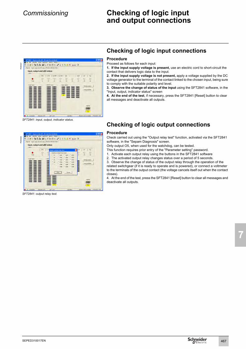
Commissioning Checking of logic input and output connections
7
Checking of logic input connections
PE
8042
7
ProcedureProceed as follows for each input:1. If the input supply voltage is present, use an electric cord to short-circuit the contact that delivers logic data to the input.2. If the input supply voltage is not present, apply a voltage supplied by the DC voltage generator to the terminal of the contact linked to the chosen input, being sure to comply with the suitable polarity and level.3. Observe the change of status of the input using the SFT2841 software, in the "Input, output, indicator status" screen4. At the end of the test, if necessary, press the SFT2841 [Reset] button to clear all messages and deactivate all outputs.
SFT2841: input, output, indicator status.
Checking of logic output connections
PE
8042
8
ProcedureCheck carried out using the "Output relay test" function, activated via the SFT2841 software, in the "Sepam Diagnosis" screen. Only output O5, when used for the watchdog, can be tested.This function requires prior entry of the "Parameter setting" password.1. Activate each output relay using the buttons in the SFT2841 software2. The activated output relay changes status over a period of 5 seconds.3. Observe the change of status of the output relay through the operation of the related switchgear (if it is ready to operate and is powered), or connect a voltmeter to the terminals of the output contact (the voltage cancels itself out when the contact closes).4. At the end of the test, press the SFT2841 [Reset] button to clear all messages and deactivate all outputs.
SFT2841: output relay test.
467SEPED310017EN

7
Commissioning Checking of GOOSE logic input connections
Procedure
PE
8042
9
This check is carried out using the "GOOSE test" screen accessed from the "Input, output and LED status" tab in the SFT2841 software.This screen can be used to perform 2 types of test on GOOSE logic inputs:b A test by controlling a GOOSE test variableb A test by forcing remote indications (TS)Test by controlling a GOOSE test variableThe test by controlling a GOOSE test variable is used to check that IEC 61850 communication is fully operational with all the Sepam units included in the IEC 61850 configuration.This test allows to activate 4 GOOSE logic input test variables (LD0.GSE_GGIO1_Test1 to LD0.GSE_GGIO1_Test4).These 4 GOOSE logic input test variables use 4 test data items defined in the IEC 61850 model of the Sepam units.Using the SFT850 software, the user configures the test logic to be used with these 4 test variables.Clicking on the [Test] button sets the selected GOOSE test variables to 1 for the duration specified.
Test by forcing remote indications (TS)The test by forcing remote indications is used to check the configuration of the relays subscribed to the GOOSE inputs to be used and the control logic associated with the GOOSE inputs to which the Sepam is subscribed.The screen initially displays the actual state of the Sepam remote indicationsFor each remote indication to be enforced, the test consists of: 1. Select the number of the remote indication to be forced by placing the pointer on the corresponding numbered box. If it exists, the description of the IEC 61850 variable corresponding to the remote indication appears in a pop-up.2. Check that the remote indication selected matches the IEC 61850 variable displayed in the pop-up. 3. Click on the remote indication(s) to be forced: b Click once to force to 0 b Click twice to force to 14. Set the test duration by entering the desired value.5. Click the [Test] button: All the selected remote indications are forced for the set duration.This function is available whether the SFT2841 software is connected on the front panel of the Sepam or to a Sepam network.
SFT2841: GOOSE logic input test
468 SEPED310017EN

Commissioning Checking of optional module connections
7
MET148-2 module temperature sensor inputsThe temperature monitoring function provided by Sepam T60, T62, M61, G60, G62, C60 units checks the connection of each RTD that is configured.An "RTD FAULT" alarm is generated whenever one of the RTDs is detected as being short-circuted or disconnected (absent).To identify the faulty RTD or RTDs:1. Display the temperature values measured by Sepam using the SFT2841 software.2. Check the consistency of the temperatures measured:b the temperature displayed is "****" if the RTD is short-circuited (T < -35 °C or T < -31° F)b the temperature displayed is "-****" if the RTD is disconnected (T > 205 °C or T > 401° F).
MSA141 module analog output1. Identify the measurement associated by parameter setting to the analog output using the SFT2841 software.2. Simulate, if necessary, the measurement linked to the analog output by injection.3. Check the consistency between the value measured by Sepam and the indication given by the device connected to the analog output.
MCS025 module voltage inputsProcedure1. Connect the single-phase voltage generator to the corresponding test terminal box, using the plugs provided, according to the block diagram below.
Block diagram
DE
5126
4
2. Turn the generator on.3. Apply a voltage V-N set to the rated secondary voltage Vns sync1 (Vns sync1= Uns sync1/3) in parallel between the input terminals of the 2 voltages to be synchronized.4. Use the SFT2841 software to check that:b the measured voltage difference dU, frequency difference dF and phase difference dPhi values are equal to 0b the close enable sent by the MCS025 module is received on the Sepam logic input assigned to this function (logic input in 1 status in the "Input, output and LED status" screen).5. Use the SFT2841 software to check that for the other Sepam units concerned by the "Synchro-check" function the close enable sent by the MCS025 module is received on the logic input assigned to this function (logic input in 1 status in the "Input, output and LED status" screen).6. Turn the generator off.
469SEPED310017EN

7
Commissioning Validation of the complete protection chain
PrincipleThe complete protection chain is validated during the simulation of a fault that causes tripping of the breaking device by Sepam.
Procedure1. Select one of the protection functions that triggers tripping of the breaking device and separately, according to their incidence in the chain, the function or functions related to the programmed or reprogrammed parts of the program logic.2. According to the selected function or functions, inject a current and/or apply a voltage that corresponds to a fault.3. Observe the tripping of the breaking device and the operation of the adapted parts of the program logic.At the end of all the voltage and current application type checks, put the covers back on the test terminal boxes.
470 SEPED310017EN

Commissioning Test sheetEasergy Sepam series 60
7
Project:........................................................ Type of Sepam
Switchboard: .............................................. Serial number
Cubicle: ....................................................... Software version V
Overall checksCheck off the box v when the check has been made and been conclusiveType of check
Preliminary general examination, prior to energizing vEnergizing vParameter and protection settings vLogic input connections vLogic output connections vValidation of the complete protection chain vValidation of the adapted functions (via the logic equation editor) vAnalog output connection to the MSA141 module vTemperature sensor input connections to the MET148-2 module vVoltage input connections to the MCS025 module vChecking of phase current and voltage inputsCheck off the box v when the check has been made and been conclusiveType of check Test performed Result Display
Phase current and phase voltage input connections
Secondary injection of CT rated current into ,i.e. 1 A or 5 A
Rated primary current of CTs connected to
I1 =.................... vI2 =.................... vI3 =.................... v
Secondary injection of phase voltage (the value to be injected depends on the test being performed)
VT rated primary phase-to-neutral voltage Unp/3
V1 = .................. vV2 = .................. vV3 = .................. v
Phase displacement ϕ(V, I) ≅ 0° ϕ1 =................... vϕ2 =................... vϕ3 =................... v
Residual current input connections
Injection of 5 A into the core balance CT primary circuit
Injected current value I0 I0 =.................... v
When applicable,secondary injectionof the rated phase-to-neutral voltage of a phase VTUns/3
VT rated primary phase-to-neutral voltage Unp/3
Phase displacement ϕ0(V0, I0)≅ 0°
V0 = .................. v
ϕ0 =................... v
Tests performed on: .....................................................................
By: ...................................................................................................
Signatures
Comments: ......................................................................................................................................................................................................
......................................................................................................................................................................................................
......................................................................................................................................................................................................
B1 B1
471SEPED310017EN

7
Commissioning Test sheetEasergy Sepam series 60
Project:........................................................ Type of Sepam
Switchboard: .............................................. Serial number
Cubicle: ....................................................... Software version V
Residual current and voltage input checksCheck off the box v when the check has been made and been conclusiveType of check Test performed Result Display
Residual voltage inputconnectionTo 3 VTs in open delta arrangement
Secondary injectionof the rated voltage of the VTs in an open delta arrangement (Uns/3or Uns/3)
VT rated primary phase-to-neutral voltage Unp/3
V0 = ................... v
When applicable, secondary injection of CT rated current, i.e. 1 A or 5 A
CT rated primary current I0Σ = .................. v
Phase displacement ϕ0Σ(I0, I0Σ) ϕ0Σ = ................. v
To 1 neutral point VT Secondary injectionof the rated voltageof the neutral point VT (Vnts)
VT rated primary phase-to-neutral voltage Vntp
Vnt = .................. v
Residual current and residual voltage input connections
Injection of 5 A into the core balance CT primary circuit
Injected current value I0 I0 = .................... v
Secondary injection of the rated voltage of the VTs in an open delta arrangement (Uns/3 or Uns/3)
VT rated primary phase-to-neutral voltage Unp/3
V0 = ................... v
Phase displacement ϕ0(V0, I0)≅ 0°
ϕ0 = ................... v
Sepam C60:unbalance current input connections
Secondary injection of the CT rated current, i.e. 1 A or 5 A
CT rated primary current I0 = .................... v
Tests performed on: .....................................................................
By:...................................................................................................
Signatures
Comments: ......................................................................................................................................................................................................
...............................................................................................................................................................................................................................
...............................................................................................................................................................................................................................
472 SEPED310017EN

Maintenance Troubleshooting assistance
7
Nothing happens when Sepam is switched on:b all LEDs offb nothing displayed on Sepam display.
There is probably an auxiliary power fault.Possible cause Action / remedy
Connector A not plugged in. Plug in connector A.Connectors A and E reversed. Put connectors in correct positions.Auxiliary power absent. Check the auxiliary power level
(range = 24 V DC to 250 V DC).Polarities reversed on terminals 1 and 2of connector A.
Check that the + polarity is on terminal 1and the – polarity on terminal 2.Correct if necessary.
Internal problem. Change base unit (see page 477)
Compatibility of Sepam version/SFT2841 version
DE
8103
2
The About SFT2841 screen indicates the minimum version of the SFT2841 software that is compatible with the Sepam being used.To display this screen on the Sepam UMI:b Press the button.b Select the General menu.b The About SFT2841 screen can be found just after the About Sepam screen.Check that the SFT2841 software version you are using is higher than or the same as that indicated on the Sepam screen.If the SFT2841 software version is lower than the minimum version compatible with the Sepam being used, the SFT2841 software cannot be connected to Sepam and the SFT2841 software displays the following error message: SFT2841 software version incompatible with the connected device.
SFT2841 compatible version screen.
About SFT2841
Please use SFT2841
12.0
473SEPED310017EN

7
Maintenance Troubleshooting assistance
MAJOR fault: Sepam is in fail-safe positionb ON LED of UMI on in front b LED of UMI on in front or LED of DSM303 remote advanced UMI flashingb green LED on rear panel onb red LED on rear panel on.
PE
5035
9
Major faults are only cleared after the cause of the fault is corrected and Sepam is switched on again.
Note : The list of self-tests which place Sepam in the fail-safe position can be found in the Control and monitoring functions chapter.
PE
5013
9
Connection cannot be made with SFT2841Possible cause Action / remedy
Memory cartridge absent. Switch off Sepam.Install the memory cartridge and secure itby tightening the 2 integrated screws.Switch Sepam on again
Fault message on display:major fault
Major internal fault. Change base unit (see page 477).
Connection can be made with SFT2841Possible cause Action / remedySFT2841 indicates major fault, but no missing module: Base unit internal fault.
Change base unit.
Memory cartridge not compatible with version of the base unit (see below).
Note the version using the SFT2841 software, Diagnosis screen. Contact the local support team.
The hardware configuration is incorrect or incomplete.
Use the SFT2841 software, in connected mode, to determine the cause.The SFT2841 Diagnosis screen displays the missing items in red (see table below).
Check on hardware configuration using SFT2841Diagnosis screen Possible cause Action / remedy
CCA630, CCA634, CCA671 connector in B1 position displayed in red.
Connector absent. Install a connector.If the connector is present, check that it is plugged in correctly and held in placeby the 2 screws.
LPCT sensors not connected. Connect the LPCT sensors.Connector in position E displayed in red.
Connector E unplugged or no jumper between terminals 19 and 20.
Plug in connector E.Fit the jumper.
MES120 module in H1 or H2 position displayed in red.
MES120 module absent. Install MES120 module.If the MES120 module is present, check that it is plugged in correctly and held in place by the 2 screws. If the fault is still present, replace the module.
PE
1015
6
Fault message displayed if cartridge is not compatible.
Rules on compatibility between the cartridge and the base unitThe major index of the base-unit version must be greater than or equal to the major index of the cartridge-application version.Example: The base unit with a version V1.05 (major index = 1) and an application with a version V2.00 (major index = 2) are not compatible.If this rule is not observed, a major fault occurs and Sepam displays the message opposite.
1
474 SEPED310017EN

Maintenance Troubleshooting assistance
7
MINOR fault: Sepam is operating in downgraded modeb ON LED of UMI on in frontb LED of UMI flashing in frontb green LED on rear panel onb red LED on rear panel flashing.
Note : The list of self-tests which place Sepam in downgraded operation mode can be found in the Control and monitoring functions chapter.
PE
5013
9
Inter-module link faultPossible cause Action / remedy
Faulty wiring. Check remote module connections: RJ45 plugs of CCA77x cords clipped correctly into sockets.
Fault message on display:inter-module link fault.
PE
5013
9
Fault message on display:MET148-2 not available.
MET148-2 module not availableLEDs Possible cause Action / remedy
MET148-2 green and red LEDs off.
Faulty wiring. Check module connections: RJ45 plugs of CCA77x cords clipped correctly into sockets.
MET148-2 green LED on.MET148-2 red LED off.
No response from MET148-2 module.
Check the positionof the module numberselection jumper:b MET1 for first MET148-2module(temperatures T1 to T8)b MET2 for second MET148-2module(temperatures T9 to T16).b If the jumper position needs to be changed, reboot the MET148-2 module(by disconnecting and reconnecting the interconnection cord).
MET148-2 red LED flashing. Faulty wiring, MET148-2 powered but loss of dialogue with base unit.
Check module connections: RJ45 plugs of CCA77x cords clipped correctly into sockets.If the MET148-2 module is the last in the chain, check that the line terminating jumper is in the Rc position. In all other cases, the jumper should be in the position marked .
MET148-2 red LED on. More than 3 remote modules connected to connector D1 on base unit.
Remove a remote module.
MET148-2 module internal fault.
Change MET148-2 module.
PE
5013
9
Fault message on display:MSA141 not available.
MSA141 module not availableLEDs Possible cause Action / remedy
MSA141 green and red LEDs off.
Faulty wiring, MSA141 not powered.
Check module connections: RJ45 plugs of CCA77x cords clipped correctly into sockets.
MSA141 green LED on.MSA141 red LED flashing.
Faulty wiring, MSA141 powered but loss of dialogue with base unit.
Check module connections: RJ45 plugs of CCA77x cords clipped correctly into sockets.If the MSA141 module is the last in the chain, check that the line terminating jumper is in the Rc position. In all other cases, the jumper should be in the position marked .
MSA141 red LED on. More than 3 remote modules connected to connector D1 on base unit.
Remove a remote module.
MSA141 module internal fault. Change MSA141 module.
2
3
Rc
4
Rc
475SEPED310017EN

7
Maintenance Troubleshooting assistance
PE
5013
9
Fault message on display: MCS025 not available.
MCS025 module not availableLEDs Possible cause Action / remedy
MCS025 LED flashing. Faulty wiring, MCS025 powered but loss of dialogue with base unit.
Check that a CCA785 cord is used with orange RJ45 plug on MCS025 end.Check module connections: RJ45 plugs of CCA785 cord clipped correctly into sockets.
MCS025 LED on. Internal fault or MCS025 fault. Check connections (DPC function - detection of plugged connector).
DSM303 module not avaliableLEDs Possible cause Action / remedy
DSM303 LED on and
display off.
Module internal fault. Replace the DSM303 module.
Faulty Sepam UMIDisplay Possible cause Action / remedy
Advanced or mimic-based UMI display off.
Display internal fault. Replace the base unit. See page 477.
PE
5013
9
Fault message on display:CPU overload.
Detection of Sepam CPU overloadPossible cause Action / remedyThe application configured exceeds the CPU capacity of the Sepam unit.
Switch off some protection functions.For further information, contact your local support center.
Alarms"METx FAULT" message.RTD faultPossible cause Action / remedy
An RTD on a MET148-2 module is disconnected or short-circuited.
Since the alarm is common to the 8 channels of the module, go to the temperature measurement display screen to determine which channel is affected by the fault.Measurement displayed:Tx.x = -**** = RTD disconnected (T > 205 °C (401 °F))Tx.x = **** = RTD short-circuited (T < -35 °C (-31 °F))
"BATTERY LOW" message.Battery faultPossible cause Action / remedy
Battery low, absent or incorrectly installed. Replace the battery.See page 477.
5
10
476 SEPED310017EN

Maintenance Replacing the base unitReplacing the battery
7
PE
8077
9
Replacing the base unitThe memory cartridge is easily accessible and can be removed from the front of Sepam. It reduces the duration of maintenance operations.When a base unit fails, simply:1. Switch off Sepam and unplug connectors2. Remove the memory cartridge3. Replace the faulty base unit with a replacement unit (no memory cartridge)put the memory cartridge in the new base unit4. Plug in the connectors and switch Sepam on again.
If there are no compatibility problems (see page 474), Sepam is operational with all its standard and customized functions, without requiring any reloading of protection and parameter settings.
Replacing the batteryCharacteristics1/2AA format 3.6 V, 0.8 Ah lithium battery Recommended models:b SAFT model LS14250b SONNENSCHEIN model SL-350/SRecycling the batteryThe used battery should be sent to a certified recycling company in compliance with the European Directive 91/157/EEC OJ L78dated 26.03.91 on batteries and accumulators containing certain dangerous materials, modified by directive 98/101/EEC OJ L1 dated 05.01.1999.Replacement1. Lift off the protective battery cover after removing both fixing screws.2. Change the battery, being sure to use the correct type and polarity.3. Replace the protective battery cover and both fixing screws.4. Recycle the used battery.Note : The battery can be replaced with the Sepam energized.
Memory cartridge accessed from the front.
477SEPED310017EN

7
Maintenance Maintenance tests
DANGER GeneralHAZARD OF ELECTRIC SHOCK, ELECTRIC ARC OR BURNSb Only qualified personnel should maintain this equipment. Such work should be performed only after reading this entire set of instructions.b NEVER work alone.b Obey all existing safety instructions when commissioning and maintaining high-voltage equipment.b Beware of potential hazards and wear personal protective equipment.Failure to follow these instructions will result in death or serious injury.
The logic inputs and outputs and the analog inputs are the parts of Sepam least covered by the self-tests. (The list of Sepam self-tests can be found in the Control and monitoring functions chapter).They should be tested during a maintenance operation.The recommended interval between preventive maintenance operations is 5 years.
Maintenance testsTo perform maintenance on Sepam, see Chapter 7, page 453. Carry out all the recommended commissioning tests according to the type of Sepam to be tested, except for the test specific to the differential function which is not necessary. If the MCS025 Synchro-check module is present, test its voltage inputs as well.
First test all the logic inputs and outputs involved in tripping the circuit breaker.A test of the complete chain including the circuit breaker is also recommended.
478 SEPED310017EN

479
7
SEPED310017EN
Maintenance Firmware modificationsApplication cartridge firmware
The table below describes the firmware version history of the Easergy Sepam series 60 application cartridge. The following information is provided for each firmware version:
release date,compatible SFT2841 version,improvements,new features added.
Firmware version
Firmware version release date
SFT2841 version compatibility
Improvements New features
V8.01 December 2012
V13 or above Protection 48/51LR: integration of the zero speed bit from 49RMS.
Protection 50/51: the H2 restraint on Max(I) is applied to the additional channels.
Protection 59: the drop out/pick up ratio rises to 99% and the setting interval changes from 1% to 0.5%.
Protection 66: modification of parameters to manage the number of hot starts and number of cold starts. Upward and downward compatibility with the previous version.
Protection 81H: Modification of the resolution (0.01 Hz), the reset difference (0.05 Hz), the setting range (fN-1 Hz to fN+5 Hz) and the blocking range (20% to 90% Un).
Protection 81L: Modification of the resolution setting (0.01 Hz), the reset difference (0.05 Hz), the setting range (fN-10 Hz to fN+1 Hz) and the blocking range (20% to 90% Un).
Notification by remote indication when a disturbance recording is available.
I'n pick up from 30 A to 40 A.Logic discrimination: Inhibition of the logic
discrimination blocking order (formerly fixed at 200 ms) can be configured.
Management of the new extended cartridge model (twice the number of disturbance recordings + new MSR/MST/DLG functions).
Protection 27: addition of setting using a custom curve.
Protection 49RMS: addition of thermal model with 2 constants whose entry can be configured by a genetic algorithm. Option of configuring the transformer type in the transformer scenario.
Protection 78PS: extension of choice (equal-area criterion, power swing, internal angle calculation) and combined use (areas and power swing, angle and power swing) of protection principles.
Phase rotation direction managed by the communication (GOOSE, Modbus, etc.).
MSR (Motor Start Report) function: archiving of 2 to 144 s of measurements upon motor tripping. Downloading of COMTRADE files via the SFT2841 software, supervision software, ACE 850 and ACE969 (TP and FO). MSRs displayed on integrated advanced UMI or
integrated mimic-based UMI.MST (Motor Start Trend) function: storage of changes
(min, max, average of MSR measurements) in 144 samples over a 30-day period. Management of 12 to 18 periods depending on the cartridge model. Trends displayed on integrated advanced UMI or
integrated mimic-based UMI. Downloading of COMTRADE files via the SFT2841 software, supervision software, ACE 850 and ACE969 (TP and FO).DLG (Data LoG) function: archiving of measurements offered by SEPAM over a period from 1 s to 30 days, management of 1 to 20 periods depending on the cartridge model. Downloading of COMTRADE files via the SFT2841 software, supervision software, ACE 850 and ACE969 (TP and FO).
V8.02 May 2013 V13 or above
V8.03 August 2013 V13 or above
V8.04 February 2014 V13 or above
V9.00 December 2014
V15 or above
Synchronization context: Initial context date forced to 2000/00/00 00:00:0000 when no other context ispresent. Disturbance record: If a power loss occurs during a disturbance recording, CFG indicates the number of valid samples before power loss. The next samples have the value 0, Digital I/O: Input status is taken into account only when the end of the initialization is effective, Improved accuracy on the trip time of the 50BF, Modbus: stabilization of the TS240 “Ethernet communication fault” transmission by increasing the number of confirmations, Logic selectivity: blocking is achieved if the circuit breaker is in the closed position. Reset of protections occurs only when the breaker is in closed position, The rounding of the calculation of the nominal active power is reviewed to coincide with SFT2841 software one, Disturbance: the "nrate" bit is set to 0 instead of 1 to allow the COMTRADE reader to use the date of each point instead of a fixed sampling, Fixed an issue causing the Sepam fallback on an avalanche warning issued by the Logipam. Fixed an issue when loading some les that result Logipam denitive fallback ECI850 : Improvement to enable unloading DataLog les congured in a circular mode. Modbus : improved management of the saturation of stamped events stacks to avoid returning again already issued events Modbus : synchronisation du bit "perte info" du motde contrôle avec la saturation réelle de la pile.
Creation of a second 6.25 kA...15 kA setting range for Unp ≤ 20 kV.
V7.10 May 2011 V12 or above Creation of the Sepam series 60 based on the firmware of the Sepam series 80 version 5.26.
Improved main channels réinitalisation of the 50N/51N protections in factory parameters reinitialization.
Automatic transfer (AT) : Back to the nominal frequency of the frequency control in 200 ms instead of 5 s when the voltage is less than 20% of Unp,

480
7
SEPED310017EN
Maintenance Firmware modificationsBase firmware
The table below describes the firmware version history of the Easergy Sepam series60 bases. The following information is provided for each firmware version:
release date,compatible SFT2841 version,improvements,new features added.
Base firmwareversion
Firmware version release date
SFT2841 version compatibility
Improvements New features
V7.20 May 2011 V12 or above Creation of a common base firmware platform forthe Sepam series 80 and for the new Sepam series 60.
V8.01 December 2012
V13 or above MSR, MST and DLG new files handling.Effective rotation direction in 32-bit diagnosis zone
V9.00 December2014
V15 or above

481
7
SEPED310017EN
Maintenance Firmware modificationsCartridge and base firmware compatibility table
Respect the compatibility between the Easergy Sepam series 80 cartridge and the base according to the following table.
Compatible with all featuresCompatible but with limited features
- Not compatible
Note : The latest version of Sepam firmware is compatible with all the Sepam hardware versions.
Firmwareversion
Base
Cartridge 7.XX 9.XX7.XX8.XX -
8.XX
9.XX - -

7
Notes
482 SEPED310017EN


Schneider Electric Industries SAS35, rue Joseph MonierCS 30323F - 92506 Rueil-Malmaison Cedex
RCS Nanterre 954 503 439Capital social 896 313 776 €
www.schneider-electric.com
As standards, specifications and designs change from time to time, please ask for confirmation of the information given in this publication.
Printed on recycled paper.
Production: Schneider electricPublication: Schneider ElectricPrinted:
02/2017SEPED310017EN/5
AR
T.8
38
00
8 ©
2017
Sch
ne
ide
r E
lectr
ic -
All
rig
hts
re
se
rve
d