
EA640 Hydrographic single beam echo sounder - KONGSBERG
94
413764/B December 2018 © Kongsberg Maritime AS EA640 Hydrographic single beam echo sounder Installation Manual This manual provides you with information required to install the Kongsberg EA640 Hydrographic single beam echo sounder.The information is intended for qualified personnel such as shipyard engineers and skilled workers. Caution The EA640 echo sounder must never be powered up when the ship is in dry dock. The transducer will be damaged if it transmits in open air. To prevent inadvertent use of the EA640, disconnect the mains power whenever the vessel is in dry dock.
-
Upload
khangminh22 -
Category
Documents
-
view
4 -
download
0
Transcript of EA640 Hydrographic single beam echo sounder - KONGSBERG
413764/BDecember 2018 © Kongsberg Maritime AS
EA640Hydrographic single beam echo sounder
Installation Manual
This manual provides you with information required to install theKongsberg EA640 Hydrographic single beam echo sounder.Theinformation is intended for qualified personnel such as shipyardengineers and skilled workers.
Caution
The EA640 echo sounder must never be powered up when the ship isin dry dock. The transducer will be damaged if it transmits in open air.To prevent inadvertent use of the EA640, disconnect the mains powerwhenever the vessel is in dry dock.

Kongsberg Maritime ASwww.kongsberg.com
Document information• Product: Kongsberg EA640• Document: Installation Manual• Document part number: 413764• Revision: B• Date of issue: December 2018
Copyright
The information contained in this document remains the sole property of KongsbergMaritime AS. No part of this document may be copied or reproduced in any form or byany means, and the information contained within it is not to be communicated to a thirdparty, without the prior written consent of Kongsberg Maritime AS.
Warning
The equipment to which this manual applies must only be used for the purpose forwhich it was designed. Improper use or maintenance may cause damage to theequipment and/or injury to personnel. You must be familiar with the contents of theappropriate manuals before attempting to operate or work on the equipment.
Kongsberg Maritime disclaims any responsibility for damage or injury caused byimproper installation, use or maintenance of the equipment.
Disclaimer
Kongsberg Maritime AS endeavours to ensure that all information in this document iscorrect and fairly stated, but does not accept liability for any errors or omissions.
Support information
If you require maintenance or repair, contact Kongsberg Maritime’ssupport organisation. You can also contact us using the following address:[email protected]. If you need information about our otherproducts, visit https://www.km.kongsberg.com.
413764/B 3
Table of contents
ABOUT THIS MANUAL.............................................................. 5EA640...................................................................................... 6System description .............................................................................................................7System diagram..................................................................................................................8System units .......................................................................................................................9
Operator Station description.....................................................................................9WBT description ......................................................................................................9Single-beam transducers.........................................................................................10
Scope of supply................................................................................................................11Basic items provided with a standard delivery.......................................................11
Installation requirements..................................................................................................13Supply power requirements....................................................................................13Cables and wiring requirements .............................................................................13Compass deviation requirements............................................................................14Noise sources..........................................................................................................14
Network security..............................................................................................................14Support information .........................................................................................................16PREPARATIONS..................................................................... 17Installation summary........................................................................................................18About installation drawings .............................................................................................19Tools, equipment and consumables required for EA640 installation ..............................19Where to install the transducer ........................................................................................20
Introduction to transducer location.........................................................................20Mount the transducer deep .....................................................................................20Avoid protruding objects near the transducer.........................................................21Keep the transducer far away from the propellers .................................................22Mount the transducer at a safe distance from bow thruster(s) ...............................22Summary and general recommendations ...............................................................22
Acoustic noise..................................................................................................................25Contributing factors................................................................................................25Self noise ................................................................................................................27Ambient noise.........................................................................................................29Electrical self noise ................................................................................................29Some means to reduce acoustic noise ....................................................................30
INSTALLING THE EA640 HARDWARE UNITS.......................... 32Installing the WBT using the integrated brackets............................................................33Installing the WBT in a 19" cabinet.................................................................................34
Installation Manual

4 413764/B
Installing a commercial computer....................................................................................35Mounting the WBT Cabinet ............................................................................................37Mounting the drawers in the WBT Cabinet.....................................................................39Designing, manufacturing and mounting the steel conduit .............................................41Installing the transducer(s)...............................................................................................43Installing the transducer on a blister or drop keel............................................................44Installing the transducer on a steel hull............................................................................46CABLE LAYOUT AND INTERCONNECTIONS............................. 48Cable plan ........................................................................................................................49List of cables ....................................................................................................................50Installing the EA640 cables .............................................................................................51
Connecting one or more transducers to the WBT ..................................................51Connecting power and ground to the WBT............................................................55Connecting the WBT and the Operator Station......................................................56Connecting a synchronization cable to the Operator Station using an RS-232
serial interfaces ..................................................................................................56Cable drawings and specifications ...................................................................................58
Transducer ..............................................................................................................58Auxiliary connector for synchronization................................................................59RS-232 used as synchronization trigger (input or output) .....................................60
DRAWING FILE...................................................................... 61388697 WBT outline dimensions ....................................................................................62400930 WBT Cabinet outline dimensions.......................................................................64TECHNICAL SPECIFICATIONS................................................ 68Performance specifications ..............................................................................................69Interface specifications.....................................................................................................70Weight and outline dimensions ........................................................................................73Power requirements .........................................................................................................73Environmental specifications ...........................................................................................74EQUIPMENT HANDLING......................................................... 75Transporting Kongsberg Maritime equipment.................................................................76Lifting units and transportation boxes .............................................................................77Inspection of units and transportation boxes after arrival................................................78Specifications for storage prior to installation or use.......................................................79Unpacking instructions ....................................................................................................80
Unpacking standard parts and units........................................................................81Unpacking mechanical units ..................................................................................82Unpacking electronic and electromechanical units ................................................82Unpacking transducers ...........................................................................................83
Specifications for storage after unpacking.......................................................................85
EA640

413764/B 5
About this manual
Purpose of manual
The purpose of this manual is to present the descriptions and drawings required to installthe EA640 Hydrographic single beam echo sounder.
Target audience
The manual is intended for technical personnel; such as skilled shipyard workers,electricians, qualified engineers and naval architects. You must also be familiar with theinstallation of electronic and mechanical products.
Online information
For information about the EA640 and other products from Kongsberg Maritime, visit ourwebsite.
https://www.km.kongsberg.com
Registered trademarks
Observe the registered trademarks that apply.
Windows® is a registered trademark of Microsoft Corporation in the United States andother countries.
About this manual

6 413764/B
EA640
TopicsSystem description, page 7
System diagram, page 8
System units, page 9
Scope of supply, page 11
Installation requirements, page 13
Network security, page 14
Support information, page 16
EA640 Installation Manual

413764/B 7
System descriptionEA640 is a high performance hydrographic wide band single beam echo sounder. Theecho sounder is developed for hydrographic use in deep to medium depth waters.
For maximum flexibility and ease of operation, the EA640 echo sounders uses theMicrosoft Windows® 7 operating system. The EA640 software can be run on anymedium range Windows compatible commercial computer.
Wide band frequency sweep (FM) in combination with advanced signal processing givesan exceptionally good signal to noise ratio and range resolution.
The EA640 offers internal storage of all raw sample data. This includes all external inputsensor data for replay purposes. A highly flexible processing regime makes it possibleto log high density complex raw data for advanced post-processing. We recommendusing an additional external storage device.
You can set up the display to suit your special needs. You can choose differentpresentations on the screen for echograms, digital depth and other features. Save usersettings for different operations and use them again for similar operations.
EA640 supports a wide range of inputs from third party sensors and you can also exportthese data and data from EA640 to a wide range of different outputs.
Available frequencies span from 10 to 500 kHz. A variety of highly efficient transducersare available to suit all your operational needs from shallow to full water depths.
EA640
8 413764/B
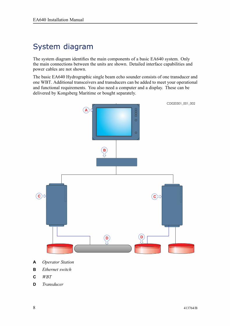
System diagramThe system diagram identifies the main components of a basic EA640 system. Onlythe main connections between the units are shown. Detailed interface capabilities andpower cables are not shown.
The basic EA640 Hydrographic single beam echo sounder consists of one transducer andone WBT. Additional transceivers and transducers can be added to meet your operationaland functional requirements. You also need a computer and a display. These can bedelivered by Kongsberg Maritime or bought separately.
A Operator StationB Ethernet switchC WBTD Transducer
EA640 Installation Manual

413764/B 9
System units
TopicsOperator Station description, page 9
WBT description, page 9
Single-beam transducers, page 10
Operator Station descriptionThe Operator Station may be a panel computer or a separate computer with a display.The computer is based on a commercial design,but the software and hardware has been specified byKongsberg Maritime to suit the EA640 requirements.
WBT descriptionThe WBT is provided to transmit acoustic energy through water. This transmission andreception are commonly referred to as a ping. After each transmission, the transceiverreceives the echoes from the targets in the water and/or the seabed. These echoes arefiltered and amplified, and then converted to digital format.The Wide Band Transceiver (WBT) comprises a ruggedbox providing all necessary transmitter and receiverelectronics. The receiver is designed for low noise,and it can handle input signals spanning a very largeinstantaneous dynamic amplitude range.A high quality Ethernet cable connects the Wide BandTransceiver (WBT) to the Operator Station. The distance between the Operator Stationand the transceiver can be extended up to maximum 70 meters. If a longer cable isrequired, cut it in half, and insert an Ethernet switch to provide buffer amplification.Note
If more than one Wide Band Transceiver (WBT) is used, a small high capacity Ethernetswitch is required to connect the transceivers to the Operator Station.
The Wide Band Transceiver (WBT) requires an external power supply offering 12 to15 Vdc, minimum 5 A. A suitable power supply is provided with the delivery. Thetransceiver can also be powered by a large capacity battery.
EA640
10 413764/B
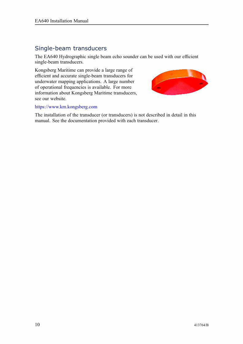
Single-beam transducersThe EA640 Hydrographic single beam echo sounder can be used with our efficientsingle-beam transducers.
Kongsberg Maritime can provide a large range ofefficient and accurate single-beam transducers forunderwater mapping applications. A large numberof operational frequencies is available. For moreinformation about Kongsberg Maritime transducers,see our website.
https://www.km.kongsberg.com
The installation of the transducer (or transducers) is not described in detail in thismanual. See the documentation provided with each transducer.
EA640 Installation Manual
413764/B 11
Scope of supply
TopicsBasic items provided with a standard delivery, page 11
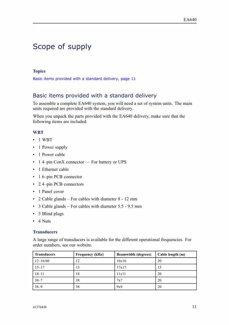
Basic items provided with a standard deliveryTo assemble a complete EA640 system, you will need a set of system units. The mainunits required are provided with the standard delivery.
When you unpack the parts provided with the EA640 delivery, make sure that thefollowing items are included.
WBT• 1 WBT• 1 Power supply• 1 Power cable• 1 4–pin ConX connector — For battery or UPS• 1 Ethernet cable• 1 6–pin PCB connector• 2 4–pin PCB connectors• 1 Panel cover• 2 Cable glands – For cables with diameter 8 - 12 mm• 3 Cable glands – For cables with diameter 5.5 - 9.5 mm• 3 Blind plugs• 4 Nuts
Transducers
A large range of transducers is available for the different operational frequencies. Fororder numbers, see our website.
Transducers Frequency (kHz) Beamwidth (degrees) Cable length (m)
12–16/60 12 16x16 20
15–17 15 17x17 15
18–11 18 11x11 20
38–7 38 7x7 20
38–9 38 9x9 20
EA640
12 413764/B
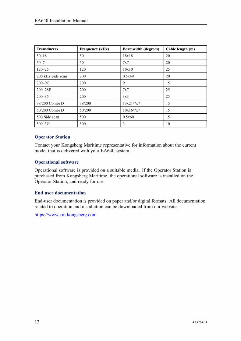
Transducers Frequency (kHz) Beamwidth (degrees) Cable length (m)
50–18 50 18x18 20
50–7 50 7x7 20
120–25 120 10x10 25
200 kHz Side scan 200 0.5x49 20
200–9G 200 9 15
200–28E 200 7x7 25
200–35 200 3x3 25
38/200 Combi D 38/200 13x21/7x7 15
50/200 Combi D 50/200 10x16/7x7 15
500 Side scan 500 0.5x60 15
500–3G 500 3 10
Operator Station
Contact your Kongsberg Maritime representative for information about the currentmodel that is delivered with your EA640 system.
Operational software
Operational software is provided on a suitable media. If the Operator Station ispurchased from Kongsberg Maritime, the operational software is installed on theOperator Station, and ready for use.
End user documentation
End-user documentation is provided on paper and/or digital formats. All documentationrelated to operation and installation can be downloaded from our website.
https://www.km.kongsberg.com
EA640 Installation Manual

413764/B 13
Installation requirements
TopicsSupply power requirements, page 13
Cables and wiring requirements, page 13
Compass deviation requirements, page 14
Noise sources, page 14
Supply power requirementsObserve the general requirements related to the supply power.
The supply voltage to the equipment must kept within ±10% of the installation’s nominalvoltage.
Maximum transient voltage variations on the main switchboard’s bus-bars are not toexceed -15% to +20% of the nominal voltage (except under fault conditions).• Make and model: Kongsberg WBT• Voltage requirement: 12 – 15 VDC, 5A• Power supply:
– Voltage requirement: 115/230 VAC, 47 to 63 Hz, single phase, nominal– Maximum voltage deviation: 15%– Maximum transient: 20% of nominal voltage, recovery time 3 s– Power consumption: 100 VA (Approximately)
Cables and wiring requirementsCorrect wiring is crucial for the operational performance of the EA640.
All cables running between system cabinets located in different rooms and/or on differentdecks must be supported and protected along their entire lengths using conduits and/orcable trays. Note that the cables must not be installed in the vicinity of high-powersupplies and cables, antenna cables or other possible sources of interference.
All transducer cables must be run in steel conduits.
For more detailed information about cables and wiring, refer to the basic cablerequirements.
EA640
14 413764/B
Compass deviation requirementsEA640 units that are installed on the bridge may have an effect on the compass.
Once the installation is complete, the vessel must be swung with the EA640 in bothoperative and inoperative modes.
The shipowner and captain are responsible for updating the compass deviation tableaccordingly with regard to the vessel’s national registry and corresponding maritimeauthority.
Noise sourcesThe operational performance of the EA640 Hydrographic single beam echo sounderdepends on the noise conditions. It is essential that the noise signature is as low aspossible.
The vessel’s hull, rudder(s) and propeller(s) must be thoroughly inspected in dry dockprior to installation.
Roughness below the water-line deformities in the shell plating and protruding obstaclescan create underwater noise. These sources of turbulence must be smoothed or removedas best as possible.
Note
It is especially important that the propeller(s) are not pitted or damaged.
Network securityIf a EA640 system is connected to a local area network, data security is important.
Equipment manufactured by Kongsberg Maritime is frequently connected to the vessel'slocal area network (LAN). When you connect a computer to a local area network youwill always expose the data on that computer. All other computers connected to the samenetwork may be able to access your data. Several threats may immediately occur:• Remote computers can read the data.• Remote computers can change the data.• Remote computers can change the behaviour of the computer, for example by
installing unwanted software.
Usually, two parameters are used to define the threat level:1 The likelihood that any remote connection will do any of the above.2 The damage done if a remote connection succeeds doing this.
Kongsberg Maritime has no information regarding the complete system installation onany vessel. Systems provided by Kongsberg Maritime are regarded as stand-alone offline
EA640 Installation Manual

413764/B 15
systems. They are stand-alone even though they may be connected to a network forsensor interfaces and/or data distribution.
Note
No network safety applications are installed on any Kongsberg Maritime computers.The computers are thus not protected against viruses, malware or unintentional accessfrom external users.
Securing the EA640 system itself has no meaning unless there is a policy in place thatsecures all computers in the network. This policy must include physical access bytrained and trusted users. The customer/end user of the EA640 system will always bein charge of defining and implementing a security policy, and providing the relevantnetwork security applications.
Note
Kongsberg Maritime will not accept any responsibility for errors and/or damages causedby unauthorized use or access to the EA640.
If you wish to connect the EA640 system to the ship's local area network, you mustimplement the same security mechanisms on the EA640 computer(s) as for the rest ofthe network. This is a task for the network responsible person on board. Some keyelements here must be:• The same anti-virus protection on all computers, including routines for updating
this protection.• The same settings for the firewall on all computers.• Controlled physical access to computers on the network.• Trusted and trained operators.• Log-in access mechanisms.• Same policy for attaching peripheral equipment to the computers (USB devices,
hard drives etc).• Installation of programs on any computer in the network, verification that each
program is authentic.• Definition of which programs are allowed to run on each computer.• Logging mechanism of computer activity, and inspection of these logs.
How to define and implement these rules depends on each end user's network systemconfiguration, which again must be a result of the policies and threat levels the end userhas defined for the complete installation. For some products the network consists of onlyprocessor units and/or work stations, transceivers and a few sensors. On other vessels,larger computer systems can be installed to include numerous products and data systems.There must be one responsible person for the security of the system, large or small.
EA640

16 413764/B
Support informationShould you need technical support for your EA640 you must contact a KongsbergMaritime office. A list of all our offices is provided on our website. You can also contactour main support office in Norway.• Company name: Kongsberg Maritime AS• Address: Strandpromenaden 50, 3190 Horten, Norway• Telephone (24h support): +47 33 03 24 07• Website: https://www.km.kongsberg.com• E-mail address: [email protected]
EA640 Installation Manual

413764/B 17
Preparations
TopicsInstallation summary, page 18
About installation drawings, page 19
Tools, equipment and consumables required for EA640 installation, page 19
Where to install the transducer, page 20
Acoustic noise, page 25
Preparations
18 413764/B
Installation summaryInstallation of the EA640 is a demanding task that requires careful preparations, anumber of specific procedures, wiring and required system settings.
ContextAn overall installation procedure is provided.Note
In order to obtain maximum safety and EA640 performance, it is very important that theinstallation procedures in this manual are complied to. You must do the tasks in the orderthey are described. The vessel owner must make sure that the installation shipyard holdsthe applicable competence to perform the installation, and that the applicable maritimeauthorities are available to verify and certify the installation.
Procedure1 Determine the physical location of the transducer (or transducers).
Necessary considerations must be taken to avoid acoustic and electric disturbances.2 Install each transducer.
Each transducer will penetrate the hull. For this reason, this is a crucial partof the installation. The installation shipyard must provide all necessary designand installation drawings, as well as the relevant work standards and mountingprocedures. If required, all documents provided by the shipyard for the physicalinstallation of the EA640 must be approved by the vessel’s national registry andcorresponding maritime authority and/or classification society. Such approval mustbe obtained before the installation can begin. The shipowner and shipyard doing theinstallation are responsible for obtaining and paying for such approval.
3 Install the EA640 system units.Note that some EA640 system units may be commercial. Unless ordered specificallythese are not included in the delivery, and must be purchased locally.
4 Install the cables between the EA640 system units.Observe the relevant cable plan, procedures, as well as the general requirements forcabling.
5 Power up the EA640 for the first time, and set it to work.Note
In order to power up of the EA640 in a safe and correct manner, the relevantprocedures must be complied to!
6 Connect the peripheral units.7 Do a complete EA640 system test.
EA640 Installation Manual

413764/B 19
About installation drawingsThe installation shipyard must provide all necessary design and installation drawings, aswell as the relevant work standards and mounting procedures.
Note
If required, all documents provided by the shipyard for the physical installation of theEA640 must be approved by the vessel’s national registry and corresponding maritimeauthority and/or classification society. Such approval must be obtained before theinstallation can begin. The shipowner and shipyard doing the installation are responsiblefor obtaining and paying for such approval.
Kongsberg Maritime offers free advice for installation planning. Proposed arrangementsmay be sent for commentary or suggestions. The following drawings should besubmitted should assistance be requested:• General arrangement• Body plan and drawings of the relevant compartment• Lines plan
Tools, equipment and consumables requiredfor EA640 installationIn order to do the EA640 installation, all necessary tools and equipment for mechanicalwork, cabinet installation and electrical wiring must be available.
It is not practical to provide a detailed list of all necessary tools and equipment. You mustbe equipped with a standard set of tools. This tool set must comprise the normal toolsfor electronic and electromechanical tasks. This includes different screwdriver types,pliers, spanners, a cable stripper, a soldering iron, etc. Each tool must be provided invarious sizes. We recommend that all tools are demagnetized to protect your equipment.However, you must make sure that the following specialized tools are available.• All necessary tools and consumables required for welding• All necessary tools and consumables required for physical installation of units,
cabinets and racks• All necessary tools and consumables required for electrical installations
Preparations
20 413764/B
Where to install the transducer
TopicsIntroduction to transducer location, page 20
Mount the transducer deep, page 20
Avoid protruding objects near the transducer, page 21
Keep the transducer far away from the propellers, page 22
Mount the transducer at a safe distance from bow thruster(s), page 22
Summary and general recommendations, page 22
Introduction to transducer locationA single answer to the question "where to install the transducer" cannot be given.
The physical location of the transducer depends on the vessel's design and construction,how the hull is shaped, and how the water runs along the hull. There are however anumber of important guidelines, and some of these are even conflicting.
Note
The information here must be considered as general advice. Each EA640 installationmust be handled separately depending on the hull design and the other electrical andmechanical systems installed on the vessel.
Mount the transducer deepIn order to achieve the best possible EA640 performance, mount the transducer as deepas possible under the vessel’s hull.
There are several reasons for this recommendation.
Flow noise
Consider the situations when the vessel is unloaded, and pitching in heavy seas. Thevessel is riding high, and the bow may even be lifted out of the water. This will cause alot of air to follow the shape of the hull.
The upper water layers of the sea contain a myriad of small air bubbles created by thebreaking waves. In heavy seas the upper 5 to 10 metres may be filled with air, and thehighest concentrations will be near the surface. Air bubbles absorb and reflect the soundenergy, and they may in worst cases block the sound transmission altogether.
EA640 Installation Manual
413764/B 21
Cavitation
Cavitation is the formation of small air bubbles close to the transducer face. The bubblesappear because the local pressure becomes negative during parts of the acoustic pressurecycles. The cavitation threshold increases with the hydrostatic pressure. The noise ismade when the bubbles implode.
Transmitting in air
The transducer must never be lifted free of the water surface. If the transducer isactivated when out of water it may be damaged beyond repair. Mounting the transducerat a deep position on the hull will in normally prevent this.
Slamming
Slamming happens if the vessel hull climbs out of the water in heavy seas. The force ofthe water when the hull falls down may push the transducer up, and may cause damageboth to the transducer and to its mounting. This is especially important for low frequencytransducers with large faces. The effect of slamming can be reduced by mounting thetransducer as deep as possible on the hull.
Note
Kongsberg Maritime AS takes no responsibility for any damages to the transducer, thecable or the mounting arrangement, caused by slamming.
Avoid protruding objects near the transducerObjects protruding from the hull will generate turbulence and flow noise. This willreduce the EA640 performance.
Protruding objects may be zinc anodes, transducers or even the vessel's keel. Holes andpipe outlets are also important noise sources, as well as rough surfaces caused by badwelding. Even traces of sealing compound, sharp edges, bolts or empty bolt holes willcreate noise. All these protruding objects may act as resonant cavities amplifying theflow noise at certain frequencies.
Do not place a transducer in the vicinity of protruding objects, and especially not closebehind them. Make sure that the surface of the transducer face, the hull plating and puttyaround the transducer is as even and smooth as possible. Mounting screws or bolts mustnot be extruding from the transducer, the installation hardware or the hull plating. Ifnecessary, grind and polish all surfaces.
Preparations

22 413764/B
Keep the transducer far away from the propellersThe propulsion propellers is the dominant noise source on most vessels. The noiseis easily transmitted through the water. This noise may often reduce the overallperformance of your EA640.
The transducer must be installed as far away from the propellers as possible. The bestpositions are therefore on the fore part of the hull. Positions outside the direct line ofsight from the propellers are best.
On small vessels we recommend mounting the transducer on that side of the keel wherethe propeller blades move upwards. This is because the propeller cavitation is weakeston that side. The cavitation starts when the water flows in the same direction as thepropeller blades. This is where the propeller blades move downwards.
Mount the transducer at a safe distance from bow thruster(s)Bow thruster propellers are extremely noisy. When you decide where to place thetransducer, you must consider the noise created by most bow thrusters.
When in operation, the noise and cavitation bubbles created by the thruster may makeyour EA640 Hydrographic single beam echo sounder useless, almost no matter where thetransducer is installed. When the bow thrusters are not in operation, the tunnel createsturbulence. If your vessel is pitching, the tunnel may be filled with air or aerated water inthe upper position and release this in the lower position.
In general, the transducer should therefore be placed well away from the bow thruster(s).
However, this is not an invariable rule. Certain thruster designs - combined with theirphysical locations on the hull - may still offer a suitable location for the transducer, evenclose to the thruster. If you are in doubt, consult a naval architect.
Summary and general recommendationsSome of the installation guidelines provided for transducer location may be conflicting.For this reason, each vessel must be treated individually in order to find the bestcompromise.
In general, the most important factor is to avoid air bubbles in front of the transducerface. For this reason, the recommended transducer location is normally in the fore part ofthe hull, well ahead of the noise created by the bow wave.
The maximum distance from the bow is normally equal to one third of the total waterline length of the hull.
Note
Mounting the transducer more than 10–15 meters from the bow may cause problemswith the turbulent flow.
EA640 Installation Manual

413764/B 23
A TransducerB Inclination angleC Hull length at water lineD Maximum 1/3 of the hull length at water line (C)
If the vessel hull has a bulbous bow, this may well be a good transducer location, butalso in this case the flow pattern of the aerated water must be taken into consideration.The foremost part of the bulb is often a good location.
A ThrusterB Transducer location
This applies to the vessel in normal trim and speed.
Preparations

24 413764/B
Important
The transducer must never be tilted backwards when the vessel is moving at normalspeed.
Do not place a transducer in the vicinity of protruding objects, and especially not closebehind them.
Make sure that the surface of the resulting installation is as smooth and streamlined aspossible.
EA640 Installation Manual
413764/B 25
Acoustic noise
TopicsContributing factors, page 25
Self noise, page 27
Ambient noise, page 29
Electrical self noise, page 29
Some means to reduce acoustic noise, page 30
Contributing factorsSeveral factors are contributing to the performance of the hydroacoustic equipmentused on board a vessel.
Factors contributing to the performance of the hydroacoustic equipment used on board avessel are:• The quality and properties of the transmitted signal• The quality of the receiving system• The operational settings made during operation• The properties of the target(s)• The signal-to-noise ratio
The majority of these factors can neither be controlled nor improved by meansof installation methods or transducer locations. The quality and properties of thetransmitting and receiving systems are key factors during our product development, whileour end user documentation aims to help the user to make the right filter settings duringoperation. As for the target properties, there is nothing any of us can do with those.
The signal-to-noise ratio, however, can be improved by making the correct choicesduring installation.
Signal-to-noise ratio (often abbreviated SNR or S/N) is a measure used inscience and engineering that compares the level of a desired signal to the level ofbackground noise. It is defined as the ratio of signal power to the noise power, oftenexpressed in decibels. A ratio higher than 1:1 (greater than 0 dB) indicates moresignal than noise. While SNR is commonly quoted for electrical signals, it canbe applied to any form of signal [...].
http://en.wikipedia.org/wiki/Signal_to_noise_ratio (September 2013)
The signal is the echo that we want to know something about, while the noise is anyunwanted signals or disturbances. The echo must be detected in the noise and therefore it
Preparations
26 413764/B
is necessary to keep the noise level is as low as possible in order to obtain long rangeand dependable interpretation.
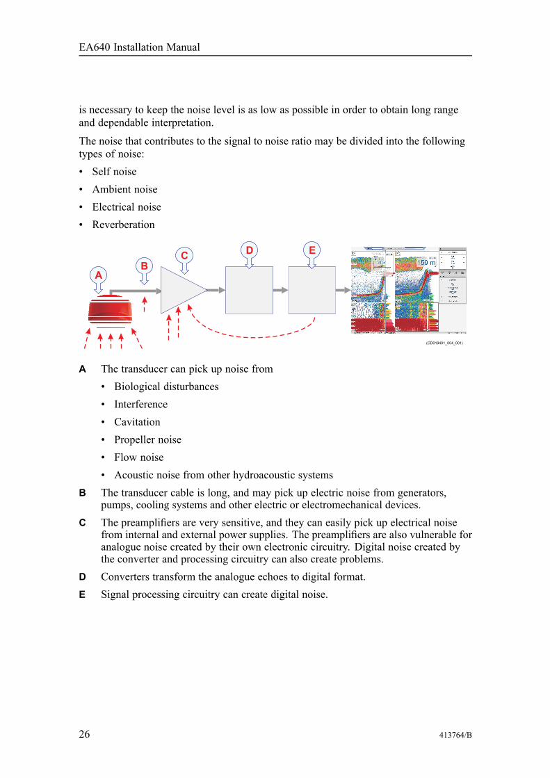
The noise that contributes to the signal to noise ratio may be divided into the followingtypes of noise:• Self noise• Ambient noise• Electrical noise• Reverberation
A The transducer can pick up noise from• Biological disturbances• Interference• Cavitation• Propeller noise• Flow noise• Acoustic noise from other hydroacoustic systems
B The transducer cable is long, and may pick up electric noise from generators,pumps, cooling systems and other electric or electromechanical devices.
C The preamplifiers are very sensitive, and they can easily pick up electrical noisefrom internal and external power supplies. The preamplifiers are also vulnerable foranalogue noise created by their own electronic circuitry. Digital noise created bythe converter and processing circuitry can also create problems.
D Converters transform the analogue echoes to digital format.E Signal processing circuitry can create digital noise.
EA640 Installation Manual
413764/B 27
Self noiseAny vessel equipped with a hydroacoustic system (for example echo sounder or sonar)will produce more or less self noise.
There are many sources of such self noise. We will here go into some details in order toanalyse the different sources of self noise on a vessel and how they may influence uponthe noise level of the hydroacoustic instruments.
Machinery noiseThe main contributor to machinery noise is usually the main engine on board the vessel.The contribution from auxiliary machinery may, however, be considerable, especially ifit is in poor shape. The machinery noise can be transmitted to the transducer as:• Structure-borne noise through the ship structure and the transducer mountings• Water-borne noise through the hull into the water to the transducer
Electrical noiseModern vessels are normally equipped with a lot of electric instruments such ashydroacoustic systems, radars, navigation systems, and communication equipment. Anyelectric instruments may in some cause electrical interference and noise. Internationalregulations and certifications are used to control and reduce this, but even these arelimited if the electrical systems are poorly installed and/or maintained.
Propeller noisePropeller noise is often the main source of noise at higher vessel speeds. Variable pitchpropellers or fast moving propellers usually make more noise than fixed propellers orslow moving propellers.
Propeller noise is usually water-borne. In some cases, however, shaft vibrations orvibrations in the hull near the propeller may be structure-borne to the transducer. If apropeller blade is damaged, this may increase the noise considerably.
Propeller cavitation is a severe source of noise. "Singing" propellers might be a source ofnoise, which interferes at discrete frequencies. In some cases static discharge from therotating propeller shaft may be quite disturbing.
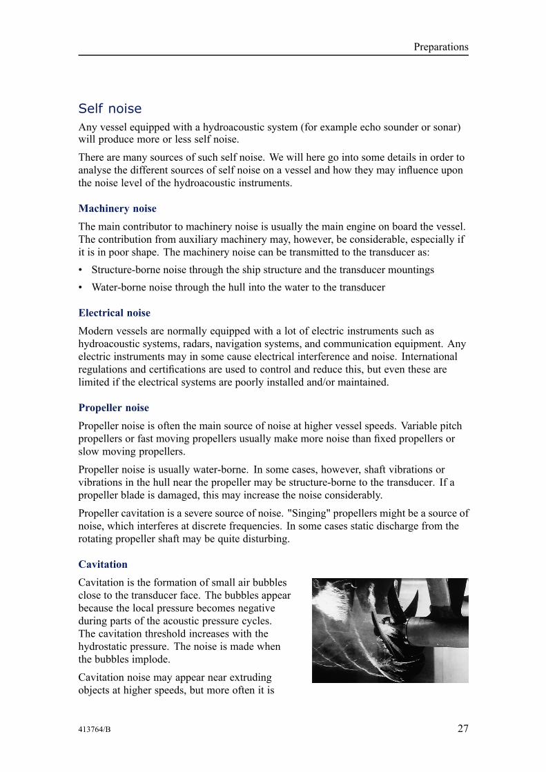
CavitationCavitation is the formation of small air bubblesclose to the transducer face. The bubbles appearbecause the local pressure becomes negativeduring parts of the acoustic pressure cycles.The cavitation threshold increases with thehydrostatic pressure. The noise is made whenthe bubbles implode.
Cavitation noise may appear near extrudingobjects at higher speeds, but more often it is
Preparations
28 413764/B
caused by the propellers. Propeller cavitation is a severe source of noise. The cavitationstarts when the water flows in the same direction as the propeller blades. This is wherethe propeller blades move downwards.
In some cases a resonant phenomenon is set up in a hole near the hull. This sound willhave a discrete frequency, while all other flow noise will have a wide frequency spectrum.
(Image from U. S. Navy in the public domain.)
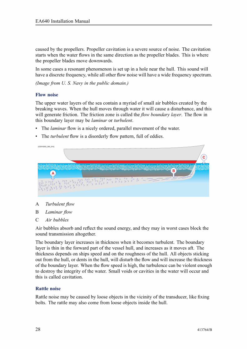
Flow noise
The upper water layers of the sea contain a myriad of small air bubbles created by thebreaking waves. When the hull moves through water it will cause a disturbance, and thiswill generate friction. The friction zone is called the flow boundary layer. The flow inthis boundary layer may be laminar or turbulent.• The laminar flow is a nicely ordered, parallel movement of the water.• The turbulent flow is a disorderly flow pattern, full of eddies.
A Turbulent flowB Laminar flowC Air bubbles
Air bubbles absorb and reflect the sound energy, and they may in worst cases block thesound transmission altogether.
The boundary layer increases in thickness when it becomes turbulent. The boundarylayer is thin in the forward part of the vessel hull, and increases as it moves aft. Thethickness depends on ships speed and on the roughness of the hull. All objects stickingout from the hull, or dents in the hull, will disturb the flow and will increase the thicknessof the boundary layer. When the flow speed is high, the turbulence can be violent enoughto destroy the integrity of the water. Small voids or cavities in the water will occur andthis is called cavitation.
Rattle noise
Rattle noise may be caused by loose objects in the vicinity of the transducer, like fixingbolts. The rattle may also come from loose objects inside the hull.
EA640 Installation Manual
413764/B 29
Interference
Interference from other hydroacoustic equipment on board the same vessel may be anannoying source of disturbance. Unless the same frequency is used for more than onepiece of equipment only the transmitted pulse will contribute to the interference.
In physics, interference is the phenomenon in which two waves superpose eachother to form a resultant wave of greater or lower amplitude. Interference usuallyrefers to the interaction of waves that are correlated or coherent with each other,either because they come from the same source or because they have the same ornearly the same frequency. Interference effects can be observed with all types ofwaves, for example, light, radio, acoustic, surface water waves or matter waves.
https://en.wikipedia.org/wiki/Interference_(wave_propagation), April 2016
Ambient noiseAmbient noise is usually not a limiting factor to the performance of sonars and echosounders.
The ambient noise may be split up as follows:• Sea noise: Air bubbles, seismic disturbances, waves, boundary turbulence, etc.• Biological noise: Fish, mammals• Man made noise: Other vessels, interference• Precipitation noise: Heavy rain or hail
In some areas, where many vessels operate together, the engine and propeller noise fromother vessels may be disturbing. Interference from hydroacoustic instruments locatedin other vessels may also be a limiting factor. The sea noise depends on the weatherconditions. In bad weather the sea noise can be quite high due to the waves.
Electrical self noiseElectrical or electronic self noise is picked up or generated in any other part of theequipment than the transducer.
Hum picked up by the transducer cables or picked up from the power supply is usuallythe most common source of electrical self noise. At higher frequencies – where ratherwide bandwidths are necessary – the noise from components, transistors or otheranalogue electronic may be a limiting factor.
Preparations
30 413764/B
Some means to reduce acoustic noiseSeveral factors are contributing to the performance of the hydroacoustic equipmentused on board a vessel. Careful planning of the EA640 installation may reduce theacoustic noise.
Unfortunately, it is impossible to simply provide a number of specific procedures toreduce the noise.
An important factor is the physical location of the transducers. This depends on thevessel's design and construction, how the hull is shaped, and how the water runs alongthe hull. Other factors deal with other equipment mounted on board, and this will also bevessel dependant. At moderate ship speeds the machinery noise is usually dominant. Atmedium speeds the flow noise increases more rapidly and takes over, while at higherspeed the propeller noise will be the main contributor.
Note
The information here must be considered as general advice. Each EA640 installationmust be handled separately depending on the hull design and the other electrical andmechanical systems installed on the vessel.
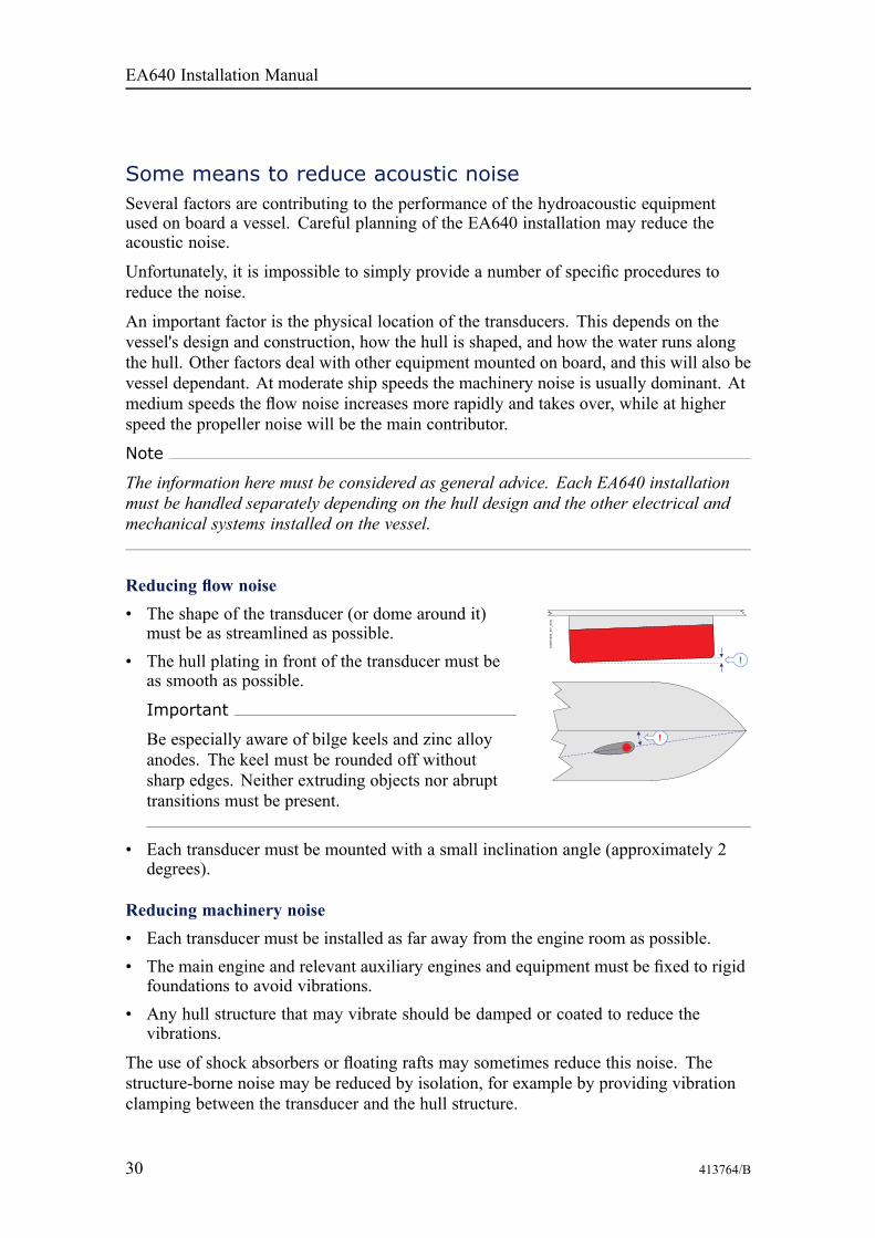
Reducing flow noise• The shape of the transducer (or dome around it)
must be as streamlined as possible.• The hull plating in front of the transducer must be
as smooth as possible.
Important
Be especially aware of bilge keels and zinc alloyanodes. The keel must be rounded off withoutsharp edges. Neither extruding objects nor abrupttransitions must be present.
• Each transducer must be mounted with a small inclination angle (approximately 2degrees).
Reducing machinery noise• Each transducer must be installed as far away from the engine room as possible.• The main engine and relevant auxiliary engines and equipment must be fixed to rigid
foundations to avoid vibrations.• Any hull structure that may vibrate should be damped or coated to reduce the
vibrations.
The use of shock absorbers or floating rafts may sometimes reduce this noise. Thestructure-borne noise may be reduced by isolation, for example by providing vibrationclamping between the transducer and the hull structure.
EA640 Installation Manual

413764/B 31
Reducing propeller noise• Each transducer must be installed as far away from the propellers as possible.• Sufficient clearance between the propellers and the hull, the rudder and the keel must
be provided.• Place the zinc alloy anodes in places where the water flow is the least disturbed.• Ensure that the propellers blades are correctly designed and without damages.• The use of a baffle between the propellers and the transducer may reduce noise
appreciably.• Static discharges caused by the rotating propeller shaft may be removed by proper
grounding or by mounting a coal brush from the shaft to vessel ground.
Reducing rattle noise
Ensure that no parts near the transducers can rattle as a result of water flow or vibrations.
Reducing interference
Interference from the transmission pulses from other hydroacoustic instruments onboard the vessel is difficult to avoid. The problem may be reduced by choosing theworking frequencies carefully and to some extent by separating the different transducers.On vessels with a large number of separate hydroacoustic systems installed and insimultaneous use, a separate synchronizing system (for example the K-Sync) shouldbe considered.
Reducing electrical noise• Place the transducer cables in a metal conduit from the transducer to the WBT.
Terminate the conduit as close to the transducers and WBT as possible.• Make sure that all units are properly grounded, as this is important to avoid electrical
noise.• Use shielded cables with correct grounding.• Separate EA640 cables from other cables with high voltages, large currents or
transients. Place all high voltage power cables in metal conduits.
Preparations

32 413764/B
Installing the EA640hardware units
TopicsInstalling the WBT using the integrated brackets, page 33
Installing the WBT in a 19" cabinet, page 34
Installing a commercial computer, page 35
Mounting the WBT Cabinet, page 37
Mounting the drawers in the WBT Cabinet, page 39
Designing, manufacturing and mounting the steel conduit, page 41
Installing the transducer(s), page 43
Installing the transducer on a blister or drop keel, page 44
Installing the transducer on a steel hull, page 46
EA640 Installation Manual

413764/B 33
Installing the WBT using the integratedbracketsThe EA640 WBT is normally positioned in a dedicated room in the vicinity of thetransducer. The physical length of the cable limits the distance between the transducerand the WBT. The WBT can be installed vertically or horizontally using the integratedmounting brackets. Four bolts are used, two on each side.
Prerequisites
A suitable location for the WBT must be defined priorto installation. We recommend that it is mounted asclose to the transducers as possible. The unit can inprinciple be mounted anywhere on board the ship,provided that the location is dry and ventilated.
The length of the transducer cables limits where theWBT can be installed.
The unit can be mounted in any direction and on any surface provided that theenvironmental requirements are met.
Note
If you mount the WBT on a bulkhead, position the unit so that all the connections arefacing down.
Procedure1 Place the WBT in the selected position.2 Secure the unit using four 5 mm bolts.
Make sure the cable connections are facing down if the unit is installed on abulkhead or wall.
3 Connect the cables.
Note
When you connect the cables, make sure that they are all properly secured, and ableto withstand the vibration and movements of the vessel.
Installing the EA640 hardware units

34 413764/B
Installing the WBT in a 19" cabinetThe WBT can be installed in a 19-inch cabinet by means of an optional drawer. Youwill need one drawer for each WBT unit.
Prerequisites
It is assumed that the WBT Cabinet has already been installed.
Context
If your EA640 comprises more than one WBT, youcan use the optional WBT Cabinet. This 19" cabinetholds maximum seven WBTs with power supplies,as well as an Ethernet switch and a power distributionpanel. Each WBT is then installed on a dedicatedWBT Drawer in the rack.
A Mounting bolts for the WBTB Mounting bracket for the power supplyC Holes for fastening and securing the cablesD Mounting bolts for the drawer assemblyE Mounting bolts for the drawer
Procedure1 Place the WBT on the WBT Drawer.2 Mount the transceiver and the power supply using the brackets, bolts and nuts
provided.
EA640 Installation Manual

413764/B 35
3 Mount the WBT Drawer into the 19-inch cabinet.4 Connect the cables.
Note
When you connect the cables, make sure that they are all properly secured, and ableto withstand the vibration and movements of the vessel.
Installing a commercial computerThe Operator Station can be installed inside a console, inside a suitable cabinet, in a 19"rack or on a desk. Make sure that adequate ventilation is available to avoid overheating.
Prerequisites
You must be equipped with a standard set of tools. This tool set must comprise thenormal tools for electronic and electromechanical tasks. This includes differentscrewdriver types, pliers, spanners, a cable stripper, a soldering iron, etc. Each toolmust be provided in various sizes. We recommend that all tools are demagnetized toprotect your equipment.
A suitable location for the computer must be defined prior to installation. Observe thecompass safe distance.
Context
For installation of a commercial computer, refer to the manual supplied by themanufacturer.
Note
Make sure that the chosen computer meets the EA640 requirements. The design andconstruction must allow for marine use, and the computer must be able to withstandthe movements and vibrations normally experienced on a vessel. Verify that you haveeasy access to cables and connectors, and that the computer can be installed in a safeand secure way.
Standard office computers may not be well fitted for maritime use. The motions andvibrations experienced on a vessel may reduce the computer lifetime considerably. Whileinstalling a commercial computer, use your common sense to improve the installationmethod suggested by the manufacturer.
Procedure1 Prepare the location and the necessary tools.2 Observe the installation requirements.
Installing the EA640 hardware units

36 413764/B
a Depending on its physical properties, install the computer inside a console, ina cabinet or 19” rack, or on a desk.
b Choose a position to fit the available cable lengths between the computer andthe other units it connects to.
c Observe the compass safe distance.d Make sure that enough space is made available for maintenance purposes.e Make sure that adequate ventilation is available to avoid overheating.f Make sure that the installation method allows for the physical vibration,
movements and forces normally experienced on a vessel.
Note
In order to allow for future maintenance, we recommend to mount the unit with itscables and connectors available for easy access.
3 Make sure that the chosen location meets the installation requirements.4 Provide ample space around the computer.
You must be able to reach and use the front and rear mounted connectors anddevices. It is also important that you allow for easy access to all the cables, andenough space for inspection, maintenance and parts replacement. If relevant, makesure that the space allows you to open the computer for unobstructed access toits internal parts.
Note
Make sure that you can access both the rear and front side of the computer after ithas been installed.
5 Install the computer.
Observe the applicable documentation provided by the manufacturer.6 Connect the cables.
Note
When you connect the cables, make sure that they are all properly secured, and ableto withstand the vibration and movements of the vessel.
EA640 Installation Manual
413764/B 37
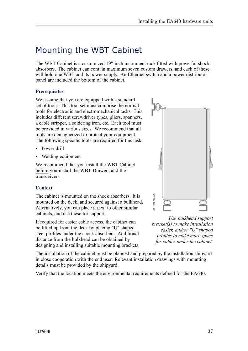
Mounting the WBT CabinetThe WBT Cabinet is a customized 19"-inch instrument rack fitted with powerful shockabsorbers. The cabinet can contain maximum seven custom drawers, and each of thesewill hold one WBT and its power supply. An Ethernet switch and a power distributorpanel are included the bottom of the cabinet.
Prerequisites
Use bulkhead supportbracket(s) to make installation
easier, and/or "U" shapedprofiles to make more spacefor cables under the cabinet.
We assume that you are equipped with a standardset of tools. This tool set must comprise the normaltools for electronic and electromechanical tasks. Thisincludes different screwdriver types, pliers, spanners,a cable stripper, a soldering iron, etc. Each tool mustbe provided in various sizes. We recommend that alltools are demagnetized to protect your equipment.The following specific tools are required for this task:• Power drill• Welding equipment
We recommend that you install the WBT Cabinetbefore you install the WBT Drawers and thetransceivers.
Context
The cabinet is mounted on the shock absorbers. It ismounted on the deck, and secured against a bulkhead.Alternatively, you can place it next to other similarcabinets, and use these for support.
If required for easier cable access, the cabinet canbe lifted up from the deck by placing "U" shapedsteel profiles under the shock absorbers. Additionaldistance from the bulkhead can be obtained bydesigning and installing suitable mounting brackets.
The installation of the cabinet must be planned and prepared by the installation shipyardin close cooperation with the end user. Relevant installation drawings with mountingdetails must be provided by the shipyard.
Verify that the location meets the environmental requirements defined for the EA640.
Installing the EA640 hardware units
38 413764/B
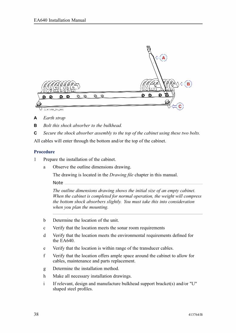
A Earth strapB Bolt this shock absorber to the bulkhead.C Secure the shock absorber assembly to the top of the cabinet using these two bolts.
All cables will enter through the bottom and/or the top of the cabinet.
Procedure1 Prepare the installation of the cabinet.
a Observe the outline dimensions drawing.
The drawing is located in the Drawing file chapter in this manual.
Note
The outline dimensions drawing shows the initial size of an empty cabinet.When the cabinet is completed for normal operation, the weight will compressthe bottom shock absorbers slightly. You must take this into considerationwhen you plan the mounting.
b Determine the location of the unit.c Verify that the location meets the sonar room requirementsd Verify that the location meets the environmental requirements defined for
the EA640.e Verify that the location is within range of the transducer cables.f Verify that the location offers ample space around the cabinet to allow for
cables, maintenance and parts replacement.g Determine the installation method.h Make all necessary installation drawings.i If relevant, design and manufacture bulkhead support bracket(s) and/or "U"
shaped steel profiles.
EA640 Installation Manual

413764/B 39
Note
The use of "U" shaped profiles and bulkhead support bracket(s) is optional.
2 Mount the "U" shaped profiles.a Design, manufacture and mount the U-shaped steel profiles.b Make sure that the profiles can withstand the full weight of the cabinet.c Make the required mounting holes to accept the bottom frame (with shock
absorbers).d Position the profiles on the deck, and mount them using bolts or welds.
3 Mount the bottom frame.The bottom frame is fitted with four shock absorbers. If you have used U-shapedprofiles, place the frame on top of these.
4 Mount the bulkhead support bracket.a Design and manufacture the bulkhead bracket.b Make the required mounting holes to accept the top shock absorbers.c Position the brackets on the bulkhead, and mount them using bolts or welds.
5 Mount the top shock absorber assembly.a Remove the four lifting lugs.b Mount the top shock absorber assembly using two of the same holes.c Use spare bolts to close the remaining lifting lug holes.
6 Place cabinet in its correct position on the bottom frame.a Use four bolts through the bottom frame to secure the cabinet.b Mount the top shock absorbers to the bulkhead support bracket(s).
7 Fasten the earth strap.
Mounting the drawers in the WBT CabinetThe WBT Cabinet can contain maximum seven custom drawers. Each drawer will holdone WBT and its power supply. The drawer is mounted in the same way as any otherequipment designed for 19" racks using standard tools.
PrerequisitesYou must be equipped with a standard set of tools. This tool set must comprise thenormal tools for electronic and electromechanical tasks. This includes differentscrewdriver types, pliers, spanners, a cable stripper, a soldering iron, etc. Each toolmust be provided in various sizes. We recommend that all tools are demagnetized toprotect your equipment.
Installing the EA640 hardware units

40 413764/B
Context
We recommend that you mount all the empty drawers into the WBT Cabinet beforeyou mount the WBT unit on each drawer.
A Mounting bolts for the WBTB Mounting bracket for the power supplyC Holes for fastening and securing the cablesD Mounting bolts for the drawer assemblyE Mounting bolts for the drawer
Procedure1 Decide where in the cabinet you wish to mount the drawers.2 Mount each drawer using six bolts on each side (D).3 Pull out the drawer.4 Remove the power supply bracket (B).5 Place the power supply on the drawer, and mount the bracket (B) to secure it.6 Mount the WBT using the bolts provided (A).
Further requirements
Connect the cables.
EA640 Installation Manual

413764/B 41
Designing, manufacturing and mounting thesteel conduitA steel conduit is used to protect the transducer cable. The conduit serves two purposes.It will protect the cable, and shield it from electric noise. Depending on how the steelconduit is terminated over the transducer, it may also secure the watertight integrityof the vessel.
Prerequisites
To design, manufacture and mount the steel conduit, the following prerequisites must bemet:• All relevant vessel and transducer drawings must be available.• All relevant work instructions, procedures and standards must be available.• The physical location of the transducer has been determined.• The installation method has been determined.• The cable gland has been installed.• All relevant personnel (naval architects, designers, skilled shipyard workers) and
tools must be available.
Installing the EA640 hardware units
42 413764/B
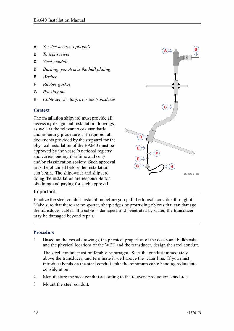
A Service access (optional)B To transceiverC Steel conduitD Bushing, penetrates the hull platingE WasherF Rubber gasketG Packing nutH Cable service loop over the transducer
Context
The installation shipyard must provide allnecessary design and installation drawings,as well as the relevant work standardsand mounting procedures. If required, alldocuments provided by the shipyard for thephysical installation of the EA640 must beapproved by the vessel’s national registryand corresponding maritime authorityand/or classification society. Such approvalmust be obtained before the installationcan begin. The shipowner and shipyarddoing the installation are responsible forobtaining and paying for such approval.
Important
Finalize the steel conduit installation before you pull the transducer cable through it.Make sure that there are no spatter, sharp edges or protruding objects that can damagethe transducer cables. If a cable is damaged, and penetrated by water, the transducermay be damaged beyond repair.
Procedure1 Based on the vessel drawings, the physical properties of the decks and bulkheads,
and the physical locations of the WBT and the transducer, design the steel conduit.
The steel conduit must preferably be straight. Start the conduit immediatelyabove the transducer, and terminate it well above the water line. If you mustintroduce bends on the steel conduit, take the minimum cable bending radius intoconsideration.
2 Manufacture the steel conduit according to the relevant production standards.3 Mount the steel conduit.
EA640 Installation Manual
413764/B 43
Secure the steel conduit to decks and/or bulkheads with welds. Observe relevantrequirements and guidelines from the classification society, and make sure that theconduit is properly supported, strong and watertight.Note
The quality of the welding is critical to the safety of the vessel. Welding must onlybe done by a certified welder.
4 If relevant, allow the maritime authority and/or classification society to inspect andapprove the design and the installation of the steel conduit.
Installing the transducer(s)The installation of the transducer (or transducers) is a key task for successful use of theEA640 Hydrographic single beam echo sounder. Not only will you need to penetratethe vessel’s hull, you must also to select a physical location for maximum performanceand minimum acoustic and electric noise.
PrerequisitesTo get a full overview of the installation, you need all relevant vessel drawings. You alsoneed the drawings provided for each transducer.
ContextNecessary information for the installation of each transducer can be found in the end-userdocumentation provided with the transducer.
Procedure1 Determine the physical location of the transducer.
The decision must be based on:• The vessel drawings• The shape and properties of the hull
Make sure that all possible considerations are made to reduce noise.2 Based on the shape of the transducer housing, and the mounting devices available,
determine the installation method.3 Design, manufacture and mount the necessary fairing, installation blister, keel box
and/or tank that is required to mount the transducer.4 Design, manufacture and mount the steel conduit for the transducer cable.5 Unpack the transducer from its transport crate.6 Position the transducer under the mounting location.7 Pull the transducer cable up through the steel conduit.
Installing the EA640 hardware units
44 413764/B
8 Tighten the packing nut on the cable gland properly to avoid leaks.9 Mount the transducer.10 Seal the top of the steel conduit to prevent water leaks.11 Connect the transducer cable to the WBT.12 If your vessel will operate in waters with a lot of marine growth, consider applying
a thin layer of anti-fouling paint to the transducer face.
Installing the transducer on a blister or dropkeelWhen all the preparations have been made, observe this procedure for the mounting ofthe transducer If required, additional and more detailed procedures must be provided bythe installation ship yard.
Prerequisites• The physical location of the transducer has been determined.• The steel conduits are installed.• A suitable fairing is designed and mounted.
Note
Whenever relevant, all drawings as well as the physical installation of each device mustbe approved by the vessel’s national registry and corresponding maritime authorityand/or classification society.
The following special tools are required for this installation:• Torque wrench for the mounting bolts• Loctite 270 (permanent high-strength threadlocker)
Context
This installation arrangement assumes that you can access the inside of the blister ordrop keel to mount the nuts. If this is not the case, the transducer must be mounted withthreaded steel rods welded to the bottom of the blister.
EA640 Installation Manual
413764/B 45
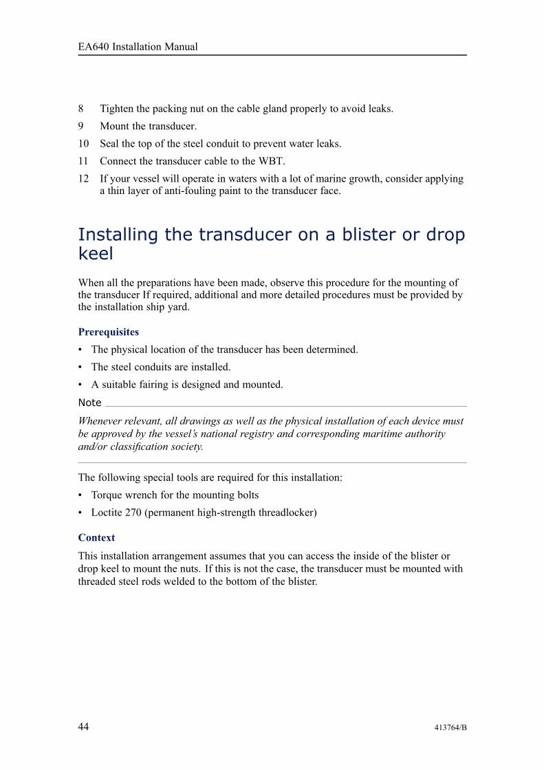
A Bolt with suitablediameter and length
B NutC WasherD Transducer cableE Blister bottom plateF Fill with suitable filling
compound (putty) toreduce flow noise
Procedure1 Lift the transducer up into is location, and align the holes on the transducer with the
holes in the blister or drop keel.
Observe the direction of the transducer. The "forward" marking must point towardsthe bow of the vessel!
2 Insert the two bolts through the transducer and the blister or drop keel bottom plate.3 Fasten the two nuts on the inside of the blister or drop keel.
Use Loctite 290 to secure the bolts.4 Fill the two bolt holes in the transducer with a suitable filling compound (putty),
and smooth out the surface of the transducer face.
Any obstructions, cracks, dents or unevenness on the transducer face may causeflow noise.
5 When the transducer has been fastened, inspect the plating around the transducerface.
Important
Make sure that the surface of the transducer face, as well as the plating and puttyaround the transducer is as even and smooth as possible. Obstructions on thesesurfaces will create problems with turbulent flow, and may cause noise.
6 If required, allow the relevant maritime authority and/or classification society toinspect and approve the transducer installation.
Installing the EA640 hardware units
46 413764/B
Installing the transducer on a steel hullWhen all the preparations have been made, observe this procedure for the mounting ofthe transducer If required, additional and more detailed procedures must be provided bythe installation ship yard.
Prerequisites• The physical location of the transducer has been determined.• The steel conduits are installed.• A suitable fairing is designed and mounted.
Note
Whenever relevant, all drawings as well as the physical installation of each device mustbe approved by the vessel’s national registry and corresponding maritime authorityand/or classification society.
The following special tools are required for this installation:• Torque wrench for the mounting bolts• Loctite 270 (permanent high-strength threadlocker)
Context
It is very important that the fairing designed for the installation supports the full lengthof the transducer body. Incomplete support will put the transducer.at risk in heavy seas.
The force of the water when the hull falls down may push the transducer up, and maycause damage both to the transducer and to its mounting.
Note
Kongsberg Maritime AS takes no responsibility for any damages to the transducer, thecable or the mounting arrangement, caused by slamming.
EA640 Installation Manual
413764/B 47
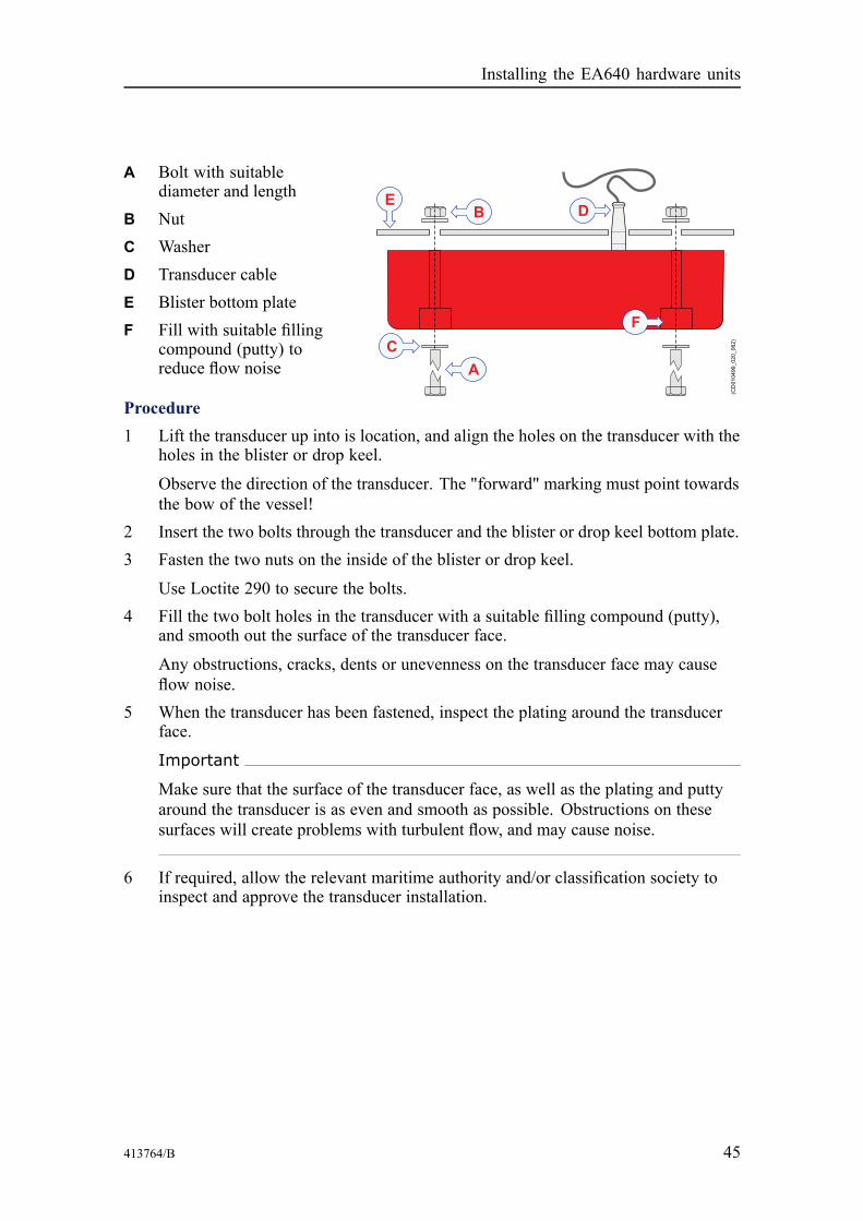
1 Nut2 Threaded rod with suitable
diameter and length,welded to the bottom ofthe fairing
3 Washer4 Transducer cable5 Hull6 Fill with suitable filling
compound (putty) toreduce flow noise
Procedure1 Lift the transducer up into
is location, and align theholes on the transducerwith the threaded rods welded to the fairing.
Observe the direction of the transducer. The "forward" marking must point towardsthe bow of the vessel!
2 Push the transducer in place.3 Fasten the two nuts on the end of each threaded rod.
Use Loctite 290 to secure the bolts.4 Fill the two bolt holes in the transducer with a suitable filling compound (putty),
and smooth out the surface of the transducer face.
Any obstructions, cracks, dents or unevenness on the transducer face may causeflow noise.
5 When the transducer has been fastened, inspect the plating around the transducerface.
Important
Make sure that the surface of the transducer face, as well as the plating and puttyaround the transducer is as even and smooth as possible. Obstructions on thesesurfaces will create problems with turbulent flow, and may cause noise.
6 If required, allow the relevant maritime authority and/or classification society toinspect and approve the transducer installation.
Installing the EA640 hardware units

48 413764/B
Cable layout andinterconnections
TopicsCable plan, page 49
List of cables, page 50
Installing the EA640 cables, page 51
Cable drawings and specifications, page 58
EA640 Installation Manual
413764/B 49
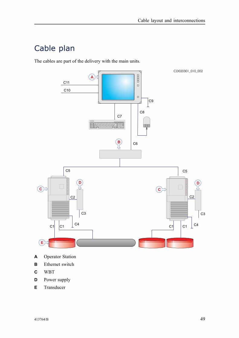
Cable planThe cables are part of the delivery with the main units.
A Operator StationB Ethernet switchC WBTD Power supplyE Transducer
Cable layout and interconnections

50 413764/B
An Ethernet switch is required if more than one WBT is used.
A junction box is required if the transducer cable is longer than provided.
List of cablesA set of cables is required to connect the EA640 units to each other, and to the relevantpower source(s).Cable Type From/To Minimum requirements
C1 Transducer cable From WBT to transducer *
C2 DC power cable From Power supply to WBT **
C3 AC power cable From Power supply to AC poweroutlet
**
C4 Ground cable From WBT to vessel ground 1 x 6 mm2
C5 Ethernet cable From WBT to Ethernet switch CAT5–E STP
C6 Ethernet cable From Operator Station toEthernet switch
CAT5–E STP
C7 Computer cable From Operator Station tokeyboard
**
C8 Computer cable From Operator Station to mouse(or another similar device)
**
C9 Ground cable From Operator Station to vesselground
1 x 6 mm2
C10 AC power cable From Operator Station to ACpower outlet
**
Comments1 The transducer cable is provided with the transducer. If you need to splice
the transducer cable to make it longer, observe the information in the end userdocumentation for the relevant transducer.
2 The cable is supplied with the EA640 delivery.
Identifying EA640 cables on a project cable drawing
The EA640 is often a part of a project delivery. For such deliveries, specific project cabledrawings are established to show all the main cables, and how the various productsare connected. In such project cable drawings, the EA640 cables may be identifiedas EA640/Cx.
EA640 Installation Manual

413764/B 51
Installing the EA640 cables
TopicsConnecting one or more transducers to the WBT, page 51
Connecting power and ground to the WBT, page 55
Connecting the WBT and the Operator Station, page 56
Connecting a synchronization cable to the Operator Station using an RS-232 serialinterfaces, page 56
Connecting one or more transducers to the WBTDepending on your operational requirements for the EA640, one or more transducersmust be connected to the WBT.
Prerequisites
It is strongly recommended to lay a steel conduit from the cable gland above thetransducer to the EA640 transceiver, and to pull the transducer cable through this conduit.
There are several reasons for this.• It will make it easier at a later stage to replace the transducer.• It will protect the cables.• Noise and interference from other electrical equipment is greatly reduced.• The risk of flooding is greatly reduced when the steel conduit is terminated above
the water line.
With a steel conduit the installation will satisfy the European Union regulations forelectromagnetic compatibility (EMC) interference. Without a steel conduit, there is arisk of reduced EA640 performance.
Context
The WBT used by the Kongsberg EA640 can be set up to work with maximum four -4-operational frequencies. This means that you can use four single frequency/single beamtransducers or two dual frequency transducers.
The transducer is connected to a terminal block under a panel plate on the rear of theWBT. The connectors are a part of the WBT delivery.
Cable layout and interconnections
52 413764/B
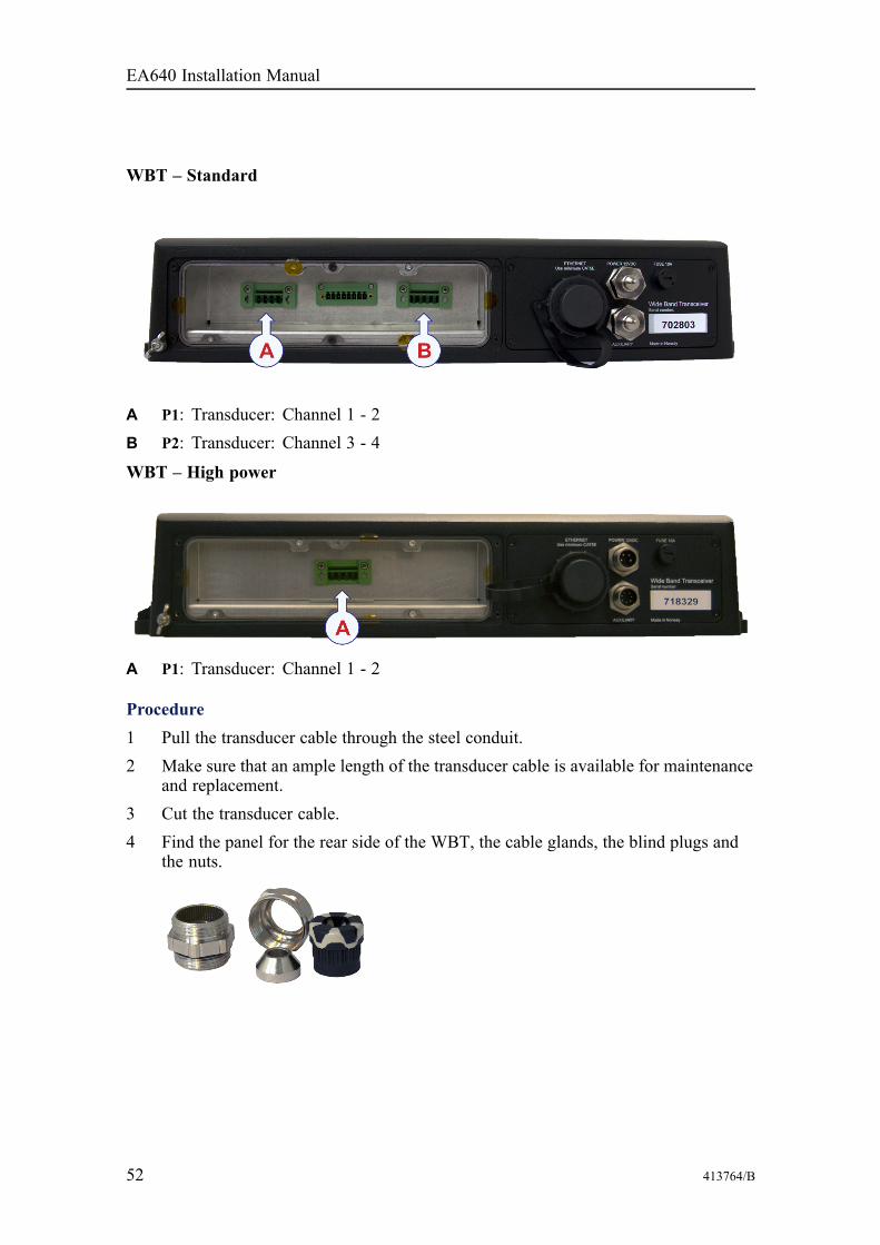
WBT – Standard
A P1: Transducer: Channel 1 - 2B P2: Transducer: Channel 3 - 4
WBT – High power
A P1: Transducer: Channel 1 - 2
Procedure1 Pull the transducer cable through the steel conduit.2 Make sure that an ample length of the transducer cable is available for maintenance
and replacement.3 Cut the transducer cable.4 Find the panel for the rear side of the WBT, the cable glands, the blind plugs and
the nuts.
EA640 Installation Manual
413764/B 53
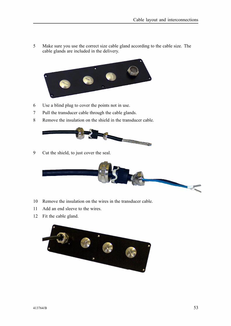
5 Make sure you use the correct size cable gland according to the cable size. Thecable glands are included in the delivery.
6 Use a blind plug to cover the points not in use.7 Pull the transducer cable through the cable glands.8 Remove the insulation on the shield in the transducer cable.
9 Cut the shield, to just cover the seal.
10 Remove the insulation on the wires in the transducer cable.11 Add an end sleeve to the wires.12 Fit the cable gland.
Cable layout and interconnections
54 413764/B
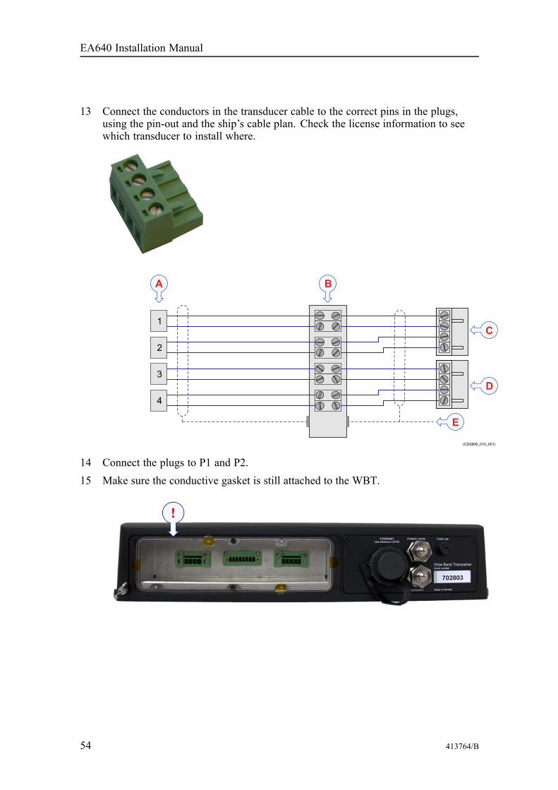
13 Connect the conductors in the transducer cable to the correct pins in the plugs,using the pin-out and the ship’s cable plan. Check the license information to seewhich transducer to install where.
14 Connect the plugs to P1 and P2.15 Make sure the conductive gasket is still attached to the WBT.
EA640 Installation Manual

413764/B 55
16 Fasten the panel.
Connecting power and ground to the WBTThe EA640 WBT is powered by a dedicated power supply connected to the AC mains,or from a suitable battery for DC operation. The unit must be properly grounded.
Context
The power for the WBT is provided by a separate power supply. It is normally connectedto an uninterruptible power supply, and will automatically detect the mains voltage (230or 115 VAC) when connected. The output from the power supply is connected to the+12 VDC input socket on the WBT. The AC and DC power cables are provided withthe power supply.
Procedure1 Connect the DC cable from the power supply to the +12 Vdc socket.
If you wish to operate your WBT from a DC supply, you can use any suitablebattery providing +12 to +15 Vdc.
2 Connect the AC mains plug on the power supply to the bulkhead power outlet (oran uninterrupted power supply).
3 Connect the grounding cable from the nearest grounding point to the dedicatedterminal on the WBT.
Cable layout and interconnections
56 413764/B
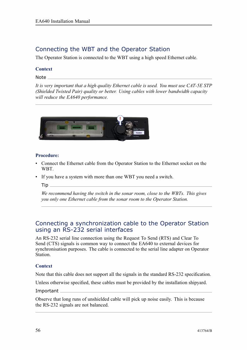
Connecting the WBT and the Operator StationThe Operator Station is connected to the WBT using a high speed Ethernet cable.
Context
Note
It is very important that a high quality Ethernet cable is used. You must use CAT-5E STP(Shielded Twisted Pair) quality or better. Using cables with lower bandwidth capacitywill reduce the EA640 performance.
Procedure:• Connect the Ethernet cable from the Operator Station to the Ethernet socket on the
WBT.• If you have a system with more than one WBT you need a switch.
Tip
We recommend having the switch in the sonar room, close to the WBTs. This givesyou only one Ethernet cable from the sonar room to the Operator Station.
Connecting a synchronization cable to the Operator Stationusing an RS-232 serial interfacesAn RS-232 serial line connection using the Request To Send (RTS) and Clear ToSend (CTS) signals is common way to connect the EA640 to external devices forsynchronisation purposes. The cable is connected to the serial line adapter on OperatorStation.
Context
Note that this cable does not support all the signals in the standard RS-232 specification.
Unless otherwise specified, these cables must be provided by the installation shipyard.
Important
Observe that long runs of unshielded cable will pick up noise easily. This is becausethe RS-232 signals are not balanced.
EA640 Installation Manual
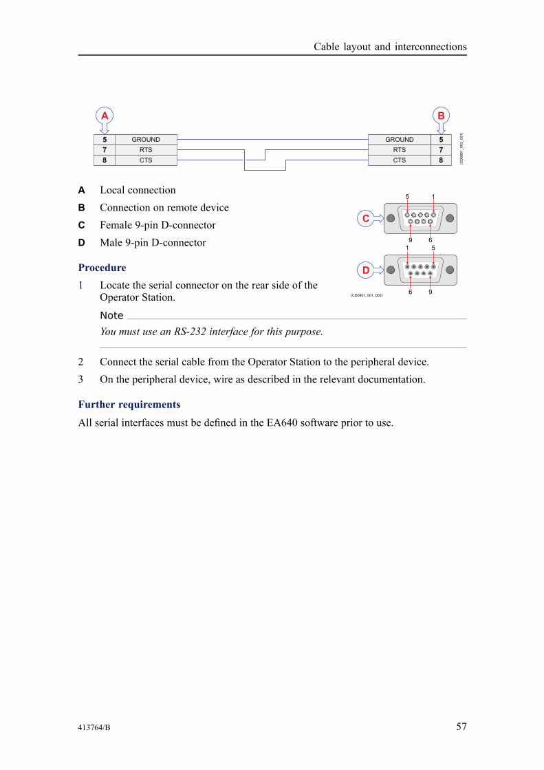
413764/B 57
A Local connectionB Connection on remote deviceC Female 9-pin D-connectorD Male 9-pin D-connector
Procedure1 Locate the serial connector on the rear side of the
Operator Station.
NoteYou must use an RS-232 interface for this purpose.
2 Connect the serial cable from the Operator Station to the peripheral device.3 On the peripheral device, wire as described in the relevant documentation.
Further requirements
All serial interfaces must be defined in the EA640 software prior to use.
Cable layout and interconnections

58 413764/B
Cable drawings and specifications
TopicsTransducer, page 58
Auxiliary connector for synchronization, page 59
RS-232 used as synchronization trigger (input or output), page 60
TransducerFor an EA640 system the WBT can handle up to four channels.
A TransducersB Optional junction boxC WBT transceiver, connector P1D WBT transceiver, connector P2E The cable screen must be terminated in the cable gland
If you need to splice the transducer cable, we strongly recommend the use of a metaljunction box with proper cable glands. The cable screen must be connected to the cableglands. The cable screen and the junction box chassis must not be connected to vesselground. Avoid ground loops. You must use the same type of cable as the originaltransducer cable, contact Kongsberg Maritime for advice.
EA640 Installation Manual
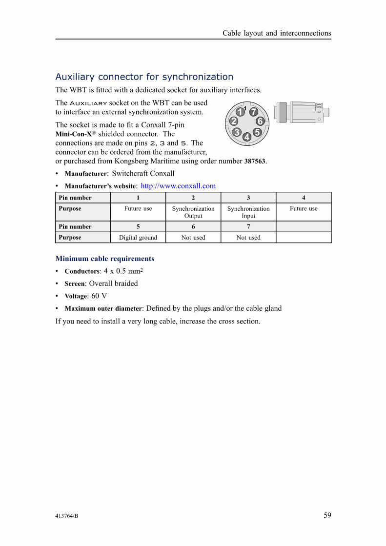
413764/B 59
Auxiliary connector for synchronizationThe WBT is fitted with a dedicated socket for auxiliary interfaces.
The Auxiliary socket on the WBT can be usedto interface an external synchronization system.
The socket is made to fit a Conxall 7-pinMini-Con-X® shielded connector. Theconnections are made on pins 2, 3 and 5. Theconnector can be ordered from the manufacturer,or purchased from Kongsberg Maritime using order number 387563.• Manufacturer: Switchcraft Conxall• Manufacturer’s website: http://www.conxall.comPin number 1 2 3 4
Purpose Future use SynchronizationOutput
SynchronizationInput
Future use
Pin number 5 6 7
Purpose Digital ground Not used Not used
Minimum cable requirements• Conductors: 4 x 0.5 mm2
• Screen: Overall braided• Voltage: 60 V• Maximum outer diameter: Defined by the plugs and/or the cable gland
If you need to install a very long cable, increase the cross section.
Cable layout and interconnections
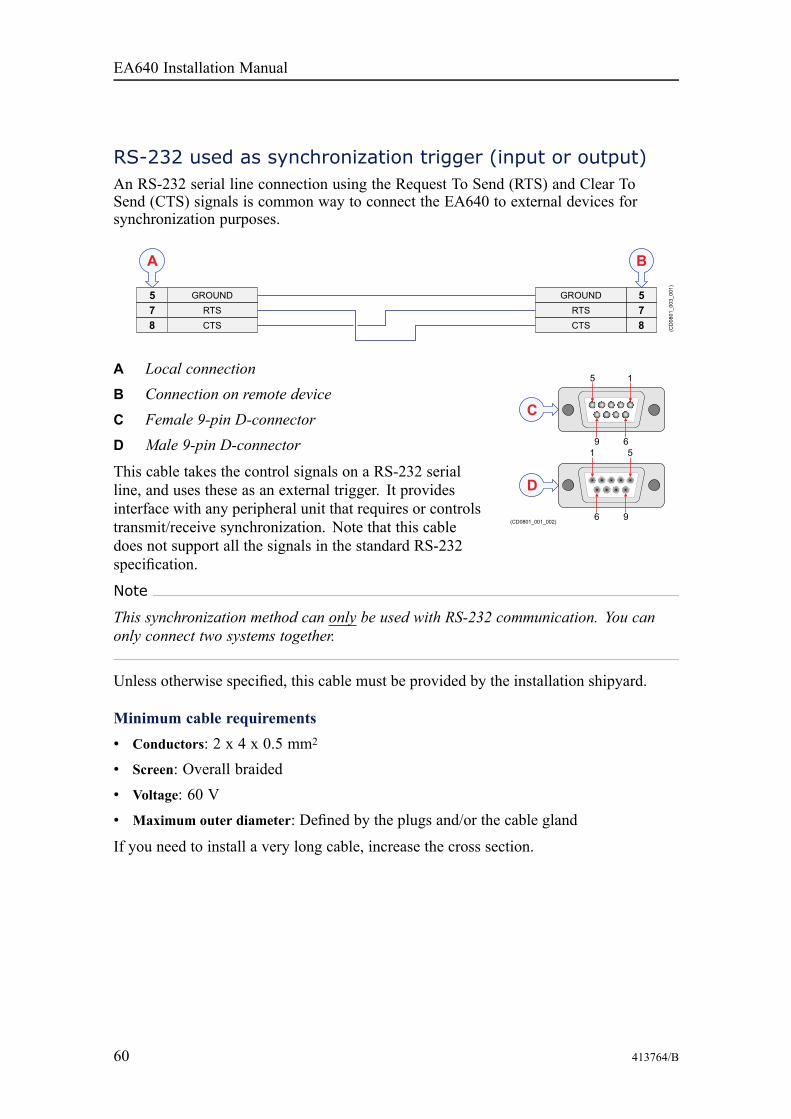
60 413764/B
RS-232 used as synchronization trigger (input or output)An RS-232 serial line connection using the Request To Send (RTS) and Clear ToSend (CTS) signals is common way to connect the EA640 to external devices forsynchronization purposes.
A Local connectionB Connection on remote deviceC Female 9-pin D-connectorD Male 9-pin D-connector
This cable takes the control signals on a RS-232 serialline, and uses these as an external trigger. It providesinterface with any peripheral unit that requires or controlstransmit/receive synchronization. Note that this cabledoes not support all the signals in the standard RS-232specification.
Note
This synchronization method can only be used with RS-232 communication. You canonly connect two systems together.
Unless otherwise specified, this cable must be provided by the installation shipyard.
Minimum cable requirements• Conductors: 2 x 4 x 0.5 mm2
• Screen: Overall braided• Voltage: 60 V• Maximum outer diameter: Defined by the plugs and/or the cable gland
If you need to install a very long cable, increase the cross section.
EA640 Installation Manual

413764/B 61
Drawing file
Topics388697 WBT outline dimensions, page 62
400930 WBT Cabinet outline dimensions, page 64
Drawing file

62 413764/B
388697 WBT outline dimensions
EA640 Installation Manual
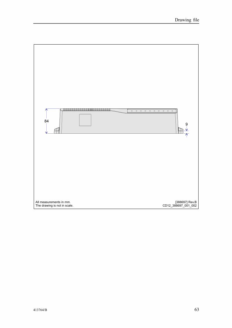
413764/B 63
Drawing file

64 413764/B
400930 WBT Cabinet outline dimensions
EA640 Installation Manual
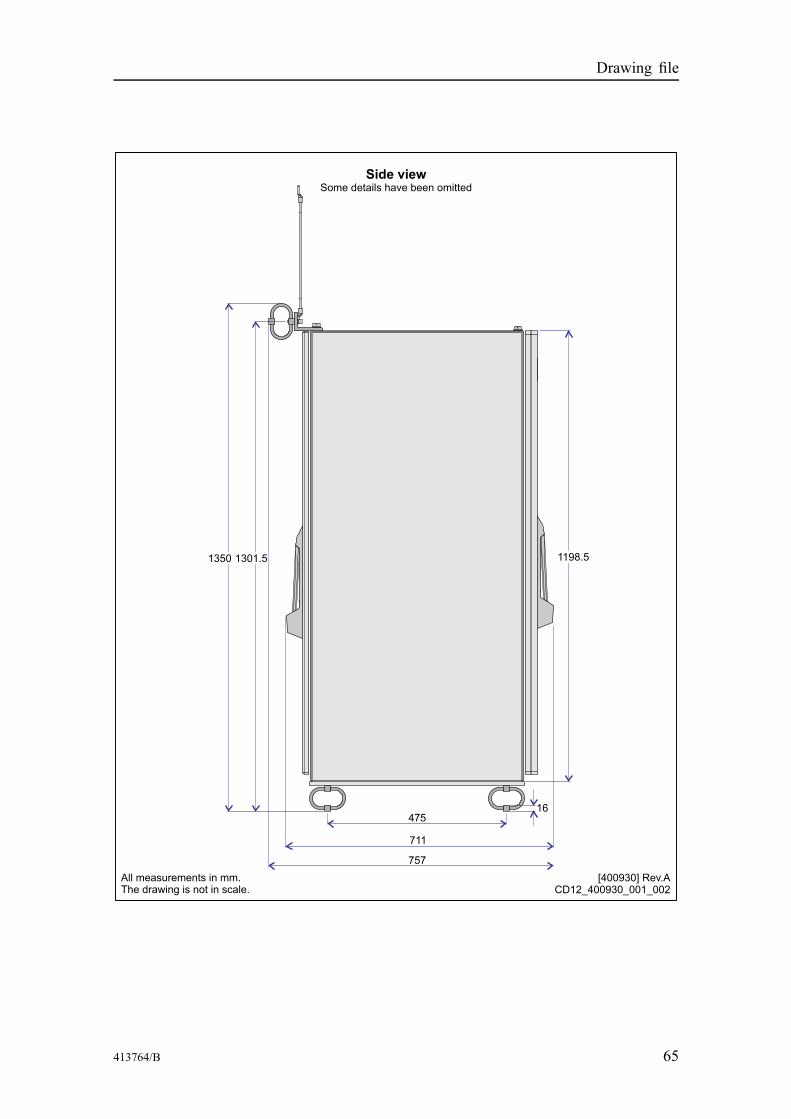
413764/B 65
Drawing file
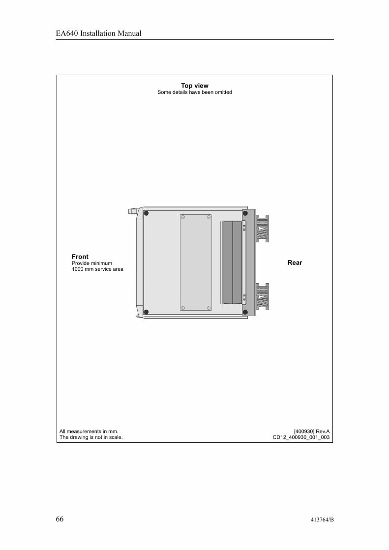
66 413764/B
EA640 Installation Manual
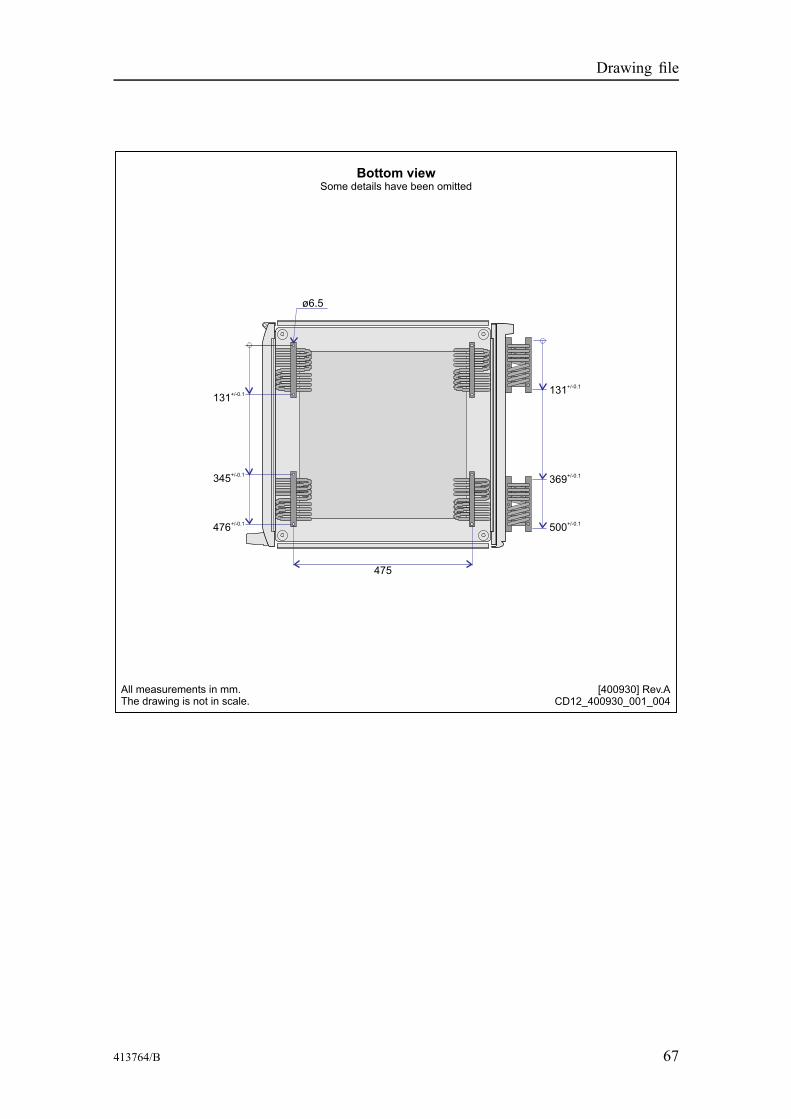
413764/B 67
Drawing file

68 413764/B
Technical specifications
TopicsPerformance specifications, page 69
Interface specifications, page 70
Weight and outline dimensions, page 73
Power requirements, page 73
Environmental requirements, page 74
EA640 Installation Manual

413764/B 69
Performance specificationsThese performance specifications summarize the main functional and operationalcharacteristics of the EA640 Hydrographic single beam echo sounder.
Pulse lengths and maximum resolution• 500 kHz: CW 32 - 512 μs, FM, Resolution: 0.3 cm• 200 kHz: CW 64 - 1024 μs, Resolution: 0.6 cm• 38 kHz: CW 256 - 4096 μs, Resolution: 2.4 cm• 18 kHz: CW 512 - 8192 μs, Resolution: 4.9 cm• 12 kHz: CW: 1 - 16 ms, Resolution: 9.8 cm
Range• Operational range: 1 to 12,500 m• Pulse bandwidth: 10 to 500 kHz
Ping rate• Maximum40 per second
Sound Speed• Manual (1400 to 1700 m/s)• Calculated from temperature and salinity• Calculated from temperature sensor and salinity• Read from sound speed probe
Interfaces• WBT: Ethernet communication• Optional interfaces:
– Ethernet to ships’ network– Sensors: GPS, gyro, motion, speed log, temperature, remote control, annotation,
water level, drop keel, external depth and sound speed• Export file formats: See Interface specifications• Depth output: See Interface specifications• Remote control: Remote start/stop logging available on serial or network
User interface• Operating system: Microsoft® Windows® 10• Main control: Mouse or touch on a comprehensive menu system
Technical specifications

70 413764/B
• Menu languages: English, French, Icelandic, Norwegian, Spanish, German
Interface specificationsThe EA640 will interface with peripheral systems and sensors using standard and/orproprietary datagram formats.
Supported datagram formats for position informationThe EA640 supports the following datagram formats for position information.• NMEA GLL
The NMEA GLL datagram transfers the latitude and longitude of vessel position, thetime of the position fix and the current status from a global positioning system (GPS).
• NMEA GGA
The NMEA GGA datagram transfers the time, position and fix related data from aglobal positioning system (GPS).
• NMEA GGK
The NMEA GGK datagram is used to decode the PTNL, Time, Position, Type andDOP (Dilution of Precision), string of the NMEA 0183 output.
• NMEA RMC
The NMEA RMC datagram transfers the time, date, position, course and speed datafrom a global navigation satellite system (GNSS) receiver.
• NMEA VTG
The NMEAVTG datagram contains the actual course and speed relative to the ground.• NMEA ZDA
The NMEA ZDA datagram contains the universal time code (UTC), day, month,year and local time zone.
Supported datagram formats for speed log informationThe EA640 supports the following datagram formats for speed information.• NMEA VTG
The NMEAVTG datagram contains the actual course and speed relative to the ground.
Supported datagram formats for heading and gyro informationThe EA640 supports the following datagram formats for vessel heading and/or gyroinformation.• NMEA HDT
The NMEA HDT datagram provides the true vessel heading. The information isnormally provided by a course gyro.
EA640 Installation Manual

413764/B 71
• NMEA HDM
The NMEA HDM datagram provides vessel heading in degrees magnetic. Thedatagram format is no longer recommended for use in new designs. It is oftenreplaced by the NMEA HDG telegram.
• NMEA HDG
The NMEA HDG datagram provides heading from a magnetic sensor. If this readingis corrected for deviation it produces the magnetic heading. If it is offset by variation,it provides the true heading.
Supported datagram formats for motion information
The EA640 supports the following datagram formats from a motion sensor.• Kongsberg EM Attitude 3000
The EM Attitude 3000 is a proprietary datagram format created by KongsbergMaritime for use with digital motion sensors.
• Simrad TSS1
Simrad Sounder/TSS1 is a proprietary datagram format created by KongsbergMaritime for heave, roll and pitch compensation. When you select this protocol, thenumber of sensor variables is fixed, and there is no token associated with it.
Supported datagram formats for annotation data
The EA640 supports the following datagram format for annotations.• Simrad ATS datagram format
Simrad ATS is a proprietary datagram format created by Kongsberg Maritime. Itallows you to import annotations from external devices.
Supported datagram formats for depth information
The EA640 supports the following datagram formats for depth output.• NMEA DBS
The NMEA DBS datagram provides the current depth from the surface. The datagramis no longer recommended for use in new designs. It is frequently replaced by theNMEA DPT datagram.
• NMEA DBT
The NMEA DBT datagram provides the current depth under the transducer. In newdesigns, this datagram is frequently used to replace the DBK and DBS datagrams.
• NMEA DPT
The NMEA DPT datagram provides the water depth relative to the transducer, andthe offset of the measuring transducer.
• Simrad depth
Technical specifications
72 413764/B
Simrad depth is a proprietary datagram format created by Kongsberg. The draft,frequency, sound velocity profile and transducer depth may be included.
• Atlas Depth
Atlas Depth is a proprietary datagram format created by Atlas Elektronik(http://www.atlas-elektronik.com) to provide the current depth from two channels.
• HymasHymas is a third party proprietary datagram format.
Processed data formats
The following processed data output formats are available.• XTF
XTF means eXtended Triton Format. This is a file format for recording varioustypes of hydrographic survey data. The source systems include sidescan sonar,shallow seismic and multibeam bathymetry, as well as associated position and altitudeinformation.
• SEGY
The SEGY (sometimes abbreviated "SEG-Y") file format is one of several standardsdeveloped by the Society of Exploration Geophysicists (SEG) for storing geophysicaldata. It is an open standard, and is controlled by the SEG Technical StandardsCommittee. For more information, see http://community.seg.org.
• XYZ
This is processed and interpolated "xyz" data in ASCII format. Note that a navigationinput must be available.
• Echogram
This is the proprietary EK500 datagram format. The datagrams consists of userdefined excerpts of the processed sample data (pixel data), ie the backscatter value ofthe targets. The echograms are stored as time tagged datagrams in separate files.
• SILAS
This is a proprietary format that was created for the SILAS software.• Out
Kongsberg Out file format. This is a proprietary format.• TIFF
TIFF file format. This is a picture format.
EA640 Installation Manual

413764/B 73
Weight and outline dimensionsThese weights and outline dimension characteristics summarize the physical propertiesof the EA640 Hydrographic single beam echo sounder.
Note
For more detailed information about the physical dimensions, see the Drawing file.
Operator Station• Make and model: Hatteland Display JH 19T14 MMC• Outline dimensions
– Depth: 82 mm– Width: 483 mm– Height: 444 mm
• Weight: 11 kg (Approximately)
WBT• Make and model: Kongsberg WBT• Outline dimensions
– Depth: 213 mm– Width: 438 mm– Height: 84 mm
• Weight: 5 kg (Approximately)
Power requirementsThese power characteristics summarize the supply power requirements for the EA640Hydrographic single beam echo sounder.
Operator Station• Make and model: Hatteland Display JH 19T14 MMC• Voltage requirement: 115/230 VAC / 50/60 Hz• Power consumption: 100 W maximum
The technical specifications are those valid for the computer that provided by KongsbergMaritime as a part of the EA640 delivery. For specifications related to a locallypurchased computer, refer to the documentation provided with the unit.
Technical specifications

74 413764/B
WBT• Make and model: Kongsberg WBT• Voltage requirement: 12 – 15 VDC, 5A
A suitable power supply is provided with the delivery.• Power supply:
– Voltage requirement115/230 VAC, 47 to 63 Hz, single phase, nominal– Maximum voltage deviation: 15%– Maximum transient: 20% of nominal voltage, recovery time 3 s– Power consumption: 100 VA (Approximately)
Environmental requirementsThese environmental specifications summarize the temperature and humidityrequirements for the EA640 Hydrographic single beam echo sounder.
Operator Station• Make and model: Hatteland Display JH 19T14 MMC• Operational temperature: -15 to 55 °C• Storage temperature: -20 to 60 °C• Relative humidity:95% maximum• Degree of protection: IP66 front, IP20 rear
The technical specifications are those valid for the computer that may be ordered fromKongsberg Maritime as a part of the EA640 delivery. For specifications related to alocally purchased computer, refer to the documentation provided with the unit.
WBT• Make and model: Kongsberg WBT• Operational temperature: 0 to +50 °C• Storage temperature: -40 to 70 °C• Relative humidity: 5 to 95% relative, non-condensing
EA640 Installation Manual

413764/B 75
Equipment handling
TopicsTransporting Kongsberg Maritime equipment, page 76
Lifting units and transportation boxes, page 77
Inspection of units and transportation boxes after arrival, page 78
Specifications for storage prior to installation or use, page 79
Unpacking instructions, page 80
Specifications for storage after unpacking, page 85
Equipment handling
76 413764/B
Transporting Kongsberg Maritime equipmentUnless otherwise stated in the accompanying documentation, electronic,electromechanical and mechanical units supplied by Kongsberg Maritime can be onlytransported using methods approved for delicate and fragile equipment.
Prerequisites
Transportation methods approved for delicate equipment includes transportation byroad, rail, air or sea.
Context
The units are to be transported in accordance with general or specific instructions forthe appropriate unit(s), using pallets, transport cases, wooden boxes, or carton boxesas appropriate.
Observe the packing instructions.
Note
Special local restrictions concerning air transportation may be applied to unitscontaining certain types of batteries. These units must be checked properly, and theregulations must be investigated by the packer/shipper before the unit is dispatched.
Procedure1 Ensure that all local transportation is done according to the same specifications as
for the initial delivery.2 Make sure that the box containing the unit is kept dry at all times, and sheltered
from the weather.
It must not be subjected to shocks, excessive vibration or other rough handling. Thebox will normally be marked with text or symbols indicating which way it is to beplaced. Follow the instructions provided, and make sure that the box is alwaysplaced with its “top” facing upwards.
3 Make sure that the box is not used for any purpose for which it was not intended(step, table, etc.).
In the absence of other information, no other boxes must be stacked on top of it.4 Handle all boxes and units with care.
Note
Due to the nature of Kongsberg Maritime’s products, and the extensive use ofdelicate electronic parts, all units and boxes must be regarded and handled asfragile equipment.
EA640 Installation Manual
413764/B 77
Lifting units and transportation boxesSome of the boxes used to hold equipment units may be heavy. Use caution when lifting.
Prerequisites
Units and boxes may be heavy. Make sure that you have the necessary equipmentrequired for lifting heavy items. Persons using the lifting equipment must be skilled andhave the relevant certificate(s).
Context
A heavy box will normally be marked with its weight. The weights of other boxes in theshipment will normally be entered on the packing list(s).
Heavy units may be equipped with dedicated lifting lugs for transportation by cranewithin the workshop or installation area.
Note
Observe the local rules and regulations related to the use of lifting equipment.
Procedure1 Check the weight of the box or unit before you attempt to lift it.2 Make sure that you have the relevant lifting apparatus required, and that this
equipment is approved and certified for the load.3 If you need to use a crane:
a Check the applicable weight certificate for the crane.b Check the security of the lifting lugs.c If the unit to be lifted is provided with dedicated lifting lugs, make sure that all
available lugs are used.d Make sure that the unit remains under full control during the lifting operation.
This is important to avoid damage to the unit, equipment or personnel.4 If you need to use a forklift truck:
a Check the applicable weight certificate for the truck.b Check the limitations for lifting height and angles.c Pay special attention to the position of the unit’s centre of gravity.d Make sure that the unit is properly secured to the truck during the lifting and
transportation operations.5 Handle all units and boxes with care.
Equipment handling
78 413764/B
Note
Due to the nature of Kongsberg Maritime’s products, and the extensive use ofdelicate electronic parts, all units and boxes must be regarded and handled asfragile equipment.
Inspection of units and transportation boxesafter arrivalA visual inspection must be done immediately after the box(es) have arrived at theirdestination.
Prerequisites
If you suspect that the equipment has been damaged during the transport, request that arepresentative of the carrier is present during the inspection.
Procedure1 Check all boxes (wooden or cardboard boxes, plastic bags and/or pallets) for
physical damage.
Look for signs of dropping, immersion in water or other mishandling.2 If external damage is detected, open the box to check its contents.
Request that a representative of the carrier to be present while the box is opened, soany transportation damage can be identified and documented.
3 If a unit has been damaged, prepare an inspection report stating the condition of theunit and actions taken.
Describe the damage, and collect photographic evidence if possible. Return theinspection report to Kongsberg Maritime as soon as possible.
4 If units are not damaged, check the humidity absorbing material.
If required, dry or replace the bags, then re-pack the unit(s) according to the packinginstructions.
EA640 Installation Manual

413764/B 79
Specifications for storage prior to installationor useWhen a system, a unit or a spare part has been delivered to the customer, it may besubject to long time storage prior to installation and use.
General specifications
During this storage period, certain specifications must be met. The equipment must bepreserved and stored in such a way that it does not constitute any danger to health,environment or personal injury.1 The equipment must be stored in its original transportation box.2 Ensure that the units are clearly separated in the shelves and that each unit is
easily identifiable.3 The box must not be used for any purpose for which it was not intended (work
platform, steps, table etc.).4 Boxes must not be placed on top of each other, unless specific markings permit this.5 Boxes must not be placed directly on a dirt floor.6 Do not open a box for inspection unless special circumstances permit so.
“Special circumstances” may be suspected damage to the box and its content, orinspections by civil authorities.a If a unit is damaged, prepare an inspection report stating the condition of the
unit and the actions taken. Describe the damage and collect photographicevidence if possible. Re-preserve the equipment.
b If the unit is not damaged, check the humidity absorbing material. If required,dry or replace the bags, then re-pack the unit according to the packinginstructions.
7 If a box has been opened, make sure that is it closed and sealed after the inspection.Use the original packing material as far as possible.
8 The storage room/area must be dry with a non-condensing atmosphere. It mustbe free from corrosive agents.
9 The storage room/area’s mean temperature must not be lower than -10° C, andnot warmer than +50° C. If other limitations apply, the crates will be markedaccordingly.
10 Boxes must not be exposed to moisture from fluid leakages.11 Boxes must not be exposed to direct sunlight or excessive warmth from heaters.12 Boxes must not be subjected to excessive shock and vibration.13 If the unit contained in a box holds normal batteries, these may have been
disconnected/isolated before the unit was packed. These must only be reconnectedbefore the installation starts. Units containing batteries are marked.
Equipment handling

80 413764/B
Caution
Units containing lithium or alkaline batteries must be handled separately and with care.Such units are marked accordingly. Do not attempt to recharge such batteries, openthem, or dispose of them by incineration.
Refer to the applicable product data sheets or battery handling procedures for furtherdetails.
Temperature protection
Any units that requires protection against extreme temperatures are identified as suchin the applicable documentation. The box used to transport and store such units areclearly marked, for example:
Must not be transported or stored in temperatures below -5 °C.
Other temperature limits may be used if applicable.
If a unit needs temperature protection, the box to be used for storage and transportationmust be lined on all walls, base and lid, using minimum 5 cm thick polyurethane orpolystyrene foam.
Most system units can normally be stored in temperatures between -30° C and +70° C.Refer to the relevant technical specifications for details.
Note
Unless otherwise specified, transducers and hydrophones must not be stored intemperatures below −10°C and above +50°C.
Unpacking instructionsPrior to installation or use, electronic, electromechanical and mechanical units mustbe unpacked from their transport boxes. It is important that this unpacking is doneaccording to the relevant instructions, and without inflicting damage to the equipment.
TopicsUnpacking standard parts and units, page 81
Unpacking mechanical units, page 82
Unpacking electronic and electromechanical units, page 82
Unpacking transducers, page 83
EA640 Installation Manual
413764/B 81
Unpacking standard parts and unitsPrior to installation or use, parts and units must be inspected, and then unpacked fromtheir transport boxes. It is important that this unpacking is done without inflictingdamage to the equipment.
Context
This procedure provides the basic tasks of unpacking units (main unit, spare parts etc)from boxes shipped from Kongsberg Maritime.
Note
If the unit in question is not unpacked for immediate use, you may consider storing itunopened in its original box. However, it may be useful to open the box to check itscontents for damage and retrieve any accompanying documentation.
Do not use a knife to open cardboard boxes - the contents may be located close to thesurface, and can then be damaged by the blade.
Procedure1 Check the carton before opening it to ensure it shows no signs of dropping,
immersion in water or other mishandling.1 If external damage is detected, open the box to check its contents.2 Request that a representative of the carrier to be present while the box is
opened, so any transportation damage can be identified and documented.3 If a unit has been damaged, prepare an inspection report stating the condition
of the unit and actions taken.Describe the damage, and collect photographic evidence if possible. Returnthe inspection report to Kongsberg Maritime as soon as possible.
2 Place the box on a stable work bench or on the floor with the top of the box facingupwards.
3 In the absence of other instructions, always open the top of the carton first.
The contents of the box will normally have been lowered into the carton fromabove, so this will usually be the easiest route to follow. Be careful when you openthe box, and make sure that the contents are not damaged. Do not use a knife toopen cardboard boxes.
4 If the box has been closed using staples, remove the staples from the carton asyou open it.
This will reduce the possibilities of scratch injury to yourself and damage to thecontents.
5 If a wooden box has been closed using screws, always remove them using ascrewdriver.
Do not attempt to force the lid open with a crowbar or similar tool.
Equipment handling
82 413764/B
6 Once the carton is open, carefully remove all loose packing and insulation material.7 Check for user manuals and other documents that may have been added to the
carton during packing.8 Check also for special tools, door keys etc.
Unpacking mechanical unitsPrior to installation or use, mechanical units must be unpacked from their transport boxes.It is important that this unpacking is done without inflicting damage to the equipment.
Prerequisites
Observe the procedure for unpacking of standard parts and units.
Context
Mechanical and electromechanical units may be heavy.
Procedure1 Obtain the necessary lifting equipment, and make sure that the equipment is
certified for the weight.2 Lift the unit out of the transportation box.3 Place it in a stable position on the floor/work bench.4 Inspect the unit for visual damage.5 Remove any packing material that may be inside the unit.6 Collect and keep the relevant user manuals and/or documents provided with the unit.
Unpacking electronic and electromechanical unitsPrior to installation or use, electronic and electromechanical units must be unpackedfrom their transport boxes. It is important that unpacking is done without inflictingdamage to the equipment.
Context
Electronic and electromechanical units are normally wrapped in clear antistatic plasticbags.
Do not break the seal to open a printed circuit board, an electronic module or a unitbefore it shall be used. If the unit is returned with a broken seal we will assume that ithas been used. You will then be billed accordingly.
EA640 Installation Manual
413764/B 83
Note
Beware of Electrostatic Discharge (ESD)!
When you handle electronic circuit boards and modules, you must beware of the dangersof electrostatic discharge (ESD), both to yourself and to the equipment. In order toensure safe transport and storage, circuit boards and other electronic units will alwaysbe wrapped in a clear plastic protective bag, and the bag will be sealed.
Procedure1 Lift the unit, in its protective bag, out of the transport box.
Note
You must never use the cables to lift or carry a unit.
2 Place it in a stable position on the floor or on the workbench.3 Inspect the unit for damage.
a If a unit has been damaged, prepare an inspection report stating the conditionof the unit and actions taken.
b Describe the damage, and collect photographic evidence if possible. Returnthe inspection report to Kongsberg Maritime as soon as possible.
4 Assuming all is well, open the bag and remove the unit.5 Take out and keep the documentation.
You will need the documentation if the item shall be returned to us.6 If applicable, open the unit and check inside.7 Remove any packing and desiccant material that may be found inside the shipping
container or bag.8 Collect and keep the relevant user manuals and/or installation documents provided
with the unit.
Unpacking transducersPrior to installation or use, transducers, sonar heads and hydrophones must be unpackedfrom their transport boxes. It is important that this unpacking is done without inflictingdamage to the equipment.
Prerequisites
Observe the procedure for unpacking of standard parts and units.
Equipment handling
84 413764/B
Context
Transducers may be supplied mounted to a hull unit (if any), or packed separately. Sonarheads and hydrophones are normally packed and shipped in separate boxes. Boxes areidentified by the order number and the serial number of the unit inside.
Note
Once a transducer, sonar head or hydrophone is unpacked, make sure that the body andthe cabling are not exposed to any mechanical stress. Protect the transducer face with apadded cover plate to prevent damage.
Transducers may be heavy.
A transducer must always be handled as a delicate instrument. Incorrect actions maydamage the transducer beyond repair.
Observe these transducer handling rules:• Do not activate the transducer when it is out of the water.• Do not lift the transducer by the cable.• Do not step on the transducer cable.• Do not handle the transducer roughly and avoid impacts.• Do not expose the transducer to direct sunlight or excessive heat.• Do not use high-pressure water, sandblasting, metal tools or strong solvents to clean
the transducer face.
Procedure1 Obtain the necessary lifting equipment, and make sure that the equipment is
certified for the weight.2 Lift the transducer, sonar head or hydrophone out of the transportation box.3 Place it in a stable position on the floor/work bench.4 Inspect the unit for visual damage.5 Make sure that the relevant protection is kept in place until the final stages of the
installation.6 Collect and keep the relevant user manuals and/or documents provided with the unit.7 Observe the handling rules for transducers.
EA640 Installation Manual

413764/B 85
Specifications for storage after unpackingThe unit must whenever possible be stored in its original transportation crate until readyfor installation.
General specifications
During storage, each box must not be used for any purpose for which it was not intended(work platform, table, steps etc.).
Once unpacked, all equipment must be kept in a dry, non condensing atmosphere, freefrom corrosive agents and isolated from sources of vibration.
Note
Do not break the seal to open a circuit board package before the board is to be used.If the board package is returned to Kongsberg Maritime with the seal broken, we willassumed that the unit has been used, and then you will be billed accordingly.
Each unit must be installed in its intended operating position as soon as possibleafter unpacking. If the unit contains normal batteries, these may have beendisconnected/isolated before the unit was packed. These must then be reconnectedduring the installation procedure. Units containing batteries are marked.
Caution
Units containing lithium or alkaline batteries must be handled separately and with care.Such units are marked accordingly. Do not attempt to recharge such batteries, openthem, or dispose of them by incineration.
Refer to the applicable product data sheets or battery handling procedures for furtherdetails.
Temperature protection
Any units that requires protection against extreme temperatures are identified as suchin the applicable documentation. The box used to transport and store such units areclearly marked, for example:
Must not be transported or stored in temperatures below -5 °C.
Other temperature limits may be used if applicable.
If a unit needs temperature protection, the box to be used for storage and transportationmust be lined on all walls, base and lid, using minimum 5 cm thick polyurethane orpolystyrene foam.
Most system units can normally be stored in temperatures between -30° C and +70° C.Refer to the relevant technical specifications for details.
Equipment handling

86 413764/B
Note
Unless otherwise specified, transducers and hydrophones must not be stored intemperatures below −10°C and above +50°C.
EA640 Installation Manual
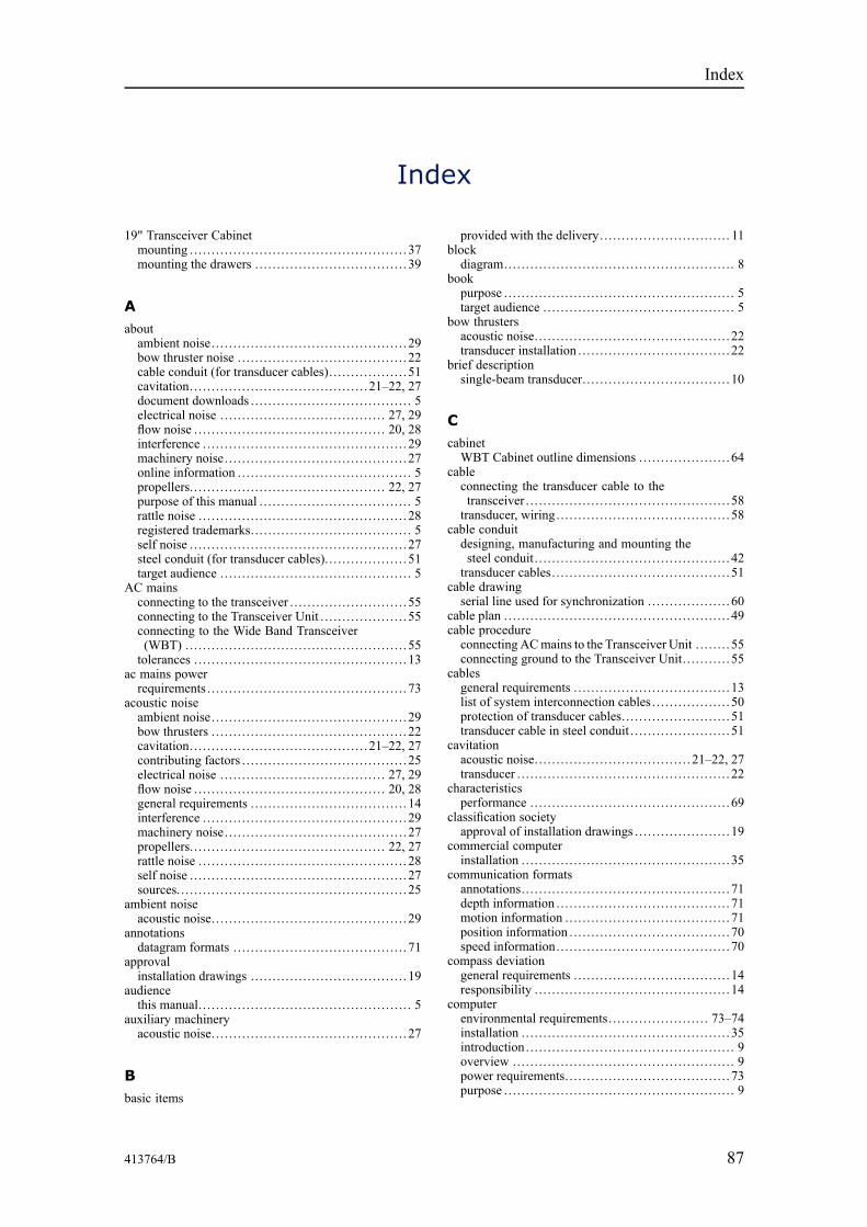
413764/B 87
Index
19" Transceiver Cabinetmounting .. . . . . . . . . . . . . . . . . . . . . . . . . . . . . . . . . . . . . . . . . . . . . . . . . 37mounting the drawers .. . . . . . . . . . . . . . . . . . . . . . . . . . . . . . . . . . 39
Aaboutambient noise.. . . . . . . . . . . . . . . . . . . . . . . . . . . . . . . . . . . . . . . . . . . . 29bow thruster noise .. . . . . . . . . . . . . . . . . . . . . . . . . . . . . . . . . . . . . . 22cable conduit (for transducer cables).. . . . . . . . . . . . . . . . . 51cavitation.. . . . . . . . . . . . . . . . . . . . . . . . . . . . . . . . . . . . . . . . 21–22, 27document downloads .. . . . . . . . . . . . . . . . . . . . . . . . . . . . . . . . . . . . 5electrical noise .. . . . . . . . . . . . . . . . . . . . . . . . . . . . . . . . . . . . . 27, 29flow noise .. . . . . . . . . . . . . . . . . . . . . . . . . . . . . . . . . . . . . . . . . . . 20, 28interference .. . . . . . . . . . . . . . . . . . . . . . . . . . . . . . . . . . . . . . . . . . . . . . 29machinery noise.. . . . . . . . . . . . . . . . . . . . . . . . . . . . . . . . . . . . . . . . . 27online information .. . . . . . . . . . . . . . . . . . . . . . . . . . . . . . . . . . . . . . . 5propellers.. . . . . . . . . . . . . . . . . . . . . . . . . . . . . . . . . . . . . . . . . . . . 22, 27purpose of this manual .. . . . . . . . . . . . . . . . . . . . . . . . . . . . . . . . . . 5rattle noise .. . . . . . . . . . . . . . . . . . . . . . . . . . . . . . . . . . . . . . . . . . . . . . . 28registered trademarks.. . . . . . . . . . . . . . . . . . . . . . . . . . . . . . . . . . . . 5self noise .. . . . . . . . . . . . . . . . . . . . . . . . . . . . . . . . . . . . . . . . . . . . . . . . . 27steel conduit (for transducer cables).. . . . . . . . . . . . . . . . . . 51target audience .. . . . . . . . . . . . . . . . . . . . . . . . . . . . . . . . . . . . . . . . . . . 5
AC mainsconnecting to the transceiver .. . . . . . . . . . . . . . . . . . . . . . . . . . 55connecting to the Transceiver Unit . . . . . . . . . . . . . . . . . . . . 55connecting to the Wide Band Transceiver(WBT) ... . . . . . . . . . . . . . . . . . . . . . . . . . . . . . . . . . . . . . . . . . . . . . . . . 55tolerances .. . . . . . . . . . . . . . . . . . . . . . . . . . . . . . . . . . . . . . . . . . . . . . . . 13
ac mains powerrequirements .. . . . . . . . . . . . . . . . . . . . . . . . . . . . . . . . . . . . . . . . . . . . . 73
acoustic noiseambient noise.. . . . . . . . . . . . . . . . . . . . . . . . . . . . . . . . . . . . . . . . . . . . 29bow thrusters .. . . . . . . . . . . . . . . . . . . . . . . . . . . . . . . . . . . . . . . . . . . . 22cavitation.. . . . . . . . . . . . . . . . . . . . . . . . . . . . . . . . . . . . . . . . 21–22, 27contributing factors .. . . . . . . . . . . . . . . . . . . . . . . . . . . . . . . . . . . . . 25electrical noise .. . . . . . . . . . . . . . . . . . . . . . . . . . . . . . . . . . . . . 27, 29flow noise .. . . . . . . . . . . . . . . . . . . . . . . . . . . . . . . . . . . . . . . . . . . 20, 28general requirements .. . . . . . . . . . . . . . . . . . . . . . . . . . . . . . . . . . . 14interference .. . . . . . . . . . . . . . . . . . . . . . . . . . . . . . . . . . . . . . . . . . . . . . 29machinery noise.. . . . . . . . . . . . . . . . . . . . . . . . . . . . . . . . . . . . . . . . . 27propellers.. . . . . . . . . . . . . . . . . . . . . . . . . . . . . . . . . . . . . . . . . . . . 22, 27rattle noise .. . . . . . . . . . . . . . . . . . . . . . . . . . . . . . . . . . . . . . . . . . . . . . . 28self noise .. . . . . . . . . . . . . . . . . . . . . . . . . . . . . . . . . . . . . . . . . . . . . . . . . 27sources.. . . . . . . . . . . . . . . . . . . . . . . . . . . . . . . . . . . . . . . . . . . . . . . . . . . . 25
ambient noiseacoustic noise.. . . . . . . . . . . . . . . . . . . . . . . . . . . . . . . . . . . . . . . . . . . . 29
annotationsdatagram formats .. . . . . . . . . . . . . . . . . . . . . . . . . . . . . . . . . . . . . . . 71
approvalinstallation drawings .. . . . . . . . . . . . . . . . . . . . . . . . . . . . . . . . . . . 19
audiencethis manual.. . . . . . . . . . . . . . . . . . . . . . . . . . . . . . . . . . . . . . . . . . . . . . . . 5
auxiliary machineryacoustic noise.. . . . . . . . . . . . . . . . . . . . . . . . . . . . . . . . . . . . . . . . . . . . 27
Bbasic items
provided with the delivery.. . . . . . . . . . . . . . . . . . . . . . . . . . . . . 11blockdiagram... . . . . . . . . . . . . . . . . . . . . . . . . . . . . . . . . . . . . . . . . . . . . . . . . . . 8
bookpurpose .. . . . . . . . . . . . . . . . . . . . . . . . . . . . . . . . . . . . . . . . . . . . . . . . . . . . 5target audience .. . . . . . . . . . . . . . . . . . . . . . . . . . . . . . . . . . . . . . . . . . . 5
bow thrustersacoustic noise.. . . . . . . . . . . . . . . . . . . . . . . . . . . . . . . . . . . . . . . . . . . . 22transducer installation .. . . . . . . . . . . . . . . . . . . . . . . . . . . . . . . . . . 22
brief descriptionsingle-beam transducer.. . . . . . . . . . . . . . . . . . . . . . . . . . . . . . . . . 10
CcabinetWBT Cabinet outline dimensions .. . . . . . . . . . . . . . . . . . . . 64
cableconnecting the transducer cable to thetransceiver .. . . . . . . . . . . . . . . . . . . . . . . . . . . . . . . . . . . . . . . . . . . . . . 58transducer, wiring.. . . . . . . . . . . . . . . . . . . . . . . . . . . . . . . . . . . . . . . 58
cable conduitdesigning, manufacturing and mounting thesteel conduit. . . . . . . . . . . . . . . . . . . . . . . . . . . . . . . . . . . . . . . . . . . . . 42transducer cables.. . . . . . . . . . . . . . . . . . . . . . . . . . . . . . . . . . . . . . . . 51
cable drawingserial line used for synchronization .. . . . . . . . . . . . . . . . . . 60
cable plan .. . . . . . . . . . . . . . . . . . . . . . . . . . . . . . . . . . . . . . . . . . . . . . . . . . . 49cable procedureconnecting ACmains to the Transceiver Unit . . . . . . . . 55connecting ground to the Transceiver Unit. . . . . . . . . . . 55
cablesgeneral requirements .. . . . . . . . . . . . . . . . . . . . . . . . . . . . . . . . . . . 13list of system interconnection cables .. . . . . . . . . . . . . . . . . 50protection of transducer cables.. . . . . . . . . . . . . . . . . . . . . . . . 51transducer cable in steel conduit . . . . . . . . . . . . . . . . . . . . . . . 51
cavitationacoustic noise.. . . . . . . . . . . . . . . . . . . . . . . . . . . . . . . . . . . 21–22, 27transducer .. . . . . . . . . . . . . . . . . . . . . . . . . . . . . . . . . . . . . . . . . . . . . . . . 22
characteristicsperformance .. . . . . . . . . . . . . . . . . . . . . . . . . . . . . . . . . . . . . . . . . . . . . 69
classification societyapproval of installation drawings .. . . . . . . . . . . . . . . . . . . . . 19
commercial computerinstallation .. . . . . . . . . . . . . . . . . . . . . . . . . . . . . . . . . . . . . . . . . . . . . . . 35
communication formatsannotations.. . . . . . . . . . . . . . . . . . . . . . . . . . . . . . . . . . . . . . . . . . . . . . . 71depth information .. . . . . . . . . . . . . . . . . . . . . . . . . . . . . . . . . . . . . . . 71motion information .. . . . . . . . . . . . . . . . . . . . . . . . . . . . . . . . . . . . . 71position information .. . . . . . . . . . . . . . . . . . . . . . . . . . . . . . . . . . . . 70speed information.. . . . . . . . . . . . . . . . . . . . . . . . . . . . . . . . . . . . . . . 70
compass deviationgeneral requirements .. . . . . . . . . . . . . . . . . . . . . . . . . . . . . . . . . . . 14responsibility .. . . . . . . . . . . . . . . . . . . . . . . . . . . . . . . . . . . . . . . . . . . . 14
computerenvironmental requirements.. . . . . . . . . . . . . . . . . . . . . . 73–74installation .. . . . . . . . . . . . . . . . . . . . . . . . . . . . . . . . . . . . . . . . . . . . . . . 35introduction .. . . . . . . . . . . . . . . . . . . . . . . . . . . . . . . . . . . . . . . . . . . . . . . 9overview ... . . . . . . . . . . . . . . . . . . . . . . . . . . . . . . . . . . . . . . . . . . . . . . . . 9power requirements.. . . . . . . . . . . . . . . . . . . . . . . . . . . . . . . . . . . . . 73purpose .. . . . . . . . . . . . . . . . . . . . . . . . . . . . . . . . . . . . . . . . . . . . . . . . . . . . 9
Index
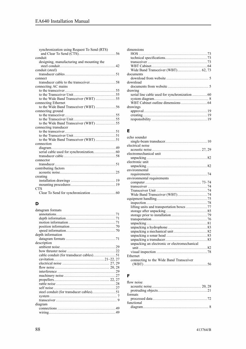
88 413764/B
synchronization using Request To Send (RTS)and Clear To Send (CTS).. . . . . . . . . . . . . . . . . . . . . . . . . . . . . 56
conduitdesigning, manufacturing and mounting thesteel conduit. . . . . . . . . . . . . . . . . . . . . . . . . . . . . . . . . . . . . . . . . . . . . 42
conduit (steel)transducer cables.. . . . . . . . . . . . . . . . . . . . . . . . . . . . . . . . . . . . . . . . 51
connecttransducer cable to the transceiver.. . . . . . . . . . . . . . . . . . . . 58
connecting AC mainsto the transceiver .. . . . . . . . . . . . . . . . . . . . . . . . . . . . . . . . . . . . . . . . 55to the Transceiver Unit . . . . . . . . . . . . . . . . . . . . . . . . . . . . . . . . . . 55to the Wide Band Transceiver (WBT) ... . . . . . . . . . . . . . 55
connecting Ethernetto the Wide Band Transceiver (WBT) ... . . . . . . . . . . . . . 56
connecting groundto the transceiver .. . . . . . . . . . . . . . . . . . . . . . . . . . . . . . . . . . . . . . . . 55to the Transceiver Unit . . . . . . . . . . . . . . . . . . . . . . . . . . . . . . . . . . 55to the Wide Band Transceiver (WBT) ... . . . . . . . . . . . . . 55
connecting transducerto the transceiver .. . . . . . . . . . . . . . . . . . . . . . . . . . . . . . . . . . . . . . . . 51to the Transceiver Unit . . . . . . . . . . . . . . . . . . . . . . . . . . . . . . . . . . 51to the Wide Band Transceiver (WBT) ... . . . . . . . . . . . . . 51
connectiondiagram... . . . . . . . . . . . . . . . . . . . . . . . . . . . . . . . . . . . . . . . . . . . . . . . . . 49serial cable used for synchronization.. . . . . . . . . . . . . . . . . 60transducer cable .. . . . . . . . . . . . . . . . . . . . . . . . . . . . . . . . . . . . . . . . . 58
connectortransducer .. . . . . . . . . . . . . . . . . . . . . . . . . . . . . . . . . . . . . . . . . . . . . . . . 51
contributing factorsacoustic noise.. . . . . . . . . . . . . . . . . . . . . . . . . . . . . . . . . . . . . . . . . . . . 25
creatinginstallation drawings .. . . . . . . . . . . . . . . . . . . . . . . . . . . . . . . . . . . 19mounting procedures .. . . . . . . . . . . . . . . . . . . . . . . . . . . . . . . . . . . 19
CTSClear To Send for synchronization .. . . . . . . . . . . . . . . . . . . 60
Ddatagram formatsannotations.. . . . . . . . . . . . . . . . . . . . . . . . . . . . . . . . . . . . . . . . . . . . . . . 71depth information .. . . . . . . . . . . . . . . . . . . . . . . . . . . . . . . . . . . . . . . 71motion information .. . . . . . . . . . . . . . . . . . . . . . . . . . . . . . . . . . . . . 71position information .. . . . . . . . . . . . . . . . . . . . . . . . . . . . . . . . . . . . 70speed information.. . . . . . . . . . . . . . . . . . . . . . . . . . . . . . . . . . . . . . . 70
depth informationdatagram formats .. . . . . . . . . . . . . . . . . . . . . . . . . . . . . . . . . . . . . . . 71
descriptionambient noise.. . . . . . . . . . . . . . . . . . . . . . . . . . . . . . . . . . . . . . . . . . . . 29bow thruster noise .. . . . . . . . . . . . . . . . . . . . . . . . . . . . . . . . . . . . . . 22cable conduit (for transducer cables).. . . . . . . . . . . . . . . . . 51cavitation.. . . . . . . . . . . . . . . . . . . . . . . . . . . . . . . . . . . . . . . . 21–22, 27electrical noise .. . . . . . . . . . . . . . . . . . . . . . . . . . . . . . . . . . . . . 27, 29flow noise .. . . . . . . . . . . . . . . . . . . . . . . . . . . . . . . . . . . . . . . . . . . 20, 28interference .. . . . . . . . . . . . . . . . . . . . . . . . . . . . . . . . . . . . . . . . . . . . . . 29machinery noise.. . . . . . . . . . . . . . . . . . . . . . . . . . . . . . . . . . . . . . . . . 27propellers.. . . . . . . . . . . . . . . . . . . . . . . . . . . . . . . . . . . . . . . . . . . . 22, 27rattle noise .. . . . . . . . . . . . . . . . . . . . . . . . . . . . . . . . . . . . . . . . . . . . . . . 28self noise .. . . . . . . . . . . . . . . . . . . . . . . . . . . . . . . . . . . . . . . . . . . . . . . . . 27steel conduit (for transducer cables).. . . . . . . . . . . . . . . . . . 51system ... . . . . . . . . . . . . . . . . . . . . . . . . . . . . . . . . . . . . . . . . . . . . . . . . . . . 7transceiver .. . . . . . . . . . . . . . . . . . . . . . . . . . . . . . . . . . . . . . . . . . . . . . . . 9
diagramconnections .. . . . . . . . . . . . . . . . . . . . . . . . . . . . . . . . . . . . . . . . . . . . . . 49wiring.. . . . . . . . . . . . . . . . . . . . . . . . . . . . . . . . . . . . . . . . . . . . . . . . . . . . . 49
dimensionsHOS ... . . . . . . . . . . . . . . . . . . . . . . . . . . . . . . . . . . . . . . . . . . . . . . . . . . . . 73technical specifications.. . . . . . . . . . . . . . . . . . . . . . . . . . . . . . . . . 73transceiver .. . . . . . . . . . . . . . . . . . . . . . . . . . . . . . . . . . . . . . . . . . . . . . . 73WBT Cabinet.. . . . . . . . . . . . . . . . . . . . . . . . . . . . . . . . . . . . . . . . . . . . 64Wide Band Transceiver (WBT)... . . . . . . . . . . . . . . . . 62, 73
documentsdownload from website .. . . . . . . . . . . . . . . . . . . . . . . . . . . . . . . . . 5
downloaddocuments from website .. . . . . . . . . . . . . . . . . . . . . . . . . . . . . . . . 5
drawingserial line cable used for synchronization .. . . . . . . . . . . 60system diagram... . . . . . . . . . . . . . . . . . . . . . . . . . . . . . . . . . . . . . . . . . 8WBT Cabinet outline dimensions .. . . . . . . . . . . . . . . . . . . . 64
drawingsapproval .. . . . . . . . . . . . . . . . . . . . . . . . . . . . . . . . . . . . . . . . . . . . . . . . . . 19creating .. . . . . . . . . . . . . . . . . . . . . . . . . . . . . . . . . . . . . . . . . . . . . . . . . . . 19responsibility .. . . . . . . . . . . . . . . . . . . . . . . . . . . . . . . . . . . . . . . . . . . . 19
Eecho soundersingle-beam transducer.. . . . . . . . . . . . . . . . . . . . . . . . . . . . . . . . . 10
electrical noiseacoustic noise.. . . . . . . . . . . . . . . . . . . . . . . . . . . . . . . . . . . . . . . 27, 29
electromechanical unitunpacking .. . . . . . . . . . . . . . . . . . . . . . . . . . . . . . . . . . . . . . . . . . . . . . . . 82
electronic unitunpacking .. . . . . . . . . . . . . . . . . . . . . . . . . . . . . . . . . . . . . . . . . . . . . . . . 82
environmentalrequirements .. . . . . . . . . . . . . . . . . . . . . . . . . . . . . . . . . . . . . . . . . . . . . 74
environmental requirementscomputer .. . . . . . . . . . . . . . . . . . . . . . . . . . . . . . . . . . . . . . . . . . . . 73–74transceiver .. . . . . . . . . . . . . . . . . . . . . . . . . . . . . . . . . . . . . . . . . . . . . . . 74Transceiver Unit . . . . . . . . . . . . . . . . . . . . . . . . . . . . . . . . . . . . . . . . . 74Wide Band Transceiver (WBT)... . . . . . . . . . . . . . . . . . . . . . 74
equipment handling.. . . . . . . . . . . . . . . . . . . . . . . . . . . . . . . . . . . . . . . . 75inspection .. . . . . . . . . . . . . . . . . . . . . . . . . . . . . . . . . . . . . . . . . . . . . . . . 78lifting units and transportation boxes .. . . . . . . . . . . . . . . . 77storage after unpacking .. . . . . . . . . . . . . . . . . . . . . . . . . . . . . . . . 85storage prior to installation .. . . . . . . . . . . . . . . . . . . . . . . . . . . . 79transportation .. . . . . . . . . . . . . . . . . . . . . . . . . . . . . . . . . . . . . . . . . . . . 76unpacking .. . . . . . . . . . . . . . . . . . . . . . . . . . . . . . . . . . . . . . . . . . . . . . . . 81unpacking a hydrophone .. . . . . . . . . . . . . . . . . . . . . . . . . . . . . . . 83unpacking a mechanical unit . . . . . . . . . . . . . . . . . . . . . . . . . . . 82unpacking a sonar head ... . . . . . . . . . . . . . . . . . . . . . . . . . . . . . . 83unpacking a transducer.. . . . . . . . . . . . . . . . . . . . . . . . . . . . . . . . . 83unpacking an electronic or electromechanicalunit . . . . . . . . . . . . . . . . . . . . . . . . . . . . . . . . . . . . . . . . . . . . . . . . . . . . . . . 82visual inspection .. . . . . . . . . . . . . . . . . . . . . . . . . . . . . . . . . . . . . . . . 78
Ethernetconnecting to the Wide Band Transceiver(WBT) ... . . . . . . . . . . . . . . . . . . . . . . . . . . . . . . . . . . . . . . . . . . . . . . . . 56
Fflow noiseacoustic noise.. . . . . . . . . . . . . . . . . . . . . . . . . . . . . . . . . . . . . . . 20, 28protruding objects.. . . . . . . . . . . . . . . . . . . . . . . . . . . . . . . . . . . . . . . 21
formatsprocessed data .. . . . . . . . . . . . . . . . . . . . . . . . . . . . . . . . . . . . . . . . . . . 72
functionaldiagram... . . . . . . . . . . . . . . . . . . . . . . . . . . . . . . . . . . . . . . . . . . . . . . . . . . 8
EA640 Installation Manual
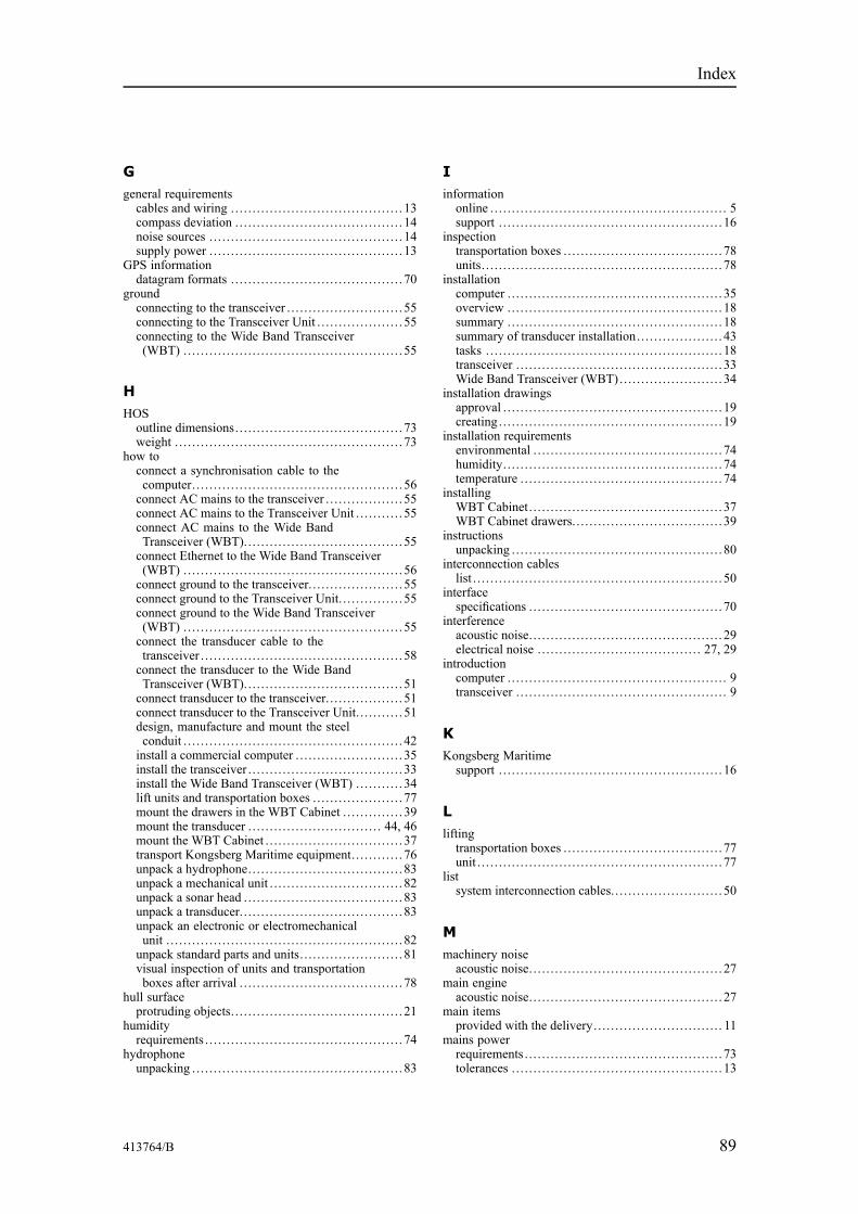
413764/B 89
Ggeneral requirementscables and wiring .. . . . . . . . . . . . . . . . . . . . . . . . . . . . . . . . . . . . . . . 13compass deviation .. . . . . . . . . . . . . . . . . . . . . . . . . . . . . . . . . . . . . . 14noise sources .. . . . . . . . . . . . . . . . . . . . . . . . . . . . . . . . . . . . . . . . . . . . 14supply power .. . . . . . . . . . . . . . . . . . . . . . . . . . . . . . . . . . . . . . . . . . . . 13
GPS informationdatagram formats .. . . . . . . . . . . . . . . . . . . . . . . . . . . . . . . . . . . . . . . 70
groundconnecting to the transceiver .. . . . . . . . . . . . . . . . . . . . . . . . . . 55connecting to the Transceiver Unit . . . . . . . . . . . . . . . . . . . . 55connecting to the Wide Band Transceiver(WBT) ... . . . . . . . . . . . . . . . . . . . . . . . . . . . . . . . . . . . . . . . . . . . . . . . . 55
HHOSoutline dimensions.. . . . . . . . . . . . . . . . . . . . . . . . . . . . . . . . . . . . . . 73weight .. . . . . . . . . . . . . . . . . . . . . . . . . . . . . . . . . . . . . . . . . . . . . . . . . . . . 73
how toconnect a synchronisation cable to thecomputer.. . . . . . . . . . . . . . . . . . . . . . . . . . . . . . . . . . . . . . . . . . . . . . . . 56connect AC mains to the transceiver .. . . . . . . . . . . . . . . . . 55connect AC mains to the Transceiver Unit . . . . . . . . . . . 55connect AC mains to the Wide BandTransceiver (WBT)... . . . . . . . . . . . . . . . . . . . . . . . . . . . . . . . . . . 55connect Ethernet to the Wide Band Transceiver(WBT) ... . . . . . . . . . . . . . . . . . . . . . . . . . . . . . . . . . . . . . . . . . . . . . . . . 56connect ground to the transceiver.. . . . . . . . . . . . . . . . . . . . . 55connect ground to the Transceiver Unit. . . . . . . . . . . . . . . 55connect ground to the Wide Band Transceiver(WBT) ... . . . . . . . . . . . . . . . . . . . . . . . . . . . . . . . . . . . . . . . . . . . . . . . . 55connect the transducer cable to thetransceiver .. . . . . . . . . . . . . . . . . . . . . . . . . . . . . . . . . . . . . . . . . . . . . . 58connect the transducer to the Wide BandTransceiver (WBT)... . . . . . . . . . . . . . . . . . . . . . . . . . . . . . . . . . . 51connect transducer to the transceiver.. . . . . . . . . . . . . . . . . 51connect transducer to the Transceiver Unit. . . . . . . . . . . 51design, manufacture and mount the steelconduit . . . . . . . . . . . . . . . . . . . . . . . . . . . . . . . . . . . . . . . . . . . . . . . . . . . 42install a commercial computer .. . . . . . . . . . . . . . . . . . . . . . . . 35install the transceiver .. . . . . . . . . . . . . . . . . . . . . . . . . . . . . . . . . . . 33install the Wide Band Transceiver (WBT) ... . . . . . . . . 34lift units and transportation boxes .. . . . . . . . . . . . . . . . . . . . 77mount the drawers in the WBT Cabinet .. . . . . . . . . . . . . 39mount the transducer .. . . . . . . . . . . . . . . . . . . . . . . . . . . . . . 44, 46mount the WBT Cabinet .. . . . . . . . . . . . . . . . . . . . . . . . . . . . . . . 37transport Kongsberg Maritime equipment.. . . . . . . . . . . 76unpack a hydrophone.. . . . . . . . . . . . . . . . . . . . . . . . . . . . . . . . . . . 83unpack a mechanical unit . . . . . . . . . . . . . . . . . . . . . . . . . . . . . . . 82unpack a sonar head ... . . . . . . . . . . . . . . . . . . . . . . . . . . . . . . . . . . 83unpack a transducer.. . . . . . . . . . . . . . . . . . . . . . . . . . . . . . . . . . . . . 83unpack an electronic or electromechanicalunit . . . . . . . . . . . . . . . . . . . . . . . . . . . . . . . . . . . . . . . . . . . . . . . . . . . . . . . 82unpack standard parts and units. . . . . . . . . . . . . . . . . . . . . . . . 81visual inspection of units and transportationboxes after arrival . . . . . . . . . . . . . . . . . . . . . . . . . . . . . . . . . . . . . . 78
hull surfaceprotruding objects.. . . . . . . . . . . . . . . . . . . . . . . . . . . . . . . . . . . . . . . 21
humidityrequirements .. . . . . . . . . . . . . . . . . . . . . . . . . . . . . . . . . . . . . . . . . . . . . 74
hydrophoneunpacking .. . . . . . . . . . . . . . . . . . . . . . . . . . . . . . . . . . . . . . . . . . . . . . . . 83
Iinformationonline .. . . . . . . . . . . . . . . . . . . . . . . . . . . . . . . . . . . . . . . . . . . . . . . . . . . . . . 5support . . . . . . . . . . . . . . . . . . . . . . . . . . . . . . . . . . . . . . . . . . . . . . . . . . . . 16
inspectiontransportation boxes .. . . . . . . . . . . . . . . . . . . . . . . . . . . . . . . . . . . . 78units. . . . . . . . . . . . . . . . . . . . . . . . . . . . . . . . . . . . . . . . . . . . . . . . . . . . . . . . 78
installationcomputer .. . . . . . . . . . . . . . . . . . . . . . . . . . . . . . . . . . . . . . . . . . . . . . . . . 35overview ... . . . . . . . . . . . . . . . . . . . . . . . . . . . . . . . . . . . . . . . . . . . . . . . 18summary ... . . . . . . . . . . . . . . . . . . . . . . . . . . . . . . . . . . . . . . . . . . . . . . . 18summary of transducer installation.. . . . . . . . . . . . . . . . . . . 43tasks .. . . . . . . . . . . . . . . . . . . . . . . . . . . . . . . . . . . . . . . . . . . . . . . . . . . . . . 18transceiver .. . . . . . . . . . . . . . . . . . . . . . . . . . . . . . . . . . . . . . . . . . . . . . . 33Wide Band Transceiver (WBT)... . . . . . . . . . . . . . . . . . . . . . 34
installation drawingsapproval .. . . . . . . . . . . . . . . . . . . . . . . . . . . . . . . . . . . . . . . . . . . . . . . . . . 19creating .. . . . . . . . . . . . . . . . . . . . . . . . . . . . . . . . . . . . . . . . . . . . . . . . . . . 19
installation requirementsenvironmental . . . . . . . . . . . . . . . . . . . . . . . . . . . . . . . . . . . . . . . . . . . . 74humidity.. . . . . . . . . . . . . . . . . . . . . . . . . . . . . . . . . . . . . . . . . . . . . . . . . . 74temperature .. . . . . . . . . . . . . . . . . . . . . . . . . . . . . . . . . . . . . . . . . . . . . . 74
installingWBT Cabinet.. . . . . . . . . . . . . . . . . . . . . . . . . . . . . . . . . . . . . . . . . . . . 37WBT Cabinet drawers.. . . . . . . . . . . . . . . . . . . . . . . . . . . . . . . . . . 39
instructionsunpacking .. . . . . . . . . . . . . . . . . . . . . . . . . . . . . . . . . . . . . . . . . . . . . . . . 80
interconnection cableslist . . . . . . . . . . . . . . . . . . . . . . . . . . . . . . . . . . . . . . . . . . . . . . . . . . . . . . . . . . 50
interfacespecifications .. . . . . . . . . . . . . . . . . . . . . . . . . . . . . . . . . . . . . . . . . . . . 70
interferenceacoustic noise.. . . . . . . . . . . . . . . . . . . . . . . . . . . . . . . . . . . . . . . . . . . . 29electrical noise .. . . . . . . . . . . . . . . . . . . . . . . . . . . . . . . . . . . . . 27, 29
introductioncomputer .. . . . . . . . . . . . . . . . . . . . . . . . . . . . . . . . . . . . . . . . . . . . . . . . . . 9transceiver .. . . . . . . . . . . . . . . . . . . . . . . . . . . . . . . . . . . . . . . . . . . . . . . . 9
KKongsberg Maritimesupport . . . . . . . . . . . . . . . . . . . . . . . . . . . . . . . . . . . . . . . . . . . . . . . . . . . . 16
Lliftingtransportation boxes .. . . . . . . . . . . . . . . . . . . . . . . . . . . . . . . . . . . . 77unit . . . . . . . . . . . . . . . . . . . . . . . . . . . . . . . . . . . . . . . . . . . . . . . . . . . . . . . . . 77
listsystem interconnection cables.. . . . . . . . . . . . . . . . . . . . . . . . . 50
Mmachinery noiseacoustic noise.. . . . . . . . . . . . . . . . . . . . . . . . . . . . . . . . . . . . . . . . . . . . 27
main engineacoustic noise.. . . . . . . . . . . . . . . . . . . . . . . . . . . . . . . . . . . . . . . . . . . . 27
main itemsprovided with the delivery.. . . . . . . . . . . . . . . . . . . . . . . . . . . . . 11
mains powerrequirements .. . . . . . . . . . . . . . . . . . . . . . . . . . . . . . . . . . . . . . . . . . . . . 73tolerances .. . . . . . . . . . . . . . . . . . . . . . . . . . . . . . . . . . . . . . . . . . . . . . . . 13
Index
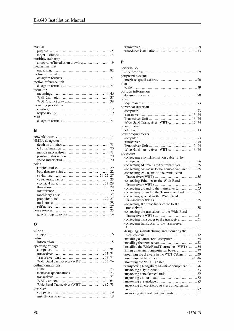
90 413764/B
manualpurpose .. . . . . . . . . . . . . . . . . . . . . . . . . . . . . . . . . . . . . . . . . . . . . . . . . . . . 5target audience .. . . . . . . . . . . . . . . . . . . . . . . . . . . . . . . . . . . . . . . . . . . 5
maritime authorityapproval of installation drawings .. . . . . . . . . . . . . . . . . . . . . 19
mechanical unitunpacking .. . . . . . . . . . . . . . . . . . . . . . . . . . . . . . . . . . . . . . . . . . . . . . . . 82
motion informationdatagram formats .. . . . . . . . . . . . . . . . . . . . . . . . . . . . . . . . . . . . . . . 71
motion reference unitdatagram formats .. . . . . . . . . . . . . . . . . . . . . . . . . . . . . . . . . . . . . . . 71
mountingmounting .. . . . . . . . . . . . . . . . . . . . . . . . . . . . . . . . . . . . . . . . . . . . 44, 46WBT Cabinet.. . . . . . . . . . . . . . . . . . . . . . . . . . . . . . . . . . . . . . . . . . . . 37WBT Cabinet drawers.. . . . . . . . . . . . . . . . . . . . . . . . . . . . . . . . . . 39
mounting procedurescreating .. . . . . . . . . . . . . . . . . . . . . . . . . . . . . . . . . . . . . . . . . . . . . . . . . . . 19responsibility .. . . . . . . . . . . . . . . . . . . . . . . . . . . . . . . . . . . . . . . . . . . . 19
MRUdatagram formats .. . . . . . . . . . . . . . . . . . . . . . . . . . . . . . . . . . . . . . . 71
Nnetwork security .. . . . . . . . . . . . . . . . . . . . . . . . . . . . . . . . . . . . . . . . . . . 14NMEA datagramsdepth information .. . . . . . . . . . . . . . . . . . . . . . . . . . . . . . . . . . . . . . . 71GPS information .. . . . . . . . . . . . . . . . . . . . . . . . . . . . . . . . . . . . . . . . 70motion information .. . . . . . . . . . . . . . . . . . . . . . . . . . . . . . . . . . . . . 71position information .. . . . . . . . . . . . . . . . . . . . . . . . . . . . . . . . . . . . 70speed information.. . . . . . . . . . . . . . . . . . . . . . . . . . . . . . . . . . . . . . . 70
noiseambient noise.. . . . . . . . . . . . . . . . . . . . . . . . . . . . . . . . . . . . . . . . . . . . 29bow thruster noise .. . . . . . . . . . . . . . . . . . . . . . . . . . . . . . . . . . . . . . 22cavitation.. . . . . . . . . . . . . . . . . . . . . . . . . . . . . . . . . . . . . . . . 21–22, 27contributing factors .. . . . . . . . . . . . . . . . . . . . . . . . . . . . . . . . . . . . . 25electrical noise .. . . . . . . . . . . . . . . . . . . . . . . . . . . . . . . . . . . . . 27, 29flow noise .. . . . . . . . . . . . . . . . . . . . . . . . . . . . . . . . . . . . . . . . . . . 20, 28interference .. . . . . . . . . . . . . . . . . . . . . . . . . . . . . . . . . . . . . . . . . . . . . . 29machinery noise.. . . . . . . . . . . . . . . . . . . . . . . . . . . . . . . . . . . . . . . . . 27propeller noise.. . . . . . . . . . . . . . . . . . . . . . . . . . . . . . . . . . . . . . 22, 27rattle noise .. . . . . . . . . . . . . . . . . . . . . . . . . . . . . . . . . . . . . . . . . . . . . . . 28self noise .. . . . . . . . . . . . . . . . . . . . . . . . . . . . . . . . . . . . . . . . . . . . . . . . . 27
noise sources .. . . . . . . . . . . . . . . . . . . . . . . . . . . . . . . . . . . . . . . . . . . . . . . 25general requirements .. . . . . . . . . . . . . . . . . . . . . . . . . . . . . . . . . . . 14
Oofficessupport . . . . . . . . . . . . . . . . . . . . . . . . . . . . . . . . . . . . . . . . . . . . . . . . . . . . 16
onlineinformation .. . . . . . . . . . . . . . . . . . . . . . . . . . . . . . . . . . . . . . . . . . . . . . . 5
operating voltagecomputer .. . . . . . . . . . . . . . . . . . . . . . . . . . . . . . . . . . . . . . . . . . . . . . . . . 73transceiver .. . . . . . . . . . . . . . . . . . . . . . . . . . . . . . . . . . . . . . . . . . 13, 74Transceiver Unit . . . . . . . . . . . . . . . . . . . . . . . . . . . . . . . . . . . . 13, 74Wide Band Transceiver (WBT)... . . . . . . . . . . . . . . . . 13, 74
outline dimensionsHOS ... . . . . . . . . . . . . . . . . . . . . . . . . . . . . . . . . . . . . . . . . . . . . . . . . . . . . 73technical specifications.. . . . . . . . . . . . . . . . . . . . . . . . . . . . . . . . . 73transceiver .. . . . . . . . . . . . . . . . . . . . . . . . . . . . . . . . . . . . . . . . . . . . . . . 73WBT Cabinet.. . . . . . . . . . . . . . . . . . . . . . . . . . . . . . . . . . . . . . . . . . . . 64Wide Band Transceiver (WBT)... . . . . . . . . . . . . . . . . 62, 73
overviewcomputer .. . . . . . . . . . . . . . . . . . . . . . . . . . . . . . . . . . . . . . . . . . . . . . . . . . 9installation tasks .. . . . . . . . . . . . . . . . . . . . . . . . . . . . . . . . . . . . . . . . 18
transceiver .. . . . . . . . . . . . . . . . . . . . . . . . . . . . . . . . . . . . . . . . . . . . . . . . 9transducer installation .. . . . . . . . . . . . . . . . . . . . . . . . . . . . . . . . . . 43
Pperformancespecifications .. . . . . . . . . . . . . . . . . . . . . . . . . . . . . . . . . . . . . . . . . . . . 69
peripheral systemsinterface specifications .. . . . . . . . . . . . . . . . . . . . . . . . . . . . . . . . . 70
plancable .. . . . . . . . . . . . . . . . . . . . . . . . . . . . . . . . . . . . . . . . . . . . . . . . . . . . . . 49
position informationdatagram formats .. . . . . . . . . . . . . . . . . . . . . . . . . . . . . . . . . . . . . . . 70
powerrequirements .. . . . . . . . . . . . . . . . . . . . . . . . . . . . . . . . . . . . . . . . . . . . . 73
power consumptioncomputer .. . . . . . . . . . . . . . . . . . . . . . . . . . . . . . . . . . . . . . . . . . . . . . . . . 73transceiver .. . . . . . . . . . . . . . . . . . . . . . . . . . . . . . . . . . . . . . . . . . 13, 74Transceiver Unit . . . . . . . . . . . . . . . . . . . . . . . . . . . . . . . . . . . . 13, 74Wide Band Transceiver (WBT)... . . . . . . . . . . . . . . . . 13, 74
power mainstolerances .. . . . . . . . . . . . . . . . . . . . . . . . . . . . . . . . . . . . . . . . . . . . . . . . 13
power requirementscomputer .. . . . . . . . . . . . . . . . . . . . . . . . . . . . . . . . . . . . . . . . . . . . . . . . . 73transceiver .. . . . . . . . . . . . . . . . . . . . . . . . . . . . . . . . . . . . . . . . . . 13, 74Transceiver Unit . . . . . . . . . . . . . . . . . . . . . . . . . . . . . . . . . . . . 13, 74Wide Band Transceiver (WBT)... . . . . . . . . . . . . . . . . 13, 74
procedureconnecting a synchronisation cable to thecomputer.. . . . . . . . . . . . . . . . . . . . . . . . . . . . . . . . . . . . . . . . . . . . . . . . 56connecting AC mains to the transceiver .. . . . . . . . . . . . . 55connecting ACmains to the Transceiver Unit . . . . . . . . 55connecting AC mains to the Wide BandTransceiver (WBT)... . . . . . . . . . . . . . . . . . . . . . . . . . . . . . . . . . . 55connecting Ethernet to the Wide BandTransceiver (WBT)... . . . . . . . . . . . . . . . . . . . . . . . . . . . . . . . . . . 56connecting ground to the transceiver.. . . . . . . . . . . . . . . . . 55connecting ground to the Transceiver Unit. . . . . . . . . . . 55connecting ground to the Wide BandTransceiver (WBT)... . . . . . . . . . . . . . . . . . . . . . . . . . . . . . . . . . . 55connecting the transducer cable to thetransceiver .. . . . . . . . . . . . . . . . . . . . . . . . . . . . . . . . . . . . . . . . . . . . . . 58connecting the transducer to the Wide BandTransceiver (WBT)... . . . . . . . . . . . . . . . . . . . . . . . . . . . . . . . . . . 51connecting transducer to the transceiver.. . . . . . . . . . . . . 51connecting transducer to the TransceiverUnit. . . . . . . . . . . . . . . . . . . . . . . . . . . . . . . . . . . . . . . . . . . . . . . . . . . . . . . 51designing, manufacturing and mounting thesteel conduit. . . . . . . . . . . . . . . . . . . . . . . . . . . . . . . . . . . . . . . . . . . . . 42installing a commercial computer .. . . . . . . . . . . . . . . . . . . . 35installing the transceiver .. . . . . . . . . . . . . . . . . . . . . . . . . . . . . . . 33installing theWide Band Transceiver (WBT) ... . . . . . 34lifting units and transportation boxes .. . . . . . . . . . . . . . . . 77mounting the drawers in the WBT Cabinet .. . . . . . . . . 39mounting the transducer .. . . . . . . . . . . . . . . . . . . . . . . . . . 44, 46mounting the WBT Cabinet .. . . . . . . . . . . . . . . . . . . . . . . . . . . 37transporting KongsbergMaritime equipment .. . . . . . . 76unpacking a hydrophone .. . . . . . . . . . . . . . . . . . . . . . . . . . . . . . . 83unpacking a mechanical unit . . . . . . . . . . . . . . . . . . . . . . . . . . . 82unpacking a sonar head ... . . . . . . . . . . . . . . . . . . . . . . . . . . . . . . 83unpacking a transducer.. . . . . . . . . . . . . . . . . . . . . . . . . . . . . . . . . 83unpacking an electronic or electromechanicalunit . . . . . . . . . . . . . . . . . . . . . . . . . . . . . . . . . . . . . . . . . . . . . . . . . . . . . . . 82unpacking standard parts and units . . . . . . . . . . . . . . . . . . . . 81
EA640 Installation Manual
413764/B 91
visual inspection of units and transportationboxes after arrival . . . . . . . . . . . . . . . . . . . . . . . . . . . . . . . . . . . . . . 78
procedurescreating mounting procedures.. . . . . . . . . . . . . . . . . . . . . . . . . 19unpacking .. . . . . . . . . . . . . . . . . . . . . . . . . . . . . . . . . . . . . . . . . . . . . . . . 80
processed dataformats .. . . . . . . . . . . . . . . . . . . . . . . . . . . . . . . . . . . . . . . . . . . . . . . . . . . 72
propellersacoustic noise.. . . . . . . . . . . . . . . . . . . . . . . . . . . . . . . . . . . . . . . 22, 27
proprietary datagramsannotations.. . . . . . . . . . . . . . . . . . . . . . . . . . . . . . . . . . . . . . . . . . . . . . . 71
protectiontransducer cables in steel conduit. . . . . . . . . . . . . . . . . . . . . . 51
protruding objectsavoid .. . . . . . . . . . . . . . . . . . . . . . . . . . . . . . . . . . . . . . . . . . . . . . . . . . . . . . 21
publicationpurpose .. . . . . . . . . . . . . . . . . . . . . . . . . . . . . . . . . . . . . . . . . . . . . . . . . . . . 5target audience .. . . . . . . . . . . . . . . . . . . . . . . . . . . . . . . . . . . . . . . . . . . 5
purposecomputer .. . . . . . . . . . . . . . . . . . . . . . . . . . . . . . . . . . . . . . . . . . . . . . . . . . 9this manual.. . . . . . . . . . . . . . . . . . . . . . . . . . . . . . . . . . . . . . . . . . . . . . . . 5transceiver .. . . . . . . . . . . . . . . . . . . . . . . . . . . . . . . . . . . . . . . . . . . . . . . . 9
Rrattle noiseacoustic noise.. . . . . . . . . . . . . . . . . . . . . . . . . . . . . . . . . . . . . . . . . . . . 28
readerthis manual.. . . . . . . . . . . . . . . . . . . . . . . . . . . . . . . . . . . . . . . . . . . . . . . . 5
registered trademarks.. . . . . . . . . . . . . . . . . . . . . . . . . . . . . . . . . . . . . . . 5requirementsac mains power.. . . . . . . . . . . . . . . . . . . . . . . . . . . . . . . . . . . . . . . . . . 73cables and wiring .. . . . . . . . . . . . . . . . . . . . . . . . . . . . . . . . . . . . . . . 13compass deviation .. . . . . . . . . . . . . . . . . . . . . . . . . . . . . . . . . . . . . . 14environmental . . . . . . . . . . . . . . . . . . . . . . . . . . . . . . . . . . . . . . . . . . . . 74humidity.. . . . . . . . . . . . . . . . . . . . . . . . . . . . . . . . . . . . . . . . . . . . . . . . . . 74mains power .. . . . . . . . . . . . . . . . . . . . . . . . . . . . . . . . . . . . . . . . . . . . . 73noise sources .. . . . . . . . . . . . . . . . . . . . . . . . . . . . . . . . . . . . . . . . . . . . 14power .. . . . . . . . . . . . . . . . . . . . . . . . . . . . . . . . . . . . . . . . . . . . . . . . . . . . . 73supply power .. . . . . . . . . . . . . . . . . . . . . . . . . . . . . . . . . . . . . . . 13, 73temperature .. . . . . . . . . . . . . . . . . . . . . . . . . . . . . . . . . . . . . . . . . . . . . . 74
responsibilitycompass deviation .. . . . . . . . . . . . . . . . . . . . . . . . . . . . . . . . . . . . . . 14installation drawings .. . . . . . . . . . . . . . . . . . . . . . . . . . . . . . . . . . . 19mounting procedures .. . . . . . . . . . . . . . . . . . . . . . . . . . . . . . . . . . . 19
RS-232serial line cable used for synchronization .. . . . . . . . . . . 60
RTSRequest To Send for synchronization .. . . . . . . . . . . . . . . . 60
Sscope of supplybasic items ... . . . . . . . . . . . . . . . . . . . . . . . . . . . . . . . . . . . . . . . . . . . . . 11
self noiseacoustic noise.. . . . . . . . . . . . . . . . . . . . . . . . . . . . . . . . . . . . . . . . . . . . 27
sensorsinterface specifications .. . . . . . . . . . . . . . . . . . . . . . . . . . . . . . . . . 70
serial lineused for synchronization .. . . . . . . . . . . . . . . . . . . . . . . . . . . . . . . 60
single-beam transducerbrief description.. . . . . . . . . . . . . . . . . . . . . . . . . . . . . . . . . . . . . . . . . 10
sizeHOS ... . . . . . . . . . . . . . . . . . . . . . . . . . . . . . . . . . . . . . . . . . . . . . . . . . . . . 73technical specifications.. . . . . . . . . . . . . . . . . . . . . . . . . . . . . . . . . 73
transceiver .. . . . . . . . . . . . . . . . . . . . . . . . . . . . . . . . . . . . . . . . . . . . . . . 73Wide Band Transceiver (WBT)... . . . . . . . . . . . . . . . . . . . . . 73
slammingtransducer .. . . . . . . . . . . . . . . . . . . . . . . . . . . . . . . . . . . . . . . . . . . . . . . . 21
sonar headunpacking .. . . . . . . . . . . . . . . . . . . . . . . . . . . . . . . . . . . . . . . . . . . . . . . . 83
specificationsinterface capabilities.. . . . . . . . . . . . . . . . . . . . . . . . . . . . . . . . . . . . 70outline dimensions.. . . . . . . . . . . . . . . . . . . . . . . . . . . . . . . . . . . . . . 73performance .. . . . . . . . . . . . . . . . . . . . . . . . . . . . . . . . . . . . . . . . . . . . . 69serial line cable used for synchronization .. . . . . . . . . . . 60storage after unpacking .. . . . . . . . . . . . . . . . . . . . . . . . . . . . . . . . 85storage prior to installation .. . . . . . . . . . . . . . . . . . . . . . . . . . . . 79weight .. . . . . . . . . . . . . . . . . . . . . . . . . . . . . . . . . . . . . . . . . . . . . . . . . . . . 73
speed informationdatagram formats .. . . . . . . . . . . . . . . . . . . . . . . . . . . . . . . . . . . . . . . 70
standard computerinstallation .. . . . . . . . . . . . . . . . . . . . . . . . . . . . . . . . . . . . . . . . . . . . . . . 35
standard itemsprovided with the delivery.. . . . . . . . . . . . . . . . . . . . . . . . . . . . . 11
steel conduitdesign, manufacture and mount.. . . . . . . . . . . . . . . . . . . . . . . 42transducer cables.. . . . . . . . . . . . . . . . . . . . . . . . . . . . . . . . . . . . . . . . 51
storageafter unpacking.. . . . . . . . . . . . . . . . . . . . . . . . . . . . . . . . . . . . . . . . . . 85prior to installation .. . . . . . . . . . . . . . . . . . . . . . . . . . . . . . . . . . . . . 79
summaryinstallation .. . . . . . . . . . . . . . . . . . . . . . . . . . . . . . . . . . . . . . . . . . . . . . . 18transducer installation .. . . . . . . . . . . . . . . . . . . . . . . . . . . . . . . . . . 43
supply powerrequirements .. . . . . . . . . . . . . . . . . . . . . . . . . . . . . . . . . . . . . . . . . . . . . 73tolerances .. . . . . . . . . . . . . . . . . . . . . . . . . . . . . . . . . . . . . . . . . . . . . . . . 13
supply voltagecomputer .. . . . . . . . . . . . . . . . . . . . . . . . . . . . . . . . . . . . . . . . . . . . . . . . . 73transceiver .. . . . . . . . . . . . . . . . . . . . . . . . . . . . . . . . . . . . . . . . . . 13, 74Transceiver Unit . . . . . . . . . . . . . . . . . . . . . . . . . . . . . . . . . . . . 13, 74Wide Band Transceiver (WBT)... . . . . . . . . . . . . . . . . 13, 74
support information.. . . . . . . . . . . . . . . . . . . . . . . . . . . . . . . . . . . . . . . . 16surfaceprotruding objects.. . . . . . . . . . . . . . . . . . . . . . . . . . . . . . . . . . . . . . . 21
synchronisationconnect to computer .. . . . . . . . . . . . . . . . . . . . . . . . . . . . . . . . . . . . 56using Request To Send (RTS) and Clear ToSend (CTS).. . . . . . . . . . . . . . . . . . . . . . . . . . . . . . . . . . . . . . . . . . . . . 56
synchronizationcables using RS-232 serial line .. . . . . . . . . . . . . . . . . . . . . . . 60
systemdescription .. . . . . . . . . . . . . . . . . . . . . . . . . . . . . . . . . . . . . . . . . . . . . . . . 7diagram... . . . . . . . . . . . . . . . . . . . . . . . . . . . . . . . . . . . . . . . . . . . . . . . . . . 8
system cableslist . . . . . . . . . . . . . . . . . . . . . . . . . . . . . . . . . . . . . . . . . . . . . . . . . . . . . . . . . . 50
Ttarget audiencethis manual.. . . . . . . . . . . . . . . . . . . . . . . . . . . . . . . . . . . . . . . . . . . . . . . . 5
technical specificationsinterface specifications .. . . . . . . . . . . . . . . . . . . . . . . . . . . . . . . . . 70outline dimensions.. . . . . . . . . . . . . . . . . . . . . . . . . . . . . . . . . . . . . . 73weight .. . . . . . . . . . . . . . . . . . . . . . . . . . . . . . . . . . . . . . . . . . . . . . . . . . . . 73
temperaturerequirements .. . . . . . . . . . . . . . . . . . . . . . . . . . . . . . . . . . . . . . . . . . . . . 74
this manualpurpose .. . . . . . . . . . . . . . . . . . . . . . . . . . . . . . . . . . . . . . . . . . . . . . . . . . . . 5target audience .. . . . . . . . . . . . . . . . . . . . . . . . . . . . . . . . . . . . . . . . . . . 5
Index
92 413764/B
tolerancessupply power .. . . . . . . . . . . . . . . . . . . . . . . . . . . . . . . . . . . . . . . . . . . . 13
trademarksregistered.. . . . . . . . . . . . . . . . . . . . . . . . . . . . . . . . . . . . . . . . . . . . . . . . . . 5
transceiverconnecting AC mains.. . . . . . . . . . . . . . . . . . . . . . . . . . . . . . . . . . . 55connecting ground ... . . . . . . . . . . . . . . . . . . . . . . . . . . . . . . . . . . . . 55connecting the transducer cable.. . . . . . . . . . . . . . . . . . . . . . . 58connecting transducer .. . . . . . . . . . . . . . . . . . . . . . . . . . . . . . . . . . 51description .. . . . . . . . . . . . . . . . . . . . . . . . . . . . . . . . . . . . . . . . . . . . . . . . 9environmental requirements.. . . . . . . . . . . . . . . . . . . . . . . . . . . 74installation .. . . . . . . . . . . . . . . . . . . . . . . . . . . . . . . . . . . . . . . . . . . . . . . 33introduction .. . . . . . . . . . . . . . . . . . . . . . . . . . . . . . . . . . . . . . . . . . . . . . . 9outline dimensions.. . . . . . . . . . . . . . . . . . . . . . . . . . . . . . . . . . . . . . 73overview ... . . . . . . . . . . . . . . . . . . . . . . . . . . . . . . . . . . . . . . . . . . . . . . . . 9power requirements.. . . . . . . . . . . . . . . . . . . . . . . . . . . . . . . . 13, 74purpose .. . . . . . . . . . . . . . . . . . . . . . . . . . . . . . . . . . . . . . . . . . . . . . . . . . . . 9weight .. . . . . . . . . . . . . . . . . . . . . . . . . . . . . . . . . . . . . . . . . . . . . . . . . . . . 73
Transceiver Cabinetmounting .. . . . . . . . . . . . . . . . . . . . . . . . . . . . . . . . . . . . . . . . . . . . . . . . . 37mounting the drawers .. . . . . . . . . . . . . . . . . . . . . . . . . . . . . . . . . . 39
Transceiver Unitconnecting AC mains.. . . . . . . . . . . . . . . . . . . . . . . . . . . . . . . . . . . 55connecting ground ... . . . . . . . . . . . . . . . . . . . . . . . . . . . . . . . . . . . . 55connecting transducer .. . . . . . . . . . . . . . . . . . . . . . . . . . . . . . . . . . 51environmental requirements.. . . . . . . . . . . . . . . . . . . . . . . . . . . 74power requirements.. . . . . . . . . . . . . . . . . . . . . . . . . . . . . . . . 13, 74transducer connector .. . . . . . . . . . . . . . . . . . . . . . . . . . . . . . . . . . . 51
transducerbow thrusters .. . . . . . . . . . . . . . . . . . . . . . . . . . . . . . . . . . . . . . . . . . . . 22brief description.. . . . . . . . . . . . . . . . . . . . . . . . . . . . . . . . . . . . . . . . . 10cavitation.. . . . . . . . . . . . . . . . . . . . . . . . . . . . . . . . . . . . . . . . . . . . . . . . . 22connecting to the transceiver .. . . . . . . . . . . . . . . . . . . . . . . . . . 51connecting to the Transceiver Unit . . . . . . . . . . . . . . . . . . . . 51connecting to the Wide Band Transceiver(WBT) ... . . . . . . . . . . . . . . . . . . . . . . . . . . . . . . . . . . . . . . . . . . . . . . . . 51connector.. . . . . . . . . . . . . . . . . . . . . . . . . . . . . . . . . . . . . . . . . . . . . . . . . 51installation summary ... . . . . . . . . . . . . . . . . . . . . . . . . . . . . . . . . . 43single beam ... . . . . . . . . . . . . . . . . . . . . . . . . . . . . . . . . . . . . . . . . . . . . 10slamming... . . . . . . . . . . . . . . . . . . . . . . . . . . . . . . . . . . . . . . . . . . . . . . . 21unpacking .. . . . . . . . . . . . . . . . . . . . . . . . . . . . . . . . . . . . . . . . . . . . . . . . 83
transducer cableconnecting the transducer cable to thetransceiver .. . . . . . . . . . . . . . . . . . . . . . . . . . . . . . . . . . . . . . . . . . . . . . 58connection .. . . . . . . . . . . . . . . . . . . . . . . . . . . . . . . . . . . . . . . . . . . . . . . 58wiring.. . . . . . . . . . . . . . . . . . . . . . . . . . . . . . . . . . . . . . . . . . . . . . . . . . . . . 58
transducer cablesprotection in steel conduit . . . . . . . . . . . . . . . . . . . . . . . . . . . . . . 51steel conduit . . . . . . . . . . . . . . . . . . . . . . . . . . . . . . . . . . . . . . . . . . . . . . 51
transducer connectorWide Band Transceiver (WBT)... . . . . . . . . . . . . . . . . . . . . . 51
transportationof delicate and fragile equipment .. . . . . . . . . . . . . . . . . . . . . 76
turbulenceprotruding objects.. . . . . . . . . . . . . . . . . . . . . . . . . . . . . . . . . . . . . . . 21
Uunpackinga hydrophone .. . . . . . . . . . . . . . . . . . . . . . . . . . . . . . . . . . . . . . . . . . . . 83a mechanical unit . . . . . . . . . . . . . . . . . . . . . . . . . . . . . . . . . . . . . . . . 82a sonar head... . . . . . . . . . . . . . . . . . . . . . . . . . . . . . . . . . . . . . . . . . . . . 83a transducer .. . . . . . . . . . . . . . . . . . . . . . . . . . . . . . . . . . . . . . . . . . . . . . 83an electronic or electromechanical unit . . . . . . . . . . . . . . . 82instructions .. . . . . . . . . . . . . . . . . . . . . . . . . . . . . . . . . . . . . . . . . . . . . . 80
standard parts and units . . . . . . . . . . . . . . . . . . . . . . . . . . . . . . . . . 81transducer .. . . . . . . . . . . . . . . . . . . . . . . . . . . . . . . . . . . . . . . . . . . 44, 46
Vvisual inspectiontransportation boxes .. . . . . . . . . . . . . . . . . . . . . . . . . . . . . . . . . . . . 78units. . . . . . . . . . . . . . . . . . . . . . . . . . . . . . . . . . . . . . . . . . . . . . . . . . . . . . . . 78
WWBTconnecting the transducer.. . . . . . . . . . . . . . . . . . . . . . . . . . . . . . 51installation .. . . . . . . . . . . . . . . . . . . . . . . . . . . . . . . . . . . . . . . . . . . . . . . 34outline dimensions.. . . . . . . . . . . . . . . . . . . . . . . . . . . . . . . . . . . . . . 62transducer connector .. . . . . . . . . . . . . . . . . . . . . . . . . . . . . . . . . . . 51
WBT Cabinetmounting .. . . . . . . . . . . . . . . . . . . . . . . . . . . . . . . . . . . . . . . . . . . . . . . . . 37mounting the drawers .. . . . . . . . . . . . . . . . . . . . . . . . . . . . . . . . . . 39outline dimensions.. . . . . . . . . . . . . . . . . . . . . . . . . . . . . . . . . . . . . . 64
websitedownload documents .. . . . . . . . . . . . . . . . . . . . . . . . . . . . . . . . . . . . 5
weightHOS ... . . . . . . . . . . . . . . . . . . . . . . . . . . . . . . . . . . . . . . . . . . . . . . . . . . . . 73technical specifications.. . . . . . . . . . . . . . . . . . . . . . . . . . . . . . . . . 73transceiver .. . . . . . . . . . . . . . . . . . . . . . . . . . . . . . . . . . . . . . . . . . . . . . . 73Wide Band Transceiver (WBT)... . . . . . . . . . . . . . . . . . . . . . 73
Wide Band Transceiver (WBT)connecting AC mains.. . . . . . . . . . . . . . . . . . . . . . . . . . . . . . . . . . . 55connecting Ethernet .. . . . . . . . . . . . . . . . . . . . . . . . . . . . . . . . . . . . 56connecting ground to .. . . . . . . . . . . . . . . . . . . . . . . . . . . . . . . . . . . 55connecting the transducer.. . . . . . . . . . . . . . . . . . . . . . . . . . . . . . 51environmental requirements.. . . . . . . . . . . . . . . . . . . . . . . . . . . 74installation .. . . . . . . . . . . . . . . . . . . . . . . . . . . . . . . . . . . . . . . . . . . . . . . 34outline dimensions.. . . . . . . . . . . . . . . . . . . . . . . . . . . . . . . . . 62, 73power requirements.. . . . . . . . . . . . . . . . . . . . . . . . . . . . . . . . 13, 74transducer connector .. . . . . . . . . . . . . . . . . . . . . . . . . . . . . . . . . . . 51weight .. . . . . . . . . . . . . . . . . . . . . . . . . . . . . . . . . . . . . . . . . . . . . . . . . . . . 73
wiringdiagram... . . . . . . . . . . . . . . . . . . . . . . . . . . . . . . . . . . . . . . . . . . . . . . . . . 49general requirements .. . . . . . . . . . . . . . . . . . . . . . . . . . . . . . . . . . . 13list of system interconnection cables .. . . . . . . . . . . . . . . . . 50transducer cable .. . . . . . . . . . . . . . . . . . . . . . . . . . . . . . . . . . . . . . . . . 58
EA640 Installation Manual


©2018 Kongsberg Maritime