Varanus glebopalma (black-palmed monitor) nocturnal activity and foraging
Upload
khangminh22Category
view
0download
0
EA-60-RI-00186.02
Varanus Island Hub Operations Oil Pollution Emergency Plan
PROJECT / FACILITY Varanus Island
REVIEW INTERVAL (MONTHS) 30 Months
SAFETY CRITICAL DOCUMENT NO
Rev
Owner Reviewer/s
Managerial/Technical/Site Approver
Senior Advisor – Oil Spill
Response
Team Lead – Security &
Emergency Response Manager - HSE
9
Holders of controlled copies:
Perth Library
Any hard copy of this document, other than those identified above, are uncontrolled. Please refer to
the Santos Offshore Business Document Management System for the latest revision.

Santos Ltd | EA-60-RI-00186.02 Page 2 of 291
Rev Rev Date Amendment
9 03/04/2020 Revised following NOPSEMA opportunity to modify and resubmit
8 17/12/2019 Revised to incorporate NOPSEMA Request for Further Written
Information
7 31/07/2019 5-year revision to NOPSEMA
6 14/06/2017 Revised to incorporate DMIRS comments
5 17/03/2017 Regulatory revision to DMIRS
4 03/09/2014 Revised to incorporate NOPSEMA Request for Further Written
Information (refer MOC-63) and DMIRS comments
3 10/07/2014 Submitted to DMIRS (03/09/2014)
2 16/06/2014 Revised activity description for State waters.
1 20/02/2014 Submitted to DMIRS (10/07/2014)
0 05/09/2013 Revised to incorporate DMIRS comments and changed
Commonwealth water spill scenarios.

Santos Ltd | EA-60-RI-00186.02 Page 3 of 291
Distribution List
Distribution
OPEP
Electronic Hardcopy
Intranet – Emergency Preparedness ●
General Manager – Gas Assets link
Varanus Island Field Supervisor / Varanus Island Control Room link ●
Manager - HSE link
Team Leader - Security & ER link
Senior Spill Response Advisor link
IMT Room – Perth office ● x 4
CCT Room – Perth office ●
AMOSC ●
DoT ●
AMSA ●
OSRL ●

Santos Ltd | EA-60-RI-00186.02 Page 4 of 291
How to use this OPEP in the event of a spill
Sections 1 to 4 contain background information only:
- Activity description and location,
- OPEP requirements,
- Oil Spill Response Framework
o Spill Response Levels
o Jurisdiction Authorities and Control Agencies
o Santos WA Incident Management Structure (Roles and responsibilities;
Training and exercises)
o Integration with other Organisations
- Spill Modelling and Protection Priorities
- Response Options and NEBA
Sections 5 to 19 contain directions on how to respond to the spill:
- Initial Response (First Strike Activation)
- Notifications and Reporting
- IAP Planning
- Spill Response Plans:
o Source Control Plan
o Monitor and Evaluate Plan
o Mechanical Dispersion Plan
o Containment and Recovery Plan
o Shoreline Protection Plan
o Shoreline Clean-up Plan
o Onshore Response Plan
o Oiled Wildlife Response Plan
o Waste Management Plan
o Scientific Monitoring Plan
o Forward Operations Plan
o Spill Response Termination
Sections 20 to 21 contain information on:
- Document Review and Revision
- OPEP Custodian
- References

Santos Ltd | EA-60-RI-00186.02 Page 5 of 291
Contents
Sections 1 to 4 contain background information only: 4
Sections 5 to 19 contain directions on how to respond to the spill: 4
Sections 20 to 21 contain information on: 4
Contents 5
List of Appendices 9
List of Figures 9
List of Tables 9
1 Oil Pollution Emergency Plan Overview 13
1.1 Description of Varanus Island Hub Operations 13
1.2 Purpose and Scope of OPEP 20
1.3 High Level Objectives of OPEP 20
2 Oil Spill Response Framework 21
2.1 Spill Response Levels 21
2.2 Jurisdictional Authorities and Control Agencies 21
2.3 Santos WA Incident Management Structure 24
2.4 Integration with other Organisations 39
2.5 Interface with External Plans 42
2.6 Interface with Internal Documents 43
2.7 Cost Recovery 44
3 Spill Risk and Protection Priorities 45
3.1 Spill risk scenarios 45
3.2 Hydrocarbon Characteristics and Behaviour 49
3.3 Offshore spills (State and Commonwealth waters) 49
3.4 Onshore spills 55
3.5 -Identify Priority Protection Areas 63
4 Response Option Selection 67
4.1 Evaluation of Applicable Response Strategies 67
4.2 Resource Arrangements and Demonstration of ALARP 77
4.3 Net Environmental Benefit Analysis (NEBA) 97
5 Initial Response (First Strike Activations) 107
5.1 Level 1 offshore spills 107
5.2 Level 2/3 offshore petroleum activity spills (platforms, monopods, pipelines and subsea
installations) 108
5.3 Level 2 offshore vessel-based Spills 111
5.4 Onshore spills 112
6 Notification and Reporting Plan 114
6.1 Regulatory notification and reporting 114
6.2 Level 2/3 spill response support notifications 120

Santos Ltd | EA-60-RI-00186.02 Page 6 of 291
7 Incident Action Plan (IAP) 125
8 Source Control 127
8.1 Vessel and Platform Releases (hydrocarbon storage, handling and transfer) 127
8.2 Vessel Tank Rupture 129
8.3 Loss of Well Control 132
8.4 Pipeline release 141
8.5 Crude oil cargo loading 142
8.6 Onshore Hydrocarbon spills 145
8.7 Source Control Environmental Performance 147
9 Monitor and Evaluate Plan (Operational Monitoring) 150
9.1 Vessel Surveillance 150
9.2 Aerial Surveillance 152
9.3 Tracking Buoys 155
9.4 Spill Fate Modelling 157
9.5 Satellite Imagery 161
9.6 Initial Oil Characterisation 162
9.7 Operational Water Quality Monitoring 166
9.8 Low Flow Well Leak Monitoring 174
9.9 Shoreline and Coastal Habitat Assessment 176
9.10 Operational Monitoring Data Collection and Frequency 178
9.11 Monitor and Evaluate Plan Environmental Performance 182
10 Mechanical Dispersion Plan 188
10.1 Mechanical Dispersion Environmental Performance 190
11 Offshore Containment and Recovery Plan 191
11.1 Equipment and Personnel 196
11.2 Deployment Locations 196
11.3 Decanting 197
11.4 Offshore Containment and Recovery Environmental Performance 197
12 Shoreline Protection Plan 199
12.1 Equipment and Personnel 204
12.2 Deployment Locations 205
12.3 Protection and Deflection Plan Environmental Performance 205
13 Shoreline Clean Up Plan 208
13.1 Equipment and Personnel 211
13.2 Clean-up activities 212
13.3 Deployment locations 213
13.4 Shoreline Clean-up Environmental Performance 213
14 Onshore Response 216
14.1 Source Control 219

Santos Ltd | EA-60-RI-00186.02 Page 7 of 291
14.2 Containment and clean-up 220
14.3 Site Remediation 220
14.4 Onshore Response Environmental Performance 221
15 Oiled Wildlife Response Plan 223
15.1 OWR Stages of Response 223
15.2 OWR Levels and Resourcing 225
15.3 Implementation Guidance 227
15.4 Oiled Wildlife Response Plan Environmental Performance 233
16 Waste Management Plan 234
16.1 Waste approvals 234
16.2 Waste Service Provider Capability 235
16.3 Waste Management Plan Environmental Performance 241
17 Scientific Monitoring Plans 243
17.1 Scope 243
17.2 Relationship to Operational Monitoring 243
17.3 Scientific Monitoring Plans 244
17.4 Baseline Monitoring 244
17.5 Monitoring Service Providers 245
17.6 Activation 246
17.7 Scientific Monitoring Plan Environmental Performance 246
18 Forward Operations Plan 248
18.1 Forward Operating Base (FOB) 248
18.2 Local facilities 248
18.3 Staging Areas 249
18.4 Wildlife Holding Facility 249
18.5 Freight Movement 249
18.6 Transport 249
18.7 Mobile Plant 249
18.8 Decontamination 249
18.9 Ablutions 249
18.10 Security 250
18.11 Messing 250
18.12 Cleaning and Repair 250
18.13 Suppliers 250
18.14 Accommodation 250
18.15 Providoring 250
18.16 PPE 251
18.17 Response Personnel Clean-up Crew 251
18.18 Radio Communications 251

Santos Ltd | EA-60-RI-00186.02 Page 8 of 291
19 Spill Response Termination 252
20 OPEP Administration 253
20.1 Document Review and Revision 253
20.2 OPEP Custodian 253
21 References 254

Santos Ltd | EA-60-RI-00186.02 Page 9 of 291
List of Appendices
Appendix A: Hydrocarbon Characteristics and Behaviour 256
Appendix B: POLREP 274
Appendix C: SITREP 275
Appendix D: Vessel Surveillance Observer Log 276
Appendix E: Aerial Surveillance Observer Log 277
Appendix F: Aerial Surveillance Surface Slick Monitoring Template 278
Appendix G: Aerial Surveillance Marine Fauna Sighting Record 279
Appendix H: Aerial Surveillance Shoreline Observation Log 280
Appendix I: Shoreline Clean-up Equipment 281
Appendix J: Shoreline Response Strategy Guidance 282
Appendix K: Operational Guidelines for Shoreline Response 283
Appendix L: Oiled Wildlife Response Personnel and Equipment 284
Appendix M: Scientific Monitoring Plans 289
Appendix N: SMP Activation Process 290
Appendix O: Scientific Monitoring Capability 291
List of Figures
Figure 1-1: Schematic of the Varanus Island Hub facilities 18
Figure 1-2: Location of the VI Hub facilities covered by this OPEP 19
Figure 2-1: Santos WA Incident Response Organisational Structure 25
Figure 2-2: Santos WA incident management structure for Level 2/3 marine oil pollution incident within or entering State
waters 41
Figure 3-1: Potential onshore spill sources, facility and surrounding sensitivities 56
Figure 3-2: Onshore pipelines (John Brookes, East Spar, Agincourt) spill ZPI - surface 58
Figure 3-3: Onshore pipelines (Harriet Bravo, Tanker Load-out) spill ZPI - surface 59
Figure 3-4: Onshore pipelines (Diesel) spill ZPI - surface 60
Figure 3-5: Onshore pipelines spill subsurface ZPI 62
Figure 7-1: Incident Action Plan process 125
Figure 8-1: John Brookes-5 Nominal Relief Well Plan View 139
List of Tables
Table 1-1: Offshore Facilities that Connect to the VI Hub 14
Table 2-1: Santos WA Oil Spill Response Levels 21
Table 2-2: Jurisdictional Authorities and Control Agencies for Varanus Island Hub oil spill response 22
Table 2-3: Roles and Responsibilities in the Crisis Support Team (CST) 26

Santos Ltd | EA-60-RI-00186.02 Page 10 of 291
Table 2-4: Roles and Responsibilities in the Incident Management Team (IMT) 27
Table 2-5: Key Field Based Roles and Responsibilities 29
Table 2-6: Santos WA Personnel Roles Embedded within the State Maritime Environmental Emergency Coordination
Centre (MEECC) / Department of Transport (DoT) IMT 30
Table 2-7: Department of Transport Roles Embedded within Santos WA’s CST / IMT 32
Table 2-8: Training and exercise requirements for CST/IMT positions 33
Table 2-9: Spill Responder Personnel Resources 34
Table 2-10: Oil Spill Response Testing Arrangements 37
Table 2-11 Environmental performance outcomes, controls and performance standards for incident management 38
Table 3-1: VI Hub Commonwealth Waters Worst Case Spill Scenario Summary 46
Table 3-2: VI Hub State Waters Worst Case Spill Scenario Summary 46
Table 3-3: VI Hub Onshore Worst Case Spill Scenario Summary 48
Table 3-4: Surface Hydrocarbon Thresholds for Response Planning 49
Table 3-5: Predicted shoreline contact for a surface release of John Brookes condensate (39,011 m3) from a loss of well
control at the John Brookes Platform in Commonwealth Waters 51
Table 3-6: Predicted shoreline contact for a short-term (5.4 hours) pipeline leak of condensate (210 m3) from the John
Brooke Pipeline at the State waters boundary (summer) 52
Table 3-7: Predicted shoreline contact for a marine diesel spill (329 m3) from Wonnich Platform in State waters 53
Table 3-8: Predicted shoreline contact for an HFO spill (1,900 m3) from the Varanus Island off-take tanker in State waters
54
Table 3-9: Predicted shoreline contact for a release of Varanus Island Crude Blend (8,629 m3) from the Varanus Island
off-take tanker in State waters 54
Table 3-10: Protection Priority Areas and Key Sensitivities 63
Table 3-11: Onshore environment features 65
Table 3-12 Onshore environmental sensitivities and priorities for protection 66
Table 4-1: Applicable Response Strategy Operational Considerations 68
Table 4-2 ALARP assessment of the resourcing for spill response strategies 78
Table 4-3: Impact of spill response strategies on the environmental values of the protection priorities following worst-
case spill of John Brookes condensate/marine diesel/VI crude blend in Commonwealth or State 98
Table 4-4: Impact of spill response strategies on the environmental values of the protection priorities following surface
release of HFO from offtake tanker in State Waters 102
Table 5-1: First Strike Activations for Level 1 Offshore Spills 107
Table 5-2: First Strike Activations for Level 2/3 Offshore Petroleum Activity Spills 108
Table 5-3: First Strike Activations for Level 2 Vessel Spills 111
Table 5-4: First Strike Activations for Onshore Pipeline Spill 112
Table 6-1: External Notification and Reporting Requirements (Commonwealth and State Water) 115
Table 6-2: External Notification and Reporting Requirements for Onshore Spills 119
Table 6-3: List of spill response support notifications 121
Table 8-1: Vessel and Platform Releases – Environmental Performance Outcome, Initiation Criteria and Termination
Criteria 127
Table 8-2: Vessel and Platform Releases Implementation Guide 128
Table 8-3: Vessel Tank Rupture - , Environmental Performance Outcome, Initiation Criteria and Termination Criteria 130
Table 8-4: Vessel Tank Rupture Implementation Guide 131
Table 8-5: Loss of Well Control - Environmental Performance Outcome, Initiation Criteria and Termination Criteria 132
Table 8-6: Loss of Well Control Implementation Guide 133
Table 8-7: Schedule for MODU arriving onsite 136
Table 8-8: Relief Well Kill Summary Results for John Brookes-5 140
Table 8-9: Pipeline Release - Environmental Performance Outcome, Initiation Criteria and Termination Criteria 141
Table 8-10: Pipeline Release Implementation Guide 141
Table 8-11: Crude Oil Cargo Loading Spill - Environmental Performance Outcome, Initiation Criteria and Termination
Criteria 142
Table 8-12: Crude Oil Cargo Loading Implementation Guide 143

Santos Ltd | EA-60-RI-00186.02 Page 11 of 291
Table 8-13: Onshore Hydrocarbon Spills - Environmental Performance Outcome, Initiation Criteria and Termination
Criteria 145
Table 8-14: Onshore Hydrocarbon Spills Implementation Guide 146
Table 8-15: Source Control Performance Standards and Measurement Criteria 148
Table 9-1: Vessel Surveillance – Environmental Performance Outcome, Initiation Criteria and Termination Criteria 150
Table 9-2: Vessel Surveillance Implementation Guide 151
Table 9-3: Aerial Surveillance – Environmental Performance Outcome, Initiation Criteria and Termination Criteria 152
Table 9-4: Aerial Surveillance Implementation Guide 153
Table 9-5: Tracking Buoys – Environmental Performance Outcome, Initiation Criteria and Termination Criteria 155
Table 9-6: Tracking Buoys Implementation Guide 156
Table 9-7: Spill Fate Modelling – Environmental Performance Outcome, Initiation Criteria and Termination Criteria 158
Table 9-8: Spill Fate Modelling Implementation Guide 159
Table 9-9: Satellite Imagery – Environmental Performance Outcome, Initiation Criteria and Termination Criteria 161
Table 9-10: Satellite Imagery Implementation Guide 162
Table 9-11: Initial Oil Characterisation – Environmental Performance Outcome, Initiation Criteria and Termination Criteria
163
Table 9-12: Initial Oil Characterisation Implementation Guide 163
Table 9-13: Operational Water Sampling and Analysis – Environmental Performance Outcome, Initiation Criteria and
Termination Criteria 167
Table 9-14: Operational Water Quality Sampling and Analysis Implementation Guide 167
Table 9-15: Operational Water Quality Sampling and Analysis Plan considerations 169
Table 9-16: Continuous Fluorometry Surveys – Objectives, Initiation Criteria and Termination Criteria 171
Table 9-17: Continuous Fluorometry Survey Implementation Guide 171
Table 9-18: Low Flow Leak Monitoring - Environmental Performance Outcome, Initiation Criteria and Termination Criteria
174
Table 9-19: Shoreline and Coastal Habitat Assessment – Environmental Performance Outcome, Initiation Criteria and
Termination Criteria 176
Table 9-20: Shoreline and Coastal Habitat Assessment Implementation Guide 177
Table 9-21 Details of Operational Monitoring Data Collection and Transfer 180
Table 9-22: Monitor and Evaluate Performance Standards and Measurement Criteria 182
Table 10-1: Mechanical Dispersion – Environmental Performance Outcome, Initiation Criteria and Termination Criteria
188
Table 10-2: Mechanical Dispersion Implementation Guide 189
Table 10-3: Mechanical Dispersion – Environmental Performance 190
Table 11-1: Criteria for the Use of Booms and Skimmers 191
Table 11-2: Offshore Containment and Recovery – Environmental Performance Outcome, Initiation Criteria and
Termination Criteria 192
Table 11-3: Offshore Containment and Recovery Implementation Guide 193
Table 11-4: Offshore Containment and Recovery – Environmental Performance 198
Table 12-1: Shoreline Protection – Environmental Performance Outcome, Initiation Criteria and Termination Criteria 199
Table 12-2: Shoreline Protection Implementation Guide 201
Table 12-3: Shoreline Protection – Environmental Performance 205
Table 13-1: Shoreline Clean-up – Objectives, Initiation Criteria and Termination Criteria 208
Table 13-2: Shoreline Clean-up Implementation Guide 209
Table 13-3: Shoreline Clean-up – Environmental Performance 214
Table 14-1: Onshore Response – Environmental Performance Outcome, Initiation Criteria and Termination Criteria 217
Table 14-2: Onshore Response Implementation Guide 217
Table 14-3: Onshore Response – Environmental Performance 221
Table 15-1: Oiled Wildlife Response – Environmental Performance Outcome, Initiation Criteria and Termination Criteria
223
Table 15-2: Oiled Wildlife Response Stages (adapted from WAOWRP) 224

Santos Ltd | EA-60-RI-00186.02 Page 12 of 291
Table 15-3: Indicative Oiled Wildlife Response Level (adapted from WA OWRP, 2014) 226
Table 15-4: Oiled Wildlife Response Level and Personnel Numbers 226
Table 15-5: Implementation Guidance – Oiled Wildlife Response 228
Table 15-6: Oiled Wildlife Response - Resource Capability 232
Table 15-7 Oiled Wildlife – Environmental Performance 233
Table 16-1: Waste Management – Environmental Performance Outcome, Initiation Criteria and Termination Criteria 234
Table 16-2: Waste Service Provider Vehicle and Equipment Availability 236
Table 16-3: Implementation Guidance – Waste Management 238
Table 16-4: Waste Management- Resource Capability 241
Table 16-5: Environmental Performance outcomes, controls and performance standards for waste management 242
Table 17-1 Scientific Monitoring - Environmental Performance Outcome, Initiation Criteria and Termination Criteria 243
Table 17-2 : Oil Spill Scientific Monitoring Plans relevant to VI Hub operations 244
Table 17-3: Environmental performance outcomes, controls and performance standards for scientific monitoring 247
Table 18-1: Dampier facilities with operational value for response 248

Santos Ltd | EA-60-RI-00186.02 Page 13 of 291
1 Oil Pollution Emergency Plan Overview
This document is the accompanying Oil Pollution Emergency Plan (OPEP) to the Varanus Island Hub
Operations Environment Plan (EP) for Commonwealth Waters (EA-66-RI-10003) required by Regulation 14(8)
of the Offshore Petroleum and Greenhouse Gas Storage (Environment) Regulations 2009 (OPGGS (E)
Regulations), and to the Varanus Island Hub Operations EP (State Waters) (EA-60-RI-00186), and Generic
Well Suspension and Well Abandonment EP (EA-00-RI-10027) (State waters) required by the Petroleum
(Submerged Lands) (Environment) Regulations 2012.
1.1 Description of Varanus Island Hub Operations
Varanus Island (VI) is the central gathering and processing hub for Santos WA’s offshore oil and gas production
facilities in the area. The VI facilities and installations are referred to as the VI Hub.
The following types of activities take place at the VI Hub facilities:
+ Routine operations and maintenance;
+ Marine operations;
+ Diving / remotely operated vehicle (ROV) activities;
+ Wireline intervention of wells for workover / re-perforation / suspension; and
+ Well abandonment operations.
Figure 1-1 shows a schematic layout of the VI Hub facilities and Figure 1-2 shows their locations. The offshore
facilities (platforms and subsea developments) that are either directly or indirectly linked to VI and their current
production status are listed in Table 1-1.
VI currently receives produced hydrocarbons from the following offshore facilities:
+ Harriet Bravo platform;
+ Linda platform
+ Halyard subsea installation;
+ Spar-2 subsea installation; and
+ John Brookes platform.
Gas/condensate and crude oil is processed on Varanus Island. Dry gas is exported to the mainland via the
sales gas pipeline for domestic use. Liquid hydrocarbons (Varanus Blend) are stored in tanks on the island
and are periodically off-loaded to offtake tankers via a tanker load-out line leading to the Marine Terminal.
The John Brookes platform, Halyard and Spar-2 subsea installations are located in Commonwealth waters
and produce to Varanus Island via the John Brookes pipeline and Halyard flowline/ East Spar pipeline,
respectively.
Airlie Island (AI) is no longer a hydrocarbon producing facility. AI is under a care and maintenance regime with
hydrocarbon containing infrastructure removed. The Chervil platform which previously produced to AI has been
removed but subsea infrastructure remains.
The Varanus Island Hub Operations Environment Plan (State Waters) (EA-60-RI-000186) and Varanus Island
Hub Operations Environment Plan for Commonwealth Waters (John Brookes, Greater East Spar and
associated Facilities) (EA-66-RI-10003) provides further detail on the operational activities at VI Hub and
further detail on the onshore and offshore facilities.

Santos Ltd | EA-60-RI-00186.02 Page 14 of 291
Table 1-1: Offshore Facilities that Connect to the VI Hub
Facility
Hydrocarbon
Production /
Status
Producing wells Inactive/ Suspended
wells
Plugged and
Abandoned wells1 Field/s Reservoir
Produced
hydrocarbon
State waters
Harriet Alpha
platform
Not producing/
suspended
N Nth Alkimos-2H
Harriet A-11
Gudrun-2
Harriet A-1
Harriet A-3
Harriet A-5 ST1
Harriet A-8H1
Harriet A-9H
N Gudrun
Harriet
Alkimos
Flag
Sandstone
N
Gipsy subsea Plugged and
abandoned
N N Gipsy-2H
Gipsy-4
Gipsy Nth Rankin
Mungaroo
N
Harriet Charlie
platform
Plugged and
abandoned
N N Harriet C-1
Harriet C-2
Harriet C-3
Harriet C-4
Harriet Flag
Sandstone
N
Harriet Bravo
platform
Oil Production Bambra-7H
Bambra-8H
Bambra East-3
Harriet Bravo-1
Harriet Bravo-5H
N Bambra
Harriet
Flag
Sandstone
Bambra
crude
Agincourt platform Not producing N Agincourt-4H
Artreus-1
Zephyrus-1
Jane-1 ST2
N Agincourt
Artreus
Zephyrus
Double
Island
Sandstone
N

Santos Ltd | EA-60-RI-00186.02 Page 15 of 291
Facility
Hydrocarbon
Production /
Status
Producing wells Inactive/ Suspended
wells
Plugged and
Abandoned wells1 Field/s Reservoir
Produced
hydrocarbon
Wonnich platform Not producing N Wonnich-1
Wonnich Deep-1H
N Wonnich Flag
Sandstone
N
Sinbad monopod Plugged and
abandoned
N N Sinbad-1
Sinbad-2
Endymion-1
Selene-1
Sinbad
Endymion
Flag
Sandstone
N
Campbell
monopod
Plugged and
abandoned
N N Campbell-2
Campbell-3
Campbell-4 ST1
Campbell-5
Campbell-6
Campbell Flag
Sandstone
N
Simpson Alpha
mini-platform
Not producing N Simpson-7
Tanami-4
Tanami-5
West Simpson-1
N Simpson
Flag
Sandstone
N
Simpson Bravo
mini-platform
Not producing N Simpson-9
Simpson-10
Monet-2
Simpson-4
N Simpson
Flag
Sandstone
N
Gibson South
Plato platform
Not producing N South Plato-1
South Plato-3H
Plato-2
South Gibson-1
South Plato Flag
Sandstone
N
Victoria platform Not producing N Albert-1
Little Sandy-1
Mohave-1H
N Albert
Little Sandy
Mohave
Flag
Sandstone
N

Santos Ltd | EA-60-RI-00186.02 Page 16 of 291
Facility
Hydrocarbon
Production /
Status
Producing wells Inactive/ Suspended
wells
Plugged and
Abandoned wells1 Field/s Reservoir
Produced
hydrocarbon
Perdika-1 ST1
Victoria-1 ST1
West Cycad-2
Perdika
Victoria
West Cycad
Double Island
monopod
Not producing N Double Island-1H
ST2
N Double Island Double
Island
Sandstone
N
Bambra Sea Pole Not producing N Bambra-3 N Bambra Flag
Sandstone
N
Twickenham
platform
Pig launching
facility only
N N N N N N
Linda platform Gas/condensate
production
Lee-3
Lee-4
Linda-3
Rose-4
Doric-2
Linda North-1
N Lee
Linda
Doric
Rose
Flag
Sandstone
Lee gas/
condensate
Linda gas/
condensate
VI Water injectors /
not producing
Alkimos-1
(Active Water
Injector – Not
Producing)
Tanami-1
(Active Water
Injector – Not
Producing)
Tanami-3
Rosette-1
N VI N
Open Water Temporarily
abandoned
Bambra-2
Koombana-1
Agincourt-1
Marley-1
Bambra
Agincourt
Flag N

Santos Ltd | EA-60-RI-00186.02 Page 17 of 291
Facility
Hydrocarbon
Production /
Status
Producing wells Inactive/ Suspended
wells
Plugged and
Abandoned wells1 Field/s Reservoir
Produced
hydrocarbon
Commonwealth waters
John Brookes
platform
Gas/condensate
Production
John Brookes-2
John Brookes-3
ST1
John Brookes-5
John Brookes-6
ST1
N N John Brookes Top Barrow
‘A’ and
Upper
Barrow
Sandstone
John
Brookes
gas/
condensate
Open Water Exploration –
Temporarily
abandoned
N Rosella-1 N John Brookes N
Halyard subsea Gas/condensate
Production
Halyard-1 N N Halyard Upper
Barrow
Sandstone
Halyard
condensate
East Spar subsea Not producing N East Spar-3 ST1
East Spar-4A ST1
East Spar-6 ST1
East Spar-7
East Spar-9
N East Spar Flacourt
Formation
Upper
Barrow
Sandstone
N
Spar subsea Gas/
condensate
production
Spar-2 N N Spar Upper
Barrow
Sandstone
Spar gas/
condensate
1Plugged and abandoned wells pose no credible spill risk and no longer require a Well Operations Management Plan (WOMP) (Commonwealth water wells) or a
Well Management Plan (WMP) (State waters wells). Plugged and abandoned wells are therefore not included in the Environment Plans associated with this
OPEP. Only plugged and abandoned wells associated with existing infrastructure (i.e. platforms) have been included in Table 1.1.

Santos Ltd | EA-60-RI-00186.02 Page 18 of 291
Figure 1-1: Schematic of the Varanus Island Hub facilities

Santos Ltd | EA-60-RI-00186.02 Page 19 of 291
Figure 1-2: Location of the VI Hub facilities covered by this OPEP

Santos Ltd | EA-60-RI-00186.02 Page 20 of 291
1.2 Purpose and Scope of OPEP
The purpose of this OPEP is to describe Santos WA’s response to a hydrocarbon spill in State or
Commonwealth waters or onshore, associated with operational activities at VI Hub facilities and care and
maintenance activities on Airlie Island.
This OPEP covers all infrastructure and operational activities on VI and AI, the associated offshore
platforms/monopods and subsea tie-backs, the subsea pipelines, flowlines and umbilicals (within State waters
and Commonwealth waters) between VI and the offshore facilities and the pipeline from VI to the marine load-
out terminal.
This OPEP covers well intervention activities, including those to temporary or permanently plug wells on
existing infrastructure.
For well interventions within State waters, a Bridging Document to the Generic Well Suspension and Well
Abandonment EP (EA-00-RI-10027) will be submitted to the Department of Mines, Industry Regulation and
Safety (DMIRS), for approval, assessing the suitability of this OPEP for the well intervention campaign and
outlining any revisions to credible spill scenarios and additional control measures as required.
This OPEP has been developed to meet all relevant requirements of the Commonwealth Offshore Petroleum
and Greenhouse Gas Storage (Environment) Regulations 2009 (OPGGS (E) Regulations), the State
Petroleum (Submerged Lands)(Environment) Regulations 2012 (P(SL)(E) Regulations), and the State
Petroleum Pipeline (Environment) Regulations 2012 (PP(E) Regulations). It is consistent with the national and
State (WA) systems for oil pollution preparedness and response, being the National Plan for Maritime
Environmental Emergencies (NatPlan) managed by the Australian Maritime Safety Authority (AMSA) and the
WA State Hazard Plan: Maritime Environmental Emergencies (MEE).
1.3 High Level Objectives of OPEP
The overall aim of this OPEP is to prevent long term significant environmental impacts by safely limiting the
adverse environmental effects from an unplanned release of hydrocarbons to the marine environment to a
level that is as low as reasonably practicable (ALARP).
The objectives of this OPEP are to:
+ Provide guidance to the IMT in relation to spill response implementation; and
+ To demonstrate the capability requirements for response activities.

Santos Ltd | EA-60-RI-00186.02 Page 21 of 291
2 Oil Spill Response Framework
2.1 Spill Response Levels
Santos WA uses a tiered system of incident response levels consistent with State and National incident
response plans including the State Hazard Plan: Maritime Environmental Emergencies and the National Plan
for Maritime Environmental Emergencies (NatPlan). Spill Response Levels help to identify the severity of an
oil spill incident and the level of response required to manage the incident and mitigate environmental impacts.
Incident Response levels are outlined within the Santos WA Incident Command and Management Manual
(QE-00-ZF-00025) and further detailed in Table 2-1 below for hydrocarbon spills.
Table 2-1: Santos WA Oil Spill Response Levels
2.2 Jurisdictional Authorities and Control Agencies
During a spill response there will be both a Jurisdictional Authority and a Control Agency assigned to the oil
spill incident for all Spill Response Levels. The Jurisdictional Authority is the relevant Statutory Authority that
has responsibilities for oil pollution in that jurisdiction. The Control Agency is the agency or company assigned
Level 1
An incident which will not have an adverse effect on the public or the environment which can be controlled
by the use of resources normally available onsite without the need to mobilise the Santos WA IMT or
other external assistance.
Spill is contained within the incident site
Spill occurs within immediate site proximity.
Discharge in excess of permitted oil in water
(OIW) content (15 ppm).
Incident can be managed by the Incident
Response Team (IRT) and its resources.
Source of spill has been contained.
Oil is evaporating quickly and no danger of explosive
vapours.
Spill likely to naturally dissipate.
No media interest/not have an adverse effect on the
public.
Level 2
An incident that cannot be controlled by the use of onsite resources alone and requires external support
and resources to combat the situation; or
An incident that can be controlled onsite but which may have an adverse effect on the public or the
environment.
Danger of fire or explosion.
Possible continuous release.
Concentrated oil accumulating in close proximity
to the site or vessel.
Potential to impact other installations.
Level-1 resources overwhelmed, requiring additional
regional resources.
Potential impact to sensitive areas and/or local
communities.
Local/national media attention/may adversely affect
the public or the environment.
Level 3
An incident which has a wide ranging impact on Santos WA and may require the mobilisation of
external state, national or international resources to bring the situation under control.
Loss of well integrity.
Actual or potentially serious threat to life, property,
industry.
Major spill beyond site vicinity.
Significant shoreline environmental impact.
Level-2 resources overwhelmed, requiring
international assistance.
Level- 3 resources to be mobilised.
Significant impact on local communities.
International media attention.

Santos Ltd | EA-60-RI-00186.02 Page 22 of 291
by legislation, administrative arrangements or within the relevant contingency plan to control response
activities to an oil pollution emergency. With respect to a hydrocarbon spill from Varanus Island Hub
operations, the relevant Jurisdictional Authority and Control Agency varies dependent upon the location of the
spill (Commonwealth or State waters or onshore), the nature of the incident (vessel based or petroleum activity
based) and the Spill Response Level (refer Table 2-2).
Table 2-2: Jurisdictional Authorities and Control Agencies for Varanus Island Hub oil spill response
Role Spill
Level
State Waters Commonwealth waters Onshore
Facility 1 Vessel 2 Facility Vessel
Control
Agency
1
Petroleum
Titleholder (Santos
WA)
DoT
Petroleum
Titleholder
(Santos WA)
AMSA
Petroleum
Titleholder
(Santos
WA)
2/3 DoT DoT
Petroleum
Titleholder
(Santos WA)
AMSA
Petroleum
Titleholder
(Santos
WA)
Jurisdictional
Authority 1/2/3 DoT DoT NOPSEMA AMSA
DFES/
DER
2.2.1 Petroleum Activity Spill in Commonwealth Waters
For an offshore petroleum activity oil spill incident in Commonwealth waters the Jurisdictional Authority is
NOPSEMA. NOPSEMA is responsible for the oversight of response actions to pollution events from offshore
Petroleum Activities, in areas of Commonwealth jurisdiction. During a spill incident, NOPSEMA’s role will be
to implement regulatory processes to monitor and secure compliance with the OPGGS Act 2006 and OPGGS
(E) Regulations, including the issuing of directions as required, and investigate accidents, occurrences and
circumstances involving deficiencies in environment management.
Under the OPGGS (E) Regulations and the OPGGS Act 2006, the Petroleum Titleholder (i.e. Santos WA) is
responsible for responding to an oil spill incident as the Control Agency in Commonwealth waters, in
accordance with its OPEP.
Santos WA is responsible as Control Agency unless NOPSEMA identifies a requirement to delegate control.
In this situation, Control Agency responsibility may be delegated to AMSA who will assume control of the
incident and respond in accordance with AMSA’s NatPlan. In such an occurrence, Santos WA would assume
a Support Agency role and make available all necessary resources to support AMSA in AMSA’s performance
of their Control Agency responsibilities.
2.2.2 Petroleum Activity Spill in State Waters
For WA State waters, the DoT Marine Safety General Manager is prescribed as the Hazard Management
Agency (HMA) for marine oil pollution as per the WA Emergency Management Act 2005 and Emergency
Management Regulations 2006. The DoT as the HMA has developed the State Hazard Plan: Maritime
Environmental Emergencies (DoT, 2018) (replacing the WestPlan-MOP). These arrangements effectively
1 Includes a ‘Facility’, such as a fixed platform, FPSO/FSO, MODU, subsea infrastructure, or a construction, decommissioning and
pipelaying vessel. As defined by Schedule 3, Part 1, Clause 4 of the OPGGSA 2006.
2 Vessels are defined by Australian Government Coordination Arrangements for Maritime Environmental Emergencies (AMSA, 2017) as
a seismic vessel, supply or support vessel, or offtake tanker.

Santos Ltd | EA-60-RI-00186.02 Page 23 of 291
nominate DoT as the equivalent Jurisdictional Authority for Petroleum Activity spills in State waters, whose
responsibility is to ensure there is an adequate response to marine pollution in State Waters.
Under the State Hazard: MEE, the Control Agency for Level 1 Petroleum Activity spills in State waters is the
Petroleum Titleholder (Santos WA) with the Control Agency for Level 2/3 spills nominated as DoT.
While Santos WA is not the Control Agency for Level 2/3 Petroleum Activity spills in State waters, Santos WA
is required to have adequate plans and resources available to respond to a worst case spill originating in State
waters under the following State petroleum legislation administered by DMIRS:
+ Petroleum (Submerged Lands) Act 1982 and Petroleum (Submerged Lands) (Environment) Regulations
2012
+ Petroleum Pipelines Act 1969 and Petroleum Pipelines (Environment) Regulations 2012
Where DoT has assumed the role of Control Agency, Santos WA will provide all necessary resources to assist
DoT. The framework under which Santos WA will provide support to DoT for an oil response within State
waters is detailed in Section 2.4.3.
2.2.3 Cross-jurisdiction Petroleum Activity Spills
For a Level 2/3 Petroleum Activity spill, there is the possibility of the spill crossing jurisdictions between
Commonwealth and State waters. In these instances, the Jurisdictional Authority remains true to the source
of the spill (i.e. NOPSEMA for Commonwealth waters and DoT for State waters). Where a Level 2/3 spill
originating in Commonwealth waters moves into State waters two Control Agencies will exist: DoT and the
Petroleum Titleholder (Santos WA), each with its own Incident Management Team (IMT) and Lead IMT
responsibilities.
The arrangements between DoT and Santos WA for sharing resources and coordinating a response across
both Commonwealth and State waters are further detailed in Section 2.4.3.
2.2.4 Vessel Spills in Commonwealth Waters
For a vessel incident originating in Commonwealth Waters the Jurisdictional Authority and Control Agency is
AMSA. AMSA is the national shipping and maritime industry regulator and was established under the
Australian Maritime Safety Authority Act 1990. AMSA manages the NatPlan on behalf of the Australian
Government, working with State and the Northern Territory governments, emergency services and private
industry to maximise Australia’s marine pollution response capability.
As with petroleum activity spills, Santos WA is required to have adequate preparedness arrangements for
spills from vessels undertaking Petroleum Activities within Commonwealth waters under OPGGS Act 2006
and OPGGS (E) Regulations.
Santos WA will be responsible for coordinating a first-strike response to a vessel based spill in Commonwealth
waters until such time as AMSA takes over the role as Control Agency, at which time Santos WA would provide
all necessary resources as a Supporting Agency.
2.2.5 Vessel Spills in State Waters
For a vessel incident originating in State Waters the Jurisdictional Authority/ Hazard Management Agency is
DoT. DoT is also the Control Agency for Level 2/3 vessel spills in State waters under the State Hazard Plan
arrangements.
As with petroleum activity spills, Santos WA is required to have adequate preparedness arrangements for
spills from vessels undertaking Petroleum Activities within State Petroleum legislation administered by DMIRS.
Santos WA will be responsible for coordinating a first-strike response to all vessel based spill until such time
as DoT takes over the role as Control Agency, in the event of a Level 2/3 spill, at which time Santos WA would
provide all necessary resources (including personnel and equipment) as a Supporting Agency.

Santos Ltd | EA-60-RI-00186.02 Page 24 of 291
2.2.6 Cross-jurisdictional Vessel Spills
For a large vessel spill (Level 2/3) that crosses Jurisdictions between Commonwealth and State waters, two
Jurisdictional Authorities exist (AMSA for Commonwealth waters and DoT for State waters). Control Agency
responsibilities will be determined by DoT and AMSA with Santos WA providing all necessary resources
(including personnel and equipment) as a Supporting Agency.
2.2.7 Onshore Spills
In the event of an onshore spill of hazardous liquids (including hydrocarbons), the Jurisdictional Authority and
Hazard Management Agency (HMA) for incident response is the Department of Fire and Emergency Services
(DFES). The DFES is the prescribed HMA for response under the Emergency Management Regulations 2006
for all emergencies in which there is an “actual or impending spillage, release or escape of oil or an oily mixture
that is capable of causing loss of life, injury to a person or damage to the health of a person, property or the
environment”.
Under the State Hazard Plan: Hazardous Materials Emergencies (HAZMAT), DFES are the Control Agency
for State waters petroleum pipeline spills, however this excludes spills at certain island facilities, including
Varanus Island. Therefore, Santos WA will be the Control Agency for onshore spills at Varanus Island.
As stated in the State Hazard Plan: Hazardous Materials Emergencies (HAZMAT), on-site recovery and clean-
up of hazardous materials is the responsibility of the owner and as such, Santos WA will ensure clean-up and
remediation of any onshore spill is completed to the satisfaction of the Department of Environment Regulation
(DER) as the relevant Jurisdictional Authority for the clean-up of onshore oil spill pollution and management
of contaminated sites.
2.3 Santos WA Incident Management Structure
The Santos WA Incident Management Team (IMT) (Perth), Crisis Support Team (CST) (Perth) and Crisis
Management Team (CMT) (Adelaide) will be activated in the event of a Level 2/3 hydrocarbon spill regardless
of the type of spill or jurisdiction. As outlined above, control of the response may be taken over by the relevant
Control Agency as the incident progresses. The Santos WA response structure to a major emergency incident
is detailed in the Incident Command and Management Manual (ICMM) (QE-00-ZF-00025) and Santos Energy
Incident and Crisis Management Bridging Procedure (SQBP). The ICMM and SQBP describes response
planning and incident management that would operate under emergency conditions – describing how the
Santos WA IMT operates and interfaces with the CST and external parties.
The first priority of an escalating oil spill response to a Level 2/3 spill is the formation of an IMT and
establishment of an Incident Command Centre (ICC). The ongoing involvement of the IMT, CST and CMT will
be dependent on the severity and type of spill and the obligations of Santos WA and other agencies/authorities
in the coordinated spill response.
Santos WA’s incident response structure relevant to a VI incident includes:
+ Varanus Island-based Incident Response Team (IRT);
+ Incident Management Team (IMT) – Perth based to coordinate and execute responses to an oil spill
incident;
+ Crisis Support Team (CST) and Crisis Management Team (CMT) - to coordinate and manage threats to
the company’s reputation and to handle Santos WA’s corporate requirements as an operator;
+ Other field-based response and monitoring teams for implementing strategies outlined within the OPEP.
The Santos WA incident response organisational structure is defined in the Incident Command and
Management Manual (QE-00-ZF-00025), and in Figure 2-1.

Santos Ltd | EA-60-RI-00186.02 Page 25 of 291
Figure 2-1: Santos WA Incident Response Organisational Structure
Note: For a Level 2/3 Petroleum Activity spill whereby DoT is involved as a Control Agency, either within a
single jurisdiction (State water only spills) or cross-jurisdictional (spills from Commonwealth to State waters),
Santos WA will work in partnership with the DoT in providing spill response capability. Santos WA’s
expanded organisational structure for these situations is detailed in Section 2.4.3.
2.3.1 Roles and Responsibilities
The tables below (Table 2-3 to Table 2-7) provide an overview of the responsibilities of the Santos WA CST,
IMT, and field-based response team members in responding to an incident, the Emergency & Oil Spill
Coordinator in preparing for and responding to an incident, and the Chief Executive Officer in supporting an
incident response.
Also provided are the roles and responsibilities of Santos WA personnel or contractors required to work within
DoT’s organisational structure, where DoT has responsibilities for spill response as a Control Agency, as per
DoT’s Offshore Petroleum Industry Guidance Note – Marine Oil pollution: Response and Consultation
Arrangements (January 2017).
DoT will provide two roles to the Santos WA CST/IMT in a coordinated response. These are also outlined for
reference.

Santos Ltd | EA-60-RI-00186.02 Page 26 of 291
Table 2-3: Roles and Responsibilities in the Crisis Support Team (CST)
CST Member Main Responsibilities
CST Leader Notify Santos Crisis Duty Manager
Provide incident briefing and ongoing updates to CMT
Identify reputational issues and relevant local stakeholders
Set objectives and tasks for CST functional roles
Legal Counsel Advise CST Leader on on-going legal aspects
Manage insurance issues
Liaise with CMT Legal & Insurance
Government
Relations/Media
Advisor
Liaise with Santos CMT GPA Team with respect to overall media strategy
Liaise with State government agencies and other local stakeholders
Manage messaging to Santos WA employees
Activate Santos WA external call centre arrangements
Manage release of communications briefs to the external call centre
JV Coordinator /
Customer Liaison
Manage all communication between Santos WA and JV partners/ customers
Liaise with the GPA to ensure consistent message with JVs and Customers
Finance Track costs and advise CMT Finance and JV Partners of financial commitments in the
response
Liaise with CMT Finance Team with respect to access to funds
Human Resource
Team Leader
Liaise with CMT HR Team
Keep CST updated of personnel activities
Validate media and holding statements releasable information with regards to Santos
WA personnel matters
Work with CST Public Affairs on content of internal statements to staff
Put EAP on alert if appropriate
Work with Police welfare person or doctors as required
Be prepared to accompany police to provide initial company support
Arrange Next of Kin (NOK) notifications for affected personnel (excluding Police
managed fatalities)
Determine NOK assistance required i.e. family travel to hospital, child support, etc
Arrange for dedicated management support for families and next-of-kin, if appropriate
Arrange EAP counselling at airports and homes where required – HR personnel to
attend where possible
CST Data Manager Ensure CST Centre resources are in place and functional
Distribute manuals, contact lists and supporting information to CST personnel
Records and collects all information associated with the response to the incident
Maintain filing system for Incident Response

Santos Ltd | EA-60-RI-00186.02 Page 27 of 291
Table 2-4: Roles and Responsibilities in the Incident Management Team (IMT)
IMT Member Main Responsibilities
Incident
Commander
Coordinate all support in accordance with the IRP and/or activity specific Oil Spill
Contingency Plan or Oil Pollution Emergency Plan
Set the response objectives and strategic direction
Oversee the development and implementation of Incident Action Plans
Oversee implementation of MoUs and contracted support for ‘mutual aid’
Ensure co-ordination with external organisations/police, etc.
Prepare and review strategic and tactical objectives with the CST
Liaise with the CST and provide factual information
Set response termination criteria in consultation with regulatory authorities
Planning Team
Leader
Collect and document situational awareness information of the incident
Develop, document, communicate and implement Incident Action Plans to achieve
incident objectives
Determine the status of action/s or planned activities under the Incident Action Plans
and assess and document performance against the objectives.
Assess long term consequences of incident and plan for long term recovery
Manage the GIS Team in a response
Operations Team
Leader/Drilling
Team Leader
Coordinate operational aspects of Incident Response
Provide the key contact for On-Scene Commanders
Liaise with contractors or third parties
Mobilise additional Santos WA staff and external experts to form Technical Support
Team
Assist Planning Team Leader with overall general plan preparation and preparation of
Incident Action Plans
Implement Incident Action Plans
Manage field response teams and activities
Logistics Team
Leader
Mobilise response equipment, helicopters, vessels, supplies and personnel
Provide transport and accommodation for evacuated personnel
Oversee the implementation of the Waste Management Plan throughout a Tier 2 or
Tier 3 oil spill response.
Liaise with the Supply Team to activate supply contracts and arrange procurements
Coordinate authorities for search and rescue
Supply Team
Leader
Arrange fast track procurement
Activate supply contracts as required
Implement and maintain Cost Tracking System to enable the tracking of all costs
associated to the response of the incident

Santos Ltd | EA-60-RI-00186.02 Page 28 of 291
IMT Member Main Responsibilities
Environmental
Team Leader
Manage notification to Designated Environmental Authorities and liaise as required
Assist in the development of Incident Action Plans
Advise of the Net Environmental Benefit Analysis of oil spill response strategies and
tactics
Oversee the implementation of scientific monitoring programs in an oil spill response
Provide liaison for implementation of the WA Oiled Wildlife Response Plan in an oil
spill response
Welfare Team
Leader
Obtain personnel status involved in the incident
Review POB lists and clarify accuracy through Safety Team Leader
Obtain list of Contactor Companies involved in the incident and obtain 3rd-Party
Contractor contact to advise of situation and safety of personnel when appropriate
Liaise with 3rd-Party Contractor contact regarding their personnel and organise
handover
Obtain employee’s emergency contact list (NOK) to advise of situation and safety of
personnel when appropriate
Take instructions from the CST HR Team Leader
Work with Logistics Team Leader to arrange transport for affected families to hospitals
etc.
Assist with arrangements through EAP to support families/employees
Safety Team
Leader
Manage notification to Designated Safety Authorities and liaise as required
Assist in the development of Incident Action Plans
Oversee the development and implementation of incident Safety Management Plans
as required.
Work with the Welfare Team Leader to support personnel safety
Computing and
Communications
Leader
Set up computing and communications in the IMT and CST Centres
Establish video monitoring between IMT and CST
Set up the incident response telephone room upon request
IMT Data Manager Ensure IMT resources are in place and functional in the ICC
Oversee the setting up of communications systems by the Computing and
Communications Leader
Distribute manuals, contact lists and supporting information to IMT personnel
Record and collect all information associated with the response to the incident
Maintain filing system for Incident Response
GIS Support Manage and keep up-to-date facility and asset drawings, data sets, and photos in the
‘GIS in IMT Database’.
Manage and keep up-to-date environmental features and sensitivity data sets in the
‘GIS in IMT Database’.
Manage and keep up-to-date marine maps in the ‘GIS in IMT Database’.
Provide IMT with quick access to up-to-date drawings and data sets in the ICC.
Provide software system to IMT that allows tactical response mapping overlays on
facility drawings and area maps.

Santos Ltd | EA-60-RI-00186.02 Page 29 of 291
Table 2-5: Key Field Based Roles and Responsibilities
Field-Based
Position
Main Responsibilities
Varanus Island
On-Scene
Commander
▪ Commands the onsite response to Varanus Island Hub incidents, including oil spills,
using onsite resources, including the Facility IRT
▪ Notifies the Perth based Incident Commander of Level 2/3 incidents, including oil spills,
requiring offsite support
▪ Single point of communications between facility/site and IMT
Varanus Island
Incident Response
Team (IRT)
▪ Respond to incidents under the instruction of an Incident Response Team Leader in
accordance with actions developed by the VI On Scene Commander.
Off-Asset On
Scene
Commander
Coordinates the field response as outlined in the Incident Action Plan developed by the
IMT
Commands a Forward Operating Base (FOB) for the coordination of resources
mobilised to site
Off-Asset Oil Spill
Response Teams
Undertake oil spill response activities as defined in Incident Action Plans and Oil
Pollution Emergency Plans.
Source Control
Team
Respond to incidents involving well loss of containment to stop the flow of oil to sea
Refer to the Source Control Emergency Response Plan (DR-00-ZF-1001) for detailed
descriptions of roles and responsibilities within the Source Control Team
Oiled Wildlife
Response Team
Respond to oiled wildlife incidents to minimise the impacts to wildlife
Refer to the Western Australia Oiled Wildlife Response Plan for detailed descriptions
of roles and responsibilities within the Oiled Wildlife Response Team
Scientific
Monitoring Teams
Monitor the impacts and recovery to sensitive receptors from an oil spill and associated
response actions
Refer to the Oil Spill Scientific Monitoring Standby and Response Manual (EA-00-RI-
10162) for detail on Scientific Monitoring Team roles and responsibilities

Santos Ltd | EA-60-RI-00186.02 Page 30 of 291
Table 2-6: Santos WA Personnel Roles Embedded within the State Maritime Environmental
Emergency Coordination Centre (MEECC) / Department of Transport (DoT) IMT
Santos Personnel
Roles embedded
within the State
MEECC / DoT IMT
Main Responsibilities
CST Liaison Officer Provide a direct liaison between the Santos CST and the State Maritime Environmental
Emergency Coordination Centre (MEECC)
Facilitate effective communications and coordination between the Santos CST
Commander and the State Maritime Environmental Emergency Coordinator (SMEEC)
Offer advice to SMEEC on matters pertaining to Santos WA crisis management
policies and procedures
Deputy Incident
Officer
Provide a direct liaison between the DoT IMT and the Santos WA IMT
Facilitate effective communications and coordination between the Santos WA Incident
Commander and the DoT Incident Controller
Offer advice to the DoT Incident Controller on matters pertaining to the Santos WA
incident response policies and procedures
Offer advice to the Safety Coordinator on matters pertaining to Santos WA safety
policies and procedures particularly as they relate to Santos WA employees or
contractors operating under the control of the DoT IMT
Intelligence
Support Officer
As part of the Intelligence Team, assist the Intelligence Officer in the performance of
their duties in relation to situation and awareness.
Facilitate the provision of relevant modelling and predications from the Santos WA
IMT.
Assist in the interpretation of modelling and predictions originating from the Santos WA
IMT.
Facilitate the provision of relevant situation and awareness information originating from
the DoT IMT to the Santos WA IMT.
Facilitate the provision of relevant mapping from the Santos WA IMT.
Assist in the interpretation of mapping originating from the Santos WA IMT.
Facilitate the provision of relevant mapping originating from the Santos WA IMT.
Deputy Planning
Officer
As part of the Planning Team, assist the DoT Planning Officer in the performance of
their duties in relation to the interpretation of existing response plans and the
development of incident action plans and related sub plans
Facilitate the provision of relevant IAP and sub plans from the Santos WA IMT
Assist in the interpretation of the Santos WA OPEP from Santos WA
Assist in the interpretation of the Santos IAP and sub plans from the Santos WA IMT
Facilitate the provision of relevant IAP and sub plans originating from the DoT IMT to
the Santos WA IMT
Assist in the interpretation of Santos WA’s existing resource plans
Facilitate the provision of relevant components of the resource sub plan originating
from the DoT IMT to the Santos WA IMT
(Note this individual must have intimate knowledge of the relevant Santos OPEP and
planning processes)

Santos Ltd | EA-60-RI-00186.02 Page 31 of 291
Santos Personnel
Roles embedded
within the State
MEECC / DoT IMT
Main Responsibilities
Environmental
Support Officer
As part of the Planning Team, assist the Environmental Officer in the performance of
their duties in relation to the provision of environmental support into the planning
process.
Assist in the interpretation of the Santos WA OPEP and relevant TRP plans
Facilitate in requesting, obtaining and interpreting environmental monitoring data
originating from the Santos WA IMT
Facilitate the provision of relevant environmental information and advice originating
from the DoT IMT to the Santos WA IMT
Public Information
Support & Media
Liaison Officer
As part of the Public Information Team, provide a direct liaison between the Santos
WA Media team and DoT IMT Media team
Facilitate effective communications and coordination between Santos WA and DoT
media teams
Assist in the release of joint media statements and conduct of joint media briefings
Assist in the release of joint information and warnings through the DoT Information &
Warnings team
Offer advice to the DoT Media Coordinator on matters pertaining to Santos WA media
policies and procedures
Facilitate effective communications and coordination between Santos WA and DoT
Community Liaison teams
Assist in the conduct of joint community briefings and events
Offer advice to the DoT Community Liaison Coordinator on matters pertaining to
Santos WA community liaison policies and procedures
Facilitate the effective transfer of relevant information obtained from through the
Contact Centre to the Santos WA IMT
Deputy Logistics
Officer
As part of the Logistics Team, assist the Logistics Officer in the performance of their
duties in relation to the provision of supplies to sustain the response effort
Facilitate the acquisition of appropriate supplies through Santos WA’s existing OSRL,
AMOSC and private contract arrangements
Collects Request Forms from DoT to action via the Santos WA IMT
(Note this individual must have intimate knowledge of the relevant Santos logistics
processes and contracts)
Facilities Support
Officer
As part of the Logistics Team, assist the Logistics Officer Supply in the performance of
their duties in relation to the provision of the management and disposal of waste
collected in State waters
Facilitate the acquisition of appropriate services and supplies through Santos WA’s
existing private contract arrangements related to waste management
Collects Request Forms from DoT to action via the Santos WA IMT
Deputy Finance
Officer
As part of the Logistics Team, assist the Finance Officer in the performance of their
duties in relation to the setting up and payment of accounts for those services acquired
through Santos’ existing OSRL, AMOSC and private contract arrangements.
Facilitate the communication of financial monitoring information to Santos WA to allow
them to track the overall cost of the response.

Santos Ltd | EA-60-RI-00186.02 Page 32 of 291
Santos Personnel
Roles embedded
within the State
MEECC / DoT IMT
Main Responsibilities
Assist the Finance Officer in the tracking of financial commitments through the
response, including the supply contracts commissioned directly by DoT and to be
charged back to Santos
Deputy On Scene
Commander (FOB)
Provide a direct liaison between the Santos WA Forward Operations Base/s (FOB/s)
and the DoT FOB
Facilitate effective communications and coordination between the Santos WA FOB
Operations Commander and the DoT FOB Operations Commander
Offer advice to the DoT FOB Operations Commander on matters pertaining to the
Santos WA incident response policies and procedures
Assist the Senior Safety Officer deployed in the FOB in the performance of their duties,
particularly as they relate to Santos WA employees or contractors
Offer advice to the Senior Safety Officer deployed in the FOB on matters pertaining to
the Santos WA safety policies and procedures
Table 2-7: Department of Transport Roles Embedded within Santos WA’s CST / IMT
DoT roles
embedded within
Santos WA’s CST /
IMT
Main Responsibilities
DoT Liaison Officer Provide a direct liaison between the Santos WA CST and the MEECC
Facilitate effective communications between DoT’s SMEEC and the Incident Controller
and Santos’ appointed CST Commander and Incident Controller
Provide enhanced situational awareness to DoT of the incident and the potential
impact on State waters
Assist in the provision of support from DoT to Santos WA
Facilitate the provision of technical advice from DoT to Santos WA’s Incident Controller
as required
Media Liaison
Officer
Provide a direct liaison between the Santos WA Media team and DoT IMT Media team
Facilitate effective communications and coordination between the Santos WA and DoT
media teams
Assist in the release of joint media statements and conduct of joint media briefings
Assist in the release of joint information and warnings through the DoT Information &
Warnings team
Offer advice to the Santos WA Media Coordinator on matters pertaining to DoT and
wider Government media policies and procedures

Santos Ltd | EA-60-RI-00186.02 Page 33 of 291
2.3.2 Incident Response Authority
During the course of incident, team members may be required to make technical and financial decisions that
exceed those levels set for normal operations.
The IMT Leader has full technical authority to request all Santos WA and contracted resources deemed
necessary to manage the incident, and to call in additional resources if required.
The IMT Leader is to request the CST Leader to obtain authority from the CMT for financial commitments to
respond to the incident consistent with the level of authorisation required for normal operations.
2.3.3 Training and Exercises
2.3.3.1 CST/IMT Training and Exercises
Santos WA sets training and exercise requirements for IMT/CST personnel to ensure skills and competency
requirements are achieved and maintained. Competency is maintained through participation in regular
response exercises and workshops. Training and exercise requirements for Santos WA are summarised in
Table 2-8.
Table 2-8: Training and exercise requirements for CST/IMT positions
CST Role Exercise Training
CST Leader 1 x Level 3 exercise annually or 3
x Level 3 desktop exercises
annually.
+ PMAOMIR320
+ AMOSC – Oil Spill Response Familiarisation Training
CST Members:
Finance Team
Leader
GPA Team
Leader
JV Coordinator/
Legal Team
Leader
Data Manager
IMT Role Exercise Training
Incident
Commander
Operations/
Drilling Team
Leader
1 x Level 2 exercise annually or 3 x
Level 2 desktop exercises annually. + PMAOMIR320;
+ PMAOMIR418; and
+ AMOSC – IMO3 Oil Spill Command & Control;
Planning Team
Leader
Logistics Team
Leader
Environmental
Team Leader
+ PMAOMIR320; and
+ AMOSC – IMO2 Oil Spill Management Course

Santos Ltd | EA-60-RI-00186.02 Page 34 of 291
Safety Team
Leader
Supply Team
Leader
GIS Team Leader
Data Manager
HR/ Welfare
Team Leader
+ PMAOMIR320; and
+ AMOSC – Oil Spill Response Familiarisation Training
2.3.3.2 Oil Spill Responders
Santos has an internal capability of trained oil spill responders that can be deployed in the field in a spill
response and has access to external trained spill responder resources (Refer Table 2-9).
Table 2-9: Spill Responder Personnel Resources
Responder Role Training Available Number
Santos AMOSC Core
Group Responders
Santos personnel
trained and
competency assessed
by AMOSC as the
AMOSC Core Group.
Deployed by IMT for
spill response
operations
AMOSC Core Group
Workshop (refresher
training undertaken
every 2 years).
AMOSC – IMO1 Oil
Spill Operators Course
12
Santos WA Facility
Incident Response
Teams
Present at Devil
Creek, Varanus Island
and Ningaloo Vision
Facilities for first strike
response to incidents
Internal Santos
training and exercises
as defined in each
facility’s Incident
Response Plan
On-scene commander
to have AMOSC – Oil
Spill Response
Familiarisation
Training.
One IR team per
operational facility per
shift.
Santos WA Aerial
Observers
Undertake aerial
surveillance of spill.
Deployed by IMT in
the aerial surveillance
aircrafts.
AMOSC – Aerial
Surveillance Course
(refresher training
undertaken tri‐annually).
7
AMOSC Core Group
Oil Spill Responders
Industry personnel as
the AMOSC Core
Group, available to
Santos under the
AMOSPlan.
For providing incident
management (IMT)
and operations (field
response) assistance.
AMOSC Core Group
Workshop (refresher
training undertaken
every 2 years).
AMOSC – IMO1 Oil
Spill Operators Course
and/or IMO2 Oil Spill
Management Course
As defined in Core
Group Member
Reports
Min.84
Max. 140 (incl.
Santos).

Santos Ltd | EA-60-RI-00186.02 Page 35 of 291
Responder Role Training Available Number
OSRL Oil Spill
Response Personnel
Oil Spill Response Ltd
professionals,
providing technical,
incident management
and operational advice
and assistance
available under
Santos-OSRL
contract.
As per OSRL training
and competency
matrix.
18
AMOSC Oil Spill
Response Specialists
Professionals,
providing technical,
incident management
and operational advice
and assistance
available under
Santos-AMOSC
contract.
As per AMOSC
training and
competency matrix.
8
Oiled Wildlife
Response Roles
(Level 4)
Refer OPEP Section 15 and Appendix L.
Monitoring Service
Provider :Monitoring
Coordination Team
(MCT) and SMP
Teams
Monitoring
Coordination Team
(MCT)
SMP Teams:
Technical Advisers
Field Team Leader
Field Team Member
As defined in the Oil
Spill Scientific
Monitoring Standby
and Response Manual
(EA-00-RI-10162)
Capability defined in
Monthly Capability
Reports.
MCT – 5 personnel
SMP Teams 12+ per
team
Level 1 Oiled Wildlife
Responders
(Workforce Hire)
Provide oiled wildlife
support activities
under supervision.
No previous training
required; on the job
training provided.
Nominally over 1,000.
Shoreline clean-up
personnel (Workforce
Hire)
Manual clean-up
activities under
supervision.
In addition to Table 2-9, the following resources are available for spill response and may be activated by the
relevant Controlling Agency:
+ National Plan: National Response Team (NRT) – Trained oil spill response specialists including aerial
observers, containment and recovery crews and shoreline clean-up personnel deployed under the
direction of AMSA and IMT in a response. The NRT is trained and managed in accordance with the
National Response Team Policy, approved by the National Plan Strategic Coordination Committee (AMSA,
2013b); and
+ The State Hazard: MEE: State Response Team (SRT) and NW Regional Response Team (RRT) - Oil
pollution response teams available to assist under the jurisdiction of the DoT. SRT and RRT members
remain trained and accredited in line with the State Hazard: MEE requirements.
In the event of a spill the trained spill responders outlined in Table 2-9 would be required to undertake various
roles in key spill response operations including operational monitoring, shoreline protection, shoreline clean-
up, oiled wildlife response and scientific monitoring.

Santos Ltd | EA-60-RI-00186.02 Page 36 of 291
In the event of a spill Team Leader roles for protection and deflection and shoreline clean-up would be filled
through Santos WA AMOSC Core Group Responders and then industry Core Group Responders.
2.3.4 Response Testing
Following acceptance of an OPEP, notification arrangements of the plan are tested through a communications
test to all external agencies and companies with roles defined within the plan. The Communications Tests are
repeated annually for activities that extend longer than 1 year.
CST and IMT members undertake Workshops and Exercises as outlined within the Incident and Crisis
Management Training and Exercise Plan (QE-92-HG-10001) to clarify and familiarise themselves with their
respective roles and responsibilities within OPEPs and other Emergency Plans. Learning aids are also
introduced through these workshops to assist improvement of capability for the personnel to perform the
functions of their role. Santos WA conducts a IMT/CST desktop and activation exercises using emergency
scenarios across its main operating facilities on the NWS or a drilling activity. An oil spill incident scenario is
used for the activation exercise once per year. Both safety and oil spill incidents tests the chain of command
of the Santos WA response system, communications and notification with external parties, communication
processes between office and facility, and field response tactics.
Testing of key response provider arrangements are done as part of larger exercises or as standalone tests
where the capability and availability of resources through the response provider is assessed against the
performance requirement.
Field deployment tests are undertaken by Santos WA as a sole responder and through Santos WA’s
involvement in multi-operator response deployment exercises.
2.3.5 Testing Schedule
Oil spill specific training, exercises, workshops and tests are detailed in the Incident and Crisis Management
Training and Exercise Plan (QE-92-HG-10001). Once completed, records are entered into the Santos Training
and Induction Database (Learning Management System). Key actions arising from exercises are recorded and
tracked through the Santos WA Action Tracking System. Progress of training, exercise and workshop
completion against the schedule is tracked and reported against on a monthly basis.
The Incident and Crisis Management Training and Exercise Plan (QE-92-HG-10001) is reviewed and revised
annually.
2.3.6 Oil Spill Response Audits
Oil spill response audits will follow the Santos WA Assurance Procedure (QE-91-IQ-10022) and are scheduled
as per the annual Assurance Schedule (QE-91-HA-20002). Audits will assist in identifying and addressing any
deficiencies in systems and procedures. At the conclusion of the audit any opportunities for improvement and
/or corrective actions required (non-conformances) will be formally noted and discussed with corrective actions
developed and accepted. In some instances, audits may conclude with potential amendments to the OPEP.
The deployment readiness and capability of AMOSC’s oil spill response equipment and resources in Geelong
and Fremantle is audited every two years under the direction of AMOSC’s participating members. The intent
of this audit is to provide assurances to Santos WA and associated members of AMOSC’s ability to respond
to an oil spill incident as per the methods and responsibilities defined in Oil Pollution Emergency Plans and
AMOSC’s Service Level Statement.
The deployment readiness and capability of OSRL’s oil spill response equipment and personnel in Singapore
is audited every two years. The intent of this audit is to provide assurances to Santos WA’s of OSRLs ability
to respond to an oil spill incident as per the methods and responsibilities defined in Santos WA’s Oil Pollution
Emergency Plans and OSRL’s Service Level Agreement.
The objectives and frequency of oil spill response testing and auditing relevant to VI Hub oil spill response are
summarised in Table 2-10.

Santos Ltd | EA-60-RI-00186.02 Page 37 of 291
Table 2-10: Oil Spill Response Testing Arrangements
Exercise Objective Frequency Recording and
review
Communication
Test
To test all communication
and notification processes
to service providers and
regulatory agencies
defined within the OPEP.
Required for every
approved OPEP.
When response
arrangements have
changed.
At least annually.
Any results of the test
are recorded in a Test
Report. Corrections
are updated within the
Incident Response
Telephone Directory
(QE-00-ZF-00025.20)
IMT/CST
Workshops
To refresh IMT & CST
roles and responsibilities
and provide familiarisation
with OPEP processes and
arrangements.
As per Incident and
Crisis Management
Training and Exercise
Plan (QE-92-HG-
10001)
All workshops
undertaken are
recorded in Santos
WA’s Learning
Management System.
OPEP Desktop and
Activation Exercise
Desktop Exercise
To familiarise IMT with
functions and process in
response to a simulated
oil spill scenario
Activation Exercise
To activate full IMT/CST
in response to oil spill
scenario and test
arrangements contained
within OPEP
As per Incident and
Crisis Management
Training and Exercise
Plan (QE-92-HG-
10001)
Minimum of one oil
spill response
activation exercise per
year.
All exercises
undertaken are
recorded in Santos
WA’s Learning
Management System.
Key recommendations
are recorded are
tracked in Santos
WA’s Action Tracking
System.
Response
arrangement tests
Tests of response
arrangements outlined
within the OPEP either as
part of desktop/ activation
exercises or as
standalone desktop tests
As per Incident and
Crisis Management
Training and Exercise
Plan (QE-92-HG-
10001)
Test reports are
recorded
Equipment
deployment
exercises/ tests
To focus on Santos WA’s
deployment capability.
To inspect and maintain
the condition of the
Santos oil spill response
equipment.
To maintain training of
field response personnel.
When new response
equipment is added.
As per Incident and
Crisis Management
Training and Exercise
Plan (QE-92-HG-
10001)
The following Santos-
owned equipment is
inspected and/or
tested
Tracker buoys
Offshore boom/
nearshore boom
Power packs
Vessel dispersant
spray systems
Reports are generated
for exercises and
recorded in Santos
WA’s Learning
Management System.
Key recommendations
are recorded are
tracked in Santos
WA’s Action Tracking
System.
Tracker Buoy tests are
recorded.

Santos Ltd | EA-60-RI-00186.02 Page 38 of 291
Exercise Objective Frequency Recording and
review
AMOSC audit To test deployment
readiness and capability
of AMOSC.
Every 2 years. Undertaken by two of
AMOSC’s participating
members and the audit
report made available
to members.
OSRL Audit To test deployment
readiness and capability
of OSRL in Singapore.
Every 2 years. Undertaken by the
Santos WA or in
coordination/
consultation with other
member company.
Recommendations
provided to OSRL for
action and close-out.
2.3.7 Incident Management Environmental Performance
Table 2-11 indicates the environmental performance outcomes, controls and performance standards for the
Santos WA incident management framework.
Table 2-11 Environmental performance outcomes, controls and performance standards for incident
management
Environmental
Performance
Outcome
Manage incident via a systematic planning process
Response
Strategy
Control
Measures Performance Standards Measurement Criteria
Incident
Management
Response Preparedness
Competent and
sufficient Incident
Management Team
(IMT) and oil spill
responder
personnel
Maintaining numbers of
responder personnel
trained as per Santos WA
standards and procedures
Training and exercise
records
Incident
management
facilities
Maintain IMT/CST facilities
as per Santos WA
standards and procedures
Inspection reports
Response Implementation
Net Environmental
Benefit Analysis
(NEBA)
NEBA undertaken to inform
response strategy selection
or rejection
Incident Log
Incident Action Plan

Santos Ltd | EA-60-RI-00186.02 Page 39 of 291
NEBA undertaken each
operational period to
determine if response
strategy is continuing to
have a net environmental
benefit. NEBA included in
development of following
period Incident Action Plan
Incident Log
Incident Action Plan
Incident Action Plan
(IAP)
Incident Action Plan is
completed for each
operational period and
approved by the Incident
Commander
Incident Log
Incident Action Plan/s
Monitor effectiveness of
response strategies being
implemented and use
information in the
development of IAPs
Incident Log
Incident Action Plan/s
2.4 Integration with other Organisations
2.4.1 Australian Marine Oil Spill Centre (AMOSC)
Santos is a Participating Company of AMOSC and as such has access to AMOSC’s Level 2/3 resources as
outlined in the AMOSPlan.
Response equipment and personnel are allocated on a first-come-first-served basis, with the intent, under best
efforts, to address any short-fall through AMOSC’s affiliation with UK-based oil spill response company, Oil
Spill Response Limited (OSRL), of which Santos WA is a direct subscriber. Further support can be gained
through OSRL to the Global Response Network (GRN).
AMOSC has contracts with all its member companies to enable the release of Core Group personnel to be
made available for any Santos WA requirements as soon as possible, as outlined in Santos WA’s Master
Service Contract and Principle and Agency Agreement with AMOSC.
The mutual aid arrangements that AMOSC operates under are collaborated under the AMOSPlan. This
provides the mechanism for members of AMOSC to access oil spill response capability of other members. To
further enhance the mutual aid arrangements, Santos WA, BHP and Woodside have signed a Memorandum
of Understanding (MOU) that defines the group’s mutual aid arrangements. Under this MoU, Santos WA, BHP
and Woodside have agreed to use their reasonable endeavours to assist in the provision of emergency
response services, personnel, consumables and equipment.
2.4.2 Australian Maritime Safety Authority (AMSA)
The Australian Maritime Safety Authority (AMSA) is the designated Combat Agency for oil spills from vessels
within Commonwealth jurisdiction. Upon notification of an incident involving a ship, AMSA will assume control
of the incident and response in accordance with AMSA’s Marine Pollution Response Plan. AMSA’s Marine
Pollution Response Plan is the operational response plan for the management of ship-source incidents. AMSA
is to be notified immediately of all ship-source incidents through RCC Australia on +61 2 62306811.
A Memorandum of Understanding (MOU) has been established between Santos WA and AMSA, outlining
respective roles and responsibilities when responding to vessel-sourced marine pollution incidents and
petroleum activity related marine pollution incidents.

Santos Ltd | EA-60-RI-00186.02 Page 40 of 291
AMSA manages the National Plan for Maritime Environmental Emergencies (NatPlan), Australia’s key
maritime emergency contingency and response plan. All resources under the NatPlan are available to Santos
through request to AMSA under the arrangements of the MoU.
For any oil pollution event, Santos WA agrees to notify AMSA immediately in the interests of facilitating the
most efficient and effective response to the incident.
2.4.3 WA Department of Transport (DoT)
In the event that a Level 2/3 spill arises within, or has potential to enter, State waters, the HMA (DoT Marine
Safety General Manager or proxy) will take on the role as the State Maritime Environmental Coordinator
(SMEEC) and DoT will take on the role as a Control Agency.
Santos WA will notify the DoT Maritime Environmental Emergency Response (MEER) unit as soon as
reasonably practicable (within 2 hours of spill occurring). On notification, the HMA will activate their Maritime
Environmental Emergency Coordination Centre (MEECC) and the DoT Incident Management Team (IMT).
Santos WA will work in partnership with DoT during such instances, as outlined within the DoT’s Offshore
Petroleum Industry Guidance Note – Marine Oil Pollution: Response and Consultation Arrangements
(available online: https://www.transport.wa.gov.au/imarine/oil-spill-contingency-plans.asp) (). The coordinated
response may occur within a single jurisdiction (spill within State waters) or cross-jurisdiction (spill crossing
from Commonwealth to State waters).
2.4.3.1 Single Jurisdiction Arrangements
For Level 2/3 spills originating within State waters, DoT will assume control as the Control Agency with the
exception of source control activities (for example well intervention and relief well drilling) which will remain
under the control of Santos WA’s IMT.
The initial first strike response will be undertaken by Santos WA; formal protocols for the transfer of Control
Agency responsibility fCrom Santos WA to DoT are outlined within Section 6.4.2 of DoT’s MOP: Response
and Consultation Arrangements.
At the request of the SMEEC, Santos WA will be required to provide all necessary resources, including
personnel and equipment, to assist the DoT’s IMT in performing duties as the Control Agency for State waters
response This includes providing an initial 9x personnel to work within the DoT IMT located at Marine House,
Fremantle, no later than 8 am following the day of the request. It also includes providing 1x personnel to serve
in DoT’s Forward Operating Base no later than 24 hours following formal request by the SMEEC.
Two DoT personnel will be provided from DoT’s command structure into Santos WA’s CST/IMT as CST /
Media Liaison Officers.
The roles and responsibilities of Santos WA activated personnel working within DoT’s command structure and
DoT personnel working within Santos WA’s command structure are provided in Section 2.3.1.
In addition to these incident management roles, Santos WA, at the request of the SMEEC, will be required to
provide an appropriate number of operational field personnel to assist with field response activities, such as
shoreline protection and clean-up and oiled wildlife response, with the required number determined based on
the nature and scale of the spill and response requirements. DoT may also stand-up field response capability
through the State Response Team and request National Response Team support.
Any matters of contention between Santos WA and DoT, with respect to the partitioning of resources and
responsibilities between IMTs will be referred to the SMEEC for resolution.
2.4.3.2 Cross Jurisdictional Arrangements
For Level 2/3 spills that crosses from Commonwealth waters to State waters, both DoT and Santos WA will be
Control Agencies. For a cross-jurisdictional response, there will be a Lead IMT (DoT or Santos WA) for each
spill response activity, with DoT’s control resting primarily for State waters activities.

Santos Ltd | EA-60-RI-00186.02 Page 41 of 291
Annex 1 within DoT’s MOP: Response and Consultation Arrangements provides guidance on the allocation of
a Lead IMT to response activities for a cross jurisdictional spill.
To facilitate coordination between DoT and Santos WA during a cross jurisdiction response a Joint Strategic
Coordination Committee (JSCC) will be established. The JSCC will be jointly chaired between the SMEEC and
a nominated senior representative of Santos WA and will ensure alignment of objectives and provide a
mechanism for de-conflicting priorities and resourcing requests.
As with a single jurisdiction response Santos WA will be responsible for ensuring adequate resources are
provided to DoT as Control Agency, including 10x personnel to fill roles in the DoT IMT or FOB (refer Section
2.3.1) and operational personnel to assist with those response strategies where DoT is the Lead IMT. Figure
2-2 shows Santos WA’s organisational structure for a Petroleum Activity spill within (single jurisdiction) or
entering (cross-jurisdiction) State waters. In both instances, the Santos WA IMT and DoT IMT will provide a
coordinated response. While Santos WA will stand up its IMT structure in both single and cross jurisdiction
incidents, the scale of operations will likely be lesser for a single jurisdiction response (State waters only)
where Santos WA will primarily be controlling Source Control activities.
Figure 2-2: Santos WA incident management structure for Level 2/3 marine oil pollution incident
within or entering State waters
2.4.4 WA Department of Biodiversity, Conservation and Attractions (DBCA)
The Western Australian Department of Biodiversity, Conservation and Attractions (DBCA) has responsibilities
associated with wildlife and activities in national parks, reserves and State marine parks. The Biodiversity
Conservation Act 2016 (WA) is the legislation that provides DBCA with the responsibility and Statutory
Authority to treat, protect and destroy wildlife. In State waters, DBCA is the Jurisdictional Authority for Oiled
Santos Ltd | EA-60-RI-00186.02 Page 42 of 291
Wildlife Response (OWR), providing advice to the Control Agency (DoT) through an Oiled Wildlife Advisor
(OWA). The role of DBCA in an OWR is outlined in the Western Australian Oiled Wildlife Response Plan
(WAOWRP) and regional sub-plans.
For a Level 2/3 petroleum spill that originates within or moves into State waters, DoT will be the Control Agency
responsible for overall command of an oiled wildlife response. Santos WA will provide all necessary resources
(equipment and personnel primarily through AMOSC membership) to DoT to facilitate this response.
For matters relating to environmental sensitivities and scientific advice in State waters DBCA may provide an
Environmental Scientific Coordinator (ESC) to support the State Maritime Environmental Emergency
Coordinator and/or DoT Incident Controller.
This may include advice on priorities for environmental protection, appropriateness of proposed response
strategies and the planning and coordination of scientific monitoring for impact and recovery assessment.
2.4.5 WA Department of Fire and Emergency Services (DFES)
Under the Emergency Management Regulations 2006, the FES Commissioner (DFES) is the Hazard
Management Agency for actual or impending spillage, release or escape of oil or an oily mixture that is capable
of causing loss of life, injury to a person or damage to the health of a person, property or the environment.
However, DFES will not be the Control Agency for onshore spills on VI given that the island is excluded from
arrangements under State Hazard Plan: Hazardous Materials Emergencies (HAZMAT).
Santos WA will notify DFES of Level 2/3 onshore hydrocarbon spills but will assume role as the Control Agency
under such scenarios.
2.4.6 Department of Water and Environmental Regulation (DWER)
For an onshore spill, the direct on-site recovery and clean-up of the hydrocarbon pollution is the responsibility
of the owner of the hazardous material (Santos WA). DWER have responsibilities under the Environmental
Protection Act 1986 to ensure that the pollution is cleaned up by the owner. DWER administers the
Contaminated Sites Act 2003 and may declare and supervise the clean-up of, a Contaminated Site, as a result
of oil pollution.
For noting, VI and AI are currently classified as Contaminated Sites and have ongoing monitoring and/or
response activities in place as per their Remedial Action Plans (RAPs) and in consultation with a Contaminated
Sites Auditor.
2.4.7 Oil Spill Response Limited (OSRL)
Through an associate membership, Santos WA has access to spill response services from Oil Spill Response
Limited (OSRL) with offices in Perth, Singapore, UK and at other various locations around the. In the event of
a Level 2/3 response, Santos WA could access OSRL’s international personnel, equipment and dispersants,
primarily through OSRL’s Singapore stockpile, to supplement resources available within Australia. Santos may
also call on OSRL for technical services to support its IMT.
Response equipment and personnel are allocated on a 50% of inventory basis under OSRL’s Service Level
Agreement (SLA).
2.5 Interface with External Plans
Information from the following external documents have been used or referred to within this Plan:
+ AMOSPlan – Australian Industry Cooperative Spill Response Arrangements
Details the cooperative arrangements for response to oil spills by Australian oil and associated industries.
+ NatPlan - National Plan for Maritime Environmental Emergencies and National Marine Oil Spill
Contingency Plan

Santos Ltd | EA-60-RI-00186.02 Page 43 of 291
Sets out national arrangements, policies and principles for the management of maritime environmental
emergencies. The Plan provides for a comprehensive response to maritime environmental emergencies
regardless of how costs might be attributed or ultimately recovered.
+ Western Australia State Hazard Plan: Maritime Environmental Emergencies
Details the management arrangements for preparation and response to a marine oil pollution incident occurring
in State waters.
+ DoT Oil Spill Contingency Plan
Defines the steps required for the management of marine oil pollution responses that are the responsibility of
the DoT.
DoT’s Offshore Petroleum Industry Guidance Note – Marine Oil Pollution: Response and Consultation
Arrangements (available online: https://www.transport.wa.gov.au/imarine/oil-spill-contingency-plans.asp)
+ Shipboard Oil Pollution Emergency Plans (SOPEP)
Under MARPOL Annex I requirements, all vessels of over 400 gross tonnage are required to have a current
SOPEP. The SOPEP includes actions to be taken by the crew in the event of an oil spill including steps taken
to contain the source with equipment available onboard the vessel.
+ Western Australia Oiled Wildlife Response Plan (WAOWRP)
Defines the steps, personnel, equipment and infrastructure required for the management of wildlife in an oil
pollution response. Each region has a Regional Oiled Wildlife Response Plan that gives further details on
sensitivities and available resources. The Pilbara Region Oiled Wildlife Response Plan is the relevant regional
plan for OWR associated with worst case spills from Varanus Island Hub operations.
+ Western Australia State Hazard Plan: Hazardous Materials Emergencies (HAZMAT)
Details the emergency management arrangements for hazardous materials emergencies throughout the State
of Western Australia
+ Oil Spill Response Limited (OSRL) Associate Agreement
Defines the activation and mobilisation methods of OSRL spill response personnel and equipment allocated
under contract.
+ Australian Government Coordination Arrangements for Maritime Environmental Emergencies
Provides a framework for the coordination of Australian Government departments and agencies in response
to maritime environmental emergencies.
2.6 Interface with Internal Documents
In addition to this OPEP, a number of other Santos WA documents provide guidance during preparation and
implementation of a spill response, including:
+ Values and Sensitivities of the Marine and Coastal Environment (EA-00-RI-10062);
+ Incident Command & Management Manual (QE-00-ZF-00025);
+ Santos Energy Incident and Crisis Management Bridging Procedure;
+ Varanus Island Hub Operations EP (EA-60-RI-00186) (State waters);
+ Generic Well Suspension and Well Abandonment EP (EA-00-RI-10027) (State waters);
+ Varanus Island Hub Operations EP for Commonwealth Waters (EA-66-RI-10003);
+ Varanus Hub Incident Response Plan (QE-00-ZF-00044);
+ Incident Response Telephone Directory (QE-00-ZF-00025.020);
+ Environment Incident Notification Guidelines and Matrices (QE-91-HF-10003);

Santos Ltd | EA-60-RI-00186.02 Page 44 of 291
+ Incident Reporting Guideline Environmental Approvals Supporting Information (QE-91-ZF-10003);
+ Environmental Management Standards for Operations Support Vessels (EA-91-ZI-10002);
+ Refuelling and Chemical Management Standard (QE-91-IQ-00098);
+ Varanus Island Diesel Distribution System Operating Procedure (VI-91-IP-10200)
+ Varanus Island Fire and Petroleum Spillage Management Plan (QE-91-RI-10001);
+ Source Control Emergency Response Plan (SCERP) (DR-00-ZF-10001);
+ Santos Drilling & Completions Management Process;
+ Reindeer Schlumberger Report 1-1BAORA3;
+ Schlumberger SIS Report No. 1-1KBOVKT;
+ Berthing Handbook Tanker Loading Facilities Port of Varanus Island (LT-10-ZG-00001);
+ Procedure for VI Tanker Loading, Crude Sampling and Quality and Quantity Determination (QE-91-IG-
00007)
+ Start up and Shutdown of Suck Back Pump (VI-91-IP-10197);
+ NWA Waste Management Plan – Oil Spill Response Support (QE-91-IF-10053);
+ Oil Spill Response HSE Management Manual (QE-91-RF-10016);
+ Detailed Site Investigation Varanus Island (EA-60-RI-10062);
+ Varanus Island Remedial Action Plan (VI-10-RG-10023);
+ Oil Spill Scientific Monitoring Plan (EA-00-RI-10099);
+ Oil Spill Scientific Monitoring Standby and Response Manual (EA-00-RI-10162);
+ Baseline Data Review document (QE-00-BI-20001);
+ Incident and Crisis Management Exercise and Training Plan (QE-92-HG-10001); and
+ Santos WA Environmental Monitoring Program (EA-00-RI-10058).
2.7 Cost Recovery
As required under Section 571(2) of the OPGGS Act 2006, Santos has financial assurances in place to cover
any costs, expenses and liabilities arising from carrying out its Petroleum Activities, including major oil spills.
This includes costs incurred by relevant Control Agencies (e.g. DoT) and third-party spill response service
providers.

Santos Ltd | EA-60-RI-00186.02 Page 45 of 291
3 Spill Risk and Protection Priorities
3.1 Spill risk scenarios
All credible oil spill scenarios, including presentation of detailed modelling results, for Varanus Island Hub
operations (offshore and onshore) are detailed in the accepted Varanus Island Hub Operations Environment
Plan (EA-60-RI-186); the Varanus Island Hub Operations Environment Plan for Commonwealth Waters
(John Brookes, Greater East Spar and associated Facilities) (EA-66-RI-10003); and the Generic Well
Suspension and Well Abandonment Environment Plan (EA-00-RI-10027).
This OPEP outlines strategies, actions and supporting arrangements applicable for all credible oil spill events
associated with Varanus Island Hub operations. Of the credible spill scenarios identified in the EPs, a sub-
set have been selected to represent worst case spills from a response perspective taking into account the
following characteristics:
+ They represent all hydrocarbon types that could be spilt during VI Hub operations;
+ They represent maximum credible release volumes;
+ Those scenarios that represent the greatest spatial extent from a response perspective based on
surface oil and shoreline accumulation as these are the key factors contributing to response;
+ Proximity to sensitive receptors, shorelines, State/Commonwealth boundaries etc.
The worst case credible spill risks that occur in Commonwealth waters (three scenarios), State waters (3
scenarios) and onshore (8 scenarios) selected to inform this OPEP are presented in Table 3-1, Table 3-2 and
Table 3-3 respectively. For a description of all characteristics and behaviour associated with hydrocarbons
that may unintentionally be released refer to Appendix A.
For spills of crude oil or HFO from offtake tanker storage tanks, spill modelling was undertaken at the Marine
Terminal location, since this is representative of the tanker location during berthing and cargo loading activities.
For marine diesel spills from support/supply vessels undertaking Varanus Island Hub operations, one spill
modelling location in State waters and one spill modelling location in Commonwealth waters was used. In State
waters a marine diesel spill location at Wonnich platform represents a spill from a vessel operating near
Varanus Island. For Commonwealth waters a vessel spill was modelled at John Brookes platform, being a
representative location for vessel activities in Commonwealth waters. Platform locations are considered higher
risk locations for vessel tank ruptures given the increased potential for collision.

Santos Ltd | EA-60-RI-00186.02 Page 46 of 291
Table 3-1: VI Hub Commonwealth Waters Worst Case Spill Scenario Summary
Worst case credible spill scenario Hydrocarbon type Maximum credible volume released
(m3)
EMBA for surface hydrocarbon
Surface spill – Release of marine diesel from
support/ supply vessel fuel tank (due to
vessel collision/dropped object)
Marine Diesel (Group
III)
329 m3 surface release over a 1 hour
period
At the surface concentration response
threshold of 10 g/m2, the potential
extent of floating surface oil is up to
approximately 101 km from the release
site.
Loss of well control/damage to infrastructure
causing condensate with gas release from
John Brookes wellheads at surface
John Brookes
Condensate (Group I)
39,011 m3 from wellheads at surface
released over 100 days
At the surface concentration response
threshold of 10 g/m2, the potential
extent of floating surface oil is up to
approximately 26.5 km from the release
site.
Pipeline leak of condensate from the John
Brooke Pipeline at the State waters boundary
John Brookes
Condensate (Group I) 210 m3 from subsea pipeline released
over 5.2 hours
At the surface concentration response
threshold of 10 g/m2, the potential
extent of floating surface oil is up to
approximately 23 km from the release
site.
Table 3-2: VI Hub State Waters Worst Case Spill Scenario Summary
Worst case credible spill scenario Hydrocarbon type Maximum credible volume
released (m3)
EMBA for surface hydrocarbon
Surface spill – release from support/ supply
vessel fuel tank (due to vessel collision or
lifting operations) at the Wonnich Platform
Marine Diesel (Group
III)
329 m3 surface release over a
0 to 24-hour period
At the surface concentration response
threshold of 10 g/m2, the potential extent of
floating surface oil is approximately 38 km north
west from the release site.
Surface spill –release from offtake tanker due
to vessel collision / vessel grounding
HFO (Group IV) 1,900 m3 surface release over
a 0 to 30-hour period
At the surface concentration response
threshold of 10 g/m2, the potential extent of
floating surface oil is approximately 396 km
north east from the release site.

Santos Ltd | EA-60-RI-00186.02 Page 47 of 291
Worst case credible spill scenario Hydrocarbon type Maximum credible volume
released (m3)
EMBA for surface hydrocarbon
Surface spill – release from offtake tanker
due to vessel collision / vessel grounding
Varanus Island Crude
Blend (Group 1)
8,629 m3 surface release over
a 0 to 30-hour period
At the surface concentration response
threshold of 10 g/m2, the potential extent of
floating surface oil is approximately 56 km west
from the release site.

Santos Ltd | EA-60-RI-00186.02 Page 48 of 291
Table 3-3: VI Hub Onshore Worst Case Spill Scenario Summary
Worst case credible spill scenario Hydrocarbon type Maximum credible volume released (m3)
Release of Marine Diesel Fuel from bunker transfer Marine Diesel (Group III) 15 m3 surface release over a 15-minute period
Loss of containment from one of the First Stage Liquid
Production Vessels
Varanus Island Crude Blend
(Group 1)
115m3 in less than 1 hour
Loss of integrity / Impact damage causing condensate with gas
release from the East Spar 14” Pipeline
Halyard-1 Condensate (Group
I)
161 m3 over a 24 hour period
Dropped object causing condensate with gas release from the
John Brookes 18” Pipeline near the VI shoreline.
John Brookes Condensate
(Group I)
220 m3 over a 24 hour period
Loss of integrity / Impact damage causing crude oil release
from the Harriet Bravo to VI 8” Pipeline
Harriet Crude (Group 2) 13 m3 over a 24 hour period
Loss of integrity / Impact damage causing crude oil release
from the Agincourt 6” Pipeline
Agincourt-1 Crude (Group 1) 10 m3 over a 24 hour period
Crude oil release from storage at VI onshore from Loss of
integrity / Impact damage
Varanus Island Crude Blend
(Group 1)
39,750 m3 in less than 1 hour
Loss of integrity / Impact damage causing crude oil release
from export 30” pipeline
Varanus Island Crude Blend
(Group 1)
2,742 m3 over a 0 to 24 hour period

Santos Ltd | EA-60-RI-00186.02 Page 49 of 291
3.2 Hydrocarbon Characteristics and Behaviour
The hydrocarbon characteristics, including weathering and behaviour is further described in Appendix A: Hydrocarbon Characteristics and Behaviour. Additionally, Laboratory assays of some of the hydrocarbons can be accessed at:
http://auperweb019.energylimited.com/drawings/default.asp?grp=Assays
3.3 Offshore spills (State and Commonwealth waters)
3.3.1 Stochastic Modelling
This section presents the spill modelling results for selected worst-case scenarios only. All scenarios were
modelled using a stochastic approach running multiple simulations across all seasons using a number of
unique environmental conditions sampled from historical metocean data.
Environmental impact assessment thresholds are addressed in Section 7.5.3 of the EPs. In addition to the
environmental impact assessment thresholds, response thresholds have been developed for response
planning to determine the conditions that response strategies would be effective. These are shown in Table
3-4.
Table 3-4: Surface Hydrocarbon Thresholds for Response Planning
Hydrocarbon
(g/m2) Description
>1 Estimated minimum threshold for commencing some scientific monitoring
components (refer to Appendix N: SMP Activation Process)
50 Estimated minimum floating hydrocarbon threshold for containment and
recovery
100
Estimated floating hydrocarbon threshold for effective containment and
recovery
Estimated minimum shoreline accumulation threshold for shoreline clean-up
Containment and recovery effectiveness drops significantly with reduced oil thickness (McKinney and Caplis,
2017; NOAA, 2013). McKinney and Caplis (2017) tested the effectiveness of various oil skimmers at different
oil thicknesses. Their results showed that the oil recovery rate of skimmers dropped significantly when oil
thickness was less than 50 g/m2.
For the purpose of spill response preparedness, outputs relating to floating oil and oil accumulated on the
shoreline are most relevant (i.e. oil that can be diverted, contained, collected or dispersed through the use of
spill response strategies) for the allocation and mobilisation of spill response resources, and therefore these
are the results presented in this OPEP.
Results for the various scenarios have only been included if there was:
+ A greater than 5 % probability of 100 g/m2 of hydrocarbons accumulated on the shoreline, as this is both
the threshold for response and impact.1
Modelling results for dissolved and entrained oil for the worst-case scenarios have not been included given
there are limited response strategies that will reduce subsurface impacts. Refer to the Accidental Release of
1 Santos WA uses a minimum threshold of 100g/m2 (which equates to an oil thickness of 0.1mm) to determine
the lower limit for effective shoreline clean-up operations.

Santos Ltd | EA-60-RI-00186.02 Page 50 of 291
Hydrocarbons in Section 7.5 of the Commonwealth (AE-66-RI-10003) and State (EA-60-RI-00186) for further
description on selection of impact exposure values.
3.3.2 Deterministic modelling
Following the stochastic modelling, deterministic modelling was conducted to interrogate the stochastic
modelling results determining the worst-case outcomes for the region and identifying the deterministic replicate
simulations associated with such outcomes. The deterministic criteria are:
+ Replicate simulation with the maximum oil volume accumulation on shorelines
+ Replicate simulation with the maximum length of shoreline oiled,
+ Replicate simulation with the shortest time before floating oil at or above 10 g/m2 contacted an onshore
feature, and
+ Replicate simulation with the shortest time before floating oil at or above 10 g/ m2 contact an offshore
feature.
3.3.3 Modelling results
Sections below present the spill modelling results of the worst-case scenarios only. The geographical extent
or ‘scale’ of the area potentially affected by the spill scenarios is described using the maximum extent of the
spill impact thresholds known as the Environment that May Be Affected (EMBA). Receptor locations used for
assessment in the modelling and the EMBA are in provided in Sections 3.1 and 7.5 in the EPs (Commonwealth
EA-66-RI-10003; State EA-00-RI-10027).
The modelling information required to inform a hydrocarbon spill response for the worst case credible scenarios
is presented below, with further detail of modelling results found in Table 3-5, Table 3-6, Table 3-7, Table 3-8,
and Table 3-9.
These results focus on Protection Priority areas that have been identified as those areas having a high
environmental value and greatest exposure to floating oil that could be responded to using spill response
measures.

Santos Ltd | EA-60-RI-00186.02 Page 51 of 291
Table 3-5: Predicted shoreline contact for a surface release of John Brookes condensate (39,011 m3) from a loss of well control at the John
Brookes Platform in Commonwealth Waters
Receptor contact Probability (%) of
floating oil
arriving at
shoreline at
concentrations
>10 g/m2
Minimum time for floating
oil arriving at shoreline at
concentrations >10 g/m2
(hours)
Probability (%) of
shoreline
accumulation at
concentrations >100
g/m2
Minimum time for
shoreline
accumulation at
concentrations
>100 g/m2 (hours)
Maximum
accumulated volumes
for shoreline
accumulation (m3) at
concentrations >100
g/m2
Montebello Islands <1 No contact predicted at
this threshold
13 171 29
Barrow Island <1 No contact predicted at
this threshold
8 105 14
Barrow-Montebello surrounds1 <1 No contact predicted at
this threshold
8 104 7
Offshore Ningaloo 8 1,396 N/A N/A N/A
1This receptor is only emergent at lowest astronomical tide therefore accumulation is considered temporary only under these tidal conditions.

Santos Ltd | EA-60-RI-00186.02 Page 52 of 291
Table 3-6: Predicted shoreline contact for a short-term (5.4 hours) pipeline leak of condensate (210 m3) from the John Brooke Pipeline at the State
waters boundary (summer)
Receptor contact Probability (%) of
floating oil
arriving at
shoreline at
concentrations
>10 g/m2
Minimum time for floating
oil arriving at shoreline at
concentrations >10 g/m2
(hours)
Probability (%) of
shoreline
accumulation at
concentrations >100
g/m2
Minimum time for
shoreline
accumulation at
concentrations
>100 g/m2 (hours)
Maximum
accumulated volumes
for shoreline
accumulation (m3) at
concentrations >100
g/m2
Lowendal Islands 1 7 7 21 5
Montebello Islands <1 No contact predicted at
this threshold
7 16 8
Barrow-Montebello surrounds1 48 1 N/A N/A N/A
Montebello Marine Park 81 1 N/A N/A N/A
1This receptor is only emergent at lowest astronomical tide therefore accumulation is considered temporary only under these tidal conditions.

Santos Ltd | EA-60-RI-00186.02 Page 53 of 291
Table 3-7: Predicted shoreline contact for a marine diesel spill (329 m3) from Wonnich Platform in State waters
Receptor contact Probability (%) of
floating oil arriving at
shoreline at
concentrations >10
g/m2
Minimum time for
floating oil arriving at
shoreline at
concentrations >10
g/m2 (hours)
Probability (%) of
shoreline contact at
concentrations >100
g/m2
Minimum time for
shoreline
accumulation at
concentrations
>100 g/m2 (hours)
Maximum
accumulated volumes
for shoreline
accumulation (m3) at
concentrations >100
g/m2
Montebello Islands 19.5 3 28.5 5 165
Barrow-Montebello Surrounds1 100 1 21.5 3 115
Montebello Marine Park 21.5 2 N/A N/A N/A
1This receptor is only emergent at lowest astronomical tide therefore accumulation is considered temporary only under these tidal conditions.
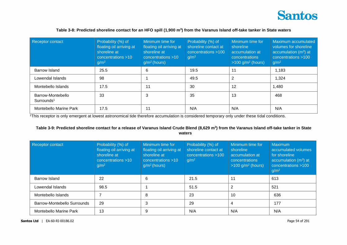
Santos Ltd | EA-60-RI-00186.02 Page 54 of 291
Table 3-8: Predicted shoreline contact for an HFO spill (1,900 m3) from the Varanus Island off-take tanker in State waters
Receptor contact Probability (%) of
floating oil arriving at
shoreline at
concentrations >10
g/m2
Minimum time for
floating oil arriving at
shoreline at
concentrations >10
g/m2 (hours)
Probability (%) of
shoreline contact at
concentrations >100
g/m2
Minimum time for
shoreline
accumulation at
concentrations
>100 g/m2 (hours)
Maximum accumulated
volumes for shoreline
accumulation (m3) at
concentrations >100
g/m2
Barrow Island 25.5 6 19.5 11 1,183
Lowendal Islands 98 1 49.5 2 1,324
Montebello Islands 17.5 11 30 12 1,480
Barrow-Montebello
Surrounds1
33 3 35 13 468
Montebello Marine Park 17.5 11 N/A N/A N/A
1This receptor is only emergent at lowest astronomical tide therefore accumulation is considered temporary only under these tidal conditions.
Table 3-9: Predicted shoreline contact for a release of Varanus Island Crude Blend (8,629 m3) from the Varanus Island off-take tanker in State
waters
Receptor contact Probability (%) of
floating oil arriving at
shoreline at
concentrations >10
g/m2
Minimum time for
floating oil arriving at
shoreline at
concentrations >10
g/m2 (hours)
Probability (%) of
shoreline contact at
concentrations >100
g/m2
Minimum time for
shoreline
accumulation at
concentrations
>100 g/m2 (hours)
Maximum
accumulated volumes
for shoreline
accumulation (m3) at
concentrations >100
g/m2
Barrow Island 22 6 21.5 11 613
Lowendal Islands 98.5 1 51.5 2 521
Montebello Islands 7 8 23 10 636
Barrow-Montebello Surrounds 29 3 29 4 177
Montebello Marine Park 13 9 N/A N/A N/A

Santos Ltd | EA-60-RI-00186.02 Page 55 of 291
3.4 Onshore spills
As described in Table 3-3, Level 2 and Level 3 onshore spills could occur from the following infrastructure:
+ Crude oil storage tanks
+ Production vessels in the process area (represented as first stage liquid production vessels)
+ Hydrocarbon supply pipelines (to VI)
+ Offtake Tanker loading line (export pipeline and hose)
+ Diesel storage/transfer system.
Figure 3-1 shows the location of onshore sources and adjacent sensitive receptor locations on VI.
The largest potential release was identified to be 39,750m3 of VI Blend hydrocarbon due to storage tank failure.
The hydrocarbon storage tanks on VI are contained within a HDPE lined earthen bund designed to contain a
catastrophic release (full tank contents) thus preventing hydrocarbon contact to the terrestrial or marine
environment outside of the Lease area or to the groundwater system. Similarly, a worst case spill from process
equipment will be contained within secondary containment around the process equipment designed to contain
spills and direct contaminated runoff to sumps and humeceptors. Further detail on the secondary containment
system around VI process equipment and crude oil storage tanks is provided within the accepted Varanus
Island Hub Operations Environment Plan (EA-60-RI-186); the Varanus Island Hub Operations Environment
Plan for Commonwealth Waters (John Brookes, Greater East Spar and associated Facilities) (EA-66-RI-
10003).
Marine diesel spills from storage tanks or the distribution network is in most instances surrounded by secondary
containment, although some sections of the diesel pipework may potentially impact the natural terrestrial
and/or marine environment if a spill was to occur.
For the live production pipelines connecting offshore infrastructure to VI processing facilities (i.e. the John
Brookes, East Spar, Agincourt and Harriet to VI pipelines) and the cargo export pipeline leading from crude
storage tanks to the VI terminal (offtake tanker terminal), there are sections of pipeline that do not have
secondary containment to contain a spill or prevent impact to the terrestrial, subterranean or marine
environment.

Santos Ltd | EA-60-RI-00186.02 Page 56 of 291
Figure 3-1: Potential onshore spill sources, facility and surrounding sensitivities

Santos Ltd | EA-60-RI-00186.02 Page 57 of 291
3.4.1 ZPI – surface extent
The onshore pipelines are a mix of above ground and buried sections. Onshore pipelines Agincourt 6”, East
Spar 14” and John Brookes 18” located east of the VI facility have buried sections (approximately 50m) from
the shoreline and are subsequently raised above ground towards the facility process area. The Harriet Bravo
8” and Tanker Load Out 30” pipelines north east of the facility are mainly buried except for short a section
(about 50 m) raised above ground.
The surface extent of the ZPIs for these pipelines has been estimated as a distance of 50 m from either side
of the pipelines, as shown in Figure 3-2 to Figure 3-4, with arrows showing potential direction of surface flow
down contour gradients. The distance was conservatively estimated based on an empirical equation (Mackay
& Mohtadi, 1975) to estimate the spread of an oil spill on permeable porous flat surface. The 50 m extent
covers all onshore pipeline spills except that from the Tanker Load Out pipeline. This line, which is running
towards the beach/dune area, is not expected to extend significantly in a radial manner, instead any spill is
expected to run down the slope reducing the radial spill footprint significantly. Based on the topography of the
site, generally most spills from the above ground section of the pipelines will likely to flow towards to the
coastline however there is expected to be considerable infiltrated into the porous sandy soils at the beach/fore
dune areas that would greatly reduce the volume entering the marine environment. This is especially true for
condensates which have lowest viscosity and therefore highest propensity for infiltration (as well as greatest
evaporation to the atmosphere).

Santos Ltd | EA-60-RI-00186.02 Page 58 of 291
Figure 3-2: Onshore pipelines (John Brookes, East Spar, Agincourt) spill ZPI - surface

Santos Ltd | EA-60-RI-00186.02 Page 59 of 291
Figure 3-3: Onshore pipelines (Harriet Bravo, Tanker Load-out) spill ZPI - surface

Santos Ltd | EA-60-RI-00186.02 Page 60 of 291
Figure 3-4: Onshore pipelines (Diesel) spill ZPI - surface

Santos Ltd | EA-60-RI-00186.02 Page 61 of 291
3.4.2 ZPI - subsurface extent
The ZPI of subsurface contamination in the event of a spill from onshore pipelines has been conservatively
estimated as the entire area of the Lease and beyond as shown in Figure 3-1. The subsurface contamination
zone delineated includes the potential extent of light non-aqueous phase liquid (LNAPL) and dissolved phase
hydrocarbon. The ZPI was estimated based on the monitoring data of the past contamination at the site
(JBS&G, 2016). Whilst the volume and rate of leaks leading to existing contamination at the Lease area has
not been measured the indicative hydrocarbon leakage volume is comparable to the maximum credible spill
of onshore pipelines identified (JBS&G, 2016).
The groundwater flow directions marked on Figure 3-1 are indicative. The inferred flow direction is highly
complex and dynamic due to the predominantly Karstic geology of the site, the highly heterogeneous nature
of the aquifer and the strong tidal influence on the groundwater hydrogeology.
It is likely for some releases to rapidly drain to the water table and be diluted and dispersed by rapid turbulent
flow along preferential pathways in response to tide induced water table fluctuations and others may be
captured by adsorption within finer matrix materials and within the capillary fringe above the water table
(Emerge, 2015).
Contaminant storage may occur in the rock matrix and epikarst, but contaminant transport occurs mostly along
preferential pathways that are typically inaccessible locations (creates complex networks of preferential flow
pathways that are difficult to locate), which makes modelling of karst systems challenging (Ghasemizadeh
et.al., 2012).
Based on the understanding developed from the numerous past studies on land contamination conducted on
VI (JBS&G, 2016), the spatial extent of the contaminated zone has been maintained largely due to the tidal
factors.

Santos Ltd | EA-60-RI-00186.02 Page 62 of 291
Figure 3-5: Onshore pipelines spill subsurface ZPI

Santos Ltd | EA-60-RI-00186.02 Page 63 of 291
3.5 -Identify Priority Protection Areas
3.5.1 Offshore spill
Protection priority areas, based on trajectory spill modelling, together with key sensitivities are included in
Table 3-10. For further information on how these were defined refer to Section 7.5 of the VI Hub Operations
EP (State Waters) (EA-60-RI-00186) and of the VI Hub Operations Environment Plan (EP) for
Commonwealth Waters (EA-66-RI-10003).
Table 3-10: Protection Priority Areas and Key Sensitivities
Protection
Priority Values Relevant key periods
Lowendal
Islands
Habitats
Shallow lagoons with seagrass meadows
Mangroves
Macro algal reefs
Reefs
Turtles
Loggerhead, green and hawksbill nesting turtles.
Significant flatback rookery
Seabirds
14 species of migratory and threatened seabirds
Whales
Humpback whale migration
Loggerhead turtle nesting:
Dec-Jan
Green turtle nesting: Nov-
to Apr. Peak period from
Jan-Feb
Hawksbill turtle nesting:
Oct-Jan
Flatback turtle nesting:
Dec-Jan
Birds: Sept-Feb
Humpback whale
migration: May-Dec
Montebello
Islands
Habitats
Reefs
Algae (40%)
Mangroves (globally unique as offshore)
Fish habitat
Intertidal sand flat communities
Turtles
Loggerhead and green (significant rookery), hawksbill,
flatback turtles.
Northwest and Eastern Trimouille Islands (hawksbill)
Western Reef and Southern Bay at Northwest Island
(green)
Seabirds
14 species of migratory and threatened seabirds
Significant nesting, foraging and resting areas
Whales
Pygmy blue whale northern migration
Humpback whale migration
Coral spawning: Mar &
Oct
Loggerhead turtle nesting:
Dec-Jan
Green turtle nesting: Nov-
to Apr. Peak period from
Jan-Feb
Hawksbill turtle nesting:
Oct-Jan
Flatback turtle nesting:
Dec-Jan
Birds: Sept-Feb
Pygmy blue whale
migration: Apr-Aug

Santos Ltd | EA-60-RI-00186.02 Page 64 of 291
Protection
Priority Values Relevant key periods
Socio-Economic
Pearling (inactive/pearling zones)
Very significant for recreational fishing and charter boat
tourism
Social amenities and other tourism
Nominated place (National heritage)
Humpback whale
migration: May-Dec
Barrow Island Habitats
Bandicoot Bay - conservation area Fisheries Act
(benthic fauna/seabird protection), mudflats, rock
platforms, mangroves, clay pans
Mangroves are in Bandicoot Bay (considered globally
unique)
Coral reefs (eastern side) - Biggada Reef
Biggada Creek
Turtles
Regionally and nationally significant green turtle
(western side) and flatback turtle (eastern side) nesting
beaches
Turtle Bay north beach
North and west coasts- John Wayne Beach also
loggerhead and hawksbill turtles.
Seabirds
Migratory birds (important bird area) 10th of top 147 bird
sites.
Highest population of migratory birds in BI Nature
reserve (south-south east island).
Double island important bird nesting (shearwaters, sea
eagles).
Whales
Pygmy blue whale northern migration
Socio-Economic
Significant for recreational fishing and charter boat
tourism
Nominated place (National heritage)
Coral spawning: Mar &
Oct
Green turtle nesting: Nov-
to Apr. Peak period from
Jan-Feb
Hawksbill turtle nesting:
Oct-Jan
Flatback turtle nesting:
Dec-Jan
Loggerhead turtle nesting:
Dec-Jan
Birds: Sept-Feb
Humpback whale
migration: May-Dec
Blue whale migration:
Apr-Aug
Barrow-
Montebello
shallows
The values and relevant key sensitive timings are as described above for Barrow
Island and the Montebello Islands.
3.5.2 Onshore spill
The existing sensitivities adjacent to onshore spill ZPIs are shown in Figure 3-1 to Figure 3-5. A general
description of the onshore environmental setting is provided Table 3-11.
In the event of a spill, onshore priorities for protection will be confirmed based on the nature (location/volume/hydrocarbon type) of the incident. However, with respect to identifying potential receptors

Santos Ltd | EA-60-RI-00186.02 Page 65 of 291
for spill response planning purposes, the following onshore sensitivities have been considered (Table 3-12)
based on contact with hydrocarbons.
Table 3-11: Onshore environment features
Key Feature Description of the feature
Landforms/Topography Topography of the general area is flat to undulating low dunes with elevation
ranges from sea level to a maximum of 18 m AHD
Surface water There are no surface water features. Stormwater runoff quickly infiltrates into
the subsurface geology.
Geology Much of the lease area and the surroundings is made of outcrop of very finely
grained massive limestone with an abundance of solution cavities.
Dominant aquifer lithologies are karstic calcarenite and karstic limestone.
Hydrogeology Groundwater flow directions substantially influenced by tidal effect and
groundwater quality is consistent with sea water.
Groundwater flow directions are variable throughout the duration of the tidal
cycle with a range of potential directions. Highly variable values are likely
attributable to the dominant limestone geology of the site that contains many
large cavities and channels allowing preferential groundwater flow through
these features. Consequently Varanus Island has high to very high hydraulic
conductivity and high spatial variability. Under these conditions local
groundwater flow is not in accordance with Darcy’s Law and is largely
unpredictable.
The depth to groundwater across the site is substantially influenced by tidal
processes and significant variation in water levels of the typical tidal range
reported in open marine water can occur.

Santos Ltd | EA-60-RI-00186.02 Page 66 of 291
Table 3-12 Onshore environmental sensitivities and priorities for protection
Protection Priority Values Relevant Key Periods
Seabird rookery protection
areas to the east and west
of the lease boundary
Wedge-tailed shearwaters, crested
terns and bridled terns
Wedge-tailed shearwater: adults
excavate burrows from Jul – Oct;
eggs laid in Nov; chicks hatch in Jan;
chicks fledge in Apr.
Crested terns: Oct to Dec.
Bridled terns: Eggs laid Oct to Jan;
chicks hatch Dec to Mar.
Pipeline Beach Turtles (flatback, hawksbill and
green)
Green turtle nesting: Nov- to Apr.
Peak period from Jan-Feb
Hawksbill turtle nesting: Oct-Jan
Flatback turtle nesting: Dec-Jan
Mangrove beach Mangroves All year
Beyond the northern
and eastern and
western lease
boundary
Near shore habitats (intertidal
zones)
All year

Santos Ltd | EA-60-RI-00186.02 Page 67 of 291
4 Response Option Selection
The response strategies outlined in this OPEP have been developed by Santos WA utilising risk assessments
to identify credible worst-case spill scenarios, expected/calculated release rates, known information of
hydrocarbon types and behaviour, and expected partitioning of the hydrocarbon within the marine environment
with an estimate of the volume of persistent oil. This information has been modelled to give a theoretical spill
dispersion extent that is used to identify potential sensitive receptors and response strategies required to
reduce the consequences of a spill to ALARP.
The process implemented throughout the response to assess the appropriate response strategies and
implement these in a controlled manner to ensure the health and safety of operational personnel and
effectiveness in response is the Incident Action Planning (IAP) process.
Incident action planning is the responsibility of the spill Control Agency. It is the responsibility of the Control
Agency IMT to evaluate the response strategies provided in this OPEP based on actual and real
circumstances. Where Santos WA is not the Control Agency, Santos WA will provide support to the incident
action process adopted by the Control Agency through provision of situational awareness information and
available resources. Where there is more than one Control Agency (i.e. a cross-jurisdictional response in
coordination with DoT), Santos WA will undertake the IAP process as Lead IMT for those spill response
activities it is responsible for and provide information and personnel to support DoT’s planning function for
those activities which DoT assumes control as Lead IMT.
4.1 Evaluation of Applicable Response Strategies
Based on the nature and scale of the credible spill scenarios outlined in Section 3.1, the following spill
response strategies have been assessed as potentially applicable for combatting a spill (Table 4-1). These
response strategies have been identified as either primary or secondary options depending on which may
result in a net environmental benefit based on the worst-case spill scenarios identified in Section 3.1. Primary
response strategies are those considered to have net environmental benefit of managing the spill. Secondary
response strategies are those that may be used to either supplement primary response options or may be
appropriate under specific circumstances.
In the event of an emergency situation where human safety is at significant risk, tasks included in this OPEP
may not be implemented, and the International Convention for the Safety of Life at Sea (SOLAS) 1974 may
take precedence.
Note: The information contained in Table 4-1 has been developed by Santos WA for preparedness purposes.
Santos WA may not be the Control Agency or Lead IMT for implementing a spill response. For example for
Level 2/3 spills within or entering State waters, DoT will ultimately determine the strategies and controls
implemented for most State water activities with Santos WA providing all necessary resources and planning
assistance.

Santos Ltd | EA-60-RI-00186.02 Page 68 of 291
Table 4-1: Applicable Response Strategy Operational Considerations
OSR
Strategy
Activities Applicability and Designated Primary (1)
or Secondary (2) Response Strategy
Considerations
Marine
Diesel
Condensate HFO Crude
Source
Control
Spill kits 1 1 1 1 Relevant for containing spills that may arise on board a vessel, offshore
platform or onshore.
Secondary
containment 1 X 1 1
Relevant for spills that may arise due to stored hydrocarbons, and from
spills arising from machinery and equipment on board a vessel, offshore
platform or onshore. Bunded areas will contain hydrocarbons reducing the
potential for a spill escaping to the surrounding environment and allowing
collection of hydrocarbon and contaminated run-off through contaminated
drainage systems as applicable.
Shipboard Oil
Pollution
Emergency Plan
(SOPEP)
1 X 1 1
MARPOL requirement for applicable vessels. In the event a vessel
hydrocarbon storage tank is ruptured, applicable strategies for reducing the
volume of hydrocarbon releases will be contained within the
vessel/MODU’s SOPEP. This may include securing cargo via transfer to
another storage area on-board the vessel, transfer to another vessel, or
through pumping in water to affected tank to create a water cushion (tank
water bottom). Trimming the vessel may also be used to avoid further
damage to intact tanks. These actions will aim to minimise the volume of
fuel spilt.
Pipeline isolation
(Emergency
Shutdown (ESD))
X 1 X 1
All pipelines and wells covered under this OPEP have ESD available
(manual and/or automatic) to isolate hydrocarbon inventories and limit the
volume of a spill.
Well Emergency
Shutdown (ESD) X 1 X 1
Pumping
procedures 1 X X 1
Provides guidance for supervision and actions required in the event of a
hydrocarbon spill during pumping operations for marine diesel and crude oil
transfers.

Santos Ltd | EA-60-RI-00186.02 Page 69 of 291
OSR
Strategy
Activities Applicability and Designated Primary (1)
or Secondary (2) Response Strategy
Considerations
Marine
Diesel
Condensate HFO Crude
Suck Back Pump X X X 1
Specifically used for sucking inventory (VI Crude) out of the Tanker Loading
Line in the event of a release from the Loading Line or Loading Hose during
offtake tanker cargo loading.
Surface well kill X 1 X 1
Considered during relief well planning but may not be possible depending
upon technical and safety constraints. Surface well kill is only considered
when the estimated leak rate is small enough not to generate an explosive
gas cloud and access to the platform is still preserved. This methodology
would not be considered should safe access to the platform or ability to
operate a vessel alongside the platform not be achievable.
Capping Stack X X X X
Capping Stacks cannot be landed and connected to subsea wellheads
under the credible loss of well control scenarios outlined in the EP and this
strategy is therefore not considered applicable.
Relief well drilling X 1 X 1
Relevant for a loss of well control. Relief well drilling is the primary method
for killing the well. To be conducted as per the Source Control Emergency
Response Plan (SCERP) (DR-00-ZF-10001).
In-Situ
Burning
Controlled burning
of oil spill X X X X
Not applicable for gas wells due to safety hazards. Not applicable to diesel
spills due to inability to contain marine diesel making it very difficult to
maintain necessary slick thickness for ignition and sustained burning.
Monitor and
Evaluate
Plan
(Operational
Monitoring)
Vessel surveillance 1 1 1 1
Provides real-time information on spill trajectory and behaviour (e.g.
weathering).
Informs implementation of other response strategies.
Vessel personnel may not be trained observers.
Vessel observers on leaking vessel may not have capacity to observe oil
during emergency response procedure implementation.
Constrained to daylight.
Limited to visual range from the vessel.

Santos Ltd | EA-60-RI-00186.02 Page 70 of 291
OSR
Strategy
Activities Applicability and Designated Primary (1)
or Secondary (2) Response Strategy
Considerations
Marine
Diesel
Condensate HFO Crude
Limited capacity to evaluate possible interactions with sensitive receptors.
Aerial surveillance
Provides real-time information on spill trajectory and behaviour (e.g.
weathering).
May identify environmental sensitivities impacted or at risk of impact (e.g.
seabird aggregations, other users such as fishers).
Informs implementation of other response strategies.
Tracking buoys
Can be implemented rapidly.
Can provide indication of near-surface entrained / dissolved hydrocarbons
(most other monitor and evaluate techniques rely on the hydrocarbon being
on the surface or shoreline).
Trajectory
Modelling
Can be implemented rapidly.
Predictive - provides estimate of where the oil may go, which can be used
to prepare and implement other responses.
No additional field personnel required.
Not constrained by weather conditions.
Can predict floating, entrained, dissolved and stranded hydrocarbon
fractions.
May not be accurate.
Requires in-field calibration.
Satellite Imagery
Can work under large range of weather conditions (e.g. night time, cloud
cover etc)
Mobilisation likely to be >24 hours
Requires processing
May return false-positives

Santos Ltd | EA-60-RI-00186.02 Page 71 of 291
OSR
Strategy
Activities Applicability and Designated Primary (1)
or Secondary (2) Response Strategy
Considerations
Marine
Diesel
Condensate HFO Crude
Operational Water
Quality Monitoring
Fluorometry surveys are used to determine the location and distribution of
the entrained oil and dissolved aromatic hydrocarbon components of the
spill and validate the spill fate modelling predictions.
Shoreline and
Coastal Habitat
Assessment
Provides information on shoreline oiling (state of the oil, extent of pollution
etc.).
Can provide information on amenability of shoreline response options (e.g.
clean-up, protect and deflect).
Provides information on status of impacts to sensitive receptors.
Considerable health & safety considerations.
Requires trained observers.
Constrained to daylight.
Delayed response time.
Chemical
dispersion
Vessel Application X X X X
Marine spills of a size where chemical dispersion could potentially be
applied are a loss of well control (gas/condensate) or vessel tank rupture of
HFO or VI Blend crude oil.
Marine Diesel:
Marine diesel is not considered a persistent hydrocarbon and has high
natural dispersion rates in the marine environment. Chemical dispersant
application is not recommended as a beneficial option for marine diesel as
it has a low additional benefit of increasing the dispersal rate of the spill
while introducing the potential for increased impacts.
Condensate:
Condensates produced are not considered a persistent hydrocarbon, and
has a very high natural evaporation and dispersion rates in the marine
environment reducing the volume of hydrocarbon remaining at the sea
surface. Spill modelling indicates that these natural weathering processes
will result in minimal contact of surface condensate at shoreline locations.
Aerial Application X X X X
Subsea Application X X X X

Santos Ltd | EA-60-RI-00186.02 Page 72 of 291
OSR
Strategy
Activities Applicability and Designated Primary (1)
or Secondary (2) Response Strategy
Considerations
Marine
Diesel
Condensate HFO Crude
On the basis of the above, chemical dispersant application is not
recommended as an applicable strategy, the benefit of applying
condensate from an environmental perspective is considered minimal.
From a subsea application perspective there are also considerable safety
risks and technical challenges in applying dispersant at the source to
shallow subsea wells with gas/condensate release.
Capping Stack application is not considered applicable for the credible loss
of well control scenarios covered in this EP and therefore there is no benefit
in subsea dispersant application for the purpose of facilitating this strategy.
Crude oil and HFO:
Crude oil or HFO could be released in significant quantities from offtake
tanker tank rupture, however the Marine Terminal is in shallow water in
State waters close to sensitive receptors. Application in shallow waters can
result in organisms being exposed to higher concentrations of naturally
dispersed oil and water soluble compounds for a longer duration than if the
product was applied in deeper water. In addition dispersant efficacy testing
on a crude blend showed results of less than 1% efficacy.
On the basis of the above, chemical dispersant application is not
recommended as an applicable strategy for the credible spill scenarios
covered under this OPEP.
Offshore
Containment
and
Recovery
Use of offshore
booms/ skimmers
or other collection
techniques
deployed from
vessel/s to contain
and collect oil.
X X 1 2
Offshore containment and recovery may be suitable for Heavy Fuel Oils
(HFO) and Crudes which are heavy residual fuels with a high viscosity and
which may exist on the sea surface at a sufficient thickness to make
containment and recovery effective.
Marine diesel is a low viscosity oils that spread quickly resulting in thin
surface expressions, making recovery via booms and skimmers difficult and
ineffective. For these oils offshore containment and recovery is not
considered an applicable strategy. Similarly, the properties of the crude oils
and condensates that could be spilt from VI infrastructure (i.e. Group 1 or 2

Santos Ltd | EA-60-RI-00186.02 Page 73 of 291
OSR
Strategy
Activities Applicability and Designated Primary (1)
or Secondary (2) Response Strategy
Considerations
Marine
Diesel
Condensate HFO Crude
light, thin oils) indicate that these hydrocarbons would also express at low
thickness on the sea surface and would be difficult to contain and collect.
Properties of oils change during weathering, and for VI hydrocarbons, this
would be monitored to assess the potential effectiveness of containment
and recovery.
Mechanical
Dispersion
Vessel prop-
washing 2 2 X 2
Safety is a key factor and slicks with potential for high VOC emission are
not suitable.
Recommended for the removal of sheens.
Mechanical dispersion will entrain surface oil into the top layer of the water
column. The aim of mechanical dispersion is to reduce the concentration of
oil floating at the surface which could potentially coat receptors at the sea
surface (e.g. sea birds) or shoreline receptors (e.g. mangroves). Once
dispersed in the water column the smaller droplet sizes enhance the
biodegradation process.
Better to keep HFO on the sea surface and collect than to disperse.
Marine diesel, condensate and crude oils are light oils that can be easily
dispersed in the water column by running vessels through the plume and
using the turbulence developed by the propellers to break up the slick. The
potential disadvantage of mechanical dispersion is that it could temporarily
increase the concentration of entrained and dissolved oil in the vicinity of
submerged shallow water receptors (e.g. corals, seagrass ad macroalgae).
This is most likely in shallow water of a few metres deep. The suitability of
mechanical dispersion as a response measure would consider the
prevailing environmental conditions (it mimics the action of wave induced
entrained so is most beneficial in calm conditions) and the type, proximity
and depth (as applicable) of sensitivities in the area.
Mechanical dispersion will be considered for petroleum activity sourced
spills at the discretion of the On-Scene Commander/IMT or by the relevant
Control Agency.

Santos Ltd | EA-60-RI-00186.02 Page 74 of 291
OSR
Strategy
Activities Applicability and Designated Primary (1)
or Secondary (2) Response Strategy
Considerations
Marine
Diesel
Condensate HFO Crude
Protection
and
Deflection
Booming in
nearshore waters
and at shorelines
2 2 1 1
Use of anchored boom or other barriers (e.g. sand bags, earthworks) to
contain/divert oil and/or to protect sensitive receptors in the nearshore
environment.
Considered for Level 2/3 spills if operational monitoring shows or predicts
spill is predicted to contact sensitive shorelines. Both marine diesel and
condensate have high volatility and low persistence with low potential for
shoreline loading. Flushing and bioremediation may provide a greater net
benefit than booming operations. Booming is likely to be more effective for
HFO.
Shoreline
clean-up
Activities include
physical removal,
surf washing,
flushing,
bioremediation,
natural dispersion
2 2 1 1
Various strategies to clean shorelines of oil including:
+ Mechanical/ manual collection
+ Low pressure flushing
+ Sorbent materials
+ Surf washing
+ Sand tilling
+ Bioremediation.
Considered if operational monitoring shows or predicts contact to sensitive
shorelines.
Shoreline clean-up may be more effective for HFO.
Intrusive activities such as physical removal of waste using manual labour
or mechanical aids requires careful site-specific planning in order to reduce
secondary impacts of habitat disturbance, erosion and spreading oil beyond
shorelines. The majority of the affected coastline is offshore islands,
mangroves and tidal flats, most of which has no access by land. Flushing
may be considered if the oil enters high priority/slow recovery habitats such
as mangroves.

Santos Ltd | EA-60-RI-00186.02 Page 75 of 291
OSR
Strategy
Activities Applicability and Designated Primary (1)
or Secondary (2) Response Strategy
Considerations
Marine
Diesel
Condensate HFO Crude
Marine diesel and condensate have low to no persistence in the
environment and therefore prolonged loading of shorelines is not expected.
Natural remediation and flushing may be preferred to more intrusive clean-
up methods given the nature and low persistence of these hydrocarbons.
Onshore
response
Protection, onshore
clean up and
monitoring
1 1 N/A 1
Sorbent booms to control contaminated surface water if present
Soil and groundwater monitoring and remediation as defined under
Contaminated Sites legislation
Shoreline response options as per above (protection/deflection booming
and shoreline clean-up) if spill reaches shoreline/marine environment.
Onshore pipelines may result in surface contamination (predicted 50 m
wide ZPI) or soil/groundwater contamination (rapid infiltration and complex
movement within aquifer due to complex/heterogeneous karst geology).
Sorbents can be used onshore to isolate surface flow from receptors
(mangroves/nesting sites for birds and turtles) although natural infiltration is
expected to be considerable. If surface contamination reaches beaches/
marine waters the process applied to marine spill shoreline/coastal
response applies.
Site remediation of soil and groundwater will be under direction of DWER
and will be detailed in a remediation action plan under Contaminated Site
legislation. VI is an existing contaminated site with ongoing monitoring and
remediation as specified within a Remedial Action Plan. Any further
contamination would build on site knowledge and techniques already
developed through this process.
Oiled wildlife
Response
Activities include
hazing, pre-emptive
capture, oiled
wildlife capture,
2 2 1 2
Can be used to deter and protect wildlife from contact with oil.
Mainly applicable for marine and coastal fauna (e.g. birds) where oil is
present at the sea surface or accumulated at coastlines. Potential for
onshore releases to impact nesting areas.

Santos Ltd | EA-60-RI-00186.02 Page 76 of 291
OSR
Strategy
Activities Applicability and Designated Primary (1)
or Secondary (2) Response Strategy
Considerations
Marine
Diesel
Condensate HFO Crude
cleaning and
rehabilitation.
Surveillance can be carried out as a part of the fauna specific operational
monitoring
Wildlife may become de-sensitised to hazing method.
Hazing may impact upon animals (e.g. stress, disturb important behaviours
such as nesting or foraging)
Permitting requirements for hazing and pre-emptive capture.
Scientific
Monitoring
The monitoring of
environmental
receptors to
determine the level
of impact and
recovery form the
oil spill and
associated
response activities.
1 1 1 1
Monitoring activities include:
+ Water and sediment quality
+ Biota of shorelines (sandy beaches, rocky shores and intertidal
mudflats)
+ Mangrove monitoring
+ Benthic habitat monitoring (seagrass, algae, corals, non-coral filter
feeders)
+ Seabirds and shorebirds
+ Marine megafauna (incl. whale sharks and mammals)
+ Marine reptiles (incl. turtles)
+ Seafood quality
+ Fish, fisheries and aquaculture
The type and extent of scientific monitoring will depend upon the nature
and scale of oil contact to sensitive receptor locations as determined
through operational monitoring. Pre-defined initiation criteria exist for
scientific monitoring plans associated with marine and coastal sensitivities.

Santos Ltd | EA-60-RI-00186.02 Page 77 of 291
4.2 Resource Arrangements and Demonstration of ALARP
A detailed ALARP assessment on the adequacy of resourcing available to support spill response strategies
and control measures is presented in Table 4-2.

Santos Ltd | EA-60-RI-00186.02 Page 78 of 291
Table 4-2 ALARP assessment of the resourcing for spill response strategies
Strategy Resourcing Justification Environmental Benefit
of Additional
Resources
Cost of Additional
Resources
ALARP Assessment
Source Control-
Relief Well
Drilling
Contract/MoUs for
source control
personnel
Santos WA Drilling and
Completions Source
Control Team
APPEA MoU for
mutual assistance for
relief well drilling
MODU Capability
Register
Santos WA’s Drilling and
Completions Source Control
Team will work in collaboration
with external Source Control
specialists whom will be
mobilised within 3 days of the
LOWC.
The monthly monitoring of the
availability of MODUs, and the
APPEA MoU for mutual
assistance for relief well drilling,
enable access to suitable
MODUs and associated
personnel. It could take up to
34 days to have a MODU
onsite. This is due to the time
required for the MODU to
suspend current operations,
prepare, and move to the relief
well location.
A Safety Case Revision for the
relief well MODU will be
submitted within 14 days of the
LOWC. The critical path time
allowed for the actual writing of
the document is 3 days. The
remaining estimated time would
be used for gathering post-
event data, mobilising the
workforce and conducting a
Santos WA base case
timeframe for the
drilling of a relief well is
77 days.
Access to source
control specialists is
not considered limiting
nor a factor in the base
case timeframe.
A MODU on standby
close to the well
location for the duration
of any drilling
operations reduces the
timeframe to mobilise a
MODU to site which
potentially reduces the
overall timeframe to
limit the hydrocarbon
released.
The total cost of having
a MODU on standby is
about $600,000 per
day. If adopted this
cost is paid regardless
if there is a loss of
containment event or
not.
The likelihood of a
LOWC is considered
rare and the cost and
the additional safety
and environmental
risks of having another
MODU and support
equipment/personnel
on standby is
considered grossly
disproportionate to the
environmental benefit
gained.
The current source
control arrangements
are considered
adequate to provide
the required function.

Santos Ltd | EA-60-RI-00186.02 Page 79 of 291
Strategy Resourcing Justification Environmental Benefit
of Additional
Resources
Cost of Additional
Resources
ALARP Assessment
HAZID. It is not practicable to
reduce the critical path days
with additional pre-planning as
document revision, final review
and approval will still be
required after completing the
HAZID.
Direct surface
intervention
Local personnel
supplemented by
additional personnel,
as required, through
arrangements with
Wild Well Control, as
outlined within the
Source Control
Emergency Response
Plan (SCERP) (DR-00-
ZF-10001
Pumping equipment
(e.g. cement units/
triplex pumps, high
pressure treating iron
pipe-work and flexible
high pressure hoses)
are readily available
within the region.
Direct surface intervention (i.e.
deployment onto the jack-up
rig) using specialised well
control personnel is a strategy
that could be adopted however
limited to very specific incidents
where the technical and safety
factors are not a constraint.
Santos has successfully
planned and executed well-kill/
bull-heading/ flushing
operations during routine non-
leak well suspension activities
in numerous platforms using
this type of equipment and local
personnel.
Additional resources
are not considered
required or limiting.
The limiting factor is
the meeting of
technical and safety
aspects of the LOWC
event which could only
be assessed at the
time of a spill event.
Not considered
required.
Given the uncertainty
for the response
strategy feasibility, in
combination with the
potential safety
hazards surrounding
the well, the current
preparedness
measures for well
intervention is
considered ALARP
Monitor and
Evaluate- Aerial
Surveillance
Helicopter services
available through
Santos WA’s primary
contracted supplier
based out of Karratha.
Given location of spill sites,
mobilisation of helicopters from
Karratha (via VI if required) is
considered adequate for
surveillance. Endurance is not
considered a limiting factor at
Resource not
considered limiting.
Primary supplier on
contract with additional
providers available to
provide desired
No additional costs as
helicopters are
currently contracted for
day-to-day operations
to and from Santos WA
facilities.
There is no value in
increasing dedicated
overpasses; therefore,
the arrangements are
considered ALARP.
However, opportunistic

Santos Ltd | EA-60-RI-00186.02 Page 80 of 291
Strategy Resourcing Justification Environmental Benefit
of Additional
Resources
Cost of Additional
Resources
ALARP Assessment
Activation of aerial
surveillance using
helicopter pilots will
occur within 3 hours of
notification of the spill.
Trained Aerial
Observers (7) will be
available from Day 2 of
the incident, following
activation (based in
Perth and Santos WA
facilities).
these locations. Mobilisation
and refuelling from Exmouth is
possible depending on
trajectory of spill.
Current arrangements can
provide for 2 passes (am and
pm) of the spill area per day.
This has been exercised as part
of major spill exercises.
Trained Aerial Observers can
mobilise to Karratha or
Exmouth for Day 2 operations.
Day 1 surveillance and
recording using helicopter pilots
considered adequate for initial
situational awareness.
overpass frequency.
Santos WA trained
observers can be
provided on rotation
from Day 2.
In the event that
additional passes are
required due to data
gaps, the cost of the
additional flights will be
added to the cost of
the response.
aerial surveillance can
be provided through
the shared use of
aircraft deployed for
other purposes.
Monitor and
Evaluate-
Vessel
Surveillance
On-hire vessels
supporting Santos
WA’s VI and Ningaloo
Vision facilities.
Vessel of opportunity
from other operators.
Additional vessels
contracted through
Santos WA vessel
providers out of
Dampier.
Santos WA has access
to automatic
identification system
On-contract vessels performing
duties at VI and Ningaloo Vision
will be available, as well as
vessels of opportunity from
other petroleum operators.
The activity area is central on
the North West Shelf and
offshore from the major marine
base of Dampier. Additional
available vessels out of
Dampier can be put on hire
through Santos WA’s
contracted vessel providers;
mobilisation times to site can
provide additional contracted
vessels relatively quickly.
Based on the close
proximity of the activity
to VI and the central
location of the activity
relative to the main
marine base of
Dampier, dedicated
additional vessels for
the purpose of oil spill
surveillance is not
considered to be
required, given the
need is met through
vessel sharing.
Surveillance will also
be conducted through
The current vessel
arrangements are
considered to provide
the required function.
Dedicated vessels on
standby for vessel
surveillance would cost
tens of thousands of
dollars per day and are
not considered
required.
There is no benefit in
having additional
dedicated surveillance
vessels, given
surveillance can be
performed from any
vessel; and these
duties will be shared
amongst spill response
vessels.

Santos Ltd | EA-60-RI-00186.02 Page 81 of 291
Strategy Resourcing Justification Environmental Benefit
of Additional
Resources
Cost of Additional
Resources
ALARP Assessment
live-vessel tracking
portal to establish
vessel availability.
Vessel surveillance will
be activated within 90
minutes for available
on-site (at VI) vessels.
Additional mobilisation from
Exmouth can be made through
Santos WA’s contracted vessel
providers.
This strategy is not designed to
perform ‘whole of spill’
coverage, which is provided by
aerial surveillance (i.e., it is a
secondary strategy).
a number of
complementary
strategies (aerial
surveillance, oil spill
trajectory modelling,
tracker buoys).
Monitor and
Evaluate- Oil
Spill fate
Modelling
24/7 standby Oil Spill
Trajectory Modelling
(OSTM) service
provider.
OSTM provider will be
contacted immediately
(within 2 hours) upon
notification of a Level 2
or 3 spill (as per
Section 2.1 of the VI
HUB OPEP). Spill
modelling to be
initiated within 24
hours.
Upon activation,
OSTM provider will
provide trajectory
models within:
2 hours for OILMAP
model for offshore and
open ocean; and
OSTM provider is to provide at
least daily updates to the IMT of
trajectory model outputs to
inform response planning. More
frequent updates can be
provided if weather conditions
are highly variable or change
suddenly. Operational
surveillance data (aerial,
vessel, tracker buoys) will be
provided to OSTM provider to
verify and adjust fate
predictions of the spill and
improve predictive accuracy.
Predictive oil spill
modelling will be used
to forecast (using real-
time data) the
trajectory and fate of
the spill. Resource is
not considered limiting
with no environmental
benefit from dedicating
additional modelling
capability.
Santos WA pays for
the provision of the
service by OSTM
provider. This is
considered to provide
the required function.
There is no benefit in
having additional
modelling capability
given that OSTM
provider have staff
based across Australia
and can provide 24/7
coverage.

Santos Ltd | EA-60-RI-00186.02 Page 82 of 291
Strategy Resourcing Justification Environmental Benefit
of Additional
Resources
Cost of Additional
Resources
ALARP Assessment
4 hours for OILMAP
operation for near-
shore.
Monitor and
Evaluate-
Tracker Buoys
Up to 12 Santos WA
tracker buoys (at
different Santos WA
facilities); 4 are
immediately available
on VI, and deployment
can be at a staggered
rate determined by the
need to track oil
heading towards
sensitive receptors.
Subscription to tracker
buoy tracking website.
Santos WA on-hire
vessels and vessels of
opportunity for buoy
deployment.
Subject to weather and
vessel availability, the
tracker buoys can be
mobilised within 2
hours upon request
from the IMT or on-
scene commander.
In addition to aerial
surveillance, tracker buoys are
an additional strategy to provide
real-time verification data
(particularly beneficial at night
and in conditions limiting aerial
surveillance). 12 buoys are
sufficient to enable timely
retrieval and redeployment.
Four are available on VI.
Vessels for buoy deployment
will be Santos WA on-hire
vessels and other operators of
vessels of opportunity. Vessels
can be shared across this and
other tasks (e.g., surveillance
and tracker buoy deployment).
Additional buoys are
available through
secondary suppliers
(e.g., AMOSC, OSRL
and AMSA – more than
20 buoys available) if
required. These can be
registered on the
Santos WA/Joubeh
satellite tracking
system within hours.
Dedicated vessels are
not required given that
the need is met
through vessel sharing.
Santos WA has 12
buoys linked to a
satellite-tracking
website designed for
first strike deployment
across its operational
facilities. No additional
buoys need to be
purchased by Santos
WA given secondary
availability through
AMSA, AMOSC, OSRL
within days. There is
no additional upfront
cost for accessing
these secondary
buoys.
The number of buoys
immediately available
and the availability of
secondary buoys within
days is sufficient to
cover tracking of oil
fronts, especially given
the spread of oil will be
limited within the initial
days of the spill.
Therefore, no
additional requirements
and the response is
considered ALARP.
Monitor and
Evaluate-
Contract in place with
third party provider to
enable access and
Suitable imagery can be
accessed through existing
contracts with AMOSC and
OSRL. The most appropriate
Satellite imagery is
considered a
supplementary source
of information that can
Not considered
required.
The current satellite
imagery arrangements
are considered

Santos Ltd | EA-60-RI-00186.02 Page 83 of 291
Strategy Resourcing Justification Environmental Benefit
of Additional
Resources
Cost of Additional
Resources
ALARP Assessment
Satellite
Imagery
analysis of satellite
imagery
images for purchase will
depend on the extent and
location of the spill.
Frequency of reporting is
subject to satellite overflight
schedule.
improve awareness but
is not critical to the
response and usage is
at the discretion of the
IMT.
Given the adequate
provision of satellite
imagery and analysis
through a third-party
provider there is no
requirement for
additional resources.
adequate to provide
the required function.
Monitor and
Evaluate-Water
Quality
Monitoring
(operational and
scientific)
Fluorometers (for
hydrocarbon detection)
within subsea gliders
or towed fluorometers.
CTD (conductivity,
temperature, and
depth) meters,
including fluorometry
and dissolved oxygen
sensors.
Water sampling
equipment (e.g., Niskin
bottles, jars).
Water quality
monitoring personnel.
Santos WA has field tested
deployment of subsea gliders
and data transfer using local
provider (Blue Ocean
Monitoring) with access to
gliders within Australia and the
USA.
Gliders and towed fluorometers
are available through contract
with OSRL – located in
Singapore.
CTD meters with fluorometers
and water sampling equipment
available locally and to be
arranged through Santos WA’s
contracted scientific monitoring
provider. Contractual standby
arrangements are in place for
There are locally
available subsea
gliders and access to
towed fluorometers.
Water sampling
equipment and CTD
meters are also
available locally. Water
sampling equipment is
not considered a
bottleneck to
deployment. Given
multiple access
avenues to equipment,
dedicated equipment
(i.e., purchased or
standby on-hire
equipment) is not
considered required.
Santos WA can access
subsea gliders with
fluorometers and
towed fluorometers
through OSRL.
Santos WA’s
contracted scientific
monitoring provider is
on an existing standby
footing in Perth with
mobilisation time of
personnel to site within
72 hours following
approved monitoring
action plan based on
incident specifics. An
enhanced standby with
vessels, equipment
and personnel all
The existing
arrangements are
considered sufficient to
provide targeted ‘first
strike’ operational
water quality
monitoring to priority
sites as identified
through oil spill
modelling and
surveillance.

Santos Ltd | EA-60-RI-00186.02 Page 84 of 291
Strategy Resourcing Justification Environmental Benefit
of Additional
Resources
Cost of Additional
Resources
ALARP Assessment
Glider Field Engineer
for deployment and
recovery.
Dedicated vessels for
towed fluorometers,
CTD meter
deployment, water
sampling.
Vessels of opportunity
(vessel sharing) for
subsea glider
deployment.
Oil sample collected
using a vessel of
opportunity and
analysed on VI or in
Perth.
rapid activation, planning and
deployment of operational
water quality monitoring
personnel.
Subsea gliders and towed
fluorometers can cover
approximately 1 km/hr.
One glider could cover
24 km/day.
CTD meters provide discrete
‘single point’ readings over a
depth profile. Water quality
sampling at discrete locations.
For subsea gliders and towed
fluorometers, the deployment
philosophy is not to ‘blindly’
patrol the entire spill area.
Deployments will be targeted to
ground truth spill modelling
predictions. That is, the
predicted front or fronts of
entrained oil will be traversed
by gliders to verify entrained oil
presence. This will be
prioritised where fronts are
predicted to reach sensitive
receptor areas.
Similarly, discrete water
sampling will target sites
Deployment personnel
will initially be provided
through Santos WA’s
contracted monitoring
provider and subsea
glider deployment
personnel.
prepositioned for
immediate deployment
would cost in the order
of tens of thousands of
dollars per day.
Similarly, subsea
gliders set-up and
prepositioned on
standby for immediate
deployment would cost
in in the order of tens
of thousands of dollars.

Santos Ltd | EA-60-RI-00186.02 Page 85 of 291
Strategy Resourcing Justification Environmental Benefit
of Additional
Resources
Cost of Additional
Resources
ALARP Assessment
positioned to validate modelling
predictions.
Monitor and
Evaluate –
Shoreline and
Coastal Habitat
Assessment
Spill response teams
(Santos WA and
AMOSC core group,
State Response Team)
Santos WA GIS
resources
Santos WA contracted
vessels and vehicles
available as required
for shoreline access
Shoreline Assessment
strategies will be implemented
under the direction of DoT as
the HMA.
AMOSC contract to facilitate
mutual aid arrangements for
access to Oil Spill Responders.
Santos WA will make available
AMOSC Core Group
Responders for shoreline and
coastal habitat assessment
positions.
Existing information on
shoreline character can be
obtained from Santos WA’s
GIS, including habitat/fauna
distribution layers and aerial
imagery.
The HFO spill (State waters)
from the VI off-take tanker
could result in the quickest
shoreline contact (above 100
g/m2) at the Lowendal Islands
(2 hrs), Barrow Island (11 hrs)
and Montebello Islands (12
hrs).
A John Brooke Pipeline
condensate leak at the State
Personnel and
equipment for shoreline
and coastal habitat
assessment is not
considered limiting.
However, the time for
deployment may
exceed predicted times
to minimum shoreline
contact, particularly at
the Lowendal Islands.
The pre-positioning of
personnel and/or pre-
assessment of
shorelines prior to a
spill is considered of
limited benefit since:
• Shoreline and
Coastal Habitat
Assessments do
not need to occur
prior to oiling since
they are designed
to record
information about
level of oiling and
applicable
response
techniques.
Not considered
required.
The existing
arrangements are
considered sufficient to
provide a first strike
shoreline and coastal
habitat assessment in
addition to supporting
DoT.

Santos Ltd | EA-60-RI-00186.02 Page 86 of 291
Strategy Resourcing Justification Environmental Benefit
of Additional
Resources
Cost of Additional
Resources
ALARP Assessment
waters boundary could also
result in a short timeframe in
shoreline contact (above 100
g/m2) at the Montebello Islands
and (16 hrs) and Lowendal
Islands (21 hrs).
First-strike deployment
arrangements would come from
personnel and equipment
based at VI. This includes
Santos WA AMOSC Core
Group personnel, and IRT
members. Santos WA maintain
the capability to implement a
first strike shoreline and coastal
habitat assessment within the
first 24 hours of a spill
notification.
• Shoreline
characteristics
change over time
and thus pre-
assessments may
not be accurate or
relevant at the time
of a spill.
Monitor and
Evaluate –
Wildlife
Reconnaissance
(aerial/ vessel
surveillance.
Shoreline and
coastal habitat
assessment)
Spill response teams
(Santos WA and
AMOSC core group,
State Response Team)
Santos WA and
AMOSC Core Group
Aerial Observers.
Santos WA contracted
helicopters, vessels
and vehicles available
as required.
First strike wildlife
reconnaissance will rely on
personnel conducting monitor
and evaluate activities (aerial
and vessel surveillance) with all
wildlife sightings reported
(including wildlife contacted
with hydrocarbons or at risk of
contact) in or near the spill
trajectory and during shoreline
and coastal habitat
assessments.
Access to experienced fauna
aerial observers and targeted
Having experienced
fauna observers and
dedicated helicopters
and vessels on standby
for targeted fauna
surveys from the very
start of the spill could
result in improving the
quality of data initially
received.
The cost of personnel,
helicopters and
vessels on standby for
this purpose would
cost in the order of
tens of thousands of
dollars per day.
The current
arrangements, in terms
of using monitor and
evaluate surveillance to
provide the initial
wildlife
reconnaissance,
followed by targeted
fauna surveys with
experienced fauna
observers as part of
the scientific monitoring
program, are
considered adequate.

Santos Ltd | EA-60-RI-00186.02 Page 87 of 291
Strategy Resourcing Justification Environmental Benefit
of Additional
Resources
Cost of Additional
Resources
ALARP Assessment
Third party Scientific
Monitoring Wildlife
aerial observers
fauna surveys will occur
through activation of the third-
party scientific monitoring
provider as per scientific
monitoring arrangements. This
may occur within 72 hours
following an approved
monitoring action plan
The cost of having
dedicated personnel
and
helicopter(s)/vessels
on standby is
considered grossly
disproportionate to the
environmental benefit
gained.
Mechanical
dispersion
On-hire vessels
supporting
Santos WA’s VI and
Ningaloo Vision
facilities.
Vessel of opportunity
from other operators.
Mechanical dispersion may be
beneficial depending upon the
state of the hydrocarbon,
weather conditions and
proximity of oil to sensitive
receptors. It is a strategy that
therefore depends on
situational awareness gathered
at the time of the incident. This
strategy targets discrete
patches of oil in an
opportunistic manner and can
be undertaken by vessels
performing other duties.
Dedicated vessels are therefore
not considered to be required.
Given there will be on-
hire vessels supporting
the activities and the
central location of
activity relative to the
main marine base of
Dampier, dedicated
additional vessels
specifically for the
purpose of mechanical
dispersion are not
considered to be
required, particularly
given this strategy can
be tasked through
vessel sharing.
The current vessel
arrangements are
considered to provide
the required function
given this strategy is
applied
opportunistically.
Vessels and crew on
standby would cost
tens of thousands of
dollars per day and is
not considered
required based on the
limited value they
would provide.
The strategy depends
on conditions at time of
the spill and can be
delivered by vessels
co-tasked with other
activities. Therefore,
the ongoing vessel
access arrangements
and vessels contracted
are considered
adequate.
Containment
and Recovery
Booms plus ancillary
equipment (Santos WA
– VI; AMOSC –
Exmouth, Fremantle
and Geelong; AMSA –
Fremantle and
Dampier).
First-strike deployment of
containment and recovery
equipment for an offtake tanker
release of HFO (State waters
only) is to be from VI using
vessels, offshore boom and oil
skimmer available onsite.
Personnel to be provided
Containment and
recovery equipment
and personnel is not
considered limiting.
However, the time for
deployment may
exceed predicted times
to shoreline contact,
The operational cost of
booms, skimmers,
vessels and personnel
on standby is in the
order of tens of
thousands of dollars
per day.
The cost of having
dedicated personnel
and equipment on
standby on operational
vessels is considered
grossly
disproportionate to the

Santos Ltd | EA-60-RI-00186.02 Page 88 of 291
Strategy Resourcing Justification Environmental Benefit
of Additional
Resources
Cost of Additional
Resources
ALARP Assessment
Boom tow-vessels.
Spill response teams
(Santos WA and
AMOSC core group,
State Response
Team).
through the VI IRT and onsite
vessel crew.
Secondary deployment of
offshore boom would most
likely be from Dampier, using
Santos WA and AMSA offshore
booms and skimming
equipment stockpiled in
Dampier. Santos WA
contracted vessel provider will
be used preferentially for vessel
deployments out of Dampier.
Offshore boom and skimming
equipment can be loaded and
ready for deployment within 4
hours from activation. Santos
WA maintain the capability to
implement first strike
containment and recovery
strategies within the first 24
hours of a spill notification.
Further deployments as
required, would be provided
from Dampier and Exmouth
using Santos WA, AMOSC and
AMSA equipment, Santos WA
contracted vessel providers and
personnel from Santos WA
IRTs, AMOSC Core Group and
State/National Response
Teams.
particularly at the
Lowendal Islands
(contact within 2 hrs).
Containment and
recovery equipment
and personnel could be
positioned permanently
on VI support vessels
which would eliminate
vessel loading time,
however this is likely to
reduce the response
time by only an hour
and would restrict
vessels and personnel
undertaking other
operational activities
given that:
• To be beneficial
the vessels with a
deployment team
would have to be
on standby near
the marine
terminal, thereby
restricting ability of
vessels and
personnel to
undertake other
duties.
• Containment and
recovery
environmental benefit
gained.

Santos Ltd | EA-60-RI-00186.02 Page 89 of 291
Strategy Resourcing Justification Environmental Benefit
of Additional
Resources
Cost of Additional
Resources
ALARP Assessment
As a backup to AMOSC
stockpiles, significant quantities
of offshore boom are available
through OSRL out of
Singapore.
For some scenarios, given the
proximity of the spill to the
shoreline or due to weather
conditions, it will not be
possible to implement
strategies prior to the minimum
modelled contact times. For
such instances, containment
and recovery could still have
environmental benefit once
implemented.
equipment would
take up significant
deck space
reducing the ability
for vessels to
undertake
operational
activities
Protection and
deflection
Shoreline and
nearshore booms plus
ancillary equipment
(Santos WA – VI;
AMOSC – Exmouth,
Fremantle and
Geelong; AMSA –
Fremantle and
Dampier).
Boom tow-vessels.
Spill response teams
(Santos WA and
AMOSC core group,
State Response
Team).
Shoreline and nearshore
booms provided by Santos WA
or through AMOSC or AMSA
are available from Exmouth, VI
and Dampier within close
proximity to shorelines
potentially contacted as
predicted by modelling.
Combined, multiple kilometres
of boom are available from
these locations. Mutual aid
arrangements through AMOSC
also provide access to
additional booms from other
operators (e.g., Chevron
Boom equipment is not
considered limiting.
However, the time for
deployment may
exceed predicted times
to shoreline contact,
particularly at the
Lowendal Islands
(contact within 2 hrs).
In addition, boom
deployment locations
cannot be confirmed
until oil spill fate
modelling and/or
aerial/vessel
Having either pre-
positioned boom and
response personnel or
boom/ personnel on
standby vessels would
involve costs in the
order of thousands of
dollars per day.
The cost of having
dedicated personnel
and equipment
prepositioned or on
standby vessels is
considered grossly
disproportionate to the
environmental benefit
gained. Pre-positioning
boom would also
create potential
environmental impacts
which would likely
outweigh any potential
benefits in the event of
a spill.

Santos Ltd | EA-60-RI-00186.02 Page 90 of 291
Strategy Resourcing Justification Environmental Benefit
of Additional
Resources
Cost of Additional
Resources
ALARP Assessment
Tactical response
plans in place for the
deployment of booms
at offshore island
locations (e.g.,
Montebello Islands).
equipment based at Barrow
Island).
For the scenarios with predicted
short-time frames to shoreline
contact (HFO spill from the off-
take tanker in State waters and
the John Brooke Pipeline
condensate leak at the State
waters boundary), first-strike
deployment arrangements
would come from personnel
and equipment based at VI.
This includes Santos WA
AMOSC Core Group personnel,
IRT members and
shoreline/nearshore booming
equipment held at VI.
Regular deployment exercises
conducted by VI AMOSC Core
Group and IRT personnel of
spill response equipment have
demonstrated the ability of
loading of VI field support
vessels within relatively short
timeframes (<4 hours). Santos
WA maintain the capability to
implement first strike protection
and deflection strategies within
the first 24 hours of a spill
notification, taking into
consideration the need for oil
spill modelling, surveillance and
surveillance data has
been assessed.
Prepositioning
equipment closer to or
at sensitive receptor
locations or having
personnel and
equipment on standby
vessels would
potentially reduce
deployment time.
However, pre-
deploying boom at
sensitive locations
creates potential for
impacts which weighed
against the uncertainty
of an oil spill reaching
the location are
deemed to be
unacceptable.
Given personnel and
equipment for
deployment of boom
are already available
on VI and within close
proximity to shorelines
with the greatest
potential, and quickest
timeframes, for impact,
the existing
arrangements are
considered to reduce
risk to ALARP.

Santos Ltd | EA-60-RI-00186.02 Page 91 of 291
Strategy Resourcing Justification Environmental Benefit
of Additional
Resources
Cost of Additional
Resources
ALARP Assessment
an operation NEBA to guide
such a response.
For some scenarios, given the
proximity of the spill to the
shoreline or due to weather
conditions, it will not be
possible to implement
strategies prior to the minimum
modelled contact times. For
such instances, protection and
deflection could still have
environmental benefit once
implemented.
Shoreline clean-
up
Manual clean-up and
flushing equipment
(Santos WA, AMOSC,
AMSA, hardware
supplies).
Staging infrastructure.
Clean-up team
leaders. (Santos WA,
AMOSC core group,
AMSA).
Clean-up labour
personnel (labour hire
as required).
Vessels for transport
(Santos WA contracted
vessel providers).
Shoreline clean up strategies
will be implemented under the
direction of DoT as the HMA.
The greatest predicted
shoreline loading is from the
HFO tanker spill (State waters
only) with 1,468 m3 (>100 g/m2)
accumulating at the Montebello
Islands within 12 hrs. Existing
Santos WA equipment and that
available through
AMOSC/AMSA arrangements
is considered to be sufficient
given stockpile locations at
Dampier, Exmouth and VI.
Further equipment can be
provided through additional
Australian stockpile locations.
The main limitation of
undertaking a shoreline
clean-up response is
based around access
for plant and personnel
to remote offshore
island locations.
VI can accommodate a
maximum of 160
personnel outside of
cyclone season.
Barrow Island also has
resident personnel
associated with
Chevron’s operations.
Provision of additional
clean-up resources
such as spill kits,
sorbents, brooms,
During a spill event,
the cost of additional
resources is not
considered the limiting
factor; the limiting
factor is considered to
be access and support
services for plant and
personnel to remote
offshore island
locations.
The current level of
resources available are
considered to be
appropriate.
There is a limit to the
number of personnel
and equipment that can
be mobilised to
offshore islands – both
in terms of
transportation, access
and support
arrangements and in
terms of safety of
responders and
environmental impact.

Santos Ltd | EA-60-RI-00186.02 Page 92 of 291
Strategy Resourcing Justification Environmental Benefit
of Additional
Resources
Cost of Additional
Resources
ALARP Assessment
Equipment is
prepositioned on VI so
readily available.
First strike deployment
arrangements would come from
personnel and equipment
based at VI. Santos WA
maintain the capability (onsite
oil spill responders and
equipment) to implement first
strike shoreline cleanup
strategies within the first 24 hrs
of a spill notification.
Transport of personnel and
equipment to Montebello
Islands could potentially occur
prior to the worst-case loading
timeframe. Santos WA has
developed Tactical Response
Plans to guide nearshore and
shoreline operations at
Montebello Islands.
A sustained clean-up would
involve large numbers of bulk
clean-up personnel through
labour-hire arrangements, led
by clean-up team leaders.
Santos has arrangements
through a labour hire company
which can provide up to 2000
personnel within a 2 week time
period suitable for shoreline
clean-up.
Maximum shoreline loading
from the LOWC at John
shovels, buckets etc
are not considered to
provide an
environmental benefit
unless additional
personnel can be
mobilised.

Santos Ltd | EA-60-RI-00186.02 Page 93 of 291
Strategy Resourcing Justification Environmental Benefit
of Additional
Resources
Cost of Additional
Resources
ALARP Assessment
Brookes is predicted to be
29 m3 (>100 g/m2)
accumulating at the Montebello
Islands within 7 days. For the
John Brookes pipeline leak
scenario at the State water
boundary, the maximum
predicted shoreline loading is 8
m3 (>100 g/m2) accumulating at
the Montebello Islands within
16 hrs.
Given the light/volatile nature of
condensate and the relatively
low volumes predicted to arrive
at shorelines under worst case
conditions, intrusive and labour
intensive methods are unlikely
to be favoured or required.
Waste
management
Assorted waste
receptacles and trucks.
Waste personnel –
project manager, local
responsible personnel
and operations
personnel.
Vessels for waste
transport from offshore
islands.
Dedicated spill
equipment container
available on VI with
Santos WA’s waste service
provider is contracted to
provide first-strike and ongoing
waste storage, transport and
disposal requirements
commensurate with a worst-
case spill across Santos WA’s
operations. These resources
are over and above those
required for the worst case
scenarios described in this
OPEP.
Waste contractor has
access to sufficient
resources for the
worst-case waste
requirements
associated with the
activity; there is no
benefit to acquiring
additional resources
specifically for the
activity.
Additional equipment to
manage shoreline
clean-up waste on
Contracted resources
are considered greater
than required to
respond to a worst-
case scenario.
Resources are
considered to be
adequate based on
worst-case modelled
waste requirements.

Santos Ltd | EA-60-RI-00186.02 Page 94 of 291
Strategy Resourcing Justification Environmental Benefit
of Additional
Resources
Cost of Additional
Resources
ALARP Assessment
equipment to establish
waste storage areas
during shoreline clean-
up (e.g., collapsible
bunds, absorbent rolls,
drain covers,
temporary fencing).
offshore islands can be
accessed and
replenished from the
mainland during an
ongoing response.
Oiled wildlife
response
Oiled wildlife response
kits and containers
available from
AMOSC, AMSA,
DBCA or DoT in
Darwin, Broome,
Exmouth, Karratha,
Fremantle, or
Kensington.
Oiled Wildlife
Response personnel
Level 2 to 4 as per the
WA Oiled Wildlife
Response Plan
(AMOSC, AMOSC-
activated Oiled Wildlife
Response contractors,
Industry Mutual Aid,
DBCA, OSRL-
activated Oiled Wildlife
Response contractors,
“Sea Alarm”).
VI HSE Advisors with
fauna handling training
In Commonwealth waters,
Santos WA is the control
agency for an OWR in
consultation with DBCA.
If a spill occurs in or crosses
into State waters an OWR will
be implemented under the
direction of DoT as the HMA
and Santos WA will assist the
response.
An operational NEBA would
direct efforts for maximum
effectiveness and ensure the
response effort itself does not
cause more harm.
In the HFO tanker spill scenario
in State waters the spatial
extent of floating oil above the
impact threshold of 10 g/m2
may extend up to 396 km from
the release location.
Additionally, the minimum
modelled contact times above
100 g/m2 is 2 hrs at the
Lowendal Islands. For this
Prehire and/or
prepositioning of
staging areas and
responders may
enhance response
times and hence the
overall success of an
OWR.
Particularly for the HFO
spill scenario, the
number of wildlife oiled
is likely to increase
over time in association
with the presence of
the hydrocarbon in the
environment. For this
reason, the OWR
should be scalable as
initially only small
numbers of animals are
likely to be recovered.
As Santos WA has
access to OWR kits
through 3rd party
agreements that can
The cost of personnel
(Level 1 responders)
on standby is $1,500
per person per day as
per existing
arrangements through
recruiting agencies.
This is a guaranteed
cost regardless of
whether a spill occurs
or not. Given that
personnel on this level
can be arranged within
relatively short
timeframes there is not
considered sufficient
environmental value in
having dedicated OWR
responders on
standby.
This is further
supported by OWR
being undertaken in
consultation with
relevant agencies (e.g.
DoT, DBCA and
The cost of setting up
staging areas and
having responders on
standby is considered
grossly
disproportionate to the
environmental benefit
gained.
The overall OWR
capability Santos WA
can access through
AMOSC, OSRL/Sea
Alarm and through
Santos WA Workforce
hire are considered
adequate.
Santos WA is
committed to improving
their first strike OWR
capability through the
development of a
Varanus Island Oiled
Wildlife First Strike
Plan prior to the end of
2020.

Santos Ltd | EA-60-RI-00186.02 Page 95 of 291
Strategy Resourcing Justification Environmental Benefit
of Additional
Resources
Cost of Additional
Resources
ALARP Assessment
Untrained resources
(level 1) through
personnel-hire
arrangements
Level of escalation of
the oiled wildlife
response is under
authority of the DoT
incident controller with
technical input from
the DBCA – Oiled
Wildlife Advisor.
scenario widespread physical
oiling to wildlife could result in a
level 5 OWR over time(Table
15-3). Santos WA will provide
all necessary resources to
assist DoT, mainly, and initially,
through its access to AMOSC
oiled wildlife resources. In the
event of large-scale OWR,
further specialised OWR
equipment and personnel will
be accessed through AMOSC
and OSRL. Equipment and
personnel required for the
development and operation of
staging areas/ treatment
facilities can be provided
locally. The Pilbara Region
OWR Plan provide detail of
local organisations and
suppliers for personnel and
equipment. Labour hire
agencies would be used to
provide large numbers of level
1 responders that would
undergo an induction and basic
training.
The minimum modelled contact
time for a condensate spill
above 100 g/m2 is 16 hrs at the
Montebello Islands from the
John Brookes pipeline spill
scenario at the State boundary.
The minimum modelled contact
be mobilised in a timely
manner, it is not
considered to be
necessary to increase
equipment.
The available OWR kits
are strategically
positioned within WA
enabling flexibility on
locations for staging
areas to be
established.
The first strike
capability of Santos
WA, prior to the arrival
of OWR/wildlife
specialists, would be
enhanced through the
development of a VI
Oiled Wildlife First
Strike Plan, which
would include training
requirements.
DoEE) which is
expected to be more of
a limiting factor with
regards to time than
mobilising additional
resources.

Santos Ltd | EA-60-RI-00186.02 Page 96 of 291
Strategy Resourcing Justification Environmental Benefit
of Additional
Resources
Cost of Additional
Resources
ALARP Assessment
time for the LOWC above 100
g/m2 is 4 days at Barrow Island.
Given the propensity of
condensate to evaporate and
the relatively small volumes
predicted ashore, the OWR is
unlikely to exceed a level 3
(Table 15-3).
Mobilisation of OWR personnel
and equipment to site will start
to occur in 24-48 hours
following notification of actual or
imminent impact to wildlife. This
will occur through access to
AMOSC oiled wildlife
resources. Preceding this, at
Varanus Island, a first strike
response may be undertaken
by the VI HSE Advisors whom
have undertaken fauna
handling training and are listed
on the DBCA licences
(Regulation 25 and 28) which
allow them to handle, and if
necessary euthanise wildlife.
Prior to any first strike actions,
approval and instruction would
be sort from DBCA.

Santos Ltd | EA-60-RI-00186.02 Page 97 of 291
4.3 Net Environmental Benefit Analysis (NEBA)
The Control Agency IMT use the NEBA process to inform the development and refinement of incident response
strategies and tactics, so the most effective response strategies and tactics with the least detrimental
environmental impacts can be identified, documented and executed.
Within Santos WA’s IMT, the Environmental Team Lead is responsible for reviewing the priority receptors
identified within the EP and this OPEP and coordinating the Operational NEBA to identify which response
options are preferred for the situation, oil type and behaviour, environmental conditions, direction of plume and
priorities for protection.
As a component of the incident action planning process, the Operational NEBA is conducted by the Control
Agency with responsibility for the spill response activity. Where there are different activities controlled by
different IMTs, as in a cross-jurisdictional response between Santos WA and DoT, consultation will be required
during the NEBA process such that there is consistency in the sensitivities to prioritise for response across the
Control Agencies.
Strategic NEBAs have been developed for all response strategies identified as applicable to credible worst-
case spills identified in this OPEP, with the benefit or potential impact to each sensitivity identified within the
Environment that May Be Affected (EMBA). Based on the similarities between the hydrocarbon types, i.e.,
condensate, marine diesel, and crude, and overlap of the shorelines contacted, a single Strategic NEBA was
developed for all of the worst-case spill scenarios identified in Section 3.3 apart from the HFO spill in State
waters, and is represented in
Table 4-3, A separate strategic NEBA was developed for the HFO spill scenario from the VI off-take tanker in
State waters and is represented in Table 4-4. Although not all spill response activities included in the strategic
NEBA would be under the control of Santos WA during a spill incident, they have however been included to
assist in planning conducted by DoT.
In the event of a spill, NEBA is applied with supporting information from situational awareness and information
collected as part of the Monitor and Evaluate Plan (Section 9) to achieve the following:
+ Identify sensitivities within the area potentially affected by a spill at that time of the year (noting that the
sensitivity of some key receptors, such as birdlife and turtles, varies seasonally);
+ Assist in prioritising and allocating resources to sensitivities with a higher ranking; and
+ Assist in determining appropriate response strategies with support of real time metocean conditions, oil
spill tracking and fate modelling.
When a spill occurs, NEBA/SIMA is applied to the current situation, or operationalised. To complete the
NEBA/SIMA:
+ All ecological and socioeconomic sensitivities identified within the spill trajectory area are inserted; and
+ Potential effects of response strategies on each sensitivity are assessed and assigned a positive,
negative or no change rating.
The Operational NEBA/SIMA documents the decisions behind the recommendation to the IMT Leader on
which resources at risk to prioritise, and the positives and negatives of response strategies to deploy. The
Operational NEBA/SIMA provides guidance to the IAPs and is revisited each Operational Period.

Santos Ltd | EA-60-RI-00186.02 Page 98 of 291
Table 4-3: Impact of spill response strategies on the environmental values of the protection priorities following worst-case spill of John Brookes
condensate/marine diesel/VI crude blend in Commonwealth or State
Key environmental
sensitivities
Relevant Key Sensitive
Periods
No
Controls
Source
Control
Monitor
and
Evaluate
Mechanical
Dispersion
Shoreline
Protection
&
Deflection
Shoreline
Clean-Up
Oiled
Wildlife
Response
Scientific
Monitoring
Montebello Islands
Turtle nesting –
Northwest and
Eastern Trimouille
Islands (hawksbills),
Western Reef and
Southern Bay and
Northwest Island
(green)
Loggerhead turtle nesting:
Dec-Jan
Green turtle nesting: Nov-
to Apr. Peak period from
Jan-Feb
Hawksbill turtle nesting:
Oct-Jan
Flatback turtle nesting:
Dec-Jan
Mangroves –
particularly
Stephenson Channel
N/A
Coral and other
subsea benthic
primary producers
Coral spawning: Mar & Oct N/A N/A N/A
Seabird nesting Sept-Feb
Migratory shorebirds Sept-Feb

Santos Ltd | EA-60-RI-00186.02 Page 99 of 291
Key environmental
sensitivities
Relevant Key Sensitive
Periods
No
Controls
Source
Control
Monitor
and
Evaluate
Mechanical
Dispersion
Shoreline
Protection
&
Deflection
Shoreline
Clean-Up
Oiled
Wildlife
Response
Scientific
Monitoring
Humpback/ Pygmy
blue whale migration
Pygmy blue whale
migration: Apr-Aug
Humpback whale
migration: May-Dec
N/A N/A
Fishing/ charter boat
tourism
Barrow Island
Turtle nesting –
particularly flatback
(western side) and
green turtles (eastern
side)
Green turtle nesting: Nov-
to Apr. Peak period from
Jan-Feb
Hawksbill turtle nesting:
Oct-Jan
Flatback turtle nesting:
Dec-Jan
Loggerhead turtle nesting:
Dec-Jan
Mangroves and
mudflats (shorebird
foraging) – Bandicoot
Bay
N/A
Coral and other
subsea benthic
primary producers –
incl. Biggada Reef
Coral spawning: Mar & Oct N/A N/A N/A

Santos Ltd | EA-60-RI-00186.02 Page 100 of 291
Key environmental
sensitivities
Relevant Key Sensitive
Periods
No
Controls
Source
Control
Monitor
and
Evaluate
Mechanical
Dispersion
Shoreline
Protection
&
Deflection
Shoreline
Clean-Up
Oiled
Wildlife
Response
Scientific
Monitoring
Seabird nesting - incl.
Double Island
Sept-Feb
Migratory shorebirds -
particularly Bandicoot
Bay
Pygmy blue whale
migration: Apr-Aug
Humpback whale
migration: May-Dec
Aboriginal listed sites
incl. pearling camps
Sept-Feb N/A N/A
Lowendal Islands
Turtles nesting-
Important hawksbill
(Beacon, Parakeelya,
Kaia and Pipeline),
Loggerhead and
green turtle nesting
(minor) Varanus
pipeline, Harriet and
Andersons),
Loggerhead turtle nesting:
Dec-Jan
Green turtle nesting: Nov-
to Apr. Peak period from
Jan-Feb
Hawksbill turtle nesting:
Oct-Jan
Flatback turtle nesting:
Dec-Jan
Mangroves- mangrove
stands on Varanus
Island on the west
coast in discrete
patches at South
Mangrove Beach also
on Bridled Island
N/A

Santos Ltd | EA-60-RI-00186.02 Page 101 of 291
Key environmental
sensitivities
Relevant Key Sensitive
Periods
No
Controls
Source
Control
Monitor
and
Evaluate
Mechanical
Dispersion
Shoreline
Protection
&
Deflection
Shoreline
Clean-Up
Oiled
Wildlife
Response
Scientific
Monitoring
Coral and other
subsea benthic
primary producers
Coral spawning: Mar & Oct N/A N/A N/A
Seabird nesting Sept-Feb
Migratory shorebirds Sept-Feb
Dugongs- Seagrass
beds around the
Lowendal islands
thought to provide
valuable food source
N/A N/A
Humpback whale
migration
May-Dec N/A N/A
Aboriginal listed sites
incl. pearling camps
N/A N/A

Santos Ltd | EA-60-RI-00186.02 Page 102 of 291
Table 4-4: Impact of spill response strategies on the environmental values of the protection priorities following surface release of HFO from
offtake tanker in State Waters
Priority for
Protection Area
Relevant Key
Sensitive
Periods
No
Controls
Source
Control
Monitor
and
Evaluate
Containment
and
Recovery
Mechanical
Dispersion
Shoreline
Protection
&
Deflection
Shoreline
Clean-Up
Oiled
Wildlife
Response
Scientific
Monitoring
Montebello Islands
Turtle nesting –
Northwest and
Eastern Trimouille
Islands
(hawksbills),
Western Reef and
Southern Bay and
Northwest Island
(green)
Loggerhead
turtle nesting:
Dec-Jan
Green turtle
nesting: Nov-
to Apr. Peak
period from
Jan-Feb
Hawksbill
turtle nesting:
Oct-Jan
Flatback turtle
nesting: Dec-
Jan
Mangroves –
particularly
Stephenson
Channel
N/A
Coral and other
subsea benthic
primary producers
Coral
spawning:
Mar & Oct
N/A N/A N/A

Santos Ltd | EA-60-RI-00186.02 Page 103 of 291
Priority for
Protection Area
Relevant Key
Sensitive
Periods
No
Controls
Source
Control
Monitor
and
Evaluate
Containment
and
Recovery
Mechanical
Dispersion
Shoreline
Protection
&
Deflection
Shoreline
Clean-Up
Oiled
Wildlife
Response
Scientific
Monitoring
Seabird nesting Sept-Feb
Migratory
shorebirds
Sept-Feb
Humpback/ Pygmy
blue whale
migration
Pygmy blue
whale
migration:
Apr-Aug
Humpback
whale
migration:
May-Dec
N/A N/A
Fishing/ charter
boat tourism
Barrow Island
Turtle nesting –
particularly flatback
(western side) and
green turtles
(eastern side)
Green turtle
nesting: Nov-
to Apr. Peak
period from
Jan-Feb
Hawksbill
turtle nesting:
Oct-Jan
Flatback turtle
nesting: Dec-
Jan

Santos Ltd | EA-60-RI-00186.02 Page 104 of 291
Priority for
Protection Area
Relevant Key
Sensitive
Periods
No
Controls
Source
Control
Monitor
and
Evaluate
Containment
and
Recovery
Mechanical
Dispersion
Shoreline
Protection
&
Deflection
Shoreline
Clean-Up
Oiled
Wildlife
Response
Scientific
Monitoring
Loggerhead
turtle nesting:
Dec-Jan
Mangroves and
mudflats (shorebird
foraging) –
Bandicoot Bay
N/A
Coral and other
subsea benthic
primary producers
– incl. Biggada
Reef
Coral
spawning:
Mar & Oct
N/A N/A N/A
Seabird nesting -
incl. Double Island
Sept-Feb
Migratory
shorebirds -
particularly
Bandicoot Bay
Pygmy blue
whale
migration:
Apr-Aug
Humpback
whale
migration:
May-Dec
Aboriginal listed
sites incl. pearling
camps
Sept-Feb N/A N/A

Santos Ltd | EA-60-RI-00186.02 Page 105 of 291
Priority for
Protection Area
Relevant Key
Sensitive
Periods
No
Controls
Source
Control
Monitor
and
Evaluate
Containment
and
Recovery
Mechanical
Dispersion
Shoreline
Protection
&
Deflection
Shoreline
Clean-Up
Oiled
Wildlife
Response
Scientific
Monitoring
Lowendal Islands
Turtles nesting-
Important hawksbill
(Beacon,
Parakeelya, Kaia
and Pipeline),
Loggerhead and
green turtle nesting
(minor) Varanus
pipeline, Harriet
and Andersons),
Loggerhead
turtle nesting:
Dec-Jan
Green turtle
nesting: Nov-
to Apr. Peak
period from
Jan-Feb
Hawksbill
turtle nesting:
Oct-Jan
Flatback turtle
nesting: Dec-
Jan
Mangroves-
mangrove stands
on Varanus Island
on the west coast
in discrete patches
at South Mangrove
Beach also on
Bridled Island
N/A
Coral and other
subsea benthic
primary producers
Coral
spawning:
Mar & Oct
N/A N/A N/A

Santos Ltd | EA-60-RI-00186.02 Page 106 of 291
Priority for
Protection Area
Relevant Key
Sensitive
Periods
No
Controls
Source
Control
Monitor
and
Evaluate
Containment
and
Recovery
Mechanical
Dispersion
Shoreline
Protection
&
Deflection
Shoreline
Clean-Up
Oiled
Wildlife
Response
Scientific
Monitoring
Seabird nesting Sept-Feb
Migratory
shorebirds
Sept-Feb
Dugongs-
Seagrass beds
around the
Lowendal islands
thought to provide
valuable food
source
N/A N/A
Humpback whale
migration
May-Dec N/A N/A
Aboriginal listed
sites incl. pearling
camps
N/A N/A
Legend
Beneficial impact
Possible beneficial impact dependent upon the situation (e.g. Timeframes and metocean conditions to dilute entrained oil)
Negative impact
N/A Not applicable for the environmental value

Santos Ltd | EA-60-RI-00186.02 Page 107 of 291
5 Initial Response (First Strike Activations)
The initial response actions to major incidents at VI Hub facilities are outlined within the Varanus Hub Incident
Response Plan (QE-00-ZF-00044). This includes site- and role-specific information relevant to the initial stages
of an incident response including notifying the Central Control Room (CCR), raising the alarm, mustering of
personnel and ESD of facility infrastructure. The Varanus Hub Incident Response Plan (QE-00-ZF-00044)
should be consulted as an overall guide to incident response at VI Hub Facilities, which includes all major
incidents additional to oil spills.
For hydrocarbon spills to the environment the Varanus Island On-scene Commander (Field Superintendent)
is to contact the Incident Commander (Incident Commander) in Perth via the on-call Duty Manager (as per
below).
Position Type of
communication Timeframe To Whom
On-Scene Commander Verbal
Within 30 minutes of incident
having been identified
or
as soon as additional resources
are required
Incident Commander via
Duty Manager
First strike activations required for the credible oil spill incidents identified in this plan are outlined in
Sections 5.1 to 5.4 below.
5.1 Level 1 offshore spills
Level 1 activations are based on spills which will not have an adverse effect on the public or the environment
and can be controlled by the use of resources available onsite, without the need to mobilise additional
resources for combatting the spill. First strike actions for level 1 offshore spills are detailed below (Table
5-1).
Low flow well leak incidents identified from subsea inspection activities of plugged and abandoned wells are
included in Table 5-1, given worst case credible releases are relatively low in volume and not considered not
to require a typical Level 2/3 spill response. Nevertheless, these releases would need operational monitoring
to assess the potential environmental consequence (refer Section 9.8) and following evaluation of
operational monitoring information may be reassessed as a Level 2 spill requiring scientific monitoring to be
initiated.
Table 5-1: First Strike Activations for Level 1 Offshore Spills
When Actions Who
Immediate Manage the safety of personnel on platform or vessel Offshore Platform
Designated Person /
Vessel Master
Immediate Control the source using available onsite resources
Refer: Source Control Plan – go to Section 7
Offshore Platform
Designated Person /
Vessel Master
Immediate Report incident to Varanus Island Central Control Room
(CCR)
Offshore Platform
Designated Person /
Vessel Master
30 minutes Report incidents where spill has reached marine
environment to Santos Offshore Duty Manager
On-Scene Commander
(Field Superintendent)

Santos Ltd | EA-60-RI-00186.02 Page 108 of 291
When Actions Who
60 minutes If spill has reached marine surface waters gain further
situational awareness by undertaking surveillance of the spill
from vessel or platform (refer Section 8.1)
Offshore Platform
Designated Person /
Vessel Master
On-Scene Commander
(Field Superintendent)
60 minutes Initiate regulatory notifications as per Notifications Plan
(refer Section 6.1)
Offshore Platform
Designated Person /
Vessel Master
On-Scene Commander
(Field Superintendent)
IMT Safety Team Leader
IMT Environment Team
Leader
Ongoing Consider undertaking mechanical dispersion using available
vessels – go to Section 10. Continue to monitor spill
behaviour
Offshore Platform
Designated Person /
Vessel Master
On-Scene Commander
(Field Superintendent)
Ongoing In the instance of a low flow subsea well leak identified from
subsea inspection refer to Section 9.8 for operational
monitoring requirements.
Santos Offshore
Operations (Gas Assets)
5.2 Level 2/3 offshore petroleum activity spills (platforms, monopods, pipelines and
subsea installations)
For Level 2/3 spills from offshore petroleum facilities (petroleum activity spills) the Control Agency is Santos
WA (Commonwealth waters), DoT (State waters) or both Santos WA and DoT (spill crossing between
Commonwealth and State waters). Santos WA will provide first strike response and then work in coordination
with DoT if DoT is required to assume Control Agency responsibilities. First strike activations for a level 2/3
offshore petroleum spill are found below (Table 5-2)
Table 5-2: First Strike Activations for Level 2/3 Offshore Petroleum Activity Spills
When Actions Who
Site Actions
Immediate Manage the safety of personnel on platform or vessel
+ Activate evacuation plans if required
Offshore Platform Designated
Person/ Observer
Immediate Report incident to On-scene Commander (Field
Superintendent) via Central Control Room (CCR)
+
Offshore Platform Designated
Person
Immediate Control the source using available onsite (platform and
remote) resources. Refer to the Source Control Plan –
go to Section 7
Offshore Platform
Designated Person

Santos Ltd | EA-60-RI-00186.02 Page 109 of 291
When Actions Who
30 minutes Assess the situation and undertake response as per
Varanus Hub Incident Response Plan
On-Scene Commander (Field
Superintendent)
30 minutes Notify IMT Duty Manager
Incident Commander
IMT Actions (0-48 hours)
Within 90
minutes
Gain situational awareness by initiating Operational
Monitoring. Refer to the Monitor and Evaluate Plan
(Section 9).
IMT Operations Team Leader
IMT Logistics Team Leader
IMT Environment Team Leader
Refer
timeframes
(Section 6)
Initiate notifications to relevant Control Agency (DoT if
spill within or entering State waters), other regulatory
agencies and oil spill service providers as per
Notifications Plan (Section 6)
IMT Incident Commander (or
delegate)
IMT Safety Team Leader
IMT Environment Team Leader
Day 1 Prepare for use of offsite source control resources as
applicable. Refer to the Source Control Plan – go to
Section 8
IMT Operations Team Leader
IMT Drilling Team Leader
IMT Logistics Team Leader
IMT Supply Team Leader
If/when
initiated
Prepare for use of Offshore Containment and Recovery-
go to Section 11
IMT Operations Team Leader
IMT Logistics Team Leader
If/when
initiated
Use mechanical dispersion (vessel) as applicable. Refer
to Mechanical Dispersion Plan – go to Section 10
IMT Operations Team Leader
IMT Logistics Team Leader
If/when
initiated
Prepare for use of Shoreline Protection and Deflection –
go to Section 12
IMT Environment Team Leader
IMT Operations Team Leader
IMT Logistics Team Leader
IMT Supply Team Leader
If/when
initiated
Prepare for Oiled Wildlife Response – go to Section 15 IMT Environment Team Leader
IMT Logistics Team Leader
IMT Supply Team Leader
If/when
initiated
Prepare for scientific monitoring as per Scientific
Monitoring Plans where applicable – go to Section 17
IMT Environment Team Leader
IMT Logistics Team Leader
IMT Supply Team Leader
If/when
initiated
Prepare for initiation of Shoreline Clean-up Plan – go to
Section 13
IMT Operations Team Leader
IMT Logistics Team Leader
IMT Supply Team Leader
Day 1 Prepare for proactive phase by completing the first
Operational NEBA and beginning Incident Action
Planning for those activities where Santos WA has
command responsibilities as the single Control Agency
or Lead IMT (for where Santos WA and DoT are Control
Agencies):
+ Develop IAPs (including Operational NEBA) for
subsequent operational periods.
Planning Team Leader
Human Resources Team
Leader
Computing and Tele-
Communications Leader
Logistics Team Leader
IMT Assistant

Santos Ltd | EA-60-RI-00186.02 Page 110 of 291
When Actions Who
+ Arrange personnel roster to extend the IMT
coverage
+ Begin set-up and mobilisation of personnel to
forward operations base (FOB) as required
+ Undertake arrangements for supplying IMT
personnel to DoT as applicable
1 day Initiate the development of a Safety Management Plan/s
for activities under the command of Santos WA.
Refer Oil Spill Recovery Safety Management Plan (QE-
91-RF-10016)
Safety Team Leader
Ongoing For spills that originate in State waters (single-
jurisdiction) or that cross from Commonwealth to State
waters (cross-jurisdiction), DoT will assume the role as
a Control Agency and Santos WA will provide the
following support as requested:
State water spills
For State water spills, DoT will assume control of all spill
response activities with the exception of facility source
control activities (well and pipeline source control).
Santos WA will provide available response equipment
and personnel (operational and IMT support) as outlined
within the following plans:
+ Monitor and Evaluate Plan (refer Section9)
+ Mechanical Dispersion Plan (refer Section 10)
+ Offshore Containment and Recovery (Section 11)
+ Protection and Deflection (refer Section12)
+ Shoreline Clean-up (refer Section 13)
+ Oiled Wildlife Response (refer Section 15)
+ Waste Management Plan (refer Section 16)
+ Scientific Monitoring Plans (Section 17)
Commonwealth to State water spills
For spills crossing from Commonwealth to State waters
(cross-jurisdiction), both Santos WA and DoT will be
Control Agencies. DoT will assume control of primarily
State water activities as Lead IMT. For these activities
Santos WA will provide available response equipment
and personnel (operational and IMT support) as outlined
within the following plans:
+ Protection and Deflection (refer Section 12)
+ Shoreline Clean-up (refer Section 13)
+ Oiled Wildlife Response (refer Section 15)
+ Waste Management Plan (refer Section 16)
+ Scientific Monitoring Plans (Section 17)
Santos WA to provide the
following roles to DoT MEECC/
IMT:
CMT Liaison Officer
IMT Liaison Officer
Intelligence Support Officer
Deputy Planning Officer
Environmental Support Officer
Public Information Support &
Media Liaison Officer
Deputy Logistics Officer
Facilities Support Officer
Deputy Finance Officer
Deputy On Scene Commander
(FOB)

Santos Ltd | EA-60-RI-00186.02 Page 111 of 291
5.3 Level 2 offshore vessel-based Spills
Level 2 activations are based on spills that cannot be controlled by the use of facility (or on-scene vessel)
resources alone or spills that may be able to be controlled using on-site resources, but which will have an
adverse effect on the public or the environment.
For Level 2 spills from vessels, AMSA is the Control Agency for Commonwealth water spills and DoT the
Control Agency for State waters spills. Santos WA will provide first strike response and then support DoT or
AMSA in their role as Control Agencies through provision of resources.
Table 5-3: First Strike Activations for Level 2 Vessel Spills
When Actions Who
Immediate Manage the safety of personnel on the vessel
Implement first-strike source control where possible as
per vessel SOPEP
Vessel Master
Within 30
minutes
Notify VI On Scene Commander/ Incident Commander Company Site Rep
As soon as
practical
Make initial notifications
Activate the Notifications Plan - go to Section 4.2
Including notifications to relevant Control Agency (DoT
or AMSA)
Vessel Master/ Company Site
Rep
Immediate Continue source control as required
Activate the suitable Source Control Plan - go to
Section 7 Control the source using available vessel
resources. Refer to the Source Control Plan - go to
Section 7
Vessel Master
As soon as
practical
Prepare a POLREP/SITREP (go to Appendices E and F)
and provide as much information to the IMT and Control
Agency as soon as possible
IMT Incident Commander
IMT Safety Team Leader
IMT Environment Team Leader
IMT Actions (0-48 hrs)
Within 90
minutes of
notification
Gain situational awareness by initiating Operational
Monitoring and initiate mobilisation of tracking buoy/s
Activate the Monitor and Evaluate Plan – go to Section
9
IMT Operations Team Leader
IMT Logistics Team Leader
IMT Environment Team Leader
Day 1 Prepare for use of offsite source control resources as
applicable. Refer to the Source Control Plan - go to
Section 7
IMT Operations Team Leader
IMT Logistics Team Leader
If/when
initiated
Prepare for use of Offshore Containment and Recovery
– go to Section 11
IMT Operations Team Leader
IMT Logistics Team Leader
If/when
initiated
Use mechanical dispersion (vessel) as applicable. Refer
to Mechanical Dispersion Plan – go to Section 10
IMT Operations Team Leader
IMT Logistics Team Leader
If/when
initiated
Prepare for initiation of Shoreline Protection and
Deflection - go to Section 12
IMT Environment Team Leader
IMT Operations Team Leader
IMT Logistics Team Leader
If/when
initiated
Prepare for initiation Oiled Wildlife Response as
applicable – go to Section 15
IMT Environment Team Leader

Santos Ltd | EA-60-RI-00186.02 Page 112 of 291
When Actions Who
IMT Logistics Team Leader
IMT Supply Team Leader
If/when
initiated
Prepare for initiation of scientific monitoring as per
Scientific Monitoring Plans where applicable – go to
Section 17
IMT Environment Team Leader
If/when
initiated
Prepare for initiation Shoreline Clean-up Plan - go to
Section 13.2
IMT Operations Team Leader
IMT Logistics Team Leader
IMT Supply Team Leader
Day 1 Initiate the development of a Safety Management Plan/s
Refer Oil Spill Recovery Safety Management Plan (QE-
91-RF-10016)
IMT Safety Team Leader
Ongoing Following notification of a Level 2/3 spill, AMSA or DoT,
as the legislated Control Agency, will assume control of
the spill response and provide direction to those
activities already commenced by Santos WA.
Santos WA will provide resources as a Support Agency
as outlined within the following plans:
+ Source Control Plan (refer Section 7)
+ Monitor and Evaluate Plan (refer Section9)
+ Mechanical Dispersion Plan (refer Section 10)
+ Offshore Containment and Recovery (Section 11)
+ Protection and Deflection (refer Section 12)
+ Shoreline Clean-up (refer Section 13)
+ Oiled Wildlife Response (refer Section 15)
+ Waste Management Plan (refer Section 16)
+ Scientific Monitoring Plans (Section 17)
5.4 Onshore spills
For response to a hydrocarbon leak from the onshore pipelines, tanks and process equipment at Varanus
Island Santos WA is the Control Agency for the response to the incident as well as being responsible for the
clean-up, monitoring and remediation of the spill site.
First strike activations are outlined in Table 5-4.
Table 5-4: First Strike Activations for Onshore Pipeline Spill
When Activation Who
Immediate Manage the safety of any personnel onsite. Onsite personnel
Immediate If personnel onsite, report incident to the On-scene
Commander (Field Superintendent) via Central Control Room
(CCR).
Onsite personnel
Immediate Control the source. Refer to the Source Control Plan - go to
Section 7
On-scene Commander
(Field Superintendent)

Santos Ltd | EA-60-RI-00186.02 Page 113 of 291
As soon
as
practical
Report incident to the Perth based Incident Commander (IMT
Leader)
On-scene Commander
(Field Superintendent)
As soon
as
practical
Initiate notifications to regulatory agencies, service providers
and stakeholders – go to Section 6
IMT Incident Commander
IMT Safety Team Leader
IMT Environment Team
Leader
2 hours Prepare for initiating Onshore Response as per Onshore
Response Plan - go to Section 14
On-scene Commander
IMT Incident Commander
IMT Operations Team
Leader
IMT Logistics Team Leader
Ongoing Coordination of monitoring and remediation as required under
Contaminated Sites legislation as directed by DWER
Designated Santos WA
personnel and
subcontractors

Santos Ltd | EA-60-RI-00186.02 Page 114 of 291
6 Notification and Reporting Plan
The Varanus Island Incident Response Plan (QE-00-ZF-00044) identifies the initial incident notifications and
actions to be conducted by onsite personnel, including notifying the incident to the Central Control Room (CCR)
and On-scene Commander (Field Superintendent).
For oil spill incidents the On-scene Commander will notify the Perth-based IMT for delegation of further
notifications to relevant Regulatory Authorities and for further spill response assistance for Level 2/3 spills.
6.1 Regulatory notification and reporting
The Incident Commander (IMT Leader) is to delegate the following regulatory reporting requirements. Typical
delegated parties will be the Safety Team Leader and the Environment Team Leader.
Contact details for the Regulatory agencies outlined in Table 6-1 and Table 6-2 are provided within the Incident
Response Telephone Directory (QE-00-ZF-00025.020)
Table 6-1 and Table 6-2 outline the external regulatory reporting requirements specifically for oil spill incidents
outlined within this OPEP in Commonwealth and State jurisdictions, noting that regulatory reporting may apply
to smaller Level 1 spills that can be responded to using onsite resources as well as larger Level 2/3 spills.
State water notifications to WA DoT will apply to spills in State waters or spills originating in Commonwealth
waters and moving to State waters.
Table 6-1 outlines Santos WA oil spill reporting requirements associated with carrying out a Petroleum
Activity in State and Commonwealth waters. There are also additional requirements for Vessel Masters to
report oil spills from their vessels under relevant marine oil pollution legislation (e.g. MARPOL). This
includes, where relevant, reporting oil spills to AMSA (Rescue Coordination Centre) and WA DoT (MEER
unit).

Santos Ltd | EA-60-RI-00186.02 Page 115 of 291
Table 6-1: External Notification and Reporting Requirements (Commonwealth and State Water)
Agency or Authority Type of Notification
/Timing
Legislation/ Guidance Reporting Requirements Responsible
Person/Group
Forms
NOPSEMA Reporting Requirements for Commonwealth water spills
NOPSEMA
(Incident Notification
Office)
Verbal notification
within 2 hours
Written report as soon
as practicable, but no
later than 3 days
Petroleum and
Greenhouse Gas
Storage Act 2006
Offshore Petroleum
Greenhouse Gas
Storage (Environment)
Regulations 2009 (as
amended 2014)
A spill associated with the
Varanus Island Hub
Operations in Commonwealth
waters that has the potential
to cause moderate to
significant environmental
damage1
Notification by IMT
Environmental Team
Leader (or delegate)
Incident reporting
requirements:
https://www.nopse
ma.gov.au/environ
mental-
management/notifi
cation-and-
reporting/
NOPTA
(National Offshore
Petroleum Titles
Administrator)
&
DMIRS (WA
Department of
Mines, Industry
Regulation and
Safety)
Written report to
NOPTA and DMIRS
within 7 days of the
initial report being
submitted to
NOPSEMA
Guidance Note (N‐
03000‐GN0926)
Notification and
Reporting of
Environmental Incidents
Spill in Commonwealth waters
that is reportable to
NOPSEMA
Notification by IMT
Environmental Team
Leader (or delegate)
Provide same
written report as
provided to
NOPSEMA
DMIRS Reporting Requirements for State water spills
WA Department of
Mines, Industry
Regulation and
Safety (DMIRS)
• Verbal phone call
within 2 hours of
incident being
identified
Guidance Note on
Environmental Non-
compliance and
Incident Reporting
A spill incident associated with
the Varanus Island Hub
Operations in State waters
that has the potential to cause
an environmental impact that
Notification by IMT
Environmental Team
Leader (or delegate)
Environmental and
Reportable
Incident/ Non-
compliance
Reporting Form

Santos Ltd | EA-60-RI-00186.02 Page 116 of 291
Agency or Authority Type of Notification
/Timing
Legislation/ Guidance Reporting Requirements Responsible
Person/Group
Forms
• Follow up written
notification within
3 days
is categorised as moderate or
more serious than moderate1
http://www.dmp.w
a.gov.au/Environme
nt/Environment-
reports-and-
6133.aspx
AMSA and DoT spill reporting requirements
AMSA Rescue
Coordination Centre
(RCC)2
Verbal notification
within 2 hours of
incident
Under the MoU
between Santos WA
and AMSA
Santos WA to notify AMSA of
any marine pollution incident1
Notification by IMT
Environmental Team
Leader (or delegate)
Not applicable
WA Department of
Transport (WA DoT)2
(Maritime
Environmental
Emergency Response
(MEER) Duty Officer )
• Verbal notification
within 2 hours
• Follow up with
POLREP as soon as
practicable after
verbal notification
• If requested,
submit SITREP
within 24 hours of
request
Emergency
Management
Regulations 2006
State Hazard Plan:
Maritime
Environmental
Emergencies
Offshore Petroleum
Industry Guidance Note
– Marine Oil Pollution:
Response and
Consultation
Arrangements
Santos WA to notify of actual
or impending Marine Pollution
Incidents (MOP) that are in, or
may impact, State waters.
Emergency Management
Regulations 2006 define MOP
as an actual or impending
spillage, release or escape of
oil or an oily mixture that is
capable of causing loss of life,
injury to a person or damage
to the health of a person,
property or the environment1.
Notification by IMT
Environmental Team
Leader (or delegate)
WA DoT POLREP:
https://www.transp
ort.wa.gov.au/medi
aFiles/marine/MAC-
F-
PollutionReport.pdf
WA DoT SITREP:
https://www.transp
ort.wa.gov.au/medi
aFiles/marine/MAC-
F-
SituationReport.pdf
Protected areas, fauna and fisheries reporting requirements

Santos Ltd | EA-60-RI-00186.02 Page 117 of 291
Agency or Authority Type of Notification
/Timing
Legislation/ Guidance Reporting Requirements Responsible
Person/Group
Forms
Commonwealth
Department of the
Environment and
Energy (DoEE)
(Director of
monitoring and audit
section)
Email notification as
soon as practicable
Environment Protection
and Biodiversity
Conservation Act 1999
If MNES are considered at risk
from a spill or response
strategy, or where there is
death or injury to a protected
species
Notification by IMT
Environmental Team
Leader (or delegate)
Not applicable
Department of
Biodiversity
Conservation and
Attractions
(Pilbara Regional
Officer)
Verbal notification
within 2 hours
DBCA consultation Santos WA to notify AMSA of
any marine pollution incident1
Notify if spill has the potential
to impact or has impacted
wildlife in State waters (to
activate the Oiled Wildlife
Advisor)
Notification by IMT
Environmental Team
Leader (or delegate)
Not applicable
Department of
Biodiversity
Conservation and
Attractions
(State Duty Officer
and Pilbara Regional
Office)
Verbal notification
within 2 hours
Western Australian
Oiled Wildlife Response
Plan
Notify if spill has the potential
to impact or has impacted
wildlife in State waters (to
activate the Oiled Wildlife
Advisor)
Notification by IMT
Environmental Team
Leader (or delegate)
Not applicable
Parks Australia
(Director of National
Parks)
Verbal notification as
soon as practicable
Environment Protection
and Biodiversity
Conservation Act 1999
An oil spill which occurs within
a marine park or are likely to
impact on an Australian
Marine Park
Notification by IMT
Environmental Team
Leader (or delegate)
Not applicable, but
the following
information should
be provided:
Titleholder’s details
Time and location
of the incident

Santos Ltd | EA-60-RI-00186.02 Page 118 of 291
Agency or Authority Type of Notification
/Timing
Legislation/ Guidance Reporting Requirements Responsible
Person/Group
Forms
(including name of
marine park likely to
be affected)
Proposed response
arrangements as
per the OPEP
Details of the
relevant contact
person in the IMT
Department of
Primary Industry and
Regional
Development
(DPIRD) - Fisheries
Verbal phone call
notification within 24
of incident
As per consultation with
DPIRD Fisheries
Reporting of marine oil
pollution1
Notification by IMT
Environmental Team
Leader (or delegate)
Not applicable
Australian Fisheries
Management
Authority
Verbal phone call
notification within 24
hours of incident
For consistency with
DPIRD Fisheries
notification
Reporting of marine oil
pollution1
Notification by IMT
Environmental Team
Leader (or delegate)
Not applicable
1- For clarity and consistency across Santos WA regulatory reporting requirements Santos WA will meet the requirement of reporting a marine oil
pollution incident by reporting oil spills assessed to have an environmental consequence of moderate or higher in accordance with Santos WA’s
environmental impact and risk assessment process outlined in Section 5 of the EPs.
2- Santos WA reporting requirements only listed. For oil spills from vessels, Vessel Masters also have obligations to report spills from their vessels to
AMSA Rescue Coordination Centre (RCC) and, in State waters, WA DoT MEER.

Santos Ltd | EA-60-RI-00186.02 Page 119 of 291
Table 6-2: External Notification and Reporting Requirements for Onshore Spills
Agency or Authority Type of Notification
/Timing
Legislation/ Guidance Reporting Requirements Responsible
Person/Group
Forms
WA Department of
Mines, Industry
Regulation and
Safety (DMIRS)
• Verbal phone call
within 2 hours of
incident being
identified
• Follow up written
notification within
3 days
Guidance Note on
Environmental Non-
compliance and
Incident Reporting
A spill incident associated with
the Varanus Island Hub
Operations in State waters
that has the potential to cause
an environmental impact that
is categorised as moderate or
more serious than moderate1
Notification by IMT
Environmental
Team Leader (or
delegate)
Environmental and
Reportable Incident/
Non-compliance
Reporting Form
http://www.dmp.wa.
gov.au/Environment/
Environment-reports-
and-6133.aspx
WA Department of
Water and
Environmental
Regulation
• Verbal phone call
within 2 hours of
incident being
identified
• Follow up written
notification as
soon as
reasonably
practicable
Section 72 of the
Environmental
Protection Act 1986
All actual spills likely to cause
pollution or environmental
harm1
Notification by IMT
Environmental
Team Leader (or
delegate)
S 72(1) Waste
Discharge
Notification Form
https://www.der.wa.
gov.au/images/docu
ments/your-
environment/pollutio
n/Notification_of_wa
ste_discharges.pdf
Department of
Biodiversity
Conservation and
Attractions
(State Duty Officer)
Verbal notification
within 2 hours
Western Australian
Oiled Wildlife Response
Plan
Notify if spill has the potential
to impact or has impacted
wildlife (to activate the Oiled
Wildlife Advisor)
Notification by IMT
Environmental
Team Leader (or
delegate)
Not applicable
Santos Ltd | Varanus Island Hub Operations Oil Pollution Emergency Plan Page 120 of 291
6.2 Level 2/3 spill response support notifications
Table 6-3 outlines notifications that should be made to supporting agencies to assist with spill response
activities outlined within this plan. This list contains key response providers that have pre-established roles in
assisting Santos WA in an oil spill response. It is not an exhaustive list of all providers that Santos WA may
use for assisting an oil spill response. The Company Incident Response Telephone Directory (QE-00-ZF-
0025.02) contains a more detailed list and contact details for incident response support and is updated every
6 months with up-to-date revisions available within the Company Incident Control room and online (intranet
procedures and emergency response pages).
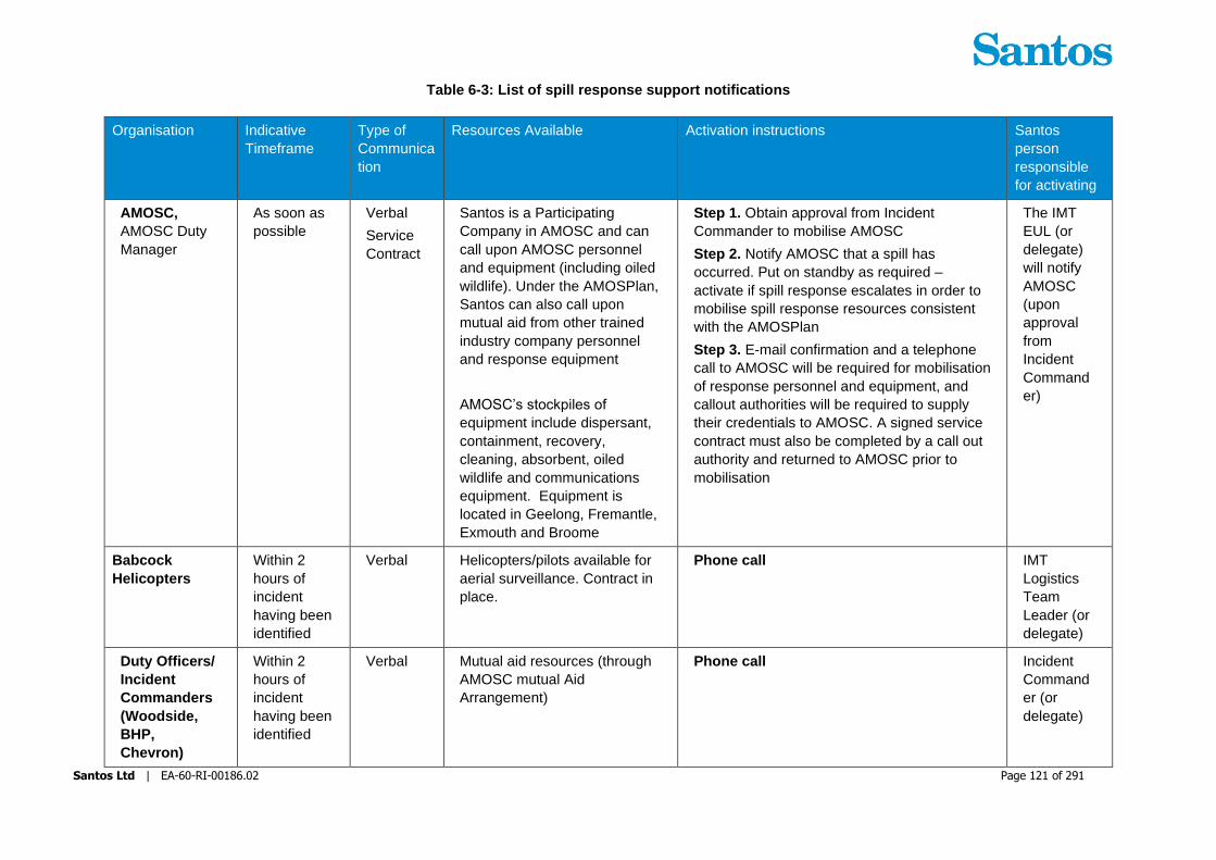
Santos Ltd | EA-60-RI-00186.02 Page 121 of 291
Table 6-3: List of spill response support notifications
Organisation Indicative
Timeframe
Type of
Communica
tion
Resources Available Activation instructions Santos
person
responsible
for activating
AMOSC,
AMOSC Duty
Manager
As soon as
possible
Verbal
Service
Contract
Santos is a Participating
Company in AMOSC and can
call upon AMOSC personnel
and equipment (including oiled
wildlife). Under the AMOSPlan,
Santos can also call upon
mutual aid from other trained
industry company personnel
and response equipment
AMOSC’s stockpiles of
equipment include dispersant,
containment, recovery,
cleaning, absorbent, oiled
wildlife and communications
equipment. Equipment is
located in Geelong, Fremantle,
Exmouth and Broome
Step 1. Obtain approval from Incident
Commander to mobilise AMOSC
Step 2. Notify AMOSC that a spill has
occurred. Put on standby as required –
activate if spill response escalates in order to
mobilise spill response resources consistent
with the AMOSPlan
Step 3. E-mail confirmation and a telephone
call to AMOSC will be required for mobilisation
of response personnel and equipment, and
callout authorities will be required to supply
their credentials to AMOSC. A signed service
contract must also be completed by a call out
authority and returned to AMOSC prior to
mobilisation
The IMT
EUL (or
delegate)
will notify
AMOSC
(upon
approval
from
Incident
Command
er)
Babcock
Helicopters
Within 2
hours of
incident
having been
identified
Verbal Helicopters/pilots available for
aerial surveillance. Contract in
place.
Phone call IMT
Logistics
Team
Leader (or
delegate)
Duty Officers/
Incident
Commanders
(Woodside,
BHP,
Chevron)
Within 2
hours of
incident
having been
identified
Verbal Mutual aid resources (through
AMOSC mutual Aid
Arrangement)
Phone call Incident
Command
er (or
delegate)

Santos Ltd | EA-60-RI-00186.02 Page 122 of 291
Organisation Indicative
Timeframe
Type of
Communica
tion
Resources Available Activation instructions Santos
person
responsible
for activating
Exmouth
Freight &
Logistics
When
equipment
from
movements
are required
in Exmouth
and
Dampier
Verbal Assistance with mobilising
equipment and loading vessels
Phone call IMT
Logistics
Team
Leader (or
delegate)
North West
Alliance –
Waste
When
Shoreline
Clean-up is
activated
(Section
13)
Verbal Santos has contract
arrangements in place with
North West Alliance to take
overall responsibility to
transport and dispose of waste
material generated through
clean up activities.
Phone call to the Primary Contact Person. In
the event the Primary Contact Person is not
available, the Secondary Contact Person will
be contacted.
IMT
Logistics
Team
Leader (or
delegate)
Astron Scientific
Monitoring
Plan
initiation
criteria are
met
(Section
17)
Verbal
and
written
Astron has been contracted by
Santos to provide Standby
Services for Scientific
Monitoring Plans (SMPs) 1-11.
This includes provision of
personnel and equipment.
Aston annually reviews the
SMPs for continual
improvement.
Step 1. Obtain approval from Incident
Commander to activate Astron for Scientific
Monitoring
Step 2. Verbally notify Astron followed by the
submission of an Activation Form
(Environment Team Leader Folder) via email
Step 3. Provide additional details as
requested by the Astron Monitoring
Coordinator on call-back
Step 4. Astron initiates Scientific Monitoring
Activation and Response Process
IMT
Environme
nt Team
Leader (or
delegate)
Intertek
Geotech (WA)
Environmental
When
characterisa
tion of oil is
activated
Verbal Oil analysis including GC/MS
fingerprinting
Ecotoxicology
Phone call IMT
Environme
nt Team

Santos Ltd | EA-60-RI-00186.02 Page 123 of 291
Organisation Indicative
Timeframe
Type of
Communica
tion
Resources Available Activation instructions Santos
person
responsible
for activating
Services and
Ecotoxicology
(Section
9.7)
Leader (or
delegate)
Oil Spill
Response
Limited
(OSRL), OSRL
Duty Manager
If spill
requires
additional
resources or
technical
expertise
Verbal
OSRL
Mobilisati
on
Authorisa
tion Form
Santos has a Service Level
Agreement with OSRL, which
includes the provision of
support functions, equipment
and personnel to meet a wide
range of scenarios. Further
details available on the OSRL
webpage.
Step 1. Contact OSRL Duty Manager in
Singapore and request assistance from OSRL
Step 2. Send notification to OSRL as soon as
possible after verbal notification
Step 4. Upon completion of the OSRL
incident notification form, OSRL will plan and
place resources on standby.
Designated
call-out
authorities
(including
Incident
Command
ers and
CST
Leaders)
RPS Group Within 2
hours
Verbal
and
written
Santos has an agreement in
place with RPS Group to allow
rapid marine hydrocarbon spill
modelling capability to be
activated at any time during
activities, which will be
undertaken for any spill greater
than Level 1. AMOSC can also
run modelling on behalf of
Santos, if required, as part of
contracting arrangements with
RPS Group
Contact RPS Group Duty Officer IMT EUL
(or
delegate)
Wild Well
Control
(WWC)
Within four
hours of a
loss of well
control
incident
Loss of
well
control
only
Verbal
Well intervention services.
Under contract.
Step 1. Following Santos management
confirmation of a subsea loss of containment,
the Incident Command Team (IMT) Drilling
Team Leader is to call the Wild Well Control
24 hour emergency hotline number to notify
WWC of the incident
Drilling
Team
Leader

Santos Ltd | EA-60-RI-00186.02 Page 124 of 291
Organisation Indicative
Timeframe
Type of
Communica
tion
Resources Available Activation instructions Santos
person
responsible
for activating
having been
identified
Step 2. As soon as practical after initial
notification and once the scale of the subsea
loss of containment is confirmed, an
emergency mobilisation authorisation form
(saved in ECM) must be filled out, signed off by
the authorised Santos Manger sent through to
WWC. The form is located on the Santos
Intranet Procedures Index under Emergency
Procedures
(http://ausintranet.enerylimited.com/dept_data/
Procedure_data/index.htm). Email as directed
by WWC point of contract provided by the
emergency hotline attendant.

Santos Ltd | EA-60-RI-00186.02 Page 125 of 291
7 Incident Action Plan (IAP)
Santos WA incident response personnel use the incident action planning process to develop Incident Action
Plans (IAPs). All stakeholders involved in the incident achieve unity of effort through application of the
disciplined planning process.
The incident action planning process is built on the following phases:
1. Understand the situation;
2. Establish incident objectives;
3. Develop the plan;
4. Prepare and disseminate the plan; and
5. Execute, evaluate and revise the plan.
The Santos WA IMT will use the IAP process to determine and document the appropriate strategies as more
information becomes available during an incident response. The IAP is to be used by the IMT for each
operational period following the initial first-strike assessments, notifications, and activations undertaken by
Santos WA.
The Santos WA IAP process is built on the phases described in Figure 7-1.
Figure 7-1: Incident Action Plan process
The IAP process facilitates the determination of appropriate strategies as more information becomes available
during a spill event. The IAP is used for each operational period following the initial incident response actions
defined in Section 5. An operational period is defined as the period scheduled for execution of actions specified

Santos Ltd | EA-60-RI-00186.02 Page 126 of 291
in the IAP. The IAP is refreshed when conditions change. There can be multiple objectives and action plans
occurring simultaneously within an IAP.
As IAPs and response strategies are implemented their performance is monitored. The performance
measurement results are fed back into the IMT to provide the IMT with greater situational awareness to enable
the effective formulation of following IAPs. Those response strategies that are effective are continued or
increased, while those strategies that are ineffective are scaled back or ceased.
The performance against the objectives of the IAP must be documented in the Incident Log by the IMT. This
provides the IMT with information required to assist in formulating the following IAP, and provides evidence of
Santos WA’s response to the incident for regulatory and legal investigations that will follow the termination of
the incident.
IAP performance is monitored through IMT communication with in-field response personnel both verbally and
through logs/reports/photos sent throughout the response (e.g. surveillance personnel, beach masters, team
leaders, laboratory chemists, etc.) who report on the effectiveness of the response strategies.
Gain situational awareness
In order to review the applicability of the contingency response strategies contained within this OPEP to the
actual and real incident characteristics, and assess the response strategies using NEBA to achieve impacts
that are ALARP, the IMT must first gain situational awareness by obtaining answers to the following:
+ What type of hydrocarbon has been spilt?
+ What is the expected behaviour of the hydrocarbon that has been spilt?
+ How much has been spilt?
+ Is the source under control?
+ Where is the hydrocarbon going?
+ Is there anything in the path of the predicted hydrocarbon travel zones?
+ Can the hydrocarbon be approached or are there safety concerns?
+ Can the hydrocarbon be contained?
+ Can the hydrocarbon be dispersed?
+ Will shoreline impact occur and clean-up be required?
+ Can wildlife be affected and require response?
IAP forms and processes are documented in the Incident Command and Management Manual (QE-00-ZF-
00025) and in the ‘Emergency Response’ folder sets at L:\Resource\Emergency Response\Incident-Exercise
Number-Name. Begin the response by copy and saving Incident-Exercise Number-Name folder set with a
unique incident name and Id number on the lead folder; this is the Incident Log. Access subfolders to display
all forms required to conduct incident action planning. Each functional position within the IMT and CMT has
subfolders carrying forms and processes unique to the functional position.

Santos Ltd | EA-60-RI-00186.02 Page 127 of 291
8 Source Control
The initial and highest priority response to an oil spill incident, following the safety of personnel, is to
prevent or limit further oil loss into the marine environment; however, this will only be attempted if safe
to do so. In most circumstances, the net benefit of source control outweighs impacts of further oil being
released into the marine environment. Further risks may arise due to increased vessels and the
associated increased health and safety risks for the team involved in the response.
8.1 Vessel and Platform Releases (hydrocarbon storage, handling and transfer)
Spills of up to 4 m3 (marine diesel, lube oils, hydraulic fluids) are considered credible from leaks and
spills associated with hydrocarbon storage, handling and transfer on offshore platform and vessels.
Spills of up to 15 m3 are considered credible for diesel transfers between support vessels and the diesel
storage system on VI which is State waters scenario only.
These scenarios do not include vessel fuel/cargo tank rupture, covered in Section 8.2.
The environmental performance outcome, initiation and termination criteria and the implementation
guide for vessel and platform releases are provided in Table 8-1 and Table 8-2 respectively.
Table 8-1: Vessel and Platform Releases – Environmental Performance Outcome, Initiation
Criteria and Termination Criteria
.
Environmental
Performance
Outcome
Implementation of source control methods to stop the release of
hydrocarbons into the marine environment.
Initiation criteria Notification of spill.
Applicable
hydrocarbons
Lube oil/
hydraulic
fluids
Condensate Crude oil Marine
Diesel
HFO
X X X
Termination
criterion
Release of oil to the marine environment has ceased and the workplace
environment is deemed environmentally safe and free of hydrocarbon.

Santos Ltd | EA-60-RI-00186.02 Page 128 of 291
Table 8-2: Vessel and Platform Releases Implementation Guide
Vessel and Platform Releases (hydrocarbon storage, handling and transfer)
Activation time Immediately upon notification of a vessel or platform
release.
Action Consideration Responsibility Complete
Init
ial A
cti
on
s
In the event of a loss of
production hydrocarbons
from platform topside
production equipment,
consult the Varanus Hub
Incident Response Plan
(QE-00-ZF-00044)
Offshore
Platform
Designated
Person/
Facility On
Scene
Commander
❑
For refuelling and chemical
transfers between support
vessels and between
support vessels and VI Hub
offshore platforms, consult
the Refuelling and Chemical
Management Standard (QE-
91-IQ-00098)
In all situations, consider
the following:
+ For spills during
pumping operations,
pumping activity to
cease immediately;
+ Where drainage is
open to the marine
environment, drainage
is to be isolated as
soon as practicable
following the spill to
prevent discharge to
the ocean (the Vessel
Master or On-scene
Commander will
confirm that the
drainage network is
closed on the vessel
before washing down
the deck after excess
oil has been cleaned
up);
+ Use of onsite spill kit
resources (i.e. sorbent
material) to clean-up
spills;
+ Recovery of dropped
container where
practicable, where
containers of
hydrocarbons are
dropped during vessel
to platform transfers;
Offshore
Platform
Designated
Person/
Vessel Master/
Facility On
Scene
Commander
❑
For refuelling of support
vessels at East or West
Wharf from VI diesel tanks,
consult the Varanus Island
Diesel Distribution System
Operating Procedure (VI-91-
IP-10200)
Offshore
Platform
Designated
Person/ Vessel
Master/ Facility
On Scene
Commander
❑

Santos Ltd | EA-60-RI-00186.02 Page 129 of 291
Vessel and Platform Releases (hydrocarbon storage, handling and transfer)
Activation time Immediately upon notification of a vessel or platform
release.
Action Consideration Responsibility Complete
+ Disposal of
contaminated waste to
licensed waste
contractor; and
+ Isolation and repair of
damaged, leaking
equipment.
Resources Location
Equipment Refer to vessel, platform
and activity specific
procedures for details of
equipment available.
Refer to vessel, platform and
activity specific procedures
for details of equipment
locations.
Personnel Refer to vessel, platform
and activity specific
procedures for details of
personnel.
Refer to vessel, platform and
activity specific procedures
for details of personnel.
Maintenance of response Spills of this nature are expected to be handled by the
resources available at the spill location due to the relatively
small credible release volumes and hydrocarbon types. The
resources on hand are expected to be sufficient to maintain
the response until the termination criteria are reached. If
required, Santos has access to additional resources
internally and through service providers to maintain this
response.
8.2 Vessel Tank Rupture
Credible vessel tank ruptures during VI Hub operations include marine diesel releases from support
vessel collision/grounding and release of HFO or crude oil from offtake tanker collision/grounding.
Diesel tank ruptures are credible within State and Commonwealth waters.
HFO tank ruptures are only credible in State waters.
Through the implementation of these controls, the amount of hydrocarbons released to the marine
environment may be reduced. However, there are several influencing factors that would result in delay
or failure to implement controls, potentially resulting in a full discharge of a fuel tank compartment; such
as a high sea state, a significantly large rupture, or injuries to personnel.
The environmental performance outcome, initiation and termination criteria and the implementation
guide for vessel tank ruptures are provided in Table 8-3 and Table 8-4 respectively.

Santos Ltd | EA-60-RI-00186.02 Page 130 of 291
Table 8-3: Vessel Tank Rupture - , Environmental Performance Outcome, Initiation Criteria and
Termination Criteria
Vessel Tank Rupture
Environmental
Performance
Outcome
Implementation of source control methods to stop the release of
hydrocarbons into the marine environment.
Initiation criteria Notification of incident/spill.
Applicable
hydrocarbons
Lube oil/
hydraulic
fluids
Condensate Crude oil Marine
Diesel
HFO
X X
Termination
criterion
The cargo in the ruptured fuel or storage tank is secured and release to the
marine environment stopped.

Santos Ltd | EA-60-RI-00186.02 Page 131 of 291
Table 8-4: Vessel Tank Rupture Implementation Guide
Vessel Tank Rupture
Activation time Immediately upon notification of a vessel tank rupture.
Action Consideration Responsibility Complete
Init
ial A
cti
on
s
The vessel’s Shipboard Oil
Pollution Emergency Plan
(SOPEP), as applicable
under MARPOL, or
procedure for responding to
a ruptured tank will be
followed as applicable
Notwithstanding vessel
specific procedures for
source control, the following
activities would be
immediately evaluated for
implementation providing
safe to do so:
+ Reduce the head of cargo by dropping or pumping the tank contents into an empty or slack tank;
+ Consider pumping water into the leaking tank to create a water cushion to prevent further cargo loss;
+ If the affected tank is not easily identified, reduce the level of the cargo in the tanks in the vicinity of the suspected area if stability of the vessel will not be compromised;
+ Evaluate the transfer of cargo to other vessels;
+ Trimming or lightening the vessel to avoid further damage to intact tanks; and/or
+ Attempt repair and plugging of hole or rupture
Vessel Master ❑
Resources Location
Equipment Refer to vessel specific
procedures for details of
equipment available.
Refer to vessel specific
procedures for details of
equipment locations.
Personnel Refer to vessel specific
procedures for details of
personnel.
Refer to vessel specific
procedures for details of
personnel.

Santos Ltd | EA-60-RI-00186.02 Page 132 of 291
Vessel Tank Rupture
Activation time Immediately upon notification of a vessel tank rupture.
Action Consideration Responsibility Complete
Maintenance of response Source control measures on vessels are typically contained
in the vessel-specific SOPEP and / or Emergency
Response Plan (ERP). The need for additional resources to
support vessels undertaking source control measures will
be specific for each spill. Santos has a range of potential
resources (e.g. support vessels with capacity to store
liquids) available through its VI Hub operations.
8.3 Loss of Well Control
Credible loss of well control events during VI Hub operations include releases of gas/condensate from
subsea or platform wells in Commonwealth waters (Halyard-1, Spar-2, John Brookes) or release of
gas/condensate or crude oil from platform/monopod wells in State waters (Wonnich, Linda, Simpson-B,
Harriet –A/B, Agincourt, Double Island, Victoria, Gibson/Sth Plato).
For all loss of well control events, the installation of a subsea Capping Stack is not considered applicable.
The primary means of controlling a well that cannot be brought under control using onsite resources is
the drilling of a relief well to intercept the well bore and kill the flow of hydrocarbons. In the process of
relief well planning the option of top-killing the well from platform or vessel will also be evaluated.
The environmental performance outcome, initiation and termination criteria and the implementation
guide for loss of well control are provided in Table 8-5 and Table 8-6 respectively. The implementation
guide provides a high level overview of actions contained within the Santos WA Source Control
Emergency Response Plan (SCERP) (DR-00-ZF-1001) and this document should be consulted for
further detail.
Table 8-5: Loss of Well Control - Environmental Performance Outcome, Initiation Criteria and
Termination Criteria
Loss of Well Control
Environmental
Performance
Outcome
Implementation of source control methods to stop the release of hydrocarbons into
the marine environment.
Initiation criteria Notification of incident/ spill.
Applicable
hydrocarbons
Lube oil/
hydraulic
fluids
Condensate Crude oil Marine
Diesel
HFO
X X X
Termination
criterion
The primary well is contained and killed to prevent any further release of
hydrocarbon to the environment.

Santos Ltd | EA-60-RI-00186.02 Page 133 of 291
Table 8-6: Loss of Well Control Implementation Guide
Loss of Well Control
Activation time Immediately upon receiving notification of incident/ spill.
Action Consideration Responsibility Complete
Init
ial A
cti
on
s
Implement the Source
Control Emergency
Response Plan (SCERP)
(DR-00-ZF-10001)
IMT Drilling
Team Leader ❑
Notify Santos WA Drilling
and Completions Team to
assemble a Source Control
Team and immediately
begin preparations
IMT Drilling
Team Leader ❑
Notify well control service
provider personnel for
mobilisation
IMT Drilling
Team Leader
and Drilling &
Completions
Source Control
Team
❑
Source MODU through
nearby drilling operations if
available or procure from
nearest operator through
mutual aid agreement MOU.
Drilling &
Completions
Source Control
Team
❑
Design Relief Well, using
relief well pre-planning
work, as applicable, and
have prepared in time to
procure equipment and
personnel prior to MODU
arrival on location
Drilling &
Completions
Source Control
Team
❑
Assess relief well equipment
and personnel
requirements. Procure and
make ready
Logistics Team
Leader ❑
Deploy equipment and
personnel to site to begin
spud and drill
Drilling Team
Leader ❑
Monitor progress of relief
well drilling and
communicate to IMT
IMT Drilling
Team Leader ❑
Supporting Documentation
Document Title Reference Note

Santos Ltd | EA-60-RI-00186.02 Page 134 of 291
Loss of Well Control
Activation time Immediately upon receiving notification of incident/ spill.
Action Consideration Responsibility Complete
Source Control Emergency
Response Plan (SCERP) DR-00-ZF-1001
Well Operations Management
Plans (WOMPs) Various Refer Santos WA Intranet
Santos Drilling & Completions
Management Process
Source Control Plan – as required
Memorandum of Understanding:
Mutual Assistance (To facilitate the
transfer of Drilling Units and Well-
Site Services between operators in
Australian and Timor Leste
administered waters to overcome
emergency conditions)
N/A
Maintained on Santos WA
Emergency Response
Website
Maintenance of response Santos WA has the resources available from existing
operations on the NWS to maintain and operate a MODU
for as long as the response is required. Santos WA D&C
personnel and well control specialists will be rotated and the
MODU will be maintained with support vessels through
existing contracts with vessel suppliers. Additional response
tactics that may be implemented following a pipeline release
(e.g. containment and recovery) are discussed separately.
8.3.1 Emergency Shutdown (ESD)
The Varanus Hub Incident Response Plan (QE-00-ZF-00044) details the initial actions to be taken by
offshore and onshore personnel to activate well ESD systems, where they are not already triggered
automatically. All wells are monitored by the VI Control Building (VICB) Central Control Room (CCR)
from where ESD can be activated.
8.3.2 Well kill
The risk of a loss of well control event is introduced during well intervention activities due to the
requirement to breach and enter the pressure envelope of the well.
Controlling a loss of well control through the drilling of a relief well by a MODU, or through top-kill of
platform wells from the platform or vessel, are strategies that will be pursued if the well cannot be brought
under control using existing onsite well control systems. Relief well drilling is the primary strategy; top-
kill may not be applicable due to technical and safety constraints.
VI Hub wells are managed in accordance with an accepted Well Operations Management Plan (WOMP)
(Commonwealth water wells) or an accepted Well Management Plan (WMP) (State waters wells).
Source control requirements, including any well kill planning requirements, are specified in these
documents.
Planning for relief well drilling is conducted as per Santos Drilling & Completions Management Process.
Findings from the planning will inform pumping/well-kill requirements for top-kill (if possible) and the
technical design and MODU requirements for drilling a relief well.

Santos Ltd | EA-60-RI-00186.02 Page 135 of 291
Surface/Top Well Kill:
For clarity, the top-kill scenario is modelled on a small uncontrolled leak to atmosphere at the production
tree that cannot be isolated upstream, that may still allow safe access to the platform, and tie-in to the
leaking well via existing infrastructure (i.e. connecting to the production tree via the kill wing outlet), and
safe operation of a vessel located alongside the John Brookes platform. It does not apply to subsea
wells (i.e. Halyard/Spar). It is estimated that this leak rate would be in the range of 400cc/min, small
enough not to generate an explosive gas cloud and access to the platform is still preserved. This
methodology would not be considered should safe access to the platform or ability to operate a vessel
alongside the platform not be achievable.
A high-pressure pumping package would be deployed on a vessel, the vessel is moored alongside the
platform, and a flexible high pressure kill line is deployed from the vessel to the platform.
Santos has previously modelled a “top-kill” scenario on analogue wellhead platform wells (Reindeer,
Schlumberger Report 1-1BAORA3). The simulation assessed the ability to bullhead the well dead from
a shut-in gas to surface scenario, whilst out-running the surface leak and not exceeding the safe working
pressure of the surface equipment.
The top-kill model utilised a leak rate of up to 10,000cc/min (which is the lowest leak surface leak rate
the modelling software allows) and demonstrated that utilising a minimum kill rate of 350gpm (~10bpm)
the gas could be effectively bull-headed without excessive well bore pressures. A large range of
reservoir injectivity values were assessed for both seawater and kill-weight mud with a maximum pump
pressure of less than 3,000psi. This is well within the capability of high-pressure pumping equipment
(e.g. cement units/triplex pumps, high-pressure treating iron pipe-work and flexible high-pressure hoses)
readily available within the region.
Santos WA has successfully planned and executed well kill/bull-heading/flushing operations during
routing non-leaking well suspension activities on numerous platforms using this technique with local
personnel and equipment.
Relief Well Drilling:
The Santos WA Source Control Emergency Response Plan (SCERP) (DR-00-ZF-10001) outlines the
overarching process for planning and mobilising personnel and equipment into the field for the purpose
of drilling a relief well. Campaign specific Source Control plans are developed prior to any well
intervention activities as per WOMP requirements and a register of these plans is saved in the Santos
WA document control system.
Relief well planning is embedded into the Santos Drilling & Completions Management Process.
The following industry accepted guidelines have been adopted to assist relief well planning
requirements:
+ SPE Calculation of Worst Case Discharge (WCD) Rev 1, 2016; this is used as part of the prospect screening review in Phase 2 (Evaluate) to generate a credible rate for oil spill modelling, as well as providing an input for the dynamic kill modelling, part of the Well Specific Source Control Plan (WDW Act 3.5); and
+ UKOG Relief Well Guidelines, Issue 2, 2013; this methodology is used to confirm a well complexity analysis and tailor required content for the Well Specific Source Control Plan (WDW Activity 3.5) to the appropriate level of detail.
The worst case credible loss of well control volume is based on control of the well by 11 weeks (77
days). This period is used as a base case well control timeframe by Santos WA across its wells and is
based on indicative mobilisation durations, relief well planning and operations. It could take up to 34
days to have a MODU onsite ready to spud and drill; an indicative schedule is provided in Table 8-7.
For noting, loss of well control spill volumes have, in some instances, been based on a more
conservative 100 day relief well drilling period to remain consistent with previous Commonwealth and
State water Environment Plans for VI Hub Operations.

Santos Ltd | EA-60-RI-00186.02 Page 136 of 291
Table 8-7: Schedule for MODU arriving onsite
Loss of well control
Task Duration (in days) Controls
Event reported – begin
mobilisation of rig for relief well
drilling
1 + On-site communications
+ Active IMT on call including
Operations/Drilling Team Lead
Relief well MODU confirmed.
Relief well MODU suspends
operations and prepares to
mobilise to relief well location.
10 + Active IMT
+ Santos Offshore Source Control
Emergency Response Plan (SCERP –
DR-00-ZF-10001)
+ Regional MODU tracking
+ APPEA Memorandum of Understanding
(MOU): Mutual Assistance
Continue preparations for relief
well and rig mobilisation
21 + Stood-up Relief Well Team (as per
SCERP)
+ Pre-complete campaign specific source
control plan complete with relief well
study.
+ Relief Well Drilling specialists services
contract (Wild Well Control)
+ Drilling services contracted
+ Pre-verified access to relief well
equipment (e.g. casing and wellhead)
+ APPEA Memorandum of Understanding
(MOU): Mutual Assistance
Rig mobilisation to well offset
location (dependent on current
and prevailing weather)
2 + Vessel and rig move services contracted
Total days prior to arrival, ready
to spud/commence relief well
operations
34
The ability to achieve the above time-line is assessed prior to any John Brookes well intervention
activities as a part of the campaign specific source control plan. Currently this time-line has been
assessed as ALARP based on the current controls/measures in place, however Santos is actively
working with industry to evaluate measures to improve on the ALARP response time model through the
APPEA DISC Source Control Response Industry (SCRI) Working Group. The SCRI working group is
an APPEA DISC initiative which has been established to drive collaboration and continuous
improvement in source control emergency response planning. The Working Group will explore and act
on opportunities to align and strengthen the Titleholders’ source control emergency response capability
though “mutual aid” initiatives and drive continuous improvement by implementing fit-for-purpose and
effective source control emergency response strategies.
Santos WA tracks the MODU activity within the region and updates the tracker on a monthly basis. The
relief well rig capability register includes the following information;
+ Rig name

Santos Ltd | EA-60-RI-00186.02 Page 137 of 291
+ Rig contract status (Operator and contract duration)
+ Current location
+ Maximum water depth capability
+ Rig type (Floating vs jack-up; mooring type; Rig Design/Class)
+ Available drilling envelope
+ BOP specifications
+ BOP/LMRP connector specifications
+ Mud pumps specifications/capability
+ Choke and Kill line IDs
+ Storage capability (i.e. diesel, base-oil, brine, drill-water, potable water, bulks)
+ NOPSEMA safety case (yes/no)
The campaign specific source control plan (including relief well study) for the John Brookes well
intervention activity, will verify the rig well kill capability and access to the relief well drilling location for
the rig types operating within the region that Santos would expect to have access to.
An APPEA Memorandum of Understanding: Mutual Assistance is in place. This agreement provides the
mechanism to facilitate the transfer of drilling units and well-site services between operators in Australian
and Timor Leste administered waters in order to respond urgently to emergency source control events.
A Safety Case Revision will be required for the relief well rig to undertake the activity; this cannot be
submitted before the event. The Safety Case Revision will be based on existing documents, specifically
the Safety Case Revision approved for the drilling of the original well and the Safety Case in force for
the relief well rig. A Safety Case Revision would be submitted within 14 days from the loss of well control,
however the critical path time allowed for the actual writing of the document is 3 days. The remaining
estimated time would be used for gathering post-event data, mobilising the workforce and conducting a
HAZID. It is not practicable to reduce the critical path days with additional pre-planning as document
revision, final review and approval will still be required after completing the HAZID.
Prior to the 2019 John Brookes memory-gauge campaign, which involved well activities entering the
pressure envelope of the well (and as such introduced the risk of a loss of well control), a relief well
study was conducted for the John Brookes wells.
Blowout modelling was performed for John Brookes-5 (JB-5) using a surface atmospheric blowout
(through completion tubing) worst case discharge scenario. JB-5 was used as it has the highest
deliverability of all the John Brookes wells.
The process of selecting an acceptable surface location for drilling a relief well involves:
+ Reviewing the seasonal prevailing conditions
+ Establishing relief well MODU requirements (pinning etc)
+ Reviewing the actual debris field generated in the well control incident.
Fluids venting from an uncontrolled John Brookes well will be carried by both wind and local sea
conditions, and the relief well locations should not be downwind, or downstream of a blowing well.
The relief well location is proposed to be 700m South of the John Brookes platform (7737190.2m N,
303901.1m E), in 48m of water. This is based on the following:
+ Requirement to be upwind of predominantly South-Westerly winds experienced throughout the year
+ Current speeds oriented mainly towards Southwest
+ Wave action mainly towards Northeast

Santos Ltd | EA-60-RI-00186.02 Page 138 of 291
+ Shallow open water location with a generally benign seabed suitable for Jack-up
+ Location enables relief well approach from behind to align for ranging and intercept. Also avoids drilling ‘backwards’
+ No collision risks with other John Brookes wells associated with relief well approach
A site survey is considered unnecessary based on the following:
+ A site survey was performed in 2003/04.
+ A geotechnical site investigation done in 2003 at the platform, with spud can penetrations at the time ranging from 1.2-3.4m.
+ The geophysical and geotechnical survey performed at Davis-1 (~6km ESE) in 2015, and subsequent use of the NTP jack-up MODU at this location.
+ A 2km quadrant from the South-West to South-East contains no seabed infrastructure, presenting a clear rig approach face. The spud location is away from the Halyard EHU (Electro-Hydraulic Umbilical) and export pipeline.
A nominal well trajectory has been developed for the relief well, an example of which for JB-5 is shown
in Figure 8-1. The planned intercept point for the relief well is below the 9 5/8” casing shoe;

Santos Ltd | EA-60-RI-00186.02 Page 139 of 291
Figure 8-1: John Brookes-5 Nominal Relief Well Plan View

Santos Ltd | EA-60-RI-00186.02 Page 140 of 291
A full dynamic kill model can be found in the Schlumberger SIS report (Report No. 1-1KBOVKT). Key
assumptions made in the dynamic kill simulation modelling included:
+ The wellbore is completely loaded with 100% gas. Therefore, there is no water column in the tubing or 9-5/8” casing above the perforations.
+ The well will produce at the gas rate forecasted by the system calculation in another reservoir program and lift all liquids (condensate and water) to surface.
+ Some reservoir pressure depletion will occur as per the history matched material balance model using a Gas-Initially-In-Place (GIIP) volume reflecting a ‘Best Estimate’ or 2P Reserves position.
+ The well will produce at the forecasted rates for the full 11-week period required to conduct the relief well well kill.
Findings of the well kill model include;
+ The well kill can be achieved by pumping 1.10 SG kill mud at a rate of 15 bpm. The flow rate is best delivered via the drill pipe to avoid high unnecessary pressures in the annulus when pumping through the 7” liner.
+ The pressures in the wells are moderate with no issues for the cased target well and little impact on the relief well casing shoe.
+ No limits are exceeded in the simulated well kill.
+ About 1350bbl of kill mud is required for the well kill including additional 40 minutes of pumping for displacing remaining hydrocarbons from the target well.
+ This is a straightforward well kill achievable with one relief well and standard rig pump configuration. Table 8-8 outlines the relief well kill summary results.
Table 8-8: Relief Well Kill Summary Results for John Brookes-5
Dynamic Kill Requirements Executable
Intersection in 7” liner below upper completion
1.02SG seawater @ 15bpm (450bbl req.)
1.10SG Kill Mud @ 15bbl/min w/ 3,080psi (1,350bbl req.)
Yes
1.10SG MW
2-3 x Lewco W-2215
The relief well design was proposed to be similar to the original John Brookes wells but with a simplified
casing design. At the time of the well services activities in Q3 2019, provision for the availability of relief
well casing was checked and verified against the Company’s OCTG inventory which included the
required 20” conductor, 13-3/8” 68ppf L80, 9-5/8” 53.5ppf L80 and 7” 29ppf casing strings.
At the time Santos has access to the following surface wellhead systems:
+ Two complete wellhead systems are currently held in inventory in Perth. Including:
– 21-1/4” 2M A-Section,
– 13-5/8” 5M B-Section,
– 9-5/8” 5M Casing Hanger,
– All running tools and accessories were confirmed available for use.
The water depth at the relief well location is ~50m, and as such a jack-up would be required to drill any
relief well. The jack-up requirements are;
+ Able to pin in 48m of water.
+ A 5,000 psi BOP
+ A current Australian safety case (preferred) or a recent Australian safety case (possible).
+ Mud pumps – 3 x Lewco W-2215 or equivalent. Minimum pump power requirement 1125 HP

Santos Ltd | EA-60-RI-00186.02 Page 141 of 291
8.4 Pipeline release
Credible pipeline release events during VI Hub operations are:
+ Condensate/gas release from production pipelines
+ Crude oil release from production pipelines
Condensate/gas release from production pipelines is a credible event in both Commonwealth and State
waters.
Crude oil release from production pipelines is credible in State waters only.
A release from the sales gas export line between VI and the mainland (State waters only) is considered
credible, however such a release would be dry gas (no condensate) and therefore not covered under
this OPEP.
The Varanus Hub Incident Response Plan (QE-00-ZF-00044) details the initial actions to be taken by
offshore and onshore personnel to activate riser/ pipeline ESD systems, where they are not already
triggered automatically. All pipelines are isolatable by way of ESD activated from the VI Control Building
(VICB) Central Control Room (CCR).
The environmental performance outcome, initiation and termination criteria and the implementation
guide for pipeline releases are provided in Table 8-9 and Table 8-10 respectively.
Table 8-9: Pipeline Release - Environmental Performance Outcome, Initiation Criteria and
Termination Criteria
Pipeline Releases
Environmental
Performance
Outcome
Implementation of source control methods to stop the release of hydrocarbons into
the marine environment.
Initiation criteria Notification of a spill.
Applicable
hydrocarbons
Lube oil/
hydraulic
fluids
Condensate Crude oil Marine
Diesel
HFO
X X X
Termination
criterion
The hydrocarbon release to the environment has stopped.
Table 8-10: Pipeline Release Implementation Guide
Pipeline Release
Activation time Immediately upon receiving notification of incident/ spill.
Action Consideration Responsibility Complete
Init
ial
Acti
on
s Consult Varanus Hub
Incident Response Plan
(QE-00-ZF-00044) to
activate riser / pipeline
On-Scene
Commander ❑

Santos Ltd | EA-60-RI-00186.02 Page 142 of 291
Pipeline Release
Activation time Immediately upon receiving notification of incident/ spill.
Action Consideration Responsibility Complete
emergency shut down
(ESD).
Where and when safe to do
so, an inspection class
ROV and support vessel,
will be mobilised to visually
identify any subsea incident
location
Incident
Commander/
Operations
Team Leader
❑
Resources Location
Equipment
Inspection class ROV.
On vessels of opportunity
Contracted at the time of
incident.
Vessels
Santos WA operational sites
Vessels of opportunity
Personnel Santos WA Facility
Incident Response Team
members
Santos WA Operational sites
Maintenance of response The resources to activate the pipeline ESDs are always
present within the VI Hub control room. Additional response
tactics that may be implemented following a pipeline release
(e.g. containment and recovery) are discussed separately.
8.5 Crude oil cargo loading
A spill of crude oil from the rigid 30” export pipeline (Tanker Loading Line) or the connected 12” hose
(Tanker Loading Hose) is considered credible during offtake tanker cargo loading.
A release could occur onshore or offshore within State waters only.
The environmental performance outcome, initiation and termination criteria and the implementation
guide for crude oil cargo releases are provided in Table 8-11 and Table 8-12 respectively.
Table 8-11: Crude Oil Cargo Loading Spill - Environmental Performance Outcome, Initiation
Criteria and Termination Criteria
Crude Oil Cargo Loading
Environmental
Performance
Outcome
Implementation of source control methods to stop the release of
hydrocarbons into the marine environment.
Initiation criteria Notification of a spill.

Santos Ltd | EA-60-RI-00186.02 Page 143 of 291
Crude Oil Cargo Loading
Applicable
hydrocarbons
Lube oil/
hydraulic
fluids
Condensate Crude oil Marine
Diesel
HFO
X X X X
Termination
criterion
The oil cargo in the ruptured subsea export pipeline is secured and release
to the marine environment stopped.
Table 8-12: Crude Oil Cargo Loading Implementation Guide
Crude Oil Cargo Loading
Activation time Immediately upon receiving notification of incident/ spill.
Action Consideration Responsibility Complete
Init
ial A
cti
on
s
Isolate tanker loading line -
consult Varanus Hub
Incident Response Plan
(QE-00-ZF-00044)
On-scene
Commander ❑
Use suck back pump at
shore crossing to pump
remaining crude oil in the
Tanker Loading Line into
the adjacent Harriet Alpha
pipeline, until the Tanker
Loading Line is flushed with
seawater and free of
hydrocarbon – consult Start
up and Shutdown of Suck
Back Pump (VI-91-IP-
10197)
On-scene
Commander ❑
Resources Location
Equipment Suck Back Pump Varanus Island
Personnel VI IRT Varanus Island
Documentation Shutdown of Suck Back
Pump (VI-91-IP-10197)
Varanus Hub Incident
Response Plan (QE-00-
ZF-00044)
Document Management
System
Maintenance of response This response can be maintained by normal staffing levels
and equipment available at the VI Hub. Additional response
tactics that may be implemented following a pipeline release
(e.g. containment and recovery) are discussed separately.

Santos Ltd | EA-60-RI-00186.02 Page 144 of 291
8.5.1 Initial Response
Procedures for offtake tanker loading, including supervision and communications requirements, to
prevent and detect spills during cargo loading, are included in the Berthing Handbook Tanker Loading
Facilities Port of Varanus Island (LT-10-ZG-00001) and Procedure for VI Tanker Loading, Crude
Sampling and Quality and Quantity Determination (QE-91-IG-00007).
The Tanker Loading Line and cargo loading pumps are controlled and operated from the VI Control
Building (VICB) Central Control Room (CCR). The Tanker Loading Line can be isolated from process
equipment by manual ESD in the event that a leak rupture is detected by or communicated to the CCR.
The activation of ESD and other initial actions to a major oil spill event at VI are covered in the Varanus
Hub Incident Response Plan (QE-00-ZF-00044).
Following shutdown of loading pumps and isolation of the Loading Line, a suck back pump position at
the shore crossing can be used to pump remaining crude oil in the Tanker Loading Line into the adjacent
Harriet Alpha pipeline, until the Tanker Loading Line is flushed with seawater and free of hydrocarbon.
The procedure for operating the suck back pump is outlined within: Start up and Shutdown of Suck Back
Pump (VI-91-IP-10197).
8.5.2 Identification and Repair
Where and when safe to do so, Tanker Loading Line inspection and repair will involve the mobilisation
a repair team including the use of divers. Loading Hose damage can be rectified by repair offsite or new
hose replacement.
Santos WA maintains limited certified spare pipe and pipeline end connectors for sectional replacement
of the Tanker Loading Line for localised damage.

Santos Ltd | EA-60-RI-00186.02 Page 145 of 291
8.6 Onshore Hydrocarbon spills
Onshore hydrocarbon spills on VI include the following:
+ minor spills associated with storage and handling of hydrocarbons (lube oils, hydraulic fluids,
marine diesel, petrol, aviation fuel, waste oil);
+ spills associated with bunkering marine diesel via the Diesel Distribution System;
+ spills from process equipment;
+ spills from the bulk crude oil storage tanks;
+ spills from the onshore section of the 30” export pipeline (Tanker Loading Line); and
+ spills from the onshore sections of live production pipelines.
Onshore spills from production pipelines and the Tanker Loading Line are covered in Sections 8.4 and
8.5, respectively.
All areas and process skids that may contain hydrocarbon or chemicals within Varanus Island
processing plants drain into local constructed metal or concrete sumps within bunded areas or to
humeceptors. Runoff from the shipping pump areas outside of the bunded areas, drains into a triple trap
and then into a humeceptor.
The bulk crude oil storage tanks are located within an earthen bund lined with a HDPE liner. Rain and
wash down water from external hardstand areas of the maintenance workshop and wash-down pad,
chemical and fuel storage areas, water maker areas, and roof of the bulk crude oil storage tanks drain
to the crude oil storage tank bund. Water from this bund is pumped to the Corrugated Plate Interceptor
(CPI) for removal of hydrocarbons and then disposal to deep injection bores on the island.
Bunded areas are designed to contain the contents of hydrocarbons from worst case spills and prevent
spread of hydrocarbons off-lease or to the groundwater. Further details on secondary containment
around hydrocarbon storage and processing equipment on VI is provided within the Varanus Island Hub
Operations Environment Plan (EA-60-RI-186).
The environmental performance outcome, initiation and termination criteria and the implementation
guide for onshore hydrocarbon spills are provided in Table 8-13 and Table 8-14 respectively.
Table 8-13: Onshore Hydrocarbon Spills - Environmental Performance Outcome, Initiation
Criteria and Termination Criteria
Onshore Hydrocarbon Spills
Environmental
Performance
Outcome
Implementation of source control methods to stop the release of
hydrocarbons into the marine environment.
Initiation criteria Notification of an onshore spill
Applicable
hydrocarbons
Lube oil/
hydraulic
fluids
Condensate Crude oil Marine
Diesel
HFO
Termination
criterion
The cargo in the leaking or ruptured pipeline/tank/vessel is secured and
release to the onshore (terrestrial) environment is stopped.

Santos Ltd | EA-60-RI-00186.02 Page 146 of 291
Table 8-14: Onshore Hydrocarbon Spills Implementation Guide
Onshore Hydrocarbon Spill
Activation time Immediately upon receiving notification of incident/ spill.
Action Consideration Responsibility Complete
Init
ial A
cti
on
s
For manual handling of
hydrocarbons on VI,
minimum standards for
equipment and
processes to prevent and
control a spill are
provided in Refuelling
and Chemical Transfer
Management Standard
(QE-91-IQ-00098).
On-scene
Commander ❑
For marine diesel transfer
operations the Varanus
Island Diesel Distribution
System Operating
Procedure (VI-91-IP-
10200) outlines
requirements to limit the
flow of hydrocarbons in
the event of a spill.
On-scene
Commander ❑
Minor spills are to be
contained using onsite
resources including spill
kits containing sorbent
materials and the use of
secondary containment
(equipment bunding, drip
trays etc).
On-scene
Commander ❑
Varanus Hub Incident
Response Plan (QE-00-
ZF-00044) details the
initial actions to be taken
by onshore personnel to
respond to major oil spill
incidents including
release from VI process
equipment and storage,
including the activation of
ESD systems.
On-scene
Commander ❑
Resources Location
Equipment spill kits containing
sorbent materials and the
use of secondary
At Facility

Santos Ltd | EA-60-RI-00186.02 Page 147 of 291
Onshore Hydrocarbon Spill
Activation time Immediately upon receiving notification of incident/ spill.
Action Consideration Responsibility Complete
containment (equipment
bunding, drip trays etc).
Personnel Incident Response Team VI Hub
Document Refuelling and Chemical
Transfer Management
Standard (QE-91-IQ-
00098).
Varanus Island Diesel
Distribution System
Operating Procedure (VI-
91-IP-10200)
Varanus Hub Incident
Response Plan (QE-00-
ZF-00044)
Document Management
System
Maintenance of response This response can be maintained by normal staffing levels
and equipment available at the VI Hub. Additional
response tactics that may be implemented following a
pipeline release (e.g. containment and recovery) are
discussed separately.
8.6.1 Identification and Repair
Identification of leaks onshore is from automated systems, monitored through the VICB CCR (applicable to spills from process and storage equipment) or through visual observations. Following detection of leaks and implementation of source control, repairs to equipment will be conducted once safe to do so, taking into consideration any requirements to leave equipment intact for incident investigation purposes.
8.7 Source Control Environmental Performance
Table 8-15 indicates the Environmental performance outcomes, controls and performance standards
for the Source Control response strategy.

Santos Ltd | EA-60-RI-00186.02 Page 148 of 291
Table 8-15: Source Control Performance Standards and Measurement Criteria
Environmental
Performance
Outcome
Implementation of source control methods to stop the release of hydrocarbons into
the marine/onshore environment.
Response
Strategy
Control
Measures Performance Standards
Measurement
Criteria
Source control –
loss of well
control
Response Preparedness
Source Control
Emergency
Response Plan
A Source Control Emergency
Response Plan is in place during
activity
Source Control
Emergency
Response Plan
(Well specific)
Source Control
Plan
A (well specific) Source Control Plan is
in place prior to a well intervention
(Well specific)
Source Control
Plan
MODU Capability
Register
Monthly monitoring of the availability of
MODUs to meet specifications for
source control
Rig Capability
Register
Arrangements for
source control
emergency
response personnel
Arrangements for access to source
control personnel are maintained
during the activity
Contract/MoUs for
source control
personnel
Industry Mutual Aid
to facilitate and
expedite the
mobilisation of a
relief well
APPEA MoU for mutual assistance for
relief well drilling
Signatory of
APPEA MoU
Response Implementation
Drilling and
Completions
Source Control
Team
Drilling and Completions Source
Control Team mobilised within 24
hours of loss of well control
Incident Log
Equipment/Services
for Relief Well
drilling
Equipment/Services for Relief Well
drilling sourced within 5 days of loss of
well control
Incident Log
Well Control
Specialists
Well control specialists mobilised
within 72 hours of loss of well control
Incident Log
Relief Well MODU A Safety Case Revision for the relief
well rig to be submitted within 14 days
from the loss of well control
Incident Log
Submission of
Safety Case
Revision
Relief Well MODU MODU for relief well drilling to be
onsite by Day 34 from the start of a
well release.
Incident Log
Relief Well Drilling First well kill attempt within 77 days of
loss of well control
Incident Log

Santos Ltd | EA-60-RI-00186.02 Page 149 of 291
Environmental
Performance
Outcome
Implementation of source control methods to stop the release of hydrocarbons into
the marine/onshore environment.
Response
Strategy
Control
Measures Performance Standards
Measurement
Criteria
Source Control
Emergency
Response Plan
(DR-00-ZF-10001)
Relief well drilling implemented in
accordance to the Source Control
Emergency Response Plan (DR-00-
ZF-10001) during a loss of well control
Incident Log
Source control
vessel collision
Vessel Spill
Response Plan
(SOPEP/SMPEP)
Support vessels have a shipboard oil
pollution emergency plan (SOPEP) or
shipboard marine pollution emergency
plan (SMPEP) that outlines steps
taken to combat spills
Audit records.
Inspection
records
As per the vessel
SOPEP
Actions to control vessel tank rupture
followed in accordance with SOPEP.
Vessel logs
SOPEP source control measures will
be undertaken to contain and clean up
oil spills on vessels.
Incident log
Vessel logs
Clean-up waste will be stored in
bunded or sealed area for onshore
disposal.
Incident log
Vessel logs
In the event of a hydrocarbon release
from a fuel tank rupture, vessel master
is to follow procedures outlined with
the vessel’s SOPEP.
Incident log
Vessel logs
Response terminated when end-point
criteria is met.
Incident log
Source Control –
Onshore release
On-shore
Infrastructure Leak
Procedures.
The Varanus Island Incident
Response Plan (QE-00-ZF-00044)
will be initiated when the integrity of a
pipeline/valve or a storage
tank/vessel is compromised.
Incident log

Santos Ltd | EA-60-RI-00186.02 Page 150 of 291
9 Monitor and Evaluate Plan (Operational Monitoring)
Operational monitoring is key to gaining situational awareness of an oil spill and in helping to identify,
assess and adapt spill response strategies such that environmental impacts are reduced to ALARP.
Operational monitoring provides information that can be used to answer the following questions:
+ How much hydrocarbon has been spilt?
+ Is the source under control?
+ Where is the hydrocarbon going?
+ What are the chemical and physical properties of the hydrocarbon?
+ What is the observed and expected behaviour of the hydrocarbon that has been spilt?
+ Is there anything in the path of the predicted hydrocarbon travel zones?
+ Can the hydrocarbon be approached or are there safety concerns?
+ Will shoreline contact occur and protection/clean-up be required?
+ Will wildlife be affected and require response?
+ Are the current response strategies effectively meeting the response objectives?
The sections below outline the operational monitoring strategies considered applicable to worst case
spill events identified for VI Hub operational activities.
9.1 Vessel Surveillance
Direct observations from the platform or vessels can be used to assess the location and visible extent
of an oil spill, aid with the verification of spill trajectory modelling and inform the application and
effectiveness of response strategies. Due to the proximity of observers to the water’s surface vessel,
surveillance is limited in its coverage in comparison to aerial surveillance and may also be compromised
in rough sea state conditions or where fresh hydrocarbons at surface poses safety risks (e.g.
gas/condensate).
The environmental performance outcome, initiation and termination criteria, the implementation guide
and the performance standards and measurement criteria for vessel surveillance are provided in Table
9-1 and Table 9-2 respectively. Environmental performance is described in Table 9-22.
Table 9-1: Vessel Surveillance – Environmental Performance Outcome, Initiation Criteria and
Termination Criteria
Vessel Surveillance
Environmental
Performance
Outcome
Implement monitor and evaluate tactics in order to provide situational
awareness to inform IMT decision making.
Initiation criteria Level 2 or 3 spills
May be deployed for a Level 1 spill if deemed beneficial by the On-scene
Commander
Applicable
hydrocarbons
Condensate Crude oil Marine Diesel HFO
Termination
criterion
Vessel-based surveillance is undertaken at scheduled intervals during
daylight hours, and continues for 24 hours after the source is under control

Santos Ltd | EA-60-RI-00186.02 Page 151 of 291
Vessel Surveillance
and a surface sheen is no longer observable, or no net environmental
benefit being achieved.
Vessel surveillance will terminate if there are unacceptable safety risks
associated with gas and VOCs at the sea surface.
Table 9-2: Vessel Surveillance Implementation Guide
Vessel Surveillance
Activation time Within 90 minutes for available onsite vessels
Action Consideration Responsibility Complete
Init
ial A
cti
on
s
Request Vessel Master of
nearest available Support
Vessel to commence
surveillance- direct to spill
location
Current Santos WA on hire
vessels or Vessels of
Opportunity (VOO) can be
used. AIS vessel tracking
is available through ER
intranet page.
On-Scene
Commander
Operations TL
❑
Source additional
contracted vessels if
possible need for
assistance.
Logistics
Team Leader ❑
Record surface slick
location and extent, weather
conditions, and marine
fauna. Complete vessel
surveillance forms, located
in Appendix F: Aerial
Surveillance Surface Slick
Monitoring Template.
Trained observers will not
be available immediately –
photos and locations will
provide initial information
that can be interpreted by
IMT.
Vessel
Observers
❑
Relay surveillance
information (spill location,
weather conditions, marine
fauna sightings and visual
appearance of the slick to
the IMT within 60 minutes of
completing vessel
surveillance
Initial reports to the IMT
may be verbal (followed by
written transmission) if the
vessel is out of range or
has no facilities for
transmitting forms.
Vessel Master
and/or On-
Scene
Commander
❑
Resources Location
Equipment Santos WA Contracted
Support Vessel
Vessels of Opportunity
Santos WA Operational
Areas
Dampier port
Personnel Support Vessel Crew With vessel

Santos Ltd | EA-60-RI-00186.02 Page 152 of 291
Systems AIS vessel tracking
software
Santos WA ER intranet
Documentation Bonn Code of Oil
Appearance
Santos WA Procedures
Index
Maintenance of response This response will be maintained through Santos WA’s
existing contractual arrangements with vessel suppliers,
which will ensure that sufficient surveillance can be
maintained. Regular rotations of vessel crews and refuelling
runs will be timed with other surveillance vessels to maintain
the response.
9.2 Aerial Surveillance
Aerial surveillance is used to record the presence and characteristics of oil at surface and other
environmental observations including weather conditions, marine fauna and sensitive receptors in the
area. Aerial surveillance provides superior coverage over vessel surveillance for estimating the spatial
extent of a spill but is generally required only for larger Level 2/3 spills.
Santos WA maintains a trained pool of Aerial Observers comprising both field staff and office staff. Aerial
Observers based in Perth can be mobilised to the airbase the day following activation. In the absence
of Aerial Observers, untrained observers (e.g. pilots) can perform initial surveillance of the spill to gain
situational awareness.
Helicopter support can be provided by Santos WA on-contract helicopters based at Karratha. Flying
time to offshore facility locations is up to 45 minutes.
Time onsite for the purpose of observations will depend on the location of the spill, the airbase of
departure, the endurance of the aircraft and the number of personnel onboard.
The environmental performance outcome, initiation and termination criteria, the implementation guide
and the performance standards and measurement criteria for aerial surveillance are provided in Table
9-3, Table 9-4 and Table 9-22 respectively.
Table 9-3: Aerial Surveillance – Environmental Performance Outcome, Initiation Criteria and
Termination Criteria
Aerial Surveillance
Environmental
Performance
Outcome
Implement monitor and evaluate tactics in order to provide situational
awareness to inform IMT decision making.
Initiation criteria Notification of a Level 2/3 spill
May be deployed for a Level 1 spill if deemed beneficial by the On-scene
Commander
Applicable
hydrocarbons
Condensate Crude oil Marine Diesel HFO
Termination
criterion
Aerial surveillance undertaken at scheduled intervals during daylight hours
and continues for 24 hours after the source is under control and a surface
sheen is no longer observable, or no net environmental benefit being
achieved.

Santos Ltd | EA-60-RI-00186.02 Page 153 of 291
Table 9-4: Aerial Surveillance Implementation Guide
Aerial Surveillance
Activation time Within 3 hours from notification
Action Consideration Responsibility
Init
ial A
cti
on
s
Contact contracted
helicopter provider –
provide details of incident
location and request aerial
surveillance
Untrained oil observers
(e.g. pilots) can perform
initial surveillance of the
spill to gain situational
awareness. - recording
extent and appearance of
oil (including using photos
where possible)
Operations TL
Logistics TL
❑
Identify available Santos
WA Aerial Observers and
deploy them to flight
departure location
Santos WA maintains a
record of current trained
Aerial Observers
comprising both field staff
and office staff. Aerial
Observers based in Perth
can be mobilised to the
airbase the day following
activation. Field based
observers may be
available same day as
notification.
Santos WA
Emergency & Oil
Spill Coordinator
Logistics TL
❑
Develop flight plan
(frequency and flight path)
to meet IMT expectations.
Expected that 2
overpasses per day of the
spill area completed.
Flight plan to confirm with
On-Scene Commander that
aircraft are permitted in the
vicinity of the spill.
Flights are only to occur
during daylight and in
weather conditions that do
not pose significant safety
risks.
Operations Team
Leader / Aviation
Superintendent
❑
Determine the spill extent
by completing Aerial
Surveillance Log
(Appendix E: Aerial
Surveillance Observer
Log) and Aerial
Surveillance Surface Slick
Monitoring Template.
Calculate volume of oil
(Appendix F: Aerial
Surveillance Surface
Slick Monitoring
Template). Take still
and/or video images of the
Aerial Observer ❑

Santos Ltd | EA-60-RI-00186.02 Page 154 of 291
Aerial Surveillance
Activation time Within 3 hours from notification
Action Consideration Responsibility
slick. Thickness estimates
are to be based on the
Bonn Agreement Code
(Santos WA Procedure
Index)
Record presence and type
of fauna by completing the
Aerial Surveillance Marine
Fauna Sighting Record
Sheet (Appendix G:
Aerial Surveillance
Marine Fauna Sighting
Record)
Aerial Observer
❑
Record shoreline habitat
type and degree of oiling
by completing the
Shoreline Aerial
Reconnaissance Log
(Appendix H: Aerial
Surveillance Shoreline
Observation Log)
Thickness estimates are to
be based on the Bonn
Agreement Code (Santos
WA Procedure Index)
Aerial Observer
❑
Relay all surveillance
records: logs, forms,
photographic images,
video footage to the IMT
(Operations/Planning TLs)
following completion of
survey (nominally 2
reports per day)
Where possible, a verbal
report via radio/telephone
en-route providing relevant
information should be
considered if the aircraft
has long transits from the
spill location to base
Aerial Observer ❑
Resources Location
Equipment Helicopters through
Santos WA contracted
aircraft suppliers.
Karratha
Aerial Observer Kits (GPS,
camera, forms)
Perth, Varanus Island
Personnel Santos WA Trained Aerial
Observers,
Industry Aerial Observers
through AMOSPlan Mutual
Aid
Perth, NWS various
Document Bonn Agreement Code Santos WA Procedure Index

Santos Ltd | EA-60-RI-00186.02 Page 155 of 291
Aerial Surveillance
Activation time Within 3 hours from notification
Action Consideration Responsibility
Maintenance of response Aerial surveillance will be maintained through continual
procurement of additional aircraft as required from Perth, the
Pilbara regions and interstate. Trained Aerial Observers will
be rotated on a roster throughout the response.
9.3 Tracking Buoys
Santos WA maintains a minimum of 12 spill tracking buoys across their North West Shelf operations
available for deployment in the event of a spill. These are located on Santos WA facilities, contracted
drilling rigs and support vessels. Each buoy acquires GPS data at 20 second intervals and transmits
once every 30 minutes.
The environmental performance outcome, initiation and termination criteria, the implementation guide
and the performance standards and measurement criteria for tracking buoys are provided in Table
9-5, Table 9-6 and Table 9-22 respectively.
Table 9-5: Tracking Buoys – Environmental Performance Outcome, Initiation Criteria and
Termination Criteria
Tracking Buoys
Environmental
Performance
Outcome
Implement monitor and evaluate tactics in order to provide situational
awareness to inform IMT decision making.
Initiation criteria Notification of a Level 2 or 3 spill.
May be deployed for a Level 1 spill if deemed beneficial by the On-scene
Commander
Applicable
hydrocarbons
Condensate Crude oil Marine Diesel HFO
Termination
criterion
Tracking buoy deployment will continue for 24 hours after the source is
under control and a surface sheen is no longer observable or NEBA is no
longer being achieved.

Santos Ltd | EA-60-RI-00186.02 Page 156 of 291
Table 9-6: Tracking Buoys Implementation Guide
Tracking Buoys
Activation time Mobilisation within 2 hours upon request from IMT or On-Scene
Commander (deployment time subject to vessel locations and
weather conditions)
Action Consideration Responsibility Complete
Init
ial A
cti
on
s
Organise vessel to
mobilise tracking buoys
from Varanus Island or
Santos WA Dampier
logistics yard to the spill
site.
Current Santos WA on
hire vessels or Vessels
of Opportunity (VOO)
can be used. AIS
vessel tracking is
available through ER
intranet page.
On-scene
Supervisor/
Operations Team
Leader
❑
Deploy tracking buoy at
leading edge of plume:
Note deployment
details and weather
conditions in incident
log
Vessel Master ❑
Monitor movement of
tracking buoys Refer login details of
tracking buoy monitoring
website on Santos WA
ER intranet site
On-Scene
Commander and/or
IMT Planning Team
Leader/GIS
❑
Use tracking buoy data
to integrate into
Common Operating
Picture
IMT Planning Team
Leader/GIS ❑
Relay information to spill
fate modelling supplier
for calibration of
trajectory modelling
Environmental Team
Leader ❑
Esc
ala
tio
n a
nd
On
go
ing
Resp
on
se A
cti
on
s
Mobilise additional
tracking buoys if
required from other
Santos WA operations
(Santos WA presently
has 12 Tracker Buoys
located on the NWS).
Develop plan for rolling
recovery and
deployment of buoys if
there is a continuous
release.
Logistics Team
Leader
Operations Team
Leader
❑
Resources Location
Equipment Santos WA Contracted Support Vessel
Vessels of Opportunity
Santos WA Operational Areas
Dampier Port

Santos Ltd | EA-60-RI-00186.02 Page 157 of 291
Tracking Buoys
Activation time Mobilisation within 2 hours upon request from IMT or On-Scene
Commander (deployment time subject to vessel locations and
weather conditions)
Action Consideration Responsibility Complete
Tracking buoys (12 in
total) Various
Additional tracking
buoys AMOSC/ AMSA/ OSRL
Personnel Vessel crew With vessel
Systems AIS vessel tracking
software
Santos WA ER intranet
Tracking buoy tracking
software
Santos WA ER intranet
Maintenance of response Additional tracking buoys will be procured as required during
the response through existing contracts with service providers.
The need for additional monitoring buoys will be determined by
the Santos WA Emergency & Oil Spill Coordinator based on
available information.
9.4 Spill Fate Modelling
A spill modelling service provider will be used to provide forecast spill fate modelling to assess the
direction, speed, and potential impacts of the spill. At the time of OPEP preparation, Santos WA has
engaged RPS APASA to provide forecast spill fate modelling. RPS APASA use SIMAP and OILMAP
modelling systems that comply with ASTM Standard F2067 “Standard Practice for Development and
Use of Oil Spill Models”. APASA also provide the capacity for forecast air quality monitoring to enable
an assessment of potential health and safety risks associated with VOCs released from a surface
slick.
The spill fate modelling service is to be initiated by the submission of the RPS APASA trajectory
modelling request form by the IMT. RPS APASA is to provide at least daily updates to the IMT of
trajectory model outputs to inform response planning. More frequent updates can be provided if weather
conditions are highly variable or change suddenly. Operational surveillance data (aerial, vessel, tracker
buoys) is to be provided to RPS APASA to verify and adjust fate predictions of the spill and improve
predictive accuracy.
The environmental performance outcome, initiation and termination criteria, the implementation guide
and the performance standards and measurement criteria for spill fate modelling are provided in Table
9-7,

Santos Ltd | EA-60-RI-00186.02 Page 158 of 291
Table 9-8 and Table 9-22 respectively.
Table 9-7: Spill Fate Modelling – Environmental Performance Outcome, Initiation Criteria and
Termination Criteria
Spill Fate Modelling
Environmental
Performance
Outcome
Implement monitor and evaluate tactics in order to provide situational
awareness to inform IMT decision making.
Initiation criteria Notification of a Level 2 or 3 spill
May be deployed for a Level 1 spill if deemed beneficial by the On-scene
Commander
Applicable
hydrocarbons
Condensate Crude oil Marine
Diesel
HFO
Termination
criterion
Spill fate modelling will continue for 24 hours after the source is under control
and surface sheens or in-situ hydrocarbons are no longer detectable, or until
no longer beneficial to predict spill trajectory and concentrations.

Santos Ltd | EA-60-RI-00186.02 Page 159 of 291
Table 9-8: Spill Fate Modelling Implementation Guide
Spill Fate Modelling
Activation time Oil Spill Modelling provider will be contacted immediately
(within 2 hours) upon notification of a Level 2 or 3 spill. Spill
modelling to be initiated within 24 hours.
As per contractual agreements with the modelling service
provider RPS APASA, upon activation and when requested by
Santos WA, will provide trajectory models with the following
minimum delay (or otherwise agreed with Santos WA on a
case-by-case basis);
• Within 2 hours for OILMAP model for offshore and open ocean
Within 4 hours for OILMAP operation for near-shore
Action Consideration Responsibility Complete
Init
ial A
cti
on
s
Initiate spill modelling by
submission of a trajectory
modelling request form
(Santos WA Procedure
Index) to RPS APASA.
Request for 3 day
forecast trajectory
modelling
Data should be stored
digitally and backed up
on to independent
digital storage media.
All datasets should be
accompanied by a
metadata summary and
documented QA/QC
procedures
Environmental
Team Leader
❑
Determine requirement
for gas/VOC modelling
and request initiation
from RPS APASA
Gas/condensate
releases have human
health and safety
considerations for
responders (volatile
gases and organic
compounds). This to be
considered for any
tactics that
monitor/recover oil –
especially at close
proximity to release site.
Safety Team Leader
Environmental
Team Leader
❑
Any operational
surveillance data (aerial,
vessel, tracker buoys) to
be provided to RPS
APASA to verify and
adjust fate predictions of
the spill and improve
predictive accuracy
Environment Team
Leader
Planning Team
Leader
❑
Login to the RPS APASA
data sharing website and
maintain connection.
Download modelling
results and report to GIS
Planning Team
Leader
GIS Support
❑

Santos Ltd | EA-60-RI-00186.02 Page 160 of 291
Spill Fate Modelling
Activation time Oil Spill Modelling provider will be contacted immediately
(within 2 hours) upon notification of a Level 2 or 3 spill. Spill
modelling to be initiated within 24 hours.
As per contractual agreements with the modelling service
provider RPS APASA, upon activation and when requested by
Santos WA, will provide trajectory models with the following
minimum delay (or otherwise agreed with Santos WA on a
case-by-case basis);
• Within 2 hours for OILMAP model for offshore and open ocean
Within 4 hours for OILMAP operation for near-shore
Action Consideration Responsibility Complete
Support (refer Santos
WA Procedure Index)
Place RPS APASA
modelling data onto the
Santos WA Mapping
System (Common
Operating Procedure)
GIS Support
❑
Update IMT on spill
trajectory.
Spill trajectory
modelling is key data
that will identify
environmental
sensitivities at risk,
guide response
strategies and
objectives and help
determine relevant
jurisdictional spill
response
arrangements.
Planning TL
❑
Resources Location
Equipment Modelling provided by
service provider (e.g.
RPS APASA).
Perth
Personnel Modellers RPS APASA
Documentation Trajectory Modelling
Request Form and
Login Instructions
Santos WA Procedures Index
Maintenance of response This response will be maintained through contracts with
suppliers to maintain spill trajectory modelling services to
Santos WA. Modelling service providers have a 24 hr, 7 day
capability.

Santos Ltd | EA-60-RI-00186.02 Page 161 of 291
9.5 Satellite Imagery
Satellite imagery is considered a supplementary source of information that can improve awareness but
is not critical to the response and usage is at the discretion of the IMT.
Suitable imagery may be available via satellite imagery suppliers. This can be done through existing
OSRL contracts. The most appropriate images for purchase will be based on the extent and location
of the oil spill. Synthetic aperture radar (SAR) and visible imagery may both be of value.
Requests for satellite imagery through OSRL can be made through the OSRL notification and
mobilisation form (http://www.oilspillresponse.com/activate-us/activation-procedure/) and actioned by
the OSRL Duty Manager.
The environmental performance outcome, initiation and termination criteria, the implementation guide
and the performance standards and measurement criteria for spill fate modelling are provided in Table
9-9, Table 9-10 and Table 9-22 respectively.
Table 9-9: Satellite Imagery – Environmental Performance Outcome, Initiation Criteria and
Termination Criteria
Satellite Imagery
Environmental
Performance
Outcome
Implement monitor and evaluate tactics in order to provide situational
awareness to inform IMT decision making.
Initiation criteria Notification of a Level 2 or 3 spill.
Applicable
hydrocarbons
Condensate Crude oil Marine Diesel HFO
Termination
criterion
Satellite monitoring will continue until no further benefit is achieved from
continuing; or as advised by relevant Control Agency.

Santos Ltd | EA-60-RI-00186.02 Page 162 of 291
Table 9-10: Satellite Imagery Implementation Guide
Satellite Imagery
Activation time 3-4 hours
Action Consideration Responsibility Complete
Init
ial A
cti
on
s
Assess requirement for
satellite imagery
Planning
Team Leader ❑
Notify AMOSC and
OSRL Duty Officer to
initiate request for
available satellite
imagery
Incident Commander
Planning
Team Leader
❑
Assess suitability and
order imagery
Planning
Team Leader ❑
Integrate satellite
imagery into common
operating picture and
provide to trajectory
modelling provider for
model validation
GIS Team Leader
Planning
Team Leader
❑
Resources Location
Equipment Satellite access
provided by service
providers (AMOSC and
OSRL)
Provided by AMOSC and
OSRL
Personnel Provided by service
providers (AMOSC and
OSRL)
Provided by AMOSC and
OSRL
Maintenance of response This response will be maintained through contracts with
suppliers to maintain satellite imagery services to
Santos WA.
9.6 Initial Oil Characterisation
The environmental performance outcome, initiation and termination criteria, the implementation guide
and the performance standards and measurement criteria for initial oil characterisation are provided in
Table 9-11, Table 9-12 and Table 9-22 respectively.

Santos Ltd | EA-60-RI-00186.02 Page 163 of 291
Table 9-11: Initial Oil Characterisation – Environmental Performance Outcome, Initiation
Criteria and Termination Criteria
Initial Oil Characterisation
Environmental
Performance
Outcome
Implement monitor and evaluate tactics in order to provide situational
awareness to inform IMT decision making.
Initiation criteria Level 2 or 3 spills
May be deployed for a Level 1 spill if deemed beneficial by the On-scene
Commander
Applicable
hydrocarbons
Condensate Crude oil Marine Diesel HFO
Termination
criterion Oil sample and analysis to occur to terminate once enough data has been
collected to profile the oil behaviour throughout weathering and to provide oil
for toxicity testing.
As directed by the relevant Control Agency.
NB: Vessel surveillance will terminate if there are unacceptable safety risks
associated with volatile hydrocarbons at the sea surface.
Table 9-12: Initial Oil Characterisation Implementation Guide
Initial Oil Characterisation
Activation time Source and spilled oil samples collected with 24 hrs of
activation of initial oil characterisation response tactic
Action Consideration Responsibility Complete
Init
ial A
cti
on
s
Source available vessels
(on hire or VOO) for oil
sampling.
Can be multi-tasked –
e.g. for vessel
surveillance or tracking
buoy deployment
Operations
Team
Leader
Logistics
Team Leader
❑
Confirm suitable
equipment onboard for
sampling.
Confirm sampling
methodology
Confirm laboratory for
sample analysis
Develop H&S
requirements/ controls
Oil sampling kits incl
sample bottles for
laboratory analyses are
currently being procured
with the intent to store at
Varanus Island and
logistics yards at
Exmouth and Dampier.
available.
Appendix A and D of
CSIRO Oil Spill
Monitoring Handbook
Environment
TL
Safety TL
❑

Santos Ltd | EA-60-RI-00186.02 Page 164 of 291
Initial Oil Characterisation
Activation time Source and spilled oil samples collected with 24 hrs of
activation of initial oil characterisation response tactic
Action Consideration Responsibility Complete
provide suitable
procedure
PPE and gas/VOC
monitoring to be
considered in context of
release scenario
(gas/condensate has
highest rick)
Vessel directed to
sampling location
Sampling of oil at thickest
part of slick – typically
leading edge
Operations
Team
Leader
Environment
TL
❑
Vessel crew to undertake
sampling and delivery of
samples to VI or
Dampier for dispatch to
laboratory.
Environmental TL to
confirm analysis of oil
with lab
Varanus Island Hub
and/or Dampier Supply
Base personnel to assist
with logistics of sending
oil samples to laboratory
for analysis.
Operations
Team Leader
Environmental
TL
Logistics TL
❑
Continue sample
collection for 14 day post
release where oil is
available
Initial monitoring by crew
of available vessels –
Once mobilised to site
Santos WA scientific
monitoring provider to
continue sampling of oil in
conjunction with
operational water quality
monitoring once
mobilised to site.
Operations
Team
Leader
Environment
Team Leader
Logistics
Team Leader
❑
Resources Location
Equipment
Hydrocarbon sampling
equipment
Opportunistically with vessel
or source locally (in first
instance). Oil sampling kits
incl sample bottles for
laboratory analyses are
currently being procured with
the intent to store at Varanus
Island and logistics yards at
Exmouth and Dampier Also
provided through Monitoring

Santos Ltd | EA-60-RI-00186.02 Page 165 of 291
Initial Oil Characterisation
Activation time Source and spilled oil samples collected with 24 hrs of
activation of initial oil characterisation response tactic
Action Consideration Responsibility Complete
Service Provider (once
activated)
Nominated laboratories
(Intertek Geotech / ESA
or suitable alternatives).
Australia
Vessels of opportunity
and contracted vessels Within area of operations
Personnel Vessel crew
Monitoring Service
Provider
With vessel
Perth, WA
Documentation Appendix A and D of
CSIRO Oil Spill
Monitoring Handbook
Santos WA Procedure Index
Maintenance of response Given the frequency and nature of hydrocarbon
fingerprinting analysis, any of the analytical laboratories in
area capable of sustaining hydrocarbon fingerprinting
throughout a response.
Given marine diesel and HFO are common fuel types with known general properties and condensates
and crude oils processed at VI Hub have been previously assayed, the general physical and chemical
characteristics of these hydrocarbons are known and have been presented in Appendix A.
Nevertheless, sampling and analysis of the released hydrocarbon will provide the most accurate
information on the hydrocarbon properties at the time of release, as well as providing information on the
effect of natural weathering at sea on these properties over time.
Using onsite vessels of opportunity, oil samples (3 x samples per location up to 2L per sample) are to
be taken daily where possible from fresh oil, and from the weathered oil locations and dispatched to
Laboratory for analysis. Where possible, larger volumes of oil (6-10L) required for ecotoxicity testing
can be recovered. Appendix A and D of CSIRO Oil Spill Monitoring Handbook provide suitable
procedure. Samples are to be collected for 14 days post release where oil is available for sampling.
Laboratory analysis of the chemical and physical properties of the recovered oil, including gas
chromatography/ mass spectrometry (GC/ MS) for the purpose of fingerprinting the oil constituents, is
to be undertaken following the initial assessment as part of operational water quality monitoring studies
(refer Section 9.7.1). Forensic fingerprinting of the released hydrocarbon potentially allows
contamination to be traced back to the source where this is otherwise unclear on in dispute.
Sampling of the released hydrocarbon is also to undertaken as part of operational water quality
monitoring to provide samples for use in ecotoxicology analysis allowing the toxicity of different
concentrations of the hydrocarbon to marine organisms to be assessed experimentally.
Sampling and analysis will allow for forensic fingerprinting of the released hydrocarbon, potentially
allowing contamination to be traced back to the source where this is otherwise unclear on in dispute.

Santos Ltd | EA-60-RI-00186.02 Page 166 of 291
Sampling of the released hydrocarbon will also provide samples for use in ecotoxicology analysis
allowing the toxicity of different concentrations of the hydrocarbon to marine organisms to be assessed
experimentally.
Ecotoxicology assessment of the oil will also be conducted at an ecotoxicology laboratory following the
Australian and New Zealand Water and Sediment Quality Guidelines (ANZECC/ARMCANZ 2000
Guidelines). A minimum of 5 species across 4 taxonomic groups are to be used as the basis of toxicity
tests. The quantity of oil required for analysis will be confirmed by the laboratory but is expected to be
in the order of 6-10 L of oil. Testing results will provide the concentrations at which toxicity endpoints
consistent with ANZECC/ARMCANZ 2000 Guidelines are met for each test. Overall species protection
concentrations, including 90%, 95% and 99% species protection trigger levels are then to be generated
using a species sensitivity distribution (SSD) fitted to the data (e.g. by using the Burrlioz software
program). These species protection trigger levels will be used to aid interpretation of spill trajectory
modelling outputs and inform the NEBA process.
9.7 Operational Water Quality Monitoring
9.7.1 Operational Water Sampling and Analysis
Operational sampling of oil and oil in water will be undertaken at discrete locations, providing visual
observations, real time fluorometry/ dissolved oxygen readings and providing oil and water samples for
laboratory analysis. This monitoring is particularly applicable to subsea releases where an
understanding on the distribution of oil entrained and dissolved underwater is required.
This monitoring is complimentary to scientific water quality monitoring (SMP1) delivered through the Oil
Spill Scientific Monitoring Plan in terms of methodology and required skillset and can be provided
through Santos WA’s Scientific Monitoring Provider (Section 17).
Key aspects of this monitoring program is provided below. The environmental performance outcome,
initiation and termination criteria, the implementation guide and the performance standards and
measurement criteria for operational water sampling and analysis are provided in Table 9-13, Table
9-14 and Table 9-22, respectively.

Santos Ltd | EA-60-RI-00186.02 Page 167 of 291
Table 9-13: Operational Water Sampling and Analysis – Environmental Performance Outcome,
Initiation Criteria and Termination Criteria
Operational Water Sampling and Analysis
Environmental
Performance
Outcome
Implement monitor and evaluate tactics in order to provide situational
awareness to inform IMT decision making.
Initiation criteria Notification of a Level 2/3 spill
May be deployed for a Level 1 spill if deemed beneficial by the On-scene
Commander
Applicable
hydrocarbons
Condensate Crude oil Marine
Diesel
HFO
Termination
criterion Operational water sampling and analysis will continue for 24 hours following
control of the source provided oil is no longer detectable.
Vessel surveillance will terminate if there are unacceptable safety risks
associated with volatile hydrocarbons at the sea surface.
Table 9-14: Operational Water Quality Sampling and Analysis Implementation Guide
Operational Water Quality Sampling and Analysis
Activation time Activation is to follow that for mobilising water quality
sampling personnel and equipment for the Water Quality
Scientific Monitoring Plan (SMP1).
Action Consideration Responsibility Complete
Init
ial A
cti
on
s
Activate Santos WA
Monitoring Service
Provider for Operational
Water Quality Monitoring
Environment
Team Leader ❑
Obtain spill trajectory
modelling and provide to
Monitoring Service
Provider
Environment Team Leader
Planning Team Leader
GIS Support
❑
Develop Monitoring
Action Plan (Including
Sampling and Analysis
Plan) for operational
water quality monitoring.
Plan to also consider oil
characterisation
sampling – Monitoring
Sites to be selected using
oil spill trajectory
modelling and distribution
of oil from surveillance
tactics.
Refer Table 9-15 for
considerations for
Sampling and Analysis
Plan
Monitoring Service Provider
Environment
Team Leader
❑

Santos Ltd | EA-60-RI-00186.02 Page 168 of 291
Operational Water Quality Sampling and Analysis
Activation time Activation is to follow that for mobilising water quality
sampling personnel and equipment for the Water Quality
Scientific Monitoring Plan (SMP1).
Action Consideration Responsibility Complete
Service Provider to take
over this sampling once
mobilised.
Develop health and
safety plan including
potential exposure to
volatile gases/VOCs
when sampling
condensate/ marine
diesel spills
Refer Oil Spill Response
Safety Management
Manual (QE-91-RF-
10016)
Monitoring Service Provider
Safety Team
Leader
❑
Source vessels for
monitoring meeting
Monitoring Service
provider requirements
Monitoring Service
provider to outline
requirements in resource
request form
Logistics
Team Leader ❑
Monitoring Service
Provider to assemble
team/s and water quality
monitoring equipment
❑
Organise Vessels,
accommodation and
transport requirements
to mobilise monitoring
team/s to site
Logistics
Team Leader ❑
Sampling and analysis
undertaken. Daily
communication and
confirmation of sampling
plan with On-scene
commander and IMT.
Daily activity/data
reports provided to IMT.
Oil/water samples
dispatched to nominated
laboratories for analysis.
Monitoring Service Provider
On-scene Commander
Operations Team Leader
Environment Team Leader
Logistics
Team Leader
❑
Monitoring results to be
conveyed to IMT through
common operating
picture and provided to
Planning Team Leader
GIS Support
❑

Santos Ltd | EA-60-RI-00186.02 Page 169 of 291
Operational Water Quality Sampling and Analysis
Activation time Activation is to follow that for mobilising water quality
sampling personnel and equipment for the Water Quality
Scientific Monitoring Plan (SMP1).
Action Consideration Responsibility Complete
spill trajectory modeller
to validate predictions. Environment
Team Leader
Resources Location
Equipment Water sampling
equipment to be provide
through Monitoring
Service Provider (MSP)
Perth, WA
Vessels of Opportunity,
Santos WA contracted
vessels
In the area of Operations
Personnel
Monitoring Service
Providers (MSPs), vessel
crew
Perth, WA, in the area of
operations,
Maintenance of response Response to be maintained through rotation of monitoring
teams/vessel crew as required with monitoring action plan
reviewed and assessed each operational period as part of
IAP revision.
Table 9-15: Operational Water Quality Sampling and Analysis Plan considerations
Considerations for Operational Water Quality Sampling and Analysis
Scope of
Work
The work scope for operational water quality monitoring will be driven by the IMT,
confirming objectives for each operational period. The sampling will occur within
the predicted or observed position of the spill on surface or the underwater plume.
The positioning of water quality locations will be informed by other operational
monitoring inputs (for example spill fate modelling, aerial surveillance).
Survey
design
The operational water sampling activities will be conducted by experienced
environmental scientists and managed through the IMT Incident Action Planning
(IAP) process. The exact nature of the sampling activities will depend upon the
objectives for each operational period, however the sampling design and
methodology will consider the following points:
+ Sampling locations will be moved with the slick and/or plume based on the
observed or predicted location and movement of oil on water and subsea
plumes. This will be informed by vessel/aerial surveillance, satellite tracking
buoys and spill fate modelling.
+ At each discrete location, sampling will be conducted along a depth profile
which captures the three dimensional distribution of the oil. For a subsea

Santos Ltd | EA-60-RI-00186.02 Page 170 of 291
Considerations for Operational Water Quality Sampling and Analysis
release or where surface oil is present in shallow water (<5 m) this should
involve a depth profile from the seabed to surface waters. Profiles should
ensure that the full gradient of oil in water concentration can be determined.
+ Oil and oil in water samples are to be collected using suitable pumping or
sampling apparatus. For samples at depth a Niskin bottle(s) or similar device
that allows remote closing and discrete sampling at depth is to be used.
Alternatively, water samples can be pumped from defined depths using a hose
suspended vertically using a suitable pump for water sampling (e.g. a
peristaltic pump).
+ Samples are to be collected in clean, fully labelled glass jars, filled to the top
and refrigerated/ kept cool and in darkness during storage and transport.
Handling, storage and documentation requirements to be confirmed with
laboratory but holding time <7 days is expected requirement.
+ Oil and oil in water samples will be replicated at each site to allow intra-site
variability to be assessed and appropriate QA/QC samples incorporated into
replicates.
+ Concurrent with collection of water samples a conductivity-temperature-depth
(CTD) meter shall be deployed at each site along the same depth profile from
which water samples are collected. The CTD will require fluorometry and
dissolved oxygen (DO) sensors as part of the sensor package to record the
presence of oil (fluorometry) and the activity of hydrocarbon degrading bacteria
(dissolved oxygen).
+ Water samples also to be provided to an independent NATA-accredited
laboratory in Perth for hydrocarbon suite analysis including polycyclic aromatic
hydrocarbons (PAHs).
Analysis
and
reporting
+ All data collected on oil properties provided in spreadsheets (including GPS
location, depth of sampling, timing, on water observations, in-situ readings and
water sample label details) to IMT on an ongoing basis during spill response
operations;
+ Daily field reports of results provided to the IMT;
+ Analytical analysis of oil properties following laboratory evaluation; and
+ Final report detailing all data collected on oil properties throughout the
monitoring program including relevant interpretation.
9.7.2 Continuous Fluorometry Surveys
In addition to operational water sampling and sensor deployment at discrete locations, a continuous
fluorometry survey(s) run across the expected plume extent, as well as vertically through the water
column will allow a far greater area of coverage than discrete sampling, aiding in the mapping of
entrained and dissolved oil movement. This strategy is most applicable for subsea releases where there
is greater potential for entrained oil to exist throughout the water column.
The environmental performance outcome, initiation and termination criteria, the implementation guide
and the performance standards and measurement criteria for continuous fluorometry surveys are
provided in Table 9-16, Table 9-17 and Table 9-22 respectively.

Santos Ltd | EA-60-RI-00186.02 Page 171 of 291
Table 9-16: Continuous Fluorometry Surveys – Objectives, Initiation Criteria and Termination
Criteria
Continuous Fluorometry Surveys
Environmental
Performance
Outcome
Implement monitor and evaluate tactics in order to provide situational
awareness to inform IMT decision making.
Initiation criteria Notification of a Level 2/3 spill
May be deployed for a Level 1 spill if deemed beneficial by the On-scene
Commander
Applicable
hydrocarbons
Condensate Crude oil Marine
Diesel
HFO
Termination
criterion
Operational water sampling and analysis will continue for 24 hours following
control of the source provided oil is no longer detectable; or
Until sampling is no longer beneficial in determining oil presence; or
As directed by the relevant Control Agency
Sub surface gliders containing fluorometers built into the body of the glider will be used preferentially for
this monitoring. This will allow continuous monitoring of entrained oil covering a large area and will
provide near real-time three-dimensional data on the distribution of entrained oil to enable decision
making within the IMT. Similarly, other sources of monitoring data (e.g. spill fate modelling) can be used
in near real-time to inform the path of the sub surface glider. Sub surface gliders are particularly suited
to subsea releases where oil may be distributed below surface layers.
In the event that sub surface fluorometers are unavailable, towed fluorometers towed behind vessels
will be used as an alternative or complementary approach.
Sub surface gliders with fluorometer sensors and towed fluorometry equipment for the monitoring of
entrained and dissolved oil are available from OSRL through Santos WA’s Associate Member Contract.
Table 9-17: Continuous Fluorometry Survey Implementation Guide
Continuous Fluorometry Surveys
Activation time Within 24 hours of request by IMT. Deployment within 5
days of activation.
Action Consideration Responsibility Complete
Init
ial A
cti
on
s
Activate OSRL and determine availability of subsea gliders and towed fluorometry equipment.
Incident Commander
Environment TL
❑

Santos Ltd | EA-60-RI-00186.02 Page 172 of 291
Continuous Fluorometry Surveys
Activation time Within 24 hours of request by IMT. Deployment within 5
days of activation.
Action Consideration Responsibility Complete
If gliders and pilot/s
available, engage provider
to develop Monitoring
Action Plan.
Arrange joint meeting
with spill modelling
provider and OSRL/
glider operator to develop
monitoring design and
ongoing data transfer
protocols to meet
objective of model
validation.
Environment
TL
❑
If gliders unavailable and
towed flurometers to be
used, engage Monitoring
Service Provider to develop
Monitoring Action Plan for
towed fluorometry as part
of Operational Water
Sampling and Analysis –
OSRL can provide
specialist technical advice
on operation of towed
flurometers. Consider:
Engaging OSRL for
review and input into
Monitoring Action plan for
towed fluorometry
Mobilising OSRL
responder to assist with
towed fluorometry survey.
Monitoring
Service
Provider
Environment
TL
OSRL
Technical
Adviser/
responder
❑
Source vessel for
deployment of glider
Deployment may be
achieved by Monitoring
Service Provider using
vessel tasked for
operational monitoring.
Logistics TL
Operations TL
❑
Deploy glider near intended
monitoring location
Deployment may be
achieved by Monitoring
Service Provider using
vessel tasked for other
operational water quality
monitoring activities.
Operations
Team Leader
Monitoring
Service
Provider/
Glider
provider
❑
Pilot glider remotely along
glide path considering daily
predictions of spill
trajectory provided by
modelling provider
Glider provider ❑
Provide real time data
uploads from sub surface
gliders to be available to
IMT/ Spill Modelling
Provider through web
portal.
Glider provider ❑
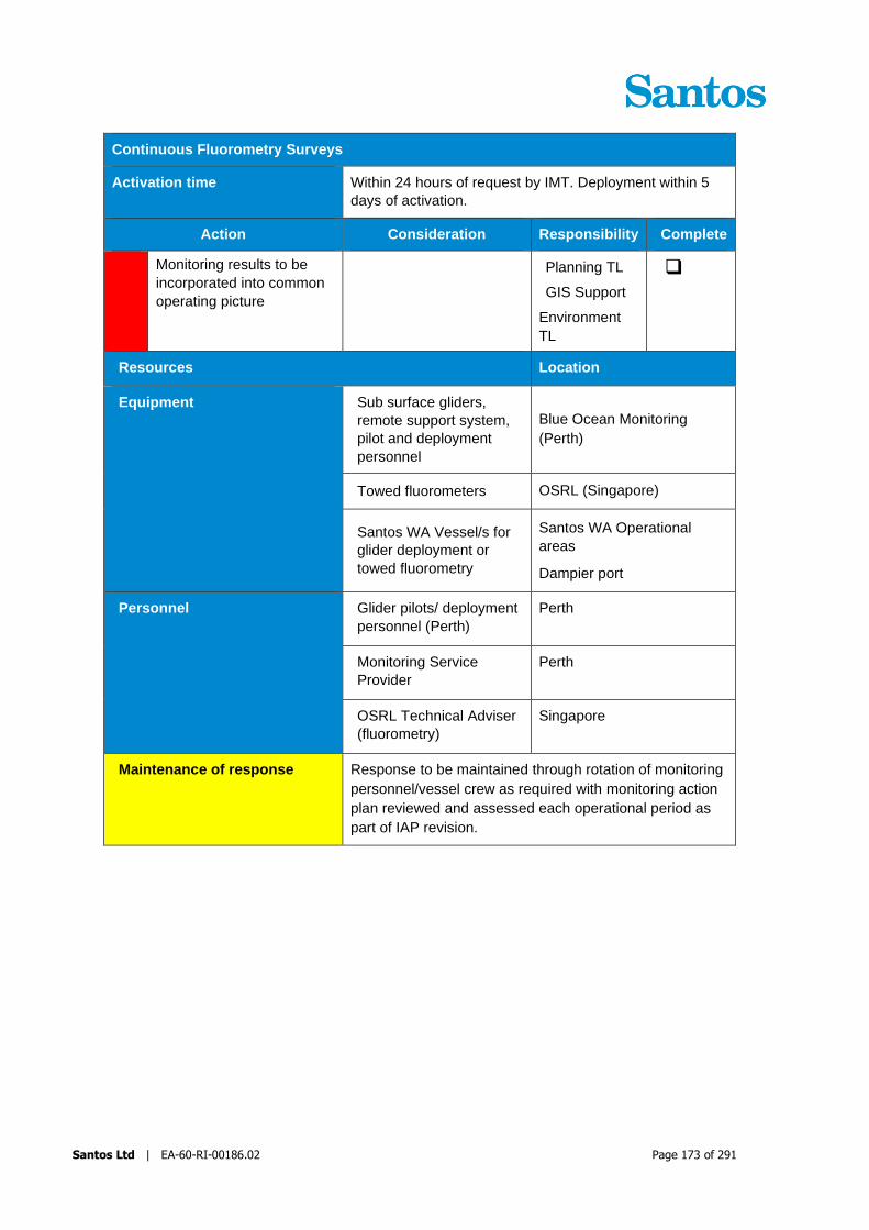
Santos Ltd | EA-60-RI-00186.02 Page 173 of 291
Continuous Fluorometry Surveys
Activation time Within 24 hours of request by IMT. Deployment within 5
days of activation.
Action Consideration Responsibility Complete
Monitoring results to be
incorporated into common
operating picture
Planning TL
GIS Support
Environment
TL
❑
Resources Location
Equipment Sub surface gliders,
remote support system,
pilot and deployment
personnel
Blue Ocean Monitoring
(Perth)
Towed fluorometers OSRL (Singapore)
Santos WA Vessel/s for
glider deployment or
towed fluorometry
Santos WA Operational
areas
Dampier port
Personnel Glider pilots/ deployment
personnel (Perth)
Perth
Monitoring Service
Provider
Perth
OSRL Technical Adviser
(fluorometry)
Singapore
Maintenance of response Response to be maintained through rotation of monitoring
personnel/vessel crew as required with monitoring action
plan reviewed and assessed each operational period as
part of IAP revision.

Santos Ltd | EA-60-RI-00186.02 Page 174 of 291
9.8 Low Flow Well Leak Monitoring
Table 9-18 provides the Environmental Performance Outcome, initiation criteria and termination criteria
for this activity.
Table 9-18: Low Flow Leak Monitoring - Environmental Performance Outcome, Initiation Criteria and
Termination Criteria
Low Flow Well Leak Monitoring
Environmental
Performance
Outcome
Implement monitor and evaluate tactics in order to provide situational
awareness to inform IMT decision making.
Initiation criteria Subsea inspection activities identify a low flow well leak.
Applicable
hydrocarbons
Condensate Crude oil Marine
Diesel
HFO
x x x
Termination
criterion
Operational monitoring will terminate when risk assessment indicates
negligible risk to the environment and well integrity risk assessment indicates
no risk of escalation.
The Varanus Island Hub Operations Environment Plan for Commonwealth Waters (John Brookes,
Greater East Spar and associated Facilities) (EA-66-RI-10003) and the Varanus Island Hub
Operations Environment Plan (State waters) outline the potential for a very low flow leak to occur from
plugged and abandoned wells in Commonwealth and State waters, respectively. While other worst
case oil spills are identified and reacted upon immediately due to their size, there is the potential for a
low flow subsea well leak (gas and/or liquid hydrocarbon) to go undetected until subsea inspection
activities (e.g. ROV surveys) identify the leak. These low flow leaks are not detectable by remote
subsea systems (e.g. pressure monitoring systems), or remote monitoring systems are not in place,
and may not be observable by visual surveillance at the water surface.
Where a subsea low flow well leak is detected through inspection activities the following will occur:
• A subsea operational monitoring survey (e.g. by ROV) will be undertaken to characterise the
volume and composition of hydrocarbon released.
• Where there is potential for liquid hydrocarbon to be released, water quality monitoring will
also occur at the release site to determine if detectable hydrocarbons in the water column.
• An environmental risk assessment will be undertaken, informed by survey results, which will
consider the following aspects of the leak:
o Rate of flow,
o Worst case length of time leak undetected and worst case volume released,
o composition of hydrocarbon,
o water quality monitoring results (as applicable),
o potentially impacted nearby environmental receptors
• An updated well integrity risk assessment will be carried out based on the outcomes of the
operational monitoring survey to assess the risk of escalation and establish appropriate action
to manage well integrity risk to ALARP.

Santos Ltd | EA-60-RI-00186.02 Page 175 of 291
• Pending the outcomes of the environmental risk assessment and updated well integrity risk
assessment, further operational monitoring will be repeated to characterise the change in
release rate (and change in water quality as applicable).
• The operational monitoring program and environmental assessment will be documented in an
incident action plan, updated to reflect ongoing survey planning and results.
Section 8.4 of the Varanus Island Hub Operations Environment Plan for Commonwealth Waters
(John Brookes, Greater East Spar and associated Facilities) (EA-66-RI-10003) outlines the
Environmental Performance Standard and Measurement Criteria for this activity.
The low flow leak environmental risk assessment and water quality monitoring results (as applicable)
will determine if initiation criteria for oil spill scientific monitoring as outlined within Section 17 have
been met. If initiation criteria have been met scientific monitoring as per the SMP will occur.

Santos Ltd | EA-60-RI-00186.02 Page 176 of 291
9.9 Shoreline and Coastal Habitat Assessment
To assist in determining which response methods are most appropriate for shorelines, it is necessary to
obtain information about shoreline character (topography, complexity, exposure etc.), degree and
distribution of oiling, if present, presence of sensitive receptors (habitats, fauna etc) and information on
shoreline processes and access routes that could aid or hamper response efforts. This detailed
information can be collected from on-ground assessments.
DoT are the designated Control Agency for shoreline response for all marine spills identified in this
OPEP and will direct resources provided through Santos WA for the purposes of on-ground shoreline
assessments and shoreline response activities. Santos WA will provide additional information on
shoreline character and oiling collected as part of aerial surveillance activities carried out under its
control (refer Section 9.2).
The information provided below is included for planning purposes and represents how Santos WA would
approach shoreline assessments. In the event of a spill with the potential for shoreline contact, the actual
survey objectives, methodology, deployment locations and resource allocation will be controlled by DoT,
as the Control Agency (with Santos WA acting as a Supporting Agency).
DoT provides guidance on shoreline assessments within their 2015 Oil Spill Contingency Plan.
The environmental performance outcome, initiation and termination criteria, the implementation guide
and the performance standards and measurement criteria for shoreline and coastal habitat assessment
are provided in Table 9-19, Table 9-20 and Table 9-22 respectively. This table also provides a list of
resources that may be used to implement this tactic. The On-Scene Commander and/or Incident
Commander is ultimately responsible for implementing the response, and may therefore determine that
some tasks be varied, should not be implemented or be reassigned.
Table 9-19: Shoreline and Coastal Habitat Assessment – Environmental Performance Outcome,
Initiation Criteria and Termination Criteria
Shoreline and Coastal Habitat Assessment
Environmental
Performance
Outcome
Implement monitor and evaluate tactics in order to provide situational
awareness to inform IMT decision making.
Initiation criteria Operational monitoring predicts or observes shoreline contact from surface
oil; or
As directed by DoT
Applicable
hydrocarbons
Condensate Crude oil Marine Diesel HFO
Termination
criterion
As directed by DoT

Santos Ltd | EA-60-RI-00186.02 Page 177 of 291
Table 9-20: Shoreline and Coastal Habitat Assessment Implementation Guide
Shoreline and Coastal Habitat Assessment
Activation time On initiation criteria
Action Consideration Responsibility Complete
Init
ial A
cti
on
s
Ensure initial notifications to
WA DoT have been
made
Refer to Section 6 for
reporting requirements
Environment
Team Leader ❑
Collect and provide spill
trajectory modelling,
other operational
monitoring data and
existing sensitivity
information/mapping to
Control Agency for
assistance in
identification of priority
protection areas and
NEBA.
Environment
Team Leader
Planning
Team Leader
❑
Actions below are indicative only and are at the final determination of DoT as the
Control Agency
Mobilising the AMOSC core
group responders.
Incident
Commander
Operations
Team Leader
Logistics
Team Leader
❑
Assessment of shoreline
character, habitats and
fauna.
Assessment includes:
+ shoreline structured biotic habitats
+ distribution of fauna
+ shoreline energy and processes (e.g. wave energy, tidal flows
+ shoreline substrate (e.g. mud, sand, pebble, rock)
shoreline form (e.g. width,
shape and gradient)
access/ safety constraints
AMOSC Core
group and
DOT
❑
1. Assessment of shoreline
oiling (if present).
Assessment includes:
+ surface distribution and cover
+ subsurface distribution
AMOSC Core
group and DOT ❑

Santos Ltd | EA-60-RI-00186.02 Page 178 of 291
Shoreline and Coastal Habitat Assessment
Activation time On initiation criteria
Action Consideration Responsibility Complete
+ oil type, thickness, concentration and physical character
sampling of oil for
laboratory analysis
Recommendations for
response strategies.
Considerations include:
+ applicable strategies based on oil type and habitat
+ potential access, safety and environmental constraints
likely resourcing (personnel
and equipment)
requirements
AMOSC Core
group and
DOT
❑
Resources Location
Equipment Santos WA contracted
vessels and vehicles as
required for shoreline
access.
Karratha, Exmouth etc
(dependent upon spill
trajectory).
Santos WA aerial
surveillance reports
Aerial surveillance monitor
and evaluate tactic
Personnel Shoreline clean-up
specialists and other
trained oil spill responders
Perth, WA
AMOSC Core Group Provided by AMOSC
DoT State Response
Team Provided by DoT
AMSA National Response
Team Provided by AMSA
Maintenance of response Santos maintains internal resources, and has contracts with
external service providers, by which shoreline and coastal
habitat assessment can be maintained for the duration of a
spill response. Assessment teams will be supported by
Santos’ existing logistics and supply arrangements (e.g.
vessel providers, freight etc.)
9.10 Operational Monitoring Data Collection and Frequency
Table 9-21 outlines details of operational monitoring data that will be collected. This includes details on
frequency of collection and reporting/data transfer back to the IMT. Operational monitoring informs

Santos Ltd | EA-60-RI-00186.02 Page 179 of 291
situational awareness, which feeds into the Incident Action Planning/NEBA process carried out for each
operational period. This is typically on a daily basis during the initial stages of incident response where
information is changing rapidly and response strategies are being initiated. Section 7 provides further
detail on how situational awareness information is used through the IAP process.

Santos WA Ltd | EA-60-RI-00186.02 Page 180 of 291
Table 9-21 Details of Operational Monitoring Data Collection and Transfer
Strategy Initiation Platform Data Provided Tools Field Personnel IMT Reporting
Contact Frequency
Vessel surveillance Within 90 minutes of spill Santos WA contracted
support vessels
Vessels of opportunity
Spill location
Weather conditions
Slick appearance
Marine fauna presence
Digital imagery
GPS
Vessel surveillance
forms
Bonn agreement code
Vessel crew
Company site
representative
Operations Team
Leader
Planning Team Leader
Collection: Minimum daily while
surveillance is undertaken
Reporting: minimum daily while
surveillance is undertaken
Aerial surveillance Initiated within 3 hours of
notification of Level 2/3 spill
Mobilisation at discretion of
On-scene Commander for
Level 1 spill
Santos WA contracted
helicopter provider
Spill location
Slick appearance
Marine fauna presence
Imagery and video
GPS
Aerial surveillance forms
and map templates
Bonn agreement code
Pilots
Trained Aerial Observers
Operations Team
Leader
Planning Team Leader
Deployment:
2 overpasses per day (am/pm) while
surveillance is undertaken
Reporting:
2 reports per day (am/pm) while
surveillance is undertaken
Tracking buoys Mobilisation within 2 hours of
notification of Level 2/3 spill
Mobilisation at discretion of
On-scene Commander for
Level 1 spill
Santos WA contracted
support vessel
Current direction/ spill front
movement
Satellite tracking buoys
Satellite tracking website
Vessel crew Operations Team
Leader
Planning Team Leader
Deployment:
As required – nominally up to 4 per day
Reporting: Position updates every 30
minutes
Spill trajectory
modelling
Level 2/3 spill
Mobilisation at discretion of
On-scene Commander for
Level 1 spill
N/A – office based Spill trajectory predictions
Oil weathering predictions
Shoreline loading
predictions
Trajectory modelling
request form
Modelling provider data
portal
N/A – office based Environment Team
Leader
Planning Team Leader
Reporting: minimum daily updates
Trajectory modelling to be provided
within 2 hours of initial request.
Satellite imagery Level 2/3 spill
Satellites Spill size and location Satellite imagery data
portal
N/A – office based Environmental Team
Leader
Planning Team Leader
Reporting:
Subject to satellite overflight schedule
Initial oil
characterisation
Level 2/3 spill
Mobilisation at discretion of
On-scene Commander for
Level 1 spill
Vessels of opportunity
Santos WA contracted
vessels
Oil physical and chemical
characteristics
Oil ecotoxicity
Digital imagery
GPS
Oil sampling equipment
Ecotoxicology and oil
analysis laboratories
Monitoring provider
Vessel crew
Operations Team
Leader
Planning Team Leader
Environment Team
Leader
Oil collection:
Daily for 14 days if possible (physical
and chemical characteristics)
Field reports:
Daily
Lab reporting:
As results available
Operational water
sampling and
analysis
Initiated on Level 2/3 spill
Mobilisation within 72 hours of
accepted SoW
Mobilisation at discretion of
On-scene Commander for
Level 1 spill
Santos WA contracted
vessels
Water quality samples
(surface and at depth) – oil
detection and related
parameters
Real-time CTD readings - oil
detection and related
parameters
Water sampling
equipment
CTDs
GPS
WQ analysis laboratories
Monitoring provider
Vessel crew
Operations Team
Leader
Planning Team Leader
Environment Team
Leader
Sampling:
Daily
Field reports:
Daily
Lab reporting:
As results available
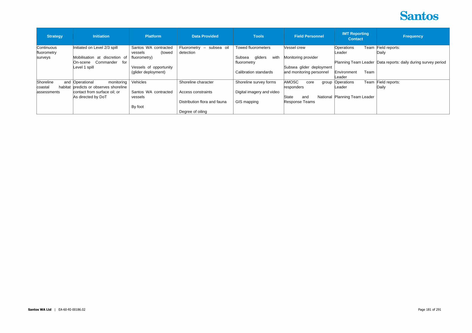
Santos WA Ltd | EA-60-RI-00186.02 Page 181 of 291
Strategy Initiation Platform Data Provided Tools Field Personnel IMT Reporting
Contact Frequency
Continuous
fluorometry
surveys
Initiated on Level 2/3 spill
Mobilisation at discretion of
On-scene Commander for
Level 1 spill
Santos WA contracted
vessels (towed
fluorometry)
Vessels of opportunity
(glider deployment)
Fluorometry – subsea oil
detection
Towed fluorometers
Subsea gliders with
fluorometry
Calibration standards
Vessel crew
Monitoring provider
Subsea glider deployment
and monitoring personnel
Operations Team
Leader
Planning Team Leader
Environment Team
Leader
Field reports:
Daily
Data reports: daily during survey period
Shoreline and
coastal habitat
assessments
Operational monitoring
predicts or observes shoreline
contact from surface oil; or
As directed by DoT
Vehicles
Santos WA contracted
vessels
By foot
Shoreline character
Access constraints
Distribution flora and fauna
Degree of oiling
Shoreline survey forms
Digital imagery and video
GIS mapping
AMOSC core group
responders
State and National
Response Teams
Operations Team
Leader
Planning Team Leader
Field reports:
Daily

Santos Ltd | EA-60-RI-00186.02 Page 182 of 291
9.11 Monitor and Evaluate Plan Environmental Performance
Table 9-22 indicates the Environmental performance outcomes, controls and performance standards for the
Monitor and Evaluate response strategy.
Table 9-22: Monitor and Evaluate Performance Standards and Measurement Criteria
Environmental
Performance
Outcome
Implement monitor and evaluate tactics in order to provide situational
awareness to inform IMT decision making.
Response Strategy Control Measures Performance
Standards
Measurement
Criteria
Monitor and Evaluate Surveillance Response Preparedness
Maintenance of MSAs
with multiple vessel
providers
Santos WA maintains
MSAs with multiple
vessel providers
MSAs with multiple
vessel providers
MSA with aircraft supplier Master Services
Agreement (MSA) in
place with helicopter
provider throughout
activity
MSA with aircraft
suppliers
Santos WA trained Aerial
Observers
Santos WA maintains
a pool of trained aerial
observers
Exercise Records
Training Records
AMOSC contract to
facilitate mutual aid
arrangements for access
to Trained Aerial
Observers
Maintenance of
AMOSC contract to
facilitate mutual aid
arrangements for
access to Trained
Aerial Observers
AMOSC Participating
Member Contract
Access to certified
Unmanned Aerial
Vehicles (UAV) providers
Maintenance of
contract for access to
UAV providers
Maintenance of
contract with service
provider
Surveillance Response Implementation
Vessel Surveillance Vessel Surveillance
strategy initiated within
90 minutes following
request from IMT (i.e.
begin to source
vessels for
surveillance)
Incident log
Daily observation
reports submitted to
IMT until termination
criteria is met
Incident log

Santos Ltd | EA-60-RI-00186.02 Page 183 of 291
Environmental
Performance
Outcome
Implement monitor and evaluate tactics in order to provide situational
awareness to inform IMT decision making.
Response Strategy Control Measures Performance
Standards
Measurement
Criteria
Aerial Surveillance Aerial Surveillance
initiated within 3 hours
following request from
IMT
Incident log
Following initiation two
passes per day of spill
area by observation
aircraft provided
Incident log
Trained Aerial
Observers supplied
from Day 2 of
response
Incident log
Flight schedules are
maintained throughout
response
Incident Action Plan
Observers completed
aerial surveillance
observer log following
completion of flight
Aerial Observer Logs
Aerial surveillance
continues until
termination criteria are
met
Incident log
Tracking Buoys Response Preparedness
Tracking Buoys available
Maintenance of 12
tracker buoys
throughout the activity
Computer tracking
software
Tracker buoy tests
Response Implementation
Tracking buoys
mobilisation within 2
hours of request from
On-Scene Commander
or Operations Team
Leader
Incident log
Tracking buoys utilised
until termination criteria
met
Incident log
Oil Spill Modelling Response Preparedness

Santos Ltd | EA-60-RI-00186.02 Page 184 of 291
Environmental
Performance
Outcome
Implement monitor and evaluate tactics in order to provide situational
awareness to inform IMT decision making.
Response Strategy Control Measures Performance
Standards
Measurement
Criteria
Maintenance of contract
for emergency response
modelling
Maintenance of
contract for forecast
spill trajectory
modelling services
throughout activity
Modelling services
contract
Oil Spill Modelling Response Implementation
Oil Spill Modelling
available
Oil Spill Modelling
provider will be
contacted immediately
(within 2 hours) upon
notification of a Level 2
or 3 spill
Incident Log
Modelling delivered to
IMT within 2 hours of
request to service
provider
Incident Log
Modelling continues
until termination criteria
are met
Incident Log
Satellite Imagery Response Preparedness
Satellite imagery available Contract in place with
third party provider to
enable access and
analysis of satellite
imagery
Contract with service
provider
Satellite Imagery Response Implementation
Satellite imagery available Data incorporated into
common operating
picture and provided to
spill modelling provider
Incident Log and
Incident Action Plan
Oil and Oil in Water
Monitoring
Response Preparedness
Maintenance of
Monitoring Service
Provider contract for water
quality monitoring
services
Maintain access to
specialist monitoring
personnel and
equipment by
maintaining contract
with Monitoring Service
Provider throughout
activity
Contract with
monitoring service
provider

Santos Ltd | EA-60-RI-00186.02 Page 185 of 291
Environmental
Performance
Outcome
Implement monitor and evaluate tactics in order to provide situational
awareness to inform IMT decision making.
Response Strategy Control Measures Performance
Standards
Measurement
Criteria
Capability reports from
Monitoring Service
Provider
Obtain monthly
capability reports from
Monitoring Service
Provider
Capability reports
Entrained oil monitoring
equipment and services
Maintenance of
arrangements to
enable access to
fluorometry services
throughout activity
Arrangement with
provider of fluorometry
equipment
Oil and Oil in Water
Monitoring
Response Implementation
Initial Oil Characterisation Oil samples sent to
laboratory for initial
fingerprinting
Incident Log
Oil samples to be sent
immediately for
laboratory ecotoxicity
testing of oil
Incident Log
90, 95 and 99%
Species protection
triggers levels will be
derived from
ecotoxicity testing
results (minimum 5
species’ tests) within
24 hours of receiving
all results
Incident Log
Operational Oil and Oil in
Water Monitoring
Identify if water quality
monitoring is required
within 2 hours of
receiving spill and
receptor information
Incident Log
Operational water
sampling and analysis
surveys mobilised
within 72 hours of
approval
Incident Log
Fluorometry surveys
mobilised within 5 days
of initiation
Incident Log
Daily report including
fluorometry results
provided to IMT
Incident Log

Santos Ltd | EA-60-RI-00186.02 Page 186 of 291
Environmental
Performance
Outcome
Implement monitor and evaluate tactics in order to provide situational
awareness to inform IMT decision making.
Response Strategy Control Measures Performance
Standards
Measurement
Criteria
Shoreline Assessment Response Preparedness
AMOSC contract to
facilitate mutual aid
arrangements for access
to Oil Spill Responders
Maintenance of
AMOSC contract to
facilitate mutual aid
arrangements for
access to Oil Spill
Responders
AMOSC Participating
Member Contract
Shoreline Assessment Response Implementation
Shoreline assessment
Shoreline Assessment
strategies will be
implemented under the
direction of DoT as the
HMA
Incident Log
Santos WA will make
available AMOSC Core
Group Responders for
shoreline and coastal
habitat assessment
positions to the Control
Agency
Incident Log
Shoreline assessment
reports provided to the
IMT daily detailing the
assessed areas to
maximise effective
utilisation of resources
Incident Log
Use of shallow draft
vessels for shoreline and
nearshore operations
Shallow draft vessels
are used for shoreline
and nearshore
operations unless
directed otherwise by
the designated Control
Agency (i.e. DoT).
Vessel specification
documentation
contained in IAP.
OSR Team Leader
assessment/selection of
vehicle appropriate to
shoreline conditions
OSR Team Leader
assess/select vehicles
appropriate to
shoreline conditions
IAP demonstrates
requirement is met
Conduct
shoreline/nearshore
habitat/bathymetry
assessment
Unless directed
otherwise by the
designated Control
Agency (i.e. DoT) a
shoreline/ nearshore
habitat/ bathymetry
IAP records
assessment records

Santos Ltd | EA-60-RI-00186.02 Page 187 of 291
Environmental
Performance
Outcome
Implement monitor and evaluate tactics in order to provide situational
awareness to inform IMT decision making.
Response Strategy Control Measures Performance
Standards
Measurement
Criteria
assessment is
conducted prior to
nearshore activities.
Establish demarcation
zones for vehicle and
personnel movement
considering sensitive
vegetation, bird
nesting/roosting areas
and turtle nesting habitat.
Unless directed
otherwise by the
designated Control
Agency (i.e. DoT)
demarcation zones are
mapped out in
sensitive habitat areas.
IAP demonstrates
requirement is met.
Operational restriction of
vehicle and personnel
movement to limit erosion
and compaction
Unless directed
otherwise by the
designated Control
Agency (i.e. DoT)
action plans for
shoreline operations
include operational
restrictions on vehicle
and personnel
movement
IAP demonstrates
requirement is met.

Santos Ltd | EA-60-RI-00186.02 Page 188 of 291
10 Mechanical Dispersion Plan
In the event of thin oil sheens resulting from a marine diesel or crude spill following weathering, vessel based
mechanical dispersion can be used to assist with the natural dispersion process, encouraging localised areas
of an oil slick to mix and suspend within the water column where it can be more easily biodegraded. This is
especially beneficial if patches of floating oil are in close proximity to sensitivities at risk from floating oil (e.g.
birdlife, mangrove habitat). To do this vessels are deployed to implement mechanical dispersion by way ‘prop
washing’ through the slick. As with other vessel based techniques the health and safety risks of potential gas
and Volatile Organic Compounds (VOCs) exposure must be considered and gas monitoring should occur prior
to commencing.
Assessment for the applicability of mechanical dispersion will continue throughout the spill response, and
utilised when weather and sea conditions are not conducive to natural dispersion of thin oil sheens, and wildlife
are under threat.
The environmental performance outcome , initiation and termination criteria and the performance standards
and measurement criteria for mechanical dispersion are provided in Table 10-1, and Table 10-3 respectively.
Table 10-2 provides guidance to the IMT on the actions and responsibilities that should be considered when
selecting this tactic. This table also provides a list of resources that may be used to implement this tactic. The
On-Scene Commander and/or Incident Commander is ultimately responsible for implementing the response,
and may therefore determine that some tasks be varied, should not be implemented or be reassigned.
Table 10-1: Mechanical Dispersion – Environmental Performance Outcome, Initiation Criteria and
Termination Criteria
Mechanical Dispersion
Environmental
Performance
Outcome
Implement mechanical dispersion to reduce the concentration of surface
hydrocarbons to reduce contact with protection priorities.
Initiation criteria Monitoring by the IMT identifies thin oil patches at sea surface that are not
naturally dissipating in sea surface and is posing risks to wildlife and shorelines by
remaining on the surface. Assessment by the IMT indicates the oil is thin enough
on the surface of the water to be dispersible using vessel prop-washing
techniques
Applicable
hydrocarbons
Condensate Crude oil Marine Diesel HFO
X
Termination
criterion There is no further environmental benefit or observed effectiveness in dispersing
floating oil underwater through mechanical dispersion; or as directed by the
relevant Control Agency.
NB: Mechanical dispersion will terminate if there are unacceptable safety risks
associated with gas and VOCs at the sea surface.

Santos Ltd | EA-60-RI-00186.02 Page 189 of 291
Table 10-2: Mechanical Dispersion Implementation Guide
Mechanical Dispersion
Activation time As directed by the IMT.
Action Consideration Responsibility Complete
Init
ial A
cti
on
s
The Operational NEBA will
confirm the suitability and
environmental benefit of
conducting mechanical
dispersion at appropriate
locations.
water depth, sea state,
possible impacts to sensitive
shorelines and/or wildlife
before spill naturally
disperses
Operations Team Leader
Environment Team Leader
Planning Team
Leader
❑
Safety team lead to develop
a safety plan for the activity
with respect to dangerous
gasses and VOC’s (including
applicable controls).
Operations Team Leader
Safety Team
Leader
❑
Notify Vessel Master of
nearest available Support
Vessel to commence
mechanical dispersion
Operations Team
Leader ❑
Response personnel on
vessels to evaluate the
effectiveness of the use of
mechanical dispersion
operations to reduce the
volume of oil on the water
surface. Communicate the
information to the IMT
Operations Team Leader for
inclusion in the Operational
NEBA.
Vessel Master/s
Santos WA
AMOSC Core
Group
Responders
❑
Source additional contracted
vessels if possible need for
assistance.
Operations Team Leader
Logistics Team
Leader
❑
Resources Location
Equipment Deployment vessels
Vessel availability accessed
through Santos WA
Emergency Response
Intranet Site
Santos WA Operational sites
Personnel Santos WA Facility
Incident Response Team
members
Santos WA Operational sites
(including Devil Creek and
Varanus Island)

Santos Ltd | EA-60-RI-00186.02 Page 190 of 291
Mechanical Dispersion
Activation time As directed by the IMT.
Action Consideration Responsibility Complete
Santos WA AMOSC Core
Group Responders
Vessel Personnel With Vessel
Maintenance of response Santos WA has access to vessel service providers by which this
response strategy can be maintained. Vessel availability may be
restricted by other needs (e.g. implementing more effective
response tactics).
10.1 Mechanical Dispersion Environmental Performance
Table 10-3 indicates the Environmental performance outcomes, controls and performance standards for the
Mechanical Dispersion response strategy.
Table 10-3: Mechanical Dispersion – Environmental Performance
Environmental
Performance
Outcome
To create mixing for oil and water to enhance natural dispersion
Response
Strategy
Control
Measures Performance Standards
Measurement
Criteria
Response implementation
Mechanical
Dispersion
Mechanical
Dispersion
Plan
Safety Plan
Operational
NEBA
Mechanical dispersion is to be
conducted during daylight only, once
the safety plan has been developed
and Operational NEBA confirms
suitability and environmental benefit
Incident Log
IAP

Santos Ltd | EA-60-RI-00186.02 Page 191 of 291
11 Offshore Containment and Recovery Plan
Offshore containment and recovery involves the use of offshore containment boom and skimmers deployed
from response vessels (typically two per operation). The effectiveness of this response will be dependent on
spill characteristics, hydrocarbon type, and the operating environment (Table 11-1). This strategy is considered
applicable for HFO spills from offtake tankers undergoing berthing operations at the Varanus Island Terminal
in State waters and crude oil spills and may be applicable for crude oil release in State waters at the platform,
export pipeline or during an offtake tanker release due to vessel collision/vessel grounding. It is not considered
applicable for Commonwealth water spills due to the properties of hydrocarbons potentially spilled in these
waters (condensate and marine diesel). On this basis offshore containment and recovery is considered
primarily a State waters activity with DoT as the relevant Control Agency. Santos WA as a Supporting Agency
will provide first strike response and then all necessary resources (equipment and personnel) to support DoT.
Table 11-1: Criteria for the Use of Booms and Skimmers
Criteria Recommended Not Recommended
Spill characteristics Patchy slick
Fresh or emulsified
Extended operations
Surface concentrations >50 g/m2 min,
100 g/m2 optimal.
Situation dependent
Surface thickness <50 g/m2
Hydrocarbon type Group 3 hydrocarbons and above
Persistent components of Group 1 and
2 hydrocarbons may be suitable
Minor to moderate spills of Group 1
and 2 hydrocarbons are likely to
weather rapidly. High volatiles of these
hydrocarbons may be a safety risk to
personnel
Operating environment Waves <1m for nearshore containment
and recovery systems
Waves <1.8m for offshore systems
Winds <25 knots
Wave heights exceed 1.8m
Current >0.75 knots
The environmental performance outcomes, initiation and termination criteria, implementations actions and the
performance standards and measurement criteria for Containment and Recovery are provided in Table 11-2,
Table 11-3 and Table 11-4 respectively. The On-Scene Commander and/or Incident Commander is ultimately
responsible for implementing the response, and may therefore determine that some tasks be varied, should
not be implemented or be reassigned.

Santos Ltd | EA-60-RI-00186.02 Page 192 of 291
Table 11-2: Offshore Containment and Recovery – Environmental Performance Outcome, Initiation
Criteria and Termination Criteria
Offshore Containment and Recovery
Environmental
Performance
Outcome
Implement containment and recovery tactics to reduce the volume of surface
hydrocarbons to reduce contact with protection priorities
Initiation criteria Notification of a Level 2/3 spill
Applicable
hydrocarbons
Condensate Crude oil Marine Diesel HFO
X X
Termination
criterion IMT assess that greater than 1 m3/day / vessel operation of oil cannot be
collected; OR
NEBA is no longer being achieved; and
Agreement is reached with Jurisdictional Authorities to terminate the response
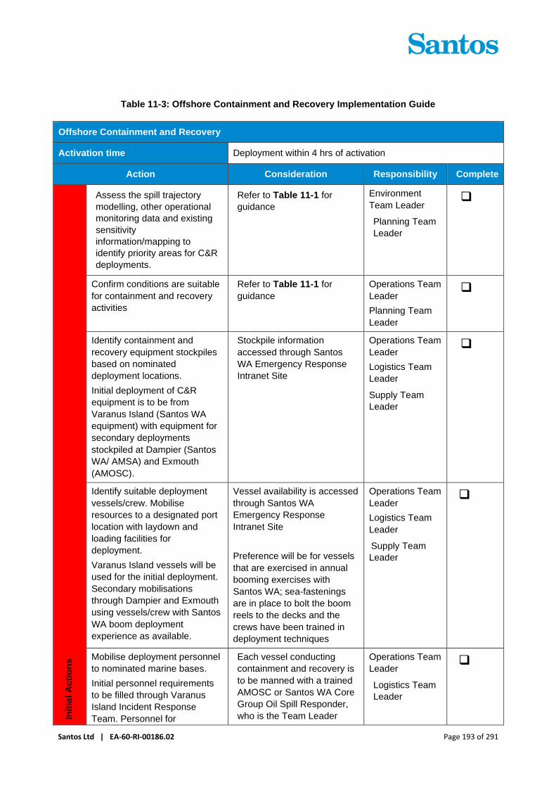
Santos Ltd | EA-60-RI-00186.02 Page 193 of 291
Table 11-3: Offshore Containment and Recovery Implementation Guide
Offshore Containment and Recovery
Activation time Deployment within 4 hrs of activation
Action Consideration Responsibility Complete
Init
ial A
cti
on
s
Assess the spill trajectory
modelling, other operational
monitoring data and existing
sensitivity
information/mapping to
identify priority areas for C&R
deployments.
Refer to Table 11-1 for
guidance
Environment
Team Leader
Planning Team
Leader
❑
Confirm conditions are suitable
for containment and recovery
activities
Refer to Table 11-1 for
guidance
Operations Team
Leader
Planning Team
Leader
❑
Identify containment and
recovery equipment stockpiles
based on nominated
deployment locations.
Initial deployment of C&R
equipment is to be from
Varanus Island (Santos WA
equipment) with equipment for
secondary deployments
stockpiled at Dampier (Santos
WA/ AMSA) and Exmouth
(AMOSC).
Stockpile information
accessed through Santos
WA Emergency Response
Intranet Site
Operations Team
Leader
Logistics Team
Leader
Supply Team
Leader
❑
Identify suitable deployment
vessels/crew. Mobilise
resources to a designated port
location with laydown and
loading facilities for
deployment.
Varanus Island vessels will be
used for the initial deployment.
Secondary mobilisations
through Dampier and Exmouth
using vessels/crew with Santos
WA boom deployment
experience as available.
Vessel availability is accessed
through Santos WA
Emergency Response
Intranet Site
Preference will be for vessels
that are exercised in annual
booming exercises with
Santos WA; sea-fastenings
are in place to bolt the boom
reels to the decks and the
crews have been trained in
deployment techniques
Operations Team
Leader
Logistics Team
Leader
Supply Team
Leader
❑
Mobilise deployment personnel
to nominated marine bases.
Initial personnel requirements
to be filled through Varanus
Island Incident Response
Team. Personnel for
Each vessel conducting
containment and recovery is
to be manned with a trained
AMOSC or Santos WA Core
Group Oil Spill Responder,
who is the Team Leader
Operations Team
Leader
Logistics Team
Leader
❑

Santos Ltd | EA-60-RI-00186.02 Page 194 of 291
Offshore Containment and Recovery
Activation time Deployment within 4 hrs of activation
Action Consideration Responsibility Complete
Dampier/Exmouth deployments
to be initially provided by
Santos WA trained crew and
onsite logistics personnel.
tasked with controlling the
operations and implementing
in a safe and responsible
method.
The Team Leader has the
responsibility of evaluating
the effectiveness of the
containment and recovery
operations and
communicating the
information to the IMT
Operations Team Leader
Coordinate aerial surveillance
support to vessels to ensure
they are being directed to
priority locations for
containment and recovery
activities within operational
zones
Focus on contain and
recover activities to areas of
slick that threaten priority
receptors and are of a
sufficient thickness whereby
contain and recover activities
will be effective
Planning Team
Leader
Operations
Team Leader
Environment
Team Leader
❑
Direct containment and
recovery operations to
designated operational zones
Operations Team
Leader ❑
Seek approval from DoT and
AMSA for decanting oily water.
Operations Team
Leader ❑
Inform Waste service provider
of predicted volumes and
collection points from Offshore
Containment and Recovery
operations. Refer to Waste
Management Plan (Section 16)
Operations Team
Leader ❑
Resources Location
Equipment Offshore boom - inflatable and
self-inflating
Skimmers
Waste oil containers
Pumps, hoses, tow bridles
and other ancillary equipment
supporting the above.
Stockpiles of the above
equipment accessed through
Santos WA Emergency
Response Intranet Site
Santos WA stockpiles
(Dampier, Varanus Island,
Exmouth) – first strike
deployment from Varanus
Island
AMSA National Stockpiles –
first strike deployment from
Dampier
AMOSC Stockpiles
(Exmouth/Fremantle/Geelong)
– initial deployment from
Exmouth

Santos Ltd | EA-60-RI-00186.02 Page 195 of 291
Offshore Containment and Recovery
Activation time Deployment within 4 hrs of activation
Action Consideration Responsibility Complete
DoT State Stockpiles
Industry Mutual Aid (Barrow
Island, Onslow, Dampier)
OSRL (Singapore)
Deployment vessels.
Vessel availability accessed
through Santos WA
Emergency Response
Intranet Site
Santos WA Operational sites
(Dampier, Exmouth, Varanus
Island) – first strike
deployments from Varanus
Island and Dampier
AMOSC Stockpiles
(Exmouth/Fremantle/Geelong)
– initial deployment from
Exmouth
Personnel Santos WA Facility IRT
members
Santos WA AMOSC Core
Group Responders
Santos WA Operational sites –
first strike from Varanus Island
Santos WA Trained Vessel
Deployment personnel –
vessel crew and
Dampier/Exmouth based
logistics personnel
Dampier and Exmouth
Industry AMOSC Core Group
Responders Mobilised through AMOSC
National Response Team
(NRT) Mobilised through AMSA
State Response Team (SRT) Mobilised through DoT
Additional Field Personnel as
required (Santos WA Labour
Hire)
Mobilised through Santos WA
labour hire arrangements
Maintenance of response Offshore containment and recovery is considered applicable for
HFO and crude oil spills in State waters and therefore ongoing
response to be directed by DoT as the relevant Control Agency.
Santos WA will provide all necessary equipment and personnel
to assist with the response under direction from DoT.
Response crews will be rotated on a roster basis from
nominated marine bases, with new personnel procured on an
as-need basis.

Santos Ltd | EA-60-RI-00186.02 Page 196 of 291
Offshore Containment and Recovery
Activation time Deployment within 4 hrs of activation
Action Consideration Responsibility Complete
Equipment will be maintained and replaced if necessary through
existing stockpiles.
11.1 Equipment and Personnel
Offshore containment and recovery equipment available for use by Santos WA is a combination of Santos WA
owned, AMOSC, AMSA, DoT and OSRL equipment as well as other operator resources available through the
AMOSPlan mutual aid arrangements.
Offshore containment and recovery personnel available to Santos WA are a combination of Santos WA Facility
Incident Response Team (IRT) members, AMOSC Core Group Responders (comprising AMOSC trained
Santos WA and Industry personnel), Santos WA trained vessel crew and logistics personnel, State Response
Team members and National Response Team members.
Deployment of equipment and personnel will be commensurate to the severity of the spill and timing/ location
of potential shoreline impact.
First-strike deployment of containment and recovery equipment for an offtake tanker release of HFO is to be
from Varanus Island using vessels, offshore boom and oil skimmer available onsite. Personnel to be provided
through the Varanus Island IRT and onsite vessel crew. Regular boom deployment exercise are run from
Varanus Island which provides training for IRT and vessel crew members and tests the functionality of the
equipment. Deployment of offshore boom can be achieved within 4 hours from activation.
Secondary deployment of offshore boom would most likely be from Dampier, using Santos WA and AMSA
offshore booms and skimming equipment stockpiled in Dampier. Santos WA contracted vessel provider will
be used preferentially for vessel deployments out of Dampier. Regular boom deployment exercise are run from
Dampier which provides training for vessel crew members and Dampier based logistics personnel and tests
the functionality of Santos WA equipment stockpiled in Dampier. Offshore boom and skimming equipment can
be loaded and ready for deployment within 4 hours from activation.
Further deployments as required, would be provided from Dampier and Exmouth using Santos WA, AMOSC
and AMSA equipment, Santos WA contracted vessel providers and personnel from Santos WA IRTs, AMOSC
Core Group and State/National Response Teams.
As a backup to AMOSC stockpiles, significant quantities of offshore boom are available through OSRL out of
Singapore.
11.2 Deployment Locations
Santos WA will direct first strike deployments of offshore containment and recovery resources, as required
based on spill trajectory mapping and operational monitoring. DoT will assume control of the response as the
relevant Control Agency for State waters response activities and will direct deployment following hand-over of
control.
During a spill response, offshore boom deployment locations will be based on predicted trajectories and the
relative locations of shoreline sensitivities. Information sources include:
+ Santos WA GIS Mapping;
+ DoT Oil Spill Response Atlas (OSRA) Web Map Application (WMA);
+ Pilbara Region Oiled Wildlife Response Plan; and

Santos Ltd | EA-60-RI-00186.02 Page 197 of 291
+ Aerial Surveillance and Shoreline Assessment records where available.
Stochastic spill modelling already undertaken for worst-case spill scenarios has been assessed for shoreline
receptor contact at floating oil thresholds and shoreline accumulation. Results show that oil from a worst case
HFO spill the shorelines of Barrow, Lowendal and Montebello islands have the highest likelihood of shoreline
contact (19.5-49.5% for a concentration >100 g/m2) and have the shortest minimum contact times (2-12 hours),
noting that predicted contact is from separate modelled simulations. These islands were also shown to have
the highest potential loading volumes (1183-1480 m3). All other coastal areas were shown by modelling to
have lower probabilities of HFO contact (<4% at >100 g/m2), longer contact times (>127 hours at >100 g/m2)
and lower maximum loading volumes (<854 m3).
Based on the spill modelling work undertaken, deployment of containment and recovery equipment should
initially focus on waters adjacent to the Lowendal, Barrow and Montebello islands.
In all areas, the primary shoreline protection priorities are mangrove environments and shorelines identified as
important for turtle nesting and hatching and shorebird/seabird nesting, roosting or foraging. Key areas for
these shoreline sensitivities are outlined in Section 3.5.
11.3 Decanting
Decanting is an important tool needed to make efficient use of waste management resources which are often
a limiting factor in contain and recover.
The reduction of overall waste in some circumstances can create an environmental benefit which outweighs
the minimal impact caused by the release of water with very low concentrations of oil.
The POWBONS Act; s. 8 allows for decanting for combating specific pollution incidents. Additionally, Annex
1 of MARPOL (Regulation 9) allows for decanting for combating specific pollution events to minimise the
damage from pollution. Under both MARPOL and POWBONS decanting must be approved by the relevant
Jurisdictional Authority. In WA State waters this is DoT (as the Hazard Management Agency under the
Emergency Management Act 2005) and in Commonwealth waters this is the Australian Maritime Safety
Authority (AMSA).
11.4 Offshore Containment and Recovery Environmental Performance
Table 11-4 indicates the Environmental performance outcomes, controls and performance standards for the
Offshore Containment and Recovery response strategy.

Santos Ltd | EA-60-RI-00186.02 Page 198 of 291
Table 11-4: Offshore Containment and Recovery – Environmental Performance
Environmental
Performance
Outcome
Implement containment and recovery tactics to reduce the volume of surface
hydrocarbons to reduce contact with protection priorities
Response
Strategy
Control
Measures Performance Standards
Measurement
Criteria
Offshore
Containment
and Recovery
Response Preparedness
Access to
containment and
recovery
equipment and
personnel
through
AMOSC, AMSA
National Plan
and OSRL
Maintenance of access to containment
and recovery equipment and personnel
through AMOSC, AMSA National Plan
and OSRL throughout activity
MoU for access
to National Plan
resources
through AMSA
AMOSC
Participating
Member Contract
OSRL Associate
Member Contract
Varanus Island
Incident
Response
Teams and
protection &
deflection
equipment
Santos WA will maintain the capability to
deploy first strike protection and
deflection resources within the first 24
hours of a spill notification.
VI oil spill
response
exercise records
Response Implementation
Competent
Personnel
Containment and recovery shall only be
undertaken under the supervision of a
AMOSC Core Group member
Incident Log
Decanting Decanting shall only be undertaken
following approval from DoT and/or
AMSA.
Incident Log
Spill response
activities
selected on
basis of a Net
Environmental
Benefit Analysis
(NEBA)
Prepare operational NEBA to determine if
containment and recovery is likely to
result in a net environmental benefit Incident Log
NEBA undertaken each operational
period by the relevant Control Agency to
determine if response strategy is
continuing to have a net environmental
benefit. NEBA included in development of
following period Incident Action Plan
IAP/Incident Log

Santos Ltd | EA-60-RI-00186.02 Page 199 of 291
12 Shoreline Protection Plan
Booms can be used to create physical barriers on the water surface to protect sensitive receptors in intertidal
and nearshore environments with the intent of taking the oil plume off its trajectory path. Booms can also be
used to deflect the oil spill to locations easier for shoreline clean-up, for example moving oil from rocky
shorelines to sandy shorelines.
The effectiveness of this response will be dependent on spill characteristics, hydrocarbon type, and the
operating environment and is recommended for slicks greater than 100 g/m2. Deployment is subject to safety
constraints such as the potential grounding of vessels.
Protection and deflection is part of an integrated nearshore/ shoreline response to be controlled by DoT as the
relevant Control Agency. Santos WA will undertake first-strike protection and deflection activities as required.
Upon assumption of Control Agency responsibilities, DoT will direct resources (equipment and personnel)
provided by Santos WA for the purposes of shoreline protection. Santos WA will provide all relevant information
on shoreline character and oiling collected as part of surveillance activities carried out under its control (refer
Section 9).
The information provided below is included for planning purposes and represents Santos WA’s first-strike
response for protection and deflection activities. In the event of a spill with the potential for shoreline contact,
the ongoing response objectives, methodology, deployment locations and resource allocation will be controlled
by DoT, as the Control Agency and therefore may differ from that included below.
Table 12-1, Table 12-2 and Table 12-3 provide the environmental performance outcome, initiation criteria and
termination criteria, implementation actions and performance standards, measurement criteria for this strategy.
The On-Scene Commander and/or Incident Commander are ultimately responsible for implementing the
response, and may therefore determine that some tasks be varied, should not be implemented or be
reassigned.
Table 12-1: Shoreline Protection – Environmental Performance Outcome, Initiation Criteria and
Termination Criteria
Shoreline Protection
Environmental
Performance
Outcome
Implement shoreline protection and deflection tactics to reduce hydrocarbon
contact with coastal protection priorities.
Initiation criteria Monitor and evaluate activities predict potential contact from surface oil to key
sensitive receptors ; or
As directed by DoT
Applicable
hydrocarbons
Condensate Crude oil Marine Diesel HFO
Termination
criterion Oil no longer posing a risk to sensitive receptors; or
Booming operations are no longer effective; or
As directed by DoT
Information gathered during operational monitoring including shoreline assessments and assessed through
an Operational NEBA will guide the selection of protection and deflection locations and techniques.
Shoreline protection and deflection techniques include:

Santos Ltd | EA-60-RI-00186.02 Page 200 of 291
+ The utilisation of earthen booming and sandbags where needed to prevent ingress of oil into tidal
creeks;
+ Nearshore booming using vessel-based operations while the spill remains on a predicted shoreline
impact trajectory; and
+ Placement of shoreline boom around areas to protect and to deflect the oil back to ocean or to easier
locations for shoreline clean-up.
The effectiveness of these techniques will be dependent on local bathymetry, sea state, current and wind
conditions. The shoreline protection plan activation process is provided in Table 12-2 below.

Santos Ltd | EA-60-RI-00186.02 Page 201 of 291
Table 12-2: Shoreline Protection Implementation Guide
Shoreline Protection
Activation time Where monitor and evaluate activities predict potential contact to
key sensitive receptors as risk from surface oil; or
As directed by DoT
Action Consideration Responsibility Complete
Init
ial A
cti
on
s
Ensure initial notifications
to WA DoT have been
made
Refer to Section 6 for
reporting requirements
Environment Team
Leader ❑
Collect and provide spill
trajectory modelling, other
operational monitoring
data and existing
sensitivity
information/mapping to
Control Agency for
assistance in identification
of priority protection areas
and NEBA.
Environment Team
Leader
Planning Team
Leader
❑
Actions below are indicative only and are at the final determination of DoT as the Control
Agency
Conduct operational NEBA
to determine if protection
and deflection is likely to
result in a net
environmental benefit
Environment Team
Leader ❑
If NEBA indicates that
there is an overall
environmental benefit,
develop a Shoreline
Protection Plan (IAP Sub-
Plan) for each deployment
area using information
from shoreline
assessments and any
tactical response plans for
the area.
Shoreline Protection Plan may include (but not be limited to):
+ Priority nearshore and shoreline areas for protection (liaise with Control Agency for direction on locations)
+ Locations to deploy protection and deflection equipment
+ Permits required (if applicable)
+ Protection and deflection tactics to be employed for each location
+ List of resources (personnel and equipment) required
Operations Team
Leader
Planning Team
Leader
❑

Santos Ltd | EA-60-RI-00186.02 Page 202 of 291
Shoreline Protection
Activation time Where monitor and evaluate activities predict potential contact to
key sensitive receptors as risk from surface oil; or
As directed by DoT
Action Consideration Responsibility Complete
+ Logistical arrangements (e.g. staging areas, accommodation, transport of personnel)
+ Timeframes to undertake deployment
+ Access locations from land or sea
+ Frequency of equipment inspections and maintenance (noting tidal cycles)
+ Waste management information, including logistical information on temporary storage areas, segregation, decontamination zones and disposal routes No access zones (to minimise disturbance to sensitive receptors)
Identify resources for
shoreline protection
activities based on
nominated deployment
locations.
Operations Team
Leader
❑
Mobilise protection and
deflection equipment to
designated location for
deployment
Potentially contacted
locations include (>5%
probability, at or above 100
g/m2 accumulation
concentration)
+ Montebello Islands
+ Lowendal Islands
+ Barrow Island
Logistics Team
Leader
❑
Identify vessels with
relevant capabilities (e.g.
shallow draught) for
equipment deployment in
consultation with Control
Agency.
Ensure vessels have
shallow draft and/or a
suitable tender (with
adequate towing capacity
and tie-points) if they are
required to access
shorelines
Operations Team
Leader
Logistics Team
Leader
❑

Santos Ltd | EA-60-RI-00186.02 Page 203 of 291
Shoreline Protection
Activation time Where monitor and evaluate activities predict potential contact to
key sensitive receptors as risk from surface oil; or
As directed by DoT
Action Consideration Responsibility Complete
Deploy shoreline
protection response teams
to each shoreline location
selected and implement
response.
If passive recovery and/or
non-oiled debris removal
has been selected as a
tactic, ensure deployment
activities prioritise their
implementation prior to
hydrocarbon contact
Operations Team
Leader
On-scene
Commander
❑
Response teams to
conduct daily inspections
and maintenance of boom
arrays
Operations Team
Leader
❑
Report to the Operations
Team Leader on the
effectiveness of the boom
arrays
Shoreline Response
Team Leader –
AMOSC core group
responder
❑
Resources Location
Equipment Sea Curtain, Near-shore
and Beach Guard Booms
and associated equipment
AMOSC
Santos WA (VI)
Other Operators through AMOSC
mutual aid
General purpose
containment boom;
inflatable general-purpose
boom
AMSA (Dampier)
Vessels Santos WA
Operational sites
Personnel Santos WA Facility
Incident Response Team
members AMOSC Core
Group Responders
Santos WA Operational sites
AMOSC Core Group
Responders Mobilised through AMOSC
Logistics personnel Exmouth Freight & Logistics
National Response Team
(NRT) Mobilised through AMSA

Santos Ltd | EA-60-RI-00186.02 Page 204 of 291
Shoreline Protection
Activation time Where monitor and evaluate activities predict potential contact to
key sensitive receptors as risk from surface oil; or
As directed by DoT
Action Consideration Responsibility Complete
State Response Team
(SRT) Mobilised through DoT
Tactical Response Plans Santos WA Procedures Index
Maintenance of response Conduct daily re-evaluation of NEBA to assess varying net benefits
and impacts of continuing to conduct shoreline protection and
deflection activities.
Shoreline protection efforts will be maintained through the forward
operation(s) facilities setup at mainland locations under direction of
DoT.
Equipment will be installed and maintained by response crews who
will be rotated on a roster basis from the forward operations
centres, with new personal procured on an as-need basis from
existing human resource suppliers.
The protection and auxiliary equipment (dinghies, tools etc.) will be
maintained and replaced if necessary through existing suppliers of
this equipment or through supplies from existing stockpiles.
12.1 Equipment and Personnel
Shoreline protection equipment available for use by Santos WA is a combination of Santos WA owned,
AMOSC, AMSA, DoT and OSRL equipment as well as other operator resources available through the
AMOSPlan mutual aid arrangements.
Shoreline personnel available to Santos WA are a combination of Santos WA Facility Incident Response Team
members, AMOSC Core Group Responders (comprising AMOSC trained Santos WA and Industry personnel),
State Response Team members and National Response Team members.
The level of deployment of equipment and personnel for shoreline protection will be commensurate to the
spatial extent of shoreline contact, and the nature of the shoreline contacted, in terms of sensitivities to be
protected. Once activated as Control Agency, deployment will be under the direction of DoT and the advice of
shoreline specialists from AMOSC/ AMOSC Core Group and National/State response teams. Shoreline
Assessments (Section 9) and existing Tactical Response Plans will provide information to guide the strategy
and deployment of resources.
Worst case modelling (HFO scenario) had identified the Lowendal Islands to have the shortest potential contact
time of floating oil (2 hours for oil >100 g/m2). For this scenario, first-strike deployment arrangements would
come from personnel and equipment based at Varanus Island. This includes Santos WA AMOSC Core Group
personnel, IRT members and shoreline/nearshore booming equipment held at Varanus Island. Regular
deployment exercises conducted by Varanus Island AMOSC Core Group and IRT personnel of spill response
equipment demonstrate loading of Varanus Island field support vessels within relatively short timeframes (<4
hours). Deployment of nearshore/shoreline boom is also conducted regularly.

Santos Ltd | EA-60-RI-00186.02 Page 205 of 291
12.2 Deployment Locations
Pre-planning has identified shoreline Protection Priority Areas which have high environmental value and which
modelling indicates could receive floating oil and shoreline loading with greater than 5% probability:
+ Lowendal Islands;
+ Montebello Islands; and
+ Barrow Island.
Of these Lowendal Islands have the shortest potential contact time of floating oil (2 hours for oil >100 g/ m2)
and one of the highest potential loading volumes (1,324 m3 of HFO). Monitor and Evaluate information and
NEBA will help validate contact to this and other Protection Priority areas, identify other contacted areas and
prioritise shoreline sites for clean-up operations. Shoreline sensitivity and mapping data provided in the
following data sources will be used to assist in evaluation of priority protection areas for response:
+ Santos WA GI;
+ DoT Oil Spill Response Atlas –Web Map Application (OSRA WMA);
+ Pilbara Region Oiled Wildlife Response Plan;
+ Aerial Surveillance and Shoreline Assessment records where available; and
+ The EP.
Santos WA GIS and the OSRA WMA, provides detailed information on shoreline features, sensitive
receptors, and potential spill response equipment mobilisation locations in the North West Shelf region.
12.3 Protection and Deflection Plan Environmental Performance
Table 12-3 indicates the Environmental performance outcomes, controls and performance standards for the
Protection and Deflection response strategy.
Table 12-3: Shoreline Protection – Environmental Performance
Environmental
Performance
Outcome
Implement shoreline protection and deflection tactics to reduce hydrocarbon contact
with coastal protection priorities.
Response
Strategy Control Measures Performance Standards
Measurement
Criteria
Shoreline
Protection and
Deflection
Response Preparedness
Access to protection and
deflection equipment and
personnel through
AMOSC, AMSA National
Plan and OSRL
Maintenance of access to
protection and deflection
equipment and personnel
through AMOSC, AMSA
National Plan and OSRL
throughout activity
MoU for access to
National Plan resources
through AMSA
AMOSC Participating
Member Contract
OSRL Associate
Member Contract
Varanus Island Incident
Response Teams and
protection & deflection
equipment
Santos WA will maintain the
capability to deploy first strike
protection and deflection
VI oil spill response
exercise records

Santos Ltd | EA-60-RI-00186.02 Page 206 of 291
Environmental
Performance
Outcome
Implement shoreline protection and deflection tactics to reduce hydrocarbon contact
with coastal protection priorities.
Response
Strategy Control Measures Performance Standards
Measurement
Criteria
resources within the first 24
hours of a spill notification.
Response Implementation
Shoreline Protection and
Deflection Plan
Santos WA IMT to confirm
protection priorities in
consultation with DoT
IAP/Incident Log
Prepare operational NEBA to
determine if shoreline
protection and deflection
activities are likely to result in
a net environmental benefit
Records indicate
operational NEBA
completed prior to
shoreline protection
and deflection activities
commencing
IAP Shoreline Protection and
Deflection Sub-plan
developed to provide
oversight and management
of shoreline protection and
deflection operation
Records indicate IAP
Shoreline Protection
and Deflection Sub-
plan prepared prior to
shoreline protection
and deflection
operations commencing
NEBA undertaken each
operational period by the
relevant Control Agency to
determine if response
strategy is continuing to have
a net environmental benefit.
NEBA included in
development of following
period Incident Action Plan
IAP/Incident Log
Ensure operational NEBA
considers waste
management, to ensure
environmental benefit
outweighs the environmental
impact of strategy
implementation which may
include secondary
contamination
Incident Log
IAP
Spill response activities
selected on basis of a Net
Environmental Benefit
Analysis (NEBA)
A NEBA is undertaken for
every operational period
Incident Log contains
NEBA

Santos Ltd | EA-60-RI-00186.02 Page 207 of 291
Environmental
Performance
Outcome
Implement shoreline protection and deflection tactics to reduce hydrocarbon contact
with coastal protection priorities.
Response
Strategy Control Measures Performance Standards
Measurement
Criteria
Use of shallow draft
vessels for shoreline and
nearshore operations
Shallow draft vessels are
used for shoreline and
nearshore operations unless
directed otherwise by the
designated Control Agency
(i.e. DoT).
Vessel specification
documentation
contained in IAP.
Conduct
shoreline/nearshore
habitat/bathymetry
assessment
Unless directed otherwise by
the designated Control
Agency (i.e. DoT) a
shoreline/ nearshore habitat/
bathymetry assessment is
conducted prior to nearshore
activities.
IAP records
assessment records

Santos Ltd | EA-60-RI-00186.02 Page 208 of 291
13 Shoreline Clean Up Plan
Shoreline clean-up is part of an integrated nearshore/ shoreline response to be controlled by DoT as the
relevant Control Agency. Santos WA will undertake first-strike activations as triggered (refer below), until such
time as DoT assume control. Upon assumption of Control Agency responsibilities, DoT will direct resources
(equipment and personnel) provided by Santos WA for the purposes of shoreline clean-up. The information
obtained from Operational Monitoring (refer Section 9), will be used by the IMT in the development of the
operational NEBA to inform the most effective clean-up tactics (if any) to apply to individual sites. Intrusive
shoreline clean-up techniques have the potential to damage sensitive shorelines. The appropriateness of
clean-up tactics will be determined as opposed to natural attenuation for sensitive sites. Selection of the
shoreline clean-up methods and controls to prevent further damage from the clean-up activities are to be
undertaken in consultation with the HMA, and selected based on NEBA.
Spill modelling indicates loading of hydrocarbons onto shorelines could occur from spills during VI Hub
operations and therefore clean-up of shorelines may be required.
Condensate is the only product that could load onto shorelines from credible spills in Commonwealth waters.
Marine diesel, condensate, crude oil and HFO may load onto shorelines from credible spills in State waters.
Marine diesel and condensate are likely to be difficult to handle for removal given their light nature but are
readily washed from sediments by wave and tidal flushing; contaminated sand and debris the likely waste
products from a shoreline response.
HFO lends itself more to manual removal techniques due to its higher viscosity, residual fraction and greater
potential for adherence. Crude oils produced at VI Hub are relatively light Group II oils, and are therefore likely
to behave more similarly to condensates and diesels than HFO.
Table 13-1, Table 13-2 and Table 13-3 provides the Environmental Performance Outcome, initiation criteria
and termination criteria, implementation actions and performance standards and measurement criteria for this
strategy. The On-Scene Commander and/or Incident Commander is ultimately responsible for implementing
the response, and may therefore determine that some tasks be varied, should not be implemented or be
reassigned.
Table 13-1: Shoreline Clean-up – Objectives, Initiation Criteria and Termination Criteria
Shoreline Clean-up
Environmental
Performance
Outcome
Implement shoreline clean-up tactics to remove stranded hydrocarbons from
shorelines in order to reduce impact on coastal protection priorities and facilitate
habitat recovery.
Initiation criteria + Level 2 or Level 3 spills where shorelines with identified or potential protection
priorities that will be , or have been, contacted;
+ NEBA indicates shoreline clean-up will benefit receptors; and
+ Approval has been obtained from DoT IC or delegate (as the Control Agency) to
initiate response strategy
Applicable
hydrocarbons
Condensate Crude oil Marine Diesel HFO
Termination
criterion
As directed by DoT

Santos Ltd | EA-60-RI-00186.02 Page 209 of 291
Table 13-2: Shoreline Clean-up Implementation Guide
Shoreline Clean-up
Activation time + Level 2 or Level 3 spills where shorelines with identified or potential protection priorities that will be, or have been, contacted;
+ NEBA indicates shoreline clean-up will benefit receptors; and
+ Approval has been obtained from DoT IC or delegate (as the Control Agency) to initiate response strategy
Action Consideration Responsibility Complete
Init
ial A
cti
on
s
Undertake shoreline
assessment as outlined
Section 9.8
Refer to
Section 9.8 ❑
Identify resources for
shoreline clean-up activities
based on nominated
deployment locations,
recommendations from
shoreline assessments and
requests from the Control
Agency. Equipment stockpile
information accessed through
Santos WA Emergency
Response Intranet Site
Equipment list to support
forward operational areas,
decontamination systems,
welfare infrastructure, and
operation deployments are
located in Appendix I:
Shoreline Clean-up
Equipment. These are for
reference for procurement
plans and must be modified
to suit actual deployment
numbers and locations,
which will be dependent on
incident specific
circumstances.
Tactical Response Plans
also contain information
outlining shoreline clean-up
resources for some
protection priority areas.
Operations
Team Leader ❑
In consultation with the
Control Agency identify vessel
requirements for transferring
personnel, equipment, and
waste to/from offshore islands
Operations
Team Leader
Logistics Team
Leader
Deputy Logistics
Officer (DoT
IMT)
❑
In consultation with the
Control Agency procure and
mobilise resources to a
designated port location for
deployment, or directly to
location via road transport.
Logistics Team
Leader
Supply Team
Leader
❑

Santos Ltd | EA-60-RI-00186.02 Page 210 of 291
Shoreline Clean-up
Activation time + Level 2 or Level 3 spills where shorelines with identified or potential protection priorities that will be, or have been, contacted;
+ NEBA indicates shoreline clean-up will benefit receptors; and
+ Approval has been obtained from DoT IC or delegate (as the Control Agency) to initiate response strategy
Action Consideration Responsibility Complete
Deputy Logistics
Officer (DoT
IMT)
Deploy shoreline clean-up
response teams to each
shoreline location selected to
begin operations under
direction of the Control
Agency.
Operations
Team Leader
Logistics Team
Leader
Deputy Logistics
Officer (DoT
IMT)
❑
Monitor progress of clean-up
efforts and report to the
Control Agency
Operations
Team Leader
On-Scene
Commander
Deputy On-
Scene
Commander
(DoT FOB)
❑
Resources Location
Equipment Mobile plant (if required) Karratha/ Exmouth/ Perth
Vessels for personnel,
equipment and waste
transfer to/from offshore
islands
Santos WA contracted vessel
providers
Shoreline Clean-up
Equipment (Decontamination,
Beach Wash Down, Beach
Clean-up kits and Temporary
Waste Storage)
Santos WA (Varanus Island)/
AMOSC / AMSA/ OSRL / Spot
purchase from various
suppliers
Waste skips and associated
waste equipment (as defined
in Section 16)
North West Alliance

Santos Ltd | EA-60-RI-00186.02 Page 211 of 291
Shoreline Clean-up
Activation time + Level 2 or Level 3 spills where shorelines with identified or potential protection priorities that will be, or have been, contacted;
+ NEBA indicates shoreline clean-up will benefit receptors; and
+ Approval has been obtained from DoT IC or delegate (as the Control Agency) to initiate response strategy
Action Consideration Responsibility Complete
Beach Clean-up equipment
and PPE
Perth Petroleum Services/ PPE
specialists/ Hardware stores
Personnel Shoreline Clean-up
specialists
AMOSC, NRT (AMSA), SRT
(DoT), OSRL
Santos WA AMOSC Core
Group and IRT Personnel Santos WA Facilities
Logistics personnel Exmouth Freight & Logistics
Waste handling and
transportation personnel
Through North West Alliance
contract
Manual clean-up personnel Santos WA labour hire
Maintenance of response This response will be maintained through Santos WA’s existing
contractual arrangements with equipment and personnel
suppliers, which will ensure that clean-up activities can be
maintained. Santos WA maintains waste management
arrangements that can be scaled dynamically to accommodate
potential wastes generated during the clean-up.
13.1 Equipment and Personnel
Shoreline clean-up equipment available for use by Santos WA is a combination of Santos WA owned, AMOSC,
AMSA, DoT and OSRL equipment as well as other industry resources available through the AMOSPlan mutual
aid arrangements. Shoreline consumables are available through hardware, PPE and specialist oil/chemical
spill suppliers and mobile plant is available through hire outlets in Perth, Karratha and other regional centres.
Where vessel deployments are required, Santos WA will leverage from existing contracted vessel providers.
Shoreline clean-up personnel available to Santos WA is a combination of Santos WA Facility Incident
Response Team members, AMOSC Core Group Responders (comprising AMOSC trained Santos WA and
Industry personnel), State Response Team members and National Response Team members. Personnel for
manual clean-up and mobile plant operation can be accessed through Santos WA’s emergency response
labour hire arrangements.
Once activated as Control Agency, deployment will be under the direction of DoT and the advice of shoreline
clean-up specialists from AMOSC Core Group and National/State response teams. Shoreline Assessments
(Section 9.8) and NEBA process will provide information to guide the clean-up tactics and deployment of
resources.
Santos Ltd | EA-60-RI-00186.02 Page 212 of 291
The level of deployment of equipment and personnel for clean-up will be commensurate to the spatial extent
of shoreline contact, the volume of oil arriving and the sensitivity and access constraints of the shoreline in
question. Across all credible spill scenarios, modelling has indicated that a worst case HFO release from an
offtake tanker in State waters would result in the highest potential shoreline loading of oil. Further to this, HFO
is the most persistent and viscous of all oils that could potentially be release during VI operations and would
likely require the greatest level of effort to respond to. Other potentially released oils are relatively light by
comparison; physical removal of other oils such as marine diesel and condensate may not be possible or
recommended due to the degree of infiltration into sediments that could occur.
HFO spill modelling indicates that shoreline loading of up to ~1,500 m3 could occur on shorelines of the
Montebello islands (refer Table 3-8). Similarly high volumes could also load onto shorelines of the Lowendal
Islands (~1,300 m3) and Barrow Island (1,200 m3), noting that these worst case loadings come from different
model simulations and these combined loadings could not occur given the maximum credible release of 1,900
m3.
Given the likelihood of HFO binding to sediments a bulking factor of 10x is considered appropriate to account
for addition of sand and debris, up to 15,000 m3 of oily waste could be required to be removed in a worst-case
scenario. An estimate of required resources for clean-up can be made by applying a removal rate of 1 m3 per
person per day for manual removal. For example, 30 small teams consisting of 6 personnel (including one
trained responder per team) could theoretically remove a loading of 1,500 m3 (15,000 m3 oily waste) in roughly
84 days. This assumes oil is accessible for removal (i.e. on accessible sections of coastline) and there would
be a net benefit in removing all oil.
13.2 Clean-up activities
Shoreline clean-up can be an effective technique for mitigating shoreline impacts and reducing the potential
for oil to remobilise and spread to other locations. However, prolonged shoreline clean-up operations or large
scale operations involving large numbers of personnel may cause adverse environmental impacts, as the
constant removal of oil through mechanical or manual techniques can result in a removal of substrate (e.g.
sand, pebbles). If this process is conducted over a long period of time, this may result in geomorphological
changes to the shoreline profile.
Many of the offshore islands (Montebello, Barrow, Lowendal) are important nesting/breeding sites with high
conservation values, therefore intensive clean-up operations will potentially do more damage than the oil alone.
For this reason, shoreline clean-up operations at sensitive locations will involve smaller teams for a longer
period, and may involve techniques such as passive recovery booms (sorbents) and flooding or flushing
(depending on the degree or oiling and hydrocarbon type). Although this may take longer to undertake the
clean-up, it is considered that the benefits outweigh the impacts as smaller teams are more targeted,
recovering more oil and less sand and debris, reducing trampling of oil into the shoreline profile and will
minimise physical impacts on the islands and their sensitive species.
13.2.1 Shoreline Clean-up Decision Guides
A number of shoreline types are found within the area potentially contacted by a spill during VI Hub operations,
including:
+ Mangroves;
+ Rocky shores including cliffs, intertidal platforms and loose rocks;
+ Sandy beaches; and
+ Intertidal mudflats and sandflats.
To assist with planning purposes, guidance for the selection of appropriate shoreline response strategies
based on the type of shoreline sensitivities is provided within Appendix J.
Operational guidelines for shoreline response activities including worksite preparation, manual and mechanical
oil removal and vessel access for remote shorelines are included in Appendix K.

Santos Ltd | EA-60-RI-00186.02 Page 213 of 291
The DoT OSCP (2015) also provides guidance on shoreline clean-up techniques.
13.2.2 Onsite waste management
Waste consolidation and storage at forward operations areas is an important aspect of the shoreline clean-up
response and will have implications for the management of waste by the Waste Service Provider (WSP). DoT
as the Control Agency for shoreline response is responsible for overseeing the consolidation and storage of
collected waste prior to collection of the waste by the WSP.
The DoT Waste Management Sub-Plan to the DoT OSCP (2015) provides guidelines to assist DoT with
preparing site-specific waste management plans for clean-up activities controlled by DoT.
Santos WA will provide a contracted WSP for the collection, treatment and disposal of waste from an oil spill
response as detailed in Section 16.
13.3 Deployment locations
Pre-planning has identified shoreline Protection Priority areas which have high environmental value and which
modelling indicates shoreline loading meets or exceeds the actionable oil threshold concentration of 100 g/m2,
above 5% probability, are:
+ Lowendal Islands;
+ Montebello Islands;
+ Barrow Island;
Monitor and Evaluate information and NEBA will help prioritise shoreline sites for clean-up operations.
Shoreline sensitivity and mapping data provided in the following data sources will be used to assist in
evaluation of priority protection areas for response:
+ Santos WA GIS;
+ DoT Oil Spill Response Atlas –Web Map Application (OSRA WMA);
+ Pilbara Region Oiled Wildlife Response Plan;
+ Spill trajectory modelling;
+ Aerial Surveillance and Shoreline Assessment records where available; and
+ the EP.
Santos WA GIS and the OSRA WMA, provides detailed information on shoreline features, sensitive receptors,
and potential spill response equipment mobilisation locations in the North West Shelf region.
In all areas, the primary shoreline protection priorities are mangrove environments and shorelines identified as
important for turtle nesting and hatching and shorebird/seabird nesting, roosting or foraging. Key areas for
these shoreline sensitivities are outlined in Section 3.5.
13.4 Shoreline Clean-up Environmental Performance
Table 13-3 indicates the Environmental Performance Outcomes, Controls and Performance Standards for the
shoreline clean-up response strategy.

Santos Ltd | EA-60-RI-00186.02 Page 214 of 291
Table 13-3: Shoreline Clean-up – Environmental Performance
Environmental
Performance
Outcome
Implement shoreline clean-up tactics to remove stranded hydrocarbons from
shorelines in order to reduce impact on coastal protection priorities and facilitate
habitat recovery.
Response
Strategy Control Measures Performance Standards
Measurement
Criteria
Shoreline Clean-Up Response Preparedness
Access to shoreline
clean-up equipment
and personnel
through AMOSC,
AMSA National Plan
and OSRL
Maintenance of access to
shoreline clean-up equipment
and personnel through AMOSC,
AMSA National Plan and OSRL
throughout activity
MoU for access to
National Plan
resources through
AMSA
AMOSC Participating
Member Contract.
OSRL Associate
Member Contract.
Response Implementation
Shoreline Clean-Up
Plan
Clean-up strategies will be
implemented under the direction
of DoT as the HMA.
Incident Log
Santos WA will make available
AMOSC Core Group
Responders for shoreline clean-
up team positions to the Control
Agency
Incident Log
Santos WA will make available
to the Control Agency
equipment from Santos WA,
AMOSC and OSRL stockpiles
Incident Log
NEBA undertaken every
operational period by the
relevant Control Agency to
determine if response strategy is
having a net environmental
benefit. NEBA included in
development of following period
Incident Action Plan.
IAP/Incident Log
Shoreline clean-up response
continues until termination
criteria is met, as outlined within
the Shoreline Clean-up Plan.
Incident Log
Prioritise use of
existing roads and
tracts
Unless directed otherwise by the
designated Control Agency (i.e.
DoT) access plans for shoreline
IAP demonstrates
requirement is met.

Santos Ltd | EA-60-RI-00186.02 Page 215 of 291
Environmental
Performance
Outcome
Implement shoreline clean-up tactics to remove stranded hydrocarbons from
shorelines in order to reduce impact on coastal protection priorities and facilitate
habitat recovery.
Response
Strategy Control Measures Performance Standards
Measurement
Criteria
operations will prioritise use of
existing roads and tracks
Soil profile
assessment prior to
earthworks
Unless directed otherwise by the
designated Control Agency (i.e.
DoT) a soil profile assessment is
conducted prior to earthworks
Documented in IAP
and Incident Log.
Pre-cleaning and
inspection of
equipment
(quarantine)
Vehicles and equipment
provided by Santos WA are
verified as clean and invasive
species free prior to deployment
to offshore islands
Documented in IAP
and Incident Log.
Use of Heritage
Advisor if spill
response activities
overlap with potential
areas of cultural
significance
Unless directed otherwise by the
designated Control Agency (i.e.
DoT) a Heritage Advisor is
consulted if shoreline operations
overlap with areas of cultural
significance
Documented in IAP
and Incident Log.
Select temporary
base camps in
consultation with DoT
and DBCA.
Any establishment of forward
staging areas at shoreline areas
done under direction or in
consultation with DoT and
DBCA
Documented in IAP
and Incident Log.
OSR Team Leader
assessment/selection
of vehicle appropriate
to shoreline
conditions
OSR Team Leader
assess/select vehicles
appropriate to shoreline
conditions
IAP demonstrates
requirement is met
Establish demarcation
zones for vehicle and
personnel movement
considering sensitive
vegetation, bird
nesting/roosting areas
and turtle nesting
habitat.
Unless directed otherwise by the
designated Control Agency (i.e.
DoT) demarcation zones are
mapped out in sensitive habitat
areas.
IAP demonstrates
requirement is met.
Operational restriction
of vehicle and
personnel movement
to limit erosion and
compaction
Unless directed otherwise by the
designated Control Agency (i.e.
DoT) action plans for shoreline
operations include operational
restrictions on vehicle and
personnel movement
IAP demonstrates
requirement is met.
Stakeholder
consultation
Consultation is undertaken with
relevant stakeholders prior to
Consultation records

Santos Ltd | EA-60-RI-00186.02 Page 216 of 291
Environmental
Performance
Outcome
Implement shoreline clean-up tactics to remove stranded hydrocarbons from
shorelines in order to reduce impact on coastal protection priorities and facilitate
habitat recovery.
Response
Strategy Control Measures Performance Standards
Measurement
Criteria
deployment of resources to
townships and marine/coastal
areas
14 Onshore Response
Onshore hydrocarbon spills on Varanus Island (VI) include the following:
+ minor spills associated with storage and handling of hydrocarbons (lube oils, hydraulic fluids, marine
diesel, petrol, aviation fuel, waste oil);
+ spills associated with bunkering marine diesel via the Diesel Distribution System;
+ spills from process equipment;
+ spills from the bulk crude oil storage tanks;
+ spills from the onshore section of the 30” export pipeline (Tanker Loading Line); and
+ spills from the onshore sections of hydrocarbon containing production pipelines.
VI is excluded as a response areas for DFES under the State Hazard: HAZMAT Plan. Therefore, for VI onshore
spills, Santos WA will remain the Control Agency for response. The State Hazard: HAZMAT Plan nominates
direct on-site recovery and clean-up of hazardous materials and infrastructure to be the responsibility of the
owner of the hazardous materials (Santos WA). In a scenario where a Level 2/3 hydrocarbon spill at an onshore
location at VI reached marine waters, DoT would be engaged as the relevant Control Agency.
Remediation of contamination at an onshore spill site declare a contaminated site under Contamination Sites
Regulations 2006 will be under the direction of DWER.
The Environmental Performance Outcome, initiation and termination criteria and the implementation guide for
shoreline response are provided in Table 14-1 and Table 14-2 and the performance standards and
measurement criteria for onshore response are provided in Table 14-3 respectively.

Santos Ltd | EA-60-RI-00186.02 Page 217 of 291
Table 14-1: Onshore Response – Environmental Performance Outcome, Initiation Criteria and
Termination Criteria
Onshore Response
Environmental
Performance Outcome Control the spread of hazardous material
Remove surface oil and debris where present and when the strategy provides
a net benefit
Remediate the site as directed by DWER as applicable.
Initiation criteria Notification of an onshore release.
Applicable
hydrocarbons
Condensate Crude oil Marine Diesel HFO
N/A
Termination criterion The site has been cleaned and remediated to the satisfaction of DWER
Table 14-2: Onshore Response Implementation Guide
Onshore Response
Activation time Level 2 or 3 spills – may be deployed in a Level-1 incident (to
be determined by On-Scene Commander)
Action Consideration Responsibility Complete
Use VI onsite resources if
required to stop spread of
hydrocarbon outside of
bunded areas reaching
sensitive onshore and coastal
areas and marine waters
where spill can spread further.
Safety constraints associated
with the hazardous material
Use of booms, sorbents and
manual/mechanical
earthmoving equipment
available on VI
On Scene
Commander
❑
In consultation with on-scene
commander determine if
further resources required to
be mobilised to site to contain
spill.
On Scene
Commander
Incident
Commander
Operations
Team Leader
Logistics Team
Leader
❑
Notification of DFES, DWER
and DBCA with respect to
onshore release and
contamination
Incident
Commander
Environmental
Team Leader
❑

Santos Ltd | EA-60-RI-00186.02 Page 218 of 291
Onshore Response
Activation time Level 2 or 3 spills – may be deployed in a Level-1 incident (to
be determined by On-Scene Commander)
Action Consideration Responsibility Complete
Notification of DoT if spill
reaching coastal area of island
and marine waters
Incident
Commander
Environmental
Team Leader
❑
In conjunction with relevant
authorities determine if net
environmental benefit in
cleaning removing surface oil
and oiled sediment/debris.
Follow process of operational
NEBA as for clean-up of oiled
shorelines.
Intrusive techniques may
make situation worse.
Environmental
Team Leader
Planning Team
Leader
Operations
Team Leader
❑
Identify and mobilise additional
resources to site to undertake
clean up and waste
management activities onsite.
Operations
Team Leader
Logistics Team
Leader
❑
On
go
ing
Conduct ongoing remediation
of soil and groundwater
affected by hydrocarbon
contamination. The relevant
Jurisdictional Authority for
remediation is DWER and
relevant legislation being the
Contaminated Sites Act and
Contaminated Site
Regulations.
Available remediation options
to reduce source
contamination include
methods such as:
+ use of down-well sorbent materials
+ use of down-well and trench skimmers
+ single/dual-phase extraction
+ vacuum extraction
+ Thermal and chemical flushing treatments
Available remediation options
to reduce the spread
contamination include
methods such as:
+ Bentonite slurry walls
+ Sheet pile walls
+ Permeable reactive barriers
+ Funnel and gate systems
Hydraulic containment
systems
Santos WA
Contaminated
Sites Project
Team
❑
Resources Location
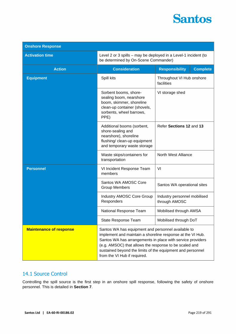
Santos Ltd | EA-60-RI-00186.02 Page 219 of 291
Onshore Response
Activation time Level 2 or 3 spills – may be deployed in a Level-1 incident (to
be determined by On-Scene Commander)
Action Consideration Responsibility Complete
Equipment Spill kits Throughout VI Hub onshore
facilities
Sorbent booms, shore-
sealing boom, nearshore
boom, skimmer, shoreline
clean-up container (shovels,
sorbents, wheel barrows,
PPE)
VI storage shed
Additional booms (sorbent,
shore-sealing and
nearshore), shoreline
flushing/ clean-up equipment
and temporary waste storage
Refer Sections 12 and 13
Waste skips/containers for
transportation
North West Alliance
Personnel VI Incident Response Team
members
VI
Santos WA AMOSC Core
Group Members Santos WA operational sites
Industry AMOSC Core Group
Responders
Industry personnel mobilised
through AMOSC
National Response Team Mobilised through AMSA
State Response Team Mobilised through DoT
Maintenance of response Santos WA has equipment and personnel available to
implement and maintain a shoreline response at the VI Hub.
Santos WA has arrangements in place with service providers
(e.g. AMSOC) that allows the response to be scaled and
sustained beyond the limits of the equipment and personnel
from the VI Hub if required.
14.1 Source Control
Controlling the spill source is the first step in an onshore spill response, following the safety of onshore
personnel. This is detailed in Section 7.

Santos Ltd | EA-60-RI-00186.02 Page 220 of 291
14.2 Containment and clean-up
Minor spills from handling and storage of hydrocarbons within the onshore Lease area will be contained and
removed through the use of onsite secondary containment and spill kits while larger potential releases from
process equipment and crude oil storage tanks are contained and controlled through bunding and drainage
systems. These pre-existing containment measures within the VI Lease area are described in Section 8.6 and
are not discussed further.
Spill from onshore sections of production pipelines and from the Tanker Loading Line may not be contained
and controlled through existing secondary containment systems. Based on the analysis provided in Section
3.4.1, onshore contamination at surface would likely be within a 50 m buffer of these pipelines. The use of
sorbent materials, including sorbent pads and boom immediately available of VI may be applicable to contain
and soak up any hydrocarbons that have not infiltrated sediments and are pooling at surface in this area.
The greatest potential for spread of hydrocarbons at surface is likely to be from any hydrocarbons reaching
the tidal zone of shorelines where mobilisation of floating oil could occur. Gradients in the vicinity of onshore
pipelines typically slope towards shorelines and while infiltration is expected to be significant oil may be
available for mobilisation.
In these instances, deployment of boom (sorbent, shore sealing or nearshore) available on VI may be
applicable to contain floating hydrocarbon against the shoreline for removal by sorbents or skimming. This is
applicable for the purpose of preventing the spread of hydrocarbons along shorelines, including along Pipeline
Beach (used seasonally for turtle nesting/hatching) and towards mangroves at Mangrove Bay. For noting,
Level 2/3 onshore spills reaching shorelines and marine waters are under the jurisdiction and control of DoT
as the relevant HMA and Control Agency and therefore strategies on shoreline response may be directed by
DoT.
Clean up of terrestrial contamination may follow the decision guidelines as per shoreline clean-up identified in
Section 13, noting that physical removal of contaminated sediments may not be the preferred strategy,
depending upon the expected additional environmental impacts of removal. Mangroves, seabird nesting and
turtle nesting are existing sensitivities to be considered in decision making for clean-up of terrestrial
contamination. If physical removal of surface contamination from an onshore spill is possible and considered
to provide greatest environmental benefit, existing clean-up equipment and personnel on VI supplemented
with offsite resources as defined in Section 13, are considered to apply.
14.3 Site Remediation
The sediments and sub-surface geology at VI encourage infiltration. Investigations of existing contamination
at VI suggest a complex subsurface groundwater system influence by the Karstic geology and tidal forcing
(refer Section 3.4.2).
Spill from onshore sections of production pipelines and from the Tanker Loading Line may not be contained
and controlled through existing secondary containment systems. Based on the analysis provided in Section
3.4.1, onshore contamination at surface would likely be within a 50 m buffer of these pipelines. The use of
sorbent materials, including sorbent pads and boom immediately available of VI may be applicable to contain
and soak up any hydrocarbons that have not infiltrated sediments and are pooling at surface in this area.
The greatest potential for spread of hydrocarbons at surface is likely to be from any hydrocarbons reaching
the tidal zone of shorelines where mobilisation of floating oil could occur. Gradients in the vicinity of onshore
pipelines typically slope towards shorelines and while infiltration is expected to be significant oil may be
available for mobilisation.
In these instances deployment of boom (sorbent, shore sealing or nearshore) available on VI may be
applicable to contain floating hydrocarbon against the shoreline for removal by sorbents or skimming. This is
applicable for the purpose of preventing the spread of hydrocarbons along shorelines, including along Pipeline
Beach (used seasonally for turtle nesting/hatching) and towards mangroves at Mangrove Bay. For noting,
Level 2/3 onshore spills reaching shorelines and marine waters are under the jurisdiction and control of DoT

Santos Ltd | EA-60-RI-00186.02 Page 221 of 291
as the relevant HMA and Control Agency and therefore strategies on shoreline response may be directed by
DoT.
Clean up of terrestrial contamination may follow the decision guidelines as per shoreline clean-up identified in
Section 13, noting that physical removal of contaminated sediments may not be the preferred strategy,
depending upon the expected additional environmental impacts of removal. Mangroves, seabird nesting and
turtle nesting are existing sensitivities to be considered in decision making for clean-up of terrestrial
contamination. If physical removal of surface contamination from an onshore spill is possible and considered
to provide greatest environmental benefit, existing clean-up equipment and personnel on VI supplemented
with offsite resources as defined in Section 13, are considered to apply.
In the event of an onshore spill, additional monitoring of soil and groundwater would likely be required under
contaminated sites legislation, building on historical groundwater monitoring activities.
14.4 Onshore Response Environmental Performance
Table 14-3 indicates the Environmental performance outcomes, controls and performance standards for the
onshore response strategy.
Table 14-3: Onshore Response – Environmental Performance
Environmental
Performance
Outcome
Control the spread of hazardous material
Remove surface oil and debris where present and when the strategy provides a
net benefit
Remediate the site as directed by DWER as applicable.
Response
Strategy
Control
Measures Performance Standards Measurement Criteria
Onshore Response Onshore
Response
Response undertaken in
consultation with DFES and
DWER
Incident Log
Santos WA will make
available AMOSC Core
Group Responders for
onshore clean-up team
positions to the Control
Agency
Incident Log
Santos WA will make
available to the Control
Agency equipment from
Santos WA, AMOSC and
OSRL stockpiles
Incident Log
NEBA undertaken every
operational period by the
relevant Control Agency to
determine if response
strategy is having a net
environmental benefit. NEBA
included in development of
following period Incident
Action Plan.
IAP/Incident Log

Santos Ltd | EA-60-RI-00186.02 Page 222 of 291
Environmental
Performance
Outcome
Control the spread of hazardous material
Remove surface oil and debris where present and when the strategy provides a
net benefit
Remediate the site as directed by DWER as applicable.
Response
Strategy
Control
Measures Performance Standards Measurement Criteria
Onshore response continues
until termination criteria is
met, as outlined within the
Onshore Response Plan.
Incident Log
Remediation Undertake remediation and
monitoring as required under
Contaminated Sites
Regulations 2003
Contaminated Sites records
incl. Detailed Site
Investigation (DSI) and
Remedial Action Plan RAP)

Santos Ltd | EA-60-RI-00186.02 Page 223 of 291
15 Oiled Wildlife Response Plan
Santos WA will provide all necessary resources to assist Department of Transport (DoT) in an oiled wildlife
response (OWR) in State waters, mainly, and initially, through its access to AMOSC oiled wildlife resources.
Timely provision of equipment and personnel will be provided by AMOSC to DoT as the Control Agency/ Lead
IMT through a combination of owned and operated equipment, call-off contracts with suppliers, and Oiled
Wildlife response advice to industry through an Oiled Wildlife Response Advisor. Industry Oiled Wildlife
responders are also available through AMOSC mutual aid arrangements. This team will work in conjunction
with Department of Biodiversity, Conservation and Attractions (DBCA) OWR capability under the direction of
the DoT Incident Command. Where Santos WA is the Control Agency for OWR in Commonwealth waters,
AMOSC will also provide the above mentioned resources and be supported by DCBA, but would instead work
under the direction of the Santos WA Incident Command.
The key plan for OWR in WA is the WA Oiled Wildlife Response Plan (WAOWRP). The WAOWRP has been
developed by DBCA and AMOSC, on behalf of the petroleum industry, to define the minimum standards for
OWR in WA as a sub-plan to the State Hazard: MEE. The WAOWRP can also be used for guidance to OWR
in Commonwealth waters, noting that OWR requirements in State waters are typically greater. The Pilbara
Region OWRP, which sits under the WAOWRP provides operational guidance to respond to injured and oiled
wildlife in the Pilbara Region and covers the areas potentially contacted by a spill from VI Hub operations.
The sections below provide guidance to the Santos WA IMT on OWR stages of response and implementation.
In some cases, the implementation guidance (Table 15-5) includes detail which is additional to what is provided
in the WAOWRP. The information below should be used in conjunction with the WAOWRP.
Note: For Spill contained solely in Commonwealth Waters, Santos WA is the Control Agency for OWR. DoT is
the Control Agency and Department of DBCA is the Jurisdictional Authority for OWR within State waters. DoT
is also the lead IMT for Oiled Wildlife Response where the spill covers both Commonwealth and State Waters.
The OWR Environmental Performance Outcome, initiation and termination criteria are found in Table 15-1.
Table 15-1: Oiled Wildlife Response – Environmental Performance Outcome, Initiation Criteria and
Termination Criteria
Oiled Wildlife Response
Environmental
Performance
Outcome
Implement tactics in accordance with the Western Australian Oiled Wildlife
Response Plan (WAOWRP) to prevent or reduce impacts, and to humanely treat,
house, and release or euthanase wildlife
Initiation criteria Operational monitoring shows that wildlife are contacted or are predicted to be
contacted by a spill
Applicable
hydrocarbons
Condensate Crude oil Marine Diesel HFO
Termination
criterion + Oiling of wildlife have not been observed over a 48 hour period;
+ Oiled wildlife have been successfully rehabilitated; and
+ Agreement is reached with Jurisdictional Authorities and stakeholders to terminate the incident response.
15.1 OWR Stages of Response
The WAOWRP includes eight stages to an OWR, which are described in Table 15-2. If an OWR is initiated,
implementation will follow these stages, as appropriate to the nature and scale of the incident.

Santos Ltd | EA-60-RI-00186.02 Page 224 of 291
Table 15-2: Oiled Wildlife Response Stages (adapted from WAOWRP)
Stage Description
Stage 1: Initial wildlife
assessment and
notifications
Gather situational awareness on whether an OWR impact has occurred or
is imminent and complete notifications to Jurisdictional Authorities and
external support agencies
Stage 2: Mobilisation of
wildlife resources
Mobilise initial preventative measures and/or mobilisation of resources to
deal with incident in early stages of development.
Stage 3: Wildlife
reconnaissance
Wildlife reconnaissance for the OWR should occur as part of the
implementation of monitor and evaluate tactics (Section 9) to aid planning
and decision making for executing spill response or clean-up operations.
Wildlife reconnaissance will be required for the duration of the wildlife
response operations
Stage 4: IAP Wildlife
Response Sub-plan
development
The Wildlife Response Sub-plan should include the following operational
components (relevant to the scale of the OWR):
+ Wildlife impact assessment
+ Reconnaissance and monitoring
+ Search and collection
+ Carcass collection and necropsy storage
+ Field stabilisation
+ Wildlife transport
+ Wildlife processing/admission
+ Wildlife intake and triage
+ Wildlife cleaning
+ Rehabilitation/conditioning
+ Release
+ Post-release monitoring
+ OWR termination and demobilisation.
(It should be noted that separate strategies and protocols may be required
for different species groups).
Stage 5: Wildlife rescue and
staging
This includes commencing actions such as hazing, pre-emptive capture,
administering first-aid and holding and/or transportation of wildlife to oiled
wildlife facilities.
If oiled birds or non–avian wildlife were to be observed at sea, on-water
collection should be considered for the effective capture of oiled animals
before they become so debilitated that their chance of survival is severely
affected (IPIECA, 2004)
Stage 6: Establishment of
an oiled wildlife facility
Treatment facilities would be required for the cleaning and rehabilitation of
affected animals.
A vessel-based ‘on-water’ facility would likely need to be established to
enable stabilisation of oiled wildlife before transport to a suitable treatment
facility

Santos Ltd | EA-60-RI-00186.02 Page 225 of 291
Stage Description
Stage 7: Wildlife
rehabilitation
Considerations include a suitable rehabilitation centre and personnel,
wildlife housing, record keeping, release and post-release monitoring
Stage 8: Oiled wildlife
response termination
Demobilisation of the OWR should be undertaken in accordance with
parameters or endpoints established in the IAP and supplementary Wildlife
Response Sub-plan. This decision will be made in consultation with the
relevant jurisdictional authorities and support agencies
15.2 OWR Levels and Resourcing
An impact assessment threshold of 10 g/m2 for impacts on fauna from floating hydrocarbons is provided in the
in the Varanus Island Hub Operations Environment Plan (EP) for Commonwealth Waters (EA-66-RI-10003)
and the Varanus Island Hub Operations EP (State Waters) (EA-60-RI-00186). This conservative threshold is
broadly accepted as being the minimal thickness of surface hydrocarbons that may result in adverse impacts
to seabirds through adhesion to feathers and secondary effects (French et al., 1996; French-McCay 2009) and
is also considered appropriate for turtles, sea snakes and marine mammals (NRDAMCME, 1997).
Review of the worst-case spill modelling indicates that floating HFO concentrations above 10g/m2 may extend
up to 396 km from the spill location and have a maximum shoreline loading of 1480 m3, at 100 g/m2, at the
Montebello Islands and effecting 67 km of shoreline. Surveys at the Montebello Islands have recorded 70 bird
species, including 12 species of seabird and 14 species of migratory shorebirds (Burbidge et al. 2000). These
islands also include both major and minor nesting areas for green, hawksbill, and flatback turtles
(Commonwealth of Australia, 2017), with hundreds of turtles nesting annually. Offshore of the Montello Islands,
dugong and migrating pygmy blue whales are known to occur.
As a case-study, the grounding of the MV Rena in the Bay of Plenty, New Zealand, which was carrying 1733
tonnes (approx. 1777 m3) and lost over 360 tonnes (approx. 369 m3) of HFO, and impacted over 60 km of
coastline, resulted in an OWR that lasted 136 days and the treatment of 407 oil affected birds.
Conservative estimates for OWR planning predict a worst-case OWR for this activity will be an OWR Level 5,
as defined in the WAOWRP (2014) (Table 15-3).
For a Level 5 response, it is expected that up to 116 personnel will be required, with a range of skill levels
(Table 15-4: Oiled Wildlife Response Level and Personnel Numbers– OWR 1 = basic training to OWR 4
= OWR Advisor; Information drawn from WAOWRP). Personnel at skill levels OWR 2 - 4 and those with
specialised skills (e.g. vets) are expected to be sourced through AMOSC, OSRL, DBCA, Universities and
contractors.
Roles could be filled by the organisations listed above and through labour hire agencies that can provide field
workers that undergo an induction and basic training. Basic training (over 1 day) for OWR personnel can be
delivered as just-in-time training through an arrangement with DBCA.

Santos Ltd | EA-60-RI-00186.02 Page 226 of 291
Table 15-3: Indicative Oiled Wildlife Response Level (adapted from WA OWRP, 2014)
OW
R L
ev
el
Ind
icati
ve
pers
on
nel
nu
mb
ers
Ind
icati
ve
du
rati
on
Ind
icati
ve
nu
mb
er
of
bir
ds (
no
n-
thre
ate
ned
sp
ecie
s)
Ind
icati
ve
nu
mb
er
of
bir
ds (
thre
ate
ned
sp
ecie
s)
Tu
rtle
s (
hatc
hlin
gs,
juven
ile
s, ad
ult
s)
Ceta
ce
an
s
Pin
nip
ed
s
Du
go
ng
s
Level
1
6 < 3 days 1–2/day
< 5 total
None None None None None
Level
2
26 > 4–14
days
1–5/day
< 20 total
None < 20 hatchlings
No juv/adults
None None None
Level
3
59 > 4–14
days
5–10/day 1–5/day
< 10
total
< 5 juv/adults
< 50 hatchlings
None < 5 None
Level
4
77 > 4–14
days
5–10/day
< 200
total
5–
10/day
< 20 juv/adults
< 500 hatchlings
< 5, or
known
habitats
affected
5–50 Habitat
affected only
Level
5
116 > 4–14
days
10–100/
day
> 200
total
10–
50/day
> 20 juv/adults
> 500 hatchlings
< 5
dolphins
> 50 Dugongs
oiled
Level
6
122 > 4–14
days
> 100/day 10–
50/day
> 20 juv/adults
> 500 hatchlings
> 5
dolphins
> 50 Dugongs
oiled
Table 15-4: Oiled Wildlife Response Level and Personnel Numbers
Skill Level OWR Response Level and Personnel Numbers
Level 1 Level 2 Level 3 Level 4 Level 5 Level 6
OWR 4 1 1 3 2 2 2
OWR 3 2 0 4 4 4 4
OWR 2 4 9 15 17 18 18
OWR 1 0 14 33 47 84 90
Technicians (i.e. vets) 0 1 2 4 4 4
Other specified skills 0 0 2 3 4 4

Santos Ltd | EA-60-RI-00186.02 Page 227 of 291
Skill Level OWR Response Level and Personnel Numbers
Level 1 Level 2 Level 3 Level 4 Level 5 Level 6
Total 7 25 59 77 116 122
15.3 Implementation Guidance
Oiled wildlife response activities can be resource intensive and require additional personnel to be positioned
within the IMT. The oiled wildlife response team will be managed according to the Wildlife Division outlined in
the WAOWRP. The wildlife operations unit will contain all the field staff and activities, including oiled wildlife
reconnaissance, who will work in close consultation with personnel undertaking relevant monitor and evaluate
activities. The IAP Wildlife Response Sub-plan as outlined in Table 15-2 will form the key management system
which will provide control and oversight over the response.
Table 15-5 provides guidance to the IMT on the actions and responsibilities that should be considered when
implementing OWR. These actions are provided as a guide and should be read in conjunction with the
WAOWRP. In some cases, the Implementation Guidance (Table 15-5) will provide additional detail to the
WAOWRP and has greater linkages to other aspects of the response operation and this OPEP (e.g. NEBA
and aerial surveillance).
The Incident Commander of the Control Agency is ultimately responsible for the implementation of the
response and therefore, depending on the circumstances of the spill, may determine that some tasks be varied,
should not be undertaken or should be reassigned.
Information on resource capability for this strategy is shown in Table 15-6 and Appendix L: Oiled Wildlife
Response Personnel and Equipment.

Santos Ltd | EA-60-RI-00186.02 Page 228 of 291
Table 15-5: Implementation Guidance – Oiled Wildlife Response
Action Consideration Responsibility Complete
Stage 1: Initial wildlife assessment and notifications
Init
ial A
cti
on
s
Personnel conducting monitor
and evaluate activities shall
report wildlife sightings in or
near the spill trajectory
(including those contacted with
hydrocarbons or at risk of
contact) and report them to the
IMT within 2 hours of detection
Record all reports of wildlife
potentially impacted and
impacted by spill. Record
reports on:
+ Location
+ Access
+ Number
+ Species
+ Condition of impacted animals (if available)
Surveillance
personnel
❑
If wildlife are sighted and are
at risk of contact (or have
been contacted), initiate oiled
wildlife response by contacting
AMOSC Duty Manager and
DCBA State Duty Officer (who
will then activate their
respective Oiled Wildlife
Advisors)
Obtain approval from IC prior to
activating AMOSC Oiled Wildlife
Advisor (OWA) and/or DCBA
OWR as outlined in Section 6.2
DoT will be the Control Agency
for OWR in State waters
Environmental
Team Leader
❑
Notify DoEE if there is a risk of
death or injury to a protected
species (including Matters of
National Environmental
Significance (MNES))
Refer to Section 6.1 for
reporting requirements.
A list of MNES is provided in the
Existing Environment Section of
the EP
Environmental
Team Leader ❑
Review all wildlife reports from
surveillance or opportunistic
activities and contact
personnel who made the
reports (if possible) to confirm
information collected
Environmental
Team Leader
Wildlife Division
Coordinator
❑
Use information from initial
assessments to prepare an
Operational NEBA. Use this
information to help determine:
+ Initial OWR Response Level (1-6), as defined in the WA OWRP
+ If OWR activities are likely to result in a net environmental benefit
Oiled wildlife response activities
can cause additional stress and
mortality on individuals than oil
pollution alone. The
Environmental Team Leader and
Wildlife Division Coordinator will
determine via an Operational
NEBA whether capture and
cleaning of oiled wildlife will
result in a net environmental
benefit. This may be done in
consultation with the DCBA and
AMOSC Oiled Wildlife Advisors,
Environmental
Team Leader
Wildlife Division
Coordinator
❑

Santos Ltd | EA-60-RI-00186.02 Page 229 of 291
Action Consideration Responsibility Complete
and any SME’s as relevant (if
available, but an Operational
NEBA should not be delayed if
they are not immediately
available)
Stage 2: Mobilisation of wildlife resources
Determine resources required to
undertake Stage 3: Wildlife
Reconnaissance and provide list to
Logistics Section
Confirm best reconnaissance
platform (e.g. vessel, aerial,
shoreline). Consider ability to
share resources (e.g. Shoreline
Clean-up Assessment Teams,
Monitor and Evaluate activities)
Wildlife Division
Coordinator
Wildlife
Reconnaissance
Officer
AMOSC OWA
❑
Determine number of Oiled Wildlife
Responders and IMT Wildlife related
positions required based on the likely
number of oiled wildlife and arrange
access to resources via AMOSC and
DCBA
Consider need for veterinary
care
Wildlife Division
Coordinator
Logistics Team
Leader
AMOSC OWA
DBCA OWA
❑
While waiting for Oiled Wildlife
Responders to arrive, Varanus Island
HSE Advisors (whom have fauna
handling training) may provide a first
strike response
Any first strike response will
need to occur under the
instruction of DBCA
Varanus Island
HSE Advisor(s) ❑
Commence mobilisation of equipment
(including adequate PPE) and
personnel to required location/s
Wildlife Logistics
Officer ❑
Contact OSRL to activate Sea Alarm if
additional support is likely to be
required to sustain an ongoing OWR
Environmental
Team Leader ❑
Stage 3: Wildlife reconnaissance
Determine reconnaissance plan
including survey locations, techniques
and priority species
Consult local experts, if
available
Liaise with personnel managing
monitor and evaluate activities
to ensure field activities are
coordinated
Wildlife Division
Coordinator
Wildlife
Reconnaissance
Officer
AMOSC OWA
DBCA OWA
Planning Team
Leader
❑

Santos Ltd | EA-60-RI-00186.02 Page 230 of 291
Action Consideration Responsibility Complete
Conduct reconnaissance activities
and upon completion, submit report
detailing:
+ Area/s surveyed
+ Estimated number of animals oiled or at risk of being affected
+ Any deaths
+ Species affected
Wildlife Division
Coordinator
Wildlife
Operations
Officer
Wildlife
Reconnaissance
Officer
OWR field
personnel
Operations
Team Leader
❑
Stage 4: IAP wildlife sub-plan development
Develop Wildlife Response Sub-plan
for inclusion in the IAP
IAP to should include options for
wildlife rescue and rehabilitation,
including:
+ Wildlife priorities for protection from hydrocarbons
+ Any deterrence/hazing measures
+ Anticipate number of oiled wildlife requiring rescue
+ Reassess Oiled Wildlife Level
+ Actions required for the collection, recovery, transport and treatment of oiled wildlife; including resourcing of equipment and personnel anticipated
Consider need for any permits to
conduct activities
Wildlife Division
Coordinator
Wildlife
Operations
Officer
AMOSC OWA
DBCA OWA
Environmental
Team Leader
❑
Stage 5: Wildlife rescue and staging
Implement Wildlife Response Sub-
plan for deterrence/hazing, pre-
emptive capture, relocation
Trained personnel required to
handle wildlife
Wildlife Division
Coordinator
Wildlife
Operations
Officer
Wildlife Rescue
Officer
AMOSC OWA
DBCA OWA
OWR field
personnel
❑

Santos Ltd | EA-60-RI-00186.02 Page 231 of 291
Action Consideration Responsibility Complete
Operations
Team Leader
Establish staging site/s Wildlife first aid/stabilisation
may be required at staging site
if OWR treatment facility is more
than 2 hours away
Wildlife
Staging/Holding
Officer
OWR field
personnel
Operations
Team Leader
❑
Stage 6: Establishment of an oiled wildlife facility
Implement Wildlife Response Sub-
plan for oiled wildlife facility
Utilise OWR containers where
possible. One container/kit can
treat up to 150 OWR units, so
will be adequate to treat oiled
wildlife from the worst-case spill.
If insufficient, additional OWR
containers can be requested via
the IAP to AMSA
Wildlife Division
Coordinator
Wildlife
Operations
Officer
Wildlife Facilities
Officer
AMOSC OWA
DBCA OWA
OWR field
personnel
Operations
Team Leader
❑
Stage 7: Wildlife rehabilitation
Implement Wildlife Response Sub-
plan for rehabilitation
Animals need to be stable to
withstand stress of washing.
Oiled animals, particularly birds,
cannot thermoregulate and
need to be kept indoors in a
temperature-controlled room.
The room needs to be well
ventilated to disperse the
hydrocarbon fumes
Wildlife Division
Coordinator
Wildlife
Veterinarian
Wildlife
Rehabilitation
Officer
AMOSC OWA
DBCA OWA
OWR field
personnel
Operations
Team Leader
❑
Stage 8: Oiled wildlife response termination

Santos Ltd | EA-60-RI-00186.02 Page 232 of 291
Action Consideration Responsibility Complete
Liaise with Jurisdictional Authorities
regarding OWR termination, using
endpoints established in the IAP and
supplementary Wildlife Response
Sub-plan (Termination and
Demobilisation section)
Wildlife Division
Coordinator
AMOSC OWA
DBCA OWA
Incident
Commander
❑
Table 15-6: Oiled Wildlife Response - Resource Capability
Service Provider Capability Location Activation Time
WA Oiled Wildlife Response Plan
Pilbara Region OWR Plan
N/A N/A
1. AMOSC oiled wildlife response
container and kit (includes wash
facility that may treat up to 150
OWR units)
2. AMSA OWR container and kits
3. DBCA OWR container and kit
4. OSRL equipment
5. Vessels via call off contracts
1. Fremantle, plus
various locations
around Australia
(Refer to Appendix
L: Oiled Wildlife
Response
Personnel and
Equipment)
2. Various locations
around Australia
(Refer to Appendix
L: Oiled Wildlife
Response
Personnel and
Equipment)
3. Kensington and
Karratha
4. Various locations
internationally (Refer
to Appendix L)
5. NW Australia
1. 24 hours from
Fremantle to
Dampier
2. AMSA OWR
container
positioned in
Dampier.
3. 24 hours from
Kensington to
Dampier
4. 48-72 hours from
Singapore to
Dampier.
5. 24 + hours
Santos WA is a participating member
of AMOSC with access to Mutual aid
arrangements. AMSA MoU and OSRL
contracts enable access to national
and international oiled wildlife
expertise (Refer to Appendix L: Oiled
Wildlife Response Personnel and
Equipment)
Various locations around
Australia and internationally
(Refer to Appendix L:
Oiled Wildlife Response
Personnel and
Equipment)
AMOSC Mutual Aid
OWR Industry Team
can be available within 3
days
Santos WA Capability Location Santos WA Activation
Time

Santos Ltd | EA-60-RI-00186.02 Page 233 of 291
Service Provider Capability Location Activation Time
5 Santos WA trained Oiled Wildlife
Responders
Perth 24 hours
Santos WA HSE Advisors with fauna
handling training
Varanus Island Imminent or actual
impact to wildlife
Untrained resources through
personnel-hire arrangements
Perth ~72 hours
15.4 Oiled Wildlife Response Plan Environmental Performance
Table 15-7 indicates the Environmental performance outcomes, controls and performance standards for the
Oiled Wildlife Response strategy.
Table 15-7 Oiled Wildlife – Environmental Performance
Environmental
Performance
Outcome
Implement tactics in accordance with the Western Australian Oiled Wildlife
Response Plan (WAOWRP) to prevent or reduce impacts, and to humanely treat,
house, and release or euthanase wildlife.
Response
Strategy Control Measures Performance Standards
Measurement
Criteria
Oiled Wildlife
Response
Response preparedness
Maintenance of
access to oiled
wildlife response
equipment and
personnel
Maintenance of access to oiled
wildlife response equipment
and personnel through
AMOSC, AMSA National Plan
and Oil spill Response Limited
(OSRL) throughout activity
MoU for access to
National Plan
resources through
AMSA
AMOSC Participating
Member Contract.
OSRL Associate
Member Contract.
Varanus Island
Oiled Wildlife First
Strike Response
Plan
Varanus Island Oiled Wildlife
First Strike Plan developed
prior to end of 2020
Varanus Island Oiled
Wildlife First Strike
Plan
Response Implementation
Prepare operational NEBA to
help classify OWR level and
determine if OWR activities
are likely to result in a net
environmental benefit
Records indicate
operational NEBA
completed prior to
OWR operations
commencing
IAP Wildlife Response Sub-
plan developed to provide
oversight and management of
OWR operation
Records indicate IAP
Wildlife Response Sub-
plan prepared prior to
OWR operations
commencing

Santos Ltd | EA-60-RI-00186.02 Page 234 of 291
16 Waste Management Plan
The implementation of some spill response strategies will generate waste solid and liquid waste that will require
rapid management, storage, transport and disposal. It is important that waste is collected and removed quickly
to ensure waste management does not create a bottleneck in response operations.
The type and amount of waste generated during a spill response will vary depending on the spill
type/characteristics, volume released, and response strategies implemented. To account for this potential
variability, waste management (including handling and capacity) needs to be scalable to allow a continuous
response to be maintained.
Where Santos WA is the Control Agency, or at the request of the designated Control Agency, Santos WA will
engage its contracted Waste Service Provider (WSP) to provide sufficient waste receptacles to store collected
waste and manage oily waste collection, transport and disposal associated with spill response activities. The
WSP will arrange for all personnel, equipment and vehicles to carry out these activities from nominated
collection points to the final disposal points. Santos’ Waste Management Plan – Oil Spill Response Support
(QE-91-IF-10053) provides detailed guidance to the WSP in the event of a spill.
Where DoT is the Control Agency, Santos WA will provide a Facilities Support Officer to the DoT IMT Logistics
Unit to support the DoT IMT in coordinating waste management services. The Environmental Performance
Outcome, initiation and termination criteria are found in Table 16-1.
Table 16-1: Waste Management – Environmental Performance Outcome, Initiation Criteria and
Termination Criteria
Waste Management
Environmental
Performance
Outcome
Comply with waste treatment, transport and disposal regulations and prevent
secondary contamination while reducing, reusing and recycling waste where
possible
Initiation criteria Response activities that will be generating oily waste have been initiated. 2 hours
for IMT to activate Waste Service Provider
Applicable
hydrocarbons
Condensate Crude oil Marine Diesel HFO
Termination
criterion All waste generated from the oil spill response has been stored, transported and
disposed as per the regulatory requirements; and
Agreement is reached with Jurisdictional Authorities to terminate the response
16.1 Waste approvals
Site clean-up, removal and disposal of response waste should be conducted in accordance with Santos’ Waste
Management Plan – Oil Spill Response Support (QE-91-IF-10053); and where relevant, the DoT Waste
Management Guidelines, and the respective Port, Port Operator and/or Ship Owner’s waste management
plan. In addition, regulatory approval may be required for the temporary storage, transport, disposal and
treatment of waste, through the Department of Water and Environmental Regulation (DWER). DWER
administers the Environmental Protection Act 1986 (WA) and is the relevant Regulatory Authority for waste
management approvals. If required, DoT may establish an Operational Area Support Group (OASG), as
defined in the State Hazard: MEE, to request support from relevant WA Government Agencies, including
DWER, during a State waters spill response. The Santos’ Waste Management Plan – Oil Spill Response

Santos Ltd | EA-60-RI-00186.02 Page 235 of 291
Support (QE-91-IF-10053) provides detail on the regulatory requirements for each port/location likely to be
used for waste management during any spill response operation associated with Santos WA activities.
16.2 Waste Service Provider Capability
Detailed guidance on Santos WA’s Waste Service Provider responsibilities for spill response waste
management is provided in the Santos’ Waste Management Plan – Oil Spill Response Support (QE-91-IF-
10053).
Key responsibilities of the waste service provider include:
+ Maintaining emergency response standby preparedness arrangements, including:
– Access to personnel, equipment and vehicles required for a first strike and ongoing response
commensurate to Santos WA worse case spill and waste requirements
– Provide primary and secondary contact details for activation of spill response waste management
services
– Have suitably trained personnel for completing critical tasks in spill response waste management
– Participation in exercising undertaken by Santos WA.
+ Ability to assist in the Control Agency’s IAP and Waste Management Sub-plan process as required;
+ Mobilise resources to waste collection points identified by the Control Agency;
+ Ensure waste handling, transport and disposal practices meet legislative requirements;
+ Keep auditable records of waste streams from collection points to final disposal points;
+ Provide regular progress reporting to the Control Agency IMT and a final report relating to quantities and
destinations of collected waste;
+ Provide a project manager responsible for the rollout of spill response resources to meet spill response
waste management objectives; and
+ Provide location specific Operations Supervisor/s to handle on-site operational aspects (management
of personnel and equipment, reporting, liaison with relevant field-based spill responders)
16.2.1 Waste management resources
Santos WA has access to capacity to deliver storage receptacles, remove, transport and dispose of all waste
material from oil spill response activities to predetermined disposal points. Stochastic modelling conducted for
a worst case hydrocarbon release shows that the highest shoreline loading was from an offtake tanker HFO
spill (1,900 m3) which could result in a maximum loading of 1480 m3 on shorelines of the Montebello Islands.
Lesser amounts were modelled as potentially arriving at Lowendal Islands (1324 m3) and Barrow Island (1183
m3), noting that these worst case loadings come from different model simulations. Conservatively assuming
all loaded hydrocarbon are required to be removed from shorelines with a bulking factor of 10x to account for
contaminated waste (sediments and organics) collected with the oil, worst case waste storage and transport
requirements would be in the order of ~15 000 m3. Table 16-2 provides waste service provider capability for
waste removal and storage, which is in excess of the waste management requirements for spill response
activities associated with this OPEP, and has been developed based on a significant loss of well control event.

Santos Ltd | EA-60-RI-00186.02 Page 236 of 291
Table 16-2: Waste Service Provider Vehicle and Equipment Availability
Plant and
Equipment
Capacity Functionality Uses per
week
Indicative
waste
stored/shifted
per week (m3)
Mobilisation schedule to meet estimated capacity
No.
Sourced
locally
No. Sourced State-wide and
Nationally
Waste removal 48 hours 1 week 2 weeks 1 month
12x Skip Lift
Trucks
Lift up to 10
Tonnes
Servicing of skip Bins 7 840 4 3 3 2
10x Front Lift
Trucks
28 m3 Body Servicing of Front lift bins 7 1960 4 3 2 1
10x Side Loading
Truck
18 m3 Body Servicing of MGB’s 7 1260 1 2 4 3
7x Hook Lift
Truck
12 Tonne rated Servicing of hook lift bins 7 588 3 2 2 N/A
12x Flat Bed
Truck
22 pallet spaces Servicing of bins 7 840 3 6 4 N/A
Waste storage 48 hours 1 week 2 weeks 1 month
500x MGB’s 240 litres Mobile bins 2 48 200 300 N/A N/A
2x Offshore 8
pack Lifting
Cradle (MGB’s)
16 x 240 litre
MGB’S
Able to remove 16 x 240L
MGB’S simultaneously
continuous 0 2 N/A N/A
Waste storage 48 hours 1 week 2 weeks 1 month

Santos Ltd | EA-60-RI-00186.02 Page 237 of 291
Plant and
Equipment
Capacity Functionality Uses per
week
Indicative
waste
stored/shifted
per week (m3)
Mobilisation schedule to meet estimated capacity
No.
Sourced
locally
No. Sourced State-wide and
Nationally
6x Lidded Bins 1,100 litres contain various waste
streams
2 13 6 N/A N/A N/A
50x Front Lift
Bins
3 m3 various waste streams 2 300 20 30 N/A N/A
25x Front Lift
Bins
4.5 m3 various waste streams 2 225 10 15 N/A N/A
100x Offshore
Rated Front Load
Bins
3 m3 various waste streams 2 600 40 60 N/A N/A
45x Offshore
Rated Bins
7 m3 various waste streams 2 630 20 25 N/A N/A
60x Marrell Skip
Bins
6-9 m3 various waste streams 2 960 20 40 N/A N/A
12x Hook Lift
Bins 15-30 m3
various waste streams 25 6900 12 N/A N/A N/A
4x Forklift 4 tonne Forklift All areas continuous N/A 4 N/A N/A N/A

Santos Ltd | EA-60-RI-00186.02 Page 238 of 291
Table 16-3: Implementation Guidance – Waste Management
Action Consideration Responsibility Complete
Init
ial A
cti
on
s
Contact WSP (Primary or
Secondary Contact Person)
and activate Waste Project
Manager. Arrange for
personnel to attend
Emergency Control Centre
Refer to Incident Response
Contacts Directory (QE-00-
ZF-00025.20) for contact
details
Logistics Team
Leader (or
delegate)
❑
Provide briefing to WSP
personnel once positioned
in IMT
Logistics Team
Leader (or
delegate)
❑
Using most recent monitor
and evaluate data, estimate
expected waste volumes to
be generated by selected
response strategies
It is better to overestimate
volumes and scale back
resources then to
underestimate waste
volumes
Logistics Team
Leader (or
delegate)
Planning Team
Leader
❑
Using most recent monitor
and evaluate data and any
existing and future response
activities, determine most
suitable locations for waste
receptacles to be positioned
and for temporary storage
locations to be established
Consideration would be given
to positioning receptacles
and locating temporary
storage sites to ensure
secondary contamination of
sensitive receptors is avoided
or minimised. The approval of
temporary storage sites
would be given through
DWER
Logistics Team
Leader (or
delegate)
Planning Team
Leader
Environmental
Team Leader
❑
For each receival location
indicate the anticipated:
+ Material types;
+ Material generation
rates;
+ Material generation
quantities;
+ Commencement
date/time;
+ Anticipated clean-up
duration;
+ Receptacle types
required;
Consider facilities for waste
segregation at source
Logistics Team
Leader
Planning Team
Leader
Deputy
Logistics
Officer
❑

Santos Ltd | EA-60-RI-00186.02 Page 239 of 291
Action Consideration Responsibility Complete
+ Logistical support
requirements;
+ Any approvals
required from Ports,
Local Governments,
Landowners, State
Government
Agencies (Refer to
Waste Management
Plan – Oil Spill
Response Support
(QE-91-IF-10053)).
Once the above information
is obtained, ensure all
necessary waste
management information is
included in the IAP
Waste management should
be conducted in accordance
with Santos’ Waste
Management Plan – Oil Spill
Response Support (QE-91-
IF-10053); and where
relevant, the DoT Waste
Management Guidelines, and
the respective Port, Port
Operator and/or Ship
Owner’s waste management
plan
Refer to Cedre (2016) for
technical guidance on waste
management techniques
Logistics Team
Leader (or
delegate)
Facilities
Support Officer
(DoT IMT)
Planning Team
Leader
WSP Location
Responsible
Person or
Operations
Supervisor
❑
Mobilise waste
management resources and
services to agreed priority
locations
WSP Location
Responsible
Person or
Operations
Supervisor
Logistics Team
Leader (or
delegate)
Facilities
Support Officer
(DoT IMT)
❑
On
go
ing
Acti
on
s
Provide ongoing point of
contact between IMT and
WSP
If DoT is the Control Agency,
the Facilities Support Officer
shall be the point of contact
between DoT and the WSP
Facilities
Support Officer
(DoT IMT)
Logistics Team
Leader
❑
Ensure all waste handling,
transport and disposal
Alert Logistics Team Leader
(or delegate)/ Deputy
WSP Location
Responsible
❑

Santos Ltd | EA-60-RI-00186.02 Page 240 of 291
Action Consideration Responsibility Complete
practices comply with
legislative requirements
Logistics Officer (if DoT is the
Control Agency) if any non-
compliance is anticipated or
detected
Person or
Operations
Supervisor
Ensure records are
maintained for all waste
management activities,
including but not limited to:
+ Waste movements
(including types of
receptacles, receival
points, temporary
storage points, final
disposal locations);
+ Volumes generated at
each site (including
total volume and
generation rates);
+ Types of waste
generated at each site;
+ Approvals obtained (as
required).
WSP Location
Responsible
Person or
Operations
Supervisor
❑

Santos Ltd | EA-60-RI-00186.02 Page 241 of 291
Table 16-4: Waste Management- Resource Capability
Service Provider
Capability
Location Service Provider Activation Time
Processes
Waste Management Plan
– Oil Spill Response
Support (QE-91-IF-
10053)
N/A N/A
Equipment
Refer to Table 16-2
NWA Waste handling and
transfer depot
N/A
Karratha
48 hours
Personnel
2 x Project Manager
2 x Operations
Supervisor
Perth
Karratha
Within 24 hours of activation
Santos WA Capability Location Santos WA Activation Time
Processes
Waste Management Plan
– Oil Spill Response
Support (QE-91-IF-10053)
N/A N/A
Equipment
Evaporation ponds Devil Creek
Gas Plant
If/when required
Personnel
Logistics Team Leader or
delegate
Perth On IMT activation
Facility Support Officer By 8 am of the day following DoT request
16.3 Waste Management Plan Environmental Performance
Table 16-5 indicates the Environmental Performance Outcomes, controls and performance standards
for the Waste Management Response strategy.

Santos Ltd | EA-60-RI-00186.02 Page 242 of 291
Table 16-5: Environmental Performance outcomes, controls and performance standards for
waste management
Environmental
Performance
Outcome
Comply with waste treatment, transport and disposal regulations and prevent secondary
contamination while reducing, reusing and recycling waste where possible.
Response
Strategy Control Measures Performance Standards
Measurement
Criteria
Waste
Management Response preparedness
Maintain access to
waste
management
equipment,
personnel,
transport and
disposal facilities
Maintain access to waste
management equipment,
personnel, transport and disposal
facilities throughout activity
Contract with
Waste Service
Provider for
emergency
response services
Response Implementation
Implement Waste
Management Plan
– Oil Spill
Response Support
(QE-91-IF-10053)
Waste Service Provider to appoint
a Project Manager within 24 hours
of activation
Incident Log
Ensure operational NEBA
considers waste management, to
ensure environmental benefit
outweighs the environmental
impact of strategy implementation
which may include secondary
contamination.
Incident Log
IAP
Waste Service Provider shall track
all wastes from point of generation
to final destination
Waste tracking
records
Waste Service Provider to provide
monthly waste management
reports and more regular situation
reports during the response until
termination criteria are met
Waste reports
Waste management to be
conducted in accordance with
Santos’ Waste Management Plan –
Oil Spill Response Support (QE-91-
IF-10053); and where relevant, the
DoT Waste Management
Guidelines, and the respective Port,
Port Operator and/or Ship Owner’s
waste management plan
Waste reports

Santos Ltd | EA-60-RI-00186.02 Page 243 of 291
17 Scientific Monitoring Plans
The overarching objective of Santos WA’s Scientific Monitoring Plans (SMPs) is to provide guidance to
staff, consultants and contractors in developing monitoring programs for detecting impacts and recovery
to environmentally sensitive receptors contacted by a spill.
Receptor specific SMPs have different objectives as outlined in Appendix M: Scientific Monitoring
Plans.
Oil spill scientific monitoring is the principle tool for detecting and quantifying environmental impact and
recovery to sensitive receptors from an oil spill. Santos WA is required to have an oil spill scientific
monitoring plan (SMP) in place for Petroleum activities in State and Commonwealth waters.
Santos WA will activate and implement scientific monitoring in State and Commonwealth waters for
hydrocarbon spills in line with its SMP unless directed otherwise by the relevant Control Agency/s.
Table 17-1 Scientific Monitoring - Environmental Performance Outcome, Initiation Criteria and
Termination Criteria
Scientific Monitoring
Environmental
Performance
Outcome
Implement monitoring programs to assess and report on the impact, extent,
severity, persistence and recovery of sensitive receptors contacted by a spill
or affected by a spill response.
Initiation criteria Refer to individual SMPs – Appendix M for receptor specific initiation criteria
Monitoring Provider activated within 2 hours of notification from IMT
Applicable
hydrocarbons
Lube oil/
hydraulic
fluids
Condensate Crude oil Marine
Diesel
HFO
Termination
criterion Refer to individual SMPs – Appendix M: Scientific Monitoring Plans
17.1 Scope
Santos WA will implement its SMPs, as applicable, for VI Hub spill scenarios across both State and
Commonwealth waters. In the event that control of scientific monitoring in State waters is taken over by
DoT under advice from the State Environmental Scientific Coordinator (ESC), Santos WA will follow the
direction of DoT and provide all necessary resources (monitoring personnel, equipment and planning)
to assist as a Supporting Agency.
17.2 Relationship to Operational Monitoring
Operational monitoring (Section 9) is monitoring undertaken to obtain information which will provide
situational awareness and assist in the planning and execution of the oil spill response.
Scientific monitoring activities have different objectives to Operational Monitoring, which influences the
monitoring methods likely to be used, the degree of scientific rigour required to meet the monitoring
objectives, and the scope of studies. Scientific monitoring may occur in parallel to operational monitoring
and is typically conducted over a wider study area, extending beyond the spill footprint. It is also typically
conducted over a longer time period, extending beyond the spill response.

Santos Ltd | EA-60-RI-00186.02 Page 244 of 291
Scientific monitoring is designed to provide data for short term and longer term environmental effects
assessment. This is typically required to be quantitative in nature and appropriate for statistical analyses.
However, these two types of monitoring are related, and Operational Monitoring outputs typically inform
the final design of the related Scientific Monitoring Plan.
17.3 Scientific Monitoring Plans
Owing to the diverse nature of sensitive receptors that could be contacted by an oil spill and the different
techniques and skillsets required to monitor impact and recovery to these receptors, there are a number
of Oil Spill Scientific Monitoring Plans relevant to VI Hub Operations (Table 17-2 ). These are detailed
further in Appendix M: Scientific Monitoring Plans each SMP has corresponding objectives,
initiation/termination criteria, methodologies, baseline data sources and analysis and reporting
requirements, noting that in a response controlled by DoT methodology, termination criteria and
analysis/reporting requirements may differ.
Table 17-2 : Oil Spill Scientific Monitoring Plans relevant to VI Hub operations
Study Title
SMP1 Marine Water Quality
SMP2 Marine Sediment Quality
SMP3 Shorelines and Coastal Habitats – Sandy Beaches and Rocky Shores
SMP4 Shorelines and Coastal Habitats – Mangroves
SMP5 Shorelines and Coastal Habitats – Intertidal Mudflats
SMP6 Benthic Habitats
SMP7 Seabirds and Shorebirds
SMP8 Marine Megafauna (including Whale Sharks)
SMP9 Marine Reptiles
SMP10 Seafood Quality
SMP11 Fish, Fisheries and Aquaculture
SMP12 Whale Sharks
17.4 Baseline Monitoring
Baseline monitoring provides information on the condition of ecological receptors prior to, or spatially
independent of (e.g. if used in control chart analyses), a spill event and is used for comparison with the
post-impact scientific monitoring where required. This is particularly important for scientific monitoring
where the ability to detect changes between pre-impact and post-impact conditions is necessary.
There are scientific monitoring components that are suited to pre-impact baseline monitoring. In the
event of a spill to marine or coastal waters, reactive pre-impact monitoring should, where practicable,
be implemented to gather additional data on the current state of the environment. Understanding priority
areas for reactive pre-impact baseline monitoring is important. Section 3 uses stochastic modelling to
indicate receptors likely to be contacted at certain thresholds within a specified timeframe. Section 3
also uses this information to help determine priority protection areas, which would provide an initial focus
for reactive pre-impact monitoring.
Santos WA periodically review the status, availability and suitability of existing baseline data sources
related to high biodiversity value receptors in their EMBA (for the findings of the latest baseline review
refer to Appendix P).

Santos Ltd | EA-60-RI-00186.02 Page 245 of 291
In addition to the baseline review, Santos WA is a participant in the Industry-Government Environmental
Metadata (I-GEM) Project. The project is a collaborative approach between industry and government to
share metadata on quantitative ecological data for key receptors in the mid to north-west of WA.
17.5 Monitoring Service Providers
Oil Spill Scientific Monitoring will be conducted on behalf of Santos WA by a principle contracted
Monitoring Service Provider (MSPs) (Astron Environmental Services) and its sub-contracted service
provider (BMT), providing capability for the implementation of SMPs 1-11.
For whale sharks, in addition to the monitoring that will be undertaken as part of SMP8 Marine
Megafauna, additional scientific monitoring of whale sharks along the Ningaloo Coast will be undertaken
(SMP12). Santos has historically and currently supports research by the Australian Institute of Marine
Science (AIMS) on the behaviour, demography and migration patterns of whale sharks at Ningaloo Reef.
In the event of a spill that could impact whale sharks, Santos will leverage off this long-term research
program to assess potential impacts to whale sharks at, and migrating to-and-from, Ningaloo Reef.
SMP12 is regarded as complementary to SMP8 which will detect potential impacts to whale sharks from
visual surveys of whale sharks wherever they may occur in relation to a spill.
As per the Oil Spill Scientific Monitoring Standby and Response Manual (EA-00-RI-10162), Santos WA’s
MSP provides the following scientific monitoring services to Santos WA:
+ 24/7 monitoring support accessed through 24 hr call out number;
+ Provision of a suitably trained Monitoring Coordination Team including a Monitoring Coordinator,
Monitoring Operations Officer, Planning and Logistics Officer and Safety Officer;
+ Provision of Technical Advisors and Field Teams (staff and contractors) for first strike
deployments;
+ Maintenance of standby monitoring equipment;
+ Monthly personnel capability reports;
+ Provision and review of Scientific Monitoring Sub-plans;
+ Provision and review of Oil Spill Scientific Monitoring Standby and Response Manual (EA-00-RI-
10162) and associated response activation forms; and
+ Participation in audits, workshops, drills and exercise to facilitate readiness.
The specific resourcing requirements and capability for SMP 1-11 first strike monitoring for both Astron
and BMT are outlined within monthly capability reports. These reports are generated by the Astron and
BMT Planning and Logistics Officers and delivered to the Santos Spill Response Adviser along with a
summary of any changes in capability, and if required, how gaps have been filled. Since the
establishment of the scientific monitoring contract in 2015 Astron has always demonstrated through this
process that it has the required capability to meet first strike resourcing as per the standby services
contract. The MSP also provides monthly capability statements outlining availability of resources to
implement SMPs. Capability statements are reviewed and filed within the IMT Environment Team
Leader folder set and are accessed via the Emergency Response intranet page.
Santos further ensures that its principle monitoring service providers capability and sub-contracting
arrangements are adequate through its exercise and auditing program. Santos has conducted exercises
and tests with Astron and BMT where the availability of resources has been checked against simulated
spill and monitoring requirements. Santo WA has also recently undertaken a tier 2 audit of Astron in
2018 against its Standby Services Manual which demonstrated a high degree of compliance. This
included a check of Astron’s sub-contracting arrangements. To-date Astron has always demonstrated
that it has the required capability in place to meet Santos WA’s spill risk needs.

Santos Ltd | EA-60-RI-00186.02 Page 246 of 291
Appendix O provides an overview of Santos WA’s processes in place to provide assurance that its oil
spill scientific monitoring arrangements for SMPs 1-11 are fit for purpose to meet the worst case first-
strike monitoring requirements associated with the Varanus Island Hub Commonwealth water activities.
17.6 Activation
The SMP Activation Process is outlined in Appendix N: SMP Activation Process. SMPs are activated
as per the initiation criteria for each as outlined in Appendix M: Scientific Monitoring Plans. The SMP
Activation Form is available on the Santos WA Procedures Index.
The Santos WA IMT Environment Team Leader (ETL) with support from IMT Environment Team
members is responsible for activating the primary MSP. The Santos WA Environment Team will assist
the MSP Monitoring Coordination personnel and relevant Technical Advisors in defining the monitoring
study design, monitoring locations and field methodologies based on Operational Monitoring information
(e.g. spill modelling and aerial surveillance information), relative location of sensitive receptors to the
spill and the timing of the spill with respect to seasonality of sensitive receptors.
This process will identify monitoring operational objectives and resourcing/ mobilisation requirements
which the Environment Team Leader will feed back to the IMT for approval.
In the event that a designated Control Agency takes command of scientific monitoring, Santos WA will follow the direction of the Control Agency providing planning and resourcing support through its MSPs as required.
17.7 Scientific Monitoring Plan Environmental Performance
Table 17-3 indicates the Environmental performance outcomes, controls and performance standards for the Scientific Monitoring program.

Santos Ltd | EA-60-RI-00186.02 Page 247 of 291
Table 17-3: Environmental performance outcomes, controls and performance standards for
scientific monitoring
Environmental
Performance
Outcome
Implement monitoring programs to assess and report on the impact, extent, severity,
persistence and recovery of sensitive receptors contacted by a spill or affected by spill
response
Response
Strategy
Control
Measures Performance Standards
Measurement
Criteria
Scientific
Monitoring
Response preparedness
Maintenance of
Monitoring
Service Provider
contract for
scientific
monitoring
services
Maintain access to specialist monitoring
personnel and equipment by maintaining
contract with Monitoring Service Provider
throughout activity
Contract with
monitoring
service provider
Capability reports
from Monitoring
Service Provider
Obtain monthly capability reports from
Monitoring Service Provider
Capability reports
Conduct
periodical review
of existing
baseline data
sources across
the Santos WA
combined EMBA
Undertake a review of the status,
availability, and suitability of existing
baseline data sources every 2 years
Baseline data
review report
Response implementation
Activate Scientific
Monitoring Plans
Initiation criteria of SMPs will be reviewed
during the preparation of the initial Incident
Action Plan (IAPs) and subsequent IAPs;
and if any criteria are met, relevant SMPs
will be activated
Incident Action
Plan and Incident
Log
If any SMPs are activated, the subsequent
activation of Monitoring Service Provider is
to follow the process outlined in Oil Spill
Scientific Monitoring Standby and
Response Manual (EA-00-RI-10162)
Incident Log
Monitoring Service Provider shall
commence activation process within 30
mins of initial notification form being
received from Santos WA
Monitoring Service
Provider records
Santos WA personnel to support
Monitoring Service Provider in finalising
monitoring study design, monitoring
locations and field methodologies based
on operational monitoring information,
relative location of sensitive receptors to
the spill and the timing of the spill with
respect to seasonality of sensitive
receptors
Incident Log and
Monitoring Service
Provider records

Santos Ltd | EA-60-RI-00186.02 Page 248 of 291
18 Forward Operations Plan
The CST and IMT operate from Perth within the Santos WA CST and IMT rooms. These rooms are
equipped and subject to regular checks as per Incident Command and Management Manual (QE-00-
ZF-00025).
18.1 Forward Operating Base (FOB)
For a significant Level 2/3 response requiring coordination of resources deployed to the field, Santos
WA will set up a Forward Operating Base (FOB). For a level 2/3 spill in State waters or a level 2/3 spill
crossing from Commonwealth to state waters (cross-jurisdictional spills) DoT will establish a FOB.
Section 2.4.3 details requirements for Santos WA providing personnel to a DoT FOB.
For the initial stages of a response to spills associated with infrastructure connected to Varanus Island,
the Varanus Island Central Control Room (CCR) will be used as the FOB.
For an ongoing response, a FOB would likely be set-up in Santos WA’s Dampier facilities leased from
Toll Energy. These facilities are located in Toll Energy’s Yard 1 and Yard 2 on Streckfuus Road Dampier;
the facilities consist of a conference room and multiple offices that could be used as break-out rooms.
The VI CCR and the Toll Energy Dampier facilities are already connected to the Santos WA internet and
telephone system. These facilities are also available to the DoT to establish a FOB for State based
response.
18.2 Local facilities
Table 18-1 lists the local facilities around Dampier/ Karratha that may potentially be utilised for response
uses.
Table 18-1: Dampier facilities with operational value for response
Facility Owner / Operator Potential Uses
Dampier Cargo
Wharf
Pilbara Ports Authority Staging area for vessel loading for spill response
equipment and waste management
Storage of oil spill response equipment
Vessel loading for spill response equipment and
waste management
Office facilities for Marine-based Command Centre
Toll Dampier
Supply Base
Toll Energy Logistics
Pty Ltd
Staging area for vessel loading for spill response
equipment and waste management
Karratha Airport City of Karratha Air freight spill response equipment.
Devil Creek
accommodation
Searipple Village
Santos WA/Sodexo
Searipple Karratha
Spill responders and IMT accommodation
Accommodation & messing for clean-up crew
Toll Energy Yard Toll Energy Logistics
Pty Ltd
Transfer yard for truck-based equipment deliveries
and waste management, Boom Maintenance and
Cleaning Facility
Materials consolidation
Marine equipment storage, staging & repairs
Oiled wildlife response centre
Laydown / storage area
Bunded washing facility for oil booms

Santos Ltd | EA-60-RI-00186.02 Page 249 of 291
Facility Owner / Operator Potential Uses
Local boat ramp
at Dampier
Yacht Club
Leased to Dampier
Yacht Club
Load out for near-shore marine based operations
Boat launching
18.3 Staging Areas
Staging Areas for shoreline operations will be set up at shoreline response locations under the direction
of the DoT as the Control Agency for shoreline response activities.
18.4 Wildlife Holding Facility
In the event that handling and rehabilitation of oiled wildlife is required (e.g. birdlife), local facilities will
be used in conjunction with mobile oiled wildlife response equipment provided through spill response
providers (refer Section 15). The Pilbara Region Oiled Wildlife Response Plan details potentially
applicable facilities to be used for oiled wildlife response. Based on the potential area of the response
and the likely use of Dampier as the closest port for vessel based operations, facilities in the
Dampier/Karratha region would be the primary options.
18.5 Freight Movement
The transportation of all equipment and service will be through Santos WA’s third party logistics
providers.
18.6 Transport
Transportation on shoreline locations will be supported by 4x4 vehicles and all-terrain vehicles. These
can be supplied by locally and nationally through hire/purchase 3rd parties.
18.7 Mobile Plant
Mobile plant and equipment for mechanical clean-up in initial response can be provided from suppliers
in Karratha, Exmouth, Port Hedland, Broome or directly from Perth as required.
18.8 Decontamination
Decontamination areas (HDPE lining provided through the provider of PPE) will be constructed for
maintaining the integrity of the ‘Zones’ at shoreline Staging Areas, location and terrain permitting and
as directed by the DoT as Control Agency for the shoreline response. Contaminated water from the
decontamination areas will be regularly pumped out. All contaminated waste water will be decanted
into suitable transportable medium provided by Santos WA’s WSP for removal.
18.9 Ablutions
Staging Areas may be supported by toilet / ablution solutions; these solutions will be dictated by the
location and terrain of the clean-up operations. Available facilities include:
+ Portable Toilets;
+ Trailer Mounted Toilets; and
+ Transportable Toilets.
These solutions are chemical and fresh water based, and supported by weekly / fortnightly flushing
servicing. The requirement of the situation will dictate if this service is supplied out of Karratha or Perth.
Santos WA’s WSP can provide disposal as required of wastewater from ablutions.

Santos Ltd | EA-60-RI-00186.02 Page 250 of 291
18.10 Security
To ensure that Staging Areas are secure, Santos WA can provide temporary fencing to contain
operations / equipment during the clean-up; suppliers of temporary fencing are available in Karratha,
or larger quantities may need to be sourced from Perth. If required, the specialist services of security
providers will be engaged.
18.11 Messing
Messing and catering facilities can be provided through one of Santos WA’s current service providers,
under local arrangements as determined by capacity and facilities geographically available.
18.12 Cleaning and Repair
Cleaning and repair of booms and other operational equipment this can be carried out in bunded areas
at the supply base facilities.
18.13 Suppliers
All material, associated equipment and services will be sourced, where possible, through existing Santos
WA suppliers. Service Orders will be raised if other/new suppliers are to be engaged to provide services
etc. in the event of an oil spill.
18.14 Accommodation
Accommodation options for field responders and FOB personnel will be dictated by proximity to their
respective activity areas, to ensure maximum utilisation of the shift time available.
VI has accommodation facilities and accommodation may also be available on Barrow Island (Chevron
facilities) under a request through AMOSC Mutual Aid arrangements.
Mainland accommodation is available at Dampier/ Karratha, Onslow and Exmouth. Santos WA’s Devil
Creek accommodation close to Karratha may also be used.
Where possible local facilities will be utilised to accommodate response personnel, however
transportable accommodation and messing facilities can be supplied through contract suppliers if
required.
Santos WA has access to transportable accommodation and messing facilities supplied through Sodexo
and its subcontractors.
Where additional support and remote accommodation is required, Santos WA would engage the
services of ASCO Transport and Logistics, who provide a complete service for remote messing and
accommodation; inclusive of transportation, laundry, potable water etc.
Transportation to respective work sites would be facilitated via modal and multimodal transport solutions,
dictated by the geographical constraints of each site. Under current contractual arrangements, Santos
WA has access to transportation providers for Land, Air and Marine operations. In general, from
accommodation locations to operational areas transport would be via road using the services of a third
party supplier. Should additional services be required to meet the demand, this would be engaged under
a Service Agreement as determined and authorised by the IMT.
18.15 Providoring
Providoring arrangements when utilising local facilities would be covered under Service Orders /
Purchase Order Terms and Conditions. Santos WA has existing contracts with local supplies in Karratha
who could be used for additional support for providoring. These supplies would be transported to the
respective spill response staging area by one of Santos WA’s third party logistics providers.
For transportable and remote messing, the providoring requirements would be provided directly through
Sodexo and ASCO Transport and Logistics respectively including the transportation thereof.

Santos Ltd | EA-60-RI-00186.02 Page 251 of 291
18.16 PPE
Santos WA would utilise the services of specialist providers of PPE for clean-up operations. All PPE
would be sourced in Perth and transported by one of Santos WA’s third party logistics providers to the
forward operating centres.
In the event of a spill incident Santos WA would engage the services of a third party to provide and
maintain inventory for the duration of oil spill operations.
The disposal of contaminated PPE is provided by Santos WA’s WSP.
PPE requirements for spill responders is detailed in the Santos WA Oil Spill Recovery Safety
Management Plan (QE-91-RF-10016).
18.17 Response Personnel Clean-up Crew
Santos WA can provide an initial clean-up workforce from existing Santos WA and AMOSC staff and
contractors. This could provide up to 150 personnel immediately from Varanus Island, Dampier Supply
Base, Karratha and Perth office, and AMOSC core group responders from around Australia.
Santos WA has arrangements in place with a number of service providers for providing work-force for
its day-to-day operations which would be utilised for providing spill response personnel. Additionally,
Santos WA would access labour hire arrangements for untrained work force required for low skill labour
intensive operations, including shoreline clean-up and roles within an oiled wildlife facility. On the job
training and inductions would be provided to enable personnel to perform their functions safely and
effectively.
18.18 Radio Communications
Santos WA would utilise the services of a specialist communication provider, mutual aid arrangements,
or control agency arrangements to access hand-held and vehicle mounted UHF radios to support
response and clean-up personnel. Portable deployed repeater stations (battery or mains powered) can
be positioned along the shoreline to provide a ‘voting’ system for transmitting and receiving during the
clean-up operation.

Santos Ltd | EA-60-RI-00186.02 Page 252 of 291
19 Spill Response Termination
The decision to terminate the spill response is made in consultation with the relevant Control Agency/s,
Jurisdictional Authorities and other Statutory Authorities that play an advisory role (e.g. DBCA). This
decision will be made with consideration of the following factors:
+ The efficacy and benefit of current response options;
+ Any potential for additional pollution;
+ Any potential for additional environmental damage caused by further clean-up efforts; and
+ An assessment of prevailing weather conditions that can increase risk to response teams or
increase the efficacy in weathering hydrocarbon.
A NEBA will be conducted to inform the decision making process. Termination criteria are defined within
each section of contingency response activities defined within the OPEP.
Upon conclusion of the spill response activity, Santos WA will complete the following tasks:
+ Prepare detailed reports and collate all documents;
+ Report on the performance objectives of each individual spill response that was mobilised;
+ Undertake an inventory of consumables and prepare accounts;
+ Arrange for the return of equipment;
+ Arrange for the refurbishment of consumed equipment;
+ Conduct an investigation into the cause of the incident and report to relevant authorities; and
+ Assess long-term environmental monitoring requirements.

Santos Ltd | EA-60-RI-00186.02 Page 253 of 291
20 OPEP Administration
20.1 Document Review and Revision
In line with regulatory requirements, this document shall be reviewed, updated and submitted to DMIRS
within every 2.5 years from date of acceptance, and submitted to NOPSEMA within every 5 years from
date of acceptance.
The document may be reviewed and revised more frequently, if required, in accordance with the Santos
WA Management of Change Procedure (EA-91-IQ-10001). This could include changes required in
response to one or more of the following:
+ When major changes have occurred which affect Oil Spill Response coordination or capabilities;
+ Changes to the Environment Plan that affect Oil Spill Response coordination or capabilities (e.g.
a significant increase in spill risk);
+ Following routine testing of the OPEP if improvements are identified; or
+ After a Level 2/3 spill incident.
The extent of changes made to the OPEP and resultant requirements for regulatory resubmission will
be informed by the relevant State and Commonwealth regulations, i.e. the OPGGS (E) Regulations,
P(SL)(E) Regulations and PP(E) Regulations.
20.2 OPEP Custodian
The custodian of the OPEP is Santos WA Senior Oil Spill Advisor:
Position: Senior Spill Response Advisor
Location Santos WA Perth Office

Santos Ltd | EA-60-RI-00186.02 Page 254 of 291
21 References
AMSA (2015). Technical guidelines for preparing contingency plans for marine and coastal facilities.
Prepared by the Australian Maritime Safety Authority, January 2015.
AMSA (2017). Australian Government Coordination Arrangements for Maritime Environmental
Emergencies. Prepared by the Australian Maritime Safety Authority, October 2017.
AMOSC (2011). Oil pollution emergency plan: guidelines for the Australian marine petroleum
exploration and production industry. Prepared by the Australian Marine Oil Spill Centre, November
2011.
ANZECC/ARMCANZ (2000). Australian and New Zealand Guidelines for Fresh and Marine Water
Quality, Volume 4. Prepared by the Australian and New Zealand Environment and Conservation
Council and the Agriculture and Resource Management Council of Australia and New Zealand.
APASA (2013a). Memorandum: Advice on the properties of Lube and hydraulic oils. Asia-Pacific
Applied Science Associates (APASA) for Apache Energy Ltd. November 2013.
APASA (2013b). Varanus Island Hub Quantitative Exposure Modelling. Asia-Pacific Applied Science
Associates (APASA) for Apache Energy Ltd. June 2013.
APASA (2014). Proxy use of Brunello-1 for John Brookes condensate in J0249 Varanus Island OSRA.
Asia-Pacific Applied Science Associates (APASA) for Apache Energy Ltd. January 2014.
Commonwealth of Australia (2017). Recovery Plan for Marine Turtles in Australia.
DoT (2018). State Hazard Plan: Maritime Environmental Emergencies. Prepared by the Western
Australian Department of Transport, December 2018.
Emerge (2015) Detailed Site Investigation Varanus Island – Summary Tables, Figures and
Appendices. EA-60-RI-10062.02. Prepared for Santos WA
FESA (2018). State Hazard Plan: Hazardous Materials Emergencies. The State:-HAZMAT. Prepared
by the Fire Emergency Services Authority of Western Australia, December 2018.
French, D., Reed, M., Jayko, K., Feng, S., Rines, H., Pavignano, S.1996. The CERCLA Type A
Natural Resource Damage Assessment Model for Coastal and Marine Environments (NRDAM/CME),
Technical Documentation, Vol. I - Model Description, Final Report. Office of Environmental Policy and
Compliance, U.S. Department of the Interior. Washington, D.C.: Contract No. 14-0001-91-C-11.
French-McCay, DP 2009, ‘State-of-the-art and research needs for oil spill impact assessment
modelling’, Proceedings of the 32nd Arctic and Marine Oil Spill Program (AMOP) Technical Seminar,
Environment Canada, Ottawa, pp. 601–653.
Ghasemizadeh, R., Hellweger, F., Butscher, C. et al. (2012) Review: Groundwater flow and transport
modeling of karst aquifers, with particular reference to the North Coast Limestone aquifer system of
Puerto Rico. Hydrogeol J 20: 1441.
ITOPF (2011). ITOPF Members Handbook 2011/12. Prepared by the International Tanker Owners
Pollution Federation Ltd. http://www.itopf.com/news-and-events/documents/itopfhandbook2011.pdf
(Accessed: 2 December 2011).
JBS&G (2016) Varanus Island Remedial Action Plan VI-10-RG-10023. Prepared for Santos WA
Mackay, D., and M. Mohtadi. 1975. The area affected by oil spills on land. Canadian Journal of
Chemical Engineering 53:140–143.
NOAA (2013). Characteristics of Response Strategies: A Guide for Spill Response Planning in Marine
Environments.
https://response.restoration.noaa.gov/sites/default/files/Characteristics_Response_Strategies.pdf

Santos Ltd | EA-60-RI-00186.02 Page 255 of 291
NOPSEMA (2012). Preparation of Oil Spill Contingency Plans. Guidance Note – Consultation Draft.
Prepared by the National Offshore Petroleum Safety and Environmental Management Authority. N-
04700-GN0940 Rev 1, March 2012.
NRDAMCME (1997). The CERCLA Type A Natural Resource Damage Assessment Model for Coastal
and Marine Environments (NRDAMCME) Technical Documentation Vol 4, 14 -42.
http://www/doi.gov/oepc/oepcbb.html.
SWCA Environmental Consultants (2015). Pipeline Spill Model Report. Prepared for Summit County,
Utah to support physical setback ordinances for hazardous liquid pipelines.

Appendix A: Hydrocarbon Characteristics and Behaviour

During Varanus Island Hub operational activities, the following hydrocarbons may be unintentionally
released to the onshore or marine environment: oily water, hydraulic/ lube oils, petrol, marine diesel,
aviation fuel, heavy fuel oil, crude oil and condensate. contains detailed analyses of the condensate
and crude oils that are currently produced or stored in bulk. The following sub-sections summarise the
characteristics of key hydrocarbons of concern and their weathering behaviour when spilt to the
marine environment.
Marine Diesel Oil
ITOPF (and Australian Maritime Oil Spill Centre-AMOSC (2011)) categorises marine diesel as a light
group II hydrocarbon. In the marine environment, a 5% residual of the total quantity of marine diesel
spilt will remain after the volatilisation and solubilisation processes associated with weathering (Table
A1).
Table A1: Characteristics of Marine Diesel
Hydrocarbon Initial
density
(kg/m3)
Viscosity
(cP) @
25oC
Component Volatiles
(%)
Semi-
volatiles
(%)
Low
volatility
(%)
Residual
(%)
Boiling
Points (oC)
<180 180–265 265–380 >380
Diesel 836.8 4.0 % of total 6 34.6 54.4 <5
In the marine environment marine diesel will behave as follows:
+ Marine diesel will spread rapidly in the direction of the prevailing wind and waves;
+ Evaporation is the dominant process contributing to the fate of spilled marine diesel from the
sea surface and will account for 60 to 80% reduction of the net hydrocarbon balance;
+ The evaporation rate of marine diesel will increase in warmer air and sea temperatures; and
+ Marine diesel residues usually consist of heavy compounds that may persist longer and will
tend to disperse as oil droplets into the upper layers of the water column.
For more details relating to the environmental impacts and risks from marine diesel, see the Varanus
Island Hub Operations Environment Plan (EA-60-RI-186) and the Varanus Island Hub Operations
Environment Plan for Commonwealth Waters (John Brookes, Greater East Spar and associated
Facilities) (EA-66-RI-10003).
Hydraulic and Lube Oils
Hydraulic oils behave similarly to marine diesel when spilt to the marine environment. These are
medium oils of light to moderate viscosity. They have a relatively rapid spreading rate and will
dissipate quickly in ocean conditions. Similar to marine diesel, the spill will have a tendency to sit on
the surface during calm conditions and will readily entrain during variable winds between 4-19 knots;
readily returning to the surface when conditions return to calm. After several days up to 40% could be
expected to evaporate and 15% decay (APASA 2013a).
Lubricating oils vary widely but in general are comprised primarily of long-carbon chain, persistent,
hydrocarbons (APASA 2013a). These are reasonably viscous and so the spreading rate of a slick of
these oils would be slow. These will not readily move into the water column, therefore are likely to

remain on the water surface during calm to windy conditions. In the marine environment,
approximately 90% residual of the total quantity of lubricating oil spilt is likely to remain after
weathering (i.e. <6% due to evaporation and <8% due decay after several days). Lubricating oils also
readily combine with sea-water to form a water-in-oil emulsion, taking up as much as 70% by volume
as water (APASA 2013a).
Heavy Fuel Oil (HFO)
Characteristics of HFO were extracted from the Applied Science Associates (ASA) oil database for
similar operational temperatures to the North West Shelf (Table A2). HFO is a manufactured blend of
hydrocarbons largely composed of low-volatile and persistent hydrocarbons to which a small
proportion of higher volatility components are added. The oil has a low percentage of volatile and
semi-volatile components (a total of < 6%). Approximately 11% of the volume has low volatility (boiling
point between 265 and 380oC), that would require weeks to evaporate. A further 83% is composed of
non-volatile components (boiling point greater than 380o C), which will not evaporate under typical
environmental conditions that occur on the North West Shelf. The soluble aromatic hydrocarbons
represent a low proportion of the volume of HFO, at approximately 2.2%.
HFO has high viscosity (> 3000 cSt) when fresh and the viscosity will rise through evaporation of
lighter components and, consequently, will not spread as rapidly as less viscous oil types. HFO can
take up water at a ratio of 30-70% of the oil volume to form a water-in-oil emulsion (mousse), which
will result in increased viscosity of the mixture. This emulsification process will inhibit evaporation rates
for the oil and increase the volume of oily waste.
Table A2: Characteristics of HFO
Hydro-
carbo
n
Initial
densit
y
(g/cm3
) @
15oC
Viscosit
y (cP) @
25oC
Volatile
s (%)
Volatile
s (%)
Semi
volatilit
y (%)
Low
volatilit
y (%)
Residua
l (%)
Aromatic
s (%)
Boiling
Points
(oC)
<180 180–265 265–380 >380 Of whole
oil < 380
°C BP
Heavy
Fuel
Oil
0.9749 3180 % of
total
1.0 4.9 11.3 82.8 2.2
Non-persistent Persistent
Source: APASA (2013b)
The mass balance weathering profile for HFO under the weathering test for variable wind at 27 °C
water temperature and 25 °C air temperature is shown in Figure A1. The weathering curve indicates
that the oil will resist entrainment due to its high viscosity. The oil is forecast to be highly persistent
with the majority of the volume remaining as surface oil. The volume on the surface is predicted to
drop to approximately 90% of the spill volume, with the decrease evenly balanced between
evaporation and decay.

Figure A1: Proportional mass balance plot representing the weathering of Heavy Fuel Oil
spilled onto the water surface as a one-off release (50 m3 over 1 hr) and subject to
variable wind at 27 °C water temperature and 25 °C air temperature.
Harriet, Bambra, Simpson and Double Island crude oils
The properties of Harriet crude oil have been derived from analysis of oil collected from the Harriet
Alpha platform by Neff et al. (1999) and represents a blend of oils from Harriet wells producing at that
platform at time of collection. Detailed data is not available for Bambra, Simpson and Double Island
crude oils, however Pressure, Volume, Temperature (PVT) analysis data is available which provides
oil density and a derived API gravity as shown in Table A3. These densities indicate that Harriet and
Bambra are classified as Group 2 light crude oils with API gravity <40 (AMSA, 2015) with Double
Island and Simpson-1 exhibiting lighter characteristics as Group 1 oils.
Characteristics of Harriet crude oil derived from the Neff et al. (1999) analysis are summarised in
Table A4, with further summary data provided in. There is no data relating to compositional
breakdown of Bambra (Harriet-B platform), Double Island and Simpson crude oils in terms of boiling
point cuts or aromatic hydrocarbon composition. In order to provide this information for spill modelling
purposes, data for Harriet crude oil was used. Harriet, Bambra, Double Island and Simpson-1 oils are
all light to very light oils. On this basis weathering properties are considered to be broadly similar and
Harriet crude properties are considered acceptable for informing the behaviour of oil released to the
environment in the absence of field-specific hydrocarbon information.
Harriet crude contains a relatively even distribution of high, moderate and low-volatility components.
Approximately 22% of the oil volume is expected to evaporate within the first 12 hours if exposed to
the atmosphere. A further 23% has moderate volatility and will evaporate over the first 24 hours, while
another 34% will evaporate over a few days. This crude contains a moderate concentration of
persistent components (20%) that will resist evaporation and remain on the water surface until decay
processes take effect. Harriet Crude is also shown to contain a moderate proportion of aromatic
hydrocarbons, being 7% of the whole oil with boiling points below 380 °C.

Table A3: Density/API of Harriet Crude, Bambra, Double Island and Simpson crude oils
Oil Name Density (g/cm3) @
25°C
API gravity
Harriet-1 crude 0.8347 38
Bambra crude 0.84156 36.6
Double Island
crude
0.7905 47.5
Simpson-1 crude 0.7727 51.6
Table A4: Characteristics of Harriet Crude
Oil
Name
Initial
density
(g/cm3)
(15 °C)
Viscosit
y (cP)
(25 °C)
Compon
ent
Volatile
s (%)
Semi-
volatiles
(%)
Low
Volatility
(%)
Residu
al (%)
Aromatics
(%)
Boiling
Points
(°C)
<180
C4 to
C10
180-265
C11 to
C15
265 – 380
C16 to
C20
>380
> C20
Of whole
oil < 380
°C BP
NON-PERSISTENT PERSISTENT
Harriet
Crude
0.83470 4.5 % of total 22.4 23.4 34.0 20.2 7.1
N/A N/A N/A %
aromatics
5.1 1.0 1.0 N/A N/A
Source: APASA (2013b)
The mass balance weathering profile modelled for Harriet Crude under variable winds (4-19 knts) at
27 °C water temperature and 25 °C air temperature is shown in Figure A2. The oil is forecast to be
moderately persistent with ~50% of the volume remaining as surface oil after a week. The decrease in
floating oil is mainly balanced by evaporation, with decayed oil constituting ~5% of the oil mass at the
end of the simulation. Evaporation rate is very high during the first 5 hours and then decreases
progressively.

Figure A2: Proportional mass balance plot representing the weathering of Harriet Crude spilled
onto the water surface as a one-off release (50 m3 over 1 hr) and subject to variable
wind at 27 °C water temperature and 25 °C air temperature.
Agincourt – 1 crude oil
No data on aromatics is available for Agincourt -1 Crude (Table A5), therefore for modelling purposes,
oil properties were completed using aromatic data from Harriet Crude. The data indicates that
Agincourt-1 Crude is relatively volatile, with approximately 62% of the oil volume expected to
evaporate within the first 12 hours if exposed to the atmosphere. A further 24% has moderate volatility
and will evaporate over the first 24 hours, while another 8% will evaporate over a few days. This crude
has a low concentration of persistent components (6%). The aromatic hydrocarbons with boiling point
below 380 °C represent approximately 15% of the whole oil.
Table A5: Characteristics of Agincourt–1 Crude
Oil
Name
Initial
density
(g/cm3)
(15 °C)
Viscosit
y (cP)
(25 °C)
Compon
ent
Volatile
s (%)
Semi-
volatiles
(%)
Low
Volatility
(%)
Residu
al (%)
Aromatics
(%)
Boiling
Points
(°C)
<180
C4 to
C10
180-265
C11 to
C15
265 – 380
C16 to
C20
>380
> C20
Of whole
oil < 380
°C BP
NON-PERSISTENT PERSISTENT
Aginco
urt–1
Crude
0.7884 1.702 % of total 62.2 23.5 8.1 6.2 15.3
N/A N/A N/A %
aromatics
14.1 1.0 0,2 N/A N/A
Source: APASA (2013b)

The mass balance expected for Agincourt -1 Crude under the weathering test for variable wind (4-19
knts) at 27 °C water temperature and 25 °C air temperature is shown in Figure A3. It is predicted that
there will be very high levels of evaporation to the atmosphere, with 85% of the released crude
evaporated at the end of the simulation. It also shows that a small percentage (~2%) of the crude may
entrain into the water column with winds of greater strength.
Figure A3: Proportional mass balance plot representing the weathering of Agincourt-1 Crude
spilled onto the water surface as a one-off release (50 m3 over 1 hr) and subject to
variable wind at 27 °C water temperature and 25 °C air temperature.
Wonnich, Rose and Linda condensates
Spill modelling has been conducted for credible spill scenarios at the Wonnich and Linda platforms. At
the time of modelling there was no assay data available for condensates produced from these
platforms, although density data was available for Wonnich and Rose condensates. Modelling studies
were therefore undertaken using compositional data of Brunello-1 condensate, for which assay data
was available at the time of modelling. Brunello-1 was considered appropriate as a proxy given its
similarity as a light Group 1 non-persistent oil with a density of 0.778 g/cm3 @ 15°C vs 0.775 g/cm3 @
20°C (Wonnich) and 0.69 g/cm3 @ 15°C (Rose).
The characteristics of Brunello – 1 condensate, as obtained from assay reports, are summarised in
Table A6. The data indicates that Brunello-1 condensate is relatively volatile, with approximately 57%
of the oil volume expected to evaporate within the first 12 hours if exposed to the atmosphere. A
further 24% has moderate volatility and will evaporate over the first 24 hours, while another 19% will
evaporate over a few days. This condensate does not contain persistent components. Brunello-1
Condensate is also shown to contain relatively high proportion of aromatic hydrocarbons, being 12%
of the whole oil with boiling points below 380 °C.
Since modelling was conducted, an assay has been performed of condensate produced from the
Linda platform (Linda condensate). These results have been added to Table A6. and show that Linda
condensate shows similar characteristics to Rose condensate in terms of density, and to Brunello
condensate in terms of its composition and aromatic content. Both Brunello-1 and Linda condensates
show a high proportion of components in the volatile range and significantly lower proportions of
components in the semi-volatile and low volatile range (Table A6). Full assay date for Linda
condensate is included in Table A6.

Table A6: Characteristics of Brunello-1 and Linda Condensates
Oil Name Initial
densi
ty
(g/cm
3) (15
°C)
Viscosity
(cP)
Compon
ent
Volatile
s (%)
Semi-
volatiles
(%)
Low
Volatility
(%)
Resi
dual
(%)
Aromatics
(%)
Boiling
Points
(°C)
<180
C4 to
C10
180-265
C11 to
C15
265 – 380
C16 to
C20
>380
>
C20
Of whole
oil < 380
°C BP
NON-PERSISTENT PERSISTENT
Brunello -
1
0.778
5
1.260 @25° % of total 57.0 24.0 19 0.0 11.9
N/A N/A N/A %
aromatics
7.9 3.4 0.6 N/A N/A
Linda 0.796
6
1.602 @20° % of total 56.0 16 28 10.9
Source: APASA (2013b), Intertek (2014)
The mass balance expected for Brunello-1 Condensate under the weathering test for variable winds
(4-19 knts) at 27 °C water temperature and 25 °C air temperature is displayed in Figure A4. It shows
a very high level of evaporation for this oil type, with over 80% of the mass being released to the
atmosphere in the first 24 hours. It also shows that with winds of greater strength entrainment into the
water column can occur, with approximately 20% of the initial volume entraining after two days, and
with an absence of floating oil by the end of the simulation period.

Figure A4: Proportional mass balance plot representing the weathering of Brunello-1
Condensate spilled onto the water surface as a one-off release (50 m3 over 1 hr)
and subject to variable wind at 27 °C water temperature and 25 °C air temperature

John Brookes condensate
John Brookes condensate is a light oil classed as a “Group 1 Non–persistent oil” (AMSA, 2015).
Characteristics of John Brookes Condensate were specified from assay reports, and are summarised
in Table A7. The data indicated that the condensate is highly volatile, with approximately 64% of the
oil, by mass, expected to evaporate within the first 12 hours if exposed to the atmosphere. A further
24% has moderate volatility and will evaporate over the first 24 hours, while another 10% will
evaporate over a few days. It is then expected that the remaining 2% will be persistent components
that will linger in the marine environment for an extended period of time. If the discharge is released at
the seabed, the oil will only be exposed to atmospheric conditions and experience evaporation if it
reaches the surface. The soluble aromatic hydrocarbons represent a moderate proportion of the mass
of John Brookes Condensate, at approximately 24% with boiling points below 380 °C. Approximately
14% of the whole oil consists of mono-aromatic hydrocarbons with high volatility and solubility while
polynuclear aromatic hydrocarbons (PAHs) represent ~10% with lower volatility and solubility.
Modelling studies of spill scenarios from the John Brookes pipeline were conducted prior to an assay
for John Brookes condensate being available. For that modelling, Brunello-1 condensate, for which an
assay was available, was used to inform spill modelling hydrocarbon parameters. The characteristics
of Brunello-1 condensate have been described in Table A6. Both Brunello-1 and John Brookes
condensate have a similar density and viscosity and are Group1 hydrocarbons. They both have a high
proportion of volatile components (57% vs 64%) and negligible proportion of residual components
(≤2%). The largest difference between the two condensates is in the proportion of aromatic
hydrocarbons (11.9 vs 23.6%). APASA (2014) conducted a study comparing the two condensates in
terms of weathering behaviour and its influence on previously modelled results. The study showed the
two condensates exhibit a similar weathering pattern under the same environmental conditions.
Modelling results comparisons indicate that the use of Brunello-1 condensate as a proxy for John
Brookes condensate likely overestimates the concentration of floating oil and entrained oil reaching
sensitive receptors but overestimates the exposure of nearby receptors to dissolved aromatic
hydrocarbons in the short term.
Table A7: Characteristics of John Brookes condensates
Condensat
e
Initial
density
(g/cm3)
(15 °C)
Viscosit
y (cP)
(20 °C)
Volatiles Semi-
volatile
s
Low
volatility Residual
Aromatics
Boiling
Points
(°C) and
Carbon
(C)
numbers
<180
(C4-C10)
180-265
(C10-
C15)
265-380
(C16-
C20)
>380
(>C20)
Of whole
oil <380
BP
Non-persistent Persiste
nt
John
Brookes 0.778 1.229
% of
total 64
24.3 9.7 2
23.6
%
aromatic
s
13.9
5.2
4.5
_
Data source: APASA (2014)

The modelled weathering profile of a worst case John Brookes Condensate spill when released from
the surface at a constant rate over 100 days under variable wind conditions is displayed in Figure A5.
The results indicate that the rate of evaporation would be similar to the rate of discharge. As a result,
evaporation would keep the oil volume on the surface low, with evaporation accounting for around 90%
of the volume after the first ten days of the blowout. The volume in the water column is forecasted to
slowly decrease over the duration of the simulation and by around 30 days into the spill, is expected to
account for less than 5% of the volume. Decay and evaporation losses represent approximately 8%
(3,100 m3) and 90% (34,000 m3), respectively, of the total oil mass by the end of the 128-day simulation
period in this example.
The modelled weathering profile of a worst case John Brookes Condensate spill released from the
seabed at a constant rate over 100 days under variable wind conditions is displayed in Figure A6. The
results indicate that condensate would initially build up in the water column in entrained form but this
representation would steadily decrease over the duration of the simulation, with around 50% of the
volume 40 days after the blowout commencement to around 10% by the end of the simulation, with
losses due to degradation and evaporation as the main processes. A low volume of oil is expected at
the surface over time (<1% of the release), due to the combination of slow surfacing rates and
evaporation. Decay and evaporation losses represent approximately 74% (27,000 m3) and 14% (5,000
m3), respectively, of the total oil mass by the end of the simulation period in this example.

Figure A5: Predictions for the partitioning of oil mass over time through weathering processes
for a 39,011m3 surface release of John Brookes Condensate at a constant rate over
100 days, as percentage (top) and by volume (bottom). Predictions are based on
examples of time varying environmental conditions.

Figure A6: Predictions for the partitioning of oil mass over time through weathering processes
for a 39,011m3 subsea release of John Brookes Condensate at a constant rate over
100 days, as percentage (top) and by volume (bottom). Predictions are based on
examples of time-varying environmental conditions

Halyard condensate
Characteristics of Halyard-1 Condensate (Table A8) were obtained from assay and for the purposes
of modelling, completed using Brunello-1 Condensate as a guide to set appropriately-scaled aromatic
concentrations. The data indicates that Halyard-1 Condensate is highly volatile, with approximately
86% of the oil volume expected to evaporate within the first 12 hours if exposed to the atmosphere. A
further 11% has moderate volatility and will evaporate over the first 24 hours, while another 3% will
evaporate over a few days. This condensate contains a very low proportion of persistent components
(0.1%). When the discharge is released at the seabed, condensate will only be exposed to
atmospheric conditions and experience evaporation if it reaches the surface and becomes floating
condensate. Halyard-1 Condensate is also shown to contain a relatively high proportion of aromatic
hydrocarbons, being 15% of the whole oil with boiling points below 380 °C.
Table A8: Characteristics of Halyard-1 Condensate
Oil
Name
Initial
density
(g/cm3)
(15 °C)
Viscosit
y (cP)
(25 °C)
Compon
ent
Volatile
s (%)
Semi-
volatiles
(%)
Low
Volatility
(%)
Residu
al (%)
Aromatics
(%)
Boiling
Points
(°C)
<180
C4 to
C10
180-265
C11 to
C15
265 – 380
C16 to
C20
>380
> C20
Of whole
oil < 380
°C BP
NON-PERSISTENT PERSISTENT
Halyard
-1
Halyard
conden
sate
0.781 1.26 % of total 86.4. 10.7 2.8 0.1 15.2
Predictions for the fate of a continuous surface release of Halyard-1 Condensate at the seabed under
representative ambient conditions are shown in Figure A7. The results indicate that the oil remained
mainly in the water column where it is subject to decay with less than 25% decaying over 14 days. A
high proportion of the oil that reaches the surface is rapidly evaporated. This, in conjunction with the
entrainment process, stops oil from accumulating on the surface. Around 15% is lost to the
atmosphere by the end of the simulation period.

Figure A7: Prediction for the partitioning of oil mass over time through weathering processes
(% of total mass) of Halyard-1 Condensate
East Spar condensate
The characteristics of East Spar condensate are presented in Table A9. This condensate shows
greatest proportion of volume is in the volatile and semi-volatile cuts with a low proportion of low
volatility hydrocarbons and no residual component following weathering. Aromatic hydrocarbons,
representing toxic MAHs (including BTEX) and low molecular weight PAHs, represent 6% of total
volume of the condensate (Table A9).
Table A9: Characteristics of East Spar condensate
Initial
densit
y
(g/cm3
) (15
°C)
Viscosit
y (cP)
(20 °C)
Componen
t Volatiles
Semi-
volatiles
Low
volatility Residual Aromatics
Boiling
Points (°C)
<140
C4-C10
180-265
C11-C15
265-380
C16-C20
>380
>C20
Of whole
oil
<380 °C BP
NON-PERSISTENT PERSISTE
NT
0.726 1.26 % of total 74.7 19.3 6.0 0.0 6
%
aromatics 3.9 2.1 0.0
Predictions for the fate of a worst case subsea release of East Spar Condensate over 120 days under
representative ambient conditions are shown in Figure A8. The results indicate that most of the oil
would remain in the water column, with decay being the main process that would limit the amount of
entrained and dissolved oil. The volume of oil in the water would peak at around 750 m3 after the end

of the 120 day leak. Decay and evaporation losses would represent 70% and 5%, respectively, of the
total oil mass by the end of the simulation period.
Figure A8: Predictions for the partitioning of oil mass over time through weathering processes
for a worst case 3,393m3 seabed release of East Spar Condensate at a constant
rate over 120 days, as percentage (top) and by volume (bottom). Predictions are
based on examples of time varying environmental conditions.

Varanus Island Blend crude
Characteristics of Varanus Island Blend crude (Table A10) were specified from assay reports and for
the purposed of oil spill modelling, completed using Harriet Crude as a guide to set appropriate
aromatic concentrations in the upper boiling-point range. The data indicates that Varanus Island Blend
crude is relatively volatile, with approximately 55% of the oil volume expected to evaporate within the
first 12 hours if exposed to the atmosphere. A further 20% has moderate volatility and will evaporate
over the first 24 hours, while another 16% will evaporate over a few days. This crude contains a low
proportion of persistent components (9%). When the discharge is released at the seabed, crude will
only be exposed to atmospheric conditions and experience evaporation if it reaches the surface and
becomes floating crude. Varanus Island Blend Crude is also shown to contain a relatively high
proportion of aromatic hydrocarbons, being 9% of the whole oil with boiling points below 380 °C.
Table A10: Characteristics of Varanus Island Blend Crude
Oil
Name
Initial
density
(g/cm3)
(15 °C)
Viscosit
y (cP)
(25 °C)
Compon
ent
Volatile
s (%)
Semi-
volatiles
(%)
Low
Volatility
(%)
Residu
al (%)
Aromatics
(%)
Boiling
Points
(°C)
<180
C4 to
C10
180-265
C11 to
C15
265 – 380
C16 to
C20
>380
> C20
Of whole
oil < 380
°C BP
NON-PERSISTENT PERSISTENT
VI
Blend
Crude
0.77600 1.007 % of total 55.3 20.4 15.6 8.7 8.8
N/A N/A N/A %
aromatics
7.0 1.4 0,4 N/A N/A
Source: APASA (2013b)
The mass balance weathering profile for Varanus Island Blend crude for variable wind at 27 °C water
temperature and 25 °C air temperature is shown in Figure A9. It shows a high level of evaporation,
with over 75% of the mass being released to the atmosphere in the first 24 hours. It also shows that
with winds of greater strength entrainment into the water column can occur, with approximately 30% of
the initial volume entraining after two days, and with less than 1% of the oil mass on the surface by the
end of the simulation period.

Figure A9: Proportional mass balance plot representing the weathering of Varanus Island
Blend Crude spilled onto the water surface as a one-off release (50 m3 over 1 hr)
and subject to variable wind at 27 °C water temperature and 25 °C air temperature.

Appendix B: POLREP

_____________________________________________________________________________________________________________________________________
_____________________________________________________________________________________________________________________________________
_____________________________________________________________________________________________________________________________________
_____________________________________________________________________________________________________________________________________
_____________________________________________________________________________________________________________________________________
_____________________________________________________________________________________________________________________________________
_____________________________________________________________________________________________________________________________________
Department ofTransport
BEFORE completing this form please contact the Marine Pollution Report (POLREP) MEER duty officer on (08) 9480 9924 (24hrs). Return completed form to:
Maritime Environmental Emergency Response Immediate reporting will enable a rapid response. Department of Transport
Email: [email protected] and [email protected] INCIDENT DETAILS Phone (08) 9480 9924
Fax: 1300 905 866 Date of Incident: ___________________Time of Incident (24 hr format): _________________
Location name/description: __________________________________________________________________________________________________________
Incident Coordinates Latitude of spill ___________________________________ Longitude of spill __________________________________________
Format of coordinates used (select one) c Degrees & decimal degrees c Degrees, minutes & decimal minutes c Degrees, minutes &
seconds
Description of Incident: ______________________________________________________________________________________________________________
POLLUTION SOURCE
c Vessel c Land (Specify) ______________________________ c Other (Specify) __________________________________ c Unknown
Vessel type (if known) c Tanker c Container c Bulk c Cargo
c Fishing c Defence c Recreational c Other (Specify)_______________________________
Vessel name: ________________________________________ Flag State / Callsign: ________________________ Australian vessel? c Yes c No
POLLUTANT
Oil (type)c c Bilge c Diesel c HFO bunker c Crude c Unknown c Other (Specify)________________________
c Name: ________________________________________________________MARPOL cat / UN Nos: ______________________Chemical
c Garbage Details/description: ____________________________________________________________________________________________________
c ____________________________________________________________________________________________________Packaged Details/description:
c Sewage Details/description: ____________________________________________________________________________________________________
c Other Details/description: ____________________________________________________________________________________________________
EXTENT
Size of spill (length & width in metres): ___________________________________________________________________________________________________
Amount of pollutant, if known (litres): __________________________________________________________________________________________________
Has the discharge stopped? c Yes c No c Unknown
Weather conditions at site: ___________________________________________________________________________________________________________
c Photos taken Details: ______________________________________________________________________held by: __________________________
c Video taken Details: ______________________________________________________________________held by: __________________________
c Samples taken Description:___________________________________________________________________ held by: __________________________
c Items retrieved Description:___________________________________________________________________ held by: __________________________

__________________________________________________________________________________________________________________________________
__________________________________________________________________________________________________________________________________
__________________________________________________________________________________________________________________________________
__________________________________________________________________________________________________________________________________
__________________________________________________________________________________________________________________________________
__________________________________________________________________________________________________________________________________
__________________________________________________________________________________________________________________________________
__________________________________________________________________________________________________________________________________
__________________________________________________________________________________________________________________________________
__________________________________________________________________________________________________________________________________
__________________________________________________________________________________________________________________________________
__________________________________________________________________________________________________________________________________
__________________________________________________________________________________________________________________________________
__________________________________________________________________________________________________________________________________
__________________________________________________________________________________________________________________________________
__________________________________________________________________________________________________________________________________
__________________________________________________________________________________________________________________________________
__________________________________________________________________________________________________________________________________
__________________________________________________________________________________________________________________________________
__________________________________________________________________________________________________________________________________
__________________________________________________________________________________________________________________________________
__________________________________________________________________________________________________________________________________
__________________________________________________________________________________________________________________________________
__________________________________________________________________________________________________________________________________
ADDITIONAL INFORMATION
Response action undertaken? c Yes c No If yes, provide details below, please include any environmental impact.
Equipment used? c AMSA c State / NT c Industry
Is assistance for an investigation required from DoT c Yes c No
ORIGINAL REPORT SOURCE
Name:_______________________________________________ Position: _____________________________________ Phone: ________________________
Combat agency:______________________________________ Statutory agency: _____________________________________________________________
SENDER DETAILS
Name:_______________________________________________ Agency: _____________________________________________ Date:__________________
Phone: ________________________ Fax: __________________________ Email: _____________________________________________________________
PRIVACY STATEMENT The Department of Transport is collecting the information on this form to enable it to carry out its role as Jurisdictional Authority as per WestPlan - Marine Oil Pollution. The Department of Transport and/or AMSA may give some or all of this information to other government bodies, non-government organisations who have responsibilities under the National Plan, and law enforcement agencies.
mep_polrep_0815

Appendix C: SITREP

_______________________________________________________________________________________________
______________________________________________________________________________________________
______________________________________________________________________________________________
______________________________________________________________________________________________
______________________________________________________________________________________________
______________________________________________________________________________________________
______________________________________________________________________________________________
______________________________________________________________________________________________
______________________________________________________________________________________________
___________________________________________________________________________________________________________
______________________________________________________________________________________________
______________________________________________________________________________________________
______________________________________________________________________________________________
______________________________________________________________________________________________
______________________________________________________________________________________________
______________________________________________________________________________________________
______________________________________________________________________________________________
______________________________________________________________________________________________
_________________________________________________________________________________________________
______________________________________________________________________________________________
______________________________________________________________________________________________
______________________________________________________________________________________________
______________________________________________________________________________________________
______________________________________________________________________________________________
______________________________________________________________________________________________
______________________________________________________________________________________________
______________________________________________________________________________________________
Marine Pollution Situation Report (SITREP)
MARINE POLLUTION SITUATION REPORT (SITREP)
This is advice from the Control Agency of the current status of the incident and the response.
This form is transmitted to all relevant agencies including:
• Jurisdictional Authority
• Support Agencies
Incident Name:_______________________________________________________________________________
Priority c Urgent c Immediate
Final SITREP? c Yes c No
Date:___________________________________________________ Time:_______________________________
POLREP Reference: ___________________________________________________________________________________________________________________
Incident location
Brief description of incident and impact:
Overall weather conditions:
Send completed form to: Maritime Environmental Emergency Response
Department of Transport PO Box 402 Fremantle , 6159
Email: [email protected] and [email protected]
Fax: 1300 905 866
Ref. No. _________________________________
c Standard
Next SITREP on: _________________________
Latitude______________________________________ Longitude ________________________________________
Summary of response actions to date:

______________________________________________________________________________________________
______________________________________________________________________________________________
______________________________________________________________________________________________
______________________________________________________________________________________________
______________________________________________________________________________________________
______________________________________________________________________________________________
______________________________________________________________________________________________
______________________________________________________________________________________________
______________________________________________________________________________________________
______________________________________________________________________________________________
______________________________________________________________________________________________
______________________________________________________________________________________________
______________________________________________________________________________________________
______________________________________________________________________________________________
______________________________________________________________________________________________
______________________________________________________________________________________________
______________________________________________________________________________________________
______________________________________________________________________________________________
______________________________________________________________________________________________
______________________________________________________________________________________________
______________________________________________________________________________________________
______________________________________________________________________________________________
______________________________________________________________________________________________
______________________________________________________________________________________________
______________________________________________________________________________________________
______________________________________________________________________________________________
____________________________________________________________________________________________________________________
______________________________________________________________________________________________
______________________________________________________________________________________________
______________________________________________________________________________________________
______________________________________________________________________________________________
______________________________________________________________________________________________
______________________________________________________________________________________________
______________________________________________________________________________________________
______________________________________________________________________________________________
Current Strategies: ___________________________________________________________________________________________________________________
Summary of resources available/deployed: _____________________________________________________________________________________________
Expected developments:______________________________________________________________________________________________________________
Other Information:
SITREP
Name:
Agency:
Role:
Contact Telephone
Prepared By Fax
Mobile
No of Pages Attached:
MEP_Sitrep_1114

Appendix D: Vessel Surveillance Observer Log

1 of 3
Vessel Surveillance Observer Log – Oil Spill
Survey Details
Date Start time: End Time: Observers:
Incident: Area of Survey:
Vessel: Master:
Weather Conditions
Wind speed (knots): Wind direction:
Time high water and height (LAT): Current direction:
Time low water and height (LAT): Current speed (nM):
Tide during observations: Sea state:
Stage of tide during observations (incoming/falling): Other weather observations:

2 of 3
Slick Details
Slick grid parameters by lat/long: Slick grid parameters (vessel speed) Slick grid dimensions: N/A
Length Axis: Width Axis: Length Axis: N/A Width Axis Length nm
Start Latitude Start Latitude Time (seconds) Time (seconds) Width nm
Start Longitude Start Longitude Length nm
End Latitude End Latitude Speed (knots) Speed (knots) Width nm
End Longitude End Longitude Grid area km2
Code Colour %age cover observed Total grid area Area per oil code Factor Oil volume
1 Silver km2 km2 40-300 L/ km2 L
2 Iridescent (rainbow) km2 km2 300-5,000 L/ km2 L
3 Discontinuous true oil colour (Brown to black)
km2 km2 5,000-50,000L/ km2 L
4 Continuous true oil colour (Brown to black)
km2 km2 50,000 – 200,000 L/ km2
L
5 Brown / orange km2 km2 >200,000 L/ km2 L

3 of 3
Timeline of observations:
Time Description

Appendix E: Aerial Surveillance Observer Log

1of 1
Aerial Surveillance Observer Log – Oil Spill
Survey Details
Date: Start time: End Time: Observer/s:
Incident: Area of Survey:
Aircraft type: Call sign: Average Altitude: Remote sensing used:
Weather Conditions
Wind speed (knots) Wind direction
Cloud base (feet) Visibility
Time high water Current direction
Time low water Current speed (nM)

1of 1
Slick Details
Slick grid parameters (lat/long) Slick grid parameters (air speed) Slick grid dimensions
Length Axis Width Axis Length Axis Width Axis Length nm
Start Latitude Start Latitude Time (seconds) Time (seconds) Width nm
Start Longitude Start Longitude Length nm
End Latitude End Latitude Air Speed (knots) Air Speed (knots) Width nm
End Longitude End Longitude Grid area km2
Code Colour % cover observed Total grid area Area per oil code Factor Oil volume
1 Silver km2 km2 40-300 L/ km2 L
2 Iridescent (rainbow) km2 km2 300-5,000 L/ km2 L
3 Discontinuous true oil colour (Brown to black)
km2 km2 5,000-50,000L/ km2 L
4 Continuous true oil colour (Brown to black)
km2 km2 50,000 – 200,000 L/ km2
L
5 Brown / orange km2 km2 >200,000 L/ km2 L

Appendix F: Aerial Surveillance Surface Slick Monitoring
Template

[Title]
1 of 1
AERIAL SURVEILLANCE SURFACE SLICK MONITORING TEMPLATE

Appendix G: Aerial Surveillance Marine Fauna Sighting Record

1 of 3
OIL SPILL SURVIELLANCE - MARINE FAUNA SIGHTING RECORD SHEET
Date: Time:
Latitude: Longitude:
MARINE FAUNA ID GUIDE

2 of 3
FAUNA DETAILS
Category Type/species?
Adult/juvenile?
ID confidence?
Number Date/Time Photo/ video taken?
Reference No.
Behaviour / Comments.
Proximity to oil? Oiled?
Milling? Feeding? Transiting?
Cetaceans
(Whales/ Dolphins)
Turtles
Birds
Dugongs
Sharks
Other

3 of 3
Other details for each observation location
WEATHER DETAILS
OBSERVER DETAILS
Observer Name
Observer signature

Appendix H: Aerial Surveillance Shoreline Observation Log

1of 1
Aerial Surveillance Reconnaissance Log – Oil Spill
Survey Details
Incident: Date: Start time: End Time:
Observer/s:
Area of Survey
Start GPS
LATITUDE:
LONGITUDE:
End GPS
LATITUDE:
LONGITUDE:
Aircraft type Call sign Average Altitude Remote sensing used (if any)
Weather Conditions
Sun/Cloud/Rain/Windy
Visibility
Tide Height
L/M/H
Time high water
Time low water
Other
Shoreline Type - Select only ONE primary (P) and ANY secondary (S) types present
Rocky Cliffs Boulder and cobble beaches Sheltered tidal flats
Exposed artificial structures Riprap Mixed sand and gravel beaches
Inter-tidal platforms Exposed tidal flats Fine-Medium sand grained beaches
Mangroves Sheltered rocky shores Other
Wetlands Sheltered artificial structures
Operational Features (tick appropriate box)
Direct backshore access Alongshore access Suitable backshore staging
Other

1of 1

Appendix I: Shoreline Clean-up Equipment

Equipment List for an Initial deployment of a 6 person Manual Clean Up Team On Shore Clean-up Tools Quantity
Disposal Bag Labelled, 140 cm x50cm x 100um 1000
Disposal Bag large fit 205ltr drum, 100cm x 150cm x 100um 50
Polyethylene Safety Shovel 247mm z 978mm 2
Steel Shovel 4
Steel Rake 2
Landscapers Rake 2
Barrier Tape – “Caution Spill Area” 10
Pool scoop with extendable handle – flat solid 2
Poly Mop Handle 2
Safety Retractable Blade Knife 2
Poly Rope 20m 6
Star Pickets 24
Star Picket driver 1
Hand Cleaner 1
Cable ties – general use 1000
Wheel Barrow 2
Galvanised Bucket 4
Pruning secateurs 2
Hedge Shears 1
Personal Protection Equipment (PPE) Team of 6
Spill Crew Hazguard water resistant coveralls (assort sizes) 36
Respirator dust/mist/fume and valve 40
Disposable box light nitrile gloves (100bx) 2
Alpha Tec gloves (assort size) 24
Ear Plugs (200bx) 1
Safety Glasses 18
Safety Goggles non vented 6
Gum Boots (assort size) 18
Rigger Gloves (assort size) 18
Day/Night Vest 6
Storage Equipment
Collapsible Bund 1.6m x 1.2m 2
Collapsible bund 4m x 2.4m 1
Misc sizes of ground sheets/tarps 6
Absorbents
Absorbent Roll ‘oil and fuel only’ 40m x 9m 6
Absorbent Pad “oil and fuel only” 45cm x 45cm 400
Poly Mops (snags) 150
Poly Absorbent Wipes 10
Additional Items
Folding Deck Chair 6
Folding Table 1
Shelter open side 1
6 Person first aid kit 1
Wide Brim Hat with cord 6
Sunburn Cream 1 litre pump bottle 1
Personal Eyewash bottle 500mls 6
Personal Drink bottle 750mls 6
Boxes, Bin and Lid Storage/transport assorted
Optional Items

Inflatable Tent 9 square metres 1
Equipment list for a decontamination unit for Beach Clean Up Team
Shore Clean-up Tools Quantity
Inflatable Decon Tent 1
Inflatable Tent 9 square metres – Modesty or Control tent 1
Misc sizes of ground sheets/tarps 4
Collapsible Bund 1.6m x 1.2m (two stages) 2
2 stools in each bund
Collapsible Bund 4m x 2.4m (for used PPE and clothing into DB’s) 1
Long Handled Scrub brush 2
Scrub Brush 2
Simple Green 20 ltr 2
Poly Absorbent Wipes 10
Wet Wipe Canister 6
Disposal Bag for Clothing, 140cm x 50cm x 100um 100
Bath towel 6
Liquid soap in push dispenser (citrus based) 1
Track mat – Absorbent for Corridor/walkway 1
Star pickets 16
Star picket driver 1
Barrier tape to create corridors 4
Safety Goggles non vented (used during decon) 6
Optional Items
Folding Deck Chair 6
Folding Table 1
Shelter open side 1
6 Person first aid kit 1
Wide Brim Hat with cord 6
Sunburn Cream 1 litre pump bottle 1
Personal Eyewash bottle 500mls 6
Personal Drink bottle 750mls 6
Boxes, Bin and Lid Storage/transport assorted

Equipment list for deployment of a 6-person team for flushing or recovery Flushing Equipment Quantity
Diesel self prime semi trash pump, 25-35 psi, 4.8hp 1
Perforated 2” lay flat hose, 20 mtr sections 2
Section Hose 2”, 20m sections 5
Hose End Strainer 1
Recovery Equipment
Tidal Boom (shoreline boom) 25m lengths 2 (50m)
Tidal Boom Accessories pack 1
Versatech Zoom Curtin Boom 300mm chamber, 450mm skirt 25m section 2 (50m)
Towing Bridle 2
Danforth Sand Anchor Kit, 30m lines, 15m trip lines 3
Diesel Powered pump with hose 1
Manta Ray skimmer 1
Personal Protection Equipment (PPE) Team of 6
Spill Crew Hazguard water resistant coveralls (assort sizes) 36
Respirator dust/mist/fume and valve 40
Disposable box light nitrile gloves (100bx) 2
Ear Plugs (200bx) 1
Safety Glasses 18
Gum Boots (assort size) 18
Hyflex Oil Restraint Gloves (assort size) 18
Day/Night Vest 6
Storage Equipment
Collapsible Bund 1.6m x1.2m 1
Misc sizes of ground sheets/tarps 6
Collapsible Tank 5000 litres 2
Absorbents
Absorbent Boom ‘oil and fuel only’ 3 or 6m x 180mm 200mtrs
Absorbent Roll ‘oil and fuel only’ 40m x 9m 10
Absorbent Pad “oil and fuel only” 45cm x 45cm 1000
Poly Absorbent Wipes 10
Additional Items
Folding Deck Chair 6
Folding Table 1
Shelter open side 1
6 Person first aid kit 1
Wide Brim Hat with cord 6
Sunburn Cream 1 litre pump bottle 1
Personal Eyewash bottle 500mls 6
Personal Drink bottle 750mls 6
Boxes, Bin and Lid Storage/transport assorted
Inflatable Tent 9 square metres 1

Equipment list for a 6 person team for near shore clean up Absorbents
Absorbent Roll ‘oil and fuel only’ 40m x 9m 20
Absorbent Pad “oil and fuel only” 45cm x 45cm 2000
Absorbent Boom “oil and fuel only” 3or6m z 180mm 200mtrs
Poly Mops (snags) 150
Poly Absorbent Wipes 20
Recovery Equipment
Tidal Boom (shoreline boom) 25m lengths 4 (100m)
Tidal Boom Accessories pack 2
Versatech Zoom Curtin Boom 300mm chamber, 450mm skirt 25m section 8 (200m)
Towing Bridle 2
Danforth Sand Anchor Kit 15kg 30m lines, 15m trip lines 10
Weir Skimmer 30T hr 1
Trash Screen for above 1
Diesel Powered pump with hose 1
Manta Ray skimmer 1
Shore Clean-up Tools Quantity
Disposal Bag large fit 205ltr drum, 100cm x 150cm x 100um 200
Pool scoop with extendable handle – flat solid 2
Poly Mop Handle 2
Poly Rope 20m 10
Star Pickets 24
Star Picket driver 1
Intrinsic Safe Torch 6
Hand Cleaner 1
Cable ties (to add extra join to absorbent booms) 150
Personal Protection Equipment (PPE) Team of 6
Spill Crew Hazguard water resistant coveralls (assort sizes) 36
Disposable box light nitrile gloves (100bx) 2
Alpha Tec gloves (assort size) 24
Ear Plugs (200bx) 1
Safety Glasses – with head strap 18
Gum Boots (worn extra large or as advised by skipper) 18
Steel cap waders 2
Personal Flotation Device 6
Rigger Gloves (assort size) 18
Storage Equipment
Collapsible Bund 1.6m x 1.2m 2
Collapsible bund 4m x 2.4m 1
Collapsible Tank 5000 litres 2
Alum box, Bin & lid Storage/transport cases 10
Misc sizes of ground sheets/tarps 6
Optional Items
6 Person first aid kit 1
Wide Brim Hat with cord 6
Sunburn Cream 1 litre pump bottle 1
Personal Eyewash bottle 500mls 6
Personal Drink bottle 750mls 6

Appendix J: Shoreline Response Strategy Guidance

Shoreline Response Strategy Guidelines
Guidance on response methods for sensitive coastal habitats is provided in Table 1.
Guidance on applicable shoreline clean-up techniques based on shoreline substrate and degree of oiling are presented in Figure 1 to Figure 4.
Table 1 Strategy Guidance for shoreline response at coastal sensitivities
Sensitive Receptors
Strategy Guidance
Mangroves - All efforts should be mounted to prevent any oil from moving towards this area by using booms to divert the oil away from this area.
- However, if oil is expected to move into this area, multiple rows of booms, or earthen booms can be deployed at the entrance of creeks or along the mangrove fringe to prevent/minimise oiling.
- Sorbents can be used to wipe heavy oil coating from roots in areas of firm substrate. Close supervision of clean-up is required.
- Where thick oil accumulations are not being naturally removed, low-pressure flushing may be attempted at the outer fringe – sorbent pads and sorbent sweeps can be used to recover the sheen.
- No attempt should be made to clean interior mangroves, except where access to the oil is possible from terrestrial areas.
- Oily debris should be removed; it is extremely important to prevent disturbance of the substrate by foot traffic; thus most activities should be conducted from boats.
- Live vegetation should not be cut or otherwise removed.
-
Seabirds, shorebirds and migratory waders
- All efforts should focus on deflecting oil away from this area or dispersing the oil offshore or using booms offshore to divert the oil away from this area.
- If oil is expected to move into the coastal colonies and roosting areas, multiple booms can be deployed along the reserve to prevent/minimise oiling.
-

Sensitive Receptors
Strategy Guidance
Turtle nesting beaches during or near nesting season
- All efforts should be mounted to prevent any oil from moving towards this area by using booms to divert the oil away from this area.
- However, if oil is expected to move into this area, booms can be deployed along the reserve to prevent/minimise oiling.
-
Fringing coral reef communities (Note: submerged coral reef communities are less susceptible to oiling)
- Little can be done to protect coral reef beds along exposed sections of shoreline.
- Floating oil would potentially coat living reef communities, which are usually slightly elevated and are consequently exposed at low tide.
- Natural recovery with a close monitoring program is the preferred clean-up technique. Clean-up of the reef itself by natural processes is expected to be rapid.
- As much as practicable, oil should be removed from adjacent intertidal areas to prevent chronic exposure of the corals to oil leaching from these sites.
- Use of sorbents should be limited to those that can be contained and recovered.
-
Macroalgal and seagrass beds
- All efforts should focus on deflecting oil away from this area, dispersing the oil offshore, or using booms to divert the oil away from this area.
- Extreme care should be taken not to disturb the sediments during clean-up operations in the vicinity of macroalgal and seagrass beds, which could result in total loss of the macroalgal and seagrass beds.
- Removal of oiled parts of the macroalgal and seagrass beds should only be considered when it can be demonstrated that special species are at significant risk of injury from contact or grazing on the macroalgal and seagrass beds.
- Otherwise, the best strategy for oiled seaweed is to allow natural recovery.
-

Sensitive Receptors
Strategy Guidance
Rocky coast - Where practicable, booms can be deployed parallel to the rocky coasts to prevent/minimise oiling.
- Flushing rocky shoreline is considered the most effective method of cleaning. Care must be taken to assess the fate and transport of the flushed oil and sorbent snares can be used to recover if deemed necessary to reduce impacts to ALARP.
- For small areas of contamination, rocky structure can be manually wiped with sorbent pads or scraped to remove oil.
-

Figure 1: Shoreline Clean-up Master Decision Guide

Figure 2: Shoreline Clean-Up Decision Guide 1

Figure 3: Shoreline Clean-Up Decision Guide 2

Figure 4: Shoreline Clean-Up decision Guide 3

Appendix K: Operational Guidelines for Shoreline Response

Operational Guidelines for Shoreline Clean-up activities
1.1.1 Worksite preparation guidelines
The following provides guidelines for the preparation of staging areas supporting shoreline clean-up operations. Organisation and worksite set-up
The worksite does not only include the polluted areas that require cleaning. Several other specific areas must be identified and cordoned off and routes for pedestrians and vehicles should be signposted.
These specific areas are:
• The polluted area;
• The waste storage area, with different types of containers suitable for the different kinds of waste;
• The decontamination area: whatever the size of the spill, a decontamination phase for operational personnel, equipment and tools must be carried out in order to provide some comfort to personnel after each work session, avoiding oiling clean areas, and group together personal clean-up equipment and protective gear, to facilitate the management of the site (cleaning, storage, re-use);
• A rest area, with at least changing rooms, toilets, a first aid kit and cold and hot beverages. Cold or even hot meals can also be organised on the spot provided that a canteen tent or temporary building is available; and
• A storage area for tools and machinery (or equipment warehouse).
Access to the worksite should be restricted and traffic of vehicles should be strictly regulated to avoid accidents.
Preparation
• Prevent the general public from accessing the worksite;
• Delineate accesses for vehicles and machinery (check load-bearing capacity) and routes;
• Channel vehicle and pedestrian traffic;
• Protect the ground (geotextile, roll out mat system…) during operations in sensitive areas (dunes...);
• Prepare and signpost the different areas of activity (on the beach), living areas (locker room, meals, showers, toilets...) and stockpiling areas presenting a risk (fuel, equipment, waste pit....);
• Define a site for fluid storage away from the locker room:
o Provide an extinguisher for each cabin o Set up a recovery system for fuel leaks
• Provide at least minimum lighting for installations and the surrounding area during the winter.

Basic Equipment
Plastic liners, geotextiles
Barrier tape and stakes
Signposting equipment
Extra Equipment
Bins, barrels, skips, tanks
Hot and cold beverages Welfare)
Cooking oil, soap (Welfare)
Earthmoving equipment
PRIMARY STORAGE OF WASTE
A primary storage site is:
An emergency staging area of the immediate deposit of the waste collected before its transfer to either an intermediate long term storage site or if possible directly to a treatment facility; and
A key stage in the waste management process for sorting, labelling and quantifying the types and volumes of waste collected and when possible, reducing volumes to be transported by pre-treatment.
The storage site must be closed as soon as clean-up operations are completed.
The return of the site to its original condition implies:
A contamination diagnosis made by an organisation specialised in ground pollution, decontamination operations if needed and the approval of the authorities; and
In some cases, botanical evaluations to define a plant cover restoration operation.
Segregate the different types of waste
Protect containers from rain water and to contain odours
Protect containers from prolonged exposure to sunlight if necessary
Ensure security to prevent unauthorised dumping
Primary waste storage sites should meet certain criteria:
Close proximity to the site of clean-up;
Good access to roads for heavy lorries; and
A flat area with enough space away from environmentally-sensitive areas (vegetation, groundwater) and out of reach of the sea tides and waves.

Depending on the volume of waste, site characteristics and availability of containers, prepare:
o Staging areas
o Pits if necessary
o Platform within earth berms
o Platform for bagged solids and liquids in tank.
Protect areas using watertight plastic liners
Lay fine gravel or sand at the base of the storage area to protect the membranes
Prepare rain water or effluent management
Ensure correct labelling of the containers to avoid mixing the different types of waste (liquid, solid, non-biodegradable – oiled plastics, contaminated cleanup equipment, biodegradable – oiled seaweed, faunal)
Control access to the cleanup sites and protect access routes using lining and/or geotextiles
BASE CAMP/REST AREA
The rest area (base camp) should at least consist of:
Changing rooms;
Toilets; and
A rest area.
At base camp, operators must be provided with:
A first aid kit; and
Hot and cold beverages, meals.
Selection of the rest area must meet certain criteria:
Close proximity to the clean-up site;
Easy access; and
A flat area with enough space away from environmentally sensitive areas.
Equipment
Shelter/rest area (tent, temporary building;
Portable toilets (at least one for men and one for women);
Locker rooms;
First aid kit;
Fire extinguisher; and
Communication equipment.

STORAGE AREA FOR EQUIPMENT AND MACHINERY
This area consists of and equipped repair and maintenance site.
In order to avoid incidents and clean-up equipment failures, equipment should only be used by trained personnel and all equipment should regularly be checked for conformity with standard operating procedures and safety.
Check and adjust daily levels of gasoline, diesel, oil, water and other fluids Regularly maintain the machines (pumps, pressure washers...) Equipment must be checked, counted by the person in charge of logistics and stored daily
at the end of the work day Some pieces of equipment must be washed or at least rinsed daily, with proper recovery
of cleaning effluent, other kinds of equipment should be washed weekly or at the end of operations
Set up a systematic maintenance-cleaning-repair operation at the end of each week Small tools and equipment and even detachable parts of all equipment remaining outside
should be securely stored away (eg stainless steel bucket of small sand screeners) In case of interruption of operations, large pieces of equipment should be moved to a
supervised site Regularly check equipment for conformity and safety
The storage area for equipment and machinery must meet certain criteria:
Close proximity to the site of clean-up;
Easy access; and
A flat area with enough space away from environmentally-sensitive areas.
Equipment
Cabins;
Hut;
Maintenance equipment and tools; and
Cleaning equipment.

1.1.2 Manual clean-up guidelines
Oil, polluted sediment and debris are removed by hand or with the help of manual tools and then stored for disposal.
Conditions of use
Pollution : all types ; most often scattered pollution; on large spills, if implementation of other techniques is impossible;
Pollutant : all types;
Substrate : all types; sufficient load bearing capacity for pedestrians and light equipment; and
Site: all types sufficiently accessible and which tolerate intensive traffic.
Equipment
Basic Equipment:
Scrapers (paint scrapers, long handle scrapers...), rakes, brushes, forks; and
Landing nets, shovels, trowels.
Extra Equipment:
Waste containers, big bags, bins, plastic bags; and
Front-end loader (for disposal).
PPE: At least protective clothing: overalls, boots, gloves, etc. depending on the nature of the pollutant, expose and responder activity.
Divide the response personnel among three functions:
o Collection/scraping/gathering o Placing in bags/waste containers o Disposal
Rotate the teams among the three functions;
The waste can be disposed of manually or with the use of mechanical means if possible;
Don’t overfill bins, plastic bags; and
Don’t remove excessive quantities of sediments.
Impact
Impact insignificant to heavy, depending on the type of substrate. Risk of destroying the structure of the substrate in marshes. Erosion;
Potentially destructive effects on vegetation (dunes, marshland);
Deconstruction and destabilisation of the foot of the dune (upper end of beach); erosion, destruction of the dune and the associated vegetation, decrease in biodiversity and fertility by reduction of the low water mark; and
Can tend to fragment the oil in certain conditions.

Performance
This is a highly selective technique, but requires a lot of time and personnel. If not done correctly, there is a risk of removal of large quantities of clean sediment.

1.1.3 Mechanical clean-up guidelines
This technique consists of collecting the oil in order to facilitate its removal from the beach. Collection is carried out using a tractor, ATV or earthmoving vehicle or earthmoving equipment.
Conditions of use
Pollution : heavy pollution, continuous slick;
Pollutant : slightly to very viscous oil;
Substrate : vast, flat foreshore with wet fine-grain sand (very damp to saturated) and a good load-bearing capacity, without ripple marks; and
Site: accessible and sufficient load bearing capacity for earthmoving equipment, sufficiently large to allow vehicles to manoeuvre.
Equipment
Basic equipment:
Backhoe loader;
Grader/bulldozer;
Tractor or loader with front blade; and
Front-end loader or lorry (for removal).
PPE: At least suitable for heavy machinery operation
Impact Normally only removes the oil, but some sediment may also be taken with it (if the operator is
poorly supervised or inexperienced), especially if used on light pollution or an unsuitable site;
High risk of disturbance due to traffic and mixing of oil with sediment; and
May lead to reduction of beach stability and beach erosion/loss of beach area.
Minimum workforce required: 2 people per vehicle (1 drive + 1 assistant)
Waste: oil mixed with a varying quantity of sediment; but can rapidly become unselective if scraping is carried out on moderate pollution (should be avoided)
Consists of bringing the oil together in order to facilitate its removal from the beach. Scraping is carried out using a tractor or earthmoving equipment fitted with a front end blade in an oblique position. According to the viscosity of the oil, two options are available:
o (case 1) fluid oil: radial or converging scraping towards a collection point on the foreshore; removal by pumping
o (case 2) more viscous oil /solids: concentration to form windrows, by successive slightly curing passes parallel to the water line; subsequent removal of windrows
Should only be carried out on heavy pollution; do not use on moderate to light pollution
Inform and supervise operators; use experienced operators
Work methodically
Set up traffic lanes on the beach in order to reduce oil and sediment mixing

Don’t remove excessive amounts of non-contaminated materials
Don’t fill the bucket of loader more than 2/3 capacity
Don’t drive on polluted materials

1.1.5 Shoreline vessel access guidelines
There are numerous landing craft vessels available in the North West Shelf area. These vessels are capable of grounding out; therefore the vessels can access a contacted area on high tide, ground out, unload equipment and personnel, reload with waste oil then depart on the next high tide. Landing craft vessels are supplied through Quadrant Energy existing vessel suppliers.
Mechanical equipment and PPE are to be mobilised to the nominated marine operational base for onward movement to the affected locations.
For shoreline clean-up of remote islands the following guidelines will be considered so as to minimise the secondary impacts of high numbers of spill response personnel on shorelines:
Vessels are to be mobilised to the designated deployment Port to mobilise shoreline clean-up teams by water. The shoreline clean-up will be undertaken through on-water deployment to the defined shorelines in 4 stages:
(1) Drop off of 6-person clean-up containers (refer below) to shoreline contact locations defined by IMT through observation data;
(2) Deployment of marine and environmental specialists to demarcate the clean-up zones with barrier posts and tape to prevent secondary impacts to flora and fauna by the clean-up teams;
(3) Deployment of small clean-up teams with a trained/competent shoreline responder as a Team Leader to conduct clean-up methods (flushing, bag and retrieve, etc.) with all waste being bagged and stored in temporary bunding made of HDPE above the high-high tide mark; and
(4) Deployment of the waste pickup barges to retrieve collected wastes from the temporary bunding and to complete the shoreline clean-up and final polishing.

Appendix L: Oiled Wildlife Response Personnel and Equipment

In the event of a spill impacting wildlife, Santos WA will commence arrangements to mobilise personnel
and equipment to fill responder positions as identified in the WAOWRP. An overview of sources of
personnel is provided in Table 1 and an overview of ‘first-strike’ equipment for initial deployment is
provided in Table 2.
In the event of large-scale OWR, further specialised OWR equipment and personnel will be provided by
in-country and international organisations, as necessary, accessed through AMOSC (primary) and
OSRL (secondary). Equipment and personnel required for the development and operation of staging
areas/ treatment facilities can be provided locally (for example veterinary personnel and supplies). The
Pilbara Region OWR Plan provide detail of local organisations and suppliers for personnel and
equipment.
Further detail on OWR capacity accessed through AMOSC, OSRL/Sea Alarm and through Santos WA
Workforce hire arrangements is provided below.
Table 1: Sources of Oiled Wildlife Response Personnel
AMOSC / INDUSTRY
RESPONDERS
Activated through Capability
AMOSC Technical Advisor –
Oiled Wildlife – assistant in IMT
(as industry OWA if required)
AMOSC Duty Officer 1*
AMOSC OWR Industry Team–
Level 2-4 responders (DBCA
training)
18*
WA Petroleum Industry Personnel
– 20 Trained in OWR
management by Massey
University through AMOSC
20
WA Petroleum industry personnel
– Trained by individual petroleum
industry companies – activated
via mutual aid
~50*
AUSTRALIAN OWR EXPERTISE Activated through Capability
Blue Planet Marine (ACT and WA)
– Oiled Wildlife Responders
AMOSC Duty Officer
10-20*
Phillip Island National Parks (VIC)
– Oiled Wildlife Responders
~70 staff
~45 volunteers*
NatPlan Mutual Aid 50-100*
Perth Zoo –
Duty
Veterinarian
Wildlife care
and
rehabilitation
advice,
expertise and
management
Personnel potentially available to petroleum industry
(currently there is no formal arrangement)
Links to
wildlife
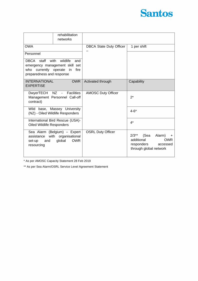
rehabilitation
networks
DBCA OWA DBCA State Duty Officer
–
1 per shift
DBCA Personnel
DBCA staff with wildlife and
emergency management skill set
who currently operate in fire
preparedness and response
INTERNATIONAL OWR
EXPERTISE
Activated through Capability
DwyerTECH NZ - Facilities
Management Personnel Call-off
contract)
AMOSC Duty Officer 2*
Wild base, Massey University
(NZ) - Oiled Wildlife Responders 4-6*
International Bird Rescue (USA)-
Oiled Wildlife Responders 4*
Sea Alarm (Belgium) – Expert
assistance with organisational
set-up and global OWR
resourcing
OSRL Duty Officer 2/3** (Sea Alarm) +
additional OWR
responders accessed
through global network
* As per AMOSC Capacity Statement 28 Feb 2019
** As per Sea Alarm/OSRL Service Level Agreement Statement
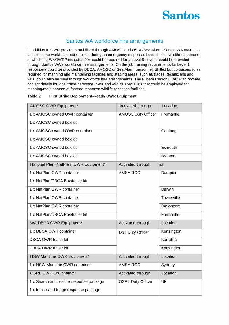
Santos WA workforce hire arrangements
In addition to OWR providers mobilised through AMOSC and OSRL/Sea Alarm, Santos WA maintains
access to the workforce marketplace during an emergency response. Level 1 oiled wildlife responders,
of which the WAOWRP indicates 90+ could be required for a Level 6+ event, could be provided
through Santos WA’s workforce hire arrangements. On the job training requirements for Level 1
responders could be provided by DBCA, AMOSC or Sea Alarm personnel. Skilled but ubiquitous roles
required for manning and maintaining facilities and staging areas, such as trades, technicians and
vets, could also be filled through workforce hire arrangements. The Pilbara Region OWR Plan provide
contact details for local trade personnel, vets and wildlife specialists that could be employed for
manning/maintenance of forward response wildlife response facilities.
Table 2: First Strike Deployment-Ready OWR Equipment
AMOSC OWR Equipment* Activated through Location
1 x AMOSC owned OWR container
1 x AMOSC owned box kit
AMOSC Duty Officer
Fremantle
1 x AMOSC owned OWR container
1 x AMOSC owned box kit
Geelong
1 x AMOSC owned box kit Exmouth
1 x AMOSC owned box kit Broome
National Plan (NatPlan) OWR Equipment* Activated through Location
1 x NatPlan OWR container
1 x NatPlan/DBCA Box/trailer kit
AMSA RCC
Dampier
1 x NatPlan OWR container Darwin
1 x NatPlan OWR container Townsville
1 x NatPlan OWR container Devonport
1 x NatPlan/DBCA Box/trailer kit Fremantle
WA DBCA OWR Equipment* Activated through Location
1 x DBCA OWR container DoT Duty Officer
Kensington
DBCA OWR trailer kit Karratha
DBCA OWR trailer kit Kensington
NSW Maritime OWR Equipment* Activated through Location
1 x NSW Maritime OWR container AMSA RCC Sydney
OSRL OWR Equipment** Activated through Location
1 x Search and rescue response package
1 x Intake and triage response package
OSRL Duty Officer
UK

2 x Cleaning and rehabilitation response
package
1 x Search and rescue response package
1 x Cleaning and rehabilitation response
package
Singapore
1 x Search and rescue response package
1 x Cleaning and rehabilitation response
package
Bahrain
1 x Wildlife Rehabilitation Unit Fort Lauderdale,
USA
* As per AMOSC Capacity Statement 28 Feb 2019
** As per OSRL Mobilisation Fact File. NB: 50% of equipment available to members.

Appendix M: Scientific Monitoring Plans

Page | 1
1 Scientific Monitoring Principles
1.1 Monitoring Design
In the event of an oil spill the monitoring design will depend upon the nature of the spill, the availability of baseline data in relation to the spill extent and expert opinion. In order to ensure the application of robust designs and sampling approaches which have the highest likelihood of detecting an environmental impact while allowing suitable flexibility, this plan provides a set of Guiding Principles for monitoring design and sampling (Table 1). A structured decision making framework for allocating monitoring effort in both time and space is described in Figure 1.
Table 1: Guiding principles for oil spill monitoring design and methodologies.
Principle Explanation Key guiding references
Match baseline Designs and methodologies should follow those used in appropriate baseline studies wherever possible.
N/A
Comprehensive sampling
Sampling methods should seek to sample the full range of taxa within each assemblage. This may require the use of several complimentary techniques (the exception is if indicator taxa are employed; see below).
N/A
Reliable indicator taxa
If indicator taxa are targeted then the choice of indicator should be defensible, and a link to the response of the broader assemblage demonstrated. Indicators of ecosystem function should also be considered.
Hilty and Merenlender (2000)
Appropriate sample area or volume
Size of sampling unit should be determined based on the level of clustering of individuals and whether the goal is to quantify this clustering, or establish low inter-sample variability (probably more the latter for oil spill studies).
Kenkel et al. (1989)
Reduce within sample variation over time
Wherever possible repeated measures are carried out on the same sample space in order to reduce within treatment variation.
N/A
Compositing of samples
Appropriate compositing to increase statistical power should be considered.
Carey and Keough (2002)
Account for environmental gradients and partition variations
Sources of variation are considered and compartmentalised to best reduce within treatment variation, and thereby maximise power to detect an impact. This is managed through several means:
1. Environmental covariates are considered in sampling design recorded and incorporated statistically.
2. A hierarchical or stratified sampling design is used to address variation at multiple scales
3. Design is standardized, by sampling equivalent strata (e.g., level of exposure, depth etc.).
English et al. (1997), Snedecor and Cochran (1989)
Assess statistical power
Where null-hypothesis tests are planned, statistical power of the design is assessed prior to execution.
Gerrodette (1987)
Legg and Nagy (2006)
Toft and Shea (1982)

Page | 2
Principle Explanation Key guiding references
Appropriate sampling extent
Sample the range of hydrocarbon concentration (and at least the upper end).
Skalski (1995)
Independence amongst samples
Site selection should aim for independence amongst samples and potential spatial or temporal autocorrelation should be considered.
Hurlbert (1984)
Reduce observation error
Observer bias and amongst observer variation should be considered.
Thompson and Mapstone (1997)
Appropriate spatial replication
Sites are replicated. A limitation is that there is only one spill, but control sites should be replicated and spatially Interspersed. Ideally, the design should be able to detect an impact at several possible scales.
Underwood (Underwood 1991, 1992, 1994)
Appropriate temporal replication
Sampling should account for natural temporal variation.
Underwood (Underwood 1991, 1992, 1994)

Page | 3
Figure 1: Structured decision making process based on Gregory et al. (2012) in reference to monitoring programs, the availability of baseline data, and oil spill trajectory. In an ideal design sampling would occur across a gradient of exposure rather than ‘impact’ and ‘control’ per se.

Page | 4
1.2 Data Analysis
The most important approaches to statistical analysis and related sampling design are summarised in Table 2 (below).
Table 2: Summary of data analysis techniques.
Analysis type Description Strengths Limitations Addressing limitations
Gradient analysis
Impact is quantified in terms of distance from spill.
Can be established post-spill.
Doesn’t account for inherent spatial patterns present prior to spill.
Include spatial covariates in model.
Incorporate a temporal component.
Control chart
Univariate
Single variable is monitored and plotted over time, and breaching of control limits tested.
Control sites are not required. Takes account of natural variation in system.
Control limits do not necessarily have biological meaning.
Doesn’t control for broader spatial scale temporal variation.
Include control charts for control sites which incorporate broad scale temporal variation.
Multivariate
Multiple variables are combined, monitored and plotted over time, and breaching of control limits tested.
Ability to combine suite of data (e.g. community composition) into one variable. Sites plots not required.
Individual responses are masked. Control limits do not necessarily have biological meaning. Significant control limits challenging to define. Direction of change is undefined.
Compliment with graphical approaches to identify direction of change and individual species responses.
Reference
Control limits are based on knowledge of biological system (e.g. minimum viable population size, toxicity).
Control limits have recognised biological meaning or consequence.
Control limits may be considered arbitrary.
Use established standards for control limits.
BACI
Quantifies state before and after potential impact, and also at impacted and control sites. Impact is tested by statistical interaction of terms.
Controls for natural variation, by incorporating control sites.
Limited power to detect significant impact. Requires appropriate matching of control (non-impacted) sites.
Requires pre-impact data.
Increase power by increasing temporal component.
Choose indicators with low natural variability.

Page | 5
2 Scientific Monitoring Plans by Receptor
2.1 SMP1 Marine Water Quality
SMP1 – Marine Water Quality
Rationale
The release of hydrocarbons at sea will pollute marine waters via floating, entrained or dissolved aromatic hydrocarbons.
The water quality SMP may also be used in conjunction with Monitor and Evaluate, to inform the sampling design of other SMPs where objectives are to evaluate impact and recovery of sensitive receptors, in relation to hydrocarbon contamination.
Aim To monitor changes in water quality following an oil spill and associated response activities for the purpose of detecting a potential impact and recovery and for informing other scientific monitoring studies.
Baseline
Refer Baseline Data Review (QE-00-BI-20001)
In addition, the Industry-Government Environmental Metadatabase (IGEM) (Santos is subscribed to) will be reviewed for applicable marine water quality baseline data.
In the absence of baseline data for hydrocarbons, data from appropriate reference sites will be used in place of the baseline values.
Initiation criteria
Upon notification of a Level 2 or 3 incident -(a level 2 or 3 incident includes those which may have an adverse effect on the environment. This may be informed by operational water quality monitoring)
Termination criteria
Concentrations of hydrocarbon contaminants, attributable to the released hydrocarbon, are not significantly higher than baseline data or similar non-impacted sites data.
In the absence of baseline or similar non-impact sites data, concentrations of hydrocarbon contaminants, attributable to the released hydrocarbon, are below the relevant hydrocarbon contaminant trigger level within the Australian and New Zealand Guidelines for Fresh and Marine Water Quality (Australian and New Zealand Governments 2018), or the relevant regulatory site-specific trigger level (where these exist), if this is lower and values are not significantly different to reference sites.
Forensic fingerprinting of the released hydrocarbon and water quality sample analysis by way of gas chromatography/mass spectrometry (GC/MS) may be used to determine the source of contaminants where this is not otherwise clear from operational monitoring.
Receptor impact
Impacts to specific receptors from hydrocarbons within marine waters are described in individual SMPs.

Page | 6
SMP1 – Marine Water Quality
Methodological approach
Overall sampling design approach will be enacted according to the availability of baseline data guided by the structured decision-making process based on Gregory et al. (2012):
4. If sites are contacted in which long-term baseline data is available, a control chart (time-series) design will be applied;
5. If insufficient long-term baseline data is available, where appropriately matched baseline data sites are impacted and non-impacted, a before-after-control-impact (BACI) approach to monitoring will be applied;
6. Where no baseline data sites are involved, a gradient approach to quantifying impacts will be applied.
See Figure 1 for detailed description of these approaches.
The selection of potentially impacted and non-impacted sites will be informed by Operational Monitoring, including operational water quality monitoring and spill trajectory modelling.
Sampling frequency will be dictated by the spatial extent of the spill, the number and location of sampling sites and the philosophy of the sampling design.
Water profiles
A water quality probe will be used to measure conductivity (to derive salinity), temperature and depth (CTD), dissolved oxygen (% and mg/L), turbidity, total dissolved solids and fluorometry along a depth profile. Sampling methods will be aligned with the recommended standard operating procedures for the use of sensors for oil spill monitoring found in Appendix F of the Oil Spill Monitoring Handbook (Hook et al. 2016).
Water quality
Water quality samples will be taken along a similar depth profile as the CTD measures using a Niskin bottle, Van Dorn water sampler, rosette sampler or equivalent instrument.
The laboratory(ies) will inform and supply the appropriate sample containers, storage requirements, holding times, detection limits/limit of reporting for required analytes and the analysis required for each sample.
Water samples shall be analysed for key contaminants of concern including polycyclic aromatic hydrocarbons (PAHs), monocyclic aromatic hydrocarbons (including benzene, toluene, ethylbenzene, xylene), and nutrients, metals and chlorophyll-a.
At each site, replicate water samples (at least three samples) will be collected to allow appropriate statistical analyses to be made including samples for quality assurance and quality control (QA/QC) purposes (i.e. split sample, triplicate sample, field blanks, transport blanks).
Water sample collection and handling will align with Standard operating procedures found in the Oil Spill Monitoring Handbook (Hook et al., 2016), specifically the following sections:
• Appendix A & B hydrocarbon analysis;
• Appendix C Volatile Organic Compounds Analysis; and
• Appendix D Surface Oil Analysis.
Environmental DNA (eDNA) will also be collected to detect for the presence of marine species in the water column. Water samples will be collected in Nalgene bottles and sent to an appropriate laboratory for analysis. Sample processing will depend on holding times required (<8 hours ideal) and may involve filtering and freezing of each sample (Grochowsi and Stat 2017).
Scope of works Prepared by monitoring provider for issue within 24 hours of SMP having been activated.

Page | 7
SMP1 – Marine Water Quality
Implementation Service provider able to mobilise within 72 hours of the SoW following approval by Santos (this time allows for costing, preparation of equipment and disposables and travel time to site).
Analysis and reporting
Chemical analysis will be carried out by NATA-accredited laboratories.
A government endorsed laboratory for forensic fingerprinting (GS/MS) will be used.
Data will be entered to spatially explicit database.
Data will be analysed appropriately in order to determine if there was a statistical difference in water quality before and after a hydrocarbon impact. Data and conclusions will be summarised in an environmental report card.
Final draft report to be prepared within one month of monitoring completion; external peer review of final draft within two weeks of report provision to reviewer; finalise report within two weeks of peer review having been completed.
2.2 SMP2 Sediment Quality
SMP2 - Sediment Quality
Rationale
Hydrocarbons released during a spill scenario may contact, settle and/or accumulate in marine sediments. Toxic substances found in accumulated hydrocarbons may lead to impacts to ecosystem processes associated with this primary producer habitat. Sediments and marine infauna will be sampled concurrently in order to establish potential correlations amongst the two parameters.
Aim
To monitor the fate and persistence of hydrocarbons in marine sediments following an oil spill and associated response activities.
To monitor marine benthic infauna assemblages as an indicator of sediment quality, in relation to an oil spill and associated response activities.
Baseline
Refer Baseline Data Review (QE-00-BI-20001)
In addition, the IGEM will be reviewed for applicable marine baseline sediment quality and infauna data.
In the absence of baseline sediment quality data, hydrocarbon contaminant trigger values for marine sediments as listed in the Australian and New Zealand Guidelines for Fresh and Marine Water Quality (Australian and New Zealand Governments 2018) will be used as a proxy for baseline levels.
Where other regulatory site-specific trigger levels exist, the lower of these levels and the Australian and New Zealand Guidelines for Fresh and Marine Water Quality (Australian and New Zealand Governments 2018) levels will be used as proxy baseline levels.
Initiation criteria
Operational Monitoring or SMP1 indicates that contacted sediment or sediment predicted to be contacted by a hydrocarbon spill.
Contact is defined as hydrocarbon exceeding one of the following thresholds:
• 1 g/m2 Floating oil
• 10 ppb Dissolved Aromatic Hydrocarbons
• 10 ppb Entrained hydrocarbons.

Page | 8
SMP2 - Sediment Quality
Termination criteria
Concentrations of hydrocarbons in marine benthic and shoreline sediments, attributable to the released hydrocarbon, are not significantly higher than baseline or similar non-impact sites.
In the absence of baseline or similar non-impact sites data, concentrations are below marine sediment quality interim guideline levels within the ANZG (2018), or the relevant regulatory site-specific trigger level (where these exist), if this is lower.
For infauna assemblages, abundance and species diversity/richness/composition are not significantly different from baseline (where baseline data exists) or are not statistically significantly different from comparable non-impacted benthic infauna assemblages.
Forensic fingerprinting of the released hydrocarbon and sediment quality samples by way of GC/MS may be used to determine the source of contaminants where this is not otherwise clear from operational monitoring.
Receptor impact
Impact to sediment quality is measured through change in hydrocarbon content and concentration. Change to sediment quality is also reflected by changes to infaunal assemblages. Potential impact to infaunal assemblages are measured through change(s) in:
• Taxonomic diversity
• Assemblage composition
• Abundance of indicator species.
Other pressures to these states are:
• Discharge of other toxicants
• Physical disturbance including dredging
• Sedimentation
• Introduction of marine pests
• Shading from marine infrastructure
• Climate change

Page | 9
SMP2 - Sediment Quality
Methodological approach
Overall sampling design approach will be enacted according to the availability of baseline data guided by the structured decision-making process based on Gregory et al. (2012):
7. If sites are contacted in which long-term baseline data is available, a control chart (time-series) design will be applied;
8. If insufficient long-term baseline data is available, where appropriately matched baseline data sites are impacted and non-impacted, a before-after-control-impact (BACI) approach to monitoring will be applied;
9. Where no baseline data sites are involved, a gradient approach to quantifying impacts will be applied.
See Figure 1 for detailed description of these approaches. The selection of potentially impacted and non-impacted sites will be informed by Operational Monitoring, including operational water quality monitoring and spill trajectory modelling.
Sampling frequency will be dictated by the spatial extent of the spill, the number and location of sampling sites and the philosophy of the sampling design
Sediment quality
Operational Monitoring (including spill trajectory modelling) and the results of SMP1 Marine Water Quality monitoring will be used to inform the location of potentially impacted sediment sites.
Sediment monitoring sites in nearshore and shoreline locations will also consider and align where practicable, with sites selected for habitat monitoring (i.e. SMP3, 4, 5 and 6).
Sampling frequency will be dictated by the spatial extend of the spill, the number and location of sampling sites and the philosophy of the sampling design.
At each site, replicate sediment samples will be taken including those for QA/QC purposes.
Sediment grab (i.e. Van Veen or Box corer) or coring equipment will be selected based on water depth (offshore, inshore or shoreline) and sample size requirements.
Sediment sample collection and handling will align with Standard operating procedures found in the Oil Spill Monitoring Handbook (Hook et al. 2016), specifically the following sections according to sampling equipment utilised:
• Appendix G hydrocarbon analysis (Grab samplers)
• Appendix H hydrocarbon analysis (Ship borne corer)
• Appendix H Manual push corer, and
• Appendix O Sediment infauna.
The laboratory(ies) will inform and supply the appropriate sample containers, storage requirements, holding times, detection limits/limit of reporting for required analytes and the analysis required for each sediment sample.
Sediment samples shall be analysed for key contaminants of concern including metals, hydrocarbons, nutrients, particle size distribution, and nutrients.
Infauna samples
A subset of the sediment sample shall be sieved in the field (if time permits) with collected infauna preserved (buffered formalin, formaldehyde or 70% ethanol) and sent to laboratory for identification of infauna to lowest taxonomic resolution possible.
eDNA will also be collected to detect for the presence of marine infauna species in sediments. Sediment will be removed from the surface of a subset of the sediment sample and sent to an appropriate laboratory for analysis.

Page | 10
SMP2 - Sediment Quality
Scope of works Prepared by monitoring provider for issue within 24 hours of SMP having been activated.
Implementation
Service provider to be capable of mobilising within 72 hours of the SoW having been approved by Santos.
Actual mobilisation time will depend on the decision to adopt post-spill pre-impact monitoring and associated timing requirements.
Analysis and reporting
Sediment samples analysed by NATA-accredited laboratories for presence and concentrations of hydrocarbons associated with the spill including full suite PAHs and total organic carbon.
A government endorsed laboratory for forensic fingerprinting (GC/MS) will be used.
Infauna samples sorted and identified by qualified marine invertebrate specialist to acceptable taxonomic groups.
Data will be entered to spatially explicit database and analysed statistically in order to detect significant differences among sites.
Data and conclusions will be summarised in an environmental report card. Final draft report to be prepared within one month of monitoring completion; external peer review of final draft within two weeks of report provision to reviewer; finalise report within two weeks of peer review having been completed.
2.3 SMP3 Sandy Beaches and Rocky Shores
SMP3 - Sandy Beaches and Rocky Shores
Rationale
Contact of entrained oil and stranded floating oil of shoreline habitats may occur on sandy beaches and rocky shores. Rocky and sandy shores provide habitat for a variety of intertidal organisms, which in turn provide food for shorebirds. Large tides tend to create a large degree of horizontal zonation amongst taxa. Rocky and sandy shores are included within the one receptor as they are often spatially mixed and both represent high energy regions.
Aim To monitor changes in biota of sandy and rocky shoreline habitats in relation to an oil spill and associated activities.
Baseline
Refer Baseline Data Review (QE-00-BI-20001)
In addition, the IGEM shall be reviewed for applicable rocky shoreline and sandy beach biota baseline data.
Minimal baseline data currently exists for rocky shorelines and sandy beaches.
Initiation criteria
Operational monitoring, SMP1 or SMP2 indicates that rocky and/or sandy shorelines are contacted or predicted to be contacted by a hydrocarbon spill.
Contact is defined as hydrocarbon exceeding one of the following thresholds:
• 1 g/m2 Floating oil
• 10 ppb Dissolved Aromatic Hydrocarbons
• 10 ppb Entrained hydrocarbons.

Page | 11
SMP3 - Sandy Beaches and Rocky Shores
Termination criteria
Shoreline assemblage structure, and hydrocarbon concentration levels in representative invertebrate species, are not significantly different from their baseline state (where baseline data exists) or are not statistically significantly different from comparable non-impacted assemblages; AND
SMP2 Sediment Quality monitoring at the site has been terminated AND
Shoreline clean-up at the site has been completed.
Receptor impact
Impact to shoreline invertebrates from pressures including hydrocarbons is measured through change in:
• Species diversity • Assemblage composition • Abundance of indicator taxa.
Other pressures to these states are:
• Physical disturbance • Discharge of toxicants • Litter/waste • Introduction of marine pests • Over-collection • Nutrification • Climate change.

Page | 12
SMP3 - Sandy Beaches and Rocky Shores
Methodological approach
Monitoring will be designed as follows:
• Where long-term baseline data sites are contacted, a control chart (time-series) design will be applied.
• Where appropriately matched baseline data sites are impacted and non-impacted, a BACI approach to monitoring will be applied.
• Where no baseline data sites are involved, a post-spill pre-impact (preferable) or gradient approach to quantifying impacts will be applied.
Owing to potentially high spatial variation in assemblage structure, post-spill pre-impact monitoring will be a priority where no baseline data exists. If this opportunity is not available, a gradient approach to monitoring will be applied.
Sampling frequency will be dictated by the number and location of sampling sites and the philosophy of the sampling design.
Rocky shoreline intertidal assemblages (fauna and flora) will be monitored using a quadrat/transect approach, with the positioning of quadrats/transects accounting for any natural variation in assemblage structure along a seaward-landward gradient. Assemblage structure to be recorded through in-situ counts of fauna and flora or still images taken for further analysis.
Sandy shoreline infauna will be sampled by way of replicated grab/core samples. Sampling sites within impacted and non-impacted areas to consider any cross-shore gradient in assemblage structure that may exist. Where baseline data exists, the methodology will be adapted to available data so that results are comparable.
Samples to be sieved with collected infauna preserved (buffered formalin, formaldehyde or 70% ethanol) and sent to laboratory for identification of fauna to lowest taxonomic resolution possible. Process to follow that for baseline data where this pre-exists.
Biomonitoring of hydrocarbon concentrations in shoreline invertebrates will occur through collection of replicated tissue samples from representative, and preferably widely available species, across impact and non-impacted locations.
The laboratory(ies) will supply and inform the appropriate method for collection, storage and holding times of tissue samples for required laboratory analysis and to avoid cross-contamination among samples.
Where limitations in the distribution and abundance of representative invertebrate species preclude collection of sufficient samples for analysis, in-situ biomonitoring using a locally available species (e.g. the use of caged oysters) shall be considered for assessing spatial and temporal changes in bioaccumulation of hydrocarbon concentrations in invertebrates across impact and reference sites.
Scope of works Prepared by monitoring provider for issue within 24 hours of SMP being activated.
Implementation
With the aim of collecting post-spill pre-impact data, service provider able to mobilise within 72 hours of the SoW having been provided to them (this time allowing for costing, preparation of equipment and disposables and travel to site).
Actual mobilisation time will depend on the decision to adopt post-spill pre-impact monitoring and associated timing requirements.

Page | 13
SMP3 - Sandy Beaches and Rocky Shores
Analysis and reporting
Specimens not identified in situ (in the field) will be processed and identified in the laboratory by appropriately qualified scientists.
Biota tissue samples (if collected) analysed for hydrocarbon contaminants by NATA-accredited laboratories.
Data will be entered to spatially explicit database and analysed in order to test for significant difference between impacted and non-impacted assemblages. Data and conclusions will be summarised in an environmental report card.
Final draft report to be prepared within one month of monitoring completion; external peer review of final draft within two weeks of report provision to reviewer; finalise report within two weeks of peer review having been completed.
2.4 SMP4 Mangrove Communities
SMP4 - Shorelines and Coastal Habitats – Mangroves
Rationale
In the event of Tier 2 or 3 spill, mangroves may be contacted by floating or entrained oil. Mangrove health may be adversely affected due to increased concentration of hydrocarbons in sediments and coating due to surface oil, which in turn can lead to leaf-loss, mortality and a reduction in areal extent of mangrove habitat. This plan’s focus is mangrove vegetation. Associated monitoring of sediment quality and mudflat fauna is described in SMP2 and SMP5, respectively.
Aim To monitor changes to mangrove extent and health in relation to an oil spill and associated activities.
Baseline
On-ground monitoring is ongoing at several locations , refer Baseline Data Review (QE-00-BI-20001).
Santos holds long term data from field mangrove health surveys at Varanus Island/ Bridled Island (Lowendal Group).
Baseline extent and of mangroves is monitored by remote sensing in several regions, and further historical and post-impact data for mangrove health and extent can be obtained as remotely sensed imagery (e.g., Sentinel, Landsat and Worldview).
Initiation criteria
Operational Monitoring, SMP1 or SMP2 indicates that mangroves are contacted or predicted to be contacted by a hydrocarbon spill.
Contact is defined as hydrocarbon exceeding one of the following thresholds:
• 1 g/m2 Floating oil
• 10 ppb Dissolved Aromatic Hydrocarbons
• 10 ppb Entrained hydrocarbons.
Termination criteria
Mangrove extent and health are not significantly different from their baseline state (where baseline data exists) or are not statistically significantly different from comparable non-impacted mangroves; AND
Sediment quality monitoring (SMP2) at the site has been terminated; AND
Shoreline response at the site has been completed.

Page | 14
SMP4 - Shorelines and Coastal Habitats – Mangroves
Receptor impact
Impact to mangroves from pressures including hydrocarbons is measured through change in:
• Tree health
• Aerial extent.
Other pressures to these states are:
• Physical disturbance
• Discharge of toxicants
• Litter
• Introduction of marine pests
• Dust
• Sedimentation from human activities
• Climate change.
Methodological approach
Remote sensing data will be accessed for the purpose of detecting change in aerial cover and change in canopy health through and index of plant health (e.g., NDVI or MSAVI) (Astron Environmental Services 2013).
Where long term on-ground baseline monitoring has occurred, further post impact onground monitoring should be carried out to complement any analysis of remote sensing. Analysis of long-term onground monitoring data will be as follows:
• Where long-term baseline data sites (only) are contacted a control chart (time-series) design will be applied.
• Where appropriately matched baseline data sites are impacted and non-impacted, a BACI approach to monitoring will be applied.
• Where no baseline data sites are involved a gradient approach to quantifying impacts will be applied (See Figure 1).
On-ground monitoring of mangroves will aim to detect change in mangrove health, including canopy cover and plant/leaf health indices.
Field methodology will follow the routine monitoring techniques currently employed for Santos at Varanus Island (Quadrant Energy Australia Limited 2018), adapting where required to align with pre-existing baseline field data, where available.
Sampling of sediments as per SMP2 will occur at mangrove health assessment sites to allow any changes in mangrove health to be related to sediment hydrocarbon levels.
In-field mangrove health sampling frequency will be dictated by the number and location of sampling sites and the sampling design applied.
Scope of works Prepared by monitoring provider for issue within 24 hours of SMP being activated.
Implementation
On-ground monitoring will only occur where long-term baseline data has been collected, and hence no post-spill pre-impact data collection will be required. On-ground post-spill data will be collected at an appropriate time as guided by the analysis of remote sensing imagery, and potential on-ground assessment.
Analysis and reporting
Data will be entered to spatially explicit database and analysed in order to test statistically significant change to parameters associated with hydrocarbon spill. Data and conclusions will be summarised in an environmental report card.
Final draft report to be prepared within one month of monitoring completion; external peer review of final draft within two weeks of report provision to reviewer; finalise report within two weeks of peer review having been completed.

Page | 15
2.5 SMP5 Intertidal Mudflats
SMP5 - Shorelines and Coastal Habitats – Intertidal Mudflats
Rationale
Intertidal mudflat communities are primary producer habitats which support invertebrate fauna, which in turn provides a valuable food source for shorebirds. High diversity of infauna (particularly molluscs) occur within these habitats and may be affected by penetrating oil. At high tide, these habitats become foraging grounds for vertebrates such as rays and sharks. While there is some localised disturbance, most of the communities in the area of interest are generally in an undisturbed condition. These habitats are at high risk of impact as the sheltered environments promote high faunal diversity combined with low-energy wave action.
Aim To monitor changes in intertidal mudflat communities associated with an oil spill and associated activities.
Baseline
Refer Baseline Data Review (QE-00-BI-20001)
. In addition, the IGEM shall be reviewed for applicable intertidal mudflat infauna baseline data.
Initiation criteria
Operational Monitoring, SMP1 or SMP2 indicates that mudflat habitats are contacted or predicted to be contacted by a hydrocarbon spill.
Contact is defined as hydrocarbon exceeding one of the following thresholds:
• 1 g/m2 Floating oil
• 10 ppb Dissolved Aromatic Hydrocarbons
• 10 ppb Entrained hydrocarbons.
Termination criteria
Mudflat infaunal assemblages are not significantly different from their baseline state (where baseline data exists) or are not statistically significantly different from comparable non-impacted assemblages; AND
SMP2 Sediment Quality monitoring at the site has been terminated; AND
Clean-up of the shoreline site has been completed.
Receptor impact
Impact to mudflat epifauna and infauna from pressures, including hydrocarbons, is measured through change in:
• Species diversity
• Assemblage composition
• Abundance of indicator taxa.
Other pressures to these states are:
• Physical disturbance
• Discharge of toxicants
• Overfishing (bait collecting)
• Introduction of marine pests
• Climate change.

Page | 16
SMP5 - Shorelines and Coastal Habitats – Intertidal Mudflats
Methodological approach
Monitoring will be designed as follows:
• Where long-term baseline data sites (e.g., Roebuck Bay) are contacted, a control chart (time-series) design will be applied.
• Where appropriately matched baseline data sites are impacted and non-impacted, a BACI approach to monitoring will be applied.
• Where no baseline data sites are involved a post-spill pre-impact (preferable) or gradient approach to quantifying impacts will be applied (See Figure 1).
Owing to potentially high spatial variation in assemblage structure, post-spill pre-impact monitoring will be a priority if baseline data are not available. If this opportunity is not available, a gradient approach to monitoring will be applied.
Mudflat infauna will be sampled by way of replicated grab/core samples. Sampling sites within impacted and non-impacted areas to consider any cross-shore gradient in assemblage structure that may exist. Where baseline data exists methodology to adapt to available data such that results are comparable.
Sites selected for mudflat infauna sampling to be concurrently sampled for sediment quality as per SMP2.
Sampling frequency will be dictated by the number and location of sampling sites and the philosophy of the sampling design.
Samples to be sieved with collected infauna preserved (buffered formalin, formaldehyde or 70% ethanol) and sent to laboratory for identification of fauna to lowest taxonomic resolution possible. Process to follow that for baseline data where this pre-exists.
Scope of works Prepared by monitoring provider for issue within 24 hours of SMP being activated.
Implementation
With the purpose of collecting post spill pre-impact data, service provider able to mobilise within 72 hours of the scope of work having been provided to them (this time allowing for costing, preparation of equipment and disposables and travel to site).
Actual mobilization time will depend on the decision to adopt post-spill pre-impact monitoring and associated timing requirements.
Analysis and reporting
Data will be entered to spatially explicit database and analysed in order to determine significant differences between impacted and non-impacted assemblages. Data and conclusions will be summarised in an environmental report card.
Final draft report to be prepared within one month of monitoring completion; external peer review of final draft within two weeks of report provision to reviewer; finalise report within two weeks of peer review having been completed.

Page | 17
2.6 SMP6 Benthic Habitats
SMP6 - Benthic Habitats
Rationale
Benthic habitats are those habitats associated with the seafloor. Major benthic habitats at risk are:
• Coral reefs (likely high susceptibility to spill)
• Macroalgae and seagrass (likely moderate susceptibility to spill)
• Non-coral benthic filter feeders (likely moderate susceptibility to spill)
• Sub-tidal pavement (likely moderate susceptibility to spill)
• Soft-substrate (likely lower susceptibility to spill).
Macroalgal and seagrass communities are important primary producers which also provide habitat, refuge areas and food for fish, turtles, dugongs and invertebrates. Seagrass and macroalgae also increase structural diversity and stabilise soft substrates. Non-coral benthic filter feeders, which include sponges, molluscs, sea whips and gorgonians, are considered indicators of disturbance due to their immobility and long living. Corals are important primary producers that provide food, substrate and shelter for a diversity of marine life, including invertebrates and fish. They also protect coastlines from wave erosion and provide important substrate for algae. Undisturbed intertidal and subtidal coral reefs occur in several locations throughout the EMBA and are generally considered to be in good condition.
Aim
To monitor changes in the cover and composition of benthic habitats in relation to an oil spill and associated activities. To monitor change in hard coral health and reproduction in relation to an oil spill and associated activities. Benthic habitats are those habitats associated with the seafloor. Major benthic habitats at risk are:
• Coral reefs (likely high susceptibility to spill)
• Macroalgae and seagrass (likely moderate susceptibility to spill)
• Non-coral benthic filter feeders (likely moderate susceptibility to spill)
• Sub-tidal pavement (likely moderate susceptibility to spill)
• Soft-substrate (likely lower susceptibility to spill).
Baseline
Refer Baseline Data Review (QE-00-BI-20001)
In addition, the IGEM will be reviewed for applicable benthic habitat and coral health and reproduction baseline data.
Remote sensing data, satellite and aerial imagery previously acquired (for example Hyperspectral imagery along the Ningaloo lagoon) (Kobryn et al. 2013) may also be applicable for shallow clear-water benthic habitats to detect changes in benthic habitat cover and composition.
Pollution-induced change to benthic habitat cover and composition may take some time to be detected. Therefore post-spill, pre-impact benthic survey data will be collected when required to have a baseline state following initial oil contact.

Page | 18
SMP6 - Benthic Habitats
Initiation criteria
Benthic habitat cover and composition
Operational Monitoring, SMP1 or SMP2 indicates that subtidal benthic habitats are contacted or are predicted to be contacted by a hydrocarbon spill.
Coral health and reproduction
Operational Monitoring, SMP1 or SMP2 indicates that coral habitat is contacted or is predicted to be contacted by a hydrocarbon spill.
Contact is defined as hydrocarbon exceeding one of the following thresholds:
• 1 g/m2 Floating oil
• 10 ppb Dissolved Aromatic Hydrocarbons
• 10 ppb Entrained hydrocarbons.
Termination criteria
Benthic habitat cover and composition
Cover and composition of benthic habitats are not statistically significantly different from that of their baseline state (where baseline data exists) or are not statistically significantly different from comparable non-impacted assemblages.
Coral health and reproduction
Hydrocarbon concentration in corals, reproductive state and settlement indices are not statistically different from the baseline state (where baseline data exists) or from comparable non-impacted assemblages.
Receptor impact
Impact to benthic habitats from pressures including hydrocarbons is measured through change in:
• Species diversity
• Assemblage composition
• Percent cover.
Other pressures to these states are:
• Physical disturbance
• Discharge of toxicants
• Introduction of marine pests
• Shading
• Climate change.

Page | 19
SMP6 - Benthic Habitats
Methodological approach
Monitoring design will be as follows:
• Where long-term baseline data sites are contacted, a control chart (time-series) design will be applied.
• Where appropriately matched baseline data sites are impacted and non-impacted, a BACI approach to monitoring will be applied.
• Where no baseline data sites are involved, a gradient approach to quantifying impacts will be applied.
Benthic Habitat Cover and Composition
Field survey methodology will be based upon acquiring repeat digital imagery (video or still images) of benthic habitats along fixed transects (preferable), using a stratified sampling approach at each site to target different habitat types and depths where clear gradients in these conditions exist. Site selection and image acquisition methodology will aim to align applicable baseline studies where these exist, such that imagery is comparable.
The number of sites and frequency of sampling will depend upon the sampling design philosophy.
Divers, towed video or remotely operated vehicles (ROVs) will be employed to collect imagery considering safety aspects and the depth of water at survey locations.
Where divers are employed, fish species will also be recorded where practicable (for example following methodologies employed by Babcock et al. (2008) to contribute to SMP11.
Coral Health and Reproduction
Using divers, selected coral colonies will have tissue samples removed for the purpose of laboratory analysis of the concentration of accumulated hydrocarbons and for determining reproductive state, noting sampling for reproductive state will be dependent upon the timing of coral spawning. Reproductive state will be determined from measures of gamete size, stage and fecundity determined from in-field examination and laboratory analysis of histological samples.
In addition to the standard suite of ecotoxicology testing done on the released hydrocarbon as part of the Operational Monitoring Program, ecotox testing of the released hydrocarbon on the larval competency of representative coral species will be conducted.
Settlement plates will be deployed to monitor settlement of coral recruits following spawning periods to ascertain the level of coral recruitment at impacted and non-impacted sites.
Scope of works Prepared by monitoring provider for issue within 24 hours of SMP being activated.
Implementation
Service provider is to be able to mobilise within 72 hours of the SoW being approved by Santos (this time allowing for costing, preparation of equipment and disposables and travel to site).
Actual mobilisation time will depend on the decision to adopt post-spill pre-impact monitoring and associated timing requirements.

Page | 20
SMP6 - Benthic Habitats
Analysis and reporting
Digital imagery will be analysed using a point-count technique (using software such as AVTAS, Coral Point Count with Excel extensions (CPCe) or TransectMeasure (SeaGIS)) to estimate the percentage cover of biotic and abiotic categories (in line with the CATAMI classification scheme) comprising the benthic habitat. Biotic categories to include the following as applicable: corals; macroalgae and seagrass; and non-coral benthic filter feeders.
Live, dead and bleached coral cover shall be recorded. The imagery collected will allow for the determination of percent cover, abundance, measurement of size (if scaling lasers are included in the image) and a visual assessment of health (Kohler and Gill 2006).
NATA accredited laboratory analysis to determine the concentration of hydrocarbons within coral tissue.
Reproductive output to be determined by complementary means, including in-field and laboratory analysis of gametes, including microscopic examination of histological samples preserved in the field.
Coral larval competency tests to be conducted by ecotox laboratory in addition to standard suite of ecotox tests using released hydrocarbon.
Data will be entered to spatially explicit database and analysed in order to determine significant differences between impacted and non-impacted assemblages. Data and conclusions will be summarised in an environmental report card provided as part of report.
Final draft report to be prepared within one month of monitoring completion; external peer review of final draft within two weeks of report provision to reviewer; finalise report within two weeks of peer review having been completed.

Page | 21
2.7 SMP7 Seabirds and Shorebirds
SMP7 - Seabirds and Shorebirds
Rationale
The region supports around 25 species of migratory shorebirds, 20 species of resident shorebirds, and approximately 30 species of seabirds. Shorebird foraging is most highly concentrated on tidal mudflats, while seabirds tend to nest on offshore islands.
Impacts to seabirds and shorebirds due to the presence of surface, entrained and dissolved hydrocarbons may include behavioural (e.g. deviation from migratory routes), physiological (e.g. disruption to digestion) or physical (e.g. matting of feathers, inability to fly). These effects may ultimately lead to death or failed breeding.
For the purposes of this document, seabirds and shorebirds are defined as:
• shorebirds – those birds that inhabit and feed in the intertidal zone and adjacent areas and are resident or migratory, using the area principally during the austral summer
• seabirds – those birds associated with the sea and deriving most of their food from it, and typically breeding colonially, including the marine raptors osprey and white-bellied sea eagle.
Aim
Quantify seabirds and shorebirds, in the spill and response areas.
Quantify lethal and/or sub‐lethal impacts of hydrocarbon spill exposure on seabirds and shorebirds.
Monitor changes in seabird populations (reproductive success) in relation to the hydrocarbon spill and clean‐up activities.
Baseline
Refer Baseline Data Review (QE-00-BI-20001)
The Oil Spill Response Atlas (Department of Transport (DoT)) and National Conservation Values Atlas (Department of the Environment and Energy ‐http://www.environment.gov.au/webgis‐framework/apps/ncva/ncva.jsf) should also be consulted.
Long-term seabird monitoring has been conducted on Lowendal, Airlie and Serrurier Islands by Santos as part of seabird and shearwater monitoring programs.
Initiation criteria
Operational monitoring indicates that known foraging, roosting or nesting areas for seabirds and/or shorebirds has been contacted, or are predicted to be contacted, by a hydrocarbon spill; OR
Operational monitoring indicates that seabirds and shorebirds have been contacted, or are predicted to be contacted, by a hydrocarbon spill.
Contact is defined as hydrocarbon exceeding one of the following thresholds:
• 1 g/m2 Floating oil
• 10 ppb Dissolved Aromatic Hydrocarbons
• 10 ppb Entrained hydrocarbons.
Termination criteria
Detectable levels of hydrocarbons attributable to the hydrocarbon spill are not present in seabird and shorebird tissues; AND
measured variables are not statistically significantly different from their baseline or pre‐spill state (where these data exist) or from measured variables at non‐impacted sites; AND
Monitoring is terminated in consultation with the relevant environmental authority (DBCA and/or DoEE).

Page | 22
SMP7 - Seabirds and Shorebirds
Receptor impact
Impact to sea and shore birds from pressures including hydrocarbons is measured through change in:
• Species diversity
• Bird abundance
• Health/condition
• Breeding success (resident species only).
Other pressures to these states are:
• Physical disturbance of foraging and nesting habitat
• Accidental chemical spillage
• Entanglement in litter
• Displacement by less favourable species (e.g. Silver Gull)
• Predation
• Climate change.
Methodological approach
Monitoring design will be as follows:
• Where long-term baseline data sites are contacted a control chart (time-series) design will be applied.
• Where appropriately matched baseline data sites are impacted and non-impacted, a BACI approach to monitoring will be applied. Given the ease of survey establishment, post-spill pre-impact monitoring will be attempted wherever practicable in order to established pre-impact state.
• Where no baseline data sites are involved a gradient approach to quantifying impacts will be applied.
Monitoring for seabirds and shorebirds will measure abundance and diversity in key foraging/roosting areas with the timing of surveys to coincide with seasonal peaks in abundance.
The seabird and shorebird roost count monitoring will follow current accepted survey methodology conducted in the area, such as Bamford and Moro (2011) at Barrow Island, and survey guidelines standardised by the Department of the Environment and Energy (2017).
Monitoring of seabirds to focus on nesting (burrow) density, breeding participation and breeding success, taking measurements of the number of adults, eggs and chicks with the timing of surveys to allow assessments immediately after egg laying and immediately prior to chick fledging.
Bird mortality to be recorded during monitoring of seabirds and shorebirds with tissue samples taken from dead birds for hydrocarbon analysis in the laboratory.
Necroscopies will follow the process of Gagnon and Rawson (2010).
Scope of works Prepared by monitoring provider for issue within 24 hours of SMP being activated.
Implementation
Service provider able to mobilise within 72 hours of the scope of work having been provided to them (this time allowing for costing, preparation of equipment and disposables and travel to site).
Actual mobilisation time will depend on the decision to adopt post-spill pre-impact monitoring and associated timing requirements.

Page | 23
SMP7 - Seabirds and Shorebirds
Analysis and reporting
Data will be entered to spatially explicit database and analysed in order to determine significant differences between impacted and non-impacted assemblages. Data and conclusions will be summarised in an environmental report card.
Draft annual report to be prepared within one month of monitoring completion; external peer review of final draft within two weeks of report provision to reviewer; finalise report within two weeks of peer review having been completed.
2.8 SMP8 Marine Megafauna
SMP8 - Marine Megafauna
Rationale
Thirty-eight species of marine mammals are known to occur within the region. These include cetaceans (whales and dolphin) and sirenians (dugong). The whale shark (Rhincodon typus) is also included within this plan. Effects to marine megafauna due to presence of surface oil, entrained oil and dissolved aromatic hydrocarbons may include behavioural (e.g. deviation from migratory routes), physiological (e.g. disruption to digestion) or physical effects. Given large spatial variation in occurrence and broad scale movement, population estimates and associated change are not often available. This plan will focus on assessing the extent of impacts to animals within the region, and where possible, the level of recovery. This will then be used to deduce potential impacts at a population level.
Aim To monitor short and long-term environmental effects on marine mammals and whale sharks that may have resulted from the hydrocarbon spill and associated response.
Baseline Refer Baseline Data Review (QE-00-BI-20001)
Initiation criteria
Operational monitoring indicates that marine megafauna are contacted or predicted to be contacted by a hydrocarbon spill.
Contact is defined as hydrocarbon exceeding one of the following thresholds:
• 1 g/m2 Floating oil
• 10 ppb Dissolved Aromatic Hydrocarbons
• 10 ppb Entrained hydrocarbons.
Termination criteria
Restoration or resumption of key biological processes (e.g. abundance, distribution, breeding) necessary to ensure post-impact recovery is demonstrated. Specific criteria to be developed by Marine Scientist(s) with expertise in marine mammals in the north-west of Western Australia; AND
No further instances of dead marine megafauna with detectable levels of hydrocarbons attributable to the hydrocarbon spill; AND
Monitoring is terminated in consultation with the relevant environmental authority (DBCA and/or DoEE).

Page | 24
SMP8 - Marine Megafauna
Receptor impact
Impact to marine mammals and whale sharks from pressures including hydrocarbons is measured through observed injury and mortality.
Other pressures to these states are:
• Physical disturbance
• Entanglement in fishing gear and litter
• Accidental chemical spillage
• Climate change
• Over-exploitation.
Methodological approach
Aerial and marine surveys will be implemented to identify individuals in proximity of the spill and to quantify damage:
• Aerial surveys will follow the protocols of Hedley et al. (2011)
• Marine surveys will follow the protocols of Watson et al. (2009)
Tissue sampling of dead or injured animals will follow the protocols of:
• Department of Environment and Heritage (DEH) (2006) (Cetaceans)
• Eros et al. (2000) (Dugongs).
Scope of works Prepared by monitoring provider for issue within 24 hours of SMP being activated.
Implementation
Service provider able to mobilise within 72 hours of the scope of work having been approved by Santos (this time allowing for costing, preparation of equipment and disposables and travel to site).
Actual mobilisation time will depend on the decision to adopt post-spill pre-impact monitoring and spill timing requirements.
Analysis and reporting
Data will be entered to spatially explicit database. Data and conclusions will be summarised in an environmental report card.
Statistical power related to these receptors is likely to be low, due to observational data and small sample sizes. Therefore, the assessment of quantified impacts will be corroborated with marine scientist(s) with expertise in relevant fauna in the north west of Western Australia.
Draft annual report to be prepared within one month of annual monitoring completion; external peer review of final draft within two weeks of report provision to reviewer; finalise report within two weeks of peer review having been completed.
2.9 SMP9 Marine Reptiles
SMP9 - Marine Reptiles
Rationale
Six species of marine turtle, 22 species of sea snake and one species of estuarine crocodile are considered to occur within the region. Impacts to marine reptiles due to presence of surface oil, entrained oil and dissolved aromatic hydrocarbons may include behavioural, physiological (e.g. disruption to digestion) or physical effects. This plan is primarily focussed on marine turtles, while assessing other reptiles where encountered.
Aim
To observe and quantify the presence of marine reptiles in the spill and response areas, and broader regional areas.
To assess and quantify lethal impacts or sub-lethal impacts of this exposure or interactions.
To monitor changes in turtle populations in relation to an oil spill and associated activities.

Page | 25
SMP9 - Marine Reptiles
Baseline
Refer Baseline Data Review (QE-00-BI-20001)
The Oil Spill Response Atlas (Department of Transport (DoT)) and National Conservation Values Atlas (Department of the Environment and Energy ‐http://www.environment.gov.au/webgis‐framework/apps/ncva/ncva.jsf) should also be consulted.
Initiation criteria
Operational monitoring indicates that marine reptiles or nesting sites are contacted or likely to be contacted by a hydrocarbon spill; OR
Operational monitoring indicates that marine reptiles are contacted, or are predicted to be contacted, by a hydrocarbon spill.
Contact is defined as hydrocarbon exceeding one of the following thresholds:
• 1 g/m2 Floating oil
• 10 ppb Dissolved Aromatic Hydrocarbons
• 10 ppb Entrained hydrocarbons.
Termination criteria
Detectable levels of hydrocarbons attributable to the hydrocarbon spill are no longer present in marine reptile tissues collected from live or dead individuals; AND
In the event that an impact attributable to the hydrocarbon spill is detected on marine reptiles, the measured parameters are not statistically significantly different from their baseline or pre-spill state (where these data exist) or from measured parameters at non impacted sites; AND
Monitoring is terminated in consultation with the relevant environmental authority (DBCA and/or DoEE).
Receptor impact
Impact to marine turtles from pressures including hydrocarbons is measured through change in:
• Abundance
• Health/condition
• Nesting success.
Impact to other marine reptiles from pressures including hydrocarbons is measured through change in observed injury and condition.
Other pressures to these states are:
• Lighting and flares causing disorientation (turtles)
• Vessel strike
• Physical disturbance of nesting sites
• Predation
• Entanglement in fishing gear and litter
• Accidental chemical spillage
• Habitat loss or change due to dredging
• Climate change
• Over-exploitation.

Page | 26
SMP9 - Marine Reptiles
Methodological approach
Abundance
In-water impacts – aerial surveys.
Shoreline impacts – ground surveys (either rapid track census survey or tagging program).
Health/condition
In-water impacts – vessel surveys (collecting observations on animal condition and collection of tissue samples or dead specimens for analysis).
Shoreline impacts – ground surveys (collecting observations on animal condition and collection of tissue samples or dead specimens for analysis).
Dead reptiles will be collected for autopsy following Gagnon (2009)
Reproductive success
Shoreline impacts – ground surveys (detailed tagging and/or nesting success studies).
Design of ground surveys for turtles will be applied as follows:
• Where long-term baseline data sites are contacted a control chart (time-series) design will be applied.
• Where appropriately matched baseline data sites are impacted and non-impacted, a BACI approach to monitoring will be applied.
• Where no baseline data sites are involved, and timing allows, a post spill pre-impact approach will be attempted
• If a post-spill pre-impact approach is not practicable, a gradient approach to quantifying impacts will be applied
Scope of works Prepared by monitoring provider for issue within 24 hours of SMP being activated.
Implementation
Service provider to be able to mobilise within 72 hours of the scope of work having been approved by Santos (this time allowing for costing, preparation of equipment and disposables and travel to site).
Actual mobilisation time will depend on the decision to adopt post-spill pre-impact monitoring and spill timing requirements.
Analysis and reporting
Data will be entered to spatially explicit database. Turtle data will be analysed in order to test for significant differences between impacted and non-impacted assemblages. Data and conclusions will be summarised in an environmental report card.
Owing to their observational nature and potentially low sample size, observed impacts to other reptile fauna will be corroborated with marine scientist(s) with expertise in relevant fauna in the north-west of Western Australia.
Draft annual report to be prepared within one month of annual monitoring completion; external peer review of final draft within two weeks of report provision to reviewer; finalise report within two weeks of peer review having been completed.
2.10 SMP10 Seafood Quality
SMP10 - Seafood Quality
Rationale
Exposure of commercial and recreationally targeted demersal and pelagic fish species to entrained and dissolved aromatic hydrocarbons can cause flesh tainting and increase the levels of toxicants above human consumption guidelines. Aromatic hydrocarbons are carcinogenic to humans. This scope includes finfish, sharks and invertebrates (principally crustacea).

Page | 27
SMP10 - Seafood Quality
Aim To identify potential human health risks due to the presence of hydrocarbon concentrations in the flesh of targeted seafood species for consumption.
Baseline
Refer Baseline Data Review (QE-00-BI-20001)
Human health benchmarks relating to the exposure of PAHs shall be used to determine health effects as per Yender et al. (2002).
Flesh samples from non-impacted sites to be used as baseline for olfactory analysis for flesh taint.
Initiation criteria
Operational monitoring and results from SMP1 predicts or observes contact of oil to target species for consumption.
Contact is defined as hydrocarbon exceeding one of the following thresholds:
• 1 g/m2 Floating oil
• 10 ppb Dissolved Aromatic Hydrocarbons
• 10 ppb Entrained hydrocarbons.
Termination criteria
The following termination criteria will be adopted in consultation with WA DPIRD-Fisheries, DAWR – Fisheries, AFMA and Department of Health.
Hydrocarbon concentrations in the tissues of seafood are not above levels considered a human health risk from consumption; AND
Flesh taint is not detected from olfactory testing of seafood samples; AND
Target species are no longer exposed to hydrocarbons in the water column.
Receptor impact
Impact to seafood quality from hydrocarbons is measured through change in:
• Toxicity indicators
• Olfactory taint.
Other pressures to these states are:
• Accidental chemical spillage
• Disease.
Methodological approach
Target fish species determined from water quality monitoring results and relevant and available commercial and recreational-fished species.
Sampling of target species will follow a gradient design (Gagnon and Rawson 2012) ranging from impacted to non-impacted (or non-suspect) catches using commercial and recreational fishing techniques undertaken by commercial and recreational fishers. Sampling method (netting, trawling, baited fish traps, spear fishing, line fishing) will be determined by habitat, target species and spill location.
If more than one target species is affected, replicate samples of each species shall be collected, with a minimum of five replicate samples.
Olfactory testing will follow Rawson et al. (Rawson et al. 2011), following the duo-trio method (Standards Australia 2005).
Scope of works Prepared by monitoring provider for issue within 24 hours of this SMP being activated.

Page | 28
SMP10 - Seafood Quality
Implementation
Service provider to be able to mobilise within 72 hours of the scope of work having been approved by Santos (this time allowing for costing, preparation of equipment and disposables and travel to site).
Actual mobilisation time will depend on the decision to adopt post-spill pre-impact monitoring and spill timing requirements.
Analysis and reporting
Laboratories will be NATA-accredited for food standards analyses. Data will be stored in spatially explicit database and analysed in order to test for significant differences between impacted and non-impacted seafood.
Final draft report to be prepared within one month of monitoring completion; external peer review of final draft within two weeks of report provision to reviewer; finalise report within two weeks of peer review having been completed.
2.11 SMP11 Fish, Fisheries and Aquaculture
SMP11- Fish, Fisheries and Aquaculture
Rationale
Impacts to fisheries species due to presence of entrained hydrocarbons may include lethal and sub-lethal physiological effects (e.g. reduced growth) and physical effects. The region comprises the Indo-West Pacific area which consists of a high diversity of fish species and assemblages and provides important spawning and nursery grounds for several fisheries species. Fish are concentrated in a number of biodiversity hotspots. The environment is also conducive to aquaculture including pearl production. Fisheries species that spawn or inhabit near shore areas face a greater risk to an oil spill than finfish found in deeper waters.
Aim
To monitor changes in structure and distribution of fish assemblages in relation to an oil spill and associated activities.
To monitor the effect of hydrocarbon exposure and physiological condition on fisheries and aquaculture species.
Baseline Refer Baseline Data Review (QE-00-BI-20001)
In addition, the IGEM shall to be reviewed for applicable baseline data.
Initiation criteria
Operational monitoring indicates fish, fisheries or aquaculture are contacted or likely to be contacted by a hydrocarbon spill.
Contact is defined as hydrocarbon exceeding one of the following thresholds:
• 1 g/m2 Floating oil
• 10 ppb Dissolved Aromatic Hydrocarbons
• 10 ppb Entrained hydrocarbons.
Termination criteria
Fish assemblages are not statistically significantly different than those of baseline or similar non-impacted assemblages; AND
Hydrocarbon concentrations, physiological condition indices, and biomarker levels in affected fish and aquaculture species are not statistically significantly different from those of non-impacted samples; AND
Termination of monitoring is done in consultation with the Department of Primary Industries and Regional Development (DPIRD).

Page | 29
SMP11- Fish, Fisheries and Aquaculture
Receptor impact
Impact to fish, fisheries and aquaculture from pressures including hydrocarbon concentrations is measured through change in:
• Species diversity
• Abundance of indicator taxa
• Assemblage structure
• Health.
Other pressures to these states are:
• Accidental chemical spillage
• Over fishing
• Introduction of marine pests
• Habitat disturbance
• Climate change.
Methodological approach
Fish assemblages will be assessed using the stereo-baited remote underwater videos (BRUVs) following Shortis et al. (2009). Fish assemblages will be randomly sampled within discrete habitats at cross-shelf impact areas and non-impact areas.
Sampling design for fish assemblages will be as follows:
• Where long-term baseline data sites are contacted a control chart (time-series) design will be applied.
• Where appropriately matched baseline data sites are impacted and non-impacted, a BACI approach to monitoring will be applied.
• If baseline data is not available, a gradient approach to quantifying impacts will be applied (See Figure 1).
Where relevant, data available from DPIRD, including catch/effort data, will be assessed to determine potential changes from baseline levels in fishing grounds potentially affected by an oil spill compared to after the event.
For fish and aquaculture species potentially exposed to an oil spill, species will be sampled across the contamination gradient as per Gagnon and Rawson (2012).
Hydrocarbon concentrations (particularly PAH) within tissues of fish and aquaculture species will be determined. Exposure to hydrocarbons on fish health will also be determine through analysis of physiological indices and biochemical markers following Gagnon and Rawson (2012).
If fish kills are observed, whole specimens will be obtained and preserved (frozen) for necropsy to determine the cause of death.
Scope of works Prepared by monitoring provider for issue within 24 hours of this SMP being activated.
Implementation
Service provider to be able to mobilise within 72 hours of the scope of work having been approved by Santos (this time allowing for costing, preparation of equipment and disposables and travel to site).
Actual mobilisation time will depend on the decision to adopt post-spill pre-impact monitoring and spill timing requirements.

Page | 30
SMP11- Fish, Fisheries and Aquaculture
Analysis and reporting
BRUV imagery will be processed using EventMeasure (SeaGIS) software.
NATA-accredited laboratories will be employed for health analyses.
Data will be entered to spatially explicit database and analysed to test for statistically significant differences between non-impacted and impacted fish assemblages.
Data and conclusions will be summarised in an environmental report card.
Final draft report to be prepared within one month of monitoring completion; external peer review of final draft within two weeks of report provision to reviewer; finalise report within two weeks of peer review having been completed.
2.12 SMP12 Whale Shark
SMP12- Whale Shark
Rationale
Whale sharks inhabit most of the Western Australian coast and seasonally aggregate at Ningaloo Reef in the austral autumn and winter, coinciding with a pulse of productivity following mass coral spawning in early autumn, with the population during this period dominated by juveniles (Bradley et al. 2016).
In addition to the monitoring that will be undertaken as part of SMP8 Marine Megafauna, additional scientific monitoring of whale sharks along the Ningaloo Coast will be undertaken (SMP12). Santos has historically and currently supported research on the behaviour, demography and migration patterns of whale sharks at Ningaloo Reef. In the event of a spill that could impact whale sharks, Santos will leverage off this long term research program to assess potential impacts to whale sharks at, and migrating to-and-from, Ningaloo Reef. SMP12 is regarded as complementary to SMP8 which will detect potential impacts to whale sharks from visual surveys of whale sharks wherever they may occur in relation to a spill.
Aim
To quantify impacts of an oil spill on whale sharks within Biologically Important Areas (BIAs) at the Ningaloo Coast and north Western Australian coastline.

Page | 31
Baseline
Baseline monitoring information of whale sharks includes:
1) Aerial survey. Monthly surveys funded by Woodside Energy were completed from 2000 to 2002. DEC undertook monthly surveys of Ningaloo Reef during the whale shark season from 2006 to 2010. The results of work funded by Woodside were published by Sleeman et al. (2010). Because whale sharks are not constrained to visit the surface in the same way as marine mammals, both surveys recorded relatively few whale sharks. Analysis of the DEC survey data by Professor Helene Marsh of James Cook University concluded its surveys did not account for problems of availability and perception errors and that due to the relatively low numbers of sharks available to be counted in the Ningaloo region, aerial survey was probably not an appropriate means to census these sharks (DEC pers. comm.). Note that while aerial survey techniques have shortfalls for determining abundance patterns, they are still useful for identifying aggregation sites of whale sharks in the Exmouth sub-basin.
2) Photo-identification databases. Two databases of whale sharks sighted at Ningaloo Reef are available although there is likely to be considerable overlap in their content. The first of these is held by AIMS and uses open-source software to compare and match images of sharks. Access to this database is not restricted. The second is held by Ecocean and requires user-access agreements to deposit, match and retrieve images or access metadata. The software used by Ecocean to compare images is proprietary. In the case of the AIMS database, images are available from 1992 to the present day with most of them provided by ecotourism operators at the end of each whale shark season. As part of licence agreements with DBCA, videographers working with each tourist operator must surrender footage of each shark encountered by the operator. DBCA staff then download id-images from these videos. Metadata and id-images are provided to both Ecocean and AIMS databases. These databases can be used in mark-recapture modelling frameworks to examine trends in the composition and abundance of whale sharks at Ningaloo, but outputs must be considered in the light of the caveats mentioned earlier (i.e. representativeness, sampling protocol etc.).
3) Operator and researcher trip logs. Each time a whale shark is encountered by a tourist and research vessel, or by a spotter plane, a record is kept of the location, size and sex (where possible) of the animal and the date and time. These records now exist from 1994 to the present day. These data suffer from the same caveats applicable to photo-id databases (e.g. representativeness of sampling of the entire population within the Exmouth region). Furthermore, planes do not search for animals in any formally structured manner, but rather fly up and down the reef at varying distances from the reef crest until a whale shark is sighted. If animals are sighted early in the day and all operators have completed tourist swims with sharks, then searches are terminated and the plane returns to base. Conversely, if whale sharks are difficult to find the area of search is widened and the plane will search for longer. Thus, the area and duration of searches can be highly variable. There have been changes in the format of reporting (written logs to GPS records) of encounters both by the boats and the planes through time. Finally, at times when there are few whale sharks, encounters with the same shark may be shared among tourist vessels, so that there is the possibility of double (or even triple) counting of the same shark in the database. Despite these problems, analysis of tourist industry databases have returned valuable insights into physical drivers of whale shark abundance at Ningaloo Reef (e.g. Sleeman et al., 2010)
Other relevant baseline datasets include:
4) Sightings by the oil and gas industry. Occasional sightings of whale sharks either from the decks of oil rigs or by remotely operated vehicles (ROVs) around oil platforms and deepwater facilities have been compiled by AIMS for the past six years. No formal sampling program exists and these sightings occur largely by

Page | 32
SMP12- Whale Shark
chance, although they do indicate the presence of these animals around oil and gas facilities offshore and in deep water on the shelf.
5) Tagging data. Satellite telemetry has been used to describe the movement patterns of whale sharks along the Ningaloo coast and extending into the Timor Sea and south-east Indian Ocean. This data cannot be used to estimate patterns of abundance, but does provide important insights into the feeding, residency and migratory behaviours of sharks under ‘normal’ oceanographic conditions within the Exmouth sub-basin. Much of this data has been gathered by tag deployments led or assisted by AIMS. Researchers from other institutions have also deployed tags on whale sharks at Ningaloo at tracked movement, including a recent study by Ecocean/University of QLD (Reynolds et al., 2017).
6) Food chain studies. Surveys of euphausiids (a major food item of whale sharks at Ningaloo; Jarman and Wilson, 2004) and other mesoplankton in the region of Ningaloo Reef have been published by Wilson et al. (2001; 2003). Preliminary work on the food chains leading to the prey of whale sharks is underway (Marcus et al., 2016, 2019). This ongoing research may identify the physical and biological factors correlated with whale shark abundance at Ningaloo and thus result in a better understanding of variability in the ecosystem. Such information is essential if the effects of an oil spill or development are to be discerned against a background of natural changes in distribution and abundance of whale sharks.
Initiation criteria
Operational monitoring indicates that Ningaloo Coast whale shark aggregations are contacted or predicted to be contacted by oil.
Contact is defined as hydrocarbon exceeding one of the following thresholds:
• 1 g/m2 Floating oil
• 10 ppb Dissolved Aromatic Hydrocarbons
• 10 ppb Entrained hydrocarbons.
Termination criteria
The termination criteria for this monitoring program are:
• Measured parameters of whale shark abundance and distribution are not significantly different to baseline levels ; AND
• The water quality at feeding/ aggregation sites has been measured as not significantly different to baseline levels.
Methodological approach
During spill activities may require the following surveys and sampling:
• Aerial surveys • Satellite tagging • Toxicology • Food chain studies • Photo-identification • Vessel and plane logs • Acoustic tagging
The methodologies adopted will follow the approaches of those baseline studies identified allowing consistency of data from baseline to impact and recovery phases.
Scope of works Prepared within 24 hours of this SMP being activated
Implementation Service provider able to mobilise within 72 hours of the scope of work having been approved
Analysis and reporting
Draft annual report to be prepared within one month of annual monitoring completion; external peer review of final draft within two weeks of report provision to reviewer; finalise report within two weeks of peer review having been completed.

Page | 33
3 References
Astron Environmental Services. 2019. Scientific Monitoring Plan Baseline Data Review, July 2019. Unpublished report for Santos WA Energy Limited.
Australian and New Zealand Governments. 2018. Australian and New Zealand Guidelines for Fresh and Marine Water Quality. Australian and New Zealand Governments and Australian state and territory governments, Canberra.
Babcock, R., M. Haywood, M. Vanderklift, G. Clapin, M. Kleczkowski, D. Dennis, T. Skewes, D. Milton, N. Murphy, R. Pillans, and A. Limbourn. 2008. Ecosystem impacts of human usage and the effectiveness of zoning for biodiversity conservation: broad-scale fish census. CSIRO Marine and Atmospheric Research, Australia.
Bamford, M., and D. Moro. 2011. Barrow Island as an Important Bird Area for migratory waders in the East Asian-Australasian flyway. Stilt 60:46–55.
Bradley, N. M., Reynolds, S., Morgan, D. L. 2016. Does the whale shark aggregate along the Western Australian coastline beyond Ningaloo Reef?. Pacific Conservation Biology 22, 72-80.Carey, J., and M. Keough. 2002. ’Compositing and subsampling to reduce costs and improve power in benthic infaunal monitoring programs. Estuaries 25:1053–1061.
Department of Environment and Conservation. 2009. Nature Conservation Service: Biodiversity Conservation Appraisal System: A Framework to Measure and Report on Biodiversity Outcome Based Conservation Achievements and Management Effectiveness. Perth.
Department of the Environment and Energy. 2017. EPBC Act Policy Statement 3.21 - Industry guidelines for avoiding, assessing and mitigating impacts on EPBC Act listed migratory shorebird species.
Department of the Environment and Heritage. 2006. Standardised protocols for the collection of biological samples from stranded cetacean. http://www.environment.gov.au/resource/standardised-protocols-collection-biological-samples-stranded-cetacean.
English, S., C. Wilkinson, and V. Baker. 1997. Survey Manual for Tropical Marine Resources. 2nd edition. Australian Institute of Marine Science, Townsville.
Eros, C., H. Marsh, R. Bonde, T. O’Shea, C. Beck, C. Recchia, K. Dobbs, M. Turner, S. Lemm, R. Pears, and R. Bowter. 2000. Procedures for the salvage and necropsy of the dugong (Dugong dugon) - Second Edition, Research Publication No. 85. Great Barrier Marine Park Authority, Townsville.
Gagnon, M. M. 2009. Report on biopsy collection from specimens collected from surrounds of West Atlas oil leak –sea snake specimens. Curtin University, Perth.
Gagnon, M. M., and C. Rawson. 2012. Montara Well Release, Monitoring Study S4A Phase IV – Assessments of Effects on Timor Sea Fish. Curtin University, Perth.

Page | 34
Gagnon, M. M., and C. A. Rawson. 2010. Montara Well Release: Report on necropsies from birds collected in the Timor Sea. Curtin University, Perth, Western Australia.
Gerrodette, T. 1987. A power analysis for detecting trends. Ecology 68:1364–1372.
Gregory, R., L. Failing, M. Harstone, G. Long, T. McDaniels, and D. Ohlson. 2012. Structured decision making: a practical guide to environmental management choices. Wiley-Blackwell.
Grochowsi, A., and A. Stat. 2017. Water and Sediment Sampling for Environmental DNA Extraction, Joint Technical Memorandum. BMT Oceanica & Trace and Environmental DNA (TrEnD) Laboratory at Curtin University.
Hedley, S., J. Bannister, and R. Dunlop. 2011. Abundance estimates of Southern Hemisphere Breeding Stock ‘D’ Humpback Whales from aerial and land-based surveys off Shark Bay, Western Australia, 2008. Journal of Cetacean Research and Management:209–221.
Hilty, J., and A. Merenlender. 2000. Faunal indicator taxa selection for monitoring ecosystem health 92:185–197.
Hockings, M., S. Stolton, F. Leverington, N. Dudley, and J. Courrau. 2006. Evaluating Effectiveness: A Framework for Assessing Management Effectiveness of Protected Areas. 2nd edition. International Union for Conservation of Nature and Natural Resources.
Hook, S., G. Batley, M. Holloway, P. Irving, and A. Ross, editors. 2016. Oil Spill Monitoring Handbook. CSIRO Publishing.
Hurlbert, S. 1984. Pseudoreplication and the design of ecological field experiments. Ecological Monographs 54:187–211.
Jarman, S.N. and Wilson, S.G. 2004. DNA‐based species identification of krill consumed by whale sharks. Journal of Fish Biology, 65(2): 586-591.
Kenkel N.C, Juhasz-Nagy P, and Podani J. 1989. On sampling procedures in population and community ecology. Vegetation 83:195–207.
Kobryn, H. T., K. Wouters, L. Beckley, and T. Heege. 2013. Ningaloo Reef: Shallow Marine Habitats Mapped Using a Hyperspectral Sensor. PLoS ONE 8:e70105.
Kohler, K. E., and S. M. Gill. 2006. Coral point count with Excel extensions (CPCe): A visual basic program for the determination of coral and substrate coverage using random point count methodology. Computers and Geosciences 32:1259–1269.
Legg, C. J., and L. Nagy. 2006. Why most conservation monitoring is, but need not be, a waste of time. Journal of Environmental Management 78:194–199.
Marcus, L., Virtue, P., Pethybridge, H. R., Meekan, M. G., Thums, M., and Nichols, P. D. 2016. Intraspecific variability in diet and implied foraging ranges of whale sharks at Ningaloo Reef, Western Australia, from signature fatty acids. Mar. Ecol. Prog. Ser. 554, 115–128. doi: 10.3354/meps11807
Marcus, L., Virtue, P., Nichols, P.D., Ferreira, L.C., Pethybridge, H. and Meekan, M.G. 2019. Stable Isotope Analysis of Dermis and the Foraging Behavior of Whale Sharks at Ningaloo Reef, Western Australia. Frontiers in Marine Science: doi: 10.3389/fmars.2019.00546

Page | 35
.
Rawson, C., M. M. Gagnon, and H. Williams. 2011. Montara Well Release: Olfactory Analysis of Timor Sea Fish Fillets. Curtin University, Perth.
Reynolds, S.D., Norman, B.M., Berger, M., Franklin, C.E. and Dwyer, R.G. 2017. Movement, distribution and marine reserve use by an endangered migratory giant. Diversity and Distributions, 2017:1-12.
Shortis, M., E. Harvey, and D. Abdo. 2009. A review of underwater stereo-image measurement for marine biology and ecology applications. Pages 257–292 in R. Gibson, R. Atkinson, and J. Gordon, editors. Oceanography and Marine Biology: An Annual Review. CRC Press, Boca Raton, Florida USA.
Skalski, J. 1995. Statistical considerations in the design and analysis of environmental damage assessment studies. Journal of Environmental Management 43:67–85.
Sleeman, J. C., Meekan, Mark G., Fitzpatrick, B.J., Steinberg, C.R., Ancel, R. and Bradshaw, Corey J. A. 2010. Oceanographic and atmospheric phenomena influence the abundance of whale sharks at Ningaloo Reef, Western Australia. Journal of Experimental Marine Biology and Ecology, 382(2):77-81.
Snedecor, G., and W. Cochran. 1989. Statistical methods. Iowa State University Press, Iowa.
Standards Australia. 2005. Australian Standard 2542: Sensory analysis - Method 2.4. Standards Australia, Sydney.
Thompson, A., and B. D. Mapstone. 1997. Observer effects and training in underwater visual surveys of reef fishes. Marine Ecology Progress Series 154:53–63.
Toft, C., and P. Shea. 1982. Detecting community-wide patterns: Estimating power strengthens statistical inference. The American Naturalist 122:618–625.
Underwood, A. J. 1991. Beyond BACI: experimental designs for detecting human environmental impacts on temporal variations in natural populations. Australian Journal of Marine and Freshwater Research 42:569–587.
Underwood, A. J. 1992. Beyond BACI: the detection of environmental impacts on populations in the real, but variable, world. Journal of Experimental Biology and Ecology 161:145–178.
Underwood, A. J. 1994. On Beyond BACI: sampling designs that might reliably detect environmental disturbances. Ecological Applications 4:3–15.
Watson, J., L. Joseph, and A. Watson. 2009. A rapid assessment of the impacts of the Montara oil leak on birds, cetaceans and marine reptiles. Department of the Environment, Water, Heritage and the Arts, Canberra.
Wilson, S.G, Pauly, T., Meekan, M.G .2001. Daytime surface swarming by Pseudeuphausia latifrons (Crustacea, Euphausiacea) off Ningaloo Reef, Western Australia. Bull Mar Sci 68:157–162
Wilson, S.G, Meekan, M.G, Carleton, J.H, Stewart, T.C., Knott, B. 2003. Distribution, abundance and reproductive biology of Pseudeuphausia latifrons and other euphausiids on the southern North West Shelf, Western Australia. Mar Biol 142:369–379

Page | 36
Yender, R., J. Michael, and C. Lord. 2002. Managing Seafood Safety After an Oil Spill. Hazardous Materials Response Division, Office of Response and Restoration, National Oceanic and Atmospheric Administration, Seattle.

Appendix N: SMP Activation Process

Santos WA Energy Ltd Oil Spill Scientific Monitoring - Standby and Response Manual, July 2019
Page | ii
Oil Spill Scientific Monitoring Activation and Response Process
Step Responsibility Action Timeframe# Resources Date/Time Complete
Phase 1 – Activation
1 Santos IMT (Environmental Team Leader (ETL))
Astron Monitoring Coordinator notified of incident.
On approval from Santos Incident Commander
Astron oil spill response phone number and answering service
2 Astron Monitoring Coordinator (MC)
Call back client for further details, request Activation Form if not received.
Within 30 minutes of receiving initial notification
Activation Form
3 Astron MC Call Planning & Logistics Officer to advise of incident.
Immediately following Step 2 n/a
4 Santos IMT (ETL) Complete Activation Form and submit to Astron via email.
Within one hour following initial notification (Step 2)
Activation Form
5 Astron Planning & Logistics Officer (PLO)
Notify MCT, Technical Advisors and key subcontractors via SMS Global.
Within 30 minutes of Step 3 SMS Global Guidance
6 Astron PLO Notify all staff of incident via SMS Global. Within one hour of receiving Activation Form
SMS Global Guidance
Phase 2 – Response Planning
7 Astron MC Maintain verbal communication with Santos IMT (ETL).
At least twice daily (0800 and 1700) n/a
EA-00-RI-10162 - Rev 3 - Issued for Approval - Code 1 - Approved - Lachlan MacArthur - 08 Jul 2019 14:20
Santos WA - Managed Information - Uncontrolled when printed

Santos WA Energy Ltd Oil Spill Scientific Monitoring - Standby and Response Manual, July 2019
Page | iii
Step Responsibility Action Timeframe# Resources Date/Time Complete
8
Astron MC Astron Operations Officer Astron PLO
Maintain Functional Log. Daily Functional Log
9 Astron PLO Set up Command Room. Within 4 hours of activation (Step 5) Command Room Resource Checklist
10 Astron MC, PLO and BMT Oceanica Operations Officer
Attend Santos incident briefing and relay information to MCT.
As advised by the Santos IMT (ETL) n/a
11 Astron Operations Officer
MCT and Technical Advisors to meet at Royal St office, review personnel and equipment resource status.
Within 6 hours of activation (Step 5)
Capability report Training matrix Resource chart
12 Astron PLO Confirm availability of additional personnel and equipment resources.
Within 16 hours of activation (Step 5)
External Supplier Details Requisition Request Form
13 Santos IMT (ETL) Provide spill trajectory modelling and sensitive receptor information to Astron. When available
APASA modelling Department of Transport database Santos GIS Mapping
14
Astron MC in consultation with Santos ETL
Define the scale of response - identify which SMPs are activated. Identify if operational water quality monitoring is required.
Within 2 hours of receiving spill and receptor information (Step 13).
Scientific Monitoring Plan* Relevant OPEP Spill trajectory modelling Operational monitoring results
EA-00-RI-10162 - Rev 3 - Issued for Approval - Code 1 - Approved - Lachlan MacArthur - 08 Jul 2019 14:20
Santos WA - Managed Information - Uncontrolled when printed

Santos WA Energy Ltd Oil Spill Scientific Monitoring - Standby and Response Manual, July 2019
Page | iv
Step Responsibility Action Timeframe# Resources Date/Time Complete
15
Astron Technical Advisors in consultation with Santos ETL
Determine monitoring locations for activated SMPs: • Identify monitoring locations in order of
priority for activated SMPs based on: o nature of hydrocarbon spill o spill trajectory modelling and time to
shoreline impacts o sensitive receptors impacted or potentially
at risk of being impacted o state of current baseline data o current environmental conditions o current results of operational monitoring.
• Determine if post-spill pre-impact data is required to be collected from any locations. See SMP Work Method Statements for decision making process when considering availability of baseline data.
Within 6 hrs of relevant SMP activation (Step 14).
Relevant SMPs Information from Astron: • baseline information for relevant
receptors. Information from Santos IMT: • sensitive receptor information from
relevant EP, Santos GIS mapping and online resources (DoT oil spill response atlas, DoE conservation values atlas)
• oil spill trajectory modelling • response strategies and priority
protection areas • results from OMPs currently activated • baseline information for relevant
receptors as reference in the relevant SMP.
16
Astron Technical Advisors in consultation with Santos ETL
Submit Department of Parks and Wildlife Licence applications
Within 12 hrs of relevant SMP activation (Step 14)
• Proposed monitoring locations • SMP methods
EA-00-RI-10162 - Rev 3 - Issued for Approval - Code 1 - Approved - Lachlan MacArthur - 08 Jul 2019 14:20
Santos WA - Managed Information - Uncontrolled when printed

Santos WA Energy Ltd Oil Spill Scientific Monitoring - Standby and Response Manual, July 2019
Page | v
Step Responsibility Action Timeframe# Resources Date/Time Complete
17
Astron Operations Officer, PLO & Technical Advisors in consultation with Santos ETL
Determine personnel requirements: • Identify number and competencies of
personnel required for monitoring teams for each SMP based on: o activated SMPs o number of locations to be monitored o number of locations where pre-spill
baseline data needs to be collected o timing of hydrocarbon spill and overlap
with sensitive receptors in activated SMPs o logistical and equipment resource
constraints. • Arrange additional personnel if required.
Within 12 hrs of activation if pre-impact data is needed.**
Information from Astron: • Capability report • Training matrix • Resource chart • relevant SMPs and WMS. Information from Santos IMT: • sensitive receptor information • oil spill trajectory modelling • response strategies and priority
protection areas • equipment (i.e. vessels, aircraft)
availability • logistics (availability of flights,
accommodation, etc).
18
Astron Operations Officer, PLO & Technical Advisors in consultation with Santos ETL
Determine equipment requirements: • Identify number and competencies of
equipment required for each SMP based on: o activated SMPs o number of locations to be monitored o number of field teams and timing of
mobilisation to the field o logistical and equipment resource
constraints. • Arrange additional equipment resources if
required.
Within 12 hrs of activation if pre-impact data is needed.** Information from Astron:
• Resource chart • relevant SMPs and WMS. Information from Santos IMT: • equipment (i.e. vessels, aircraft)
availability • logistics (availability of flights,
accommodation, etc).
EA-00-RI-10162 - Rev 3 - Issued for Approval - Code 1 - Approved - Lachlan MacArthur - 08 Jul 2019 14:20
Santos WA - Managed Information - Uncontrolled when printed

Santos WA Energy Ltd Oil Spill Scientific Monitoring - Standby and Response Manual, July 2019
Page | vi
Step Responsibility Action Timeframe# Resources Date/Time Complete
19
Astron MC, Operations Officer, PLO & Technical Advisors
Prepare and submit Monitoring Action Plan (mission, objectives, strategies, tactics, tasks), including scope of works. Prepare and submit cost estimate. Prepare and submit logistics request: • Allocate personnel and equipment resources
to field teams for relevant SMPs. • Submit SOW and logistics request for each
activated SMP to Santos IMT for approval.
Within 24hrs of request for SoW (Step 15) for relevant SMP if pre-impact data is needed.**
Information from Astron: • Resource chart • relevant SMPs and WMS • agreed monitoring locations • Mobilisation and Logistics Form (incorporating SOW) • Monitoring Action Plan. Information from Santos IMT: • request for SoW • agreed monitoring locations.
20 Santos IMT (ETL) Santos to approve SOW, provide purchase order and initiate logistical arrangements.
Within 24 hours of SOW submission (Step 19).
Astron Mobilisation and Logistics Request
21 Astron MC Advise field personnel by email meeting invite, or phone if not in office.
Within 24 hours of SOW approval (Step 20).
Field team allocation
22 Astron Conduct incident briefing with all available Astron personnel.
Within 24 hours of SOW approval (Step 22).
Briefing template Monitoring Action Plan
Phase 3 – Mobilisation
24 Astron PLO GIS and device preparation requests (field maps, data capture) submitted, and discussed with Geospatial team.
Within 24 hours of SOW approval (Step 22).
https://voyager/
25 Astron Operations Officer
Conduct field team overview briefing, allocate tasks.
Within 36 hours of SOW approval (Step 22).
Briefing Template
EA-00-RI-10162 - Rev 3 - Issued for Approval - Code 1 - Approved - Lachlan MacArthur - 08 Jul 2019 14:20
Santos WA - Managed Information - Uncontrolled when printed

Santos WA Energy Ltd Oil Spill Scientific Monitoring - Standby and Response Manual, July 2019
Page | vii
Step Responsibility Action Timeframe# Resources Date/Time Complete
26 Field Team Leaders Compile SMP grab packs, GIS information, field equipment, and prepare and submit HSE documentation to Santos IMT.
Within 48 hours of SOW approval (Step 22).
Information from Astron • SoW • Grab packs, SMP WMS and HSE
documentation • GIS information/field maps • field equipment. Information from Santos IMT: • booking and logistics confirmations.
27 Astron Technical Advisors Conduct scope specific pre-mobilisation briefings. Prior to mobilisation. Pre-mob Briefing Template
28 Santos ETL Santos to approve HSE plan. Within 24 hours of receiving HSE Plan.
Mobilisation and Logistics Form HSE plan
29 Astron PLO Personnel mobilised to site.
Within 72 hrs of SOW approval (Step 22) if pre-impact data is needed.**
Approved SOW
Phase 4 – Response Operations
30 Astron MC Conduct Monitoring Action Plan review with MCT and Technical Advisors and communicate to Santos IMT (ETL).
Daily Monitoring Action Plan template
31 Astron PLO Hold post-demobilisation debrief with field teams.
Within 3 days of demobilisation. Demob Meeting Template
32 Santos ETL Santos to arrange approval of Monitoring Action Plan revisions and any additional mobilisation/logistics requirements.
Daily or as required Monitoring Action Plan Mobilisation and Logistics Form
33 Astron Field Team Leaders Provide activity reports to Santos ETL. Daily Daily Activity Report Template
EA-00-RI-10162 - Rev 3 - Issued for Approval - Code 1 - Approved - Lachlan MacArthur - 08 Jul 2019 14:20
Santos WA - Managed Information - Uncontrolled when printed

Santos WA Energy Ltd Oil Spill Scientific Monitoring - Standby and Response Manual, July 2019
Page | viii
# Timeframes are indicative and may be require adjustment where activities are dependent on information availability or affected by logistical constraints *The Scientific Monitoring Plan (EA-00-RI-10099) provides the most up to date list of SMPs and activation criteria. Refer to the OPEP for operational water quality monitoring requirements. **If post-spill, pre-impact data is not required then timeframes will be specific to each SMP. The lead times for resourcing, preparation of SoW and mobilisation of field teams may be longer depending on the timing of the spill, likely trajectory and life stages of receptors present or likely to be impacted. For example, in SMP4 if post-spill, pre-impact data collection is not required then mangrove decline is likely to take several weeks to occur and there is lower priority for mobilisation of field teams for this SMP within the 72 hr timeframe. In this case, mobilisation within 30 days may be more appropriate. Abbreviations EMBA – Environment that May Be Affected IMT – Incident Management Team OMP – Operational Monitoring Program OPEP – Oil Pollution Emergency Plan Santos – Santos Energy Australia Limited SMP – Scientific Monitoring Plan/Program SoW – Scope of Works WMS – Work Method Statement
EA-00-RI-10162 - Rev 3 - Issued for Approval - Code 1 - Approved - Lachlan MacArthur - 08 Jul 2019 14:20
Santos WA - Managed Information - Uncontrolled when printed

Appendix O: Scientific Monitoring Capability

Scientific Monitoring Assurance and Capability Assessment
1.1 Assurance arrangements
Astron Environmental Services (Astron) is currently Santos WA’s primary Monitoring Service Provider
for the implementation of SMPs 1-11. A contractual arrangement exists with Astron to maintain standby
arrangements as per the Oil Spill Scientific Monitoring Standby and Response Manual (EA-00-RI-
10162) and have the resourcing capability to implement a first-strike response at all times. Astron
maintains a relationship with a primary sub-contractor (BMT) for the provision of scientific monitoring
for those SMPs where Astron does not have the required capability. Between Astron and BMT,
capability exists to deliver first strike resourcing against SMPs 1-11.
Assurance on the continued maintenance of capability is provided through the delivery of monthly
capability reports. These reports are generated by the Astron and BMT Planning and Logistics Officers
and delivered to the Santos Spill Response Adviser along with a summary of any changes in resourcing
or, and if required, how gaps in resourcing have been managed. Since the establishment of the scientific
monitoring contract in 2015 Astron has always demonstrated through this process that it has the
required capability to meet first strike resourcing as per the standby services contract.
Santos ensures that Astron/BMT standby arrangements are adequate through its exercise and auditing
program. Santos regularly conducts exercises and tests with Astron and BMT to ensure that Santos
IMT roles and Astron/BMT monitoring roles are familiar with the SMP activation arrangements while
providing spot checks on resource availability. Santo WA has also recently undertaken a Tier 2 audit of
Astron (December 2018) against its Oil Spill Scientific Monitoring Standby and Response Manual (EA-
00-RI-10162). Assurance activities to date have demonstrated a high degree of compliance with
standby service requirements.
1.2 Continuous improvement
Santos WA is committed to further improving its oil spill scientific monitoring capability. To that end,
Santos is participating in a Joint Industry Operational and Scientific Monitoring Plans (OSMP) project,
governed through an APPEA-Industry Steering Committee. This project, being progressed throughout
2020, is working towards a joint-industry capability for implementing a common suite of oil spill
operational and scientific monitoring plans. The project aims to deliver efficiencies in implementing and
testing oil spill scientific monitoring arrangements while increasing the level of resourcing and capability
available to participating companies.
1.3 Baseline Data and Capability Assessment
Santos WA is currently committed to undertaking a review of the status, availability, currency and
suitability of existing baseline data for oil spill scientific monitoring sources every 2 years. The latest
review was undertaken in March 2019 by Astron (Baseline Data Review document QE-00-BI-20001)
and looked at all high biodiversity value receptors in the Santos WA EMBA. Following this an additional
assessment was undertaken in September 2019 (DC-40-RI-20017) to determine whether existing
baseline data is sufficient and accessible for sensitive receptors that could be impacted from worst case
Commonwealth waters spills scenarios associated with operational activities at or around Devil Creek
pipeline/Reindeer platform, Varanus Island and Ningaloo Vision facilities. This study concentrated on
sensitive receptor areas with minimum hydrocarbon contact times of less than seven days as indicated
by stochastic spill modelling; it is considered that contact within seven days would require an enhanced
understanding of available baseline data to ensure a timely response.
The assessment of baseline data included:
1. A review of the following parameters for each program identified:
• IMCRA

• Custodian- contact point for data
• Spatial extent
• Variables available for monitoring
• Methods applied to monitoring
• Year of most recent data capture
• Total duration of monitoring program
• Data completeness (number of years monitored as proportion of program duration)
• How often data is captured
• Appropriateness of variables (Judgement as to whether variables are appropriate for
future oil spill monitoring)
• Is there any clear indication that the monitoring will continue?
2. The quality of the following parameters were then ranked as high, medium, low or unknown:
I. Year of most recent capture:
• 2015-2018 (if a single data capture has occurred in the last two years, then the
overall program can be considered of high quality) = high
• 2009-2014 = medium
• <2009 = low
II. Duration:
• >4 years = high
• 2-4 years = medium
• 1 year = low
III. Data completeness:
• 100% = high
• 75-99% = medium
• <75% = low
IV. Frequency of capture
• Annually = high
• Bi-annually = medium
• <Bi-annually = low
V. Appropriateness of parameters
• High/medium/low
Appropriateness of parameters was based on reference to the Scientific Monitoring
Plan’s targeted states for each receptor and considering whether the monitoring
parameters were sufficient to compare against these states. Parameters were
considered highly appropriate if all targeted states for a receptor could be quantified,
of medium appropriateness if only some states could be quantified and low if the
monitored parameters had little relevance to the targeted states of an individual
receptor.
3. An overall assessment of each study program was then made as follows:
• All parameters rated high = overall ‘good’
• At least one parameter rated medium = overall ‘fair’
• At least one parameter rated low = overall ‘poor’
• Unknown = overall not enough data to rate
The above assessment process was also performed across monitoring programs which specified at
least one of the priority protection areas within their monitoring sites. For Priority protection areas, the
above assessment was then used to determine if 1) the baseline data available could be used to
detect change in the state in the event of a significant impact - Classified as “good” in the above
assessment (ie., data was current, of reasonable duration and frequency, and employed appropriate
methodologies) or 2) the existing baseline data is unlikely to be suitable to detect change in state –
classified as “fair” or “poor” by the above assessment (ie., the data was dated, infrequent, of limited

duration and/or relied on inappropriate methodologies). Following this assessment a Protection
Priority Area by SMP matrix summarising recommendations on baseline data status and
recommendations for further action was developed (Table 1) based on three categories:
• Not applicable – SMP is not applicable to the priority protection area as sensitive receptor does
not occur.
• Survey - current monitoring/knowledge is considered sufficient (i.e. could be used to detect
change in state in the event of a significant impact) and is considered a lower priority for post-
spill pre-impact data collection.
• Priority survey – current monitoring is not in place or not practicable; post-spill pre-impact
baseline data collection should be prioritised.
The assessment determined for the majority of sensitive receptors within the priority protection areas
(Montebello Islands, Barrow Island, Lowendal Islands, Ningaloo, Muiron Islands and Dampier
Archipelago) post-spill pre-impact monitoring should be prioritised, noting that alternative approaches
exist for detecting impacts where it is not feasible to conduct first-strike pre-impact baseline surveys,
for example, impact versus multiple control sites and/or a gradient approach. These experimental
design approaches are described within the Oil Spill Scientific Monitoring Plan (EA-00-RI-10099).
Table 1: Summary of recommendations for further action based on review of available baseline data.
SMP
Priority Protection Areas
Montebello Islands
Barrow Island
Lowendal Islands
Ningaloo Muiron Islands
Dampier Archipelago
Water Quality (SMP1)
Priority survey
Priority survey
Priority survey
Priority survey
Priority survey
Priority survey
Sediment Quality (SMP2)
Priority survey
Priority survey
Priority survey
Priority survey
Priority survey
Priority survey
Sandy Beaches/Rocky Shorelines (SMP3)
Priority survey
Priority survey
Priority survey
Priority survey
Priority survey
Priority survey
Mangroves (SMP4) Survey Survey Survey Survey Not
applicable Survey
Intertidal Mudflats (SMP5)
Priority survey
Priority survey
Priority survey
Priority survey
Priority survey
Priority survey
Benthic Habitats (SMP6)
Priority survey
Survey Priority survey
Survey Survey Priority survey
Seabirds/ shorebirds (SMP7)
Priority survey
Survey Survey Survey Survey Priority survey
Marine megafauna (SMP8)
Survey Survey Priority survey
Survey Survey Survey
Marine reptiles (SMP9)
Priority survey
Survey Survey Survey Survey Survey
Seafood Quality (SMP10)
Priority survey
Priority survey
Priority survey
Priority survey
Priority survey
Priority survey
Fish, Fisheries & Aquaculture (SMP11)
Priority survey
Priority survey
Priority survey
Priority survey
Priority survey
Priority survey
Whale sharks (Ningaloo)(SMP12)
Not applicable
Not applicable
Not applicable
Survey Not
applicable Not
applicable

Based on the assessment of priority survey areas/receptors outlined in Table 1 a capability assessment
was undertaken to understand whether existing scientific monitoring capability would be sufficient to
mount a first-strike monitoring program to gather baseline data within a short-timeframe (<7 days),
noting that in the event of very short contact timeframes mobilisation of scientific monitoring teams to
priority receptor sites may not be possible within contact timeframes and experimental designs not
relying on pre-impact baseline would have to be employed.
Given that Table 1 lists Protection Priority areas that could be contacted within 7 days based on
stochastic modelling data (i.e. the outcomes of 100s of spill modelling simulations rather than a single
spill event) it was not considered appropriate or credible that baseline monitoring would have to occur
at all areas over this timeframe. For the purposes of the assessment it was considered credible that
only one of the three broad regions: 1) Barrow/ Montebello/ Lowendal Islands; 2) Ningaloo Coast/
Muiron Islands or; 3) Dampier Archipelago would potentially require priority baseline monitoring within
the 7 day time period.
Table 2 outlines the required scientific monitoring capability for rapid response in Scenario 1 (Barrow/
Montbello/ Lowendal Islands), and Astron’s actual capability. Scenario 1 was used to demonstrate
capability as it requires the most personnel simultaneously to undertake priority baseline surveys. When
determining actual team capability, personnel were only allocated to a single SMP team.
The results of the Baseline Data Review document (QE-00-BI-20001) and subsequent baseline and
capability assessment of protection priority areas summarised herein (but detailed further in DC-40-RI-
20017) has been provided within the Environment Functional Team Folder on the Emergency Response
Intranet page so that this information is accessible to guide Santos IMT Environmental roles and
monitoring provider roles in the event of activating oil spill scientific monitoring.

Table 2: Scenario 1 capability assessment for rapid sampling of Montebello/Barrow/Lowendal Islands area within seven days.
Receptors
Priority Protection Areas Required capability for rapid response
(per Priority Protection Area) Actual Team Capability Montebello
Islands Barrow Island
Lowendal Islands
Water Quality (SMP1)
Priority survey Priority survey Priority survey 1 teams of 2 personnel
• at least one member in each team to have experience in water sampling
• at least one member in each team to have experience in deep sea sediment sampling
3 teams of 2 personnel
Sediment Quality (SMP2)
Priority survey Priority survey Priority survey
Sandy Beaches/Rocky Shorelines (SMP3)
Priority survey Priority survey Priority survey 1 teams of 2 personnel
• at least one team member with experience in shoreline macrofauna/infauna assessment
3 teams of 2 personnel
Intertidal Mudflats (SMP5)
Priority survey Priority survey Priority survey
Mangroves (SMP4) Survey Survey Survey Not required3 Not required
Benthic Habitats (SMP6)
Priority survey Survey Priority survey
1 teams of 2 personnel
• at least one team member with experience in benthic habitat assessment
• ROV operator or divers
2 teams of 2 personnel
Seabirds/ shorebirds (SMP7)
Priority survey Survey Survey
1 ground-based survey team of 2 personnel2
• at least one member be experienced ornithologist
4 teams of 2 available
Marine megafauna (SMP8)
Survey Survey Priority survey
1 aerial survey team of 2 personnel1
• both to be experienced wildlife observers
1 vessel-based survey team of 2 personnel1
both to be experienced wildlife observers
2 teams of 2 available (aerial)
2 teams of 2 available (vessel)

Receptors
Priority Protection Areas Required capability for rapid response
(per Priority Protection Area) Actual Team Capability Montebello
Islands Barrow Island
Lowendal Islands
Marine reptiles (SMP9)
Priority survey Survey Survey
1 aerial survey team of two personnel1
• both to be experienced wildlife observers
1 vessel-based survey team of two personnel1
• both to be experienced wildlife observers
1 ground-based survey team of 2 personnel2
• at least one member with experience in turtle survey techniques
2 teams of 2 available (aerial)4
3 teams of 2 available (vessel)4
3 teams of 2 available (ground-based)5
Seafood Quality (SMP10)
Priority survey Priority survey Priority survey 1 teams of 3 personnel
• at least one member to have experience in fish identification and necropsy
• at least one member to have BRUV experience
3 teams of 3 personnel
Fish, Fisheries & Aquaculture (SMP11)
Priority survey Priority survey Priority survey
Whale sharks (Ningaloo)(SMP12)
Not applicable Not applicable Not applicable Not required due to ongoing research along the Ningaloo coast
Not required due to ongoing research along the Ningaloo coast
1Aerial and vessel surveys could be conducted by the same team. The aerial-based surveys would be conducted first and then this would help inform
target areas for vessel-based surveys.
2Ground based surveys for shorebirds/seabirds and marine reptiles at Montebello Islands could be conducted by the same survey team.
3Remote sensing data would be collected for mangroves, with no field team required to be mobilised.
4Two of these teams are those also assigned to SMP8
5One of these teams is also assigned to vessel-based surveys for the same SMP. They can be moved according to priority for either vessel-based or
ground surveys

Copyright © 2022 FDOKUMEN