E610II Savage 120 II E630II Savage 60 II - DJ-Store
24
E610II Savage 120 II E630II Savage 60 II Operator´s Manual
-
Upload
khangminh22 -
Category
Documents
-
view
0 -
download
0
Transcript of E610II Savage 120 II E630II Savage 60 II - DJ-Store

E610II Savage 120 II E630II Savage 60 II
Operator´s Manual
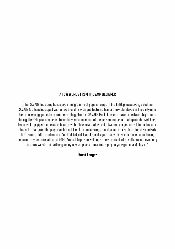
A FEW WORDS FROM THE AMP DESIGNER
„The SAVAGE tube amp heads are among the most popular amps in the ENGL product range and theSAVAGE 120 head equipped with a few brand new unique features has set new standards in the early nine-ties concerning guitar tube amp technology. For the SAVAGE Mark II series I have undertaken big efforts
during the R&D phase in order to usefully enhance some of the proven features to a top notch level. Furt-hermore I equipped these superb amps with a few new features like two mid range control knobs for main channel I that gives the player additional freedom concerning individual sound creation plus a Noise Gate
for Crunch and Lead channels. And last but not least I spent again many hours in intense sound tuning sessions, my favorite labour at ENGL Amps. I hope you will enjoy the results of all my efforts: not even only
take my words but rather give my new amp creation a trial - plug in your guitar and play it!.“
Horst Langer
INTRODUCTION
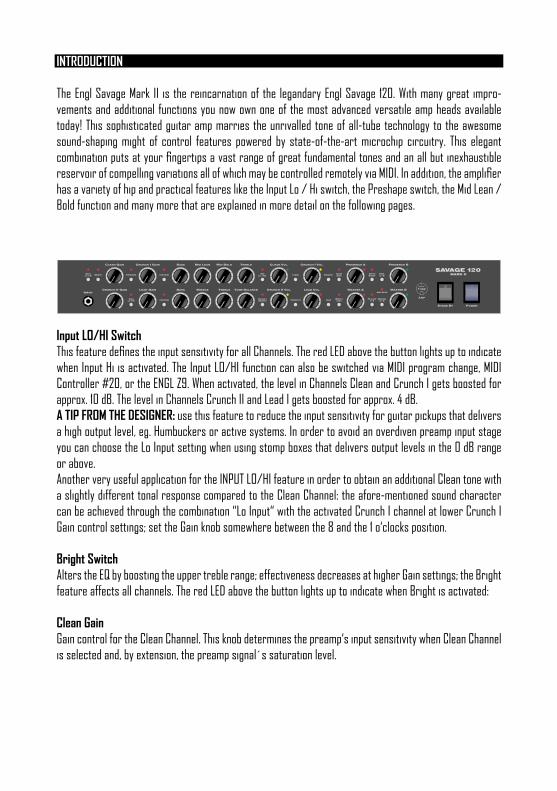
The Engl Savage Mark II is the reincarnation of the legandary Engl Savage 120. With many great impro-vements and additional functions you now own one of the most advanced versatile amp heads available today! This sophisticated guitar amp marries the unrivalled tone of all-tube technology to the awesome sound-shaping might of control features powered by state-of-the-art microchip circuitry. This elegant combination puts at your fingertips a vast range of great fundamental tones and an all but inexhaustible reservoir of compelling variations all of which may be controlled remotely via MIDI. In addition, the amplifier has a variety of hip and practical features like the Input Lo / Hi switch, the Preshape switch, the Mid Lean / Bold function and many more that are explained in more detail on the following pages.
Input LO/HI SwitchThis feature defines the input sensitivity for all Channels. The red LED above the button lights up to indicate when Input Hi is activated. The Input LO/HI function can also be switched via MIDI program change, MIDI Controller #20, or the ENGL Z9. When activated, the level in Channels Clean and Crunch I gets boosted for approx. 10 dB. The level in Channels Crunch II and Lead I gets boosted for approx. 4 dB.A TIP FROM THE DESIGNER: use this feature to reduce the input sensitivity for guitar pickups that delivers a high output level, eg. Humbuckers or active systems. In order to avoid an overdiven preamp input stage you can choose the Lo Input setting when using stomp boxes that delivers output levels in the 0 dB range or above. Another very useful application for the INPUT LO/HI feature in order to obtain an additional Clean tone with a slightly different tonal response compared to the Clean Channel: the afore-mentioned sound character can be achieved through the combination “Lo Input“ with the activated Crunch I channel at lower Crunch I Gain control settings; set the Gain knob somewhere between the 8 and the 1 o‘clocks position.
Bright SwitchAlters the EQ by boosting the upper treble range; effectiveness decreases at higher Gain settings; the Bright feature affects all channels. The red LED above the button lights up to indicate when Bright is activated:
Clean GainGain control for the Clean Channel. This knob determines the preamp‘s input sensitivity when Clean Channel is selected and, by extension, the preamp signal´s saturation level.
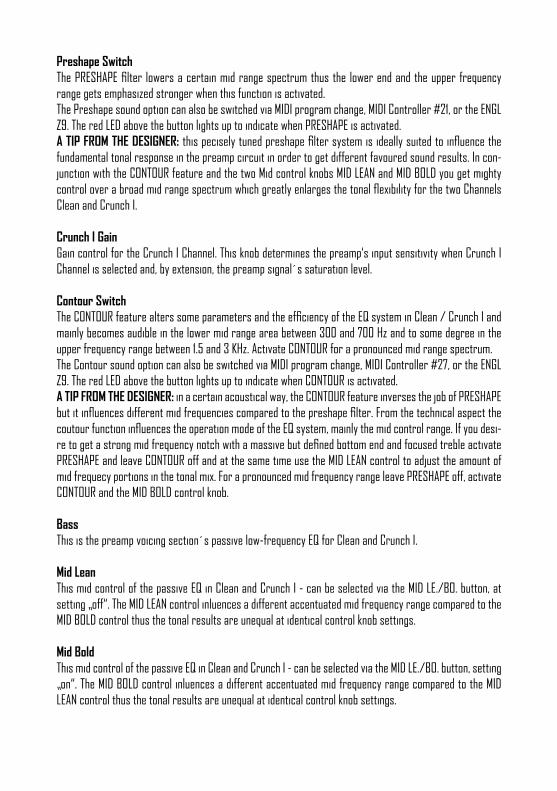
Preshape SwitchThe PRESHAPE filter lowers a certain mid range spectrum thus the lower end and the upper frequency range gets emphasized stronger when this function is activated.The Preshape sound option can also be switched via MIDI program change, MIDI Controller #21, or the ENGL Z9. The red LED above the button lights up to indicate when PRESHAPE is activated.A TIP FROM THE DESIGNER: this pecisely tuned preshape filter system is ideally suited to influence the fundamental tonal response in the preamp circuit in order to get different favoured sound results. In con-junction with the CONTOUR feature and the two Mid control knobs MID LEAN and MID BOLD you get mighty control over a broad mid range spectrum which greatly enlarges the tonal flexibility for the two Channels Clean and Crunch I.
Crunch I GainGain control for the Crunch I Channel. This knob determines the preamp‘s input sensitivity when Crunch I Channel is selected and, by extension, the preamp signal´s saturation level.
Contour SwitchThe CONTOUR feature alters some parameters and the efficiency of the EQ system in Clean / Crunch I and mainly becomes audible in the lower mid range area between 300 and 700 Hz and to some degree in the upper frequency range between 1.5 and 3 KHz. Activate CONTOUR for a pronounced mid range spectrum.The Contour sound option can also be switched via MIDI program change, MIDI Controller #27, or the ENGL Z9. The red LED above the button lights up to indicate when CONTOUR is activated.A TIP FROM THE DESIGNER: in a certain acoustical way, the CONTOUR feature inverses the job of PRESHAPE but it influences different mid frequencies compared to the preshape filter. From the technical aspect the coutour function influences the operation mode of the EQ system, mainly the mid control range. If you desi-re to get a strong mid frequency notch with a massive but defined bottom end and focused treble activate PRESHAPE and leave CONTOUR off and at the same time use the MID LEAN control to adjust the amount of mid frequecy portions in the tonal mix. For a pronounced mid frequency range leave PRESHAPE off, activate CONTOUR and the MID BOLD control knob.
BassThis is the preamp voicing section´s passive low-frequency EQ for Clean and Crunch I.
Mid LeanThis mid control of the passive EQ in Clean and Crunch I - can be selected via the MID LE./BO. button, at setting „off“. The MID LEAN control inluences a different accentuated mid frequency range compared to the MID BOLD control thus the tonal results are unequal at identical control knob settings.
Mid BoldThis mid control of the passive EQ in Clean and Crunch I - can be selected via the MID LE./BO. button, setting „on“. The MID BOLD control inluences a different accentuated mid frequency range compared to the MID LEAN control thus the tonal results are unequal at identical control knob settings.
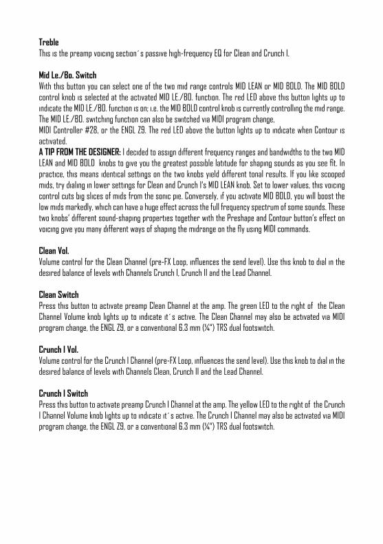
TrebleThis is the preamp voicing section´s passive high-frequency EQ for Clean and Crunch I.
Mid Le./Bo. SwitchWith this button you can select one of the two mid range controls MID LEAN or MID BOLD. The MID BOLD control knob is selected at the activated MID LE./BO. function. The red LED above this button lights up to indicate the MID LE./BO. function is on; i.e. the MID BOLD control knob is currently controlling the mid range.The MID LE./BO. switching function can also be switched via MIDI program change,MIDI Controller #28, or the ENGL Z9. The red LED above the button lights up to indicate when Contour is activated.A TIP FROM THE DESIGNER: I decided to assign different frequency ranges and bandwidths to the two MID LEAN and MID BOLD knobs to give you the greatest possible latitude for shaping sounds as you see fit. In practice, this means identical settings on the two knobs yield different tonal results. If you like scooped mids, try dialing in lower settings for Clean and Crunch I‘s MID LEAN knob. Set to lower values, this voicing control cuts big slices of mids from the sonic pie. Conversely, if you activate MID BOLD, you will boost the low mids markedly, which can have a huge effect across the full frequency spectrum of some sounds. These two knobs‘ different sound-shaping properties together with the Preshape and Contour button‘s effect on voicing give you many different ways of shaping the midrange on the fly using MIDI commands.
Clean Vol.Volume control for the Clean Channel (pre-FX Loop, influences the send level). Use this knob to dial in the desired balance of levels with Channels Crunch I, Crunch II and the Lead Channel.
Clean SwitchPress this button to activate preamp Clean Channel at the amp. The green LED to the right of the Clean Channel Volume knob lights up to indicate it´s active. The Clean Channel may also be activated via MIDI program change, the ENGL Z9, or a conventional 6.3 mm (¼“) TRS dual footswitch.
Crunch I Vol.Volume control for the Crunch I Channel (pre-FX Loop, influences the send level). Use this knob to dial in the desired balance of levels with Channels Clean, Crunch II and the Lead Channel.
Crunch I SwitchPress this button to activate preamp Crunch I Channel at the amp. The yellow LED to the right of the Crunch I Channel Volume knob lights up to indicate it´s active. The Crunch I Channel may also be activated via MIDI program change, the ENGL Z9, or a conventional 6.3 mm (¼“) TRS dual footswitch.
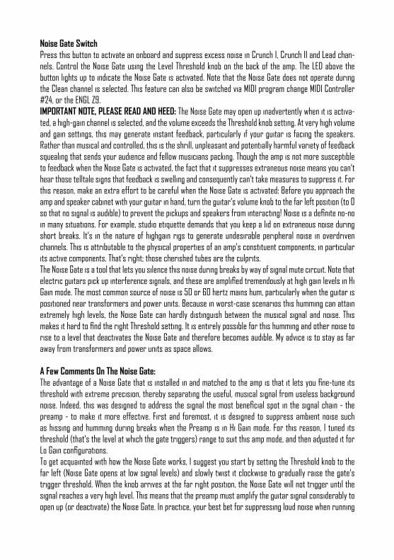
Noise Gate SwitchPress this button to activate an onboard and suppress excess noise in Crunch I, Crunch II and Lead chan-nels. Control the Noise Gate using the Level Threshold knob on the back of the amp. The LED above the button lights up to indicate the Noise Gate is activated. Note that the Noise Gate does not operate during the Clean channel is selected. This feature can also be switched via MIDI program change MIDI Controller #24, or the ENGL Z9.IMPORTANT NOTE, PLEASE READ AND HEED: The Noise Gate may open up inadvertently when it is activa-ted, a high-gain channel is selected, and the volume exceeds the Threshold knob setting. At very high volume and gain settings, this may generate instant feedback, particularly if your guitar is facing the speakers. Rather than musical and controlled, this is the shrill, unpleasant and potentially harmful variety of feedback squealing that sends your audience and fellow musicians packing. Though the amp is not more susceptible to feedback when the Noise Gate is activated, the fact that it suppresses extraneous noise means you can‘t hear those telltale signs that feedback is swelling and consequently can‘t take measures to suppress it. For this reason, make an extra effort to be careful when the Noise Gate is activated: Before you approach the amp and speaker cabinet with your guitar in hand, turn the guitar‘s volume knob to the far left position (to 0 so that no signal is audible) to prevent the pickups and speakers from interacting! Noise is a definite no-no in many situations. For example, studio etiquette demands that you keep a lid on extraneous noise during short breaks. It‘s in the nature of highgain rigs to generate undesirable peripheral noise in overdriven channels. This is attributable to the physical properties of an amp‘s constituent components, in particular its active components. That‘s right; those cherished tubes are the culprits. The Noise Gate is a tool that lets you silence this noise during breaks by way of signal mute circuit. Note that electric guitars pick up interference signals, and these are amplified tremendously at high gain levels in Hi Gain mode. The most common source of noise is 50 or 60 hertz mains hum, particularly when the guitar is positioned near transformers and power units. Because in worst-case scenarios this humming can attain extremely high levels, the Noise Gate can hardly distinguish between the musical signal and noise. This makes it hard to find the right Threshold setting. It is entirely possible for this humming and other noise to rise to a level that deactivates the Noise Gate and therefore becomes audible. My advice is to stay as far away from transformers and power units as space allows.
A Few Comments On The Noise Gate:The advantage of a Noise Gate that is installed in and matched to the amp is that it lets you fine-tune its threshold with extreme precision, thereby separating the useful, musical signal from useless background noise. Indeed, this was designed to address the signal the most beneficial spot in the signal chain - the preamp - to make it more effective. First and foremost, it is designed to suppress ambient noise such as hissing and humming during breaks when the Preamp is in Hi Gain mode. For this reason, I tuned its threshold (that‘s the level at which the gate triggers) range to suit this amp mode, and then adjusted it for Lo Gain configurations.To get acquainted with how the Noise Gate works, I suggest you start by setting the Threshold knob to the far left (Noise Gate opens at low signal levels) and slowly twist it clockwise to gradually raise the gate‘s trigger threshold. When the knob arrives at the far right position, the Noise Gate will not trigger until the signal reaches a very high level. This means that the preamp must amplify the guitar signal considerably to open up (or deactivate) the Noise Gate. In practice, your best bet for suppressing loud noise when running
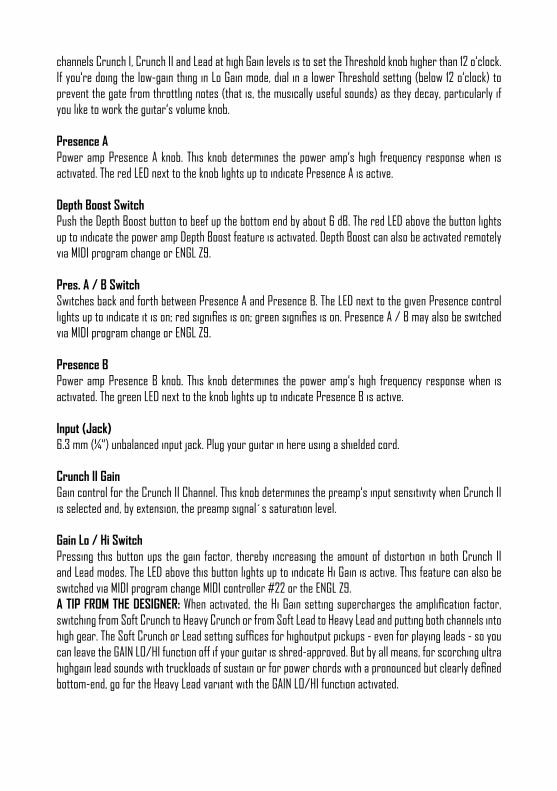
channels Crunch I, Crunch II and Lead at high Gain levels is to set the Threshold knob higher than 12 o‘clock. If you‘re doing the low-gain thing in Lo Gain mode, dial in a lower Threshold setting (below 12 o‘clock) to prevent the gate from throttling notes (that is, the musically useful sounds) as they decay, particularly if you like to work the guitar‘s volume knob.
Presence APower amp Presence A knob. This knob determines the power amp‘s high frequency response when is activated. The red LED next to the knob lights up to indicate Presence A is active.
Depth Boost SwitchPush the Depth Boost button to beef up the bottom end by about 6 dB. The red LED above the button lights up to indicate the power amp Depth Boost feature is activated. Depth Boost can also be activated remotely via MIDI program change or ENGL Z9.
Pres. A / B SwitchSwitches back and forth between Presence A and Presence B. The LED next to the given Presence control lights up to indicate it is on; red signifies is on; green signifies is on. Presence A / B may also be switched via MIDI program change or ENGL Z9.
Presence BPower amp Presence B knob. This knob determines the power amp‘s high frequency response when is activated. The green LED next to the knob lights up to indicate Presence B is active.
Input (Jack)6.3 mm (¼“) unbalanced input jack. Plug your guitar in here using a shielded cord.
Crunch II GainGain control for the Crunch II Channel. This knob determines the preamp‘s input sensitivity when Crunch II is selected and, by extension, the preamp signal´s saturation level.
Gain Lo / Hi SwitchPressing this button ups the gain factor, thereby increasing the amount of distortion in both Crunch II and Lead modes. The LED above this button lights up to indicate Hi Gain is active. This feature can also be switched via MIDI program change MIDI controller #22 or the ENGL Z9.A TIP FROM THE DESIGNER: When activated, the Hi Gain setting supercharges the amplification factor, switching from Soft Crunch to Heavy Crunch or from Soft Lead to Heavy Lead and putting both channels into high gear. The Soft Crunch or Lead setting suffices for highoutput pickups - even for playing leads - so you can leave the GAIN LO/HI function off if your guitar is shred-approved. But by all means, for scorching ultra highgain lead sounds with truckloads of sustain or for power chords with a pronounced but clearly defined bottom-end, go for the Heavy Lead variant with the GAIN LO/HI function activated.

Lead GainGain control for the Lead Channel. This knob determines the preamp‘s input sensitivity when Lead Channel is selected and, by extension, the preamp signal´s saturation level.
Contour SwitchThe CONTOUR feature alters some parameters and the efficiency of the EQ system in CRUNCH II / LEAD and mainly becommes audible in the lower mid range area between 300 and 700 Hz and to some degree in the upper frequency range between 1.5 and 3 KHz. Activate CONTOUR for a pronounced mid range spectrum. The Contour sound option can also be switched via MIDI program change, MIDI Controller #29, or the ENGL Z9. The red LED above the button lights up to indicate when CONTOUR is activated.A TIP FROM THE DESIGNER: From the technical aspect the CONTOUR function influences the operation mode of the EQ system, mainly the mid control range. If you desire to get a strong mid frequency notch (a very heavy sound style) with a massive but defined bottom end and focused treble leave CONTOUR off. For a pronounced mid frequency range and an assertive sound response activate CONTOUR.
BassThis is the preamp voicing section´s passive low-frequency EQ for Crunch II and Lead.
MiddleThis is the preamp voicing section´s passive midrange-frequency EQ for Crunch II and Lead.
TrebleThis is the preamp voicing section´s passive hi-frequency EQ for Clean Crunch II and Lead.
Tone BalanceThis additional EQ control knob is activated in Smooth mode only. Starting from the center position (12 o‘clock that is) of the TONE BALANCE control, a certain lower mid frequency range is emphasized if the knob is turned counterclockwise. If turned clockwise an additional portion of treble is added to the sonic scenario.
Rough / Smooth SwitchSwitches between two completely unique overdrive characteristics in Crunch II and Lead:ROUGH: pronounced bottom end and at the same time strong emphasis on the upper frequency range; high efficiency of BASS, MIDDLE and TREBLE controls;SMOOTH: strong emphasis on the mid frequency range; noticeably lower efficiency of BASS, MIDDLE and TREBLE controls, TONE BALANCE control is activated;The red LED above this button lights up to indicate the SMOOTH mode is activated.The ROUGH/SMOOTH switching function can also be switched via MIDI program change,MIDI Controller #15, or the ENGL Z9.A TIP FROM THE DESIGNER: The ROUGH sound mode is the right choice for heavier styles with fewer mi-drange frequencies in the mix but plenty of low and high end frequencies. Choose the SMOOTH sound mode
to go for vintage tube tone and for playing solos. This sound character is ideally suited to push your guitar tone through in the musical event.
Crunch II Vol.Volume control for the Crunch II Channel (pre-FX Loop, influences the send level). Use this knob to dial in the desired balance of levels with Channels Clean, Crunch I and the Lead Channel.
Crunch II Switch Press this button to activate preamp Crunch II Channel at the amp. The yellow LED to the right of the Crunch II Channel Volume knob lights up to indicate it´s active. The Crunch II Channel may also be activated via MIDI program change, the ENGL Z9, or a conventional 6.3 mm (¼“) TRS dual footswitch.
Lead Vol. Volume control for the Lead channel (pre-FX Loop, influences the send level). Use this knob to dial in the desired balance of levels with Channels Clean, Crunch I and Crunch II Channel.
Lead SwitchPress this button to activate preamp Lead Channel at the amp. The red LED to the right of the Lead Channel Volume knob lights up to indicate it´s active. The Lead Channel may also be activated via MIDI program change, the ENGL Z9, or a conventional 6.3 mm (¼“) TRS dual footswitch.
Write / CopyPress this button to store the modified setting of a programmable feature to a MIDI memory slot (gene-rally called a preset). Here‘s how to distinguish between WRITE and COPY: with the former you‘re actually programming or writing a new MIDI preset, with the latter you‘re making an exact duplicate of an existing preset. The system will select a WRITE operation whenever you edit a MIDI preset, that is, when you have modified a programmable feature. You‘ll know that this is the case because the Status LED flashes steadily when you edit one or several programmable features. If you press the button and did not edit a MIDI preset, the system will select. This means that the given preset becomes the source, and its contents are dumped to another preset and stored there. When you press this button, the Status LED lights up continuously to indicate is activated. The system quits mode autonomously if you do not select a new MIDI preset within about 30 seconds. The preset programming process -- the WRITE command, that is -- is not carried out as soon as you press the button. Pressing the button merely initiates the process. You must hold it down for about a second until the Status LED flashes three times in rapid succession. This mechanism is designed to prevent inadvertent programming. You can cancel the programming process at any time before the Status LED first illuminates by releasing the WRITE button. Again, the preset will only be programmed successfully if you press and hold the button until the Status LED flashes three times.You‘ll have to go through a similar routine to copy a preset once you select a target preset: When the Status LED extinguishes, the copy operation is underway and can no longer be cancelled. The LED flashes three times to indicate the preset was copied successfully. You can cancel the copy operation by releasing the key, but only for as long as the LED lights up continuously.
MORE GOOD TO KNOW INFO: Note that the Status LED also indicates the status of components unrelated to WRITE and COPY. The micro-controller runs a short system check after you switch the amp on. Should it find a defect in the memory chip (EEPROM), the LED will flash in a pattern of five short bursts. Press the WRITE/COPY button to confirm that you got the message. Once you have done this, the system will be ready to run, although you may encounter problems when attempting to select or store MIDI preset.
Master AMaster A volume knob. Located post effect loops, it controls power amp output. The red LED to the right of the knob lights up to indicate is enabled and determining the master level.
FX Loop I / II SwitchThis button switches to and from between FX Loop I and FX Loop II. The red LED above the button lights up to indicate is on. You can also select loops via MIDI program change or the ENGL Z9.
Master A / B SwitchSwitches back and forth between the Master A and Master B knobs. The LEDs next to the knobs light up to indicate which Master knob is active the red LED for Master A, the green LED for Master B. can also be switched via MIDI program change or the ENGL Z9.
Amp Mute (LED)This red LED lights up to show AMP MUTE is engaged, that is, the power amp is silenced. Activate and deac-tivate this mode via sending the appropriate MIDI controller command.
Master BMaster B volume knob. Located post effect loops, it controls power amp output. The green LED to the right of the knob lights up to indicate is enabled and determining the master level.

Stand By SwitchPower amp Stand By switch: Use this switch to protect the power tubes against wear (0 position) when you take a longer break. The amp‘s tubes stay nice and toasty, and the amp is ready to roll immediately when you ramp it back up to full power. Activates as soon as you set the Stand By switch to the 0 position.
Power SwitchMains power on/off. PLEASE NOTE: ensure that the Stand By is set to Stand By (0 position) before you switch the amp on. Let the tubes heat up for about 30 seconds before you activate the power amp. This procedure spares the tubes. CAUTION: After an extended period of operation and higher ambient temperatures the amps‘s chassis can become very hot, therefore avoid touching the rear panel surface and the ventilation grille on the top!

Main Supply Connector (AC Power Inlet, IEC – C14 connector) Plug the mains cord in here.CAUTION: Make sure you use an intact mains line cord with a grounded plug! Beforeyou power the amp up, ensure the voltage value printed alongside the mains port is the same as the current of the local power supply or wall outlet.Please also heed the guidelines set forth in the separately included pamphlet, Instructions for the Preven-tion of Fire, Electrical Shock and Injury.
Mains Fuse BoxThe rear chamber contains the mains fuse and the front chamber a spare fuse. CAUTION: Always make sure replacement fuses are of the same type and have the same ratings as the original fuse! To this end, please refer to the fuse ratings shown on the type panel.
Midi ThruThis 5-pin DIN port patches incoming MIDI data from the MIDI in to any other connected MIDI device.
Midi InThis 5-pin DIN port accepts data sent by a MIDI sender (for example, the ENGL Z9, Z12, Z15 footcontrollers) or from or routed through another MIDI device.CAUTION: Before you connect any other MIDI footcontroller or effects device, always make sure that the ENGL MIDI Footcontroller Power Supply switch is set to the right to avoid damaging the device.
ENGL Midi Footcontroller Power SupplyThis selector activates a MIDI In port power supply for connected ENGL MIDI footcontroller. Power is fed to the board via the MIDI circuit. When the switch is set to the left position, power is routed to the MIDI In port‘s pin 1 and pin 2. If you choose to use another MIDI footcontroller, be sure to set the switch to the right to avoid damaging it. If the footcontroller you are using is designed to handle phantom power, consult its operating manual to learn how it is wired (that is, which pins carry its power supply) and what its voltage and current specifications are. If the voltage and current specifications and wiring match, you may set the switch to the left to power this footcontroller via the MIDI cable.
PLEASE READ AND HEED: Note that a MIDI footcontroller may not draw more than 200 milliamperes of current if you want to power it via this port. You must also check and verify if this footcontroller is able to handle 11 volts of alternating current (AC)! If you are in any doubt, be sure to consult a specialist, meaning an amp technician or electronics engineer who earns a living with a screwdriver!
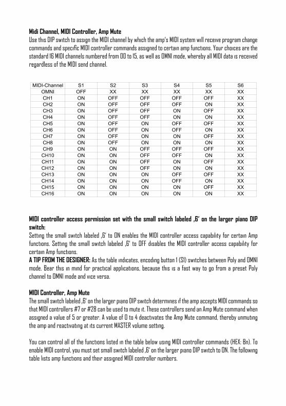
Midi Channel, MIDI Controller, Amp MuteUse this DIP switch to assign the MIDI channel by which the amp‘s MIDI system will receive program change commands and specific MIDI controller commands assigned to certain amp functions. Your choices are the standard 16 MIDI channels numbered from 00 to 15, as well as OMNI mode, whereby all MIDI data is received regardless of the MIDI send channel.
MIDI-Channel S1 S2 S3 S4 S5 S6
OMNI OFF XX XX XX XX XX
CH1 ON OFF OFF OFF OFF XX
CH2 ON OFF OFF OFF ON XX
CH3 ON OFF OFF ON OFF XX
CH4 ON OFF OFF ON ON XX
CH5 ON OFF ON OFF OFF XX
CH6 ON OFF ON OFF ON XX
CH7 ON OFF ON ON OFF XX
CH8 ON OFF ON ON ON XX
CH9 ON ON OFF OFF OFF XX
CH10 ON ON OFF OFF ON XX
CH11 ON ON OFF ON OFF XX
CH12 ON ON OFF ON ON XX
CH13 ON ON ON OFF OFF XX
CH14 ON ON ON OFF ON XX
CH15 ON ON ON ON OFF XX
CH16 ON ON ON ON ON XX
MIDI controller access permission set with the small switch labeled ‚6‘ on the larger piano DIP switch: Setting the small switch labeled ‚6‘ to ON enables the MIDI controller access capability for certain Amp functions. Setting the small switch labeled ‚6‘ to OFF disables the MIDI controller access capability for certain Amp functions. A TIP FROM THE DESIGNER: As the table indicates, encoding button 1 (S1) switches between Poly and OMNI mode. Bear this in mind for practical applications, because this is a fast way to go from a preset Poly channel to OMNI mode and vice versa.
MIDI Controller, Amp Mute The small switch labeled ‚6‘ on the larger piano DIP switch determines if the amp accepts MIDI commands so that MIDI controllers #7 or #28 can be used to mute it. These controllers send an Amp Mute command when assigned a value of 5 or greater. A value of 0 to 4 deactivates the Amp Mute command, thereby unmuting the amp and reactivating at its current MASTER volume setting.
You can control all of the functions listed in the table below using MIDI controller commands (HEX: Bn). To enable MIDI control, you must set small switch labeled ‚6‘ on the larger piano DIP switch to ON. The following table lists amp functions and their assigned MIDI controller numbers.

Functions SAVAGE II Amp: MIDI Controller: as HEX value: Cntrl value 0-4 Cntrl value 5-127
Master A/B controller #14 0x0E off on
Rough/Smooth controller #15 0x0F off on
Input Lo/Hi controller #20 0x14 off on
Preshape controller #21 0x15 off on
Gain Lo/Hi controller #22 0x16 off on
Bright controller #23 0x17 off on
Noise Gate controller #24 0x18 off on
Presence A/B controller #25 0x19 off on
Depth Boost controller #26 0x1A off on
Contour – Clean/Crunch I controller #27 0x1B off on
Mid Lean/Bold controller #28 0x1C off on
Contour – Crunch II/Lead controller #29 0x1D off on
FX Loop I/II controller #30 0x1E off on
Amp Mute Controller #7 0x07 off on
MIDI Logic resetPressing the CRUNCH I and PRESENCE A/B buttons for 3 seconds simultaneously will reset the logic unit to the factory defaults and clear the MIDI presets created by the user.
Footswitch: Serial Amp Control Port (S.A.C.)This serial data input accepts the ENGL Z9 (optional), which lets you control various amp functions remo-tely. Connect the ENGL Z9 to the amp port using a cord equipped with stereo 6.3 mm (¼“) jack plugs. This MIDI-enabled foot board is a custom design that switches every amp feature designated as footswitchable in this manual. To learn if a given feature may be controlled remotely, refer to its description herein. The MIDI In port is disabled when the Z9 is connected. CAUTION: Connect only the ENGL Z9 to this 6.3 mm (¼“) stereo jack! Connecting any other switching device may damage it and/or the amp‘s circuitry!
Footswitch: Clean, Crunch I, Crunch II, LeadUse this jack to connect a conventional footswitch with two switching functions (for example, the ENGL Z4) that let you access the four channels Clean, Crunch I, Cruch II and Lead. One of the switches activates the selection between the top channel section (Clean / Crunch I) and the bottom channel section (Crunch II / Lead) and the other between Clean and Crunch I or Crunch II and Lead. The onboard channel switching facility is disabled when you plug a footswitch into this jack. The MIDI In port and the S.A.C. Port are both disabled when a plug is connected to this jack. NOTE: A footswitch may be equipped with LEDs indicating the given switching status. Each of the two swit-ches is provided with 15 milliamperes current, which suffices to power a standard LED. The jack‘s mono terminal selects the top / bottom section, while the stereo terminal selects between Clean and Crunch I or Crunch II and Lead.
Noise Gate Threshold LevelUse this knob to set a threshold value (that is, the noise level) at which the Noise Gate activates to suppress the signal. The further you twist the knob to the right, the higher the signal level at which Noise Gate the kicks in. The can be activated and deactivated as required for Crunch I, Crunch II and Lead by pushing the front panel Noise Gate Button.
FX Loop I SendConnect this FX Loop I output to a signal processor´s input/return or an effect pedals´s input/return jack using the shortest possible shielded cord equipped with 6.3 mm (¼“) plugs. Activate and deactivate it via the FX Loop I / II button, which switches between these two loops. In the signal path, FX Loop I is located post preamp and pre the two power amp Master knobs.
FX Loop I ReturnConnect this FX Loop I input to a signal processor´s output/send jack or an effect pedal´s output/send jack using the shortest possible shielded cord equipped with 6.3 mm (¼“) plugs. Activate and deactivate it via the FX Loop I / II button, which switches between these two loops. In the signal path, is located post preamp and pre the two power amp Master knobs.
FX Loop I BalanceFX mix control for FX Loop I. When the knob is set to Dry, the amp signal is routed through with no processed signal (0% wet balance) added to the mix. Twist the knob clockwise to blend in the processed signal (paral-lel/passive, wet balance 1-99%, depending on knob position). When the knob arrives at the Effect position, only the wet signal (that is, the processed signal generated by the connected effect device) is patched to the power amp (serial, 100% wet). NOTE: Set this knob to Dry when the FX Loop is not in use! Settings between 9 and 3 o‘clock position reduce the signal level. In the event of contact corrosion of the FX Return socket, volume fluctuations may occur.
FX Loop II SendConnect this FX Loop II output to a signal processor´s input/return or an effect pedals´s input/return jack using the shortest possible shielded cord equipped with 6.3 mm (¼“) plugs. Activate and deactivate it via the FX Loop I / II button, which switches between these two loops. In the signal path, FX Loop II is located post preamp and pre the two power amp Master knobs.
FX Loop II ReturnConnect this FX Loop II input to a signal processor´s output/send jack or an effect pedal´s output/send jack using the shortest possible shielded cord equipped with 6.3 mm (¼“) plugs. Activate and deactivate it via the FX Loop I / II button, which switches between these two loops. In the signal path, is located post preamp and pre the two power amp Master knobs.
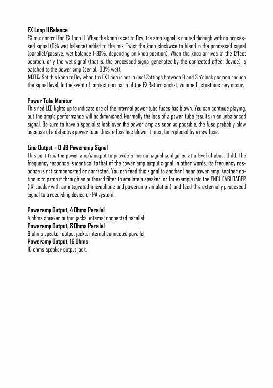
FX Loop II BalanceFX mix control for FX Loop II. When the knob is set to Dry, the amp signal is routed through with no proces-sed signal (0% wet balance) added to the mix. Twist the knob clockwise to blend in the processed signal (parallel/passive, wet balance 1-99%, depending on knob position). When the knob arrives at the Effect position, only the wet signal (that is, the processed signal generated by the connected effect device) is patched to the power amp (serial, 100% wet). NOTE: Set this knob to Dry when the FX Loop is not in use! Settings between 9 and 3 o‘clock position reduce the signal level. In the event of contact corrosion of the FX Return socket, volume fluctuations may occur.
Power Tube MonitorThis red LED lights up to indicate one of the internal power tube fuses has blown. You can continue playing, but the amp‘s performance will be diminished. Normally the loss of a power tube results in an unbalanced signal. Be sure to have a specialist look over the power amp as soon as possible; the fuse probably blew because of a defective power tube. Once a fuse has blown, it must be replaced by a new fuse.
Line Output – 0 dB Poweramp SignalThis port taps the power amp‘s output to provide a line out signal configured at a level of about 0 dB. The frequency response is identical to that of the power amp output signal. In other words, its frequency res-ponse is not compensated or corrected. You can feed this signal to another linear power amp. Another op-tion is to patch it through an outboard filter to emulate a speaker, or for example into the ENGL CABLOADER (IR-Loader with an integrated microphone and poweramp simulation), and feed this externally processed signal to a recording device or PA system.
Poweramp Output, 4 Ohms Parallel4 ohms speaker output jacks, internal connected parallel.Poweramp Output, 8 Ohms Parallel8 ohms speaker output jacks, internal connected parallel.Poweramp Output, 16 Ohms16 ohms speaker output jack.

Cabinet options1. One 4 Ohm cabinet connected to a 4 Ohm jackSummary: 4 Z, --> connected to 4 Ohm output2. Two 8 Ohm cabinets connected to the 4 Ohm jacksSummary: 8 Z + 8 Z, --> connected to 4 Ohm + 4 Ohm output3. One 8 Ohm cabinet connected to an 8 Ohm jackSummary: 8 Z, --> connected to 8 Ohm output4. Two 16 Ohm cabinets connected to the 8 Ohm jacksSummary: 16 Z + 16 Z --> connected to 8-ohm + 8-ohm output.5. One 16 Ohm cabinet connected to the 16 Ohm jackSummary: 16 Z --> connected to 16 Ohm output6. An 8 Ohm cabinet connected to one of the 4 Ohm jacks in combinationwith a 16 Ohm cabinet connected to one of the 8 Ohm jacksSummary: 8 Z + 16 Z --> connected to 4-ohm + 8-ohm output
NOTE: Never operate the power amp without a sufficient load, otherwise you may damage or destroy it! Always check the connected cabinets‘ impedance to confirm it matches the amp‘s output impedance! For example, if you are connecting a cabinet to one of the two 8-ohms output, make sure the speaker system is indeed rated for 8 ohms. You‘ll find the various speaker cabinet options listed in the section above. I cannot stress enough the importance of proper impedance matching when connecting one or more cabinets to your amp. Impedance mismatching can damage the power amp!

TECHNICAL DATA:
Output power: approx. 60 Watts; adjusted accordingly to 4, 8 and 16 Ohm – E630II approx. 120 Watts; adjusted accordingly to 4, 8 and 16 Ohm – E610IIInput sensitivityInput: from -20 dB, nominal, max. 0 dBEffect RETURN: from -20 dB, nominal, max. 0 dBOutput levelSEND, level range: from -20 dB to approx. 0 dB max.Line Out: approx. 0 dB at nominal power outputPower consumption: approx. 280 Watt (335 VA) max. - E630II approx. 400 Watt (475 VA) max. - E610IIFuses:220 / 230 / 240 supply voltage 1,6 AT L (T: slow-blow) – E630II 2,5 AT L (T: slow-blow) – E610II 100 / 115 / 120 supply voltage 3,15 AT L (T: slow-blow) – E630II 5 AT L (T: slow-blow) – E610IIPower Tube Fuses: 2 x 0,16 AM (M: medium-blow) – E630II 2 x 0,315AM (M: medium-blow) – E610IIImportant: Replace these with fuses oft he same type and rating only!Tubes:V1: ENGL ECC83 First Quality (FQ)V2 / V3 / V4 / V5 / V6: ENGL ECC83 SelectedV7 / V8: ENGL EL34 Hand-matched duet – E630II ENGL 6550 Hand-matched duet – E610IISystem interfaces:MIDI: Asynchronous data protocol according to the MIDI standard MIDI program changes 0 - 127 MIDI channels 1 - 16 MIDI controller #7, #14, #15, #20, #21, #22, #23, #24, #25, #26, #27, #28, #29, #30 value 0 - 4 function deactivated value >/= 5 function activated Serial Amp Control (S.A.C.): Proprietary ENGL asynchronous data protocolDimension: approx. 71 cm x 28 cm x 29 cm (l x h x d) approx. 27.95 in x 11 in x 11.4 in (l x h x d) approx. 22.5 kg / 49.6 lb – E610II approx. 21.5 kg / 47.4 lb – E630II
HANDLING AND CARE• Keep the amp safe from hard knocks and shocks. Tubes are fragile and tend to suffer when exposed
to mechanical stress!• Let the amp cool down before you transport it. Ten minutes or so will spare the tubes.• Tubes take some 20 seconds to warm up after you switch the power on, and about two to three
minutes before they are able to pump out full power. Make a habit of giving your amp plenty of time to get toasty and flipping the Standby switch for short breaks.
• In order to spare the power tubes and prolong their lifetime, we recommend to set the Stand By switch to (0 position, that is) before you switch the amp on. After a period of 30 seconds you may activate the power amp by flipping the Stand By switch.
• Avoid storing the amp in damp or dusty rooms to spare jacks, switches and potentiometers. If you don‘t use the amp all the time, we recommend that you drape a covering over it to prevent the in-trusion of dust. Even better, keep it in a transport cover or flight case.
• Never use caustic or scouring detergents to clean the amp‘s housing, front or rear panels. Use a soft, damp cloth or sponge with diluted soapsuds or a standard brand of mild dishwashing liquid instead. Never use solvents they can corrode the amp‘s vinyl skin and dissolve the front and rear panel labels. Keep liquids well away from the amp, particularly the interior of the housing. * Make sure air can circulate at the rear and top of the amp to allow for adequate cooling, which increases component life.
• Never operate the amp without an adequate load (a speaker, cabinet or suitable terminating resistor).• High ambient temperatures place an additional strain on diverse components; so if at all possible,
avoid operating the amp at temperatures far higher than 30°C for longer periods. Running the amp at mains voltages exceeding the nominal mains input voltage over longer periods can also shorten component life.
• Replace tubes with selected tubes that satisfy ENGL selection criteria to forestall microphonic pro-perties, undesirable noise and unbalanced power amp signals. Because power tubes‘ idle current (bias) must checked and possibly adjusted when replacing tubes, this is a job best left to experienced and authorized specialists.
Attention! Be sure to read this section before powering the amp up!A few comments on tube amplifiers:• This amp´s input is extremely sensitive due to its high gain factor.• This guitar amplifier can produce high volume levels. Exposure to high volume levels may cause hea-
ring damage!• Leave tube replacement and power amp biasing to qualified professionals.• Be sure the unit is switched off and unplugged!• Caution! Tubes can get very hot and burn skin when touched. Always use high quality cables.• Never plug the amp into an ungrounded outlet!• Never bridge a defective fuse and be sure replacement fuses feature identical ratings!• Pull the AC mains plug before replacing fuses!• Never open the chassis or attempt repairs on your own. Consult qualified service personnel!• Never expose the amplifier to extreme humidity or dampness!• Please read the instructions carefully before operating the unit!
• Be sure to operate and handle this amp as it was designed for. To this end, please heed the instruc-tions in the operator‘s manual.
• You‘ll find an additional pamphlet accompanying this owner‘s manual entitled „Instruction for the prevention of fire, electric shock or injury of persons“. Be sure to read it before you plug the preamp in and switch it on!
In combination with inherent microphonics of tubes, at certain settings this can elicit powerful feedback from the speakers – even without a guitar being connected! This occurs primarily when Crunch and Lead channels (that is, all channels whose preamp is easily over-driven) are activated and the following settings are dialed in: Gain and/or Lead Gain knob past the 12 o‘clock position; Treble knob past the 12 o‘clock position; Crunch/Lead Volume knob past the 12 o‘clock position; Presence knob past the 12 o‘clock position. Avoid setting the aforementioned knobs to extreme positions (that is, combinations in which several of these knobs are set past the 12 o‘clock position). This type of configuration can cause considerable feedback that could well damage your hearing and de-stroy speakers. If you set the Volume or Master knobs to higher volume levels, always make sure to back off amplification levels to prevent feedback by turning the Lead channel Gain knobs down. The same applies to these channels´ Treble and Presence knob settings. Before you power the amp up, take a moment to check out the control panel and make sure that these knobs are not set to any configuration similar to the one described above! A few words on background noise in tube amplifiers: You may hear slight background noise right after you power a tube amp up or even while you are operating. It manifests as intermittent hissing or sizzling, crackling, or popping noises. Caused by tubes, this type of noise may even occur with brand new tubes. This noise is particularly noticeable in high-gain Lead channels; reason being that these channels´ gain stages are particularly powerful, amplifying noise along with these useful signal. It is not necessary to swap tubes if you encounter this kind of noise every now and then, though you may consider replacing tubes if it becomes a constant companion.
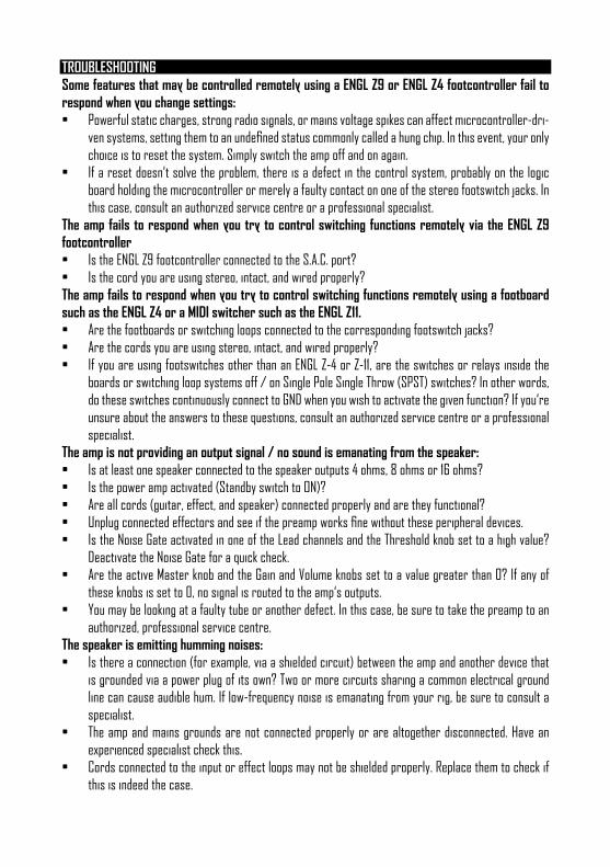
TROUBLESHOOTINGSome features that may be controlled remotely using a ENGL Z9 or ENGL Z4 footcontroller fail to respond when you change settings:• Powerful static charges, strong radio signals, or mains voltage spikes can affect microcontroller-dri-
ven systems, setting them to an undefined status commonly called a hung chip. In this event, your only choice is to reset the system. Simply switch the amp off and on again.
• If a reset doesn‘t solve the problem, there is a defect in the control system, probably on the logic board holding the microcontroller or merely a faulty contact on one of the stereo footswitch jacks. In this case, consult an authorized service centre or a professional specialist.
The amp fails to respond when you try to control switching functions remotely via the ENGL Z9 footcontroller• Is the ENGL Z9 footcontroller connected to the S.A.C. port?• Is the cord you are using stereo, intact, and wired properly?The amp fails to respond when you try to control switching functions remotely using a footboard such as the ENGL Z4 or a MIDI switcher such as the ENGL Z11.• Are the footboards or switching loops connected to the corresponding footswitch jacks?• Are the cords you are using stereo, intact, and wired properly?• If you are using footswitches other than an ENGL Z-4 or Z-11, are the switches or relays inside the
boards or switching loop systems off / on Single Pole Single Throw (SPST) switches? In other words, do these switches continuously connect to GND when you wish to activate the given function? If you‘re unsure about the answers to these questions, consult an authorized service centre or a professional specialist.
The amp is not providing an output signal / no sound is emanating from the speaker:• Is at least one speaker connected to the speaker outputs 4 ohms, 8 ohms or 16 ohms?• Is the power amp activated (Standby switch to ON)?• Are all cords (guitar, effect, and speaker) connected properly and are they functional?• Unplug connected effectors and see if the preamp works fine without these peripheral devices.• Is the Noise Gate activated in one of the Lead channels and the Threshold knob set to a high value?
Deactivate the Noise Gate for a quick check.• Are the active Master knob and the Gain and Volume knobs set to a value greater than 0? If any of
these knobs is set to 0, no signal is routed to the amp‘s outputs.• You may be looking at a faulty tube or another defect. In this case, be sure to take the preamp to an
authorized, professional service centre.The speaker is emitting humming noises:• Is there a connection (for example, via a shielded circuit) between the amp and another device that
is grounded via a power plug of its own? Two or more circuits sharing a common electrical ground line can cause audible hum. If low-frequency noise is emanating from your rig, be sure to consult a specialist.
• The amp and mains grounds are not connected properly or are altogether disconnected. Have an experienced specialist check this.
• Cords connected to the input or effect loops may not be shielded properly. Replace them to check if this is indeed the case.
• The amp or speaker cords may be picking up interference from powerful magnetic fields (for example, of nearby power transformers or electrical motors). Reposition the amp and connector cables.
• The amp or speaker cords may be picking up radio signals, for example, from activated mobile tele-phones or powerful local transmitting stations nearby. Switch off mobile phones while troubleshoo-ting noise problems.
One of the power tube fuses blows:• The given power tube is probably defective. If that power tube‘s fuse is replaced and the new fuse also
blows, the tube needs to be swapped out.• The amp has been overloaded, perhaps by excessive volume levels, excess mains voltage, or the
wrong output impedance (where the impedance setting does not match the connected speaker‘s impedance). Check the speakers‘ overall impedance and, if necessary, adjust your setup accordingly.
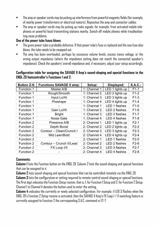
Configuration table for assigning the SAVAGE II Amp‘s sound-shaping and special functions to the ENGL Z9 footcontroller‘s Functions 1 and 2:
Button Z-9: Functions SAVAGE II amp: Setup: Displayed: S.A.C.:
Function 1 Master A/B 1: Channel 1 LED 1 lights up F1-1
Function 1 Rough/Smooth 1: Channel 2 LED 2 lights up F1-2
Function 1 Input Lo/Hi 1: Channel 3 LED 3 lights up F1-3
Function 1 Preshape 1: Channel 4 LED 4 lights up F1-4
Function 1 - 1: Channel 1 LED 1 flashes F1-5
Function 1 Gain Lo/Hi 1: Channel 2 LED 2 flashes F1-6
Function 1 Bright 1: Channel 3 LED 3 flashes F1-7
Function 1 Noise Gate 1: Channel 4 LED 4 flashes F1-8
Function 2 Presence A/B 2: Channel 1 LED 1 lights up F2-1
Function 2 Depth Boost 2: Channel 2 LED 2 lights up F2-2
Function 2 Contour – Clean/Crunch I 2: Channel 3 LED 3 lights up F2-3
Function 2 Mid Lean/Bold 2: Channel 4 LED 4 lights up F2-4
Function 2 - 2: Channel 1 LED 1 flashes F2-5
Function 2 Contour – Crunch II/Lead 2: Channel 2 LED 2 flashes F2-6
Function 2 FX Loop I/II 2: Channel 3 LED 3 flashes F2-7
Function 2 - 2: Channel 4 LED 4 flashes F2-8
Comments:Column 1 lists the Function button on the ENGL Z9. Column 2 lists the sound-shaping and special functions that can be assigned to it.Column 2 lists sound-shaping and special functions that can be controlled remotely via the ENGL Z9.Column 3 lists the configuration or setting required to remote-control sound-shaping or special functions. The first digit indicates the Function Setup routine, that is, 1: for Function 1 Setup and 2: for Function 2 Setup. Channel 1 to Channel 4 denotes the button used to enter the setting.Column 4 indicates the currently or newly selected configuration. For example, if LED 3 flashes when the ENGL Z9‘s Function 2 Setup routine is activated, then the SAVAGE II Amp‘s FX Loop I / II switching feature is currently assigned to Function 2 the corresponding S.A.C. command is F2-7.
Column 5 lists the shorthand designations for specific configurations that appear throughout the ENGL Z9 Operator‘s Manual. For detailed information, please refer to the ENGL Z9 Operator‘s Manual.PLEASE NOTE: The ENGL Z9 is an optional accessory. The afore mentioned Function buttons, LEDs and setup routines pertain to the ENGL Z9.
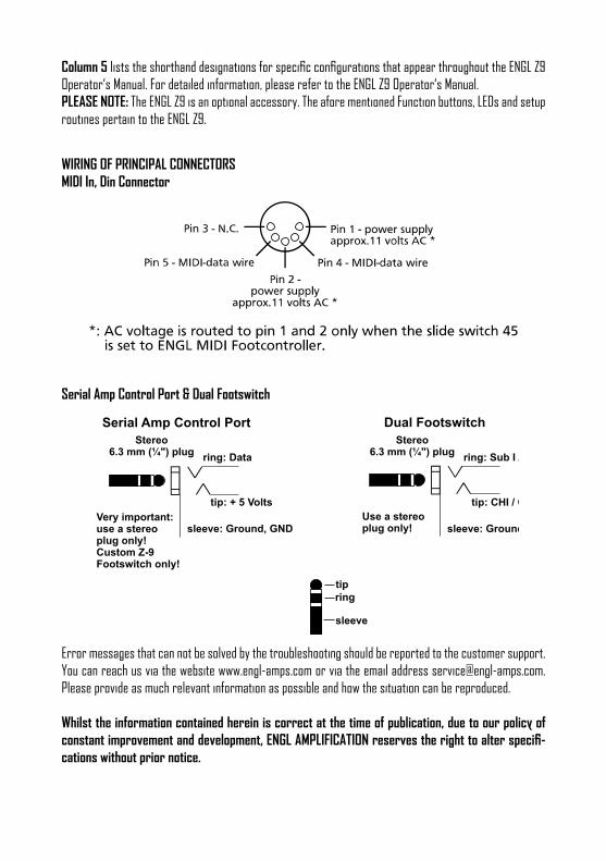
WIRING OF PRINCIPAL CONNECTORSMIDI In, Din Connector
Serial Amp Control Port & Dual Footswitch
Stereo6.3 mm (¼") plug
tipring
sleeve
sleeve: Ground, GNDsleeve: Ground, GNDUse a stereo plug only!
Stereo6.3 mm (¼") plug
Stereo6.3 mm (¼") plug
Very important:use a stereoplug only!Custom Z-9Footswitch only!
Serial Amp Control Port Dual Footswitch
ring: Data
tip: + 5 Volts
ring: Sub I / II
tip: CHI / CHII
Error messages that can not be solved by the troubleshooting should be reported to the customer support. You can reach us via the website www.engl-amps.com or via the email address [email protected]. Please provide as much relevant information as possible and how the situation can be reproduced.
Whilst the information contained herein is correct at the time of publication, due to our policy of constant improvement and development, ENGL AMPLIFICATION reserves the right to alter specifi-cations without prior notice.

www.engl-amps.com