
E-Tender-Doc-wwh-2019.pdf - Kerala State Women's ...
316
eTendering System Government of Kerala Tender Details Date : 01-Feb-2019 05:18 PM Print Basic Details Organisation Chain Kerala State Womens Development Corporation Ltd Tender Reference Number KSWDC/CCS/WWH-KKD/2017-2018 Tender ID 2019_KSWDC_265394_1 Tender Type Open Tender Form of contract Item Rate Tender Category Works No. of Covers 2 General Technical Evaluation Allowed No ItemWise Technical Evaluation Allowed Yes Payment Mode Online Is Multi Currency Allowed For BOQ No Is Multi Currency Allowed For Fee No Allow Two Stage Bidding No Payment Instruments Online Bankers S.No Bank Name 1 SBI MOPS Cover Details, No. Of Covers - 2 Cover No Cover Document Type Description 1 Fee/PreQual /Technical .pdf Power of Attorney, .pdf Digitally Signed copies of Technical Bid, GC C and SCC Technical specifications and Drawings .pdf Letter of transmittal .pdf Financial information Applicant should furnish the Annual financial statement for the last five year .pdf Experience in works/ similar works .pdf Organization information .pdf Construction plant and equipment 2 Finance .xls Price Bid Tender Fee Details, [Total Fee in ₹ * - 25,000] Tender Fee in ₹ 25,000 Fee Payable To Nil Fee Payable At Nil Tender Fee Exemption Allowed No EMD Fee Details EMD Amount in ₹ 15,52,197 EMD Exemption Allowed Yes EMD Fee Type fixed EMD Percentage NA EMD Payable To online EMD Payable At online eTendering System Government of Kerala https://etenders.kerala.gov.in/nicgep/app?component=$DirectLink&p... 1 of 2 01-02-2019 17:25
-
Upload
khangminh22 -
Category
Documents
-
view
0 -
download
0
Transcript of E-Tender-Doc-wwh-2019.pdf - Kerala State Women's ...

eTendering System Government of Kerala
Tender Details
Date : 01-Feb-2019 05:18 PM
Basic Details
Organisation Chain Kerala State Womens Development Corporation Ltd
Tender Reference
NumberKSWDC/CCS/WWH-KKD/2017-2018
Tender ID 2019_KSWDC_265394_1
Tender Type Open Tender Form of contract Item Rate
Tender Category Works No. of Covers 2
General Technical
Evaluation AllowedNo
ItemWise Technical Evaluation
AllowedYes
Payment Mode OnlineIs Multi Currency Allowed For
BOQNo
Is Multi Currency
Allowed For FeeNo Allow Two Stage Bidding No
Payment Instruments
Online
BankersS.No Bank Name
1 SBI MOPS
Cover Details, No. Of Covers - 2
Cover
NoCover Document Type Description
1Fee/PreQual
/Technical.pdf
Power of
Attorney,
Digitally
Signed copies
of Technical
Bid, GC C and
SCC Technical
specifications
and Drawings
.pdfLetter of
transmittal
Financial
information
Applicant
should
furnish the
Annual
financial
statement for
the last five
year
Experience in
works/ similar
works
.pdfOrganization
information
Construction
plant and
equipment
2 Finance .xls Price Bid
Tender Fee Details, [Total Fee in ₹ * - 25,000]
Tender Fee in ₹ 25,000
Fee Payable To Nil Fee Payable At Nil
Tender Fee
Exemption Allowed
No
EMD Fee Details
EMD Amount in ₹ 15,52,197 EMD Exemption
Allowed
Yes
EMD Fee Type fixed EMD Percentage NA
EMD Payable To online EMD Payable At online
eTendering System Government of Kerala https://etenders.kerala.gov.in/nicgep/app?component=$DirectLink&p...
1 of 2 01-02-2019 17:25

Work /Item(s)
Title CONSTRUCTION OF WORKING WOMENS HOSTEL FOR KSWDC AT PERINTHALMANNA MALAPPURAM
Work Description CONSTRUCTION OF WORKING WOMENS HOSTEL FOR KSWDC AT PERINTHALMANNA MALAPPURAM
Pre Qualification
Details
Please refer Tender documents.
Independent External
Monitor
NA
Tender Value in ₹ 7,76,00,000 Product Category Civil Works -
Buildings
Sub category NA
Contract Type Tender Bid Validity(Days) 120 Period Of
Work(Days)
365
Location PERINTHALMANNA MALAPPURAM Pincode 679322 Pre Bid Meeting
Place
KSWDC
HO
Pre Bid Meeting
Address
KSWDC Basant, T.C. 20/2170,
Opp.Manmohan Bunglow, Kowdiar
P.O, Thiruvananthapuram-3
Pre Bid Meeting Date 07-Feb-2019
11:00 AM
Bid Opening Place KSWDC
HO
Should Allow NDA
Tender
No Prequalification
Approval Date
NA Allow Preferential
Bidder
No
Critical Dates
Publish Date 01-Feb-2019 05:00 PM Bid Opening Date 18-Feb-2019 03:30 PM
Document Download / Sale Start
Date
01-Feb-2019 05:15 PM Document Download / Sale End
Date
14-Feb-2019 03:00 PM
Clarification Start Date NA Clarification End Date NA
Bid Submission Start Date 02-Feb-2019 09:00 AM Bid Submission End Date 14-Feb-2019 03:00 PM
Tender Documents
NIT
Document S.No Document Name DescriptionDocument Size
(in KB)
1 Tendernotice_1.pdf NIT 407.14
Work Item
Documents S.No Document Type Document Name DescriptionDocument Size
(in KB)
1 Tender Documents Technical.pdf Technical Bid 985.51
2 Additional Documents GCC.pdf GCC 3037.43
3 Other Document Structural.pdf Drawings 1513.06
4 Other Document Architectural.pdf Drawings 1093.15
5 Tender Documents BOQ.xls BOQ Financial Bid 1092.50
Bid Openers List
S.No Bid Opener Login Id Bid Opener Name Certificate Name
1. [email protected] Bindu VC BINDU V CHANDRANANDAN
2. [email protected] Anil Kumar ANILKUMAR S
Tender Inviting Authority
Name Finance Officer
Address KSWDC Basant, T.C. 20/2170, Opp.Manmohan Bunglow, Kowdiar P.O, Thiruvananthapuram-3
Tender Creator Details
Created By Anil Kumar
Designation Finance Officer
Created Date 01-Feb-2019 04:25 PM
eTendering System Government of Kerala https://etenders.kerala.gov.in/nicgep/app?component=$DirectLink&p...
2 of 2 01-02-2019 17:25

E-TENDER
FOR
CONSTRUCTION OF WORKING WOMENS HOSTEL FOR KSWDC AT PERINTHALMANNA, MALAPPURAM
PART-I
TECHNICAL BID
February 2019
Kerala State Women’s Development Corporation Ltd For details
www.kswdc.org e-mail: [email protected]
Ph ;0471-2727668

1
TABLE OF CONTENTS
Description Page No.
Schedule of submission of Tender 1
Notice Inviting Tender 2
Definition 3
Section-I
Notice Inviting E-Tender 4
Section-II
Information & Instructions regarding e-tendering 7
Section-III
Information & Instructions for Applicants
1. General 9
2. Method of Application 10
3. Final Decision making Authority 10
4. Particulars Provisional 10
5. Site Visit 10
6. Tender documents 10
7. Submission of tender documents 11
8. Eligibility Criteria for Qualification 12
9. Evaluation of Technical Bid 14
10. Signing of the application and number of copies 14
11. Deadline and address for submission of applications 15
12. Manual submission of tenders 15
13. Validity of applications 15
14. Amendment of qualification document 15
15. Price bid opening 16
16. Award criteria 16
17. Employer’s right 16
18. Jurisdiction 16
19. Special Conditions 16
Section-IV
LETTER OF TRANSMITTAL 18
Form A 19

2
Form B 20
Form C 21
Form D 22
Form E 23
Form F 24
Form G 25
Form H 27

1
SCHEDULE FOR SUBMISSION OF BIDS
EVENT DATE
Date of downloading documents 01.02.2019
Date of pre bid meeting 07.02.2019 at 11 am at the Office of The Managing Director
KSWDC Basant, T.C. 20/2170, Opp.Manmohan Bunglow, Kowdiar P.O, Thiruvananthapuram-3
Last date and time for submission of e- Tender 14.02.2019 at 15.00 hrs
Date and time for Opening of Technical Bid through e-tendering
18.02.2019 at 15.30 hrs
The Tender documents containing the Technical Bid, Notice Inviting Tender, General Conditions of Contract, Bill of quantities & drawings can be downloaded from Kerala electronic procurement portal http://etenders.kerala.gov.in.
Interested and qualified contractors are requested to bid only through Government of
Kerala electronic procurement portal http://etenders.kerala.gov.in
The Managing Director, KSWDC

2
KSWDC
NOTICE INVITING E-TENDER
Date :01.02.2019 The Managing Director, Kerala State Women’s Development Corporation Ltd. (KSWDC), Department of Social Justice, Government of Kerala invites Item Rate e-Tenders from eligible contractors/firms for the following work:
Name of work & Location
Estimated cost (Rs)
& Completion
period
EMD (Rs`) Pre bid meeting
Date of downloading
of tender documents
Last date of
Submission
of tender documen
ts
Date of Opening of Technical
bid
CONSTRUCTION OF WORKING
WOMENS HOSTEL FOR KSWDC AT
PERINTHALMANNA,
MALAPPURAM
Rs.
7,76,09,845/-
& 12 months
Rs 15,52,197/-
07.02.2019 at 11.00 am
01.02.2019 14.02.2019 at
15.00 hrs
18.02.2019 at 15.30 hrs
The Tender documents containing the Technical Bid, Notice Inviting Tender, General Conditions of Contract, Bill of quantities & drawings can be downloaded from of Kerala electronic procurement portal http://etenders.kerala.gov.in. Interested and qualified contractors are requested to bid only through Government of Kerala electronic procurement portal http://etenders.kerala.gov.in
The Managing Director, KSWDC

3
DEFINITIONS
1. “APPLICANT” means a reputed Indian firm having the required experience that has
downloaded the tender document and applied for the same.
2. “BID” means the Tender document submitted by an Applicant interested in the
Project in the prescribed format through the e-Government Procurement (e-GP)
website (www.etenders.kerala.gov.in).
3. “Project” shall mean Construction of Working Womens Hostel for KSWDC at
Perinthalmanna, Malappuram
4. “Site” shall mean the place where the works under the Project are to be carried out
and the details of which are provided in this document.
5. “Bid Security/ Earnest Money” shall mean the amount to be deposited by the
Tenderer with the Tender.
6. “Bid Validity” shall mean the period for which the Bids shall remain valid.
7. “Bidder” shall mean the party participating in the Tendering process pursuant to
and in accordance with the terms of this document.
8. “Contract Agreement” shall mean the agreement to be signed between the
Successful Tenderer and the competent authority of KSWDC.
9. “Contract Price” shall mean the financial bid of the Successful Tenderer as accepted
by the Client.
10. “Client/ Owner/ Employer” shall mean Kerala State Women’s Development
Corporation Ltd. (KSWDC), Department of Social Justice, Government of Kerala.
11. “Project Management Consultant” shall mean HLL Infra Tech Services Ltd (HITES)
12. “YEAR” means “Financial Year” unless stated otherwise

4
SECTION I
NOTICE INVITING E- TENDER
1. Kerala State Women’s Development Corporation Ltd. (KSWDC), Department of Social Justice, Government of Kerala invites Item Rate e-Tender from eligible contractors/firms for the work “Construction of Working Womens Hostel for KSWDC at Perinthalmanna, Malappuram.
2. The work is estimated to cost Rs 7,76,09,845/-. This estimate however, is given merely as a rough guide. The estimated cost of each component in Rupees is given below:
Sl. No. Item Amount in Rs
1 Civil works Rs 63168168.50
2 Plumbing works Rs 2931664.00
3 Septic Tank Rs 514912.00
4 Electrical works Rs 5864453.00
5 ELV Rs 333441.00
6 Air conditioning Rs 252000.00
7 Fire Fighting/Alarm system Rs 459398.00
8 Lift Rs 1357287.68
9 Compound Wall & Gate Rs 1632718.00
10 Rain Water Harvesting Rs 634548.00
11 Security kiosk Rs 461255.00
Total Amount Rs 77609845.18
3. Agreement shall be drawn with the successful tenderer and all the volumes of the
tender document shall form part of the contract.

5
4. The time allowed for carrying out the work will be 12 months from the date of
letter of acceptance or from the first day of handing over the site, whichever is later, in accordance with the phasing, if any, indicated in the tender documents.
5. The site for the work is available.
6. Tender documents can be downloaded from Kerala electronic procurement portal http://etenders.kerala.gov.in from 01.02.2019
7. TENDER FEE (NON-REFUNDABLE): The tender document(s), may be downloaded free of cost from the e-Government Procurement (e-GP) website (www.etenders.kerala.gov.in). However a bid submission fee, as mentioned in the NIT, is required to be submitted along with the online bid.
8. EMD: The Bidder shall furnish, as part of his Bid, a Bid Security for an amount as
detailed in the Notice Inviting Tender (NIT). For e tenders, Bidders shall remit the Bid Security using the online payment options of e-Procurement system only. Bidders are advised to visit the “Downloads” section of e-Procurement website www.etenders.kerala.gov.in for State Bank of Travancore or by using NEFT facility. Bidders opting for NEFT facility of online payment are advised to exercise this option at least 48 hours before the last date of bid submission to ensure that payment towards Bid Security is credited and a confirmation is reflected in the e-Procurement system. The online NEFT remittance form provided by e-Procurement system for making a NEFT transaction is not a payment confirmation. KSWDC shall not be responsible for any kind of delay in payment status confirmation.
. 9. The interested bidders can attend the pre bid meeting on 07.02.2019 ,11am at
KSWDC HO.
10. Tender document shall be submitted through the e-tender portal on or before the due date of submission of bid of 14.02.2019,3pm. The Technical Bid will be opened by the authorized representative at the office of the KSWDC on 18.02.2019
11. The contractor shall be required to deposit an amount equal to 5% of the tendered value of the work as performance guarantee in the form of an irrevocable guarantee bond of any scheduled bank or State Bank of India in the prescribed form within 30 days of issue of letter of acceptance.
12. The scope of the work is Construction of Working Womens Hostel for KSWDC at
Perinthalmanna, Malappuram
13. Tenderers are advised to inspect and examine the site and its surroundings and satisfy themselves before submitting their tenders as to the nature of the site, the means of access to the site, the accommodation they may require and in general shall themselves obtain all necessary information as to risks, contingencies and

6
other circumstances which may influence or affect their tender. A tenderer shall be deemed to have full knowledge of the site whether he inspects or not and no extra charges consequent on any misunderstanding or otherwise shall be allowed. The tenderer shall be responsible for arranging and maintaining at his own cost all materials, tools & plants, water, electricity, access, facilities for workers and all other services required for executing the work unless otherwise specifically provided for in the contract documents. Submission of a tender implies that the tenderer has read this notice and all other contract documents and has made himself aware of the scope and specifications of the work to be done, local conditions and other factors having a bearing on the execution of the work.
14. KSWDC does not bind itself to accept the lowest or any other tender and reserves
to itself the authority to reject any or all the tenders received without assigning any reason. All tenders in which any of the prescribed condition is not fulfilled or any condition including that of conditional rebate is put forth by the tenderer, shall be summarily rejected.
15. Canvassing whether directly or indirectly, in connection with tenders is strictly prohibited and the tenders submitted by the contractors who resort to canvassing will be liable for rejection.
16. KSWDC reserves the right of accepting the whole or any part of the tender and the
tenderer shall be bound to perform the same at the rates quoted. The firm or contractor shall not be permitted to tender for work in case his near relative (s) (directly recruited or on deputation in KSWDC) is/are posted in any capacity either non-executive or executive employee. The contractor shall also intimate the names of persons who are working with him in any capacity or are subsequently employed by him and who are near relative to any executive employee/ gazetted officer in KSWDC
17. No Engineer of Gazetted rank or other Gazetted Officer employed in engineering or
administrative duties in an Engineering Department of the Government of India/State Government or PSE’s is allowed to work as a contractor for a period of two years after his retirement from Govt. service, without previous permission of the KSWDC in writing. This contract is liable to be cancelled if either the contractor or any of his employees is found any time to be such a person who had not obtained the permission of the Govt. of India/State Government or PSE’s as aforesaid before submission of the tender or engagement in the contractor’s service.
18. The tender for the work shall remain open for acceptance for a period of 120 days from the date of opening of financial bid. If any tenderer withdraws his tender before the said period or issue of letter of acceptance/intent, whichever is earlier, or, makes any modifications in the terms and conditions of the tender which are not acceptable to KSWDC, then KSWDC shall, without prejudice to any other right or remedy, be at liberty to forfeit 50% of the said earnest money as aforesaid.

7
19. This Notice Inviting e-Tender shall form a part of the Contract Document. In accordance with clause 1 of the contract, the letter of acceptance shall be issued in favour of the successful Tenderer/Contractor. The contract shall be deemed to have come into effect on issue of communication of acceptance of the tender. On such communication of acceptance, the successful Tenderer/Contractor shall, within 30 days from such date, formally sign the agreement consisting of: - The Notice Inviting Tender, all the documents including additional conditions, specifications and drawings, forming part of the tender, and, as issued at the time of invitation of tender and acceptance thereof together with any correspondence leading thereto. Agreement signed on non-judicial stamp paper as per Proforma annexed to the tender document.
The Managing Director
KSWDC

8
SECTION II
INFORMATION & INSTRUCTIONS FOR THE BIDDERS REGARDING E-TENDERING
1. All Bidders are required to register in the e-procurement portal. The Bidder intending to participate in the bid is required to register in the e-tenders portal using his/her Login ID and attach his/her valid Digital Signature Certificate (DSC) to his/her unique Login ID. He/ She has to submit the relevant information as asked for about the firm/contractor. The bidders, who submit their bids for this tender after digitally signing using their Digital Signature Certificate (DSC), accept that they have clearly understood and agreed the terms and conditions
2. All prospective bidders are expected to see all information regarding submission of bid for the Work published in the e tender website during the period from the date of publication of NIT for the Work and up to the last date and time for submission of bid. Non observance of information published in the website shall not be entertained as a reason for any claim or dispute regarding a tender at any stage.
3. All bids shall be submitted online on the e-GP website only in the relevant envelope(s)/ cover(s), as per the type of tender. No manual submission of bids shall be entertained for the tenders published through e-GP system under any circumstances. The Bid Document as uploaded can be viewed and downloaded from e-Government Procurement (e-GP) website (www.etenders.kerala.gov.in).
4. The e-GP system shall not allow submission of bids online after the stipulated date & time. The bidder is advised to submit the bids well before the stipulated date & time to avoid any kind of network issues, traffic congestion, etc. In this regard, the department shall not be responsible for any kind of such issues faced by bidder.
5. Please ensure that all prerequisites are in place before starting for bidding.
6. In the event of any amendments in the Bid, an E-mail communication will be sent to
all registered bidders for the particular tender. Please ensure the correctness of
Email IDs given to KSWDC
7. Bidders will not be able to participate in the e-tender after the closing time
mentioned for the submission of bid. Please make note of the dynamic time
displayed in the screen.
8. The tender document(s), may be downloaded free of cost from the e-Government
Procurement (e-GP) website (www.etenders.kerala.gov.in). However a bid

9
submission fee, as mentioned in the NIT, is required to be submitted along with the
online bid.
9. EMD: The Bidder shall furnish, as part of his Bid, a EMD for an amount as detailed in
the Notice Inviting Tender (NIT). For e tenders, Bidders shall remit the Bid Security
using the online payment options of e-Procurement system only. Bidders are
advised to visit the “Downloads” section of e-Procurement website
www.etenders.kerala.gov.in for State Bank of India or by using NEFT facility.
Bidders opting for NEFT facility of online payment are advised to exercise this
option at least 48 hours before the last date of bid submission to ensure that
payment towards Bid Security is credited and a confirmation is reflected in the e-
Procurement system. The online NEFT remittance form provided by e-Procurement
system for making a NEFT transaction is not a payment confirmation.
10. The interested bidders can attend the pre bid meeting on 07.02.2019,11am at
KSWDC HO .
11. The Price Bid of those Bidders, who qualify in the Technical Bid, only will be opened.
The date and time of opening of price bid will be intimated separately.
12. It is mandatory to upload scanned copies in PDF format of all the documents
including experience certificates, financial details, GST registration, manpower
details, details of construction equipment as stipulated in the eligibility criteria of
the technical bid document. If such document is not uploaded, his bid will become
invalid and cost of bid document shall not be refunded.
13. In order to quote the rates, the contractor has to enter their rates in the price bid in
excel format and upload it in the e-tender portal.
14. Contractor must ensure to quote rate of each item. If any cell is left blank and no rate
is quoted by the bidder, rate of such item shall be treated as "0" (ZERO).

10
SECTION III
INFORMATION & INSTRUCTIONS FOR APPLICANTS
1.0 GENERAL: 1.1 Letter of transmittal and forms for Technical Evaluation are given in Section III. 1.2 All information called for in the enclosed forms should be furnished against the
relevant columns in the forms. If for any reason, information is furnished on a separate sheet, this fact should be mentioned against the relevant column. Even if no information is to be provided in a column, a “nil” of “no such case” entry should be made in that column. If any particulars/query is not applicable in case of the applicant, it should be stated as “not applicable”. The applicants are cautioned that not giving complete information called for in the application forms or not giving it in clear terms or making any change in the prescribed forms or deliberately suppressing the information may result in the applicant being summarily disqualified. Applications made by telegram or telex and those received late will not be entertained.
1.3 References, information and certificates from the respective clients certifying
suitability, technical know how or capability of the applicant should be signed by an officer not below the rank of Executive Engineer or equivalent.
1.4 The applicant may furnish any additional information, which he thinks is necessary
to establish his capabilities to successfully complete the envisaged work. He is, however, advised not to furnish superfluous information. No information shall be entertained after submission of tender document unless it is called for by the KSWDC
1.5 Any information furnished by the applicant found to be incorrect either
immediately or at a later date, would render him liable to be debarred from tendering/taking up of work for KSWDC
1.6 Prospective applicants may request clarification regarding the Tender document
on before the date specified in the “SCHEDULE FOR SUBMISSION OF APPLICATION”. Any clarification given by the Employer will be posted in the e-tender portal. No request for clarification will be considered after.
1.7 Joint Venture firms are not allowed to participate in the tender. 2.0 METHOD OF APPLICATION: 2.1 If the applicant is an individual, the applicant shall affix his signature above his
name type written in full along with his current address.

11
2.2 If the applicant is a proprietary firm, the application shall be signed by the proprietor above his name type written in full along with the full name of his firm and its current address.
2.3 If the applicant is a firm in partnership, the application shall be signed by all the partners of the firm above their full type-written names and current addresses or alternatively by a partner holding power of attorney for the firm. In the latter case a certified copy of the power of attorney should accompany the application. In both cases a certified copy of the partnership deed and current address of all the partners of the firm should accompany the application.
2.4 If the applicant is a limited company or a corporation, the application shall be signed by a duly authorized person holding power of attorney for signing the application accompanied by a copy of the power of attorney. The applicant should also furnish a copy of the Memorandum of Articles of Association duly attested by a Public Notary.
3.0 FINAL DECISION MAKING AUTHORITY
The KSWDC reserves the right to accept or reject any application and to annul the qualification process and reject all application at any time, without assigning any reason or incurring any liability to the applicants.
4.0 PARTICULARS PROVISIONAL The particulars of the work given in Section 1 are provisional. They are liable to change and must be considered only as advance information to assist the applicant.
5.0 SITE VISIT
The applicant is advised to visit the site of work, at his own cost, and examine it and its surroundings by himself, collect all information that he considers necessary for proper assessment of the prospective assignment.
6.0 TENDER DOCUMENTS 6.1 The tender documents consisting of the following three parts documents
1. Part-1 Part-I - Technical Bid
2. Part-II – General Conditions of Contract & Technical Specifications
3. Part 2 Part-III- Price Bid & Drawings

12
6.2 The tenderer is expected to examine carefully all the contents of the tender documents including instructions, conditions, forms, terms etc. and take them fully into account before submitting the offer. Failure to comply with the requirements as detailed in these documents shall be at the tenderers own risk.
7.0 SUBMISSION OF THE TENDER DOCUMENTS
The tender document shall be submitted in two parts
1. Part- 1- Technical Bid, General Conditions of Contract & Technical Specifications 2. Part- 2 Part-III- Price Bid
7.1 Part –1 Technical Bid
The Bidder shall submit their bid online only through the e-GP web site of Kerala(www.etenders.kerala.gov.in) as per the procedure laid down for e-submission as detailed in the web site. For e tenders, the bidders shall download the tender documents including the Bill of Quantity (BoQ) file from the e tendering portal http://www.etenders.kerala.gov.in. The Bidder shall fill up the documents and submit the same online using their Digital Signature Certificate. On successful submission of bids, a system generated receipt can be downloaded by the bidder for future reference. Copies of all certificates and documents shall be uploaded while submitting the tender online. The following scanned copies of documents are to be submitted online as required by the e-tenders portal.
The technical bid shall consisting of the following,
a. Power of Attorney
Attested copy of Power of Attorney (in favour of the authorized signatory of the tenderer) to submit the tender. c. Digitally Signed copies of Technical Bid, General Conditions of Contract & Special
conditions of contract, Technical specifications & Drawings. d. Letter of transmittal
The applicant should submit the letter of transmittal attached with this document.
e. Financial information Applicant should furnish the Annual financial statement for the last five years (in Form “A”)

13
f. Experience in works/ similar works
Applicant should furnish the following: A. List of all works of similar class successfully completed during the last seven
years (in Form “B”). B. List of the projects under execution or awarded (in Form “C”).
C. Particulars of completed works and performance of the applicant duly
authenticated/certified by an officer not below the rank of Executive Engineer or equivalent should be furnished separately for each work completed or in progress (in Form “D”).
g. Organization information
Applicant is required to submit the following information in respect of his organization (in Forms “E” & “F”).
A. Name & Postal Address, Telephone & Fax Number etc. B. Copies of original documents defining the legal status, place or
Registration and principal places of business: C. Names & Title of Directors and Officers to be concerned with the
work, with designation of individuals authorized to act for the organization.
D. Information on any litigation in which the applicant was involved during the last five years, including any current litigation.
E. Authorization for employer to seek detailed references. F. Number of Technical & Administrative Employees in parent
company, subsidiary company and how these would be involved in this work (in Form “F”).
G. Copies of PAN & GST registration.
h. Construction plant & equipment
Applicant should furnish the list of construction plant and equipment including steel shuttering, centering and scaffolding likely to be used in carrying out the work. (In Form “G”). Details of any other plant & equipment required for the work (not included in Form F) and available with the applicant may also be indicated.
7.2 Part –2 Part III Price Bid shall consist of the following This shall contain only the duly filled BoQ-file in MS-Excel format and shall be uploaded using the digital signature of the bidder in the e-tenders portal.

14
8.0 ELIGIBILITY CRITERIA FOR QUALIFICATION
a) The applicant should have an establishment in Kerala.
b) The applicant should be a registered contractor of Kerala PWD, CPWD or other
approved agencies c) Those who had done work/doing work KSWDC/HLL/HITES shall produce completion/progress certificate from the Engineer in charge that the performance of work executed by them is satisfactory or above. This is mandatory d) The applicant shall produce the credentials of the subcontractor /agency doing electrical works. The subcontractor should have valid ‘A’ grade contractors /Supervisory license as per the rules and regulations of Kerala State Electrical Licensing Authority, for similar works. Suitable competent electrical subcontractor should engage full time Engineer/ Supervisor for the work. e) The applicant shall have the eligibility criteria and experience as follows. The applicant should have satisfactorily completed during the last seven years ending last day of the month of December 2018.
1. Three similar works each costing not less than 40% of the estimate value or
2. Two similar works each costing not less than 60% of the estimate value or
3. One similar work each costing not less than 80% of the estimate value
The value of executed works shall be brought to current costing level by enhancing the actual value of work at simple rate of 7% per annum; calculated from the date of completion to the last date of receipt of applications for tender.
The applicant should submit successful completion certificates for the above works. The certificate issued by Client should contain date of start, date of completion, value on completion etc.
f) The applicant should have had an average annual financial turn over (gross) of 50% of the estimated cost on construction works during the last three consecutive financial years ending 31st March 2018. The figures shall be supported with copies of relevant pages in Balance sheet duly certified by Chartered Accountant.
g) The applicant should not have incurred any loss in more than two years during the immediate last five consecutive financial years ending 31st March 2018. The figures shall

15
be supported with copies of relevant pages in Profit & Loss account duly certified by Chartered Accountant
h) The applicant should own construction equipment as per list required for the proper and timely execution of the work. Else, he should certify that he would be able to manage the equipment by hiring etc., and submit the list of firms from whom he proposes to hire.
i) The firms should be registered with Income Tax and other Tax Authorities and copies of PAN and GST Registration have to be submitted along with application. j) The applicant should have sufficient number of Technical and Administrative employees as per clause 36(i) of General Conditions of contract for the proper execution of the contract. The applicant should submit a list of these employees stating clearly how they would be involved in this work.
9.0 EVALUATION OF TECHNICAL BID 9.1 The applicants will be evaluated in the following manner:
i. The initial criteria prescribed above in respect of experience of similar class of works completed, and financial turn over etc. will first be scrutinized and the applicant’s eligibility for qualification for the work is determined.
KSWDC, however, reserves the right to restrict the list of qualified bidders to any number deemed suitable by it.
b. Even though an applicant may satisfy the above requirements, he would be liable for
disqualification if he has:
A. Made misleading or false representation or deliberately suppressed the information in the forms, statements and enclosures required in the pre-qualification document,
B. Record of poor performance such as abandoning work, not properly completing the contract, or financial failures/ weaknesses etc.
C. If the applicant, or any constituent partner in case of partnership firm, has been debarred/black listed or terminated for poor performance by any organization at any time or ever been convicted by a court of law , their application will be summarily rejected.
9.2 All tenderers who qualified based on Technical Bid evaluation shall be informed and
their price bids shall be opened through the e-tender portal.

16
10. SIGNING OF THE APPLICATION AND NUMBER OF COPIES 10.1 The power of attorney on a stamp paper authorizing the person to sign and act on
behalf of the firm, duly notarized should be submitted. 10.2 The completed tender shall be without alteration, overwriting, interlineations or
erasures except those to accord with instructions issued by KSWDC or as necessary to correct errors made by the tenderer. All amendments/ corrections shall be initialled by the person/ persons signing the tender.
10.3 An authorized representative shall have the authority to conduct all Business and
incur liabilities related thereto for and on behalf of the Applicant, during the process and thereafter.
11 DEADLINE AND ADDRESS FOR SUBMISSION OF APPLICATIONS
11.1 Applications shall be submitted to MD KSWDC through e-tender portal not later
than 15.00 Hrs on 14.02.2019 KSWDC shall not assume any responsibility for any delay in submission of e-tender. Documents submitted in connection with this tender will be treated confidential.
11.2 The Application should be addressed to
The Managing Director KSWDC
Basant, T.C. 20/2170, Opp.Manmohan Bunglow, Kowdiar P.O, Thiruvananthapuram-3
11.3 KSWDC may, at its discretion, extend the deadline for the submission of Tender, in which case all rights and obligations of KSWDC and the Applicants subject to the previous deadline shall thereafter be subject to the deadline as extended.
12.0 MANUAL SUBMISSION OF TENDERS
Tenders have to be submitted online only through e-tender portal. Submission of tender documents in hard copy shall not be entertained.

17
13.0 VALIDITY OF TENDERS
Tender document shall be valid for a period of 120 days from the date of opening of price bid. KSWDC retain the right that in exceptional circumstances at its own discretion, it may ask the applicants to extend the validity of their application for a specified period. The Applicant not submitting the letter of extension of the validity period at that time shall not be further considered.
14.0 AMENDMENT OF TENDER DOCUMENTS
14.1 At any time prior to the deadline for submission of Applications, KSWDC either on its own or on request of the Applicant may amend the Tender Documents by issuing
addenda.
14.2 An addendum issued shall be part of the Tender Documents and shall be posted at
the website as per the date specified in Schedule for submission of tender. The applicants are advised to check the websites specified above after the last date of issue of addendum and download the addendum issued, if any.
14.3 To give Applicants reasonable time to take an addendum into account in preparing their Applications, KSWDC may, at its discretion, extend the deadline for the
submission of Applications.
15.0 PRICE BID OPENING
The price bid of only the qualified bidders will be opened. Evaluation of the financial offer will be based on price quoted by the contractor. Any subsequent alteration in prices shall not be given any cognizance.
16.0 AWARD CRITERIA
KSWDC will award, the contract to the tenderer, whose tender has been determined to be subsequently responsive, complete and in accordance with the tender documents, and whose total evaluated price for undertaking the entire project as per the tender documents is the lowest.
17.0 EMPLOYER’S RIGHT TO ACCEPT AND TO REJECT ANY OR ALL TENDERS. 17.1 The employer reserves the right, without being liable for any damages or obligation
to inform the applicant, to: A. Amend the scope and value of contract to the applicant. B. Reject any or all of the applications without assigning any reason.

18
17.2 Any effort on the part of the applicant or his agent to exercise influence or to pressurize the employer would result in rejection of his application. Canvassing of any kind is strictly prohibited.
18.0 JURISDICTION
All disputes arising shall be subject to the jurisdiction of the appropriate court at
Thiruvananthapuram, India and will be governed by the laws of India.
19.0 SPECIAL CONDITIONS
1) The invoice/ bills shall be raised in the name of KSWDC and the same shall be
submitted to the Engineer in charge.
2) Warranty of the works has to be given in the name of client.
3) The completed works shall be handed over to the client after due verification.
4) The Defect liability period for the entire work shall be Five years from the issue of
the certificate final or otherwise, of completion of work, or till the final bill has been
prepared and passed whichever is later.
5) The quoted rates should be inclusive of all applicable taxes and duties including
GST.

19
SECTION IV LETTER OF TRANSMITTAL
From: To The Director, KSWDC
Subject: Submission of E-Tender for the work of “Construction of Working Womens
Hostel for KSWDC at Perinthalmanna, Malappuram”
Sir, Having examined the details given in the Tender press notice and Qualification documents for the above work, I/we hereby submit the qualification document and other relevant information.
1. I/We hereby certify that all the statements made and information supplied in the enclosed forms A to F and accompanying statements are true and correct.
2. I/We have furnished all information and details necessary for pre-qualification and have no further pertinent information to supply.
3. I/We also authorize KSWDC to approach individuals, employers, firms and corporation to verify out competence and general reputation
4. I/We submit the following certificates in support of our suitability, technical know-how and capability for having successfully completed the following works:
Name of work Certificate from
Enclosures. Seal of applicant Date of submission Signature(s) of Applicant

20
FORM ‘A’
FINANCIAL INFORMATION I. Financial Analysis – Details to be furnished duly supported by figures in balance
sheet/profit & loss account for the last five years duly certified by the Chartered Accountant. (Copies to be attached).
A. Gross Annual turn over on construction works.
Years 2015-16 2016-17 2017-18
B. Profit/Loss
Years 2013-14 2014-15 2015-16 2016-17 2017-18
II. The following certificates are enclosed: 1. PAN & GST registration
Signature of Chartered Accountant with Seal Signature of Applicant

21
FORM ‘B’
DETAILS OF ALL WORKS OF SIMILAR CLASS COMPLETED DURING THE LAST SEVEN YEARS ENDING LAST DAY OF THE MONTH OF December 2018
Sl. No
Nam
e of w
ork
/ pro
ject an
d lo
cation
Ow
ner o
r spo
nso
r
Co
st in cro
res with
b
reaku
p fo
r com
po
nen
ts as in
para 3
, section
I
Date o
f com
men
cemen
t as p
er con
tract
Stipu
lated d
ate of
com
pletio
n
Actu
al date o
f com
pletio
n
Litigatio
n /arb
itration
p
end
ing /in
pro
gress with
d
etails*
Nam
e and
add
ress /telep
ho
ne n
um
ber o
f o
fficer to w
ho
m
reference m
ay b
e mad
e
Rem
arks
1 2 3 4 5 6 7 8 8 10
* Indicate gross amount claimed and amount awarded by the Arbitrator. Signature of Applicant

22
FORM ‘C’
PROJECTS UNDER EXECUTION OR AWARDED
Sl.No
Nam
e of w
ork
/ pro
ject and
lo
cation
Ow
ner o
r spo
nso
ring
organ
ization
Co
st of w
ork
in cro
res
Date o
f com
men
cemen
t as per
con
tract
Stipu
lated d
ate of co
mp
letion
Actu
al date o
f com
pletio
n
Litigatio
n /arb
itration
pen
din
g /in
pro
gress with
details*
Nam
e and
add
ress /teleph
on
e n
um
ber o
f officer to
wh
om
referen
ce may
be m
ade
R
emark
s
1 2 3 4 5 6 7 8 8 10
Signature of Applicant

23
FORM ‘D’
PERFORMANCE REPORT OF WORKS REFERRED TO IN FORM “B” & “C”
1. Name of Contractor
2. Name of work /Project & Location 3. Agreement No. 4. Estimated Cost. 5. Tendered Cost
6. Final Cost on completion of the project : 7. Date of start 8. Date of completion
(i) Stipulated date of completion (ii) Actual date of completion
9. Amount of compensation levied for delayed completion, if any 10. Amount of reduced rate items, if any. 11. Performance Report
1) Quality of work Very Good/Good/Fair/Poor 2) Financial soundness Very Good/Good/Fair/Poor 3) Technical Proficiency Very Good/Good/Fair/Poor 4) Resourcefulness Very Good/Good/Fair/Poor 5) General behavior Very Good/Good/Fair/Poor
Dated: Executive Engineer or Equivalent

24
FORM ‘E’
STRUCTURE & ORGANIZATION 1. Name & Address of the applicant 2. Telephone No. /Fax No. 3. Legal status of the applicant (attach copies of original document the legal status).
(a) An individual (b) A proprietary firm (c) A firm in partnership (d) A limited company or Corporation
4. Particulars of registration with various Government bodies (attach attested photocopy). Organization/Place of registration Registration No. 1. 2. 3.
5. Names and Titles of Directors & Officers with designation to be concerned with this
work. 6. Designation of individuals authorized to act for the organization. 7. Was the applicant ever required to suspend construction for a period of more than
six months continuously after you commenced the construction? If so, give the name of the project and reasons of suspension of work.
8. Has the applicant or any constituent partner in case of partnership firm, ever abandoned the awarded work before its completion? If so, give name of the project and reasons for abandonment.
9. Has the applicant or any constituent partner in case of partnership firm, even been debarred/black listed for tendering in any organization at any time? If so, give details.
10. Has the applicant or any constituent partner in case of partnership firm, ever been convicted by a court of law? If so, give details.
11. In which field of Civil Engineering construction the applicant has specialization and interest?
12. Any other information considered necessary by not included above.
Signature of Applicant

25
FORM ‘F’
DETAILS OF TECHNICAL & ADMINISTRATIVE PERSONNEL TO BE EMPLOYED FOR THE WORK
S.
No. Designation Number
available for this work
Name Qualification
Professional experience and details
of work carried out
Responsibility
Remarks
1 2 3 4 5 6 7 8
Signature of Applicant

26
FORM ‘G’ DETAILS OF CONSTRUCTION PLANT AND EQUIPMENT LIKELY TO BE USED IN
CARRYING OUT THE WORK
S. N
o.
Nam
e of
Eq
uip
men
t
No
s
Cap
acity or T
ype
Yr o
f man
ufactu
re
Co
nd
ition
Ow
ne
rship
statu
s
Cu
rrent L
ocatio
n
Rem
arks P
resently
o
wn
ed
Leased
To
be
pu
rchased
1 2 3 4 5 6 7 8 9 10 11 Earth moving
equipment 1. Excavators (various
sizes) Equipment for hoisting
& lifting 1. Tower crane 2. Builder’s hoist Equipment for concrete
work 1. Concrete batching
plant 2. Concrete pump 3. Concrete transit mixer 4. Concrete mixer (diesel) 5. Concrete mixer
(electrical) 6. Needle vibrator
(electrical) 7. Needle vibrator
(petrol) 8. Table vibrator
(elect./petrol) Equipment for building work 1. Block making machine 2. Bar bending machine 3. Bar cutting machine 4. Wood thickness planer 5. Drilling machine 6. Circular saw machine 7. Welding generators 8. Welding transformers 9. Cube testing machines 10. M.S. pipes 11. Steel shuttering 12. Steel scaffolding 13. Grinding/polishing
machines

27
Equipment for transportation 1. Tippers 2. Trucks Pneumatic equipment 1. Air compressors (diesel)
Dewatering equipment 1. Pump (diesel) 2. Pump (electric)
Power equipment 1. Diesel generators
Any other plant/ equipment

28
FORM H
SAP VENDOR CREATION TEMPLATE
Name of Vendor / Supplier
Address for Communication
Phone Number
Type of Organization Company / Partnership / Proprietor
PAN Number [attach copies]
TIN Number [attach copies]
GST Number [attach copies]
Service Tax Registration No [attach copies]
Bank Details
Name of Bank
Account Number
RTGS / NEFT [IFS] Code
Branch Name & Address

Kerala State Women’s Development Corporation Ltd
TENDER
FOR
CONSTRUCTION OF WORKING WOMENS HOSTEL FOR KSWDC AT PERINTHALMANNA, MALAPPURAM
Volume- II
General Conditions of Contract
Kerala State Women’s Development Corporation Ltd For details
www.kswdc.org e-mail: [email protected]
Ph ;0471-2727668

INDEX
Sl. No.
Clause No.
Heading
Page No.
01 Section -1
CONDITIONS OF CONTRACT
15
02 Section -2
CLAUSES OF CONTRACT
18
03 Section-3
SAFETY CODE
66
04 Section-4
RULES FOR THE PROTECTION OF HEALTH AND SANITARY ARRANGEMENTS FOR WORKERS EMPLOYED BY C0NTRACTORS
71
05 Section-5
CONTRACTOR’S LABOUR REGULATIONS
77
06 Section - 6
FORMATS 84
07 Section - 7 PROFORMA OF SCHEDULES
99
08 Section 8 Technical specifications , Special conditions & List of approved Makes.

INTEGRITY PACT
To,
…………..
Sub: Construction of Working women’s hostel for KSWDC at Perinthalmanna, Malappuram.
Dear Sir,
It is here by declared that the KSWDC is committed to follow the principle of transparency, equity and competitiveness in public procurement.
The subject Notice Inviting Tender (NIT) is an invitation to offer made on the condition that the Bidder will sign the integrity Agreement, which is an integral part of tender/bid documents, failing which the tenderer/bidder will stand disqualified from the tendering process and the bid of the bidder would be summarily rejected.
This declaration shall form part and parcel of the Integrity Agreement and signing of the same
shall be deemed as acceptance and signing of the Integrity Agreement on behalf of the KSWDC.
Yours faithfully
The Managing Director
KSWDC

INTEGRITY PACT
To,
The Managing Director
KSWDC
Sub: Submission of Tender for the work of Construction of womens hostel for KSWDC at
Perinthalmanna, Malappuram.
Dear Sir,
I/We acknowledge that the KSWDC is committed to follow the principles thereof as enumerated
in the Integrity Agreement enclosed with the tender/bid document.
I/We agree that the Notice Inviting Tender (NIT) is an invitation to offer made on the condition that I/We will sign the enclosed integrity Agreement, which is an integral part of tender documents, failing which I/We will stand disqualified from the tendering process. I/We acknowledge that the making of the bid shall be regarded as an unconditional and absolute acceptance of this condition of the NIT.
I/We confirm acceptance and compliance with the Integrity Agreement in letter and spirit and
further agree that execution of the said Integrity Agreement shall be separate and distinct from
the main contract, which will come into existence when tender/bid is finally accepted by the
KSWDC, I/We acknowledge and accept the duration of the Integrity Agreement, which shall be
in the line with Clause 12 of the enclosed Integrity Agreement.
I/We acknowledge that in the event of my/our failure to sign and accept the Integrity
Agreement, while submitting the tender/bid, the KSWDC shall have unqualified, absolute and
unfettered right to disqualify the tenderer/bidder and reject the tender/bid is accordance with
terms and conditions of the tender/bid.
Yours faithfully
(Duly authorized signatory of the Bidder)

To be signed by the bidder and same signatory competent/ authorized to
Sign the relevant contract on behalf of KSWDC
PRE-CONTRACT INTEGRITY AGREEMENT
This Integrity Agreement is made at ................................ on this ......................... day of...........
2019
BETWEEN
Kerala State Women’s Development Corporation Ltd. (KSWDC), Department of
Social Justice, Government of Kerala with registered office
……………………………(Hereinafter referred as the KSWDC), which expression shall
unless repugnant to the meaning or context hereof include its successors and
permitted assigns
AND’
…………………………….. (Name and Address of the Individual/firm/Company)
through(Hereinafter referred to as the (Details of duly authorized signatory)
“Bidder/Contractor” and which expression shall unless repugnant to the meaning
or context hereof include its successors and permitted assigns)
Preamble
WHEREAS the KSWDC has floated the Tender for the Construction of Working
Womens Hostel for KSWDC atPerinthalmanna, Malappuram vide NIT
No.……………………..(hereinafter referred to as “Tender/Bid”) and intends toaward,
under laid down organizational procedure, contract for Construction of Working
Womens Hostel for KSWDC atPerinthalmanna, Malappuram hereinafter referred
to as the “Contract”.
AND WHEREAS the KSWDCvalues full compliance with all relevant laws of the
land, rules, regulations, economic use of resources and of fairness/transparency in
its relation with its Bidder(s) and Contractor(s).
AND WHEREAS to meet the purpose aforesaid both the parties have agreed to
enter into this Integrity Agreement (hereinafter referred to as “Integrity Pact” or
“Pact”), the terms and conditions of which shall also be read as integral part and
parcel of the Tender/Bid documents and Contract between the parties.
NOW, THEREFORE, in consideration of mutual covenants contained in this act, the

parties hereby agree as follows and this Pact witnesses as under:
Article 1: Commitment of KSWDC
1) The KSWDC commits itself to take all measures necessary to prevent
corruption and to observe the following principles:
(a) No employee of the KSWDC, personally or through any of his/her
family members, will in connection with the Tender, or the
execution of the Contract, demand, take a promise for or accept, for
self or third person, any material or immaterial benefit which the
person is not legally entitled to.
(b) The KSWDC will, during the Tender process, treat all Bidder(s) with
equity and reason. The KSWDCwill, in particular, before and during
the Tender process, provide to all Bidder(s) the same information
and will not provide to any Bidder(s) confidential / additional
information through which the Bidder(s) could obtain an advantage
in relation to the Tender process or the Contract execution.
(c) The KSWDCshall Endeavour to exclude from the Tender process
any person, whose conduct in the past has been of biased nature.
2) If the KSWDCobtains information on the conduct of any of its employees
which is a criminal offence under the Indian Penal code (IPC)/Prevention
of Corruption Act, 1988 (PC Act) or is in violation of the principles herein
mentioned or if there be a substantive suspicion in this regard, the
KSWDCwill inform the Chief Vigilance Officer and in addition can also
initiate disciplinary actions as per its internal laid down policies and
procedures.
Article 2: Commitment of the Bidder(s)/Contractor(s)
1) It is required that each Bidder/Contractor (including their
respectiveofficers, employees and agents) adhere to the highest
ethical standards, and report to the Government / Department all
suspected acts of fraud or corruption or Coercion or Collusion of
which it has knowledge or becomes aware, during the tendering
process and throughout the negotiation or award of a contract.
2) The Bidder(s)/Contractor(s) commit himself to take all measures
necessary to prevent corruption. He commits himself to observe
the following principles during his participation in the Tender
process and during the Contract execution:
a) The Bidder(s)/Contractor(s) will not, directly or through

any other person or firm, offer, promise or give to any of
the Principal/Owner’s employees involved in the Tender
process or execution of the Contract or to any third person
any material or other benefit which he/she is not legally
entitled to, in order to obtain in exchange any advantage of
any kind whatsoever during the Tender process or during
the execution of the Contract.
b) The Bidder(s)/Contractor(s) will not enter with other
Bidder(s) into any undisclosed agreement or
understanding, whether formal or informal. This applies in
particular to prices, specifications, certifications, subsidiary
contracts, submission or non-submission of bids or any
other actions to restrict competitiveness or to cartelize in
the bidding process.
c) The Bidder(s)/Contractor(s) will not commit any offence
under the relevant IPC/PC Act. Further the
Bidder(s)/Contract(s) will not use improperly, (for the
purpose of competition or personal gain), or pass on to
others, any information or documents provided by the
Principal/Owner as part of the business relationship,
regarding plans, technical proposals and business details,
including information contained or transmitted
electronically.
d) The Bidder(s)/Contractor(s) of foreign origin shall disclose
the names and addresses of agents/representatives in
India, if any. Similarly Bidder(s)/Contractor(s) of Indian
Nationality shall disclose names and addresses of foreign
agents/representatives, if any. Either the Indian agent on
behalf of the foreign principal or the foreign principal
directly could bid in a tender but not both. Further, in cases
where an agent participate in a tender on behalf of one
manufacturer, he shall not be allowed to quote on behalf of
another manufacturer along with the first manufacturer in
a subsequent/parallel tender for the same item.
e) The Bidder(s)/Contractor(s) will, when presenting his bid,
disclose any and all payments he has made, is committed to
or intends to make to agents, brokers or any other
intermediaries in connection with the award of the
Contract.
3) The Bidder(s)/Contractor(s) will not instigate third persons to
commit offences outlined above or be an accessory to such

offences.
4) The Bidder(s)/Contractor(s) will not, directly or through any
other person or firm indulge in fraudulent practice means a
willful misrepresentation or omission of facts or submission of
fake/forged documents in order to induce public official to act in
reliance thereof, with the purpose of obtaining unjust advantage
by or causing damage to justified interest of others and/or to
influence the procurement process to the detriment of the
Government interests.
5) The Bidder(s)/Contractor(s) will not, directly or through any
other person or firm use Coercive Practices (means the act of
obtaining something, compelling an action or influencing a
decision through intimidation, threat or the use of force directly
or indirectly, where potential or actual injury may befall upon a
person, his/ her reputation or property to influence their
participation in the tendering process).
Article 3: Consequences of Breach
Without prejudice to any rights that may be available to the KSWDCunder
law or the Contract or its established policies and laid down procedures, the
KSWDCshall have the following rights in case of breach of this Integrity Pact
by the Bidder(s)/Contractor(s) and the Bidder/ Contractor accepts and
undertakes to respect and uphold the KSWDC’s absolute right:
1) If the Bidder(s)/Contractor(s), either before award or during execution
of Contract has committed a transgression through a violation of
Article 2 above or in any other form, such as to put his reliability or
credibility in question, the KSWDCafter giving 14 days notice to the
contractor shall have powers to disqualify the Bidder(s)/Contractor(s)
from the Tender process or terminate/determine the Contract, if
already executed or exclude the Bidder/Contractor from future
contract award processes. The imposition and duration of the
exclusion will be determined by the severity of transgression and
determined by the KSWDC. Such exclusion may be forever or for a
limited period as decided by the KSWDC.
2) Forfeiture of EMD/Performance Guarantee/Security Deposit: If the
KSWDChas disqualified the Bidder(s) from the Tender process prior to
the award of the Contract or terminated/determined the Contract or

has accrued the right to terminate/determine the Contract according
to Article 3(1), the KSWDCapart from exercising any legal rights that
may have accrued to the KSWDC, may in its considered opinion forfeit
the entire amount of Earnest Money Deposit, Performance Guarantee
and Security Deposit of the Bidder/Contractor.
3) Criminal Liability: If the KSWDCobtains knowledge of conduct of a
Bidder or Contractor, or of an employee or a representative or an
associate of a Bidder or Contractor which constitutes corruption
within the meaning of IPC Act, or if the KSWDChas substantive
suspicion in this regard, the KSWDCwill inform the same to law
enforcing agencies for further investigation.
Article 4: Previous Transgression
1) The Bidder declares that no previous transgressions occurred in the
last 5 years with any other Company in any country confirming to the
anticorruption approach or with Central Government or State
Government or any other Central/State Public Sector Enterprises in
India that could justify his exclusion from the Tender process.
2) If the Bidder makes incorrect statement on this subject, he can be
disqualified from the Tender process or action can be taken for
banning of business dealings/ holiday listing of the Bidder/Contractor
as deemed fit by the KSWDC.
3) If the Bidder/Contractor can prove that he has resorted/ recouped the
damage caused by him and has installed a suitable corruption
prevention system, the KSWDCmay, at its own discretion, revoke the
exclusion prematurely.
Article 5: Equal Treatment of all Bidders/Contractors/Subcontractors
1) The Bidder(s)/Contractor(s) undertake(s) to demand from all
subcontractors a commitment in conformity with this Integrity Pact.
The Bidder/Contractor shall be responsible for any violation(s) of the
principles laid down in this agreement/Pact by any of its Sub-
contractors/sub-vendors.
2) The KSWDC will enter into Pacts on identical terms as this one with all
Bidders and Contractors.
3) The KSWDCwill disqualify Bidders, who do not submit, the duly signed
Pact between the KSWDC and the bidder, along with the Tender or
violate its provisions at any stage of the Tender process, from the

Tender process.
Article 6- Duration of the Pact
This Pact begins when both the parties have legally signed it. It expires for
the Contractor/Vendor,36 months after the completion of work under the
contract or till the continuation of defect liability period, whichever is more
and for all other bidders, till the Contract has been awarded.
If any claim is made/lodged during the time, the same shall be binding and
continue to be valid despite the lapse of this Pacts as specified above, unless
it is discharged/determined by the Competent Authority, KSWDC.
Article 7- Other Provisions
1) This Pact is subject to Indian Law, place of performance and
jurisdiction is the Head quarters of the Division of the KSWDC, who has
floated the Tender.
2) Changes and supplements need to be made in writing. Side agreements
have not been made.
3) If the Contractor is a partnership or a consortium, this Pact must be
signed by all the partners or by one or more partner holding power of
attorney signed by all partners and consortium members. In case of a
Company, the Pact must be signed by a representative duly authorized
by board resolution.
4) Should one or several provisions of this Pact turn out to be invalid; the
remainder of this Pact remains valid. In this case, the parties will strive
to come to an agreement to their original intensions.
5) It is agreed term and condition that any dispute or difference arising
between the parties with regard to the terms of this Integrity
Agreement/ Pact, any action taken by the KSWDCin accordance with
this Integrity Agreement/ Pact or interpretation thereof shall not be
subject to arbitration.
Article 8- LEGAL AND PRIOR RIGHTS
All rights and remedies of the parties hereto shall be in addition to all the other
legal rights and remedies belonging to such parties under the Contract and/or law
and the same shall be deemed to be cumulative and not alternative to such legal
rights and remedies aforesaid. For the sake of brevity, both the Parties agree that
this Integrity Pact will have precedence over the Tender/Contact documents with
regard any of the provisions covered under this Integrity Pact.

IN WITNESS WHEREOF the parties have signed and executed this Integrity Pact at
the place and date first above mentioned in the presence of following witnesses:
KSWDC BIDDER
Witness Witness
1……………….. 1 ………….
2 ………………. 2………….

General Rules and Directions
1. All work proposed for execution by contractor will be notified in a form of invitation to
tender and signed by the officer inviting tender or by publication in Newspapers as the case
may be.
This form will state the work to be carried out, as well as the date for submitting and
opening tenders and the time allowed for carrying out the work, also the amount of earnest
money to be deposited with the tender, and the amount of the security deposit and
Performance guarantee to be deposited by the successful tenderer and the percentage, if
any, to be deducted from bills. Copies of the specifications, designs and drawings and any
other documents required in connection with the work signed for the purpose of
identification by the officer inviting tender shall also be open for inspection by the
contractor at the office of officer inviting tender during office hours.
2. In the event of the tender being submitted by a firm, it must be digitally signed separately by
each partner thereof or in the event of the absence of any partner, it must be signed on his
behalf by a person holding a power-of attorney authorizing him to do so, such power of
attorney to be produced with the tender, and it must disclose that the firm is duly registered
under the Indian Partnership Act, 1952.
3. Receipts for payment made on account of work, when executed by a firm, must also be
signed by all the partners, except where contractors are described in their tender as a firm,
in which case the receipts must be signed in the name of the firm by one of the partners, or
by some other person having due authority to give effectual receipts for the firm.
4. Tenders, which propose any alteration in the work specified in the said form of invitation to
tender, or in the time allowed for carrying out the work, or which contain any other
conditions of any sort, including conditional rebates, will be summarily rejected.
The rate(s) must be quoted in decimal coinage. Amounts must be quoted in full rupees by
ignoring fifty paisa and considering more than fifty paisa as rupee one.
5. The officer inviting tender or his duly authorized assistant will open tenders in the presence
of any intending contractors who may be present at the time, and will enter the amounts of
the several tenders in a comparative statement in a suitable form. In the event of a tender
being rejected, the earnest money shall thereupon be returned to the contractor remitting
the same, without any interest.
6. The officer inviting tenders shall have the right of rejecting all or any of the tenders and will
not be bound to accept the lowest or any other tender.
7. The tenderers shall sign a declaration under the officials Secret Act 1923, for maintaining
secrecy of the tender documents drawings or other records connected with the work given

to them. The unsuccessful tenderers shall return all the drawings given to them.
8. In the case of Item Rate Tenders, only rates quoted shall be considered. Any tender
containing percentage below/above the rates quoted is liable to be rejected. In event no rate
has been quoted for an item(s), leaving space both in figure(s), word(s), and amount blank,
it will be presumed that the contractor has included the cost of this/these item(s) in other
items and rate for such item(s) will be considered as zero and work will be required to be
executed accordingly.
9. In the case of any tender where unit rate of any item/items appear unrealistic, such tender
will be considered as unbalanced and in case the tenderer is unable to provide satisfactory
explanation, such a tender is liable to be disqualified and rejected.
10. All rates shall be quoted on the tender form.
11. (i) The Contractor whose tender is accepted will be required to furnish performance
guarantee of 5% (Five Percent) of the tendered amount within the period specified in
Schedule F. This guarantee shall be in the form of cash (in case guarantee amount is less
than Rs. 10,000/-) or Guarantee Bonds of any Scheduled Bank or the State Bank of India in
accordance with the prescribed form.
(ii) The contractor whose tender is accepted will also be required to furnish by way of
Security Deposit for the fulfillment of his contract, an amount equal to 2.5% of the tendered
value of the work. The Security deposit will be collected by deductions from the running
bills of the contractor at the rates mentioned above. The Security amount will also be
accepted in cash or in the shape of Government Securities. Fixed Deposit Receipt of a
Scheduled Bank or State Bank of India will also be accepted for this purpose provided
confirmatory advice is enclosed.
12. On acceptance of the tender, the name of the accredited representative(s) of the contractor
who would be responsible for taking instructions from the Engineer-in-Charge shall be
communicated in writing to the Engineer-in-Charge.
13. GST or any other applicable in respect of inputs procured by the contractor for this contract
shall be payable by the Contactor and the Client will not entertain any claim whatsoever in
respect of the same. However, component of GST at the time of supply of service (as
provided in CGST act 2017) provided by the contract shall be varied if different from that
applicable on the last date of receipt of tender including extensions if any.
14. The contractor shall give a list of both Executive/Non Executive employees of client related
to him.
15. The tender for the work shall not be witnessed by a contractor or contractors who himself/
themselves has/ have tendered or who may and has/have tendered for the same work.
Failure to observe this condition would render, tenders of the contractors tendering, as well
as witnessing the tender, liable to summary rejection.
16. The tender for composite work includes, in addition to building work, all other works such

as sanitary and water supply installations drainage installation, electrical work etc. The
tenderer must associate himself with agencies of appropriate class which are eligible to
tender for sanitary and water supply drainage, electrical works in the composite tender.
17. The contractor shall submit list of works which are in hand (progress) in the following
form:-
Name of Work
Name and Particulars Divn.
Where work is being executed
Value of Work
Position of works in Progress Remarks
18. The contractor shall comply with the provisions of the Apprentices Act 1961, and the rules
and orders issued there under from time to time. If he fails to do so, his failure will be a
breach of the contract and the Client may in their discretion, without prejudice to any other
right or remedy available in law, cancel the contract. The contractor shall also be liable for
any pecuniary liability arising on account of any violation by him of the provisions of the
said Act.

Section -1
CONDITIONS OF CONTRACT
Definitions
1. The Contract means the documents forming the tender and acceptance thereof and the formal agreement executed between the competent authority as indicated in Schedule ‘F’ on behalf of the Client and the Contractor, together with the documents referred to therein including these conditions, the specifications, designs, drawings and instructions issued from time to time by the Engineer-in-charge of the Consultant appointed by the Client and all these documents taken together, shall be deemed to form one contract and shall be complementary to one another.
2. In the contract the following expressions shall, unless the context otherwise requires, have the meanings, thereby respectively assigned to them:-
i) The expressions works or work shall, unless there be something either in the subject or context repugnant to such construction, be construed and taken to mean the works by or by virtue of the contract contracted to be executed whether temporary or permanent, and whether original, altered, substituted or additional.
ii) Accepting Authority shall mean the authority mentioned in Schedule ’F’.
iii) The Contractor shall mean the individual, firm or company, whether incorporated or not, undertaking the works and shall include the legal personal representative of such individual or the persons composing such firm or company, or the successors of such firm or company and the permitted assignees of such individual, firm or company.
iv) Department/ ClientmeansDepartment of Health & Family Welfare, Govt. of Kerala and shall include their legal representatives, nominee, employees and
v) The Engineer-in-charge means the Engineer Officer of KSWDCas mentioned in Schedule ‘F’ hereunder, authorized by competent authority ofKSWDC, who shall supervise and be in charge of the work.
vi) Expected risk(s) are risks due to riots(other than those on account of the contractor’s employees), war (whether declared or not) invasion, act of foreign enemies, hostilities, civil war, rebellion revolution, insurrection, military or usurped power, any act of Government, damage from aircraft, acts of God, such as earthquake, lightening and unprecedented floods, and other causes over which the contractor has no control and accepted as such by the Accepting Authority or causes solely due to use or occupation by Government of the part of the works in respect of which a certificate of completion has been issued or a cause solely due to Government’s faulty design of work.
vii) Market rate shall be the rate as decided by Engineer-in-charge on the basis of the cost of materials and labour at the site where the work is to be executed plus the percentage mentioned in Schedule ‘F’ to cover, all overheads and profits.
viii) Schedule(s) referred to in these conditions shall mean the relevant schedule(s) annexed to the tender papers or the standard Schedule of Rates of the Government mentioned in Schedule ‘F’ hereunder, with the amendments thereto issued upto the date of receipt of the tender.

ix) The Site shall mean the land/ or place on, into or through which work is to be executed under the contract or any adjacent land , path or street through which work is to be executed under the contract or any adjacent land, path or street which may be located or used for the purpose of carrying out the contract.
x) “Tendered Value”/”Contract Price” means the value of the entire work as stipulated in the letter of award.
xi) GST shall mean Goods and Service Tax – Central, State and Inter State.
Scope and performance
3. Where the context so requires, words imparting the singular only also include the plural or vice versa. Any reference to masculine gender shall whenever required include feminine gender and vice versa
4. Heading and Marginal notes to these General Conditions of Contract shall not be deemed to form part thereof or be taken into consideration in the interpretation or construction thereof or of the contract.
5. The contractor shall be furnished, free of cost one certified copy of the contract documents except standard specifications, Schedule of rates and such other printed and published documents, together with all drawings as may be forming part of the tender papers. None of these documents shall be used for any purpose other than that of this contract.
Works to be carried out
6. The work to be carried out under the contract shall, except as otherwise provided in these conditions, include all labour, materials, tools, plants, equipment and transport which may be required in preparation of and for and in the full and entire execution and completion of the works. The description given in the Schedule of Quantities shall, unless otherwise stated, be held to include wastage of materials, cartage and carriage, carrying and return of empties, hoisting, setting, fitting and fixing in position and all other labournecessary in and for the full entire execution and completion of the work as aforesaid in accordance with good practice and recognized principles.
Sufficiency of tender
7. The contractor shall be deemed to have satisfied himself before tendering as to the correctness and sufficiency of his tender for the works and of the rates and price quoted in the Schedule of Quantities, which rates and price shall, except as otherwise provided, cover all his obligations under the contract and all matters and things necessary for the proper completion and maintenance of the works.
Discrepancies and Adjustment of errors
8. The several documents forming the contract are to be taken as mutually explanatory of one another, detailed drawings being followed in preference to small scale drawings and figured dimensions in preference to scale and specific conditions in preference to general conditions.
8.1In the case of discrepancy between the Schedule of Quantities, the Specifications and/or the Drawings, the following order of preference shall be observed –
a) Description of Schedule of Quantities

b) Tender Drawings
d) Special Conditions of Contract
e) GCC, NIT, ITB
f) CPWD Specifications including up-to-date correction slips
g) Technical Specification
h) Indian Standard Specifications of B.I.S.
i) NBC
8.2 If there are varying or conflicting provisions made in any one document forming Part of
the contract, Tender Accepting Authority shall be the deciding authority with regard to the intention of the document and his decision shall be final and binding on the Contractor.
Any error in description, quantity or rate in schedule of quantities or any omission there from shall not vitiate the contract or release the contractor from the execution of the whole or any part of the works comprised therein according to drawings and specifications or from any of his obligation under the contract.
Signing of Contract
9. The successful bidder/contractor, on acceptance of his tender by the Accepting Authority, shall, within 25 days from the stipulated date of start of the work, sign the contract consisting of:-
i. The notice inviting tender, all the documents including drawings, amendments, corrigendum etc, if any, forming the tender as issued at the time of invitation of tender and acceptance thereof together with any correspondence leading thereto.
ii. Standard Form as mentioned in Schedule ‘F’ consisting of:
(a) Various standard clauses with corrections upto the date stipulated in Schedule ‘F’ along with annexure thereto.
(b) CPWD Safety Code.
(c) Model Rules for the protection of health, sanitary arrangements for workers employed by the Client or its contractors, which are applicable for the workers employed by the Contractor for this Project.
(d) CPWD Contractor’s Labour Regulations, to be followed by the Contractor for this Project.
(e) List of Acts and omissions for which fines can be imposed.
iii. No payment for the work done will be made
(a) Unless contract is signed by the contractor& PBG is submitted by the Contractor.
(b) Till the copy of registration with EPFO and ESI is submitted by the contractor.

CLAUSES OF CONTRACT
CLAUSE 1 PERFORMANCE GUARANTEE
(i) The contractor shall submit an irrevocable Performance Guarantee of 5% (Five percent) of the tendered value in addition to other deposits mentioned elsewhere in the contract for his proper performance of the contract agreement, (not withstanding and/or without prejudice to any other provisions in the contract) within period specified in Schedule ‘F’ from the date of issue of letter of acceptance. This period can be further extended by the Engineer-in-Charge up to a maximum period as specified in schedule ‘F’ on written request of the contractor stating the reason for delays in procuring the Performance Guarantee, to the satisfaction of the Engineer-in-Charge. This guarantee shall be in the form of Guarantee Bonds of any Scheduled Bank or the State Bank of India in accordance with the form annexed hereto.
(ii) The Performance Guarantee shall be initially valid up to the stipulated date of completion plus sixty days beyond that. In case the time for completion of work gets enlarged, the contractor shall get the validity of Performance Guarantee extended to cover such enlarged time for completion of work. After recording of the completion certificate for the work by the competent authority, the performance guarantee shall be returned to the contractor, without any interest.
(iii) The Engineer-in-Charge shall not make a claim under the performance guarantee except for amounts to which the Client is entitled under the contract (not withstanding and/or without prejudice to any other provisions in the contract agreement) in the event of:
(a) Failure by the contractor to extend the validity of the Performance Guarantee as described herein above, in which event the Engineer-in-Charge may claim the full amount of the Performance Guarantee.
(b) Failure by the contractor to pay the Client any amount due, either as agreed by the contractor or determined under any of the Clauses/Conditions of the agreement, within 30 days of the service of notice to this effect by Engineer-in-Charge.
(iv) In the event of the Contract being determined or rescinded under provision of any of the
Clause/Condition of the agreement, the performance guarantee shall stand forfeited in full
and shall be absolutely at the disposal of the Client.
(v) On substantial Completion of any work which has been completed to such an extent that the intended purpose of the work is met and ready to use, then a provisional Completion certificate shall be recorded by the Engineer-in-Charge. The provisional certificate shall have appended with a list of outstanding balance item of work that need to be completed in accordance with the provisions of the contract.This provisional completion certificate shall be recorded by the concerned Engineer- in-charge. After recording of the provisional Completion Certificate for the work by the competent authority, the 80 % of performance guarantee shall be returned to the contractor, without any interest.The balance 20% of performance guarantee shall be returned to the contractor without any interest after fulfillment of all the relevant conditions & obligations of the Contract.
CLAUSE 1 A RECOVERY OF SECURITY DEPOSIT
The person/persons whose tender(s) may be accepted (hereinafter called the contractor) shall permit Government/Client at the time of making any payment to him for work done under the contract to deduct a sum at the rate of 2.5% of the gross amount of each running and final bill till

the sumdeductedwill amount to security deposit of 2.5% of the tendered value of the work. Such deductions will be made and held by Government/Client by way of Security Deposit unless he/they has/have deposited the amount of Security at the rate mentioned above in cash or in the form of Government Securities or fixed deposit receipts. In case a fixed deposit receipt of any Bank is furnished by the contractor to the Client as part of the security deposit and the Bank is unable to make payment against the said fixed deposit receipt, the loss caused thereby shall fall on the contractor and the contractor shall forthwith on demand furnish additional security to the Client to make good the deficit.
All compensations or the other sums of money payable by the contractor under the terms of this contract may be deducted from, or paid by the sale of a sufficient part of his security deposit or from the interest arising there from, or from any sums which may be due to or may become due to the contractor by Client on any account whatsoever and in the event of his Security Deposit being reduced by reason of any such deductions or sale as aforesaid, the contractor shall within 10 days make good in cash or fixed deposit receipt tendered by the State Bank of India or by Scheduled Banks or Government Securities (if deposited for more than 12 months) endorsed in favour of the Engineer-in-Charge, any sum or sums which may have been deducted from, or raised by sale of his security deposit or any part thereof. The security deposit shall be collected from the running bills of the contractor at the rates mentioned above.
The security deposit as deducted above can be released against bank guarantee issued by a scheduled bank, on its accumulations to a minimum of Rs. 5 lakh subject to the condition that amount of such bank guarantee, except last one, shall not be less than Rs. 5 lakh.Provided further that the validity of bank guarantee including the one given against the earnest money shall be in conformity with provisions contained in clause 17 which shall be extended from time to time depending upon extension of contract granted under provisions of Clause 2 and Clause 5.
Note-1: Government papers tendered as security will be taken at 5% (five per cent) below its market price or at its face value, whichever is less. The market price of Government paper would be ascertained by the Engineer-in-Charge at the time of collection of interest and the amount of interest to the extent of deficiency in value of the Government paper will be withheld if necessary.
Note-2: Government Securities will include all forms of Securities mentioned in Rule No. 274 of the G.F. Rules except fidelity bond. This will be subject to the observance of the condition mentioned under the rule against each form of security.
Note-3: Note 1 & 2 above shall be applicable for both clause 1 and 1A
CLAUSE 2 COMPENSATION FOR DELAY
If the contractor fails to maintain the required progress in terms of clause 5 or to complete the work and clear the site on or before the contract or justified extended date of completion as per clause 5, (excluding any extension under Clause 5.5) as well as any extension granted under clauses 12 and 15 he shall, without prejudice to any other right or remedy available under the law to the Government/Client on account of such breach, pay as agreed compensation the amount calculated at the rates stipulated below as the authority specified in schedule ‘F’ (whose decision in writing shall be final and binding) may decide on the amount of tendered value of the work for every completed day/month (as determined) that the progress remains below that specified in Clause 5 or that the work remains incomplete.
This will also apply to items or group of items for which a separate period of completion has been specified.
(i) Compensation for delay of work
@ 1.5 % of tendered value per month of delay to be computed on per day basis

Provided always that the total amount of compensation for delay to be paid under this Condition shall not exceed 10% of the Tendered Value of work or of the Tendered Value of the item or group of items of work for which a separate period of completion is originally given. In case no compensation has been decided by the authority in Schedule ‘F’ during the progress of work, this shall be no waiver of right to levy compensation by the said authority if the work remains incomplete on final justified extended date of completion. If the Engineer in Charge decides to give further extension of time allowing performance of work beyond the justified extended date, the contractor shall be liable to pay compensation for such extended period. If any variation in amount of contract takes place during such extended period beyond justified extended date and the contractor becomes entitled to additional time under clause 12, the net period for such variation shall be accounted for while deciding the period for levy of compensation. However, during such further extended period beyond the justified extended period, if any delay occurs by events under sub clause 5.2, the contractor shall be liable to pay compensation for such delay. Provided that compensation during the progress of work before the justified extended date of completion for delay under this clause shall be for non-achievement of sectional completion or part handing over of work on stipulated/justified extended date for such part work or if delay affects any other works/services. This is without prejudice to right of action by the Engineer in Charge under clause 3 for delay in performance and claim of compensation under that clause. In case action under clause 2 has not been finalized and the work has been determined under clause 3, the right of action under this clause shall remain post determination of contract but levy of compensation shall be for days the progress is behind the schedule on date of determination, as assessed by the authority in Schedule F, after due consideration of justified extension. The compensation for delay, if not decided before the determination of contract, shall be decided after of determination of contract. The amount of compensation may be adjusted or set-off against any sum payable to the Contractor under this or any other contract with KSWDC. In case, the contractor does not achieve a particular milestone mentioned in schedule F, or the re-scheduled milestone(s) in terms of Clause 5.4, the amount shown against that milestone shall be withheld, to be adjusted against the compensation levied as above. With-holding of this amount on failure to achieve a milestone, shall be automatic without any notice to the contractor. However, if the contractor catches up with the progress of work on the subsequent milestone(s), the withheld amount shall be released. In case the contractor fails to make up for the delay in subsequent milestone(s), amount mentioned against each milestone missed subsequently also shall be withheld. However, no interest, whatsoever, shall be payable on such withheld amount.
CLAUSE 3 WHEN CONTRACT CAN BE DETERMINED
Subject to other provisions contained in this clause, the Engineer-in-Charge may, without prejudice to his any other rights or remedy against the contractor in respect of any delay, inferior workmanship, any claims for damages and/or any other provisions of this contract or otherwise, and whether the date of completion has or has not elapsed, by notice in writing absolutely determine the contract in any of the following cases:
(i) If the contractor having been given by the Engineer-in-Charge a notice in writing to rectify, reconstruct or replace any defective work or that the work is being performed in an inefficient or otherwise improper or unworkman like manner shall omit to comply with the requirement of such notice for a period of seven days thereafter.

(ii) If the contractor has, without reasonable cause, suspended the progress of the work or has failed to proceed with the work with due diligence and continues to do so after a notice in writing of seven days from the Engineer-in-Charge.
(iii) If the contractor fails to complete the work or section of work with individual date of completion on or before the stipulated or justified extended date, on or before such date of completion; and the Engineer in Charge without any prejudice to any other right or remedy under any other provision in the contract has given further reasonable time in a notice given in writing in that behalf as either mutually agreed or in absence of such mutual agreement by his own assessment making such time essence of contract and in the opinion of Engineer-in-Charge the contractor will be unable to complete the same or does not complete the same within the period specified.
(iv) If the contractor persistently neglects to carry out his obligations under the contract and/or commits default in complying with any of the terms and conditions of the contract and does not remedy it or take effective steps to remedy it within 7 days after a notice in writing is given to him in that behalf by the Engineer-in-Charge.
(v) If the contractor shall offer or give or agree to give to any person in Government service or to any other person on his behalf any gift or consideration of any kind as an inducement or reward for doing or forbearing to do or for having done or forborne to do any act in relation to the obtaining or execution of this or any other contract for Client.
(vi) If the contractor shall enter into a contract with Client in connection with which commission has been paid or agreed to be paid by him or to his knowledge, unless the particulars of any such commissionand the terms of payment thereof have been previously disclosed in writing to the Engineer-in-Charge.
(vii) If the contractor shall obtain a contract with KSWDC/Client as a result of wrong tendering or other non-bonafide methods of competitive tendering or commits breach of integrity pact.
(viii) If the contractor being an individual, or if a firm, any partner thereof shall at any time be adjudged insolvent or have a receiving order or order for administration of his estate made against him or shall take any proceedings for liquidation or composition (other than a voluntary liquidation for the purpose of amalgamation or reconstruction) under any Insolvency Act for the time being in force or make any conveyance or assignment of his effects or composition or arrangement for the benefit of his creditors or purport so to do, or if any application be made under any Insolvency Act for the time being in force for the sequestration of his estate or if a trust deed be executed by him for benefit of his creditors.
(ix) If the contractor being a company shall pass a resolution or the court shall make an order that the company shall be wound up or if a receiver or a manager on behalf of a creditor shall be appointed or if circumstances shall arise which entitle the court or the creditor to appoint a receiver or a manager or which entitle the court to make a winding up order.
(x) If the contractor shall suffer an execution being levied on his goods and allow it to be continued for a period of 21 days.
(xi) If the contractor assigns,(excluding part(s) of work assigned to other agency(s) by the contractor as per terms of contract), transfers, sublets (engagement of labour on a piece-work basis or of labour with materials not to be incorporated in the work, shall not be deemed to be subletting) or otherwise parts with or attempts to assign, transfer, sublet or otherwise parts with the entire works or any portion thereof without the prior written approval of the Engineer -in-Charge.
When the contractor has made himself liable for action under any of the cases aforesaid, the Engineer-in-Charge shall have powers:

(a) To determine the contract as aforesaid so far as performance of work by the Contractor is concerned (of which determination notice in writing to the contractor under the hand of the Engineer-in-Charge shall be conclusive evidence). Upon such determination, the Earnest Money Deposit, Security Deposit already recovered and Performance Guarantee under the contract shall be liable to be forfeited and shall be absolutely at the disposal of KSWDC.
(b) After giving notice to the contractor to measure up the work of the contractor and to take such whole, or the balance or part thereof, as shall be un-executed out of his hands and to give it to another contractor to complete the work. The contractor, whose contract is determined as above, shall not be allowed to participate in the tendering process for the balance work.
In the event of above courses being adopted by the Engineer-in-Charge, the contractor shall have no claim to compensation for any loss sustained by him by reasons of his having purchased or procured any materials or entered into any engagements or made any advances on account or with a view to the execution of the work or the performance of the contract. And in case action is taken under any of the provision aforesaid, the contractor shall not be entitled to recover or be paid any sum for any work thereof or actually performed under this contract unless and until the Engineer-in-Charge has certified in writing the performance of such work and the value payable in respect thereof and he shall only be entitled to be paid the value so certified.
CLAUSE 3A
In case, the work cannot be started due to reasons not within the control of the contractor within 1/8th of the stipulated time for completion of work or one month whichever is more, either party may close the contract by giving notice to the other party stating the reasons. In such eventuality, the Performance Guarantee of the contractor shall be refunded. Neither party shall claim any compensation for such eventuality. This clause is not applicable for any breach of the contract by either party. CLAUSE 4 CONTRACTOR LIABLE TO PAY COMPENSATION EVEN IF ACTION NOT TAKEN
UNDER CLAUSE 3
In any case in which any of the powers conferred upon the Engineer-in-Charge by Clause-3 thereof, shall have become exercisable and the same are not exercised, the non-exercise thereof shall not constitute a waiver of any of the conditions hereof and such powers shall notwithstanding be exercisable in the event of any future case of default by the contractor and the liability of the contractor for compensation shall remain unaffected. In the event of the Engineer-in-Charge putting in force all or any of the power vested in him under the preceding clause he may, if he so desires after giving a notice in writing to the contractor, take possession of (or at the sole discretion of the Engineer-in-Charge which shall be final and binding on the contractor) use as on hire (the amount of the hire money being also in the final determination of the Engineer-in-Charge) all or any tools, plant, materials and stores, in or upon the works, or the site thereof belonging to the contractor, or procured by the contractor and intended to be used for the execution of the work/or any part thereof, paying or allowing for the same in account at the contract rates, or, in the case of these not being applicable, at current market rates to be certified by the Engineer-in-Charge, whose certificate thereof shall be final, and binding on the contractor, clerk of the works, foreman or other authorized agent to remove such tools, plant, materials, or stores from the premises (within a time to be specified in such notice) in the event of the contractor failing to comply with any such requisition, the Engineer-in-Charge may remove them at the contractor’s expense or sell them by auction or private sale on account of the contractor and his risk in all respects and the certificate of the Engineer-in-Charge as to the expenses of any such removal and the amount of the proceeds and expenses of any such sale shall be final and conclusive against the contractor.

CLAUSE 5 TIME AND EXTENSION FOR DELAY
The time allowed for execution of the Works as specified in the Schedule ‘F’ or the extended time in accordance with these conditions shall be the essence of the Contract. The execution of the works shall commence from such time period as mentioned in schedule ‘F’ or from the date of handing over of the site, notified by the Engineer- in-charge, whichever is later. However,the handing over of site by the Engineer in Charge, in full or in part (if so provided in contract),shall be completed within two months from issue of acceptance letter. If the Contractor commits default in commencing the execution of the work as aforesaid, the performance guarantee shall be forfeited by the Engineer in Charge and shall be absolutely at the disposal of the KSWDC without prejudice to any other right or remedy available in law. 5.1 As soon as possible but within twenty one days of award of work and in consideration of a) Schedule of handing over of site as specified in the Schedule ‘F’
b) Schedule of issue of designs as specified in the Schedule ‘F’
(i) The Contractor shall submit a Time and Progress Chart for each mile stone. The
Engineer-in-Charge may within 30 days thereafter, if required modify, and communicate the program approved to the contractor failing which the program submitted by the contractor shall be deemed to be approved by the Engineer-in-Charge. The work programme shall include all details of balance drawings and decisions required to complete the contract with specific dates by which these details are required by contractor without causing any delay in execution of the work. The Chart shall be prepared in direct relation to the time stated in the Contract documents for completion of items of the works. It shall indicate the forecast of the dates of commencement and completion of various trades of sections of the work and may be amended as necessary by agreement between the Engineer-in-charge and the Contractor within the limitations of time imposed in the Contract documents, and further to ensure good progress during the execution of the work, the contractor shall in all cases in which the time allowed for any work, exceeds one month (save for special jobs for which a separate programme has been agreed upon) complete the work as per mile stones given in Schedule ‘F’.
(ii) In case of non submission of construction programme by the contractor the program approved by the Engineer-in-Charge shall be deemed to be final.
(iii) The approval by the Engineer-in-Charge of such programme shall not relieve the
contractor of any of the obligations under the contract. (iv) The contractor shall submit the Time and Progress Chart and progress report
using the mutually agreed software or in other format decided by Engineer-in-Charge for the work done during previous month to the Engineer-in-charge on or before 5thday of each month failing which a recovery Rs. 5000/- shall be made on per week or part basis in case of delay in submission of the monthly progress report.
5.2 If the work(s) be delayed by:-
(i) force majeure, or
(ii) abnormally bad weather, or

(iii) serious loss or damage by fire, or
(iv) civil commotion, local commotion of workmen, strike or lockout, affecting any of the trades employed on the work, or
(v) delay on the part of other contractors or tradesmen engaged by Engineer-in- Charge in executing work not forming part of the Contract, or
(vi) non-availability of stores, which are the responsibility of Client to supply or
(vii) non-availability or break down of tools and Plant to be supplied or supplied by Client or
(viii) any other cause like above which, in the reasoned opinion of the Engineer-in-Charge is beyond the Contractor’s control.
then upon the happening of any such event causing delay, the Contractor shall immediately give notice thereof in writing to the Engineer-in-Charge for entry in the hindrance register (physical or web-based as prescribed in schedule F) but shall nevertheless use constantly his best endeavours to prevent or make good the delay and shall do all that may be reasonably required to the satisfaction of the Engineer-in-Charge to proceed with the works. The contractor shall have no claim of damages for extension of time granted or rescheduling of milestone/s for events listed in sub clause 5.2.
5.3 In case the work is hindered by any reasons, in the opinion of the contractor, by KSWDC/ Client or for someone for whose action the KSWDC is responsible, the contractor may immediately give notice thereof in writing to the Engineer-in-Charge in the same manner as prescribed under sub Clause 5.2 seeking extension of time or rescheduling of milestone/s. The authority as indicated in Schedule ‘F’ shall, if justified, give a fair and reasonable extension of time and reschedule the mile stones for completion of work after due consideration of the same within30 days of receipt of such request. In event of non application by the contractor for extension of time E-in-C after affording opportunity to the contractor may give, supported with a programme, a fair and reasonable extension within a reasonable period of occurrence of the event.
Such extension of time or rescheduling of milestone/s shall be without prejudice to any other right or remedy of the parties in contract or in law; provided further that for concurrent delay sunder this sub clause and sub clause 5.2 to the extent the delay is covered under sub clause5.2 the contractor shall be entitled to only extension of time and no damages.
5.4 Request for rescheduling of Mile stones or extension of time, to be eligible for consideration, shall be made by the Contractor in writing within fourteen days of the happening of the event causing delay on the prescribed form i.e. Form of application by the contractor for seeking rescheduling of milestones (Appendix-XVI) or Form of application by the contractor for seeking extension of time (Appendix –XVII) respectively to the authority as indicated in Schedule ‘F’. The Contractor shall indicate in such a request the period by which rescheduling of milestone/s or extension of time is desired.
With every request for rescheduling of milestones, or if at any time the actual progress of work falls behind the approved programme by more than 10% of the stipulated period of completion of contract, the contractor shall produce a revised programme which shall include all details of pending drawings and decisions required to complete the contract and also the target dates by which these details should be available without causing any delay in execution of the work. A recovery as specified in Schedule ‘F’ shall be made on per day basis in case of delay in submission of the revised programme.

5.4 In any such case the authority as indicated in Schedule ‘F’ may give a fair reasonable
extension of time and reschedule the mile stones for completion of work. Such extension or rescheduling of the milestones shall be communicated to the Contractor by the authority as indicated in Schedule ‘F’ in writing, within 30 days of the date of receipt of such request from the contractor in prescribed form. In event of non-application by the contractor for extension of time E-in-C after affording opportunity to the contractor, may give, supported with a programme (as specified under 5.4 above), a fair and reasonable extension within a reasonable period of occurrence of the event.
5.5 In case the work is delayed by any reasons, in the opinion of the Engineer-in-Charge, by
the contractor for reasons beyond the events mentioned in clause 5.2 or clause 5.3 or clause 5.4 and beyond the justified extended date without prejudice to right to take action under Clause 3, the Engineer-in-Charge may grant extension of time required for completion of work without rescheduling of milestones. The contractor shall be liable for levy of compensation for delay for such extension of time.
CLAUSE 6 MEASUREMENTS OF WORK DONE
Engineer-in-Charge shall, except as otherwise provided, ascertain and determine by measurement, the value in accordance with the contract of work done.
All measurement of all items having financial value shall be entered in Measurement Book and/or level field book so that a complete record is obtained of all works performed under the contract.
All measurements and levels shall be taken jointly by the Engineer-in-Charge or his authorized representative and by the contractor or his authorized representative from time to time during the progress of the work and such measurements shall be signed and dated by the Engineer-in-Charge and the contractor or their representatives in token of their acceptance. If the contractor objects to any of the measurements recorded, a note shall be made to that effect with reason and signed by both the parties.
If for any reason the contractor or his authorized representative is not available and the work of recording measurements is suspended by the Engineer-in-Charge or his representative, the Engineer-in-Charge and the Department shall not entertain any claim from contractor for any loss or damages on this account. If the contractor or his authorized representative does not remain present at the time of such measurements after the contractor or his authorized representative has been given a notice in writing three (3) days in advance or fails to countersign or to record objection within a week from the date of the measurement, then such measurements recorded in his absence by the Engineer-in-Charge or his representative shall be deemed to be accepted by the Contractor.
The contractor shall, without extra charge, provide all assistance with every appliance, labour and other things necessary for measurements and recording levels.
Except where any general or detailed description of the work expressly shows to the contrary, measurements shall be taken in accordance with the procedure set forth in the specifications notwithstanding any provision in the relevant Standard Method of measurement or any general or local custom. In the case of items which are not covered by specifications, measurements shall be taken in accordance with the relevant standard method of measurement issued by the Bureau of Indian Standards and if for any item no such standard is available, then a mutually agreed method shall be followed.
The contractor shall give, not less than seven days’ notice to the Engineer-in-Charge or his authorized representative in charge of the work, before covering up or otherwise placing beyond the reach of measurement any work in order that the same may be measured and correct

dimensions thereof be taken before the same is covered up or placed beyond the reach of measurement and shall not cover up and place beyond reach of measurement any work without consent in writing of the Engineer-in-Charge or his authorized representative in charge of the work who shall within the aforesaid period of seven days inspect the work, and if any work shall be covered up or placed beyond the reach of measurements without such notice having been given or the Engineer-in-Charge’s consent being obtained in writing, the same shall be uncovered at the Contractor’s expense, or in default thereof no payment or allowance shall be made for such work or the materials with which the same was executed.
Engineer-in-Charge or his authorized representative may cause either themselves or through another officer of the department to check the measurements recorded jointly or otherwise as aforesaid and all provisions stipulated herein above shall be applicable to such checking of measurements or levels.
It is also a term of this contract that recording of measurements of any item of work in the measurement book and/or its payment in the interim, on account or final bill shall not be considered as conclusive evidence as to the sufficiency of any work or material to which it relates nor shall it relieve the contractor from liabilities from any over measurement or defects noticed till completion of the defects liability period.
CLAUSE 6A COMPUTERIZED MEASUREMENT BOOK
Engineer-in-Charge shall, except as otherwise provided, ascertain and determine by measurement the value of work done in accordance with the contract. All measurements of all items having financial value shall be entered by the contractor and compiled in the shape of the Computerized Measurement Book having pages of A-4 size as per the format of the department so that a complete record is obtained of all the items of works performed under the contract.
All such measurements and levels recorded by the contractor or his authorized representative from time to time, during the progress of the work, shall be got checked by the contractor from the Engineer-in-Charge or his authorized representative as per interval or program fixed in consultation with Engineer-in-Charge or his authorized representative. After the necessary corrections made by the Engineer-in-Charge, the measurement sheets shall be returned to the contractor for incorporating the corrections and for resubmission to the Engineer-in-Charge for the dated signatures by the Engineer-in- Charge and the contractor or their representatives in token of their acceptance.
Whenever bill is due for payment, the contractor would initially submit draft computerized measurement sheets and these measurements would be got checked/test checked from the Engineer-in-Charge and/or his authorized representative. The contractor will, thereafter, incorporate such changes as may be done during these checks/test checks in his draft computerized measurements, and submit to the department a computerized measurement book, duly bound, and with its pages machine numbered. The Engineer-in- Charge and/or his authorized representative would thereafter check this MB, and record the necessary certificates for their checks/test checks.
The final, fair, computerized measurement book given by the contractor, duly bound, with its pages machine numbered, should be 100% correct, and no cutting or over-writing in the measurements would thereafter be allowed. If at all any error is noticed, the contractor shall have to submit a fresh computerized MB with its pages duly machine numbered and bound, after getting the earlier MB cancelled by the department. Thereafter, the MB shall be taken in the Engineer- in- charge’s Office records, and allotted a number as per the Register of Computerised MBs. This should be done before the corresponding bill is submitted to the Division Office for payment. The contractor shall submit two spare copies of such computerized MB’s for the purpose of reference and record by the various officers of the department.

The contractor shall also submit to the department separately his computerized Abstract of Cost and the bill based on these measurements, duly bound, and its pages machine numbered along with two spare copies of the bill. Thereafter, this bill will be processed by the Division Office and allotted a number as per the computerized record in the same way as done for the measurement book meant for measurements.
The contractor shall, without extra charge, provide all assistance with every appliance, labour and other things necessary for checking of measurements/levels by the Engineer-in- Charge or his representative.
Except where any general or detailed description of the work expressly shows to the contrary, measurements shall be taken in accordance with the procedure set forth in the specifications notwithstanding any provision in the relevant Standard Method of measurement or any general or local custom. In the case of items which are not covered by specifications, measurements shall be taken in accordance with the relevant standard method of measurement issued by the Bureau of Indian Standards and if for any item no such standard is available then a mutually agreed method shall be followed.
The contractor shall give not less than seven days’ notice to the Engineer-in-Charge or his authorized representative in charge of the work before covering up or otherwise placing beyond the reach of checking and/or test checking the measurement of any work in order that the same may be checked and/or test checked and correct dimensions thereof be taken before the same is covered up or placed beyond the reach of checking and/or test checking measurement and shall not cover up and place beyond reach of measurement any work without consent in writing of the Engineer-in-Charge or his authorized representative in charge of the work who shall within the aforesaid period of seven days inspect the work, and if any work shall be covered up or placed beyond the reach of checking and/or test checking measurements without such notice having been given or the Engineer-in-Charge’s consent being obtained in writing the same shall be uncovered at the Contractor’s expense, or in default thereof no payment or allowance shall be made for such work or the materials with which the same was executed.
Engineer-in-Charge or his authorized representative may cause either themselves or through another officer of the department to check the measurements recorded by contractor and all provisions stipulated herein above shall be applicable to such checking of measurements or levels.
It is also a term of this contract that checking and/or test checking the measurements of any item of work in the measurement book and/or its payment in the interim, on account of final bill shall not be considered as conclusive evidence as to the sufficiency of any work or material to which it relates nor shall it relieve the contractor from liabilities from any over measurement or defects noticed till completion of the defects liability period.
CLAUSE 7 PAYMENT ON INTERMEDIATE CERTIFICATE TO BE REGARDED AS ADVANCES
No payment shall be made for work, estimated to cost Rs. One lac or less till after the whole of the work shall have been completed and certificate of completion given. For works estimated to cost over Rs. One lac, the interim or running account bills shall be submitted by the contractor for the work executed on the basis of such recorded measurements on the format of the Department in triplicate on or before the date of every month fixed for the same by the Engineer-in-Charge. The contractor shall not be entitled to be paid any such interim payment if the gross work done together with net payment/ adjustment of advances for material collected, if any, since the last such payment is less than the amount specified in Schedule ‘F’, in which case the interim bill shall be prepared on the appointed date of the month after the requisite progress is achieved. Engineer-in-Charge shall arrange to have the bill verified by taking or causing to be taken, where necessary, the requisite measurements of the work. In the event of the failure of the contractor to submit the bills, no claims whatsoever due to delays on payment including that of interest shall be payable to the contractor. Payment on account of amount admissible shall be made by KSWDCdirectly to the

contractor’s account certifying the sum to which the contractor is considered entitled by way of interim payment at such rates as decided by the Engineer-in-Charge. The amount admissible shall be paid by 15th working day by the KSWDCafter the day of presentation of the bill by the Contractor to the KSWDCbased on the recommendation of the Engineer in charge together with the account of the material issued by the department, or dismantled materials, if any. In the case of works outside the headquarters of KSWDC, the period of fifteen working days will be extended to twenty working days.
All such interim payments shall be regarded as payment by way of advances against final payment only and shall not preclude the requiring of bad, unsound and imperfect or unskilled work to be rejected, removed, taken away and reconstructed or re-erected. Any certificate given by the Engineer-in-Charge relating to the work done or materials delivered forming part of such payment, may be modified or corrected by any subsequent such certificate(s) or by the final certificate and shall not by itself be conclusive evidence that any work or materials to which it relates is/are in accordance with the contract and specifications. Any such interim payment, or any part thereof shall not in any respect conclude, determine or affect in any way powers of the Engineer-in-Charge under the contract or any of such payments be treated as final settlement and adjustment of accounts or in any way vary or affect the contract.
Pending consideration of extension of date of completion, interim payments shall continue to be made as herein provided without prejudice to the right of the KSWDC/ CLIENT to take action under the terms of this contract for delay in the completion of work, if the extension of date of completion is not granted by the competent authority.
The Engineer-in-Charge in his sole discretion to the effect that the work has been completed up to the level in question make interim advance payments without detailed measurements for work done (other than foundations, items to be covered under finishing items) up to lintel level (including sunshade etc.) and slab level, for each floor working out at 75% of the assessed value. The advance payments so allowed shall be adjusted in the subsequent interim bill to be submitted by the contractor within 10 days of the interim payment. In case of delay in submission of bill by the contractor a simple interest @ 10% per annum shall be paid to the KSWDC from the date of expiry of prescribed time limit which will be compounded on yearly basis. In case main contractor fails to make the payment to hissubcontractor associated by him within 15 days of receipt of each running account payment, then on the written complaint of subcontractor associated for such component, Engineer in charge shall serve the show cause to the main contractor and if reply of main contractor either not received or found unsatisfactory, he may make the payment directly to the subcontractor associated for such component as per the terms and conditions of the agreement drawn between main contractor and associate contractor fixed by him. Such payment made to the associate contractor shall be recovered by Engineer-in-charge from the next RA/ final bill due to main contractor as the case may be.
CLAUSE 7A
The Contractor shall submit proof of having valid ESI registration for Construction site workers located in the ESI implemented areas for every construction site workers before his/her engagement on the site of works as per requirement of ESI act, 1948 amended upto date and rules made there under.
The contractors are required to ensure that in ESI implementedareas,every construction site worker has been registered online and theyarerequired to ensure that these workers and their families have gottheirphotography and capturing of biometrics at nearest ESIC branch officeand got their respective Identity cards (from ESIC office) issuedforextension of ESI benefits to all the engaged construction siteworkers.

The contractors are required to submit proof of having registered/gotissued Identity cards in respect of every Construction site workers inESIimplemented areas before engagement at site ofworks.
The contractors are required to comply with all the relevant provisions of ESI act,1 948 as amended from time to timeand deposit of hiscontribution as may be required under the above said act to the ESI authorities at required intervals/ time of deposit and submit the proof to Engineer in charge of KSWDC.
The contractor shall at all times indemnify Client/ KSWDC and owner against all claims, damages or compensation under the provision of ESI Act, 1948 or any modifications thereof or as consequence of any accident or injury to any workman or other persons in or about the works, whether in the employment of the contractor or not, against all costs, charges and expenses of any suit, action or proceedings arising out of such incident or injury and against all sum or sums which may with the consent of the contractor be paid to compromise or Compound any such claim.
No running account bill shall be paid for the work till the applicable labour licenses, registration with EPFO, ESIC and BOCW Welfare Board, whatever applicable are submitted by the contractor to the Engineer-in-charge.
CLAUSE 8 COMPLETION CERTIFICATE AND COMPLETION PLANS
Within ten days of the completion of the work, the contractor shall give notice of such completion to the Engineer-in-Charge and within thirty days of the receipt of such notice, the Engineer-in-Charge shall inspect the work and if there is no defect in the work, shall furnish the contractor with a final certificate of completion, otherwise a provisional certificate of physical completion indicating defects (a) to be rectified by the contractor and/or (b) for which payment will be made at reduced rates, shall be issued. But no final certificate of completion shall be issued, nor shall the work be considered to be complete until the contractor shall have removed from the premises on which the work shall be executed all scaffolding, surplus materials, rubbish and all huts and sanitary arrangements required for his/their work people on the site in connection with the execution of the works as shall have been erected or constructed by the contractor(s) and cleaned off the dirt from all wood work, doors, windows, walls, floor or other parts of the building, in, upon, or about which the work is to be executed or of which he may have had possession for the purpose of the execution; thereof, and not until the work shall have been measured by the Engineer-in-Charge. If the contractor shall fail to comply with the requirements of this Clause as to removal of scaffolding, surplus materials and rubbish and all huts and sanitary arrangements as aforesaid and cleaning off dirt on or before the date fixed for the completion of work, the Engineer-in-Charge may at the expense of the contractor remove such scaffolding, surplus materials and rubbish etc., and dispose of the same as he thinks fit and clean off such dirt as aforesaid, and the contractor shall have no claim in respect of scaffolding or surplus materials as aforesaid except for any sum actually realized by the sale thereof.
CLAUSE 8A CONTRACTOR TO KEEP SITE CLEAN
When the annual repairs and maintenance of works are carried out, the splashes and droppings from white washing, colour washing, painting etc., on walls, floor, windows, etc shall be removed and the surface cleaned simultaneously with the completion of these items of work in the individual rooms, quarters or premises etc. where the work is done: without waiting for the actual completion of all the other items of work in the contract. In case the contractor fails to comply with the requirements of this clause, the Engineer-in-Charge shall have the right to get this work done at the cost of the contractor either departmentally or through any other agency.

Before taking such action, the Engineer-in-Charge shall give ten days’ notice in writing to the contractor.
CLAUSE 8B COMPLETION PLANS TO BE SUBMITTED BY THE CONTRACTOR
The contractor shall submit completion plan as directed by Engineer in charge as perCPWD Specifications within thirty days of the completion of the work.
In case, the contractor fails to submit the completion plan as aforesaid, he shall be liable to pay a sum equivalent to 0.1% of the tendered value of the work or as may be fixed by the Engineer- in- charge concerned and in this respect the decision of the Engineer- in- charge shall be final and binding on the contractor.
The contractor shall submit completion plans for Internal and External Civil, Electrical and Mechanical Services within thirty days of the completion of the work, provided that the service plans having been issued for execution by the Engineer-in-Charge, unless the contractor, by virtue of any other provision in the contract, is required to prepare such plans.
CLAUSE 9 PAYMENT OF FINAL BILL
The final bill shall be submitted by the contractor,along with all supporting documents and as per Specific Conditions of Contract in the same manner as specified in interim bills within three months of physical completion of the work or within one month of the date of the final certificate of completion furnished bythe Engineer-in-Charge whichever is earlier. No further claims shall be made by the contractor after submission of the final bill and these shall be deemed to have been waived and extinguished. Payments of those items of the bill in respect of which there is no dispute and of items in dispute, for quantities and rates as approved by Engineer-in-Charge, will, as far as possible be made based on recommendation of KSWDC E-I-Cwithin the period specified here-in-under, the period being reckoned from the date of receipt of the bill by the Engineer-in-Charge or his authorized Engineer, complete with account of dismantled materials.
CLAUSE 9A
PAYMENT OF CONTRACTOR’S BILLS TO BANKS
Payments due to the contractor may, if so desired by him, be made to his bank, registered financial, co-operative or thrift societies or recognized financial institutionsinstead of direct to him provided that the contractor furnishes to the Engineer-in-Charge/ Client (1) an authorization in the form of a legally valid document such as a power of attorney conferring authority on the bank; registered financial, co-operative or thrift societies or recognized financial institutions to receive payments and (2) his own acceptance of the correctness of the amount made out as being due to him by Client or his signature on the bill or other claim preferred against Client before settlement by the Engineer-in-Charge of the account or claim by payment to the bank, registered financial, co-operative or thrift societies or recognized financial institutions. While the receipt given by such banks; registered financial, co-operative or thrift societies or recognized financial institutions shall constitute a full and sufficient discharge for the payment, the contractor shall whenever possible present his bills duly receipted and discharged through his bank, registered financial, co-operative or thrift societies or recognized financial institutions.
(i) If the Tendered value of work is up to Rs. 45 lac: 2 Months
(ii) If the Tendered value of work is more than Rs. 45 lac and up to Rs.
2.5 Crore:
3 Months
(iii) If the Tendered value of work exceeds Rs. 2.5 Crore: 6 Months

Nothing herein contained shall operate to create in favour of the bank; registered financial, co-operative or thrift societies or recognized financial institutions any rights or equities vis- a-vis the Client.
CLAUSE 10 MATERIALS SUPPLIED BY Client
Materials which KSWDC will supply are shown in Schedule ‘B’ which also stipulates quantum, place of issue and rate(s) to be charged in respect thereof. The contractor shall be bound to procure them from the Engineer-in-Charge.
As soon as the work is awarded, the contractor shall finalise the programme for the completion of work as per clause 5 of this contract and shall give his estimates of materials required on the basis of drawings/or schedule of quantities of the work. The Contractor shall give in writing his requirement to the Engineer-in-Charge which shall be issued to him keeping in view the progress of work as assessed by the Engineer-in-Charge, in accordance with the agreed phased programme of work indicating monthly requirements of various materials. The contractor shall place his indent in writing for issue of such materials at least 7 days in advance of his requirement.
Such materials shall be supplied for the purpose of the contract only and the value of the materials so supplied at the rates specified in the aforesaid schedule shall be set off or deducted, as and when materials are consumed in items of work (including normal wastage) for which payment is being made to the contractor, from any sum then due or which may therefore become due to the contractor under the contract or otherwise or from the security deposit. At the timeof submissionof bills, the contractor shall certify that balance of materials supplied is available at site in original good condition.
The contractor shall submit along with every running bill (on account or interim bill) material- wise reconciliation statements supported by complete calculations reconciling total issue, total consumption and certified balance (diameter/section-wise in the case of steel) and resulting variations and reasons thereof. Engineer-in-Charge shall (whose decision shall be final and binding on the contractor) be within his rights to follow the procedure of recovery in clause 42 at any stage of the work if reconciliation is not found to be satisfactory.
The contractor shall bear the cost of getting the material issued, loading, transporting to site, unloading, storing under cover as required, cutting assembling and joining the several parts together as necessary. Notwithstanding anything to the contrary contained in any other clause of the contract and (or theCPWA Code) all stores/materials so supplied to the contractor or procured with the assistance of the Client shall remain the absolute property of Client and the contractor shall be the trustee of the stores/materials, and the said stores/materials shall not be removed/disposed off from the site of the work on any account and shall be at all times open to inspection by the Engineer-in-Charge or his authorized agent. Any such stores/materials remaining unused shall be returned to the Engineer-in-Charge in as good a condition in which they were originally supplied at a place directed by him, at a place of issue or any other place specified by him as he shall require, but in case it is decided not to take back the stores/materials the contractor shall have no claim for compensation on any account of such stores/materials so supplied to him as aforesaid and not used by him or for any wastage in or damage to in such stores/materials.
On being required to return the stores/materials, the contractor shall hand over the stores/ materials on being paid or credited such price as the Engineer-in-Charge shall determine, having due regard to the condition of the stores/materials. The price allowed for credit to the contractor, however, shall be at the prevailing market rate not exceeding the amount charged to him, excluding the storage charge, if any. The decision of the Engineer-in-Charge shall be final and conclusive. In the event of breach of the aforesaid condition, the contractor shall in addition to throwing himself open to account for contravention of the terms of the licenses or permit and/or for criminal breach of trust, be liable to Client for all advantages or profits resulting or which in the usual course would have resulted to him by reason of such breach. Provided that the

contractor shall in no case be entitled to any compensation or damages on account of any delay in supply or non-supply thereof all or any such materials and stores provided further that the contractor shall be bound to execute the entire work if the materials are supplied by the Client within the original scheduled time for completion of the work plus 50% thereof or schedule time plus 6 months whichever is more if the time of completion of work exceeds 12 months, but if a part of the materials only has been supplied within the aforesaid period, then the contractor shall be bound to do so much of the work as may be possible with the materials and stores supplied in the aforesaid period. For the completion of the rest of the work, the contractor shall be entitled to such extension of time as may be determined by the Engineer-in-Charge whose decision in this regard shall be final and binding on the contractor.
The contractor shall see that only the required quantities of materials are got issued. Any such material remaining unused and in perfectly good/original condition at the time of completion or determination of the contract shall be returned to the Engineer-in-Charge at the stores from which it was issued or at a place directed by him by a notice in writing. The contractor shall not be entitled for loading, transporting, unloading and stacking of such unused material except for the extra lead, if any involved, beyond the original place of issue.
CLAUSE 10A MATERIALS TO BE PROVIDED BY THE CONTRACTOR
The contractor shall, at his own expense, provide all materials, required for the works other than those which are stipulated to be supplied by the Client.
The contractor shall, at his own expense and without delay, supply to the Engineer-in- Charge samples of materials to be used on the work and shall get these approved in advance. All such materials to be provided by the Contractor shall be in conformity with the specifications laid down or referred to in the contract. The contractor shall, if requested by the Engineer-in-Charge furnish proof, to the satisfaction of the Engineer-in-Charge that the materials so comply. The Engineer-in-Charge shall within thirty days of supply of samples or within such further period as he may require intimate to the Contractor in writing whether samples are approved by him or not. If samples are not approved, the Contractor shall forthwith arrange to supply to the Engineer-in-Charge for his approval, fresh samples complying with the specifications laid down in the contract. When materials are required to be tested in accordance with specifications, approval of the Engineer-in-Charge shall be issued after the test results are received.
The Contractor shall at his risk and cost submit the samples of materials to be tested or analyzed and shall not make use of or incorporate in the work any materials represented by the samples until the required tests or analysis have been made and materials finally accepted by the Engineer-in-Charge. The Contractor shall not be eligible for any claim or compensation either arising out of any delay in the work or due to any corrective measures required to be taken on account of and as a result of testing of materials.
The contractor shall, at his risk and cost, make all arrangements and shall provide all facilities as the Engineer-in-Charge may require for collecting, and preparing the required number of samples for such tests at such time and to such place or places as may be directed by the Engineer-in-Charge and bear all charges and cost of testing unless specifically provided for otherwise elsewhere in the contract or specifications. The Engineer-in-Charge or his authorized representative shall at all times have access to the works and to all workshops and places where work is being prepared or from where materials manufactured articles or machinery are being obtained for the works and the contractor shall afford every facility and every assistance in obtaining the right to such access.
The Engineer-in-Charge shall have full powers to require the removal from the premises of all materials which in his opinion are not in accordance with the specifications and in case of default, the Engineer-in-Charge shall be at liberty to employ at the expense of the contractor, other persons to remove the same without being answerable or accountable for any loss or damage that

may happen or arise to such materials. The Engineer-in-Charge shall also have full powers to require other proper materials to be substituted thereof and in case of default, the Engineer-in-Charge may cause the same to be supplied and all costs which may attend such removal and substitution shall be borne by the Contractor.
The contractor shall,at his own expense, provide a material testing lab at the site for conducting routine field tests. The lab shall be equipped at least with the testing equipment as specified in schedule F.
CLAUSE 10B
(i) SECURED ADVANCE ON NON-PERISHABLE MATERIAL
The contractor, on signing an indenture in the form in Annexure XVIII by the Engineer-in-Charge, shall be entitled to be paid during the progress of the execution of the work up to75% of the assessed value of any materials which are in the opinion of the Engineer-in-Charge non-perishable, non-fragile and non-combustible and are in accordance with the contract and which have been brought on the site in connection therewith and are adequately stored and/or protected against damage by weather or other causes butwhich have not at the time of advance been incorporated in the works. When materialson account of which an advance has been made under this sub-clause are incorporatedin the work, the amount of such advance shall be recovered/deducted from the nextpayment made under any of the clause or clauses of this contract. Such secured advance shall also be payable on other items of perishable nature, fragileand combustible with the approval of the Engineer-in-Charge provided the contractorprovides a comprehensive insurance cover for the full cost of such materials. The decisionof the Engineer- in-Charge shall be final and binding on the contractor in this matter. Nosecured advance, shall however, be paid on high-risk materials such as ordinary glass,sand, petrol, diesel etc.
(ii) MOBILISATION ADVANCE
Mobilization advance not exceeding 10% of the tendered value may be given, if requested by the contractor in writing within one month of the order to commence the work. Such advance shall be in two or more instalments to be determined by the Engineer-in-Charge at his sole discretion. The first instalment of such advance shall be released by theEngineer-in-Charge to the contractor on a request made by the contractor to the Engineer-in-Charge in this behalf. The second and subsequent instalments shall be released bythe Engineer- in- Charge only after the contractor furnishes a proof of the satisfactoryutilization of the earlier instalment to the entire satisfaction of the Engineer-in-Charge. Before any instalment of advance is released, the contractor shall execute a Bank Guarantee Bonds not more than 6 in number from Scheduled Bank for the amount equal to 110% of the amount of advance and valid for the period till recovery of advance. This (Bank Guarantee from Scheduled Bank for the amount equal to 110% of the balance amount of advance) shall be kept renewed from time to time to cover the balance amountand likely period of complete recovery. Provided always that provision of Clause 10 B (ii) shall be applicable only when soprovided in ‘Schedule F’.
(iii) PLANT MACHINERY & SHUTTERING MATERIAL ADVANCE – Not applicable
(iv) Interest & recovery

The mobilization advance in (ii) above bear simple interest at the rate of 10 per cent per annum and shall be calculated from the date of payment to the date of recovery, both days inclusive, on the outstanding amount of advance. Recovery of such sums advanced shall be made by the deduction from the contractors bills commencing after first ten per cent of the gross value of the work is executed and paid, on pro-rata percentage basis to the gross value of the work billed beyond 10% in such a way that the entire advance is recovered by the time eighty per cent of the gross value of the contract is executed and paid, together with interest due on the entire outstanding amount up to the date of recovery of the instalment.
(v) If the circumstances are considered reasonable by the Engineer-in-Charge, the period mentioned in (ii) and (iii) for request by the contractor in writing for grant of mobilization advance and plant and equipment advance may be extended in the discretion of the Engineer-in-Charge.
CLAUSE 10C PAYMENT ON ACCOUNT OF INCREASE IN PRICES/WAGES DUE TO STATUTORY ORDER(S)
Not Applicable
CLAUSE 10 CA PAYMENT DUE TO VARIATION IN PRICES OF MATERIALS AFTER RECEIPT OF TENDER
If after submission of the tender, the price of materials specified in Schedule F increases/decreases beyond the base price(s) as indicated in Schedule F for the work, then the amountof the contract shall accordingly be varied and provided further that any such variations shallbe effected for stipulated period of Contract including the justified period extended under theprovisions of Clause 5 of the Contract without any action under Clause 2. However for work done/during the justified period extended as above, it will be limited toindices prevailing at the time of updated stipulated date of completion considering the effectof extra work (extra time to be calculated on pro-rata basis only as cost of extra work xstipulated period/tendered cost). The increase/decrease in prices of cement, steel reinforcement, structural steel and POLshall be determined by the Price indices issued by the Director General, CPWD. For otheritems provided in the Schedule ‘F’, this shall be determined by the All India Wholesale PriceIndices of materials as published by Economic Advisor to Government of India, Ministry ofCommerce and Industry. Base price for cement, steel reinforcement, structural steel andPOL shall be as issued under the authority of Director General CPWD applicable for Delhiincluding Noida, Gurgaon, Faridabad & Ghaziabad and for other places as issued under theauthority of Zonal Chief Engineer, CPWD and base price of other materials issued by concernedZonal chief Engineer and as indicated in Schedule ‘F’. In case, price index of a particularmaterial is not issued by Ministry of Commerce and Industry, then the price index of nearestsimilar material as indicated in Schedule ‘F’ shall be followed. The amount of the contract shall accordingly be varied for all such materials and will be worked out as per the formula given below for individual material:-
Adjustment for component of individual material
CI - CIo

V = Px Q x ---------------- CIo
where,
V = Variation in material cost i.e. increase or decrease in the amount of rupees to be paid or recovered.
P = Base Price of material as issued under authority of DG, CPWD or concerned Zonal Chief Engineer as indicated in Schedule "F"
For Projects and Original Works
Q = Quantity of material brought at site for bonafide use in the works since previous bill excluding any such quantity consumed in the deviated quantity of items beyond deviation limit and extra/substituted items, paid/to be paid at rates derived on the basis of market rate under Clause 12.2.
CIo = Price index for cement, steel reinforcement bars, structural steel and POL as issued by the DG, CPWD and corresponding to the time of base price of respective material indicated in Schedule ‘F’. For other items, if any, provided in Schedule ‘F’, All India Wholesale Price Index for the material as published by the Economic Advisor to Government of India, Ministry of Industry and Commerce and corresponding to the time of base price of respective material indicated in Schedule ‘F’.
Cl = Price index for cement, steel reinforcement bars, structural steel and POL as issued under the authority of DG, CPWD for period under consideration. For other items, if any, provided in Schedule ‘F’, All India Wholesale Price Index for the material for period under consideration as published by Economic Advisor to Government of India, Ministry of Industry and Commerce.
Note : (i) In respect of the justified period extended under the provisions of clause 5 of the contract without any action under clause 2, the index prevailing at the time of updated stipulated date of completion considering the effect of extra work (extra time to be calculated on pro-rata basis only as cost of extra work x stipulated period /tendered cost).
Provided always that provisions of the preceding Clause 10 C shall not be applicable in respect of Materials covered in this Clause.
(ii) If during progress of work or at the time of completion of work, it is noticed that any material brought at site is in excess of requirement, then amount of escalation if paid earlier on such excess quantity of material shall be recovered on the basis of cost indices as applied at the time of payment of escalation or as prevailing at the time of effecting recovery, whichever is higher.
(iii) Cement mentioned wherever in this clause includes cement component used in RMC brought at site form outside approved RMC plants, if any.
(iv) The date wise record of ready mix concrete shall be kept in a register and the cement consumption for the same shall be calculated accordingly.
(v) If built-up steel items are brought at site from workshop, then the variation shall be paid for the structural steel up to the period when the built up item/finished product is brought at site.
CLAUSE 10 CC PAYMENT DUE TO INCREASE/DECRE ASE IN PRICES/ WAGES (EXCLUDING
MATERIALS COVERED UNDER CLAUSE 10 (CA) AFTER RECEIPT OF TENDER FOR WORKS)

Not applicable
CLAUSE 10 D DISMANTLED MATERIAL GOVT. PROPERTY
The contractor shall treat all materials obtained during dismantling of a structure, excavation of the site for a work, etc. as Client’s property and such materials shall be disposed off to the best advantage of Client according to the instructions in writing issued by the Engineer-in-Charge.
CLAUSE 11 WORK TO BE EXECUTED IN ACCORDANCE WITH SPECIFICATIONS, DRAWINGS, ORDERS ETC.
The contractor shall execute the whole and every part of the work in the most substantial and workmanlike manner both as regards materials and otherwise in every respect in strict accordance with the specifications. The contractor shall also conform exactly, fully and faithfully to the design, drawings and instructions in writing in respect of the work signed by the Engineer-in-Charge and the contractor shall be furnished free of charge one copy of the contract documents together with specifications, designs, drawings and instructions.
The contractor shall comply with the provisions of the contract and with the care and diligence execute and maintain the works and provide all labour and materials, tools and plants including for measurements and supervision of all works, structural plans and other things of temporary or permanent nature required for such execution and maintenance in so far as the necessity for providing these, is specified or is reasonably inferred from the contract. The Contractor shall take full responsibility for adequacy, suitability and safety of all the works and methods of construction.
CLAUSE 12 DEVIATIONS/ VARIATIONS EXTENT AND PRICING
The Engineer-in-Charge shall have power (i) to make alteration in, omissions from, additions to, or substitutions for the original specifications, drawings, designs and instructions that may appear to him to be necessary or advisable during the progress of the work, and (ii) to omit a part of the works in case of non-availability of a portion of the site or for any other reasons and the contractor shall be bound to carry out the works in accordance with any instructions given to him in writing signed by the Engineer-in-Charge and such alterations, omissions, additions or substitutions shall form part of the contract as if originally provided therein and any altered, additional or substituted work which the contractor may be directed to do in the manner specified above as part of the works, shall be carried out by the contractor on the same conditions in all respects including price on which he agreed to do the main work except as hereafter provided.
12.1 The time for completion of the works shall, in the event of any deviations resulting in additional cost over the tendered value sum being ordered, be extended, if requested by the contractor, as follows:
(i) In the proportion which the additional cost of the altered, additional or substituted work, bears to the original tendered value plus
(ii) 25% of the time calculated in (i) above or such further additional time as may be considered reasonable by the Engineer-in-Charge.
Deviation, Extra Items and Pricing
12.2 In the case of extra item(s) (items that are completely new, and are in addition to the items contained in the contract), the contractor may within fifteen days of receipt of order or occurrence of the item(s) claim rates, supported by proper analysis which shall include invoice, vouchers etc and manufacturer’s specification for the work failing which the rate

approved later by the Engineer in charge shall be binding and the Engineer-in-charge shall within prescribed time limit of the receipt of the claims supported by analysis, after giving consideration to the analysis of the rates submitted by the contractor, determine the rates on the basis of the market rates and the contractor shall be paid in accordance with the rates so determined, failing which it will be deemed to have been approved.
Deviation, Substituted Items& Pricing
In the case of substituted items (items that are taken up with partial substitution or in lieu of items of work in the contract), the rate for the agreement item (to be substituted) and substituted item shall also be determinedin the manner as mentioned in the following para.
(a) If the market rate for the substituted item so determined is more than the market rate of the agreement item (to be substituted), the rate payable to the contractor for the substituted item shall be the rate for the agreement item (to be substituted) so increased to the extent of the difference between the market rates of substituted item and the agreement item (to be substituted).
(b) If the market rate for the substituted item so determined is less than the market rate of the agreement item (to be substituted), the rate payable to the contractor for the substituted item shall be the rate for the agreement item (to be substituted) so decreased to the extent of the difference between the market rates of substituted item and the agreement item (to be substituted).
Deviation, Deviated Quantities& Pricing
In the case of contract items, substituted items, contract cum substituted items, which exceed the limits laid down in schedule F, the contractor may within fifteen days of receipt of order or occurrence of the excess, claim revision of the rates, supported by proper analysis for the work in excess of the above mentioned limits, provided that if the rates so claimed are in excess of the rates specified in the schedule of quantities, the Engineer-in-Charge shall within prescribed time limit of receipt of the claims supported by analysis, after giving consideration to the analysis of the rates submitted by the contractor, determine the rates on the basis of the market rates and the contractor shall be paid in accordance with the rates so determined.
The prescribed time limit for finalizing rates for Extra Item(s), Substitute Item(s) and
Deviated Quantities of contract items is within 30 days after submission of proposal by the
contractor without observation of the Engineer-in-Charge.
12.3 The provisions of the preceding paragraph shall also apply to the decrease in the rates of items for the work in excess of the limits laid down in Schedule F, and the Engineer- in-Charge shall after giving notice to the contractor within one month of occurrence of the excess and after taking into consideration any reply received from him within fifteen days of the receipt of the notice, revise the rates for the work in question within one month of the expiry of the said period of fifteen days having regard to the market rates.
12.4 The contractor shall send to the Engineer-in-Charge once every three months, an up to date account giving complete details of all claims for additional payments to which the contractor may consider himself entitled and of all additional work ordered by the Engineer-in-Charge which he has executed during the preceding quarter failing which the contractor shall be deemed to have waived his right. However, the Engineer- in- charge may authorise consideration of such claims on merits.
12.5 For the purpose of operation of Schedule “F”, the following works shall be treated as works relating to foundation unless & otherwise defined in the contract:

(i) For Buildings : All works up to 1.2 metres above ground level or up to floor 1 level whichever is lower.
(ii) For abutments, piers and well staining: All works up to 1.2 m above the bed level.
(iii) For retaining walls, wing walls, compound walls, chimneys, overhead reservoirs/tanks and other elevated structures: All works up to 1.2 metres above the ground level.
(iv) For reservoirs/tanks (other than overhead reservoirs/tanks) : All works up to 1.2 metres above the ground level.
(v) For basement: All works up to 1.2 m above ground level or up to floor 1 level whichever is lower.
(vi) For Roads, all items of excavation and filling including treatment of sub base.
12.6 Any operation incidental to or necessarily has to be in contemplation of tenderer while filing. tender, or necessary for proper execution of the item included in the Schedule of quantities or in the schedule of rates mentioned above, whether or not, specifically indicated in the description of the item and the relevant specifications, shall be deemed to be included in the rates quoted by the tenderer or the rate given in the said schedule of rates, as the case may be. Nothing extra shall be admissible for such operations.
CLAUSE 13 FORECLOSURE OF CONTRACT DUE TO ABANDONMENT OR REDUCTION IN SCOPE OF WORK
If at any time after acceptance of the tender or during the progress of work, the purpose or object for which the work is being done changes due to any supervening cause and as a result of which the work has to be abandoned or reduced in scope, KSWDC shall decide to abandon or reduce the scope of the works for any reason whatsoever and hence not require the whole or any part of the works to be carried out, the Engineer-in-Charge shall give notice in writing to that effect to the contractor stating the decision as well as the cause for such decision and the contractor shall act accordingly in the matter. The contractor shall have no claim to any payment of compensation or otherwise whatsoever, on account of any profit or advantage which he might have derived from the execution of the works in full but which he did not derive in consequence of the foreclosure of the whole or part of the works.
The contractor shall be paid at contract rates, full amount for works executed at site and, in addition, a reasonable amount as certified by the Engineer-in-Charge for the items hereunder mentioned which could not be utilized on the work to the full extent in view of the foreclosure;
(i) Any expenditure incurred on preliminary site work, e.g. temporary access roads, temporary labour huts, staff quarters and site office; storage accommodation and water storage tanks.
(ii) KSWDCshall have the option to take over contractor’s materials or any part thereof either brought to site or of which the contractor is legally bound to accept delivery from suppliers (for incorporation in or incidental to the work) provided, however KSWDC shall be bound to take over the materials or such portions thereof as the contractor does not desire to retain. For materials taken over or to be taken over by KSWDC, cost of such materials as detailed by Engineer-in- Charge shall be paid. The cost shall, however, take into account purchase price, cost of transportation and deterioration or damage which may have been caused to materials whilst in the custody of the contractor.
(iii) If any materials supplied by KSWDC are rendered surplus, the same except normal wastage shall be returned by the contractor to KSWDC at rates not exceeding those at which these

were originally issued, less allowance for any deterioration or damage which may have been caused whilst the materials were in the custody of the contractor. In addition, cost of transporting such materials from site to stores, if so required by KSWDC, shall be paid.
(iv) Reasonable compensation for transfer of T & P from site to contractor’s permanent stores or to his other works, whichever is less. If T & P are not transported to either of the said places, no cost of transportation shall be payable.
(v) Reasonable compensation for repatriation of contractor’s site staff and imported labour to the extent necessary.
The contractor shall, if required by the Engineer- in-Charge, furnish to him, books of account, wage books, time sheets and other relevant documents and evidence as may be necessary to enable him to certify the reasonable amount payable under this condition.
The reasonable amount of items on (i), (iv) and (v) above shall not be in excess of 2% of the cost of the work remaining incomplete on the date of closure, i.e. total stipulated cost of the work as per accepted tender less the cost of work actually executed under the contract and less the cost of contractor’s materials at site taken over by the Client as per item (ii) above. Provided always that against any payments due to the contractor on this account or otherwise, the Engineer-in-Charge shall be entitled to recover or be credited with any outstanding balances due from the contractor for advance paid in respect of any tool, plants and materials and any other sums which at the date of termination were recoverable by the Clientfrom the contractor under the terms of the contract.
In the event of action being taken under Clause 13 to reduce the scope of work, the contractor may furnish fresh Performance Guarantee on the same conditions, in the same manner and at the same rate for the balance tendered amount and initially valid up to the extended date of completion or stipulated date of completion if no extension has been granted plus 60 days beyond that. Wherever such a fresh Performance Guarantee is furnished by the contractor the Engineer-in-Charge may return the previous Performance Guarantee.
CLAUSE 14 CARRYING OUT PART WORK AT RISK & COST OF CONTRACTOR
If contractor:
(i) At any time makes default during currency of work or does not execute any part of the work with due diligence and continues to do so even after a notice in writing of 7 days in this respect from the Engineer-in-Charge; or
(ii) Commits default in complying with any of the terms and conditions of the contract and does not remedy it or takes effective steps to remedy it within 7 days even after a notice in writing is given in that behalf by the Engineer-in-Charge; or
(iii) Fails to complete the work(s) or items of work with individual dates of completion, on or before the date(s) so determined, and does not complete them within the period specified in the notice given in writing in that behalf by the Engineer-in-Charge.
The Engineer-in-Charge without invoking action under clause 3 may, without prejudice to any other right or remedy against the contractorwhich have either accrued or accrue thereafter to EIC, by a notice in writing to take the part work/ part incomplete work of any item(s) out of his hands and shall have powers to:
(a) Take possession of the site and any materials, constructional plant, implements, stores, etc., thereon; and/or
(b) Carry out the part work/ part incomplete work of any item(s) by any means at the risk and cost of the contractor.

The Engineer-in-Charge shall determine the amount, if any, is recoverable from the contractor for completion of the part work/ part incomplete work of any item(s) taken out of his hands and execute at the risk and cost of the contractor, the liability of contractor on account of loss or damage suffered by Client/KSWDCbecause of action under this clause shall not exceed 10% of the tendered value of the work.
In determining the amount, credit shall be given to the contractor with the value of work done in all respect in the same manner and at the same rate as if it had been carried out by the original contractor under the terms of his contract, the value of contractor's materials taken over and incorporated in the work and use of plant and machinery belonging to the contractor. The certificate of the Engineer-in-Charge as to the value of work done shall be final and conclusive against the contractor provided always that action under this clause shall only be taken after giving notice in writing to the contractor. Provided also that if the expenses incurred by the KSWDC/Client are less than the amount payable to the contractor at his agreement rates, the difference shall not be payable to the contractor.
Any excess expenditure incurred or to be incurred by KSWDC/Client in completing the part work/ part incomplete work of any item(s) or the excess loss of damages suffered or may be suffered by KSWDC/Clientas aforesaid after allowing such credit shall without prejudice to any other right or remedy available to KSWDC/Client in law or per as agreement be recovered from any money due to the contractor on any account, and if such money is insufficient, the contractor shall be called upon in writing and shall be liable to pay the same within 30 days.
If the contractor fails to pay the required sum within the aforesaid period of 30 days, the Engineer-in-Charge shall have the right to sell any or all of the contractors' unused materials, constructional plant, implements, temporary building at site etc. and adjust the proceeds of sale thereof towards the dues recoverable from the contractor under the contract and if thereafter there remains any balance outstanding, it shall be recovered in accordance with the provisions of the contract.
In the event of above course being adopted by the Engineer-in-Charge, the contractor shall have no claim to compensation for any loss sustained by him by reason of his having purchased or procured any materials or entered into any engagements or made any advance on any account or with a view to the execution of the work or the performance of the contract.
CLAUSE 15 SUSPENSION OF WORK
(i) The contractor shall, on receipt of the order in writing of the Engineer-in-Charge, (whose decision shall be final and binding on the contractor) suspend the progress of the works or any part thereof for such time and in such manner as the Engineer-in-Charge may consider necessary so as not to cause any damage or injury to the work already done or endanger the safety thereof for any of the following reasons:
(a) on account of any default on the part of the contractor or;
(b) for proper execution of the works or part thereof for reasons other than the default of the contractor; or
(c) for safety of the works or part thereof.
The contractor shall, during such suspension, properly protect and secure the works to the extent necessary and carry out the instructions given in that behalf by the Engineer- in-Charge.
(ii) If the suspension is ordered for reasons (b) and (c) in sub-para (i) above:
(a) the contractor shall be entitled to an extension of time equal to the period of every such suspension PLUS 25%, for completion of the item or group of items of work

for which a separate period of completion is specified in the contract and of which the suspended work forms a part, and;
(b) If the total period of all such suspensions in respect of an item or group of items or work for which a separate period of completion is specified in the contract exceeds thirty days, the contractor shall, in addition, be entitled to such compensation as the Engineer-in-Charge may consider reasonable in respect of salaries and/or wages paid by the contractor to his employees and labour at site, remaining idle during the period of suspension, adding thereto 2% to cover indirect expenses of the contractor provided the contractor submits his claim supported by details to the Engineer-in-Charge within fifteen days of the expiry of the period of 30 days.
(iii) If the works or part thereof is suspended on the orders of the Engineer-in-Charge for more than three months at a time, except when suspension is ordered for reason (a) in sub-para (i) above, the contractor may after receipt of such order serve a written notice on the Engineer-in-Charge requiring permission within fifteen days from receipt by the Engineer-in-Charge of the said notice, to proceed with the work or part thereof in regard to which progress has been suspended and if such permission is not granted within that time, the contractor, if he intends to treat the suspension, where it affects only a part of the works as an omission of such part by Client/EIC or where it affects whole of the works, as an abandonment of the works by Client/EIC, shall within ten days of expiry of such period of 15 days give notice in writing of his intention to the Engineer-in-Charge. In the event of the contractor treating the suspension as an abandonment of the contract by Client/EIC, he shall have no claim to payment of any compensation on account of any profit or advantage which he might have derived from the execution of the work in full but which he could not derive in consequence of the abandonment. He shall, however, be entitled to such compensation, as the Engineer-in-Charge may consider reasonable, in respect of salaries and/or wages paid byhim to his employeesand labour at site, remaining idle in consequence adding to the total thereof 2% to cover indirect expenses of the contractor provided the contractor submits his claim supported by details to the Engineer-in-Charge within 30 days of the expiry of the period of 3 months.
CLAUSE 15A
The Contractor shall not be entitled to claim any compensation from KSWDCfor the loss suffered by him on account of delay by Client in the supply of materials in schedule ‘B’ where such delay is covered by difficulties relating to the supply of wagons, force majeure or any reasonable cause beyond the control of the Client/EIC.
This Clause 15A will not be applicable for works where no material is stipulated.
CLAUSE 16 ACTION IN CASE WORK NOT DONE AS PER SPECIFICATIONS
All works under or in course of execution or executed in pursuance of the contract, shall at all times be open and accessible to the inspection and supervision of the Engineer-in- charge, his authorized subordinates in charge of the work and all the superior officers, officer of the Quality Assurance Unit of the KSWDC or any organization engaged by the KSWDCfor Quality Assurance and of the Chief Technical Examiner’s Office, and the contractor shall, at all times, during the usual working hours and at all other times at which reasonable notice of the visit of during the usual working hours and at all other times at which reasonable notice of the visit of such officers has been given to the contractor, either himself be present to receive orders and instructions or have a responsible agent duly accredited in writing, present for that purpose. Orders given to the Contractor’s agent shall be considered to have the same force as if they had been given to the contractor himself.

If it shall appear to the Engineer-in-charge or his authorized subordinates in-charge of the work or to the Chief Engineer in charge of Quality Assurance or his subordinate officers or the officers of the organization engaged by the KSWDC/Client for Quality Assurance or to the Chief Technical Examiner or his subordinate officers, that any work has been executed with unsound, imperfect, or unskillful workmanship, or with materials or articles provided by him for the execution of the work which are unsound or of a quality inferior to that contracted or otherwise not in accordance with the contract, the contractor shall, on demand in writing which shall be made within twelve months (six months in the case of work costing Rs. 10 Lac and below except road work) of the completion of the work from the Engineer-in-Charge specifying the work, materials or articles complained of notwithstanding that the same may have been passed, certified and paid for forthwith rectify, or remove and reconstruct the work so specified in whole or in part, as the case may require or as the case may be, remove the materials or articles so specified and provide other proper and suitable materials or articles at his own charge and cost. In the event of the failing to do so within a period specified by the Engineer-in- Charge in his demand aforesaid, then the contractor shall be liable to pay compensation at the same rate as under clause 2 of the contract (for non-completion of the work in time) for this default.
In such case the Engineer-in-Charge may not accept the item of work at the rates applicable under the contract but may accept such items at reduced rates as the authority specified in schedule ‘F’ may consider reasonable during the preparation of on account bills or final bill if the item is so acceptable without detriment to the safety and utility of the item and the structure or he may reject the work outright without any payment and/or get it and other connected and incidental items rectified, or removed and re-executed at the risk and cost of the contractor. Decision of the Engineer-in-Charge to be conveyed in writing in respect of the same will be final and binding on the contractor.
CLAUSE 17 CONTRACTORS LIABLE FOR DAMAGES, DEFECTS DURING MAINTENANCE PERIOD
If the contractor or his working people or servants shall break, deface, injure or destroy any part of building in which they may be working, or any building, road, road kerb, fence, enclosure, water pipe, cables, drains, electric or telephone post or wires, trees, grass or grassland, or cultivated ground contiguous to the premises on which the work or any part is being executed, or if any damage shall happen to the work while in progress, from any cause whatever or if any defect, shrinkage or other faults appear in the work within DLP period after a certificate final or otherwise of its completion shall have been given by the Engineer-in-Charge as aforesaid arising out of defect or improper materials or workmanship the contractor shall upon receipt of a notice in writing on that behalf make the same good at his own expense or in default the Engineer-in-Charge cause the same to be made good by other workmen and deduct the expense from any sums that may be due or at any time thereafter may become due to the contractor, or from his security deposit or the proceeds of sale thereof or of a sufficient portion thereof. The security deposit of the contractor shall not be refunded before the expiry of DLP period after the issue of the certificate final or otherwise, of completion of work, or till the final bill has been prepared and passed whichever is later.
In case of Maintenance and Operation works of E&M services, the security deposit deducted from contractors shall be refunded within one month from the date of final payment or within one month from the date of completion of the maintenance contract whichever is earlier.
CLAUSE 18 CONTRACTOR TO SUPPLY TOOLS & PLANTS ETC.
The contractor shall provide at his own cost all materials (except such special materials, if any, as may in accordance with the contract be supplied from the Engineer-in-Charge’s stores), machinery, tools & plants as specified in schedule F. In addition to this, appliances, implements, other plants, ladders, cordage, tackle, scaffolding and temporary works required for the

proper execution of the work, whether original, altered or substituted and whether included in the specifications or other documents forming part of the contract or referred to in these conditions or not, or which may be necessary for the purpose of satisfying or complying with the requirements of the Engineer-in-Charge as to any matter as to which under these conditions he is entitled to be satisfied, or which he is entitled to require together with carriage therefore to and from the work. The contractor shall also supply without charge the requisite number of personswith the meansand materials, necessary for the purpose of setting out works, and counting, weighing and assisting the measurement for examination at any time and from time to time of the work or materials. Failing his so doing, the same may be provided by the Engineer-in-Charge at the expense of the contractor and the expenses may be deducted, from any money due to the contractor, under this contract or otherwise and/or from his security deposit or the proceeds of sale thereof, or of a sufficient portions thereof.
CLAUSE 18A RECOVERY OF COMPENSATION PAID TO WORKMEN
In every case in which by virtue of the provisions sub-section (1) of Section 12, of the Workmen’s Compensation Act, 1923, Government is obliged to pay compensation to a workman employed by the contractor, in execution of the works, Client will recover from the contractor, the amount of the compensation so paid; and, without prejudice to the rights of the Client under sub-section (2) of Section 12, of the said Act, Government shall be at liberty to recover such amount or any part thereof by deducting it from the security deposit or from any sum due by Client to the contractor whether under this contract or otherwise. Client shall not be bound to contest any claim made against it under sub-section (1) of Section 12, of the said Act, except on the written request of the contractor and upon his giving to Client/EIC full security for all costs for which Client/EIC might become liable in consequence of contesting such claim.
CLAUSE 18B ENSURING PAYMENT AND AMENITIES TO WORKERS IF CONTRACTOR FAILS
In every case in which by virtue of the provisions of the Contract Labour (Regulation and Abolition) Act, 1970, and of the Contract Labour (Regulation and Abolition) Central Rules, 1971, Client is obliged to pay any amounts of wages to a workman employed by the contractor in execution of the works, or to incur any expenditure in providing welfare and health amenities required to be provided under the above said Act and the rules under Clause 19H or under the Contractor’s Labour Regulations, or under the Rules framed by Client from time to time for the protection of health and sanitary arrangements for workers employed by Contractors, Client will recover from the contractor, the amount of wages so paid or the amount of expenditure so incurred; and without prejudice to the rights of the Client under sub-section(2) of Section 20, and sub-section (4) of Section 21, of the Contract Labour (Regulation and Abolition) Act, 1970, Client shall be at liberty to recover such amount or any part thereof by deducting it from the security deposit or from any sum due by Client to the contractor whether under this contract or otherwise Client shall not be bound to contest any claim made against it under sub-section (1) of Section 20, sub-section (4) of Section 21, of the said Act, except on the written request of the contractor and upon his giving to the Government full security for all costs for which Government might become liable in contesting such claim.
CLAUSE 19 LABOUR LAWS TO BE COMPLIED BY THE CONTRACTOR
The contractor shall obtain a valid license under the Contract Labour (R&A) Act, 1970, and the Contract Labour (Regulation and Abolition) Central Rules, 1971, before the commencement of the work, and continue to have a valid license until the completion of the work. Thecontractor shall

also comply with provisions of the Inter-State Migrant Workmen(Regulation of Employment and Conditions of Service) Act, 1979.
The contractor shall also abide by the provisions of the Child Labour (Prohibition and Regulation) Act, 1986.
The contractor shall also comply with the provisions of the building and other Construction Workers (Regulation of Employment & Conditions of Service) Act, 1996 and the building and other Construction Workers Welfare Cess Act, 1996.
The contractor shall also comply with provisions of the Inter-State migrant Workmen (Regulation of Employment and Conditions of Service) Act, 1979.
Any failure to fulfill these requirements shall attract the penal provisions of this contract arising out of the resultant non-execution of the work.
CLAUSE 19A
No labour below the age of fourteen years shall be employed on the work.
CLAUSE 19 B PAYMENT OF WAGES
Payment of wages:
(i) The contractor shall pay to labour employed by him either directly or through sub- contractors, wages not less than fair wages as defined in the CPWD Contractor’s Labour Regulations or as per the provisions of the Contract Labour (Regulation and Abolition) Act, 1970 and the contract Labour (Regulation and Abolition) Central Rules, 1971, wherever applicable.
(ii) The contractor shall, notwithstanding the provisions of any contract to the contrary, cause to be paid fair wage to labour indirectly engaged on the work, including any labour engaged by his sub-contractors in connection with the said work, as if the labour had been immediately employed by him.
(iii) In respect of all labour directly or indirectly employed in the works for performance of the contractor’s part of this contract, the contractor shall comply with or cause to be complied with the Central Public Works Department contractor’s Labour Regulations made by Government from time to time in regard to payment of wages, wage period, deductions from wages recovery of wages not paid and deductions unauthorizedly made, maintenance of wage books or wage slips, publication of scale of wages and other terms of employment, inspection and submission of periodical returns and all other matters of the like nature or as per the provisions of the Contract Labour (Regulation and Abolition) Act, 1970, and the Contract Labour (Regulation and Abolition) Central Rules, 1971, wherever applicable.
(iv) (a) The Engineer-in-Charge concerned shall have the right to deduct from the moneys due to the contractor any sum required or estimated to be required for making good the loss suffered by a worker or workers by reason of non-fulfillment of the conditions of the contract for the benefit of the workers, non-payment of wages or of deductions made from his or their wages which are not justified by their terms of the contract or non-observance of the Regulations.
(b) Under the provision of Minimum Wages (Central) Rules, 1950, the contractor is bound to allow to the labours directly or indirectly employed in the works one day rest for 6 days continuous work and pay wages at the same rate as for duty. In the event of default, the Engineer-in-Charge shall have the right to deduct the sum or sums not paid on account of

wages for weekly holidays to any labours and pay the same to the persons entitled thereto from any money due to the contractor by the Engineer-in-Charge concerned.
In the case of Union Territory of Delhi, however, as the all-inclusive minimum daily wages fixed under Notification of the Delhi Administration No.F.12(162)MWO/ DAB/43884-91, dated 31-12-1979 as amended from time to time are inclusive of wages for the weekly day of rest, the question of extra payment for weekly holiday would not arise.
(v) The contractor shall comply with the provisions of the Payment of Wages Act, 1936, Minimum Wages Act, 1948, Employees Liability Act, 1938, Workmen’s Compensation Act, 1923, Industrial Disputes Act, 1947, Maternity Benefits Act, 1961, and the Contractor’s Labour (Regulation and Abolition) Act 1970, or the modifications thereof or any other laws relating thereto and the rules made thereunder from time to time.
(vi) The contractor shall indemnify and keep indemnified Client against payments to be made under and for the observance of the laws aforesaid and the CPWD Contractor’s Labour Regulations without prejudice to his right to claim indemnity from his sub-contractors.
(vii) The laws aforesaid shall be deemed to be a part of this contract and any breach thereof shall be deemed to be a breach of this contract.
(viii) Whatever is the minimum wage for the time being, or if the wage payable is higher than such wage, such wage shall be paid by the contractor to the workmen directly without the intervention of Jamadar and that Jamadar shall not be entitled to deduct or recover any amount from the minimum wage payable to the workmen as and by way of commission or otherwise.
(ix) The contractor shall ensure that no amount by way of commission or otherwise is deducted or recovered by the Jamadar from the wage of workmen.
CLAUSE 19C
In respect of all labour directly or indirectly employed in the work for the performance of the contractor’s part of this contract, the contractor shall at his own expense arrange for the safety provisions as per Safety Code framed from time to time and shall at his own expense provide for all facilities in connection therewith. In case the contractor fails to make arrangement and provide necessary facilities as aforesaid, he shall be liable to pay a penalty of Rs.200/- for each default and in addition, the Engineer-in- Charge shall be at liberty to make arrangement and provide facilities as aforesaid and recover the costs incurred in that behalf from the contractor.
CLAUSE 19 D
The contractor shall submit by the 4th and 19th of every month, to the Engineer-in-Charge, a true statement showing in respect of the second half of the preceding month and the first half of the current month respectively:-
(1) the number of labourers employed by him on the work,
(2) their working hours,
(3) the wages paid to them,
(4) the accidents that occurred during the said fortnight showing the circumstances under which they happened and the extent of damage and injury caused by them, and
(5) the number of female workers who have been allowed maternity benefit according to Clause 19F and the amount paid to them.

Failing which the contractor shall be liable to pay to Client, a sum not exceeding Rs.200/- for each default or materially incorrect statement. The decision of the Engineer in charge shall be final in deducting from any bill due to the contractor; the amount levied as fine and be binding on the contractor.
CLAUSE 19E
In respect of all labour directly or indirectly employed in the works for the performance of the contractor’s part of this contract, the contractor shall comply with or cause to be complied with all the rules framed by Government from time to time for the protection of health and sanitary arrangements for workers employed by the Central Public Works Department and its contractors.
CLAUSE 19 F
Leave and pay during leave shall be regulated as follows:-
1. Leave :
(i) in the case of delivery - maternity leave not exceeding 8 weeks, 4 weeks up to and including the day of delivery and 4 weeks following that day,
(ii) in the case of miscarriage - upto 3 weeks from the date of miscarriage.
2. Pay :
(i) in the case of delivery - leave pay during maternity leave will be at the rate of the women’s average daily earnings, calculated on total wages earned on the days when full time work was done during a period of three months immediately preceding the date on which she gives notice that she expects to be confined or at the rate of Rupee one only a day whichever is greater.
(ii) in the case of miscarriage - leave pay at the rate of average daily earning calculated on the total wages earned on the days when full time work was done during a period of three months immediately preceding the date of such miscarriage.
3. Conditions for the grant of Maternity Leave:
No maternity leave benefit shall be admissible to a woman unless she has been employed for a total period of not less than six months immediately preceding the date on which she proceeds on leave.
4. The contractor shall maintain a register of Maternity (Benefit) in the Prescribed Form as shown in appendix -I and II, and the same shall be kept at the place of work.
CLAUSE 19 G
In the event of the contractor(s) committing a default or breach of any of the provisions of the CPWD Contractor’s Labour Regulations and Model Rules for the protection of health and sanitary arrangements for the workers as amended from time to time or furnishing any information or submitting or filing any statement under the provisions of the above Regulations and’ Rules which is materially incorrect, he/they shall, without prejudice to any other liability, pay to the Client a sum not exceeding Rs.200/- for every default, breach or furnishing, making, submitting, filing such materially incorrect statements and in the event of the contractor(s) defaulting continuously in this respect, the penalty may be enhanced to Rs.200/- per day for each day of default subject to a maximum of 5 per cent of the estimated cost of the work put to tender. The decision of the Engineer-in-Charge shall be final and binding on the parties.

Should it appear to the Engineer-in-Charge that the contractor(s) is/are not properly observing and complying with the provisions of the CPWD Contractor’s Labour Regulations and Model Rules and the provisions of the Contract Labour (Regulation and Abolition) Act 1970, and the Contract Labour (R& A) Central Rules 1971, for the protection of health and sanitary arrangements for work-people employed by the contractor(s) (hereinafter referred as “the said Rules”) the Engineer-in-Charge shall have power to give notice in writing to the contractor(s) requiring that the said Rules be complied with and the amenities prescribed therein be provided to the work-people within a reasonable time to be specified in the notice. If the contractor(s) shall fail within the period specified in the notice to comply with and/observe the said Rules and to provide the amenities to the work-people as aforesaid, the Engineer-in-Charge shall have the power to provide the amenities hereinbefore mentioned at the cost of the contractor(s). The contractor(s) shall erect, make and maintain at his/their own expense and to approved standards all necessary huts and sanitary arrangements required for his/their work-people on the site in connection with the execution of the works, and if the same shall not have been erected or constructed, according to approved standards, the Engineer-in-Charge shall have power to give notice in writing to the contractor(s) requiring that the said huts and sanitary arrangements be remodeled and/or reconstructed according to approved standards, and if the contractor(s) shall fail to remodel or reconstruct such huts and sanitary arrangements according to approved standards within the period specified in the notice, the Engineer-in-Charge shall have the power to remodel or reconstruct such huts and sanitary arrangements according to approved standards at the cost of the contractor(s).
CLAUSE 19H
The contractor(s) shall at his/their own cost provide his/their labour with a sufficient number of huts (hereinafter referred to as the camp) of the following specifications on a suitable plot of land to be approved by the Engineer-in-Charge.
(i) (a) The minimum height of each hut at the eaves level shall be 2.10m (7 ft.) and the floor area to be provided will be at the rate of 2.7 sq.m. (30 sq.ft.)for each member of the worker’s family staying with the labourer.
(b) The contractor(s) shall in addition construct suitable cooking places having a minimum area of 1.80m x 1.50m (6’x5') adjacent to the hut for each family.
(c) The contractor(s) shall also construct temporary latrines and urinals for the use of the labourers each on the scale of not less than four per each one hundred of the total strength, separate latrines and urinals being provided for women.
(d) The contractor(s) shall construct sufficient number of bathing and washing places, one unit for every 25 persons residing in the camp. These bathing and washing places shall be suitably screened.
(ii) (a) All the huts shall have walls of sun-dried or burnt-bricks laid in mud mortar or other suitable local materials as may be approved by the Engineer-in-Charge. In case of sun-dried bricks, the walls should be plastered with mud gobri on both sides. The floor may be kutcha but plastered with mud gobri and shall be at least 15 cm (6") above the surrounding ground. The roofs shall be laid with thatch or any other materials as may be approved by the Engineer-in-Charge and the contractor shall ensure that throughout the period of their occupation, the roofs remain water-tight.
(b) The contractor(s) shall provide each hut with proper ventilation.
(c) All doors, windows, and ventilatorsshall be providedwith suitable leaves for security purposes.
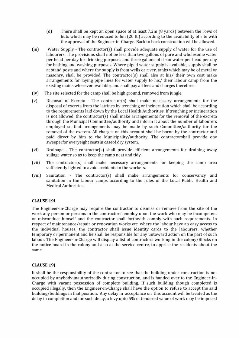
(d) There shall be kept an open space of at least 7.2m (8 yards) between the rows of huts which may be reduced to 6m (20 ft.) according to the availability of site with the approval of the Engineer-in-Charge. Back to back construction will be allowed.
(iii) Water Supply - The contractor(s) shall provide adequate supply of water for the use of labourers. The provisions shall not be less than two gallons of pure and wholesome water per head per day for drinking purposes and three gallons of clean water per head per day for bathing and washing purposes. Where piped water supply is available, supply shall be at stand posts and where the supply is from wells or river, tanks which may be of metal or masonry, shall be provided. The contractor(s) shall also at his/ their own cost make arrangements for laying pipe lines for water supply to his/ their labour camp from the existing mains wherever available, and shall pay all fees and charges therefore.
(iv) The site selected for the camp shall be high ground, removed from jungle.
(v) Disposal of Excreta - The contractor(s) shall make necessary arrangements for the disposal of excreta from the latrines by trenching or incineration which shall be according to the requirements laid down by the Local Health Authorities. If trenching or incineration is not allowed, the contractor(s) shall make arrangements for the removal of the excreta through the Municipal Committee/authority and inform it about the number of labourers employed so that arrangements may be made by such Committee/authority for the removal of the excreta. All charges on this account shall be borne by the contractor and paid direct by him to the Municipality/authority. The contractorshall provide one sweeperfor everyeight seatsin caseof dry system.
(vi) Drainage - The contractor(s) shall provide efficient arrangements for draining away sullage water so as to keep the camp neat and tidy.
(vii) The contractor(s) shall make necessary arrangements for keeping the camp area sufficiently lighted to avoid accidents to the workers.
(viii) Sanitation - The contractor(s) shall make arrangements for conservancy and sanitation in the labour camps according to the rules of the Local Public Health and Medical Authorities.
CLAUSE 19I
The Engineer-in-Charge may require the contractor to dismiss or remove from the site of the work any person or persons in the contractors’ employ upon the work who may be incompetent or misconduct himself and the contractor shall forthwith comply with such requirements. In respect of maintenance/repair or renovation works etc. where the labour have an easy access to the individual houses, the contractor shall issue identity cards to the labourers, whether temporary or permanent and he shall be responsible for any untoward action on the part of such labour. The Engineer-in-Charge will display a list of contractors working in the colony/Blocks on the notice board in the colony and also at the service centre, to apprise the residents about the same.
CLAUSE 19J
It shall be the responsibility of the contractor to see that the building under construction is not occupied by anybodyunauthorizedly during construction, and is handed over to the Engineer-in-Charge with vacant possession of complete building. If such building though completed is occupied illegally, then the Engineer-in-Charge shall have the option to refuse to accept the said building/buildings in that position. Any delay in acceptance on this account will be treated as the delay in completion and for such delay, a levy upto 5% of tendered value of work may be imposed

by the Engineer-in-Charge whose decision shall be final both with regard to the justification and quantum and be binding on the contractor.
However, the Engineer- in- charge, through a notice, mayrequire the contractor to remove the illegal occupation any time on or before construction and delivery.
CLAUSE 19K EMPLOYMENT OF SKILLED/SEMI SKILLED WORKERS
The contractor shall, at all stages of work, deploy skilled/semi-skilled tradesmen who are qualified and possess certificate in particular trade from CPWD Training Institute/Industrial Training Institute/National Institute of construction Management and Research (NICMAR)/ National Academy of Construction, CIDC, National Skill Development Corporation certified training institute or any similar reputed and recognized Institute managed/ certified by State/Central Government. The number of such qualified tradesmen shall not be less than 20% of total skilled/semi-skilled workers required in each trade at any stage of work. The contractor shall submit number of man days required in respect of each trade, its scheduling and the list of qualified tradesmen along with requisite certificate from recognized Institute to Engineer in charge for approval. Notwithstanding such approval, if the tradesmen are found to have inadequate skill to execute the work of respective trade, the contractor shall substitute such tradesmen within two days of written notice from Engineer- in-Charge. Failure on the part of contractor to obtain approval of Engineer-in-Charge or failure to deploy qualified tradesmen will attract a compensation to be paid by contractor at the rate of Rs. 100 per such tradesman per day. Decision of Engineer in Charge as to whether particular tradesman possesses requisite skill and amount of compensation in case of default shall be final and binding.
Provided always, that the provisions of this clause shall not be applicable for works with estimated cost put to tender being less than Rs. 5 crores.
CLAUSE 19L CONTRIBUTION OF EPF AND ESI
The ESI and EPF contributions on the part of the KSWDCin respect of this Contract shall be paid by the Contractor. These contributions on the part of the KSWDCpaid by the contractor shall be reimbursed by the Engineer-in-charge to the Contractor on actual basis.The applicableand eligible amount of EPF&ESI shall be reimbursed preferably within 7 days butnot later than 30 days of submission of documentary proof of payment providedsame are in order.
CLAUSE 20 MINIMUM WAGES ACT TO BE COMPLIED WITH
The contractor shall comply with all the provisions of the Minimum Wages Act, 1948, and Contract Labour (Regulation and Abolition) Act, 1970, amended from time to time and rules framed thereunder and other labour laws affecting contract labour that may be brought into force from time to time.
CLAUSE 21 WORK NOT TO BE SUBLET. ACTION IN CASE OF INSOLVENCY
The contract shall not be assigned or sublet without the written approval of the Engineer-in- Charge. And if the contractor shall assign or sublet his contract, or attempt to do so, or become insolvent or commence any insolvency proceedings or make any composition with his creditors or attempt to do so, or if any bribe, gratuity, gift, loan, perquisite, reward or advantage pecuniary or otherwise, shall either directly or indirectly, be given, promised or offered by the contractor, or any of his servants or agent to any public officer or person in the employ of Client in any way relating to his office or employment, or if any such officer or person shall become in any way directly or indirectly interested in the contract, the Engineer-in-Charge on behalf of the Clientshall

have power to adopt the course specified in Clause 3 hereof in the interest of Client and in the event of such course being adopted, the consequences specified in the said Clause 3 shall ensue.
CLAUSE 22
All sums payable by way of compensation under any of these conditions shall be considered as reasonable compensation to be applied to the use of KSWDCwithout reference to the actual loss or damage sustained and whether or not any damage shall have been sustained.
CLAUSE 23 CHANGES IN FIRM’S CONSTITUTION TO BE INTIMATED
Where the contractor is a partnership firm, the previous approval in writing of the Engineer- in-Charge shall be obtained before any change is made in the constitution of the firm. Where the contractor is an individual or a Hindu undivided family business concern, such approval as aforesaid shall likewise be obtained before the contractor enters into any partnership agreement where under the partnership firm would have the right to carry out the works hereby undertaken by the contractor. If previous approval as aforesaid is not obtained, the contract shall be deemed to have been assigned in contravention of Clause 21 hereof and the same action may be taken, and the same consequences shall ensue as provided in the said Clause 21.
CLAUSE 24
All works to be executed under the contract shall be executed under the direction and subject to the approval in all respects of the Engineer-in-Charge who shall be entitled to direct at what point or points and in what manner they are to be commenced, and from time to time carried on.
CLAUSE 25 SETTLEMENT OF DISPUTES & ARBITRATION
Except where otherwise provided in the contract, all questions and disputes relating to the meaning of the specifications, design, drawings and instructions here-in before mentioned and as to the quality of workmanship or materials used on the work or as to any other question, claim, right, matter or thing whatsoever in any way arising out of or relating to the contract, designs, drawings, specifications, estimates, instructions, orders or these conditions or otherwise concerning the works or the execution or failure to execute the same whether arising during the progress of the work or after the cancellation, termination, completion or abandonment thereof shall be dealt with as mentioned hereinafter:
(i) If the contractor considers any work demanded of him to be outside the requirements of the contract, or disputes any drawings, record or decision given in writing by the Engineer-in-Charge or the Engineer in charge considers any act or decision of the contractor on any matter in connection with or arising out of the contract or carrying out of the work, to be unacceptable, such party shall promptly within 15 days of the arising of the disputes request the authority indicating in schedule ‘F” (Reviewing Authority) who shall refer the disputes to Dispute redressal committee (DRC) within a period of 15 days along with a list of disputes with amounts claimed in respect of each such dispute. The DRC shall give the opposing party two weeks for a written response, and, give its decision within a period of 60 days extendable by 30 days by consent of both the partiesfrom the receipt of reference from Reviewing authority. The constitution of Dispute Redressal Committee (DRC) shall be as indicated in Schedule ‘F’. Provided that no party shall be represented before the Dispute Redressal Committee by an advocate/ legal counsel etc.

If the Dispute Redressal Committee (DRC) fails to give his decision within the aforesaid period or any party is dissatisfied with the decision of Dispute Redressal Committee (DRC) or expiry of time limit given above, then either party may within a period of 30 days from the receipt of the decision of Dispute Redressal Committee (DRC), give notice to the Director (KSWDC) for appointment of arbitrator on prescribed proforma as per Appendix XV, under intimation to the other party. It is a term of contract that each party invoking arbitration must exhaust the aforesaid mechanism of settlement of claims/disputes prior to invoking arbitration. The KSWDC shall in such case appoint the sole arbitrator as the case may be within 30 days of receipt of such a request and refer such disputes to arbitration. (ii) Disputes or difference shall be referred for adjudication through arbitration by a Tribunal having sole arbitrator. The requirements of the Arbitration and Conciliation Act, 1996 (26 of 1996) and any further statutory modifications or re-enactment thereof and the rules made there under and for the time being in force shall be applicable. It is a term of this contract that the party invoking arbitration shall give a list of disputes with amounts if any claimed in respect of each such dispute along with the notice for appointment of arbitrator and giving reference to the decision of the DRC.
It is also a term of this contract that any member of the Arbitration Tribunal shall be a Graduate Engineer with experience in handling public works engineering contracts at a level not lower than Chief Engineer. This shall be treated as a mandatory qualification to be appointed as arbitrator. Parties, before or at the time of appointment of Arbitral Tribunal may agree in writing for fast track arbitration as per the Arbitration and Conciliation Act, 1996 (26 of 1996) as amended in 2015.
Subject to provision in the Arbitration and Conciliation Act, 1996 (26 of 1996) as amended in 2015 whereby the counter claims if any can be directly filed before the arbitrator without any requirement of reference by the appointing authority, the arbitrator shall adjudicate on only such disputes as are referred to him by the appointing authority and give separate award against each dispute and claim referred to him and in all cases where the total amount of the claims by any party exceeds Rs. 1,00,000/-, the arbitrator shall give reasons for the award.
It is also a term of the contract that if any fees are payable to the arbitrator, these shall be paid as per the act.
The place of arbitration shall be as mentioned in Schedule F. In case there is no mention of place of arbitration, the arbitral tribunal shall determine the place of arbitration. The venue of the arbitration shall be such place as may be fixed by the Arbitral Tribunal in consultation with both the parties. Failing any such agreement, then the Arbitral Tribunal shall decide the venue.
CLAUSE 26 CONTRACTOR TO INDEMNIFY KSWDCAGAINST PATENT RIGHTS
The contractor shall fully indemnify and keep indemnified the KSWDCagainst any action, claim or proceeding relating to infringement or use of any patent or design or any alleged patent or design rights and shall pay any royalties which may be payable in respect of any article or part thereof included in the contract. In the event of any claims made under or action brought against

KSWDCin respect of any such matters as aforesaid, the contractor shall be immediately notified thereof and the contractor shall be at liberty, at his own expense, to settle any dispute or to conduct any litigation that may arise therefrom, provided that the contractor shall not be liable to indemnify the KSWDC if the infringement of the patent or design or any alleged patent or design right is the direct result of an order passed by the Engineer-in-Charge in this behalf.
CLAUSE 27 LUMPSUM PROVISIONS IN TENDER
When the estimate on which a tender is made includes lump sum in respect of parts of the work, the contractor shall be entitled to payment in respect of the items of work involved or the part of the work in question at the same rates as are payable under this contract for such items, or if the part of the work in question is not, in the opinion of the Engineer-in-Charge payable of measurement, the Engineer-in-Charge may at his discretion pay the lump-sum amount entered in the estimate, and the certificate in writing of the Engineer-in-Charge shall be final and conclusive against the contractor with regard to any sum or sums payable to him under the provisions of the clause.
CLAUSE 28 ACTION WHERE NO SPECIFICATIONS ARE SPECIFIED
In the case of any class of work for which there is no such specifications as referred to in Clause 11, such work shall be carried out in accordance with the Bureau of Indian Standards Specifications. In case there are no such specifications in Bureau of Indian Standards, the work shall be carried out as per manufacturers’ specifications, if not available then as per District Specifications. In case there are no such specifications as required above, the work shall be carried out in all respects in accordance with the instructions and requirements of the Engineer-in-Charge.
CLAUSE 29 WITHHOLDING AND LIEN IN RESPECT OF SUM DUE FROM CONTRACTOR
(i) Whenever any claim or claims for payment of a sum of money arises out of or under the contract or against the contractor, the Engineer-in-Charge shall be entitled to withhold and also have a lien to retain such sum or sums in whole or in part from the security, if any deposited by the contractor and for the purpose aforesaid, the Engineer-in-Chargeshall be entitled to withhold the security deposit, if any, furnished as the case may be and also have a lien over the same pending finalisation or adjudication of any such claim. In the event of the security being insufficient to cover the claimed amount or amounts or if no security has been taken from the contractor, the Engineer-in-Charge shall be entitled to withhold and have a lien to retain to the extent of such claimed amount or amounts referred to above, from any sum or sums found payable or which may at any time thereafter become payable to the contractor under the same contract or any other contract with the Engineer-in-Charge of the KSWDCor any contracting person through the Engineer- in-Charge pending finalization of adjudication of any such claim.
It is an agreed term of the contract that the sum of money or moneys so withheld or retained under the lien referred to above by the Engineer-in-Charge will be kept withheld or retained as such by the Engineer-in-Charge till the claim arising out of or under the contract is determined by the arbitrator(if the contract is governed by the arbitration clause) by the competent court, as the case may be and that the contractor will have no claim for interest or damages whatsoever on any account in respect of such withholding or retention under the lien referred to above and duly notified as such to the contractor. For the purpose of this clause, where the contractor is a partnership firm or a limited company, the Engineer-in-Charge shall be entitled to withhold and also have a lien to retain towards such claimed

amount or amounts in whole or in part from any sum found payable to any partner/limited company as the case may be, whether in his individual capacity or otherwise.
(ii) KSWDCshall have the right to cause an audit and technical examination of the works and the final bills of the contractor including all supporting vouchers, abstract, etc., to be made after payment of the final bill and if as a result of such audit and technical examination any sum is found to have been overpaid in respect of any work done by the contractor under the contract or any work claimed to have been done by him under the contract and found not to have been executed, the contractor shall be liable to refund the amount of over-payment and it shall be lawful for Client to recover the same from him in the manner prescribed in sub-clause (i) of this clause or in any other manner legally permissible; and if it is found that the contractor was paid less than what was due to him under the contract in respect of any work executed by him under it, the amount of such under payment shall be duly paid by KSWDC to the contractor, without any interest thereon whatsoever.
Provided that the KSWDCshall not be entitled to recover any sum overpaid, nor the contractor shall be entitled to payment of any sum paid short where such payment has been agreed upon between the Engineer- in- charge on the one hand and the contractor on the other under any term of the contract permitting payment for work after assessment by the Engineer- in- charge.
CLAUSE 29A LIEN IN RESPECT OF CLAIMS IN OTHER CONTRACTS
Any sum of money due and payable to the contractor (including the security deposit returnable to him) under the contract may be withheld or retained by way of lien by the Engineer-in-Charge or any other contracting person or persons through Engineer-in-Charge against any claim of the Engineer-in-Charge or such other person or persons in respect of payment of a sum of money arising out of or under any other contract made by the contractor with the Engineer- in-Charge or with such other person or persons.
It is an agreed term of the contract that the sum of money so withheld or retained under this clause by the Engineer-in-Charge will be kept withheld or retained as such by the Engineer-in-Charge or till his claim arising out of the same contract or any other contract is either mutually settled or determined by the arbitration clause or by the competent court, as the case may be and that the contractor shall have no claim for interest or damages whatsoever on this account or on any other ground in respect of any sum of money withheld or retained under this clause and duly notified as such to the contractor.
CLAUSE 30 EMPLOYMENT OF COAL MINING OR CONTROLLED AREA LABOUR NOTPERMISSIBLE
The contractor shall not employ coal mining or controlled area labour falling under any category whatsoever on or in connection with the work or recruit labour from area within a radius of 32 km (20 miles) of the controlled area. Subject as above the contractor shall employ imported labour only i.e., deposit imported labour or labour imported by contractors from area, from which import is permitted.
Where ceiling price for imported labour has been fixed by State or Regional Labour Committees not more than that ceiling price shall be paid to the labour by the contractor.
The contractor shall immediately remove any labourerwho maybe pointed out by the Engineer- in-Charge as being a coal mining or controlled area labourer. Failure to do so shall render the contractor liable to pay to Client a sum calculated at the rate of Rs.10/- per day per labourer. The certificate of the Engineer-in-Charge about the number of coal mining or controlled area labourer

and the number of days for which they worked shall be final and binding upon all parties to this contract.
It is declared and agreed between the parties that the aforesaid stipulation in this clause is one in which the public are interested within the meaning of the exception in Section 74 of Indian Contract Act, 1872.
Explanation:- Controlled Area means the following areas:
Districts of Dhanbad, Hazaribagh, Jamtara - a Sub-Division under SanthalParganaCommissionery, Districts of Bankuara, Birbhum, Burdwan, District of Bilaspur.
Any other area which may be declared a Controlled Area by or with the approval of the Central Government.
CLAUSE 31 UNFILTERED WATER SUPPLY
The contractor(s) shall make his/their own arrangements for water required for the work and nothing extra will be paid for the same. This will be subject to the following conditions.
(i) That the water used by the contractor(s) shall be fit for construction purposes to the satisfaction of the Engineer-in-Charge.
(ii) The Engineer-in-Charge shall make alternative arrangements for supply of water at the risk and cost of contractor(s) if the arrangements made by the contractor(s) for procurement of water are in the opinion of the Engineer-in- Charge, unsatisfactory.
CLAUSE 31 A DEPARTMENTAL WATER SUPPLY, IF AVAILABLE
Water if available may be supplied to the contractor by the department subject to the following conditions:-
(i) The water charges @ 1 % shall be recovered on gross amount of the work done.
(ii) The contractor(s) shall make his/their own arrangement of water connection and laying of pipelines from existing main of source of supply.
(iii) The Department do not guarantee to maintain uninterrupted supply of water and it will be incumbent on the contractor(s) to make alternative arrangements for water at his/ their own cost in the event of any temporary break down in the Government water main so that the progress of his/their work is not held up for want of water. No claim of damage or refund of water charges will be entertained on account of such break down.
CLAUSE 32 ALTERNATE WATER ARRANGEMENTS
(i) Where there is no piped water supply arrangement and the water is taken by the contractor from the wells or hand pump constructed by the Client, no charge shall be recovered from the contractor on that account. The contractor shall, however, draw water at such hours of the day that it does not interfere with the normal use for which the hand pumps and wells are intended. He will also be responsible for all damage and abnormal repairs arising out of his use, the cost of which shall be recoverable from him. The Engineer-in-Charge shall be the final authority to determine the cost recoverable from the contractor on this account and his decision shall be binding on the contractor.
(ii) The contractor shall be allowed to construct temporary wells in Clientland for taking water for construction purposes only after he has got permission of the Engineer- in-Charge in writing. No charges shall be recovered from the contractor on this account, but

the contractor shall be required to provide necessary safety arrangements to avoid any accidents or damage to adjacent buildings, roads and service lines. He shall be responsible for any accidents or damage caused due to construction and subsequent maintenance of the wells and shall restore the ground to its original condition after the wells are dismantled on completion of the work.
CLAUSE 33 RETURN OF SURPLUS MATERIALS
Notwithstanding anything contained to the contrary in this contract, where any materials for the execution of the contract are procured with the assistance of Client / KSWDC either by issue from Client KSWDCs stocks or purchase made under orders or permits or licenses issued by Client, the contractor shall hold the said materials economically and solely for the purpose of the contract and not dispose of them without the written permission of the Client and return, if required by the Engineer-in-Charge, all surplus or unserviceable materials that may be left with him after the completion of the contract or at its termination for any reason whatsoever on being paid or credited such price as the Engineer-in-Charge shall determine having due regard to the condition of the materials. The price allowed to the contractor however shall not exceed the amount charged to him excluding the element of storage charges. The decision of the Engineer-in-Charge shall be final and conclusive. In the event of breach of the aforesaid condition, the contractor shall in addition to throwing himself open to action for contravention of the terms of the licence or permit and/or for criminal breach of trust, be liable to Client for all moneys, advantages or profits resulting or which in the usual course would have resulted to him by reason of such breach.
CLAUSE 34 HIRE OF PLANT & MACHINERY
(i) The contractor shall arrange at his own expense all tools, plant, machinery and equipment (hereinafter referred to as T&P) required for execution of the work except for the Plant & Machinery listed in Schedule ‘C’ and stipulated for issue to the contractor. If the contractor requires any item of T&P on hire from the T&P available with the KSWDCover and above the T&P stipulated for issue, the KSWDCwill, if such item is available, hire it to the contractor at rates to be agreed upon between him and the Engineer-in-Charge. In such a case, all the conditions hereunder for issue of T&P shall also be applicable to such T&P as is agreed to be issued.
(ii) Plant and Machinery when supplied on hire charges shown in Schedule ‘C’ shall be made over and taken back at the departmental equipment yard/shed shown in Schedule ‘C’ and the contractor shall bear the cost of carriage from the place of issue to the site of work and back. The contractor shall be responsible to return the plant and machinery with condition in which it was handed over to him, and he shall be responsible for all damage caused to the said plant and machinery at the site of work or elsewhere in operation and otherwise during transit including damage to or loss of plant and for all losses due to his failure to return the same soon after the completion of the work for which it was issued. The Engineer-in-Charge shall be the sole judge to determine the liability of the contractor and its extent in this regard and his decision shall be final and binding on the contractor.
(iii) The plant and machinery as stipulated above will be issued as and when available and if required by the contractor. The contractor shall arrange his programme of work according to the availability of the plant and machinery and no claim, whatsoever, will be entertained from him for any delay in supply by the Department.
(iv) The hire charges shall be recovered at the prescribed rates from and inclusive of the date the plant and machinery made over upto and inclusive of the date of the return in good order even though the same may not have been working for any cause except major

breakdown due to no fault of the contractor or faulty use requiring more than three working days continuously (excluding intervening holidays and Sundays) for bringing the plant in order. The contractor shall immediately intimate in writing to the Engineer-in- Charge when any plant or machinery gets out of order requiring major repairs as aforesaid. The Engineer-in-Charge shall record the date and time of receipt of such intimation in the log sheet of the plant or machinery. Based on this if the breakdown before lunch period or major breakdown will be computed considering half a day’s breakdown on the day of complaint. If the breakdown occurs in the post lunch period of major breakdown will be computed starting from the next working day. In case of any dispute under this clause, the decision of the Engineer-in-Charge shall be final and binding on the contractor.
(v) The hire charges shown above are for each day of 8 hours (inclusive of the one hour lunch break) or part thereof.
(vi) Hire charges will include service of operating staff as required and also supply of lubricating oil and stores for cleaning purposes. Power fuel of approved type, firewood, kerosene oil etc. for running the plant and machinery and also the full time chowkidar for guarding the plant and machinery against any loss or damage shall be arranged by the contractor who shall be fully responsible for the safeguard and security of plant and machinery. The contractor shall on or before the supply of plant and machinery sign an agreement indemnifying the Department against any loss or damage caused to the plant and machinery either during transit or at site of work.
(vii) Ordinarily, no plant and machinery shall work for more than 8 hours a day inclusive of one hour lunch break. In case of an urgent work however, the Engineer-in-Charge may, at his discretion, allow the plant and machinery to be worked for more than normal period of 8 hours a day. In that case, the hourly hire charges for overtime to be borne by the contractor shall be 50% more than the normal proportionate hourly charges (1/8th of the daily charges) subject to a minimum of half day’s normal charges on any particular day. For working out hire charges for over time, a period of half an hour and above will be charged as one hour and a period of less than half an hour will be ignored.
(viii) The contractor shall release the plant and machinery every seventh day for periodical servicing and/or wash out which may take about three to four hours or more. Hire charges for full day shall be recovered from the contractor for the day of servicing/ wash out irrespective of the period employed in servicing.
(ix) The plant and machinery once issued to the contractor shall not be returned by him on account of lack of arrangements of labour and materials, etc. on his part, the same will be returned only when they are required for major repairs or when in the opinion of the Engineer-in-Charge, the work or a portion of work for which the same was issued is completed.
(x) Log Book for recording the hours of daily work for each of the plant and machinery supplied to the contractor will be maintained by the Department and will be countersigned by the contractor or his authorized agent daily. In case the contractor contests the correctness of the entries and/or fails to sign the Log Book, the decision of the Engineer-in-Charge shall be final and binding on him. Hire charges will be calculated according to the entries in the Log Book and will be binding on the contractor. Recovery on account of hire charges for road rollers shall be made for the minimum number of days worked out on the assumption that a roller can consolidate per day and maximum quantity of materials or area surfacing as noted against each in the annexed statement (see attached annexure).
(xi) In the case of concrete mixers, the contractors shall arrange to get the hopper cleaned and the drum washed at the close of the work each day or each occasion.

(a) In case rollers for consolidation are employed by the contractor himself, log book for such rollers shall be maintained in the same manner as is done in case of departmental rollers, maximum quantity of any items to be consolidated for each roller-day shall also be same as in Annexure to Clause 34(x). For less use of rollers, recovery for the less roller days shall be made at the stipulated issue rate.
(xii) The contractor shall be responsible to return the plant and machinery in the condition in which it was handed over to him and he shall be responsible for all damage caused to the said plant and machinery at the site of work or elsewhere in operation or otherwise or during transit including damage to or loss of parts, and for all losses due to his failure to return the same soon after the completion of the work for which it was issued. The Engineer-in-Charge shall be the sole judge to determine the liability of the contractor and its extent in this regard and his decision shall be final and binding on the contractor.
(xiii) In the event of the contractor not requiring any item of plant and machinery issued by Client though not stipulated for issue in Schedule ‘C’ any time after taking delivery at the place of issue, he may return it after two days written notice or at any time without notice if he agrees to pay hire charges for two additional days without, in any way, affecting the right of the Engineer-in-Charge to use the said plant and machinery during the said period of two days as he likes including hiring out to a third party.
CLAUSE 35 CONDITION RELATING TO USE OF ASPHALTIC MATERIALS
(i) The contractor undertakes to make arrangement for the supervision of the work by the firm supplying the tar or bitumen used.
(ii) The contractor shall collect the total quantity of tar or bitumen required for the work as per standard formula, before the process of painting is started and shall hypothecate it to the Engineer-in-Charge. If any bitumen or tar remains unused on completion of the work on account of lesser use of materials in actual execution for reasons other than authorized changes of specifications and abandonment of portion of work, a corresponding deduction equivalent to the cost of unused materials as determined by the Engineer-in-Charge shall be made and the material return to the contractors. Although the materials are hypothecated to Client, the contractor undertakes the responsibility for their proper watch, safe custody and protection against all risks. The materials shall not be removed from site of work without the consent of the Engineer-in- Charge in writing.
(iii) The contractor shall be responsible for rectifying defects noticed within a year from the date of completion of the work and the portion of the security deposit relating to asphaltic work shall be refunded after the expiry of this period.
CLAUSE 36 EMPLOYMENT OF TECHNICAL STAFF AND EMPLOYEES
Contractors Superintendence, Supervision, Technical Staff & Employees
(i) The contractor shall provide all necessary superintendence during execution of the work and all along thereafter as may be necessary for proper fulfilling of the obligations under the contract.
The contractor shall immediately after receiving letter of acceptance of the tender and before commencement of the work, intimate in writing to the Engineer-in-Charge, the name(s), qualifications, experience, age, address(s) and other particulars along with certificates, of the principal technical representative to be in charge of the work and other technical representative(s) who will be supervising the work. Minimum requirement of such technical representative(s) and their qualifications and experience shall not belowthanspecifiedin Schedule ‘F’. The Engineer-in-Charge shall within 3 days of receipt

of such communication intimate in writing his approval or otherwise of such a representative(s) to the contractor. Any such approval may at any time be withdrawn and in case of such withdrawal, the contractor shall appoint another such representative(s) according to the provisions of this clause. Decision of the tender accepting authority shall be final and binding on the contractor in this respect. Such a principal technical representative and other technical representative(s) shall be appointed by the contractor soon after receipt of the approval from Engineer-in-charge and shall be available at site before start of work.
All the provisions applicable to the principal technical representative under the Clause will also be applicable to other technical representative(s) The principal technical representative and other technical representative(s) shall be present at the site of work for supervision at all times when any construction activity is in progress and also present himself/themselves, as required, to the Engineer-in-Charge and/or his designated representative to take instructions. Instructions given to the principal technical representative or other technical representative(s) shall be deemed to have the same force as if these have been given to the contractor. The principal technical representative and other technical representative(s) shall be actually available at site fully during all stages of execution of work, during recording/checking/test checking of measurements of works and whenever so required by the Engineer-in-Charge and shall also note down instructions conveyed by the Engineer-in- Charge or his designated representative(s) in the site order book and shall affix his/their signature in token of noting down the instructions and in token of acceptance of measurements/ checked measurements/test checked measurements. The representative(s) shall not look after any other work. Substitutes, duly approved by Engineer-in-Charge of the work in similar manner as aforesaid shall be provided in event of absence of any of the representative(s) by more than two days.
If the Engineer-in-Charge, whose decision in this respect is final and binding on the contractor, is convinced that no such technical representative(s) is/are effectively appointed or is/are effectively attending or fulfilling the provision of this clause, a recovery (non-refundable) shall be effected from the contractor as specified in Schedule ‘F’ and the decision of the Engineer-in-Charge as recorded in the site order book and measurement recorded checked/test checked in Measurement Books shall be final and binding on the contractor. Further if the contractor fails to appoint suitable Principal technical representative and/or other technical representative(s) and if such appointed persons are not effectively present or are absent by more than two days without duly approved substitute or do not discharge their responsibilities satisfactorily, the Engineer-in-Charge shall have full powers to suspend the execution of the work until such date as suitable other technical representative(s) is/are appointed and the contractor shall be held responsible for the delay so caused to the work. The contractor shall submit a certificate of employment of the technical representative(s) alongwith every on account bill/ final bill and shall produce evidence if at any time so required by the Engineer-in-Charge. The contractor shall submit a certificate of employment of the technical representative(s) (in the form of copy of Form-16 or CPF deduction issued to the Engineers employed by him) along with every on account bill/final bill and shall produce evidence if at any time so required by the Engineer-in-Charge.
(ii) The contractor shall provide and employ on the site only such technical assistants as are skilled and experienced in their respective fields and such foremen and supervisory staff as are competent to give proper supervision to the work.
The contractor shall provide and employ skilled, semiskilled and unskilled labour as is necessary for proper and timely execution of the work.

The Engineer-in-Charge shall be at liberty to object to and require the contractor to remove from the works any person who in his opinion misconducts himself, or is incompetent or negligent in the performance of his duties or whose employment is otherwise considered by the Engineer-in-Charge to be undesirable. Such person shall not be employed again at works site without the written permission of the Engineer-in-Charge and the persons so removed shall be replaced as soon as possible by competent substitutes.
CLAUSE 37 LEVY/TAXES PAYABLE BY CONTRACTOR
(i) GST, Building and other Construction Workers Welfare Cess or any other tax, levy or Cess in respect of input for or output by this contract shall be payable by the contractor and KSWDCshall not entertain any claim whatsoever in this respect except as provided under clause 38.
(ii) The contractor shall deposit royalty and obtain necessary permit for supply of the red bajri, stone, kankar, etc. from local authorities.
(iii) If pursuant to or under any law, notification or order any royalty, cess or the like becomes payable by the Government of India and does not any time become payable by the contractor to the State Government, Local authorities in respect of any material used by the contractor in the works, then in such a case, it shall be lawful to the Government of India and it will have the right and be entitled to recover the amount paid in the circumstances as aforesaid from dues of the contractor.
CLAUSE 38 CONDITIONS FOR REIMBURSEMENT OF LEVY/TAXES IF LEVIED AFTER RECEIPT OF TENDERS
(i) All tendered rates shall be inclusive of any tax, levy or cess applicable on last date of receipt of tender including extension if any. No adjustment ie., increase or decrease shall be made for any variation in the rate of GST, Building and other Construction Workers Welfare Cess or any other tax, levy or Cess applicable on inputs. However effect of variation in rates of GST or Building and other Construction Workers Welfare Cess or imposition or repeal of any other tax, levy or cess applicable on output of the works contract shall be adjusted on either side, increase or decrease. Provided for Building and other Construction Workers Welfare Cess or any tax (other than GST), levy or cess varied or imposed after the last date of receipt of tender including extension if any, any increase shall be reimbursed to the contractor only if the contractor necessarily and properly pays such increased amount of taxes/ levies/ cess. Provided further that such adjustment including GST shall not be made in the extended period of contract for which the contractor alone is responsible for delay as determined by authority for extension of time under clause 5 in Scheule F.
(ii) The contractor shall keep necessary books of accounts and other documents for the purpose of this condition as may be necessary and shall allow inspection of the same by a duly authorized representative of the Client and/or the Engineer-in-Charge and shall also furnish such other information/document as the Engineer-in-Charge may require from time to time.
(iii) The contractor shall, within a period of 30 days of the imposition of any such further tax or levy or cess, give a written notice thereof to the Engineer-in-charge that the same is given pursuant to this condition, together with all necessary information relating thereto.

CLAUSE 39 TERMINATION OF CONTRACT ON DEATH OF CONTRACTOR
Without prejudice to any of the rights or remedies under this contract, if the contractor dies, the authority indicated in schedule “F” on behalf of the Client shall have the option of terminating the contract without compensation to the contractor.
CLAUSE 40 IF RELATIVE WORKING IN OFFICE OF CLIENT/KSWDC THEN THE CONTRACTOR NOT ALLOWED TO TENDER
The contractor shall not be permitted to tender for works in the Client/ KSWDCin which his near relative is posted as Divisional Accountant or equivalent or as an officer in any capacity between the grades of the General Manager/ Chief Engineer and Site Engineer (both inclusive). He shall also intimate the names of persons who are working with him in any capacity or are subsequently employed by him and who are near relatives to any Gazetted Officer in KSWDC. Any breach of this condition by the contractor would render him liable to be removed from the approved list of contractors of KSWDC. If however the contractor is registered in any other department, he shall be debarred from tendering in the Department in future for any breach of this condition.
NOTE: By the term “near relatives” is meant wife, husband, parents and grandparents, children and grandchildren, brothersand sisters, uncles, aunts and cousinsand their corresponding in-laws.
CLAUSE 41 NO GAZETTED ENGINEER TO WORK AS CONTRACTOR WITHIN ONE YEAR OF RETIREMENT
No engineer of gazetted rank or other gazetted officer employed in engineering or administrative duties in an engineering department of the Government of India shall work as a contractor or employee of a contractor for a period of one year after his retirement from government service without the previous permission of Government of India in writing. This contract is liable to be cancelled if either the contractor or any of his employees is found at any time to be such a person who had not obtained the permission of Government of India as aforesaid, before submission of the tender or engagement in the contractor’s service, as the case may be.
CLAUSE 42 RETURN OF MATERIAL & RECOVERY FOR EXCESS MATERIAL USED
(i) After completion of the work and also at any intermediate stage in the event of non- reconciliation of materials issued, consumed and in balance -(see Clause 10), theoretical quantity of materials issued by the KSWDCfor use in the work shall be calculated on the basis and method given hereunder:-
(a) Quantity of cement & bitumen shall be calculated on the basis of quantity of cement & bitumen required for different items of work as shown in the Schedule of Rates mentioned in Schedule ‘F’. In case any item is executed for which standard constants for the consumption of cement or bitumen are not available in the above mentioned schedule/statement or cannot be derived from the same shall be calculated on the basis of standard formula to be laid down by the Engineer-in-Charge.
(b) Theoretical quantity of steel reinforcement or structural steel sections shall be taken as the quantity required as per design or as authorized by Engineer-in-Charge, including authorized lappages, chairs etc. plus 3% wastage due to cutting into pieces, such theoretical quantity being determined and compared with the actual issues each diameter wise, section wise and category wise separately.
(c) Theoretical quantity of G.I. & C.I. or other pipes, conduits, wires and cables, pig lead and G.I./M.S. sheets shall be taken as quantity actually required and measured plus 5% for wastage due to cutting into pieces (except in the case of G.I./M.S. sheets it shall be 10%), such determination & comparison being made diameter wise & category wise.

(d) For any other material as per actual requirements.
(ii) Over the theoretical quantities of materials so computed a variation shall be allowed as specified in Schedule ‘F’. The difference in the net quantities of material actually issued to the contractor and the theoretical quantities including such authorized variation, if not returned by the contractor or if not fully reconciled to the satisfaction of the Engineer-in- Charge within fifteen days of the issue of written notice by the Engineer-in-charge to this effect shall be recovered at the rates specified in Schedule ‘F’, without prejudice to the provision of the relevant conditions regarding return of materials governing the contract. Decision of Engineer-in-Charge in regard to theoretical quantities of materials, which should have been actually used as per the Annexure of the standard schedule of rates and recovery at rates specified in Schedule ‘F’, shall be final & binding on the contractor. For non-scheduled items, the decision of the Engineer-in-Charge regarding theoretical quantities of materials which should have been actually used, shall be final and binding on the contractor.
(iii) The said action under this clause is without prejudice to the right of the Client to take action against the contractor under any other conditions of contract for not doing the work according to the prescribed specifications.
CLAUSE 43 COMPENSATION DURING WARLIKE SITUATIONS
The work (whether fully constructed or not) and all materials, machines, tools and plants, scaffolding, temporary buildings and other things connected therewith shall be at the risk of the contractor until the work has been delivered to the Engineer-in-Charge and a certificate from him to that effect obtained. In the event of the work or any materials properly brought to the site for incorporation in the work being damaged or destroyed in consequence of hostilities or warlike operation, the contractor shall when ordered (in writing) by the Engineer-in-Charge to remove any debris from the site, collect and properly stack or remove in store all serviceable materials salvaged from the damaged work and shall be paid at the contract rates in accordance with the provision of this agreement for the work of clearing the site of debris, stacking or removal of serviceable material and for reconstruction of all works ordered by the Engineer-in-Charge, such payments being in addition to compensation upto the value of the work originally executed before being damaged or destroyed and not paid for. In case of works damaged or destroyed but not already measured and paid for, the compensation shall be assessed by the Engineer- in- charge or his authorized representative. The contractor shall be paid for the damages/destruction suffered and for restoring the material at the rate based on analysis of rates tendered for in accordance with the provision of the contract. The certificate of the Engineer-in-Charge regarding the quality and quantity of materials and the purpose for which they were collected shall be final and binding on all parties to this contract.
Provided always that no compensation shall be payable for any loss in consequence of hostilities or warlike operations (a) unless the contractor had taken all such precautions against air raid as are deemed necessary by the A.R.P. Officers or the Engineer-in-Charge (b) for any material etc. not on the site of the work or for any tools, plant, machinery, scaffolding, temporary building and other things not intended for the work.
In the event of the contractor having to carry out reconstruction as aforesaid, he shall be allowed such extension of time for its completion as is considered reasonable by the Engineer- in- charge.
CLAUSE 44 APPRENTICES ACT PROVISIONS TO BE COMPLIED WITH
The contractor shall comply with the provisions of the Apprentices Act, 1961 and the rules and orders issued thereunder from time to time. If he fails to do so, his failure will be a breach of the contract and the Client may, in his discretion, cancel the contract. The contractor shall also be

liable for any pecuniary liability arising on account of any violation by him of the provisions of the said Act.
CLAUSE 45 RELEASE OF SECURITY DEPOSIT AFTER LABOUR CLEARANCE
Deposit of the work shall not be refunded till the contractor produces a clearance deposit after labour certificate from the Labour Officer. As soon as the work is virtually complete the contractor clearance shall apply for the clearance certificate to the Labour Officer under intimation to the Engineer-in-Charge. The Engineer-in-Charge, on receipt of the said communication, shall write to the Labour Officer to intimate if any complaint is pending against the contractor in respect of the work. If no complaint is pending, on record till after 3 months after completion of the work and/or no communication is received from the Labour Officer to this effect till six months after the date of completion, it will be deemed to have received the clearance certificate and the Security Deposit will be released if otherwise due.
CLAUSE 46Insurance
Without limiting the Contractor’s obligations and responsibilities stated elsewhere in the Contract, the Contractor shall at his own cost arrange, secure and maintain insurance in the joint names of the KSWDC and the contractor with any of the subsidiary of the General Insurance Corporation of India in such a manner that the KSWDC and the contractor are covered for all time during the period of contract i.e. the time period allowed for completion of work, extended period and the defect liability period. The insurance shall be effected in accordance with terms approved by the KSWDC and the contractor shall submit the insurance policies to the Engineer-In-Charge within one week of signing of the agreement along with the receipt of premium. The contractor shall timely pay and submit the receipts of payment of premiums for extensions of policies, if any. The insurance shall cover the following:-
A. Contractor’s All Risks Insurance The contractor shall insure the work for a sum equivalent to the Contract value or such additional sums as specified and the interests of the KSWDC against ALL RISKS claims, proceedings, loss or damages, costs, charges and expenses from whatsoever cause arising out of or in consequence of the execution and maintenance of the work for which the contractor is responsible under the contract B. Workman Compensation & Employers Liability Insurance. This insurance shall be effected for all the contractor’s employees engaged in the performance of the contract. The KSWDC shall not be liable in respect of any damages or compensation payable at law in respect of or in consequence of any accident or injury to any workman or any other person in the employment of the contractor and the contractor shall indemnify and keep indemnified the KSWDC against all such damages and compensation and against all claims, demands, proceedings, costs, charges and expenses, whatsoever in respect or in relation thereof. C. Third Party Insurance. The contractor shall be responsible for making good to the satisfaction of the Engineer-in-Charge any loss or any damage to all structures and properties belonging to the KSWDC or being executed or procured or being procured by the KSWDC or of the other agencies within the premises of all work of the KSWDC. If such loss or damage is due to fault and or the negligence or willful acts or omissions of the contractor, his employees, agents, representatives. The contractor shall take sufficient care in moving his plants, equipments and materials from one place to another so that they do not cause any damage to any person or to the property of the

KSWDC or any third party including overhead and underground cables and in the event of any damage resulting to the property of the KSWDC or to a third party during the movement of the aforesaid plant, equipment or materials, the cost of such damages including eventual loss of production, operation or services in any plant or establishment as estimated by the KSWDC or ascertained or demanded by the third party, shall be borne by the contractor. Before commencing the execution of the work, the contractor, shall insure and indemnify and keep the KSWDC harmless of all claims, against the contractor’s liability for any materials or physical damage, loss or injury which may occur to any property, including that of the KSWDC or to any person including any employee of KSWDC, or arising out of the execution of the work or in the carrying out of the contract, otherwise than due to the matters referred to in the provision to (a) above. Such insurance shall be effected for an amount sufficient to cover such risks. The terms shall include a provision whereby, in the event of any claim in respect of which the contractor, would be entitled to receive indemnify under the policy being brought or made against the KSWDC, the insurer willfully indemnify KSWDC against such claims and any costs, charges and expenses in respect thereof. D. The contractor shall also at times indemnify the KSWDC against all claims, damages or compensation under the provisions of Payment or Wages Act, 1936, Minimum Wages Act, 1948, Employer’s Liability Act, 1938, the Workman’s Compensation Act, 1947, Industrial Disputes Act, 1947 and Maternity Benefit Act, 1961, or any modification thereof or any other law relating thereof and rules made there under from time to time. E. Contractor shall also at his own cost carry and maintain any and all other insurance(s) which he may be required to take out under any law or regulation from time to time. He shall also carry and maintain any other insurance, which may be required by the Engineer-in-Charge. 46.2 The Contractor shall prove to the Engineer-in-charge from time to time he has taken out all the insurance policies referred to above and has paid the necessary premiums for keeping the policies alive till expiry of the Defects Liability Period. 46.3 The aforesaid insurance policies shall provide that they shall not be cancelled till the Engineer-in-charge has agreed for cancellation. 46.4 Remedy on the contractor’s failure to insure If the contractor shall fail to effect and keep in force the insurance referred to above or any other insurance which he/they may be required to effect under the terms of the contract then and in any such case Engineer-in-charge may without being bound to, effect and keep in force any such insurance and pay such premium or premiums, as may be necessary for that purpose and from time to time deduct the amount so paid by the Engineer-in-charge from any moneys due or which may become due to the contractor or recover the same as a debt due from the contractor.
Clause 47Ofice accommodation for Contractor, Employer/Employer’s representative and visiting
officials.
The Contractor shall provide and maintain all necessary office/s, workshops, stores, shelters,
sanitary facilities, canteens and other temporary buildings for themselves and their staff at site to
the approval of the Employer’s Representative.
Within 30 days of the date of the work order/handing over of site the Contractor shall also
provide without any extra cost, office accommodation of required usable space (8 m x 5m)

including meeting room as per the direction of the Engineer-in-charge for the Employer’s
Representative, visiting and inspecting officials with attached Toilets. The office spaces shall be
well lighted and air conditioned and shall be provided with adequate number of electric lights,
computer & printer, plug points, ceiling fans. An inverter shall be provided for emergency power
supply, and all required furniture and fittings including cabinets and drawing stands. One
telephone connection & one Wi-Fi connection shall be provided. The layout and detail plan of all
temporary office accommodations to be built at the site shall be to the approval of the Engineer in
Charge.All expenses for maintenance of the above facilities as well as running expenses shall be
borne by the Contractor at no extra cost.
The contractor shall, maintain his site office separately.Electricity & drinking water shall also be
provided by the contractor free of cost for such period.

SECTION-3
SAFETY CODE
1. Suitable scaffolds should be provided for workmen for all works that cannot safely be done from the ground, or from solid construction except such short period work as can be done safely from ladders. When a ladder is used an extra Mazdoor shall be engaged for holding the ladder and if the ladder is used for carrying materials as well suitable footholds and hand-hold shall be provided on the ladder and the ladder shall be given an inclination not steeper than ¼ to 1 (1/4 horizontal and 1 vertical).
2. Scaffolding of staging more than 3.6 m (12 ft.) above the ground or floor, swung or suspended from an overhead support or erected with stationary support shall have a guard rail properly attached or bolted, braced and otherwise secured atleast 90 cm (3 ft.) high above the floor or platform of such scaffolding or staging and extending along the entire length of the outside and ends thereof with only such opening as may be necessary for the delivery of materials. Such scaffolding or staging shall be so fastened as to prevent it from swaying from the building or structure.
3. Working Platforms, gangways and stairways should be so constructed that they should not sag unduly or unequally, and if the height of the platform or the gangway or the stairway is more than 3.6 m (12 ft.) above ground level or floor level, they should be closely boarded, should have adequate width and should be suitably fastened as described in (2) above.
4. Every opening in the floor of a building or in a working platform shall be provided with suitable means to prevent the fall of person or materials by providing suitable fencing or railing whose minimum height shall be 90 cm (3 ft.).
5. Safe means of access shall be provided to all working platforms and other working places. Every ladder shall be securely fixed. No portable single ladder shall be over 9 m (30 ft) in length while the width between side rails in rung ladder shall in no case be less than 29 cm. (11 ½”) for ladder upto and including 3 metre (10 ft.) in length. For longer ladders this width should be increased atleast ¼” for each additional 30 cm.(1 foot) of length. Uniform step spacing of not more than 30 cm shall be kept. Adequate precautions shall be taken to prevent danger from electrical equipment. No materials on any of the sites or work shall be so stacked or placed as to cause danger or inconvenience to any person or the public. The contractor shall provide all necessary fencing and lights to protect the public from accident and shall be bound to bear the expenses of defence of every suit, action or other proceedings at law that may be brought by any person for injury sustained owing to neglect of the above precautions and to pay any damages and cost which maybe awarded in any such suit, action or proceedings to any such person or which may, with the consent of the contractor, be paid to compensate any claim by any such person.
6. (a) Excavation and trenching- All trenches 1.2 m (4 ft,) or more in depth, shall at all times be supplied with at least one ladder for each 30 metre (100 ft) in length or fraction thereof. Ladder shall extend from bottom of the trench to at least 90 cm. (3 ft) above the surface of the ground. The sides of the trenches, which are 1.5 m (5 ft) or more in depth shall be stepped back to give suitable slope or securely held by timber bracing, so as to avoid the danger of sides collapsing. The excavated material shall not be placed within 1.5 m (5 ft) of the edges of the trench or half of the depth of the trench whichever is more. Cutting shall be done from top to bottom. Under no circumstances undermining or undercutting shall be done.
(b) Safety Measures for digging bore holes:-
(i) If the bore well is successful, it should be safely capped to avoid caving and collapse of the bore well. The failed and the abandoned ones should be completely refilled

to avoid caving and collapse;
(ii) During drilling, Sign boards should be erected near the site with the address of the drilling contractor and the Engineer in-charge of the work;
(iii) Suitable-fencing should be erected around the well during the drilling and after the installation of the rig on the point of drilling, flags shall be put 50m alround the point of drilling to avoid entry of people;
(iv) After drilling the borewell, a cement platform (0.50m x 0.50m to 1.20m) 0.60m above ground level and 0.60m below ground level should be constructed around the well casing;
(v) After the completion of the borewell, the contractor should cap the bore well properly by welding steel plate, cover the bore well with the drilled wet soil and fix thorny shrubs over the soil. This should be done even while repairing the pump;
(vi) After the borewell is drilled the entire site should be brought to the ground level.
7. Demolition. - Before any demolition work is commenced and also during the progress of the work,
i) All roads and open areas adjacent to the work site shall either be closed or suitably protected.
ii) No electric cable or apparatus which is liable to be a source of danger or a cable or apparatus used by the operator shall remain electrically charged.
iii) All practical steps shall be taken to prevent danger to persons employed from risk of fire or explosion or flooding. No floor, roof or other part of the building shall be so overloaded with debris or materials as to render it unsafe.
8. All necessary personal safety equipment as considered adequate by the Engineer-in-Charge should be kept available for the use of the person employed on the site and maintained in a condition suitable for immediate use, and the contractor should take adequate steps to ensure proper use of equipment by those concerned. The following safety equipment shall invariably be provided.
i) Workers employed on mixing asphaltic materials, cement and lime mortars shall be provided with protective footwear and protective goggles.
ii) Those engaged in whitewashing and mixing or stacking of cement bags or any material, which is injurious to the eyes, shall be provided with protective goggles.
iii) Those engaged in welding works shall be provided with welder’s protective eye shields.
iv) Stonebreakers shall be provided with protective goggles and protective clothing and seated at sufficiently safe intervals.
v) When workers are employed in sewers and manholes, which are in active use, the contractors shall ensure that the manhole covers are opened and ventilated atleast for an hour before the workers are allowed to get into manholes and the manholes so opened shall be cordoned off with suitable railing and provided with warning signals or boards to prevent accident to the public. In addition , the contractor shall ensure that the following safety measures are adhered to:-
a) Entry for workers into the line shall not be allowed except under supervision of the Engineer in Charge or any other higher officer.
b) At least 5 to 6 manholes upstream and downstream should be kept open for atleast 2 to 3 hours before any man is allowed to enter into the manhole for working inside.

c) Before entry presence of toxic gases should be tested by inserting wet lead acetate paper, which changes colour in the presence of such gases and gives indication of their presence.
d) Presence of oxygen should be verified by lowering a detector lamp into the manhole. In case, no oxygen is found inside the sewer line, worker should be send only with oxygen kit.
e) Safety belt with rope should be provided to the workers. While working inside the manhole such rope should be handled by two men standing outside to enable him to be pulled out during emergency.
f) The area should be barricaded or cordoned off by suitable means to avoid mishaps of any kind. Proper warning signs should be displayed for the safety of the public whenever for the cleaning works are undertaken during night or day.
g) No smoking or open flames shall be allowed near the blocked manhole being cleaned.
h) The malba obtained on account of cleaning of blocked manholes and sewer lines should be immediately removed to avoid accidents on account of slippery nature of the malba.
i) Workers should not be allowed to work inside the manhole continuously. He should be given rest intermittently. The Engineer-in-Charge may decide the time upto which worker may be allowed to work continuously inside the manhole.
j) Gas masks with Oxygen cylinder should be kept at site for use in emergency.
k) Air blowers should be used for flow of fresh air through the manholes. Whenever called for, portable air blowers are recommended for ventilating the manholes. The motors for these, shall be vapour proof and of totally enclosed type. Non-sparking gas engines also could be used but they should be placed at least 2 metres away from the opening and on the leeward side, protected from wind so that they will not be the source of friction on any inflammable gas that might be present.
l) The workers engaged for cleaning the manholes/sewers should be properly trained before allowing working in the manhole.
m) The worker shall be provided with Gumboots or non-sparking shoes bump helmets and gloves non-sparking tools and safety lights and gas masks and portable air-blowers (when necessary). They must be supplied with barrier cream for anointing the limits before working inside the sewer lines.
n) Workmen descending a manhole shall try each ladder stop or rung carefully before putting his full weight on it to guard against insecure fastening due to corrosion of the rung fixed to manhole well.
o) If a man has received a physical injury, he should be brought out of the sewer immediately and adequate medical aid should be provided to him.
p) The extent to which these precautions are to be taken depend on individual situation but the decision of the Engineer-in-Charge regarding the steps to be taken in this regard in an individual case will be final.
vi) The contractor shall not employ men and women below the age of 18 years on the work of painting with products containing lead in any form. Whenever men above the age of 18 years are employed on the work of lead painting, the following precautions should be taken: -

a) No paint containing lead or lead products shall be used except in the form of paste or readymade paint.
Suitable face masks should be supplied for use by the workers when paint is applied in the form of spray or a surface having lead paint is dry rubbed and scrapped.
b) Overalls shall be supplied by the contractors to the workmen and adequate facilities shall be provided to enable the working painters to wash during and on the cessation of work.
9. As per additional clause (viii)(i)of Safety Code(iv), the Contractor shall not employ women and men below the age of 18 years on the work of painting with product containing lead in any form. Whenever men above the age of 18 are employed on the work of lead painting, the following principles must be observed for such use:
i) White lead, sulphate of lead or product containing these pigments, shall not be used in painting operation except in the form of pastes or paint ready for use.
ii) Measures shall be taken, wherever required in order to prevent danger arising from the application of paint in the form of spray.
iii) Measures shall be taken, wherever practicable to prevent danger arising out of from dust caused by dry rubbing down and scrapping.
iv) Adequate facilities shall be provided to enable working painters to wash during and on cessation of work
v) Overall shall be worn by working painters during the whole of working period.
vi) Suitable arrangement shall be made to prevent clothing put off during working hours being spoiled by painting materials.
vii) Cases of lead poisoning and suspected lead poisoning shall be notified and shall be subsequently verified by medical man appointed by the competent authority of Department.
viii) Department may require, when necessary, medical examination of workers.
ix) Instructions with regard to special hygienic precautions, to be taken in the painting trade, shall be distributed to working painters.
10. When the work is done near any place where there is risk of drowning, all necessary equipment should be provided & kept ready for use and all necessary steps taken for prompt rescue of any person in danger and adequate provision, should be made for prompt first aid treatment of all injuries likely to be obtained during the course of the work.
11. Use of hoisting machines and tackle including their attachments, anchorage and supports shall conform to the following standards or conditions: -
(i) (a) These shall be of good mechanical construction, sound materials and adequate strength and free from patent defects and shall be kept repaired and in good working order.
(b) Every rope used in hoisting or lowering materials or as means of suspension shall be of durable quality and adequate strength, and free from patent defects.
(ii) Every crane driver or hoisting appliance operator shall be properly qualified and no person under the age of 21 years should be in charge of any hoisting machine including any scaffolding winch or give signals to operator.

(iii) In case of every hoisting machine and of every chain ring hook, shackle swivel and pulley blocks used in hoisting or as means of suspension the safe working load shall be ascertained by adequate means. Every hoisting machine and all gear referred to above shall be plainly marked with the safe working load. In case of hoisting machine having a variable safe working load each safe working load and the condition under which it is applicable shall be clearly indicated. No part of any machine or any gear, referred to above in this paragraph shall be loaded beyond the safe working load except for the purpose of testing.
(iv) In case of departmental machines, the safe working load shall be notified by the Electrical Engineer-in-Charge. As regard contractor’s machines the contractors shall notify the safe working load of the machines to the Engineer-in-Charge whenever he brings any machinery to the site of work and get it verified by the Electrical Engineer concerned.
12. Motors, gearing, transmission, electric wiring and other dangerous parts of hoisting appliances should be provided with efficient safeguards. Hoisting appliances should be provided with such means as will reduce to the minimum the risk of accidental descent of the load. Adequate precautions should be taken to reduce to the minimum the risk of any part of a suspended load becoming accidentally displaced. When workers are employed on electrical installations, which are already energised, insulating mats, wearing apparel, such as gloves, sleeves and boots, as may be necessary, should be provided. The worker should not wear any rings, watches and carry keys or other materials, which are good conductors of electricity.
13. All scaffolds ladders and other safety devices mentioned or described herein shall be maintained in safe condition and no scaffold, ladder or equipment shall be altered or removed while it is in use. Adequate washing facilities should be provided at or near places of work.
14. These safety provisions should be brought to the notice of all concerned by display on a notice board at a prominent place at work spot. The person responsible for compliance of the safety code shall be named therein by the contractor.
15. To ensure effective enforcement of the rules and regulations relating to safety precautions the arrangements made by the contractor shall be open to inspection by Labour Officer or the Engineer-in-Charge or their representatives.
16. Notwithstanding the above clauses from (1) to (15) there is nothing in these to exempt the contractor from the operations of any other Act or Rule in force in the Republic of India.

Section -4
RULES FOR THE PROTECTION OF HEALTH AND SANITARY ARRANGEMENTS FOR WORKERS EMPLOYED BY CONTRACTORS
1. APPLICATION
These rules shall apply to all buildings and construction works in charge of the Client in which twenty or more workers are ordinarily employed or are proposed to be employed in any day during the period during which the contract work is in progress.
2. DEFINITION
Work place means a place where twenty or more workers are ordinarily employed in connection with construction work, on any day during the period, during which the contract work is in progress.
3. FIRST-AID FACILITIES
i) At every work place there shall be provided and maintained, so as to be easily accessible during working hours, first aid boxes at the rate of not less than one box for 150-contract labour or part thereof ordinarily employed.
ii) The first-aid box shall be distinctly marked with a red cross on white back ground and shall contain the following equipment: -
a) For work places in which the number of contract labour employed does not exceed 50- Each first-aid box shall contain the following equipment: -
1. 6 small sterilised dressings.
2. 3 medium size sterilised dressings.
3. 3 large size sterilised dressings.
4. 3 large sterilised burn dressings.
5. 1 (30 ml.) bottle containing a two percent alcoholic solution of iodine
6. 1 (30ml) bottle containing salvolatile having the dose and mode of administration indicated on the label.
7. 1 snakebite lancet.
8. 1 (30gms.) bottle of potassium permanganate crystals.
9. 1 pair scissors.
10. 1 copy of the first-aid leaflet issued by the Director General, Factory Advice Service and Labour Institute, Government of India or his Client.
11. 1 Bottle containing 100 tablets (each of 5 gms.) of aspirin.
12. Ointment for burns.
13. A bottle of suitable surgical antiseptic solution
b) For workplaces in which the number of contract labour exceeds 50- Each first–aid- box shall contain the following equipment.

1. 12 small sterilized dressing.
2. 6 medium size sterilised dressings.
3. 6 large size sterilised dressings.
4. 6 large size sterilised burn dressings.
5. 6 (15-gms.) packets sterilised cotton wool.
6. 1 (60 ml.) bottle containing two percent alcoholic solution iodine.
7. 1 (60-ml.) bottle containing salvolatile having the dose and mode of administration indicated on the label.
8. 1 roll of adhesive plaster.
9. 1 snake bite lancet.
10. 1 (30 gms.) bottle of potassium permanganate crystals.
11. 1 pair of scissors.
12. 1 copy of the first-aid leaflet issued by the Director General Factory Advice Service and Labour Institute/ Government of India or Client of India.
13. A bottle containing 100 tablets (each of 5 gms.) of aspirin.
14. Ointment for burns.
15. A bottle of suitable surgical antiseptic solution.
iii) Adequate arrangements shall be made for immediate procurement of the equipment when necessary.
iv) Nothing except the prescribed contents shall be kept in the First-aid box.
v) The first-aid box shall be kept in charge of a responsible person who shall always be readily available during the working hours at the work place.
vi) A person in charge of the first-aid box shall be a person trained in First-Aid treatment, at the work places where the number of contract labour employed is 150 or more.
vii) In work places where the number of contract labour employed is 500 or more and hospital facilities are not available within easy distance from the works, First-aid posts shall be established and run by a trained compounder. The compounder shall be on duty and shall be available at all hours when the workers are at work.
viii) Where work places are situated in places, which are not towns or cities, a suitable motor transport shall be kept readily available to carry injured person or person suddenly taken ill to the nearest hospital.
4. DRINKING WATER
i) In every work place, there shall be provided and maintained, at suitable places, easily accessible to labour, a sufficient supply of cold water fit for drinking.

ii) Where drinking water is obtained from an intermittent public water supply, each work place shall be provided with storage where such drinking water shall be stored.
iii) Every water supply or storage shall be at a distance of not less than 50 feet from any latrine drain or other source of pollution. Where water has to be drawn from an existing well, which is within such proximity of latrine, drain or any other source of pollution, the well shall be properly chlorinated before water is drawn from it or for drinking. All such wells shall be entirely closed in and be provided with a trap door, which shall be dust and waterproof.
iv) A reliable pump shall be fitted to each covered well, the trap door shall be kept locked and opened only for cleaning or inspection which shall be done at least once a month.
5. WASHING FACILITIES
i) In every work place adequate and suitable facilities for washing shall be provided and maintained for the use of contract labour employed therein.
ii) Separate and adequate cleaning facilities shall be provided for the use of male and female workers.
iii) Such facilities shall be conveniently accessible and shall be kept in clean and hygienic condition.
6. LATRINES AND URINALS
i) Latrines shall be provided in every work place on the following scale namely:-
a) Where female are employed there shall be at least one latrine for every 25 females.
b) Where males are employed, there shall be at least one latrine for every 25 males.
Provided that where the number of males or females exceeds 100, it shall be sufficient if there is one latrine for 25 males or females as the case may be upto the first 100, and one for every 50 thereafter.
ii) Every latrine shall be under cover and so partitioned off as to secure privacy, and shall have a proper door and fastenings.
iii) Construction of latrines: The inside walls shall be constructed of masonry or some suitable heat-resisting nonabsorbent materials and shall be cement washed inside and outside at least once a year. Latrines shall not be of a standard lower than bore-hole system.
iv) a) Where workers of both sexes are employed, there shall be displayed outside each block of latrine and urinal, a notice in the language understood by the majority of the workers “For Men only” or “For Women only” as the case may be.
b) The notice shall also bear the figure of a man or a woman, as the case may be.
v) There shall be at least one urinal for upto 50 number of male workers and one for upto 50 number of female workers employed at a time, provided that where the number of male or female workers, as the case may be,

exceeds 500, it shall be sufficient if there is one urinal for every 50 males or females, upto the first 500 and one for every 100 or part thereafter.
vi) a) The latrines and urinals shall be adequately lighted and shall be maintained in a clean and sanitary condition at all times.
b) Latrines and urinals other than those connected with a flush sewage system shall comply with the requirements of the Public Health Authorities.
vii) Water shall be provided by means of tap or otherwise so as to be conveniently accessible in or near the latrines and urinals.
viii) Disposal of excreta: - Unless otherwise arranged for by the local sanitary authority, arrangements for proper disposal of excreta by incineration at the work place shall be made by means of a suitable incinerator. Alternately excreta may be disposed off by putting a layer of night soil at the bottom of a pucca tank prepared for the purpose and covering it with a 15 cm. layer of waste or refuse and then covering it with a layer of earth for a fortnight (When it will turn to manure).
ix) The contractor shall at his own expense, carry out all instructions issued to him by the Engineer-in-Charge to effect proper disposal of night soil and other conservancy work in respect of the contractor’s workmen or employees on the site. The contractor shall be responsible for payment of any charges, which may be levied by Municipal or Cantonment Authority for execution of such on his behalf.
7. PROVISION OF SHELTER DURING REST
At every place there shall be provided, free of cost, four suitable sheds, two for meals and the other two for rest separately for the use of men and women labour. The height of each shelter shall not be less than 3 metres (10 ft.) from the floor level to the lowest part of the roof. These shall be kept clean and the space provided shall be on the basis of 0.6 sq. m. (6 sft.) per head.
Provided that the Engineer-in-Charge may permit subject to his satisfaction, a portion of the building under construction or other alternative accommodation to be used for the purpose.
8. CRECHES
i) At every work place, at which 20 or more women worker are ordinarily employed, there shall be provided two rooms of reasonable dimensions for the use of their children under the age of six years. One room shall be used as a playroom for the children and the other as their bedroom. The rooms shall be constructed with specifications as per clause 19 H (ii) a, b & c.
ii) The rooms shall be provided with suitable and sufficient openings for light and ventilation. There shall be adequate provision of sweepers to keep the places clean.
iii) The contractor shall supply adequate number of toys and games in the playroom and sufficient number of cots and beddings in the bedroom.
iv) The contractor shall provide one ayah to look after the children in the crèche when the number of women workers does not exceed 50 and two when the number of women workers exceeds 50.
v) The use of the rooms earmarked as crèches shall be restricted to children, their attendants and mothers of the children.

9. CANTEENS
i) In every work place where the work regarding the employment of contract labour is likely to continue for six months and where in contract labour numbering one hundred or more are ordinarily employed, an adequate canteen shall be provided by the contractor for the use of such contract labour.
ii) The contractor shall maintain the canteen in an efficient manner.
iii) The canteen shall consist of atleast a dining hall, kitchen, storeroom, pantry and washing places, separately for workers and utensils.
iv) The canteen shall be sufficiently lighted at all times when any person has access to it.
v) The floor shall be made of smooth and impervious materials and inside walls shall be lime-washed or colour washed atleast once in each year. Provided that the inside walls of the kitchen shall be lime-washed every 4 months.
vi) The premises of the canteen shall be maintained in a clean and sanitary condition.
vii) Wastewater shall be carried away in suitable covered drains and shall not be allowed to accumulate so as to cause a nuisance.
viii) Suitable arrangements shall be made for the collection and disposal of garbage.
ix) The dining hall shall accommodate at a time 30 percent of the contract labour working at a time.
x) The floor area of the dining hall, excluding the area occupied by the service counter and any furniture, except tables and chairs, shall not be less than one square metre (10 sft.) per diner to be accommodated as prescribed in sub-Rule 9.
xi)
a) A portion of the dining hall and service counter shall be partitioned off and reserved for women workers in proportion to their number.
b) Washing places for women shall be separate and screened to secure privacy.
xii) Sufficient tables’ stools, chair or benches shall be available for the number of diners to be accommodated as prescribed in sub-Rule 9.
xiii) a)
1. There shall be provided and maintained, sufficient utensils, crockery, furniture and any other equipment’s, necessary for the efficient running of the canteen.
2. The furniture utensils and other equipment shall be maintained in a clean and hygienic condition.
b)
1. Suitable clean cloths for the employees serving in the canteen shall be provided and maintained.
2. A service counter, if provided, shall have top of smooth and impervious material.

3. Suitable facilities including an adequate supply of hot water shall be provided for the cleaning of utensils and equipment’s.
xiv) The foodstuffs and other items to be served in the canteen shall be in conformity with the normal habits of the contract labour.
xv) The charges for foodstuffs, beverages and any other items served in the canteen shall be based on ‘No profit, No loss’ and shall be conspicuously displayed in the canteen.
xvi) In arriving at the price of food stuffs, and other articles served in the canteen, the following items shall not be taken into consideration as expenditure namely: -
a) The rent of land and building.
b) The depreciation and maintenance charge for the building and equipment’s provided for the canteen.
c) The cost of purchase, repairs and replacement of equipment’s including furniture, crockery, cutlery and utensils.
d) The water charges and other charges incurred for lighting and ventilation.
e) The interest and amounts spent on the provision and maintenance of equipment’s provided for the canteen.
xvii) The accounts pertaining to the canteen shall be audited once every 12 months by Registered accountants and auditors.
10. ANTI-MALARIAL PRECAUTIONS
The contractor shall at his own expense, conform to all anti-malarial instructions given to him by the Engineer-in-Charge including the filling-up of any borrow pits which may have been dug by him.
11. The above rules shall be incorporated in the contracts and in notices inviting tenders and shall form an integral part of the contracts.
12. AMENDMENTS
Department may, from time to time, add to or amend these rules and issue directions it may consider necessary for the purpose of removing any difficulty, which may arise in the administration thereof.

71
TENDER NO.
SECTION-5
CONTRACTOR’S LABOUR REGULATIONS TO BE FOLLOWED IN THIS PROJECT
1. SHORT TITLE
These regulations may be called the CPWD Contractors Labour Regulations and shall be followed by the Contractor for this Project.
2. DEFINITIONS
i) Workman means, any person employed by Department or its contractor directly or indirectly, through a subcontractor, with or without the knowledge of the Department, to do any skilled, semiskilled or unskilled, manual, supervisory, technical or clerical work, for hire or reward, whether the terms of employment are expressed or implied, but does not include any person: -
a) Who is employed mainly in a managerial or administrative capacity; or,
b) Who, being employed in a supervisory capacity draws wages exceeding five hundred rupees per mensem or exercises either by the nature of the duties attached to the office or by reason of powers vested in him, functions mainly of managerial nature; or,
c) Who is an out worker, that is to say, person to whom any article or materials are given out by or on behalf of the principal employers to be made up cleaned, washed, altered, ornamental finished, repaired adopted or otherwise processed for sale for the purpose of the trade or business of the principal employers and the process is to be carried out either in the home of the out worker or in same another premises, not being premises under the control and management of the principal employer.
No person below the of 14 years shall be employed to act as a workman
ii) Fair Wages means wages whether for time or piecework fixed and notified under the provision of the Minimum Wages Act from time to time.
iii) Contractors shall include every person who undertakes to produce a given result other than a mere supply of goods or articles of manufacture through contract labour or who supplies contract labour for any work and includes a subcontractor.
iv) Wages shall have the same meaning as defined in the Payment of Wages Act.
3.
i) Normally working hours of an adult employee should not exceed 9 hours a day. The working day shall be so arranged that inclusive of interval for rest, if any, it shall not spread over more than 12 hours on any day.
ii) When an adult worker is made to work for more than 9 hours on any day or for more than 48 hours in any week he shall be paid over time for the extra hours put in by him at double the ordinary rate of wages.
iii) a) Every worker shall be given a weekly holiday normally on a Sunday, in accordance with the provisions of Minimum Wages (Central) Rules 1960, as amended from time to

72
TENDER NO.
time, irrespective of whether such worker is governed by the Minimum Wages Act or not.
b) Where the minimum wages prescribed by the Government, under the Minimum Wages Act, are not inclusive of the wages for the weekly day of rest, the worker shall be entitled to rest day wages, at the rate applicable to the next preceding day, provided he has worked under the same contractor for a continuous period of not less than 6 days.
c) Where a contractor is permitted by the Engineer-in-Charge to allow a worker to work on a normal weekly holiday, he shall grant a substituted holiday to him for the whole day, on one of the five days, immediately before or after the normal weekly holiday, and pay wages to such worker for the work performed on the normal weekly holiday at the overtime rate.
4. DISPLAY OF NOTICE REGARDING WAGES ETC.
The contractor shall, before he commences his work on contract, display and correctly maintain and continue to display and correctly maintain, in a clear and legible condition in conspicuous places on the work, notices in English and in local Indian languages spoken by the majority of the workers, giving the minimum rates of the wages fixed under Minimum Wages Act, the actual wages being paid, the hours of work for which such wage are earned, wages periods, dates of payments of wages and other relevant information as per Appendix ‘III’.
5. PAYMENT OF WAGES.
i) The contractor shall fix wage periods in respect of which wages shall be payable.
ii) No wage period shall exceed one month.
iii) The wages of every person employed as contract labour in an establishment or by a contractor, where less than one thousand such persons are employed, shall be paid before the expiry of seventh day and in other cases before the expiry of tenth day after the last day of the wage period in respect of which the wages are payable.
iv) Where the employment of any worker is terminated by or on behalf of the contractor the wages earned by him shall be paid before the expiry of the second working day from the date on which his employment is terminated.
v) All payment of wages shall be made on a working day at the work premises and during the working time and on a date notified in advance and in case the work is completed before the expiry of the wage period, final payment shall be made within 48 hours of the last working day.
vi) Wages due to every worker shall be paid to him direct or to other person authorised by him in this behalf.
vii) All wages shall be paid in current coin or currency or in both.
viii) Wages shall be paid without any deductions of any kind except those specified by the Central Government by general or special order in this behalf or permissible under the Payment of Wages Act 1956.
ix) A notice showing the wages period and the place and time of disbursement of wages shall be displayed at the place of work and a copy sent by the contractor to the Engineer-in-Charge under acknowledgement.

73
TENDER NO.
x) It shall be the duty of the contractor to ensure the disbursement of wages in presence of authorised representative of the Engineer-in-Charge who will be required to be present at the place and time of the disbursement of wages by the contractor to workmen.
xi) The contractor shall obtain from the junior engineer or any other authorised representative of the Engineer-in-Charge, as the case may be, a certificate under his signature at the end of the entries in the “Register of Wages” or the “Wage-cum-Muster Roll”, as the case may be, in the following form: -
“Certified that the amount shown in the column No…………has been paid to the workman concerned in my presence on……….…..at…………”
6. FINES AND DEDUCTIONS WHICH MAY BE MADE FROM WAGES
(i) The wages of a worker shall be paid to him without any deduction of any kind except the following: -
(a) Fines
(b) Deductions for absence from duty i.e. from the place or the places where by the terms of his employment he is required to work. The amount of deduction shall be in proportion to the period for which he was absent.
(c) Deductions for damage to or loss of goods expressly entrusted to the employed person for custody, or for loss of money or any other deductions which he is required to account, where such damage or loss is directly attributable to his neglect or default.
(d) Deduction for recovery of advances or for adjustment of overpayment of wages, advances granted shall be entered in a register.
(e) Any other deduction, which the Central Government may from time to time, allows.
(ii) No fines should be imposed on any worker save in respect of such acts and omissions on his part as have been approved of by the Chief Labour Commissioner.
Note:- An approved list of Acts and Omission for which fines can be imposed is enclosed at Appendix-1.
(iii) No fine shall be imposed on a worker and no deduction for damage or loss shall be made from his wages until the worker has been given an opportunity of showing cause against such fines or deductions.
(iv) The total amount of fine, which may be imposed, in any one-wage period, on a worker, shall not exceed an amount equal to three paise in a rupee of the total wages, payable to him in respect of that wage period.
(v) No fine imposed on any worker shall be recovered from him by instalment, or after the expiry of sixty days from the date on which it was imposed.
(vi) Every fine shall be deemed to have been imposed on the day of the act or omission in respect of which it was imposed.
7. LABOUR RECORDS
(i) The contractor shall maintain a Register of Persons employed on work on contract in Form XIII of the CL (R&A) Central Rules 1971 (Appendix IV)
(ii) The contractor shall maintain a Muster Roll register in respect of all workmen employed by him on the work under Contract in Form XVI of the CL (R&A) Rules 1971 (Appendix V)

74
TENDER NO.
(iii) The contractor shall maintain a Wage Register in respect of all workmen employed by him on the work under contract in Form XVII of the CL (R&A) Rules 1971 (Appendix VI)
(iv) Register of accident – The contractor shall maintain a register of accidents in such form as may be convenient at the work place but the same shall include the following particulars:
a) Full Particulars of the labourers who met with accident.
b) Rate of wages.
c) sex
d) Age
e) Nature of accident and cause of accident
f) Time and date of accident
g) Date and time when admitted in hospital
h) Date of discharge from the hospital
i) Period of treatment and result of treatment
j) Percentage of loss of earning capacity and disability as assessed by Medical Officer.
k) Claim required to be paid under Workmen’s Compensation Act.
l) Date of payment of compensation
m) Amount paid with details of the person to whom the same was paid
n) Authority by whom the compensation was assessed
o) Remarks.
v) The contractor shall maintain a Register of Fines in the Form XII of the CL (R&A) Rules 1971 (Appendix XI)
The contractor shall display in a good condition and in a conspicuous place of work the approved list of acts and omission for which fines can be imposed (Appendix X)
vi) The contractor shall maintain a Register of deductions for damage or loss in Form XX of the CL (R&A) Rules 1971 (Appendix XII).
vii) The contractor shall maintain a Register of Advances in Form XXIII of the CL (R&A) Rules 1971 (Appendix-XIII).
viii) The contractor shall maintain a Register of Overtime in Form XXIII of the CL (R&A) Rules 1971 (Appendix-XIV).
8. ATTENDANCE CARD-CUM WAGE SLIP
i) The contractor shall issue an Attendance card cum wage slip to each workman employed by him in the specimen form at (Appendix-VII).
ii) The card shall be valid for each wage period.
iii) The contractor shall mark the attendance of each workman on the card twice each day, once at the commencement of the day and again after the rest interval, before he actually starts work.
75
TENDER NO.
iv) The card shall remain in possession of the worker during the wage period under reference.
v) The contractor shall complete the wage slip portion on the reverse of the card at least a day prior to the disbursement of wages in respect of the wage period under reference.
vi) The contractor shall obtain the signature or thumb impression of the worker on the wage slip at the time of disbursement of wages and retain the card with him.
9. EMPLOYMENT CARD
The contractor shall issue an Employment Card in the Form XIV of CL (R&A) Central Rules 1971 to each worker within three days of the employment of the worker (Appendix-VIII).
10. SERVICE CERTIFICATE
On termination of employment for any reason whatsoever the contractor shall issue to the workman whose services have been terminated, a Service Certificate in the Form XV of the CL (R&A) Central Rules 1971 (Appendix-IX).
11. PRESERVATION OF LABOUR RECORDS
All records required to be maintained under Regulations Nos. 6 &7 shall be preserved in original for a period of three years from the date of last entries made in them and shall be made available for inspection by the Engineer-in-Charge or Labour Officer or any other officers authorised by the Department this behalf.
12. POWER OF LABOUR OFFICER TO MAKE INVESTIGATIONS OR ENQUIRY
The labour officer or any person authorised by the Central Government on their behalf shall have power to make enquiries with a view to ascertaining and enforcing due and proper observance of Fair Wage Clauses and provisions of these Regulations. He shall investigate into any complaint regarding the default made by the contractor or subcontractor in regard to such provision.
13. REPORT OF LABOUR OFFICER
The Labour Officer or other persons authorised as aforesaid shall submit a report of result of his investigation or enquiry to the Engineer in charge concerned indicating the extent, if any, to which the default has been committed with a note that necessary deductions from the contractor’s bill be made and the wages and other dues be paid to the labourers concerned. In case an appeal is made by the contractor under Clause 13 of these regulations, actual payment to labourers will be made by the Client after thecompetent authority of KSWDChas given their recommendation on such appeal and on approval by client.
i) Engineer in charge shall recommend for payments to the labour concerned within 45 days from the receipt of the report fromcompetent authority of KSWDC and approval from clientas the case may be.

76
TENDER NO.
14. APPEAL AGAINST THE DECISION OF LABOUR OFFICER
Any person aggrieved by the decision and recommendations of the Labour Officer or other person so authorised may appeal against such decision to theClient concerned within 30 days from the date of decision, forwarding simultaneously a copy of his appeal to the Engineer in charge concerned but subject to such appeal, the decision of the officer shall be final and binding upon the contractor.
15. PROHIBITION REGARDING REPRESENTATION THROUGH LAWYER
i) A workman shall be entitled to be represented in any investigation or enquiry under these regulations by: -
a) An officer of a registered trade union of which he is a member.
b) An officer of a federation of trade unions to which the trade union referred to in Clause (a) is affiliated.
c) Where the employer is not a member of any registered trade union, by an officer of a registered trade union, connected with the industry in which the worker is employed or by any other workman employed in the industry in which the worker is employed.
ii) An employer shall be entitled to be represented in any investigation or enquiry under these regulations by:-
a) An officer of an association of employers of which he is a member.
b) An officer of a federation of associations of employers to which association referred to in Clause (a) is affiliated.
c) Where the employer is not a member of any association of employers, by an officer of association of employer connected with the industry, in which the employer is engaged or by any other employer, engaged in the industry in which the employer is engaged.
iii) No party shall be entitled to be represented by a legal practitioner in any investigation inquiry under these regulations.
16. INSPECTION OF BOOKS AND SLIPS
The contractor shall allow inspection of all the prescribed labour records to any of his workers or to his agent at a convenient time and place after due notice is received or to the Labour Officer or any other person, authorised by the Central Government on his behalf.
17. SUBMISSION OF RETURNS
The contractor shall submit periodical returns as may be specified from time to time.
18. AMENDMENTS
The Client may from time to time add to or amend the regulations and on any question as to the application/interpretation or effect of those regulations the decision of the EIC concerned shall be final.

77
TENDER NO.

78
TENDER NO.
Appendix ’I’
REGISTER OF MATERNITY BENEFITS (Clause 19F) Name and address of the contractor____________________________________ Name and Location of the work________________________________________ Name of the Employee
Father’s/ husband’s name
Nature of Employment
Period of actual confinement
Date on which notice of confinement given
1 2 3 4 5
Date on which maternity leave commenced and ended Date of Delivery/ Miscarriage
In case of delivery In case of miscarriage Commenced Ended Commenced Ended
6 7 8 9 10
Leave pay paid to the employee Remarks In case of delivery In case of miscarriage Rate of leave pay
Amount paid Rate of leave pay
Amount paid
11 12 13 14 15

79
TENDER NO.
Appendix ’II’ SPECIMEN FORM OF THE REGISTER, REGARDING MATERNITY BENEFIT ADMISSIBLE TO THE CONTRACTOR’S LABOUR
Name and address of the contractor_______________________________ Name and location of the work___________________________________ 1. Name of the woman and her husband’s name.
2. Designation
3. Date of appointment.
4. Date with months and years in which she is employed.
5. Date of discharge / dismissal, if any.
6. Date of production of certificates in respect of pregnancy.
7. Date on which the woman informs about the expected delivery.
8. Date of delivery / miscarriage / death.
9. Date of production of certificates in respect of delivery / miscarriage.
10. Date with the amount of maternity/ death benefit paid in advance of expected delivery.
11. Date with amount of subsequent payment of maternity benefit.
12. Name of the person nominated by the woman to receive the payment of the maternity benefit
after her death.
13. If the woman dies, the date of death, the name of the person to whom maternity benefit amount
was paid, the month thereof and the date of payment.
14. Signature of the contractor authenticating entries in the register.
15. Remarks column for the use of inspecting officer.

80
TENDER NO.
Appendix ’III’
LABOUR BOARD Name of work:__________________________________________________ Name of Contractor:_____________________________________________ Address of Contractor:___________________________________________ Name and address of Construction Unit _______________________________ Name of CLIENT LabourOfficer :____________________________________ Address of CLIENT Labour Officer:___________________________________ Name of Labour Enforcement Officer:_______________________________ Address of Labour Enforcement Officer:_____________________________ Sl.No Category Minimum
wage Fixed
Actual wage paid
Number Present
Remarks
Weekly holiday_____________________________________________________ Wage period ______________________________________________________ Date of payment of Wages__________________________________________ Working hours____________________________________________________ Rest interval______________________________________________________

81
TENDER NO.
Appendix ’IV’ Form-XIII (See Rule 75) Register of Workmen Employed by Contractor Name and address of contractor_______________________________________ Name and address of establishment under which contract is carried on_____________________________________________ Nature and location of Work___________________________________________
Name and address of Principal Employer_______________________________
Sl
. No
.
Nam
e an
d s
urn
ame
of
Wo
rkm
an
Age
an
d S
ex
Fat
her
’s/
Hu
sban
d’s
N
ame
Nat
ure
o
f em
plo
ym
ent
/ d
esig
nat
ion
.
Per
man
ent
ho
me
add
ress
of
the
wo
rkm
an
(Vil
lage
an
d T
ehsi
l, T
alu
ka
and
Dis
tric
t)
Lo
cal A
dd
ress
D
ate
of
com
men
cem
ent
of
emp
loy
men
t
Sign
atu
re
or
thu
mb
imp
ress
ion
of
the
wo
rkm
an
Dat
e o
f T
erm
inat
ion
o
f em
plo
ym
ent.
Rea
son
s F
or
term
inat
ion
s.
Rem
ark
s
1 2 3 4 5 6 7 8 9 10 11 12

82
TENDER NO.
Appendix ’V’
Form-XVI (See Rule 78(2)(a) Muster Roll Name and address of the contractor__________________________________ Name and address of establishment under which contract is carried on_____________________________________________ Nature and location of work_________________________________________
Name and address of Principal Employer______________________________
For the month of fortnight__________________________________________
Sl. No. Name of workman
Sex Father’s/ Husband’s Name
Dates Remarks
1 2 3 4 5 6 1 2 3 4 5

83
TENDER NO.
Appendix ’VI’
Form –XVII (See Rule 78(2)(a)) Register of Wages
Name and address of the contractor______________________________ Name and address of establishment under which contract is carried on__________________________________________ Nature and location of work____________________________________ Name and address of Principal Employer_________________________ Wages period_______ Monthly/fortnightly
Sl.N
o.
Nam
e o
f w
ork
man
Seri
al
No
.in
the
regi
ster
o
f w
ork
man
Des
ign
atio
n
Nat
ure
o
f w
ork
do
ne
No
. o
f d
ays
wo
rked
Un
its
of
wo
rk d
on
e
Dai
ly r
ate
of
wag
es/p
iece
ra
te
Bas
ic W
ages
1 2 3 4 5 6 7 8
Dea
rnes
s al
low
ance
s
Ove
rtim
e
Oth
er
cash
p
aym
ents
(In
dic
ate
nat
ure
)
To
tal
Ded
uct
ion
s if
an
y,
(in
dic
ate
nat
ure
)
Net
t am
ou
nt
pai
d
Sign
atu
re
or
thu
mb
im
pre
ssio
n
of
the
wo
rkm
an
Init
ial
of
con
trac
tor
or
his
re
pre
sen
tati
ve
9 10 11 12 13 14 15 16

84
TENDER NO.
Appendix’VII’ (Observe)
Wage Card
Wage Card No.___________ Name and address of the contractor____________________ Date of issue_______
Name and location of work___________________________ Designation_______
Name of Workman__________________________________ Month/fortnight------------
Rate of Wages_______________________________________________
DATE
1 2 3 4 5 6 7 8 9 1
0
1
1
1
2
1
3
1
4
1
5
1
6
1
7
18 1
9
2
0
2
1
2
2
2
3
2
4
2
5
2
6
2
7
2
8
2
9
3
0
3
1
Mo
rnin
g
Ev
enin
g
Init
ial
Rate_______________ Amount________________________________ Received from_____________________ the sum of Rs. _____________on account of my wages. Signature The wage card is valid for one month from the date of issue

85
TENDER NO.
Appendix ’VII’ (Reverse)
Form-XIX (See rule 78(2)(b)) Wages Slip Name and address of the contractor______________________________ Name and Father’s/Husband’s name of workman_____________________ Nature and location of work______________________________________ For the Week/Fortnight/Month ending______________________________
1. No. of days worked _____________________________________ 2. No. of units worked in case of piece rate workers______________
3. Rate of daily wages/piece rate______________________________
4. Amount of overtime wages_________________________________
5. Gross wages payable_____________________________________
6. Deduction, if any_________________________________________
7. Net amount of wages paid________________________________
Initials of the Contractors or his representative

86
TENDER NO.
Appendix ’VIII’
Form-XIV (See rule 76) Employment Card Name and address of the contractor__________________________________
Name and address of establishment under which contract is carried on_____________________________________________ Nature of work and location of work_____________________________________ Name and address of Principal Employer________________________________
1. Name of Workman__________________________________________ 2. Sl No. in the register of workman employed_______________________ 3. Nature of employment/designation_______________________________ 4. Wage rate (with particulars of unit in case of piece work)_____________ 5. Wages period_______________________________________________ 6. Tenure of employment________________________________________ 7. Remarks___________________________________________________ Signature of contractor

87
TENDER NO.
Appendix ’IX’
Form-XV (See Rule 77) Service Certificate Name and address of the contractor____________________________________ Nature and location of work___________________________________________ Name and Address of workman________________________________________ Age or date of birth__________________________________________________ Identification marks_________________________________________________ Father’s/Husband’s name____________________________________________ Name and address of establishment in under which contract is carried on__________________________________________ Name and address of Principal Employer________________________________ Sl.No. Total period for
which employed Nature of work done
Rate of Wages (with particulars of unit in case of piece work)
Remarks
From To 1 2 3 4 5 6
Signature

88
TENDER NO.
Appendix ’X’
LIST OF ACTS AND OMISSIONS FOR WHICH FINES CAN BE IMPOSED
In accordance with rule 7 (v) of the Contractor’s Labour Regulations to be displayed prominently at the site of work both in English and local Language.
1. Willful insubordination or disobedience, whether along or in combination with other.
2. Theft fraud or dishonestly in connection with the contractors beside a business or property of Department.
3. Taking or giving bribes or any illegal gratifications.
4. Habitual late attendance.
5. Drunkenness fighting, riotous or disorderly or indifferent behaviour.
6. Habitual negligence.
7. Smoking near or around the area where combustible or other materials are locked.
8. Habitual indiscipline.
9. Causing damage to work in the progress or to property of the Department or of the contractor.
10. Sleeping on duty.
11. Malingering or slowing down work.
12. Giving of false information regarding name, age, father’s name etc.
13. Habitual loss of wage cards supplied by the employers.
14. Unauthorized use of employer’s property of manufacturing or making of unauthorized particles at the work place.
15. Bad workmanship in construction and maintenance by skilled workers which is not approved by the Department and for which the contractors are compelled to undertake rectification.
16. Making false complaints and/or misleading statements.
17. Engaging on trade within the premises of the establishments.
18. Any unauthorized divulgence of business affairs of the employees.
19. Collection or canvassing for the collection of any money within the premises of an establishment unless authorized by the employer.
20. Holding meeting inside the premises without previous sanction of the employers.
21. Threatening or intimidating any workman or employer during the working hours within the premises.

89
TENDER NO.
Appendix ’XI’
Form-XII (See Rule 78(2)(d)) Register of Fines Name and address of the contractor________________________________ Name and address of establishment in under which contract is carried on_______________________________________ Nature and location of work_______________________________________ Name and address of Principal Employer_____________________________
Sl.No. Name of
workman Father’s/Husband’s name
Designation/nature of employment
Act/Omission For which fine imposed
Date of Offence
1 2 3 4 5 6
Whether workman Showed cause against fine
Name of person in whose presence employees explanation was heard
Wage period and wages payable
Amount of fine imposed
Date on which fine realized
Remarks.
7 8 9 10 11 12

90
TENDER NO.
Appendix ’XII’
Form-XX (See Rule 78(2)(d)) Register of Deduction for Damage or Loss
Name and address of the contractor______________________________ Name and address of establishment in under which contract is carried on________________________________ Nature and location of work______________________________________ Name and address of Principal Employer___________________________
Sl.No. Name of workman
Father’s/Husband’s name
Designation/nature of employment
Particulars of damage or loss
Date of damage or loss
1 2 3 4 5 6
Whether workman showed cause against fine
Name of person in whose presence employees explanation was heard
Amount of deduction imposed
No. of installments
Date of recovery Remarks
First installment
Last installment
7 8 9 10 11 12 13

91
TENDER NO.
Appendix ’XIII’
Register of Advances Name and address of the contractor_______________________________ Name and address of establishment in under which contract is carried on___________________________________________________________
Nature and location of work_______________________________________ Name and address of Principal Employer____________________________
Sl. N
o.
Nam
e o
f w
ork
man
Fat
her
’s/H
usb
and
’s
nam
e
Des
ign
atio
n n
atu
re o
f em
plo
ymen
t
Wag
e p
erio
d a
nd
w
ages
pay
able
Dat
e an
d A
mo
un
t o
f A
dva
nce
giv
en
Pu
rpo
se(s
) fo
r w
hic
h
Ad
van
ce m
ade
Nu
mb
er o
f In
stal
lmen
ts b
y w
hic
h
adva
nce
to
be
rep
aid
Dat
e an
d a
mo
un
t o
f ea
ch i
nst
allm
ents
re
pai
d
Dat
e o
n w
hic
h la
st
Inst
allm
ents
was
re
pai
d
Rem
ark
s
1 2 3 4 5 6 7 8 9 10 11

92
TENDER NO.
Appendix ’XIV’ Form-XXIII (See Rule 78(2)(e)) Register of Overtime
Name and address of the contractor________________________________ Name and address of establishment in under which contract is carried on ______________________________________
Nature and location of work_______________________________________ Name and address of Principal Employer _____________________________
Sl.N
o.
Nam
e o
f w
ork
man
Fat
her
’s/h
usb
and
’s
nam
e
Sex
Des
ign
atio
n /
nat
ure
o
f em
plo
ym
ent
Dat
e o
n w
hic
h
Ove
rtim
e w
ork
ed
To
tal o
vert
ime
wo
rked
or
pro
du
ctio
n
in c
ase
of
pie
ce r
ated
No
rmal
rat
e o
f w
ages
Ove
rtim
e ra
te o
f w
ages
Ove
rtim
e ea
rnin
gs
Rat
e o
n w
hic
h
ov
erti
me
wag
es p
aid
Rem
ark
s
1 2 3 4 5 6 7 8 9 10 11 12

93
TENDER NO.
PROFORMA OF SCHEDULES
PROFORMA OF SCHEDULES
(Operative Schedules)
SCHEDULE "A"
Schedule of Quantities (as per Part –III – Bill of Quantities)
SCHEDULE "B"
Schedule of Materials to be issued to the Contractor
Sl No. Description of Item Quantity
Rates in figures & words at
Place of issue
which the materials will be charged from the contractor
1 2 3 4 5
NIL
SCHEDULE "C" Tools and Plants to be hired to the contractor
Sl No. Description of Item Hire charges per day Place of issue
1 2 3 4
Not Applicable
SCHEDULE "D"
Nil SCHEDULE “E”
Reference to General Conditions of Contract
Name of Work :CONSTRUCTION OF WORKING WOMENS HOSTEL FOR KSWDC AT
PERINTHALMANNA, MALAPPURAM
Estimated cost of Work Rs. 7,76,09,845/-
Earnest Money Rs 15,52,197/-
Performance Guarantee (5 % of the tendered value in two parts in the form of Bank Guarantee from Scheduled Bank)
Rs.____________________(Rupees _________________only)

94
TENDER NO.
Security Deposit
(2.5 % of the tendered value in the form of Bank Guarantee from Scheduled Bank)
Rs.____________________(Rupees_________________only) SCHEDULE “F” GENERAL RULES AND DIRECTIONS
Officer inviting tender Director, KSWDC
Maximum percentage for quantity of items of work to be executed beyond which rates are to be determined in accordance with Clause 12.2 & 12.3 -building work -30%
a) foundation work –100%
Definition See Below
2(v) Engineer - in charge Project Engineer or any officer Nominated By AVP(IDD) & HROT (HITES)
2(viii) Accepting Authority Director, KSWDC
2(x) Materials and labour to cover all overheads and profit 15%
2(xi) Standard schedule of rates CPWD Schedule of Rates for Delhi 2016
9(ii) Standard HITES Contract Form HITES W - 8 form as modified and corrected upto date
Clause 1
a) Time allowed for submission of Performance Guarantee - From the date of issue of letter of
acceptance- 30 days b) Maximum allowable extension beyond the period –NIL
Clause 2
a) Authority for fixing compensation under Clause 2 –Competent authority of HLL Infra Tech Services
Ltd
Clause 2 A Whether Clause 2 A shall be applicable - Not applicable

95
TENDER NO.
Clause 5
a) Number of days from the date of issue of letter of acceptance for reckoning date of start – handing over of site by HITES Engineer in Charge/ from the date of issue of LOA whichever is later.
b) Mile stone(s) as per table given below
S. No.
Description of Milestone (Physical)
Time allowed in days (from date of start)
Amount to be with-held in cases of non achievement of milestone
To be jointly prepared and finalized by HITES Engineer in charge and contractor within 10
days of LOA
Time allowed for execution of work –12 months
Clause 6, 6A
a) Clause applicable (6 or 6A) - 6A
Clause 7
a) Gross value of work to be done together with net payment /adjustment of advances for materials
collected, if any, since the last such payment for being eligible to interim payment. –NIL
Clause 10A - List of Testing Equipment to be provided by the contractor at site lab:
1. Cube Moulds 2. Set of Sieves 3. Slump Cones 4. Spring Balance 5. Bulkage Jars 6. Weighing Machine 7. Any other testing equipment 8. Compression Testing Machine 9. Rebound Hammer 10. Moisture Testing Apparatus 11. Electrical testing apparatus 12. Any other testing equipment as instructed by engineer in charge of HITES
Clause 10 B a) Whether Clause 10 B (ii) shall be applicable –Not Applicable b) Whether Clause 10 B (iii) shall be applicable- Not Applicable

96
TENDER NO.
Clause 10C - NOT APPLICABLE
Clause 11 a) Specification to be followed for execution of work –CPWD Specifications with up to date correction
slips, (up to date floating of tender) and, Technical Specifications in the tender documents. b) Clause 12 b) 12.2 & 12.3 – Deviation limit beyond which Clauses 12.2 & 12.3 shall apply for building work –30% c) 12.5 – Deviation limit beyond which Clauses 12.2 & 12.3 shall apply for foundation work –100%
Clause 16
Competent authority for deciding reduced rates – Deputy General Manager (IDD), HITES
Clause 18
a) List of mandatory machinery, T & P to be deployed by the contractor at site – As per
requirements of Description of work in BOQ and provisions of Clause 34. Clause 25
Reviewing Authority - Deputy General Manager (IDD), HITES
Constitution of Dispute Redressal Committee – Chairman: Director ,KSWDC Member: AVP(IDD) HROT Member: DGM(IDD) Member: SM(F) Engineer in Charge (Convener)
Clause 36(i) a) Requirement of Technical Representative(s) and recovery Rate Sl.
no. Minimum
Qualification of
Technical
Representative
Discipline
Designation
Principal
Technical
representative Min
imu
m
Nu
mb
er
Rate at which recovery shall
be made from the contractor
in the event of not fulfilling
provision of clause 36(i) per
month
Figures
Words
1 Graduate
Engineer
Civil Principal
Technical
Representative
5yrs 1 25000 Twenty Five
thousand
2 Graduate
Engineer
Civil Project/Site
Engineer
2yrs 1 15000 Fifteen thousand

97
TENDER NO.
3 Diploma Engineer Civil &
Electrical
(Project
Planning/ Site/
billing
Engineer)
5 yrs 1 15000 Fifteen thousand
Clause 42
i) a) Schedule/statement for determining theoretical quantity of cement & bitumen on the basis of Delhi Schedule of Rates 2016 printed by CPWD
Variation permissible on theoretical quantities
a) Cement for works with estimated cost put to tender more than Rs. 5 lakhs.
2% plus/minus
b)Bitumen for all works 2.5% plus & only & nil on minus side.
c) Steel reinforcement and structural steel Sections for diameter, section and category.
2% plus/minus
d)All other materials Nil
NOTE:
1. Technical personnel to be employed as per above requirement and shall be subject to the approval of their CVs by the Engineer-in-Charge.
2. Any change in the personnel already employed shall be done only with the prior approval of the Engineer-in-Charge.
3. Assistant Engineers retired from Government services that are holding Diploma will be treated at par with Graduate Engineers
4. The contractor shall ensure that each of the specialized agencies employed by him for the
various components of this work, engage at least one graduate engineer as Senior Technical
representative and adequate number of supervisors.

98
TENDER NO.
Clause 42
a) Schedule statement for determining theoretical quantity of cement on the basis of Delhi Schedule of Rates - Printed by C.P.W.D
b) Variations permissible on theoretical quantities
• Cement - 2% plus/minus Steel Reinforcement and structural steel sections for each diameter, section and
category - 2% plus/minus

1
Annexure – II
Field Testing Instruments (Minimum)
1. Steel tapes – 3m
2. Vernier calipers
3. Micrometer screw 25 mm gauge
4. A good quality plumb bob
5. Spirit level, minimum 30 cms long with 3 bubbles for horizontal vertical
6. Wire gauge (circular type) disc
7. Foot rule
8. Long nylon thread
9. Rebound hammer for testing concrete
10. Dynamic penetrometer
11. Magnifying glass
12. Screw driver 30 cms long
13. ball pin hammer, 100 gms
14. Plastic bags for taking samples
15. Moisture meter for timber
16. Earth resistance tests (for Electrical Divisions)
17. Meggar (for Electrical Divisions)
Note: The above list is indicative and is bare minimum. However Contractors are advised to provide Field Testing Equipments in required number so that Quality of work does not suffer due to shortage of Equipment.

2
APPENDIX XV Notice for appointment of Arbitrator
[Refer clause 25]
To
The Director,
KSWDC
Dear Sir,
In terms of clause 25 of the agreement, particulars of which are given below, I/we hereby give notice to you to appoint an arbitrator for settlement of disputes mentioned below:
1. Name of applicant
2. Whether applicant is Individual/Prop. Firm/Partnership Firm/Ltd. Co.
3. Full address of the applicant
4. Name of the work and contract number in which arbitration sought
5. Contract amount in the work
6. Date of contract
7. Date of contract Date of initiation of work
8. Stipulated date of completion of work
9. Actual date of completion of work (if completed)
10. Total number of claims made
11. Total amount claimed
12. Date of intimation of final bill (if work is completed)
13. Date of payment of final bill (if work is completed)
14. Amount of final bill (if work is completed)
15. Date of request made to Reviewing Authority for decision
16. Date of receipt of Reviewing Authority’s decision
Specimen signatures of the applicant
(only the person/authority who signed the contract should sign)
I/We certify that the information given above is true to the best of my/our knowledge.
I/We enclose following documents.
1. Statement of claims with amount of claims.
2.
3.
4.

3
Yours faithfully,
Copy in duplicate to:
1. The Engineer –in-charge

4
Appendix-XVI
FORM OF APPLICATION BY THE CONTRACTOR FOR SEEKING RESCHEDULING OF MILESTONES
[Refer Clause 5.3]
1. Name of contractor 2. Name Ofwork as given in the agreement 3. Agreement no. 4. Estimated amount put tender 5. Date of commencement of work as per agreement 6. Period allowed for completion of work as per agreement 7. Date of completion stipulated in agreement 8. Rescheduling of milestones done previously
Milestone No. Already Rescheduled
EE's Letter No. and Date
Rescheduling Of Milestones Done
Original Date Rescheduled Date (A) 1st Milestone (B) 2nd Milestone
Rescheduling of Milestone applied for
Milestone No. For Which Rescheduling is Applied
Original/ Rescheduled Date
Details And Period of Hindrances
Comments of EIC Proposed Rescheduled Date
(A) 1st Milestone (B) 2nd Milestone
Submitted to the EIC Signature of Contractor Dated

5
APPENDIX – XVII (Refer Clause 5) FORM OF APPLICATION BY THE CONTRACTOR FOR SEEKING EXTENSION OF TIME
1. Name of Contractor 2. Name of work as given in the agreement 3. Agreement no. 4. Estimated amount put to tender 5. Date of commencement of work as per agreement 6. Period allowed for completion of work as per agreement 7. Date of completion as stipulated in the agreement 8. Period for which extension of time if it has been given by authority in schedule F previously
Letter no. & date Extension granted
Months Days
(a) 1st extension
(b) 2nd extension
(c) 3rd extension
(d) 4th extension
(e) Total extension previously given
9. Reasons for which extension have been previously given (copies of the previous
applications should be attached) 10. Period for which extension applied for 11. Hindrances on account of which extension is applied for with dates on which hindrances
occurred and the period for which these are likely to last (for causes under clause 5.2/ and 5.3)
Submitted to the Authority indicated in Schedule F.
Signature of Contractor Dated
Annexure-XVIII

6
(FORM 31) INDENTURE FOR SECURED ADVANCES (Referred to in paragraphs 10.2.20 and 10.2.22 of CPW A Code)
(For use in cases in which the contract is for finished work and the contractor has entered into an agreement for the execution of certain specified quantity of work in a given time) THIS INDENTURE made the………………… day of …………………..20……. BETWEEN ………………………… (hereinafter called the Contractor which expression shall where the context so admits or implies be deemed to include his executors administrators and assigns) of the one part and the authorised signatory of KSWDC (hereinafter called the KSWDC which expression shall where the context so admits or implies be deemed to include his successors in office and assigns) of the other part. WHEREAS by an agreement dated……………………….. (hereinafter called the said agreement) the Contractor has agreed AND WHEREAS the Contractor has applied to the KSWDC that he may be allowed advances on the security of materials absolutely belonging to him and brought by him to the site of the works the subject of the said agreement for use in the construction of such of the works as he has undertaken to execute at rates fixed for the finished work (inclusive of the cost of materials and labour and other charges) AND WHEREAS the KSWDC has agreed to advance to the Contractor the sum of Rupees …………………………………………. on the security of materials the quantities and other particulars of which are detailed in Accounts of Secured Advances attached to the Running Account Bill for the said works signed by the Contractor on ………………………………………and the KSWDChas reserved to himself the option of making any further advance or advances on the security of other materials brought by the Contractor to the site of the said works. Now THIS INDENTURE WITNESSETH that in pursuance of the said agreement and in consideration of the sum of Rupees ………………………………on or before the execution of these presents paid to the Contractor by the KSWDC on recommendation from (the receipt whereof the Contractor do hereby acknowledge) and of such further advances (if any) as may be made to him as aforesaid the Contractor do hereby covenant and agree with the KSWDC and declare as follows: - (1) That the said sum of Rupees ……………………………………………so advanced on recommendation from KSWDCto the Contractor as aforesaid and all or any further sum or sums advanced as aforesaid shall be employed by the Contractor in or towards expediting the execution of the said works and for no other purpose whatsoever. (2) That the materials detailed in the said Account of Secured Advances which have been offered to and accepted by the KSWDC as security are absolutely the Contractor's own property and free from encumbrances of any kind and the contractor will not make any application for or receive a further advance on the security of materials which are not absolutely his own property and free from encumbrances of any kind and the Contractor indemnifies the KSWDC against all claims to any materials in respect of which an advance has been made to him as aforesaid.
(3) That the materials detailed in the said Account of Secured Advances and all other materials on the security of which any further advance or advances may hereafter be made as aforesaid (hereinafter called the said materials) shall be used by the Contractor solely in the execution of the said works in accordance with the directions of the Engineer in charge ……………………. (hereinafter called the Engineer in charge) and in the term of the said agreement.

7
(4) That the Contractor shall make at his own cost all necessary and adequate arrangements for the proper watch, safe custody and protection against all risks of the said materials and that until used in construction as aforesaid the said materials shall remain at the site of the said works in the Contractor's custody and on his own responsibility and shall at all times be open to inspection by the Engineer in charge or any officer authorised by him. In the event of the said materials or any part thereof being stolen, destroyed or damaged or becoming deteriorated in a greater degree than is due to reasonable use and wear thereof the Contractor will forthwith replace the same with other materials of like quality or repair and make good the same as required by the Engineer in charge. (5) That the said materials shall not on any account be removed from the site of the said works except with the written permission of the Engineer in charge or an officer authorized by him on that behalf.
(6) That the advances shall be repayable in full when or before the Contractor receives payment from KSWDC of the price payable to him for the said works under the terms and provisions of the said agreement. Provided that if any intermediate payments are made to the Contractor on account of work done than on the occasion of each such payment the KSWDC will be at liberty to make a recovery from the Contractor's bill for such payment by deducting there from the value of the said materials then actually used in the construction and in respect of which recovery has not been made previously, the value for this purpose being determined in respect of each description of materials at the rates at which the amounts of the advances made under these presents were calculated. (7) That if the Contractor shall at any time make any default in the performance or observance in any respect of any of the terms and provisions of the said agreement or of these presents the total amount of the advance or advances that may still be owing to the KSWDC shall immediately on the happening of such default be repayable by the Contractor to the KSWDCtogether with interest thereon at twelve per cent per annum from the date or respective dates of such advance or advances to the date of repayment and with all costs charges, damages and expenses incurred by the KSWDC/Client in or for the recovery thereof or the enforcement of this security or otherwise by reason of the default of the Contractor and the Contractor hereby covenants and agrees with the KSWDC to repay and pay the same respectively to him accordingly. (8) That the Contractor hereby charges all the said materials with the repayment to the KSWDC the said sum of Rupees …………………………………………and any further sum or sums advanced as aforesaid and all costs charges, damages and expenses payable under these presents
PROVIDED ALWAYS and it is hereby agreed and declared that notwithstanding anything in the said agreement and without prejudice to the powers contained therein if and whenever the covenant for payment and repayment herein before contained shall become enforceable and the money owing shall not be paid in accordance therewith the KSWDC may at any time thereafter adopt all or any of the following courses as he may deem best :- (a) Seize and utilize the said materials or any part thereof in the completion of the said works on behalf of the Contractor in accordance with the provisions in that behalf contained in the said agreement debiting the Contractor with the actual cost of effecting such completion and the amount due in respect of advances under these presents and crediting the Contractor with the value of work done as if he had carried it out in accordance with the said agreement and at the rates thereby provided. If the balance is against the Contractor he is to pay same to the KSWDC on demand.

8
(b) Remove and sell by public auction the seized materials or any part thereof and out of the moneys arising from the sale retain all the sums aforesaid repayable or payable to the KSWDC under these presents and pay over the surplus (if any) to the Contractor.
(c) Deduct all or any part of the moneys owing out of the security deposit or any sum due to the Contractor under the said agreement. (9) That except in the event of such default on the part of the Contractor as aforesaid interest on the said advance shall not be payable. (10) That in the event of any conflict between the provisions of these presents and the said agreement the provisions of these presents shall prevail and in the event of any dispute or difference arising over the construction or effect of these presents the settlement of which has not been herein before expressly provided for the same shall be finally resolved as per provisions of clause 25 of the contract. In witness whereof the said ……………………and ………………………by the order and under the direction of the KSWDC have hereunto set their respective hands the day and year first above written. Signed, sealed and delivered by……………………….. the said contractor in the presence of Signature ……………………… Witness Name ………………………… Address ………………………. Signed by……………………….. by the order and direction of KSWDC in the presence of Signature ……………………… Witness Name ………………………… Address ………………………

9
Annexure to clause 34 (x) showing quantities of materials of areas of surfacing to be considered for working out minimum period for which hire charges of road roller are to be
recovered.
S.No. Material for Surfacing Qty. or Area
1. Consolidation of earth subgrade 1860 Sqm.
2. Consolidation of stones soling 15cm. to 22.5 cm thick 170 Cu.m
3. Consolidation of brick soling 10cm. to 20 cm thick 230 Cu.m
4. Consolidation of wearing coat of stone ballast 7.5cm to 11.5 cm thick 30 Cu. m
5. Consolidation of wearing coat of brick ballast 10 cm. thick 60 Cu. M
6. Spreading and consolidation of red bajri 6mm 1860 Sqm.
7. Painting one coat using stone aggregate 12.5 mm nominal size
b. @1.65 m3 per 100 m2 and bitumen A-90 or S-90 @ 2.25 Kg per m
2
c. @1.50 m3 per 100 m2 and bitumen emulsion or Road tar @ 2.25Kg
per m2
930 Sqm
8. Paining two coats using –
a. For first coat, stone aggregate 12.5 mm nominal size:
i. @1.65 m3 per 100 m2 with paving bitumen A-90 or S-90 @ 2 Kg
per m2
ii. @1.35 m3 per 100 m2 with bitumen emulsion @ 2 Kg per m
2
iii. @1.25 m3 per 100 m2 with roadtar @ 2.25 Kg per m
2
b. For 2nd Coat, stone aggregate 10mm nominal size 0.9 Cu.m per 100 Sq. m with –
i. 1 Kg of paving bitumen A-90 or S-90 or bitumen emulsion per Sqm
ii. 1.25 Kg of road tar, per Sqm
600 Sqm
9. Re-paining with stone aggregate 10mm nominal size 0.9 Cu. M per 100 Sqm. With-
a. 1 Kg of paving bitumen A-90 or S-90 per Sqm
b. 1.25 Kg of bitumen emulsion per Sqm
1670 Sqm.
10. 2 cm premix carpet surfacing using 2.4 m3 of stone aggregate 10 mm nominal size per 100 m2 and binder including tack coat,, the binder being hot cut back bitumen or bitumen emulsion specified quantities.
930 Sqm.

10
S.No. Material for Surfacing Qty. or Area
11. 2.5 cm premix carpet surfacing using 3 m3 of stone aggregate 10 mm nominal size per 100 m2 and binder including tack coat,, the binder being hot cut back bitumen or bitumen emulsion specified quantities.
930 Sqm.
12. 4 cm thick bitumen concrete surfacing using stone aggregate 3.8 Cu. m (60% 20 mm nominal size and 40% 12.5 mm nominal size) per 100 m2 and coarse sand 1.9 Cu. m per 100 m2 and hot cut back bitumen over a tack coat of hot cut back bitumen.
460 Sqm.
13. 5 cm thick bitumen concrete surfacing using stone aggregate 4.8 Cu. m (60% 25 mm nominal size and 40% 20 mm nominal size) per 100 m2 and coarse sand 2.4 Cu. m per 100 m2 and hot cut back bitumen over a tack coat of hot cut back bitumen.
370 Sqm.
14. 6 cm thick bitumen concrete surfacing using stone aggregate 5.8 Cu. m (60% 40 mm nominal size and 40% 25 mm nominal size) per 100 m2 and coarse sand 2.9 Cu. m per 100 m2 and hot cut back bitumen over a tack coat of hot cut back bitumen.
280 Sqm.
15. 7.5 cm thick bitumen concrete surfacing using stone aggregate 7.3 Cu. m (60% 50 mm nominal size and 40% 40 mm nominal size) per 100 m2 and coarse sand 3.65 Cu. m per 100 m2 and hot cut back bitumen over a tack coat of hot cut back bitumen.
230 Sqm.
16. 2.5 cm bitumastic sheet using stone aggregate 1.35 Cu. m (60% 12.5 mm nominal size, 40% 10mm nominal size) per 100 Sqm. and coarse sand 1.65 Cu. m per 100 Sqm. and hot cut back bitumen over a tack coat of hot cut back bitumen.
750 Sqm.
17. 4 cm bitumastic sheet using stone aggregate 2.6 Cu. m (60% 12.5 mm nominal size, 40% 10mm nominal size) per 100 Sqm. coarse sand 2.5 Cu. m per 100 Sqm. and hot cut back bitumen over a tack coat of hot cut back bitumen.
560 Sqm.
18. Laying full grouted surface using stone aggregate 40mm nominal size 6.10 Cu.m per 100 Sqm. with binder, binding with 20mm to 12.5mm nominal size stone grit. 1.83 Cu.m. per 100 Sqm. and seal coat of binder and stone grit 10mm nominal size, 1.07 Cu. m/100 Sqm the binder being hot bitumen or tar as specified.
460 Sqm.
19. Laying full grouted surface using stone aggregate 50mm nominal size 9.14 Cu.m per 100 Sqm. with binder, with stone grit 20mm to 12.5mm nominal size stone grit. 1.83 Cu.m. per 100 Sqm. and seal coat of binder and stone grit 10mm nominal size, 1.07 Cu. m/100 Sqm the binder being hot bitumen or tar as specified.
370 Sqm.
20. 4 cm thick premix macadum surfacing using stone aggregate 25mm nominal size 4.57 Cu.m per 100 Sqm. and hot bitumen binding with stone aggregate 12.5mm nominal size 1.52 Cu.m per 100 Sqm. and seal
560 Sqm.

11
S.No. Material for Surfacing Qty. or Area
coat of hot bitumen and stone aggregate 10mm nominal size 1.07 Cu.m per 100 Sqm.
21. 5 cm thick premix macadum surfacing using stone aggregate 25mm nominal size 6.10 Cu.m per 100 Sqm. and hot bitumen binding with stone aggregate 12.5mm nominal size 1.52 Cu.m per 100 Sqm. and seal coat of hot bitumen and stone aggregate 10mm nominal size 1.07 Cu.m per 100 Sqm.
460 Sqm.

12

13
ADDITIONAL & PARTICULAR SPECIFICATIONS
GENERAL
The quoted rates for various items in the tender shall be inclusive of all the additional conditions and
particular specifications and for adherence to all these conditions and specifications, no extra payment
shall be made to the contractor. Any infringement and/or breach of these specification and
condition(s) etc. shall render the contractor liable to action(s) under various clauses of the contract and
such action stipulated in conditions therein.
“A” ADDITIONAL CONDITIONS
1. The Contractor shall maintain safe custody of materials brought to the site. The Contractor shall also employ necessary watch and ward establishment for the work and other purposes as required at his own cost.
2. For Cement and Steel and other materials, as prescribed, the quantities brought at site shall be entered in the respective material at site accounts and shall be treated as issued for maintenance of daily consumption.
3. The procurement of Cement and Reinforcement Steel, and, their issue and consumption shall be governed as per conditions laid down hereunder.
3.1. Cement
3.1.1. The contractor shall procure 43 grade cement Conforming to IS: 8112/ IS: 1489, as required in
the work, from reputed manufactures of cement such as ACC/ Ultra tech/ JK Cement/ Ambuja/
India cement/ Ramco/ Dalmia/ Malabar Cement/ Birla/ Chettinad/ Cement Corporation of
India/ Bharati as mentioned in the list of approved makes. Supply of cement shall be taken in
50 kg bags bearing manufacture’s name and ISI marking. Samples of cement arranged by the
contractor shall be taken by the Engineer-in-Charge and got tested whenever felt necessary in
accordance with provisions of the relevant BIS codes. In case test results indicate that the
cement arranged by the contractor does not conform to the relevant BIS codes, the same shall
stand rejected and shall be removed from the site by the contractor at his own cost within a
week’s time of written order from the Engineer-in-Charge to do so.

14
3.1.2. The Cement shall be brought at site in bulk supply of approximately 20 tonnes or as decided by the Engineer-in-Charge.
3.1.3. The cement godown of the capacity to store about 500 bags of cement or as decided by the Engineer-in-Charge shall be constructed by the contractor at site of work for which no extra payment shall be made. Double lock provision shall be made to the door of the cement godown. The keys of one lock shall remain with the Engineer-in-Charge or his authorized representative and the key of other lock shall remain with the contractor. The contractor shall facilitate the inspection of the cement godown by the Engineer-in-Charge or his authorized subordinate at any time.
3.1.4. The contractor shall supply free of charge the cement required for testing. The cost of tests shall be borne by the contractor/ Department in the manner indicated below:
i. By the contractor, if the results show that the cement does not conform to relevant BIS codes.
ii. By the Department, if the results show that the cement conforms to relevant BIS codes.
3.2. Steel
3.2.1. The contractor shall procure steel reinforcement bars conforming to relevant BIS codes from main producers like SAIL, TISCO, and RINL as approved by the Ministry of Steel. In cases when the contractor is required to procure steel reinforcement bars conforming to relevant BIS codes from other than main producers such as secondary producers or re-rollers having BIS License, can be done with prior approval of the Engineer-in-Charge. The procurement of TMT Bars conforming to relevant BIS codes shall be made from main producers and secondary producers having BIS License with prior approval of the Engineer-in-Charge. The contractor shall have to obtain and furnish test certificates to the Engineer-in-Charge. The contractor shall have to obtain and furnish test certificates to the Engineer-in-Charge in respect of all supplies of steel brought by him to the site of work. Samples shall also be taken and got tested by the Engineer-in-Charge as per the provisions in this regard in the relevant BIS codes. In case the test results indicate that the steel arranged by the contractor does not conform to BIS codes, the same shall stand rejected and shall be removed from the site of work within; a weeks’ time of written order from the Engineer-in-Charge to do so.
3.2.2. The steel reinforcement shall be brought to the site in quantity of lots as approved by the Engineer-In-Charge.

15
3.2.3. The steel reinforcements shall be stored by the contractor at site of work in such a way as to prevent distortion and corrosion and nothing extra shall be paid on this account. Bars of different sizes (diameters) and lengths shall be stored separately to facilitate easy counting and checking.
3.2.4. For steel procured from main producers, for checking nominal mass, tensile strength, bend test, etc. specimen of sufficient length shall be cut from each diameter of the bar at random at frequency not less than that specified below. In case of works costing more than 2 Crores and when the steel is procured from other than main producers, additional tests such as, retest, re-bend test, elongation test, proof stress may also be conducted
Size (Diameter) of
bar
For consignment
Below 100 tonnes Over 100 tonnes
Under 10mm dia One sample for each 25 tonnes
or part thereof
One sample for each 40 Tonnes
or part thereof
10mm to 16mm dia One sample for each 35 tonnes or
part thereof
One sample for each 45 Tonnes
or part thereof.
Over 16mm dia One sample for each 45 tonnes or
part thereof.
One sample for each 50 Tonnes
or part thereof.
3.2.5. The contractor shall supply free of charge the steel bars required for testing. The cost of tests shall be borne by the contractor/ Department in the manner indicated below:
1. By the contractor, if the results show that the steel does not conform to relevant BIS codes.
2. By the Department, if the results show that the steel conforms to relevant BIS codes.
3.2.6. Coefficient of weight i.e. the weight per unit length of the steel procured by the contractor shall be ascertained at site before using it and certified by the Engineer-In-Charge. In case weight per unit length is beyond the rolling margin as laid down in the BIS: 1786, the steel will be rejected and shall be removed from the site of work within; a weeks’ time from the date of written order from the Engineer-in-Charge to do so. In case weight per unit length is more than the standard coefficient of weight for the diameter, but is within the rolling margin, then the payment shall be made as per the standard weight per unit length, and, where the weight per unit length is lesser than the standard coefficient of weight for the diameter, but is within the rolling margin, the payment shall be restricted with respect to the actual weight per unit length of the diameter.

16
3.3. The standard sectional weights referred to in standard table under Para 5.3.3., page 75 of the revised CPWD Specifications 2002 for Cement Mortar, Cement Concrete and RCC works, are to be considered for conversion of length of various sizes of Steel Reinforcement bars into weight and are reproduced below for ready reference.
SIZE (mm) WEIGHT (Kg/M) SIZE (mm) WEIGHT (Kg/M)
6 0.222 20 2.470
8 0.395 22 2.980
10 0.617 25 3.850
12 0.888 28 4.830
16 1.580 32 6.310
18 2.000 36 7.990
3.4. The actual issue and consumption of steel and Cement on the work shall be regulated and proper accounts maintained as provided in clause 10 of the contract. The theoretical consumption of steel shall be worked out as per procedure prescribed in clause 42 of the contract and shall be governed by conditions laid therein.
3.5. Steel and Cement brought to site and remaining unused shall not be removed from site without the written permission of the Engineer-In-Charge.
3.6. Cement used in Ready Mix Concrete shall be evaluated based on the certification by the in-charge of the RMC Plant in accordance with design approved by the Engineer-In-Charge.
4. No payment shall be made to the contractor for any damage caused during the execution of work because of cause(s) not covered under Clause 43 of the Contract. The damage to work will be made good by the contractor at his own cost, and no claim on this account shall be entertained.
5. Some restrictions may be imposed by the security staff etc. on the working and/ or movement of labour, materials etc. and the contractor shall be bound to follow all such restrictions/ instructions and nothing extra shall be payable on this account.
6. The contractor shall comply with proper and legal orders and directions of the local or public authority or municipality and abide by their rules and regulations and pay all fees and charges which he may be liable and nothing extra shall be payable on this account. The work shall be carried out without infringing on any of the local Municipal Bye-Laws.

17
7. The contractors shall given a performance test of the entire installations as per standard specifications before the work is finally accepted and nothing extra what so ever shall be payable to the contractor for the tests.
8. The contractor shall engage licensed plumber for sanitary, water supply, drainage work and also get all the materials and system (including the materials supplied if any, by the department) tested by the Municipal Authority, Whenever required, at his own cost including testing fees, transport etc. according to Municipal by Laws. The contractor shall produce necessary certificate from the Municipal Authorities after completion of work. Nothing extra will be paid on this account. The Contractor shall execute the guarantee for removal of defects after completion in respect of water supply and sanitary installation.
9. The water supply sanitary installation and drainage work shall be carried out in a manner complying in all respects with the requirement of relevant by laws of the local municipal authority of the place at no extra cost of the department.
10. The rate for every item of work to be done under this contract shall be for all heights, depths, lengths and widths of the structure (except where specially mentioned in the item) and nothing extra will be paid on this account.
11. The contractor shall take all precautions to avoid all accidents by exhibiting necessary caution boards such as day and night boards, speed limit boards and flags, red lights and providing barriers etc. He shall be responsible for all damages and accidents caused due to negligence on his part. No hindrance shall be caused to traffic during the execution of work. Nothing extra shall be paid on this account.
12. The contractor will work in close liaison, during the works, with other contractors of water supply, sanitary, drainage arrangements, electrical installation and any other works and adjust his work plan accordingly.
B. ADDITIONAL SPECIFICATIONS
1. GENERAL 1.1. The Work shall, in general, conform to the CPWD Specifications. The CPWD specifications shall
mean CPWD Specifications – 1996 Vol. 1 to VI with up-to-date correction slips and Revised CPWD Specifications 2002 for Cement Mortar, Cement Concrete and RCC works which supersede Chapter 3,4& 5 of CPWD specifications 1996 Vol.II.
1.1.1. Should there be any difference between the specifications mentioned above and the specifications given in the schedule of quantities, the later shall prevail.

18
1.1.2. If the specifications for any item are not available in the CPWD Specifications cited above, relevant BIS Specifications should be followed.
1.1.3. In case BIS Specifications are also not available, the decision of Engineer-in-Charge given in writing based on acceptable sound engineering practice and local usage shall be final and binding on the contractor.
1.1.4 Articles classified as first quality by the manufacturer shall be used unless otherwise specified.
1.2. The work will be carried out in accordance with the architectural drawings and structural drawings to be issued by the Engineer-in-Charge. The structural and architectural drawings shall have to be properly correlated before executing the work.
1.2.1. In case of any difference noticed between Architectural and Structural drawings, the contractor shall obtain final decision in writing of the Engineer-in-Charge.
1.2.2. In case of any discrepancy in the item given in the schedule of quantities appended with the tender and architectural drawings relating to the relevant item, former shall prevail unless otherwise given in writing by the Engineer-in-Charge
1.3. For items were so desired, samples shall be prepared before starting the particular items of work for prior approval of the Engineer-in-Charge and nothing extra shall be payable on this account.
1.4. Materials brought at site of work shall not be used in the work before getting satisfactory Mandatory test results. For details, relevant provisions in the CPWD specification shall be referred to.
1.4.1. Wherever it is desired to procure factory-made materials, such factory-made materials shall be procured from reputed and approved manufacturers or through their authorized dealers. The contractor shall obtain the approval from the Engineer-in-Charge of such firms prior to procurement of such factory-made materials. The Engineer-in-charge may, at any stage, inspect such factories/ manufacturing units. The contractor shall have no claim if the factory made materials brought to the site are rejected by the Engineer-in-charge in part or in full due to bad workmanship/ quality etc. even after the inspection of the manufacturing units.
1.4.2. The manufactured materials brought at site of work shall, in general, conform to the relevant specifications. The source for supply of the manufactured materials shall be approved by the Engineer-in-charge. The contractor shall have no claim if the manufactured materials brought to the site are rejected by the Engineer-in-charge in part or in full due to bad workmanship/ quality etc.
1.4.3. The preference amongst the various alternative materials available shall be as follows: -
19
(a) The materials shall be as per the Brand specified to be used in the work. (b) If the Brand specified material is not available then the material shall be ISI marked. (c) If ISI marked item is not available then it should be from ISO certified Company. (d) If the ISI marked or ISO certified items are not available then the best available items in the
market to be procured.
1.4.4. Equivalents for the various materials and the materials of approved make shall be got approved from the Engineer-in-Charge of work in writing before using them on the work.
1.4.5. The contractor shall maintain register for cement, paint and other registers as required by the Engineer-in –charge and those should be signed by the contractor or his authorized agents and the Asst. Project Engineer in charge of the work.
2. The following modifications to the above specifications shall, however, apply.
2.1. Earth Work 2.1.1. During excavation and trenching work etc., the contractors shall ensure compliance to the
guidelines in such matters laid down by the local body/ bodies to ensure that there is minimum hazard to the operating personnel’s and users, minimum inconvenience to the users, minimized damage to the underground plant/services of other utilities in a coordinated way, in the interest of public convenience and overall safety.
2.1.2. Any trenching and digging for laying sewer lines/ water lines/ cables etc. shall be commenced by the contractor only when all men, machinery’s and materials have been arranged and closing of the trench(s) thereafter shall be ensured within the least possible time.
2.1.3. Surplus excavated earth which is beyond the requirement of the H.L.L shall have to be disposed of by the contractor at his own cost beyond the municipal limits or at places identified by the local bodies or as directed by the Engineer-in-Charge after obtaining written permission of the Engineer-in-Charge and no payment will be made by the Department for such disposal of this surplus excavated earth.
2.1.4. The contractor shall, at his own expense and without extra charges, make provision for all shoring, pumping, dredging or bailing out water, if necessary, irrespective of the source of water. The foundation trenches shall be kept free from water while all the works below Ground Level are in progress, without any extra payment.
2.2. BRICK WORK: - Bricks used in the work shall be of class designation specified to be obtained from kilns approved by Engineer-In-Charge. In all other respects they shall conform to the provisions in CPWD specifications.
2.3. STONE WORK: Stone used for stone masonry work shall be hard granite/ basalt/ quartz stone/sand stone to be obtained from quarries approved by Engineer-In-Charge and shall conform to the relevant provision in the CPWD specifications.

20
2.4. All above materials like stone aggregates, coarse sand, fine sand, Bricks, Surkhi, Stone etc. confirming to the CPWD specifications to be brought from the sources approved by Engineer-In-Charge. In case, at any stage during execution of work, the material from the approved source being not available or otherwise, and, is required to be arranged from other sources conforming to relevant CPWD specifications and duly approved of Engineer-in-charge, involving extra lead etc. nothing extra shall be paid on this account.
2.5. FACTORY MADE SHUTTERS etc.:- The shutters for doors, windows & ventilators, and, chowkhats etc. shall be factory made and obtained from suppliers approved by the Engineer-in-charge.
2.6. STEEL WORK:- All steel doors, steel windows, steel ventilators, wire gauge, steel glazing, steel grill shall be according to the Architect’s detailed drawings and factory made and obtained from approved suppliers.
2.6.1. In the case of composite steel windows the rates shall include the cost of coupling mullion and transom etc. Where windows with inside openable shutters are fixed along-with windows with shutters openable outside, such inside openable windows shall be fitted with suitable friction hinges and openable outside with box type hinges, lever handles or otherwise as approved by the Engineer-in-Charge of the work. For such windows, cement concrete blocks of size 15cmx 10cmx 10cm shall be provided. Nothing extra shall be paid on this account.
2.6.2. In the case of steel windows and doors, steel glazing, wire gauge steel ventilators, rolling shutters, grills etc. an approved quality-priming coat of zinc chromate shall be applied over and above shop coat of primer. Nothing extra shall be payable for providing shop-coat primer.
2.7. Approval of sample work of repetitive/ typical nature prior to general execution of work shall be as enumerated hereafter.
2.7.1.1. Samples of typical portion of the works of repetitive nature such as typical room, toilet room, or any other work shall be prepared by the contractor under the directions and to the satisfaction of Engineer-in-Charge and got approved from him in writing before the commencement of these items for the entire work.
2.7.1.2. The work shall be so arranged to be carried out that the requirement for preparation of samples are observed and fulfilled without any detriment to the general progress of work. In other words, this will not be allowed to have any effect on the general progress of work or on any of the terms and conditions of the contract. No claims of any kind whatsoever including the claim of extension of time will be entertained due to the incorporation of this requirement.

21
2.8. TEST RESULTS & RELATED ASPECTS
2.8.1. Normally, part-rate payment shall be allowed in the running account bills only if the materials conforming to the CPWD specifications for works as mentioned in the work are used and test results are awaited by the Engineer-in-Charge.
2.8.2. The Engineer-in-Charge of work shall check the test results and satisfy himself before allowing any payment in the running/final bill.
C. PARTICULAR SPECIFICATIONS
CHECK LIST FOR QUALITY ASSURANCE: For works with estimated cost Rs.10 Lakhs and above, quality
Assurance Check list for Back Filling, Plain Cement Concrete, Shuttering, Reinforced Cement Concrete and
Structural Steel fabrication as annexed shall form a part of the Tender Document. Compliance of this
Quality Assurance Check List shall be before release of the payment.
TECHNICAL SPECIFICATIONS FOR ELEVATORS 1.1 This section deals with technical requirement of Electric Traction Type & Passenger
Elevator, its components, and safety devices. All features shall be of latest International standards such as EN81, European standards, American standards or IS 14665 (part -1 to 5) and amended up to date. The technical specifications given below are for general guidance only and standard specifications of manufactures are acceptable subject to the condition that these specifications meet the technical / functional requirement specified below.
The contractor shall be responsible to check and ensure dimensions of hoist way,
before tendering those requirements of statutory laws and local codes of Electrical / elevator inspector are met with and the equipment offered are suitable for the space available and getting the approval from inspectorate. The scope of work also includes minor civil works and providing necessary channel supports etc for making lift shaft suitable for erection of lifts.
1.2 POWER SUPPLY HLL shall provide 415 V+10%, 3 phases, 50 Hz AC power supply for the elevator at
suitable location in top landing. Elevator shall be suitable for operation on 415 V+10%, 3 phases, 50 Hz AC power supply. Wiring shaft lighting, earthing and required electrical panel with all switches and connections shall be carried outby the elevator contractor which shall be included in his quoted rates and nothing extra shall be paid on this account. All power required for erection, testing and handing over the elevator shall be in the scope of the contractor.

22
1.3 CODES & STANDARDS 1.3.1 Work carried out shall in general be in conformity with following:
(i) CPWD specification for electrical work. (ii) IS 14665 (part -1 to 5) and amended up to date or international specifications
which ever is superior shall be applicable and in accordance with regulations of local codes which govern the requirements of the elevator.
(iii) In addition, Indian Electricity Rules 1956 and Indian Electricity Act 1910 and the rules issued there under with amendments issued from time to time shall also apply.
(iv) All the codes and standards mean the latest publication. Unless specified otherwise, the installation shall generally follow the Indian Standard code of practice/the relevant British Standard code of Practice.
1.3.2 All designs, materials, manufacturing techniques and workmanship shall be in
accordance with accepted National or international standards/ practices for this type of equipment.
1.3.3 The tenderer shall also state, where applicable, the National or other International
Standard (s) to which the whole or any specific part, of the equipment or system complies. In addition, any other information/ description, the tenderers may wish to provide, the features/ performance figures specified/indicated shall be with supporting documents/calculations.
1.4 TECHNICAL REQUIREMENT 1.4.1. Lifts
Sl.No. Items Technical requirement
1 Type of Elevator Passenger cum bed Lift
2 Capacity 1.544 Kgs (minimum), 8 Persons (minimum)
3 Speed 0.75 Mtr/sec
4 Serving Floors Ground floor to Second floor
5 Travel in meters i. Approx. 12 m
6 Stops & Opening i. 3 stops & 3 Openings
7 Machine Machine Room less Gearless traction machine with
electro-magnetic brake placed in the hoist way on
top.

23
8 Control system Micro-processor based control with variable voltage
variable frequency technology.
9 Operation Simplex full collective.
10 Car Enclosure Mat finish stainless steel panel on all the four sides &
Ceiling for passenger lift.
11 Flooring Granite flooring
12 Number of Entrance
Entrance at front side on all the serving floors (All
stops – Center / side opening).
13 Car & Hoist way
Entrance (landing)
Doors.
Automatic center opening automatic mat finish
stainless steel door.
14 Safety Feature (i) All safety feature required as per IS / International
Standards.
(ii) Additional features.
a) Reverse phase relay on controller.
b) Single Phasing power supply protection.
c) Overload warning indicator on car (visual and
audio)
d) Fireman’s switch
e) Battery operated alarm bell & emergency light with
battery and charger.
f) Infra red rays sensing device along the edge of the
car door for full height.
15 Signals a) LED Hall buttons/ landing call registered indicator
at all landings.
b) Digital car position indicator in car and at all
landings.
c) Up/ Down pre-announcing indicator at all landings
d) Integral car operating panel with aesthetic
luminous switches, emergency stop switch, key
switch for auto/ attendant mode.
e) Annunciator in car
16 Fixtures (In car) a) Matt finish stainless steel fixtures four sides.
b) Concealed decorative luminaries with CFL lamps
complete with housing, reflector and accessories.

24
c) Axial pressure fan suitable design to suit the
ceiling.
17 Inter com (In car) Suitable to hook to EPABX system.
18 Automatic rescue
device.
Solid state battery operated device to automatically
rescue passengers trapped in the elevator car in
between floors in the event of power failure.
19 Manual Rescue Device Manual rescue device shall also be provided so as to
bring the elevator car to the nearest floor in the
event of failure of battery operated automatic rescue
device.
1.5 CONTROLLER 1.5.1 The control system shall be of microprocessor controller type, incorporating variable
voltage variable frequency drive for elevators of 1.0 m/s speed. It shall be suitable for site programmability and shall have field test mechanism for quick fault diagnosis. The elevator motor shall be fed through this controller for smooth & silent operation of elevator.
1.6 ELEVATOR HOISTING MACHINE 1.6.1 Manufacturer’s standard design/constructional features are acceptable. The elevator
hoisting machine shall be compact, energy efficient and proven design. The hoisting machinery shall be gearless type with 3 Phase AC motor. The drive shall be of variable voltage variable frequency type.
1.7 MOTOR 1.7.1 The elevator hoisting motor shall be as per manufacturer’s selection. Motor shall be
dynamically balanced and shall have high starting torque and low starting current, suitable for elevator duty and equipped with required protection. Motor shall be part of drive unit.
1.8 INSTALLATION OF ELEVATOR HOISTING MACHINE 1.8.1 The required arrangement for installation of elevator hoisting machine shall be
provided by the contractor. Necessary scaffolding, channels, load hooks, buffer spring, cutouts on slab and all related civil works shall be in the scope of the contractor.
1.9 GUIDE

25
1.9.1 Machined steel guides shall be provided for the car and counterweight. The guide rails shall have tongued and grooved joints, sliding clips shall be used for fastening the guides to allow building settlement without distorting the guide. The flanges shall be mechanical for the fish plate mounting so that rail alignments at joints almost remain constant. To keep down the noises level and to reduce wear and tear of sections, only Nylon ribs shall be used in the guide shoes. However, initially cast iron ribs shall be provided for smoothening of guide rails which shall later be replaced free of cost by Nylon ribs.
1.10 DRIVING MACHINE BRAKE 1.10.1 Electric elevator machine shall be equipped with brakes which shall be applied
automatically by means of springs in compression only or by gravity when the operating device is in the ‘off’ position or in the event of power failure. The brake shall be designed to have a capacity sufficient to hold the car at rest with 125% of its rated load.
1.11 ROPES / FLAT BELTS 1.11.1 The elevator shall be provided with round stranded steel wire ropes or flat belts
having tensile strength not less than 12.5 tone/ cm2. Lubricants between the strands shall be achieved by providing impregnated hemp core. The rope shall conform to IS –2365 – 1963 amended up to date.
1.12 LEVELING 1.12.1 Leveling with floors should be exact virtually independent of passenger load. This is
to be achieved by self adaptive load compensation. 1.13 SELECTOR Selector shall be as per OEM, however selector shall be microprocessor based. 1.14 CAR DETAILS 1.14.1 CAR FRAME The car frame shall be made of structural steel of rigid construction to withstand
without permanent deformation the operation of safety gear. The car shall be so mounted on the frame that vibration and noise transmitted to the passengers inside is minimized.
1.15 CAR PLATFORM

26
1.15.1 The car platform shall be of framed construction and designed on the basis of rated load evenly distributed. The dimensions shall conform to IS – 3534 – 1968 amended up to date unless otherwise specified. The flooring shall be finished with antiskid wooden material (sample shall be got approved).
1.16 CAR BODY 1.16.1 The side walls of the car shall be as per SOQ. 1.17 CAR ROOF 1.17.1 The roof of the car shall be solid type with extra supporting arrangement capable of
taking load of maintenance team (at least 140 Kg weight) and also have a fan and light fittings.
1.18 CAR DOOR 1.18.1 The car entrance doors shall be as per SOQ. Doors shall be automatic side/centre
opening horizontal sliding and power operated type. 1.19 HOIST WAY (LANDING) DOORS 1.19.1 Doors shall be as per SOQ. It shall be fitted with a locking device which shall comply
with clause 21 of IS –3-4666-1980 amended up to date. 1.20 CAR DOOR & HOIST WAY DOOR OPERATORS 1.20.1 (i) Each hoist way door shall be provided with an interlock which shall prevent
movement of the car away from the landing unless the door is in the closed position as defined in the IS codes.
(ii) Door system should have the following features:
(a) Reliable robust construction, linear drive door gear with electronically controlled closing and opening for trouble free operation under adverse duty conditions.
(b) Door system interface compatible with modern micro-contactor control
system for optimum performance. (c) Proven door safety devices for maximum safety of users.
1.21 SAFETY GEARS & GOVERNORS

27
(a) Elevator shall be provided with car safety devices attached to the elevator car-frame and placed beneath the car. The safety device shall be capable of stopping and sustaining the elevator car with full rated load.
(b) The elevator shall be provided with over speed monitoring & tripping safety
device and its operation shall be independent of power. (c) The car safety is provided to stop the car whenever excessive descending speed
is attained. The safety shall be operated by a centrifugal speed governor located at the top of hoist way and connected to the governor through a continuous steel rope. The governor shall be provided with ropes in proper tension. Even after ropes stretch, suitable means shall be applied to cut off power from motor and apply the brakes on applications of the safety.
(d) Temper proof infrared rays sensing device shall be provided through out the
height of door or upto 1.8m above sill as per OEM to ensure the door reopens till the obstruction exits in case obstruction comes while the door is closing.
1.22 COUNTER BALANCE 1.22.1 A suitable guided structural steel frame with appropriate CI weights shall be
furnished to promote smooth and economical operation. 1.23 TERMINAL SWITCHES 1.23.1 Elevator shall be provided with proximity switches arranged to stop the car
automatically within the limits of top car clearance and bottom run by over travel from any speed attained in normal operation. Such switches shall Act independently of the operating device, the ultimate or final limit switches and the buffers.
Proximity switches may be fitted in the elevator car or in the elevator well or in the
machine room and such switches shall be brought in to operation by the movement of elevator car.
An automatic safety switch shall be provided to stop the machine should the chain,
rope or other similar device mechanically connecting the stopping device to the car, fail.
1.24 ULTIMATE OR FINAL SWITCHES 1.24.1 Elevator shall be provided with ultimate or final switches arranged to stop the car
automatically within the top and bottom clearance independently of the normal operating device and the terminal switches.

28
Final switches shall act to prevent movement of the elevator car under power in both directions of travel and shall after operating remains open until the elevator car has been moved by a hand winding to a position within the limits of normal travel.
All ultimate or final switches shall be of enclosed type and shall be securely mounted.
The contacts of all switches shall be opened positively and mechanically by the movement of elevator car.
1.25 TERMINAL BUFFERS 1.25.1 Heavy-duty spring Buffers/polyerethene rubber pads as per OEM to adhere the latest
safety parameters shall be installed as a means of stopping the car and counter weight at the extreme limits of travel. Buffers in the pit shall be mounted on steel channels, which shall extend between both the car and counter weight guide rails. Oil buffer as per OEM standard is acceptable.
1.26 ELECTRICAL INSTALLATION REQUIREMENTS 1.26.1 IS: 4666 – 1980 amended up to date state the requirement for main switches and
wiring with reference to relevant regulations and read in conjunction with clause-3.1 (i).
1.27 ELECTRICAL WIRING AND WIRING FOR SIGNALS 1.27.1 Complete electric wiring shall be done in copper cable/ wires by the elevator supplier
as per clause 7.1.2 of IS: 1860-1980 amended up to date and read in conjunction with clause-3.1 (i).
The wiring for signals, landing call buttons & indicators shall use serial
communication technique to reduce the number of wires and read in conjunction with clause-3.1 (i)
1.28 TRAVELLING CABLE 1.28.1 Flat traveling cable shall be 16/20 core to give better running performance. 1.29 OVER LOAD WARNING 1.29.1 Over load warning feature with audiovisual indication shall be provided (Visual
indication shall show “Over Loaded” and a buzzer shall also operate). Car shall not move until the overload condition is removed.
1.29.2 A load plate giving the rated load and permissible maximum number of passengers
should be fitted in each lift car in a conspicuous position.

29
1.30 INTERCOM SYSTEM 1.30.1 Intercom suitable to hook to EPABX shall be provided inside the car for making
emergency calls. 1.31 EMERGENCY RESCUE DEVICE: 1.31.1 AUTOMATIC EMERGENCY RESCUE DEVICE: Elevator system shall have automatic battery operated emergency rescue device to
automatically rescue passengers trapped in the elevator car in between floors in the event of power failure having following features:
Automatic operation and immediate actions in the event of mains failure capable to
move the elevator to the nearest landing, opens the doors automatically. Shall have sealed maintenance free battery back up of suitable size with automatic charging unit and auto change over unit on mains failure.Message indicator in the elevator car.
1.32 MANUAL EMERGENCY RESCUE DEVICE 1.32.1 Manual emergency rescue device shall be provided to rescue the passengers trapped
in the elevator car in the event of failure of battery operated automatic emergency rescue device. The elevator car stopped in between floors due to power failure shall be brought to the nearest landing by releasing the break by means of pulling the mechanical lever provided in the last landing. The standard constructional feature of OEM for this manual emergency rescue device is acceptable.
1.33 OPERATION 1.33.1 The elevator shall be operated in simplex mode (with/ without attendant) and
generally the elevator shall be in automatic mode. However a two position key-operated switch marked to indicate “ATT” (Attended Operation) and “AUTO” (Automatic Mode) shall be provided. When the switch is in the position of “ATT” mode, the elevator shall be in attendant mode. It will connect the hall button pushes to the annunciate, provided in the car, to register the calls. In automatic mode, momentary pressure of the car button/ landing button will send/ bring the car to this landing and car will automatically stop.
1.34 LIST OF APPROVED MAKES
ELEVATORS OTIS/ KONE / SCHINDLER /JOHNSON/THYSSENKRUPP

30
FIRE PROTECTION SYSTEM
1. SCOPE
The basic system requirement shall be as per National Building Code of India 2016 -Part 4.
Type of Building Occupancy- Residential Buildings (A) - (c) less than 15 m in height.
2. CODES AND STANDARDS
NBC: National Building Code 2016, Part 4, Fire and Life Safety & as per the direction given by
the local fire force department
Engineering Practices
IS-1239 / IS-3589: Specifications for GI Pipes
IS-778/14846: Specifications for Gun Metal gate, globe, and check Values for water supply.
IS-814: Specifications for covered electrodes for metal arc welding of structural steel. BS-5155:
Specifications for C.I. butterfly valve.
IS-1641: Specifications for C.I. screwed fittings.
IS-903: Specifications for Branch pipes (long Pattern)
IS-3844: Code of practice for installation of internal Fire Hydrant in Multi storied building IS-IS
5290: Specifications for hydrant landing values.
IS-903: Specifications for coupling double male double female instantaneous pattern for
firefighting.
IS-1879: Malleable iron fittings (Parts I to X)
IS-4853: Recommended practice for radiographic inspection of fusion welded butt joints in
steel pipes.
IS-636: Synthetic, jacketed hose pipes.
IS-1520: Electrically operated pump.
IS-5: Specification for painting

3. PUMPING SYSTEM
Sl No Pump Details
1 Terrace Fire Pump with minimum pressure of 3.5 kg/sq.cm (electrical of
capacity 450 l/min)
Positive suction arrangement is considered for firefighting pump. Terrace tank of 5,000 L is
considered for firefighting application.
4. DESIGN PARAMETERS
Downcomer system is proposed as per the NBC 2016
In each floor tapping will be taken for connecting a Single headed hydrant valve and a hose reel drum having 20mm/19 mm dia rubber hose of 30m long with nozzle at one end.
Each single headed hydrant valve will be provided with 2 Nos. of 15 m hose and 1 No. of branch pipe.
Isolating valves will be provided from maintenance point of view as will be provided from maintenance point of view as well as fire service requirements.
The downcomer system piping will be as per relevant IS standards.
Minimum pressure of 3.5 kg/cm2 will be ensured at the remotest hydrant point.
All the hydrants will be used oblique type with the outlet angle towards ground.
All hydrants will be provided with two (2) Nos. RRL hoses (63 mm size x15m long with couplings) and one (1) no. branch pipe with nozzle (20mm bore).
At every internal hydrant location, one (1) no. of hose reel arrangement will be provided except for terrace level.
In addition there shall be a set of fire department connections mounted on the external wall of the property near the main entrance. These shall comprise of 3 Nos. 63 mm dia male outlets capable of directly filling the complex’s static fire storage tanks.
The system will be automatic in operation.

5. PIPE AND FITTINGS.
Pipe for firefighting will be MS pipe conforming to IS: 1239 / IS: 3589 (Heavy grade
for Wet riser / hydrant system and sprinkler system) including all fittings like bends,
elbows, tees anchor fasteners, couplings etc., and will be of reputed make.
Pipes 150 mm dia and below will conform to IS: 1239.
For pipes 50mm dia and below, socket welded joints, will be used and fittings will be
of forged steel. For pipes above 50 mm dia, Butt welded joints will be used.
Flanges will have appropriate number of holes as per the relevant IS Standard
fastened with nuts, bolts and 3mm thick compressed rubber gasket.
6. PIPE PROTECTION
All pipes above ground and in exposed locations will be painted with one coat of
red oxide primer and two coats of synthetic enamel paint as per IS : 5 (Shade 536).
7. PIPE SUPPORT
All pipes will be adequately supported from ceiling or walls from existing inserts by
structural clamps fabricated from M.S. structural e.g. rods, channels, angles and flats or by
using anchor fasteners type as per site conditions. All clamps will be painted with one coat of
red oxide and two coats of black enamel paint.
8. PORTABLE FIRST-AID FIRE EXTINGUISHERS
The portable first-aid fire extinguishers shall be provided for all the buildings as per
requirements of NBC 2016.
SYSTEM DESCRIPTION
The extinguishers are used to put-off small fires. The extinguishers will be used in the
incipient stage of fire. Fire extinguishers are easy to handle. This is useful to put off the fire
in the initial stage itself and thus avoiding major losses.
9. SAFETY SIGNGES
Safety signage shall be provided for exits & fire escape route.

10. FIRE ALARM CONTROL PANEL (FACP)
Conventional Fire Alarm System with Manual Call Points and Hooters shall be provided.
FIRE ALARM CONTROL PANEL (FACP)
The Fire detection system shall comprise of a central unit, connected by two wires to field
devices. Including fire detection devices, alarm devices and control devices, located
throughout the protected building area. The control unit shall continuously monitor the
status of all sensing devices and initiate action when a fire or smoke, Heat condition is
present. The alarm management shall be field configurable from the control panel via a
key pad to enable the system and to permit future changes. This configuration shall be
maintained under power failure conditions. The Fire alarm panel shall be designed to
communicate with the sensors and field devices. It shall be a microprocessor based unit,
and shall incorporate all hardware and software to enable it to make decisions upon
information received from sensors, and operate appropriate outputs to initiate required
alarm and signals. The panel shall comply with IS 2189 code of practice. The control unit
shall have a front panel comprising of indicating LED’s, control keyboard, and LCD display.
The panel shall have 16x2 characters LCD monitoring & programming setup through menu
option. Alarm and Fault signalling and its annunciation shall be capable of zone wise by
means of LED and LCD display. The panel shall be capable to do and indicate the zone wise
disablement. The LCD message shall have priority when there is multiple even persists;
Alarm should have higher priority than Fault. However, it must be possible to view all other
events currently in the system, including, alarm, fault and disable. The visual indications
must be arranged so that the different warning are clearly distinguished. (i.e. amber for
fault, red for alarm) The internal audible signal device may be the same for all alarms, but
either tone variation shall be used to differentiate the signals. Outputs shall be provided
for audible alarms, control functions and remote repeater. The panel shall have number of
zones as required by site conditions (tenderer shall specify the number of zones). The
zones must be fully field programmable to permit sensors to be allocated to any zone.
Panel Indicators
All visual indicators shall be LED’s and no incandescent lamps are to be used. The following

LED’s must be provided:
System ON.
AC Power ON.
Standby ON.
Hooter Fault.
Silenced.
Zone wise Fire
Zone wise Fault
Zone wise Isolate
Panel Display
The LCD text display must be able to simultaneously display a minimum of the following
information in each display mode.
Zone Display Mode:
Type of alarm (Fire/ Fault)
Alarm count
Total number of alarms
Total number of Faults
Panel Controls
The panel is to incorporate a keyboard with the following functions:
Numeric keyboard
System reset button
Silence alarm button
Menu button
Enter button Left / Right Arrow button
The panel shall have 3 potential free contact form C relay (2 for fire and 1 for fault)
Optional: Zone wise Relay & zone wise Sounder, provided based on requirement.
Technical Specifications:
Power
120-240 VAC, 50 Hz.

Wire size: 1.5 Sq. mm with 600V insulation
Battery (Lead Acid only)
Charging Voltage: 27.9 VDC.
Charging Capacity: 7 AmpHour Battery Max.
System Quiescent Current: 50mA + (4.2mA per zone)
Initiating Device Circuits (Zone Circuit)
All zones are Class B wiring supervisory
Normal Operating Voltage: Nominal 24 VDC
Alarm Current: 20 -35mA threshold
Short Circuit Current: 40mA Maximum
Loop resistance: 50 ohms Maximum
End-Of-Line Resistor: 4.7K, 1/4watt
Standby Current: 6.8mA (2.4mA for Detectors)
Notification Appliance Circuits (Sounder/Hooter Circuit)
Class B wiring Supervisory
Operating Nominal Voltage: 24 VDC
Hooter (NACs) output: 1 Amps.
End-Of-Line Resistor: 4.7K, 1/4watt
Remote Outputs
Fire Contact (C, NO, NC): 0.5A @ 220v AC/30v DC@ 2A
Fault Contact (C, NO, NC): 0.5A @ 220v AC/30v DC@ 2A (Optional)
24 VDC Power For remote devices
Operating Voltage: 24VDC, 500mA Max
Manual Call Points (MCP):
The Manual call points (MCP) shall confirm to the relevant standards having the following

features.
1. MCP shall be resettable Type.
2. MCP shall be either surface mounted or flush mounted.
3. The MCP shall have a LED to indicate Alarms
4. The MCP ABS type and red in colour.
Conventional Sounder:
The Sounder shall conform to the relevant standards having the following features.
1. The Sounder shall be a Conventional sounder. (Bidder shall consider external power
supply - Sounders)
2. The sounder shall have an audibility level of 85dB
3. The sounder shall have the capability of being tested from the FACP.
4. The sounder ABS type and red in colour.
11. STATUTORY AUTHORITIES' TESTS AND INSPECTIONS
The Tenderer shall be responsible for the submission of all necessary forms and drawings to
the Statutory Authorities which shall conform to the latest architectural plans submitted to
and kept by this Authorities. Tenderer shall be responsible for obtaining the final NOC from
Statutory Authorities. Statutory fees will be paid by the contractor as per the GO, which
shall be reimbursed by HITES on producing the actual bill.
12. FINAL ACCEPTANCE TESTS
Following commissioning and inspection of the entire installation, and prior to issue of the
Completion Certificate, the Tenderer shall carry out final inspection from fire and rescue
department and obtaining the Final NOC.
Should the results of the acceptance tests show that plant, systems and/or equipment fail
to perform to the efficiencies or other performance figures as given in this Specification, the
Tenderer shall adjust, modify and if necessary replace the equipment without further
payment in order that the required performance is obtained.

13. REJECTION OF INSTALLATION
Any item of system or component which fails to comply with the requirements of this
Specification in any respect whatsoever at any stage of manufacture, test, and erection or
on completion at site may be rejected by the in whole or in part as he considers
necessary/appropriate. Adjustment and/or modification work as required by the Architect
/ Consultant/ Client/ Project Manager so as to comply with the Authority's requirements
and the intent of the Specification shall be carried out by the Tenderer at his own expense
and to the satisfaction of the Authority/Architect/Consultant.
After works have been accepted, the Tenderer may be required to carry out assist in
carrying out additional performance tests as reasonably required by the Architect/Client/
Consultant/ Project Manager.
14. WARRANTY AND HANDOVER
The Tenderer shall warrant that all plant, materials and equipment supplied and all
workmanship performed by him to be free from defects of whatsoever nature before
handover to the Owner.
15. HANDING OVER OF DOCUMENTS
All testing and commissioning shall be done by the Tenderer to the entire satisfaction of the
Client/ HITES. And all testing and commissioning documents shall be handed over to the
Client/ HITES.
The Tenderer shall also hand over all maintenance and operation manuals, all certificates
and all other documentation as per the terms of the contract to the Client/ HITES.
RELATING TO ELECTRICAL WORKS, ELV & INSTALLATIONS
1.0 General
i. The electrical & ELV installations shall be in total conformity with the control wiring drawings prepared by the Contractor and approved by the Engineer-in-charge & shall be connected and tested in the presence of an authorized representative of the Contractor and of the Engineer - in- Charge.
ii. The responsibility for the sufficiency, adequacy and conformity to the Contract requirements of the electrical installation work lies solely with the Contractor.
2.0 Regulations and Standards
The installations shall conform in all respects to Indian Standard Code of Practice for Electrical Wiring Installation IS: 732-1989 and as per latest CPWD General Specifications for Electrical Works, latest NBC guidelines, State electrical inspectorate

guidelines, state electricity board regulations as mentioned in Schedule “F” of General Conditions of Contract. It shall also be in conformity with the current Indian Electricity Rules and regulations in so far as these are applicable to the installations. Wherever these Additional Specific Conditions call for a higher standard of material and/or workmanship than those required by any of the above regulations, then this Additional Specific Conditions shall take precedence over the said Regulation and Standards.
Fire detection & alarm system and system works to be done as per latest CPWD/ NFPA / NBC specifications & BS codes.
3.0 Completeness of Bid
All sundry fittings, assemblies, accessories, hardware items, foundation bolts, termination lugs for electrical connections as required, and all other sundry items which are useful and necessary for proper assembly and efficient working of the various components of the work shall be deemed to have been included in the Bid rates and prices, whether such items are specifically mentioned in the Bid documents or not.
4.0 Eligibility criteria of sub-contractor for ELV services
The specialized agency appointed by the Contractor to carryout ELV services shall
possess authorization letter from OEM (original equipment manufacturer) to carry
out the specializes systems (CCTV, fire alarm & detection, Telephone system).Original
equipment manufacturer for above mentioned systems must submit details of similar
executed works (value and volume) in Kerala, Tamilnadu & Karnataka for a minimum
period of 5 years OEM must have presence in this region (Kerala, Tamil nadu,
Karnataka) since last 5 years and must have service support offices in Kerala.
Main contractor shall submit performance certificates from clients regarding
satisfactory operation of these systems after expiry of Defects liability Period.
Main contractor shall submit above mentioned credentials of specialized agencyto be
engaged for ELV works to Engineer in charge after signing of agreement.
If required main contractor shall arrange site visit to the engineer in charge at his cost
in projects executed by the proposed OEM. Main contractor shall send his
representative also for the site visit.
Engagement of specialized agency shall be confirmed after fulfilling above mentioned
points.
5.0 Works to be done by the Contractor :-
Unless and otherwise mentioned in the Bid documents, the following works shall be done by the Contractor, and their cost shall be deemed to be included in the contract price:

i. Foundations for equipment and components where required, including foundation bolts
ii. Cutting and making good all damages caused during installation and restoring the same to their original finish
iii. Sealing of all floor openings provided for pipes and cables, from fire safety point of view, after laying of the same
iv. Painting at site of all exposed metal surfaces of the installation other than pre-painted items like fittings, fans, switchgear/ distribution gear items, cubicle switch board etc. damages during erection, shall however be rectified by the contractor.
v. Testing and commissioning of complete installation.
6.0 Completion Certificate by the licensed supervisor
i. On completion of the installation, a certificate shall be submitted to the Engineer-in-charge by the Contractor which shall be countersigned by the licensed supervisor/agency under whose direct supervision the installation was carried out. This certificate shall be in the prescribed form as required by the local authority. On the basis of this certificate, the Contractor shall arrange for inspection of installation by the concerned local authorities.
ii. The Contractor shall be responsible at his own cost for getting the installation duly approved by the authorities concerned.
iii. The contractor has to do liasoning works and obtain statutory approval from Electricity Board, Electrical inspectorate, PCB and any another body for the successful energization of electrical supply to the building and successful commissioning and operation of the DG set. No charges will be paid to the contractor in this regard. However, statutory fees if any, will be paid by Client on production of valid and certified receipts. All necessary drawings and documents required for the same has to be prepared and submitted by the Contractor with the concurrence/approval of the engineer in charge.
iv. First fill of Lubrication oil, coolant & Diesel for the DG set is in the scope of contractor.
v. Power supply for the testing and commissioning of equipments like transformer, HT& LT panels, UPS, Bus duct, rising main etc. has to be arranged by the contractor at his own cost.
vi. Before availing permanent power supply, contractor must get the details of contract demand from client with the concurrence of engineer in charge.
vii. Any changes in CT/PT rating suggested by electrical inspectorate/electricity board shall be incorporated by the contractor without claiming additional cost.
viii. The agreement between local electricity authority and client shall be prepared by the contractor on client’s behalf.
ix. Contractor shall continuously follow up with electricity board in getting

permanent power supply at the earliest.
x. On availing permanent power supply in the project, electricity charges till handing over the project shall be paid by the contractor
xi. Electrical contractor shall forward following details to the civil works contractor:
• General arrangement drawing of DG set, Diesel tank (if required), LT panels, UPS with battery racks.
• Hume pipe details - to be laid for cable entry to electrical room in the main building including quantity, location and dimensions),
• Cable trench details in substation and main building
• Pedestal details (including structural details)
• Cut out details required for the installation of cables, cable trays
• Cable trench cover plate details etc.
xii. GA drawing shall include dimensional details (height, length, width) and weight of electrical equipment.
xiii. Above details shall be forwarded to the civil contractor in order to initiate the construction of FP/DP structure , DG room and for any other construction works related to installation of electrical equipment in the main building.
xiv. Contractor to be appointed for carrying out electrical works shall prepare electrical scheme of the project. The scheme shall include electrical service drawings for the main building to be carried out by the civil contractor also. The defects if any noticed by the electrical inspectorate shall be forwarded to the main contractor also for rectification to be done on their part.
xv. Contractor shall prepare GFC layouts of Electrical room, UPS room and DG room mentioning cable trench details, Hume pipe details, cable entry cut out details, pedestal details necessary for the installation of electrical equipment to be located in these rooms.
xvi. Necessary supervision during installation, site testing & commissioning for the DG sets, LT panels, electrical protection relays, UPS, rising main etc. has to be done by the technical expert from manufacturer. Commissioning reports of equipments/relay settings of electrical panels etc. shall be recorded during testing and commissioning of these equipments. The reports shall be attached and handed over to the client before handing over the project. On completion of installation of electrical and mechanical equipments, fine tuning in equipment setting (current setting, trip setting, time setting etc.) has to be carried out. The final set values shall be recorded and forwarded to client before handing over of the project.
xvii. Before taking over of the entire electrical installation all necessary O&M manuals, as built drawing - 3 sets of hard copies (minimum A2 size) & 2 set DVD (Drawings in AutoCAD format), guarantee certificates from OEMs, room wise Inventory list as required by client etc shall be submitted. Necessary training on the operation and maintenance of electrical systems shall be provided to the client. 3 copies of standard operation & maintenance procedures for all the

major equipments & systems shall be included in the O & M manual.
7.0 Completion Drawings
On completion of the work, the Contractor shall at his own cost submit to the Engineer-in-charge 4 (four) sets of layout drawings drawn at the approved scale indicating the installations. These drawings shall clearly indicate the complete plant layouts, and piping layouts, location wiring, exact location of all the concealed piping, valves, controls, wiring and other services. The Contractor shall also submit 4 (four) sets of consolidated control diagrams, technical literature on all automatic controls and complete technical literature on all equipment and materials. The Contractor shall mount a set of all consolidated control diagrams and all piping diagrams in a frame with glass, and display in the plant room.
8.0 Interrelationship of Services
The Contractor shall keep a check at all stages and supervise at the point of connection the associated civil, electrical and plumbing works like underground and overhead tanks, power supply and installation of makeup water connection, drain connection in the firefighting tanks and vicinity of plant room etc. In case of any discrepancy the same should be brought into the knowledge of Engineer-in-charge in writing, all rectifications etc, required in future as a result of failure on the part of the contractor to do so, shall be carried out by the Contractor at his own expenses.
9.0 Check List
The Contractor shall provide to the Engineer-in-charge, 4 (four) copies of a comprehensive maintenance checklist and shall place a copy of it in the Substations &Plant Room. The checklist shall be a list of each piece of equipment in this Contract, and shall provide a space for each of the next fifty-two weeks to record the maintenance results and status of various equipments during the maintenance period. This list shall be updated every month at the time of inspection. The Contractor shall certify on this check list that he has examined each piece of equipment and that; it is operating as intended in the contract/by the manufacturer, and that all necessary tests have been performed.
10.0 Repairs
All equipment that requires repairing shall be immediately serviced and repaired during the maintenance period. All spares/parts and labours shall be furnished by the contractor free of cost.
11.0 Control System
During the Defect Liability Period/ Maintenance Period, the Contractor shall monthly check all controls in various areas to ensure that these are functioning satisfactorily. This shall apply to all pressure switches and pressure gauges, contacts, relays, controller switches, high and low pressure cut-outs etc.
12.0 Reference Points
Contractor shall provide permanent bench marks, flag tops and other reference points in consultation with Engineer-in-charge for the proper execution of work and these shall be preserved till the completion of the work.

13.0 Cutting of structural members
No structural member shall be chased or cut without the written permission of the Engineer-in- Charge.
14.0 Regulations and Standards
The installations shall conform in all respects to Indian Standard Code of Practice for Electrical Wiring Installation IS: 732-1989 and as per latest CPWD General Specifications for Electrical Works, latest NBC guidelines, State electrical inspectorate guidelines, state electricity board regulations as mentioned in Schedule “F” of General Conditions of Contract. It shall also be in conformity with the current Indian Electricity Rules and regulations in so far as these are applicable to the installations. Wherever these Additional Specific Conditions call for a higher standard of material and/or workmanship than those required by any of the above regulations, then these Additional Specific Conditions shall take precedence over the said Regulation and Standards. Fire detection & alarm system works to be done as per latest CPWD/ NFPA / NBC specifications & BS codes.
15.0 Tools for Handling and Erection
All tools and tackles required for handling of equipments and materials at Site of work as well as for their assembly and erection and also necessary test instruments shall be the responsibility of the Contractor.
16.0 Drawings
The drawings indicate the extent and general arrangements of the fixtures, controlling switches, wiring system etc. and are essentially diagrammatic explanation. The drawings indicate the points of termination of conduit runs and broadly suggest the routes to be followed. The Contractor shall submit six sets of working electrical drawings based on tender drawing including reflected ceiling plan coordinating other essential building services for the Engineer-in-charge ’s approval. Contractor has to make necessary changes if any as per comments given by Engineer-in-charge before execution. The work shall be executed as indicated in the approved drawings, however any minor changes found essential to co-ordinate the installation of this work with the other trades shall be made in consultation with the Engineer-in-charge.
The drawings are for guidance of the contractor and exact locations, distance and levels shall be governed by the building. The Contractor shall examine all architectural, structural, plumbing and sanitary & electrical drawings before starting the work. Any discrepancies noticed shall be reported to the Engineer-in-charge for clarification. In case of failure to do so Contractor shall not be entitled to any cost for omissions or defects in electrical drawings due to any conflict with other services work.
17.0 Conduit/ Trunking Layout
Prior to the laying of the conduits and trunking, the Contractor shall examine/ study drawings and report to Engineer-in-charge. If the Contractor desires to make any changes, then he shall submit proposed conduit layout plan to Engineer-in-

charge and before execution, he shall get the same approved from Engineer-in-charge.
18.0 Shop Drawings
The Contractor shall prepare and submit to the Engineer-in-charge for his approval detail shop drawings for Main & Sub Panels / Distribution Boards, special pull boxes, light & fan switch boards, telephone distribution boards, FDA system and lightning protection system and other equipment to be procured/ fabricated by the Contractor before 15 days of placing of the orders with manufacturers/suppliers.
Contractor shall submit shop drawings of Electrical & ELV services in the following manner:
• Floor layouts (where furniture & false ceiling must be inserted) indicating light fixtures, switches, small power layouts (Raw & UPS) etc. All items must be numbered and separate identification marks must be given for raw & UPS power services.
• Distribution board schedule mentioning circuit number, wire size of circuit, quantity of items, room/location of circuit being fed, connected load of circuit, DB location, incoming cable size, total connected load details, incoming & outgoing circuit breaker details etc.
• For lighting & small power, separate layouts shall be submitted.
• Conduit layout shall be submitted separately for each services.
• Mounting heights of all items must be clearly indicated in the layouts.
• Cable route & size, cable tray route & dimensions etc. between DBs & panel boards shall be marked for each services in the layout.
• Position of floor electrical panels shall be marked in the layouts.
• Main single line diagram of electrical system shall be submitted. Main SLD shall provide arrangement of power intake, details of connected load, details of KSEB metering board, DG set, Electrical panels, UPS, Cable size, etc.
• Site plan of external electrical services showing location of KSEB metering board, DG set, FP/DP structure, HT cable route, street lights, LT cable route etc. shall be clearly marked in the layout. Trench dimensions, dimensions of equipments, clearance between equipments/wall etc.
• Electrical earthing layout showing position of earth pits, earth conductor route
• Lightning protection system layout showing position of air terminal, horizontal conductor, down conductor, earth pit location etc.
• Floor layouts indicating position of ELV items CCTV cameras, speakers, Fire alarm devices, telephone outlets, data outlets, token system devices etc.
• Riser diagrams of CCTV, Fire alarm, telephone system, system etc.

• Coordination drawing shall be prepared by the contractor. All services above & below false ceiling must be inserted in the latest false ceiling layout. The layout shall clearly indicate all dimensional details of various equipments/services. Sectional details must be prepared where all services coincide at many places.
• Coordination drawing shall be prepared for external services also by inserting electrical, HVAC, water supply, drainage, firefighting, landscaping, internal roads in the site plan. Sectional details must be prepared to provide dimensional details.
Installation work shall commence only after the approval of above mentioned drawing by engineer in charge.
19.0 Manufacturer's Instruction
Manufacturer’s instructions for approved products shall be followed in consultation with Engineer-in-charge.
Factory Acceptance Test
Following equipments are to be tested at their factory/works before delivery to the site:
LT/AMF/Other electrical panels
DG set
UPS (including battery)
FAT format for each equipment shall be submitted to engineer in charge for approval prior to visit.
Contractor shall comply factory acceptance test formalities as per relevant clause in GCC.
Material without factory acceptance test certificates shall not be permitted to install at site
20.0 Materials & Equipment
All materials and equipment shall be ISI marked and shall be of the make and design approved by the Engineer-in-charge . Unless otherwise called for, only the best Grade of materials and equipment shall be used. The Contractor shall be responsible for the safe custody of all materials and equipments till these are taken over by Client/HITES and shall insure them against theft, damage by fire, earth quake etc. A list of items of materials and equipment, together with a sample of each shall be submitted to the Engineer-in-charge for his approval and shall be kept in the sample box.
21.0 Scale
All drawings shall be prepared to the scale as required for proper explanation and shall indicate the size and location of all equipments and accessories therein. The Contractor shall follow all dimensions of approved architectural drawings for the

work or part concerned and check proposed drawings for any interference with the building structure or other equipment or services.
22.0 Brochures and Data
The Contractor shall submit the number of copies, as required, of all brochures / manufacturer's description data, operation manuals with internal complete circuit diagrams and other similar literature while obtaining the approval of product from Engineer-in-charge.
23.0 Approval of Shop Drawings
The approval of shop drawings, schedule, brochures etc. by Engineer-in-charge /shall be an approval of general details and arrangements only and shall not relieve the Contractor from responsibility for any deviation from drawings or specifications unless he has in writing informed by Engineer-in-charge of such deviations at the time of submission of the drawings nor shall it relieve the Contractor from any responsibility for errors or omissions of any kind in the shop drawings.
24.0 Samples & Catalogues
Contractor shall submit the samples & catalogue of the material, which are proposed to be used at Site as per the approved makes for obtaining approval of the Engineer-in-charge.
25.0 Approval of Materials
All materials used on the Works shall be new and of the approved quality, conforming to the relevant specifications. Prior approval shall be obtained in writing from the Engineer-in-charge for all materials proposed and when approved, sample shall be duly identified and labeled, it shall be deposited with the by Engineer-in-charge/ and shall be kept in the sample room at Site.
26.0 Inspection, Testing and Inspection Certificate
i. The Engineer-in-charge and their authorised representative shall have at all reasonable times access to the Contractor's premises or Works and shall be at liberty to inspect and examine the materials and workmanship during its manufacture or erection even when they are being manufactured or assembled at other premises.
ii. The Contractor shall arrange all the materials and labour required for inspection of equipment or for any testing to be carried out at his/ manufacturer's works or at Site. Notice for such inspection/ presence for testing shall be given to the Engineer-in-charge by the Contractor at least fifteen (15) days in advance together with the routine test certificates of the equipments/ materials given by the manufacturer.
iii. Notwithstanding approval of tests or equipment by the by Engineer-in-charge, the Contractor shall be required to perform site tests and prove the correctness of ratings and performance of equipment/ machinery and materials supplied and installed by the Contractor as per the Contract specifications and conditions. The Engineer-in-charge shall also have the power to order the material or work to be tested by an independent agency at the

Contractor's expense in order to prove soundness & adequacy.
27.0 Schedule & Manner of Operation
Time being the essence of this Contract, Contractor shall arrange for all required labour& material in sufficient quantities and at appropriate time, execute as per schedule for execution of work to meet the contract period requirement and so manage the operations that the work shall be completed in time as provided in the contract.
28.0 Conformity with Statutory Acts, Rules and Standards
i. All installations shall be in conformity with the Bye-laws, Regulations and Standards of the local authorities applicable. But if the specifications and drawings call for a higher standard of material and/or workmanship than those required by any of the above Regulations and Standards, then the specifications and drawings provided in the contract shall take precedence over the said regulations and standards as per the directions of the Engineer-in-charge.
ii. However, if the drawings or specifications required something which violates the Bye-laws and Regulations, then the Bye-laws and Regulations shall govern the requirement of this installation as per the directions of the Engineer-in-charge.
iii. Indian Electricity Act and Rules: All electrical works in connection with installations of the system shall be carried out in accordance with the provision of the Indian Electricity Act, 1910 and the Indian Electricity Rules 1956, both amended up to date.
iv. CPWD Specifications: as at Schedule “F” of GCC.
v. Indian Standards: The system / components shall conform to relevant BIS wherever they exist and to the National Building Code-2016 with latest amendments / addendums.
vi. Nothing in these specifications shall be construed to relieve the Contractor of his responsibility for the design, manufacture and installation of the equipment with all its accessories in accordance with applicable Statutory Regulations and safety codes in force.
29.0 Completion Drawings (As Built Drawings)
i. On completion of the work and before issue of certificate of virtual completion, the Contractor shall submit to the HITES/ Engineer-in-charge, completion drawings/details drawn to a scale in the manner decided by him including the under mentioned details alongwith one set of computer CD containing the data.
a. Run and size of conduits, inspection boxes, junction boxes and pull boxes
b. Number of circuits in each conduit

c. Location and rating of sockets and switches controlling the light and power outlets
d. distribution board schedule in the format approved by engineer in charge
e. Location and details of main & sub distribution boards, distribution boards indicating the circuit number controlled by them
f. Type of fitting viz. fluorescent, pendants, brackets, bulkhead etc., including their rating & type of lamp, fans and exhaust fans
g. A complete wiring diagram as installed and schematic drawing showing all connections for the complete electrical system
h. Location of telephone & data outlets, junction boxes and sizes of various conduits and number & sizes of wire drawn
i. Layout of telephone & data cables
j. Location of all earthing stations, route and size of all earthing conductors, manholes etc.
k. Layout and particulars of cables & sub mains.
l. Schematic drawing for telephone & data system
m. Layout of conduits for computer outlet points
n. Layout and details of lightning protection system.
o. Insulation tests and earth test results
s. Cable route layout of HT, LT & other cables
t. External lighting drawing with road layout
u. CCTV system layout
v. Fire alarm & detection system layout
y. Riser diagram of above mentioned systems
z. Any other drawings/details as per requirements and directions of Engineer-in-charge
30.0 Checking of BOQ Quantities
All quantities indicated in BOQ are tentative which may vary as per site conditions. Contractor has to verify quantities before procuring the materials. No payment shall be payable for quantity brought to site but not used.
31.0 Training of Personnel
The Contractor shall arrange for training of the Client's personnel prior to provisional takeover of the project for the following:
a. FP/DP structure
b. DG set
c. UPS

d. LT panels/AMF panels/ other electrical panel boards
e. Fire alarm system
f. All other Equipment like pumps, panels etc.
g. Adjustment of setting for controls and protective devices
h. Preventive maintenance
i. Operation of all electrical panels including their interconnectivity and interlocking scheme
j. Any other specialized system as executed under this contract
32.0 Safe Custody and Storage
Safe custody of all machinery and equipment dismantled, shifted & supplied by the Contractor shall be his own responsibility till the final taking over by the Client/HITES/ Engineer-in-charge. The Contractor should, therefore, employ sufficient staff for watch and ward at his own expenses. Client/HITES/ Engineer-in-charge may, however, allow the Contractor to use the building space for temporary storage of such equipment, if such space is available.
33.0 Testing and Commissioning
The Contractor shall pay for and arrange without any cost to the Engineer-in-charge, all necessary balancing and testing equipment, instruments, materials, accessories, power, water, fuel and the requisite labour for testing. Any defects in materials and/ or in workmanship detected in the course of testing shall be rectified by the Contractor entirely at his own cost, to the satisfaction of the Engineer-in-charge. The installation shall be retested after rectification of defects and shall be commissioned only after approval by the Engineer-in-charge. All tests shall be carried out in the presence of the Engineer-in-charge or his representative.
34.0 Operation and Running of entire system
The contractor shall pay for and arrange for operation & running of entire electrical system and other equipment for a minimum period of one month after satisfactory completion of work as desired by Engineer-in-charge. Cost of operation & running of entire system including required material e.g. Water, electricity consumables, tools & tackles, requisite manpower etc. shall be deemed to be included in the contract price and nothing extra shall be paid.
35.0 Layout of all services, operating and maintenance instructions. DO’s and Don’ts’s etc for all the plant rooms, pump room, control panels etc must be equipped with coloured layout of services for the each floor. Operation and maintenance manual of the respective services, Do’s and don’ts’s for all the plants, machinery & services to be installed with every individual units.

SPECIAL CONDITIONS FOR ELECTRICAL SERVICES
1.0 GENERAL
The design and workmanship shall be in accordance with the best engineering practices, to ensure satisfactory performance and service life. The requirement offered by the contractor shall be complete in all respects. Any materials or accessories which may not have been specifically mentioned, but which are usual and necessary for the satisfactory and trouble free operation and maintenance of the equipment shall be provided without any extra cost of the purchaser. This shall also include spares for commissioning of the equipment.
2.0 The contractor shall obtain all sanctions (electrical loads, approval of drawing/ D.G.set/ approval of meter room etc. from the concerned authorities and permits required for the electrical installation work. All actual fee payable in this regard will be reimbursed against receipt/documentary evidence. On completion of work, the contractor shall obtain NOC from KSEB,Kerala State Pollution Control Board, Kerala State Electrical Inspectorate; a copy of the same shall be delivered to HITES. Contractor shall be responsible for handing over to SEB and other authorities shall be responsibility of contractor till commissioning and getting electricity in the complex.
The HITES shall have full power regarding the materials or work got tested by independent agency at the electrical contractor’s expenses in order to prove their soundness and adequacy. The contractor will rectify the defects/suggestions pointed out by HITES/ independent agency at his own expenses.
The installation shall comply in all respects with the requirements of Indian Electricity Act 2003, Indian Electricity Rules (IER) 1956, Works manual CPWD 2016, NBC 2016, Relevant IS codes, IEC codes etc. The bidder is liable to furnish the list of authorized licensed persons/ employed/deputed to carry out the works/perform the assigned duties to fulfill the requirement of Rule No.3 of IER 1956 as amended up to date.
3.0 DRAWINGS
i) The list of drawings along with these specifications is given in Annexure. These drawings are meant to give general idea to bidder regarding the nature of work covered by these specifications.
ii) Any information/data shown/not shown in these drawings shall not relieve the contractor of his responsibility to carry out the work as per the specifications. Additional information required by the bidder/tenderer for successfully completing the work shall be obtained by him.
iii) Shop Drawings
The contractor shall prepare detailed coordinated electrical shop drawing indicating lighting/ lighting fixtures, ceiling/exhaust/wall fans, position of switches, socket outlets, isolators for mechanical/biomedical equipments, distribution boards for various services,

cables, cable trays/ladders, D.G set, , FP/DP Structure, Transformer, M.V. Panel Boards/Relay Panel, PCC, DB’s, Cable Schedule with other relevant services and submit to the HITES for approval or the Engineer-in-Charge before commencing the work.
The shop drawings shall indicate all setting out details and physical dimensions of all components with wiring and cable details including system operating write up in the system i.e. Control and Relay Panel Package Substation, D.G.’s, PCC’s, MCC’s, cable schedule and routes, manhole trap and fixing details as well as for conduit indicating run and size of wire/cables, outlet/pull/junction boxes etc. with fixing details, mounting heights etc. for the above mentioned work.
All work shall be carried out on the approval of these drawings. However, approval of these drawings do not relieve the contractor of his responsibility for providing maintenance free and fool proof system including any missing component/ accessories to meet with the intent of the specifications. Contractor will submit 2 prints for preliminary approval and finally six prints for distribution.
Coordination drawing
In case of locations where false ceiling is available, contractor shall prepare coordination drawings for below and above false ceiling services. Sectional details are to be prepared for locations in each floor where interference of many services are occurred.
The coordination drawing shall clearly mark with all services coming up in the floor with dimensions, clearances from wall/slab/other services. The possible false ceiling level shall be marked in the coordination layout.
While preparing coordination layout for below false ceiling services, contractor shall refer finalized and approved shop drawings of each services and aesthetical correction may be done with necessary changes.
When more services are to be laid externally, contractor shall prepare external coordination drawing.
Routing of all services, spacing between each service, depth and level of each service with respect to finished ground level etc shall be clearly marked in the external coordination drawing.
Contractor shall commence the work only after getting approval of coordination drawing from engineer in charge.
iv) Completion Drawings/As Built Drawings
On completion of the work and before issue of certificate of virtual completion, the contractor shall submit to the HITES 4 sets along with soft copy of ‘As Built’ drawings (in AutoCAD & PDF format) of the work along with 01 Nos. cloth tracing originals including write up (trouble shooting, installation, operation and maintenance manual with instructions) incorporating all such changes and modifications during engineering and execution along with warrantee & guarantee certificates from manufacturers.
These drawings must provide:

Run and size of conduit, inspection and pull boxes including routing and locations.
Number and size of conductor in each conduit.
Locations and rating of sockets and switches controlling the light and power outlet.
A complete wiring diagram as installed and schematic drawings showing all connections in the complete electrical system.
Location of outlets of various services, junction boxes, light fixtures.
Location of all earthing stations route and size of all earthing conductors.
Layout and particulars of all cables.
Location and details of PCC’s, MCC’s, PLC D.G. set panel, UPS panel, and relay panels with description detailed control wiring diagram.
Location of Hume pipe and manhole including LT cable layout and scheduling.
Location of D.G.’s, exhaust and auxiliary equipment with schematic drawings.
Location of UPS, battery bank and allied electrical panels, cabling etc.
Layout of cable trays with support and their fixing details.
Location of FP/DP structure, power intake arrangement(metering point)
Location of all earthing station, route and size of all earthing conductor.
Lightning protection system layout
On grid solar power PV system
v) Position of LT Switch Boards/Transformer & D.G.’S
The recommended position of the switch boards, transformer & D.G.’s as shown on the layout drawings will be adhered to as far as practicable.
The contractor shall submit 2 sets of samples of each type of accessories and apparatus, proposed to be used in the installation at site for approval (drawings or samples) as required shall be submitted by contractor and the choice of selection out of the approved list lies with the HITES. For all non-specified items, approval of the HITES shall be obtained prior to procurement of the same. HITES shall in no way be liable for rejection of the any material due to poor quality, poor workmanship, poor material etc.
4.0 MANUFACTURER’S INSTRUCTIONS
Where manufacturers have furnished specific instructions, relating to the material/equipment to be used on this job, covering points not specifically mentioned in this document, manufacturers’ instructions should be followed.
5.0 MATERIALS AND EQUIPMENT
All the materials and equipment shall be of the approved make and design. Unless otherwise called for any approval by HITES’s Engineer-in-Charge, only the best quality materials and equipment shall be used.

The contractor shall fill in the data sheet for capital equipment as attached elsewhere in this document. The Material/Equipment shall be rejected due to not giving / filling in the details of the said equipment.
6.0 GENERAL DETAILS
6.01 Space Heaters & Lighting.
One of more adequately rated heaters thermostatically controlled with On-Off switch and fuse shall be provided to prevent condensation in any panel compartment. The heaters shall be installed in the lower portion of the compartment and electrical connections shall be made from below the heaters to minimize deterioration of supply wire insulation. The heaters shall be suitable to maintain the compartment temperature to prevent condensation. CFL lamp shall be provided in any panel compartment.
6.02 Fungistatic Varnish
Besides the space heaters, special moisture and fungus resistant varnish shall be applied on parts, which may be subjected or predisposed to the formation of fungi due to the presence or deposit of nutrient substances. The varnish shall not be applied to any surface of part where the treatment will interfere with the operation or performance of the equipment. Such surfaces or parts shall be protected against the application of the varnish.
6.03 Ventilation Opening
In order to ensure adequate ventilation, compartments shall have ventilation openings provided with fine wire mesh of brass to prevent the entry of insects and to reduce to a minimum the entry of dirt and dust. Outdoor compartment openings shall be provided with shutter type blinds.
6.04 Degree of Protection
The enclosures of the Control Cabinets, Junction Boxes and Marshalling Boxes, Panels etc. to be installed shall provide degree of protection as called for in specification / BOQ whenever it is not mentioned it shall be as given below.
Installed out door: IP-55.
Installed indoor in air-conditioned area: IP-52.
Installed in covered area: IP-52.
Installed indoor in non-air-conditioned area where possibility of entry of water is limited: IP-42.
For L.T. switchgear (AC and DC distribution boards): IP-52.
The degree of protection shall be in accordance with IS: 13947 (Part-I)/IEC-947 (Part-I). Type test report for degree of protection test, on each type of the box shall be submitted for approval.
6.05 Rating Plates, Name Plates and Labels

Main PCC, PCC’s, MDB and auxiliaries items installed in the building are to permanently attach to it in a conspicuous position. A rating plate of non-corrosive material with engraved manufacturer’s name, year of manufacture, equipment name, type or serial number together with details of the loading conditions of equipment in question has been designed to operate and such diagram plates as may be required by the purchaser. The rating plate of each equipment shall be according to IEC requirement.
All such nameplates, instruction plates, rating plates shall be trilingual including local language with Hindi inscription first followed by English. Alternatively two separate plates one with Hindi and the other with English inscriptions may be provided.
6.06 First Fill of Consumables, Oil and Lubricants
All the first fill of consumables such as fuels,oils, lubricants, filling compounds, touch up paints, welding/soldering/brazing material for all copper/G.I. earthing and essential chemicals etc. which will be required to put the equipment/scheme covered under the scope of the specifications, into successful operation, shall be furnished by the Contractor unless specifically excluded under the exclusions in these specifications and documents.
7.0 DESIGN IMPROVEMENTS
The bidder shall note that the equipment offered by him in the bid only shall be accepted for supply. If for any reason, Contractor wishes to deviate from specification, prior permission from HITES will be sought.
If any such agreed upon change is such that if affects the price and schedule of completion, the parties shall agree in writing as to the extent of any change in the price and/or schedule of completion before the Contractor proceeds with the change. Following such agreement, the provision thereof, shall be deemed to have been amended accordingly in the specification.
8.0 QUALITY ASSURANCE PROGRAMME
To ensure that the equipment and services under the scope of this Contract whether manufactured or performed within the Contractor’s works or at his sub-contractor’s premises or at the Purchaser’s site or at any other place of work are in accordance with the specifications, the Contractor shall adopt suitable quality assurance programme to control such activities at all points necessary. Such programme shall be outlined by the Contractor and shall be finally accepted by the Purchaser after discussions before the award of Contract. A quality assurance programme of the contractor shall generally cover the following:
His organization structure for the management and implementation of the proposed quality assurance programme.
Documentation control system.
Qualification data for bidder’s key personnel.

The procedure for purchases of materials, parts components and selection of sub-contractor’s services including vendor analysis, source inspection, incoming raw material inspection, verification of material purchases etc.
System for shop manufacturing and site erection controls including process controls and fabrication and assembly control.
Control of non-conforming items and system for corrective actions.
Inspection and test procedure both for manufacture and field activities.
Control of calibration and testing of measuring instruments and field activities.
System for indication and appraisal of inspection status.
System for quality audits.
System for authorizing release of manufactured product to the Purchaser.
System for maintenance of records.
System for handling storage and delivery.
A quality plan-detailing out the specific quality control measures and procedures adopted for controlling the quality characteristics relevant to each item of equipment furnished and/or services rendered.
The Purchaser or his duly authorized representative reserves the right to carry out quality audit and quality surveillance of the system and procedure of the Contractor/his Vendor’s quality management and control activities.
9.0 QUALITY ASSURANCE DOCUMENTS
The Contractor shall be required to submit the following Quality Assurance Documents within three weeks after dispatch of the equipment.
All Non-Destructive Examination procedures, stress relief and weld repair procedure actually used during fabrication and reports including radiography interpretation reports.
Welder and welding operator qualification certificates.
Welder’s identification list, listing welders and welding operator’s qualification procedure and welding identification symbols.
Raw material test reports on components as specified by the specification and/or agreed to in the quality plan.
Stress relief time temperature charts/oil impregnation time temperature charts.
Factory test results for testing required as per applicable codes/mutually agreed quality plan/standards referred in the technical specification.
The quality plan with verification of various customer inspection points (CIP) as mutually and methods used to verify the inspection and testing points in the quality plan were performed satisfactorily.

10.0 INSPECTION, TESTING AND INSPECTION CERTIFICATE
The HITES or duly authorized representative shall have at all reasonable times free access to the Contractor/ Manufacturer’s premises or works and shall have the power at all reasonable times to inspect and examine the materials and workmanship of the works during its manufacture or erection, if part of the works is being manufactured or assembled at other premises or works, the Contractor shall obtain permission to inspect as if the works were manufactured or assembled on the Contractor’s own premises or works. Inspection may be made at any stage of manufacture, dispatch or at site at the option of the Purchaser and the equipment if found unsatisfactory due to bad workmanship or quality, material is liable to be rejected.
All equipment being supplied shall conform to type tests and shall be subject to routine tests in accordance with requirements stipulated under respective sections. Bidder shall submit the type tests reports for approval. The Contractor shall intimate the HITES the detailed programme about the tests at least three (3) weeks in advance in case of domestic supplies. If for any item type test is pending payment would be made on successful completion of type/routine test(s) actually carried out as per HITES instructions.
The Contractor shall give the HITES thirty (30) days written notice of any material being ready for testing. Such tests shall be to the Contractor’s account. The HITES, unless witnessing of the tests is virtually waived off, will attend such tests within thirty (30) days of the date of which the equipment is notified as being ready for test/inspection, failing which the Contractor may proceed with the test which shall be deemed to have been made in the presence of HITES and he shall forthwith forward to the HITES duly certified copies of tests in triplicate.
The HITES shall within fifteen (15) days from the date of inspection as defined shall inform in writing to the Contractor of any objection to any drawings and all or any equipment and workmanship which in his opinion is not in accordance with the Contract. The Contractor shall give due consideration to such objections and make the necessary modifications accordingly.
Contractor shall arrange factory acceptance test for DG set, LT panels, UPS, any other specialized electrical equipment which is eventually required to complete the project. Contractor shall arrange the factory inspection at his cost. Inspection team shall include engineers from client,Contractor& HITES. All expenditure in connection with factory inspection such as flight/train/bus tickets, accommodation and other expenses involved in due course shall be borne by the contractor.When the factory tests have been completed at the Contractor’s or Sub-contractor’s works, the HITES shall issue a certificate to this effect within fifteen (15) days after completion of tests but if the tests are not witnessed by the HITES, the certificate shall be issued within fifteen (15) days of receipt of the Contractor’s Test certificate by the HITES. Failure of the issue such a certificate shall not prevent the Contractor from proceeding with the works. The completion of these tests or the issue of the

certificate shall not bind the HITES to accept the equipment should, it, on further tests after erection, is found not to comply with the Specification. The equipment shall be dispatched to site only after approval of test reports and issuance of clearance by the HITES.
The equipment shall not be dispatched to site unless the formalities of testing gets completed in accordance with the FAT procedure.
The contractor shall arrange all necessary instruction and testing facilities free of cost for this purpose including air travel, lodging and boarding expenses.
For tests whether at the premises or at the works of the Contractor or of any Sub-Contractor, the Contractor except where otherwise specified shall provide free of charge such items as labour, materials, electricity, fuel, water, stores, apparatus and instruments as may be required by HITES or this authorized representative to carry out effectively such tests of the equipment in accordance with the Specification.
The inspection by HITES and issue of Inspection Certificate thereon shall in no way limit the liabilities and responsibilities of the Contractor in respect of the agreed quality assurance programme forming a part of the Contract.
The HITES will have the right of having at his own expenses any other tests(s) of reasonable nature carried out at Contractor’s premises or at site or in any other place in addition of aforesaid type and routine tests to satisfy that the material comply with the specifications.
The HITES reserves the right for getting any field tests not specified in respective sections of the technical specification conducted on the completely assembled equipment at site. The testing equipment for these tests shall be provided by the Contractor.
11.0 TESTS
11.01 Charging
On completion of erection of the equipment and before charging, each item of the equipment shall be thoroughly cleaned and then inspected jointly by the HITES and the Contractor for correctness and completeness of installation and acceptability for charging, leading to initial pre-commissioning tests at Site. The pre-commissioning tests to be performed as per relevant I.S. given and shall be included in the Contractor’s quality assurance programme.
11.02 Commissioning Tests
The available instrumentation and control equipment will be used during such tests and the Contractor will calibrate all such measuring equipment and devices as far as practicable. However, unmeasurable parameters shall be taken into account in a

reasonable manner by the Contractor for the requirement of these tests. The tests will be conducted at the specified load points and as near the specified cycle condition as practicable. The Contractor will apply proper corrections in calculation, to take into account conditions, which do not correspond to the specified conditions.
All instruments, tools and tackles required for the successful completion of the Commissioning Tests shall be provided by the Contractor, free of cost.
Pre-commissioning test shall be carried out as per relevant IS and/or as specified in the relevant clause.
The Contractor shall be responsible for obtaining statutory clearances from the concerned authorities for commissioning of the equipment. However necessary fee shall be reimbursed by the HITES/Client on production of requisite documents.
12.0 PACKAGING
All the equipment shall be suitably protected, coated, covered or boxed and crated to prevent damage or deterioration during transit, handling and storage at Site till the time of erection. While packing all the materials, the limitation from the point of view of availability of Railway wagon/truck/trailer sizes in India should be taken account of the Contractor shall be responsible for any loss or damage during transportation, handling and storage due to improper packing. Any demurrage, wharfage and other such charges claimed by the transporters, railways etc. shall be to the account of the Contractor. HITES takes no responsibility of the availability of any special packaging/transporting arrangement.
13.0 PROTECTION
All coated surfaces shall be protected against abrasion, impact, discoloration and any other damages. All exposed threaded portions shall be suitably protected with either a metallic or a non-metallic protecting device. All ends of all valves and pipings and conduit equipment connections shall be properly sealed with suitable devices to protect them from damage. The parts which are likely to get rusted, due to exposure to weather should also be properly treated and protected in a suitable manner.
14.0 FINISHING OF METAL SURFACES
14.01 General
All metal surfaces shall be subjected to treatment for anti-corrosion protection. All ferrous surfaces for external use unless otherwise stated elsewhere in the specification or specifically agreed, shall be hot-dip galvanized after fabrication. High tensile steel nuts and bolts and spring washers shall be electro galvanized. All steel conductors used for earthing/grounding (above ground level) shall be galvanized according to IS: 2629.
14.02 Hot Dip Galvanizing
The minimum weight of the zinc coating shall be 700 gm/sq.m and minimum thickness of coating shall be 85 microns.

The galvanized surfaces shall consist of a continuous and uniform thick coating of zinc, firmly adhering to the surface of steel. The finished surface shall be clean and smooth and shall be free from defects like discolored patches, bare spots, unevenness of coating, spelter which is loosely attached to the steel globules, spiky deposits, blistered surface, flaking or peeling off etc. The presence of any of these defects noticed on visual or microscopic inspection shall render the material liable to rejection.
After galvanizing drilling or welding shall be performed on the galvanized parts of the earthing materials. Sodium dichromate treatment shall be provided to avoid formation of white rust after hot dip galvanization.
The galvanized steel shall be subjected to six one minute dips in copper sulphate solution as per IS-2633.
Sharp edges with radii less than 2.5mm shall be able to withstand four immersions of the Standard Preece test. All other coatings shall withstand six immersions. The following galvanizing tests should essentially be performed as per relevant Indian Standards.
- Coating thickness,
- Uniformity of zinc,
- Adhesion test,
- Mass of zinc coating.
Galvanized material must be transported properly to ensure that galvanized surfaces are not damaged during transit. Application of zinc rich paint at site shall not be allowed.
14.03 Painting
All sheet steel work shall be degreased, pickled, phosphate in accordance with the IS-6005 “Code of practice for phosphating iron and sheet”. All surfaces which will not be easily accessible after shop assembly shall beforehand be treated and protected for the life of the equipment. The surfaces, which are to be finished painted after installation or require corrosion protection until installation, shall be shop painted with at least two coats of primer. Oil, grease, dirt and swaf shall be thoroughly removed by emulsion cleaning. Rust and scale shall be removed by pickling with dilute acid followed by washing with running water, rinsing with slightly alkaline hot water and drying.
After phosphating, thorough rinsing shall be carried out with clean water followed by final rinsing with dilute dichromate solution and oven drying. The phosphate coating shall be sealed with application of two coats of ready mixed, staving type zinc chromate primer. The first coat may be “flash dried” while the second coat shall be shoved.
Powder coating/electrostatic painting of approved shade shall be applied.

The exterior color of the paint shall be as per shade no.697 of IS-5 or as approved by Engineer-in-charge and inside shall be white or as approved by Engineer-in-charge. A small quantity of finishing paint shall be supplied for minor touching up required at site after installation of the equipments, if required.
In case the Bidder proposes to follow his own standard surface finish and protection procedures or any other established painting procedures like electrostatic painting etc. the procedure shall be submitted along with the Bids for HITES’s review and approval.
15.0 HANDLING, STORING AND INSTALLATION
In accordance with the specific installation instructions as shown on manufacturer’s drawings or as directed by the Purchaser or his representative, the Contractor shall unload, store, erect, install, wire, test and place into commercial use all the equipment included in the contract. Equipment shall be installed in a neat, workmanlike manner so that it is level, plumb, square and properly aligned and oriented.
Contractor shall follow the unloading and transporting procedure at site, as well as storing, testing and commissioning of the various equipment being procured by him separately. Contractor shall unload, transport, store, erect, test and commission the equipment as per instructions of the manufacturer’s Engineer(s) and shall extend full co-operation to them.
In case of any doubt/ misunderstanding as to the correct interpretation of manufacturer’s drawings or instructions, necessary clarifications shall be obtained from the HITES. Contractor shall be held responsible for any damage to the equipment consequent for not following manufacturer’s drawings/instructions correctly.
Where assemblies are supplied in more than the one section, Contractor shall make all necessary connections between sections. All components shall be protected against damage during unloading, transportation, storage, installation, testing and commissioning. Any equipment damaged due to negligence or carelessness or otherwise shall be replaced by the Contractor at his own expense.
The Contractor shall submit to the HITES every week, a report detailing all the receipts during the weeks. However, the Contractor shall be solely responsible for any shortages or damages in transit, handling and/or in storage and erection of the equipment at Site. Any demurrage, wharfage and other such charges claimed by the transporters, railways etc. shall be to the account of the Contractor.
The Contractor shall be fully responsible for the equipment/material until the same is handed over to the HITES in an operating condition after commissioning. Contractor shall be responsible for the maintenance of the equipment/material while in storage as well as after erection until taken over by HITES, as well as protection of the same against theft, element of nature, corrosion, damages etc.

The Contractor shall be responsible for making suitable indoor storage facilities, to store all equipment, which require indoor storage.
The words ‘erection’ and ‘installation’ used in the specification are synonymous.
Exposed live parts shall be placed high enough above ground to meet the requirements of electrical and other statutory safety codes.
The minimum phase to earth, phase to phase and section clearance along with other technical parameters for the various voltage levels shall be maintained as per relevant IS.
16.0 PROTECTIVE GUARDS
Suitable guards shall be provided for protection of personnel on all exposed rotating and/or moving machine parts. All such guards with necessary spares and accessories shall be designed for easy installation and removal for maintenance purpose.
17.0 DESIGN CO-ORDINATION
The Contractor shall be responsible for the selection and design of appropriate equipments to provide the best co-ordinated performance of the entire system. The basic design requirements are detailed out in this Specification. The design of various components, sub-assemblies and assemblies shall be so done that it facilitates easy field assembly and maintenance.
18.0 DESIGN COORDINATION MEETING
The Contractor will be called upon to attend design co-ordination meetings with the Engineer, and the HITES during the period of Contract. The Contractor shall attend such meetings at his own cost at New Delhi or at mutually agreed venue as and when required and fully co-operate with such persons and agencies involved during those discussions.
19.0 TOOLS AND TACKLES
The Contractor shall supply with the equipment one complete set of all special tools and tackles for the erection, assembly, dis-assembly and maintenance of the equipments.

CHAPTER E
TECHNICAL SPECIFICATIONS FOR ELECTRICAL & ELV SERVICES-
GENERAL REQUIREMENTS
1 GENERAL
To provide a complete electrical system for the distribution of electric power from the point of supply (SEB), D.G.s to the utilization equipment, all as shown in the drawings and described in these specifications. The quantities mentioned in BOQ are tentative. It will be the bidder’s responsibility to work out the exact quantities from drawings or from work site, which trade provides said equipment, materials, tools and labour.
2 SCOPE
ELECTRICAL SERVICES
The bidder shall supply, install and commission along with requisite spare, maintenance tools and tackles the following equipment and system in the Project. The scope also covers the detailed engineering and calculations of the various equipment/system mentioned hereunder and the same shall be approved by the HITES/Engineer-in-charge prior to execution of the job.
DP/FP strucuture as per KSEB’s requirement
Medium voltage switchgear.
Battery and battery charger.
DG sets
UPS
Light fixtures – internal & street lights
Wiring devices – switches & sockets
Earthing.
Lightning protection system.
On grid solar power PV system
Synchronization and AMF panel.
Laying and termination of L.T. cables.
Distribution Boards / Sub-Distribution Board.
Providing power supply to mechanical/bio medical equipments
Complete internal building wiring as per specification.
Safety to personnel and equipment during both operation and maintenance.
Reliability of Service.

Minimum fire risk.
Ease of maintenance and convenience of operation.
Automatic protection of all electrical equipment through selective relaying system.
Electrical supply to equipment and machinery within the design operating limits.
Adequate provision for future expansion and modification.
Maximum interchange ability of equipment.
Fail-safe feature.
Suitability for applicable environmental factors.
This specification defines the basic guidelines to develop a suitable electrical system as necessary for the Hospital. All data required in this regard shall be taken into consideration to develop a detailed engineering of the system. Site conditions as applicable are mentioned elsewhere.
Compliance with these specifications and/or approval of any of the Contractor’s documents shall in no case relieve the Contractor of his contractual obligations.
All work to be performed and supplies shall be affected as a part of contract requires specific approval/ review of HITES or his authorised representative. Major activities requiring approval/ review shall include but not be limited to the following:
The engineering activities shall comprise the submission for approval of the following:
Basic engineering documents e.g. overall single line diagram, area classification drawing, overall cable layout, testing, type test report, guaranteed particulars of all equipment and maintenance manuals.
Quality assurance procedures.
Field testing and commissioning procedures.
Basic engineering calculations viz. load analysis; load flow, fault level calculations, and voltage drop calculations during motor start-up/re-acceleration etc.
Control and protection schemes.
Load sharing and annunciation scheme,
Sizing calculation for cable trays/cable trenches.
Area-wise illumination level calculation and preparation of power supply distribution drawing.
Calculation for earthing system and lightning protection.
The Contractor shall be responsible for:
Detailed co-ordination with other services, shop drawings for various electrical layouts such as equipment layout, lighting layouts, cabling layouts, earthing and

lightning protection layouts, including equipment installation and cable termination details etc. prior to start of work.
Preparation of bill of materials for cabling, lighting, earthing and miscellaneous items etc.
Cable schedule.
Lighting/power panel schedule.
Interconnection drawing.
Protection co-ordination drawings/tables for complete power system.
Shop inspection and testing procedures.
Field testing and commissioning procedures.
Preparation of as built drawings for all services.
Any other work/activity which is not listed above however is necessary for completeness of electrical system.
3 CODES & STANDARDS
The design engineering manufacturing and the installation shall be in accordance with established codes, sound engineering practices, and specifications and shall conform to the statutory regulations applicable in the country. Contractor shall obtain all approvals from statutory authorities’ e.g. Electrical inspector, pollution control boards, KSEB as applicable before commissioning of electrical/DGs.
Indian Electricity Act.
Indian Electricity Rules.
Factory Act.
Pollution Control Act.
Works manual – CPWD 2016
NBC 2016
IS-732: Code of practice for electrical wiring installation system voltage not exceeding 650V.
IS-3043: Earthing.
IS-2309: Code of practice for the protection of buildings and allied structure against Lightning
IS-7689: Guide for control of undesirable static electricity.
IS-3716: Insulation co-ordination application guide.
IS-8130: Conductors for insulated electrical cables and flexible cords.

IS-5831: PVC insulation and sheath of electric cables.
IS-3975: Mild steel wire, strips & tapes for armouring cable.
IS-3961: Current rating of cables
IS-694: PVC insulated (heavy duty) electric cables for working. Voltage up to and including 1100 volts.
IS-424- 1475 (F-3): Power cable flexibility test.
IEC-439/IS-7098: Specification for cross linked polyethylene insulated PVC sheathed cable for working voltage up to 1.1 KV.
IS-1554: PVC insulated cables up to 1100 volts.
IS-10810: Test procedures for cables.
IS-6121: Cable glands.
IS-10418: Cable drums.
IEC-754(1): FRLS PVC insulated cable.
ASTM-D-2863: Standard method for measuring minimum oxygen concentration to support candle-like combustion of plastic (oxygen index).
ASTM-D-2843: Standard test method for measuring the density of smoke from burning or decomposition.
ASTM E-662/IEC 754(A) Standard test method for specific optical density of smoke generated by solid materials.
IEEE-383: Standard for type test class-IE, electric cables, field splicers and connections for power generation station.
IS 13947/IEC 947: Air circuit breaker/moulded case circuit breaker.
IS-8623: Specification for factory built assemblies of switch gear and control gear for voltage upto and including 1000vac/1200vdc
IS 1018: Switchgear and control gear selection/installation and maintenance
IS-1248: Direct acting indicating analogue electrical measuring instruments and testing accessories.
IS-13779: Digital measuring instruments and testing accessories.
IS-3156: Voltage transformer
IS-2705: Current transformer for metering and protection with classification burden and insulation.
IS -2147: Degree of protection provided by enclosures for low voltage.
PART I, II,III Switchgear and control gear

IS-3427: Metal enclosed switchgear and control gear
BS-162: Safety clearance
IS-3202: Code of practice for climate proofing of electrical equipment.
IS-375: Marking and arrangement for switchgear, bus bars, main connections and auxiliary wiring.
IS-722: Ac electric meters
IS-3231 /IEC-255: Electrical relays for power system protection.
IS-5082: Electrolytic copper/aluminium bus bars
IS-2834: Capacitors
IS-2713: Steel tubular pole
IS-335: Specification for insulating oil
IS-3837: Specifications for accessories for rigid steel conduit for electrical wiring.
IS-2026& 335: Distribution transformer
(PART I, II, III) GI/STEEL /PVC conduit pipe for electrical wiring.
IS-2274: Code of practice for electrical wiring installation system voltages exceeding 650 volts.
IS-6665: Code of practice for industrial lighting
IS-3646: Interior insulation part 1&2
IS-1944: Code of practice for lighting of public through fares.
IS-7752: Guide for improvement of power factor consumer’s installation.
IS-13346: General requirement for electrical for explosive gas atmosphere.
IS-13408: Code of practice for the selection, installation and maintenance of electrical apparatus for use in potentially explosive atmospheres
IS-12360: Voltage and frequency for ac transmission & distribution system.
IS-5572: Classification of hazardous area for electrical installations.
IS-5571: Guide for selection of electrical equipment for hazardous area.
IS-4201: Application guide for Current Transformer
IS-4146: Application guide for Voltage Transformer
IS-10028: Code of practice for installation and maintenance of transformer
IS-8478: Application guide for on load tap changer
IS-10561: Application guide for power transformer

IS-1646: Code of practice for fire safety of buildings electrical installation
IS-3034: Code of practice for fire safety of industrial building-electrical generating and distribution station
IP-30: National electrical code (NEC) BIS publication.
IS-4722: Rotating electrical machines.
IS-4889: Method of determination of efficiency of rotating electrical machines.
IS-325: Three phase induction motors.
IS-4729: Measurement and evaluation of vibration of rotating electrical machines.
IS-900: Installation and maintenance of induction motors.
IS-4029: Air break switches.
IS-2208-9224: HRC cartridge fuses.
IS-2959: Contactors.
IS-9537: Rigid steel conduit.
IS-1030-1982: Specification for carbon steel castings for general engineering purpose.
IS-1601/ BS-649: Performance& testing of Internal Combustion (IC) engines for general purpose.
AIEE-606(1959): Recommended specification for speed governing of I.C. engine generator units.
BS-5514/IS-3046 8528(Part-2): Reciprocating IC engine driven A.C. generators.
Any other standard may be followed provided it is equivalent or more stringent than the standards specified above.
In case of any deviation /conflict of this specification with the codes & standards, the following order of precedence shall govern.
a) Specification, particular specification if any, and drawings.
b) Indian regulations/codes and standards.
4 SITE CONDITIONS
i) Design ambient 50 Deg.C. Maximum, 2 Deg. C. minimum
ii) Relative Humidity 85% maximum
iii) Site environment Normal

5 DESIGN CRITERIA
I Electrical Details of Incoming Supply
a Supply Voltage 11 KV as per SEB approved.
b Fault level (sym.) at supply of point (designed)
350 MVA (to be confirmed from State Electricity Board by Tenderer).
c Neutral Earthing Solid Earthing
d Voltage Regulation + 10%
e Frequency Regulations + 3%
f Combined + 10%
II L.T. Power Distribution Systems
a Voltage 415 V / 240 V
b Frequency 50 Hz
c Neutral Earthing Grounded
d Short Circuit Fault withstand Capacity
10 KA - 50 KA (1 Sec.) as per B.O.Q. and specification.
III Control Supply for Electrical System :- The various supply voltage to be used in the control panels for main equipment are
a Spring Charge Motor 230 Volt A/C
b Closing/Trip Coil 24 V DC / 230V AC
c Alarm/ Indication/ Relay 24 V DC/ 230 V AC
d Heaters 230 V AC
IV Power Supply Load Control /
Distribution Panel.
433 V TPN / 240 V 1 phase A.C. (other
supply if required shall be derived by
package vendor
V Painting of Panel. Powder coating of approved shade
VI Painting of Cable Tray & Structure
Steel.
Powder coated of approved shade

6 ACCURACY CLASS OF METERS
a Revenue Metres & CT/PT To be as per the latest requirement from KSEB
b Ammeter, Voltmeter and Other
Instruments. Class – I Digital / Analogue as per BOQ.

CHAPTER F
TECHNICAL SPECIFICATIONS - ELECTRIFICATION
3.0 L.T. PANELS & SWITCHGEARS
GENERAL
The Panels and the associated equipment including switchgear, control gear, Busbar supports, Busbar orientation, Busbar links etc shall be identical in construction to the assembly which has undergone the total type test.
The totally type tested designs of the switchboards shall be proven design from switchgear manufacturer (OEM)
All Switch gears shall conforms Ics= 100% Icu as per IEC 60947-2
The contractor shall consider the following details in their scope of works no additional cost shall be paid, wherever required:
Supporting rigid steel framework.
Cubicle type, 14 gauge CRCA sheet steel enclosed.
Complete with interconnections and distribution bus bars.
Proper bonding to earth.
Painting/ lettering on Breakers and distribution boards, the location they serve, providing on each panel its circuit diagram.
Providing cable clamps / supports within distribution boards cable alley.
TPN ACB’s / MCCB’s shall mean 3 pole ACB’s / MCCB’s with adequate size of neutral link.
All MCB’s /MCCB shall be of minimum KA breaking capacity as per CPWD General Specification Part-IV Substation
All motor feeders MCCBs shall be of motor duty.
Distribution panels shall be Powder Coated with Siemens gray paint shade no. RAL-7032 of IS-5 or as pwer direction of EIC.
Degree of protection for following type of distribution panel enclosure shall be as per IS: 13947-1993.
All MCCB’s shall be provided with operating mechanism for door interlock.
Bus bars shall be of sufficient cross-section so that a current density of 130A/sq.cm (800A/sq.inch) is not exceeded at nominal current rating foraluminium bus bars, and 160A/sq.cm (1000A/sq.inch) for copper bus bars.

Tinned copper earth bus shall be provided through out the length of each board.
All measuring instruments (Meters) shall be of digital electronic with LED of approved make and compatible with BAS.
All hinged door shall be earthed through 2.5 sq mm tinned braided copper wire.
All panels shall have provision of the following:
Pad locking of Switch board doors.
Pad locking of MCCB’s handles in “OFF” Position.
Additional set of C.T.s, potential free contacts, connectors, contactors with wiring etc are to be provided for BAS including space required for various transducers in Main Switch Board sections. Only transducers shall be supplied by BAS contractor.
All MCB’s used for protection of resistive and lightly inductive load shall be type “B” characteristic and inductive (motor) load shall be of type “C” characteristic and discharge lamps and UPS etc. shall be of type D characteristic.
All incoming and outgoing air circuit breakers shall be placed on middle portion of the vertical in single tier formation.
All PTs / control transformer shall be provided with centre tap earth secondary.
All DOL & Star-Delta Starters shall be provided with SPPR (single phase preventor relay) and 2 nos. of Aux.Contacts for Remote operation/monitor.
The Panel fabricator shall provide Al./ Copper Bus-bars link from Breakers wherever more than two nos. of cables are terminated in the breakers.
Readymade 16SWG Sheet steel Enclosure with cut out For MCBs
The breaking capacity of MCCB’s are mentioned panel wise. All MCCB’s shall be with thermal magnetic releases upto 200 amps and miroprocessor based above 200 amps capacity, unless specified otherwise.
Medium voltage switch boards/distribution boards, the combination of both these and components shall conform to the equipments of the latest revision including amendments of the following codes and standards.
The drawings, specification and BOQ complement each other and which is shown or called for one shall be interpreted as being called for on both. Material, if any, which may not have been specified but fairly required to make a complete assembly of switch gear as shown on the drawing, specifications shall be construed as being required and no extra charges shall be payable on this account.
CODES & STANDARDS
The design, manufacture and performance of equipment shall comply with all the currently applicable statues, safety codes, relevant Bureau of Indian Standards (BIS),

British Standards (B.S.), International Dutro Technical Commission (IEC) Publication, NEMA, IDE & DEMA standard as amended upto date.
a) IS: 13947- 1993/IEC 60947-1989: Air circuit breaker/moulded case circuit breaker.
b) IS:3156 Voltage transformers.
c) IS:2705 Current transformers for metering and protection with classification Part-I, II burden and insulation & III 1964
d) IS:9224 Low voltage fuse and protection.
e) IS:3231 Specification for electrical relays for power system protection.
f) IS:8623 Specification for factory built assemblies of switchgear and control gear for voltage upto and including 1000-V AC/1200 V-DC.
g) IS:4237 General requirements for switch gear and control gear for voltage not exceeding gear.
h) IS:2147 Degree of protection provided by enclosures for low voltage switch gear and control gear.
i) IS:1018 Switchgear and control gear selection/installation and maintenance.
j) IS:1248 Direct acting electrical indicating instruments.
k) IS:375 Arrangement for switchgear, bus bars, main connections, auxiliary wiring and marking.
l) IS:2959 AC contactors for voltage not exceeding 1000V.
m) IS:5578 Guide for marking of insulated conductors.
n) IS:11050 Guide for forming system of marking and identification of conductors & apparatus terminal.
o) IS:1248 Direct acting indicating analogue electrical measuring instruments and Testing accessories.
p) IS:600 Code of practice for phosphating of iron & steel.
The board shall be metal enclosed single front, indoor, floor mounted, free standing type or wall mounting type as mentioned in BOQ. The panel shall be designed for a degree of protection of IP-55. However bus bar chamber shall have IP: 42 degree of protection incase bus bar rating exceed 1600 Amps. Keeping in view the operating height of the top switch 1750mm from finish floor. 400mm clear space shall be left throughout the panel at bottom. The cold rolled sheet steel will be of 2mm thick. The structure shall be mounted on a rigid base frame of folded sheet steel of minimum 3mm thickness and 50mm height.
All cutouts and covers shall be provided with synthetic rubber gaskets (preferably neoprene).

The panel shall be divided into distinct vertical sections each comprising of:
i) Complete enclosed bus bar compartment for running horizontal and vertical bus bars.
ii) Complete enclosed switchgear compartment one for each circuit for housing air circuit breaker, MCCB/MPCB with starters etc.
iii) Compartment for power and control cables of at least 300mm width covering entire height provided.
iv) The panel shall have sufficient space at least 20% of outgoing feeders for future use.
The front of each compartment shall be provided with hinged single leaf door with locking facilities. Panel shall be provided with suitable lifting facilities. Isolators and MCCB/ACBs and accessories shall be of fixed/drawout type as per BOQ.
Each feeder shall have compartmentalized or non-compartmentalized for MCB feeders only. Ri-tall type with separate construction cable entry shall be from top/bottom (3mm thick gland plate with suitable numbers & sizes of knockout holes (as called for in schematic/ fabrication drawings) shall be provided.
The panel shall be provided with three phase buses & neutral bus bars of high
conductivity electrolytic copper/Aluminium sections throughout the length of the panel
& shall be adequately supported and braced to withstand the stressed due to the short
circuit current of 35 KA rms. for 1 sec. as called for in BOQ/Data Sheet. Maximum
temperature rise of bus bars and bus bar connection while carrying rated current shall
not exceed 40 Deg.C over an ambient temperature of 50 Deg.C. Bus bars shall be of
sufficient cross-section so that a current density of 130A/sq.cm (800A/sq.inch) is not
exceeded at nominal current rating foraluminium bus bars, and 160A/sq.cm
(1000A/sq.inch) for copper bus bars.
The minimum clearance in air between phases and between phases and earth for the entire run of the bus bar connections shall be 32mm minimum. Bus bars support insulators shall be made of non-hydroscopic non-combustible track resistant and high strength SMC or polyester fiberglass moulded material.
All bus bars shall be colour coded as per IS: 375.
Copper /G.I./Aluminium earth bus of suitable size shall be provided at the bottom of the panel throughout the length. Similarly suitable size of strip in each vertical section for earthing the individual equipment/accessories shall be provided and connected to main horizontal bus.
Sheet steel hinged lockable doors shall be interlocked with MCCB to prevent opening of the panel when MCCB is on position. Safety interlock with operating handle shall be provided.

Contactors shall be electromagnetic type with interrupted duty as per IS: 2959. The main contacts shall be of silver or silver alloy, provided with minimum 2 NO and 2 NC auxiliary contacts. The push button should be of shrouded type and each should be provided with 1 NO and 1 NC contact. Colour coding shall be as per IS: 6875 (Part-II).
General Note for ACBs/MCCBs/MCBs
Preferred Specification/Selection of Air Circuit Breaker and Moulded Case Circuit Breakers; These should be confirmed entering into the agreements:-
(I) MCCBs: MCCBs should preferably be used for loads below 800 Amperes.
(1) Upto 160 A MCCBs shall be of > 20 Ka (Ics=Icu) at 433 V Short CKt. Current rating and should be Thermal Magnetic.
(2) From 200 A- 250 A MCCBs shall be of > 35 Ka (Ics= Icu) at 433 V Short Ckt. Current rating and should be Thermal Magnetic.
(3) From 300A0 onwards MCCBs shall be of > 50 Ka (Ics=Icu) at 433 V Short Ckt. Current rating and should be microprocessor based having over load and short circuit protection. If used as incomer should also have earth fault protection & time delay. Earth leakage modules are not acceptable.
(II) ACBs: From 800 A onwards ACBs shall normally (MCCBs should be used judiciously for such loads) be used. These should have 50 Ka (Icu=Ics) Short Ckt. Current rating with microprocessor based overload, short circuit and earth fault protection at 415 volts, 50 Hz
ACB (IEC 60947-2; IS 13947)
The circuit breaker shall be of air break type in order to eliminate fire and explosion risk and shall comply with the IEC with a rupturing capacity of not less than 35 MVA at 415 volts or as specified elsewhere (The service short circuit breaking capacity shall be as specified and equal to the short circuit with stand value Ics = Icu). The breaker shall be provided with variable microprocessor based releases within built fault differentiation for integral over load, short circuit and earth fault & other protection as called for in BOQ, LED indication for type of fault, CT’s for protection and measurement class as called for in BOQ, and LCD display of curves and parameters. Electrical endurance without maintenance shall be greater than 2000 cycles.
Mechanical & electrical anti pumping devices shall be provided in breaker, as required.
The breaker shall have memory for logging history for type of fault, load, time & date and the Vendor shall mention in the data sheet for no. of loggings available in the breaker memory.
The breaker shall consist of a horizontal draw out pattern triple/four pole, fully interlocked, independent manual/motorized spring operated mechanism. The mechanism

should be such that the circuit breaker is at all times free to open immediately. The trip coil is energized. Current carrying parts should be silver plated and suitable arcing contacts shall be provided to protect the main contact arc-chutes for each pole shall be provided and shall be lifted out for the inspection of main and arching contact.
Self-aligning cluster type isolating contacts shall be provided on breaker for interlocking protection metering and for any other purposes. The breaker should have 3 distinct positions - SERVICE/TEST/ISOLATED within the cubicle.
The ACB shall be with molded housing class II front fuse and shall be suitable for Isolation as per the annexure 7.1.2 in the standard.
Breaker shall be provided with automatic safety shutters to screen the main live contact when the breaker is withdrawn. The frame of the circuit breaker could be positively earthed when the breaker is racked into the cubicle.
The following safety arrangements shall be provided for the safety of the personnel to prevent mal-operation.
i) Interlock to prevent the truck from being withdrawn or replaced except in the fully isolated position.
ii) Interlock to prevent earth connection from being made by the earthing device except breaker is open.
iii) Interlock to prevent the breaker being closed unless it is fully raised.
iv) Interlock to prevent the breaker from being made alive without its rack in position.
Protection Releases
Self-powered & true RMS sensing microprocessor based release with following features.
a) Incomer ACB of Panels:
Long time short circuit protection with time delay. Instantaneous and earth fault protection with LCD display to show RMS current in all three phases, neutral (for 4pole) simultaneously. The other features of the release to be as under.
The release should display distinct fault indication for each type of tripping for faster fault diagnosis and reduce down time & should protect ACB from over temperature and Phase unbalance.
Release should provide contact wear indication in display no. of operation seen by the breaker for case of maintenance.
The release shall be self-diagnosis & should provide fault history including cause of fault as well as level of fault current. It should be possible to store minimum 20 last trip data with nonvolatile memory.
The protection setting of release should be accessible to change locally.
LCD display should be at least 4 line display and should be able to display current is all the 3 phases and neutral (4 pole) simultaneously.

b) For Outgoing ACB feeder:
Long time Short circuit protection with time delay (for discrimination), instantaneous. The other features of the release to be as under.
The release should have distinct fault indication for each type of tripping for faster fault diagnosis and reduced down time and shall protect ACB from over temperature and phase unbalance.
Operation counter
Alarm and warning indication
Type test certificate : The ACB’s shall be type tested ad certified for coplion is to IS 13947/equivalent / EC standard from Indian / Internation testing authority, supplier to submit certificate of the same.
MOULDED CASE CIRCUIT BREAKER (MCCB)
MCCB shall confirm to the latest IS13947-1993/IEC 60947. The Service Short Circuit Breaking Capacity (Ics at 415 VAC) should be as specified.
MCCB shall be Current Limiting and comprise of Quick Make – Quick Break switching mechanism & Double Break Contact system. The arc extinguishing device and the tripping unit contained in a compact, high strength, heat resistant, flame retardant, insulating molded case with high withstand capability against thermal and mechanical stresses. All MCCBs shall be capable of defined variable overload short circuit and earth fault adjustment with thermo- magnetic releases upto 250A and with electronic release above 250A onwards.
The Service Short Circuit Breaking Capacity (Ics at 415 VAC) should be as called for in BOQ and is the required minimum value for that feeders/ panel, however if the rating of feeder mentioned is not available, the contractor shall used next higher rating without any extra charges. The service short circuit breaking capacity shall be equal to ultimate breaking capacity of MCCB, i.e. Ics= 100%Icu
The trip command shall over ride all other commands. MCCB shall employ maintenance free double break contact system to minimize the let thru’ energies and capable of achieving discrimination upto the full short circuit capacity of downstream MCCB. The manufacturer shall provide both the discrimination tables and let thru’ energy curves. The MCCB shall not be restricted to Line/Load connections.
The handle position shall give positive indication of ‘ON’, ‘OFF’ or ‘Tripped’ thus qualifying to disconnection as per the IS/IEC indicating the true position of all the contacts. In case of 4 pole MCCB the neutral shall be defined and capable of offering protection upto full rating. The remote tripping coil should be of continuous duty. The general-purpose control switch shall be provided for ON/OFF Auto/Manual. The switch shall be provided with engraving plates on the front with the complete inscription.
The switch shall be normally a fixed control box type heavy-duty unit.

Indicating lamps shall be of the panel mounting, LED type and shall have execution plates marked with its function wherever necessary. The color of the lamp cover shall be red for ‘ON’ and green for ‘OFF’ indicating lamps shall be provided with series resistor. MCCB shall be provided with interlocking devise for interlocking the door of switchboard. Following shall be included if specified in the drawing or in the schedule of quantities:
o Under voltage trip
o Shunt trip
o Alarm Switch
o Auxiliary switch
CONTACTORS
The contactors should comply with the latest IEC947-4 and the corresponding IS13947-4 standards. They shall have UL and CSA approval. The contactors should be rated for AC3 duty at 415V and 50Hz. The contacts should be fast closing and fast opening type. The making and breaking capacity values of the contactors should be as follows (as per IEC947-4):
For AC3 Duty
- Making Capacity equal to or more than 10 Ie
- Breaking Capacity equal to or more than 8 Ie
For AC4 Duty
- Making Capacity equal to or more than 12 Ie
- Breaking Capacity equal to or more than 10 Ie
The contactors should be capable of frequent switching and should operate without derating at 600C for AC3 applications. They should be climate proof as standard .The coil of the contactor should have class H insulation to support frequent switching.
The rated voltage of the contactor shall be equal or superior at 690 V, and rated insulation voltage shall be 690 V. The rated impluse voltage of the contactor should be 8 KV.
The contactor should be modular in design with minimum inventory requirements and built in mechanically interlocked 1NO 1NC auxiliary contact up to 32A. They should be suitable for the addition of auxiliary contacts and other electrical auxiliaries without any compromise on the performance or the operation of the contactors .The contactors from 4 KW to 400 KW will be associated with the same auxiliary contact block range.
Wherever D.C control is required, the contactor should have wide range (0.7 to 1.25Uc) D.C coil with built in interference suppression as standard.
The control and power terminals should be at separate layers preferably with colour coding (black for power and white for control)

All contactors power connection will be finger safe (IP2X) as standard.
They should be capable of being integrated into automated system (PLCs etc.) without any interposing components in minimum operating conditions.
The thermal over load relay if used will be directly mounting under the contactor without any specific connections.
NAME PLATES & LABELS
i) Panel and all modules shall be provided with prominent engraved identification plates. The module identification designation. For single front switchboards, similar panel and board identification labels shall be provided at the rear also.
ii) All nameplates shall be of non-rusting metal or 3-ply lamicold, with white engraved lettering on black background. Inscription and lettering sizes shall be subject to MoHFW’s approval.
iii) Suitable stenticilled paint marks shall be provided inside the panel/module identification of all equipments in addition to the plastic sticker labels. These labels shall be partitioned so as to be clearly visible and shall have the device number, as mentioned in the module wiring design.
PAINTING
All steel work shall be pretreated in tanks and finally powder coated of approved shade.
WIRING
Control and protective wiring shall be done with copper conductor PVC insulated 1100 volts grade multi-stranded flexible wire of 1.5 / 2.5sq.mm cross section. The colour coding shall be as per latest edition of IS: 375.
Each wire shall be identified by plastic ferrule. All wire termination shall be made with type connection. Wire shall not be taped or splied between terminal points.
Terminal blocks shall preferably by grouped according to circuit function and each terminal block group shall have at least 20% spare capacity.
Not more than one wire shall be connected to any terminal block. All doorframe of L.T. switchboard shall be earthed with bare braided copper wire.
TESTING & INSPECTION
After completion of all work at the manufacturer’s works the switchboards shall be inspected and tested in presence of Purchaser’s representative. However, stage inspection may be carried out from time to time to check progress of work and workmanship. The following tests shall be carried out:
i) All routine tests specified in relevant Indian/British Standards shall be carried out on all circuit breakers.
ii) Test for protective relay operation by primary or secondary injection method.

iii) Operation of all meters.
iv) Secondary wiring continuity test.
v) Insulation test with 1000 Volts megger, before and after voltage test.
vi) HV test on secondary wiring and components on which such test is permissible (2 KV for one minute)
vii) Simulating external circuits for remote operation of breaker, remote indicating lights and other remote operations, if any.
viii) Measurement of power required for closing/trip coil of the breaker.
ix) Pick up and drop out voltages for shunt trip and closing coils.
x) CT Polarity test.
Vendor shall provide all facilities such as power supply, testing instruments and apparatus required for carrying out the tests. Required copies of test certificates for all the tests carried out alongwith copies of type test certificates and certificates from Sub-Vendor for the components procured from them are to be submitted before despatch of switchboards.
DRAWINGS AND INFORMATION
The Vendor shall furnish following drawings/documents in accordance with enclosed requirements:
i) General Arrangement drawing of the Switchboard, showing front view, plan, foundation plan, floor cutouts/trenches for external cables and elevations, transport sections and weights.
ii) Sectional drawings of the circuit breaker panels, showing general constructional features, mounting details of various devices, bus bars, current transformers, cable boxes, terminal boxes for control cables etc.
iii) Schematic and control wiring diagram for circuit breaker and protection including indicating devices, metering instruments, alarms, space heaters etc.
iv) Terminal plans showing terminal numbers, ferrules markings, device terminal numbers, function etc.
v) Relay wiring diagrams.
vi) Equipment List.
Vendor shallfurnish required number of copies of above drawings for Purchaser’s review, fabrication of switch boards shall start only after Purchaser’s clearance for the same. After final review, required number of copies and reproducible shall be furnished as final certified drawings.
The information furnished shall include the following:
i) Technical literature giving complete information of the equipment.

ii) Erection, Operation and Maintenance Manual complete with all relevant information, drawings and literature for auxiliary equipment and accessories, characteristics curves for relays etc.
iii) A comprehensive spare parts catalogue.
TOOLS
One complete set of all special or non-standard tools required for installation, operation and maintenance of the switchboard shall be provided. The manufacturer shall provide a list of such tools with his quotation.
SPARES
The manufacturer/tenderer shall also supply a complete list of commissioning spares and tools. The same shall be included in the bid price. No extra payment shall be made on account of non-availability of spares during commissioning.
QUALITY ASSURANCE
Quality Assurance shall follow the requirements of HITES as applicable.
Quality Assurance involvement will commence at enquiry and follow through to completion and acceptance thus ensuring total conformity to Purchaser’s requirements.
DEVIATIONS
Deviation from specification must be stated in writing at the quotation stage.
In absence of such a statement, it will be assumed that the requirements of the specifications are met without exception.
5.0 EARTHING
All electrical equipment is to be earthed by connecting two earth tapes from the frame of the equipment to a main earth ring. The earthing ring will be connected via several earth electrodes. The cable armour will be earthed through cable glands. Earthing shall be in conformity with provision of rules 32, 61, 62, 67 & 68 of Indian Electricity Rules 1956 and as per IS-3843-1966.
The following shall be earthed:
1. Transformer & D.G. Set neutrals.
2. Transformer Housing.
3. H.T. Panels.
4. Non-current carrying metallic parts of electrical equipment such as switchgear, bus ducts, rising mains, panel boards, motor control centres, power panels, distribution boards, cable trays, metal conduits, welding sockets etc.
5. Generator & motor frames.

6. All fixtures, sockets outlets, fans, switch boxes and junction boxes etc. shall be earthed with PVC insulated copper wire as specified in item of work. The earth wires ends shall be connected with solderless bottle type copper lugs.
7. The third pin of Outlets on UPS shall be provided with a separate PVC insulated Cu. Wire (green with yellow stripe) as Isolated ground earth wire apart from the earthing of box.
The earth connections shall be properly made. A small copper loop to bridge the top cover of the transformer and the tank shall be provided to avoid earth fault current passing through fastened bolts, when there is a lightning surge, high voltage surge or failure of bushings.
The shop drawing for earthing system shall be prepared by the contractor and be got approved by MoHFW/Engineer-in-charge. The work shall be done in accordance with approved drawings.
All earth electrodes shall be given to a depth sufficient to reach permanently moist soil. Their location shall be marked and approval taken from Engineer-in-Charge before excavation for the same.
The earth electrodes shall be tested for earth resistance by means of a standard earth test ohms meter. All tests shall take place during the dry months, preferably after a protected dry spell.
The resistance between earthing system and the general mass of earth shall not be greater than 1 ohm.
The earth loop resistance to any point in the electrical system shall not be in excess of 1 ohm in order to ensure satisfactory operation of protective devices.
The resistance to earth shall be measured at the following: -
a) At each electrical system ground or system neutral ground.
b) At one point on each grounding system used to ground electrical equipment enclosures.
c) At one point on each grounding system used to ground wiring system enclosures such as metal conduits and cable seaths or armoured.
All earthing conductors shall be of high conductivity copper/ G.I. as per B.O.Q. and shall be protected against mechanical damage. The cross-sectional area of earth conductors shall not be smaller than half that of the largest current carrying conductor. However, the contractor shall use the sizes specified in the bill of quantities of the Tender.
Pipe Earth Electrode
G.I. pipe shall be of medium class and of the size and dia as specified in BOQ. G.I. Pipe electrode shall be cut tappered at bottom and provided with holes of 12mm dia drilled not less than 7.5cm from each other upto 2m of length from bottom. The electrode shall be burried in the ground vertically with its top not less than 20cm below ground level.

Plate Earth Electrode
The plate earth electrode shall consist of copper plate or G.I. plate as per item of work. The plate electrode shall be burried in ground with its faces vertical and top not less than 2.5m below Ground level. The plate shall be filled with charcoal dust and common salt filling, extending 15cm around it on all sides.
A watering pipe as specified in BOQ, of medium class G.I pipe shall be provided. The top of the pipe shall be provided with a funnel and a G.I. mesh screen for watering the earth. In the case of pipe electrode a removable plug shall be provided as per drawing. This will be housed in a masonry sump (with cement plastering) of not less than 40 cm square and 40 cm deep. A C.I. frame with hinged cover of 10mm thickness and locking arrangement shall be suitably provided over the sump. The earthing lead from electrode onwards shall be suitably protected from mechanical injury by a suitable dia medium class PVC/ HDPE pipe. The overlapping in G.I. strips in joints shall be rivetted with revets and welded in approved manner. The protection pipe within ground shall be burried at least 30 cm deep (to be increased to 60cm in case of road crossing and pavements). The portion within the building shall be recessed in walls and floors to adequate depth. In the case of plate earth electrode, two nos. 50mm x 6mm GI/Cu. Strip the earthing lead shall be securely bolted to the plate with two zinc passivated bolts, nuts, checknuts and washers. In case of pipe electrode, it shall be connected by means of a through bolt, nuts and washers and cable socket. Main earthing conductor is taken from the earth electrode with which the connection is to be made.
No earth pit shall be fixed within 2.5M of a wall of foundation. The location of the earth electrode will be such where the soil has reasonable chance of remaining moist. Effort shall be made to locate them in grass lawns or near flowerbeds or water taps. The distance between two earthing stations shall be at least 3.0 meters.
Testing and Commissioning
Testing and commissioning shall be done as per the programme/ instructions to be given by HITES’s authorised representative. All testing equipments necessary to carry out the tests shall be arranged by the electrical Contractor.
Before the electrical system is made live, the electrical Contractor shall carry out suitable tests to the satisfaction of HITES that all equipment wiring and connections have been correctly done and are in good working condition and will operate as intended.
All tests shall be conducted in the presence of the HITES authorised representative by the electrical Contractor and shall be notified one week before tests are to take place.
All measurements shall conform to establish minimum acceptable test values. HITES’s Engineer reserves the right to approve all test results before circuit or equipments are energised for the first time.
6.0 LIGHTNING PROTECTION SYSTEM

Protection of buildings against lightning shall generally be done in accordance with latest IEC-62305 part-3.
The installation shall be done as per routes and location of equipment indicated on the drawing and bill of quantities. The conductors and the earth electrode conductor shall be fixed so that they are free to expand and contract. Special care shall be taken in the fixing of support to allow free movement.
The materials of lightning conductors, down conductors, earth termination etc. shall be reliably resistant to corrosion or be adequately protected against corrosion. All air terminations shall be GI and the conductors shall be GI / as specified in the BOQ.
The entire lightning protection system should be mechanically strong to withstand the mechanical forces produced in case of a lightning strike. The system shall be installed such that it does not spoil the architectural or aesthetic beauty of the buildings but on other hand at should meet IS code/safety code.
Horizontal air terminations should be so interconnected that no part of the roof is more than 9 metres away from the nearest horizontal conductor. For a flat roof horizontal air termination along the outer perimeter of the roof is used. For a roof of larger area a network of parallel horizontal conductors shall be installed. Horizontal air terminations shall be laid along contours such as ridges, parapets and edges of flat roofs and where necessary area flat surfaces in such a way as to connect each air termination to the rest and shall, they form a closed network.
All metallic finials, chimneys, ducts, vent pipes, railings, gutters, metallic flag staff, on or above the main surface of the roof of the structure shall be bonded to and form part of the air termination network. All air terminations shall be effectively recessed against over turning either by attachment to the object to be protected or by means to substantial braces and fixing which shall be permanently and rigidly attached to the buildings.
Down conductors shall be distributed around the outside walls of the structure. They shall preferably be run along the corners and other projection, due considerations being given to the locations of air terminations and earth terminations. Lift shafts shall not be used for fixing down conductors. Metal pipes leading rainwater from the roof to the ground may be connected to the down conductors but cannot replace them. Such conductors shall have disconnecting joints. All vertical conductors shall be plumbed before fixing. Insulation shall be provided between down conductors and wall.
The lightning protective system shall have as few joints in it as possible. Wherever joints in the down conductor above ground level are necessary they shall be mechanically and electrically effective. The joint overlap shall not be less than the width of the tape. In the down conductor below ground level there shall be no joint. The joints may be clamped, screwed, bolted, revitted, sweated, braced or welded. The bonding of the external metal forming part of a structural or drain water pipe shall have a cross sectional area not less than that employed for the main conductors. Gas pipe, however, in no case shall be bonded to the earth termination system.

Conductors shall be securely attached to the building to be protected by fasteners, which shall be substantial in construction, not subject to breakage and shall be of steel. The conductors shall be secured at not more than 900mm apart for horizontal run and 750mm for vertical run.
Where tape are required to pass through roof asphalting or other waterproofing membrances, a special seal shall be used comprising a 38mm diameter plastic, copper or aluminium tube with 100mm diameter flange 50mm from the top of the tube. The tube length shall suit the thickness of the roof through which the conductor passes, allowing for the tube to protrude 50mm above the membrane. The seal is to be asphalted in position and the conductor shall be sealed in the tube by a setting waterproof compartment.
Each down conductor shall have an independent earth termination. The interconnection of all the earth termination shall be preferable. It should be capable of isolation for testing purpose by “testing joints” at position approchable easily for the meggar testing. The whole of the system could have a combined resistance to earth not exceeding 2 ohm before any bonding has been affected to metal in or on structure or two surfaces below ground.
9.0 L.T. CABLES & WIRE
a) Wires
The design manufacture, testing and supply of single core LEAD FREEFRLS PVC insulated 1.1 KV grade multi-stranded twisted wires under this specification shall comply with latest edition of following standards.
IS : 3961 Current rating for cables.
IS: 5831 PVC insulation and sheath of electric cables.
IS : 694 PVC insulated cables for working voltage upto and including 1100 volts.
IEC: 754(i) FRLS PVC insulated cable.
Copper multi-stranded twisted conductor FRLS PVC insulated wires shall be used in conduit as per item of work.
The wires shall be colour coded R Y B, for phases, Black for neutral and Green for earth.
Progressive automatic in line indelible, legible and sequential marking of the length of cable in metres at every one metre shall be provided on the outer sheath of wire.
The material & insulation of wires shall be ROHS compliant (Reduction Of Hazardous Substance) and shall comply the following directives:
• EU Directive 2002/95/EC Issued Jan 2003
• EU Directive 94/62/EC and 2004/12/EC (amendment)
• EU Directive 91/338/EEC
• EU Directive 91/157/EEC & 98/101/EC (amendement)
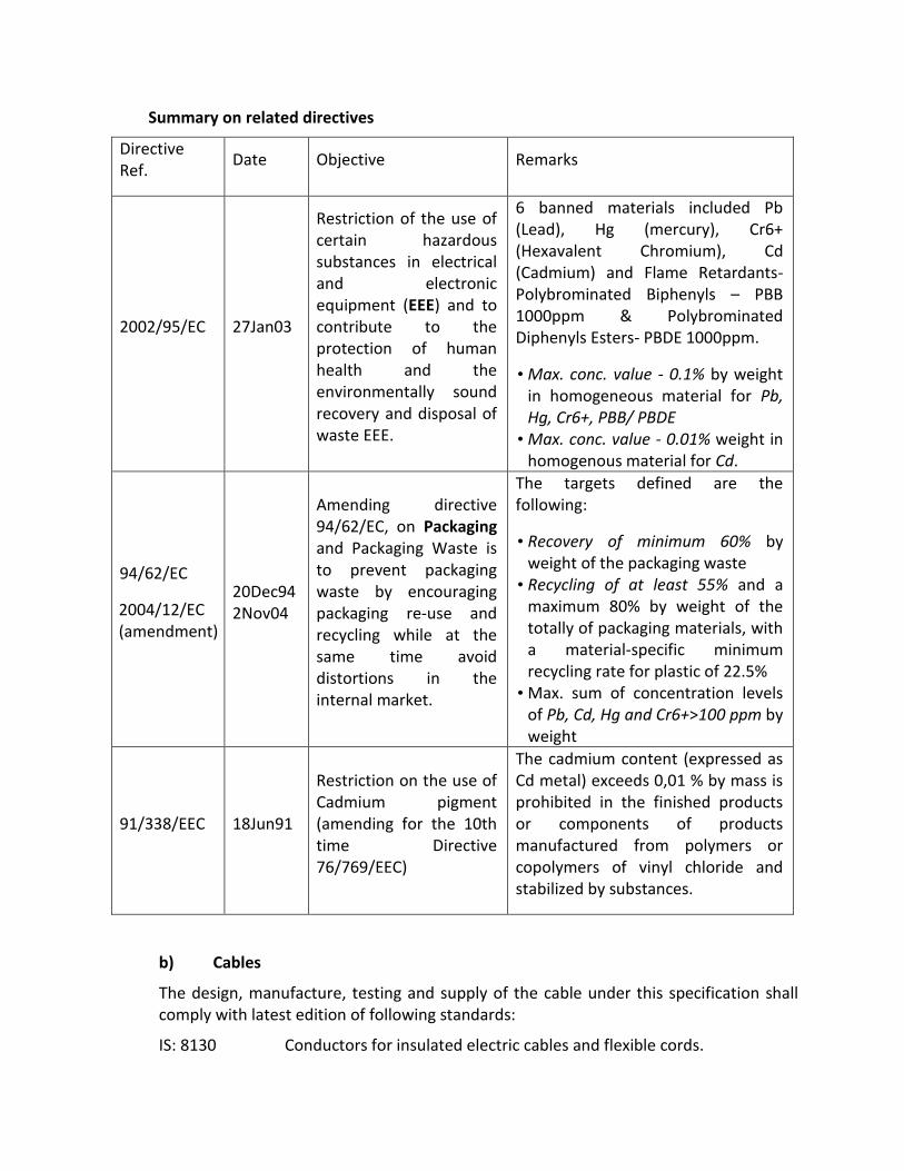
Summary on related directives
Directive Ref.
Date Objective Remarks
2002/95/EC 27Jan03
Restriction of the use of certain hazardous substances in electrical and electronic equipment (EEE) and to contribute to the protection of human health and the environmentally sound recovery and disposal of waste EEE.
6 banned materials included Pb (Lead), Hg (mercury), Cr6+ (Hexavalent Chromium), Cd (Cadmium) and Flame Retardants- Polybrominated Biphenyls – PBB 1000ppm & Polybrominated Diphenyls Esters- PBDE 1000ppm.
• Max. conc. value - 0.1% by weight in homogeneous material for Pb, Hg, Cr6+, PBB/ PBDE
• Max. conc. value - 0.01% weight in homogenous material for Cd.
94/62/EC
2004/12/EC (amendment)
20Dec94 2Nov04
Amending directive 94/62/EC, on Packaging and Packaging Waste is to prevent packaging waste by encouraging packaging re-use and recycling while at the same time avoid distortions in the internal market.
The targets defined are the following:
• Recovery of minimum 60% by weight of the packaging waste
• Recycling of at least 55% and a maximum 80% by weight of the totally of packaging materials, with a material-specific minimum recycling rate for plastic of 22.5%
• Max. sum of concentration levels of Pb, Cd, Hg and Cr6+>100 ppm by weight
91/338/EEC 18Jun91
Restriction on the use of Cadmium pigment (amending for the 10th time Directive 76/769/EEC)
The cadmium content (expressed as Cd metal) exceeds 0,01 % by mass is prohibited in the finished products or components of products manufactured from polymers or copolymers of vinyl chloride and stabilized by substances.
b) Cables
The design, manufacture, testing and supply of the cable under this specification shall comply with latest edition of following standards:
IS: 8130 Conductors for insulated electric cables and flexible cords.

IS: 7098 XLPE insulation and sheath of electric cables.
IS: 3975 Mild steel wires, strips and tapes for armouring cables.
IS: 7098 Current rating of cables.
IS: 7098 XLPE insulated (heavy duty) electric cables for working voltage upto and including 1100 volts.
IS: 424-1475(F-3) Power cable-flammability test.
Specification for cross-linked polyethylene insulated XLPE sheathed cable for working voltage upto 1.1 KV.
Specification for XLPE insulated (heavy duty) electric cables for working voltages upto and including 1100 volts.
ASTM-D: 2863 Standard method for measuring the minimum oxygen concentration to support candle-like combustion of plastics (Oxygen Index).
ASTM-D: 2843 Standard test method for measuring the density of smoke from the burning or decomposition.
IEEE : 383 Standard for type of test Class-IE, Electric cables, feild splicers and connections for power generation station.
ASTME:662IEC:754(x) Standard test method for specific optical density of smoke generated by solid materials.
IS : 10418 Cable drums.
c) Technical Requirements:
i. The cables shall be suitable for laying in racks, ducts, trenches conduits and under-ground buried installation with uncontrolled back fill and chances of flooding by water.
ii. They shall be designed to withstand all mechanical, electrical and thermal stresses under steady state and transient operating condition.
iii. The aluminium/copper wires used for manufacturing the cables shall be true circular/sector in shape before stranding and shall be of uniformally good quality, free from defects. The conductor used in manufacture of the cable shall be of H2 grade.
iv. The cable should withstand 25 KA for 0.5 sec with insulation armour insulated at one end. Bidder shall furnish calculation in support of capability to withstand the earth fault currents. The current carrying capacity of armour and screen (as applicable) shall not be less than the earth fault current values and duration.
v. The fillers and inner sheath shall be of non-hygroscopic fire retardant materials and shall be suitable for the operating temperature of the cable. Filler and inner sheath shall not stick to insulation and outer sheath.

vi. Progressive automatic in line indelible, legible and sequential marking of the length of the cable in metres at every one metres shall be provided on the outer sheath of all cables and at every 5 metre ‘FRLS’ marking in case of ‘FRLS’ cables.
vii. Strip/Wire armouring following method (b) mentioned in IS: 3975 shall only be acceptable. For single core cable aluminium wire armouring shall be used.
viii. Allowable tolerance on the overall diameter of the cables shall be + 2mm.
ix. The normal current rating of all XLPE insulated cables shall be as per IS: 7098.
x. A distinct inner sheath shall be provided by pressure extrusion process for all multicore armoured and unarmoured cables as per IS: 5831.
xi. Outer sheath shall be provided by extrusion process as per IS: 5831
xii. The breaking load of armour joint shall not be less than 95% of that armour wire. Zinc rich paint shall be applied on armoured joint surface.
xiii. In plant repairs to the cables shall not be accepted.
xiv. All the cables shall be supplied in non-returnable drums as per IS: 10418.
d) In Case of FRLS Cables
i) The outer sheath of cables shall have an oxygen index of not less than 29 as per ASIMD: 2863.
ii) The maximum acid gas generation by weight as per IEC: 754 (i) shall not be more than 20% for outer sheath material of all cables. Bidder shall also guarantee the maximum theoretical acid gas generation with 20% by weight of outer sheath.
iii) The cables outer sheath shall meet the requirement of light transmission of 40% (minimum and shall be tested as per ISTMD: 2843). In case the test for light transmission is conducted as per ASTME: 662. The bidder shall furnish smoke density values as per this standard and shall co-relate the anticipated light transmission when tested as per ASTMD: 2843.
iv) The cable shall pass the fire resistance test as per SS: 42, 41, 475 (I) and flammability test as per EEE: 383.
e) Inspection:
All cables shall be inspected on receipt of the same at site and checked for any damage during transit.
f) Joint in Cables
The contractor shall take care that the cables received at site are distributed to various locations in such a manner as to ensure maximum utilisation and avoidance of cable jointing. Cable shall be rechecked before cutting in lengths, where the joints are unavoidable, and the location of such joints shall be got approved from the MoHFW/HITES. The joints shall be done by qualified jointer strictly in accordance with manufacturer’s instruction/drawings.

g) Joint Boxes for Cables
The cable joint boxes shall be of appropriate size suitable for type of cable of particular voltage rating.
h) Jointing of Cables
All straight through joints shall be done in epoxy mould boxes with epoxy resins. Straight through joints shall not be permitted unless the length of run is in excess of cable drum.
End terminations of cables more than 1.1 KV grade shall be done with epoxy mould boxed and epoxy resin. Cable glands shall be 1.1KV grade double compression type and made to tin plated heavy-duty brass casting and machine finished. Glands shall be of robust construction capable of clamping cable and cable armour, firmly without injury of cable.
All washers and hardwares shall be made of brass tinned. Rubber components used in the glands shall be made of neoprene of tested quality.
Cable lugs shall be tinned copper/aluminium solderless crimping type conforming to IS: 8309 suitable for aluminium or copper conductor.
Crimping of terminals shall be done by using Corrosion inhabitory compound, with crimping tool.
Fire resistant paint has to be applied 1 Metre on either side of cable joint.
The contractor shall liaise fully with all other contractors to achieve an efficient and properly coordinated installation where equipment has to be re-positioned due to lack of site liaison; no extra cost shall be incurred by the HITES.
i) Testing of Cables
Cables shall be tested at factory as per requirement of IS: 7098 Part-I. The tests shall incorporate routine tests, type tests and acceptance tests. Prior to laying of cables, following tests shall be carried out:
i) Insulation test between phases and phase to earth for each length of cable before and after jointing.
On completion of cable laying work, the following test shall be conducted in the presence of Engineer-in-charge/HITES/ MoHFW.
ii) Insulation resistance test (Sectional and overall) 1000/5000V depending upon the voltage grade of cable.
iii) Continuity resistance test.
iv) Sheathing continuity test.
v) Earth test.
j) Laying of Cable

The cable drum shall be placed on jacks before unwinding the cable. Great care shall be exercised in laying cables to avoid forming links. At all changes in directions in horizontal & vertical places, the cable shall be bent with a radius of bend not less than 8 times the diameter of cable.
The cable of 1.1KV grade shall be laid not less than 750mm below ground level in a 375mm wide trench (throughout), where more than one cable is to be laid in the same trench, the width of the trench shall be increased such that the interaxial spacing between the cables except where otherwise specified shall at least be 150mm minimum or as per site requirements or as approved by the Engineer-in-charge. Where single core cables are used in multiphase systems, the cables shall be installed in trefoil where possible.
In case the cables are laid in vertical formation due to unavoidable circumstance the depth per tier shall be increased by 200mm (minimum). Cable shall be laid in reasonably straight line, where a change in direction takes place a suitable cur-vature shall be i.e. either 12 times the dia meter of the cable or the radius of the bend shall not be less than twice the diameter of the cable drum or whichever is less. Minimum 3-meter long loop shall be provided at both sides of every straight through joint & 3 meters at each end of cable or as directed at site.
Greater care shall be exercised in handling the cable in order to avoid forming ‘Kinks’. The cable drum shall in-verbally convey on wheels and the cable unrolled in right direction as indicated on the drum by the manufacturer. The cable shall be pulled over rollers in the trench steadily and uniformly without jerks and strains.
Cables laid in trenches in single tier formation, 10 cms. All around sand cushioning is provided below and above the cable before a protective cover is laid. For every additional vertical tier. The 30cm of sand cushion are provided over the initial tier. The cable shall be protected by 2nd class bricks of size not less than 230x115x75mm, stone tiles/RCC curved channel be placed on top of the sand breadth wise for the full length of the cable and where more than one cable is to be laid in the same trench the brick shall cover all cables and project at least 8 cms. Over the outer sides of the end cables.
Filling of trenches shall be done after the sand cushioning and laying of tilesor bricks are carried out to the satisfaction of the Engineer-in-charge (Refer drawing). Back fill for trenches shall be filled in layer not exceeding 150 mm. Each layer shall be properly rammed & consolidate before laying the next layer.
PVC pipe shall be provided for all road crossing. The size of the pipe shall be according to the cable and a minimum 100mm dia. pipe shall be provided. The pipe shall be laid in ground with special arrangement and shall be cement jointed and concreting with 1:5:10 shall be made as per relevant IS with latest amendment. Location of cables laid directly underground shall be indicated by cable marker at an interval of 30 meters & with change of direction. Aluminium

strip cable tag of 20mm wide with engraved tag no. shall be provided at both ends of cable.
Where the cables are to be laid in ducts (pucca trenches) in side the building, they will have to be laid on MS rack/ on MS cable trays grouted in walls trenches. Cables sizing through floors shall be protected from mechanical damage by a steel channel to a height of one meter above the floor where cable pass through wall they shall be sleeved with PVC/steel conduit.
Where the cables are laid in open (in building) along walls, ceiling or above false ceiling, cable rack (ladder type) or cable tray shall be provided. The size of the cable tray or rack shall depend on the number of cables to pass over that rack. Cable tray/rack shall be properly supported through wall/ceiling according to the site conditions. Cable laid on tray & riser shall be neatly dressed &clamped at an interval of 1000 mm & 750mm for horizontal & vertical cable run respectively either side at each bend of cable. All power cables shall be clamped individually & control cables shall be clamped in groups of three or four cables. Clamps for multicore cables shall be fabricated of 25x3 GI flats. Single core power cable shall be laid in trefoil formation & clamped with trefoil clamps made of PVC/fibre glass.
Cable openings in wall/floor shall be sealed by the contractor suitably by hession tape & bitumen compound or by any other proven to prevent ingress of water.
After the cables are laid, these shall be tested as per IS and the results submitted to Engineer-in-charges/Engineer and in case the results found unsatisfactory, all the repairing/ replacing of cables will be done by the contractor free of charge.
k) Fire Seal System
i) All the floor/wall opening provided for cable crossing shall be sealed by fire seal system.
ii) The fire proof sealing system shall fully comply with the requirements of relevant IS/BS: 476 Part-B. The fireproof seal system shall have minimum one hour fire resistance rating.
iii) The fire proof seal system shall be physically, chemically, thermally stable and shall be mechanically secured to the masonary concrete members. The system shall be completely gas and smoke tight, antirodent and anti-termite.
iv) The material used in fireproof seal system shall be non-toxic and harmless to the working personnel.
v) Type of fireproof seal system shall be foaming type or flamemastic type compound or approved equivalent.
After laying and jointing work is completed, high voltage test should be applied to all cables to ensure that they have not been damaged during or after the laying operation and that there is not fault in the jointing.

Cables for use on low and medium voltage system (1.1KV grade cables) should withstand for 15 minutes a pressure of 3000V DC applied between conductors and also between each conductor and sheaths. In the absence of pressure testing facilities it is sufficient to test for one minute with a 1000V insulation tester In case the test results are unsatisfactory the cost of repairs and replacements and extra work of removal & laying will be made good by the contractor.
Cable shall be installed so that separation shown in the table below are observed.
HV Cable (11 KV/ 33 KV) - HV Cable (11 KV/ 33 KV) 50 mm
ELV & LV 230 V/433 V - ELV & LV cable 230 V/433 V Equal to the diameter of the bigger cable.
HV cables (11 KV/33 KV) - ELV & LV cables 230 V/433 V 300 mm
LV cables 433 V - Telephone/Instrument cable 350 mm
All cables - All hot pipe work 200 mm
l) Quality Assurance
Quality Assurance shall follow the requirements of MoHFW/ HITES as applicable. Quality Assurance involvement will commence at enquiry and follow through to completion and acceptance thus ensuring total conformity to Purchaser’s requirements.
m) Deviations
Deviation from specification must be stated in writing at the quotation stage.
In absence of such a statement, it will be assumed that the requirements of the specifications are met without exception.
n) Spares for Commissioning Including Consumables
The manufacturer/tenderer shall also supply a complete list of commissioning spares and tools and consumables. The same shall be included in the bid price. No extra payment shall be made on account of non-availability of spares during commissioning.
10.0 CABLE TRAYS
a. Perforated Cable tray – for Power Cables & Low current service both
The perforated cable trays are fabricated out of 1.6mm thick CRCA sheet steel having minimum 50mm depth or as called for in BOQ, hot dip galvanized or epoxy coated of approved shade. Perforations are maximum 10mm spaced at maximum 20mm distance. The cables shall be tied with the cable tray with nylon strip/ aluminium clamps/M.S. clamps as per requirements.

Suitable provision shall be made where a tray crosses expansion joints. The width of the tray shall allow for a suitable separation between cables the design shall allow for adequate bending radius for the sizes of cables. No sharp bend to be allowed in cable tray. Joints between sections shall be bolted.
The tray shall be suspended from the surface of the concrete slab by means of approved steel hangers spaced at a distance of not more than 125cms. Suitable bushes shall be provided where cables pass through apertures in the tray. Cables must be securely fixed to the tray with clamps or cable ties. In routing necessary barrier and spacing shall be maintained for cables of different voltages in case they lie side by side. Telephone cables shall cross the power cables only at about right angle and these two shall not run in close proximity. Full details of the tray shall be approved by the HITES/Engineer-in-charge before fabrication. Earth continuity shall be maintained between each section of cable tray and each total run of tray shall be effectively bonded to the nearest earth continuity 0conductor. All nuts and bolts used shall be of galvanised steel.
Depending on the size of cable trays space of 20-33% has to be maintained for future expansion.
Cable tray is manufactured to comply with the specifications of National Electrical Code (NEC) and National Electrical Manufacturer’s Association (NEMA).
11.0 INTERNAL ELECTRICAL WORKS
A. Conducting (M.S Conduit)
All conduits shall be of heavy gauge solid drawn ERW welded manufactured out of 16 (1.6mm) gauge MS Sheet up to 32mm dia and of 14 (2 mm) gauge for sizes higher than this. Both inner and outer surfaces shall be smooth without burrs, dents and kinks. Conduits shall be black stove enameled inside and outside. The cross section of conduit shall be uniform throughout. The welding shall be uniform such that welded joints do not yield when subjected to flattening test. Welded joint shall not break when threaded or bent at an angle. Conduit shall conform to specifications of IS: 9537 (Part-II) and the capacity of conduits shall be in accordance with the standards and shall never be exceeded. The minimum size of the conduit shall be 20mm dia. Care shall be taken to ensure that all conduits are adequately protected while stored at site prior to erection and no damaged conduit shall be used.
B. PVC Conduit
All conduits shall be high impact rigid 2mm thickness PVC heavy duty type and shall comply with I.E.E. regulations for non-metallic conduit 2mm thick as per IS-9537/1983 (Part-III). All sections of conduit and relevant boxes shall be properly cleaned and glued by using epoxy resin glue and the proper connecting pieces. Inspection type conduit fittings such as inspection boxes, drawn boxes, fan boxes

and outlet boxes shall be M.S. or otherwise mentioned. Conduit shall be terminated with adopter/PVC glands as required.
Accessories
Conduit accessories such as normal bends, unions, circular junction boxes and pull boxes, locknuts etc. shall be heavy gauge type and approved make. Conduit accessories shall conform in all respects to IS: 3837-1966 with latest amendment. Wherever several conduits are running together, adequately sized adoptable boxes common to all runs shall be used to avoid inserting inspection boxes in the individual run. Where it is necessary to segregate wiring metal filler shall be fixed with in the box.
Conduits shall be laid before casting in the upper portion of a slab or otherwise, as may be instructed or in accordance with approved drawings, so as to conceal the entire run of conduits and ceiling outlet boxes. Vertical drops shall be buried in columns or walls. Wherever necessary, chases will be cut by the contractor with the help of chase cutting m/c or by hand. Nothing extra shall be paid to the contractor on this account. In case of exposed brick/ rubble masonry work special care shall be taken to fix the conduit and accessories in position along with the building work. Sufficient depth of the chases will be made to accommodate the required number of conduits. The chase will be filled with cement, coarse sand mortar (1:3) and properly cured by watering for one week.
If a chase is cut in an already finished surface the contractor shall fill the chase and finish it to match the existing finish. Contractor must not cut any iron bars to fix conduits. Conduits shall be kept at a minimum distance of 100mm from the pipes of other non-electrical services. Where the conduit is to be embedded in a concrete member it shall be adequately tied to the reinforcement to prevent displacement during casting, conduits in chases shall be held by steel hooks of approved design at maximum of 100 cm centres. The embedding of conduits in walls shall be so arranged as to allow at least 12mm plaster cover the same. All threaded joints of conduit pipes shall be treated with some approved ‘preservative compound’ to secure protection against rust.
Suitable expansion joints fittings of approved make and design shall be provided at all the points where the conduit crosses the expansion joint in the building. (Preferably with Pilca metallic watertight conduits). Conduits shall cross at right angles of the joints only.
Separate conduit shall be used for:
1) Normal light, fan call bell
2) 16 A power outlets
3) Emergency Light Point
4) Fire alarm System
5) Computer Outlets
6) P.A System

7) Telephone system
8) TV Network
9) Or any other services not mentioned here.
Wiring for short extensions to outlets in hung ceiling or to vibrating equipments, motors etc. shall be installed in flexible conduits. Flexible conduits shall be formed from a continuous length of spirally wound interlocked wire steel with a fused zinc coating on both sides. The conduit shall be provided with approved type adoptor. A separate and accessible earth connection shall bond across the flexible conduit.
Conduit runs on surfaces shall be supported with metal 1.2 mm thick saddles, which in turn are properly secured on to GI spacer to the wall or ceiling. Fixing screws shall be with round or cheese head and of rust proof materials. Exposed conduits shall be neatly run parallel or at right angles to the walls of the building and shall be painted in color matching the adjoining area. Unseemly conduit bends and offsets shall be avoided by using better appearance. Cross cover of conduits shall be minimum and entire conduit installation shall be clean and with good appearance. For surface work, the boxes shall be raised back pattern type, designed for use with distance saddles to give clearance of 6mm between the back of conduit and the fixing surface.
Where conduits are run on steel work, they will be fixed by means of purpose made GI Caddy clips in manner meeting with the approval of the Engineer prior to the installation being carried out. Other methods of fixing may be agreed in special circumstances, but approval must first be obtained from the site engineer.
The spacing of saddles shall be not more than 600mm centers for up to 32mm diameter conduits and at 750mm for conduit sizes of 40mm diameter and above in case of MS conduit and not more than 600 mm for PVC conduit. In addition, saddles shall be fixed at each side of any bend/Tee, or set at a distance of 200mm from the bend/Tee. The holes in the brickwork or concrete for fixing plugs shall be neatly drilled by means of a masonry drill of the appropriate size.
All the GI sheet steel /passivated boxes used for housing switches, plugs, fan regulator etc. shall be five sided conforming to IS: 5133 Part I-1969. Suitable size of boxes shall be provided a minimum of 2 adjustable fixing lugs on vertical sides. Suitable earth terminal inside each box shall be provided. All fixing lugs shall be threaded to receive standard machined chromium plated brass screws. Sufficient number of knockouts shall be provided for conduit entry. Conduits carrying wires of different circuit can terminate in common J.B having metal compartments. Necessary GI pull wires shall be inserted into the conduit for drawings wires. In case conduit pipe is required to cross any RCC beam special adopter boxes shall be provided for crossing & nothing shall be paid extra.
Where conduits are used for non-air-conditioned space to air-conditioned space or into a fan chamber or duct, a junction box shall be installed to break the continuity of such conduit at the point of entry or just outside and conduit shall be sealed around the conductors.

Particular care shall be taken during the progress of the work to prevent the ingress of dirt and rubbish such as plaster droppings into erected conduits. Conduit which has become so clogged shall be entirely freed from these accumulations or will be replaced. Screwed plastic or metal caps or turned wooden plugs shall be employed to protect all open ends. Plugs of waste wood, paper, cotton or other fibrous matter shall not be used. All unused conduit entries shall be blanked off in an approved manner and where conduits terminate in adaptable boxes, all removable box covers shall be firmly secured to provide complete enclosure. If considered necessary by the Engineer-in-charge, the conduits shall be swabbed out by drawing swabs of rag through the conduit to remove moisture prior to any cables being drawn in.
All conduit installations must be completed and erected in their totality before they are wired and must be fully rewireable from outlets to distribution boards or trunking systems etc. to which they connect. No wiring of any part of the installation shall be commenced until instructions are received to do so by the Engineer-in-charge at such time as he is satisfied that the wiring will not be damaged due to building operations.
Conduits shall be installed so that they are self-draining in the event of ingress of moisture due to condensation or any other reason. A suitable drainage hole shall be drilled at the bottom of the lowest conduit box in every 9-meter of horizontal run.
PVC bush of good quality shall be used in each conduit termination in a switch box, draw box, lighting fixtures and circular junction boxes.
Exposed conduits running above false ceilings shall be suitably clamped independently along with the dropped ceiling. Perforated straphangers or twisted attachment shall not be acceptable. In no case shall raceways be supported or fastened to other pipe for repair and maintenance. They shall be arranged symmetrically and in the cost compact design, in no way unduly criss-crossing each other. Proper spacing shall be maintained when two or more conduits run side by side. The layout of the pipes shall be co-ordinated with other services if any. The junction boxes and conduits used in hazardous areas shall be flameproof type with cast iron construction complete with threaded covers. The conduit of each circuit or section shall be completed before conductors are drawn in. The entire system of conduit after erection shall be tested for mechanical and electrical continuity throughout and permanently connected to earth conforming to the requirements by means of special approved type of earthing clamp efficiently fastened to conduit pipe in a workman like manner for a perfect continuity between the earth and conduit.
The conduit system shall be so laid out that it will obviate the use of tees, elbows and sharp bends. No length of conduit shall have more than the equivalent of two-quarter bends from inlet to outlet. The conduit itself being given required smooth bend with radius of bends suiting to the site conditions but not less than 6 times overall diameter.
Outlet boxes shall be of heavy-duty sheet steel installed as to maintain continuity throughout. These shall be so protected at the time of laying that no mortar finds its way inside during concrete filling or plastering. For fluorescent fittings, the outlet boxes

heavy duty shall be provided 300mm off centre for a 1200mm fitting and 150mm off centre for a 600mm fittings or as per B.O.Q.
Draw boxes of ample dimensions shall be provided at convenient points to facilitate pulling of long runs of cables. They shall be completely concealed with MS covers flush with plasterwork painted to match the wall. These boxes will be as few as possible and located where found suitable by the HITES.
Switch Boxes
The switch boxes shall be zinc passivated & shall not be less than 18 SWG thick or shall be as called for in BOQ. It will be so designed that accessories could be mounted on integral pedestals or on adjustable flat iron mounting straps with tapped holes by brass machine screw. Leaving ample space at the back and on the sides for accommodating wires and check nuts at conduit entries. These shall be attached to conduits by means of check nuts on either side of their walls. These shall be completely concealed leaving edges flush with wall surfaces. Earthing terminal inside box shall be provided.
Moulded plate switches screw less as specified in item of work shall be provided. No timber shall be used for any supports. Boxes, which come within concrete, shall be installed at the time of casting. Care shall be taken to fix the box rigidly so that its position is not shifted while concreting.
Wiring
All the wiring installation shall be as per IS: 732 with latest amendment. PVC insulated copper conductor cables as specified in bills of quantity shall be used for sub-circuit runs from the distribution boards to the points and shall be pulled into conduits. They shall be twisted copper conductors with thermoplastic insulations of 660/1100 volts grade. Colour Code for wiring shall be followed.
Looping system of wiring shall be used, wires shall not be jointed. Where joints are unavoidable, they shall be made through approved mechanical connectors with prior permission of the HITES. No reduction of strands is permitted at terminations. No wire smaller than 1.5 sq.mm shall be used and shall be as per B.O.Q. Wherever wiring is run through trunkings or raceways, the wires emerging from individual distributions shall be bunched together with cable straps at required regular intervals. Identification ferrules indicating the circuit and DB number shall be used for submains sub-circuit wiring. The ferrules shall be provided at both end of each submain and sub-circuit.
Where single-phase circuits are supplied from a three phase and a neutral distribution board, no conduit shall contain the wiring fed from more than one phase. In any one room in the premises where all or part of the electrical load consists of lights, fans and/or other single phase current consuming devices, all shall be connected to the same phase of the supply. Circuits fed from distinct sources of supply or from different distribution boards or through switches or MCBs shall not be bunched in one conduit. In large areas and other situations where the load is divided between two or three phase,

no two single-phase switches connected to different phase shall be mounted within one box.
All splicing shall be done by means of terminal blocks or connectors and no twisting connection between conductors shall be allowed.
Industrial sockets shall be of moulded plastic BoQ and deeply recessed contact tubes. Visible scraping type earth terminal shall be provided. Socket shall have self-adjustable spring loaded protective cap. Socket shall have MCB/ELCB/RCCB as specified in the schedule of work.
Maximum number of PVC insulated 650/1100 V grade/copper conductor cable conforming to IS: 694-1990.
Conduit size
20mm 25mm 32mm 40mm 50mm 60mm
Wire size in sq.mm.
S B S B S B S B S B S B
1.50 7 5 12 10 20 14 - - - - - -
2.50 6 5 10 8 18 12 - - - - - -
4 4 3 7 6 12 10 - - - - - -
6 3 2 6 5 10 8 - - - - - -
10 2 - 4 3 6 5 8 6 - - - -
16 - - 2 - 4 3 7 6 - - - -
25 - - - - 3 2 5 4 8 6 9 7
Notes:
1) The above table shows the maximum capacity of conduits for a simultaneous drawing in of cables.
2) The columns heads ‘S’ apply to runs of conduits which have distance not exceeding 4.25 m between draw in boxes and which do not deflect from the straight by an angle of more than 15 degrees. The columns heads ‘B’ apply to runs of conduit which deflect from the straight by an angle of more than 15 degrees.
3) Conduit sizes are the nominal external diametres.
12.0 UPS SYSTEM: SPECIFICATION FOR THE UPS.
Quality power Supply

DSP Based VFI technology 3 Level inverter , True on line, Hot swappable Modular UPS system as per IEC 62040-3 with 415V +/- 15% V,50Hz,3Ph Input & 415V +/- 15%,3Ph, 50 Hz output. Each Module shall be 3 phase either with 20/25/30 kVA Capacity, having kVA=KW (Unity power factor)and frame size shall be suitable for adding modules upto 100 kVA. The battery cabinets used in the UPS shall be for longer runtime, The UPS shall have Optional filters, Isolation transformer module, LCD-based remote control panel, LED-based remote control panel & Communication software “professional” version.
The Operating mode of UPS
It should operate in on-line operating mode as follows.
Economy Mode: The UPS should use Line Interactive technology, i.e. the load is powered from the mains; the energy consumption is reduced with a subsequent improvement in efficiency (98%).
Smart active mode: The UPS should automatically selects On Line or Line Interactive operating mode according to the quality of the mains supply, by monitoring the number, frequency and type of disturbances at the mains power input.
Stand-by-off mode: With the mains available the UPS should normally not powered and consequently the power consumption is almost nil. Only when the mains fails or falls outside a preset range, does the inverter take over in 200ms using power from the batteries. This mode shall be suitable for Emergency escape lighting as pr standard EN 50171.
The UPS shall have Expandable feature. The units can be connected in parallel up to 8 units to increase power availability or redundancy. The system can be expanded at any time. For the expandability there shall be “Hot System Expansion” feature, the additional unit can be connected in parallel while the other units are on-line and supplying regular power to the load. The new UPS is on-line and will receive the updated information automatically.
High Reliability
The UPS should be connected in parallel up to 8 units to exponentially increase the reliability of the system.
Maximum battery care
In the UPS there shall be an automatic battery test which shall be able to periodically check the efficiency of the batteries. The batteries should not be used during micro-interruption (40ms), as the required energy is drawn from a group of capacitor. (Battery saving).
Maximum safety for personal
There should be a feedback protection device in the UPS to prevent any voltage back feed in the upstream distribution board, thus ensuring the maintenance personal.

For Advanced communication there shall be software system which displays the most important information such as the input and output Voltage, the load applied, the remaining back-up time, etc. It should also be able to provide information even in the event of a failure, to support the fault diagnostics.
It should also contain the following hardware interfaces:
RS232 serial port / as specified in the BOQ
Dry contacts
EPO (Emergency Power Off)
Contact for UPS shutdown using the remote emergency button.
To allow easy and intuitive operation of the UPS There should be Mimic Panel. This helps in accessing the most important parameters: status and alarm, control and commands, input, output, battery measurements (power, current, voltage, frequency and temperature) and settings.
Low Input Harmonic Distortion, The UPS shall have The Power Factor Correction (PFC), standard on all modules, so that the input power factor level to 0.95 for any load percentages so that it is ideal in conjunction with motor generator or in installation with other sensitive loads. There shall be built in Active Filter designed to reduce the level of THDi to less than 4% and to increase the input power factor up to 0.99.
This Active filter shall be based on the IGBT’s Technologies controlled by the Digital Signal Processor (DSP). This DSP instantly monitors and controls the inputs current absorbed by the UPS in order to eliminate the unlike harmonics and maintain the THDi less than 4%. With the effect of Active Filter the UPS can also be connected to the low loads. These active filters shall be fitted inside the UPS so that no additional footprint is required.
Less harmonics in the UPS input reduces the neutral cable size and consequently the installation cost. Also it gives maximum reliability as any failure of the optional Active Filter has no influence on the power supplied to the load; the only consequence is the increase of current harmonics level rejected to the mains, which gives maximum reliability for the load.
The input requirements of the UPS are as follows:
Voltage : 400 V three-phase + N
Voltage tolerance : ± 20%+
Frequency : 45-65 Hz
Current distortion : <4% with active filter
Power factor : 0.99 with active filter
The Bypass of the UPS are as follows:
Rated voltage : 400 V three-phase + N

Phases number : 3 + N
Voltage tolerance : ± 10 %
Rated frequency : 50 Hz
Frequency tolerance : ± 2%
By-pass : Static and manual for maintenance
Transfer time : Nil
The Battery for the UPS are as follows:
Type of battery : SMF - VRLA
Battery blocks : 12 V
Recharge time minimum : 6 Hr
The Output of UPS are as follows:
Rated power : As per BOQ
Active power : As per BOQ
Phases number : 3 + N
Waveform : Sinewave
Rated voltage : 415V
Frequency : 50 Hz
Dynamic stability : ± 5%0.
Static stability : ± 1% 00
Crest factor : 3 : 1
Overload : 110% for 5h, 125% for 10’, 150% for 1
The System of UPS is as follows:
AC/AC efficiency : 92% in On-line mode, 98% in Economy Mode / Smart active mode/ Emergency mode.
Noise : 50-56 Dba a 1 m.
Operating temperature : -2º - 45ºC
Relative humidity : 95% non-condensing
Remote controls : EPO & Bypass
Remote signals : volt free contacts
Protection degree : IP20
Communication : Double RS232/C + slot for SNMP Adapter / as specified in the BOQ.

Colour : Dark grey RAL 7024
The Standard of UPS are as follows:
1. Safety EN 62040-1
2. EMC IEC 62040-2
3. EN 50091-2 lev. A
4. Directives 73/23, 93/68, 89/336 EEC
5. EN 62040-3.
Refer particular specification mentioned in BOQ regarding capacities of UPS
13.0 DISTRIBUTION BOARDS & MCBs
General
Distribution boards shall be of standard make with MCBs as per approved make given. Distribution boards shall be constructed out of steel sheet all weld enclosure with double door IP42 protection and shall be powder coated. Ample clearance between the conductors of opposite pole, between conductors and sheet steel body shall be maintained in order to obviate any chance of short circuit. Removable conduits entry or knockouts plates shall be provided at top and bottom to facilitate drilling holes at site to suit individual requirements. Also on additional/separate adopter box of suitable length and size shall be provided to accommodate wires and cables. No. of conduits etc. and nothing shall be payable on this account. The MCBs shall be mounted on high-grade rigid insulating support and connected by electrolytic copper bus bars. Each incoming MCB isolator shall be provided with solderless cable sockets for crimping. Phase separation barriers made out of arc resistant materials shall be provided between the phases. Bus bars shall be colour coded for phase identification.
Distribution boards shall be recessed in wall nitch or if required mounted on the surface of the wall with necessary clamp bolts etc. The mounting height shall not exceed 1200mm from finished floor level. Distribution board shall be provided with proper circuit identification nameplate and danger sticker/plate as per requirements.
All the distribution boards shall be provided with engraved nameplates with ‘lighting’, ‘power’ or ‘UPS’ with DB Nos., as the case may be. Each DB shall be provided with a circuit list giving details of each circuit. All the outgoing circuit wiring shall be provided with identification ferrules giving the circuit number & phase.
Each distribution board shall have a separate neutral connection bar and a separate earth connection bar mounted within the DB each having the same number of terminals as the total number of outgoing individual circuits from the distribution board. Conduit & cable armouring shall be bonded together & connected to the distribution board earth bar.

Where oversized cables are specified due to voltage drop problems, it shall be contractors responsibility to ensure that satisfactory terminal arrangements are provided without an extra cost.
Residual Current Circuit Breaker
RCCB shall be 4 pole 415 volts 50Hz, 30-300mA sensitivity. These shall be of approved make. The rating of the RCCB shall be as specified in BOQ. These shall be suitable for manual closing and opening and automatic tripping under earth fault circuit of 30-300mA as specified in item of work. The enclosure of the RCCB shall be moulded from high quality insulating material. The material shall be fire retardent, anti-tracking, non-hygroscopic, impact resistant and shall with stand high temperature. All parts of switching mechanism shall be non-greasing, self-lubricating material so as to provide consistent and trouble free operation. Operation of RCCB shall be independent of mounting position and shall be trip free type. The RCCB shall be protected against nuisance tripping by protective device.
Miniature Circuit Breaker
1. The MCB shall be current limiting type and suitable for manual closing and opening and automatic tripping under overcurrent and short circuit. The MCB shall also be trip free type.
2. Single pole/three pole versions shall be furnished as required.
3. The MCB shall be rated for 10 KA/15 KA fault level.
4. The MCB shall be suitable for its housing in the distribution boards and shall be suitable for connection at the outgoing side by tinned cable lugs and for bus-bars connection on the incoming side.
5. The terminal of the MCBs and the open and close conditions shall be clearly and indelibly marked.
6. The MCB shall generally conform to IS: 8828. -1996
7. The MCB shall have 20,000 electrical operation upto 63A.
8. The MCB shall have minimum power loss (Watts) as per I.S./ IEC.
CHAPTER G
TECHNICAL SPECIFICATIONS FOR D.G.SETS
General
All items of work under this Contract shall be executed strictly to fulfill the requirements
laid down in the specifications. Type of equipment, material specification, methods of
installation and testing and type of control shall be in accordance with the
specifications, approved shop drawings and the relevant Indian Standards, however

capacity of each component and their quantities shall be such as to fulfill the above
mentioned requirement.
The unit rate for all equipments or materials shall include cost in RUPEES for equipment
and materials including all taxes and duties and also including forwarding, freight,
insurance and transport into Contractor’s store at site, storage, installation, testing,
balancing, commissioning and other works required.
The rate for each item of work included in the Schedule of Quantities shall, unless
expressly stated otherwise, include cost of :
a. All materials, fixing materials, accessories, appliances tools, plants, equipment,
transport, labour and incidentals required in preparation for and in the full and entire
execution, testing, balancing, commissioning and completion of work called for in the
item and as per Specifications and Drawings.
b. Wastage on materials and labour.
c. Loading, transporting, unloading, handling/ double handling, hoisting to all levels,
setting, fitting and fixing in position, protecting, disposal of debris and all other labour
necessary in and for the full and entire execution and for the job in accordance with the
contract documents, good practice and recognize principles.
d. Liabilities, obligations and risks arising out of Conditions of Contract.
e. All requirements of Specifications, whether such requirements are mentioned in the
item or not. The Specifications and Drawings where available, are to be read as
complimentary to and part of the Schedule of Quantities and any work called for in one
shall be taken as required for all.
f. In the event of conflict between Schedule of Quantities and other documents
including the Specifications, the most stringent shall apply. The interpretation of the
HITES/ Engineer-In-Chargeshall be final and binding.
All equipments, quantities and technical data indicated in this Schedule are for the
Contractor’s guidance only, these are based on the documents prepared by the HITES.
This schedule must be read in conjunction with other documents. The Contractor shall
be paid for the actual quantity of work executed by him in accordance with the
approved Shop Drawings at the contract rates.
This Schedule shall be fully priced and the extensions and totals duly checked. The rates
for all items shall be filled in INK including NIL items.
No alteration whatsoever is to be made to the text or quantities of this Schedule unless
such alteration is authorised in writing by HITES. Any such alterations, notes or additions

shall, unless authorized in writing, be disregarded when tender documents are
considered.
In the event of an error occurring in the amount of the Schedule, as a result of wrong
mention of the unit rate and quantity, the unit rate quoted by the tenderer shall be
regarded as firm and the amount shall be amended on the basis of rates.
Any error in totalling in the amount column and in carrying forward total shall be
corrected. Any error, in description or in quantity, omission of items from this Schedule
shall not vitiate this Contract but shall be corrected and deemed to be variation
required by the Engineer –In-Charge / HITES.
Rates have been called for a number of items of works, as alternatives which, for the
present do not form part of the total value of tender. However the rates for these items
shall be quoted, with due care so that in the event of choice of an alternative item of
work, said rate shall form part of the contract and shall not violate the contract any way.
The Contractor shall procure and bring Materials/ Equipment to the site only on the
basis of drawings approved for construction and shop drawings and not on the basis of
Schedule of Quantities which are provisional only. This also applies to the Contractor’s
requisition for HITES’s supplied materials. Choice of make shall be as per approved
makes
DRAWINGS
The drawings, specifications and bill of quantities shall be considered, as a part of this
contract and any work or materials shown on the drawings and not called for in the
specifications or vice-versa, shall be executed as if specification called for in both. The
contract drawings indicate the extent and general arrangement of various equipments
and their wiring, etc. and are essentially diagrammatic. The drawings indicate the point
of termination for conduit runs and broadly suggest the routes to be followed. The
work shall be done as indicated on the drawings. However, any minor change if found
essential to co-ordinate the installation of this work with other traders shall be made
without any additional cost to the MoHFWs. The data given herein and on the drawings
is as could be secured but its complete accuracy is not guaranteed. The drawings and
specifications are for the assistance and guidance of the contractor. The exact location,
distances and levels etc. will be governed by the space conditions. The contractor shall
examine all Architectural, structural, Plumbing and Sanitary, Air-conditioning and
electrical drawings before starting the work and report to the Engineer-in-charge any
discrepancies, which in his opinion appear, on them, and get them clarified. He shall not
be entitled to any extras, for omissions or defects in electrical drawings or when they
conflict with other works.

SHOP DRAWINGS
The Contractor shall prepare and submit to the HITESs/Engineer-in-charge/ MoHFW for
their approval detailed shop drawings within 30 days of signing of the contact or before
7 days of particular work or whichever is earlier. The shop drawings shall clearly
indicate.
a) The general arrangement and schematic diagram of main D.G Panel, PLC Panel, clearly stipulating the material, size of sheet steel, bus bar, inter connections detail, make and rating of switchgear and other equipment etc.
b) Number, size and route of the Cable Tray, and fixing details.
c) Total number of cable runs, size make, material and type of cables with clear routing, trenches / treys detail, installation mode, starting and termination point of each and individual cable etc.
d) The shop drawings shall also show all setting out details and physical dimensions of all equipments components used in the system, location of manholes fixing, cutout details etc.
QUALITY
The HITES’s decision with regard to the quality of the material and workmanship will be
final and binding, any material rejected by the HITES shall be immediately removed by
the Contractor from the site. The HITES or their representative shall at all reasonable
times have free access to the works and / or to the workshops, factories or other places
where materials are being prepared or constructed for the contract and also to any
place where the material lying or form which they are being obtained, and the
contractor shall give every facility necessary for inspection and examinations and test of
the material and workmanship free of cost.
COST OF SAMPLES AND TESTS
The Contractor at his own cost shall supply all samples and the cost of making any test
as per specifications shall be borne by the contractor. The Contractor shall submit four
copies of all brochures, manufacturers’ description data and similar literature. One copy
will be returned to the Contractor after approval.
COMPLETION DRAWINGS
The Contractors shall submit to the HITES, layout drawings drawn at approved scale in
six sets and a reproductive (original) copy clearly showing.
a) Location of distribution and PLC Panel
b) All types of cables (L.T. / Control etc.) layout.
c) Layout of DG Room and switchgears and associated equipments.

d) Layout of Diesel Generator Sets.
e) Location of Fuel Tank, Exhaust piping layout.
f) As built drawing with equipments operation and maintenance literature. - After the completion of the work and before issuance of certificate of virtual completion.
FOREMAN / SUPERVISOR
The Contractor shall employ a competent, licensed qualified full time electrical engg./
foreman/ supervisors to direct the work of electrical installations in accordance with the
drawings and specifications. The foreman / supervisor shall be available at all times on
the site to receive instructions from the Engineer-in-charge / Engineer in the day to day
activities throughout the duration of the Contract and as long as there after as the
HITESs may consider necessary until the expiration of the “Defect Liability Period”. The
Foreman / Supervisor shall correlate the progress of the work in conjunction with all the
relevant requirements of the supply authority. The skilled workers employed for the
work should have requisite qualifications and should possess competency certificate
from the Electrical Inspectorate of the Local Government. The Contractor shall on the
request of the HITESs immediately dismiss from the works any person employed there
on who may, in the opinion of the HITESs, be unsuitable or incompetent or who may
misconduct himself and such person shall not be again employed or allowed on the
work without the permission of HITESs/Employee.
INSPECTION AND TESTING
Contractor shall employ a full time qualified Engineer who shall be available at all
working hours at site for taking instructions and to look after the quality of the work.
Instructions given to the Engineer of the contractor shall be construed as issued to the
contractor.
Contractor shall maintain at site the following tools and instruments, but not limited to
the list below in working conditions.
a) Clip-on Ammeter and voltmeter
b) 1000 V Meggar and 5 KV Meggar
c) Steel tapes of various lengths
d) Sprit Level
e) Hydraulic Crimping Tool
f) Earth Testing Meggar
g) Pipe bending Tool, thread-cutting die, bench vice etc.
h) Cable jointing kit

The contractor shall provide at least four permanent benchmark at site, which shall be
preserved till the completion of works. These are essential for laying of cables at correct
levels.
CLEARANCE FROM LOCAL AUTHORITIES
The Contractor shall get the entire installation tested inspected and approved by Local
Authorities like Electrical inspectorate pollution control explosive clearance and any
other agency required to take permission for commissioning of the installation. He will
also undertake the Liaison work with local Electricity Supply Company for obtaining the
Electrical Service Connection.
SCOPE
In general, the contractor shall supply, store, erect test and commission all the
equipment required for electrical installation. The contractor shall furnish all the
materials, labour, tools and equipment for electrical work, as shown in the
accompanying drawings and in the bill of quantities and specifications hereinafter
described.
CONTRACTOR
The contractor shall be a licensed electrical contractor, possessing a valid electrical
contractor’s in the state, employing licensed supervisors and skilled workers having valid
permits as per the regulation of Indian Electricity Rules and Local Electrical Inspector’s
requirements.
2.0 Preamble to BOQ for D.G. Set:
1. All items of work under this Contract shall be executed strictly to fulfil the
requirements laid down under the specifications. Type of equipment, material
specifications, methods of installation and testing, and type of controls shall be in
accordance with the Specifications, approved shop Drawings and the relevant Indian
Standards, however, capacity of each component and their quantities shall be such as
to fulfill the above mentioned requirement.
2. The rate for each item of work included in the Bill of Quantities shall, unless expressly
stated otherwise, include cost of:
a. All materials, fixing materials, accessories, appliances, tools, plants, equipment,
transport, labour and incidentals required in preparation for and in the full and
entire execution, testing, balancing, commissioning and completion of the work
called for in the item and as per Specifications and Drawings.
b. Wastage on materials and labour.

c. Loading, transporting, unloading, handling / double handling, hoisting to all levels,
setting, fitting and fixing in position, protecting, disposal of debris and all other
labour necessary in and for the full and entire execution and to fully complete the
job in accordance with the contract documents, good practice and recognized
principles.
d. Liabilities, obligations and risks arising out of Conditions of Contract.
e. All requirements of specifications, whether such requirements are mentioned in
the item or not. The specifications and drawings where available, are to be read as
complimentary to and part of the Schedule of Quantities and any work called for
in one shall be taken as required for all.
f. In the event of conflict between Bill of Quantities and other documents including
the specifications, the most stringent shall apply and the interpretation of the
HITES’s shall be final and binding.
3. The unit rate for each equipment or materials shall include cost in Rupees for
equipment and material including the excise duty, and also including forwarding,
freight and insurance up to Contractor’s store at site, storage, installation, testing
balancing, commissioning and other works required.
The extension for (total) amounts against each item shall be based on the quantities
indicated in this Schedule.
4. All equipment, quantities and technical data indicated in this Schedule are for the
Contractors guidance only; these are based on the documents prepared by the HITESs.
The contractor shall assess the required quantity of cables, cable trays, piping etc that
are required for completion of the work. This schedule must be read in conjunction
with these documents. The Contractor shall be paid for the actual quantity of work
executed by him in accordance with the approved shop drawings at the contract rates.
5. The quantities given in this schedule are provisional, the MoHFW reserves the right to
increase or decrease the quantities of work or to totally omit any items of work and
the Contractor shall not be entitled to claim any extras or damages on these grounds.
These variations shall be permitted until such time Contractors shop drawings are
approved.
6. This schedule shall be fully priced and the extensions and totals duly checked. The
rates for all items shall be filled in INK.
7. No alteration whatsoever is to be made to the text or quantities of this Schedule
unless such alteration is authorized in writing by the HITES. Any such alterations,

notes or additions shall unless authorized in writing be disregarded when tender
documents are considered.
8. In the event of an error occurring in the amount column of the Schedule, as a result of
wrong extension of the unit rate and quantity, the unit rate quoted by the tenderer
shall be regarded as firm and the extensions shall be amended on the basis of the
rates.
9. Any errors in totalling in the amount column and in carrying forwarded totals shall be
corrected. Any error, in description or in quantity or commission of items from this
schedule shall not vitiate this contract but shall be corrected and deemed to be a
variation required by the HITESs.
3.0 D.G. SET
The D.G. set shall be provided with Diesel Engine of Model no. & no. of Cylinder as given
below, vertical 4 stroke cycle, Aircooled radiator having turbo charged after cooled
Engine at 1500 RPM under NTP conditions of BS: 5514. The D.G. set shall be provided
with electrical starting arrangement and shall give the electrical output of as given
below at 0.8 power factor, 415 Volts at the alternator terminal.
ELECTRICAL OUTPUT No. of Cylinder
As specified in the BOQ 12 or as per approved
manufacturer
Other accessories of the engine would be as under:
COOLING SYSTEM
Thermostat
Corrosion Inhibitor
Self contained piping
FUEL SYSTEM
PT fuel pump
Injectors
Fuel filters
Self contained piping
LUBRICATING SYSTEM
Oil pump
Strainer

Lub oil cooler
Oil filter
Bypass filter
Self contained piping
AIR INTAKE SYSTEM
Dry type filter
Air intake manifold with necessary connections
Turbo charged after Cooled
EXHAUST SYSTEM
Exhaust manifold
Flexible piping
Silencer
GOVERNING SYSTEM
Electronic Governor
STARTING SYSTEM
Starter, 24V, DC
Battery charging Alternator
With in-built Regulator
ENGINE CONTROL PANEL (ECP) (it will display)
Lub oil pressure
Jacket water temperature
Engine RPM
Battery voltage
Engine Running Hours
SAFETY SYSTEM
Low lub oil pressure
High water temperature
Over speed
OTHER SYSTEM

Flywheel
Flywheel housing
ALTERNATOR:
Output i) As specified in the BOQ
Power factor : 0.8
Rated Generating Voltage : 415 Volts
Voltage regulation : +/- 1% all load between no load to full load &
factor 0.8 to unity
Frequency : 50 Hz
Speed : 1500 RPM
Class of insulation : H
Winding connection : Star connection (all six leads will be brought out of
stator frame)
Overload capacity : 10% for one hour in any 12 hours of operation
without exceeding temperature rise limits specified in
BS:2613 or BS:5000 when corrected to ambient
temperature at site.
Bearings : Long life single bearing
Enclosures : Drip proof & screen protected IP-23
Parallel operations : All machines shall be suitable for operation in
parallel. Damper winding shall be provided to facilitate
parallel operation
Power Command Paralleling Genset Controls (PCC3.3 of Cummins or equivalent)
The features shall be given as below:-
Digital governing
Digital Voltage regulation
AmpSentry Protection for true alternator O/C protection on PCC 3.3 for solo / paralleling applications.
Analog/ Bargraph/ Digital AC output Metering
Battery Monitoring System to sense and warn against a weak battery condition
Digital Alarm and Status Message Display

Genset Monitoring : Displays status of all critical engine and generator set functions
Smart Starting Control System : Integrated fuel ramping to limit black smoke and frequency over shoot
Advanced serviceability
Synchronizers and load sharing controls
KVAR and power factor controls
Import / Export controls for paralleling with utility / main bus.
The alternator shall be of self-excited, self-regulated, self-ventilated in brush less design,
provided with suitable automatic voltage regulator and shall conform to BS:2613 or BS :
5000 and shall give rated output at NTP conditions.
ESSENTIAL ACCESSORIES:
One set of essential accessories shall be supplied with each D.G. Set. This set of
accessories shall comprise of the following:
BASE FRAME:
One no. MS Fabricated adequately machine Channel Common Base Frame with lifting
facility, pre-drilled foundation holes suitable for permanent installation on concrete
foundation for direct grouting or on anti-vibration mountings which will be suitable to
receive the offered engine and alternator duly coupled through a flexible coupling. A
suitable coupling guard shall also be provided.
FUEL TANK:
One no. Daily fuel tank of 990 LITRES capacity / or as per OEM Supplier Specification for
each DG set made out of 3 mm thick MS sheet complete with inlet and outlet
connections, drain plug, manhole, etc. & suitable for mounting on floor with mounting
pedestals. Wire-braided hoses shall also be supplied with fuel tank.
BATTERIES:
For electrical control circuit of 24 volt DC, 2 Nos. batteries of 12 volts 180 AH for each
set respectively (dry and uncharged) of approved make with battery leads for electrical
starting of each DG Set.
4.0 DIESEL GENERATING SET
DESIGN
1.1 The engine alternation set shall be capable of working at ambient temperature
between 0°C to 50°C and relative humidity upto 95%.

The operating capacity of each set shall be arrived at after considering a load with
power factor of 0.8 lagging, and after taking into consideration suitable de-rating on
account of above parameters of the station.
1.2 The engine/alternator set shall be capable of taking 10% over-load for a period of
one hour during any 12 hours period, while operating continuously at full rated
load.
1.3 Nominal output voltage of engine/alternator set shall be 415 volts 50 Hz AC Supply
with manual adjustment at all conditions of load with coarse and fine controls with
a range of ± 5%.
The frequency shall be maintained at 50 Hz ± 2% for the set.
1.4 The output wave-form shall be sinusoidal at all load conditions.
1.5 The engine/alternator set shall be selected for a high degree of performance with
over all low fuel consumption for the normal life of the alternator set.
1.6 The engine/alternator set shall meet the requirements of all linear & non-linear
loads, but over-sizing of the alternator in order to meet the non-liner characteristics
of loads in not envisaged.
1.7 The Engine shall be capable to minimum 60% bulk load of the rating during transfer
of the load from NO Load position without tripping.
SYSTEM OPERATION
The set may be idle for a long time except for periodical test whenever there is a
electrical supply failure, the set may required to run continuously for period even
exceeding 24 hours.
SYSTEM FEATURE
The entire work shall confirm to Bureau of Indian Standards safety standards; British
Standards, and C.P.W.D. specifications.
DETAILS OF ENGINE/ALTERNATOR
Scope
The scope of this section covers general requirement for reciprocating diesel engine and
alternator complete with drive, safety controls, lubricating system, cooling system,
instruments etc., including erection, testing and successful commissioning on load.
Diesel Engine

Diesel engine shall be multi-cylinder, 1500 RPM reciprocating, 4-stroke internal
combustion conforming to BS 649 and shall be of welded construction or of fine grain
cast iron. The crank case shall be of iron alloy, casting, crank shaft shall be of high
tensile forging corresponding to medium carbon steel of 1045 (AISI) grade, Main B.E
bearing shall be of high grade bearing material, connecting rod shall be of 1 beam high
grade of drop forged steel corresponding to carbon steel of 1139 grade, cylinder liner
shall be wet type cast alloy iron with specially machined groomed in the bores to serve
as oil retaining surfaces, piston shall be of low expansion aluminium alloy with machined
surfaces.
The engine shall be equipped with all required standard accessories:
Fly wheel & housing
Oil bath air cleaner
Exhaust turbo charger & after coolers as called for.
Flexible coupling and coupling guard
Flexible connection between heat Exchanger and water pipe.
Lubricating pump and fuel injection pump
Nozzles
Electronic / hydraulic Governor as called for in BOQ.
Oil pressure gauge and water temp gauge
Fuel filter, fuel tank and fuel lines
Turbo charged aspiration
Water-cooled radiator/ Heat Exchanger as called for in BoQ.
12 cylinders or as required.
Other fittings as recommended by the manufacturer.
The lubricating system shall be positive pressure type for all moving parts. No moving
parts shall require lubricating by hand, either prior to starting or while in operation.
The lubricating system shall consist of following major components.
Oil pan
Oil pump
Oil filter
Oil pipe/hose
Oil cooler

Piston cooling nozzle
Oil temperature & gauge
Oil pressure gauge
By-pass filters.
Lubricating oil filter shall be provided for operation of 500 hour without any necessity of
replacement or cleaning.
The engine shall be water cooled with Heat Exchanger. All standard accessories like
inlet, outlet connection, fuel connection, drain plug etc. shall be provided.
Engines shall be suitable for running at 1500 RPM the speed of the engine shall be
controlled by means of a governor which may sense the actual speed and make
adjustment to the fuel system when required. The speed governing system shall be Class
A hydraulic type as per BS 649. The maximum change in speed of engine shall be not
more than 10% or 4% when the full load is either taken off or thrown ON temporary or
permanently as the case may be. The engine/alternator set shall be able to attain the
steady speed within a time period of 3 seconds from the time load change takes place.
Engine Starting
The engine shall be self starting type. The starter motor shall conform to BS-2613-1970.
Time required for starting of engine from cold conditions shall be 10-20 secs maximum.
Fuel Tanks
Fuel tank(s) shall be fabricated from 3 mm thick MS sheet and of 990 litres capacity.
Fuel lines shall be of MS "C" class welded pipe & standard hose pipes. The fuel tank
shall have all standard fittings like outlet, fuel return, drain & vent connection. The fuel
tank shall also level indicator so as to indicate the quantity of fuel present in litres with
calibration chart. It shall be provided with high & low level switches having potential
free contacts for annunciation and also for auto control of fuel oil pump.
Exhaust System
Industrial type Air intake filter shall be provided in the turbo charger assembly of the
engine unit. The exhaust system shall consist of turbo charger with cladded pipe inter
connecting it with the cylinder head inlet. The exhaust manifold shall be suitably lagged
and covered as well. The exhaust pipe shall discharge the exhaustible smoke at the top
of the building.
The exhaust system, which carries away the products of combustion from the engine to
the atmosphere, shall be such as to restrict the backpressure within prescribed limit
(below 75 mm of Hg) to ensure proper engine operation. The exhaust system shall

consist exhaust pipe, flexible pipe of minimum 30 cm length, and exhaust noise
suppressor silencer, and catalytic converter.
The silencer shall be of hospital type, which can provide suppression in noise as per
specifications. A test certificate to this effect shall be furnished.
The exhaust piping system shall have a provision of condensate trap with drain plug
valves. Exhaust piping shall be insulated with a layer of 75 mm dia glass wool with
aluminium cladding rope to minimize the heat radiated to the room.
DETAILS OF D.G.SET
Engine Instrumentation on Engine
Speedometer with time totalizer.
Lub oil pressure gauge.
Lub oil temperature gauge.
Cooling water temperature gauge.
Battery Charger (Separate).
Starting switch with key.
Over speed relays.
Run/Idle toggle switch
Alarms/Trip (Audio and Visual)
Over speed.
High Cooling water temperature.
Low lub oil pressure.
Alternator
Screen protected, drip proof, 3 phase 415 Volts, 4 wire, 50 Hz, 0.8 p.f., 1500 RPM, self
regulated, class H insulation, brushless alternator; continuous rating as per relevant
Indian Standards, A removable gland plate shall be provided for the cables. Also an
automatic voltage regulator at 415 Volts ± 2.5% shall be provided. Enclosure shall be as
per IP-23. Rated voltage shall be 415 V suitable for 50° ambient temperature and
overload capacity shall be 10% for one hour during 12 hours continuous running must
have droop characteristics and others for synchronizing system and fine adjustment of
voltages.
Exciter

Self excited, self regulated, providing alternator output regulation at plus or minus 2.5%,
from no load to full load along P.F. between unity to 0.8 lagging, with 4% speed variable,
of the engine. Solid state excitation system is preferred.
BATTERY CHARGING EQUIPMENT
Battery charging equipment should be incorporated in the generator control panel and
shall comprise of:
AC and DC "ON" and "OFF" switches with HRC fuses.
Indicating lamps for indicating mains "ON" and battery charging.
Ballast to give charging.
Single phase double wound (copper conductor) impregnated natural air cooled mains transformer for rectifier stock.
Rotary switch to give step control.
Single phase full wave bridge connected silicon rectifier stack.
Moving coil ammeter to indicate charging current.
Moving coil Voltmeter with a selector switch to measure the battery/charger voltage.
Silicon blocking diodes connected to a suitable tap to maintain continuity of DC supply. Trickle and boost arrangement must be there.
AC and DC contactors of suitable rating as required
SPECIFICATION OF MATERIALS
Exhaust Silencer Piping
The exhaust silencer piping system shall be of heavy duty MS pipes confirming to
Class C. Suitable length of flexible piping shall be used for connecting the exhaust
piping to the engine as per the recommendations of the manufacturer. MS screwed
flanges and bends shall be used as per site requirements.
Exhaust pipe inside the building shall be lagged with 75 mm dia glass wool with
aluminium cladding and suitably bonded with asbestos cloth.
Water Piping and Oil Piping
Water Piping shall be of C class MS pipe. Oil piping shall be of MS or braided flexible
type only. Cooling water and oil piping shall be tested in accordance with ASA-B
31.1 pressure piping code.
Wiring

All the wiring outside the panel shall be drawn to 16 gauge MS conduits.
The minimum size of wires outside the panel shall be 2.5 sq. mm stranded copper
conductor.
The minimum size of control cables inside the panel shall be 1.5 sq. mm stranded
copper conductor.
All the wires and cables suitable for 650/1100 Volts.As per IS-694-1990 latest
amendment.
INSTALLATION OF GENERATING SET
The engine and alternator shall be mounted on specially designed common MS base
plate and frame of extremely rigid welded construction, so as to provide no deflection.
The engine/alternator set shall be installed over the Dunlop-make, S-type anti-vibration
cushy base in order to isolate the transmission of vibrations to the floor or building
structures.
The exhaust system shall be designed and installed in such a manner that it avoids
excessive stresses on the exhaust manifold of turbocharger, washing spray or any other
source.
The exhaust pipe shall pass through an oversized collar, filled with glass wool when
crossing floor/wall.
All exposed metal parts shall be suitably painted to prohibit corrosion under the climatic
conditions at site.
The installation of fuel piping, power distribution and control panels shall be carried out
in accordance with the specification of respective items.
PRELIMINARY TRIALS
After completion of erection of generating sets and before carrying out main trials,
preliminary trials shall be conducted in the presence of the Engineer-In- Charge and the
results shall be recorded in the test sheet at 30 minutes intervals. Alternator efficiencies
as determined in works test shall be used as the basis of calculation for fuel
consumption rate. A tolerance of 15% shall be allowed on the fuel oil consumption to
cover possible errors of measurement.
Tests providing the satisfactory performance of all safety and operating controls shall be
carried out. Governor trials shall be carried out as laid down in BS: 639. Alternator
insulation resistance and commutation check shall be as per BS 2613/BS 5000. Starting
time of sets shall be tested at least five times the sufficient time integral to allow for

cold start. On completion of tests, inspection doors shall be removed and running gears
inspected and alignment has to be checked. A further reasonable trial as suggested by
the HITES shall be carried out with no extra charges. All instruments, materials and
labour required for carrying out the trials shall be provided by the Contractor. Test
sheets of trials shall be forwarded in quadruplicate to Engineer-In-Charge. The
successful bidder has to submit a list of recommended spares to HITES for purchasing
the same. A set of tools and tackles has to be supplied alongwith each set. List of
recommended spares shall be indicated to HITES.
DAY SERVICE TANK
Day service tank shall be of 3mm thick MS sheet fuel oil storage tank of capacity 990
litres for each set with all accessories such as oil level indicator, inlet pipe connection.
Outlet pipe connection, with gun metal valve through to collect split oil, air vent pipe,
manhole with cover, low level and full level float valve arrangements and
interconnections between tanks and painting. The tank shall be provided with Suitable
calibration scale. The tank shall be fabricated from 3mm thick MS sheet.
FOUNDATION
Foundation shall be casted as per the recommendations of the manufacturer in
consultation with the Supplier and as per the requirements of the site. The successful
bidder shall submit detailed foundation drawings within 7 days of award of work.
PAINTING
The Contractor shall paint all exposed metal parts and equipment supplied by him. All
sheet metal work shall undergo a process of phosphating, passivating and then sprayed
with high corrosion treatment of two coats of synthetic enamel paint of approved
colour. All piping shall be colour coded.
5.0 VOLTS DC BATTERIES & BATTERY CHARGER
Lead acid type batteries, 2 x 12V - 25 plates: 180AH as required conforming to IS shall be
provided for each set for starting purposes as per requirements. These batteries shall
be fitted with electrolyte (specific gravity 1.280) and initially charged, discharged and
recharged and placed in suitable enclosure, in ready to use shape.
SHOCK TREATMENT CHART
Shock treatment chart explaining the method of shock treatment in English, Hindi and
local language shall be provided dully framed in glass in the diesel generating station.
WIRING

Providing conduits and drawing wires for the following: -
Control wiring between diesel generating set and the automatic mains failure panel.
All wiring associated with the fuel oil transfer pump and including level controllers and circulating water pumps.
All wiring associated with DC supply.
All earthing conductors associated with this installation.
All wiring and cables shall be PVC insulated stranded copper conductor wires and cables suitable for 660/1100 volts minimum size of wires for control wiring shall be 2.5 sq. mm and minimum size of wire for pumps shall be 4 sq.mm. The wires would be as per IS.
CABLES
MV cables shall be XLPE aluminium conductor armoured cables, laid in trenches
between diesel generating set and DG panel. All power & control cables will be rated
for 1.1 KV grade. Storing, laying, jointing procedures as same as that for the LT cables
stated elsewhere.
TEST PERFORMANCE
Scope
This section lay down the procedure for conducting test on the installation. In general
the procedure laid down here shall be followed. However, if manufacturer of the
equipment has prescribed different procedure which is at variance, the same may be
adopted. All required artificial load, testing equipment other required material required
for testing purpose shall be supplied by agency.
Physical Test
Particulars such as name plate details of all major component equipment shall be recorded and compared with what has been offered by the contractor as per agreement.
Level of foundation.
Firmness of mounting.
Verticality of installed set.
Tightness of nuts & bolts.
Proper installation of exhaust pipe.
Insulation of exhaust pipe with 75 mm dia glass wool with aluminium cladding.

Provision of guard on engine/alternator set coupling joints.
Termination of various cables.
Rating of various fuses.
Termination of earth leads on neutral & body.
Earth Resistance
The resistance shall be measured by isolating the connecting earth lead in respect of all
earth stations.
Run Test
The engine shall be given a test run continuously for at least six hours with alternator
supplying full rated load. During this run following observation shall be recorded.
S.No. ITEMS TIME AFTER START OF RUN/TEST
1 Hr 2 Hr 3 Hr 4 Hr 5 Hr 6 Hr 7Hr
1. Lubricating oil pressure
2. Exhaust gas colour
3. Speed engine
4. Output voltage
5. Load current
6. Load (KW)
7. Noise Level (DB)
Stator Temperature Rise Test
The alternator shall be loaded of full rated load and stator (alternator) body
temperature be recorded as under at intervals of 30 minutes till such time that there
consecutive readings are the same.
S.No. TIME AMBIENT TEMP STATOR TEMP
(Hr) (ºC) (ºC)
a. The temperature rise shall be maintained within 60°C above the ambient.
Fuel Consumption Test
. Fuel consumption for half an hour shall be measured after the full load operation
condition have stabilized.

. During this measurement the load shall be maintained unchanged.
. The fuel consumption shall be compared with values given in the technical
particulars.
Over Load
Over load test to the extent of 10% over the rated load shall be conducted immediately after the full load run test.
The various parameters as in the case of run test shall regularly be monitored and recorded.
After the over load test, the load shall be normalized to rated value and all parameters recorded.
Insulation Test
Insulation test shall be conducted after testing the engine/alternator set at overload.
The insulation resistance between the starter coil and from shall be measure with 5000 volts meggar.
The insulation resistance of alternator winding shall be not below:
Rated output voltage + 1 Mega Ohms
1000 + Rated output in KVA
Insulation resistance of control wiring with 500 volts meggar shall be measure, which shall not be less than one mega ohms.
Regulation Test
The voltage regulation from no laid to full rated load at 0.8 p.f. and from no load to half the rated load at 0.8 p.f. shall be measured between phase & neutral under automatic and manual regulation mode, which shall not exceed 0.5% of the nominal rated output voltage.
In automatic regulation mode, the recovery line shall be noted which shall not exceed 3 seconds.
The frequency of output supply of various load conditions shall be noted and recorded.
The variation shall be compared with the accuracy standards specified.
Change in speed of engine with change in load shall be observed and compared with standard reading for the speed governor.
Data Sheet:

Vendors shall fill in the performance data in the block columns of the attached Data
sheets.
6.0 ACCOUSTIC ENCLOSURE
Construction Details
The Structure is fabricated using CRCA sheets of 14/16 SWG Thickness and steel
members. The enclosure is fabricated on a MS Channel Frame work further
strengthened by suitable cross members to make it robust and sturdy. Rock wool /
Mineral wool of suitable thickness and density conforming to IS 8183 is used for acoustic
insulation to reduce the sound level to 68 – 70 d b from the original sound level of 105 –
110 d b, when measured at 1mtr.distance from the D.G. Set. The acoustic enclosure
consists of following:
a) Acoustic Insulation :
High density Fireproof Acoustic Enclosure Material i.e. resin bonded rock wool / fiber
glass wool (75 – 100mm thick of 64Kg/m3 density) conforming to IS:8183 is provided on
all doors and roof to absorb noise. The insulation material used is fire retardant. The
insulation is covered with fiber glass cloth and is supported by perforated sheet. Sound
attenuators / down stream silencers are provided at all openings for air inlet/outlet to
facilitate free air flow but to absorb sound resulting in extremely low noise level.
Detachable partitions are provided inside the enclosure to attain further noise
attenuation of the engine.
b) Noise Suppressor :
A suitably designed absorption type Hospital noise suppressor is provided which
minimize the exhaust noise of the engine.
c) Exhaust System :
The exhaust gas is taken out through a specially designed flexible pipe, which prevents
any back pressure on the engine.
d) Thermal Insulation :
The exhaust system and noise suppressor is provided thermal insulation by using glass
wool & covering it with Aluminum sheet. This prevents it from radiating excess heat on
the engine, makes it safe for the operator and enhances aesthetics.
e) Surface Treatment :
The enclosure is surface treated and painted with high quality polyurethane epoxy paint
with prior zinc oxide primer base, which makes it weather proof and suitable for
outdoor application. The paint is highly resistant to acids, alkaline, salt sprays, halogens,

solvents, lubricants etc and has very good dielectric properties and is resistant to
abrasion and cracking.
f) Air Circulation & Ventilation System:
A suitable forced air circulation and ventilation system is designed to maintain safe
operating temperatures inside the enclosure. Requisite air circulation for engine
aspiration combustion and cooling is provided by means of Exhaust fans or tube axial
fan driven by a 3 phase squirrel cage induction motor according to need of engine.
g) Vibration Isolation:
The engine and alternator is mounted on Anti-Vibration Mounting pads to eliminate
engine vibration.
h) Hardware:
Inlet and Outlet for cable, draining of lube oil and diesel etc. are provided. The doors are
gasketed with high quality EPDN gaskets to avoid leakage of sound. All doors are
lockable.
i) Testing / R&D:
The Gen set shall be thoroughly tested on load before it is dispatched from factory.
Technical Data Sheet
Diesel Generator (Alternator)
(As per BOQ)
Nameof the Project:
Date:
S.No. Item Data
1 Serial
2 Type
3 Make
4 Voltage, Phase, Frequency 415V,3PHASE, 50Hz
5 Normal Continuous Rating KVA as per BOQ
6 Starting KVA (PLEASE SPECIFY)
7 Manufacturer

8 MAXIMUM VALUE OF MOTORLOAD WHICH
DOESNOTAFFECT STARTING
(PLEASE SPECIFY-minm. 60% of
the rating)
9 Power Factor 0.8
10 Class of insulation H
11 Efficiency & losses at 0.8 p.f. and AS REQUIRED / PER IS.
Actual
a) 1/4th Full load
b) ½ th Full load
c) ¾ Full load
d) full load
12 OVERLOAD CAPACITY 10%
13 Build up time for voltage from no load to full
load
20sec Maximum
14 NO. of hours alternator can be run with no
increase in temp under 10% over load
1hr Minimum
Prepared by: Name : Date:
ON GRID SOLAR PV STATION
PLEASE REFER SPECIFICATION MENTIONED IN BOQ
CHAPTER H
ELV SERVICES
Scope of work

Telephone & Data system
A.0 TELEPHONE SYSTEM
1.0 Scope of work
Supply, installation, testing, commissioning and handing over of telephone system
including all materials and manpower as per the specifications, bill of quantities,
drawings, layout and schematic diagram to the satisfaction of client, consultant.
The contractor shall carry out the entire work of the system which consists of following
devices/items/works:
Telephone outlets
2 pair telephone cable
Terminal blocks & Floor Junction box
Multi pair telephone cable
Main distribution box
Cable containment system
Contractor shall follow CPWD specifications for installation works for the system.
The list of approved manufacturers for the products covered in the system is attached
separately.
The detailed bill of quantities, scope of work, technical specifications of products to be
used, installation method, testing, commissioning and handing over procedures are
attached to the tender documents.
Contractor shall avail product approval before procurement of the materials.

Shop drawings shall be submitted and get approved before commencing the installation
works at site.
Contractor must go through the above mentioned documents before submitting the
estimate for the system.
2.0. Standards and Codes
Following standards and codes are to be considered for the telephone system for the
project.
CPWD standards for wiring installations
IEC 60364 -5 -523 : Installation method of electrical
Conductors/cables
Sec 54, Electricity Act 2003 & R36 : Wiring in high rise buildings
IEC 732 IS 4648-1968(reaffirmed 1997) : Electrical wiring
3.0 Manufacturingstandards
Cables – 2 pair/multi pair
Unarmored & multi pair armoured : Code DOT GWIR06/02
C-DOT/VDE: 0815,
0816/IEC189/IS5608
PVC conduits : BIS CODE: 4985 – 2000, IS 9537 part-
3, FRLS
Telephone sockets : BS 6305, 6312
Cable trays/trunking : IS 4759, 2629, 2633
PVC Ducts : ASTM D1785 & D2665
4.0. Technical specification

Telephone wires to be used must be one or more twisted pairs of copper wire as per UL
-444 & EIA/TIA 568 B for application up to 16MHz,with annealed bare high conductivity
copper, PVC/PE/Cellular PE insulated overall sheathed cores, twisted to form a pair,
individual or overall shielding using aluminium-mylar tape/copper tape. Armouring to be
provided with an extruded inner PVC/PE sheath and overall sheath of PVC/PE flame
retardant, wherever required.
2 pair, 0.5 mm dia cable must be used for wiring from each telephone outlets to the
floor terminal box.2 pair telephone cable must be drawn in PVC conduit embedded in
concrete slab or installed on surface of wall.
The PVC conduit shall be medium gauge rigid type of minimum 25mm dia.
Contractor must use standard fittings like bend, couplers etc. from the same
manufacturer to ensure good workmanship.
Cable tray to be used shall be perforated pre-painted GI cable trays with perforation not
more than 17.5%, in convenient sections. Accessories like couplers, Tees, Bends, etc.
must be from same manufacturer.
Telephone outlets shall be of modular type. Contractor must refer make list provided for
wiring devices in electrical part of the specification for type and finish of the telephone
socket.
5.0 Installation
For each floor, 2 pair wires from each telephone outlet must be taken to the terminal
blocks fixed in lockable junction boxes. The junction boxes shall be suitably located in
services room or in a convenient place located in each floor, preferably in the lobby at
high level close to the false ceiling. 25 mm dia rigid medium gauge PVC conduit must be
used to contain the 2 pair telephone cable. PVC conduit must be either embedded in
concrete or installed below RCC slab on surface as per site condition. When conduits are

to be taken open, it can be either installed on wall or beneath concrete slab by using GI
saddle spaced at 60cm intervals.
When a bunch of PVC conduits are to be installed above false ceiling, cable support
system using anchor fasteners, threaded rods and GI slotted C channel of appropriate
size must be used. GI back boxes of suitable size must be concealed in the block/RCC
wall to accommodate telephone sockets. Type and finish of telephone sockets must
match with other electrical wiring accessories of the project. Telephone socket and back
box must be from same manufacturer. Telephone socket must be modular type
matching with other electrical wiring devices. Cable tags must be provided at both ends
to identify the cable.
Multi pair unarmored telephone cable must be used for connecting floor terminal box to
main distribution frame located in the main telephone room within the building Multi
pair cable must be laid in a suitable sized containment system( cable tray/cable
trunking) which runs between floor distribution frame & MDF. Tray/Trunking shall be
pre-painted GI cable trays perforated type and installed on wall or hanged from RCC slab
using proper support system/ anchor fasteners at regular intervals. Cable laid in the tray
shall be neatly dressed using heavy gauge cable tie at regular intervals.
Multi pair armoured telephone cable must be used for interconnection of buildings if
required. Heavy gauge PVC ducts of suitable size must be laid at specified depth in the
excavated trench to contain externally laid telephone cables. Minimum size of PVC duct
must be 100 mm. Inspection chambers at regular intervals must be provided in this
route. Draw wires/Plastic rope must be provided to achieve hassle free cable pulling.
Floor distribution frame shall be located in the service room of each floor. It consists of
multi pair terminal blocks located inside lockable type junction boxes. The work includes
terminal blocks, cable manager, jumper wire etc.
Main distribution frame shall be consists of metal rack, terminal blocks, cable manager,
jumper wires, power supply outlets etc.
6.0 Warranty
5 years from date of taking over of works

7.0 Contractor’s responsibility
Shop drawings
Upon award of the job, the contractor shall submit a set of shop drawings for the
approval of the consultant. The drawing shall clearly indicate position of telephone
sockets, routing of conduit, cable tray, floor junction boxes, main distribution frame etc.
etc.
A schematic diagram must be submitted to have an overall view of the system. Standard
symbols of devices and its mounting height must be clearly marked in the layouts.
The drawing must be submitted in hard copies of minimum A2 size.
Material Approval
The contractor shall submit technical data sheets of all components to be used for the
system in the project for consultant’s approval. The submittal shall include product’s
technical data sheets from the manufacturer, compliance statement, company profile,
reference list etc.
All products to be proposed must be from a single manufacturer unless otherwise
specified.
The material procurement may commence upon approval of material submittal and
shop drawings.
8.0 As built drawings and Maintenance manuals
On successful completion of the work, contractor must submit three sets of hard copies
and softcopy in DVD in AutoCAD format of latest version of as built drawings and
operation & maintenance manual to the client. The document shall be submitted as
directed by the consultant.
E.0 TECHNICAL SPECIFICATION - IP BASED CCTV SYSTEM
GENERAL

1. Standards and codes UL 60950-1, emission EN55022 class B CE standards ANSI C63.4: 2003 Class A Digital Devices UL 60065, 7th Edition. 2007-12-11 CAN/CSA-C22.2 UL60065-03, 1st Edition, 2006-04 + A1:2006 EN55022:2006, Class A EN50130-4:1995+A1:1998+A2:2003 LVD 2006/95EC EN60950-1:2006+A11:2009 IEC 60950-1:2005 (2nd Edition) 2. Scope of work Supply,installation, testing & commissioning of IP based CCTV survelliance system as pre following details: IP based dome camera IP based Bullet camera Network Video Recorders Storage hard disk LED display units PoE switches Patch Panels Racks 3. Technical specification The system offered must be capable of simultaneous viewing, recording and playback facility. All components going to be used must be compatible for high definition & high resolution capability. The system shall be IP based and capable of viewing from multiple locations using appropriate web based applications apart from viewing in the monitor provided in the security room. 16 Channel Network Video Recorder Professional and Reliable dual OS design to ensure high reliability of system running ANR technology to enhance the storage reliability when the network is disconnected HD input H.265/H.264+/H.264/MPEG4 video formats Connectable to the third-party network cameras Up to 16 IP cameras can be connected Recording at up to 12 MP resolution Supports live view, storage, and playback of the connected camera at up to 12 MP resolution HD Output

HDMI and VGA outputs provided HDMI Video output at up to 4K (3840 × 2160) resolution HD Storage Up to 4 SATA interfaces connectable for recording and backup Storage space effectively saved by 50% to 70% with the use of H.264+decoding format HD Transmission 1 self-adaptive 10M/100M/1000M network interface 8/16 independent PoE network interfaces are provided Various Applications Centralized management of IP cameras including configuration, information import/export, real-time information display, two-way audio, upgrade etc. Connectable to smart IP cameras, recording, playback and backing up of VCA alarms can be realized VCA detection alarm is supported Instant playback for assigned channel during multi-channel display mode Smart search for the selected area in the video and smart playback to improve the playback efficiency Supports HDD quota and group modes; different capacity can be assigned to different channels
Video/Audio
input
IP video input 16-ch
Up to 12 MP resolution
Two-way audio 1-ch, RCA (2.0 Vp-p, 1kΩ)
Network Incoming
bandwidth
256 Mbps
Outgoing
bandwidth
256 Mbps
Remote
connection
128
Video/Audio
output
Recording
resolution
12 MP/8 MP/6 MP/5 MP/4 MP/3
MP/1080p/UXGA/720p/VGA/4CIF/DCIF/ 2CIF/CIF/QCIF
HDMI output
resolution
4K (3840 × 2160)/60Hz, 4K (3840 × 2160)/30Hz, 1920 ×
1080p/60Hz, 1600 × 1200/60Hz, 1280 ×
1024/60Hz, 1280 × 720/60Hz, 1024 × 768/60Hz
VGA output 1920 × 1080p/60Hz, 1280 × 1024/60Hz, 1280 ×

resolution 720/60Hz, 1024 × 768/60Hz
Audio output 1-ch, RCA (Linear, 1 KΩ)
Decoding Decoding format H.265/H.264+/H.264/MPEG4
Live view /
Playback
resolution
12 MP/8 MP/6 MP/5 MP/4 MP/3
MP/1080p/UXGA/720p/VGA/4CIF/DCIF/ 2CIF/CIF/QCIF
Synchronous
playback
16-ch
Capability 4-ch @ 4K, or 16-ch @ 1080p
Hard disk SATA 4 SATA interfaces for 4HDDs
Capacity Up to 6TB capacity for each HDD
External
interface
Network interface 1 RJ-45 10/100/1000 Mbps self-adaptive Ethernet
interface
Serial interface 1 RS-485 (half-duplex), 1 RS-232
USB interface Front panel: 2 × USB 2.0; Rear panel: 1 × USB 3.0
Alarm in/out 16/4
POE Interface
(for /P
series
NVR only)
Interface 16 RJ-45 10/100 Mbps self-adaptive Ethernet
interfaces
Power ≤200W
Supported
standard
IEEE 802.3 af/at
General Power supply 100 to 240 VAC
Power ≤300 W
Consumption
(without hard
disk)
≤20 W (without enabling PoE)

Working
temperature
-10 to +55ºC (14 to 131ºF)
Working humidity 10 to 90 %
Chassis 19-inch rack-mounted 1.5U chassis
Dimensions(W × D
× H)
445 × 390 ×70 mm ( 17.5"× 15.3" × 2.8")
Weight(without
hard disk)
≤ 5 Kg (11 lb)
IP IR Bullet Camera
Image sensor 1/3” progressive scan CMOS
Min.
illumination
0.01 [email protected], AGC on
0.014 [email protected], AGC on
0 lux with IR
Shutter time 1/25s (1/30s) ~ 1/100,000s
Lens 2.7 ~ 12 mm @F1.4, angle of view: 80° ~ 28.7°
Lens mount Φ14
Day & night ICR
Digital noise
reduction
3D DNR
Wide
dynamic
range
Digital WDR
Backlight
compensatio
Yes, zone configurable

n
Video
compression
H.264 / MJPEG
H.264
compression
profile
Main profile
Bit rate 32 Kbps ~ 16 Mbps
Audio
compression
(-S)
G.711 / G.726
Audio bit
rate (-S)
64Kbps (G.711) / 16Kbps (G.726)
Max. image
resolution
1280 x 960
Frame rate 50Hz: 25fps (1280 x 960), 25fps (1280 x 720)
60Hz: 30fps (1280 x 960), 30fps (1280 x 720)
Image
settings
Saturation, brightness, contrast adjustable through client software or
web browser
Network
storage
NAS
Alarm trigger Motion detection, tampering alarm, network disconnect, IP address
conflict, storage exception, storage error
Protocols TCP/IP, ICMP, HTTP, HTTPS, FTP, DHCP, DNS, DDNS, RTP, RTSP, RTCP,
PPPoE, NTP, UPnP, SMTP, SNMP, IGMP, 802.1X, QoS, IPv6, Bonjour (SIP
optional)
System
compatibility
ONVIF, PSIA, CGI
General
functionalitie
User authentication, watermark, dual stream

s
Communicati
on interface
1 RJ45 10M / 100M Ethernet port
On-board
storage
Built-in Micro SD/SDHC/SDXC card slot, up to 64 GB
Operating
conditions
-30 °C ~ 60 °C (-22 °F ~ 140 °F), humidity 95% or less (non-condensing)
Power
supply
DC12V ± 10%, PoE (802.3af)
Power
consumption
Max. 5.5W (Max. 7.5W with ICR on)
Ingress
protection
level
IP66
IR range Up to 30m
Dimensions 95 x 105 x 258.6 mm (3.74” x 4.13” x10.18”)
Weight 1200g
IP IR dome camera
Parameter 1.3 dome Network Camera
Image Sensor 1/3" Progressive Scan CMOS
Min. Illumination 0.01 Lux @(F1.2,AGC ON), 0 Lux with IR
0.014 Lux @(F1.4,AGC ON), 0 Lux with IR
Shutter Speed 1/3 s to 1/100,000 s
Lens 4mm, 6mm optional
Angle of view: 71°(4mm), 46°(6mm), 17.2°(16mm)

Lens Mount M12
Day &Night IR cut filter with auto switch
Digital Noise Reduction 3D DNR
Wide Dynamic Range Digital WDR
Compression Standard
Video Compression H.264/ MJPEG
H.264 Compression
Type
Main/ Basic Profile
Video Bit Rate 32 Kbps – 8 Mbps
Dual Stream Yes
Max. Resolution 1280 x 960
Frame Rate 50 Hz: 25 fps (1280 × 960), 25 fps (1280 x 720), 25 fps (704 x
576),
25 fps (640 x 480)
60 Hz: 30 fps (1280 × 960), 30 fps (1280 x 720), 30 fps (704 x
576),
30 fps (640 x 480)
Image Settings Rotate mode, Saturation, Brightness, Contrast adjustable by
client software or web browser
Backlight
compensation
Yes, zone optional
ROI Support
Network Storage NAS (Support NFS,SMB/CIFS)
Alarm Trigger Intrusion detection, Line crossing detection, Motion detection,
Dynamic Analysis, Tampering alarm, Network disconnect, IP
address conflict, Storage full, Storage error
Protocols TCP/IP,ICMP,HTTP,HTTPS,FTP,DHCP,DNS,DDNS,RTP,RTSP,RTCP,

PPPoE,NTP,UPnP,SMTP,SNMP,IGMP,802.1X,QoS,IPv6,Bonjour
General One-key reset, Flash-prevention, dual stream, heartbeat,
mirror, password protection, privacy mask, watermark, IP
address filtering, Anonymous access
Standard ONVIF, PSIA, CGI, ISAPI
Communication
Interface
1 RJ45 10M/100M Ethernet interface
Operating Conditions -30 °C – 60 °C (-22 °F – 140 °F)
Humidity 95% or less (non-condensing)
Power Supply 12 V DC ± 10% PoE (802.3af)
Power Consumption I3: Max. 5W I5: Max. 6.5W I8: Max. 10W
Ingress Protection level IP66
IR Range 40 meters
Dimensions(mm) 194.04×93.85×89.52 mm
Weight 750g
Network switch
Network Ports : 8/24 auto speed-sensing 10/100 RJ-45 ports
Network Protocol and Standards
IEEE 802.3i 10BASE-T
IEEE 802.3u 100BASE-TX
IEEE 802.1p priority tags
IEEE 802.3x Flow Control
IEEE 802.3af DTE Power via MDI

Performance Specifications
Forwarding modes: Store-and-forward
Bandwidth: 1.6Gbps
Network latency: Less than 20 μs for64-byte frames in store-and-forward mode for 100Mbps to
100Mbps transmission
Buffer memory: 96KB embedded memory per unit
Address database size: 1000 media access control (MAC) addresses per system
Addressing: 48-bit MAC address
Mean time between failures (MTBF): 927,000 hours
Acoustic noise: 0dB (fanless)
Power Supply
Total power consumption: 56.1W maximum
802.3af power consumption: 53W maximum (Ports 1 – 4)
48V DC, 1.25A power output; plug is localized to country of sal
Physical Specifications
Dimensions: (W x D x H)
235 x 103 x 27mm (9.3 x 4.1 x 1.1in)
Environmental Specifications
Operating temperature: 32˚ to 104°F (0˚ to 40°C)
Storage temperature: -40° to 158°F (-40° to 70°C)
Operating humidity: 90% maximum relative humidity, non-condensing
Storage humidity: 95% maximum relative humidity, non-condensing
Operating altitude: 10,000ft (3,000m) maximum
Storage altitude: 10,000ft (3,000m) maximum

Electromagnetic Emissions
CE mark, commercial
FCC Part 15 Class B
VCCI Class B
EN 55022 (CISPR 22), Class B
C-Tick, Class B
Hard disk
Specifications 4 TB
Formatted capacity 4 TB
Form factor 3.5-inch
Advanced Format (AF) Yes
RoHS compliant3 Yes
Performance
Data transfer rate (max) Buffer to host
Host to/from drive (sustained)
6 Gb/s
150 MB/s
Cache (MB) 64
Rotational speed (RPM) 7200
Reliability/Data Integrity
Load/unload cycles4 300,000
Non-recoverable read errors per bits read <1 in 1014
Limited warranty (years)5 3

Power Management
Average power requirements (W) Read/Write
Idle
Standby and Sleep
4.80
4.33
0.52
Environmental Specifications6
Temperature (°C, on the base casting) Operating
Non-operating
0 to 65
-40 to 70
Shock (Gs)
Operating (2 ms, read/write) Operating (2 ms,
read)
Non-operating (2 ms)
30
65
250
Acoustics (dBA)
Idle
Seek (average)
25
26
Physical Dimensions
Height (in./mm, max) 1.028/26.1
Length (in./mm, max) 5.787/147
Width (in./mm, ± .01 in.) 4/101.6
Weight (lb./kg, ± 10%) 1.50/0.68
Installation
The installation shall be carried out with quality workmanship as per the specifications,
approved shop drawings and to the satisfaction of client and consultant.
Material Approval
Upon award of the job, the contractor shall submit technical data sheets of all components to
be used for the system in the project for consultant’s approval. The submittal shall include

product’s technical data sheets from the manufacturer, compliance statement, OEM’s
authorization letter, company profile, reference list etc.
The material procurement may commence only after getting approval of material submittal and
shop drawings.
Shop drawings
Upon award of the job, the contractor shall submit a set of shop drawings for the approval of
the consultant. Contractor must submit shop drawings clearly indicating location of cameras,
network video recorders, LED monitor, racks, server PC, cable route, installation method of
cameras etc. before commencement of work.
A schematic diagram must be submitted to have an overall view of the system. The symbols
and mounting heights of all devices must be clearly marked in the layouts. The drawing must be
submitted as hard copies of minimum A2 size.
Contractor must submit method statement and inspection report before commencing any
installation.
Contractor may proceed with installation only after approval of shop drawings from the
consultant.
Cat6 cable shall be drawn through PVC conduit from location of camera to the NVRs located in
the server room of the building. PVC conduit to be used shall be of medium duty rigid type and
contractor must use standard accessories of conduits like bends, couplers, junction boxes etc.
from same manufacturer where ever required. The minimum size of PVC conduit shall be 25mm
dia. PVC conduit shall be either concealed or surface type depending on the site requirement. If
installed on surface, it shall be fixed on brick/concrete walls by means of GI saddles of proper
size at regular intervals of 60cm. Contractor must coordinate with other services before
finalizing the cable route and ensure that radio interference is avoided by keeping safe distance
from other communication/electrical cables as mentioned in the specifications. PVC conduit
may also be installed beneath the concrete slab of typical floors by the method mentioned
earlier. When cable needs to be terminated in any device, suitably sized connectors must be
used.

When conduit run along walls or concrete slabs the plumb and line must be maintained to
ensure good workmanship. Conduit shall not run at angles other than 90 degree (vertical or
horizontal) to the wall or slab.
Power supply to the CCTV equipments shall be taken from outlets fed from UPS.
NVRs with hard disks shall be placed in server room of the building. Metal racks of suitable size
must be used to keep the NVR.
All cables from cameras shall be concealed in the wall and terminated in NVRs by appropriate
method.
LED monitor shall be fixed on the wall in the security room by using wall mounting kits. 6Amp
UPS power point shall be provided by the contractor to hook up the monitor. Necessary power
points to feed NVRS must be provided by the contractor.
Testing
CCTV system shall be tested in accordance with the specifications, the testing instructions
provider by the manufacturer and to the satisfaction of the HITES.
Testing must be done by the specialist contractor for the system to ensure that all equipments
are performing to the requirements as mentioned in the specifications.
Testing may be conducted in the presence of representatives from consultant and client.
Performance of each device in the system may be verified against the values mentioned in the
specification. Any suggestions from consultant may be incorporated by the contractor before
handing over of the system.
Training to the client
On successful completion of the work, contractor must conduct a training session to the client’s
representative in presence of the consultant. The session shall include familiarization of the

system, operation, routine maintenance etc. Competent person from OEM must conduct the
training session.
As built drawings and Maintenance manuals
On successful completion of the work, contractor must submit three sets of hard copies and
softcopy in DVD in AutoCAD format of latest version of as built drawings and operation &
maintenance manual to the client. The document shall be submitted as directed by the
consultant.
List of Approved Makes- CIVIL & Plumbing Services
S.No Details of equipment/ material Make/Manufacturer

1 Adhesive for Ceramic tiles Cico / Pidilite / BalEndura / Sikka
2 Adhesive for Wood Work Fevicol/ Vamicol/ Dunlop
3 Aluminium Cladding Sheets Aludecor / Armstrong / Alucobond
4 Aluminium Extrusion/ Sections Hindalco / Jindal / Indal
5 Aluminium Fabricator To be approved by the Engineer-in-Charge
6 Anchor Fastner Hilti / Fischer /Bosch/ Canon
7 Anti – Termite Treatment It should be done by permanent members of IPCA as approved by Engineer-in-Charge.
8 Automatic variable temperature control / fixed temperature control faucets
Jaquar / Parry / Angash
9 Back up rod Supreme Industry or equivalant
10 Ball Cock Sant / L&T/ Audco/ Gpa
11 Ball valves with floats Zoloto / Leader / Sant / Jayco
12 Batch Mix Concrete (BMC) / Ready Mix Concrete (RMC)
The contractor to install his own computerized batching plant of suitable capacity and arrange for Transit Mixers, pumps etc. as per approval of Engineer – In- Charge. OR The RMC shall be procured from the source as approved by Engineer- In- Charge. RMC producing plants of the main Cement producers shall be preferred.
13 Brass stop & Bib Cock Jaquar / Hindware / Parryware/ Crome
14 Butterfly valves GM / Uday / Parthiv
15 C.I. Manhole Covers Neco/ R.I.F./ B.C./ Hepco/ SKF/ Kajeco
16 C.P. Fittings Mixer / Pillar taps/ C.P brass angle valve/ Valves Washers, C.P. brass accessories
Parko / Jaquar/ Parry ware / Hindware
17 C.P. Waste, Spreaders, Urinal Parko /Jaquar/ Parry ware / Hindware
18 Carpet Flooring & Skirting (Floatax) Forbo/ Polyflor/ Tarket
19 Cement ACC/ Ultra tech/ JK Cement/ Ambuja/ India cement/ Ramco/ Dalmia/ Malabar Cement/ Birla/ Chettinad/ Cement Corporation of India
20 Cement: White Birla White / JK
21 Clear Glass / Clear Float Glass / Toughened Glass
Modi/ Saint Gobain (SG)/ Asahi India Safety Glass Ltd
22 Cockroach Trap Chilly/ Player/ Camry
23 Compressed Chequered tiles Somany / Kajaria / Nitco /Orient /Johnson

24 Concrete Additive Sikka/ CICO/ Pidilite/ Fosroc/ Fairmate/ MC Bauchemie
25 Copper Fittings (Capillary) Yorkshire Imperial, U.K./ Rajco Metal Works Mumbai/ IBP Conex Ltd.
26 CPVC Pipes & Fittings Supreme/ Astral/ Finolax
27 Curtain Rod/Drapery Rod Vista work / Mac Decor
28 Dash Fasteners Hilti / Fischer/ Bosch/ Canon
29 Disc Filter Azud, Spain/ Amaid / Arkal,
30 Door closer / Floor spring Everite/ Hardwyn/ Master/ Doorma (Frameless Door)
31 Door Locks Godrej / Harrison / Link
32 Door Seal – Woolpile Weather Strip Anand Reddiplex/ Enviroseal
33 Doors & Windows Fixtures / Fitting. Everite/ Classic/ Crown/ Earl Bihari
34 Drainage Pumps Grundfos/ KSB/ Salmson/ Kirloskar/ DP Holland
35 Ductile Iron Fittings (IS:9523) Electrosteel/ Kesoram/ Tisco/ Jindal
36 Ductile Iron Pipes (IS:8329) Electrosteel/ Kesoram/ Tisco/ Jindal
37 E.P.D.M Gaskets Anand Reddiplex/ Enviro Seals
38 Epoxy Flooring Fosroc/ Dr. Beck/ Flamaflor
39 False Ceiling - Calcium Silicate Boards & Tiles
India Gypsum/ Armstrong/ Aerolite/ Hilux/ Saint Gobain (Gyproc)
40 False Ceiling - Metal Armstrong/ Hunter-Douglas/ USG/ Unimet or equivalant
41 False Ceiling - Mineral fibre Armstrong/ Decosonic/ USG/ AMF/ Saint Gobain (Gyproc)
42 Fire rated Doors & Frames Shakti-Hormann/ Promat
43 Fire Rated Glass Asahi India Safety Glass Ltd./ Modi/ Saint Gobin
44 Fire Retardant Paint Viper FRS 881/ Nullifire/ Burger
45 Fire Seal Sealz/ Alstroflam/ Abacus
46 Fire: Door Closures, Mortice Dead locks
Becker Fire Solution/ Inersoll Rand LCN Series/ Dorma TH Series
47 Fire: D-Type Pull Handles Becker Fire Solution/ Dorma/ Hardwin
48 Fire: Hinges Becker Fire Solution/ Inersoll Rand/ Dorma
49 Fire: Panic Exit Devices Becker Fire Solution/ Inersoll Rand LCN Series/ Dorma PHA Series/ D-line
50 Fire: Tower Bolts Suzu/ Nulite/ Dorset
51 Glass : Float & Mirror Saint Gobain/ Asahi India Safety
52 Glass for Aluminum Doors/ Windows/ Structural Glazing
Modiguard/ Saint Gobain/ Asahi India Safety Glass Ltd.
53 Glass Wool / Insulation Boards Rockwool/ UP Twiga/ Lioyd Insulation

54 Grab bars and Disabled Hardware Dorma/ D-line
55 Gypsum Board / Gypsum False Ceiling/ Gypsum Partitions
Boral Gypsum/ India Gypsum/ Saint Gobain (Gyproc)
56 Hand Drier Kopal/ Utech Systems/ Euronics Automat
57 MS Saddle with G.I. Riser Harvel/ Alprene/ Rain Bird, USA
58 Night Latch Godrej/ Harrison/ Link
59 OT: Conductive Tile Flooring: ESD-Control Tile Flooring
Tarkett/ Gerflor/ Armstrong
60 P.T.M.T. Fitting Jaquar / Hindware / Parryware
61 Paints - Cement Based Snowcem Plus/, Asian / Dulux
62 Paints - Epoxy paint ICI Dulux/ Nerolac / Cico / Sikka / BASF / Berger / Pidilite
63 Paints - Other Paints / Primer ICI Dulux/ Asian / Nerolac
64 Paints - Plastic Emulsion Paint ICI Dulux/ Asian / Nerolac
65 Paints - Synthetic Enamel Paints ICI Dulux (Gloss), Asian (Apcolite),
66 Paints - Texture paint Spectrum / Unilite Heritage /Asian
67 Plywood/Block board/Ply board Duro/ Greenply/ Century/ Kitply/ National / Anchor/ Merino
68 Polycarbonate Sheets Galina/ GE Plastic / / Skyarch/ Polytechno
69 Polyethylene Storage Tank Sintex / Polycon/ Fusion
70 Powder Coating Material pure Polyester
Jotun / Berger / Goodlass Nerolac
71 Pre-coated Galvanised Steel Sheet Tata BlueScope / Llyod Insulations India Ltd / S.R.Metals
72 Pre-Laminated Particle Board Novapan /Century /Green Ply
73 PVC Doors Sintex/ Polyex/ Rajshri
74 PVC Flooring LG Floors / Gerflor / Premier Vinyl flooring / Armstrong
75 PVC flushing cistern Commander / Parryware / Hindware/Jaquar
76
PVC Pipes & fitting, Waste & Vent Pipes and fittings, Type B PVC Casing & Screen Pipes /CPVC pipes and Specials
Prince / Supreme / Finolex /Astrol
77 PVC Water Stops Prince /Supreme/ Finolex /Astrol
78 R.C.C Pipes Indian Hume Pipe / Pragati Concrete Udyog /ISI Marked Pipes/Daya/KK / JSP
79 R.O. Water Purifier Unit Eureka Forbes/ Kent/ Zero B/ Dr. RO
80 Reinforcement Steel / Structural Steel
SAIL/ RINL/ TATA Steel Ltd./ Jindal Steel & Power Ltd./ JSW Steel Ltd./TISCO/VSP/IISCO/Vizag

81 RQRC Hydrant Harvel/Alprene/Rain Bird, USA
82 RQRC Key Harvel/ Aqua/ Drip& Drip
83 Sensor Operated Auto Flushing System Urinals
Jaquar /Hindware /Parryware
84 C.I. Manhole Covers Neco /R.I.F. /Hepco /SKF / Kajeco
85 Silicon sealants /Weather Sealant / Structural Glazing Sealant
GE- Silicon / Pidilite / Forsoc
86 Sluice valve / NRV Kirloskar/IVC/Kilburn /Zoloto/Castle/ Leader / L&T/Audco
87 Stone ware pipes & Gully Traps Perfect / SKF/ R.K/ Hind / Anand /Burn
88 Submersible Drainage pump Jyoti / Crompton/ Kirloskar/ KSB /Grundfos/ Mather & Platt / JS/Wilo/ITT
89 Sunken Portion Treatment Sika / Cico, / BASF
90 Super plasticizer CICO, Roffes Construction Chemicals, Pidilite Industries
91 Tiles: Ceramic tiles Somany / Kajaria / Nitco / Orient-Bell / Spartek/ Johnson RAK
92 Tiles: Glazed (Ceramic) tiles Somany / Kajaria /NITCO/ Orient-Bell
93 Tiles: Heat Resistant Terrace Tiles Thermatek or equivalent
94 Tiles: Vitrified Tiles (Double / Multy Charged)/ Germ free
Kajaria / Nitco /Somany / Orient-Bell/ Johnson RAK
95 UPVC Pipes & fittings Finolex / Supreme / Astral
96 Vacuum Dewatered Flooring Tremix / Sun Build / Avcon technics
97 Valve Box Rain Bird, /Carson Brook /Dura,
98 Veneered Particle Board Greenply / Century / Novapan
99 VFD Pump Jyoti / Crompton/ Kirloskar/ KSB/ Grundfos/ Mather & Platt
100 Vibration Eliminator Resisto-flex Pads & Connections
Relay Corpn./ Kanwal
101
Vitreous China/ Sanitary ware/ WC Pan/ Europian WC/ Urinal/ Wash basin/ Stanless Steel Kitchen Sink/ PVC Watse Pipe/ Mirror/ PTMT waste coupling/ PTMT Towel Rail
Hindware / Parryware /Jaquar
102 Water Cooler Blue Star/ Voltas/ Usha/ Godrej
103 Water Meter Capstan / Kranti/ Anand/ Kant
104 Water Proofing treatment Agencies To be approved by the Engineer-in-Charge

ELECTRICAL
ITEM MANUFACTURERS / AGENCIES
Diesel Generator Engine Cummins / Kriloskar/ Perkins
Alternator Stamford / Leroy somer / KEL
LT Panels (ACBs, MCCBs) Schneider (Prisma)/ Legrand(XL3)/ ABB(ArTu)
MCBs , RCCB, Isolator, MCB
Distribution board
Indo asian-optipro/Hager/Legrand/Crabtree
Industrial plug & Socket Indo asian-optipro/Hager/Legrand/Crabtree
105 Water Proofing Materials (Bitumenistic)
BASF/ Fosroc / Sikka / CICO / Pedilite
106 Water supply pumps KSB/ Grunfos/ Kirloskar/ Crompton/ Mather & Platt
107 Gun Metal gate valve Leader / Kriloskar/Sant
108 Brass Ball Valve Supreme/Finolex/Astral/Kirloskar
109 PVC Connection pipe / PVC Pipes /uPVC pipes PVC SWR pipes /Health Faucet
Supreme/Finolex/Astral
110 CP Brass long body bib cock,/Stop cock/Angel valve/PTMT Swivelling Shower / Soap Dish holder
Jaquar / Hindware /Parryware/ Crome
111 SW Gully trap Fidvi /Supertech / Bhavya
112 RCC NP2 Pipes Spun pipes/ Hume pipes / MCP
113 Safety foot Steps MCP/GP/Surabh
114 PVC Floor trap Jay / Saffron / Platinum / khodiyar
115 Centrifugal pump set Kriloskar / DP Holland / CR pumps / Wilo

Contactors, Switch
Disconnector unit, Change
over switch
Schneider / Legrand/ ABB
Indication lamp ,Selector
switch, Push button
Schneider/Siemens/L&T
Battery charger Waves Electronics / Keltron / Sabnife
HT/LT cables RPG /Finolex/Universal
HT Cable Termination kit Raychem / M seal /Brila-3M
PVC wire-FRLS(copper) Anchor/ Finolex/ KEI/Traco
Modular Switches Crabtree(Amare)/Havells(Fabio)
/Legrand(Myrius)
UPS APC / Emerson/ Socomec
Solar System Tata power solar/ Bosch/ Havells/Approved
vendor of MNRE
Storage Battery Amara raja / Exide / Panasonic
Relay & controls Siemens / Beluk / Schneider
CTs / PT Kappa / Intrans / Resitech / PGR powertech
Cable trays OBO Bettermann / Profab / Ercon / Sumip
PVC Conduit & Accessories Precision / Avonplast / Balco/AKG
Ceiling /Exhaust fan/Wall fan Orient / Usha / Havells

Please refer BOQ item for particular model nos
Light Fittings Jaquar / HPL / Crompton
Please refer BOQ item for particular model nos
PIR sensors Jaquar / HPL / Crompton
Street light pole Havells/ Wipro/ Crompton
Ceiling rose/ Batten
holder/Buzzer
HPL / Anchor / GM /Havells
Multifunction meters,
Voltmeter, Ammeter
Schneider/Siemens/L&T
Cable gland & Lugs Hex / Jainson / Dowells / Comet
Lightning Protection system Furse/ OBO Bettermann /Dehn
ELV
FIRE ALARM SYSTEM – CONVENTIONAL TYPE
system integrator / fire alarm panel Ravel/ Agni/GST
armoured FRLS copper cable for fire alarm system
polycab/finolex/havells/RR cable
manual call point Ravel/ Agni/GST
sounder Ravel/ Agni/GST
VOICE SYSTEM
pvc conduit & accessories precision/balco /conseal /avon plast
GI back boxes mk/legrand/schneider/wipro

data socket, RJ 11 Crabtree(Amare)/Havells(Fabio) /Legrand(Myrius)
Face plate for telephone & data sockets Crabtree(Amare)/Havells(Fabio) /Legrand(Myrius)
paired telephone cable, unarmoured/armoured
polycab/finolex/havells/rr cable
terminal block for telephone krone/connectwell/schneider
CCTV SYSTEM – IP BASED
system integrator authorized OEM vendor from Dahuwa/CP plus
UTP cat 6 cable, 4 pair d link/schneider//belden
patch panel (all passive components)
d link/schneider/amp/cisco
switches, modules, transceiver (all active components)
d link/cisco/juniper
rack rittal/netrack/schneider/d link
dome/bullet camera Dahuwa/CP plus
network video recorder Dahuwa/CP plus
hard disk seagate/thoshiba/wd
led display lg / samsung

FIRE FIGHTING SYSTEM INSTALLATION
(All materials should carry the IS mark in case for any material is marked is not available prior
approval for the same shall be taken by the contractor)
S. No. Details of Materials /
Equipment
Manufacturer’s Name
1 Fire / Sprinkler Main
Pump / Terrace/Jockey Kirloskar, Grundfos, KSB, Wilo-Mather&Platt
2 Motor ABB,Bharat Bijlee,Kirloskar,Siemens
3 G.I. / M.S. Pipes (IS : 1239
/ IS : 3589) Jindal,Prakash,Tata Steel
4 Standard M.S. Fittings Seamless Fittings,Pipeline products
5 DI / CI / Forged Steel
Fittings Jainsons Industries,VS,SS fittings,BM fittings
6 Paints Asian Paints,Berger,ICI,Shalimar Paints
7 Double / Single Headed
Landing Valve New Age, Minimax, Aaag.
8 Fire Hose New Age,Safeguard, Minimax
9 First Aid Hose Reel New Age,Safeguard,Minimax
10 Branch Pipe New Age,Safeguard,Minimax
11 Fire Extinguishers Minimax, Safefire, Safegaurd, Supremex
12 Pipe clamp & supports Chilly, Euroclamp, Kanwal
13 GM / Forged Brass Valves RB, Honeywell, Zoloto
14 Butterfly Valve Audco,Zoloto, Tyco,Viking
15 Foot Valve/ Strainer Emerald , Sant, SKS, Zoloto
16 Check Valve – Wafer Type Advance, Zoloto ,Kirloskar
17 Check Valve – Dual Plate Advance, Audco, Honeywell

18 Air Release Valve Arco,OR,RB,Zoloto
19 Mechanical Seal Burgmann,Sealol
20 Couplings Lovejoy
21 Anti-Vibration Mounting
& Flexible Connections
Cori,Dunlop,Flexionics,Kanwal industrial
Corporation,Resistoflex
22 Pressure Gauge Emerald ,Fiebig,H Guru,Wika
23 Welding Rods ADOR,Esab
24 Fastener Fisher,Hilti
25
Switch gears and control
switches and other items
for fire control panel L&T,ABB, Shneider
26 Pressure Switch Indfoss, Danfoss, Waaree
27 Hosebox NewAge, Aaag, Friends
B. Fire Alarm System
1 Fire Alarm Control Panel Agni/ Ravel/ GST
2 LOOP POWERED
SOUNDER
Agni/ Ravel/ GST
3 Manual Call Stations /
Hooters
/Speakers
Agni/ Ravel/ GST
4 Sealed Maintenance free
Batteries
Exide /GS Batteries /Hitachi
5 FRLS cable National/Polycab/Gloster/RR Kabel/Finolex
END OF VOLUME - II

T B - 1
T B - 2
T B - 3
T B - 4
T B - 5
T B - 6
T B - 7
T B - 8
T B - 11
T B - 9
T B - 10
T B - 12
T B - 13T B - 14
T B - 15T B - 16
T B - 18
T B - 17
T B - 19
T B - 23T B - 22
T B - 21
T B - 24
T B - 26
T B - 25
T B - 20
T B
- 2
7
T B
- 2
8
T B
- 2
9
T B
- 3
1
T B
- 3
2
T B
- 3
4
T B
- 3
7
T B
- 3
9
T B
- 4
1 T B
- 4
3
T B
- 4
7
T B
- 4
8
T B
- 5
0
T B
- 4
6
T B
- 5
2
T B
- 5
1
T B
- 5
3
T B
- 5
4
T B
- 5
5
T B
- 5
6
T B
- 3
6
T B
- 3
5
T B
- 3
3
T B
- 3
0
T B
- 3
8
T B
- 4
0
T B
- 4
4T
B -
45
T B
- 4
2
T B
- 4
9
D B
D B
D B
D B
D B D B
D B
D B
D B D B
D B
D B
D B
D B
D B
D B
D B
D B
TERRACE FLOOR BEAM LAYOUT
A B D E F G I MN
O Q R
4674 2766 3979 1463 2200 2812 5410 620 2230 2460 1770
4100
1260
1070
2600
860
1150
2500
5110
1
2
3
4
6
7
8
11
13
5
9
10
12
14
15
1830
4230
1230
3655
3705
3990
1
2
4100
A C E H J K L P S T U
5140 6279 4381 2682 2658 2480 5030 6280 6280 2050
NAME OF CLIENT /OWNER
PROJECT TITLE
DRAWING TITLE
A & E DESIGN & PMC
DWG NO:
SCALE : NOT TO SCALE
THIRUVANANTHAPURAM-12
( A fully owned subsidiary of HLL Lifecare Ltd.)
( A Government of India Enterprise)
COPYRIGHT
R E V I S I O N SDATENOS. DESCRIPTION
R0
* THIS DRAWING IS PROTECTED UNDER COPYRIGHT, NOT TO BE
REPRODUCED OR COPIED TO A THIRD PARTY OR USED FOR ANY
PURPOSE OTHER THAN THE PROJECT TO WHICH ISSUED WITHOUT
THE KNOWLEDGE AND CONSENT OF THE DESIGN OFFICE - HITES.
Tel: +91 471 2775500 / 2355404
web : www.hllhites.com
KERALA STATE WOMEN'S
DEVELOPMENT
CORPORATION LTD
GEETHU
DRAUGHTSMAN
ANITHA S S
(CE DESIGN)
CIBY S MOSES
D M (C)
HITES/IDD/KSWDC/WWH/PTMN/2017-18/S-14
NOTE
WORKING WOMEN'S HOSTEL
AT PERINTHALMANNA
TERRACE FLOOR BEAM LAYOUT
22/11/2018
TENDER DRAWINGS

SCHEDULE OF TERRACE FLOOR BEAMS
BEAMMARK
SIZE (mm)
B D T1 T2 T3 B1 B2
TWO LEGGED STIRRUPS 8mm
IN END IN MIDDLEREMARK
S1 S2
TOP
MAIN REINFORCEMENT
BOTTOM
B3
T B 1
T B 2
T B 3
T B 4
T B 5
T B 6
T B 7
T B 8
T B 9
T B 10
T B 11
T B 12
3T 16Ø8@100mmc/c500 Ø8@150mmc/c
T B 13
T B 14
T B 15
T B 16
T B 17
500
T B 18
500
500
500
500
500
500
500
500
Ø8@100mmc/c Ø8@150mmc/c
Ø8@100mmc/c Ø8@150mmc/c
Ø8@100mmc/c Ø8@150mmc/c
Ø8@100mmc/c Ø8@150mmc/c
Ø8@100mmc/c Ø8@150mmc/c
Ø8@100mmc/c Ø8@150mmc/c
Ø8@100mmc/c Ø8@150mmc/c
Ø8@100mmc/c Ø8@150mmc/c
Ø8@100mmc/c Ø8@150mmc/c
Ø8@100mmc/c Ø8@150mmc/c
Ø8@100mmc/c Ø8@150mmc/c
Ø8@100mmc/c Ø8@150mmc/c
Ø8@100mmc/c Ø8@150mmc/c
Ø8@100mmc/c Ø8@150mmc/c
Ø8@100mmc/c Ø8@150mmc/c
Ø8@100mmc/c Ø8@150mmc/c
Ø8@100mmc/c Ø8@150mmc/c
3T 16 3T 16 3T 16 3T 16 3T 16250
500
500
500
500
500
500
500
500
250
250
250
250
250
250
250
250
250
250
250
250
250
250
250
250
250
250
250
250
250
250
250
250
250
250
250
500
500
500
500
500
500
500
500
500
500
T B 19
T B 20
T B 21
T B 22
T B 23
T B 24
T B 25
T B 26
T B 27
T B 28
T B 29
Ø8@100mmc/c Ø8@150mmc/c
Ø8@100mmc/c Ø8@150mmc/c
Ø8@100mmc/c Ø8@150mmc/c
Ø8@100mmc/c Ø8@150mmc/c
Ø8@100mmc/c Ø8@150mmc/c
Ø8@100mmc/c Ø8@150mmc/c
Ø8@100mmc/c Ø8@150mmc/c
Ø8@100mmc/c Ø8@150mmc/c
Ø8@100mmc/c Ø8@150mmc/c
Ø8@100mmc/c Ø8@150mmc/c
Ø8@100mmc/c Ø8@150mmc/c
230 500
3T 16 3T 16 3T 16
3T 16 3T 16 3T 16 3T 16 3T 16 3T 16
3T 16 3T 16 3T 16 3T 16 3T 16 3T 16
3T 16 3T 16 3T 16
3T 16 3T 16 3T 16 3T 16 3T 16 3T 16
3T 16 3T 16 3T 16 3T 16 3T 16 3T 16
3T 16 3T 16 3T 16 3T 16 3T 16 3T 16
3T 16 3T 16 3T 16 3T 16 3T 16 3T 16
3T 16 3T 16 3T 16 3T 16 3T 16 3T 16
3T 16 3T 16 3T 16 3T 16 3T 16 3T 16
3T 16 3T 16 3T 16 3T 16 3T 16 3T 16
3T 16 3T 16 3T 16 3T 16 3T 16 3T 16
3T 16 3T 16 3T 16 3T 16 3T 16 3T 16
3T 16 3T 16 3T 16 3T 16 3T 16 3T 16
3T 16 3T 16 3T 16
3T 16 3T 16 3T 16
3T 16 3T 16 3T 16 3T 16 3T 16 3T 16
3T 16 3T 16 3T 16 3T 16 3T 16 3T 16
3T 16 3T 16 3T 16 3T 16 3T 16 3T 16
3T 16 3T 16 3T 16 3T 16 3T 16 3T 16
2T 25 2T 25 2T 25 3T 16 3T 16 3T 16
3T 16 3T 16 3T 16 3T 16 3T 16 3T 16
3T 16 3T 16 3T 16
2T 25 2T 25 2T 25
2T 25 2T 25 2T 25
2T 25 2T 25 2T 25 2T 25 2T 25 2T 25
2T 25 2T 25 2T 25
2T 25 2T 25 2T 25
3T 16 3T 16 3T 16 3T 16 3T 16 3T 16
3T 16 3T 16 3T 16
3T 16 3T 16 3T 16 3T 16 3T 16 3T 16
2T 25 2T 25 2T 25
3T 16 3T 16 3T 16 3T 16 3T 16 3T 16
3T 16 3T 16 3T 16
SCHEDULE OF TERRACE FLOOR BEAMS
BEAMMARK
SIZE (mm)
B D T1 T2 T3 B1 B2
TWO LEGGED STIRRUPS 8mm
IN END IN MIDDLEREMARK
S1 S2
TOP
MAIN REINFORCEMENT
BOTTOM
B3
T B 32
T B 33
T B 34
T B 35
T B 36
T B 37
T B 38
T B 39
T B 40
T B 41
T B 42
T B 43
Ø8@100mmc/c Ø8@150mmc/c
T B 44
T B 45
T B 46
T B 47
T B 48
T B 49
Ø8@100mmc/c Ø8@150mmc/c
Ø8@100mmc/c Ø8@150mmc/c
Ø8@100mmc/c Ø8@150mmc/c
Ø8@100mmc/c Ø8@150mmc/c
Ø8@100mmc/c Ø8@150mmc/c
Ø8@100mmc/c Ø8@150mmc/c
Ø8@100mmc/c Ø8@150mmc/c
Ø8@100mmc/c Ø8@150mmc/c
Ø8@100mmc/c Ø8@150mmc/c
Ø8@100mmc/c Ø8@150mmc/c
Ø8@100mmc/c Ø8@150mmc/c
Ø8@100mmc/c Ø8@150mmc/c
Ø8@100mmc/c Ø8@150mmc/c
Ø8@100mmc/c Ø8@150mmc/c
Ø8@100mmc/c Ø8@150mmc/c
Ø8@100mmc/c Ø8@150mmc/c
Ø8@100mmc/c Ø8@150mmc/c
250
250
500
500
T B 30
T B 31
T B 50
Ø8@100mmc/c Ø8@150mmc/c
T B 51
Ø8@100mmc/c Ø8@150mmc/c
T B 52
Ø8@100mmc/c Ø8@150mmc/c
T B 53
Ø8@100mmc/c Ø8@150mmc/c
T B 54
Ø8@100mmc/c Ø8@150mmc/c
T B 55
Ø8@100mmc/c Ø8@150mmc/c
T B 56
Ø8@100mmc/c Ø8@150mmc/c
Ø8@100mmc/c Ø8@150mmc/c
Ø8@100mmc/c Ø8@150mmc/c
500250
500250
500250
500250
500250
500250
500250
500250
500250
500250
500250
500250
500250
500250
500250
500250
500250
500250
500250
500250
500250
500250
500250
D B 500230
Ø8@100mmc/c Ø8@150mmc/c
500250
500250
3T 16 3T 16 3T 16 3T 16 3T 16 3T 16
3T 16 3T 16 3T 16 3T 16 3T 16 3T 16
3T 16 3T 16 3T 16 3T 16 3T 16 3T 16
3T 16 3T 16 3T 16 3T 16 3T 16 3T 16
2T 25 2T 25 2T 25 3T 16 3T 16 3T 16
3T 16 3T 16 3T 16 3T 16 3T 16 3T 16
3T 16 3T 16 3T 16 3T 16 3T 16 3T 16
3T 16 3T 16 3T 16 3T 16 3T 16 3T 16
3T 16 3T 16 3T 16 3T 16 3T 16 3T 16
2T 25 2T 25 2T 25 3T 16 3T 16 3T 16
3T 16 3T 16 3T 16 3T 16 3T 16 3T 16
3T 16 3T 16 3T 16 3T 16 3T 16 3T 16
3T 16 3T 16 3T 16 3T 16 3T 16 3T 16
3T 16 3T 16 3T 16 3T 16 3T 16 3T 16
3T 16 3T 16 3T 16
3T 16 3T 16 3T 16
3T 16 3T 16 3T 16 3T 16 3T 16 3T 16
3T 16 3T 16 3T 16 3T 16 3T 16 3T 16
3T 16 3T 16 3T 16 3T 16 3T 16 3T 16
3T 16 3T 16 3T 16
3T 16 3T 16 3T 16 3T 16 3T 16 3T 16
3T 16 3T 16 3T 16 3T 16 3T 16 3T 16
3T 16 3T 16 3T 16 3T 16 3T 16 3T 16
2T 25 2T 25 2T 25 3T 16 3T 16 3T 16
3T 16 3T 16 3T 16 3T 16 3T 16 3T 16
3T 16 3T 16 3T 16 3T 16 3T 16 3T 16
3T 16 3T 16 3T 16 3T 16 3T 16 3T 16
2T 25 2T 25 2T 25
2T 25 2T 25 2T 25
2T 25 2T 25 2T 25
2T 16 2T 16 2T 16 2T 16 2T 16 2T 16
NAME OF CLIENT /OWNER
PROJECT TITLE
DRAWING TITLE
A & E DESIGN & PMC
DWG NO:
SCALE : NOT TO SCALE
THIRUVANANTHAPURAM-12
( A fully owned subsidiary of HLL Lifecare Ltd.)
( A Government of India Enterprise)
COPYRIGHT
R E V I S I O N SDATENOS. DESCRIPTION
R0
* THIS DRAWING IS PROTECTED UNDER COPYRIGHT, NOT TO BE
REPRODUCED OR COPIED TO A THIRD PARTY OR USED FOR ANY
PURPOSE OTHER THAN THE PROJECT TO WHICH ISSUED WITHOUT
THE KNOWLEDGE AND CONSENT OF THE DESIGN OFFICE - HITES.
Tel: +91 471 2775500 / 2355404
web : www.hllhites.com
KERALA STATE WOMEN'S
DEVELOPMENT
CORPORATION LTD
GEETHU
DRAUGHTSMAN
ANITHA S S
(CE DESIGN)
CIBY S MOSES
D M (C)
HITES/IDD/KSWDC/WWH/PTMN/2017-18/S-15
NOTE
WORKING WOMEN'S HOSTEL
AT PERINTHALMANNA
TERRACE FLOOR BEAM SCHEDULE
22/11/2018
TENDER DRAWINGS

TERRACE FLOOR SLAB LAYOUT
S1
S1
S1
S1
S2 S2 S2 S2 S2 S2 S2 S2 S2 S2
S2S2S2S2S2
S1
S1 S1
S2
S2
S2
S2
S2S2
S2 S2 S2 S2
S2
S1 S1 S1 S1
S1 S1 S1 S1 S1 S1
S1
S2
S2
S2
S1
S1 S1
S1
S2
S2S2
S2
S2
S2
S2
S2
S2
S2 S2
S2
S2S2
S2S2
S2S2S2
S1
S1S1
S1
NAME OF CLIENT /OWNER
PROJECT TITLE
DRAWING TITLE
A & E DESIGN & PMC
DWG NO:
SCALE : NOT TO SCALE
THIRUVANANTHAPURAM-12
( A fully owned subsidiary of HLL Lifecare Ltd.)
( A Government of India Enterprise)
COPYRIGHT
R E V I S I O N SDATENOS. DESCRIPTION
R0
* THIS DRAWING IS PROTECTED UNDER COPYRIGHT, NOT TO BE
REPRODUCED OR COPIED TO A THIRD PARTY OR USED FOR ANY
PURPOSE OTHER THAN THE PROJECT TO WHICH ISSUED WITHOUT
THE KNOWLEDGE AND CONSENT OF THE DESIGN OFFICE - HITES.
Tel: +91 471 2775500 / 2355404
web : www.hllhites.com
KERALA STATE WOMEN'S
DEVELOPMENT
CORPORATION LTD
GEETHU
DRAUGHTSMAN
ANITHA S S
(CE DESIGN)
CIBY S MOSES
D M (C)
HITES/IDD/KSWDC/WWH/PTMN/2017-18/S-16
NOTE
WORKING WOMEN'S HOSTEL
AT PERINTHALMANNA
TERRACE FLOOR SLAB LAYOUT
22/11/2018
TENDER DRAWINGS

4674 2766 3979 1463 2200 2812 5410 620 2230 2460 1770
41
00
12
60
10
70
26
00
86
01
15
02
50
05
11
04
23
0
5140 6279 4381 2682 2658 2480 5030 6280 6280
18
30
42
30
12
30
36
55
37
05
41
00
A
1
2
3
4
5
6
7
89
10
11
13
12
14
1516
B
A C
D E
E
F G
H
I
J K
1
2
L
MN
P
O Q R
S T U
2050
C1
C 2 C 3
C 4
C 4
C 4
C 4
C 4 C 4
C 4
C 4
C 4
C 4
C 4
C 4 C 4
C 4
C 4 C 4
C 4 C 4
C 4 C 4 C 4
C 4 C 4
C 4C 4
C 4 C 4 C 4
C 4
C 4 C 4
C 4
C 4
C 4C 4 C 4 C 4
C 4C 4C 4
C 5
C 5
C 5
C 5
C 6 C 6 C 6
C 6 C 6
C 7
C 8 C 8
100 100 100 100
100100100100100
100
100
250
49 70100 100
170170170
100 100
49100
170
100 100
39
90
NAME OF CLIENT /OWNER
PROJECT TITLE
DRAWING TITLE
A & E DESIGN & PMC
DWG NO:
SCALE : NOT TO SCALE
THIRUVANANTHAPURAM-12
( A fully owned subsidiary of HLL Lifecare Ltd.)
( A Government of India Enterprise)
COPYRIGHT
R E V I S I O N SDATENOS. DESCRIPTION
R0
* THIS DRAWING IS PROTECTED UNDER COPYRIGHT, NOT TO BE
REPRODUCED OR COPIED TO A THIRD PARTY OR USED FOR ANY
PURPOSE OTHER THAN THE PROJECT TO WHICH ISSUED WITHOUT
THE KNOWLEDGE AND CONSENT OF THE DESIGN OFFICE - HITES.
Tel: +91 471 2775500 / 2355404
web : www.hllhites.com
KERALA STATE WOMEN'S
DEVELOPMENT
CORPORATION LTD
GEETHU
DRAUGHTSMAN
ANITHA S S
(CE DESIGN)
CIBY S MOSES
D M (C)
HITES/IDD/KSWDC/WWH/PTMN/2017-18/S-02
NOTE
WORKING WOMEN'S HOSTEL
AT PERINTHALMANNA
COLUMN LAYOUT & ALIGNMENT
30/10/2018
TENDER DRAWINGS

SL NO: COLUMN SIZE LONGITUDINAL BARS
FOR THELENGTH 'lo'
8 MM TIES AS
SECTIONS
SHAPE OF
STIRRUPS
REINFORCEMENTS
C 1 300x300 8mm @150mm8mm @100mm
C 2
REST OF LENGTH
2
C 3
C 4
C 5
C 6
C 7
C 8
Ø20 04 nos.
300x500
300x500
300x500
300x550
300dia
Ø16 08 nos.
8mm @150mm8mm @100mm
8mm @150mm8mm @100mm
8mm @150mm8mm @100mm
8mm @150mm8mm @100mm
8mm @150mm8mm @100mm
8mm @150mm8mm @100mm
8mm @150mm8mm @100mm
1
300x300
300x300
Ø20 08 nos.
Ø20 06 nos.
Ø 20 08 nos.
Ø 25 08 nos.
Ø16 08 nos.
Ø16 08 nos.
3
4
Lo
hc
Lo
S > 150mm
B
D
>hc/
4>
hc/
4
Lo
PROVISION OF SPECIAL CONFINING
REINFORCEMENT IN COLUMN & JOINT DETAILING
Lo
S<
B
/2
Sp
lice
Lo
REFER DETAIL H
NAME OF CLIENT /OWNER
PROJECT TITLE
DRAWING TITLE
A & E DESIGN & PMC
DWG NO:
SCALE : NOT TO SCALE
THIRUVANANTHAPURAM-12
( A fully owned subsidiary of HLL Lifecare Ltd.)
( A Government of India Enterprise)
COPYRIGHT
R E V I S I O N SDATENOS. DESCRIPTION
R0
* THIS DRAWING IS PROTECTED UNDER COPYRIGHT, NOT TO BE
REPRODUCED OR COPIED TO A THIRD PARTY OR USED FOR ANY
PURPOSE OTHER THAN THE PROJECT TO WHICH ISSUED WITHOUT
THE KNOWLEDGE AND CONSENT OF THE DESIGN OFFICE - HITES.
Tel: +91 471 2775500 / 2355404
web : www.hllhites.com
KERALA STATE WOMEN'S
DEVELOPMENT
CORPORATION LTD
GEETHU
DRAUGHTSMAN
ANITHA S S
C E (DESIGN)
CIBY S MOSES
D M (C)
HITES/IDD/KSWDC/WWH/PTMN/2017-18/S-03
NOTE
WORKING WOMEN'S HOSTEL
AT PERINTHALMANNA
COLUMN SCHEDULE &
SECTION DETAILS
30/10/2018
TENDER DRAWINGS

TYPE :SECTION OF BEAM SECTION 1-1
B1
T1
STIRRUPS
(S1)
DB
SECTION 2-2
B2
T2
STIRRUPS
(S2)
B
SECTION 3-3
B3
T3
STIRRUPS
(S1)
B
S1 S2 S1
D D D
Sl. No. SLAB THICKNESS
1
2
REINFORCEMENT IN SHORTER DIRECTION
S1
S2
REINFORCEMENT IN LONGER DIRECTION
TOP BOTTOM
*Ø8@150mm c/c shall be provided as temperature steel wherever required unless noted otherwise.
* *
TOP BOTTOM
8Ø @ 150mm c/c 8Ø @ 150mm c/c
8Ø @ 150mm c/c
8Ø @ 150mm c/c 8Ø @ 150mm c/c
8Ø @ 150mm c/c
140
140
3 S3 120 8Ø @ 150mm c/c 8Ø @ 150mm c/c 8Ø @ 150mm c/c 8Ø @ 150mm c/c
TYPICAL SECTION OF SLAB
(REINFORCEMENT DETAIL OF SLAB)
NAME OF CLIENT /OWNER
PROJECT TITLE
DRAWING TITLE
A & E DESIGN & PMC
DWG NO:
SCALE : NOT TO SCALE
THIRUVANANTHAPURAM-12
( A fully owned subsidiary of HLL Lifecare Ltd.)
( A Government of India Enterprise)
COPYRIGHT
R E V I S I O N SDATENOS. DESCRIPTION
R0
* THIS DRAWING IS PROTECTED UNDER COPYRIGHT, NOT TO BE
REPRODUCED OR COPIED TO A THIRD PARTY OR USED FOR ANY
PURPOSE OTHER THAN THE PROJECT TO WHICH ISSUED WITHOUT
THE KNOWLEDGE AND CONSENT OF THE DESIGN OFFICE - HITES.
Tel: +91 471 2775500 / 2355404
web : www.hllhites.com
KERALA STATE WOMEN'S
DEVELOPMENT
CORPORATION LTD
GEETHU
DRAUGHTSMAN
ANITHA S S
(CE DESIGN)
CIBY S MOSES
D M (C)
HITES/IDD/KSWDC/WWH/PTMN/2017-18/S-18
NOTE
WORKING WOMEN'S HOSTEL
AT PERINTHALMANNA
TYPICAL BEAM & SLAB
SECTION DETAILS
23/11/2018
TENDER DRAWINGS

2000
1800
22003200
2200
3600
2200
2800
3200
22002200
2600
2200
2200
2400
2400
2400
2000
2000
2400
2000
2400
2200
2000
2000
2600
1800
1800
2200
2400
1800
1800
1800
2000
1800
1800
2000
2000
2000
2000
1800
1800
2000
2400
2000
2200
2000
2200
2000
2000 2000
2400
4250
1400
4250
2400
2600
3200
2000
2200
2400
2800
2400
2600
2200
2400
2200
2600
2000
2000
2000
2800
1800
1800
1200
1200
1200
1200
2000
2400
2000
2200
1800
2000
2000
2400
2000
3000
2000
2000
5000
1600
4800
1300
5100
2700
3900
1200
F 1 F 1
F 2
F 3
F 2
F 4
F 5 F 10
F 9
F 8
4100
1260
1070
2600
860
1150
2500
5110
4230
A C E H J K L P S T U
1
2
3
4
6
7
8
11
13
16
A B D E F G I MN
O Q R
5
9
10
12
14
15
1
2
1830
4230
1230
3655
3705
4100
3990
5140 6279 4381 2682 2658 2480 5030 6280 6280 2050
4674 2766 3979 1463 2200 2812 5410 620 2230 2460 1770
F 11
F 21 F 22F 23
F 21F 24
F 18
F 25 F 28 F 32 F 14 F 15 F 26
F 6
F 14 F 17
F 17
F 14
F 31
F 19
C F 5
C F 6
C F 1
C F 2
C F 3
F 17
F 29F 30 F 27 F 24
F 7F 20
F 14 F 16 F 17 F 13
C F 4
F 27
F 12
NAME OF CLIENT /OWNER
PROJECT TITLE
DRAWING TITLE
A & E DESIGN & PMC
DWG NO:
SCALE : NOT TO SCALE
THIRUVANANTHAPURAM-12
( A fully owned subsidiary of HLL Lifecare Ltd.)
( A Government of India Enterprise)
COPYRIGHT
R E V I S I O N SDATENOS. DESCRIPTION
R0
* THIS DRAWING IS PROTECTED UNDER COPYRIGHT, NOT TO BE
REPRODUCED OR COPIED TO A THIRD PARTY OR USED FOR ANY
PURPOSE OTHER THAN THE PROJECT TO WHICH ISSUED WITHOUT
THE KNOWLEDGE AND CONSENT OF THE DESIGN OFFICE - HITES.
Tel: +91 471 2775500 / 2355404
web : www.hllhites.com
KERALA STATE WOMEN'S
DEVELOPMENT
CORPORATION LTD
GEETHU
DRAUGHTSMAN
ANITHA S S
(CE DESIGN)
CIBY S MOSES
D M (C)
HITES/IDD/KSWDC/WWH/PTMN/2017-18/S-04
NOTE
WORKING WOMEN'S HOSTEL
AT PERINTHALMANNA
FOOTING LAYOUT
31/10/2018
TENDER DRAWINGS

F B - 1
F B-2
F B - 5
F B - 6
F B - 7
F B -10
F B
-3
3
F B
-3
2
F B -15
F B -16
F B 21
F B -22
F B
-3
7
F B 26
F B -27
F B
- 4
4
F B
- 4
8
F B
- 5
2F
B -
51
F B
- 4
6F B
- 4
3D B
F B -12
F B -14
F B -18
F B
- 4
0
F B - 11 F B
- 5
4
F B
- 5
8
F B
- 5
6
F B
- 4
7 F B
- 4
9
F B
- 5
0
F B
- 5
3
F B
-3
8
F B
-3
9 F B
- 4
2
F B
-3
6
F B
- 4
1
F B
- 5
5
F B -23
F B
-6
1
F B
- 5
7
F B
-62
F B
-6
3
F B - 28F B
- 6
0
F B
- 6
4
F B
- 6
5
F B
-6
6
F B -29
F B -30
F B
- 6
7
F B -20
F B 13
F B -17
F B -25
F B
-3
4
F B
- 4
5
D B
D B
D B
D B
D B
D B D B
D B D B D B
D B
D B D B
F B -19
F B -31
D B
D B F B -3 F B - 4
F B-8 F B - 9
F B -24
F B
- 3
5
F B
- 5
9
F B
-6
8
D B
D B
D B
D B
D B
FIRST FLOOR BEAM LAYOUT
A B D E F G I MN
O Q R
4674 2766 3979 1463 2200 2812 5410 620 2230 2460 1770
41
00
12
60
10
70
26
00
86
01
15
02
50
05
11
04
23
0
1
2
3
4
6
7
8
11
13
16
5
9
10
12
14
15
18
30
42
30
12
30
36
55
37
05
39
90
1
2
41
00
A C E H J K L P S T U
5140 6279 4381 2682 2658 2480 5030 6280 6280 2050
NAME OF CLIENT /OWNER
PROJECT TITLE
DRAWING TITLE
A & E DESIGN & PMC
DWG NO:
SCALE : NOT TO SCALE
THIRUVANANTHAPURAM-12
( A fully owned subsidiary of HLL Lifecare Ltd.)
( A Government of India Enterprise)
COPYRIGHT
R E V I S I O N SDATENOS. DESCRIPTION
R0
* THIS DRAWING IS PROTECTED UNDER COPYRIGHT, NOT TO BE
REPRODUCED OR COPIED TO A THIRD PARTY OR USED FOR ANY
PURPOSE OTHER THAN THE PROJECT TO WHICH ISSUED WITHOUT
THE KNOWLEDGE AND CONSENT OF THE DESIGN OFFICE - HITES.
Tel: +91 471 2775500 / 2355404
web : www.hllhites.com
KERALA STATE WOMEN'S
DEVELOPMENT
CORPORATION LTD
GEETHU
DRAUGHTSMAN
ANITHA S S
(CE DESIGN)
CIBY S MOSES
D M (C)
HITES/IDD/KSWDC/WWH/PTMN/2017-18/S-08
NOTE
WORKING WOMEN'S HOSTEL
AT PERINTHALMANNA
FIRST FLOOR BEAM LAYOUT
17/11/2018

FOOTINGS
FOOTING [F]
LENGTH [Lx]
BREADTH [Ly]
DEPTH[D]
TOP REINFORCEMENT
T1
FOOTINGS - SCHEDULE
F 1 1200 1200
[mm] [mm] [mm] [dia/mm] [dia/mm]
T2
BOTTOM REINFORCEMENT
[dia/mm]
B1
[dia/mm]
B2
300 8@150mm c/c
FOOTING DEPTH
[H] [mm]
2000
F 2
F 3
F 4
8@150mm c/c 8@150mm c/c 8@150mm c/c
F 5
1800 1800 400 10@120mm c/c
1800 1800 400 8@100mm c/c
1800 1800 400 10@120mm c/c
1800 1800 350 12@120mm c/c
F 6 2000 2000 400 12@120mm c/c
F 7 2000 2000 400 10@120mm c/c
F 8 2000 2000 500 10@100mm c/c
F 9 2000 2000 400 12@100mm c/c
F 10 2000 2000 350 12@120mm c/c
F 11 2000 1800 400 12@100mm c/c
1800 2000 F 12 400 10@120mm c/c
1800 2000 F 13 400 10@100mm c/c
F 14 2000 2400 400 12@100mm c/c
F 15 2000 2400 500 10@100mm c/c
F 16 2000 2400 400 12@120mm c/c
F 17 2000 2200 400 12@100mm c/c
F 18 2000 2600 400 12@100mm c/c
F 19 2000 2800 500 12@100mm c/c
F 20 2000 3000 500 12@100mm c/c
F 21 2200 3200 500 12@100mm c/c
F 22 2200 3600 500 16@120mm c/c
F 23 2200 2800 500 12@100mm c/c
F 24 2200 2600 500 12@100mm c/c
F 25 2200 2200 500 12@100mm c/c
F 26 2200 2000 500 12@100mm c/c
F 27 2200 2400 500 12@100mm c/c
F 28 2400 2400 650 12@100mm c/c
10@100mm c/c
12@120mm c/c
12@100mm c/c
12@100mm c/c
12@100mm c/c
12@100mm c/c
12@100mm c/c
12@100mm c/c
12@100mm c/c
12@100mm c/c
12@100mm c/c
12@100mm c/c
10@100mm c/c
12@120mm c/c
12@100mm c/c
12@100mm c/c
12@100mm c/c
12@100mm c/c
12@100mm c/c
12@100mm c/c
12@100mm c/c
12@100mm c/c
12@100mm c/c
12@100mm c/c
10@100mm c/c
12@120mm c/c
12@100mm c/c
12@100mm c/c
12@100mm c/c
12@100mm c/c
12@100mm c/c
12@100mm c/c
12@100mm c/c
12@100mm c/c
12@100mm c/c
12@100mm c/c
10@120mm c/c
8@100mm c/c
10@120mm c/c
12@120mm c/c
12@120mm c/c
10@120mm c/c
10@100mm c/c
12@100mm c/c
12@120mm c/c
12@100mm c/c
10@120mm c/c
10@100mm c/c
12@100mm c/c
10@120mm c/c
8@100mm c/c
10@120mm c/c
12@120mm c/c
12@120mm c/c
10@120mm c/c
10@100mm c/c
12@100mm c/c
12@120mm c/c
12@100mm c/c
10@120mm c/c
10@100mm c/c
12@100mm c/c
10@120mm c/c
8@100mm c/c
10@120mm c/c
12@120mm c/c
12@120mm c/c
10@120mm c/c
10@100mm c/c
12@100mm c/c
12@120mm c/c
12@100mm c/c
10@120mm c/c
10@100mm c/c
12@100mm c/c
2000
2000
2000
2000
2000
2000
2000
2000
2000
2000
2000
2000
2000
2000
2000
2000
2000
2000
2000
2000
2000
2000
2000
2000
2000
2000
2000
12@100mm c/c 12@100mm c/c 12@100mm c/c
16@120mm c/c 16@120mm c/c 16@120mm c/c
FOOTINGS
FOOTING [F]
LENGTH [Lx]
BREADTH [Ly]
DEPTH[D]
TOP REINFORCEMENT
T1
FOOTINGS - SCHEDULE
[mm] [mm] [mm] [dia/mm] [dia/mm]
T2
BOTTOM REINFORCEMENT
[dia/mm]
B1
[dia/mm]
B2
FOOTING DEPTH
[H] [mm]
F 29 2400 2800 500 16@120mm c/c
F 30 2400 2600 500 16@120mm c/c
F 31 2600 3200 600 16@100mm c/c
C F 1 5000 1600 500 12@100mm c/c
C F 2 4800 1300 500 12@120mm c/c
C F 3 5100 1200 500 10@120mm c/c
C F 4 2700 3900 600 16@120mm c/c
C F 5 4250 1400 500 12@100mm c/c
C F 6 4250 2400 500 10@100mm c/c
16@120mm c/c
16@120mm c/c
16@100mm c/c
12@100mm c/c
12@120mm c/c
10@120mm c/c
16@120mm c/c
12@100mm c/c
10@100mm c/c
16@120mm c/c
16@120mm c/c
16@100mm c/c
12@100mm c/c
12@120mm c/c
10@120mm c/c
16@120mm c/c
12@100mm c/c
10@100mm c/c
16@120mm c/c
16@120mm c/c
16@100mm c/c
12@100mm c/c
12@120mm c/c
10@120mm c/c
16@120mm c/c
12@100mm c/c
10@100mm c/c
2000
2000
2000
2000
2000
2000
2000
2000
2000
F 32 2400 2000 400 12@100mm c/c 2000 12@100mm c/c 12@100mm c/c 12@100mm c/c
10
0
10
0
100
10
0
100
Lx
Ly
10
00
MM
D
100
Lx
Ly
AA
10
0D
10
00
mm
NAME OF CLIENT /OWNER
PROJECT TITLE
DRAWING TITLE
A & E DESIGN & PMC
DWG NO:
SCALE : NOT TO SCALE
THIRUVANANTHAPURAM-12
( A fully owned subsidiary of HLL Lifecare Ltd.)
( A Government of India Enterprise)
COPYRIGHT
R E V I S I O N SDATENOS. DESCRIPTION
R0
* THIS DRAWING IS PROTECTED UNDER COPYRIGHT, NOT TO BE
REPRODUCED OR COPIED TO A THIRD PARTY OR USED FOR ANY
PURPOSE OTHER THAN THE PROJECT TO WHICH ISSUED WITHOUT
THE KNOWLEDGE AND CONSENT OF THE DESIGN OFFICE - HITES.
Tel: +91 471 2775500 / 2355404
web : www.hllhites.com
KERALA STATE WOMEN'S
DEVELOPMENT
CORPORATION LTD
GEETHU
DRAUGHTSMAN
ANITHA S S
(CE DESIGN)
CIBY S MOSES
D M (C)
HITES/IDD/KSWDC/WWH/PTMN/2017-18/S-05
NOTE
WORKING WOMEN'S HOSTEL
AT PERINTHALMANNA
FOOTING SCHEDULE &
SECTION DETAILS
31/10/2018
TENDER DRAWINGS

Ø8@100mmc/c Ø8@150mmc/cF B 1
F B 2
F B 3
F B 4
F B 5
F B 6
F B 7
F B 8
F B 9
F B 10
F B 11
F B 12
F B 13
F B 14
F B 15
F B 16
F B 17
F B 18
F B 19
F B 20
F B 21
F B 22
F B 23
F B 24
F B 25
F B 26
SCHEDULE OF FIRST FLOOR BEAMS
BEAMMARK
SIZE (mm)
B D T1 T2 T3 B1 B2
TWO LEGGED STIRRUPS 8mm
IN END IN MIDDLEREMARK
S1 S2TOP
MAIN REINFORCEMENT
BOTTOM
B3
Ø8@100mmc/c Ø8@150mmc/c
Ø8@100mmc/c Ø8@150mmc/c
Ø8@100mmc/c Ø8@150mmc/c
Ø8@100mmc/c Ø8@150mmc/c
Ø8@100mmc/c Ø8@150mmc/c
Ø8@100mmc/c Ø8@150mmc/c
Ø8@100mmc/c Ø8@150mmc/c
Ø8@100mmc/c Ø8@150mmc/c
Ø8@100mmc/c Ø8@150mmc/c
Ø8@100mmc/c Ø8@150mmc/c
Ø8@100mmc/c Ø8@150mmc/c
Ø8@100mmc/c Ø8@150mmc/c
Ø8@100mmc/c Ø8@150mmc/c
Ø8@100mmc/c Ø8@150mmc/c
Ø8@100mmc/c Ø8@150mmc/c
Ø8@100mmc/c Ø8@150mmc/c
Ø8@100mmc/c Ø8@150mmc/c
Ø8@100mmc/c Ø8@150mmc/c
Ø8@100mmc/c Ø8@150mmc/c
Ø8@100mmc/c Ø8@150mmc/c
Ø8@100mmc/c Ø8@150mmc/c
Ø8@100mmc/c Ø8@150mmc/c
Ø8@100mmc/c Ø8@150mmc/c
Ø10@100mmc/c Ø10@150mmc/c
Ø8@100mmc/c Ø8@150mmc/c
Ø8@100mmc/c Ø8@150mmc/c
Ø8@100mmc/c Ø8@150mmc/c
Ø8@100mmc/c Ø8@150mmc/c
Ø8@100mmc/c Ø8@150mmc/c
Ø8@100mmc/c Ø8@150mmc/c
Ø8@100mmc/c Ø8@150mmc/c
Ø8@100mmc/c Ø8@150mmc/c
Ø8@100mmc/c Ø8@150mmc/c
Ø8@100mmc/c Ø8@150mmc/c
F B 27
F B 28
F B 29
F B 30
F B 31
F B 32
F B 33
F B 34
F B 35
3T 16500
3T 16 3T 16 3T 16 3T 16 3T 16250
500250
500250
500250
500250
500250
500250
500250
500250
500250
500250
500250
500250
500250
500250
500250
500250
500250
500250
500250
500250
500250
500250
500250
500250
500250
500250
500250
500250
500250
500250
500250
500250
500250
500250
2T 25
3T 16 3T 16 3T 16
2T 25 2T 25 2T 25 2T 25 2T 25
2T 25 2T 25 2T 25 2T 25 2T 25 2T 25
2T 25 2T 25 2T 25 2T 25 2T 25 2T 25
2T 25 2T 25 2T 25
3T 16 3T 16 3T 16 3T 16 3T 16 3T 16
3T 16 3T 16 3T 16 3T 16 3T 16 3T 16
2T 25 2T 25 2T 25
2T 16 2T 16 2T 16
2T 25 2T 25 2T 25
2T 25 2T 25 2T 25 2T 25 2T 25 2T 25
3T 16 3T 16 3T 16
2T 25 2T 25 2T 25
2T 16 2T 16 2T 16
2T 25 2T 25 2T 25
2T 25 2T 25 2T 25 3T 16 3T 16 3T 16
3T 16 3T 16 3T 16 3T 16 3T 16 3T 16
3T 16 3T 16 3T 16 3T 16 3T 16 3T 16
3T 16 3T 16 3T 16 3T 16 3T 16 3T 16
2T 25 2T 25 2T 25
2T 20 2T 20 2T 20
3T 16 3T 16 3T 16
2T 16 2T 16 2T 16
2T 25 2T 25 2T 25 3T 16 3T 16 3T 16
3T 16 3T 16 3T 16 3T 16 3T 16 3T 16
3T 16 3T 16 3T 16 3T 16 3T 16 3T 16
2T 25 2T 25 2T 25
2T 20 2T 20 2T 20
3T 16 3T 16 3T 16
3T 16 3T 16 3T 16
2T 25 2T 25 2T 25
2T 25 2T 25 2T 25
2T 25 2T 25 2T 25
2T 25 2T 25 2T 25
2T 20 2T 20 2T 20
2T 25 2T 25 2T 25
3T 16 3T 16 3T 16 3T 16 3T 16 3T 16
3T 16 3T 16 3T 16 3T 16 3T 16 3T 16
3T 16 3T 16 3T 16 3T 16 3T 16 3T 16
2T 32
2T 20
2T 32
2T 20
2T 32
2T 20
2T 20
2T 20
2T 20
2T 20
2T 20
2T 20
2T 25 2T 25 2T 25 3T 16 3T 16 3T 16
2T 25 2T 25 2T 25
2T 25 2T 25 2T 25
2T 25 2T 25 2T 25
3T 16 3T 16 3T 16 3T 16 3T 16 3T 16
3T 16 3T 16 3T 16 3T 16 3T 16 3T 16
2T 25
2T 25
2T 25
2T 25
2T 25
2T 25
3T 16 3T 16 3T 16
2T 16 2T 16 2T 16
3T 16 3T 16 3T 16 2T 25 2T 25 2T 25
2T 25 2T 25 2T 25
2T 25 2T 25 2T 25
2T 20
2T 20
2T 20
2T 20
2T 20
2T 20
2T 25 2T 25 2T 25 2T 25 2T 25 2T 25
3T 16 3T 16 3T 16 3T 16 3T 16 3T 16
3T 16 3T 16 3T 16
3T 16 3T 16 3T 162T 25 2T 25 2T 25
2T 16 2T 16 2T 16
2T 25 2T 25 2T 25
2T 20 2T 20 2T 20
2T 20 2T 20 2T 20
2T 16 2T 16 2T 16
Ø8@100mmc/c Ø8@150mmc/cF B 36
F B 37
F B 38
F B 39
F B 40
F B 41
F B 42
F B 43
F B 44
F B 45
F B 46
F B 47
F B 48
F B 49
F B 50
F B 51
F B 52
F B 53
F B 54
F B 55
F B 56
F B 57
F B 58
F B 59
F B 60
F B 61
SCHEDULE OF FIRST FLOOR BEAMS
BEAMMARK
SIZE (mm)
B D T1 T2 T3 B1 B2
TWO LEGGED STIRRUPS 8mm
IN END IN MIDDLEREMARK
S1 S2
TOP
MAIN REINFORCEMENT
BOTTOM
B3
Ø8@100mmc/c Ø8@150mmc/c
Ø8@100mmc/c Ø8@150mmc/c
Ø8@100mmc/c Ø8@150mmc/c
Ø8@100mmc/c Ø8@150mmc/c
Ø8@100mmc/c Ø8@150mmc/c
Ø8@100mmc/c Ø8@150mmc/c
Ø8@100mmc/c Ø8@150mmc/c
Ø10@100mmc/c Ø10@150mmc/c
Ø8@100mmc/c Ø8@150mmc/c
Ø8@100mmc/c Ø8@150mmc/c
Ø8@100mmc/c Ø8@150mmc/c
Ø8@100mmc/c Ø8@150mmc/c
Ø8@100mmc/c Ø8@150mmc/c
Ø8@100mmc/c Ø8@150mmc/c
Ø8@100mmc/c Ø8@150mmc/c
Ø8@100mmc/c Ø8@150mmc/c
Ø8@100mmc/c Ø8@150mmc/c
Ø8@100mmc/c Ø8@150mmc/c
Ø8@100mmc/c Ø8@150mmc/c
Ø8@100mmc/c Ø8@150mmc/c
Ø8@100mmc/c Ø8@150mmc/c
Ø8@100mmc/c Ø8@150mmc/c
Ø8@100mmc/c Ø8@150mmc/c
Ø8@100mmc/c Ø8@150mmc/c
Ø8@100mmc/c Ø8@150mmc/c
F B 62 Ø8@100mmc/c Ø8@150mmc/c
F B 63 Ø8@100mmc/c Ø8@150mmc/c
F B 64 Ø8@100mmc/c Ø8@150mmc/c
F B 65 Ø8@100mmc/c Ø8@150mmc/c
F B 66 Ø8@100mmc/c Ø8@150mmc/c
F B 67 Ø8@100mmc/c Ø8@150mmc/c
F B 68 Ø8@100mmc/c Ø8@150mmc/c
D B Ø8@100mmc/c Ø8@150mmc/c
500250
500250
500250
500250
500250
500250
500250
500250
500250
500250
500250
500250
500250
500250
500250
500250
500250
500250
500250
500250
500250
500250
500250
500250
500250
500250
500250
500250
500250
500250
500250
500250
500250
500230
3T 16 3T 16 3T 16 3T 16 3T 16 3T 16
2T 25 2T 25 2T 25 3T 16 3T 16 3T 16
3T 16 3T 16 3T 16 3T 16 3T 16 3T 16
3T 16 3T 16 3T 162T 25 2T 25 2T 25
2T 25 2T 25 2T 25
2T 20 2T 20 2T 20
3T 16 3T 16 3T 16
2T 16 2T 16 2T 16
2T 25 2T 25 2T 25 3T 16 3T 16 3T 16
3T 16 3T 16 3T 16 3T 16 3T 16 3T 16
2T 25 2T 25 2T 25 3T 16 3T 16 3T 16
2T 25 2T 25 2T 25
2T 20 2T 20 2T 20
3T 16 3T 16 3T 16
2T 16 2T 16 2T 16
2T 25 2T 25 2T 25 3T 16 3T 16 3T 16
2T 25 2T 25 2T 25 3T 16 3T 16 3T 16
3T 16 3T 16 3T 16 3T 16 3T 16 3T 16
2T 25 2T 25 2T 25
2T 20 2T 20 2T 20
2T 25 2T 25 2T 25
2T 25 2T 25 2T 25 3T 16 3T 16 3T 16
3T 16 3T 16 3T 16 3T 16 3T 16 3T 16
3T 16 3T 16 3T 16 3T 16 3T 16 3T 16
3T 16 3T 16 3T 16 3T 16 3T 16 3T 16
2T 25 2T 25 2T 25
2T 25 2T 25 2T 25
2T 25 2T 25 2T 25
2T 25 2T 25 2T 25
2T 25 2T 25 2T 25
2T 25 2T 25 2T 25
2T 25 2T 25 2T 25 3T 16 3T 16 3T 16
2T 20 2T 20 2T 20
2T 25 2T 25 2T 25 3T 16 3T 16 3T 16
2T 16 2T 16 2T 16
2T 25 2T 25 2T 25 3T 16 3T 16 3T 16
2T 25 2T 25 2T 25
2T 25 2T 25 2T 25
2T 25 2T 25 2T 25
2T 20 2T 20 2T 20
3T 16 3T 16 3T 16 3T 16 3T 16 3T 16
3T 16 3T 16 3T 16 2T 25 2T 25 2T 25
3T 16 3T 16 3T 16 3T 16 3T 16 3T 16
3T 16 3T 16 3T 16 3T 16 3T 16 3T 16
2T 25 2T 25 2T 25 2T 25 2T 25 2T 25
2T 25 2T 25 2T 25 2T 25 2T 25 2T 25
2T 25 2T 25 2T 25 2T 25 2T 25 2T 25
2T 25 2T 25 2T 25 2T 25 2T 25 2T 25
2T 25 2T 25 2T 25 2T 25 2T 25 2T 25
3T 16 3T 16 3T 16 3T 16 3T 16 3T 16
2T 25 2T 25 2T 25 2T 20 2T 20 2T 20
2T 20 2T 20 2T 20
2T 20 2T 20 2T 20
2T 16 2T 16 2T 16 2T 16 2T 16 2T 16
2T 16 2T 16 2T 16
NAME OF CLIENT /OWNER
PROJECT TITLE
DRAWING TITLE
A & E DESIGN & PMC
DWG NO:
SCALE : NOT TO SCALE
THIRUVANANTHAPURAM-12
( A fully owned subsidiary of HLL Lifecare Ltd.)
( A Government of India Enterprise)
COPYRIGHT
R E V I S I O N SDATENOS. DESCRIPTION
R0
* THIS DRAWING IS PROTECTED UNDER COPYRIGHT, NOT TO BE
REPRODUCED OR COPIED TO A THIRD PARTY OR USED FOR ANY
PURPOSE OTHER THAN THE PROJECT TO WHICH ISSUED WITHOUT
THE KNOWLEDGE AND CONSENT OF THE DESIGN OFFICE - HITES.
Tel: +91 471 2775500 / 2355404
web : www.hllhites.com
KERALA STATE WOMEN'S
DEVELOPMENT
CORPORATION LTD
GEETHU
DRAUGHTSMAN
ANITHA S S
(CE DESIGN)
CIBY S MOSES
D M (C)
HITES/IDD/KSWDC/WWH/PTMN/2017-18/S-09
NOTE
WORKING WOMEN'S HOSTEL
AT PERINTHALMANNA
FIRST FLOOR BEAM SCHEDULE
17/11/2018
TENDER DRAWINGS

30784
48
1
37
63
2460
COLUMN LAYOUT
(Column Till Plinth LVL)
C 9
C 9
C 9
C 9
A
1
C
2
3
4
A B
3003
44
81
37
63
2460
FOOTING LAYOUT
1000
10
00
1000
10
00
1000
10
001000
10
00
F 32
F 32
F 32
F 32
A C
1
4
2
3
A B
3078
44
81
37
63
2460
ROOF SLAB LAYOUT
A B
A C
2
3
1
4
S2
S2
S2
3078
44
81
37
63
2460
PLINTH BEAM LAYOUT
P B
-5
P B
-7
P B -4
P B - 1
P B -2
P B -3
P B
-6
A B
A C
2
3
1
4
Ø8@100mmc/c Ø8@150mmc/cP B 1
P B 2
P B 3
P B 4
P B 5
P B 6
P B 7
SCHEDULE OF PLINTH BEAMS - SECURITY ROOM
BEAMMARK
SIZE (mm)
B D T1 T2 T3 B1 B2
TWO LEGGED STIRRUPS 8mm
IN END IN MIDDLEREMARK
S1 S2
TOP
MAIN REINFORCEMENT
BOTTOM
B3
Ø8@100mmc/c Ø8@150mmc/c
Ø8@100mmc/c Ø8@150mmc/c
Ø8@100mmc/c Ø8@150mmc/c
Ø8@100mmc/c Ø8@150mmc/c
Ø8@100mmc/c Ø8@150mmc/c
Ø8@100mmc/c Ø8@150mmc/c
2T 16400230
400230
400230
400230
400230
400230
400230
2T 16 2T 16 2T 16 2T 16 2T 16
2T 16
2T 16
2T 16
2T 16
2T 16
2T 16
2T 16
2T 16
2T 16
2T 16
2T 16
2T 16
2T 16
2T 16
2T 16
2T 16
2T 16
2T 16
2T 16
2T 16
2T 16
2T 16
2T 16
2T 16
2T 16
2T 16
2T 16
2T 16
2T 16
2T 16
2T 16
2T 16
2T 16
2T 16
2T 16
2T 16
NAME OF CLIENT /OWNER
PROJECT TITLE
DRAWING TITLE
A & E DESIGN & PMC
DWG NO:
SCALE : NOT TO SCALE
THIRUVANANTHAPURAM-12
( A fully owned subsidiary of HLL Lifecare Ltd.)
( A Government of India Enterprise)
COPYRIGHT
R E V I S I O N SDATENOS. DESCRIPTION
R0
* THIS DRAWING IS PROTECTED UNDER COPYRIGHT, NOT TO BE
REPRODUCED OR COPIED TO A THIRD PARTY OR USED FOR ANY
PURPOSE OTHER THAN THE PROJECT TO WHICH ISSUED WITHOUT
THE KNOWLEDGE AND CONSENT OF THE DESIGN OFFICE - HITES.
Tel: +91 471 2775500 / 2355404
web : www.hllhites.com
KERALA STATE WOMEN'S
DEVELOPMENT
CORPORATION LTD
GEETHU
DRAUGHTSMAN
ANITHA S S
(CE DESIGN)
CIBY S MOSES
D M (C)
HITES/IDD/KSWDC/WWH/PTMN/2017-18/S-21
NOTE
WORKING WOMEN'S HOSTEL
AT PERINTHALMANNA
SECURITY ROOM COLUMN , FOOTING ,
PLINTH BEAM & SLAB DETAILS
01/12/2018
TENDER DRAWINGS

FIRST FLOOR SLAB LAYOUT
S1
S1
S1
S1
S2 S2 S2 S2 S2 S2 S2 S2 S2 S2
S2S2S2S2S2
S1
S1
S1
S1 S1
S1 S1 S1
S1
S1
S1
S1
S2
S2
S2
S2
S2S2
S2 S2 S2 S2 S2
S2
S2
S2
S2
S2
S1 S1 S1 S1
S1 S1 S1 S1 S1 S1
S1
S2 S2 S2
S2S2
S2S2 S2S1S1
S2 S2
S2S1
S2 S2
S2 S2
S1
S1
S1 S1 S1
S1
S1S1
S2
S2
S2
NAME OF CLIENT /OWNER
PROJECT TITLE
DRAWING TITLE
A & E DESIGN & PMC
DWG NO:
SCALE : NOT TO SCALE
THIRUVANANTHAPURAM-12
( A fully owned subsidiary of HLL Lifecare Ltd.)
( A Government of India Enterprise)
COPYRIGHT
R E V I S I O N SDATENOS. DESCRIPTION
R0
* THIS DRAWING IS PROTECTED UNDER COPYRIGHT, NOT TO BE
REPRODUCED OR COPIED TO A THIRD PARTY OR USED FOR ANY
PURPOSE OTHER THAN THE PROJECT TO WHICH ISSUED WITHOUT
THE KNOWLEDGE AND CONSENT OF THE DESIGN OFFICE - HITES.
Tel: +91 471 2775500 / 2355404
web : www.hllhites.com
KERALA STATE WOMEN'S
DEVELOPMENT
CORPORATION LTD
GEETHU
DRAUGHTSMAN
ANITHA S S
(CE DESIGN)
CIBY S MOSES
D M (C)
HITES/IDD/KSWDC/WWH/PTMN/2017-18/S-10
NOTE
WORKING WOMEN'S HOSTEL
AT PERINTHALMANNA
FIRST FLOOR SLAB LAYOUT
31/10/2018
TENDER DRAWINGS

Ø8@100mmc/c Ø8@150mmc/cH B 1
H B 2
H B 3
H B 4
H B 5
H B 6
H B 7
H B 8
SCHEDULE OF HEAD ROOM BEAMS
BEAM
MARKSIZE (mm)
B D T1 T2 T3 B1 B2
TWO LEGGED STIRRUPS
8mm
IN END IN MIDDLEREMARK
S1 S2
TOP
MAIN REINFORCEMENT
BOTTOM
B3
Ø8@100mmc/c Ø8@150mmc/c
Ø8@100mmc/c Ø8@150mmc/c
Ø8@100mmc/c Ø8@150mmc/c
Ø8@100mmc/c Ø8@150mmc/c
Ø8@100mmc/c Ø8@150mmc/c
Ø8@100mmc/c Ø8@150mmc/c
Ø8@100mmc/c Ø8@150mmc/c
3T 16500
3T 16 3T 16 3T 16 3T 16 3T 16250
500250
500250
500250
500250
500250
500250
500250
3T 16 3T 16 3T 16 3T 16 3T 16 3T 16
3T 16 3T 16 3T 16 3T 16 3T 16 3T 16
H B 9
D B
500250
5002302T 16
3T 16 3T 16 3T 16 3T 16 3T 16 3T 16
3T 16 3T 16 3T 16 3T 16 3T 16 3T 16
3T 16 3T 16 3T 16 3T 16 3T 16 3T 16
3T 16 3T 16 3T 16 3T 16 3T 16 3T 16
3T 16 3T 16 3T 16 3T 16 3T 16 3T 16
2T 25 2T 25 2T 25 3T 16 3T 16 3T 16
2T 16 2T 16 2T 16 2T 16 2T 16
Ø8@100mmc/c Ø8@150mmc/c
Ø8@100mmc/c Ø8@150mmc/c
H B -1
H B -3
H B - 4 H B -5
H B -6
H B
-7
H B
-8
H B
-9
H B -2
HEAD ROOM BEAM LAYOUT
D B
HEAD ROOM SLAB LAYOUT
S3
S3
S3
S3 S3
S3 S3
NAME OF CLIENT /OWNER
PROJECT TITLE
DRAWING TITLE
A & E DESIGN & PMC
DWG NO:
SCALE : NOT TO SCALE
THIRUVANANTHAPURAM-12
( A fully owned subsidiary of HLL Lifecare Ltd.)
( A Government of India Enterprise)
COPYRIGHT
R E V I S I O N SDATENOS. DESCRIPTION
R0
* THIS DRAWING IS PROTECTED UNDER COPYRIGHT, NOT TO BE
REPRODUCED OR COPIED TO A THIRD PARTY OR USED FOR ANY
PURPOSE OTHER THAN THE PROJECT TO WHICH ISSUED WITHOUT
THE KNOWLEDGE AND CONSENT OF THE DESIGN OFFICE - HITES.
Tel: +91 471 2775500 / 2355404
web : www.hllhites.com
KERALA STATE WOMEN'S
DEVELOPMENT
CORPORATION LTD
GEETHU
DRAUGHTSMAN
ANITHA S S
(CE DESIGN)
CIBY S MOSES
D M (C)
HITES/IDD/KSWDC/WWH/PTMN/2017-18/S-17
NOTE
WORKING WOMEN'S HOSTEL
AT PERINTHALMANNA
HEAD ROOM BEAM & SLAB DETAILS
23/11/2018
TENDER DRAWINGS

S B- 1
S B -2
S B - 3
S B - 4
S B -5
S B - 6
S B
- 2
8
S B
- 2
7
S B -11
S B -12
S B -17
S B -18
S B
- 3
2
S B - 23
S B
- 4
3
S B
- 3
9
S B
- 4
7
S B
- 4
6S B
- 4
1S B
-3
8
D B
S B -8
S B -10
S B -14
S B
- 3
5
S B -7
S B
- 4
9
S B
- 5
1
S B
- 4
2 S B
- 4
4
S B
- 4
5
S B
- 4
8
S B
- 3
3
S B
- 3
4 S B
- 3
7
S B
- 3
1
S B
- 3
6
S B
- 5
0
S B -19
S B
- 5
6
S B
- 5
2
S B
-5
7S
B -
58
S B - 24S B
- 5
5
S B
-5
9
S B
- 6
1
S B - 25
S B - 26
S B
- 6
2
S B -16
S B 9
S B -13
S B - 21
S B
- 2
9
S B
- 4
0
S B - 22
D B
D B
D B
D B
S B
- 3
0
D B D B
D B
D B
D B D B
D B
D B
D B
D B
D B
S B -15
D B
D B
D B
S B - 20
S B
- 5
3
S B
-5
4
S B
-6
0
S B
- 6
3
SECOND FLOOR BEAM LAYOUT
A B D E F G I MN
O Q R
4674 2766 3979 1463 2200 2812 5410 620 2230 2460 1770
41
00
12
60
10
70
26
00
86
01
15
02
50
05
11
0
1
2
3
4
6
7
8
11
13
5
9
10
12
14
15
18
30
42
30
12
30
36
55
37
05
39
90
1
2
41
00
A C E H J K L P S T U
5140 6279 4381 2682 2658 2480 5030 6280 6280 2050
NAME OF CLIENT /OWNER
PROJECT TITLE
DRAWING TITLE
A & E DESIGN & PMC
DWG NO:
SCALE : NOT TO SCALE
THIRUVANANTHAPURAM-12
( A fully owned subsidiary of HLL Lifecare Ltd.)
( A Government of India Enterprise)
COPYRIGHT
R E V I S I O N SDATENOS. DESCRIPTION
R0
* THIS DRAWING IS PROTECTED UNDER COPYRIGHT, NOT TO BE
REPRODUCED OR COPIED TO A THIRD PARTY OR USED FOR ANY
PURPOSE OTHER THAN THE PROJECT TO WHICH ISSUED WITHOUT
THE KNOWLEDGE AND CONSENT OF THE DESIGN OFFICE - HITES.
Tel: +91 471 2775500 / 2355404
web : www.hllhites.com
KERALA STATE WOMEN'S
DEVELOPMENT
CORPORATION LTD
GEETHU
DRAUGHTSMAN
ANITHA S S
(CE DESIGN)
CIBY S MOSES
D M (C)
HITES/IDD/KSWDC/WWH/PTMN/2017-18/S-11
NOTE
WORKING WOMEN'S HOSTEL
AT PERINTHALMANNA
SECOND FLOOR BEAM LAYOUT
22/11/2018
TENDER DRAWINGS

8@150mm C/C
both ways
8@150mm C/C
both ways
8@150mm C/C
both ways
8@150mm C/C
both ways
8@100mm C/C
both ways
8@100mm C/C
both ways
200 1900 200
1600
150
SECTION A - A
LIFT PIT DETAILS
A A
F G
6
8
PLAN
2200
20
10
JG
4
8
6
B
BPLAN
2600
2010
3400
3000 Liter
Flush Water
5000 Liter
Fire Water
5000 Liter
Drinking Water
3170
SECTION B - B
8@150mm C/C
both ways
8@150mm C/C
both ways
8@150mm C/C
both ways
8@150mm C/C
both ways
8@150mm C/C
both ways
8@150mm C/C
both ways
150 1510 150 1500 150 1500 150
300
120
1500
150
800
140
8@150mm C/C 8@150mm C/C 8@150mm C/C16@120mm C/C
8@150mm C/C 16@120mm C/C16@120mm C/C 16@120mm C/C
16@120mm C/C16@120mm C/C
8@150mm C/C 8@150mm C/C
8@150mm C/C
16@120mm C/C
8@150mm C/C
16@120mm C/C
8@150mm C/C
16@120mm C/C
8@150mm C/C
16@120mm C/C
8@150mm C/C
16@120mm C/C
8@150mm C/C
16@120mm C/C
16@120mm C/C 16@120mm C/C
8@150mm C/C 8@150mm C/C
D
30
01
80
01
50
8@150mm C/C
both ways
8@150mm C/C
both ways
10@100mm C/C
both ways
10@100mm C/C
both ways
10@100mm C/C
both ways
10@100mm
C/C both ways
10@100mm
C/C both ways
10@100mm C/C
both ways
16@150mm C/C
both ways
16@150mm C/C
both ways
200400
200700
200
20
01
30
02
00
SECTION D-D
D
PLAN
FILTER CHAMBER
SECTION C-C
500
3000
150
10@100mm C/C
both ways
10@100mm C/C
both ways
10@100mm C/Cboth ways
10@100mm C/C
both ways
16@150mm C/C
both ways
16@150mm C/C
both ways
8@150mm C/Cboth ways
8@150mm C/Cboth ways
230 1700 230
23
04
00
02
30
230 1700 230
PLAN
C C
RAIN WATER STORAGE TANK
(20400 LITERS )
NAME OF CLIENT /OWNER
PROJECT TITLE
DRAWING TITLE
A & E DESIGN & PMC
DWG NO:
SCALE : NOT TO SCALE
THIRUVANANTHAPURAM-12
( A fully owned subsidiary of HLL Lifecare Ltd.)
( A Government of India Enterprise)
COPYRIGHT
R E V I S I O N SDATENOS. DESCRIPTION
R0
* THIS DRAWING IS PROTECTED UNDER COPYRIGHT, NOT TO BE
REPRODUCED OR COPIED TO A THIRD PARTY OR USED FOR ANY
PURPOSE OTHER THAN THE PROJECT TO WHICH ISSUED WITHOUT
THE KNOWLEDGE AND CONSENT OF THE DESIGN OFFICE - HITES.
Tel: +91 471 2775500 / 2355404
web : www.hllhites.com
KERALA STATE WOMEN'S
DEVELOPMENT
CORPORATION LTD
GEETHU
DRAUGHTSMAN
ANITHA S S
(CE DESIGN)
CIBY S MOSES
D M (C)
HITES/IDD/KSWDC/WWH/PTMN/2017-18/S-22
NOTE
WORKING WOMEN'S HOSTEL
AT PERINTHALMANNA
LIFT PIT , WATER TANK &
RAIN WATER TANK DETAILS
23/11/2018
WATER TANK DETAILS
TENDER DRAWINGS

(TYP.)
(TYP. STEP DETAIL)
(TYP.)
8Ø@150C/C
1-8Ø
LANDING BEAM
L B -1250X550
Ø8-2L@150C/C
2 T 20
2 T 20
TREAD
RIS
E
1300
400
400
FLOOR BEAM
FLOOR LEVEL
1300
180
LANDING BEAM
8Ø@150C/C
8Ø@150C/C
8Ø@150C/C
8Ø@150C/C
12Ø@80C/C
12Ø@80C/C
12Ø@80C/C
TYPICAL FLIGHTFL 2
TREAD
RIS
E
1300
400
400
1300
FLOOR LEVEL
8Ø@150C/C
8Ø@150C/C8Ø@150C/C
8Ø@150C/C
12Ø@80C/C
12Ø@80C/C
12Ø@80C/C
12Ø@80C/C
LANDING BEAM
TYPICAL FLIGHTFL 1
2 T 20
1
1
JG
4
8
6
1650
1500
1650
1500
1650
1500
3150
3150
3150
2500
150
175
150
175
150
175
2500
RAISER - 150TREAD - 300
L B - 250X500
L B - 250X500
L B - 250X500
AS PER FLOOR BEAM
AS PER FLOOR BEAM
AS PER FLOOR BEAM
AS PER FLOOR BEAM
AS PER FLOOR BEAM
AS PER FLOOR BEAM
AS PER FLOOR BEAM
AS PER FLOOR BEAM
AS PER FLOOR BEAM
GROUND FLOOR LEVEL
FIRST FLOOR LEVEL
SECOND FLOOR LEVEL
TERRACE FLOOR LEVEL
HEAD ROOM LEVEL
FL 1
FL 1
FL 1
SECTION 1 1
PLAN
NAME OF CLIENT /OWNER
PROJECT TITLE
DRAWING TITLE
A & E DESIGN & PMC
DWG NO:
SCALE : NOT TO SCALE
THIRUVANANTHAPURAM-12
( A fully owned subsidiary of HLL Lifecare Ltd.)
( A Government of India Enterprise)
COPYRIGHT
R E V I S I O N SDATENOS. DESCRIPTION
R0
* THIS DRAWING IS PROTECTED UNDER COPYRIGHT, NOT TO BE
REPRODUCED OR COPIED TO A THIRD PARTY OR USED FOR ANY
PURPOSE OTHER THAN THE PROJECT TO WHICH ISSUED WITHOUT
THE KNOWLEDGE AND CONSENT OF THE DESIGN OFFICE - HITES.
Tel: +91 471 2775500 / 2355404
web : www.hllhites.com
KERALA STATE WOMEN'S
DEVELOPMENT
CORPORATION LTD
GEETHU
DRAUGHTSMAN
ANITHA S S
(CE DESIGN)
CIBY S MOSES
D M (C)
HITES/IDD/KSWDC/WWH/PTMN/2017-18/S-19
NOTE
WORKING WOMEN'S HOSTEL
AT PERINTHALMANNA
STAIRCASE DETAILS
B/W GRID NOS G & J
23/11/2018
TENDER DRAWINGS

FIRST FLOOR LEVEL
SECOND FLOOR LEVEL
TERRACE FLOOR LEVEL
2100
1500
1650
1500
1500
450
3150
3150
3150
GROUND FLOOR LEVEL
AS PER FLOOR BEAM
PLAN ABOVE FIRST FLOOR
175
150
150
2
2
2
2
L B - 250X500
AS PER FLOOR BEAM
L B - 250X500
AS PER FLOOR BEAM
L B - 250X500
AS PER FLOOR BEAM
1650
AS PER FLOOR BEAM
AS PER FLOOR BEAM
AS PER FLOOR BEAM
SECTION 2 2AS PER FLOOR BEAM
RAISER - 150TREAD - 300
TREAD
RIS
E
1300
400
400
FLOOR BEAM
FLOOR LEVEL
1300180
LANDING BEAM
8Ø@150C/C
8Ø@150C/C
8Ø@150C/C
8Ø@150C/C
12Ø@80C/C
12Ø@80C/C
12Ø@80C/C
TYPICAL FLIGHTFL 2
TREAD
RIS
E
1300
400
400
1300
FLOOR LEVEL
8Ø@150C/C
8Ø@150C/C8Ø@150C/C
8Ø@150C/C
12Ø@80C/C
12Ø@80C/C
12Ø@80C/C
12Ø@80C/C
LANDING BEAM
TYPICAL FLIGHTFL 1FL 1
FL 1
FL 1
(TYP.)
(TYP. STEP DETAIL)
(TYP.)
8Ø@150C/C
1-8Ø
LANDING BEAM
L B -1250X550
Ø8-2L@150C/C
2 T 20
2 T 20
10
T U
10
12
T U
12
2 T 20
NAME OF CLIENT /OWNER
PROJECT TITLE
DRAWING TITLE
A & E DESIGN & PMC
DWG NO:
SCALE : NOT TO SCALE
THIRUVANANTHAPURAM-12
( A fully owned subsidiary of HLL Lifecare Ltd.)
( A Government of India Enterprise)
COPYRIGHT
R E V I S I O N SDATENOS. DESCRIPTION
R0
* THIS DRAWING IS PROTECTED UNDER COPYRIGHT, NOT TO BE
REPRODUCED OR COPIED TO A THIRD PARTY OR USED FOR ANY
PURPOSE OTHER THAN THE PROJECT TO WHICH ISSUED WITHOUT
THE KNOWLEDGE AND CONSENT OF THE DESIGN OFFICE - HITES.
Tel: +91 471 2775500 / 2355404
web : www.hllhites.com
KERALA STATE WOMEN'S
DEVELOPMENT
CORPORATION LTD
GEETHU
DRAUGHTSMAN
ANITHA S S
(CE DESIGN)
CIBY S MOSES
D M (C)
HITES/IDD/KSWDC/WWH/PTMN/2017-18/S-20
NOTE
WORKING WOMEN'S HOSTEL
AT PERINTHALMANNA
STAIRCASE DETAILS
B/WGRID NOS T & U
23/11/2018
TENDER DRAWINGS

Ø8@100mmc/c Ø8@150mmc/cS B 1
S B 2
S B 3
S B 4
S B 5
S B 6
S B 7
S B 8
S B 9
S B 10
S B 11
S B 12
S B 13
S B 14
S B 15
S B 16
S B 17
S B 18
S B 19
S B 20
S B 21
S B 22
S B 23
S B 24
S B 25
S B 26
SCHEDULE OF SECOND FLOOR BEAMS - CAPT
BEAMMARK
SIZE (mm)
B D T1 T2 T3 B1 B2
TWO LEGGED STIRRUPS 8mm
IN END IN MIDDLEREMARK
S1 S2
TOP
MAIN REINFORCEMENT
BOTTOM
B3
Ø8@100mmc/c Ø8@150mmc/c
Ø8@100mmc/c Ø8@150mmc/c
Ø8@100mmc/c Ø8@150mmc/c
Ø8@100mmc/c Ø8@150mmc/c
Ø8@100mmc/c Ø8@150mmc/c
Ø8@100mmc/c Ø8@150mmc/c
Ø8@100mmc/c Ø8@150mmc/c
Ø8@100mmc/c Ø8@150mmc/c
Ø8@100mmc/c Ø8@150mmc/c
Ø8@100mmc/c Ø8@150mmc/c
Ø8@100mmc/c Ø8@150mmc/c
Ø8@100mmc/c Ø8@150mmc/c
Ø8@100mmc/c Ø8@150mmc/c
Ø8@100mmc/c Ø8@150mmc/c
Ø8@100mmc/c Ø8@150mmc/c
Ø8@100mmc/c Ø8@150mmc/c
Ø8@100mmc/c Ø8@150mmc/c
Ø8@100mmc/c Ø8@150mmc/c
Ø8@100mmc/c Ø8@150mmc/c
Ø10@100mmc/c Ø10@150mmc/c
Ø8@100mmc/c Ø8@150mmc/c
Ø8@100mmc/c Ø8@150mmc/c
Ø8@100mmc/c Ø8@150mmc/c
Ø8@100mmc/c Ø8@150mmc/c
Ø8@100mmc/c Ø8@150mmc/c
Ø8@100mmc/c Ø8@150mmc/c
Ø8@100mmc/c Ø8@150mmc/c
Ø8@100mmc/c Ø8@150mmc/c
Ø8@100mmc/c Ø8@150mmc/c
Ø8@100mmc/c Ø8@150mmc/c
Ø8@100mmc/c Ø8@150mmc/c
S B 27
S B 28
S B 29
S B 30
S B 31
S B 32
3T 16500
3T 16 3T 16 3T 16 3T 16 3T 16250
500250
500250
500250
500250
500250
500250
500250
500250
500250
500250
500250
500250
500250
500250
500250
500250
500250
500250
500250
500250
500250
500250
500250
500250
500250
500250
500250
500250
500250
500250
500250
2 T 25
2 T 25
2 T 25
2 T 25
2 T 25
2 T 25
3T 16
3T 16
3T 16
3T 16
3T 16
3T 16
3T 16
3T 16
3T 16
3T 16
3T 16
3T 16
3T 16
3T 16
3T 16
3T 16
3T 16
3T 16
2 T 25
2 T 20
2 T 25
2 T 20
2 T 25
2 T 20
2 T 25
2 T 20
2 T 25
2 T 20
2 T 25
2 T 20
3T 16
2T 16
3T 16 3T 16 3T 16 3T 16 3T 16
2T 16 2T 16
2 T 25 2 T 25 2 T 25 3T 16 3T 16 3T 16
3T 16 3T 16 3T 16 3T 16 3T 16 3T 16
3T 16 3T 16 3T 16 3T 16 3T 16 3T 16
3T 16 3T 16 3T 16 3T 16 3T 16 3T 16
2 T 25
2 T 20
2 T 25
2 T 20
2 T 25
2 T 20
3T 16 3T 16 3T 16
3T 16
3T 16
3T 16
3T 16
3T 16
3T 16
3T 16
3T 16
3T 16
3T 16
3T 16
3T 16
3T 16
3T 16
3T 16
3T 16
3T 16
3T 16
2 T 25 2 T 25 2 T 25 3T 16
2T 16
3T 16
2T 16
3T 16
2T 16
2 T 25
2 T 20
2 T 25
2 T 20
2 T 25
2 T 20
2 T 25 2 T 25 2 T 25
2 T 25
2 T 20
2 T 25
2 T 20
2 T 25
2 T 20
2 T 25 2 T 25 2 T 25
3T 16 3T 16 3T 16 3T 16 3T 16 3T 163T 16 3T 16 3T 16
3T 16
3T 16
3T 16
3T 16
3T 16
3T 16
3T 16
3T 16
3T 16
3T 16
3T 16
3T 16
2 T 32
2 T 25
2 T 32
2 T 25
2 T 32
2 T 25 2 T 20 2 T 20 2 T 20
2 T 25 2 T 25 2 T 25
2 T 25 2 T 25 2 T 25 3T 16 3T 16 3T 16
2 T 25
2 T 25
2 T 25
2 T 25
2 T 25
2 T 25
2 T 25 2 T 25 2 T 25
3T 16
3T 16
3T 16
3T 16
3T 16
3T 16
3T 16
3T 16
3T 16
3T 16
3T 16
3T 16
2 T 25 2 T 25 2 T 25 3T 16
2T 16
3T 16
2T 16
3T 16
2T 16
2 T 25
2 T 20
2 T 25
2 T 20
2 T 25
2 T 20
2 T 25 2 T 25 2 T 25
3T 16 3T 16 3T 16 3T 16 3T 16 3T 16
2 T 25
2 T 20
2 T 25
2 T 20
2 T 25
2 T 20
3T 16
2T 16
3T 16
2T 16
3T 16
2T 16
2 T 25 2 T 25 2 T 25 3T 16 3T 16 3T 16
3T 16 3T 16 3T 16 3T 16 3T 16 3T 16
2T 25 2T 25 2T 25 3T 16 3T 16 3T 16
2T 16 2T 16 2T 16
2T 16 2T 16 2T 16
2T 16 2T 16 2T 16
Ø8@100mmc/c Ø8@150mmc/cS B 33
S B 34
S B 35
S B 36
S B 37
S B 38
S B 39
S B 40
S B 41
S B 42
S B 43
S B 44
S B 45
S B 46
S B 47
S B 48
S B 49
S B 50
S B 51
S B 52
S B 53
S B 54
S B 55
S B 56
S B 57
SCHEDULE OF SECOND FLOOR BEAMS
BEAM
MARKSIZE (mm)
B D T1 T2 T3 B1 B2
TWO LEGGED STIRRUPS 8mm
IN END IN MIDDLEREMARK
S1 S2
TOP
MAIN REINFORCEMENT
BOTTOM
B3
Ø8@100mmc/c Ø8@150mmc/c
Ø8@100mmc/c Ø8@150mmc/c
Ø8@100mmc/c Ø8@150mmc/c
Ø8@100mmc/c Ø8@150mmc/c
Ø8@100mmc/c Ø8@150mmc/c
Ø8@100mmc/c Ø8@150mmc/c
Ø8@100mmc/c Ø8@150mmc/c
Ø8@100mmc/c Ø8@150mmc/c
Ø8@100mmc/c Ø8@150mmc/c
Ø8@100mmc/c Ø8@150mmc/c
Ø8@100mmc/c Ø8@150mmc/c
Ø8@100mmc/c Ø8@150mmc/c
Ø8@100mmc/c Ø8@150mmc/c
Ø8@100mmc/c Ø8@150mmc/c
Ø8@100mmc/c Ø8@150mmc/c
Ø8@100mmc/c Ø8@150mmc/c
Ø8@100mmc/c Ø8@150mmc/c
Ø8@100mmc/c Ø8@150mmc/c
Ø8@100mmc/c Ø8@150mmc/c
Ø8@100mmc/c Ø8@150mmc/c
Ø8@100mmc/c Ø8@150mmc/c
Ø8@100mmc/c Ø8@150mmc/c
Ø8@100mmc/c Ø8@150mmc/c
Ø8@100mmc/c Ø8@150mmc/c
Ø8@100mmc/c Ø8@150mmc/cS B 58
Ø10@100mmc/c Ø10@150mmc/cS B 59
Ø8@100mmc/c Ø8@150mmc/cS B 60
Ø8@100mmc/c Ø8@150mmc/c
500250
500250
500250
500250
500250
500250
500250
500250
500250
500250
500250
500250
500250
500250
500250
500250
500250
500250
500250
500250
500250
500250
500250
500250
500250
500250
500250
500250
500250
3T 16 3T 16 3T 16 3T 16 3T 16 3T 16
S B 61
Ø8@100mmc/c Ø8@150mmc/c500250S B 62
Ø8@100mmc/c Ø8@150mmc/c500250S B 63
Ø8@100mmc/c Ø8@150mmc/cD B 500230
3T 16 3T 16 3T 162T 25 2T 25 2T 25
2T 25
2T 20
2T 25
2T 20
2T 25
2T 20
3T 16 3T 16 3T 16
3T 16 3T 16 3T 16
3T 16 3T 16 3T 16 3T 16 3T 16 3T 16
3T 16 3T 16 3T 16 3T 16 3T 16 3T 16
2T 25 2T 25 2T 25 3T 16 3T 16 3T 16
2T 25
2T 20
2T 25
2T 20
2T 25
2T 20
3T 16 3T 16 3T 16
2T 16 2T 16 2T 16
2T 25 2T 25 2T 25 3T 16 3T 16 3T 16
3T 16 3T 16 3T 16 3T 16 3T 16 3T 16
3T 16 3T 16 3T 16 3T 16 3T 16 3T 16
3T 16
3T 16
3T 16
3T 16
3T 16
3T 16
2T 25 2T 25 2T 25
3T 16 3T 16 3T 16 3T 16 3T 16 3T 16
3T 16 3T 16 3T 16
3T 16 3T 16 3T 16
3T 16 3T 16 3T 16
3T 16 3T 16 3T 16
3T 16 3T 16 3T 16
3T 16 3T 16 3T 16 3T 16 3T 16 3T 16
3T 16 3T 16 3T 16
3T 16 3T 16 3T 16 3T 16 3T 16 3T 16
3T 16 3T 16 3T 16
3T 16 3T 16 3T 16
3T 16 3T 16 3T 16 3T 16 3T 16 3T 16
3T 16 3T 16 3T 16
3T 16 3T 16 3T 16
2T 25 2T 25 2T 25
2T 25 2T 25 2T 25
2T 25 2T 25 2T 25
2T 25 2T 25 2T 25
2T 25 2T 25 2T 25 2T 25 2T 25 2T 25
2T 25 2T 25 2T 25 2T 25 2T 25 2T 25
2T 25 2T 25 2T 25
3T 16 3T 16 3T 16
3T 16 3T 16 3T 16
3T 16 3T 16 3T 16
2T 20 2T 20 2T 20
2T 32
2T 20
2T 32
2T 20
2T 32
2T 20
2T 25 2T 25 2T 25
2T 25
2T 20
2T 25
2T 20
2T 25
2T 20
2T 16 2T 16 2T 16 2T 16 2T 16 2T 16
2T 25
2T 20
2T 25
2T 20
2T 25
2T 20
3T 16 3T 16 3T 16
2T 25 2T 25 2T 25 2T 25 2T 25 2T 25
2T 25
2T 20
2T 25
2T 20
2T 25
2T 20
3T 16 3T 16 3T 16
3T 16 3T 16 3T 16
3T 16 3T 16 3T 16 3T 16 3T 16 3T 16
3T 16
2T 16
3T 16 3T 16 3T 16 3T 16 3T 16
2T 16 2T 16
NAME OF CLIENT /OWNER
PROJECT TITLE
DRAWING TITLE
A & E DESIGN & PMC
DWG NO:
SCALE : NOT TO SCALE
THIRUVANANTHAPURAM-12
( A fully owned subsidiary of HLL Lifecare Ltd.)
( A Government of India Enterprise)
COPYRIGHT
R E V I S I O N SDATENOS. DESCRIPTION
R0
* THIS DRAWING IS PROTECTED UNDER COPYRIGHT, NOT TO BE
REPRODUCED OR COPIED TO A THIRD PARTY OR USED FOR ANY
PURPOSE OTHER THAN THE PROJECT TO WHICH ISSUED WITHOUT
THE KNOWLEDGE AND CONSENT OF THE DESIGN OFFICE - HITES.
Tel: +91 471 2775500 / 2355404
web : www.hllhites.com
KERALA STATE WOMEN'S
DEVELOPMENT
CORPORATION LTD
GEETHU
DRAUGHTSMAN
ANITHA S S
(CE DESIGN)
CIBY S MOSES
D M (C)
HITES/IDD/KSWDC/WWH/PTMN/2017-18/S-12
NOTE
WORKING WOMEN'S HOSTEL
AT PERINTHALMANNA
SECOND FLOOR BEAM SCHEDULE
22/11/2018
TENDER DRAWINGS

SECOND FLOOR SLAB LAYOUT
S1
S1
S1
S1
S2 S2 S2 S2 S2 S2 S2 S2 S2 S2
S2S2S2S2S2
S1
S1
S1
S1 S1
S1 S1 S1
S1
S1
S1
S1
S2
S2
S2
S2
S2S2
S2 S2 S2 S2 S2
S2
S2
S2
S2
S1 S1 S1 S1
S1 S1 S1 S1 S1 S1
S1
S2 S2 S2
S2S2
S2S2 S2S1S1
S2 S2
S2S1
S2 S2
S2 S2
S1
S1
S1 S1 S1
S1
S1S1
S2
S2
S2
NAME OF CLIENT /OWNER
PROJECT TITLE
DRAWING TITLE
A & E DESIGN & PMC
DWG NO:
SCALE : NOT TO SCALE
THIRUVANANTHAPURAM-12
( A fully owned subsidiary of HLL Lifecare Ltd.)
( A Government of India Enterprise)
COPYRIGHT
R E V I S I O N SDATENOS. DESCRIPTION
R0
* THIS DRAWING IS PROTECTED UNDER COPYRIGHT, NOT TO BE
REPRODUCED OR COPIED TO A THIRD PARTY OR USED FOR ANY
PURPOSE OTHER THAN THE PROJECT TO WHICH ISSUED WITHOUT
THE KNOWLEDGE AND CONSENT OF THE DESIGN OFFICE - HITES.
Tel: +91 471 2775500 / 2355404
web : www.hllhites.com
KERALA STATE WOMEN'S
DEVELOPMENT
CORPORATION LTD
GEETHU
DRAUGHTSMAN
ANITHA S S
(CE DESIGN)
CIBY S MOSES
D M (C)
HITES/IDD/KSWDC/WWH/PTMN/2017-18/S-13
NOTE
WORKING WOMEN'S HOSTEL
AT PERINTHALMANNA
SECOND FLOOR SLAB LAYOUT
22/11/2018
TENDER DRAWINGS

EXISTING WELL
SEPTIC TANK
3.2 m. WIDE ROAD
PROPOSED
BUILDING
205
150
310
520450
3680 3580
3000
800
1750
29802500
2320
2180
2660
2120
2200
1320
DRIVE WAYDRIVE WAY
GATE
TO IRAVIMANGALAM ROAD
TO DEAD END
2980 GATE
CAR PARKING
CAR PARKING
SECURITY
CABIN
INCINERATOR
TWO WHEELER
PARKING
262 259
612
483
585
416
195
360
203
UP
1. ALL DIMENSIONS ARE IN CENTIMETRES2. SCALE 1:1003. DISCAIMER :THESE DRAWINGS ARE THE
SOLE PROPERTY OF HLL LIFECARELTD. NO CHANGES OR COPIES CAN BE MADE WITHOUT CONSENT
4. ANY DISCREPANCY SHALL BE IMMEDIATELY
REFERED TO THE ARCHITECT FOR CLARIFICATION
HITES/IDD/KSWDC/WWH/PTMN/2018-19/A-00
THIRUVANANTHAPURAM-12
( A fully owned subsidiary of HLL Lifecare Ltd.)
( A Government of India Enterprise)
Tel: +91 471 2775500 / 2355404
web : www.hllhites.com
NOTE
DRAWING TITLE
PROJECT TITLE
DRG. NO.
SCALE : 1:200
ARCHITECT
CLIENT
SITE PLAN
KERALA STATE WOMEN'S
WORKING WOMEN'S HOSTEL
AT PERINTHALMANNA
DEVELOPMENTCORPORATION LTD
R E V I S I O N SDATENOS. CKD.DWNDESCRIPTION
CONSULTANT
DATE: 22-01-2019
TENDER DRAWING
22-01-2019R0 SREELATHABISMITENDER DRAWING

UP
PORCH
564X430
RECEPTION
OFFICE
420x318 ENTRANCELOBBY
DINING
821x498
KITCHEN
498x473
RECREATION
393 X 819
TOI135x210
WARDEN'S ROOM
563X393
CRECHE &
DAYCARE CENTRE
1240X393
4 SEATERS ROOM
642x380
RAMP DOWN
3 SEATERS ROOM518x380
SICK ROOM
270x498
STORE
236x300STAFFROOM
250x300
W
W
W
W W W W W W
W
W
W
V V
W
FG
WW
D6
MD
23150
12150
12120
23642
23642
23518
23518
23
23
125
12
115
12
115
12
126
12
300
12
473
23
498
23
23
380
23
819
23
393
23
1881
2901
(24 SQ.M)
4 SEATERS ROOM
642x380
(24 SQ.M)(20 SQ.M)
3 SEATERS ROOM518x380
(20 SQ.M)
(32 SQ.M)
(50 SQ.M)
12MM THICK
TOUGHENED GLASS
(13 SQ.M)(37 SQ.M)
(24 SQ.M)
(3.1 SQ.M)
TOILET BLOCK
(20 SQ.M)
A
A
VERANDAH
200CM WIDE CORRIDOR
200CM WIDE CORRIDOR
WASH
TOILET
TOI135x171
V
V1
138x220
V1
W
23671
23
138
12
270
23
518
23
563
23 23
135
D5
D5
D1
D5
DD'
DD
120CM HEIGHT
S.S HANDRAIL
120CM HEIGHT
S.S HANDRAIL
D6 D6 D6
W1
+35 LVL +35 LVL
PARKING AREA
TOILET
250X125
WC150X115
BATH
150X125
WC
150X115
BATH
120X135
(13 SQ.M)
(26 SQ.M)
PLUMB
DUCT
LIFT
ELECTRICAL
ROOM
190
190
SPACE FOR
DG
160
403
COURTYARD
540x500540x500
COURTYARD
75
88
150
FIRE DUCT
420
23
1240
23
4151
589
B
B
2297TREAD = 30CM
WIDTH = 90CM
RISER = 15CM
NO.OF RISERS = 24
UP
1. ALL DIMENSIONS ARE IN CENTIMETRES2. SCALE 1:1003. DISCAIMER :THESE DRAWINGS ARE THE
SOLE PROPERTY OF HLL LIFECARELTD. NO CHANGES OR COPIES CAN BE MADE WITHOUT CONSENT
4. ANY DISCREPANCY SHALL BE IMMEDIATELY
REFERED TO THE ARCHITECT FOR CLARIFICATION
HITES/IDD/KSWDC/WWH/PTMN/2018-19/A-01
THIRUVANANTHAPURAM-12
( A fully owned subsidiary of HLL Lifecare Ltd.)
( A Government of India Enterprise)
Tel: +91 471 2775500 / 2355404
web : www.hllhites.com
NOTE
DRAWING TITLE
PROJECT TITLE
DRG. NO.
SCALE : 1:150
ARCHITECT
CLIENT
GROUND FLOOR PLAN
KERALA STATE WOMEN'S
WORKING WOMEN'S HOSTEL
AT PERINTHALMANNA
DEVELOPMENTCORPORATION LTD
R E V I S I O N SDATENOS. CKD.DWNDESCRIPTION
CONSULTANT
DATE: 22-01-2019
TENDER DRAWING
22-01-2019R0 SREELATHABISMITENDER DRAWING

UP
TOI
360x380
135x210
420x380
380x420
150
420x380
180
420x380
380x420
380x420
420x380
2 SEATERS ROOM
420x380
BATH
120x140BATH
150x125
TOI135x220
TOI135x220
PH TOI150x220
247x275240x275240x275
150
FG FG
W W W
W
W1 W1 W1
D6
D4D4D4D4D4
D4
D4
D4
D4
D4D4D4
W
W
W
V VW W W W WV V
W1
23
125
12
115
12
115
12
115
23
118
23
275
23
150
23
393
23
720
23
380
23
150
200CM WIDE CORRIDOR
2447
23
380
23 23
420
23
518 180
23
135
23
240
23
247
23
420
23
420
23
420
23
118
BALCONY
BALCONY
DN
2 SEATERS ROOM2 SEATERS ROOM
TOILET BLOCK
(22 SQ.M)
(16 SQ.M)(16 SQ.M) (16 SQ.M)
(16 SQ.M)
(9 SQ.M)(9 SQ.M)(9 SQ.M)
(16 SQ.M) (16 SQ.M)
2 SEATERS ROOM
PH ROOMSINGLE ROOMSINGLE ROOM
2 SEATERS ROOM 2 SEATERS ROOM
BALCONY
BALCONY
TERRACE
150CM WIDE CORRIDOR
1881
BATH
W C BATH W C120x150 120x150 120x150
150x120
BALCONY
BALCONY
23
100
160
W1W1W1VVV
V1V1V1 BALCONY
4 SEATERS ROOM
4 SEATERS ROOM715x393
393x720
D4 D4
D3
D3 D3
D5 D5
D5
D5 D5 D5
D5
D3
DD'
120CM HEIGHT
S.S HANDRAIL
120CM HEIGHT
S.S HANDRAIL
D6 D6 D6 D6
D6
D6
D6D6D6
D6D6D6
D6
D6
D6 W
W
WC
150X115
WC
150X115
WC150X115
2 SEATERS ROOM
2 SEATERS ROOM
2 SEATERS ROOM
A
A
360x380
2 SEATERS ROOM
(16 SQ.M) D5
TOI135x210
150
23
420
D3
135
23
150
1223
240
12
(16 SQ.M)
(16 SQ.M)
(16 SQ.M)
(28 SQ.M)
(28 SQ.M)
PLUMB
DUCT
200CM WIDE CORRIDOR
LIFT190
190
COURTYARD
75
88
150
FIRE DUCT
STORE
D4
90
12
0
D4
3 SEATERS ROOM518x380
(20 SQ.M)
518
49
8
W1
D6
23
BELOW
COURTYARD
BELOW
4151
GW
TREAD = 30CM
WIDTH = 90CM
RISER = 15CM
NO.OF RISERS = 21
B
B
UPDN
42023
420
1. ALL DIMENSIONS ARE IN CENTIMETRES2. SCALE 1:1003. DISCAIMER :THESE DRAWINGS ARE THE
SOLE PROPERTY OF HLL LIFECARELTD. NO CHANGES OR COPIES CAN BE MADE WITHOUT CONSENT
4. ANY DISCREPANCY SHALL BE IMMEDIATELYREFERED TO THE ARCHITECT FOR CLARIFICATION
HITES/IDD/KSWDC/WWH/PTMN/2018-19/A-02
THIRUVANANTHAPURAM-12
( A fully owned subsidiary of HLL Lifecare Ltd.)
( A Government of India Enterprise)
Tel: +91 471 2775500 / 2355404
web : www.hllhites.com
NOTE
DRAWING TITLE
PROJECT TITLE
DRG. NO.
SCALE : 1:150
ARCHITECT
CLIENT
FIRST FLOOR PLAN
KERALA STATE WOMEN'S
WORKING WOMEN'S HOSTEL
AT PERINTHALMANNA
DEVELOPMENTCORPORATION LTD
R E V I S I O N SDATENOS. CKD.DWNDESCRIPTION
CONSULTANT
DATE: 22-01-2019
TENDER DRAWING
22-01-2019R0 SREELATHABISMITENDER DRAWING

UP
TOI
360x380
135x210
420x380
380x420
150
420x380
180
420x380
380x420
380x420
420x380
2 SEATERS ROOM
420x380
BATH
120x140BATH
150x125
TOI135x220
TOI135x220
PH TOI150x220
247x275240x275240x275
150
FG FG
W W W
W
W1 W1 W1
D6
D4D4D4D4D4
D4
D4
D4
D4
D4D4D4
W
W
W
V VW W W W WV V
W1
23
125
12
115
12
115
12
115
23
118
275
23
150
23
417
23
720
23
380
23
150
200CM WIDE CORRIDOR
2447
23
380
23 23
420
23
518 180
23
135
23
240
23
247
23
420
23
420
23
420
23
118
BALCONY
BALCONY
DN
2 SEATERS ROOM2 SEATERS ROOM
TOILET BLOCK
(22 SQ.M)
(16 SQ.M)(16 SQ.M) (16 SQ.M)
(16 SQ.M)
(9 SQ.M)(9 SQ.M)(9 SQ.M)
(16 SQ.M) (16 SQ.M)
2 SEATERS ROOM
PH ROOMSINGLE ROOMSINGLE ROOM
2 SEATERS ROOM 2 SEATERS ROOM
BALCONY
BALCONY
150CM WIDE CORRIDOR
1881
BATH
W C BATH W C120x150 120x150 120x150
150x120
BALCONY
BALCONY
23
76
160
W1W1W1VVV
V1V1V1 BALCONY
4 SEATERS ROOM
4 SEATERS ROOM715x393
393x720
D4 D4
D3
D3 D3
D5 D5
D5
D5 D5 D5
D5
D3
DD'
120CM HEIGHT
S.S HANDRAIL
120CM HEIGHT
S.S HANDRAIL
D6 D6 D6 D6
D6
D6
D6D6D6
D6D6D6
D6
D6
D6 W
W
WC
150X115
WC
150X115
WC
150X115
2 SEATERS ROOM
2 SEATERS ROOM
2 SEATERS ROOM
A
A
360x380
2 SEATERS ROOM
(16 SQ.M) D5
TOI135x210
150
23
420
D3
135
23
150
1223
240
12
(16 SQ.M)
(16 SQ.M)
(16 SQ.M)
(28 SQ.M)
(28 SQ.M)
PLUMBDUCT
200CM WIDE CORRIDOR
LIFT190
190
75
88
150
FIRE DUCT
STORE
D4
518
90
120
D4
150
3 SEATERS ROOM518x380
(20 SQ.M)
498
W1
D6
23
COURTYARD
BELOW
COURTYARD
BELOW
4151
GW
B
B
23
TREAD = 30CM
WIDTH = 90CM
RISER = 15CM
NO.OF RISERS = 21
UPDN
1. ALL DIMENSIONS ARE IN CENTIMETRES2. SCALE 1:1003. DISCAIMER :THESE DRAWINGS ARE THE
SOLE PROPERTY OF HLL LIFECARELTD. NO CHANGES OR COPIES CAN BE MADE WITHOUT CONSENT
4. ANY DISCREPANCY SHALL BE IMMEDIATELYREFERED TO THE ARCHITECT FOR CLARIFICATION
HITES/IDD/KSWDC/WWH/PTMN/2018-19/A-03
THIRUVANANTHAPURAM-12
( A fully owned subsidiary of HLL Lifecare Ltd.)
( A Government of India Enterprise)
Tel: +91 471 2775500 / 2355404
web : www.hllhites.com
NOTE
DRAWING TITLE
PROJECT TITLE
DRG. NO.
SCALE : 1:150
ARCHITECT
CLIENT
SECOND FLOOR PLAN
KERALA STATE WOMEN'S
WORKING WOMEN'S HOSTEL
AT PERINTHALMANNA
DEVELOPMENTCORPORATION LTD
R E V I S I O N SDATENOS. CKD.DWNDESCRIPTION
CONSULTANT
DATE: 22-01-2019
TENDER DRAWING
22-01-2019R0 SREELATHABISMITENDER DRAWING

DN
TERRACE
POLYCARBONATESHEET ROOFING
POLYCARBONATESHEET ROOFING
TERRACE
TERRACE
TERRACE
23
190
23
317
23
994
23
1240
23
23
982
23
596
23
721
23
2391
D1
A
A
W
75
88
FIRE DUCT
STORE
D4
B
B
4151
23
1835
23
60
1941
23444
23805
23190
23317
231167
23
3061
TREAD = 30CM
WIDTH = 90CM
RISER = 15CM
NO.OF RISERS = 21
DN
23
1272
C
C
1. ALL DIMENSIONS ARE IN CENTIMETRES2. SCALE 1:1003. DISCAIMER :THESE DRAWINGS ARE THE
SOLE PROPERTY OF HLL LIFECARELTD. NO CHANGES OR COPIES CAN BE MADE WITHOUT CONSENT
4. ANY DISCREPANCY SHALL BE IMMEDIATELYREFERED TO THE ARCHITECT FOR CLARIFICATION
HITES/IDD/KSWDC/WWH/PTMN/2018-19/A-04
THIRUVANANTHAPURAM-12
( A fully owned subsidiary of HLL Lifecare Ltd.)
( A Government of India Enterprise)
Tel: +91 471 2775500 / 2355404
web : www.hllhites.com
NOTE
DRAWING TITLE
PROJECT TITLE
DRG. NO.
SCALE : 1:150
ARCHITECT
CLIENT
TERRACE FLOOR PLAN
KERALA STATE WOMEN'S
WORKING WOMEN'S HOSTEL
AT PERINTHALMANNA
DEVELOPMENTCORPORATION LTD
R E V I S I O N SDATENOS. CKD.DWNDESCRIPTION
CONSULTANT
DATE: 22-01-2019
TENDER DRAWING
22-01-2019R0 SREELATHABISMITENDER DRAWING

Polycarbonate Sheet Roofing on
truss work as per structural drawing
Polycarbonate Sheet Roofing on
truss work as per structural drawing
1. ALL DIMENSIONS ARE IN CENTIMETRES2. SCALE 1:1003. DISCAIMER :THESE DRAWINGS ARE THE
SOLE PROPERTY OF HLL LIFECARELTD. NO CHANGES OR COPIES CAN BE MADE WITHOUT CONSENT
4. ANY DISCREPANCY SHALL BE IMMEDIATELY
REFERED TO THE ARCHITECT FOR CLARIFICATION
HITES/IDD/KSWDC/WWH/PTMN/2018-19/A-05
THIRUVANANTHAPURAM-12
( A fully owned subsidiary of HLL Lifecare Ltd.)
( A Government of India Enterprise)
Tel: +91 471 2775500 / 2355404
web : www.hllhites.com
NOTE
DRAWING TITLE
PROJECT TITLE
DRG. NO.
SCALE : 1:150
ARCHITECT
CLIENT
FRONT ELEVATION
KERALA STATE WOMEN'S
WORKING WOMEN'S HOSTEL
AT PERINTHALMANNA
DEVELOPMENTCORPORATION LTD
R E V I S I O N SDATENOS. CKD.DWNDESCRIPTION
CONSULTANT
DATE: 22-01-2019
TENDER DRAWING
22-01-2019R0 SREELATHABISMITENDER DRAWING

FOOTINGS AS PER STRUCTURAL DESIGN
PARAPET PARAPET
GL
50
310
315
320
120
995
FIRST FLOOR LEVEL
SECOND FLOOR LEVEL
TERRACE FLOOR LEVEL
GROUND LEVEL ± 0 LVL
ROOM CORRIDOR
ROOM CORRIDOR
ROOM CORRIDOR
60
60
GL
PORCHCORRIDOR ENTRANCE
LOBBYSITOUT
CORRIDOR ROOM
ROOM
STAIR ROOM250
30
CORRIDOR
STAIRCASE
STAIRCASE
STAIRCASE
120
120
120
120
120
280
21
0
1. ALL DIMENSIONS ARE IN CENTIMETRES2. SCALE 1:1003. DISCAIMER :THESE DRAWINGS ARE THE
SOLE PROPERTY OF HLL LIFECARELTD. NO CHANGES OR COPIES CAN BE MADE WITHOUT CONSENT
4. ANY DISCREPANCY SHALL BE IMMEDIATELYREFERED TO THE ARCHITECT FOR CLARIFICATION
HITES/IDD/KSWDC/WWH/PTMN/2018-19/A-06
THIRUVANANTHAPURAM-12
( A fully owned subsidiary of HLL Lifecare Ltd.)
( A Government of India Enterprise)
Tel: +91 471 2775500 / 2355404
web : www.hllhites.com
NOTE
DRAWING TITLE
PROJECT TITLE
DRG. NO.
SCALE : 1:150
ARCHITECT
CLIENT
SECTION - AA
KERALA STATE WOMEN'S
WORKING WOMEN'S HOSTEL
AT PERINTHALMANNA
DEVELOPMENTCORPORATION LTD
R E V I S I O N SDATENOS. CKD.DWNDESCRIPTION
CONSULTANT
DATE: 22-01-2019
TENDER DRAWING
22-01-2019R0 SREELATHABISMITENDER DRAWING

5
Foldable Foldable
45x45
Brickwall
5 90 5
5
90 5
5
90 5 90 5
400
45
21
05
03
0
33
5
GL GL
ELEVATION SECTION -XX
PLAN
D4
W1
SECURITYROOM
TOILET D5
V1
X X
23
14
02
32
67
23
47
8
23 100 23 107 23
276
23 230 23
276
50
23
36
32
3
45
8
45
60
16
5
31
5
GL GL
35 1
0
60
20
30
53
0
20
0
30
60
10
51
05
18
0
45x45
Brickwall
SECURITY
ROOM
HANDLE
CAST IRON
50X50 MMSQUARE GI PIPE 1.2 MM THICK
M S SHEET
20X20 MM
SQUARE GI PIPE
ENTRANCE GATE&
COMPOUND WALL
SECURITY ROOM
ELEVATION
PLAN
1. ALL DIMENSIONS ARE IN CENTIMETRES2. SCALE 1:1003. DISCAIMER :THESE DRAWINGS ARE THE
SOLE PROPERTY OF HLL LIFECARELTD. NO CHANGES OR COPIES CAN BE MADE WITHOUT CONSENT
4. ANY DISCREPANCY SHALL BE IMMEDIATELYREFERED TO THE ARCHITECT FOR CLARIFICATION
HITES/IDD/KSWDC/WWH/PTMN/2018-19/A-07
THIRUVANANTHAPURAM-12
( A fully owned subsidiary of HLL Lifecare Ltd.)
( A Government of India Enterprise)
Tel: +91 471 2775500 / 2355404
web : www.hllhites.com
NOTE
DRAWING TITLE
PROJECT TITLE
DRG. NO.
SCALE : 1:100
ARCHITECT
CLIENT
SECURITY ROOM, GATE
KERALA STATE WOMEN'S
WORKING WOMEN'S HOSTEL
AT PERINTHALMANNA
DEVELOPMENTCORPORATION LTD
R E V I S I O N SDATENOS. CKD.DWNDESCRIPTION
CONSULTANT
DATE: 22-01-2019
TENDER DRAWING
22-01-2019R0 SREELATHABISMITENDER DRAWING
& COMPOUND WALL