Dynamic Responses of a Drivetrain System with Dry Friction Clutch under Time-Varying Normal Load
10
Dynamic Responses of a Drivetrain System with Dry Friction Clutch under Time-Varying Normal Load Chengwu Duan a , Rajendra Singh b Acoustics and Dynamics Laboratory Department of Mechanical Engineering The Ohio State University Columbus, Ohio 43202, USA ABSTRACT This study aims to acquire a better understanding of the dynamic response of a dry friction (slip torque converter) clutch that is widely found in automatic transmissions. A drivetrain system is simplified as a two-degree of freedom torsional system for the sake of illustration. Friction clutch is treated as a power transmission path that is subjected to time-varying normal load. Under a sinusoidal torque excitation, three types of friction interface motions, namely pure stick, pure slip and stick-slip motions are determined via analytical or computational approaches. Transient time histories are of interest. It is observed that a well-tuned normal load could possibly attenuate the stick-slip transients even in the presence of the negative slope in friction-velocity characteristics. Plausible physical explanations are provided. 1 INTRODUCTION In this paper, we examine the slipping torque converter clutch (TCC) that is employed in automotive driveline system, as illustrated in Figure 1a. In particular, we investigate the nonlinear dynamics of a two-degree of freedom (2DOF) torsional system with a dry friction controlled path. Earlier work by Duan and Singh [1-2] had found significant stick-slips motions in this torsional system and. However, prior work assumed a time-invariant friction problem, i.e. constant normal load N . In this study, we investigate the effect of time-varying N for the same torsional system. Unlike the classical dry friction damper problem that has been examined by many researchers [3-5], the dry friction element of Figure 1a is a key path that transmits the mechanical power. The non-linear friction torque sf T is applied by an actuation pressure () Pt , and in this study, we assume () Pt to be harmonic along with a mean term. Figure 1b shows the schematic of a reduced automotive driveline system. Here, 1 I represents the combined torsional inertia of flywheel, 2 I is the inertia of friction shoe and pressure plate, 3 I is the wheel and vehicle sub-system that is assumed to be rigid. The governing equations for this system are: 1 1 1 2 ( , ) () sin( ) f e m p I T t T t T T t θ θ θ ω + − = = + && & & , (1a) 2 2 23 2 23 2 1 2 ( , ) f I C K T t θ θ θ θ θ + + = − && & & & . (1b) Here, 1 θ are 2 θ are absolute angular displacements; 23 C and 23 K are the lumped viscous damping and stiffness associated the automotive driveline. The engine torque excitation () e T t a Email: [email protected] b Email: [email protected]
-
Upload
independent -
Category
Documents
-
view
4 -
download
0
Transcript of Dynamic Responses of a Drivetrain System with Dry Friction Clutch under Time-Varying Normal Load
Dynamic Responses of a Drivetrain System with Dry Friction Clutch under Time-Varying Normal Load
Chengwu Duana, Rajendra Singhb
Acoustics and Dynamics Laboratory Department of Mechanical Engineering
The Ohio State University Columbus, Ohio 43202, USA
ABSTRACT This study aims to acquire a better understanding of the dynamic response of a dry friction (slip torque converter) clutch that is widely found in automatic transmissions. A drivetrain system is simplified as a two-degree of freedom torsional system for the sake of illustration. Friction clutch is treated as a power transmission path that is subjected to time-varying normal load. Under a sinusoidal torque excitation, three types of friction interface motions, namely pure stick, pure slip and stick-slip motions are determined via analytical or computational approaches. Transient time histories are of interest. It is observed that a well-tuned normal load could possibly attenuate the stick-slip transients even in the presence of the negative slope in friction-velocity characteristics. Plausible physical explanations are provided.
1 INTRODUCTION In this paper, we examine the slipping torque converter clutch (TCC) that is employed in
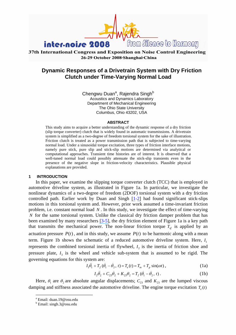
automotive driveline system, as illustrated in Figure 1a. In particular, we investigate the nonlinear dynamics of a two-degree of freedom (2DOF) torsional system with a dry friction controlled path. Earlier work by Duan and Singh [1-2] had found significant stick-slips motions in this torsional system and. However, prior work assumed a time-invariant friction problem, i.e. constant normal load N . In this study, we investigate the effect of time-varying N for the same torsional system. Unlike the classical dry friction damper problem that has been examined by many researchers [3-5], the dry friction element of Figure 1a is a key path that transmits the mechanical power. The non-linear friction torque sfT is applied by an actuation pressure ( )P t , and in this study, we assume ( )P t to be harmonic along with a mean term. Figure 1b shows the schematic of a reduced automotive driveline system. Here, 1I represents the combined torsional inertia of flywheel, 2I is the inertia of friction shoe and pressure plate, 3I is the wheel and vehicle sub-system that is assumed to be rigid. The governing equations for this system are:
1 1 1 2( , ) ( ) sin( )f e m pI T t T t T T tθ θ θ ω+ − = = +&& & & , (1a)
2 2 23 2 23 2 1 2( , )fI C K T tθ θ θ θ θ+ + = −&& & & & . (1b) Here, 1θ are 2θ are absolute angular displacements; 23C and 23K are the lumped viscous
damping and stiffness associated the automotive driveline. The engine torque excitation ( )eT t a Email: [email protected] b Email: [email protected]

is composed of mean m e tT T=< > and pulsating pT components, where t< > is the time-average operator. When relative motions are of interest, rewrite (1) where 1 1 2δ θ θ= − and
22 θδ = . 1 1 1
1 1 23 2 23 2 12 2 2
(1.0 ) ( , ) sin( )f m pI I I
I C K T t T T tI I I
δ δ δ δ ω− − + + = +&& & & , (2a)
2 2 23 2 23 2 1( , )fI C K T tδ δ δ δ+ + =&& & & . (2b)
Flywheel
Engine Transimission & Differential
Pressure Plate
N=P(t)A
Wheels & Vehicle
T (t) Ω Ωe e t
Friction Liner
a)
1I
T (t)
1
T (t)f
P(t)
2I
2
C
K23
23
I → ∞3
b)
Figure 1: Torsional systems with dry friction element. a) Automotive driveline system with torque converter clutch; b) schematic of a 2DOF system.
2 NON-LINEAR TIME-VARYING DRY FRICTION FORMULATION The non-linear friction torque 1( , )fT tδ& is carried by the clutch and then it acts as an
equivalent torque excitation to the downstream system. In a realistic automotive system, a pulse-width modulated solenoid valve would generate )(tP by changing the command value or duty ratio [6-7]. That results in a non-linear time-varying (NLTV) friction torque formulation, 1 1( , ) ( ) ( )fT t P t ARδ µ δ=& & where µ is the velocity-dependent coefficient of friction. Note that A and R are pressure area and moment arm and they are assumed to be time-invariant. Express the ( )P t profile in the form of a sinusoidal signal with mean pressure mP , amplitude pP , starting time 0t and the actuation pressure frequency fω .

0
0
0( )
sin( )m p f
t tP t
P P t t tω ψ−
+
<⎧⎪= ⎨ + + ≥⎪⎩ (3)
Here, ψ is the phase lag between the actuation pressure and ( )eT t . In this study, we set the initial engagement time at 0 0t + = without the loss of generality and ( )P t is assumed to be positive-definite to ensure that no separation occurs across the frictional interface, i.e.
/ [0, 1)p mP P ∈ . The following friction formulation 1( )µ δ& is employed since the aim of this study is to examine the phenomenological dynamic behavior [8].
1
1 11
1
( ) sgn( ) 0( )
[0 ] 0
k s k
s
eα δ
µ µ µ δ δµ δ
µ δ
−⎧⎡ ⎤+ − >⎪⎢ ⎥
= ⎨⎣ ⎦⎪
=⎩
&& &
&
&
(4)
Here, α is a positive constant that controls the gradient of µ with respect to 1δ& ; sµ is the static friction coefficient; kµ is the kinetic friction coefficient and sgn is the conventional triple-valued signum function. In our study, 2α = is chosen for the sake of illustration. To further reduce the system parameters, we could incorporate kµ , A and R within ( )P t to yield the NLTV friction torque ( , )fT tδ& as:
1( , ) ( ) ( )f sT t T tδ µ δ=& & , ( ) ( ) sin( )s k sm sp fT t AR P t T T tµ ω ψ= = + + . (5a, b)
Here, 1( )µ δ& has been normalized with respect to kµ . Further, the sign function of (4) is smoothened by a hyper-tangent function to facilitate the numerical integration [9] for the non-linear stick-slip motions.
11 1( ) [1.0 ( 1.0) ]tanh( )s
ke
α δµµ δ σδ
µ−
= + −&
& & (6)
A value of 50 is chosen for the smoothening factorσ . Duan and Singh [1-2] have justified this choice by applying the same formulation and factor to a similar automotive drive train torsional system.
0 0.1 0.2 0.3 0.4 0.5 0.6 0.7 0.8 0.9 10
20
40
60
80
100
120
140
160
180
200
. δ1, rad/s
t, s
Stick-Slip Transient Pure Slip Transient
Figure 2 Typical transient response for the 2DOF torsional system given ω = 150 rad/s, mT = 300; pT = 250,
smT = 500, spT = 0.2 smT , fω = ω , ψ =0, kµ / sµ = 0.8 and eΩ = 150 rad/s.

3 PURE SLIP TRANSIENT RESPONSE Typical parameters for the reduced driveline system of Figure 1b are: 2
1 2.0 mkgI ⋅= , 2
2 02.0 mkgI ⋅= , sradNmC /6.023 ⋅= , radNmK /300023 = , 208.0 mA = , mR 1.0= , 3.0=sµ , 0.15 ~ 0.38kµ = , NmTm 300= and NmTp 250= . First, observe a pure slip
transient in Figure 2 that results due to a speed difference between 1I and 2I during the initial engagement. Second, if we were to assume that only (pure) positive slip motions ( 1 0δ >& ) occur and that k sµ µ= since the negative gradient dominates only when 1δ& approaches zero, equations (2a-b) can be approximated as:
1 1 11 1 23 2 23 2
2 2 2(1.0 )( sin( )) sin( )sm sp f m p
I I II C K T T t T T tI I I
δ δ δ ω ψ ω− − + + + + = +&& & , (7a)
2 2 23 2 23 2 sin( )sm sp fI C K T T tδ δ δ ω ψ+ + = + +&& & . (7b) Assume that 1I rotates at the same speed as the engine and the rest of the driveline system
stays still before any engagement process can take place, we obtain the following initial conditions:
1(0) 0δ = , 1(0) eδ = Ω& , 2 (0) 0δ = , 2 (0) 0δ =& . (8a-d) An analytical solution to equation (7b) is then given by a sum of complementary and
particular solutions as:
223
( ) ( cos( ) sin( )) sin( )n spt smd d f
TTt e a t b t tK
ςωδ ω ω ω ψ φ− ⎧ ⎫= + + + + +⎨ ⎬
Λ⎩ ⎭ (9a)
23 2/n K Iω = , 23 23 2/(2 )C K Iς = , 21d nω ω ς= − , (9b-d) 2 2
23 2 23( ) ( )K I Cω ωΛ = − + , 1 223 23 2tan ( /( ))C K Iφ ω ω−= − − . (9e-f)
The constants a and b of (9a) are determined by applying the initial conditions (8c-d):
23
sin( )spsm TTaK
ψ φ= − − +Λ
, 1 cos( )spn f
d
Tb aςω ω ψ φ
ω⎧ ⎫
= − +⎨ ⎬Λ⎩ ⎭
. (10a,b)
Substitute (10) into (7a) to yield the solution for 1δ&& and 1δ& respectively:
11 1 1
2 2 22
2 2 2
( )( ) sin( ) sin( )
( 2 )cos( )sin( )
( 2 )sin( )n
p spm smf
d n d n dsp tf f
d n d n d
T TT Tt t tI I I
a b a tTt e
b a bςω
δ ω ω ψ
ω ς ω ω ς ω ωω ω ψ φ
ω ς ω ω ς ω ω τ−
−= + − +
⎧ ⎫− − +⎪ ⎪+ + + + ⎨ ⎬Λ + − + +⎪ ⎪⎩ ⎭
&&
, (11a)
11
2
1 1
2 2 2
2 2 2
( )( )
sin( ) sin( ) sin( )
( 2 )cos( )
( 2 )sin( )n
m smm
p sp spf f f
d n d n dt
d n d n d
T Tt V tI
T T Tt t t dt
I I
a b a te dt
b a b tςω
δ
ω ω ψ ω ω ψ φ
ω ς ω ω ς ω ω
ω ς ω ω ς ω ω−
−= +
⎧ ⎫+ − + + + +⎨ ⎬
Λ⎩ ⎭⎧ ⎫− − +⎪ ⎪+ ⎨ ⎬
+ − + +⎪ ⎪⎩ ⎭
∫
∫
&
. (11b)
The 1( )tδ& solution is further given in the following functional form where the coefficients
0a , 1a , 21a , 22a and 3a are defined by (11b):

21 211 0 1 3 3
22 22
sin( )( ) sin( )
sin( )nt
df
a tt a a t a e t
a tςωω ϕ
δ ω ϕω ϕ
−+⎧ ⎫⎪ ⎪= + + + +⎨ ⎬+ +⎪ ⎪⎩ ⎭
& (12)
The above solutions lead to some interesting results. Under the situation when the amplitude of oscillatory part is small and when the decaying component dies out quickly, the clutch engagement rate is controlled by a ramp of gradient 1 1( ) /m sma T T I= − . The time-varying friction torque spT contributes to the oscillatory motion during the ramp. As shown in Figure 3, when /m smT T is increased from 0.75 to 0.9, the ramp gradient decreases. Analytically, an increase in 1I indicates more kinetic energy and thus the dissipation process should take more time. Conversely, when the oscillatory and decaying parts dominate the pure slip motion, it is difficult to determine the ramp gradient rate. Nonetheless, our analysis still gives a guideline regarding the value of ( )m smT T− . As evident from (12), when mT is higher than smT , no final engagement can be realized because since 1a t term would monotonically grow with time and ultimately it would dominate the response.
0 0.1 0.2 0.3 0.4 0.5 0.6 0.7 0.8 0.9 10
50
100
150
200
250
. δ1(t), rad/s
t
Figure 3 Effect of smT on pure slip transients. Key: ⎯, mT / smT = 0.75, spT = 0; ⋅ ⋅ ⋅ , mT / smT = 0.75,
spT / smT =0.167; − − − , mT / smT = 0.9, spT / smT =0.167.
4 STICK-SLIP TRANSIENT RESPONSE (JUDDER) When 2θ& approaches 1θ& subsequent to the pure slip motion as discussed in the previous
section, stick-slip transient motions would take place as shown in Figure 2. In addition to introducing an objectionable noise problem, significant stick-slip torsional motions could be transferred by the differential to vehicle that will result to a rough ride. This phenomenon is usually referred to the clutch judder problem that typically occurs at low frequencies [10]. Yamada and Ando [11] and Centea et. al. [10] have called this as the “negative damping” problem, introduced by the negative slope of 1( )kµ δ& . Similar to their research, the negative

slope of kµ will be first investigated under a time-invariant friction torque smT . Then we will examine the effect of ( )sT t under the k sµ µ= assumption.
0.1 0.2 0.3 0.4 0.5 0.6 0.7 0.80
10
20
30
40
50
60
t, s
. δ1(t), rad/s
Figure 4 Effect of kµ on transient stick-slip responses given ω = 50 rad/s and smT = 550 Nm.
Key: ⎯ , kµ / sµ = 1.0; ⋅ ⋅ ⋅ , kµ / sµ = 0.75; − ⋅ − , kµ / sµ = 1.25.
From the friction formulation of (6), a decrease in kµ with 1δ& affects the system in two ways. First, a negative slope regime is formed. Second, the saturation friction torque
sm k mT ARPµ= is reduced and thus more slip motions are allowed. Figure 4 shows results for three values of kµ / sµ . As expected, the stick-slip motions become more pronounced when
k sµ µ< because the negative damping enhances the slip motions. Conversely, when k sµ µ> , the stick-slip motions are attenuated as a result of the positive damping as well as a higher value of smT as seen in Figure 4.
5 EFFECT OF HARMONICALLY-VARYING DRY FRICTION To examine the effect of harmonically-varying friction torque on judder, first apply ( )sT t
at fω ω= , where ω is the frequency of engine torque ( )eT t but with a phase lag of ψ . Results of Figure 5 show that in-phase ( )sT t tends to attenuate the stick-slip motions. A physical explanation can be found by analyzing the relationship between ( )eT t and ( )sT t in a quasi-static manner as shown in Figure 6a. Note that only positive stick-slip motions ( 1 0δ ≥& ) are excited under a significantly high positive mean torque mT . When the engine torque ( )eT t is higher, say in the first half cycle ( [ 2 2 / 2), intt n n n egerω π π π∈ + = ), the friction interface tends to initiate positive slipping motions. Quasi-statically a higher value of sT should suppress this tendency. But when there is a phase lag between sT and eT , such a suppression should be reduced. One could mathematically explain this by rewriting equation (7a) into the following form:

)]sin()0.1()sin([])0.1([2
1
2
1223
2
1223
2
111 ψωωδδδ ++−++−=−− tT
IItTT
IITK
IIC
III sppsmm
&&& (13)
As noted, when positive slipping tends to occur in the first half engine torque cycle, 0=ψ provides the maximum decrease of the effective excitation as illustrated by the right
hand side of the above equation. This is consistent with the observation of Figure 6a.
0 0.1 0.2 0.3 0.4 0.5 0.60
10
20
30
40
50
60
70
80
90
t, s
. δ1(t), rad/s
Figure 5 Effect of phase lag ψ on stick-slip transients given ω =60 rad/s and fω ω= .
Key: ⎯ , ψ = 0, − − − , ψ = π/2, ⋅ ⋅ ⋅ , ψ = π.
Similar results reveal that ( )sT t with a mismatched frequency produces more slip motions. Similar physical explanation is presented in Figure 6b and 6c. Since fω ω≠ and 0ψ ≠ , some “leakage” as indicated by the shaded areas occurs and consequently the slip motions are enhanced. Further, a time varying ( )sT t with fω ω= and 0ψ = is applied to a clutch with negative damping. Results of Figure 7 show that ( )sT t could efficiently reduce the judder problem in this case. Nonetheless, explanation of Figure 6 only applies at lower frequencies due to its quasi-static nature. As ω increases, phase delay between excitation and response may become important and the quasi-static explanation is no longer valid. Further research on this problem is reported in [12-13]

T
t
T
t
t
T T
t
e e
s s
First half Cycle First half Cycleπ/ω
T
smT
s
ψ/ω
First Half Cycle
mT
eT
t
t Tm
Tsm
Tm
Tsm
π/ω π/ω
a) b) c)
Figure 6 Quasi-static explanation of the effect of harmonically-varying friction torque on slip motions. All shaded areas represent the case for enhanced slip motions. a) Effect of phase lag ( fω ω= ): ⎯, ( )eT t ; − − − ,
( )sT t in phase; − ⋅ −, ( )sT t not in phase. b) Effect of mismatched frequency (ψ = 0): ⎯ , ( )eT t ; − − − ,
fω ω= ; − − ⋅ − − , fω ω> . c) Effect of mismatched frequency (ψ = 0): ⎯ , ( )eT t ; − − − , fω ω= ;
− ⋅ − , fω ω< .
6 CONCLUSION A better understanding of the dynamic response of a dry friction (slip torque converter
clutch) is achieved through this study. Under a sinusoidal torque excitation, three types of friction interface motions, namely pure stick, pure slip and stick-slip motions are determined via analytical or computational approaches. Our results show that three key parameters ( mT ,
smT and 1I ) control the engagement rate within the friction interface. The m smT T≤ guideline has to be strictly followed to ensure the final engagement. The friction characteristics with a negative slope ( k sµ µ< ) are found to significantly affect the system dynamics in two ways: introduction of the “negative” damping effect and a reduction in the saturation friction torque. Although the negative damping may induce substantial stick-slip motions, a well-tuned harmonically-varying dry friction torque could possibly quench this behavior. Plausible physical explanations have also been proposed.

0.1 0.15 0.2 0.25 0.3 0.35 0.4 0.45 0.5 0.55 0.60
10
20
30
40
50
60
t, s
. δ1(t), rad/s
Figure 7 Effect of harmonically-varying friction ( )sT t on clutch judder. Key: ⎯, kµ / sµ = 1.0 and spT =0;
⋅ ⋅ ⋅ , kµ / sµ = 0.75 and spT =0; − − − , kµ / sµ = 0.75 and spT =1/3 smT .
REFERENCES [1] C. Duan and R. Singh, “Super-Harmonics in a Torsional System with Dry Friction Path
Subject to Harmonic Excitation under a Mean Torque”, Journal of Sound and Vibration, 285, 803-834, 2005.
[2] C. Duan and R. Singh, “Stick-Slip Behavior in Torque Converter Clutch”, SAE Transactions Journal of Passenger Car: Mechanical Systems, 116, 2785-2795, 2005.
[3] J.P. Den Hartog, “Forced Vibrations with Combined Coulomb and Viscous Friction”, Transaction of the ASME, APM-53-9, 107-115, 1931.
[4] T.K. Pratt and R. Williams, “Nonlinear Analysis of Stick/Slip Motion”, Journal of Sound and Vibration, 74, 531-542, 1981
[5] S.W. Shaw, “On the Dynamic Response of a System with Dry Friction”, Journal of Sound and Vibration, 108, 305-325, 1986.
[6] K. Kono, H. Itoh, S. Nakamura, and K. Yoshizawa, “Torque Converter Clutch Slip Control System”, SAE paper 950672, 1995.
[7] J. Hahn and K. Lee, “Nonlinear Robust Control of Torque Converter Clutch Slip System for Passenger Vehicles Using Advanced Torque Estimation Algorithms”, Vehicle System Dynamics, 37, 175-192, 2002
[8] E.J. Berger, “Friction Modeling for Dynamic System Simulation”, Applied Mechanics Review, 55, 535-577, 2002.

[9] J.R. Dormand and P.J. Prince, “A Family of Embedded Runge-Kutta Formulae”, J. Computational and Applied Mathematics, 6, 19-26, 1980.
[10] D. Centea, H. Rahnejat and M.T. Menday, “Non-Linear Multi-Body Dynamic Analysis for the Study of Clutch Torsional Vibrations (Judder)”, Applied Mathematical Modelling, 25, 177-192, 2001.
[11] N. Yamada and K. Ando, “An Analysis of Clutch Self-Excited Vibration in Automotive Drive Line”, SAE paper 951319, 1995.
[12] C. Duan and R. Singh, “Transient Responses of a 2DOF Torsional System with Non-Linear Dry Friction under Harmonically-Varying Normal Load”, Journal of Sound and Vibration, 285, 1223-1234, 2005.
[13] C. Duan and R. Singh, “Influence of Harmonically-Varying Normal Load on Steady State Behavior of a 2DOF Torsional System with Dry Friction”, Journal of Sound and Vibration, 294, 503-528, 2006.