Dynamic Movement Primitives for object handover
8
Implementation and experimental validation of Dynamic Movement Primitives for object handover* Miguel Prada 1 , Anthony Remazeilles 1 , Ansgar Koene 2 and Satoshi Endo 3 Abstract— This article presents the implementation and ex- perimental validation of a control system dedicated to human robot physical interaction during object handovers. Our control law defines the trajectory of the robotic arm towards a previously unknown handover location based on the Dynamic Movement Primitives formalism adapted for human robot object handover. The control law was deployed on a Kuka Light-Weight Arm equipped with the Azzurra anthropomor- phic hand. We employed an industrial-like setting involving three different human postures for object handover in order to evaluate the performance and user experience of our control law and its generalizability. The evaluation was conducted over 1000 object handover trials between the human and robot partners, and the kinematic data and subjective experience were gathered for each trial. The outcomes of this evaluation validate the current implementation and guide the next steps towards more efficient and fluid human robot interaction. I. INTRODUCTION It is broadly accepted that robots will have a great im- pact on human activities in a near future [6]. The recent advancements on robotic technologies foresee a strong col- laboration between humans and robots for the achievement of domestic and industrial tasks. As stated in the European strategic agenda for robotics, such collaboration relies on natural physical interaction between the two partners, which highlights the importance of human-robot object handover actions [1]. Previously, various research has addressed the importance of fluid interaction using a human-robot object handover as an example task [21]. One of the main streams in the literature addresses an estimation of the most preferred handover location where the robot should bring the object at. In [2] cost functions are defined to maximize the comfort of the handover, considering both the mobile base positioning and the arm configuration. In [18], the A * algorithm permits to estimate the best handover location based on a 3D cost map which reflects three cost functions respectively focused on the safety, visibility and comfort criteria. Once the handover location is defined, several techniques are available to define the robot motion towards this site. In [8], different motion profiles (minimum-jerk, trapezoidal *This work was supported by the Coglaboration project within the 7th Framework Programme of the European Union - Cognitive Sstems and Robotics, contact number FP7-28788, see also http://www.coglaboration.eu 1 Dept. of Assitive Technologies, Helath Division of Tecnalia Research and Innovation, Parque Tecnologico de San Sebastian, E-2009 San Sebastian [email protected] 2 Dept. of Psychology, Univ. of Birmingham, B152TT, UK [email protected] 3 Institute for Information-Oriented Control, Technische Universit¨ at M¨ unchen, Munich, Germany [email protected] velocity profiles) are experimentally evaluated with humans, and, based on the results, a decoupled minimum jerk tra- jectory generator is proposed [9]. In [19], the Soft Motion Trajectory planner provides an active control of maximum jerks, accelerations and velocities. As highlighted in [2], [21], the use of such off-line planning-like approaches permits to get a good reachability score but lacks adaptability to the human motion (the robotic hand may move too far and push the the human hand for example), and may not provide motions or handover config- urations that feel natural to the human. Another alternative consists of explicitly learning good exchange strategies from the human. In [2], a learning technique is proposed in which the users are involved in the definition of the preferred handover configurations. In [23], the robot motions are defined from a human motion database. An adapted sliding- window search is proposed to find the most likely states in the database related to the current human position, and the related human receiver postures are then combined to define the robot motion. In this last work, the capability of appropriately responding to the human behavior implicitly depends on the database completeness, since the robot does not have mechanisms to handle novel user motions. In [12] a reactive mechanism is proposed in which the robot is driven through visual servoing towards the human hand location. The robot velocities, however, are proportional to the distance to the object which tends to produce motion speeds that could be perceived as unsafe by the users, in particular at the beginning of the interaction. The approach we present in this paper permits to produce robot motions inspired by human behaviors while maintain- ing a feedback mechanism to provide flexibility. This duality aspect is nicely handled by the concept of Dynamic Move- ment Primitives (DMP) that permits to combine a shape- driven control strategy (to reproduce human-like trajectories) with a goal driven strategy (to ensure an on line convergence towards the real observed handover location). We previously introduced the theoretical specialization of the DMP mechanism to object exchange in [14] and compared it in simulation with human behaviors in [15]. In this paper we extensively describe an implementation of this control law onto the robotic platform designed in the context of the European project Coglaboration. The next section summarizes the key aspect of the control law itself. Section III describes this implementation onto the Light-Weight Robot (LWR) equipped with the Azzurra anthropomorphic hand. Section IV describes the experiments we performed to evaluate the control law during object handovers with human 2013 IEEE/RSJ International Conference on Intelligent Robots and Systems (IROS) September 14-18, 2014. Chicago, IL, USA, 978-1-4799-6933-3/14/$31.00 ©2014 IEEE 2146
-
Upload
nottingham -
Category
Documents
-
view
1 -
download
0
Transcript of Dynamic Movement Primitives for object handover
Implementation and experimental validation of Dynamic MovementPrimitives for object handover*
Miguel Prada1, Anthony Remazeilles1, Ansgar Koene2 and Satoshi Endo3
Abstract— This article presents the implementation and ex-perimental validation of a control system dedicated to humanrobot physical interaction during object handovers. Our controllaw defines the trajectory of the robotic arm towards apreviously unknown handover location based on the DynamicMovement Primitives formalism adapted for human robotobject handover. The control law was deployed on a KukaLight-Weight Arm equipped with the Azzurra anthropomor-phic hand. We employed an industrial-like setting involvingthree different human postures for object handover in order toevaluate the performance and user experience of our control lawand its generalizability. The evaluation was conducted over 1000object handover trials between the human and robot partners,and the kinematic data and subjective experience were gatheredfor each trial. The outcomes of this evaluation validate thecurrent implementation and guide the next steps towards moreefficient and fluid human robot interaction.
I. INTRODUCTION
It is broadly accepted that robots will have a great im-pact on human activities in a near future [6]. The recentadvancements on robotic technologies foresee a strong col-laboration between humans and robots for the achievementof domestic and industrial tasks. As stated in the Europeanstrategic agenda for robotics, such collaboration relies onnatural physical interaction between the two partners, whichhighlights the importance of human-robot object handoveractions [1].
Previously, various research has addressed the importanceof fluid interaction using a human-robot object handoveras an example task [21]. One of the main streams in theliterature addresses an estimation of the most preferredhandover location where the robot should bring the objectat. In [2] cost functions are defined to maximize the comfortof the handover, considering both the mobile base positioningand the arm configuration. In [18], the A∗ algorithm permitsto estimate the best handover location based on a 3D costmap which reflects three cost functions respectively focusedon the safety, visibility and comfort criteria.
Once the handover location is defined, several techniquesare available to define the robot motion towards this site.In [8], different motion profiles (minimum-jerk, trapezoidal
*This work was supported by the Coglaboration project within the 7thFramework Programme of the European Union - Cognitive Sstems andRobotics, contact number FP7-28788, see also http://www.coglaboration.eu
1Dept. of Assitive Technologies, Helath Division of Tecnalia Researchand Innovation, Parque Tecnologico de San Sebastian, E-2009 San [email protected]
2Dept. of Psychology, Univ. of Birmingham, B152TT, [email protected]
3Institute for Information-Oriented Control, Technische UniversitatMunchen, Munich, Germany [email protected]
velocity profiles) are experimentally evaluated with humans,and, based on the results, a decoupled minimum jerk tra-jectory generator is proposed [9]. In [19], the Soft MotionTrajectory planner provides an active control of maximumjerks, accelerations and velocities.
As highlighted in [2], [21], the use of such off-lineplanning-like approaches permits to get a good reachabilityscore but lacks adaptability to the human motion (the robotichand may move too far and push the the human hand forexample), and may not provide motions or handover config-urations that feel natural to the human. Another alternativeconsists of explicitly learning good exchange strategies fromthe human. In [2], a learning technique is proposed in whichthe users are involved in the definition of the preferredhandover configurations. In [23], the robot motions aredefined from a human motion database. An adapted sliding-window search is proposed to find the most likely statesin the database related to the current human position, andthe related human receiver postures are then combined todefine the robot motion. In this last work, the capability ofappropriately responding to the human behavior implicitlydepends on the database completeness, since the robot doesnot have mechanisms to handle novel user motions.
In [12] a reactive mechanism is proposed in which therobot is driven through visual servoing towards the humanhand location. The robot velocities, however, are proportionalto the distance to the object which tends to produce motionspeeds that could be perceived as unsafe by the users, inparticular at the beginning of the interaction.
The approach we present in this paper permits to producerobot motions inspired by human behaviors while maintain-ing a feedback mechanism to provide flexibility. This dualityaspect is nicely handled by the concept of Dynamic Move-ment Primitives (DMP) that permits to combine a shape-driven control strategy (to reproduce human-like trajectories)with a goal driven strategy (to ensure an on line convergencetowards the real observed handover location).
We previously introduced the theoretical specializationof the DMP mechanism to object exchange in [14] andcompared it in simulation with human behaviors in [15]. Inthis paper we extensively describe an implementation of thiscontrol law onto the robotic platform designed in the contextof the European project Coglaboration. The next sectionsummarizes the key aspect of the control law itself. SectionIII describes this implementation onto the Light-WeightRobot (LWR) equipped with the Azzurra anthropomorphichand. Section IV describes the experiments we performed toevaluate the control law during object handovers with human
2013 IEEE/RSJ International Conference onIntelligent Robots and Systems (IROS)September 14-18, 2014. Chicago, IL, USA,
978-1-4799-6933-3/14/$31.00 ©2014 IEEE 2146

partners using an industrial scenario, and highlights the mainoutcomes of that evaluation.
II. ROBOT CONTROL LAW
This section highlights the main characteristics of theDMP formalism and its extension for the case of humanrobot object handover (see [14], [15] for more detail).
A. Dynamic Movement Primitives formalism
The DMP concept was initially introduced for trajectorylearning and reproduction by Ijspeert in [10]. Since then,several works were derived from the basic formalism, tohandle obstacle avoidance [7] or to boostrap reinforcementlearning methods for example in [4], [22].
Let x(t) be a one dimension trajectory that transits fromx(t0) = x0 to x(t f ) = g. The DMP formalism consists of mod-eling the reference trajectory with a second order dynamicalsystem named transformation system:
τ v = (1− s)K(g− x)+ sK(
f (s)s
+ x0− x)−Dv (1a)
τ x = v (1b)
The first term K(g− x) can be seen as a goal attractor thatensures the convergence towards the desired position g. Thesecond term K
(f (s)
s + x0− x)
acts like a shape attractorstimulating the system to follow the reference motion pattern.The contribution of these two terms are weighed by the phasevariable s which exponentially decreases from 1 towards 0following the canonical system:
τ s =−αs (2)
Thus, the shape attractor plays a predominant role at the be-ginning of the movement when s≈ 1 while the goal attractorbecomes predominant towards the end of the trajectory whens→ 0.
The shape attractor encapsulates the learned trajectorythrough the forcing term f that represents a non linearfunction as a sum of weighted functions:
f (s) =∑
Ni=1 ψi(s)wi
∑Ni=1 ψi(s)
s, with ψi(s) = exp(−hi(s− ci)2) (3)
The forcing term does not explicitly depend on time but onthe phase variable s instead. The system is thus time-scalableby adjusting the time constant τ .
B. Specialization for object handover
The main benefit of using the DMP formalism for learningand reproducing a trajectory is that during the reproductionof the learned motion pattern, the target position g in (1a) canbe modified to adjust the final position of the trajectory whilemaintaining dynamics similar to the reference trajectory.This is particularly convenient for our specific applicationin which the handover location, i.e. the target position,is not known a priori. Thus, in contrast with the workperformed in [18], we do not perform an initial estimationof the hand-over location which is affected by the qualityof the estimator and inflexible against unpredictable human
behaivor. Instead, we propose to consider the target locationg as the human hand location, therefore, constantly updatedduring a handover. The previously mentioned dominanceshift in attractors permits to limit the impact of the targetposition on the early phase of the motion (when the humanhand is far from the future handover site), and progressivelyincreases its influence when the two partners get closer tothe handover site, with the transformation system becominglinear when s→ 0.
Nevertheless, the goal attractor in the basic DMP modelstarts dominating the control law too early for this approachto work. As demonstrated in [14] the exponential evolutionof the phase variable quickly decreases from 1, so thatthe purely shape-driven motion is only present during alimited period of time. In addition, the basic DMP modeldoes not permit to adjust when and how fast the weightswitches between the two phases. This is considered as alimitation for our object handover application, where humanbehavior studies have shown that the transition in betweenthe feedforward (or shape-driven) and the feedback (or goal-driven) strategies tends to occur at the middle of the reachingmotion [5].
In order to account for this issue, we proposed in [14]to decouple the weights applied to each of the terms in thetransformation system from the phase variable, and to useinstead an arbitrary function of the phase variable to computethese weights:
τ v = (1−wg)( fw + x0− x)+wgK(g− x)−Dv (4a)τ x = v (4b)τ s =−αs, (4c)
where fw(s) is now defined as:
fw(s) =∑
Ni=1 ψi(s)wi
∑Ni=1 ψi(s)
. (5)
In our implementation, the weighing function wg(t) is se-lected to be a sigmoid function related to the CumulativeDistribution Function (CDF) of the Normal distribution:
wg(t) = 0.5[
1+ er f(
t−µ
σ√
2
)], (6)
where er f stands for the Gauss error function. This weighingfunction relies on two parameters, the mean µ of the Normaldistribution and the standard deviation σ of the distribution,that respectively permit to decide when the transition occursand how long it lasts. With these two parameters we caneasily control when the goal-attractor starts influencing thegenerated motion.
Furthermore, in order to better adjust the convergence toa varying goal, we also proposed to incorporate a velocityfeedback term to the transformation system:
τ v = (1−wg)( fw + x0− x)+wg[K(g− x)+Kvg]−Dv (7)
The evolution of this last system is the one driving therobot motion according to the perception feedback thatadjusts the goal location. We will now describe how thismodel is implemented onto our robotic platform.
2147

III. IMPLEMENTATION
A. Overall architecture
The previously described technique has been used todesign a controller for the hardware platform presented onFig. 1, the LWR from Kuka equipped with the Azzurra handfrom Prensilia [3]. The perception is performed with theKinect sensor mounted above the arm. The software systemhas been implemented using mainly ROS [16] framework(the low level arm connexion also involves Orocos [20]),and distributed in components as shown in Fig. 2.
The Perception component is in charge of providing thepose of the target location with respect to a fixed referenceframe, using the output of a Kinect sensor. Depending on thehandover direction, that pose can represent the pose of thehuman hand (robot → human) or the pose of the object inthe human hand (human → robot). A detailed description ofthe algorithms used by this component is beyond the scopeof the current paper.
Interface to the robotic hardware is managed by the LWRFRI, and the IH2 Azzurra components. The first componentinterfaces with the robot arm and is, in turn, composed by anOrocos subsystem which deals with the low-level interfaceto the robot using the network-based Fast Research Inter-face (FRI); details are given in III-B. The later componentcommunicates with the Prensilia hand as described in III-C.
The DMP Controller component receives data from theperceptual layer and from the robot interface components,and computes the motion commands sent to the robot inorder to reproduce the learned trajectories (see III-D).
In order to coordinate the operation of the aforementionedcomponents, the CogLab Master component runs a statemachine which selects the appropriate configurations foreach component at every step of the system operation.Section III-E gives an overview of this coordinator.
Fig. 1: Azzurra hand from Prensilia mounted onto the KukaLight Weight Arm
Fig. 2: Simplified software component architecture
B. LWR FRI component
As described above, the LWR FRI ROS node is in itselfa composition of Orocos components. The main componentof this subsystem is the one actually interfacing with therobot. The robotic arm is controlled using the FRI offeredby the Kuka Robot Controller (KRC) [17]. This interfaceoffers several control modes through a simple protocol usingUDP messages over an Ethernet connection. Joint position isselected as the control input since it allows complete controlover the robot posture, while avoiding the complexities ofa joint torque-based controller, which does not benefit ourapproach of imitating observed human motions.
Since the FRI requires that the motion commands receivedare reachable within the selected control cycle period (setto 100Hz in our case). To meet this requirement, we haveincorporated an interpolator component in this subsystem. Ituses a state of the art on-line trajectory generation algorithm,based on the work of Kroger [11]. This component acceptsvelocity set-points and generates attainable commands for therobot, which respect specific velocity, acceleration and jerklimits at the target communication frequency. These velocitycommands can be safely integrated into positions reachablein a single FRI period and directly transmitted to the KRC.
C. Prensilia IH2 Azzurra component
The IH2 Azzurra anthropomorphic hand by Prensilia em-beds internal microprocessors which perform the low-levelfinger motor control. The communication protocol permitsto send through a serial link high-level commands whichallow to set position targets for each finger individually orto automatically execute pre-defined grasps. A helper Pythonlibrary was developed and later used to build a ROS node tointeract with the hand using an Actionlib-based interface.
D. DMP based controller implementation
Currently only Cartesian position data is available bothin the learning dataset used to train the DMP, and in theoutput of the Perception component. Therefore, we proposeto learn position-only trajectories from human demonstrationand to encode and reproduce those with the DMP system.Afterward we augment this position trajectory with a desiredCartesian orientation interpolation from the initial orientationof the robot end effector to the target orientation based on apre-defined per-object delivery orientation.
This component reads the position of the pose output fromthe Perception component and uses this to set the g parameterin the DMP system in (7). Integration of the system fora fixed time step generates new desired Cartesian positionand velocity for the robot. Desired orientation and rotationalvelocity are computed separately with an ad-hoc strategywhich lets the end-effector move solidarily with the robot’sforearm during the initial phases of the motion, and usesBezier curves to make it converge to the desired orientationduring the final approach phase.
In order to combine these position and orientation com-mands we have implemented a system based on prioritised
2148
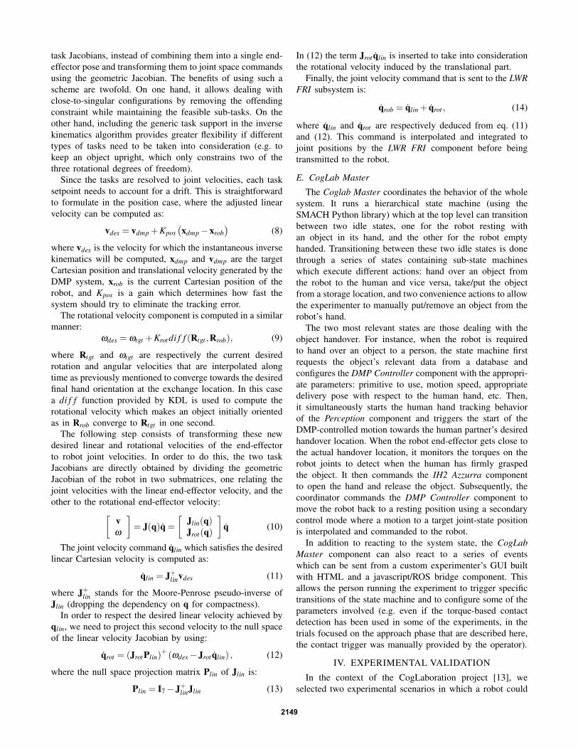
task Jacobians, instead of combining them into a single end-effector pose and transforming them to joint space commandsusing the geometric Jacobian. The benefits of using such ascheme are twofold. On one hand, it allows dealing withclose-to-singular configurations by removing the offendingconstraint while maintaining the feasible sub-tasks. On theother hand, including the generic task support in the inversekinematics algorithm provides greater flexibility if differenttypes of tasks need to be taken into consideration (e.g. tokeep an object upright, which only constrains two of thethree rotational degrees of freedom).
Since the tasks are resolved to joint velocities, each tasksetpoint needs to account for a drift. This is straightforwardto formulate in the position case, where the adjusted linearvelocity can be computed as:
vdes = vdmp +Kpos(xdmp−xrob
)(8)
where vdes is the velocity for which the instantaneous inversekinematics will be computed, xdmp and vdmp are the targetCartesian position and translational velocity generated by theDMP system, xrob is the current Cartesian position of therobot, and Kpos is a gain which determines how fast thesystem should try to eliminate the tracking error.
The rotational velocity component is computed in a similarmanner:
ωdes = ωtgt +Krotdi f f (Rtgt ,Rrob), (9)
where Rtgt and ωtgt are respectively the current desiredrotation and angular velocities that are interpolated alongtime as previously mentioned to converge towards the desiredfinal hand orientation at the exchange location. In this casea di f f function provided by KDL is used to compute therotational velocity which makes an object initially orientedas in Rrob converge to Rtgt in one second.
The following step consists of transforming these newdesired linear and rotational velocities of the end-effectorto robot joint velocities. In order to do this, the two taskJacobians are directly obtained by dividing the geometricJacobian of the robot in two submatrices, one relating thejoint velocities with the linear end-effector velocity, and theother to the rotational end-effector velocity:[
vω
]= J(q)q =
[Jlin(q)Jrot(q)
]q (10)
The joint velocity command qlin which satisfies the desiredlinear Cartesian velocity is computed as:
qlin = J+linvdes (11)
where J+lin stands for the Moore-Penrose pseudo-inverse ofJlin (dropping the dependency on q for compactness).
In order to respect the desired linear velocity achieved byqlin, we need to project this second velocity to the null spaceof the linear velocity Jacobian by using:
qrot = (JrotPlin)+ (ωdes−Jrot qlin) , (12)
where the null space projection matrix Plin of Jlin is:
Plin = I7−J+linJlin (13)
In (12) the term Jrot qlin is inserted to take into considerationthe rotational velocity induced by the translational part.
Finally, the joint velocity command that is sent to the LWRFRI subsystem is:
qrob = qlin + qrot , (14)
where qlin and qrot are respectively deduced from eq. (11)and (12). This command is interpolated and integrated tojoint positions by the LWR FRI component before beingtransmitted to the robot.
E. CogLab Master
The Coglab Master coordinates the behavior of the wholesystem. It runs a hierarchical state machine (using theSMACH Python library) which at the top level can transitionbetween two idle states, one for the robot resting withan object in its hand, and the other for the robot emptyhanded. Transitioning between these two idle states is donethrough a series of states containing sub-state machineswhich execute different actions: hand over an object fromthe robot to the human and vice versa, take/put the objectfrom a storage location, and two convenience actions to allowthe experimenter to manually put/remove an object from therobot’s hand.
The two most relevant states are those dealing with theobject handover. For instance, when the robot is requiredto hand over an object to a person, the state machine firstrequests the object’s relevant data from a database andconfigures the DMP Controller component with the appropri-ate parameters: primitive to use, motion speed, appropriatedelivery pose with respect to the human hand, etc. Then,it simultaneously starts the human hand tracking behaviorof the Perception component and triggers the start of theDMP-controlled motion towards the human partner’s desiredhandover location. When the robot end-effector gets close tothe actual handover location, it monitors the torques on therobot joints to detect when the human has firmly graspedthe object. It then commands the IH2 Azzurra componentto open the hand and release the object. Subsequently, thecoordinator commands the DMP Controller component tomove the robot back to a resting position using a secondarycontrol mode where a motion to a target joint-state positionis interpolated and commanded to the robot.
In addition to reacting to the system state, the CogLabMaster component can also react to a series of eventswhich can be sent from a custom experimenter’s GUI builtwith HTML and a javascript/ROS bridge component. Thisallows the person running the experiment to trigger specifictransitions of the state machine and to configure some of theparameters involved (e.g. even if the torque-based contactdetection has been used in some of the experiments, in thetrials focused on the approach phase that are described here,the contact trigger was manually provided by the operator).
IV. EXPERIMENTAL VALIDATION
In the context of the CogLaboration project [13], weselected two experimental scenarios in which a robot could
2149

provide assistance to a person: a industrial scenario, and adomestic scenario. In the analysis we present here, we focuson the first scenario, studying the velocity aspects and verbalvs vision based triggering.
A. Experiment description
1) Experiment design: The design of the experiment wasinspired by the industrial scenario of a car mechanic with arobot assistant and was implemented with three configura-tions, with different human postures:• ’Engine Bay’ with the mechanic bent forward over the
engine, able to view the handover, generally reachingto the right and slightly backwards with only slightmovement restriction (Fig. 3 a).
• ’Hydraulic Lift’ with the mechanic under a car on ahydraulic lift, reaching above the head, free to observethe handover, generally reaching to the right side withonly slightly impaired freedom of movement (Fig. 3 b).
• ’Lying under car’ with the machanic lying on the backunder the car, limiting the field of view and the rangeof arm movement (Fig. 3 c)).
2) Experiment procedure: Each scenario configurationwas tested on a separate day to avoid frequent reconfigura-tions of the setup and minimize participant fatigue. We testedwith 7 (4 male, 3 female) naıve participants, recruited fromTecnalia staff, 5 of whom had little or no prior experienceof interacting with robots. In each scenario a base case, andvariations in two factors were tested: velocity and movementtriggering.
To test the effect of speed-accuracy trade-off on the userexperience the Robot movements were executed at 5 differentspeeds ranging between approximately 1 and 1/4 times as fastas an average human reaching movement calculated from anexisting data set of a similar setup.
Another manipulation was a switch from the default visionbased robot movement triggering (mocked by the operatormanually starting the robot motion), used in the speed trials,to verbal triggering in which participants provided a verbal”GO” command.
Each session started with 5 base handovers (mediumspeed, approximately 1/2 human speed, and visual trigger-ing), to familiarize the participant with the robot and theevaluation protocol. All other trials were performed in arandom order with each of the 5 speeds repeated 3 times andthe verbal triggering repeated 5 times. Each trial consistedof the following sequence.
Fig. 3: Human postures in the 3 car mechanic configurations:a) Engine Bay; b) Hydraulic Lift; c) Lying under Car
1) Delivery from robot to human (R→ H)• Human requests object by reaching to robot• Robot brings the object to the human• Human takes object to task area• The participant evaluates the handover
2) Retrieval from human to robot (H→ R)• Human holds object out to the robot• Robot reaches to the object• Robot takes the object back to itself• Human evaluates the handover
The evaluation after each handover was provided in fourcriteria by rating the following statements:• Q1: It was easy to receive the object• Q2: I was satisfied with the interaction• Q3: The interaction was comfortable• Q4: I felt safe during the interaction
The participants were asked to enter an evaluation scorebetween 1 (fully disagree) and 9 (fully agree) using a touch-screen. Once all trials were completed, the participant wasinterviewed to provide additional feedback and qualitativeevaluation of their experiences.
In addition to the qualitative evaluation, we also recorded(i) the location of the human hand as a function of time,providing movement kinematics, (ii) the articular pose ofthe robot as well as the measured efforts per joint, and (iii)the timing of the events during the handover procedure (e.g.motion start, end).
3) Experiment setup & equipment: The car mechanicscenario was simulated using the setup shown in Fig. 4.The metal frame defined the task area, i.e. the car. The tasksurface was moved from the waist height (’Engine Bay’),to above the participant’s head (’Hydraulic Lift’, shown inFig. 4 left image). For the ’Lying under the car’ configurationparticipants lay on a height adjusted bed, to accommodatethe workspace limitations of the robot (Fig. 4 right image).The work frame and bed were positioned such that partic-ipants were 100-125cm from the robot. This allowed theiroutstretched hand to be inside the robot’s workspace whiletheir body remained safely beyond reach of the robot. ALiberty magnetic motion tracking system (Polhemus Inc.,Vermont, USA) with four magnetic markers, was used torecord the position and orientation of the participant’s armat 240Hz during the object handover. The magnetic markerswere placed onto the participant’s right arm (one on theshoulder, one on the back of the hand, one on the thumb
Fig. 4: Setup: Standing configuration for ’Engine Bay’and ’Hydraulic Lift’ (left image) and Lying under the carconfiguration (right image)
2150
and one on the index finger). This system was used only foroff-line analysis, as the control system only used the Kinectsensor for real-time visual input.
The object used for the handovers was a plastic flashlightwhich was always grasped using a cylindrical power grasp.
B. Main outcomes of the experiments
In order to evaluate the performance of our control systemfor Human-Robot Interaction, the results of the experimentsare evaluated not only in terms of success in achieving objecthandovers but also in term of the subjective experiences ofthe participants.
1) Success rate: Table I summarizes the overall objecthandover success rate. Notably the experiment configurationhad only a minor impact on the success rate despite thelarge differences in the participants sensory and movementcapacities in the three configurations.
Success rates are grouped per behavioural conditions onTable II. As it shows, the lowest success rate was observedin the trials with the highest robot velocity (Sp. 1).
Handover failures in the high speed conditions were pri-marily due to the torque limit of the Kuka LWR triggering thesafety stop in the mid-motion. On the other hand, the failuresin the verbal triggered trials were caused by participantsinstructing the robot to start moving before they had movedtheir own hand into the operating space of the robot.
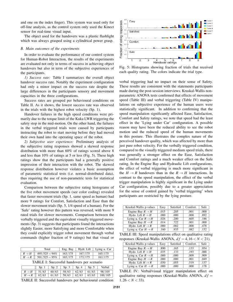
2) Subjective user experience: Preliminary analysis ofthe subjective rating responses showed a skewed responsedistribution with more than 60% of ratings scored above 8and less than 10% of ratings at 5 or less (Fig. 5). These highratings show that the participants had a generally positiveimpression of their interaction with the robot. The skewedresponse distribution however violates a basic assumptionof parametric statistical tests (i.e. normal-distributed data),thus requiring the use of non-parametric tests for statisticalevaluation.
Comparison between the subjective rating histograms ofthe five robot movement speeds (see color coding) revealedthat faster movement trials (Sp. 1, same speed as human) hadmore 9 ratings for Comfort, Satisfaction and Ease than theslower movement trials (Sp. 5, 1/4 speed of a human). For the’Safe’ rating however this pattern was reversed, with more 9rated trials for slower movements. Comparison between theverbally triggered and the equivalent visually triggered move-ments (Sp. 3) suggests that participants found the interactionsslightly Easier, more Satisfying and more Comfortable whenthey could explicitly trigger robot movement through verbalcommands (higher fraction of 9 ratings) but that visual or
Total Eng. Bay Hydr. Lift Lying u. CarR→ H 495/525 = 94% 163/175 167/175 165/175H→ R 501/525 = 95% 165/175 173/175 163/175
TABLE I: Successful handovers per scenarioSp. 1 Sp. 2 Sp. 3 Sp. 4 Sp. 5 Verbal
R→ H 51/63 60/63 58/63 62/63 61/63 98/105H→ R 62/63 61/63 58/63 62/63 63/63 100/105
TABLE II: Successful handovers per behavioural condition
Fig. 5: Histograms showing fraction of trials that receivedeach quality rating. The colors indicate the trial type.
verbal triggering had no impact on their sense of Safety.These results are consistent with the statements participantsmade during the post-session interviews. Kruskal-Wallis non-parametric ANOVA tests confirmed that effects of movementspeed (Table III) and verbal triggering (Table IV) manipu-lations on subjective experience of the human users werestatistically significant. In addition to confirming that thespeed manipulation significantly affected Ease, Satisfaction,Comfort and Safety ratings, we note that speed had the leasteffect in the ’Lying under Car’ configuration. A possiblereason may have been the reduced ability to see the robotmotion and the reduced speed of the human movementsin this posture. This illustrates the complex nature of theperceived handover quality, which was affected by more thanjust pure robot velocity. For the verbally triggered condition,compared to the visually triggered medium speed trials, therewas generally a stronger effect on the Ease, Satisfactionand Comfort ratings and a much weaker effect on the Saferating. In the Engine Bay and Hydraulic Lift configurations,the effect of verbal triggering is much more significant inthe H → R handovers than in the R→ H interactions. Incontrast to the speed manipulation, the effect of the verbaltrigger manipulation is highly significant in the Lying underCar configuration, possibly due to a greater appreciationfor the sense of control gained by ’verbal triggering’ whenparticipants are restricted by the lying posture.
Kruskal-Wallis p-values Easy Satisfied Comfort. SafeEngine Bay R→ H .015 .205 .001 .000Hydo. Lift R→ H .000 .000 .000 .892
Lying u. Car R→ H .026 .200 .605 .186Engine Bay H→ R .014 .722 .001 .000Hydo. Lift H→ R .000 .002 .000 .478
Lying u. Car H→ R .160 .935 .082 .152
TABLE III: Speed manipulations effect on qualitative ratingresponses (Kruskal-Wallis ANOVA, d f = 4,16 < N < 21).
Kruskal-Wallis p-values Easy Satisfied Comfort. SafeEngine Bay R→ H .890 .165 .133 .954Hydo. Lift R→ H .035 .133 .193 .088
Lying u. Car R→ H .000 .000 .009 .909Engine Bay H→ R .000 .000 .001 .049Hydo. Lift H→ R .030 .055 .519 .137
Lying u. Car H→ R .000 .000 .000 .178
TABLE IV: Verbal/visual trigger manipulation effect onqualitative rating responses (Kruskal-Wallis ANOVA, d f =1,26 < N < 33).
2151
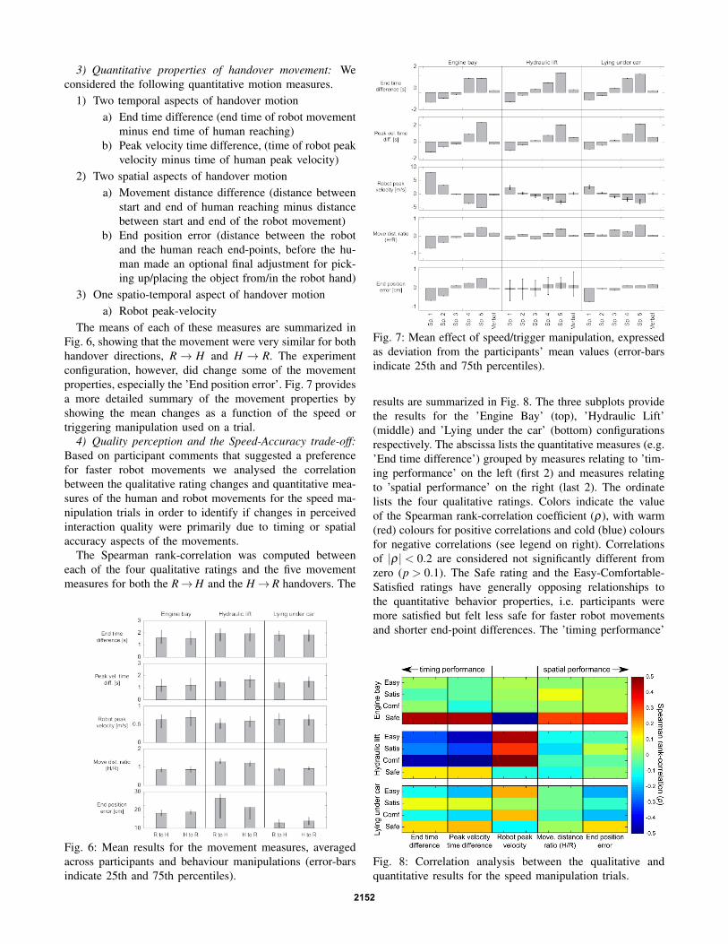
3) Quantitative properties of handover movement: Weconsidered the following quantitative motion measures.
1) Two temporal aspects of handover motiona) End time difference (end time of robot movement
minus end time of human reaching)b) Peak velocity time difference, (time of robot peak
velocity minus time of human peak velocity)2) Two spatial aspects of handover motion
a) Movement distance difference (distance betweenstart and end of human reaching minus distancebetween start and end of the robot movement)
b) End position error (distance between the robotand the human reach end-points, before the hu-man made an optional final adjustment for pick-ing up/placing the object from/in the robot hand)
3) One spatio-temporal aspect of handover motiona) Robot peak-velocity
The means of each of these measures are summarized inFig. 6, showing that the movement were very similar for bothhandover directions, R → H and H → R. The experimentconfiguration, however, did change some of the movementproperties, especially the ’End position error’. Fig. 7 providesa more detailed summary of the movement properties byshowing the mean changes as a function of the speed ortriggering manipulation used on a trial.
4) Quality perception and the Speed-Accuracy trade-off:Based on participant comments that suggested a preferencefor faster robot movements we analysed the correlationbetween the qualitative rating changes and quantitative mea-sures of the human and robot movements for the speed ma-nipulation trials in order to identify if changes in perceivedinteraction quality were primarily due to timing or spatialaccuracy aspects of the movements.
The Spearman rank-correlation was computed betweeneach of the four qualitative ratings and the five movementmeasures for both the R→H and the H→ R handovers. The
Fig. 6: Mean results for the movement measures, averagedacross participants and behaviour manipulations (error-barsindicate 25th and 75th percentiles).
Fig. 7: Mean effect of speed/trigger manipulation, expressedas deviation from the participants’ mean values (error-barsindicate 25th and 75th percentiles).
results are summarized in Fig. 8. The three subplots providethe results for the ’Engine Bay’ (top), ’Hydraulic Lift’(middle) and ’Lying under the car’ (bottom) configurationsrespectively. The abscissa lists the quantitative measures (e.g.’End time difference’) grouped by measures relating to ’tim-ing performance’ on the left (first 2) and measures relatingto ’spatial performance’ on the right (last 2). The ordinatelists the four qualitative ratings. Colors indicate the valueof the Spearman rank-correlation coefficient (ρ), with warm(red) colours for positive correlations and cold (blue) coloursfor negative correlations (see legend on right). Correlationsof |ρ| < 0.2 are considered not significantly different fromzero (p > 0.1). The Safe rating and the Easy-Comfortable-Satisfied ratings have generally opposing relationships tothe quantitative behavior properties, i.e. participants weremore satisfied but felt less safe for faster robot movementsand shorter end-point differences. The ’timing performance’
Fig. 8: Correlation analysis between the qualitative andquantitative results for the speed manipulation trials.
2152

related measures were more strongly correlated with thequalitative ratings than the ’spatial performance’ measures,indicating a willingness by participants to engage in a speed-accuracy trade-off in favour of rapid interactions. Overall, thestrongest correlations between qualitative ratings and move-ment measures were found in the ’Hydraulic Lift’ configura-tion for the Easy-Comfortable-Satisfied ratings whereas the’Safe’ ratings showed strongest correlations in the ’EngineBay’ configuration. ’Lying on the Bed’ yielded the weakestcorrelations, probably because the reduced visibility andreduced freedom of movement dominated the participants’experiences. ’End position error’ had its strongest (negative)correlations in the ’Lying under the car’ configuration. Usersmay prefer a greater weight on speed when they themselveshave the space to make compensation movements, while theyprefer to wait for more accurate robot behaviour when theythemselves are constrained in their movement space.
V. CONCLUSION
In this article we presented the implementation of a robotarm control based on the Dynamic Movement Primitivesformalism adapted to human robot object handover. Theproposed control law has been implemented onto a LWRrobot equipped with the Azzurra hand and experimentallytested through more than 1000 handovers with a range ofconfigurations and behavior manipulations. The results of thebehavioral experiments validate the proposed control modewith a success rate of more than 95%. Although the setupof the experiment only covers a specific scenario and objectfor handover, the proposed method is not limited to any ofthem, and further experimentation will evaluate the system ina different scenario and with other objects requiring differentgrasping modes.
The next steps towards fluent object handovers in thatframework will consist of increasing the autonomy andadaptability of the control strategy. In that line we would liketo extend the situation awareness by permitting the systemto automatically detect when the user launches an interactionprocedure, or when the same user decides to stop it for anyparticular reason.
The adaptability will be addressed in terms of objectaffordance on the one hand and individual preferences inhandover location and speed on the other hand. Concerningobject afforcances we would like, through perception, tobetter understand how the user would like to grasp an objector how he would like to deliver it. Concerning individualpreference, the experiment showed that the humans implicitlyadapted their behavior to the robotic partner, we wouldlike the robotic system to perform a similar effort, takinginto account, through the accumulation of exchanges, thepreferred handover location or exchange speed of the human.
Finally, some preliminary internal experiments (not eval-uated here) on the automatic detection of the contact inbetween the two agents, through forces analysis at the handwrist, to trigger the object grasping or release show promis-ing results for possibility of using such data to recognize thehandover events.
REFERENCES
[1] R. Bischoff and T. Guhl. The strategic research agenda for robotics ineurope [industrial activities]. Robotics Automation Magazine, IEEE,17(1):15–16, 2010.
[2] M. Cakmak, S. Srinivasa, M. Lee, J. Forlizzi, and S. Kiesler. Humanpreferences for robot-human hand-over configurations. In IEEE/RSJIROS, pages 1986–1993, San Francisco, CA, Sept. 2011.
[3] C. Cipriani, M. Controzzi, and M. Carrozza. The smarthand transradialprosthesis. Journal of NeuroEngineering and Rehabilitation, 8(32),May 2011.
[4] C. Daniel, G. Neumann, and J. Peters. Learning concurrent motorskills in versatile solution spaces. In IEEE/RSJ IROS, pages 3591–3597, Vilamoura, Portugal, Oct. 2012.
[5] M. Desmurget and S. Grafton. Forward modeling allows feedbackcontrol for fast reaching movements. Trends in cognitive sciences,4(11):423–431, Nov. 2000.
[6] B. Gates. A robot in every home. Scientific American, 296(1):44–51,2007.
[7] H. Hoffmann, P. Pastor, D.-H. Park, and S. Schaal. Biologically-inspired dynamical systems for movement generation: Automatic real-time goal adaptation and obstacle avoidance. In IEEE ICRA, pages2587–2592, Kobe, Japan, May 2009.
[8] M. Huber, C. Lenz, M. Rickert, A. Knoll, T. Brandt, and S. Glasauer.Human preferences in industrial human-robot interactions. In Int.Workshop on Cognition for Technical Systems, Munich, Germany,2008.
[9] M. Huber, H. Radrich, C. Wendt, M. Rickert, A. Knoll, T. Brandt,and S. Glasauer. Evaluation of a novel biologically inspired trajectorygenerator in human-robot interaction. In IEEE RO-MAN, pages 639–644, Toyama, Japan, Sept. 2009.
[10] A. Ijspeert, J. Nakanishi, T. Shibata, and S. Schaal. Nonlineardynamical systems for imitation with humanoid robots. IEEE-RASInt. Conf. on Humanoid Robots, 2001.
[11] T. Kroger. Opening the Door to New Sensor-based Robot ApplicationsThe Reflexxes Motion Libraries. In IEEE ICRA, Shangai, China, 2011.
[12] Vincenzo Micelli, Kyle Strabala, and Siddhartha Srinivasa. Perceptionand control challenges for effective human-robot handoffs. In RSS,workshop on RGB-D, Los Angeles, California, June 2011.
[13] G. Pegman. Report on scenarios, tasks and goals. Technical ReportDeliverable D2.10, European Project Coglaboration, FP7-ICT-7-2.1(No. 287888), 2012.
[14] M. Prada and A. Remazeilles. Dynamic Movement Primitives forHuman Robot Interaction. In IEEE/RSJ IROS, workshop on RobotMotion Planning: online, reactive and in Real-time, Algarve, Portugal,2012.
[15] M. Prada, A. Remazeilles, A. Koene, and S. Endo. Dynamic move-ment primitives for human-robot interaction: Comparison with humanbehavioral observation. In IEEE/RSJ IROS, pages 1168–1175, Tokyo,Japan, 2013.
[16] M. Quigley, B. Gerkey, K. Conley, J. Faust, T. Foote, J. Leibs,E. Berger, R. Wheeler, and A. Y. Ng. ROS: an open-source RobotOperating System. In IEEE ICRA, Open-Source Software workshop,Kobe, Japan, May 2009.
[17] G. Schereiber, A. Stemme, and R. Bischoff. The Fast ResearchInterface for the Kuka Lightweight robot. In IEEE ICRA, workshopon Innovative Robot Control Architectures for Demanding (research)applications, pages 15–21, Anchorage, Alaska, May 2010.
[18] E. Sisbot, L. Marin-Urias, R. Alami, and T. Simeon. A human awaremobile robot motion planner. IEEE Trans. on Robotics, 23(5), 2007.
[19] E. Sisbot, L. Marin-Urias, X. Broquere, D. Sidobre, and R. Alami.Synthesizing robot motions adapted to human presence. InternationalJournal of Social Robotics, 2(3), 2010.
[20] P. Soetens. A Software Framework for Real-Time and DistributedRobot and Machine Control. PhD thesis, Katholieke UniversiteitLeuven, Belgium, May 2006.
[21] K. Strabala, M. Lee, A. Dragan, J. Forlizzi, S. Srinivasa, M. Cakmak,and V. Micelli. Towards seamless human-robot handovers. Journal ofHuman-Robot Interaction, 2(1), 2013.
[22] F. Stulp. Adaptive exploration for continual reinforcement learning. InIEEE/RSJ IROS, pages 1631–1636, Vilamoura, Portugal, Oct. 2012.
[23] K. Yamane, M. Revfi, and T. Asfour. Synthesizing object receivingmotions of humanoid robots with human motion database. In IEEEICRA, pages 1629–1636, Karlsruhe, Germany, May 2013.
2153


![KLV-30MR1 - Error: [object Object]](https://static.fdokumen.com/doc/165x107/631786651e5d335f8d0a6a63/klv-30mr1-error-object-object.jpg)