Dynamic compactness- and bearing capacity measuring method
16
Mérnökgeológia-Kőzetmechanika 2015 (Szerk: Török Á., Görög P. & Vásárhelyi B.) oldalak: 379 – 394 CWA15846:2008 módosítási javaslat és főbb háttértanulmányai CWA15846:2008 Modification Draft and Main Background Studies István Subert MSc Civil Engineer, MSc Economic Engineer, CEO Andreas Ltd, Hungary e-mail: [email protected] ÖSSZEFOGLALÁS: CWA15846:2008 (dinamikus tömörség- és teherbírás mérés) javasolt módosítása héttér vizsgálatokat igényelt az elmúlt nyolc év mérési tapasztalatainak figyelembe vételével. Az Európai egyetemeken végzett mérési verifikációkat és szakértői véleményeket megvizsgáltuk - bevonva azokat, illetve háttérelemzések eredményei alapján kiegészítő javaslatokat dolgoztuk ki a dinamikus tömörségmérés vizsgálati szabványához. Ily módon lehetővé vált a módosítás tervezet elkészítése a felmerült kérdések elemzése a beérkezett észrevételek feldolgozásával. A fontos talaj -jellemzők meghatározására kifejlesztett első szabályozást CWA15846- WS33 munkabizottság készítette el 2006-ban az Andreas előkészítésében. Az alkalmazott tárcsa alatti terhelés 0.35MPa jelentősen eltér a korábban alkalmazottaktól (pl német mérési mód TP BF-StB Part B8.3) így nem csak a dinamikus modulus, hanem a dinamikus tömörségi fok meghatározására is alkalmas a tárcsa elmozdítása nélkül végrehatott 10-18 ejtéssel. Meghatározható egy süllyedési- alakváltozási görbe az LFW terhelési módszert alkalmazva, így a vizsgálat egy helyszíni Porctor - tömöríthetőségi vizsgálatot szimulál. Jelen cikkben összefoglaltuk mindezen mérési- tapasztalatokat és a háttérvizsgátokat és javaslatokat a CWA15846:2008 véglegesítéséhez, egy EN szabvány eléréséhez. Kulcsszavak: Dinamikus tömörség- és teherbírás mérés, SP-LFWD kistárcsás könnyűejtősúlyos mérőeszköz, tömörség és teherbírás mérés egy méréssel, CWA15846, környezetbarát mérőeszköz laboroknak, kivitelezői önellenőrzés. ABSTRACT: The modification draft of the CWA15846:2008 (dynamic compactness- and bearing capacity measuring method) needed background investigations, which based on the test experiences gained in last eight years. The verifications of the test – made by European Universities and foreign experts in this theme - also needs deep investigations, to solve or to involve the addition of this dynamic compactness test standard. On this way we can finished and working our suggestion for the CWA modification draft, with analyzing the questions and incoming comments. The theory determines this important soil parameters developed and prepared in the first regulation CWA15846-WS33 in 2006, prepared by Andreas. The applied loading under the disc is 0.35 MPa is very different from the earlier (e.g.TP BF-StB Part B8.3 German test method), thus suitable measuring not only the E d module but the dynamic compactness-degree also, calculated from the deformation- settlement curve, gained from 10-18 drops of weight without moving the plate. On this way can be determined the settlement curve - using the LFW loading system - so this test simulating on-site compatibility Proctor test. In this article we summarized all the test experiences and background investigations results, finalization the CWA15846 to reach an EN Standard from this. keywords: Dynamic compactness-test, isotope-free SP-LFWD small plate light falling weight compactness measurement device, compactness- and bearing capacity measuring with one test, environmental friendly equipment for laboratory, CWA15846, environmental laboratory test, Contractor’s self-checking. 1. INTRODUCTION The most important quality parameters of the building of earthworks, of building materials of railway, roadway, base of industrial buildings, waterway embankment structures is the compactness-rate and bearing capacity, which can be measuring by CWA15846:2008 in one test. All European regulations treat the limiting values necessary for avoiding the settlement after compacting, reduction of the water penetration, near the necessary bearing. The compactness degree traditionally is a quotient of the dry bulk density and the dry reference density, expressed in percentage. Totally new direction and method can be considered in the CWA 15846 Standard SP-LFWD (Small-Plate Light Falling Weight
-
Upload
independent -
Category
Documents
-
view
6 -
download
0
Transcript of Dynamic compactness- and bearing capacity measuring method

Mérnökgeológia-Kőzetmechanika 2015 (Szerk: Török Á., Görög P. & Vásárhelyi B.)
oldalak: 379 – 394
CWA15846:2008 módosítási javaslat és főbb háttértanulmányai
CWA15846:2008 Modification Draft and Main Background Studies
István Subert MSc Civil Engineer, MSc Economic Engineer, CEO Andreas Ltd, Hungary e-mail: [email protected]
ÖSSZEFOGLALÁS: CWA15846:2008 (dinamikus tömörség- és teherbírás mérés) javasolt
módosítása héttér vizsgálatokat igényelt az elmúlt nyolc év mérési tapasztalatainak figyelembe
vételével. Az Európai egyetemeken végzett mérési verifikációkat és szakértői véleményeket
megvizsgáltuk - bevonva azokat, illetve háttérelemzések eredményei alapján kiegészítő javaslatokat
dolgoztuk ki a dinamikus tömörségmérés vizsgálati szabványához. Ily módon lehetővé vált a
módosítás tervezet elkészítése a felmerült kérdések elemzése a beérkezett észrevételek
feldolgozásával. A fontos talaj-jellemzők meghatározására kifejlesztett első szabályozást CWA15846-
WS33 munkabizottság készítette el 2006-ban az Andreas előkészítésében. Az alkalmazott tárcsa alatti
terhelés 0.35MPa jelentősen eltér a korábban alkalmazottaktól (pl német mérési mód TP BF-StB Part
B8.3) így nem csak a dinamikus modulus, hanem a dinamikus tömörségi fok meghatározására is
alkalmas a tárcsa elmozdítása nélkül végrehatott 10-18 ejtéssel. Meghatározható egy süllyedési-
alakváltozási görbe az LFW terhelési módszert alkalmazva, így a vizsgálat egy helyszíni Porctor-
tömöríthetőségi vizsgálatot szimulál. Jelen cikkben összefoglaltuk mindezen mérési- tapasztalatokat és
a háttérvizsgátokat és javaslatokat a CWA15846:2008 véglegesítéséhez, egy EN szabvány eléréséhez. Kulcsszavak: Dinamikus tömörség- és teherbírás mérés, SP-LFWD kistárcsás könnyűejtősúlyos mérőeszköz, tömörség és teherbírás mérés egy méréssel, CWA15846, környezetbarát mérőeszköz laboroknak, kivitelezői önellenőrzés.
ABSTRACT: The modification draft of the CWA15846:2008 (dynamic compactness- and bearing
capacity measuring method) needed background investigations, which based on the test experiences
gained in last eight years. The verifications of the test – made by European Universities and foreign
experts in this theme - also needs deep investigations, to solve or to involve the addition of this
dynamic compactness test standard. On this way we can finished and working our suggestion for the
CWA modification draft, with analyzing the questions and incoming comments.
The theory determines this important soil parameters developed and prepared in the first regulation
CWA15846-WS33 in 2006, prepared by Andreas. The applied loading under the disc is 0.35 MPa is
very different from the earlier (e.g.TP BF-StB Part B8.3 German test method), thus suitable measuring
not only the Ed module but the dynamic compactness-degree also, calculated from the deformation-
settlement curve, gained from 10-18 drops of weight without moving the plate. On this way can be
determined the settlement curve - using the LFW loading system - so this test simulating on-site
compatibility Proctor test. In this article we summarized all the test experiences and background
investigations results, finalization the CWA15846 to reach an EN Standard from this. keywords: Dynamic compactness-test, isotope-free SP-LFWD small plate light falling weight compactness measurement device, compactness- and bearing capacity measuring with one test, environmental friendly equipment for laboratory, CWA15846, environmental laboratory test, Contractor’s self-checking.
1. INTRODUCTION
The most important quality parameters of the building of earthworks, of building materials of railway,
roadway, base of industrial buildings, waterway embankment structures is the compactness-rate and
bearing capacity, which can be measuring by CWA15846:2008 in one test. All European regulations
treat the limiting values necessary for avoiding the settlement after compacting, reduction of the water
penetration, near the necessary bearing. The compactness degree traditionally is a quotient of the dry
bulk density and the dry reference density, expressed in percentage. Totally new direction and method
can be considered in the CWA 15846 Standard SP-LFWD (Small-Plate Light Falling Weight

Subert
380
Deflectometer) equipment, with the analysis of the compaction curve taking shape in the course of the
drops. The widespread nuclear (isotope) density test measurement method is cannot applicable in the
future. Not an environment friendly and not a SMEs-friendly test method. The CWA15846:2008
Measuring method for Dynamic Compactness & Bearing Capacity with SP-LFWD (Small - plate
Light Falling Weight Deflectometer test gives the only solution. Near the qualification tests, the self-
control concept of the ISO is important also, the contractors have not had any opportunity until now
for self-checking. Only the laboratory was able to qualify their earthwork - ex post and not during the
construction. The quality of earthwork is feasible with avoid the settlement. Immediate, in-situ
monitoring (e.g. the limy-mix stabilization work) is possible using BC2 device solely, applying this
Standard test.
2. TRADITIOLAL TEST METHODS IN EUROPE
There are traditional compactness on-site test all over the world, which based on the ratio of dry field
density and reference (e.g. modified Proctor) maximum dry density.
2.1. Nuclear Density Test
One of the most widespread measurement procedures (ASTM D6938), a detector observes the
gamma-radiation; and the number of the impulsions counted under the measurement time is
proportional to the wet density of the soil. Plane probe and pin probe measurements happened as well.
For the determination of the compactness degree is needed also the value of the water content and the
reference density, to which the field dry density is compared. In Europe characteristically according to
the EN 13286-2 modified- (on German areas still the simplified-) Proctor dry density in use. The
examination time is 15-25 minutes and it is necessary to make three different directions and average it.
Two laboratory technicians is the staff requirement. The measurement accuracy is high +/-5-6 Trd%
2.2. Sand-Cone method
The principle of the measurement (ASTMD4914) is that the soil sample taken out with the chisel, a
spoon, is substituted for sand, to define the volume. Onto the surface they put the circle disk slot
scheme, it is taken out carefully through its slot then, and wet mass and water content are measured.
Filled up with dry sand, can be calculated the volume. From the received field density it is - taking the
reference density into consideration - the compactness-rate. The examination time of the sand filling
method is more than 30 minutes on site; one laboratory technician is sufficient.
Picture 1. Isotopic compactness test Picture 2. Sand-Cone test
2.3. Tube sampling
This method is a well-known old measurement, but its accuracy according to certain estimations is
similar to the isotopic measurement. The mass of the substance staying in the cylinder, the value of the
water content are needed for the determination of the field density, and then the relation of the dry
field density calculated in this manner and the ratio with the reference density gives the compactness
degree. We are aware of a comparative measurement on a flying ash filling on the motorway M35 in
Hungary. The density-corrected values of the B&C measurement were some percentages lower, than
the tube sampling results (see later).

CWA 15846:2008
381
2.4. Portancemetre-method
This is a French instrument for continuous measuring of the load bearing capacity of the earthwork
towed with a vehicle. The entire measurement can be commanded from the driver's cabin, where the
data collecting and processing system receives placed. The wheel with a vibratory load, the perceptive
framework of this are hanged on the frame of the trailer. The measurement velocity is 1m/sec. The
great advantage of the examination is that it is continuous, in 30 minutes 1.800 metres are measurable
on the site. A laboratory technician and a leader are sufficient for the measurement. As a parallel
examination they measure backwards and forwards on a trace beside each other.
Picture 3. BP-LFWD and SP-LFWD test Picture 4. Portancemetre test method
2.5. SP-LFWD dynamic compactness measuring method: CWA15846:2008
This is a 2nd
generation test using light falling weight loading system, near p=0.35Mpa under plate
press, D=163mm diameter of the rigid plate, named small-disk. It generates a compaction curve, in
that manner, that we drop the falling weight from 10 to 18 times from a given altitude with a 10kg
weight using even a stabile flexible behaviour artificial gum or steel-disc damper. From the series of
the fall amplitudes defined the compaction curve and from the weighted settlement differences gives
the on-site relative compactness degree, beside the given field water content (TrE%).
The dynamic compactness-rate (Trd%) is the multiplication of this on-site relative compactness
degree (TrE%) and the moister correction coefficient (Trw). The moister correction coefficient taking
the effect of the moistness into consideration characterizes the proctor-compactness of the soil
depending on the field water content (Trw<=1,00). The +/-1TrE% measurement accuracy of the quick
test enables the correction of the efficiency of the quality control, the fair quality attestation. The
measurement is very quick (one minute), needs only one technician, and forms an average with a
parallel test measurement. The method is independent of the density (only depending on rate of
densities) ; therefore it is suitable for the measurement of any type of laying materials, even of the very
low density flying ash, or of the inhomogeneous density blast furnace slag, suitable for test of limy
(calcareous) stabilisations, which unable to test with isotopic method. Furthermore the B&C near the
dynamic compactness-degree at the same time determines also the dynamic load bearing capacity
modulus Ed (MPa) of the soil. A parallel test is applied – as the CWA15846 standard required.
2.6. Continuous Compaction Control (CCC) – Large surface compactness test method
For compactness and load bearing capacity measurement of large surface compactions, which
developed by Prof Brandl, Prof Kopf and Prof Adam for the qualification of large surface earthworks.
Comprehensive comparative test series involving also the nuclear (isotope) density tests, that they
performed already in the 1970s showed, that nuclear method has several weak points. Therefore, this
method was hardly used any more in Austria (from about 1980 on). The German-LFWD (TP BF-StB
Part B8.3) dynamic load plate test has proved very well, also for the calibration of CCC. This roller-
integrated method has been obligatory in Austria for all earthworks (e.g. roads and highways,
railways, dams and dykes, waste deposits, soil exchange, etc.) since about 15 years. With the
accelerometer fixed on the roller from the changes of the measured amplitudes can be determine the
Evib modulus and the Omega index-number. The measurement gives a three dimension table result,
which identifies with colour codes the for the compactness typical measurement results. It was related
to the compactness degree already in an experiential way.
Subert
382
We have to remark that the studies of the Geotechnical Faculty of the Technical University Slovenia
manifested an outstandingly good correlation (R2=0,92) between the CWA15846 draft B&C dynamic
bearing capacity (Ed) and the value of the CCC Evib also.
Picture 5. CCC - Large surface compactness test (Evib and Omega)
2.7. Compactness - determined from static bearing modulus ratio E2v / E1v
The Plate Load test bearing capacity can be examined according to the static plate examination
traditional (used also in Hungary) near D=300mm (e.g. ASTM D1194) or D=600mm French standard
(NF P 94-117-1). The ratio of two E module (second / first uploading) shows the compactness-
coefficient known as a related parameter with the compactness. The uploading sections and the
valuation of the standard measuring methods differ in some points from the one accustomed in
Hungary MSZ 2509-3 (CEN ISO/TS 22476-13). One examination time is 25-35 minutes on the site,
one technician is sufficient for the measurement. For the loading a counterweight (e.g. roller) is
necessary. Parallel examination is not applied.
2.8. BP-LFWD Light Falling Weight Devices
The application of dynamic load measurement methods has spread all over the world very quickly.
The method does not require any counterweight, and the measurement is much quicker in comparison
to the earlier static method. It has enabled a measurement of the same modelling impact as the
effective dynamic traffic loading, on the one hand, and the application of a more accurate and reliable
(e.g. more just and economical) qualification mode, on the other hand. Furthermore, it has increased
the efficiency and the reliability of the quality control of pavements, earthworks and other granular
substance layers. (Dynatest, KUAB, German LFWD, HMP, Loadman)
As it is known, from the measurement result of the D=300mm disk diameter Big-Plate Light Falling
Weight Device the s/v (deflection/velocity) quotient somehow represents the compactibility also. The
appliance of the LFWD type devices (Zorn, HMP) is widespread in Europe for the determination the
load bearing capacity, at which from a given height drop a 10kg mass body. This creates only pdin=0,1
MPa press under the plate (TPBF-StB8.3, RVS 08.03.04), near using c=2 Boussinesq plate-multiplier
(flexible) and 0.5 (clay) Poisson-ratio (from this C=22,5) and Evd = 22,5/s (N/mm2). The average
settlement amplitude (s) must be determined of the second series (from 4-5-6 drops).
In the extension of the CCC method Professor Bradl-Kopf-Adam suggested to use this method as a
very informative, pre-calculated calibrated test.
The examination time is 2-4 minutes on site; one laboratory technician is sufficient for the
measurement. Parallel examination is not applied.
2.9. GeoGauge method – for determine the variability stiffness
For load bearing capacity feature’s determination suitable applied the GeoGauge electromechanical
method (ASTMD 6758 – 02). The instrument recommended for the measurement of granular materials
without cohesion, and for the analysis of slightly muddy and clayey substances, that are not exposed to
the change of the moisture content. The main disadvantage of the method is that vibratory load of the
workplace (running roller) can disturb the measurement result very easily. According to our
knowledge the compactness cannot be characterised, but from the load bearing capacity it is possible
to deduce the suitability based on the test compaction. The examination time is 10-15 minutes per site,
one laboratory technician is sufficient for the measurement. A parallel examination is not applied.

CWA 15846:2008
383
Picture 6. Static PLT test D=600mm, Picture 7. Humboldt H-4140 Geogauge device
On the invitation of the Geotechnical Faculty of the Technical University of Portugal Professor
Correia, on a test section - beside this above mentioned tests – Andreas Ltd may have been also tested
with the CWA15846 Dynamic Compactness and Bearing Capacity Test device in Evora (Portugal) -
with many thanks on this way also.
3. THE BASIC THEORY OF DYMANIC COMPACTNESS-RATE
TrE% - on site relative compactness rate (near natural field-water content)
This is the measured test value using the CWA15846 SP-LFWD device, which represents the roller
work effectiveness, independently from the optimum water content, near the given field-water
(1)
where comes from the modified Proctor test regression, and 1,25 is the rate of
Picture 8. Introduction the dynamic compactness measurement’s theory
CWA 15846 requires control the value from the Proctor laboratory test results. If the value and
difference higher than the given limit, the measured real value must use in the calculation. (There
wasn’t such as cases in our practice). The chosen value is *.
Trw%=0,97%
Proctor TrE%=100%
Trd%= TrE%*Trw=96,0x0,97=93,4%
B&C measurement TrE%=96,0%
wopt=Trw%=1,00

Subert
384
Moister Correction Coefficient (Trw)
To get the Compactness-rate one can transform the TrE% in-site relative compactness to the optimum
water content. To do this, one can use the normalized Proctor-curve, the dry density near the given
water content divided by the maximum dry density. This can define easily from the Proctor test.
Dynamic Compactness Rate (CWA15846:2008 SP-LFWD)
Multiplying the TrE% in-site relative compactness rate (near natural field-water content) and the
to transform on optimum water content.
and (2)
4. STUDIES ABOUT CORRECTIONS
4.1. Dynamic modulus correction due to Law of Impulse
All of measured dynamic modulus should be corrected depending on soil density. Correction must be
done for Ed only, it has smaller effect on TrE%. Correction must only be done in case fly-ash, slag or
other high-density materials:
Ed KORR = Ed *K where K= 1.766/ (dmax*1/(1+wopt)) (3)
All dynamic (falling weight) measurements use the act of impulse in order to create a loading on the
surface of the earthwork. The links and the weights thereof are known. The purpose of this essay is to
make statements as regards possible consequences of the density variation of soil, by looking at and
analysing these links, and by revealing the potential correlations thereof. Only the CWA15846 SP-
LFWD is, that applies an alternative Poisson’s ratio (=0.3-0.4-0.5 or others), which is closer to the
measured type of material, as well as with an optional plate multiplier (c=2 or /2) (because of that:
C= is not constant):
a
din
ds
rpcE
)1( 2 (4)
4.1.1. Impulse transmitted to the soil, or a granular layer
The final side of the impulse is the soil layer which compacts by the impulse transmitted by the plate;
it moves downwards. The soil, depending on its flexibility, generates a recoil motion towards the plate
which is reduced by the energy put on the deformation. One part of the energy will be consumed by
the remaining deformation, and this is the reason why the recoil motion can never reach the typical
value of the infinite rigid modulus, e.g. h=v2/2g. The difference in height, measured in comparison to
this, is at the same time proportional to the absorbed energy, and the latter is proportional to the
deflection (settlement) under the plate.
Deformation under the plate results in volume contraction and the increase of density. The subplate
area and the effective depth are constant, the thusly determined volume can be considered as standard.
The soil density to be observed by the act of impulse can be easily calculated by the measurement
theory of CWA15846. The density is directly proportional to compactness (the smaller the
compactness is, the smaller the density will be), and it is directly proportional to water content (the
lower the humidity is, the lower the density will be).
It follows from this that the soil density under the plate at the time of the measurement is:
100
%1
100
%Pr
wTrEn (5)
where: w% water content during measurement
ρPr the highest dry density according to the Proctor-test, Section 7.4 of EN13282-2
%rET the on-site relative compactness of the tested layer at a given water content
Since the subsoil can be of different types and the water content may differ, too, values of the recoiling
- and of the deformation measured under the plate - will also depend thereon. Accordingly, the
measured deflection amplitude will include the impact thereof.
The principle question is whether this measured value has to reach the qualifying limit values of
bearing capacity and compactness, or the measured value has to be fulfilled “irrespective of the

CWA 15846:2008
385
material”. Obviously that a given general qualifying limit values, not handle them depending on the
material.
4.1.2. Correction of the Ed dynamic modulus
Calculation of the dynamic modulus (formula 4) occurs on the basis of the measurement of the “s”
deflection amplitude. If the density of the measured material changes, then so does the deflection
amplitude, and accordingly, the dynamic modulus, changes too. This means that the dynamic modulus
is proportional to density, which, at the same time, depends on the compactness and the density
furthermore the water content of soil.
Correction factors calculated in Table Nr. 1-2. shows, that the measurement result Ed=40 MPa
looks as follows for materials included in the examination the series, by order, includes fly-ash, fine
sand, silty sand and gravel, after corrections due to compactness and water content.
Table Nr. 1. Standard qualifying dynamic modulus of tested materials in case of a basis of Ed=40 MPa
We calculated the relative ratios from the measured values. We indicate this as a typical range for
actually tested cases (which is valid for materials with a variation of both extreme and non-extreme
densities) in Table Nr. 2.
Table Nr. 2. Typical relative variation of the extreme values of tested materials
for all the four tested materials Average 100%
Min 74%
Max 148%
Standard deviation 21%
for reference base and silty sand Average 100%
Min 86%
Max 116%
Standard deviation 8%
By summarizing the analysis on dynamic modulus, it can be stated that by examining materials of
extreme densities (that are used in the construction practice), the correction factor of the dynamic
modulus will modify the modulus value measurably, and the correction factor will have a value
between 1.69 and 0.84 (!). Correction cannot even be avoided in case of a smaller density variation
and an allowable range of water content, which shows a relative variation of -14% to +16% in a
compactness range of 85-100%, and accordingly, in the whole measurement practice. Based on the
above mentioned every measured dynamic modulus would be corrected in every case in order to
enable a correlation thereof with the limit values, because the variation might be considerable. The
correction thereof is usually calculated as follows:
%
100
1
1
22
11
rEE Tw
w
(6)
If we want to determine dynamic bearing capacity exactly, then conclusions and correlations can not
be considered acceptable without correction.
It’s only natural that statements made here are to be adapted to all dynamic deflectometers, such as the
big-plate LFWD and FWD-s (Dynatest, KUAB...). By the correction there of (by introducing the term
’qualifying dynamic modulus’) significant progress can be made by the review of correlations.
Accordingly, it can be stated that the exact value of the dynamic modulus cannot be determined
without the knowledge of soil density (compactness rate, water content and dry Proctor-density).
Edmin qualifying, standard value: Ed measured = 40MPa* correction factor Substance
65.9 67.5 64.4 62.3 63.8 60.8 59.0 60.4 57.6 56.0 57.4 54.7 Fly-ash
47.1 48.4 45.8 44.4 45.7 43.2 42.1 43.3 41.0 40.0 41.2 38.9 Sa, Basis
43.5 44.7 42.4 41.1 42.2 40.0 38.9 40.0 37.9 37.0 38.0 36.0 saSi
40.8 42.0 39.7 38.6 39.7 37.5 36.5 37.6 35.5 34.7 35.7 33.7 Gr
wopt% -3% +3% wopt% -3% +3% wopt% -3% +3% wopt% -3% +3% w (m%)
TrE%=85 TrE%=90 TrE%=95 TrE%=100 TrE%

Subert
386
4.1.3. Correction of the dynamic compactness rate
Based on the previous train of thought, the measured deflection amplitude can also be corrected due to
the variation of the values of water content and density. Since in the calculation of the relative
compactness rate we take the deflection amplitude differences into account, their effects have to be
different as well. The situation is different in case of a correction due to the variation of water content,
because there will be only a small change in the value of Trw around wopt.
We performed analysis of the dynamic compactness rate for materials which had been selected
for the present test. These are presented in Table Nr. 6. Here, the multiplier can be transposed before
Dm in the formula.
mrE DT 100% and rwrErd
TTT %% (7)
From the chosen materials we selected data series for examination. Here we examined how the
calculated on-site relative compactness rate will change by a chosen continued proportion, e.g.
0.85–0.9–0.95–1.0–1.05–1.1–1.15, beside a correction factor that reckons with the impact of water
content and density (Formula 8). Based on the above mentioned, the density and water content
correction will be as follows:
22
11
1
1
w
w
(8)
Table Nr. 3 - Sensitivity of TrE% to the correction of density
TrE%
56th
measurement
62nd
measurement Variation
56th
measurement
62nd
measurement
0.85 95.8 92.0 90.3 -0.15 0.70 1.40 1.70
0.90 95.6 91.6 89.7 -0.10 0.50 1.00 1.10
0.95 95.3 91.1 89.2 -0.05 0.20 0.50 0.60
1.00 95.1 90.6 88.6 0.00 0.00 0.00 0.00
1.05 94.8 90.2 88.0 0.05 -0.30 -0.40 -0.60
1.10 94.6 89.7 87.4 0.10 -0.50 -0.90 -1.20
1.15 94.3 89.2 86.9 0.15 -0.80 -1.40 -1.70
Table Nr.3 presents the examination of elasticity of 25 measurement data series. Results were
processed in such a way that density corrections were also considered by the determination of
deflection amplitudes, the on-site relative compactness rate was recalculated, and the variation thereof
was determined. For all corrections we calculated the average of the values of the on-site relative
compactness rates of 25 measurements, and we took out the 56th and the 62
nd measurement, where the
on-site relative compactness rate turned to be the lowest, and accordingly, the most sensitive.
To take an example, the TrE% average of 25 measurements changed from 95.1% to 95.8% at a
density correction factor of 0.85. Since compactness rates must be rounded to whole numbers, it is to
be stated that variation of the dynamic compactness rate in case of traditional materials moves around
1% because of the correction of density, which is not significant.
Figure 1. Dependence of the TrE% relative dynamic compactness rate on the correction of density
Figure (1) shows the impact of the correction of density on the average as well as the on-site relative
compactness rates of the 56th and 62nd recorded measurements. These are linear, but the slope there
of is different. By analysing the correlation between the slope (m) and the on-site relative compactness
rate we arrived at the following result:
m = 0.986·TrE% – 98.7 (R2=1) (9)
According to the above mentioned, in case of traditional materials, density will have only a marginal
impact on the relative compactness rate, but in case that high accuracy is requested, it can be

CWA 15846:2008
387
calculated easily. In fact, it has significance during the use of fly-ash in the construction industry,
because the density thereof is very low. Figure Nr. 2. Dependence of the slope of correlation on TrE%
It follows from this that, according to the examination of the impulse, the impact on the dynamic
compactness rate is irrelevant. This means that, in case of generally used materials, density has no
significant impact on the compactness rate. In case that fly-ash is used, the measured on-site relative
compactness rate has to be corrected, too, but the impact thereof is not so significant, either, that it
could not be neglected for safety.
4.2. Controlling the sufficient compacting work
CWA 15846 modification draft determines the layer thickness limits, to ensure the accuracy of the
dynamic compactness test. Lot of cases may be the layer ticker, or must to know if the compactness
work was enough or not. Perform a new compactness test, without moving the plate. If the result TrE%
is smaller than 98%, correction needed, This value decreases the Trw value.
(10)
TrwCorr = Trw * CWC; and Trd% = TrE% * TrwCorr (11)
In this way the dynamic compactness rate measuring can be considered as an independent test from
the layer thickness.
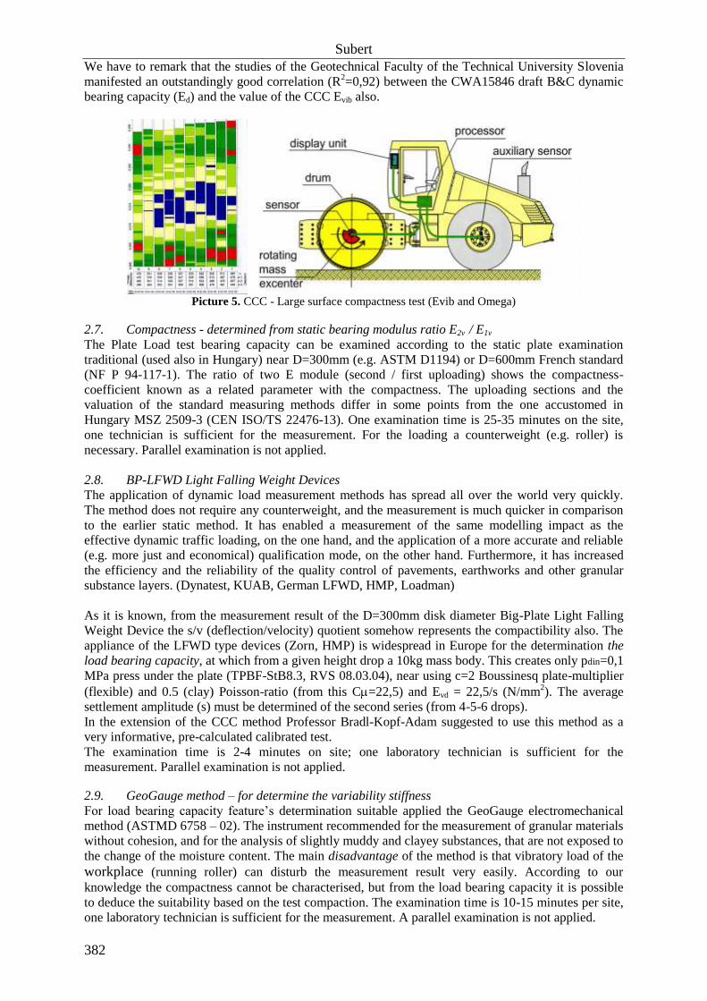
4.3. IDP Correction: Investigation of effective depth - using the Boussinesq-theory
IDP= Impact Depth Multiplier, to considering the layer thickness.
Example: (12)
, in case of different E soil-modulus also. Proctor value depending on layer thickness. No need thickness correction between 22-28cm layer
thickness if we accept accurate range. No need thickness correction
between 20-31cm layer thickness if we accept range of accuracy.
Table Nr. 4 – IDP Correction factor depending on layer thickness
cm
+2% 1,25 20 0,474
+1% 1,14 22 0,431
0% 1,0 25 0,380
-1% 0,89 28 0,340
-2% 0,81 31 0,308
To choose the layer thickness 25,0cm, we select IDP=1,25 which makes ±2% in TrE%, in case of 25cm
layer thickness. Thickness correction need in all, other cases. LTC=Layer Thickness Correction.
LTC is: where
where: h is the layer thickness in cm (13)
Subert
388
Figure Nr. 3. Value depending on layer thickness
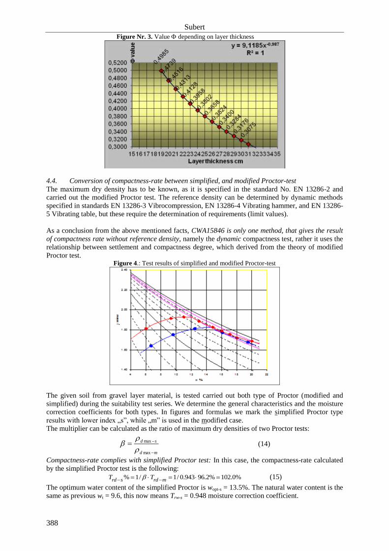
4.4. Conversion of compactness-rate between simplified, and modified Proctor-test
The maximum dry density has to be known, as it is specified in the standard No. EN 13286-2 and
carried out the modified Proctor test. The reference density can be determined by dynamic methods
specified in standards EN 13286-3 Vibrocompression, EN 13286-4 Vibrating hammer, and EN 13286-
5 Vibrating table, but these require the determination of requirements (limit values).
As a conclusion from the above mentioned facts, CWA15846 is only one method, that gives the result
of compactness rate without reference density, namely the dynamic compactness test, rather it uses the
relationship between settlement and compactness degree, which derived from the theory of modified
Proctor test. Figure 4.: Test results of simplified and modified Proctor-test
The given soil from gravel layer material, is tested carried out both type of Proctor (modified and
simplified) during the suitability test series. We determine the general characteristics and the moisture
correction coefficients for both types. In figures and formulas we mark the simplified Proctor type
results with lower index „s”, while „m” is used in the modified case.
The multiplier can be calculated as the ratio of maximum dry densities of two Proctor tests:
md
sd
max
max
(14)
Compactness-rate complies with simplified Proctor test: In this case, the compactness-rate calculated
by the simplified Proctor test is the following:
%0.102%2.96943.0/1/1% mrdsrd TT (15)
The optimum water content of the simplified Proctor is wopt-s = 13.5%. The natural water content is the
same as previous wt = 9.6, this now means Trw-s = 0.948 moisture correction coefficient.

CWA 15846:2008
389
It is well-known, that the simplified Proctor 100% compactness-rate corresponds only 94.3%, in the
scale of the modified proctor test, that is why, if we have larger then 94.3% compactness-rate, then it
exceeds the 100% compactness-rate in terms of simplified Proctor compactness-rate.
We developed the method, which is capable to measure the on site relative compactness-rate by
CWA15846 SP-LFWD. This conversion is always made so, that we chose values of Trd-m%, wopt-m and
convert them to values of Trd-s%, wopt-s, the on site relative TrE-s% compactness is calculated with the
Trw-s moisture correction coefficient.
Figure 5: Conversion calculation between modified and simplified Proctor test results
5. CWA 15846:2008 MODIFICATION DRAFT
We performed in the last period with the measurements and we analyzed them, which need to clarify
the processing, and prepare the final modifications. In particular, the following questions we have
clarified:
- We worked out a regulation of the inspections which must apply on all trial section
- Refine of the value of linear coefficient based on 411pcs Proctor-test series, modification
from 0,365 to 0,380
- Change the tolerance also of value from +/-0.025 to +/-0.020
- Relationship of and the layer thickness (accuracy between 22-28cm+/-1Trd%, and between
20--31cm +/-2Trd%)
- Controlling the test device compactness work and correction opportunity
- Investigation of the effect of high or law bulk density materials on test results using impulse low
- Calculation of the deformation index modification from n=18 to n=17
- Calculation opportunity of dynamic bedding coefficient in case of BC
- Calculation opportunity of CBR% value from dynamic measuring results of BC (Subert)
- Usage of Proctor-curve 6-th degree polynomial regression at Trw
- Conversion opportunity of the dynamic compactness rate from modified Proctor to simplified
one
- Taking into consideration of the depth effect on value, near D163 SP-plate and the modified
Proctor test mould geometry, using Boussinesq-stress and strain distribution (1,25·)
- Comparing the sand-cone test to BC Trd% compactness results from independent measurement
- Analysis the deviation of isotopic- and dynamic test theoretically and on real 26pc trial sections
- Controlling the Proctor-work calculations based on EN 13286-2, regarding the fact that the
mould area four times of rammer area, which is the standard ignore
=1,82/1,93=0,943
1/=1,060
Trd-m=*Trd-s
Trd-s=1/*Trd-m
87,6%
92,9%
97,5%
103,4%

Subert
390
Investigation of the suggested modification shows at Trd90% only -2,5Trd%, but significant in the low
measurement range.
6. RESULTS OF RELATIOSHIP INVESTIGATIONS
6.1. Investigation of E2v – Ed relationship (figure 6.) Based on Hungarian motorways M43, M7, M6 trial sections database, we analyzed the relationships.
We involved 58 trial sections, with all of 763 measured data point.
The investigation shows that the static modulus E2v Ed or E2v=1,0*Ed R2=0,8, so the approximately
the same value like the SP-LFWD’s Ed value. The regression degree is rather good, which means that
CWA15846:2015 may be a useful device in civil engineering practice.
Tests carried out MSZ2509-3 by D=300mm static plate test and BC-1 Dynamic Compactness- and
Bearing Capacity device. The considered tolerance of static plate test is ±5MPa, CWA 15846 Ed value
±2,6MPa.
Figure 6. Relationship between dynamic Ed and static E2v
6.2. Investigation of Isotopic Tr% and Trd% Dynamic compactness-rate relationship
Based on Hungarian motorways M43, M7, M6 trial sections database, we analyzed the relationships.
We involved 32 trial sections, with all of 501 measured data point (figure 7.) The investigation shows that Trd% dynamic Compactness-rate equal to the other, density-ratio
systems. (R2=0.7)
The regression degree is rather good. This means that BC is a useful device in civil engineering
practice. Tests carried out by MC-3 Nuclear density measure device and type BC-1 Dynamic
Compactness- and Bearing Capacity device. The considered tolerance in case of isotopic test is
±3Tr% and CWA 15846:2015 ±1 TrE%.

CWA 15846:2008
391
Figure 7. Relationship between dynamic Compactness-rate and Nuclear Density test
6.3. Sand Cone test Compaction-rate – Dynamic Compaction-rate Comparative test
The investigation shows that Sand Cone test Compaction-rate – Dynamic Compaction-rate
Relationship is very tight. We’ve got the measure data from RAMKHAMHAENG University,
Bangkok Thailand Department of Civil Engineering (Comparison of B&C LFWD and sand filling
method –Ramkhamhaeng University, Thailand Ms.Panarat-Mr Korrakoch Taweesin: Calibration
Certificate B&C, Gabor Enterprise CO Ltd. 2007). One place, 30pcs test results:
Figure 8. Relationship between dynamic Compactness-rate and Sand-Cone test
AASHTO T-191 Sand Cone test comparing to the CWA 15864 dynamic compaction rate (Bangkok-
Thailand) N=30 pcs, carried out on the same place. The deviation of Sand Cone test results is 1.40,
average 95,9%, The deviation of CWA15846 Dynamic Compactness test results is 1.13 (better),
average 95,9% (equal), the gray line is the CWA15846 modification result.
6.4. Investigation of compactibility measure work –Proctor Test
Standard EN 13286-2 point 7.4 has been recommended the modified Proctor test. It is important in EN
13286-2 to highlight the calculation method of the amount of the executed work, which is in our
opinion faulty, as well as the inaccuracies of the indicated data (which is supposed to be suitable for
reference and comparison).

Subert
392
Main point of the error: The area of the rammer differs from the area of the mould; but at the same
time, the calculation supposes the ramming of the whole surface for all drops (instead of one quarter!).
The height of the attachment placed on the mould is regulated only approximately (>50 mm), but
during the calculation of the executed work neither its height, nor its volume is taken into
consideration. In our opinion, at the execution of work projected on the volume not the remaining
roller volume, but the volume of the heightened roller at the time of the compaction (i.e. the
parameters of the roller without removing the attachment) should be taken into consideration.
6.5. The air content and the saturation level belonging to the optimal water content We found the relationship between the air content and the saturation belonging to the optimal water
content for 8 different materials. These relationships are linear. By the processing of the very different
materials and all our 566 pcs Proctor results we fixed the relationship between the air content and the
saturation belonging to the optimal water content, which is the following:
aSr 03.01 (16)
where:
a the air content,
Sr the relevant saturation.
It is typical to have fare lower pores than 12 volume% at the optimal water content (at the highest dry density).
Figure 9. General relationships between the air content and the saturation belonging to wopt
The relationship between air content and saturation belonging to the optimum water
content
y = -0.03x + 1
R2 = 0.92
0.40
0.60
0.80
1.00
0 2 4 6 8 10 12 14 16 18 20 22 24
air content
satu
ration
all samples Grail dolomite Linear (all samples)
Figure 10. Frequency distribution of the air content belonging to the optimal water content
Distribution of air content belonging to the optimum water content
0
10
20
30
40
50
60
70
80
90
0 -
1
1 -
2
2 -
3
3 -
4
4 -
5
5 -
6
6 -
7
7 -
8
8 -
9
9 -
10
10 -
11
11 -
12
12 -
13
13 -
14
14 -
15
15 -
16
16 -
17
17 -
18
18 -
19
19 -
20
20 -
21
21 -
22
22 -
23
23 -
24
24 -
25
The distribution of the available Proctor-test results is lognormal (figure 10). The air content defined
at wopt is very frequently, typically in range 1-6 volume% Using the relationship of the regression-
analysis is the saturation correctly between S=0.88 – 0.94, which accords to the experiences and is
practically determinant for the adaptation of the dynamic compactness measurement.

CWA 15846:2008
393
6.6. Analysis of isotopic and the dynamic compactness rate’s deviation
The traditional way of compactness test is wet density measurement, where the calculated the dry
density value and compared to the laboratory reference dray density, expressed as a percentage. Since
wet density and water content are both measured on site, there are a total of three measuring
accuracies that cumulate in the compactness rate: the measuring accuracy of Proctor-test, the on site
water content and the wet density.
We calculated the measurement accuracy with a reliability of 90%, by the Student’s
distribution used for small-sample statistical analysis (for both density and water content), with the
following formula. The expected value (M), the measurement range and the accuracy are as follows:
n
tS , the expected value M = X ± (17)
positive and negative range from the expected value, the accuracy range of measurement
S standard deviation of the measurement fundamental set
n 3, isotopic measurement is averaged from partial results measured from three different directions, in
accordance with regulation ÚT 2-3.103 but n=2 and = (n-1) = 1 degree, Student 6.314 at ÚT2-2.124
t 2.92 at a Student’s coefficient = (n-1) = 2 degree of freedom and = 0.1 significance level
X average value of measured test results
6.7. Comparison of standard deviation, range and test accuracy
Results on the measurement accuracy, that we’ve got from the range, calculated on the basis of the
standard deviations, on the M7 motorway we did a total of 19 pcs trial-sections by the method
described above, are presented in Table 5. The two different types of compactness measurement were
analysed the same way during the analysis of the year 2008 trial-sections, which aimed at the
determination of the standard deviation of the isotopic test, as well as of the standard deviation, the
range and the accuracy of the dynamic compactness rate measured by the CWA15846. We went on by
using different materials for test compactions on the motorway M6 between Dunaújváros and Paks
(section 76+200 – 109+700 km). So far a total of seven test trial sections have been carried out, the
results thereof are summarized in Table 6.
Table Nr. 5. Results of compactness measurements at 19pcs trial-section of M7 highway
19 trial sections M7
isotopic test N=21pcs/hole
dynamic test N=9pcs/1m2
ACCURACY [compactness rate, ± %]
without effect of dmax with accuracy of
dmax
Type of compactness measurement
isotopic dynamic isotopic dynamic
Expected value range (p=90%, Student ) 5,3% 1,2% 6,5% 2,0%
The average accuracy of the isotopic measurements at the M7 highway (half of the range determined
by standard deviation) was ±6,5Tr%. In case of the dynamic compactness measurement it was much
lower: ±2,0Trd%. The average accuracy of isotopic measurements at the M6 highway (under
construction) was ±8,8Tr% from a sample (which contained also blast furnace slag aggregate with
inhomogeneous density), while in case of the dynamic compactness measurement it was much more
favourable ±2.5Trd%.
It can be stated on the basis of the processing of available data that the CWA15846 dynamic
compactness rate seems to be more accurate and to have a smaller range than the isotopic method of
measurement.
Table Nr. 6. Results of compactness measurements at the trial-sections of M6 motorway
7 trial sections M6
isotopic test N=21pcs/hole
dynamic test N=9pcs/1m2
+/- ACCURACY [compactness rate %]
without the effect of dmax with accuracy of dmax
Type of compactness measurement
isotopic dynamic isotopic dynamic
Expected value range
(p=90%Student ) 7.7% 1.3% 8.8% 2.5%

Subert
394
Literature
CWA15846:2008 Measuring method for Dynamic Compactness & Bearing Capacity with SP-LFWD
(Small - plate Light Falling Weight Deflectometer)
EN 13286-2 “Unbound and hydraulically bound mixtures 2.Test methods for the determination of the
laboratory reference density and water content. Proctor compaction”
CEN ISO/TS 22476-13 Geotechnical investigation and testing – Field testing,
Part 13 Plate Loading Test
MSZ 2509-3:1989 Útpályaszerkezetek teherbíró képességének vizsgálata. Tárcsás vizsgálat.
MSZ 15320 Földművek tömörségének meghatározása radioizotópos módszerrel
ÚT 2-2.124 Dinamikus tömörség és teherbírás mérés kistárcsás könnyűejtősúlyos berendezéssel.
ÚT 2-3.103 Radiometriás tömörségmérés. Földművek, kötőanyag nélküli alaprétegek hidraulikus
kötőanyagú útalapok térfogatsűrűségének és víztartalmának meghatározása
Dr Kézdy Á. Talajmechanika I. 1972. Tankönyvkiadó p.74-94, 388-403.
Dr Kézdy Á. Talajmechanika II. 1975. Tankönyvkiadó p.153-163, 175-196.
D.Adam, F.Kopf (2004) Operational devices for compaction optimization and quality control
(Continuous Compaction Control & Light Falling Weight Device). Proceedings of the International
Seminar on Geotechnics in Pavement and Railway Design and Construction, Rotterdam.
Brandl, H. and Adam, D. (2004) Basics and Application of the Dynamic Load Plate Test in Form of the
Light Falling Weight Device. A.W. Skempton Memorial Conference. Proc. of Imperial College,
London.
Anna Petkovsek (2008) Report on usage of Andreas dynamic load bearing capacit ity of Ljubljana
Katedra za mehaniko tal z laboratorijem. Univerza v Ljubljani Faculteta za gradbenistvo in
geodezijo. Report p.:10
Ms. Panarat (2007): Comparison of B&C LFWD and sand filling method Ramkhamhaeng University,
Thailand. Calibration Report
Dr Boromisza Tibor (2005) Megjegyzések Subert István: A dinamikus tömörség- és teherbírás mérés
újabb paraméterei és modulusok átszámíthatósági kérdései c.cikkéhez. Közúti és mélyépítési Szemle
55.évf 2.szám. p.:35-36.
Subert (2006) Method for measuring Compactness-rate with New Dynamic LFWD. XIIIth Danube-
European Conference on Geotechnical Engineering Ljubljana, Slovenia 2006, V.2. p:125-130.
Subert (2006) CWA15846-WS33 Measuring method for Dynamic Compactness & Bearing Capacity
with SP-LFWD (Small - plate Light Falling Weight Deflectometer) Draft. p.26
Subert (2014) Isotope-free Compaction-rate & Bearing Capacity Measure on Lime Stabilization – Self
control. Article and Presentation. Carmeuse Conference. 09 sept 2014 Vecsés, Hungary p.:10
Subert (2014) Izotópmentes tömörség- és teherbírás mérése – Önellenőrzés. 2014EPB Konferencia
Gyergyószentmiklós, Románia, p:14, á 6.
Subert (2012) Önellenőrzés a földműépítésben. Innotéka június p:35
Subert (2010) Földmű süllyedések elkerülése garanciával - A B&C dinamikus tömörség- és
teherbírásmérő berendezés egy új lehetőség. Gazdasági tükörkép magazin, nov p:57
Subert-T.Q.Phong (2009) Az izotópos és a dinamikus tömörség szórásának vizsgálata. Transport
Science Bulletin / Közlekedéstudományi szemle apr p:23-27.
Subert (2009) A tömörségi fok átszámítása az egyszerűsített és módosított Proctor vizsgálatok között”.
Transport Science Bulletin / Közlekedéstudományi szemle jun-2009 p:23-28.
Subert-T.Q.Phong (2007) Proctor-vizsgálat új értelmezési lehetőségei. Revue of Roads and Civil
Engineering / Közúti és mélyépítési szemle, ISSN 1419-0702 , 57. évf. 12. sz. p.7-12.
Fáy M., Király Á., Subert I. (2006) Közúti forgalom igénybevételének modellezése új, dinamikus
tömörség- és teherbírásméréssel. Urban Transport / Városi közlekedés, 46. évf. 5. sz. 274-278. old
Fáy M., Király Á., Subert I. (2006) Egy földmű-tömörségi anomália feltárása és megoldása. Revue of
Roads and Civil Engineering /Közúti és mélyépítési szemle, 56. évf. 9-10. p.: 19-23.
Subert I.(2005): „A dinamikus tömörség- és teherbírásmérés újabb paraméterei és a modulusok
átszámíthatósági kérdései” Közúti és mélyépítési szemle 55. évf. 1. sz. p.28-32.
Subert I. (2004) B&C dinamikus tömörségmérés Mélyépítés 2004 október–december p. 38–39
Subert I. (2004) Új, környezetkímélő, gazdaságos mérőeszközök a közlekedésépítésben /New,
environmental-friendly, economical measuring instruments in traffic building / Geotechnika
Konferencia Ráckeve október 26–27.
Subert (2003) Dinamikus tömörség- és teherbírás-mérés könnyű-ejtősúlyos berendezéssel. Közúti és
mélyépítési szemle 53. évf. N°5. p: 184-191.