DX340LCA-K - Doosan
15
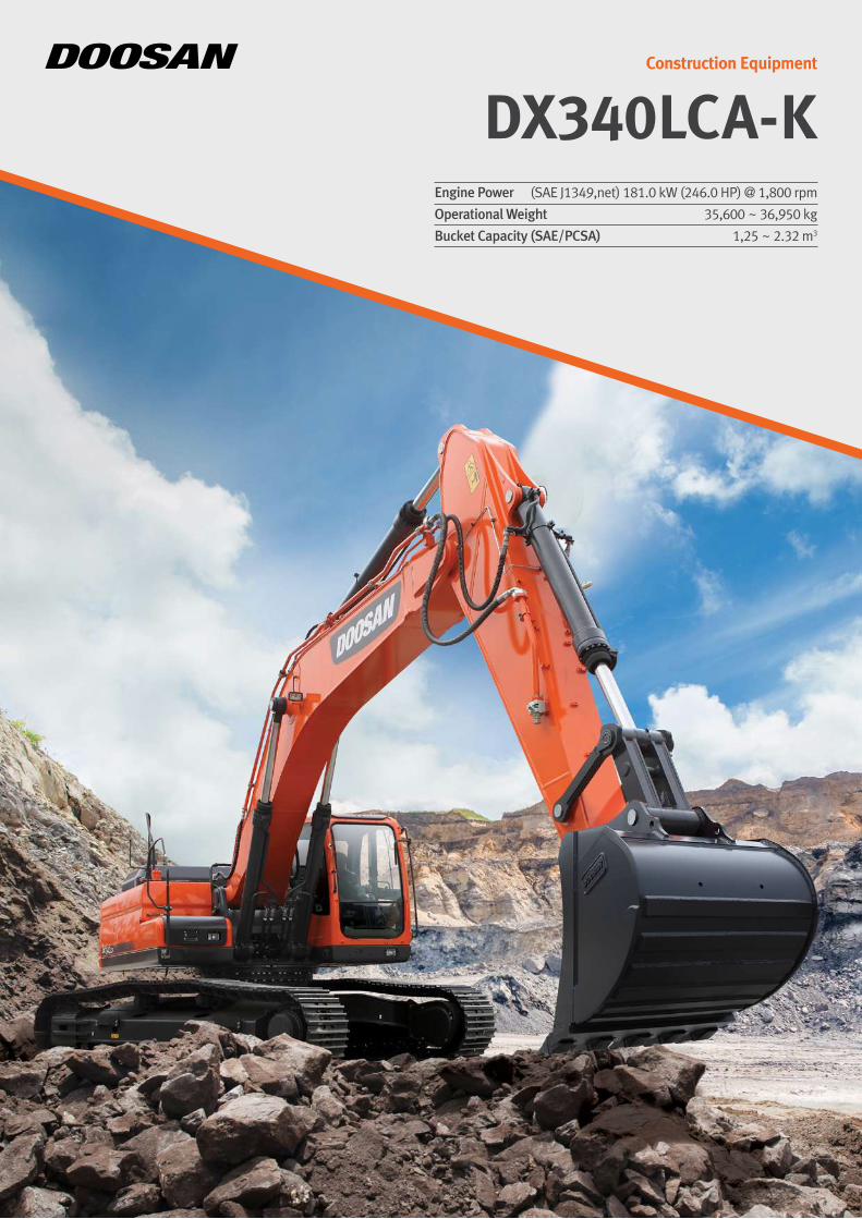
DX340LCA-K Construction Equipment Engine Power Operational Weight Bucket Capacity (SAE/PCSA) (SAE J1349,net) 181.0 kW (246.0 HP) @ 1,800 rpm 35,600 ~ 36,950 kg 1,25 ~ 2.32 m 3
-
Upload
khangminh22 -
Category
Documents
-
view
3 -
download
0
Transcript of DX340LCA-K - Doosan
DX340LCA-KConstruction Equipment
Engine Power
Operational Weight
Bucket Capacity (SAE/PCSA)
(SAE J1349,net) 181.0 kW (246.0 HP) @ 1,800 rpm
35,600 ~ 36,950 kg
1,25 ~ 2.32 m3

The brand new DX340LCA-K is equipped with Doosan’s newly developed DX12 engine, which is even more durable than before and will allow you to operate the machine with perfect stability even with the heaviest workloads.The high swing speed and EPOS-driven hydraulic system will also play a crucial part in further boosting your productivity. The use of high-performance materials combined with new methods of structural stress analysis have increased component lifespan and greatly enhanced reliability. With various new options designed for your comfort and safety, including a 7-inch monitor and centralized fuel filtration, this renewed machine will be your most trusted business partner always.
OPTIMAL DURABILITY AND TOTAL RELIABILITY WITH NEW ENGINE
* The above image may differ from the actual product.
1
2
4
3
6 7
5
9 8
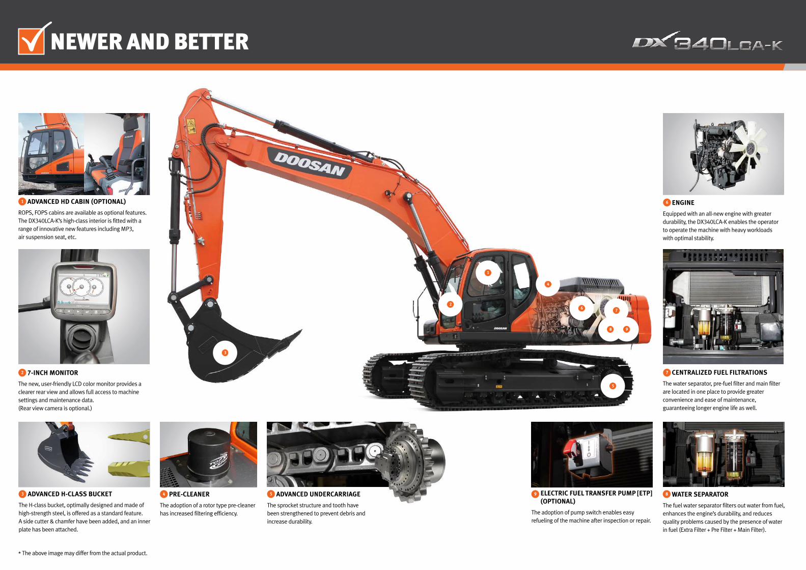
NEWER AND BETTER
7-INCH MONITOR
The new, user-friendly LCD color monitor provides a clearer rear view and allows full access to machine settings and maintenance data.(Rear view camera is optional.)
2
ADVANCED HD CABIN (OPTIONAL)
ROPS, FOPS cabins are available as optional features.The DX340LCA-K’s high-class interior is fitted with a range of innovative new features including MP3, air suspension seat, etc.
1
PRE-CLEANER
The adoption of a rotor type pre-cleaner has increased filtering efficiency.
4 ADVANCED H-CLASS BUCKET
The H-class bucket, optimally designed and made of high-strength steel, is offered as a standard feature.A side cutter & chamfer have been added, and an inner plate has been attached.
3 ELECTRIC FUEL TRANSFER PUMP [ETP] (OPTIONAL)
The adoption of pump switch enables easy refueling of the machine after inspection or repair.
9 WATER SEPARATOR
The fuel water separator filters out water from fuel, enhances the engine’s durability, and reduces quality problems caused by the presence of water in fuel (Extra Filter + Pre Filter + Main Filter).
8
* The above image may differ from the actual product.
CENTRALIZED FUEL FILTRATIONS
The water separator, pre-fuel filter and main filter are located in one place to provide greater convenience and ease of maintenance, guaranteeing longer engine life as well.
7
ENGINE
Equipped with an all-new engine with greater durability, the DX340LCA-K enables the operator to operate the machine with heavy workloads with optimal stability.
6
ADVANCED UNDERCARRIAGE
The sprocket structure and tooth have been strengthened to prevent debris and increase durability.
5

INDUSTRY-LEADING PERFORMANCE AND PRODUCTIVITY
Best-in-Class Productivity with Unparalleled Lifting Capacity and Machine Stability
The DX12 is a whole new mechanical engine built on Doosan’s continuously evolving engine technology.
Its quality and durability have been significantly improved against the previous engine, delivering greater maximum engine output through various system improvements, and thereby reducing the engine’s workload during machine operation. Doosan has also improved the engine’s components to eliminate any possibility of failure in the field.The improved design and materials of key components such as the engine block, cylinder head and piston has extended the engine’s lifespan to a significant extent.
The new engine represents a breakthrough to even greater operational comfort, safety and productivity.
EXCAVATOR CONTROL
Excavator control improved by the New EPOSTM systemAs the brain of the hydraulic excavator, the EPOSTM (Electronic Power Optimizing system) has been improved and perfectly synchronized with the newly adopted CAN (Controller Area Network) communication link.
DOOSAN ENGINE-DX12
How the DX340LCA-K performs has a direct impact on productivity. The combination of a newly improved engine and a redesigned EPOS-driven hydraulic system with an attractive cost-performance ratio is unrivalled by any other hydraulic excavators in its class.
* The above image may differ from the actual product.
EPOSTM system
LIFTING CAPACITY
Incomparable Lifting CapacityThe counterweight and undercarriage are built on the solid structure of this huge and powerful machine to create the best lifting capacity in its class.
Lifting Capacity
kg
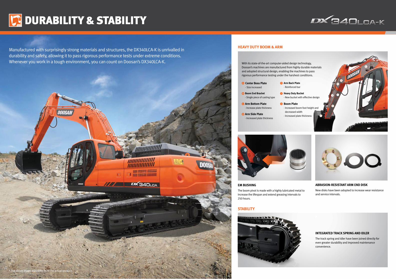
DURABILITY & STABILITY
EM BUSHING
The boom pivot is made with a highly lubricated metal to increase the lifespan and extend greasing intervals to 250 hours.
ABRASION-RESISTANT ARM END DISK
New disks have been adopted to increase wear resistance and service intervals.
HEAVY DUTY BOOM & ARM
STABILITY
INTEGRATED TRACK SPRING AND IDLER
The track spring and idler have been joined directly for even greater durability and improved maintenance convenience.
Center Boss Plate- Size increased
Boom End Bracket
- Single piece of casting type
Arm Bottom Plate- Increase plate thickness
Arm Side Plate- Increased plate thickness
Arm Back Plate
- Reinforced bar
Heavy Duty Bucket
- New bucket with effective design
A E
B F
C G
D
With its state-of-the-art computer-aided design technology, Doosan’s machines are manufactured from highly durable materials and adopted structural design, enabling the machines to pass rigorous performance testing under the harshest conditions.
Manufactured with surprisingly strong materials and structures, the DX340LCA-K is unrivalled in durability and safety, allowing it to pass rigorous performance tests under extreme conditions. Whenever you work in a tough environment, you can count on Doosan’s DX340LCA-K.
* The above image may differ from the actual product.
B
G
A
C D
E
F
Boom Plate- Increased boom foot height and
decreased width
- Increased plate thickness
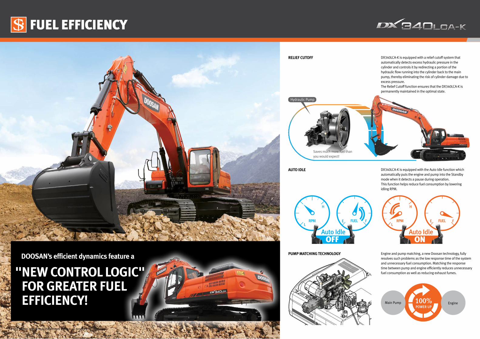
Engine and pump matching, a new Doosan technology, fully resolves such problems as the low response time of the system and unnecessary fuel consumption. Matching the response time between pump and engine efficiently reduces unnecessary fuel consumption as well as reducing exhaust fumes.
DX340LCA-K is equipped with a relief cutoff system that automatically detects excess hydraulic pressure in the cylinder and controls it by redirecting a portion of the hydraulic flow running into the cylinder back to the main pump, thereby eliminating the risk of cylinder damage due to excess pressure.The Relief Cutoff function ensures that the DX340LCA-K is permanently maintained in the optimal state.
PUMP MATCHING TECHNOLOGY
RELIEF CUTOFF
100%POWER UP
Main Pump Engine
DOOSAN’s efficient dynamics feature a
" NEW CONTROL LOGIC" FOR GREATER FUEL EFFICIENCY!
Hydraulic Pump
Saves much more fuel than you would expect!
* The above image may differ from the actual product.
FUEL EFFICIENCY
AUTO IDLE DX340LCA-K is equipped with the Auto Idle function which automatically puts the engine and pump into the Standby mode when it detects a pause during operation. This function helps reduce fuel consumption by lowering idling RPM.
ONAuto Idle
RPM FUELE F
OFFAuto Idle
RPM FUELEL L
H H
F

OPERATOR COMFORT
More space, wider visibility, better air conditioning, and a very comfortable seat - all these elements allow the operator to work safely and comfortably for long hours in the best possible conditions.
CONTROL PANEL
SIMPLE OPERATION
Levelling operations, the movement of lifted loads and tricky maneuvers are all controlled easily and precisely with the control levers. The buttons integrated into the levers can also be used to operate additional equipment such as grabs, crushers and grapples and to activate the power boost function.
3 work modes to suit all your work requirements- 1-way mode- 2-way mode- Digging mode
3 power modes for maximum efficiency- Power mode- Standard mode- Economy mode
MONITOR
AIR CONDITIONING WITH CLIMATE CONTROL
The high-performance air conditioning adjusts and electronically controls the flow of air according to the work conditions. The choice of five operating modes will keep even the most demanding operator happy and satisfied.
1
1
Comfortable 2-stage sliding seat
Control stand (Telescopic Function)
2
3
SLIDING SEAT 2
REAR VIEW CAMERA (OPTIONAL) 3
A
D E F
B C
Operation history
Contrast control
Filter/oil information
Flow rate control
Anti-theft protection
Standard screen A
B
C
D
E
F
* The above image may differ from the actual product.
4
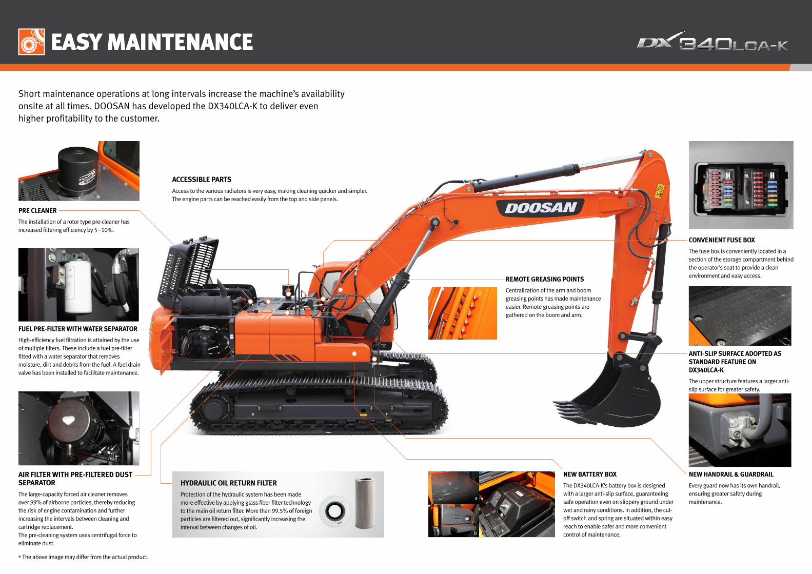
EASY MAINTENANCE
Short maintenance operations at long intervals increase the machine’s availability onsite at all times. DOOSAN has developed the DX340LCA-K to deliver even higher profitability to the customer.
FUEL PRE-FILTER WITH WATER SEPARATOR
High-efficiency fuel filtration is attained by the use of multiple filters. These include a fuel pre-filter fitted with a water separator that removes moisture, dirt and debris from the fuel. A fuel drain valve has been installed to facilitate maintenance.
NEW HANDRAIL & GUARDRAIL
Every guard now has its own handrail, ensuring greater safety during maintenance.
ANTI-SLIP SURFACE ADOPTED AS STANDARD FEATURE ON DX340LCA-K
The upper structure features a larger anti-slip surface for greater safety.
AIR FILTER WITH PRE-FILTERED DUST SEPARATOR
The large-capacity forced air cleaner removes over 99% of airborne particles, thereby reducing the risk of engine contamination and further increasing the intervals between cleaning and cartridge replacement.The pre-cleaning system uses centrifugal force to eliminate dust.
ACCESSIBLE PARTS
Access to the various radiators is very easy, making cleaning quicker and simpler.The engine parts can be reached easily from the top and side panels.
PRE CLEANER
The installation of a rotor type pre-cleaner has increased filtering efficiency by 5~10%.
CONVENIENT FUSE BOX
The fuse box is conveniently located in a section of the storage compartment behind the operator’s seat to provide a clean environment and easy access.REMOTE GREASING POINTS
Centralization of the arm and boom greasing points has made maintenance easier. Remote greasing points are gathered on the boom and arm.
HYDRAULIC OIL RETURN FILTER
Protection of the hydraulic system has been made more effective by applying glass fiber filter technology to the main oil return filter. More than 99.5% of foreign particles are filtered out, significantly increasing the interval between changes of oil.
NEW BATTERY BOX
The DX340LCA-K’s battery box is designed with a larger anti-slip surface, guaranteeing safe operation even on slippery ground under wet and rainy conditions. In addition, the cut-off switch and spring are situated within easy reach to enable safer and more convenient control of maintenance.b
a
c
* The above image may differ from the actual product.
TELEMATICS SERVICE (OPTIONAL) GLOBAL PARTS NETWORK
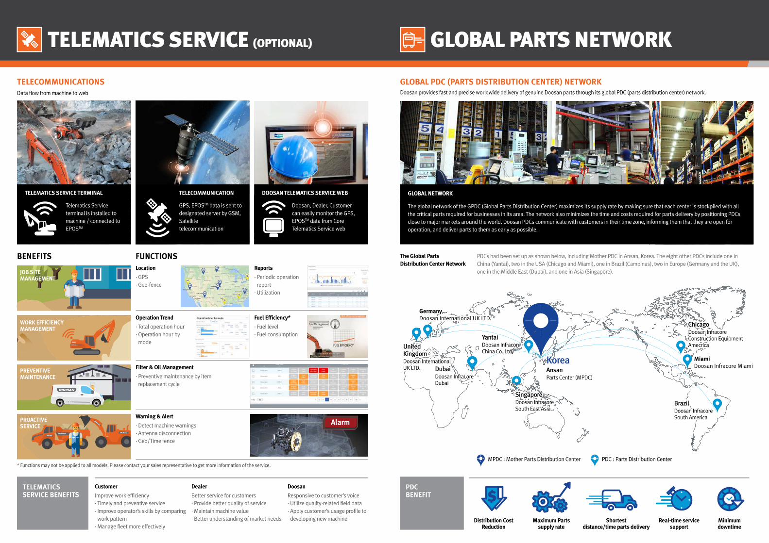
TELECOMMUNICATIONSData flow from machine to web
GLOBAL PDC (PARTS DISTRIBUTION CENTER) NETWORKDoosan provides fast and precise worldwide delivery of genuine Doosan parts through its global PDC (parts distribution center) network.
Telematics Service terminal is installed to machine / connected to EPOSTM
GPS, EPOSTM data is sent to designated server by GSM, Satellite telecommunication
Doosan, Dealer, Customer can easily monitor the GPS, EPOSTM data from Core Telematics Service web
DOOSAN TELEMATICS SERVICE WEBTELECOMMUNICATIONTELEMATICS SERVICE TERMINAL
The Global Parts Distribution Center Network
Distribution Cost Reduction
Maximum Parts supply rate
Shortest distance/time parts delivery
Real-time service support
Minimum downtime
PDCBENEFIT
GLOBAL NETWORK
The global network of the GPDC (Global Parts Distribution Center) maximizes its supply rate by making sure that each center is stockpiled with all the critical parts required for businesses in its area. The network also minimizes the time and costs required for parts delivery by positioning PDCs close to major markets around the world. Doosan PDCs communicate with customers in their time zone, informing them that they are open for operation, and deliver parts to them as early as possible.
PDC : Parts Distribution CenterMPDC : Mother Parts Distribution Center
TELEMATICS SERVICE BENEFITS
FUNCTIONSLocation
· GPS· Geo-fence
Reports
· Periodic operation report
· Utilization
Filter & Oil Management
· Preventive maintenance by item replacement cycle
Warning & Alert
· Detect machine warnings· Antenna disconnection· Geo/Time fence
* Functions may not be applied to all models. Please contact your sales representative to get more information of the service.
Operation Trend
· Total operation hour· Operation hour by mode
Alarm
BENEFITS
JOB SITEMANAGEMENT
WORK EFFICIENCYMANAGEMENT
PREVENTIVEMAINTENANCE
PROACTIVESERVICE
Dealer
Better service for customers· Provide better quality of service· Maintain machine value· Better understanding of market needs
Doosan
Responsive to customer’s voice· Utilize quality-related field data· Apply customer’s usage profile to developing new machine
Customer
Improve work efficiency· Timely and preventive service· Improve operator’s skills by comparing work pattern
· Manage fleet more effectively
PDCs had been set up as shown below, including Mother PDC in Ansan, Korea. The eight other PDCs include one in China (Yantai), two in the USA (Chicago and Miami), one in Brazil (Campinas), two in Europe (Germany and the UK), one in the Middle East (Dubai), and one in Asia (Singapore).
Fuel Efficiency*
· Fuel level· Fuel consumption
Operation hour by mode
GermanyDoosan International UK LTD.GermanyDoosan International UK LTD.
MiamiDoosan Infracore MiamiMiamiDoosan Infracore Miami
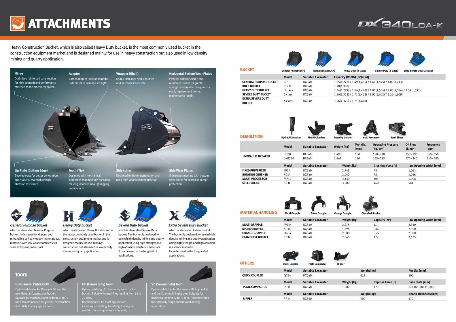
ATTACHMENTS
General Purpose bucket Heavy Duty bucket Severe Duty bucketwhich is also called General Purpose bucket, is designed for digging and re-handling soft to medium materials e.g. materials with low wear characteristics such as top-soil, loam, coal.
which is also called Heavy Duty bucket, is the most commonly used bucket in the construction equipment market and is designed mainly for use in heavy construction but also used in low density mining and quarry application.
which is also called Severe Duty bucket. The bucket is designed for use in high density mining and quarry application using high strength and high abrasion resistance materials. It can be used in the toughest of applications.
which is also called X class bucket. The bucket is designed for use in high density mining and quarry application using high strength and high abrasion resistance materials.It can be used in the toughest of applications.
Extra Severe Duty Bucket
Heavy Construction Bucket, which is also called Heavy Duty bucket, is the most commonly used bucket in the construction equipment market and is designed mainly for use in heavy construction but also used in low density mining and quarry application.
Optimized design for Doosan’s GP and the new General Construction bucket. Suitable for machines ranging from 14 to 70 tons. Recommended for general construction and utility loading applications.
GD (General Duty) Tooth
Optimized design for the Heavy Construction bucket. Suitable for machines ranging from 14 to 70 tons.Recommended for most applicationsincluding excavating, trenching, loading and medium density quarries and mining.
HD (Heavy Duty) Tooth
Optimized design for the Severe Mining bucket and the Xtreme Mining bucket. Suitable for machines ranging 22 to 70 tons. Recommended for extremely tough quarries and mining application.
SD (Severe Duty) Tooth
Side Wear Plates
Side plates meet up with bottom wear plates for seamless corner protection.
Horizontal Bottom Wear Plates
Protects bottom section and reinforces bucket for greater strength and rigidity. Designed for easily replacement during maintenance repair.
Wrapper (Shell)
Shape increases heel clearance and decreases wear rate.
TOOTH
Hinge
Optimized reinforced construction for high strength and performance matched to the machine‘s power.
Side cutter
Designed for better penetration and used high wear resistant material.
Adapter
Corner adapter Positioned under Side cutter to increase strength.
Lip Plate (Cutting Edge)
Beveled edge for better penetration and 500BHN material for high abrasion resistance.
Tooth (Tip)
Designed with mechanical properties that maintain hardness for long wear life in tough digging applications.
Model Suitable Excavator Capacity (Width) [m3(mm)]
GENERAL PURPOSE BUCKET GP DX340 1.25(1,273) / 1.49(1,455) / 1.61(1,545) / 1.83(1,713)ROCK BUCKET ROCK DX340 1.28(1,382)HEAVY DUTY BUCKET H class DX340 1.44(1,272) / 1.66(1,428) / 1.81(1,534) / 2.03(1,684) / 2.32(1,892)SEVERE DUTY BUCKET S class DX340 1.56(1,352) / 1.71(1,452) / 1.92(1,602) / 2.22(1,809)EXTRA SEVERE DUTY
BUCKETX class DX340 1.56(1,370) / 1.71(1,470)
BUCKET General Purpose (GP) Heavy Duty (H class)Rock Bucket (ROCK) Severe Duty (S class) Extra Severe Duty (X class)
Hydraulic Breaker Steel Shear
Model Suitable Excavator Weight [kg] Crushing Force [t] Jaw Opening Width [mm]
FIXED PULVERIZER FP34 DX340 2,745 78 1,061ROTATING CRUSHER RC34 DX340 2,950 78 1,056MULTI-PROCESSOR MP34 DX340 3,130 103 1,008STEEL SHEAR SS34 DX340 3,200 460 581
Model Suitable Excavator Weight [kg]Tool dia. [mm]
Operating Pressure[kg/cm2]
Oil Flow [l/min]
Frequency [bpm]
HYDRAULIC BREAKERHB30 DX340 2,498 150 180~220 150~190 350~650DXB230 DX340 2,465 150 165~185 170~240 310~680
DEMOLITION Fixed Pulverizer Rotating Crusher Multi Processor
Clamshell BucketStone Grapple Orange Grapple
Model Suitable Excavator Weight [kg] Capacity [m3] Jaw Opening Width [mm]
MULTI GRAPPLE MG34 DX340 2,275 1.1 2,350STONE GRAPPLE SG34 DX340 1,695 0.62 2,300ORANGE GRAPPLE OG34 DX340 2,000 0.72 2,300CLAMSHELL BUCKET CB34 DX340 2,040 1.5 2,135
MATERIAL HANDLING Multi-Grapple
Quick Coupler Ripper
Model Suitable Excavator Weight [kg] Pin dia. [mm]
QUICK COUPLER QC34 DX340 629 100
Model Suitable Excavator Weight [kg] Shank Thickness [mm]
RIPPER RP34 DX340 900 130
Model Suitable Excavator Weight [kg] Impulse Force [t] Base plate [mm]
PLATE COMPACTOR PC34 DX340 1,502 17.3 1,000x1,300 (1.3m2)
OTHERS Plate Compactor

TECHNICAL SPECIFICATIONS
The brain of the excavator is the EPOSTM (Electronic Power OptimizingSystem). It allows the efficiency of the hydraulic system to beoptimised for all working conditions and minimises fuel consumption.The EPOSTM is connected to the engine’s electronic control unit (ECU)via a data transfer link to harmonise the operation of the engine andhydraulics.
• The hydraulic system enables independent or combined operations • Two travel speeds offer either increased torque or high speed • Cross-sensing pump system for fuel savings • Auto deceleration system • Three operating modes, three power modes • Button control of flow in auxiliary hydraulic circuits • Computer-aided pump flow control
Main pumps Parallel, Bentaxis, PistonMax. flow : 2 x 274 l/min
Pilot pump GearMax. flow : 22.5 l/minRelief valve pressure : 40 kgf/cm2
Maximum system pressureMain Relief Valve Pressure : 330/350 kgf/cm2
Travel Crossover Relief Valve Pressure : 335 kgf/cm2
Swing Crossover Relief Valve Pressure : 275 kgf/cm2
ENGINEModelDOOSAN DX12TIWater-Cooled, Turbo-charged, Mechanical Governor
Number of cylinders 6
Rated horse power 195.0 kW (262.0 HP) @ 1,800 rpm (SAE J1995, Gross)181.0 kW (246.0 HP) @ 1,800 rpm (SAE J1349, net)
Max torque 114 kgf.m @ 1,400 rpm
Idle (low - high) 1,000 [+/-25] - 2,050 [+50] rpm
Piston displacement 11.1 l
Bore x stroke∅ 123 mm x 155 mm
Starter24 V / 7.0 kW
Batteries2 x 12 V / 150 Ah
Air filterDouble element
HYDRAULIC SYSTEM REFILL CAPACITIESFuel tank550 l
Cooling system (radiator capacity) 38.8 l
Engine oil 31 l
Swing drive 6 l
Final drive 2 x 5.5 l
Hydraulic tank324 l
UNDERCARRIAGEVery robust construction of all chassis elements. All welded structuresdesigned to limit stresses. High-quality, durable materials. Lateralchassis welded and rigidly attached to undercarriage. Track rollerslubricated for life. Idlers and sprockets fitted with floating seals. Trackshoes made of induction-hardened alloy with triple grouser. Heat-treated connecting pins. Hydraulic track adjuster with shock-absorbingtension mechanism.
Number of rollers and track shoes per side Upper rollers : 2Lower rollers : 9Track shoes : 48
Each track is driven by an independent, high-torque axial piston motor through a planetary reduction gearbox. Two levers or foot pedals guarantee smooth travel with counter-rotation on demand.
Travel speed (High/low) 4.7/3.1 km/h
Maximum traction force 27.0/15.1 ton
Gradeability 70 %
DRIVE
HYDRAULIC CYLINDERSPiston rods and cylinder bodies of high-strength steel.Shock-absorbing mechanism fitted in all cylinders for shock-free operation and extended piston life.
Cylinders Quantity Bore x Rod diameter x stroke Boom 2 150 x 100 x 1,430Arm 1 170 x 120 x 1,805Bucket 1 170 x 100 x 1,300
SWING MECHANISM • High-torque, axial piston motor with planetary reduction gear bathed in oil • Swing circle is a single-row, shear type ball bearing with induction-hardened
internal gear • Internal gear and pinion immersed in lubricant
Max. Swing speed - 8.9 rpm Max. Swing torque - 11,660 kgf.m
Model Arm Length (mm) Weight (kg) Digging force (ton)
DX340LCA-K
Heavy Duty 3,200 1,338 [SAE] 16.9/17.8, [ISO] 17.6/18.5
Short 2,600 1,146 [SAE] 20.8/21.8, [ISO] 21.7/22.8
Long 3,950 1,462 [SAE] 14.4/15.1, [ISO] 14.8/15.6
ARM DIGGING FORCES
BUCKET DIGGING FORCES
Bucket typeCapacity (m3) Width (mm) Digging force
(NOM./Press.up, ton)SAE/PCSA CECE With cutter W/O Cutter
GP
1.25 1.10 1,228 1,278
[SAE] 21.4 / 22.5
[ISO] 22.7 / 23.9
1.49 1.30 1,410 1,460
1.61 1.41 1,500 1,550
1.83 1.60 1,668 1,718
ROCK 1.28 1.12 1,382 -
H Class
1.44 1.30 1,238 1,272
[SAE] 22.0 / 23.1
[ISO] 24.4 / 25.6
1.66 1.49 1,394 1,428
1.81 1.61 1,500 1,534
2.03 1.80 1,650 1,684
2.32 2.05 1,858 1,892
S Class
1.56 1.40 1,352 1,352
[SAE] 21.4 / 22.5
[ISO] 24.4 / 25.6
1.71 1.53 1,452 1,452
1.92 1.71 1,602 1,602
2.22 1.96 1,809 1,809
X Class1.56 1.40 1,352 1,370
1.71 1.53 1,452 1,470
Based on ISO 10567 and SAE J296, arm length without quick change clampA : Suitable for materials with density of 2,100 kg/m3 (3,500 lb/yd3) or lessB : Suitable for materials with density of 1,800 kg/m3 (3,000 lb/yd3) or lessC : Suitable for materials with density of 1,500 kg/m3 (2,500 lb/yd3) or lessD : Suitable for materials with density of 1,200 kg/m3 (2,000 lb/yd3) or less- : Not recommended
BUCKET
Track STD track Narrow trackC/W (ton) 7.1 7.1Shoe (mm) 600 600
Buckettype
Capacity (m3) Width (mm)Radius (mm)
Weight (kg)
6.5 m Boom 6.2 m Boom 6.5 m Boom 6.2 m Boom
SAE/PCSA CECE With cutter
W/O cutter
2.6 m Arm
3.2 m Arm
3.95 m Arm
2.6 mArm
2.6 m Arm
3.2 m Arm
3.95 m Arm
2.6 mArm
GP
1.25 1.1 1,228 1,278 1,704 1,249 A A A A A A B A
1.49 1.3 1,410 1,460 1,704 1,344 A A B A A B C A
1.61 1.41 1,500 1,550 1,704 1,392 A B B A B C D A
1.83 1.6 1,668 1,718 1,704 1,522 B C C A C D - B
ROCK 1.28 1.12 1,382 - 1,700 1,427 A A B A A B C A
H Class
1.44 1.3 1,238 1,272 1,652 1,389 A A B A A B C A
1.66 1.49 1,394 1,428 1,652 1,489 A B B A B C D B
1.81 1.61 1,500 1,534 1,652 1,588 B C C A C D - B
2.03 1.8 1,650 1,684 1,652 1,684 C D D B D - - C
2.32 2.05 1,858 1,892 1,652 1,817 D D D C - - - D
S Class
1.56 1.4 1,352 1,352 1,700 1,893 A C C A C D - B
1.71 1.53 1,452 1,452 1,700 1,973 B C C A C D - C
1.92 1.71 1,602 1,602 1,700 2,094 C D D B D - - D
2.22 1.96 1,809 1,809 1,700 2,309 D - - D - - - -
X Class1.56 1.4 1,352 1,370 1,700 2,050 B C C A C D - B
1.71 1.53 1,452 1,470 1,700 2,136 C D D B D - - C
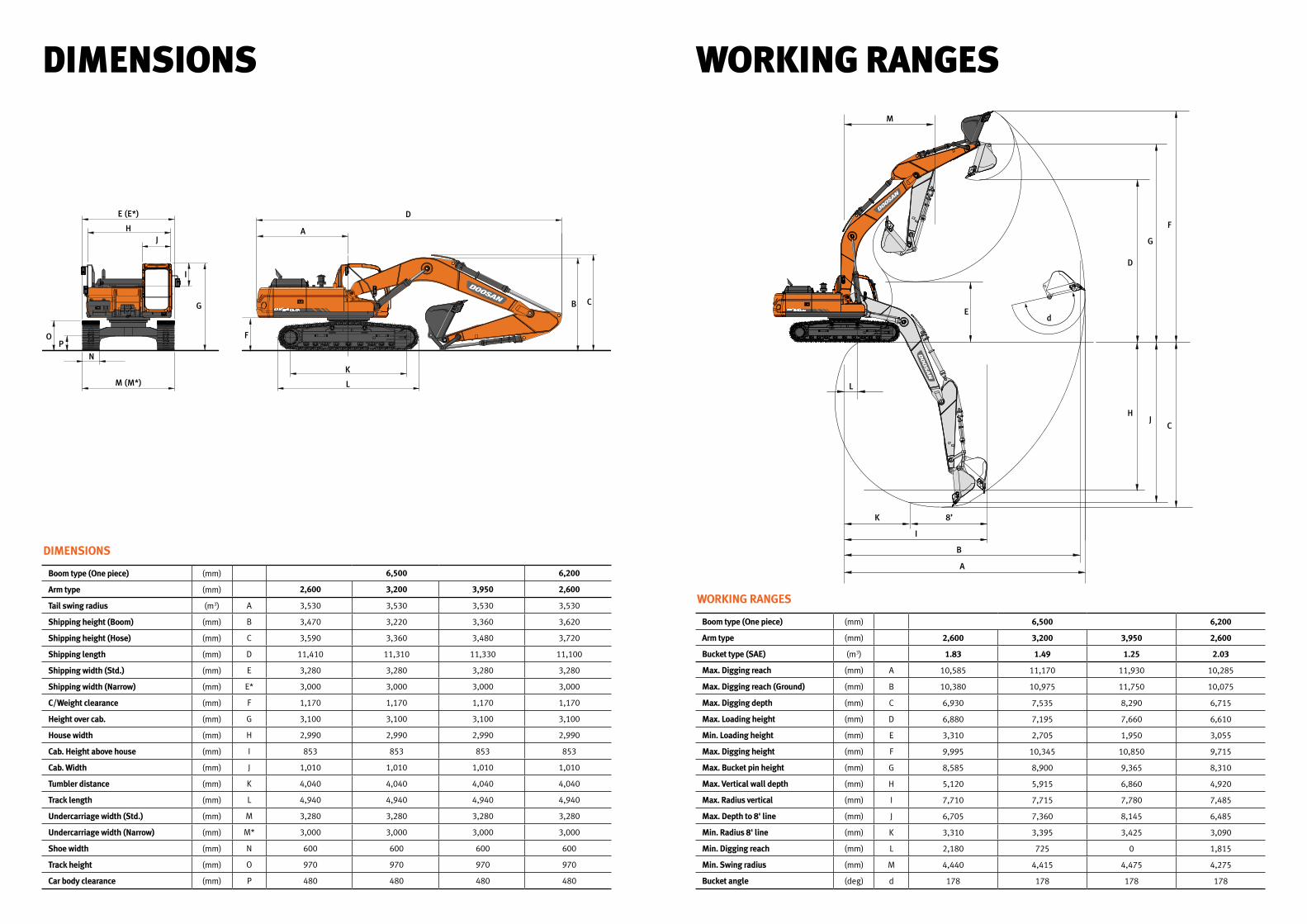
DIMENSIONS
Boom type (One piece) (mm) 6,500 6,200
Arm type (mm) 2,600 3,200 3,950 2,600
Tail swing radius (m3) A 3,530 3,530 3,530 3,530
Shipping height (Boom) (mm) B 3,470 3,220 3,360 3,620
Shipping height (Hose) (mm) C 3,590 3,360 3,480 3,720
Shipping length (mm) D 11,410 11,310 11,330 11,100
Shipping width (Std.) (mm) E 3,280 3,280 3,280 3,280
Shipping width (Narrow) (mm) E* 3,000 3,000 3,000 3,000
C/Weight clearance (mm) F 1,170 1,170 1,170 1,170
Height over cab. (mm) G 3,100 3,100 3,100 3,100
House width (mm) H 2,990 2,990 2,990 2,990
Cab. Height above house (mm) I 853 853 853 853
Cab. Width (mm) J 1,010 1,010 1,010 1,010
Tumbler distance (mm) K 4,040 4,040 4,040 4,040
Track length (mm) L 4,940 4,940 4,940 4,940
Undercarriage width (Std.) (mm) M 3,280 3,280 3,280 3,280
Undercarriage width (Narrow) (mm) M* 3,000 3,000 3,000 3,000
Shoe width (mm) N 600 600 600 600
Track height (mm) O 970 970 970 970
Car body clearance (mm) P 480 480 480 480
DIMENSIONS
OP
N
M (M*)
G
I
JH
E (E*) D
A
F
K
L
B C
WORKING RANGES
Boom type (One piece) (mm) 6,500 6,200
Arm type (mm) 2,600 3,200 3,950 2,600
Bucket type (SAE) (m3) 1.83 1.49 1.25 2.03
Max. Digging reach (mm) A 10,585 11,170 11,930 10,285
Max. Digging reach (Ground) (mm) B 10,380 10,975 11,750 10,075
Max. Digging depth (mm) C 6,930 7,535 8,290 6,715
Max. Loading height (mm) D 6,880 7,195 7,660 6,610
Min. Loading height (mm) E 3,310 2,705 1,950 3,055
Max. Digging height (mm) F 9,995 10,345 10,850 9,715
Max. Bucket pin height (mm) G 8,585 8,900 9,365 8,310
Max. Vertical wall depth (mm) H 5,120 5,915 6,860 4,920
Max. Radius vertical (mm) I 7,710 7,715 7,780 7,485
Max. Depth to 8' line (mm) J 6,705 7,360 8,145 6,485
Min. Radius 8' line (mm) K 3,310 3,395 3,425 3,090
Min. Digging reach (mm) L 2,180 725 0 1,815
Min. Swing radius (mm) M 4,440 4,415 4,475 4,275
Bucket angle (deg) d 178 178 178 178
WORKING RANGES
L
K 8’
I
B
A
H
D
Ed
M
J
G
C
F
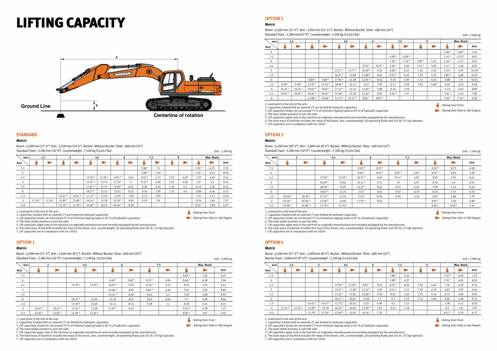
LIFTING CAPACITY
1. Load point is the end of the arm.2. Capacities marked with an asterisk (*) are limited by hydraulic capacities.3. Lift capacities shown do not exceed 75 % of minimum tipping loads or 87 % of hydraulic capacities.4. The least stable position is over the side.5. Lift capacities apply only to the machine as originally manufactured and normally equipped by the manufacturer.6. The total mass of machine includes the mass of the boom, arm, counterweight, all operating fluids and 165 lb. (75 kg) operator.7. Lift capacities are in compliance with iso 10567.
STANDARD
Boom : 6,500 mm (21’ 4”) Arm : 3,200 mm (10’ 6”) Bucket : Without Bucket Shoe : 600 mm (24”) Standard Track : 3,280 mm (10’ 9”) Counterweight : 7,100 kg (15,653 lbs) Unit : 1,000 kg
1.5 3 4.5 6 7.5 9 Max. Reach
A(m)
7.5 7.88 * 7.1 7.55 * 6.75 7.70
6 7.98 * 7.02 7.35 * 5.52 8.59
4.5 12.30 * 12.30 * 9.83 * 9.62 8.55 * 6.77 7.57 4.99 7.37 4.85 9.14
3 15.47 * 13.74 11.32 * 9 9.31 * 6.46 7.42 4.85 6.9 4.5 9.42
1.5 17.67 * 12.73 12.60 * 8.47 9.58 6.16 7.26 4.7 6.74 4.36 9.45
0 18.27 * 12.31 13.11 8.12 9.34 5.95 7.15 4.6 6.89 4.44 9.23
-1.5 14.47 * 14.47 * 17.73 * 12.24 12.95 7.99 9.23 5.85 7.41 4.75 8.76
-3 17.24 * 17.24 * 21.89 * 21.89 * 16.24 * 12.38 12.39 * 8.03 9.29 5.9 8.54 5.46 7.97
-4.5 17.70 * 17.70 * 13.49 * 12.73 10.24 * 8.28 8.57 * 7.04 6.77
A(m)
B(m)
: Rating Over Front
: Rating Over Side or 360 Degree
Metric
OPTION 1
Boom : 6,500 mm (21’ 4”) Arm : 2,600 mm (8’ 6”) Bucket : Without Bucket Shoe : 600 mm (24”) Standard Track : 3,280 mm (10’ 9”) Counterweight : 7,100 kg (15,653 lbs) Unit : 1,000 kg
3 4.5 6 7.5 Max. Reach
A(m)
7.5 8.83 * 7.92 6.97
6 9.48 * 9.48 * 8.72 * 6.94 8.64 * 6.28 7.94
4.5 13.76 * 13.76 * 10.67 * 9.49 9.18 * 6.73 8.25 5.45 8.53
3 12.06 * 8.92 9.84 * 6.46 7.67 5.03 8.83
1.5 13.14 * 8.46 9.61 6.2 7.49 4.88 8.87
0 18.27 * 12.44 13.18 8.21 9.43 6.04 7.7 4.99 8.64
-1.5 17.26 * 12.49 13.11 8.14 9.38 6 8.39 5.41 8.13
-3 19.42 * 19.42 * 15.35 * 12.69 11.91 * 8.25 9.33 * 6.39 7.27
-4.5 14.85 * 14.85 * 11.94 * 11.94 * 8.92 * 8.8 5.92
A(m)
B(m)
1. Load point is the end of the arm.2. Capacities marked with an asterisk (*) are limited by hydraulic capacities.3. Lift capacities shown do not exceed 75 % of minimum tipping loads or 87 % of hydraulic capacities.4. The least stable position is over the side.5. Lift capacities apply only to the machine as originally manufactured and normally equipped by the manufacturer.6. The total mass of machine includes the mass of the boom, arm, counterweight, all operating fluids and 165 lb. (75 kg) operator.7. Lift capacities are in compliance with iso 10567.
: Rating Over Front
: Rating Over Side or 360 Degree
Metric
A
B
OPTION 2
Boom : 6,500 mm (21’ 4”) Arm : 3,950 mm (12’ 11”) Bucket : Without Bucket Shoe : 600 mm (24”) Standard Track : 3,280 mm(10’ 9”) Counterweight : 7,100 kg (15,653 lbs) Unit : 1,000 kg
1.5 3 4.5 6 7.5 9 Max. Reach
A(m)
9 5.94 * 5.94 * 7.45
7.5 6.89 * 6.89 * 5.52 * 5.52 * 8.63
6 7.16 * 7.16 * 7.00 * 5.21 5.36 * 4.77 9.42
4.5 8.79 * 8.79 * 7.82 * 6.92 7.25 * 5.09 5.37 * 4.26 9.92
3 13.77 * 13.77 * 10.39 * 9.24 8.68 * 6.57 7.49 4.91 5.54 * 3.97 10.18
1.5 16.55 * 13.08 11.89 * 8.61 9.52 * 6.22 7.29 4.72 5.86 * 3.86 10.21
0 8.89 * 8.89 * 17.94 * 12.38 12.91 * 8.16 9.35 5.95 7.12 4.56 6.08 3.9 10.01
-1.5 9.38 * 9.38 * 13.35 * 13.35 * 18.04 * 12.13 12.9 7.93 9.17 5.79 7.03 4.48 6.45 4.12 9.58
-3 14.25 * 14.25 * 19.07 * 19.07 * 17.12 * 12.14 12.83 * 7.88 9.14 5.76 7.23 4.62 8.86
-4.5 20.05 * 20.05 * 20.82 * 20.82 * 15.08 * 12.38 11.42 * 8.02 8.56 * 5.9 7.94 * 5.63 7.80
-6 15.08 * 15.08 * 11.27 * 11.27 * 8.05 * 8.05 * 7.56 * 7.56 * 6.20
A(m)
B(m)
Metric
1. Load point is the end of the arm.2. Capacities marked with an asterisk (*) are limited by hydraulic capacities.3. Lift capacities shown do not exceed 75 % of minimum tipping loads or 87 % of hydraulic capacities.4. The least stable position is over the side.5. Lift capacities apply only to the machine as originally manufactured and normally equipped by the manufacturer.6. The total mass of machine includes the mass of the boom, arm, counterweight, all operating fluids and 165 lb. (75 kg) operator.7. Lift capacities are in compliance with iso 10567.
: Rating Over Front
: Rating Over Side or 360 Degree
OPTION 3
Boom : 6,200 mm (20’ 4”) Arm : 2,600 mm (8’ 6”) Bucket : Without Bucket Shoe : 600 mm (24”) Standard Track : 3,280 mm (10’ 9”) Counterweight : 7,100 kg (15,653 lbs) Unit : 1,000 kg
3 4.5 6 7.5 Max. Reach
A(m)
7.5 9.25 * 9.25 * 9.28 * 8.75 6.58
6 9.63 * 9.63 * 9.07 * 6.97 9.07 * 6.81 7.60
4.5 13.50 * 13.50 * 10.75 * 9.65 9.41 * 6.82 8.83 5.87 8.22
3 16.60 * 13.82 12.14 * 9.12 10 6.57 8.18 5.4 8.53
1.5 18.49 * 13.01 13.27 * 8.67 9.74 6.34 7.99 5.24 8.56
0 18.67 * 12.74 13.4 8.41 9.57 6.19 8.24 5.37 8.33
-1.5 18.26 * 18.26 * 17.72 * 12.74 13.31 8.34 9.54 6.16 9.05 5.86 7.79
-3 20.36 * 20.36 * 15.66 * 12.94 11.95 * 8.45 9.91 * 7.03 6.89
-4.5 14.96 * 14.96 * 11.70 * 11.70 * 9.40 * 9.40 * 5.44
A(m)
B(m)
1. Load point is the end of the arm.2. Capacities marked with an asterisk (*) are limited by hydraulic capacities.3. Lift capacities shown do not exceed 75 % of minimum tipping loads or 87 % of hydraulic capacities.4. The least stable position is over the side.5. Lift capacities apply only to the machine as originally manufactured and normally equipped by the manufacturer.6. The total mass of machine includes the mass of the boom, arm, counterweight, all operating fluids and 165 lb. (75 kg) operator.7. Lift capacities are in compliance with iso 10567.
: Rating Over Front
: Rating Over Side or 360 Degree
Metric
1. Load point is the end of the arm.2. Capacities marked with an asterisk (*) are limited by hydraulic capacities.3. Lift capacities shown do not exceed 75 % of minimum tipping loads or 87 % of hydraulic capacities.4. The least stable position is over the side.5. Lift capacities apply only to the machine as originally manufactured and normally equipped by the manufacturer.6. The total mass of machine includes the mass of the boom, arm, counterweight, all operating fluids and 165 lb. (75 kg) operator.7. Lift capacities are in compliance with iso 10567.
OPTION 4
Boom : 6,500 mm (21’ 4”) Arm : 2,600 mm (8’ 6”) Bucket : Without Bucket Shoe : 600 mm (24”) Narrow Track : 3,000 mm (9’ 10”) Counterweight : 7,100 kg (15,653 lbs) Unit : 1,000 kg
1.5 3 4.5 6 7.5 9 Max. Reach
A(m)
7.5 7.88 * 6.34 7.55 * 6.03 7.70
6 7.98 * 6.27 7.35 * 4.91 8.59
4.5 12.30 * 12.30 * 9.83 * 8.55 8.55 * 6.02 7.54 4.42 7.34 4.29 9.14
3 15.47 * 11.99 11.32 * 7.95 9.31 * 5.72 7.39 4.29 6.87 3.97 9.42
1.5 17.67 * 11.02 12.60 * 7.43 9.54 5.43 7.23 4.14 6.72 3.84 9.45
0 18.27 * 10.62 13.06 7.1 9.3 5.22 7.12 4.04 6.86 3.89 9.23
-1.5 14.47 * 14.47 * 17.73 * 10.55 12.9 6.96 9.2 5.13 7.38 4.17 8.76
-3 17.24 * 17.24 * 21.89 * 21.28 16.24 * 10.69 12.39 * 7.01 9.25 5.18 8.5 4.8 7.97
-4.5 17.70 * 17.70 * 13.49 * 11.02 10.24 * 7.25 8.57 * 6.19 6.77
A(m)
B(m)
: Rating Over Front
: Rating Over Side or 360 Degree
Metric
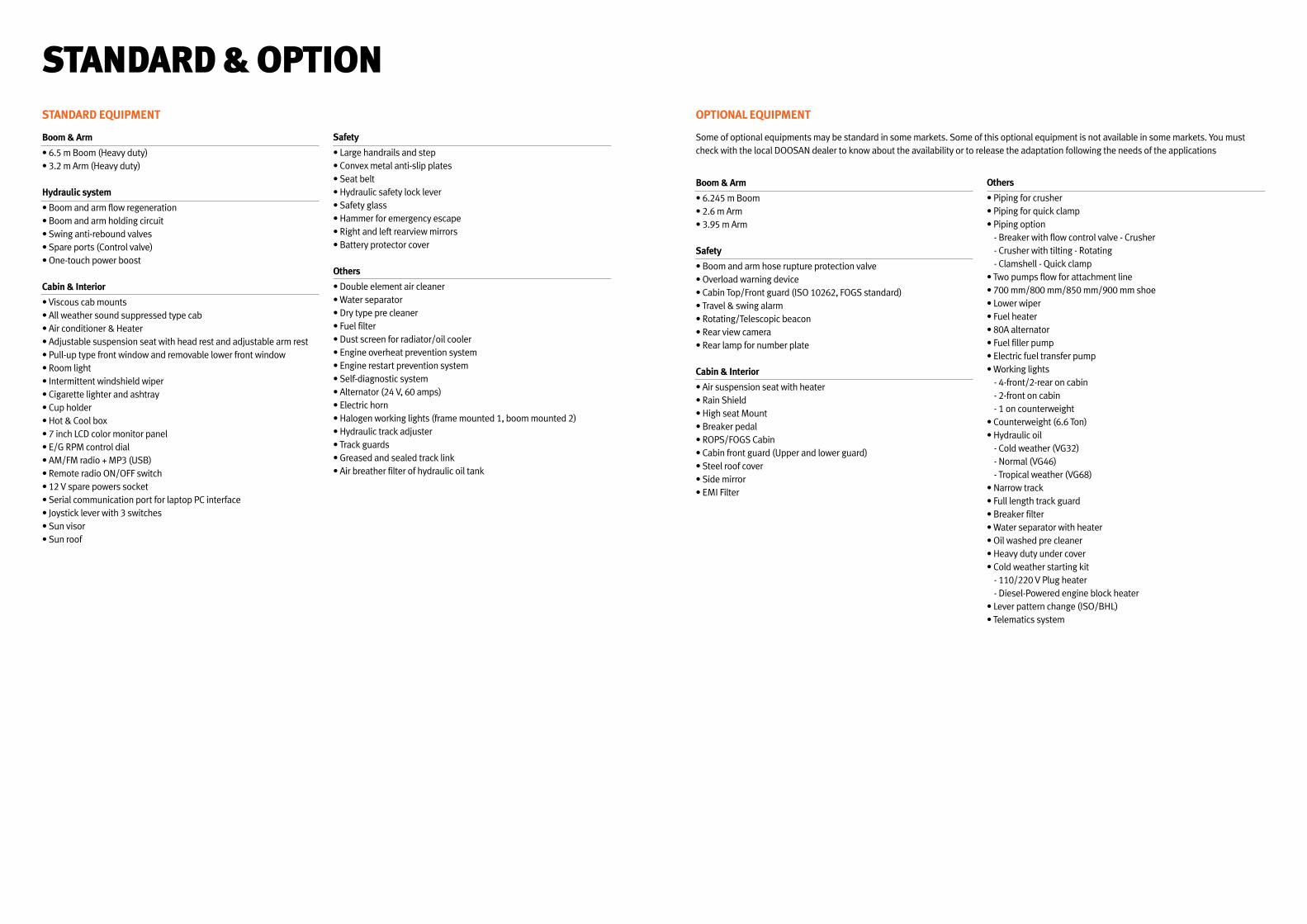
STANDARD & OPTION
Boom & Arm
• 6.5 m Boom (Heavy duty)• 3.2 m Arm (Heavy duty)
Hydraulic system
• Boom and arm flow regeneration• Boom and arm holding circuit• Swing anti-rebound valves• Spare ports (Control valve)• One-touch power boost
Cabin & Interior
• Viscous cab mounts• All weather sound suppressed type cab• Air conditioner & Heater• Adjustable suspension seat with head rest and adjustable arm rest• Pull-up type front window and removable lower front window• Room light• Intermittent windshield wiper• Cigarette lighter and ashtray• Cup holder• Hot & Cool box• 7 inch LCD color monitor panel• E/G RPM control dial• AM/FM radio + MP3 (USB)• Remote radio ON/OFF switch• 12 V spare powers socket• Serial communication port for laptop PC interface• Joystick lever with 3 switches• Sun visor• Sun roof
Safety
• Large handrails and step• Convex metal anti-slip plates• Seat belt• Hydraulic safety lock lever• Safety glass• Hammer for emergency escape• Right and left rearview mirrors• Battery protector cover
Others
• Double element air cleaner• Water separator• Dry type pre cleaner• Fuel filter• Dust screen for radiator/oil cooler• Engine overheat prevention system• Engine restart prevention system• Self-diagnostic system• Alternator (24 V, 60 amps)• Electric horn• Halogen working lights (frame mounted 1, boom mounted 2)• Hydraulic track adjuster• Track guards• Greased and sealed track link• Air breather filter of hydraulic oil tank
STANDARD EQUIPMENT
Boom & Arm
• 6.245 m Boom• 2.6 m Arm• 3.95 m Arm
Safety
• Boom and arm hose rupture protection valve• Overload warning device• Cabin Top/Front guard (ISO 10262, FOGS standard)• Travel & swing alarm• Rotating/Telescopic beacon• Rear view camera• Rear lamp for number plate
Cabin & Interior
• Air suspension seat with heater• Rain Shield• High seat Mount• Breaker pedal• ROPS/FOGS Cabin• Cabin front guard (Upper and lower guard)• Steel roof cover• Side mirror• EMI Filter
Others
• Piping for crusher• Piping for quick clamp• Piping option - Breaker with flow control valve - Crusher - Crusher with tilting - Rotating - Clamshell - Quick clamp• Two pumps flow for attachment line• 700 mm/800 mm/850 mm/900 mm shoe• Lower wiper• Fuel heater• 80A alternator• Fuel filler pump• Electric fuel transfer pump• Working lights - 4-front/2-rear on cabin - 2-front on cabin - 1 on counterweight• Counterweight (6.6 Ton)• Hydraulic oil - Cold weather (VG32) - Normal (VG46) - Tropical weather (VG68)• Narrow track• Full length track guard • Breaker filter • Water separator with heater • Oil washed pre cleaner • Heavy duty under cover • Cold weather starting kit - 110/220 V Plug heater - Diesel-Powered engine block heater• Lever pattern change (ISO/BHL)• Telematics system
OPTIONAL EQUIPMENT
Some of optional equipments may be standard in some markets. Some of this optional equipment is not available in some markets. You must check with the local DOOSAN dealer to know about the availability or to release the adaptation following the needs of the applications
Materials and Specifications in the catalogue are subject to change without notice.
Copyright 2018. Doosan Infracore. All rights reserved.
Doosan isSince 1896, Doosan, the oldest company in Korea, has evolved with its people. The company grew up rapidly for last 10 years with reputation. For human-oriented vision, Doosan has been building constructions, energy, machines, infra structures globally. As a global leader of infra structure, Doosan continues its vision to make human-oriented future.
First in Korea, Doosan self-developed excavators in 1985 and continued building versatile construction machines including excavators, wheel loaders, articulated dump trucks to execute its human-oriented philosophy. Doosan became a global leader of heavy construction machine industry by achieving global sales line, producing line, and distribution line. Along with large production bases in Korea, China, USA, Czech, Brazil, Doosan has 1400 dealer networks and Doosan is providing reliable products and trusted solutions for your stable business at no risk.
Doosan Infracore Co., Ltd. 489 (Hwasu-dong), Injung-ro, Dong-Gu, Incheon, Korea(22502)www.doosaninfracore.com/ce/