DX Static Hydraulic Universal Testing System - Pre-Installation ...
48
www.instron.com Industrial Products Group Model DX Static Hydraulic Universal Testing System Pre-Installation Manual M47-17026-EN Revision B The difference is measurable ®
-
Upload
khangminh22 -
Category
Documents
-
view
1 -
download
0
Transcript of DX Static Hydraulic Universal Testing System - Pre-Installation ...

www.instron.com
Industrial Products Group
Model DX Static HydraulicUniversal Testing System
Pre-Installation ManualM47-17026-EN Revision B
The difference is measurable ®

Electromagnetic Compatibility
Where applicable, this equipment is designed to comply with International Electromagnetic Compatibility (EMC) standards.
To ensure reproduction of this EMC performance, connect this equipment to a low imped-ance ground connection. Typical suitable connections are a ground spike or the steel frame of a building.
Proprietary Rights Notice
This document and the information that it contains are the property of Illinois Tool Works Inc. (ITW). Rights to duplicate or otherwise copy this document and rights to disclose the docu-ment and the information that it contains to others and the right to use the information con-tained therein may be acquired only by written permission signed by a duly authorized officer of ITW.
Trademarks
Instron® is a registered trademark of Illinois Tool Works Inc. (ITW). Other names, logos, icons and marks identifying Instron products and services referenced herein are trademarks of ITW and may not be used without the prior written permission of ITW.
Other product and company names listed are trademarks or trade names of their respective companies.
Original Instructions
Copyright © 2017 Illinois Tool Works Inc. All rights reserved. All of the specifications shown in this document are subject to change without notice.
Corporate Headquarters
Instron825 University Avenue
Norwood, MA 02062-2643United States of America
European Headquarters
InstronCoronation Road
High Wycombe, Bucks HP12 3SYUnited Kingdom

Preliminary Pages
General Safety Precautions
Materials testing systems are potentially hazardous.
Materials testing involves inherent hazards from high forces, rapid motions, and stored energy. You must be aware of all moving and operating components in the testing system that are potentially hazardous, particularly force actuators or a moving crosshead.
Carefully read all relevant manuals and observe all Warnings and Cautions. The term Warning is used where a hazard may lead to injury or death. The term Caution is used where a hazard may lead to damage to equipment or to loss of data.
Instron products, to the best of its knowledge, comply with various national and international safety standards, in as much as they apply to materials and structural testing. We certify that our products comply with all relevant EU directives (CE mark).
Because of the wide range of applications with which our instruments are used, and over which we have no control, additional protection devices and operating procedures may be necessary due to specific accident prevention regulations, safety regulations, further EEA directives or locally valid regulations. The extent of our delivery regarding protective devices is defined in your initial sales quotation. We are thus free of liability in this respect.
At your request, we will gladly provide advice and quotations for additional safety devices such as protective shielding, warning signs or methods of restricting access to the equipment.
The following pages detail various general warnings that you must heed at all times while using materials testing equipment. You will find more specific Warnings and Cautions in the text whenever a potential hazard exists.
Your best safety precautions are to gain a thorough understanding of the equipment by reading your instruction manuals and to always use good judgment.
It is our strong recommendation that you should carry out your own product safety risk assessment.
3Product Support: www.instron.com

Preliminary Pages
Warnings
Hazard - Press the Emergency Stop button whenever you consider that an unsafe condition exists.
The Emergency Stop button removes hydraulic power or electrical drive from the testing system and brings the hazardous elements of the system to a stop as quickly as possible. It does not isolate the system from electrical power, other means are provided to disconnect the electrical supply. Whenever you consider that safety may be compromised, stop the test using the Emergency Stop button. Investigate and resolve the situation that caused the use of the Emergency Stop button before you reset it.
Flying Debris Hazard - Make sure that test specimens are installed correctly in grips or fixtures in order to eliminate stresses that can cause breakage of grip jaws or fixture components.
Incorrect installation of test specimens creates stresses in grip jaws or fixture components that can result in breakage of these components. The high energies involved can cause the broken parts to be projected forcefully some distance from the test area. Install specimens in the center of the grip jaws in line with the load path. Insert specimens into the jaws by at least the amount recommended in your grip documentation. This amount can vary between 66% to 100% insertion depth; refer to supplied instructions for your specific grips. Use any centering and alignment devices provided.
Hazard - Protect electrical cables from damage and inadvertent disconnection.
The loss of controlling and feedback signals that can result from a disconnected or damaged cable causes an open loop condition that may drive the actuator or crosshead rapidly to its extremes of motion. Protect all electrical cables, particularly transducer cables, from damage. Never route cables across the floor without protection, nor suspend cables overhead under excessive strain. Use padding to avoid chafing where cables are routed around corners or through wall openings.
High/Low Temperature Hazard - Wear protective clothing when handling equipment at extremes of temperature.
Materials testing is often carried out at non-ambient temperatures using ovens, furnaces or cryogenic chambers. Extreme temperature means an operating temperature exceeding 60 °C (140 °F) or below 0 °C (32 °F). You must use protective clothing, such as gloves, when handling equipment at these temperatures. Display a warning notice concerning low or high temperature operation whenever temperature control equipment is in use. You should note that the hazard from extreme temperature can extend beyond the immediate area of the test.
4 M47-17026-EN

Preliminary Pages
Crush Hazard - Take care when installing or removing a specimen, assembly, structure, or load string component.
Installation or removal of a specimen, assembly, structure, or load string component involves working inside the hazard area between the grips or fixtures. When working in this area, ensure that other personnel cannot operate any of the system controls. Keep clear of the jaws of a grip or fixture at all times. Keep clear of the hazard area between the grips or fixtures during actuator or crosshead movement. Ensure that all actuator or crosshead movements necessary for installation or removal are slow and, where possible, at a low force setting.
Hazard - Do not place a testing system off-line from computer control without first ensuring that no actuator or crosshead movement will occur upon transfer to manual control.
The actuator or crosshead will immediately respond to manual control settings when the system is placed off-line from computer control. Before transferring to manual control, make sure that the control settings are such that unexpected actuator or crosshead movement cannot occur.
Robotic Motion Hazard - Keep clear of the operating envelope of a robotic device unless the device is de-activated.
The robot in an automated testing system presents a hazard because its movements are hard to predict. The robot can go instantly from a waiting state to high speed operation in several axes of motion. During system operation, keep away from the operating envelope of the robot. De-activate the robot before entering the envelope for any purpose, such as reloading the specimen magazine.
Hazard - Set the appropriate limits before performing loop tuning or running waveforms or tests.
Operational limits are included within your testing system to suspend motion or shut off the system when upper and/or lower bounds of actuator or crosshead travel, or force or strain, are reached during testing. Correct setting of operational limits by the operator, prior to testing, will reduce the risk of damage to test article and system and associated hazard to the operator.
Electrical Hazard - Disconnect the electrical power supply before removing the covers to electrical equipment.
Disconnect equipment from the electrical power supply before removing any electrical safety covers or replacing fuses. Do not reconnect the power source while the covers are removed. Refit covers as soon as possible.
Warnings
5Product Support: www.instron.com

Preliminary Pages
Rotating Machinery Hazard - Disconnect power supplies before removing the covers to rotating machinery.
Disconnect equipment from all power supplies before removing any cover which gives access to rotating machinery. Do not reconnect any power supply while the covers are removed unless you are specifically instructed to do so in the manual. If the equipment needs to be operated to perform maintenance tasks with the covers removed, ensure that all loose clothing, long hair, etc. is tied back. Refit covers as soon as possible.
Hazard - Shut down the hydraulic power supply and discharge hydraulic pressure before disconnection of any hydraulic fluid coupling.
Do not disconnect any hydraulic coupling without first shutting down the hydraulic power supply and discharging stored pressure to zero. Tie down or otherwise secure all pressurized hoses to prevent movement during system operation and to prevent the hose from whipping about in the event of a rupture.
Hazard - Shut off the supply of compressed gas and discharge residual gas pressure before you disconnect any compressed gas coupling.
Do not release gas connections without first disconnecting the gas supply and discharging any residual pressure to zero.
Explosion Hazard - Wear eye protection and use protective shields or screens whenever any possibility exists of a hazard from the failure of a specimen, assembly or structure under test.
Wear eye protection and use protective shields or screens whenever a risk of injury to operators and observers exists from the failure of a test specimen, assembly or structure, particularly where explosive disintegration may occur. Due to the wide range of specimen materials, assemblies or structures that may be tested, any hazard resulting from the failure of a test specimen, assembly or structure is entirely the responsibility of the owner and the user of the equipment.
Hazard - Ensure components of the load string are correctly pre-loaded to minimize the risk of fatigue failure.
Dynamic systems, especially where load reversals through zero are occurring, are at risk of fatigue cracks developing if components of the load string are not correctly pre-loaded to one another. Apply the specified torque to all load string fasteners and the correct setting to wedge washers or spiral washers. Visually inspect highly stressed components such as grips and threaded adapters prior to every fatigue test for signs of wear or fatigue damage.
Warnings
6 M47-17026-EN

Preliminary Pages
Table of Contents
Chapter 1 Introduction . . . . . . . . . . . . . . . . . . . . . . . . . . . . . . . . . . . . . . . . . . . . . . . . . . . . . . 9
About these instructions . . . . . . . . . . . . . . . . . . . . . . . . . . . . . . . . . . . . . . . . . . . . . . . . . . . . . . . . . . . . 9
System overview . . . . . . . . . . . . . . . . . . . . . . . . . . . . . . . . . . . . . . . . . . . . . . . . . . . . . . . . . . . . . . . . . 10Purpose . . . . . . . . . . . . . . . . . . . . . . . . . . . . . . . . . . . . . . . . . . . . . . . . . . . . . . . . . . . . . . . . . . . . 10
System components . . . . . . . . . . . . . . . . . . . . . . . . . . . . . . . . . . . . . . . . . . . . . . . . . . . . . . . . . . 10
Frame configuration options . . . . . . . . . . . . . . . . . . . . . . . . . . . . . . . . . . . . . . . . . . . . . . . . . . . 12Testing accessories . . . . . . . . . . . . . . . . . . . . . . . . . . . . . . . . . . . . . . . . . . . . . . . . . . . . . . . . . . 12
System identification . . . . . . . . . . . . . . . . . . . . . . . . . . . . . . . . . . . . . . . . . . . . . . . . . . . . . . . . . 12
System safety and information labels . . . . . . . . . . . . . . . . . . . . . . . . . . . . . . . . . . . . . . . . . . . . . . . . 13Product support . . . . . . . . . . . . . . . . . . . . . . . . . . . . . . . . . . . . . . . . . . . . . . . . . . . . . . . . . . . . . . . . . 15
Product documentation . . . . . . . . . . . . . . . . . . . . . . . . . . . . . . . . . . . . . . . . . . . . . . . . . . . . . . . . . . . 15
Calibration upon installation . . . . . . . . . . . . . . . . . . . . . . . . . . . . . . . . . . . . . . . . . . . . . . . . . . . . . . . 16
Training . . . . . . . . . . . . . . . . . . . . . . . . . . . . . . . . . . . . . . . . . . . . . . . . . . . . . . . . . . . . . . . . . . . . . . . . 16Delivery time . . . . . . . . . . . . . . . . . . . . . . . . . . . . . . . . . . . . . . . . . . . . . . . . . . . . . . . . . . . . . . . . . . . . 16
Customer’s responsibilities . . . . . . . . . . . . . . . . . . . . . . . . . . . . . . . . . . . . . . . . . . . . . . . . . . . . . . . . . 17
Site preparation . . . . . . . . . . . . . . . . . . . . . . . . . . . . . . . . . . . . . . . . . . . . . . . . . . . . . . . . . . . . . . 17Handling and transporting . . . . . . . . . . . . . . . . . . . . . . . . . . . . . . . . . . . . . . . . . . . . . . . . . . . . . . 17
Insurance and safety . . . . . . . . . . . . . . . . . . . . . . . . . . . . . . . . . . . . . . . . . . . . . . . . . . . . . . . . . . 17
Instron’s responsibilities . . . . . . . . . . . . . . . . . . . . . . . . . . . . . . . . . . . . . . . . . . . . . . . . . . . . . . . . . . 18Insurance. . . . . . . . . . . . . . . . . . . . . . . . . . . . . . . . . . . . . . . . . . . . . . . . . . . . . . . . . . . . . . . . . . . 18
Installation. . . . . . . . . . . . . . . . . . . . . . . . . . . . . . . . . . . . . . . . . . . . . . . . . . . . . . . . . . . . . . . . . . 18
Initial operation. . . . . . . . . . . . . . . . . . . . . . . . . . . . . . . . . . . . . . . . . . . . . . . . . . . . . . . . . . . . . . 18Documentation . . . . . . . . . . . . . . . . . . . . . . . . . . . . . . . . . . . . . . . . . . . . . . . . . . . . . . . . . . . . . . 18
Chapter 2 Specifications . . . . . . . . . . . . . . . . . . . . . . . . . . . . . . . . . . . . . . . . . . . . . . . . . . . 19
Environmental conditions . . . . . . . . . . . . . . . . . . . . . . . . . . . . . . . . . . . . . . . . . . . . . . . . . . . . . . . . . 19
Noise level . . . . . . . . . . . . . . . . . . . . . . . . . . . . . . . . . . . . . . . . . . . . . . . . . . . . . . . . . . . . . . . . . . . . . . 20
Heat load. . . . . . . . . . . . . . . . . . . . . . . . . . . . . . . . . . . . . . . . . . . . . . . . . . . . . . . . . . . . . . . . . . . . . . . 21Frame ground bearing pressure . . . . . . . . . . . . . . . . . . . . . . . . . . . . . . . . . . . . . . . . . . . . . . . . . . . . 21
Physical dimensions of components. . . . . . . . . . . . . . . . . . . . . . . . . . . . . . . . . . . . . . . . . . . . . . . . . 21
Frame. . . . . . . . . . . . . . . . . . . . . . . . . . . . . . . . . . . . . . . . . . . . . . . . . . . . . . . . . . . . . . . . . . . . . . 21Crate dimensions . . . . . . . . . . . . . . . . . . . . . . . . . . . . . . . . . . . . . . . . . . . . . . . . . . . . . . . . . . . . . . . . 23
Frame. . . . . . . . . . . . . . . . . . . . . . . . . . . . . . . . . . . . . . . . . . . . . . . . . . . . . . . . . . . . . . . . . . . . . . 23
Chapter 3 Site Preparation . . . . . . . . . . . . . . . . . . . . . . . . . . . . . . . . . . . . . . . . . . . . . . . . . . 25
Requirement checklist . . . . . . . . . . . . . . . . . . . . . . . . . . . . . . . . . . . . . . . . . . . . . . . . . . . . . . . . . . . . 25
Determine system placement . . . . . . . . . . . . . . . . . . . . . . . . . . . . . . . . . . . . . . . . . . . . . . . . . . . . . . 26Prepare foundation. . . . . . . . . . . . . . . . . . . . . . . . . . . . . . . . . . . . . . . . . . . . . . . . . . . . . . . . . . . . . . . 28
7Product Support: www.instron.com

Preliminary Pages
Prepare electrical power supply . . . . . . . . . . . . . . . . . . . . . . . . . . . . . . . . . . . . . . . . . . . . . . . . . . . . . 31
Frame . . . . . . . . . . . . . . . . . . . . . . . . . . . . . . . . . . . . . . . . . . . . . . . . . . . . . . . . . . . . . . . . . . . . . 31Computer system . . . . . . . . . . . . . . . . . . . . . . . . . . . . . . . . . . . . . . . . . . . . . . . . . . . . . . . . . . . . 31
Provide telephone line and network connection. . . . . . . . . . . . . . . . . . . . . . . . . . . . . . . . . . . . . . . . 33
Provide additional utilities . . . . . . . . . . . . . . . . . . . . . . . . . . . . . . . . . . . . . . . . . . . . . . . . . . . . . . . . . 33Prepare for shipment arrival. . . . . . . . . . . . . . . . . . . . . . . . . . . . . . . . . . . . . . . . . . . . . . . . . . . . . . . . 33
Chapter 4 Shipment Arrival . . . . . . . . . . . . . . . . . . . . . . . . . . . . . . . . . . . . . . . . . . . . . . . . . 35
Requirement checklist . . . . . . . . . . . . . . . . . . . . . . . . . . . . . . . . . . . . . . . . . . . . . . . . . . . . . . . . . . . . 35
Review as-shipped condition . . . . . . . . . . . . . . . . . . . . . . . . . . . . . . . . . . . . . . . . . . . . . . . . . . . . . . . 35
Frame . . . . . . . . . . . . . . . . . . . . . . . . . . . . . . . . . . . . . . . . . . . . . . . . . . . . . . . . . . . . . . . . . . . . . . 35Other system components . . . . . . . . . . . . . . . . . . . . . . . . . . . . . . . . . . . . . . . . . . . . . . . . . . . . . 36
Receive the system . . . . . . . . . . . . . . . . . . . . . . . . . . . . . . . . . . . . . . . . . . . . . . . . . . . . . . . . . . . . . . . 37
Uncrate the system . . . . . . . . . . . . . . . . . . . . . . . . . . . . . . . . . . . . . . . . . . . . . . . . . . . . . . . . . . . . . . . 37Move system components to installation area . . . . . . . . . . . . . . . . . . . . . . . . . . . . . . . . . . . . . . . . . 38
Before you begin . . . . . . . . . . . . . . . . . . . . . . . . . . . . . . . . . . . . . . . . . . . . . . . . . . . . . . . . . . . . . 38
Frame . . . . . . . . . . . . . . . . . . . . . . . . . . . . . . . . . . . . . . . . . . . . . . . . . . . . . . . . . . . . . . . . . . . . . . 39
Computer stand. . . . . . . . . . . . . . . . . . . . . . . . . . . . . . . . . . . . . . . . . . . . . . . . . . . . . . . . . . . . . . 41Prepare the system . . . . . . . . . . . . . . . . . . . . . . . . . . . . . . . . . . . . . . . . . . . . . . . . . . . . . . . . . . . . . . . 43
Remove shipping hardware from the frame . . . . . . . . . . . . . . . . . . . . . . . . . . . . . . . . . . . . . . . 43
Fill/check reservoir . . . . . . . . . . . . . . . . . . . . . . . . . . . . . . . . . . . . . . . . . . . . . . . . . . . . . . . . . . . 43Install air breather assembly . . . . . . . . . . . . . . . . . . . . . . . . . . . . . . . . . . . . . . . . . . . . . . . . . . . 43
Computer system - network connection . . . . . . . . . . . . . . . . . . . . . . . . . . . . . . . . . . . . . . . . . . 44
Prepare for installation service visit . . . . . . . . . . . . . . . . . . . . . . . . . . . . . . . . . . . . . . . . . . . . . . . . . 45
8 M47-17026-EN

Chapter 1Introduction
• About these instructions. . . . . . . . . . . . . . . . . . . . . . . . . . . . . . . . . . . . . . . . . . . . . . . . . . . . . 9
• System overview . . . . . . . . . . . . . . . . . . . . . . . . . . . . . . . . . . . . . . . . . . . . . . . . . . . . . . . . . . 10
• System safety and information labels . . . . . . . . . . . . . . . . . . . . . . . . . . . . . . . . . . . . . . . . . 13
• Product support. . . . . . . . . . . . . . . . . . . . . . . . . . . . . . . . . . . . . . . . . . . . . . . . . . . . . . . . . . . 15
• Product documentation . . . . . . . . . . . . . . . . . . . . . . . . . . . . . . . . . . . . . . . . . . . . . . . . . . . . 15
• Calibration upon installation . . . . . . . . . . . . . . . . . . . . . . . . . . . . . . . . . . . . . . . . . . . . . . . . 16
• Training . . . . . . . . . . . . . . . . . . . . . . . . . . . . . . . . . . . . . . . . . . . . . . . . . . . . . . . . . . . . . . . . . 16
• Delivery time . . . . . . . . . . . . . . . . . . . . . . . . . . . . . . . . . . . . . . . . . . . . . . . . . . . . . . . . . . . . . 16
• Customer’s responsibilities . . . . . . . . . . . . . . . . . . . . . . . . . . . . . . . . . . . . . . . . . . . . . . . . . 17
• Instron’s responsibilities. . . . . . . . . . . . . . . . . . . . . . . . . . . . . . . . . . . . . . . . . . . . . . . . . . . . 18
About these instructionsThe information in this document is intended to aid customers in the site preparation, unpacking, lifting, and installation of the Instron Model DX Static Hydraulic Universal Testing Systems.
These instructions assume the following:
• Your system consists of a frame, a hydraulic power supply, a control unit, a computer system with an Instron materials testing software package, and any testing accessories necessary to secure the specimen in the test space.
It is important that the site be adequately prepared in order to avoid unnecessary delays in the installation process and to ensure that the testing system operates without interference from various environmental conditions (i.e. excess building vibrations or extreme temperature and humidity levels).
Throughout your documentation are NOTE, CAUTION and WARNING statements that alert your attention to important information. They appear as follows:
CautionCautions alert the user to situations that may cause equipment damage.
Warning
Please read these instructions, and any other documents provided, thoroughly and carefully. Be sure to understand all Warnings and Cautions before attempting to lift or install this equipment.
Notes provide further clarification on particular issues.
Warnings alert the user to situations that may cause serious personal injury or death.
9
Chapter 1: Introduction
System overview
Purpose
Warning
The Instron Model DX Static Hydraulic Universal Testing Systems are available in a variety of capacities. They have been developed for high-capacity testing to provide the forces necessary for static tension, compression, bend and shear testing. They are suited for tests on specimen samples such as bar, rebar, plate, tube, pipe, sheet, wire, and concrete. These frames feature two test spaces so that users can quickly change between tension and compression testing without having to remove heavy fixtures. This flexible design helps to ensure safety, reduce operator fatigue and improve productivity.
System componentsModel DX systems consist of:
• Frame
• Hydraulic Power Supply (HPS)
• 59 Series control unit and other system controls and electronics
• Instron approved computer system with Instron materials testing software
Figure 1 identifies the system components and various frame configurations (see “Frame configuration options” on page 12).
If the equipment is used in a manner not specified by Instron, the protection provided by the equipment may be impaired. Injury to personnel or damage to the system may result. Be sure to read and understand the material presented in these instructions and in any other accompanying instructions.
10 M47-17026-EN

System overview
Figure 1. DX testing systems - various configurations shown.
30
0D
X Fr
ame
show
n w
ithG
7-S
tyle
Cro
sshe
ads
60
0D
X Fr
ame
show
n w
ithG
1-S
tyle
Cro
sshe
ads
30
0D
X Fr
ame
show
n w
ithG
8-S
tyle
Cro
sshe
ads
1.
G1
-sty
le c
ross
head
s - C
lose
d-fr
ont c
ross
head
s w
ith
man
ually
ope
rate
d in
-hea
d w
edge
grip
s fo
r te
nsio
n te
stin
g2
.G
7-s
tyle
cro
sshe
ads
- Ope
n-fr
ont c
ross
head
s w
ith
hydr
aulic
ally
ope
rate
d in
-hea
d w
edge
grip
s fo
r te
nsio
n te
stin
g3
.G
8-s
tyle
cro
sshe
ad -
Com
pres
sion
onl
y fr
ame
with
bol
t pa
tter
n to
acc
ept c
ompr
essi
on fi
xtur
es4
.H
PS a
nd e
lect
roni
cs lo
cate
d in
bas
e of
fram
e5
.O
ptio
nal o
pera
tor d
ashb
oard
/tou
ch m
onito
r
1
2
53
4
44
11Product Support: www.instron.com

Chapter 1: Introduction
Frame configuration optionsFrames can be configured with a variety of options. These options include:
• Crosshead variations:
• G1-style crossheads - Closed-front crossheads with manually operated grip assemblies for tension testing
• G7-style crossheads - Open-front crossheads with hydraulically operated grip assemblies for tension testing
• G8-style crosshead - Compression only frame with bolt pattern to accept compression fixtures
• Test opening variations:
• E1 - Standard tension opening
• E2 - Increase tension test space by: 610 mm (24 in) for 300DX frames, 406.4 mm (16 in) for 600DX frames
The configuration options selected for your frame are identified in the complete model number of the frame. The complete model number is defined as:
{Capacity (in kN)}{Model family}-{Controller}{Crosshead style option}{Test opening option}
Some examples would be:
300DX-V1-G1-E1, 300DX-V1-G7-E1, 600DX-V1-G1-E1, 600DX-V1-G8
It is very important to be aware of and understand the configuration of your frame as you perform various operations and procedures so that they can be performed correctly - the complete model number (in whole or in part) is used throughout this manual to identify specifications and procedures appropriate for your frame configuration. Knowing the complete model number of your frame is critical. To determine the complete model number (and thus configuration) of your frame, refer to one of the following:
• The frame serial tag (see “System identification” on page 12)
• The Instron quote
Testing accessoriesTesting accessories are purchased separately from the frame. Testing accessories either provide a means to secure the specimen in the test space or provide additional functionality to the frame. Instructions on the installation, use and maintenance of Instron testing accessories are provided separately with each testing accessory. A variety of testing accessories are available. Contact your Instron Sales Representative for more information.
System identificationYour system has been given a unique serial number for system identification. This serial number can be found on the serial tag located on the rear of the frame (i.e. the frame serial tag).
The frame serial tag includes other important system information, including information on your frame’s configuration. Frame configuration information can also be found on your Instron quote. Refer to “Frame configuration options” on page 12 for explanation of frame configuration.
12 M47-17026-EN

System overview
System safety and information labelsTable 1 explains the meanings of any safety and information labels that may be attached to any part of the testing system.
Table 1. Descriptions of safety and information labeling.
Label Meaning and Purpose
Crush hazard - Indicates that a pinching or crush hazard exists from two objects coming together and instructs the user to read and understand the operator’s manual before using the machine.
Electrical hazard - Indicates that a hazard exists from high voltage or electrical current.
Electrical hazard - Indicates that a hazard exists from leakage current and that the equipment must be connected to a mains ground point.
High pressure hazard - Indicates that a hazard exists from high pressure. Do not adjust or reset any pressure settings until you have read and understood the operator’s manual. Personal injury or damage to equipment may result. Most pressure settings should only be adjusted by an Instron service engineer.
Eye protection - Indicates that a flying debris hazard exists either from specimen failure or improper use of system components. Wear eye protection or use protective shields or screens. Be sure to read and understand the operator’s manual before using the system.
Read the manual - Read and understand the operator’s manual before using the system.
Guard removal hazard - Indicates that a hazard exists - do not operate the system with covers removed. Be sure to read and understand the operator’s manual before using the system. Only authorized personnel should service the equipment.
Guard removal hazard - chain drive inside - Indicates that a hazard exists from a chain drive - do not operate the system with covers removed. Be sure to read and understand the operator’s manual before using the system. Only authorized personnel should service the equipment.
Hand crush hazard - Indicates that a pinching or crush hazard exists from two objects coming together - movement from the sides.
Pinching hazard - Indicates that an increased risk of pinching hazard exists if the grip closing speed is adjusted to be faster than 4 mm/sec (0.16 in/sec).
Ground stud - Indicates a ground stud. Connect to an appropriate ground/earth system.
Protective earth - Indicates the protective earth terminal for the main power supply.
Three-phase power supply - Indicates that the equipment requires a three-phase power supply.
Grip engagement - Indicates the proper amount of grip engagement to avoid damage to equipment.
13Product Support: www.instron.com

Chapter 1: Introduction
Grease location - Indicates the location of grease fitting to apply appropriate lubricant.
Table 1. Descriptions of safety and information labeling. (Continued)
Label Meaning and Purpose
14 M47-17026-EN

Product documentation
Product supportInstron provides documentation, including manuals and online help, that can answer many of the questions you may have. It is recommended that you review the documentation sent with the system you purchased for possible solutions to your questions.
If you cannot find answers in these sources, contact Instron’s Services department directly. A list of Instron offices is available on our website at www.instron.com. You may email your questions to [email protected] (if your system is still in warranty, please include “IPG Warranty” in the subject line). In the US and Canada, you can call directly at 1-800-473-7838.
Product documentationInstron offers a comprehensive range of documentation to help you get the most out of your Instron products. Depending on what you have purchased, your documentation may include some or all of the following:
We welcome your feedback on any aspect of the product documentation. Please email [email protected] with your comments.
Pre-Installation Manual Information about preparing your site for installation of the system, receiving the system, and lifting and handling of the system.
Operating Instructions How to use your system components and controls, and other frequently performed operating tasks.
System Concepts Additional information about your system.
Online Help Software products come complete with context sensitive help, which provides detailed information on how to use all software features.
Accessory Equipment Reference
How to set up and use any accessories you have purchased, for example grips, fixtures, extensometers, transducers, hydraulic power units, non-standard actuators, and environmental chambers.
15Product Support: www.instron.com
Chapter 1: Introduction
Calibration upon installationASTM, ISO, and EN standards require the system be calibrated when it is installed or when it is moved or relocated. Instron calibrates the system at the factory, and provides a record of readings for the load cell. This machine may be verified on-site to ASTM E-4, BS 1610, DIN 51221, ISO 7500/1, EN 10002-2, JIS B7721, JIS B773 or AFNOR A03-501 standards. The factory calibration is not a complete verification to any current version of any of the above standards. Installation and Basic Software training are included with the purchase of your system. Verification services are available at a reduced rate if performed as part of the installation, but must be purchased separately. Contact your local Instron office for more information about our on-site verification services. Refer to “Product support” on page 15 for Instron’s contact information.
TrainingDuring installation, the service engineer provides basic familiarization training on your testing system. However, attending a training class specifically designed for your system helps you to realize the full potential and flexibility of Instron’s testing systems. It is recommended that anyone who will regularly use the testing system attend a training class. This may include daily operators of the system, lab supervisors or product engineers.
Detailed training on the operation of your testing system is available through Instron’s training center. Classes are offered at several Instron locations and can also be scheduled on-site at your location. For a detailed description of available classes, refer to Instron’s web site at www.instron.com or contact your local Instron office.
Delivery timeThe estimated delivery time for an Instron testing system varies from system to system. No models are kept in inventory, so every testing system is custom configured to the specifications outlined in your order. In addition to building your system, it must also be thoroughly tested and inspected to ensure that it meets various national and international testing standards. This process can range from a few days to several months, depending upon the type of system purchased and the level of customizing involved.
This time period provides you adequate time to prepare your testing location for the installation.
Contact your local Instron sales representative to obtain information on the status of your system and an estimated delivery date.
16 M47-17026-EN

Delivery time
Customer’s responsibilitiesIt is the customer’s responsibility to ensure that all required support services (i.e. power, air, and/or water supplies, telephone line, etc.) are available, and that all necessary checks are made prior to installing the testing system. These services and checks are described below.
Site preparationProper site preparation is imperative so that the testing system operates in accordance with its specifications and provides accurate test results. The customer must ensure that the site requirements are satisfied prior to scheduling an installation appointment with Instron Service. These site requirements are described in this manual under Chapter 3 and Chapter 4. Always verify your equipment’s specific model when referencing any information in this manual; refer to your copy of the Instron quote, or the serial number tag located on the equipment.
Handling and transportingUnless specifically arranged otherwise, it is the customer’s responsibility to arrange the off-loading, unpacking and moving of the testing system to the final installation location. Refer to “Move system components to installation area” on page 38 for details on handling and transporting your system to its final location.
Upon special arrangements, an Instron service engineer can supervise the off-loading and transportation of the frame to its final installation location. Contact Instron’s service department or your local Instron office for additional information on this service. Refer to “Product support” on page 15 for Instron’s contact information.
Insurance and safetyUnder Instron’s standard contract, the shipping terms are Ex-Works (or FOB Factory), meaning ownership and liability for the testing system transfers to the customer at Instron’s loading dock. Unless other shipping terms are specified in a purchase order, which Instron does not dispute, the Ex-Works shipping terms apply. Under these terms, the customer is responsible for securing the applicable transit insurance on the shipment and arranging safe transport to the final destination. Arrangements can be made through Instron to secure insurance cover and shipping, at the customer’s expense.
When transporting a frame within your own premises, you are responsible for its safe transport. As stated under “Handling and transporting” above, you can arrange for an Instron service engineer to supervise the off-loading and transportation of the frame to its final installation location.
17Product Support: www.instron.com

Chapter 1: Introduction
Instron’s responsibilitiesInstron’s standard contract requires Instron to provide the necessary services to ensure that your testing system operates accurately. These services are described below.
Additional services and equipment may be negotiated with Instron, but these additional services must be mutually agreed upon and specifically described in your purchase order.
InsuranceUnder Instron’s standard contract, the shipping terms are Ex-Works (or FOB Factory), meaning ownership and liability for the testing system transfers to the customer at Instron’s loading dock. Unless other shipping terms are specified in a purchase order, which Instron does not dispute, the Ex-Works shipping terms apply. Under these terms, Instron is responsible for insurance cover while the testing system is in the factory up until it reaches the loading dock for shipping.
InstallationInstallation is included with the purchase of the system. After the site is prepared, the frame is in place on its foundation, and all components are on site, installation by Instron will cover complete setup of the frame, hydraulic power supply, controller and computer interface, including all electrical and hydraulic hookups.
Initial operationOnce installation is complete, as part of the installation, Instron provides development of one test method to the user’s requirement and basic familiarization training on the testing system.
DocumentationInstron provides all documentation required to operate the system, including manuals for the frame and any required software applications.
Additional copies are available and can be ordered through any Instron sales office.
18 M47-17026-EN

Chapter 2Specifications
• Environmental conditions. . . . . . . . . . . . . . . . . . . . . . . . . . . . . . . . . . . . . . . . . . . . . . . . . . . 19
• Noise level . . . . . . . . . . . . . . . . . . . . . . . . . . . . . . . . . . . . . . . . . . . . . . . . . . . . . . . . . . . . . . . 20
• Heat load . . . . . . . . . . . . . . . . . . . . . . . . . . . . . . . . . . . . . . . . . . . . . . . . . . . . . . . . . . . . . . . . 21
• Frame ground bearing pressure. . . . . . . . . . . . . . . . . . . . . . . . . . . . . . . . . . . . . . . . . . . . . . 21
• Physical dimensions of components . . . . . . . . . . . . . . . . . . . . . . . . . . . . . . . . . . . . . . . . . . 21
• Crate dimensions . . . . . . . . . . . . . . . . . . . . . . . . . . . . . . . . . . . . . . . . . . . . . . . . . . . . . . . . . 23
Environmental conditionsTable 2 lists the recommended environmental conditions in which the system should be operated and stored.
Table 2. Recommended environmental conditions.
Operating Temperature: +10 to +38 deg C (+50 to +100 deg F)
Storage Temperature: -40 to +66 deg C (-40 to +150 deg F)
Humidity: 10% to 90% (non-condensing)
Atmosphere: Designed for use under normal laboratory conditions. Protective measures may be required if excessive dust, corrosive fumes, electromagnetic fields, or hazardous conditions are encountered.
19
Chapter 2: Specifications
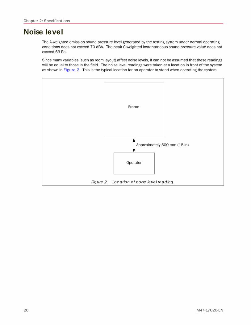
Noise levelThe A-weighted emission sound pressure level generated by the testing system under normal operating conditions does not exceed 70 dBA. The peak C-weighted instantaneous sound pressure value does not exceed 63 Pa.
Since many variables (such as room layout) affect noise levels, it can not be assumed that these readings will be equal to those in the field. The noise level readings were taken at a location in front of the system as shown in Figure 2. This is the typical location for an operator to stand when operating the system.
Figure 2. Location of noise level reading.
Frame
Operator
Approximately 500 mm (18 in)
20 M47-17026-EN

Frame ground bearing pressure
Heat loadThe HPS generates a certain amount of heat during operation. Refer to Table 3 for the approximate heat output of the HPS operating at both a 10% duty cycle and 50% duty cycle. The duty cycle is defined as the amount of time that the HPS operates under full load conditions. For example, operating at a 10% duty cycle would mean performing approximately one 6-minute test at full load per hour.
Frame ground bearing pressureTable 4 lists the various DX frame configurations and their ground bearing pressures.
Physical dimensions of components
FrameTable 5 lists the various standard configurations of DX frame models and their physical dimensions.
Table 3. Approximate heat output of various frame models.
Frame ModelApproximate Heat Output at 10%
Duty CycleApproximate Heat Output at 50%
Duty Cycle
300DX 232 W (792 BTU/hour) 459 W (1569 BTU/hour)
600DX 286 W (976 BTU/hour) 496 W (1694 BTU/hour)
Table 4. Ground bearing pressure of standard DX frame configurations.
Frame Model Ground Bearing Pressure
300DX-G1-E1 0.65 kg/cm2 (9.3 psi)
300DX-G1-E2 0.67 kg/cm2 (9.5 psi)
300DX-G7-E1 0.76 kg/cm2 (10.8 psi)
300DX-G7-E2 0.78 kg/cm2 (11.1 psi)
300DX-G8 0.56 kg/cm2 (7.9 psi)
600DX-G1-E1 1.05 kg/cm2 (15.0 psi)
600DX-G1-E2 1.08 kg/cm2 (15.3 psi)
600DX-G7-E1 1.11 kg/cm2 (15.8 psi)
600DX-G7-E2 1.13 kg/cm2 (16.1 psi)
600DX-G8 0.86 kg/cm2 (12.3 psi)
Table 5. Dimensions of standard DX frames.
Frame Model1, 2 Height3 Overall Area4 (W x D) Approx. Weight
300DX-G1-E1 2440 mm (96 in) 786 x 993 mm (30.94 x 39.13 in) 1,110 kgs (2,440 lbs)
300DX-G1-E2 3050 mm (120 in) 786 x 993 mm (30.94 x 39.13 in) 1,140 kgs (2,510 lbs)
21Product Support: www.instron.com

Chapter 2: Specifications
300DX-G7-E1 2595 mm (102 in) 786 x 993 mm (30.94 x 39.13 in) 1,290 kgs (2,840 lbs)
300DX-G7-E2 3205 mm (126 in) 786 x 993 mm (30.94 x 39.13 in) 1,320 kgs (2,910 lbs)
300DX-G8 1855 mm (73 in) 786 x 993 mm (30.94 x 39.13 in) 945 kgs (2,080 lbs)
600DX-G1-E1 2505 mm (99 in) 974 x 1205 mm (38.31 x 47.44 in) 2,270 kgs (5,000 lbs)
600DX-G1-E2 2910 mm (115 in) 974 x 1205 mm (38.31 x 47.44 in) 2,310 kgs (5,085 lbs)
600DX-G7-E1 2910 mm (115 in) 974 x 1205 mm (38.31 x 47.44 in) 2,390 kgs (5,265 lbs)
600DX-G7-E2 3315 mm (131 in) 974 x 1205 mm (38.31 x 47.44 in) 2,430 kgs (5,350 lbs)
600DX-G8 1880 mm (74 in) 974 x 1205 mm (38.31 x 47.44 in) 1,855 kgs (4,090 lbs)
1. As designated on frame serial number tag2. G1 = Dual test space with closed-front crossheads and manual crank and pinion grip actuation
G7 = Dual test space with open-front crossheads and hydraulic grip actuationG8 = Compression only test space with closed-front adjustable crossheadE1 = Standard tension openingE2 = Extended tension opening by: - 610 mm (24 in) for 300DX frames - 406.4 mm (16 in) for 600DX frames
3. Maximum height of the frame (i.e. frame height at full stroke).4. Dimensions are of the widest and deepest portion(s) of the frame.
Table 5. Dimensions of standard DX frames. (Continued)
Frame Model1, 2 Height3 Overall Area4 (W x D) Approx. Weight
22 M47-17026-EN

Physical dimensions of components
Crate dimensions
FrameRefer to Figure 3 and Table 6 for typical crate dimensions of your specific frame model.
Table 6. Typical crate dimensions of standard DX frame models.
Frame Model1, 2Shipped
ConditionApproximate Crate Dimensions
(L x W x H)Approx. Weight of Crated
Frame3
300DX-G1-E1 Horizontal 2667 x 1042 x 1372 mm (105 x 41 x 54 in) 2,014 kgs (4,440 lbs)
300DX-G1-E2 Horizontal 3277 x 1042 x 1372 mm (129 x 41 x 54 in) 2,045 kgs (4,510 lbs)
300DX-G7-E1 Horizontal 2820 x 1042 x 1372 mm (111 x 41 x 54 in) 2,195 kgs (4,840 lbs)
300DX-G7-E2 Horizontal 3430 x 1042 x 1372 mm (135 x 41 x 54 in) 2,227 kgs (4,910 lbs)
300DX-G8Vertical 1423 x 1143 x 2083 mm (56 x 45 x 82 in) 1,738 kgs (3,830 lbs)
Horizontal 2235 x 1042 x 1397 mm (88 x 41 x 55 in) 1,753 kgs (3,865 lbs)
600DX-G1-E1 Horizontal 2745 x 1245 x 1600 mm (108 x 49 x 63 in) 3,062 kgs (6,750 lbs)
600DX-G1-E2 Horizontal 3150 x 1245 x 1600 mm (124 x 49 x 63 in) 3,098 kgs (6,830 lbs)
600DX-G7-E1 Horizontal 3150 x 1245 x 1600 mm (124 x 49 x 63 in) 3,182 kgs (7,015 lbs)
600DX-G7-E2 Horizontal 3560 x 1245 x 1600 mm (140 x 49 x 63 in) 3,220 kgs (7,100 lbs)
600DX-G8Vertical 1600 x 1245 x 2160 mm (63 x 49 x 85 in) 2,649 kgs (5,840 lbs)
Horizontal 2285 x 1245 x 1600 mm (90 x 49 x 63 in) 2,790 kgs (6,150 lbs)
1. As designated on frame serial number tag2. G1 = Dual test space with closed-front crossheads and manual crank and pinion grip actuation
G7 = Dual test space with open-front crossheads and hydraulic grip actuationG8 = Compression only test space with closed-front adjustable crossheadE1 = Standard tension openingE2 = Extended tension opening by: - 610 mm (24 in) for 300DX frames - 406.4 mm (16 in) for 600DX frames
3. This weight includes 455 kgs (1,000 lbs) for accessories that may be packed with the frame. This is only an estimation; the actual weight for accessories could be higher or lower depending on accessories purchased.
23Product Support: www.instron.com

Chapter 2: Specifications
Figure 3. Identifying crate dimensions.
W
WL
L
HH
W
D
H
Frameuncrated
(face front)
Framecrated vertically
(face front)
Framecrated horizontally
(face up)
Legend:W = widthD = depthH = heightL = length
24 M47-17026-EN

Chapter 3Site Preparation
• Requirement checklist . . . . . . . . . . . . . . . . . . . . . . . . . . . . . . . . . . . . . . . . . . . . . . . . . . . . . 25
• Determine system placement . . . . . . . . . . . . . . . . . . . . . . . . . . . . . . . . . . . . . . . . . . . . . . . 26
• Prepare foundation . . . . . . . . . . . . . . . . . . . . . . . . . . . . . . . . . . . . . . . . . . . . . . . . . . . . . . . . 28
• Prepare electrical power supply . . . . . . . . . . . . . . . . . . . . . . . . . . . . . . . . . . . . . . . . . . . . . . 31
• Provide telephone line and network connection. . . . . . . . . . . . . . . . . . . . . . . . . . . . . . . . . 33
• Provide additional utilities . . . . . . . . . . . . . . . . . . . . . . . . . . . . . . . . . . . . . . . . . . . . . . . . . . 33
• Prepare for shipment arrival. . . . . . . . . . . . . . . . . . . . . . . . . . . . . . . . . . . . . . . . . . . . . . . . . 33
Requirement checklistBefore the DX system arrives at your facility, it is important that the site be adequately prepared. This will avoid unnecessary delays in frame placement and installation and will ensure that the system operates without interference from various environmental conditions (i.e. excess building vibrations or extreme temperature and humidity levels).
Below is a reference checklist designed to aid the customer in preparing the testing system(s) installation site. Each item of the checklist is discussed in more detail in the following sections. Please use and refer to this checklist to complete each item.
Determine system placement; see page 26.
Prepare foundation; see page 28.*
Prepare electrical power supply; see page 31.
Provide telephone line and network connection; see page 33.
Provide additional utilities; see page 33.
Prepare for shipment arrival; see page 33.
* Instron is not responsible for foundation recommendations. This should be reviewed with a certified civil engineer.
25

Chapter 3: Site Preparation
Determine system placementThe location where the system will be put into service must meet certain requirements:
• Ensure that the location meets the standards described under “Environmental conditions” on page 19.
• The system should not be near any equipment that emits an extreme static discharge.
• The location must be large enough to house all system components and allow clearance on all sides of the system for use and maintenance. Refer to “Physical dimensions of components” on page 21 for dimensions of system components. Refer to Figure 4 for the recommended system layout and minimum clearance requirements.
• If your system includes a test space enclosure (i.e. a guard), additional space around the frame is required. Refer to Figure 5.
• The system must be within a certain distance of appropriate mains power supplies. Refer to “Prepare electrical power supply” on page 31 for information on lengths of power cables supplied with system components.
In addition to the above requirements, the installation location may also need to meet these criteria:
• Consider the availability of lifting equipment that may be needed for daily operation of the system. In most cases, daily operation of the system includes installation and removal of various testing accessories. Many testing accessories weigh in excess of 15 kg (30 lb) and may be difficult for operators to install and remove from the frame without the aid of lifting equipment. The lifting equipment could be an overhead crane, hoist, fork truck, etc. All of these considerations are the responsibility of the customer. If you need specific weight/size information for any testing accessory that you have ordered, contact your local Instron Sales Representative as directed on page 15.
• Check the ceiling height. Ensure that there is adequate ceiling clearance so that the frame can be easily put in its testing location. Take into consideration how you will be transporting the frame (by forklift or crane, for instance) and ensure that the ceiling height can accommodate your mode of transportation.
If your frame is shipped horizontally, it will be necessary to stand the frame upright before it can be placed on its foundation. This may require extra ceiling height that is not necessary for normal frame operation. Refer to Table 7 for the height required to stand your frame upright; this is referred to as the ‘tip-up height’. This height does not include clearance for the shipping skid or any lifting equipment.
Table 7. Ceiling height required to stand frame upright.
Frame Model1 Approximate Tip-Up Height
300DX-G1-E1 2365 mm (93 in)
300DX-G7-E1 2415 mm (95 in)
300DX-G1-E2 2950 mm (116 in)
300DX-G7-E2 3025 mm (119 in)
300DX-G8 1755 mm (69 in)
600DX-G1-E1 2465 mm (97 in)
600DX-G1-E2, 600DX-G7-E1 2875 mm (113 in)
600DX-G7-E2 3255 mm (128 in)
600DX-G8 1755 mm (69 in)
1. As designated on frame serial number tag
26 M47-17026-EN

Requirement checklist
Figure 4. Recommended system layout (top view).
A
B
C, D
1. Frame2. Optional Operator
Dashboard or customer supplied workstation
1
2
Minimum clearance required:A. 510 mm (20 in)B. 610 mm (24 in)C. When using optional Operator Dashboard - 510 mm (20 in)D. When using customer supplied workstation - 305 mm (12 in) plus width of workstationRecommended minimum workspace in front of system for operator is 1020 mm (40 in).
Figure 5. Additional space and clearance requirements for a test space enclosure.
1
3
2
1. Test space enclosure2. Door (front and rear)3. FrameD
E
C
A
B
Typical maximum enclosure dimensions:A. 1400 mm (55 in)B. 1220 mm (48 in)C. 765 mm (30 in)
Minimum clearance requirements:D. 915 mm (36 in)E. 915 mm (36 in)
27Product Support: www.instron.com

Chapter 3: Site Preparation
Prepare foundationWarning
The frame must be placed on a proper foundation. The foundation must be substantial enough to maintain permanent placement of the frame, and be able to withstand the shock and recoil that is generated by the frame during testing. Foundation bolts, when used, must be incorporated into the foundation. Instron cannot know the exact soil conditions in your area. Instron highly recommends that the exact design of the foundation be determined by a certified civil engineer. In general however, the following guidelines can be observed:
• Foundation type and area required: The frame is designed to be floor mounted. Refer to Figure 6 and Table 8 on page 29 for dimensions of the frame’s footprint and mounting hole locations.
• Foundation thickness: A concrete pad that is 125 mm (5 in) thick is typically adequate.
• Foundation composition: In general, the foundation should be an isolated reinforced concrete pad. The concrete used must be a 280 kgs/cm2 (4000 psi) quality and be properly cured prior to the installation of the frame. The cross sectional area of the steel reinforcement should be in the range of 0.2% of cross sectional area of the cement (i.e., 185 mm2 (0.288 in2) of steel for every 92,900 mm2 (144 in2) of concrete). The reinforcement should be installed uniformly through the total area of the foundation.
• Foundation shock load: The shock load is estimated at two times the frame weight when the frame is mounted on an appropriate isolation material. Included with the frame are eight isolation pads. Place one thick and one thin pad under each point of support as follows:
• Always place the thick pad next to the floor.
• Check the frame for levelness. Insert a shim when necessary between the two isolation pads. The gripping action of the isolation pads holds the shim in place. In some instances, multiple shims may be necessary to level. If this is the case, shims should be spot or tack welded together. When possible, it is better to replace multiple shims with a single piece of the required thickness.
• When the frame is to be secured to the foundation, clearance holes must be drilled through each isolation pad set and then the pad set placed over the foundation bolts as shown in Figure 7 on page 30.
• These pads are not intended to absorb all shock transmitted by the frame during use. Depending on the requirements for your facility, it may be necessary to supply and install other isolation precautions. An isolation pad is especially recommended if shock transmitted through the floor can affect other equipment in the laboratory/facility.
• Foundation mounting hardware: Instron highly recommends that the frame be bolted to the foundation, although this is not required. The frame is equipped with four mounting holes in the feet to accept foundation bolts. Refer to Figure 6 and Table 8 on page 29 for the location of the mounting holes in the feet.
Foundation mounting hardware is not supplied by Instron. Figure 7 on page 30 shows the recommended components and configuration of the mounting hardware. The foundation bolts must be a medium carbon steel with a minimum tensile strength of 413.7 MPa (60,000 psi). The bolts are
The DX frames will exceed a 10-degree tilt angle (will not topple when tilted through an angle of 10-degrees from its normal floor standing position). Bolting the frame to its foundation is highly recommended, but is not required.
The foundation can be an existing floor if the floor can maintain permanent placement of the frame and can withstand the shock and recoil that is generated by the frame during testing. In general, it should meet the guidelines listed below. Contact a certified civil engineer.
28 M47-17026-EN

Requirement checklist
to have a coarse thread. Expandable anchor bolts are not recommended for this application. Refer to Table 9 for mounting hole size, the recommended bolt diameter, and the thickness of the feet. The length of the foundation bolts should be determined by the civil engineer that is designing the foundation.
Isolation pads as discussed in bullet point “Foundation shock load” must be used between the frame and foundation. In addition, isolation washers and flat metal washers must be used between the nut and the frame. The isolation washers can be rubber or a similar material. If proper isolation pads and washers are not used, the frame can be adversely affected by the shock generated when a specimen breaks. Grout should be used to level the frame.
The nuts should be lock nuts, or double nuts to lock in place. When tightening the nut, tighten it until it contacts the upper metal washer to make sure that all components are seated properly, and then back the nut off slightly so that the isolation washer can sufficiently absorb shock. You should be able to just move the upper metal washer side to side.
• Frame ground bearing pressure: Refer to Table 4 on page 21 for your frame’s ground bearing pressure. This table lists the minimum ground bearing pressure for a given frame configuration and does not take into account additional ground bearing pressure created by any accessories or fixtures mounted to the frame. Some accessories or fixtures could be heavy enough to affect the ground bearing pressure.
Figure 6. Top view of DX frame showing frame footprint and mounting hole locations.
Illustration not to scale.
BD
CA
1. Mounting hole2. Mounting footSee Table 9 for mounting hole diameter and mounting foot thickness.
See Table 8 for the values of the labeled dimensions for a given frame model.
F
E
1
2
Table 8. Foundation dimensions. Refer to Figure 6.
Frame Model A B C D E F
300DX619 mm
(24.375 in)565 mm
(22.25 in)718 mm
(28.25 in)870 mm
(34.25 in)49 mm
(1.938 in)184 mm(7.25 in)
600DX835 mm
(32.875 in)775 mm(30.5 in)
921 mm(36.25 in)
1083 mm(42.625 in)
43 mm(1.688 in)
133 mm(5.25 in)
29Product Support: www.instron.com

Chapter 3: Site Preparation
Figure 7. Recommended foundation mounting hardware detail.
Table 9. Foundation bolt information.
Frame Model Mounting Hole DiameterRecommended Bolt
Diameter Mounting Foot Thickness
300DX 19 mm (0.75 in) M12 (0.5 in) 25 mm (1 in)
600DX 19 mm (0.75 in) M12 (0.5 in) 38 mm (1.5 in)
1. Foundation bolt2. Lock nut (or equal)3. Heavy metal washer, flat4. Isolation washer, 13 mm (0.5 in) thick5. Isolation pads:
a. 6 mm (0.25 in) thickb. 16 mm (0.625 in) thick
6. Grout, 25 mm (1 in) thick or as needed to level the frame
7. Frame mounting foot8. Foundation
Note: All foundation mounting hardware to be supplied by the customer.
1 2
3
4
3
7
8
5a
6
BA
C
5b
A. Distance extended above floor:300DX - 114 mm (4.5 in)600DX - 140 mm (5.5 in)
B. Minimum thread length, 89 mm (3.5 in)C. Total thickness of isolation pads and grout
(47 mm (1.875 in) nominal).
30 M47-17026-EN

Requirement checklist
Prepare electrical power supplyThe customer must supply all electrical power to operate all components of the DX testing system. Refer to the following sections for information on the power requirements of the various components.
CautionIt is always best to verify the power requirements for any piece of equipment before connecting it to a power supply.
CautionBe sure all power supplies are properly grounded.
Frame The single phase electrical requirements for the frame vary from one system to another depending on individual customer requirements. Your specific electrical requirements can be found on your copy of the Instron quote. The standard power options and the associated power requirements are listed in Table 10.
In addition to providing the incoming power, the following items must be supplied and considered:
• The customer’s power supply should be fused, properly grounded, and equipped with a disconnectswitch.
• The frame is supplied with a power cable that is of the appropriate gauge size for the power required.
• The supplied power cable is 3 m (10 ft) long. Keep this in mind when determining the relativelocation of the customer’s power connection to the system’s installation location. The location ofwhere the power cable connects to the frame is shown in Figure 8. .
• The supplied power cable is provided without a plug. The power cable can be hardwired to anappropriately sized electrical circuit during installation, or the customer must provide an appropriateplug to be added to the power cable.
• If local codes require a residual current device (i.e. GCFI, GFI, RCCB, RCD, etc.), then it should berated for less than 1 mA of current leakage.
• Do not connect the frame to its power supply at this time.
Computer systemThe computer system requires a separate, single phase power source. The power source requirements are typically:
Table 10. Power options and power requirements.
Power Option1 Power Requirements
D1 200-250 VAC, 3Phase, 50/60 Hz, 15 Amp
D2 380-415 VAC, 3Phase, 50/60 Hz, 10 Amp
D3 440-480 VAC, 3Phase, 50/60 Hz, 10 Amp
1. The power option is typically the “D” option selected for the system. Examples of this would be:DX300-D1 or DX600-D3.
31Product Support: www.instron.com

Chapter 3: Site Preparation
• Computer tower (CPU):
• Either a low supply voltage of 100-120 VAC or a high supply voltage of 220-240 VAC.
• Supply frequency of 50/60 Hz (no adjustment required).
• Monitor:
• Supply voltage of 100-240 VAC (no adjustment required).
• Supply frequency of 50/60 Hz (no adjustment required).
• Printer: Printers must be purchased for a specific supply voltage and frequency and must be run on that voltage and frequency, no adjustment is possible. Check your printer for exact power requirements.
Figure 8. Location of incoming power cable.
A
B
Rear view of frame.
A. 125 mm (5 in)B. 70 mm (2.75 in)
The incoming power supply setting on the tower must match the supply voltage or damage will occur.
32 M47-17026-EN

Provide additional utilities
Provide telephone line and network connectionEnsure that a telephone line is located within the general testing area. This enables the user to contact Instron’s service department directly from the testing area so the user can perform the instructions provided and resolve the situation while on the telephone with the service representative. This facilitates resolving issues in a timely manner and reduces the number of repeated phone calls on the same problem.
It is also suggested that network drops, or digital phone lines, be within the general testing area. Instron’s goal is to provide remote diagnostics in order to resolve system issues. Having a network drop or digital phone line available will enable an Instron service representative to dial into the testing system’s computer to diagnose and resolve problems more efficiently. Including the network or digital lines in your initial site preparation will facilitate adding this function if it becomes necessary in the future. Do not connect the computer to the network until instructed to do so by Instron Service personnel.
Provide additional utilitiesDepending on the system purchased and the customer’s requirements, the customer may need to provide other utilities to the installation site; in addition to the main electrical power supply.
These additional utilities may include: an air supply for optional pneumatic grips/fixtures; cables for network connections; and/or direct phone line for modem connection (Internet access and phone support).
If any grips or fixtures being used with the system are pneumatically operated, the customer must supply an appropriate air supply to the installation site (unless the air supply is part of the customer order).
Prepare for shipment arrivalBefore your shipment arrives, be sure that you review the requirements outlined in Chapter 4, “Shipment Arrival” so that you are prepared to handle the system and can successfully have everything in place before the arrival of the service engineer. Especially be sure to review the information provided in “Move system components to installation area” on page 38 and that you have appropriate lifting equipment or have made arrangements with a rigger. Be sure all personnel involved understand what is required to move a frame of this size.
33Product Support: www.instron.com

Chapter 3: Site Preparation
34 M47-17026-EN

Chapter 4Shipment Arrival
• Requirement checklist . . . . . . . . . . . . . . . . . . . . . . . . . . . . . . . . . . . . . . . . . . . . . . . . . . . . . 35
• Review as-shipped condition . . . . . . . . . . . . . . . . . . . . . . . . . . . . . . . . . . . . . . . . . . . . . . . . 35
• Receive the system . . . . . . . . . . . . . . . . . . . . . . . . . . . . . . . . . . . . . . . . . . . . . . . . . . . . . . . . 37
• Uncrate the system . . . . . . . . . . . . . . . . . . . . . . . . . . . . . . . . . . . . . . . . . . . . . . . . . . . . . . . . 37
• Move system components to installation area . . . . . . . . . . . . . . . . . . . . . . . . . . . . . . . . . . 38
• Prepare the system. . . . . . . . . . . . . . . . . . . . . . . . . . . . . . . . . . . . . . . . . . . . . . . . . . . . . . . . 43
• Prepare for installation service visit . . . . . . . . . . . . . . . . . . . . . . . . . . . . . . . . . . . . . . . . . . 45
Requirement checklistOnce the testing system arrives at the customer’s site, the customer must also complete the following before arrival of the Instron service engineer:
Review as-shipped condition; see page 35.
Receive the system; see page 37.
Uncrate the system; see page 37.
Move system components to installation area; see page 38.*
Prepare the system; see page 43.*
Prepare for installation service visit; see page 45.*
* For these items it will be necessary to remove the covers from the frame base. It is also recommended that the covers remain off until after the Instron service engineer has completed installation.
Review as-shipped conditionThe testing systems are carefully crated at the factory to minimize the possibility of damage to the system during transportation.
FrameFrames can be crated either vertically or horizontally depending on the system configuration; refer to Table 6 on page 23. Frames are prepared for shipment in the following manner:
• System interconnections are disconnected.
• The tension (top) crosshead is lowered to a point near the adjustable (bottom) crosshead and the crossheads are then secured together with shipping hardware. The type of shipping hardware is dependent on frame options and crating method. The shipping hardware adds stability to the frame and minimizes bending and twisting of the frame during crating, shipment and installation. DO NOT remove any shipping hardware from the frame until directed to do so by the procedures outlined in these instructions.
• The position encoder cable may be unplugged from the position encoder on the frame.
35

Chapter 4: Shipment Arrival
• A solid cap is installed on the fill hole of the reservoir. In most cases, the oil is drained from the reservoir.
When it is necessary to ship the frame in a horizontal position, the following additional measures are taken to ensure that the equipment arrives in good condition:
• Additional shipping hardware is mounted to the frame to better secure it to the skid. All frames will have a foot shipping bracket and table shipping bracket (see View C of Figure 9 on page 42). Once the frame is in place on the skid, these shipping brackets are secured to the skid or supported by blocking on the skid.
• The oil is drained from the reservoir of the HPS and a solid cap is installed on the fill hole of the reservoir.
Once the frame is prepared for shipment, it is placed on a heavy-duty wooden skid, secured to the skid with metal banding and blocked or supported to prevent the frame from shifting on the skid. Appropriate crating is then placed around it to protect the contents from damage.
Other system componentsOther system components are prepared for shipment and crated or packaged as follows:
• Computer system: When supplied by the factory, the computer system is packed into boxes and crated with other system components.
• Optional computer stand or workstation: When purchased, this is typically disassembled and crated separately.
• Optional testing accessories: When testing accessories are purchased, they are packaged according to their size and weight. Smaller items are typically packed into boxes and crated with other system components. Larger items may be placed in their own crates if necessary. Refer to the following items for crating/packaging information for some of the larger accessories.
• Optional test space enclosure: When purchased, this is crated separately.
• Optional furnace system: When purchased, the furnace and its mounting bar and hinge are removed from the frame. The mounting bar is secured to the skid with the frame, and the furnace and hinge are packed into a box.
• Optional tee-slot table: When purchased, the tee-slot table is mounted to the frame before shipment from the factory.
36 M47-17026-EN

Uncrate the system
Receive the systemThe system should arrive at the customer’s site in one or more crates as described in “Review as-shipped condition”. Each crate is marked with a crate number relating to the total number of crates included for the shipment. A packing list is attached to one of the crates and is enclosed in an adhesive backed package labeled “Packing List Enclosed”.
When the system is received visually check for damage to crating that may have occurred during shipment. If damage is visible, check the contents of the crate for damage to system parts. Notify both the common carrier and Instron immediately to report any damage. Take pictures of the system as received, if possible, to document damage.
The crate containing the frame will be the largest and the heaviest. Refer to Table 6 on page 23 for typical frame crate dimensions and weights.
Uncrate the systemPerform the following to uncrate the system. Be sure to avoid damaging the system while uncrating.
• Remove the crating and packing material from the frame and its components.
• Verify the content of your shipment against the packing list provided. Retain all packing materials until the system is satisfactorily installed and all parts, assemblies and accessories have been located.
• Notify Instron and the common carrier immediately if there are any discrepancies.
37Product Support: www.instron.com

Chapter 4: Shipment Arrival
Move system components to installation area
Before you beginBefore moving any part of the system ensure that:
• The final operating site is properly set up. Review all information in Chapter 3, in particular “Prepare foundation” on page 28 and “Prepare electrical power supply” on page 31.
• You have all the necessary lifting equipment as outlined under the “Equipment Required” section and that all equipment is appropriately rated to lift the frame and other system components.
• Your equipment operators have the appropriate licenses and have complied with your local safety standards (i.e. the appropriate training required by OSHA in the U.S.).
• At the final site location, there is adequate clearance between the ceiling and the top of the frame, including clearance for lifting the frame via a forklift or crane.
• There are no loose accessories on any skid, crate or component that is being moved.
• The frame and forklift (or crane) can fit through all doorways, halls, elevators or stairs from the shipping dock to the final site location. Also that the floors from the shipping dock to the final site location have sufficient support for the weight of the frame and forklift (or crane) combined. If you move the frame while it is still crated, refer to the crated dimensions listed in Table 6 on page 23. If you move the frame without its crating, refer to the frame dimensions in Table 5 on page 21.
• All factory installed shipping hardware is intact on the frame and that the frame has not been altered from its as-shipped configuration. This as-shipped configuration ensures that the crossheads are secure. The crossheads must be secure before lifting the frame. Personal injury or damage to frame could result if they are not secure. Do not remove any shipping hardware from the frame or alter the as-shipped configuration until directed to do so by the procedures outlined in these instructions. The factory installed shipping hardware should consist of:
• Foot bracket (only used when frame shipped horizontally)
• Table bracket (only used when frame shipped horizontally)
• Blocking between crossheads (or between adjustable crosshead and table for G8-style frames)
38 M47-17026-EN

Uncrate the system
FrameFollowing are instructions to remove the frame from its skid, stand the frame upright (when necessary), move it to the installation area, and place it on its foundation. It is recommended that at least two qualified personnel be present when moving the frame. Be sure to refer to the appropriate moving instructions for the shipped condition of your frame.
Frames crated vertically
Equipment required
• Overhead crane or fork truck - for moving frame to foundation
• Two slings of equal length that are appropriately rated for weight of frame - only needed when moving frame with overhead crane
• Protective material (such as leather or heavy cardboard) to place between the lifting equipment and frame components
Recommended procedure
Warning
1. Be sure that all crating has been removed from around the frame. Cut and remove all metal banding that secures the frame to the wooden skid. If any accessories are packed with the frame, remove them.
2. Remove any bolts or blocking that secure the frame to the skid. Be sure that the frame is not secured to the skid in any way.
3. If the frame will be secured to the foundation (recommended), it is necessary to remove the front and both side covers to access the mounting holes in the feet. Refer to procedures provided in Chapter 4 of the System Operating Instructions (supplied separately) and follow the appropriate instructions for your frame model. Leave covers off until after the Instron service engineer has finished installation.
4. Position the lifting equipment:
a. When using a crane: Place the slings under the adjustable crosshead at the outermost position while staying within the columns (as shown in View C of Figure 9 on page 42). Use protective material between the slings and crossheads. Attach the ends of each sling to the crane.
b. When using a fork truck: Cover the forks with protective material. Place the forks under the adjustable crosshead at the outermost position while staying within the columns (as shown in View C of Figure 9 on page 42).
5. Carefully lift the frame.
6. Carefully move the frame to the foundation location.
All equipment must be supplied by the customer unless noted as “supplied”.
Only experienced operators should run the crane or fork truck. If unfamiliar with proper placement or use of slings, contact an experienced rigger.
39Product Support: www.instron.com

Chapter 4: Shipment Arrival
7. If desired, place the supplied shock absorbent pads and any other desired isolation material onto the foundation over the foundation bolts.
8. Place the frame over the foundation bolts. Secure the frame to the foundation bolts.
9. Remove all lifting equipment from the frame.
Frames crated horizontally
Equipment required
• Overhead crane - for standing frame upright
• Overhead crane or fork truck - for moving frame to foundation
• Two slings of equal length that are appropriately rated for weight of frame
• One piece of lumber with approximate dimensions of 75 x 75 x 1145 mm (3 x 3 x 45 in)
• Protective material (such as leather or heavy cardboard) to place between the lifting equipment and frame components
Recommended procedure
Warning
1. Be sure that all crating has been removed from around the frame. Cut and remove all metal banding that secures the frame to the wooden skid. If any accessories are packed with the frame, remove them.
2. Unbolt the foot shipping bracket and table shipping bracket from the skid (see View A of Figure 9 on page 42). Do not unbolt the foot shipping bracket from the frame. Be sure that the frame is not secured to the skid in any way.
3. Place two slings under and around both crossheads in a “choker” configuration (see the Inset and View B of Figure 9 on page 42). Be sure that each sling is at its outermost position while staying within the columns. Be sure to use protective material between the slings and crossheads. Attach the end of each sling to the crane.
4. Using the crane, SLOWLY lift the frame upright. It will be necessary to move the position of the crane as the frame comes upright. Move the crane slowly so as to remain in control of the frame. Be sure to maintain tension in the slings. See View B of Figure 9 on page 42.
5. Once the frame is upright and completely supported by the crane:
a. Place the piece of lumber on the floor.
b. Lower the frame to the floor so that the front of the frame is resting on the lumber and the foot shipping bracket is resting on the floor. Be sure that the piece of lumber is properly positioned to fully support the frame under both mounting feet. See View C and View D of Figure 9 on page 42.
All equipment must be supplied by the customer unless noted as “supplied”.
Only experienced operators should run the crane or fork truck. If unfamiliar with proper placement or use of slings, contact an experienced rigger.
40 M47-17026-EN
Uncrate the system
c. Lower the crane and relax the sling.
6. If the frame will be secured to the foundation (recommended), it is necessary to remove the front and both side covers to access the mounting holes in the feet. Refer to procedures provided in Chapter 4 of the System Operating Instructions (supplied separately) and follow the appropriate instructions for your frame model. Leave covers off until after the Instron service engineer has finished installation.
7. Prepare the frame for placement on the foundation:
a. When using a crane: Reposition the slings so that the frame will lift without tipping (the “choker” position can be maintained).
b. When using a fork truck: Remove the slings from the frame. Cover the forks with protective material. Place the forks under the adjustable crosshead at the outermost position while staying within the columns. See View C of Figure 9 on page 42.
8. Carefully lift the frame.
9. Remove the foot shipping bracket from the frame.
10. Carefully move the frame to the foundation location.
11. If desired, place the supplied shock absorbent pads and any other desired isolation material onto the foundation over the foundation bolts.
12. Place the frame over the foundation bolts. Secure the frame to the foundation bolts.
13. Remove all lifting equipment from the frame.
Computer standIf a computer stand was purchased, it will require assembly. The computer stand box can be removed from the shipping container by two qualified personnel or with a fork truck. See the instructions provided with the stand for assembly. Place the stand next to the right side of the frame (typical placement).
41Product Support: www.instron.com

Chapter 4: Shipment Arrival
Figure 9. Removing DX frame from skid and standing upright.
Unbolt from skidInstall slings
Maintain tension on slings and move crane in direction shown to stand frame upright.
View A
View B
Remove blocking (when used)
View DTensioncrosshead
Adjustablecrosshead
Columns
Position ofslings or
fork truck.
View C
Table shipping bracket
Foot shipping bracket
Piece oflumber
InsetExample of
“choker” configuration
for slings.
42 M47-17026-EN

Uncrate the system
Prepare the systemOnce the frame is in place on its foundation, the following preparations are necessary.
Remove shipping hardware from the frameRemove all shipping hardware from the frame. A description of the typical shipping hardware is provided in “Before you begin” on page 38. Typically, you will need the following tools:
• For all frames, a 14 mm hex key
• For 300DX frames, a 10 mm hex key (supplied)
• For frames with G1-style crossheads, an adjustable crescent wrench
Fill/check reservoir
CautionDo not operate the HPS without oil in the reservoir. Damage to pump will occur.
CautionMake sure the oil level in the reservoir is at the proper level before starting the HPS.
For systems shipped with no oil in the reservoir, it must be filled with hydraulic oil before starting the pump. Damage to pump will occur if reservoir is not filled! Refer to procedures provided in Chapter 4 of the System Operating Instructions (supplied separately) and fill the reservoir. When possible, the appropriate amount and type of oil is placed in a separate container and shipped with the system. If it was not possible to ship oil with the system (due to freight restrictions), it will be necessary for the customer to supply the appropriate amount and type of oil for the system; refer to procedures provided in Chapter 4 of the System Operating Instructions (supplied separately).
For systems shipped with oil in the reservoir, check the level of the oil in the reservoir. The oil should be to the top of the sight gauge (with the hydraulic cylinder completely retracted).
Install air breather assembly
CautionDo not run the test system with the solid cap in place on the HPS reservoir. Pump cavitation could result.
For shipment purposes, a solid cap is installed on the fill hole of the reservoir. Once the system is installed, this solid cap must be removed and replaced with the supplied air breather assembly. If the solid cap is left on the reservoir and the HPS started, pump cavitation could occur.
All equipment must be supplied by the customer unless noted as “supplied”.
43Product Support: www.instron.com

Chapter 4: Shipment Arrival
Computer system - network connectionIf the computer system will be connected to a corporate network, Instron highly recommends that it not be connected until after installation is complete. Most Instron software requires an Administrator level password in order to install the software correctly. Connecting the computer to the network before the arrival of the Instron service engineer usually delays the installation until the required password is obtained and may cause conflicts with the control system until it is fully operational. After installation, the computer can be connected to the network without interfering with the control system.
44 M47-17026-EN

Uncrate the system
Prepare for installation service visitSystem installation is included with the purchase of the system. Instron service will schedule an installation appointment to take place after delivery of the testing system to the customer’s site. An Instron field service engineer will arrive at the customer site for connecting system components, system checkout, verification of system calibration, and customer training.
Before the service engineer arrives for installation, the customer must prepare the installation site as described under the “Requirement checklist” on page 25 and page 35. In particular, be sure that the following items have been completed:
• All system components are at or near their final location.
• Adequate power source(s) are available for the frame, computer system and other peripherals.
• Network and phone connections are available. Do not connect the computer system to the network.
• All preparations discussed under “Prepare the system” on page 43 have been completed.
• Adequate work area is available to allow interconnection and final installation.
If there are any questions or if more information is needed, contact Instron’s Services department as directed on page 15.
The following list is an overview of what the field service engineer will complete at the time of installation:
• Review the customer’s order against the goods that were actually received.
• Electrical hook-up of test system.
• Unpack and set up the computer system and interconnect system components.
• Bring test system to operational/functional state.
• Install grips/fixtures for training.
• Provide basic software training for a basic system. This may be extended depending on software options purchased.
45Product Support: www.instron.com

Chapter 4: Shipment Arrival
46 M47-17026-EN