DVA T8_manual-2.pdf
7
A.E.B. INDUSTRIALE s.r.l. Via Brodolini, 8 - 40056 Crespellano (Bo) - ITALIA Tel. + 39 051 969870 - Fax. + 39 051 969725 Internet: www.dbtechnologies.com E-mail: [email protected] Made in Italy COD. 420120203 Rev 2.0 Digital Vertical Array Digital Vertical Array T8 MANUALE D’USO - Sezione 1 USER MANUAL - Section 1 BEDIENUNGSANLEITUNG - Abschnitt 1 CARACTERISTIQUES TECHNIQUES - Section 1
-
Upload
khangminh22 -
Category
Documents
-
view
5 -
download
0
Transcript of DVA T8_manual-2.pdf
A.E.B. INDUSTRIALE s.r.l.Via Brodolini, 8 - 40056 Crespellano (Bo) - ITALIATel. + 39 051 969870 - Fax. + 39 051 969725Internet: www.dbtechnologies.comE-mail: [email protected]
Made in ItalyCOD. 420120203 Rev 2.0
Digital Vertical ArrayDigital Vertical Array
T8MANUALE D’USO - Sezione 1USER MANUAL - Section 1BEDIENUNGSANLEITUNG - Abschnitt 1CARACTERISTIQUES TECHNIQUES - Section 1

DESCRIPTION
The DVA T8 is equipped with three class D amplifiers of DIGIPRO® G2 series, high efficiency, which delivers high output power in a compact size and low weight. Thanks to its high efficiency the cooling of the amplifier module is obtained statically, thus avoiding the use of a fan.
® The power supply circuits of the DIGIPRO G2 amplifier has been conceived to work in full-range mode; thanks to the SMPS (Switched-Mode Power Supplies) technology with PFC (Power Factor Correction) the operation with supply voltages between 100 Vac and 240Vac is guaranteed by ensuring the same sound performances even with floating and non-stabilized power supply systems.
The amplifier module is able to deliver 350W (RMS) for the bass section, 175W (RMS) for the mid-section and 175W (RMS) for the treble section.
T h e b a s s s e c t i o n c o n t r o l s a 8 " neodymium woofer (2.5" voice coil) g u a r a n t e e s a h i g h S P L a n d t h e obtainment of frequencies of up to 70Hz.
The mid-section controls one 6.5" neodymium midranges (2" voice coil), enclosed in its own acoustic chamber and horn loaded with a power factor corrector. The plug phases located in front of the cones prevent the vertical phases from overlapping, creating in fact a local array with 3 output slot that increases directivity. The horn design was specifically created to couple it correctly with the DVA T4 and DVA T12 modules.
The treble section controls two 1" neodymium drivers (1.4" voice coil) positioned vertically and spaced to optimize the vertical cover. The horn design was specifically created to couple it correctly with the DVA T4 and DVA T12 modules.
En
glis
hE
ng
lish
En
glis
hu
se
r m
an
ua
lu
se
r m
an
ua
l
12
Modifiche strutturali alla supporto flybar
Accessori originali dBTechnologies
Inizio e funzionamento
E’ vietato apportare qualunque modifica alla struttura del flybar e relative staffe a corredo dei diffusori stessi.Manomettere e/o modificare la struttura o gli accessori a corredo può provocare pericolo di cedimenti o rottura.
E’ vietato utilizzare parti e accessori diversi da quelli forniti a corredo.Utilizzare solo parti originali fornite da dBTechnologies.Ogni installazione ed utilizzo delle parti fornite deve essere eseguito in accordo alle istruzioni di montaggio a corredo. Conservare ed archiviare tutti i documenti del sistema DVA in un posto sicuro!
AttenzioneLa dB Technologies non può essere ritenuta responsabile di danne a persone, a cose ed animali nel caso in cui le prescrizioni di sicurezza e i calcoli dei pesi massimi non siano rispettati!
Note
Durante le installazioni accertarsi che nella struttura portante del sistema vengano inclusi nel calcolo dei pesi totali anche il peso del flybar, delle catene dei sollevatori, dei motori, dei cavi e ulteriori pesi aggiuntivi.
§ 39, VBG 9a sull'assicurazione obbligatoria da parte datori di lavoro Tedeschi per la prevenzione degli incidenti richiede che l'equipaggiamento del carico-portante debba essere ispezionato da personale qualificato ed i possibili difetti debbano essere eliminati prima della consegna al utente finale.
§ 41 VBG 9a richiede che l'equipaggiamento del carico-portante debba essere soggetto a una manutenzione non ordinaria successivamente a danni, riparazioni e altri incidenti che possono avere effetto sulla capacità del carico-portante.
AttenzioneLe normative sulla sicurezza possono essere diverse in funzione del paese di destinazione. L’utilizzatore è tenuto a verificare le regolamentazioni e le leggi cogenti in materia di sicurezza nel paese in cui utilizza il prodotto!
DV
A T
8D
VA
T1
2
DV
A T
8D
VA
S1
51
8N
!
!
Ita
lian
oIta
lian
oIta
lian
oM
an
uale
d’u
so
Ma
nu
ale
d’u
so
11

En
glis
hE
nglis
hE
nglis
hu
ser
man
ual
user
man
ual
14
user
man
ual
user
man
ual
Englis
hE
nglis
hE
nglis
h
13
This specific design has made it possible to obtain a constant and precise 100° coverage in a horizontal direction and 15° coverage in a vertical director for each diffuser.
CONTROLS AND FUNCTIONS
"Balanced Audio" section
1) " INPUT” INPUT CONNECTORBalanced input at line level. It is able to accept “XLR” sockets.
2) "LINK” OUTPUT CONNECTORThe “XLR” connector connected in parallel with input (1) can be used to send the input audio signal to another amplified speaker.
"Status" section
3) “LIMITER” INDICATOR LIGHTThis indicator comes on red to indicate that the internal limiter circuit has tripped. This prevents amplifier distortion and protects the speakers against overloads.
Always avoid operating conditions where the system works for long periods of time with LED flashes or it is always ON
4) “SIGNAL” INDICATOR LIGHT
This indicator comes on green to indicate the presence of an input signal to a level higher than-20dBu.
5) “MUTE/PROT” INDICATOR LIGHTThis yellow indicator indicates amplifier status. In normal operating conditions, the LED is off; if it flashes or is always on, refer to the diagnostics table to check amplifier status.
6) “READY” INDICATOR LIGHTThis indicator comes on green to indicate that the main power voltage is correct. In normal operating conditions, the LED is on; if it flashes or is off, refer to the diagnostics table to check amplifier status.
"Input control " section
7) “INPUT SENS” INPUT SENSITIVITY CONTROLThis control regulates the sensitivity of the signal amplifier input. This control does not affect the “BALANCED LINK/OUT” output level
"RDNET " section
8) INPUT CONNECTOR "DATA INPUT” RJ45 connector 'data input.
9) OUTPUT CONNECTOR "DATA INPUT” RJ45 connector 'data output for cascading connections.
10) “LINK” INDICATION LIGHTThis green indicator turns on only when the amplifier has recognized and is connected with the main RDNET unit via the computer.
11) “ACTIVE” INDICATOR LIGHT This yellow indicator flashes when there is an active data transmission between RDNET and the amplifier module.
!!
100°15°
DVA Network
DVA USB Manager
The firmware of the amplifier module can be updated via the USB port.To make this update possible and simple, a dedicated program has been developed.
DVA T8 is equipped with proprietary network interface, called RDNET, for PC interface through a device (RDNET control).For this purpose, a proprietary communication protocol has been developed for receiving and sending data; this connection permits real-time monitoring of the diffuser parameters, such as output power, amplifier temperature, limiter status, etc... It is also possible to select various equalizations or create new ones, set the desired volume levels using the specific plug-in.
It is recommended to download DVA Network free software directly from dB Technologies (www.dbtechnologies.com) in the special section «Software & Controller»
It is recommended to download DVA USB Manager free software directly from dB Technologies (www.dbtechnologies.com) in the special section «Software & Controller»
DVA Composer Acoustical Simulation and aiming for DVA Systems
DVA Composer is a 2D software for aiming and simulating acoustical response of all line arrays and Subwoofers from DVA Series.The software allows you to set up a stereo system composed by tops and subs, and simulates separately the acoustical response of bothDVA Composer also gives to the user all the information about phase alignment between flown systems and ground stacked subwoofers, as well as it suggests an optimized aiming of the line arrays modules and their suggested EQ presets, in order to guarantee maximum performances even for non-expert customers.
It is recommended to download DVA_Composer free software directly from dB Technologies (www.dbtechnologies.com) in the special section «Software & Controller»
PC
DOWNLOAD
DOWNLOAD
DOWNLOAD
Englis
hE
nglis
hE
nglis
hu
ser
man
ual
user
man
ual
16
user
man
ual
user
man
ual
Englis
hE
nglis
hE
nglis
h
15
"DSP configuration" section
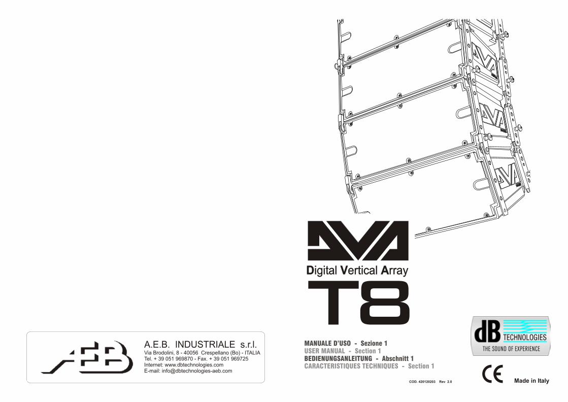
12) “Remote Preset Active” INDICATION LIGHTThis yellow indicator indicates the exclusion of the Volume control and the “DSP Preset” rotary switch (13) when the amplifier is remotely controlled by a computer via RDNET.The indicator flashes slowly if the rotary switch is set to 9 and a previously saved user equalization has been stored.
13) “DSP Preset” 10-position ROTARY SWITCH This 10-position rotary switch makes it possible to select the nine preset equalization curves (selector 0-8) or to select the equalization previously saved by the user via RDNET (selector 9). If this option is not used, curve 9 will be equal to curve 0Refer to the table for the correspondence of the equalization curve.
14) “Service Data USB” Connector Via this USB connector, it is possible to update the firmware of the DVA T8 amplifier module using the computer and a dedicated program.
15) "MAINS INPUT" POWER SOCKETFor connecting the power cable.The connector used for mains connection is a POWER CON® (blue)
16) “MAINS OUTPUT LINK” RELAUNCH POWER SOCKETFor relaunching the mains power. The output is connected in parallel with input (15) and can be used to power another amplified speaker. The connector uses a POWER CON® (grey)
17) "MAINS FUSE" FUSE CARRIERMains fuse housing.
CHARACTERISTICS AND PROTECTION
The speakers’s components in the box are protected by 1.2mm metal steel grille covered by foam on backside.
CoolingThermal control is managed by the main microprocessor that interacts with the local microprocessors (amplifiers and power supply) and communicates the data to the DSP for any corrections.If the amplifier module heats up excessively, the volume is gradually reduced step wise to 0.1dB until the module is thermally stabilised.The volume is automatically restored when the normal operating temperature is reached.
Power onThe diffusor is powered up normally by an initialization process during which the module is powered by the auxiliary power supply.When all of the amplifier peripherals are correctly detected, the main power supply is activated.The IPOS technology (Intelligent Power-On Sequence) introduces a random and differentiated delay for each module prior to the power on of the main PSU (Power Supply Unit).This prevents the breakaway starting currents of the various modules from accumulating, overloading the AC power supply line.At the end of the power on procedure, only the green “READY” LED will remain on fixed on the amplifier module.
Failure indications and safeties
The microprocessor is able to signal three different kinds of failure by flashing the “READY”, “ ” and “LIMIT” LED as reported in the table of diagnostic. The three types of failure are:
1) WARNING: a non severe error or auto-ripristinate malfunction is detected and the performance of the speaker is not limited
2) LIMITATION: an error is detected and diffuser performance is limited. The sound level is reduced or one or more amplifiers are disabled. This state partially influences the correct functioning of the diffuser.If the problem persists the next time the module is turned on, contact the support centre for assistance.
3) FAILURE: a severe malfunction is detected. The speaker switches to “mute”.
If the case of a malfunction, before contacting the support centre, try to turn the module off and on to check if the problem still exists.
Connecting to the mains supply
Each active speaker features its own power cable. Connection is done by a Neutrik POWER CON® (blue) model which permits easy and fast connection to the speaker as well as being an excellent locking system.
The same connector serves as a switch to turn ON and OFF the active loudspeaker by turning the connector to the left (OFF) or right (ON).
The active speaker must be connected to a power supply able to deliver the maximum required power.
Main power supply linking
On the rear of the speaker, a Neutrik POWER CON® connector (grey) offers linking the mains power supply.
This socket links the power supply to another speaker, thereby reducing the direct connections to the mains. Maximum amplifier input power is shown on the amplifier panel.The maximum number of speakers connected together varies of max input power and of the maximum allowed current of the first power socket.
Front Grille
MUTE/PROT
7
15
16
17
Made in Italy
Input
Link
AudioInput Sens
READY
MUTE/PROT
SIGNAL
LIMITER
0dB
+10dB
+4dB
1 = GND2 = HOT3 = COLD
10
2
3
45
6
7
8
9
Active
DataLink
Link
Active
DataInput
Input Control
Balanced Audio
Status
ServiceData
UserRemote Preset
DSP Configuration
SERIAL N.
“CAUTION”RISK OF ELECTRICAL SHOCK
DO NOT OPEN
“AVIS”RISQUE DE CHOCH ELECTRIQUE
NE PAS OUVRIR
ddBB TECHNOLOGIESTECHNOLOGIES
(REPLACE FUSE WITH SAME RATINGS)
MAINSFUSE
220-240V~ (18Amax) 3680Wmax100-120V~ (16Amax) 1320Wmax
100-120V~ 4Amax
MAINSLINK
MAINSINPUT
FULL RANGE
ACTIVE P.F.C.
100-240V~ 50-60Hz
Digital Vertical Array
8220-240V~ 2Amax
220-240V~ (T3,15A L 250V~)
100-120V~ (T6,3A L 250V~)
PU
SH
PU
SH
PU
SH
1
2
6
5
4
3
111098
141312
L177007324
REV SW 2.32

Englis
hE
nglis
hE
nglis
hu
ser
man
ual
user
man
ual
18
user
man
ual
user
man
ual
Englis
hE
nglis
hE
nglis
h
17
TECHNICAL SPECIFICATION
System Active 3-Amps
Type of amplifier Digital - Class D DIGIPRO G2 technology
RMS power 700WHigh (HF) RMS 175WMide (MF) RMS 175WLow (LF) RMS 300W
Musical power 1400W
Frequency response (-6dB) 66-18.000HzFrequency response (-10dB) 61-19.900Hz
Crossover MF-HF (Mid-High) 1900Hz24dB/Oct
Crossover LF-MF (Low-Mid) 400Hz24dB/Oct
Sound pressure (SPL) 132dB max
Component parts 1 woofer 8" - VC 2.5" - Neodymium1 midrange 6,5" - VC 2" - Neodymium2 compression driver 1" - VC 1.4" - Neodymium
Input sensitivity nominal 0dBu
Input impendence Balanced 20KohmUnbalanced 10Kohm
Power supply Full-range with PFC and SMPS100-240V~ 50-60Hz
Inrush current 3,3A
Dimension (WxHxD) 580x386x327mm(23,2x9,6x13,08 inch.)
Weight 14,2Kg(31,3 lbs)
DSP PROCESSOR
DSP Analog Device 56 bitsAudio conversion 24 bit / 96kHz S/N=114dBVolume control DigitalEqualization 9 preset EQU
MECHANICAL PARTS
Box material Polipropilene (PP) Box internal reinforcement SteelFlying support material SteelStirrup angle 0° - 1,5° - 3° - 4,5° - 6° - 8° - 10° - 12,5° - 15°Housing shape Trapezoidal - angle 15°Handle 1 x sideRear grille Performed sheet 1.2mm with internal foam
®
EMI CLASSIFICATION
According to the standards EN 55103 this equipment is designed and suitable to operate in E3 (or lower E2, E1) Electromagnetic environments.
MO
DU
LE
L
ED
LE
D
LE
DL
ED
STA
TU
S«R
EA
DY
» «
MU
TE
/PR
OT
» «
SIG
NA
L»
«L
IMIT
»
Pow
er
ON
OF
FO
N for
5 s
ec.
OF
FO
FF
Norm
al u
seO
N
OF
F
Part
ial f
ault
ON
Tota
l fault
OF
FO
NO
FF
Am
plifi
er
tem
pera
ture
man
ag
em
en
t:F
irst
therm
al
ON
thre
shold
The a
mplif
ier
module
begin
s a g
rad
ual
decr
ease
of th
e v
olu
me in
0.1
dB
m s
teps
to
com
pensa
te 't
em
pera
ture
incr
ease
up to a
m
axi
mum
reduct
ion o
f 3dB
m.
Seco
nd therm
al
ON
Audio
AC
TIV
Eth
resh
old
The a
mplif
ier
module
reduce
s th
e v
olu
me furt
her
3dB
m
alw
ays
in 0
.1dB
m s
teps
up to a
maxi
mum
reduct
ion o
f 6dB
m r
esp
ect
origin
al v
olu
me.
NB
T
he tem
pera
ture
s sh
ow
n o
n the p
lug-in R
Dnet so
ftw
are
refe
r to
the in
tern
al t
em
pera
ture
of th
e p
ow
er
sem
iconduct
ors
.T
hese
te
mpera
ture
s are
not dis
pla
yed the tem
pera
ture
s of acc
ess
ible
part
s use
r
MO
DU
LE
FU
NC
TIO
NS
Audio
MU
TE
DIn
itializ
atio
n o
f th
e a
mplif
ier
module
Norm
al o
pera
tion
Norm
al o
pera
tion
Audio
AC
TIV
EM
odule
initi
aliz
atio
n c
om
ple
te a
nd c
orr
ect
Cyc
lic fla
shin
gN
orm
al o
pera
tion
Norm
al o
pera
tion
Audio
AC
TIV
E(3
or
more
quic
k fla
shes)
The m
odule
has
dete
cted a
part
ial a
nom
aly
and r
em
ain
s act
ive w
ith li
mite
d funct
ions
Cyc
lic fla
shin
gA
udio
MU
TE
DT
he m
odule
has
dete
cted a
serious
anom
aly
and is
in p
rote
cted m
ode
Cyc
lic fla
shin
gN
orm
al o
pera
tion
Norm
al o
pera
tion
Audio
AC
TIV
E(1
slo
w fla
shes)
Cyc
lic fla
shin
gN
orm
al o
pera
tion
Norm
al o
pera
tion
(2 q
uic
k fla
shes)
DIA
GN
OS
TIC
S T
AB
LE
MO
DU
LE
STA
TU
SL
ED
LE
DL
ED
M
OD
UL
E F
UN
CT
ION
S«
»«
»«A
CT
IVE
»
RD
NE
T n
ot act
ive
OF
FO
FF
OF
F
RD
NE
T c
onnect
ON
ON
O
FF
OF
F
Rem
ote
Pre
set
Acti
ve
LIN
K
The m
odule
is funct
ionin
g n
orm
ally
.T
he v
olu
me (
INP
UT
SE
NS
) and the r
ota
ry s
witc
h (
DS
P P
rese
t) a
re a
ctiv
e
Cyc
lic fla
shin
gT
he a
mplif
ier
module
is r
em
ote
ly c
ontr
olle
d b
y R
DN
ET.
T
he v
olu
me (
INP
UT
SE
NS
) and the r
ota
ry s
witc
h (
DS
P P
rese
t) a
re b
ypass
ed
Equaliz
atio
n «
US
ER
Eq»
Cyc
lic fla
shin
gT
he m
odule
funct
ions
norm
ally
.(r
ota
ry s
witc
h
T
he e
qualiz
atio
n s
ave
d b
y m
eans
of R
DN
ET
is b
ein
g u
sed.
«D
SP
Pre
set»
set to
9)
19
Englis
hE
nglis
hE
nglis
hu
ser
man
ual
user
man
ual
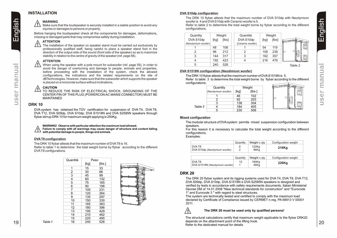
DRK 10DVA system has obtained the TÜV certification for suspension of DVA T4, DVA T8, DVA T12, DVA S09dp, DVA S10dp, DVA S1518N and DVA S2585N speakers through flybar stirrup DRK 10 for maximum weight applying is 250Kg.
WARNING! Observe with particular attention the maximum load allowed.Failure to comply with all warnings may cause danger of structure and content falling with potential damage to people, things and animals.
Quantity Weight
DVA S10dp [kg] [lbs](Neodymium woofer)
1 48 106
2 96 212
3 144 317
4 192 423
5 240 528
Quantità Weight
DVA S10dp [kg] [lbs] (Ceramic woofer)
1 54 119
2 108 238
3 162 357
4 216 476
INSTALLATION
DVA S1518N configuration
(Neodymium woofer)
(Neodimium woofer)
The DRK 10 flybar attests that the maximum number of DVA S1518N is 5.Refer to table 3 to determine the total weight borne by flybar according to the different configurations.
Quantity Weight [kg] [lbs.]
1 46 102 2 92 203 3 138 304
Table 3 4 184 405 5 230 506
Mixed configuration
The modular structure of DVA system permits mixed suspension configuration between speakers.For this reason it is necessary to calculate the total weight according to the different configurations.Examples:
DRK 20The DRK 20 flybar system and its rigging systems used for DVA T4, DVA T8, DVA T12, DVA S09dp, DVA S10dp, DVA S1518N e DVA S2585N speakers is designed and verified by tests in accordance with safety requirements documents, Italian Ministerial Decree DM of 14.01.2008 "New technical standards for construction" and "Eurocode 1" and Eurocode 3 " with regard to steel structures.The system are technically tested and certified to comply with the maximum load declared by Certificate of Compliance issued by CERMET n.reg. PA 68913 V 00001 2011.
The DRK 20 must be used only by qualified persons!
The structural calculations certify that maximum weight applicable to the flybar DRK20 depends on the attachment point of the lifting hook. Refer to the dedicated manual for details
!
!
!
!
!
20
En
glis
hE
nglis
hE
nglis
hu
ser
man
ual
user
man
ual
DVA S10dp configuration
The DRK 10 flybar attests that the maximum number of DVA S10dp with Neodymium woofer is 4 and DVA S10dp with Ceramic woofer is 5.Refer to table 2 to determine the total weight borne by flybar according to the different configurations.
DVA T8 configuration
The DRK 10 flybar attests that the maximum number of DVA T8 is 16.Refer to table 1 to determine the total weight borne by flybar according to the different DVA T8 configurations.
Quantità Peso[kg] [lbs.]
1 15 332 30 663 45 994 60 1325 75 1656 90 1987 105 2318 120 2649 135 29710 150 33011 165 36312 180 39613 195 42914 210 46215 225 495
Table 1 16 240 528
WARNINGMake sure that the loudspeaker is securely installed in a stable position to avoid any injuries or damages to persons or property.
Before hanging the loudspeaker check all the components for damages, deformations, missing or damaged parts that may compromise safety during installation.
ATTENTIONThe installation of the speaker on speaker stand must be carried out exclusively by professionally qualified staff, being careful to place a speaker stand foot in the direction of the output side of the sound (front side of the speaker) so as to maximize stability in relation to the centre of gravity of the speaker (ref. page 58).
ATTENTIONWhen using the speaker with a pole mount for subwoofer (ref. page 59), in order to avoid the danger of overturning and damage to people, animals and properties, before proceeding with the installation of the system, check the allowed configurations, the indications and the related requirements on the site of dBTechnologies. However, make sure that the subwoofer which supports the speaker is placed on a horizontal surface without inclinations.
CAUTIONTO REDUCE THE RISK OF ELECTRICAL SHOCK, GROUNDING OF THE CENTER PIN OF THIS PLUG (POWERCON AC MAINS CONNECTOR) MUST BE MAINTAINED
Table 2
Quantity x qty Configuration weight
DVA T8 8 120KgDVA S10dp (Neodymium woofer) 2 96Kg
Weight
Quantity x qty Configuration weight
DVA T8 12 180KgDVA S1518N (Neodymium woofer) 1 46Kg
Weight
216Kg
226Kg
!

54 621 3 1110 1287 9 1716 181413 15 222019 21
1200Kg(12KN)
1000Kg(10KN)
1300Kg(13KN)
750Kg(7.5KN)
Lifting hook Maximunposition load
1 - 9 1200kg 9 - 13 1300kg13 - 16 1000kg16 - 22 750kg
LIFTING HOOK
Mixed configuration with DVA T8 and DVA T12
The modular structure of DVA System permits mixed suspension configuration between DVA T8 and DVA T12. For this reason, it is necessary to calculate the total weight. Example:
Quantity Weight x qty Configuration weight
DVA T12 10 300KgDVA T8 6 90Kg
390Kg
Mixed configuration with DVA T8 and DVA S1518N (Neodimium woofer)
The modular structure of DVA System permits mixed suspension configuration between DVA T8 and DVA S1518N (Neodimium woofer).For this reason, it is necessary to calculate the total weight.Example:
Mixed configuration with DVA T8 and DVA S10dp (Neodimium woofer)
The modular structure of DVA System permits mixed suspension configuration between DVA T8 and DVA S10dp (Neodymium woofer).For this reason, it is necessary to calculate the total weight.Example:
54 621 3 1110 1287 9 1716 181413 15 222019 21
54 621 3 1110 1287 9 1716 181413 15 222019 21
22
Structural modification of flybar
Original parts dB Technologies
Note
Initiation and Operation
It is prohibited to make any changes to the structure of the flybar and on the stirrups assembling of the speakers.Tampering and/or modify the structure or the accessories may be causes risk of failure or breakage.
It is forbidden to use parts and accessories other than those supplied.Use only dB Technologies original parts.Always install parts in accordance with these installation instruction! Compile and store all DVA system documents in a safe place!
Warning
dB Technologies is not responsible for any possible damage to people, things and animals if the security norms and total weight calculations are not observed!
During installation ensure that carrying structure of the system has added in the total weight also the flybar weight, chain hoists, motors, cables and further weights.
§ 39, VBG 9a of the German employers' liability insurance association's accident prevention regulations requires that load-carrying equipment be inspected by a qualified expert and possible defects be eliminated prior to initial commissioning by the recipient.
§ 41 VBG 9a requires that load-carrying equipment be subjected to a non-routine inspection following damage, repair work and other incidents that can affect load-carrying capacity.
WarningThe safety regulations might be different in other countries. Please check with your national safety authority the valid regulations!
En
glis
hE
ng
lish
En
glis
hu
se
r m
an
ua
lu
se
r m
an
ua
l
!
!
21
En
glis
hE
ng
lish
En
glis
hu
se
r m
an
ua
lu
se
r m
an
ua
l!
WARNING! with particular attention the maximum load of point of attachment of the lifting hook. Failure to comply with all warnings may cause danger of structure and content falling with potential damage to people, things and animals.
Observe
Quantity x qty Configuration weight
DVA T8 20 300KgDVA S1518N (Neodymium woofer) 4 184Kg
Weight
Quantity x qty Configuration weight
DVA T8 14 210KgDVA S10dp (Neodymium woofer) 4 192Kg
Weight
484Kg
402Kg
DV
A T
8D
VA
T1
2
DV
A T
8D
VA
S1
51
8N