DST 1110H-163-76, Small Arms ID Operations Guide Free ...
403
UNCLASS~HED DST-1110H16376 DEFENSE INTELLIGENCE AGENCY SMALL ARMS IDENTIFICATION AND OPERATIONS GUIDE— FREE WORLD APPROVED FOR PUBLIC RELEASE; DISTRIBUTION UNLIMITED 3 FEBRUARY 1984 THIS COPY IS A REPRINT I THAT INCLUDES CURRENT PAGES FROM CHANGES 1 AND 2 LJIIJ~SSIFIED
-
Upload
khangminh22 -
Category
Documents
-
view
2 -
download
0
Transcript of DST 1110H-163-76, Small Arms ID Operations Guide Free ...

UNCLASS~HED DST-1110H16376
DEFENSE
INTELLIGENCE
AGENCY
SMALL ARMSIDENTIFICATION ANDOPERATIONS GUIDE—FREE WORLD
APPROVED FOR PUBLIC RELEASE; DISTRIBUTION UNLIMITED
3 FEBRUARY 1984
THIS COPY IS A REPRINTI THAT INCLUDES CURRENT
PAGES FROM CHANGES 1 AND 2
LJIIJ~SSIFIED

SMALL ARMS IDENTIFICATION AND OPERATIONSGUIDE——FREEWORLD
AUTHORJames F. Kettrick
DST—111OH—163—76—CHG2
DIA Task PT—111O—O1—04L
DATE OF PUBLICATION3 February 1984
Information Cutoff Date1 September 1983
This document supersedes ST—HB—07—163—74.
This is a Department of DefenseIntelligence Document prepared by theForeign Science and Technology Center,US Army Materiel Development andReadiness Command, and approved by theAssistant Vice Directorate forScientific and Technical Intelligenceof the Defense Intelligence Agency.
APPROVEDFOR PUBLIC RELEASE;DISTRIBUTION UNLIMITED
(Reverse Blank)

a

DST—lllOH—163—76—CHG23 February 1984
PREFACE
This guide* is intended to provide informationon the identification, physical characteristics,operation and functioning, user maintenance, acces-sories, and ammunition of free world small arms. Noattempt has been made to provide instruction forcomplete maintenance and repair. This guide doesnot provide information on US small arms or smallarms of Communist origin. The latter weapons arecovered in DST—111OH—394—76, Small Arms Identifica-ET1 w200 427 m336 427 lSBTtion and Operation Guide——Eurasian CommunistCountries
This guide covers, in order, pistols, submachine—guns, rifles, and machineguns. Individual sectionsprovide information on specific weapon models:general information, technical data, operation ofthe weapon, disassembly and assembly, and functioningof the mechanism and accessories normally used withthe basic weapon.
The disassembly and assembly proceduresdescribed are limited to those operations requiredby the user to maintain the weapon properly.Detailed or complete disassembly should not beundertaken because of the danger of lost or brokenparts, which would render the weapon unuseable.Major parts (such as bolts and trigger mechanisms)should not be interchanged between weapons; theseparts are usually numbered to specific weapons, andtheir use in other weapons could cause malfunctions.
*Pages requiring no charges are reprinted and
therefore bear the previous short title and date.Amended and new pages bear the current short titleand date, An asterisk (*) on changed pages indicatesnew or significantly changed information in theparagraph, illustration, or table so indicated.
iii

DST—111OH—163—76—CHG23 February 1984
Unless otherwise specified, the weapons coveredherein should be cleaned and lubricated with thesame materials and techniques used for standard USsmall arms. Special care should be taken to removethe firing residue from the components of the gasmechanism of gas—operated arms.
Many military weapons have “V”—notch rear sightsand post front sights. The correct sight picturewith this type of sight is identical with that usedfor the US Pistol, Caliber 45 M1911A1. The frontsight is centered in the notch with the top of thefront sight level with the top of the rear sight.This sight picture is held at the point where it isdesired that the bullet strike. To zero a weapon’ssights, move them so that the relative motion of therear sight is in the same direction as it is desiredto move the strike of the bullet. Practical range,as used in this publication, is defined by the USArmy Foreign Science and Technology Center (FSTC) asthat range at which the average trained rifleman canbe expected to hit a man—sized target with approxi-mately 50% of his shots.
Constructive criticisms, comments, or suggestedchanges are encouraged and should be forwarded tothe Defense Intelligence Agency, Washington,DC 20301 (ATTN: DT).
iv

DST—111OH—163—76—CHG23 February 1984
LIST OF EFFECTIVE PAGES
SUBJECT MATTER PAGE NUMBERS DATE
Title Page ......... None 3 Feb 1984Preface ............ iii and iv 3 Feb 1984List of Effective
Page ............. v thru vi 3 Feb 1984Record of Changes .. vii (RB) Dec 1976Table of Contents .. ix thru xxv
ix and x Dec 1976xi and xii 3 Feb 1984xiii and xiv 5 Sep 1980xv and xvi 3 Feb 1984xvii andxviii.1 (RB) 5 Sep 1980
xix and xx Dec 1976xxi 5 Sep 1980xii Dec 1976xxiii thru xxv 3 Feb 1984
List of Illustra-tions ............ xxvi thru xxxi
xxvi 3 Feb 1984xxvi.1 (RB) 5 Sep 1980xxvii and xxviii 3 Feb 1984xxix and xxx 5 Sep 1980xxxi and xxxii 3 Feb 1984
List of tables ..... xxxiii (RB) Dec 1976Section I .......... 1 thru 54.16
1 thru 44 Original45 and 46 3 Feb 198447 thru 50 Original51 thru 54 3 Feb 198454.1 thru 54.14 5 Sep 198054.15 and 54.16 3 Feb 1984
Section II ......... 55 thru 126.3 (RB)55 and 56 5 Sep 198057 thru 75 Original76 Dec 1976
v

3 February 1984
SUBJECT MATTER PAGE NUMBERS DATE
Section II (Cont) .. 77 thru 79 Original80 5 Sep 198081 thru 122 Original123 thru 126.3 (RB) 3 Feb 1984
Section III ........ 127 thru 240127 thru 136 Original137 and 138 3 Feb 1984139 thru 172 Original173 and 174 3 Feb 1984174.1 thru 175 5 Sep 1980176 thru 182 Original183 and 184 3 Feb 1984185 thru 188 Original189 thru 192 3 Feb 1984193 thru 218 Original219 and 220 3 Feb 1984221 thru 238 Original238.1 and 238.2 5 Sep 1980238.3 thru 240 3 Feb 1984
Section IV ......... 241 thru 310241 thru 253 Original254 and 255 Dec 1976256 thru 281 Original282 thru 290.2 5 Sep 1980291 thru 299 Original300 thru 304.2 5 Sep 1980305 and 306 Original307 thru 311 (RB) 3 Feb 1984
Section V .......... 313 and 314313 and 314 3 Feb 1984
Distribution List .. 315 thru 318315 thru 318 3 Feb 1984
vi
I

ecember1976 DST-1110H163-76
RECORDOF CHANGES
CHANGE DATE OF DATE SIGNATURE, RANK/RATE AND
NUMBERCHANGE ENTERED ORGANIZATIONOF INDIVIDUAL
ENTERINGCHANGE
(ReverseBlank)
vii


December 1976 DST-111UH-163-75
TABLE OF CONTENTS
Para Page
PREFACE iii
SECTION1. PISTOLS
A. THE 9-MM PISTOLE P1 (WESTGERMANY)
General 1 1TechnicalData 2 2Operation 3 2DisassemblyandAssembly 4 3Functioning 5 5Accesscries 6 7
B. THE 9-MM F.N. BROWNING HIGH POWERPISTOL (BELGIUM)
General 7 8TechnicalData 8 12Operation 9 12DisassemblyandAssembly 10 13Functioning 11 15Accessories 12 17
C. THE 9-MM BERETTA MODEL 1951PISTOL (ITALY)
General 13 18TechnicalData 14 18Operation 15 18DisassemblyandAssembly 16 20Functioning~ 17 21Accessories 18 24
ix

DST-111OH-163-76 December 1978
TABLE OF CONTENTS(Continued).1
Para Page
SECTIONI. PISTOLS(Continued)
D. THE 9-MM M.A.S. MODEL 1950 PISTOL(FRANCE)
General 19 24TechnicalData 20 25Operation 21 25DisassemblyandAssembly 22 26Functioning 23 27Accessories 24 29
E. THE 9-MM M.A.B. P15 PISTOL(FRANCE)
General 25 29TechnicalData 26 30Operation 27 31DisassemblyandAssembly 28 32Functioning 29 33Accessories 30 36
F. THE 9-MM HECKLER AND KOCH P9AND P9SPISTOLS (WEST GERMANY)
General 31 36TechnicalData 32 37
Operation 33 37DisassemblyandAssembly 34 39Functioning 35 40Accessories 36 44
x

L)ST—1I1OH—163—76—CHG23 February 1984
TABLE OF CONTENTS(Continued)
Para Page
SECTION I. PISTOLS (Continued)
G. THE 9—MMMODEL 49 (SIG P210)PISTOL (SWITZERLAND)
General ..................... 37 45Technical Data .............. 38 46Operation ................... 39 46Disassembly and Assembly .... 40 47Functioning ........... 41 48Accessories ................. 42 50
G.1. THE 9—MM MODEL 75 (SIG—SAUERP210) PISTOL (SWITZERLAND)
General ..................... 42.1 52Technical Data .............. 42.2 53Operation . . . . . . . . . . . . . . . . ... 42.3 53Disassembly and Assembly .... 42.4 54.2Functioning ................. 42.5 54.5Accessories ................. 42.6 54.9
H. MISCELLANEOUSPISTOLS
General ..................... 42.1.1 54.10The Spanish 9—mm Super
StarPistol .............. 42.2.154.10The West German 9—mm
VP—70Pistol ............, 42.3.154.11The Japanese9—mm Model
57A Pistol ............... 42.4.1 54.13The Japanese7.65—mm Model
57B Pistol ............... 42.5.1 54.14
xi

DSf—iL1Ut1—JMi—/ b—UFib Z3 February 1984
TABLE OF CONTENTS (Continued)
Para Page
I. MAINTENANCE
Care and Cleaning ........... 43 54.15Malfunctions and Stoppages .. 44 54.15
SECTION II. SUBMACHINEGUNS
A. TIlE 9—MML2A3 and L34A1SUBMACHINEGUNS (UK)
General ....... 45 55Technical Data .............. 46 56Operation . . . . * 47 56Disassembly and Assembly .... 48 58Functioning 49 59Accessories 50 62
B. THE 9—NM UZI SUBMACHINEGUN(ISRAEL)
General ..................... 51 62Technical Data .............. 52 63Operation 53 64Disassembly and Assembly .... 54 65Functioning ................. 55 66Accessories .. ... 56 68
C. THE 9—MM M.A.T. MODEL 1949SUBMACHINEGUN (MAT-49)(FRANCE)
General . 57 69Technical Data ....... 58 70Operation . . . . . . * . . . . . * 59 70Disassembly and Assembly .... 60 72Functioning .... ... 61 73Accessories ................. 62 74
xii
5 September 1980 DST—111OH—163—76—CHG1
TABLE OF CONTENTS (Continued)
Para Page
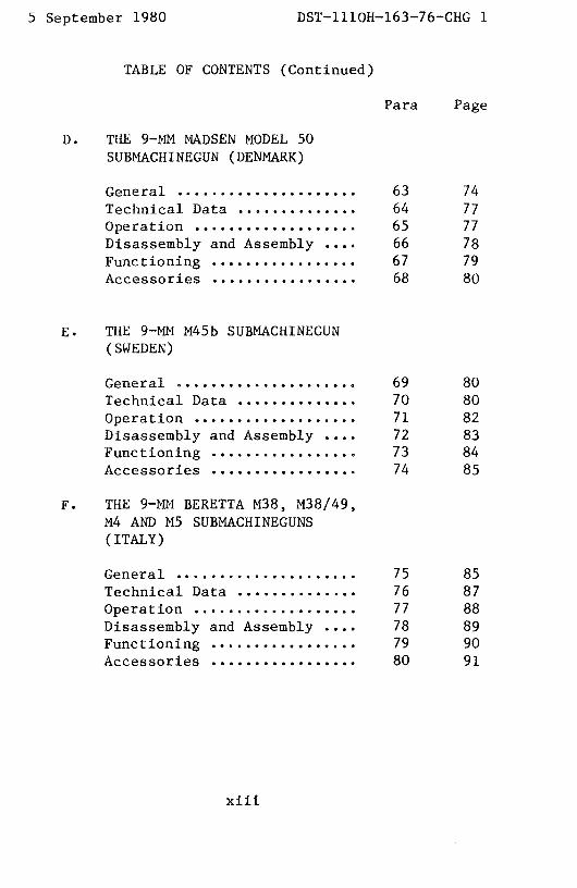
D. THE 9—MM MADSENMODEL 50SUBMACHINEGUN (DENMARK)
General 63 74Technical Data 64 77Operation 65 77Disassembly and Assembly .... 66 78
Functioning 67 79Accessories 68 80
E. THE 9—MN M45b SUBMACHINEGUN(SWEDEN)
General 69 80Technical Data 70 80Operation 71 82Disassembly and Assembly .... 72 83Functioning 73 84Accessories 74 85
F. THE 9—MM BERETTA M38, M38/49,M4 AND MS SUBMACHINEGUNS(ITALY)
General 75 85Technical Data 76 87Operation 77 88Disassembly and Assembly .... 78 89Functioning 79 90Accessories 80 91
xiii

Dsr—1iiou—ibi—/~—uri( I ~ September I~3~$U
TABLE OF CONTENTS (Continued)
Para Page
G. THE 9—MNBERETTA MODEL 12SUBMACHINEGUN (ITALY)
General 81 91Technical Data 82 92Operation 83 92Disassembly and Assembly .... 84 94Functioning 85 95Accessories 86 96
H. THE 9—MMSTEYR MODEL 69SUBMACHINEGUN (MPi STEYR 69)(AUSTRIA)
General 87 97Technical Data 88 97Operation 89 97Disassembly and Assembly ... 90 100Sight Adjustment 91 102Functioning 92 104Accessories 93 107
1
xiv

3 February 1984
TABLE OF CONTENTS (Continued)
Para Page
SECTION II SUBMACHINEGUNS (Continued)
I • THE 9-NM WALTHER NP-K ANDMP—L SUBMACHINEGUNS (WESTGERMANY)
General • . * . . . * * . * . . . . . • . * * . . 94 108Technical Data .............. 95 108Operation •. * • ••...•.. * • . . * . * 96 109Disassembly and Assembly .... 97 111Functioning................. 98 112Accessories ................. 99 115
J. THE 9—MM H&K MP5 (HK52)SUBMACHINEGUN(WEST GERMANY)
General ..................... 100 115Technical Data .............. 101 117Operation ................... 102 117Disassemblyand Assembly .... 103 117Functioning................. 104 117Accessories ................. 105 117
K. THE 9—MMSTEN SUBMACHINEGUN(UK)
General * * . . * . . * * . * . . 106 117Technical Data .............. 107 119Operation •.................. 108 119
xv

~J.~LL LL~LLLU.JI U’..,fl~J £.
3 February 1984
TABLE OF CONTENTS (Continued)
Para Pagea
SECTION II. SUBMACHINEGUNS (Continued)
K. THE 9-NM STEN SUBMACHINEGUN(UK) (Continued)
Disassemblyand Assembly .... 109 120Functioning ...•............. 110 122Accessories ....•............ 111 124
L • MISCELLANEOUS SUBMACHINEGUNS
General .•........ ..... ..... . 111.1 124The Belgium Vigneron
Submachinegun•...•....... 111.2 124The PortugueseF.B.P. M/48
Submachinegun•........... 111.3 125The South Korean K—i
Submachinegun.e.......... 111.4 126
N • MAINTENANCE
Care and Cleaning ........... 112 126Malfunctions and Stoppages .• 113 126.1
SECTION III. RIFLES
A. THE 5.56—MM C.A.L. ASSAULTRIFLE (BELGIUM)
General . . * . . * * . . * * • . . . . * . • * . 114 127TechnicalData.............. 115 127
xvi

December1916 DST-111OH-163-76
TABLE OF CONTENTS (Continued)
Para Page
SECTION III. RIFLES (Continued)
A. The 5.56-MM C.A.L. ASSAULT RIFLE
(BELGIUM) (Continued)
Operation 116 127
DisassemblyandAssembly 117 130
Functioning 118 133
Accessories 119 136
B. THE 5.56-MM HECKLER AND
KOCH HK33 AND HK53 ASSAULT
RIFLES (WEST GERMANY)
General 120 137
TechnicalData 121 139
Operation 122 139
DisassemblyandAssembly 123 139
Functioning 124 139Accessories 125 139
C. THE 7.62-MM FN/FAL RIFLE
(BELGIUM, UK, ETC.)
General 126 140
TechnicalData 127 144
Operation 128 144
Disassemblyarid Assembly 129 147
Functioning 130 148
Accessories 131 151
xvii

TABLE OF CONTENTS(Continued)
Para Page
D. THE 5.56—MM GALIL RIFLE(ISRAEL)
General . 132 152TechnicalData 133 153Operation ...... 134 153Disassembly and Assembly .... 135 158Functioning 136 159Accessories 137 163
E. THE 5.56—MM BERETTAM70/.223RIFLE (ITALY)
General . 138 165TechnicalData 139 167Operation 140 167Disassembly and Assembly .... 141 169Functioning 142 171Accessories. 143 173
E.1 THE 5.56—MM St.G 77 (AUG)RIFLE (AUSTRIA)
General 143.1 174TechnicalData 143.2 174.2Operation 143.3 174.2Disassembly and Assembly .... 143.4 174.7Functioning 143.5 174.12Accessories . 143.6 174.17
xviii

5 September1980 DST—111OH—163—76—CHG1
TABLE OF CONTENTS(Continued)
Para Page
F. THE 7.62—MM G3 RIFLE (WESTGERMANY, ETC.)
General • . 144 174.18TechnicalData. ........ 145 176Operation .... 146 176Disassembly and Assembly •... 147 177Functioning................. 148 179Accessories ................. 149 183
xviii.1(Reverse Blank)


uecemnerui/b DST-111OH-163-76
TABLE OF CONTENTS (Continued)
Para Page
SECTION III. RIFLES (Continued)
G. THE 7.62-MM BERETTA BM-59
RIFLE (ITALY)
General 150 183
TechnicalData 151 185
Operation 152 185DisassemblyandAssembly 153 186
Functioning 154 188
Accessories 155 190
H. THE 7.5-MM MODEL 49 AND 49/56
RIFLES (MAS 49 AND MAS 49/56)
(FRANCE)
General 156 191
TechnicalData 157 193
Operation 158 193
DisassemblyandAssembly 159 196
Functioning 160 197
Accessories 161 199
THE 7.5-MM StG57 (SIG 510)
ASSAULT RIFLE (SWITZERLAND)
General 162 200
TechnicalData 163 202
Operation 164 203
Disassemblyand Assembly 165 204
xix

IJST-111UH-1bJ-ib December1916
TABLE OF CONTENTS (Continued)
Para Page
SECTIONIII. RIFLES (Continued)
THE 7.5-MM StG57 (SIG 510)ASSAULT RIFLE (SWITZERLAND)
(Continued)
Functioning 166 206
Accessories 167 211
J. THE 7.62-MM TYPE 64 RIFLE
(JAPAN)
General 168 213
Technical Data 169 214
Operation 170 214
Disassembly and Assembly 171 215
Functioning 172 216
Accessories 173 218
K. THE 7.5-MM FR-Fl SNIPER’S
RIFLE (FRANCE)
General 174 218
Technical Data 175 220
Operation 176 220
Disassembly and Assembly 177 222
Functioning 178 225
Accessories 179 226
xx

.—.-,..- ~.~J.~J~--—J..J_J—I u’..ruJ I
TABLE OF CONTENTS (Continued)
Para Page
L. THE 7.5—MM MODEL 1936 RIFLE(MAS—36) (FRANCE)
General 180 228Technical Data 181 229Operation... 182 229Disassembly and Assembly .... 183 230Functioning 184 230Accessories 185 231
N. THE .303 CALIBER (7.7—MM) LEEENFIELD RIFLES (UK)
General 186 231TechnicalData 187 233Operation 188 234Disassembly and Assembly .... 189 236Functioning 190 237Accessories 191 238
N. MISCELLANEOUSRIFLES
General 191.1 238.1The French 5.56 FA.M.A.S.
Rifle 191.2 238.1The West German H&K SSG
Sniper’s Rifle 191.3 238.2The Austrian Stegr 7.62—MM
SSG Sniper’s Rifle 191.4 238.2The Belgium 5.56—MM FNC
Assault Rifle 191.5 238.3
xxi

DST-111OH-163-16 December 1976
TABLE OF CONTENTS (Continued)
Para Page
p
SECTIONIII. RIFLES (Continued)
0. MAINTENANCE
CareandCleaning 192 240MalfunctionsandStoppages 193 240
SECTION IV. MACHINEGUNS
A. THE 7.62-MM M.A.G. 58 (BELGIUM)andL7A1 (UK) MACHINEGUNS
General 194 241TechnicalData 195 243Operation 196 244DisassemblyandAssembly 197 246Functioning 198 247Accessories 199 251
B. THE 7.62-MM AND .303 (7.7-MM)BREN LIGHT MACHINEGUNS (UK)
General 200 252Technical Data 201 256
Operation 202 256DisassemblyandAssembly 203 258Functioning 204 259Accessories 205 262
xxii

DST—1110H—163—76—CHG23 February 1984
TABLE OF CONTENTS(Continued)
Para Page
SECTION IV. MACHINEGUNS
C. THE 7.5—MM AA—52 MACHINEGUN(FRANCE)
General • . . * * • * . . • * • * * • . . * . . . 206 262Technical Data .............. 207 264Operation ................... 208 265Disassembly and Assembly •... 209 267Functioning ................. 210 269Accessories ................. 211 272
D. THE 7.5—MM MODEL 24/29 LIGHTMACHINEGUN (FRANCE)
General .. .. 212 273Technical Data •............. 213 274Operation ................... 214 274Disassembly and Assembly .... 215 276Functioning ......... 216 278Accessories ................. 217 281
E. THE 5.56—MM or 7.62—MM HECKLERAND KOCHIlK 13, IlK 21, ANDIlK 2lAl MACHINEGUNS (WESTGERMANY)
General . • * . • * . * . . • . . . 218 282TechnicalData.............. 219 283Operation .... .. 220 284
xxiii

DST—lllOH—163—76C11G23 February 1984
TABLE OF CONTENTS (Continued)
Para Page
E. THE 5.56—MN or 7.62—MM HECKLERAND KOCH IlK 13, UK 21, ANDIlK 21A1 MACHINEGUNS (WESTGERMANY) (Continued)
Disassemblyand Assembly .... 221 286Functioning •.........•...... 222 286Accessories ................. 223 287
F. THE 7.62—NM MG—1/MG—3MACHINEGUN (WEST GERMANY)
General .........•....•...... 224 287Technical Data .............. 225 292Operation................... 226 292Disassembly and Assembly .... 227 294Functioning ................. 228 296Accessories ................. 229 299
G • THE 7.62—MM TYPE 62 ANDTYPE 74 MACHINEGUNS(JAPAN)
General .............•.....•. 230 300Technical Data .............. 231 302Operation................... 232 302Disassembly and Assembly .... 233 304Functioning ................. 234 304.2Accessories ................. 235 307
* H. THE 5.56—MMMINIMI LIGHTMACHINEGUN(BELGIUM)
General . .. . •• ....••. ........ 235.1 308TechnicalData.............. 235.2 309Operation ................... 235.3 309
xxiv

DST—111OH—163—76—CHG23 February 1984
TABLE OF CONTENTS(Continued)
Para Page
SECTION IV. MACHINEGUNS
I • MAINTENANGE
Care and Cleaning ........... 236 309
Malfunctions and Stoppages .. 237 309SECTION V. AMMUNITION
General ..................... 238 313References .................. 239 313
DistributionList ..••....•...•....... 315
xxv
DST—111OH—163—76—CIIG 23 February 1984
LIST OF ILLUSTRATIONS
Figure Page
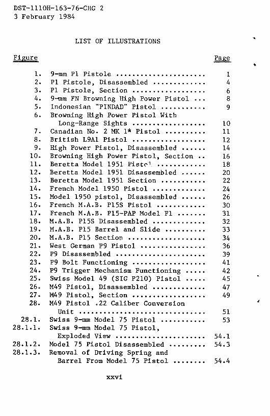
1. 9—mm P1 Pistole 12. P1 Pistole, Disassembled 43. P1 Pistole, Section 64. 9—mm FN Browning High Power Pistol ... 85. Indonesian ~PINDAD’~Pistol 96. Browning High Power Pistol With
Long—Range Sights 107. Canadian No. 2 MX 1* Pistol 118. British L9A1 Pistol 129. High Power Pistol, Disassembled 14
10. Browning High Power Pistol, Section .. 1611. Beretta Model 1951 Pistc~1. 1812. Beretta Model 1951 Disassembled 2013. Beretta Model 1951 Section 2214. French Model 1950 Pistol 2415. Model 1950 pistol, Disassembled 2616. French M.A.B. P15S Pistol 3017. French M.A.B. P15—PAPModel Fl 3118. M.A.B. P1SS Disassembled 3219. M.A.B. P15 Barrel and Slide 3320. M.A.B. P15 Section 3421. West German P9 Pistol 3622. P9 Disassembled 3923. P9 Bolt Functioning 4124. P9 Trigger Mechanism Functioning 4225. Swiss Model 49 (SIG P210) Pistol 4526. M49 Pistol, Disassembled 4727. M49 Pistol, Section 4928. M49 Pistol .22 Caliber Conversion
Unit 5128.1. Swiss 9—mmModel 75 Pistol S3
28.1.1. Swiss 9-mm Model 7S Pistol,Exploded View S4.1
28.1.2. Model 75 Pistol Disassembled 54.328.1.3. Removal of Driving Spring and
Barrel From Model 75 Pistol 54.4
xxvi

5 September 1980 DST—111OH—163—76—CHG1
LIST OF ILLUSTRATIONS
Figure Page
28.1.4. Model 7S trigger mechanism, cocked .. 54.628.1.S. Model 75 trigger mechanism, at rest . 54.728.1.6. Swiss Model 75 pistol with (from
left to right) cleaning kit, sparemagazine carrier, and holster 54.9
28.2.1. The Spanish 9—mm Super Star Pistol .. 54,1128.2.2. The West German 9—mmH&K VP—70
machinepistol 54.1228.2.3. The VP—7Owith holster—stock
attached 54.1228.2.4. The Japanese 9—mm Model 57A pistol .. 54.1328.2.5. The Japanese 7.65—mm Model 57B
pistol 54.13
xxvi .1(Reverse Blank)


DST—1110H—163—76—CHG23 February 1984
Figure Page
29. British L2A3 Submachinegun ........... 5530. British L34A1 Silenced
Submachinegun * * . . . . * • . . . * * • . . . . . * • . 5631, L2A3 Submachinegun, Section .......... 6032. Israeli UZI Submachinegun, Early
Model .............................. 6333. UZI Submachinegun, Late Model With
Folding Butt . . . . . • . . . * . • . * • . . * • • . . . 6434. UZI Submachinegun, Field Stripped .... 6635. UZI Submachinegun, Section ........... 6736. French M.A.T. 49 Submachinegun ....... 7037. M,A.T.49Disassembled............... 7338. Danish Madsen Model 50
Submachinegun . . * . . . . * • * * • * . . • * . • . • * 7539, Madsen Model 1953 Submachinegun •..... 7640. Brazilian INA 53 Submachinegun....... 7641. MadsenM1946 SubmachinegunSection •.. 7942. Swedish M45b Submachinegun ........... 8143. Egyptian Port Said Submachinegun ..... 8144, M45b Section ......................... 8445. Italian Beretta M38A Submachinegun •.. 8646. Beretta M38/42 Submachinegun ......... 8647, Beretta Model 4 and Model 5
Submachineguns ..................... 8748. Beretta Submachinegun, Disassembled •. 8949. Italian Beretta Model 12
Submachinegun (Early Model) .•...... 9150. Beretta Model 12 Submachinegun,
Stock Folded, (Late Model) •........ 9451. Beretta Model 12 Disassembled ........ 9852. Austrian Steyr MPi 69 Submachinegun .. 9853, MP1 Steyr 69 Disassembled .........•.. 10154, MPi Steyr 69 Section •...•.........,.. 10555. West German Walther NP—K
Submachinegun . * • • • . • . • . . . * . . * • . . * . . 10856. West German Walther MP—L
Submachinegun. . • . . * . • . . . . * . * • . . . . • * 109
xxvii
DST—111OH—163—76—CHG23 February 1984
Figure Page
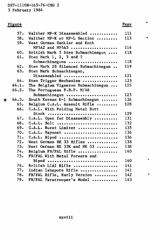
57. Walther NP—K Disassembled •..•........ 11158. Walther NP—K or MP—L Section •........ 11359. West German Heckler and Koch
NP5A2andMP5A3.................... 116
60. British Mark 5 Sten Submachinegun .... 11861. Sten Mark 1, 2, 3 and 5
Submachineguns • . • . . . . •... ... .....,. 11862. Sten Mark 2S Silenced Submachinegun.. 11963. Sten Mark Submachinegun,
Disassembled ....................... 12164. Sten Trigger Mechanism •.............. 123
64.1. The Belgium Vigneron Submachinegun... 12564.2. The PortugueseF.B.P. M/48
Submachinegun• • . • • . . . . . • . . . • . . . . . . . 125* 64.3. South Korean K—i Submachinegun •...... 126
65. Belgium C.A.L. Assault Rifle •........ 12866. C.A.L. With Folding Metal Butt
Stock ...........•.................. 12967. C.A.L. Open for Disassembly .......... 13168. C.A.L. Bolt .s..........o..•.•e,...... 13269. C.A.L.BurstLimiter .....•...•....... 13570. C.A.L. Bayonet • . . . • . . . . . . * . . • • • . . • . . . 13671. C.A.L. Bipod •..•e••o••...•........... 13672. West German IlK 33 Rifles ............. 13873. West German UK 33K and UK 53 •........ 13874. BelgiumFN/FALRIf1e..............•.. 14075. FN/FAL With Metal Forearm and
Bipod . . • . . . . • . . . . . . . . . . . . . . . • . . . . • . 14076. BritishLlAi Rifle ................... 14177. Indian Ishapore Rifle ...............• 14178. FN/FAL Rifle, Early Version •......... 14279. FN/FAL Paratrooper’s Model ........... 143
xxviii

~eptember L9~3U DST—iliOH—163—76—CHG 1
LIST OF ILLUSTRATIONS
Figure Page
80. Canadian C2A1 automatic rifle 14381. FN/FAL (FALO) automatic rifle 14382. Israeli FN/FAL rifle and automatic
rifle 14483. L1A1 receiver details 14S84. FN/FAL bolt mechanism 14985. FN/FAL trigger 15086. Israeli Galil rifle 15387. Galil on bipod 15488. Galil with folded stock 15489. Loading theGalil 15590, Loading a rifle grenade 15791. Removing gas cylinder tube 15892. Gaul mechanism 16193. Using the Galil to cut wire 16394. Galil bayonet 16495. Galil bottle opener 16496. Galil front night sight 16597. Italian Beretta M7O/.223 rifle 16698. Beretta M70/.223 rifle with folding
stock (early model) 16699. Beretta M7O/.223 automatic rifle .... 167
100. Beretta M7O/.223 disassembled 169101. Beretta M7O/.223 section 172102. Beretta M7O/.223 bayonet 173103. Beretta M7O/.223 telescopic sight ... 174
103.1. Austrian 5.56—mm St.G. 77 (AUG)assault rifle with 508—mmbarrel .. 174.1
103.2. Austrian St.G. 77 (AUG) with 610—mmbarrel. Operating handle lockedto rear 174.2
103.3. St.G. 77 (AUG) controls 174.3103.4. Barrelremoval 174.5103.5. Barrelremoved 174.6103.6. Separation of receiver from stock ... 174.7
xxix

DST—lllOH—163—76—CHG 1 5 September1980
LIST OF ILLUSTRATIONS
Figure Page
103.7. Removal of bolt mechanism fromreceiver 174.8
103.8. Bolt unit disassembled 174.9103.9. Releasing rear sling swivel 174.10
103.10. Stock unit disassembled 174.11103.11. St.G. 77 (AUG) field stripped 174.12103.12, Boltfunctioning 174.13103.13. Hammer housing functioning 174.16
104. Early G3 (CETME) rifle 174.18105. West German G3 rifle 175106. G3 disassembled 178107. G3 bolt functioning 179108. G3 rifle section 181109. Italian BM 59 Mark 1 rifle 183110. BM 59 Mark Ital rifle 184111. BM 59 Mark Ital—A paratrooper’s
rifle 184112. BM 59 mechanism 189113. French M.A.S. 49 rifle 191114. M.A.S. 49 grenade launcher 192115. M.A.S. 49/56 rifle 192116. M.A.S. 49/56 with rifle grenade 194117. M.A.S. 49/56 grenade launcher
and sight 195118. M.A.S. 49 disassembled 196119. M.A.S. 49/56 section 197120. M.A.S. 49/56 bolt 198121. M.A.S. 49/S6 bayonet 200122. Swiss St.G. S7 assault rifle 201123. St.G. 57 with bipod extended 201124. Swiss SIG 510—4 assault rifle 202125. Early SIG 510 assault rifle 202126. St.G. 57 disassembly 20S127. St.G. S7 bolt functioning 206128. St.G. 57 bolt 207129. SIG 510—4 section 208130. St.G, 57 trigger mechanism 209
xxx

usr—iiiUki—163—75—CHG 23 February 1984
Figure Page
131. St.G. 57 Trigger Functioning ........ 210132. Japanese Type 64 Rifle .............. 213133. French FR—Fl Sniper’s Rifle .... 218134. FR—Fl, Left Side View ............... 219135. APX 804 Telescopic Sight •........... 219136. Sight Picture . . . . . * . . • • . . • * . . * . 222137. FR—Fl Bolt Removal .................. 223138. French M.A.S. 36 Rifle •............. 228139. French M.A.S. 36 CR 39 Rifle ........ 229140. Lee Enfield Rifles ........... 233
140.1. The French F.A.M.A.S. Rifle ......... 238.1140.2. The West German H&K SSG Sniper’s
Rifle ................. 238.2140.3. The Austrian 7.62—mm Steyr SSG
Sniper’s Rifle ...................• 238.3140.4. The Belgium 5.56—mm FNC Assault
Rifle, StockExtended •............ 238.4140.5. The Belgium FNC Assault Rifle,
Stock Folded . * . . • . . . • . . • . . . • • . . * • . 238.4141. Belgium M.A.G. Machinegun * 241142. British L7A1 Machinegun •............ 242143. M.A.G.onTripodMount ......... 242144. L7A1 on Tripod Mount (w/o Butt
Stock) ••...••• * 24314S. Tank Versions of the M.A.G./L7A1 .,.. 243146. M.A.G. Disassembled. 246147. M.A.G. Bolt Functioning •.. ... 248148. M.A.G. Trigger Functioning .. 249149. M.A.G. Feed Mechanism Functioning ... 250150. Mark 1 Bren .... * 253151. Mark 2 Bren ... • 2S3152. Mark 2M Bren .,., 254153. L4A1 Bren . ... 254154. L4A1 Bren •.... 255lS5. Nationalist Chinese Type 41 Bren .... 255
xxxi

DST—11 lOU—i 63—76—CHG23 February 1984
Figure Page
156. Bren Bolt and Trigger MechanismFunctioning .• ..••...•. ....• ....... . 260
157. French AA—52 Light Machinegun ........ 263158. French AA—52 Heavy Machinegun .. 263159. AA—52 Heavy Machinegunon Tripod ..•.. 264160. AAT—52 Tank Machinegun ............... 265161. AA—52 Barrel Change .............•.... 267162. AA—52 Disassembled.........•.•....... 268163. AA—52 Section . . . . * ...• . * • • • . . . . . • . . . . 270164. AA—52 Bolt and Feed Cover ............ 272165. French Model 24/29 Light Machinegun .. 274166. M24/29 Disassembled .................. 277167. M24/29Section....................... 279168. M24/29 Trigger Mechanism ............. 280169. West GermanUK 13 Light Machinegun ... 282170. West GermanIlK 21 Machinegun ......... 283
170.1. West GermanIlK 21A1 Machinegun .•..... 283171. West German UK 21A1 Feeder ........... 285
171.1. Inserting Feed Belt With Feed Tab;Feeder Closed ...................... 286
172. UK21 Barrel Change ... .......... 287173. H2l Section ........ .. .... .. ... 288174. UK 2iAl FeederMechanism ..... 290175. Old German MG 42 Machinegun .......... 290176. West German MGi or MG3 Machinegun ...• 291177. MG 42, MGi, MG3 Barrel Change ........ 293178. MG—i Disassembled ........•........... 29S179. MG—i Bolt .................... 296180. MG—i Bolt Functioning ................ 297181. MG—i Trigger Functioning .•. ... 298182. Japanese Type 62 Machinegun .......... 300
182.1. Japanese Type 74 Machinegun ... .. 301183. Type 62 With Telescopic Sight
Attached . . * . . * . . . * • . . . * . . . . * * 301183.1. Current Production Type 62 .. 302
184. Type 62 Disassembled ................. 304.1185. Type62Section...... .......... 306
* 185.1. Belgian Minimi Light Machinegun ...... 308186. Ammunition Identification Guide ...... 314
xxxii

Uecember1916 DST-111OH-163-75
LIST OF TABLES
Table Page
I. Pistol TechnicalData 54,15II, Pistol Malfunctions 54.16
III. SubmachinegunTechnicalData 125IV. Submachinegun Malfunctions . 126V. Rifle TechnicalData 239
VI. Rifle Malfunctions 240
VII. MachinegunTechnicalData . . 309VIII. Machinegun Malfunctions . . . 310
(ReverseBlank)
xxxiii


ST-H B-O1-1 63-14Original
SMALLARMSIDENTIFICATION AND OPERATION
GUIDE—FREEWORLD
SECTIONI. PISTOLS
A. THE 9-MM P~ST0LEP1 (WEST GERMANY)
1. General
a. The 9-mm Pistole P1 (fig 1) is the standardsidearm of
the West GermanArmy. Commercial versionsare usedby otherarmies. The P1, descendedfrom the World War II vintage German
P-38,differs from the older pistol in its lightweight dural receiver
and redesignedfiring pin. The latter is not interchangeablewiththe older P-38 firing pin. The P1 and its civilian version, the P-38,
both bear identical manufacturers’markings on t~he slide: theword “Waither” enclosedin a bannerfollowed by the legend“Carl
Waither Waffenfabrik Ulm/Do.” Below this a secondline reads
“P1 Cal 9-mm” for West German Army weapons,or “P-38 Cal
9-mm” for commercialweapons.World War II vintageP-38’scarrya code symbol such as “ac”, “byf”, ‘~cyq”,or “svw” with atwo-digit date on the slide.
r1AM ‘)~‘~‘
V V .-MAG~ZINFCATCI-1
Figurc 9-mm P1 pistolc.
1

ST-H 8-07-163-74Original
b. The P1 is an eight-shot,semiautomatic,recoil-operatedweapon fed from a detachable box magazine. This pistol has a
double—action trigger mechanism that, in addition to conventional
functioning, allows the hammer to be cocked and released by a
single long pull on the trigger. The P1 fires the 9x19-mmpistolcartridge(secV).
2. TechnicalData
Technical data concerning the Pistole P1 aregivenin table I.
3. Operation
a. Remove the magazine by pressing the magazine catch
(fig 1) rearward,away from the magazine, and withdrawing themagazine.If open, the slide can be closed either by pulling itslightly rearward and releasing it, or by pressing the slide stop(fig 1) downward.
b. Load the magazine by placing a cartridge on themagazine follower just forward of the feed lips; press the cartridge
down andslide it to the rear, under the feed lips, until it seatsagainstthe rear wall of the magazine.Repeatthis actionuntil themagazineis full.
c. Insert the magazineinto the pistol until the magazinecatch(fig 1) snapsinto place.
d. Grasp the slide by its serrations and pull it fullyrearward.Releasethe slide, and it will run forward and load thefirst cartridge.CAUTION: Thepistol is nowreadyto Lire. A smallpin (fig 3) protrudesfrom the slide,abovethe hammer,to indicatethat the pistol hasa cartridgein its chamber.
2

I -flb-U,-iOj-I~Original
e. If desired,set the pistol on safeby rotating the safetylever (fig 1) downwardas far as possible.If the hammeris cocked,it will snapforward,but thepistol will not fire.
f. To fire the weapon,rotate the safetyupwarduntil itslever is horizontal. The hammer can be manually cocked bypressing it rearward by thumb pressureor, when the pistol isaimed,the trigger canbe pressedthrough its full travel.(The first
method is preferredbecauseof thegreateraccuracyof fire.) Usinga conventionalsight picture, aim and pressthe trigger for eachshot. The slide will remain open when the last round is fired.Removethe magazine(a above).
g. To clearthe pistol, set it on safe(e above),removethemagazine,and retract the slide. Pressthe slide stop upward andreleasethe slide; it will be held open. Inspect to insure that nocartridges are pi’-sent. Pressdown the slide stop and insert themagazine.
4. Disassembly andAssembly
To disassemblethe P1 for cleaning, and to reassembleit, thefollowing stepsmustbe taken:
a. Clear the weapon (para 3g), but do not insert the
magazine.Leavethe safety leverseton safe.Retractthe slide,andlock it to the rear with the slide stop (para 3g). Rotate the
takedown lever (fig 1) downward. Pull the slide slightly rearward
(to release the slide stop); then ease it forward. The hammer will
fall as the slidealignswith the receiver;continueto move the slideforward until both it and the barrelare free of the receiver.
b. Invert the slide and barrel. Press in on the unlockingplunger (fig 2) to unlock the barrel from the slide and push thebarrelforward,out of the slide.
3

d. To reassemblethe pistol, insert the barrel into theinverted slide;when the barrel is seatedagainsttheslide face,pressthe lock (fig 2) down.
e. Be sure that the hammer is uncocked, that the ejector is
pushedforward into the magazinewell, and that the takedownleveris rotatedfully forward.
f. Turn the slideso that the sightsareup andjoin theslideto the receiver.Pull the slide fully rearwardandhold it there with
the slide stop. Rotate the takedown lever back to its normalposition.Releasethe slideandinsertthe magazine.
~I -nD-UI- 10JI’+
Original
Figure 2. P1 pistol, disassembled,
c. No furtherdisassemblyis necessarynor desirable.
4

ST-H8-07-1 63-74Original
5. Functioning
a. The P1 pistol is recoil operated. The barrel and slide are
locked togetherat the instantof firing; the rearwardmovementof
the barrel (as the result of recoil) unlocks the slide from the barrel
and imparts to the slidesufficient inertia to drive it fully rearward
against the driving springs. These springs provide the thrust todrive the slide forward and to reload the barrel with anothercartridge.
b. if the hammer is in its forward position,finger pressureon the trigger moves the trigger bar (fig 3-14) forward. A hook on
the upper rear end 0f the trigger bar engagesthe sear (fig 3-15),
and as the trigger bar continuesforward, the searrotatesupward.
The pawl (fig 3-12) on the hammeris lifted by the searandcausesthe hammer to rock back. The sear eventually moves far enough
forward to releasethe pawl; when this happens,the hammer,under the force of its spring (fig 3-8), swings forward and strikes
the firing pin to fire the pistol. As the slide recoils, it depressesthe
trigger bar, which then disengagesfrom the sear.The searspring
immediatelyreturnsthe searto its original position.
c. As the slide recoils, it rocks the hammer back. Aprojection on the bottom of the hammer contacts the sear andlifts it up. When the slide counterrecoils and releases the hammer,the projection on the bottom of the hammer is caught by a notchin the bottom of the spring loaded sear (fig 3-15), and the hammeris held cocked.
d. Pressureon the trigger moves the trigger bar (fig 3-14)
forward, and a hook on the end of the trigger bar pulls the searout of engagementwith the hammer.The hammerswingsforward
and strikes the firing pin (fig 3), to fire the cartridge.The recoiling
slide depressesthe trigger barout of engagementwith the sear,and
the action describedin paragraphc abovestartsagain.
5

Figure 3. P1 pistol, section.

I flDUI IU.)-I’+
Original
e. The barrel is locked to the slide by the lock (fig 3), andtogether they recoil on the receiverwhenthe pistol fires. As thelock moves rearward,off a shelf in the receiver, the unlockingplunger (fig 3) hits the receiver and stops. The lock movesrearward onto the now stationary unlocking plunger and iscammeddown out of engagementwith the slide.
f. Becauseof its inertia, the slide continuesrearwardandcompressesthe dual driving springs.The extractorpulls the firedcartridge from the barrel andholds it to the slide until the casestrikes the ejectorand is expelled. The driving springsforce theslide forwardanda new cartridgeis loadedinto the chamber.
g. The barrel is held rearwardby thelock, which in turn ishelddown by ribs insidethe slide. When the locking recessesin theslide align with the lock, the barrelis driven forwardby the slideand a cam surfacelifts the lock, which locks the barrel andslidetogether.
h. When the safety lever is rotatedto the safeposition, acam surface depressesthe trip (fig 3-18). The trip forcesthe searout of contact with the hammer, and the hammer falls. As itrotates,the safetyalso interposesa solid block in the pathof thefiring pin. Thispreventsthepistol from firing.
i. A ledgeon the magazinefollower pushesthe slide stopupwardwhen the last round is fed from the magazine.The stopthenautomaticallyholdsthe slide open.
6. Accessories
A leatherholsterwith a pocket for an extramagazine,a cleaningrod, and a lanyard are usually issuedin conjunctionwith the P1pistol. Conversion kits to allow the use of 4-mm subcalibercartridgesor to convertthe pistol to .22 caliber rimfire cartridgesare availablefor usein training.
7

ST-H B-al-i 63-74
Original
B. THE 9-MM F.N. BROWNING HIGH POWER PISTOL (BELGIUM)
7. General
a. The F.N. Browning High Power pistol (fig 4) wasintroduced in 1935 and since then has become one of the world’smost widely used pistols. This pistol, currently produced inBelgium,hasbeenmanufacturedin Canadaand in Indonesia.TheBelgium productsbear the legend “FABRIQUE NATIONALED’ARMES DE GUERREHERSTAL-BELGIGUE” and “BrowningPatentDepose”on the left side of the slide. The addition 0f astampedP35 (b) indicatesa pistol used by the GermansduringWorld War II. The Indonesianpistols (fig 5) bear the stamping“FABRIK SENDJATA RINGAN” over “PINDAD” followed by“PiA 9-mm”. The Canadian—producedpistols were made forCanada,UK, andNationalist China. Thesepistols are stampedonthe left of the slide, “BROWNING FN HP INGLES CANADA”,andhave a model designation:No. 1, Mk 1; No. 1, Mk 1*; No 2,Mk 1: or No. 2. Mk
c A~ETY
SLJDEST (
MAGAZINE CATCH
NEC. 510003 UNCLASSiFIED V V
Figure 4. 9-mm FN Browning High Power pistol.
8

Original
b. In addition to the different manufacturers,there areseveraldistinct versionsof the Browning High Powerpistol:
(1) A basic model (fig 4) with sights similar to thoseon the US M1911 Al pistol. This is the mostcommonversion;theIndonesianpistol follows this pattern.
(2) A modelequippedwith an adjustabletangent-ramplong-range rear sight (fig 6). This sight is graduatedup to 500yards. Pistols with this sight usually have a slot attaching abuttstockmilled intn the frame (fig 6)V The CanadianNn. 1 MidandNo. 1 Mkl* pistolsconformto thismodel.
Figure 5. Indonesian“PINDAD” pistol.
9

S I-Hb-(J!-lbJ-14Original
Neg. 510005
Figure 6. Browning High Power pistol with long-range sights.
(3) The Canadian model, similar to the basic model (1)
above,but with a prominenthump on the slide for the rearsight(fig 7). The No. 2 Mk 1 andNo. 2 Mk I * pistolsconformto thispattern.The No. 2 Mk 1* is the only modelnow in useby the UKforces.
(4) The current productionBrowning hasits extractorexposedbehindthe ejectionport andhasa multipiecebarrel. (Thetube is brazedinto a sleevecontainingbullet rampandcam.)Thecurrent standardUK L9A1 pistol (fig 8) is of this type.The L9AIcan be distinguishedfrom the commercialpistolsby the additional
10

I -flb~UI-1bi-I4Original
stamping on the left side of the slide “PISTOL - AUTOMATIC9-mm L9A1”. Commercial pistols sold to governments in quantityare often found with national crestsstampedinto the slide. EachBrowning High Power usually carries its serial number in threeplaces—on the barrel, visible in the ejection port; in the slide,directly below the ejection port; and on the receiver, directlybelow the slide number (fig 7). Thesenumbersshould agree. Ifthey differ, the pistol hasbeenassembledfrom partsof differentpistols.
c. All Browning High Power pistols are recoil-operated,semiautomaticweaponsfeeding from a 13-round capacity boxmagazine. A safety device that prevents firing unless a magazine isin place is found in all but the World War II German models. AllBrowning High Power pistols fire the 9x19-mm cartridge (sec V).
Figure 7. Canadian No, 2 Mk 1 * pistol.
11

Figure8. British L9A1 pistol.
8. TechnicalData
Technical data concerningthe Browning High Power aregiven intableI.
9. Operation
a. Remove the magazineby pressingthe magazinecatch(fig 4). The magazinenormally will eject, but if necessary, pull itout of the pistol. Load themagazineasdescribedin paragraph3b.
It will hold 13 cartridges.
b. Insert the loaded magazine into the pistol until themagazine catch snaps into place. Tap the baseof the magazinewith the palm to insure it is seatedandlockedin place.
c. Grasp the slide by its serrations, and pull it fullyrearward. Releasethe slide; it will run forward and load the firstcartridge.CAUTION: The pistol is now ready to fire.
12

ST-Il B-Ui-i 6~-14Original
d. If desired, set the pistol on safe by pressingthe safety(fig 4) fully upward;alternatively, the hammercan be loweredto
the half cock/safe position. Do this by carefully thumbing thehammer rearward and, after pressing the trigger, easing thehammer slightly forward. Release the trigger and allow thehammer to come to rest at half cock.
e. To fire, press the safety downward or bring the hammerback to full cock. Aim (using a conventionalsight picture), andpress the trigger for each shot. The slide will remain open whenthe last round is fired.
f. Remove the magazineby pressingthe magazinecatch(fig 4). The magazine normally will eject, but, if necessary,pull itout of the pistol. The slide, if open, can be closedby pulling itslightly rearward, or the slide stop (fig 4) can be presseddownward.
g. To clear the pistol, remove the magazine and retract theslide. Press the rear of the slide stop up, and ease the slide forward;it will be held open. Inspectthe pistol to insurethat no cartridgesare present.Pressthe slide stop down to releasethe slide, insertthe magazine, and press the trigger. Note: Most Browning HighPower pistols have a magazine safety to preventthe hammerfromfalling unlessthemagazineis inserted.
10. DisassemblyandAssembly
a. To disassemblethe Browning High Powerfor cleaning:
(1) Clear the weapon (para 9g), but do not insert themagazine.
(2) Retract the slide until the safetycanbe pressedupinto the dismounting notch (fig 9). Press the rear 0f the slide stopup, and then pressin on the right endof the slidestoppin to startthe slide stop out of the receiver. Pull the slide stop fully out.
13

Original
(3) Hold the slide, andpressthe safetydown.Easetheslide forward,andpull it from the receiver.
(4) Grasp the driving spring guide (fig 9) and pull itforward (out 0f its seat in the barrel); then easethe guide andspringup andout of the slide.
(5) Pull the rearendof the barrelout of the slide; thenpull the barrelrearwarduntil it is free.
(6) No furtherdisassemblyis necessaryor desirable.
14

ST-H 8-07-163-74Original
b. To reassemblethe Browning High Power:
(1) Insert the muzzle end of the barrel into the slide;pressthe rear endof the barrel into the slideandmove thebarrelrearward until its locking ribs snap into place in the slide. Insertthe free end of the driving spring into its tunnel in the front of theslide; then mate the driving spring guide to the barrel.Note: Theholein theguide mustbe positionedsothat it is towardthe barrel;refer to figure 9 for correctpositioning.
(2) Start the slide onto the rails of the receiver (from
the front) and pull the slide rearward until the safety can be
pressed into thedismountingnotch.Insert the slidestoppin (from
left to right) into its hole and fully seat it. Disengagethe safety
from the slideandinsert themagazine.Pull the trigger.
11. Functioning
a. The Browning High Power is recoil operated. (Refer to
para5a.)
b. When the hammeris cocked and the trigger is pressed,the trigger pivots on its pin. The tripping lever(fig 10-15)risesand
contactsthe connector(fig 10). The connector then rotates on its
pin, and its rear end causes the sear (fig 10-8) to turn and release
the hammer.The hammer swings forward, strikesthe firing pin,anda shot is fired.
c. The barrel and slide, locked together,recoil as a unit tocompress the driving spring and rock the hammerback. The camcut in the lug on the barrel mateswith acrosspin in the receiver;this puils the barrel ribs down, out of engagementwith the slide.
The inertia of the slide continues moving it to the rear and
compressesthe driving spring.
15

ST-HB-07-163-74Original
1. Buah, slide, front2. Barrel3. Bush, slide, rear (alternative
methodof manufacture)4. Slide5. Pins, firing6. Spring, 1)in, firing7. Haainer8. Sear9. Spring., sear
10. Link, haniner
Neg. 510009
11. Sprthg, link12. Butt13. Catch, magazine14. Plt~ger,lever, tripping15. Lever, tripping16. Trigger17. Bodi16. Guide, spring, main19. 9pring, lever, lockth&20. Spring, main
Figure 10. Browning High Powerpistol, section.
d. The extractor pulls the fired cartridge case from thechamberandholdsit to the slide.The casestrikesthe fixed ejectorand is expelled. The driving spring then forcesthe slide forward.As the slide movesforward, the feed rib drives a cartridgeout of
16

I -i1b-U/-iLi~-14Original
the magazineand into the barrel.The slide strikesthe rearendofthe barrel; the barrel is forced forward; and the cross pin cams therear of the barrelup into the lockedposition.
e. At the start of slide recoil, the connector,which isattachedto the slide, moves rearward,0ff the tripping leverandsear. The sear, under pressure0f its spring, snaps against thehammer and holds the hammer cocked when the slidecounterrecoils.
f. During the final counterrecoil travel of the slide, the
connectorstrikesthelifted tripping leverandswingsit forward.Asthe trigger is released,the tripping lever movesdownwardand,asit clears the connector,it moves rearwardunder the connector.Pressureon the triggerwill now fire anothershot.
g. A lug on the safety, when on safe,blocksmovementof
the sear.This preventsthe pistol from firing. The magazinesafety(fig 10-14) is a spring-loadedplunger in the trigger. When themagazine is removed, this plunger movesslightly rearward; theplungercontactsthe tripping leverand causesit to rotate forwardfrom under the connector. This breaks the linkage between the
trigger and sear,and the pistol cannot be fired, Inserting themagazineforcesthe plunger in and rotatesthe tripping leverbackto its operatingposition.
h. The magazinefollower contactsthe slidestopwhen the
last cartridge is fed from the magazine.The pressureof themagazinespring (working through the follower) forces the slidestopup whereit canengageandhold openthe slide.
12. Accessories
A holster,a sparemagazine,a cleaningrod, anda lanyardareusedin conjunction with the Browning M35 pistol. Theseaccessories
vary widely in designandmaterial.
17

ST-HB-U1-1U3-14Original
C. THE 9-MM BERETTA MODEL 1951 PISTOL (ITALY)
13. General
The Italian Beretta9-mm Model 1951 pistol is the standard sidearm of the Italian armedforcesandhasbeensold to severalothernations.It is a lightweight,recoil-operated,semiautomaticweaponof conventionaldesign(fig 11). The BerettaM1951 fires 9x19-mm
ammunition(secV).- V — — IAKEDO.\’N NCTC~
SLI E STOP
I
S ~FETY
Figure1.1. BerettaModei 1951 pktol.
14. Technical Data
Technical data concerning the Beretta Model 1951 pistol will befound in tableI.
15. Operation
a. Remove the magazine by pressing the magazine release(fig 11) in the lower left grip and removethe magazine.Load the
18

ST-H 8-07-163-74Original
magazinewith eight cartridgesas describedin paragraph3b. Insertthe loadedmagazineinto thepistol until themagazinecatchsnapsinto placeandretainsthe magazine.
b. Grasp the slide by the serrations and pull it fullyrearward againstthe force of the driving spring. Releasethe slideandallow it to snapforward.CAUTION: Thepistol is now readyto fire.
To render thepistol safe,pressthe safety,locatedin thetop rear of the grip (fig 11), from right to left. As an alternative,the hammercan be pulledback by thethumb, the trigger pressed,and the hammereasedforward.CAUTION: Point pistol in a safedirection when doing the latter. The pistol is safe when thehammer is down, becausethe inertia-type firing pin does nottouch the primer. The firing pin requiresa sharpblow to impartsufficient inertia to it to fire the primer.
d. To fire, either cock the hammermanuallyor pressthesafety (fig 11) to the right. Aim—using a conventional sightpicture—and press the trigger. The pistol will fire one shot andreload itself. To fire anothershot, releaseandrepressthe trigger.When the last round in the magazineis fired, theslide will remainback.
e. Remove the magazine by pressing in the magazinereleaseandwithdrawing the magazine.The slidecan be closedbyeither manuallydepressingthe slidestop (fig 11) or by pulling theslide slightly rearwardandreleasingit. Hold the hammer,pressthetrigger, andeasethe hammerhome.
f. Clear the Beretta M1951 by removing the magazine(e above),applying upwardpressureon the slide stop andpullingthe slide rearward.Easethe slide forwarduntil it is caughtby theslide stop, Inspect to insurethat no cartridgesare presentin the
19

ST-H 8-07-1 63-74Original
barrel or slide.Pull the sliderearward,theneaseit forward.Holdthe hammer and press the trigger. Ease the hammer forward.Reinsert the magazine.
16. DisassemblyandAssembly
a. Clear the pistol (para 16f), but do not insert themagazine or lower the hammer.Hold the pistol in the left handand with the right hand, push the slide rearward until thetakedown lever (fig 11) aligns with the takedownnotch in theslide (fig 11). Hold the slide in place with the left index finger(fig 12). Rotate the takedown lever forward. Ease the slideforward, thenpull it forwardoff the receiver.
b. Press the driving spring guide (fig 12) forward todisengageit, theneaseit up and rearwardandremoveit. With theslide inverted, pressforward on the unlocking plungeruntil thebarreljust startsto move forward. Lift the rearend of the barrelout of the slide, then pull the barrel rearward out of the slide.Furtherdisassemblyis neitherrequirednor desirable.
Figure 12. Beretta Model 1951 disassembled.
20

ST-H B-07-1 63-74Original
c. To reassemble the pistol, first insert the barrel into theslide, inserting the muzzle through the hole in the front of theslide. With the slide inverted, push thebarrelslowly forwarduntilit drops into the slide; pressdown on the barrel lock (fig 12) andmove the barrel slightly rearward.Insert the driving springinto itshousing in the front of the slide. Press the driving spring guide(fig 12) forward, slightly compressingthe driving spring, until thelarge ring on the guide can be seatedin its recesson the lock(fig 13).
d. Mate the slide with the groovesin the receiverandpushthe slide onto the receiver as far as possible. Pull the sliderearward,againstspring pressure,until the takedownlever canberotated downward. Releasethe slide.Hold the hammer,pressthetrigger,andeasethe hammerforward. Insert the magazine.
17. Functioning
a. The Beretta M1951 is recoil-operated (refer toparagraph5a).
b. When the hammer is cockedand the trigger is pressed,the trigger bar moves rearwardand contacts the sear (fig 13).Continued movementof the trigger bar causesthe sear to rotateon its pin and the upper end of the sear disengagesfrom thehammer (fig 13). The hammer spring then drives the hammeragainstthe firing pin, firing the cartridge.
c. Upon firing, the barrelandslide, lockedtogether,recoilrearward.After moving a shortdistance,the unlockingplungeronthe barrel (fig 13) strikes a shoulderof thereceiverandstops.Thebarrel and lock continue rearward, and the now stationaryunlocking plungerforces the lock down, releasingthe barrelfromthe slide. The slide, becauseof its inertia, continuesrearward,rocking the hammerrearwardandcompressingthe driving spring.
21

ST-H 8-07-1 63-74Original
27
120
6
40
4
Is
60
IShi42
~~~©i;VVV1;VV?hVVi~
4347 454420
1 V B.40
14 V S~~tL,,,o 27 V Bj,oto. Pie 40 V Ch,,k 5,,,c~,2.5,l~ It V 5t Lc,r ,nd Sot.,y Catch Spoon 20V Mag.,itc, Ch.ttb,r 47 V Right Cl,.,k3 V B,tt~I tO V S~~tI,.,, Pin,, 29. M,g,,ot, Sp.ioo Feed,, Spoit,) 42 V Loft Ch,.k4 V p,g,pglog Pin 17 T4gg,r 30 - M,g,.io. to,det 43 Bolt C,toh 0,.,,S V P,rtcaaloe Pin Opting lB V Trig,,. Lea,, 37 - Maoaoc.c, Baa, 44 - Bolt C,tnh L,no, Sp,it, Sc.,,,o V Bottaat,, 79 V
94gg_~0,0.. OptIng 32 V B,~, Pl,t, 43 V Bolt C,toh ton,, Sp,ing
7.0010,00 Opticg 20.Ttigg,o L,o,t Spti,g Rod 33. t4~gcalc~Catch BoRon 44.T,i,g,, Pin,,V 0,0,,,,,, Pie 21 V Ttigg,, 0.,,, Pinot 34 - M,gaoin, Cotch Spoing 47 V Bolt C.tth 0,.,, Pin
S V Hamot.t 22 V T,iog,t Lao,, Oilo,,g,gitg Rod 33 . M.g.,i,c. Catch 40 S.f.ty C,tchto V ‘ate,,.., Opting Rod 23 V 0l...a.o,bl,e, C,toh 30 V L,00ioo Cat.h 49. R..,It . tFemo,.r Spol.,g 34 V Fec,il Spting Rod 37 Looki..g C.t,h Co.,00l Pin 50 . L000l.tg Catch Optingt2.0..o.,.,,Pjoot 2S.R,coli Sprig, 3T.Coott,l Pin Sct.n,13 . H,,ntc., S,rin~ Bad Soppont 26.Bi~~t~o 39. C.tclc B,,,., N~~t~V510012
Figure 13. Beretta Model 1951 section.
d. As the slide recoils, the disconnector(fig 13) is forceddown by a cam cut into the slide. The disconnector,whosebottom end rests on the trigger bar, forces the trigger bar down,out of engagement with the sear. The sear, poweredby its spring,snapsbackagainstthe hammer(fig 13).
e. The slide, continuingrearward,pulls the fired cartridgecasefrom the chamberby meansof the extractor.The extractorholds the case against the slide until the fixed ejector (fig 1 3)
4 30 26 49 9
46n
7
9
20
76
25
71
22

ST-HB-07-163-74Original
strikes the case,pivots it about the extractor, and expels it from
the pistol. The driving spring housingstrikes the barrel lug and
rearwardmovementceases.
f. The driving spring (fig 13) now expandsanddrives theslide forward.The feedrib on the slidedrivesa cartridgefrom themagazine into the barrel. As the slide nears its most forwardposition, it strikesthe barrel anddrives it forward.The lock ridesup a cam in the receiver(fig 13) andlocks the barrelto the slide.Forward motion stopswhen the barrel strikesthe takedownlevershaft (fig 13).
g. As the slide moves forward, it allows the hammer toswing forward until the sear engages.The hammer is then heldcocked. The spring-loaded trigger bar forces the disconnectorupward and as the slide goesinto battery, thedisconnectorentersits camcut in the slide.
h. To fire anothershot, the trigger mustbe released;as itis, the trigger bar moves forward until it clears the sear. As thetrigger bar clears the sear,the trigger bar springsup in front of thelower end of the sear. Trigger pressure,when reapplied,will fireanothershot.
i. The sliding safety (fig 13) blocks the searwhenpressedto the safeposition. When the safetyis pressedto the fire position,cutawaysectionson the safetyallow the searto moveand releasethe hammer.
j. The slide stop is actuatedby the follower. When thelastround is removedfrom the magazine,the follower moves almostto its uppermost position. A ledge on the follower contactstheslide stop and transfersthe force of the magazinefeed spring tothe slide stop. When the slide recoils, the slidestopentersa notchon the slideandholds it open.
23

ST-H B-07-1 63-74
Original
18. Accessories
A holster of conventionaldesign, spare magazines,and cleaning
rodsareavailableas accessories.
D. THE 9-MM M.A.S. MODEL 1950 PISTOL (FRANCE)
19. General
The FrenchModel 1950 (fig 14) pistol is usedalmost exclusivelyby the FrenchArmy and the armiesof formerFrenchcolonies.Itcan be readily identified by its general resemblanceto the USMl911 Al pistol andthe marking“M.A.S. 1950 cal 9-mm” on theright side of the slideand “M.A.C.” or, lesscommonly,“M.A.S.”on the left side0f the slide.The prominentsafetyhousing(fig 14)is also a prime recognition feature.The Model 1950 pistol hasanautomatic safetydevice that preventsthe pistol from beingfiredunless the magazine is in place. The Model 1950 pistol fires9x19-mmcartridges(secV).
Figure14. French Model 1950 pistol.
24

ST-H 8-07-163-74
Original
20. Technical Data
Technicaldata concerningthe Model 1950 pistol will be found intableI.
21. Operation
a. Remove the magazineby pressingthe magazinecatch(fig 14). Load the magazinewith nine cartridgesas describedinparagraph3b, Insert the loadedmagazineinto the pistol until themagazinecatchsnapsinto placeandretainsthe magazine.
b. Grasp the slide by the serrationsand pull it fullyrearward. Release the slide and allow it to snap forward.
CAUTION: The pistol is now ready to fire. An indicator to therear of the ejection port projectsabove the slide to indicate aloadedchamber.
c. To render the pistol safe, rotate the safety (fig 14)upward (to a horizontalposition). If desired,the hammercan belowered by pressing the trigger. The Model 1950 will not firebecausethe safetyblocks the hammerfrom strikingthe firing pin.
d. To fire, rotate the safety downward (a red dot isexposed),cock the hammerif necessary,aim (usinga normalsightpicture), and squeezethe trigger. The Model 1950 will fire oneshot each time the trigger is pressedandreleased.The slide willremainopenwhenthe last roundhasbeenfired.
e. Remove the magazineby pressingthe magazinecatch(fig 14), or by pulling the slideslightly rearwardandreleasing.Themagazinemust be reinsertedbefore pressingthe trigger to lowerthehammer.
f. Clear the Model 1950 by applying the safety (c above),removing the magazine(e above),applyingupwardpressureon the
25

ST-H8-07-163-14Original
slide stop (fig 14), and pulling the slide rearward.Easethe slideforward until it is caughtby the slide stop. Inspectto insurethatno cartridges are in the barrel or slide. Pull the slide slightlyrearward and ease it forward. Insert the magazineand, whileholding the hammerto easeit forward, pressthe trigger.
22. Disassembly and Assembly
a, Clear the weapon (para 21f), but do not insert themagazine.
Figure 15. Model 1950 pistol, disassembled.
26

ST-H B-Ui-i 63-14Original
b. Pull the slide rearwarduntil the slide stop (fig 14 and15) canbe pushedup into its notch in the slide.Hold the slideandpull the slide stop out to the left. Ease the slide forward and pull it
off the receiver.
c. Invert the slide and remove the driving spring and guide.
Lift the rear endof the barrel upwardandpull it out of the slide.
d. The hammer mechanism(fig 15) canbe pulled up andout of the receiver as aunit,No furtherdisassemblyis requiredordesirable.
e. To reassemble,invert the slide and placethebarrelintothe slide,muzzle end first. Insurethat thebarrelhasdroppedintothe locking position with the slide and insert the recoil spring,roundedend first, into its tunnel under the slide. Pressthe rearendof thespringinto positionagainstthe link (fig 15).
f. Replacethe hammermechanisminto the receiver.Matethe ribs on the slide with the groovesin the receiverand pull theslide rearwarduntil it is felt to stop.Look through the hole in the
receiverto ascertainthat the hole in the link is alignedwith thehole in the receiverand insert the slide stop. Pull the slideall theway to the rear until the slide stop can be pushedup andinwardto its fully seatedposition. Note: Occasionaldifficulty will beencounteredin seating the recQil spring in its seat in the slide.Releasethe slide stop and allow the slide to go forward.Hold thehammer,pressthe trigger, easethe hammerforward,andinsert themagazine.
23. Functioning
a. The French Model 1950 pistol is recoil operated.Thebarrel is locked to the slide and, upon firing, the recoil of the
27

ST-H B-Ui-i 63-74Original
barrel providessufficient energy to unlock the barreland drive the
slide rearward, extracting the cartridge, causing ejection, andcompressingthe driving spring and hammerspring. The drivingspring providesthe power to return the slide fully forward. Thefiring cycle startswith the hammercockedanda cartridge in thechamber. When the trigger is pressed,the hammer is released,rotatesabout its pin, and strikesthe firing pin, driving it forwardto fire a cartridge.The recoil of the cartridgecausesthebarreltomove rearwardand, as it does,the rotary motion of the link pullsthe rear end of the barrel down, out of engagementwith thelocking lugs. The slidehassufficient inertia to continueto the rearunder its own power.The extractorwithdrawsthe fired cartridgecasefrom the chamberandholds it against the face of the slide,The cartridge case strikes a fixed ejector and pivots about theextractor as it is expelled from the gun. During this rearwardmovement, the driving spring is compressedand the hammer isrotated rearward to the cock position. When the slide passesbythe magazine,the follower forcesa new cartridgeup into position.
b. The compresseddriving spring drives the slide forward.The feed rib of the slide strikesthe top cartridgesin the magazineanddrives it out of themagazine,into the barrel.Theslidestrikesthe rear end of the barrel, driving the barrel forward. The linkrotatesabout its pin, forcingthe rearend0f thebarrelup into thelocked position. Forward movementstops when the lug on thebottom of the barrel strikes the slide stop pin. The triggermechanismon the Model 1950 pistol is extremelysimple and issimilar to that of the Model 1951 Berettapistol (subsecC). Whenthe hammeris cocked,pressureon the trigger causesthetrigger torotate about its pin, moving the trigger bar rearward,The triggerbar contactsa lug on thebottom of the searandcausesthe seartorotate aboutits pin, releasingthe hammer,The hammer,under theforce of the hammerspring, swings forward to fire the pistol. Asthe slide recoils, a cam forcesthe disconnectordown, shovingthetrigger bar down. The trigger bar depressessufficiently to release
28

ST-H B-Ui-i 63-74Original
the sear, which, under pressure of its spring, snaps back against thehammer. As mentioned earlier, the slide rocks the hammerrearward and, when the slide returns forward, the hammer iscaught by the sear. To fire anothershot, the trigger must bereleasedto allow the trigger bar to move forwardto a pointwhereit can hop up in front of the sear. When this occurs, pressure on
the triggerwill thenfire anothershot.
c. The safety, an extremelysimple mechanism,is simply ablock that, when on safe,preventsthe hammerfrom striking thefiring pin. When it is rotated to the fire position, a cutawayportion on the block allows the hammerto enterinto the safetybar slightly and strike the firing pin.
24. Accessories
Normal pistol accessoriesare foundwith this pistol. They includea web or leather holster, a cleaning rod, a lanyard, and spare
magazinesin a carrier. The lanyardis attachedto the crosspin atthe lower rearend0f the receiver.
E. THE 9-MM M.A.B. P15 PISTOL (FRANCE)
25. General
~i. The 9-mm M.A.B. P15 pistol is produced in France andis used by the French armed forces. The P15 is also sold
commerciallyand may be found in useby the small nationsandby paramilitaryandpolice forces.
b. The P15 can be readily recognizedby its large, bulkyshape,thick grip, andprominent spurat the rear of the receiver.The burr type hammer is also a good identification feature.
29

ST-H B-Ui-i 63-74Original
c. Thereare severalversionsof the P15; theseinclude thestandardmodel, the P15S (fig 16) and a target model, the PAPModel Fl (fig 17). The latter is identified by its target sightsandtubularslideextension.
d. The P15 pistols are recoil-operatedweapons with arotary link usedto lock andunlockthe barrel.The unusuallylargedouble-rowmagazineholds 15 cartridges.
e. All P15 pistolsfire 9x19-mmammunition(secV).
26, TechnicalData
Technical data pertaining to the M.A.B. P15S will be found intableI.
Figure 16. French M.A.B. P15S pistol.
4
30

ST-H B-Ui-i 63-74Original
a. Press the magazine catch (fig 16) and catch themagazineas it ejects.Load the magazineas describedin paragraph3b; it holds 15 cartridges.Insert a loadedmagazineinto the pistoluntil the magazinecatchsnapsinto place andretainsthe magazine.The P15 has a magazinesafety and cannot be fired unlessthemagazineis in place.
b. Graspthe slide (fig 16) andpull it fully to the rearandreleaseit, CAUTION: The pistol is now loadedandreadyto fire,
c. if the pistol is not to be immediately fired, push thesafety (fig 16) up.This locksboththe trigger mechanismandslide.To fire, pressthe safetydown, aim (usinganormalsight picture),andpressthe trigger.The pistol will fire oneshotandreloaditself.To fire successiverounds,releaseandrepressthe trigger. The slidewill remainrearwardwhen thelast round is fired.
Figure 17. French M.A.B. P15- PAP Model Fl.
27. Operation
31

ST-HB-Ui-i 63-74Original
d. To unload or clear the P15, pressthe magazinecatchand catch the magazine as it is expelled. Push the safety down, if
necessary,andwhile pressingthe slide stop (fig 16) upward, pullthe slide fully rearwardandreleaseit. The slidestop,undernormalpressure,will snapinto the slidestop notchin the slideandhold itopen. Inspect to insure that no cartridges are present.Presstheslide stop down to allow the slide to drive forward, insert themagazine,andpressthe trigger.
28. Disassembly and Assembly
a. To disassemblethe P15 pistol, first clear it (para 27d)
but do not insert the magazineor pressthe trigger. Apply strongfinger pressureto the endof the slide stoppin (fig 18) and, while
applyingpressure,pull the slide (fig 16) about1/4 inch to the rear.The slide stop (fig 16) will move out to the left a short distance;pull it completelyout.
b. Pull the slide forward, off the receiver.Turn the slideupside down and press the driving spring guide and barrel seat(fig 18) toward the muzzleuntil they disengageandcan be liftedout of the slide.Move thebarrel(fig 18) forward about5/16 inch,then pull it up and back until it can be lifted out of the slide.
Figure 18. M.A.B. P15Sdisassembled.
32

ST-HB-Oi-163-i4
Original
No further disassembly is required or desirable.
d. To reassemble, insert the barrel into the slide, muzzlefirst, with the muzzle entering the hole in the front of the slide.Engage the cam lug with the cam groove in the top of the slide(fig 19). Seat the barrel fully into the slide andmove the barrelback against the slide face (fig 19).
e, Insert the free end of the driving spring (fig 18) into itstunnel at the front end of the slide. Press the barrel seat forwarduntil it slips over the seat lug on the barrel (fig 18).
f. Hold the slide inverted and start the receiver onto theslide from the rear of the slide. Insert the slide stop pin into itshole (from the left side),Pressthe slide stopin andwhile applyingpressure,pull the slide back slightly (about 1/4 inch) until theslidestop seats,insert the magazineandpressthe trigger.
29. Functioning
a. The P15 pistol usesa hesitationlock. When the pistol isloadedandcocked,pressureon the trigger will releasethe hammer
Figure 19. M.A.B, P15 barrel and slide,
33

ST-HB-O7-163-i4
Original
and fire one cartridge. The rearward thrust of the fired cartridge
drives the slide rearward; however, this rearward movement is
delayedby the interactionof the cam lug on the barrelwith thecam grooveon the slide. The barrel seat is pinnedto the receiverand engagesthe seat lug on the barrel (fig 19). This arrangementpreventsbackandforth barrelmovementbut doesallow the barrelto rotate. The cam groove in the slide thus causesthe barreltorotate as the slide starts to recoil; this rotary motion delays theslide recoil until the gas pressurefrom the fired cartridge hassubsidedto a safe level. Residualgaspressurethendrivesthe slidefully rearward,rocking the hammerback,compressingthedrivingspring anddepressingthe trigger bar.The extractorwithdrawsthefired cartridge and holds it to the slide face until the cartridgestrikesthe ejector (fig 18). The cartridgeis thenexpelledout theejection port, andwhen the rear of the lower part of the slidestrikesthe barrelseat,rearwardmovementceases.
4
Figure 20. M.A,B. P15 section.
34

I -11 b-UI-i bJ-/4Original
b. The compresseddriving spring now expandsanddrivesthe slide forward.The feedrib (fig 19) drivesthe top cartridgeoutof the magazine,up the ramp on the rear of the barrel seat,andinto the barrel. The cam groove thenrotates the barrel and theextractor snapsinto the rim of the cartridge.The trigger bar risesinto its recess,andforwardmovementceases.
c. The hammer,when cocked,is heldby thespring-loadedsear, When the trigger is pressed,the trigger bar (fig 20) movesforward, andahook on its rearendengagesthe sear (fig 20) andpulls the searforward, out of engagementwith the hammer.Thehammer,under the force of the hammerspring, swings forward,strikes the firing pin, and fires the cartridge.As the slide recoils,the trigger bar is forced down, out of its recess(fig 20) andreleasesthe sear.The sear,underpressureof its spring,snapsbackagainst the hammer which is rocked rearward by the recoilingslide.
d. When the slide counterrecoils, the hammer is heldcocked by the sear.The trigger must be releasedprior to firinganothershot; as this occurs,the trigger bar canreenterits recessinthe slide and the trigger bar hook canreengagethe sear,Pressureon the trigger will now fire anothershot.
e. When the safety is movedup to its safeposition, a lugon the safetymovesin front of the left top of the searandblocksforward searmovement.Thispreventsthehammerfrom releasing.
f. The front endof the magazinesafety (fig 20) hasahookthat fits in front of the left top of the sear,preventingmovementof the sear. When the magazine is fully inserted1 it lifts themagazinesafety out of engagementso that the trigger bar canmovethe searto fire.
35

ST-H B-Ui-i 13.3-74Original
30. Accessories
The P15 has the usual pistol accessories: spare magazine, holster
andcleaningrod.
F. THE 9-MM HECKLER AND KOCH P9 AND P9S PISTOLS
(WEST GERMANY)
31. General
a. The 9-mm P9 andP9S pistols (fig 21) are amongthemost modern military pistols in the world. These weaponsareunique becauseof the extensiveuse of pressedmetal andplasticparts in their construction.The receiver, for example, is a lightpressed-steelshell encasedin plastic. The P9 and P9Spistols arealmost identical,but the P9 hasa single-actiontrigger whereastheP9Shasa double-actiontrigger (refer to paragraphib). In additionto the slide marking differentiatingthe two pistols, the P9Shasasmallspurinsidethe trigger guardnot presenton theP9,
Figure 21. West
36

IuIJ_uI_IUtrVt~V?
Original
b. The P9 and P9S are roller-locked, recoil-operatedsemiautomatic pistols fed from nine-round capacity boxmagazines.Both weaponshave internal hammerswhich can becockedby an external cockinglever. An adjustabletrigger stopinthe rear of the triggerguard permitseasyrefinementof the triggerpull.
c. The P9 and P9S pistols are not presentlyusedby anyarmy, but they are offered for sale and may be expectedto beusedby paramilitaryandpoliceunits.
d. The P9 and P9S fire the 9xl9-min cartridge; refer tosectionV.
32. TechnicalData
Technical data pertaining to the P9 and P9Spistols are given intableI.
33. Operation
a. Pressthe magazinecatch (fig 21) to the rear with theleft thumb and, using the left index finger hooked over themagazinefloor-plate, pull the magazineout of the pistol. Loadthemagazineas describedin paragraph3b. Insert the loadedmagazineinto the pistol until the magazinecatch snaps into place andretainsthemagazine.
b. Rotate the safety (fig 21) downward as far as possible;thengrasptheslideby its serrations(fig 21), pull it rearwardas faras possible,and releaseit. The pistol is now loaded.The extractorwill protrudefrom the bolt, indicating by sight and feel that thereis a cartridge in the chamber.The indicator pin also protrudesfi-om the rear of the receiverbelow the slide. At this point, thepistol can be fired or renderedfully safe.
37

ST-HB-U1-i63-74Original
c. To render the pistol fully safe,grasp it in the right hand
and use the right thumb to fully depress the cocking lever (fig 21)andhold it depressed. Use the left thumb to rotate the safety up
to the fire position, pressthe trigger, theneasethe cockingleverupward. The indicator pin will retract into the slide, indicatingthat the hammer is no longer cocked. Rotate the safety fullydownward.
d. To fire, if the indicator pin is protruding, rotate thesafety fully upward, aim (using a normal sight picture), and press
the trigger. The pistol will fire oneshot and reloaditself. To firesuccessiverounds,releaseand repressthe trigger for eachround.The slide will remain to the rear after the last cartridge in themagazinehasbeenfired.
e. To fire, if the indicator pin is not protruding,rotatethesafety upward, then fully depressthe cocking lever (fig 21) andreleaseit. Aim andfire as describedin paragraphd above.
f. If the pistol is a P9S and the indicator pin is notprotruding, the weaponcan be cocked and fired as describedinthe preceedingparagraphor, after rotating the safetyupward,thetrigger can be pressedover its full travel to cockautomaticallyandreleasethe hammer.This pistol thenwill function normally afterthe first roundhasbeenfired.
g. To clear or unload, rotate the safety downward,pressthe magazinecatch to the rear, andwithdraw the magazine.Pressthe cocking lever (fig 21) upward and draw the slide to the rearwhere it will be caughtby the slidestop (fig 21). Inspectto insurethat no cartridgesare present,thendepressthe cocking leverfullyto releasethe slide. Rotatethe safetyupward,depressthe cockinglever, pressthe trigger, andeasethe cocking lever up. Rotatethesafety down and insert the magazine, unloading it first ifnecessary.
38

34. Disassembly and Assembly
S I -H B-Ui-i 63-14Original
a. Clear the pistol (para33g) but do not insert themagazine. Press the takedown lever (figs 21 and 22) into thetrigger guard and push the slide forward; then lift it up, off thereceiver.
b. Pressthe barrel forward in the slideagainsttheforce ofthe driving spring until the rearend of the barrel canbe easedupandout of the slide.Removethe barrelanddriving spring.
Figure 22. P9 disassembled.
c. Normally no furtherdisassemblyis required;however,ifdesired,the bolt (fig 22) canbe removedfrom the slide.To do so,
5100 1
39
SI-Il b-UI-i bJ-I4Original
insert one of the barrel extensionsinto the slide, just forward ofthe bolt carrier (fig 22), andpressthe barrel down to releasethebolt lever (fig 22). Pressthe bolt forward, off the bolt carrier.Nofurther disassemblyshouldbeattempted.
d. To reassemblethe pistol, place thebolt (if disassembled)into the slide with its extractor or rounded side toward theejection port (fig 22) and start it onto the bolt carrier. Use thebarrel extensionto depressthe bolt lever andpushthe bolt fullyonto the bolt carrier, Remove the barrel extension and push the
bolt forwarduntil it clicks into place.
e. Insert the barrelanddriving springinto the slide (drivingspring first) andinsurethat the springis seatedin its recessaroundthe inner front of the slide. Rotatethe barrel so that its roundedside is toward the ejection port (fig 22); then press the barrelforward into the slide,againstthe forceof thedriving spring,untilthe barrel seatsinto the slide. Easethe barrel rearwardsothat theextensionsfit alongsidethebolt.
f. Placethe slideon thereceiverso that the indentationsinthe slide are aligned with the cutaways(fig 22) in the receiver.Pressthe slide down on the receiver, thenpull the slide rearwardandreleaseit. Clearthe pistol as describedin paragraph33g.
35. Functioning
a. The P9pistolsare operatedby delayedblow-back.Whenthe pistol is loadedandcocked,pressureon the trigger releasesthefiring pin, and the cartridge is fired. The rear thrust of thecartridge, upon firing, is transmitted to the bolt and, via therollers, to the barrelextension(fig 21). The rollers effectively lockthe bolt (and slide) to the barrel. The angle on the locking cam(fig 21) doesallow the rollers to cam out of their recessesandtomove into the bolt as the rearward thrust 0f the cartridge
40

S I-Il B-Ui-i 63-14Original
LOCKING CAN
BOLT BARREL ~(TENSI0N
BARREL -
- FIRING PIN
ROLLERSSchematic diagram ofroller-locking slide system SLIDE(locked condition)
Neg. 510022
Figure 23. P9 bolt functioning.
continuesand, when the rollers are fully into the bolt, the boltand slide are then unlocked from the barrel and can moverearward.The bolt lever snapsinto the bolt and holds the boltforward in its unlocked position. The delay occasionedby therollers’ retraction allowsgaspressureto drop to a safe level. Therearward thrust of the casehas given enoughmomentumto theslide to drive it fully rearward. This rearward movementcompressesthe driving springandrocksthe hammerback(fig 24).The extractorholds the fired cartridge caseagainstthe bolt until
the cartridge case strikes the ejector (fig 22); the case is thenexpelled out through the ejection port. The rearward movement
stops when the inside front of the slide strikes the buffer; thedriving spring then drives the slide forward. The feed rib on thebolt drives the top cartridge out of the magazineand into the
41

ST-H B-Ui-i 63-14Original
Figure 24. P9 trigger mechanism functioning.
barrel. As the bolt entersthe barrel extension,a cam on the edgeof the extensionforces the bolt lever out of engagementwith thebolt; this permits the bolt to be driven backonto the bolt carrier.As the bolt movesonto the carrier, the locking cam forces therollers outward,thusrelockingthe barrelto the bolt.
b. When the trigger is pressed,the trigger movesthetriggerbar forward (fig 24), The trigger bar moves the sear fromengagementwith the hammer,which, under force of the hammerspring, swings forward and strikes the firing pin, firing thecartridge.As the slide recoilsupon firing, the disconnector(fig 24)is forced out of its recessin the slide, and the front endof thedisconnectormoves upward. This upward movementallows thetrigger bar spring to move the rear of the trigger bar up, out ofengagementwith the sear.The releasedsearsnapsbackagainstthehammer. When the slide counterrecoils, the sear engagesthehammer and holds it cocked. Upon completion of the slide’sforward movement,the disconnectormovesbackinto its recessin
42

I -Illi-U!-ib~-/4Original
the slide. When the trigger is released,the trigger bar movesforward until it drops down into engagementwith the sear.Pressingthe trigger will nowfire anothershot.
c. The P9S double-actiontrigger can cockand releasethehammer (by pressingthe trigger through its entire travel). As thetrigger is pressed,it causesthe trigger bar to move forward, and(on the P9S only) a pull-lever moveswith the trigger bar, The
pull-lever actuatesintermediatelever on theleft sideof the pistol;this lever, in turn, causesthe main cocking arm to pivot about itspin. The main cockingarm fits over the hammerstrutandcausesitto move, compressingthe hammerspringandrockingthe hammerrearward.As the trigger nearsthe endof its rearwardtravel, a camon the receiver lifts the pull-lever out 0f engagementwith theintermediatelever. When the intermediatelever is released,thehammerspring drives the partsbackto their startingposition, andthe hammer thus strikes the firing pin. The pistol’s triggermechanismthenfunctionsas describedin paragraphb above.
d. The cocking lever (fig 21), when depressed,acts uponthe left side of the main cockingarm andcausesthe arm to rotateon its pin, forcing the hammer strut down to compress thehammer spring and cock the hammer,When the cocking lever isreleased,a spring returns it upward, and the main cocking armthen returns to its original position. The sear, however, hasengagedthe hammerandholds it cocked.Pressureon the triggerwill now initiate the actionsdescribedin paragraphb above.
The cockingarm also fits under the top shoulderof theslide stop (fig 21). Upward pressureon the cockingarmwill forcethe slide stop up to engagethe slide stop notch (fig 21) andholdthe slide open. A bottom shoulder on the slide is engagedwhenthe cocking arm is depressed.This forcesthe slide stopdown andreleases the slide.
43

I 1 IUUI — I Ug11’?
Original
f. The safety,when applied,causesthe safety lever (fig 24)
to move and force the disconnectorout of its recessin the slide.The front endof the disconnectorrises andallows the trigger bar
to rise out 0f engagementwith the sear.When the safetyis rotated
to the fire position, the safety lever allows the disconnectortomove into its recessand reestablishthe connectionbetweenthe
trigger bar andsear.
g. The indicator pin (fig 21) is loosely attachedto thehammer.As the hammerrotatesrearward,apin on the sideof thehammercausesthe indicator to move rearward;this samepin pullsthe indicator in when the hammeris forward.
h. A shoulderon the magazinefollower contactsthe slidestop and, when the last cartridge is fed from the magazine, the
magazine spring (acting through the follower) forces it up toengage the slide. When the magazineis removed and the slideretracted,thefollower springforcesthe follower down.
36. Accessories
a. The P9 and P9S are usually issued with an extramagazineandan L-shapedscrewdriver.The screwdriveris usedtoturn the variousscrewsthat secure thereceiver’splasticcover and
to adjustthe trigger stop.
b. The trigger stop is located in the rear of the triggerguard (fig 21). To adjust it, loosen the screwat the right rear ofthe guard and push the stop up into the guard about 1/4 inch.Cock the hammerand press the trigger, if the hammerdoes not
fall, move the trigger stop slightly back into the guard until it
does.When the trigger pull is satisfactory,retightenthe screw,Useof the trigger stop prevents the P9S from being fired in the
double-actionmode.
44

DST—1LLOH--163--76—CHG 23 February 1984
C. THE 9—MM MODEL 49 (SIC P210) PISTOLSWITZERLAND)
37. General
a. The Swiss Model 49 pistol (fig 25) is themilitary version of the Swiss SIC P210 pistol. Theydiffer only in finish and grips; the P210 has ahighly polished blue finish and wood grips, whereasthe Model 49 has a dull, sandblast finish and plasticgrips. A target version is also produced, andsporting models in 7.65—mni and .22 caliber are alsoavailable. The Model 49 pistol is recoil operatedand semiautomatic, feeding from an eight—roundmagazine.
Neg. 510024Figure 25. Swiss Model 49 (SIC P210) Pistol
b. The Model 49 was the standard side arm ofthe Swiss Army, and some have been used by the WestGerman Border Guards. Because the pistol is acommercial item, it can be found in at least limiteduse by several other armies.
45

DST—1I1OR—l63—16—CHG 23 February 1984
~‘ c. The Model 49 fires 9x19—nun pistol cartridges(sec V); however, by changing only the barrel anddriving spring, 7.65x19—mni cartridges can be fired.It can also be converted to fire .22 LR by changingthe barrel, return spring, slide, and magazine.
38. Technical Data
Technical data concerning the Model 49 (SIC P210)
will be found in table I.
39. Operation
a. Remove the magazine by pressing themagazine catch (fig 25) rearward, away from themagazine, and withdrawing the magazine. Load themagazine as described in paragraph 3b. It will holdeight cartridges.
b. Push the safety (fig 25) upward to the safeposition. Insert the loaded magazine into the pistoluntil the magazine catch snaps into place. Pull theslide fully to the rear and release it. CAUTION:The pistol is now loaded.
c. To fire, press the safety down, aim (usinga normal sight picture), and squeeze the trigger.The pistol will fire one shot; to fire successiveshots, release and resqueeze the trigger. After thelast round in the magazine is fired, the slide willremain to the rear. The slide can be released byeither pressing down the slide stop (fig 25) or,after removing the magazine (a above), by pullingthe slide rearward and releasing it.
d. Clear the pistol by pressing the safetyupward (to safe), and then removing the magazine(a above). Then pull the slide rearward whilepressing up the slide stop (fig 25) until the stopmoves up into its notch in the slide. Inspectthrough the ejection port to insure that nocartridges are present, then press down the
46

ST-H B-Ui-i 63-74Original
slide stop to release the slide, move the safety downward, andpress the trigger. Move the safety back to safe and insert themagazine.
40. Disassembly and Assembly
a. Clear the pistol (para 39d), but do not reinsert themagazine.Hold the pistol in the right handand,after pulling theslide back about one-quarterinch, hold it in this position bywrappingthe right-handfingers over the slide.Pressin on therightend of the slide stop shaft (fig 25 and 26) until the slide stopmoves sufficiently to the left to clear the slide. Releasethe slideandpull the slidestopto the left, out of the pistol.
b. Pull the slide forward, off the receiver.Invert the slideandpull the rearendof the driving springguide (fig 26) up,out ofengagementwith the barrel. Grasp the barrel at the cam lug(fig 26), pull up andrearwardto remove.
c. Pull the hammermechanism(fig 26) upward,out of itsseatin thereceiver.
Figure 26. M49 pistol, disassembled.
47

.) I UUI IU.r1t
Original
d. Furtherdisassemblyis not necessaryor advisable.
e. To reassemble,insert the hammermechanismbackinto
its seatin the receiver,
f. Insert the muzzle end 0f the barrel into the hole in thefront of the slide, then seatthe rearendof the barrel into position
within the slide. Seatthe driving spring againstits seatin the front
of the slide and force the driving spring guide (fig 26) forwardagainstpressureof the spring until the guide canbe seatedin the
camlug of thebarrel.
g. Align the rails at the bottom of the slide with the
grooves at the top of the receiver and move the slide rearward
until it stops.Pull the slide farther rearwardslightly, againstspringpressure,and insert the shaftof the slidestop (fig 26) into its hole
from the left. Seat the slide stop fully; it may be necessaryto
slightly move the slide back and forth to allow the slide stop to
seat. Insert the magazine.
41. Functioning
a. The Swiss M49 pistol is recoil operated (refer to
paragraph5a). When the weapon is loaded and the hammeris
cocked, pressureon the triggercausesit to rotateabout its pin and
move the trigger bar (fig 27) rearward.The rearendof the trigger
bar movesinto acut in the slide,anda lug on the rearcontactsthesear (fig 27) to causeit to pivot. The searnosedisengagesfrom the
hammer (fig 27) which, under the force 0f the hammer spring,
swings forward andstrikesthe firing pin to fire the cartridge.
b. The barrel and slide, locked together,recoil as a unit to
compressthe driving spring and rock the hammerback, Theslide
stop shaft fits into the cam grooveon the barrel (fig 27) and, as
48

I -Ilö-UI-iLJJ-/4Original
the barrel recoils, the cam groove, acting on the slide stop shaft,
causesthe rearend0f the barrel to move down out of engagement
with the locking recesses. The barrel stops, but the slide, because
of its inertia, continuesrearward.
c. The extractor pulls the fired cartridge case out of the
chamberandholds it to the slideuntil the ejectorexpelsthe firedcase out through the ejection port. The slide finally strikes ashoulderin the receiverandstopsits rearwardmovement.
d. The driving spring forcesthe slide forward,andthe feedrib drives the top cartridge out of the magazine and into the
barrel. The slide drives the barrel forward, and the barrel cam,
working on the slide stop shaft (fig 27), forces the barrel up intoengagementwith the locking ribs 0f the slide.
e. When the slide recoils, it depressesthe rear endof thetrigger bar (fig 27). The trigger bar lug thendisengagesfrom the
LOCKING RECESSESCUT IN SLIDE
SLIDE
HAMMER
Neg. 510026
Figure 27. M49 pistol, section.
49

ST-H B-Ui-i 63-14Original
sear; the sear, powered by the sear spring, snaps against the
hammer.The hammer is rockedback by the recoil of the slideand,upon counterrecoil,is held cockedby the searengagingwiththesearnotch of the hammer(fig 27).
f. To fire again, the trigger must first be released.Thiscausesthe trigger bar to moveforwardto a point whereit can rise
by pressureof its spring,and its lug reengagesthe sear.Pressureon
the trigger will initiate anothercycle.
g. The safety, when set to safe,hasa shoulderthat swings
into a cut on the trigger bar (fig 27) and prevents rearward
movementof the trigger bar, Theweaponthuscannotbe fired.
h. The magazinefollower has a lip that engagesthe slide
stop when the last round is fed out of the magazine.The upward
pressureon the slide stop forces it up so that it snapsinto its cut
on the slideandholdsthe slideopen.
42. Accessories
a. Several accessoriesare available for the M49 pistol.
Theseinclude:
(1) Leatherholster
(2) Sparemagazinesandcarrier
(3) Magazine loader
(4) Cleaningkit
(5) Front-sightpusher
(6) .22 caliber conversionunits.
50

DST_l11OIF16376”CHC23 February 1984
b. The magazine loader is slipped over theback of the magazine. By forcing the loader down,the follower spring will be depressed enough to per—mit a cartridge to be slid under the feed lips. Theloader is moved upward to prepare for loading thenext round and the cartridge fully seated.
c. The front—sight pusher is a “C”—shapeddevice equipped with a thumbscrew. This device isplaced over the slide along the front sight, and,after the screw is aligned with the front sightblade, the screw is turned to move the front—sightblade for zeroing. This tool should be used by anarmorer only.
Neg. 510027Figure 28. M49 Pistol .22 Caliber Conversion Unit
51

DST—111OH—l63—76—CHG-3 February 1984
d. The .22 caliber conversion unit (fig 28)consists of a slide, barrel, driving spring assem-bly, and magazine. The 9—mmpistol is disassembledand, when reassembled (para 40) with the conversionunit parts, can fire .22 long—rifle ammunition fortraining purposes. The .22 magazine has a button onits right side that, when depressed, lowers thefollower for ease ~n loading cartridges.
C.l THE 9—MN MODEL 75 (SIC—SAUER P210) PISTOL(SWITZERLAND)
42.1. General
a. The Swiss Model 75 pistol (fig 28.1) is themilitary version of the Swiss SIC P210 pistol. TheModel 75 is produced only in Switzerland for use bythe Swiss Armed Forces. The Model 75 has a dullfinish and plastic grips, and can be identified bythe marking “SIC” on the left side of the slide.The SIC P210 is produced in Switzerland and WestCermany for commercial sales; it has a polished bluefinish and wood or plastic grips, and can be identi-fied by the marking ‘~SIG SAUER’ on the left side of
the slide, The P210 is also being produced in.45 ACP and 7.65—mm PARA. The hammer droppingsafety (fig 28.1) is a recognition feature for allmodels. A firing pin safety prevents the loadedpistol from firing unless the trigger isdeliberately pulled. The Model 75 is short—recoiloperated, fires semiautomatic, and feeds from anine—round—capacity box magazine.
b. The Model 75 was adopted as the standardsidearm for the Swiss Army in 1975, and designatedas the 9-mm Pistol 75.
c. The Model 75 fires the 9x19—mm pistol car-tridge; refer to section V~.
52

42.2. Technical Data
DST—1110H—163—76--CHG23 February 1984
Technical data pertaining to the Model 75 and theSIG—SAUERP210 are found in table 1.
42.3. Operation
a. Remove the magazine by pressing the mag-azine catch (fig 28.1) rearward, away from the mag-azine, and withdraw the magazine. Load the magazineas described in paragraph 3b. It will hold nine car-tridges. Insert the loaded magazine into the pistoluntil the magazine catch snaps into place and re-tains the magazine.
Meg. 527780Figure 28.1. Swiss 9—mmModel 75 Pistol
53

DST—111OH—163—76—CHG23 February 1984
b. Grasp the slide (fig 28.1) by its milledgrooves and pull it fully to the rear and release itto feed a round into the chamber. CAUTION: Thepistol is now loaded and ready to fire.
c. A firing pin lock (the safety slide)(fig 28.1.1) renders the pistol safe. The pistolcannot be discharged accidently if the cocked hammersnaps forward. It can be fired only by pulling thetrigger. If the weapon is not to be fired immedi-ately, the cocked hammer should be lowered bypressing the hammer dropping safety (fig 28.1)downward to release the hammer forward until thesear engages the safety notch of the hammer.
d. To fire, aim (using a normal sight picture),and squeeze the trigger. The pistol will fire oneshot and reload itself. To fire successive rounds,release and repress the trigger. The slide willremain rearward when the last round is fired.
e. To clear the pistol, remove the magazine(a above), and, while pressing up on the slide toplever (fig 28.1), pull the slide to the rear untilthe lever engages the slide stop notch (fig 28.1) inthe slide and holds it open. Inspect to insure thatno cartridges are present in the chamber or slide,Press down on the slide stop lever to release slideforward. Press the trigger, and insert the magazine.
54

33 1. Frame 25. Slide catch spring42 2. De-cocking lever seating 26. Dismantling lever
3. De-cocking lever 27. Trigger spring4. De-cocking lever spring 28. Right hand grip plate
5. Sear 29. Washer35 6, Sear pin 30. Grip plate screw
36 7. Torsionspringforsear 31. Strapring
44 “ste5
8, Safety lever 32. Left hand grip plate
9. Spring pin 33. Slide10, Hammer 34, Rear insert
11. Hammer pin 35, Extractor12. Hammer axle 36. Firing pin spring
13. Pin for stop 37. Firing pin14, Stop 38. Safety slide15. Hammer spring stirrup 39. Safety slide spring
48 16, Main spring 40. Outer spring pin17. Magazine catch 41. Inner spring pinI—, .w.wZ~, 18. Hammer spring pin 42. Rear sight
~ 19. Magazine catch pin 43. Barrel
20. Trigger 44, Recoil spring
21. Trigger rod 45. Recoil spring tube22. Slide catch lever 46. Magazine casing
23. Trigger pin 47, Feeder24. Locking insert 48. Magazine spring
49. Magazine base plate
19 17Exploded .l.~Of MiS Pistol.
Neg. 527781Figure 28.1.1. Swiss 9—mmModel 75 pistol, exploded view.

DST—1110H—163—76—CHG1 5 September1980
42.4. Disassembly and Assembly
a. To disassemble the Model 75 for cleaning:
(1) Clear the weapon (para 42.3e), but donot insert the magazine.
(2) Retract the slide while pressing up onthe slide stop lever (fig 28.1) until the leverengages in the slide stop notch (fig 28.1).
(3) Rotate the takedown lever downward(fig 28.1) 90°. Pull the slide slightly rearwarduntil the slide stop lever drops, and ease the slideforward until it is free of the receiver.
(4) Turn the slide over. Grasp the driv-ing spring and guide with one hand and the slide inthe other. Press the spring and guide (fig 28.1.2)with one hand and the slide in the other. Press thespring and guide toward the muzzle of the barreluntil they clear the notch on the barrel lug. Letthe spring expand, and ease the spring and guide upand out of the slide (fig 28.1.3).
(5) Grasp the barrel lug, and, while hf t—
ing, pull the barrel forward until it frees itself.Lift out.
(6) No further assembly is necessary ordesirable.
b. To reassemble the pistol:
(1) Insert the barrel into the invertedslide until it falls into place.
(2) Place driving spring and guide intoreceiver, and press until driving spring guide canbe placed into the notch on the barrel lug.
54.2

RECEIVER—
TAKE DOWN,’~~~,
IMAGAZINE
Neg. 529266Figure 28.1.2. Model 75 pistol disassembled.
1% 5i
DRIVING SPRING
U)
t

5 September1980DST_111OH’16376CHG1
r10
CO
‘r’4
0)-o0
0
‘1)I-I
(ti
~0
bO
---I
Cl)
-‘-4
“-I1-4-0
‘4-40
r’l
08
54.4

-, ~wii~ i,~ov DST1110H16376CHG 1
(3) Cock hammer.
(4) Align rear of slide with the sidegrooves on the front of the receiver. Push slideback onto receiver, while pushing up on the slidestop lever, until slide is held to rear. Rotate thetakedown lever 900 upward.
(5) Release the slide, squeeze thetrigger, and insert the magazine.
42.5. Functioning
a. The Swiss M75 is recoil operated (refer toparagraph 5a). When the pistol is loaded and readyto fire, it can be fired by double action or singleaction of the hammer and trigger mechanism. Referto figure 28.1.1 for nomenclature and parts relation-ship.
b. With the hammer in its forward position,finger pressure on the trigger moves the trigger rodforward. The shoulder on the trigger rod engagesthe notch in the bottom of the hammer and causes thehammer to rotate back. When the trigger rod is al-most at the limit of its forward travel, the sear ismoved away from the hammer, and the firing pin isreleased by the rotation of the spring—loaded safetylever, which pushes the safety locking slide(fig 28.1.1—38) through the firing pin. By contin-ual pressure on the trigger, the trigger rod movesforward and the cam on the side rear of the rodcomes in contact with the hammer pin, forcing therod down, releasing the hammer. The hammer springpin (fig 28.1.1—18) swings the hammer to fire thecartridge.
54.5

DST—lllOH—l63—76—CHG1 5 September 1980
c. Single action is accomplished by cockingthe hammer by hand or by rearward slide movement.Pressure on the trigger will move the trigger rod(fig 28.1.4 and 28.1.5) forward. As the trigger rodnears the point where it will lift the sear(fig 28.1.4) from the hammer notch, it rotates thespring—loaded safety lever (fig 28.1.1—8), whichrises under the firing pin (fig 28.1.1—37) andpushes the safety locking slide (fig 28.1.1—38)through the firing pin, which is then free to goforward when struck by the hammer.
Neg. 529269Figure 28.1.4. Model 75 trigger mechanism, cocked.
54.6

5 September 1980 DST—111OH—163—76—CHC 1
d. The barrel and slide, locked together, re-coil for about 3 mm. After this free travel (to al-low the chamber pressure to drop to a safe level),the barrel (28.1.1—43) unlocks from the slide. Theunlocking surface under the barrel strikes the cam
Meg. 529268Figure 28.1.5. Model 75 trigger mechanism, at rest.
54.7

DST—111OH—163—76—CHG1 5 September 1980
surface at the front of the operating cam(fig 28.1.1—24) and the rear of the barrel is forceddown, unlocking it from the slide. The slide contin-ues rearward by inertia. The trigger rod is forceddown when the disconnector cam cut on the side ofthe recoiling slide depresses the vertical arm ofthe trigger rod. This disconnects the shoulder onthe trigger rod from the safety lever arm, whichthen frees the sear to snap back, where it can en-gage the hammer and hold it cocked.
e. The fired cartridge is held to the breechface by the extractor until it is thrown out throughthe ejection port in the top of the slide. Thehammer is rocked back by the recoiling slide. Therear of the driving spring tunnel on the slidestrikes the face of the operating cam, stopping therearward movement of the slide.
f. The driving spring now expands and drivesthe slide forward. As the slide moves forward, thefeed rib drives a cartridge out of the magazine andinto the chamber. The extractor snaps into the rimof the cartridge. The safety locking slide(fig 28.1.1—38) engages and locks the firing pin.The sear, under pressure of its spring, engages thesear notch in the hammer and holds the hammercocked.
g. The barrel lug surface under the barrelrides up the slope on the rear of the operating camand slides forward an additional 3 mm along the flattop of the cam. This action fully supports the rearend of the barrel, and locks it to the slide. For-ward movement stops when the barrel lug strikes thetakedown lever shaft.
h. When the slide returns forward and the trig-ger is released, the trigger rod moves rearward andup into the disconnector cam cut on the side of
54.8

-, .~1
JL_c~jj5ucj .L705J U~iLLiUttI0j—/t~—CHG 1
the slide. The shoulder on the trigger rod can nowengage the rear of the safety lever arm, and, by re-pressing the trigger, another shot can be fired.
i. To fire another shot, the trigger must bereleased. The trigger rod moves rearward, allowingthe hook on the rear of the trigger rod to engagethe notch on the back portion of the hammer. Trig-ger pressure, when reapplied, will fire anothershot.
j. A ledge on the magazine follower pushes theslide stop lever upward when the last round is fedfrom the magazine. The stop then automaticallyholds the slide open.
42.6. Accessories
A leather holster, leather magazine holder withspare magazine, and a cleaning rod and oiler in acanvas carrier are provided as accessories(fig 28.1.6).
Neg. 529270Figure 28.1.6. Swiss Model 75 pistol with (from
left to right) cleaning kit, spare magazinecarrier, and holster.
54.9

DST—111OH—163—76—CHG1 5 September 1980
H. MISCELLANEOUS PISTOLS
42.1.1 General
a. Some pistols, because of their relativescarcity, or newness, do not warrant full coveragein this guide, but must be included for identif i—cation purposes. This group includes the SpanishSuper Star and West German VP—7Opistols.
b. Occasionally a pistol of World War II orearlier vintage will be encountered. Information onthese older weapons is readily available in standardreference texts such as Ezell’s Small Arms of theWorld.
42.2.1 The Spanish 9—mm Super Star Pistol
a. The 9—mm Super Star pistol (fig 28.1) isthe standard sidearm of the Spanish Army and isoffered for commercial sale by its manufacturer.The Spanish Army version fires the 9x23—mm Largocartridge. The commercial versions usually fire the9x19—mm cartridge.
b. The Super Star resembles the US pistol, cal..45 M1911A1; however, the Super Star does not have agrip safety, and the trigger rotates rather thanslides. The Super Star is operated, disassembled,and reassembled in the same ways as in the US Armycal. .45 M1911A1 pistol. The Super Star can beidentified by the markings on its slide.
54.10

5 September 1980 DST—1110H_l63_76CHG1
Figure 28.2.1. The Spanish 9—mm Super Star pistol.
42.3.1
a. The Heckler and Koch Company produces theVP—70 pistol in West Germany, and, while it has notbeen adopted by any army, it is offered for com-mercial sales and may be used by the armies of somesmaller nations. The VP—70 Is a large, blowback—operated semiautomatic pistol (fig 28.2.2) with theunique feature of having a holster—stock that, whenattached to the pistol (fig 28.2.3), permits firingin three—shot bursts at a cyclic rate of fire of2200 shots per minute.
b. The VP—70 can be identified by its squatoutline, angular, plastic holster—stock withselector, and double—action—oniy trigger mechanism.
54.11

DST—111OH—163—76—CHG1 5 September 1980
Figure 28.2.2. The West German 9—mm H&KVP—70 machine pistol.
Figure 28.2,3. The VP—70 with holster—stockattached.
54.12

5 September1980 DST—111OH—163—76—CHG1
42.4.1. The Japanese9—mm Model 57A Pistol
a. The 9—mmModel 57A pistol (fig 28.2.4) is adesign based on that of the US M1911A1 caliber .45pistol. This weapon is in limited production andfires the 9x19—mmcartridge.
Neg. 528899Figure 28.2.4. The Japanese9—mmModel 57A pistol.
b. The Model 57A can be identif led by eitherits nomenclature stamped into the left side of theslide or its resemblance to the US caliber .45M1911A1 pistol. The M57A differs from the latter inthat it has no grip safety, is of a smaller caliber,and has a magazine release button on the lower leftside of its grip.
54.13

I ~ ~ L~ou
42.5,1, Thejapanese765
a. The 7’65—mm Model 57B piStol (fig 28.2.5)While sharing most of its nomenclature with the M57APistol, is an entirely different weapon and itfires the 7.65x178R cartridge It i~ also inlimited Production,
I
I
Meg. 528898Figure 28,2,5, The Japane~~7.65—~Model
57B pistol,
b. The M57g can be identified by either themarkings Ofl the left side of its Slide or therounded front slide, Partially concealed hammer, andodd trigger angle. The magazjn0 catch is at thebottom rear of the grip,
54,14

DSI—LLlUki—lbi—/6—CHG 23 February 1984
I. MAINTENANCE
43. Care and Cleaning
The procedures and materials prescribed for cleaningstandard US Army pistols also apply to foreignpistols. These weapons should be disassembled onlyto the extent necessary for adequate cleaning toprevent breakage and subsequent loss of use. Norepairs should be attempted on foreign pistolsexcept for replacement of parts, which should bedone only by a competent armorer.
44. Malfunctions and Stoppages
Most malfunctions and stoppages are caused bydefective magazines or ammunition. Malfunctionscaused by broken or worn parts can be corrected byreplacing the defective part with a serviceable one.This should be done only by a competent armorer, andthe repaired weapon must then be function test—fired. Table II lists common problems and theirremedies.
* Table I. Pistol Technical Data
SICModel
75Ft 5,rette M.A.5. SIC 515
Pl,tole Srowoiog Model Model M.A.8. 09 C.d.t SAlESWoapoc Pt Hi Power 1951 1950 015 095 49 p215
Caliber Corn) 9ol9 9019 9019 9,19 9,19 9.19 9,19 9,19
Leogth (mc) 214 205 203 195 203 193 215 198
Weight, e.,pcy (kg) 0.69 0.86 0.7l~ 0,82 1.08 0.88 0.90 0.74
Sorr,l leogth (coo) 125 118 115 112 116.8 102 120 112
M.geeloo Oopoctty (rd) 8 13 8 9 15 9 8 9
Oporatloo Short Short Short Short Short 5.layed short Short
recoil recoil recoil recoil recoil blowback recoil recoil
Fire—cypo Se,i— So,l— Semi— S..i— semi— s,,i— Semi— Se,S—
outoeetic ootomotic aoto,atlc eoto,Stic aotomatio aOtO,atic aotO,etio Soto,aticMoeolo velocity (m/o)1 350 350 350 350 350 350 350 345
Procticol raogc (m) 50 55 55 50 55 50 55 50
Rote of fire (rd/,io) 35 40 35 35 40 35 35 Siogle
,hoc,lMay vary from 540 to 400 .10, depeodiog opoo o.mooitioo.
~ alloy receiver; 0.875 kg with etoel receiver,
54.15
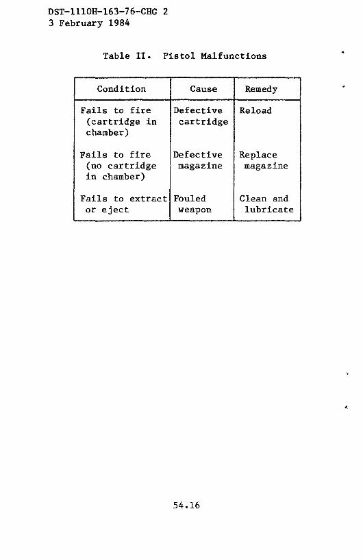
DST—111OH—163—76—CHG 23 February 1984
Table II. Pistol Malfunctions
Condition Cause Remedy
Fails to fire Defective Reload(cartridge in cartridgechamber)
Fails to fire Defective Replace(no cartridge magazine magazinein chamber)
Fails to extract Fouled Clean andor eject weapon lubricate
54.16

~ieptember i~iou DST—111OH—163—76—CHG1
SECTION II. SUBMACHINEGUNS
A. THE 9—MM L2A3 AND L34A1 SUBMACHINEGUNGUNS (UK)
45. General
a. The 9—mm L2A3 submachinegun (fig 29) iscurrently the standard submachinegun in the BritishArmy. A commercial version, the Sterling Mk4, is
offered for export sales, and a slightly modifiedversion, the Cl submachinegun, is produced in Canadafor use in the Canadian Armed Forces. A silencedversion, the L34A1 (fig 30), is used by the BritishArmy and is also offered for commercial sale. Allversions, both military and commercial, can be foundin use throughout the British Commonwealth andformer colonies.
Meg. 510028Figure 29. British L2A3 submachinegun.
b. The L2 series submachineguns are readilyrecognized by their cylindrical receiver, sharplypitched grip, and left—extending horizontal maga-zine. The silenced versions are identified by theirlong, unperforated jackets (fig 30). All areselective—fire, blowback—operated, box—magazine—fed
MAGAZINE HOUSINGN
NJ N
55

DST—111OH—163—76—CHG1 5 September1980
weapons equipped with folding metal stocks. TheL2A3, Mk4, and Cl versions have a boss and a lug fora bayonet on the lower left front of the barrel jack-et. Early versions (the ~‘Patchett~~, L2, L2A1, andL2A2) may differ in details from the guns described,but, in general, the information given is applicableto all. The L2A3, Cl, L34A1, and commercial ver-sions fire the 9x19—mmpistol cartridges (sec V).
Neg. 510029Figure 30. British L34A1 silenced submachinegun.
46, Technical Data
Technical data concerningthe L2A3 submachinegunare given intableIII.
47. Operation
a. The instructions given generally apply to all models.Referencewill be madeonly to L2A3 unlessotherwiseindicated.
b. The L2A3 can be fed from its normal 34-roundmagazine,from the Canadian10— or 32-roundmagazines,from theobsoleteSten32-round or Lanchester50-roundmagazines,if theL2A3 or Cl magazinesareused (preferably), place a cartridgeonthe follower and pressdownward until the cartridgerolls underthe feed lip; repeatuntil the magazine is full, If the Sten orLanchestermagazinesare used,place the cartridge in front of the
feed lips, pressdown and slide rearward until the cartridge base
strikes the rearwall of the receiver.Repeatuntil the magazineis
56

i’th-UI-1tiJ~I4Or~gina~
full. Theselatter magazinesare difficult to fill, and loadingcanbe
facilitated by usinga 1/4-inch, short—bladescrewdriverto depressand hold down the precedingcartridgeprior to inserting another
cartridge.
c. Rotate the selector (fig 29) rearward to S position.Insert a loadedmagazineinto the magazinehousing(fig 29) untilthe magazinereleasesnapsinto place.
d. If the stock is folded, unfold by pulling the rear of the
butt plate away from thejacket and thenswinging the butt fully
rearward. Pressthe receiver cap lock (fig 30) and snapthe stockagainstthe receiver;receivercapwill hold the stock in place.Pull
the butt plate down to open the stock fully. To fold the stock,
pressthe butt catch (fig 29) againstthe innerwall of the butt plate
and push the lower stock arm (fig 29) upward. Pressthe receiver
cap lock (fig 30) andforce the receivercap forwarduntil the stock
is freed. Rotate the stock forward until it is under the barreljacket; press the stock firmly againstthe jacket andlift the buttplate until the catch (fig 29) engagesthe hole in thejacket. Tap
thebutt plate firmly againstthe stock.
e. Rotatethe selector(fig 29) to either the A or R position(A for full automatic; R for repeat or semiautomatic).Pull the
operatinghandlefully rearward,then easeit forward until the bolt
is caught. if the gun is not to be immediately fired, rotate the
selectorto S. Flip the rear sight to the desiredrange, 100 or 200
meters. (The L34A1 sight, in either position, is set for only 100
meters.)Rotate the selector to A or R, aim (using a normalsight
picture), and press the trigger. The gun will fire one shot if the
selectoris on R; the trigger mustbe releasedandrepressedto fire asucceedingshot, If the selectoris set at A, thegun will fire as long
as the trigger is held and cartridges are in the magazine.CAUTION: Except in emergencies,fire the L34A1/Mk5 in the
semiautomaticmode only! When the last round is fired, the bolt
57

ST.H B.07-163-74Original
will close on an empty chamber. Press the magazine release
(fig 29) and pull the empty magazine straight out of the gun.
f. To clear the gun, removethe magazineby pressingthemagazinerelease(fig 29) andpulling the magazineout of the gun.Retract the operating handle until it is caught to the rear. Inspectto insure that no cartridgesarepresent,hold the operatinghandle,press the trigger, andeasethe bolt forward. Rotate the selectorrearwardto safeandreinsertthe magazine.
48. Disassembly and Assembly
a. Clearthe weapon(para47f) beforestarting disassembly,but do not rotatethe selectorto safeor reinsertthemagazine.
b. Pressthe receivercaplock (fig 30), push the receiver cap
forward, and rotate it counterclockwise.When the receiver caplugs disengage,easethe cap rearward and remove it. Pull theoperatinghandlerearwarduntil it aligns with the circular hole atthe end of its slot. Pull the handleoutward to removeit. Pull thedriving spring unit out. Removethe bolt by placinga hand overthe open rear end of the receiver, elevating the muzzle, andpressingthe trigger.
c. If desired,rotate the headof the trigger groupretainingpin (on thepistolgrip) (fig 30) so that the slot alignswith the “FREE” marking; then pull the pin out. Pull the trigger grouprearwardand swing its front endup andout of the gun.
d. No furtherdisassemblyis necessaryor desired.
e. To reassemble,first engage the lip at the front endofthe trigger group with its seat in the receiver, thenswing the rearend into place.Pushthe trigger groupforward to fully seat it; then
58

ST.H 6-07.1 63-74Original
insert the trigger group retainingpin, seatit fully, andturn its slot
sothat it alignswith the 0’LO CK” marking.
f. Insert the bolt into the receiverwith the largecutaway
portion at the front, aligned with the magazinehousing (fig 29).Pressthe trigger andpushthe bolt forward; it maybe necessaryto
twist the bolt to align it with the ejector.Move thebolt rearwarduntil the hole for the operatinghandle mateswith the hole in the
end of the operating handle slot. Insert the operating handle,
concavesurfaceforward, then pressthe trigger and slide the bolt
fully forward. Insert the driving spring unit into the receiver,small
end leading (if a dual spring). Placethe receivercap over the end
of the spring,depressthe receivercap lock (fig 30), andpressthe
cap forward over the receiver.The cap must mate with its seatso
that it canbe twistedclockwiseand locked.
g. The silencer of the L34A1 (Mk 4) submachinegun
should not be disassembledbecausespecialtools are required to
disassembleand reassemblethe silencer unit. When cleaning the
L34A1 barrel, use a minimum amount of cleaningsolventand oil
in the barrel; an excess of either will decreasethe silencer’s
efficiency andcauseexcessivesmokewhenfiring.
49. Functioning
a. The L2 series submachinegunsare blowback-operatedand fire from the open-boltposition.Whena loadedmagazineis inplace, the bolt is held cocked by the sear, and the selector ismoved0ff the safeposition;pressureon the trigger will releasethebolt from the sear.The driving spring thendrivesthebolt forwardand the feed rib, on the bolt, pushesthe top cartridge out of themagazineand into the barrel. The extractor snapsinto the grooveof the cartridge and the fixed pin strikes the primer to fire thecartridge. The weight and inertia of the bolt holds the firedcartridge case in place until the bullet leavesthe muzzle and
propellantgaspressuresubsides.The rearwardthrust of the fired
59
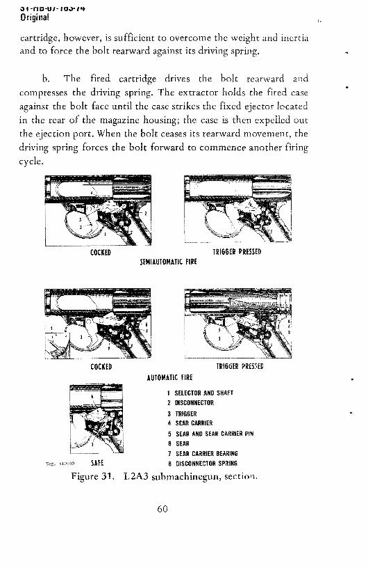
~I-flD-UI-IUJ-I~+
Original
cartridge,however,is sufficient to overcomethe weightand inertia
andto force the bolt rearwardagainstits driving spring.
b. The fired cartridge drives the bolt rearward and
compressesthe driving spring. The extractor holds the fired case
against the bolt face until the casestrikesthe fixed ejectorlocatedin the rear of the magazinehousing;the case is then expelledout
the ejection port. When the bolt ceases its rearward movement, the
driving spring forces the bolt forwardto commenceanotherfiringcycle.
J—J -J~_~ T~
COCKED TRI6GER PRESSEDSEMIAUTOMATIC FIRE
COCKED TRIG6ER PRESSEDAUTOMATICFIRE
1 SELECTOR AND SHAFT
2 DISCONNECTOR3 TRIGGER4 SEAR CARRIER5 SEAR AND SEAR CARRIER PIN
6 SEAR
1 SEAR CARRIER BEARINGleg~510030 SAFE 8 DISCONNECTOR SPRING
Figure 31. L2A3 submachinegun,section.
60
ST-tiB-Ui-i 63.74Original
c. The type of fire is determinedby rotating the selector
lever; this actionchangesthe positionof a lug on the selectorshaftin relation to the disconnector(fig 31). The searanddisconnectorare mountedon a spring-loadedsearcarrier.The roughly L-shapeddisconnector is spring loaded so that its nose will engage ashoulderatthe rearof the sear.Thelower arm of the disconnectorextendsforward under the sear and over the selectorshaft. Ashoulderon the rear of the pivoted trigger bearson the front ofthe searcarrier (fig 31).
d. When the selector is rotatedto the A (automatic fire)position, the lug on the selectorshaft swings forward out fromunder the disconnector(fig 31). As the trigger is pressed,thetrigger shouldersbear against the sear carrier and force the sear
carrier to rotate on its pin; the rear end 0f the sear carrierdepresses.The disconnectoris pinnedto the rearof the searcarrierandmoveswith it. The disconnectornoseis also engagedwith thesearand,as the searcarriermoves,the disconnectorcausesthe sear(which also is pivoted on the sear carrier pin) to depressandreleasethe bolt. The weaponwill continueto fire until the triggeris releasedto allow the searcarrier, disconnector,andsearto riseup so the searcaninterceptthebolt andstopthe firing cycle.
e. When the selector is turned to the R (repeat orsemiautomatic)position, thelug on the selectorshaftmovesunderthe lower front of the disconnector.As the trigger is pressed,itcausesthe sear carrier, disconnector,and sear to rotate, as inautomatic fire (d above), to releasethe bolt. As pressureon thetrigger continues to cause the sear carrier to rotate, thedisconnectorstrikes the lug on the selectorshaft (fig 31). Thiscausesthedisconnectorto pivot on its pin (in the searcarrier),andthe disconnectornose releasesthe sear (fig 31). The sear spring
immediately forces the searupwardto interceptthebolt andstopthe firing cycle aftera singleround hasbeenfired. To fire a secondshot, the trigger must be releasedto allow the rear of the sear
61

ST-I-I B-Ui-i LiJ-i4Original
carrier to rise. The disconnectorrises (with the searcarrier) untilits nose snaps into the shoulder in the sear (fig 31). Pressure on the
triggerwill now causeanothershotto be fired.
f. When the selectoris rotatedrearwardto S (safe),the lug
on the selector shaft moves rearward, under the rear end of the
disconnector (fig 31). With the lug thus blocking the downward
movement of the disconnector, the sear cannot be depressed.
Because the sear cannot be depressed, the bolt will be locked in
position by the sear engaging the sear notch if the bolt is cocked
or, if it is uncocked, the safety notch at the rear of the bolt
(fig 31).
50. Accessories
Few accessoriesare used in conjunction with the L2 seriessubmachineguns.The accessoriesusually available include web
carrying slings, extra magazines, magazine carrier, and eithercleaningrodsor pull-through cordsfor cleaningthebarrel.
B. THE 9-MM IJZl SUBMACHINEGUN (ISRAEL)
51. General
a. The 9-mm UZI submachinegun (fig 32 and 33) was
designed by an Israeli Army officer in the early 1950’s.The designappears to have beeninfluencedby the CzechoslovakM-23submachinegun.However, the UZI hasseveralnovel featuresfor asubmachinegun,including a bayonet and a spigot-typegrenadelauncher. The UZI is a simple gun to manufacture, using a
maximumamountof stampedmetal parts,andis consideredto bean extremely reliable weapon.
62

ST-HB-07-i 63-74Original
b. The UZI, which has been manufacturedin Israel andBelgium, is a standard weapon in Israel, West Germany, and the
Netherlands. It also is offered commercially. The No. 2 Mark Agunsused by the Israeli Army can be identified by the Hebrewcharacters used to identify the selector settings; the German MP1
and the Dutch gunsuse “D”, “E”, and “S” for thesemarkings,
while export or commercialmodels are marked“A”, “R”, and
c. Like most submachineguns,the UZI fires from an openbolt andcan be fired eitherautomaticallyor semiautomatically.Itis fed by 25- or 40-round-capacity box magazines inserted into the
pistol grip. Although the UZI is usually equipped with a foldingmetal butt (fig 33), a wood butt (fig 32), in atleast two differentlengths, is also used.
d.
cartridge (sec V).
All UZI submachinegunsfire the 9x19-mm pistol
52. TechnicalData
Technical data concerning the UZI submachineguns are given in
table III.
Figure 32. Israeli UZI submachinegun,early model.
63

bI-llb-UI-IQJ-IqOriginal
a. Load the magazineby placing a cartridgebetweenthefeed lips and pressingdownward until the cartridge rolls to theside and under one of the feedlips. Repeatuntil the magazineis
full.
b. if the gun is a folding stock model,pressthebutt release(fig 33), pull down on the butt plate,andunfold thebutt. To foldthe butt, squeeze the rear half together, just to the rear of thejoint, and fold the stock down and forward, insuringthat it locksto thereceiver.
c. Insert the magazineinto the bottom of thebutt untilthe magazinecatch snapsinto place.After pressingthe grip safety(fig 32), pull the operating handlefully to the rear and releaseit.CAUTION: The UZI is now loadedandreadyto fire, If the gun is
not to be immediately fired, slide the selector (fig 32) fullyrearwardto the “safe” position.
Figure 33. UZI submachinegun, late model
with folding butt.53. Operation
64

ST-H B-Ui-i 63-74Original
d. To fire the UZI, flip the rear sight to the desiredrange(100 or 200 meters) and slide the selector to either thesemiautomatic(middle) or the full automatic(forward) position.Using a normal sight picture, aim, depressthe grip safety, andpressthe trigger.The gun will fire accordingto the selectorsetting;after thelast round is fired, the bolt will remainforward.
e. Removethe magazineby pressingthe magazinecatch(fig 32 or 33) andpulling themagazineout of the gun.
f. To clearthe gun, removethemagazine(e above),set theselector forward, depressthe grip safety, and pull the operatinghandle to the rear.Look into the ejectionport to insurethat nocartridgesare present.Pull the operatinghandle to the rear againand, while holding it, pressthe grip safety and trigger. Easetheoperatinghandle forward, set the safety to safe, and insert themagazine.
54. DisassemblyandAssembly
a. To disassembletheUZI, clear the gun (para53f), but donot set it on safeor insertthe magazine.
b. Press in the cover catch (fig 33) and lift the cover(fig 33) from the receiver. Pull the bolt slightly rearward; thenswing its front end up and out of the receiver.Separatethe boltanddriving springfrom the receiverandthenfrom eachother.
c. Press in the barrel nut lock (fig 33) and unscrew thebarrelnut; pull the barrel (fig 34) forwardandout of the receiver.
d. To assemble the weapon, insert the barrel into thereceiverand turn the barrel until it seats.Replaceand tightenthebarrel nut so that thereis no fore or aft play in the barrel. Placethe driving spring and guide into the bolt and,with the cut out of
65
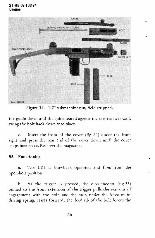
ST-HB-07-i63-74Original
the guide down and the guideseatedagainsttherear receiverwall,swing the bolt backdown into place.
e. Insert the front of the cover (fig 34) under the frontsight and pressthe rear end of the cover down until the coversnapsinto place.Reinsertthe magazine.
55. Functioning
a. The UZ1 is blowback operatedand fires from theopen—boltposition.
b. As the trigger is pressed,the disconnector (fig 35)
pinned to the front extensionof the trigger pulls the searout ofengagementwith the bolt, and the bolt, under the force of itsdriving spring, starts forward; the feed rib of the bolt forcesthe
Figure 34. UZI submachinegun,field stripped.
66

ST.H 8-07-i 63-7 4Original
top cartridge out of the magazine and into the chamber. As the
cartridge seats in the chamber, the extractor snaps over the
cartridge rim, and the fixed firing pin strikes the primer to fire the
cartridge.
c. The fired cartridgeblows the bolt backandcompressesthe driving spring. The extractorholds the fired cartridge casetothe bolt face until the case strikes the fixed ejector (fig 35) in the
bottom of the receiver; the case is then expelled through theejection port. The driving spring forces the bolt forward again to
continue the firing cycle.
d. When the selectoris in the forward (automatic)positionand the trigger is pulled, the sear is depressed, and the gun
continues to fire until the trigger is released or the magazine is
empty.
e. When the selector is in the middle (or semiautomatic)position, the transversebar of the selector (fig 35) slips underthe
front of the disconnector.When the trigger is pressed, the
DISCONNECTORSEM
)ieg~510034
Figure 35. UZI submachinegun, section.
67

ST-H 8-07-i 63-74Original
disconnectordepressesthe sear to releasethe bolt, but as thedisconnectorcontacts the bar 0f the selector, the disconnector
rocks rearwardand releasesthe sear.Under the force of the searspring, the sear moves upward and intercepts the bolt, thus firingonly one shot. The trigger must be released to allow thedisconnectorto riseandreengagethe searfor anothershot.
f. When the selector is moved to its rearmost or safe
position, the bar moves under the front end of the trigger andprevents the trigger from being pulled.
g. When the grip safety is at its normal position, a shoulderin the forward extending bar fits under a lug on the right side of
the sear. This prevents the sear from being depressed. The gripsafety must be pressed in to move its shoulder forward from under
the sear,which then can be depressedand allow the gun to befired.
h. The sear extends up into cuts in the bolt when the boltis forward, and, unlessthe grip safetyis pressedto unlockthe sear,the bolt is locked forward and cannot be cocked.
56. Accessories
a. In addition to the normal accessories (spare magazines,magazine carriers, and web slings), the UZI has a bayonet, agrenadelauncher,andan accessoryclip for joining two magazines.
b. The bayonetis affixed by mating the dovetailslot in thehandle with the lug under the gun, just behind the barrel nut. The
bayonetis removedby pressingits catchandpulling it forward.
c. The grenade launcher is attached by removing the barrelnut (para Sob) and replacing it with the grenade launcher.
CAUTION: Do not insertamagazineinto the gun whenagrenadeis in placeon the launcher.
68

ST-H 8-07-i 63-74
Original
(1) Open the bolt andplacethe specialblank cartridgeinto the chamber. (CAUTION: Never use a bulleted cartridge.)Placethe selectoron safe.
(2) Hold the UZI horizontal and slide the grenade(only 22-mm inside-diameter tail boom grenades)onto thelauncher.Removethe safetypins if necessary.
(3) Using the ogive of the grenadeas the sight, aim,pressthe selector forward, andsqueezethe trigger andgrip safety.
(4) If possible,avoid using a folding stock UZI forlaunchinggrenades.
d. The accessoryclip snaps around the bottom of twomagazinesand holds them in an “L” shape.This permits rapidreloading.
C. THE 9-MMM.A.T.MODEL 1949SUBMACHINEGUN(MAT49) (FRANCE)
57. General
a. The French 9-mm M.A.T. Model 1949 submachinegun(fig 36) is standardin the FrenchArmy andin many of the armiesof former French colonies. Thesegunsare also usedby the VietCongandotherguerrillaforcesin Asia andAfrica.
b. The M.A.T. 49, which has a folding magazinehousingand a prominent grip safety, is readily recognized by itsrectangularreceiverandperforated,cylindrical, barreljacket.TheM,A.T. 49 has a sliding wire stock and a dust cover over itsejectionport.
c. The M.A.T. 49 fires 9x19-mmammunition(secV).
69

ST-H B-Ui-i 1i3-i4Original
58. Technical Data
Technicaldataconcerningthe M.A.T. 49 submachinegunaregivenin tableIII.
59. Operation
a. Load the magazineas describedin paragraph47 for theSten or Lanchestermagazines.Placea cartridge on the followerwith the cartridge basejust ahead0f the feed lips; press thecartridgedown, againstthe force of the follower spring,andslideit rearward under the feed lips. After severalcartridgeshavebeen
Figure 36. French M.A.T. 49 submachinegun.
70
ST-HB-Ui-i 63-14Original
loaded and the magazinespring has been compressed,loadingadditional cartridges is difficult. A screwdriver with a1/4-inch-widebladecanbe usedto aid loading.After eachroundisinsertedinto the magazine,place the edgeof the screwdriverintothe grooveof the cartridgeandpressdown.This will depressthefollower andcartridgessufficiently to allow a freshcartridge to beinsertedunder the feedlips without havingto overcomethe forceof the magazinespring.
b. If the magazinehousing is folded forward, pressthehousingcatch (fig 36) and swing themagazinehousingdown untilit is vertical and until the release located on the undersideof thetrigger housing (fig 36) engages the magazine housing. Insert theloaded magazine into the housing until it is caught by themagazinecatch. Depressthe grip safety and pull the operatinghandle (fig 36) to the rear; then push the handle back to itsforwardposition.CAUTION: The gun is nowready to fire.
c. if the ejection port cover is open,swing it forward toclose the port and to keep out dirt. The cover will openautomaticallywhen the bolt movesforwarduponfiring.
d. There is no manual safety, as such,on this weapon,butthe magazineand its housing can be swung forward under thebarrel (fig 36). This action, which is the only manual safetyfeature, also renders the gun more compact. Press the releaseunder the trigger housing and swing the housingand magazineforward until the housing catch locks to the bracket under thebarrel jacket. The magazine and housing must be swung intopositionbeforefiring (parab above).
e. Press the stock latch (fig 36) and slide the stock toeither the openedor closedposition.
f. Set the rear sight for the desiredrange (100 or 200meters) by flipping it forward or rearward.Using a normal sight
71

ST-H B-Ui-i 63-74Original
picture, aim, depress the grip safety, and squeeze the trigger. The
gun will fire as long as the trigger is pressed and ammunition is
present. The bolt will remain closed when the last round is fired.
g. Remove the magazine by depressing the magazine catch
(fig 36) and pulling the magazinestraight out of the magazinehousing.
h. To clear the M.A.T. 49, removethe magazineandswingthe magazinehousingforward (parac andd above).Depressthegrip safety and retract the operating handle. Look into theejection port to insure that no cartridgesare present.Hold theoperatinghandle,depressthe grip, andpressthe trigger;theneasethe bolt forward. Close the ejection port cover and insert themagazineinto the magazinehousing.
60. Disassemblyand Assembly
a. To disassemble the weapon (fig 37), clear the
submachinegun (para 59f) and release the magazine housing fromthe barrel jacket (para 59b), but do not latch it to the receiver.Press in the knurled take-down button under the rear end of the
barrel jacket. Swing the barrel and receiverassemblyupward,offthe trigger frame. The bolt and driving spring can be removedthroughthe searof the receiver.No furtherdisassemblyis requiredor desirable.
b. To reassemblethe gun, insertthe bolt anddriving springinto the receiver. Insert the rear of the receiver into the cap at the
rear end of the trigger frame, lower the front end of the receiver,
and push it rearward into the frame until the frame and receiver
lock together.
72

61. Functioning
ST-H6-07-i 63-74Original
a. The M,A.T. 49 is blowback operated. When a loadedmagazine is in place and the bolt is cocked,pressureon the triggermoves the searout of engagementwith the bolt. The compressed
driving spring drives the bolt forward; the feedrib on thebottomof the bolt drives the top cartridgefrom the magazineand into thebarrel, As the bolt continuesforward, theextractorsnapsovertherim of the cartridge, the firing pin (machinedinto the bolt face)
strikesthe primer, and the cartridge fires,
b. The fired cartridge drives the bolt rearward andcompressesthe driving spring. The extractor holds the cartridgecase to the bolt until the casestrikes the ejector; the caseis thenexpelledthrough the ejectionport. The firing cycle continuesuntilthe trigger is released or the magazine is emptied.
c. The grip safety performs two functions: It locks thetrigger, and, if the bolt is forward, it is locked in that position.
Figure 37. M.A.T. 49 disassembled.
73

I F1 UU1 — I U.1 ~
Original
When the grip safety is depressed, it pivots around its pin, and a
small lug behind the trigger swingsup to releasethetrigger. At thesame time, a linkage attached to the left top of the grip safety
depresses a lock located to the left of the sear; this lock must bedepressedto allow the bolt to move rearward.This mechanismpreventsaccidentalfiring if a gun with loadedmagazinein placeisdropped on the butt. Otherwise, inertia could move the heavy bolt
to the rear,a cartridgecould be strippedfrom the magazine,andthe weapon could be fired.
d. The front endof the L-shapedtrigger is attachedto thesear. When the trigger is pressed, it pivots around its pin and
depressesthe rear endof the sear.Whenthe trigger is released,thesear spring returnsall parts to their normalpositions;this allowsthe sear to intercept the bolt and stop the firing cycle.
62. Accessories
A web sling, spare magazines,a magazinecarrier, and a cleaning
rod areusually availableas accessories.
D. THE 9-MM MADSEN MODEL 50 SUBMACHINEGUN(DENMARK)
63. General
a. The 9-mm MadsenModel 50 submachinegun(fig 38), aremarkablysimpleweaponevenfor a submachinegun,usespressedmetal parts to the maximum.The “clamshell” methodof openingthe receiver readily exposesall of the gun’s mechanismfor user
maintenance.A magazineloaderandsparepartsare storedin thepistol grip.
74

ST-H 8-07-163-74Original
b. Severalvariantsof this submachinegunare in existence.An early model, the M1946 (fig 41), has a flat, flanged operating
handle that extends across the top and down over the sides of the
receiver.The more commonM1950 (fig 38) usesa small circularknob for its operating handle. The M53 (fig 39) model has acurved magazineand a short cylindrical barrel nut that screwsonto the barrel instead0f onto the receiver as in the M46 and
M50. The Mark II resemblesthe M53 but has a selectorbuttonlocated over the left grip plate; this model may also be fitted with
Figure 38. Danish Madsen Model 50 submachinegun.
75

DST-i ii OH-163-76 December1976
a slotted barrel jacket over the full length of the barrel. In addition
to the Danish guns,thereis a ll.43-mm (.45-caliber)model, theINA Model 953 (fig 40) producedby Brazil. The operatinghandleon this model protrudesfrom the right side of the receiver.
c. The 9-mm Madsen submachinegun, used by the policeand the armies of several European, Asian, and Latin Americancountries, is also sold commercially. These guns, stolen, captured,or purchased, are often found in use by guerrilla units.
d. The M46, M50, M53, and Mark II Madsensfire the9x19-mmcartridge,the Brazilian INA 953 fires the US .45-caliberM1911 cartridge (sec V).
Figure 39. MadsenModel 1953 submachinegun.
Figure 40. Brazilian INA 53 submachinegun.
76

ST-H 8-07-163-74Original
64. Technical Data
Technical data concerning the Madsen submachinegun are given intable III.
65. Operation
a. Open the receiver (para66c) and removethe magazineloader from the pistol grip (fig 38). After loading the magazine,return the loader to its storage place and close the receiver.
b. Place the magazineloaderover the top of a magazine;press the plunger down to depress the follower, and slide acartridge-baseend first-under the magazinefeed lips. Releasetheplunger and slide the cartridge completely to the rear. Repeat thisaction until the magazineis filled (32 rounds). If the magazineloader is missing, load the magazineas prescribedin paragraph5 9a.
c. Insert a loaded magazine into the magazine openinguntil the magazine catch snaps into place. Insure that the safety
(fig 38) is in its forward position. Grasp the gun around the
magazinehousingand depressthe grip safety (fig 38). Draw theoperatinghandle (fig 38) fully to the rearandeaseit forwarduntilthe bolt is caughtby the sear.CAUTION: The gun is now readyto fire.
d. If the gun is not be be immediatelyfired, put it on safe
by moving the safety to the rear. The stock can be folded orunfolded by depressingthe stock catch (fig 38) and moving thestock to the desired position.
To fire the gun, move the safety forward, set theselector for the type of fire desired(Mark II only), and (using anormal sight picture)aim andpressthe grip safetyand trigger. The
77
ST-H8-07-163-74Original
gun will fire until either the trigger is released (orsemiautomatically,if so set on the Mark II) or the magazineisempty. The bolt will remainforwardwhenthe last roundhasbeenfired.
f. Remove the magazineby pressingthe magazinecatch(fig 38) and pulling the magazine out of the receiver.
g. Clear the gun by removingthe magazineandpulling thebolt to the rear. Look into the ejection port to insure that nocartridgesare present.Hold the operatinghandle, pressthe gripsafety and trigger, and ease the operating handle forward. Replacethe magazine.
66. Disassembly and Assembly
a. Clear the gun (para 65), but do not insert the magazine.
b. If the gun is a M1946 model, pull the operatinghandlestraight up and out of the bolt. The handle is held by a
spring-loadeddetent.
c. Unscrew and remove the barrel nut (or jacket 0f aMarkIII). Swing the receiver open (fig 38) and lift the barrel out. Pullthe rear endof the driving spring guide (fig 38) forward out of its
seat, and removethe guide and spring. Lift the bolt out 0f thereceiver-
d. No further disassembly is necessary or desirable.
e. To reassemblethe weapon,place the bolt backinto theright receiver shell and insert the driving spring and its guide into
the bolt. Force the rearendof the guideinto its seatin the rearof
78

ST-HB-07-i63-74Original
the receiver. Lay the barrel onto its seat in the front end of the
receiverand insure that the flange on the barrelfits fully into thereceivergroove.Swing the receiverclosedandscrewthebarrelnutback into place. if the gun is an M46, press the operating handle
down into the bolt until thedetentsnapsinto place.
67. Functioning
The basic functioning 0f the blowback-operated Madsensubmachinegun is similar to that of the M.A.T.-49 (para 61). The
grip’ safety (fig 41) is a simple, spring-loadedcatch that, unlessmanually depressed,will engagewith the sear notch in the boltand preventthe bolt from moving fully forward.Whenat safe,thesafetyblocks the sear and prevents it from depressing to release
thebolt.
Figure 41. MadsenM1946 submachinegun,section,
79
DST—lllOH—l63—76—CHG 1 5 September 1980
68. Accessories
In addition to the normal accessories (such as a websling, a spare magazine, and a magazine carrier),the Madsen submachineguns have a magazine loaderstored in the grip. Each gun should also have aspare firing pin, an extractor, and a safety buttonstored in the grip.
E. ThE 9—NM M45b SIJBMACHINEGUN (SWEDEN)
69. General
a. The Swedish M45b submachinegun (fig 42) isthe standard submachinegun of Sweden, where it wasdeveloped in 1945. The design is based on theBritish Mk 2 Sten submachinegun, considerably simpli-fied. There are several variations in the M45series guns; these variations usually involve themagazine and magazine housing. Original M45 gunsused a large multi—row 50—round box magazine and hadno magazine housing. The current M45b uses 32—roundbox magazines. Early models of the M45 have detach-able magazine housings to allow the use of the 50—round magazine, while current production guns havepermanently attached magazine housings (eitherwelded or riveted).
b. In addition to its use by the SwedishArmy, the M45 is sold commercially as the ~~CarlGustaf” or “Swedish K” submachinegun. Copies aremanufactured in Egypt as the “Port Said’s submachine—gun (fig 43).
70. Technical Data
Technical data concerning the M45 submachinegun aregiven in table III.
80

ST-H B-Ui-i 63-74Original
Figure42. SwedishM45b submachinegun.
Figure 43. Egyptian Port Said submachinegun.
81

ST-H B-Ui-i 63-74
Original
71. Operation
a. Load the magazine by placing a cartridge on the
magazine follower between the feed lips; press the cartridge downuntil it rolls sideways under one of the feed lips. Repeat thisaction until 36 rounds have been loaded.
b. Insert the magazineinto the magazinehousing(fig 42)until the magazinecatchretainsthemagazine.
c. Pull the stockawayfrom the receiverto openthe stock.Flip the rear sight to the desired range (100, 200, or 300 meters).
d. Pull the operating handle (fig 43) outward (ifnecessary);pull it to the rear,and theneaseit forward until thebolt is caught by the sear.CAUTION: The gun is now readytofire. Using a normal sight picture, aim andpressthe trigger. Thegun will fire until the trigger is released or the magazine is empty.The bolt will remain forward after the last round has fired.
e. The gun can be made safe by pulling the operating
handle rearward until it can be turned upward into the safetynotch. Move the handle back to its normal position before
attempting to fire.
f. Fold the stock by pressingthe stock catch (fig 43) tothe left and then forcibly press the stock to the right until itswings forward.
g. Clear the gun by removing the magazine, retracting thebolt, and insuring that no cartridgesare present.Press the trigger
and easethe bolt forward. Press the operatinghandleinward tolock thebolt; theninsertthe magazine.
82

b i-il U-UI-i Ui-I~Original
72. Disassemblyand Assembly
a. Clear the weapon (para 71g), but do not press the bolthandle in or insert the magazine.
b. Press in the button in the middle of the receivercap(fig 43) and while holding the button inward, rotate the capcounterclockwiseuntil it releases;ease the cap rearward andremove. Pull the driving spring out of the receiver.
c. Grasp the bolt handle and pull the bolt rearward, out ofthe receiver.
d. Pressthe small barrel nut lock at the lower rear of thebarrel nut and unscrew the barrel nut. Pull the barrel jacket andbarrel nut forward, off the receiver. Pull the barrel forward, out ofthe receiver.
e. No further disassembly is required or desirable.
f. To reassemble,insert the barrel into the receiver,twisting the barrel until it seats and cannot rotate. Place the barrel
jacket over the barrel, insuring that the jacketslot mateswith thekey protruding from the top front of the receiver.Finger-tightenthe barrelnut.
g. Slide the bolt into the receiver,largeend first andbolthandlealignedwith the longslot. Pointthe muzzledownandpressthe trigger; bolt will slide forward. Insert the driving spring intothe receiver so that it seats onto the bolt. Place the receiver capover the spring. Press the cap forward, aligning hook on the capwith the left side of the plate on top of the receiver.When thehook is in front of the plate, rotate the cap to the right until it
locks into place. Press the bolt handle inward and insert themagazine-
83

Original
73. Functioning
a. The M45 is blowbackoperated(referto para47a).
b. The firing cycle startswith the bolt cockedto the rear,caught by the sear, compressingthe driving spring (fig 44).Pressureon the trigger causesit to rotate,anda forward lug on thetrigger bearsagainstthe rear of the searto force the seardown toreleasethebolt. The driving springforces the bolt forward. As itmoves, the feed rib drivesa cartridgeout of the magazineandintothe barrel chamber. As the cartridge seats in the barrel, the fixedfiring pin strikes the primer andfires the cartridge.
c. The rearwardthrust 0f the fired cartridge blows the boltrearward,compressingthe driving spring. The extractorholds thecartridge against the bolt face until the fixed ejector expels thecase.
d. Release of the trigger allows the sear to rotate upwardto intercept the bolt, stopping the firing cycle.
e. The bolt handle safety, when pressedin, mechanically
engages a hole in the left wall of the receiver to lock the boltforward. When the handle is turned up into the safetyslot, the
BOLTICOCKEO1 SPRI~4G
Ileg. 510043
Figure 44. M45b section.
84

ST-HB-Ui-i 63-74Original
mechanicalinterferencebetweenthe handleand receiverpreventsthe bolt from beingdrawnforward.
74. Accessories
The usualsubmachinegunaccessories(sparemagazines,a sling,andacleaningrod) aresuppliedwith theseguns.
F. THE 9-MM BERETTA M38, M38/49, M4, AND MSSUBMACHINEGUNS (ITALY)
75. General
a. The Italian Beretta M38 series submachinegunsareexcellent,well-constructedweapons.The basicdesign,as indicatedby the model designation, dates back to 1938.There havebeenmany changesand modifications to the basic M38 gun. Thecurrent Beretta Model 38/49 or its commercial versions, theBeretta M4 and M5, representthe continual refinementsof theoriginal design.
b. The BerettaM38 series submachinegunswere used byboth the Italian and Germanarmies during World War II, andnumerouscapturedweaponswere used after World War II bymany Europeanand African nations.The current Model 38/49,initially producedin 1949, has beenpurchasedby CostaRica,Egypt, Indonesia,Dominican Republic,Thailand,WestGermany,Tunesia,andYeman.In WestGermany,the Beretta38/49 (knownas the MP1) is usedby borderguards.
c. The original Beretta M38 and M38A (fig 45) hadperforatedbarreljacketswith built-in compensators;however,theoriginal 38 hada single-bafflemuzzlebrakeanda bayonetlug, andthe 38A had a four-slotmuzzlebrakeandno bayonetlug.M38A’swere last producedin 1947 for the ArgentineGovernment.The
8S
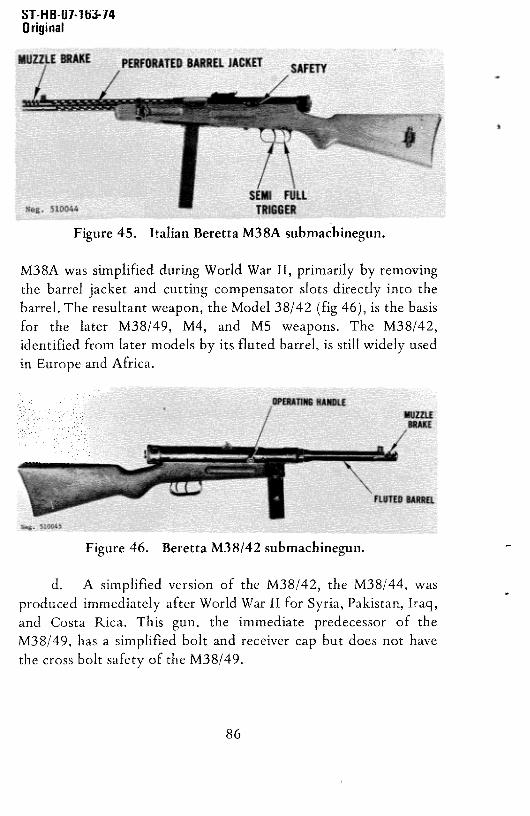
ST-H B-Ui-i ti~-i4Original
Figure 45. Italian Beretta M38A submachinegun.
M38Awas simplified during World War II, primarily by removing
the barrel jacket and cutting compensatorslots directly into thebarrel. The resultant weapon, the Model 38/42 (fig 46),is the basisfor the later M38/49, M4, and MS weapons. The M38/42,identified from later modelsby its fluted barrel, is still widely usedin EuropeandAfrica.
d. A simplified version of the M38/42, the M38/44, wasproduced immediately after World War II for Syria, Pakistan,Iraq,and Costa Rica. This gun. the immediate predecessor of theM38/49, has a simplified bolt and receiver cap but does not havethe crossbolt safetyof the M38/49.
Figure 46. Beretta M38/42 submachinegun.
86

ST-H B-Ui-i 63-74Original
e. The current gun is the BerettaModel 38/49 (fig 47),also known as the Beretta Model 4. This gun can be easilyrecognizedby its push-throughsafety. A variation, the BerettaModel 5, is identicalexcept that thepush-throughsafetyhasbeenreplacedwith a largegrip safetybar (fig 47).
f. The Beretta 38 seriessubmachinegunsare selective-fireweapons; the two triggers govern the type of fire. The guns areblowback-operatedand fed from 10-, 20-, or 40-round boxmagazines.Prime recognition points are the double triggers andthe slots cut across the muzzle end of the barrel (fig 45, 46, and47). All the Beretta M38 series weapons fire the 9x19-mmcartridge (sec V).
76. Technical Data
Technical data concerning the Beretta M38/49 submachinegunswill befound in table III.
Figure 47. Beretta Model 4 and Model 5
submachineguns.
87

ST-H B-Ui-i 63-74Original
77. Operation
a. Load the magazine as described in paragraph 71a. If amagazinefiller andclipped cartridgesare available,place the fillerover the mouth of the magazine, insert the clip into the guidesinthe filler, and, with thumb pressure,force the cartridges0ff theclip into the magazine. Repeatuntil the magazineis full, thenremovethe filler.
b. Insert the loadedmagazineinto the magazineguideuntilthe magazinecatch snapsinto place.Pushthe safetycatch to theleft or, for aModel 5, depressthe grip safety bar (fig 47). On theearlierM38, M38A, M38/42,andM38/44,pushforwardthe safety(on the left side of the receiver) (fig 45). Pull theoperatinghandlefully rearward to cock the weapon, then return it forward.
CAUTION: Thegun is now readyto fire.
c. If the weapon is not to be fired immediately: On theM38, M38A, M38/42, and M38/44, move the safety (fig 45)rearward; on the M38/49 or M4, push the safety (fig 47) to theright; or on the M5, release the grip safety bar. To fire, move thesafety back to fire position (or, on the MS squeezethe grip safetybar), aim, and press the trigger. If the front trigger (fig 45) ispressed, only one shot will be fired. This trigger must be releasedand repressed to fire successive shots, if the rear trigger (fig 4S) ispressed, the weapon will continue to fire until the magazineisempty. When the last round is fired, the bolt will close on anempty chamber. Press the magazinecatch (fig 47) and pull themagazine out of the gun.
d. To clear the Berettas,removethe magazine,thencockthe bolt as described in paragraph c above. Look through theejection port to insure that no cartridges are present,pull theoperating handle rearward,and, while holding the handle, pressthe trigger (on the M5, first depressingthe grip safetybar), and
88

~i-nD-UI-iUJ-IqOriginal
ease the operating handle forward. Move the safety to the safepositionandinsertthe magazine.
78. Disassemblyand Assembly
a. Clear the gun (para 77), but do not insert the magazine
or apply the safety. Rotate the receiver cap (fig 47 and 48)one-quarterturn to the left andeaseit back.Removethe receivercap and pull the driving spring and bolt out of the receiver. It maybe necessaryto elevate the muzzle and press the trigger (firstdepressingthe grip safetybar on the M5) to allow the bolt to sliderearwardout of the receiver.No furtherdisassemblyis requiredordesirable.
BARREL CASING
BARREL /
SAFETY LOCK CATCHBOLT MAIN SPRING BOLT CAP
~ J~~-__MAINSPRlNG RETAINER
HAMMER SPRING PLUNGER MAGAZINE
Neg. 510047
Figure 48. Beretta submachinegun,disassembled.
b. To reassemble,slide the driving springover the rearendof the bolt, then insert the bolt into the receiver. The lug on thebolt must align with the slot in the bottom of the receiver.Pointthe muzzledown andpressthe trigger (on the M5, first depressingthe grip safety bar) to allow the bolt to slide forward. Place thereceiver cap over the endof the driving spring andpressforwarduntil the cap fits onto the receiver. Rotate the cap to the rightuntil the indicator arrowsalign. Insert the magazine. Note: Whenreassembling the M5, keep the grip safety bar depressed.
89

ST-llb-U1-163-i4Original
79. Functioning
a. The Beretta M38 series submachineguns areblowback-operated,without positive locking betweenthe bolt andreceiver.The weightandinertia of the bolt hold the fired cartridgecase in place until the bullet leaves the muzzle and propellant gaspressuresubsides.The rearward thrust of the fired cartridge,however, is sufficient to overcome the weight and inertia and toforce the bolt rearwardagainstits driving spring.
b. When a loaded magazine is in place and the bolt iscocked,pressureon the trigger rotatesthe searout of engagementwith the bolt. The compresseddriving spring drives the boltforward, and the feed rib on the bolt drivesthe top cartridgefromthe magazineinto the barrel. As the bolt continuesforward, theextractor snapsover the rim of the cartridge,and the firing pinstrikes the primer to fire the cartridge.Acting like a piston, thefired cartridgedrives the bolt rearwardandcompressesthe drivingspring. The extractorholds the cartridgecasein placein the boltface until the case strikes the fixed ejector in the rear of themagazinehousing.The caseis thenexpelledthrough the ejectionport. This cycle continues until the trigger is releasedor themagazineis emptied.
c. When the front (semiautomatic)trigger is pressed,thetrigger rotates on its pin and a long forward extension swingsdownward.This extensioncontactsa paw! in the rear of the searto rotate the searabout its pin to releasethe bolt. As the triggerandsearcontinue to rotate, the extensionslips off the searpawl,and the sear spring returns the sear upward where it can intercept
the bolt. To fire anothershot,the trigger mustbe released;as it is,the extensionforcesthepaw! inward until the extensionpassesthepawl. The paw! then springs out under the trigger extension.
d. When the rear trigger is pressed, its long extensiondepresses the sear as before; but, because of the length of the
90

ST-H B~07-i63.74Original
extension, the sear is held depressed and the gun firesautomatically.
e. On all guns, when the safety is applied,ablock movesunder the sear and prevents it from being depressed.
80. Accessories
The only accessoriesavailable are spare magazines, magazineloader,sling (leatheror fabric), andsectionalcleaningrod.
G. THE 9-MM BERETTA MODEL 12 SUBMACHINEGUN (ITALY)
81. General
a. The 9-mm Beretta M12 submachinegun(fig 49) is amodern-designgun producedin Italy. It is a standardweaponinthe Italian Army and is offered for commercial sale to othercountries.A copyof this gun is also producedin Indonesia.
Figure 49. Italian Beretta Model 12 submachinegun(early model).
91

Original
b The M12 is a blowback-operated,selective-fireweaponfed from 20- or 40-roundcapacityboxmagazines.Thebolt of thisgun extendsforwardover most of the barrel,thusallowing useofa long barrel in a fairly short andcompactweapon.The BerettaM12 is easily recognized by its double-hand grips, largewedge-shapedoperatinghandle,andgrip safetyin front of the rear
grip (fig SO). The M12 is usuallyfound with a folding metal stock,
but aconventional,fixed wood stock is alsoavailable.
c. The Beretta M12 submachinegun fires 9x19-mmammunition(secV).
82. Technical Data
Technical data concerning the Beretta M12 submachinegun will be
found in tableIII.
83. Operation
a. Load the magazine by placing a cartridge on the
magazine follower or top cartridge and pressing the cartridge down
92
Figure 50. Beretta Model 12 submachinegun,stockfolded, (late model).

ST-H B-Ui-i 63-74Original
until it rolls sidewaysunder a feed lip. Repeatuntil the magazineis full.
b. If the weapon is equipped with a folding stock,openthestockby vigorouslyswinging it rearward.Reverseto close.
c. Inserta loadedmagazineinto the magazinewell (fig 49)until the magazinecatch snapsinto place.Pressthe safetybutton(fig 50) to the left, squeezethe grip safety,andpull the operatinghandle (fig 50) fully rearward, then ease it forward until it is
caught by the sear. CAUTION: The weapon is now ready to fire.
d. If the weapon is not to be fired immediately,place it onsafe by pressingthe safetybutton in the top centerof the reargrip(fig 50) to the right. Upon release of the rear grip, the grip safety(fig 50) will automatically move to the safe position.
e. To fire, select the mode 0f fire by pressingthe selector(abovethe trigger) (fig SO) to theright for semiautomaticfire andto the left for automaticfire. Pressthe safetybutton (fig SO) tothe right, and squeeze the grip safety (fig SO). Aim (usinga normalsight picture) and press the trigger, If the selector has been set forsemiautomatic,the gun will fire one shot, after which the triggermust be released and repressed to fire a second shot. if the selectorhas been set for automatic, the gun will fire continually until thetrigger is releasedor the magazineis empty.The bolt will remainopenbetweenshotsbut will closeon an emptychamberwhen thelast roundin the magazineis fired.
f. To clear the gun, pressthe magazinecatch (fig SO) andwithdraw the magazine. If necessary,pull the operatinghandlefully to the rear and easeit forward until it is caught. Inspect
through the ejectionport to insure that no cartridgesarepresent.Hold the operating handle, squeezethe grip safety and trigger(fig 50), and ease the operating handle forward. Push the safetybuttonto the left (safe)and insertthe magazine.
93

ST-HB-U!-1IJJ-!4Original
84. Disassembly and Assembly
a. Clear the gun, but do not set on safe or insert themagazine.
b. Depress the barrel nut catch (fig 49) andunscrewthebarrel nut. Pull the barrel nut, barrel, andbolt forwardoutof thereceiver.Twist the barrel nut until it alignswith its groovesin the
barrel and can be removed.Pull the barrelupward,thenrearward,to removeit from the bolt.
c. Depressthe receivercap catch (fig Si) and unscrewthereceiver cap. Remove the cap and driving spring.
Figure 51. Beretta Model 12 disassembled.
94

ST-H B-Ui-i 63-74Original
e. Furtherdisassemblyis neitherrequirednordesirable.
f. To reassemble,if the trigger group has beenremoved,engage its rear top with the receiver and then swing the front endup into place.Install the trigger-grouppin andits retainer.
g. Slide the driving spring into the receiver and, afterdepressing the receiver cap catch, screw the cap back onto thereceiver.
h. Slide the muzzle endof the barrel through the ring onthe front 0f the bolt, thenplace the flange on the rear of thebarrel in front of the bolt face.Slip the barrelnut onto the barrel,align the ribs on the nut with the grooveson the outside of the
barrel, and fully seat the nut against the solid shoulder of thebarrel.
i. Insert the barreland bolt assemblyinto the front of the
receiver,depressthe barrelnut catch (fig 51), and screw the barrelnut into the receiver.Insert the magazine.
85. Functioning
a. The BerettaMi2 submachinegunis blowback-operated;refer to paragraphs79aandb for basicbolt functioning.
b. When the trigger is pressed,it pivots aroundits pin, and
the spring-loaded disconnector, pivoted to the rear end of thetrigger, rises until it contacts the front of the sear.Continuedtrigger pressurewill causethe searto rotatearoundits pin and,asthe rear end 0f the sear depresses, it releasesthe bolt. Furtheractionof the disconnectordependson thepositionof the selector.The selector is a cylindrical steel shaft with a grooveturnedin itsmiddle. When the selector is in the automatic fire position, thisgroove is aligned with the disconnector.In this position the
95

ST-HB-0i-i63-i4Original
selector has no influence on the disconnector;the disconnectorwill continue to hold the sear up, and the searnose will notintercept the bolt. When the disconnector is moved to thesemiautomaticposition, the solid section of its shaft movesintoposition behindthe disconnector.Pressureon the triggerwill againcausethe disconnectorto rise which, in turn, raisesthe front endof the sear. As trigger pressurecontinues,the lower end of thedisconnector contacts the selectorshaft and the shaft, bearingonthe disconnector, forces the disconnector to pivot forward on itspin. The forward movement of the disconnectormovesit out from
under the seat.The sear,under pressurefrom its spring, rotatesaroundits pin so that it interceptsthebolt after it recoils.To fireanother shot, the trigger must be released; this lowers thedisconnectorso that it springsrearwardunder the sear.When thisoccurs, trigger pressurewill causeanothershotto be fired.
The grip safety normally presentsa solid block to thefront of the sear; this block preventsthe sear from moving. Thegrip safety also forces a vertical shaft upwardto block the bolt.When the grip safety is squeezed, it pivots on its pin to unblock
the sear and pull the vertical shaft away from the bolt. Theweapon can now be cocked or fired.
d. The manual safety, when applied, restrains movement ofthe grip safety. The grip safety, as explained in paragraph c,prevents movement 0f the sear or bolt.
86. Accessories
A canvas or leathersling, spare 20- or 40-round magazines,andmagazinecarriersare the only accessoriesavailablefor the BerettaModel 12 submachinegun.
96

Original
H. THE 9-MM STEYR MODEL 69 SUBMACHINEGUN(MPiSTEYR 69) (AUSTRIA)
87. General
a. The Austrian 9-mm Steyr submachinegunis a productof the world-famousSteyr Daimler Puch factory, a firm that hasproducedsmallarmsfor over 100 years.The Steyrsubmachinegunwas recently adopted by the Austrian Federal Armed Forces underthe designation“MaschinenpistoleSteyr 69” or MPiSteyr 69.”The Steyr submachinegunis also offered for sale to foreignpurchasers. The Steyr submachinegun is blowback-operated,selective-fire, and fed from 25- or 32-round capacity boxmagazines.The gun is equippedwith a sliding wire stock.Thesighting equipment comprises a conventional“L”-flip aperturerear sight and zeroable-protectedpost front sight. Pads formountinga“Singlepoint” sight are standard.
b. The Steyr submachinegun(fig 52) closely resemblesthewell-known UZI submachinegun (subsec B) both in configurationand mechanicaloperation. The design0f UZI, in turn, obviouslywas influenced by the Czechoslovak Vz 23 submachinegun.
c. The Steyr Model 69 submachinegunfires 9x19-mmammunition (sec V).
88. Technical Data
Technicaldataconcerningthe SteyrModel 69 submachinegunwillbefound in tableIII.
89. Operation
a. Load the 2S- and32-roundmagazinesthe sameway. if amagazine filler is available, place it over the magazine mouth so
97

~I -MU-UI- Joj-iqOriginal
Figure 52. Austriaii SteyrMPi Steyr69 submachinegun.
98

ST-H8-07-i 63-74Original
that the opening in the filler is on the same side of the magazineasthe indicator hole. Place the magazine on a firm surface,insert acartridge into the opening of the filler, press the filler downagainst the magazine, and release it. Repeat until the magazine isfull, When the magazine is full, a cartridge will show in theindicator hole. if no magazinefiller is available,place a cartridgeon the follower, bullet toward the angled cut on the magazinemouth, andpressthe round down until it seatsunder oneof thefeed lips. Repeat until the magazine is full.
b. Insert a loaded magazine into the opening in the bottomof the pistol grip and seat it until the magazinecatch snapsintoplace to retain the magazine. Pressthe selector(fig 52) to the rightuntil the white groove around the selectoris visible. Squeezethestock catches (fig 52) together and move the stock to either itsextended or closed position as desired. The best results will beobtained by extending the stock and bracing it against the
shoulderduring firing.
If the metallic sights are used, flip the rear aperture to
the desired range (100 or 200 meters). Use a normal sight picturefor aiming.
d. if the Singlepointsight is used,attachthe sight to theweapon by holding it at a 45-degreeangle to the right of thereceiver and mating the front mount ring with the front squarepad. Swing the rear end of the sight to the left until the sight latchsnaps into engagement with the rear mounting pad. To remove theSinglepointsight, pull the sight latch rearwardand,while holdingthe latch, swing the rear end of the sight to the right as far aspossible. Lift the sight to remove it. Aiming instructions whenusingthe Singlepoint sight are found in paragraph 91.
Cock the Steyr submachinegunby grasping the slingbehind its front leather reinforcement, pulling the sling directly
99

ST-H 8-07-1 63-74Original
out to the side (disengagingthecockingslidecatchfrom the frontsight base), and pulling the sling andattachedcockingslide to therear. Release the sling; it andthe cockingslidewill return forward.CAUTION: The weaponis now cockedandreadyto fire.
f. To fire: Move the selectoroff safeby pressingit to theleft. When the selector is in midposition, with the red groovearound the selectorjust visible, pressingthe trigger will fire oneshot. To fire successiveshots, the trigger must be releasedandrepressedfor each shot. When the selectoris pressedfully to theleft, light pressure on the trigger will fire one shotsemiautomatically;but heavy pressure(moving the trigger fully tothe rear) will causethe weaponto fire automatically.The bolt willremain open between bursts and will close on an empty chamberwhen the last roundin themagazineis fired.
g. Removethe empty magazineby pressingthe magazinecatch (fig 52) towardthe magazineandwithdrawingthe magazine.
h. Clear the Steyr submachinegun by first pressing theselector fully to the right so that the white groove around theselector is visible. Press the magazine catch and remove themagazine. Grasp the front of the sling behind its leatherreinforcement,pull it out to the side, then straight back, Release
the sling. Inspect through the ejection port to insure that nocartridgesare present.Pressthe selectorto the left, pull the slingrearward,andpressthe trigger. Easethe bolt forward, represstheselector fully to the right (safe), and insert the magazine.
90. Disassemblyand Assembly
a. Clear the gun (para 89), but do not set the selector backon safe or insert the magazine.Remove the Singlepointsight ifpresent (para 89).
100

ST-H B-07-i 63-74Original
b. Press in the rounded end 0f the driving spring guidewhere it protrudesthrough the receiver cap (fig 52). Swing thereceiver cap upward to open the rear of the receiver. Graspthesides of the buffer pad(fig S3) andwithdrawthebolt, buffer, anddriving-spring unit -
c. Press back the barrel nut lock (fig 52) and, whileholding it back, unscrewthe barrelnut. Pull the barrel forward outof the receiver.
d. Press the stock catches(fig 52) together and pull thestock clear off the weapon.
e. Remove the trigger frame assembly(fig S3) by gentlytapping it forward on the receiver until the rear of the triggerframe can be pulled away from the receiver and separated. DONOTUSE EXCESSIVE FORCE.The trigger frame fits tightly onthe receiver,but it can be removed with minimum force.
Figure 53. MPi Steyr 69 disassembled.
101

ST-H 8-07-i 63-74Original
f. To reassemble,first slip the front receiverinsertthroughthe hole in the trigger frame. Tap the receiver forward in thetrigger frame until the threadsappear.Insert the barrel, insuringthat the barrel shoulderseatsfully into the front receiverinsert.Screw the barrel nut onto the front receiver insert and handtighten until the front edge of the receiver is snug against thetrigger frame.
g. Insert the bolt unit into the receiver, driving spring tothe left top. Point the muzzledownandpressthe trigger; the boltwill slide home. Pressin the driving springguidehead(fig S3) andswing the receiver capover theopeningat the rearof the receiver.Insure that the driving spring guide headseatsin the hole in thereceivercap.
h. Start the stock into its guide under the rear of thereceiver, press the stock catches(fig 52) together,and seat thestock. Attach the Singlepoint sight (para89) and insert themagazine.
91. Sight Adjustment
a. The aperture rear sight cannot be adjusted beyondsetting it at one of its two range settings (100 or 200 meters). Allzeroadjustmentsare madeat thefront sight. (Seeparagraphd fordescription of the front sight.)
b. The front sight is adjusted for both vertical andhorizontal zero by turning the sight in the base. The sight isthreaded,and rotary motion will screwthe sight into or out of thebase to change the height 0f the front sight post. The post isformed off center, and rotary motion also will causea relativeside-to-sidemotion of the blade.
102

ST-HB-Oi-i63-74Original
c. A special wrench is required for zeroing. The outersleeve is used to loosen or tighten the sight lock nut. The innersleeveis usedto turn the front sight whenthe lock nut is loose.Touse the wrench, place it over the front sight, insuringthat the lugson the outer sleeve mate with the slots in the lock nut and that theslot on the inner sleevemateswith the front sight. Turn theoutersleeve about a half turn, counterclockwise, to loosen the lock nut.Turn the inner sleeve as necessary to align the line of sight withthe bullet impact. Hold the inner sleeve stationaryand turn theouter sleeveclockwiseuntil the lock nut is tight. Fire at leastthreewell-aimedsemiautomaticshotsandreadjustas necessary.Turningthe front sight clockwiselowersthe impactof the bullet relativetothe line 0f sight and, as the front post moves to the right, thepoint of impactmovesleft.
d. The Singlepoint sight can also be zeroed. Attach sight asdirected in paragraph89d. Removethe cover from the elevationand windage screws and fire several semiautomaticshots at SOmeters range. if the bullets hit above or below the target, use acoin to turn the adjustmentscrew on the top (elevation) drum.Refire andreadjustuntil satisfactoryhits areachieved.Side-to-sidezero is accomplished in two stages. Set the windagescrewon theside (windage) drum to zero and fire a few shotssemiautomatically.Coarseadjustmentsare madeby looseningtheopposing screws on the rear mount ring just ahead of thethumbpiece. Tighten one of the screws to move the rear sight(tightening the left screw moves the bullet strike to the right),then tighten the other screw to lock the adjustment.Refire andreadjust as needed.Final fine adjustmentis made by turning the
screw in the windage drum with a coin. The direction of bulletstrike is marked on the drum. Both eyes must be open when usingthe Singlepoint sight. One eyelooks into the sight, theotherat thetarget.
103

ST-H B-Ui-i 63-74Original
92. Functioning
a. The Steyr submachinegunis blowback-operated.Whenthe gun is cocked and a loadedmagazineis in place, pressureonthe trigger causes the sear to release the bolt. The bolt, underpressureof the compresseddriving spring, goes forward.The feedrib (fig 54) on the bottom of the bolt strikesthe top cartridgeinthe magazine and drives the cartridge up the feed ramp and intothe chamber.The extractorsnapsinto the extractorgroovein thecartridge case and the fixed pin (fig 54) strikes the primer to firethe cartridge.
b. The cartridge, upon firing, generatesgas to drive thebullet through the barrel; at the same time, the gas drives thecartridge caserearwardwith greatforce.Thecaseis held, however,by the slight remainingforward movementof the heavy bolt. Bythe time the rearward thrust 0f the cartridge case overcomes thebolt’s inertia and drives it rearward,the bullet has left themuzzle,the gas pressurehas subsided, and only low residual pressureremains. The bolt has had sufficient momentum to continuerearwardandcompressthe driving spring.The extractorholdsthecartridge to the bolt face until the casestrikes the fixed ejector.The ejector pivots the cartridge case around the extractor andexpels the casethrough the ejection port. The bolt continuesitsrearwardmovementuntil it strikes the buffer (fig 54) and stops.
The driving spring then forces the bolt forward again. Themagazinespring has forced a fresh cartridge up in the magazinefeedlips, and the bolt is readyto commenceanotherfiring cycle,as activatedby the triggermechanism.
The trigger mechanism is simple in construction butsophisticatedin functioning. Figure 54 is a sectionalview of thetrigger mechanism.The sear and the trigger have free fore andaftmovement,but the latter is spring-loadedto therear.
104

uopaas 69 lAa4sMW •f79 ain~i~j
DRIVING SPRING
BARREL
SEAR SPRING
TRIGGER SELECTOR
BAR
Lr)0
Neg. 510053

ST-H B-07-1 63-74Original
d. When the weapon is cocked,the searnose engagesthesear notch of the bolt. The pressure of the driving spring,transmitted through the bolt, moves the sear to its foremostposition. When the searis so positioned,the forward crossarmofthe trigger is positionedover the rearcrossbarof the sear.Pressureon the trigger will rotate it about its pin, andits forwardarm willrotate the searaboutits pin. When this occurs,thebolt is released,anda cartridgeis fired.
e. If the selector is in its mid or semiautomaticposition,the rearward movement of the trigger is limited, and the seardepresses just enough to release the bolt. The bolt, uponcompletion of its forward travel, impacts upon the receiver andimparts a forward motion to the gun. The heavy sear,however,tends to remain stationary as the gun moves forward. As thetrigger moves with the gun, the crossarmof the trigger ridesforward, off the crossbarof the stationarysear. The sear thenrises, under force of its spring, to reengage the bolt. Asengagementoccurs, the sear is againdriven forwardby thedrivingspring, but the sear crossbar strikes the crossarm of thestill-depressedtrigger, and all motion ceases.To fire anothershot,the trigger must be released;this allows the crossarmto rise abovethe crossbarand releasethe sear.The driving spring then movesthe searfully forward so that its crossbaris underthe crossarmofthe trigger. Pressure on the trigger will not repeat thesemiautomaticcycle.
f. When the trigger is pressedfully to the left to its fullsemiautomaticposition, the selectorno longer limits the distancethat the trigger can be pressed.However, the front edgeof thefeed rib intercepts a shoulder on the rear of the trigger, limitingtrigger movement to that requiredfor semiautomaticfire. Whenthe trigger is pressed,the initial firing cycle is as described inparagraphe above, except that the feed rib now limits trigger
106

ST-HB-Ui-i 63-74Original
travel. If light pressureis applied, the gun will go through asemiautomatic cycle and fire one shot. If heavy pressure is applied,a semiautomatic cycle will commence, but upon post~firing recoil(or when the bolt strikesthe buffer), the trigger movesforwardslightly againstthe forceof its spring. As the trigger moves,its rearshouldermovesout of engagementwith feed rib, and the triggermovesfully rearward.As it doesso, the trigger crossarmbearsonthe sear just ahead of the crossbar, and because of the increaseddistance the trigger rotates, the crossarmholds the sear fullydepressed.Becausethe trigger crossarmbearson the searproperand not on the higher sear crossbar,the searremainsdepressed,and the weaponfires automatically.When the trigger is released,the searrises, underpressureof the searspring,andinterceptsthebolt to stop the firing. The trigger also movesrearwardsothat itsshoulderwill matewith the feedrib.
g. When the selector is pressed fully to the right, it
interposesasolid shoulderbehindthe trigger and preventstriggermovement.
93. Accessories
a. Few accessories are available for the Steyrsubmachinegun.The sling, usually consideredan accessoryto mostsmall arms, is an essentialweapon componenton the Steyrbecause it is used to cock the weapon and cannot be removedwithoutdamageto the sling.
b. Twenty-five and 32-round capacity magazinesand amagazinefiller are available.Two specialtools are also available.One is aspannerusedto loosenthebarrel nut; the other,a tubularwrench, is used to adjust the front sight.
107

ST-H B-07-1 63-i4Original
I. THE 9-MM WALTHER MP-K AND MP-L SUBMACHIF~JEGUNS(WEST GERMANY)
94. General
a. The 9-mm Walther MP-K and MP-L submachineguns(fig S5 and 56) are not standardin any army, but they areproducedin large quantitiesandare found in use by paramilitaryand naval forces. The MP-K (Maschinen-PistoleKurz-submachinegun,short) and MP-L (Lang-Long) are identicalexcept that the barrel and front receiverof the MP-L are longerthan those of the MP-K. The guns are easily recognized by theirprominent rear sight guards, the bulging appearanceof the topreceiver, and the oddly shapedfolding metalbutt stock.
Figure 55. West German Waither MP-K submachinegun.
b. The Walther MP-K and MP-L submachinegunsaresimple, blowback-operated, open-bolt firing, selective-fireweapons,fed from detachable32-roundcapacitybox magazines.
95, Technical Data
Technical data concerning the MP-K and MP-L submachinegunsaregiven in tableIII.
108

96. Operation
ST-H B-Ui-i 63-74Original
a. Load the magazine as described in paragraph 89a.Rotate the selector (fig S6) to safe (S). Insert the loaded magazineinto the magazine well until the magazine catch snaps into placeand retains the magazine.
b, If the stock is folded forward, grasp it and vigorouslypull it to the side, away from the receiver. Continue moving it
rearwarduntil it locks into its open position. To fold the stockforward, press the stock release (fig 55) and swing the stock
forward. Best results are obtained, when firing, by using theextendedstock; however,for close-rangefiring, the vertical part ofthe fold stock can be used as a foregrip to aid in controlling thepointing of the gun.
Rotate the selector (fig 56) rearward to its “S” or safe
position. Pull the operatinghandle (fig 56) fully rearward andrelease it. The gun incorporates an automatic safety device to
intercept the bolt if it is drawn back far enough to pick up a
cartridge from the magazine,but not far enoughto catch on the
Figure 56. West German Walther MP-L submachinegun.
109

ST-H B-Ui-i 63-74Original
sear. Insure that the operatinghandle is drawn fully to the rear.CAUTION: Exceptfor beingon safe, the gun is now readyto fire.Prior to firing, rotate theselectorforward“D” (automaticfire) or“E” (semiautomaticfire).
d. The sightson the WaltherMP-K or MP-L areset for 100meters. For snap or quick reaction shooting,especiallyin poorlight, use the upper open rear sight and top of the front sightprotector.For preciseshooting,usethe lower aperturerear sightandthe front sight post.
e. To fire: Aim (usingthe appropriatesight),andpressthetrigger. The bolt will remain openbetweenburstsandcloseon anempty chamberwhen the last cartridge in the magazineis fired.Pressthe magazinecatch toward the magazineandwithdraw themagazine.
f. To clear the gun, swing the selectorrearward to “5”(safe); remove the magazine by pressing the magazine catchtoward the magazine and withdrawing the magazine.Pull theoperating handle rearward and release it. Inspect through theejection port to insurethat no cartridgesare present.Rotatetheselectoroff safe,pull the operatinghandlerearward,hold it, andpressthe trigger. Easethe operatinghandleandbolt forward, thenresetthe selectorto “S” andinsert the magazine.
g. If the Walther MP-K or MP-L malfunctionsbecauseofexcessivedirt or fouling in the receiver, removethe magazine,setthe selector to “D”, and press and hold the trigger. Pushtheoperating handle inward to lock it to the bolt, then work theoperating handle and bolt back and forth, manually, until themechanismworksfreely. Insert the magazineandfire.
110

97. DisassemblyandAssembly
ST-H 8-07-163-74Original
a. Clear the gun (para 96g above) but do not insert themagazine. Open the stock. Pressthespringcatchin the take-downpin (fig S6) in until the pin can be extracted,(It cannot normally
be removed completely from the receiver.) Grasp the upperreceiver under the barrel and push it upwardto separatetheupper
and lower receiver.
b. Pull the operating handle rearward to start the bolt outof the receiver, thengrasp the driving spring guide andpull thebolt completely out of the receiver, if desired,rest the driving
guide on a firm surface,hold thebolt, andpressin the small springcatch at the front end of the driving spring. Pull the bolt off thedriving spring.
c. Depress the barrel nut lock and unscrew the barrel nut(fig 57) and pull the barrel forward, out of the upper receiver.Furtherdisassemblyis neitherrequirednor desirable.
111
Figure 57. WaitherMP-K disassembled.

ST-H 8-07-163-74Original
d. To reassemble, insert the barrel into the upper receiver,
insuring that the semicircularflange on the barrelis seatedinto its A
recessin the front endof the upperreceiver.Screwthe barrelnuton, finger tight. It is not necessaryto depressthebarrelnut lock.Insert the driving spring assemblyinto the large opening in theback of the bolt and press it into the bolt until the lock on thefront of the driving springguide (fig 57) snapsinto place.
e. Insert the bolt into the upper receiver with the smalldiameter portion leading (fig 57). Hold the upper receiver at aslight angle to the lower receiverand insert the rear end of theupper receiver and the driving spring into the ring in the lowerreceiver (fig 57). Force the upper receiver to the rear until it can
be fully seated into the lower receiver. Pressthe takedown pinback into place.
98. Functioning
a. The Walther MP-K and MP-L submachineguns are
blowback-operated;refer to paragraph67a. When the weaponisloaded and the bolt caught to the rear by the sear (fig S8),
pressureon the trigger causesthe searto disengagefrom thebolt.The bolt, under the force of the driving spring,goesforward.Thefeed rib strips the top cartridge out of the magazine and pushes it
into the chamber. As the bolt ends its forwardtravel, the extractorsnaps into the groove of the cartridge,and the fixed firing pinindents the primer, firing the cartridge.
b. The rearwardthrustof the fired cartridgeovercomestheinertia of the still forward-moving bolt and drives it rearward,
compressingthe driving spring. The extractor holds the firedcartridge case against the bolt until the case strikes the fixed
ejector, which expels the case through the ejection port.
112

SAFETY
ST-H 8-07-i 63-74Original
c. The trigger mechanismis illustrated in figure 58. Thesearnot only pivots on its pin, but can also move fore and aft on
the pin. The trigger pivots on its pin, andthe torsionspring (whichreturns the trigger forward) has an arm which forces the searupward and rearward,A trip is also containedwithin the trigger.The rearward positioning of the sear is determined by the rotation
of theselector.
d. When the selector is set on “E” (semiautomatic), thesearis forced, by the trigger spring, to the rearmostposition.Whenthe sear nose engagesthe bolt when the weapon is cocked, thedriving spring pressureovercomesthe trigger spring, and the searmoves forward until its front end is overthe trip in the trigger. As
the trigger is pressed,it rotateson its pin, andthe trip rises underthe front of the sear.As the trip continues to rise, the searpivots
on its pin until the searnosedisengagesfrom the bolt, The bolt,under force from the driving spring, goesforward. Concurrently,
the sear, no longer influenced by the driving spring, moves
rearward becauseof the trigger spring and, as the sear moves
ELU~GATEDHOLEIH SEAR
Figure 58. WaltherMP-K or MP-L section.
113

ST-HB-Oi-i 63-74Original
rearward, it moves off the trip. When this occurs, the sear pivotsabout its pin (again due to the force of the trigger spring) andmoves up so the sear nose can intercept the bolt. The bolt,recoiling after firing, overrides the sear nose and forces it downagainst the spring. As the bolt counterrecoils, the spring-loadedsear intercepts the bolt and the driving spring again moves the searforward. The front of the sear strikes the trip and rotates it around
its pin against its spring. The firing cycle now halts. To fireanother shot, the trigger must be released. As it is, the trip snapsback under the sear. Trigger pressure will now fire another shot.
e. When the selector is set on “D” (automatic fire), theselectorshaftmovesthe searforward.As the trigger is pressed,thetrip again actuates the sear, but because the selector prevents therearward movement of the sear, the sear remains depressed and
cannot move off the trip. This prevents the sear nose fromintercepting the bolt and results in automatic fire.
f. The trigger mechanismcontains a safety lever whichpivots on the searpin and is actuatedby the trigger. The rearendof the safety lever has a large inward boss. The surface of theselectorhas two recesse~,so that when it is rotated to either “E”
or “D” positions, the bosscan fit into theserecesses.However,when the selectoris rotatedto the “5” position, thereis no recess,and the boss will strike the selector shaft, thus preventing thetrigger from movingenoughto depressthesear.
g. The trigger mechanism also incorporates a safety sear tointercept the bolt if, during cocking, it is drawn back only farenough to pick up a cartridge from the magazinebut not farenough to engage the sear. The spring-loaded safety sear will bearagainst the bolt until it entersthe sear notch. The searnotch isundercut, and a thin nose on the safety sear enters the undercut,locking the bolt and safety sear together. When this occurs, the
114

u -no-u,-ioj-iqOriginal
only way the bolt can be unlocked is to draw it fully rearwardonto the sear. When the trigger is pressedfor normal firing,extensionson the front of the trigger depressthe safetysear,andthe safetysearlock springsrearwardoverthe safetysearto hold itdepressed.When the trigger is released,the safetysearlock holdsthe safetyseardepresseduntil thebolt completesits final forwardstroke.As this occurs,the searlug on the bolt strikesandswingsthe safety searlock forward, releasingthe safetysear,The safetysearnow springsup againstthebottomof thebolt andis readytolock the bolt if it is not fully cocked.
h. The operatinghandle, whenpressedinward againstitsspring, extendsaplungerbetweenthe circular rib on the bolt massand the main body of the bolt. This locks the bolt and operatinghandle together so that the bolt can be reciprocated manually toclearfouling in the receiver.
99. Accessories
Accessories available for the Walther MP-K and MP-Lsubmachinegunsinclude web slings, spare magazines,magazinecarriers,a blank fire device,andasilencer.
J. THE 9-MM H&K MP5 (HK52) SUBMACHINEGUN (WEST GERMANY)
100. General
a. The MP5 submachinegun,developedfrom the G3 rifle(secIIIF), has been adopted as a standardarm for the WestGermanArmy, borderguards,and federalpolice. The gun is alsooffered for commercialsale and may be encounteredin use byothercountries.HKS2 is thecompanydesignationfor the MP5.
b. Becausethe MP5 was developedfrom the G3 rifle, theMPS not only sharesmany design featureswith the G3 but also
115

%I I ~I I LP~UP— I U~D-
Original
has many interchangeableparts.There are severalversionsof the
MPS, including the MPSA2 with plastic fixed conventionalbutt
stock and the MPSA3 with sliding metalbutt stock (fig 59). Some
late model MPS’s are equipped with a device which optionallylimits automatic fire to three-shotbursts; a silencedversion, the
HKS2SD, is also produced.
c. The MP5 is unique among modern submachinegunsin
that it commencesits firing cycle from a closed,lockedbolt andis
fired by a swinginghammer. Becauseof the closed-boltfiring, the
MPS is moreaccuratethan mostother 9-mm submachineguns.TheMPS fires 9x19-mmammunition (secV).
A
116

i-rib-UI- io.i-i~Original
101. Technical Data
Technicaldatapertainingto the MP5 will be found in tableIII.
102. Operation
The MPS is operatedexactly the sameas the G3 rifle; refer toparagraph 146.
103. Disassemblyand Assembly
The MPS is assembledand disassembledexactly the sameas theG3 rifle; refer to paragraph147.
104. Functioning
The MP5 functions exactly the same as the G3 rifle; refer toparagraph148,
105. Accessories
The usual submachinegunaccessoriesare used with the MP5.These include extra magazinesand magazinecarrier. A specialcombat carrying sling is available; however, conventional slings canalso be used.A blank firing device is also available.This deviceslips over the muzzleand is locked in place by a quarter turn. Anozzlebolt in the front side of the devicemay have to be turnedto achieveoptimum functioning. As the nozzlebolt is turned,itchangesthe sizeof theaperturein the blank device.
K. THE 9-MM STEN SUBMACHINEGUN (UK)
106. General
a. The 9-mm Sten submachinegun(fig 60), developedinEngland early in World War II, was manufactured in enormous
117

~flDiJI-UU.)I’~Original
quantities.This model,the first simple,cheapsubmachinegun,wasconstructed mainly from steel tubing and stampings. Severaldifferent models have been produced (fig 61), but all are operatedand function in the same manner. The Mark 2 and Mark S versionsare the most common, and even these will be found with butts andbarrels from other models. A silenced version, the Mark 2S(fig 62), was also used.
BARRELREMOVABLE HOUSING
TUBULAR SUIT
~RHOU~NG
SPRINGRETAINING CoCKING
BARRELME II
Neg. 510060
TUBUlAR FLASHBUTT STOCK ELIMINATORDETACHABLE I
~POLDINGT~LARONT GRIP
FORENDMR I
SHORT PERPORATROEL JACKET
BARRELMR II
SAME AS MX IIIEXCEPT FOR BARBEL DETAILSI
FRONTSIGHTOGDEN
lOCK
~AE ME VBAR~NTJACKET (J” GRIP
GRIP
Figure 60. British Mark 5 Sten submachinegun.
Figure 61. StenMark 1, 2, 3 and 5 submachineguns.
118

I -I1U-UI-JtjJ-/4Original
b. The Stens, which were freely distributed toundergroundgroupsduring World War II, are still usedby severalarmies and by clandestine, irregular, or guerrilla organizations. Thelight weight and compactness0f the Stenmake it ideal for suchusc.
( M\GAZ~NECATCH
CAN”AS HAND GUAPD — -
Figure62. StenMark 2S silencedsubmachinegun.
c. The Stens are blowback-operated, selective-fire,box-magazine-fed, shoulder weapons. The box magazine normallyholds 32 roundsof 9x19-mm ammunition (secV); however, thelonger SO-round magazine used in the obsolete Lanchestermachinecarbinealsocanbe usedin theSten.
107. TechnicalData
Technical data concerningthe Sten submachinegunsare given intable III.
108. Operation
a. Load the magazine as described in paragraph 47b.
b. If the magazine housing is in the vertical (storage)position, rotate it to the left until the horizontal position isreachedand thehousinglock seatsin place.
c. Insert the magazine into the magazine housing until themagazine catch (fig 62) snaps into place. Pull the operating handle
119

,~ ‘UU9JI~U.JI’t
Original
(fig 60) to the rear,andeaseit forwarduntil thebolt is caughtbythe sear. (Note: On some Stens with modified operating handles,the handle must be pulled outward before it can be pulledrearward.) CAUTION: The Sten is now ready to fire.
d. If the submachinegunis not to be immediately fired,put it on safe by drawing the operatinghandlerearwardandthenturning it up into the L-shapedsafetynotch.
To fire the gun, select the desiredfire modeby pressingthe selector (fig 60) in andto the left (for automaticfire) or to theright (for semiautomatic fire). If the gun is on safe, pull theoperatinghandle to the rear, turn it down, andease it forward
until the sear catches the bolt. Using a normal sight picture, aim
and press the trigger. The bolt will stay closed when the last roundis fired.
f. Remove the magazine by pressing the magazine catch(fig 62) and withdrawing the magazine from its housing. Forstorage,pull out the magazinehousing lock on the front of themagazinehousing (fig 62) and rotate the housing to a verticalposition.
g. To clear the gun, removethe magazine(f above) andpull the bolt to the rear. Look into the ejectionport to insurethatno cartridgesarepresent,hold the operatinghandle,thenpressthetrigger andeasethe bolt forward. Pressin the operatinghandletolock the bolt forward, if the weaponhasthe modified operatinghandle.
109.DisassemblyandAssembly
a. Clear the submachinegun(para lO8g), but do not pressin the operating handle. Press in the driving spring cap in the rear
120

Original
of the receiver;then slide the butt down andoff. (Note: Somebuttsmay be a very tight fit.) Pressthe cap in againandrotate it
clockwise as far as possible;easethe cap rearwardand removeit
with the insertandspring.
b. Pull the operating handle rearward until it is at thesafetycut; turn the handle slightly upwardandpull it out of thebolt.Tilt the muzzleup, pull the trigger, and the bolt will slide outof the receiver. No further disassembly of the Mark 1 or Mark 3submachinegun is necessary or desirable.
c. If the gun is a Mark 2, 2S, or 5 model, unscrew thebarrel nut (fig 60) (or the silenceron 2S) andpull the barrelout tothe front. The magazinehousingshouldbe verticalbeforethis canbe done.
d. To reassemble the weapon, insert the barrel and the
barrel nut (or silencer) into the receiver; insure that the Mark Sbarrel aligns with the receiver keyway. Hand tighten the barrel nut
andturn the magazinehousingto the horizontal.
Figure 63. Sten Mark 2 submachinegun,disassembled.
121

ST-H 8-07-i 63-74Original
e. Insert the bolt into the receiver, with the extractoralignedwith the operatingslot. Pull the trigger and pushtheboltforward until theholefor the operatinghandleis at the safetycut.Insert the operating handle, turn it down, pull the trigger, andpushthe bolt forward.
f. Slide the driving spring over the rear of the bolt andplace the cap and its insert over the exposedendof the spring.Align the lugs of the capwith the slots in the receiver,pressthecap andinsert in as far as possible,androtate the capclockwisetolock it.
g. Place the butt in place,using the loop on the butt todepressthe cap.Slide thebutt upwarduntil its hook seatsinto thereceiver and the insert snaps into place.
110. Functioning
a. The Stensubmachinegunsareblowback-operated.
b. When a loaded magazine is in place and the gun iscockedand set for automaticfire (fig 64), pressureon the triggermovesthe trigger bar (fig 64) forward. A notch in the trigger barmateswith the lower end of the L-shapedsear(fig 64), andas thetrigger bar movesforward, it will causethe searto rotateabout itspin and releasethe bolt. The driving springdrivesthe bolt forwardto strip a round from the magazineanddrive it into the chamber.The fixed firing pin strikestheprimer andfires the cartridgewhenit is fully chambered.
c. The fired cartridge, acting like a piston, drives the boltback and compressesthe driving spring. The extractorholds thecartridge casein place in the bolt face until the casestrikesthefixed ejector in the left wall of the receiver,The caseis expelledthroughtheejectionport.
122

3 February 1984
SIDE
4
FRONT
A - AUTOMATICFIRE B - SEMIAUTOMATICFIRE
- SEAR 4 - TRIGGER2 - SELECTOR 5 - TRIGGERSPRING3 — TRIGGER BAR 6 - TRIGGERSPRINGCONNECTOR
7 - BOLT
Neg. 510063Figure 64. Sten Trigger Mechanism
d. When the trigger is released, the triggerspring (fig 64) returns the trigger forward, and asthe trigger bar moves to the rear, the front end ofthe trigger spring moves the sear to where it canintercept the bolt and stop the firing.
123

3 February 1984
e. When the weaponEs selector is set at semi-automatic (fig 64), the trigger bar is moved from itsnormal off—side location in the receiver to a centralposition. When the trigger is pressed, the triggeraction is as described in paragraph b above; however,a cam on the bottom rear of the bolt acts on anextension of the trigger bar and forces the triggerbar out of engagement with the sear. The sear thenreturns to its normal position and intercepts thebolt so that only one shot is fired. The triggermust be released to allow the trigger bar to moverearward and reengage the sear prior to firinganother shot.
111, Accessories
A simple canvas sling, spare magazines, a magazinefiller, and a cleaning rod are usually available foruse with Sten guns.
L. MISCELLANEOUS SUBMACHINEGUNS
111,1, General
There are probably more different types of subma—chineguns in use than any other kind of weapon H Inaddition to the guns previously covered in thisguide, there are a few guns that may be encounteredwhich, becauseof their relative scarcity or age, donot warrant full coverage but are included foridentification only.
111,2. The Belgium Vigneron Submachinegun
The Vigneron submachinegun was used only by theBelgium Armed Forces and will be found in use bymany of BelgiumEs former colonies. The Vigneron(fig 64.1), fires the 9x19—mm cartridge and can berecognized by its lean appearance, annular rings onthe barrel, sliding tubular butt, and sling ring onthe receiver rear.
124

3 February 1984
111.3. The Portuguese F.B.P. M/48 Submachinegun
The F.B.P. M/48 submachinegun(fig 64.2) is used bythe Portuguese Army and will be found in many ofPortugal’s former colonies. The F.B.P. M/48 issimilar in design to the UK Sten (para 106) and canbe recognized by its stepped barrel with a prominentbayonet lug halfway along its length, and thetapered trigger mechanism housing.
Neg. 532351Figure 64.1. The Belgium Vigneron Submachinegun
Meg. 532352Figure 64.2. The Portuguese F.B,P. M/48 Submachinegun
125

~.JA LL JAR LU.J~IV’..,W-L7 ~.
3 February 1984
~11i.4. The South Korean K—i Submachinegun
The South Korean K—i submachinegun (fig 64.3) is usedby units of the Korean Special Warfare Command. Itfires a 5.56—nun cartridge and has a three—round burstoption, in addition to full automatic and semiauto-matic modes. It has a telescoping wire stock thatlocks in three positions: Closed, half—opened, andfully—opened. The receiver group and many of theinternal parts are based on the US M—16 design. Thecone—shaped flash suppressor will probably bereplaced on future models of the K—i. Technicaldetails for this weapon are provided in table III(page 125).
Neg 533236Figure 64.3, South Korean K—i Submachinegun
N. MAINTENANCE
112. Care and Cleaning
The procedure and materials prescribed for cleaningstandard US Army submachineguns also apply to foreignsubmachineguns. These weapons should be disassembledonly to the extent necessary for adequate cleaning,in order to prevent breakage and subsequent loss ofuse. Other than the replacement of parts, whichshould be done only by a competent armorer, no re-pairs should be attempted on foreign submachineguns.
126

DST—111OH—i63—76—CHG23 February 1984
113. Malfunctions and Stoppages
Most malfunctions and stoppages are caused bydefective magazines. Table IV lists common problemsand their remedies. Malfunctions caused by brokenor worn parts can be corrected by replacing thedefective part with a serviceable one. This shouldbe done only by a competent armorer, and therepaired weapon must then be function test fired.
126.1

Table III. Submachinegun Technical Data
Weapon L2A3 UZI M.A.T. 49Mad.en
Ff50 M45bSeretta
Ff4
I Seretta
Ff12Steyr
Ff69
Waither
MP—K/MP—L 116K MP5
St..
MK2 Xl
Length, ,tockopen (mm) 685 640 711 800 808 790 645 670 635/737 660 762 770
Length, atockfolded (mm) 482 455 553 528 551 N/A 417 465 368/455 490 N/A 585
Weight, empty (kg) 2.72 3.5 3.5 3.15 3.45 3.3 3.0 2.9 2.R/3.0 2.5 3.0 2.75
Barrel length (mm) 19R 260 228 198 203 210 200 260 171/257 225 196 263
Magazine capacity(rd)
34 25, 32,or 40
32 32 32 20 and40
20, 30,or 40
25 and 32 32 30 32 20, 30
Fire—type Selective Selective Automatic Automatic Aotomatic Selective Selective Selective Selective Selective Selective Selectiv
Muzzle velocity(,/,)l 390 435 350 390 400 400 390 435 356/396 400 395 820
Practical range (a) 200 200 100 100 200 100 100 220 100 200 200 250
Rate of fire, Remi—automatic (rd/mi.) 45—50 40—50 N/A N/A N/A 40—50 40—50 50 40—50 40—50 40 ———
Rate of fire,automatic (rd/mm) 80—100 80—100 90 100 100 100 100 100l20 100 100 100
Rate of fire,cyclic (rd/mi.) 550 600 600 550 600 450—500 550 550 550 650 575 700—900
1May vary + or — 50 a/n, depending upon a.,monition.
a’
C
(11
Pit-
PlC
I-
I—. C
C
ci
N

~.‘JLrJ.UJIUL.flI.z h
3 February 1984
Table IV. Submachinegun Malfunctions
Condition Cause Remedy
Fails to fire Defective Retract bolt(cartridge in cartridge and firechamber)
Weak driving Replacespring spring
Fails to fire Defective Replace(no cartridge magazine magazinein chamber)
Short recoil Clean andlubricate
Fouled weapon Clean andlubricate
Fails to eject Fouled weapon Clean andlubricate
126.3
(Reverse Blank)


ST-H 8-07-163-74Original
SECTION III. RIFLES.• .• •.•.• .•.••.•.•.•_• .• .• _•.•_• —
A. THE 5.56~MMC.A.L. ASSAULT RIFLE (BELGIUM)
114. General
a. The 5.56-mm C.A.L. assaultrifle (fig 65) was developedby the FabriqueNationaleCompanyof Belgium as a weapontosupplement their FN/FAL rifle (paragraph 126). Although theinitials C,A.L. stand for Carabine Automatique Legere/LightAutomatic Carbine, this weaponis consideredan assaultrifle byUS standards.The C.A.L. can be fitted with either aconventionalor afolding metalbutt stock (fig 66).
b. The C.A.L. is a gas-operated,magazine-fedweaponcapableof semiautomatic,full-automatic, or three-shotburst fire.An adjustablegasregulatorpermits the rifleman to increasethequantity of operatinggasif the rifle is dirty or usedunderadverseconditions.The flash suppressoris usedas a grenadelauncher,anda cutoff valve is used to prevent breechmechanismfunctioningwhen launchinggrenades.An accessory40-mmgrenadelauncherisalso available.The C.A.L. fires S.56x45-mmammunition(US 5.56M193) (secV) and 22-mm tubed rifle grenades.When theaccessory40-mm grenadelauncher is fitted, US 40-mm grenadescanbe fired.
115. Technical Data
Technicaldataconcerningthe C.A.L. will be found in tableV.
116, Operation
a. Remove the magazine by pressing the magazine catch(fig 66); the magazinewill eject. Load the magazineby placing acartridge on the magazinefollower andpressthe cartridgedownuntil it rolls sidewaysunder one of the feedlips. Repeatuntil themagazine is full (20 rounds).
127

00
Figure 65. Belgium C.A.L. assault rifle.

ST-H B~O7-i63-14Original
b. Insert the loaded magazineinto the receiver until themagazinecatch snapsinto place and retainsthe magazine.Insurethat the “A” on the gas plug faces up (fig 65).
c. Rotate the selector (fig 65) to “S” (safe), pull the
operating handle fully rearward, and release it. CAUTION: Therifle is now loadedand readyto fire. To fire, place the selectoronthe desired setting: 1 for semiautomatic fire, 3 for three-shotburst automatic fire, or A for fully automaticfire. Aim (using anormal sight picture), and squeeze the trigger. The weapon will
fire accordingto the chosenselectorsetting. The bolt will remainclosed between shots and will open when the last round is fired.
d. When the bolt is caught to the rear after the last roundis fired, it can be closed by (1) removingthe magazine(a above)andpulling the operatinghandle(fig 65) rearwardandreleasingit;or (2) pressingin on thebolt stop(fig 65).
e. Clear the C,A,L. by setting the selector on safe,removing the magazine (a above), and, while holding the bottom
of the bolt stop (fig 65) inward, pull the operating handlerearwardand releaseit; the bolt will be caught to the rearby the
bolt stop. Inspect to insure that no cartridges are present in thebarrel or receiver.Pressthe top of the bolt stop inward to releasethe bolt, rotate the selector off safe, pressthe trigger, and thenrotate the selector back to safe. Insert the magazine.
Figure 66. C.A.L. with folding metal butt stock.
129

ST-H 8-07-163-74Original
f. To adjust the gas regulator (fig 65), rotate the regulatorto the left until theoblonggasvent,locatedbehindthe front sighthose, is uncovered, then close the regulator two clicks. Load the
rifle (with a magazinecontainingone cartridge) and fire. If the
bolt is not caught to the rear, close the regulatoran additionalclick and fire another single round. Repeat until the bolt is caughtto the rear, then close one additional click. If the rifle becomesfouled during use, close the regulator one click at a time untilreliablefunctioningoccurs.
g. Prior to firing rifle grenades,rotatethe gasplug (fig 65)to shut off the gas. Pressin on the plungerandrotate the plug sothat the letter “A” on the plug is towardthe barrel.With the plugin this position, the rifle mustbe manuallyreloadedfor eachshot.To again fire normally, pressin the lock androtate the gas pluguntil the“A” is upward.
h. The front sight canbe screwedup or down to adjustforelevation. Rotatethe sight clockwise(in) to raisethe bullet’s pointof impact.The adjustmentdrum (fig 65) on the rearsight canberotated to adjust for windage (lateral) zero. Turning the drumclockwise moves the point of bullet impact to the right.
117. Disassembly and Assembly
a. Clear the rifle (para116e) but do not resetthe selectorto safeor insertthe magazine.
b. With the bolt forward, firmly pull the operatinghandleto the right; it will move about one-quarterof an inch. (If B
necessary, use a cartridge between the operating handle and
receiverto pry thehandleoutward.)Pressout thetakedownpin tothe right and swing openthe weapon(fig 67). Pull the operatinghandlefully rearward(it should not have any spring tension), thenpull it out of its slot in the receiver. Placea handbehind the
130

ST-H 8-07-1 63-74Origina~
receiver,elevatethe muzzle, and catch the bolt as it starts out of
the receiver.Removethe bolt.
c. Pressin the lock on the gasplug (fig 65),rotate the plug
until the letter “A” is to the left, then easethe plug out to removeit. Point the muzzle down and catch the piston assembly as it
comes out of its tube.
d. Push the bolt fully into the bolt carrier (fig 68). Use asmall punch or a nail to push the firing pin retainer out from left
to right. Point the bolt upwardand catch the firing pin as it falls
free. Remove the cam pin (fig 68). Pull the bolt and carrier
forward from the slide, then twist the bolt until it can be pulledforward out of the bolt carrier. Slide the carrier rearwardin the
slide (fig 68) until the bolt partsseparate.
e. No further disassemblyis required or desirable for
cleaning.
f. To reassemble,first mate the bolt carrier to the slide
andshovethe carrier as far forwardaspossible.Insert the bolt into
Figure 67. C,A.L. openfor disassembly.
131

ST-H 8-07-163-74Original
the carrier and twist the bolt until the lug on its side entersthebolt carrier. When the bolt enters the carrier, again twist the boltso that the lug enters its recess on the top of the slide. Push the
bolt and carrier into the slide until the cam pin hole in the boltaligns with the cam slot of the slide (fig 68). Insert the cam pin.Insert the firing pin, insuring that the cam on the firing pin head isupward. Push the bolt and carrier fully into the slide and,afterfully seatingthe firing pin, insertthe firing pin retainerfrom rightto left.
g. Hold the rifle muzzle up and drop the piston assembly,small end first, into the opening under the front sight. Place theplug (fig 65) into the hole with the largeendof the lock towardthe barrel, then turn the plug until its stamped letter “A” is up.Depressthe lockwhile turning the plug.
h. Pull the bolt and carrier forward in the slide and insert
the bolt assemblyinto the receiver.Align the rear0f the operating
handleslot in the receiverwith the slot in the bolt and insert the
operatinghandle. Slide the bolt unit fully forward and, with asharp blow of the hand,fully seatthe operatinghandle.Pull the
Figure 68. C.A.L. bolt.
132

ST-H B-07-1 63-74Original
operatinghandle rearward to insure that it has coupledthe boltunit to the driving spring; spring pressureshould resist the pull of
theoperatinghandle.
i. Swing the receiver shut and push the takedown pin
inward. Insert the magazine.
118.Functioning
a. The C.A,L. is gas operated; some of the gas that drives
the bullet down the barrel is tappedoff and directed against apiston to drive it to the rear. The piston is connected to themechanism of the gun and imparts sufficient energy to the
mechanismto perform all functions necessaryto fire a succeeding
shot.
b. When the piston is driven rearward, the slide moves
rearward.After short travel, the cam cut in the slidecontactsthe
cam pin (fig 68). Continuedmovementof the slide causesthe campin to rotateon the cam; this rotationcausesthe bolt to rotate inthe bolt carrier. The firing pin doesnot rotate with the bolt and,
as the bolt rotates,a cam on the end of the bolt causesthe firingpin point to retract into the bolt,
c. As the bolt rotates,the locking lugs (fig 68) (formed asa segment of a screw) unscrews from the locking bushing. Thepowerful camming action, resulting from the unscrewing, causes
the bolt to moveslightly rearward;the extractor,moving thebolt,loosensthe fixed cartridgefrom the chamberwalls.When theboltis fully disengaged from the locking bushing, the slide strikes the
bolt carrier and starts the bolt carrier and bolt rearward, The
extractor pulls the fired cartridge from the chamber and holds it
to the bolt until the ejector strikes the case and expels it through
theejectionport.
133

ST-HB-01-i63-14Original
d. The driving spring is compressedand the hammerrockedrearwardduring the rearwardtravel of theslide.When theslide strikes the rearwall of the receiver,rearwardmotion ceasesand the driving spring then forces the slide and related partsforward.
e. As the bolt goes forward, its feed rib drives the topcartridge out of the magazine,up the feed ramp, and into thebarrel. The bolt stops,but the slide continuesforward;as it does,
the slide cam causesthe cam pin andbolt to rotate. The boltscrewsinto the locking bushingand, as it does,the extractorsnapsover the rim of the cartridge.The slide strikesthe barrel bushingand stops.
f. The selector controls the type of fire (automatic,three-shotburst, semiautomatic,or safe).Cuts in the shaft of theselectoralign a lug on the trigger with aprojectionon the seartopermit eachmode 0f fire. The selectoralsocontrolsthe operationof thethree-shotburstmechanism.
g. A safety searholds the hammercockeduntil the slidestrikes the safetysear.This releasesthe hammer;resultantactiondepends upon selector setting. When the selector is set on Safe, asolid portion of the selector shaft blocks the trigger tit andpreventstrigger motion.
h. When the selector is set on 1 (semiautomatic),thetrigger lug can fit into oneof the cutson the selectorshaft.As thetrigger is pressedandrotatesabout its pin, the front hook of thetrigger swings forward to releasethe hammerwhich, under forceof its spring, swings forwardand strikesthe firing pin to fire theround. The spring-loadedsearalsorotatesforwardwith the trigger.When the hammer is rocked back (by the recoiling slide), thehammerridespastthe searbut is caughtby the searwhen the slidereturnsforward.When the trigger is released,the front hookof the
134

ST-H B-Ui-i 63-74Original
hammer and the sear rotate rearward, The sear releases thehammer, which swings forward and is caught by its front hook. Tofire anothershot,the trigger mustbe repressed.
Figure 69. C.A.L. burst limiter.
i. When the selectoris set to 3 (three-shotburst),the basicaction is identical to the semiautomaticmodeas describedin “h”above;however, the selectormovesthe rear of the control arm ofthe burst limiter (fig 69) downward.This causesthe rachetteethin the front of the control arm to move up into contactwith apawl on the hammer. When the hammer falls, the pawl lifts thefront of the control arm, and the rear of the control arm swingsthe searstop (fig 69) down to block the sear to the rear,where it
cannotengagethe hammer,Becausethe seardoesnot engagethehammer,only the safetysearholdsthe hammercockedand,whenthe slide counterrecoils,the sear trip is actuatedby the slide toreleasethe hammer.As the hammerswingsto fire the secondshot,its pawl lifts the control arm onemore space.When the hammerfires the third cartridge, the control arm is lifted far enoughtoreleasethe searstop.The searstop, in turn, releasesthe searwhichinterceptsthe hammerandstops the firing cycle. To fire anotherburst,the trigger mustbe releasedandrepressed.
135

ST-HB.07-163-74Original
j. When the selectoris set at “S” (safe),asolid portion ofthe selectorshaft rotatesover the tit on the trigger and prevents
the trigger from being pressedfar enoughto releasethe hammer.
119. Accessories
a. The C,A.L. usesa numberof accessories.Theseincludea spike bayonet, a bipod, telescopicand infrared sights, and a40-mmgrenadelauncher.
Figure 70. C.A.L. bayonet.
b. Affix the bayonet (fig 70) by sliding it over the flashsuppressoruntil the catch locks onto the backof the suppressor.To removethe bayonet,push the catch out of engagementandpull thebayonetforwardoff the weapon.
Figure 71. C.A.L. bipod.
136

DST—111OH—l63--76—CHG 23 February 1984
c. The bipod (fig 71) is attached by squeezingthe legs together and, after aligning the clampsection with the barrel, releasing the legs. Squeezethe legs together to remove the bipod.
d. The telescopic sight and the infrared sightare attached by fitting them to the rear sight base,then screwing the clamp screw on the sight into therear sight base.
e. The 40—mm grenade launcher attachment isstill under development, and its operation is stillsubject to change. It will not be further covered.B, THE 5.56—MM HECKLERAND KOCK HR 33 AND HR 53
ASSAULT RIFLES (WEST GERMANY)
120. General
a. The HK 33 (fig 72) and HK 53 (fig 73) riflesare reduced—size versions of the West German G3 rifle(sec F). The HR 33 and HK 53 differ mainly in themuch shorter barrel of the latter, The HR 33, whenfitted with a shorter barrel and a sliding metalstock, is known as the IlK 33K (fig 72). The HR 53can be fitted with either a conventional or slidingmetal stock similar to that of the HK 33K. Aplastic cap, to fit over the end of the receiver inlieu of either type of stock, is also available forthe IlK 53.
b. The HK 33 and HK 53 are selective—fire,delayed—blowback--operated weapons fed from 20— or40—capacity magazines. These weapons are reduced—size versions of the 7.62—NATO caliber G3 assaultrifle, and many HR 33/53 and G3 parts are inter-changeable.
c. The HR 33 and HR 53 fire the 5.56x45—mmammunition (sec V).
137

DST—111OH—163—16—CHG23 February 1984
Neg. 510072Figure 73, West German HK 33K
and HR 53
138
Neg. 510071Figure 72. West German HR 33 Rifles

ST-H B-IJ1-153-74Original
121. Technical Data
Technicaldatapertaining to the HK 33 and HK 53 will be foundin table V.
122. Operation
Operate the HK 33 and HK 53 weaponsexactly the sameas theG3 assaultrifle (para146).
123. DisassemblyandAssembly
The HK 33 and HK 53 weaponsare disassembledandassembledinexactly the samemanneras the G3 assaultrifle (para147).Underno circumstancesshould locking cams be interchangedbetweenweapons0f differentcalibers.Suchinterchangecould kill or injurethe shooter.
124. Functioning
The HK 33 and HK 53 function exactly the same as the G3(para 148).
125. Accessories
In general, the HK 33 and HK 53 usethe sameaccessoriesas theG3 (para 149). The bayonetcannotbe affixed to the HK 53, andthe cleaning equipmentis adaptedto the small diameterbore ofthe HK 33 or 53.
139

S F-HU-01-163-14
Original
C. THE 7.62-MM FN/FAL RIFLE (BELGIUM, UK, ETC.)
126.General
a. The 7.62-mm FN/FAL rifle (fig 74) was developed by
the Fabrique Nationale (FN) Arms Factory in Belgium. This
gas-operated, selective-fire, magazine-fed, shoulder weapon is oneof the most widely distributed rifles in the free world. It is
produced in Belgium, Great Britain, Canada,Australia, India,
Israel, Austria, and Argentina and, in addition, is used by the
Netherlands,Luxembourg,New Zealand,Chile, Venezuela,Peru,Ecuador,Ireland,the Congo, WestGermany,andCuba.TheFAL,
obtainedby commercialpurchaseor capture, is also often foundin use by dissidentgroups.
a ~- — ‘— — ‘~‘~ :2’ “~ -. — .. .,,.
~ ~~ ~
Figure 74. Rclg’um FN/FAL rifle.
Figure 75. FN/FAL with metal forearmandbipod.
140

ST-H6-01-1 63-14Original
b. Severalmodifications may help to determinethe originof a particular PAL. The West GermanG-1, the Austrian StG58,
and the Dutch FAL all have a lightweight, folding metal bipodincorporated in their metal forestock (fig 75); the British L1AI
and Indian Ishapore rifles (fig 76 and 77), capable of
semiautomatic fire only, have zigzag dirt clearance cuts in the bolt
carriers, folding operatinghandles,and enlargedmagazinecatches
and selectors. In addition, the PAL are found with or withoutflash suppressors,with different types of bolt covers,and with aforearm of several different styles (fig 78). It is often difficult to
identify the original purchasingnation of an FAL unlesstherifle is
stampedwith an identifying sealor crest.
Figure 76. British L1A1 rifle.
Figure 77. Indian Ishaporerifle.
141

ST-H B-Ui-i 63-74Original
FIXED REAR SIGHT
SIJDE LOCK \
Neg~ 510077
c. All FAL’s use -he samebasicdesignmechanism,exceptfor thefolding-metal-stockparachutistversion (fig 79). This modelhasits driving springhousedin the top of the bolt carrier insteadof in thebutt stock,
GAS PLUG
GAS REGULATOR
CARRYING HANDLE
\~, NROUND FOREARM
Figure 78. FN/FAL rifle, early version.
Figure 79. FN/FAL paratrooper’s model.
142
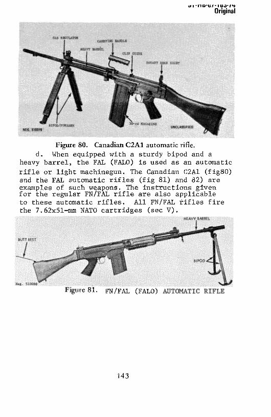
U ~ ~iJ~~UI~ I U.J~I’t
Original
Figure 80. Canadian C2A1 automatic rifle.d. When equippedwith a sturdy bipod and a
heavy barrel, the FAL (FALO) is used as an automaticrifle or light machinegun. The Canadian C2A1 (fig8o)and the FAL automatic rifles (fig 81) and 82) areexamples of such weapons. The instructions givenfor the regular FN/F.AL rifle are also applicableto these automatic rifles. All FN/FAL ~ifles firethe 7.62x5l—mm NATO cartridges (sec V).
~e81. FN/FAL (FAL0) AIfl
143

Original
Figure 82. IsraeliFN/FAL rifle andautomaticrifle.
127.TechnicalData
Technical datapertainingto theFN/FAL rifle aregiven in tableV.
128.Operation
a. Load the magazine by placing a cartridge on themagazine platform and pressing down until the cartridge rolls
sidewaysunder one of the feed lips. Repeatthis action until the
magazineis full,
b. Graspthe magazineby its base,andwhile holdingit at a
slight forward angle to insure that the lip on the top front 0f themagazine engages its seat in the receiver, insert the magazineintothe magazinehousing.Pull the bottom of the magazine to the rearuntil themagazinecatch (fig 83) snaps into place.
S.
144

Ut IUUUIIUUI’P
Original
c. Rotate the selector (fig 83) to its upper rear position(safe). Grasp the operating handle (fig 83) (unfolding it ifnecessary),pull it fully to the rear,andreleaseit. CAUTION: Therifle is now loaded.
d. Adjust the rear sight for the desiredrangeby unfolding(if necessary),by pressingin the slide lock (fig 83), andby slidingthe apertureon its baseuntil the numberthat correspondsto therange, in hundreds of meters, is visible,
e. Rotate the selectorto the desiredposition, down forsemiautomatic or fully forward for full automatic. (Note: SomeFAL’s can fire only semiautomatically.) Using a normal sight
picture, aim andpressthe trigger. Thebolt will remainopenwhenthe lastshot is fired,
f.(fig 83)
forward
Remove the magazineby pressingthe magazinecatchforward and, at the same time, rotate the magazineout of the gun. The bolt can be closed by pulling the
Figure 83. L1A1 receiver details,
145

~J-nD-uI-IuJ-,’*Original
operating handle fully to the rearandtheneasingit forward or bypressingdown the bolt stop (fig 83).
g. Clear the FAL by removing the magazine (f above),pressing up on and holding thebolt stop(fig 83), andthenpullingtheoperatinghandlefully to therearandreleasingit. The bolt willremainopen;inspectto insurethat no cartridgesarepresent.Movethe selector from safe, depress the bolt stop, press the trigger, setthe safety back on safe, and reinsertthemagazine.
h. There are two types of gas regulators(fig 78), both ofwhich are adjustable.Both function in the samemannerbut areadjusteddifferently.The older typeregulatorhasa squareforwardface; move this type back until it just uncoversthe oval gasescapeport behind the front sight. Insert an empty magazine, close theregulator 20 clicks, load a live round into the chamber, and fire. If
the bolt does not catch to the rear, close the regulator five moreclicks and refire. Continue this actionuntil the bolt is just caughtto the rear, for five consecutive shots; then close the regulatorthree additional clicks. If the gun fails to reload after it has been
fired, close the regulator two clicks at a time until reliablefunctioning is achieved.The new style regulatorhasan angledcuton its forwardface andis easierto adjust.Move this regulatorbackuntil the gas escapeport is uncovered; then, with an emptymagazinein place,fire onecartridge; if thebolt doesnot catch tothe rear, close the regulator one click and refire. Repeat (andadjust if necessary) until the bolt is caught for five consecutiveshots;thenclose the regulatoronemore click. When aweaponinuse fails to reload, close the regulator one click at a time untilproperfunctioningis achieved.In all cases,notethe correctsettingfor future use.
i. The gas plug (fig 78) is adjustable for firing rifle S.
grenades.Press in the plunger on the plug androtate it to the
146

U I - I I UU 1 I UU I ‘I
Original
desired position. The rifle will function normally when the letteror symbol on the plugis at the top. Whenit is at the bottom, or ifthe letters “GR” are visible, the gas port is closed (for firing
grenades),andthe rifle mustbe manuallyreloadedafter each shot.
j. The front sight canbe screwed up or down to adjust forelevation zero. Screw the sight clockwise (inward) to raise thepoint of impact. The rear sight can be zeroed laterally by means ofthe screws (fig 83) directly under it. Loosen one screw and tightenthe opposingscrewto move the sight. Thesight will movetowardthe loosened screw, in the direction the shot pattern is to bemoved.
129. Disassembly and Assembly
a. To disassemble the weapon, clear the rifle (para g) but
do not press the trigger or insert the magazine.
b. The takedown lever (fig 83) may be either the oldervertical type or the newerhorizontal type. Pressthe former to the
rear, pressthe latter upward, and while holding the FAL by itshandguard,pressthebutt stock down to swing the rifle open.
c. Pull the bolt cover (fig 83) to the rear, off the receiver.
d. Grasp the rod that extends from the rear of the boltcarrier andpull the bolt andcarrierto the rearout of the receiver.Hold the bolt carrier horizontally and push the bolt back into thecarrier until the bolt drops. Press in on the end 0f the firing pin,and the bolt will drop clear of the carrier.
e. Use the point of a cartridge or similar item to force in
the plunger on the side of the gasplug (fig 78). Rotate the plug
until it comes free; remove the plug, the piston, and the piston
spring.
147

Original
f. No further disassembly is necessary or desirable.
g. To reassemblethe rifle, insert the piston andspring into
their tube andforce them into place with the gas plug. The lugs onthe plug must be vertical; after the plug is in as far as possible,depressits plunger and rotate the plug to retain it in place.(Note: Referto para128i.)
h. Holding the bolt at an angle, insert it into the boltcarrier so that the firing pin enters its hole in the rear end of thecarrier. Press the bolt to the rear (while pressing in on theprotruding end of the firing pin) until the bolt seats in the carrier,
i. Hold the openedrifle muzzle down, and, after insuring
that the bolt is forward in the carrier, align the rails of thecarrierwith their grooves in the receiver and slide the carrier fully
forward. Mate the bolt cover with its groovesin the receiver andslide the carrier fully forward.
j. Swing the rifle shut, pull the trigger to releasethehammer, place the selector to safe, and insert the magazine.
130. Functioning
a. The FN/FAL rifle is gasoperated;some0f the gas that
drives the bullet down the barrelis tappedoff anddirectedagainsta piston to drive it to the rear. The piston imparts sufficientenergy to the mechanismof the gun so that all functions necessaryto fire anothershotareperformed.
b. When the trigger is pressed,the hammer strikes thefiring pin; this fires the cartridge,and the propellantgasesdrivethe bullet down the bore. After the bullet passesthe gasport inthe barrel, someof the gasesenterthe gas cylinder anddrive the
148

Original
I - PISTON 5 - LOCKING CAM2 - BOLT 6 - DRIVING SPRING ROD3- BOLT CARRIER 7- LOCKING SEAT4- UNLOCKING CAM 8- LUGS
Neg. 510083 9 — BARREL
Figure 84. FN/FAL bolt mechanism.
piston rearward,The piston strikes the bolt carrier (fig 84) and
drives it rearward,compressingthe driving spring. After a shortfree travel, the bolt carrier unlocking cam (fig 84) camsthe boltup out of its locking seatin the receiver.The bolt andcarriernowtravel to the rearas oneunit.
c. The piston spring returns the piston forward, and thebolt carrier rocks the hammer back. The extractor pulls the firedcartridge case from the chamber and holds it against the bolt until
the casestrikesthe ejector.The caseis expelledfrom the rifle.
d. The driving spring forces the bolt and bolt carrier
forward; the feed rib on the bolt drives a cartridge out of the
magazineand into the chamber.The extractorsnapsover the rimof the cartridge,and the bolt stops its forward travel, The boltcarriercontinuesforwardfor a shortdistance,andby meansof thelocking cam (fig 84), camsthe bolt down into its lockedposition.The carrier finally trips the automatic sear (fig 84).
149
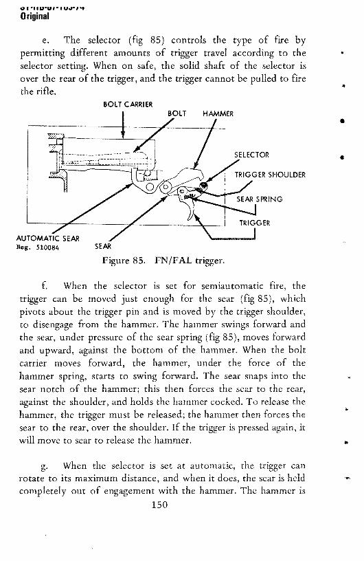
U I I1 UU I - I UU I t
Original
e. The selector (fig 85) controls the type of fire bypermitting different amounts of trigger travel accordingto theselectorsetting. When on safe, the solid shaft of the selector isover the rearof the trigger, andthe trigger cannotbe pulled to firethe rifle.
BOLT CARRIER
AUTOMATIC SEARNeg. 510084 SEAR
Figure 85. FN/FAL trigger.
f. When the selector is set for semiautomaticfire, thetrigger can be moved just enough for the sear (fig 85), whichpivots about the trigger pin and is movedby the trigger shoulder,to disengagefrom the hammer.The hammerswings forward andthe sear,under pressureof the searspring(fig 85), movesforwardandupward, against the bottom of the hammer.When the boltcarrier moves forward, the hammer, under the force of thehammer spring, starts to swing forward, The searsnapsinto thesearnotch of the hammer; this then forces the searto the rear,againstthe shoulder,andholdsthe hammercocked.To releasethehammer,the trigger mustbe released;the hammerthenforcesthesearto the rear,over the shoulder,if the triggeris pressedagain, itwill moveto searto releasethe hammer.
g. When the selector is set at automatic, the trigger canrotate to its maximumdistance,andwhenit does,the searis heldcompletelyout of engagementwith the hammer.The hammeris
150

I -flU-UI- ~J.IL~Original
then held cockedonly by the automaticsear (fig 85). Thissearistripped by the bolt carrier during its last bit of forwardtravel andreleasesthe hammer to fire anothershot. This action, whichoccurseachtimethe bolt carriergoesforward, resultsin automaticfire. The releaseof the trigger causesthe hammerto be caughtbythe searin the samemanneras in paragraphf above.
h. Two automaticsafetyfeatureson the rifle preventfiringif the bolt is not locked. This condition will preventthe boltcarrier from going fully forward becauseits camswill be blockedby the lugs on the bolt, if the bolt carrieris not fully forward, thefollowing will occur:
(1) The automaticsear(fig 85) will not be tripped,andit will continueto hold the hammercocked,even if the trigger ispressed.
(2) The firing pin will not protrude through the rearwall of the carrierandcannotbe struckby the hammer.
i. The bolt stop is held down by a light spring. A rib onthe magazineplatform contactsthe bolt stopwhen thelast roundleaves the magazineand the force of the magazinespringlifts thebolt stop up into the pathof the bolt. This holds the bolt openwhenthe last roundis fired.
131. Accessories
a. Many accessories are made for the FN/FAL rifle. These
include severaltypesof bayonets,telescopicsights, infrarednightsights, bipods, grenadelaunchers, and blank firing devices. Acompletedescriptionof all these would require too much spaceandis not warranted,
151 ~

Original
b. Two types of bayonetsare in use; one is a conventional
type that is slippedoveradovetailon the barrelor flash hiderandis removed after a release button is pressed. The other type has a
tubular socket handle that slips over the flash suppressorand isheld by a spring catch,The catch is pulled away from the socketto removethebayonet.
c. The grenade launchers are attached and removedlike
the tubular socket bayonet referred to above. Never insert abulletedcartridge into the rifle whenlaunchinggrenades—useonlythe special blanks. Be sure to rotate the gasplug (para128i) topreventdamageto the rifle mechanismwhen launchinggrenades.
d. Web slingsandcleaningrodsare usually availablefor usewith theFN/FAL rifle.
0. THE 5.56-MM GALIL RIFLE (ISRAEL)
132.General
a. The 5.56-mm Galil rifle (fig 86) is a standardIsraeliArmy weapon. This rifle’s design is based on the Soviet AK-47,with improvements to meet Israeli requirements. The Gaul canbeidentified by its large rectangularforearm, prominantfront sight
mount and the gascylinder,uniquebent-upOperatinghandle,andpermanentlyattachedbipod.
b. The Galil hasseveralunusualfeatures: thebipod canbeused to cut barbed wire or other wire, and the bipod clip in therear of the hand guard can be used to open soda pop bottles. Afold-away carrying handle is also provided.
c. The Galil is a gas-operated,detachablebox-magazinefed, selective—fire shoulder weapon equippedwith a folding metalstock.The Gall fires 5.56x45-mmammunition(secV).
152

Ua-rJo-uI-JOJ-Iq
Original
133. Technical Data
Technicaldatapertainingto theGalil rifle aregivenin table III.
134.Operation
a. Removethe magazineby pressing the magazinecatch(fig 86) forward and then rotating the magazineforward, out ofthe rifle, Placea 5.56x45-mmcartridgeon the magazinefollowerandpressthe cartridgedown until it rolls sideways,underthefeedlip. Repeatuntil the magazineis full.
b. Unfold the stock by pressingdown on the stock pivot(fig 86) until the stock can be swungoutward.-Rotate the stockrearward until it locks in place. The stock is folded by againpressingdown on the stock pivot until it unlocks from thereceiver;thenswingthe stockforward until it locks in place.
Figure 86. Israeli Gaulrifle,
153

~-Mb-UI-~J-IqOriginal
c. Set the rear sight (fig 86) for range by flipping it
forward (300-metersetting) or rearward(500-metersetting).The
front sight can be adjustedto zero the rifle. Refer to paragraph137e for use of night sights.
d. When firing from the prone position, especially at longerranges, the bipod (fig 87) should be used to steady the rifle.
Squeezethe bipod legs togetherto disengagethem from thebottleopener (fig 86), swing them forward, and allow them to spring
Figure 87, Galil on bipod.
Figure 88. Galil with folded stock,
I-
154
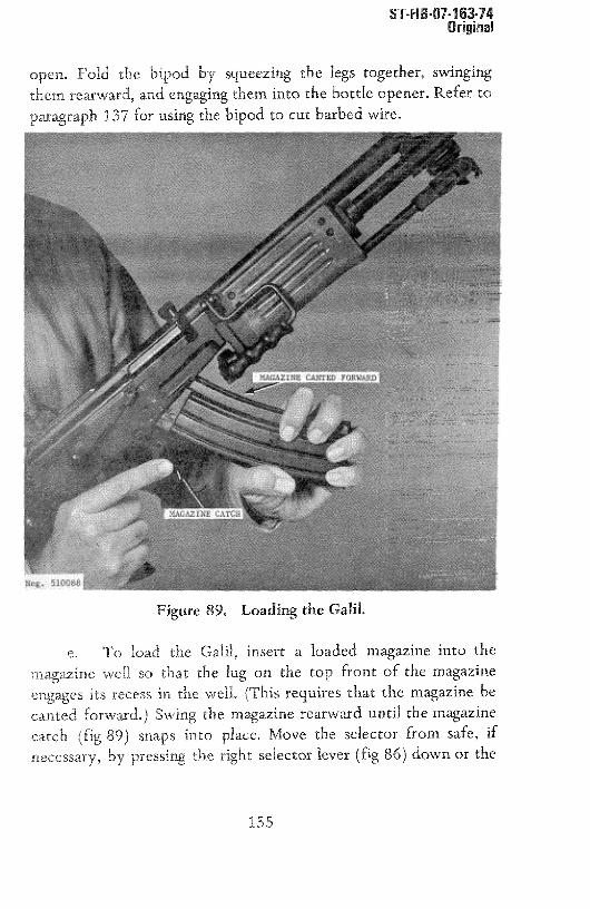
ST-H 6~O7-163-74Original
open. Fold the bipod by squeezing the legs together,swingingthem rearward, and engaging them into the bottle opener.Refer to
paragraph137 for using the bipoci to cut barbedwire.
e. To load the Gall, insert a loaded magazineinto themagazinewell so that the lug on the top front of the magazineengagesits recessin the well. (This requiresthat the magazinebecantedforward.) Swing the magazinerearwarduntil themagazinecatch (fig 89) snaps into place. Move the selectorfrom safe, ifnecessary,by pressingthe right selectorlever (fig 86) down or the
Figure 89. Loadingthe Gaul.
155

~-t1b-UI•itJ.j-IqOriginal
left selector lever (fig 86) rearward.Pull the operating handle(fig 86) fully rearward and release it. CAUTION: The Gail is nowloadedand readyto fire! if the rifle is not to be immediatelyfired,move the right-handselectorup, or the left-handselectorforward,to renderthe rifle safe.
f. To fire the Gall, move the selector from safe. Themid-position of the selector provides fully automatic fire, theremaining position (down or rearward)provides semiautomaticfire. Aim (using a normal sight picture), and pressthe trigger; therifle will fire accordingto the modeselected.The bolt will remainclosedbetweenshotsandafter the last roundhasbeenfired.
g. The Gail maybe usedto launch 22-mm ID tubed riflegrenades.A special10-roundcapacitymagazinefor holding special
(bulletless) grenade launching cartridges is available; however,individual launching cartridges may be directly inserted into thechamber.There are some 22-mm ID tubedgrenadesthat can be
launchedby a 5.56-mm ball round; however, at present, onlybulletlessgrenadelaunchingcartridges(crimpedcartridges)shouldbe used to launch grenadesfrom the Galil, to precludeinjury tothe firer or the rifle. Removethe magazine,retract the operatinghandle, insert a grenadelaunching cartridge into the chamber,releasethe operatinghandle, and move the selector(s) to safe.Remove a rifle grenadefrom its containerand slide it over theflash hider (fig 90) as far as possible.If the grenadehasa sight leafpackedwith it, attachthis to thegrenade.Removeanysafety pinsor devices.Aim, using the ogive (largestdiameter)0f the grenadeas a front aiming point, move the selectorfrom safe,andpressthetrigger. CAUTION: Recoil is severe and some gas may bedischargedfrom the ejection port. It is recommendedthat riflegrenadesbe fired only in emergencysituations.
156

,~ -,-u3.uI. uja-iqOriginal
h. To clear or unload the Galil, pressthe magazinecatch
forwardandrotate the magazineforward, out of the rifle. insure
that the selectoris not in the safeposition, thenpull the operatinghandle rearward and inspect to insure that no cartridges are
present.Releasethe operatinghandle,pressthetrigger to drop thehammer, and move the selector to the safe position. When the
selectoris at safe, the operatinghandlecan bedrawn backjust far
enough for the rifleman to ascertainif the chamberis loaded or
empty. Any cartridgesin the magazinecanbe removed,if desired,
by pressing forward, out 0f the magazine. Insert the emptymagazinebackinto the rifle,
Figure 90. Loading a rifle grenade.
157

ST-HB-UI-i 63-14OrigInal
135. DisassemblyandAssembly
a. Clear the rifle (para 134h), but do not place the selector
on safe or insert the magazine.Press the driving spring guide
(fig 86) inward as far as possible,and,while holding it in, pull up
the rear endof the receivercover to disengageit from the receiver.
Remove the receiver cover. Press the driving spring guide farenough forward to disengage it from its seat in the receiver.
Removethe driving springassembly.
b, Pull the operatinghandle fully rearward.Pull the gascylinder tube(fig 91) to the rear to disengageit from the receiver
andgas cylinder. Lift the bolt carrier, with bolt andgascylindertube,out of the receiver.(Note: The bolt carriermustbe fully tothe rear.) Pull the gas cylinder tubeoff the gaspiston.Rotatethebolt in the carrier to disengagethe operatinglug 0f the bolt fromits cam path in the carrier, thenpull the bolt forward, out 0f thecarrier,
Figure91. Removing gas cylinder tube.
158

ST-H 6-07-163-74Original
c. No additional disassembly is required or desirablefornormal user servicing.
d. To reassemble,insert the bolt into the bolt carrierandrotate the bolt until its operatinglug mateswith the cam path inthe bolt carrier, Slide the gascylinder tube, largeend first, overthe piston. Pull thebolt fully forwardin the bolt carrier.Placethecompleteunit (bolt carrier, bolt, andgas cylinder tube) into thereceiver so that the guide lugs on the sides of the bolt carrier(fig 91) enterthe cutoutsat therearof the receiver,Presstheboltcarrier down and slide it forwardin the receiver. CAUTION: Becareful not to strike the piston against the gascylinder.Align thelugs of the gascylinder tube(fig 91) with their seatin the receiverand slide the gas cylinder tube forward, seating it on the gascylinder.Pushthebolt carrierfully forward.
e. Insert the driving spring into the bolt carrier and forcethe driving spring guide forward until it can be seatedinto itsrecess.Releasethe guide.
f, Place the receiver cover on the receiver so that thedriving spring guide is inside the rear endof the cover. Pressthecover forward, insuring that the front end of the coverentersthecircular groove in the gascylinder tube,Pressthe rear endof thecover down until it seatsin thecrossgroove in the receiverandthedriving spring guideprotrudes.
136.Functioning
a. The Gall assaultrifle is gasoperated,i.e., a portion ofthe gas that propels the bullet through the barrel is tapped0ffthrough a port in the barrel and is used to drive the boltmechanism to the rear during firing. A strong driving springreturnsthebolt forward,
159

ST-H6-07-163-14Original
b. When the Galil is loadedandcocked,finger pressureonthe trigger causesthetwin lugs on the top of the trigger (fig 92) todisengagefrom the hammer; the hammer,under pressureof thehammerspring, swings forward andfires the weapon.The bullet isdriven through the barrel by the propellantgases.After the bulletpassesthe gas port, some of the gasesare tappedoff anddirected
againstthepiston extendingfrom thebolt carrier.
The propellantgasesdrive the piston andthe bolt carrier(fig 92) rearward, compressingthe driving spring.After one-thirdinch of free travel, a cam in the bolt carriercontactsthecam studon the bolt; further travel rotatesthebolt 35°andunlocks it fromthe receiver. The piston, carrier, and bolt all move rearwardtogether, rocking the hammerback. The extractorwithdrawstheempty cartridge case from the chamberand holds it against the
bolt until the case strikes the fixed ejector; the casethen pivotsaround the extractor and is expelled. The bolt carrier hits theinnerrearwall of the receiverandstops.
d. The driving spring drives the recoiling parts forward,and, as the bolt moves,its feedrib drives the top cartridgeout ofthe magazineand into the barrel. The extractor snapsinto thegroove of the cartridge case, and, as the bolt carrier continuesforward, its cam rotatesthebolt to its lockedposition.During thefinal one-third inch of travel, the carrierdepressesthe automaticsear.The forward movementterminateswhen the front 0f the boltcarrier strikesthe receiver.
e, The selector or change lever (fig 92) controls thefunctioning of the trigger mechanismby causingits arm insidethereceiver to change positions, in relation to the trigger, as theselector is moved. The safety sear (fig 92), which also holds thehammer cocked, not affected by the selector in any way, isoperated solely by the bolt carrier.A projection on the rear of the
160

a
-4 .~4 ~3.a
1 1 ~. ~3.3.
~0 0
~ 3 30 S4 a a3 e,aa “ I I
-1 6 6a
g~.
a
nonI ID’
a ~ a~g
a-,-1
-TI00
z00
LrI
oF-’ a
an,,
0
3
a-0
0
0.
0
aa
-1a-I
303I,
5-
aa
.;-I
=
—a

ST-H 6-07-163-14Original
bolt carrier, above the bolt spindle, preventsthe hammerfrom
striking the firing pin unless the bolt carrier has moved forward
enoughto lock the bolt to the receiver,
f. When the selector is in its lowest (semiautomatic)
position, the arm of the selector moves to its rearmostposition
(fig 92) and has no effect on the triggermechanism.As the trigger
is pressed,the twin lugs on the trigger disengagefrom the hammer,
which swings forward.The recoilingbolt carrier rocks thehammer
to the rear, and the hammer forces the disconnector (which,
becauseof the movement of the trigger, has moved forward) to
the rear against its spring.As the hammerpassesthe disconnector,
the searsnapsforward,where it can catchthe hammer.Therefore,
when the counterrecoilingbolt carrier trips the safety sear,the
disconnectorholds the hammer. When the trigger is released, the
disconnectormoves rearward and releasesthe hammer, which is
then caught by the twin tugs of the trigger. The trigger must be
pressedagainto fire anotherround.
g. By moving the selector to its middle (automatic fire)position, the arm inside the receiver is positionedover the tail of
the disconnector (fig 92). As the trigger is pressed, the
disconnectorsearcontactsthe arm and is rocked rearward; it thencannotcatch the hammer.Only the safetysearholdsthe hammer
cocked, and,as the carrier in its final travel depressesthe safety
sear and releasesthe hammer, the weapon fires. This action
continuesas long as the trigger is held depressedandammunitionis present.To stop firing, the trigger is released,and its twin lugs
interceptthe hammerand hold it cocked,
h. As the selector is moved into its upper (safe) position
(fig 92), the arm moves over the rear0f the trigger andblocks any
trigger movement. If the hammer is uncocked, interference
between the hammer and the twin lugs of the locked trigger
preventsfull retractionof thebolt,
162

137. Accessories
ST-H B~07.163-74Original
a, Severaldifferent magazinesare available for the Gaul.
Theseinclude 35- and 50-roundcapacity magazinesand a special
12-round capacity magazine used only with crimped
grenade-launchingblank cartridges.
b. The bipod is openedby squeezingits feet togetherto
disengagethem from thebottle openerat the lower rearendof the
forearm and then swingingthe bipod to aright angleto the barrel.
When thelegs are released,theywill now spring apartfor use.Fold
the bipod by squeezingthelegs together,swingingthemrearward,
andengagingthem with the bottle opener.The bipod canbeused
to cut wire by swinging the bipod forward after thewire is placed
in the cuttingjaw (fig 93).
j N~g~51DO9~
Figure 93. Using the Gall to cut wire.
163

ST-H B-Ui-i 63-74Original
c. The Galil uses a spike—typebayonet(fig 94) similar tothat used with the Bel ‘im C.A,L. rifle (para119b).
S
Figure 94. Gall bayonet.
d. To use the bottle opener(fig 95), disengagethe bipodlegs from it andplaceoneedgeof the bottle capunderoneside ofthe opener.Lever the bottle against the other side, and the capwill pop off.
I
Figure95. Galil bottle opener.
164

ST-H B-07-163-74Original
The Gahil has auxiliary luminous night sights (fig 96),Flip these sights up for useat rangesto 100 metersat night andflip them down for daytimeuse0f the normalsights.
E. THE 5.56~MMBERETTA Mi0/.223 RIFLE (ITALY)
138,General
a. The 5.56-mm BerettaM70/.223rifle is the mostrecentmilitary rifle developed by the Beretta firm of Italy. The
M70/.223 is made as a conventionallystockedrifle (fig 97), as afolding-stockrifle (fig 98), and as a light machinegun(fig 99). Allof thesevariant weaponsuse the samemechanismand magazine;the differenceslay in the different type stocks used and in theheavybarrel andbipod of the machinegun.
Figure 96. Gall front night sight.
165

ST-H 8-01-163-74Original
b. No army has yet adopted the M70/.223, but thisweapon is offered for sale throughout the free world andprobablywill be adoptedby severalnations.
Figure 97. Italian BerettaM70/.223rifle.
Figure98. BerettaM70/.223rifle with foldingstock (early model).
166

S[-l1B-O7-163-14Original
c. The Beretta M70/.223 is a gas-operated,detachablebox-magazinefed, selective-fireshoulderweapon.It is fitted witha combination flash hider/grenadelauncherand integral grenadelaunching sights. These sights, when erected for launchinggrenades,automaticallycut 0ff the rifle’s gasmechanism.
d. The BerettaM70/.223 rifles fire 5.56x45-mmcartridges(referto secV).
139. Technical Data
Technical data pertaining to the Beretta M70/.223 are given intableV.
140. Operation
a. Load the magazine by placing a cartridge on thefollower and pressingit down until it rolls sideways under a feedlip; repeatuntil the magazine is full. Insert the loadedmagazinestraight into therifle until the magazinecatchsnapsinto placeandretainsthe magazine.
Figure 99. Beretta M70/.223 automatic rifle (LM) -
167

ST-H 8-07-1 63-14Original
b. Grasp the operating handle (fig 97), pull it fullyrearward, and release it. CAUTION: The rifle is now loadedandreadyto fire, If the rifle is not to be immediatelyfired, place it on
safe by rotating the selector (fig 97) to the vertical position,
indicatedby the letter “5”.
c. To fire, rotate the selector to the position for thedesiredtype of fire—rearwardto 1 for semiautomaticfire, forwardto A for automaticfire. Adjust the rearsight for the desiredrange,aim (using a normal sight picture), and pressthe trigger. If theselectorhas beenset to 1, the rifle will fire oneshot and reloaditself; if set to A, it will fire as long as the trigger is pressedandcartridges are in the magazine.The bolt will remain closedbetweenrounds and will remain caughtrearward when the lastroundin themagazinehasbeenfired.
d. Remove the empty magazineby pressingthe magazinecatch (fig 97) toward the magazineand pulling the magazineoutof the rifle. The bolt can be closedeitherby pulling the operatinghandle rearward and releasingit or by pressingin the top of thebolt catch (fig 97) inward.
e. To clear the rifle, set the selector (fig 97) to the safe(vertical) position “S”. Press the magazine catch toward themagazine and pull the magazine out 0f the rifle, Press in thebottom of thebolt catch (fig 97) and,while holdingit in, pull the
operating handle fully rearwardand releaseit. The bolt will becaughtopen. Inspectto insurethat no cartridgesarepresent.Pressin the top of the bolt catch,rotatethe selectoroff safe,andpressthe trigger. Insert themagazine.
f. To launch grenades,set the rifle on safeafter loading (aabove).Ball cartridgescanbe usedonly if MECAR brand 22-mmtube rifle grenadeswith bullet trapsareavailable.The grenadesare
168

ST-H 8-07-163-74Original
marked on the tail boom if a bullet trap is incorporated.If it is not
known that the grenade has a bullet trap, clear the rifle
and insert a bulletless, crimped grenade cartridge into thechamber. Slide a grenadeover the grenadelauncherand seat it
fully. Erect the front and rear grenadesights (fig 97). (Note: Thefront sight is only an indicator that the gas mechanismhasbeenturned 0ff to protect the rifle’s mechanism.)Aim, using theappropriate 50-, 75-, or 100-meteraperture in the rear grenade
sight and the regularfront sight post,andpressthe trigger. Pull theoperatinghandlerearwardto ejectthefired cartridgecase.
141. Disassembly andAssembly
a, Clear the rifle (without moving the safety off safe),press the trigger, or insert the magazine. Press out the takedownpin (fig 97) from left to right and swing open the receiver
(fig 100). Pull the operatinghandleretainer (fig 98) to the rearwith the point of a bullet andpull out the operatinghandle.Holda hand behind the receiver openingandpoint the muzzleupward;the bolt unit will emerge from the rear 0f the receiver. Ifnecessary,partially engagethe operatinghandle with its hole inthe bolt carrier andpull the bolt unit to the rear until it can beremoved. Pull the bolt (fig 100) forward in the carrier (fig 100),twisting the bolt at the sametime until it comesout 0f the carrier.
169

ST-H8-07-163-74Original
b. In the front of the gascylinder is a smallplunger thatseatsin the notchesof the flash hider (fig 100). Pushthe plungerin and unscrew the flash hider (right-hand thread). Pull the gascylinder (fig 100) forward, off the barrel, andpull the gaspistontube (fig 100) forward and remove it. Push the piston (fig 100)rearwardslightly,againstthepressureof its spring,until the pistoncan be rotated. Ease the piston forward, then rotate it until it
comesfree.
The handguard (fig 100) can be removed by pullingdown on its front end until it comes off the barrel. Rotatethehandguarddown until it can be removed.
d. No furtherdisassemblyis necessaryor desirable,
e. To reassemble,engage the hook at the rear 0f thehandguardwith its crosspinin the lower front of thereceiverandswing the handguard up until it canbe snappedonto thegaspistontube.
f. Insert the piston into the receiver. The small pin(fig 100) must be aligned with its slot in order to enter thereceiver.Once in the receiver,rotate the piston so that thenotchfor the operatinghandle (fig 100) faces down andthe pin seatsinits recessto preventrotation of the piston. Slip the piston tubeover the pistonandseatit in the receiver.
g. Slide the gascylinder on over the barrelandfit the frontendof the piston tube into the gascylinder.Seatthe gascylinderfully againstits shoulderon the barrel.Screwthe flash hiderontothe barrel; it is necessaryto depressthe lock plungerto screwtheflash hider fully in place. Releasethe lock and rotate the gascylinder until the lock seatsin oneof the notches.
170

ST-HB-U1-163-74Original
h. Insert the bolt spindle into the hole in the bolt carrierand seat the bolt in the carrier.Twist the bolt while seatingit toinsurethat the operatinglug on thebolt mateswith the camrecessin the bolt carrier. Pull the bolt forward in the carrier until thebolt stops.
i. Insert the bolt carrier into the receiver,bolt first, andmove it fully forward. Insert the operatinghandleinto its hole in
the bolt carrier (forcing the retainer rearward)until the retainersnapsinto place.Pull the operatinghandlerearwardto insurethatit has engagedthe piston, and spring pressureis felt. Close thereceiver, push the takedownpin (fig 97) home, move the safetyoff safe,pressthe trigger, and insertthe magazine.
142. Functioning
a. The Beretta M70!.223 is gas operated. When the rifle isloaded and cocked, pressure on the trigger releasesthe hammerwhich, under pressureof its spring, swings forward, strikes thefiring pin, and fires the chamberedcartridge.As the bullet drivesdown the barrel, it passesthe gasport andsomepropellantgasesarediverted through the port into the gascylinder.The gaspiston(fig 101) is driven rearward,driving the bolt carrierrearward,andcompressingthe driving spring.
b, As the bolt carrier moves rearward, it causesthehammerto rock back, and the safetysear (fig 101) rises.As thebolt carrier continues rearward, the cam recess in the carrier(fig 101) acts on the operatinglug of the bolt androtatestheboltto its unlockedposition.Onceunlocked,the bolt andcarriermoveto the rear as a unit, The extractorpulls the fired cartridgecasefrom the chamberandholdsit to thebolt until the casestrikestheejector and is expelled through the ejectionport. The bolt carrierfinally strikesthe rearof the receiverandstops.Thedriving springthen drives thebolt carrier forward, and the feed rib on the bolt
171

ST-H 8-07-i 63-74Original
drives the top cartridge out of the magazine and into the barrel.
The bolt strikes the barrel and stops; the bolt carrier continuesforward, rotates the bolt to its locked position, and trips the
safety sear.The extractorsnapsinto the cartridgegroove.
Figure 101. Beretta M70/.223 section,
c. When the selector is set on I (semiautomatic), the
hammeris held cockedby the noseof the trigger engaging a notchin the hammer; when the trigger is pressed,it disengagesfrom thehammer,allowing it to swing forward. As the trigger rotates, the
disconnector(fig 101) rotates with it, and the disconnectorhookmoves forward to where it can engagea secondnotch on thehammer (fig 101). When the bolt carrier counterrecoils, thedisconnectorthencatchesthe hammerandholds it cocked. Whenthe trigger is released, the disconnector rotates rearward with itand releasesthe hammer;the trigger, however,hasmovedenoughso that the trigger nose reengages the hammer. Pressure on thetriggerwill nowfire a secondshot,
d. When the selectoris set at A (automatic),a portion ofthe selectorswings off the rear of the disconnector(fig 101) so
that when the trigger is pressedthe disconnectoris blockedanddoesnot move with the trigger as in paragraphc above.When the
172

DST—ll10Ij--163—76--cIjc 23 February 1984
bolt carrier counterrecoils, only the safety sear(fig 101) holds the hammer cocked, and as the boltcarrier completes its forward travel, it trips thesafety sear which releases the hammer to fireanother round. This action continues until themagazine is empty, or until the trigger is releasedand its nose engages the hammer.
e. When the selector is set at safe, a portionmoves over the rear of the trigger and prevents itfrom being pressed sufficiently to release thehammer.
f, When the magazine is empty, the magazinefollower contacts the bolt catch and, because thestrong magazine spring overcomes the weaker boltcatch spring, moves the bolt catch to where it canintercept the bolt. Thus, the bolt and carrier areheld open when the last round is fired.
143, Accessories
a. The Beretta M70h223 has the usual rifleaccessories (extra magazines, web sling, bayonet,and telescopic sight).
b. The bayonet (fig 102) is affixed by slippingits loop over the flash hider engaging the T slot inthe bayonet hilt with the lug under the gas cylinder.Press the bayonet on until the locks engage. Toremove the bayonet, press the locks and pull thebayonet forward, off the rifle.
Figure 102, Beretta M70/.223 Bayonet
173

DST—1110H—163~-76—CHG23 February 1984
c. Mounting pads are necessary to install thetelescopic sight on the receiver. These pads arefactory installed. To mount the telescope, fit itover the pads with the lock lever (fig 103) rear—ward. When the telescope is seated, swing the leverforward to lock the telescope in place. Reverse toremove the telescope.
Neg. 510102Figure 103. Beretta M70/.223 Telescopic Sight.
d. The telescopic sight is adjusted asdescribed in paragraph 91d. Close the non—aimingeye when using the B~retta telescope.
E.1. THE 5.56—MM AUG (St.G.) RIFLE (AUSTRIA)
143.1. General
r a. The 5.56—mm AUG (Armee—Universal—Gewehr) orArmy Universal Rifle (fig 103.1) is the lateststandard rifle of the Austrian Army. It is manufac-tured by the world—famous Steyr—Daimler—Puch factoryand comes in three versions. There is a short--barreled (407—mm) carbine version, a medium—length—(508—inm)—barreled rifle, and a long—barreled (610—mm)light machinegun version. The AUG can be easilyrecognized by its unique shape and by the extensiveuse of plastics in its construction. All parts areplastic with the exception of the steel barrel, boltand pins, and springs and the aluminum and steelreceiver.
S
174

-, ~pt-emDeE L~IOU DST—111OH—163—76—CHG1
b. The St.C 77 (AUG) cannot be equipped withany type of folding stock, because its breech mech-anism operates within the buttstock. In order toprovide shorter than normal weapons, various barrellength are available; the shortest of these, wheninstalled, provides a rifle as short as any with afolding stock.
c. The major sighting equipment is a 1.5 poweroptical sight. The reticle of this sight is in aring suspended in the middle of the telescope. Asmall blade—type foresight and “v” notch rear sightare formed into the telescope body top surface foremergencyuse. An adjustable gas regulator permitsvarying the operating power when the rifle isfouled; it also, by setting the regulator to an“off” position, permits the launch of 22—mm tuberifle grenade by using the flash suppressor as agrenade launcher.
d. The St.G 77 (AUG) fires 5.56x45—mm ammuni-tion. The clear plastic magazinespermit the ammuni-tion status to be determined at a glance. Full orsemiautomatic fire is determined by how hard thetrigger is pressed.
Neg. 529275Figure 103.1. Austrian 5.56—mm St.G 77 (AUG)
assault rifle with 508—mmbarrel.
174.1

USi—ii1Ufl—i~iIO’~rn, oeptemDer
Neg. 539274Figure 103.2. Austrian St.G 77 (AUG) with 610-mm
barrel- Operating handle locked to rear.
143.2. Technical Data
Technical data pertaining to the St.G 77 (AUG)rifle are presentedin Table V.
143.3. Operation
a. Load the magazine by placing a cartridge onthe follower and pressing it down until it rollssideways under a feedlip. Repeat until the magazineis full.
b. Insert a loaded magazine into the magazineopening until the magazine catch (fig 103.3) snapsinto place and retains the magazine. Grasp theoperating handle (fig 103,3), pull it fully rear-ward, and release it. It will fly forward, alongwith the bolt mechanism, and load the rifle.(CAUTION: The rifle is now loaded and ready tofire.) Should the bolt fail to fully close, pullthe operating handle as far rearward as possibleand, while holding the bolt engagement button(fig 103.3) inward, force the operating handle fullyhome.
174.2

Neg. 529273Figure 103.3. St.G 77 (AUG) controls.

DST—111OH—163—76—CHG1 5 September 1980
c. If it is not desired to immediately firethe rifle, press the safety catch (fig 103.3) to theright. The foregrip can be placed in either up or adown position (fig 103.1 and 103.3); to do this,pull the grip away from the receiver against theforce of its spring, then move the grip to whateverposition is desired.
d. To fire: Press the safety catch(fig 103.3) to the left, aim, (see subpara 3 below)and press the trigger. Light pressure on the trig-ger will fire one shot and the rifle will reloaditself, Heavy pressure on the trigger will resultin automatic fire (Note: Newly manufactured riflesrequire a deliberate heavy pull to achieve fullautomatic fire). When the last round in the mag-azine has been fired, the bolt mechanism will beheld to the rear. Remove the empty magazine bygrasping it, then pressing the magazine catch(fig 103.3) and withdrawing the magazine. Thebreech mechanism may be released by pulling theoperating handle fully rearward and then releasing
e. To aim (using the telescope sight), thecircular reticle, visible in the center of the fieldof view when looking through the telescope, shouldbe aligned over the area of the target it is desiredto hit before pressing the trigger. The telescopecan be zeroed to the rifle by turning the adjustmentscrew as necessary (fig 103.3) on the side (windage)and top (elevation) of the telescope. Do not removethe bottom cap on the telescope sight. Should thetelescope sight be unserviceable, use the emergencysights formed on top of the telescope sight reticle(fig 103.3). Use a sight picture similar to that ofthe US caliber .45 Pistol M1911A1.
174.4

September1980 DST—111OH—163—76—CHG1
f. To clear the rifle, first remove theagazine by pressing the magazine catch (fig 103.3),hen withdraw the magazine. Grasp the operatingandle, pull it fully to the rear, then rotate itpward into its rear retaining notch (fig 103.3).nspect to insure that no cartridges are present inhe barrel or mechanism, then rotate the operatingandle downward, out of the retaining notch, andelease it. Press the trigger and reinsert theagazine.
g. There are three different lengths ofbarrels available (refer to para 143.6). To cl~ngebarrels, clear the weapon (f above) but do notrelease the operating handle from its rearmostposition. Move the foregrip to its verticalposition. Press the barrel latch (fig 103.4),votate the barrel (by means of the foregrip) clock-wise, until the barrel disengages, and then slidethe barrel forward Out of the receiver. Insert thereplacementbarrel into the receiver, slide it fullyrearward, and rotate it counterclockwise until thebarrel latch snaps into place. Release the operat-ing handle.
‘eg. 529277Figure 103.4. Barrel removal.
174.5

LLjLJ~J_U.VI ~ i. oepcem~er
h. The gas plug (fig 103.3) is adjustable.Normally the small dot on the plug is aligned withthe index on the gas cylinder (fig 103.3). If therifle becomes very foul and fails to reload itselfduring firing, the gas plug should be adjusted toincrease operating power. Use a bullet point topress the spring—loaded plug lock (fig 103.3) out ofengagement with the gas cylinder; then rotate theplug until the large dot aligns with the index onthe gas cylinder.
i. Should it become necessary to launch riflegrenades from the St.G 77 (AUG), disengage the pluglock as described in the proceding paragraph androtate the plug 1800 to cut off the gas supply tothe rifle mechanism. Slide the 22—mm tail—boom—tubed grenade over the flash suppressor (fig 103.3)
Neg. 529279Figure 103.5. Barrel removed.
174.6

~oiiLVriLO3IO~ffl,~ I
as required. The retainer spring (fig 103.3) willhold the grenade in place. CAUTION: Observe allprecautions applicable to the particular type/makeof grenade used, especially as to the type ofcartridge used to launch the grenade. Never, ~never, use a ball cartridge to launch a grenade(unless the use of a ball cartridge is authorized bythe manufacturer of the grenade being launched); useonly the special grenade launching cartridge.
143.4. Disassembly and Assembly
a. Clear the weapon by pressing the magazinecatch and withdrawing the magazine; then pull theoperating handle fully to the rear and rotate it
upward (fig 103.3) into its retaining notch.Inspect to insure that no cartridges are present.
b. Press the barrel lock (fig 103.4) down andrearward. While holding the lock, rotate the barrelclockwise as far as possible; then pull the barrelstraight out to the front. Note: the bolt must beretracted before removing the barrel.
eg-. 529278Figure 103.6, Separation of receiver from stock.
174.7

DST—111OH—163—76—CHG1 5 September 1980
c. Press the takedown block (fig 103.3 and103.5) fully to the right; then pull the receiverforward, out of the stock (fig 103.6). The boltassembly may or may not come out with the receiver.If it does, pull it rearward out of the receiver.If it remains in the stock, pull it forward, out ofthe stock (fig 103.7).
Neg. 529280Figure 103.7. Removal of bolt mechanism
from receiver.
d. Grasp the firing pin (fig 103.7), pull itrearward; then twist it counterclockwise one quarterturn. This will free the firing pin so that it canbe withdrawn rearward. Turn the bolt unit over andinsert the firing pin point in the large hole in thebolt carrier. Press the pin in until it forces thelocking cam pin (fig 103.8) out of the bolt and boltcarrier. CAUTION: Press straight in on the firingpin; do not apply any side force; to do so can breakthe firing pin. Remove the firing pin. Pull thebolt, bolt guide, bolt guide spring, and bolt guidespring plunger forward out of the bolt carrier
174.8

5 September1980 DST_l11OH16376”~C~1
(fig 103.8). The bolt carrier plug (fig 103.8) canbe pulled free of the carrier if it does not fallfree. Separate the bolt from the bolt guide. Ifnecessary, remove the extractor by using the firingpin point to press out the extractor pin. CAUTION:Be careful not to lose the small pin or the springwith its plastic insert.
e. Reassemble the bolt by placing the extrac-tor in its recess and pressing it down until theholes in the bolt align with those in the extractor.Press the extractor pin back into place. Place thebolt in the bolt guide so that the right hand projec-tion on the bolt guide is between the bright lug onthe extractor and the locking lug to its immediateleft, and insuring that the cam pin hole in the boltis not blocked by the bolt guide. Align the boltguide spring plunger with the hole in the bolt car-rier and slide the unit about half way back into thecarrier- Slide the bolt carrier plug into its seat;then press the bolt and its guide fully into thebolt carrier against spring pressure until the campin can be inserted into the bolt. Note: If thecam pin cannot be inserted, pull the bolt forwardout of the engagement with its guide, and rotate thebolt until the end of the cam pin hole without thestake mark can be seen. Reinsert the bolt and cam
Neg. 529283Figure 103.8. Bolt unit disassembled.
174.9

U’,~fLU £ _J .~epLeILtueL £2O’J
pin. Turn the cam pin until the line inscribed onits end is aligned with the bolt unit. Insert thefiring pin into the bolt carrier plug so that thelugs and the pin enter the plug. Press the firingpin fully home; it will automatically rotate andlock in place. Slide the two guide rods into thetunnels in the receiver.
f. Firmly press in on the recess in the buttplate (fig 103.9) and, while pressing, press therear sling swivel toward the stock. This frees thebutt plate, which now can be recovered. The clean-ing kit (fig 103,10) is contained under a removablecover in the bottom of the butt. The hammermechanism housing (fig 103.10) can be removed forcleaning. Press in on the extension (fig 103.10)and, while holding it in, pull the rear sling swiveland pin out of the stock. The hammer mechanismhousing can now be slid out of the stock.
leg. 529284Figure 103.9. Releasing rear sling swIvel,
174.10

., ~~~epLemDer i.~5ou DST—111OH—163—76—CHG1
g. No further disassembly is necessary oradvisable.
h. Cock the hammer and insert the hammermechanism into the stock, hammer end first. Pressin the extension and reinsert the rear sling swiveland pin. Insure that the swivel is fully againstthe side of the stock. The swivel normally shouldbe inserted from right to left; however, if desired,it can be inserted in the opposite way. Engage thebottom of the buttplate (fig 103.10) into the bottomof the stock; press the buttplate into place; thenpull the swivel away from the stock.
i. Insure that the takedown block (fig 103.7)is fully to the right; then insert the receiver andbolt into the stock. When the receiver is fully in,press the takedown block fully into the stock.
j. Insert the barrel into the receiver, press-ing it rearward against the force of the barrellock. Rotate the barrel until it is locked inplace.
Neg. 529282Figure 103.10. Stock unit disassembled.
174.11

)ST—111OH--163—/b—CHG I D ~eptem~er i’iou
143.5. Functioning
a. The AUG rifle is gas operated. UponEiring, when the bullet passes the gas port in thebarrel, some of the propellent gases are divertedthrough the port into the gas plug through one ofthe two ports in the plug. The gases then act uponthe piston, driving it rearward and compressing thepiston return spring. Excess gas is vented from oneDf the two different sizes of ports in the gas plug.rhe rearward movement of the piston is transmittedto the right rod of the bolt carrier (fig 103.12),driving the bolt carrier rearward. The multiplelugs on the bolt are locked to their mating lugs inthe receiver, but as the bolt carrier moves rearwardthe cam pin, acted on by the cam path in the boltcarrier, rotates the bolt to unlock it from thereceiver (fig 103.12). The bolt guide, thrust
~eg. 529281Figure 103,11. St.G 77 (AUG) field stripped-.
174.12

septemberI9~i0 DST—111OH—163—76—CHG1
forward by its spring, places its prongs (fig 103.8)between the top locking lugs of the bolt as the boltclears the receiver, This action prevents the boltfrom rotation in relation to the bolt carrier, andalso holds the bolt extended for relocking. A smallfore and aft motion of the bolt, resisted by thebolt guide spring, buffers the bolt when it inter-cepts the top round in the magazine when feeding.
b. The spring—loaded extractor withdraws thefired cartridge case from the chamber. When thefront of the case clears the front edge of theejection port, the spring—loaded, plunger—typeejector causes the case to pivot about the extractorand be expelled from the rifle.
c. The driving spring in the guide rods of thebolt carrier (fig 103.8) is compressed during therearward movement by fixed push rods attached to theinside of the stock. As the bolt carrier moves rear-ward, it allows the automatic sear (fig 103.13) to
Neg. 529271Figure 103,12, Bolt functioning.
174.13

DST—ll1Oll—lbi—/b—CtfG I ~ September I’~öU
move rearward, and then the bolt carrier rocks thehammer back, compressing the hammer spring. Afterthe hammer rotates sufficiently rearward, the auto-matic sear snaps into engagement with the hammer.The rearward movement stops when the bolt carrierstrikes the buffers that surround the push rodsinside the stock.
d. The driving springs now drive the bolt andbolt carrier forward. The bolt strikes the topround in the magazine and drives the round out ofthe magazine and into the barrel. The bolt guidestrikes the locking lug plate on the end of thereceiver and ceases forward movement. As the boltcontinues forward, the prongs on the bolt guide movefrom between the bolt locking lugs and release thebolt. The ejector is compressed, and the boltcarrier acts on the cam pin; this action rotates thebolt into its locked position with the receiver.The automatic sear is tripped to release the hammerin the last bit of bolt carrier travel in thereceiver. If for some reason the bolt does notfully lock, a projection on the bolt carrier plug(fig 103.12) prevents the hammer from striking thefiring pin.
e. The trigger is a two—stage trigger. Thefirst part of the pull will cause semiautomaticfire. The trigger will come to a definite stop. Ifpressed beyond the stop, fully automatic fire willresult.
f. When the trigger is pressed to fire thefirst round, the automatic sear has disengaged thehammer, which is then held cocked by the rear searengagement of the rear hammer lug (fig 103.13). Asthe trigger is pressed, rods that extend rearwardfrom the trigger pass each side of the magazine andenter the hammer housing and force the sear unitrearward. The rear sear releases the hammer, which,
174.14

Ubi’IIIUHIbj/bCHG 1
under the force of its tension spring, swingsforward and strikes the firing pin, driving itagainst the cartridge primer, firing the round.
g. The hammer is rocked back by the recoiling
bolt carrier (h above), and, as it strikes the frontsear (fig 103.13), it forces this sear forwardagainst a light spring. As the hammer continues torotate rearward, it passes the front sear, whichswings back into position to engage the front of thehammer lug. This engagement occurs when the auto-matic sear is tripped by the bolt carrier justbefore it completes its forward movement. To fireanother shot, the trigger must be released; thisallows the sear spring to drive the sear unit andtrigger forward. As the sear unit moves forward,the front sear releases the hammer, and, underpressure of its spring, the hammer swings slightlyforward until it is caught by the rear sear. Pres-sure on the trigger will now fire another shot,
h. In semiautomatic fire, the rear movement ofthe sear unit is stopped by projections on eachinner side of the hammer box. By increasing thepressure on the trigger, the rear sear overrides thestop projections and moves somewhat further rearwardafter releasing the hammer. During the increasedtravel, a lug on the front sear engages a crosspin
in the hammer box. As this occurs, the front searis rotated forward, where it cannot engage thehammer. At this point, only the automatic sear(fig 103.13) holds the hammer cocked, and, when thissear is tripped by the bolt carrier, the hammer isreleased to fire another shot. This action contin-ues until the trigger is released and the rear searengages the hammer to hold it cocked.
174.15

DST—lllOR—153—76—CHG1 5 September 1980
Neg. 529272Figure 103.13, Hammer housing functioning.
174.16

September 19tJ0 DST—111OH—163—76—CHG1
i. When the last round is fed from themagazine, a projection on the magazine followerengages the hold open catch on the front of the ham-mer box (fig 130.13). The strong follower springovercomes the weaker spring that holds the hold opencatch depressed. The catch then rises when the boltrecoils, and, as the bolt starts to counterrecoil,catches the bolt and holds it to the rear.
143.6. Accessories
a. The St.G 77 (AUG) has a number of acces-sories available. These include three interchange--able barrels: 407 mm (16 in), 508 mm (20 in) and610 mm (24 in) long. Each barrel is complete withits flash suppressor/grenadelauncher, gas cylinder,and gas plug. A quick attachable bipod, a bayonet,and a blank fire device are also available. Besidesthe integral optical sight, night vision sights arealso available.
b. Each rifle carries a cleaning kit under thebuttplate (refer to para l43.4f). This kit includesa plastic oil container, a “pull—through” cord withtwo weights, a brass bore brush, a nylon bore brush,and a slotted tip for cleaning patches. To use thepull—through, screw one of the brushes or the patchtip onto one of the weights; then, with the breachmechanism held open (by inserting an empty magazineand pulling the operating handle fully rearward),drop the other weight into the chamber. By tiltingthe muzzle downward, the weight will pass throughthe barrel and emerge from the muzzle. Using theweight as a handle, pull the other weight withattachment through the bore. CAUTION: Insure thatthe cord is not frayed and do not use excessiveforce to pull the patch through the barrel. If thecord breaks, the rifle cannot be used without majorrepairs.
174.17

DST—111OH—163—76—CHG1 5 September 1980
F. THE 7.62—MM G3 RIFLE (WEST GERMANY, ETC.)
144. General
a. The 7.62—mm G3 rifle (fig 104 and 105) is astandard weapon in the West German, Portuguese,Swedish, Burmese, Nigerian, and other armies, andalso is produced for commercial sale. The G3 is adevelopment of the Spanish CETME assault rifle,which, in turn, was developed from a German WorldWar II rifle design. These rifles are unusual inthat they function by retarded blowback and areconstructed mostly from steel stampings. There area variety of G3 rifles, including the conventionalwood—stocked model, a folding—stock model, and ashort—barreled carbine. These weapons can be foundchambered for the 7.62x51—nim NATO cartridge or the7.62x39—mm Soviet cartridge. The 7.62—mm NATOversion is normally used only with the fixed wood orfolding metal butt G3 models.
Neg. 510103Figure 104. Early G3 (CETME) rifle.
174.18

september I9SO DST—111OH—l63—76—CHG1
b. The G3 is produced and used in WestGermany, Spain, Norway, Sweden, Burma, and Portugal,and is also used by Indonesia, Ghana, Denmark,Nigeria, the Dominican Republic, Iran, Pakistan, andLiberia, The country of origin or use can usuallybe determined by the national markings on theweapon. The West German guns are stamped G—3, theSwedish guns are stamped AK—4, and the Portugueseguns are stamped m961.
Neg. 510104Figure 105. West GermanG3 rifle.
175

~I-flb-UI~OJ-I’~Original
c. Most of the G3 rifles in use fire the 7.62x51-mm NATO
cartridge. Refer to section V for information concerningammunitionusedin thisrifle.
145. Technical Data
Technical data concerning the G3 assaultrifle aregiven in tableV.
146. Operation
a. Load the magazineas describedin paragraph128aandinsert the magazine into the rifle as describedin paragraph128b.
b. Rotatethe selector (fig 104) to its uppermostposition.
This puts the rifle on safe.
c. Grasp the operatinghandle(fig 104),unfold it, andpull
it fully to the rear; then releaseit. CAUTION: The rifle is nowloaded.
d. Two types 0f rear sights are used.The early L—type
(fig 104) is graduatedfor 200 and300 meters; the later drum-type
sight (fig 105) has a 100-meter V—notch and 200-, 300-, and
400-meterapertures.Flip the L sight or twist the drum sight to
the desiredrange.
e. To fire the G-3, rotate the selectordown from the safeposition. The middle position givessemiautomaticfire; thelowestposition gives full automatic fire. Using a normal sight picture,aim, and press the trigger to fire. The bolt will remain forwardwhen the last round is fired. The operatinghandle will alwaysremain forwardduring firing.
f. Pressthe magazine catch (fig 104) forwardandpull the
magazineout of the rifle.
176

ST-H B-O7-1 63-14Origina’
g. Clear the G3 by rotating the selector(fig 104) upwardto the safe position. Remove the magazine(f above) and pull the
operating handle to the rear; then rotate it up into the retaining
notch (fig 105). Inspect the rifle to insure that no cartridgesarepresent.Pull the operatinghandle rearward,rotate it downward
out of the retainingnotch, andreleaseit. Rotate the selector from
safe, pressthe trigger, and return the selectorto safe. Insert themagagine.
h. By using the screws,the drum rearsight canbe adjustedfor elevation and windage zero.
147. Disassembly and Assembly
a. To disassemble the weapon, clear the rifle (para l46g),
but do not pressthe trigger or reinsertthe magazine.Leavetheselector set on safe.
b. Removethe takedownpins andplacethem in the stockstorage holes for safekeeping(fig 105). Pull the butt stock anddriving spring off to the rear.
c. Allow the trigger group to hangdown on its front pin.Pull the operatinghandleto the rear andpoint the muzzleupwarduntil the bolt assemblycan be graspedandwithdrawnto the rear.
d. Turn the bolt head(fig 106) 90°to the right andpull it
forward out of the carrier. Turn the locking cam (fig 106) until itslug clearsthe carrier; thenremovethe locking cam,the firing pin,andthe spring.
e, No further disassembly is necessary or advisable.
f. To reassemble the rifle, insert the locking cam and the
firing pin, with its spring into the bolt head. Insure that the lug on
177

ST-H B-O1-1 63-74Original
the locking cam is alignedwith theroundedside of thebolt head.Place the bolt head(bolt face down) on a firm surfaceandplacethe bolt carrier on the assembledbolt head/lockingcam unit.Strike the rear endof the bolt carrier (fig 106) a firm blow with
the hand to seat the bolt head against the carrier. Turn the bolthead slightly to the left; pull it forward about one-fourth inch, andthen rotate it fully to the left. If the bolt headis pushedbackintothe carrier, the rollers will lock outward,and the bolt cannotbeassembledinto the rifle. If this happens,swing the trigger groupdown on its pin. Reverse the bolt unit and insert it into thereceiver as far as possible.Strike the projecting driving springtubular housing(on the bolt carrier) asharpblow. Thiswill causethe rollers to retract into the bolt, and the entire unit will gofarther into the receiver. Remove the reversedbolt unit andproceed as in the following paragraph.
g. Insure that the locking rollers are flush with sides of the
bolt head;theninsert the complete bolt assembly into the receiverandpoint the muzzledown; the bolt will slide forward.
h. Swing the trigger group up into place; thenslide thebutt over the rear0f thereceiverandinsurethat the driving springenters its recessin the bolt carrier. Removethe takedownpins
Figure 106. G3 disassembled.
178
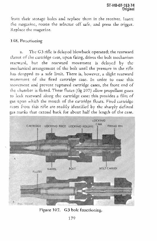
ST-H B.07-1 63-74Origina~
from their storageholes and replace them in the receiver.Insert
the magazine, rotate the selector 0ff safe, and press the trigger.
Replace the magazine.
148, Functioning
a, The G3 rifle is delayed blowback operated; the rearward
thrust of the cartridge case, upon firing, drives the bolt mechanismrearward, but the rearward movement is delayed by the
mechanical arrangement of the bolt until the pressure in the riflehas droppedto a safe limit. There is, however,a slight rearward
movement of the fired cartridge case. In order to ease this
movement and prevent ruptured cartridge cases,the front end of
the chamber is fluted. These flutes (fig 107) allow propellant gases
to leak rearward along the cartridgecase;this providesa film of
gas upon which the mouth of the cartridge floats, Fired cartridgecases from this rifle are readily identified by the sharply defined
gas marks that extendback for about half the length of the case.
Figure 107. G3 bolt functioning.
179

ST-H B-07.1 53-74Original
b. When the G3 is ready to fire, a cartridge is chambered,the locking cam forces the locking rollers into their recesses,andthe hammeris cocked.When the trigger is pressed,the hammerisreleasedand strikes the firing pin, which fires the cartridge.The
gas pressure generated drives the cartridge case rearward,andthismovement is resistedby the bolt headwhose locking rollers areseated in the locking piece (fig 107) attachedto the barrel.
c. The rearwardthrust 0f the caseis sufficient to startthebolt rearward; this causesthe rollers to be forced out of theirseats.As they move, the rollers ride on the cam surfaceof thelocking cam (fig 107) and force it rearward; becausethe cam islocked to the heavy bolt carrier,the bolt carrier is also forced tothe rear against the driving spring.The delay,occasionedby therollers resisting camming the heavy bolt carrier rearward, allows
time for the bullet to leave the muzzleandthepressureto drop toa safe level. The inertia developed and residual gas pressure stillthrusting the bolt rearward provide sufficient energy to drive thebolt fully rearward,to compressthe driving spring, and to cockthe hammer.
d. The extractor pulls the fired cartridge case from thechamber and holds it to the bolt face. The rearendof the ejector(fig 108) is struck by the recoiling bolt carrier; this causes the
ejector to pivot so that its front endentersthebottom of the bolthead. As the bolt continuesto recoil, the cartridgecasestrikestheejector,pivots about the extractor,and is expelled from therifle,
e. The bolt carrier strikes the buffer (fig 108) at the front
0f the butt stock and stops. The driving spring then drives thecarrier forward, and the bolt headforcesthe top cartridge out ofthe magazineand into the barrel. The extractor snapsinto thecartridge groove, and the forward movementof the bolt headstops when it hits the end of the barrel. The carrier hasa lock tokeep the bolt head locked forward; this is now trippedby a lug in
180

ST.H B-Oil 63-74Original
the receiver. The carrier continues forward, and the locking cam,
which travels with the carrier, forces the locking rollers into theirrecesses(fig 107).
f. The rifle’s trigger mechanism is similar to that of theFN/FAL rifle (para 130f and g). The hammer, powered by a coil
spring and plunger, is held cocked by a sear that can move back
and forth in relation to the trigger. When the hammeris cocked,pressure on the trigger is transmittedto the rear endof the searthrough the trigger ledge (fig 108). This causes the front of the
sear to move down and release the hammer. The hammer, under
pressure of its spring, swings forward and strikes the firing pin.
Upon firing, the recoiling bolt carrier rocks the hammer back to its
cockedposition.
g. When the selector is set for semiautomatic fire, acutaway section on the selector shaftlimits theupwardmovementof the trigger lug (fig 108). When the trigger is pressed and the
Figure 108. G3 rifle section.
181

ST-H 6-01-163-74Original
hammer is released,the sear spring forces the front of the sear
forward and upward. As the bolt carrier returns forward, thehammerstarts to move forward, and the sear mates with a notchon the hammer. When this happens, the strong hammer springovercomes the weak sear spring, and the sear is forced rearwardagainst the trigger ledge to hold the hammer cocked. By releasingthe trigger, the ledge is lowered, and the hammer spring, working
through the hammer, forces the sear rearward over the ledge.Pressure on the trigger will now move the sear and fire anothershot-
h, When the selector is set for automatic fire, the trigger
can rise to its highestpoint, and the nose0f the sear is depressedfar enough so that the sear cannot reengage the hammer. Theautomatic sear (fig 108), however, holds the hammer cocked, andas the bolt carrier completes its forward travel, it depresses theautomaticsear lever (fig 108); this, in turn, moves the automaticsear out of engagement - with the hammer.The hammer swingsforward to fire, and this action is repeateduntil the trigger isreleased. The sear can then rise, intercept the hammer, and
interrupt the firing cycle.
i. When set at safe, the selector places a solid section of itsshaft over the trigger lug. This preventsthe trigger from movingenough to disengage the sear from the hammer and keeps theweapon from firing.
j. There are two automatic safeties on the G3: theautomatic sear and the locking cam. If the mechanism is not fully
forward, the automaticsearwill continueto hold thehammerandprevent firing. The locking cam, unless it is fully forward and
holding the locking rollers fully outward, will prevent the firing
pin from protruding through the bolt face, and the weapon cannot
fire if the bolt is not fully locked,
182

149. Accessories
DST—111OH—163—76—CHG23 February 1984
a. The G3 is usually issued with a canvas orleather sling, spare magazines, a magazine carrier,and a bayonet. Some G3 rifles may be equipped withtelescopic or infrared sights.
b. The bayonet is installed by fitting its ringover the muzzle and guiding the belt into engagementwith the bayonet lug between the bipod (early models)or with the plug in front of the front sight. Ineither case, the bayonet is removed by pressing itscatch and pulling it forward, off the rifle.
c. Some C3’s have bipods built into theirforestocks. Pull the legs down or fold them upagainst spring pressure as desired.
d. Rifle grenades may be launched from the G3.The flash suppressor can be used as a launcher,Refer to paragraph 155a for precautions. No adjust-ment is necessary for firng grenades from the C3;just insert the special blank cartridge into thechamber, slide the grenade into place, aim, and fire.
G. THE 7.62—MN BERETTA BM—59 RIFLE (ITALY)
150. General
a. The Italian BM—59 rifle (fig 109) is basedupon the design if the US caliber .30 Ml rifle and
Meg. 510108Figure 109. Italian BM 59 Mark 1 Rifle
183

DST—111OH—163—76—CHG23 February 1984
resembles the US 7.62—mm M14 rifle. The BM—59 is gasoperated, selective fire, and is fed from 20—rounddetachable box magazines. There are several distinctmodels of the BM—59, differing primarily in stockdesign and muzzle devices. All are mechanicallyidentical. The Italian Army uses the BM—59 MarkITAL (fig 110) and the BM—59 Mark ITAL—A (fig 111)as standard weapons. The other versions are offeredfor sale and may be encountered in use in some of thesmaller armies. BM—59 rifles were also produced inIndonesia.
Meg. 510110Figure 111. BM—59Mark ITAL—A Paratroopers Rifle
Neg. 510109Figure 110. BM—59Mark ITAL Rifle
b. All versions of the BM—59 fire the 7.62x51—mmNATO cartridge (sec V).
184

ST-H B-07-1 63-74Original
151. Technical Data
Technicaldataconcerningthe BM-59 will be found in tableV.
152. Operation
a. Press the magazine catch (fig 109) toward the magazineand simultaneouslyrotate the bottom of the magazineforward
until the magazinereleasesfrom the rifle and can be removed.
Load the magazineas described in paragraph 128. Insert themagazineinto the receiverandstrike with the heelof the handtoinsurethemagazineis firmly caughtin place.
b. if desired, leave the magazine in place, pull theoperatinghandle(fig 109) fully rearward, and release; the bolt will
be held open. insert NATO five-round stripper clips into the clip
guide (fig 110) and press the cartridges off the clip into themagazine. Individual rounds can also be placed on the follower
and presseddown into the magazine.Adjust the sight for desired
range(para 152g).
c. Pull the operating handle (fig 109) fully to therearandreleaseit. CAUTION: The rifle is now loadedandready to fire. It
is a good practiceto tap the operatinghandle to insure that it is
fully forward. if the rifle is not be be fired immediately,pressthe
safety (fig 109) toward the trigger.
d. if the BM-59 has a bipod, swing it down into position
andopenthe hingedbutt plate if the rifle is to be fired from theproneposition (if theweaponis soequipped).
e, Set the selector (fig 110) for the type of fire
desired: forward for automatic fire, rearwardfor semiautomaticfire. Pushthe safety (fig 109) forward. Aim (using a normal sight
185

ST-H 3-07-163-74Original
picture), and press the trigger. The weaponwill fire accordingto
the selectorsetting. The bolt will remain closed between bursts or
shotsand open when the last cartridgein the magazineis fired.
f. Clear the BM-59 by first pressingthe safety (fig 109) to
the rear, then pressingthe magazinecatch (fig 109) andremovingthe magazine.Pull the operatinghandle(fig 109) rearward,pressin the bolt catch (fig 110), and easethe operatinghandleforward
until the bolt is held open. Inspectto insurethat no cartridgesarepresent. Pull the operatinghandlerearward and releaseit, then
insert the magazine.Pressthe safetyforward and pressthe trigger.
g. Adjust the rear sight for the desiredrangeby twisting
the elevation knob (fig 110), locatedto the left of the rear base,
until the desired range (number x 100 meters)aligns with theindex mark on the receiver.Windage is adjustedby rotating the
right-handknob (fig 109) in the appropriatedirection as indicated
by the arrow engravedon the knob. The elevationknob can beadjustedfor zero by firing therifle at a known distancetargetand
adjustingthe sights until satisfactoryresultsareobtained.Without
changing sight elevation, loosen the screw in the center of the
elevation knob, turn the drum so that the appropriate range
indicator is aligned with the receiver index line, andretightenthe
screw.
153. Disassembly and Assembly
a. Clear the rifle but do not insert the magazine. Pull therear of the trigger guard back to unlatch it, then swing the trigger
guard down and forward. Pull the entire trigger group straight outof theweapon.
b. Invert the rifle, grasp the stock behind the receiver, andpull the stock away from the barrel and receiver.
186
ST-H 8-07-1 63-74Original
c. Invert the barrel and receiver. Grasp the driving spring
close to its rearendand force it forward until the driving springguide comesfree. Move the spring andguide to one side andeasethem rearwardto remove.Pull the operatingrod to the rearwhileapplying downward pressureon the handle, When the rod snapsinto its dismountingnotch, pull the rod sideways,away from thereceiver. Pull the disengagedrod to the rearandlift up the handleuntil therod canberemovedfrom thegascylinder.
d. Turn the barrel and action upright. Grasp the bolt bythe protruding lug andpull it forwardand outwarduntil theboltcomesout of the receiver.No furtherdisassemblyis necessaryordesirable.
e. To reassemble,hold the bolt at an angle to the receiverand insert thebolt into the receiverso that the firing pin tangslipsbehind the lower bridge acrossthe receiver. Twist the bolt andmove it rearwarduntil it seatsin the receiver.Invert the barrelandreceiverwith thebolt to its rearmostposition.
f. If the front driving spring guide has been removed,insert it into the operatingrod, largeend first. Insert the operatingrod piston into the gascylinder andmove the operatingrod intothe gas cylinder until the rod dropsdown on the barrel. Engagethe cam of the operatingrod with the lug on the bolt. Pushtheoperatingrod in, toward the receiver,andmoveit forwarduntil it
snaps into place. Push the operatingrod fully forward. Slide thedriving spring into the operatingrod until the driving spring guidecanbe seatedagainstthe front receiverinsert.
g. Engage the ferrule on the front 0f the stock with thebarrel band (fig 110). Lower the stock onto the barrel andreceiver. Insert the trigger group straight into the openingon thestock, insuring that the ribs on the trigger housingmatewith theirgroovesin thereceiver,Fully seat the trigger housingandpressthe
187

ST-H 8-07-163-74Original
trigger guard shut. Be sure that the trigger guard locks into place.
Insert the magazine.
154. Functioning
a. The BM-59 is gas operated; refer to paragraph 138a.
b. When the weapon is loaded and the trigger pressed. the
hammer strikes the firing pin and fires the cartridge. Thepropellant gases drive the bullet down the barrel bore and, afterthe bullet passes the gas port, some of the propellant gases enter
the gas cylinder (fig 109) and drive the operating rod rearward.The driving spring is compressed,the hammer rockedrearward,and, after a short distance, the cam in the operating rod hump
contacts the bolt operating lug. Continued operating rod travelcauses the bolt to rotate to its unlockedposition and thenmoverearward. The extractor pulls the fired cartridge case from the
chamber(initial extractionoccurredas the bolt unlockedby theleft-handlocking lug contactinga camsurface)andholdsit to the
bolt until the fired case clears the chamber. The spring-loadedejector expands and hurls the fired case out of the weapon. The
operating rod finally strikes the front of the receiver and stops.
The driving spring then forces the operating rod and bolt forward.As the bolt moves, its feed rib drives the top cartridge out of the
magazineandinto the chamber.Thebolt stopswhenit strikesthe
barrel, but the operating rod continues forward. During this final
forward movement, the cam in the operating rod rotates the boltto its locked position; as this occurs, the extractor snaps into thegroove of the cartridge case and the ejector spring is compressed.
Forward motion ceases when the end of the cam groove in the
operating rod strikes the operating lug 0f the bolt.
c. When the trigger is pressed, the trigger disengages fromthe front hammer hooks. The hammer, under pressure 0f the
188

.~,.-,.‘ ~ h
3 February 1984
TRIP LEVER SELECTOR
SEARCAM
Meg. 510111Figure 112. BM’59 Mechanism
hammer spring, swings forward to fire the weapon. Asthe bolt recoils, after a shot is fired, the hammeris rocked rearward, and the rear hammer hooks passthe sear (fig 112), forcing it rearward against pres-sure from the hammer spring. When the bolt returnsforward, the hammer is held cocked by the sear.
d. When the selector is set for automatic fire,the trip lever rises to engage the operating rod, andthe operating rod cams down the front end of the triplever. The trip lever pivots and its rear end forcesthe sear rearward, releasing the hammer (fig 112).The hammer swings forward and fires another shot.This action continues as long as cartridges are inthe magazine and the trigger is pressed. When thetrigger is released, the trigger lugs swing rearwardand catch the front hammer hooks when the trip leveractuates the sear. The fire again, the trigger mustbe pressed.
e. When the selector is moved to its semi-
automatic position, the front of the trip lever is
189

3 February 1984
lowered so it cannot engage the operating rod andthus not actuate the sear. The hammer is now caughtby the sear. To fire another shot, the trigger mustbe released; this allows the trigger lugs and searto move rearward. The sear releases the hammer, thefront hooks of which are then caught by the triggerlugs. The trigger must now be pressed to fireanother shot.
f. When the safety is applied, it rotates, andits upper forward end engages a lug on the side ofthe hammer. As the engagement is made, the hammer iscammed slightly rearward so that its hooks are outof engagement with the trigger lugs. As the safetyis rotated, a second lug swings into place in frontof the trigger lug and prevents movement of thetrigger.
g. The follower, when the magazine is empty,applies pressure against the bolt catch and, afterovercoming the force of the light bolt catch spring,forces the bolt catch to pivot inward. The rearwardmoving bolt will override the bolt catch; however,the bolt catch will intercept the bolt’s left lockinglug when the bolt moves forward. This holds thebolt open and indicates that the magazine is empty.
155. Accessories
a. The BM—59can be used to launch 22—mminsidediameter tubed grenades. The compensator (fig 111)also serves as a grenade launcher and a muzzle brake,BM—59’s used to fire grenades are equipped with afolding grenade sight (fig 110). Prior to firing agrenade, erect the sight; this will automaticallycut off the gas mechanism. Load the rifle with agrenade—launching cartridge. (CAUTION: Never use acartridge with a bullet! Use only special launchingcartridges without bullets. Use of bulleted roundsto launch grenades will kill the shooter!) Placethe weapon on safe and slide a grenade over thelauncher. The grenade must slide onto the launcher
190

3 February 1984
easily, without force. To fire, push the safetyforward, align the desired range bar of the sightwith the ogive (diameter) of the grenade, and alignthe whole weapon upon the target. Press the trigger.(CAUTION: Recoil is severe~ Do not brace the bodyagainst any solid object when firing rifle grenades.)
b. Some rifle stocks have a recess for cleaningequipment and oil. A combination screwdriver, punchand chamber brush; a vial of rifle grease; and atube of oil are carried in the recess.
c. A winter trigger is available. This unitextends the trigger below the guard so that thetrigger can be operated by a gloved hand.
d. A blank firing device, which is secured tothe muzzle attachment, permits automatic firing ofblank cartridges.
H. THE 7.5—MM MODEL 49 AND 49/56 RIFLES(MAS 49 AND MAS 49/56) (FRANCE)
156. General
a. At the end of World War II the French Armywas equipped with a variety of obsolete and foreignrifles. To correct this situation, a crash programwas started to develop a new rifle. The result wasthe Model 49 rifle (fig 113), usually referred to asthe MAS 49. This weapon is a gas—operated, semiauto—matic, magaz-ine--fed arm, equipped with an integral,
Meg. 510112Figure 113. French N.A.S. 49 Rifle
191

USE—i11ULbi—/b—~tK 13 February 1984
adjustable grenade launcher (fig 114). All Model49’s are equipped with a telescopic sight base on theleft side of the receiver.
Meg. 510113Figure 114. M.A.S. 49 Grenade Launcher
- b. The Model 49 was extensively modified in1956. The resulting weapon, the Model 49/56(fig 115), has a shortened forearm, a new combinationmuzzle brake/grenade launcher, and minor internalchanges. The Model 49/56 became the standard rifleof the French Army, and most Model 49’s wereconverted to the M49/56 version. Only the FrenchArmy and a few of the former French possessions usethe M49 or M49/56 rifles.
Neg. 510114Figure 115. M.A.S. 49/56 Rifle
192

..,, ~,,~-IUU—I~~t
Original
c. While some experimental Model 49 rifles were produced
to fire the 7.62x51-mmNATO cartridge, the standardM49 andM49/56 rifles fire the 7.5x54-mm cartridge (sec V).
157, TechnicalData
Technicaldatapertainingto theModel 49/56 rifle will be found intableVI.
158. Operation
a. The Model 49 and Model 49/56 rifles are operated inthe same manner except for the grenade launcher.
b. Press the lower end of the magazine catch (fig 113 and11 5) against the magazine and pull the magazineout of thereceiver. Placea cartridgeon the magazinefollower and pressthecartridge down until it snapsunder one of the feed lips; repeatuntil the magazineis filled with ten cartridges.Insert the loadedmagazine into the receiver until the magazinecatch snapsintoplace.Alternatively, the operatinghandle (fig 113 and 115) canbe pulled rearwardas far as possibleandreleased.Thebolt will becaught open. insert a chargerinto the clip guide (fig 113) at thefront 0f the bolt coverand, with the thumb,pressthe cartridgesoff rhe guide and into the magazine. Repeatwith a secondfive-roundcharger.
c. Pull the operating handle (fig 113 and 115) fullyrearward and releaseit. CAUTION: The rifle is now loadedandready to fire. If immediatefiring is not intended,render the riflesafeby rotatingthe safety (fig 113 and115) downward.
d. Adjust the rear sight for rangeby pressingdown on theaperture (fig 113) and then moving the slide (fig 113) to thenumber that correspondswith the range in hundredsof meters.
193

Original
Windage adjustments can be made by using a screwdriverto turnthe windagescrew(fig 113).
e. To fire, rotate the safety upward, aim (using a normalsight picture), and press the trigger. The rifle will fire once; the
trigger must be releasedand repressedto fire anothershot.Thebolt will closebetweenshotsandremainopenwhenthe last roundis fired.
f. To launch grenades,first clear the rifle (parag below).Do no insert the magazine. Load a special non-bulleted,grenade-launching cartridge into the chamber and close the bolt.
Rotatethe safety (fig 113 and115) downward.Erect the grenadesight(fig ll3andll5).
(1) If the rifle is a Model 49, rotate the knurled nut(fig 114) until the range, in tens of meters (to 260 meters), isaligned with the housing (fig 114). Slip a grenadefully onto thelauncherand align the grenadesightswith the target.Rotatethesafety upwardand~ the trir~r.
Figure116. M.A.S. 49/56with rifle grenade.
(2) if the rifle is a Model 49/56,slide the grenadeoverthe launcher and seat it fully onto the rangeslide (fig 116). Theretainer spring on the range slide prevents the grenadefromslipping off the rifle. Pressthe button (fig 117) on the rangeslideandmove the slide back or forth on the barrel until therear edgeof the range slide aligns with the numbercorrespondingto the
194

Original
proper range (to 200 meters). Erect the sight to its highestpoint(fig 117) and use the open sight to align the grenade on target.
This sight and range technique is used only for indirect fire with
antipersonnelgrenades.For antitankgrenadesor direct fire, movethe range slide back to the 20 graduationand,with the grenadesight in its highestposition, align the appropriatearc on the sightwith the grenadeogive (largestdiameter) and target (fig 117).Once sighted, rotate the safety upward andpressthetrigger.
Figure 117. M.A.S. 49/56 grenade launcher and sight.
(3) When finishedlaunchinggrenades,fold the grenadesightsdown and, in caseof the M49, withdraw the rangesleeveinto the front endby rotatingthe knurled nut.
g. To clear the rifle, rotate the safety forward, pressthemagazinecatch (fig 113 and115),andremovethe magazine.Pullthe operatinghandle (fig 113 and 115) fully to the rear, Inspectto insurethat no cartridgesare in the barrelor receiver,releasetheoperatinghandle, squeezethe trigger, rotate the safety rearward,andinsert the magazine.
195

~,.flDUIIU’)I”
Original
159. Disassembly and Assembly
a. TheM49 andM49/56 aredisassembledidentically.
b. Clear the rifle (para 158g) but do not squeeze the triggeror insert the magazine.
c. Press down the cover catch (fig 118) at the rear of the
receiver and, while the catch is in, push the receiver cover forward
until the rear endcan be easedup, out of the receiver.Allow thereceiver cover to move rearward until it can be removed. Pull out
the driving spring. Move the operatinghandlerearwarduntil thebolt carrier (fig 118) can be lifted out 0f the receiver.Lift out thebolt (fig 118).No furtherdisassemblyis requiredor desirable.
Figure 118. M.A.S. 49 disassembled.
196

Original
d. To reassemble, insure that the hammer is cocked, then
place the bolt, large end forward, into the rear end of the receiver.Set the bolt carrier down, over the bolt, and move the bolt carrierback and forth until it mates with the bolt. Push the operatinghandle fully forward.
e. Put the driving spring over its guide in the receivercover, then insert the front end of the spring into the bolt carrier.Place the receiver cover onto the receiver and press the receivercover forward and down, against the pressure of the driving spring,
until the receiver cover seats into the receiver. Use the core topreventthe driving springfrom becomingkinked.Easethe receivercoverrearwarduntil it locks into place.Insert themagazine.
160. Functioning
a. The M49 and M49/56 function identically. The rifles aregas operated. Upon firing, some of the gas that propels the bulletis tapped off and directed back, through a gas tube, into the boltcarrier (fig 119). The gas impulse drives the bolt carrier rearward.The driving spring compresses and the hammer rocks back,
compressing its spring. After a short distance, cam grooves (in therear of the bolt carrier) contact lugs on the bolt (fig 119) and liftsthe rear of the bolt up, out of the locking recess in the receiver.
BOLT cARRIER
GAS TUBE
Neg. LUG ON TRIGGER SAFETY SHAFT
Figure 119. M.A.S. 49/56section.
197

Original
b. The bolt and carrier now move rearward as a unit. Theextractor pulls the fired cartridge caseout 0f the chamberand
holds the caseagainst the bolt face until the ejector expels the
fired case.Rearwardmovementceaseswhen the bolt carrierstrikestherear of the receiver.
c. When the hammeris cocked,a hook on the hammeriscaught by a lug on the trigger (fig 119). When the trigger is
pressed,it rotatesabout its pin, and its lug releasesthe hammer,Concurrently, the spring-loadedsear,pivoted to the rear of thetrigger (fig 119), rotates forward. The hammerspring swings thehammerforwardto fire the c~
Figure 120. M.A.S. 49/56 bolt.
d. Upon recoil of the bolt, the hammerrocksback, and as
its rear hook passesthe sear, it forces the sear back against its
T
198

—. -...a—u,—Iu_—,_.
Original
spring. When the bolt counterrecoils, the sear, which has returned
to its normalposition, interceptstherearhook of the hammerandholds thehammerback.
e. The triggermustbe releasedprior to firing anothershot.When released,the upper endof the trigger rotatesrearward.Thesear releasesthe hammer,but, becauseof the rearwardmovement,the hammer hook is caught by the trigger lug. To fire anothershot, the trigger must be pressedto recommencethe firing cycle.
f. When the safety (fig 113 and 115) is rotatedrearwardto safe, the solid portion of its shaft (fig 119) rotates in front of
the trigger and thus preventsforward trigger motion. When thesafety is rotated forward to the fire position,acutawaysection0fthe shaft moves in front of the trigger and no longerblocks itsmovement.
g. When the small leaf of the grenadesight of the M49/56is lifted, its shaft, through which the gas port is drilled, rotates.This misaligns the gasportsandautomaticallycutsoff operatinggas whenlaunchinggrenades.
161. Accessories
a. The manyaccessoriesfor the M49/56rifles include:
(1) atelescopicsight.
(2) an infraredsight.
(3) a night sight (M49/56 only).
(4) abayonet(49/56 only) (fig 121).
(5) cleaningequipment.
(6) leatherweb sling.
199

-ris-ui~uj.~-i’~Original
b. The telescopic and infrared sights slide onto the sightbase on the left rear of the receiver (fig 115) from rear to front.
Swing the lever on the sight adapter forward to lock the sight to
the rifle. Adjust the telescopic sight as described in paragraph
179c.The infrared sight is operatedaccording to the instructions
issuedwith the sight.
The night sight is slipped over the flash suppressor and
front sight; then the clampwing nut is tightened.Use the same
aiming techniqueas describedin paragraph179c.
I. THE 1.5-MM StG 51 (SIG 510)ASSAULT RIFLE (SWITZERLAND)
162. General
a. The 7.5-mm StG 57 (Sturmgewehr57) assaultrifle isthe standard Swiss Army rifle. This weapon, developed by theSwiss SIG Company, is also known as the SIC 510 when
chambered for the 7.62-mm NATOcartridge. A small quantity ofthese rifles also were producedby Beretta in italy and sold in
Figure 121. M.A.S. 49/56 bayonet.
200

SI -Il B-Ui-i 63-74Original
Figure 122. Swiss StG 57 assault rifle.
- Si~RT SiISTEDaLlis ssuSsmoN
Figure 123. StG 57 with bipod extended.
SouthAmerica. There is little military useof this rifle exceptbythe Swiss Army; however, the S1G 510’s are offered forcommercial sales in both selective—fire and in semiautomatic firemodels.The StG 57 (fig 122 and 123) is easily identified by its
angular, ungraceful appearance; long, perforated tubular barreljacket; folding sights; small plasticforearm;andplasticbutt. Also,the Swiss crossis stampedover its chamber.The commercialSIG510’s aresimilar to the StG 57 but canbe identified by their largerwood forearm(fig 124 and 125).
201

Original
b. The StG 57 (SIG 510) is a delay blowback-operated,
detachablebox magazine-fed,selective-fireweapon.althoughsomecommercial versions are capable of semiautomatic fire only. Theserifles often are equippedwith a folding metal hipod (fig 123), afold-away winter trigger (fig 122),anda loaded-chamberindicator.
c. The StG 57 fires 7.5x55,5-mmcartridgesonly; the SIG510 series fire 7.62x51-mm cartridges (refer to sec V).
163.Technical Data
Technical datapertainingto the StG 57 assaultrifle are presentedin tableV.
Figure 124. Swiss SIG 510-4 assault rifle.
4
Figure 125. Early ~ ~IO assault
202

U ~ - I ~U’UI - I U.)’ I ‘*
Original
164. Operation
a. Load the magazine as described in paragraph 128a.
Rotatethe selector (fig 124) to its vertical (safe)position,alignedwith the letter S. Hold the magazineso that the lips on its frontedge can be mated to the recess in the receiver (fig 127); mate thelip with recess; then pull the bottom of the magazine rearwarduntil the magazinecatchsnapsinto place.
b. Move the front and rear sights to their erect position(fig 123) if an StG 57 or if equippedwith folding sights.Adjustthis model for rangeby rotating the knurled drum (fig 123) untilthe numbercorrespondingto the rangein hundredsof metersisalignedwith the index work. If the rifle is a SIG 510 equippedwith non-folding sights (fig 124), press the lock (fig 124) andmovethe sight alongthe baseuntil the numberon the sight basethatcorrespondsto the rangein hundredsof metersis alignedwith
the sight.
c. Grasp the operating handle (fig 122), pull it fullyrearward,and releaseit. CAUTION: The rifle is now loaded,Theloaded chamberindicator protrudesabove the top front of the
receiver to indicate that the rifle is loaded (fig 122 and 127).Rotatethe selectorforwardoff safeto the positionfor the desiredmode of fire: T for semiautomaticfire, or A for fully automaticfire. Aim (using a normal sight picture),andpressthe trigger. The
rifle will fire accordingto the modeof fire selected,The bolt willremain closed betweenshots or bursts of fire andwhen the lastroundin the magazinehasbeenfired.
d. If gloves are worn, pull the winter trigger (fig 122)
down. This trigger, extending outside the trigger guard, can bepulled by using two gloved fingers.CAUTION: Thistrigger is notguardedandcancauseaccidentaldischarges.
203

ST-H 8-07-1 63-74Original
e. If the rifle is equipped with a bipod, the greatestaccuracy is obtainedby using it to steady the rifle while firingprone.Pull the bipod legs (fig 122 and 123) awayfrom the barreljacket until theylock into position. Fold the legsby pressingthembackalongthejacket.
f, To unload or clear the rifle, move the selector to itsvertical (safe) position, pressthe magazinecatch (fig 122) towardthe magazine,androck the magazineforward,out of the rifle. Pullthe operating handle fully to the rear, hold it, and inspect toinsurethat no cartridgesare present.Releasethe operatinghandle,move the selectoroff safe, pressthe trigger, movethe safetybackto safe,andinsert the magazine.Fold the sightsandwinter triggerif necessary.
165. Disassembly and Assembly
a. Clear the rifle (para 164f) but do not move the selectoroff safe or insert the magazine. Press the butt catch (fig 123) on
the stock behind the pistol grip and twist the butt stockone-eighthturn to the left until it disengagesfrom the receiver.
Removethebutt stockwith the driving spring.
b. Pull the operatinghandle rearwarduntil the bolt canbegraspedand pulled out of the back 0f the receiver.The operatinghandle will come0ff the receiver if the handle is alignedwith itsdisassemblynotchesin the receiver(fig 126).
c. Pressin on the headof the takedownpin (fig 122) andpull the pin out, to the right. It will not come fully out of thetrigger housing(fig 126). Pull the trigger housingoff the receiver.
d. Further disassemblyis neithernecessarynor desirable.
204

ST-H 8-07-1 63-74Original
e. To reassemblethe rifle, engagethe projectionson thetrigger housing (fig 126) with their seats on the sides of thereceiver.Pushthe takedownpin fully home;it is necessaryto pressin theheadto seatthe pin fully.
f. Placethe operatinghandleonto its rails on thereceiver,with its small springlatch forward,andslidewith thehandlefullyforward.
g. Start the bolt into the opening at the rear of thereceiver. It may be necessary to move the extractor carefully toallow the bolt to enter the receiver fully. Once in the receiver,slide the bolt fully forward.
h. Slide the butt stock claws (fig 126) over the rear of thereceiver.The stockmustbe twistedout of line with the receiverasthis is done. Be sure that the point 0f the driving spring seatsinthe recessin thebolt, then twist thebutt stock onto the receiveruntil the butt lock snapsinto place.Cleartheweaponas describedin paragraph164f.
Figure 126. StG 57 disassembly.
205

ST-H8-07-163-14
Original
166. Functioning
a. The StG 57 and SIG 510 function identically, andareboth delay blowbackoperated.When the trigger is pressed,thehammer is released to strike the firing pin lever and fire thecartridge. The pressure generated during firing drives the cartridge
caserearward,and the case(part 17, fig 127), in turn, attempts todrive the bolt (part 4, fig 127) rearward.Therearwardmovementof the bolt is, however, delayed becausethe two roundedlocks(part 3, fig 127) are seated in recesses in the receiver and held
there by the cam nose 0f the bolt carrier (part 9, fig 127). Therearward thrust of the bolt causes the locks to attempt to cam outof their recesses and as they do, their pressure against the camnose of the bolt carrier forces the heavy carrier rearward.Thedelaycausedby thelocks coming out of their seatsandforcing theheavy carrier rearward allows sufficient time for the bullet to leave
the barrel for the gas pressure to fall to a safe level.
Figure 127. StG 57 bolt functioning.
206

ST-H 6-07-1 63-74Original
b. The bolt carrier, however, has been given sufficient
momentumto travel fully to the rear.As it does,it compressesthedriving spring and rocksthe hammerrearward.The extractor(part5, fig 127 and 128) pulls the fired cartridge case out of thechamberand holds it to the bolt face.As the bolt nearsthe endofits travel, the ejector strikesa camsurfacein the receiver(fig 129)
and suddenly pivots on its pin. This throws the fired case out
through theejectionport (fig 129).
‘I
-- I
r— •I ‘—“P—” —- — 7
Figure 128. StG 57 bolt.
207

ST-H 8-01-163-14Original
c. The bolt strikes the forward end 0f the butt stock andstops; the compressed driving spring then drives the bolt forward.The feed rib drives the top cartridge out of the magazine and into
the barrel. As the bolt nears the end of its forward travel, thecarrier cam nose forces the locks out into their recesses,and theextractor engages the rim of the cartridge. The bolt strikes the
barrel, the carrier strikesthebolt, and forward movementceases.
d. The hammer (part 14, fig 127, 129, and 130) whenreleasedis driven by its spring (fig 130) andstrikesthe endof the
firing pin lever (part 11, fig 122 and 130). This lever pivots on its
pin and drives the firing pin (part 12, fig 127) forward to strike
the cartridge primer.
e. When the selector is set at T for semiautomaticfire, itdoes not affect the componentsof the trigger mechanism,The
trigger and the searpivot on the same pin (fig 130). As the triggeris pressed,the connector(fig 131) movesupwardandcontactstherear undersideof the sear (fig 131). Continued trigger pressure
causesthe sear to pivot on the pin andreleasethe hammer.Thehamrrier swings forward and strikes the firing pin lever. Theconnector is a fairly heavypart, with most of its weight aboveits
Figure 129. SIG 5 10-4 section.
208

ST-H8-01-163-14Original
pivot. The normal recoil of the rifle upon firing givessufficientmomentumto the connector for it to move rearwardagainstitsweak spring, out from under the sear.When this occurs,the sear
spring (fig 130) forces the searback to its normalpositionwhereitcan reengagethe hammer,upon counterrecoil0f the bolt. Thus,
only one round is fired. To fire a secondround, the trigger must
209

ST-H 8.01-163-14Original
BASIC PARTS TRIPPING SEARTRIGGER RELEASED
READY TO FIRE SEAR TRIPPED
Ne.~. ~::3.
Figure 131. StG 57 trigger functioning.
be released; this lowers the connectorso that it can spring under
the rear of the sear. Trigger pressure will thenstartanothercycle.
f. When the selectoris movedto A for automaticfire, thetrip link (fig 131), becauseof its joint, movesforward.This actioncausesthe trip link stud (fig 130) to move along the top of thesear until it fits betweenthe searand the disconnector(fig 131).
As the trigger is pressedthe basicaction in paragraphc abovetakesplace to releasethe hammer;however, the position takenby thetrip link stud now forcesthe disconnectorto protrudeinto a slotin the bolt. This slot has a closed rear end and when the boltcounterrecoils, it strikes the disconnector and rocks it forward.
210

ST-H 8-07-163-74Original
The forwardmovementis transmittedthroughthe trip link studtothe sear (fig 131) andcausesthe sear to depressand releasethehammer.This action continuesas long as the triggeris pressedandcartridges are in the magazine.When the trigger is released,thedisconnectoris lowered; this breaks the connectionbetweenthebolt andsearandfiring stop.
g. When the selector is rotated to the safe position, aprojection on the selectorshaft fits into the trigger, stopstriggermovement,andthus preventsfiring.
h. The loaded chamber indicator is a small spring-loadedplunger that fits into the top rear endof the barrel.Normally theindicator is flush with the top of the receiver, but when thecartridge is chambered, the rear of the cartridge forces theindicator up, abovethe top surface0f the receiver.The projecting
indicator thussignifiesthat thereis a cartridgein the chamber.
i. Thereis no last-roundcatch on the rifle.
167, Accessories
a There are numerous accessories for the StG 57 and SIG510 rifles, with some commonto both rifles. Accessoriesinclude:
(1) Telescopicsight.
(2) Blank firing device.
(3) Cleaningkit (carriedin pistol grip).
(4) Night sights.
(5) Grenade sight (SIG 510).
(6) Bayonet.
211
ST-H 8-07-163-74
Original
(7) Sling.
(8) Extra magazines.
b. The telescopicsight is attachedby fitting it onto the
padson the receiverand rotating the lock leverson the scopebase.
c. The bayonet is affixed by placing its ring over themuzzle while fitting the butt onto the bayonet stud until thebayonetlocks in place. Removethe bayonetby pressingthelargeround catch on the butt and pull it forward off the rifle.
d. The cleaning kit consists of a weight and stringpull-through with a bristle brush and a small clip to keep thechamberindicator out of the chamber.To usetheclip, reachintothe chamberand pressthe indicator; when it protrudes,slip the
clip onto the groove in the indicator.The cleaning kit and nightsights are carried in the pistol grip. To obtain them, insert thepoint of a bullet into the hole in the plateover thebottomof thepistol grip to slidethe plateopen.
e. The StG 57 and SIG 510 rifles can be usedto launch22-mm inside-diameter tube grenades. Only special blankgrenade-launchingcartridges can be used.The use of a bulletedround will causethe grenadeto explodewhile still in placeon therifle!
f. A specialgrenadesight is availablefor theSIG 510 to beclampedonto the barreljacket.For direct fire, usethe sight in themanner described in paragraph 158f. For indirect fire set the anglefor the range desired, and level the bubble. The StG 57 usesitsnormal front sight for direct fire, but only the Swiss UG 58 orHPzG 58 rifle grenades can be fired because the front sight is used,in conjunction with the ogive of the grenade,for aiming. The
212

ST-H 8-07-1 63-74Original
bipod of the StG 58 is graduated for indirect fire. The bipod isopened, the rifle turned sideways and a weighed string attached to
the bayonet lug. The string, when aligned with a mark on thebipod leg, setsthe rifle at thecorrectanglefor range.
168, General
J. THE 7.62-MM TYPE 64 RIFLE (JAPAN)
a. The 7.62-mm Type 64 rifle (fig 132) was developed inJapan.It is the standardrifle of the JapaneseGroundSelf-DefenseForcebut is usedby np othercountry.
b. The Type 64 rifle, fairly conventional in appearance,can be identified by its odd—shapedbutt stock,deepperforatedforearm, and vertical operating handle.
c. The Type 64 rifle is a gas-operated,detachableboxmagazine-fed,selective-fire shoulder weapon equipped with alightweight folding bipod and a hinged butt rest.A rotary gasregulatorpermitsadjustmentsfor varioustype cartridges.
Figure 132. JapaneseType 64 rifle.
213

ST-H 8-07-163-74Original
d. The Type 64 rifle is chamberedfor 7.62x51-mmNATOammunition (refer to secV). The Japanese-preferred cartridge for
the Type 64 rifle hasaviolet-coloredbullet tip; this indicatesthatthe cartridge is only 70% as powerfulas the standard7.62x51-mmNATO cartridge. The gas regulator must be adjusted to fire thisround.
169. TechnicalData
Technical data pertainingto theType 64 rifle are presentedintableIII.
170. Operation
a. Load and insert the magazineas describedin paragraph128a and b. If the front and rear sights are folded, pull them up
into firing position. Greatestaccuracyis obtainedwith the bipod.To use it, pull the bipod legs forward until they snapinto place.(Push the legs rearward to fold them.)
b. The gasregulator (fig 132) hasthreesettings.The loweris usedfor firing full-powered 7.62-mmNATO cartridges;the midsetting is used for firing violet-tipped Japanese reduced—powercartridges, or to give increasedpower when firing 7.62 NATOcartridgesin a fouled rifle. The upper setting is usedwhen firingviolet-tipped cartridges in a fouled rifle. Set the regulatorbyrotatingit as necessary.
c. Adjust the rear sight for rangeby twisting the knurledring on the rearsight (fig 132). Windagecorrections can be madeby rotating the windageknob.
d. Pull the operating handle (fig 132) fully rearward andrelease it. CAUTION: The rifle is now loaded and ready to fire.Pull out the selector and rotate it to the position desired (rearward
214

ST-H 8-07-163-74Original
for safe, forward for semiautomatic, up for fully automatic). Aim(using a normal sight picture), and press the trigger. The rifle willfire according to the mode of fire selected. The bolt will remain
closed between shots or bursts and when the last round is fired.
e. To unload or clear the Type 64, rotate the selectortoits vertical or safe position, press the magazine catch (fig 132)toward the magazine and rock the magazine forward, out of therifle. Pull the operating handle to the rear and inspect to insure
that no cartridges are present. Release the operating handle, rotatethe selector off safe, press the trigger and move the selectorbackon safe. Insert the magazine. If desired, fold the sights and bipod.
171. Disassembly and Assembly
a. Clear the rifle, but leave the hammer cocked and do notinsert the magazine. Set the selector off safe and fold the bipod orsights.
b. Pull the takedown pin (fig 132) to the right, then lift upthe rear end of the receiver cover (fig 132) until the cover comesoff. Pull the driving spring out of the bolt carrier, then pull thecarrier (fig 132) to the rear until it can be lifted out of thereceiver. Lift the bolt out of the receiver.
c. No further disassembly is necessary or desirable.
d. To reassemble, first place the bolt onto the rear of the‘eceiver with the leveled end up and to the rear. Place the bolt:arrier over the bolt so that the cam on the bolt carrier mates withhe cam cuts in the bolt. Move the carrier slightly back and forthEntil the carrier seats into the receiver. Push the bolt and carrier~ully forward. Insert the driving spring into the bolt carrier.
215

ST-H 8-07-163.74Original
e. Place the receiver cover onto the receiver so that theprojections on the cover fit into their recesses in the receiver and
the driving spring seats in the cover. Push the takedown pin backinto place. Clear the weapon (para l7Oe).
172. Functioning
a. The Type 64 rifle is gas operated. When the weapon isfired, some 0f the propellant gases are tapped off through the gasport as the bullet passes the port and enters the gas cylinder
(fig 132). The gases drive the piston rearward, and the rear end ofthe piston strikes the bolt carrier and drives it rearward. Thepiston’s spring has been compressed and now returns the pistonforward.
b. The piston’s blow was sufficient to drive the carrierrearward, compressing the driving spring and driving the hammerback against its spring.
c. After a short free travel, the cam in the bolt carriercontacts the cam on the bolt and lifts the bolt up out of thelocking recess,and both then move to the rear as a unit. Thisaction is somewhat similar to that of the FN/F.A.L. (fig 84). Theextractor holds the fired cartridge case to the bolt until the casestrikes the ejector and is expelled. The bolt carrier finally hits thebuffer in the back of the receiver and stops. The driving springexpands and drives the bolt carrier and bolt forward. The feed ribon the bolt drives the top cartridgeout 0f the magazine and into
the chamber. The bolt strikes the end of the barrel and stops; thebolt carrier continues forward and cams the bolt down into itslocking recess. The extractor snaps into the groove of thecartridge, and the bolt carrier stops when it hits the front wall ofthe receiver.
216

ST-H B-07.1 63-74Original
d. When the hammer is cocked, it is caught by the sear.
The hammer spring forces the sear forward on its elongated pinhole against the force 0f the sear spring and positions the front of
the sear over the trigger.
e. In the semiautomatic mode, as the trigger is pressed, the
rearendof the trigger rises under the searandrotatesthe searonits pin. The sear disengages from the hammer, which drives
forward, under force of its spring, firing the rifle. Becausethehammer no longer forces the sear forward, it moves rearward,under force of its spring, sufficiently to clear the hammer. As thishappens, the sear raises to catch the hammer after it is drivenrearward by the bolt recoil and then moves forward uponcounterrecoil.The hammer forces the sear forward against thestill-pressedtrigger. To fire anotherround, the trigger must bereleased; as it is, the sear moves forward over it, and trigger
pressure will then start the firing cycle again.
f. When the selector is turned to the automaticposition,the automatic connector is raised, on the eccentric on the selectorshaft, to the highest position. In this position, as the bolt carriercompletes its forward movement, it contacts the automaticconnector and makes it rotate on its shaft. The rear end of theautomatic connector has a cam cut and, as the sear is forcedforward by the recockedhammer,the searrides up the cam andreleasesthe hammerto fire anotherround. This actioncontinuesas long as the trigger is pressedandammunition is present.Whenthe trigger is released, it allows the sear to move to the rear andhold the hammer cocked.
g. When the selector is moved to the safe position, theautomatic connector is moved rearward and forces the searrearward to a point where the trigger cannot contact it; thus therifle cannot be fired.
217

ST-H B-07-163-74
Original
173. Accessories
The Type 64 rifle has a knife bayonet and a web sling as standard
accessories. A plastic muzzle cover, magazine cover, and magazine
well insert are used to prevent fouling of the rifle.
K. THE 7.5-MM FR-Fl SNIPER’S RIFLE (FRANCE)
174. General
a. The FR-Fl sniper’s rifle (fig 133 and 134) is one of thenewest weaponsof the French Army. This extremelyaccurateweapon has been designed expecially for use by snipers. Theprimary sighting equipment is a 3.8-power telescopic sight, andnonadjustable 100-meter open sights, with a self-contained
Figure 133. French FR-Fl sniper’s rifle.
luminous feature, are provided for aiming under adverselight oremergency conditions. The designation FR-Fl is the abbreviation
for Fusil a Repetition Modele Fl, i.e., Repeating Rifle Model Fl.The sole producer of this weapon, which is used only by the
French Army, is the Manufacture Nationale d’Armes de St.Etienne, St. Etienne, France. The FR-Fl sniper’s rifle is a
manually operated, bolt-action repeating rifle fed from a
detachable, 10-round box magazine. The breech mechanism of theFR-Fl is similar to that 0f the now obsoleteFrench 7.5-mmModel 1936 rifle (para 180) and, although the FR-Fl is a new
218

DST’—l11OIJ—],63—76—C}IG 23 February1984
weapon, some parts (firing pin, firing pin spring,bolt plug, extractor, sear, bolt stop, aj~d searspring) can be interchanged between the two weapons.A bayonet cannot be affixed to the FR—Fl sniper’srifle, nor can it be used to launch grenades.
Meg. 510133Figure 134, FR—Fl, Left Side View
b. The FR—Fl rifle is produced in threeversions: (1) Tireur d’Elite (sniper), the subjectof this section; (2) Tir Sportif (target rifle),which has target—type metallic front and rear sights,and a 3.3— to 4.2—pound trigger pull; and (3) GrandeChasse (hunting rifle), which has an APX Model 804telescopic sight and a 4.5— to 5.5—pound triggerpull. Only the sniper’s rifle is equipped with abipod.
Meg. 510134Figure 135, APX 804 Telescopic Sight
219

DST—lllOH—l63—76—CHG 23 February 1984
* c. The FR—Fl sniper’s rifle normally will firethe French standard 7.5x54—mm cartridge; but anotherFR—Fl version will fire the 7.62x5l—mm NATO car-tridge. Only ball ammunition, preferably of matchquality, should be fired; the use of armor—piercingor tracer ammunition will ruin the accuracy of therifle. The caliber designation, 7.5—mm or 7.62—mm,is inscribed on the left wall of the receiver; onlyuse the appropriate cartridge.
175. Technical Data
Technical data concerning the FR—Fl sniper’s riflewill be found in table V.
176. Operation
a. After removing the telescope from itscarrying case, mount the telescope on the rifle bymating the two claws on the right of the mount withthe undercuts on the two dovetail pads on top of thereceiver. The single lug on the left side of themount must align with the slot between the two pads,and the locking lever (fig 135) must point rearward.Rock the telescope to the left, slide it forwarduntil it stops, and swing the locking lever fullyforward.
b. Remove the magazine by pressing themagazine catch (fig 133) and catching the magazineas it ejects. Place a cartridge on the magazineplatform and press the cartridge into the magazineuntil it rolls sideward under the magazine lip.Repeat until the magazine is full. (The rubber capcan be removed from the bottom of the magazine andused as a dust cap over the top of the loadedmagazines. The cap must be removed and replaced onthe magazine’s bottom before loading the magazineinto the rifle.) Insert the loaded magazine intothe opening in the receiver until
220

ST-H B-Ui-i 63-74Original
magazine catch snaps into place and retains the magazine. Apartially expended magazine can be reloaded by pressing cartridgesinto it while it is in the rifle; this operation is awkward, however.
The bipod gives maximum stability while firing andshould normally be used. Place the fingers under the forearm and,with the thumb on the knurled collar of the bipod, press hard onthe bipod leg until it swings down; then pull it rearward until theleg clicks into place. The legs can be extended by twisting theknurled collar in the direction 0f the arrow inscribed on the collar;
the spring~loaded lower legs will extend automatically. Twist thecollar back to its original position to lock the legs at the desiredheight.
d. To prepare the rifle for firing, lift up the bolt handle(fig 133), pull it fully rearward, then thrust it forward and turn itdown. CAUTION. The rifle is now ready to fire. To render therifle safe, swing the safety down behind the trigger (fig 134). Tofire: (1) swing the safety to the left, (2) aim (fig 136), and(3) press the trigger. To reload: (1) lift up the bolt handle,(2) pull it vigorously rearward, and (3) thrust forward and turn itdown. The rifle is now ready to fire another shot. When the lastcartridge in a magazine is fired, the bolt is blocked after it is drawnrearward and cannot be thrust forward until the magazine isremoved or refilled.
e. Under adverse light, it may be necessary to use the opensights. Remove the telescope by rotating the lock lever rearward,and then pulling the telescope rearward until it disengages from
the receiver.Replacethe telescopein its carryingcase.Flip up theopen front and rear sights (fig 133). The sight picture to be usedduring the daytime is the same as that for the US M1911A1 pistol.At night, a green luminous dot on the front sight and twohorizontally aligned red dots on the rear sight will glow; align and
221

~I 11DU11U.J1’t
Original
AIMING POINT
LUMINOUS DOT (RED)
FRONT S IGNT B LADE
//LUMINOUS DOT (GREEN)
~Y~’- REAR SIGHT
OPEN SIGHT PICTURE
Figure 136. Sight picture.
evenly spaceall three dots,greenin the center,andsuperimposethem on the target (fig 136).
f. To clear the rifle, first set the safetyon safe, then press
the magazine catch and remove the magazine. Open the bolt,inspectto insurethat no cartridgesarepresent,then close the bolt.
Swing the safety to the side, pressthe trigger andresetthe safetyto safe. If there are cartridges in the magazine, press them forwardout of the magazine,then insert the magazineback into therifle.
177. Disassembly and Assembly
a. To disassemblethe FR-Fl rifle for cleaning, clear the
rifle (para l76f), but do not resetthe safetyto safeor replacethe
magazine.Removethe cheek pad (para l76f), open the bolt, pull
the trigger fully rearwardand, while holding the trigger, remove
the bolt (fig 137).
b. Firmly pressin the plug at therearof the bolt; turn the
plug clockwiseuntil the letter D alignswith the index line on the
TELESCOPE RETICLE
222
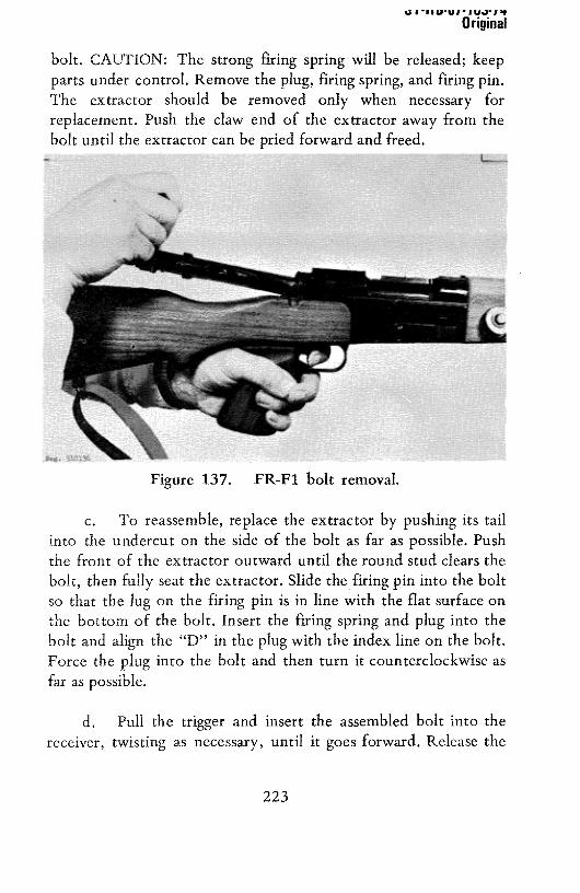
UI 11UU1 1UJ1’*
Original
bolt. CAUTION: The strong firing spring will be released;keepparts under control. Remove the plug, firing spring, and firing pin.The extractor should be removed only when necessary forreplacement.Push the claw end of the extractoraway from thebolt until the extractorcanbepried forwardandfreed.
c. To reassemble, replace the extractor by pushing its tailinto the undercut on the side of the bolt as far as possible.Pushthe front of the extractor outward until the round stud clears thebolt, then fully seat the extractor. Slide the firing pin into the boltso that the lug on the firing pin is in line with the flat surface onthe bottom of the bolt. Insert the firing spring and plug into thebolt and align the “D” in the plugwith the index line on thebolt.Force the plug into the bolt and then turn it counterclockwise as
far as possible.
d. Pull the trigger and insert the assembled bolt into thereceiver, twisting as necessary, until it goes forward. Release the
Figure 137. FR-Fl bolt removal.
223

ST-HB-U7-163-74Original
trigger, turn the bolt handle down, press the trigger, and move the
safety to the safe position. Insert the magazine.
e. To install the cheek pad, choose the one with thedesired height, either 8- or 17-mm, align the pins on the undersideof the pad with the holes in the comb of the stock and force thepins into the holes. It may be necessaryto useasoft mallet to seatthe pad.The padis removedby gentlyprying up on the endsuntilit comes free. The pad must be removed before the bolt can beextracted from the rifle.
f. Two wood spacers issued with the FR-Fl rifle are usedto lengthenthe stock to suit the individual shooter.Theseare 20and 40 millimeters thick andare installedby removing the screwin thebutt plate, removingthebutt plateandinsertingthespacer,then replacing the butt plate and butt plate screw. Be sure that thespacer is aligned with the stock and not installed in an invertedposition.
g. The trigger mechanism has adjustments for length andweight of pull; however, these adjustments should be made by
competent armorer.
h. The adjustment of the flash suppressor is extremelycritical in obtaining maximum accuracy; avoid altering the factory
setting by turning the flash suppressor or its locking collar. If theflash suppressorhasbeenremovedor replaced,the barrelassemblymust be returned. Loosen the locking collar (fig 133) as far aspossible and,usinga broad woodenbar insertedthrough the slotsin the flash suppressor,screw thesuppressorfully onto thebarrel.Hand-tighten the collar and fire a five-shot group. Loosen thecollar and unscrew the suppressor two turns, retighten the collar,then fire anotherfive-shot group. Repeatuntil the smallestradiusshot pattern is achieved,then use one-half-turn incrementsandrepeatthe firing. When the smallestgroup is achieved,usea strapwrench to tightenthe collar.
224

ST-HB-Ui-i 63-14Original
178. Functioning
a. The FR-Fl rifle is manually operated.All energy toremove the fired cartridge and replace it with a fresh one issupplied by the shooter’smanipulationof the bolt. As the bolthandle is turned upward, a camming action between the bolt andthe firing pin retracts the firing pin point and compresses the firingspring. Concurrently, a cam at the root of the bolt handle bearsagainst a cam surface at the left rear of the receiver (fig 135),providing slow initial extraction (if necessary) to break a stickingcartridge case loose from the chamber. The locking lugs on thebolt alsorotate out of their seatsin thereceiver.
b. As the bolt is drawn rearward, the extractor removes thecartridge case from the chamber and holds it againstthe bolt faceuntil the stationaryejector (locatedwell behindthe magazineatthe left rear) expels the cartridge case. As the bolt is drawnrearward, the bolt stops, under pressure0f its spring, and ridesagainst the flat surfaceon the bottom of the bolt; this stop, inconjunctionwith the ejector protruding into its slot in the bolt,prevents rotary motion of the bolt as it moves back and forth. Ashoulderon the bottom front 0f the bolt finally strikesthe boltstopto limit rearwardtravel of the bolt.
c. The magazine spring forces a fresh cartridge intoposition in the feed lips, and, as the bolt is pushed forward, it
forcesa cartridgefrom the magazineinto the chamber.The bolt islocked by turning the bolt handle down; as this happens,theextractor snaps over the rim of the cartridge, and the searinterceptsthe firing pin lug, holding the firing pin cocked.
d. When the trigger is pressed, it swings to the rear on thetripper pin (which joins the trigger andsear)until the trigger stud:ontacts the bottom of the receiver. Further movement of the
225

UI IUUUIIUUI~?
Original
trigger, transmitted through the tripper pin, causesthe sear topivot on the sear pin and to compressthe searspring. Finally, thetop 0f the trigger adjusting screwcontactsthe receiverandcausesa definite stop; any further movement 0f the sear requires aheavier pull on the trigger, and this in turn will release the firingpin and fire the rifle.
e. The bolt stop also pivots on the trigger pin. When thetrigger is pulled fully rearward,a shoulderon the top of the trigger
strikes the bolt stop and forces it to pivot downward against the
pressure of a separate spring. The bolt stop moves downsufficiently so that it cannotcontactthe stop surfacein the bolt,and the bolt then can be pulled out of the rifle.
179. Accessories
a. The FR-Fl sniper’s rifle is issued with a complete set ofaccessories.The set includes:
(1) An extramagazine.
(2) Two stock extensionsof different lengths(20- and40-mm).
(3) Two cheek pads of different height (8- and
17-mm).
(4) A Modele 53 bis telescopewith its carrying caseand adjustmenttool.
(5) A sparefiring pin spring.
(6) A standardFrenchissueleathersling.
(7) A leather cleaning case with two pull-through
thongs.
226

~,I I 11 1JU1 - I U.J~I ~T
Original
The above listed accessories are packed, along with an instructionmanual, in a sturdy wood chest used for storing and shipping an
FR-Fl sniper’s rifle.
b. The pull-through thongs can be used for cleaning thebarrel. One thong shouldbe left dry, the other lightly oiled. Theoiled thongshould beenclosedin aplasticbagto precludetransferof oil to the dry thong.Point the muzzledown; drop the weightinto the chamber and allow the weight to fall out of the muzzle.Grasp the weightandpull the thong through the barrel. The use ofthesethongs is not recommendedexceptas a last resort,when aconventional cleaning rod is not available.
c. The M53 bis telescope can be zeroed to the rifle’s point
of impact. The eccentricplastic rings betweenthe telescopeandthe mount rings provide a meansof coarseadjustment;final, fineadjustments can be made on the windage and elevation knobs.Install the telescope on the rifle (para 176a), remove the rifle’sbolt (para 177a), loosen the screws at the bottom of the mountrings, set the elevation knob at 2, and set the red line on the
windageknob (fig 135) to its index. Selectan aiming point at least200 meters distant and, sighting through the barrel, center thevarious concentric rings in the barrel on the aiming point. If thepoint of the reticledoesnot coincidewith the aiming point, rotateone or both of the plastic rings until the reticle does coincide.Recheckto insurethe barrel is still alignedwith the aimingpoint.if it is, tighten the screwson the mount rings. The FR-Fl rifleshould now be fired, at 200 meters range, to provide three-shotgroups. If the point of the reticle does not coincide with the pointof impact of the bullets, loosen the three lock screws on theelevation knob. The adjustment tool, carried in the telescopecarrying case,is used to loosenthe screws.Rotate the windageknob and,usingthe spannerendof theadjustmenttool, rotate theelevation zeroring until the point of the reticle and the point of
227

b I -MU-UI-I DJ-I’Original
impact of the bullet coincide. Hold the zero ring stationarywiththe spannerand turn the elevationknob until the figure 2 alignswith the index, Tighten the three screwson the elevation knob,Loosenthe threescrewson the windageknob androtate the knobuntil its red line is aligned with the index; then tighten the threescrews. The rifle should be fired again to insure no changesoccurredwhile the final adjustmentswerebeingmade.
L. THE 7.5-MM MODEL 1936 RIFLE (MAS-36) (FRANCE)
180. General
a. The French Model 1936 rifle (MAS-36), althoughobsoletein the French Army, is widely used by the armies ofmany of the old French colonies and protectorates.Capturedweapons are often used by irregular or guerrilla forces. ThemanuallyoperatedMAS-36, while somewhatcrude in constructionand appearance, is an extremely simple and rugged rifle. It isreadily identified by its odd, swept-forward bolt handle, two-piecestock, and spike bayonet.
Figure 138. French M.A.S. 36 rifle.
228

I -FJU-UI-163-74Original
b. The latest version, the Model 36/51 rifle has a grenadelauncher system similar to that on the Model 49 rifle (para 156).
An older model, the MAS-36 CR39, has a folding metal stock.This weapon is for use by paratroops and is rarely encounteredtoday. The MAS-36 fires only French 7.5x54-mm cartridges(sec V).
Technicaldataconcerningthe MAS-36 rifle aregiven in tableV.
182. Operation
a. The MAS-36 is operatedin the same manneras theFR-Fl rifle (para 176). The easiestway to unloadthis rifle is toopen the bolt and, after catchingthe ejectedcartridge,leave thebolt open. Squeeze in the floor plate release (fig 138) and open
the floor plate;the cartridgeswill fall out 0f the magazine.
b. Set the rearsight for the desiredrangeby depressingtheaperture(fig 138) and moving the slide until it is aligned with the
Figure 139. French M.A.S. 36 CR 39 rifle.
181. Technical Data
229

U I 1 I UU I - IU.r I ?
Original
graduation corresponding to the range in hundreds of meters.Release the aperture.
The bayonet is carried reversed in the forestock. Pressthe catch on the bayonet, withdraw it, and after reversing it, slidethe bayonet’s butt back into the tube. The catch will retain it.
Remove the bayonet by pressing the catch and pulling the bayonet
out of the tube.
183. Disassembly and Assembly
a. To disassemble the rifle, clear the weapon by openingthe bolt and the floor plate (para l82a).
b. Pull the trigger and, while holding it, draw the bolt out
of the receiver.
c. No further disassembly is required or desirable.
d. To reassemble the weapon, start the bolt into thereceiver, turn it as necessary,and push it home; then insert thefollower andspring into the magazineopeningandclosethe floorplate.
184. Functioning
a. The MAS-36 rifle is manually operated.As the bolthandle is turned up to unlock the bolt, a camming action betweenthe end of the bolt and firing pin forcesthe firing pin rearwardand compresses the firing spring. A cam surface at the root of thebolt handle bears against a cam surface on the left rear of thereceiver; this provides initial extraction.
b. The extractor holds the cartridge case to the bolt andthus extractsthe casefrom the chamber.When the bolt is drawn
230

ST-H 8-07-163.74Original
fully rearward, the ejector expels the fired case. Meanwhile, themagazine spring has moved a freshcartridgeinto positionin frontof the bolt.
c. When the bolt is thrust forward, it pushes the cartridgeout of the magazine and into the barrel. The bolt is rotated toreseatthe locking lugs, andthe extractorsnapsoverthe rim of thecartridge.
d. The MAS-36 has no manual safety; however, if the boltis not fully locked and the interactionbetweenthe cam on therear of the bolt and the firing pin lug will close the bolt or prevent
the firing pin from striking the cartridge.
e. While slightly different in detail, the MAS-36 triggermechanism is essentially similar to that of the FR-Fl rifle (paral78d).
185, Accessories
The MAS-36 has a spike bayonet housed in its forestock. A websling is usedto carry the rifle.
M. THE 303-CALIBER (7.7-MM) LEE ENFIELD RIFLES (UK)
186. General
a. The .303-caliber (7.7-mm), manually-operated LeeEnfield rifle hasbeenmadein many different models; figure 140depictsthe more commonvarieties.The prominentmagazineis aprime recognitionfeaturefor all LeeEnfields,andtheolderNo. 1rifle (fig 140) can be recognized by its snub-nosed muzzle. Asniper version of the No. 4 equipped with a telescope (fig 140) wasissued,anda lightenedversionwith a shortenedforestock,the No.5 (fig 140),wasdesignedfor junglewarfare.The variousmodels0f
231
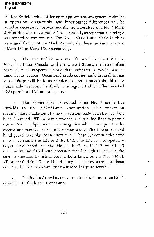
T-H B-Ui-i 53-14)riginal
:he Lee Enfield, while differing in appearance, are generally similaroperation, disassembly,and functioning; differenceswill be
ioted as necessary.Postwarmodificationsresultedin a No. 4 Mark2 rifle; this was the same as No. 4 Mark 1, exceptthat the trigger~as pinnedto the receiver.The No. 4 Mark 1 andMark 1* rifleswere modified to No. 4 Mark 2 standards;theseare knownas No.I Mark 1/2 or Mark 1/3, respectively.
b. The Lee Enfield was manufacturedin Great Britain,
~ustralia, India, Canada,and the United States;the latter oftenbears a “US Property” mark that indicates a World War IILend-Leaseweapon.Occasionalcrudecopiesmadein small Indianvillage shops will be found; under no circumstancesshould thesehomemadeweaponsbe fired. The regular Indian rifles, marked“Ishapore”or “IA,” aresafeto use.
c. The British have converted some No. 4 series Lee
Enfields to fire 7.62x5l-mm ammunition. This conversion
includesthe installationof a new precision-madebarrel, anew bolthead(stampedl9T), a new extractor,a clip guide liner to permituse of NATO clips, and a new magazinewhich incorporatestheejector and removal of the old ejectorscrew. The fore stocksandhandguard havealso been shortened.These7.62-mm rifles existin two versions, the L37 and the L42. The L37 is a competativetarget rifle based on the No. 4 Mk2 or Mkl/2 or MK1/3mechanismand fitted with precisionmetallic sights.The L42, thecurrent standardBritish snipers’ rifle, is basedon the No. 4 MarkiT snipers’ rifles. Some No. 4 Jungle carbineshave also beenconverted to 7.62x5 1-mm, but their recoil is quite severe.
d. The Indian Army has convertedits No. 4 and some No. 1
seriesLee Enfieldsto 7.62x51-mm.
232

ST-H 8-07-1 63-7 4Original
Figure 140. Lee Enfield rifles.
e, Refer to section V for information concerningammunition fired in LeeEnfield rifles.
187. Technical Data
Technical data concerning the Lee Enfield rifles are given in tableV.
233

Original
188. Operation
a. Openthe bolt by turning the bolt handleupwardas faras possible;thenpull the bolt fully rearward.
b. Load the rifle. Any of the following methods can beused.
(1) If clipped ammunition is available, insert the clipinto the clip guides (fig 140), and with the thumb as close as
possible to the clip, press the cartridges into the magazine.
Removethe clip andrepeatthis actionwith a secondclip so that10 rounds are loaded into the magazine.When loading loose
cartridges into empty clips, insure that therims of the cartridgesin
the middle and on the ends are below the rims of the other two
cartridges.
(2) Loose cartridges can be individually pressedinto
the magazineto insure that the rim 0f eachcartridgeis in front of
therim of the round that precededit.
(3) Individual cartridgescan be directly insertedinto
the chamber.
c. When the rifle is loaded, shove the bolt fully forward(spring resistancewill be felt during approximatelythe last inch of
travel) and turn the handle down. CAUTION: The rifle is loadedand ready to fire.
d. If the rifle is not to be fired immediately, render it safe
by rotating the safetyat the left rear of the receiverfully to therear. This locks the firing pin and bolt. An alternate method is tograsp the cocking piece (fig 140) firmly, puli it to the rear, and
after pressingthe trigger, easethe cocking piece forward. Release
the trigger and bring the cocking piece to rest at the half cock
position. Thisprocedureis not recommended.
234

I flD-UI-lbi-Iq,Original
e. Set the sights for the desired range according to the riflemodel:
(1) If the rifle is a No. 1, press the slide locks on therear sight (fig 140), and move the slide along the leaf until theindex mark on the slide lines up with the number on the leaf thatcorrespondswith the range in hundreds of yards. Final fireadjustments can be made by rotating the worm screwon the slide.
(2) if the rifle is an early No. 4 with an L rear sight(fig 140), flip the sight to the desired range (300 or 600 yards).The 300-yard aperture is used for firing at 400 yards if thebayonetis attached.
(3) if the rifle is a No. 4 with an adjustable rear sightor a No. 5 carbine(fig 140), lift the leafandmovethe slidealongit until the index mark is aligned with the numberdenotingtherange in hundredsof yards.The slide is movedeitherby pressingacatch on the slide or by turning an adjustingscrewat the top 0fthe slide, dependingon the model of the sight. The fixed largebattle aperture can be used when the sight is folded down; this isset for about a 300-yard range. By aiming at a man’s chest withthis sight, ahit should be scoredon somepart of his body at anyrange up to 300 yards. The sniper rifles do not have the battleaperture.
(4) The No. 32 telescope is used on the No. 4 Mark1T; with minor changes, it is also used on the L42 sniper’s rifle.The telescopeis set for rangeanddeflectionby rotating its knobs,and the elevation knob at top is marked to indicate hundreds of
yards.
f. To fire these weapons, rotate the safety forward (or pullthe cocking piece fully rearward) and (using a conventional sight
235

ST-H B-Ui- 163-74Original
picture) aim, and squeeze the trigger. The rifle will fire one shot,To reload, turn the bolt handle up, pull it fully and brisklyrearward, thrust it forward, and turn it down, The rifle is now
ready for another shot. When the last round is fired, the bolt is notcaughtto the rear.
g. To unload or clear the rifle, press the magazine release(fig 140) and remove the magazine. Open the bolt and catch anyejected cartridge. Push any remaining cartridges forward, out of
the magazine,and insert the empty magazine into the rifle,striking it with the heel 0f thehand to insurethat it is fully seated.
Close the bolt andpressthe trigger.
189. Disassembly and Assembly
a. To disassemble the Lee Enfield:
(1) Clear the rifle (para 188g), but do not insert the
magazine.
(2) Remove the bolt.
(a) If it is a No. 1 rifle, open the bolt and draw itfully to the rear; then pressup on the bolt headuntil it is released
by the bolt head catch (fig 140) and the head is vertical. Thisrequires considerableforce. Pull the bolt rearward out of thereceiver.
(b) If it is a No. 4 Mark 1*, MK1/3 or L37, openthe bolt and draw it slightly to the rear until the bolt head isalignedwith the disassemblycut in the receiver(fig 140).Turn thebolt headup and,after lifting therear sight to its verticalposition,pull the bolt out 0f the receiver.
(c) If it is a No. 4 Mkl, MK2, MK1/2, sniperrifle, No. 5 carbine, or L42, open the bolt, depress the bolt catch
236

ST-HB-Ui-i 63-74Original
(fig 140), and pull the bolt fully rearward (holding the catchdepressed). Turn the bolt head to a vertical position and, afterlifting the rear sight, pull the bolt to the rear out of the rifle.
b. To reassemble the rifle, insure that the bolt head isscrewedinto the bolt as far as possible;thenbackif 0ff until it is
in line with the guide rib of the bolt. Insert the bolt into thereceiver;the rear sight leaf of the No. 4 andNo. 5 rifles must bevertical. When the bolt head is just forward of the shoulder, turnthe head down. If the rifle is a No. 4 Mkl*, MK1/3, or L37 pressthe bolt forward until the bolt head is aligned with the cut
(fig 140) in the receiver;seat thebolt headinto this cut andclosethe bolt. For all other rifles, as soonas the bolt headclears theshoulder, press it down, against the spring catch, until the bolt can
be pushedforward.Reinsertthemagazine(para188g).
190. Functioning
a. The Lee Enfields are manuallyoperated,and the basicbolt functioning is similar to that of the FR-Fl (para 178);however, the cam on the bolt merelyretractsthe firing pin pointinto the bolt and does not fully compressthe firing spring. Thisspring is compressed by the shooter as he forces the bolt forwardin its last inch or so of travel.
b. The extractor pulls the fired cartridge out of thechamberandholdsit to the bolt face.At the sametime, however,the extractor also forcesthe rim of the cartridgehardagainsttheinner left wall of the receiver;the friction is usually sufficient tocausethe cartridge,when clearof the chamber,to pivot abouttheextractor and to be expelled, if the extractor spring is weak, asmall screwprotruding into the receiverinsuresthatejectiontakesplace by stopping the cartridge and making it pivot about theextractor, However, on the L37 and L42 rifles, a lip on themagazineperformsthis function.
237

ST-H B-Ui-i 63-14Original
c. The safety performs two functions, locking both thebolt and the cockingpiece. When the safety is rotatedrearward,asteeppitch multiple threadmovesasmall lug inward andinto thebolt. This preventsthe bolt from being rotated.A sectorof thesafetyshaft concurrentlymesheswith the cocking piece,forcesit
rearward,andlocks it in place.
d. The sear is an L-shapedcomponent,onearm of whichprojects in front of the cocking piece to hold it in the cockedposition. The other arm extendsdownwardin front of the trigger.The upper end of the triggerhastwo humps;theseact in the samefashionas do thehumpson theFR-Fl (para178).
191. Accessories
a. Severaldifferent styles of bayonetsare used,accordingto the model of the rifle. The No. 1 rifles use a long swordbayonet; the No. 5 carbine usesa Bowie knife-type of bayonet.Theseare affixed andremovedin the samemanneras the Mauser1898 bayonet(para59a). The No. 4 rifles usean odd, handleless,short bayonetwith either a spike or blade. Thesebayonetsareaffixed by placing their loop over the muzzle,forcing themback,and twisting until locked in place.The bayonetis removedbypressingin theknurledlock atits rearendandtwisting andpullingit off the muzzle.
b. A web sling is invariably used with this rifle.Miscellaneous accessories such as breech covers, pull through
strings (usedfor cleaningin lieu 0f a cleaningrod), and oil bottles
(carried in thebutt trap) areusuallyfoundwith theserifles.
238

5 September 1980 DST—lllOH—l63—76—CHG1
191.1. General
N. MISCELLANEOUSRIFLES
In addition to the rifles previously covered, thereare a few rifles that because of their relative new-ness or limited distribution do not warrant fullcoverage in this guide and thus are presented foridentification only.
191.2. The French 5.56 F.A.M.A.S. Rifle
The F.A.M.A.S. rifle (fig 140.1) was recentlyadopted by the French Army as their standard rifle.This rifle fires 5.56x45—mm ammunition and iscapable of firing either fully or semiautomatically.The muzzle attachment permits firing 22—mm tubedrifle grenades. The F.A.M.A.S. can be recognized byits unique shape; in fact the French have nicknamedthis weapon the “Clarion” (Bugle) because of itsshape.
LRFTV~EW
Figure 140.1, The French F.A.M.A.S. rifle.
238 .1

DST—lllOH—163—76—CHG1 5 September1980
191.3. The West German H&K SSG Sniper’s Rifle
The SSG is based on the well—known G—3 rifle(para 144) but differs in that the SSG has beenselected for its accuracy and has been fitted withan excellent varipower Zeiss telescope sight(fig 140.2). A pad has been added to the stock toenable sighting without strain, and a special set~trigger has been incorporated into the triggermechanism. When the weapon is loaded and ready tofire, the projection immediately behind the triggeris pressed in as far as possible to cock the setmechanism. When this is done, the trigger willrelease the hammer upon the application of approx—imately 0.25—kilogram pressure. The SSG is used bythe West German Army and police forces.
191.4. The Austrian Steyr 7.62—mm SSG Sniper’sRifle
The Austrian Steyr SSG Sniper’s rifle (fig 140.3) isa military version of the world famous Steyr Mann—licker sporting rifle, The SSG is in service withthe Austrian Army and, because it is offered forcommercial sales, may be found in use by othernation’s armed forces. The SSG iS equipped with a
238.2

DST—1110}I—163--76—CHG 23 February 1984
ZF691A telescope sight and has simple open sights onthe barrel for emergency use. The SSG fires7.62x51—mm (NATO) ammunition; for best performance,match or target grade ammunition should be used.The SSG can be readily identified by its greenplastic sporter—type stock, spoon—handle—shaped bolthandle, and flush detachable magazine, located infront of the trigger guard.
Neg. 529276Figure 140.3. Austrian 7.62—mm Steyr SSG
Sniper’s Rifle
191,5. The Belgium 5.56—mm FNC Assault Rifle
The 5.56—mm FNC assault rifle (fig 140.4 and 140.5)is the latest military weapon offered by the BelgiumFabrique Nationale concern. The FNC will eventuallyreplace the C.A.L. (para 114). The FNC, which fires5.56x45—mm ammunition, can be identified by itsslab—sided receiver, tubular folding stock, andheavy ribbed forearm.
238.3

3T—111OH—163—76—CHG2February 1984
~g. 524785Figure 140.4. The Belgium 5.56—mm FNC Assault
Rifle, Stock Extended
The Belgium FNC Assault Rifle,Stock Folded
~g. 524786Figure 140.5.
4
4
238.4

Table V. Rifle Technical Data
We,p,, C.A,L.580 31 or
53 081007 CALILfler,tr,970/.223 AOG~ 43
0059MR 1T&L 049/56 10.0. 57 Ty~t64 F691 0700 36
LEE -ROrIULO
40116., (.,,) 5.56,45 5.56,45 7.62,50 5.56.45 5.56,45 5,56,45 1,62,51 1.62,51 1.5,54 1.5,55.5 1.62,51 1,5,54 or7,62,50
1.5,54 .101.77,560
Le,gth (.,.) 980 9151 1500 9794 940 790 1020 1095 lOlO~ 1100 930 1163 1020 1130
Woight, MAltS (kg) 3.4 3,452 4~3 4.3 3.4 3.6 1.3 4.2 4,50 5,7 4.7 5,1 3,76 4.1
gored 1..Roh (o..) 465 390 533 460 450 508 450 490 520~ 690 450 600 515 641
Mog,ol toy )rd) 20,, 10 20,, 40 20 35 or 50 30 30 20 20 10 24 20 10 5 10
090rotRo, Go. Ooloy,db100book
Go, G.e 0,, Got 001,5,0bloobook
000 Go. l.loyedbloobock
C., 800,01 Ronool Mofl001
Fir.—typo 0.10001,0 Selo20tvn 0,1,200,, 5,10010,, 0.1,206,, SeLect!,, 5.7,001,, 0,10,01,, 0,01— 0.10000., 0.10,00,. 800,00008 R,roo050g SepooLong
1.ookl.g to,,,., Rot.rybol,
Roller TiltIngbolt
800,oybolt
Rotorybolt
Rotorybolt
Roller RotorSbolt
TIllingbolt
Roller Tlltiogbolt
000orybolt
Rotarybolt
Rot,rybolt
Mo,,l, rolootty (.1.) 965 960 840 980 970 970 800 800 820~ 730 7106 860(7.62,51)
850 745
90,0010,1 r0O~o,,e,80000,otRo (,)
400 408 600 400 600 400 400 bOO 500 500 500 bOO 500 550
Rat, of ft..,Cyollo (rd/.R.)Se,taoto.otlo (rd/tot,)
70060—80~
60060
650—70060
65060
63060
680—85060
55060
81060
00835—40
450—60060
45060
10—IS004
15006
15—20086
t4,ohod OR 1000009 5.t,oh,ble ll,tooh,b1, 1.LEoh,bl, tl,lo060bl, 0,0,00,61, tso100
hobl, lt,t,00,bl, 7300,ch,blo 1,0,choblo 0,00oblt 000aoh,blo ll.t,oboblo Internal 1,0,00,1.03.00,0 .agaette ,aga,00, Magoe100 .ago.100 .OR,0
10. .ogaetoo .030000. .Oga0100 .agoatoe tmga,100 .agaoloe magOeIOo .ag00
100
-_________ - (000aohablo)
IStock foldod~ 750 ,, ~849Roth tol010g ..t,l ,took, 3.62bg
6Rith J,
900,,, 0101,0 019 otooo, ~O0 9000 068.03
U.t.,g ,hro,—roood 0,0,0, ~A1) dot, 1. for Rho oo,a,lt rtflo oor,000, a,. poro 143.1142 MOth .00,6 t010.d 8401.,. .00 610—.,, 600001, or, olon ,,011obI,
(-1,°00
Cl)1i3
6-’
m‘1 L~)
b~t
C)
00

DST—111OH—163—76—CHG 23 February 1984
0. MAINTENANCE
192. Care and Cleaning
The procedures and materials prescribed for cleaningstandard US Army rifles also apply to free worldrifles. These weapons should be disassembled onlyto the extent necessary for adequate cleaning inorder to prevent breakage and subsequent loss ofuse. No repairs other than replacement of partsshould be attempted on foreign rifles, and thisshould be done only by a competent armorer.
193. Malfunctions and Stoppages
See table VI for common malfunctions and theirremedies. Malfunctions caused by broken or wornparts can be corrected by replacing the defectivepart with a serviceable one. This should be doneonly by a competent armorer, and the repaired weaponmust then be function test fired.
Table VI. Rifle Malfunctions
Condition Cause Remedy
Fails to fire Defective Reload(cartridge cartridgein chamber)
Bolt notfully locked
Clean andlubricate
Fails to fire Short recoil Clean and(no cartridge lubricatein chamber)
Fails to Fouled weapon Clean andextract or lubricateeject
240

ST-HB-Ui-i63-14
Original
SECTION IV. MACHINEGUNS
A. THE i.62-MM M.A.G. 58 (BELGIUM) AND hAl (UK) MACHINEGUNS
194. General
a. The M.A.G. machinegun (fig 141) was developed inBelgium by the F.N. organization in 1958; M.A.G. stands forMitrailleuse a Gazor gas-operated machinegun. The M.A.G. is usednot only by the Belgian Army, but also by British, Swedish,Israeli, and several other armies. The British guns (fig 142) areknown as Machinegun 7.62-mm L7A1 (or L7A2) and are somarked on the left side 0f the receiver. The Swedish gun is theKuispruta 58, and the other countries usually refer to these gunsby the manufacturer’s designation: M.A.G. 58.
Figure 141. Belgium M.A.G. machinegun.
b. The M.A.G. is an air-cooled, gas-operated belt-fedgeneral purpose machinegun. It is normally fired from its bipod,
but it can also be mounted on and fired from a light tripod(figs 143 and 144). The barrel is of the quick change type. Specialversions without butt stocks or bipods are available for use inarmoredvehicles.An accessorybutt stock andbipod is carriedinthe vehicle for use when the gun must be dismounted foremergency ground use.
241

ST-H B-O1-1 63-14Origina~
c. The British have several versions of their L7 seriesmachinegun. These include the L8A1 (fig 145) and the L37A1guns installed on armored vehicles. These guns, while basically L7weapons,havespecialbarrelsand triggeringmechanisms,and mayhavea gasextractor tube fitted under the barrel. Thesegunsalsomay havebutt stocksandbipods for emergencydismounteduse.
:~~•3 M,A,~. ~ tripod mount.
Figure 142. British L7A1 machinegun.
242

ST-H 8-07-163-140 rigina~
d. Most M,A.G.’s andtheBritish L7A1 or A2 machineguns
fire the 7.62x51-mm NATO cartridge (secV). Early SwedishKulsprutea58’s fire a Swedish6.5-mmcartridge,but mostof these
now havebeenconvertedto 7.62-mmNATO.
Technical data pertaining to the M.A,G. type machineguns will befound in table VII.
~~1~,~
Figure 145. Tank versions of the M,A.G,/ L7A1,
Figure 144. L7A1 on tripod mount (w/o butt stock).
195. TechnicalData
243

ST-H B-Ui-i 63-14
Original
196. Operation
a. M.A.G. machineguns use either a nondisintegratingmetallic link belt or US M13 disintegratinglinks.The beltsarenot
interchangeable, and as the guns are not marked to indicate whichbelt is to be used,this will haveto be determinedby testingbeforeuse. If the nondisintegratingbelts are used, insert the cartridges
into the link until the rib on the link extension snaps into thecartridge groove. Fifty-round belt sections can be joined byinserting the small link on the endof onebelt into the slotof thelarge-endlink of theotherbelt. Insurethat thesmall projection onthe small link is in the hole in the large link. Insert a cartridge tolock the links together.If M13 links areused,insertthe single loopof one link betweenthe double loops of anotherlink. Insert acartridge to join the links. Insurethat the rib on the extensionisengaged in the groove of the cartridge. If possible, put filled belts
into the ammocontainers.
b. Open the bipod by pressing in the bipod retainers(located on the receiverbetweenthe bipod feed),andat the sametime, squeezethe bipod legs together to disengagethem from thereceiver.When the legsarefree, swing them to open.To install thegun on a tripod mount,align the front mounting pin hole of thegun (fig 141) with the front adapter (fig 143) andinstall the frontpin. Lower the receiver down onto the rear mount adapterandinsert the rear pin. Refer to paragraph 199 for additional
information on tripod mounts.
Pull the operatinghandle (fig 141) fully rearwardandthen thrust it fully forward. Pressthe safety(fig 141) to the right(to safe “S”). Pressthe cover catches(fig 141) and open the cover.Placea loadedammunitionbelt on the feedtray,opensideof thelink down, and first cartridge resting against the cartridge stop(fig 141). Close the cover. CAUTION: The gun is now loaded and
ready to fire.
244

ST-H 8-07-163-74Original
d. Lift the rear slight leaf. Press the slide catches (fig 141)and move the slide along the leaf until the top of the slide alignswith the numeral that correspondsto the range in hundredsofmeters. The battle sight, visible when the leaf is folded, is forranges up to 200 meters.
e. To fire, press the safety to the left, aim (using a normalsight picture), and press the trigger. The gun will fire as long as the
trigger is pressedand cartridgesare in the belt. Short five-to-tenround burstsgive bestresults.The bolt will remainopenbetweenburstsandclosewhenthe last roundis fired.
f. When the barrel becomeshot from firing, it shouldbechanged.Pressthe barrel nut lock (fig 143) and,while holding it
in, rotate the carrying handleto its vertical position. (Thisactionrotates the barrel nut and unlocks the barrel.) Pull the barrelforward, out 0f thegun. Placeacool barrelon the restat the frontof the gas tube (fig 146). Align the rear endof the barrelwith itshole in the receiver andseat the barrel, Rotatethe barrel handledown to the right until thebarrelnut lock clicks into place.
g. The barrelhandleis usedboth to carry the gunand tochangethe barrel. By pulling the handle out, away from the gun,the handle will disengagefrom the barrel nut andcan be turnedupward for carrying the gun. Prior to changingthe barrel,turn thehandlefully to the right to reengageit with thenut.
h. The gasregulatorshould be set sothat the figure “1” isjust visible under the left side of the sleevearound the barrel(fig 143). This gives a normal firing rate of approximately650roundsper minute. If amaximumrateof fire is desired,rotatetheregulatoruntil it is fully closedagainstits stop.Use settings“2” or“3” when thegun startsto malfunctiondueto fouling. Underveryadverseconditions,closethe regulatorfully.
245

ST-H B-O1-l 63-14Original
i. To clear or unload the gun, press the cover catch andopen the cover. Lift the belt out 0f the feedway, inspectto insurethat no cartridges are present, and close the cover, Pull the
operating handle to the rear and, while holding it, pressthe triggerand ease the operating handle forward.
197.Disassemblyand Assembly
a. Clear the gun (para 196i). Remove the barrel (para196f). Press the cover catches (fig 141) and open the cover.Depressthe butt catch (fig 146) andslide thebutt upwarduntil it
is removed.
b. Press the end of the driving spring guide (fig 146)forward, thenupward, and easeit to the rear.Removethedrivingspring. Hold a handbehind the receiverrear openingandpull theoperating handle (fig 141) sharply rearward. The bolt andoperatingslide will comeout of the rearof the receiverandcan beremoved. Push out the link pin (fig 146) and separatethe boltfrom the slide.
c. To start reassembly,engagethe slot in the front of thetrigger group with the front edgeof the slot in the receiver.Reinsertthe triggergrouppin.
246

ST-H 8-01-163-74Original
d. Align the holes in the link and slide and insert the linkpin. Start the pistoninto the receiver.Pressthe bolt lock (fig 146)
against the bolt andpull the bolt as far forward as possiblefromthe slide. Align the bolt up with its guides and push the entire boltand slide forward. Insert the driving spring into the slide, press thetrigger, and use the spring to push the slide (and bolt) fullyforward. Press the driving rod forward, against spring pressure,
until it can be seated in the slot in the bottom of the receiver.
e. Start the butt in the vertical slot in the rear of thereceiver and slide the butt down until it locks in place.Pull theoperating handle to the rear. Close the cover, hold the handle,squeeze the trigger, and ease the handle forward.
198. Functioning
a. The M.A,G. is gas operated. (Refer to paragraph 128a.)The firing cycle commences when the slide and bolt are caught tothe rear by the sear, cartridges are in the feed tray, and the triggeris pressed.Referto figure 147 for diagrams of bolt functioning.
b. When the trigger is pressed,the sear releases the slide.The slide, under the force of the driving spring, starts forward; the
bolt, attached to the slide, moves with it (fig 147). The feed ribdrives the cartridge out of the feed tray and into the chamber.
c. The curved upper side of the lock contacts the cams on
the bolt guide and starts to move down (fig 147). The bolt,continuing forward, chambers the round, and the extractor snapsinto the cartridge case groove. As the bolt lock moves down, the
link pin moves past the center line 0f the other two pins, and thiscauses the link to rotate down and seat the lock against theshoulderin the receiver(fig 147).
247
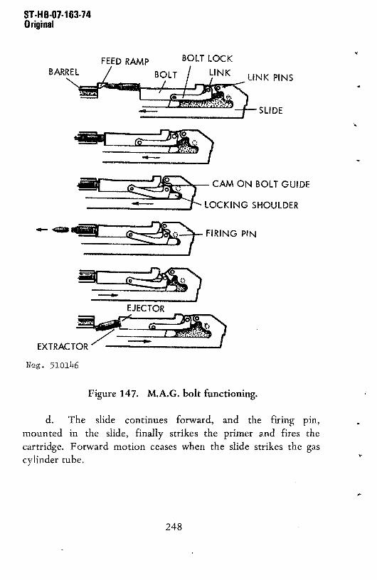
ST.H B-D1-l 63-14Original
FEED RAMP BOLT LOCK
BOL LINK LiNK PINSBAR~L~~ SLIDE
CAM ON BOLTGUIDE
LOCKING SHOULDER
~ FIRING PIN
EJECTOR
EXTRACT~~
Neg. 51O11~6
Figure 147. M.A.G. bolt functioning.
d. The slide continues forward, and the firing pin,mounted in the slide, finally strikes the primer and fires thecartridge. Forward motion ceases when the slide strikes the gascylinder tube.
248
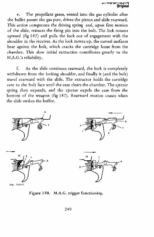
i~I 11DU1 IU,)’I’IOriginal
e. The propellant gases, vented into the gas cylinder after
the bullet passes the gas port, drives the piston and slide rearward.This action compresses the driving spring and, upon first motionof the slide, retracts the firing pin into the bolt. The link rotatesupward (fig 147) and pulls the lock out of engagement with theshoulder in the receiver. As the lock moves up, the curved surfacesbear against the bolt, which cracks the cartridge loose from thechamber, This slow initial extraction contributes greatly to theM.A.G.’s reliability.
f. As the slide continues rearward, the lock is completelywithdrawn from the locking shoulder, and finally it (and the bolt)
travel rearward with the slide. The extractor holds the cartridgecase to the bolt face until the case clears the chamber. The ejectorspring then expands, and the ejector expels the case from the
bottom of the weapon (fig 147). Rearward motion ceases whenthe slide strikes the buffer.
A
A
K
M
A A
Neg, 510147
Figure 148. M.A.G. trigger functioning.
249

Original
g. The trigger mechanism is very simple; refer to figure148. When the trigger is pressed, it pivots on pin “c”, and theroller “e” lifts the front of the sear. The sear “a” pivots on its pinandreleasesthe slide. As the searrises, the T_lug “f” is caught by
the notch “g” of the searcatch“b”. Whenthe trigger is released,itrotatesaboutits pin, and the searcatchmovesupward.This actionfurther elevates the front end of the sear, As the sear catch rises, it
is hit by the recoiling bolt androckedrearward,releasingthe sear.The sear, under pressure of its spring, rises and catches the slide
when it counterrecoils. This mechanism prevents slow rising 0f thesear,with resultantpartial engagement0f the searandslidewhichcauses battering and breakage.
h. The safety is a bar with a cutaway section,When thecutaway section is under the sear, the trigger, when pressed,causes
the sear to depress and the cutawayprovidesroom for the seartomove. When the safety is on Safe, the cutaway is moved to oneside, and the solid portion of the safety moves under the sear to
prevent it from depressing and releasing the slide (fig 147).
Neg. 510148
Figure 149. M.A.G. feed mechanism functioning.
250

I 11UU1 1UJ1’t
Original
i. The feed mechanism (fig 149) is actuated by the recoiland counterrecoil of the slide. A roller (A) on the slide rides in achannel in the belt feed lever (G). The lever is pivoted (C) andshaped so that the roller causes the front end of the lever to movefrom side to side. When the slide is releasedby the searandstartsforward, the roller moves in a straightsection0f thelever,andnosidewise motion occurs until the round in the feed tray is drivenout of the link. At the time, the roller moves into the curved
portion of the lever, and the front end (D) of the lever moves tothe right. The lever causes the link to move the feed slide to theright. The pawls on the feedslidemovethenextcartridgeinward,onto the slot on the feed tray. The cartridge guide snaps over the
cartridge and holds it in the slot. When the slide is fully inward, aholding pawl snaps into place to prevent withdrawal of theround/belt. The round that had been rammed out of the feed trayfires, and the slide starts to recoil.
j. As the slide recoils, the roller moves the front end of the
lever to the left~ this causes the link to move the slide outward.The feed pawls override the cartridges held by the holding pawlsand position themselves in preparation for feeding the next round.
199. Accessories
a. The most important 0f the accessories available for usewith the M.A.G./L7A1 machineguns are the tripod mounts. Thereare two mounts: the M.A.G. tripod manufactured in Belgium andthe L4A1 tripod used with the British L7A1 or A2.
b. Both tripods are set up by loosening the clamps on thelegs and unfolding the legs, then tightening the clamps. Mount thegun according to the type of tripod as described in the followingparagraphs.
251

ST.H8-07-163-74Original
c. For the M.A.G. tripod, remove the rear pin (fig 143)from its hole, then place the gun on the mount with the gunmount bossesengagedwith the shoulderson the front of the frontmount adaptor (fig 143). Align the rear pin holes in the receiverwith the holes in the mount and insert the rear pin (fig 143).Reverse this procedure to remove the gun. To traverse the gun,loosen the traverseclamp. Tighten this clampbefore firing. Finetraverseadjustmentsare madeafter tightening the traverseclampby rotating the fine traverse knob. To elevate the gun, release the
clamp on the elevating knob and rotate the knob to elevate ordepress the gun. Relock the clamp before firing.
d. For the L4A1 tripod, pull out the mountingpin, placethe gun or the cradle andslide the gun forward until it clicks intoplace. Reinsert the mounting pin. Reverse this proceduretoremove the gun. To elevate or traverse the gun, loosenthe socketclamp. This allows the gun and cradle to freely traverse and elevateon the ball and socket joint between the tripod and cradle.Tighten the socket clamp before firing. The right handwheel
provides fine elevation adjustments, and the left handwheel, finetraverseadjustments.
e. Spare belts, belt boxes, sparebarrels, and covers areusually provided for each gun. Simple combinationtools to aid indisassemblyarealsoused.
B. THE 7.62-MM AND .303 (7.7-MM) BRENLIGHT MACHINEGUNS (UK)
200. General
a. The Bren light machinegun is a British developmentbased on the Czech ZB3O light machinegun. The basic Mark IBren (fig 150) was adopted by the British Army in 1936.Although it was an expensive and difficult to produce weapon, it
252

rapidly replaced all other light machineguns in the British and
Commonwealth armies. Two additional models were producedduring World War II, a simplified Mark 2 (fig 151) and alightweight Mark 3 model. In addition, a special model of the
Mark 2 using the 7.92x57-mmcartridgewas produced in Canadafor the NationalistChinese(fig 152).
1o~
Figure 151. Mark 2 Bren.
S~MP1UIEORECE{VER
b I -Ilb-UI-lLii-14Original
Figure 150. Mark 1 Bren.
253

IJ~bcIIIIJCI I 511 U
b. The Mark 1 gun can be identified by its prominent rearsight elevating drum and one-piecestainlesssteel flash hiderandgas regulator housing (fig 150), The other Brenshavea leaf rearsight and a flash hider separate from the gas regulator housing
(fig, 151). The Mark 2 and Mark 3 guns are similar; the Mark 3 gun
however,hasashortened,smaller diameter, lightweight barrel. The7.92-mm Mark 2M Bren can be identified by its straightmagazine(fig 152) as opposed to the arc-shaped magazines used in the
standard .303 Mark 1, 2, and 3 Brens.
Figure 152. Mark 2M Bren.
Figure 153. L4A1 Bren.
254

c. Many Brens now fire the 70
62-mm NATO cartridge.
Some were convertedfrom the earlier .303 models, and some are
new production. These weapons, the L4 series (fig 153 and 154),
can be identified by their bar-type flash suppressors and long,
slightly curved magazine. The large head of the screws that hold
the magazine a - - ‘ in place is also a major recognition point.
d. The Nationalist Chineseproducedaversionof the Mark
2 Bren. Their gun, the Type 41 light machinegun, fires the US
.30-caliber M1906 cartridge (7.62x63-mm) and is easilydistinguished from the other Brens by its receiver with theseparategas-cylindertube (fig 155). The orig’nal patternMark 1
Figure 154. L4A1 Bren.
Figure 155. NationalistChineseType 41 Bren,
255
UI 11UU11U.r,,
Original
Brens were also produced in Czechoslovakia after World War II.These guns can be identified by the Czechoslovak inscriptions on
their receivers.
e. The British Brens, except for the L4 series, fire the .303rimmed cartridge; the L4’s fire the 7.62x51-mmNATO cartridge.The Canadian special Mark 2 fires the 7.92x57-mm cartridge,while the Chinese Type 41 fires the US .30-caliber M1906
cartridge. Information concerning ammunition will be found insection V.
201. Technical Data
TechnicaldataconcerningtheBren machinegunsaregivenin tableVII.
202. Operation
a. Load the magazines in the manner described inparagraph 1 28a. When loading rimmed .303cartridges,insurethatthe rim of each cartridge, when loaded, is ahead of the rim of thepreceding cartridge; otherwise, severe jams will occur.
b. The Bren bipod latches onto rails on the receiver when
it is folded; a vigorous pull is necessary to disengage the bipod feetfrom the rails. Swing the bipod legsforwarduntil theyspringapartand lock into place. They can be folded by pressing the legstogether and swinging them rearwarduntil they can be engagedwith the receiver.SomeBrenshaveextendablebipod legs;extendtheseas necessaryby pulling the lower leg out of the upperleg.Pressthe leg catch to releasethe lower leg andslide it back into
the upper leg.
256

UI -IIU-UI-IU.rI’t
Original
The leaf-sight-equipped Brens are adjusted for range byturning the knurled knob at the top of the leaf until the indexmark on the slide (fig 151) is aligned with the number on the leafthat corresponds with the range in hundreds of yards (Mark 2-3)
or meters(L4). For the earlymodelBren, turn the elevationdrum(fig 150) until the desiredrange(in hundredsof meters)appearsinthe openingat the rear of the drum.
d. If necessary,slide forward the dust cover, over the
magazine opening, tilt the magazine forward, and engage its frontlug with the recessin the front of themagazineopening.Rock themagazinebackuntil the magazinecatch (fig 150) snapsinto place.
e. Rotate the selector (fig 150) to its middle (safe)position. Grasp the operating handle (fig 152), pull it fullyrearward,and thenreturn it forward. (Some Brens have a folding
operatinghandle;this mustbe unfoldedprior to use.)
f. Rotate the selector (fig 150) forward for automatic fireor rearward for semiautomatic fire. CAUTION: The gun is nowready to fire. Using a normal sight picture, aim, and press thetrigger to fire. The bolt will be caught to the rear when themagazine is empty.
g. Remove the magazine by pressing the magazine catch(fig 150) toward the magazine; at the same time press themagazine forward and rotate it out of the gun. Reload as described
in paragraphc above.The gun doesnot haveto be recockedafterreloading.
h. The Bren machineguns have quick-change barrels.Removethe magazine;pressthe latch on the inside of the barrellock lever (fig 150) into the lever to release the lever from the
receiver. Rotate the lever up as far as possible, and by means of
257 -
Original
the carrying handle, pull the barrel forward off the gun. Insert areplacementbarrel, and insurethat the gas cylinder entersthe gascylinder tube. Turn the barrel lock lever down until it locks in
place; reloadand resumefire. The barrel can be changedwith thebolt rearwardor forward.
i. The Bren guns have adjustable, rotary gas regulators(fig 150). The regulator can be set at four positions, each indicated
by a different—sized dot drilled into the side of the regulator. Thesmallest gas port is used when the smallest dot is positionedbetweenthe barrel and the gas—cylindertube. The regulator ischanged to the next largestport wheneverfailure to eject occurs.To change regulator position, remove the barrel, and using acartridge or combination tool, rotate the regulator 90°. Reinstall
the barrel.
j. To clear the gun, set the selector to its middle (safe)
position, removethe magazine,andthenpull the operatinghandlerearward.Look through the magazineopeningto insure that no
cartridges are present.Move the selector from safe, grasp theoperatinghandle, pressthe trigger, andeasethe operatinghandleforward. Slide the magazine openingdust cover rearward; then
slide the ejection cover rearward. Set the selector back to itsmiddle (safe) position.
203. Disassembly and Assembly
a. To disassemble the weapon, clear the gun (para 202j),
but do not close the dust covers or move the selector from its safeposition. Remove the barrel (para 202h).
b. Press out the takedown pin (fig 150) from left to right
and slide the butt and trigger mechanismrearward out 0f thereceiver.
258

b I-MIS-UI-i bJ-I4Original
c. Hold a hand over the rear end of the receiver, and point
the front end up. The slide and bolt will slide rearward;removethem. Pull the bolt rearward and up off the slide,
d. No furtherdisassemblyis necessaryor desirable.
e. To reassemble the gun, place the bolt over the slide post
and push the bolt forwardon the slideso that the undercutsat thefront of the bolt matewith their trackson the slide. Insert the gaspiston into the rearof the receiver,andwhenthe pistonis insertedfar enough,align the ribs on the slide andreceiverandpushtheslide into the receiver. Tilt the receiver down until the bolt andslidego forward.
f. Slide the butt and trigger mechanisminto the receiverfrom the rear.Be sure that the driving-springrod is seatedinto itsrecess in the end 0f the slide. When the butt and triggermechanismare fully seatedin the receiver, insert the takedownpin.
g. Replace the barrel and clear the gun.
204. Functioning
a. The Bren light machineguns are gas operated. When the
weaponis fired, a portionof the propellantgasesis divertedinto agas cylinder and drives the piston and attached parts rearward. Thedriving springis compressed,anduponcompletionof the rearwardmovement, this spring drives the breechmechanismforward toreloadandfire anothercartridge.
b. The Bren machinegunscommencetheir firing cycle withthe slide and bolt held to the rear by the sear. The driving spring iscompressed.When the trigger is pressed,the seardisengagesfrom
259
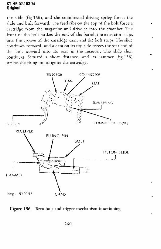
ST.H 6-01-163-74Original
the slide (fig 156), and the compressed driving spring forces theslide and bolt forward, The feed ribs on the top of the bolt force acartridge from the magazine and drive it into the chamber. The
front of the bolt strikes the end of the barrel, the extractor snaps
into the groove of the cartridge case, and the bolt stops.The slidecontinues forward, and a cam on its top side forces the sear end 0fthe bolt upward into its seat in the receiver. The slide then
continues forward a short distance, and its hammer (fig 156)strikes the firing pin to ignite the cartridge.
SELECTOR CONNECTOR
SEAR
CONNECTOR HOOKS
RECEIVERPIN
BOLT
PISTON SUDE
Neg. 510155 CAMS
Figure 156. Bren bolt and trigger mechanism functioning.
260

ST-H B-07-163-74Original
c. The propellant gases from the cartridge drive the bullet
through the barrel. Just beforethe bullet reachesthe muzzle,someof the gases are diverted through the gas port and into the gascylinder. The gasesthen drive the piston rearward. As the piston
andslidemoverearward,thedriving springis compressed.
d. As the slide moves, the cams on the slide (fig 156)contact the bolt and pull it down from its locked position; whenunlocked, the bolt and slide travel rearward as a unit. Theextractor pulls the fired cartridge case from the chamber and holdsthe caseto thebolt until the ejectorstrikesthe case.The casethenpivotson the extractorandis expelledthrough the ejectionport inthe bottom of the gun. The slide finally strikes the buffer andstops. The driving spring then drives the slide forward, and anothercycle commences.
e. The Bren trigger mechanism can be set for either semi-or full-automatic fire by rotating the selector (fig 156). When theselector is rotated forward to the full automatic setting, a solid
section on its shaft depresses the connector, which fits through ahole in the lower arm of the sear. As the trigger is pressed,theconnector moves forward; the lower hook (fig 156) engagesthesear and causes it to rotate about the pin. The sear nosereleasesthe slide and, the firing cycle commencesand continuesuntil thetrigger is released and the sear spring forces the sear up tointercept the slide.
f. When the selector is rotated rearward to thesemiautomaticsetting, the connectorrises to its highestposition;as the trigger is pressed, the upper hook of the connector rises toits highest position. As the slide drives forward, it hits the cam(fig 156) on the connectorand forces the connectordown. Thehook releasesthe sear that, because of its spring, snaps up andcatches the slide when it recoils. Thus only one shot is fired; the
261

trigger must be released to allow the connector to move rearward
and its hook to reengage the sear so that a second shot can befired.
g. When the selector is rotated to its middle or safe
position, the hooksare positionedcentrallyin the holein the sear(fig 156). Thus, when the trigger is pressed, the connector hooksdo not activate the sear to release the slide.
h. The magazine platform has a rear-edge lug that can dropin front of the bolt when the last round has been fed, When thebolt recoils after firing the last round, the lug stops the bolt; this,in turn, stops the slide slightly to the rear of the place where itnormally would be engaged by the sear. As the emptymagazineisremoved, the bolt and slide move slightly forward onto the sear,andafter a loadedmagazineis inserted,the gun is againready tobe fired,
205. Accessories
A wide assortment of accessories are available for the Bren. The
following are usually found with these weapons: spare barrel;
extra magazines with a metal magazine box or web or leathermagazinecarrier; a sling; anda tool roll or boxwith cleaningrod,combination tool, spare parts (firing pins, extractors, ejectors,springs, etc.), and a gun cover.
C. THE 7.5-MM AA-52 MACHINEGUN (FRANCE)
206. General
a. The AA-52 machinegun (fig 157 and 158) is the
standard general-purpose machinegun of the French Army. The
gun can be readily fitted with oneof two differentweightbarrels,fired from a bipod (fig 157) or a light tripod (fig 159), and fired
262

‘130’U1 LU.)13
+
Onginal
with the sliding stock folded or extended.A heavy-barrelmodelwithout stock or sights is also available for use in coaxial mounting
of armoredvehicles (fig 160).
Figure 1 ~7. French AA-52 light machinegun’
Figure 158. French AA-52 heavy machiflegufl~
263

Original
b. The AA-52 or its export model AAT-52 (Armes
Automatic, Transformable) (convertible machinegun) is a
delayed-blowbackoperated,fully automatic,metallic link-belt fed
weapon equipped with a quick-change barrel, Thedelayed-blowback operation requires a fluted chamber that leaves
characteristic lines on the fired cartridge case.
c. The French Army and some of the former French
coloniesuse this chamberfor 7.5x54-mmcartridges.This versionis officially known as the AA-52. By changing barrels,7.62x51-mmNATO cartridgescan be used; this version (AAT-52)
is offered for commercial sale and is often found as a tank version
(fig 160) in armored vehicles sold by France,
d. Additional information on ammunition used can befound in sectionV.
207, Technical Data
Technical data pertaining to the AAT-52 machinegunwill befound in tableVII.
AA-52 heavy machinegun on tripod.
264

ST~HB-07-163~74Original
208.Operation
a. Ammunition for the AAT-52 normally will come in
belts.However, if empty beltsand loosecartridgesare to be used,insert a cartridge into each link insuring that the tab on the linksnaps into the cartridge groove. Be sure to use the rightammunition: 7.62-mm cartridges cannot be used in 7.5-mm guns
and vice versa; 7.62-mm barrels are stamped on top“M52-300-7.62”. Only feed belts designed for this gun can beused.
b. If the weapon is bipod equipped,unsnap the catch(fig 157) and swing the bipod down. When it is at a right angletothe barrel, spreadthe bipod legs. If the gun is to be used on atripod, mate the front recessof the trigger guard with the mountadaptor, then close the barrel clamp (fig 159) and tighten. Pressthe catch (fig 157) and extend the stock if desired.
Pull the operatinghandle (fig 158) fully rearward,thenthrust it fully forward. Pressthe safety (fig 157) to the left (safe).Press the cover catch (fig 157) forward and open the cover.
Figure 160. AAT-52 tankmachinegun.
265

ST-H 6-07-i 63-74Original
d. Place a loaded belt, open side of the links down, acrossthe feedplate (fig 160). The first cartridge must rest against thestop (fig 160) and the belt must be located between the stop andthe rear of the feedplate.Close the cover.CAUTION: The gun isloadedandreadyto fire.
e. Erect the front sight, then press in the catch on the rear
sight and move the slide along the bar until the correct range, inhundreds of meters, is alignedwith the slide. Pressthe safety tothe right. Aim, usinga normal sight picture, and press the trigger.The AAT-52 will fire as long as the trigger is pressed and cartridges
are in the feed belt. The bolt will remain open between shots andclose on an empty chamber when the last round in the belt isfired. Short, three-to-five-shot bursts, with re-aiming betweenbursts, give best results.
f. To unload or clear the gun, pull the operating handlefully rearward, then thrust it fully forwardandpressthe safetytothe left. Press forward the cover catch and open the feed cover.Lift the belt off the feed tray. Inspect to insure that no cartridges
are presentin feed, receiver,or barrel, then close the feed cover.Push the safety to the right, draw the operating handle to the rear(while holding it), squeezethe trigger, then easethe operatinghandleforward.
g. To change barrels, pull the operating handle fullyrearward and push the safety to the left. Press down on the barrellock (fig 161) (on some guns, pull back on barrel lock) and, usingthe carrying handle, rotate the barrel to the right until it stops,then pull it forward out of the receiver. Insert the fresh barrel
fully into the receiver,thenrotate it to the left until it locks intoplace.
266

ST-H 8-07-163-74Original
COVER PIN
BARREL LOCK
£1
1 lU
Figure 161. AA-52 barrel change.
209. Disassembly and Assembly
a. Clear the gun (para 208f). Press the cover catch(fig 157) forward and open the feed cover.
b. Unscrewthe takedownscrew (fig 157) at the left rear
the receiver and remove it. CAUTION: Press down on top of the
butt while removing the takedown pin. Ease the butt stockupward and remove it. Pull out the driving spring andguide.
c. Slide the bolt rearward until it can be removed(Note: The bolt headmay separatefrom the bolt during removal;if so, just pull thebolt head out of the receiver). Pull the firing pinout of the bolt heador bolt body as requiredafter separatingthebolt head and bolt body (fig 162).
d. Remove the trigger group pin (fig 157) after depressingits lock, andpull the trigger group out 0f the receiver.
267

Figure 162. AA-52 disassembled.
e. Lift the feed tray (fig 162) up against the open feedcover and pull out the pin (fig 162) by its knurled head, Remove
the feed cover and feed tray. No further disassemblyis necessaryor desirable.
f. Assemble the feed tray and feed cover to the receiverand insert the cover pin as far as possible.Fully openthe coverand feed tray and seat the pin.
g. Insert the trigger group into the bottom rear slot of thereceiver. After mating the slot in the front of the trigger group
with the receiver, slide the trigger group forwarduntil the trigger
group pin can be inserted.
h. Insert the firing pin into the bolt head,but leaveabout
1-1/2 inchesprotruding.Placethe bolt headonto the bolt body so
ST-HB-Ui-i Li 3-14Original
268

ST-H8-07-163-74Original
that the tang of the firing pin enters the hole in the bolt body.
Seat the bolt head against the bolt body. it may be necessary to
push in the rear of the retarder prior to sealing the bolt head.
i. Start the bolt head into the receiver and press theretarder forward and inward until the bolt enters the receiver.Press the trigger and move the bolt fully forward. Insert thedriving spring, free endfirst, into thebolt body.
j. Seatthe driving spring into the recessin the backplate,then mate the lip on the top of the back plate with its recess in theinner top of the receiver. Press down on the top of the butt stockto seat the backplate and insertthe takedownscrew.Tightenthetakedown screw. Pull the operating handle rearward,close thecover, hold the handle, press the trigger, and ease the handleforward.
210. Functioning
a, The AAT-52 functions on the principle of delayedblowback. As soon as the cartridge fires, gas pressure generateddrives the bolt rearward; however,a mechanicalretarderpreventsall but a minimum of bolt head movement until the gas pressurehasgreatlysubsided.Becausethe cartridgecasedoesmove, albiet avery small distance, under high gas pressure, the AAT-52 chamberhas lengthwise flutes cut into it. These flutes allow gas to leakback and “float” the front of the case on a film of gas. Because of
this, the case does not adhere to the chamber and case ruptures areprevented.
b. When the AAT-52 is cocked and a loaded belt is in thefeed tray, pressureon the trigger releases the bolt which, under theforce of the driving spring, starts forward. At this time, theretarder is flush with the right side of the bolt head, The retarder
269

ST-HB-Ui-i 63-74Original
also holds the bolt head away from the bolt body. The feed rib onthe bolt head drives the cartridge out of the feed tray and into thebarrel. The extractor snaps into the cartridge case groove, and thebolt head strikes the end of the barrel and stops. At this time, theretarder aligns with a recess in the receiver and, as the bolt bodycontinues forward, a cam forces the retarder to rotate outward.The firing pin, connected to the bolt body, also continues forwardand fully fires the cartridge. Forward motion ceases when the boltstrikes the bolt head.
c. Upon firing, the gas pressure generated immediatelythrusts the bolt head rearward. The retarder lever is outward,being against the rear wall of its recess (fig 164) and, as the bolthead moves the retarder is forced to swing inward. The inner armof the retarder presses against the bolt body, and, before theretarder can rotate, it must force the bolt body rearward awayfrom the bolt head (fig 164). This action causes a 3:1 mechanicaldisadvantage against the bolt head while accelerating the rearwardmotion of the bolt body. The mechanical disadvantage, in essence,
CARTRIDGE DEPRESSOR
LUG*
RETARDER
SEAR CATCH
Beg. 510162
Figure 163. AA-52 section.
270
ST-H8-07-163-74Original
keeps the bolt head locked until gas pressure has subsided to a safedegree. The inertia imparted by the retarder to the bolt body is
sufficient to move the entire bolt rearward and compress thedriving spring.
d. The extractor holds the fired cartridge against the boltface until the twin fixed ejectorson thebottom rear of the feedtray strike the cartridgeandexpel it out the bottom of the gun.Rearwardmovement ceases when the buffer (fig 162) in the rearof the bolt strikes the backplate. if the trigger is still depressed,anotherfiring cycle starts.
e. The shuttle-type feed mechanism, quite simple infunction, is actuatedby the recoil and counterrecoil of the bolt. Acam lug on (fig 164) the pivoted belt feed lever projects into arecess(fig 164) in the top of the bolt, As the bolt drives forward
and pushes the round out of. the feed tray, a cam surface at therear left of the bolt recess contacts the cam lug on the belt feedlever; this movesthe front endof the lever(andtheattachedbeltfeed slide) outward. The spring-loaded pawis of the feed slideoverride and then snap over the next cartridge to be fired. Uponfiring and resultant bolt recoil, the angular right side of the boltrecess actuates the belt feed lever inward. The feed pawis thus
move the next round into position over the slot in the feed tray.The spring-loadedcartridgedepressor(fig 164) holds the cartridge
solidly in the slot and the fixed belt holding pawls in the coverprevent the belt from moving out of the gun during feed.
f. The trigger mechanism (fig 163) is also simple. When thetrigger is pressed, a roller contacts the sear and lifts its front end.
The rear end of the sear depresses and releases the bolt. As thetrigger is pressed, the sear catch, attached to the front of thetrigger, moves down and, as the front 0f the sear rises, the searsnaps forward over the “T” lugs at the front of the sear. When the
- 271

ST-HB-01-163-74Original
Figure 164. AA-52 bolt and feed cover.
trigger is released,the sear catch movesupward and,becauseit
now holds the sear “T” lug, the sear pivots further about its pin,further depressing the sear nose. The searcatch finally rises farenoughso that the recoiling bolt rocks it rearward to release the
sear. The sear snaps upward and, when the bolt counterrecoils, thesear engages the sear notch and holds the bolt cocked, This use ofasearcatch preventsslow rising of the sear with resultant partialengagementsandchippingor breakageof the searandbolt.
g. The safety, when applied, puts a solid bar under thesear, preventing the sear from being depressed. When the safety ismoved to the fire position, a cutaway section moves under thesear. The sear can then be depressed to release the bolt.
211. Accessories
a. The usual accessories for machinegunsare availableforthe AAT-52. These include:
272

ST-HB-Oh-i 63-74Original
(1) Extra 50-round nondisintegrating metallic feed
belts.
(2) Belt boxes.
(3) A 50-round bandoleer, which can be attached to
the feed tray.
(4) Cleaning rods and cleaning equipment.
(5) Spare firing pins, extra springs, and the like.
b. The AAT-52 can be mounted on the French M52 tripodor, with a suitable adapter, on the US M2/M122 tripod mounts.
0. THE 7.5-MM MODEL 24/29 LIGHT MACHINEGUN (FRANCE)
212. General
The 7.5-mm Model 24/29 (fig 165) was a standard pre-World WarII French Army weapon that was put back into production afterthe war. It is an excellent weapon 0f simple design andunsurpassed ease of maintenance. Although the French refer tothis weapon as an automatic rifle, it is a light machinegun bycontemporary standards. The Model 24/29 is sometimes referredto as the Chatellerault machinegun. Its double triggers, large wood
forearm, and multiperforated conical flash hider are primerecognition features. There is a large vertical hole in the forearm;
this is to adapt the gun to an antiaircraft or vehicular post mount.Although obsolescent in the French Army, the Model 24/ 29 is stillin widespread use in many former French possessions. The Model24/29 fires the 7.5x54-mm cartridge (sec V).
273

ST-H 8-01-1 63-74Oriqinal
213. Technical Data
Technical data concerning the Model 24/29 light machinegun aregiven in table V.
214. Operation
a. Load the magazine as described in paragraph 1 28a.
b. Unhookthe clip that holdsthe bipod legstogether,thenswing the legs forward and down. Spread the legs until they arelocked open by the locking link between the legs.
Figure 165. French Model 24/29 light machinegun.
274

ST-H 8-07-1 63-74Original
c. Open the dust cover by turning the dust cover lock(fig 166) upward, then pull the magazine catch release (fig 165)rearward; this will allow the magazine catch to spring up into
position. Fold the dustcoverforwardover the barrel.If necessary,the rear sight aperturecan be swung to the left for use.Set thesight to the desiredrange by depressingthe locks andmoving the
slide along the ramp until the top of the slide is aligned with the
figure that corresponds to the range in hundreds of meters. Unfold
the butt rest if desired.
d. Hold the magazine, tilted forward, and mate the lug
(fig 166) on its front side with the recessin the magazinewell.Rotatethe magazinerearwarduntil the magazinecatchsnapsintoplace. Pull the operating handle fully rearward; then push itforward. CAUTION: The gun is now ready to fire. If desired,render the gun safe by moving the safety (fig 165) downward.
e. To fire, push the safety upward; using a normal sightpicture, aim and press one of the triggers. Pressing the front triggerwill fire one shot; the trigger must then be released and repressedto fire another shot. Pressing the rear trigger will cause the gun tofire until the magazine is empty or the trigger is released.
f. When the last cartridge in the magazine is fired, the boltwill remain open. Press the magazinecatch (fig 165) towardthemagazineand,at the sametime, tip the magazineforward out ofthe gun.
g. To clear the M24/29, rotate the safety downward,remove the magazine (para f above), and pull the bolt fullyrearward. Inspect to insure that no cartridges are present. Press the
safety upward, hold back on the operating handle, press one 0f thetriggers, and easethe operating mechanismforward. Swing thedust cover (fig 165) to the rearover the magazineopening; then
275

I ‘ho-UI- IOi-I’~Original
swing the ejection port cover down. Lock it in place by turning
the lock lever down. Reset safety to safe and press the magazinecatch back until it locks.
h. Fold the bipod by pressing the center 0f the locking linkupward; then fold the legs together.Swing them backwardandsecure them with the bipod clip (fig 165). The bipod can bestowed under or alongside the barrel.
215.Disassemblyand Assembly
a. Clear the gun (para 2l4g), but do not close the dustcover; leave the safety upward in the fire position.
b. Unscrew the takedown screw (fig 165) until it can bepulled out of its hole, Tilt the butt up and off the receiver.Thetrigger group will swing down.
c. Press the front end of the trigger group into the receiver;then remove the trigger group. The ejector is housed in a dovetailin the left wall of the receiver; pull the ejector rearward and out of
the gun.
d. The driving spring can now be pulled rearward andremoved from the slide (fig 166).
e, Pull the operating handle rearward. This will move the
bolt and slide to the rear where they can be grasped and pulled outof the receiver. Turn the tube lock (fig 166) to the verticalposition and swing the rear end of the gas cylinder tube to theright; after it disengages from the receiver,it canbe removed.
f. The bolt link pin can be pulled out and the bolt can beseparated from the slide.
276

g. Although further disassemblyis neither necessarynordesirable, the barrel can be removed. Turn the barrel lock at theleft front end of the receiverto the “0” marking.Placea wrenchon the flats on each side of the rear end of the barrel and unscrewit. The barrel has right hand threads. The barrel is replaced byscrewing it into the receiver until it seats and the lines on thebarrel and receiver are aligned. Turn the barrel lock back to itslock position.
h. Place the bolt onto the slide, position the link (fig 166),
and replace the link pin.
i. Mate the gas cylinder tube with the gas cylinder andslide the rear end of the tube to the left and into place in thereceiver,
I -FtIS-UI-itjj’I4Original
Figure 166. M24/29 disassembled,
277

ST-HB-Oi-163-74Original
j. Push the bolt as far forward as possible on the slide;then insert the bolt and slide into the receiver, insuring that thepiston enters the gas cylinder tube. Tip the muzzle down so thatthe bolt and slide will go fully forward. Replace the ejector(fig 166) into its recess.
k. Insert the driving spring and guide into the slide, guideto the rear. Mate the hook (fig 166) on the trigger group with itscross pin in the receiver; then swing the trigger group up intoplace.
1. Hold the stock at an upward angle to the receiver and fit
its lug (fig 166) into its recess in the inner top of the receiver.Hold the trigger group up in place and swing the stock down untilit seats against the receiver. Insert the takedownscrew, from theright, and screw it fully home. Close the dust covers, fold theapertureto the right, andpressthe magazinecatchdown until it islocked in place.
216.Functioning
a. The M24/29 light machinegun is gas operated andcommences its firing cycle with the slide and bolt held to the rearby the sear. When either trigger is pressed, the sear disengages fromthe slide, and the compressed driving spring forces the slide andbolt forward.
b. The feed ribs on the top of the bolt force a cartridgefrom the magazine and drive it into the chamber. The extractorsnaps into the groove of the cartridge case, and when the front of
the bolt strikes the end of the barrel, the bolt stops its forwardmovement. The slide continues forward and the links (fig 167)
pivot about the pin to force the rear end 0f the bolt up into itsseat in front of the locking shoulder. The slide continues forward
278
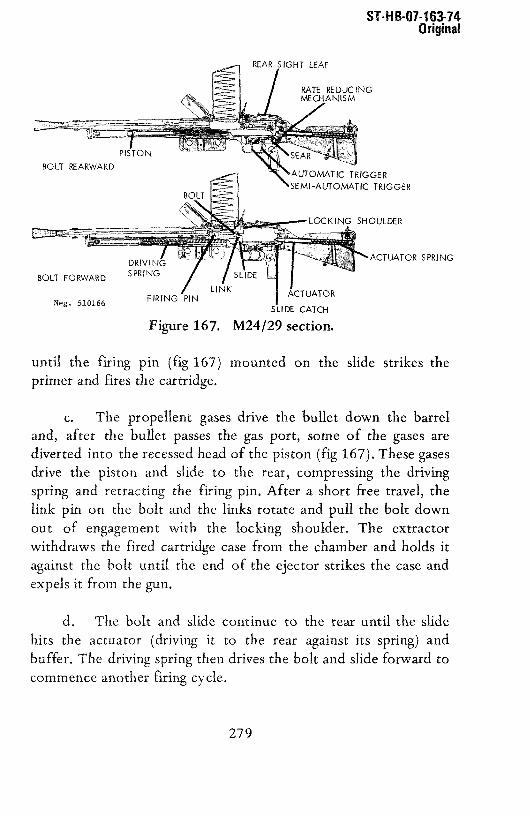
Beg. 510166SLIDE CATCH
Figure 167. M24/29 section.
until the firing pin (fig 167)primer and fires the cartridge.
ST-H 8-07-163-14Original
SPRING
c. The propellent gases drive the bullet down the barreland, after the bullet passes the gas port, some of the gases arediverted into therecessedheadof the piston (fig 167). These gasesdrive the piston and slide to the rear, compressing the drivingspring and retracting the firing pin. After a short free travel, thelink pin on the bolt and the links rotate and pull the bolt down
out 0f engagement with the locking shoulder. The extractorwithdrawsthe fired cartridgecasefrom the chamberandholds itagainst the bolt until the end of the ejector strikes the case andexpelsit from the gun.
d. The bolt and slide continue to the rear until the slide
hits the actuator (driving it to the rear against its spring) andbuffer. The driving spring then drives the bolt and slide forward tocommenceanotherfiring cycle.
BOLT REARWARD
BOLT FORWARD
DR~VIISPRING
SHOULDER
FIRING PIN ~TOR
mounted on the slide strikes the
279

ST-HB-Oi-163-i4Original
e. The trigger mechanism consists of a conventional searand two triggers, one for automatic and one for semiautomaticfire. If the weapon is cocked, i.e., the slide is held to the rear bythe sear (fig 168); pressure on the rear or automatic trigger(fig 168) will lift the front end of the sear and cause it todisengage from and release the slide and thus commence the firing
cycle. The sear rises and catches the slide to the rear, thus stoppingthe firing cycle,only when the trigger is released.
SAFETY SHAFTDISC ON NE CTOR
AUTOMATIC TRIGGERSEMIAUTOMATIC TRIGGER
SEAR SPRING
SPRING
DISCO N NECbRSPRING
Neg. 510167
Figure 168. M24/29 trigger mechanism.
f. When the front or semiautomatic trigger (fig 168) is
pressed, the disconnector lifts the front end of the sear, causingthe sear to release the slide. As the trigger moves, thedisconnector, because it moves in a circular path (on the end ofthe trigger), travels forward until it moves out from under the sear.The sear spring snaps the sear upward to intercept the slide. Tofire a second shot, the trigger must be released so that the trigger
280

ST-HB-O7-163-74Original
spring can force the trigger forward and lower the disconnector.The disconnector pivots toward the trigger as it passes the front ofthe sear, and as soon as the disconnector is under the sear, thedisconnector spring forces the disconnector rearward under thesear. Pressure on the trigger will now cause the triggering action tobe repeated and another shot to be fired.
g. When the safety is rotated downward to the safeposition, the safety shaft (fig 168) rotates so that its lower endblocks the semiautomatic trigger and its upper end blocks theautomatic trigger. Because neither trigger can be pressed, the armcannot be fired,
h. The butt of the M24/29 light machinegun has a simplerate reducing mechanism. When the slide recoils, it drives theactuator (fig 167) to the rear against its spring. At the same timethe slide catch engages the slide and holds it to the rear until the
actuator is driven forward. When the heavy actuator reaches theend of its return stroke, it depresses the slide catch to release the
slide. The time lag caused by the movement of the actuator resultsin a reduced cyclic rate of fire.
217. Accessories
Several accessories are available for the M24/29 lightmachinegun. Opening a sliding plate in the butt plate reveals aspare ejector and takedown screw housed in recesses in the buttstock. A leather sling is used to carry the M24/29 and, whenavailable, a simple monopod can be inserted into a socket in thebottom of the butt stock. The monopod, in conjunction with the
bipod, forms a tripod mount for better stability during long-rangefiring. The monopod is removed by pressing the key-shaped latchon the right side of the butt stock and pulling the monopod out ofits socket. Spare magazines, magazine carriers and a spare barrelare normally carried with each M24/29.
281

us’r—jjjo}j—jbj~-/~_~ff~ I ~ September 19130
E. THE 5.56—NM OR 7.62—NM HECKLER AND KOCH HR 13,HK 21, AND ilK 21A1 MACHINEGUNS(WEST GERNANY)
218. General
a.. The S.56—mm ilK 13, HR 21, and HR 21A1machineguns are based on the design of the G3 rifle(para 144). The three guns are slmiliar, but theHR 13 (fig 169) is fed only by box magazines, theHK 21 (fig 170) is fed by belt, or with an adapter,by box magazines, and the HR 21A1 (fig 170.1) Is animproved, lightened IlK 21. The guns, as coveredhere, are S.56—mm; however, they are also availablein 7.62—mm, and in the case of the HR 21 may beconverted from one caliber to the other.
Neg. 510168FIgure 169. West German IlK 13 light machinegun.
b. The HR 21 is used by Portugal and Sweden(in 7.62—mm), and all guns are offered for salecommercially. The Heckler and Koch machineguns canbe identified by their short, compact appearances,operating handle at the front of the receiver(fig 170), and prominent barrel change handle(fig 170).
282

-, pL.~LUU~L i.YOV ~~i—iLi0~—Ib~/bCRG 1
c. The Heckler and Koch machineguns fireeither 5.56x45mm or 7.62x51—mm ammunition; refer tosection V. The belt—fed models use Stoner ‘635.56—mm or US Ml3 7.62—mm links.
219. TechnIcal Data
Technical data concerning the HR machineguns aregiven in table VII.
Neg. 510169Figure 170. West German HR 21 machinegun.
Neg. 529188Figure 170.1. West German HR 21A1 machinegun.
283

DST111OH16376CHG1 5 September 1980
220. Operation
a. Operate the HR 13 or HR 21 with magazineadapter according to the directions in para-graph 146,
b. The HR 21 (belt fed) and HR 21A1 areloaded by first pulling the operating handlerearward and turning it up into the safety notch(fIg 170). If the weapon is an HK 21, press thefeed catch and pull the feeder out to the left.CAUTION: As soon as the feeder moves, release thecatch; otherwise, the feeder will come out of thegun. Place the ammunition belt on the feeder withthe link opening up and the first round engaged inthe feed sprocket (fig 171). Hold the belt in placeand force the feeder back in until it latches. Ifthe gun is an HR 2lAl, press the feeder catch andallow the feeder to drop (fig 171). Then place thebelt on the feeder as described above, and swing thefeeder up until it catches in place or, withoutopening the feeder, insert the tab end of a feedbelt into the feeder, open side of the link up, andpull tab hard to right (fig 171.1).
c. Pull the operating handle (fig 170) to therear slightly, rotate it down, out of its safetyrecess, and release It. CAUTION: The machinegun isnow ready to fire. If the gun is not to be immedi-ately fired, rotate the safety to its highest posi-tion.
d. Best results are obtained by use of thebipod. Pull the legs away from the barrel jacketuntil they lock in place. The legs are folded bypressing the locks (fig 169) and then -folding thelegs rearward. Set the sight for the desired rangeby rotating the elevation knob (fig 169) until thedesired range, in hundreds of meters, appears in thewindow alongside the knob.
284

zeptentber 19t$U DST—lllOil--l63’--76—CHG 1
e. To fire, rotate the selector to thedesired position (mid for semiautomatic and bottomfor full automatic), aim (using a normal sightpicture), and press the trigger. Best results inautomatic fire are obtained with three to five shotbursts. The bolt will remain forward.
f. If the weapon is either an IlK 21 or anIlK 2lAl, clear or unload it by rotating the selectorup to the safe position, pressing the feeder catchand pulling the IlK 21 feeder to the left or allowingthe HR 21A1 feeder to drop. Lift the belt off thesprocket, and then c~’ose the feeders, insuring thatthey are caught by the feeder catches. If the gunis an IlK 13, proceed as directed in paragraph l46g.
Neg. 510170Figure 171. West German HR 2lAl feeder.
285

U~LLLLUt1~1~.5’/bd~ 1. September 1980
Neg. 529189Figure 171.1. Inserting feed belt with feed tab;
feeder closed.
286

,~,.-,..‘ ,~.J’.JLL LU,J’IU~.,flIJ 1,
,~.
—~
Neg. 510171
85. Barrel 94. Set bolt86. Barrel grip 95. Left bipod leg87. Spacer 96. Operating handle88. Grip holder with elbow spring89. Barrel catch with 97. Locking roller
elbow spring 98. Bolt head locking90. Extractor with lever
extractor spring 99. Protective cap91. Catch 100. Scale drum92. Range drum93. Eye bolt
Figure 172. IlK 21 barrel change.
g. To change barrels, pull the operatinghandle to the rear and turn it up Into the safetynotch. Grasp the barrel handle (fig 169) and, atthe same time, press the catch at the back of thehandle (fig 169). Rotate the handle up, and thenshove the handle and barrel forward. Pull thehandle to the side and remove the barrel to therear. Insert the flash hider of the new barrel intothe hole in the front of the barrel jacket and pushthe barrel forward until It can be placed inside thejacket; then, with the handle up, pull the barrelback into the receiver. Rotate the handle downuntil the catch snaps into place.
287

DST—L11OH--163—16—CHG1 5 September 1980
221. Disassembly and Assembly
a. Disassemble and assemble the HR 13, ilK 21,and HR 2lAl as described in paragraph 147athrough h.
b. The feeder of the HR 21 can then be removedby pressing the feeder catch and pulling the feederout to the left while holding the catch. Reversethis operation to install the feeder.
222. Functioning
a. The basic functioning of the HK 13, IlK 21,and HR 2lAl is identical to that of the G3 rifle(refer to paragraph 148 and figure 173).
b. The bolt carrier of the HR 21 and HR 21A1has a diagonal slot cut across its bottom side toactuate the belt feeder. As the bolt carrierrecoils and counterrecoils, this slot causes aroller stud in the feeder (fig 174) to move fromside to side. This side—to—side movement actuates arachet mechanism on the end of the sprocket(fig 174) to revolve the sprocket. A pawl preventscounterrotation and, as the sprocket rotates, itplaces fresh cartridges in position for the boltfeed rib to pick up and bring into the chamber.
223. Accessories
a. The accessories used with the G3 rifle
(para 149) can also be used on the machineguns.
b. The telescopic sight is attached by seatingits right side over the ridge on top of the re-ceiver, then swinging its left side down over thereceiver and rotating the lock lever until the leverfits into place.
288

.~, aeptemDer L~su DST—lilOH—163—76—CHG 1
c. The HR 21 and H21A1 have a plasticammunition box that can be attached to the lugs infront of the receiver.
F. THE 7.62—NM MG-1/NG—3MACHINEGUN(WEST GERMANY)
224. General
a. The predecessor of the MG—i, the MG—42, wasdeveloped in Germany during World War II as a re-placement for the complex, undependable, and expen-sive MG—34. Like the MG—34, the MG—42 is belt fedand recoil operated, but the MG—42 is constructedlargely of stamped sheet metal, as contrasted to theintricately forged and machined MG—34. The MG—42gave excellent performances, from the sandy tropicdeserts to the cold, snowy, northlands. It was anuncomplicated and fairly trouble—free machinegun.Production of the MG—42 halted at the end of WorldWar II, but in 1959 production was resumed by theRheinmetall Corporation of West Germany.
289

80 81 82 83 84
leo. 51017)
Figure 173, H21 section.
‘.0
0
‘4
CC

1. Flash suppressor (with retaining 29. Stop abutment with operating housing 55. Buffer screwspring for flash suppressor) 30. Operatinghandlespindle 56. Bipodhead
2. Receiver with barrel jacket 31. Operatinghandlesupportwith 57. Blocking pin3. Grip assembly coller tube 58. Catchlever4. Selector 32. Stop pin for recoil spring 59. Springpin5. Sightbase 33. Clampingsleevefor recoil spring 60. Springfor springpin6. Sightarm stop pin 61. Clampingsleeve7. Butt stock with backplate 34. Recoil spring guidering 62. Left spike8. Buttplate 35. Recoilspring 63. Barrelextension9. Leaf spring 36. Clampingsleeveandholderfor 64. Retainingcatch
10. Slingholder locking rollers 65. Catchlever11. Field mountattachment 37. Bolt head 66. Catchleverspindle12. Leafspring 38. Locking piece 67. Transportspindle13. Iiipod attachment 39. Bolt body 68. Driver14. Belt feedinsertionunit 40, Firing pin with firing pin spring 69. Catch
0 15. Grip assemblylockingpin 41, Camroller 70. Triggerlever16. Grip 42. Releaselever 71. Elbow spring androller17. Butt stocklockingpins 43. Hammer 72. Elbow spring for trigger18. Pivot for field mount 44. Ejectorspindle 73. Trigger19. Cartridgeguide 45. Safety pin 74. Triggerassemblyhousing20. Springbearing(with elbowspring) 46. Ejectorwith pressurespring 75. Bufferpin21. Transportwheel 47. Pressureshankwith pressurespring 76. Selfiockingcountersunkscrew22. Pressureroller 48. Pressurespringfor sightarm 77. Bufferspring, inner andouter23. Locking plate 49. Sightsupport 78. Bufferhousingsupport24. Front sightholder 50. Fixingscrewwith toothedwasher 79. Slidespindle25. Frontsight 51. Recoilspringguiderod 80. Cylindrical pin26. Clampingsleevefor front sight 52. Recoilspring guide rod pin 81. Pawl with pressurespring27. Retainingsleeve 53. Bufferhousing 82. Ratchetring28. Stoppin 54. Bufferlocking screw 83. Rivet pin with roller
84. Slide
Figure 173. H21 section. (Continued)

DST—lllOH—l63—76—CHG1 5 September 1980
Figure 175. oldGerman MG42 machinegun.
FIgure 174. HR 2lAl feeder mechanism.
~. 110174
\
USCLAISIFUII
290.2

ST-H 8-07-163-74Original
b. The Rheinmetall gun is known either by its commercialdesignation of MG-42/59, or by the West German Militarydesignation of MG-i (fig 176). There are several variations of theMG-i. The original MG-i, in 7.62x51-mm NATO, was almostidentical to the old MG-42; the MG-1A1, chambered for the
7.62x51-mm NATO cartridge,had a chrome-platedbarrel bore;
the MG-1A2 has several minor modifications and can be fed witheither the German 50-section belt or US M13 links. The MG-iA3also has several minor changes, most 0f which were made to
simplify production. The latest version, the MG-3, has anantiaircraft ring sight and a device to prevent the belt from fallingout of the gun when the cover is opened. The Yugoslavs alsoproduce a copy of the original MG-42 (fig 175) in 7.92x57-mm;
they call their gun the SARACM-i953. The MG-42159 is used byAustria, Denmark, Spain, West Germany, and Italy (the latter twocountriesalsomanufacturethe gun); manysmallernationsalsousevariousversions0f theMG-42.
Figure 176. West German MGi or MG3 machinegun.
291

Original
c. The origin of the gun can be determined by the receivermarkings,which are normally found in the left side of the receiverjust ahead of the butt stock.
d. The original MG-42 had a very high cyclic rate (from1100 to about 1200 rounds per minute), but by exchanging some
parts, the MG-42/59 and MG-i series can be set to fire either 550or 950 rounds per minute. The modern versions are used in tanksand armored personnel carriers as well as by infantry. The WorldWar II MG-42 and the SARACM-i953 guns fire the 7.92x57-mmcartridge; the MG-42/59, the MG-i, and the M63 fire the7.62x5 i-mm NATOcartridge (sec V).
225. Technical Data
Technical data concerning the MG-i are given in table VII.
226. Operation
a. The ammunition belt is constructedfrom semicircularlinks held together by a spiral connector.Only this belt can be
used with the MG-42, MG-i, or SARAC 53. if the gun is anMG-1A2 or later modification, ammunition belted with US M13links, such as those used in the US M60 machinegun, can be used.Load the belt by pressinga cartridge into eachlink until the tab
on the link snaps into the groove of the cartridge case. Long beltscan be made by seating the last or connecting link of one belt into
the first link 0f another belt and locking them together byinserting a cartridge. If a leading tab is not available, leave the firstfew links empty to serve as a leading tab.
b. Grasp the operating handle (fig 176), pull it fullyrearward, and then thrust it forward. This cocks the gun’s
mechanism. Press the safety (fig 176) fully to the left to lock thegun in its safeposition.
292

SI- H 8-07-163-74Origin&
c. if the gun is an MG-42 or an SARAC M4953, pressinthe bipod latch and pull the bipod down into position;its legswill
spring apartautomatically.All other gunshavea spring clamp tohold the bipod; simply puii the bipod awayfrom the receiver.
d. if the feedbelt doesnot havea feedtab, the covermustbe opened.Pressthe covercatch (fig 176) forwardand swing thecoverup and forward.Placethebelt so that thefirst cartridgerestsagainst the stop (fig 177) in the feedtray and the belt or link isbetweenthe stop and inner rear edgeof the feed tray. Close thecover. The barrel should be changed after each 150 rounds (threebelt sections) of continuous fire. To change barrels, pull theoperatinghandleto the rear.Pushforwardon the barrel-coverlock(fig 177) until the barrel cover swingsout. The rear end of thebarrel will be pulled out of the receiver,and it can then be easilyremovedto the rear. (CAUTION: The barrelmay be hot.) Thrusta cool barrel into the jacketas far as it will go and close the barrelcover. Insure that the barrel cover lock is caught, push theoperatinghandleforward, andresumefire.
a LATCH
Figure 177. MG42, MGi, MG3barrel change.
293

ST-H B-Ui-i b3-14Original
e. To clear or unloadthe gun, pull the operatinghandletothe rear, press the safety to the left, andopen the cover (paradabove). Lift the belt and any empty links from the feed tray.Removethe barrel(g above),inspectit to insurethat no cartridgesare present, and replace the barrel. Inspect to insure that nocartridgesare present in the feed tray or receiver,andclosethecover. Pressthe safety to the right, grasp the operatinghandle,press the trigger, and ease the bolt forward. Closethe ejectionportcover under the receiverby pressingit up againsttheejectionport.Reset the safety to the left, fold the front and rear sightsdown,squeezethe bipod legs together, and f0ld the bipod to the rear
until it locks to the receiver.
227. Disassembly and Assembly
a. To disassemblethe weapon,clear the gun (para226e),but do not fold the bipod; leave the safetypushedto the right.Leave the cover open.
b. Press the butt catch (fig 176) and rotate the butt whilepushing it in against the force 0f the driving spring. The butt willdisengagefrom the receiver;easethe butt awayfrom the receiver.Pull the driving springout of the receiver.
c. Holding a hand over the opening at the rear end of thereceiver, grasp the operating handle, give it a sharp jerk rearward,
and thenpushit forward,Thisactionmovesthebolt to therear inthe receiver;the bolt canbe graspedandpulled outof thereceiver.
d. Pull the locking rollers (fig 178) to the side in the bolthead; then twist the bolt headcounterclockwiseuntil it is freeof
the bolt body. The ejector actuator, locking cam, and firing pincan now be removed from the disassembledbolt. Note: Someguns have a powerful spring housed in the bolt body; use carewhentwisting the bolt head.
294

ST-HB-07-1 63-74Original
e. Lift the recoil-booster latch (fig 176) and unscrew therecoil booster; thoroughly clean it of carbonand firing residue.Remove the barrel (para l6Og) and thoroughly clean it. Reinstallthe barrel, and screw the recoil booster back onto the front of thereceiver.
f. To reassemblethe gun, insert the flat endof the firingpin into the locking cam and place the locking cam into the bolthead. Slip the ejector into the bolt body. If the bolt has aninternal spring and plunger, install these parts with the plungertoward the narrow end of the ejector actuator. Place the bolt headover the bolt body and twist the bolt headsothat theextractor isin line with thedoubleprojections(fig 178) on the bolt body.
g. Insert the assembledbolt into the receiver, extractordown; pull the trigger andpushthe bolt as far forwardas possible.
~&2 I~
Figure 178. MG-i disassembled.
295

ST-H B-07-163-74Original
Insert the driving spring into the receiver and use the spring topush the bolt fully home.Slip the buffer (fig 178) into the drivingspring. Hold the butt twisted to 90°and insert its threaded sectioninto the receiver;rotate the butt until thebutt catch snapsintoplace. Close the cover and press the safety to the left. Fold thebipod.
228. Functioning
a. TheMG-i is recoil operated.
b. The firing cycle startswhen the trigger is pressedandthe searreleasesthebolt. The compresseddriving springforcesthebolt forward, and as it goes,the feedrib on top of thebolt forcesa cartridgefrom the belt into the chamber.
~J~j ~1~Hi* I
Figure 179. MG-i bolt.
There is a locking roller (fig 179) on each side of thebolt head (fig 179); rails on the inside of the receiver hold therollers in their inner position until the bolt headentersthe barrelextension (fig 178). After the bolt head enters the barrelextension, the locking cam (fig 179) forces the locking rollersoutward and into the locking recessesin the barrelextension.Thefiring pin is carriedin the locking cam,andafter the locking rollersare engaged with the barrel extension, the cam drives the firing pininto the primer of the cartridge and fires the cartridge.
0~
296

ST-H 6-07-1 63-7 4Original
UNLOCKED LOCKED
BARREL EXTENSION
FIXED CAM 2
ROLLER3
Neg. 510179
Figure 180. MG-i bolt functioning.
d. The barrel, with the bolt lockedto it, recoils within thereceiver,compressingthe barrel returnand driving springs. After ashort one-third inch travel, the locking rollers contactfixed cams(fig 180) in the receiver. These cams force the locking rollersinward; the rollers in turn force the locking cam,with the firingpin, rearward. When the rollers disengage from the barrelextension,the barrel return springdrives the barrel forwardto itsoriginal position; the unlocked bolt continuesto the rear. Theextractor withdraws the fired cartridge from the chamber andholds it to the bolt face. The bolt continuesto the rearuntil theejector actuator strikes the buffer. This action forcesthe ejectorout through the top of the bolt face andcausesthe cartridgecaseto pivot around the extractor, andto be expelledfrom thebottomof the gun. The bolt body thenstrikesthe buffer, andall rearwardmovement stops.
297

U I ~II IJ~UI — I U.i I ~
Original
e. The driving springnow forcesthe bolt forward to repeatthe firing cycle, or if the trigger has been released, to beintercepted by the sear and thus to interrupt the firing cycle.
TRIGGER PIVOT
SEAR
TRIGGER
B
C
Neg. 510180
Figure 181. MG-i trigger functioning.
f. The trigger mechanism(fig 181) of theMG-42 is simple.When the trigger is pressed,it pivotsaroundits pin, andthe rearofthe trigger appliespressureto the front undersideof the sear.Thiscausesthe sear to swing about its pin, and the rear of the seardepressesand releasesthebolt.
298

-Il ti-U/-i ti~-74Original
g. The sear release is mounted on the front upper end ofthe trigger, andwhenthe triggeris pressed,the searcatchis pulleddown out of the path of the bolt. When it is fully depressed, thesear is held depressed, even when the trigger is released,becausethe searcatch swings forward over lugs on the front of the sear(fig l8iB). When the trigger is released, the sear release rises up(fig 181C) into the path of the bolt; the bolt, going rearward,rocks the sear releaseto the rear, which releasesthe sear,Thisaction prevents the partial engagement of sear andbolt thatmightoccur if the trigger wereslowly released,possiblycausingchippingor breaking of the sear or bolt. The sear,when fully released,interceptsthe bolt andhaltsthe firing cycle. The safety is a simple
pushbotton that, when on safe,interposesa solid block underthetail of the sear andpreventsthe searfrom being depressed.Whenat fire, a slot in the safety permits the tail of the searto movedownward, and the triggercanbe depressedto fire the gun.
h. The recoil and counterrecoil movement of the boltoperates the feed mechanism. A long, curved belt-feed lever,pivoted at the rear end of the cover, hasa channelrunningalongits length. This channel fits over a roller or studat the top rearofthe bolt carrier (fig 179). As the bolt movesrearwardin recoil (ina straight line), the roller causesthe front of the curvedbelt-feedlever to move sideways. The belt-feed lever, in turn, operatesanintermediate feed lever; this lever (fig 177) fits into the belt-feedslide and moves the slide back and forth. A spring-loadedfeedpawl, mounted on the slide, rides on the ammunitionbelt andfeeds it into the gun. The cartridges are held in the feed tray’s feed
slot by a cartridge hold-down; this part also servesapawl to holdthe belt in the gun.
229. Accessories
a. Numerousaccessoriesare available for the MG-i seriesguns. A heavy tripod, allowing the gun to be used in a heavy
299

~eptemoer i~~ou~ST—IiiOti—ibi—/t--UtK 1
iachinegun role, is also available; the use of this:ripod should be avoided because of the extensiveraining necessary to use this mount effectively.
b. Spare barrels, ammunition belts, and ammu—Lition boxes normally will be available. In addi—:ion, a sling and a ruptured cartridge extractor areLsually used. The extractor is placed In the cham—)er, and the handle Is levered rearward. This willLsually remove the remnants of the cartridge case.
C. THE 7.62—MM TYPE 62 AND TYPE 74M~CHINEGUNS(JAPAN)
~30. General
a. The 7.62—mm Type 62 (fig 182) and Type 74fig 182.1) machineguns are the current standard
Lutomatic weapons of the Japanese Ground Self—)efense Force. These guns, of Japanese design andtanufacture, are used only by the Japanese. The~ype 62 and Type 74, while mechanically similar, are.ntended for different uses. The Type 62 is an.nfantry machinegun, while the Type 74 Is intended~or use on armored vehicles.
‘eg. 510181Figure 182. Japanese Type 62 machinegun.
300
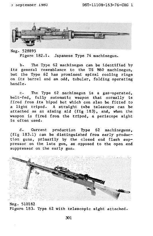
~eptember 19S0 DST—1110H—163—76—CHG 1
b. The Type 62 machinegun can be identif led byits general resemblance to the US N60 machinegun,but the Type 62 has prominent spiral cooling ringson its barrel and an odd, tubular, folding operatinghandle.
c. The Type 62 machinegun Is a gas—operated,belt—fed, fully automatic weapon that normally isfired from Its bipod but which can also be fitted toa light tripod. A straight tube telescope can beattached as an aiming aid (fig 183), and, when theweapon is fired from the tripod, a periscope sightis often used.
d. Current production Type 62 machineguns,(fig 183.1) can be distinguished from early produc-tion guns, primarily by the closed end flash sup-pressor on the late gun, as opposed to the open endsuppressor on the early gun.
Neg. 510182Figure 183. Type 62 with telescopic sight attached.
Neg. 528895Figure 182.1. Japanese Type 74 niachinegun.
30].

e. The Type 62 tuachinegun fires 7.62x51—mmNATO ammunition (sec V) and uses the US M13 linksfor the feed belt.
f. The Type 74 machinegun (fig 182.1), whilemechanically similar to the Type 62 machinegun, hasno bipod, buttstock, pistol grip trigger mechanism,front sight, or cooling fans on its barrel. TheType 74 weapon does have twin spade grips with amechanical trigger at the rear of the gun, anelectrical trigger solenoid under the rear of thereceiver, a nonfolding “T”—shaped operating handle,an armored vehicle mount adapter, and a heavy smoothbarrel. A unique method of adjusting the gasregulator is provided (para 232g).
231. Technical Data
Technical data pertaining to the Type 62 machinegunare presented in table VII.
232, Operation
a. Before loading, if the bipod legs arefolded, pull them away from the bipod head untilthey can be moved to their open position. The legscan be lengthened by pulling the feet out of thelegs or shortened by pressing the catch (fig 182)
Neg. 528896Figure 183.1. Current production Type 62.
F-
t
302

september 19t~O DST—1I1OH—163—76—CHG 1
and pushing the feet back into the legs. Open thehinged butt plate by pulling it forward against itsspring until It can be swung rearward.
b. Prior to loading the gun, insure that thebolt Is forward (pull the trigger) and that the feedcover is closed. Push the double—loop end of a beltof cartridges into the feedway from the left, untilthe holding pawl engages. Unfold the operatinghandle (fig 182), pull it fully to the rear, thenpush it forward and turn it up.
c. If the gun Is not to be immediately fired,render it safe by pulling the head of the safety(fig 182) out and then rotating it rearward.
d. To fire, adjust the sight for range byrotating the elevation and windage knobs on the rearsight to the appropriate setting, or choose theappropriate aiming mark in the telescope reticle.Pull out the safety head and rotate the safetyforward; aim (using a normal sight picture), andpress the trigger. Best results will be obtainedwith five—to—six—round bursts at a rate of 80 to100 rounds per minute. This will permit 10 minutesof firing before the barrel must be replaced with acool one. When releasing the trigger betweenbursts, do not ease it forward, but let it snapforward.
e. To unload or clear the gun, press the covercatch (fig 182) forward and swing the cover open.Lift the feed belt off the feed tray and return thebelt to its container. Unfold the operating handle,pull it to the rear, and, while holding the handle,press the trigger and ease the handle forward.Close the cover; insure that the cover catchengages.
303

DST—111OH—163—76—CHG 1 5 September 1980
f. To change a hot barrel, unload (e above);as the cover opens, the barrel nut (fig 182) isunlocked and can be rotated by engaging the rear endof the carrying handle with one of the notches inthe barrel nut. Turn the handle and nut as far aspossible to the right, and then use the handle toremove the hot barrel from the gun. Seat the coolbarrel fully into the nut, and then again use thehandle to rotate the nut to the left. If the barrelnut lock (fig 182) is not aligned with its notch inthe barrel nut, the cover cannot be closed. Closethe cover and reload (b above).
g. If the Type 62 becomes sluggish, adjust theregulator. The regulator (fig 182) has threepositions. The lowest setting can be used when thegun is broken in; new guns require the middlesetting. Rotate the regulator to the lowest settingthat will provide reliable functioning. If theweapon is a Type 74 machinegun, pull to the rear thesmall handle located to the right of the triggersolenoid. This handle is attached to a push rodwith a yoke on its front end. The yoke is engagedwith a crank on the gun’s regulator, and movement ofthe handle and push rod will cause the regulator torotate from one setting to the other. For normaluse, the handle should be forward. If the gun willnot function properly on the highest setting, itmust be disassembled and cleaned.
233. Disassembly and Assembly
a. Clear the gun (para 232e) and remove thebarrel (para 232f). Pull the operating handle rear—ward, and, while holding it, press the trigger andease the mechanism forward.
b. Press the takedown pin (fig 182) from theright. Hold the stock group while doing this; it is
304
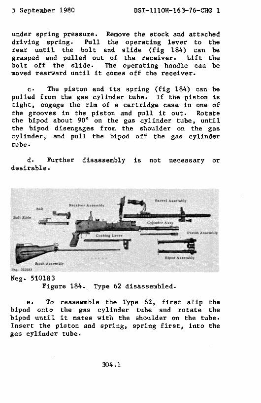
5 September 1980 DST—111OR—163—76—CHG1
under spring pressure. Remove the stock and attacheddriving spring. Pull the operating lever to therear until the bolt and slide (fig 184) can begrasped and pulled out of the receiver. Lift thebolt off the slide. The operating handle can bemoved rearward until it comes off the receiver.
c. The piston and its spring (fig 184) can bepulled from the gas cylinder tube. If the piston istight, engage the rim of a cartridge case in one ofthe grooves in the piston and pull it out. Rotatethe bipod about 900 on the gas cylinder tube, untilthe bipod disengages from the shoulder on the gascylinder, and pull the bipod off the gas cylindertube.
d. Further disassemblydesirable.
is not necessary or
e. To reassemble the Type 62, first slip thebipod onto the gas cylinder tube and rotate thebipod until it mates with the shoulder on the tube.Insert the piston and spring, spring first, into thegas cylinder tube.
Meg. 510183Figure 184., Type 62 disassembled.
304.1

DST—111OH—163—76—CHG1 5 September 1980
f. Replace the operating handle over itsguide. Place the bolt onto the slide and move thebolt forward on the slide. As the bolt moves, itsfront end should drop down. Insert the bolt andslide into the receiver. Insert the end of thedriving spring (fig 184) into the hole in the slide,press the trigger, and push the butt stock intoplace in the receiver. Push the takedown pin(fig 182) into place. Replace the barrel(para 232f) and clear the gun (para 232e).
234, Functioning
a. The Type 62 machinegun is gas operated.The functional cycle starts with the bolt and slideto the rear, the driving spring compressed, and acartridge in the feedway.
b. When the trigger is pressed, it rotates onits pin, and a forward extension of the triggercontacts the rear of the sear (fig 185). Continuedpressure on the trigger forces the sear out of
f
304.2

ST-H 6-07-163-74
Original
engagement with the slide. The slide and bolt, under the force ofthe driving spring, start forward, and the feed rib on the bolt(fig 185) drives the cartridge in the feedway out of its link andinto the chamber. The extractor engages the rim of the cartridge,and the bolt stops its forward movement when it contacts thebarrel.
c. The slide continues forward, and a cam on the front ofthe slide forces the front end of the bolt upward into the lockingshoulders of the receiver, locking the bolt. The slide continuesforward, and the fixed firing pin (fig 185) strikes the cartridgeprimer and fires the cartridge. The firing pin support of the slidestrikes the bolt, and forward movement ceases.
d. When the bullet passesthe gasport in the barrel, someof the gasesare vented off into the gas cylinder and drive thepiston (fig 185) rearward, compressingthe piston spring. Thepiston strikes the slide and drives the slide rearward; the pistonthen stops, and its spring returns it forward.
e. The slide travels to the rear, because of the momentumgiven it by the blow of the piston. After a short period of freetravel, during which the firing pin retracts into the slide, cams onthe slide contact the bolt and pull its front end down, out of thelocking shoulders. A special cam on the slide locks the extractortothe fired cartridgecaseand,oncethe slide is unlocked,it moves tothe rear with the slide. The slide compresses the driving spring.The extractor pulls the firedcartridgefrom the chamberandholdsit to the bolt until the case strikes the ejector attached to thecover (fig 185) and is expelled down, out of the gun. The slidecontinues rearward until it strikes the buffer (fig 185) and stops;the driving spring then forcesthe slide andbolt forward to startanother cycle.
305
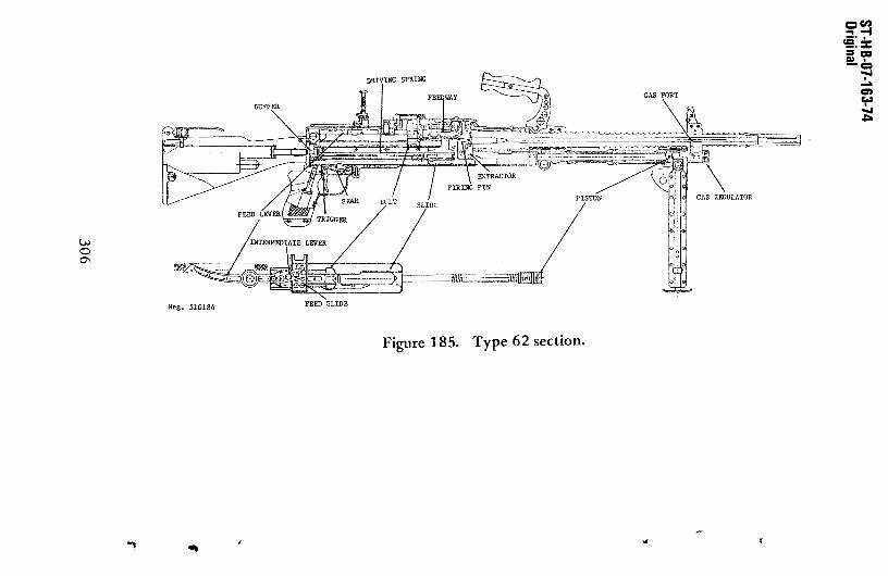
CCI)-‘—4
-a
C,
-.1
C0’
Figurei85. Type 62 section.

3 February 1984
f. If the trigger is released, the sear, underspring pressure, moves upward and catches the slide,causing the gun to stop firing. The safety, when inthe fire position, has a cutaway portion on itsshaft that provides clearance for the sear (fig 185).When the safety is turned to the safe position, thesolid section of the shaft prevents the sear frombeing depressed by the trigger. The slide thuscannot be released, and the gun is safe.
g. A set of guides on the rear end of the boltfits along the sides of the belt—feed lever (fig 185)and causes the belt—feed lever to move from side toside. The front end of the belt feed lever isattached to an Intermediate feed lever which, inturn, is attached to the feed slide (fig 185). Theback—and—forth movement of the bolt during firingthus causes the belt—feed slide to move in and outof the feed cover. As the slide moves in, a set ofspring—loaded pawls on the slide snaps over the nextcartridge to be fired and, as the feed slide movesIn, the pawls move the cartridge into the center ofthe feed tray where it can be picked up by the feedrib of the bolt. A spring—loaded holding pawl(fig 185) prevents outward movement of the feed beltwhen the feed slide moves outward.
235. AccessorIes
a. There are several major accessories used inconjunction with the Type 62 machinegun. Theseinclude a tripod mount, a sling, straight tube tele-scope, periscopic telescope, spare barrel, spareparts set, combination tool, cleaning rod, andammunition belt boxes.
b. The telescopes are attached by slidingtheir bases onto the receiver until the retainersnaps into its seat. The telescopes are removed bypulling up the retainer and sliding the telescopeoff to the rear.
307

February 1984
c. The gun is mounted on the tripod by fitting:he rails just forward of the trigger onto the reartount, then moving the gun forward on the mount until:he pin can be inserted into the hole and the lowerront of the receiver.
H. THE 5.56—MM MINIMI LIGHT MACHINEGUN(BELGIUM)
35.1. General
a. The 5.56—mm Minlmi (fig 185.1) is a newultIpurpose machinegun produced by Fabrlquerationale Herstal SA of Belgium. It is considered aomplete weapon system because of Its weight, size,ase of handling, and combat effectiveness (asvidenced by its high rate of fire and high hitrobability). A derivative of the Minimi, the M249,as been type—classified for production by the US.rmy and Marine Corps.
eg. 527345FIgure 185.1. BelgIan M1nImI Light Machinegun
b. The weapon operates with an open breech—lock, a rotating bolt, two—position gas adjustment,ad quick—change barrel capability. As a support
308

J.flJJ. S SS~J&sS.J., S —
3 February 1984
weapon, the Ninimi can sustain a high rate of firebecause it can be belt—fed. However, for thosecountries that prefer to use the Minimi as anindividual weapon, a clip or magazine can be used.
c. The usual accessories for this weaponinclude: A blank—firing device on a flash—hider, asling for carrying the weapon or firing it from thehip, a cleaning kit provided with the weapon, asleeve for a grenade launcher, a tripod that can beused to increase firing accuracy or in defensiveoperations, 200—round ammunition boxes, and M16A1magazines.
235.2. Technical Data
Technical data for the Mmiii are provided in
table VII, page 309.235.3. Operation
No details are yet available. Data will be providedin the next update of this publication and/orthrough other publications.
I. MAINTENANCE
236. Care and Cleaning
The procedures and materials prescribed for cleaningstandard US Army gas—operatedmachineguns also applyto foreign machineguns. These weapons should bedisassembled only to the extent necessary foradequate cleaning to prevent breakage and subsequentloss of use. No repairs on foreign machinegunsshould be attempted other than the replacement ofparts, and this should be done only by a competentarmorer.
237. Malfunctions and Stoppages
See table VIII for common malfunctions and theirremedies.
309

Table VII. Machinegun Technical Data
Weapon MAG L7A11
Bren L4 AAT’52 1(24/29HR 13
HR 21 MC 1 Type 62
Minimi
FN carbine
Caliber (mm) 7.62x51 l.63x51 7.5x542
l.3
x54
5.56x452
7.62x51 7.62x51 5.56x4
5
Length (mm) 1255 1090 1133~ 1082 1016 1125 1200 1012
Weight, empty (kg) 10.98 9.2 L54
9.2 6.9567.9
11.0 10.7 8.36
Barrel length (mm) 568 544 492k 500 450 530 600 465
Barrel changeable Yes Yes Yes Yes5
Yes Yes Yes Yes
Feed device Metallic
belt
30—rd boxmagazine
Metallicbelt
26—rd boxmagazine
40—rd box6
metallicbelt
Metallicbelt
Metallicbelt
100—rd boxmetallicbelt
Operation Gas Gas Delayed
blowback
Gas Delayed
blowback
Recoil Gas Gas
Locking feature Swing
flap
Tilting
bolt
None Tilting
bolt
Rollers Rollers Tilting
bolt
Rotating
bolt
Fire—type Selective Selective Automatic Selective Selective Automatic Automatic Automatic
Muzzle velocity (mIs) 820 815 850 850 970~ 820 8558770~
930
Practical range (m) 1000 800 800 550 600 1000 1000 600
Rate of fire,
practical (rd/mm) 150—200 90—120 150 125 150 250 80—100 1
Rate of fire,
cyclic (rd/mm)
650—1000 500 700 500 850 700—1300 650~
6O0~
750-1000
Mount type Bipod ortripod
Bipod ortripod
Bipod ortripod
Bipod Bipod Bipod ortripod
Bipod ortripod
Bipod ortripod
1Data for M.A.G.
4W/light barrel
75.56x45
~A1so made in 7.62x~l—ma5
Not quick change8
NATO round3stock extended, 9
72—mmfolded
6HK 13 only
9Violet tip round
0

3 February 1984
Table VIII. Machinegun Malfunctions
Condition Cause Remedy
Fails to fire (cartridge Defective cartridge Retract bolt and firein chamber)
Weak driving spring Replace spring
Fouled weapon Clean and lubricate
Fails to fire (no Defective magazine Replace magazinecartridge in chamber)
Short recoil Adjust gas regulatorto next largestsetting
Short recoil Clean and lubricate
Ruptured cartridge Excessive headspace, Adjust(repeatedly) loose barrel, worn
bolt
Fails to extract Dirty chamber Clean
Broken extractor Replace extractor
Fails to eject Fouled weapon Clean and lubricate
Short recoil Adjust gas regulator
Runaway gun Short recoil Adjust gas regulator,lubricate
311(Reverse Blank)


3 February 1984
SECTION V. AMMUNITION
238. General
The ammunition used with free world weapons can beidentified by comparing a cartridge with the outlinedrawing contained in ammunition identification guide(fig 186). Place the cartridge on top the drawingand examine the fit between the drawing and car-tridge. If a small uniform line of white showsbetween the case and the drawing, and if each lineon the cartridge case is substantially parallel withits corresponding line on the drawing, the cartridgecan reasonably be expected to be that identifiedwith the drawing and will fit the weapons listed.The ammunition for these older weapons can and doesvary widely in quality, and samples should be test—fired to assure functioning. Gas regulators shouldbe set to the smallest setting that will permitrelIable functioning. Ammunition that is badlycorroded, dented, or split in any portion of thecase should not be used. Special—purpose bulletsare marked various color codes. These bulletsshould be tested to ascertain their exact type.
239. References
For a more detailed discussion of small armsammunItion see the Small Caliber Ammunition Guide,DST—11600—514—81—VOL 1, 2. Foreign small arms ammu-nition should be handled and preserved In the manneras prescribed for US small arms ammunitIon inTM 9—1305—200 (Small Arms Ammunition).
313

February 1984
Li El9 a 19.
11.43 * 23.
7.62 a SI. 7.5 * 54.
7.5 * 55.5.
~ ~ 56R.
7.92 5
7.62 s 63.
Meg. 510185Figure 186. Ammunition Identification Guide
314

i re~ruary 1984
PAPER COPY
DISTRIBUTION BY DIA/RTS—2C DISTRIBUTION DIRECT TO RECIPIENT(397 Copies) (2948 Copies)
A086 NAT DEF UNIV (SCDC) A305 JSOC
AilS OASD ISA A306 SFOD—DAl17 OASD PA&E C003 DUSA(OR)A125 OUSDRE COôl NP SCHA34l .TCS/J—5 H/UN NEC CO65 USAITIC—PAC8040 DIA/DI0 C202 III CORPS8060 OIA/RTS—2A.5 PENT C204 TCATA8110 DIA/JS—CAJIT (A&T) C231 21(I) ARM DIV8111 DIA/JS—CAJIT (061) C234 1ST CASI DIVBl36 DIA/DE—3 C235 1ST INF DIV8150 DIA/DT C238 364TH MI CO (TI) (4)Bl55 DIA/RTS—2A4 PP C239 11TH MI SN (PROV) (6)Bl69 DIA/DT-2D (2) C24l FIRST US MU4Y8312 DIA/JSO—2 C300 172ND IMP BDE (AX)8313 DIA/JSO—2A C3OS 18TH ARM CORPSB239 DIA/JSO—l C306 82ND ARM DIVB352 DIA/RTS—2A2C STOCK (200) C307 24TH IRE DIV8361 OIA/DB—lBlA C309 SOOTH MICB363 DIA/D8—1B1B C314 513TH MIC8364 DIA/O8—lBlC C348 4530 MID8501 DIA/OS—l C35l 10TH SFG(ABN)1STSF (20)B57l DIA/DB—4Gl C4O5 MTMC8607 DIA/DB—2B1 C414 4TH IMP DIVB626 DIA/DB—3C1 C415 5TH IMP DIV (M) (5)8628 DIA/O8—3Dl C417 7TH IMP DIV (2)8631 DIA/OB—3El C419 9TH IMP DIVB663 DIA/DB—382 C429 1ST BM(R) 75TH IMP (5)8737 DIA/RTS—2B (LIB) (2) C459 COND—GENSTF CDL8798 DIA/DB—2D1 C461 INFANTRY SCHB854 USDAO AUSTRALIA C465 US NIL ACADEMYB855 USDAO AUSTRIA C470 ARMYWAR CDLB873 USDAO DOMINIC REP C500 TRADOC (2)8879 USDAO FRANCE C507 USAITAC (GIPD) (2)8894 USDAO IVORY COAST C587 CMBT 0EV EXPR CORD8900 USOAO LEBANON C59O USATAC8903 USDAO MALAWI C605 JFK CTR NIL ASSISTB9l6 USDAO PHILIPPINES C6l7 CONCEPT ANLYS ACCY8918 USDAOPORTUGAL C62O USAITAC (CR0)B926 USDAO SUDAN C639 CMBT&TNG0EV DIR (2)B928 USDAO SWITZERLAND C667 USAIMADOO8 NISC C683 INTEL CTR&SCH (4)0150 CMC (11(T) (16) C684 USAISD0247 MAVSURPWPNCEN WOAX C715 ARMORCTR (5)0947 NIC—522 C763 RQDADAMI—FITE749 HQ USAF/INYR C766 HQDADAMI—FICP002 NPIC/REG (5) C768 USAITAC (LIB) (2)P055 CIA/OCR/DSD/SD (18) C786 HQDA DANI—FIWP085 STATE (106) C788 HQDAOAZ4I—FISP090 NSA (5) C801 SIXTH US ARMYP175 US CUSTOMSSERVICE 0039 FOURTHMAW/HARTCSO3O FRO LIB OF CONG DiOl MCLB ALBANY (2200)
DISTRIBUTION CODE L91
315

3 February 1984
DISTRIBUTION DIRECT TO RECIPIENT Continued)
D152 MISC CBD DET 0003 FSTC0224 MAG—49D246 NAVSURFWPNCENDAHL DRXST—IS3 (500)D263 NOSC DRXST—MTD492 NAVSCOLEOD DRXST—CA (50)D583 FIRSTPAC 0919 (2) DRXST—FS (3)E411 ASD/FTD/NIIS DRXST—ST2 (5)5420 FTD/NIIS (2) DRXST—IS15438 3480 TCHTC/TTVL DRXST—1S2 (2)E451 AUL/LSE5500 3420 TCHTC/TTMNL
P059 1 SOS/INH010 SOTFE (J—2)HUll USAFE 497RTC (IRC)1)300 00CS IN(USAREUR)H315 21ST SUPPORTCOMD (2)1)321 18TH MI SNH350 SFDET (ARM) EUR1)524 HQV CORPS1)527 HQ 8TH IMP DIV1(528 1ST IMP DIV (FWD)H529 HQ 3RD ARMORED DIVH530 HQ 1ST ARMOREDDIV (2)H531 RQ 56TH FA BDE3435 COMNAVSPECWARGRU2J436 COMNAVSPECWARU23515 FICEURLANT3522 COMNAVBASEGTMO (2)
3586 UDT 21KOOS CINCPACROb USFKK100 PACAF 548 RTGRibS 5TH AFKl20 326 AD/INK300 IPAC (LIBRARY)K305 25TH INF DIVK3l4 IPAC (CODE PT)K34O CBDFLDARMY(ROK/US) (2)1(342 2ND IMP DIV (8)LO4O SAC 544 SIW/DAA
1(005 USCINCSO1(301 193RD INF BDE (PM)MOOS USREDCOM
DARCON
C5l2 HQTRS DARCOM DRCDE—PIOC513 ARRADCOM DRDAR—SEI (5)C517 Benet Weapons Lab DRDAR—SEI—W(2)C5O9 Ballistic Res Lab DRDAR—SEI—B (2)C515 Chemical Sys Lab ORDAR-SEI—CC545 ARRCOM DRSAR—ASB(10)C697 Test & Eval Cmd. DRSTE—T0—F (2)C538 White Sands Msl
Range STEWS—TE—FC522 YUMA PG STEYP—FIO—CDC505 ANMRC DRXMR—XFI (2)C619 MIA REDSTONE DRSMI—YDL (6)
TOTAL DISTRIBUTIOM: 3345 Paper Copies
316

DST—IbbOH—163—76—CRG 23 February 1984
DISTRIBUTION BY DIA/RTS—2C (37 Copies) MICROFICHE
B329 DIA/JSO—l 8922 USDAOSENEGAL8331 DIA/RTS—2A2 8924 USDAOSOUTH AFRICA8352 DIA/RTS—2A2C STOCK (10) 8931 USDAO THAILAND
8738 DIA/RTS—2A1A AHS—A B932 USDAO TUNISIA8853 USDAO ARGENTINA 8937 USDAOVENEZUELAB858 ITSDAO BRAZIL 8938 USDAOYEMEN8866 USDAO COLOMBIA 3939 USDAOYUGOSLAVIA8868 USUAO ZAIRE B942 USDAO SINGAPORE3870 USDAOCYPRUS 8944 USDAOBANGLADESR8875 USDAO EL SALVADOR 8948 USDAOEGYPT8878 USDAO FINLAND 0900 NAVOPINTCEN3883 USDAO GUATEMALA P002 NPIC/REG3885 USDAO HONDURASB888 USDAO INDONESIA8892 USDAO ISRAEL8914 USDAOPARAGUAY
DISTRIBUTION DIRECT TO RECIPIENT (13 Copies)
C242 FORSCOM C667 USAIMAC500 TRADOC C768 USAITAC (LIB)C591 FSTC (ST1) (5) C772 HQDA DAMI—FIOC644 LOG CTR 1)522 649TH ENGR RE (T) (2)
TOTAL DISTRIBUTION: 50 Microfiche Copies
317

DST—l1b0}l—163—76—CNC 23 February 1984
This Page Intentionally Left Blank
*~J~S. COVESSNENT PRINTING OFFICE: I 994——F17—430/11309
318