DRY ZONE URBAN WATER AND SANITATION PROJECT
653
Initial Environmental Examination Report This report has been submitted to ADB by the Ministry of Water Supply and Drainage and is made publicly available in accordance with ADB’s public communications policy (2005). It does not necessarily reflect the views of ADB. Project Number: 37381-013 September 2012 Sri Lanka: DRY ZONE URBAN WATER AND SANITATION PROJECT - for Chilaw Septage Treatment Plant Prepared by Project Management Unit for Dry Zone Urban Water and Sanitation Project, Colombo, Sri Lanka. For Water Supply and Drainage Board Ministry of Water Supply and Drainage, Sri Lanka.
-
Upload
khangminh22 -
Category
Documents
-
view
1 -
download
0
Transcript of DRY ZONE URBAN WATER AND SANITATION PROJECT

Initial Environmental Examination Report
This report has been submitted to ADB by the Ministry of Water Supply and Drainage and is made publicly available in accordance with ADB’s public communications policy (2005). It does not necessarily reflect the views of ADB.
Project Number: 37381-013 September 2012
Sri Lanka: DRY ZONE URBAN WATER AND SANITATION PROJECT - for Chilaw Septage Treatment Plant
Prepared by Project Management Unit for
Dry Zone Urban Water and Sanitation Project,
Colombo, Sri Lanka.
For Water Supply and Drainage Board Ministry of Water Supply and Drainage, Sri Lanka.
i
Project Implementation Agency: National Water Supply and Drainage Board
Funding Agency: Asian Development Bank
Project Number: 4853-SRI
Sri Lanka: Dry Zone Urban Water and Sanitation
Project (DZUWSP)
INITIAL ENVIRONMENTAL EXAMINATION: SEPTAGE TREATMENT PLANT FOR CHILAW (DRAFT)
MAIN TEXT
DECEMBER, 2011
ii
TABLE OF CONTENTS
TABLE OF CONTENTS ............................................................................................................. ii
ABBREVIATIONS ..................................................................................................................... vi
EXECUTIVE SUMMARY ............................................................................................................ 1
1.0 INTRODUCTION .............................................................................................................. 3
1.1 Project Name ............................................................................................................... 3 1.2 Details of the Project Developer ................................................................................... 3 1.3 Key Information on the Project ..................................................................................... 4 1.4 Ownership of the Project Site ....................................................................................... 4 1.5 Project and Study Background ..................................................................................... 4 1.6 Purpose of the Initial Environmental Examination (IEE) ............................................... 5 1.7 Extent and the Scope of the IEE Study ........................................................................ 5
1.7.1 Government policy / status regarding the project .................................................. 5 1.7.2 Applicable laws, regulations, standards and requirements .................................... 6 1.7.3 Approvals needed for the proposed development ................................................. 6 1.7.4 Conditions laid down by the Government Agencies .............................................. 6 1.7.5 Checklist on Sensitive Areas ................................................................................. 7
2.0 DESCRIPTION OF THE PROJECT AND ALTERNATIVES CONSIDERED .................... 8
2.1 Aim and Scope of the Proposed Project ....................................................................... 8 2.1.1 Category of Project: .............................................................................................. 8 2.1.2 Type of project ...................................................................................................... 8 2.1.3 Project main objectives ......................................................................................... 8 2.1.4 Main beneficiaries ................................................................................................. 8 2.1.5 Socio-economic effects ......................................................................................... 8 2.1.6 Description of the project ...................................................................................... 8 2.1.7 Project components .............................................................................................. 9 2.1.8 Project Layout ....................................................................................................... 9 2.1.9 Operation and Maintenance .................................................................................. 9 2.1.10 Size or magnitude of operation ............................................................................. 9
2.2 Justification of the Project ...........................................................................................11 2.3 Location ......................................................................................................................12
2.3.1 Location of Treatment Plant Site ..........................................................................12 2.3.2 Service Area ........................................................................................................14
2.4 Process Description and Design Details .....................................................................16 2.4.1 Brief description of the treatment process ............................................................16
2.5 Pre-construction and Construction Activities ...............................................................17 2.5.1 Pre-construction work ..........................................................................................17 2.5.2 Construction work ................................................................................................17 2.5.3 Construction cost .................................................................................................17 2.5.4 Construction labor requirement (both skilled and non skilled) ..............................18 2.5.5 Construction materials .........................................................................................18
2.6 Schedule of Implementation ........................................................................................18 2.7 Operation and Maintenance ........................................................................................18
2.7.1 Operational and Maintenance cost .......................................................................18 2.7.2 Institutional arrangement for operation .................................................................19 2.7.3 Capacity to meet the O&M expenditure................................................................19 2.7.4 Septage collection and delivery ...........................................................................19 2.7.5 Operation and Maintenance of treatment plant ....................................................19 2.7.6 Skills requirements...............................................................................................20
2.8 Evaluation of Alternatives............................................................................................20 2.8.1 Alternative Technologies ......................................................................................20
iii
2.8.1.1 Technology of Choice ..........................................................................................21 2.8.2 Alternative Designs ..............................................................................................21 2.8.2.1 Design of Choice .................................................................................................23 2.8.3 Alternative Sites ...................................................................................................23 2.8.3.1 Site of Choice ......................................................................................................28 2.8.4 No Action Alternative ...........................................................................................28
3.0 DESCRIPTION OF ENVIRONMENT .............................................................................. 30
3.1 Physical Environment .................................................................................................30 3.1.1 Study Area ...........................................................................................................30 3.1.2 Topography .........................................................................................................32 3.1.3 Soils and Geology ................................................................................................32 3.1.4 Climate ................................................................................................................33 3.1.5 Drainage ..............................................................................................................35 3.1.6 Surface Water ......................................................................................................38 3.1.7 Groundwater ........................................................................................................41 3.1.8 Land-use ..............................................................................................................42 3.1.9 Air and Noise Environment ..................................................................................44 3.1.10 Natural Disasters and Risks .................................................................................44
3.2 Ecological Environment ..............................................................................................45 3.2.1 Description of the existing ecosystem dynamics ..................................................45 3.2.2 Key Ecological Characteristics .............................................................................45
3.3 Socio-economic Environment .....................................................................................48 3.3.1 Social Environment ..............................................................................................48 3.3.2 Economic Environment ........................................................................................54 3.3.3 Institutional Environment ......................................................................................55 3.3.3.1 Capacity of the O&M Institution ............................................................................55 3.3.3.2 Issues associated with Project being located outside of the service area .............55 3.3.4 Social and Institutional Threats ............................................................................55
4.0 DESCRIPTION OF ANTICIPATED ENVIRONMENTAL IMPACTS ................................ 57
4.1 Construction Phase .....................................................................................................57 4.1.1 Impacts of land clearing and development ...........................................................57 4.1.2 Noise, vibration and dust due to construction activities ........................................57 4.1.3 Transportation of heavy vehicles with filling / spoil materials ................................58 4.1.4 Air quality impacts from traffic during transportations of material and equipment .58 4.1.5 Impact on natural drainage pattern due to construction activities .........................58
4.2 Operational Impacts ....................................................................................................58 4.2.1 Impacts on water resources .................................................................................58 4.2.2 Impacts due to release of obnoxious gases .........................................................59 4.2.3 Impact due to Movement of Gully Trucks .............................................................59
4.3 Impacts on Ecological Resources (Construction and Operational) ..............................60 4.3.1 Destruction or alternation of habitats ....................................................................60 4.3.2 Affects on the prevailing ecosystem balance .......................................................60 4.3.3 Impacts on terrestrial and aquatic flora and fauna ................................................60 4.3.4 Impacts on receiving water-body..........................................................................60
4.4 Impacts on Socio-economic Environment (Construction and Operational) ..................61 4.4.1 Social economic benefits (Health etc) ..................................................................61 4.4.2 Impact due to land-use change ............................................................................61 4.4.3 Impact on land values ..........................................................................................61 4.4.4 Impact on quality of life ........................................................................................61 4.4.5 Employment opportunities....................................................................................62 4.4.6 Resettlement requirements (if any) ......................................................................62 4.4.7 Social impacts due to transportation of septage ...................................................62
4.5 Any other Impacts .......................................................................................................62
iv
5.0 PROPPOSED MITIGATORY MEASURES .................................................................... 63
5.1 Mitigatory Measures proposed for Constructional Impacts ..........................................63 5.1.1 Mtigation of Impacts due to land clearing and development .................................63 5.1.2 Establishing a green belt ......................................................................................63 5.1.3 Mitigatory Measures for Noise and Vibration Impacts ..........................................63 5.1.4 Mitigatory Measures for Impact on Air Quality ......................................................64 5.1.5 Mitigatory Measures for Impacts due to Burrow Pits ............................................65 5.1.6 Mitigatory Measures for Impacts due to Waste Disposal ......................................65 5.1.7 Mitigatory Measures for impact on natural drainage pattern due to construction activities ...........................................................................................................................66
5.2 Mitigatory Measures for Operational Impacts ..............................................................66 5.2.1 Mitigatory Measures for impacts on water resources ...........................................66 5.2.2 Mitigatory Measures for impacts due to release of obnoxious gases ....................66 5.2.3 Mitigatory Measures for impact due to Movement of Gully Trucks .......................67 5.2.4 Sludge disposal ...................................................................................................67
6.0 ENVIRONMENTAL MONITORING PROGRAM ............................................................. 68
6.1 Introduction .................................................................................................................68 6.2 Compliance Monitoring ...............................................................................................68 6.3 Effects Monitoring .......................................................................................................68 6.4 Environmental Monitoring Committee (EMC) ..............................................................69
7.0 PUBLIC CONSULTATION AND INFORMATION DISCLOSURE .................................. 74
7.1 Methodology adopted .................................................................................................74 7.2 Consultation and disclosure events .............................................................................74 7.3 Awareness ..................................................................................................................75
8.0 FINDINGS AND RECOMMENDATIONS ........................................................................ 77
8.1 Suitability of the Site ...................................................................................................77 8.2 Regulatory Environment..............................................................................................77 8.3 Impact on Physical Environment .................................................................................77 8.4 Impact on Social Environment ....................................................................................77 8.5 Impact on Biological Environment ...............................................................................77 8.6 Operation of the Plant .................................................................................................77 8.7 Overall Findings and Recommendations .....................................................................78
9.0 CONCLUSIONS ............................................................................................................. 79
v
APPENDICES
Appendix 1: References
Appendix 2: Survey Plan of the Land
Appendix 3: Approval / Consent Letters
Appendix 4: Septage Treatment Plant Design Details
Appendix 5: Photographs of Alternative Site
Appendix 6: Water Quality Analysis Reports
Appendix 7: Plant Species Observed in the Direct Impact Zone of the Project Site
Appendix 8: Animal Species Recorded within the Various Habitat Types Observed in the
Direct Impact Zone of the Project Site
Appendix 9: List of Meetings / Discussions Conducted During IEE Study and Attendance
Lists
Appendix 10: Meeting Minutes of Public Consultation Meeting
Appendix 11: List of Environmental Study Team Including their Work Allocation
Appendix 12: Terms of Reference
vi
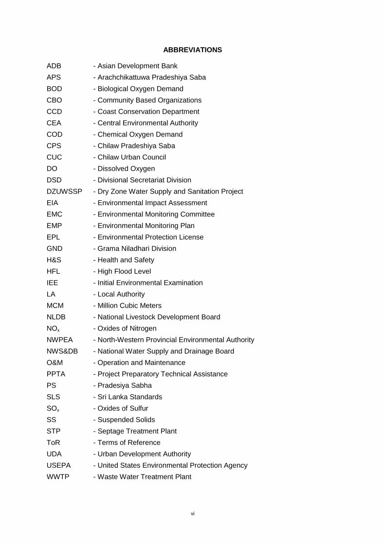
ABBREVIATIONS
ADB - Asian Development Bank
APS - Arachchikattuwa Pradeshiya Saba
BOD - Biological Oxygen Demand
CBO - Community Based Organizations
CCD - Coast Conservation Department
CEA - Central Environmental Authority
COD - Chemical Oxygen Demand
CPS - Chilaw Pradeshiya Saba
CUC - Chilaw Urban Council
DO - Dissolved Oxygen
DSD - Divisional Secretariat Division
DZUWSSP - Dry Zone Water Supply and Sanitation Project
EIA - Environmental Impact Assessment
EMC - Environmental Monitoring Committee
EMP - Environmental Monitoring Plan
EPL - Environmental Protection License
GND - Grama Niladhari Division
H&S - Health and Safety
HFL - High Flood Level
IEE - Initial Environmental Examination
LA - Local Authority
MCM - Million Cubic Meters
NLDB - National Livestock Development Board
NOx - Oxides of Nitrogen
NWPEA - North-Western Provincial Environmental Authority
NWS&DB - National Water Supply and Drainage Board
O&M - Operation and Maintenance
PPTA - Project Preparatory Technical Assistance
PS - Pradesiya Sabha
SLS - Sri Lanka Standards
SOx - Oxides of Sulfur
SS - Suspended Solids
STP - Septage Treatment Plant
ToR - Terms of Reference
UDA - Urban Development Authority
USEPA - United States Environmental Protection Agency
WWTP - Waste Water Treatment Plant
1
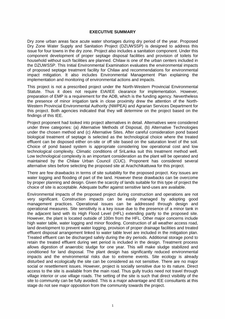
EXECUTIVE SUMMARY
Dry zone urban areas face acute water shortages during dry period of the year. Proposed Dry Zone Water Supply and Sanitation Project (DZUWSSP) is designed to address this issue for four towns in the dry zone. Project also includes a sanitation component. Under this component development of proper septage disposal facilities and provision of toilets for household without such facilities are planned. Chilaw is one of the urban centers included in the DZUWSSP. This Initial Environmental Examination evaluates the environmental impacts of proposed septage treatment facility for Chilaw and recommendations for environmental impact mitigation. It also includes Environmental Management Plan explaining the implementation and monitoring of environmental actions and impacts.
This project is not a prescribed project under the North-Western Provincial Environmental Statute. Thus it does not require EIA/IEE clearance for implementation. However, preparation of EMP is a requirement for the ADB, which is the funding agency. Nevertheless the presence of minor irrigation tank in close proximity drew the attention of the North-Western Provincial Environmental Authority (NWPEA) and Agrarian Services Department for this project. Both agencies indicated that they will determine on the project based on the findings of this IEE.
Project proponent had looked into project alternatives in detail. Alternatives were considered under three categories: (a) Alternative Methods of Disposal, (b) Alternative Technologies under the chosen method and (c) Alternative Sites. After careful consideration pond based biological treatment of septage is selected as the technological choice where the treated effluent can be disposed either on-site or off site based on the saturation level of the soil. Choice of pond based system is appropriate considering low operational cost and low technological complexity. Climatic conditions of SriLanka suit this treatment method well. Low technological complexity is an important consideration as the plant will be operated and maintained by the Chilaw Urban Council (CUC). Proponent has considered several alternative sites before selecting the proposed site at Arachchikattuwa for this project.
There are few drawbacks in terms of site suitability for the proposed project. Key issues are water logging and flooding of part of the land. However these drawbacks can be overcome by proper planning and design. Given the scarcity of lands suitable for this type of project the choice of site is acceptable. Adequate buffer against sensitive land-uses are available.
Environmental impacts of the proposed project during construction and operations are not very significant. Construction impacts can be easily managed by adopting good management practices. Operational issues can be addressed through design and operational measures. Site sensitivity is a key issue due to the presence of a minor tank in the adjacent land with its High Flood Level (HFL) extending partly to the proposed site. However, the plant is located outside of 100m from the HFL. Other major concerns include high water table, water logging and minor flooding. Construction of all weather access road, land development to prevent water logging, provision of proper drainage facilities and treated effluent disposal arrangement linked to water table level are included in the mitigation plan. Treated effluent can be discharged safely during the dry periods. Additional storage pond to retain the treated effluent during wet period is included in the design. Treatment process allows digestion of anaerobic sludge for one year. This will make sludge stabilized and conditioned for land disposal. The plant design has significantly reduced environmental impacts and the environmental risks due to extreme events. Site ecology is already disturbed and ecologically the site can be considered as not sensitive. There are no major social or resettlement issues. However, project is socially sensitive due to its nature. Direct access to the site is available from the main road. Thus gully trucks need not travel through village interior or use village roads. The setting of the site is such that direct visibility of the site to community can be fully avoided. This is a major advantage and IEE consultants at this stage do not see major opposition from the community towards the project.

2
IEE Consultants recommends implementation of this project subjected to the implementation of proposed mitigation measures and approval by relevant authorities. IEE Consultants also recommend project benefits to be made available to the community living in the project site area through provision of household sanitation support targeting the needy families. Environmental Management Plan (EMP) and monitoring plan is included in the IEE Report to ensure the compliance with IEE recommendations and for effective monitoring.
3
1.0 INTRODUCTION
1.1 Project Name
Construction of Septage Treatment Plant (STP) for Chilaw under the Dry Zone Urban Water and Sanitation Project (DZUWSSP)
1.2 Details of the Project Developer
Name of the Developer: National Water Supply and Drainage Board (NWS&DB)
Contact Name: Mr. Mohan Lechuman (Project Manager – Chilaw)
Project Office
Address: ADB 5th Project Office
National Water Supply and Drainage Board
No 68, Ebert Lane, Kaldemulla
Moratuwa
Telephone: 011-2635727
077-2240570 (Mobile / Project Manager)
Fax: 011-2605756
E-mail: [email protected]
Site Office
Address: ADB 5th Project Manager’s Office
National Water Supply and Drainage Board
1st Floor, No. 1, Jetty Street
Chilaw
Telephone: 032-3297556
Fax: 032-2224890
E-mail: [email protected]
4
1.3 Key Information on the Project
Type of Project: Sanitation
Nature of Project: Septage Treatment
Project Proponent: NWS&DB
Project Developer: NWS&DB
Design by: Design Consultants appointed by the NWS&DB
Construction by: Construction Contractor to be appointed by the NWS&DB
Operation and Maintenance: Chilaw Urban Council (CUC)
Service Area: Chilaw Urban Council Area
Treatment Plant Site Location Manaweriya, Arachchikattuwa
Site Extent: 4 Acres
Estimated Cost: LKR 129.7 Million
Source of Funding: Asian Development Bank
Date of Start: Refer Figure 2.5
Expected Date of Completion: Refer Figure 2.5
Duration of Construction: 42 months
1.4 Ownership of the Project Site
The selected site for the STP is located in Manaweriya Division. The land owned by the National Livestock Development Board (NLDB) was already purchased by the NWS&DB for the implementation of the Project through the standard land acquisition procedure. Once the Project is completed, ownership will remain with the NWS&DB.
Survey Plans of the land and the relevant letter obtained from the NLDB are attached in Appendix 2 and 3 respectively.
1.5 Project and Study Background
The Dry Zone Urban Water and Sanitation Project (DZUWSP) intend to facilitate sustainable development in disadvantaged districts in Sri Lanka. This will be achieved by investing in priority water supply and sewerage/sanitation infrastructure in selected urban areas, and assisting the NWS&DB to institutionalize the development of sustainable community-based infrastructure. Assistance will be targeted in those parts of the Northern and North-Western Provinces with the most acute shortages of drinking water and sanitation services. Chosen urban areas are the towns of Mannar, Vavuniya, Puttalam and Chilaw.
In the initial stages of the project formulation, a conventional sewerage system was considered for the Chilaw area. However due to reasons of cost, this proposal was not considered further. Instead, a septage treatment system was considered to address the critical need of a proper disposal system waste collected in on-site systems. The ADB PPTA consultants carried out the initial feasibility study for construction of STP for Chilaw. Accordingly, a tentative design for septage treatment was proposed. Land was identified after considering several alternative sites. Key design parameters were also determined. This project proposal was included in the PTTA main report and parallel to which, an Initial Environmental Examination report was prepared covering both sub projects namely water supply and septage components for each project town. This IEE was conducted in

5
accordance with ADB’s Environment Policy and ADB’s Environmental Guidelines, and in line with the Terms of Reference issued to the Consultant by the Client (Appendix 12).
1.6 Purpose of the Initial Environmental Examination (IEE)
The main purpose of the Initial Environmental Examination Report (IEER) is to explain the environmental and social impacts of the project and the proposed mitigation measures together with a monitoring plan to the Asian Development Bank and the other concerned government and provincial agencies. The project area is coming under the North-Western Provincial Council and the applicable environmental regulation is that of the said provincial council. However, the proposed project does not require a mandatory environmental assessment under the said regulations (See Section 1.7 below). Nevertheless the provincial authorities have visited the site and informed the project proponent that they will make a determination on the matter after reviewing this IEE study report. Therefore this report is also intended to explain the environmental and social impacts of the project to Provincial (North-Western) authorities for them to make a decision. Their approval for the site (site clearance) is required for the construction work.
The IEER will also be the primary tool for providing the project information together with its impacts and mitigation measures to the public
1.7 Extent and the Scope of the IEE Study
The IEE study covered the area that could be affected directly or indirectly by construction or operation of the proposed septage treatment systems. For physical and biological environments this comprised the immediate surroundings of the proposed project facilities and their environs, as defined as Project Study Area (Chapter 3.1.1). Socio-economic conditions were investigated over a somewhat wider area such as GNDs and DSDs as these are the units within which government data are normally collected and presented. Impacts associated with road haulage and discharge of effluent and sludge were also considered.
Potential positive and negative impacts during the construction and operational phases of the project were studied, taking into consideration the direct and indirect as well as long- and short- term effects. Possible magnitudes of the impacts were judged, and for negative impacts that were considered likely to be significant, appropriate mitigation measures were identified. In relation to the socio-economic impacts, most of the main stakeholders were identified and consulted through meetings, and discussions. The impacts were categorized according to the phase of the project and the implementation of the mitigation measures was set out in detail in an Environmental Monitoring Plan (EMP).
1.7.1 Government policy / status regarding the project
Entire STP site and the service area are coming under the jurisdiction of North-Western Province. In the North-Western Province, the NEA is inoperative and the EIA system is established under the North-Western Provincial Environmental Statute No 12 of 1990 and Provincial EIA Regulations published in Gazette Notification, No. 1020/21 dated March 27, 1998. The requirement for EIA and the level of study required for a proposed development project are determined by the North-Western Provincial Environmental Authority (NWPEA) which is the competent authority established under the North-Western Provincial Environmental Statute. The EIA regulations specify the projects and undertakings for which environmental assessment is mandatory (Prescribed Projects) based on the magnitude of such projects and also weather such project is located within an environmental sensitive area.
6
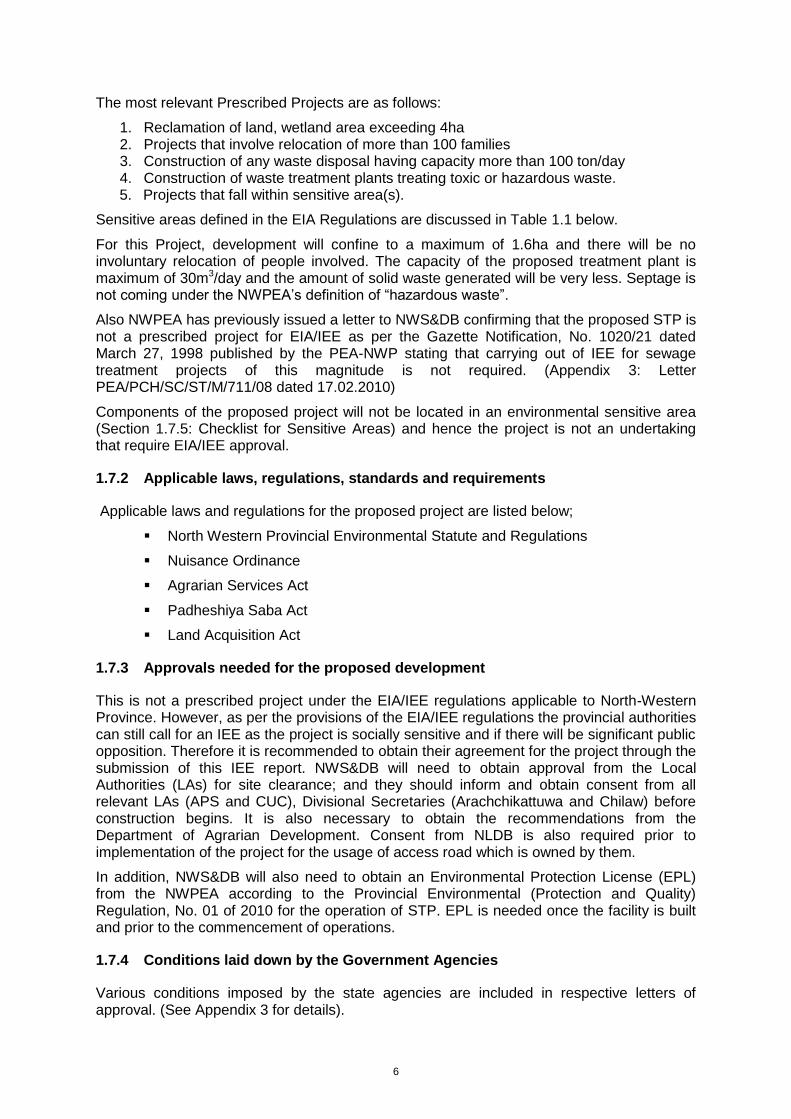
The most relevant Prescribed Projects are as follows:
1. Reclamation of land, wetland area exceeding 4ha 2. Projects that involve relocation of more than 100 families 3. Construction of any waste disposal having capacity more than 100 ton/day 4. Construction of waste treatment plants treating toxic or hazardous waste. 5. Projects that fall within sensitive area(s).
Sensitive areas defined in the EIA Regulations are discussed in Table 1.1 below.
For this Project, development will confine to a maximum of 1.6ha and there will be no involuntary relocation of people involved. The capacity of the proposed treatment plant is maximum of 30m3/day and the amount of solid waste generated will be very less. Septage is not coming under the NWPEA’s definition of “hazardous waste”.
Also NWPEA has previously issued a letter to NWS&DB confirming that the proposed STP is not a prescribed project for EIA/IEE as per the Gazette Notification, No. 1020/21 dated March 27, 1998 published by the PEA-NWP stating that carrying out of IEE for sewage treatment projects of this magnitude is not required. (Appendix 3: Letter PEA/PCH/SC/ST/M/711/08 dated 17.02.2010)
Components of the proposed project will not be located in an environmental sensitive area (Section 1.7.5: Checklist for Sensitive Areas) and hence the project is not an undertaking that require EIA/IEE approval.
1.7.2 Applicable laws, regulations, standards and requirements
Applicable laws and regulations for the proposed project are listed below;
North Western Provincial Environmental Statute and Regulations
Nuisance Ordinance
Agrarian Services Act
Padheshiya Saba Act
Land Acquisition Act
1.7.3 Approvals needed for the proposed development
This is not a prescribed project under the EIA/IEE regulations applicable to North-Western Province. However, as per the provisions of the EIA/IEE regulations the provincial authorities can still call for an IEE as the project is socially sensitive and if there will be significant public opposition. Therefore it is recommended to obtain their agreement for the project through the submission of this IEE report. NWS&DB will need to obtain approval from the Local Authorities (LAs) for site clearance; and they should inform and obtain consent from all relevant LAs (APS and CUC), Divisional Secretaries (Arachchikattuwa and Chilaw) before construction begins. It is also necessary to obtain the recommendations from the Department of Agrarian Development. Consent from NLDB is also required prior to implementation of the project for the usage of access road which is owned by them.
In addition, NWS&DB will also need to obtain an Environmental Protection License (EPL) from the NWPEA according to the Provincial Environmental (Protection and Quality) Regulation, No. 01 of 2010 for the operation of STP. EPL is needed once the facility is built and prior to the commencement of operations.
1.7.4 Conditions laid down by the Government Agencies
Various conditions imposed by the state agencies are included in respective letters of approval. (See Appendix 3 for details).
7
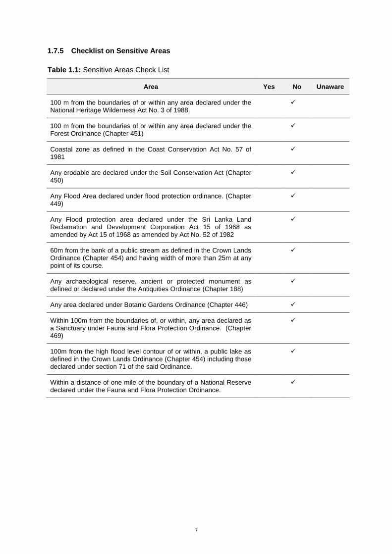
1.7.5 Checklist on Sensitive Areas
Table 1.1: Sensitive Areas Check List
Area Yes No Unaware
100 m from the boundaries of or within any area declared under the National Heritage Wilderness Act No. 3 of 1988.
100 m from the boundaries of or within any area declared under the Forest Ordinance (Chapter 451)
Coastal zone as defined in the Coast Conservation Act No. 57 of 1981
Any erodable are declared under the Soil Conservation Act (Chapter 450)
Any Flood Area declared under flood protection ordinance. (Chapter 449)
Any Flood protection area declared under the Sri Lanka Land Reclamation and Development Corporation Act 15 of 1968 as amended by Act 15 of 1968 as amended by Act No. 52 of 1982
60m from the bank of a public stream as defined in the Crown Lands Ordinance (Chapter 454) and having width of more than 25m at any point of its course.
Any archaeological reserve, ancient or protected monument as defined or declared under the Antiquities Ordinance (Chapter 188)
Any area declared under Botanic Gardens Ordinance (Chapter 446)
Within 100m from the boundaries of, or within, any area declared as a Sanctuary under Fauna and Flora Protection Ordinance. (Chapter 469)
100m from the high flood level contour of or within, a public lake as defined in the Crown Lands Ordinance (Chapter 454) including those declared under section 71 of the said Ordinance.
Within a distance of one mile of the boundary of a National Reserve declared under the Fauna and Flora Protection Ordinance.
8
2.0 DESCRIPTION OF THE PROJECT AND ALTERNATIVES CONSIDERED
2.1 Aim and Scope of the Proposed Project
2.1.1 Category of Project:
Improvement in Urban Infrastructure in Sanitation; Environmentally the Project is placed under Category B (ADB).
2.1.2 Type of project
Septage Treatment
2.1.3 Project main objectives
Provide a sustainable, long-term arrangement for disposal of septage for the CUC.
2.1.4 Main beneficiaries
Residences, Commercial Establishments, Institutions located within CUC Area. The CUC will be the service area of the project and institutionally the CUC is a direct beneficiary of the project
2.1.5 Socio-economic effects
The land acquisition for the treatment site has no negative social or economic impact. Land is part of an abandoned coconut plantation. The land is state owned (owned by National Live Stock and Development Board) prior to the purchase by the NWSDB for the purpose of this project. Therefore it is a transfer of land between two state agencies without resulting an economic loss as it is not productive at present. The price has been negotiated between the owner and the developer. Construction work is relatively simple and there will be opportunities for unskilled or low skilled workers. Therefore there will be opportunities for the local people to gain employment during construction.
There is no sewerage service in Chilaw Urban Area at present. The CUC is providing sanitation services by collection and disposal of septage using gully tankers. The service provided is affected by lack of proper disposal site. New STP plant will address this drawback and help to improve the urban environment in Chilaw. People in Chilaw will have significant social and economic benefit due to improved sanitation facilities/service.
The area chosen for the STP construction is not heavily populated and can be isolated from interfering in to community life and well being through proper planning and design. It is direct access through the main road thus the gully tankers need not take village roads. Therefore significant social impacts are not expected of the project in the site area.
2.1.6 Description of the project
Improving the septage disposal services provided by the CUC through (a) Construction of independent septage treatment facility and (b) Improving septage collection and transportation capacity with the provision of two gully truck. Once fully commissioned the plant is capable of receiving 30 m3 of septage daily.
9
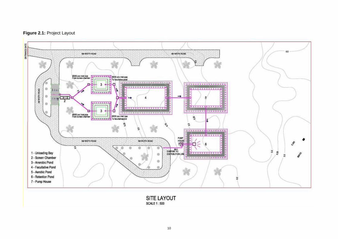
2.1.7 Project components
STP using waste stabilization pond technology consisting of two anaerobic ponds (for alternative use), facultative pond, polishing pond and retention ponds and disposal arrangement. In addition two gully trucks will also be provided to CUC.
2.1.8 Project Layout
See Figure 2.1
2.1.9 Operation and Maintenance
by Chilaw Urban Council
2.1.10 Size or magnitude of operation
Maximum of 2 operators working on daily basis at the treatment plant size; In addition there will be three gully trucks, including the two provided by this project will be operated by the CUC. The total crew manning the gully trucks is 8 (driver + operator). A senior technical officer or public health officer will supervise the operation.
Plant has the capacity to handle 30m3 of septage a day.
10
Figure 2.1: Project Layout
11
2.2 Justification of the Project
With the rapid urbanization and increasing commercial activities, the Chilaw Township and its suburbs have become a fast growing centre in the North-Western Province. As a result population and building density in the town area is rapidly in rise. In absence of a sewerage system this town depends on septic tanks and other types of latrines for disposal of sewerage. Emptying of these units from time to time is required for their proper functioning. This is a function that rests with the CUC.
Septage is obnoxious waste carrying pathogenic matter thus needing proper and safe collection, transport and disposal. CUC is currently disposing collected septage in a coconut plantation situated outside the CUC area by empting into dug pits and covering it with soil. Also no public health hazard or other significant ground water impacts have been reported so far. This is a safe practice for septage disposal provided soils are of right type, nitrogen build up in the soil is manageable and groundwater pollution is contained. The owner of the present disposal land has informed the CUC of adverse build up of nitrogen levels in soil. Therefore he has indicated that he might stop further disposal of septage soon. As such CUC faced with finding an alternative solution to septage disposal soon.
The groundwater table in Chilaw is high. This condition commonly increases the septic tank emptying frequency. Critical issues faced with regard to septage disposal in Chilaw are listed below.
1. High groundwater levels during wet season cause soakage systems to fail resulting a higher than usual demand for septic tank emptying. Single gully bowser available to the CUC is grossly inadequate to meet the demand in this period. As a result citizens have to wait long periods to empty their septic tanks.
2. In low density areas it is common that septic tanks/ pits are emptied to dug pits within the same land. Increasing density in the town area and suburbs no longer permit this alternative to be practiced. Thus the demand for gully service is in the rise.
3. As a result of (1) and (2) above, the capacity requirement of septage disposal facility is also on the rise.
Septage disposal commonly depends one of the three technological alternatives. These are: land disposal; disposal at existing sewerage treatment plant; and disposal to independent septage treatment systems. In general the last is the most expensive. Land disposal is the most preferred option in terms of cost. This method of disposal also has environmental and economic advantage under suitable conditions. The critical factor is availability of land. Although many coconut plantations are situated around Chilaw which can be acceptable for septage disposal, the NWS&DB and CUC informed the IEE Consultants that owners are reluctant to allow septage disposal. Also Wastewater Treatment plant of sufficient capacity is not available at a reasonable distance. Therefore the two less costly alternatives are not available for Chilaw. As such independent septage treatment facility was selected as practical solution.
In the case of independent septage treatment several treatment process streams are available. The proposed treatment process is based on pond system which depends on natural biological digestion/decay process. The treatment method is known for low cost and simple operation among the technologies used for independent treatment facilities. Again the crucial factor is availability of land as this process has high land demand. In this instance the project proponent was able to secure a land of sufficient extent at an acceptable location.
The project also enhances the septage collection capacity of the CUC by providing two vacuum trucks or gully bowsers. This is expected to reduce the waiting time for septic tank emptying. The project is also not unfamiliar to the CUC as they already have one gully
12
bowser and operate a septage land disposal site. Therefore they have the institutional infrastructure to operate the project successfully with additional help to improve the capacity.
2.3 Location
Chilaw is situated on the west coast of the North-Western Province of Sri Lanka, 83km north of the national capital Colombo, 73km north-west of the provincial capital Kurunegala and 50km south of administrative district capital Puttalam. The town is located on the A3 highway and railway running from Colombo to Puttalam. Chilaw is at the mouth of the Deduru Oya.
2.3.1 Location of Treatment Plant Site
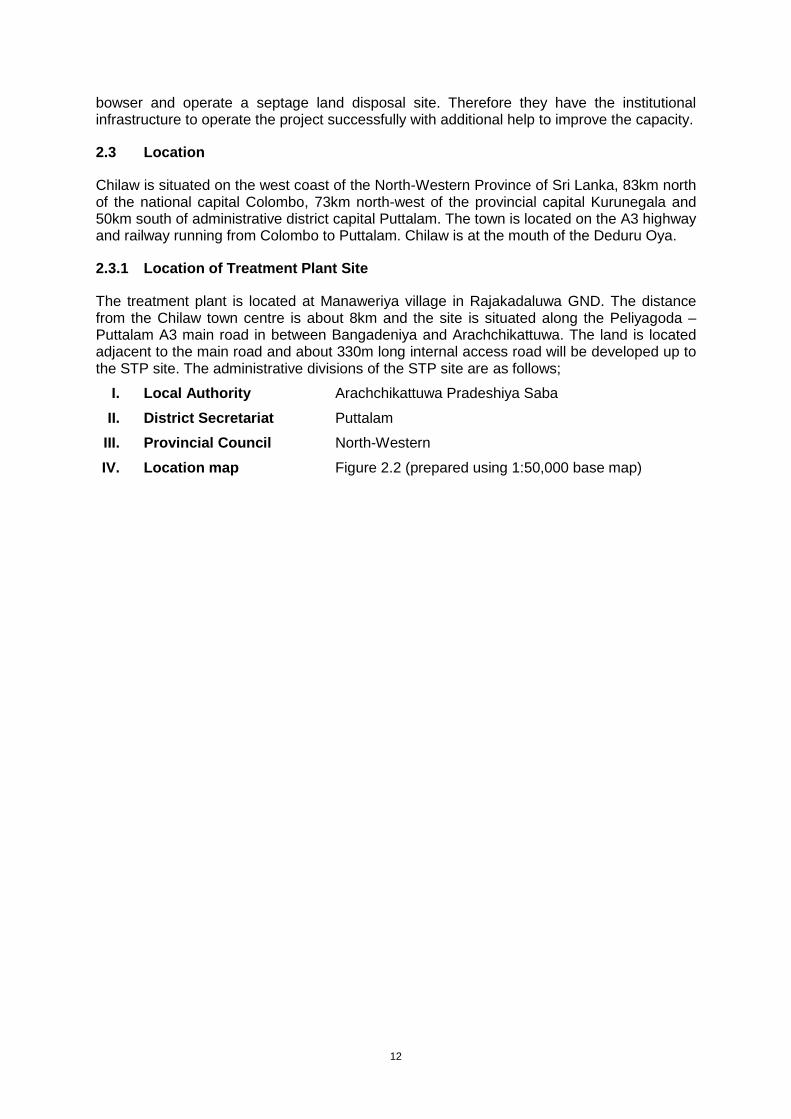
The treatment plant is located at Manaweriya village in Rajakadaluwa GND. The distance from the Chilaw town centre is about 8km and the site is situated along the Peliyagoda – Puttalam A3 main road in between Bangadeniya and Arachchikattuwa. The land is located adjacent to the main road and about 330m long internal access road will be developed up to the STP site. The administrative divisions of the STP site are as follows;
I. Local Authority Arachchikattuwa Pradeshiya Saba
II. District Secretariat Puttalam
III. Provincial Council North-Western
IV. Location map Figure 2.2 (prepared using 1:50,000 base map)
13
Figure 2.2: Project Location Map
14
2.3.2 Service Area
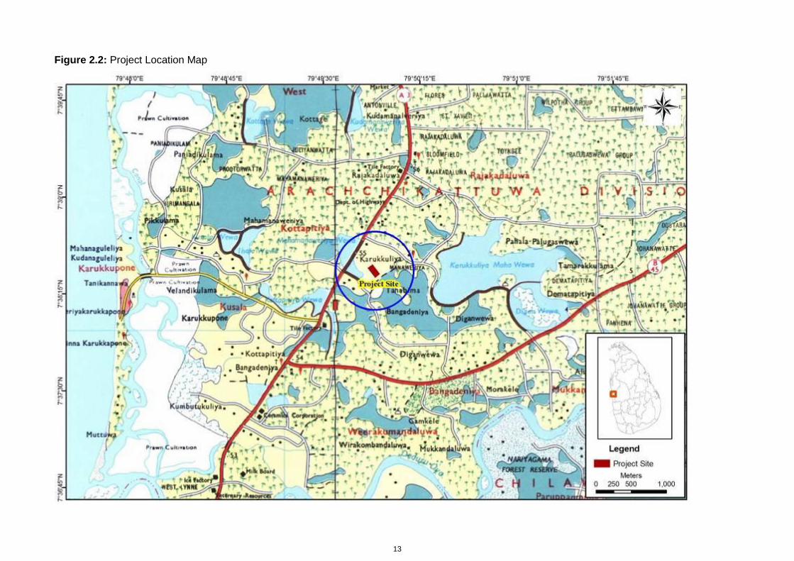
The main service area of the project will be the CUC area at the beginning. There are 13 GNDs located within the CUC. Total land area covered under this service area is 6.4km2 with a total population of 25,208 (CUC Statistics, 2001). However it is expected that the gradually increasing population in the other LAs such as Chilaw Pradeshiya Saba (CPS), APS and Bingiriya in which the population densities are comparatively low with that of Chilaw Urban area will also benefited from the proposed project. The administrative divisions in which the service area lies are as follows;
I. Local Authority Chilaw Urban Council
II. District Secretariat Puttalam
III. Provincial Council North-Western
IV. Service Area Map Figure 2.3: Service Area and Access Roads.
15
Figure 2.3: Project Location with Service Area and Access Road
16
2.4 Process Description and Design Details
2.4.1 Brief description of the treatment process
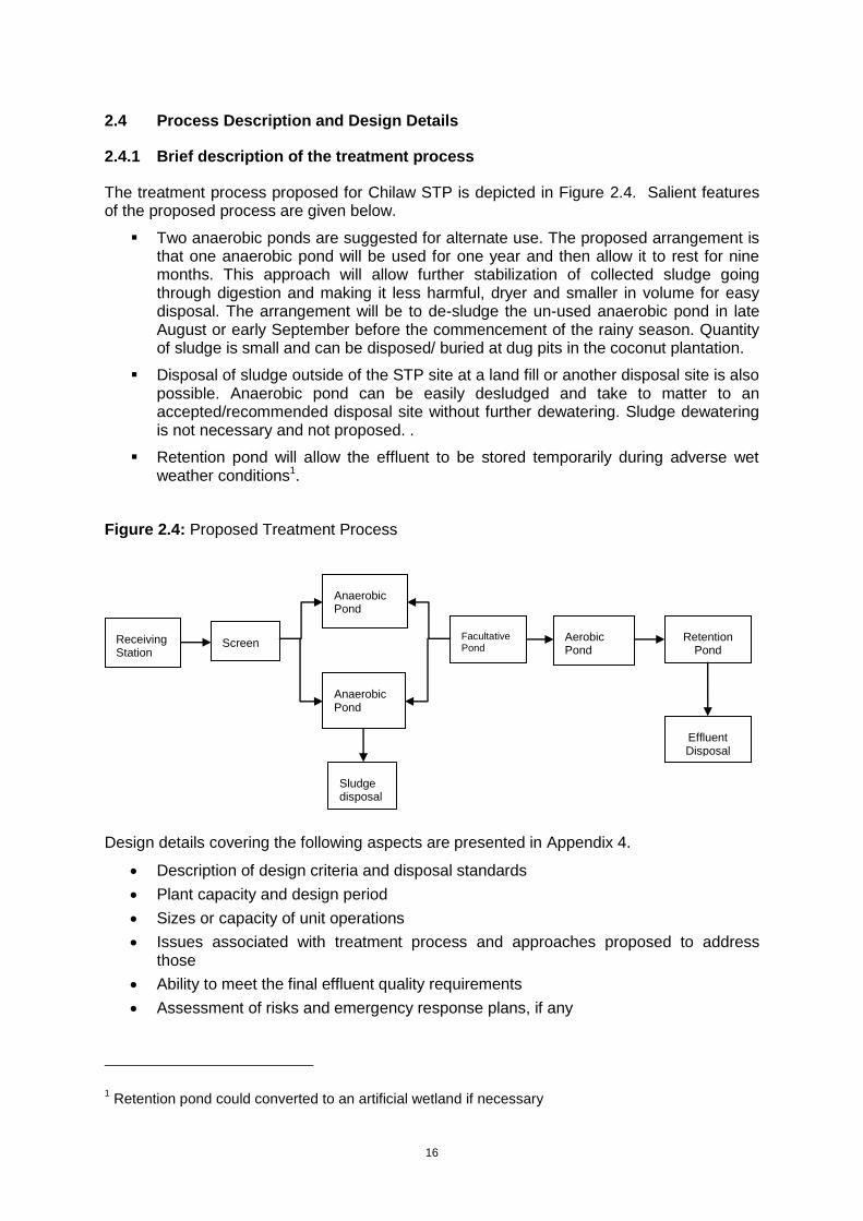
The treatment process proposed for Chilaw STP is depicted in Figure 2.4. Salient features of the proposed process are given below.
Two anaerobic ponds are suggested for alternate use. The proposed arrangement is that one anaerobic pond will be used for one year and then allow it to rest for nine months. This approach will allow further stabilization of collected sludge going through digestion and making it less harmful, dryer and smaller in volume for easy disposal. The arrangement will be to de-sludge the un-used anaerobic pond in late August or early September before the commencement of the rainy season. Quantity of sludge is small and can be disposed/ buried at dug pits in the coconut plantation.
Disposal of sludge outside of the STP site at a land fill or another disposal site is also possible. Anaerobic pond can be easily desludged and take to matter to an accepted/recommended disposal site without further dewatering. Sludge dewatering is not necessary and not proposed. .
Retention pond will allow the effluent to be stored temporarily during adverse wet weather conditions1.
Figure 2.4: Proposed Treatment Process
Design details covering the following aspects are presented in Appendix 4.
Description of design criteria and disposal standards
Plant capacity and design period
Sizes or capacity of unit operations
Issues associated with treatment process and approaches proposed to address those
Ability to meet the final effluent quality requirements
Assessment of risks and emergency response plans, if any
1 Retention pond could converted to an artificial wetland if necessary
Anaerobic Pond
Sludge disposal
Screen Facultative Pond
Anaerobic Pond
Retention Pond
Receiving Station
Effluent Disposal
Pond
Aerobic Pond
17
2.5 Pre-construction and Construction Activities
2.5.1 Pre-construction work
The main pre-construction activities will include:
Acquisition of the property, and Detailed designs including investigations work Development of access road
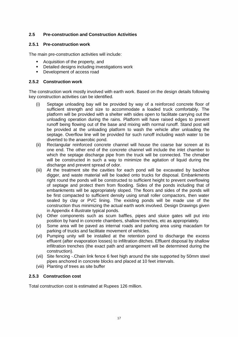
2.5.2 Construction work
The construction work mostly involved with earth work. Based on the design details following key construction activities can be identified.
(i) Septage unloading bay will be provided by way of a reinforced concrete floor of sufficient strength and size to accommodate a loaded truck comfortably. The platform will be provided with a shelter with sides open to facilitate carrying out the unloading operation during the rains. Platform will have raised edges to prevent runoff being flowing out of the base and mixing with normal runoff. Stand post will be provided at the unloading platform to wash the vehicle after unloading the septage. Overflow line will be provided for such runoff including wash water to be diverted to the anaerobic pond.
(ii) Rectangular reinforced concrete channel will house the coarse bar screen at its one end. The other end of the concrete channel will include the inlet chamber to which the septage discharge pipe from the truck will be connected. The chmaber will be constructed in such a way to minimize the agitation of liquid during the discharge and prevent spread of odor.
(iii) At the treatment site the cavities for each pond will be excavated by backhoe digger, and waste material will be loaded onto trucks for disposal. Embankments right round the ponds will be constructed to sufficient height to prevent overflowing of septage and protect them from flooding. Sides of the ponds including that of embankments will be appropriately sloped. The floors and sides of the ponds will be first compacted to sufficient density using small roller compactors, then water sealed by clay or PVC lining. The existing ponds will be made use of the construction thus minimizing the actual earth work involved. Design Drawings given in Appendix 4 illustrate typical ponds.
(iv) Other components such as scum baffles, pipes and sluice gates will put into position by hand in concrete chambers, shallow trenches, etc as appropriately.
(v) Some area will be paved as internal roads and parking area using macadam for parking of trucks and facilitate movement of vehicles.
(vi) Pumping unity will be installed at the retention pond to discharge the excess effluent (after evaporation losses) to infiltration ditches. Effluent disposal by shallow infiltration trenches (the exact path and arrangement will be determined during the construction).
(vii) Site fencing -.Chain link fence 6 feet high around the site supported by 50mm steel pipes anchored in concrete blocks and placed at 10 feet intervals.
(viii) Planting of trees as site buffer
2.5.3 Construction cost
Total construction cost is estimated at Rupees 126 million.
18
2.5.4 Construction labor requirement (both skilled and non skilled)
Considering the volume of work about 20- 25 work force will be involved with the construction work. Half of this requirement will be unskilled labour.
2.5.5 Construction materials
As the ponds are already present at the site, earth work will be mostly with construction of embankments and re-arranging the ponds. Therefore additional earth material will be required. IEE Consultants estimate the requirement for earth material to be around 2000m3. In additional clay or PVC lining will be required for water proofing of ponds. The area requiring lining will be around 6000m2. Other main construction material required will be concrete aggregates, cement and sand. About 1500 L-feet of chain link fence material and steel pipes as links support will be required. Small quantity of pipes, pipe fittings and two small pumps (one standby) and other accessories will also be required.
2.6 Schedule of Implementation
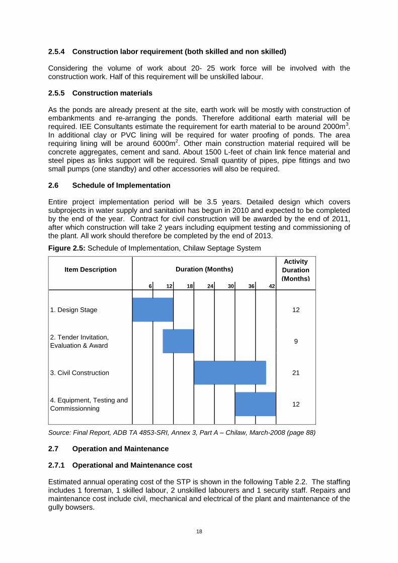
Entire project implementation period will be 3.5 years. Detailed design which covers subprojects in water supply and sanitation has begun in 2010 and expected to be completed by the end of the year. Contract for civil construction will be awarded by the end of 2011, after which construction will take 2 years including equipment testing and commissioning of the plant. All work should therefore be completed by the end of 2013.
Figure 2.5: Schedule of Implementation, Chilaw Septage System
Item Description
Activity
Duration
(Months)6 12 18 24 30 36 42
1. Design Stage 12
2. Tender Invitation,
Evaluation & Award9
3. Civil Construction 21
4. Equipment, Testing and
Commissionning12
Duration (Months)
Source: Final Report, ADB TA 4853-SRI, Annex 3, Part A – Chilaw, March-2008 (page 88)
2.7 Operation and Maintenance
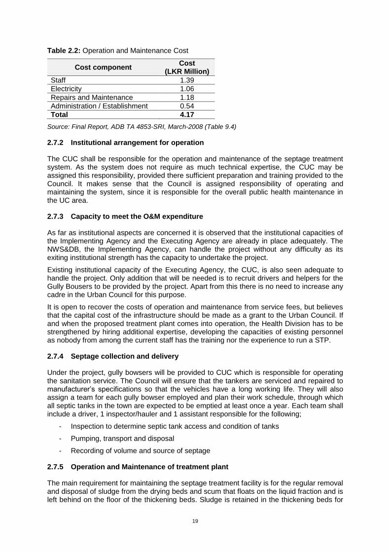
2.7.1 Operational and Maintenance cost
Estimated annual operating cost of the STP is shown in the following Table 2.2. The staffing includes 1 foreman, 1 skilled labour, 2 unskilled labourers and 1 security staff. Repairs and maintenance cost include civil, mechanical and electrical of the plant and maintenance of the gully bowsers.
19
Table 2.2: Operation and Maintenance Cost
Cost component Cost
(LKR Million)
Staff 1.39
Electricity 1.06
Repairs and Maintenance 1.18
Administration / Establishment 0.54
Total 4.17
Source: Final Report, ADB TA 4853-SRI, March-2008 (Table 9.4)
2.7.2 Institutional arrangement for operation
The CUC shall be responsible for the operation and maintenance of the septage treatment system. As the system does not require as much technical expertise, the CUC may be assigned this responsibility, provided there sufficient preparation and training provided to the Council. It makes sense that the Council is assigned responsibility of operating and maintaining the system, since it is responsible for the overall public health maintenance in the UC area.
2.7.3 Capacity to meet the O&M expenditure
As far as institutional aspects are concerned it is observed that the institutional capacities of the Implementing Agency and the Executing Agency are already in place adequately. The NWS&DB, the Implementing Agency, can handle the project without any difficulty as its exiting institutional strength has the capacity to undertake the project.
Existing institutional capacity of the Executing Agency, the CUC, is also seen adequate to handle the project. Only addition that will be needed is to recruit drivers and helpers for the Gully Bousers to be provided by the project. Apart from this there is no need to increase any cadre in the Urban Council for this purpose.
It is open to recover the costs of operation and maintenance from service fees, but believes that the capital cost of the infrastructure should be made as a grant to the Urban Council. If and when the proposed treatment plant comes into operation, the Health Division has to be strengthened by hiring additional expertise, developing the capacities of existing personnel as nobody from among the current staff has the training nor the experience to run a STP.
2.7.4 Septage collection and delivery
Under the project, gully bowsers will be provided to CUC which is responsible for operating the sanitation service. The Council will ensure that the tankers are serviced and repaired to manufacturer’s specifications so that the vehicles have a long working life. They will also assign a team for each gully bowser employed and plan their work schedule, through which all septic tanks in the town are expected to be emptied at least once a year. Each team shall include a driver, 1 inspector/hauler and 1 assistant responsible for the following;
- Inspection to determine septic tank access and condition of tanks
- Pumping, transport and disposal
- Recording of volume and source of septage
2.7.5 Operation and Maintenance of treatment plant
The main requirement for maintaining the septage treatment facility is for the regular removal and disposal of sludge from the drying beds and scum that floats on the liquid fraction and is left behind on the floor of the thickening beds. Sludge is retained in the thickening beds for
20
approximately a month and the drying beds for 10-15 days, after which the scum and sludge are removed from one thickening bed and a pair of drying beds by a small front-end loader and deposited into a truck.
2.7.6 Skills requirements
As described above, nobody from among the current staff of CUC training or experience in STP and therefore it is suggested that this project should provide CUC with training and assistance in establishing such a system. The staff assigned shall be trained on the job prior to development. After which, they shall receive continuing training to further their expertise in the O&M of the STP.
A unit within the Public Health Division of CUC shall be comprised with the following skills’
- Billing and collection staff
- Inspectors and Haulers
- STP operators
- Sanitary Engineer
2.8 Evaluation of Alternatives
2.8.1 Alternative Technologies
Septage disposal commonly depends one of the three technological alternatives. These are: land disposal; disposal at existing sewerage treatment plant; and disposal at independent septage treatment systems.
Land Disposal
Land application of septage is the most common means of septage disposal. This is in fact happening at household level where septic tanks are emptied to dug-pits within the same property and backfilled. Most LAs to the knowledge of the consultant depend on land for septage disposal. The advantages of land disposal are: it is simple and economical; low in energy use; and recycle the organic and nutrients to land. This is the method currently practiced by the CUC to dispose septage collected in the CUC area.
Chilaw is situated in an area where there are some opportunities for land disposal. Common requirements for land disposal are: ability to finds land of sufficient extent far from human habitats; suitable soil and groundwater table levels. The loading rates are determined by the nitrogen levels, which in turn is link to nitrogen demand by crops/vegetation. Presence of large coconut plantation in Chilaw area generally presents an opportunity for land disposal.
According to the project proponent (NWS&DB) as well as the project beneficiary (CUC), their search for suitable site/land for septage disposal did not materialized. There is an unwillingness to accept septage by land owners even though it adds fertilizer to the soil. Among the reasons for lack of support are odor and health problems. Septage transportation is also an issue that constraint locations for disposal sites. Septage is an objectionable waste. Transportation through narrow roads in built up areas also generate community resistance to disposal sites. As a result although the project planners preferred land disposal, it had to be abundant due to lack of proper disposal site.
Disposal at Wastewater Treatment Plant
The next obvious technological alternative to land disposal is disposal at existing Wastewater Treatment Plants (WWTP). However, disposal of septage creates significant loading (organic loading) related problems in small treatment plants. Furthermore the plants should have proper facilities and arrangement to handles the odor problems. Finally the
21
WWTP if available should be at a reasonable distance from the source to realize the economic rationale of choosing it.
The WWTPs closest to Chilaw are: Ekala-Jaela plant and Raddoluwa plant. Both these plants are situated more than 40km away from the source. Raddoluwa treatment plant is relatively small and very unlikely to have adequate capacity to accept 45m3 of septage a day. Ekala-Ja-ela plant is larger in size but does not have built in provisions to handle the odor issue. The same can be said about Raddoluwa plant regarding odor. Therefore on account of distance, plant capacity and odor management the existing WWTPs are not a solution to the septage disposal problem in Chilaw.
Independent Septage Treatment System
Technologically this is the least preferred option for septage disposal because of cost. They range from lagoons systems to complex mechanical systems that include many unit operations and processes. Treatment need to handle both liquid and solid components of septage. The mechanical systems can be complex in operation and maintenance similar to WWTPs. Lagoons in general are easy to operate and maintain. Despite the cost disadvantage the project proponent selected independent treatment option as other technological alternatives are not viable.
There is number of process design options available for dedicated treatment. The choice of technology will depend on volume of septage generated; economy of scale; land availability; regulatory requirements, etc. The common process options listed below are discussed in Section 2.8.2.
Lagoons
Composting
Biological secondary treatment processes
Aerobic digestion
Anaerobic digestion
Lime stabilization
Chlorine oxidation
There are other supplementary treatment processes which may also be required to be integrated with above main treatment methods. These include:
Conditioning
Dewatering
Disinfection
Odor control
Combining design options listed above is also practiced.
2.8.1.1 Technology of Choice
As explained both land disposal and disposal at existing WWTP are not viable for disposal of septage collected in CUC area. This was despite the fact that those alternatives would cost less. Therefore independent STP was selected as the viable option for Chilaw.
2.8.2 Alternative Designs
Designers considered the design options available to them before finalization of the process design. The choice of design process was governed by: low capital and operational cost;
22
ease of operation; and not excessive demand on O&M agency capacity and operator skills. Details are given below.
Lagoons
Lagoons are again preferred independent treatment design option when suitable land is available at reasonable cost. Properly designed lagoons are easy to operate and maintain. They perform well and meet the treatment goals consistently. They can be operated year-round and are relatively easy and inexpensive to build and operate and suits the conditions of Sri Lanka.
Lagoons can be built in series where the first lagoon also acts as an anaerobic digester. The other lagoons in the series act as facultative, aerobic/polishing ponds providing further treatment. Effluent shall meet the discharge standards and sludge need to be removed from the lagoons particularly from the first lagoon periodically. With long retention periods good quality effluent is achievable.
The design option considered for Chilaw plant is system of lagoons in series. This include anaerobic pond (lagoon) followed by two facultative ponds and two polishing ponds. Anaerobic pond will be de-sludged time to time. Sludge drying beds are proposed to reduce its water content. Dried sludge will be disposed at landfill.
Composting
Composting is another treatment and disposal method used for septage. Separated septage sludge or liquid septage can be composted. The composting of liquid septage is accomplished by adding additional bulking agents (e.g., woodchips, sawdust, bark chips, etc.). This process requires large quantities of bulking agents and generally not recommended if bulking agents are not easily and freely (without cost) accessible. Composting of sludge does require lesser quantity of bulking agents. Where there is a good demand for compost composting can be an attractive option.
Composting was not considered as an alternative in this case. First liquid septage composting is impractical due to demand for large quantity of bulking material. Sludge composting will require unit operation to separate liquid and solid components, composting system for sludge and additional treatment mechanism for liquid portion. Therefore this treatment train is too cumbersome compared to the lagoon option. Thus it is not considered as a suitable method of treatment.
Biological Secondary Treatment Processes
Basic composition of septage is similar to domestic sewage although concentration levels are extremely high and highly variable. Thus processes used in treating sewage can be used to the treatment of septage. High variability in waste strength and characteristics may present operational problems for some activated sludge processes. However, extended aeration processes are capable of handling such conditions. Fixed growth biological systems at low loadings are also suited to septage treatment due to their relative ease of operation.
However, these treatment systems are high in construction cost. They also consume large amount of energy and high in operational cost. The O&M agency have sufficient capability to operate the plant. Due to these factors biological secondary treatment was not considered as design option.
Aerobic Digestion
Aerobic digestion operates in the endogenous respiration phase. Cell matter is oxidized to carbon dioxide, water, and other inert materials. Compared with anaerobic digestion, aerobic process is easier to operate and maintain. It is lower in capital costs, and produces an odorless, biologically stable residual that dewaters easily.
Major problem associated with aerobic digestion of septage is odor. Form can also be a problem, if detergents are used substantially. Aerobic digestion requires constant monitoring
23
and operator attention. Thus have high demand for operator skills. It is sensitive to toxic substances. This method requires further handling (e.g. dewatering, transportation, etc.) prior to ultimate disposal.
Aerobic digestion is not an attractive design option in this case. This is due to high capital cost, high energy demand, high operating cost, high operator skill requirement, and high O&M agency capacity. Because of these limitations this design option was not considered further.
Anaerobic Digestion
Anaerobic digestion is another process that fits for septage treatment. The limitations of anaerobic digestion include its high capital cost (compared with aerobic digestion), very sensitive to reactor environment; needs close monitoring requirements; poor quality supernatant (high oxygen demand and high concentrations of nitrogen and suspended solids), and relatively long detention time required for stabilization. Thus further treatment is required to meet the standards.
Compared to aerobic digestion the anaerobic digestion also has the same limitations and more. Because of this anaerobic digestion was not considered as treatment option.
Lime Stabilization
Lime stabilization is relatively low cost stabilization option. However, it is only an intermediate solution with several limitations. In this case lime stabilization was not considered as an option.
Chlorine Oxidation
This is a complex high cost operation and not considered in this case.
2.8.2.1 Design of Choice
The design choice is a lagoon system with adequate retention period to meet the bacteriological quality of the effluent to meet the standards. The process train will include screening device; anaerobic lagoon, facultative pond and polishing ponds and storage pond which will also act as storage pond.
2.8.3 Alternative Sites
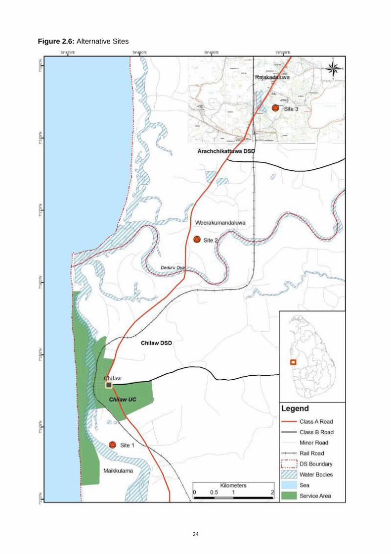
Three locations were considered for siting the septage disposal plant (Figure 2.6). Key site characteristics are described below. The merits and demerits of these sites in relation to the proposed design are reviewed in sub-section 2.8.3.1.
24
Figure 2.6: Alternative Sites
25
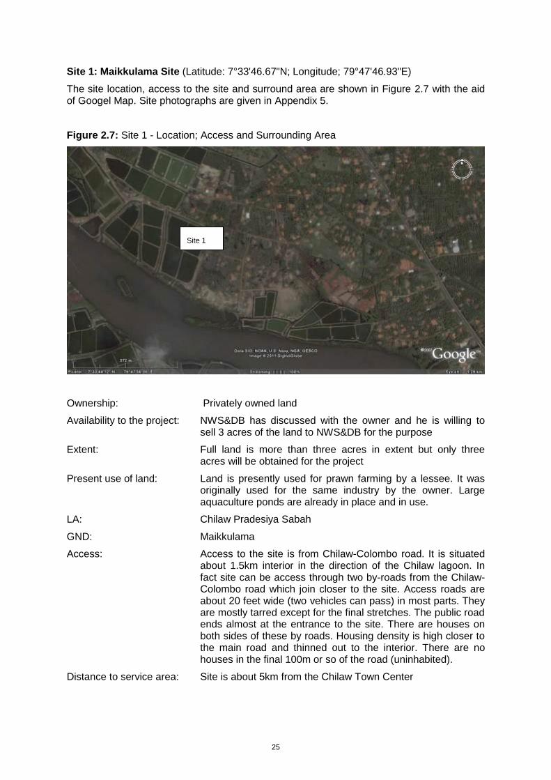
Site 1: Maikkulama Site (Latitude: 7°33'46.67"N; Longitude; 79°47'46.93"E)
The site location, access to the site and surround area are shown in Figure 2.7 with the aid of Googel Map. Site photographs are given in Appendix 5.
Figure 2.7: Site 1 - Location; Access and Surrounding Area
Ownership: Privately owned land
Availability to the project: NWS&DB has discussed with the owner and he is willing to sell 3 acres of the land to NWS&DB for the purpose
Extent: Full land is more than three acres in extent but only three acres will be obtained for the project
Present use of land: Land is presently used for prawn farming by a lessee. It was originally used for the same industry by the owner. Large aquaculture ponds are already in place and in use.
LA: Chilaw Pradesiya Sabah
GND: Maikkulama
Access: Access to the site is from Chilaw-Colombo road. It is situated about 1.5km interior in the direction of the Chilaw lagoon. In fact site can be access through two by-roads from the Chilaw-Colombo road which join closer to the site. Access roads are about 20 feet wide (two vehicles can pass) in most parts. They are mostly tarred except for the final stretches. The public road ends almost at the entrance to the site. There are houses on both sides of these by roads. Housing density is high closer to the main road and thinned out to the interior. There are no houses in the final 100m or so of the road (uninhabited).
Distance to service area: Site is about 5km from the Chilaw Town Center
Site 1
26
Surrounding Land-use: No houses are present within 100m from the site. Surrounding area is primarily developed for prawn farming. Most farms are now abandoned due to repeated outbreaks of prawn diseases. Only a few are in operation at a lower scale. Prawn farms obtain water from canals connected to the Dutch Canal. As such large canal network has been established by the prawn farmers.
Proximity to residences: No houses are present within 100m from the site.
Ecology: Area was under coconut and mangroves but completely denuded now.
Soil and Geology: Soil is sandy
Groundwater: Groundwater level is very high
Flooding Situation: Area is subjected to flooding
Disposal of treated effluent: To Chilaw Lagoon
Social Economic Factors: There is public opposition and proposed project can be a threat to prawn industry in the area.
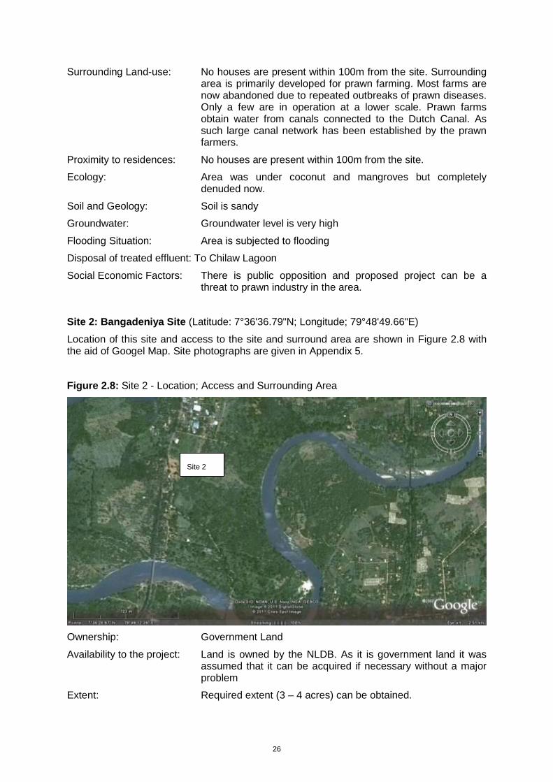
Site 2: Bangadeniya Site (Latitude: 7°36'36.79"N; Longitude; 79°48'49.66"E)
Location of this site and access to the site and surround area are shown in Figure 2.8 with the aid of Googel Map. Site photographs are given in Appendix 5.
Figure 2.8: Site 2 - Location; Access and Surrounding Area
Ownership: Government Land
Availability to the project: Land is owned by the NLDB. As it is government land it was assumed that it can be acquired if necessary without a major problem
Extent: Required extent (3 – 4 acres) can be obtained.
Site 2
27
Present use of land: This is an abandoned coconut land now under scrub vegetation.
LA: Arachikatuwa Pradesiya Sabah
GND: Bangadeniya
Access: Access is available from Chilaw Puttalam main road
Distance to service area: Site is about 5km from the Chilaw Town Center
Surrounding Land-use: The land-use in the surrounding area is mix of coconut plantations and residential.
Proximity to residences: Site entrance area from the main road is developed with some commercial activities.
Ecology: Scrub vegetation
Soil and Geology Alluvial soils
Groundwater Groundwater level is very high throughout the year
Flooding Situation Area is subjected to flooding
Disposal of treated effluent: Infiltration at site
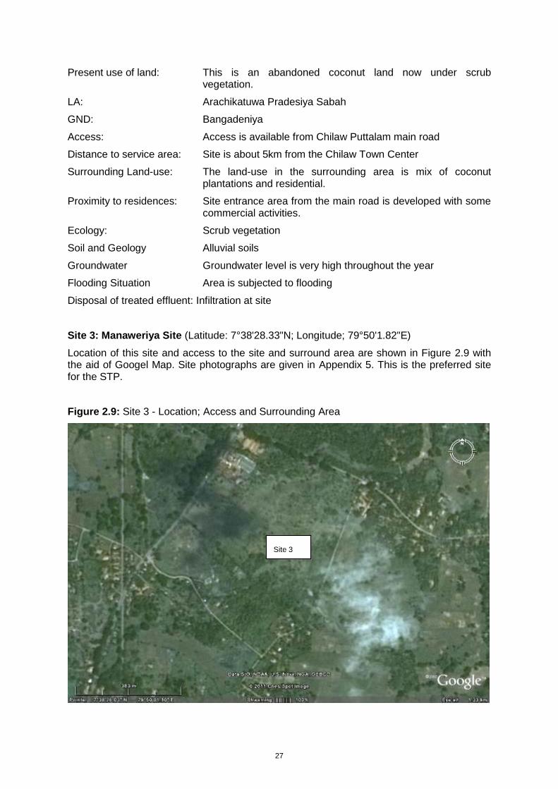
Site 3: Manaweriya Site (Latitude: 7°38'28.33"N; Longitude; 79°50'1.82"E)
Location of this site and access to the site and surround area are shown in Figure 2.9 with the aid of Googel Map. Site photographs are given in Appendix 5. This is the preferred site for the STP.
Figure 2.9: Site 3 - Location; Access and Surrounding Area
Site 3
28
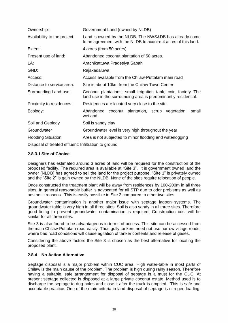
Ownership: Government Land (owned by NLDB)
Availability to the project: Land is owned by the NLDB. The NWS&DB has already come to an agreement with the NLDB to acquire 4 acres of this land.
Extent: 4 acres (from 50 acres)
Present use of land: Abandoned coconut plantation of 50 acres.
LA: Arachikattuwa Pradesiya Sabah
GND: Rajakadaluwa
Access: Access available from the Chilaw-Puttalam main road
Distance to service area: Site is about 10km from the Chilaw Town Center
Surrounding Land-use: Coconut plantations; small irrigation tank, coir, factory The land-use in the surrounding area is predominantly residential.
Proximity to residences: Residences are located very close to the site
Ecology: Abandoned coconut plantation, scrub vegetation, small wetland
Soil and Geology Soil is sandy clay
Groundwater Groundwater level is very high throughout the year
Flooding Situation Area is not subjected to minor flooding and waterlogging
Disposal of treated effluent: Infiltration to ground
2.8.3.1 Site of Choice
Designers has estimated around 3 acres of land will be required for the construction of the proposed facility. The required area is available at “Site 3”. It is government owned land the owner (NLDB) has agreed to sell the land for the project purpose. “Site 1” is privately owned and the “Site 2” is gain owned by the NLDB. None of the sites require relocation of people.
Once constructed the treatment plant will be away from residences by 100-200m in all three sites. In general reasonable buffer is advocated for all STP due to odor problems as well as aesthetic reasons. This is easily possible in Site 3 compared to other two sites.
Groundwater contamination is another major issue with septage lagoon systems. The groundwater table is very high in all three sites. Soil is also sandy in all three sites. Therefore good lining to prevent groundwater contamination is required. Construction cost will be similar for all three sites.
Site 3 is also found to be advantageous in terms of access. This site can be accessed from the main Chilaw-Puttalam road easily. Thus gully tankers need not use narrow village roads, where bad road conditions will cause agitation of tanker contents and release of gases.
Considering the above factors the Site 3 is chosen as the best alternative for locating the proposed plant.
2.8.4 No Action Alternative
Septage disposal is a major problem within CUC area. High water-table in most parts of Chilaw is the main cause of the problem. The problem is high during rainy season. Therefore having a suitable, safe arrangement for disposal of septage is a must for the CUC. At present septage collected is disposed at a large private coconut estate. Method used is to discharge the septage to dug holes and close it after the truck is emptied. This is safe and acceptable practice. One of the main criteria in land disposal of septage is nitrogen loading.

29
The owner of the coconut estate has informed the CUC on the built up of soil nitrogen content and that he would be that compelled to stop further disposal of septage soon. This situation has forced the CUC to look for long-term permanent arrangement. In fact Chilaw area is surrounded by large coconut estates giving ideal opportunity for land disposal. This is also good viable technical alternative. However, owners of the estates are reluctant to allow discharge of septage citing health and social reasons. As a result the CUC has to look for alternative disposal methods although it will be costlier.
No actions could lead to unsafe disposal of septage by CUC, if alternate land disposal site is not available. General public will also resort to bad practices for disposal of septage. This is because under such circumstances the CUC will be reluctant to provide gully services to its citizens. The result will have very negative environmental, pollution and health impacts.
30
3.0 DESCRIPTION OF ENVIRONMENT
3.1 Physical Environment
3.1.1 Study Area
The geographic area of the study will include the areas where significantly affected by the project directly and indirectly. The study area for the assessment is as follows;
1. Location of the STP
2. 500m on either side of the above stretch
3. Main anticipated road haulage to the project site
4. Effluent Discharge area – coconut lands away from sensitive places, not affected to
water sources
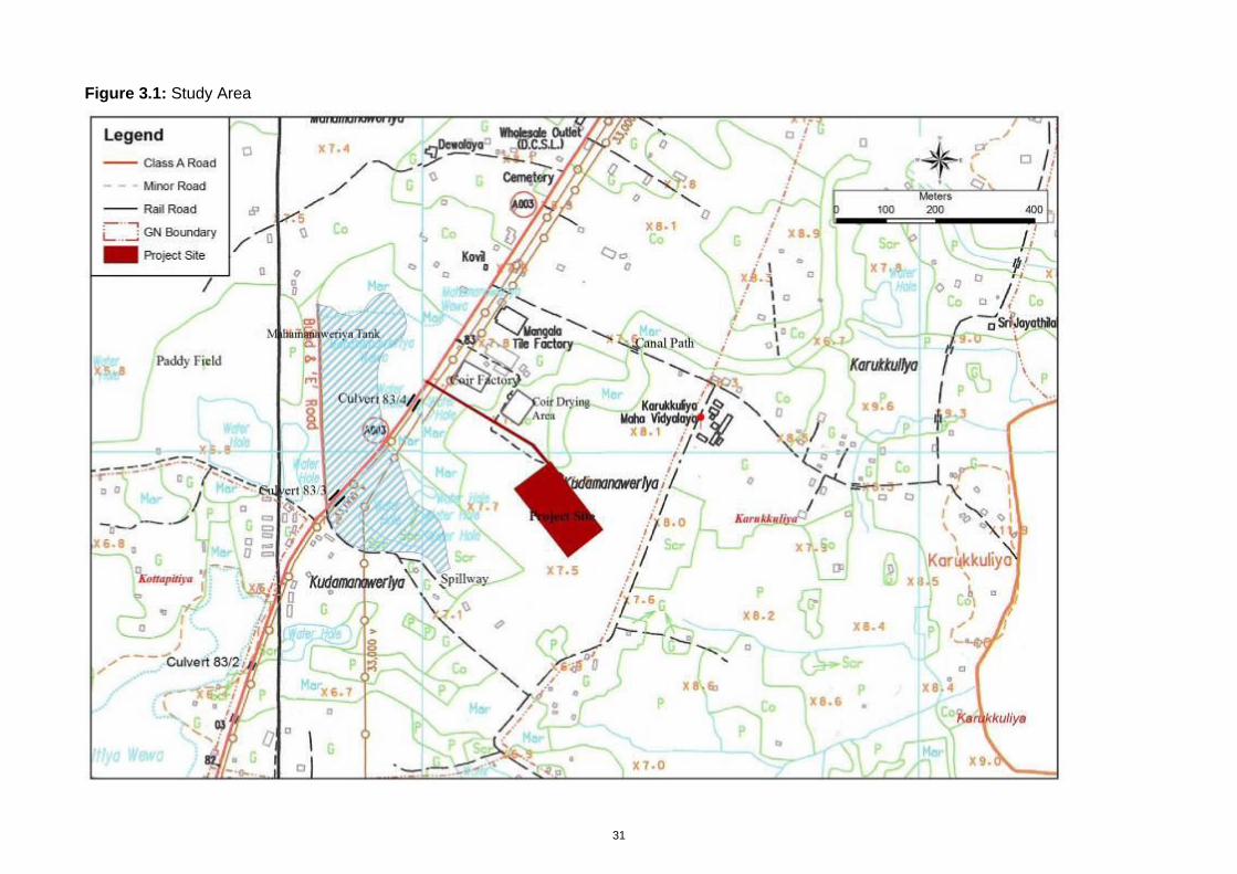
The study area is shown in Figure 3.1.
31
Figure 3.1: Study Area
32
3.1.2 Topography
The project site and its area vicinity are generally flat. The elevation of this area varies between 6 and 9m above MSL. The land is located 3.6km eastwards to the sea and Deduru Oya which is the main drainage path of the area flows in the south and nearest point from the site is about 2.8km. The proposed land is located in the basin of a cascade of an irrigation system between Karukkuliya Tank in the east and Mahamanaweriya Tank in the south west direction of the land.
3.1.3 Soils and Geology
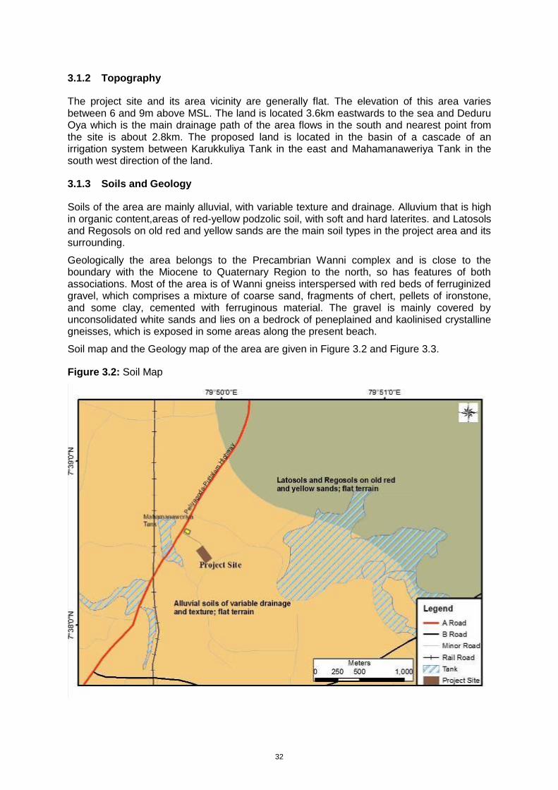
Soils of the area are mainly alluvial, with variable texture and drainage. Alluvium that is high in organic content,areas of red-yellow podzolic soil, with soft and hard laterites. and Latosols and Regosols on old red and yellow sands are the main soil types in the project area and its surrounding.
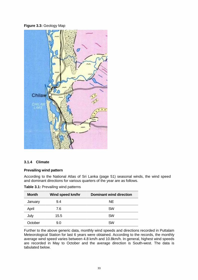
Geologically the area belongs to the Precambrian Wanni complex and is close to the boundary with the Miocene to Quaternary Region to the north, so has features of both associations. Most of the area is of Wanni gneiss interspersed with red beds of ferruginized gravel, which comprises a mixture of coarse sand, fragments of chert, pellets of ironstone, and some clay, cemented with ferruginous material. The gravel is mainly covered by unconsolidated white sands and lies on a bedrock of peneplained and kaolinised crystalline gneisses, which is exposed in some areas along the present beach.
Soil map and the Geology map of the area are given in Figure 3.2 and Figure 3.3.
Figure 3.2: Soil Map
33
Figure 3.3: Geology Map
3.1.4 Climate
Prevailing wind pattern
According to the National Atlas of Sri Lanka (page 51) seasonal winds, the wind speed and dominant directions for various quarters of the year are as follows.
Table 3.1: Prevailing wind patterns
Month Wind speed km/hr Dominant wind direction
January 9.4 NE
April 7.6 SW
July 15.5 SW
October 9.0 SW
Further to the above generic data, monthly wind speeds and directions recorded in Puttalam Meteorological Station for last 6 years were obtained. According to the records, the monthly average wind speed varies between 4.8 km/h and 10.8km/h. In general, highest wind speeds are recorded in May to October and the average direction is South-west. The data is tabulated below.
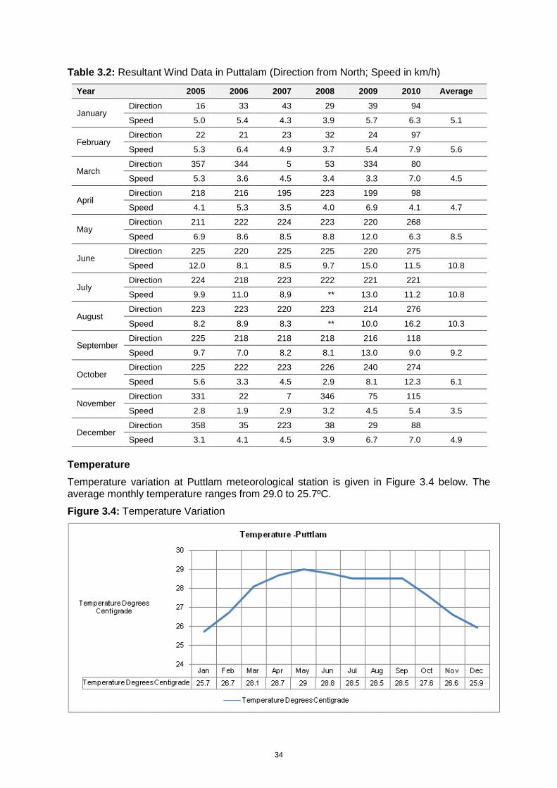
34
Table 3.2: Resultant Wind Data in Puttalam (Direction from North; Speed in km/h)
Year 2005 2006 2007 2008 2009 2010 Average
January Direction 16 33 43 29 39 94
Speed 5.0 5.4 4.3 3.9 5.7 6.3 5.1
February Direction 22 21 23 32 24 97
Speed 5.3 6.4 4.9 3.7 5.4 7.9 5.6
March Direction 357 344 5 53 334 80
Speed 5.3 3.6 4.5 3.4 3.3 7.0 4.5
April Direction 218 216 195 223 199 98
Speed 4.1 5.3 3.5 4.0 6.9 4.1 4.7
May Direction 211 222 224 223 220 268
Speed 6.9 8.6 8.5 8.8 12.0 6.3 8.5
June Direction 225 220 225 225 220 275
Speed 12.0 8.1 8.5 9.7 15.0 11.5 10.8
July Direction 224 218 223 222 221 221
Speed 9.9 11.0 8.9 ** 13.0 11.2 10.8
August Direction 223 223 220 223 214 276
Speed 8.2 8.9 8.3 ** 10.0 16.2 10.3
September Direction 225 218 218 218 216 118
Speed 9.7 7.0 8.2 8.1 13.0 9.0 9.2
October Direction 225 222 223 226 240 274
Speed 5.6 3.3 4.5 2.9 8.1 12.3 6.1
November Direction 331 22 7 346 75 115
Speed 2.8 1.9 2.9 3.2 4.5 5.4 3.5
December Direction 358 35 223 38 29 88
Speed 3.1 4.1 4.5 3.9 6.7 7.0 4.9
Temperature
Temperature variation at Puttlam meteorological station is given in Figure 3.4 below. The average monthly temperature ranges from 29.0 to 25.7ºC.
Figure 3.4: Temperature Variation
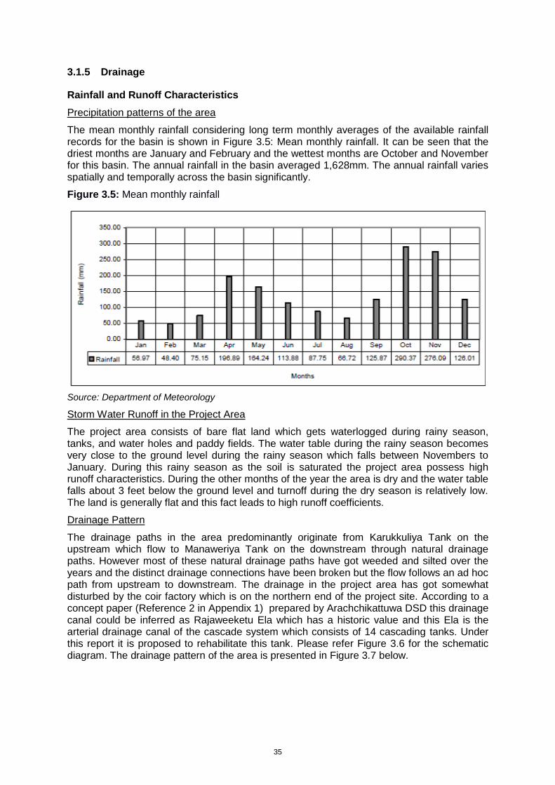
35
3.1.5 Drainage
Rainfall and Runoff Characteristics
Precipitation patterns of the area
The mean monthly rainfall considering long term monthly averages of the available rainfall records for the basin is shown in Figure 3.5: Mean monthly rainfall. It can be seen that the driest months are January and February and the wettest months are October and November for this basin. The annual rainfall in the basin averaged 1,628mm. The annual rainfall varies spatially and temporally across the basin significantly.
Figure 3.5: Mean monthly rainfall
Source: Department of Meteorology
Storm Water Runoff in the Project Area
The project area consists of bare flat land which gets waterlogged during rainy season, tanks, and water holes and paddy fields. The water table during the rainy season becomes very close to the ground level during the rainy season which falls between Novembers to January. During this rainy season as the soil is saturated the project area possess high runoff characteristics. During the other months of the year the area is dry and the water table falls about 3 feet below the ground level and turnoff during the dry season is relatively low. The land is generally flat and this fact leads to high runoff coefficients.
Drainage Pattern
The drainage paths in the area predominantly originate from Karukkuliya Tank on the upstream which flow to Manaweriya Tank on the downstream through natural drainage paths. However most of these natural drainage paths have got weeded and silted over the years and the distinct drainage connections have been broken but the flow follows an ad hoc path from upstream to downstream. The drainage in the project area has got somewhat disturbed by the coir factory which is on the northern end of the project site. According to a concept paper (Reference 2 in Appendix 1) prepared by Arachchikattuwa DSD this drainage canal could be inferred as Rajaweeketu Ela which has a historic value and this Ela is the arterial drainage canal of the cascade system which consists of 14 cascading tanks. Under this report it is proposed to rehabilitate this tank. Please refer Figure 3.6 for the schematic diagram. The drainage pattern of the area is presented in Figure 3.7 below.
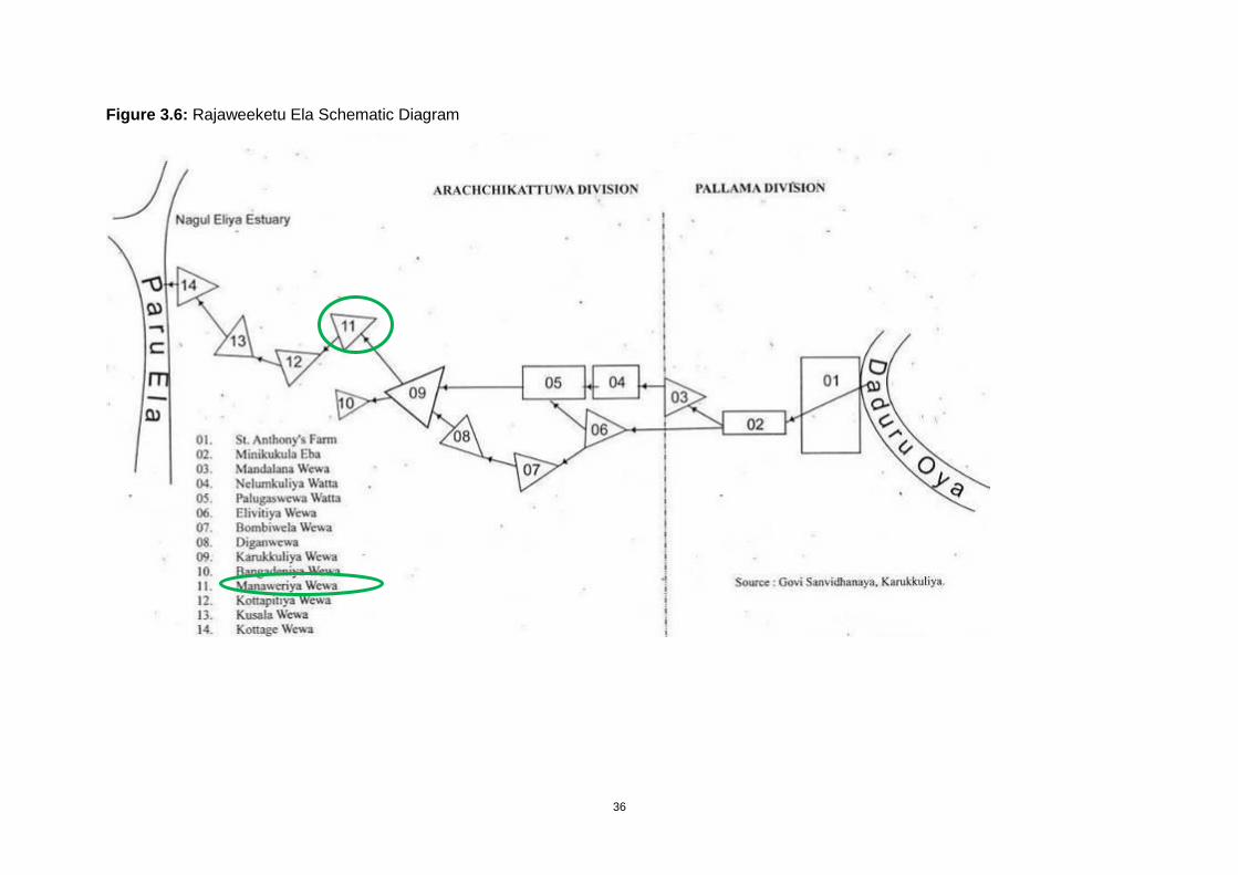
36
Figure 3.6: Rajaweeketu Ela Schematic Diagram
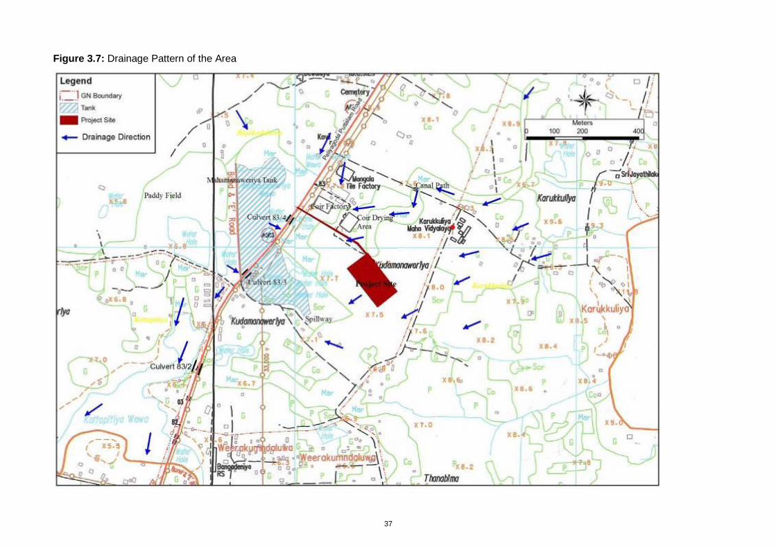
37
Figure 3.7: Drainage Pattern of the Area
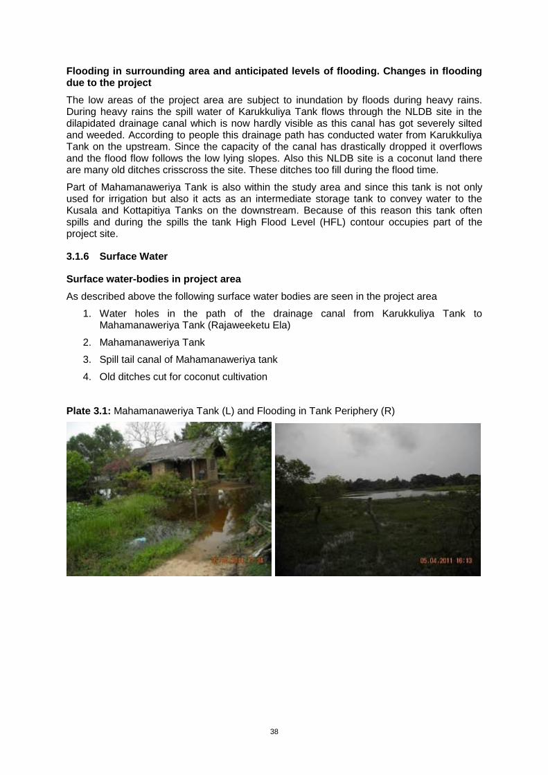
38
Flooding in surrounding area and anticipated levels of flooding. Changes in flooding due to the project
The low areas of the project area are subject to inundation by floods during heavy rains. During heavy rains the spill water of Karukkuliya Tank flows through the NLDB site in the dilapidated drainage canal which is now hardly visible as this canal has got severely silted and weeded. According to people this drainage path has conducted water from Karukkuliya Tank on the upstream. Since the capacity of the canal has drastically dropped it overflows and the flood flow follows the low lying slopes. Also this NLDB site is a coconut land there are many old ditches crisscross the site. These ditches too fill during the flood time.
Part of Mahamanaweriya Tank is also within the study area and since this tank is not only used for irrigation but also it acts as an intermediate storage tank to convey water to the Kusala and Kottapitiya Tanks on the downstream. Because of this reason this tank often spills and during the spills the tank High Flood Level (HFL) contour occupies part of the project site.
3.1.6 Surface Water
Surface water-bodies in project area
As described above the following surface water bodies are seen in the project area
1. Water holes in the path of the drainage canal from Karukkuliya Tank to Mahamanaweriya Tank (Rajaweeketu Ela)
2. Mahamanaweriya Tank
3. Spill tail canal of Mahamanaweriya tank
4. Old ditches cut for coconut cultivation
Plate 3.1: Mahamanaweriya Tank (L) and Flooding in Tank Periphery (R)
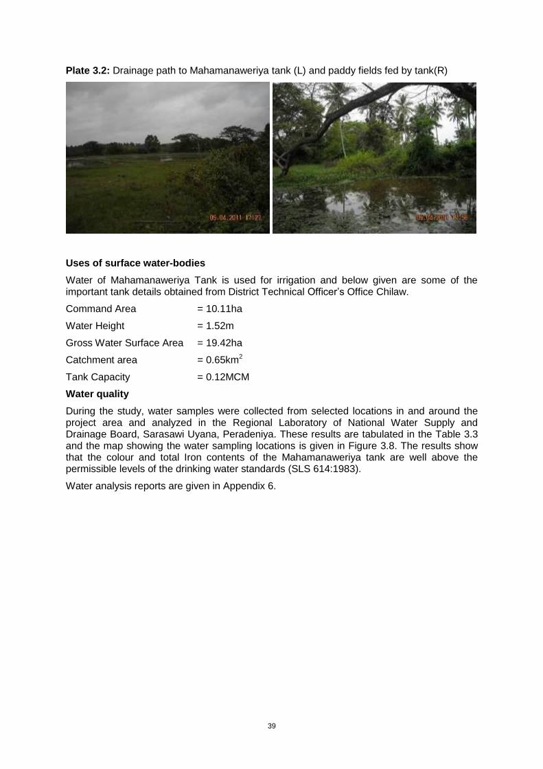
39
Plate 3.2: Drainage path to Mahamanaweriya tank (L) and paddy fields fed by tank(R)
Uses of surface water-bodies
Water of Mahamanaweriya Tank is used for irrigation and below given are some of the important tank details obtained from District Technical Officer’s Office Chilaw.
Command Area = 10.11ha
Water Height = 1.52m
Gross Water Surface Area = 19.42ha
Catchment area = 0.65km2
Tank Capacity = 0.12MCM
Water quality
During the study, water samples were collected from selected locations in and around the project area and analyzed in the Regional Laboratory of National Water Supply and Drainage Board, Sarasawi Uyana, Peradeniya. These results are tabulated in the Table 3.3 and the map showing the water sampling locations is given in Figure 3.8. The results show that the colour and total Iron contents of the Mahamanaweriya tank are well above the permissible levels of the drinking water standards (SLS 614:1983).
Water analysis reports are given in Appendix 6.
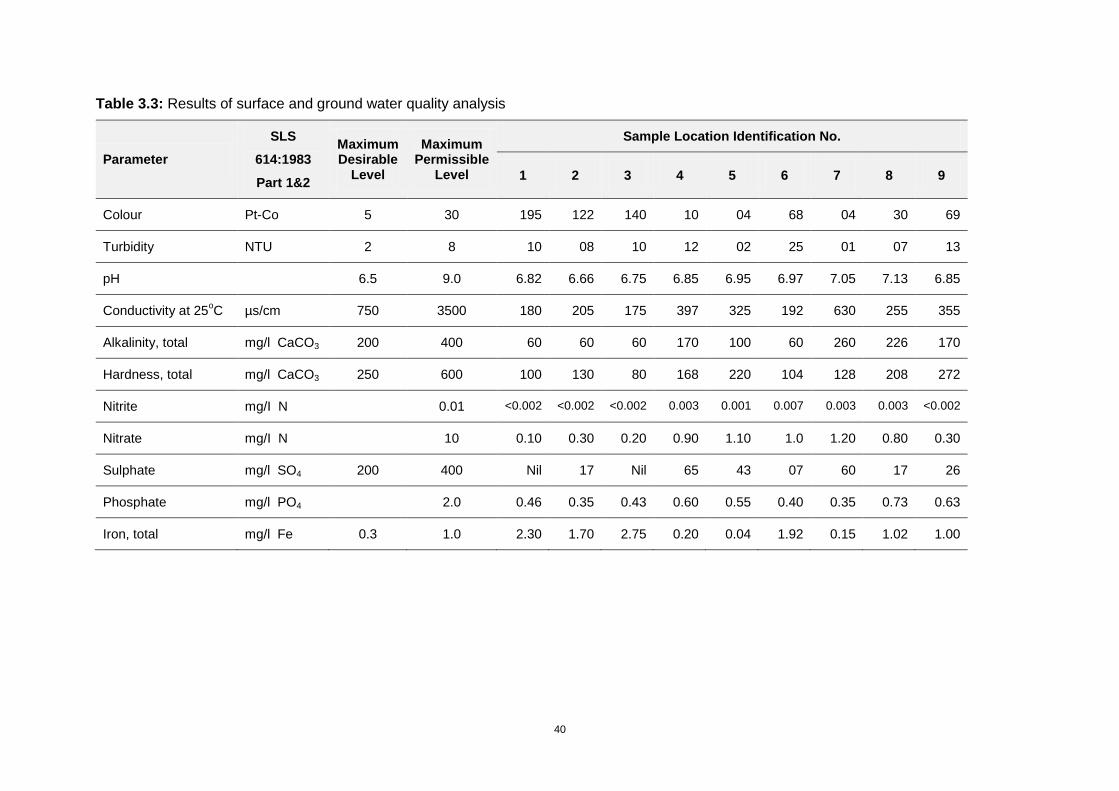
40
Table 3.3: Results of surface and ground water quality analysis
Parameter
SLS
614:1983
Part 1&2
Maximum Desirable
Level
Maximum Permissible
Level
Sample Location Identification No.
1 2 3 4 5 6 7 8 9
Colour Pt-Co 5 30 195 122 140 10 04 68 04 30 69
Turbidity NTU 2 8 10 08 10 12 02 25 01 07 13
pH 6.5 9.0 6.82 6.66 6.75 6.85 6.95 6.97 7.05 7.13 6.85
Conductivity at 25oC µs/cm 750 3500 180 205 175 397 325 192 630 255 355
Alkalinity, total mg/l CaCO3 200 400 60 60 60 170 100 60 260 226 170
Hardness, total mg/l CaCO3 250 600 100 130 80 168 220 104 128 208 272
Nitrite mg/I N 0.01 <0.002 <0.002 <0.002 0.003 0.001 0.007 0.003 0.003 <0.002
Nitrate mg/I N 10 0.10 0.30 0.20 0.90 1.10 1.0 1.20 0.80 0.30
Sulphate mg/l SO4 200 400 Nil 17 Nil 65 43 07 60 17 26
Phosphate mg/l PO4 2.0 0.46 0.35 0.43 0.60 0.55 0.40 0.35 0.73 0.63
Iron, total mg/l Fe 0.3 1.0 2.30 1.70 2.75 0.20 0.04 1.92 0.15 1.02 1.00
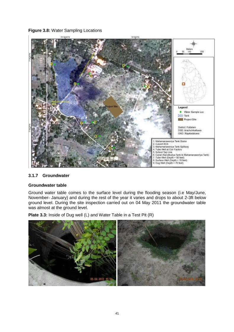
41
Figure 3.8: Water Sampling Locations
3.1.7 Groundwater
Groundwater table
Ground water table comes to the surface level during the flooding season (i.e May/June, November- January) and during the rest of the year it varies and drops to about 2-3ft below ground level. During the site inspection carried out on 04 May 2011 the groundwater table was almost at the ground level.
Plate 3.3: Inside of Dug well (L) and Water Table in a Test Pit (R)
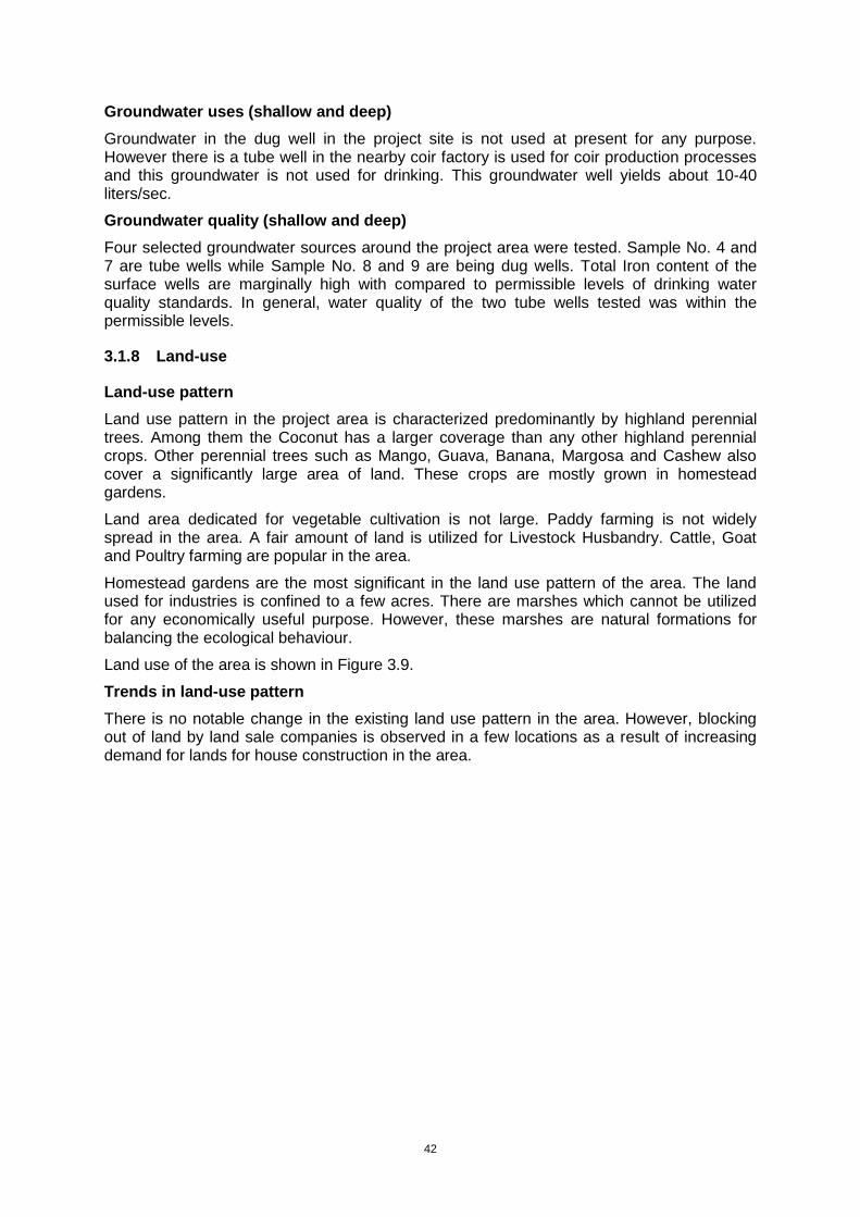
42
Groundwater uses (shallow and deep)
Groundwater in the dug well in the project site is not used at present for any purpose. However there is a tube well in the nearby coir factory is used for coir production processes and this groundwater is not used for drinking. This groundwater well yields about 10-40 liters/sec.
Groundwater quality (shallow and deep)
Four selected groundwater sources around the project area were tested. Sample No. 4 and 7 are tube wells while Sample No. 8 and 9 are being dug wells. Total Iron content of the surface wells are marginally high with compared to permissible levels of drinking water quality standards. In general, water quality of the two tube wells tested was within the permissible levels.
3.1.8 Land-use
Land-use pattern
Land use pattern in the project area is characterized predominantly by highland perennial trees. Among them the Coconut has a larger coverage than any other highland perennial crops. Other perennial trees such as Mango, Guava, Banana, Margosa and Cashew also cover a significantly large area of land. These crops are mostly grown in homestead gardens.
Land area dedicated for vegetable cultivation is not large. Paddy farming is not widely spread in the area. A fair amount of land is utilized for Livestock Husbandry. Cattle, Goat and Poultry farming are popular in the area.
Homestead gardens are the most significant in the land use pattern of the area. The land used for industries is confined to a few acres. There are marshes which cannot be utilized for any economically useful purpose. However, these marshes are natural formations for balancing the ecological behaviour.
Land use of the area is shown in Figure 3.9.
Trends in land-use pattern
There is no notable change in the existing land use pattern in the area. However, blocking out of land by land sale companies is observed in a few locations as a result of increasing demand for lands for house construction in the area.
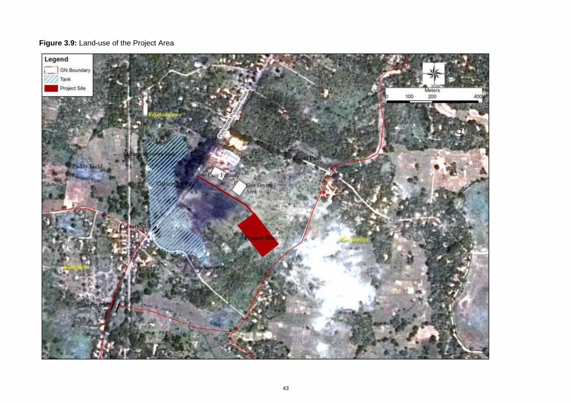
43
Figure 3.9: Land-use of the Project Area
44
3.1.9 Air and Noise Environment
Air quality
No data are available on air quality in or around Chilaw, although the absence of heavy industry in the town should ensure that air quality is reasonably good. Exhaust emissions from vehicles might increase the levels of carbon monoxide and certain other pollutants such as SOx, NOx and hydrocarbons but the coastal location means that winds are relatively strong, which would ensure effective dispersion. The NWPEA have confirmed that no air quality problems have been reported from the town.
Noise
The proposed treatment plant site is located in a rural area where surrounded by A3 highway, a villege road, a coir factory and Karukkuliya school and the observed noise level is fairly low. Coconut plantation extends from the selected land towards the coir factory and the highway making open environment and noise from vehicle movements and coir making activities without much interruption. In the other hand, north-east side of the land which is the direction where the school located and the villege road passes through are covered with a thick vegetation belt which acts as a noise barrier.
3.1.10 Natural Disasters and Risks
Because of its location on the west coast, Chilaw was largely unaffected by the Asian tsunami of December 2004, which caused such extensive damage on the east coast of Sri Lanka. The area is not seismically active, and the generally flat topography means that there are no risks of the landslides. The Disaster Management Center’s database has the past disaster incidents from 1974, and number of events recorded in Chilaw and Arachchikattuwa DSDs are given in the following Table 3.4.
Table 3.4: Natural Disasters Recorded in Chilaw and Arachchikattuwa DSDs
Disaster category No of Events
Chilaw DSD Arachchikattuwa DSD
Floods 14 10
Cyclones 1 -
Gale 9 1
Strong Wind 16 5
Drought 4 9
During heavy rains the spill water of Karukkuliya Tank flows through the NLDB site to the Mahamanaweriya Tank and the low lands of the project area are subject to inundation. However the inundation not remains for a longer period. The drainage canal flowing through the land which is now hardly visible as this canal has got severely silted and weeded.
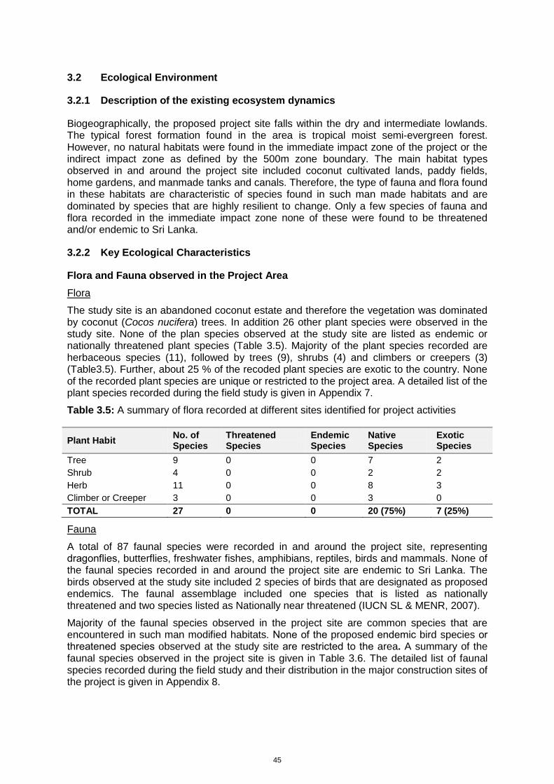
45
3.2 Ecological Environment
3.2.1 Description of the existing ecosystem dynamics
Biogeographically, the proposed project site falls within the dry and intermediate lowlands. The typical forest formation found in the area is tropical moist semi-evergreen forest. However, no natural habitats were found in the immediate impact zone of the project or the indirect impact zone as defined by the 500m zone boundary. The main habitat types observed in and around the project site included coconut cultivated lands, paddy fields, home gardens, and manmade tanks and canals. Therefore, the type of fauna and flora found in these habitats are characteristic of species found in such man made habitats and are dominated by species that are highly resilient to change. Only a few species of fauna and flora recorded in the immediate impact zone none of these were found to be threatened and/or endemic to Sri Lanka.
3.2.2 Key Ecological Characteristics
Flora and Fauna observed in the Project Area
Flora
The study site is an abandoned coconut estate and therefore the vegetation was dominated by coconut (Cocos nucifera) trees. In addition 26 other plant species were observed in the study site. None of the plan species observed at the study site are listed as endemic or nationally threatened plant species (Table 3.5). Majority of the plant species recorded are herbaceous species (11), followed by trees (9), shrubs (4) and climbers or creepers (3) (Table3.5). Further, about 25 % of the recoded plant species are exotic to the country. None of the recorded plant species are unique or restricted to the project area. A detailed list of the plant species recorded during the field study is given in Appendix 7.
Table 3.5: A summary of flora recorded at different sites identified for project activities
Plant Habit No. of Species
Threatened Species
Endemic Species
Native Species
Exotic Species
Tree 9 0 0 7 2
Shrub 4 0 0 2 2
Herb 11 0 0 8 3
Climber or Creeper 3 0 0 3 0
TOTAL 27 0 0 20 (75%) 7 (25%)
Fauna
A total of 87 faunal species were recorded in and around the project site, representing dragonflies, butterflies, freshwater fishes, amphibians, reptiles, birds and mammals. None of the faunal species recorded in and around the project site are endemic to Sri Lanka. The birds observed at the study site included 2 species of birds that are designated as proposed endemics. The faunal assemblage included one species that is listed as nationally threatened and two species listed as Nationally near threatened (IUCN SL & MENR, 2007).
Majority of the faunal species observed in the project site are common species that are encountered in such man modified habitats. None of the proposed endemic bird species or threatened species observed at the study site are restricted to the area. A summary of the faunal species observed in the project site is given in Table 3.6. The detailed list of faunal species recorded during the field study and their distribution in the major construction sites of the project is given in Appendix 8.
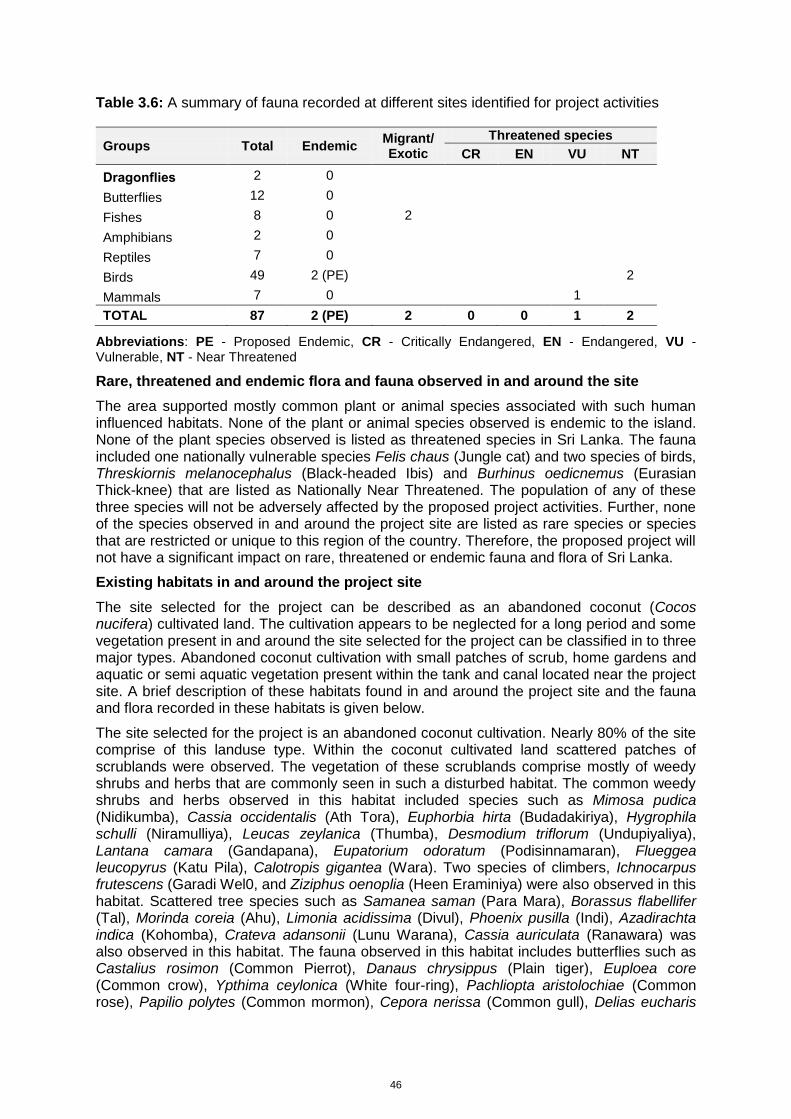
46
Table 3.6: A summary of fauna recorded at different sites identified for project activities
Groups Total Endemic Migrant/ Exotic
Threatened species
CR EN VU NT
Dragonflies 2 0
Butterflies 12 0
Fishes 8 0 2
Amphibians 2 0
Reptiles 7 0
Birds 49 2 (PE) 2
Mammals 7 0 1
TOTAL 87 2 (PE) 2 0 0 1 2
Abbreviations: PE - Proposed Endemic, CR - Critically Endangered, EN - Endangered, VU - Vulnerable, NT - Near Threatened
Rare, threatened and endemic flora and fauna observed in and around the site
The area supported mostly common plant or animal species associated with such human influenced habitats. None of the plant or animal species observed is endemic to the island. None of the plant species observed is listed as threatened species in Sri Lanka. The fauna included one nationally vulnerable species Felis chaus (Jungle cat) and two species of birds, Threskiornis melanocephalus (Black-headed Ibis) and Burhinus oedicnemus (Eurasian Thick-knee) that are listed as Nationally Near Threatened. The population of any of these three species will not be adversely affected by the proposed project activities. Further, none of the species observed in and around the project site are listed as rare species or species that are restricted or unique to this region of the country. Therefore, the proposed project will not have a significant impact on rare, threatened or endemic fauna and flora of Sri Lanka.
Existing habitats in and around the project site
The site selected for the project can be described as an abandoned coconut (Cocos nucifera) cultivated land. The cultivation appears to be neglected for a long period and some vegetation present in and around the site selected for the project can be classified in to three major types. Abandoned coconut cultivation with small patches of scrub, home gardens and aquatic or semi aquatic vegetation present within the tank and canal located near the project site. A brief description of these habitats found in and around the project site and the fauna and flora recorded in these habitats is given below.
The site selected for the project is an abandoned coconut cultivation. Nearly 80% of the site comprise of this landuse type. Within the coconut cultivated land scattered patches of scrublands were observed. The vegetation of these scrublands comprise mostly of weedy shrubs and herbs that are commonly seen in such a disturbed habitat. The common weedy shrubs and herbs observed in this habitat included species such as Mimosa pudica (Nidikumba), Cassia occidentalis (Ath Tora), Euphorbia hirta (Budadakiriya), Hygrophila schulli (Niramulliya), Leucas zeylanica (Thumba), Desmodium triflorum (Undupiyaliya), Lantana camara (Gandapana), Eupatorium odoratum (Podisinnamaran), Flueggea leucopyrus (Katu Pila), Calotropis gigantea (Wara). Two species of climbers, Ichnocarpus frutescens (Garadi Wel0, and Ziziphus oenoplia (Heen Eraminiya) were also observed in this habitat. Scattered tree species such as Samanea saman (Para Mara), Borassus flabellifer (Tal), Morinda coreia (Ahu), Limonia acidissima (Divul), Phoenix pusilla (Indi), Azadirachta indica (Kohomba), Crateva adansonii (Lunu Warana), Cassia auriculata (Ranawara) was also observed in this habitat. The fauna observed in this habitat includes butterflies such as Castalius rosimon (Common Pierrot), Danaus chrysippus (Plain tiger), Euploea core (Common crow), Ypthima ceylonica (White four-ring), Pachliopta aristolochiae (Common rose), Papilio polytes (Common mormon), Cepora nerissa (Common gull), Delias eucharis
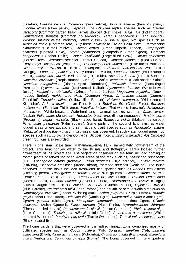
47
(Jezebel), Eurema hecabe (Common grass yellow), Junonia almana (Peacock pansy), Junonia atlites (Grey pansy), Leptosia nina (Psyche) reptile species such as Calotes versicolor (Common garden lizard), Ptyas mucosa (Rat snake), Naja naja (Indian cobra), Hemidactylus frenatus (Common house-gecko), Varanus bengalensis (Land monitor), Varanus salvator (Water monitor), Daboia russelii (Russell’s viper) bird species such as Aegithina tiphia (Common Iora), Cypsiurus balasiensis (Asian Palm Swift), Pericrocotus cinnamomeus (Small Minivet), Ducula aenea (Green Imperial Pigeon), Streptopelia chinensis (Spotted Dove), Treron pompadora (Pompadour Green-pigeon), Coracias benghalensis (Indian Roller), Corvus levaillantii (Large-billed Crow), Corvus splendens (House Crow), Centropus sinensis (Greater Coucal), Clamator jacobinus (Pied Cuckoo), Eudynamys scolopacea (Asian Koel), Phaenicophaeus viridirostris (Blue-faced Malkoha), Dicaeum erythrorhynchos (Pale-billed Flowerpecker), Dicrurus caerulescens (White-bellied Drongo), Lonchura punctulata (Scaly-breasted Munia), Lonchura striata (White-rumped Munia), Copsychus saularis (Oriental Magpie Robin), Nectarina lotenia (Loten’s Sunbird), Nectarina zeylonica (Purple-rumped Sunbird), Oriolus xanthornus (Black-hooded Oriole), Dinopium benghalense (Black-rumped Flameback), Psittacula krameri (Rose-ringed Parakeet), Pycnonotus cafer (Red-vented Bulbul), Pycnonotus luteolus (White-browed Bulbul), Megalaima rubricapilla (Crimson-fronted Barbet), Megalaima zeylanica (Brown-headed Barbet), Acridotheres tristis (Common Myna), Orthotomus utorius (Common Tailorbird), Turdoides affinis (Yellow-billed Babbler), Halcyon smyrnensis (White-throated Kingfisher), Ardeola grayii (Indian Pond Heron), Bubulcus ibis (Cattle Egret), Burhinus oedicnemus (Eurasian Thick-knee), Vanellus indicus (Red-wattled Lapwing), Amaurornis phoenicurus (White-breasted Waterhen) and mammal species such as Canis aureus (Jackal), Felis chaus (Jungle cat), Herpestes brachyurus (Brown mongoose), Hystrix indica (Procupine), Lepus nigricollis (Black-naped hare), Bandicota indica (Malabar bandicoot), Funambulus palmarum (Palm squirrel). Some parts of the coconut land exist as water logged areas where aquatic and semi aquatic plant species such as Aponogeton natans (Kekatiya) and Xanthium indicum (Urukossa) was observed. In such water logged areas frog species such as Euphlyctis cyanophlyctis (Skipper frog), Euphlyctis hexadactylus (Six-toed green frog) was also recorded.
There is one small scale tank (Mahamanaweriya Tank) immediately downstream of the project. This tank convey water to the Kusala and Kottapitiya Tanks located further downstream of the project site. The vegetation observed on the tank included floating or rooted plants observed the open water areas of the tank such as, Nymphaea pubescens (Olu), Aponogeton natans (Kekatiya), Pistia stratiotes (Diya paradel), Salvinia molesta (Salvinia), Eichhornia crassipes (Japan jabara), Ipomoea aquatica (Kankung). The fauna observed in these tanks included freshwater fish species such as Anabas testudineus (Climbing perch), Trichogaster pectoralis (Snake skin gourami), Channa striata (Murrel), Etroplus suratensis (Pearl spot), Oreochromis niloticus (Tilapia), Puntius bimaculatus (Redside barb), Rasbora carverii (Carverii Rasbora), Heteropneustes fossilis (Stinging catfish) Dragon flies such as Crocothemis servilia (Oriental Scarlet), Diplacodes trivialis (Blue Percher), Neurothemis tullia (Pied Parasol) and aquatic or semi aquatic birds such as Dendrocygna javanica (Lesser Whistling-duck), Ardea purpurea (Purple Heron), Ardeola grayii (Indian Pond Heron), Bubulcus ibis (Cattle Egret), Casmerodius albus (Great Egret), Egretta garzetta (Little Egret), Mesophoyx intermedia (Intermediate Egret), Ciconia episcopus (Asian Openbill), Prinia inornata (Plain Prinia), Hydrophasianus chirurgus (Pheasant-tailed Jacana), Phalacrocorax fuscicollis (Indian Cormorant), Phalacrocorax niger (Little Cormorant), Tachybaptus ruficollis (Little Grebe), Amaurornis phoenicurus (White-breasted Waterhen), Porphyrio porphyrio (Purple Swamphen), Threskiornis melanocephalus (Black-headed Ibis).
The home gardens that were observed in the indirect impact zone comprised mostly of cultivated species such as Cocos nucifera (Pol), Borassus flabellifer (Tal), Limonia acidissima (Divul), Azadirachta indica (Kohomba), Cassia auriculata (Ranawara), Mangifera indica (Amba) and Terminalia catappa (Kottan). The fauna observed in home gardens
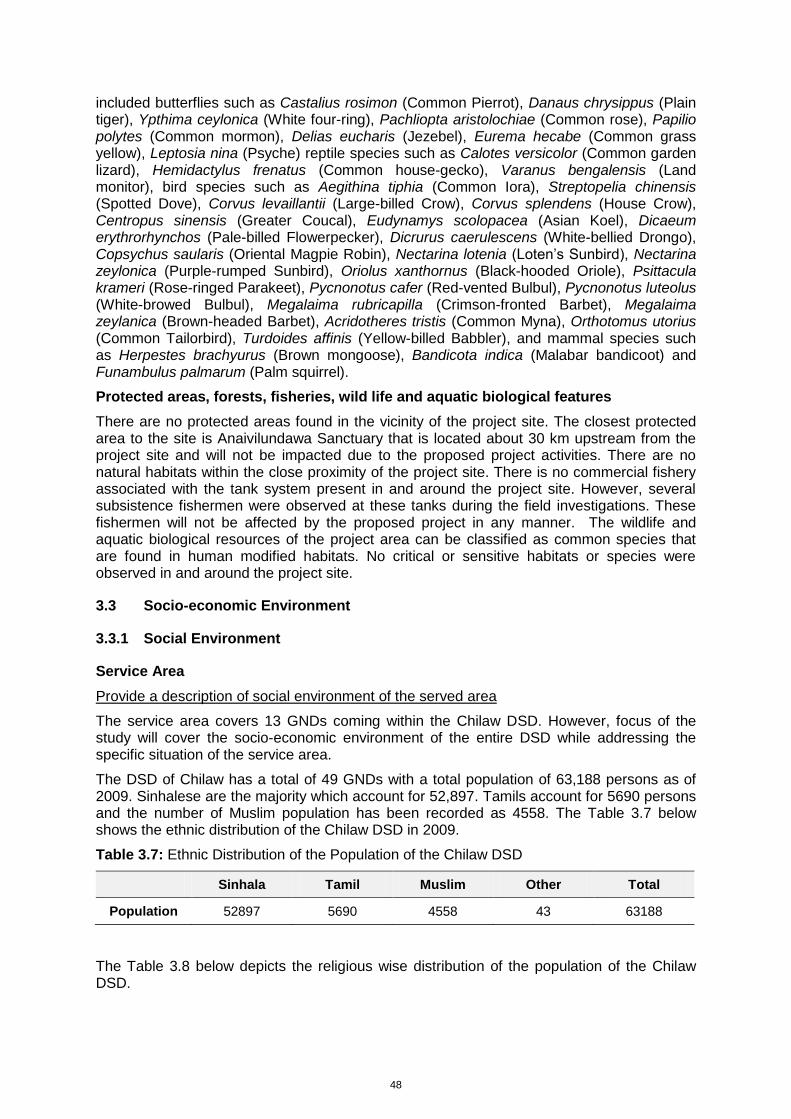
48
included butterflies such as Castalius rosimon (Common Pierrot), Danaus chrysippus (Plain tiger), Ypthima ceylonica (White four-ring), Pachliopta aristolochiae (Common rose), Papilio polytes (Common mormon), Delias eucharis (Jezebel), Eurema hecabe (Common grass yellow), Leptosia nina (Psyche) reptile species such as Calotes versicolor (Common garden lizard), Hemidactylus frenatus (Common house-gecko), Varanus bengalensis (Land monitor), bird species such as Aegithina tiphia (Common Iora), Streptopelia chinensis (Spotted Dove), Corvus levaillantii (Large-billed Crow), Corvus splendens (House Crow), Centropus sinensis (Greater Coucal), Eudynamys scolopacea (Asian Koel), Dicaeum erythrorhynchos (Pale-billed Flowerpecker), Dicrurus caerulescens (White-bellied Drongo), Copsychus saularis (Oriental Magpie Robin), Nectarina lotenia (Loten’s Sunbird), Nectarina zeylonica (Purple-rumped Sunbird), Oriolus xanthornus (Black-hooded Oriole), Psittacula krameri (Rose-ringed Parakeet), Pycnonotus cafer (Red-vented Bulbul), Pycnonotus luteolus (White-browed Bulbul), Megalaima rubricapilla (Crimson-fronted Barbet), Megalaima zeylanica (Brown-headed Barbet), Acridotheres tristis (Common Myna), Orthotomus utorius (Common Tailorbird), Turdoides affinis (Yellow-billed Babbler), and mammal species such as Herpestes brachyurus (Brown mongoose), Bandicota indica (Malabar bandicoot) and Funambulus palmarum (Palm squirrel).
Protected areas, forests, fisheries, wild life and aquatic biological features
There are no protected areas found in the vicinity of the project site. The closest protected area to the site is Anaivilundawa Sanctuary that is located about 30 km upstream from the project site and will not be impacted due to the proposed project activities. There are no natural habitats within the close proximity of the project site. There is no commercial fishery associated with the tank system present in and around the project site. However, several subsistence fishermen were observed at these tanks during the field investigations. These fishermen will not be affected by the proposed project in any manner. The wildlife and aquatic biological resources of the project area can be classified as common species that are found in human modified habitats. No critical or sensitive habitats or species were observed in and around the project site.
3.3 Socio-economic Environment
3.3.1 Social Environment
Service Area
Provide a description of social environment of the served area
The service area covers 13 GNDs coming within the Chilaw DSD. However, focus of the study will cover the socio-economic environment of the entire DSD while addressing the specific situation of the service area.
The DSD of Chilaw has a total of 49 GNDs with a total population of 63,188 persons as of 2009. Sinhalese are the majority which account for 52,897. Tamils account for 5690 persons and the number of Muslim population has been recorded as 4558. The Table 3.7 below shows the ethnic distribution of the Chilaw DSD in 2009.
Table 3.7: Ethnic Distribution of the Population of the Chilaw DSD
Sinhala Tamil Muslim Other Total
Population 52897 5690 4558 43 63188
The Table 3.8 below depicts the religious wise distribution of the population of the Chilaw DSD.
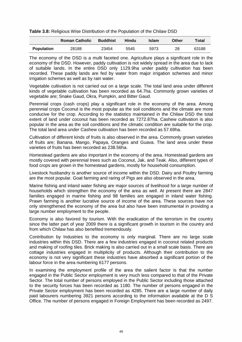
49
Table 3.8: Religious Wise Distribution of the Population of the Chilaw DSD
Roman Catholic Buddhist Hindu Islam Other Total
Population 28188 23454 5545 5973 28 63188
The economy of the DSD is a multi faceted one. Agriculture plays a significant role in the economy of the DSD. However, paddy cultivation is not widely spread in the area due to lack of suitable lands. In the entire DSD only 1129.9ha under paddy cultivation has been recorded. These paddy lands are fed by water from major irrigation schemes and minor irrigation schemes as well as by rain water.
Vegetable cultivation is not carried out on a large scale. The total land area under different kinds of vegetable cultivation has been recorded as 64.7ha. Commonly grown varieties of vegetable are; Snake Gaud, Okra, Pumpkin, and Bitter Gaud.
Perennial crops (cash crops) play a significant role in the economy of the area. Among perennial crops Coconut is the most popular as the soil conditions and the climate are more conducive for the crop. According to the statistics maintained in the Chilaw DSD the total extent of land under coconut has been recorded as 7272.87ha. Cashew cultivation is also popular in the area as the soil conditions and the climatic condition are suitable for the crop. The total land area under Cashew cultivation has been recorded as 57.69ha.
Cultivation of different kinds of fruits is also observed in the area. Commonly grown varieties of fruits are; Banana. Mango, Papaya, Oranges and Guava. The land area under these varieties of fruits has been recorded as 238.56ha.
Homestead gardens are also important in the economy of the area. Homestead gardens are mostly covered with perennial trees such as Coconut, Jak, and Teak. Also, different types of food crops are grown in the homestead gardens, mostly for household consumption.
Livestock husbandry is another source of income within the DSD. Dairy and Poultry farming are the most popular. Goat farming and raring of Pigs are also observed in the area.
Marine fishing and inland water fishing are major sources of livelihood for a large number of households which strengthen the economy of the area as well. At present there are 2847 families engaged in marine fishing and 98 families are engaged in inland water fishing. Prawn farming is another lucrative source of income of the area. These sources have not only strengthened the economy of the area but also have been instrumental in providing a large number employment to the people.
Economy is also favored by tourism. With the eradication of the terrorism in the country since the latter part of year 2009 there is a significant growth in tourism in the country and from which Chilaw has also benefited tremendously.
Contribution by Industries to the economy is only marginal. There are no large scale industries within this DSD. There are a few industries engaged in coconut related products and making of roofing tiles. Brick making is also carried out in a small scale basis. There are cottage industries engaged in multiplicity of products. Although their contribution to the economy is not very significant these industries have absorbed a significant portion of the labour force in the area numbering 6177 persons.
In examining the employment profile of the area the salient factor is that the number engaged in the Public Sector employment is very much less compared to that of the Private Sector. The total number of persons employed in the Public Sector including those attached to the security forces has been recorded as 1180. The number of persons engaged in the Private Sector employment has been recorded as 4285. There are a large number of daily paid labourers numbering 3921 persons according to the information available at the D S Office. The number of persons engaged in Foreign Employment has been recorded as 2497.
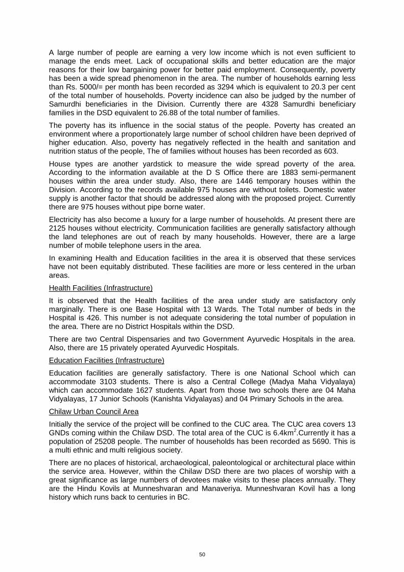
50
A large number of people are earning a very low income which is not even sufficient to manage the ends meet. Lack of occupational skills and better education are the major reasons for their low bargaining power for better paid employment. Consequently, poverty has been a wide spread phenomenon in the area. The number of households earning less than Rs. 5000/= per month has been recorded as 3294 which is equivalent to 20.3 per cent of the total number of households. Poverty incidence can also be judged by the number of Samurdhi beneficiaries in the Division. Currently there are 4328 Samurdhi beneficiary families in the DSD equivalent to 26.88 of the total number of families.
The poverty has its influence in the social status of the people. Poverty has created an environment where a proportionately large number of school children have been deprived of higher education. Also, poverty has negatively reflected in the health and sanitation and nutrition status of the people, The of families without houses has been recorded as 603.
House types are another yardstick to measure the wide spread poverty of the area. According to the information available at the D S Office there are 1883 semi-permanent houses within the area under study. Also, there are 1446 temporary houses within the Division. According to the records available 975 houses are without toilets. Domestic water supply is another factor that should be addressed along with the proposed project. Currently there are 975 houses without pipe borne water.
Electricity has also become a luxury for a large number of households. At present there are 2125 houses without electricity. Communication facilities are generally satisfactory although the land telephones are out of reach by many households. However, there are a large number of mobile telephone users in the area.
In examining Health and Education facilities in the area it is observed that these services have not been equitably distributed. These facilities are more or less centered in the urban areas.
Health Facilities (Infrastructure)
It is observed that the Health facilities of the area under study are satisfactory only marginally. There is one Base Hospital with 13 Wards. The Total number of beds in the Hospital is 426. This number is not adequate considering the total number of population in the area. There are no District Hospitals within the DSD.
There are two Central Dispensaries and two Government Ayurvedic Hospitals in the area. Also, there are 15 privately operated Ayurvedic Hospitals.
Education Facilities (Infrastructure)
Education facilities are generally satisfactory. There is one National School which can accommodate 3103 students. There is also a Central College (Madya Maha Vidyalaya) which can accommodate 1627 students. Apart from those two schools there are 04 Maha Vidyalayas, 17 Junior Schools (Kanishta Vidyalayas) and 04 Primary Schools in the area.
Chilaw Urban Council Area
Initially the service of the project will be confined to the CUC area. The CUC area covers 13 GNDs coming within the Chilaw DSD. The total area of the CUC is 6.4km2.Currently it has a population of 25208 people. The number of households has been recorded as 5690. This is a multi ethnic and multi religious society.
There are no places of historical, archaeological, paleontological or architectural place within the service area. However, within the Chilaw DSD there are two places of worship with a great significance as large numbers of devotees make visits to these places annually. They are the Hindu Kovils at Munneshvaran and Manaveriya. Munneshvaran Kovil has a long history which runs back to centuries in BC.
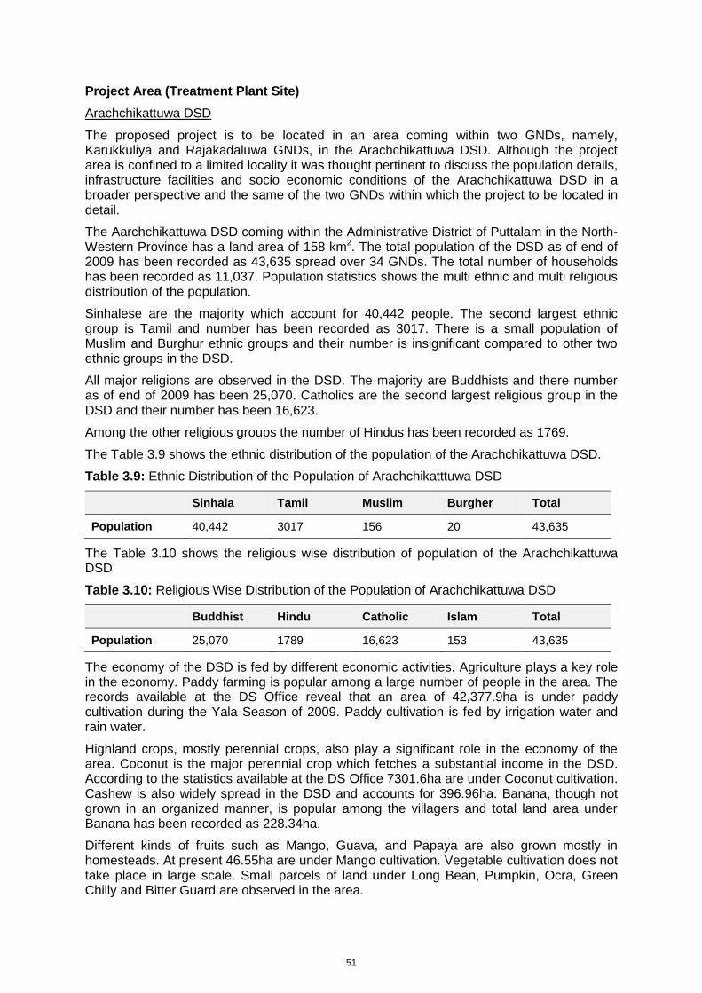
51
Project Area (Treatment Plant Site)
Arachchikattuwa DSD
The proposed project is to be located in an area coming within two GNDs, namely, Karukkuliya and Rajakadaluwa GNDs, in the Arachchikattuwa DSD. Although the project area is confined to a limited locality it was thought pertinent to discuss the population details, infrastructure facilities and socio economic conditions of the Arachchikattuwa DSD in a broader perspective and the same of the two GNDs within which the project to be located in detail.
The Aarchchikattuwa DSD coming within the Administrative District of Puttalam in the North-Western Province has a land area of 158 km2. The total population of the DSD as of end of 2009 has been recorded as 43,635 spread over 34 GNDs. The total number of households has been recorded as 11,037. Population statistics shows the multi ethnic and multi religious distribution of the population.
Sinhalese are the majority which account for 40,442 people. The second largest ethnic group is Tamil and number has been recorded as 3017. There is a small population of Muslim and Burghur ethnic groups and their number is insignificant compared to other two ethnic groups in the DSD.
All major religions are observed in the DSD. The majority are Buddhists and there number as of end of 2009 has been 25,070. Catholics are the second largest religious group in the DSD and their number has been 16,623.
Among the other religious groups the number of Hindus has been recorded as 1769.
The Table 3.9 shows the ethnic distribution of the population of the Arachchikattuwa DSD.
Table 3.9: Ethnic Distribution of the Population of Arachchikatttuwa DSD
Sinhala Tamil Muslim Burgher Total
Population 40,442 3017 156 20 43,635
The Table 3.10 shows the religious wise distribution of population of the Arachchikattuwa DSD
Table 3.10: Religious Wise Distribution of the Population of Arachchikattuwa DSD
Buddhist Hindu Catholic Islam Total
Population 25,070 1789 16,623 153 43,635
The economy of the DSD is fed by different economic activities. Agriculture plays a key role in the economy. Paddy farming is popular among a large number of people in the area. The records available at the DS Office reveal that an area of 42,377.9ha is under paddy cultivation during the Yala Season of 2009. Paddy cultivation is fed by irrigation water and rain water.
Highland crops, mostly perennial crops, also play a significant role in the economy of the area. Coconut is the major perennial crop which fetches a substantial income in the DSD. According to the statistics available at the DS Office 7301.6ha are under Coconut cultivation. Cashew is also widely spread in the DSD and accounts for 396.96ha. Banana, though not grown in an organized manner, is popular among the villagers and total land area under Banana has been recorded as 228.34ha.
Different kinds of fruits such as Mango, Guava, and Papaya are also grown mostly in homesteads. At present 46.55ha are under Mango cultivation. Vegetable cultivation does not take place in large scale. Small parcels of land under Long Bean, Pumpkin, Ocra, Green Chilly and Bitter Guard are observed in the area.
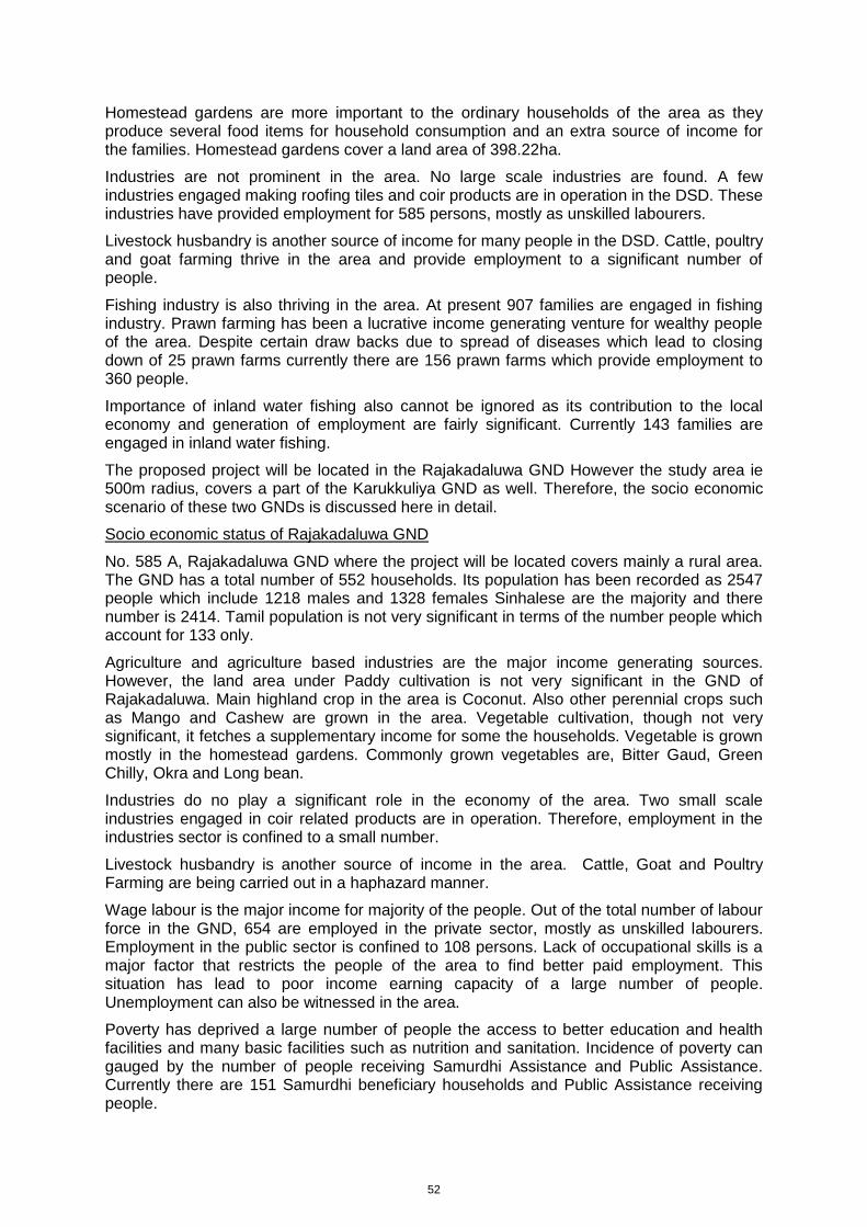
52
Homestead gardens are more important to the ordinary households of the area as they produce several food items for household consumption and an extra source of income for the families. Homestead gardens cover a land area of 398.22ha.
Industries are not prominent in the area. No large scale industries are found. A few industries engaged making roofing tiles and coir products are in operation in the DSD. These industries have provided employment for 585 persons, mostly as unskilled labourers.
Livestock husbandry is another source of income for many people in the DSD. Cattle, poultry and goat farming thrive in the area and provide employment to a significant number of people.
Fishing industry is also thriving in the area. At present 907 families are engaged in fishing industry. Prawn farming has been a lucrative income generating venture for wealthy people of the area. Despite certain draw backs due to spread of diseases which lead to closing down of 25 prawn farms currently there are 156 prawn farms which provide employment to 360 people.
Importance of inland water fishing also cannot be ignored as its contribution to the local economy and generation of employment are fairly significant. Currently 143 families are engaged in inland water fishing.
The proposed project will be located in the Rajakadaluwa GND However the study area ie 500m radius, covers a part of the Karukkuliya GND as well. Therefore, the socio economic scenario of these two GNDs is discussed here in detail.
Socio economic status of Rajakadaluwa GND
No. 585 A, Rajakadaluwa GND where the project will be located covers mainly a rural area. The GND has a total number of 552 households. Its population has been recorded as 2547 people which include 1218 males and 1328 females Sinhalese are the majority and there number is 2414. Tamil population is not very significant in terms of the number people which account for 133 only.
Agriculture and agriculture based industries are the major income generating sources. However, the land area under Paddy cultivation is not very significant in the GND of Rajakadaluwa. Main highland crop in the area is Coconut. Also other perennial crops such as Mango and Cashew are grown in the area. Vegetable cultivation, though not very significant, it fetches a supplementary income for some the households. Vegetable is grown mostly in the homestead gardens. Commonly grown vegetables are, Bitter Gaud, Green Chilly, Okra and Long bean.
Industries do no play a significant role in the economy of the area. Two small scale industries engaged in coir related products are in operation. Therefore, employment in the industries sector is confined to a small number.
Livestock husbandry is another source of income in the area. Cattle, Goat and Poultry Farming are being carried out in a haphazard manner.
Wage labour is the major income for majority of the people. Out of the total number of labour force in the GND, 654 are employed in the private sector, mostly as unskilled labourers. Employment in the public sector is confined to 108 persons. Lack of occupational skills is a major factor that restricts the people of the area to find better paid employment. This situation has lead to poor income earning capacity of a large number of people. Unemployment can also be witnessed in the area.
Poverty has deprived a large number of people the access to better education and health facilities and many basic facilities such as nutrition and sanitation. Incidence of poverty can gauged by the number of people receiving Samurdhi Assistance and Public Assistance. Currently there are 151 Samurdhi beneficiary households and Public Assistance receiving people.
53
Utility services such as pipe borne water and electricity from the National Grid are generally satisfactory. Out of the total number of 552 households 350 have access to pipe borne water. Only 20 households are without electricity supply. Communication facilities are mostly by mobile phones.
Education levels of the population seem inequitable. Only a few has had higher education. A large number of people have studied only up to primary level. There are people without any school education.
Socio economic Status of Karukkuliya GND
Only a small area of No. 574 A, Karukkuliya GND is coming within the proposed project location. However, it was thought pertinent to examine the socio economic status of the entire Karukkuliya GND.
According to the information available with the Grama Niladhari of the Karukkuliya GND the total number of families living at present is 320. Total population has been recorded as 1760. Majority are Sinhala and the number has been recorded as 1743.
The economy of the GND mainly based agriculture. Paddy cultivation is not very prominent within the GND. The village tank called Karukkuliya provides irrigation facilities to 140 acres. Currently 96 families are engaged in Paddy farming. Vegetable cultivation is also observed in the area but not in a large scale. Commonly grow varieties of vegetable are Green Chilly, Long Been and Okra.
The more significant highland crop observed in the area is Coconut. Different kinds of fruits are also grown in the area. Cashew and Mangos are grown in unorganized manner. Guava and Banana are other varieties of fruits observed. Homestead gardens are more important in the village economy as they provide supplementary food varieties and extra income to a large number of households.
Industries are not flourishing in the area. Only one small scale industry engaged in coir products was observed in the study which provides employment to a very few people.
Livestock husbandry is fairly popular. Cattle, poultry and goat farming fetch a fair income to those engaged in these activities.
Wage employment is the source income to a large number of people. Skilled labour is in short supply. Majority of the labour force works as unskilled labourers. Monthly income of the unskilled labourers is very poor. Unemployment is also observed in the area.
There is small number of People employed in the Public Sector in the GND. A few people are engaged in foreign employment.
Lack of opportunities to find better paid employments due to lack of skills has lead to poverty in the area. Poverty incidence can be judged by the number of households receiving Samurdhi Assistance and Public Assistance. The number of Samurdhi beneficiary families has been recorded as 107 and 33 persons are drawing Public Assistance.
Utility facilities are generally satisfactory. Three Hundred and Fifty families have the access to pipe borne water. Electricity supply is from the National Grid. However, still there are 20 houses without electricity. Communication facilities are generally satisfactory. Although number of land telephone lines are available at a very few households mobile telephones have become vogue of the day.
Social environment of the project area (Treatment plant site and access road)
Social environment of the project area has been described in the preceding paragraphs. As far as the facility land (project site) is concerned the NWS&DB has made arrangements to obtain a block of land in extent of 04 acres released from the NLDB, the present owner of the land, located approximately 03 kilo metres southward from the Lunu Oya on the Colombo – Puttlam highway. The total extent of the land within which facility land is located
54
is 50 acres and it is a neglected coconut land. The land is situated bordering the Colombo – Puttalam highway and is easily accessible from that high way. The proposed site is located closer to the Mahamanaweriya Tank which provides irrigation water to a paddy land in extent of 20 acres. Although the area in the immediate vicinity of the Mahamanaweriya Tank gets flooded during the rainy season, the proposed land for the project site doesn’t go under water at any given time of the year.
Within the 500m radius of the facility land 14 houses have been observed. Karukkuliya Maha Vidyalayaya is also located within the 500 metre radius from the project site. Also, there is a coir factory currently in operation closer to project site.
Provide details of social infrastructure (health and educational facilities, etc)
There are no health institutions within the project area. Public Health Inspectors (PHIs) and Public Health Midwives make routine visits to the area to create awareness in their respective fields. As far as education is concerned only one school is observed in the project area.
Identify sites that are of historical, archaeological, paleontological, or architectural significance
Any sites of historical, archaeological, paleontological or architectural significance have not been found in the project area.
Population statistics
Population statistics have been elaborated in some of the preceding Paragraphs.
Socio-economic conditions (income level)
Socio economic conditions of the project area have also been described in some of the preceding paragraphs.
3.3.2 Economic Environment
Industries
In the project area industries of significant importance have not been observed. In the two GNDs under our study a few industries engaged in making of roofing tiles and coir products are in operation. Within the 500m radius from the proposed project a coir industry is observed.
Land use (dedicated area uses)
In examining the land use pattern of the two GNDs under reference (Rajakadaluwa and Karukkuliya) it is observed that a larger area is under coconut cultivation. Paddy cultivation is not very prominent. Karukkuliuya Tank and the Mahamanaweriya Tank provide irrigation facilities to 160 acres. The vegetable cultivation is scattered within the two GNDs but does not cover a large area of land.
Homestead gardens are the most significant mode of land use. Homestead gardens are covered mostly with coconut trees. Other perennial crops such as Cashew and Mango can also been seen in the homestead gardens. Guava and Banana are the other varieties of crops observed in the homestead gardens. There are marshy lands which cannot be used for any productive purpose.
Land use pattern in the project area is more or less the same as in the two GNDs.
Power sources and transmission
The power supply of the area is by the Ceylon Electricity Board through the National Grid. Except for a small number of households others within the project area have access to electricity from the National Grid.
55
Agricultural development and tourism facilities
Currently 20 acres of paddy lands are being cultivated using the water from the Mahamanaweriya Tank by 20 farmers in the project area. Other than this, no other agricultural development is taking place at present. The area is covered mostly by coconut cultivation.
As far as the tourism is concerned the project area does not have any special features that can attract tourists. With the current increasing trend in tourism in the country some improvement can be expected.
3.3.3 Institutional Environment
3.3.3.1 Capacity of the O&M Institution
The operation and maintenance of the plant will be the responsibility of the CUC. The technical capability requirement of the proposed plant is not heavy. This is because it does not include mechanical process equipment or sophisticated control systems. The O&M will mostly be routine work which can be handled even by unskilled labour with some training. These include:
(a) Unloading of septage from gully trucks
(b) Weeding of the ponds
(c) Removal of screen material
(d) Deluuding of anaerobic pond and removal of sludge
In addition monitoring of water quality is part of the O&M program. This cannot be handled by the CUC. It is proposed to outsource this responsibility to an independent agency other than the NWS&DB on long term basis. The party thus appointed will be responsible for visiting the site and collecting a representative sample for testing, carry out the quality tests and report (See the details given in EMP).
3.3.3.2 Issues associated with Project being located outside of the service area
The project site is located within Arachchikattuwa (outside the service area). The IEE consultants had detailed discussions with officials of CUC, APS and Divisional Secretaries of Chilaw and Arachchikattuwa on issues arising out of this situation.
The APS officials clearly indicated that they do not oppose the project as long as they are also benefited by the same. The area is dependent on on-site sanitation and demand for septage disposal services is not high. The proposed STP can provide septage disposal service to the Arachchikattuwa area as well. Also the project includes household sanitation program, where financial assistance is provided to build toilets for needy. There is a request from the APS for allocation of funding for their area under the household sanitation program.
3.3.4 Social and Institutional Threats
The service area and the project area are coming with two different DSDs and two LAs. In the project area social threats due to the project are not expected. The Treatment Plant will not pose any threat to the social life of the people living in the close proximity or in the suburban area. At the public consultation meeting held at the APS Office on August 10, 2011 it was elaborated that no health or social problem would be generated due to the project. It was also elaborated that even in transportation of septage to the Treatment Plant every precautionary measure will be taken to avoid any possible harm to the health and the social life of the people. People will not know what is being transported even.

56
As far as institutional aspects are concerned it is observed that the institutional capacities of the Implementing Agency and the Executing Agency are already in place adequately. The NWS&DB, the Implementing Agency, can handle the project without any difficulty as its exiting institutional strength has the capacity to undertake the project.
Existing institutional capacity of the Executing Agency, the CUC, is also seen adequate to handle project. Only addition that will be needed is to recruit drivers and helpers for the Gully Bousers to be provided by the NWS&DB. Apart from this there is no need to increase any cadre in the Urban Council for this purpose.
57
4.0 DESCRIPTION OF ANTICIPATED ENVIRONMENTAL IMPACTS
4.1 Construction Phase
4.1.1 Impacts of land clearing and development
Construction of the STP will involve land clearing, excavation, filling, compaction and concreting. Therefore potential physical and other impacts can be expected. However, as these activities will take place within a very small area of about 1.97ha of coconut land, no major negative impacts will be expected. Only a few unproductive coconut trees and shrubs will have to be removed during land clearing.
Excavation of the tank beds and ponds will create substantial amount of spoil material. Although this is not a significant quantity, it adds to the waste burden of the project and considered as significant. Excavated materials need to be stockpiled until either they will be utilized for filling or taken out as an excess material. During the excavation work in the case of raining, there may be temporary blockages of drainage paths and erosion which result in siltation of downstream tanks.
It will be necessary to use a large quantity of earth as filling material to achieve the required levels of tanks, bunds and access roads and hence, operation of burrow pit will be necessary. This operation may generate dust and noise due to excavation, loading and transportation of earth. Excavation during rainy period may cause soil erosion, sedimentation outflow and possible slope failures, if not properly planned and operated the burrow area. Since there will be heavy machinery and hauling trucks involved in the operation, the attention should be paid on public safety issues and the traffic control. Magnitude of the impact of land clearing and development will depend on to what extent suitable fill and lining material are available and obtained on-site. This information is not available at present.
To minimize the impacts, eligible contractor/s that is operating burrow pits with necessary approvals will be engaged to supply the land filling material.
4.1.2 Noise, vibration and dust due to construction activities
Noise vibration and dust are common construction issues typical to projects of this nature. During the construction period generation of noise would be an inevitable event. Involvement of heavy equipments, machineries, movement of heavy vehicles and presence of large number of workers will be the main sources of noise generation. According to the Provincial Environmental (Noise Control) Regulation No. 04 of 2010 (Schedule III), the permissible noise level at boundaries of the land in which the source noise is located for the construction activities is 75 dB(A) in day time and 50 dB(A) in night time.
The high noise generation equipments to be engaged in the construction activities should consist of proper noise attenuation. It is advisable to avoid the construction work in the night time and do some noise level measurements during the time of construction activities are going on. Noise levels for some of the common types of heavy construction machinery and equipment that are likely to be used for the Project are given in Table 4.1. However, these potential impacts are not difficult to mitigate, by applying the measures as recommended in the Section 5.1.2, 5.1.3 and 5.1.4 below.
In this case impacts will not be significant as most of the sensitive receptors are located adequately away from the site. Also vegetation cover is adequate to reduce these impacts. The main sensitive receptors are the coir factory and the residence of the caretaker of the site. Both these will very likely be adversely affected by dust and to some extent the noise. Vibration is unlikely to be a significant impact.
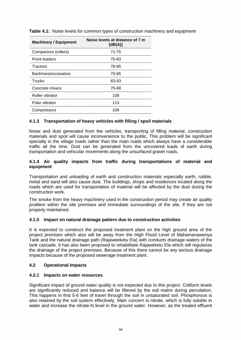
58
Table 4.1: Noise levels for common types of construction machinery and equipment
Machinery / Equipment Noise levels at distance of 7 m
[dB(A)]
Compactors (rollers) 71-75
Front loaders 70-83
Tractors 78-95
Backhoes/excavators 70-85
Trucks 83-93
Concrete mixers 75-88
Roller vibrator 108
Poke vibrator 113
Compressors 109
4.1.3 Transportation of heavy vehicles with filling / spoil materials
Noise and dust generated from the vehicles, transporting of filling material, construction materials and spoil will cause inconvenience to the public. This problem will be significant specially in the village roads rather than the main roads which always have a considerable traffic all the time. Dust can be generated from the uncovered loads of earth during transportation and vehicular movements along the unsurfaced gravel roads.
4.1.4 Air quality impacts from traffic during transportations of material and equipment
Transportation and unloading of earth and construction materials especially earth, rubble, metal and sand will also cause dust. The buildings, shops and residences located along the roads which are used for transportation of material will be affected by the dust during the construction work.
The smoke from the heavy machinery used in the construction period may create air quality problem within the site premises and immediate surroundings of the site, if they are not properly maintained.
4.1.5 Impact on natural drainage pattern due to construction activities
It is expected to construct the proposed treatment plant on the high ground area of the project premises which also will be away from the High Flood Level of Mahamanaweriya Tank and the natural drainage path (Rajaweeketu Ela) with conducts drainage waters of the tank cascade. It has also been proposed to rehabilitate Rajaweketu Ela which will regularize the drainage of the project premises. Because of this there cannot be any serious drainage impacts because of the proposed sewerage treatment plant.
4.2 Operational Impacts
4.2.1 Impacts on water resources
Significant impact of ground water quality is not expected due to this project. Coliform levels are significantly reduced and balance will be filtered by the soil matrix during percolation. This happens in first 5-6 feet of travel through the soil in unsaturated soil. Phosphorous is also retained by the soil system effectively. Main concern is nitrate, which is fully soluble in water and increase the nitrate-N level in the ground water. However, as the treated effluent
59
is applied to abandoned coconut land with good grass cover vegetated quantity of nitrogen will be taken up by the plants. Also significant quantity of nitrogen is removed from the wastewater through settling at anaerobic pond and biological actions in facultative and maturation ponds. Therefore the quantity of nitrogen released to the environment is very negligible. Treated effluent is high in DO and very low in biodegradable organics thus discharge of treated effluent will not result in soil pollution. However, monitoring of ground water quality in wells in the area is proposed as a precautionary step.
Impact on flooding
Flooding only takes place in the low lying areas within the project area and the inundation threat to the high ground area which has been selected to establish the sewerage treatment plant. The flood impact could be mitigated through appropriate mitigatory measures. See Chapter 5 for details.
Impact on Irrigation activities of surrounding areas of the project
As stated above the proposed sewerage plant will be established on the upper reach of the tank on the high ground well away from its high flood level. Most of the irrigation activities takes place in the downstream area which is at a considerable distance (Refer Figure 3.7: Drainage Pattern Map for details). Hence there cannot be any obstruction to irrigation activities because of the project.
The location of the treatment plant could fall within the High Flood Level of Mahamanaweriya Tank. Hence it will cause an impact on the tank. However since the land is flat it is difficult to determine the ground boundary where the high flood level will terminate.
4.2.2 Impacts due to release of obnoxious gases
Obnoxious gases arise under anaerobic conditions in ponds. However, this problem can be avoided by maintaining loading rates such that top few centimeters is under aerobic condition. This is done through the design.
In general the release of obnoxious gases takes place in STPs during unloading operations. There are several actions commonly adopted to address this. The design has taken several steps to address this issue. These include
(a) Shielding of the unloading bay to an extend to prevent odorous gases being blown away by the wind
(b) Hydraulic arrangements that would minimize agitation of sewage during the release to the treatment system
(c) Keeping much of the screen channel close to prevent release of gases to air
4.2.3 Impact due to Movement of Gully Trucks
Noise, Odour and Trafic
Gully trucks will be provided by the Project to CUC, which is responsible for operating the sanitation service. The Council will ensure that the tankers are serviced and repaired to manufacturer’s specifications so that the vehicles have a long working life. They will also employ and train tanker drivers and plan their work schedule, through which all septic tanks in the town are expected to be emptied at least once a year. However, anticipated noise and traffic impact due to movement of Gully trucks will not be significant.
There should also be no major odour problems from the operation of the Gully trucks in the town because any related disturbances will be infrequent and short-lived, and people will tolerate such small-scale disturbance if they are aware that their environment will be improved as a result. Efforts should still be made to avoid affecting socially and culturally important locations (churches, schools, hospitals, etc) to the extent possible.
60
There are some risks to workers and the public from the pumping operation to remove material from septic tanks. The Urban Council should therefore protect the health and safety of their workers and the public by ensuring that procedures are properly defined and followed.
4.3 Impacts on Ecological Resources (Construction and Operational)
4.3.1 Destruction or alternation of habitats
The site selected for the project is an abandoned coconut land with patches of scrub scattered within the land. The indirect impact zone contains other man made habitats such as small tanks, paddy land, home gardens etc., Further, the project activities are will be restricted to a small area (less than 0.25 ha) of the coconut land selected. Therefore, the project will not result in any destruction or alteration of habitats either natural or manmade.
4.3.2 Affects on the prevailing ecosystem balance
As discussed above the direct impact zone of the project is limited to a small area within a man made habitat. There are no natural ecosystems within the direct or indirect impact zones of the project. Therefore, the project will not have any impact on the ecosystem balance in the area.
4.3.3 Impacts on terrestrial and aquatic flora and fauna
The site selected for the project tends to undergo inundation seasonally while some parts of the project site lying closer to the drainage canal tend to be water logged due to poor drainage. One aquatic plant Aponogeton natans (Kekatiya) was observed in such water logged areas. Other than these several species aquatic plants, Pistia stratiotes (Diya paradel), Salvinia molesta (Salvinia), Eichhornia crassipes (Japan jabara) and Ipomoea aquatica (Kankung) were observed in the Mahamanaweriya Tank lying immediately downstream of the project site. Out of these species the most abundant species were Salvinia molesta (Salvinia) and Eichhornia crassipes (Japan jabara), both of which are listed as invasive alien plant species. The aquatic fauna also comprised of common freshwater fish species as well as aquatic associated bird species. The terrestrial fauna and flora also comprise of common plant and animal species that can be observed in such human modified landscapes. These species are highly adaptable and can withstand disturbance by man. Further, the project activities are restricted to a small area and there will be no effluent release to the water bodies in the surrounding areas. Therefore, terrestrial and aquatic fauna and flora will not be adversely affected by the proposed project activities. Effluent contains nutrients and help plant growth. In any case the quantity of effluent to be released is not high for nearly nine months of the year due to evaporation.
4.3.4 Impacts on receiving water-body
The project does not involve release of any effluents in to the water bodies present around the project site. Therefore, this impact does not arise.
Based on these observations it can be concluded that the proposed project activities will not result in any adverse impacts on the habitats or species present in the direct or indirect impact zone of the selected site for project implementation.
61
4.4 Impacts on Socio-economic Environment (Construction and Operational)
4.4.1 Social economic benefits (Health etc)
Social benefits of the project will be enormous. Removal of septage has been a critical problem within the CUC area since the recent past and this situation has posed a threat to the heath and sanitation of the people. The entire CUC area is in a low line terrain and most parts of it get inundated when precipitation of heavy rains occur. Since the ground water level also very high, removal of septage has to be carried out more frequently than in other areas. However, currently the CUC does not have enough resources to cope up with the situation and this has already become a serious problem for health.
Currently the septage is carried by the Gully Bousers and discharged at open places in the coconut lands located in distance places away from the residential houses. This is an unhealthy practice as it can pose threats to the health of the people. Therefore, the proposed project would a blessing to the people living within the service area as it will result in improving their health conditions and social life.
However, in the project area people are not going to receive any social benefits due the project at the beginning as the service of the project will be extended to them after some time. Also, there can be negative impacts unless all precautionary measures are taken to prevent any odour emanating from the Treatment Plant.
As far as impacts on the economy in the service area and the project area are concerned no significant impacts either positive or negative will be expected. In the service area there will be no change in the land use pattern or the existing economic activities due to the project. In the project area too, there will be no change in the land use pattern due to the project. However, the project area will be benefited economically in a small way during the construction period due to availability of employment for the local people.
4.4.2 Impact due to land-use change
The site is part of an abandoned coconut plantation. There is no economic return from the land at present. The proposed change however could have social and economic impacts as this is normally not a socially acceptable project. Typical impacts are drop in land value and social stigma. However, the consultants do not consider major impacts in this case due to several reasons as follows.
Site is far from sensitive areas and away from the visibility
Adequate distance and vegetative buffer can be provided to separate it from other land uses
Site can be directly accessed from the main road and interior roads are not affected
4.4.3 Impact on land values
Since this is a very small project, despite the fact it will provide an invaluable service to the area, and it will be located in a four (04) acre bloc of land, any changes in the land value of the area, upward or downward are not anticipated. There is a possibility of drop in the land values in the immediate vicinity of the project however, the consultants do not think that it will be significant considering the above mentioned factors and rural nature of the area.
4.4.4 Impact on quality of life
Quality of life of life of the people living in the service area will improve tremendously once the project is implemented. Improvements will be in the areas of (a) public health; (b) affordable sanitation service; (c) improved natural environment and (d) improved built
62
environment. Although demand is not high for septage services in the project site area, they will also be provided with the service as wanted.
4.4.5 Employment opportunities
Employment opportunities, mostly for unskilled labourers, in the area will be created by the project
4.4.6 Resettlement requirements (if any)
The question of resettlement of people will not arise as not a single household will be affected by the project.
4.4.7 Social impacts due to transportation of septage
As explained in some of the preceding Paragraphs any negative social impacts will not generate due to transport of septage.
4.5 Any other Impacts
Any impacts other than those discussed above will not be expected due to implementation of the project.
63
5.0 PROPPOSED MITIGATORY MEASURES
5.1 Mitigatory Measures proposed for Constructional Impacts
5.1.1 Mtigation of Impacts due to land clearing and development
Soil erosion causing water quality problems and sedimentation of lagoons, wetlands and tanks will be controlled through;
Careful planning of construction activities that lead to heavy erosion, to avoid heavy rainy seasons (ie., November-January)
Remove waste soil as soon as it is excavated, by loading directly onto trucks, it is recommended to imposed condition to the contractor to use the on-site excavated material for filling purpose if they are suitable for the purpose. Only the un-suitable and excess excavated material shall be allowed to dispose
The work, permanent or temporary shall consist of measures to control soil erosion, sedimentation and water pollution. Typical measures include the use of berms, dikes, sediment basins, fibre mats, mulches, grasses, slope drains and other devices.
Adequate compaction of filled surfaces on completion and progressive re-vegetation of batters and other disturbed areas as quickly as possible
Protection of drainage channels with berms (i.e. ridge or embankment bordering channel) to prevent overspill
Sedimentation ponds will be constructed to reduce suspended solids before water is discharged to water bodies.
All debris and residual spoil material including any excess earth will be disposed only at designated locations.
The debris and spoil material will be disposed in such a manner that (i) watercourses and drainage paths are not blocked; (ii) the disposed material will not be washed away by floods and (iii) will not be a nuisance to the public.
5.1.2 Establishing a green belt
It is recommended that a green belt is established around the project site in order to prevent noise and odour generated at the site from escaping into the surrounding area. The green belt should be at least three tree rows in thickness to ensure effectiveness of the green belt. The tree species that can be used for this purpose include Neem (Azadirachta indica), Teak (Tectona grandis), Mango (Mangifera indica), Cashew (Anacardium occidentale) and Kottan (Terminalia catappa).
5.1.3 Mitigatory Measures for Noise and Vibration Impacts
Noise and vibration due to land filling and other construction related activities
According to the Provincial Regulations, the permissible noise level at boundaries of the land in which the source noise is located for the construction activities is 75 dB(A) in day time and 50 dB(A) in night time. For the control of noise generated due to machine and equipment operation the following measures will be implemented.
In places where sensitive receptors are present in close proximity to construction sites, temporary noise barriers / screens will be placed.
64
All construction work will be carried out during day time as much as possible (due to occupational, health and safety reasons too) and work will be stopped after 6 pm. In case of any night work required, prior notifications to the public has to be made.
Workers involved in high noise generating activities (such as compacting, concrete/cement mixing operations using the mixers) and handling high noise generating machinery and equipment will be provided with ear plugs or mufflers.
To the extent possible, attempts will be made to use equipment and machinery that produce low noise levels (for example, concrete/cement mixers and poker vibrators). Also, proper and regular maintenance and/or servicing of equipment and machinery will be carried out.
Transportation of heavy vehicles with filling materials
Following measures will be implemented to control noise generated due to transportation of heavy vehicles with filling materials.
Filling materials transportation arrangements of will be carefully planned.
Vehicles will be properly maintained to ensure the good running conditions and those which are not in suitable condition will be replaced.
5.1.4 Mitigatory Measures for Impact on Air Quality
Dust emission will be minimized through
Enclosing or covering (specially in the boundaries of the residences) the construction site in order to control the dust dispersion.
Protecting stockpiles from water and wind erosion;
Using a water truck for dust suppression on all exposed areas (filling area, roads and spoil banks and burrow pits etc) as required. Recommended daily road watering schedule;
0700 to 0900 hr
1200 to 1400 hr
1600 to 1800 hr
Establishing and enforcing vehicle speed limits to minimize dust generation;
Use tarpaulins to cover loose material when transported to and from the site.
Locating stockpiles away from sensitive receptors;
Loaded haul trucks travelling to and from the site having loads leveled to avoid spillage;
Carrying out progressive rehabilitation of cleared land;
Other emissions will be minimized by
Prohibiting the burning of all forms of waste;
Minimizing of exhaust emissions from construction equipment;
Regular maintenance of all construction machinery and vehicles;
65
5.1.5 Mitigatory Measures for Impacts due to Burrow Pits
Possible impacts due to operation of burrow sites will be minimized by taking following
actions.
Eligible contractor/s who are operating burrow pits with necessary approvals / permits, will only be selected.
Noise, dust and related safety issues during loading, transportation and unloading will be controlled as stated in Section 5.1.4 and 5.1.6.
5.1.6 Mitigatory Measures for Impacts due to Waste Disposal
Mitigatory measures to arrest those impacts are given bellow.
Construction Waste
System to collect waste cement slurry will be provided to avoid contamination of drainage paths.
Wastewater from washing of equipment used for concrete mixing and transporting of concrete will be disposed safely.
All discarded and used oil and grease will be collected, stored and disposed (reuse / sell).
All potentially water polluting chemicals and oils will be stored (a) at locations sufficiently away from watercourses and storm water drainage paths and (b) in a manner that would minimise chances of spillage.
Minimize the oil and chemical spillages during operation and properly maintain the equipment and machinery.
Debris and spoil will be disposed of only to designated places in such a manner that (i) waterways and drainage paths are not blocked, and (ii) the disposed material will not be washed away by heavy storm water flows.
Disposal of debris / unsuitable soil
During Loading / Transportation
Load trucks with soil only to an extent that no spillage will occur while in transportation.
Cover material during transportation.
Loading / transportation / unloading will be scheduled to avoid the possible traffic congestions.
Dump trucks / tractors carrying mud (on tyres and body) to travel in the main public roads is not allowed.
To avoid dust emissions and to ensure the workers and public safety, speed limits will be set.
Stop transportation activities during schools opening and closing times.
At disposal site (Spoil banks)
Select appropriate spoil banks in consultation with Environmental Monitoring Committee (EMC) prior to the commencement of works.
Dispose of soil in a manner that will not wash into watercourses and water-bodies affecting water quality and obstructing flow paths
66
Restrict the disposal only to the designated area
Install protective measures against sediment transport at the site prior to disposal of soil
Prevent sediment outflow / runoff from the disposal area / embankments by providing drains as applicable. Such out flows will be directed to sediment basins before release if necessary
Prevent disturbing the existing vegetation (if any) in the vicinity of the disposal site
Re-vegetate the embankments and the filled area immediately after the completion of land filling
5.1.7 Mitigatory Measures for impact on natural drainage pattern due to construction activities
The following mitigatory measures are suggested to mitigate drainage impacts
The treatment plant components should be established in the relatively high ground as far as possible
Natural Drainage paths should not be disturbed. However the ditches within the project premises are not natural drainage paths and they could be disturbed if necessary.
The treatment plant should be established beyond 100m of the HFL contour of the tank
The drainage path (Rajaweketu Ela) should be rehabilitated so that most of the drainage water to the site could be conducted through it to the downstream and this rehabilitation process should be facilitated and expedited through Divisional Secretary - Arachchikattuwa and other relevant agencies. If this activity is delayed the project should undertake the rehabilitation of the canal.
Culverts and side drains in the access road to the project site through NLDB site should be improved and the detailed drainage management plan should be prepared and incorporated into the detailed design
Final recommendation regarding the tank boundaries such as tank operating level and HFL should be confirmed by Department of Agrarian services.
5.2 Mitigatory Measures for Operational Impacts
5.2.1 Mitigatory Measures for impacts on water resources
Impacts on water resources and mitigatory measures suggested were discussed in Section 4.2.1.
5.2.2 Mitigatory Measures for impacts due to release of obnoxious gases
In general the release of obnoxious gases takes place in STPs during unloading operations. There are several actions commonly adopted to address this. The design has taken several steps to address this issue. These include;
Shielding of the unloading bay to an extend to prevent odorous gases being blown away by the wind
Hydraulic arrangements that would minimize agitation of sewage during the release to the treatment system
Keeping much of the screen channel close to prevent release of gases to air
67
5.2.3 Mitigatory Measures for impact due to Movement of Gully Trucks
Noise, Odour and Trafic
Efforts should be made to avoid affecting socially and culturally important locations (churches, schools, hospitals, etc) to the extent possible and CUC should plan the work to ensure that:
Septic tanks located near churches and temples are not emptied during important festivals or at other times of religious observance;
Tanks near or within schools, clinics and hospitals are emptied at weekends when the buildings are less used.
In addition to the risk to workers at the septage facility from contact with bacteria and pathogens in the sludge, there are some risks to workers and the public from the pumping operation to remove material from septic tanks. The CUC should therefore protect the health and safety of their workers and the public by ensuring that procedures are properly defined and followed. CUC should:
Prepare O&M manuals describing the procedures that are to be followed by workers in all aspects of the sanitation service, including operation of the tankers and the maintenance work at the septage treatment facility;
Prepare a Health and Safety Plan and ensure that it is operated throughout all work activities;
Provide workers with regular training in the relevant procedures (O&M and H&S);
5.2.4 Sludge disposal
De-sludging of anaerobic pond not in operation is recommended as annual event. The proposed arrangement is that one of two anaerobic ponds will be used for one year and then allow it to rest for nine months. The sludge in the anaerobic ponds which is allowed for digestion for nearly one year is expected to be stabilized significantly. This approach will allow sufficient stabilization of collected sludge going through digestion and making it less harmful, dryer and smaller in volume for easy disposal.
Stabilized sludge needs to be disposed safely and properly. The arrangement will be to de-sludge the un-used anaerobic pond in late August or early September before the commencement of the rainy season. Quantity of sludge is small and it is recommended that the sludge be disposed at a sanitary land fill or at suitable site as coconut plantation through burial in to dug pits.
68
6.0 ENVIRONMENTAL MONITORING PROGRAM
6.1 Introduction
It is proposed to implement the environmental monitoring program through an Environmental Management Plan (EMP). The EMP characterizes the proposed mitigation and monitoring actions as a set of tasks. In the EMP the specific responsibilities on task implementation on the project proponent, the contractor(s), and the regulatory agency (agencies) are assigned. These tasks should be implemented within a specified time/period by the agency responsible and as per the specifications set out in the EMP.
The EMP is presented in a format that distinguishes the tasks involved with monitoring of: (a) compliance with environmental mitigation measures and (b) the environmental effects. It is further sub-divided construction and, operational phases.
6.2 Compliance Monitoring
Compliance monitoring has two phases.
1. During construction, all mitigation measures designed to reduce the impact of the construction activities should be monitored and enforced. This responsibility rests mainly with the project proponent. However, provincial environmental agency is expected to carry out their own monitoring
2. During operations, the North-Western Provincial Environmental Authority shall carry out the compliance monitoring.
The EMP identifies the responsibilities of compliance monitoring. Table 6.1 gives the EMP for compliance monitoring. The recommended activities in the EMP with regard to compliance monitoring, should be included in the specifications and conditions of contract as appropriate. The cost of compliance monitoring is estimated at Rs. 1.5 million over the two year construction period. The estimate includes investigation work and studies, payments for committee members, cost of transport and visits made by committee, allowance for secretarial work and documentation and reporting work. The work coming under contractor’s activities and consultant supervision are excluded in the cost estimate. These should be covered in the Bill of Quantities and consultancy fees.
6.3 Effects Monitoring
Effects monitoring evaluates the validity of assessments made in the environmental impact study. It can also determine the effectiveness of the mitigation measures. The effect-monitoring plan includes: parameters for monitoring, duration of monitoring, locations and timing of sampling as well as effect monitoring responsibilities. The cost of effect monitoring includes cost of carrying out tests and investigations, reporting and documentation, allowance for consultancy services. The estimated cost of effect monitoring program is estimated Rs. 1.2 million.
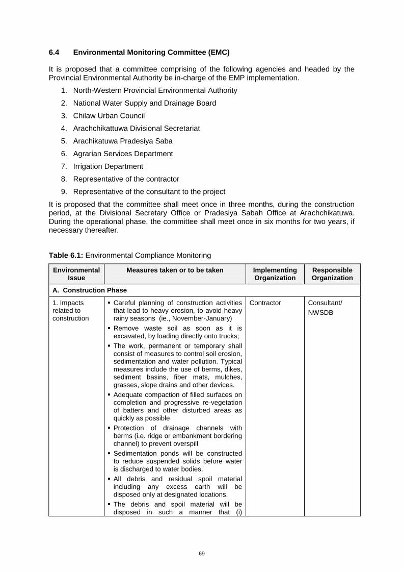
69
6.4 Environmental Monitoring Committee (EMC)
It is proposed that a committee comprising of the following agencies and headed by the Provincial Environmental Authority be in-charge of the EMP implementation.
1. North-Western Provincial Environmental Authority
2. National Water Supply and Drainage Board
3. Chilaw Urban Council
4. Arachchikattuwa Divisional Secretariat
5. Arachikatuwa Pradesiya Saba
6. Agrarian Services Department
7. Irrigation Department
8. Representative of the contractor
9. Representative of the consultant to the project
It is proposed that the committee shall meet once in three months, during the construction period, at the Divisional Secretary Office or Pradesiya Sabah Office at Arachchikatuwa. During the operational phase, the committee shall meet once in six months for two years, if necessary thereafter.
Table 6.1: Environmental Compliance Monitoring
Environmental Issue
Measures taken or to be taken Implementing Organization
Responsible Organization
A. Construction Phase
1. Impacts related to construction
Careful planning of construction activities that lead to heavy erosion, to avoid heavy rainy seasons (ie., November-January)
Remove waste soil as soon as it is excavated, by loading directly onto trucks;
The work, permanent or temporary shall consist of measures to control soil erosion, sedimentation and water pollution. Typical measures include the use of berms, dikes, sediment basins, fiber mats, mulches, grasses, slope drains and other devices.
Adequate compaction of filled surfaces on completion and progressive re-vegetation of batters and other disturbed areas as quickly as possible
Protection of drainage channels with berms (i.e. ridge or embankment bordering channel) to prevent overspill
Sedimentation ponds will be constructed to reduce suspended solids before water is discharged to water bodies.
All debris and residual spoil material including any excess earth will be disposed only at designated locations.
The debris and spoil material will be disposed in such a manner that (i)
Contractor
Consultant/
NWSDB
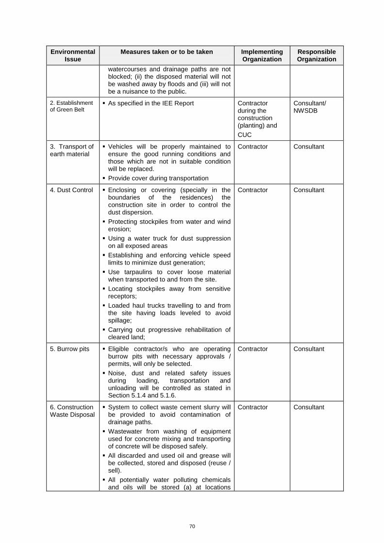
70
Environmental Issue
Measures taken or to be taken Implementing Organization
Responsible Organization
watercourses and drainage paths are not blocked; (ii) the disposed material will not be washed away by floods and (iii) will not be a nuisance to the public.
2. Establishment of Green Belt
As specified in the IEE Report Contractor during the construction (planting) and
CUC
Consultant/ NWSDB
3. Transport of earth material
Vehicles will be properly maintained to ensure the good running conditions and those which are not in suitable condition will be replaced.
Provide cover during transportation
Contractor
Consultant
4. Dust Control Enclosing or covering (specially in the boundaries of the residences) the construction site in order to control the dust dispersion.
Protecting stockpiles from water and wind erosion;
Using a water truck for dust suppression on all exposed areas
Establishing and enforcing vehicle speed limits to minimize dust generation;
Use tarpaulins to cover loose material when transported to and from the site.
Locating stockpiles away from sensitive receptors;
Loaded haul trucks travelling to and from the site having loads leveled to avoid spillage;
Carrying out progressive rehabilitation of cleared land;
Contractor
Consultant
5. Burrow pits Eligible contractor/s who are operating burrow pits with necessary approvals / permits, will only be selected.
Noise, dust and related safety issues during loading, transportation and unloading will be controlled as stated in Section 5.1.4 and 5.1.6.
Contractor
Consultant
6. Construction Waste Disposal
System to collect waste cement slurry will be provided to avoid contamination of drainage paths.
Wastewater from washing of equipment used for concrete mixing and transporting of concrete will be disposed safely.
All discarded and used oil and grease will be collected, stored and disposed (reuse / sell).
All potentially water polluting chemicals and oils will be stored (a) at locations
Contractor
Consultant
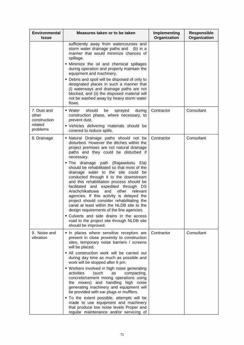
71
Environmental Issue
Measures taken or to be taken Implementing Organization
Responsible Organization
sufficiently away from watercourses and storm water drainage paths and (b) in a manner that would minimize chances of spillage.
Minimize the oil and chemical spillages during operation and properly maintain the equipment and machinery.
Debris and spoil will be disposed of only to designated places in such a manner that (i) waterways and drainage paths are not blocked, and (ii) the disposed material will not be washed away by heavy storm water flows.
7. Dust and other construction related problems
Water should be sprayed during construction phase, where necessary, to prevent dust.
Vehicles delivering materials should be covered to reduce spills.
Contractor
Consultant
8. Drainage Natural Drainage paths should not be disturbed. However the ditches within the project premises are not natural drainage paths and they could be disturbed if necessary.
The drainage path (Rajaweketu Ela) should be rehabilitated so that most of the drainage water to the site could be conducted through it to the downstream and this rehabilitation process should be facilitated and expedited through DS Arachchikattuwa and other relevant agencies. If this activity is delayed the project should consider rehabilitating the canal at least within the NLDB site to the design requirements of the line agencies.
Culverts and side drains in the access road to the project site through NLDB site should be improved.
Contractor
Consultant
9. Noise and vibration
In places where sensitive receptors are present in close proximity to construction sites, temporary noise barriers / screens will be placed.
All construction work will be carried out during day time as much as possible and work will be stopped after 6 pm.
Workers involved in high noise generating activities (such as compacting, concrete/cement mixing operations using the mixers) and handling high noise generating machinery and equipment will be provided with ear plugs or mufflers.
To the extent possible, attempts will be made to use equipment and machinery that produce low noise levels Proper and regular maintenance and/or servicing of
Contractor Consultant
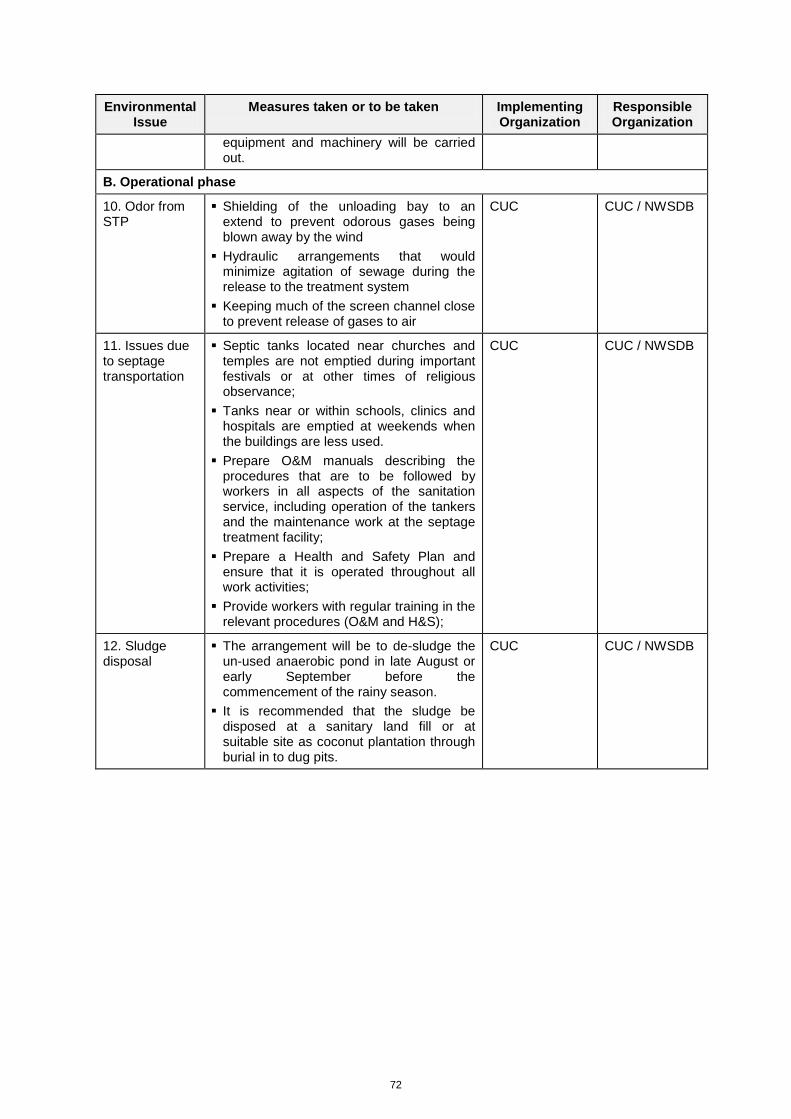
72
Environmental Issue
Measures taken or to be taken Implementing Organization
Responsible Organization
equipment and machinery will be carried out.
B. Operational phase
10. Odor from STP
Shielding of the unloading bay to an extend to prevent odorous gases being blown away by the wind
Hydraulic arrangements that would minimize agitation of sewage during the release to the treatment system
Keeping much of the screen channel close to prevent release of gases to air
CUC CUC / NWSDB
11. Issues due to septage transportation
Septic tanks located near churches and temples are not emptied during important festivals or at other times of religious observance;
Tanks near or within schools, clinics and hospitals are emptied at weekends when the buildings are less used.
Prepare O&M manuals describing the procedures that are to be followed by workers in all aspects of the sanitation service, including operation of the tankers and the maintenance work at the septage treatment facility;
Prepare a Health and Safety Plan and ensure that it is operated throughout all work activities;
Provide workers with regular training in the relevant procedures (O&M and H&S);
CUC CUC / NWSDB
12. Sludge disposal
The arrangement will be to de-sludge the un-used anaerobic pond in late August or early September before the commencement of the rainy season.
It is recommended that the sludge be disposed at a sanitary land fill or at suitable site as coconut plantation through burial in to dug pits.
CUC CUC / NWSDB
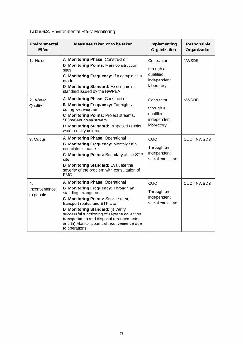
73
Table 6.2: Environmental Effect Monitoring
Environmental
Effect
Measures taken or to be taken Implementing
Organization
Responsible
Organization
1. Noise A Monitoring Phase: Construction
B Monitoring Points: Main construction sites
C Monitoring Frequency: If a complaint is made
D Monitoring Standard: Existing noise standard issued by the NWPEA
Contractor
through a
qualified
independent
laboratory
NWSDB
2. Water
Quality
A Monitoring Phase: Construction
B Monitoring Frequency: Fortnightly, during wet weather
C Monitoring Points: Project streams, 500meters down stream
D Monitoring Standard: Proposed ambient water quality criteria.
Contractor
through a
qualified
independent
laboratory
NWSDB
3. Odour A Monitoring Phase: Operational
B Monitoring Frequency: Monthly / If a complaint is made
C Monitoring Points: Boundary of the STP site
D Monitoring Standard: Evaluate the severity of the problem with consultation of EMC
CUC
Through an
independent
social consultant
CUC / NWSDB
4.
Inconvenience
to people
A Monitoring Phase: Operational
B Monitoring Frequency: Through an standing arrangement
C Monitoring Points: Service area, transport routes and STP site
D Monitoring Standard: (i) Verify successful functioning of septage collection, transportation and disposal arrangements; and (ii) Monitor potential inconvenience due to operations.
CUC
Through an
independent
social consultant
CUC / NWSDB
74
7.0 PUBLIC CONSULTATION AND INFORMATION DISCLOSURE
7.1 Methodology adopted
As indicated above, the methodology adopted in the IEE study was mainly threefold. Firstly, the IEE team met with all relevant stakeholders and made field visits to study the suitability of the identified lands for location of the STP. In these field visits, the IEE team met individual people to apprise them on the project. Secondly awareness meetings were held with a selected group of people to create awareness among them and to gather certain vital information relevant to the project. Lastly, a public meeting was held to create awareness about the proposed project among the people of the project area. This meeting was instrumental in exchange of views and opinions of the stakeholders.
7.2 Consultation and disclosure events
In the public consultation and information disclosure the IEE team developed a strategy to create awareness among the all relevant stakeholders about the proposed project and to invite their views, opinions and suggestions that may be useful for its implementation. The strategy consisted of meeting all relevant stakeholder agencies such as the Divisional Secretaries and their staff, chair person and secretaries of the CUC and the APS, NWS&DB, NLDB, MOH, PHI and relevant Grama Niladaries of to gather first hand information of socio economic and cultural situation of the project area and the service area. Also the IEE team met with the President of the Farmers Oraganization of the Mahamanaweriya Tank to apprise her on the proposed project and to seek her views and suggestions.
The list of meetings conducted by the IEE team with various organizations and list of attendance are listed in Appendix 9.
Later, with a view to get a wider participation in the process and to enlighten, the people of the area, it was planned to conduct a meeting at the APS office on August 10, 2011. As planned, the meeting was held on the appointed date. The IEE team invited the following stakeholders for the meeting;
Officials from the NWS&DB.
Officials from the NLDB.
Chair person of the CUC and the APS.
Divisional Secretaries of Chilaw and Arachchikattuwa and relevant officials of these offices.
Relevant Grama Niladharies.
President and the members of the Farmer Organization of Mahamanweriya Tank.
People living around the proposed location of the STP.
Principal of the Karukkuliya Maha Vidyalaya.
At the meeting their presentations were made. Dr. Vasantha Siriwardhane, STP Design Consultant made a presentation on the Technical Design of the Treatment Plant. Mr. Arunashantha, Project Engineer of the NWS&DB made a presentation on the proposed Drinking Water and Sanitation Project funded by the ADB. Mr. Anura Ranwala in his presentation elaborated on the project location. He emphasized that adverse impacts will not occur in the socio economic and cultural status of this project area.
After the presentations, the forum was open for discussions. In the discussions, several stakeholders expressed their views and opinions. A few of them made valuable suggestions. Full details of the discussions are elaborated in the Appendix 10: Minutes of the meeting.
75
7.3 Awareness
STP Site Area
Awareness programs
Since the IEE team visited the area on several times and met with some of the stakeholders, message had reached the people. After the meeting, held on August 10, 2011, people became fully aware on the benefits of the project and the project will not create any harmful impact in the area. Minutes of the Public Consultation Meeting held on August 10, 2011 is given in Appendix 10.
Public understanding on the project
The people are convinced that the project will bring about long awaited solutions to the removal of sewage in the service area. Also, the people in the project area are convinced that no negative impact will be generated by the project. Also, they welcome the move to provide drinking water and toilets facilities to the households of the project area under the Drinking Water and Sanitation Project to be implemented by the NWS&DB under ADB financial assistance.
Public opinion on the project
The people in the service area have already faced the problem of septage disposal while the people of the project area have not experienced the gravity of the problem so far.
The CUC area (service area) has encountered the problem of septage disposal due to several reasons. The area is a low-lying terrain where the ground water level is very high. Therefore, there is a risk of polluting the round water due to non emptying the toilets at the proper time. Removal of septage in time is handicapped mainly due to two reasons, i.e. absence of suitable land to dump the septage and the shortage of bowsers to carry the septage.
Therefore, disposal of septage at present is not carried out in an efficient manner and the people of the area have felt the need to improve the exercise.
Service Area
General view of community on degree of importance that they attached to the project
In the field visits and the meeting held on August 10, 2011 in the Pradeshiya Saba office at Arachchikattuwa, the general view of the community was obtained. Also the importance of the project was discussed at length and after exchanging the views of the executing agency and other stakeholder meetings, the general public it was agreed upon that the project I a timely need considering the fact that the problem of disposal of septage has already become a serious problem in the area.
Prevailing situation of handling the septage disposal;
At present, the disposal of septage in the service area (CUC area) is handled by the UC of Chilaw. Septage is collected by a gully bowser and disposed to a certain land located in an inhabited area but this practice appears to be unsatisfactory. Also, C is unable to meet the demand due to lack of adequate number of gully bowsers.
Public opinion on the prevailing CUC service
People in the service area are not satisfied with the current situation. However, are compelled to wait a few days until the gully bowser comes to collect the septage causing enormous difficulties. The main reason for the delay is removal of septage is due to lack of adequate numbers of gully bowsers.

76
Common impacts due to the prevailing septage disposal methods
When the delays occur in removing the septage not only disturb the day to day life of the people, the overflow of septage will cause serious threat to the health and sanitation of the people of the area.
Public opinion on the service fee of the present system
The people of the area are not only unhappy about the fee charged for removal of septage. Their major concern is timely removal of this obnoxious sludge.
77
8.0 FINDINGS AND RECOMMENDATIONS
8.1 Suitability of the Site
Design consultants have carried out a detailed analysis of the suitability of the site for proposed project. This was discussed in the design report under citing criteria and minimum distance requirements. There are some issues with respect to these factors. These include all weather access to site, groundwater table, site flooding and proximity wells. Design proposed suitable remedial measures against these. The proposals given in the design report on these regards are acceptable to IEE consultants. IEE Consultants recommend they are being implemented properly.
8.2 Regulatory Environment
The proposed project does not violate national or provincial regulations. However the site (not the plant) partly falls within the 100m boundary of the High Flood Level of the Mahamanaweriya Tank. The plant will not create significant environmental risks on the tank. However, the Agrarian Services Department (who has the legal ownership of the tank) and Provincial Environmental Authority shall take decision on this regard.
8.3 Impact on Physical Environment
Significant impacts on physical environment are not expected due to this project. The most important area regarding the physical environment is drainage. Site is found to be water logged during rains mainly due to excavation of ditches for planting coconuts. These needs to be filled and levels and then proper drainage system for the site as specified in the IEE mitigation measures should be adopted. Access road shall be raised as specified to maintain all weather access.
8.4 Impact on Social Environment
Significant impacts on social environment are not expected although the proposed project is coming under category of project that normally draws social objections. Adequate buffer is maintained for all important land-uses. Mitigation measures tree planting as vegetative cover/buffer. Also design includes measures to avoid odor problems. Land values are unlikely to be affected by the proposed project based on the findings of the IEE consultants. Recommendations also include providing social benefits to the project area through support for household sanitation program. IEE include other recommendations to minimize social concerns and make the project acceptable to the community in the project area.
8.5 Impact on Biological Environment
Site is abandoned coconut plantation. It is ecologically disturbed land. Finding of the IEE consultants show that there is no significant ecological impacts due to this project. IEE consultants proposed minor recommendations aimed at minimizing the environmental risked on ecology of the area.
8.6 Operation of the Plant
Proposed STP will be operated by CUC. Although the STP is not complex in terms of technology the IEE consultants finds that CUC technical staff is not familiar with STP operation and maintenance. Therefore IEE consultants recommend that NWS&DB to conduct both re-operation and on the job training for CUC operators.
78
De-sludging of anaerobic pond not in operation is recommended as annual event. This sludge which is allowed for digestion for nearly one year is expected to be stabilized significantly. It needs to be disposed safely and properly. It is recommended that the sludge be disposed at a sanitary land fill or at suitable site as coconut plantation through burial.
8.7 Overall Findings and Recommendations
IEE consultants are of the opinion that this project is a need for the area. IEE consultants agree with the project technology and site although certain concerns remain regarding the site. There are no significant environmental or social issues regarding the project. However, social objections may arise time to time considering the nature of the project. Client should be aware of this and IEE consultants recommend to work closely with the community and ensure that the project area also receive benefits out of this project. Considering these factors IEE consultants recommend project implementation subjected to the mitigation measures proposed in this IEE report. We also recommend that the design is followed properly in the implementation and high quality is maintained in construction to prevent seepage of untreated wastewater to ground and breach of pond bunds in case of minor floods, if happens. NWS&DB shall provide technical support to CUC through training of operators and trouble shooting and provision of technical advice as required.
79
9.0 CONCLUSIONS
The proposed project is important and necessary to meet the sanitation needs of Chilaw Urban areas. In absence of a wastewater collection, treatment and disposal system Chilaw Urban area needs an alternative arrangement for management of their on-site systems consisting of septic tanks, holding tanks and pits. The need for a septage management system is high due to small plot sizes and high groundwater table. This requirement will prevail till construction of conventional sewerage system for Chilaw Urban area.
Consultants consider that the project proponent has considered the available alternatives adequately. Although the land disposal is the easiest approach to disposal of septage there are practical difficulties due to non availability of suitable lands to the project proponents. Next best alternative in terms of ease, the disposal at existing WWTP is also out due to non availability of such plants within reasonable distance. Therefore choice of dedicated STP is the choice available to the project proponent. Technical choice of waste stabilization lagoons is the easiest to manage and the lowest in terms of operational costs. Proponents consider several lands for the purpose. This technical option requires more land but considering the operation ease and cost consultants agree with the choice. This is so particularly considering the fact that the system will be operated by the CUC. The propose site in the opinion of the consultants is the best suited for the project out of the sites considered. Reasonable distance can be maintained from critical land uses. Nevertheless presence of a minor irrigation tank (Mahamanaweriya Tank) in the adjoining land is an important factor that needs consideration. While the project can be implemented without affecting the said tank there are minor risks and regulatory aspects that need consideration. It is the view of the Consultants that the authorities shall consider this issue based on the findings of this IEE when making a decision. Consultants are aware for final decision will be made based on the findings of the IEE report. Having carefully examined the propose site location and surroundings, as well as other project issues, consultants proposed several recommendations regarding the site utilization particularly with regard to provision of buffer area, site access and treated effluent disposal.
Consultants agree with the design recommendations particularly to reduce the estimated waste loads in light of the ground situation. The design includes prolonged retention of wastewater in the lagoon system which is adequate to bring down the coliform levels well below the discharge requirements. Furthermore it provides additional storage to store the treated effluent during rainy days. This will prevent treated effluent getting mixed up with storm water runoff during rains. Consultants also agree with the provision made for the off-site and on-site disposal of treated effluent. During prolonged dry period wastewater can be easily and safely discharged on-land. Plant vegetation in the abandoned coconut land can take up the nutrients released with the treated effluent and infiltration through soil will provide further treatment. During the wet season the effluent can be stored for disposal at off-site locations (lands) or disposal on-site at suitable times. In the opinion of the consultants site layout provides adequate distances to critical land-uses. Thus consultants are in agreement with the design proposal.
IEE consultants consider that there are no significant project impacts on the ecology, natural resources and physical conditions of the project area. However, the critical factors for this project would be (a) acceptance by the community in consideration of the nature of the project and (b) minor risks it poses to the nearby tank in case of breach of lagoon bund or flooding. Adequate design measures have been taken to minimize this risk. The consultant recommends the project with the proposed mitigation measures and subjected to the determination by the relevant authorities regarding its proximity to the irrigation tank. Consultant is confident that chance of accidental release of untreated wastewater is insignificant with adequate design and good construction quality. Consultants conclude that project is beneficial to the area and does not have significant negative environmental or social impacts or associated high risks. Adequate measures have been proposed in the

80
design to cater to environmental issues during construction and operation. This IEE also proposed additional measures to minimize environmental impacts and risks. The project can be safely implemented and operated with these measures being implemented.
Project Implementation Agency: National Water Supply and Drainage Board
Funding Agency: Asian Development Bank
Project Number: 4853-SRI
Sri Lanka: Dry Zone Urban Water Supply and Sanitation
Project (DZUWSP)
INITIAL ENVIRONMENTAL EXAMINATION: SEPTAGE TREATMENT PLANT FOR CHILAW (DRAFT)
APPENDICES
DECEMBER, 2011
APPENDICES
1. REFERENCES
2. SURVEY PLAN OF THE LAND
3. APPROVAL / CONSENT LETTERS
4. SEPTAGE TREATMENT PLANT DESIGN DETAILS
5. PHOTOGRAPHS OF ALTERNATIVE SITE
6. WATER QUALITY ANALYSIS REPORTS
7. PLANT SPECIES OBSERVED IN THE DIRECT IMPACT ZONE OF THE PROJECT
SITE
8. ANIMAL SPECIES RECORDED WITHIN THE VARIOUS HABITAT TYPES
OBSERVED IN THE DIRECT IMPACT ZONE OF THE PROJECT SITE
9. LIST OF MEETINGS / DISCUSSIONS CONDUCTED DURING IEE STUDY AND
ATTENDANCE LISTS
10. MEETING MINUTES OF PUBLIC CONSULTATION MEETING
11. LIST OF ENVIRONMENTAL STUDY TEAM INCLUDING THEIR WORK
ALLOCATION
12. TERMS OF REFERENCE
APPENDIX 1: REFERENCES
1. Water Resources Study for Water Supply Planning – Puttlam District – GFA Umwelt
February 2002
2. Concept Paper for Rehabilitation of Rajaweeketu ela- DS Office Arachchikattuwa –
September 2009
3. National Atlas of Sri Lanka, Survey Department
4. Environmental Atlas of Sri Lanka, Central Environmental Authority, 2005
5. North-Western Provincial Environmental Statute No 12 of 1990
6. Provincial EIA Regulations published in Gazette Notification, No. 1020/21 dated March
27, 1998
7. Resource Profile of Divisional Secretariat - Arachchikattuwa, 2009
8. Resource Profile of Divisional Secretariat - Chilaw, 2009
9. Draft Concept Paper on Implementation of Household and Public Toilet Program,
NWS&DB
10. Annex 3 – Urban Water Supply and Sanitation Sub Projects, Part A: Chilaw, Final
Report, ADB TA 4853-SRI, Small Town and Rural Arid Areas Water Supply and
Sanitation Project, 2008
11. Initial Environmental Examination: Chilaw (Draft), Dry Zone Urban Water Supply and
Sanitation Project (DZUWSP), March 2008
12. Safeguard Policy Statement, Asian Development Bank, June 2009
13. Environmental Assessment Guidelines, Asian Development Bank, 2003
14. Guide to Septage Treatment and Disposal, USEPA, September 1994
15. Elements of Environmental Engineering, KN Duggal, S Chand and Co. Ltd., 2008
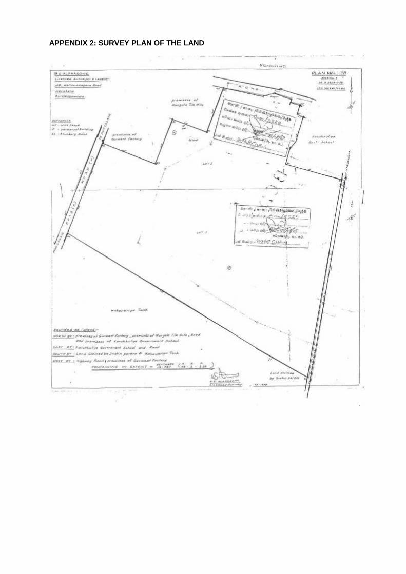
APPENDIX 2: SURVEY PLAN OF THE LAND
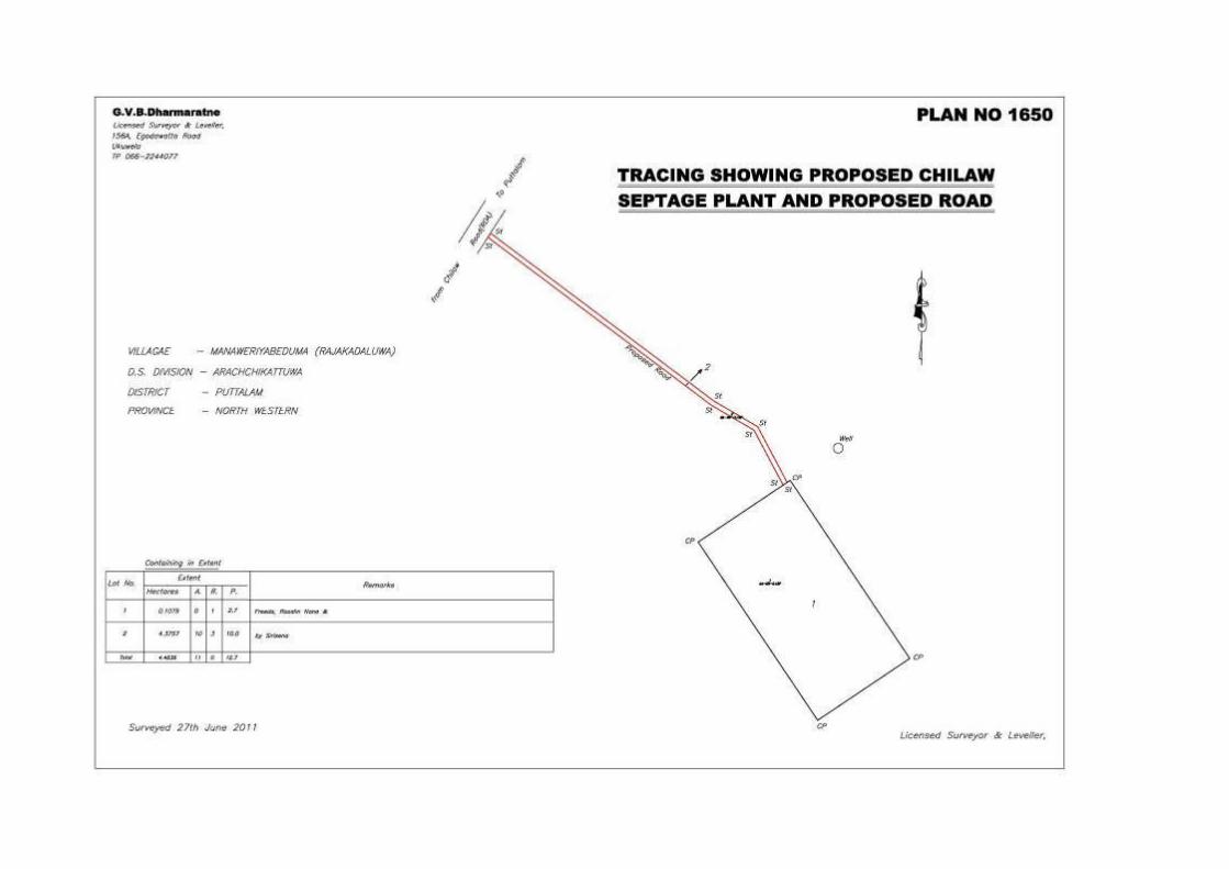
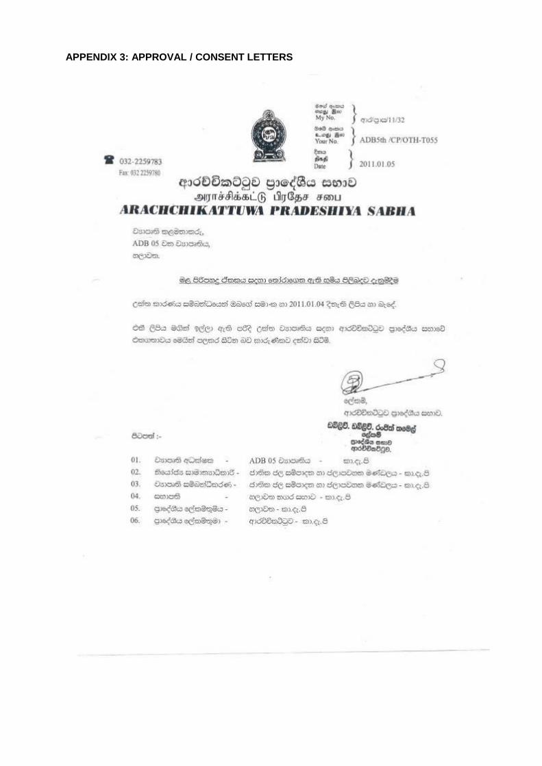
APPENDIX 3: APPROVAL / CONSENT LETTERS
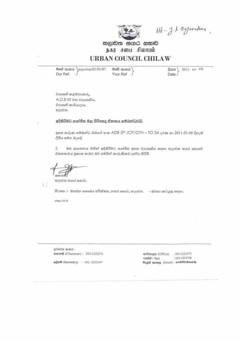
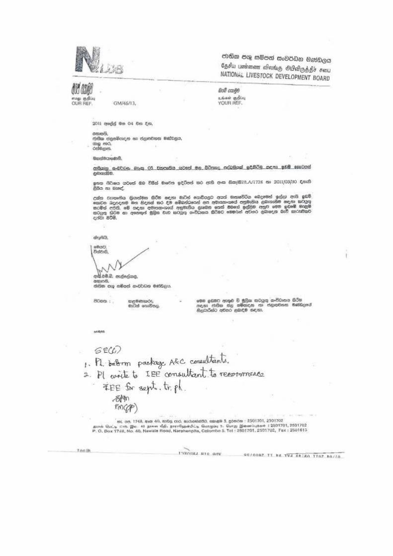
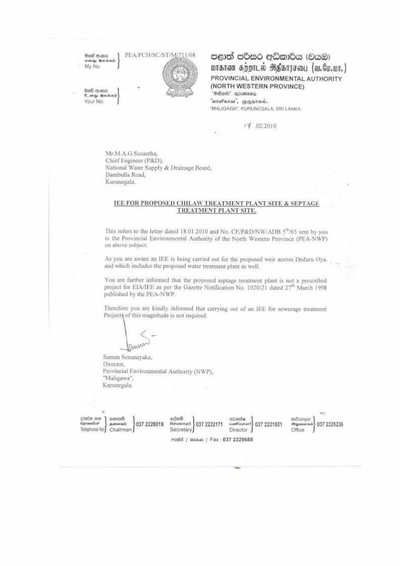
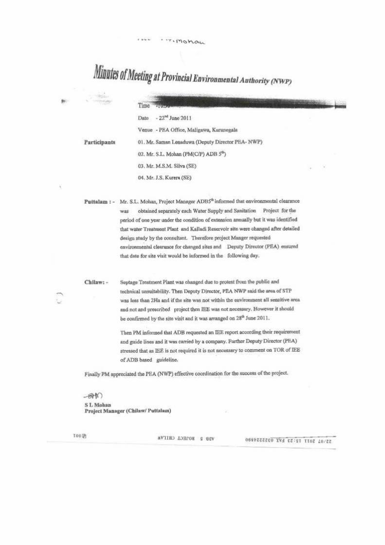
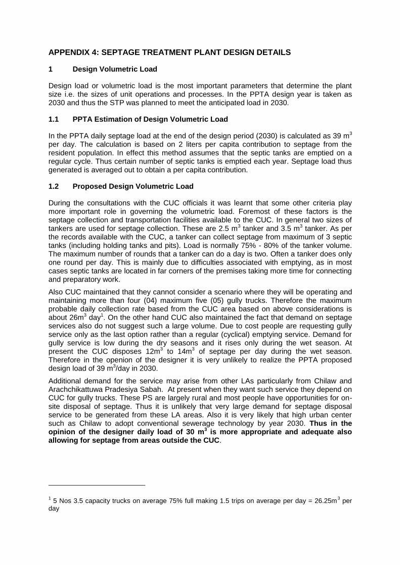
APPENDIX 4: SEPTAGE TREATMENT PLANT DESIGN DETAILS
1 Design Volumetric Load
Design load or volumetric load is the most important parameters that determine the plant size i.e. the sizes of unit operations and processes. In the PPTA design year is taken as 2030 and thus the STP was planned to meet the anticipated load in 2030.
1.1 PPTA Estimation of Design Volumetric Load
In the PPTA daily septage load at the end of the design period (2030) is calculated as 39 m3 per day. The calculation is based on 2 liters per capita contribution to septage from the resident population. In effect this method assumes that the septic tanks are emptied on a regular cycle. Thus certain number of septic tanks is emptied each year. Septage load thus generated is averaged out to obtain a per capita contribution.
1.2 Proposed Design Volumetric Load
During the consultations with the CUC officials it was learnt that some other criteria play more important role in governing the volumetric load. Foremost of these factors is the septage collection and transportation facilities available to the CUC. In general two sizes of tankers are used for septage collection. These are 2.5 m3 tanker and 3.5 m3 tanker. As per the records available with the CUC, a tanker can collect septage from maximum of 3 septic tanks (including holding tanks and pits). Load is normally 75% - 80% of the tanker volume. The maximum number of rounds that a tanker can do a day is two. Often a tanker does only one round per day. This is mainly due to difficulties associated with emptying, as in most cases septic tanks are located in far corners of the premises taking more time for connecting and preparatory work.
Also CUC maintained that they cannot consider a scenario where they will be operating and maintaining more than four (04) maximum five (05) gully trucks. Therefore the maximum probable daily collection rate based from the CUC area based on above considerations is about 26m3 day1. On the other hand CUC also maintained the fact that demand on septage services also do not suggest such a large volume. Due to cost people are requesting gully service only as the last option rather than a regular (cyclical) emptying service. Demand for gully service is low during the dry seasons and it rises only during the wet season. At present the CUC disposes 12m3 to 14m3 of septage per day during the wet season. Therefore in the openion of the designer it is very unlikely to realize the PPTA proposed design load of 39 m3/day in 2030.
Additional demand for the service may arise from other LAs particularly from Chilaw and Arachchikattuwa Pradesiya Sabah. At present when they want such service they depend on CUC for gully trucks. These PS are largely rural and most people have opportunities for on-site disposal of septage. Thus it is unlikely that very large demand for septage disposal service to be generated from these LA areas. Also it is very likely that high urban center such as Chilaw to adopt conventional sewerage technology by year 2030. Thus in the opinion of the designer daily load of 30 m3 is more appropriate and adequate also allowing for septage from areas outside the CUC.
1 5 Nos 3.5 capacity trucks on average 75% full making 1.5 trips on average per day = 26.25m
3 per
day
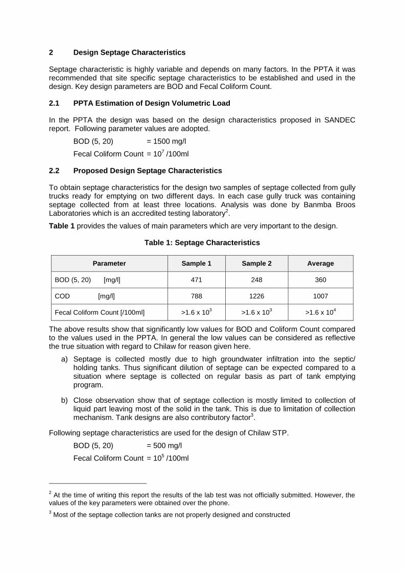
2 Design Septage Characteristics
Septage characteristic is highly variable and depends on many factors. In the PPTA it was recommended that site specific septage characteristics to be established and used in the design. Key design parameters are BOD and Fecal Coliform Count.
2.1 PPTA Estimation of Design Volumetric Load
In the PPTA the design was based on the design characteristics proposed in SANDEC report. Following parameter values are adopted.
BOD (5, 20) = 1500 mg/l
Fecal Coliform Count = 107 /100ml
2.2 Proposed Design Septage Characteristics
To obtain septage characteristics for the design two samples of septage collected from gully trucks ready for emptying on two different days. In each case gully truck was containing septage collected from at least three locations. Analysis was done by Banmba Broos Laboratories which is an accredited testing laboratory2.
Table 1 provides the values of main parameters which are very important to the design.
Table 1: Septage Characteristics
Parameter Sample 1 Sample 2 Average
BOD (5, 20) [mg/l] 471 248 360
COD [mg/l] 788 1226 1007
Fecal Coliform Count [/100ml] >1.6 x 10³ >1.6 x 10
3 >1.6 x 10
4
The above results show that significantly low values for BOD and Coliform Count compared to the values used in the PPTA. In general the low values can be considered as reflective the true situation with regard to Chilaw for reason given here.
a) Septage is collected mostly due to high groundwater infiltration into the septic/ holding tanks. Thus significant dilution of septage can be expected compared to a situation where septage is collected on regular basis as part of tank emptying program.
b) Close observation show that of septage collection is mostly limited to collection of liquid part leaving most of the solid in the tank. This is due to limitation of collection mechanism. Tank designs are also contributory factor3.
Following septage characteristics are used for the design of Chilaw STP.
BOD (5, 20) = 500 mg/l
Fecal Coliform Count = 105 /100ml
2 At the time of writing this report the results of the lab test was not officially submitted. However, the
values of the key parameters were obtained over the phone.
3 Most of the septage collection tanks are not properly designed and constructed
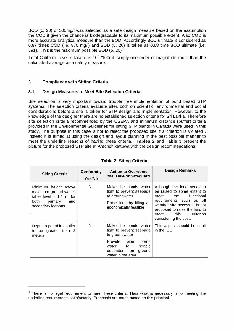
BOD (5, 20) of 500mg/l was selected as a safe design measure based on the assumption the COD if given the chance is biodegradable to its maximum possible extent. Also COD is more accurate analytical measure than the BOD. Accordingly BOD ultimate is considered as 0.87 times COD (i.e. 870 mg/l) and BOD (5, 20) is taken as 0.68 time BOD ultimate (i.e. 591). This is the maximum possible BOD (5, 20).
Total Coliform Level is taken as 105 /100ml, simply one order of magnitude more than the calculated average as a safety measure.
3 Compliance with Sitting Criteria
3.1 Design Measures to Meet Site Selection Criteria
Site selection is very important toward trouble free implementation of pond based STP systems. The selection criteria evaluate sites both on scientific, environmental and social considerations before a site is taken for STP design and implementation. However, to the knowledge of the designer there are no established selection criteria for Sri Lanka. Therefore site selection criteria recommended by the USEPA and minimum distance (buffer) criteria provided in the Environmental Guidelines for sitting STP plants in Canada were used in this study. The purpose in this case is not to reject the proposed site if a criterion is violated4. Instead it is aimed at using the design and layout planning in the best possible manner to meet the underline reasons of having these criteria. Tables 2 and Table 3 present the picture for the proposed STP site at Arachchikattuwa with the design recommendations.
Table 2: Siting Criteria
Siting Criteria Conformity
Yes/No
Action to Overcome the Issue or Safeguard
Design Remarks
Minimum height above
maximum ground water-
table level - 1.2 m for
both primary and
secondary lagoons
A.
No Make the ponds water tight to prevent seepage to groundwater
Raise land by filling as economically feasible
Although the land needs to be raised to some extent to meet the functional requirements such as all weather site access, it is not proposed to raise the land to meet this criterion considering the cost.
Depth to portable aquifer
to be greater than 2
meters
No
Make the ponds water tight to prevent seepage to groundwater
Provide pipe borne water to people dependent on ground water in the area
This aspect should be dealt in the IEE
4 There is no legal requirement to meet these criteria. Thus what is necessary is to meeting the
underline requirements satisfactorily. Proposals are made based on this principal
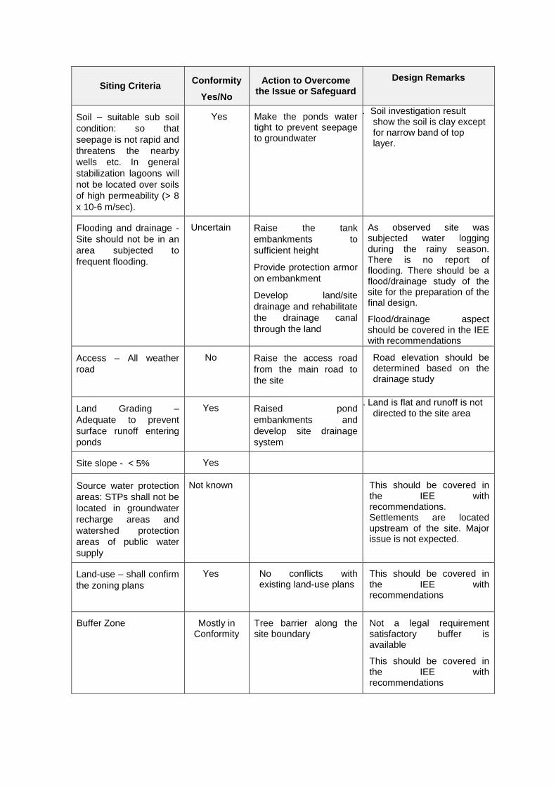
Siting Criteria Conformity
Yes/No
Action to Overcome the Issue or Safeguard
Design Remarks
Soil – suitable sub soil
condition: so that
seepage is not rapid and
threatens the nearby
wells etc. In general
stabilization lagoons will
not be located over soils
of high permeability (> 8
x 10-6 m/sec).
Yes Make the ponds water tight to prevent seepage to groundwater
B. Soil investigation result show the soil is clay except for narrow band of top layer.
Flooding and drainage -
Site should not be in an
area subjected to
frequent flooding.
Uncertain Raise the tank
embankments to
sufficient height
Provide protection armor
on embankment
Develop land/site
drainage and rehabilitate
the drainage canal
through the land
As observed site was subjected water logging during the rainy season. There is no report of flooding. There should be a flood/drainage study of the site for the preparation of the final design.
Flood/drainage aspect should be covered in the IEE with recommendations
Access – All weather
road
No Raise the access road
from the main road to
the site
Road elevation should be determined based on the drainage study
Land Grading –
Adequate to prevent
surface runoff entering
ponds
Yes Raised pond
embankments and
develop site drainage
system
C. Land is flat and runoff is not directed to the site area
Site slope - < 5% Yes
Source water protection
areas: STPs shall not be
located in groundwater
recharge areas and
watershed protection
areas of public water
supply
Not known This should be covered in the IEE with recommendations. Settlements are located upstream of the site. Major issue is not expected.
Land-use – shall confirm
the zoning plans
Yes No conflicts with existing land-use plans
This should be covered in the IEE with recommendations
Buffer Zone Mostly in Conformity
Tree barrier along the site boundary
Not a legal requirement satisfactory buffer is available
This should be covered in the IEE with recommendations
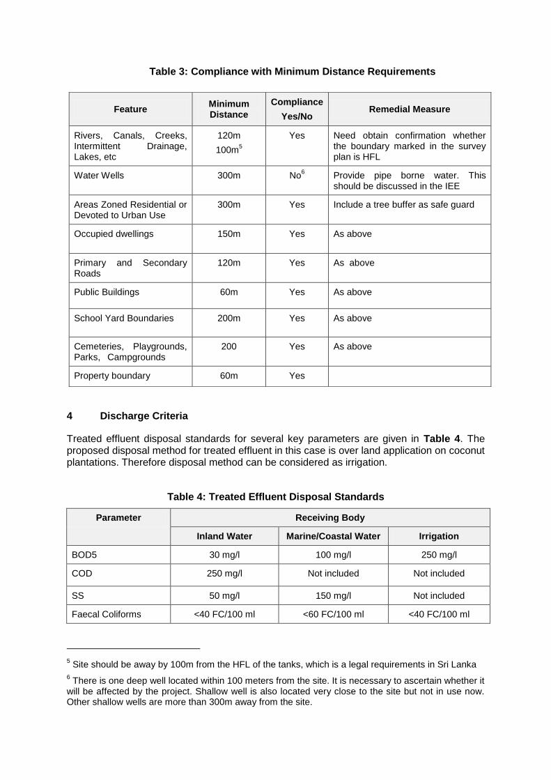
Table 3: Compliance with Minimum Distance Requirements
4 Discharge Criteria
Treated effluent disposal standards for several key parameters are given in Table 4. The proposed disposal method for treated effluent in this case is over land application on coconut plantations. Therefore disposal method can be considered as irrigation.
Table 4: Treated Effluent Disposal Standards
Parameter Receiving Body
Inland Water Marine/Coastal Water Irrigation
BOD5 30 mg/l 100 mg/l 250 mg/l
COD 250 mg/l Not included Not included
SS 50 mg/l 150 mg/l Not included
Faecal Coliforms <40 FC/100 ml <60 FC/100 ml <40 FC/100 ml
5 Site should be away by 100m from the HFL of the tanks, which is a legal requirements in Sri Lanka
6 There is one deep well located within 100 meters from the site. It is necessary to ascertain whether it
will be affected by the project. Shallow well is also located very close to the site but not in use now. Other shallow wells are more than 300m away from the site.
Feature Minimum Distance
Compliance
Yes/No Remedial Measure
Rivers, Canals, Creeks, Intermittent Drainage, Lakes, etc
120m
100m5
Yes Need obtain confirmation whether the boundary marked in the survey plan is HFL
Water Wells
300m No6 Provide pipe borne water. This
should be discussed in the IEE
Areas Zoned Residential or Devoted to Urban Use
300m Yes Include a tree buffer as safe guard
Occupied dwellings 150m Yes As above
Primary and Secondary Roads
120m Yes As above
Public Buildings 60m Yes As above
School Yard Boundaries 200m Yes As above
Cemeteries, Playgrounds, Parks, Campgrounds
200 Yes As above
Property boundary 60m Yes
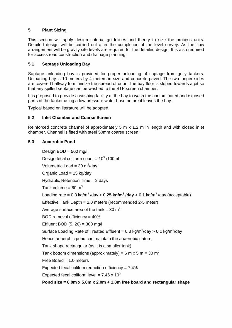
5 Plant Sizing
This section will apply design criteria, guidelines and theory to size the process units. Detailed design will be carried out after the completion of the level survey. As the flow arrangement will be gravity site levels are required for the detailed design. It is also required for access road construction and drainage planning.
5.1 Septage Unloading Bay
Saptage unloading bay is provided for proper unloading of saptage from gully tankers. Unloading bay is 10 meters by 4 meters in size and concrete paved. The two longer sides are covered halfway to minimize the spread of odor. The bay floor is sloped towards a pit so that any spilled septage can be washed to the STP screen chamber.
It is proposed to provide a washing facility at the bay to wash the contaminated and exposed parts of the tanker using a low pressure water hose before it leaves the bay.
Typical based on literature will be adopted.
5.2 Inlet Chamber and Coarse Screen
Reinforced concrete channel of approximately 5 m x 1.2 m in length and with closed inlet chamber. Channel is fitted with steel 50mm coarse screen.
5.3 Anaerobic Pond
Design BOD = 500 mg/l
Design fecal coliform count = 105 /100ml
Volumetric Load = 30 m3/day
Organic Load = 15 kg/day
Hydraulic Retention Time = 2 days
Tank volume = 60 m3
Loading rate = 0.3 kg/m3 /day > 0.25 kg/m3 /day > 0.1 kg/m3 /day (acceptable)
Effective Tank Depth = 2.0 meters (recommended 2-5 meter)
Average surface area of the tank = 30 m2
BOD removal efficiency = 40%
Effluent BOD (5, 20) = 300 mg/l
Surface Loading Rate of Treated Effluent = 0.3 kg/m2/day > 0.1 kg/m2/day
Hence anaerobic pond can maintain the anaerobic nature
Tank shape rectangular (as it is a smaller tank)
Tank bottom dimensions (approximately) = 6 m x 5 m = 30 m2
Free Board = 1.0 meters
Expected fecal colifom reduction efficiency = 7.4%
Expected fecal coliform level = 7.46 x 10³
Pond size = 6.0m x 5.0m x 2.0m + 1.0m free board and rectangular shape
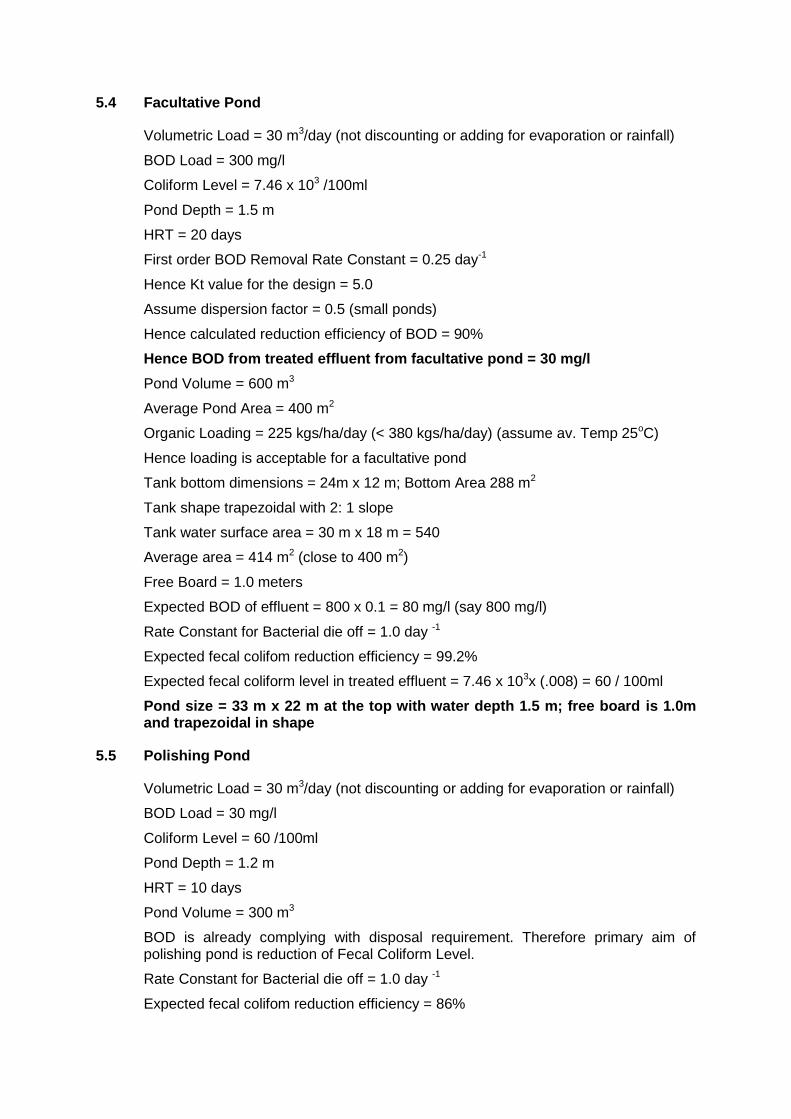
5.4 Facultative Pond
Volumetric Load = 30 m3/day (not discounting or adding for evaporation or rainfall)
BOD Load = 300 mg/l
Coliform Level = 7.46 x 10³ /100ml
Pond Depth = 1.5 m
HRT = 20 days
First order BOD Removal Rate Constant = 0.25 day-1
Hence Kt value for the design = 5.0
Assume dispersion factor = 0.5 (small ponds)
Hence calculated reduction efficiency of BOD = 90%
Hence BOD from treated effluent from facultative pond = 30 mg/l
Pond Volume = 600 m3
Average Pond Area = 400 m2
Organic Loading = 225 kgs/ha/day (< 380 kgs/ha/day) (assume av. Temp 25oC)
Hence loading is acceptable for a facultative pond
Tank bottom dimensions = 24m x 12 m; Bottom Area 288 m2
Tank shape trapezoidal with 2: 1 slope
Tank water surface area = 30 m x 18 m = 540
Average area = 414 m2 (close to 400 m2)
Free Board = 1.0 meters
Expected BOD of effluent = 800 x 0.1 = 80 mg/l (say 800 mg/l)
Rate Constant for Bacterial die off = 1.0 day -1
Expected fecal colifom reduction efficiency = 99.2%
Expected fecal coliform level in treated effluent = 7.46 x 103x (.008) = 60 / 100ml
Pond size = 33 m x 22 m at the top with water depth 1.5 m; free board is 1.0m and trapezoidal in shape
5.5 Polishing Pond
Volumetric Load = 30 m3/day (not discounting or adding for evaporation or rainfall)
BOD Load = 30 mg/l
Coliform Level = 60 /100ml
Pond Depth = 1.2 m
HRT = 10 days
Pond Volume = 300 m3
BOD is already complying with disposal requirement. Therefore primary aim of polishing pond is reduction of Fecal Coliform Level.
Rate Constant for Bacterial die off = 1.0 day -1
Expected fecal colifom reduction efficiency = 86%
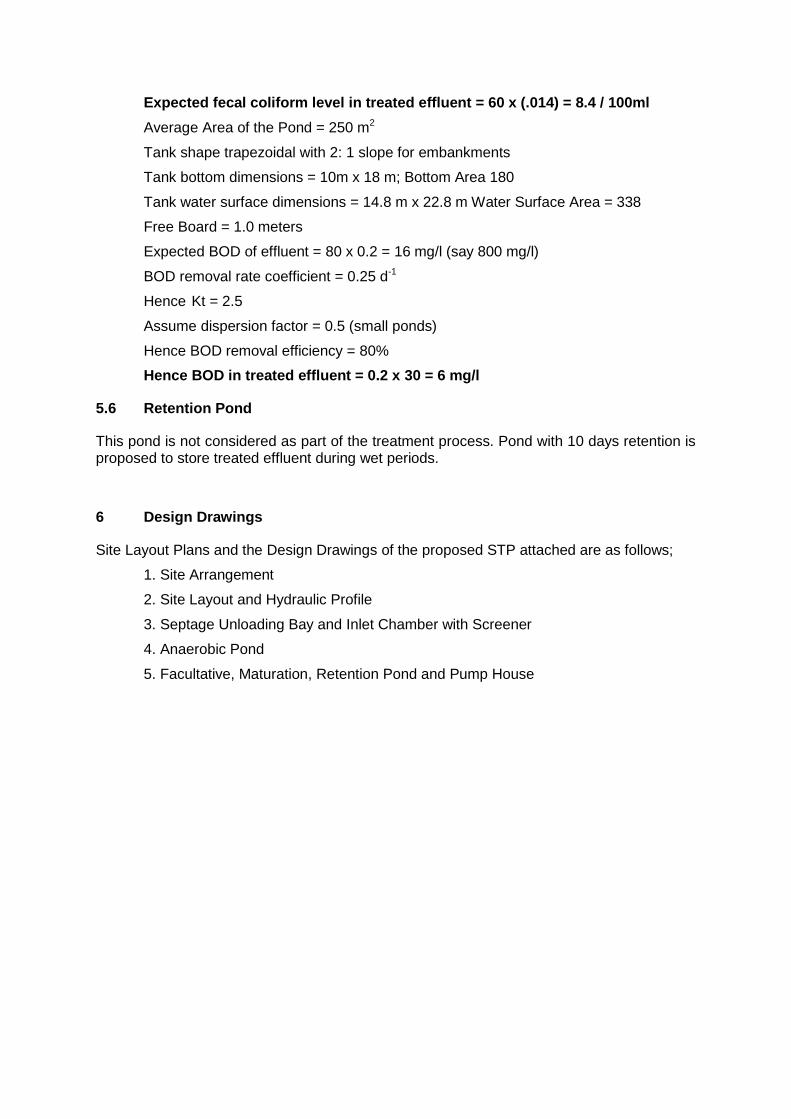
Expected fecal coliform level in treated effluent = 60 x (.014) = 8.4 / 100ml
Average Area of the Pond = 250 m2
Tank shape trapezoidal with 2: 1 slope for embankments
Tank bottom dimensions = 10m x 18 m; Bottom Area 180
Tank water surface dimensions = 14.8 m x 22.8 m Water Surface Area = 338
Free Board = 1.0 meters
Expected BOD of effluent = 80 x 0.2 = 16 mg/l (say 800 mg/l)
BOD removal rate coefficient = 0.25 d-1
Hence Kt = 2.5
Assume dispersion factor = 0.5 (small ponds)
Hence BOD removal efficiency = 80%
Hence BOD in treated effluent = 0.2 x 30 = 6 mg/l
5.6 Retention Pond
This pond is not considered as part of the treatment process. Pond with 10 days retention is proposed to store treated effluent during wet periods.
6 Design Drawings
Site Layout Plans and the Design Drawings of the proposed STP attached are as follows;
1. Site Arrangement
2. Site Layout and Hydraulic Profile
3. Septage Unloading Bay and Inlet Chamber with Screener
4. Anaerobic Pond
5. Facultative, Maturation, Retention Pond and Pump House
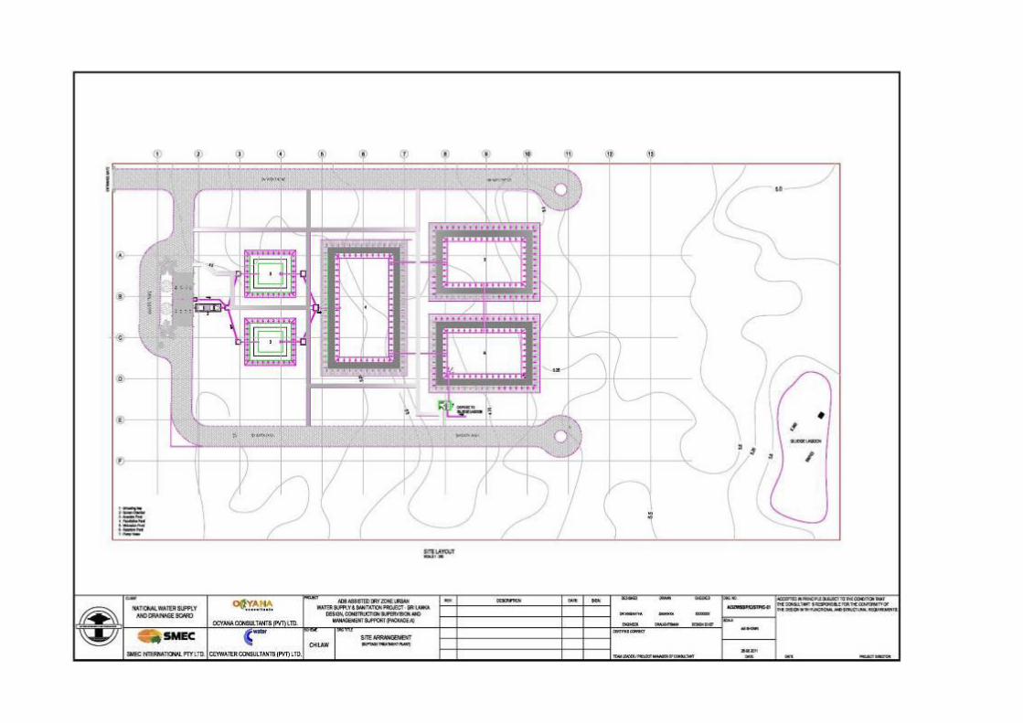
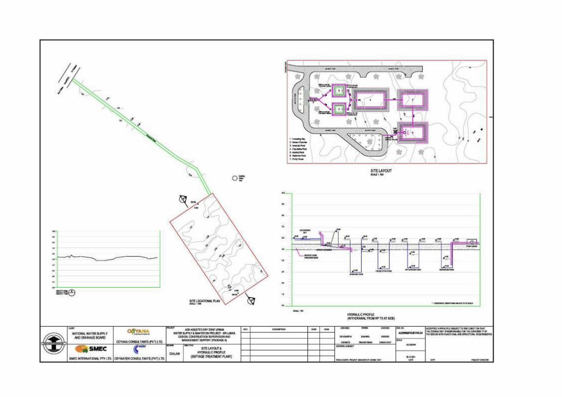
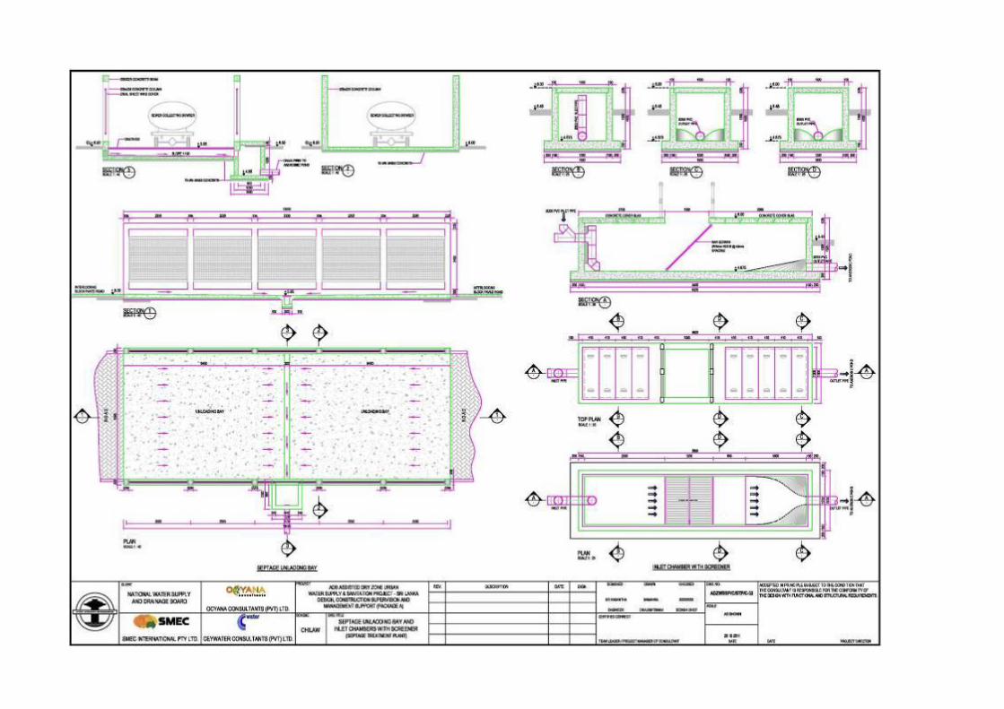
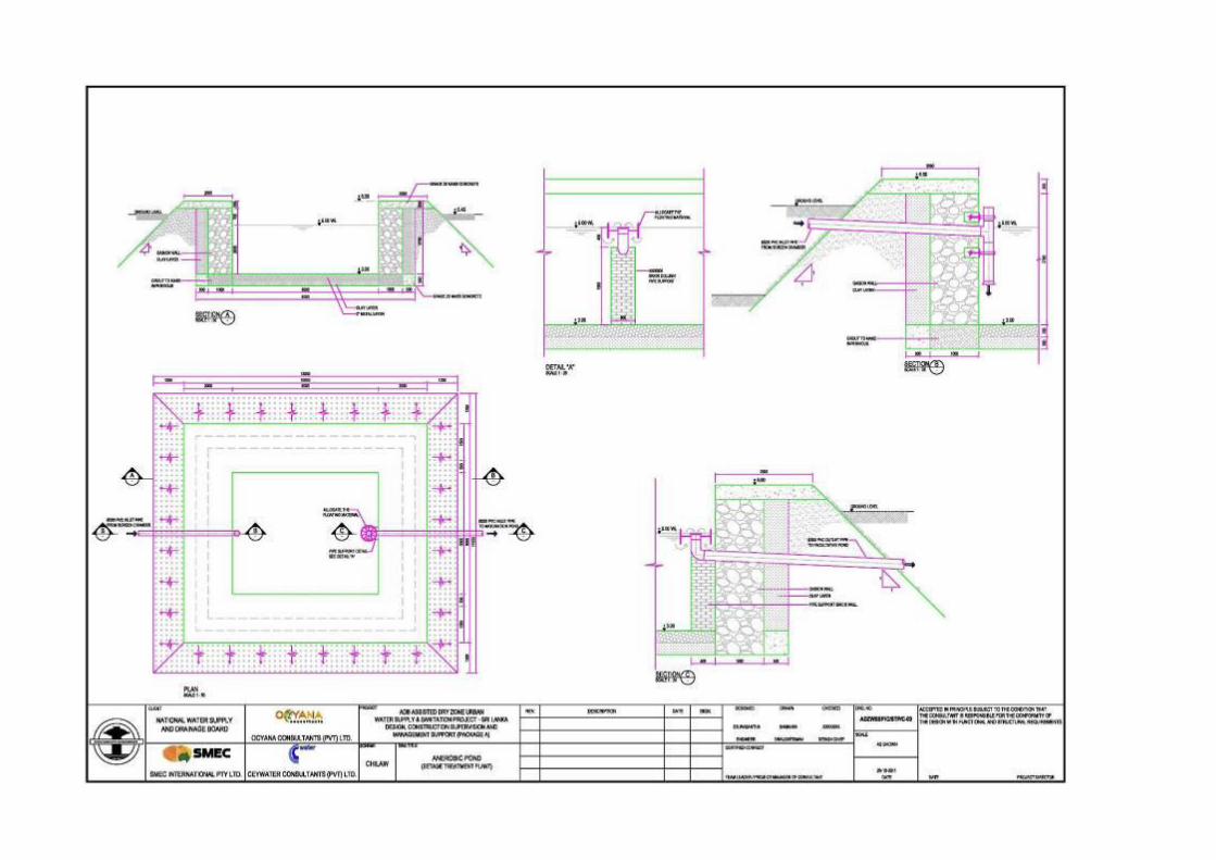
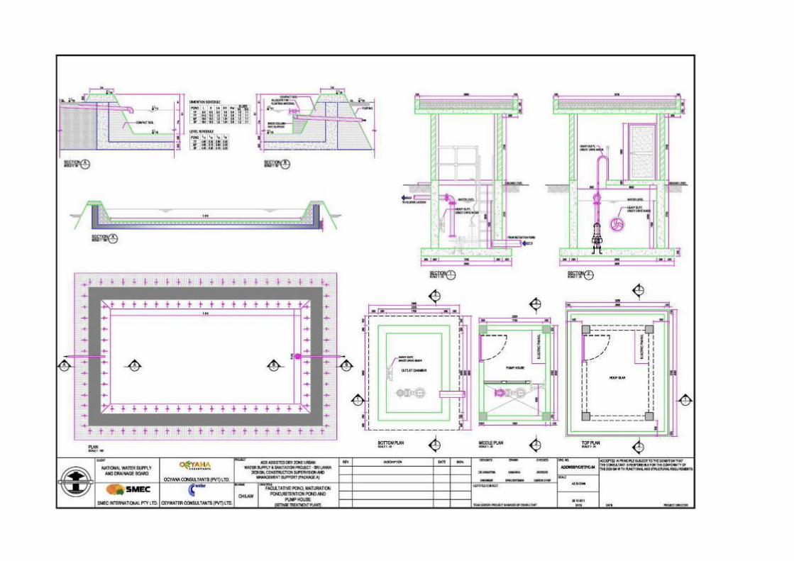
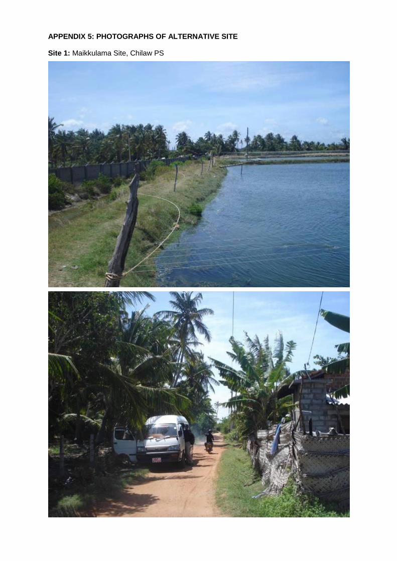
APPENDIX 5: PHOTOGRAPHS OF ALTERNATIVE SITE
Site 1: Maikkulama Site, Chilaw PS
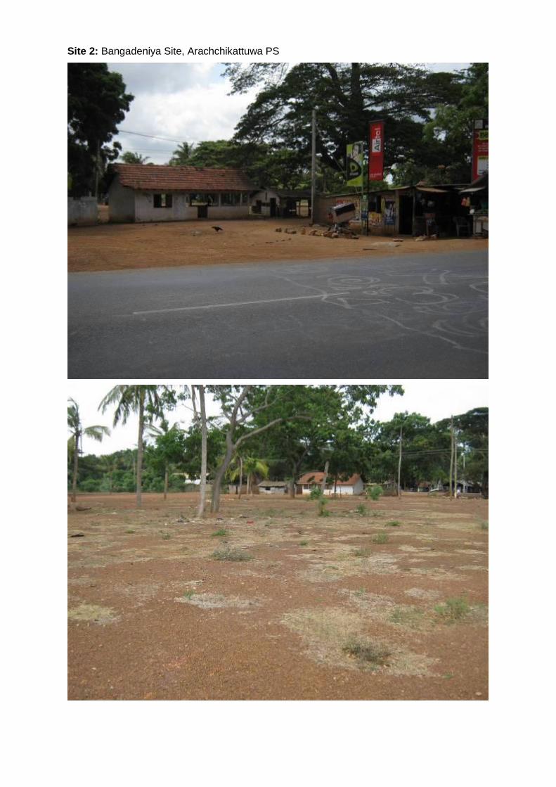
Site 2: Bangadeniya Site, Arachchikattuwa PS
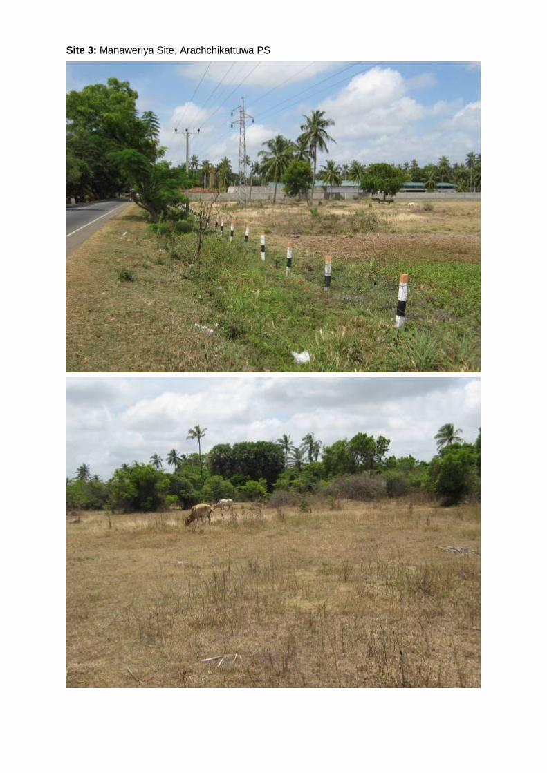
Site 3: Manaweriya Site, Arachchikattuwa PS
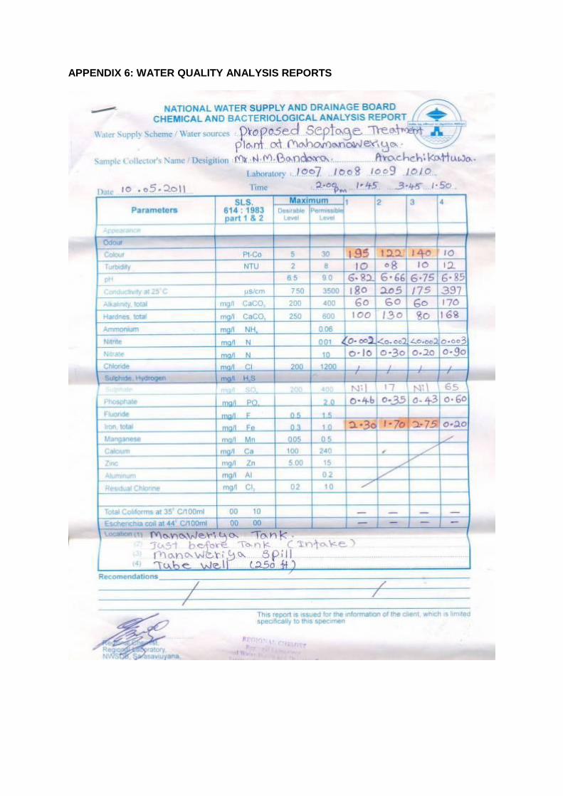
APPENDIX 6: WATER QUALITY ANALYSIS REPORTS
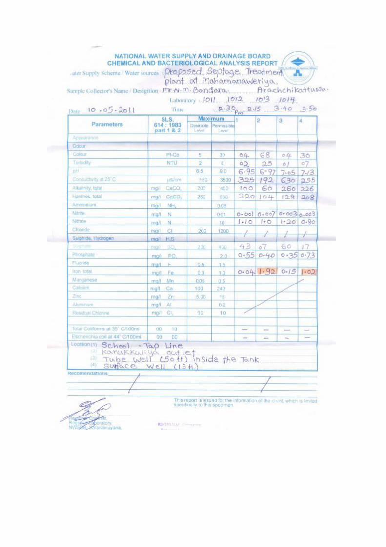
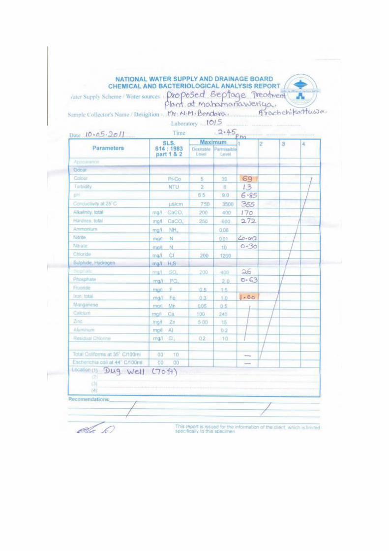
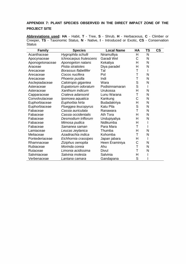
APPENDIX 7: PLANT SPECIES OBSERVED IN THE DIRECT IMPACT ZONE OF THE
PROJECT SITE
Abbreviations used: HA - Habit, T - Tree, S - Shrub, H - Herbaceous, C - Climber or Creeper, TS - Taxonomic Status, N - Native, I - Introduced or Exotic, CS - Conservation Status
Family Species Local Name HA TS CS
Acanthaceae Hygrophila schulli Niramulliya H N Apocynaceae Ichnocarpus frutescens Garadi Wel C N Aponogetonaceae Aponogeton natans Kekatiya H N Araceae Pistia stratiotes Diya paradel H N Arecaceae Borassus flabellifer Tal T I Arecaceae Cocos nucifera Pol T N Arecaceae Phoenix pusilla Indi T N Asclepiadaceae Calotropis gigantea Wara S N Asteraceae Eupatorium odoratum Podisinnamaran S I Asteraceae Xanthium indicum Urukossa H N Capparaceae Crateva adansonii Lunu Warana T N Convolvulaceae Ipomoea aquatica Kankung C N Euphorbiaceae Euphorbia hirta Budadakiriya H N Euphorbiaceae Flueggea leucopyrus Katu Pila S N Fabaceae Cassia auriculata Ranawara T N Fabaceae Cassia occidentalis Ath Tora H N Fabaceae Desmodium triflorum Undupiyaliya H N Fabaceae Mimosa pudica Nidikumba H I Fabaceae Samanea saman Para Mara T I Lamiaceae Leucas zeylanica Thumba H N Meliaceae Azadirachta indica Kohomba T N Pontederiaceae Eichhornia crassipes Japan jabara H I Rhamnaceae Ziziphus oenoplia Heen Eraminiya C N Rubiaceae Morinda coreia Ahu T N Rutaceae Limonia acidissima Divul T N Salviniaceae Salvinia molesta Salvinia H I Verbenaceae Lantana camara Gandapana S I
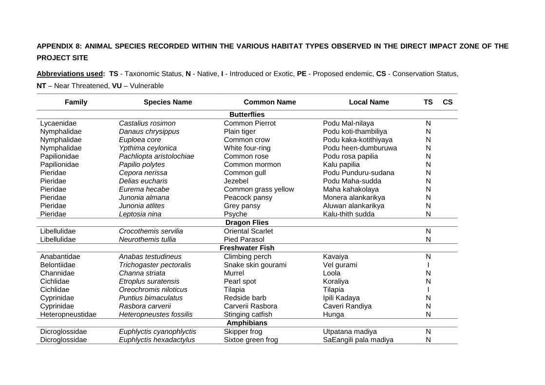
APPENDIX 8: ANIMAL SPECIES RECORDED WITHIN THE VARIOUS HABITAT TYPES OBSERVED IN THE DIRECT IMPACT ZONE OF THE
PROJECT SITE
Abbreviations used: TS - Taxonomic Status, N - Native, I - Introduced or Exotic, PE - Proposed endemic, CS - Conservation Status,
NT – Near Threatened, VU – Vulnerable
Family Species Name Common Name Local Name TS CS
Butterflies
Lycaenidae Castalius rosimon Common Pierrot Podu Mal-nilaya N Nymphalidae Danaus chrysippus Plain tiger Podu koti-thambiliya N Nymphalidae Euploea core Common crow Podu kaka-kotithiyaya N
Nymphalidae Ypthima ceylonica White four-ring Podu heen-dumburuwa N Papilionidae Pachliopta aristolochiae Common rose Podu rosa papilia N Papilionidae Papilio polytes Common mormon Kalu papilia N Pieridae Cepora nerissa Common gull Podu Punduru-sudana N
Pieridae Delias eucharis Jezebel Podu Maha-sudda N Pieridae Eurema hecabe Common grass yellow Maha kahakolaya N Pieridae Junonia almana Peacock pansy Monera alankarikya N Pieridae Junonia atlites Grey pansy Aluwan alankarikya N
Pieridae Leptosia nina Psyche Kalu-thith sudda N
Dragon Flies
Libellulidae Crocothemis servilia Oriental Scarlet N Libellulidae Neurothemis tullia Pied Parasol N
Freshwater Fish
Anabantidae Anabas testudineus Climbing perch Kavaiya N
Belontiidae Trichogaster pectoralis Snake skin gourami Vel gurami I Channidae Channa striata Murrel Loola N Cichlidae Etroplus suratensis Pearl spot Koraliya N Cichlidae Oreochromis niloticus Tilapia Tilapia I
Cyprinidae Puntius bimaculatus Redside barb Ipili Kadaya N Cyprinidae Rasbora carverii Carverii Rasbora Caveri Randiya N Heteropneustidae Heteropneustes fossilis Stinging catfish Hunga N
Amphibians
Dicroglossidae Euphlyctis cyanophlyctis Skipper frog Utpatana madiya N Dicroglossidae Euphlyctis hexadactylus Sixtoe green frog SaEangili pala madiya N
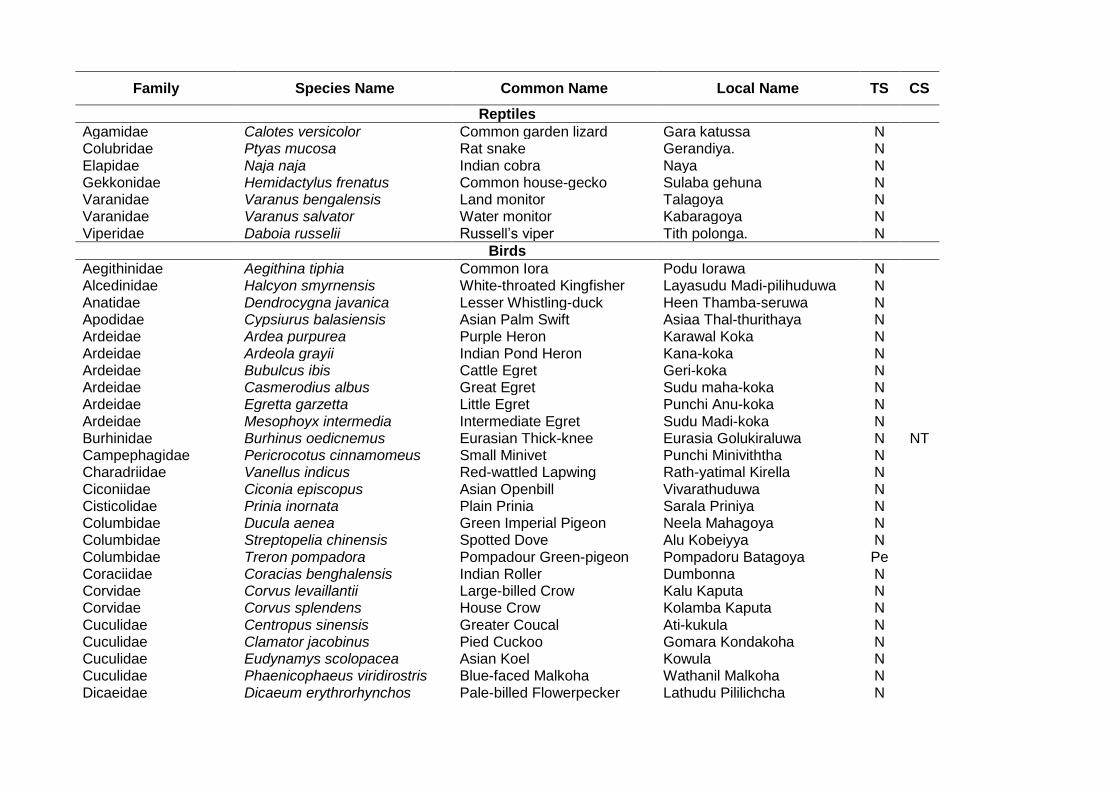
Family Species Name Common Name Local Name TS CS
Reptiles
Agamidae Calotes versicolor Common garden lizard Gara katussa N Colubridae Ptyas mucosa Rat snake Gerandiya. N Elapidae Naja naja Indian cobra Naya N Gekkonidae Hemidactylus frenatus Common house-gecko Sulaba gehuna N Varanidae Varanus bengalensis Land monitor Talagoya N Varanidae Varanus salvator Water monitor Kabaragoya N Viperidae Daboia russelii Russell’s viper Tith polonga. N
Birds
Aegithinidae Aegithina tiphia Common Iora Podu Iorawa N Alcedinidae Halcyon smyrnensis White-throated Kingfisher Layasudu Madi-pilihuduwa N Anatidae Dendrocygna javanica Lesser Whistling-duck Heen Thamba-seruwa N Apodidae Cypsiurus balasiensis Asian Palm Swift Asiaa Thal-thurithaya N Ardeidae Ardea purpurea Purple Heron Karawal Koka N Ardeidae Ardeola grayii Indian Pond Heron Kana-koka N Ardeidae Bubulcus ibis Cattle Egret Geri-koka N Ardeidae Casmerodius albus Great Egret Sudu maha-koka N Ardeidae Egretta garzetta Little Egret Punchi Anu-koka N Ardeidae Mesophoyx intermedia Intermediate Egret Sudu Madi-koka N Burhinidae Burhinus oedicnemus Eurasian Thick-knee Eurasia Golukiraluwa N NT Campephagidae Pericrocotus cinnamomeus Small Minivet Punchi Miniviththa N Charadriidae Vanellus indicus Red-wattled Lapwing Rath-yatimal Kirella N Ciconiidae Ciconia episcopus Asian Openbill Vivarathuduwa N Cisticolidae Prinia inornata Plain Prinia Sarala Priniya N Columbidae Ducula aenea Green Imperial Pigeon Neela Mahagoya N Columbidae Streptopelia chinensis Spotted Dove Alu Kobeiyya N Columbidae Treron pompadora Pompadour Green-pigeon Pompadoru Batagoya Pe Coraciidae Coracias benghalensis Indian Roller Dumbonna N Corvidae Corvus levaillantii Large-billed Crow Kalu Kaputa N Corvidae Corvus splendens House Crow Kolamba Kaputa N Cuculidae Centropus sinensis Greater Coucal Ati-kukula N Cuculidae Clamator jacobinus Pied Cuckoo Gomara Kondakoha N Cuculidae Eudynamys scolopacea Asian Koel Kowula N Cuculidae Phaenicophaeus viridirostris Blue-faced Malkoha Wathanil Malkoha N Dicaeidae Dicaeum erythrorhynchos Pale-billed Flowerpecker Lathudu Pililichcha N
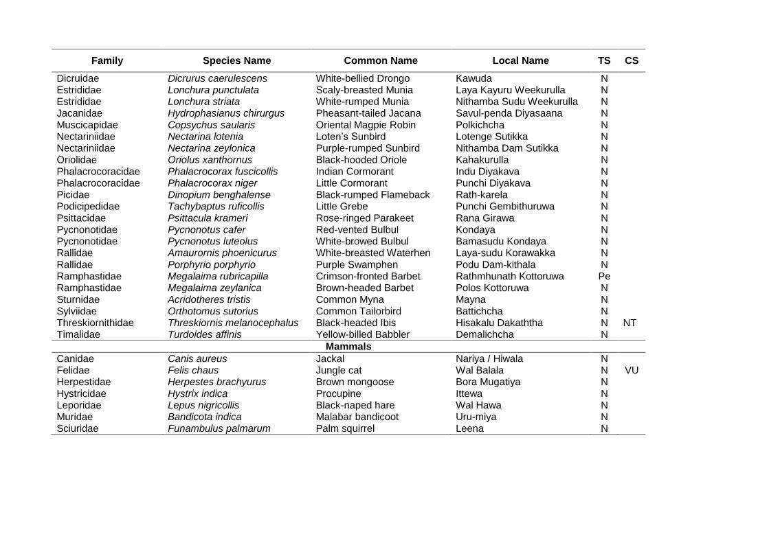
Family Species Name Common Name Local Name TS CS
Dicruidae Dicrurus caerulescens White-bellied Drongo Kawuda N Estrididae Lonchura punctulata Scaly-breasted Munia Laya Kayuru Weekurulla N Estrididae Lonchura striata White-rumped Munia Nithamba Sudu Weekurulla N Jacanidae Hydrophasianus chirurgus Pheasant-tailed Jacana Savul-penda Diyasaana N Muscicapidae Copsychus saularis Oriental Magpie Robin Polkichcha N Nectariniidae Nectarina lotenia Loten’s Sunbird Lotenge Sutikka N Nectariniidae Nectarina zeylonica Purple-rumped Sunbird Nithamba Dam Sutikka N Oriolidae Oriolus xanthornus Black-hooded Oriole Kahakurulla N Phalacrocoracidae Phalacrocorax fuscicollis Indian Cormorant Indu Diyakava N Phalacrocoracidae Phalacrocorax niger Little Cormorant Punchi Diyakava N Picidae Dinopium benghalense Black-rumped Flameback Rath-karela N Podicipedidae Tachybaptus ruficollis Little Grebe Punchi Gembithuruwa N Psittacidae Psittacula krameri Rose-ringed Parakeet Rana Girawa N Pycnonotidae Pycnonotus cafer Red-vented Bulbul Kondaya N Pycnonotidae Pycnonotus luteolus White-browed Bulbul Bamasudu Kondaya N Rallidae Amaurornis phoenicurus White-breasted Waterhen Laya-sudu Korawakka N Rallidae Porphyrio porphyrio Purple Swamphen Podu Dam-kithala N Ramphastidae Megalaima rubricapilla Crimson-fronted Barbet Rathmhunath Kottoruwa Pe Ramphastidae Megalaima zeylanica Brown-headed Barbet Polos Kottoruwa N Sturnidae Acridotheres tristis Common Myna Mayna N Sylviidae Orthotomus sutorius Common Tailorbird Battichcha N Threskiornithidae Threskiornis melanocephalus Black-headed Ibis Hisakalu Dakaththa N NT Timalidae Turdoides affinis Yellow-billed Babbler Demalichcha N
Mammals
Canidae Canis aureus Jackal Nariya / Hiwala N Felidae Felis chaus Jungle cat Wal Balala N VU Herpestidae Herpestes brachyurus Brown mongoose Bora Mugatiya N Hystricidae Hystrix indica Procupine Ittewa N Leporidae Lepus nigricollis Black-naped hare Wal Hawa N Muridae Bandicota indica Malabar bandicoot Uru-miya N Sciuridae Funambulus palmarum Palm squirrel Leena N
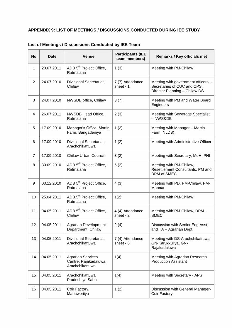
APPENDIX 9: LIST OF MEETINGS / DISCUSSIONS CONDUCTED DURING IEE STUDY
List of Meetings / Discussions Conducted by IEE Team
No Date Venue Participants (IEE team members)
Remarks / Key officials met
1 20.07.2011 ADB 5th Project Office,
Ratmalana 1 (3) Meeting with PM-Chilaw
2 24.07.2010 Divisional Secretariat, Chilaw
7 (7) Attendance sheet - 1
Meeting with government officers – Secretaries of CUC and CPS, Director Planning – Chilaw DS
3 24.07.2010 NWSDB office, Chilaw 3 (7) Meeting with PM and Water Board Engineers
4 26.07.2011 NWSDB Head Office, Ratmalana
2 (3) Meeting with Sewerage Specialist – NWS&DB
5 17.09.2010 Manager’s Office, Martin Farm, Bangadeniya
1 (2) Meeting with Manager – Martin Farm, NLDB)
6 17.09.2010 Divisional Secretariat, Arachchikattuwa
1 (2) Meeting with Administrative Officer
7 17.09.2010 Chilaw Urban Council 3 (2) Meeting with Secretary, MoH, PHI
8 30.09.2010 ADB 5th Project Office,
Ratmalana 6 (2) Meeting with PM-Chilaw,
Resettlement Consultants, PM and DPM of SMEC
9 03.12.2010 ADB 5th Project Office,
Ratmalana 4 (3) Meeting with PD, PM-Chilaw, PM-
Mannar
10 25.04.2011 ADB 5th Project Office,
Ratmalana 1(2) Meeting with PM-Chilaw
11 04.05.2011 ADB 5th Project Office,
Chilaw 4 (4) Attendance sheet - 2
Meeting with PM-Chilaw, DPM-SMEC
12 04.05.2011 Agrarian Development Department, Chilaw
2 (4) Discussion with Senior Eng Asst and TA – Agrarian Dept.
13 04.05.2011 Divisional Secretariat, Arachchikattuwa
7 (4) Attendance sheet - 3
Meeting with DS-Arachchikattuwa, GN-Karukkuliya, GN-Rajakadaluwa
14 04.05.2011 Agrarian Services Centre, Rajakadaluwa, Arachchikattuwa
1(4) Meeting with Agrarian Research Production Assistant
15 04.05.2011 Arachchikattuwa Pradeshiya Saba
1(4) Meeting with Secretary - APS
16 04.05.2011 Coir Factory, Manaweriiya
1 (2) Discussion with General Manager-Coir Factory
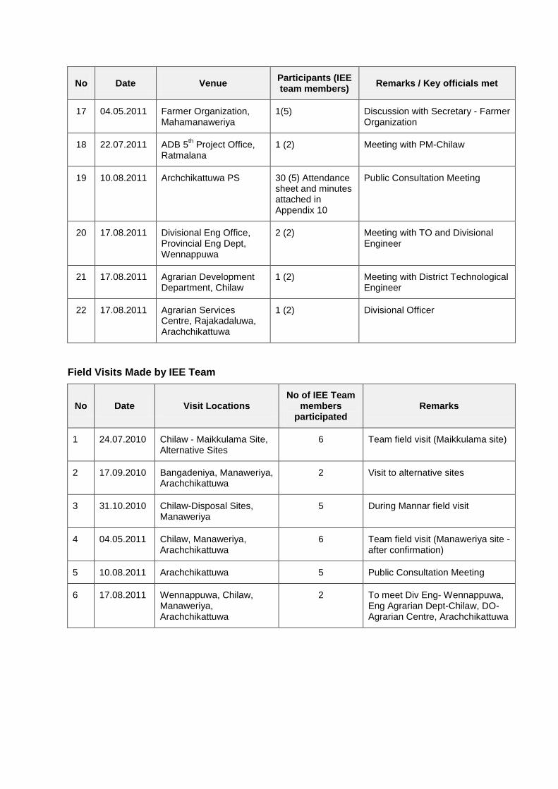
No Date Venue Participants (IEE team members)
Remarks / Key officials met
17 04.05.2011 Farmer Organization, Mahamanaweriya
1(5) Discussion with Secretary - Farmer Organization
18 22.07.2011 ADB 5th Project Office,
Ratmalana 1 (2) Meeting with PM-Chilaw
19 10.08.2011 Archchikattuwa PS 30 (5) Attendance sheet and minutes attached in Appendix 10
Public Consultation Meeting
20 17.08.2011 Divisional Eng Office, Provincial Eng Dept, Wennappuwa
2 (2) Meeting with TO and Divisional Engineer
21 17.08.2011 Agrarian Development Department, Chilaw
1 (2) Meeting with District Technological Engineer
22 17.08.2011 Agrarian Services Centre, Rajakadaluwa, Arachchikattuwa
1 (2) Divisional Officer
Field Visits Made by IEE Team
No Date Visit Locations No of IEE Team
members participated
Remarks
1 24.07.2010 Chilaw - Maikkulama Site, Alternative Sites
6 Team field visit (Maikkulama site)
2 17.09.2010 Bangadeniya, Manaweriya, Arachchikattuwa
2 Visit to alternative sites
3 31.10.2010 Chilaw-Disposal Sites, Manaweriya
5 During Mannar field visit
4 04.05.2011 Chilaw, Manaweriya, Arachchikattuwa
6 Team field visit (Manaweriya site - after confirmation)
5 10.08.2011 Arachchikattuwa 5 Public Consultation Meeting
6 17.08.2011 Wennappuwa, Chilaw, Manaweriya, Arachchikattuwa
2 To meet Div Eng- Wennappuwa, Eng Agrarian Dept-Chilaw, DO-Agrarian Centre, Arachchikattuwa
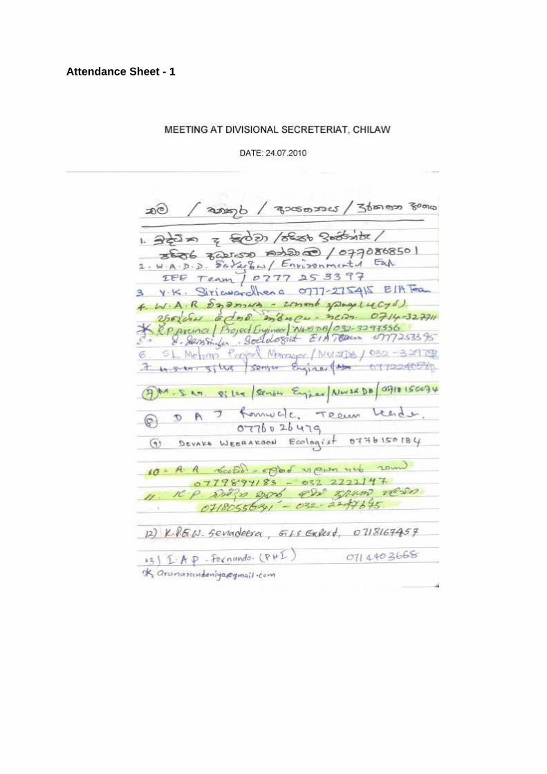
Attendance Sheet - 1
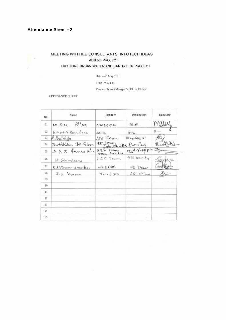
Attendance Sheet - 2
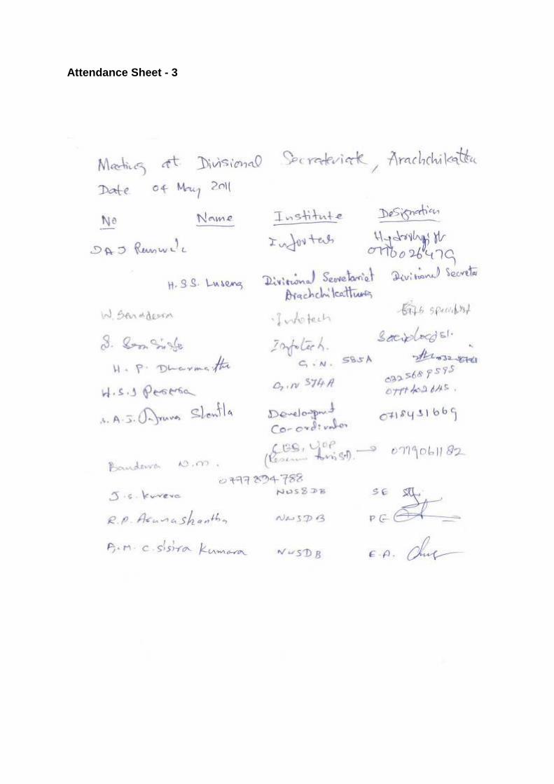
Attendance Sheet - 3
APPENDIX 10: MEETING MINUTES OF PUBLIC CONSULTATION MEETING
Date : August 10, 2011
Time : 1030 hrs
Venue : Auditorium of Arachchikattuwa Pradeshiya Saba
Participants : Attendance sheet attached
The meeting commenced with the welcome address made by Mr. Jude Coorera, Senior Engineer of National Water Supply and Drainage Board Office at Chillaw.
Dr. Vasantha Siriwardhane made a Power Point Presntation on the Technical Design of the Septage Treatment Plant to be located at Bangadeniya on a block of land belongs to the National Livestock Development Board. In his presentation he emphasized that the treatment plant will not pose any threat to the health or the environment of the area. He further reiterated that an unpleasant smell will not be emanated due to the project.
Mr. RP Aruna Shantha, Project Engineer, NWSDB explained about the drinking water and sanitation project funded by the Asian Development Bank. Flowing water of Deduru Oya and the ground water will be used for the drinking water project. The proposed Septage Treatment Plant is only a component of this project.
Mr. Aruna Shantha pointed out that already there is a threat of contamination to surface water and ground water due to disposal of sewerage in a haphazard manner by the people of the area. Currently instances have been observed that toilet pits are over-flown due to non emptying them at the proper time. During the rainy season, the situation becomes worse and this has posed in threat to the sanitation of the Chilaw Urban Council area.
Mr. Arunashantha further observed that several lands were earmarked for the Septage Treatment Plant and after several inspections it was decided to locate the plant at Bangadeniya on a land in extent of 49 acres belonging to NLDB. However, the project will need only 4 acres of the land, beyond the villege tank called Mahamanaweriya Tank.
Mr. Aruna Shantha also said that the households of the project area will receive drinking water facility under the proposed project. Apart from this it has been planned to provide toilet facilities to the houses of the area by the NWSDB, under the project.
Mr. Aruna Shantha reiterated that water of the existing dug wells of the area will not be contaminated or affected otherwise due to the project.
After the briefing of Mr. Aruna Shantha participants were requested to expressed their views on the proposed project.
At this stage GN Karukkuliya suggested that the IEER be prepared in the first instance and then people of the area be given the opportunity to present their views on the report.
Mr. G.M. Wijeratne who spoke next said that term septage is not clear to the people. He requested is throwing more light on the term septage. PHI Chilaw UC explained as to what the septage means.
Mr. Wijeratne again inquired as to whether effluents from the septage plant would be harmful to the people of the area. PHI said that the water discharge from the ponds will be collected and taken away and released to the coconut lands located away from the populated area.
Mr. A M Abeywardhane expressing his views stated that the land selected for the Septage Treatment Plant is very close to the Mahamanaweriya Tank and inquired whether the water discharged from the Setptage Treatment Plant Plant would be released to the tank.
Mr. Arunashantha, the Project Engineer assured that discharged water will not be released to the Mahamanaweriya Tank.
Mr. Patrick inquired whether bad smell would be emanated during the transport of sewage from the collection points to the treatment plant. If no unpleasant smell is emanated during transportation, there is no reason for the people to object to the project he said. He further said that in the implementation of development projects, all precautionary measures are taken to avoid harmful affects at the beginning. However, such measures are neglected once the projects are being executed. If the situation ids not addressed seriously, people of the area will raise objections to the project.
Mr. H A Sanath, PHI of the Chillaw UC said that transport of septage will be carried out in such a manner; no bad smell would be emanated during transportation. Transportation will be carried out along the Colombo – Puttalam highway. The bowsers that will carry the septage will be tightly sealed to prevent emanation of any unpleasant smell. This will not have the slightest idea on what is being transported by the bowsers, he said.
Next item was the presentation by mr. Anura Ranwala, Team Leader of the IE team. In his presentation he stated the IEE report will be prepared in accordance with the ADB requirement and the regulations of the Environmental Authority of the North Central Province.
Mr. Ranwala explained that the septage treatment plant will be operated in a such a manner that no hazard will cause to the environment. Treatment plant will be located more than 100 meters away from the high flood level of the Mahamanaweriya Tank so that the water of the Tank will not be contaminated due to the treatment plant. He further said that the existing irrigation channel will not be disturbed and where necessary culverts will be constructed to allow the free flow of water of the Rajaweeketu Ela.
Secretary of the Arachchikattuwa Pradeshiya Sabha expressing his views said that the Chairman of the Pradeshiya Sabha was unable to attend the meeting due to unavoidable circumstances. However, the Chairman wanted conveyed his message that the people of the area should be apprised on the benefits of the project. Also the project will be implemented in a such a way safeguard the sanitation and social status of the people of the area.
Assistant Director of Planning of the Arachchikattuwa DS Division stated that the people of the area were not in support for the project. Therefore, it is necessary to educate the people on the operation of the project and the benefits made available to them by the project.
Mr. Jude Coorera, Chief Engineer of NWS&DB explained about the benefits from the project to the people of the area. He said there will be a scheme to provide drinking water to the households of the Arachchikattuwa Pradeshiya Sabha area. A new public toilet will be built at weekly fare (sathi pola) of Arachchikattuwa. There will be a programme to provide toilets for the needy households as well, he said.
Mr. S A Dayaratne, Secretary to the Community Based Organization of Arachchikattuwa expressed his doubts as to whether polluted water discharged from the Treatment Plant would be sucked in to the pipelines already providing drinking water to the households. He said that the present strength of the CBO is 1200 households and they will be thoroughly unhappy if such a situation is going to occur. He further inquired any remedial measures are taken in such a situation occurs.
PHI of Chillaw UC in reply said that water released from the Treatment Plant will not be polluted. Also there is no possibility to suck this water in to the pipelines already providing drinking water to the households.
Grama Niladari, Karukkuliya speaking on the proposed drinking water project stated that he had heard that the NWS&DB is planning to use water from the Deduru Oya for the proposed water supply scheme and also to extract ground water for the project. He opined that tapping of water from Deduru Oya would be more suitable than extracting ground water. He raised the following questions;
Will the water released from the last pond of the treatment plant be released to the surface of the nearby land?
Will this water be overflowed during the rainy season? If it so happens what are the remedial measures to avoid such a situation?
Will the road leading to Septage Treatment Plant be raised, if so will the main road go under water during the rainy season?
Responding to GN - Karukkuliya, Mr. Arunashantha - Project Engineer said that proposed water supply scheme will not pose any threat to the environment. The dam for diversion of water of Deduru Oya will be built at Wilaththawa. If the quantity of water from Deduru Oya will not be sufficient ground water will have to be extracted.
Water released from the Septage Treatment Plant will not be discharged to the adjoining land.
At this stage Mr. Anura Ranwala, Team Leader of the IEE Team said the road leading to the Septage Treatment Plant will have to be raised. However, all precautionary measures will be taken to ensure free flow of water flowing from the Karukkuliya tank and to avoid inundation of the main road during the rainy season.
Mr. Patrick again inquired whether the project will commence after completion of the IEE report or IEE report will be prepared after execution of the project. Mr. Ranwala replied that the project will not take off until the IEE report is finalized.
Professor Ms. Hemanthi Ranasinghe who spoke next said that the interest shown by the people in the area about the project is very encouraging. She said that people are skeptical about the project due to lack of awareness. There is no need to have fear about environmental problems due to the project. Currently there are a number of Septage Treatment Plants operating in different parts of the country. They are functioning smoothly and the people living closer to these septage treatment plants even do not notice their existence as there is no unpleasant smell emanated from them.
Mr. KA Ariya Rathnapala said that he has witnessed how these Septage Treatment Plants are operated in Indonesia. He said that the Treatment Plants are located in congested areas but people do not notice there existence as no bad smell is emanating from these plants.
Divisional Secretary, Arachchikattuwa explaining her views said that involvement of Grama Niladharies in the projects in this nature is very important. Also, she emphasized that the need of awareness among the people of the area about the benefits of the project and the measures taken by the implementing agency to avoid any possible negative impacts on the environment.
Meeting concluded at 1.30pm.
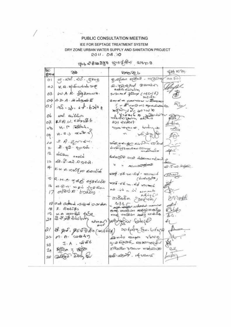
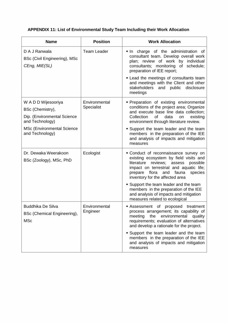
APPENDIX 11: List of Environmental Study Team Including their Work Allocation
Name Position Work Allocation
D A J Ranwala
BSc (Civil Engineering), MSc
CEng, MIE(SL)
Team Leader In charge of the administration of consultant team. Develop overall work plan; review of work by individual consultants; monitoring of schedule; preparation of IEE report;
Lead the meetings of consultants team and meetings with the Client and other stakeholders and public disclosure meetings
W A D D Wijesooriya
BSc (Chemistry),
Dip. (Environmental Science and Technology)
MSc (Environmental Science and Technology)
Environmental Specialist
Preparation of existing environmental conditions of the project area; Organize and execute base line data collection; Collection of data on existing environment through literature review.
Support the team leader and the team members in the preparation of the IEE and analysis of impacts and mitigation measures
Dr. Dewaka Weerakoon
BSc (Zoology), MSc, PhD
Ecologist Conduct of reconnaissance survey on existing ecosystem by field visits and literature reviews; assess possible impact on terrestrial and aquatic life; prepare flora and fauna species inventory for the affected area
Support the team leader and the team members in the preparation of the IEE and analysis of impacts and mitigation measures related to ecological
Buddhika De Silva
BSc (Chemical Engineering),
MSc
Environmental Engineer
Assessment of proposed treatment process arrangement; its capability of meeting the environmental quality requirements; evaluation of alternatives and develop a rationale for the project.
Support the team leader and the team members in the preparation of the IEE and analysis of impacts and mitigation measures
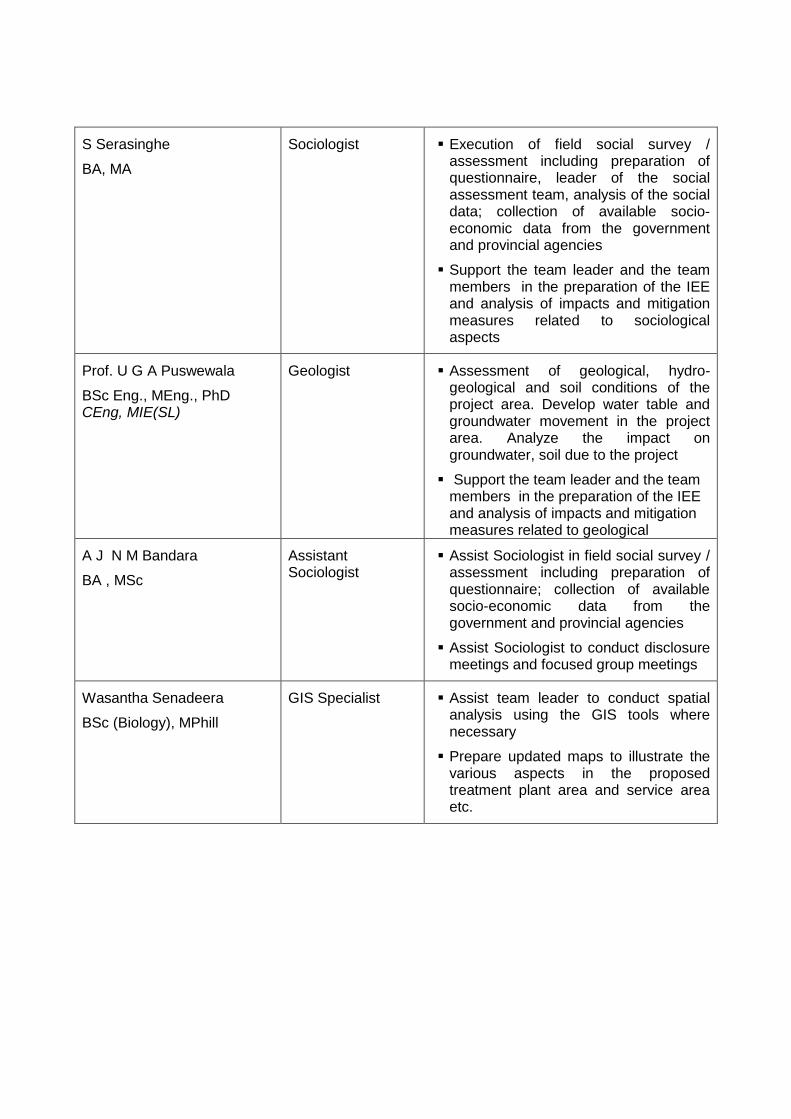
S Serasinghe
BA, MA
Sociologist Execution of field social survey / assessment including preparation of questionnaire, leader of the social assessment team, analysis of the social data; collection of available socio-economic data from the government and provincial agencies
Support the team leader and the team members in the preparation of the IEE and analysis of impacts and mitigation measures related to sociological aspects
Prof. U G A Puswewala
BSc Eng., MEng., PhD CEng, MIE(SL)
Geologist Assessment of geological, hydro-geological and soil conditions of the project area. Develop water table and groundwater movement in the project area. Analyze the impact on groundwater, soil due to the project
Support the team leader and the team members in the preparation of the IEE and analysis of impacts and mitigation measures related to geological
A J N M Bandara
BA , MSc
Assistant Sociologist
Assist Sociologist in field social survey / assessment including preparation of questionnaire; collection of available socio-economic data from the government and provincial agencies
Assist Sociologist to conduct disclosure meetings and focused group meetings
Wasantha Senadeera
BSc (Biology), MPhill
GIS Specialist Assist team leader to conduct spatial analysis using the GIS tools where necessary
Prepare updated maps to illustrate the various aspects in the proposed treatment plant area and service area etc.
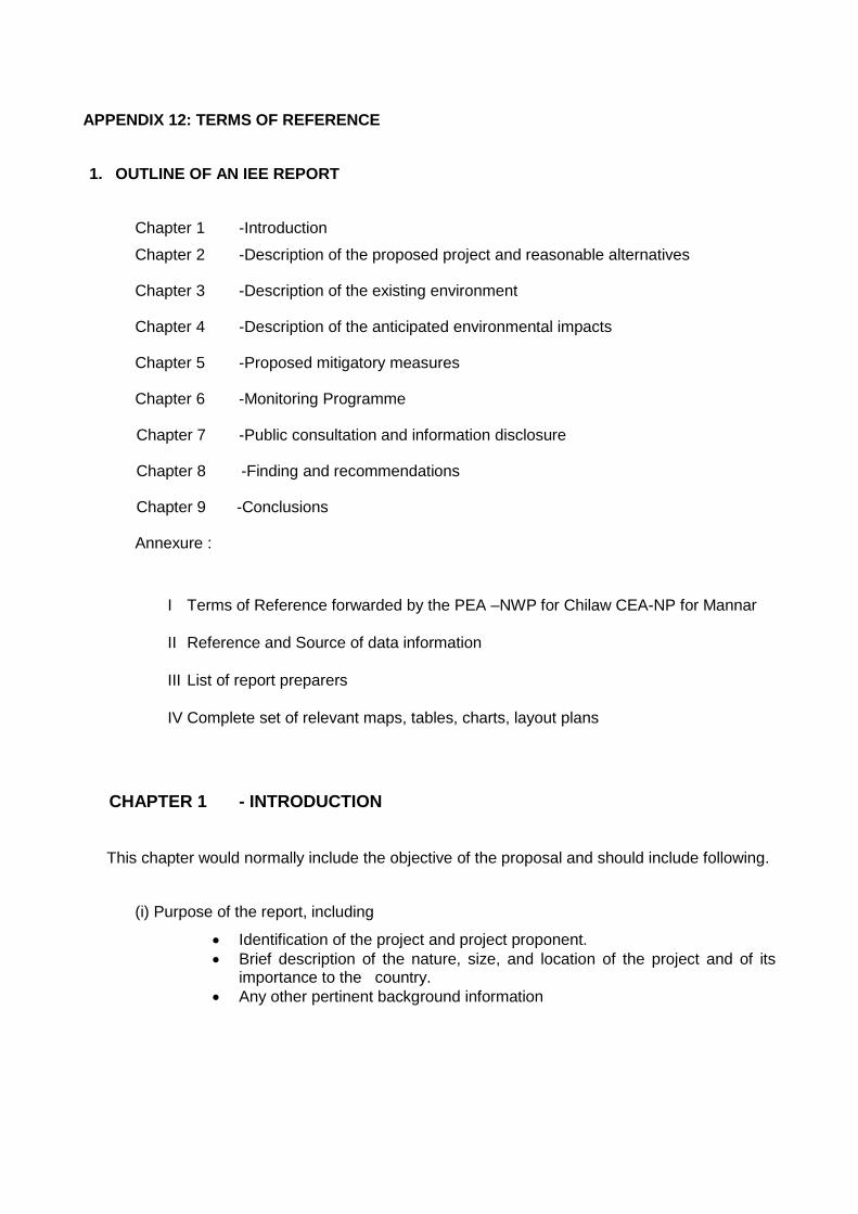
APPENDIX 12: TERMS OF REFERENCE
1. OUTLINE OF AN IEE REPORT
Chapter 1 -Introduction
Chapter 2 -Description of the proposed project and reasonable alternatives
Chapter 3 -Description of the existing environment
Chapter 4 -Description of the anticipated environmental impacts
Chapter 5 -Proposed mitigatory measures
Chapter 6 -Monitoring Programme
Chapter 7 -Public consultation and information disclosure
Chapter 8 -Finding and recommendations
Chapter 9 -Conclusions
Annexure :
I Terms of Reference forwarded by the PEA –NWP for Chilaw CEA-NP for Mannar
II Reference and Source of data information
III List of report preparers
IV Complete set of relevant maps, tables, charts, layout plans
CHAPTER 1 - INTRODUCTION
This chapter would normally include the objective of the proposal and should include following.
(i) Purpose of the report, including
Identification of the project and project proponent.
Brief description of the nature, size, and location of the project and of its importance to the country.
Any other pertinent background information
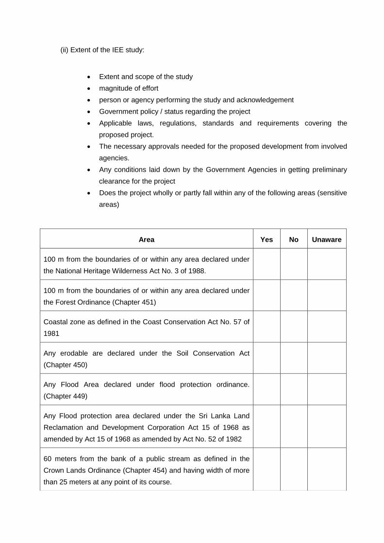
(ii) Extent of the IEE study:
Extent and scope of the study
magnitude of effort
person or agency performing the study and acknowledgement
Government policy / status regarding the project
Applicable laws, regulations, standards and requirements covering the
proposed project.
The necessary approvals needed for the proposed development from involved
agencies.
Any conditions laid down by the Government Agencies in getting preliminary
clearance for the project
Does the project wholly or partly fall within any of the following areas (sensitive
areas)
Area Yes No Unaware
100 m from the boundaries of or within any area declared under
the National Heritage Wilderness Act No. 3 of 1988.
100 m from the boundaries of or within any area declared under
the Forest Ordinance (Chapter 451)
Coastal zone as defined in the Coast Conservation Act No. 57 of
1981
Any erodable are declared under the Soil Conservation Act
(Chapter 450)
Any Flood Area declared under flood protection ordinance.
(Chapter 449)
Any Flood protection area declared under the Sri Lanka Land
Reclamation and Development Corporation Act 15 of 1968 as
amended by Act 15 of 1968 as amended by Act No. 52 of 1982
60 meters from the bank of a public stream as defined in the
Crown Lands Ordinance (Chapter 454) and having width of more
than 25 meters at any point of its course.
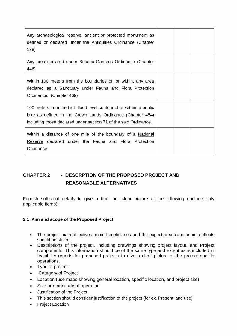
Any archaeological reserve, ancient or protected monument as
defined or declared under the Antiquities Ordinance (Chapter
188)
Any area declared under Botanic Gardens Ordinance (Chapter
446)
Within 100 meters from the boundaries of, or within, any area
declared as a Sanctuary under Fauna and Flora Protection
Ordinance. (Chapter 469)
100 meters from the high flood level contour of or within, a public
lake as defined in the Crown Lands Ordinance (Chapter 454)
including those declared under section 71 of the said Ordinance.
Within a distance of one mile of the boundary of a National
Reserve declared under the Fauna and Flora Protection
Ordinance.
CHAPTER 2 - DESCRPTION OF THE PROPOSED PROJECT AND
REASONABLE ALTERNATIVES
Furnish sufficient details to give a brief but clear picture of the following (include only applicable items):
2.1 Aim and scope of the Proposed Project
The project main objectives, main beneficiaries and the expected socio economic effects should be stated.
Descriptions of the project, including drawings showing project layout, and Project components. This information should be of the same type and extent as is included in feasibility reports for proposed projects to give a clear picture of the project and its operations.
Type of project
Category of Project
Location (use maps showing general location, specific location, and project site)
Size or magnitude of operation
Justification of the Project
This section should consider justification of the project (for ex. Present land use)
Project Location
i. Pradeshiya Sabha
ii. District Secretariat
iii. Provincial Council
iv. Provide a location map indicating the project site, access to the site,
surrounding development and infrastructure within 500 m radius of the site (at
appropriate scale)
2.2 Extent of the project area
Project layout drawing showing project layout plan covering the entire identified site
including all major component of project.
Project characteristics including its principal features, permanent and temporary Structures.
Proposed schedule for implementation.
2.3 Design details of Septage Treatment Plant and method of sludge disposal.
2.4 Raw materials to be used for constructional purposes (quantity, source and location of borrow areas/pits, transportation and storage of raw materials etc.)
2.5 Labour requirements
i. Requirement of labour during construction and operation (both skilled and non
skilled)
ii. Availability of labour in the area.
2.6 Infrastructure facilities [details of any access road to be built / improved (existing condition and anticipated]
2.7 Are future additions, expansions envisaged.
2.8 State the proposed time schedule for construction.
2.9 Evaluation of Alternatives
Describe reasonable alternative considered and the basic environmental engineering and economic parameters used in their investigation and evaluation. Compare alternatives in terms of potential environment impacts, mitigatory measures capital an operating cost, reliability etc.
The following alternatives could be considered.
No action alternatives
Alternative site/s,
Alternative design, technology and construction techniques
Comparison of the alternatives considered and construction and recommendation should be given.
CHAPTER 3 - DESCRIPTION OF THE EXISTING ENVIRONMENT
This chapter should provide information on physical features, ecological resources, socio economic, archeological and cultural consideration likely to be affected by any aspect of the proposal during its constructional or operational phase.
The methods used to collect data should clearly be stated under each category. Any technical terms used should clearly be defined. The existing environment should be described under the following.
STUDY AREA
The study area for the assessment shall include the following:
1. Location of the Septage Treatment Plant including impounding area.
2. 500m on either side of the above stretch
3. Main anticipated road haulage to the project site
4. Effluent Discharge area.
3.1 Physical Features
3.1.1 Hydrology
General description of project area:
Topography, geology, forest area, turbidity, Sources/point & point source of
siltation/pollution etc.
Any surface water bodies within or in the vicinity of the site.
Surface drainage pattern of the area.
Flooding – Flooding in surrounding area and anticipated levels of flooding.
Changes in flooding due to the project.
Water table – Effect of water table within the site before and after the project.
List of existing irrigation or drainage / flood protection schemes encountered.
3.1.2 Climate and meteorology (use existing data as much as possible)
Precipitation patterns of the area
Prevailing wind patterns.
3.1.3 Geological aspects of the site
Subsurface geology
3.1.4 Soil types find in the area
3.1.5 Description of Lagoon and nearby Sea
3.1.6 Is the project area prone / subject to natural disasters such as landslides, earth slips, floods, Tsunami, cyclone (give details)
3.1.7 Atmosphere ( e.g. Air quality and climate)
3.2 Ecological Resources (both terrestrial an aquatic)
List rare, threatened and endemic flora and fauna known to be in and around the
site.
Existing natural habitats if any, in and around the project site.
List any protected areas, coastal resources, forests,fisheries, wild life and aquatic
biology.
3.3 Economic Development
Industries
Infrastructure facilities ( water supply, sewerage, flood control )
Transportation ( roads, harbors and navigation )
Land use ( dedicated area uses )
Powers sources and transmission.
Agricultural development and tourism facilities.
3.4 Social and Cultural Resources
Structures or sites that are of historical, archaeological, paleontological, or architectural significance.
Population and communities (e.g. numbers, locations, composition, employment)
Health facilities
Education facilities
Socio-economic conditions ( e.g. community structure, family structure, social well being)
Physical or cultural of heritage
Current use of lands and resources for traditional purposes by indigenous peoples
Structures or sites that are of historical, archaeological, paleontological or architectural significance.
List any prime agricultural lands, catchment areas, urban / residential areas, schools, religious, sites, wetlands, tourist resorts wild life etc.
Number of house holds within the immediate project area
Resettlement options (If any)
CHAPTER 4 - DESCRIPTION OF ANTICIPATED ENVIRONMENTAL IMPACTS.
This chapter should show the overall negative as well as positive impacts on the individual components during construction and operation of the proposed project. Impacts should include foreseeable direct and indirect, long and short term effects.
4.1 4.1 Constructional impacts – state briefly the following
Impacts of land clearing (soil erosion and increase in run off, cutting, leveling and mode of removal of unwanted materials from the site an effect of transportation of materials on existing roads)
Noise, vibration and dust due to construction activities (If blasting operations are carried out it should be clearly mentioned)
Air quality impacts from traffic during transportations of material and equipment
Impact on natural drainage pattern due to construction activities
4.2 Operational impacts
Impact on water quality in adjacent ground water
Impact on flooding
Impact on Irrigation activities of surrounding areas of the project & Flood
protection.
Impact on lagoon / sea due to disposal of effluent water
Impact on near by prawn farms
Impact due to odor.
Impact due to tidal effect of the Sea.
4.3 Noise due to operations
Possible source of noise
Method proposed to minimize excessive noise
4.4 Impacts on ecological resources (Construction and operational phase)
Does the project cause any destruction / alternation of habitats?
Impacts of project activities on animals in nearby reservation and parks/direct
impacts/indirect impacts
State briefly the anticipated impacts on terrestrial and aquatic flora and fauna
with special reference to mitigation pattern of such species and the measures to
mitigate such impacts.
Will the project result in unexpected loss of forest specially along the reservation
of the water body.
4.5 Sociological Impacts
Employment opportunities to be provide to the local people during construction
and operation
Number of families to be affected and to be replaces by the development
Unemployment due to acquisition of agricultural lands
Resettlement plan, compensation of package etc
Social impacts on the relocation site
Degree of affection to the peripheral people from the resettled host community
Social economic benefits (other than employments) to be provided to the local
people
4.6 Any other impacts which has not being anticipated at this stage but may come up in the future.
CHAPTER 5 - PROPPOSED MITIGATORY MEASURES
This chapter should set out the proposed measures to minimize the impacts identified the chapter 4. The migratory measures should be defined in the specific practical terms and its effectiveness should be evaluated. This chapter should also present rationale for selection of chosen mitigatory measures.
CHAPTER 6 - INSTITUTIONAL REQUIREMENTS AND ENVIRONMENTAL
MONITORING PLAN.
This section should state the impacts to be mitigated, and activities to implement the mitigation measures, including how, when, and where they will be implemented. Institutional arrangements for implementation should be described. The environmental monitoring plan should be describe the impacts to be monitored, and when and where monitoring activities will be carried out, and who will carry them out. The environmental management and monitoring costs should also be described.
An effective reporting procedure should be outlined. Availability of funds, expertise, facilities should be stated. This section also included following.
Responsibility agency/ agencies
Facilities available with such Parameters to be monitored
Proposed locations of sampling points
Frequency of monitoring
Agencies
Emergency Plan
A suitable safety and contingency plan (emergency action) should be involved to ensure the safety of the community.
CHAPTER 7 - PUBLIC CONSULTATION AND INFORMATION DISCLOSURE
The process undertaken to involve the public in project design and recommended measures for continuing pubic participation ;summarize major comments received from beneficiaries, local officials, community leaders, NGOs, and others and describe how these comments were addressed ; list milestones in public involvement such as dates, attendance, and topics of public meetings ; list recipients of this document and other project related documents ; describe compliance with relevant regulatory requirements for pubic participation ; and summarize other related materials or activities, such as press releases and notification. This section will provide of summary of information disclosed to date and procedures for future disclosure.
CHAPTER 8 - FINDING AND RECOMMENDATIONS
An evaluation of the screening process and recommendation will be provided whether significant environmental impacts exist needing further detailed study or EIA. If there is no need for further study, the IEE itself, which at times may need to be supplemented by a special study in view of limited but significant impact, becomes the completed environmental assessment for the project and no follow- up EIA will be needed. If an EIA is needed, then this section will include a brief terms of reference ( TOR) for the needed follow – up EIA, including approximate description of works tasks, professional skills required, time required, and estimated costs.
CHAPTER 9 - CONCLUSIONS
In this section should be discussed the results of the IEE and justification, if any of the need for additional study or EIA. If an IEE, or an IEE supplemented by a special study, is sufficient for the project, then the IEE with the recommended institutional and monitoring program becomes the completed EIA. Any programme to improve general environmental conditions can also be stated here.
SUMMERY OF IEE REPORT
The summary IEE (SIEE) report is the executive summary of the IEE report. It describes the significant findings of the IEE report, and recommendations to manage them. The SIEE report
should be presented clearly and concisely as a stand-alone document for submission to the Board and disclosure to the public.
Outline of an SIEE Report
A. Introduction (1/2 page)
This section will include the purpose of the report, extent of the IEE study and brief description of any special techniques or methods used.
B. Description of the Project (1/2 page)
This section will include the type of and need for the project; and project location, size or magnitude, operation, and proposed schedule for implementation.
C. Description of the Environment (2 pages)
This section will include the physical and ecological resources, human and economic development, and quality of life values.
D. Forecasting Environmental Impacts and Mitigation Measures (2-4 pages)
This section will identify "no significant impacts" from those with significant adverse impacts and will discuss the appropriate mitigation measures, where necessary.
E. Institutional Requirements and Environmental Monitoring Plan (1 page)
This section will describe the impacts to be mitigated, and activities to implement the mitigation measures, including how, when, and where they will be implemented. The environmental monitoring plan will describe the impacts to be monitored, and when and where monitoring activities will be carried out, and who will carry them out.
F. Public Consultation and Disclosure
This section will describe the process undertaken to involve the public in project design and recommended measures for continuing public participation; summarize major comments received from beneficiaries, local officials, community leaders, NGOs, and others, and describe how these comments were addressed; list milestones in public involvement such as dates, attendance, and topics of public meetings; list recipients of this document and other project related documents; describe compliance with relevant regulatory requirements for public participation; and summarize other related materials or activities, such as press releases and notifications. This section will provide of summary of information disclosed to date and procedures for future disclosure.
G. Findings and Recommendations (1-2 pages)
This section will include an evaluation of the screening process, and recommendation will be provided whether significant environmental impacts exist needing further detailed study or EIA. If there is no need for further study, the IEE itself, which at times may need to be supplemented by a special study in view of some small significant impacts, becomes the completed EIA for the project and no follow-up EIA will be needed. If further additional study is needed, then this section will include a brief terms of reference (TOR) for the needed follow-up EIA, including approximate descriptions of work tasks, professional skills required, time required, and estimated costs. The Bank's Environment Guidelines provides a guide for preparing the TOR for different projects.
H. Conclusions (1/2 page)
This section will discuss the result of the IEE and justification if any of the need for additional study or EIA. If an IEE or an IEE supplemented by a special study is sufficient for the project, then the IEE with the recommended institutional requirements and monitoring program become the completed EIA.


Addendum 1
Committee for Grievance Redress and Environment Monitoring
In absence of such provisions, affected parties/persons (AP) will seek solutions outside the
project which may lead to a number of adverse consequences. It is necessary to include
grievance redress provisions for the people adversely affected (or about to be affected) by the
development of sub projects because such people should have provisions to forward their
grievances by seeking solutions. Environmental Monitoring Committees (EMC) are already
proposed to discuss the critical environmental issues and thereby find solutions in some sub
projects. Facility for Grievance Redressing shall be incorporated to the proposed EMCs because
all regional level key officials will become the members of such EMCs and will be functioning
as Grievance Redress and Environment Monitoring Committee (GREMC). New GREMCs shall
be formed for the sub-projects where EMCs have not been proposed.
The GREMC comprises with responsible officers of following agencies and headed by the
Provincial Environmental Authority or Central Environmental Authority (which is functioning in
the area concern) jointly with the divisional secretary. The secretary to the committee and the
convener shall be the project manager of the NWSDB.
1. Provincial Environmental Authority/Central Environmental Authority (Regional office)
2. Project Manager of the sub project
3. Urban Council/ Municipal Council
4. Divisional Secretariat
5. Agrarian Service Department
6. Provincial Irrigation Department / Central Irrigation Department.
7. Representative of the contractor
8. Representative of the consultant to the project
9. Any other officers by considering the need
If APs are not satisfied about the decision of the GREMC, the matter should be referred to the
District Secretary who will make the final decision. The District Secretary may appoint a
committee to find the observations. The GREMC is effective with the commencement of the
construction and shall meet once in six weeks during the construction period. During the
operational phase, the committee shall meet once in three months for two years and if necessary
thereafter. If there are critical issues, the committee shall meet by fixing a convenient date.

During the operational phase, Regional Manager (O&M) of the NWSDB shall represent the
NWSDB.
This should be published in all three languages by displaying notices in the notice boards of all
member offices and other public offices such as Grama Niladhari (Village Head) office, post
office etc. to make aware the public.
Initial Environmental Examination Report
This report has been submitted to ADB by the Ministry of Water Supply and Drainage and is made publicly available in accordance with ADB’s public communications policy (2005). It does not necessarily reflect the views of ADB.
Project Number: 37381-013 September 2012
Sri Lanka: DRY ZONE URBAN WATER AND SANITATION PROJECT - for Chilaw Water Treatment System
Prepared by Project Management Unit for
Dry Zone Urban Water and Sanitation Project,
Colombo, Sri Lanka.
For Water Supply and Drainage Board Ministry of Water Supply and Drainage, Sri Lanka.
1
I. INTRODUCTIONI. INTRODUCTIONI. INTRODUCTIONI. INTRODUCTION A. Purpose of the Report A. Purpose of the Report A. Purpose of the Report A. Purpose of the Report
The Dry Zone Urban Water and Sanitation Program (DZUWSP) is intended to facilitate sustainable development in disadvantaged districts in Sri Lanka. This will be achieved by investing in priority water supply and sanitation infrastructure in selected urban areas. Assistance will be targeted in those parts of the Northern and North-Western Provinces with the most acute shortages of drinking water and sanitation. Chosen urban areas are the towns of Mannar, Vavuniya, Puttalam and Chilaw. DZUWSP will be implemented over five years beginning in early 2009, up to 2014 and is supported by ADB through a project loan and grant. The Ministry of Water Supply and Drainage (MWSD) is the Executing Agency (EA) for the program and NWSDB is the Implementing Agency (IA). DZUWSP will improve infrastructure through the development, design and implementation of subprojects in water supply and sanitation in each town. The Project has been classified by ADB as environmental assessment category B, where the component requiring greater attention is the Vavuniya water supply subproject (a 10.5 m high dam and 238.4 ha storage reservoir). The impacts of providing infrastructure in the four urban areas were assessed by four Initial Environmental Examination (IEE) reports (one for each location). For Vavuniya an Environmental Impact Assessment (EIA) has been prepared and submitted to the Central Environmental Authority (CEA) for approval. Environmental Management Plans including a monitoring component have been prepared for all the subprojects and also costed and included in the tender documents. In addition to the original IEE for Chilaw which was approved by Provincial Environmental Authority in 2009, due to the change of the sites, separate IEEs have been conducted for the water treatment plant and the septage treatment plant .Approval from the Provincial Environmental Authority (PEA) had been granted for the Water Treatment Plant in Chilaw while the IEE for the Septage Treatment Plant has been completed and handed over to the NWSDB. NWSDB is expected to submit the IEE to the PEA to obtain approval for construction. Studies were conducted according to ADB Environment Policy (2002) and Environmental Assessment Guidelines (2003) and National Environmental Act 1981 and this document is the updated IEE report for Chilaw. There is a separate report on the approved IEE for the Water Treatment Plant in Chilaw. The IEE for the septage treatment plant in Chilaw is ready and pending submission to the PEA. B. Extent of IEE study B. Extent of IEE study B. Extent of IEE study B. Extent of IEE study
Sri Lankan law and ADB policy require that the environmental impacts of development projects are identified and assessed as part of the planning and design process, and that action is taken to reduce those impacts to acceptable levels. This is done through the environmental assessment process, which has become an integral part of lending operations and project development and implementation worldwide.
1.1.1.1. ADB Policy ADB Policy ADB Policy ADB Policy
ADB’s Environment Policy requires the consideration of environmental issues in all aspects of the
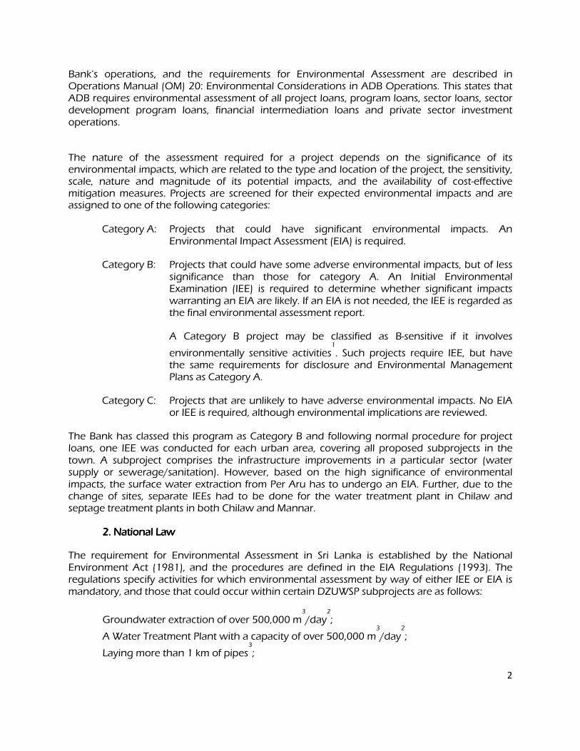
2
Bank’s operations, and the requirements for Environmental Assessment are described in Operations Manual (OM) 20: Environmental Considerations in ADB Operations. This states that ADB requires environmental assessment of all project loans, program loans, sector loans, sector development program loans, financial intermediation loans and private sector investment operations.
The nature of the assessment required for a project depends on the significance of its environmental impacts, which are related to the type and location of the project, the sensitivity, scale, nature and magnitude of its potential impacts, and the availability of cost-effective mitigation measures. Projects are screened for their expected environmental impacts and are assigned to one of the following categories:
Category A: Projects that could have significant environmental impacts. An Environmental Impact Assessment (EIA) is required.
Category B: Projects that could have some adverse environmental impacts, but of less significance than those for category A. An Initial Environmental Examination (IEE) is required to determine whether significant impacts warranting an EIA are likely. If an EIA is not needed, the IEE is regarded as the final environmental assessment report.
A Category B project may be classified as B-sensitive if it involves
environmentally sensitive activities1
. Such projects require IEE, but have the same requirements for disclosure and Environmental Management Plans as Category A.
Category C: Projects that are unlikely to have adverse environmental impacts. No EIA or IEE is required, although environmental implications are reviewed.
The Bank has classed this program as Category B and following normal procedure for project loans, one IEE was conducted for each urban area, covering all proposed subprojects in the town. A subproject comprises the infrastructure improvements in a particular sector (water supply or sewerage/sanitation). However, based on the high significance of environmental impacts, the surface water extraction from Per Aru has to undergo an EIA. Further, due to the change of sites, separate IEEs had to be done for the water treatment plant in Chilaw and septage treatment plants in both Chilaw and Mannar.
2. National Law 2. National Law 2. National Law 2. National Law
The requirement for Environmental Assessment in Sri Lanka is established by the National Environment Act (1981), and the procedures are defined in the EIA Regulations (1993). The regulations specify activities for which environmental assessment by way of either IEE or EIA is mandatory, and those that could occur within certain DZUWSP subprojects are as follows:
Groundwater extraction of over 500,000 m3
/day2
;
A Water Treatment Plant with a capacity of over 500,000 m3
/day2
;
Laying more than 1 km of pipes3
;
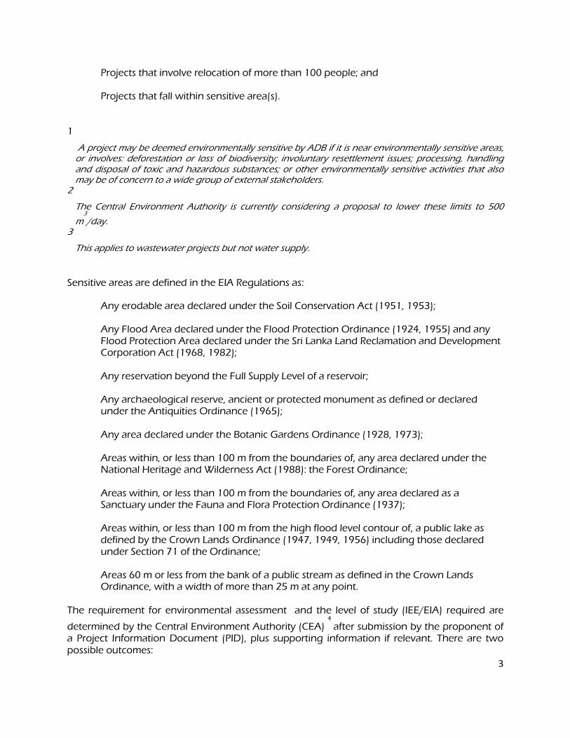
3
Projects that involve relocation of more than 100 people; and Projects that fall within sensitive area(s).
1
A project may be deemed environmentally sensitive by ADB if it is near environmentally sensitive areas, or involves: deforestation or loss of biodiversity; involuntary resettlement issues; processing, handling and disposal of toxic and hazardous substances; or other environmentally sensitive activities that also may be of concern to a wide group of external stakeholders.
2
The Central Environment Authority is currently considering a proposal to lower these limits to 500
m3
/day. 3
This applies to wastewater projects but not water supply.
Sensitive areas are defined in the EIA Regulations as:
Any erodable area declared under the Soil Conservation Act (1951, 1953);
Any Flood Area declared under the Flood Protection Ordinance (1924, 1955) and any Flood Protection Area declared under the Sri Lanka Land Reclamation and Development Corporation Act (1968, 1982);
Any reservation beyond the Full Supply Level of a reservoir;
Any archaeological reserve, ancient or protected monument as defined or declared
under the Antiquities Ordinance (1965);
Any area declared under the Botanic Gardens Ordinance (1928, 1973);
Areas within, or less than 100 m from the boundaries of, any area declared under the National Heritage and Wilderness Act (1988): the Forest Ordinance;
Areas within, or less than 100 m from the boundaries of, any area declared as a Sanctuary under the Fauna and Flora Protection Ordinance (1937);
Areas within, or less than 100 m from the high flood level contour of, a public lake as defined by the Crown Lands Ordinance (1947, 1949, 1956) including those declared under Section 71 of the Ordinance;
Areas 60 m or less from the bank of a public stream as defined in the Crown Lands Ordinance, with a width of more than 25 m at any point.
The requirement for environmental assessment and the level of study (IEE/EIA) required are
determined by the Central Environment Authority (CEA) 4
after submission by the proponent of a Project Information Document (PID), plus supporting information if relevant. There are two possible outcomes:
4
Categorical Exclusion: the activity is not on the list of prescribed projects in the EIA regulations, is not in or near a sensitive area, has not been the subject of public protest, and it is clear from the PID and supporting information that the project will have no significant environmental impacts. Environmental Clearance is granted (with or without conditions) and the project may proceed;
All other projects require Environmental Assessment and the CEA or PEA4
establishes a Scoping Committee to decide on the level of study (IEE or EIA) and prepare Terms of Reference (ToR). Alternatively, if the project lies wholly within the jurisdiction of a single Government agency (eg UDA) CEA/PEA may refer the project to this authority (as the Project Approving Agency) to administer the EIA process. A Technical Review Committee reviews the completed IEE or EIA report and recommends whether Environmental Clearance should be granted. The final decision is made by CEA.
1 The urban areas selected under this Project have populations of between 40,000 and 120,000, so the infrastructure subprojects are relatively small, and groundwater abstraction and water treatment will not be of the scale quoted in the EIA regulations as requiring environmental assessment. Components will not be located in protected or sensitive areas and no people will be relocated. 2 However two of the water supply subprojects (Chilaw and Vavuniya) involve the construction of structures across a river or stream to impound water, which is considered as a prescribed activity by CEA/PEA, and required an EIA/IEE. IEE was conducted and approved for the water supply subproject in Chilaw while EIA was submitted to the CEA for the water supply subproject in Vavuniya.
4
In the North-Western Province (which includes Chilaw and Puttalam) the EIA system is established by the North-Western Provincial Act (1981) and Provincial EIA Regulations (1992, 1998). The system is the same as the national procedure, except for: (i) the North-Western Provincial Environmental Authority (NWPEA) replaces CEA as the competent authority (although projects with trans-regional impacts are referred to CEA and dealt with under the national system); (ii) EIA and IEE reports are made available for public comment (under the national system this is required for EIAs only); (iii) Projects that are the subject of significant public interest or protest can be required to conduct an EIA by the NWPEA Board of Directors, even though this may not be required by the legislation.
3. Review and Approval Procedure 3. Review and Approval Procedure 3. Review and Approval Procedure 3. Review and Approval Procedure
For Category B projects the Draft IEE report and its summary (SIEE) are reviewed by ADB’s Regional Department sector division and Environment and Social Safeguards Division, and by the Executing Agency, and additional comments may be sought from project affected people and other stakeholders. All comments are incorporated in preparing the final documents, which are reviewed by the Executing Agency (EA) and the national environmental protection agency (CEA or NWPEA in this case). The EA then officially submits the IEE and SIEE reports to ADB for consideration by the Board of Directors. Completed reports are made available worldwide by ADB, via the depository library system and the ADB website.
4. Scope of Study 4. Scope of Study 4. Scope of Study 4. Scope of Study
This is the updated IEE for the water supply and sanitation subprojects proposed in Chilaw. It discusses the environmental impacts and mitigation measures relating to the location, design, construction and operation of all physical works proposed under these subprojects. The original
5
IEE was one of eight documents describing the environmental impacts and mitigation of all urban and rural subprojects proposed by the Project Preparatory Technical Assistance conducted in 2007-08. These documents were prepared between October 2007 and March 2008 by one International and one Domestic Environmental Specialist via inputs of three months each. These documents are now updated by the Domestic Environmental Specialist in 2012 including the current position.
II. DESCRIPTION OF THE PROJECT II. DESCRIPTION OF THE PROJECT II. DESCRIPTION OF THE PROJECT II. DESCRIPTION OF THE PROJECT
A. Type, Category and Need A. Type, Category and Need A. Type, Category and Need A. Type, Category and Need
1 DZUWSP is a Project to improve urban infrastructure, by the design and implementation of subprojects in water supply and sanitation. As explained above, the Project has been classified by ADB as Category B. As the urban component will be funded by a project loan, ADB procedure requires that an IEE is conducted for each town to identify and mitigate the impacts of subprojects, and to determine whether further study or a more detailed EIA may be required. This is the IEE for Chilaw. Improvements in water supply and sanitation are needed in Chilaw because the present infrastructure is inadequate for the needs of the growing population. The main problems are that:
The water distribution system is old and beset with leaks, and as a result water pressure is very low and the supply is only available for a few hours per day;
Present groundwater abstraction will not supply future population needs and additional sources are required to improve both quality and quantity of water; and
There is no municipal sewerage in the town and households rely on septic tanks or pit latrines with soakage pits, in which poured water is the method of cleansing.
2 These and the other subprojects designed by the DZUWSP are intended to raise the standards of the municipal infrastructure and services of the selected urban centres to those expected of modern Asian towns. B. Location, Size and Implementation Schedule B. Location, Size and Implementation Schedule B. Location, Size and Implementation Schedule B. Location, Size and Implementation Schedule
The subprojects assessed in this report is located in Chilaw, on the west coast of the North-Western Province of Sri Lanka, 60 km north of the national capital Colombo (Figure 1).
The improved infrastructure will extend through a good part of the town, where water pipes will be buried alongside roads. Outside the town in Munneswaram, new tube-wells will be dug alongside existing wells; a low-level weir will be built across the Deduru Oya (river) with a pumped surface water intake alongside; a new Water Treatment Plant will be built at close proximity to the weir and located on the grounds of Rajamahaviharaya in Willattewa. A new transmission main will carry treated water to the town (Figure 2). A Septage Treatment Plant will be built to treat material removed from septic tanks in the town (Figure 3).
The new water supply system will serve a population of 48,000 in an area of 11,800 ha in 2010
and a population of 93,000 in an area of 16,500 ha in 2030. It will abstract 8,000 m3
/d of
6
groundwater from existing and new tube-wells and 6,000 m3
/d of surface water from the
Deduru Oya in 2010 and 9,000 m3
/d of groundwater and 15,000 m3
/d of surface water in
2030. The Water Treatment Plant (WTP) will treat 6,000 m3
/d initially, increasing to 9,000 m3
/d in 2020, and water will be treated to Sri Lankan drinking water standards (Appendix 1). Table 1 shows the components of the scheme that will be funded by the project and are addressed in this IEE. The new sanitation system will comprise two vacuum tankers (“gully bowsers”) to extract partially decomposed material from septic tanks, and a septage treatment facility of sludge drying beds and effluent treatment ponds. The capacity of the bowsers will be Each 3,000 litres and 1500 litres respectively and will make up to six journeys per day, so two vehicles should be able to empty every septic tank in the town at least once a year. Liquid will be treated in anaerobic ponds and a constructed wetland, designed to produce an effluent that meets both current discharge standards (Appendix 2) and amendments being prepared by CEA for gazetting in 2008 (Appendix 3). Detailed design of the infrastructure is complete. Once the IEE is approved by the PEA the construction will commence C. Description of the SubC. Description of the SubC. Description of the SubC. Description of the Sub----projects projects projects projects
Table 1 shows the nature and size of the various components of the three proposed subprojects.
1.1.1.1. Water Supply Water Supply Water Supply Water Supply
TTTThere are three elements to the water supply subproject: supply augmentation, improving water treatment, and improving and expanding the distribution network (Table 1).
Increasing the supply of water will involve expanding the abstraction of groundwater by boring new tube-wells (TW) alongside malfunctioning existing wells; and abstracting surface water from the Deduru Oya by means of a weir, pumped intake, and transmission main to convey water to a new treatment plant.
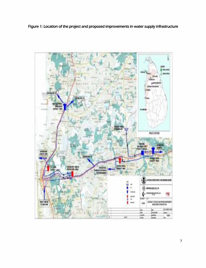
7
Figure 1: Location of the project and proposed improvements in water supply infrastructure Figure 1: Location of the project and proposed improvements in water supply infrastructure Figure 1: Location of the project and proposed improvements in water supply infrastructure Figure 1: Location of the project and proposed improvements in water supply infrastructure
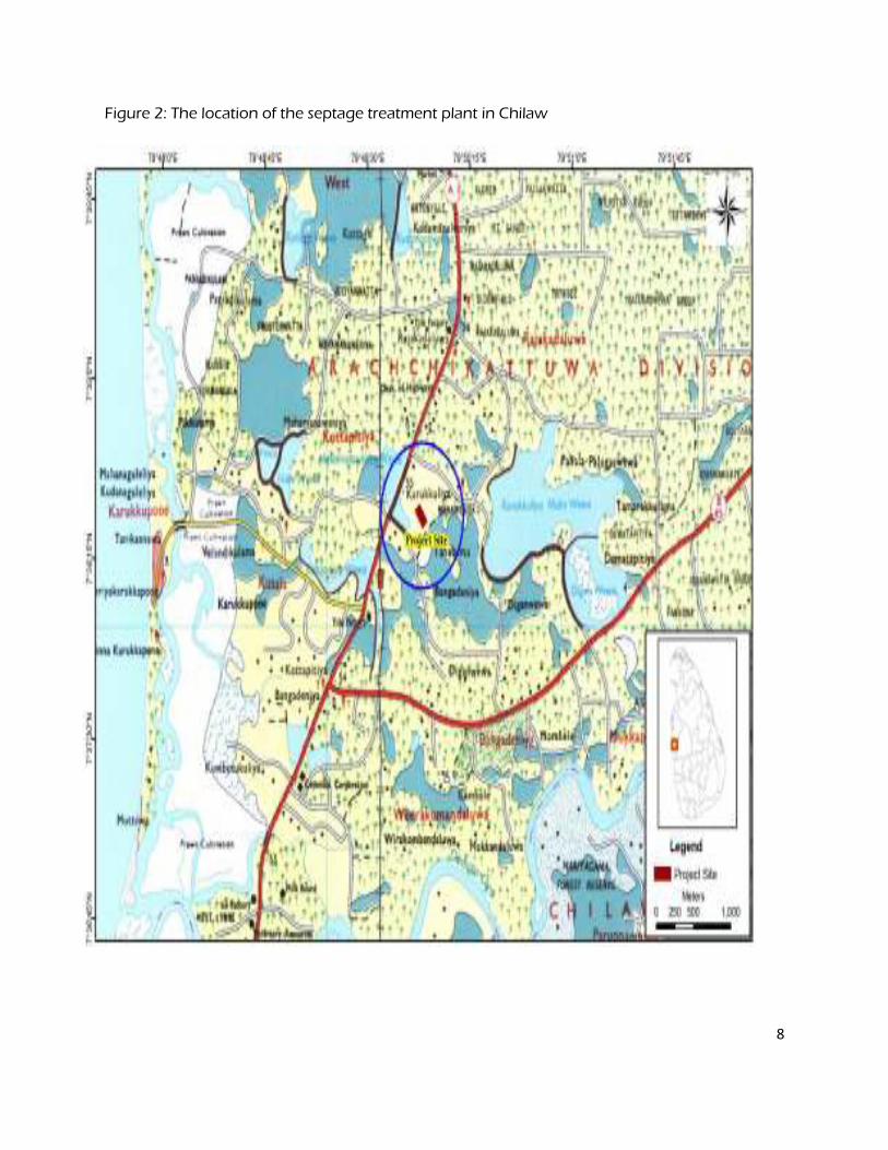
8
Figure 2: The location of the septage treatment plant in Chilaw
Table 1: Water Supply and Sanitation sub projects in Chilaw
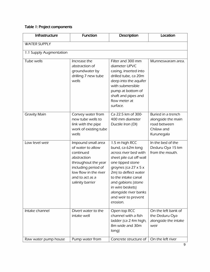
9
Table 1: Project componentsTable 1: Project componentsTable 1: Project componentsTable 1: Project components
Infrastructure Infrastructure Infrastructure Infrastructure FunctionFunctionFunctionFunction DescriptionDescriptionDescriptionDescription Location Location Location Location
WATER SUPPLY
1.1 Supply Augmentation
Tube wells Increase the
abstraction of
groundwater by
drilling 7 new tube
wells
Filter and 300 mm
diameter UPVC
casing, inserted into
drilled tube, ca 20m
deep into the aquifer
with submersible
pump at bottom of
shaft and pipes and
flow meter at
surface.
Munneswaram area.
Gravity Main Convey water from
new tube wells to
link with the pipe
work of existing tube
wells
Ca 22.5 km of 300-
400 mm diameter
Ductile Iron (DI)
Buried in a trench
alongside the main
road between
Chilaw and
Kurunegala
Low level weir Impound small area
of water to allow
continued
abstraction
throughout the year
including period of
low flow in the river
and to act as a
salinity barrier
1.5 m high RCC
bund, ca 62m long
across river bed with
sheet pile cut off wall
one tipped stone
groynes (ca 27 x 5 x
2m) to deflect water
to the intake canal
and gabions (stone
in wire beskets)
alongside river banks
and weir to prevent
erosion.
In the bed of the
Deduru Oya 15 km
from the mouth.
Intake channel Divert water to the
intake well
Open top RCC
channel with a fish
ladder (ca 2.4m high,
8m wide and 30m
long)
On the left bank of
the Deduru Oya
alongside the intake
weir
Raw water pump house Pump water from Concrete structure of On the left river
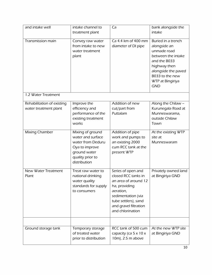
10
and intake well intake channel to
treatment plant
Ca bank alongside the
intake
Transmission main Convey raw water
from intake to new
water treatment
plant
Ca 4.4 km of 400 mm
diameter of DI pipe
Buried in a trench
alongside an
unmade road
between the intake
and the B033
highway then
alongside the paved
B033 to the new
WTP at Bingiriya
GND
1.2 Water Treatment
Rehabilitation of existing
water treatment plant
Improve the
efficiency and
performance of the
existing treatment
works
Addition of new
cut/part from
Puttalam
Along the Chilaw –
Kurunegala Road at
Munneswarama,
outside Chilaw
Town
Mixing Chamber Mixing of ground
water and surface
water from Deduru
Oya to improve
ground water
quality prior to
distribution
Addition of pipe
work and pumps to
an existing 2000
cum RCC tank at the
present WTP
At the existing WTP
site at
Munneswaram
New Water Treatment
Plant
Treat raw water to
national drinking
water quality
standards for supply
to consumers
Series of open and
closed RCC tanks in
an area of around 12
ha, providing
aeration,
sedimentation (via
tube settlers), sand
and gravel filtration
and chlorination
Privately owned land
at Bingiriya GND
Ground storage tank Temporary storage
of treated water
prior to distribution
RCC tank of 500 cum
capacity (ca 5 x 10 x
10m), 2.5 m above
At the new WTP site
at Bingiriya GND
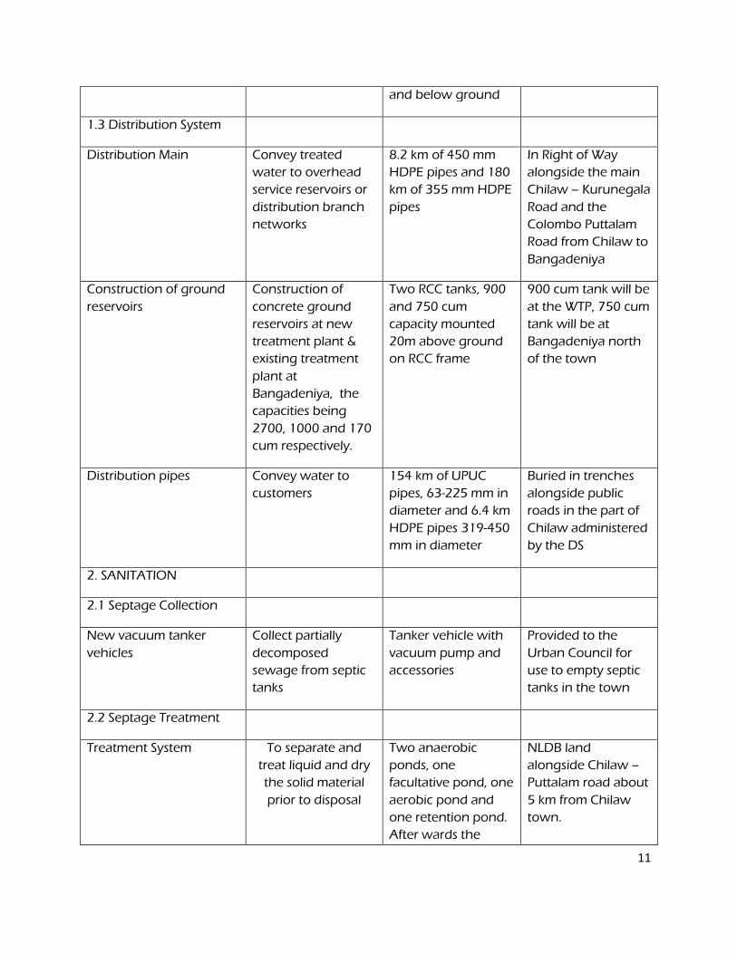
11
and below ground
1.3 Distribution System
Distribution Main Convey treated
water to overhead
service reservoirs or
distribution branch
networks
8.2 km of 450 mm
HDPE pipes and 180
km of 355 mm HDPE
pipes
In Right of Way
alongside the main
Chilaw – Kurunegala
Road and the
Colombo Puttalam
Road from Chilaw to
Bangadeniya
Construction of ground
reservoirs
Construction of
concrete ground
reservoirs at new
treatment plant &
existing treatment
plant at
Bangadeniya, the
capacities being
2700, 1000 and 170
cum respectively.
Two RCC tanks, 900
and 750 cum
capacity mounted
20m above ground
on RCC frame
900 cum tank will be
at the WTP, 750 cum
tank will be at
Bangadeniya north
of the town
Distribution pipes Convey water to
customers
154 km of UPUC
pipes, 63-225 mm in
diameter and 6.4 km
HDPE pipes 319-450
mm in diameter
Buried in trenches
alongside public
roads in the part of
Chilaw administered
by the DS
2. SANITATION
2.1 Septage Collection
New vacuum tanker
vehicles
Collect partially
decomposed
sewage from septic
tanks
Tanker vehicle with
vacuum pump and
accessories
Provided to the
Urban Council for
use to empty septic
tanks in the town
2.2 Septage Treatment
Treatment System To separate and
treat liquid and dry
the solid material
prior to disposal
Two anaerobic
ponds, one
facultative pond, one
aerobic pond and
one retention pond.
After wards the
NLDB land
alongside Chilaw –
Puttalam road about
5 km from Chilaw
town.
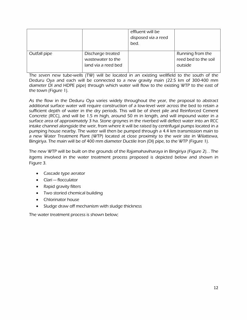
12
effluent will be
disposed via a reed
bed.
Outfall pipe Discharge treated
wastewater to the
land via a reed bed
Running from the
reed bed to the soil
outside
The seven new tube-wells (TW) will be located in an existing wellfield to the south of the Deduru Oya and each will be connected to a new gravity main (22.5 km of 300-400 mm diameter DI and HDPE pipe) through which water will flow to the existing WTP to the east of the town (Figure 1). As the flow in the Deduru Oya varies widely throughout the year, the proposal to abstract additional surface water will require construction of a low-level weir across the bed to retain a sufficient depth of water in the dry periods. This will be of sheet pile and Reinforced Cement Concrete (RCC), and will be 1.5 m high, around 50 m in length, and will impound water in a surface area of approximately 3 ha. Stone groynes in the riverbed will deflect water into an RCC intake channel alongside the weir, from where it will be raised by centrifugal pumps located in a pumping house nearby. The water will then be pumped through a 4.4 km transmission main to a new Water Treatment Plant (WTP) located at close proximity to the weir site in Wilattewa, Bingiriya. The main will be of 400 mm diameter Ductile Iron (DI) pipe, to the WTP (Figure 1). The new WTP will be built on the grounds of the Rajamahaviharaya in Bingiriya (Figure 2). . The
itgems involved in the water treatment process proposed is depicted below and shown in
Figure 3.
• Cascade type aerator
• Clari — flocculator
• Rapid gravity filters
• Two storied chemical building
• Chlorinator house
• Sludge draw off mechanism with sludge thickness
The water treatment process is shown below;
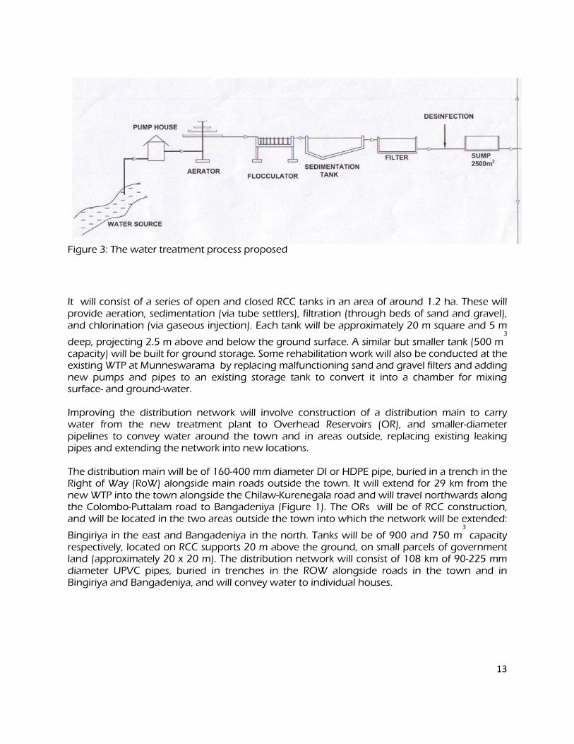
13
Figure 3: The water treatment process proposed
It will consist of a series of open and closed RCC tanks in an area of around 1.2 ha. These will provide aeration, sedimentation (via tube settlers), filtration (through beds of sand and gravel), and chlorination (via gaseous injection). Each tank will be approximately 20 m square and 5 m
deep, projecting 2.5 m above and below the ground surface. A similar but smaller tank (500 m3
capacity) will be built for ground storage. Some rehabilitation work will also be conducted at the existing WTP at Munneswarama by replacing malfunctioning sand and gravel filters and adding new pumps and pipes to an existing storage tank to convert it into a chamber for mixing surface- and ground-water. Improving the distribution network will involve construction of a distribution main to carry water from the new treatment plant to Overhead Reservoirs (OR), and smaller-diameter pipelines to convey water around the town and in areas outside, replacing existing leaking pipes and extending the network into new locations. The distribution main will be of 160-400 mm diameter DI or HDPE pipe, buried in a trench in the Right of Way (RoW) alongside main roads outside the town. It will extend for 29 km from the new WTP into the town alongside the Chilaw-Kurenegala road and will travel northwards along the Colombo-Puttalam road to Bangadeniya (Figure 1). The ORs will be of RCC construction, and will be located in the two areas outside the town into which the network will be extended:
Bingiriya in the east and Bangadeniya in the north. Tanks will be of 900 and 750 m3
capacity respectively, located on RCC supports 20 m above the ground, on small parcels of government land (approximately 20 x 20 m). The distribution network will consist of 108 km of 90-225 mm diameter UPVC pipes, buried in trenches in the ROW alongside roads in the town and in Bingiriya and Bangadeniya, and will convey water to individual houses.
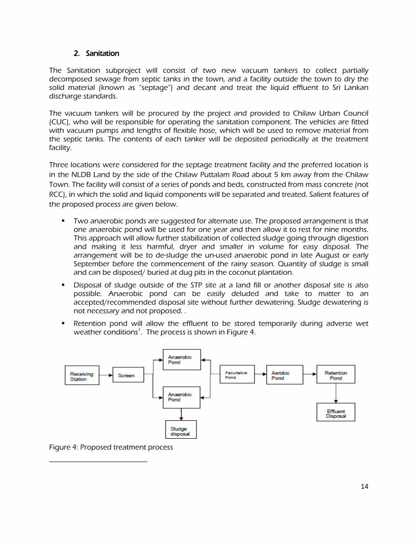
14
2.2.2.2. Sanitation Sanitation Sanitation Sanitation
The Sanitation subproject will consist of two new vacuum tankers to collect partially decomposed sewage from septic tanks in the town, and a facility outside the town to dry the solid material (known as “septage”) and decant and treat the liquid effluent to Sri Lankan discharge standards. The vacuum tankers will be procured by the project and provided to Chilaw Urban Council (CUC), who will be responsible for operating the sanitation component. The vehicles are fitted with vacuum pumps and lengths of flexible hose, which will be used to remove material from the septic tanks. The contents of each tanker will be deposited periodically at the treatment facility. Three locations were considered for the septage treatment facility and the preferred location is
in the NLDB Land by the side of the Chilaw Puttalam Road about 5 km away from the Chilaw
Town. The facility will consist of a series of ponds and beds, constructed from mass concrete (not
RCC), in which the solid and liquid components will be separated and treated. Salient features of
the proposed process are given below.
� Two anaerobic ponds are suggested for alternate use. The proposed arrangement is that one anaerobic pond will be used for one year and then allow it to rest for nine months. This approach will allow further stabilization of collected sludge going through digestion and making it less harmful, dryer and smaller in volume for easy disposal. The arrangement will be to de-sludge the un-used anaerobic pond in late August or early September before the commencement of the rainy season. Quantity of sludge is small and can be disposed/ buried at dug pits in the coconut plantation.
� Disposal of sludge outside of the STP site at a land fill or another disposal site is also possible. Anaerobic pond can be easily deluded and take to matter to an accepted/recommended disposal site without further dewatering. Sludge dewatering is not necessary and not proposed. .
� Retention pond will allow the effluent to be stored temporarily during adverse wet weather conditions1. The process is shown in Figure 4.
Figure 4: Proposed treatment process
15
III. DESCRIPTION OF THE ENVIRONMENT III. DESCRIPTION OF THE ENVIRONMENT III. DESCRIPTION OF THE ENVIRONMENT III. DESCRIPTION OF THE ENVIRONMENT
A. Physical Resources A. Physical Resources A. Physical Resources A. Physical Resources
1. Location 1. Location 1. Location 1. Location
Chilaw is on the west coast of the North-Western Province of Sri Lanka, 72 km north of the national capital Colombo, and 60 km north-west of the provincial capital Kurunegala. The town is located on the main road and railway running north from Colombo to Puttalam and beyond, and is at the mouth of the Deduru Oya (Figure 1). Its coastal location made Chilaw an important trading centre in the past, although economic growth has slowed in recent decades. Situated at a node in Sri Lanka’s “coconut triangle”, plantations and coconut produce are prominent in and around the town . Chilaw is in Puttalam District and is administered in three areas (Chilaw, Arachikattuwa and Bingiriya) by central Government (via a Divisional Secretary), and also by three Local Authorities (Chilaw Urban Council, Chilaw Pradesiya Sabah and Arachikattuwa Pradesiya Sabah). The Local Authorities are in turn governed by the North-Western Provincial Council and the Commissioner of Local Government (CLD) of the North-Western Province.
2. Topography, Soil and Geology 2. Topography, Soil and Geology 2. Topography, Soil and Geology 2. Topography, Soil and Geology
Located at the coast and in the floodplain of the Deduru Oya, Chilaw is generally quite flat, and soils are mainly alluvial, with variable texture and drainage. Soils include both alluvium that is high in organic content, and areas of red-yellow podzolic soil, with soft and hard laterites. Geologically the area belongs to the Precambrian Wanni complex and is close to the boundary with the Miocene to Quaternary Region to the north (Figure 5), so has features of both associations. Most of the area is of Wanni gneiss interspersed with red beds of ferruginized gravel, which comprises a mixture of coarse sand, fragments of chert, pellets of ironstone, and some clay, cemented with ferruginous material. The gravel is mainly covered by unconsolidated white sands and lies on a bedrock of peneplaned and kaolinised crystalline gneisses, which is exposed in some areas along the present beach. Because of its location on the west coast, Chilaw was largely unaffected by the Indonesian tsunami of December 2004, which caused such extensive damage on the east coast of Sri Lanka. The area is not seismically active, and the generally flat topography means that there is little risk of the landslides that frequently occur inland after heavy rain.
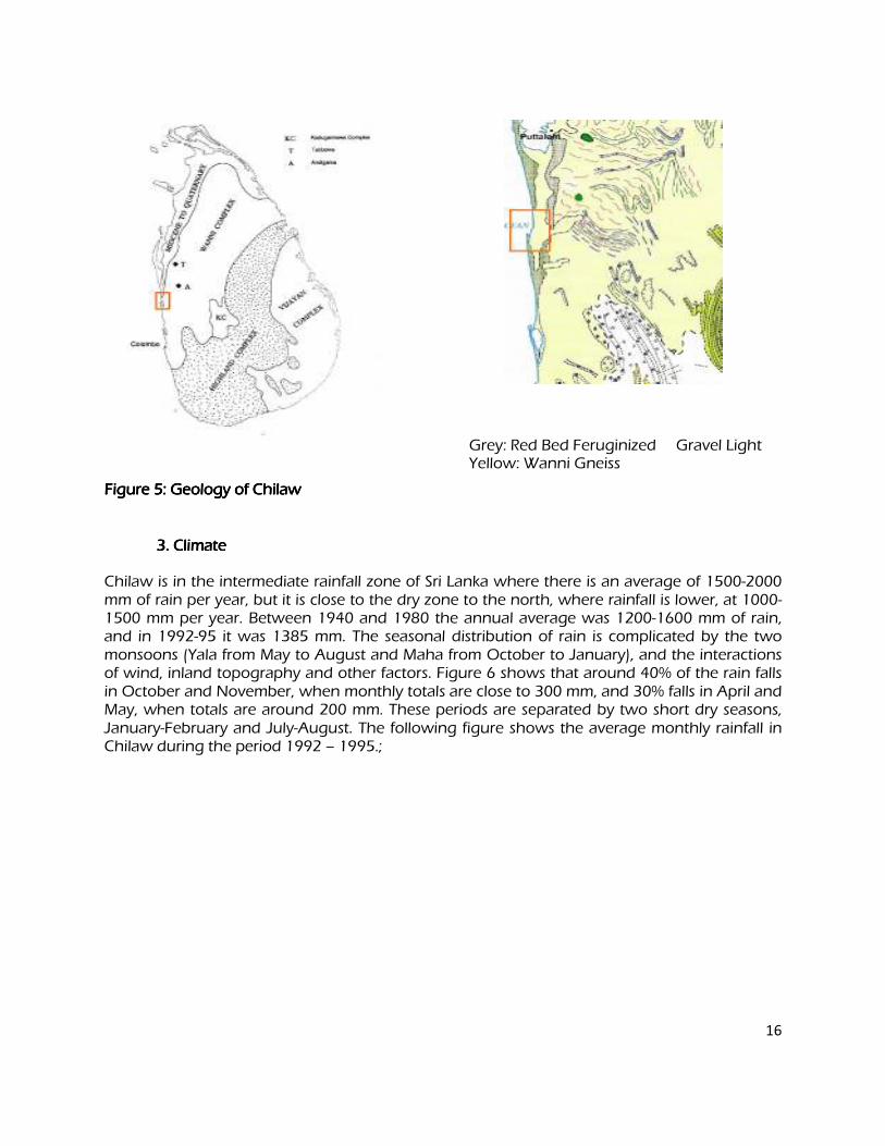
16
Grey: Red Bed Feruginized Gravel Light Yellow: Wanni Gneiss
Figure 5: GeoFigure 5: GeoFigure 5: GeoFigure 5: Geology of Chilaw logy of Chilaw logy of Chilaw logy of Chilaw
3. Climate 3. Climate 3. Climate 3. Climate
Chilaw is in the intermediate rainfall zone of Sri Lanka where there is an average of 1500-2000 mm of rain per year, but it is close to the dry zone to the north, where rainfall is lower, at 1000-1500 mm per year. Between 1940 and 1980 the annual average was 1200-1600 mm of rain, and in 1992-95 it was 1385 mm. The seasonal distribution of rain is complicated by the two monsoons (Yala from May to August and Maha from October to January), and the interactions of wind, inland topography and other factors. Figure 6 shows that around 40% of the rain falls in October and November, when monthly totals are close to 300 mm, and 30% falls in April and May, when totals are around 200 mm. These periods are separated by two short dry seasons, January-February and July-August. The following figure shows the average monthly rainfall in Chilaw during the period 1992 – 1995.;
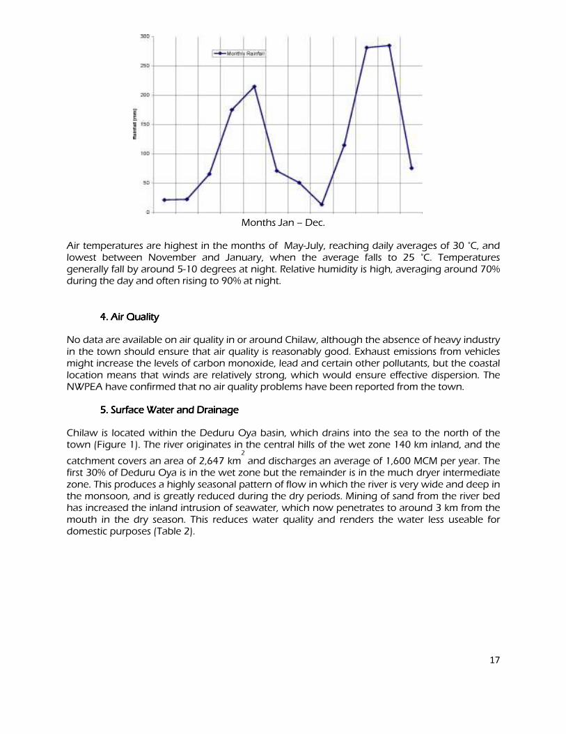
17
Months (January to December)
Months Jan – Dec.
Air temperatures are highest in the months of May-July, reaching daily averages of 30 °C, and lowest between November and January, when the average falls to 25 °C. Temperatures generally fall by around 5-10 degrees at night. Relative humidity is high, averaging around 70% during the day and often rising to 90% at night.
4. Air Quality 4. Air Quality 4. Air Quality 4. Air Quality
No data are available on air quality in or around Chilaw, although the absence of heavy industry in the town should ensure that air quality is reasonably good. Exhaust emissions from vehicles might increase the levels of carbon monoxide, lead and certain other pollutants, but the coastal location means that winds are relatively strong, which would ensure effective dispersion. The NWPEA have confirmed that no air quality problems have been reported from the town.
5. Surface Water and Drainage 5. Surface Water and Drainage 5. Surface Water and Drainage 5. Surface Water and Drainage
Chilaw is located within the Deduru Oya basin, which drains into the sea to the north of the town (Figure 1). The river originates in the central hills of the wet zone 140 km inland, and the
catchment covers an area of 2,647 km2
and discharges an average of 1,600 MCM per year. The first 30% of Deduru Oya is in the wet zone but the remainder is in the much dryer intermediate zone. This produces a highly seasonal pattern of flow in which the river is very wide and deep in the monsoon, and is greatly reduced during the dry periods. Mining of sand from the river bed has increased the inland intrusion of seawater, which now penetrates to around 3 km from the mouth in the dry season. This reduces water quality and renders the water less useable for domestic purposes (Table 2).
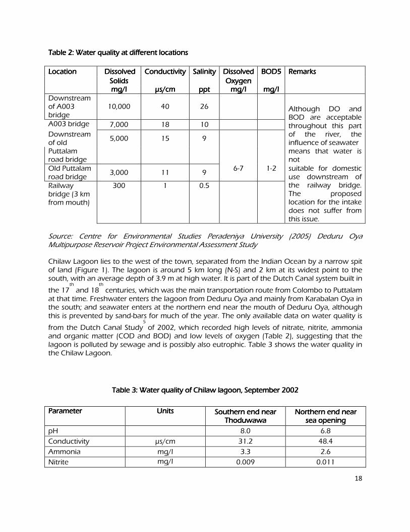
18
Table 2: Water quality at different locations Table 2: Water quality at different locations Table 2: Water quality at different locations Table 2: Water quality at different locations
LocationLocationLocationLocation Dissolved Dissolved Dissolved Dissolved Conductivity Conductivity Conductivity Conductivity Salinity Salinity Salinity Salinity Dissolved Dissolved Dissolved Dissolved BOD5 BOD5 BOD5 BOD5 Remarks Remarks Remarks Remarks
Solids Solids Solids Solids Oxygen Oxygen Oxygen Oxygen mg/l mg/l mg/l mg/l µµµµs/cm s/cm s/cm s/cm ppt ppt ppt ppt mg/l mg/l mg/l mg/l mg/l mg/l mg/l mg/l Downstream of A003 bridge
10,000 40 26
Although DO and BOD are acceptable throughout this part of the river, the influence of seawater
A003 bridge 7,000 18 10
Downstream of old
5,000 15 9
Puttalam road bridge
means that water is not
Old Puttalam road bridge
3,000 11 9 6-7 1-2 suitable for domestic
use downstream of the railway bridge. The proposed location for the intake does not suffer from this issue.
Railway bridge (3 km from mouth)
300 1 0.5
Source: Centre for Environmental Studies Peradeniya University (2005) Deduru Oya Multipurpose Reservoir Project Environmental Assessment Study
Chilaw Lagoon lies to the west of the town, separated from the Indian Ocean by a narrow spit of land (Figure 1). The lagoon is around 5 km long (N-S) and 2 km at its widest point to the south, with an average depth of 3.9 m at high water. It is part of the Dutch Canal system built in
the 17th
and 18th
centuries, which was the main transportation route from Colombo to Puttalam at that time. Freshwater enters the lagoon from Deduru Oya and mainly from Karabalan Oya in the south; and seawater enters at the northern end near the mouth of Deduru Oya, although this is prevented by sand-bars for much of the year. The only available data on water quality is
from the Dutch Canal Study5
of 2002, which recorded high levels of nitrate, nitrite, ammonia and organic matter (COD and BOD) and low levels of oxygen (Table 2), suggesting that the lagoon is polluted by sewage and is possibly also eutrophic. Table 3 shows the water quality in the Chilaw Lagoon.
Table 3:Table 3:Table 3:Table 3: Water quality of Chilaw lagoon, September 2002 Water quality of Chilaw lagoon, September 2002 Water quality of Chilaw lagoon, September 2002 Water quality of Chilaw lagoon, September 2002
Parameter Parameter Parameter Parameter Units Units Units Units Southern end near Southern end near Southern end near Southern end near Thoduwawa Thoduwawa Thoduwawa Thoduwawa
Northern end near Northern end near Northern end near Northern end near sea opening sea opening sea opening sea opening
pH 8.0 6.8
Conductivity µs/cm 31.2 48.4
Ammonia mg/l 3.3 2.6
Nitrite mg/l 0.009 0.011
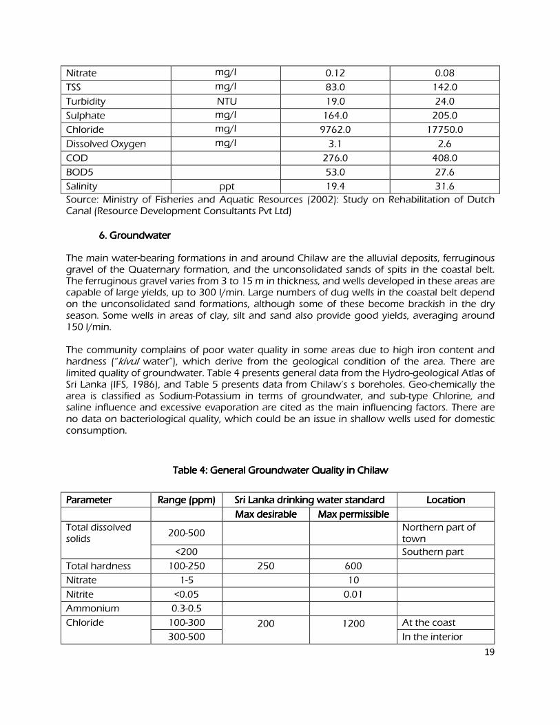
19
Nitrate mg/l 0.12 0.08
TSS mg/l 83.0 142.0
Turbidity NTU 19.0 24.0
Sulphate mg/l 164.0 205.0
Chloride mg/l 9762.0 17750.0
Dissolved Oxygen mg/l 3.1 2.6
COD 276.0 408.0
BOD5 53.0 27.6
Salinity ppt 19.4 31.6
Source: Ministry of Fisheries and Aquatic Resources (2002): Study on Rehabilitation of Dutch Canal (Resource Development Consultants Pvt Ltd)
6. Groundwater 6. Groundwater 6. Groundwater 6. Groundwater
The main water-bearing formations in and around Chilaw are the alluvial deposits, ferruginous gravel of the Quaternary formation, and the unconsolidated sands of spits in the coastal belt. The ferruginous gravel varies from 3 to 15 m in thickness, and wells developed in these areas are capable of large yields, up to 300 l/min. Large numbers of dug wells in the coastal belt depend on the unconsolidated sand formations, although some of these become brackish in the dry season. Some wells in areas of clay, silt and sand also provide good yields, averaging around 150 l/min. The community complains of poor water quality in some areas due to high iron content and hardness (“kivul water”), which derive from the geological condition of the area. There are limited quality of groundwater. Table 4 presents general data from the Hydro-geological Atlas of Sri Lanka (IFS, 1986), and Table 5 presents data from Chilaw’s s boreholes. Geo-chemically the area is classified as Sodium-Potassium in terms of groundwater, and sub-type Chlorine, and saline influence and excessive evaporation are cited as the main influencing factors. There are no data on bacteriological quality, which could be an issue in shallow wells used for domestic consumption.
Table 4: General Groundwater Quality in ChilawTable 4: General Groundwater Quality in ChilawTable 4: General Groundwater Quality in ChilawTable 4: General Groundwater Quality in Chilaw
Parameter Parameter Parameter Parameter Range (ppm) Range (ppm) Range (ppm) Range (ppm) Sri Lanka drinking water standard Sri Lanka drinking water standard Sri Lanka drinking water standard Sri Lanka drinking water standard Location Location Location Location
Max desirable Max desirable Max desirable Max desirable Max permissible Max permissible Max permissible Max permissible
Total dissolved solids
200-500 Northern part of
town <200 Southern part
Total hardness 100-250 250 600
Nitrate 1-5 10
Nitrite <0.05 0.01
Ammonium 0.3-0.5
Chloride 100-300 200 1200 At the coast
300-500 In the interior
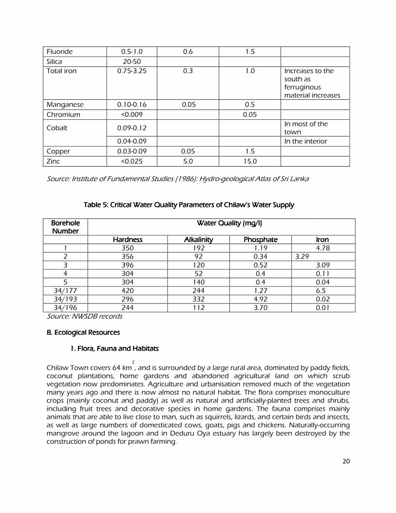
20
Fluoride 0.5-1.0 0.6 1.5
Silica 20-50
Total iron 0.75-3.25 0.3 1.0 Increases to the south as ferruginous material increases
Manganese 0.10-0.16 0.05 0.5
Chromium <0.009 0.05
Cobalt 0.09-0.12 In most of the
town 0.04-0.09 In the interior
Copper 0.03-0.09 0.05 1.5
Zinc <0.025 5.0 15.0
Source: Institute of Fundamental Studies (1986): Hydro-geological Atlas of Sri Lanka
Table 5: Critical Water Quality Parameters of Chilaw’s Water Supply Table 5: Critical Water Quality Parameters of Chilaw’s Water Supply Table 5: Critical Water Quality Parameters of Chilaw’s Water Supply Table 5: Critical Water Quality Parameters of Chilaw’s Water Supply
Borehole Borehole Borehole Borehole NumberNumberNumberNumber
Water Quality (mg/l) Water Quality (mg/l) Water Quality (mg/l) Water Quality (mg/l)
Hardness Hardness Hardness Hardness Alkalinity Alkalinity Alkalinity Alkalinity Phosphate Phosphate Phosphate Phosphate Iron Iron Iron Iron 1 350 192 1.19 4.78 2 356 92 0.34 3.29 3 396 120 0.52 3.09 4 304 52 0.4 0.11 5 304 140 0.4 0.04
34/177 420 244 1.27 6.5 34/193 296 332 4.92 0.02 34/196 244 112 3.70 0.01
Source: NWSDB records
B. Ecological Resources B. Ecological Resources B. Ecological Resources B. Ecological Resources
1. Flora, Fauna and Habitats 1. Flora, Fauna and Habitats 1. Flora, Fauna and Habitats 1. Flora, Fauna and Habitats
Chilaw Town covers 64 km2
, and is surrounded by a large rural area, dominated by paddy fields, coconut plantations, home gardens and abandoned agricultural land on which scrub vegetation now predominates. Agriculture and urbanisation removed much of the vegetation many years ago and there is now almost no natural habitat. The flora comprises monoculture crops (mainly coconut and paddy) as well as natural and artificially-planted trees and shrubs, including fruit trees and decorative species in home gardens. The fauna comprises mainly animals that are able to live close to man, such as squirrels, lizards, and certain birds and insects, as well as large numbers of domesticated cows, goats, pigs and chickens. Naturally-occurring mangrove around the lagoon and in Deduru Oya estuary has largely been destroyed by the construction of ponds for prawn farming.
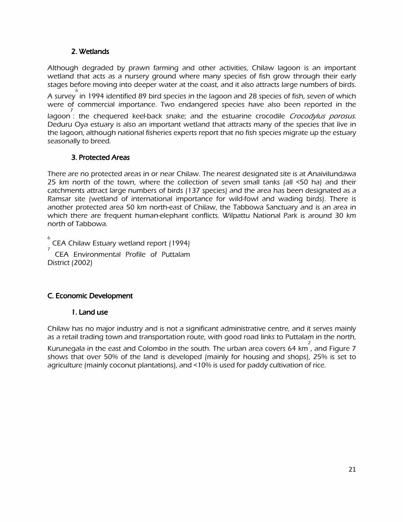
21
2. Wetlands 2. Wetlands 2. Wetlands 2. Wetlands
Although degraded by prawn farming and other activities, Chilaw lagoon is an important wetland that acts as a nursery ground where many species of fish grow through their early stages before moving into deeper water at the coast, and it also attracts large numbers of birds.
A survey6
in 1994 identified 89 bird species in the lagoon and 28 species of fish, seven of which were of commercial importance. Two endangered species have also been reported in the
lagoon7
: the chequered keel-back snake; and the estuarine crocodile Crocodylus porosus. Deduru Oya estuary is also an important wetland that attracts many of the species that live in the lagoon, although national fisheries experts report that no fish species migrate up the estuary seasonally to breed.
3. Protected Areas 3. Protected Areas 3. Protected Areas 3. Protected Areas
There are no protected areas in or near Chilaw. The nearest designated site is at Anaivilundawa 25 km north of the town, where the collection of seven small tanks (all <50 ha) and their catchments attract large numbers of birds (137 species) and the area has been designated as a Ramsar site (wetland of international importance for wild-fowl and wading birds). There is another protected area 50 km north-east of Chilaw, the Tabbowa Sanctuary and is an area in which there are frequent human-elephant conflicts. Wilpattu National Park is around 30 km north of Tabbowa.
6
CEA Chilaw Estuary wetland report (1994) 7
CEA Environmental Profile of Puttalam District (2002)
C. Economic Development C. Economic Development C. Economic Development C. Economic Development
1. Land use 1. Land use 1. Land use 1. Land use
Chilaw has no major industry and is not a significant administrative centre, and it serves mainly as a retail trading town and transportation route, with good road links to Puttalam in the north,
Kurunegala in the east and Colombo in the south. The urban area covers 64 km2
, and Figure 7 shows that over 50% of the land is developed (mainly for housing and shops), 25% is set to agriculture (mainly coconut plantations), and <10% is used for paddy cultivation of rice.
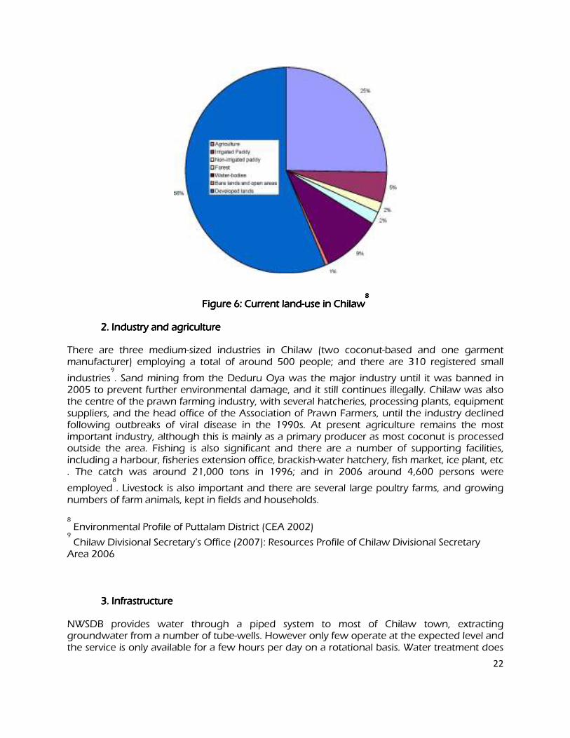
22
Figure Figure Figure Figure 6666: Current land: Current land: Current land: Current land----use in Chilawuse in Chilawuse in Chilawuse in Chilaw8 8 8 8
2. Industry and agriculture 2. Industry and agriculture 2. Industry and agriculture 2. Industry and agriculture
There are three medium-sized industries in Chilaw (two coconut-based and one garment manufacturer) employing a total of around 500 people; and there are 310 registered small
industries9
. Sand mining from the Deduru Oya was the major industry until it was banned in 2005 to prevent further environmental damage, and it still continues illegally. Chilaw was also the centre of the prawn farming industry, with several hatcheries, processing plants, equipment suppliers, and the head office of the Association of Prawn Farmers, until the industry declined following outbreaks of viral disease in the 1990s. At present agriculture remains the most important industry, although this is mainly as a primary producer as most coconut is processed outside the area. Fishing is also significant and there are a number of supporting facilities, including a harbour, fisheries extension office, brackish-water hatchery, fish market, ice plant, etc . The catch was around 21,000 tons in 1996; and in 2006 around 4,600 persons were
employed8
. Livestock is also important and there are several large poultry farms, and growing numbers of farm animals, kept in fields and households. 8
Environmental Profile of Puttalam District (CEA 2002) 9
Chilaw Divisional Secretary’s Office (2007): Resources Profile of Chilaw Divisional Secretary Area 2006
3. Infrastructure 3. Infrastructure 3. Infrastructure 3. Infrastructure
NWSDB provides water through a piped system to most of Chilaw town, extracting groundwater from a number of tube-wells. However only few operate at the expected level and the service is only available for a few hours per day on a rotational basis. Water treatment does
23
not remove sufficient iron to improve the colour and taste of the product and consumers complain of the poor quality. There are two Community Operated Water Supply Schemes in outlying rural areas, using tube wells to provide water to 260 households in Punchiwilattawa and others in Arachikatuwa. There is no sewerage in Chilaw except for the system at the hospital, which discharges wastewater into two small ponds, from where effluent flows into the lagoon. The rest of the town relies on on-site systems, which are a combination of septic tanks and pour-flush pit latrines. There are open concrete drains alongside roads, shops and houses in most of the urban area through which storm-water is discharged into the lagoon. However grey water from domestic washing and business premises is released into drains, which are inadequately maintained and frequently clogged with garbage and silt. As a result many drains are stagnant and unsanitary, and localised flooding occurs during rain. Outside the town drainage is mainly by roadside ditches, irrigation canals and natural streams, and flash-flooding occurs in low-lying areas. The Pradesiya Sabah is responsible for the collection and disposal of solid waste, which is produced at an estimated rate of 6-7 tons per day in the urban area. Refuse is collected by truck from the town and other population centres and from the weekly markets, and is dumped at three open disposal sites. These are relatively small (0.5-1.0 ha), and CEA has recently issued a closure notice on one site because of the unsanitary conditions. The availability of suitable land for future disposal sites, and the unsanitary methods of disposal, are major problems for the Urban Council. Power in Chilaw is supplied by the Ceylon Electricity Board via the national grid, for which power is generated by mainly oil-fired thermal stations. At present there are around 15,000 houses in Chilaw, and around 85% have a power supply. However in the more rural area of Arachikatuwa only around a third of the 10,000 houses are connected to the grid. Power is supplied by overhead cables carried on metal and concrete poles, mainly located in public areas alongside roads. The power supply is erratic and there are frequent outages in warmer months, and large fluctuations in voltage. Transportation Transportation Transportation Transportation Chilaw is at the junction of two important trunk roads: the A003 Colombo-Puttalam highway runs north-south through the town; and the B033 runs east then south-east to Kurunegala (Figure 1). These are national roads, maintained by the Road Development Authority. Smaller regionally-important roads are maintained by the Provincial Roads Authority, and the smallest roads between townships and villages in the interior are maintained by local authorities. Most local authority roads are surfaced with gravel and many are in need of repair, whereas most of the larger roads are tarred and in a relatively good condition . The Colombo-Puttalam railway also runs through Chilaw and there are stations in most small towns along the route. Buses provide the main mode of transportation for most of the population, and there are a variety of conveyances and routes in the town and outside to all regional centres and Colombo. Goods are mainly transported by truck because of the unreliability of the rail service. There are large numbers of vehicles in the centre of the town, particularly at road intersections and the main shopping areas, where narrower streets are often congested. There are fewer vehicles in the outskirts, where traffic jams are not a major problem.
24
D. Social and Cultural Resources D. Social and Cultural Resources D. Social and Cultural Resources D. Social and Cultural Resources
1. Demography 1. Demography 1. Demography 1. Demography
According to data from the Divisional Secretary’s office, in 2006 the population of the Chilaw DS area was 67,656, and has shown a slow but steady rise over the past decade. The gender ratio is
almost exactly 1:1, and the population density is an average of 734 persons/km2
. The urban parts of Chilaw town are the most crowded area, where there are 35,400 people at a density of
over 1000/km2
, compared with the larger but more rural Arachikattuwa, where there are
42,400 people at 319/km2
. Literacy is high in both Chilaw and Arachikattuwa, where over 30% of people reach Grade 6 at secondary school and only 5-7% of children do not attend school. Ethnically both areas are dominated by Sinhalese, who make up around 80% of the population, followed by Tamil (10-15%), Muslim and Malay (5%); and around 1% are Burghers (descendents of Portuguese and
Dutch settlers from the 16th
and 17th
centuries). Although Buddhism is the main religion of the Sinhalese community, in Chilaw almost 50% of people are Christian, 40% Buddhist and the remainder are Muslim or Hindu. The Christian influence however ends at Chilaw, as in Arachikatuwa over 90% of people are Buddhist. 2. Socio2. Socio2. Socio2. Socio----Economics Economics Economics Economics Currently around 40,000 people are of working age (18-60 years) in Chilaw, and unemployment is very high, at over 30%, of whom around one third are skilled in various trades. Unemployment is even higher in Arachikatuwa at around 50%, mainly because work is seasonal in the agricultural sector. Seasonally unemployed people generally register with the local authority to obtain benefits from the Samurdhi poverty alleviation programme. Employed people are distributed fairly evenly between the agriculture, fishery, business/trading, government and private sectors, which each employ around 10-15% of the working population, although in Arachikatuwa a higher proportion (30%) are engaged in agriculture. There are currently 15,388 housing units in Chilaw, comprising 10,928 permanent houses, 2,945 semi-permanent and 1,445 temporary dwellings. A very high proportion of people own their houses (12,928 families). Only 870 families live in rented accommodation, 1,239 are squatters occupying land illegally, 145 families live in government houses (quarters) and 1,320 families (8%) have no house. Chilaw is the more affluent of the two areas as almost 25% of families have a monthly income of over SLR 5,000, compared with 2% in Arachikatuwa. There are, however more poor people in urban Chilaw, where 13% of families live on less than SLR 1,000 per month, compared with 5% in Arachikatuwa. The extent of poverty is indicated by the number of families receiving Samurdhi benefits: currently 33% in Chilaw and 52% in Arachikatuwa.
25
3. Health and Educational Facilities 3. Health and Educational Facilities 3. Health and Educational Facilities 3. Health and Educational Facilities
As is common in most countries, health, education and other facilities are more numerous and of better quality in the urban areas than in rural Arachikatuwa. Chilaw has one base hospital with a number of speciality clinics and doctors, and there are also two small private hospitals and 68 dispensaries and clinics, including two large central dispensaries run by the Government. In Arachikatuwa there is only one rural hospital and 35 dispensaries and clinics, of which around 70% practice western medicine and the remainder offer indigenous remedies (Aurveda). Public health is the responsibility of a Medical Officer of Health (MOH) appointed by Government in both Chilaw and Arachikatuwa, assisted by Public Health Inspectors (PHI) and Family Health Nurses. There are no publicly-available data on public health and although statistics on the incidence of disease were requested from the Ministry of Health, no information was provided. There are 36 pre-schools and 30 schools in Chilaw, including one national school and two central colleges, with a total of 12,000 pupils and 483 teachers. In Arachikattuwa there are 19 pre-schools and 22 schools, with 5,500 pupils and 247 teachers. However the schools in Arachikatuwa are less prominent and well-regarded than those in Chilaw and many students from Arachikatuwa travel to attend schools in Chilaw. There are 9 vocational training institutions in Chilaw run by both government and the private sector, in which 2076 students are enrolled. There are no similar institutions in Arachikatuwa. 3. History, Culture and Tourism 3. History, Culture and Tourism 3. History, Culture and Tourism 3. History, Culture and Tourism Numerous social organisations, CBOs and NGOs operate in the study area. Most villages have death donation societies, which support family members at times of bereavement, and these may also have money-lending and saving functions. Women’s groups and youth and sports clubs are also common, and farmer associations are prominent and important. Most NGOs assist communities in dealing with health and social issues or work on environmental matters, and there are some that operate micro-credit schemes to encourage cottage industry. There are a variety of buildings and areas that are important to the different religious communities, including 30 Christian churches, 25 Buddhist temples, 8 Hindu kovils and 6 mosques. The main religious centres are Chilaw church, St James church, Ariyagama Buddhist temple and the Muneswaram Hindu temple . There are also numerous small shrines, often located beside roads. Two older sites that are of both archaeological and religious importance are the ruins of Chethiya temple and Puliyankaduwa. There are no attractions in this area for tourists and none of the necessary infrastructure such as hotels and resorts, and there are also few visitors from within Sri Lanka.
IV. ENVIRONMENTAL IMPACTS AND MITIGATION: INFRASTRUCTURIV. ENVIRONMENTAL IMPACTS AND MITIGATION: INFRASTRUCTURIV. ENVIRONMENTAL IMPACTS AND MITIGATION: INFRASTRUCTURIV. ENVIRONMENTAL IMPACTS AND MITIGATION: INFRASTRUCTURE CONSTRUCTIOCONSTRUCTIOCONSTRUCTIOCONSTRUCTION
A. Screening out areas of no significant impact A. Screening out areas of no significant impact A. Screening out areas of no significant impact A. Screening out areas of no significant impact
From the descriptions given in Section II.C it is clear that implementation of the project will affect most of the commercial area in the centre of Chilaw town, where trenches will be dug to
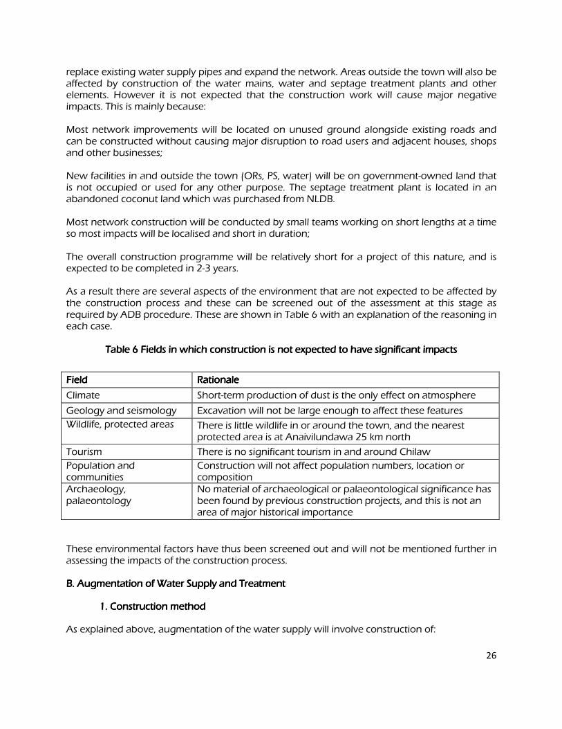
26
replace existing water supply pipes and expand the network. Areas outside the town will also be affected by construction of the water mains, water and septage treatment plants and other elements. However it is not expected that the construction work will cause major negative impacts. This is mainly because: Most network improvements will be located on unused ground alongside existing roads and can be constructed without causing major disruption to road users and adjacent houses, shops and other businesses; New facilities in and outside the town (ORs, PS, water) will be on government-owned land that is not occupied or used for any other purpose. The septage treatment plant is located in an abandoned coconut land which was purchased from NLDB. Most network construction will be conducted by small teams working on short lengths at a time so most impacts will be localised and short in duration; The overall construction programme will be relatively short for a project of this nature, and is expected to be completed in 2-3 years. As a result there are several aspects of the environment that are not expected to be affected by the construction process and these can be screened out of the assessment at this stage as required by ADB procedure. These are shown in Table 6 with an explanation of the reasoning in each case.
Table Table Table Table 6666 Fields in which construction is not expected Fields in which construction is not expected Fields in which construction is not expected Fields in which construction is not expected to have significant impacts to have significant impacts to have significant impacts to have significant impacts
Field Field Field Field Rationale Rationale Rationale Rationale
Climate Short-term production of dust is the only effect on atmosphere
Geology and seismology Excavation will not be large enough to affect these features
Wildlife, protected areas There is little wildlife in or around the town, and the nearest protected area is at Anaivilundawa 25 km north
Tourism There is no significant tourism in and around Chilaw
Population and communities
Construction will not affect population numbers, location or composition
Archaeology, palaeontology
No material of archaeological or palaeontological significance has been found by previous construction projects, and this is not an area of major historical importance
These environmental factors have thus been screened out and will not be mentioned further in assessing the impacts of the construction process.
B. Augmentation of Water Supply and Treatment B. Augmentation of Water Supply and Treatment B. Augmentation of Water Supply and Treatment B. Augmentation of Water Supply and Treatment
1. Construction method 1. Construction method 1. Construction method 1. Construction method
As explained above, augmentation of the water supply will involve construction of:
27
7 new tube-wells alongside malfunctioning existing wells and a 22.5 km gravity main of 300-400 mm DI and HDPE pipe to transfer water to the existing WTP; A 1.5 m RCC and sheet-pile weir across the Deduru Oya to impound water during periods of low river flow to allow year-round abstraction; An RCC intake channel alongside the weir, with stone groynes to deflect water to the intake and stone gabions along the river banks and weir to prevent erosion; A pump station and 4.4 km Transmission Main of 500-600 mm DI pipe to convey water to the new treatment plant. Improving water treatment will involve construction of:
A new WTP on 1.2 ha of land at Wilattawa in Bingiriya DS Division, comprising a series of RCC tanks to provide aeration, sedimentation, sand filtration, chlorination and storage; Replacement of sand/gravel filters at the existing WTP at Munneswarama and provision of new pumps and pipes to convert an existing tank to a mixing chamber. The gravity main and transmission main are pipelines and will be constructed in the same way as the distribution networks, so their impacts are likely to be similar. These are therefore considered together in Section IV.C below. The remainder of the work in this component is quite large in scale, but will involve relatively straightforward construction methods, mainly simple excavation and the construction of structures from Reinforced Cement Concrete (RCC). Work in the Deduru Oya will be conducted in the dry season when the reduced flow of water can be diverted away from working areas by bunds formed by excavating sand from the riverbed. Foundations for the weir and intake canal will then be dug by backhoe digger, and steel sheet piles will be inserted by hydraulic hammer on the downstream side of the weir. Hard-core, gravel and cement will be brought to site on trucks and tipped into the cavities, after which metal reinforcing will be added by hand to form the above-ground structure of the weir and the walls and weir of the canal. Segments will then be encased in wooden shuttering , after which concrete mixed on site will be poured in. The process will be repeated in the adjacent segments, gradually creating the structures as each portion dries. Any surface blemishes will be smoothed by masons by hand. Gabions (cubical metal baskets containing 200-400 mm diameter stone) will be placed along the banks of the river and upstream and downstream of the weir to prevent erosion, and these will be brought ready-made to site on trucks and placed in position by a small crane. Two groynes will be built on the riverbed opposite and upstream of the intake, by tipping stone trucked in from local quarries, and repositioning stones by hand and grab-crane to form the 2 m high, 20-30 m long structures. Pipes will be laid in trenches from the intake up the adjacent riverbank , to the Raw Water Pump House. The pump house will measure approximately 8 x 6 x 3 m and will be constructed by normal house-building methods. Foundations, 0.5 m in depth will be excavated by backhoe, and hardcore and concrete (mixed on site) will be tipped in. Masons will then build the walls by applying bricks and mortar by hand, and the pumps and pipes will be brought in on trucks, put into place by crane, and connected up by hand. The roof of the PS will then be added by hand.
28
Tube wells will be built alongside malfunctioning existing wells by drilling new boreholes using a small drilling rig, and inserting ready-made stainless steel screens and lengths of UPVC pipe and a submersible pump to lift the water from the aquifer. Pipe-work and a valve and meter will then be added at the surface. . At the new WTP site, vegetation will be cleared by hand and using a bulldozer, after which 20 x 20 m cavities will be dug to 2.5 m depth by backhoe and bulldozer, loading material into trucks for offsite disposal. Metal reinforcing rods will be inserted by hand along the floor and sides of each tank, after which concrete (mixed on site) will be poured into sections of reinforcing encased in wooden shuttering. This will be repeated to form the roof of each closed tank. A small pump house will be built by masons as described above, and pumps and pipes will be positioned by crane and joined up by hand. Exterior pipe-work will be laid on the surface or in shallow trenches dug by backhoe. Other components including settling tubes for the sedimentation tanks and sand and gravel for the filter beds will be brought in on trucks and put into place by hand or using cranes or bucket loaders as appropriate. Rehabilitation of the existing WTP at Munneswarama will involve replacement of faulty sand filters and conversion of an existing tank to a chamber in which groundwater and surface water will be mixed. Sand will be removed from the malfunctioning units by hand digging, and new sand will be brought in on trucks and lifted into the tanks by crane. Additional pipes and pumps will be put into place alongside the mixing tank by crane and connected up by hand. 2. 2. 2. 2. Impact on Impact on Impact on Impact on Physical Resources Physical Resources Physical Resources Physical Resources
Replacement of sand filters and provision of new pumps and pipes at the existing WTP will not have significant environmental impacts as it will involve small-scale work, conducted at an existing operating facility. Drilling new tube-wells alongside malfunctioning wells should also not have significant impacts as the work will be completed in an estimated 2-5 days, and will occur at isolated small sites , where there is already a similar well. The noise and visual impact of the drilling rig will not be significant as most wells are located in rural areas where few people will be disturbed, and the small amount of soil and gravel excavated by the drill will be taken away on a single truck. The remainder of the work in this component is much larger in scale and is thus likely to have greater impacts. In physical terms the main source of impact is likely to be the excavation, which will remove large quantities of soil, sand and stone, very little of which will automatically be re-used (some stone may be suitable for gabions and groynes and sand from the river bed may be used for concreting). The remainder will be waste, of which there will be an estimated 26,000
m3
, from excavation to construct the weir (ca 200 m3
), intake channel (800 m3
) and WTP
(25,000 m3
). Although 26,000 m3
is not a major quantity in itself, when added to the amounts produced by other components (in particular the water supply networks and septage treatment ponds), then it is clear that the project as a whole will produce a significant amount of waste. This could not be dumped without causing at least some adverse physical impacts on air quality (dust), topography, soil quality, etc at the disposal site, which could be significant depending on the location. It will be very important therefore to take steps to reduce the amount of dumping
29
by finding beneficial uses for as much of the waste material as possible. The civil works contractor (appointed to carry out the construction work) should be required to: Re-use as much excavated material in this project as possible (for example sand
excavated from the river bed may be suitable for use as infill in pipe trenches); Contact the town authorities to find beneficial uses for waste material in other projects,
to raise the level of land prior to construction of roads or buildings, or to fill previously excavated areas such as prawn farms to improve coastal protection.
Most excavation is likely to be conducted in the dry season to avoid the difficult conditions that can occur when earthworks are carried out during rain. There will therefore be a risk of producing dust. Although most of these locations are in rural areas where there is little or no inhabitation nearby, precautions will nevertheless be needed to reduce dust to provide a suitable and safe environment for workers. Contractors should therefore be required to: Remove waste rapidly by loading material onto trucks as soon as it is excavated; Cover or damp down sand and soil retained on site in windy weather; Use tarpaulins to cover loose material during transportation to and from the site; Plan the work carefully to ensure that sand is only brought to site when it is needed.
Another physical impact that may be associated with large-scale excavation is the effect on drainage and the local water table if groundwater and surface water collect in the voids. However this should not be a major problem at these locations, because a) as indicated above, most excavation will probably be conducted in the dry season, b) the top of the water table is 5-10 m below ground level in most of Chilaw, and c) the soil is low in permeability because of its clay-like consistency. The diversion of river water during construction of the weir in the Deduru Oya should also not have major impacts as downstream flow will continue, and the river will only be diverted in the vicinity of the weir. Impacts of the retention of water by the weir are discussed in Section V.B below (impacts of operation).
3. Ecological Resources 3. Ecological Resources 3. Ecological Resources 3. Ecological Resources
There are no protected areas or locations of any particular ecological interest at or near any of the sites affected by these works, so it is unlikely that the work will have major ecological impacts. There is however a risk that downstream aquatic ecology and fisheries could be affected by the construction work in the Deduru Oya if any toxic material was spilled into the river. This can be prevented simply by requiring the contractor to follow standard working practices at construction sites, in particular ensuring that: No toxic materials (fuel, oil, cement, etc) are stored at or near the Deduru Oya site; Working areas are separated from the river by secure watertight bunds to prevent any
spilled material reaching the water; The contractor’s Method Statement (submitted with the tender) includes adequate safety
measures to prevent fuel and other spills as a result of accidents. 4. Economic Development 4. Economic Development 4. Economic Development 4. Economic Development
Most of the structures within this component will be built on government-owned land, including the weir and other elements in the bed of the Deduru Oya, new tube-wells alongside existing wells, and the pump stations. Construction of these facilities should thus not require the acquisition of private land and should therefore not affect the income and assets of landowners and tenants.
30
There is however not enough government land available in a single plot for the new WTP, which will therefore have to be located on private land. 1.2 ha of land was purchased from the Bingiriya Rajamahaviharaya for the water treatment plant. .One family who was living in the premises was resettled by the Chief Incumbent already. There is no industrial activity at these sites, and construction should also not affect agriculture because none of the structures will be located on farm land, and the coconut plantation of the NLDB at the STP site is not active. WTP will be located in temple premises. Because the sites are all located outside the town it is also unlikely that they will contain infrastructure such as power lines and water supply pipes that could be damaged by the construction work. The contractor should however confirm this with the local authority before commencing work and should take action to prevent accidental damage if any such infrastructure is present. The other aspect of the work that may have economic implications is the transportation of waste material from these sites to locations where it can be put to beneficial use as recommended above. This will require a large number of truck movements, which could disrupt traffic, particularly if such vehicles were to enter the town. This activity will be implemented by the contractor in liaison with the town authorities, and the following precautions should be adopted to reduce effects on traffic: Plan transportation routes carefully to prevent heavy vehicles entering the town; and
ensure that if this cannot be avoided vehicles use main roads only, and do not use narrow local roads, except in the immediate vicinity of delivery sites; Schedule transportation activities to avoid peak traffic periods.
5. Social and Cultural Resources 5. Social and Cultural Resources 5. Social and Cultural Resources 5. Social and Cultural Resources
Construction activities inevitably produce noise and dust, and these plus the visual appearance of the site and restrictions in access caused by excavation and the presence of vehicles and machinery, are generally the factors that disturb people who live or work in the vicinity. In the Water Treatment Plant site which is temple premises the site is somewhat away from the main area of the temple which is inhabited by the people. The patch of forest in between will act as a noise barrier. However, the contractor will be advised to minimize the disturbance to the temple from the construction activities. With regard to the septage treatment plant site, it is located further interior to the Chilaw – Puttalam road and therefore the public will not be affected due to construction. However, as the area is rather flat and lies between two tanks used for cultivation and on an area which gets flooded during the heavy rains, it is imperative to include a drain to take excess waters from Karukkuliya tank which is located upstream to Mahamanaweriya tank located downstream of the site. Otherwise if the area is flooded there is a possibility of contamination of the waters. There are also no socially or culturally important buildings (schools, hospitals, temples, churches, etc) near any of the sites that could be disturbed by construction activities. There are however small religious shrines at various locations elsewhere in the study area. In order to minimize disturbances to the communities, work should be planned to avoid working during sensitive times such as religious festivals. The health and safety of workers will be protected by measures included in a Health and Safety Plan, which the contractor will be required to produce and apply. Even though the rural areas are sparsely populated, this should include measures to assure the safety of the public. The plan should thus require:
31
Exclusion of the public from all sites; Provision and use of appropriate Personal Protective Equipment (PPE) by all workers; Health and Safety Training for all site personnel; Documented procedures to be followed for all site activities; Accident reports and records;
Construction work can provide short-term socio-economic gains for local communities if contractors employ local people in the workforce. To ensure that these benefits are directed to communities that are affected by the work, contractors should be encouraged to employ at least 50% of their workforce from communities in the vicinity of construction sites. This will help to mitigate the impacts of any disturbance as well as creating a positive impression of the project. Building a workforce from mainly local people will also avoid problems that can occur if workers are imported, including social difficulties in the host community and issues of health and sanitation in poorly serviced temporary camps. C. Improving the Water Supply Network C. Improving the Water Supply Network C. Improving the Water Supply Network C. Improving the Water Supply Network
1. Construction Method 1. Construction Method 1. Construction Method 1. Construction Method
Improving the water supply network will involve construction of:
A 8.2 km distribution main of 450 mm diameter HDPE pipe and 180 km of 335 mm HDPE pipes to carry water from the new WTP into the town and beyond, to Bangadeniya in the north;
2 RCC overhead reservoirs, at Bingiriya in the east and Bangadeniya in the north; A 154 km network of 63-225 mm UPVC pipes to convey water to consumers.
The pipelines outside the town are also assessed in this section, and these comprise:
A 22.5 km gravity main of 300-400 mm DI and HDPE pipe to convey water from the new TW to the existing WTP east of the town;
A 4.4 km transmission main of 400 mm DI pipe to transfer water from the Deduru Oya intake to the new WTP at Bingiriya.
Most pipes will be buried in trenches in the RoW alongside public roads. Most of the mains will run alongside paved highways, where there is normally ample unused ground at the edge of the road. The transmission main and gravity main will run alongside rural roads for the initial part of the route and will then follow the highways; and the distribution main will also run alongside these main roads (Figure 1). Parts of the distribution network however will be located in smaller streets in the commercial part of town, where in places the RoW may be occupied by drains or the edges of shops and houses. In these locations trenches will be dug into the edge of the road if necessary to avoid removing structures. Trenches will be dug by backhoe digger , supplemented by manual digging where necessary . Excavated soil will be placed beside the trench, and the pipes (brought to site on trucks and stored on unused land nearby) will be placed in the trench by crane or using a small rig. Pipes will be joined by hand, and sand from local quarries will be shovelled into the trench beneath and around the pipe for support and protection. Soil will then be replaced manually on top of the pipe and compacted by a vibration. compressor. Roads are repaired by the local authority, so a layer of gravel will be placed on the surface of the trench to provide a protective layer until
32
the tarmac is reinstated. Pipes are normally covered by 1.2 m of soil, and a clearance of 100 mm is left between the pipe and each side of the trench to allow backfilling. Trenches will therefore be a maximum of 1.7 m deep and 0.6 m wide for the mains, and a minimum of 1.4 m deep and 0.3 m wide for the network. The new Overhead Reservoirs will be built on small areas of government land outside the town, following the same process as for the other RCC structures described above. At each site the cavity for the foundations will be dug to about 1 m depth by backhoe, with soil being loaded into trucks for disposal. Aggregate and concrete will be tipped in to create the foundations and floor, after which metal reinforcing rods are inserted vertically to form the structure of the vertical supports. Sections of reinforcing are then encased in wooden shuttering and concrete is poured in, and this process is repeated to gradually form the supporting pillars and tank. After drying, concrete surfaces are smoothed and finished where necessary by hand. 2. 2. 2. 2. Impact on Impact on Impact on Impact on Physical RPhysical RPhysical RPhysical Resources esources esources esources
This work is similar to the source augmentation and water treatment component in that construction will involve quite extensive excavation. However in this case work will be spread over various locations both inside and outside the town, so the nature and significance of the impacts are likely to be different. If average trench dimensions are 1.7 x 0.6 m for the 22.5 km gravity main and the 4.4 km transmission main, 1.6 x 0.5 m for the 29 km distribution main, and 1.4 x 0.3 m for the 108 km
distribution network, then trench construction will excavate around 100,000 m3
of material. After construction, approximately 25% of the trench will be occupied by the pipe, 50% by backfilled sand, and 25% by excavated soil replaced on top of the pipe. This means that around
50,000 m3
of sand will be brought to site, 25,000 m3
of soil will be retained for replacement in
the trench, and 75,000 m3
of waste material will be left over. This adds significantly to the total waste produced by this subproject, reinforcing the need to adopt the measures recommended above to limit the amount of material taken for disposal. The contractor should thus be required to: Reduce the amount of waste by re-using as much excavated material in this project as
possible; Liaise with the town authorities to find beneficial uses for waste in other projects, to raise
the level of land prior to construction of roads or buildings, or to fill previously excavated areas such as prawn farms. This work is also likely to be conducted in the dry season so there is again considerable potential for the production of dust, and in this case impacts will be more significant as much of the work is located in inhabited areas. Dust should therefore be reduced by: Removing waste soil as soon as it is excavated by loading directly onto trucks; Covering or watering sand and soil retained on site in dry weather; Using tarpaulins to cover loose material during transportation to and from each site; Planning work carefully to ensure that sand is only brought to site when it is needed.
33
Conducting the work in the dry season should avoid impacts on drainage or surface and groundwater as would occur if rainfall collected in open trenches. The physical impacts of trenching will also be reduced by the method of working, whereby the network improvements will probably be constructed by small teams working on short lengths at a time, so the impacts will be mainly localised and short in duration. Physical impacts are also mainly temporary as trenches will be refilled and compacted after pipes are installed, and any disturbed road surfaces will be repaired. 3. 3. 3. 3. Impact on Impact on Impact on Impact on Ecological Resources Ecological Resources Ecological Resources Ecological Resources
There are no significant ecological resources in or outside the town, so the network improvements should have no ecological impacts. Roadside trees should however not be removed unnecessarily to build the trenches, and to discourage this and mitigate any such losses, the contractor should be required to plant and maintain two new trees (of the same species) for each one that is removed. When the water treatment plant is being constructed, as it is located in a land belongs to a famous temple visited and used by many maximum precautions should be taken to reduce noise during construction work. However, there is a thick tree buffer between the proposed construction site and the actual temple ground which would help to muffle the noises to a large extent. GeneralGeneralGeneralGeneral
The forest land has to be cleared during the construction period of the treatment plant. There
are no rare threatened plants species found in the site except for the common plants found. This
forest clearing will also have an impact on endemic fauna such as the Sri Lanka Jungle Fowl
which was spotted during the site reconnaissance.
Fauna (animals) Fauna (animals) Fauna (animals) Fauna (animals)
The forecast for the impact of the Deduru Oya weir and the treatment plant on the animals was
based on the assessment during the field studies. The assessment made was a site
reconnaissance in the form of transect walks in the project area and performing visual
observations. No threatened or endangered species are expected to be affected and most
animals presently located within the area are expected to move to other locations close to
Deduru Oya riverine forest which is a conducive habitat to these animals.
HerpetoHerpetoHerpetoHerpeto fauna (amphibians and reptiles)fauna (amphibians and reptiles)fauna (amphibians and reptiles)fauna (amphibians and reptiles)
Under the natural conditions herpeto fauna may suffer during the drier period of the year. Due
to the perennial water being provided by the proposed Deduru Oya project, amphibians and
reptiles species may become abundant in several years after the damming of the reservoir. The
amphibian species will use the impounded water for spawning and development of larvae. It is
likely that grass snakes and tortoises will exist in low numbers in the less accessible areas.
However these cannot be a significant impact on herpetofauna because of the construction of
the treatment plant site.
34
Avi fauna (birds)Avi fauna (birds)Avi fauna (birds)Avi fauna (birds)
There will not be any significant impact on avi fauna due to the construction of the treatment plant although land has to be cleared to construct the treatment plant as the cleared area is small compared to the larger habitat of the project area and replanting of trees will be undertaken within the proposed buffer zone 4. 4. 4. 4. Impact on Impact on Impact on Impact on Economic Development Economic Development Economic Development Economic Development
As the trenches for the water pipelines will be located in the RoW of existing roads (either adjacent to the road or beneath the road surface in narrower streets) there will be no need to acquire land for this component. This should also be the case for the ORs, which will be located on small parcels of unused Government land at Bingiriya and Bangadeniya (Figure 1). There should thus be no direct effect on the income or assets of landowners, or the livelihoods of tenants or other land-users. There could be some economic impacts however, if the presence of trenches, excavated material, workers and machinery beside roads in the town discourages customers from visiting shops and businesses, which lose income as a result. These losses will be short in duration as work at any one site should be completed in a week or less. However the loss of income could be significant for small traders and other businesses that exist on low profit margins. These impacts should therefore be mitigated by: Leaving spaces for access between mounds of excavated soil, and providing footbridges
so that pedestrians can cross open trenches; Increasing the workforce in these areas to ensure that work is completed quickly; Consulting affected businesspeople to inform them in advance when work will occur.
In addition to these practical measures to reduce the economic impact of the construction work, to comply with ADB policy on Involuntary Resettlement, the Resettlement Framework establishes that owners and/or tenants of affected businesses will also be compensated in cash for any income they lose. Excavation in the town could damage existing infrastructure, in particular water supply pipes which are located alongside roads. The local authority should therefore be asked to provide details of the nature and location of all infrastructure in affected areas so that the new and improved networks can be planned to avoid all potential conflicts. Transport is another type of infrastructure that will be affected by some of this work, as in the narrower streets there is not enough space for excavated soil to be piled off the road, and as noted above, trenches will be dug into the road at some locations. Traffic will therefore be disrupted, and in some very narrow streets the whole road may need to be closed for short periods. The contractor should therefore: Plan this work with the town authorities and police so that work is carried out during
periods when traffic is known to be lighter; Request the provision of alternative routes and effective diversions where needed; Increase the workforce in these areas to complete the work as soon as practicable.
This work will inevitably increase the number of heavy vehicles in the town (particularly trucks removing waste and delivering pipes and other materials to site), and this could be a further source of disruption to traffic and other economic activities. This should be mitigated by:
35
Careful planning of transportation routes with the local authorities to avoid problem areas as much as possible, including narrow streets and congested roads;
Scheduling the transportation of waste to avoid peak traffic periods.
5. 5. 5. 5. Impacts on Impacts on Impacts on Impacts on Social and Cultural Resources Social and Cultural Resources Social and Cultural Resources Social and Cultural Resources
Disturbance of people by the noise, dust and visual intrusion of construction sites, and by access restrictions disrupting normal activities, is normally much more of a problem in urban areas than at rural sites, because far more people are affected. However in this case these impacts should not be greatly significant, even though most of the pipeline construction will be conducted in and around the town. This is because:
Impacts will be short-lived as at any one location network construction will be completed in a in a in a in a week at most;
People will tolerate this kind of disturbance if they know that their infrastructure and water supply will be improved as a result;
The centre of Chilaw is a congested environment that is subject to noise and visual disturbance already, so people are naturally adapted to such conditions. Efforts should still be made to reduce these impacts as far as possible, particularly in residential areas and at sites of social and cultural importance, such as schools, hospitals, temples, mosques and churches. This will require the same kind of measures as recommended above to reduce the physical and economic impacts of this work. The contractor should therefore be required to:
Limit dust by removing waste soil quickly, covering and watering stockpiles of soil and sand, and covering loose material with tarpaulins when carried on trucks;
Increase the workforce in sensitive areas to complete the work quickly; Provide wooden bridges for pedestrians and metal sheets for vehicles to allow access
across open trenches to houses and other buildings where required; Use modern vehicles and machinery with standard adaptations to reduce noise and
exhaust emissions and ensure they are maintained to manufacturers’ specifications; Include residents as key stakeholders in public consultation meetings and inform the
community in advance regarding the nature and duration of work in their vicinity. It will again be necessary to avoid damaging any sites or artefacts that are of local social and cultural significance such as roadside shrines, so the same process as recommended above should be followed. Each community should be consulted in the detailed design stage to identify any locally-important sites that may be affected, and action should be taken to avoid impacts if necessary. This includes:
Adjusting locations to avoid any especially sensitive sites; Planning work programmes with the community to avoid working during sensitive times
such as religious festivals. Protecting the health and safety of workers and the public will be a more significant issue at the urban sites than in the rural area because of the congested nature of many of the locations, and the presence of greater numbers of people. This will again be covered by the contractor’s Health
36
and Safety Plan, and by the vigilance of the Supervising Consultant (appointed by NWSDB to supervise construction) in ensuring that the provisions in the plan are strictly applied. There would be very significant impacts on people and communities if water supplies were closed down for extended periods when work is conducted on the network. This would be inconvenient in the short term, and there could be health risks if the water supply was unavailable for several successive days or longer. It will therefore be important to take all necessary measures to avoid such a situation. This will require: Detailed planning of the construction programme to keep the cessation of water
supplies to the minimum possible (in both area and duration); Provision of alternative potable water to affected households and businesses for the
duration of the shut-down; Liaison with affected persons to inform them of any cessation in advance, and to ensure that
they are provided with an alternative supply.
There would again be short-term socio-economic benefits if local people were employed in the construction workforce. This would mitigate some of the effects of disruption and disturbance and avoid the social and environmental problems that may arise when an imported workforce is housed in work-camp accommodation in a host community. The contractor should therefore again be encouraged to employ at least 50% of his labour force from communities in the vicinity of construction sites, including the sites of the overhead reservoirs. With special reference to the water treatment plant, The people residing by the side of the
access roads and the people who gather to temple for religious activities will be affected by
dust, noise, and exhaust fumes mainly excreted by the vehicles which will transport materials to
the site. This impact will be limited to the construction stage of which the duration is
approximately 12 months according to the implementation schedule. There could also be
accidents because of these plying vehicles along the access road.
Labour gangs will temporarily occupy the sites during the construction and there could be
positive and negative social impacts because of them.
There is on squatter family who reside in the treatment plant site and he will lose his place of
living.
Cultural and Archaeological Impacts Cultural and Archaeological Impacts Cultural and Archaeological Impacts Cultural and Archaeological Impacts
The propose site is part of the temple property and it is located adjacent to the temple premises.
This temple has a unique historical and archaeological value as the temple falls into the category
of Tampita Viharaya ( the structure on pillars) and this is the largest of such kind in Sri Lanka
according to the Sinhalese publication “Pauranica Stana Saha Smaraka- Kurunegala Distrikkaya “
by the Department of Archaeology. This temple has been presumably been constructed in 8th
Century . The Department of Archaeology has issued a no objection letter stating that there are
no historical monuments of artefacts on the surface.
37
D. Sanitation D. Sanitation D. Sanitation D. Sanitation
1. Construction Method 1. Construction Method 1. Construction Method 1. Construction Method
As explained earlier, the sanitation component will involve construction of a septage treatment facility on a 0.75 ha plot of land, located on an abandoned coconut cultivation belonging to NLDB few kilometers away from Chilaw town. The facility will consist of:
� Two anaerobic ponds are suggested for alternate use. The proposed arrangement is that one anaerobic pond will be used for one year and then allow it to rest for nine months. This approach will allow further stabilization of collected sludge going through digestion and making it less harmful, dryer and smaller in volume for easy disposal. The arrangement will be to de-sludge the un-used anaerobic pond in late August or early September before the commencement of the rainy season. Quantity of sludge is small and can be disposed/ buried at dug pits in the coconut plantation.
� Disposal of sludge outside of the STP site at a land fill or another disposal site is also possible. Anaerobic pond can be easily desludged and take to matter to an accepted/recommended disposal site without further dewatering. Sludge dewatering is not necessary and not proposed. .
� Retention pond will allow the effluent to be stored temporarily during adverse wet weather conditions2.
Two vacuum tankers of 3,000 litres capacity will also be provided to the Urban Council, which they will use to remove material from septic tanks in the town, and transport it to the septage facility. At the treatment site the cavities for each pond will be excavated by backhoe digger, and waste material will be loaded onto trucks for disposal. The floors of the thickening and drying beds will be adjusted to the required slope by addition and compaction of soil as necessary, and an aggregate and concrete mix will be poured in to the required depth to form the mass concrete floor (Figure 4). The vertical walls of each bed will then be built from bricks, placed by masons by hand, after which a covering of cement mortar will be applied to the floor and sides. The remaining ponds will be excavated with sloping sides, and the floors will be compacted by a small roller vehicle, before a clay or PVC lining is added by hand (the material and source will be determined during the detailed design stage). The same aggregate and concrete mix will then be poured in to form the floor of each tank, and in this case it will also be applied to the sloping sides. A final cement mortar covering will then be applied, again by masons by hand. Sand for the drying beds will be brought to site on a truck and spread across each bed by hand using wheelbarrows and shovels. Other fitments such as scum baffles, pipes and sluice gates will also be brought in on a truck and offloaded and put into position by hand. Some pipes will be laid in shallow trenches, dug to the requisite depth by backhoe. Soil for the wetland bed will also be brought in on a truck and placed into the pond by hand, after which plants of the selected species will be inserted into the soil by hand, at the appropriate density for the
2 Retention pond could converted to an artificial wetland if necessary
38
calculated volume of effluent. 2. 2. 2. 2. Impact on Impact on Impact on Impact on Physical Resources Physical Resources Physical Resources Physical Resources
Procurement and delivery of the vacuum tankers will not have significant environmental impacts as the process will use only relatively small amounts of oil, fuel, etc, which are of little consequence compared to the very large amounts of these materials that are used in transportation each day in Sri Lanka and elsewhere. Exhaust gases would not be sufficient to produce a noticeable effect on air quality, particularly as the vehicles will be purchased new, and should thus be fitted with the most up-to-date emission reduction devices. Construction of the septage treatment facility involves excavation and the building of structures and will therefore have more noticeable physical and other impacts. However as these will occur at a single small site located in an uninhabited area, they are not expected to be of major significance.
Excavation of the beds and ponds will create around 12,000 m3
of waste soil and stone. Although this is by no means a major quantity, it adds to the waste burden of the project, is already considerable. The same measures as recommended for the water supply subproject should therefore be applied to reduce the overall amount of dumping. The contractor should thus be required to: Re-use as much excavated material in this project as possible (for example topsoil may be
suitable for use in the wetland bed); and
Liaise with the town authorities to find beneficial uses for waste in other projects to the extent possible.
As at the other sites, the excavation will almost certainly be conducted in the dry season to avoid the difficult conditions that occur during the monsoon, so it is likely that the work will produce a certain amount of dust. This should not be a major problem as there are no inhabited areas near the site. However dust will still need to be reduced to provide a safe and suitable environment for workers, so the contractor should be required to apply the same measures as at the other excavation sites. These are to: Remove waste soil as soon as it is excavated, by loading directly onto trucks; Cover or water sand and soil retained on site in dry weather; Use tarpaulins to cover loose material when transported to and from the site.
As the site is located in an area on the upper watershed of Mahamanaweriya tank and also in the downstream of the Karukkali tank, there is a possibility of soil erosion and sedimentation of especially Mahamanaweriya tank due to construction. 3. 3. 3. 3. Effect on Effect on Effect on Effect on Ecological Resources Ecological Resources Ecological Resources Ecological Resources
The site for the septage treatment facility is situated on the upstream of the Mahamanaweriya tank which is used for providing irrigation waters for downstream cultivation. As it is located downstream of the construction site, the waters could get sedimented due to soil erosion.
39
4. 4. 4. 4. Effect on Effect on Effect on Effect on Economic Development Economic Development Economic Development Economic Development
The proposed site for the septage treatment plant is under private ownership. This was purchased from the NLDB. During construction, there will be both skilled and non skilled workers employed by the contractor. This will create employment opportunities for the people and is a positive impact. Because this site has been under agriculture, there is no infrastructure (such as water pipes and electricity poles) that could be damaged by the work. The local authority should however be contacted to confirm this and designs should be altered to avoid damaging any infrastructure if found to be necessary. Transportation could be indirectly affected by the work, if trucks carrying waste material from the site disrupt traffic on the roads in and around the town. This should be reduced by applying the same kind of measures as recommended for the water supply subproject, so the contractor should be required to: Plan transportation routes with the local authority to limit the number of vehicles that
enter the town; Where this cannot be avoided, ensure that heavy vehicles use main roads only and do
not use narrow local roads except in the immediate vicinity of delivery sites; Schedule transportation activities to avoid peak traffic periods. 5. 5. 5. 5. Impact on Impact on Impact on Impact on Social and Cultural Resources Social and Cultural Resources Social and Cultural Resources Social and Cultural Resources The noise, dust and visual intrusion of construction, and any limitations in access caused
by the work should all be of little significance because there is limited inhabitation near the septage treatment site. It should therefore not be necessary to take additional measures to mitigate these impacts, beyond those already recommended above There are also no socially or culturally important buildings (schools, clinics, churches, etc) in the vicinity of the site, although there could again be small shrines or artefacts that are of local importance. The nearest communities should therefore be consulted during the detailed design stage to determine whether there are any such sites that might be affected by the work, and if that is the case the designs should be adjusted to: Avoid any such locations; Avoid working during sensitive times, such as religious festivals.
As at the other locations, the contractor will be required to prepare and implement a Health and Safety Plan to protect workers and the public. This should include measures to: Exclude the public from all sites; Provide appropriate PPE to all workers and ensure that it is used; Provide H&S training to all site personnel; Follow documented procedures for all site activities; Retain and periodically review accident reports and records; etc.
The contractor should again be encouraged to employ at least 50% of the workforce from local community, in this case those living nearest to the site. This will provide a socioeconomic benefit, that should help to ameliorate the impacts they will experience, which include construction vehicles (and tankers once the system is functioning) operating on local roads.
40
V. V. V. V. ENVIRONMENTAL IMPACTS AND MITIGATION: OPERATION AND MAINTENANCE ENVIRONMENTAL IMPACTS AND MITIGATION: OPERATION AND MAINTENANCE ENVIRONMENTAL IMPACTS AND MITIGATION: OPERATION AND MAINTENANCE ENVIRONMENTAL IMPACTS AND MITIGATION: OPERATION AND MAINTENANCE
A. A. A. A. Screening out areas of no significant impact Screening out areas of no significant impact Screening out areas of no significant impact Screening out areas of no significant impact
. The water supply and sanitation infrastructure will require regular maintenance once it is operating, but with a few straightforward precautions this can be conducted without major environmental impacts. There are therefore several environmental sectors that should be unaffected once each system begins to function. These are identified in Table 7, with an explanation of the reasoning in each case. These factors are thus screened out of the impact assessment and will not be mentioned further.
Table 7: Fields in which operation and maintenance of the completed infrastruTable 7: Fields in which operation and maintenance of the completed infrastruTable 7: Fields in which operation and maintenance of the completed infrastruTable 7: Fields in which operation and maintenance of the completed infrastructure is not cture is not cture is not cture is not expected to have significant impacts expected to have significant impacts expected to have significant impacts expected to have significant impacts
Field Field Field Field Rationale Rationale Rationale Rationale
Climate, geology, seismology
Operation of water supply, sewerage and drainage infrastructure in a small town should not affect these features
Topography and soil Water will be used for domestic purposes not agriculture or irrigation, and treated wastewater effluent will be discharged to a coconut land
Wildlife, forests, protected areas
There is little wildlife in or around the town, no significant natural forest, and the nearest protected area is at Anaivilundawa 25 km north
Industry There are no major industries in the town
Tourism There is no significant tourism in and around Chilaw
Archaeology, palaeontology
No material of archaeological or palaeontological significance has been found by previous construction projects, and this is not an area of major historical importance
B. Water Supply B. Water Supply B. Water Supply B. Water Supply
1. Operation and Maintenance 1. Operation and Maintenance 1. Operation and Maintenance 1. Operation and Maintenance
The main requirement for maintenance of the new water supply system will be for the detection and repair of leaks. The generally flat topography and the usage of good quality DI, HDPE and UPVC pipes should mean that pipeline breaks are relatively rare, and that leaks are mainly limited to joints between pipes. These will be repaired in essentially the same way that the pipes were installed. Trenches will be dug to expose the leaking area and the faulty connection will be re-fitted, or the pipe will be removed and replaced if necessary.
Sludge will need to be removed periodically from settlement tanks at the WTP, and this is normally washed out onto waste ground within the site. There is also some small scale maintenance at the WTP and other facility sites (TW, OR, PS), which involves regular checking and recording of the performance of the components for signs of deterioration (pumps, pipes,
41
valves, meters, etc), and servicing and replacement of parts where necessary. Three or four people will be employed at each PS, OR and the WTP, and small maintenance teams will visit the TWs and other locations periodically. The low-level weir across the Deduru Oya will need its own schedule of checking and maintenance, to ensure that bank erosion does not impair the functioning of the structure and to remove any debris entering the intake canal. This will be conducted by workers from the nearby In all cases NWSDB will ensure that personnel are properly trained and supervised, and that all procedures are defined in Operation and Maintenance (O&M) Manuals.
2. 2. 2. 2. Impact on Impact on Impact on Impact on Physical Resources Physical Resources Physical Resources Physical Resources
Generally the main risk to the physical environment of operating an improved water supply system is that increased abstraction will deplete the water resource. That should not be the case for the surface water element of this scheme as the purpose of the weir in the Deduru Oya is to retain a sufficient depth of water to enable the pumps to function in the dry season, not to retain a large volume of water for abstraction. Rates were estimated from the average monthly rainfall over the catchment area, plus the minimum flow from the Deduru Oya reservoir (under construction at Wariyapola 20 km upstream), which is guaranteed by the Irrigation Department
at 3.2 m3
/s. These calculations show a maximum flow in the river of 3.5 million m3
/d in
November and a minimum of 814,000 m3
/d in August, so abstraction by this project (15,000
m3
/d in 2030) will be <2% of the annual minimum river flow, which should not deplete the resource. The same cannot be said for the increase in groundwater abstraction (increasing by 50% the present rate of abstraction by 2020), because despite the fact that the wellfield is already exploited by NWSDB for the present Chilaw water supply scheme, there are limited data on the extent of the aquifer or its potential yield. This information is vital as it enables informed decisions on the appropriate locations of tube-wells and levels of a sustainable abstraction, to prevent over-exploitation of the aquifer and related impacts. These can include: Ground subsidence leading to surface damage, which could cause the collapse of buildings and other structures; Deteriorating quality of the water in the aquifer, particularly from seawater intrusion at
coastal sites such as this; Adverse effects on those who are currently using water from the aquifer sustainably (for
example via existing wells). It is imperative that a suitable monitoring programme be put in place by an experienced hydrogeologist, to collect the required data. This would include trial boreholes at various locations to establish the extent and potential yield of the aquifer and monitoring over an extended period to determine rates of natural depletion and replenishment. The data obtained from the trial bore holes pointed to the fact that there is potential only in and around Munneswaram area for ground water abstraction on a sustainable basis.
42
There are also limited data on the quality of water in the aquifer (Table 5), and limited data on the quality of surface water in the Deduru Oya (see Table 2). These needs to be further investigated/confirmed, given that the system as currently proposed would apply separate treatment to groundwater, and surface water and mix it (in a mixing chamber at the existing WTP) to improve its quality. Some laboratory trials have been conducted but these concentrate on improving hardness and alkalinity, and do not consider other parameters that are potentially more damaging to human consumers. These include organic matter, nitrates, phosphates and faecal bacteria, which could be significant components of both surface and ground water given the usage of chemical fertilizers in agriculture and the absence of a sewerage system. The quality of both surface water and groundwater must therefore be properly examined to determine whether the system as presently proposed will produce water of the mandatory legal standards (Appendix 1). The impoundment weir and intake weir may be designed as simple barriers without sluice gates. These structures will therefore impede the flow of sand and silt, which is transported downstream in large quantities, particularly in peak-flow periods. This will obstruct the proper functioning of the abstraction scheme as it will reduce the storage capacity of the weir and may damage the pumps if silt it enters the intake in a significant volume. Silt is also essential to replenish sediment at the coast to sustain the natural geomorphology of the lagoon, beach and subtidal area, and maintain effective protection against coastal erosion and flooding. The design of both weirs should therefore incorporate sluice gates, and O&M Manuals should specify the periodic opening of the sluices to purge retained silt. In contrast the physical impacts of operating the remaining elements of the water supply system should be very minor. If trenches are dug to locate and repair leaks or remove and replace lengths of pipe, the work will follow the same procedure as occurred when the infrastructure was improved. In this case soil and backfilled sand will be removed to expose the leaking junction or pipe, and if necessary a new pipe will be brought to site and replaced. The trench will then be refilled and re-compacted. This work should be very infrequent, and will affect individual small locations for short periods only (an average of a few hours for most repairs). Physical impacts will therefore be negligible. Work will not be conducted during rainfall so there will be no effect on drainage, and the removed material will be replaced in the trench so there will be no waste. There should also be no need to cover excavated material to prevent dust as it will have been wetted by the leaking water. When the sludge from the water treatment plant is sent to the outside it contains chemicals which are polluting to the environment. However, in the design of the water treatment plant sludge drying beds are incorporated. This is very essential as the sludge needs to be settled in the beds prior to disposal. The thus accumulated material should be dried and then transported to the municipal waste sites.
3. Impact Impact Impact Impact on on on on Ecological Resources Ecological Resources Ecological Resources Ecological Resources
Where structures are built across rivers to impound water for water supply or power generation purposes there are generally concerns regarding ecological impacts. These focus mainly on three elements:
i) The structure may impede the upstream migration of freshwater and marine fish to breeding grounds, so breeding may be unsuccessful and populations may decline; ii) The removal of water will reduce downstream flow and this may cause the
43
death of species and habitats if the river dries out seasonally to a greater extent than normal;
iii) Changes in the quality and quantity of water may affect the ecology and behaviour of downstream species (for example by altering factors such as temperature and salinity that stimulate the breeding migrations).
These are complex issues that are frequently the subject of detailed studies in the case of large dam, reservoir and hydropower schemes, in order to plan detailed mitigation measures to reduce ecological impacts. These often involve assuring a minimum ‘environmental flow’ at all times (sufficient to maintain the downstream ecology), and incorporating fish passes or other structures to allow fish to migrate upstream and downstream. It should not be necessary to adopt such measures in this case. This is because: This structure is a low-level weir with a crest height of 1.5 m, which is of a much smaller
scale than the types of structure for which such measures are normally considered necessary (hydropower dams may be over 100 m high);
As explained above, the purpose of the weir is to provide a sufficient depth of water for
safe pumping rather than retain a large quantity for abstraction, and downstream flow will continue throughout the year, in volumes that are similar to normal flows;
There are no known features of ecological significance in the river, and the downstream
area has been heavily degraded in the recent past by extensive sand mining; According to national fisheries experts there are no fish species in the Deduru Oya that
migrate large distances upstream to breed. However, fish inhabiting the Deduru Oya may be affected to a certain extent by this and fish ladders may be suggested to overcome this situation.
It is therefore not considered necessary to provide any mitigation to reduce the impacts of the weir and impoundment on the aquatic ecology of the river. The weir may in fact provide small ecological benefits by creating a small artificial lake in the inter-monsoon periods, a habitat that is not available at present, in which certain species may increase in numbers. Maintenance work at the various facilities and any repairs to the network in or outside the town should not cause any ecological impacts as there are no significant ecological resources in these areas. 4. 4. 4. 4. Impact on Impact on Impact on Impact on Economic Development Economic Development Economic Development Economic Development
The presence of the weir should also not have any economic or social impacts, as there will be little reduction in flow, and there are no downstream users of river water (for irrigation, domestic supply, or other purposes). Repairs to the water supply network could result in shops losing some business if the work means that access is difficult for customers, but any losses will be small and short-lived and will probably be at the level of normal business fluctuations. It should therefore not be necessary to compensate for such losses. Nevertheless simple steps should be taken to reduce the inconvenience of the works, including: Informing all residents and businesses about the nature and duration of any work in
advance so that they can make preparations if necessary;
44
Requiring contractors to provide wooden walkways across trenches for pedestrians and metal sheets where vehicle access is required; Consulting the local police so that work can be planned to avoid traffic disruption as far as possible, and road diversions can be organised if necessary.
The improved water supply system will benefit business and residential consumers in the town, but this is unlikely to generate economic gains as there are no industries that are significant water users. There may however be small economic benefits from the expected improvements in the overall health of the community (see below) as fewer working days will be lost through sickness for example, so productivity should increase. 5. 5. 5. 5. Impact on Impact on Impact on Impact on Social and Cultural ReSocial and Cultural ReSocial and Cultural ReSocial and Cultural Resources sources sources sources
Network repair could cause some temporary disruption of activities at locations of social and cultural importance such as schools, hospitals, temples, etc, so the same kinds of precautions as employed during the construction period should be adopted. These include: Completing work in these areas quickly;
Providing wooden bridges for pedestrians and metal sheets for vehicles to allow access across open trenches where required; Using modern vehicles and machinery with standard adaptations to reduce noise and exhaust emissions;
Informing residents about the nature and duration of all such work in advance; Avoiding working during sensitive periods, such as times of religious observance.
NWSDB will operate the water supply system and they will employ local contractors to conduct network repairs. To protect both workers and the public, contractors should be required to operate the same kinds of Health and Safety procedures as used in the construction phase. . This should include measures to keep the public away from locations in which work is being conducted, and the use of appropriate PPE and construction practices by workers. The use of local contractors will provide economic benefits to the companies and the workers they employ. There is however little prospect of directing these benefits to persons affected by any maintenance or repair works as contractors will utilise their existing workforce. To provide at least some economic benefits to affected communities, persons employed at the various facility sites (PS, OR, WTP) should be residents of the neighbouring area. The weir across the Deduru Oya should bring some benefit to people living in the vicinity as the impounded area will attract fish during the inter-monsoon periods, which are almost certain to be harvested by local fishers. The citizens of the town and the other areas supplied with mains water will be the major beneficiaries of the improved water supply, because if the scheme is developed following the precautions given above, they will be provided with a more regular supply of better quality water. This gives the potential of improving the social capital of these areas, and individual and community health and well-being, providing the improvements in water supply and sanitation are combined with improved sanitary practices. It is very important therefore that the project should fund a campaign of public education to raise awareness of the importance of hand washing, water purification, cleanliness in food preparation, etc. If this is done then the infrastructure and education measures will reduce the incidence of diseases of poor sanitation, such as diarrhoea and dysentery. This should then bring socio-economic benefits as people will spend less on healthcare and lose fewer working days due to illness, so their economic status should improve, as well as their overall health.
45
C. C. C. C. Sanitation Sanitation Sanitation Sanitation
1. 1. 1. 1. Operation and Maintenance Operation and Maintenance Operation and Maintenance Operation and Maintenance
During operation of the new sanitation system, the vacuum tankers provided by the
project will collect partially decomposed sewage from septic tanks in Chilaw town, and deposit it at the septage treatment facility (Figure 4). Here the sludge will gradually flow by gravity from thickening beds to drying beds where it is allowed to dry in the air and sunlight. Supernatant liquid from each bed passes into anaerobic treatment ponds where solid material gradually settles out. The liquid then flows into a wetland pond, where any remaining nutrients are absorbed by the plants (normally reeds, bamboo or grass) and most of the water evaporates from the plants by transpiration. The final effluent is expected to be a small quantity that complies with the existing and proposed new effluent disposal standards (Appendix 2 and 3), and will thus be discharged into the coconut plantation. (Figure 2).
The tankers will be provided to Chilaw Urban Council (CUC), which is responsible for operating the sanitation service. The Council will ensure that the tankers are serviced and repaired to manufacturer’s specifications so that the vehicles have a long working life. They will also employ and train tanker drivers and plan their work schedule, through which all septic tanks in the town are expected to be emptied at least once a year.
The main requirement for maintaining the septage treatment facility is for the regular removal and disposal of sludge from the drying beds and scum that floats on the liquid fraction and is left behind on the floor of the thickening beds. Sludge is retained in the thickening beds for approximately a month and the drying beds for 10-15 days, after which the scum and sludge are removed from one thickening bed and a pair of drying beds by a small front-end loader and deposited into a truck. The drying process kills enteric bacteria and pathogens so the material is deposited at the municipal solid waste disposal site or may be applied free to coconut plantations if requested by the owner. Once the solid material has been removed the empty tanks are washed clean and inspected, and if necessary the floors and sides are repaired by masons applying fresh concrete by hand. Effluent is retained in the anaerobic ponds for 2-3 months, during which time solid material settles on the floor or the tank reducing the BOD of the effluent. These tanks fill very slowly and need emptying only every 5-10 years, when the operation is carried out by front loader as for the drying beds. The plants in the reed-bed system need replacing every few years because younger plants grow faster and absorb more nutrients and water. This is done by hand and the old plants are normally loaded onto a truck and taken to the solid waste disposal site. 2. 2. 2. 2. Impact on Impact on Impact on Impact on Physical Resources Physical Resources Physical Resources Physical Resources
The main risks associated with the servicing and repair of the tanker vehicles are of the pollution of land and water from the inappropriate disposal of spent oil from the engines and other components, and reduced efficiency and increased exhaust emissions if the vehicles are not serviced regularly and parts are not replaced when necessary. CUC should therefore ensure that vehicles are serviced at least twice per year and repaired when necessary, and that the work is conducted by reputable local companies with responsible waste disposal practices that do not
46
cause pollution or other environmental damage. The main risks at the septage treatment plant are that workers handling the dried sludge could become infected by enteric bacteria and pathogens if these are not all killed by the drying process, and could then contract intestinal and other diseases. These should not be major risks because: a) most material is already partially decomposed before removal from the septic tanks and will decompose further during the three months in the wet thickening beds; and b) the 10-15 day period in open drying beds should ensure that most bacteria and pathogens are killed by desiccation or exposure to sunlight. Nevertheless, CUC should test the bacterial content of the sludge periodically to assure the health and safety of workers, and should extend the drying period beyond 15 days if necessary to achieve 100% safety. The disposal of dried sludge at solid waste dumpsites represents a loss of a valuable resource, as the material is high in organic matter, nitrates and phosphates and is therefore an excellent plant fertilizer. As indicated above, proposals are already being considered to offer the material to owners of coconut plantations, thus providing both a fertilizer and an effective means of disposal. However there would be further benefits if this was taken further and the material was offered for sale to farmers, because this would: Improve the structure and fertility of soils, which are often poor in fields subject to
repeated irrigation; Increase the yield of crops and provide more income for farmers; and Provide a means of partial cost recovery against the outlay of building and maintaining
the treatment facility.
It is suggested therefore that this project should provide CUC with training and assistance in establishing such a system. This initiative would include:
Training staff in methods of drying and marketing sewage sludge as a fertilizer, and pricing and account-keeping;
A public education programme to raise awareness of farmers of the potential for the safe use of this material in agriculture, and benefits in terms of increased yields; Regular monitoring and laboratory testing as suggested above, to ensure that methods and durations of drying remove all harmful bacteria and pathogens; A study of the feasibility of setting up a compost plant at the septage treatment site to make the sludge more attractive to farmers and provide a beneficial use for plants removed from the wetland bed, which would otherwise be discarded.
If Sewage Treatment Plants are located in inhabited areas, residents are often concerned about odour and the visual impact of the plant, and this can be even more significant in the case of septage treatment, which liberates more foul odours than conventional treatment. This is one of several impacts that have been avoided by action taken during early development of the project, in this case by ensuring that there are no inhabited areas near any of the potential sites considered for septage treatment. No further mitigation of these impacts should therefore be necessary. Effluents from conventional sewage treatment can have beneficial and detrimental impacts when discharged to the marine environment, depending on the characteristics of the effluent and the receiving body. Effluents that are discharged to a well mixed water body with strong currents or wave action in which the material is quickly diluted and dispersed can be beneficial in providing plant nutrients that promote the growth of seaweeds, seagrass and phytoplankton.
47
Monitoring the quality and quantity of the wastewater effluent periodically when the scheme is operating; and Monitoring the impact of the discharge on water quality in the lagoon.
Impacts on water quality would be more significant if the septage facility malfunctioned and did not treat the effluent to the standards expected. The system should therefore include an emergency procedure for use if effluent monitoring shows that the legal discharge standards are exceeded (Appendix 3). This should involve: Shutting off the discharge to the coconut land and recycling the effluent through the anaerobic ponds and wetland bed to improve its quality; Investigating the reason for the treatment failure and taking remedial action to restore correct functioning; Resuming discharge to the lagoon only when the effluent complies with the legal standards.
Designs should be amended to incorporate emergency pumps if necessary to recycle the effluent, and O&M Manuals should require personnel operating the plant to take the necessary action. 3. 3. 3. 3. Impact on Impact on Impact on Impact on Ecological Resources Ecological Resources Ecological Resources Ecological Resources
As the septage treatment site is on the upstream of the Mahamanaweriya Tank and downstream of Karukkaliya Tank in case of floods, in the absence of flood drains, there is a possibility of septage to be mixed with the waters and pollute Mahamanaweriya Tank. However, the IEE done on this will be submitted to the PEA for necessary approvals shortly.
4. 4. 4. 4. Impact on Impact on Impact on Impact on Economic Development Economic Development Economic Development Economic Development
The routine operation and maintenance work at the septage treatment facility will not have any economic impacts as it will all be conducted within the boundaries of the site and will not affect any outside areas or parties. The operation of the tankers emptying septic tanks in the town could have some economic impacts if their presence were to disrupt traffic and make access to shops difficult. However these impacts will be very short-lived and temporary, given that most septic tanks will be emptied once a year, and that the average time taken to empty a tank is around 30 minutes. It should therefore not be necessary to compensate businesses for any loss of income. As noted above there could be economic benefits if the sludge is successfully marketed to local farmers as an agricultural fertilizer, as CUC will gain some income from the sale of the product and farmers should obtain higher yields from fields onto which the material is applied, so their income should increase. Further CUC will gain income from the charges made for emptying the septage. 5. 5. 5. 5. Impact on Impact on Impact on Impact on Social and Cultural Resources Social and Cultural Resources Social and Cultural Resources Social and Cultural Resources
The operation of the septage treatment facility should have no impacts on people or locations/facilities of social or cultural importance, because as explained above a lack of inhabitation in the area was one of the main criteria in the site selection process. There are therefore no people living near the site. There should also be no major problems from the operation of the vacuum tankers in the town because any related disturbance will be infrequent and short-lived, and people will tolerate such
48
small-scale disturbance if they are aware that their environment will be improved as a result. Efforts should still be made to avoid affecting socially and culturally important locations (churches, schools, hospitals, etc) to the extent possible and CUC should plan the work to ensure that: Septic tanks located near churches and temples are not emptied during important
festivals or at other times of religious observance; Tanks near or within schools, clinics and hospitals are emptied at weekends when the
buildings are less used. In addition to the risk to workers at the septage facility from contact with bacteria and pathogens in the sludge, there are some risks to workers and the public from the pumping operation to remove material from septic tanks. The Urban Council should therefore protect the health and safety of their workers and the public by ensuring that procedures are properly defined and followed. CUC should: Prepare O&M manuals describing the procedures that are to be followed by workers in
all aspects of the sanitation service, including operation of the tankers and the maintenance work at the septage treatment facility; Prepare a Health and Safety Plan and ensure that it is operated throughout all work
activities; Provide workers with regular training in the relevant procedures (O&M and H&S);
The project should assist and train CUC in preparing and implementing these aspects as necessary.
The citizens of the town will be the beneficiaries of the new sanitation service, as septic tanks will be cleared more frequently and effectively than at present, so there should be fewer leaks and foul odours from overflowing and malfunctioning tanks. This should improve the living environment of these areas, and in conjunction with the development of the other infrastructure (in particular water supply), will provide the potential for delivering major improvements in individual and community health and well being. As noted above, this will only occur if the improvements in infrastructure and services are combined with a campaign of public health education (also funded by this project) to raise awareness of the importance of cleanliness, and the links between disease and poor sanitation. If this campaign is widespread and successful then diseases like diarrhoea and dysentery should be reduced. People should then spend less on healthcare and lose fewer working days due to illness, so their economic status should also improve, as well as their overall health.
VI. ENVIRONMENTAL IMPACTS AND MITIGATION: LOCATION AND DESIGN VI. ENVIRONMENTAL IMPACTS AND MITIGATION: LOCATION AND DESIGN VI. ENVIRONMENTAL IMPACTS AND MITIGATION: LOCATION AND DESIGN VI. ENVIRONMENTAL IMPACTS AND MITIGATION: LOCATION AND DESIGN
ADB Environmental Assessment Guidelines require that an IEE should evaluate impacts due to the location, design, construction and operation of the project. Construction and operation are the two activities in which the project interacts physically with the environment, so they are the two activities during which the environmental impacts occur. In assessing the effects of these processes therefore, all potential impacts of the project are identified, and mitigation is devised for any negative impacts. This has already been done above. In many environmental assessments there are certain effects that, although they will occur during either the construction or operation stage, should be considered as impacts primarily of
49
the location or design of the project, as they would not occur if an alternative location or design was chosen. For example, if a groundwater resource was depleted by excessive abstraction this would be an impact of both the location and design, because groundwater may not be depleted if the design had used surface water to augment the supply, and the specific aquifer would not have been depleted if the wellfield was located elsewhere. In the case of these subprojects there are few impacts that can clearly be said to result from either the design or location. This is mainly because of the following: Although there are many different elements to the project as a whole, with the
exception of the water networks, most other components will be built at relatively small, discrete sites, where environmental impacts will be very localised;
The manner in which the water networks will be constructed (by small teams completing a short length of pipeline before moving onto the next), means that these elements will also have mainly localised impacts;
Despite the number of components, most will involve straightforward construction and low-maintenance operation in an environment that is not especially sensitive, so it is unlikely that there will be major impacts;
Most of the impacts are associated with the construction process, and are produced because that process is invasive, involving trenching and other ground disturbance. However the routine nature of the impacts means that most can be easily mitigated.
There are however four impacts that would be a result of the design if they were to occur. These are:
i) The depletion of the aquifer from abstraction in excess of levels that are replenished naturally;
ii) Human health problems from the consumption of water of unsuitable quality; iii) The retention of silt by the Deduru Oya weir, which could cause coastal erosion
from a reduction in the sediment supply; iv) Workers at the septage treatment facility contracting diseases from contact with
sludge if the drying process does not kill all bacteria and pathogens.
. The four impacts would clearly be a result of the design as: depletion of the aquifer would not occur if abstraction was maintained at sustainable levels or if an alternative source was used; consumption of the water would not cause health problems if the quality of the water was properly investigated and more extensive treatment provided if necessary; the downstream flow of sediment would not be impeded if the weir was not built across the river bed; and workers at the septage plant would not contract diseases if the sludge drying process killed the bacteria and pathogens. It should be noted that measures have been recommended above which, if implemented thoroughly, should ensure that these impacts do not occur. These involve:
i) Monitoring the extent and yield of the aquifer and planning abstraction at sustainable levels;
ii) Monitoring the quality of water in the aquifer and the Deduru Oya to assess whether the proposed treatment will produce water of the legally required standards, and amending the treatment method if necessary;
iii) Incorporating sluice gates in the weir including in the O&M procedure a procedure for regular opening of the gates;
iv) Monitoring the levels of bacteria and pathogens in dried sludge and extending the
50
drying period if necessary; v) Monitoring the quality and quantity of wastewater effluent and the quality of water
discharged to the coconut land.
VII. INSTITUTIONAL REQUIREMENTS AND ENVIRONMENTAL MONITORING PLAN VII. INSTITUTIONAL REQUIREMENTS AND ENVIRONMENTAL MONITORING PLAN VII. INSTITUTIONAL REQUIREMENTS AND ENVIRONMENTAL MONITORING PLAN VII. INSTITUTIONAL REQUIREMENTS AND ENVIRONMENTAL MONITORING PLAN
A. Summary of environmental impacts and mitigation measures A. Summary of environmental impacts and mitigation measures A. Summary of environmental impacts and mitigation measures A. Summary of environmental impacts and mitigation measures
Table 8 lists the potential adverse impacts of the Chilaw water supply, sanitation and drainage subprojects as identified and discussed in Sections above, and the mitigation proposed to reduce these impacts to acceptable levels. The table also shows how the mitigation will be implemented, who will be responsible, and where and when the mitigation activities will take place.
B. Institutional arrangements for project implementation B. Institutional arrangements for project implementation B. Institutional arrangements for project implementation B. Institutional arrangements for project implementation
The main agencies involved in managing and implementing the project (covering both urban and rural components) are as follows: 1. The Ministry of Water Supply and Drainage (MWSD) is the Executing Agency (EA) responsible for management, coordination and execution of all activities funded under the loan; and NWSDB is the Implementing Agency (IA) responsible for supervising construction of the infrastructure and conducting the non-infrastructure elements.
2. NWSDB has established a Project Coordinating Cell (PCC), at its Head Office in Colombo, responsible for the overall management of the program, and central coordination of the administrative and financial aspects.
3. NWSDB has also strengthened its Regional Offices (ROs) in Puttalam and Vavuniya, to manage implementation of the project in North-Western and Northern Provinces respectively. Each RO will be headed by the NWSDB Chief Engineer and staffed by NWSDB personnel.
4. The PCC had l appointed Design and Supervision Consultants (DCSMS) who will support the ROs in designing the infrastructure, managing the tendering of Contractors and supervising the construction process. NGOs will be appointed to manage and implement the public consultation process and conduct public awareness campaigns.
2. Each RO will appoint Construction Contractors (CC) to build elements of the infrastructure in a particular location. The CCs will be managed by the relevant ROs, and construction will be supervised by the DCSMS.
3. NWSDB is assisted by an inter-ministerial Project Implementation Coordination Committee (PICC), to provide policy guidance and coordination across all locations and subprojects. The PICC will be chaired by the secretary of MWSD, and members will include senior officials from the Ministry of Finance and Planning, NWSDB, Ministry of Local Government, Central Environment Authority; and representatives of provincial governments, local authorities, aid agencies and NGOs.

51
4. A Project Provincial Coordination Committee (PPCC) is set up in each town and rural area to monitor project implementation at the local level, and will report directly to the PICC.
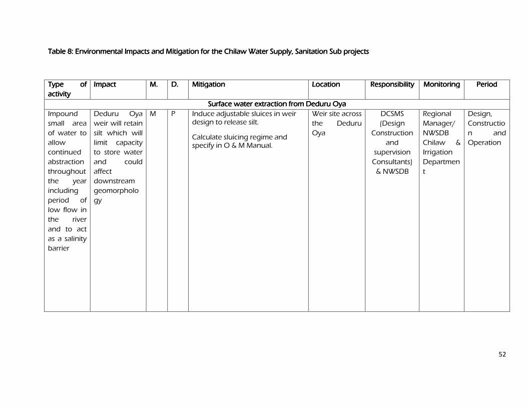
52
Table 8Table 8Table 8Table 8: : : : EnvironmeEnvironmeEnvironmeEnvironmental Impacts and Mitigation for thental Impacts and Mitigation for thental Impacts and Mitigation for thental Impacts and Mitigation for the Chilaw Water Supply, Sanitation Sub projects Chilaw Water Supply, Sanitation Sub projects Chilaw Water Supply, Sanitation Sub projects Chilaw Water Supply, Sanitation Sub projects
Type of Type of Type of Type of
activityactivityactivityactivity
ImpactImpactImpactImpact M.M.M.M. D.D.D.D. MitigationMitigationMitigationMitigation Location Location Location Location Responsibility Responsibility Responsibility Responsibility Monitoring Monitoring Monitoring Monitoring PeriodPeriodPeriodPeriod
Surface water extraction from Deduru Oya Surface water extraction from Deduru Oya Surface water extraction from Deduru Oya Surface water extraction from Deduru Oya
Impound
small area
of water to
allow
continued
abstraction
throughout
the year
including
period of
low flow in
the river
and to act
as a salinity
barrier
Deduru Oya
weir will retain
silt which will
limit capacity
to store water
and could
affect
downstream
geomorpholo
gy
M P Induce adjustable sluices in weir design to release silt.
Calculate sluicing regime and specify in O & M Manual.
Weir site across
the Deduru
Oya
DCSMS
(Design
Construction
and
supervision
Consultants)
& NWSDB
Regional
Manager/
NWSDB
Chilaw &
Irrigation
Departmen
t
Design,
Constructio
n and
Operation
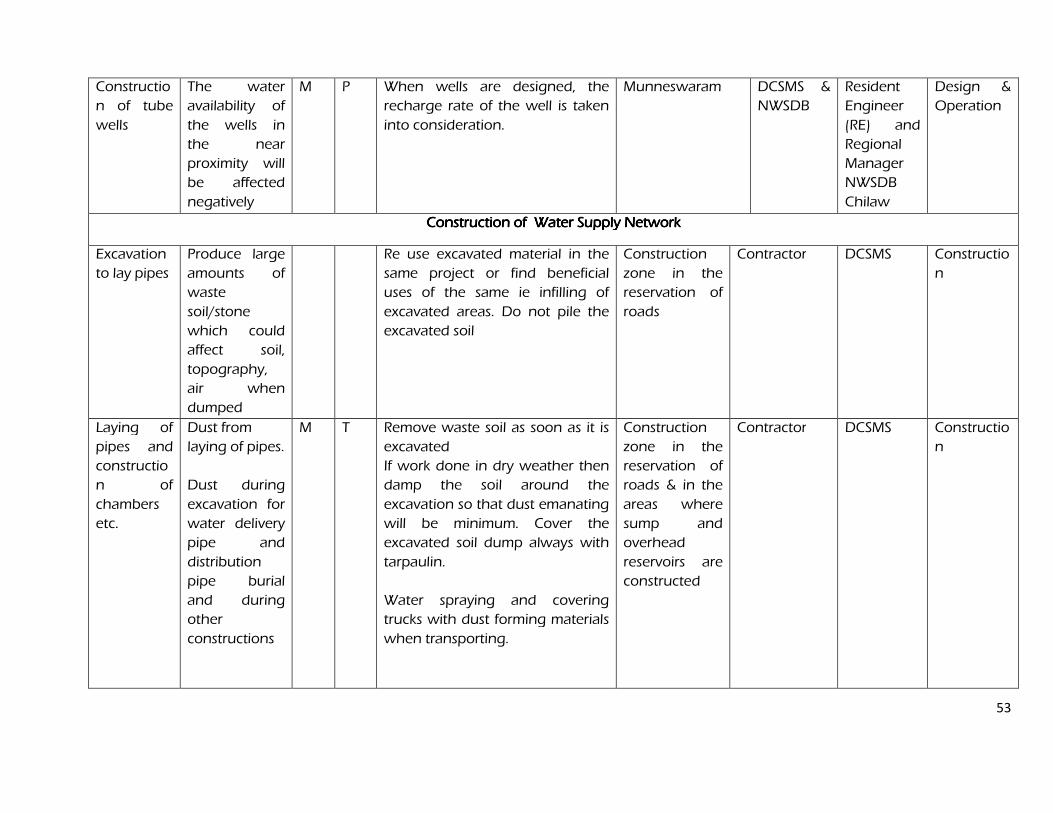
53
Constructio
n of tube
wells
The water
availability of
the wells in
the near
proximity will
be affected
negatively
M P When wells are designed, the
recharge rate of the well is taken
into consideration.
Munneswaram DCSMS &
NWSDB
Resident
Engineer
(RE) and
Regional
Manager
NWSDB
Chilaw
Design &
Operation
Construction of Water Supply NetworkConstruction of Water Supply NetworkConstruction of Water Supply NetworkConstruction of Water Supply Network
Excavation
to lay pipes
Produce large
amounts of
waste
soil/stone
which could
affect soil,
topography,
air when
dumped
Re use excavated material in the
same project or find beneficial
uses of the same ie infilling of
excavated areas. Do not pile the
excavated soil
Construction
zone in the
reservation of
roads
Contractor
DCSMS Constructio
n
Laying of
pipes and
constructio
n of
chambers
etc.
Dust from
laying of pipes.
Dust during
excavation for
water delivery
pipe and
distribution
pipe burial
and during
other
constructions
M T Remove waste soil as soon as it is
excavated
If work done in dry weather then
damp the soil around the
excavation so that dust emanating
will be minimum. Cover the
excavated soil dump always with
tarpaulin.
Water spraying and covering
trucks with dust forming materials
when transporting.
Construction
zone in the
reservation of
roads & in the
areas where
sump and
overhead
reservoirs are
constructed
Contractor DCSMS Constructio
n
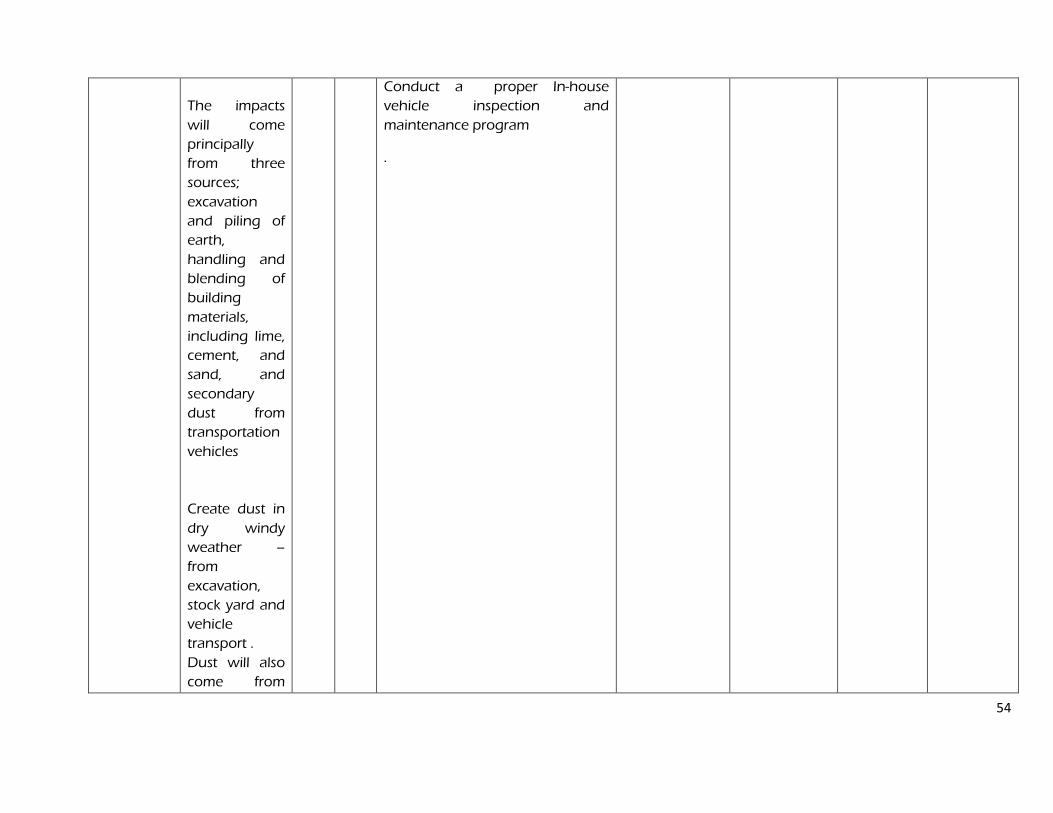
54
The impacts
will come
principally
from three
sources;
excavation
and piling of
earth,
handling and
blending of
building
materials,
including lime,
cement, and
sand, and
secondary
dust from
transportation
vehicles
Create dust in
dry windy
weather –
from
excavation,
stock yard and
vehicle
transport .
Dust will also
come from
Conduct a proper In-house
vehicle inspection and
maintenance program
.
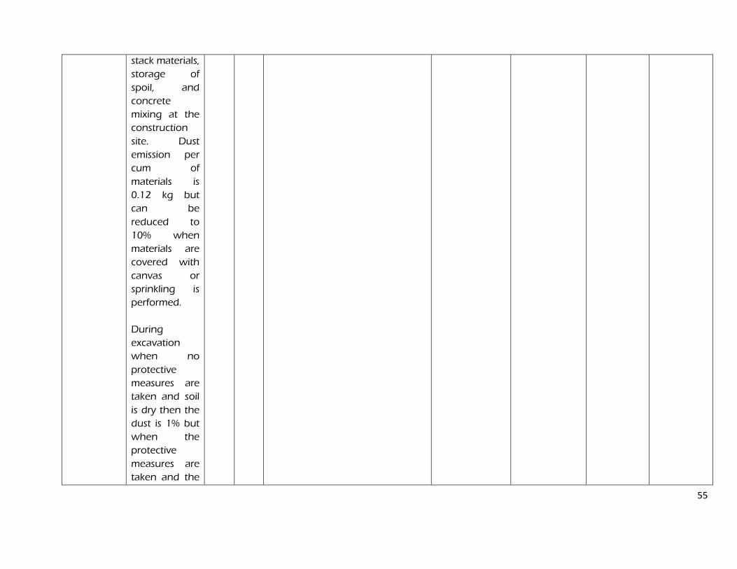
55
stack materials,
storage of
spoil, and
concrete
mixing at the
construction
site. Dust
emission per
cum of
materials is
0.12 kg but
can be
reduced to
10% when
materials are
covered with
canvas or
sprinkling is
performed.
During
excavation
when no
protective
measures are
taken and soil
is dry then the
dust is 1% but
when the
protective
measures are
taken and the
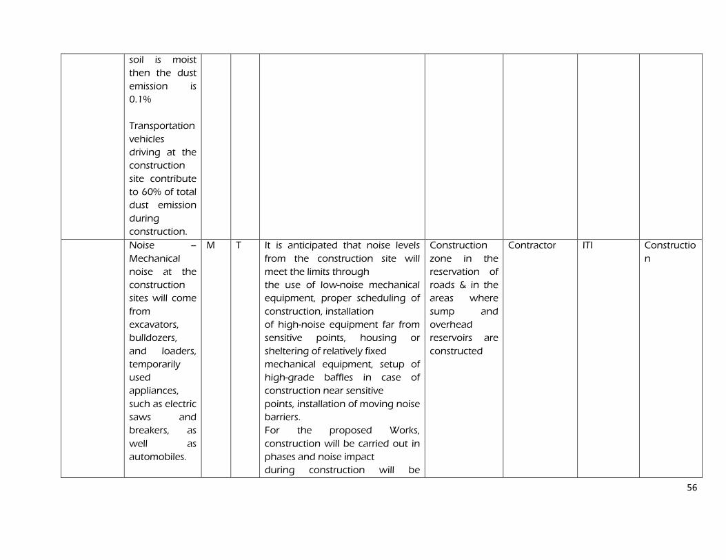
56
soil is moist
then the dust
emission is
0.1%
Transportation
vehicles
driving at the
construction
site contribute
to 60% of total
dust emission
during
construction.
Noise –
Mechanical
noise at the
construction
sites will come
from
excavators,
bulldozers,
and loaders,
temporarily
used
appliances,
such as electric
saws and
breakers, as
well as
automobiles.
M T It is anticipated that noise levels
from the construction site will
meet the limits through
the use of low-noise mechanical
equipment, proper scheduling of
construction, installation
of high-noise equipment far from
sensitive points, housing or
sheltering of relatively fixed
mechanical equipment, setup of
high-grade baffles in case of
construction near sensitive
points, installation of moving noise
barriers.
For the proposed Works,
construction will be carried out in
phases and noise impact
during construction will be
Construction
zone in the
reservation of
roads & in the
areas where
sump and
overhead
reservoirs are
constructed
Contractor ITI Constructio
n
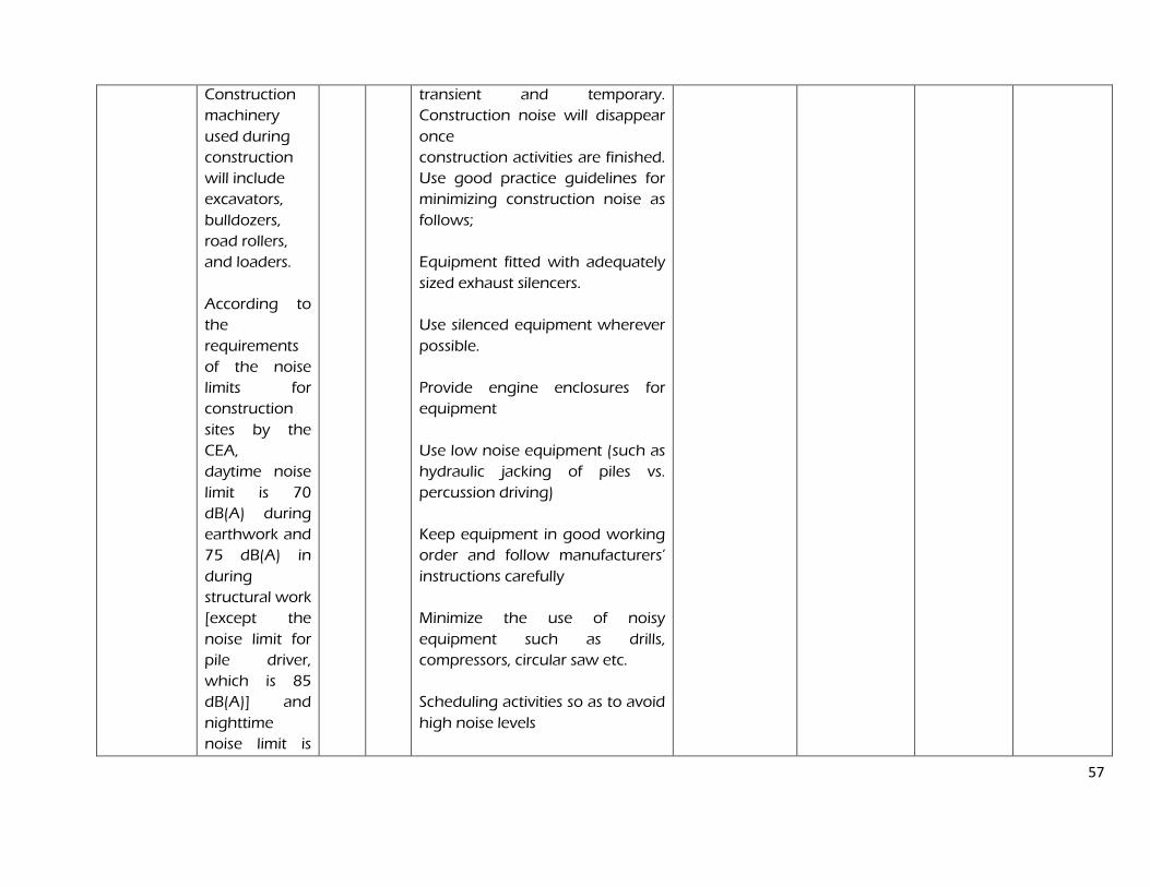
57
Construction
machinery
used during
construction
will include
excavators,
bulldozers,
road rollers,
and loaders.
According to
the
requirements
of the noise
limits for
construction
sites by the
CEA,
daytime noise
limit is 70
dB(A) during
earthwork and
75 dB(A) in
during
structural work
[except the
noise limit for
pile driver,
which is 85
dB(A)] and
nighttime
noise limit is
transient and temporary.
Construction noise will disappear
once
construction activities are finished.
Use good practice guidelines for
minimizing construction noise as
follows;
Equipment fitted with adequately
sized exhaust silencers.
Use silenced equipment wherever
possible.
Provide engine enclosures for
equipment
Use low noise equipment (such as
hydraulic jacking of piles vs.
percussion driving)
Keep equipment in good working
order and follow manufacturers’
instructions carefully
Minimize the use of noisy
equipment such as drills,
compressors, circular saw etc.
Scheduling activities so as to avoid
high noise levels
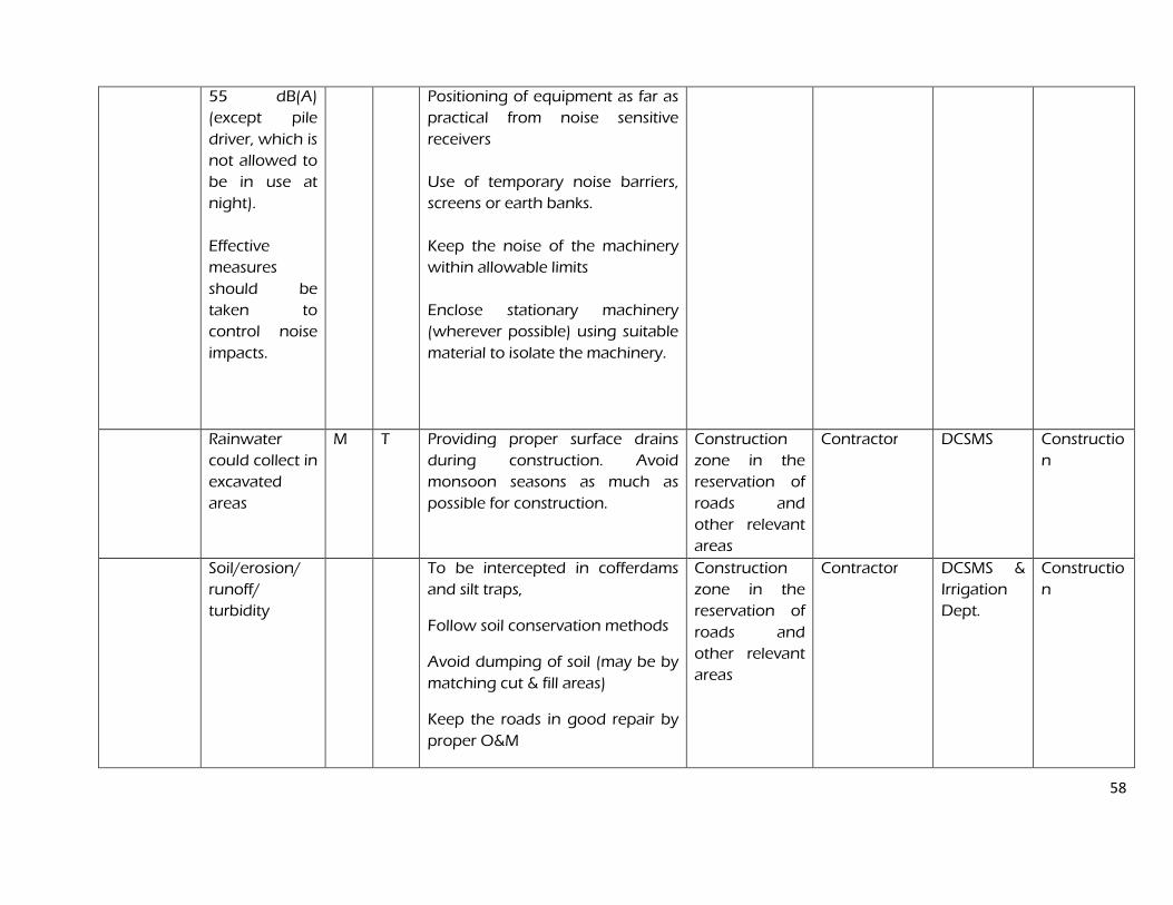
58
55 dB(A)
(except pile
driver, which is
not allowed to
be in use at
night).
Effective
measures
should be
taken to
control noise
impacts.
Positioning of equipment as far as
practical from noise sensitive
receivers
Use of temporary noise barriers,
screens or earth banks.
Keep the noise of the machinery
within allowable limits
Enclose stationary machinery
(wherever possible) using suitable
material to isolate the machinery.
Rainwater
could collect in
excavated
areas
M T Providing proper surface drains
during construction. Avoid
monsoon seasons as much as
possible for construction.
Construction
zone in the
reservation of
roads and
other relevant
areas
Contractor DCSMS Constructio
n
Soil/erosion/
runoff/
turbidity
To be intercepted in cofferdams
and silt traps,
Follow soil conservation methods
Avoid dumping of soil (may be by
matching cut & fill areas)
Keep the roads in good repair by
proper O&M
Construction
zone in the
reservation of
roads and
other relevant
areas
Contractor DCSMS &
Irrigation
Dept.
Constructio
n
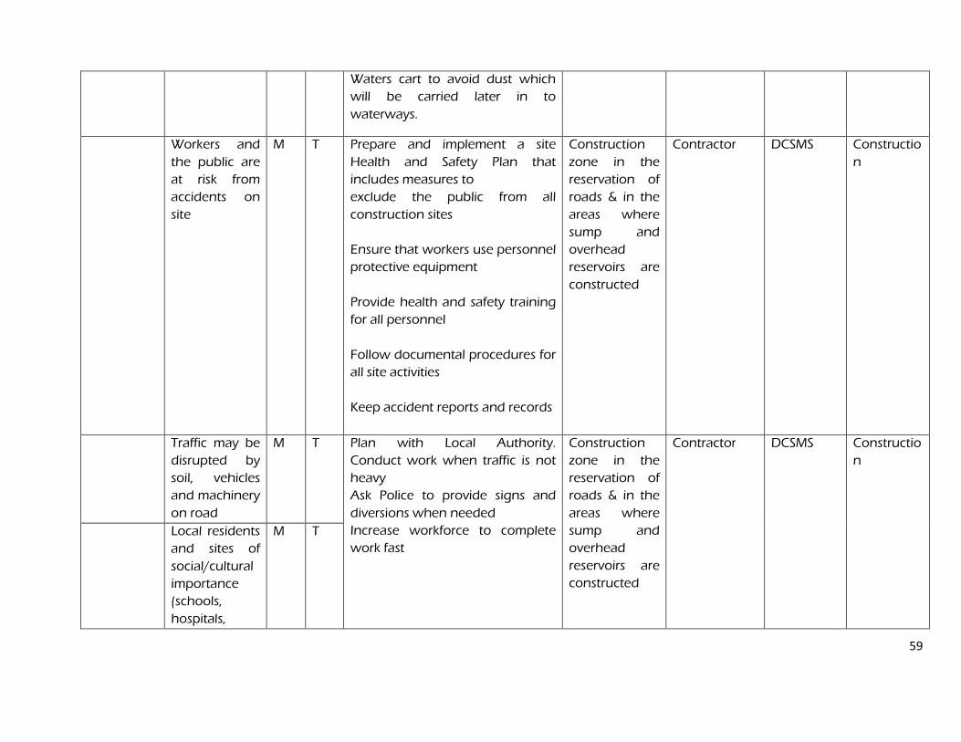
59
Waters cart to avoid dust which
will be carried later in to
waterways.
Workers and
the public are
at risk from
accidents on
site
M T Prepare and implement a site
Health and Safety Plan that
includes measures to
exclude the public from all
construction sites
Ensure that workers use personnel
protective equipment
Provide health and safety training
for all personnel
Follow documental procedures for
all site activities
Keep accident reports and records
Construction
zone in the
reservation of
roads & in the
areas where
sump and
overhead
reservoirs are
constructed
Contractor DCSMS Constructio
n
Traffic may be
disrupted by
soil, vehicles
and machinery
on road
M T Plan with Local Authority.
Conduct work when traffic is not
heavy
Ask Police to provide signs and
diversions when needed
Increase workforce to complete
work fast
Construction
zone in the
reservation of
roads & in the
areas where
sump and
overhead
reservoirs are
constructed
Contractor DCSMS Constructio
n
Local residents
and sites of
social/cultural
importance
(schools,
hospitals,
M T
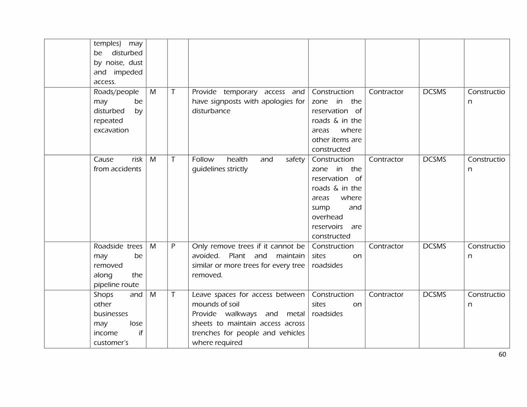
60
temples) may
be disturbed
by noise, dust
and impeded
access.
Roads/people
may be
disturbed by
repeated
excavation
M T Provide temporary access and
have signposts with apologies for
disturbance
Construction
zone in the
reservation of
roads & in the
areas where
other items are
constructed
Contractor DCSMS Constructio
n
Cause risk
from accidents
M T Follow health and safety
guidelines strictly
Construction
zone in the
reservation of
roads & in the
areas where
sump and
overhead
reservoirs are
constructed
Contractor DCSMS Constructio
n
Roadside trees
may be
removed
along the
pipeline route
M P Only remove trees if it cannot be
avoided. Plant and maintain
similar or more trees for every tree
removed.
Construction
sites on
roadsides
Contractor DCSMS Constructio
n
Shops and
other
businesses
may lose
income if
customer’s
M T Leave spaces for access between
mounds of soil
Provide walkways and metal
sheets to maintain access across
trenches for people and vehicles
where required
Construction
sites on
roadsides
Contractor DCSMS Constructio
n
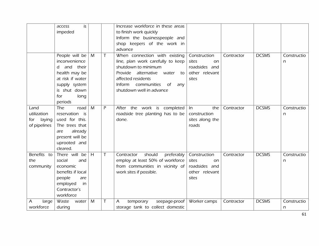
61
access is
impeded
Increase workforce in these areas
to finish work quickly
Inform the businesspeople and
shop keepers of the work in
advance
People will be
inconvenience
d and their
health may be
at risk if water
supply system
is shut down
for long
periods
M T When connection with existing
line, plan work carefully to keep
shutdown to minimum
Provide alternative water to
affected residents
Inform communities of any
shutdown well in advance
Construction
sites on
roadsides and
other relevant
sites
Contractor DCSMS Constructio
n
Land
utilization
for laying
of pipelines
The road
reservation is
used for this.
The trees that
are already
present will be
uprooted and
cleared.
M P After the work is completed
roadside tree planting has to be
done.
In the
construction
sites along the
roads
Contractor DCSMS Constructio
n
Benefits to
the
community
There will be
social and
economic
benefits if local
people are
employed in
Contractor’s
workforce
H T Contractor should preferably
employ at least 50% of workforce
from communities in vicinity of
work sites if possible.
Construction
sites on
roadsides and
other relevant
sites
Contractor
DCSMS Constructio
n
A large
workforce
Waste water
during
M T A temporary seepage-proof
storage tank to collect domestic
Worker camps Contractor DCSMS Constructio
n
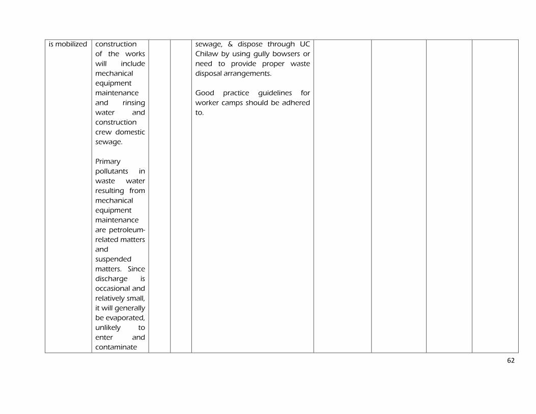
62
is mobilized construction
of the works
will include
mechanical
equipment
maintenance
and rinsing
water and
construction
crew domestic
sewage.
Primary
pollutants in
waste water
resulting from
mechanical
equipment
maintenance
are petroleum-
related matters
and
suspended
matters. Since
discharge is
occasional and
relatively small,
it will generally
be evaporated,
unlikely to
enter and
contaminate
sewage, & dispose through UC
Chilaw by using gully bowsers or
need to provide proper waste
disposal arrangements.
Good practice guidelines for
worker camps should be adhered
to.
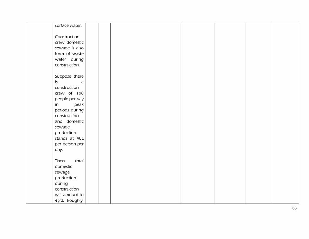
63
surface water.
Construction
crew domestic
sewage is also
form of waste
water during
construction.
Suppose there
is a
construction
crew of 100
people per day
in peak
periods during
construction
and domestic
sewage
production
stands at 40L
per person per
day.
Then total
domestic
sewage
production
during
construction
will amount to
4t/d. Roughly,
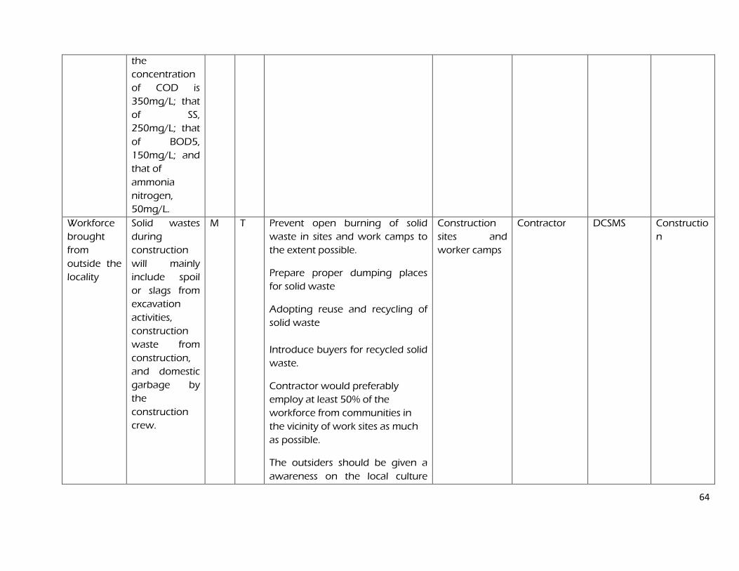
64
the
concentration
of COD is
350mg/L; that
of SS,
250mg/L; that
of BOD5,
150mg/L; and
that of
ammonia
nitrogen,
50mg/L.
Workforce
brought
from
outside the
locality
Solid wastes
during
construction
will mainly
include spoil
or slags from
excavation
activities,
construction
waste from
construction,
and domestic
garbage by
the
construction
crew.
M T Prevent open burning of solid
waste in sites and work camps to
the extent possible.
Prepare proper dumping places
for solid waste
Adopting reuse and recycling of
solid waste
Introduce buyers for recycled solid
waste.
Contractor would preferably
employ at least 50% of the
workforce from communities in
the vicinity of work sites as much
as possible.
The outsiders should be given a
awareness on the local culture
Construction
sites and
worker camps
Contractor DCSMS Constructio
n
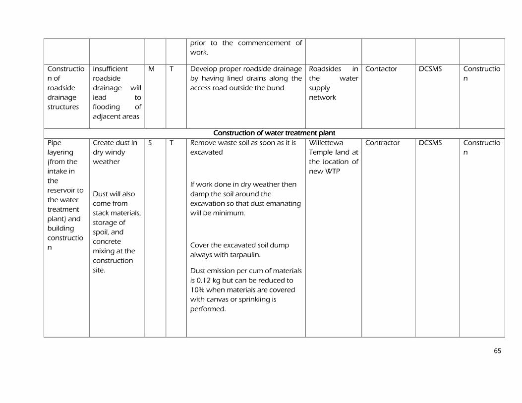
65
prior to the commencement of
work.
Constructio
n of
roadside
drainage
structures
Insufficient
roadside
drainage will
lead to
flooding of
adjacent areas
M T Develop proper roadside drainage
by having lined drains along the
access road outside the bund
Roadsides in
the water
supply
network
Contactor DCSMS Constructio
n
Construction of water treatment plantConstruction of water treatment plantConstruction of water treatment plantConstruction of water treatment plant
Pipe
layering
(from the
intake in
the
reservoir to
the water
treatment
plant) and
building
constructio
n
Create dust in
dry windy
weather
Dust will also
come from
stack materials,
storage of
spoil, and
concrete
mixing at the
construction
site.
S T Remove waste soil as soon as it is
excavated
If work done in dry weather then
damp the soil around the
excavation so that dust emanating
will be minimum.
Cover the excavated soil dump
always with tarpaulin.
Dust emission per cum of materials
is 0.12 kg but can be reduced to
10% when materials are covered
with canvas or sprinkling is
performed.
Willettewa
Temple land at
the location of
new WTP
Contractor DCSMS Constructio
n

66
During excavation when no
protective measures are taken and
soil is dry then the dust is 1% but
when the protective measures are
taken and the soil is moist then the
dust emission is 0.1%
Transportation vehicles driving at
the construction site contribute to
60% of total dust emission during
construction
Noise -
Mechanical
noise at the
construction
site will come
from
excavators,
bulldozers,
and
loaders,
temporarily
used
appliances,
such as electric
saws and
breakers, as
well as
automobiles.
As this is a
S T equipment far from sensitive
points, housing or sheltering of
relatively fixed mechanical
equipment, setup of high-grade
baffles in case of construction near
sensitive points, installation of
moving noise barriers, and
prohibition of construction at
night.
For the proposed Works,
construction will be carried out in
phases and noise impact
during construction will be
transient and temporary.
Construction noise will disappear
once
construction activities are finished
WTP plant site Contractor DCSMS Constructio
n
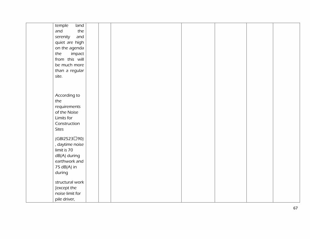
67
temple land
and the
serenity and
quiet are high
on the agenda
the impact
from this will
be much more
than a regular
site.
According to
the
requirements
of the Noise
Limits for
Construction
Sites
(GBl2523T90)
, daytime noise
limit is 70
dB(A) during
earthwork and
75 dB(A) in
during
structural work
[except the
noise limit for
pile driver,
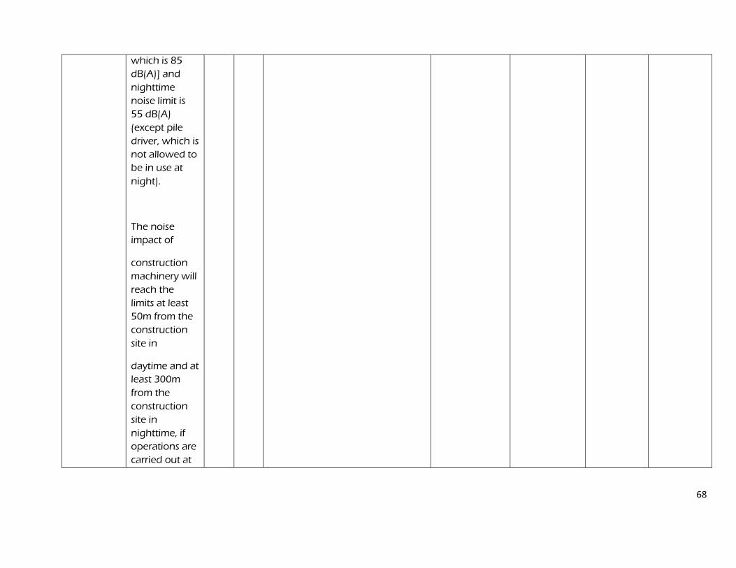
68
which is 85
dB(A)] and
nighttime
noise limit is
55 dB(A)
(except pile
driver, which is
not allowed to
be in use at
night).
The noise
impact of
construction
machinery will
reach the
limits at least
50m from the
construction
site in
daytime and at
least 300m
from the
construction
site in
nighttime, if
operations are
carried out at
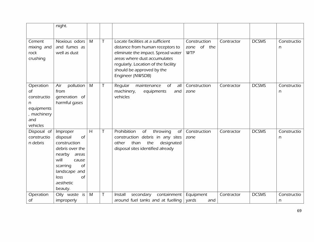
69
night.
Cement
mixing and
rock
crushing
Noxious odors
and fumes as
well as dust
M T Locate facilities at a sufficient
distance from human receptors to
eliminate the impact. Spread water
areas where dust accumulates
regularly. Location of the facility
should be approved by the
Engineer (NWSDB)
Construction
zone of the
WTP
Contractor DCSMS Constructio
n
Operation
of
constructio
n
equipments
, machinery
and
vehicles
Air pollution
from
generation of
harmful gases
M T Regular maintenance of all
machinery, equipments and
vehicles
Construction
zone
Contractor DCSMS Constructio
n
Disposal of
constructio
n debris
Improper
disposal of
construction
debris over the
nearby areas
will cause
scarring of
landscape and
loss of
aesthetic
beauty.
H T Prohibition of throwing of
construction debris in any sites
other than the designated
disposal sites identified already
Construction
zone
Contractor DCSMS Constructio
n
Operation
of
Oily waste is
improperly
M T Install secondary containment
around fuel tanks and at fuelling
Equipment
yards and
Contractor DCSMS Constructio
n
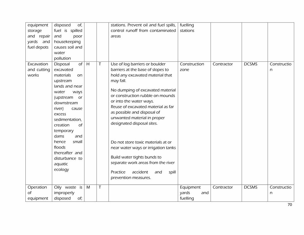
70
equipment
storage
and repair
yards and
fuel depots
disposed of,
fuel is spilled
and poor
housekeeping
causes soil and
water
pollution
stations. Prevent oil and fuel spills,
control runoff from contaminated
areas
fuelling
stations
Excavation
and cutting
works
Disposal of
excavated
materials on
upstream
lands and near
water ways
(upstream or
downstream
river) cause
excess
sedimentation,
creation of
temporary
dams and
hence small
floods
thereafter and
disturbance to
aquatic
ecology
H T Use of log barriers or boulder
barriers at the base of slopes to
hold any excavated material that
may fall.
No dumping of excavated material
or construction rubble on mounds
or into the water ways.
Reuse of excavated material as far
as possible and disposal of
unwanted material in proper
designated disposal sites.
Do not store toxic materials at or
near water ways or irrigation tanks
Build water tights bunds to
separate work areas from the river
Practice accident and spill
prevention measures.
Construction
zone
Contractor DCSMS Constructio
n
Operation
of
equipment
Oily waste is
improperly
disposed of;
M T Equipment
yards and
fuelling
Contractor DCSMS Constructio
n
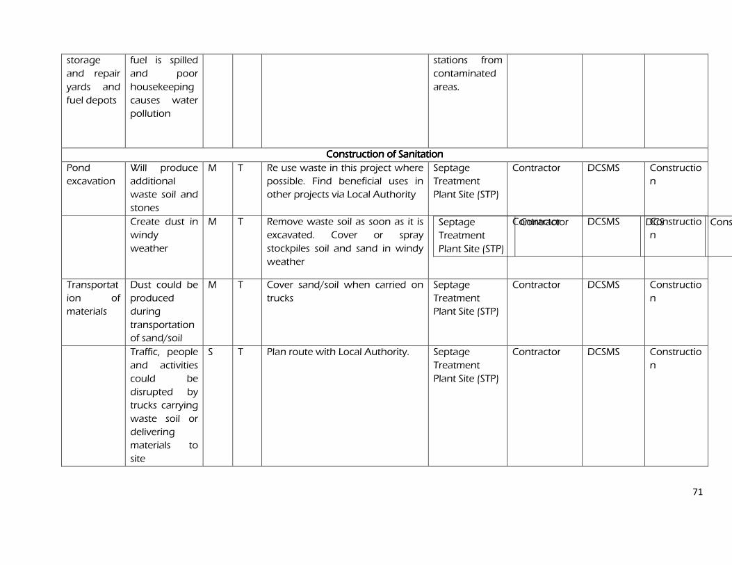
71
storage
and repair
yards and
fuel depots
fuel is spilled
and poor
housekeeping
causes water
pollution
stations from
contaminated
areas.
ConConConConstruction of Sanitationstruction of Sanitationstruction of Sanitationstruction of Sanitation
Pond
excavation
Will produce
additional
waste soil and
stones
M T Re use waste in this project where
possible. Find beneficial uses in
other projects via Local Authority
Septage
Treatment
Plant Site (STP)
Contractor DCSMS Constructio
n
Create dust in
windy
weather
M T Remove waste soil as soon as it is
excavated. Cover or spray
stockpiles soil and sand in windy
weather
Septage
Treatment
Plant Site (STP)
Contractor DCS Construction
Contractor
DCSMS Constructio
n
Transportat
ion of
materials
Dust could be
produced
during
transportation
of sand/soil
M T Cover sand/soil when carried on
trucks
Septage
Treatment
Plant Site (STP)
Contractor DCSMS Constructio
n
Traffic, people
and activities
could be
disrupted by
trucks carrying
waste soil or
delivering
materials to
site
S T Plan route with Local Authority. Septage
Treatment
Plant Site (STP)
Contractor DCSMS Constructio
n
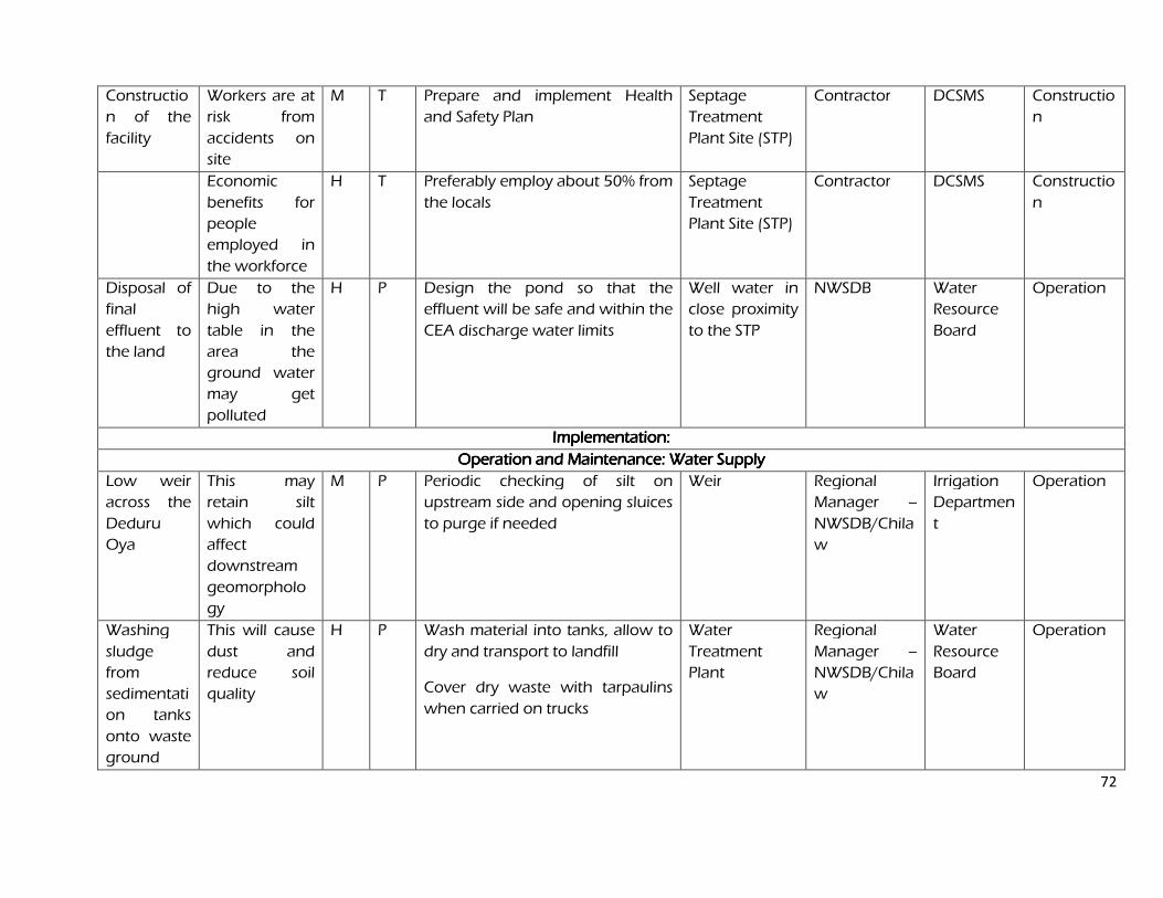
72
Constructio
n of the
facility
Workers are at
risk from
accidents on
site
M T Prepare and implement Health
and Safety Plan
Septage
Treatment
Plant Site (STP)
Contractor DCSMS Constructio
n
Economic
benefits for
people
employed in
the workforce
H T Preferably employ about 50% from
the locals
Septage
Treatment
Plant Site (STP)
Contractor DCSMS Constructio
n
Disposal of
final
effluent to
the land
Due to the
high water
table in the
area the
ground water
may get
polluted
H P Design the pond so that the
effluent will be safe and within the
CEA discharge water limits
Well water in
close proximity
to the STP
NWSDB Water
Resource
Board
Operation
Implementation: Implementation: Implementation: Implementation:
Operation and Maintenance: Water SupplyOperation and Maintenance: Water SupplyOperation and Maintenance: Water SupplyOperation and Maintenance: Water Supply
Low weir
across the
Deduru
Oya
This may
retain silt
which could
affect
downstream
geomorpholo
gy
M P Periodic checking of silt on
upstream side and opening sluices
to purge if needed
Weir Regional
Manager –
NWSDB/Chila
w
Irrigation
Departmen
t
Operation
Washing
sludge
from
sedimentati
on tanks
onto waste
ground
This will cause
dust and
reduce soil
quality
H P Wash material into tanks, allow to
dry and transport to landfill
Cover dry waste with tarpaulins
when carried on trucks
Water
Treatment
Plant
Regional
Manager –
NWSDB/Chila
w
Water
Resource
Board
Operation
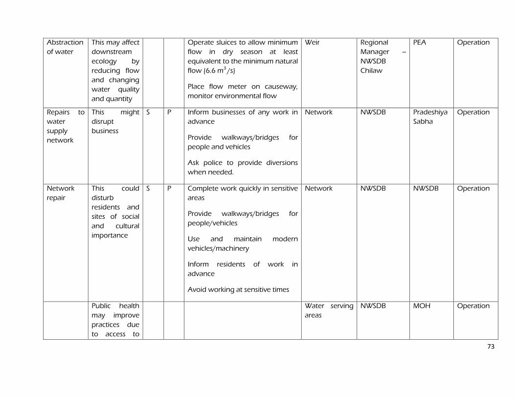
73
Abstraction
of water
This may affect
downstream
ecology by
reducing flow
and changing
water quality
and quantity
Operate sluices to allow minimum
flow in dry season at least
equivalent to the minimum natural
flow (6.6 m3 /s)
Place flow meter on causeway,
monitor environmental flow
Weir Regional
Manager –
NWSDB
Chilaw
PEA Operation
Repairs to
water
supply
network
This might
disrupt
business
S P Inform businesses of any work in
advance
Provide walkways/bridges for
people and vehicles
Ask police to provide diversions
when needed.
Network NWSDB Pradeshiya
Sabha
Operation
Network
repair
This could
disturb
residents and
sites of social
and cultural
importance
S P Complete work quickly in sensitive
areas
Provide walkways/bridges for
people/vehicles
Use and maintain modern
vehicles/machinery
Inform residents of work in
advance
Avoid working at sensitive times
Network NWSDB NWSDB Operation
Public health
may improve
practices due
to access to
Water serving
areas
NWSDB MOH Operation
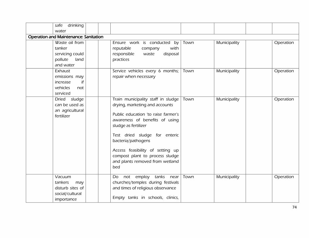
74
safe drinking
water
Operation and Maintenance: SanitOperation and Maintenance: SanitOperation and Maintenance: SanitOperation and Maintenance: Sanitation ation ation ation
Waste oil from
tanker
servicing could
pollute land
and water
Ensure work is conducted by
reputable company with
responsible waste disposal
practices
Town Municipality Operation
Exhaust
emissions may
increase if
vehicles not
serviced
Service vehicles every 6 months;
repair when necessary
Town Municipality Operation
Dried sludge
can be used as
an agricultural
fertilizer
Train municipality staff in sludge
drying, marketing and accounts
Public education ‘to raise farmer’s
awareness of benefits of using
sludge as fertilizer
Test dried sludge for enteric
bacteria/pathogens
Access feasibility of setting up
compost plant to process sludge
and plants removed from wetland
bed
Town Municipality Operation
Vacuum
tankers may
disturb sites of
social/cultural
importance
Do not employ tanks near
churches/temples during festivals
and times of religious observance
Empty tanks in schools, clinics,
Town Municipality Operation
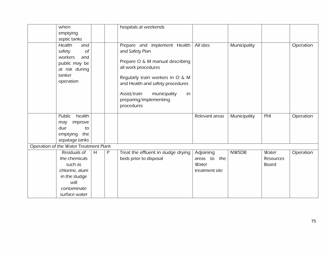
75
when
emptying
septic tanks
hospitals at weekends
Health and
safety of
workers and
public may be
at risk during
tanker
operation
Prepare and implement Health
and Safety Plan
Prepare O & M manual describing
all work procedures
Regularly train workers in O & M
and Health and safety procedures
Assist/train municipality in
preparing/implementing
procedures
All sites Municipality Operation
Public health
may improve
due to
emptying the
sepatage tanks
Relevant areas Municipality
PHI Operation
Operation of the Water Treatment Plant
Residuals of
the chemicals
such as
chlorine, alum
in the sludge
will
contaminate
surface water
H P Treat the effluent in sludge drying
beds prior to disposal
Adjoining
areas to the
Water
treatment site
NWSDB Water
Resources
Board
Operation
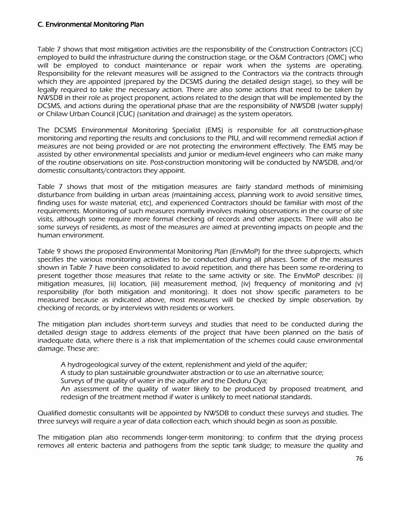
76
C. Environmental MC. Environmental MC. Environmental MC. Environmental Monitoring Plan onitoring Plan onitoring Plan onitoring Plan
Table 7 shows that most mitigation activities are the responsibility of the Construction Contractors (CC) employed to build the infrastructure during the construction stage, or the O&M Contractors (OMC) who will be employed to conduct maintenance or repair work when the systems are operating. Responsibility for the relevant measures will be assigned to the Contractors via the contracts through which they are appointed (prepared by the DCSMS during the detailed design stage), so they will be legally required to take the necessary action. There are also some actions that need to be taken by NWSDB in their role as project proponent, actions related to the design that will be implemented by the DCSMS, and actions during the operational phase that are the responsibility of NWSDB (water supply) or Chilaw Urban Council (CUC) (sanitation and drainage) as the system operators. The DCSMS Environmental Monitoring Specialist (EMS) is responsible for all construction-phase monitoring and reporting the results and conclusions to the PIU, and will recommend remedial action if measures are not being provided or are not protecting the environment effectively. The EMS may be assisted by other environmental specialists and junior or medium-level engineers who can make many of the routine observations on site. Post-construction monitoring will be conducted by NWSDB, and/or domestic consultants/contractors they appoint. Table 7 shows that most of the mitigation measures are fairly standard methods of minimising disturbance from building in urban areas (maintaining access, planning work to avoid sensitive times, finding uses for waste material, etc), and experienced Contractors should be familiar with most of the requirements. Monitoring of such measures normally involves making observations in the course of site visits, although some require more formal checking of records and other aspects. There will also be some surveys of residents, as most of the measures are aimed at preventing impacts on people and the human environment. Table 9 shows the proposed Environmental Monitoring Plan (EnvMoP) for the three subprojects, which specifies the various monitoring activities to be conducted during all phases. Some of the measures shown in Table 7 have been consolidated to avoid repetition, and there has been some re-ordering to present together those measures that relate to the same activity or site. The EnvMoP describes: (i) mitigation measures, (ii) location, (iii) measurement method, (iv) frequency of monitoring and (v) responsibility (for both mitigation and monitoring). It does not show specific parameters to be measured because as indicated above, most measures will be checked by simple observation, by checking of records, or by interviews with residents or workers. The mitigation plan includes short-term surveys and studies that need to be conducted during the detailed design stage to address elements of the project that have been planned on the basis of inadequate data, where there is a risk that implementation of the schemes could cause environmental damage. These are:
A hydrogeological survey of the extent, replenishment and yield of the aquifer; A study to plan sustainable groundwater abstraction or to use an alternative source; Surveys of the quality of water in the aquifer and the Deduru Oya; An assessment of the quality of water likely to be produced by proposed treatment, and
redesign of the treatment method if water is unlikely to meet national standards. Qualified domestic consultants will be appointed by NWSDB to conduct these surveys and studies. The three surveys will require a year of data collection each, which should begin as soon as possible. The mitigation plan also recommends longer-term monitoring: to confirm that the drying process removes all enteric bacteria and pathogens from the septic tank sludge; to measure the quality and
77
quantity of treatment plant effluent; and to determine its impact on water quality in the lagoon. Given the scale of the investment in providing infrastructure, NWSDB will also wish to conduct surveys during the operational period to ensure that the water treatment method is providing water of the required quality, and to confirm the lasting benefits of the schemes. The following aspects will thus be monitored over the long term: Bacteriological content of dried sewage sludge Chemical and bacteriological quality of treated STF effluent Chemical and bacteriological quality of water in wells adjacent to the STP Health of the population and the prevalence of diseases due to poor water quality and
sanitation.
These surveys should be conducted for at least four years. The quality of the sewage sludge, Septage Treatment Facility (STF) effluent and receiving water will be checked each week for the first three months, then every 6 months for the next 3 ¾ years (20 surveys in total). The other surveys will all require monitoring at six-monthly intervals during the final year of construction (to establish baseline conditions) and during the first three years of operation of each scheme (8 surveys each). The survey on population health will be conducted in the first and final year of the project.
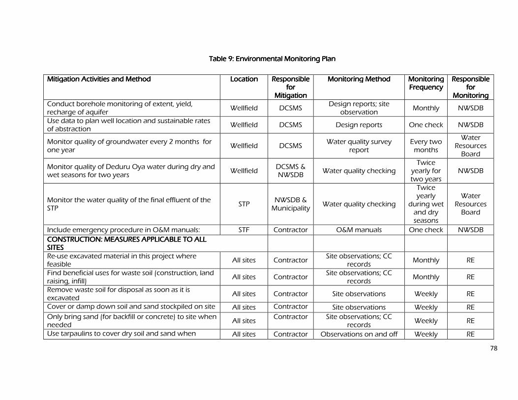
78
Table 9: Environmental Monitoring Plan Table 9: Environmental Monitoring Plan Table 9: Environmental Monitoring Plan Table 9: Environmental Monitoring Plan
Mitigation ActivMitigation ActivMitigation ActivMitigation Activities and Method ities and Method ities and Method ities and Method Location Location Location Location Responsible Responsible Responsible Responsible for for for for
Mitigation Mitigation Mitigation Mitigation
Monitoring Method Monitoring Method Monitoring Method Monitoring Method Monitoring Monitoring Monitoring Monitoring Frequency Frequency Frequency Frequency
Responsible Responsible Responsible Responsible for for for for
Monitoring Monitoring Monitoring Monitoring Conduct borehole monitoring of extent, yield, recharge of aquifer
Wellfield DCSMS Design reports; site observation
Monthly NWSDB
Use data to plan well location and sustainable rates of abstraction
Wellfield DCSMS Design reports One check NWSDB
Monitor quality of groundwater every 2 months for one year
Wellfield DCSMS Water quality survey
report Every two months
Water Resources Board
Monitor quality of Deduru Oya water during dry and wet seasons for two years
Wellfield DCSMS & NWSDB
Water quality checking Twice yearly for two years
NWSDB
Monitor the water quality of the final effluent of the STP
STP NWSDB & Municipality
Water quality checking
Twice yearly
during wet and dry seasons
Water Resources Board
Include emergency procedure in O&M manuals: STF Contractor O&M manuals One check NWSDB
CONSTRUCTION: MEASURES APPLICABLE TO ALL CONSTRUCTION: MEASURES APPLICABLE TO ALL CONSTRUCTION: MEASURES APPLICABLE TO ALL CONSTRUCTION: MEASURES APPLICABLE TO ALL SITES SITES SITES SITES
Re-use excavated material in this project where feasible
All sites Contractor Site observations; CC
records Monthly RE
Find beneficial uses for waste soil (construction, land raising, infill)
All sites Contractor Site observations; CC
records Monthly RE
Remove waste soil for disposal as soon as it is excavated
All sites Contractor Site observations Weekly RE
Cover or damp down soil and sand stockpiled on site All sites Contractor Site observations Weekly RE
Only bring sand (for backfill or concrete) to site when needed
All sites Contractor Site observations; CC
records Weekly RE
Use tarpaulins to cover dry soil and sand when All sites Contractor Observations on and off Weekly RE
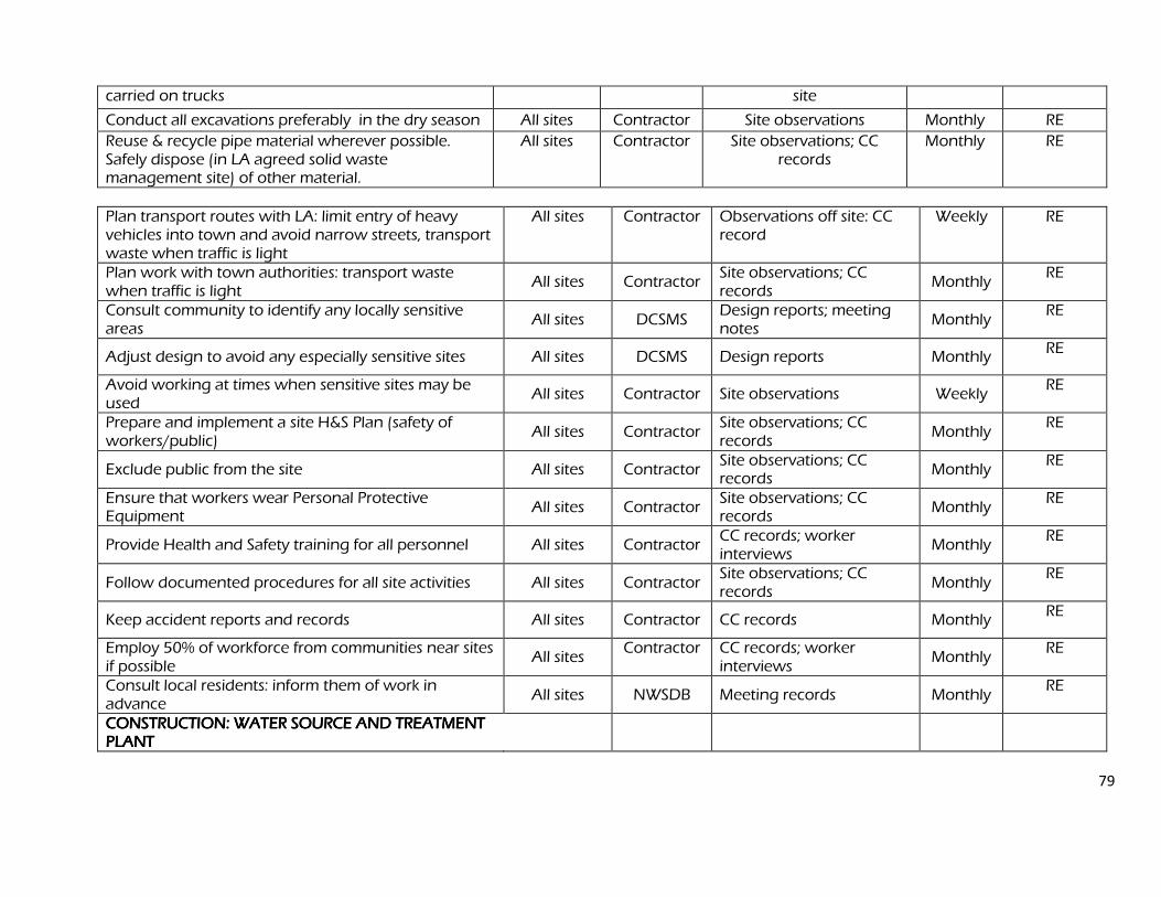
79
carried on trucks site
Conduct all excavations preferably in the dry season All sites Contractor Site observations Monthly RE
Reuse & recycle pipe material wherever possible. Safely dispose (in LA agreed solid waste management site) of other material.
All sites Contractor Site observations; CC records
Monthly RE
Plan transport routes with LA: limit entry of heavy vehicles into town and avoid narrow streets, transport waste when traffic is light
All sites Contractor Observations off site: CC record
Weekly RE
Plan work with town authorities: transport waste when traffic is light
All sites Contractor Site observations; CC records
Monthly RE
Consult community to identify any locally sensitive areas
All sites DCSMS Design reports; meeting notes
Monthly RE
Adjust design to avoid any especially sensitive sites All sites DCSMS Design reports Monthly RE
Avoid working at times when sensitive sites may be used
All sites Contractor Site observations Weekly RE
Prepare and implement a site H&S Plan (safety of workers/public)
All sites Contractor Site observations; CC records
Monthly RE
Exclude public from the site All sites Contractor Site observations; CC records
Monthly RE
Ensure that workers wear Personal Protective Equipment
All sites Contractor Site observations; CC records
Monthly RE
Provide Health and Safety training for all personnel All sites Contractor CC records; worker interviews
Monthly RE
Follow documented procedures for all site activities All sites Contractor Site observations; CC records
Monthly RE
Keep accident reports and records All sites Contractor CC records Monthly RE
Employ 50% of workforce from communities near sites if possible
All sites Contractor CC records; worker
interviews Monthly
RE
Consult local residents: inform them of work in advance
All sites NWSDB Meeting records Monthly RE
CONSTRUCTION: WATER SOURCE AND TREATMENT CONSTRUCTION: WATER SOURCE AND TREATMENT CONSTRUCTION: WATER SOURCE AND TREATMENT CONSTRUCTION: WATER SOURCE AND TREATMENT PLANT PLANT PLANT PLANT
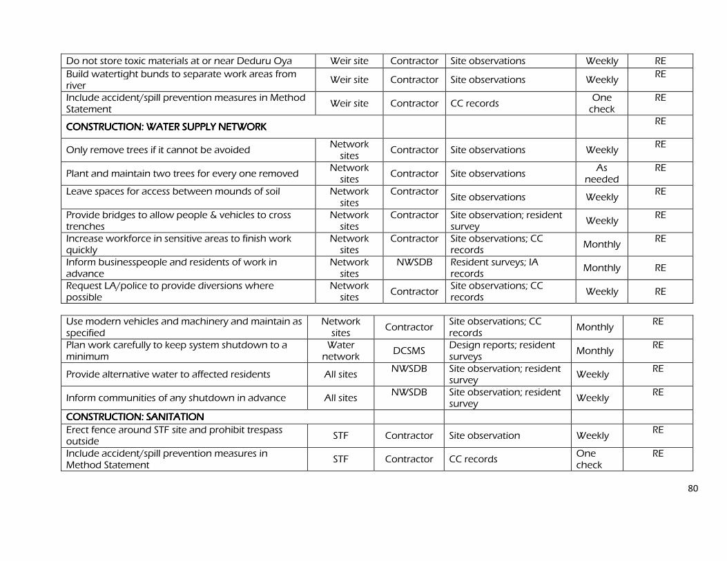
80
Do not store toxic materials at or near Deduru Oya Weir site Contractor Site observations Weekly RE
Build watertight bunds to separate work areas from river
Weir site Contractor Site observations Weekly RE
Include accident/spill prevention measures in Method Statement
Weir site Contractor CC records One check
RE
CONSTRUCTION: WATER SUPPLY NETWORK CONSTRUCTION: WATER SUPPLY NETWORK CONSTRUCTION: WATER SUPPLY NETWORK CONSTRUCTION: WATER SUPPLY NETWORK RE
Only remove trees if it cannot be avoided Network sites
Contractor Site observations Weekly RE
Plant and maintain two trees for every one removed Network sites
Contractor Site observations As
needed RE
Leave spaces for access between mounds of soil Network sites
Contractor Site observations Weekly
RE
Provide bridges to allow people & vehicles to cross trenches
Network sites
Contractor Site observation; resident survey
Weekly RE
Increase workforce in sensitive areas to finish work quickly
Network sites
Contractor Site observations; CC records
Monthly RE
Inform businesspeople and residents of work in advance
Network sites
NWSDB Resident surveys; IA records
Monthly RE
Request LA/police to provide diversions where possible
Network sites
Contractor Site observations; CC records
Weekly RE
Use modern vehicles and machinery and maintain as specified
Network sites
Contractor Site observations; CC records
Monthly RE
Plan work carefully to keep system shutdown to a minimum
Water network
DCSMS Design reports; resident surveys
Monthly RE
Provide alternative water to affected residents All sites NWSDB Site observation; resident
survey Weekly
RE
Inform communities of any shutdown in advance All sites NWSDB Site observation; resident
survey Weekly
RE
CONSTRUCTION: SANITATION CONSTRUCTION: SANITATION CONSTRUCTION: SANITATION CONSTRUCTION: SANITATION
Erect fence around STF site and prohibit trespass outside
STF Contractor Site observation Weekly RE
Include accident/spill prevention measures in Method Statement
STF Contractor CC records One check
RE
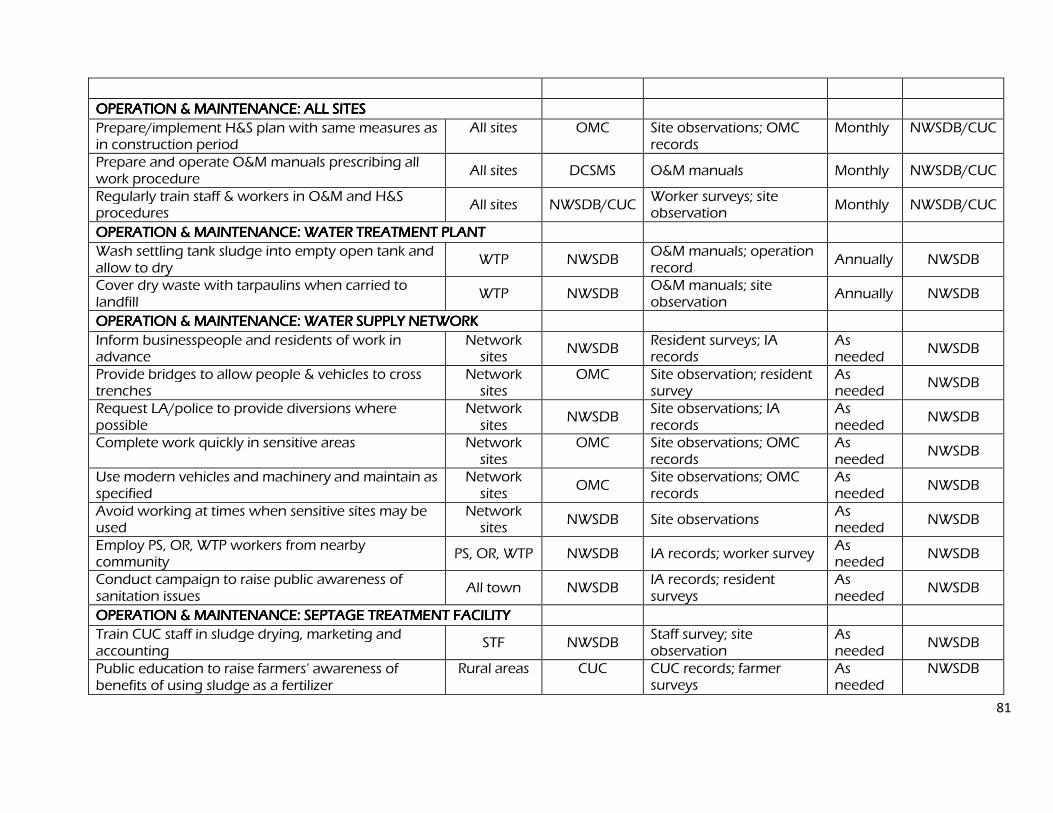
81
OPERATION & MAINTENANCE: ALL SITES OPERATION & MAINTENANCE: ALL SITES OPERATION & MAINTENANCE: ALL SITES OPERATION & MAINTENANCE: ALL SITES
Prepare/implement H&S plan with same measures as in construction period
All sites OMC Site observations; OMC records
Monthly NWSDB/CUC
Prepare and operate O&M manuals prescribing all work procedure
All sites DCSMS O&M manuals Monthly NWSDB/CUC
Regularly train staff & workers in O&M and H&S procedures
All sites NWSDB/CUC Worker surveys; site observation
Monthly NWSDB/CUC
OPERATION & MAINTENANCE: WATER TREATMENT PLANT OPERATION & MAINTENANCE: WATER TREATMENT PLANT OPERATION & MAINTENANCE: WATER TREATMENT PLANT OPERATION & MAINTENANCE: WATER TREATMENT PLANT
Wash settling tank sludge into empty open tank and allow to dry
WTP NWSDB O&M manuals; operation record
Annually NWSDB
Cover dry waste with tarpaulins when carried to landfill
WTP NWSDB O&M manuals; site observation
Annually NWSDB
OPERATION & MAINTENANCOPERATION & MAINTENANCOPERATION & MAINTENANCOPERATION & MAINTENANCE: WATER SUPPLY NETWORK E: WATER SUPPLY NETWORK E: WATER SUPPLY NETWORK E: WATER SUPPLY NETWORK
Inform businesspeople and residents of work in advance
Network sites
NWSDB Resident surveys; IA records
As needed
NWSDB
Provide bridges to allow people & vehicles to cross trenches
Network sites
OMC Site observation; resident survey
As needed
NWSDB
Request LA/police to provide diversions where possible
Network sites
NWSDB Site observations; IA records
As needed
NWSDB
Complete work quickly in sensitive areas Network sites
OMC Site observations; OMC records
As needed
NWSDB
Use modern vehicles and machinery and maintain as specified
Network sites
OMC Site observations; OMC records
As needed
NWSDB
Avoid working at times when sensitive sites may be used
Network sites
NWSDB Site observations As needed
NWSDB
Employ PS, OR, WTP workers from nearby community
PS, OR, WTP NWSDB IA records; worker survey As needed
NWSDB
Conduct campaign to raise public awareness of sanitation issues
All town NWSDB IA records; resident surveys
As needed
NWSDB
OPERATION & MAINTENANCE: SEPTAGE TREATMENT FACILITY OPERATION & MAINTENANCE: SEPTAGE TREATMENT FACILITY OPERATION & MAINTENANCE: SEPTAGE TREATMENT FACILITY OPERATION & MAINTENANCE: SEPTAGE TREATMENT FACILITY
Train CUC staff in sludge drying, marketing and accounting
STF NWSDB Staff survey; site observation
As needed
NWSDB
Public education to raise farmers’ awareness of benefits of using sludge as a fertilizer
Rural areas CUC CUC records; farmer surveys
As needed
NWSDB
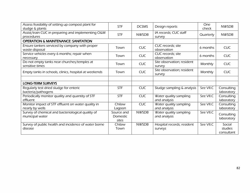
82
Assess feasibility of setting up compost plant for sludge & plants
STF DCSMS Design reports One check
NWSDB
Assist/train CUC in preparing and implementing O&M procedures
STF NWSDB IA records; CUC staff survey
Quarterly NWSDB
OPERATION & MAINTENANCE: SANITATION OPERATION & MAINTENANCE: SANITATION OPERATION & MAINTENANCE: SANITATION OPERATION & MAINTENANCE: SANITATION
Ensure tankers serviced by company with proper waste disposal
Town CUC CUC records; site observation
6 months CUC
Service vehicles every 6 months; repair when necessary
Town CUC CUC records; site observation
6 months CUC
Do not empty tanks near churches/temples at sensitive times
Town CUC Site observation; resident survey
Monthly CUC
Empty tanks in schools, clinics, hospital at weekends Town CUC Site observation; resident survey
Monthly CUC
LONGLONGLONGLONG----TERM SURVEYS TERM SURVEYS TERM SURVEYS TERM SURVEYS
Regularly test dried sludge for enteric bacteria/pathogens
STF CUC Sludge sampling & analysis See VII.C Consulting laboratory
Periodically monitor quality and quantity of STF effluent
STF CUC Water quality sampling and analysis
See VII.C Consulting laboratory
Monitor impact of STF effluent on water quality in nearly by wells
Chilaw Lagoon
CUC Water quality sampling and analysis
See VII.C Consulting laboratory
Survey of chemical and bacteriological quality of municipal water
Source and Domestic sites
NWSDB Water quality sampling and analysis
See VII.C Consulting laboratory
Survey of public health and incidence of water borne disease
Chilaw Town
NWSDB Hospital records; resident surveys
See VII.C Social studies consultant
83
D. Environmental Management and Monitoring Costs D. Environmental Management and Monitoring Costs D. Environmental Management and Monitoring Costs D. Environmental Management and Monitoring Costs
Most of the mitigation measures require the contractors to adopt good site practice, which should be part of their normal procedures already, so there are unlikely to be major costs associated with compliance. Regardless of this, any costs of mitigation by the contractors (those employed to construct the infrastructure or the local companies employed to conduct O&M when the system is operating) are included in the budgets for the civil works and do not need to be estimated separately here. Mitigation that is the responsibility of NWSDB will be provided as part of their management of the project, so this also does not need to be duplicated here. Costs of acquiring land and compensating shopkeepers for loss of business income during the construction period (Table 8) are calculated separately in the budgets for the Resettlement Framework and Resettlement Plans so are also excluded from this analysis. The remaining actions in the Environmental Monitoring Plan are: The environmental monitoring during construction, conducted by the RE - DCSMS The short-term surveys of the quality and quantity of water in the aquifer and the
quality of water in the Deduru Oya; Studies to plan sustainable water abstraction and appropriate water treatment; The long-term post-construction surveys that will be commissioned by NWSDB
(Table 9).
These have not been budgeted elsewhere, and their costs are shown in Table 10, with details of the calculations shown in footnotes beneath the table. The figures show that the total cost of environmental management and monitoring for the Chilaw subprojects (covering design, four years of construction and the first three years of operation) is SLR 1,250,000.
VIII. PUBLIC CONSULTATION AND INFORMATION DISCLOSURE VIII. PUBLIC CONSULTATION AND INFORMATION DISCLOSURE VIII. PUBLIC CONSULTATION AND INFORMATION DISCLOSURE VIII. PUBLIC CONSULTATION AND INFORMATION DISCLOSURE
A. Project stakeholders A. Project stakeholders A. Project stakeholders A. Project stakeholders
Most of the main stakeholders have already been identified and consulted during preparation of the IEEs, and any others that are identified during project implementation will be brought into the process in the future. Primary stakeholders are:
Residents, shopkeepers and businesspeople who live and work alongside the roads in which improvements in the water supply network will be provided;
Local communities living in the vicinity of the various facilities (OR, PS, WTP, STF); Owners and users of any land that is acquired for the project (eg new WTP site);
Secondary stakeholders are:
MWSD as the Executing Agency and NWSDB as the Implementing Agency; Other government institutions whose remit includes areas or issues affected by the project (state and local planning authorities; Ministry of Provincial Councils and Local Government; Department of Public Health Engineering; Central Environment Authority; National, Provincial and Local Roads Authorities; etc);
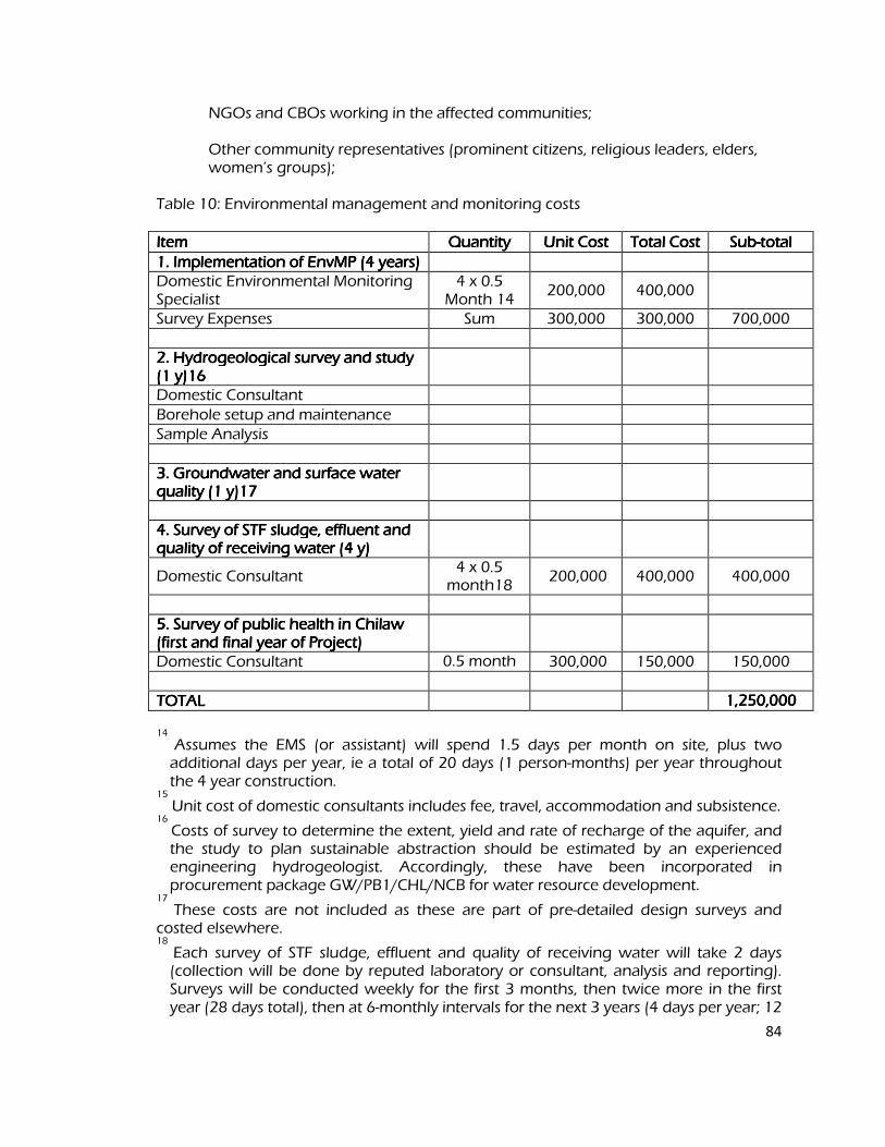
84
NGOs and CBOs working in the affected communities; Other community representatives (prominent citizens, religious leaders, elders,
women’s groups); Table 10: Environmental management and monitoring costs IIIItem tem tem tem Quantity Quantity Quantity Quantity Unit Cost Unit Cost Unit Cost Unit Cost Total Cost Total Cost Total Cost Total Cost SubSubSubSub----total total total total
1. Implementation of EnvMP (4 years) 1. Implementation of EnvMP (4 years) 1. Implementation of EnvMP (4 years) 1. Implementation of EnvMP (4 years) Domestic Environmental Monitoring Specialist
4 x 0.5 Month 14
200,000 400,000
Survey Expenses Sum 300,000 300,000 700,000 2. Hydrogeological survey 2. Hydrogeological survey 2. Hydrogeological survey 2. Hydrogeological survey and study and study and study and study (1 y)16 (1 y)16 (1 y)16 (1 y)16
Domestic Consultant
Borehole setup and maintenance
Sample Analysis 3. Groundwater and surface water 3. Groundwater and surface water 3. Groundwater and surface water 3. Groundwater and surface water quality (1 y)17 quality (1 y)17 quality (1 y)17 quality (1 y)17
4. Survey of STF sludge, effluent and 4. Survey of STF sludge, effluent and 4. Survey of STF sludge, effluent and 4. Survey of STF sludge, effluent and quality of receiving water (4 y) quality of receiving water (4 y) quality of receiving water (4 y) quality of receiving water (4 y)
Domestic Consultant 4 x 0.5 month18
200,000 400,000 400,000
5555. Survey of public health in Chilaw . Survey of public health in Chilaw . Survey of public health in Chilaw . Survey of public health in Chilaw (first and final year of Project) (first and final year of Project) (first and final year of Project) (first and final year of Project)
Domestic Consultant 0.5 month 300,000 150,000 150,000
TOTAL TOTAL TOTAL TOTAL 1111,,,,252525250,000 0,000 0,000 0,000
14
Assumes the EMS (or assistant) will spend 1.5 days per month on site, plus two additional days per year, ie a total of 20 days (1 person-months) per year throughout the 4 year construction.
15
Unit cost of domestic consultants includes fee, travel, accommodation and subsistence. 16
Costs of survey to determine the extent, yield and rate of recharge of the aquifer, and the study to plan sustainable abstraction should be estimated by an experienced engineering hydrogeologist. Accordingly, these have been incorporated in procurement package GW/PB1/CHL/NCB for water resource development.
17
These costs are not included as these are part of pre-detailed design surveys and costed elsewhere. 18
Each survey of STF sludge, effluent and quality of receiving water will take 2 days (collection will be done by reputed laboratory or consultant, analysis and reporting). Surveys will be conducted weekly for the first 3 months, then twice more in the first year (28 days total), then at 6-monthly intervals for the next 3 years (4 days per year; 12
85
days total). The total expert time is thus 40 days or 2 person-months. 19
Each survey will analyse 10 samples from each medium, 30 in total; there will be 20 surveys (14 in year 1, 2 each in years 2-4).
20
Each survey of domestic water quality will take 3 days to collect 50 samples and 2 days to prepare an interpretative report. There will be two surveys per year for 4 years, total 40 days or 2 person-months.
21
Each public health survey will take a week to collect and analyse data from the hospital and medical centres and prepare an interpretative report, so the time spent will be 2 weeks per year, ie 0.5 person-months.
22
Total excluding the cost of the hydrogeological survey and study and surveys required pre-design. The beneficiary community in general; and The ADB. B. Consultation and Disclosure to Date B. Consultation and Disclosure to Date B. Consultation and Disclosure to Date B. Consultation and Disclosure to Date
Two forms of public consultation were used during preparation of the IEEs, to discuss the project and involve the community in planning the mitigation measures and developing the Environmental Monitoring Plan. These are:
Public meetings were held in the target towns and villages between December 2007 and January 2008, to which representatives of primary and secondary stakeholders were invited. Attendees were informed about the aim of the relevant subprojects and the benefits they would bring, together with their likely impacts and the ways in which they would be mitigated. Participants were invited to discuss their views and concerns, which were then incorporated into the IEEs. Separate public consultations were done for the IEE on the water treatment plant and on septage treatment plant in Chilaw. Separate IEEs are available for the above, the former being approved and the latter pending approval from the PEA. Appendix 4 contains a summary of the meeting in Chilaw and Table 11 summarises the main points made during the discussion; Ad hoc discussions were also held on site with people and communities who could be affected by the subprojects, so that views could be expressed in a less formal setting. These were also considered in preparing the IEE. NWSDB disclosed the IEEs on the water treatment plant to the public by providing copies in the local language in the NWSDB office in each town. The latter will also be done soon. Exposure to a wider audience will be achieved by placing the Summary IEE (SIEE) on the ADB website.
C. Future Consultation and Disclosure C. Future Consultation and Disclosure C. Future Consultation and Disclosure C. Future Consultation and Disclosure
All relevant consultants pertaining to the proposed infrastructure had been done already. Public consultations were held with regard to the water supply network, water treatment and sanitation projects. With regards to the extraction of ground water agreements had been arrived at with the stakeholders. IEEs had been done on Water treatment plant and septage treatment plants. The former went through an intensive public consultation process done by the consultants as well as the Provincial
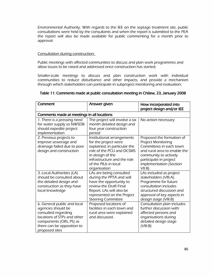
86
Environmental Authority. With regards to the IEE on the septage treatment site, public consultations were held by the consultants and when the report is submitted to the PEA the report will also be made available for public commenting for a month prior to approval.
Consultation during construction:
Public meetings with affected communities to discuss and plan work programmes and allow issues to be raised and addressed once construction has started; Smaller-scale meetings to discuss and plan construction work with individual communities to reduce disturbance and other impacts, and provide a mechanism through which stakeholders can participate in subproject monitoring and evaluation; Table 11: Comments made at public consultation mTable 11: Comments made at public consultation mTable 11: Comments made at public consultation mTable 11: Comments made at public consultation meeting in Chilaw, 23eeting in Chilaw, 23eeting in Chilaw, 23eeting in Chilaw, 23, , , , January 2008 January 2008 January 2008 January 2008
Comment Comment Comment Comment Answer given Answer given Answer given Answer given How incorporated into How incorporated into How incorporated into How incorporated into project design and/or IEE project design and/or IEE project design and/or IEE project design and/or IEE
Comments made at meetings in all locations Comments made at meetings in all locations Comments made at meetings in all locations Comments made at meetings in all locations
1. There is a pressing need for water supply so NWSDB should expedite project implementation
The project will involve a six month detailed design and four year construction period
No action necessary
2. Previous projects to improve sewerage and drainage failed due to poor design and construction
Institutional arrangements for the project were explained, in particular the role of the PCU and DCSMS in design of the infrastructure and the role of the PIUs in local organisation
Proposed the formation of Project Monitoring Committees in each town and rural area to enable the community to actively participate in project implementation (Section VII.B)
3. Local Authorities (LA) should be consulted about the detailed design and construction as they have local knowledge
LAs are being consulted during the PPTA and will have the opportunity to review the Draft Final Report. LAs will also be represented on the Project Steering Committee
LAs included as project stakeholders (VIII.A). Programme for future consultation includes structured discussion and approval of key aspects in design stage (VIII.B)
6. General public and local agencies should be consulted regarding locations of STPs and other components (ORs, PS) as there can be opposition to proposed sites
Proposed locations of facilities in each town and rural area were explained and discussed.
Consultation plan includes further discussion with affected persons and organisations during detailed design stage (VIII.B)
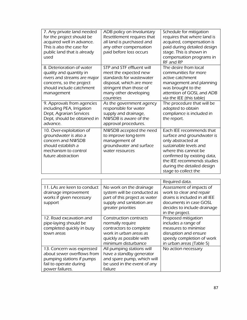
87
7. Any private land needed for the project should be acquired well in advance. This is also the case for public land that is already used
ADB policy on Involuntary Resettlement requires that all land is purchased and any other compensation paid before loss occurs
Schedule for mitigation requires that where land is acquired, compensation is paid during detailed design stage. This is shown in compensation programs in RF and RP
8. Deterioration of water quality and quantity in rivers and streams are major concerns, so the project should include catchment management
STP and STF effluent will meet the expected new standards for wastewater disposal, which are more stringent than those of many other developing countries
The desire from local communities for more active catchment management and planning was brought to the attention of GOSL and ADB via the IEE (this table)
9. Approvals from agencies including PEA, Irrigation Dept, Agrarian Services Dept, should be obtained in advance.
As the government agency responsible for water supply and drainage, NWSDB is aware of the approval procedures.
The procedure that will be adopted to obtain compliance is included in the report.
10. Over-exploitation of groundwater is also a concern and NWSDB should establish a mechanism to control future abstraction
NWSDB accepted the need to improve long-term management of groundwater and surface water resources
Each IEE recommends that surface and groundwater is only abstracted at sustainable levels and where this cannot be confirmed by existing data, the IEE recommends studies during the detailed design stage to collect the
Required data.
11. LAs are keen to conduct drainage improvement works if given necessary support
No work on the drainage system will be conducted as part of this project as water supply and sanitation are greater priorities
Assessment of impacts of work to clear and repair drains is included in all IEE documents in case GOSL decides to include drainage in the project.
12. Road excavation and pipe-laying should be completed quickly in busy town areas
Construction contracts normally require contractors to complete work in urban areas as quickly as possible with minimum disturbance
Proposed mitigation includes a range of measures to minimise disruption and ensure speedy completion of work in urban areas (Table 5)
13. Concern was expressed about sewer overflows from pumping stations if pumps fail to operate during power failures.
All pumping stations will have a standby generator and spare pump, which will be used in the event of any failure
No action necessary
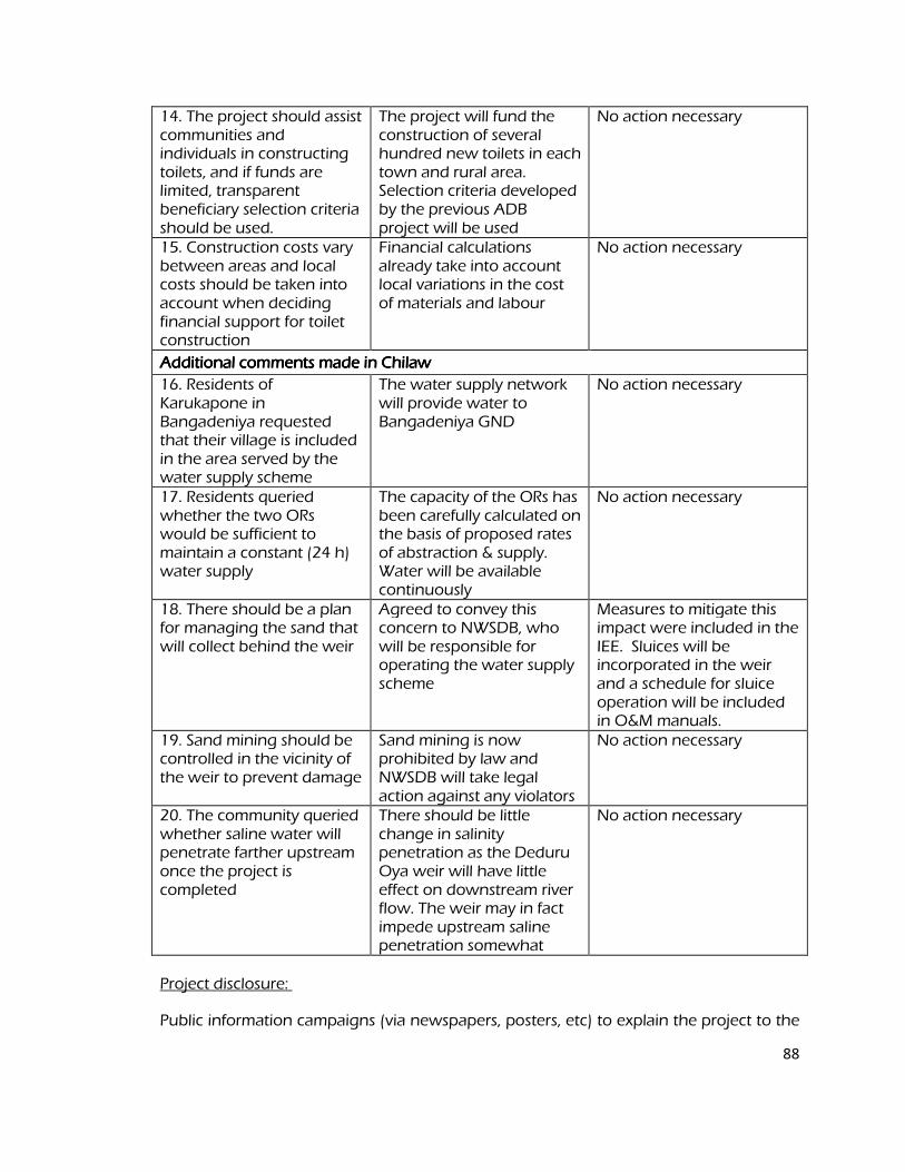
88
14. The project should assist communities and individuals in constructing toilets, and if funds are limited, transparent beneficiary selection criteria should be used.
The project will fund the construction of several hundred new toilets in each town and rural area. Selection criteria developed by the previous ADB project will be used
No action necessary
15. Construction costs vary between areas and local costs should be taken into account when deciding financial support for toilet construction
Financial calculations already take into account local variations in the cost of materials and labour
No action necessary
Additional comments made in Chilaw Additional comments made in Chilaw Additional comments made in Chilaw Additional comments made in Chilaw
16. Residents of Karukapone in Bangadeniya requested that their village is included in the area served by the water supply scheme
The water supply network will provide water to Bangadeniya GND
No action necessary
17. Residents queried whether the two ORs would be sufficient to maintain a constant (24 h) water supply
The capacity of the ORs has been carefully calculated on the basis of proposed rates of abstraction & supply. Water will be available continuously
No action necessary
18. There should be a plan for managing the sand that will collect behind the weir
Agreed to convey this concern to NWSDB, who will be responsible for operating the water supply scheme
Measures to mitigate this impact were included in the IEE. Sluices will be incorporated in the weir and a schedule for sluice operation will be included in O&M manuals.
19. Sand mining should be controlled in the vicinity of the weir to prevent damage
Sand mining is now prohibited by law and NWSDB will take legal action against any violators
No action necessary
20. The community queried whether saline water will penetrate farther upstream once the project is completed
There should be little change in salinity penetration as the Deduru Oya weir will have little effect on downstream river flow. The weir may in fact impede upstream saline penetration somewhat
No action necessary
Project disclosure:
Public information campaigns (via newspapers, posters, etc) to explain the project to the
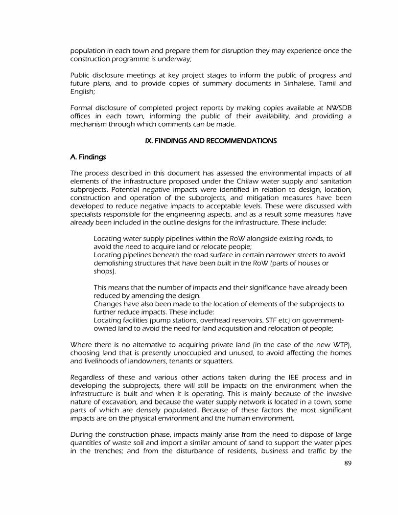
89
population in each town and prepare them for disruption they may experience once the construction programme is underway; Public disclosure meetings at key project stages to inform the public of progress and future plans, and to provide copies of summary documents in Sinhalese, Tamil and English; Formal disclosure of completed project reports by making copies available at NWSDB offices in each town, informing the public of their availability, and providing a mechanism through which comments can be made.
IX. FINDINGS AND RECOMMENDATIONS IX. FINDINGS AND RECOMMENDATIONS IX. FINDINGS AND RECOMMENDATIONS IX. FINDINGS AND RECOMMENDATIONS
A. Findings A. Findings A. Findings A. Findings
The process described in this document has assessed the environmental impacts of all elements of the infrastructure proposed under the Chilaw water supply and sanitation subprojects. Potential negative impacts were identified in relation to design, location, construction and operation of the subprojects, and mitigation measures have been developed to reduce negative impacts to acceptable levels. These were discussed with specialists responsible for the engineering aspects, and as a result some measures have already been included in the outline designs for the infrastructure. These include:
Locating water supply pipelines within the RoW alongside existing roads, to avoid the need to acquire land or relocate people; Locating pipelines beneath the road surface in certain narrower streets to avoid demolishing structures that have been built in the RoW (parts of houses or shops). This means that the number of impacts and their significance have already been reduced by amending the design. Changes have also been made to the location of elements of the subprojects to further reduce impacts. These include:
Locating facilities (pump stations, overhead reservoirs, STF etc) on government-owned land to avoid the need for land acquisition and relocation of people;
Where there is no alternative to acquiring private land (in the case of the new WTP),
choosing land that is presently unoccupied and unused, to avoid affecting the homes and livelihoods of landowners, tenants or squatters. Regardless of these and various other actions taken during the IEE process and in developing the subprojects, there will still be impacts on the environment when the infrastructure is built and when it is operating. This is mainly because of the invasive nature of excavation, and because the water supply network is located in a town, some parts of which are densely populated. Because of these factors the most significant impacts are on the physical environment and the human environment. During the construction phase, impacts mainly arise from the need to dispose of large quantities of waste soil and import a similar amount of sand to support the water pipes in the trenches; and from the disturbance of residents, business and traffic by the
90
construction work. These are common impacts of construction in urban areas, and there are well developed methods for their mitigation. These include:
Finding beneficial uses for waste material; Covering soil and sand during transportation and when stored on site; Planning work to minimise disruption of traffic and communities; Providing temporary structures to maintain access across trenches where
required. Where private land is acquired for the project, this will be done through the legal process of the GOSL Land Acquisition Act, through which the market value is paid, based on an analysis of recent transactions. ADB policy on Involuntary Resettlement requires that no-one should be worse off as a result of an ADB-funded project, so a Resettlement Framework has been prepared to deal with losses not covered by national law. This establishes that cash compensation will be provided to:
Landowners for any productive trees that are growing on acquired land; Owners or tenants of businesses that lose income if access is difficult for customers when construction work is in their vicinity.
There were limited opportunities to provide environmental enhancements, but certain measures were included. For example it is proposed that the project will:
Employ people from nearby communities in the construction workforce and to maintain and operate the new facilities, to provide them with an economic gain; Set up a system of marketing sludge from the septage treatment facility to
farmers to fertilize their soil and increase yields, and provide partial cost recovery for CUC.
These and the other mitigation and enhancement measures are summarised in Table 7, which also shows the location of the impact, the body responsible for the mitigation, and the programme for its implementation. Operation and maintenance of the water supply infrastructure will be the responsibility of NWSDB. Most elements should operate with routine maintenance, which should not affect the environment. Network leaks will be repaired from time to time, but impacts will be less than those of the construction period as the work will be infrequent, affecting small areas only. Maintenance at the other sites will involve routine checking of components and replacement of parts where necessary. Work will be conducted according to O&M procedures developed in the detailed design stage. The proposed abstraction from the Deduru Oya should not deplete the river, because the amount removed is a very small proportion of the total volume (< 2% of the estimated minimum annual flow). There will be few ecological impacts as there are no important species or habitats in the river, and no fish are known to migrate upstream to breed. There should also be no impacts on downstream users as there are no irrigation systems fed by the river, and no usage of river water for domestic supply. The weir design should be amended to incorporate sluices so that retained sediment can be
91
purged periodically, which should avoid impacts on geomorphology downstream and at the coast. With regard to the ground water abstraction, yield tests and recharge rates will be assessed prior to deciding the wells to ensure sustainable supply of water. There are also limited data on the quality of water from the aquifer or the Deduru Oya, and as the subproject proposes to mix treated surface water with treated groundwater before supply to the public there is a health risk from consumption of contaminated water, given the usage of chemical fertilizers and the lack of sewerage in the area. It is therefore very important that the quality of surface- and ground-water be fully investigated in detail, so that the level of treatment can be increased if necessary to produce water that complies with national drinking water standards. Chilaw Urban Council will be responsible for operating the sanitation service, which comprises two vacuum tankers to empty septic tanks and a Septage Treatment Facility (STF). The tankers should operate without significant impacts, providing sensible precautions are taken, such as ensuring the vehicles are serviced regularly and that tanks near churches and temples are not emptied at times of religious observance. The STF should also operate without major impacts, providing it functions as intended. To ensure that this is the case, CUC should regularly monitor: The quantity and quality of the effluent (against 2008 draft discharge standards); The bacteriological quality of dried sludge to ensure that all enteric bacteria and
pathogens are killed by the drying process. CUC should also establish an emergency procedure to recycle the effluent through the ponds for further treatment if it fails to meet national wastewater discharge standards. Designs should be amended to provide the necessary pumps and pipe-work. If groundwater is abstracted sustainably and the water provided is of an acceptable quality, then the main impacts of the operating water supply and sanitation systems should be beneficial. The citizens of Chilaw will be provided with a constant supply of better quality water; and septic tanks in the town will be emptied around once per year, reducing the leaks and foul odours emanating from overloaded tanks at present. A public education programme will be implemented to raise awareness of sanitation issues, so the improvements in municipal services and sanitary practices should raise the quality of life and deliver major improvements in individual and public health. This should then lead to economic gains as people will be away from work less and will spend less on healthcare, so their incomes should increase. Table 7 also assesses the effectiveness of each mitigation measure in reducing each impact to an acceptable level. This is shown as the level of significance of the residual impact (remaining after the mitigation is applied). This shows that all impacts will be rendered at least neutral (successfully mitigated), and that certain measures will produce a benefit (in addition to the major benefits provided by the operating schemes). Mitigation will be assured by a program of environmental monitoring conducted during both construction and operation to ensure that all measures are provided as intended, and to determine whether the environment is protected as envisaged. This will include observations on and off site, document checks, and interviews with workers and beneficiaries, and any requirements for remedial action will be reported to the PCU.
92
There will also be longer-term surveys to monitor certain aspects, including the expected improvements in the quality of domestic water and the health of the population.
Finally, stakeholders were involved in developing the IEE through both face-to-face discussions on site and a large public meeting held in the town, after which views expressed were incorporated into the IEE and the planning and development of the project. The IEE will be made available in the local language at public locations in the town and the summary will be disclosed to a wider audience via the ADB website. The consultation process will be continued and expanded during project implementation, when a nationally-recognised NGO will be appointed to handle this key element to ensure that stakeholders are fully engaged in the project and have the opportunity to participate in its development and implementation. One further aspect requiring attention regards climate change and climate adaptation.
Whilst existing models23
generally point to a general increase in temperature and a possible decline in rainfall in the Dry Zone of Sri Lanka with a consequent increase in evapotranspiration and soil moisture by 2050, it is noted that studies have only used one global circulation model (out of 7 available at present) and one time slice. Although the data cannot be considered to be conclusive, rainwater harvesting (such as that in reservoirs) is encouraged as this would be advantageous based on predictions of an increase in rainfall during the south west monsoon. 23
WEDC. 2006. 32nd
WEDC International Conference: Impacts of Climate Change on Water Resources in Sri Lanka. Colombo. B. Recommendations B. Recommendations B. Recommendations B. Recommendations
There are two straightforward but essential recommendations that need to be followed to ensure that the environmental impacts of the project are successfully mitigated. These are that NWSDB should ensure that:
All mitigation, compensation and enhancement measures proposed in this IEE report (Table 8) and in the Resettlement Framework for the DZUWSP are implemented in full, as described in these two documents; The Environmental Monitoring Plan proposed in this report and the internal and external monitoring proposed in the Resettlement Framework are also implemented in full.
X. CONCLUSIONS X. CONCLUSIONS X. CONCLUSIONS X. CONCLUSIONS
1 The environmental impacts of the proposed improvements in water supply and sanitation infrastructure in Chilaw have been assessed by the Initial Environmental Examination reported in this document, conducted according to ADB guidelines. Issues related to Involuntary Resettlement were assessed by a parallel process of resettlement planning and will be compensated by measures set out in detail in the Resettlement Framework for the project. These measures were integrated into the IEE and are summarised in this report. However, separate IEEs were conducted for the water treatment plant in Wilattewa, Bingiriya and also for the septage treatment plant in Chilaw. The former was approved by the PEA and the latter is pending approval.
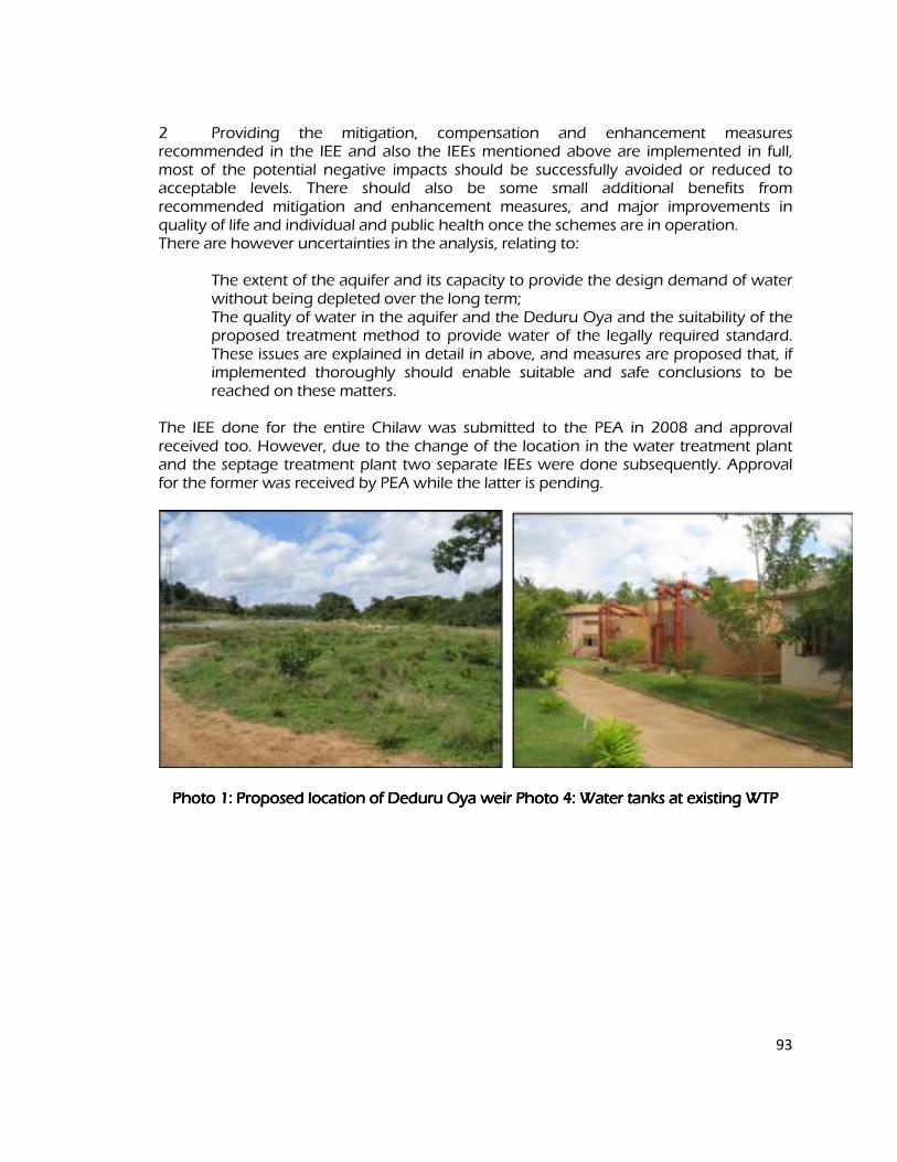
93
2 Providing the mitigation, compensation and enhancement measures recommended in the IEE and also the IEEs mentioned above are implemented in full, most of the potential negative impacts should be successfully avoided or reduced to acceptable levels. There should also be some small additional benefits from recommended mitigation and enhancement measures, and major improvements in quality of life and individual and public health once the schemes are in operation. There are however uncertainties in the analysis, relating to: The extent of the aquifer and its capacity to provide the design demand of water
without being depleted over the long term; The quality of water in the aquifer and the Deduru Oya and the suitability of the proposed treatment method to provide water of the legally required standard. These issues are explained in detail in above, and measures are proposed that, if implemented thoroughly should enable suitable and safe conclusions to be reached on these matters.
The IEE done for the entire Chilaw was submitted to the PEA in 2008 and approval received too. However, due to the change of the location in the water treatment plant and the septage treatment plant two separate IEEs were done subsequently. Approval for the former was received by PEA while the latter is pending.
Photo 1: Proposed location of Photo 1: Proposed location of Photo 1: Proposed location of Photo 1: Proposed location of DeduruDeduruDeduruDeduru Oya weir Photo 4: Water tanks at existing WTP Oya weir Photo 4: Water tanks at existing WTP Oya weir Photo 4: Water tanks at existing WTP Oya weir Photo 4: Water tanks at existing WTP
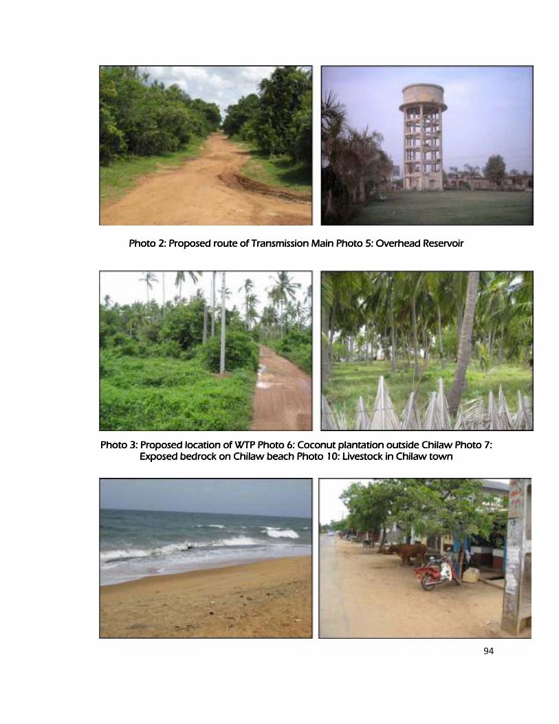
94
Photo 2: Proposed route of Transmission Main Photo 5: Overhead Reservoir Photo 2: Proposed route of Transmission Main Photo 5: Overhead Reservoir Photo 2: Proposed route of Transmission Main Photo 5: Overhead Reservoir Photo 2: Proposed route of Transmission Main Photo 5: Overhead Reservoir
Photo 3: Proposed location of WTP PhotoPhoto 3: Proposed location of WTP PhotoPhoto 3: Proposed location of WTP PhotoPhoto 3: Proposed location of WTP Photo 6: Coconut plantation outside Chilaw Photo 7: 6: Coconut plantation outside Chilaw Photo 7: 6: Coconut plantation outside Chilaw Photo 7: 6: Coconut plantation outside Chilaw Photo 7: Exposed bedrock on Chilaw beach Photo 10: Livestock in Chilaw town Exposed bedrock on Chilaw beach Photo 10: Livestock in Chilaw town Exposed bedrock on Chilaw beach Photo 10: Livestock in Chilaw town Exposed bedrock on Chilaw beach Photo 10: Livestock in Chilaw town
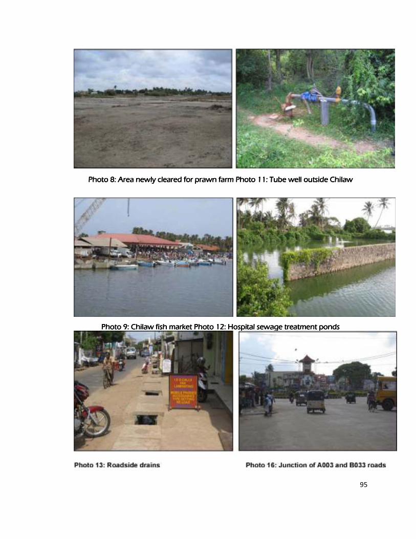
95
Photo 8: Area newly cleared for prawn farm Photo 11: Tube well outside Chilaw Photo 8: Area newly cleared for prawn farm Photo 11: Tube well outside Chilaw Photo 8: Area newly cleared for prawn farm Photo 11: Tube well outside Chilaw Photo 8: Area newly cleared for prawn farm Photo 11: Tube well outside Chilaw
Photo 9: Chilaw fish market Photo 12: Hospital sewage trPhoto 9: Chilaw fish market Photo 12: Hospital sewage trPhoto 9: Chilaw fish market Photo 12: Hospital sewage trPhoto 9: Chilaw fish market Photo 12: Hospital sewage treatment ponds eatment ponds eatment ponds eatment ponds
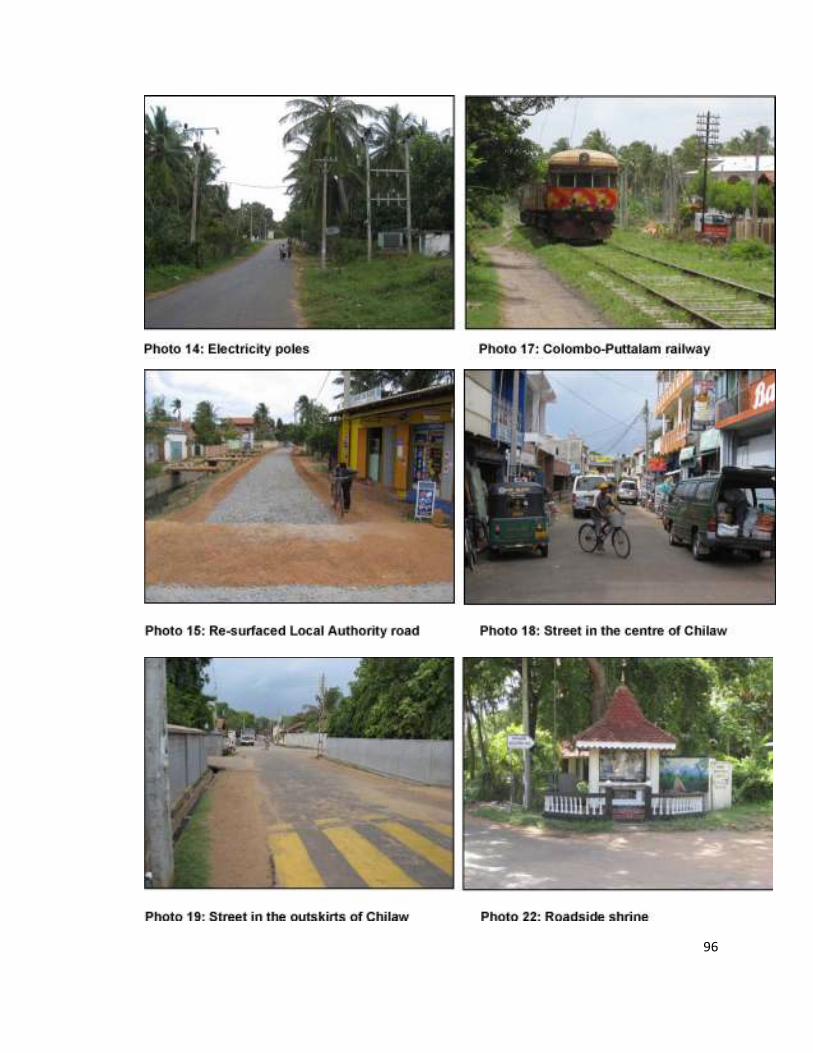
96
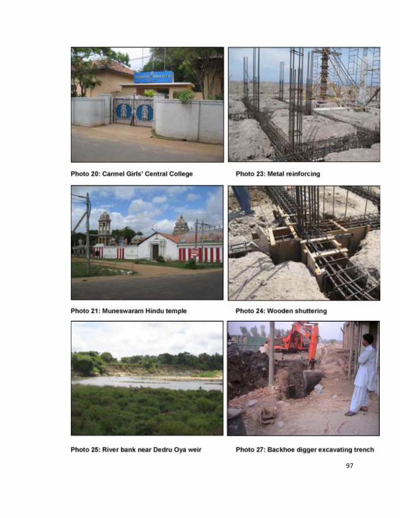
97
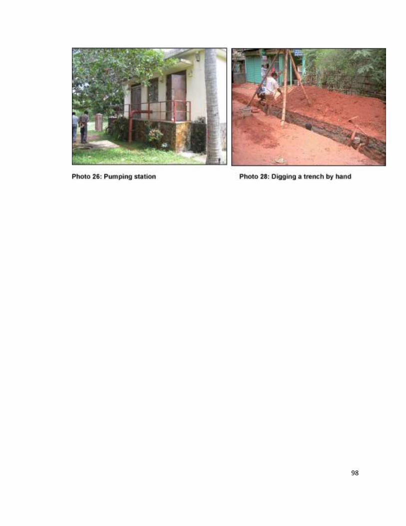
98
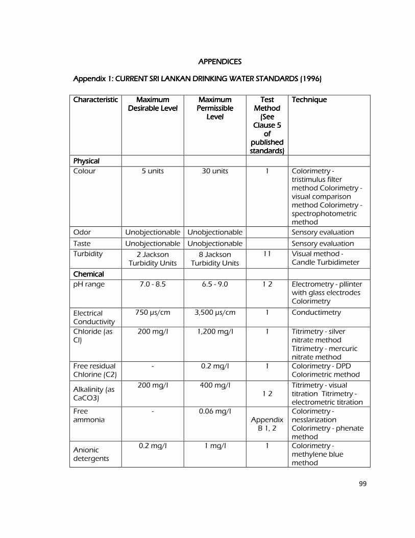
99
APPENDICESAPPENDICESAPPENDICESAPPENDICES
Appendix 1: CURRENT SRI LANKAN DRINKING WATER STANDARDS (1996) Appendix 1: CURRENT SRI LANKAN DRINKING WATER STANDARDS (1996) Appendix 1: CURRENT SRI LANKAN DRINKING WATER STANDARDS (1996) Appendix 1: CURRENT SRI LANKAN DRINKING WATER STANDARDS (1996)
Characteristic Characteristic Characteristic Characteristic Maximum Maximum Maximum Maximum Desirable Level Desirable Level Desirable Level Desirable Level
Maximum Maximum Maximum Maximum Permissible Permissible Permissible Permissible Level Level Level Level
Test Test Test Test Method Method Method Method (See (See (See (See
Clause 5 Clause 5 Clause 5 Clause 5 of of of of
published published published published standards) standards) standards) standards)
Technique Technique Technique Technique
Physical Physical Physical Physical
Colour 5 units 30 units 1 Colorimetry - tristimulus filter method Colorimetry - visual comparison method Colorimetry - spectrophotometric method
Odor Unobjectionable Unobjectionable Sensory evaluation
Taste Unobjectionable Unobjectionable Sensory evaluation
Turbidity 2 Jackson Turbidity Units
8 Jackson Turbidity Units
11 Visual method - Candle Turbidimeter
Chemical Chemical Chemical Chemical
pH range 7.0 - 8.5 6.5 - 9.0 1 2 Electrometry - pllinter with glass electrodes Colorimetry
Electrical Conductivity
750 µs/cm 3,500 µs/cm 1 Conductimetry
Chloride (as Cl)
200 mg/l 1,200 mg/l 1 Titrimetry - silver nitrate method Titrimetry - mercuric nitrate method
Free residual Chlorine (C2)
- 0.2 mg/l 1 Colorimetry - DPD Colorimetric method
Alkalinity (as CaCO3)
200 mg/l 400 mg/l 1 2
Titrimetry - visual titration Titrimetry - electrometric titration
Free ammonia
- 0.06 mg/l Appendix B 1, 2
Colorimetry - nesslarization Colorimetry - phenate method
Anionic detergents
0.2 mg/l 1 mg/l 1 Colorimetry - methylene blue method
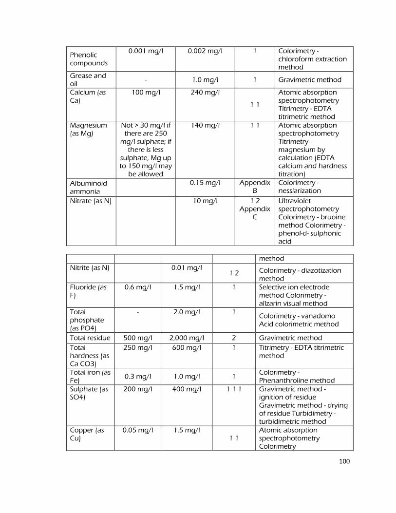
100
Phenolic compounds
0.001 mg/l 0.002 mg/l 1 Colorimetry - chloroform extraction method
Grease and oil
- 1.0 mg/l 1 Gravimetric method
Calcium (as Ca)
100 mg/l 240 mg/l
1 1
Atomic absorption spectrophotometry Titrimetry - EDTA titrimetric method
Magnesium (as Mg)
Not > 30 mg/l if there are 250 mg/l sulphate; if there is less
sulphate, Mg up to 150 mg/l may be allowed
140 mg/l 1 1 Atomic absorption spectrophotometry Titrimetry - magnesium by calculation (EDTA calcium and hardness titration)
Albuminoid ammonia
0.15 mg/l Appendix B
Colorimetry - nesslarization
Nitrate (as N) 10 mg/l 1 2 Appendix
C
Ultraviolet spectrophotometry Colorimetry - bruoine method Colorimetry - phenol-d- sulphonic acid
method
Nitrite (as N) 0.01 mg/l 1 2 Colorimetry - diazotization
method Fluoride (as F)
0.6 mg/l 1.5 mg/l 1 Selective ion electrode method Colorimetry - allzarin visual method
Total phosphate (as PO4)
- 2.0 mg/l 1 Colorimetry - vanadomo Acid colorimetric method
Total residue 500 mg/l 2,000 mg/l 2 Gravimetric method
Total hardness (as Ca CO3)
250 mg/l 600 mg/l 1 Titrimetry - EDTA titrimetric method
Total iron (as Fe)
0.3 mg/l 1.0 mg/l 1 Colorimetry - Phenanthroline method
Sulphate (as SO4)
200 mg/l 400 mg/l 1 1 1 Gravimetric method - ignition of residue Gravimetric method - drying of residue Turbidimetry - turbidimetric method
Copper (as Cu)
0.05 mg/l 1.5 mg/l 1 1
Atomic absorption spectrophotometry Colorimetry
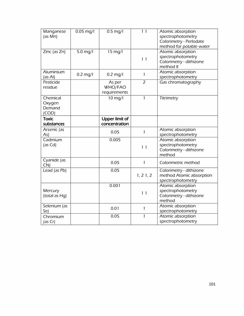
101
Manganese (as Mn)
0.05 mg/l 0.5 mg/l 1 1 Atomic absorption spectrophotometry Colorimetry - Perlodate method for potable water
Zinc (as Zn) 5.0 mg/l 15 mg/l
1 1
Atomic absorption spectrophotometry Colorimetry - dithizone method II
Aluminium (as Al)
0.2 mg/l 0.2 mg/l 1 Atomic absorption spectrophotometry
Pesticide residue
As per WHO/FAO requirements
2 Gas chromatography
Chemical Oxygen Demand (COD)
10 mg/l 1 Titrimetry
Toxic Toxic Toxic Toxic substances substances substances substances
Upper limit of Upper limit of Upper limit of Upper limit of concentration concentration concentration concentration
Arsenic (as As)
0.05 1
Atomic absorption spectrophotometry
Cadmium (as Cd)
0.005
1 1
Atomic absorption spectrophotometry Colorimetry - dithizone method
Cyanide (as CN)
0.05 1 Colorimetric method
Lead (as Pb) 0.05 1, 2 1, 2
Colorimetry - dithizone method Atomic absorption spectrophotometry
Mercury (total as Hg)
0.001
1 1
Atomic absorption spectrophotometry Colorimetry - dithizone method
Selenium (as Se)
0.01 1
Atomic absorption spectrophotometry
Chromium (as Cr)
0.05 1 Atomic absorption spectrophotometry
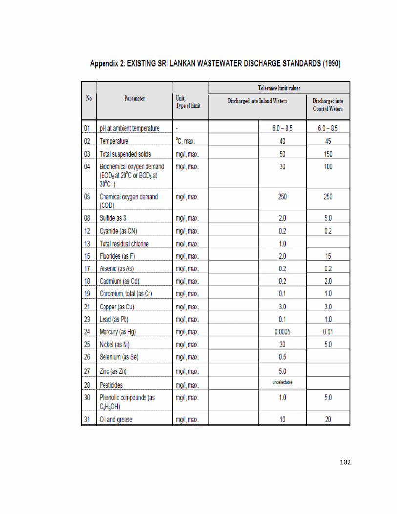
102
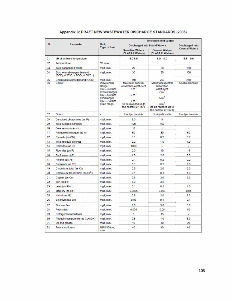
103
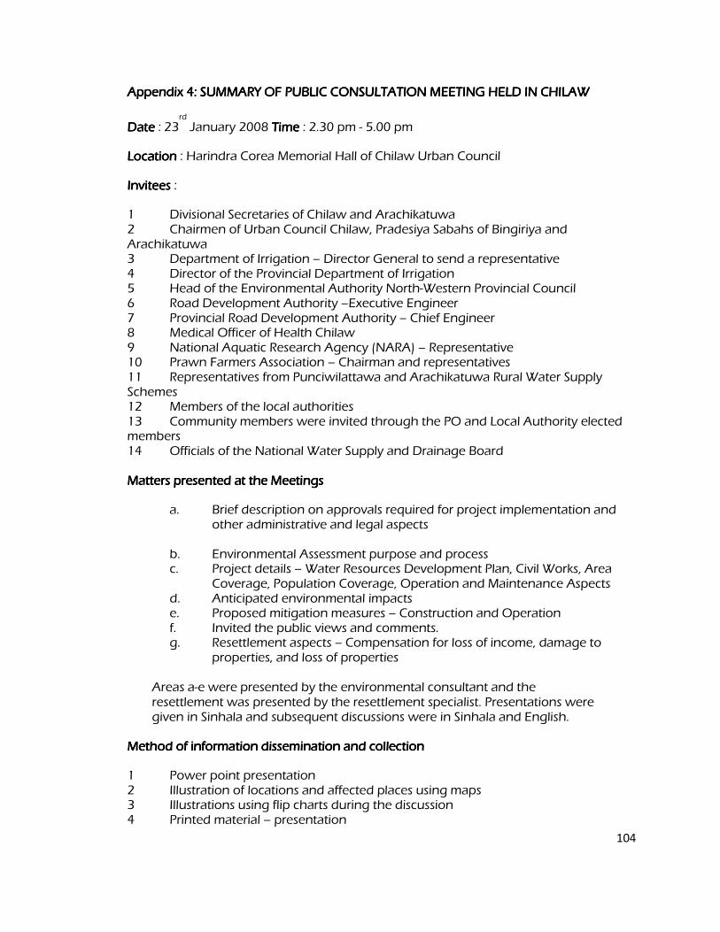
104
Appendix 4: SUMMARY OF PUBLIC CONSULTATION MEETING HELD IN CHILAW Appendix 4: SUMMARY OF PUBLIC CONSULTATION MEETING HELD IN CHILAW Appendix 4: SUMMARY OF PUBLIC CONSULTATION MEETING HELD IN CHILAW Appendix 4: SUMMARY OF PUBLIC CONSULTATION MEETING HELD IN CHILAW
Date Date Date Date : 23rd
January 2008 Time Time Time Time : 2.30 pm - 5.00 pm
Location Location Location Location : Harindra Corea Memorial Hall of Chilaw Urban Council
InviteesInviteesInviteesInvitees :
1 Divisional Secretaries of Chilaw and Arachikatuwa 2 Chairmen of Urban Council Chilaw, Pradesiya Sabahs of Bingiriya and Arachikatuwa 3 Department of Irrigation – Director General to send a representative 4 Director of the Provincial Department of Irrigation 5 Head of the Environmental Authority North-Western Provincial Council 6 Road Development Authority –Executive Engineer 7 Provincial Road Development Authority – Chief Engineer 8 Medical Officer of Health Chilaw 9 National Aquatic Research Agency (NARA) – Representative 10 Prawn Farmers Association – Chairman and representatives 11 Representatives from Punciwilattawa and Arachikatuwa Rural Water Supply Schemes 12 Members of the local authorities 13 Community members were invited through the PO and Local Authority elected members 14 Officials of the National Water Supply and Drainage Board Matters presented at the Meetings Matters presented at the Meetings Matters presented at the Meetings Matters presented at the Meetings
a. Brief description on approvals required for project implementation and other administrative and legal aspects
b. Environmental Assessment purpose and process c. Project details – Water Resources Development Plan, Civil Works, Area
Coverage, Population Coverage, Operation and Maintenance Aspects d. Anticipated environmental impacts e. Proposed mitigation measures – Construction and Operation f. Invited the public views and comments. g. Resettlement aspects – Compensation for loss of income, damage to
properties, and loss of properties
Areas a-e were presented by the environmental consultant and the resettlement was presented by the resettlement specialist. Presentations were given in Sinhala and subsequent discussions were in Sinhala and English.
Method of information dissemination and collection Method of information dissemination and collection Method of information dissemination and collection Method of information dissemination and collection
1 Power point presentation 2 Illustration of locations and affected places using maps 3 Illustrations using flip charts during the discussion 4 Printed material – presentation
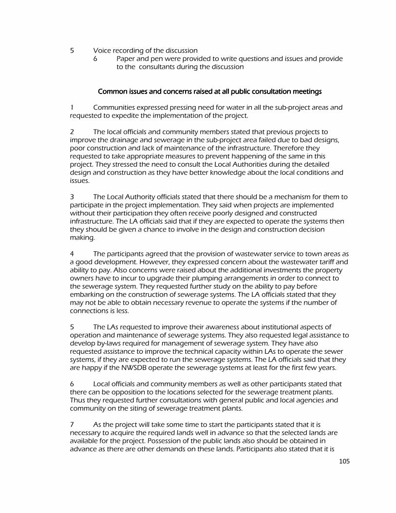
105
5 Voice recording of the discussion 6 Paper and pen were provided to write questions and issues and provide
to the consultants during the discussion
Common issues and concernsCommon issues and concernsCommon issues and concernsCommon issues and concerns raised at all public consultation meetings raised at all public consultation meetings raised at all public consultation meetings raised at all public consultation meetings
1 Communities expressed pressing need for water in all the sub-project areas and requested to expedite the implementation of the project. 2 The local officials and community members stated that previous projects to improve the drainage and sewerage in the sub-project area failed due to bad designs, poor construction and lack of maintenance of the infrastructure. Therefore they requested to take appropriate measures to prevent happening of the same in this project. They stressed the need to consult the Local Authorities during the detailed design and construction as they have better knowledge about the local conditions and issues. 3 The Local Authority officials stated that there should be a mechanism for them to participate in the project implementation. They said when projects are implemented without their participation they often receive poorly designed and constructed infrastructure. The LA officials said that if they are expected to operate the systems then they should be given a chance to involve in the design and construction decision making. 4 The participants agreed that the provision of wastewater service to town areas as a good development. However, they expressed concern about the wastewater tariff and ability to pay. Also concerns were raised about the additional investments the property owners have to incur to upgrade their plumping arrangements in order to connect to the sewerage system. They requested further study on the ability to pay before embarking on the construction of sewerage systems. The LA officials stated that they may not be able to obtain necessary revenue to operate the systems if the number of connections is less. 5 The LAs requested to improve their awareness about institutional aspects of operation and maintenance of sewerage systems. They also requested legal assistance to develop by-laws required for management of sewerage system. They have also requested assistance to improve the technical capacity within LAs to operate the sewer systems, if they are expected to run the sewerage systems. The LA officials said that they are happy if the NWSDB operate the sewerage systems at least for the first few years. 6 Local officials and community members as well as other participants stated that there can be opposition to the locations selected for the sewerage treatment plants. Thus they requested further consultations with general public and local agencies and community on the siting of sewerage treatment plants. 7 As the project will take some time to start the participants stated that it is necessary to acquire the required lands well in advance so that the selected lands are available for the project. Possession of the public lands also should be obtained in advance as there are other demands on these lands. Participants also stated that it is
106
important to inform the public about the project with details of the locations of constructed components, such as water towers, sewerage pumping stations, sewerage treatment plants, etc. 8 The deterioration of water quality and quantity in rivers and streams as wells as other activities such as sand mining were identified as threats to the future viability of the projects. Thus the participants highlighted the importance of catchment management and requested to include catchment management activities in this project. 9 The importance of obtaining the approval from necessary agencies well in advance was highlighted. These include: environmental agencies, Irrigation Department and Provincial Irrigation Department, Agrarian Services Department. 10 Over exploitation of the ground water resources was also cited as a threat. Participants stated the need to establish a mechanism for controlling the future ground water extraction in the well fields. 11 The Local Authorities expressed their willingness to carry out the drainage improvement works in the town areas, if they are allowed to do so. 12 It was requested to complete the road excavation and pipe laying work in busy town areas as soon as possible. 13 Concern was expressed about sewer overflows from pumping stations, if pumps fail to operate and during power failures. 14 Establish a procedure for providing assistance for toilet construction. Decide the beneficiary selection criteria for assistance for toilet construction If the funds available is limited to provide for all those who request for such assistance. 15 When deciding the financial support for toilets it is necessary to consider the construction material cost that prevails in the respective areas. Specific issues raised at the meeting in Chilaw Specific issues raised at the meeting in Chilaw Specific issues raised at the meeting in Chilaw Specific issues raised at the meeting in Chilaw
1 Requested to include Karukapone in Bangadeniya in the water supply scheme if it is not already included in the service area. 2 Asked whether the two OH tanks added by this project is adequate to maintain the water supply on 24/7 basis. 3 There should be a plan for management of sand collected behind the weir. 4 Stated the need to control sand mining in the intake area to prevent damage to the same. 5 Asked whether the salinity will move further up in the Deduru Oya once the project is completed. 6 Requested to fully disinfect the treated water before releasing to Chilaw Lagoon

107
as the lagoon water is used for prawn farming. 7 National Aquatic Resources Agency requested for funding for monitoring the water quality of the lagoon at least for two years once the sewerage treatment system comes into operation.
Addendum 1
Committee for Grievance Redress and Environment Monitoring
In absence of such provisions, affected parties/persons (AP) will seek solutions outside the
project which may lead to a number of adverse consequences. It is necessary to include
grievance redress provisions for the people adversely affected (or about to be affected) by the
development of sub projects because such people should have provisions to forward their
grievances by seeking solutions. Environmental Monitoring Committees (EMC) are already
proposed to discuss the critical environmental issues and thereby find solutions in some sub
projects. Facility for Grievance Redressing shall be incorporated to the proposed EMCs because
all regional level key officials will become the members of such EMCs and will be functioning
as Grievance Redress and Environment Monitoring Committee (GREMC). New GREMCs shall
be formed for the sub-projects where EMCs have not been proposed.
The GREMC comprises with responsible officers of following agencies and headed by the
Provincial Environmental Authority or Central Environmental Authority (which is functioning in
the area concern) jointly with the divisional secretary. The secretary to the committee and the
convener shall be the project manager of the NWSDB.
1. Provincial Environmental Authority/Central Environmental Authority (Regional office)
2. Project Manager of the sub project
3. Urban Council/ Municipal Council
4. Divisional Secretariat
5. Agrarian Service Department
6. Provincial Irrigation Department / Central Irrigation Department.
7. Representative of the contractor
8. Representative of the consultant to the project
9. Any other officers by considering the need
If APs are not satisfied about the decision of the GREMC, the matter should be referred to the
District Secretary who will make the final decision. The District Secretary may appoint a
committee to find the observations. The GREMC is effective with the commencement of the
construction and shall meet once in six weeks during the construction period. During the
operational phase, the committee shall meet once in three months for two years and if necessary
thereafter. If there are critical issues, the committee shall meet by fixing a convenient date.

During the operational phase, Regional Manager (O&M) of the NWSDB shall represent the
NWSDB.
This should be published in all three languages by displaying notices in the notice boards of all
member offices and other public offices such as Grama Niladhari (Village Head) office, post
office etc. to make aware the public.
Initial Environmental Examination Report
This report has been submitted to ADB by the Ministry of Water Supply and Drainage and is made publicly available in accordance with ADB’s public communications policy (2005). It does not necessarily reflect the views of ADB.
Project Number: 37381-013 September 2012
Sri Lanka: DRY ZONE URBAN WATER AND SANITATION PROJECT - for Puttalam Water Treatment System
Prepared by Project Management Unit for
Dry Zone Urban Water and Sanitation Project,
Colombo, Sri Lanka.
For Water Supply and Drainage Board Ministry of Water Supply and Drainage, Sri Lanka.
1
I. INTRODUCTION
A. Purpose of the Report A. Purpose of the Report A. Purpose of the Report A. Purpose of the Report
The Dry Zone Urban Water and Sanitation Program (DZUWSP) is intended to facilitate sustainable development in disadvantaged districts in Sri Lanka. This will be achieved by investing in priority water supply and sanitation infrastructure in selected urban areas. Assistance will be targeted in those parts of the Northern and North-Western Provinces with the most acute shortages of drinking water and sanitation. Chosen urban areas are the towns of Mannar, Vavuniya, Puttalam and Chilaw. DZUWSP will be implemented over five years beginning in early 2009, and will be supported by ADB through a project loan and grant. The Ministry of Water Supply and Drainage (MWSD) is the Executing Agency (EA) for the program and NWSDB is the Implementing Agency (IA). DZUWSP will improve infrastructure through the development, design and implementation of subprojects in water supply and sanitation in each town. The Project has been classified by ADB as environmental assessment category B, where the component requiring greater attention is the Vavuniya water supply subproject (a 10.5 m high dam and 237 ha storage reservoir). The impacts of providing infrastructure in the four urban areas were assessed by four Initial Environmental Examination (IEE) reports (one for each location). For Vavuniya an Environmental Management Plan for the storage reservoir and a detailed Environmental Monitoring plan (EnvMoP) for the other less sensitive sub-components have been prepared. In the other three towns, where impacts will be less significant, and detailed Environmental Monitoring Plans have been prepared. Studies were conducted according to ADB Environment Policy (2002) and Environmental Assessment Guidelines (2003) and this document is the IEE report for Puttalam. B. Extent of IEE study B. Extent of IEE study B. Extent of IEE study B. Extent of IEE study
4Sri Lankan law and ADB policy require that the environmental impacts of development projects are identified and assessed as part of the planning and design process, and that action is taken to reduce those impacts to acceptable levels. This is done through the environmental assessment process, which has become an integral part of lending operations and project development and implementation worldwide.
1. ADB Policy 1. ADB Policy 1. ADB Policy 1. ADB Policy
ADB’s Environment Policy requires the consideration of environmental issues in all aspects of the Bank’s operations, and the requirements for Environmental Assessment are described in Operations Manual (OM) 20: Environmental Considerations in ADB Operations. This states that ADB requires environmental assessment of all project loans, program loans, sector loans, sector development program loans, financial intermediation loans and private sector investment operations. The nature of the assessment required for a project depends on the significance of its environmental impacts, which are related to the type and location of the project, the sensitivity, scale, nature and magnitude of its potential impacts, and the availability of cost-effective
2
mitigation measures. Projects are screened for their expected environmental impacts and are assigned to one of the following categories:
Category A: Projects that could have significant environmental impacts. An Environmental Impact Assessment (EIA) is required.
Category B: Projects that could have some adverse environmental impacts, but of less significance than those for category A. An Initial Environmental Examination (IEE) is required to determine whether significant impacts warranting an EIA are likely. If an EIA is not needed, the IEE is regarded as the final environmental assessment report.
A Category B project may be classified as B-sensitive if it involves
environmentally sensitive activities1
. Such projects require IEE, but have the same requirements for disclosure and Environmental Management Plans as Category A.
Category C: Projects that are unlikely to have adverse environmental impacts. No EIA or IEE is required, although environmental implications are reviewed.
The Bank has classed this project as Category B and following normal procedure for project loans, one IEE was conducted for each urban area, covering all proposed subprojects in the town. A subproject comprises the infrastructure improvements in a particular sector (water supply or sewerage/sanitation).
2. National Law 2. National Law 2. National Law 2. National Law
The requirement for Environmental Assessment in Sri Lanka is established by the National Environment Act (1981), and the procedures are defined in the EIA Regulations (1993). The regulations specify activities for which environmental assessment is mandatory, and those that could occur within certain DZUWSP subprojects are as follows:
Groundwater extraction of over 500,000 m3
/day2
;
A Water Treatment Plant with a capacity of over 500,000 m3
/day2
;
Laying more than 1 km of pipes3
; Projects that involve relocation of more than 100 people; and Projects that fall within sensitive area(s).
Sensitive areas are defined in the EIA Regulations as:
Any erodable area declared under the Soil Conservation Act (1951, 1953); Any Flood Area declared under the Flood Protection Ordinance (1924, 1955) and any
Flood Protection Area declared under the Sri Lanka Land Reclamation and Development Corporation Act (1968, 1982); Any reservation beyond the Full Supply Level of a reservoir;
1
A project may be deemed environmentally sensitive by ADB if it is near environmentally
3
sensitive areas, or involves: deforestation or loss of biodiversity; involuntary resettlement issues; processing, handling and disposal of toxic and hazardous substances; or other environmentally sensitive activities that also may be of concern to a wide group of external stakeholders.
2
The Central Environment Authority is currently considering a proposal to lower these limits to
500 m3
/day. 3
This applies to wastewater projects but not water supply.
Any archaeological reserve, ancient or protected monument as defined or declared under the Antiquities Ordinance (1965);
Any area declared under the Botanic Gardens Ordinance (1928, 1973); Areas within, or less than 100 m from the boundaries of, any area declared under the
National Heritage and Wilderness Act (1988): the Forest Ordinance; Areas within, or less than 100 m from the boundaries of, any area declared as a
Sanctuary under the Fauna and Flora Protection Ordinance (1937);
Areas within, or less than 100 m from the high flood level contour of, a public lake as defined by the Crown Lands Ordinance (1947, 1949, 1956) including those declared under Section 71 of the Ordinance;
Areas 60 m or less from the bank of a public stream as defined in the Crown Lands
Ordinance, with a width of more than 25 m at any point. The requirement for EIA and the level of study required are determined by the Provincial
Environment Authority (PEA) 4
after submission by the proponent of a Project Information Document (PID), plus supporting information if relevant. There are two possible outcomes:
Categorical Exclusion: the activity is not on the list of prescribed projects in the EIA regulations, is not in or near a sensitive area, has not been the subject of public protest, and it is clear from the PID and supporting information that the project will have no significant environmental impacts. Environmental Clearance is granted (with or without conditions) and the project may proceed;
All other projects require Environmental Assessment and the CEA or PEA4
establishes a Scoping Committee to decide on the level of study (IEE or EIA) and prepare Terms of Reference (ToR). Alternatively, if the project lies wholly within the jurisdiction of a single Government agency (eg UDA) CEA/PEA may refer the project to this authority (as the Project Approving Agency) to administer the EIA process. A Technical Review Committee reviews the completed IEE or EIA report and recommends whether Environmental Clearance should be granted. The final decision is made by CEA.
The urban areas selected under this program have populations of between 40,000 and 120,000, so the infrastructure subprojects are relatively small, and groundwater abstraction and water treatment will not be of the scale quoted in the EIA regulations as requiring environmental
4
assessment. Components will not be located in protected or sensitive areas and no people will be relocated. However two of the water supply subprojects (Chilaw and Vavuniya) involve the construction of structures across a river or stream to impound water, which is considered as a prescribed activity under the National Environmental Act/Provincial Environmental Act (NEA/PEA), and will thus require an EIA/IEE. Furthermore, if during detailed designs the location of proposed tube wells for the Mannar water supply scheme is within or 100 m away from the Giants Tank Sanctuary, this too would be considered as a prescribed activity and would require an EIA/IEE.The regulations may also apply to the other urban water supply 4
In the North-Western Province (which includes Chilaw and Puttalam) the EIA system is established by the North-Western Provincial Act (1981) and Provincial EIA Regulations (1992, 1998). The system is the same as the national procedure, except for: (i) the North-Western Provincial Environmental Authority (NWPEA) replaces CEA as the competent authority (although projects with trans-regional impacts are referred to CEA and dealt with under the national system); (ii) EIA and IEE reports are made available for public comment (under the national system this is required for EIAs only); (iii) Projects that are the subject of significant public interest or protest can be required to conduct an EIA by the NWPEA Board of Directors, even though this may not be required by the legislation schemes in the future if CEA reduces the size of groundwater abstraction and water treatment plants for which EIA/IEE is required (see Footnote 2).
3. Review and Approval Procedure 3. Review and Approval Procedure 3. Review and Approval Procedure 3. Review and Approval Procedure
For Category B projects the Draft IEE report and its summary (SIEE) are reviewed by ADB’s Regional Department sector division and Environment and Social Safeguards Division, and by the Executing Agency, and additional comments may be sought from project affected people and other stakeholders. All comments are incorporated in preparing the final documents, which are reviewed by the Executing Agency (EA) and the national environmental protection agency (CEA or NWPEA in this case). The EA then officially submits the IEE and SIEE reports to ADB for consideration by the Board of Directors. Completed reports are made available worldwide by ADB, via the depository library system and the ADB website.
4. Scope of Study 4. Scope of Study 4. Scope of Study 4. Scope of Study
This is the IEE for the water supply and sanitation subprojects proposed in Puttalam. It discusses the environmental impacts and mitigation measures relating to the location, design, construction and operation of all physical works proposed under these subprojects. It is one of four documents describing the environmental impacts and mitigation of all urban subprojects proposed by the Project Preparatory Technical Assistance conducted in 2007-08. These documents were prepared in October 2007 and by one International and one Domestic Environmental Specialist via inputs of three months each.
5
II. DESCRIPTII. DESCRIPTII. DESCRIPTII. DESCRIPTION OF THE PROJECT ION OF THE PROJECT ION OF THE PROJECT ION OF THE PROJECT
A. Type, Category and Need A. Type, Category and Need A. Type, Category and Need A. Type, Category and Need
DZUWSP is a project to improve urban and rural infrastructure, by the design and implementation of subprojects in water supply and sanitation. As explained above the Project has been classified by ADB as Category B. As the Project will be funded by a loan and a grant, ADB procedure requires that an IEE is conducted for each town to identify and mitigate the impacts of subprojects, and to determine whether further study or a more detailed EIA may be required. This is the IEE for Puttalam. Improvements in water supply and sanitation are needed in Puttalam because the present infrastructure is inadequate for the needs of the growing population. The main problems are that: The water distribution system is old and beset with leaks, and as a result water pressure
is very low and the supply is only available for a few hours per day; Present groundwater abstraction will not supply future population needs and additional
sources are required to improve both quality and quantity of water; and There is no municipal sewerage in the town and households rely on septic tanks or pit
latrines with soakage pits, in which poured water is the method of cleansing;
These and the other subprojects designed by the DZUWSP are intended to raise the standards of the municipal infrastructure and services of the selected urban centres to those expected of modern Asian towns. B. Location, Size and Implementation Schedule B. Location, Size and Implementation Schedule B. Location, Size and Implementation Schedule B. Location, Size and Implementation Schedule
The subprojects assessed in this report will be located in Puttalam, on the west coast of the North-Western Province of Sri Lanka, 130 km north of the national capital Colombo (Figure 1). The improved infrastructure will extend through approximately 50% of the town, where water pipes will be buried alongside roads. Outside the town certain existing facilities will be improved (abstraction weir, water storage tanks and canals); various new facilities will be built (canals, intake well, raw water main and water treatment plant); and a new transmission main will carry treated water to the town (Figure 1). A facility will also be built to treat material removed from septic tanks in the town (Figure 2)
The new water supply system will serve a population of 58,000 in an area of 14,600 ha in 2010
and a population of 99,000 in an area of 18,200 ha in 2030. It will abstract 8,600 m3
/d of
groundwater from existing tube-wells and 9,000 m3
/d of surface water from the Kala Oya in
2010 and 4,500 m3
/d of groundwater and 30,000 m3
/d of surface water from Kala Oya and
Inginimitiya in 2030. The new Water Treatment Plant (WTP) will treat 9,000 m3
/d, to Sri Lankan drinking water standards (Appendix 1). Table 1 shows the components of the scheme that will be funded by the project and are assessed in this IEE. The new sanitation system comprise one vacuum tanker (“gully bowser”) to extract partially decomposed material from septic tanks, and a septage treatment facility of sludge drying beds and effluent treatment ponds. Each bowser will carry 1,500 litres and will make up to six journeys per day, so two vehicles should be able to empty every septic tank in the town at least
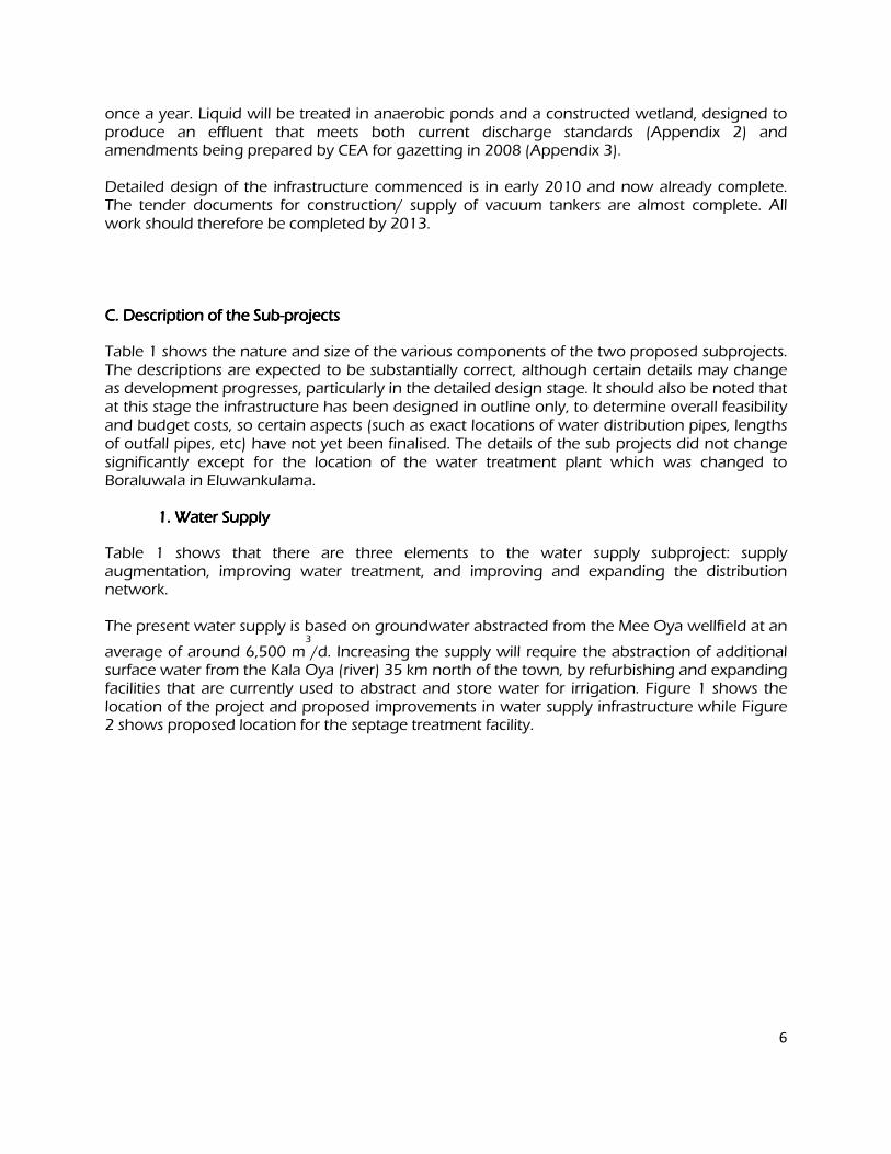
6
once a year. Liquid will be treated in anaerobic ponds and a constructed wetland, designed to produce an effluent that meets both current discharge standards (Appendix 2) and amendments being prepared by CEA for gazetting in 2008 (Appendix 3). Detailed design of the infrastructure commenced is in early 2010 and now already complete. The tender documents for construction/ supply of vacuum tankers are almost complete. All work should therefore be completed by 2013. C. Description of the SubC. Description of the SubC. Description of the SubC. Description of the Sub----projects projects projects projects
Table 1 shows the nature and size of the various components of the two proposed subprojects. The descriptions are expected to be substantially correct, although certain details may change as development progresses, particularly in the detailed design stage. It should also be noted that at this stage the infrastructure has been designed in outline only, to determine overall feasibility and budget costs, so certain aspects (such as exact locations of water distribution pipes, lengths of outfall pipes, etc) have not yet been finalised. The details of the sub projects did not change significantly except for the location of the water treatment plant which was changed to Boraluwala in Eluwankulama.
1. Water Supply 1. Water Supply 1. Water Supply 1. Water Supply
Table 1 shows that there are three elements to the water supply subproject: supply augmentation, improving water treatment, and improving and expanding the distribution network. The present water supply is based on groundwater abstracted from the Mee Oya wellfield at an
average of around 6,500 m3
/d. Increasing the supply will require the abstraction of additional surface water from the Kala Oya (river) 35 km north of the town, by refurbishing and expanding facilities that are currently used to abstract and store water for irrigation. Figure 1 shows the location of the project and proposed improvements in water supply infrastructure while Figure 2 shows proposed location for the septage treatment facility.
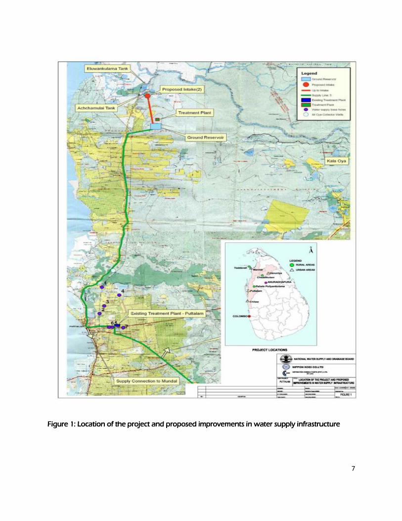
7
Figure 1: Location of the project and proposed improvements in water supply infrastructure Figure 1: Location of the project and proposed improvements in water supply infrastructure Figure 1: Location of the project and proposed improvements in water supply infrastructure Figure 1: Location of the project and proposed improvements in water supply infrastructure
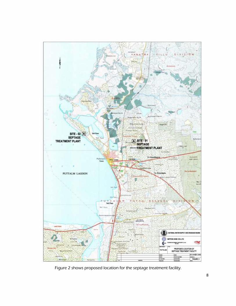
8
Figure 2 shows proposed location for the septage treatment facility.
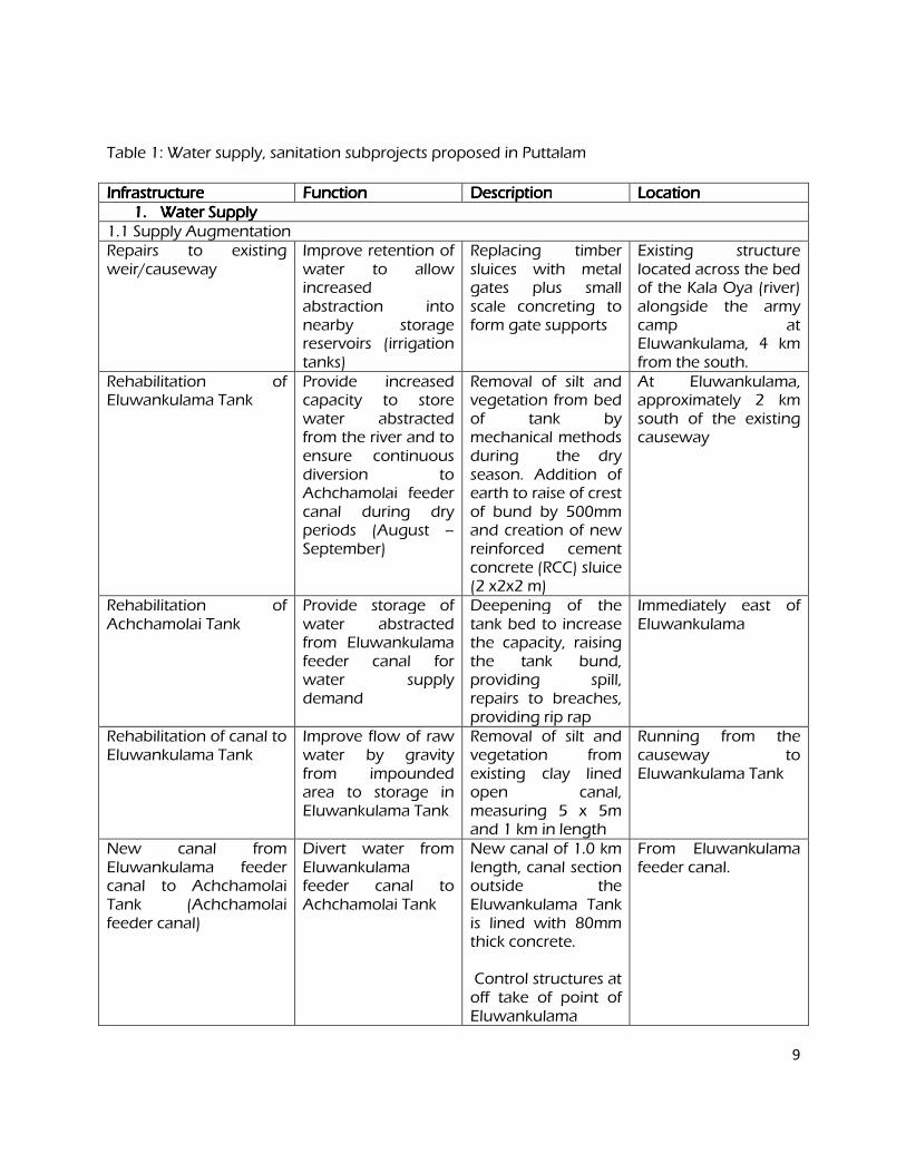
9
Table 1: Water supply, sanitation subprojects proposed in Puttalam
InfrastructureInfrastructureInfrastructureInfrastructure FunctionFunctionFunctionFunction DescriptionDescriptionDescriptionDescription Location Location Location Location 1.1.1.1. Water SupplyWater SupplyWater SupplyWater Supply
1.1 Supply Augmentation Repairs to existing weir/causeway
Improve retention of water to allow increased abstraction into nearby storage reservoirs (irrigation tanks)
Replacing timber sluices with metal gates plus small scale concreting to form gate supports
Existing structure located across the bed of the Kala Oya (river) alongside the army camp at Eluwankulama, 4 km from the south.
Rehabilitation of Eluwankulama Tank
Provide increased capacity to store water abstracted from the river and to ensure continuous diversion to Achchamolai feeder canal during dry periods (August – September)
Removal of silt and vegetation from bed of tank by mechanical methods during the dry season. Addition of earth to raise of crest of bund by 500mm and creation of new reinforced cement concrete (RCC) sluice (2 x2x2 m)
At Eluwankulama, approximately 2 km south of the existing causeway
Rehabilitation of Achchamolai Tank
Provide storage of water abstracted from Eluwankulama feeder canal for water supply demand
Deepening of the tank bed to increase the capacity, raising the tank bund, providing spill, repairs to breaches, providing rip rap
Immediately east of Eluwankulama
Rehabilitation of canal to Eluwankulama Tank
Improve flow of raw water by gravity from impounded area to storage in Eluwankulama Tank
Removal of silt and vegetation from existing clay lined open canal, measuring 5 x 5m and 1 km in length
Running from the causeway to Eluwankulama Tank
New canal from Eluwankulama feeder canal to Achchamolai Tank (Achchamolai feeder canal)
Divert water from Eluwankulama feeder canal to Achchamolai Tank
New canal of 1.0 km length, canal section outside the Eluwankulama Tank is lined with 80mm thick concrete. Control structures at off take of point of Eluwankulama
From Eluwankulama feeder canal.
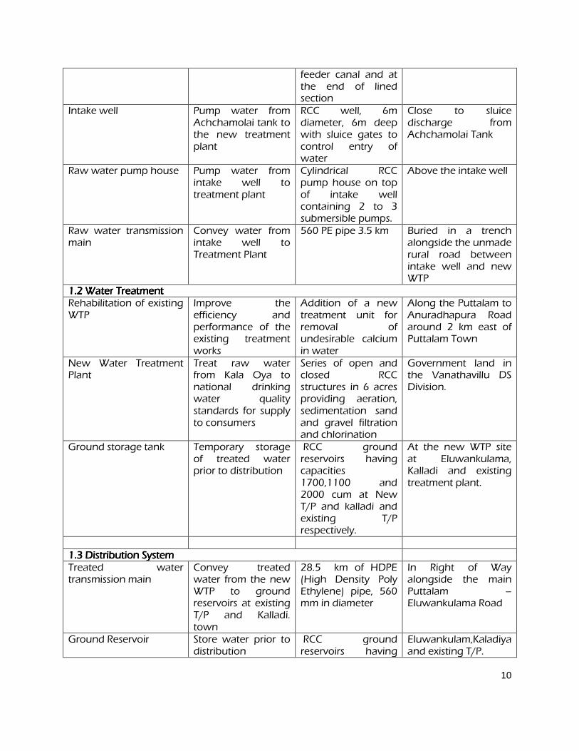
10
feeder canal and at the end of lined section
Intake well Pump water from Achchamolai tank to the new treatment plant
RCC well, 6m diameter, 6m deep with sluice gates to control entry of water
Close to sluice discharge from Achchamolai Tank
Raw water pump house Pump water from intake well to treatment plant
Cylindrical RCC pump house on top of intake well containing 2 to 3 submersible pumps.
Above the intake well
Raw water transmission main
Convey water from intake well to Treatment Plant
560 PE pipe 3.5 km Buried in a trench alongside the unmade rural road between intake well and new WTP
1.2 Water1.2 Water1.2 Water1.2 Water TreatmentTreatmentTreatmentTreatment Rehabilitation of existing WTP
Improve the efficiency and performance of the existing treatment works
Addition of a new treatment unit for removal of undesirable calcium in water
Along the Puttalam to Anuradhapura Road around 2 km east of Puttalam Town
New Water Treatment Plant
Treat raw water from Kala Oya to national drinking water quality standards for supply to consumers
Series of open and closed RCC structures in 6 acres providing aeration, sedimentation sand and gravel filtration and chlorination
Government land in the Vanathavillu DS Division.
Ground storage tank Temporary storage of treated water prior to distribution
RCC ground reservoirs having capacities 1700,1100 and 2000 cum at New T/P and kalladi and existing T/P respectively.
At the new WTP site at Eluwankulama, Kalladi and existing treatment plant.
1.3 Distribution System1.3 Distribution System1.3 Distribution System1.3 Distribution System Treated water transmission main
Convey treated water from the new WTP to ground reservoirs at existing T/P and Kalladi. town
28.5 km of HDPE (High Density Poly Ethylene) pipe, 560 mm in diameter
In Right of Way alongside the main Puttalam – Eluwankulama Road
Ground Reservoir Store water prior to distribution
RCC ground reservoirs having
Eluwankulam,Kaladiya and existing T/P.
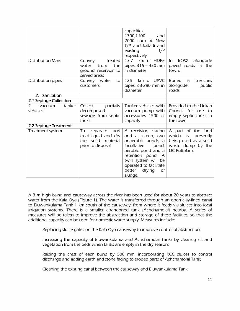
11
capacities 1700,1100 and 2000 cum at New T/P and kalladi and existing T/P respectively
Distribution Main Convey treated water from the ground reservoir to served areas
13.7 km of HDPE pipes, 315 – 450 mm in diameter
In ROW alongside paved roads in the town.
Distribution pipes Convey water to customers
125 km of UPVC pipes, 63-280 mm in diameter
Buried in trenches alongside public roads.
2.2.2.2. Sanitation Sanitation Sanitation Sanitation 2.1 Septage Collection 2.1 Septage Collection 2.1 Septage Collection 2.1 Septage Collection 2 vacuum tanker vehicles
Collect partially decomposed sewage from septic tanks
Tanker vehicles with vacuum pump with accessories 1500 lit capacity
Provided to the Urban Council for use to empty septic tanks in the town
2.2 Septage Treatment2.2 Septage Treatment2.2 Septage Treatment2.2 Septage Treatment Treatment system To separate and
treat liquid and dry the solid material prior to disposal
A receiving station and a screen, two anaerobic ponds, a facultative pond, aerobic pond and a retention pond. A twin system will be operated to facilitate better drying of sludge.
A part of the land which is presently being used as a solid waste dump by the UC Puttalam.
A 3 m high bund and causeway across the river has been used for about 20 years to abstract water from the Kala Oya (Figure 1). The water is transferred through an open clay-lined canal to Eluwankulama Tank 1 km south of the causeway, from where it feeds via sluices into local irrigation systems. There is a smaller abandoned tank (Achchamolai) nearby. A series of measures will be taken to improve the abstraction and storage of these facilities, so that the additional capacity can be used for domestic water supply. Measures include:
Replacing sluice gates on the Kala Oya causeway to improve control of abstraction; Increasing the capacity of Eluwankulama and Achchamolai Tanks by clearing silt and
vegetation from the beds when tanks are empty in the dry season; Raising the crest of each bund by 500 mm, incorporating RCC sluices to control
discharge and adding earth and stone facing to eroded parts of Achchamolai Tank; Cleaning the existing canal between the causeway and Eluwankulama Tank;
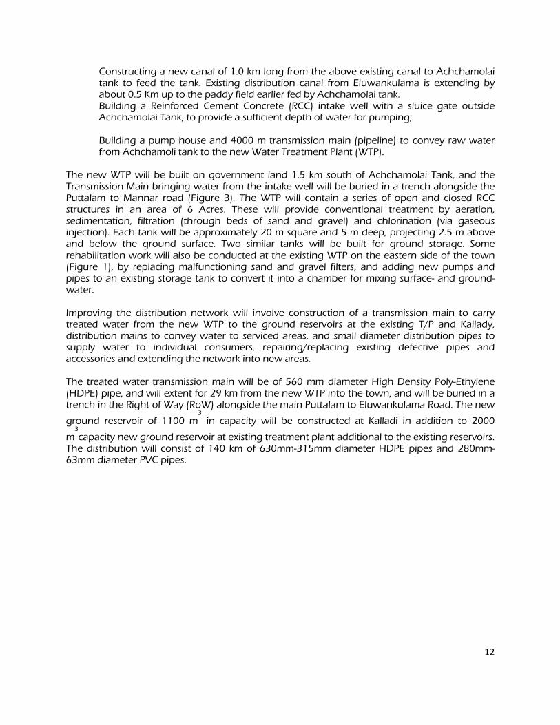
12
Constructing a new canal of 1.0 km long from the above existing canal to Achchamolai tank to feed the tank. Existing distribution canal from Eluwankulama is extending by about 0.5 Km up to the paddy field earlier fed by Achchamolai tank.
Building a Reinforced Cement Concrete (RCC) intake well with a sluice gate outside Achchamolai Tank, to provide a sufficient depth of water for pumping;
Building a pump house and 4000 m transmission main (pipeline) to convey raw water
from Achchamoli tank to the new Water Treatment Plant (WTP). The new WTP will be built on government land 1.5 km south of Achchamolai Tank, and the Transmission Main bringing water from the intake well will be buried in a trench alongside the Puttalam to Mannar road (Figure 3). The WTP will contain a series of open and closed RCC structures in an area of 6 Acres. These will provide conventional treatment by aeration, sedimentation, filtration (through beds of sand and gravel) and chlorination (via gaseous injection). Each tank will be approximately 20 m square and 5 m deep, projecting 2.5 m above and below the ground surface. Two similar tanks will be built for ground storage. Some rehabilitation work will also be conducted at the existing WTP on the eastern side of the town (Figure 1), by replacing malfunctioning sand and gravel filters, and adding new pumps and pipes to an existing storage tank to convert it into a chamber for mixing surface- and ground-water. Improving the distribution network will involve construction of a transmission main to carry treated water from the new WTP to the ground reservoirs at the existing T/P and Kallady, distribution mains to convey water to serviced areas, and small diameter distribution pipes to supply water to individual consumers, repairing/replacing existing defective pipes and accessories and extending the network into new areas. The treated water transmission main will be of 560 mm diameter High Density Poly-Ethylene (HDPE) pipe, and will extent for 29 km from the new WTP into the town, and will be buried in a trench in the Right of Way (RoW) alongside the main Puttalam to Eluwankulama Road. The new
ground reservoir of 1100 m3
in capacity will be constructed at Kalladi in addition to 2000
m3
capacity new ground reservoir at existing treatment plant additional to the existing reservoirs. The distribution will consist of 140 km of 630mm-315mm diameter HDPE pipes and 280mm-63mm diameter PVC pipes.
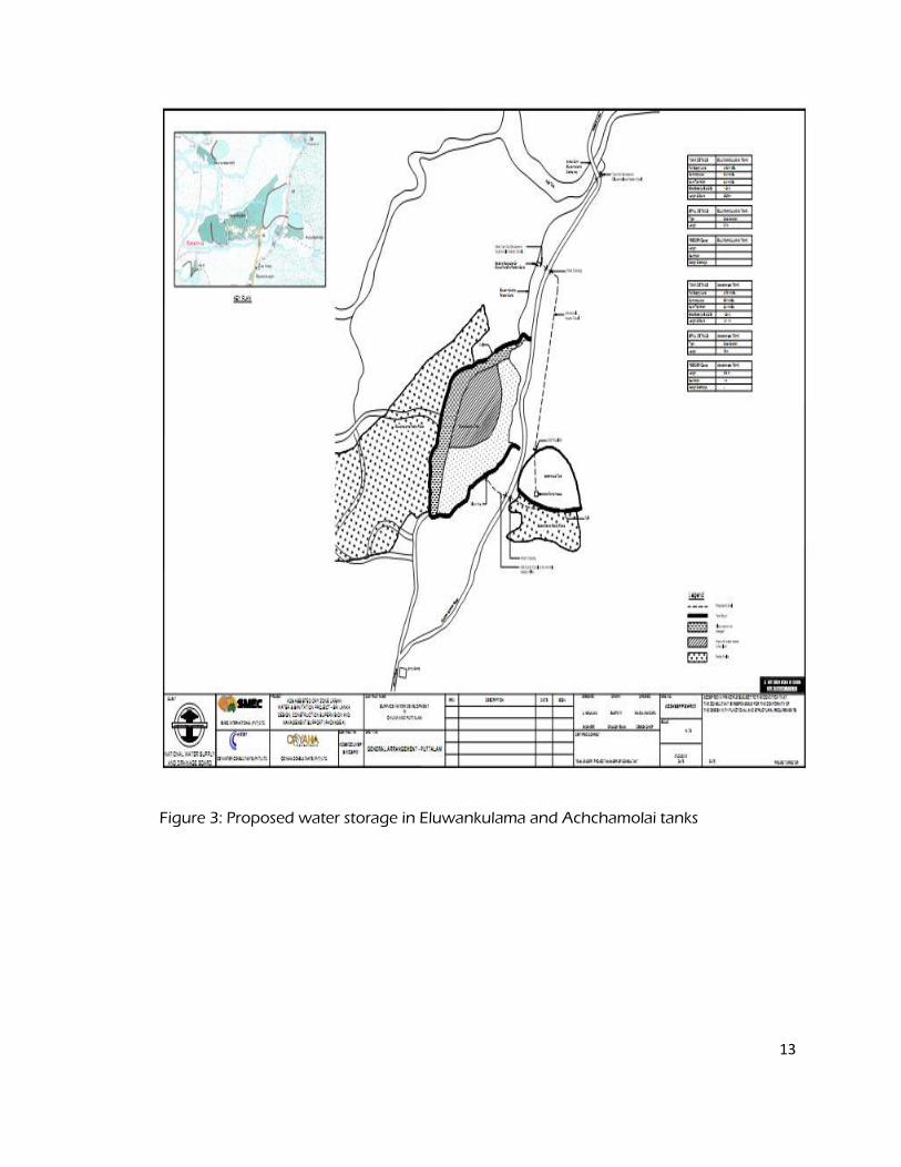
13
Figure 3: Proposed water storage in Eluwankulama and Achchamolai tanks
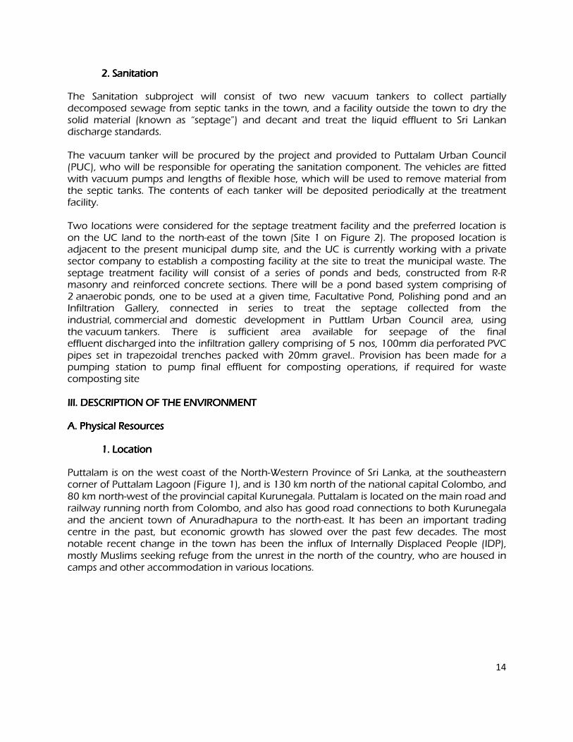
14
2. Sanitation 2. Sanitation 2. Sanitation 2. Sanitation
The Sanitation subproject will consist of two new vacuum tankers to collect partially decomposed sewage from septic tanks in the town, and a facility outside the town to dry the solid material (known as “septage”) and decant and treat the liquid effluent to Sri Lankan discharge standards. The vacuum tanker will be procured by the project and provided to Puttalam Urban Council (PUC), who will be responsible for operating the sanitation component. The vehicles are fitted with vacuum pumps and lengths of flexible hose, which will be used to remove material from the septic tanks. The contents of each tanker will be deposited periodically at the treatment facility. Two locations were considered for the septage treatment facility and the preferred location is on the UC land to the north-east of the town (Site 1 on Figure 2). The proposed location is adjacent to the present municipal dump site, and the UC is currently working with a private sector company to establish a composting facility at the site to treat the municipal waste. The septage treatment facility will consist of a series of ponds and beds, constructed from R-R masonry and reinforced concrete sections. There will be a pond based system comprising of 2 anaerobic ponds, one to be used at a given time, Facultative Pond, Polishing pond and an Infiltration Gallery, connected in series to treat the septage collected from the industrial, commercial and domestic development in Puttlam Urban Council area, using the vacuum tankers. There is sufficient area available for seepage of the final effluent discharged into the infiltration gallery comprising of 5 nos, 100mm dia perforated PVC pipes set in trapezoidal trenches packed with 20mm gravel.. Provision has been made for a pumping station to pump final effluent for composting operations, if required for waste composting site III. DESCRIPTION OF THE ENVIRONMENT III. DESCRIPTION OF THE ENVIRONMENT III. DESCRIPTION OF THE ENVIRONMENT III. DESCRIPTION OF THE ENVIRONMENT
A. Physical Resources A. Physical Resources A. Physical Resources A. Physical Resources
1. Location 1. Location 1. Location 1. Location
Puttalam is on the west coast of the North-Western Province of Sri Lanka, at the southeastern corner of Puttalam Lagoon (Figure 1), and is 130 km north of the national capital Colombo, and 80 km north-west of the provincial capital Kurunegala. Puttalam is located on the main road and railway running north from Colombo, and also has good road connections to both Kurunegala and the ancient town of Anuradhapura to the north-east. It has been an important trading centre in the past, but economic growth has slowed over the past few decades. The most notable recent change in the town has been the influx of Internally Displaced People (IDP), mostly Muslims seeking refuge from the unrest in the north of the country, who are housed in camps and other accommodation in various locations.

15
Figure 4: Layout of proposed Septage Treatment Facility Figure 4: Layout of proposed Septage Treatment Facility Figure 4: Layout of proposed Septage Treatment Facility Figure 4: Layout of proposed Septage Treatment Facility
Puttalam service are covered by the project is administered by Wanathawillu, Puttalam and Anamaduwa Divisional Secretaries and also by two Local Authorities (Puttalam Urban Council, Puttalam Pradesiya Sabah,Wanathawilluwa PS and Anamaduwa PS)....
2. Topography, Soil and Geology 2. Topography, Soil and Geology 2. Topography, Soil and Geology 2. Topography, Soil and Geology
Located at the coast, Puttalam is generally quite flat, although the land rises to around 60 m a few kilometres inland. Soils are mainly red-yellow latosols, and there are areas of reddish brown earth and low humic gley soils inland (Figure 3). To the north, in the floodplains of the Mee Oya and Kala Oya, soils are mainly alluvial, with variable texture and drainage; and there are pockets of solodized solonetz, solonchacks and marine calcareous deposits bordering Puttalam Lagoon. Geologically most of the area comprises rocks from the Miocene to Quarternary era, which dominate the coastal strip in the north of the country (Figure 5). Subsurface layers include red beds of ferruginized gravel, and alluvial and lagoon clay deposits over Miocene bedrock. The ferruginized gravel includes a mixture of coarse sand, fragments of chert and pellets of ironstone cemented with ferruginous material, and are the most likely source of the high iron content found in groundwater deposits. Inland the Precambrian Wanni complex becomes more obvious, and is characterised by a bedrock of granitic gneiss, overlain with sandy clay and/or laterite.
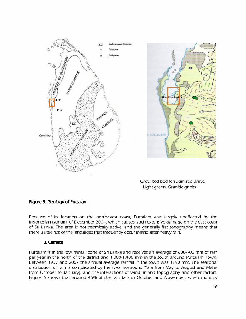
16
Grey: Red bed ferruginized gravel
Figure 5: Geology of Puttalam Figure 5: Geology of Puttalam Figure 5: Geology of Puttalam Figure 5: Geology of Puttalam
Because of its location on the north-west coast, Puttalam was largely unaffected by the Indonesian tsunami of December 2004, which caused such extensive damage on the east coast of Sri Lanka. The area is not seismically active, and the generally flat topography means that there is little risk of the landslides that frequently occur inland after heavy rain.
3. Climate 3. Climate 3. Climate 3. Climate
Puttalam is in the low rainfall zone of Sri Lanka and receives an average of 600-900 mm of rain per year in the north of the district and 1,000-1,400 mm in the south around Puttalam Town. Between 1957 and 2007 the annual average rainfall in the town was 1190 mm. The seasonal distribution of rain is complicated by the two monsoons (Yala from May to August and Maha from October to January), and the interactions of wind, inland topography and other factors. Figure 6 shows that around 45% of the rain falls in October and November, when monthly
Light green: Granitic gneiss
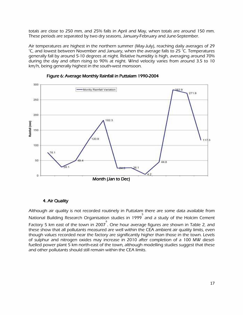
17
totals are close to 250 mm, and 25% falls in April and May, when totals are around 150 mm. These periods are separated by two dry seasons, January-February and June-September. Air temperatures are highest in the northern summer (May-July), reaching daily averages of 29 °C, and lowest between November and January, when the average falls to 25 °C. Temperatures generally fall by around 5-10 degrees at night. Relative humidity is high, averaging around 70% during the day and often rising to 90% at night. Wind velocity varies from around 3.5 to 10 km/h, being generally highest in the south-west monsoon.
Figure 6: Average Monthly Rainfall in Puttalam 1990Figure 6: Average Monthly Rainfall in Puttalam 1990Figure 6: Average Monthly Rainfall in Puttalam 1990Figure 6: Average Monthly Rainfall in Puttalam 1990----2004 2004 2004 2004
Month (Jan to Dec) Month (Jan to Dec) Month (Jan to Dec) Month (Jan to Dec)
4. 4. 4. 4. Air Quality Air Quality Air Quality Air Quality
Although air quality is not recorded routinely in Puttalam there are some data available from
National Building Research Organisation studies in 19995
and a study of the Holcim Cement
Factory 5 km east of the town in 20076
. One hour average figures are shown in Table 2, and these show that all pollutants measured are well within the CEA ambient air quality limits, even though values recorded near the factory are significantly higher than those in the town. Levels of sulphur and nitrogen oxides may increase in 2010 after completion of a 100 MW diesel-fuelled power plant 5 km north-east of the town, although modelling studies suggest that these and other pollutants should still remain within the CEA limits.
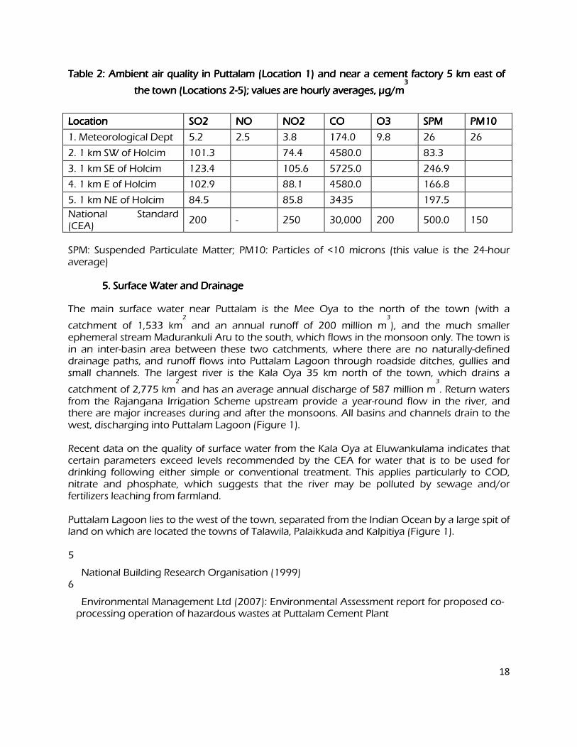
18
Table 2: Ambient air quality in PuTable 2: Ambient air quality in PuTable 2: Ambient air quality in PuTable 2: Ambient air quality in Puttalam (Location 1) and near a cement factory 5 km east of ttalam (Location 1) and near a cement factory 5 km east of ttalam (Location 1) and near a cement factory 5 km east of ttalam (Location 1) and near a cement factory 5 km east of
the town (Locations 2the town (Locations 2the town (Locations 2the town (Locations 2----5); values are hourly averages, 5); values are hourly averages, 5); values are hourly averages, 5); values are hourly averages, µµµµg/mg/mg/mg/m3 3 3 3
Location Location Location Location SO2 SO2 SO2 SO2 NO NO NO NO NO2 NO2 NO2 NO2 CO CO CO CO O3 O3 O3 O3 SPM SPM SPM SPM PM10 PM10 PM10 PM10
1. Meteorological Dept 5.2 2.5 3.8 174.0 9.8 26 26
2. 1 km SW of Holcim 101.3 74.4 4580.0 83.3
3. 1 km SE of Holcim 123.4 105.6 5725.0 246.9
4. 1 km E of Holcim 102.9 88.1 4580.0 166.8
5. 1 km NE of Holcim 84.5 85.8 3435 197.5
National Standard (CEA)
200 - 250 30,000 200 500.0 150
SPM: Suspended Particulate Matter; PM10: Particles of <10 microns (this value is the 24-hour average)
5. Surface Water and Drainage 5. Surface Water and Drainage 5. Surface Water and Drainage 5. Surface Water and Drainage
The main surface water near Puttalam is the Mee Oya to the north of the town (with a
catchment of 1,533 km2
and an annual runoff of 200 million m3
), and the much smaller ephemeral stream Madurankuli Aru to the south, which flows in the monsoon only. The town is in an inter-basin area between these two catchments, where there are no naturally-defined drainage paths, and runoff flows into Puttalam Lagoon through roadside ditches, gullies and small channels. The largest river is the Kala Oya 35 km north of the town, which drains a
catchment of 2,775 km2
and has an average annual discharge of 587 million m3
. Return waters from the Rajangana Irrigation Scheme upstream provide a year-round flow in the river, and there are major increases during and after the monsoons. All basins and channels drain to the west, discharging into Puttalam Lagoon (Figure 1). Recent data on the quality of surface water from the Kala Oya at Eluwankulama indicates that certain parameters exceed levels recommended by the CEA for water that is to be used for drinking following either simple or conventional treatment. This applies particularly to COD, nitrate and phosphate, which suggests that the river may be polluted by sewage and/or fertilizers leaching from farmland. Puttalam Lagoon lies to the west of the town, separated from the Indian Ocean by a large spit of land on which are located the towns of Talawila, Palaikkuda and Kalpitiya (Figure 1). 5
National Building Research Organisation (1999) 6
Environmental Management Ltd (2007): Environmental Assessment report for proposed co-processing operation of hazardous wastes at Puttalam Cement Plant

19
Table 3: WTable 3: WTable 3: WTable 3: Water quality of Kala Oya at Eluwankulama in 2003 (monthly average) ater quality of Kala Oya at Eluwankulama in 2003 (monthly average) ater quality of Kala Oya at Eluwankulama in 2003 (monthly average) ater quality of Kala Oya at Eluwankulama in 2003 (monthly average)
Parameter Parameter Parameter Parameter Unit Unit Unit Unit Jan Jan Jan Jan Feb Feb Feb Feb Mar Mar Mar Mar May May May May Jun Jun Jun Jun Jul Jul Jul Jul Aug Aug Aug Aug Sep Sep Sep Sep Oct Oct Oct Oct Nov Nov Nov Nov ST ST ST ST CT CT CT CT
Turbidity NTU 7.0 2.8 8.0 15.0 6.0 7.8 6.3 5.1 17.0 5
Conductivity µs/cm 431 602 483 499 526 510 546 98 607 564
pH
7.7 8.3 7.6 7.8 9.4 7.8 8.3 7.9 8.4 6-8.5
6-9
Total Alkalinity
mg/l CaCO3
190 240 238 211 257 251 255 286 249 263
Dissolved Oxygen
mg/l 6.9 5.6 5.7 5.8 6.4 6.0 6.6 5.0 6.0 5.9 6 4
COD mg/l 27.9 27.3 15.2 23.5 36.6 12.4 35.1 22.4 15 30
Sodium mg/l 128 182 150 196 174 368 231 220 211 155
Potassium mg/l 4.6 2.5 3.4 5.4 2.4 2.9 4.2 0.0 6.6 5.2
Calcium mg/l 35.1 39.5 41.5 32.8 40.4 38.9 35.3 39.6 56.9 40.3
Magnesium mg/l 18.0 21.0 15.8 16.3 19.4 21.5 19.3 25.8 7.2 21.2
Fluoride mg/l 0.7 0.9 1.0 0.8 0.9 1.0 1.0 1.2 1.0 1.6 1.5 1.5
Chloride mg/l
61.6
51.6 66.7 84.4 66.5 120.5 75.2 112.0 89.2
200 200
Nitrate mg/l 7.5 11.7 18.0 16.7 18.6 27.3 33.6 43.8 86.2 57.3 5 5
Phosphate mg/l 3.6 2.0 3.0 2.0 2.8 1.2 2.2 3.0 0.7 0.9 0.7 0.7
Sulphate mg/l 7.1 13.4 2.4 0.0 4.3 0.0 19.4 17.7 0.6 10.3 250 250
Source: Sri Lanka Mahaveli Authority (2003), Kala Oya Basin Study. ST, CT: CEA standards for water suitable as a source for drinking water with simple (ST) or conventional treatment (CT)
The lagoon was artificially extended in the south by the construction of the Dutch Canal
system in the 17th
and 18th
centuries, which was the main transportation route from Colombo to Puttalam at that time. Together these two water bodies form a major wetland that covers 46,000 ha, and is around 63 km in length and up to 11 km wide, but only 2-3 m deep at high water. All of the rivers in the area drain into the lagoon, and there is a wide but shallow connection with the sea in the north.
A study by the CEA in 1994 reported that salinity in the lagoon varied between 38-53 ppt, and had risen by around 25% between 1960 and1990, because of increased abstraction of
river water for irrigation. More recent data on water quality from the Dutch Canal Study7
of 2002 recorded high levels of nitrate, nitrite, ammonia and organic matter (COD and BOD) and low levels of oxygen (Table 4), suggesting that the lagoon is polluted by sewage and is
possibly also eutrophic8
.
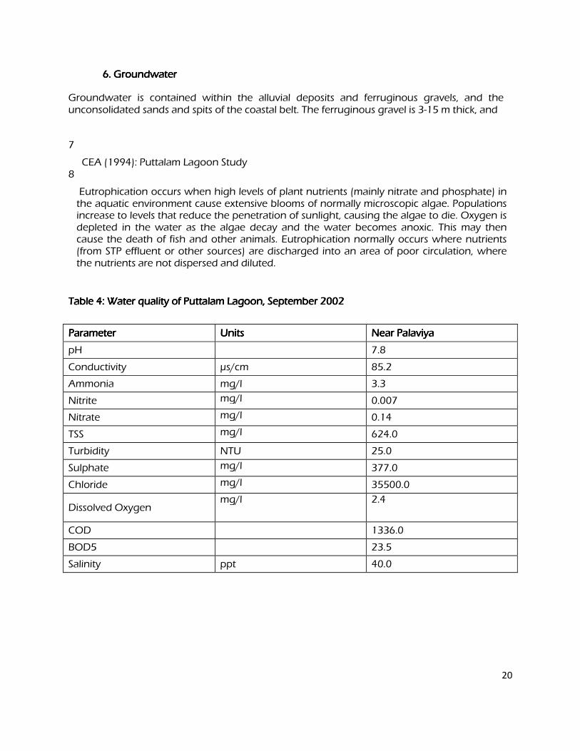
20
6. Groundwater 6. Groundwater 6. Groundwater 6. Groundwater
Groundwater is contained within the alluvial deposits and ferruginous gravels, and the unconsolidated sands and spits of the coastal belt. The ferruginous gravel is 3-15 m thick, and
7
CEA (1994): Puttalam Lagoon Study 8
Eutrophication occurs when high levels of plant nutrients (mainly nitrate and phosphate) in the aquatic environment cause extensive blooms of normally microscopic algae. Populations increase to levels that reduce the penetration of sunlight, causing the algae to die. Oxygen is depleted in the water as the algae decay and the water becomes anoxic. This may then cause the death of fish and other animals. Eutrophication normally occurs where nutrients (from STP effluent or other sources) are discharged into an area of poor circulation, where the nutrients are not dispersed and diluted.
Table 4: Water quality of Puttalam Lagoon, SeptembeTable 4: Water quality of Puttalam Lagoon, SeptembeTable 4: Water quality of Puttalam Lagoon, SeptembeTable 4: Water quality of Puttalam Lagoon, September 2002 r 2002 r 2002 r 2002
Parameter Parameter Parameter Parameter Units Units Units Units Near Palaviya Near Palaviya Near Palaviya Near Palaviya
pH 7.8
Conductivity µs/cm 85.2
Ammonia mg/l 3.3
Nitrite mg/l 0.007
Nitrate mg/l 0.14
TSS mg/l 624.0
Turbidity NTU 25.0
Sulphate mg/l 377.0
Chloride mg/l 35500.0
Dissolved Oxygen mg/l 2.4
COD 1336.0
BOD5 23.5
Salinity ppt 40.0
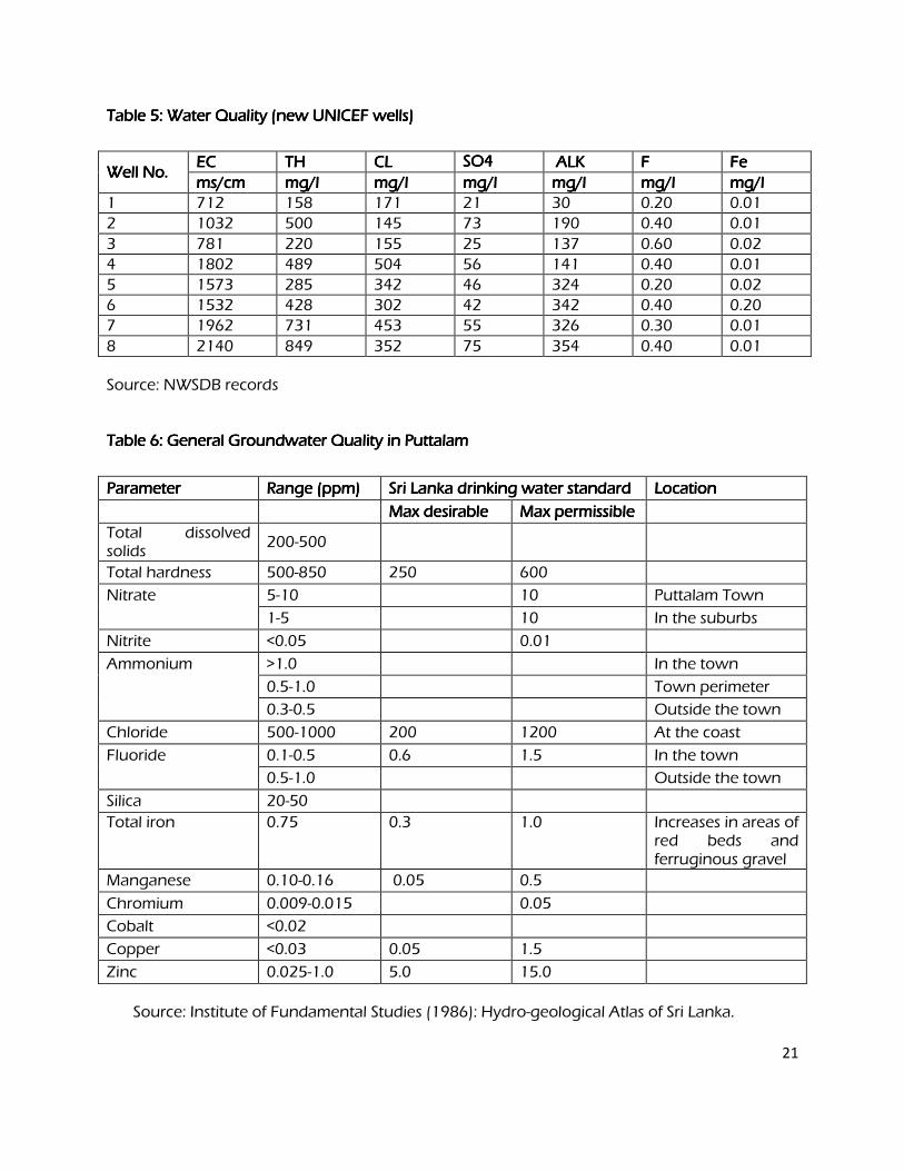
21
Table 5: Water Quality (new UNICEF wells) Table 5: Water Quality (new UNICEF wells) Table 5: Water Quality (new UNICEF wells) Table 5: Water Quality (new UNICEF wells)
Well No. Well No. Well No. Well No. EC EC EC EC TH TH TH TH CL CL CL CL SO4SO4SO4SO4 ALK ALK ALK ALK F F F F Fe Fe Fe Fe
ms/cm ms/cm ms/cm ms/cm mg/l mg/l mg/l mg/l mg/l mg/l mg/l mg/l mg/l mg/l mg/l mg/l mg/l mg/l mg/l mg/l mg/l mg/l mg/l mg/l mg/l mg/l mg/l mg/l
1 712 158 171 21 30 0.20 0.01
2 1032 500 145 73 190 0.40 0.01
3 781 220 155 25 137 0.60 0.02
4 1802 489 504 56 141 0.40 0.01
5 1573 285 342 46 324 0.20 0.02
6 1532 428 302 42 342 0.40 0.20
7 1962 731 453 55 326 0.30 0.01
8 2140 849 352 75 354 0.40 0.01 Source: NWSDB records Table 6: General Groundwater Quality in Puttalam Table 6: General Groundwater Quality in Puttalam Table 6: General Groundwater Quality in Puttalam Table 6: General Groundwater Quality in Puttalam
Parameter Parameter Parameter Parameter Range (ppm) Range (ppm) Range (ppm) Range (ppm) Sri Lanka drinking water standard Sri Lanka drinking water standard Sri Lanka drinking water standard Sri Lanka drinking water standard Location Location Location Location
Max desirable Max desirable Max desirable Max desirable Max permissible Max permissible Max permissible Max permissible
Total dissolved solids
200-500
Total hardness 500-850 250 600
Nitrate 5-10 10 Puttalam Town
1-5 10 In the suburbs
Nitrite <0.05 0.01
Ammonium >1.0 In the town
0.5-1.0 Town perimeter
0.3-0.5 Outside the town
Chloride 500-1000 200 1200 At the coast
Fluoride 0.1-0.5 0.6 1.5 In the town
0.5-1.0 Outside the town
Silica 20-50
Total iron 0.75 0.3 1.0 Increases in areas of red beds and ferruginous gravel
Manganese 0.10-0.16 0.05 0.5
Chromium 0.009-0.015 0.05
Cobalt <0.02
Copper <0.03 0.05 1.5
Zinc 0.025-1.0 5.0 15.0
Source: Institute of Fundamental Studies (1986): Hydro-geological Atlas of Sri Lanka.
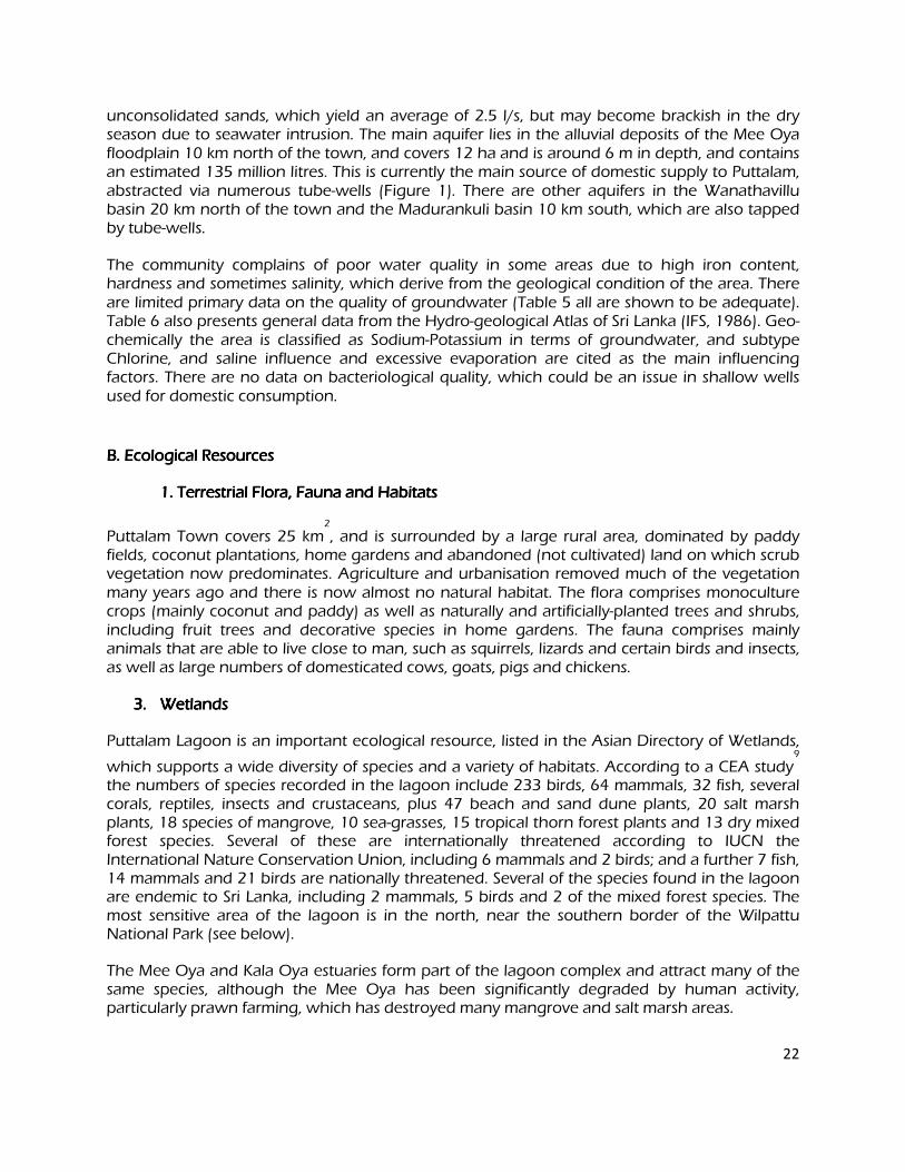
22
unconsolidated sands, which yield an average of 2.5 l/s, but may become brackish in the dry season due to seawater intrusion. The main aquifer lies in the alluvial deposits of the Mee Oya floodplain 10 km north of the town, and covers 12 ha and is around 6 m in depth, and contains an estimated 135 million litres. This is currently the main source of domestic supply to Puttalam, abstracted via numerous tube-wells (Figure 1). There are other aquifers in the Wanathavillu basin 20 km north of the town and the Madurankuli basin 10 km south, which are also tapped by tube-wells.
The community complains of poor water quality in some areas due to high iron content, hardness and sometimes salinity, which derive from the geological condition of the area. There are limited primary data on the quality of groundwater (Table 5 all are shown to be adequate). Table 6 also presents general data from the Hydro-geological Atlas of Sri Lanka (IFS, 1986). Geo-chemically the area is classified as Sodium-Potassium in terms of groundwater, and subtype Chlorine, and saline influence and excessive evaporation are cited as the main influencing factors. There are no data on bacteriological quality, which could be an issue in shallow wells used for domestic consumption.
B. Ecological Resources B. Ecological Resources B. Ecological Resources B. Ecological Resources
1. Terrestrial Flora, Fauna and Habitats 1. Terrestrial Flora, Fauna and Habitats 1. Terrestrial Flora, Fauna and Habitats 1. Terrestrial Flora, Fauna and Habitats
Puttalam Town covers 25 km2
, and is surrounded by a large rural area, dominated by paddy fields, coconut plantations, home gardens and abandoned (not cultivated) land on which scrub vegetation now predominates. Agriculture and urbanisation removed much of the vegetation many years ago and there is now almost no natural habitat. The flora comprises monoculture crops (mainly coconut and paddy) as well as naturally and artificially-planted trees and shrubs, including fruit trees and decorative species in home gardens. The fauna comprises mainly animals that are able to live close to man, such as squirrels, lizards and certain birds and insects, as well as large numbers of domesticated cows, goats, pigs and chickens.
3.3.3.3. Wetlands Wetlands Wetlands Wetlands
Puttalam Lagoon is an important ecological resource, listed in the Asian Directory of Wetlands,
which supports a wide diversity of species and a variety of habitats. According to a CEA study9
the numbers of species recorded in the lagoon include 233 birds, 64 mammals, 32 fish, several corals, reptiles, insects and crustaceans, plus 47 beach and sand dune plants, 20 salt marsh plants, 18 species of mangrove, 10 sea-grasses, 15 tropical thorn forest plants and 13 dry mixed forest species. Several of these are internationally threatened according to IUCN the International Nature Conservation Union, including 6 mammals and 2 birds; and a further 7 fish, 14 mammals and 21 birds are nationally threatened. Several of the species found in the lagoon are endemic to Sri Lanka, including 2 mammals, 5 birds and 2 of the mixed forest species. The most sensitive area of the lagoon is in the north, near the southern border of the Wilpattu National Park (see below).
The Mee Oya and Kala Oya estuaries form part of the lagoon complex and attract many of the same species, although the Mee Oya has been significantly degraded by human activity, particularly prawn farming, which has destroyed many mangrove and salt marsh areas.
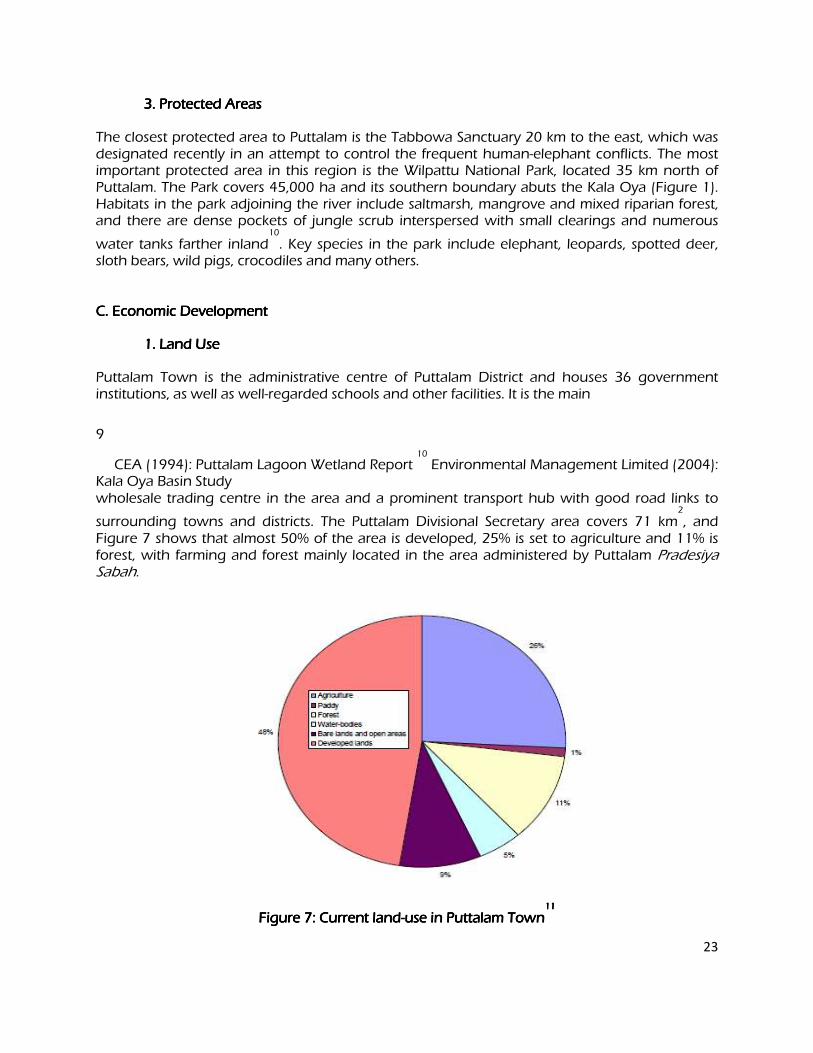
23
3. Protected Areas 3. Protected Areas 3. Protected Areas 3. Protected Areas The closest protected area to Puttalam is the Tabbowa Sanctuary 20 km to the east, which was designated recently in an attempt to control the frequent human-elephant conflicts. The most important protected area in this region is the Wilpattu National Park, located 35 km north of Puttalam. The Park covers 45,000 ha and its southern boundary abuts the Kala Oya (Figure 1). Habitats in the park adjoining the river include saltmarsh, mangrove and mixed riparian forest, and there are dense pockets of jungle scrub interspersed with small clearings and numerous
water tanks farther inland10
. Key species in the park include elephant, leopards, spotted deer, sloth bears, wild pigs, crocodiles and many others. C. Economic Development C. Economic Development C. Economic Development C. Economic Development
1. Land Use 1. Land Use 1. Land Use 1. Land Use
Puttalam Town is the administrative centre of Puttalam District and houses 36 government institutions, as well as well-regarded schools and other facilities. It is the main
9
CEA (1994): Puttalam Lagoon Wetland Report 10
Environmental Management Limited (2004): Kala Oya Basin Study wholesale trading centre in the area and a prominent transport hub with good road links to
surrounding towns and districts. The Puttalam Divisional Secretary area covers 71 km2
, and Figure 7 shows that almost 50% of the area is developed, 25% is set to agriculture and 11% is forest, with farming and forest mainly located in the area administered by Puttalam Pradesiya Sabah.
Figure 7: Current landFigure 7: Current landFigure 7: Current landFigure 7: Current land----use in Puttalam Townuse in Puttalam Townuse in Puttalam Townuse in Puttalam Town11111111
24
The Wanathavillu DS area to the north of the town is much more rural in character and is one of
the least developed areas in the country. It covers 710 km2
(one of the largest DS areas), of which more than 85% is classified as government land, mainly forest, scrub or degraded forest.
2. Industry and Agriculture 2. Industry and Agriculture 2. Industry and Agriculture 2. Industry and Agriculture
There are two large-scale industries in Puttalam: the Holcim Cement Factory 5 km south-east of the town and the Puttalam salterns (producing salt by evaporating seawater in salt pans) in the coastal strip. As noted above, a new 100 MW coal power plant is currently under construction 5 km east of the town, and the government is also preparing to establish a 60 ha industrial zone at Kaladiya on the Kurunegala Road. The remaining industry is small and mainly involved in manufacturing, including light engineering (producing household items), brick factories, coir manufacture, ice plants, garments, etc. The only large industry in Wanathavillu is the dolomite mining at Aruwakalu, owned by the cement plant. There are also 172 small industries in this area (salterns, engineering workshops, car repair, etc), employing 252 persons. Puttalam is also an important centre for the retail trade, with 570 registered retail businesses, selling mainly grocery items, textiles and garments.
11
Environmental Profile of Puttalam District (CEA 2002)
Agriculture is also an important sector, and there are 1800 ha of land producing coconut (mainly processed outside the area) and 930 ha of paddy, in which cropping intensity is low, mainly because of insufficient water. Prawn farming was important in the past, but this declined following the outbreaks of viral disease in the 1990s. There are also 950 families involved in the lagoon fishery, supported by five boat anchorages, an ice plant and an extension service. Animal husbandry also contributes significantly to the economy, particularly the ten poultry farms. Agriculture is dominant in Wanathavillu, including coconut, paddy and banana, and this is the main cashew producing area in the country.
3. Infrastructure 3. Infrastructure 3. Infrastructure 3. Infrastructure
NWSDB provides water through a piped system to Puttalam town, extracting groundwater from tube-wells, mainly along the Mee Oya (Figure 1). There are serious problems of quality and quantity and the service is available for only a few hours per day, and treatment does not significantly reduce the hardness or iron content. Large numbers of people await a mains connection, and there is no public system in Wanathavillu. There are several Community Operated Water Supply Schemes using tube-wells, but these involve little or no treatment and suffer similar problems of limited availability and poor quality. There is no sewerage system in Puttalam, where wastewater disposal is through on-site methods, a combination of septic tanks and pour-flush pit latrines. In the centre of the town the building density is too high for the effective use of septic tanks and many commercial premises discharge wastewater into storm drains.
25
There are open concrete drains alongside roads, shops and houses in most of the urban area, through which storm-water is discharged into the lagoon. However grey water from domestic washing and business premises is released into drains, which are inadequately maintained and frequently clogged with garbage and silt. As a result many drains are stagnant and unsanitary, and localised flooding occurs during rain. Outside the town drainage is mainly by roadside ditches, irrigation canals and natural streams, and flash-flooding occurs in certain low-lying areas. Puttalam Urban Council is responsible for the disposal of solid waste from the town, which is produced at a rate of 4-5 tons/day. This creates a major problem as there is no engineered landfill and refuse is collected by truck and transported to the outskirts where it is simply dumped on open ground. Solid waste is less of a problem in the rural areas as there is generally enough space in home gardens to allow on site disposal by burning or burial. Power in Puttalam is supplied by the Ceylon Electricity Board via the national grid, for which power is generated by mainly oil-fired thermal stations. At present there are around 14,500 houses in the urban area, and around 60% have a power supply. However in the more rural area of Wanathavillu only around a third of the houses are connected to the grid. Power is supplied by overhead cables carried on metal and concrete poles, mainly located in public areas alongside roads , power supply is erratic and there are frequent outages in warmer months, and large fluctuations in voltage. 4. Transportation 4. Transportation 4. Transportation 4. Transportation
Puttalam is at the junction of three important trunk roads: the A3 Colombo-Puttalam highway from the south; the A10 from Kurunegala in the south-east; and the A12 from Anuradhapura in the north-east (Figure 1). These are national roads maintained by the Road Development Authority, who are also responsible for 26 km of regionally important B-grade roads in the area, such as the Puttalam to Kalpitiya road. Villages outside the town are served by minor roads maintained by the local authority, some of which are tarred, although most are surfaced with gravel and many are in need of repair. The area is also served by the Colombo-Puttalam railway, which runs north beyond Wanathavillu by a branch maintained by the Holcim Cement Company, which is used to transport raw material from Aruwakalu quarry to the factory in Puttalam. Public buses provide the main mode of transportation for most of the population, and there are a variety of conveyances and routes in the town and to the surrounding areas and districts. Goods are mainly transported by truck because of the unreliability of the rail service. There are large numbers of vehicles in the centre of the town, particularly at road intersections and the main shopping areas, where the narrower streets are often congested . There are fewer vehicles in the outskirts, where traffic jams are generally not a major problem . D. Social and Cultural Resources D. Social and Cultural Resources D. Social and Cultural Resources D. Social and Cultural Resources
1. Demography 1. Demography 1. Demography 1. Demography
According to data from the Divisional Secretary’s office, in 2006 the population of Puttalam DS area was 70,969 and has risen over the past few years mainly because of influxes of Internally Displaced Persons (IDP), who now total around 7,000 persons. The gender ratio in the town is
almost exactly 1:1, and the population density is an average of 999/km2
. In contrast there are
26
17,740 people living in the larger but more rural Wanathavillu DS area, at a density of only
24/km2
. Literacy is good in both Puttalam and Wanathavillu, where 36% of people reach Grade 6 at secondary school and only around 10% of children do not attend school. In Puttalam around 50% of the population is Muslim, followed by Sinhalese (34%), Tamil (12%) and 2% Burghurs
(descendents of Portuguese and Dutch settlers from the 16th
and 17th
centuries). In contrast in Wanathavillu the Sinhalese population is in the majority (60%), followed by Muslim (34%) and Tamil (7%). Buddhism is the main religion of the Sinhalese, and Tamils are mainly Hindu, and both communities include some Christians. Islam is the main religion in Puttalam and Buddhism in Wanathavillu. 2. Socio2. Socio2. Socio2. Socio----Economics Economics Economics Economics
Currently around 40,000 people are of working age (18-60 years) in Puttalam and around 10,000 in Wanathavillu. There are no reliable data on the number of unemployed persons in Puttalam, but based on other towns in the region (such as Chilaw) it is likely to be high, possibly as much as 20-30%. Unemployment is lower in Wanathavillu, at around 14%, mainly because of the seasonal availability of jobs in the agricultural sector. Employed people are mainly involved in agriculture (and fishing in Puttalam), plus trading/business, and the government and private sectors. There are currently 14,470 housing units in Puttalam, comprising 10,292 permanent houses, 2,188 semi-permanent and 1,990 temporary dwellings. A very high proportion of people own their own houses (11,914 families). Only 960 families live in rented accommodation, 1,013 are squatters occupying land illegally, 78 families live in government quarters and 1,450 families (9%) have no house. Income distribution is similar in Puttalam and Wanathavillu, where 21-24% of families have a monthly income of over SLR 5,000 and 15-18% of families live on less than SLR 1,000 per month. The extent of poverty is indicated by the number of families receiving Samurdhi benefits (a Government income support programme for the poor), which is 38% in Puttalam and 52% in Wanathavillu. 3. Health and Educational Facilities 3. Health and Educational Facilities 3. Health and Educational Facilities 3. Health and Educational Facilities
As is common in most countries, health, education and other facilities are more numerous and of better quality in the urban areas than in rural Wanathavillu. Puttalam has one base hospital with a number of speciality clinics and doctors, and there are also a number of public and private general clinics and dispensaries. In Wanathavillu there is one maternity home and only 7 public clinics and 6 dispensaries, of which three practice arurveda (indigenous remedies). Public health is the responsibility of a Medical Officer of Health (MOH) appointed by the Government, and there are 7 Public Health Inspectors (PHI) and 19 Family Health Nurses. People in Wanathavillu are heavily dependent on the facilities and services in Puttalam, which causes problems of both cost and transport. There are no publicly-available data on public health and although statistics on the incidence of disease were requested from the Ministry of Health, no information was provided.
27
There are 63 pre-schools and 9 schools in Puttalam, including one national school and two central colleges, with a total of 20,200 pupils and 783 teachers, providing a good pupil/ teacher ratio of 26. In Wanathavillu there are 14 pre-schools and 5 schools, with 990 pupils and 37 teachers. Although the schools in Puttalam are better-equipped than those in Wanathavillu, Puttalam schools are generally less well regarded than those in neighbouring regional towns, such as Chilaw. There are two vocational training institutions in Puttalam, with 75 students and 5 instructors. There are no similar institutions in Wanathavillu. 4. History, Culture and Tourism 4. History, Culture and Tourism 4. History, Culture and Tourism 4. History, Culture and Tourism
Numerous social organisations and NGOs operate in the study area. Most villages have death donation schemes, which support family members at times of bereavement, and these may also have money-lending and saving functions. Women’s groups and youth and sports clubs are also common, and farmer associations are prominent and important. Most NGOs assist communities in dealing with health and social issues or work on environmental matters, and there are some that operate micro-credit schemes to encourage cottage industry. There are a variety of buildings and areas that are important to the different religious communities, including 52 mosques, 23 Christian churches, 13 temples and 12 Hindu kovils. There are also a small number of locations of historical importance including a Dutch fort on the peninsula road south of the town that dates from 1670 and is still manned by the Sri Lankan army; and a Catholic shrine to St Anne at Talawila, which is visited by thousands of pilgrims in May and July when there are festivals honouring St Anne, and processions and healing services. There are no attractions in this area for tourists and none of the necessary infrastructure such as hotels and resorts, and there are also few visitors from within Sri Lanka. IV. ENVIRONMENTAL IMPACTS AND MITIGATION: INFRASTRUCTURIV. ENVIRONMENTAL IMPACTS AND MITIGATION: INFRASTRUCTURIV. ENVIRONMENTAL IMPACTS AND MITIGATION: INFRASTRUCTURIV. ENVIRONMENTAL IMPACTS AND MITIGATION: INFRASTRUCTURE CONSTRUCTIOCONSTRUCTIOCONSTRUCTIOCONSTRUCTION
A. Screening out areas of no significant impact A. Screening out areas of no significant impact A. Screening out areas of no significant impact A. Screening out areas of no significant impact
From the descriptions given in Section II.C it is clear that implementation of the project will affect most of the commercial area in the centre of Puttalam town, where trenches will be dug to replace existing water supply pipes and expand the network, and existing drains will be cleared and repaired. Areas outside the town will also be affected by construction of the water mains, treatment plants and other elements. However it is not expected that the construction work will cause major negative impacts. This is mainly because: Most network improvements will be located on unused ground alongside existing roads
and can be constructed without causing major disruption to road users and adjacent houses, shops and other businesses;
New facilities in and outside the town (OR, PS, septage treatment) will be located on government-owned land that is not occupied or used for any other purpose;
Most network construction will be conducted by small teams working on short lengths at a time so most impacts will be localised and short in duration;
The overall construction programme will be relatively short for a project of this nature,
28
and is expected to be completed in 2-3 years.
As a result there are several aspects of the environment that are not expected to be affected by the construction process and these can be screened out of the assessment at this stage as required by ADB procedure. These are shown in Table 7, with an explanation of the reasoning in each case. These environmental factors have thus been screened out and will not be mentioned further in assessing the impacts of the construction process. Table 7: Fields in which construction is not expected to have significant impacts Table 7: Fields in which construction is not expected to have significant impacts Table 7: Fields in which construction is not expected to have significant impacts Table 7: Fields in which construction is not expected to have significant impacts
Field Field Field Field Rationale Rationale Rationale Rationale
Climate Short-term production of dust is the only effect on atmosphere
Geology and seismology Excavation will not be large enough to affect these features
Tourism There is no significant tourism in and around Puttalam
Population and communities
Construction will not affect population numbers, location or composition
Archaeology, palaeontology
No material of archaeological or palaeontological significance has been found by previous construction projects, and this is not an area of major historical importance
B. Augmentation of Water Supply and Treatment B. Augmentation of Water Supply and Treatment B. Augmentation of Water Supply and Treatment B. Augmentation of Water Supply and Treatment
1. Construction Method 1. Construction Method 1. Construction Method 1. Construction Method
As explained above, augmentation of the water supply will involve:
Improving abstraction control by replacing sluice gates on the Kala Oya causeway; Cleaning the existing canal between the causeway and Eluwankulama Tank and
building a new 1.0 km channel from the Eluwankulama feeder canal to Achchamolai Tank;
Increasing the capacity of Eluwankulama and Achchamolai Tanks by removing silt and vegetation and adding soil to raise the crest of the bunds by 500 mm;
Repairing and reconstructing the breached sections of Achchamolai existing bund and strengthening it.
Building a RCC intake well, plus a pump house and 3.5km raw water transmission main to convey water to the new WTP.
Improving water treatment will involve construction of:
A new WTP on 6 Acre of land in Eluwankulaml, comprising a series of RCC structures to provide aeration, sedimentation, sand filtration, chlorination and water storage;
Replacement of sand/gravel filters at the existing WTP to the east of the town and providing new pumps and pipes to convert an existing tank to a mixing chamber.
29
Construction will therefore involve a complex series of interrelated activities, some of which are quite large in scale. It will however entail relatively straightforward methods, mainly simple excavation and the creation of structures from Reinforced Cement Concrete (RCC). The de-silting operation will be conducted in the dry season, after any remaining water has been pumped from the tanks and the existing canal into irrigation channels. Silt and vegetation will then be removed by bulldozers and backhoe diggers and piled onto vacant land nearby, where it will be allowed to drain and dry out in the sun. The bunds of the two tanks will then be refurbished by placing soil (from the bed of the tank) onto the crest and eroded sides of each bund by backhoe digger, after which the soil is compressed by a hand operated vibrating compactor. Medium-grade stone from local quarries will then be tipped from trucks onto the inside face of the repaired areas to provide the rip-rap erosion protection. Areas to be excavated include: dredging of Eluwankulam tank; deppening Achchamolai tank; 1.0 Km Achchamolai feeder canal , extending Eluwankulam distribution canal by 500m;intake well, transmission main and treatment facilities at the WTP site. These locations will first be cleared of vegetation by hand and bulldozer, after which each area is excavated to the required dimensions by mechanical means, and waste soil and stone are loaded onto trucks and taken offsite for disposal. The RCC structures (sluice gates, spillways, intake well and pump house, and the tanks at the WTP) will then all be constructed in the same way. Metal reinforcing bars are first put into position by hand in the locations of the foundations, walls and other solid structures, after which sections of reinforcing are encased in wooden shuttering. Concrete (mixed on site) is then poured into the shuttered sections and allowed to dry, after which the shuttering is removed and where necessary surface blemishes are smoothed by masons applying concrete by hand. This process is then repeated in adjacent areas to gradually create the RCC structure. Other components are then added, including the pipes and pumps at the WTP, metal sluice gates and lifting mechanism, etc. These will be brought to site on trucks and offloaded and placed into position by a small crane, and connected up by hand. Trenches will then be refilled by hand and any remaining material is removed on trucks for disposal. Work on the causeway will be conducted in the dry season when the reduced flow in the river can be diverted away from working areas by bunds formed by excavating sand from the river bed. Existing wooden sluice gates will be removed and the channels into which the gates slide will be enlarged by drilling out the existing concrete and creating new RCC structures. After drying, the metal sluice gates will be inserted into the channels by means of a small crane and the control mechanism will be fitted to the top. Rehabilitation of the existing WTP outside the town will involve replacement of faulty sand filters and conversion of an existing tank to a chamber in which groundwater and surface water will be mixed. Sand will be removed from the malfunctioning units by hand digging, and new sand will be brought in on trucks and lifted into the tanks by crane. Additional pipes and pumps will be put into place alongside the mixing tank by crane and connected up by hand.
30
2. Physical Resources 2. Physical Resources 2. Physical Resources 2. Physical Resources
Replacement of sand filters and provision of new pumps and pipes at the existing WTP will not have significant environmental impacts as it will involve small-scale work, conducted at an existing operating facility. The remainder of the work in this component is however much larger in scale and is thus likely to have greater impacts. In physical terms the main source of impact is likely to be the excavation, which will remove large quantities of soil, sand and stone, very little of which will automatically be re-used (some stone may be suitable for use as rip-rap, and some soil will be replaced in the trench above the transmission main). The remainder will be waste, of which
there will be an estimated 110,000 m3
, from excavation to construct the two canals (85,000 m3
),
the intake well (2,000 m3
), transmission main (300 m3
) and RCC tanks at the WTP site (20,000
m3
). When added to the amounts produced by other components (in particular the water supply networks and the septage treatment ponds), then it is clear that the project as a whole will produce a significant amount of waste. This could not be dumped without causing adverse physical impacts on air quality (dust), topography, soil quality, etc at the disposal site, which could be significant depending on the location. It will be very important therefore to take steps to reduce the amount of dumping by finding beneficial uses for as much of the waste material as possible. The civil works contractors (appointed to carry out the construction work) should therefore be required to: Re-use as much excavated material in this project as possible (for example the soil may be
suitable for use in repairing and raising the tank bunds); Contact the town authorities to find beneficial uses for waste material in other projects,
to raise the level of land prior to construction of roads or buildings, or to fill previously excavated areas such as prawn farms to improve coastal protection.
Excavation is likely to be conducted in the dry season to avoid the difficult conditions that can occur when earthworks are carried out during rain. There will therefore be a risk of producing dust. Although these locations are in rural areas where there is little or no inhabitation nearby, precautions will nevertheless be needed to reduce dust to provide a suitable and safe environment for workers. Contractors should therefore be required to:
Remove waste rapidly by loading material onto trucks as soon as it is excavated; Cover or damp down sand and soil retained on site in windy weather; Use tarpaulins to cover loose material during transportation to and from the site; Plan the work carefully to ensure that sand is only brought to site when it is needed.
The other physical impact that may be associated with large-scale excavation is the effect on drainage and the local water table if groundwater and surface water collect in the voids. However this should not be a major problem at these locations, because a) as indicated above, most excavation will probably be conducted in the dry season, and b) the soil is low in permeability because of its clay-like consistency. The diversion of river water in the Kala Oya to enable replacement of the sluice gates should also not have major impacts as downstream flow will continue, and the river will only be diverted into an adjacent part of the bed. Although removing silt from the two tanks and the canal from the river to Eluwankulama Tank is also a form of excavation, these are existing structures rather than new construction, so the
31
impacts are somewhat different. The main impact is from the disposal of silt, which is normally deposited onto adjacent land and allowed to drain and dry, from where farmers may collect the material to fertilize their fields as it is rich in organic matter that settles out from the water. Normally there are few controls on the disposal process, and it can have negative impacts by: Changing the quality and structure of soil in and around the disposal area; Reducing the quality of surface water and groundwater from silt-laden runoff; Reducing air quality if dust is liberated when the material dries; Changing local topography if the mounds of silt are not taken for disposal. 89. There is also a loss of resource if the silt is just left for farmers to utilise on an ad hoc
basis, as the organic matter can rejuvenate fields from which organic material is frequently leached by over-watering, and it could be a source of partial cost recovery if it were marketed to farmers on a commercial basis. These issues should be addressed by measures to reduce the negative impacts and promote the benefits of using the material. The dredging contractor should be required to: Deposit silt and removed vegetation separately on unused land in a small number of
locations, rather than dumping material haphazardly as is the normal practice; Build earth bunds around silt deposition areas to retain the material in as small an area
as possible; Remove silt for use or disposal when it is still damp, to reduce the generation of dust. 90. The project should also assist NWSDB to set up a system to sell the silt to farmers, by: Providing training to NWSDB staff in methods of preparing, distributing and marketing
the material, plus associated skills including account-keeping, etc; Conducting a public information campaign to inform farmers of the benefits of using silt
as a fertilizer; Establish a pilot project to demonstrate the benefits and provide on-the-job training.
Vegetation removed from the tanks and the WTP and other excavation sites is also a lost resource if, as is usually the case, it is either burnt on site or allowed to rot down. This could be a further valuable source of organic material to fertilize fields if it were properly composted, and it could then be marketed to farmers. This should thus be promoted by similar actions to those recommended above. The project should therefore: Train selected NWSDB staff in the principles, methods and benefits of composting; Establish a small composting plant close to the tanks and WTP site to process material
during the construction period; Expand the public information campaign to explain the benefits of fertilizing fields with
naturally-produced compost.
In time these actions might then provide further physical benefits by improving the structure and fertility of farm land to which the silt and compost has been applied, and providing financial benefits to farmers from increased yields. 3. Ecological Resources 3. Ecological Resources 3. Ecological Resources 3. Ecological Resources
Although the Wilpattu National Park adjoins the northern bank of the Kala Oya, the flow of water will be unaffected during the construction period, so there should be no impacts on habitats or species within the park. There are no other protected areas in or near any of the other construction sites, so the work should not have major ecological impacts. During construction of the canals to divert water from the Kala Oya to the Achchamolai tank, the use of heavy equipment within a 1.2 km from the boundary of the park will be minimized and excavation will be done with manual labor.
32
There will be some ecological impacts when aquatic vegetation is removed from the tanks and canal and when trees and ground vegetation are cleared from the worksites, as this will destroy habitats and some of the inhabiting species. The de-silting operation will also kill invertebrates living in the sediment, and also any fish, amphibians and insects that are left behind when water is pumped from the tanks and canal. These should not however be major impacts because: Relatively small areas will be affected (around 0.5 ha at the WTP and an estimated 15 ha
in each tank); None of the areas are known to contain any rare or especially important habitats or
species; There are large areas containing the same habitats and species in the surrounding
countryside (including more than 50 tanks in Wanathavillu alone).
Given the amount of work that will be conducted in or near water bodies that support a variety of animal and plant life (as well as being used for irrigation and domestic purposes), then precautions will be needed to protect the water bodies from pollution by potentially toxic materials that are used on site. This can be prevented simply by requiring the contractor to follow standard working practices at construction sites, in particular ensuring that: No toxic materials (fuel, oil, cement, etc) are stored at or near any water bodies; Working areas are separated from the water body by secure watertight bunds to
prevent any spilled material reaching the waterway; The contractor’s Method Statement (submitted with the tender) includes adequate safety
measures to prevent fuel and other spills as a result of accidents. 4. Economic Development 4. Economic Development 4. Economic Development 4. Economic Development
All of the new structures in this component will be built on government-owned land (canals, intake well and sluices, transmission main, WTP), and all other work including the drying of silt and vegetation, storage of pipes etc, will also be on government land. Construction should thus not require the acquisition of private land, and should therefore not affect the income and assets of landowners or tenants. The de-silting operation would however cause significant economic impacts if they were not mitigated, as removing water from the tanks and canal to allow access by the vehicles and machinery will mean that water is not available to local farmers to irrigate their fields during the dry season of one year. ADB policy on Involuntary Resettlement requires that no-one should be worse off as a result of the project, so a Resettlement Framework has been prepared to examine these and related issues. This establishes a series of measures through which farmers and any workers they employ will be compensated for losses in income during this period. These include: Providing affected farmers with cash compensation equivalent to the income they would
normally receive from the sale of crops grown during one dry season; Providing workers who lose employment with a cash sum equivalent to their normal
income during this period; NWSDB will include farmers and farm workers in consultation meetings during the
design stage and will inform them of the impacts and compensation measures; Detailed surveys will be conducted to identify those who will be affected.
There are no industries near these sites, and because they are all located outside the town it is also unlikely that they will contain infrastructure such as power lines and water supply pipes that could be damaged by the construction work. The contractor should however confirm this with the local authority before commencing work and should take action to prevent accidental
33
damage if any such infrastructure is present. One aspect of the work that could have economic implications is the transportation of waste material to locations where it can be put to beneficial use as recommended above. This will require a large number of truck movements, which could disrupt traffic, both on rural roads used by farmers to transport produce, and particularly in the town if heavy vehicles were to enter the urban area. This activity will be implemented by the contractor in liaison with the town authorities, and the following precautions should be adopted to reduce effects on traffic: Plan transportation routes carefully to limit the number of vehicles that enter the town;
and ensure that if this cannot be avoided vehicles use main roads only, and do not use narrow local roads, except in the immediate vicinity of delivery sites;
Schedule transportation activities to avoid peak traffic periods; Liaise with local farmers and communities in the vicinity of the excavation sites and plan
truck movements to avoid times when farm produce is transported. 5. Social and Cultural Resources 5. Social and Cultural Resources 5. Social and Cultural Resources 5. Social and Cultural Resources
Construction activities inevitably produce noise and dust, and these plus the visual appearance of the site and restrictions in access caused by excavation and the presence of vehicles and machinery, are generally the factors that disturb people who live or work in the vicinity. These should however not be major problems in this case as the facilities are all located in rural areas outside the town, where there are few people living nearby. There are also no buildings that are of social or cultural importance to the community (schools, hospitals, temples, etc) that could be disturbed by construction activities. There are however small religious shrines at various locations elsewhere in the study area the communities should be consulted during the detailed design stage to ascertain whether there are any sites or artefacts of local significance that could be affected. If this is the case it will be necessary to: Adjust locations to avoid any especially sensitive sites; Plan work programmes with the community to avoid working during sensitive times
such as religious festivals.
A particular issue in the Eluwankulama area at the time of PPTA was the presence of army camps, because the southern edge of the area controlled by the Liberation Tigers of Tamil Eelam (LTTE) currently runs along the Kala Oya valley. Because of this there is one army camp immediately alongside the Kala Oya causeway, and another adjacent to the proposed WTP site. Occupancy of these sites could change if the LTTE-controlled area were to expand or contract significantly, but if the camps remain at the present locations then measures must be included to ensure that military personnel are not disturbed by the construction work, and particularly to avoid any hindrance of military activity. However, due to the end of the war this does not become a large issue. However, NWSDB should: Include the Sri Lankan army in project consultations as a key stakeholder; Consult the commanding officer of each camp regarding the detailed construction
programme and take any such action as may be necessary to avoid disturbing military personnel or activity; this may involve:
o Prohibiting night-time working in the vicinity of the army camps; o Security checks and clearance for all construction personnel and vehicles;
34
o Regular liaison between the contractor and the military so that measures are taken both routinely and in an emergency to avoid any conflict between construction and military activity.
The health and safety of workers will be protected by measures included in a Health and Safety Plan, which the contractor will be required to produce and apply. Even though the rural areas are sparsely populated, this should include measures to assure the safety of the public. The plan should thus require:
Exclusion of the public from all sites; Provision/use of appropriate Personal Protective Equipment (PPE) by all workers; Health and Safety Training for all site personnel; Documented procedures to be followed for all site activities; Accident reports and records; Security and safety procedures for work near the army camps; Etc.
Construction work can provide short-term socio-economic gains for local communities if contractors employ local people in the workforce. To ensure that these benefits are directed to communities that are affected by the work, contractors should be encouraged to employ at least 50% of their workforce from communities in the vicinity of construction sites where possible. This will help to mitigate the impacts of any disturbance that may be caused by the construction work as well as creating a positive impression of the project. Building a workforce from mainly local people will also avoid problems that can occur if workers are imported, including social difficulties in the host community and issues of health and sanitation in poorly serviced temporary camps. Avoiding the importation of workers will be of particular importance at these sites as the military presence would preclude any possibility of establishing a labour camp nearby.
C. Improving the Water Supply Network C. Improving the Water Supply Network C. Improving the Water Supply Network C. Improving the Water Supply Network
1. Construction Method 1. Construction Method 1. Construction Method 1. Construction Method
105. Improving the water supply network will involve construction of:
A 28.5 km transmission main of 560 mm diameter HDPE pipe to carry treated water from the new WTP into the town;
A 2000 m3
RCC ground reservoir in the existing T/P and 1100m3.
At kalladi; A 13.7 km distribution main of 630-315 mm HDPE to convey water towards the served
areas; A 125 km network of 63-280 mm UPVC pipes to deliver water to consumers.
Most pipes will be buried in trenches in the ROW alongside roads. The transmission main will be alongside the road from Eluwankulama to Puttalam, which is unmade for the first few kilometres but is wider and metalled over most of its length and there is ample unused ground at the edge. The distribution mains will be located alongside main roads in the town; and the distribution network will be in smaller streets in the commercial part of town, where in places the RoW may be occupied by drains or the edges of shops and houses; In such locations trenches will be dug into the edge of the road to avoid removing existing structures. Trenches will be dug by backhoe digger; supplemented by manual digging where necessary;
35
Excavated soil will be placed beside the trench, and the pipes (brought to site on trucks and stored on unused land nearby) will be placed in the trench by crane or using a small rig; Pipes will be joined by hand, and sand from local quarries will be shovelled into the trench beneath and around the pipe for support and protection. Soil will then be replaced manually on top of the pipe and compressed by a vibrating compactor. Roads are repaired by the local authority, so a layer of gravel will be placed on the surface of the trench to provide a protective layer until the tarmac is reinstated. Water pipes are normally covered by 1.2 m of soil, and a clearance of 100 mm is left between the pipe and each side of the trench to allow backfilling. Trenches will therefore be a maximum of 1.7 m deep and 0.6 m wide for the transmission and distribution mains, and a minimum of 1.4 m deep and 0.3 m wide for the network. The new Ground Reservoirs will be built on 1 Acre government land in kalladi. At each site the cavity for the foundations will be dug to about 1 m depth by backhoe, with soil being loaded into trucks for disposal. Aggregate and concrete will be tipped in to create the foundations and floor, after which metal reinforcing rods are inserted vertically to form the structure of the vertical supports. Sections of reinforcing are then encased in wooden shuttering and concrete is poured in, and this process is repeated to gradually form the supporting pillars and tank. After drying, concrete surfaces are smoothed and finished where necessary by hand. 2. Physical Resources 2. Physical Resources 2. Physical Resources 2. Physical Resources This work is similar to the source augmentation and water treatment component in that construction will involve quite extensive excavation. However in this case work will be spread over various locations, many of which are in the town, so the nature and significance of the impacts are likely to be different. If average trench dimensions are 1.7 x 0.6 m for the 33 km transmission main, 1.6 x 0.5 m for the 28.5 km distribution main and 1.5 x 0.4 m for the 64 km distribution network, then trench
construction will excavate around 100,000 m3
of material. After construction, approximately 25% of the trench will be occupied by the pipe, 50% by backfilled sand, and 25% by excavated
soil replaced on top of the pipe. This means that around 50,000 m3
of sand will be brought to
site, 25,000 m3
of soil will be retained for replacement in the trench, and 75,000 m3
of waste material will be left over. This adds significantly to the total waste produced by this subproject, reinforcing the need to adopt the measures recommended above to limit the amount of material taken for disposal. The contractor should thus be required to: Reduce the amount of waste by re-using as much excavated material in this project as possible; Liaise with the town authorities to find beneficial uses for waste in other projects, to raise the level of land prior to construction of roads or buildings, or to fill previously excavated areas such as abandoned prawn farms. This work is also likely to be conducted in the dry season so there is again considerable potential for the production of dust, and in this case impacts will be more significant as much of the work is located in inhabited areas. Dust should therefore be reduced by: Removing waste soil as soon as it is excavated by loading directly onto trucks;
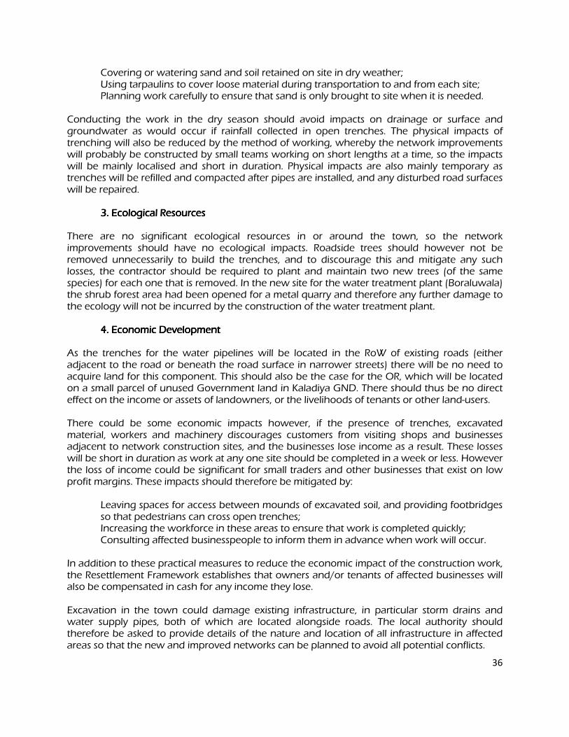
36
Covering or watering sand and soil retained on site in dry weather; Using tarpaulins to cover loose material during transportation to and from each site; Planning work carefully to ensure that sand is only brought to site when it is needed.
Conducting the work in the dry season should avoid impacts on drainage or surface and groundwater as would occur if rainfall collected in open trenches. The physical impacts of trenching will also be reduced by the method of working, whereby the network improvements will probably be constructed by small teams working on short lengths at a time, so the impacts will be mainly localised and short in duration. Physical impacts are also mainly temporary as trenches will be refilled and compacted after pipes are installed, and any disturbed road surfaces will be repaired. 3. Ecological Resources 3. Ecological Resources 3. Ecological Resources 3. Ecological Resources
There are no significant ecological resources in or around the town, so the network improvements should have no ecological impacts. Roadside trees should however not be removed unnecessarily to build the trenches, and to discourage this and mitigate any such losses, the contractor should be required to plant and maintain two new trees (of the same species) for each one that is removed. In the new site for the water treatment plant (Boraluwala) the shrub forest area had been opened for a metal quarry and therefore any further damage to the ecology will not be incurred by the construction of the water treatment plant. 4. Economic Development 4. Economic Development 4. Economic Development 4. Economic Development
As the trenches for the water pipelines will be located in the RoW of existing roads (either adjacent to the road or beneath the road surface in narrower streets) there will be no need to acquire land for this component. This should also be the case for the OR, which will be located on a small parcel of unused Government land in Kaladiya GND. There should thus be no direct effect on the income or assets of landowners, or the livelihoods of tenants or other land-users. There could be some economic impacts however, if the presence of trenches, excavated material, workers and machinery discourages customers from visiting shops and businesses adjacent to network construction sites, and the businesses lose income as a result. These losses will be short in duration as work at any one site should be completed in a week or less. However the loss of income could be significant for small traders and other businesses that exist on low profit margins. These impacts should therefore be mitigated by: Leaving spaces for access between mounds of excavated soil, and providing footbridges
so that pedestrians can cross open trenches; Increasing the workforce in these areas to ensure that work is completed quickly; Consulting affected businesspeople to inform them in advance when work will occur.
In addition to these practical measures to reduce the economic impact of the construction work, the Resettlement Framework establishes that owners and/or tenants of affected businesses will also be compensated in cash for any income they lose. Excavation in the town could damage existing infrastructure, in particular storm drains and water supply pipes, both of which are located alongside roads. The local authority should therefore be asked to provide details of the nature and location of all infrastructure in affected areas so that the new and improved networks can be planned to avoid all potential conflicts.
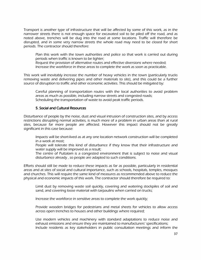
37
Transport is another type of infrastructure that will be affected by some of this work, as in the narrower streets there is not enough space for excavated soil to be piled off the road, and as noted above, trenches will be dug into the road at some locations. Traffic will therefore be disrupted, and in some very narrow streets the whole road may need to be closed for short periods. The contractor should therefore: Plan this work with the town authorities and police so that work is carried out during
periods when traffic is known to be lighter; Request the provision of alternative routes and effective diversions where needed; Increase the workforce in these areas to complete the work as soon as practicable.
This work will inevitably increase the number of heavy vehicles in the town (particularly trucks removing waste and delivering pipes and other materials to site), and this could be a further source of disruption to traffic and other economic activities. This should be mitigated by: Careful planning of transportation routes with the local authorities to avoid problem
areas as much as possible, including narrow streets and congested roads; Scheduling the transportation of waste to avoid peak traffic periods. 5. Social and Cultural Resources 5. Social and Cultural Resources 5. Social and Cultural Resources 5. Social and Cultural Resources
Disturbance of people by the noise, dust and visual intrusion of construction sites, and by access restrictions disrupting normal activities, is much more of a problem in urban areas than at rural sites, because far more people are affected. However this impact should not be greatly significant in this case because: Impacts will be short-lived as at any one location network construction will be completed
in a week at most; People will tolerate this kind of disturbance if they know that their infrastructure and
water supply will be improved as a result; The centre of Puttalam is a congested environment that is subject to noise and visual
disturbance already , so people are adapted to such conditions.
Efforts should still be made to reduce these impacts as far as possible, particularly in residential areas and at sites of social and cultural importance, such as schools, hospitals, temples, mosques and churches. This will require the same kind of measures as recommended above to reduce the physical and economic impacts of this work. The contractor should therefore be required to: Limit dust by removing waste soil quickly, covering and watering stockpiles of soil and
sand, and covering loose material with tarpaulins when carried on trucks; Increase the workforce in sensitive areas to complete the work quickly; Provide wooden bridges for pedestrians and metal sheets for vehicles to allow access
across open trenches to houses and other buildings where required; Use modern vehicles and machinery with standard adaptations to reduce noise and
exhaust emissions and ensure they are maintained to manufacturers’ specifications; Include residents as key stakeholders in public consultation meetings and inform the
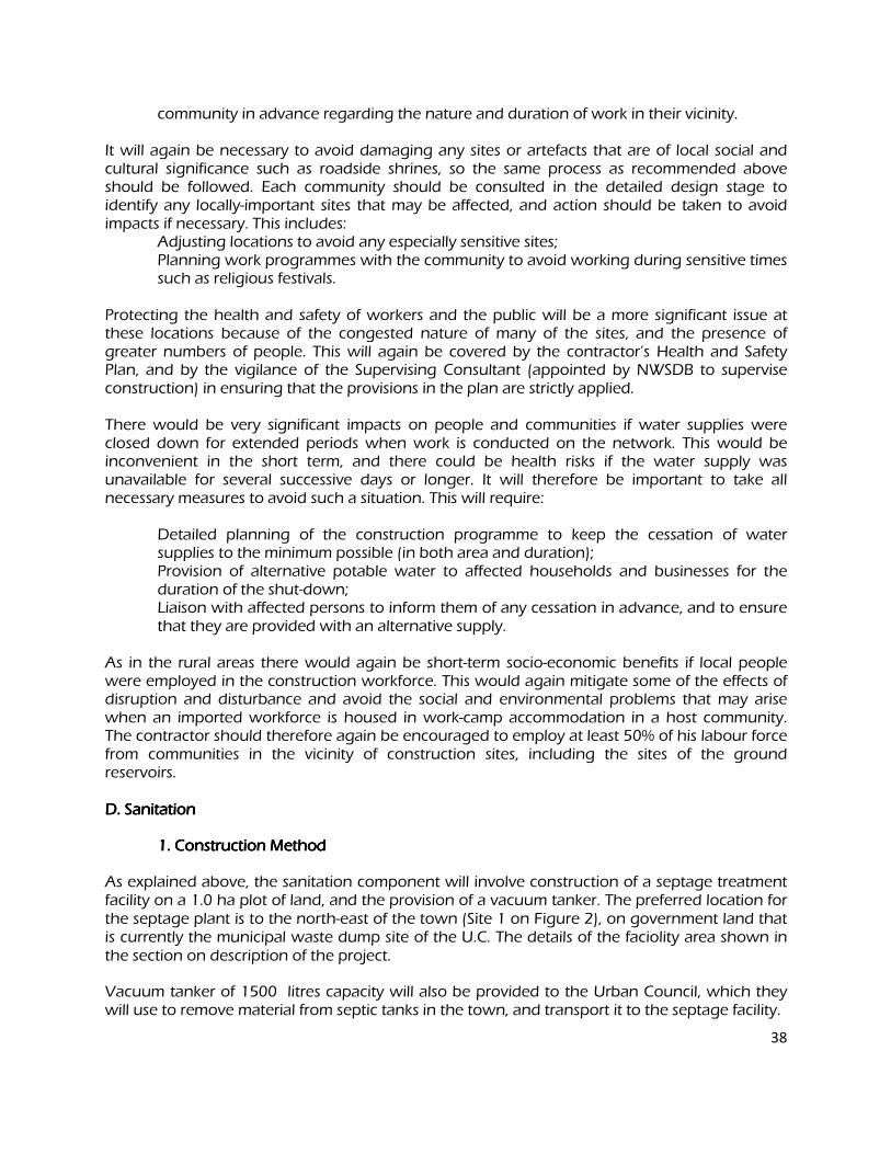
38
community in advance regarding the nature and duration of work in their vicinity.
It will again be necessary to avoid damaging any sites or artefacts that are of local social and cultural significance such as roadside shrines, so the same process as recommended above should be followed. Each community should be consulted in the detailed design stage to identify any locally-important sites that may be affected, and action should be taken to avoid impacts if necessary. This includes: Adjusting locations to avoid any especially sensitive sites; Planning work programmes with the community to avoid working during sensitive times
such as religious festivals.
Protecting the health and safety of workers and the public will be a more significant issue at these locations because of the congested nature of many of the sites, and the presence of greater numbers of people. This will again be covered by the contractor’s Health and Safety Plan, and by the vigilance of the Supervising Consultant (appointed by NWSDB to supervise construction) in ensuring that the provisions in the plan are strictly applied. There would be very significant impacts on people and communities if water supplies were closed down for extended periods when work is conducted on the network. This would be inconvenient in the short term, and there could be health risks if the water supply was unavailable for several successive days or longer. It will therefore be important to take all necessary measures to avoid such a situation. This will require: Detailed planning of the construction programme to keep the cessation of water
supplies to the minimum possible (in both area and duration); Provision of alternative potable water to affected households and businesses for the
duration of the shut-down; Liaison with affected persons to inform them of any cessation in advance, and to ensure
that they are provided with an alternative supply.
As in the rural areas there would again be short-term socio-economic benefits if local people were employed in the construction workforce. This would again mitigate some of the effects of disruption and disturbance and avoid the social and environmental problems that may arise when an imported workforce is housed in work-camp accommodation in a host community. The contractor should therefore again be encouraged to employ at least 50% of his labour force from communities in the vicinity of construction sites, including the sites of the ground reservoirs. D. Sanitation D. Sanitation D. Sanitation D. Sanitation
1. Construction Method 1. Construction Method 1. Construction Method 1. Construction Method
As explained above, the sanitation component will involve construction of a septage treatment facility on a 1.0 ha plot of land, and the provision of a vacuum tanker. The preferred location for the septage plant is to the north-east of the town (Site 1 on Figure 2), on government land that is currently the municipal waste dump site of the U.C. The details of the faciolity area shown in the section on description of the project.
Vacuum tanker of 1500 litres capacity will also be provided to the Urban Council, which they will use to remove material from septic tanks in the town, and transport it to the septage facility.
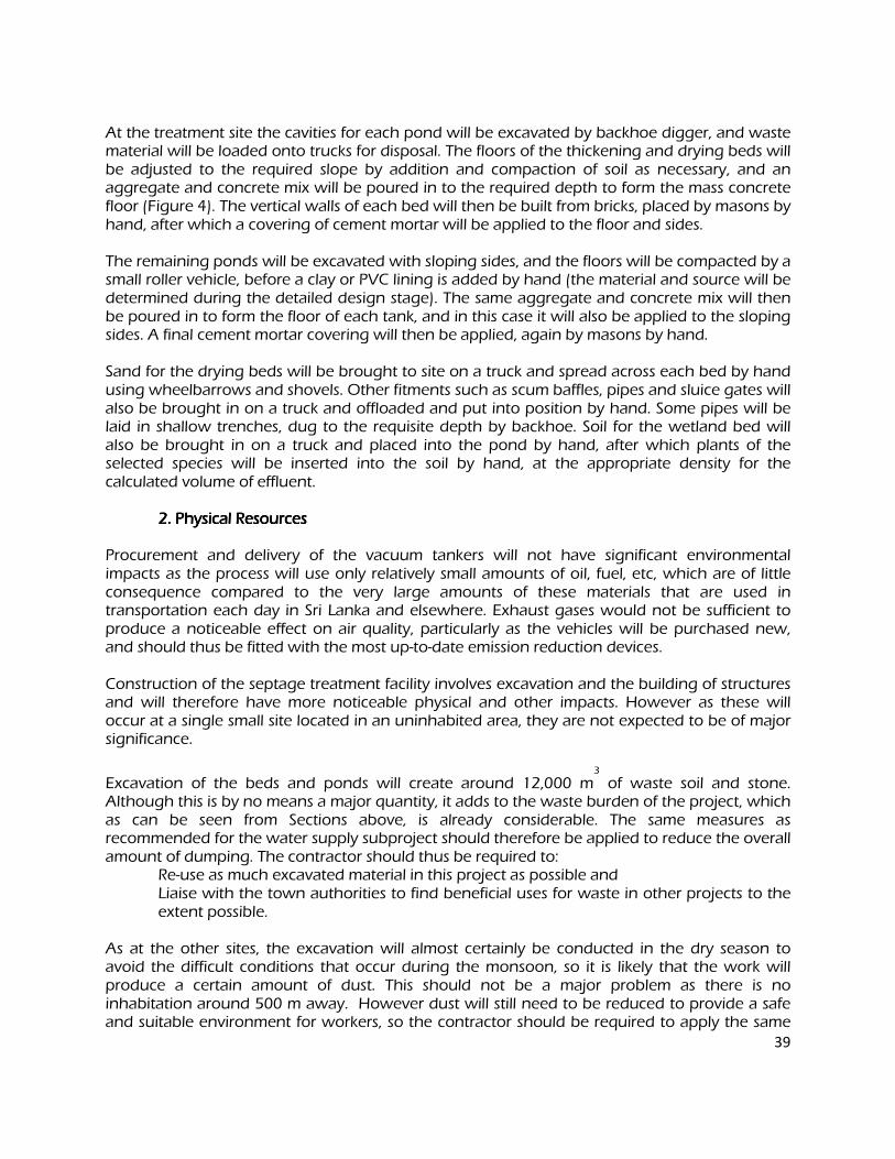
39
At the treatment site the cavities for each pond will be excavated by backhoe digger, and waste material will be loaded onto trucks for disposal. The floors of the thickening and drying beds will be adjusted to the required slope by addition and compaction of soil as necessary, and an aggregate and concrete mix will be poured in to the required depth to form the mass concrete floor (Figure 4). The vertical walls of each bed will then be built from bricks, placed by masons by hand, after which a covering of cement mortar will be applied to the floor and sides. The remaining ponds will be excavated with sloping sides, and the floors will be compacted by a small roller vehicle, before a clay or PVC lining is added by hand (the material and source will be determined during the detailed design stage). The same aggregate and concrete mix will then be poured in to form the floor of each tank, and in this case it will also be applied to the sloping sides. A final cement mortar covering will then be applied, again by masons by hand. Sand for the drying beds will be brought to site on a truck and spread across each bed by hand using wheelbarrows and shovels. Other fitments such as scum baffles, pipes and sluice gates will also be brought in on a truck and offloaded and put into position by hand. Some pipes will be laid in shallow trenches, dug to the requisite depth by backhoe. Soil for the wetland bed will also be brought in on a truck and placed into the pond by hand, after which plants of the selected species will be inserted into the soil by hand, at the appropriate density for the calculated volume of effluent. 2. Physical Resources 2. Physical Resources 2. Physical Resources 2. Physical Resources
Procurement and delivery of the vacuum tankers will not have significant environmental impacts as the process will use only relatively small amounts of oil, fuel, etc, which are of little consequence compared to the very large amounts of these materials that are used in transportation each day in Sri Lanka and elsewhere. Exhaust gases would not be sufficient to produce a noticeable effect on air quality, particularly as the vehicles will be purchased new, and should thus be fitted with the most up-to-date emission reduction devices. Construction of the septage treatment facility involves excavation and the building of structures and will therefore have more noticeable physical and other impacts. However as these will occur at a single small site located in an uninhabited area, they are not expected to be of major significance.
Excavation of the beds and ponds will create around 12,000 m3
of waste soil and stone. Although this is by no means a major quantity, it adds to the waste burden of the project, which as can be seen from Sections above, is already considerable. The same measures as recommended for the water supply subproject should therefore be applied to reduce the overall amount of dumping. The contractor should thus be required to:
Re-use as much excavated material in this project as possible and Liaise with the town authorities to find beneficial uses for waste in other projects to the
extent possible.
As at the other sites, the excavation will almost certainly be conducted in the dry season to avoid the difficult conditions that occur during the monsoon, so it is likely that the work will produce a certain amount of dust. This should not be a major problem as there is no inhabitation around 500 m away. However dust will still need to be reduced to provide a safe and suitable environment for workers, so the contractor should be required to apply the same
40
measures as at the other excavation sites. These are to: Remove waste soil as soon as it is excavated, by loading directly onto trucks; Cover or water sand and soil retained on site in dry weather; Use tarpaulins to cover loose material when transported to and from the site. 3. Ecological Reso3. Ecological Reso3. Ecological Reso3. Ecological Resources urces urces urces
Since the preferred site is away from the lagoon area and is in an urban area, there are no significant ecological resources in or around the site. Therefore, this activity will not have any impacts on the ecological resources. 4. Economic Deve4. Economic Deve4. Economic Deve4. Economic Development lopment lopment lopment
The land is owned by the Urban Council, so there will be no need to purchase the land.. There are no houses, roads, water supply pipes, or other infrastructure on the site, so there is no risk of damage causing economic impacts. Transportation is the one sector that could be indirectly affected, if trucks carrying waste material from the site disrupt traffic on the roads in and around the town. This should be reduced by applying the same kind of measures as recommended for the water supply subproject, so the contractor should be required to: Plan transportation routes with the local authority to limit the number of vehicles that
enter the town; Where this cannot be avoided, ensure that heavy vehicles use main roads only and do
not use narrow local roads except in the immediate vicinity of delivery sites; Schedule transportation activities to avoid peak traffic periods. 5. Social and Cultural Resources 5. Social and Cultural Resources 5. Social and Cultural Resources 5. Social and Cultural Resources
As the only residents live 500 m or more from the septage treatment site, it should not be necessary to impose special measures to reduce disturbance by construction noise, visual intrusion and impeded access, beyond those already recommended above. NWSDB and the UC should however include the residents in consultation meetings as key stakeholders, and should inform them in advance regarding the nature and duration of work in their vicinity. There are also no socially or culturally important buildings (schools, hospitals, temples, etc) near the site, but as was the case in the rural locations, the community should be consulted during the detailed design stage to determine whether there are any shrines or other sites of local importance that could be affected. If that is the case the work should be adjusted in order to: Avoid any such locations; Avoid working during sensitive times, such as religious festivals.
As at the other sites, the contractor will be required to prepare and implement a Health and Safety Plan to protect workers and the public. This should include measures to: Exclude the public from all sites; Provide appropriate PPE to all workers and ensure that it is used; Provide H&S training to all site personnel;
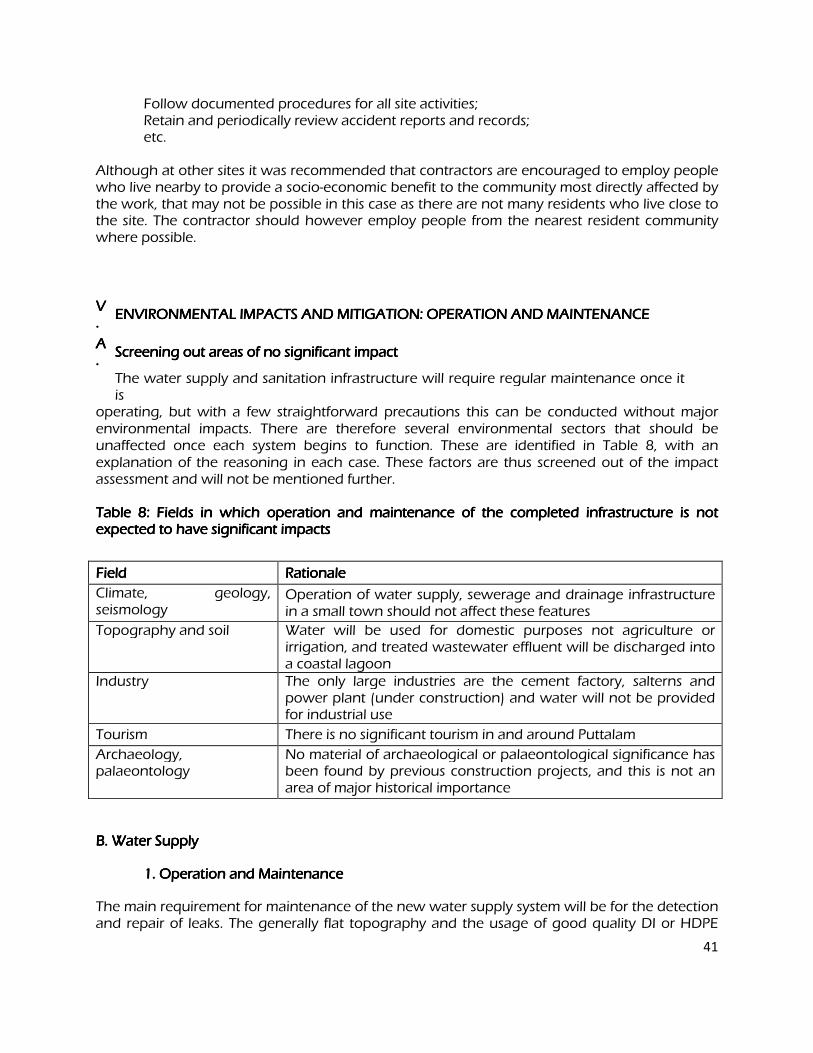
41
Follow documented procedures for all site activities; Retain and periodically review accident reports and records; etc.
Although at other sites it was recommended that contractors are encouraged to employ people who live nearby to provide a socio-economic benefit to the community most directly affected by the work, that may not be possible in this case as there are not many residents who live close to the site. The contractor should however employ people from the nearest resident community where possible.
VVVV. . . .
ENVIRONMENTAL IMPACTS AND MITIGATION: OPERATION AND MAINTENANCE ENVIRONMENTAL IMPACTS AND MITIGATION: OPERATION AND MAINTENANCE ENVIRONMENTAL IMPACTS AND MITIGATION: OPERATION AND MAINTENANCE ENVIRONMENTAL IMPACTS AND MITIGATION: OPERATION AND MAINTENANCE
AAAA. . . .
Screening out areas of no signifiScreening out areas of no signifiScreening out areas of no signifiScreening out areas of no significant impact cant impact cant impact cant impact
The water supply and sanitation infrastructure will require regular maintenance once it is
operating, but with a few straightforward precautions this can be conducted without major environmental impacts. There are therefore several environmental sectors that should be unaffected once each system begins to function. These are identified in Table 8, with an explanation of the reasoning in each case. These factors are thus screened out of the impact assessment and will not be mentioned further.
Table 8: Fields in which operation and maintenance of the completed infrastructure is not Table 8: Fields in which operation and maintenance of the completed infrastructure is not Table 8: Fields in which operation and maintenance of the completed infrastructure is not Table 8: Fields in which operation and maintenance of the completed infrastructure is not expected to have significant impacts expected to have significant impacts expected to have significant impacts expected to have significant impacts
Field Field Field Field Rationale Rationale Rationale Rationale
Climate, geology, seismology
Operation of water supply, sewerage and drainage infrastructure in a small town should not affect these features
Topography and soil Water will be used for domestic purposes not agriculture or irrigation, and treated wastewater effluent will be discharged into a coastal lagoon
Industry The only large industries are the cement factory, salterns and power plant (under construction) and water will not be provided for industrial use
Tourism There is no significant tourism in and around Puttalam
Archaeology, palaeontology
No material of archaeological or palaeontological significance has been found by previous construction projects, and this is not an area of major historical importance
B. Water Supply B. Water Supply B. Water Supply B. Water Supply
1. Operation and Maintenance 1. Operation and Maintenance 1. Operation and Maintenance 1. Operation and Maintenance
The main requirement for maintenance of the new water supply system will be for the detection and repair of leaks. The generally flat topography and the usage of good quality DI or HDPE
42
pipes should mean that pipeline breaks are relatively rare, and that leaks are mainly limited to joints between pipes. These will be repaired in essentially the same way that the pipes were installed. Trenches will be dug to expose the leaking area and the faulty connection will be re-fitted, or the pipe will be removed and replaced if necessary. Sludge will need to be removed periodically from settlement tanks at the WTP, and this is normally washed out onto waste ground within the site. There is also some small scale maintenance at the WTP and other facility sites (PS, OR), which involves regular checking and recording of the performance of the components for signs of deterioration (pumps, pipes, valves, meters, etc), and servicing and replacement of parts where necessary. There will also need to be a properly defined regime for operating the refurbished sluices in the Kala Oya causeway to ensure that water is abstracted at the appropriate time in the quantities needed. Three or four people will be employed at each site to conduct these various operations, and NWSDB will ensure that personnel are properly trained and supervised, and that all procedures are fully defined in Operation and Maintenance (O&M) Manuals. 2. Physical Resources 2. Physical Resources 2. Physical Resources 2. Physical Resources
Generally the main risk to the physical environment of operating an improved water supply system is that increased abstraction will significantly deplete the water resource. However that
should not be the case here. Around 9,000 m3
/day of water will be abstracted from the Kala
Oya when the scheme begins to operate, and this will increase to 15,000 m3
/day in 2030 (0.18
m3
/s). This is a small fraction of the water available in the river, as Kala Oya is a perennial river with good year-round flow, augmented by return waters from irrigation schemes upstream. There are some flow data available for the river. Also flow rates are estimated from water level measurements at Neelabemma Anicut 32 km upstream. These calculations predict a maximum
flow at Eluwankulama of 50.1 m3
/s in December and a minimum of 6.6 m3
/s in September, so abstraction by this project will be around 5% of the annual minimum flow, which should not deplete the resource. Groundwater will also not be over-exploited as the rate of abstraction will
be reduced from the current level of 6,500 m3
/day to 4,500 m3
/day in 2030. There is concern however regarding the quality of the raw water that will be feeding the proposed water treatment system. The only recent data available from the Kala Oya (Table 3) suggests that certain parameters sometimes exceed those recommended by the CEA. This applies to COD, nitrate and phosphate, which are not reduced significantly by a conventional treatment method; and if levels of these parameters were to be high in the treated water, it may not be fit for human consumption. There are also some data on the quality of water in the aquifer, already used by NWSDB as the source for the existing water supply to Puttalam Town with mixed results. As groundwater and surface water could both be contaminated by sewage, agricultural runoff and other pollutants, there is clearly a risk that the water supplied could be harmful to human health and therefore additional tests need to be conducted.. The quality of surface water and groundwater must therefore be properly examined and the suitability of the treatment method fully assessed, so that increased levels of treatment can be incorporated if necessary to provide water of the mandatory legal standards (Appendix 1). During the detailed design stage therefore NWSDB should: Implement a detailed programme to monitor the quality of groundwater at four
43
representative abstraction points every fortnight for a full year; Monitor the quality of water in the Kala Oya and Achchamolai Tank every 2 weeks for a
year and examine how water quality may be altered by storage in the tanks; On the basis of the data, examine in detail the quality of water that will be produced by
the proposed treatment and how this will be affected by mixing with groundwater; Redesign the subproject with alternative treatment or/or water sources if the study
shows that the water produced will not meet Sri Lankan drinking water standards.
For most of the year water will continue to flow over the top of the causeway irrespective of whether or not the sluice gates are closed). The refurbished causeway should therefore not impede the flow of sand and silt, which is transported downstream in large quantities and is essential for the replenishment of sediment at the coast to sustain the natural geomorphology of the lagoon, beach and subtidal area, and maintain protection against coastal erosion and flooding. As a precaution, the O&M procedures should require periodic checking of the level of sediment on the upstream side of the causeway, so that sluice gates can be opened to purge accumulated sediment if necessary. The physical impacts of operating the remaining elements of the water supply system should be very minor. If trenches are dug to locate and repair leaks or remove and replace lengths of pipe, the work will follow the same procedure as occurred when the infrastructure was improved. In this case soil and backfilled sand will be removed to expose the leaking junction or pipe, and if necessary a new pipe will be brought to site and replaced. The trench will then be refilled and re-compacted. This work should be very infrequent, and will affect individual small locations for short periods only (an average of a few hours for most repairs). Physical impacts will therefore be negligible. Work will not be conducted during rainfall so there will be no effect on drainage, and the removed material will be replaced in the trench so there will be no waste. There should also be no need to cover excavated material to prevent dust as it will have been wetted by the leaking water. The current practice of washing sludge from settling tanks onto waste ground at the WTP is poor site management and it could have physical impacts by affecting soil quality, reducing the appearance of the area and causing dust as the material dries. These impacts should thus be avoided at both the existing and new WTP sites by washing the material into open tanks and allowing it to dry, and then removing and transporting to a municipal landfill. Tarpaulins should be used to cover the material during transportation, to prevent dust. 3. Ecological Resources 3. Ecological Resources 3. Ecological Resources 3. Ecological Resources
Where structures are built across rivers to abstract water there are generally concerns regarding ecological impacts. These focus mainly on three elements:
i) The structure may impede the upstream migration of freshwater and marine fish to breeding grounds, so breeding may be unsuccessful and populations may decline;
ii) The removal of water will reduce downstream flow and this may cause the death of species and habitats if the river dries out seasonally to a greater extent than normal;
iii) Changes in the quality and quantity of water may affect the ecology and behaviour of downstream species (for example by altering water temperature and salinity,
44
which are factors that stimulate breeding migrations in fish).
In this case the structure of the causeway (which is perforated by culverts through which the flow of water will be controlled by the new sluices) provides a means of avoiding these impacts if an appropriate operating regime is adopted. This should allow fish to migrate through the causeway, and provide a minimum flow in the river during the dry season that is as near as possible to the natural flow at this time (so that the river does not dry out more than normal). The O&M procedure for operation of the sluices should therefore require that:
At least one sluice in the causeway is kept fully open at all times so that migrating fish have a means of passing through the barrier; or alternatively to have a fish ladder to facilitate fish migration
Sluices are operated to allow a minimum downstream flow throughout the dry season
that is at least equivalent to the minimum natural seasonal flow at this time (estimated at
6.6 m3
/s). These measures will not be necessary during higher flow periods when water runs both through and over the causeway. However, to ensure that fish migration is not impeded by sluices being closed unnecessarily the O&M procedure should also require that the maximum feasible number of sluices are kept open at all times. The fact that the Wilpattu National Park borders the northern bank of the Kala Oya reinforces the need to adopt an environmentally sensitive abstraction regime, because there is clearly riparian vegetation in the protected area that depends on the flow of water in the river, and this is likely also to be the case for other habitats and plant and animal species in the park. The increase in abstraction should not be a problem in the rainy season because abstraction rates are so low that there should be no change in the flooding regime, which is likely to be an important factor in maintaining the ecology of floodplains bordering the river. There should also be little change in the ecology of the river and adjoining areas in the dry season if, as recommended above, a minimum environmental flow is provided that is close to the natural dry season flow. This should be achieved by abstracting more than the demand during the rainy season and storing the excess in Eluwankulama and Achchamolai tanks so there is sufficient to meet dry season needs without increasing abstraction at the expense of the environmental flow. Remote-recording flow meters should be fitted to the causeway on the downstream side to assist NWSDB in ensuring that the specified environmental flow is provided throughout the dry season. No special precautions will be required to avoid ecological damage from operation or maintenance work at the other water supply facilities, because they are all located at sites from which the vegetation has been cleared, which thus have no ecological interest. Similarly any repairs to the network in or outside the town should not cause any ecological impacts as there are no significant ecological resources in these areas. 4. Economic Development 4. Economic Development 4. Economic Development 4. Economic Development
Increasing the abstraction of water from the Kala Oya should not have any economic or social implications, as there will be little reduction in flow, and there are no downstream users of river water (for irrigation, domestic supply, or other purposes). Eluwankulama Tank is operated by the
45
Irrigation Department, with whom NWSDB had negotiated an agreement regarding the proposed shared use of the tank, the construction and refurbishing works, and the amount of water to be abstracted for water supply purposes. This guarantees that present irrigation usage will be maintained, so there will be no reduction in water available to farmers and therefore no effect on their income or livelihoods. Repairs to the water supply network could result in shops losing some business if the work means that access is difficult for customers, but any losses will be small and short-lived and will probably be at the level of normal business fluctuations. It should therefore not be necessary to compensate for such losses. Nevertheless simple steps should be taken to reduce the inconvenience of the works, including: Informing all residents and businesses about the nature and duration of any work in
advance so that they can make preparations if necessary; Requiring contractors to provide wooden walkways across trenches for pedestrians and
metal sheets where vehicle access is required; Consulting the local police so that work can be planned to avoid traffic disruption as far
as possible, and road diversions can be organised if necessary.
The improved water supply system will benefit business and residential consumers in the town, but this is unlikely to generate economic gains as there are no industries that are significant water users. There may however be small economic benefits from the expected improvements in the overall health of the community as fewer working days will be lost through sickness for example, so productivity should increase. 5. Social and Cultural Resources 5. Social and Cultural Resources 5. Social and Cultural Resources 5. Social and Cultural Resources
Network repair could cause some temporary disruption of activities at locations of social and cultural importance such as schools, hospitals, temples, etc, so the same kinds of precautions as employed during the construction period should be adopted. These include: Completing work in these areas quickly; Providing wooden bridges for pedestrians and metal sheets for vehicles to allow access
across open trenches where required; Using modern vehicles and machinery with standard adaptations to reduce noise and
exhaust emissions; Informing residents about the nature and duration of all such work in advance; Avoiding working during sensitive periods, such as times of religious observance.
NWSDB will operate the water supply system and they will employ local contractors to conduct network repairs. To protect both workers and the public, contractors should be required to operate the same kinds of Health and Safety procedures as used in the construction phase to protect workers and the public. This should include measures to keep the public away from locations in which work is being conducted, and the use of appropriate PPE and construction practices by workers. The use of local contractors will provide economic benefits to the companies and the workers they employ. There is however little prospect of directing these benefits to persons affected by any maintenance or repair works as contractors will utilise their existing workforce. To provide at least some economic benefits to affected communities, persons employed at the various facility sites (PS, OR, WTP) should be residents of the neighbouring area.
46
The citizens of the town will be the major beneficiaries of the improved water supply, because if the scheme is developed following the precautions noted above, they will be provided with a more regular supply of better quality water. This gives the potential of improving the social capital of the town, and individual and community health and well-being, providing the improvements in water supply and sewerage are combined with improved sanitary practices. It is very important therefore that the project should fund a campaign of public education to raise awareness of the importance of hand washing, water purification, cleanliness in food preparation, etc. If this is done then the infrastructure and education measures will reduce the incidence of diseases of poor sanitation, such as diarrhoea and dysentery. This should then bring socio-economic benefits as people will spend less on healthcare and lose fewer working days due to illness, so their economic status should improve, as well as their overall health. C. Sanitation C. Sanitation C. Sanitation C. Sanitation
1. Operation and Maintenance 1. Operation and Maintenance 1. Operation and Maintenance 1. Operation and Maintenance
During operation of the new sanitation system, the vacuum tankers provided by the project will collect partially digested sewage from septic tanks in Puttalam town, and deposit it at the septage treatment facility (Figure 4). Here the sludge will gradually flow by gravity from thickening beds to drying beds where it is allowed to dry in the air and sunlight. Supernatant liquid from each bed passes into anaerobic treatment ponds where solid material gradually settles out. The liquid then flows into a reed-bed pond, where any remaining nutrients are absorbed by the plants (normally reeds, bamboo or grass) and most of the water evaporates from the plants by transpiration. The final effluent is expected to be a small quantity that complies with the existing and proposed new effluent disposal standards (Appendix 2 and 3), and will be reused in the composting operations (Figure 2). The tanker will be provided to Puttalam Urban Council (PUC), which is responsible for operating the sanitation service. The Council will ensure that the tankers are serviced and repaired to manufacturer’s specifications so that the vehicles have a long working life. They will also employ and train tanker drivers and plan their work schedule, through which all septic tanks in the town are expected to be emptied at least once a year. The main requirement for maintaining the septage treatment facility is for the regular removal and disposal of sludge from the drying beds and scum that floats on the liquid fraction and is left behind on the floor of the thickening beds. Sludge is retained in the thickening beds for approximately a month and the drying beds for 10-15 days, after which the scum and sludge are removed from one thickening bed and a pair of drying beds by a small front-end loader and deposited into a truck. The drying process kills enteric bacteria and pathogens so the material is combined in the municipal waste composting operations or may be applied free to coconut plantations if requested by the owner. Once the solid material has been removed the empty tanks are washed clean and inspected, and if necessary the floors and sides are repaired by masons applying fresh concrete by hand. Effluent is retained in the anaerobic ponds for 2-3 months, during which time solid material settles on the floor or the tank reducing the BOD of the effluent. These tanks fill very slowly and need emptying only every 5-10 years, when the operation is carried out by front loader as for the drying beds. The plants in the reed-bed system need replacing every few years because younger plants grow faster and absorb more nutrients and water. This is done by hand and the
47
old plants could also be used in the composting process. 2. Physical Resources 2. Physical Resources 2. Physical Resources 2. Physical Resources
The main risks associated with the servicing and repair of the tanker vehicles are of the pollution of land and water from the inappropriate disposal of spent oil from the engines and other components, and reduced efficiency and increased exhaust emissions if the vehicles are not serviced regularly and parts are not replaced when necessary. PUC should therefore ensure that vehicles are serviced maximum frequency of either as per the manufacturer’s requirements or at least twice per year and repaired when necessary, and that the work is conducted by reputable local companies with responsible waste disposal practices that do not cause pollution or other environmental damage. The main risks at the septage treatment plant are that workers handling the dried sludge could become infected by enteric bacteria and pathogens if these are not all killed by the drying process, and could then contract intestinal and other diseases. These should not be major risks because: a) most material is already partially decomposed before removal from the septic tanks and will decompose further during the three months in the wet thickening beds; and b) the 10-15 day period in open drying beds should ensure that most bacteria and pathogens are killed by desiccation or exposure to sunlight. Nevertheless, PUC should test the bacterial content of the sludge periodically to assure the health and safety of workers, and should extend the drying period beyond 15 days if necessary to achieve 100% safety. The disposal of dried sludge at solid waste dumpsites represents a loss of a valuable resource, as the material is high in organic matter, nitrates and phosphates and is therefore an excellent plant fertilizer. As indicated above, proposals are already being considered to use the dried sludge in the composting process of the Municipality which is already in operation or offer the material to owners of coconut plantations, thus providing both a fertilizer and an effective means of disposal. However there would be further benefits if this was taken further and the material was offered for sale to farmers, because this would: Improve the structure and fertility of soils, which are often poor in fields subject to
repeated irrigation; Increase the yield of crops and provide more income for farmers; and Provide a means of partial cost recovery against the outlay of building and maintaining
the treatment facility. It is suggested therefore that this project should provide PUC with training and assistance in establishing such a system. This initiative would include:
Training staff in methods of drying and marketing sewage sludge as a fertilizer, and pricing and account-keeping;
A public education programme to raise awareness of farmers of the potential for the safe use of this material in agriculture, and benefits in terms of increased yields;
Regular monitoring and laboratory testing as suggested above, to ensure that methods and durations of drying remove all harmful bacteria and pathogens;
A study of the feasibility of setting up a compost plant at the septage treatment site to make the sludge more attractive to farmers and provide a beneficial use for plants removed from the wetland bed, which would otherwise be discarded.
48
If Sewage Treatment Plants are located in inhabited areas, residents are often concerned about odour and the visual impact of the plant, and this can be even more significant in the case of septage treatment, which liberates more foul odours than conventional treatment. However these should not be major issues in this case as the nearest residents are more than 500 m from the edge of the STP, from where the odour of the facility should not be detectable, and there already exists a good cover of vegetation providing a buffer. Residents should nevertheless be included in public consultations so that they can be informed of these and other issues and can express their views. Impacts on workers reusing the effluent would b significant if the septage facility malfunctioned and did not treat the effluent to the standards expected. The system should therefore include an emergency procedure for use if effluent monitoring shows that the legal discharge standards are exceeded (Appendix 3). This should involve: Shutting off the discharge to the lagoon and recycling the effluent through the
anaerobic ponds and wetland bed to improve its quality; and Investigating the reason for the treatment failure and taking remedial action to restore
correct functioning; Resuming re-use of effluent only when the effluent complies with the legal standards.
Designs should be amended to incorporate emergency pumps if necessary to recycle the effluent, and O&M Manuals should require personnel operating the plant to take the necessary action. 3. Ecological Resources 3. Ecological Resources 3. Ecological Resources 3. Ecological Resources
The handling of sludge at the septage treatment facility will not have any ecological impacts as it will occur within the confines of the treatment site, on which there are no areas of ecological interest. The disposal of sludge should also not have ecological impacts regardless of whether it is co-composted with municipal solid waste or used as an agricultural fertilizer. 4. Econom4. Econom4. Econom4. Economic Development ic Development ic Development ic Development
The routine operation and maintenance work at the septage treatment facility will not have any economic impacts as it will all be conducted within the boundaries of the site and will not affect any outside areas or parties. The operation of the tankers emptying septic tanks in the town could have some economic impacts if their presence were to disrupt traffic and make access to shops difficult. However these impacts will be very short-lived and temporary, given that most septic tanks will be emptied once a year, and that the average time taken to empty a tank is around 30 minutes. It should therefore not be necessary to compensate businesses for any loss of income. As noted above there could be economic benefits if the sludge is successfully marketed to local farmers as an agricultural fertilizer, as PUC will gain some income from the sale of the product and farmers should obtain higher yields from fields onto which the material is applied, so their income should increase. 5. Social and Cu5. Social and Cu5. Social and Cu5. Social and Cultural Resources ltural Resources ltural Resources ltural Resources
The operation of the septage treatment facility should have no impacts on people or locations and facilities of social or cultural importance, because as explained above there are no people
49
living near the site. There should also be no major problems from the operation of the vacuum tankers in the town because any related disturbance will be infrequent and short-lived, and people will tolerate such small-scale disturbance if they are aware that their environment will be improved as a result. Efforts should still be made to avoid affecting socially and culturally important locations (churches, schools, hospitals, etc) to the extent possible and PUC should plan the work to ensure that: Septic tanks located near churches and temples are not emptied during important
festivals or at other times of religious observance; Tanks near or within schools, clinics and hospitals are emptied at weekends when the
buildings are less used.
In addition to the risk to workers at the septage facility from contact with bacteria and pathogens in the sludge, there are some risks to workers and the public from the pumping operation to remove material from septic tanks. The Urban Council should therefore protect the health and safety of their workers and the public by ensuring that procedures are properly defined and followed. PUC should: Prepare O&M manuals describing the procedures that are to be followed by workers in
all aspects of the sanitation service, including operation of the tankers and the maintenance work at the septage treatment facility;
Prepare a Health and Safety Plan and ensure that it is operated throughout all work activities;
Provide workers with regular training in the relevant procedures (O&M and H&S); The project should assist and train PUC in preparing and implementing these aspects as necessary.
The citizens of the town will be the beneficiaries of the new sanitation service, as septic tanks will be cleared more frequently and effectively than at present, so there should be fewer leaks and foul odours from overflowing and malfunctioning tanks. This should improve the living environment of these areas, and in conjunction with the development of the other infrastructure (in particular water supply), will provide the potential for delivering major improvements in individual and community health and well being. As noted above, this will only occur if the improvements in infrastructure and services are combined with a campaign of public health education (also funded by this project) to raise awareness of the importance of cleanliness, and the links between disease and poor sanitation. If this campaign is widespread and successful then diseases like diarrhoea and dysentery should be reduced. People should then spend less on healthcare and lose fewer working days due to illness, so their economic status should also improve, as well as their overall health.
VI. ENVIRONMENTAL IMPACTS AND MITIGATION: LOCATION AND DESIGN VI. ENVIRONMENTAL IMPACTS AND MITIGATION: LOCATION AND DESIGN VI. ENVIRONMENTAL IMPACTS AND MITIGATION: LOCATION AND DESIGN VI. ENVIRONMENTAL IMPACTS AND MITIGATION: LOCATION AND DESIGN
ADB Environmental Assessment Guidelines require that an IEE should evaluate impacts due to the location, design, construction and operation of the project. Construction and operation are the two activities in which the project interacts physically with the environment, so they are the two activities during which the environmental impacts occur. In assessing the effects of these processes therefore, all potential impacts of the project are identified, and mitigation is devised
50
for any negative impacts. This has been done. In many environmental assessments there are certain effects that, although they will occur during either the construction or operation stage, should be considered as impacts primarily of the location or design of the project, as they would not occur if an alternative location or design was chosen. For example, if a groundwater resource was depleted by excessive abstraction this would be an impact of both the location and design, because groundwater may not be depleted if the design had used surface water to augment the supply, and the specific aquifer would not have been depleted if the wellfield was located elsewhere. In the case of these subprojects there are few impacts that can clearly be said to result from either the design or location. This is mainly because of the following: Although there are many different elements to the project as a whole, with the
exception of the water networks, most other components will be built at relatively small, discrete sites, where environmental impacts will be very localised;
The manner in which the water networks will be constructed (by small teams completing a short length of pipeline before moving onto the next), means that these elements will also have mainly localised impacts;
Despite the number of components, most will involve straightforward construction and low-maintenance operation in an environment that is not especially sensitive, so it is unlikely that there will be major impacts;
Most of the impacts are associated with the construction process, and are produced because that process is invasive, involving trenching and other ground disturbance. However the routine nature of the impacts means that most can be easily mitigated.
There are however two impacts that would be a result of the design if they were to occur. These are:
i) Human health problems from the consumption of water of unsuitable quality; ii) Workers at the septage treatment facility contracting diseases from contact with
sludge if the drying process does not kill all bacteria and pathogens, and in reusing the effluent if it has met not required standards.
The above impacts would clearly be a result of the design as: consumption of the water would not cause health problems if the quality of the water was properly investigated and more extensive treatment provided if necessary; and workers at the septage plant would not contract diseases if the sludge drying process killed the bacteria and pathogens. It should be noted that measures have been recommended above which, if implemented thoroughly, should ensure that these impacts do not occur. These involve:
i) Monitoring the quality of water in the aquifer, Kala Oya and Eluwankulam Tank to assess whether the proposed treatment will produce water of the legally required standards, and amending the treatment method if necessary; and
ii) Monitoring the levels of bacteria and pathogens in dried sludge and extending the drying period if necessary;
iii) Monitoring the quality and quantity of wastewater effluent and increasing the level of effluent treatment at the septage plant if necessary.
51
VII. INSTITUTIONAL REQUIREMENTS AND ENVIRONMENTAL MONITORING PLAN VII. INSTITUTIONAL REQUIREMENTS AND ENVIRONMENTAL MONITORING PLAN VII. INSTITUTIONAL REQUIREMENTS AND ENVIRONMENTAL MONITORING PLAN VII. INSTITUTIONAL REQUIREMENTS AND ENVIRONMENTAL MONITORING PLAN
A. Summary of environmental impacts and mitigation measures A. Summary of environmental impacts and mitigation measures A. Summary of environmental impacts and mitigation measures A. Summary of environmental impacts and mitigation measures
Table 9 lists the potential adverse impacts of the Puttalam water supply and sanitation subprojects as identified and discussed above and the mitigation proposed to reduce these impacts to acceptable levels. The table also shows how the mitigation will be implemented, who will be responsible, and where and when the mitigation activities will take place. The mitigation programme is shown as the year in which each activity will occur, which relates to the project programme described in previous sections. The final column assesses whether the proposed action will successfully mitigate the impact (shown as 0), and indicates that some of the measures will provide an additional benefit (shown as +).
B. Institutional arrangements for project implementation B. Institutional arrangements for project implementation B. Institutional arrangements for project implementation B. Institutional arrangements for project implementation
The main agencies involved in managing and implementing the project are as follows: The Ministry of Water Supply and Drainage (MWSD) is the Executing Agency (EA) responsible for management, coordination and execution of all activities funded under the loan; and NWSDB is the Implementing Agency (IA) responsible for supervising construction of the infrastructure and conducting the non-infrastructure elements.
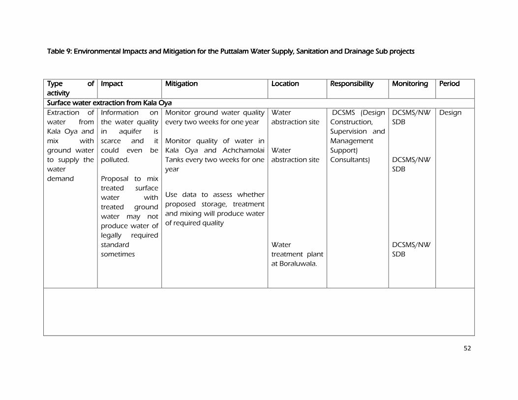
52
Table 9: Table 9: Table 9: Table 9: Environmental Impacts and Mitigation for the Puttalam Water Supply, Sanitation and Drainage Sub projects Environmental Impacts and Mitigation for the Puttalam Water Supply, Sanitation and Drainage Sub projects Environmental Impacts and Mitigation for the Puttalam Water Supply, Sanitation and Drainage Sub projects Environmental Impacts and Mitigation for the Puttalam Water Supply, Sanitation and Drainage Sub projects
Type of Type of Type of Type of
activityactivityactivityactivity
ImpactImpactImpactImpact MitigationMitigationMitigationMitigation Location Location Location Location Responsibility Responsibility Responsibility Responsibility Monitoring Monitoring Monitoring Monitoring PeriodPeriodPeriodPeriod
Surface water extraction from Kala OySurface water extraction from Kala OySurface water extraction from Kala OySurface water extraction from Kala Oyaaaa
Extraction of
water from
Kala Oya and
mix with
ground water
to supply the
water
demand
Information on
the water quality
in aquifer is
scarce and it
could even be
polluted.
Proposal to mix
treated surface
water with
treated ground
water may not
produce water of
legally required
standard
sometimes
Monitor ground water quality
every two weeks for one year
Monitor quality of water in
Kala Oya and Achchamolai
Tanks every two weeks for one
year
Use data to assess whether
proposed storage, treatment
and mixing will produce water
of required quality
Water
abstraction site
Water
abstraction site
Water
treatment plant
at Boraluwala.
DCSMS (Design
Construction,
Supervision and
Management
Support)
Consultants)
DCSMS/NW
SDB
DCSMS/NW
SDB
DCSMS/NW
SDB
Design
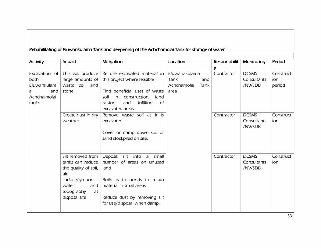
53
Rehabilitating of Eluwankulama Tank and deepening of the Achchamolai Tank for storage of water Rehabilitating of Eluwankulama Tank and deepening of the Achchamolai Tank for storage of water Rehabilitating of Eluwankulama Tank and deepening of the Achchamolai Tank for storage of water Rehabilitating of Eluwankulama Tank and deepening of the Achchamolai Tank for storage of water
ActivityActivityActivityActivity ImpactImpactImpactImpact MitigationMitigationMitigationMitigation LocationLocationLocationLocation ResponsibilitResponsibilitResponsibilitResponsibilit
yyyy
MonitoringMonitoringMonitoringMonitoring Period Period Period Period
Excavation of
both
Eluwankulam
a and
Achchaimolai
tanks
This will produce
large amounts of
waste soil and
stone
Re use excavated material in
this project where feasible
Find beneficial uses of waste
soil in construction, land
raising and infilling of
excavated areas
Eluwanakulama
Tank and
Achchamolai Tank
area
Contractor DCSMS
Consultants
/NWSDB
Construct
ion
period
Create dust in dry
weather
Remove waste soil as it is
excavated.
Cover or damp down soil or
sand stockpiled on site.
Contractor DCSMS
Consultants
/NWSDB
Construct
ion
Silt removed from
tanks can reduce
the quality of soil,
air,
surface/ground
water and
topography at
disposal site
Deposit silt into a small
number of areas on unused
land
Build earth bunds to retain
material in small areas
Reduce dust by removing silt
for use/disposal when damp.
Contractor DCSMS
Consultants
/NWSDB
Construct
ion
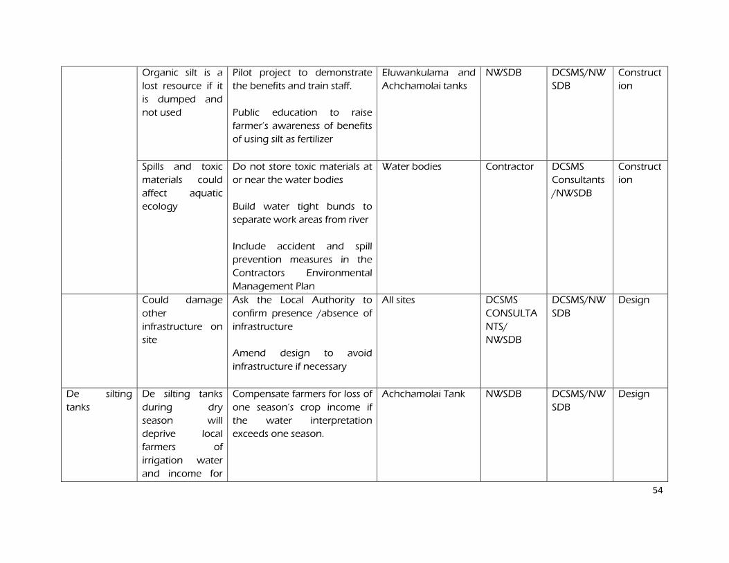
54
Organic silt is a
lost resource if it
is dumped and
not used
Pilot project to demonstrate
the benefits and train staff.
Public education to raise
farmer’s awareness of benefits
of using silt as fertilizer
Eluwankulama and
Achchamolai tanks
NWSDB DCSMS/NW
SDB
Construct
ion
Spills and toxic
materials could
affect aquatic
ecology
Do not store toxic materials at
or near the water bodies
Build water tight bunds to
separate work areas from river
Include accident and spill
prevention measures in the
Contractors Environmental
Management Plan
Water bodies Contractor DCSMS
Consultants
/NWSDB
Construct
ion
Could damage
other
infrastructure on
site
Ask the Local Authority to
confirm presence /absence of
infrastructure
Amend design to avoid
infrastructure if necessary
All sites DCSMS
CONSULTA
NTS/
NWSDB
DCSMS/NW
SDB
Design
De silting
tanks
De silting tanks
during dry
season will
deprive local
farmers of
irrigation water
and income for
Compensate farmers for loss of
one season’s crop income if
the water interpretation
exceeds one season.
Achchamolai Tank NWSDB DCSMS/NW
SDB
Design
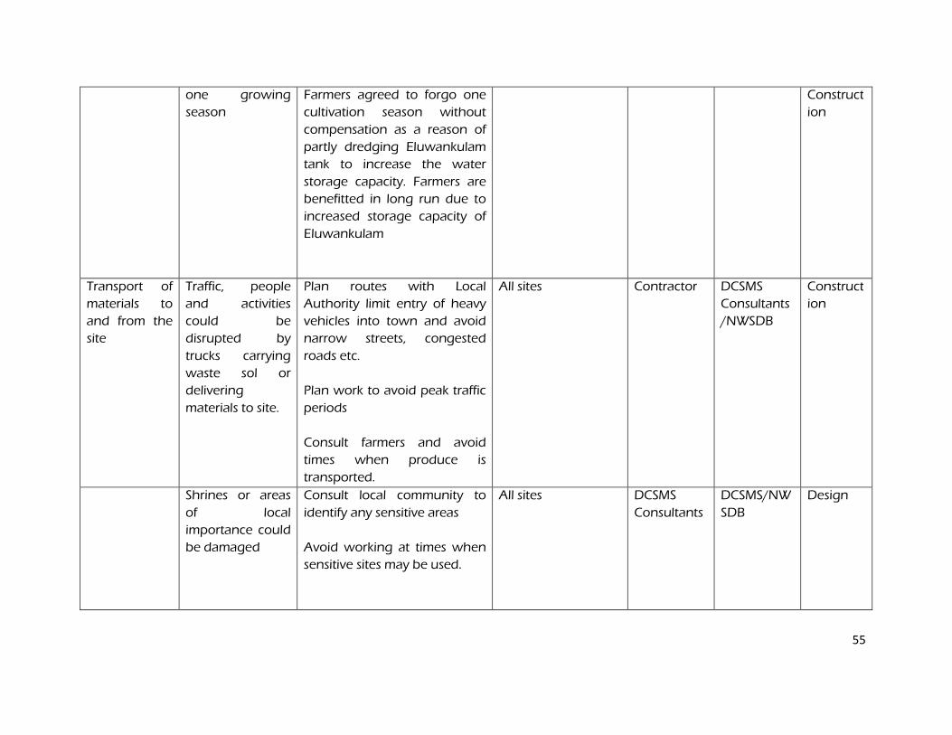
55
one growing
season
Farmers agreed to forgo one
cultivation season without
compensation as a reason of
partly dredging Eluwankulam
tank to increase the water
storage capacity. Farmers are
benefitted in long run due to
increased storage capacity of
Eluwankulam
Construct
ion
Transport of
materials to
and from the
site
Traffic, people
and activities
could be
disrupted by
trucks carrying
waste sol or
delivering
materials to site.
Plan routes with Local
Authority limit entry of heavy
vehicles into town and avoid
narrow streets, congested
roads etc.
Plan work to avoid peak traffic
periods
Consult farmers and avoid
times when produce is
transported.
All sites Contractor DCSMS
Consultants
/NWSDB
Construct
ion
Shrines or areas
of local
importance could
be damaged
Consult local community to
identify any sensitive areas
Avoid working at times when
sensitive sites may be used.
All sites DCSMS
Consultants
DCSMS/NW
SDB
Design
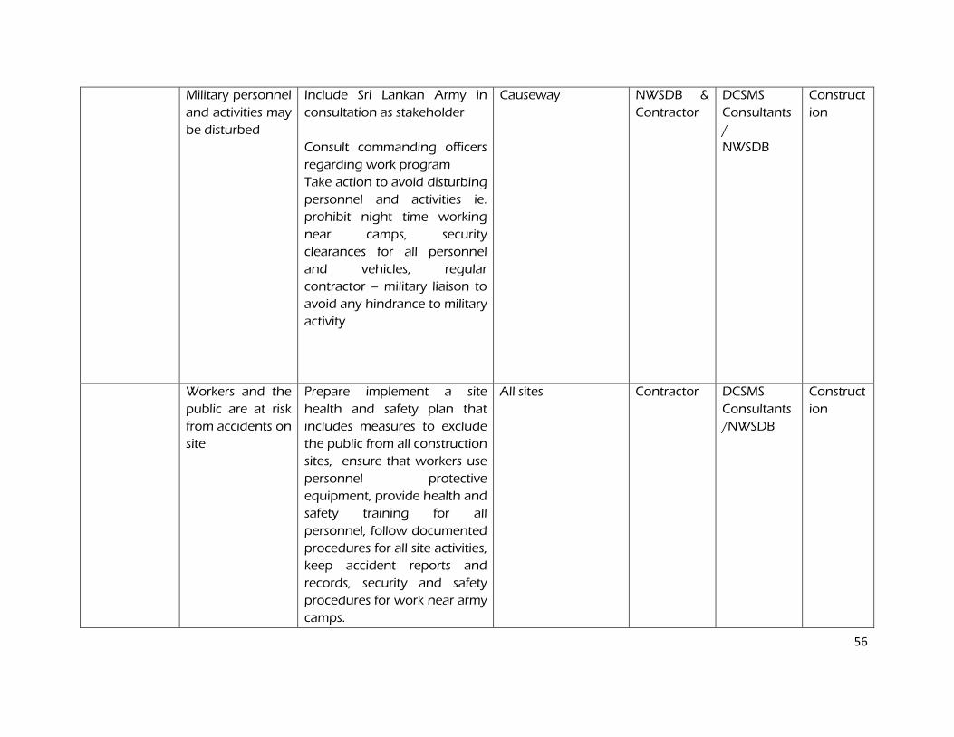
56
Military personnel
and activities may
be disturbed
Include Sri Lankan Army in
consultation as stakeholder
Consult commanding officers
regarding work program
Take action to avoid disturbing
personnel and activities ie.
prohibit night time working
near camps, security
clearances for all personnel
and vehicles, regular
contractor – military liaison to
avoid any hindrance to military
activity
Causeway NWSDB &
Contractor
DCSMS
Consultants
/
NWSDB
Construct
ion
Workers and the
public are at risk
from accidents on
site
Prepare implement a site
health and safety plan that
includes measures to exclude
the public from all construction
sites, ensure that workers use
personnel protective
equipment, provide health and
safety training for all
personnel, follow documented
procedures for all site activities,
keep accident reports and
records, security and safety
procedures for work near army
camps.
All sites Contractor DCSMS
Consultants
/NWSDB
Construct
ion
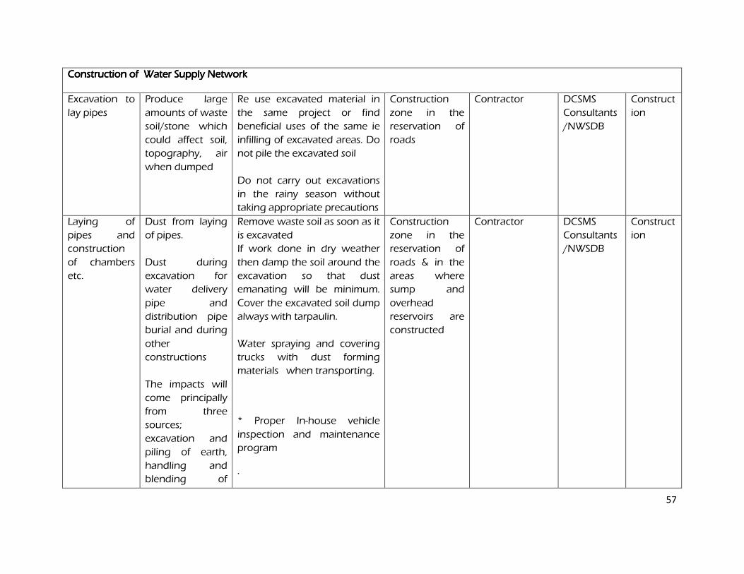
57
Construction of Water Supply NetworkConstruction of Water Supply NetworkConstruction of Water Supply NetworkConstruction of Water Supply Network
Excavation to
lay pipes
Produce large
amounts of waste
soil/stone which
could affect soil,
topography, air
when dumped
Re use excavated material in
the same project or find
beneficial uses of the same ie
infilling of excavated areas. Do
not pile the excavated soil
Do not carry out excavations
in the rainy season without
taking appropriate precautions
Construction
zone in the
reservation of
roads
Contractor
DCSMS
Consultants
/NWSDB
Construct
ion
Laying of
pipes and
construction
of chambers
etc.
Dust from laying
of pipes.
Dust during
excavation for
water delivery
pipe and
distribution pipe
burial and during
other
constructions
The impacts will
come principally
from three
sources;
excavation and
piling of earth,
handling and
blending of
Remove waste soil as soon as it
is excavated
If work done in dry weather
then damp the soil around the
excavation so that dust
emanating will be minimum.
Cover the excavated soil dump
always with tarpaulin.
Water spraying and covering
trucks with dust forming
materials when transporting.
* Proper In-house vehicle
inspection and maintenance
program
.
Construction
zone in the
reservation of
roads & in the
areas where
sump and
overhead
reservoirs are
constructed
Contractor DCSMS
Consultants
/NWSDB
Construct
ion
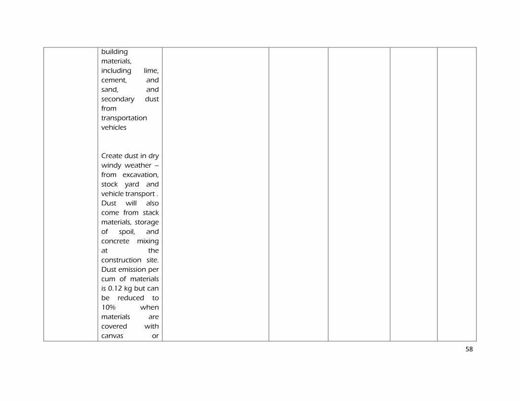
58
building
materials,
including lime,
cement, and
sand, and
secondary dust
from
transportation
vehicles
Create dust in dry
windy weather –
from excavation,
stock yard and
vehicle transport .
Dust will also
come from stack
materials, storage
of spoil, and
concrete mixing
at the
construction site.
Dust emission per
cum of materials
is 0.12 kg but can
be reduced to
10% when
materials are
covered with
canvas or
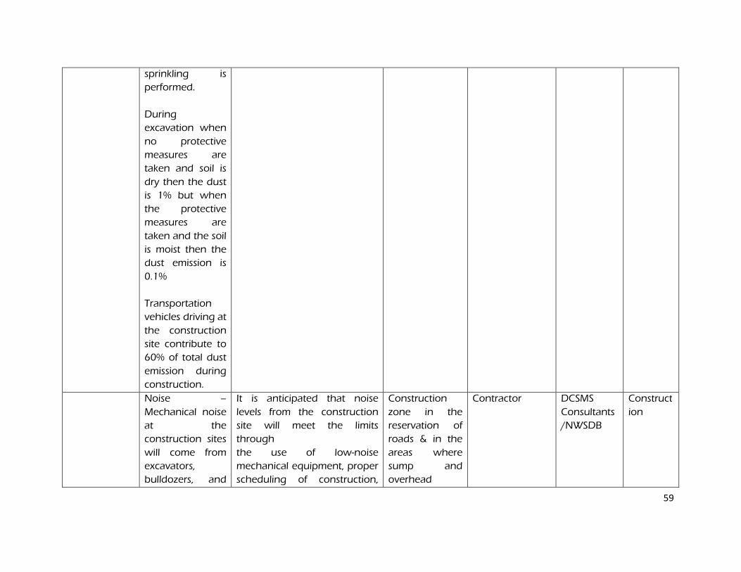
59
sprinkling is
performed.
During
excavation when
no protective
measures are
taken and soil is
dry then the dust
is 1% but when
the protective
measures are
taken and the soil
is moist then the
dust emission is
0.1%
Transportation
vehicles driving at
the construction
site contribute to
60% of total dust
emission during
construction.
Noise –
Mechanical noise
at the
construction sites
will come from
excavators,
bulldozers, and
It is anticipated that noise
levels from the construction
site will meet the limits
through
the use of low-noise
mechanical equipment, proper
scheduling of construction,
Construction
zone in the
reservation of
roads & in the
areas where
sump and
overhead
Contractor DCSMS
Consultants
/NWSDB
Construct
ion
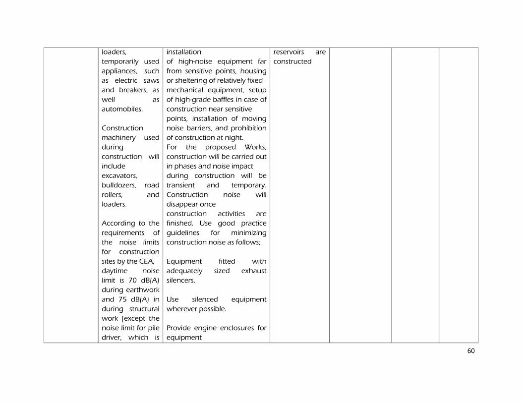
60
loaders,
temporarily used
appliances, such
as electric saws
and breakers, as
well as
automobiles.
Construction
machinery used
during
construction will
include
excavators,
bulldozers, road
rollers, and
loaders.
According to the
requirements of
the noise limits
for construction
sites by the CEA,
daytime noise
limit is 70 dB(A)
during earthwork
and 75 dB(A) in
during structural
work [except the
noise limit for pile
driver, which is
installation
of high-noise equipment far
from sensitive points, housing
or sheltering of relatively fixed
mechanical equipment, setup
of high-grade baffles in case of
construction near sensitive
points, installation of moving
noise barriers, and prohibition
of construction at night.
For the proposed Works,
construction will be carried out
in phases and noise impact
during construction will be
transient and temporary.
Construction noise will
disappear once
construction activities are
finished. Use good practice
guidelines for minimizing
construction noise as follows;
Equipment fitted with
adequately sized exhaust
silencers.
Use silenced equipment
wherever possible.
Provide engine enclosures for
equipment
reservoirs are
constructed
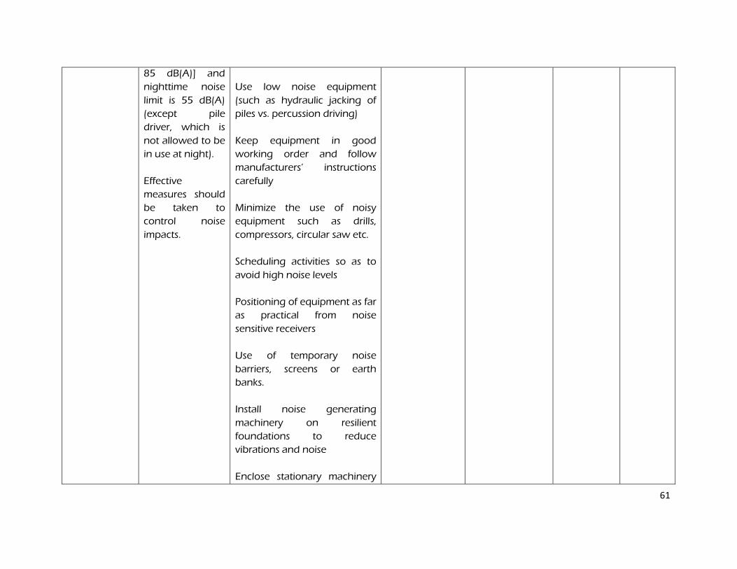
61
85 dB(A)] and
nighttime noise
limit is 55 dB(A)
(except pile
driver, which is
not allowed to be
in use at night).
Effective
measures should
be taken to
control noise
impacts.
Use low noise equipment
(such as hydraulic jacking of
piles vs. percussion driving)
Keep equipment in good
working order and follow
manufacturers’ instructions
carefully
Minimize the use of noisy
equipment such as drills,
compressors, circular saw etc.
Scheduling activities so as to
avoid high noise levels
Positioning of equipment as far
as practical from noise
sensitive receivers
Use of temporary noise
barriers, screens or earth
banks.
Install noise generating
machinery on resilient
foundations to reduce
vibrations and noise
Enclose stationary machinery
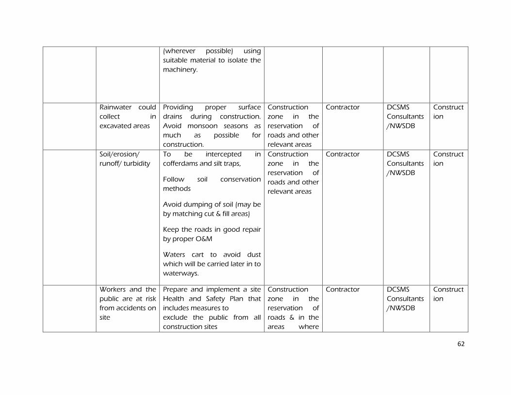
62
(wherever possible) using
suitable material to isolate the
machinery.
Rainwater could
collect in
excavated areas
Providing proper surface
drains during construction.
Avoid monsoon seasons as
much as possible for
construction.
Construction
zone in the
reservation of
roads and other
relevant areas
Contractor DCSMS
Consultants
/NWSDB
Construct
ion
Soil/erosion/
runoff/ turbidity
To be intercepted in
cofferdams and silt traps,
Follow soil conservation
methods
Avoid dumping of soil (may be
by matching cut & fill areas)
Keep the roads in good repair
by proper O&M
Waters cart to avoid dust
which will be carried later in to
waterways.
Construction
zone in the
reservation of
roads and other
relevant areas
Contractor DCSMS
Consultants
/NWSDB
Construct
ion
Workers and the
public are at risk
from accidents on
site
Prepare and implement a site
Health and Safety Plan that
includes measures to
exclude the public from all
construction sites
Construction
zone in the
reservation of
roads & in the
areas where
Contractor DCSMS
Consultants
/NWSDB
Construct
ion
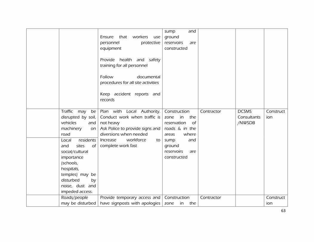
63
Ensure that workers use
personnel protective
equipment
Provide health and safety
training for all personnel
Follow documental
procedures for all site activities
Keep accident reports and
records
sump and
ground
reservoirs are
constructed
Traffic may be
disrupted by soil,
vehicles and
machinery on
road
Plan with Local Authority.
Conduct work when traffic is
not heavy
Ask Police to provide signs and
diversions when needed
Increase workforce to
complete work fast
Construction
zone in the
reservation of
roads & in the
areas where
sump and
ground
reservoirs are
constructed
Contractor DCSMS
Consultants
/NWSDB
Construct
ion
Local residents
and sites of
social/cultural
importance
(schools,
hospitals,
temples) may be
disturbed by
noise, dust and
impeded access.
Roads/people
may be disturbed
Provide temporary access and
have signposts with apologies
Construction
zone in the
Contractor Construct
ion
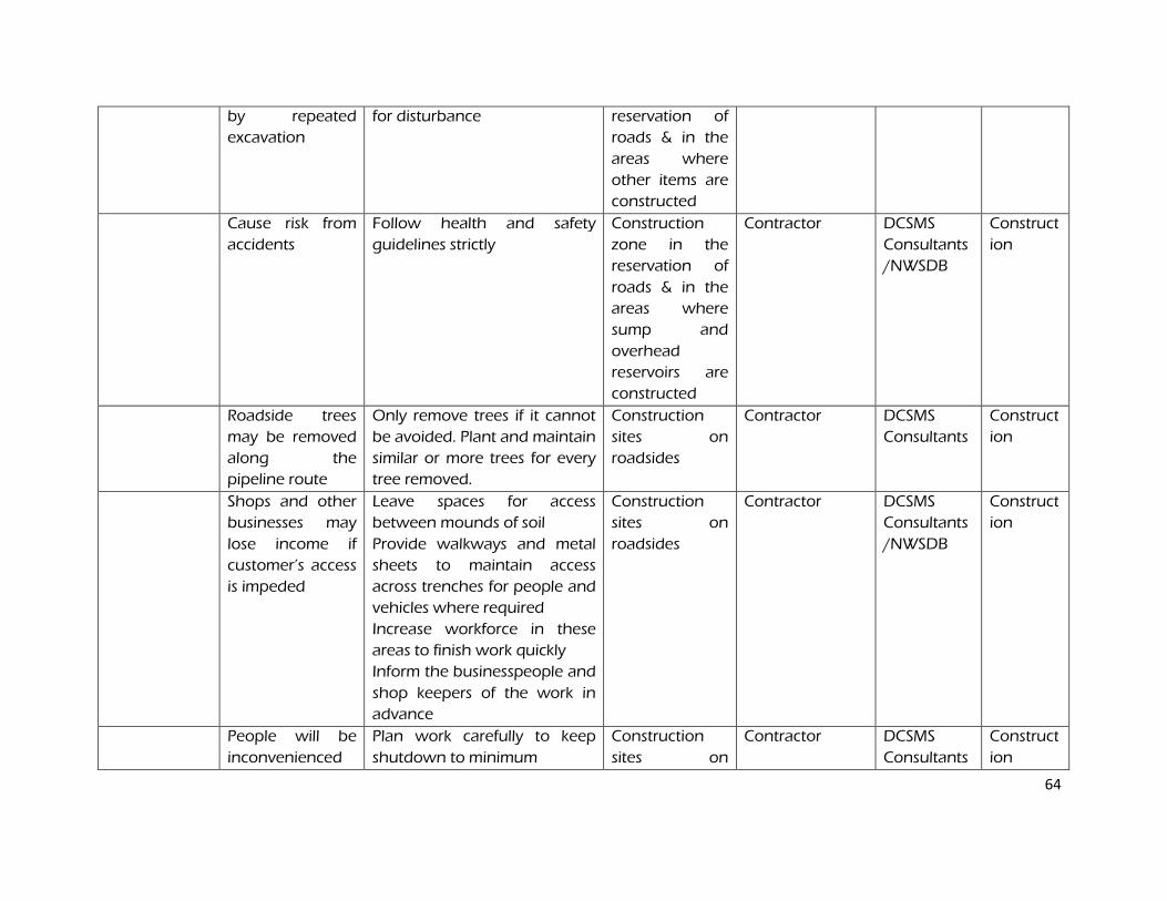
64
by repeated
excavation
for disturbance reservation of
roads & in the
areas where
other items are
constructed
Cause risk from
accidents
Follow health and safety
guidelines strictly
Construction
zone in the
reservation of
roads & in the
areas where
sump and
overhead
reservoirs are
constructed
Contractor DCSMS
Consultants
/NWSDB
Construct
ion
Roadside trees
may be removed
along the
pipeline route
Only remove trees if it cannot
be avoided. Plant and maintain
similar or more trees for every
tree removed.
Construction
sites on
roadsides
Contractor DCSMS
Consultants
Construct
ion
Shops and other
businesses may
lose income if
customer’s access
is impeded
Leave spaces for access
between mounds of soil
Provide walkways and metal
sheets to maintain access
across trenches for people and
vehicles where required
Increase workforce in these
areas to finish work quickly
Inform the businesspeople and
shop keepers of the work in
advance
Construction
sites on
roadsides
Contractor DCSMS
Consultants
/NWSDB
Construct
ion
People will be
inconvenienced
Plan work carefully to keep
shutdown to minimum
Construction
sites on
Contractor DCSMS
Consultants
Construct
ion
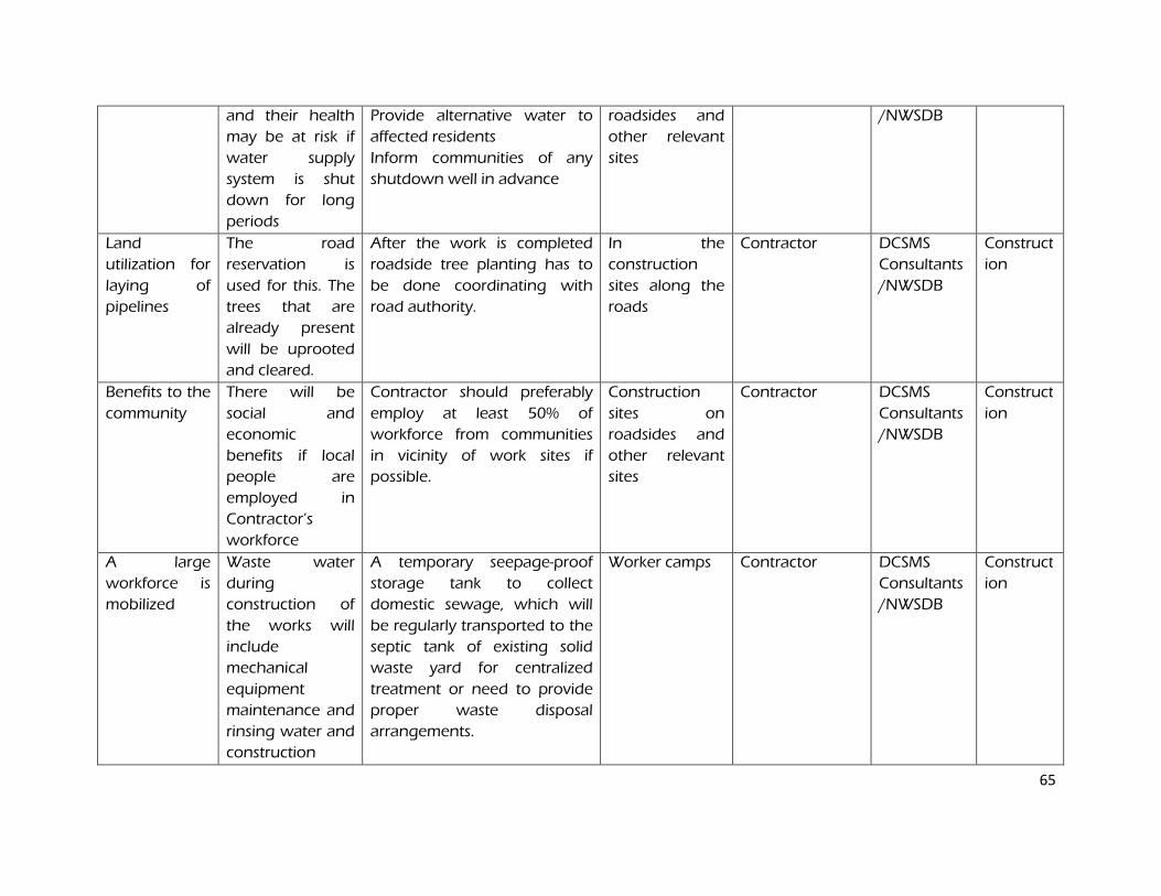
65
and their health
may be at risk if
water supply
system is shut
down for long
periods
Provide alternative water to
affected residents
Inform communities of any
shutdown well in advance
roadsides and
other relevant
sites
/NWSDB
Land
utilization for
laying of
pipelines
The road
reservation is
used for this. The
trees that are
already present
will be uprooted
and cleared.
After the work is completed
roadside tree planting has to
be done coordinating with
road authority.
In the
construction
sites along the
roads
Contractor DCSMS
Consultants
/NWSDB
Construct
ion
Benefits to the
community
There will be
social and
economic
benefits if local
people are
employed in
Contractor’s
workforce
Contractor should preferably
employ at least 50% of
workforce from communities
in vicinity of work sites if
possible.
Construction
sites on
roadsides and
other relevant
sites
Contractor
DCSMS
Consultants
/NWSDB
Construct
ion
A large
workforce is
mobilized
Waste water
during
construction of
the works will
include
mechanical
equipment
maintenance and
rinsing water and
construction
A temporary seepage-proof
storage tank to collect
domestic sewage, which will
be regularly transported to the
septic tank of existing solid
waste yard for centralized
treatment or need to provide
proper waste disposal
arrangements.
Worker camps Contractor DCSMS
Consultants
/NWSDB
Construct
ion
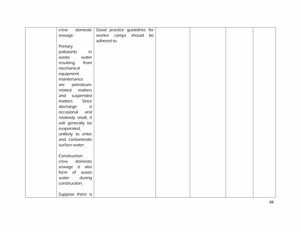
66
crew domestic
sewage.
Primary
pollutants in
waste water
resulting from
mechanical
equipment
maintenance
are petroleum-
related matters
and suspended
matters. Since
discharge is
occasional and
relatively small, it
will generally be
evaporated,
unlikely to enter
and contaminate
surface water.
Construction
crew domestic
sewage is also
form of waste
water during
construction.
Suppose there is
Good practice guidelines for
worker camps should be
adhered to.
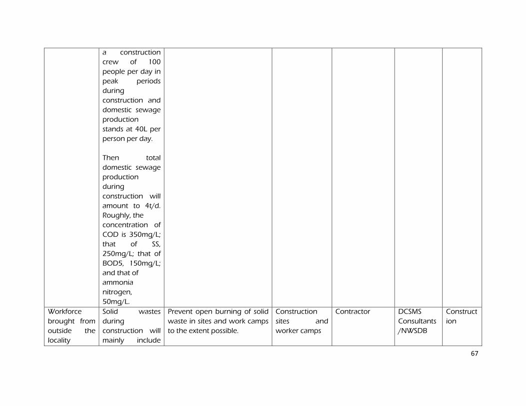
67
a construction
crew of 100
people per day in
peak periods
during
construction and
domestic sewage
production
stands at 40L per
person per day.
Then total
domestic sewage
production
during
construction will
amount to 4t/d.
Roughly, the
concentration of
COD is 350mg/L;
that of SS,
250mg/L; that of
BOD5, 150mg/L;
and that of
ammonia
nitrogen,
50mg/L.
Workforce
brought from
outside the
locality
Solid wastes
during
construction will
mainly include
Prevent open burning of solid
waste in sites and work camps
to the extent possible.
Construction
sites and
worker camps
Contractor DCSMS
Consultants
/NWSDB
Construct
ion
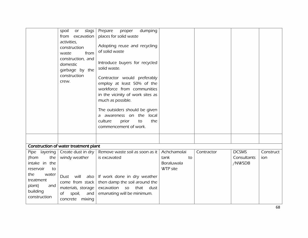
68
spoil or slags
from excavation
activities,
construction
waste from
construction, and
domestic
garbage by the
construction
crew.
Prepare proper dumping
places for solid waste
Adopting reuse and recycling
of solid waste
Introduce buyers for recycled
solid waste.
Contractor would preferably
employ at least 50% of the
workforce from communities
in the vicinity of work sites as
much as possible.
The outsiders should be given
a awareness on the local
culture prior to the
commencement of work.
Construction of water treatment plantConstruction of water treatment plantConstruction of water treatment plantConstruction of water treatment plant
Pipe layering
(from the
intake in the
reservoir to
the water
treatment
plant) and
building
construction
Create dust in dry
windy weather
Dust will also
come from stack
materials, storage
of spoil, and
concrete mixing
Remove waste soil as soon as it
is excavated
If work done in dry weather
then damp the soil around the
excavation so that dust
emanating will be minimum.
Achchamolai
tank to
Boraluwala
WTP site
Contractor DCSMS
Consultants
/NWSDB
Construct
ion

69
at the
construction site.
Cover the excavated soil dump
always with tarpaulin.
Dust emission per cum of
materials is 0.12 kg but can be
reduced to 10% when
materials are covered with
canvas or sprinkling is
performed.
During excavation when no
protective measures are taken
and soil is dry then the dust is
1% but when the protective
measures are taken and the
soil is moist then the dust
emission is 0.1%
Transportation vehicles driving
at the construction site
contribute to 60% of total dust
emission during construction
Noise -
Mechanical noise
at the
construction site
will come from
excavators,
equipment far from sensitive
points, housing or sheltering
of relatively fixed mechanical
equipment, setup of high-
grade baffles in case of
WTP plant site Contractor DCSMS
Consultants
/NWSDB
Construct
ion
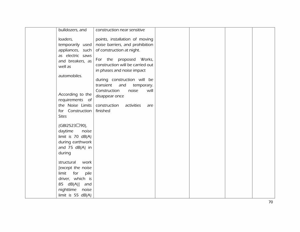
70
bulldozers, and
loaders,
temporarily used
appliances, such
as electric saws
and breakers, as
well as
automobiles.
According to the
requirements of
the Noise Limits
for Construction
Sites
(GBl2523U90),
daytime noise
limit is 70 dB(A)
during earthwork
and 75 dB(A) in
during
structural work
[except the noise
limit for pile
driver, which is
85 dB(A)] and
nighttime noise
limit is 55 dB(A)
construction near sensitive
points, installation of moving
noise barriers, and prohibition
of construction at night.
For the proposed Works,
construction will be carried out
in phases and noise impact
during construction will be
transient and temporary.
Construction noise will
disappear once
construction activities are
finished
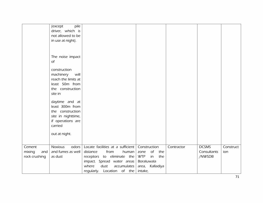
71
(except pile
driver, which is
not allowed to be
in use at night).
The noise impact
of
construction
machinery will
reach the limits at
least 50m from
the construction
site in
daytime and at
least 300m from
the construction
site in nighttime,
if operations are
carried
out at night.
Cement
mixing and
rock crushing
Noxious odors
and fumes as well
as dust
Locate facilities at a sufficient
distance from human
receptors to eliminate the
impact. Spread water areas
where dust accumulates
regularly. Location of the
Construction
zone of the
WTP in the
Boraluwala
area, Kalladiya
intake,
Contractor DCSMS
Consultants
/NWSDB
Construct
ion
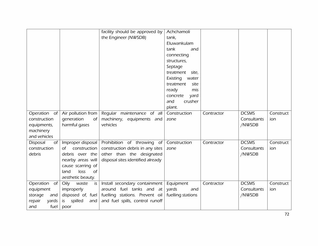
72
facility should be approved by
the Engineer (NWSDB)
Achchamoli
tank,
Eluwankulam
tank and
connecting
structures,
Septage
treatment site,
Existing water
treatment site
ready mis
concrete yard
and crusher
plant.
Operation of
construction
equipments,
machinery
and vehicles
Air pollution from
generation of
harmful gases
Regular maintenance of all
machinery, equipments and
vehicles
Construction
zone
Contractor DCSMS
Consultants
/NWSDB
Construct
ion
Disposal of
construction
debris
Improper disposal
of construction
debris over the
nearby areas will
cause scarring of
land loss of
aesthetic beauty.
Prohibition of throwing of
construction debris in any sites
other than the designated
disposal sites identified already
Construction
zone
Contractor DCSMS
Consultants
/NWSDB
Construct
ion
Operation of
equipment
storage and
repair yards
and fuel
Oily waste is
improperly
disposed of, fuel
is spilled and
poor
Install secondary containment
around fuel tanks and at
fuelling stations. Prevent oil
and fuel spills, control runoff
Equipment
yards and
fuelling stations
Contractor DCSMS
Consultants
/NWSDB
Construct
ion
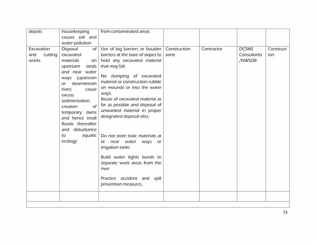
73
depots housekeeping
causes soil and
water pollution
from contaminated areas
Excavation
and cutting
works
Disposal of
excavated
materials on
upstream lands
and near water
ways (upstream
or downstream
river) cause
excess
sedimentation,
creation of
temporary dams
and hence small
floods thereafter
and disturbance
to aquatic
ecology
Use of log barriers or boulder
barriers at the base of slopes to
hold any excavated material
that may fall.
No dumping of excavated
material or construction rubble
on mounds or into the water
ways.
Reuse of excavated material as
far as possible and disposal of
unwanted material in proper
designated disposal sites.
Do not store toxic materials at
or near water ways or
irrigation tanks
Build water tights bunds to
separate work areas from the
river
Practice accident and spill
prevention measures.
Construction
zone
Contractor DCSMS
Consultants
/NWSDB
Construct
ion
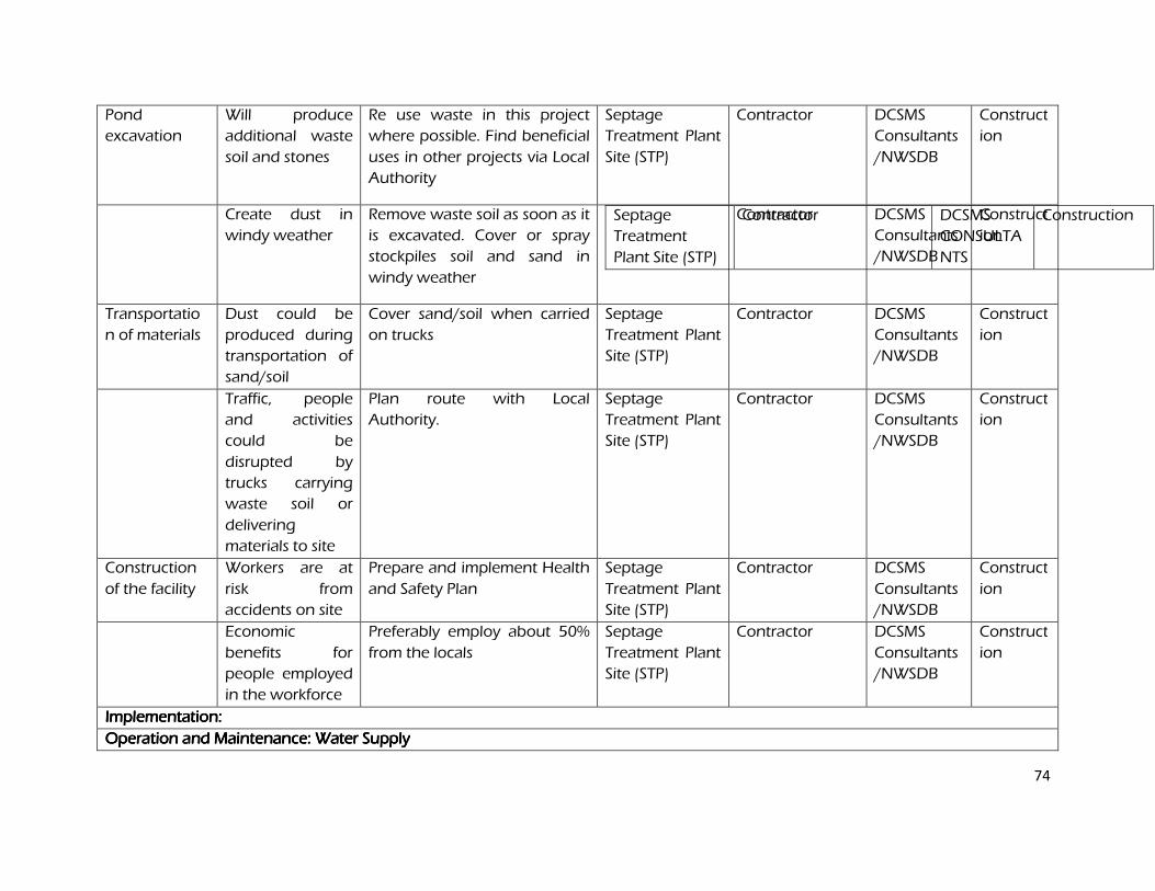
74
Pond
excavation
Will produce
additional waste
soil and stones
Re use waste in this project
where possible. Find beneficial
uses in other projects via Local
Authority
Septage
Treatment Plant
Site (STP)
Contractor DCSMS
Consultants
/NWSDB
Construct
ion
Create dust in
windy weather
Remove waste soil as soon as it
is excavated. Cover or spray
stockpiles soil and sand in
windy weather
Septage
Treatment
Plant Site (STP)
Contractor DCSMS
CONSULTA
NTS
Construction
Contractor
DCSMS
Consultants
/NWSDB
Construct
ion
Transportatio
n of materials
Dust could be
produced during
transportation of
sand/soil
Cover sand/soil when carried
on trucks
Septage
Treatment Plant
Site (STP)
Contractor DCSMS
Consultants
/NWSDB
Construct
ion
Traffic, people
and activities
could be
disrupted by
trucks carrying
waste soil or
delivering
materials to site
Plan route with Local
Authority.
Septage
Treatment Plant
Site (STP)
Contractor DCSMS
Consultants
/NWSDB
Construct
ion
Construction
of the facility
Workers are at
risk from
accidents on site
Prepare and implement Health
and Safety Plan
Septage
Treatment Plant
Site (STP)
Contractor DCSMS
Consultants
/NWSDB
Construct
ion
Economic
benefits for
people employed
in the workforce
Preferably employ about 50%
from the locals
Septage
Treatment Plant
Site (STP)
Contractor DCSMS
Consultants
/NWSDB
Construct
ion
Implementation: Implementation: Implementation: Implementation:
Operation and Maintenance: Water SupplyOperation and Maintenance: Water SupplyOperation and Maintenance: Water SupplyOperation and Maintenance: Water Supply
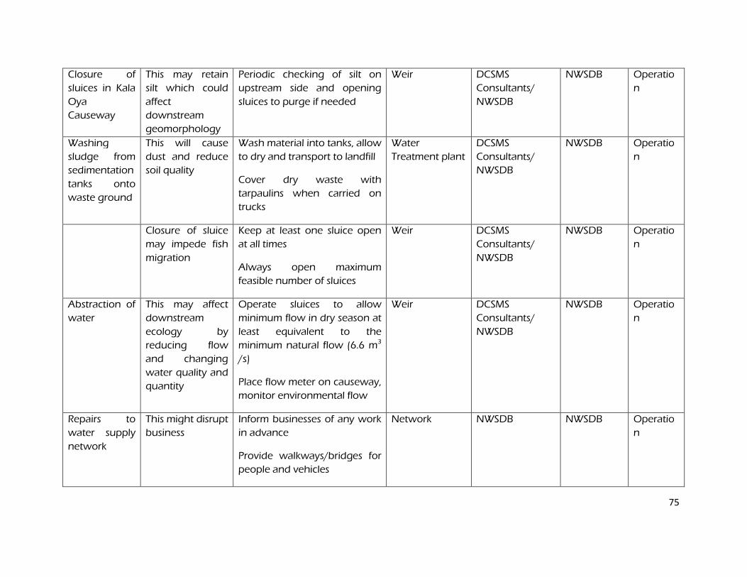
75
Closure of
sluices in Kala
Oya
Causeway
This may retain
silt which could
affect
downstream
geomorphology
Periodic checking of silt on
upstream side and opening
sluices to purge if needed
Weir DCSMS
Consultants/
NWSDB
NWSDB Operatio
n
Washing
sludge from
sedimentation
tanks onto
waste ground
This will cause
dust and reduce
soil quality
Wash material into tanks, allow
to dry and transport to landfill
Cover dry waste with
tarpaulins when carried on
trucks
Water
Treatment plant
DCSMS
Consultants/
NWSDB
NWSDB Operatio
n
Closure of sluice
may impede fish
migration
Keep at least one sluice open
at all times
Always open maximum
feasible number of sluices
Weir DCSMS
Consultants/
NWSDB
NWSDB Operatio
n
Abstraction of
water
This may affect
downstream
ecology by
reducing flow
and changing
water quality and
quantity
Operate sluices to allow
minimum flow in dry season at
least equivalent to the
minimum natural flow (6.6 m3
/s)
Place flow meter on causeway,
monitor environmental flow
Weir DCSMS
Consultants/
NWSDB
NWSDB Operatio
n
Repairs to
water supply
network
This might disrupt
business
Inform businesses of any work
in advance
Provide walkways/bridges for
people and vehicles
Network NWSDB NWSDB Operatio
n
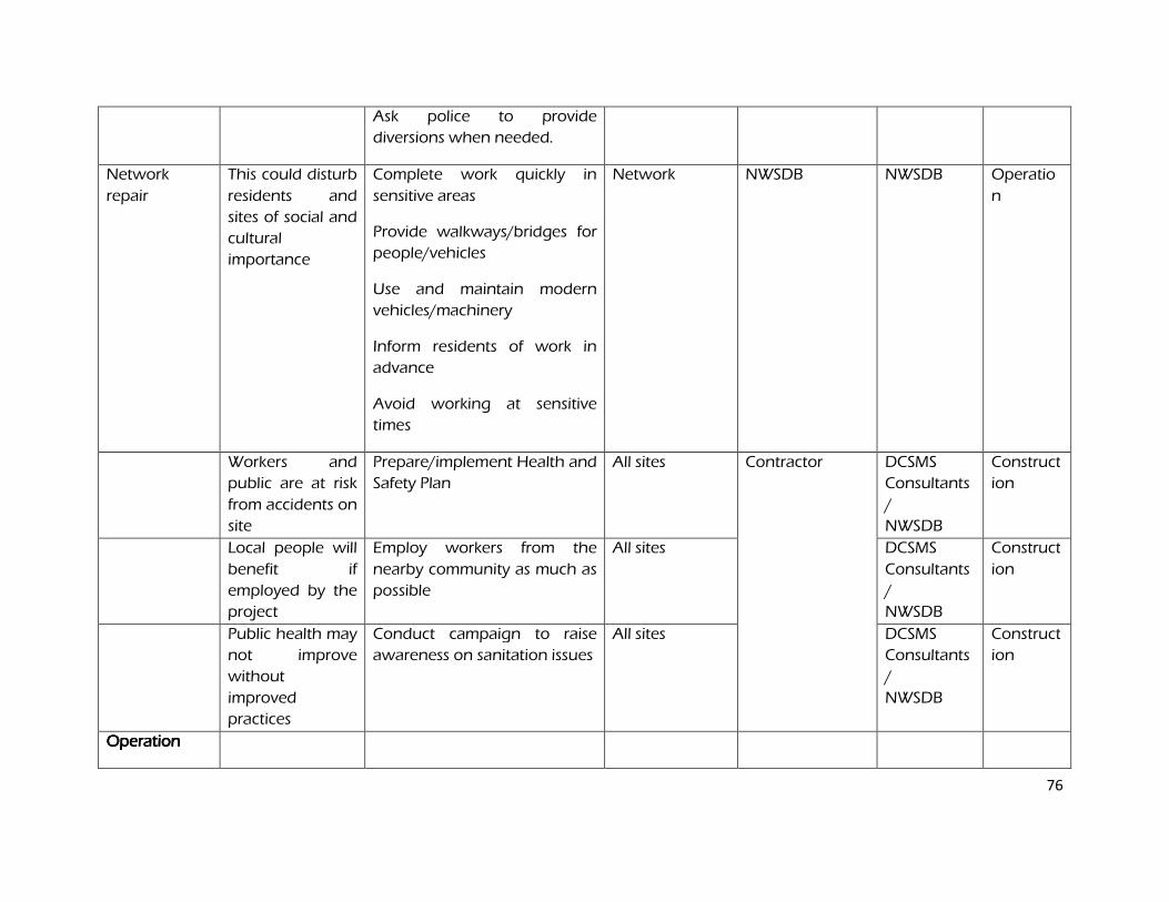
76
Ask police to provide
diversions when needed.
Network
repair
This could disturb
residents and
sites of social and
cultural
importance
Complete work quickly in
sensitive areas
Provide walkways/bridges for
people/vehicles
Use and maintain modern
vehicles/machinery
Inform residents of work in
advance
Avoid working at sensitive
times
Network NWSDB NWSDB Operatio
n
Workers and
public are at risk
from accidents on
site
Prepare/implement Health and
Safety Plan
All sites Contractor DCSMS
Consultants
/
NWSDB
Construct
ion
Local people will
benefit if
employed by the
project
Employ workers from the
nearby community as much as
possible
All sites DCSMS
Consultants
/
NWSDB
Construct
ion
Public health may
not improve
without
improved
practices
Conduct campaign to raise
awareness on sanitation issues
All sites DCSMS
Consultants
/
NWSDB
Construct
ion
Operation Operation Operation Operation
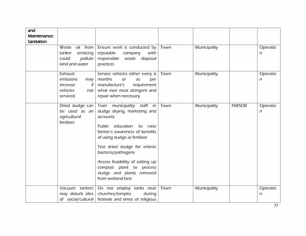
77
and and and and
Maintenance: Maintenance: Maintenance: Maintenance:
Sanitation Sanitation Sanitation Sanitation
Waste oil from
tanker servicing
could pollute
land and water
Ensure work is conducted by
reputable company with
responsible waste disposal
practices
Town Municipality Operatio
n
Exhaust
emissions may
increase if
vehicles not
serviced
Service vehicles either every 6
months or as per
manufacture’s requirement
what ever most stringent and
repair when necessary
Town Municipality Operatio
n
Dried sludge can
be used as an
agricultural
fertilizer
Train municipality staff in
sludge drying, marketing and
accounts
Public education ‘to raise
farmer’s awareness of benefits
of using sludge as fertilizer
Test dried sludge for enteric
bacteria/pathogens
Access feasibility of setting up
compost plant to process
sludge and plants removed
from wetland bed
Town Municipality NWSDB Operatio
n
Vacuum tankers
may disturb sites
of social/cultural
Do not employ tanks near
churches/temples during
festivals and times of religious
Town Municipality Operatio
n
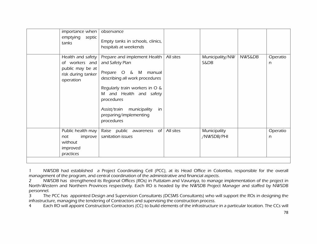
78
importance when
emptying septic
tanks
observance
Empty tanks in schools, clinics,
hospitals at weekends
Health and safety
of workers and
public may be at
risk during tanker
operation
Prepare and implement Health
and Safety Plan
Prepare O & M manual
describing all work procedures
Regularly train workers in O &
M and Health and safety
procedures
Assist/train municipality in
preparing/implementing
procedures
All sites Municipality/NW
S&DB
NWS&DB Operatio
n
Public health may
not improve
without
improved
practices
Raise public awareness of
sanitation issues
All sites Municipality
/NWSDB/PHI
Operatio
n
1 NWSDB had established a Project Coordinating Cell (PCC), at its Head Office in Colombo, responsible for the overall management of the program, and central coordination of the administrative and financial aspects. 2 NWSDB has strengthened its Regional Offices (ROs) in Puttalam and Vavuniya, to manage implementation of the project in North-Western and Northern Provinces respectively. Each RO is headed by the NWSDB Project Manager and staffed by NWSDB personnel. 3 The PCC has appointed Design and Supervision Consultants (DCSMS Consultants) who will support the ROs in designing the infrastructure, managing the tendering of Contractors and supervising the construction process. 4 Each RO will appoint Construction Contractors (CC) to build elements of the infrastructure in a particular location. The CCs will
79
be managed by the relevant RO, and construction will be supervised by the DCSMS Consultants. 5 NWSDB is assisted by an inter-ministerial Project Implementation Coordination Committee (PICC), to provide policy guidance and coordination across all locations and subprojects. The PSC is chaired by the secretary of MWSD, and members will include senior officials from the Ministry of Finance and Planning, NWSDB, Ministry of Local Government, Central Environment Authority; and representatives of provincial governments, local authorities, aid agencies and NGOs. 6 A Provincial Project Coordination Committee (PPCC) was set up in each town and rural area to monitor project implementation at the local level, and will report directly to the PPIC. 7 Resettlement issues are coordinated by a Resettlement Specialist in the RO, who ensures consistency across all subprojects and prepare and implement local Resettlement Plans following the ‘Guidelines for Updating Resettlement Plans’ developed during project preparation. 8 Environmental issues are coordinated by an Environmental Specialist in the RO who ensures that all subprojects comply with ADB and national environmental safeguards. Applications for Environmental Clearance has been submitted to CEA, comprising a completed Project Information Document (PID) and a full or simplified IEE as appropriate. In the event that CEA require further study, this will be conducted by Domestic Environmental Consultants appointed by NWSDB. 9 Each IEE includes an Environmental Monitoring Plan (EnvMoP), involving observations and surveys to be conducted during construction and operation to ensure that mitigation measures are provided and that they protect the environment as intended. Construction-phase monitoring is supervised by an Environmental Monitoring Specialist (EMS) who is part of the DCSMS Consultants team. Monitoring during operation will be conducted by consultants appointed by NWSDB. Once the various elements of the infrastructure have been built and commissioned, responsibility for the operation and maintenance of each scheme will be as follows: Urban water supply: NWSDB; Urban sanitation: The Public Health Department of the Urban Council.
80
C. Environmental Monitoring Plan C. Environmental Monitoring Plan C. Environmental Monitoring Plan C. Environmental Monitoring Plan
Table 9 shows that most mitigation activities are the responsibility of the Construction Contractors (CC) employed to build the infrastructure during the construction stage, or the O&M Contractors (OMC) who will be employed to conduct maintenance or repair work when the systems are operating. Responsibility for the relevant measures will be assigned to the Contractors via the contracts through which they are appointed (prepared by the DCSMS Consultants during the detailed design stage), so they will be legally required to take the necessary action. There are also some actions that need to be taken by the NWSDB in their role as project proponent, actions related to the design that will be implemented by the DCSMS Consultants, and actions during the operational phase that are the responsibility of NWSDB (water supply) or PUC (sanitation ) as the system operators. The DCSMS Consultants Environmental Monitoring Specialist (EMS) is responsible for all construction-phase monitoring and reporting the results and conclusions to the PIU, and will recommend remedial action if measures are not being provided or are not protecting the environment effectively. The EMS may be assisted by other environmental specialists and junior or medium-level engineers who can make many of the routine observations on site. Post-construction monitoring will be conducted by NWSDB, and/or domestic consultants/contractors they appoint. Table 9 shows that most of the mitigation measures are fairly standard methods of minimising disturbance from building in urban areas (maintaining access, planning work to avoid sensitive times, finding uses for waste material, etc), and experienced contractors should be familiar with most of the requirements. Monitoring of such measures normally involves making observations in the course of site visits, although some require more formal checking of records and other aspects. There will also be some surveys of residents, as most of the measures are aimed at preventing impacts on people and the human environment. Table 10 shows the proposed Environmental Monitoring Plan (EMP) for the subprojects, which specifies the various monitoring activities to be conducted during all phases. Some of the measures shown in Table 9 have been consolidated to avoid repetition, and there has been some re-ordering to present together those measures that relate to the same activity or site. The EMP describes: (i) mitigation measures, (ii) location, (iii) measurement method, (iv) frequency of monitoring and (v) responsibility (for both mitigation and monitoring). It does not show specific parameters to be measured because as indicated above, most measures will be checked by simple observation, by checking of records, or by interviews with residents or workers. The mitigation plan includes short-term surveys and studies that need to be conducted during the detailed design stage to assess the proposed method of water treatment, which has been planned on the basis of inadequate data and could provide water that is a risk to human health. These are: Surveys of the quality of water in the aquifer, Kala Oya and Achchamolai Tank; An assessment of the quality of water likely to be produced by proposed treatment, and
redesign of the treatment method if water is unlikely to meet national standards.
Qualified domestic consultants will be appointed by NWSDB to conduct these surveys and studies. The three surveys will require a year of data collection each, which should begin as soon as possible.
81
The mitigation plan also recommends longer-term monitoring: to confirm that the drying process removes all enteric bacteria and pathogens from the septic tank sludge; to measure the quality and quantity of treatment plant effluent; and to determine its impact on water quality in the lagoon. Given the scale of the investment in providing infrastructure, NWSDB will also wish to conduct surveys during the operational period to ensure that the water treatment method is providing water of the required quality, and to confirm the lasting benefits of the schemes. The following aspects will thus be monitored over the long term:
Bacteriological content of dried sewage sludge; Chemical and bacteriological quality of treated STF effluent; Chemical and bacteriological quality of water in Puttalam Lagoon near the STF outfall; Chemical and bacteriological quality of water provided by the municipal system; Health of the population and the prevalence of diseases of poor sanitation.
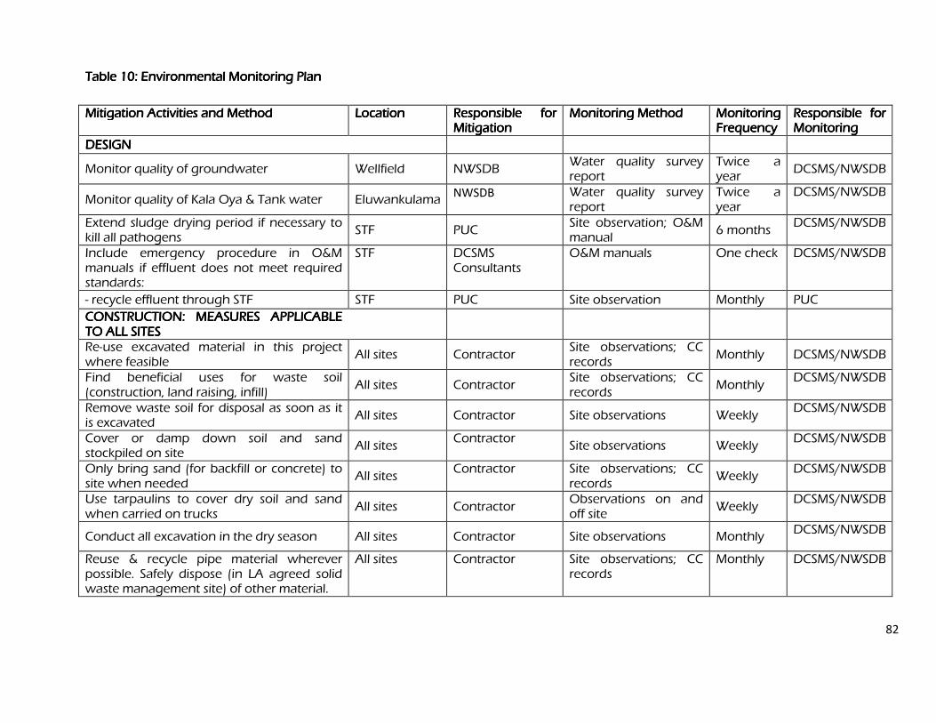
82
Table 10: Environmental Monitoring Plan Table 10: Environmental Monitoring Plan Table 10: Environmental Monitoring Plan Table 10: Environmental Monitoring Plan
Mitigation Activities and Method Mitigation Activities and Method Mitigation Activities and Method Mitigation Activities and Method Location Location Location Location Responsible for Responsible for Responsible for Responsible for Mitigation Mitigation Mitigation Mitigation
Monitoring Method Monitoring Method Monitoring Method Monitoring Method Monitoring Monitoring Monitoring Monitoring Frequency Frequency Frequency Frequency
Responsible for Responsible for Responsible for Responsible for Monitoring Monitoring Monitoring Monitoring
DESIGN DESIGN DESIGN DESIGN
Monitor quality of groundwater Wellfield NWSDB Water quality survey report
Twice a year
DCSMS/NWSDB
Monitor quality of Kala Oya & Tank water Eluwankulama NWSDB Water quality survey
report Twice a year
DCSMS/NWSDB
Extend sludge drying period if necessary to kill all pathogens
STF PUC Site observation; O&M manual
6 months DCSMS/NWSDB
Include emergency procedure in O&M manuals if effluent does not meet required standards:
STF DCSMS Consultants
O&M manuals One check DCSMS/NWSDB
- recycle effluent through STF STF PUC Site observation Monthly PUC
CONSTRUCTION: MEASURES APPLICABLE CONSTRUCTION: MEASURES APPLICABLE CONSTRUCTION: MEASURES APPLICABLE CONSTRUCTION: MEASURES APPLICABLE TO ALL SITES TO ALL SITES TO ALL SITES TO ALL SITES
Re-use excavated material in this project where feasible
All sites Contractor Site observations; CC records
Monthly DCSMS/NWSDB
Find beneficial uses for waste soil (construction, land raising, infill)
All sites Contractor Site observations; CC records
Monthly DCSMS/NWSDB
Remove waste soil for disposal as soon as it is excavated
All sites Contractor Site observations Weekly DCSMS/NWSDB
Cover or damp down soil and sand stockpiled on site
All sites Contractor
Site observations Weekly DCSMS/NWSDB
Only bring sand (for backfill or concrete) to site when needed
All sites Contractor Site observations; CC
records Weekly
DCSMS/NWSDB
Use tarpaulins to cover dry soil and sand when carried on trucks
All sites Contractor Observations on and off site
Weekly DCSMS/NWSDB
Conduct all excavation in the dry season All sites Contractor Site observations Monthly DCSMS/NWSDB
Reuse & recycle pipe material wherever possible. Safely dispose (in LA agreed solid waste management site) of other material.
All sites Contractor Site observations; CC records
Monthly DCSMS/NWSDB
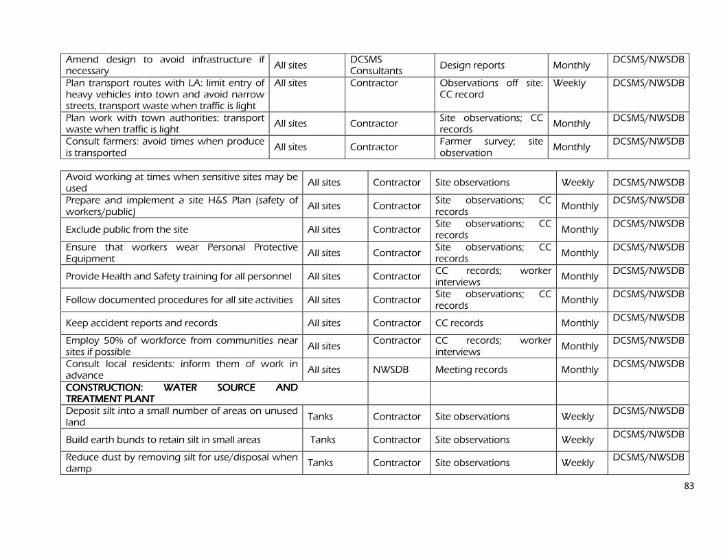
83
Amend design to avoid infrastructure if necessary
All sites DCSMS Consultants
Design reports Monthly DCSMS/NWSDB
Plan transport routes with LA: limit entry of heavy vehicles into town and avoid narrow streets, transport waste when traffic is light
All sites Contractor Observations off site: CC record
Weekly DCSMS/NWSDB
Plan work with town authorities: transport waste when traffic is light
All sites Contractor Site observations; CC records
Monthly DCSMS/NWSDB
Consult farmers: avoid times when produce is transported
All sites Contractor Farmer survey; site observation
Monthly DCSMS/NWSDB
Avoid working at times when sensitive sites may be used
All sites Contractor Site observations Weekly DCSMS/NWSDB
Prepare and implement a site H&S Plan (safety of workers/public)
All sites Contractor Site observations; CC records
Monthly DCSMS/NWSDB
Exclude public from the site All sites Contractor Site observations; CC records
Monthly DCSMS/NWSDB
Ensure that workers wear Personal Protective Equipment
All sites Contractor Site observations; CC records
Monthly DCSMS/NWSDB
Provide Health and Safety training for all personnel All sites Contractor CC records; worker interviews
Monthly DCSMS/NWSDB
Follow documented procedures for all site activities All sites Contractor Site observations; CC records
Monthly DCSMS/NWSDB
Keep accident reports and records All sites Contractor CC records Monthly DCSMS/NWSDB
Employ 50% of workforce from communities near sites if possible
All sites Contractor CC records; worker
interviews Monthly
DCSMS/NWSDB
Consult local residents: inform them of work in advance
All sites NWSDB Meeting records Monthly DCSMS/NWSDB
CONSTRUCTION: WATER SOURCE AND CONSTRUCTION: WATER SOURCE AND CONSTRUCTION: WATER SOURCE AND CONSTRUCTION: WATER SOURCE AND TREATMENT PLANT TREATMENT PLANT TREATMENT PLANT TREATMENT PLANT
Deposit silt into a small number of areas on unused land
Tanks Contractor Site observations Weekly DCSMS/NWSDB
Build earth bunds to retain silt in small areas Tanks Contractor Site observations Weekly DCSMS/NWSDB
Reduce dust by removing silt for use/disposal when damp
Tanks Contractor Site observations Weekly DCSMS/NWSDB
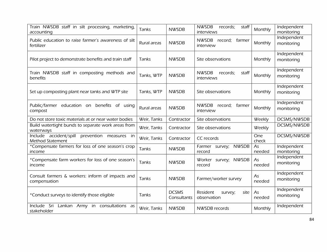
84
Train NWSDB staff in silt processing, marketing, accounting
Tanks NWSDB NWSDB records; staff interviews
Monthly Independent monitoring
Public education to raise farmer’s awareness of silt fertilizer
Rural areas NWSDB NWSDB record; farmer interview
Monthly Independent
monitoring
Pilot project to demonstrate benefits and train staff Tanks NWSDB Site observations Monthly Independent
monitoring
Train NWSDB staff in composting methods and benefits
Tanks, WTP NWSDB NWSDB records; staff interviews
Monthly Independent
monitoring
Set up composting plant near tanks and WTP site Tanks, WTP NWSDB Site observations Monthly Independent
monitoring
Public/farmer education on benefits of using compost
Rural areas NWSDB NWSDB record; farmer interview
Monthly Independent
monitoring
Do not store toxic materials at or near water bodies Weir, Tanks Contractor Site observations Weekly DCSMS/NWSDB
Build watertight bunds to separate work areas from waterways
Weir, Tanks Contractor Site observations Weekly DCSMS/NWSDB
Include accident/spill prevention measures in Method Statement
Weir, Tanks Contractor CC records One check
DCSMS/NWSDB
*Compensate farmers for loss of one season’s crop income
Tanks NWSDB Farmer survey; NWSDB record
As needed
Independent monitoring
*Compensate farm workers for loss of one season’s income
Tanks NWSDB Worker survey; NWSDB record
As needed
Independent
monitoring
Consult farmers & workers: inform of impacts and compensation
Tanks NWSDB Farmer/worker survey As needed
Independent
monitoring
*Conduct surveys to identify those eligible Tanks DCSMS Consultants
Resident survey; site observation
As needed
Independent
monitoring
Include Sri Lankan Army in consultations as stakeholder
Weir, Tanks NWSDB NWSDB records Monthly Independent
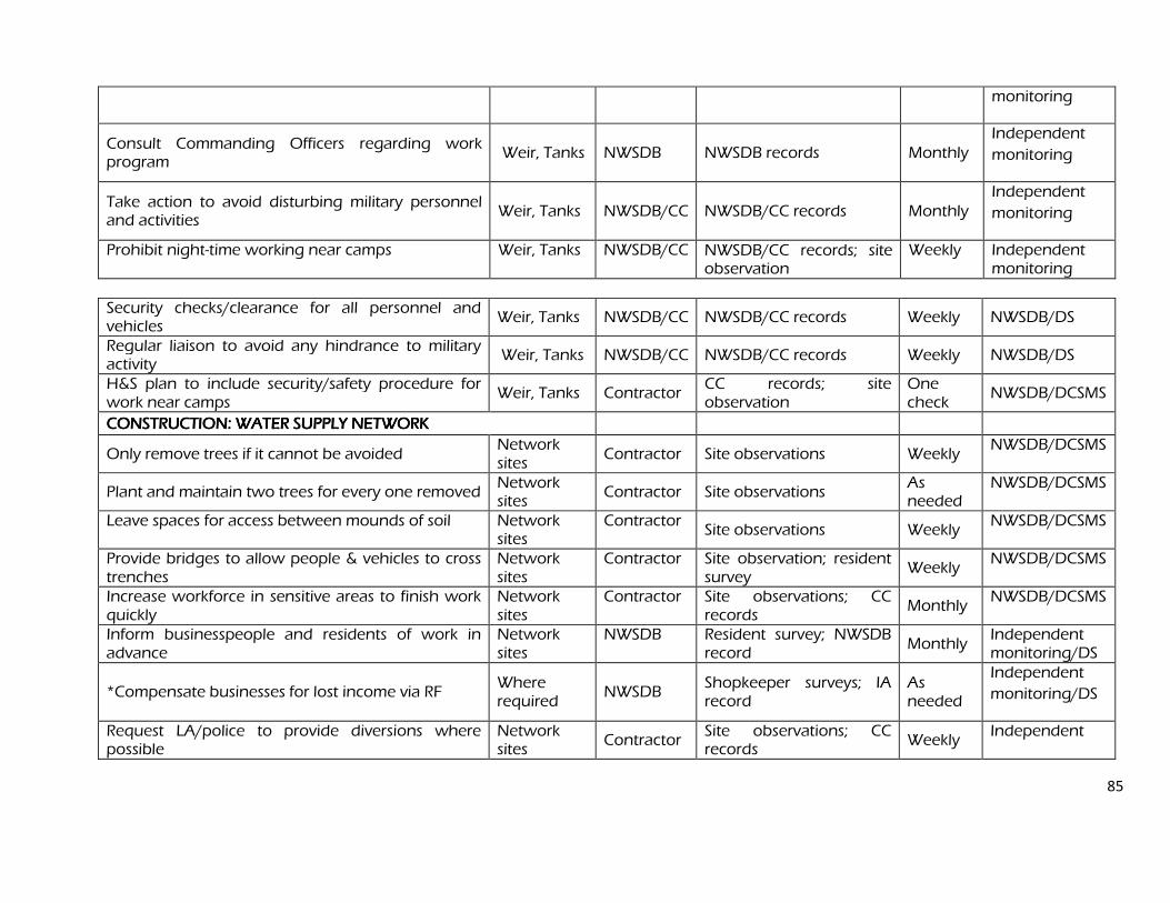
85
monitoring
Consult Commanding Officers regarding work program
Weir, Tanks NWSDB NWSDB records Monthly Independent
monitoring
Take action to avoid disturbing military personnel and activities
Weir, Tanks NWSDB/CC NWSDB/CC records Monthly Independent
monitoring
Prohibit night-time working near camps Weir, Tanks NWSDB/CC NWSDB/CC records; site observation
Weekly Independent monitoring
Security checks/clearance for all personnel and vehicles
Weir, Tanks NWSDB/CC NWSDB/CC records Weekly NWSDB/DS
Regular liaison to avoid any hindrance to military activity
Weir, Tanks NWSDB/CC NWSDB/CC records Weekly NWSDB/DS
H&S plan to include security/safety procedure for work near camps
Weir, Tanks Contractor CC records; site observation
One check
NWSDB/DCSMS
CONSTRUCTION: WATER SUPPLY NETWORK CONSTRUCTION: WATER SUPPLY NETWORK CONSTRUCTION: WATER SUPPLY NETWORK CONSTRUCTION: WATER SUPPLY NETWORK
Only remove trees if it cannot be avoided Network sites
Contractor Site observations Weekly NWSDB/DCSMS
Plant and maintain two trees for every one removed Network sites
Contractor Site observations As needed
NWSDB/DCSMS
Leave spaces for access between mounds of soil Network sites
Contractor Site observations Weekly
NWSDB/DCSMS
Provide bridges to allow people & vehicles to cross trenches
Network sites
Contractor Site observation; resident survey
Weekly NWSDB/DCSMS
Increase workforce in sensitive areas to finish work quickly
Network sites
Contractor Site observations; CC records
Monthly NWSDB/DCSMS
Inform businesspeople and residents of work in advance
Network sites
NWSDB Resident survey; NWSDB record
Monthly Independent monitoring/DS
*Compensate businesses for lost income via RF Where required
NWSDB Shopkeeper surveys; IA record
As needed
Independent
monitoring/DS
Request LA/police to provide diversions where possible
Network sites
Contractor Site observations; CC records
Weekly Independent
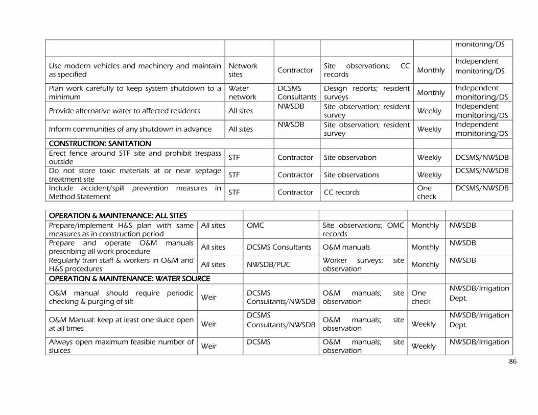
86
monitoring/DS
Use modern vehicles and machinery and maintain as specified
Network sites
Contractor Site observations; CC records
Monthly Independent
monitoring/DS
Plan work carefully to keep system shutdown to a minimum
Water network
DCSMS Consultants
Design reports; resident surveys
Monthly Independent monitoring/DS
Provide alternative water to affected residents All sites NWSDB Site observation; resident
survey Weekly
Independent monitoring/DS
Inform communities of any shutdown in advance All sites NWSDB Site observation; resident
survey Weekly
Independent monitoring/DS
CONSTRUCTION: SANITATION CONSTRUCTION: SANITATION CONSTRUCTION: SANITATION CONSTRUCTION: SANITATION
Erect fence around STF site and prohibit trespass outside
STF Contractor Site observation Weekly DCSMS/NWSDB
Do not store toxic materials at or near septage treatment site
STF Contractor Site observations Weekly DCSMS/NWSDB
Include accident/spill prevention measures in Method Statement
STF Contractor CC records One check
DCSMS/NWSDB
OPERATION & MAINTENANCE: ALL SITES OPERATION & MAINTENANCE: ALL SITES OPERATION & MAINTENANCE: ALL SITES OPERATION & MAINTENANCE: ALL SITES
Prepare/implement H&S plan with same measures as in construction period
All sites OMC Site observations; OMC records
Monthly NWSDB
Prepare and operate O&M manuals prescribing all work procedure
All sites DCSMS Consultants O&M manuals Monthly NWSDB
Regularly train staff & workers in O&M and H&S procedures
All sites NWSDB/PUC Worker surveys; site observation
Monthly NWSDB
OPERATION & MAINTENANCE: WATER SOURCE OPERATION & MAINTENANCE: WATER SOURCE OPERATION & MAINTENANCE: WATER SOURCE OPERATION & MAINTENANCE: WATER SOURCE
O&M manual should require periodic checking & purging of silt
Weir DCSMS Consultants/NWSDB
O&M manuals; site observation
One check
NWSDB/Irrigation
Dept.
O&M Manual: keep at least one sluice open at all times
Weir DCSMS
Consultants/NWSDB O&M manuals; site observation
Weekly NWSDB/Irrigation
Dept.
Always open maximum feasible number of sluices
Weir DCSMS O&M manuals; site
observation Weekly
NWSDB/Irrigation
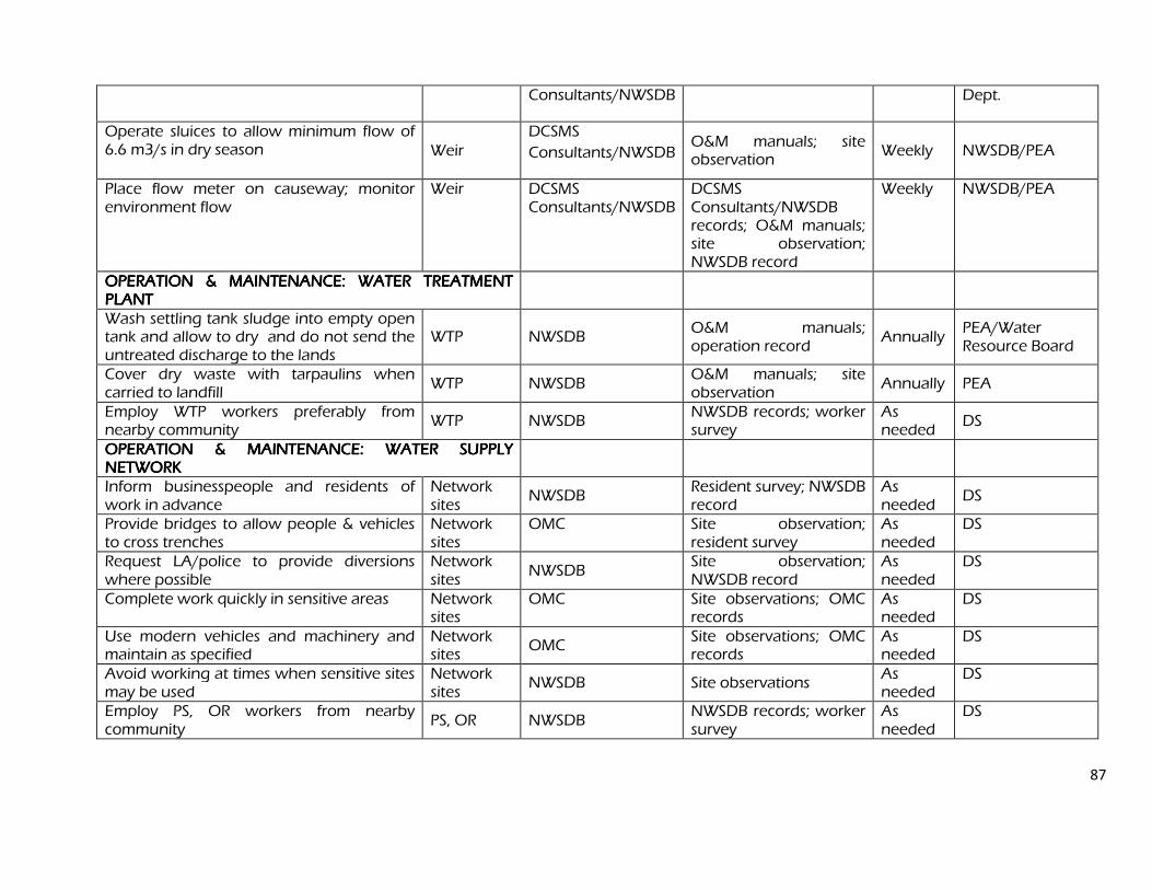
87
Consultants/NWSDB Dept.
Operate sluices to allow minimum flow of 6.6 m3/s in dry season Weir
DCSMS
Consultants/NWSDB O&M manuals; site observation
Weekly NWSDB/PEA
Place flow meter on causeway; monitor environment flow
Weir DCSMS Consultants/NWSDB
DCSMS Consultants/NWSDB records; O&M manuals; site observation; NWSDB record
Weekly NWSDB/PEA
OPERATION & MAINTENANCE: WATER TREATMENT OPERATION & MAINTENANCE: WATER TREATMENT OPERATION & MAINTENANCE: WATER TREATMENT OPERATION & MAINTENANCE: WATER TREATMENT PLANT PLANT PLANT PLANT
Wash settling tank sludge into empty open tank and allow to dry and do not send the untreated discharge to the lands
WTP NWSDB O&M manuals; operation record
Annually PEA/Water Resource Board
Cover dry waste with tarpaulins when carried to landfill
WTP NWSDB O&M manuals; site observation
Annually PEA
Employ WTP workers preferably from nearby community
WTP NWSDB NWSDB records; worker survey
As needed
DS
OPERATION & MAINTENANCE: WATER SUPPLY OPERATION & MAINTENANCE: WATER SUPPLY OPERATION & MAINTENANCE: WATER SUPPLY OPERATION & MAINTENANCE: WATER SUPPLY NETWORK NETWORK NETWORK NETWORK
Inform businesspeople and residents of work in advance
Network sites
NWSDB Resident survey; NWSDB record
As needed
DS
Provide bridges to allow people & vehicles to cross trenches
Network sites
OMC Site observation; resident survey
As needed
DS
Request LA/police to provide diversions where possible
Network sites
NWSDB Site observation; NWSDB record
As needed
DS
Complete work quickly in sensitive areas Network sites
OMC Site observations; OMC records
As needed
DS
Use modern vehicles and machinery and maintain as specified
Network sites
OMC Site observations; OMC records
As needed
DS
Avoid working at times when sensitive sites may be used
Network sites
NWSDB Site observations As needed
DS
Employ PS, OR workers from nearby community
PS, OR NWSDB NWSDB records; worker survey
As needed
DS
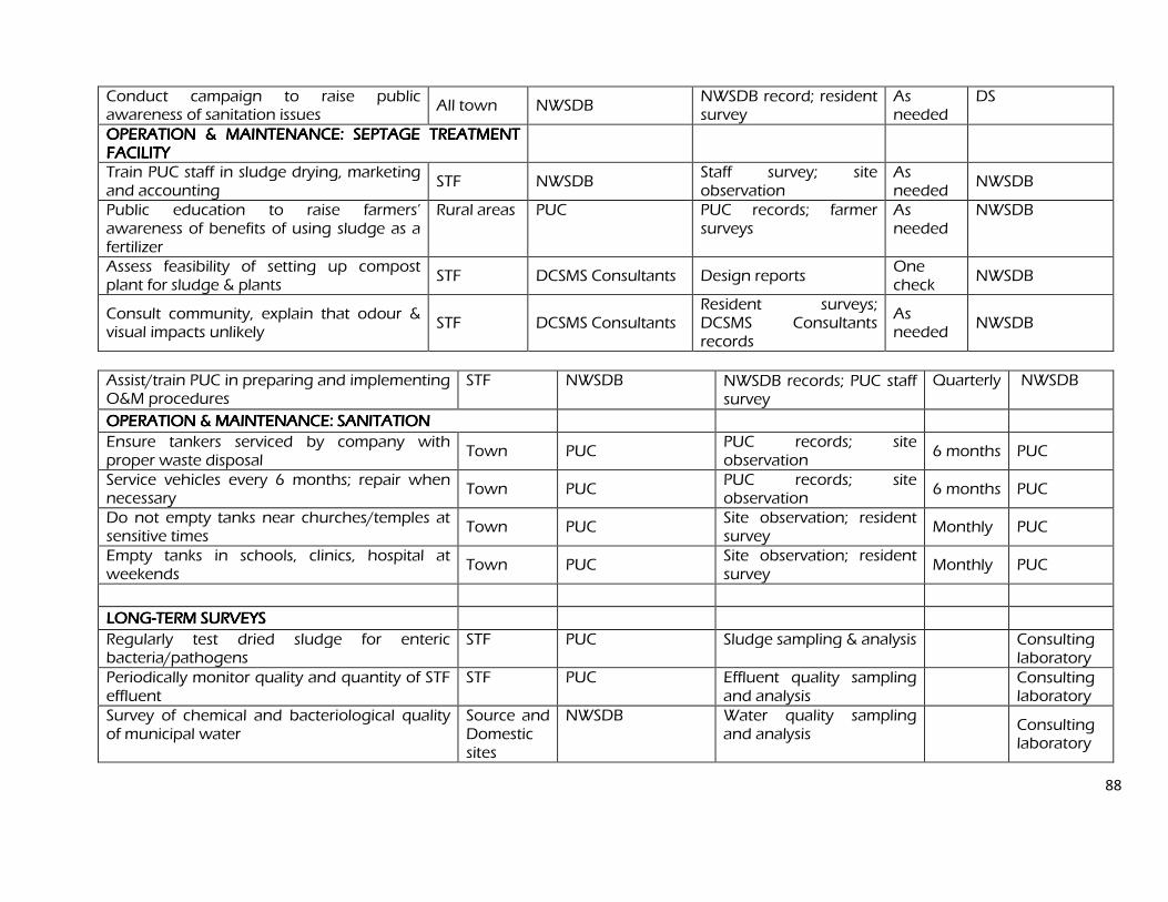
88
Conduct campaign to raise public awareness of sanitation issues
All town NWSDB NWSDB record; resident survey
As needed
DS
OPERATION & MAINTENANCE: SEPTAGE TREATMENT OPERATION & MAINTENANCE: SEPTAGE TREATMENT OPERATION & MAINTENANCE: SEPTAGE TREATMENT OPERATION & MAINTENANCE: SEPTAGE TREATMENT FACILITY FACILITY FACILITY FACILITY
Train PUC staff in sludge drying, marketing and accounting
STF NWSDB Staff survey; site observation
As needed
NWSDB
Public education to raise farmers’ awareness of benefits of using sludge as a fertilizer
Rural areas PUC PUC records; farmer surveys
As needed
NWSDB
Assess feasibility of setting up compost plant for sludge & plants
STF DCSMS Consultants Design reports One check
NWSDB
Consult community, explain that odour & visual impacts unlikely
STF DCSMS Consultants Resident surveys; DCSMS Consultants records
As needed
NWSDB
Assist/train PUC in preparing and implementing O&M procedures
STF NWSDB NWSDB records; PUC staff survey
Quarterly NWSDB
OPERATION & MAINTENANCE: SANITATION OPERATION & MAINTENANCE: SANITATION OPERATION & MAINTENANCE: SANITATION OPERATION & MAINTENANCE: SANITATION
Ensure tankers serviced by company with proper waste disposal
Town PUC PUC records; site observation
6 months PUC
Service vehicles every 6 months; repair when necessary
Town PUC PUC records; site observation
6 months PUC
Do not empty tanks near churches/temples at sensitive times
Town PUC Site observation; resident survey
Monthly PUC
Empty tanks in schools, clinics, hospital at weekends
Town PUC Site observation; resident survey
Monthly PUC
LONGLONGLONGLONG----TERM SURVEYS TERM SURVEYS TERM SURVEYS TERM SURVEYS
Regularly test dried sludge for enteric bacteria/pathogens
STF PUC Sludge sampling & analysis Consulting laboratory
Periodically monitor quality and quantity of STF effluent
STF PUC Effluent quality sampling and analysis
Consulting laboratory
Survey of chemical and bacteriological quality of municipal water
Source and Domestic sites
NWSDB Water quality sampling and analysis
Consulting laboratory
89
These surveys should be conducted for at least four years. The quality of the sewage sludge, Septage Treatment Facility (STF) effluent and receiving water will be checked each week for the first three months, then every 6 months for the next 3 ¾ years (20 surveys in total). The other surveys will all require monitoring at six-monthly intervals during the final year of construction (to establish baseline conditions) and during the first three years of operation of each scheme (8 surveys each). The survey on public health will be conducted in the first and final year of the project.
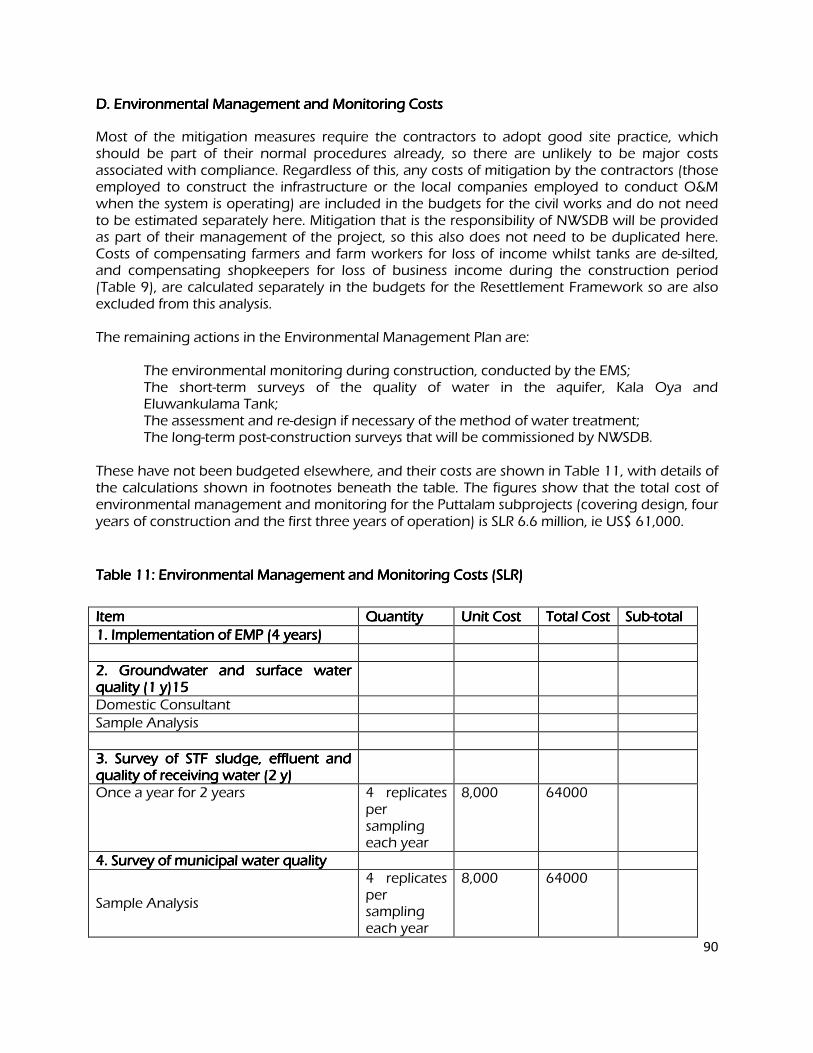
90
D. Environmental Management and Monitoring Costs D. Environmental Management and Monitoring Costs D. Environmental Management and Monitoring Costs D. Environmental Management and Monitoring Costs
Most of the mitigation measures require the contractors to adopt good site practice, which should be part of their normal procedures already, so there are unlikely to be major costs associated with compliance. Regardless of this, any costs of mitigation by the contractors (those employed to construct the infrastructure or the local companies employed to conduct O&M when the system is operating) are included in the budgets for the civil works and do not need to be estimated separately here. Mitigation that is the responsibility of NWSDB will be provided as part of their management of the project, so this also does not need to be duplicated here. Costs of compensating farmers and farm workers for loss of income whilst tanks are de-silted, and compensating shopkeepers for loss of business income during the construction period (Table 9), are calculated separately in the budgets for the Resettlement Framework so are also excluded from this analysis. The remaining actions in the Environmental Management Plan are: The environmental monitoring during construction, conducted by the EMS; The short-term surveys of the quality of water in the aquifer, Kala Oya and
Eluwankulama Tank; The assessment and re-design if necessary of the method of water treatment; The long-term post-construction surveys that will be commissioned by NWSDB.
These have not been budgeted elsewhere, and their costs are shown in Table 11, with details of the calculations shown in footnotes beneath the table. The figures show that the total cost of environmental management and monitoring for the Puttalam subprojects (covering design, four years of construction and the first three years of operation) is SLR 6.6 million, ie US$ 61,000.
Table 11: Environmental Management and Monitoring Costs (SLR) Table 11: Environmental Management and Monitoring Costs (SLR) Table 11: Environmental Management and Monitoring Costs (SLR) Table 11: Environmental Management and Monitoring Costs (SLR)
Item Item Item Item Quantity Quantity Quantity Quantity Unit Cost Unit Cost Unit Cost Unit Cost Total Cost Total Cost Total Cost Total Cost SubSubSubSub----total total total total
1. Implementation of EMP (4 years) 1. Implementation of EMP (4 years) 1. Implementation of EMP (4 years) 1. Implementation of EMP (4 years) 2. Groundwater and surface water 2. Groundwater and surface water 2. Groundwater and surface water 2. Groundwater and surface water quality (1 y)15 quality (1 y)15 quality (1 y)15 quality (1 y)15
Domestic Consultant
Sample Analysis 3. Survey of STF sludge, effluent a3. Survey of STF sludge, effluent a3. Survey of STF sludge, effluent a3. Survey of STF sludge, effluent and nd nd nd quality of receiving water (2quality of receiving water (2quality of receiving water (2quality of receiving water (2 y) y) y) y)
Once a year for 2 years 4 replicates per sampling each year
8,000 64000
4. Survey of municipal water quality 4. Survey of municipal water quality 4. Survey of municipal water quality 4. Survey of municipal water quality
Sample Analysis
4 replicates per sampling each year
8,000 64000

91
TOTAL TOTAL TOTAL TOTAL 128000
VIII. PUBLIC CONSULTATION AND INFORMATION DISCLOSURE VIII. PUBLIC CONSULTATION AND INFORMATION DISCLOSURE VIII. PUBLIC CONSULTATION AND INFORMATION DISCLOSURE VIII. PUBLIC CONSULTATION AND INFORMATION DISCLOSURE
A. Project Stakeholders A. Project Stakeholders A. Project Stakeholders A. Project Stakeholders
Most of the main stakeholders have already been identified and consulted during preparation of the IEEs, and any others that are identified during project implementation will be brought into the process in the future. Primary stakeholders are:
Residents, shopkeepers and businesspeople who live and work alongside the roads in which improvements in the water supply network will be provided;
Local communities living in the vicinity of the various facilities (OR, PS, WTP, STF); The Sri Lankan Army (located in camps alongside the causeway and WTP sites);
Secondary stakeholders are:
MWSD as the Executing Agency and NWSDB as the Implementing Agency; Other government institutions whose remit includes areas or issues affected by the
project (state and local planning authorities; Ministry of Local Government; Department of Public Health Engineering; Central Environment Authority; National, Provincial and Local Roads Authorities; etc);
NGOs and CBOs working in the affected communities; Other community representatives (prominent citizens, religious leaders, elders, women’s
groups); The beneficiary community in general; and The ADB.
B. Consultation and Disclosure to Date B. Consultation and Disclosure to Date B. Consultation and Disclosure to Date B. Consultation and Disclosure to Date
Two forms of public consultation were used during preparation of the IEEs, to discuss the project and involve the community in planning the mitigation measures and developing the Environmental Monitoring Plan. These are:
Public meetings were held in the target towns and villages between December 2007 and January 2008, to which representatives of primary and secondary stakeholders were invited. Attendees were informed about the aim of the relevant subprojects and the benefits they would bring, together with their likely impacts and the ways in which they would be mitigated. Participants were invited to discuss their views and concerns, which were then incorporated into the IEE. Appendix 4 contains a summary of the meeting in Puttalam and Table 12 summarises the main points made during the discussion; Ad hoc discussions were also held on site with people and communities who could be affected by the subprojects, so that views could be expressed in a less formal setting. These were also considered in preparing the IEE. NWSDB will disclose the IEEs to the public by providing copies in the local language in the NWSDB office in each town. Disclosure to a wider audience will be achieved by placing the
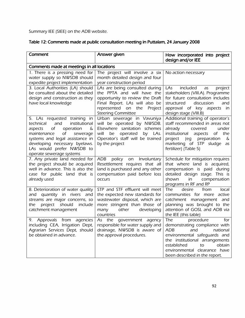
92
Summary IEE (SIEE) on the ADB website.
Table 12: Comments made at public consultation meeting in Puttalam, 24 January 2008 Table 12: Comments made at public consultation meeting in Puttalam, 24 January 2008 Table 12: Comments made at public consultation meeting in Puttalam, 24 January 2008 Table 12: Comments made at public consultation meeting in Puttalam, 24 January 2008
Comment Comment Comment Comment Answer given Answer given Answer given Answer given How incorporated into project How incorporated into project How incorporated into project How incorporated into project design and/or IEE design and/or IEE design and/or IEE design and/or IEE
Comments made at meetings in all locations Comments made at meetings in all locations Comments made at meetings in all locations Comments made at meetings in all locations
1. There is a pressing need for water supply so NWSDB should expedite project implementation
The project will involve a six month detailed design and four year construction period
No action necessary
3. Local Authorities (LA) should be consulted about the detailed design and construction as they have local knowledge
LAs are being consulted during the PPTA and will have the opportunity to review the Draft Final Report. LAs will also be represented on the Project Steering Committee
LAs included as project stakeholders (VIII.A). Programme for future consultation includes structured discussion and approval of key aspects in design stage (VIII.B)
5. LAs requested training in technical and institutional aspects of operation & maintenance of sewerage systems and legal assistance in developing necessary byelaws. LAs would prefer NWSDB to operate sewerage systems
Urban sewerage in Vavuniya will be operated by NWSDB. Elsewhere sanitation schemes will be operated by LAs. Operator’s staff will be trained by the project
Additional training of operator’s staff recommended in areas not already covered under institutional aspects of the project (eg preparation & marketing of STP sludge as fertilizer) (Table 5)
7. Any private land needed for the project should be acquired well in advance. This is also the case for public land that is already used
ADB policy on Involuntary Resettlement requires that all land is purchased and any other compensation paid before loss occurs
Schedule for mitigation requires that where land is acquired, compensation is paid during detailed design stage. This is shown in compensation programs in RF and RP
8. Deterioration of water quality and quantity in rivers and streams are major concerns, so the project should include catchment management
STP and STF effluent will meet the expected new standards for wastewater disposal, which are more stringent than those of many other developing countries
The desire from local communities for more active catchment management and planning was brought to the attention of GOSL and ADB via the IEE (this table)
9. Approvals from agencies including CEA, Irrigation Dept, Agrarian Services Dept, should be obtained in advance.
As the government agency responsible for water supply and drainage, NWSDB is aware of the approval procedures.
The procedure for demonstrating compliance with ADB and national environmental safeguards and the institutional arrangements established to obtain environmental clearance have been described in the report.
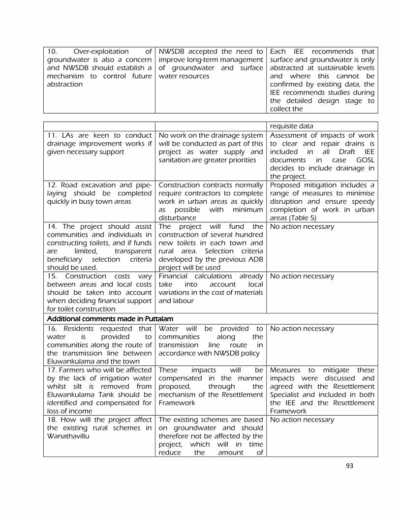
93
10. Over-exploitation of groundwater is also a concern and NWSDB should establish a mechanism to control future abstraction
NWSDB accepted the need to improve long-term management of groundwater and surface water resources
Each IEE recommends that surface and groundwater is only abstracted at sustainable levels and where this cannot be confirmed by existing data, the IEE recommends studies during the detailed design stage to collect the
requisite data
11. LAs are keen to conduct drainage improvement works if given necessary support
No work on the drainage system will be conducted as part of this project as water supply and sanitation are greater priorities
Assessment of impacts of work to clear and repair drains is included in all Draft IEE documents in case GOSL decides to include drainage in the project.
12. Road excavation and pipe-laying should be completed quickly in busy town areas
Construction contracts normally require contractors to complete work in urban areas as quickly as possible with minimum disturbance
Proposed mitigation includes a range of measures to minimise disruption and ensure speedy completion of work in urban areas (Table 5)
14. The project should assist communities and individuals in constructing toilets, and if funds are limited, transparent beneficiary selection criteria should be used.
The project will fund the construction of several hundred new toilets in each town and rural area. Selection criteria developed by the previous ADB project will be used
No action necessary
15. Construction costs vary between areas and local costs should be taken into account when deciding financial support for toilet construction
Financial calculations already take into account local variations in the cost of materials and labour
No action necessary
Additional comments made in Puttalam Additional comments made in Puttalam Additional comments made in Puttalam Additional comments made in Puttalam
16. Residents requested that water is provided to communities along the route of the transmission line between Eluwankulama and the town
Water will be provided to communities along the transmission line route in accordance with NWSDB policy
No action necessary
17. Farmers who will be affected by the lack of irrigation water whilst silt is removed from Eluwankulama Tank should be identified and compensated for loss of income
These impacts will be compensated in the manner proposed, through the mechanism of the Resettlement Framework
Measures to mitigate these impacts were discussed and agreed with the Resettlement Specialist and included in both the IEE and the Resettlement Framework
18. How will the project affect the existing rural schemes in Wanathavillu
The existing schemes are based on groundwater and should therefore not be affected by the project, which will in time reduce the amount of
No action necessary
94
groundwater abstracted
19. The national Aquatic Resources Agency requested the project to provide funds to monitor water quality in the lagoon for at least two years once the septage plant begins operation
Since effluent is not going to be discharged to the lagoon as final selected is inland, this does not arise any more.
No action necessary
20. When Achchamolai Tank is refurbished under this project it should be dedicated for water supply purposes as otherwise farmers may take water from the tank to restore currently abandoned agriculture
NWSDB will negotiate an agreement with the Irrigation Department for the shared use of water in the two tanks. This will guarantee that present volumes of water will continue to be available for use in irrigation and farmers will be prohibited from abstracting additional volumes.
A discussion of this issue was added to the IEE
C. Future Consultation and Disclosure C. Future Consultation and Disclosure C. Future Consultation and Disclosure C. Future Consultation and Disclosure
Consultation during detailed design:
Focus-group discussions with affected persons and other stakeholders (including women’s groups, NGOs and CBOs) to hear their views and concerns, so that these can be addressed in subproject design where necessary; Structured consultation meetings with the institutional stakeholders (government bodies and NGOs) to discuss and approve key aspects of the project. Consultation during construction:
Public meetings with affected communities to discuss and plan work programmes and allow issues to be raised and addressed once construction has started; Smaller-scale meetings to discuss and plan construction work with individual communities to reduce disturbance and other impacts, and provide a mechanism through which stakeholders can participate in subproject monitoring and evaluation; Project disclosure:
Public information campaigns (via newspapers, posters, etc) to explain the project to the population in each town and prepare them for disruption they may experience once the construction programme is underway; Public disclosure meetings at key project stages to inform the public of progress and future
95
plans, and to provide copies of summary documents in Sinhalese, Tamil and English; Formal disclosure of completed project reports by making copies available at NWSDB offices in each town, informing the public of their availability, and providing a mechanism through which comments can be made. IX. FINDINGS AND RECOMMENDATIONS IX. FINDINGS AND RECOMMENDATIONS IX. FINDINGS AND RECOMMENDATIONS IX. FINDINGS AND RECOMMENDATIONS
A. Findings A. Findings A. Findings A. Findings
The process described in this document has assessed the environmental impacts of all elements of the infrastructure proposed under the Puttalam water supply and sanitation subprojects. Potential negative impacts were identified in relation to design, location, construction and operation of the subprojects, and mitigation measures have been developed to reduce negative impacts to acceptable levels. These were discussed with specialists responsible for the engineering aspects, and as a result some measures have already been included in the outline designs for the infrastructure. These include:
Locating water supply pipelines within the RoW alongside existing roads, to avoid the need to acquire land or relocate people;
Locating pipelines beneath the road surface in certain narrower streets to avoid demolishing structures that have been built in the RoW (parts of houses or shops).
This means that the number of impacts and their significance have already been reduced by amending the design.
Changes have also been made to the location of elements of the subprojects to further reduce impacts. These include:
Locating facilities (pump stations, overhead reservoir, WTP, STF) on government-owned land to avoid the need for land acquisition and relocation of people;
Routing the 33 km treated water transmission main alongside roads between Eluwankulama and the town to avoid acquiring agricultural land and affecting the livelihoods of farmers and farm workers.
Regardless of these and various other actions taken during the IEE process and in developing the subprojects, there will still be impacts on the environment when the infrastructure is built and when it is operating. This is mainly because of the invasive nature of excavation, and because the water supply network is located in a town, some parts of which are densely populated. Because of these factors the most significant impacts are on the physical environment and the human environment. During the construction phase, impacts mainly arise from the need to dispose of large quantities of waste soil and import large volumes of sand to support the water pipes in the trenches; and from the disturbance of residents, business and traffic by the construction work. These are common impacts of construction in urban areas, and there are well developed methods for their mitigation. These include: Finding beneficial uses for waste material; Covering soil and sand during transportation and when stored on site; Planning work to minimise disruption of traffic and communities;
96
Providing temporary structures to maintain access across trenches where required. Although there will be no need to acquire land or relocate people, roadside businesses will lose some income as access will be difficult for customers when water pipes are installed nearby; and farmers in the vicinity of Eluwankulama Tank will lose income from reduced crop yields in one dry season as irrigation water will not be available while the tank is de-silted. ADB policy on Involuntary Resettlement requires that no-one should be worse off as a result of an ADB-funded project, so a Resettlement Plan and Framework were prepared to examine these issues. This establishes that farmers, farm workers and businesses will be compensated in cash for any income they lose. Because the new water abstraction and treatment facilities will be at Eluwankulama near the army camp adjacent to the causeway of the Kala Oya, special measures were developed to avoid disrupting military personnel/activities in and around the 2 army camps in the area. These are: Including the Sri Lankan Army in consultations as a project stakeholder; Consulting Commanding Officers of each camp regarding the construction program;
Taking action to avoid disturbing military personnel and activities (eg prohibiting night working, security checks/clearance for all site personnel and vehicles, etc);
Regular liaison between the contractor and the military to avoid any hindrance to military activity, during both routine and emergency operations.
There were limited opportunities to provide environmental enhancements, but certain measures were included. For example it is proposed that the project will: Employ people from the nearby community in the construction workforce and to
maintain and operate the new facilities, to provide them with an economic gain; Set up a plant to produce compost from cut vegetation, and a system of marketing
compost and organic silt removed from tanks to farmers to fertilize their soil and increase yields, and provide a partial cost recovery for NWSDB.
These and the other mitigation and enhancement measures are summarised in Table 8, which also shows the location of the impact, the body responsible for the mitigation, and the programme for its implementation. Operation and maintenance of the water supply infrastructure will be the responsibility of NWSDB. Most elements should operate with routine maintenance, which should not affect the environment. Network leaks will be repaired from time to time, but impacts will be less than those of the construction period as the work will be infrequent, affecting small areas only. Maintenance at the other sites will involve routine checking of components and replacement of parts where necessary. Work will be conducted according to O&M procedures developed in the detailed design stage. Although increases in water abstraction can deplete the resource, that should not be the case
here because the rate of abstraction (a maximum of 0.35 m3
/s in 2030) is a small fraction of the water available in the perennially-flowing Kala Oya. Groundwater will also not be overexploited
as abstraction will be reduced from the current 6,500 m3
/day to 4,500 m3
/day in 2030. NWSDB will however need to adopt an environmentally sensitive abstraction regime to sustain the ecology in the river downstream and particularly in the riparian areas of the Wilpattu National Park, which abuts the northern bank of the river. This should include:
97
Keeping at least one sluice in the causeway fully open at all times to allow passage by
fish migrating to and from upstream breeding grounds; Keeping the maximum feasible number of sluices open at all times; Providing a minimum downstream flow throughout the dry season that is at least
equivalent to the minimum natural seasonal flow (estimated at 6.6 m3
/sec).
There are some data available on the quality of water in the aquifer and the limited data from the Kala Oya suggest that it may be optimal as a source for domestic supply following conventional treatment. It is therefore important that the quality of surface- and ground- water is investigated in detail, so that the level of treatment can be increased if necessary to produce water that complies with national drinking water standards. Puttalam Urban Council will be responsible for operating the sanitation service, which comprises vacuum tankers to empty septic tanks and a Septage Treatment Facility (STF). The tankers should operate without significant impacts, providing sensible precautions are taken, such as ensuring the vehicles are serviced regularly and that tanks near churches and temples are not emptied at times of religious observance. The STF should also operate without major impacts, providing it functions as intended. To ensure that this is the case, PUC should regularly monitor: The quantity and quality of the effluent (against 2008 draft discharge standards); The bacteriological quality of dried sludge to ensure that all enteric bacteria and
pathogens are killed by the drying process. PUC should also establish and emergency procedure to recycle the effluent through the ponds for further treatment if it fails to meet national wastewater discharge standards. Designs should be amended to provide the necessary pumps and pipe-work.
If the water provided is of an acceptable quality then the main impacts of the operating water supply and sanitation systems should be beneficial. The citizens of Puttalam will be provided with a constant supply of better quality water; and septic tanks in the town will be emptied around once per year, reducing the leaks and foul odours emanating from overloaded tanks at present. A public education programme will be implemented to raise awareness of sanitation issues, so the improvements in municipal services and sanitary practices should raise the quality of life and deliver major improvements in individual and public health. This should then lead to economic gains as people will be away from work less and will spend less on healthcare, so their incomes should increase. Table 7 also assesses the effectiveness of each mitigation measure in reducing each impact to an acceptable level. This is shown as the level of significance of the residual impact (remaining after the mitigation is applied). This shows that all impacts will be rendered at least neutral (successfully mitigated), and that certain measures will produce a benefit (in addition to the major benefits provided by the operating schemes). Mitigation will be assured by a program of environmental monitoring conducted during both construction and operation to ensure that all measures are provided as intended, and to determine whether the environment is protected as envisaged. This will include observations on and off site, document checks, and interviews with workers and beneficiaries, and any requirements for remedial action will be reported to the PCU. There will also be longer-term surveys to monitor certain aspects, including the expected improvements in the quality of domestic water and the health of the population.
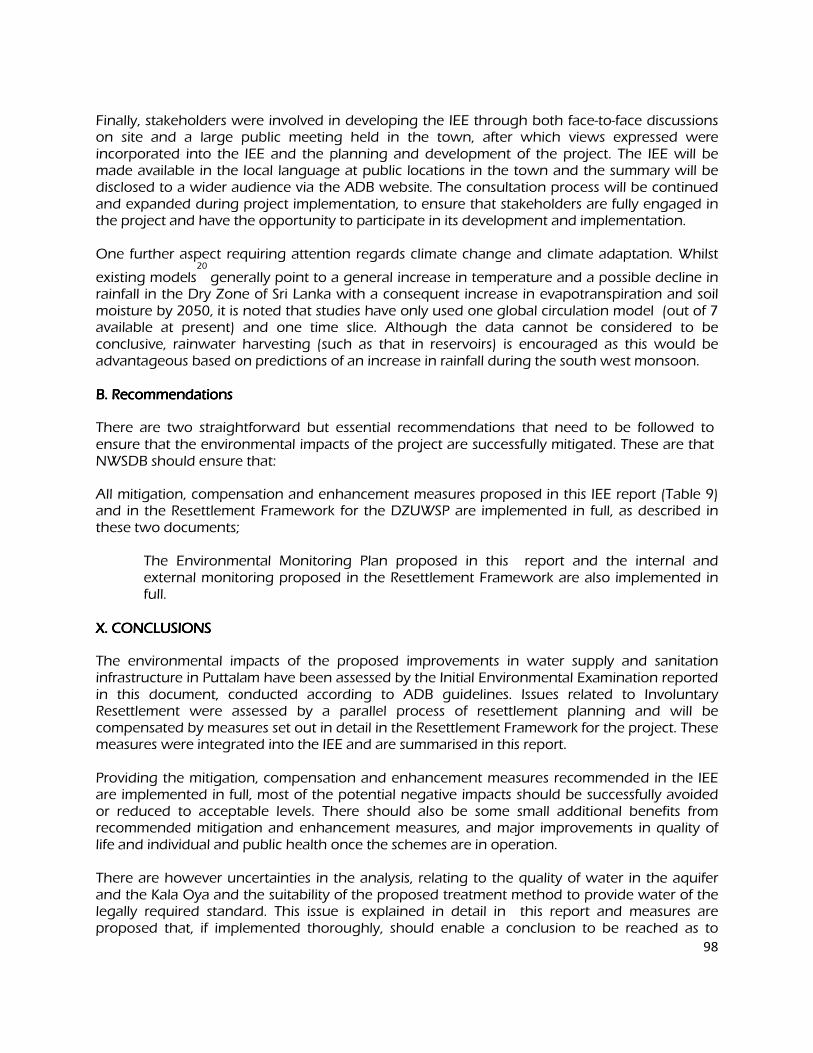
98
Finally, stakeholders were involved in developing the IEE through both face-to-face discussions on site and a large public meeting held in the town, after which views expressed were incorporated into the IEE and the planning and development of the project. The IEE will be made available in the local language at public locations in the town and the summary will be disclosed to a wider audience via the ADB website. The consultation process will be continued and expanded during project implementation, to ensure that stakeholders are fully engaged in the project and have the opportunity to participate in its development and implementation. One further aspect requiring attention regards climate change and climate adaptation. Whilst
existing models20
generally point to a general increase in temperature and a possible decline in rainfall in the Dry Zone of Sri Lanka with a consequent increase in evapotranspiration and soil moisture by 2050, it is noted that studies have only used one global circulation model (out of 7 available at present) and one time slice. Although the data cannot be considered to be conclusive, rainwater harvesting (such as that in reservoirs) is encouraged as this would be advantageous based on predictions of an increase in rainfall during the south west monsoon. B. Recommendations B. Recommendations B. Recommendations B. Recommendations
There are two straightforward but essential recommendations that need to be followed to ensure that the environmental impacts of the project are successfully mitigated. These are that NWSDB should ensure that:
All mitigation, compensation and enhancement measures proposed in this IEE report (Table 9) and in the Resettlement Framework for the DZUWSP are implemented in full, as described in these two documents; The Environmental Monitoring Plan proposed in this report and the internal and
external monitoring proposed in the Resettlement Framework are also implemented in full.
X. CONCLUSIONS X. CONCLUSIONS X. CONCLUSIONS X. CONCLUSIONS
The environmental impacts of the proposed improvements in water supply and sanitation infrastructure in Puttalam have been assessed by the Initial Environmental Examination reported in this document, conducted according to ADB guidelines. Issues related to Involuntary Resettlement were assessed by a parallel process of resettlement planning and will be compensated by measures set out in detail in the Resettlement Framework for the project. These measures were integrated into the IEE and are summarised in this report. Providing the mitigation, compensation and enhancement measures recommended in the IEE are implemented in full, most of the potential negative impacts should be successfully avoided or reduced to acceptable levels. There should also be some small additional benefits from recommended mitigation and enhancement measures, and major improvements in quality of life and individual and public health once the schemes are in operation. There are however uncertainties in the analysis, relating to the quality of water in the aquifer and the Kala Oya and the suitability of the proposed treatment method to provide water of the legally required standard. This issue is explained in detail in this report and measures are proposed that, if implemented thoroughly, should enable a conclusion to be reached as to
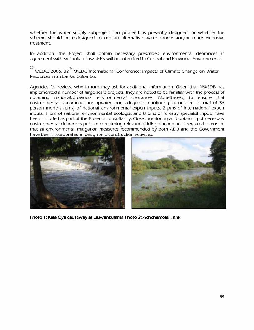
99
whether the water supply subproject can proceed as presently designed, or whether the scheme should be redesigned to use an alternative water source and/or more extensive treatment. In addition, the Project shall obtain necessary prescribed environmental clearances in agreement with Sri Lankan Law. IEE's will be submitted to Central and Provincial Environmental 20
WEDC. 2006. 32nd
WEDC International Conference: Impacts of Climate Change on Water Resources in Sri Lanka. Colombo. Agencies for review, who in turn may ask for additional information. Given that NWSDB has implemented a number of large scale projects, they are noted to be familiar with the process of obtaining national/provincial environmental clearances. Nonetheless, to ensure that environmental documents are updated and adequate monitoring introduced, a total of 36 person months (pms) of national environmental expert inputs, 2 pms of international expert inputs, 1 pm of national environmental ecologist and 8 pms of forestry specialist inputs have been included as part of the Project's consultancy. Close monitoring and obtaining of necessary environmental clearances prior to completing relevant bidding documents is required to ensure that all environmental mitigation measures recommended by both ADB and the Government have been incorporated in design and construction activities.
Photo 1: Kala Oya Photo 1: Kala Oya Photo 1: Kala Oya Photo 1: Kala Oya causeway at Eluwankulama Photo 2causeway at Eluwankulama Photo 2causeway at Eluwankulama Photo 2causeway at Eluwankulama Photo 2: Achchamolai Tank : Achchamolai Tank : Achchamolai Tank : Achchamolai Tank
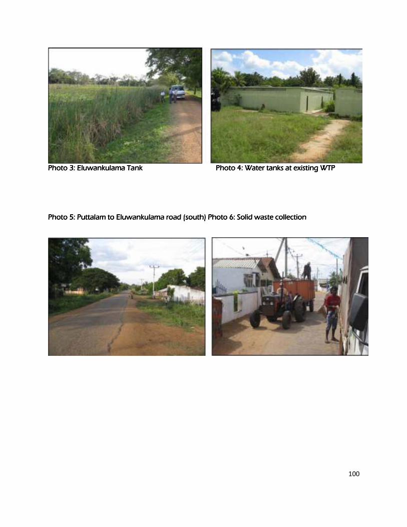
100
Photo 3: Eluwankulama Tank Photo 3: Eluwankulama Tank Photo 3: Eluwankulama Tank Photo 3: Eluwankulama Tank Photo 4Photo 4Photo 4Photo 4: Wat: Wat: Wat: Water tanks at existing WTP er tanks at existing WTP er tanks at existing WTP er tanks at existing WTP
Photo 5Photo 5Photo 5Photo 5: Puttalam to El: Puttalam to El: Puttalam to El: Puttalam to Eluwankulamuwankulamuwankulamuwankulama road (south) Photo 6a road (south) Photo 6a road (south) Photo 6a road (south) Photo 6: Solid waste collection : Solid waste collection : Solid waste collection : Solid waste collection
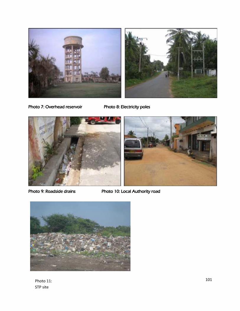
101
Photo 7Photo 7Photo 7Photo 7: Overhead reservoir : Overhead reservoir : Overhead reservoir : Overhead reservoir Photo 8Photo 8Photo 8Photo 8: Electricity poles : Electricity poles : Electricity poles : Electricity poles
Photo 9Photo 9Photo 9Photo 9: Roadside drains : Roadside drains : Roadside drains : Roadside drains Photo 10Photo 10Photo 10Photo 10: Local Authority road : Local Authority road : Local Authority road : Local Authority road
Photo: STP site (adjacent land)
Photo 11:
STP site
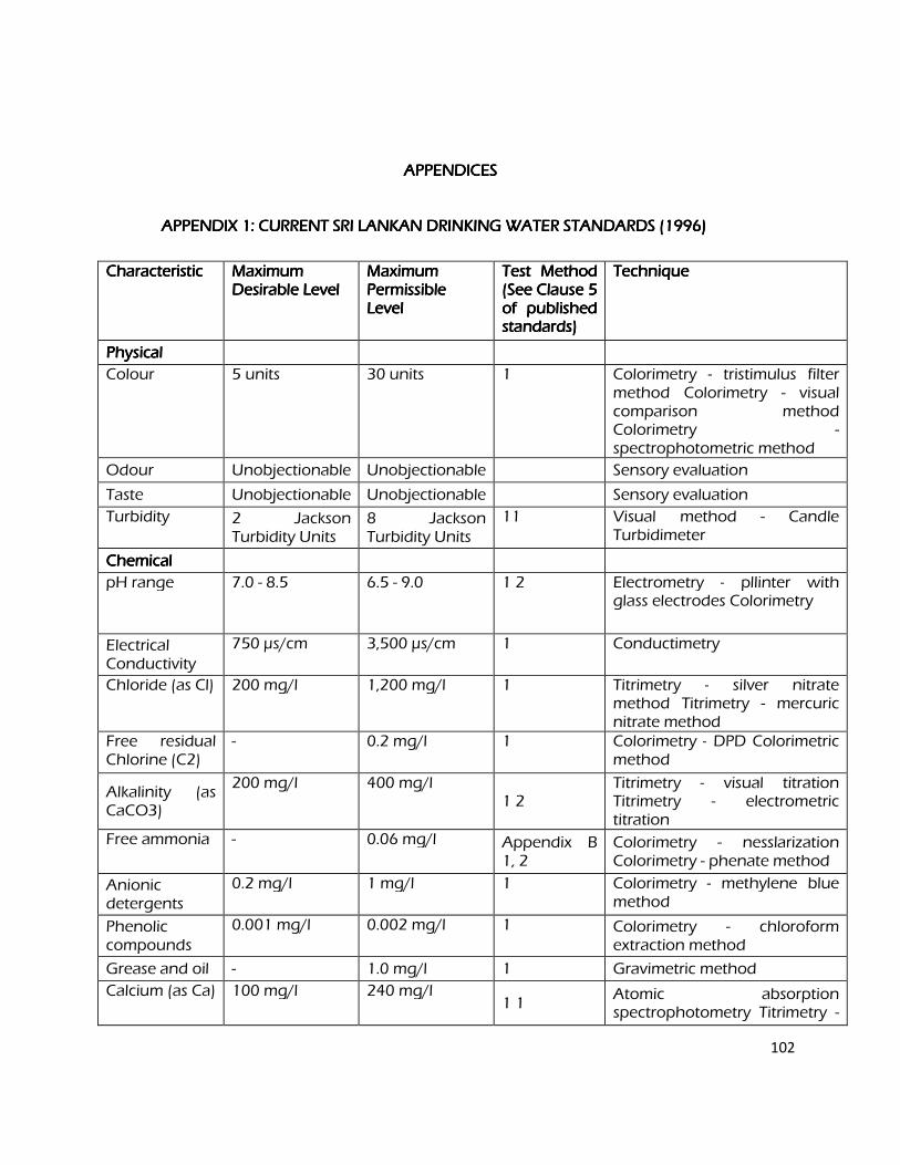
102
APPENDICES APPENDICES APPENDICES APPENDICES
APPENDIX 1: CURRENT SRI LANKAN DRINKING WATER STANDARDS (1996) APPENDIX 1: CURRENT SRI LANKAN DRINKING WATER STANDARDS (1996) APPENDIX 1: CURRENT SRI LANKAN DRINKING WATER STANDARDS (1996) APPENDIX 1: CURRENT SRI LANKAN DRINKING WATER STANDARDS (1996)
Characteristic Characteristic Characteristic Characteristic Maximum Maximum Maximum Maximum Desirable Level Desirable Level Desirable Level Desirable Level
Maximum Maximum Maximum Maximum Permissible Permissible Permissible Permissible Level Level Level Level
Test Method Test Method Test Method Test Method (See Clause 5 (See Clause 5 (See Clause 5 (See Clause 5 of published of published of published of published standards) standards) standards) standards)
Technique Technique Technique Technique
Physical Physical Physical Physical
Colour 5 units 30 units 1 Colorimetry - tristimulus filter method Colorimetry - visual comparison method Colorimetry - spectrophotometric method
Odour Unobjectionable Unobjectionable Sensory evaluation
Taste Unobjectionable Unobjectionable Sensory evaluation
Turbidity 2 Jackson Turbidity Units
8 Jackson Turbidity Units
11 Visual method - Candle Turbidimeter
Chemical Chemical Chemical Chemical
pH range 7.0 - 8.5 6.5 - 9.0 1 2 Electrometry - pllinter with glass electrodes Colorimetry
Electrical Conductivity
750 µs/cm 3,500 µs/cm 1 Conductimetry
Chloride (as Cl) 200 mg/l 1,200 mg/l 1 Titrimetry - silver nitrate method Titrimetry - mercuric nitrate method
Free residual Chlorine (C2)
- 0.2 mg/l 1 Colorimetry - DPD Colorimetric method
Alkalinity (as CaCO3)
200 mg/l 400 mg/l 1 2
Titrimetry - visual titration Titrimetry - electrometric titration
Free ammonia - 0.06 mg/l Appendix B 1, 2
Colorimetry - nesslarization Colorimetry - phenate method
Anionic detergents
0.2 mg/l 1 mg/l 1 Colorimetry - methylene blue method
Phenolic compounds
0.001 mg/l 0.002 mg/l 1 Colorimetry - chloroform extraction method
Grease and oil - 1.0 mg/l 1 Gravimetric method
Calcium (as Ca) 100 mg/l 240 mg/l 1 1
Atomic absorption spectrophotometry Titrimetry -
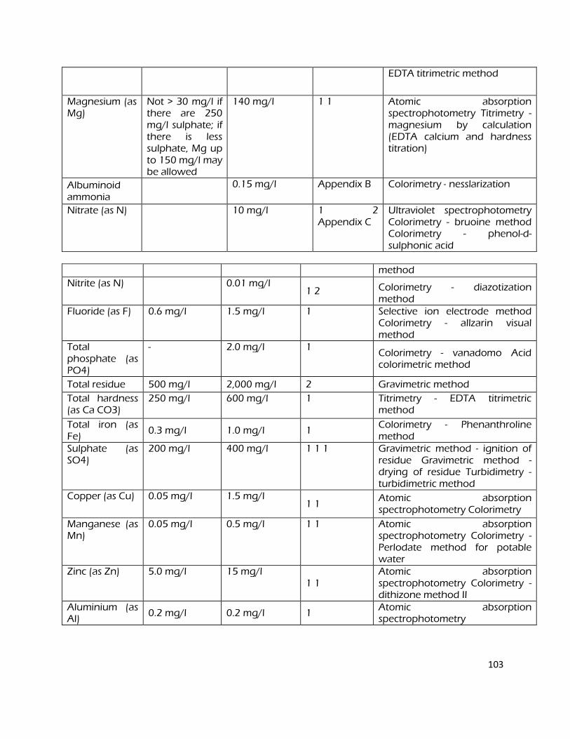
103
EDTA titrimetric method
Magnesium (as Mg)
Not > 30 mg/l if there are 250 mg/l sulphate; if there is less sulphate, Mg up to 150 mg/l may be allowed
140 mg/l 1 1 Atomic absorption spectrophotometry Titrimetry - magnesium by calculation (EDTA calcium and hardness titration)
Albuminoid ammonia
0.15 mg/l Appendix B Colorimetry - nesslarization
Nitrate (as N) 10 mg/l 1 2 Appendix C
Ultraviolet spectrophotometry Colorimetry - bruoine method Colorimetry - phenol-d- sulphonic acid
method
Nitrite (as N) 0.01 mg/l 1 2 Colorimetry - diazotization
method Fluoride (as F) 0.6 mg/l 1.5 mg/l 1 Selective ion electrode method
Colorimetry - allzarin visual method
Total phosphate (as PO4)
- 2.0 mg/l 1 Colorimetry - vanadomo Acid colorimetric method
Total residue 500 mg/l 2,000 mg/l 2 Gravimetric method
Total hardness (as Ca CO3)
250 mg/l 600 mg/l 1 Titrimetry - EDTA titrimetric method
Total iron (as Fe)
0.3 mg/l 1.0 mg/l 1 Colorimetry - Phenanthroline method
Sulphate (as SO4)
200 mg/l 400 mg/l 1 1 1 Gravimetric method - ignition of residue Gravimetric method - drying of residue Turbidimetry - turbidimetric method
Copper (as Cu) 0.05 mg/l 1.5 mg/l 1 1
Atomic absorption spectrophotometry Colorimetry
Manganese (as Mn)
0.05 mg/l 0.5 mg/l 1 1 Atomic absorption spectrophotometry Colorimetry - Perlodate method for potable water
Zinc (as Zn) 5.0 mg/l 15 mg/l 1 1
Atomic absorption spectrophotometry Colorimetry - dithizone method II
Aluminium (as Al)
0.2 mg/l 0.2 mg/l 1 Atomic absorption spectrophotometry
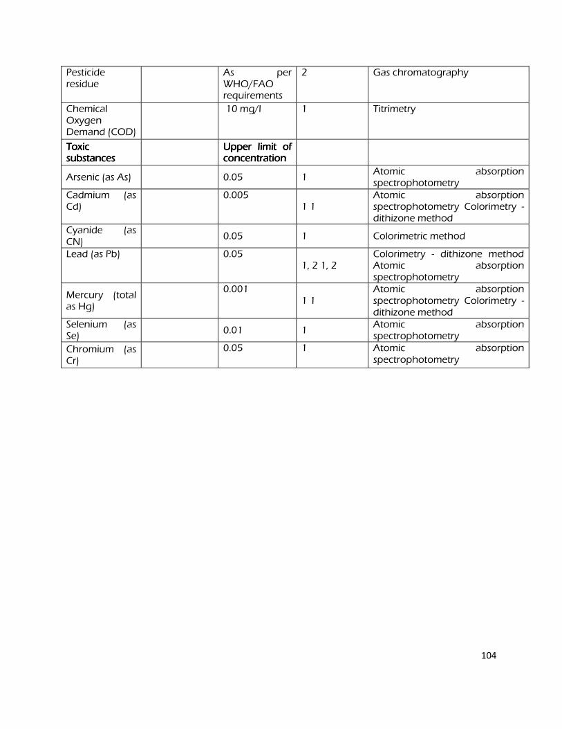
104
Pesticide residue
As per WHO/FAO requirements
2 Gas chromatography
Chemical Oxygen Demand (COD)
10 mg/l 1 Titrimetry
Toxic Toxic Toxic Toxic substances substances substances substances
Upper limit of Upper limit of Upper limit of Upper limit of concentration concentration concentration concentration
Arsenic (as As)
0.05 1 Atomic absorption spectrophotometry
Cadmium (as Cd)
0.005 1 1
Atomic absorption spectrophotometry Colorimetry - dithizone method
Cyanide (as CN)
0.05 1 Colorimetric method
Lead (as Pb) 0.05 1, 2 1, 2
Colorimetry - dithizone method Atomic absorption spectrophotometry
Mercury (total as Hg)
0.001 1 1
Atomic absorption spectrophotometry Colorimetry - dithizone method
Selenium (as Se)
0.01 1
Atomic absorption spectrophotometry
Chromium (as Cr)
0.05 1 Atomic absorption spectrophotometry
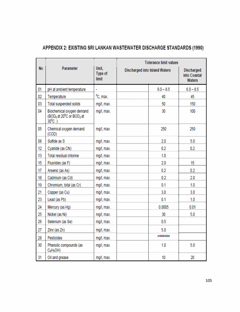
105
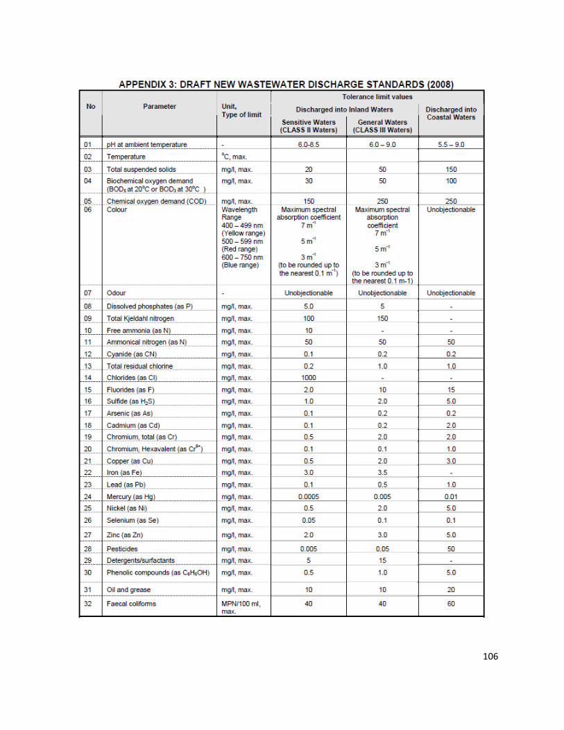
106
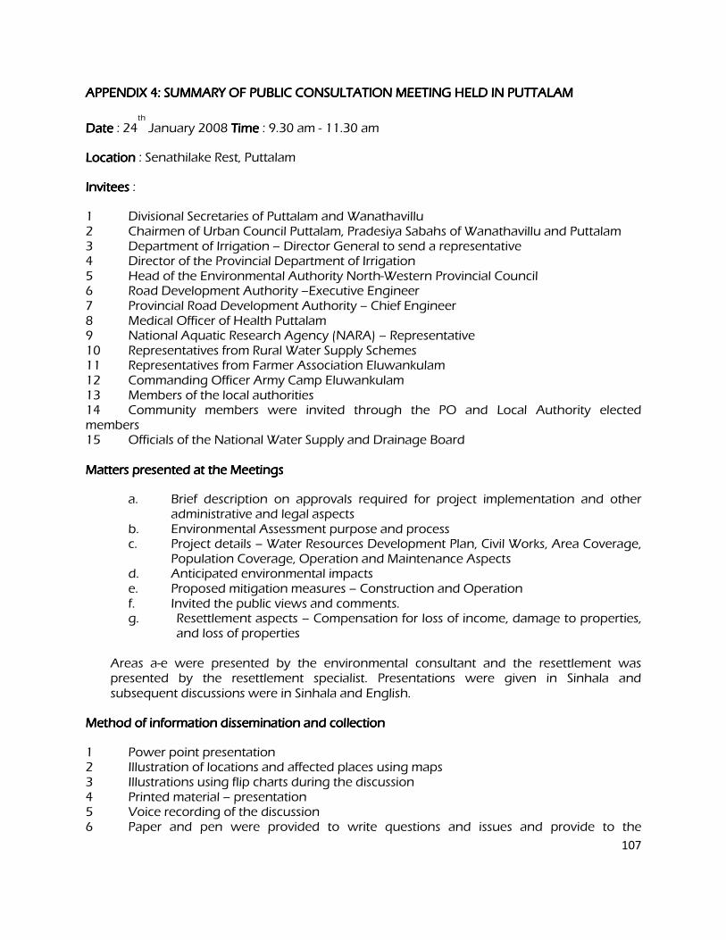
107
APPENDIX 4: SUMMARY OF PUBLIC CONSULTATION MEETING HELD IN PUTTALAM APPENDIX 4: SUMMARY OF PUBLIC CONSULTATION MEETING HELD IN PUTTALAM APPENDIX 4: SUMMARY OF PUBLIC CONSULTATION MEETING HELD IN PUTTALAM APPENDIX 4: SUMMARY OF PUBLIC CONSULTATION MEETING HELD IN PUTTALAM
Date Date Date Date : 24th
January 2008 Time Time Time Time : 9.30 am - 11.30 am
Location Location Location Location : Senathilake Rest, Puttalam
InviteesInviteesInviteesInvitees :
1 Divisional Secretaries of Puttalam and Wanathavillu 2 Chairmen of Urban Council Puttalam, Pradesiya Sabahs of Wanathavillu and Puttalam 3 Department of Irrigation – Director General to send a representative 4 Director of the Provincial Department of Irrigation 5 Head of the Environmental Authority North-Western Provincial Council 6 Road Development Authority –Executive Engineer 7 Provincial Road Development Authority – Chief Engineer 8 Medical Officer of Health Puttalam 9 National Aquatic Research Agency (NARA) – Representative 10 Representatives from Rural Water Supply Schemes 11 Representatives from Farmer Association Eluwankulam 12 Commanding Officer Army Camp Eluwankulam 13 Members of the local authorities 14 Community members were invited through the PO and Local Authority elected members 15 Officials of the National Water Supply and Drainage Board Matters presented at the Meetings Matters presented at the Meetings Matters presented at the Meetings Matters presented at the Meetings
a. Brief description on approvals required for project implementation and other administrative and legal aspects
b. Environmental Assessment purpose and process c. Project details – Water Resources Development Plan, Civil Works, Area Coverage,
Population Coverage, Operation and Maintenance Aspects d. Anticipated environmental impacts e. Proposed mitigation measures – Construction and Operation f. Invited the public views and comments. g. Resettlement aspects – Compensation for loss of income, damage to properties,
and loss of properties
Areas a-e were presented by the environmental consultant and the resettlement was presented by the resettlement specialist. Presentations were given in Sinhala and subsequent discussions were in Sinhala and English.
Method of information dissemination and collection Method of information dissemination and collection Method of information dissemination and collection Method of information dissemination and collection
1 Power point presentation 2 Illustration of locations and affected places using maps 3 Illustrations using flip charts during the discussion 4 Printed material – presentation 5 Voice recording of the discussion 6 Paper and pen were provided to write questions and issues and provide to the
108
consultants during the discussion Common issues and concerns raised at all public consultationCommon issues and concerns raised at all public consultationCommon issues and concerns raised at all public consultationCommon issues and concerns raised at all public consultation meetings meetings meetings meetings
1 Communities expressed pressing need for water in all the sub-project areas and requested to expedite the implementation of the project. 2 The Local Authority officials stated that there should be a mechanism for them to participate in the project implementation. They said when projects are implemented without their participation they often receive poorly designed and constructed infrastructure. The LA officials said that if they are expected to operate the systems then they should be given a chance to involve in the design and construction decision making. 3 The participants agreed that the provision of wastewater service to town areas as a good development. However, they expressed concern about the wastewater tariff and ability to pay. Also concerns were raised about the additional investments the property owners have to incur to upgrade their plumping arrangements in order to connect to the sewerage system. They requested further study on the ability to pay before embarking on the construction of sewerage systems. The LA officials stated that they may not be able to obtain necessary revenue to operate the systems if the number of connections is less. 4 The LAs requested to improve their awareness about institutional aspects of operation and maintenance of sewerage systems. They also requested legal assistance to develop bylaws required for management of sewerage system. They have also requested assistance to improve the technical capacity within LAs to operate the sewer systems, if they are expected to run the sewerage systems. The LA officials said that they are happy if the NWSDB operate the sewerage systems at least for the first few years. 5 As the project will take some time to start the participants stated that it is necessary to acquire the required lands well in advance so that the selected lands are available for the project. Possession of the public lands also should be obtained in advance as there are other demands on these lands. Participants also stated that it is important to inform the public about the project with details of the locations of constructed components, such as water towers, sewerage pumping stations, sewerage treatment plants, etc. 6 The deterioration of water quality and quantity in rivers and streams as wells as other activities such as sand mining were identified as threats to the future viability of the projects. Thus the participants highlighted the importance of catchment management and requested to include catchment management activities in this project. 7 The importance of obtaining the approval from necessary agencies well in advance was highlighted. These include: environmental agencies, Irrigation Department and Provincial Irrigation Department, Agrarian Services Department. 8 Over exploitation of the ground water resources was also cited as a threat. Participants stated the need to establish a mechanism for controlling the future ground water extraction in the well fields.
109
9 It was requested to complete the road excavation and pipe laying work in busy town areas as soon as possible. 10 Establish a procedure for providing assistance for toilet construction. Decide the beneficiary selection criteria for assistance for toilet construction If the funds available is limited to provide for all those who request for such assistance. 11 When deciding the financial support for toilets it is necessary to consider the construction material cost that prevails in the respective areas. Specific issSpecific issSpecific issSpecific issues raised at the meeting in Puttalam ues raised at the meeting in Puttalam ues raised at the meeting in Puttalam ues raised at the meeting in Puttalam
1 Requested to provide water for the areas along which the transmission line is taken to Puttalam. 2 Requested to identify all the affected farmers in Eluwankulama who would be loosing income due to the project and provide them satisfactory compensation. 3 Wanted to know how the project affects the existing rural schemes in the served areas in Wanathavillu. 4 National Aquatic Resources Agency requested for funding for monitoring the water quality of the lagoon at least for two years once the sewerage treatment system comes into operation 5 The Achchamolai tank which will be restored under this project should be a dedicated source for water supply. There is a concern over farmers attempting to obtain water for now abandoned agriculture after the tank is restored.

Addendum 1
Committee for Grievance Redress and Environment Monitoring
In absence of such provisions, affected parties/persons (AP) will seek solutions outside the
project which may lead to a number of adverse consequences. It is necessary to include
grievance redress provisions for the people adversely affected (or about to be affected) by the
development of sub projects because such people should have provisions to forward their
grievances by seeking solutions. Environmental Monitoring Committees (EMC) are already
proposed to discuss the critical environmental issues and thereby find solutions in some sub
projects. Facility for Grievance Redressing shall be incorporated to the proposed EMCs because
all regional level key officials will become the members of such EMCs and will be functioning
as Grievance Redress and Environment Monitoring Committee (GREMC). New GREMCs shall
be formed for the sub-projects where EMCs have not been proposed.
The GREMC comprises with responsible officers of following agencies and headed by the
Provincial Environmental Authority or Central Environmental Authority (which is functioning in
the area concern) jointly with the divisional secretary. The secretary to the committee and the
convener shall be the project manager of the NWSDB.
1. Provincial Environmental Authority/Central Environmental Authority (Regional office)
2. Project Manager of the sub project
3. Urban Council/ Municipal Council
4. Divisional Secretariat
5. Agrarian Service Department
6. Provincial Irrigation Department / Central Irrigation Department.
7. Representative of the contractor
8. Representative of the consultant to the project
9. Any other officers by considering the need
If APs are not satisfied about the decision of the GREMC, the matter should be referred to the
District Secretary who will make the final decision. The District Secretary may appoint a
committee to find the observations. The GREMC is effective with the commencement of the
construction and shall meet once in six weeks during the construction period. During the
operational phase, the committee shall meet once in three months for two years and if necessary
thereafter. If there are critical issues, the committee shall meet by fixing a convenient date.

During the operational phase, Regional Manager (O&M) of the NWSDB shall represent the
NWSDB.
This should be published in all three languages by displaying notices in the notice boards of all
member offices and other public offices such as Grama Niladhari (Village Head) office, post
office etc. to make aware the public.
Project Implementation Agency: National Water Supply & Drainage Board Funding Agency: Asian Development Bank Project Number: 37381
Sri Lanka: Dry Zone Urban Water Supply and Sanitation Project (DZUWSSP) INITIAL ENVIRONMENTAL EXAMINATION: MANNAR NOVEMBER 2012
CONTENTS
I. INTRODUCTION .................................................................................................................................. 1
A. Purpose of the Report ........................................................................................................................... 1
B. Extent of IEE study ............................................................................................................................... 1
II. DESCRIPTION OF THE PROJECT ..................................................................................................... 5
A. Type, Category and Need ..................................................................................................................... 5
B. Location, Size and Implementation Schedule ...................................................................................... 5
C. Description of the Sub-projects ............................................................................................................. 5
III. DESCRIPTION OF THE ENVIRONMENT ......................................................................................... 11
A. Physical Resources ............................................................................................................................ 11
B. Ecological Resources ......................................................................................................................... 15
C. Economic Development ...................................................................................................................... 16
D. Social and Cultural Resources ........................................................................................................... 18
IV. ENVIRONMENTAL IMPACTS AND MITIGATION: INFRASTRUCTURE CONSTRUCTION .......... 20
A. Screening out areas of no significant impact ...................................................................................... 20
B. Water Supply ...................................................................................................................................... 21
C. Sanitation ............................................................................................................................................ 26
V. ENVIRONMENTAL IMPACTS AND MITIGATION: OPERATION AND MAINTENANCE ............... 27
A. Screening out areas of no significant impact ...................................................................................... 27
B. Water Supply ...................................................................................................................................... 27
C. Sanitation ............................................................................................................................................ 30
VI. ENVIRONMENTAL IMPACTS AND MITIGATION: LOCATION AND DESIGN ............................... 31
VII. INSTITUTIONAL REQUIREMENTS AND ENVIRONMENTAL MONITORING PLAN ..................... 32
A. Summary of environmental impacts and mitigation measures ........................................................... 32
B. Institutional arrangements for project implementation ........................................................................ 32
C. Environmental Monitoring Plan ........................................................................................................... 37
ii
D. Environmental management and monitoring costs ............................................................................ 42
VIII. PUBLIC CONSULTATION AND INFORMATION DISCLOSURE .................................................... 44
A. Project stakeholders ........................................................................................................................... 44
B. Consultation and disclosure to date .................................................................................................... 44
C. Future consultation and disclosure ..................................................................................................... 47
IX. FINDINGS AND RECOMMENDATIONS ........................................................................................... 48
A. Findings .............................................................................................................................................. 48
B. Recommendations .............................................................................................................................. 50
X. CONCLUSIONS ................................................................................................................................. 51
APPENDIX 1: Current Sri Lankan drinking water standards (1996)…………………………………………..55
APPENDIX 2: Existing Sri Lankan wastewater discharge standards (1990)………………………………...57
APPENDIX 3: Draft new wastewater discharge standards (2008)……………………………………………58
APPENDIX 4: Summary of public consultation meeting held in Mannar……………………………………..59
Addendum 1…………………………………………………………………………………….62

iii
LIST OF TABLES
Table 1: Water supply, sanitation and drainage subprojects proposed in Mannar .................................... 8
Table 2: General groundwater quality in Mannar ..................................................................................... 15
Table 3: Fields in which construction is not expected to have significant impacts ................................... 20
Table 4: Fields in less significant impacts ................................................................................................ 27
Table 5: Environmental impacts and mitigation measures ....................................................................... 33
Table 6 : Environmental Monitoring Plan ................................................................................................. 39
Table 7: Environmental management and monitoring costs (SLR) ......................................................... 43
Table 8: Comments made at public consultation meeting in Mannar, 25 January 2008 ......................... 45
iv
LIST OF FIGURES
Figure 1: Location of the project and proposed improvements in water supply infrastructure ................... 7
Figure 2: Geology of Mannar .................................................................................................................... 12
Figure 3: Average monthly rainfall in Mannar (1957-2007) ...................................................................... 13
Figure 4: Groundwater map of the Mannar area ...................................................................................... 14
v
LIST OF PHOTOGRAPHS
Photo 1: Tube Well ................................................................................................................................... 52
Photo 2 : Irrigation tank ............................................................................................................................ 52
Photo 3: RCC tanks for water treatment .................................................................................................. 52
Photo 4: Sluice gate ................................................................................................................................. 52
Photo 5: Overhead Reservoir ................................................................................................................... 52
Photo 6: Electricity poles .......................................................................................................................... 52
Photo 7: Metal reinforcing......................................................................................................................... 53
Photo 8: Digging a trench by hand ........................................................................................................... 53
Photo 9: Wooden shuttering ..................................................................................................................... 53
Photo 10: Pipe bridges across a stream .................................................................................................. 53
Photo 11: Backhoe digger excavating a trench ........................................................................................ 53
Photo 12: Roadside shrine ....................................................................................................................... 53
1
I. INTRODUCTION
A. Purpose of the Report
1. The Dry Zone Urban Water Supply and Sanitation Project (DZUWSSP) is intended to facilitate sustainable development in disadvantaged districts in Sri Lanka. This will be achieved by investing in priority water supply and sewerage/sanitation infrastructure in selected urban areas, and assisting the National Water Supply and Drainage Board (NWSDB) to institutionalise the development of sustainable community-based infrastructure. Assistance will be targeted in those parts of the Northern and North-Western Provinces with the most acute shortages of drinking water and sanitation. Chosen urban areas are the towns of Mannar, Vavuniya, Puttalam and Chilaw. 2. DZUWSSP will be implemented over five years beginning early 2009, and will be supported by ADB through a project loan and grant. The Ministry of Water Supply and Drainage (MWSD) is the Executing Agency (EA) for the program and NWSDB is the Implementing Agency (IA). 3. DZUWSSP will improve infrastructure through the development, design and implementation of subprojects in water supply and sanitation in each town. The Project has been classified by ADB as environmental assessment category B sensitive, as the Vavuniya water supply subproject includes one environmentally sensitive component (a 4 m high dam and 215 ha storage reservoir). The impacts of providing infrastructure in the four urban areas were assessed by four Initial Environmental Examination (IEE) reports (one for each location). For Vavuniya an Environmental Management Plan for the storage reservoir and a detailed Environmental Monitoring plan (EnvMP) for the other less sensitive sub-components have been prepared. In the other three towns, where impacts will be less significant, and individually can be classified as Category B, detailed Environmental Monitoring Plans have been prepared.. Studies were conducted according to ADB Environment Policy (2002) and Environmental Assessment Guidelines (2003) and this document is the IEE report for Mannar.
B. Extent of IEE study
4. Sri Lankan law and ADB policy require that the environmental impacts of development projects are identified and assessed as part of the planning and design process, and that action is taken to reduce those impacts to acceptable levels. This is done through the environmental assessment process, which has become an integral part of lending operations and project development and implementation worldwide.
1. ADB Policy
5. ADB’s Environment Policy requires the consideration of environmental issues in all aspects of the Bank’s operations, and the requirements for Environmental Assessment are described in Operations Manual (OM) 20: Environmental Considerations in ADB Operations. This states that ADB requires environmental assessment of all project loans, program loans, sector loans, sector development program loans, financial intermediation loans and private sector investment operations. 6. The nature of the assessment required for a project depends on the significance of its environmental impacts, which are related to the type and location of the project, the sensitivity, scale, nature and magnitude of its potential impacts, and the availability of cost-effective
2
mitigation measures. Projects are screened for their expected environmental impacts and are assigned to one of the following categories:
Category A: Projects that could have significant environmental impacts. An Environmental Impact Assessment (EIA) is required.
Category B: Projects that could have some adverse environmental impacts, but of less significance than those for category A. An Initial Environmental Examination (IEE) is required to determine whether significant impacts warranting an EIA are likely. If an EIA is not needed, the IEE is regarded as the final environmental assessment report. A Category B project may be classified as B-sensitive if it involves environmentally sensitive activities1. Such projects require IEE, but have the same requirements for disclosure and Environmental Management Plans as Category A.
Category C: Projects that are unlikely to have adverse environmental impacts. No EIA or IEE is required, although environmental implications are reviewed.
7. The Bank has classed this program as Category B sensitive and following normal procedure for project loans, one IEE was conducted for each urban area, covering all proposed subprojects in the town. A subproject comprises the infrastructure improvements in a particular sector (water supply or sewerage/sanitation).
2. National Law
8. The requirement for Environmental Assessment in Sri Lanka is established by the National Environment Act (1981), and the procedures are defined in the EIA Regulations (1993). The regulations specify activities for which environmental assessment is mandatory, and those that could occur within certain DZUWSSP subprojects are as follows:
Groundwater extraction of over 500,000 m3/day2; A Water Treatment Plant with a capacity of over 500,000 m3/day2; Laying more than 1 km of pipes3; Projects that involve relocation of more than 100 people; and Projects that fall within sensitive area(s).
9. Sensitive areas are defined in the EIA Regulations as:
Any erodable area declared under the Soil Conservation Act (1951, 1953); Any Flood Area declared under the Flood Protection Ordinance (1924, 1955) and
any Flood Protection Area declared under the Sri Lanka Land Reclamation and Development Corporation Act (1968, 1982);
Any reservation beyond the Full Supply Level of a reservoir; Any archaeological reserve, ancient or protected monument as defined or declared
under the Antiquities Ordinance (1965);
1 A project may be deemed environmentally sensitive by ADB if it is near environmentally sensitive areas, or involves: deforestation
or loss of biodiversity; involuntary resettlement issues; processing, handling and disposal of toxic and hazardous substances; or other environmentally sensitive activities that also may be of concern to a wide group of external stakeholders. 2 The Central Environment Authority is currently considering a proposal to lower these limits to 500 m
3/day.
3 This applies to wastewater projects but not water supply.
3
Any area declared under the Botanic Gardens Ordinance (1928, 1973); Areas within, or less than 100 m from the boundaries of, any area declared under
the National Heritage and Wilderness Act (1988): the Forest Ordinance; Areas within, or less than 100 m from the boundaries of, any area declared as a
Sanctuary under the Fauna and Flora Protection Ordinance (1937); Areas within, or less than 100 m from the high flood level contour of, a public lake as
defined by the Crown Lands Ordinance (1947, 1949, 1956) including those declared under Section 71 of the Ordinance;
Areas 60 m or less from the bank of a public stream as defined in the Crown Lands Ordinance, with a width of more than 25 m at any point.
10. The requirement for EIA and the level of study required are determined by the Central Environment Authority (CEA) 4 after submission by the proponent of a Project Information Document (PID), plus supporting information if relevant. There are two possible outcomes:
Categorical Exclusion: the activity is not on the list of prescribed projects in the EIA regulations, is not in or near a sensitive area, has not been the subject of public protest, and it is clear from the PID and supporting information that the project will have no significant environmental impacts. Environmental Clearance is granted (with or without conditions) and the project may proceed; All other projects require Environmental Assessment and the CEA or PEA4 establishes a Scoping Committee to decide on the level of study (IEE or EIA) and prepare Terms of Reference (ToR). Alternatively, if the project lies wholly within the jurisdiction of a single Government agency (eg UDA) CEA/PEA may refer the project to this authority (as the Project Approving Agency) to administer the EIA process. A Technical Review Committee reviews the completed IEE or EIA report and recommends whether Environmental Clearance should be granted. The final decision is made by CEA.
11. The urban areas selected under this program have populations of between 40,000 and 120,000, so the infrastructure subprojects are relatively small, and groundwater abstraction and water treatment will not be of the scale quoted in the EIA regulations as requiring environmental assessment. Components will not be located in protected or sensitive areas and no people will be relocated. 12. However two of the water supply subprojects (Chilaw and Vavuniya) involve the construction of structures across a river or stream to impound water, which is considered as a prescribed activity under the National Environmental Act (NEA), and will thus require an EIA. Furthermore, if during detailed designs if location of proposed tube wells for the Mannar water supply scheme is within or 100 m away from the Giants Tank Sanctuary, this too would be considered as a prescribed activity. The National Environmental Act regulations may also apply to the other urban water supply schemes in the future if the Central Environmental Authority (CEA) reduces the size of groundwater abstraction and water treatment plants for which EIA is required (see Footnote 2). The NWSDB will submit the PID and this IEE to the CEA/PEA for review.
4 In the North-Western Province (which includes Chilaw and Puttalam) the EIA system is established by the North-
Western Provincial Act (1981) and Provincial EIA Regulations (1992, 1998). The system is the same as the national procedure, except for: (i) the North-Western Provincial Environmental Authority (NWPEA) replaces CEA as the competent authority (although projects with trans-regional impacts are referred to CEA and dealt with under the national system); (ii) EIA and IEE reports are made available for public comment (under the national system this is required for EIAs only); (iii) Projects that are the subject of significant public interest or protest can be required to conduct an EIA by the NWPEA Board of Directors, even though this may not be required by the legislation
4
3. Review and Approval Procedure
13. For Category B projects the Draft IEE report and its summary (SIEE) are reviewed by ADB’s Regional Department sector division and Environment and Social Safeguards Division, and by the Executing Agency, and additional comments may be sought from project affected people and other stakeholders. All comments are incorporated in preparing the final documents, which are reviewed by the Executing Agency (EA) and the national environmental protection agency (CEA or NWPEA in this case). The EA then officially submits the IEE and SIEE reports to ADB for consideration by the Board of Directors. Completed reports are made available worldwide by ADB, via the depository library system and the ADB website.
4. Scope of Study
14. This is the IEE for the water supply subprojects proposed in Mannar. It discusses the environmental impacts and mitigation measures relating to the location, design, construction and operation of all physical works proposed under these subprojects. These documents were prepared in October 2007 and February 2008 by one International and one Domestic Environmental Specialist via inputs of three months each.
5
II. DESCRIPTION OF THE PROJECT
A. Type, Category and Need
1. DZUWSSP is a program to improve urban infrastructure, by the design and implementation of subprojects in water supply and sanitation. As explained above the program has been classified by ADB as Category B sensitive, because it is not expected to have major negative environmental impacts. As the Project will be funded by a loan and grant, ADB procedure requires that an IEE is conducted for each town to identify and mitigate the impacts of subprojects, and to determine whether further study or a more detailed EIA may be required. This is the IEE for Mannar water supply system. A separate IEE is carried out for the septage treatment plant in Manner. 2. Improvements in water supply are needed in Mannar because the present infrastructure is inadequate for the needs of the growing population. The main problems are that:
The water supply system is based on groundwater abstracted by tube wells, which perform below capacity and provide insufficient water for present demands;
The transmission main and distribution system are beset with leaks and water is only available for 2-3 hours/day; and
3. These and the other subprojects designed by the DZUWSSP are intended to raise the standards of the municipal infrastructure and services of the selected urban centres to those expected of modern Asian towns.
B. Location, Size and Implementation Schedule
4. The subprojects assessed in this report will be located in Mannar, on the west coast of the Northern Province of Sri Lanka, 220 km north of the national capital Colombo, and 80 km south of the provincial capital Jaffna (Figure 1). The improved infrastructure will extend through approximately 40% of the town, where water pipes will be buried alongside roads, and a new overhead reservoir and ground tank will be built on small pockets of land. Outside the town, existing tube-wells will be refurbished and new tube-wells will be dug, and a new transmission main will be built to carry water to the town (Figure 1). 5. The new water supply system will serve a population of 20,000 in an area of 2,540 ha in 2010 and a population of 41,000 in an area of 5,000 ha in 2030. It will abstract 6,500 m3/d of groundwater from existing and new tube-wells in 2010, and 10,500 m3/d in 2030. Water will be chlorinated, but as there are data on water quality in the aquifer it is not certain whether the treated water will meet Sri Lankan drinking water standards (Appendix 1). Table 1 shows the components of the scheme that will be funded by the project. 6. Detailed design of the infrastructure will begin in the middle of 2008 and should be completed by the end of the year, after which construction will take up to 4 years. All work should therefore be completed by the middle of 2012.
C. Description of the Sub-projects
7. Table 1 shows the nature and size of the various components of the proposed subprojects. The descriptions are expected to be substantially correct, although certain details may change as development progresses, particularly in the detailed design stage. It should also be noted that at this stage the infrastructure has been designed in outline only, to determine
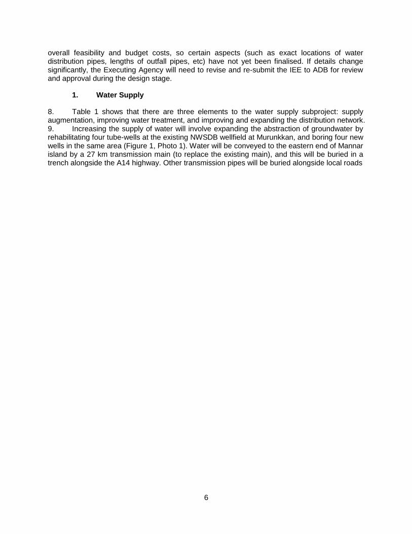
6
overall feasibility and budget costs, so certain aspects (such as exact locations of water distribution pipes, lengths of outfall pipes, etc) have not yet been finalised. If details change significantly, the Executing Agency will need to revise and re-submit the IEE to ADB for review and approval during the design stage.
1. Water Supply
8. Table 1 shows that there are three elements to the water supply subproject: supply augmentation, improving water treatment, and improving and expanding the distribution network. 9. Increasing the supply of water will involve expanding the abstraction of groundwater by rehabilitating four tube-wells at the existing NWSDB wellfield at Murunkkan, and boring four new wells in the same area (Figure 1, Photo 1). Water will be conveyed to the eastern end of Mannar island by a 27 km transmission main (to replace the existing main), and this will be buried in a trench alongside the A14 highway. Other transmission pipes will be buried alongside local roads
7
Figure 1: Location of the project and proposed improvements in water supply infrastructure
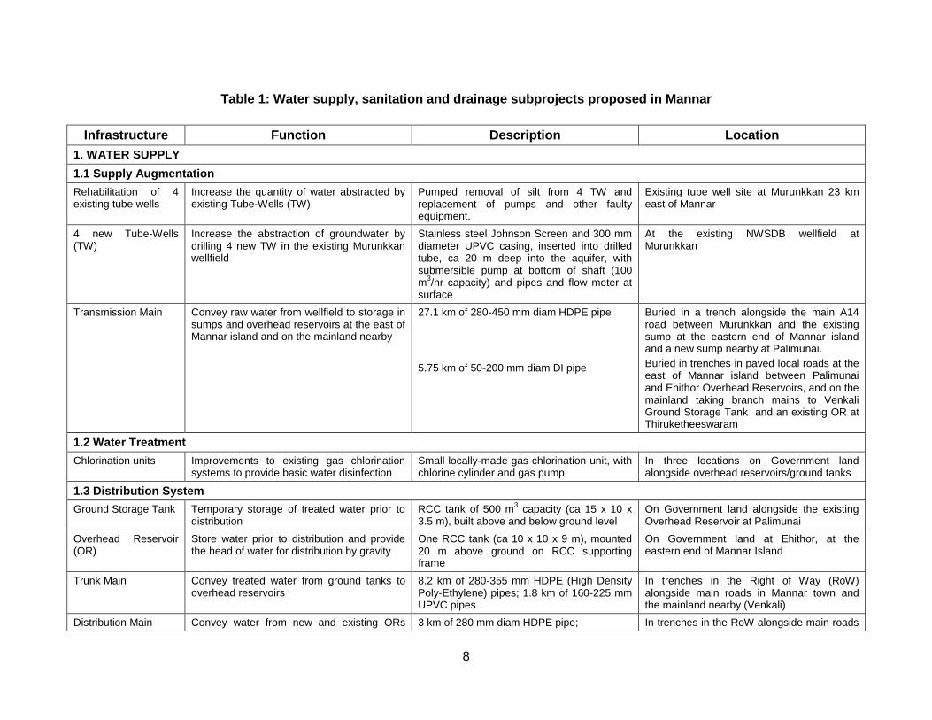
8
Table 1: Water supply, sanitation and drainage subprojects proposed in Mannar
Infrastructure Function Description Location
1. WATER SUPPLY
1.1 Supply Augmentation
Rehabilitation of 4 existing tube wells
Increase the quantity of water abstracted by existing Tube-Wells (TW)
Pumped removal of silt from 4 TW and replacement of pumps and other faulty equipment.
Existing tube well site at Murunkkan 23 km east of Mannar
4 new Tube-Wells (TW)
Increase the abstraction of groundwater by drilling 4 new TW in the existing Murunkkan wellfield
Stainless steel Johnson Screen and 300 mm diameter UPVC casing, inserted into drilled tube, ca 20 m deep into the aquifer, with submersible pump at bottom of shaft (100 m
3/hr capacity) and pipes and flow meter at
surface
At the existing NWSDB wellfield at Murunkkan
Transmission Main Convey raw water from wellfield to storage in sumps and overhead reservoirs at the east of Mannar island and on the mainland nearby
27.1 km of 280-450 mm diam HDPE pipe
5.75 km of 50-200 mm diam DI pipe
Buried in a trench alongside the main A14 road between Murunkkan and the existing sump at the eastern end of Mannar island and a new sump nearby at Palimunai.
Buried in trenches in paved local roads at the east of Mannar island between Palimunai and Ehithor Overhead Reservoirs, and on the mainland taking branch mains to Venkali Ground Storage Tank and an existing OR at Thiruketheeswaram
1.2 Water Treatment
Chlorination units Improvements to existing gas chlorination systems to provide basic water disinfection
Small locally-made gas chlorination unit, with chlorine cylinder and gas pump
In three locations on Government land alongside overhead reservoirs/ground tanks
1.3 Distribution System
Ground Storage Tank Temporary storage of treated water prior to distribution
RCC tank of 500 m3 capacity (ca 15 x 10 x
3.5 m), built above and below ground level On Government land alongside the existing Overhead Reservoir at Palimunai
Overhead Reservoir (OR)
Store water prior to distribution and provide the head of water for distribution by gravity
One RCC tank (ca 10 x 10 x 9 m), mounted 20 m above ground on RCC supporting frame
On Government land at Ehithor, at the eastern end of Mannar Island
Trunk Main Convey treated water from ground tanks to overhead reservoirs
8.2 km of 280-355 mm HDPE (High Density Poly-Ethylene) pipes; 1.8 km of 160-225 mm UPVC pipes
In trenches in the Right of Way (RoW) alongside main roads in Mannar town and the mainland nearby (Venkali)
Distribution Main Convey water from new and existing ORs 3 km of 280 mm diam HDPE pipe; In trenches in the RoW alongside main roads
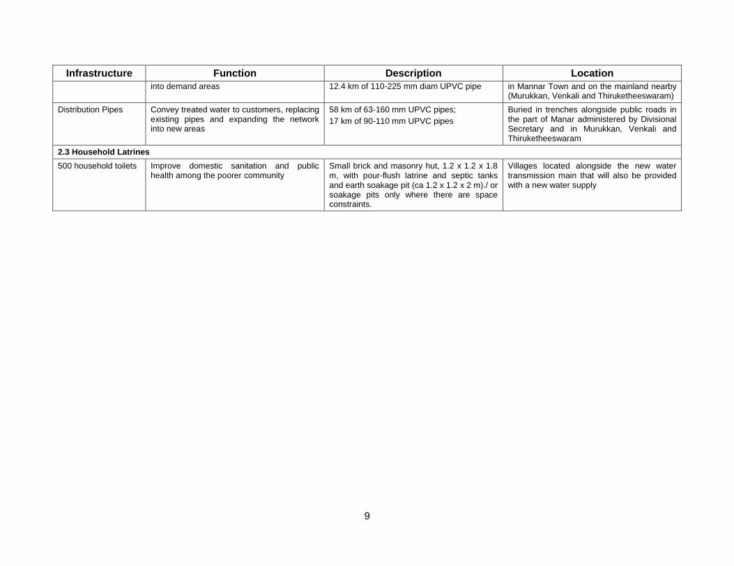
9
Infrastructure Function Description Location
into demand areas 12.4 km of 110-225 mm diam UPVC pipe in Mannar Town and on the mainland nearby (Murukkan, Venkali and Thiruketheeswaram)
Distribution Pipes Convey treated water to customers, replacing existing pipes and expanding the network into new areas
58 km of 63-160 mm UPVC pipes;
17 km of 90-110 mm UPVC pipes
Buried in trenches alongside public roads in the part of Manar administered by Divisional Secretary and in Murukkan, Venkali and Thiruketheeswaram
2.3 Household Latrines
500 household toilets Improve domestic sanitation and public health among the poorer community
Small brick and masonry hut, 1.2 x 1.2 x 1.8 m, with pour-flush latrine and septic tanks and earth soakage pit (ca 1.2 x 1.2 x 2 m)./ or soakage pits only where there are space constraints.
Villages located alongside the new water transmission main that will also be provided with a new water supply
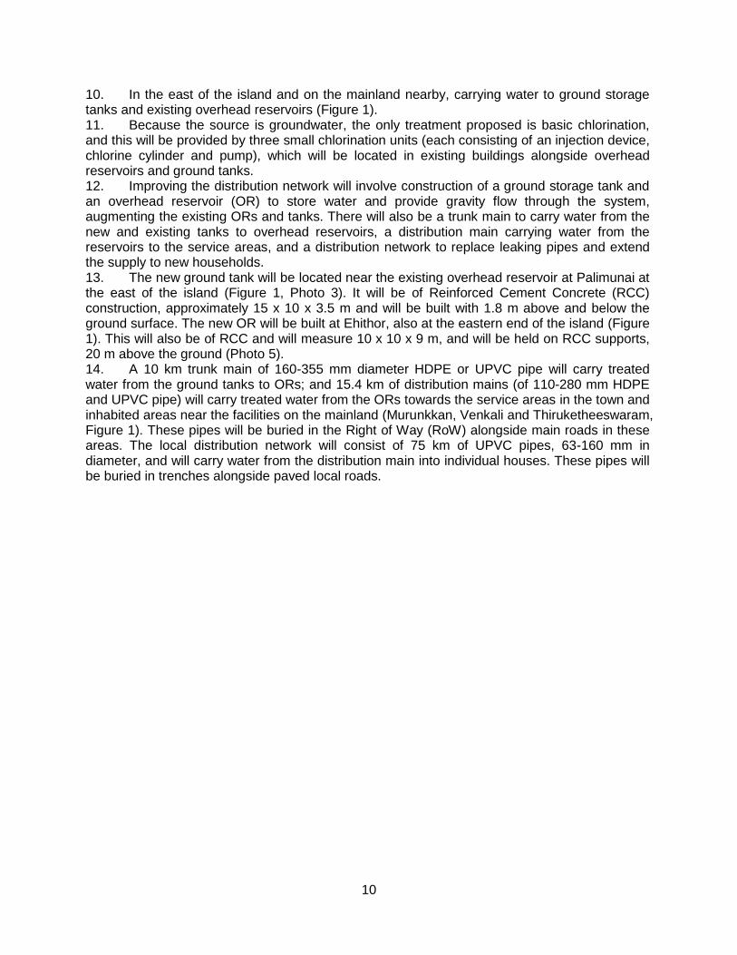
10
10. In the east of the island and on the mainland nearby, carrying water to ground storage tanks and existing overhead reservoirs (Figure 1). 11. Because the source is groundwater, the only treatment proposed is basic chlorination, and this will be provided by three small chlorination units (each consisting of an injection device, chlorine cylinder and pump), which will be located in existing buildings alongside overhead reservoirs and ground tanks. 12. Improving the distribution network will involve construction of a ground storage tank and an overhead reservoir (OR) to store water and provide gravity flow through the system, augmenting the existing ORs and tanks. There will also be a trunk main to carry water from the new and existing tanks to overhead reservoirs, a distribution main carrying water from the reservoirs to the service areas, and a distribution network to replace leaking pipes and extend the supply to new households. 13. The new ground tank will be located near the existing overhead reservoir at Palimunai at the east of the island (Figure 1, Photo 3). It will be of Reinforced Cement Concrete (RCC) construction, approximately 15 x 10 x 3.5 m and will be built with 1.8 m above and below the ground surface. The new OR will be built at Ehithor, also at the eastern end of the island (Figure 1). This will also be of RCC and will measure 10 x 10 x 9 m, and will be held on RCC supports, 20 m above the ground (Photo 5). 14. A 10 km trunk main of 160-355 mm diameter HDPE or UPVC pipe will carry treated water from the ground tanks to ORs; and 15.4 km of distribution mains (of 110-280 mm HDPE and UPVC pipe) will carry treated water from the ORs towards the service areas in the town and inhabited areas near the facilities on the mainland (Murunkkan, Venkali and Thiruketheeswaram, Figure 1). These pipes will be buried in the Right of Way (RoW) alongside main roads in these areas. The local distribution network will consist of 75 km of UPVC pipes, 63-160 mm in diameter, and will carry water from the distribution main into individual houses. These pipes will be buried in trenches alongside paved local roads.
11
III. DESCRIPTION OF THE ENVIRONMENT
A. Physical Resources
1. Location
1. Mannar town is on the eastern half of Mannar Island, which is on the west coast on the Northern Province of Sri Lanka, 220 km north of the national capital Colombo and 80 km south of the provincial capital Jaffna. The main A14 highway runs through Mannar to Talaimannar at the north-western end of the island and continues south-east to Medawachchiya, from where other major roads run to Vavuniya and Jaffna to the north, Trincomalee on the east coast and Anuradhapura to the south. 2. Mannar was an important trading centre in the past, particularly with India, the south-east coast of which is only 30 km from Talaimannar. However like most other parts of the Vanni region in the north of Sri Lanka, Mannar has been greatly affected over the past 25 years by the political conflict between the Government and the Liberation Tigers of Tamil Eelam (LTTE), who are seeking to establish an autonomous Tamil state in the north. Although Mannar is in the area presently controlled by Government forces, travel to the area is restricted, and the effect of the conflict is evident in the town in damaged and abandoned houses, the former occupants having moved to safer locations in the south of the country. 3. Mannar Town is the administrative centre of Mannar district, and is administered by the Central Government via Divisional Secretary. The Local Authority is the Mannar Pradesiya Sabah, which is part of the Northern Provincial Council, so its work is overseen by the Commissioner of Local Government (CLG) of the Northern Province. 4. The water supply element of the project focuses on Mannar town, and specifically 22 Gramaseva Nildari Divisions (GND)5 at the eastern end of the island, plus small areas in the vicinity of the facilities on the mainland, at Murukkan, Venkali and Thiruketheeswaram (Figure 1). The Divisional Secretary Area as a whole consists of 124 GND.
2. Topography, soil and geology
5. Mannar Island is a coastal area and its topography is mainly flat. Soils are mainly regosols located over recent beach and dune sands, which have been moved northwards along the coast by wave and wind action. The geology is of more recent origin than much of the rest of Sri Lanka and falls in the area of Miocene to Quaternary rocks, consisting mainly of quaternary era red beds of ferruginized gravel, overlain by coastal sand ( 6. 7. 8. Figure 2). 9. The mainland areas served by the project consist mainly of alluvial and lagoonal clays in the surface layers, plus silt, sand and beach and dune sands. Miocene limestone is present beneath these deposits, and these provide good water-bearing aquifers in Murunkkan and other locations.
5 GND is the lowest level of central Government administration, in which the administration is headed by a Gramaseva Nildari (GN).
A GND normally consists of a town and/or several villages, although rarely a GND can comprise a single village or town. Each Divisional Secretary (DS) area comprises a number of GNDs (typically around a hundred), and the DS is normally the main decision-maker, implementing central Government policy.
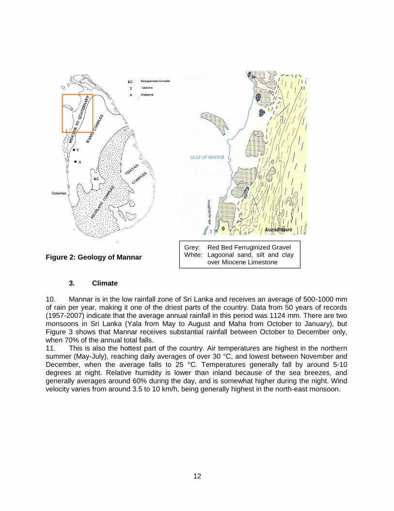
12
Figure 2: Geology of Mannar
3. Climate
10. Mannar is in the low rainfall zone of Sri Lanka and receives an average of 500-1000 mm of rain per year, making it one of the driest parts of the country. Data from 50 years of records (1957-2007) indicate that the average annual rainfall in this period was 1124 mm. There are two monsoons in Sri Lanka (Yala from May to August and Maha from October to January), but Figure 3 shows that Mannar receives substantial rainfall between October to December only, when 70% of the annual total falls. 11. This is also the hottest part of the country. Air temperatures are highest in the northern summer (May-July), reaching daily averages of over 30 °C, and lowest between November and December, when the average falls to 25 °C. Temperatures generally fall by around 5-10 degrees at night. Relative humidity is lower than inland because of the sea breezes, and generally averages around 60% during the day, and is somewhat higher during the night. Wind velocity varies from around 3.5 to 10 km/h, being generally highest in the north-east monsoon.
Grey: Red Bed Ferruginized Gravel White: Lagoonal sand, silt and clay
over Miocene Limestone
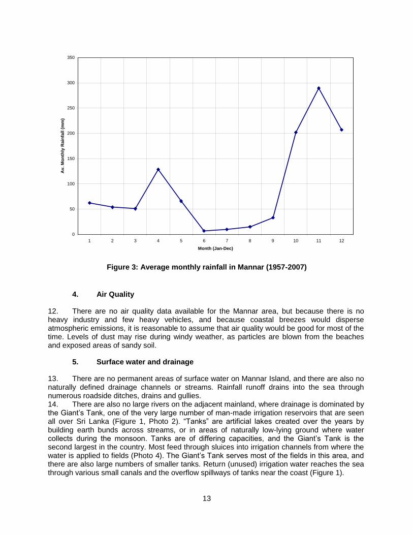
13
Figure 3: Average monthly rainfall in Mannar (1957-2007)
4. Air Quality
12. There are no air quality data available for the Mannar area, but because there is no heavy industry and few heavy vehicles, and because coastal breezes would disperse atmospheric emissions, it is reasonable to assume that air quality would be good for most of the time. Levels of dust may rise during windy weather, as particles are blown from the beaches and exposed areas of sandy soil.
5. Surface water and drainage
13. There are no permanent areas of surface water on Mannar Island, and there are also no naturally defined drainage channels or streams. Rainfall runoff drains into the sea through numerous roadside ditches, drains and gullies. 14. There are also no large rivers on the adjacent mainland, where drainage is dominated by the Giant’s Tank, one of the very large number of man-made irrigation reservoirs that are seen all over Sri Lanka (Figure 1, Photo 2). “Tanks” are artificial lakes created over the years by building earth bunds across streams, or in areas of naturally low-lying ground where water collects during the monsoon. Tanks are of differing capacities, and the Giant’s Tank is the second largest in the country. Most feed through sluices into irrigation channels from where the water is applied to fields (Photo 4). The Giant’s Tank serves most of the fields in this area, and there are also large numbers of smaller tanks. Return (unused) irrigation water reaches the sea through various small canals and the overflow spillways of tanks near the coast (Figure 1).
0
50
100
150
200
250
300
350
1 2 3 4 5 6 7 8 9 10 11 12
Month (Jan-Dec)
Av
. M
on
thly
Ra
infa
ll (
mm
)
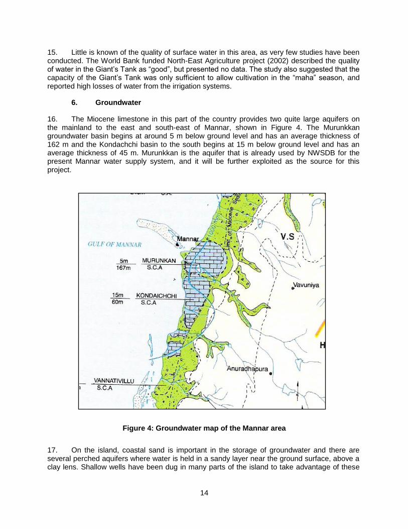
14
15. Little is known of the quality of surface water in this area, as very few studies have been conducted. The World Bank funded North-East Agriculture project (2002) described the quality of water in the Giant’s Tank as “good”, but presented no data. The study also suggested that the capacity of the Giant’s Tank was only sufficient to allow cultivation in the “maha” season, and reported high losses of water from the irrigation systems.
6. Groundwater
16. The Miocene limestone in this part of the country provides two quite large aquifers on the mainland to the east and south-east of Mannar, shown in Figure 4. The Murunkkan groundwater basin begins at around 5 m below ground level and has an average thickness of 162 m and the Kondachchi basin to the south begins at 15 m below ground level and has an average thickness of 45 m. Murunkkan is the aquifer that is already used by NWSDB for the present Mannar water supply system, and it will be further exploited as the source for this project.
Figure 4: Groundwater map of the Mannar area
17. On the island, coastal sand is important in the storage of groundwater and there are several perched aquifers where water is held in a sandy layer near the ground surface, above a clay lens. Shallow wells have been dug in many parts of the island to take advantage of these
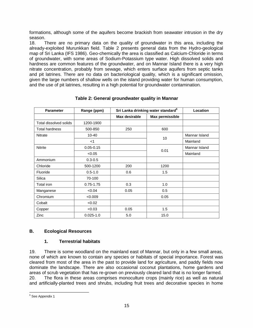
15
formations, although some of the aquifers become brackish from seawater intrusion in the dry season. 18. There are no primary data on the quality of groundwater in this area, including the already-exploited Murunkkan field. Table 2 presents general data from the Hydro-geological map of Sri Lanka (IFS 1986). Geo-chemically the area is classified as Calcium-Chloride in terms of groundwater, with some areas of Sodium-Potassium type water. High dissolved solids and hardness are common features of the groundwater, and on Mannar Island there is a very high nitrate concentration, probably from sewage, which enters surface aquifers from septic tanks and pit latrines. There are no data on bacteriological quality, which is a significant omission, given the large numbers of shallow wells on the island providing water for human consumption, and the use of pit latrines, resulting in a high potential for groundwater contamination.
Table 2: General groundwater quality in Mannar
Parameter Range (ppm) Sri Lanka drinking water standard6 Location
Max desirable Max permissible
Total dissolved solids 1200-1900
Total hardness 500-850 250 600
Nitrate 10-40 10
Mannar Island
<1 Mainland
Nitrite 0.05-0.15 0.01
Mannar Island
<0.05 Mainland
Ammonium 0.3-0.5
Chloride 500-1200 200 1200
Fluoride 0.5-1.0 0.6 1.5
Silica 70-100
Total iron 0.75-1.75 0.3 1.0
Manganese <0.04 0.05 0.5
Chromium <0.009 0.05
Cobalt <0.02
Copper <0.03 0.05 1.5
Zinc 0.025-1.0 5.0 15.0
B. Ecological Resources
1. Terrestrial habitats
19. There is some woodland on the mainland east of Mannar, but only in a few small areas, none of which are known to contain any species or habitats of special importance. Forest was cleared from most of the area in the past to provide land for agriculture, and paddy fields now dominate the landscape. There are also occasional coconut plantations, home gardens and areas of scrub vegetation that has re-grown on previously cleared land that is no longer farmed. 20. The flora in these areas comprises monoculture crops (mainly rice) as well as natural and artificially-planted trees and shrubs, including fruit trees and decorative species in home
6 See Appendix 1
16
gardens. The fauna comprises mainly animals that are able to live close to man, such as squirrels, lizards and certain birds and insects, as well as large numbers of domesticated cows, goats, pigs and chickens. 21. On Mannar Island the combined influence of wind and sea on soils that are sandy, with low fertility and poor water retention capacity, make this an inhospitable area for terrestrial plants and animals. Natural low-form scrub vegetation is present in some areas, but there are no plants or animals that are of any special value or importance. Much of the natural vegetation has been cleared to provide land for housing and other development, and there is little vegetation in the town, with the exception of a few roadside trees, and planted trees and shrubs in gardens.
2. Wetlands
22. Giant’s Tank and the other smaller tanks support a range of aquatic vegetation, including reeds and water hyacinth, which grow in profusion in some areas, significantly reducing the quantity of water retained (Photo 2). The tanks also support a range of aquatic fauna including fish, amphibians, birds and insects, and there are active fisheries in the larger tanks. Species include those that occur naturally in the rivers and streams farther inland, plus introduced species such as tilapia and carp.
3. Coastal habitats
23. The shallow coastal waters around Mannar island support a small fishery and there are interesting coral reef habitats in certain areas, most notably the Adam’s Bridge series of patch reefs and sandbanks at the north-western end of the island, which lead towards the south-eastern coast of India (Figure 1). Little is known of the ecology of these areas, and study has been prevented in recent years by the LTTE activity. None of the areas on or around the island are designated or protected however, so it can be assumed that there are no especially important species or habitats.
4. Protected areas
24. Giant’s tank is a significant wetland and it is within a declared sanctuary, mainly because of the migrating water-birds that are found there. There is however no other information in the literature regarding the flora and fauna of the area. Madhu Road Sanctuary is a much larger protected area about 30 km north-east of the Murunkkan wellfield, inhabited by a variety of Sri Lanka’s more notable species, including elephants, leopards and a variety of primates.
C. Economic Development
1. Land use
25. Mannar Island covers 263 km2 and is the most developed part of Mannar district. Most of the land is used for housing, plus commercial purposes in the three main towns: Talaimannar; Pasalai; and Mannar. Only 13 % of the land on the island is used for agriculture, mainly because of the poor quality of the soil. In contrast on the mainland agriculture is the main land use, and there are much smaller areas of scrub woodland, developed land, and water-bodies. 26. As noted above, this part of the country has been greatly affected by the ethnic conflict of the past three decades. Residents have been displaced from the area several times during this period and there has been significant outward migration, mainly by Muslims, many of whom are now living as Internally Displaced Persons (IDP) in refugee camps in Puttalam and
17
elsewhere. The effects of the migration can be seen on Mannar Island and the nearby mainland in abandoned houses and home gardens.
2. Industry and Agriculture
27. Information from the GOSL Census and Statistics Department reports only a few small industries on Mannar island, and as noted above, only 13% of the land is used for agriculture (mainly cultivation of rice in paddy fields, plus vegetables and fruits in home gardens). There are 131 ha of rain fed paddy lands on the island, but because of the outward migration, less than half of this is currently cultivated, and only in the Maha season. There is also some dry-land cultivation and a small amount of livestock farming. 28. Despite the large area covered by the Giant’s Tank, water losses from the irrigation system mean that most farmers on the mainland are also only able to cultivate in the Maha season. Rice is the main crop, and there is some corn and maize, plus other vegetables such as potatoes, carrots, chillies, etc. There are some small industries in the inhabited areas, mostly in the service sector, such as vehicle repair, furniture manufacture, etc.
3. Infrastructure
29. The subproject area is poorly provided with infrastructure. There is a public water supply scheme to the town provided by NWSDB, but this reaches less than 30% of the households. It extracts water from the Murunkkan field via tube-wells, but these are functioning below their design capacity and the volume abstracted is well short of the demand. The network also suffers badly from leaks, particularly the transmission main from the wellfield to the town, which fails frequently. Because of these various deficiencies water is available from the piped system for a few hours per day only. Inhabitants supplement the supply by using wells, of which there are 1,578 functioning private wells in the town and 120 common or public wells. 30. There is also no sewerage or wastewater disposal system, and most households rely on pour-flush pit latrines, and there are some septic tanks. Only 43% of houses on Mannar island have a private toilet, and the other residents use public toilets, toilets of neighbouring houses, or practice open defecation. 31. There is a storm water drainage system consisting of open concrete drains alongside roads and shops/houses, but this is present in only a very small part of the urban area, where most of the Government offices and main businesses are located. In the other parts of the town rainwater runs off the roads onto the surrounding land and eventually into the sea, and some areas experience flooding in the monsoon. 32. According to data from the Ministry of Environment, in 2001 an estimated 2,775 kg of solid waste was produced each day in Mannar. Collection and disposal is the responsibility of the Pradesiya Sabah, which operates a small number of collection vehicles, through which material is deposited at a landfill site near the coast 3 km to the west of the town. Because the population has fallen since the MoE survey, current solid waste production is estimated at around 2,000 kg per day. 33. Like most of the rest of the country, electricity in Mannar is supplied by the Ceylon Electricity Board via the national grid, for which generation is mainly by oil-fired thermal stations. Almost all houses on the island have an electricity supply, which is delivered by overhead cables carried on metal and concrete poles, mainly located in public areas alongside roads (Photo 6). The supply is however erratic and there are frequent outages in warmer months, and large fluctuations in voltage.
18
4. Transportation
34. The A14 highway, which runs north-west from Medawachchiya through Mannar and on to Talaimannar at the north-western tip of the island, is the only road connection between Mannar and the mainland. It is thus a vital artery in terms of the economy of the area and is of strategic importance to both the Government forces and the LTTE. There is also a rail link that runs alongside the highway (Figure 1), but sections of the track were destroyed by the LTTE some time ago, so the rail service no longer functions. 35. The A14 is a national road maintained by the Road Development Authority and is in a reasonably good state of repair. Smaller roads on the island and the mainland are maintained by the Provincial Roads Authority, and the smallest roads between townships and villages are maintained by local authorities. Most local authority roads are surfaced with gravel and many are in need of repair, whereas most of the larger roads are tarred and in a relatively good condition. 36. Private and public buses are the main form of transportation to destinations along the main roads, and long distance and regional bus services are available from Mannar to Vavuniya, Medawachchiya, Anuradhapura and farther afield including Colombo. On internal roads local transportation is by a variety of private vehicles including hand-tractors, auto-rickshaws, motor cycles and bicycles. Goods are mainly transported by lorries, and costs are generally high because of the unsettled security situation.
D. Social and Cultural Resources
1. Demography
37. According to data from the Divisional Secretary’s office, in 2004 the total population of Mannar Island was 40,789 in 10,722 families, of which almost 12% were headed by women. In the area to be served by this project the 2004 population was 22,074 in 5,354 families, 11% headed by women. Population density is low, at around 150 persons/km2, reflecting the outward migration that has occurred in the past two decades. Almost 80% of the population has been displaced at least once, because of the ethnic conflict. The major displacement occurred in 1990, after which many of the families were not resettled until 1997. 38. There are no data on literacy, although the rural nature of most of Mannar District and the limited educational facilities are likely to mean that literacy and academic achievement are below the national average. The 2004 Vulnerability and Poverty Profile Survey classified most villages in the area as having poor educational services and standards. 39. In 2004, 86% of the population of the island was Tamil, 13% Muslim and the remainder Sinhalese. Most of the Tamils are Christian (of the Roman Catholic faith), and a few are Hindu. Before the conflict there was a far higher proportion of both Muslims and Sinhalese, which represented 30% and 10% of the population respectively in 1981.
2. Socio-Economics
40. In 2004 only 24% of the population of Mannar Island was engaged in employment or income-generating activity, with the majority (40%) being employed as daily labour (3,906 persons). Around 24% were employed in the local fishery, 15 % worked for government or the private sector, 14% were self-employed, and only 3% were engaged in agriculture (314 persons). 41. In 2004 there were 11,265 houses on Mannar Island, slightly more than the number of families because people have left the area and abandoned their houses, with the result that in some areas entire villages are now unoccupied. Most houses are in poor condition and many
19
have been damaged during the conflict. Almost 40% of the housing stock is classified as temporary, built by families moving to safer areas. In the area to be served by this project there are 4,737 housing units and 5,354 families, because the urban area is more crowded than the island as a whole and some families do not have even temporary houses. 42. Although there is no formal data on household income, poverty is known to be a major issue in the area, as the Vulnerability and Poverty Profile Study shows that almost 60% of families receive some form of livelihood support.
3. Health and Educational Facilities
43. Hospital and health facilities are poor in Mannar compared to those in Vavuniya and Anuradhapura, the other district capitals in the region, and this situation is only partially eased by the presence of a base hospital in Mannar. There are also 13 maternity homes in the town and 22 centres with mobile health services. Critical cases and those needing specialist treatment have to be transferred to the better equipped hospitals in Vavuniya or Anuradhapura. There are no publicly-available data on public health and although statistics on the incidence of disease were requested from the Ministry of Health, no information was provided. 44. Educational facilities are also very limited, comprising 44 pre-schools, 31 primary schools but very few schools with classes up to GCE Advanced Level (university entrance).
4. History, Culture and Tourism
45. There are a number of social organisations operating in the study area, including death donation societies (which support family members at times of bereavement), farmer associations and women’s groups. There are also a number of NGOs, mainly working with the displaced and resettled communities. 46. The places of cultural interest in the project area are mainly those related to the religious practices of the community, mainly the Christian churches, plus one or two Hindu or Buddhist temples. There are also shrines, meeting places and other locations that are important to local communities. 47. There used to be a tourist industry on Mannar Island, mainly centred around the ferry service between Talaimannar Pier and Danuskody and Chennai in India. Large numbers of people used the service to travel between Sri Lanka and India, and there were links to the national railways in both countries. Tourists generally passed through Mannar, but some visited the few attractions on the island, including St Lucia’s Church at Palimunai, the Martyr’s Church at Peaslai, and the ancient baobab tree in Mannar, dating from the 15th century. In recent years the ethnic conflict has curtailed all tourist activity in the area; the Talaimannar ferry has not run since 1984, and the Mannar area is considered unsafe for visitors, both foreign and domestic.

20
IV. ENVIRONMENTAL IMPACTS AND MITIGATION: INFRASTRUCTURE CONSTRUCTION
A. Screening out areas of no significant impact
1. As described in previous sections, it is clear that implementation of the project will affect most of the central part of Mannar town, where trenches will be dug to replace existing water supply pipes and/or provide new water networks, and existing drains will be cleared and repaired. Areas on the mainland will be affected by construction of the water transmission main and the pipes and facilities to be built at Murunkkan, Venkali and Thiruketheeswaram. 2. However it is not expected that the construction work will cause major negative impacts. This is mainly because:
Most improvements to the water supply network will be located on unused ground alongside existing roads and can be constructed without causing major disruption to road users and adjacent houses, shops and other businesses;
New facilities in the town and other areas (e.g., ground sump) will be located on government-owned land that is not occupied or used for any other purpose;
Most network construction will be conducted by small teams working on short lengths at a time so most impacts will be localised and short in duration;
The overall construction programme will be relatively short for a project of this nature, and is expected to be completed in 2-3 years.
3. As a result there are several aspects of the environment that are not expected to be affected by the construction process and these can be screened out of the assessment at this stage as required by ADB procedure. These are shown in Table 3, with an explanation of the reasoning in each case. 4. These environmental factors have thus been screened out and will not be mentioned further in assessing the impacts of the construction process.
Table 3: Fields in which construction is not expected to have significant impacts
Field Rationale
Climate Short-term production of dust is the only effect on atmosphere
Geology and seismology Excavation will not be large enough to affect these features
Wildlife, forests, protected areas, rare or endangered species
There is little natural habitat or wildlife in or around the town or on the mainland, and the small protected area on the northern edge of the Giant’s Tank will not be affected by the work
Tourism Because of the ethnic conflict there is now no tourism on Mannar Island
Population and communities Construction will not affect population numbers, location or composition
Archaeology, palaeontology No material of archaeological or palaeontological significance has been found by previous construction projects, and this is not an area of major historical importance
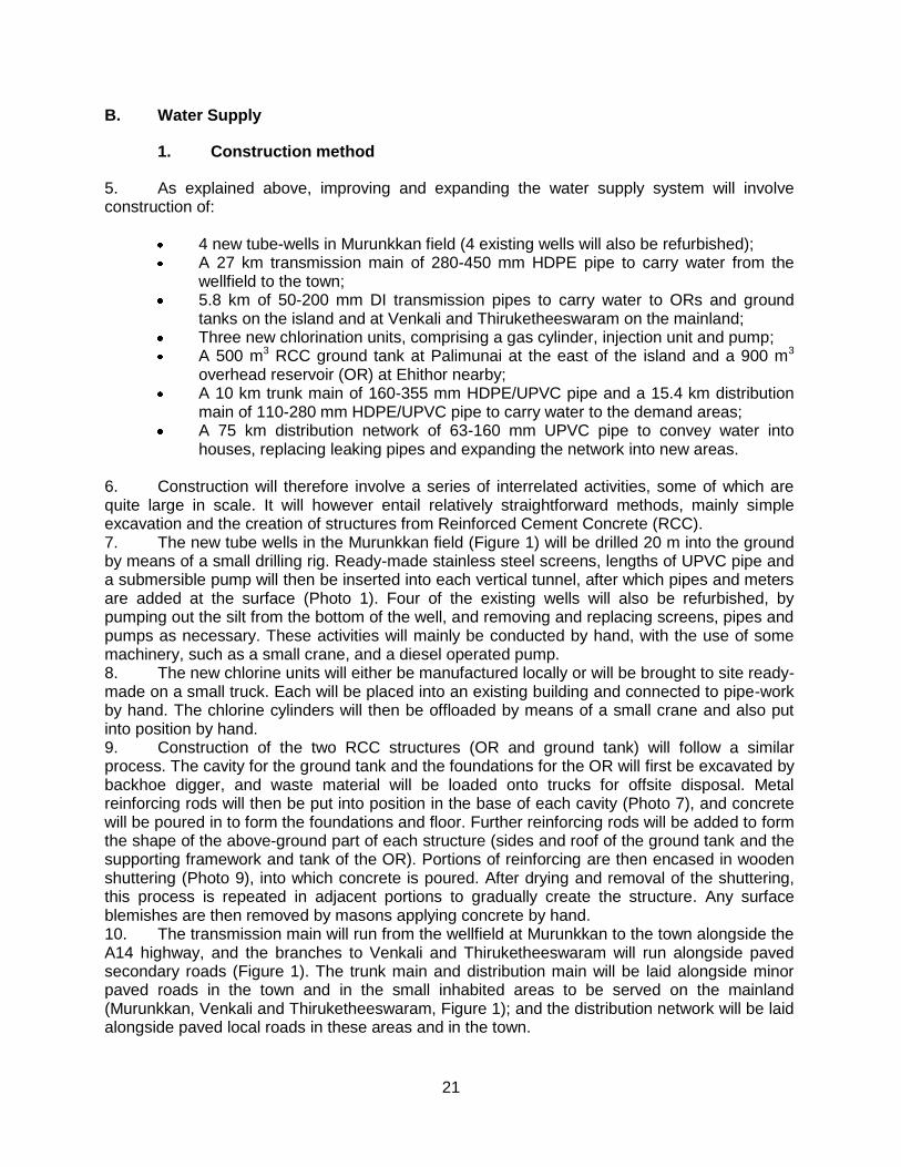
21
B. Water Supply
1. Construction method
5. As explained above, improving and expanding the water supply system will involve construction of:
4 new tube-wells in Murunkkan field (4 existing wells will also be refurbished); A 27 km transmission main of 280-450 mm HDPE pipe to carry water from the
wellfield to the town; 5.8 km of 50-200 mm DI transmission pipes to carry water to ORs and ground
tanks on the island and at Venkali and Thiruketheeswaram on the mainland; Three new chlorination units, comprising a gas cylinder, injection unit and pump; A 500 m3 RCC ground tank at Palimunai at the east of the island and a 900 m3
overhead reservoir (OR) at Ehithor nearby; A 10 km trunk main of 160-355 mm HDPE/UPVC pipe and a 15.4 km distribution
main of 110-280 mm HDPE/UPVC pipe to carry water to the demand areas; A 75 km distribution network of 63-160 mm UPVC pipe to convey water into
houses, replacing leaking pipes and expanding the network into new areas. 6. Construction will therefore involve a series of interrelated activities, some of which are quite large in scale. It will however entail relatively straightforward methods, mainly simple excavation and the creation of structures from Reinforced Cement Concrete (RCC). 7. The new tube wells in the Murunkkan field (Figure 1) will be drilled 20 m into the ground by means of a small drilling rig. Ready-made stainless steel screens, lengths of UPVC pipe and a submersible pump will then be inserted into each vertical tunnel, after which pipes and meters are added at the surface (Photo 1). Four of the existing wells will also be refurbished, by pumping out the silt from the bottom of the well, and removing and replacing screens, pipes and pumps as necessary. These activities will mainly be conducted by hand, with the use of some machinery, such as a small crane, and a diesel operated pump. 8. The new chlorine units will either be manufactured locally or will be brought to site ready-made on a small truck. Each will be placed into an existing building and connected to pipe-work by hand. The chlorine cylinders will then be offloaded by means of a small crane and also put into position by hand. 9. Construction of the two RCC structures (OR and ground tank) will follow a similar process. The cavity for the ground tank and the foundations for the OR will first be excavated by backhoe digger, and waste material will be loaded onto trucks for offsite disposal. Metal reinforcing rods will then be put into position in the base of each cavity (Photo 7), and concrete will be poured in to form the foundations and floor. Further reinforcing rods will be added to form the shape of the above-ground part of each structure (sides and roof of the ground tank and the supporting framework and tank of the OR). Portions of reinforcing are then encased in wooden shuttering (Photo 9), into which concrete is poured. After drying and removal of the shuttering, this process is repeated in adjacent portions to gradually create the structure. Any surface blemishes are then removed by masons applying concrete by hand. 10. The transmission main will run from the wellfield at Murunkkan to the town alongside the A14 highway, and the branches to Venkali and Thiruketheeswaram will run alongside paved secondary roads (Figure 1). The trunk main and distribution main will be laid alongside minor paved roads in the town and in the small inhabited areas to be served on the mainland (Murunkkan, Venkali and Thiruketheeswaram, Figure 1); and the distribution network will be laid alongside paved local roads in these areas and in the town.
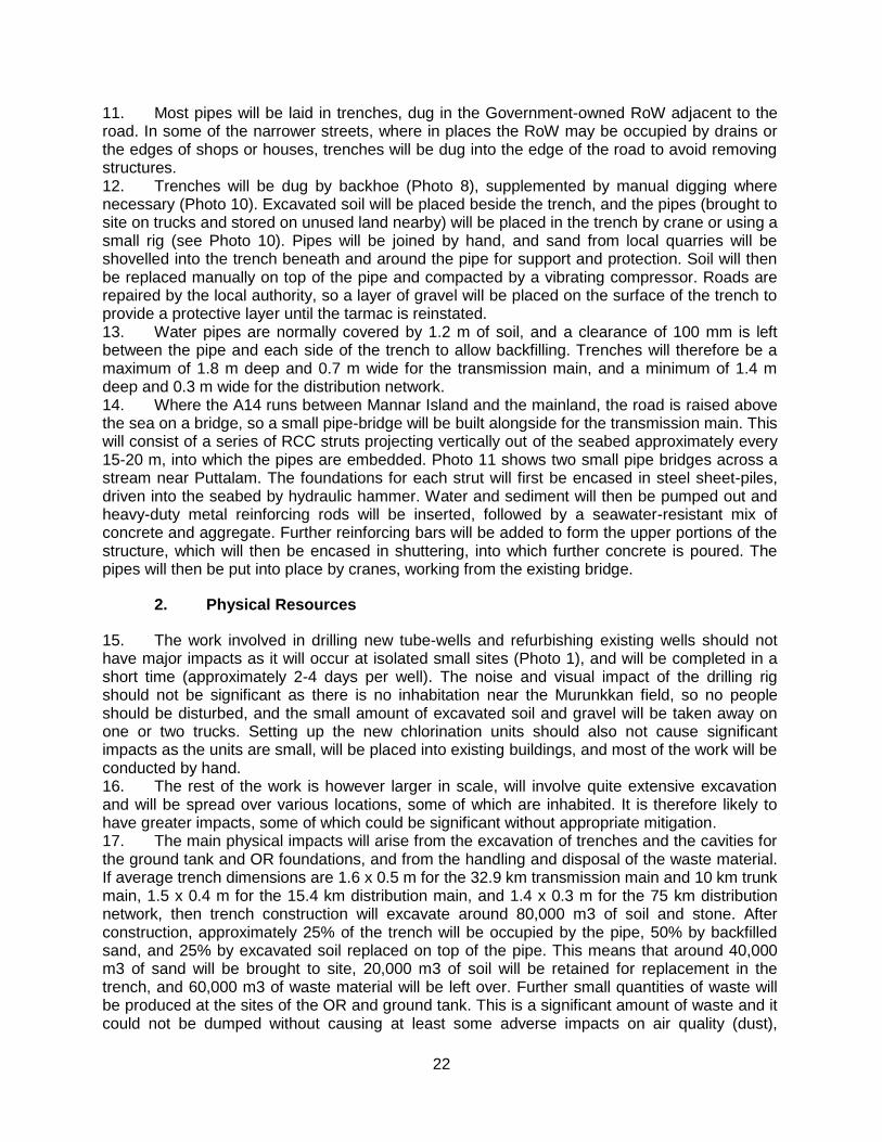
22
11. Most pipes will be laid in trenches, dug in the Government-owned RoW adjacent to the road. In some of the narrower streets, where in places the RoW may be occupied by drains or the edges of shops or houses, trenches will be dug into the edge of the road to avoid removing structures. 12. Trenches will be dug by backhoe (Photo 8), supplemented by manual digging where necessary (Photo 10). Excavated soil will be placed beside the trench, and the pipes (brought to site on trucks and stored on unused land nearby) will be placed in the trench by crane or using a small rig (see Photo 10). Pipes will be joined by hand, and sand from local quarries will be shovelled into the trench beneath and around the pipe for support and protection. Soil will then be replaced manually on top of the pipe and compacted by a vibrating compressor. Roads are repaired by the local authority, so a layer of gravel will be placed on the surface of the trench to provide a protective layer until the tarmac is reinstated. 13. Water pipes are normally covered by 1.2 m of soil, and a clearance of 100 mm is left between the pipe and each side of the trench to allow backfilling. Trenches will therefore be a maximum of 1.8 m deep and 0.7 m wide for the transmission main, and a minimum of 1.4 m deep and 0.3 m wide for the distribution network. 14. Where the A14 runs between Mannar Island and the mainland, the road is raised above the sea on a bridge, so a small pipe-bridge will be built alongside for the transmission main. This will consist of a series of RCC struts projecting vertically out of the seabed approximately every 15-20 m, into which the pipes are embedded. Photo 11 shows two small pipe bridges across a stream near Puttalam. The foundations for each strut will first be encased in steel sheet-piles, driven into the seabed by hydraulic hammer. Water and sediment will then be pumped out and heavy-duty metal reinforcing rods will be inserted, followed by a seawater-resistant mix of concrete and aggregate. Further reinforcing bars will be added to form the upper portions of the structure, which will then be encased in shuttering, into which further concrete is poured. The pipes will then be put into place by cranes, working from the existing bridge.
2. Physical Resources
15. The work involved in drilling new tube-wells and refurbishing existing wells should not have major impacts as it will occur at isolated small sites (Photo 1), and will be completed in a short time (approximately 2-4 days per well). The noise and visual impact of the drilling rig should not be significant as there is no inhabitation near the Murunkkan field, so no people should be disturbed, and the small amount of excavated soil and gravel will be taken away on one or two trucks. Setting up the new chlorination units should also not cause significant impacts as the units are small, will be placed into existing buildings, and most of the work will be conducted by hand. 16. The rest of the work is however larger in scale, will involve quite extensive excavation and will be spread over various locations, some of which are inhabited. It is therefore likely to have greater impacts, some of which could be significant without appropriate mitigation. 17. The main physical impacts will arise from the excavation of trenches and the cavities for the ground tank and OR foundations, and from the handling and disposal of the waste material. If average trench dimensions are 1.6 x 0.5 m for the 32.9 km transmission main and 10 km trunk main, 1.5 x 0.4 m for the 15.4 km distribution main, and 1.4 x 0.3 m for the 75 km distribution network, then trench construction will excavate around 80,000 m3 of soil and stone. After construction, approximately 25% of the trench will be occupied by the pipe, 50% by backfilled sand, and 25% by excavated soil replaced on top of the pipe. This means that around 40,000 m3 of sand will be brought to site, 20,000 m3 of soil will be retained for replacement in the trench, and 60,000 m3 of waste material will be left over. Further small quantities of waste will be produced at the sites of the OR and ground tank. This is a significant amount of waste and it could not be dumped without causing at least some adverse impacts on air quality (dust),
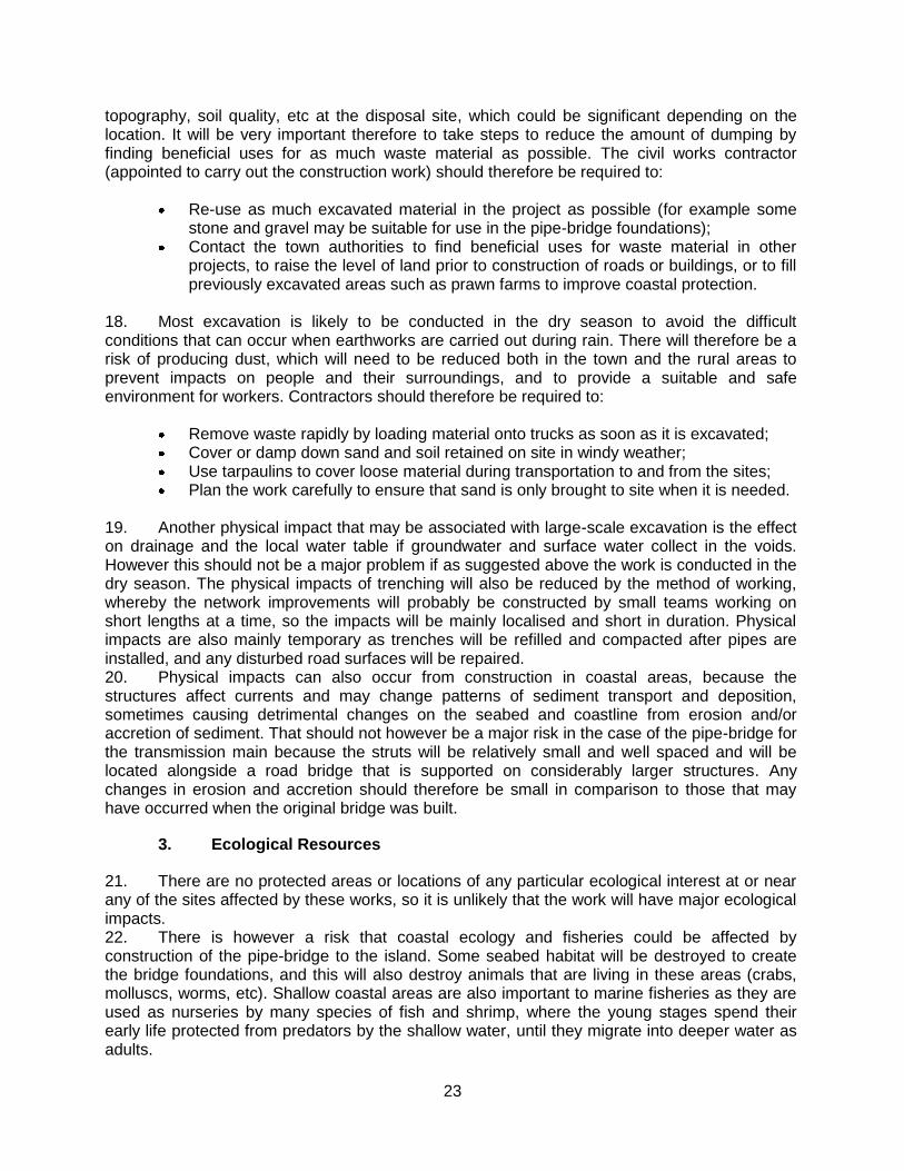
23
topography, soil quality, etc at the disposal site, which could be significant depending on the location. It will be very important therefore to take steps to reduce the amount of dumping by finding beneficial uses for as much waste material as possible. The civil works contractor (appointed to carry out the construction work) should therefore be required to:
Re-use as much excavated material in the project as possible (for example some stone and gravel may be suitable for use in the pipe-bridge foundations);
Contact the town authorities to find beneficial uses for waste material in other projects, to raise the level of land prior to construction of roads or buildings, or to fill previously excavated areas such as prawn farms to improve coastal protection.
18. Most excavation is likely to be conducted in the dry season to avoid the difficult conditions that can occur when earthworks are carried out during rain. There will therefore be a risk of producing dust, which will need to be reduced both in the town and the rural areas to prevent impacts on people and their surroundings, and to provide a suitable and safe environment for workers. Contractors should therefore be required to:
Remove waste rapidly by loading material onto trucks as soon as it is excavated; Cover or damp down sand and soil retained on site in windy weather; Use tarpaulins to cover loose material during transportation to and from the sites; Plan the work carefully to ensure that sand is only brought to site when it is needed.
19. Another physical impact that may be associated with large-scale excavation is the effect on drainage and the local water table if groundwater and surface water collect in the voids. However this should not be a major problem if as suggested above the work is conducted in the dry season. The physical impacts of trenching will also be reduced by the method of working, whereby the network improvements will probably be constructed by small teams working on short lengths at a time, so the impacts will be mainly localised and short in duration. Physical impacts are also mainly temporary as trenches will be refilled and compacted after pipes are installed, and any disturbed road surfaces will be repaired. 20. Physical impacts can also occur from construction in coastal areas, because the structures affect currents and may change patterns of sediment transport and deposition, sometimes causing detrimental changes on the seabed and coastline from erosion and/or accretion of sediment. That should not however be a major risk in the case of the pipe-bridge for the transmission main because the struts will be relatively small and well spaced and will be located alongside a road bridge that is supported on considerably larger structures. Any changes in erosion and accretion should therefore be small in comparison to those that may have occurred when the original bridge was built.
3. Ecological Resources
21. There are no protected areas or locations of any particular ecological interest at or near any of the sites affected by these works, so it is unlikely that the work will have major ecological impacts. 22. There is however a risk that coastal ecology and fisheries could be affected by construction of the pipe-bridge to the island. Some seabed habitat will be destroyed to create the bridge foundations, and this will also destroy animals that are living in these areas (crabs, molluscs, worms, etc). Shallow coastal areas are also important to marine fisheries as they are used as nurseries by many species of fish and shrimp, where the young stages spend their early life protected from predators by the shallow water, until they migrate into deeper water as adults.
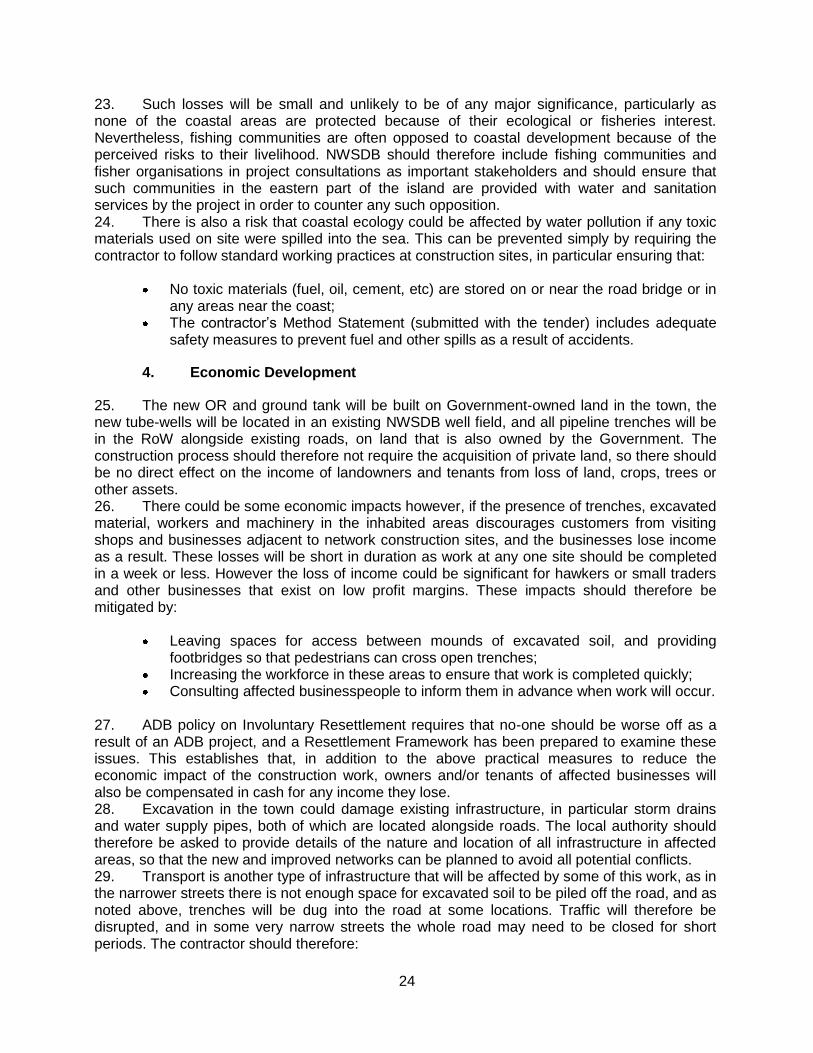
24
23. Such losses will be small and unlikely to be of any major significance, particularly as none of the coastal areas are protected because of their ecological or fisheries interest. Nevertheless, fishing communities are often opposed to coastal development because of the perceived risks to their livelihood. NWSDB should therefore include fishing communities and fisher organisations in project consultations as important stakeholders and should ensure that such communities in the eastern part of the island are provided with water and sanitation services by the project in order to counter any such opposition. 24. There is also a risk that coastal ecology could be affected by water pollution if any toxic materials used on site were spilled into the sea. This can be prevented simply by requiring the contractor to follow standard working practices at construction sites, in particular ensuring that:
No toxic materials (fuel, oil, cement, etc) are stored on or near the road bridge or in any areas near the coast;
The contractor’s Method Statement (submitted with the tender) includes adequate safety measures to prevent fuel and other spills as a result of accidents.
4. Economic Development
25. The new OR and ground tank will be built on Government-owned land in the town, the new tube-wells will be located in an existing NWSDB well field, and all pipeline trenches will be in the RoW alongside existing roads, on land that is also owned by the Government. The construction process should therefore not require the acquisition of private land, so there should be no direct effect on the income of landowners and tenants from loss of land, crops, trees or other assets. 26. There could be some economic impacts however, if the presence of trenches, excavated material, workers and machinery in the inhabited areas discourages customers from visiting shops and businesses adjacent to network construction sites, and the businesses lose income as a result. These losses will be short in duration as work at any one site should be completed in a week or less. However the loss of income could be significant for hawkers or small traders and other businesses that exist on low profit margins. These impacts should therefore be mitigated by:
Leaving spaces for access between mounds of excavated soil, and providing footbridges so that pedestrians can cross open trenches;
Increasing the workforce in these areas to ensure that work is completed quickly; Consulting affected businesspeople to inform them in advance when work will occur.
27. ADB policy on Involuntary Resettlement requires that no-one should be worse off as a result of an ADB project, and a Resettlement Framework has been prepared to examine these issues. This establishes that, in addition to the above practical measures to reduce the economic impact of the construction work, owners and/or tenants of affected businesses will also be compensated in cash for any income they lose. 28. Excavation in the town could damage existing infrastructure, in particular storm drains and water supply pipes, both of which are located alongside roads. The local authority should therefore be asked to provide details of the nature and location of all infrastructure in affected areas, so that the new and improved networks can be planned to avoid all potential conflicts. 29. Transport is another type of infrastructure that will be affected by some of this work, as in the narrower streets there is not enough space for excavated soil to be piled off the road, and as noted above, trenches will be dug into the road at some locations. Traffic will therefore be disrupted, and in some very narrow streets the whole road may need to be closed for short periods. The contractor should therefore:
25
Plan this work with the town authorities and police so that work is carried out during
periods when traffic is known to be lighter; Request the provision of alternative routes and effective diversions where needed; Increase the workforce in these areas to complete the work as soon as practicable.
30. Traffic in and outside the town will also be affected by the increased numbers of heavy vehicles on the roads, particularly trucks removing waste for disposal and vehicles delivering pipes, sand and other materials to site. The contractor should therefore be required to plan this operation carefully in conjunction with the local authorities in order to:
Prevent heavy vehicles entering the town, and where this cannot be avoided ensure that vehicles use main roads only and do not use narrow local roads, except in the immediate vicinity of delivery sites;
Schedule transportation activities to avoid peak traffic periods.
5. Social and Cultural Resources
31. Construction activities inevitably produce noise and dust, and these plus the visual appearance of the site and restrictions in access caused by excavation and the presence of vehicles and machinery, are generally the factors that disturb people who live or work in the vicinity. These should however not be major problems in this case because:
Impacts will be short-lived as at any one location network construction will be completed in a week at most;
People will tolerate this kind of disturbance if they know that their infrastructure and water supply will be improved as a result;
The centre of Mannar is a congested environment that is subject to noise and visual disturbance already, so people are naturally adapted to such conditions.
32. Efforts should still be made to reduce these impacts as far as possible, particularly in residential areas and at sites of social and cultural importance, such as schools, hospitals, churches and temples. This will require the same kind of measures as recommended above to reduce the physical and economic impacts of this work. The contractor should therefore be required to:
Limit dust by removing waste soil quickly, covering and watering stockpiles of soil and sand, and covering loose material with tarpaulins when carried on trucks;
Increase the workforce in sensitive areas to complete the work quickly; Provide wooden bridges for pedestrians and metal sheets for vehicles to allow
access across open trenches to houses and other buildings where required; Use modern vehicles and machinery with standard adaptations to reduce noise and
exhaust emissions and ensure they are maintained to manufacturers’ specifications; Include residents as key stakeholders in public consultation meetings and inform the
community in advance regarding the nature and duration of work in their vicinity. 33. There are also small religious shrines at various sites elsewhere in the study area, particularly in rural locations (Photo 13). Communities should therefore be consulted during the detailed design stage to ascertain whether there are any sites or artefacts of local significance that could be affected by the work. If this is the case it will be necessary to:
26
Adjust locations to avoid any especially sensitive sites; Plan work programmes with the community to avoid working during sensitive times
such as religious festivals.
34. The health and safety of workers and the public will be protected by measures included in a Health and Safety Plan, which the contractor will be required to produce and apply. This should include:
Exclusion of the public from all sites; Provision/use of appropriate Personal Protective Equipment (PPE) by all workers; Health and Safety Training for all site personnel; Documented procedures to be followed for all site activities; Accident reports and records;
35. There would be very significant impacts on people and communities if water supplies were closed down for extended periods when work is conducted on the network. This would be inconvenient in the short term, and there could be health risks if the water supply was unavailable for several successive days or longer. It will therefore be important to take all necessary measures to avoid such a situation. This will require:
Detailed planning of the construction programme to keep the cessation of water supplies to the minimum possible (in both area and duration);
Provision of alternative potable water to affected households and businesses for the duration of the shut-down;
Liaison with affected persons to inform them of any cessation in advance, and to ensure that they are provided with an alternative supply.
36. Construction work can provide short-term socio-economic gains for local communities if contractors employ local people in the workforce. To ensure that these benefits are directed to communities that are affected by the work, contractors should be encouraged to employ at least 50% of their workforce from communities in the vicinity of construction sites (including the transmission main). This will help to mitigate the impacts of any disturbance as well as creating a positive impression of the project. Building a workforce from mainly local people will also avoid problems that can occur if workers are imported, including social difficulties in the host community and issues of health and sanitation in poorly serviced temporary camps.
C. Sanitation
37. The sanitation component will involve construction of a Septage Treatment Facility which will be covered by a separate IEE study.
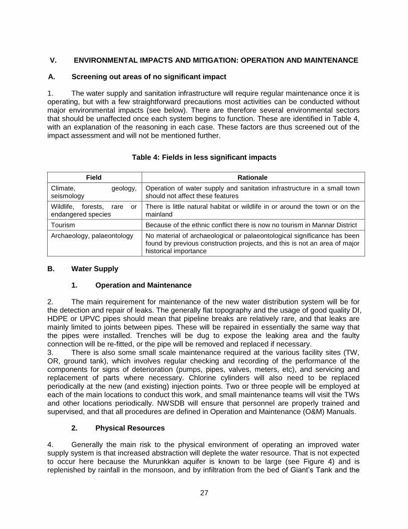
27
V. ENVIRONMENTAL IMPACTS AND MITIGATION: OPERATION AND MAINTENANCE
A. Screening out areas of no significant impact
1. The water supply and sanitation infrastructure will require regular maintenance once it is operating, but with a few straightforward precautions most activities can be conducted without major environmental impacts (see below). There are therefore several environmental sectors that should be unaffected once each system begins to function. These are identified in Table 4, with an explanation of the reasoning in each case. These factors are thus screened out of the impact assessment and will not be mentioned further.
Table 4: Fields in less significant impacts
Field Rationale
Climate, geology, seismology
Operation of water supply and sanitation infrastructure in a small town should not affect these features
Wildlife, forests, rare or endangered species
There is little natural habitat or wildlife in or around the town or on the mainland
Tourism Because of the ethnic conflict there is now no tourism in Mannar District
Archaeology, palaeontology No material of archaeological or palaeontological significance has been found by previous construction projects, and this is not an area of major historical importance
B. Water Supply
1. Operation and Maintenance
2. The main requirement for maintenance of the new water distribution system will be for the detection and repair of leaks. The generally flat topography and the usage of good quality DI, HDPE or UPVC pipes should mean that pipeline breaks are relatively rare, and that leaks are mainly limited to joints between pipes. These will be repaired in essentially the same way that the pipes were installed. Trenches will be dug to expose the leaking area and the faulty connection will be re-fitted, or the pipe will be removed and replaced if necessary. 3. There is also some small scale maintenance required at the various facility sites (TW, OR, ground tank), which involves regular checking and recording of the performance of the components for signs of deterioration (pumps, pipes, valves, meters, etc), and servicing and replacement of parts where necessary. Chlorine cylinders will also need to be replaced periodically at the new (and existing) injection points. Two or three people will be employed at each of the main locations to conduct this work, and small maintenance teams will visit the TWs and other locations periodically. NWSDB will ensure that personnel are properly trained and supervised, and that all procedures are defined in Operation and Maintenance (O&M) Manuals.
2. Physical Resources
4. Generally the main risk to the physical environment of operating an improved water supply system is that increased abstraction will deplete the water resource. That is not expected to occur here because the Murunkkan aquifer is known to be large (see Figure 4) and is replenished by rainfall in the monsoon, and by infiltration from the bed of Giant’s Tank and the
28
many other smaller surface water impoundments in the area. However it is not certain that the proposed rate of abstraction will not deplete the aquifer because, despite the fact that this field is already exploited by NWSDB as the source for the existing Mannar water supply scheme, there are no data on the extent of the aquifer, or its sustainable yield. Such data are a vital prerequisite of any scheme proposing to abstract groundwater as they allow informed decisions on the appropriate locations of tube-wells and levels of abstraction, and ensure that the aquifer is protected from over-exploitation. 5. Depletion of an aquifer can have a range of consequences, and these may include:
Ground subsidence leading to surface damage, which could cause the collapse of buildings and other structures;
Adverse effects on those who are currently using water from the aquifer sustainably (in this case via the many wells in towns and rural areas);
Deterioration in the quality of groundwater from increased infiltration of seawater in coastal areas;
Effects on the ecology of areas that depend on groundwater, via springs, ponds, etc. 6. If this water supply scheme is to be pursued it is imperative that a suitable monitoring programme is designed by an experienced hydrogeologist, to collect the required data. This would include trial boreholes at various locations to establish the extent and potential yield of the aquifer and monitoring over an extended period to determine rates of natural depletion and replenishment. If the data show that sustainable abstraction is not possible then the scheme would need to be redesigned with lower rates of abstraction and a supplementary water source to make up the shortfall. 7. There are also no data on the quality of water in the aquifer, which is also vital before any such scheme is proposed, particularly in a case like this where the only water treatment proposed is basic chlorine disinfection. Given the heavy usage of chemical fertilizers by farmers and the rate at which these can leach into groundwater from over-irrigation, and the lack of proper sanitation and the prevalence of pit latrines, then the quality of the groundwater must be properly examined to determine whether the proposed treatment will produce water of the mandatory legal standards (Appendix 1). During the detailed design stage therefore, NWSDB should:
Decide whether they wish to continue with this scheme as presently proposed; If that is the case, implement a detailed programme to monitor the quality of the
water at the four proposed abstraction points every fortnight for a full year; Redesign the subproject if the data shows that more extensive treatment is
necessary to produce water of the legally required standard; Abandon the subproject if data shows that water cannot be treated to Sri Lankan
drinking water standards, or if treatment would not be cost-effective. 8. If the subproject is implemented, then the physical impacts of operating the other elements of the water supply system should be very minor. If trenches are dug to locate and repair leaks or remove and replace lengths of pipe, the work will follow the same procedure as occurred when the infrastructure was improved. In this case soil and backfilled sand will be removed to expose the leaking junction or pipe, and if necessary a new pipe will be brought to site and replaced. The trench will then be refilled and re-compacted. This work should be very infrequent, and will affect individual small locations for short periods only (an average of a few hours for most repairs). Physical impacts will therefore be negligible. Work will not be conducted during rainfall so there will be no effect on drainage, and the removed material will be replaced
29
in the trench so there will be no waste. There should also be no need to cover excavated material to prevent dust as it will have been wetted by the leaking water.
3. Ecological Resources
9. Depletion of an aquifer can have ecological impacts as noted above. In this case over-abstraction could have quite widespread impacts on aquatic ecology if it increased rates of infiltration from the Giant’s Tank and other surface water bodies, and caused these areas to dry out to a greater extent as a result. This would then increase the desiccation and death of plants and animals at the periphery of the tanks that occurs during the dry season at present. This would not be of major ecological significance as none of the inhabitants of the tanks are known to be rare or of any special ecological value, but it is still an impact that should be avoided. It would also be of greater significance if it affected the small protected area in the Giant’s Tank. This reinforces the need to conduct the studies recommended above to ensure that abstraction is at a rate that does not deplete the aquifer. 10. The remainder of the O&M work at the various facilities and any repairs conducted to the network in or outside the town should not cause any ecological impacts as there is little natural terrestrial vegetation in these areas and no significant ecological resources.
4. Economic Development
11. Repairs to the water supply network could result in shops losing some business if access is difficult for customers whilst the work is carried out. However any losses will be small and short-lived and will probably be at the level of normal business fluctuations, so it should not be necessary to provide compensation. Nevertheless simple steps should be taken to reduce the inconvenience of the works, including:
Informing all residents and businesses about the nature and duration of any work in advance so that they can make preparations if necessary;
Requiring contractors to provide wooden walkways across trenches for pedestrians and metal sheets where vehicle access is required;
Consulting the local police so that work can be planned to avoid traffic disruption as far as possible, and road diversions can be organised if necessary.
12. The improved water supply system will benefit business and residential consumers in the town, but this is unlikely to generate direct economic gains as there are no industries that are significant water users. There may however be small economic benefits from the expected improvements in the overall health of the community (see below) as fewer working days will be lost through sickness for example, so productivity should increase.
5. Social and Cultural Resource
13. Network repair could cause some temporary disruption of activities at locations of social and cultural importance such as schools, clinics, churches, etc, so the same kinds of precautions as employed during the construction period should be adopted. These include:
Completing work in these areas quickly; Providing wooden bridges for pedestrians and metal sheets for vehicles to allow
access across open trenches where required; Using modern vehicles and machinery with standard adaptations to reduce noise
and exhaust emissions;
30
Informing residents about the nature and duration of all such work in advance; Avoiding working during sensitive periods, such as times of religious observance.
14. NWSDB will operate the water supply system and they will employ local contractors to conduct network repairs. To protect both workers and the public, contractors should be required to operate the same kinds of Health and Safety procedures as used in the construction phase. This should include measures to keep the public away from locations in which work is being conducted, and the use of appropriate PPE and construction practices by workers. 15. The use of local contractors will provide economic benefits to the companies and the workers they employ. There is however little prospect of directing these benefits to persons affected by any maintenance or repair works as contractors will utilise their existing workforce. To provide at least some economic benefits to affected communities, persons employed at the various facility sites (ORs, ground tank) should be residents of the neighbouring area. 16. The citizens of the town and the other areas supplied with mains water will be the major beneficiaries of the improved infrastructure, this gives the potential of improving the social capital of these areas, and individual and community health and well-being, providing the improvements in water supply and sanitation are combined with improved sanitary practices. It is very important therefore that the project should fund a campaign of public education to raise awareness of the importance of hand washing, water purification, cleanliness in food preparation, etc. If this is done then the infrastructure and education measures will reduce the incidence of diseases of poor sanitation, such as diarrhoea and dysentery. This should then bring socio-economic benefits as people will spend less on healthcare and lose fewer working days due to illness, so their economic status should improve, as well as their overall health.
C. Sanitation
17. Sanitation part is covered by a separate IEE study.
31
VI. ENVIRONMENTAL IMPACTS AND MITIGATION: LOCATION AND DESIGN
1. ADB Environmental Assessment Guidelines require that an IEE should evaluate impacts due to the location, design, construction and operation of the project. Construction and operation are the two activities in which the project interacts physically with the environment, so they are the two activities during which the environmental impacts occur. In assessing the effects of these processes therefore, all potential impacts of the project are identified, and mitigation is devised for any negative impacts. 2. In many environmental assessments there are certain effects that, although they will occur during either the construction or operation stage, should be considered as impacts primarily of the location or design of the project, as they would not occur if an alternative location or design was chosen. For example, if a weir or dam was built across a riverbed to retain water for abstraction and the reduction in flow affected downstream users and ecology, these would be impacts of the design, as they would not have occurred if groundwater had been used as the source, or if the operating regime had maintained an adequate downstream flow. 3. In the case of these subprojects there are few impacts that can clearly be said to result from either the design or location. This is mainly because of the following:
Although there are many different elements to the project as a whole, with the exception of the water network, most other components will be built at relatively small, discrete sites, where environmental impacts will be very localised;
The manner in which the water network will be constructed (by small teams completing a short length of pipeline before moving on to the next) means that these elements will also have mainly localised impacts;
Despite the number of components, most will involve straightforward construction and low-maintenance operation in an environment that is not especially sensitive, so it is unlikely that there will be major impacts;
Most of the impacts are associated with the construction process, and are produced because that process is invasive, involving trenching and other excavation. However the routine nature of the impacts means that most can be easily mitigated.
4. There are however three impacts that would be a result of the design if they were to occur. These are:
(i) The depletion of the aquifer from abstraction in excess of levels that are replenished naturally;
(ii) Human health problems from the consumption of water of unsuitable quality;
5. The first two impacts would clearly be a result of the design as: depletion of the aquifer would not occur if abstraction was maintained at sustainable levels or if an alternative source was used; consumption of the water would not cause health problems if the quality of the water was properly investigated and more expensive treatment provided if necessary. 6. It should be noted that measures have been recommended above which, if implemented thoroughly, should ensure that these impacts do not occur. These involve:
(i) Monitoring the extent and yield of the aquifer and planning abstraction at sustainable levels;
(ii) Monitoring the quality of water in the aquifer to assess whether chlorination will produce water of the legally required standards, and increasing the level of treatment if necessary;
32
VII. INSTITUTIONAL REQUIREMENTS AND ENVIRONMENTAL MONITORING PLAN
A. Summary of environmental impacts and mitigation measures
1. Error! Reference source not found. lists the potential adverse impacts of the Mannar water supply, sanitation and drainage subprojects and the mitigation proposed to reduce these impacts to acceptable levels. The table also shows how the mitigation will be implemented, who will be responsible, and where and when the mitigation activities will take place. The mitigation programme is shown as the year in which each activity will occur. The final column assesses whether the proposed action will successfully mitigate the impact (shown as 0), and indicates that some of the measures will provide an additional benefit (shown as +).
B. Institutional arrangements for project implementation
2. The main agencies involved in managing and implementing the project (covering both urban and rural components) are as follows: 3. The Ministry of Water Supply and Drainage (MWSD) is the Executing Agency (EA) responsible for management, coordination and execution of all activities funded under the loan; and NWSDB is the Implementing Agency (IA) responsible for supervising construction of the infrastructure and conducting the non-infrastructure elements. 4. NWSDB will establish a Project Coordinating Unit (PCU) at its Head Office in Colombo, responsible for the overall management of the program, and central coordination of the administrative and financial aspects. 5. NWSDB will also establish Protect Implementation Units (PIU) in the NWSDB Regional Offices in Puttalam and Vavuniya, to manage implementation of the project in North-Western and Northern Provinces respectively. Each PIU will be headed by the NWSDB Chief Engineer and staffed by NWSDB personnel.
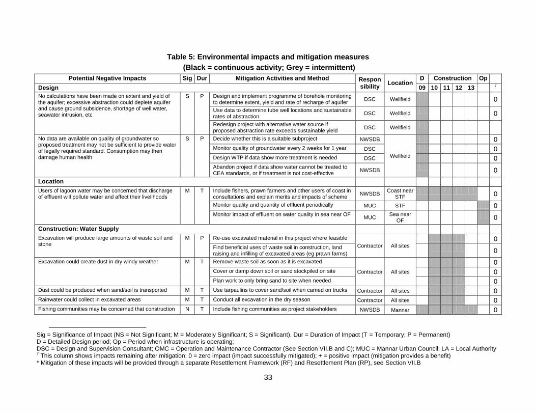
33
Table 5: Environmental impacts and mitigation measures
(Black = continuous activity; Grey = intermittent)
Potential Negative Impacts Sig Dur Mitigation Activities and Method Responsibility
Location D Construction Op
Design 09 10 11 12 13 7
No calculations have been made on extent and yield of the aquifer; excessive abstraction could deplete aquifer and cause ground subsidence, shortage of well water, seawater intrusion, etc
S P Design and implement programme of borehole monitoring to determine extent, yield and rate of recharge of aquifer
DSC Wellfield
0
Use data to determine tube well locations and sustainable rates of abstraction
DSC Wellfield
0
Redesign project with alternative water source if proposed abstraction rate exceeds sustainable yield
DSC Wellfield
No data are available on quality of groundwater so proposed treatment may not be sufficient to provide water of legally required standard. Consumption may then damage human health
S P Decide whether this is a suitable subproject NWSDB
Wellfield
0
Monitor quality of groundwater every 2 weeks for 1 year DSC 0
Design WTP if data show more treatment is needed DSC 0
Abandon project if data show water cannot be treated to CEA standards, or if treatment is not cost-effective
NWSDB
0
Location
Users of lagoon water may be concerned that discharge of effluent will pollute water and affect their livelihoods
M T Include fishers, prawn farmers and other users of coast in consultations and explain merits and impacts of scheme
NWSDB Coast near
STF
0
Monitor quality and quantity of effluent periodically MUC STF 0
Monitor impact of effluent on water quality in sea near OF MUC
Sea near OF
0
Construction: Water Supply
Excavation will produce large amounts of waste soil and stone
M P Re-use excavated material in this project where feasible
Contractor All sites
0
Find beneficial uses of waste soil in construction, land raising and infilling of excavated areas (eg prawn farms)
0
Excavation could create dust in dry windy weather M T Remove waste soil as soon as it is excavated
Contractor All sites
0
Cover or damp down soil or sand stockpiled on site 0
Plan work to only bring sand to site when needed 0
Dust could be produced when sand/soil is transported M T Use tarpaulins to cover sand/soil when carried on trucks Contractor All sites 0
Rainwater could collect in excavated areas M T Conduct all excavation in the dry season Contractor All sites 0
Fishing communities may be concerned that construction N T Include fishing communities as project stakeholders NWSDB Mannar 0
Sig = Significance of Impact (NS = Not Significant; M = Moderately Significant; S = Significant). Dur = Duration of Impact (T = Temporary; P = Permanent) D = Detailed Design period; Op = Period when infrastructure is operating; DSC = Design and Supervision Consultant; OMC = Operation and Maintenance Contractor (See Section VII.B and C); MUC = Mannar Urban Council; LA = Local Authority 7 This column shows impacts remaining after mitigation: 0 = zero impact (impact successfully mitigated); + = positive impact (mitigation provides a benefit)
* Mitigation of these impacts will be provided through a separate Resettlement Framework (RF) and Resettlement Plan (RP), see Section VII.B
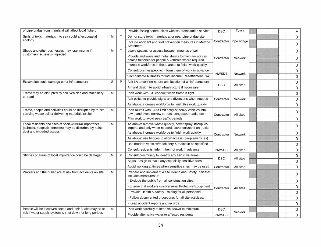
34
of pipe bridge from mainland will affect local fishery Provide fishing communities with water/sanitation service DSC Town +
Spills of toxic materials into sea could affect coastal ecology
M T Do not store toxic materials at or near pipe bridge site
Contractor Pipe bridge
0
Include accident and spill prevention measures in Method Statement
0
Shops and other businesses may lose income if customers’ access is impeded
M T Leave spaces for access between mounds of soil
Contractor Network
0
Provide walkways and metal sheets to maintain access across trenches for people & vehicles where required
0
Increase workforce in these areas to finish work quickly 0
Consult businesspeople: inform them of work in advance NWSDB Network
0
*Compensate business for lost income: Resettlement Fwk 0
Excavation could damage other infrastructure S P Ask LA to confirm nature and location of all infrastructure DSC All sites
0
Amend design to avoid infrastructure if necessary 0
Traffic may be disrupted by soil, vehicles and machinery on road
M T Plan work with LA: conduct when traffic is light
Contractor Network
0
Ask police to provide signs and diversions when needed 0
As above: increase workforce to finish this work quickly 0
Traffic, people and activities could be disrupted by trucks carrying waste soil or delivering materials to site
M T Plan routes with LA to limit entry of heavy vehicles into town, and avoid narrow streets, congested roads, etc Contractor All sites
0
Plan work to avoid peak traffic periods 0
Local residents and sites of social/cultural importance (schools, hospitals, temples) may be disturbed by noise, dust and impeded access
M T As above: remove waste quickly, cover/spray stockpiles, imports and only when needed, cover soil/sand on trucks
Contractor Network
0
As above: increase workforce to finish work quickly 0
As above: use bridges to allow access (people/vehicles) 0
Use modern vehicles/machinery & maintain as specified 0
Consult residents; inform them of work in advance NWSDB All sites 0
Shrines or areas of local importance could be damaged M P Consult community to identify any sensitive areas DSC All sites
0
Adjust design to avoid any especially sensitive sites 0
Avoid working at times when sensitive sites may be used Contractor All sites 0
Workers and the public are at risk from accidents on site M T Prepare and implement a site Health and Safety Plan that includes measures to:
Contractor All sites
0
- Exclude the public from all construction sites; 0
- Ensure that workers use Personal Protective Equipment 0
- Provide Health & Safety Training for all personnel; 0
- Follow documented procedures for all site activities; 0
- Keep accident reports and records. 0
People will be inconvenienced and their health may be at risk if water supply system is shut down for long periods
M T Plan work carefully to keep shutdown to minimum DSC Network
0
Provide alternative water to affected residents NWSDB 0
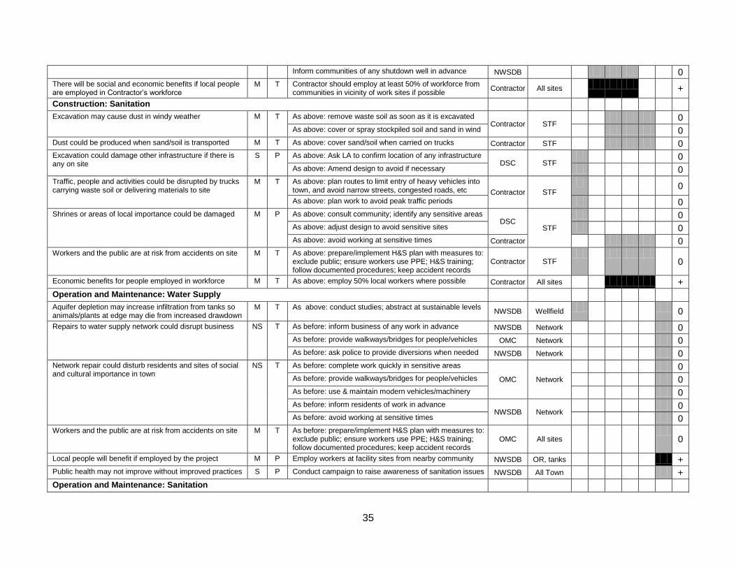
35
Inform communities of any shutdown well in advance NWSDB 0
There will be social and economic benefits if local people are employed in Contractor’s workforce
M T Contractor should employ at least 50% of workforce from communities in vicinity of work sites if possible
Contractor All sites
+
Construction: Sanitation
Excavation may cause dust in windy weather M T As above: remove waste soil as soon as it is excavated Contractor STF
0
As above: cover or spray stockpiled soil and sand in wind 0
Dust could be produced when sand/soil is transported M T As above: cover sand/soil when carried on trucks Contractor STF 0
Excavation could damage other infrastructure if there is any on site
S P As above: Ask LA to confirm location of any infrastructure DSC STF
0
As above: Amend design to avoid if necessary 0
Traffic, people and activities could be disrupted by trucks carrying waste soil or delivering materials to site
M T As above: plan routes to limit entry of heavy vehicles into town, and avoid narrow streets, congested roads, etc Contractor STF
0
As above: plan work to avoid peak traffic periods 0
Shrines or areas of local importance could be damaged M P As above: consult community; identify any sensitive areas DSC
STF
0
As above: adjust design to avoid sensitive sites 0
As above: avoid working at sensitive times Contractor 0
Workers and the public are at risk from accidents on site M T As above: prepare/implement H&S plan with measures to: exclude public; ensure workers use PPE; H&S training; follow documented procedures; keep accident records
Contractor STF
0
Economic benefits for people employed in workforce M T As above: employ 50% local workers where possible Contractor All sites +
Operation and Maintenance: Water Supply
Aquifer depletion may increase infiltration from tanks so animals/plants at edge may die from increased drawdown
M T As above: conduct studies; abstract at sustainable levels NWSDB Wellfield
0
Repairs to water supply network could disrupt business NS T As before: inform business of any work in advance NWSDB Network 0
As before: provide walkways/bridges for people/vehicles OMC Network 0
As before: ask police to provide diversions when needed NWSDB Network 0
Network repair could disturb residents and sites of social and cultural importance in town
NS T As before: complete work quickly in sensitive areas
OMC Network
0
As before: provide walkways/bridges for people/vehicles 0
As before: use & maintain modern vehicles/machinery 0
As before: inform residents of work in advance NWSDB Network
0
As before: avoid working at sensitive times 0
Workers and the public are at risk from accidents on site M T As before: prepare/implement H&S plan with measures to: exclude public; ensure workers use PPE; H&S training; follow documented procedures; keep accident records
OMC All sites
0
Local people will benefit if employed by the project M P Employ workers at facility sites from nearby community NWSDB OR, tanks +
Public health may not improve without improved practices S P Conduct campaign to raise awareness of sanitation issues NWSDB All Town +
Operation and Maintenance: Sanitation
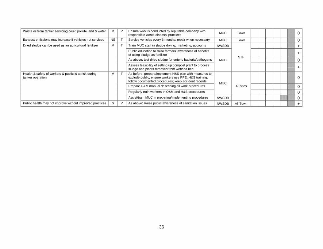
36
Waste oil from tanker servicing could pollute land & water M P Ensure work is conducted by reputable company with responsible waste disposal practices
MUC Town
0
Exhaust emissions may increase if vehicles not serviced NS T Service vehicles every 6 months; repair when necessary MUC Town 0
Dried sludge can be used as an agricultural fertilizer M T Train MUC staff in sludge drying, marketing, accounts NWSDB
STF
+
Public education to raise farmers’ awareness of benefits of using sludge as fertilizer
MUC
+
As above: test dried sludge for enteric bacteria/pathogens 0
Assess feasibility of setting up compost plant to process sludge and plants removed from wetland bed
+
Health & safety of workers & public is at risk during tanker operation
M T As before: prepare/implement H&S plan with measures to: exclude public; ensure workers use PPE; H&S training; follow documented procedures; keep accident records
MUC All sites
0
Prepare O&M manual describing all work procedures 0
Regularly train workers in O&M and H&S procedures 0
Assist/train MUC in preparing/implementing procedures NWSDB 0
Public health may not improve without improved practices S P As above: Raise public awareness of sanitation issues NWSDB All Town +
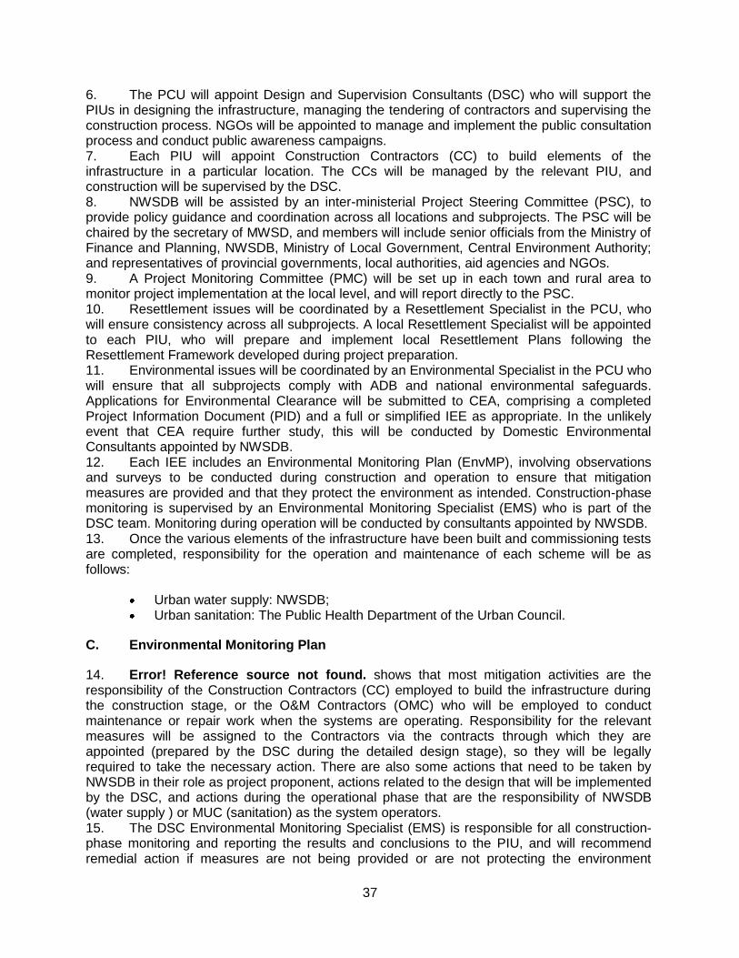
37
6. The PCU will appoint Design and Supervision Consultants (DSC) who will support the PIUs in designing the infrastructure, managing the tendering of contractors and supervising the construction process. NGOs will be appointed to manage and implement the public consultation process and conduct public awareness campaigns. 7. Each PIU will appoint Construction Contractors (CC) to build elements of the infrastructure in a particular location. The CCs will be managed by the relevant PIU, and construction will be supervised by the DSC. 8. NWSDB will be assisted by an inter-ministerial Project Steering Committee (PSC), to provide policy guidance and coordination across all locations and subprojects. The PSC will be chaired by the secretary of MWSD, and members will include senior officials from the Ministry of Finance and Planning, NWSDB, Ministry of Local Government, Central Environment Authority; and representatives of provincial governments, local authorities, aid agencies and NGOs. 9. A Project Monitoring Committee (PMC) will be set up in each town and rural area to monitor project implementation at the local level, and will report directly to the PSC. 10. Resettlement issues will be coordinated by a Resettlement Specialist in the PCU, who will ensure consistency across all subprojects. A local Resettlement Specialist will be appointed to each PIU, who will prepare and implement local Resettlement Plans following the Resettlement Framework developed during project preparation. 11. Environmental issues will be coordinated by an Environmental Specialist in the PCU who will ensure that all subprojects comply with ADB and national environmental safeguards. Applications for Environmental Clearance will be submitted to CEA, comprising a completed Project Information Document (PID) and a full or simplified IEE as appropriate. In the unlikely event that CEA require further study, this will be conducted by Domestic Environmental Consultants appointed by NWSDB. 12. Each IEE includes an Environmental Monitoring Plan (EnvMP), involving observations and surveys to be conducted during construction and operation to ensure that mitigation measures are provided and that they protect the environment as intended. Construction-phase monitoring is supervised by an Environmental Monitoring Specialist (EMS) who is part of the DSC team. Monitoring during operation will be conducted by consultants appointed by NWSDB. 13. Once the various elements of the infrastructure have been built and commissioning tests are completed, responsibility for the operation and maintenance of each scheme will be as follows:
Urban water supply: NWSDB; Urban sanitation: The Public Health Department of the Urban Council.
C. Environmental Monitoring Plan
14. Error! Reference source not found. shows that most mitigation activities are the responsibility of the Construction Contractors (CC) employed to build the infrastructure during the construction stage, or the O&M Contractors (OMC) who will be employed to conduct maintenance or repair work when the systems are operating. Responsibility for the relevant measures will be assigned to the Contractors via the contracts through which they are appointed (prepared by the DSC during the detailed design stage), so they will be legally required to take the necessary action. There are also some actions that need to be taken by NWSDB in their role as project proponent, actions related to the design that will be implemented by the DSC, and actions during the operational phase that are the responsibility of NWSDB (water supply ) or MUC (sanitation) as the system operators. 15. The DSC Environmental Monitoring Specialist (EMS) is responsible for all construction-phase monitoring and reporting the results and conclusions to the PIU, and will recommend remedial action if measures are not being provided or are not protecting the environment
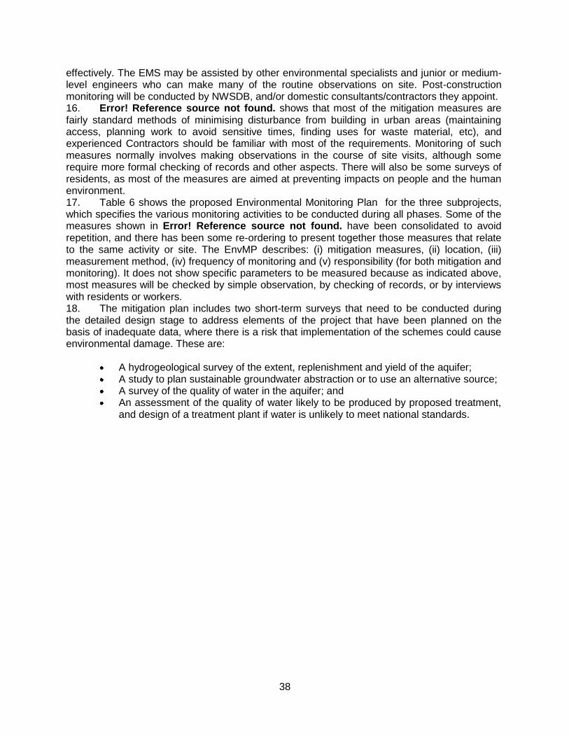
38
effectively. The EMS may be assisted by other environmental specialists and junior or medium-level engineers who can make many of the routine observations on site. Post-construction monitoring will be conducted by NWSDB, and/or domestic consultants/contractors they appoint. 16. Error! Reference source not found. shows that most of the mitigation measures are fairly standard methods of minimising disturbance from building in urban areas (maintaining access, planning work to avoid sensitive times, finding uses for waste material, etc), and experienced Contractors should be familiar with most of the requirements. Monitoring of such measures normally involves making observations in the course of site visits, although some require more formal checking of records and other aspects. There will also be some surveys of residents, as most of the measures are aimed at preventing impacts on people and the human environment. 17. Table 6 shows the proposed Environmental Monitoring Plan for the three subprojects, which specifies the various monitoring activities to be conducted during all phases. Some of the measures shown in Error! Reference source not found. have been consolidated to avoid repetition, and there has been some re-ordering to present together those measures that relate to the same activity or site. The EnvMP describes: (i) mitigation measures, (ii) location, (iii) measurement method, (iv) frequency of monitoring and (v) responsibility (for both mitigation and monitoring). It does not show specific parameters to be measured because as indicated above, most measures will be checked by simple observation, by checking of records, or by interviews with residents or workers. 18. The mitigation plan includes two short-term surveys that need to be conducted during the detailed design stage to address elements of the project that have been planned on the basis of inadequate data, where there is a risk that implementation of the schemes could cause environmental damage. These are:
A hydrogeological survey of the extent, replenishment and yield of the aquifer; A study to plan sustainable groundwater abstraction or to use an alternative source; A survey of the quality of water in the aquifer; and An assessment of the quality of water likely to be produced by proposed treatment,
and design of a treatment plant if water is unlikely to meet national standards.
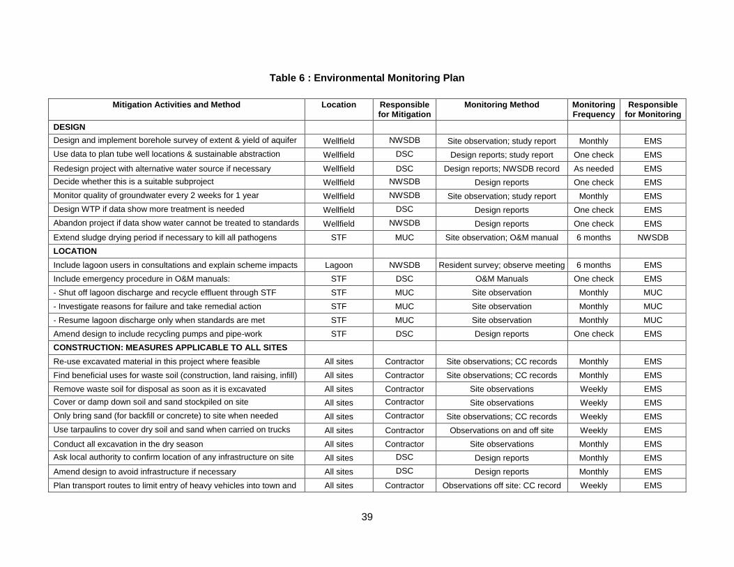
39
Table 6 : Environmental Monitoring Plan
Mitigation Activities and Method Location Responsible for Mitigation
Monitoring Method Monitoring Frequency
Responsible for Monitoring
DESIGN
Design and implement borehole survey of extent & yield of aquifer Wellfield NWSDB Site observation; study report Monthly EMS
Use data to plan tube well locations & sustainable abstraction Wellfield DSC Design reports; study report One check EMS
Redesign project with alternative water source if necessary Wellfield DSC Design reports; NWSDB record As needed EMS
Decide whether this is a suitable subproject Wellfield NWSDB Design reports One check EMS
Monitor quality of groundwater every 2 weeks for 1 year Wellfield NWSDB Site observation; study report Monthly EMS
Design WTP if data show more treatment is needed Wellfield DSC Design reports One check EMS
Abandon project if data show water cannot be treated to standards Wellfield NWSDB Design reports One check EMS
Extend sludge drying period if necessary to kill all pathogens STF MUC Site observation; O&M manual 6 months NWSDB
LOCATION
Include lagoon users in consultations and explain scheme impacts Lagoon NWSDB Resident survey; observe meeting 6 months EMS
Include emergency procedure in O&M manuals: STF DSC O&M Manuals One check EMS
- Shut off lagoon discharge and recycle effluent through STF STF MUC Site observation Monthly MUC
- Investigate reasons for failure and take remedial action STF MUC Site observation Monthly MUC
- Resume lagoon discharge only when standards are met STF MUC Site observation Monthly MUC
Amend design to include recycling pumps and pipe-work STF DSC Design reports One check EMS
CONSTRUCTION: MEASURES APPLICABLE TO ALL SITES
Re-use excavated material in this project where feasible All sites Contractor Site observations; CC records Monthly EMS
Find beneficial uses for waste soil (construction, land raising, infill) All sites Contractor Site observations; CC records Monthly EMS
Remove waste soil for disposal as soon as it is excavated All sites Contractor Site observations Weekly EMS
Cover or damp down soil and sand stockpiled on site All sites Contractor Site observations Weekly EMS
Only bring sand (for backfill or concrete) to site when needed All sites Contractor Site observations; CC records Weekly EMS
Use tarpaulins to cover dry soil and sand when carried on trucks All sites Contractor Observations on and off site Weekly EMS
Conduct all excavation in the dry season All sites Contractor Site observations Monthly EMS
Ask local authority to confirm location of any infrastructure on site All sites DSC Design reports Monthly EMS
Amend design to avoid infrastructure if necessary All sites DSC Design reports Monthly EMS
Plan transport routes to limit entry of heavy vehicles into town and All sites Contractor Observations off site: CC record Weekly EMS
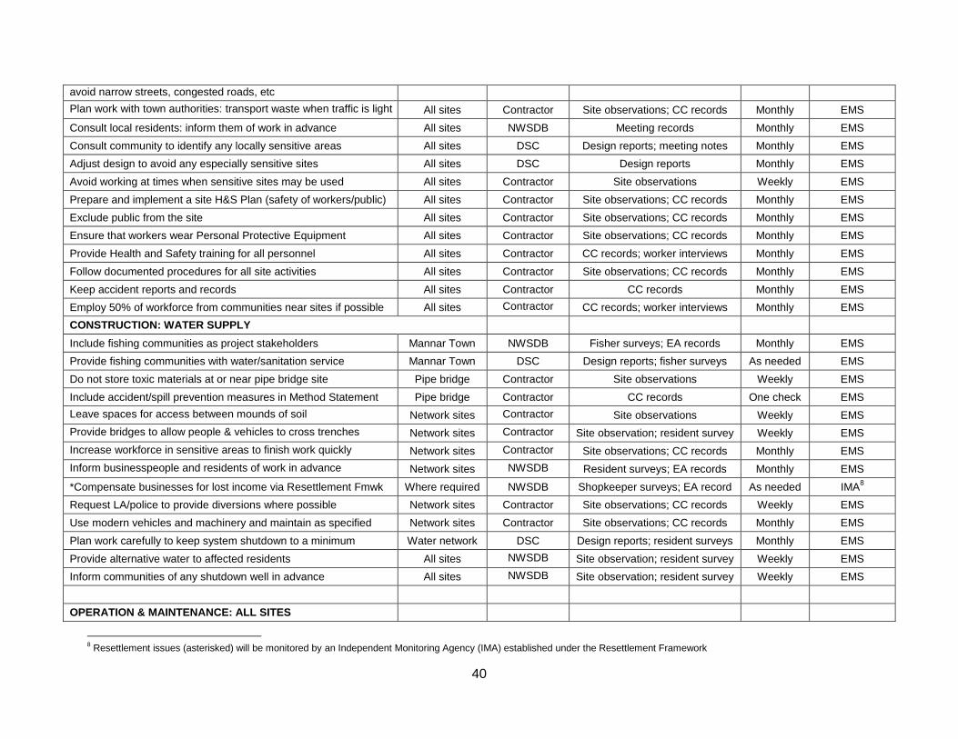
40
avoid narrow streets, congested roads, etc
Plan work with town authorities: transport waste when traffic is light All sites Contractor Site observations; CC records Monthly EMS
Consult local residents: inform them of work in advance All sites NWSDB Meeting records Monthly EMS
Consult community to identify any locally sensitive areas All sites DSC Design reports; meeting notes Monthly EMS
Adjust design to avoid any especially sensitive sites All sites DSC Design reports Monthly EMS
Avoid working at times when sensitive sites may be used All sites Contractor Site observations Weekly EMS
Prepare and implement a site H&S Plan (safety of workers/public) All sites Contractor Site observations; CC records Monthly EMS
Exclude public from the site All sites Contractor Site observations; CC records Monthly EMS
Ensure that workers wear Personal Protective Equipment All sites Contractor Site observations; CC records Monthly EMS
Provide Health and Safety training for all personnel All sites Contractor CC records; worker interviews Monthly EMS
Follow documented procedures for all site activities All sites Contractor Site observations; CC records Monthly EMS
Keep accident reports and records All sites Contractor CC records Monthly EMS
Employ 50% of workforce from communities near sites if possible All sites Contractor CC records; worker interviews Monthly EMS
CONSTRUCTION: WATER SUPPLY
Include fishing communities as project stakeholders Mannar Town NWSDB Fisher surveys; EA records Monthly EMS
Provide fishing communities with water/sanitation service Mannar Town DSC Design reports; fisher surveys As needed EMS
Do not store toxic materials at or near pipe bridge site Pipe bridge Contractor Site observations Weekly EMS
Include accident/spill prevention measures in Method Statement Pipe bridge Contractor CC records One check EMS
Leave spaces for access between mounds of soil Network sites Contractor Site observations Weekly EMS
Provide bridges to allow people & vehicles to cross trenches Network sites Contractor Site observation; resident survey Weekly EMS
Increase workforce in sensitive areas to finish work quickly Network sites Contractor Site observations; CC records Monthly EMS
Inform businesspeople and residents of work in advance Network sites NWSDB Resident surveys; EA records Monthly EMS
*Compensate businesses for lost income via Resettlement Fmwk Where required NWSDB Shopkeeper surveys; EA record As needed IMA8
Request LA/police to provide diversions where possible Network sites Contractor Site observations; CC records Weekly EMS
Use modern vehicles and machinery and maintain as specified Network sites Contractor Site observations; CC records Monthly EMS
Plan work carefully to keep system shutdown to a minimum Water network DSC Design reports; resident surveys Monthly EMS
Provide alternative water to affected residents All sites NWSDB Site observation; resident survey Weekly EMS
Inform communities of any shutdown well in advance All sites NWSDB Site observation; resident survey Weekly EMS
OPERATION & MAINTENANCE: ALL SITES
8 Resettlement issues (asterisked) will be monitored by an Independent Monitoring Agency (IMA) established under the Resettlement Framework
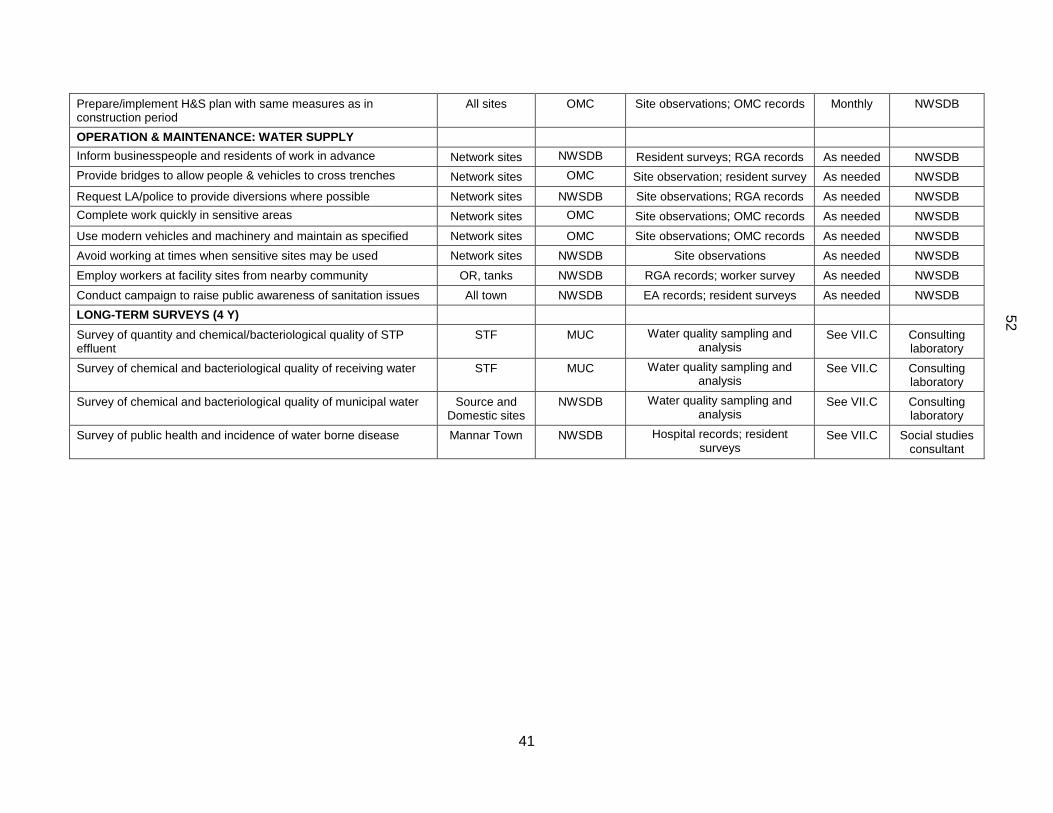
41
Prepare/implement H&S plan with same measures as in construction period
All sites OMC Site observations; OMC records Monthly NWSDB
OPERATION & MAINTENANCE: WATER SUPPLY
Inform businesspeople and residents of work in advance Network sites NWSDB Resident surveys; RGA records As needed NWSDB
Provide bridges to allow people & vehicles to cross trenches Network sites OMC Site observation; resident survey As needed NWSDB
Request LA/police to provide diversions where possible Network sites NWSDB Site observations; RGA records As needed NWSDB
Complete work quickly in sensitive areas Network sites OMC Site observations; OMC records As needed NWSDB
Use modern vehicles and machinery and maintain as specified Network sites OMC Site observations; OMC records As needed NWSDB
Avoid working at times when sensitive sites may be used Network sites NWSDB Site observations As needed NWSDB
Employ workers at facility sites from nearby community OR, tanks NWSDB RGA records; worker survey As needed NWSDB
Conduct campaign to raise public awareness of sanitation issues All town NWSDB EA records; resident surveys As needed NWSDB
LONG-TERM SURVEYS (4 Y)
Survey of quantity and chemical/bacteriological quality of STP effluent
STF MUC Water quality sampling and analysis
See VII.C Consulting laboratory
Survey of chemical and bacteriological quality of receiving water STF MUC Water quality sampling and analysis
See VII.C Consulting laboratory
Survey of chemical and bacteriological quality of municipal water Source and Domestic sites
NWSDB Water quality sampling and analysis
See VII.C Consulting laboratory
Survey of public health and incidence of water borne disease Mannar Town NWSDB Hospital records; resident surveys
See VII.C Social studies consultant
52

42
19. Qualified domestic consultants will be appointed by NWSDB to conduct these surveys and studies. Both surveys will require a year of data collection, which will begin as soon as possible.
D. Environmental management and monitoring costs
20. Most of the mitigation measures require the contractors to adopt good site practice, which should be part of their normal procedures already, so there are unlikely to be major costs associated with compliance. Regardless of this, any costs of mitigation by the contractors (those employed to construct the infrastructure or the local companies employed to conduct O&M when the system is operating) are included in the budgets for the civil works and do not need to be estimated separately here. Mitigation that is the responsibility of NWSDB will be provided as part of their management of the project, so this also does not need to be duplicated here. Costs of compensating shopkeepers for loss of income during construction in the town are calculated separately in the budgets for the Resettlement Framework and Resettlement Plans so are also excluded from this analysis. 21. The remaining actions in the Environmental Monitoring Plan are:
The environmental monitoring during construction, conducted by the EMS; The short-term surveys of the quality and quantity of water in the aquifer; Assessment and re-design if necessary of the proposed water supply and treatment; The long-term post-construction surveys that will be commissioned by NWSDB.
22. These have not been budgeted elsewhere, and their costs are shown in Table 7, with details of the calculations shown in footnotes beneath the table. The figures show that the total cost of environmental management and monitoring for the Mannar subprojects is SLR 6.2 million, ie US$ 57,000, plus the cost of the hydrogeological survey.
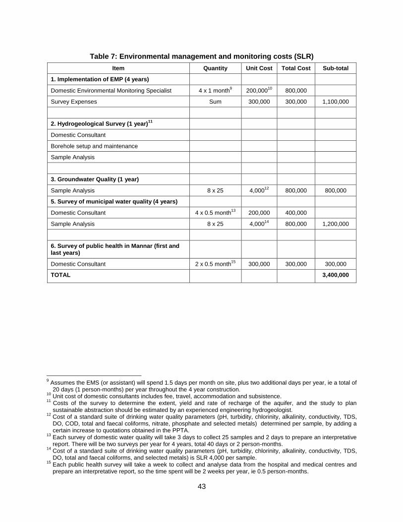
43
Table 7: Environmental management and monitoring costs (SLR)
Item Quantity Unit Cost Total Cost Sub-total
1. Implementation of EMP (4 years)
Domestic Environmental Monitoring Specialist 4 x 1 month9 200,000
10 800,000
Survey Expenses Sum 300,000 300,000 1,100,000
2. Hydrogeological Survey (1 year)11
Domestic Consultant
Borehole setup and maintenance
Sample Analysis
3. Groundwater Quality (1 year)
Sample Analysis 8 x 25 4,00012
800,000 800,000
5. Survey of municipal water quality (4 years)
Domestic Consultant 4 x 0.5 month13
200,000 400,000
Sample Analysis 8 x 25 4,00014
800,000 1,200,000
6. Survey of public health in Mannar (first and last years)
Domestic Consultant 2 x 0.5 month15
300,000 300,000 300,000
TOTAL 3,400,000
9 Assumes the EMS (or assistant) will spend 1.5 days per month on site, plus two additional days per year, ie a total of
20 days (1 person-months) per year throughout the 4 year construction. 10
Unit cost of domestic consultants includes fee, travel, accommodation and subsistence. 11
Costs of the survey to determine the extent, yield and rate of recharge of the aquifer, and the study to plan sustainable abstraction should be estimated by an experienced engineering hydrogeologist.
12 Cost of a standard suite of drinking water quality parameters (pH, turbidity, chlorinity, alkalinity, conductivity, TDS, DO, COD, total and faecal coliforms, nitrate, phosphate and selected metals) determined per sample, by adding a certain increase to quotations obtained in the PPTA.
13 Each survey of domestic water quality will take 3 days to collect 25 samples and 2 days to prepare an interpretative report. There will be two surveys per year for 4 years, total 40 days or 2 person-months.
14 Cost of a standard suite of drinking water quality parameters (pH, turbidity, chlorinity, alkalinity, conductivity, TDS, DO, total and faecal coliforms, and selected metals) is SLR 4,000 per sample.
15 Each public health survey will take a week to collect and analyse data from the hospital and medical centres and prepare an interpretative report, so the time spent will be 2 weeks per year, ie 0.5 person-months.
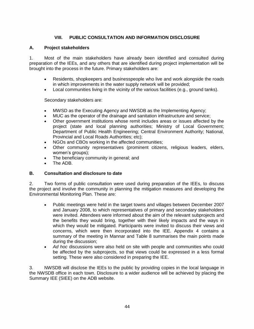
44
VIII. PUBLIC CONSULTATION AND INFORMATION DISCLOSURE
A. Project stakeholders
1. Most of the main stakeholders have already been identified and consulted during preparation of the IEEs, and any others that are identified during project implementation will be brought into the process in the future. Primary stakeholders are:
Residents, shopkeepers and businesspeople who live and work alongside the roads in which improvements in the water supply network will be provided;
Local communities living in the vicinity of the various facilities (e.g., ground tanks).
Secondary stakeholders are:
MWSD as the Executing Agency and NWSDB as the Implementing Agency; MUC as the operator of the drainage and sanitation infrastructure and service; Other government institutions whose remit includes areas or issues affected by the
project (state and local planning authorities; Ministry of Local Government; Department of Public Health Engineering; Central Environment Authority; National, Provincial and Local Roads Authorities; etc);
NGOs and CBOs working in the affected communities; Other community representatives (prominent citizens, religious leaders, elders,
women’s groups); The beneficiary community in general; and The ADB.
B. Consultation and disclosure to date
2. Two forms of public consultation were used during preparation of the IEEs, to discuss the project and involve the community in planning the mitigation measures and developing the Environmental Monitoring Plan. These are:
Public meetings were held in the target towns and villages between December 2007 and January 2008, to which representatives of primary and secondary stakeholders were invited. Attendees were informed about the aim of the relevant subprojects and the benefits they would bring, together with their likely impacts and the ways in which they would be mitigated. Participants were invited to discuss their views and concerns, which were then incorporated into the IEE. Appendix 4 contains a summary of the meeting in Mannar and Table 8 summarises the main points made during the discussion;
Ad hoc discussions were also held on site with people and communities who could be affected by the subprojects, so that views could be expressed in a less formal setting. These were also considered in preparing the IEE.
3. NWSDB will disclose the IEEs to the public by providing copies in the local language in the NWSDB office in each town. Disclosure to a wider audience will be achieved by placing the Summary IEE (SIEE) on the ADB website.
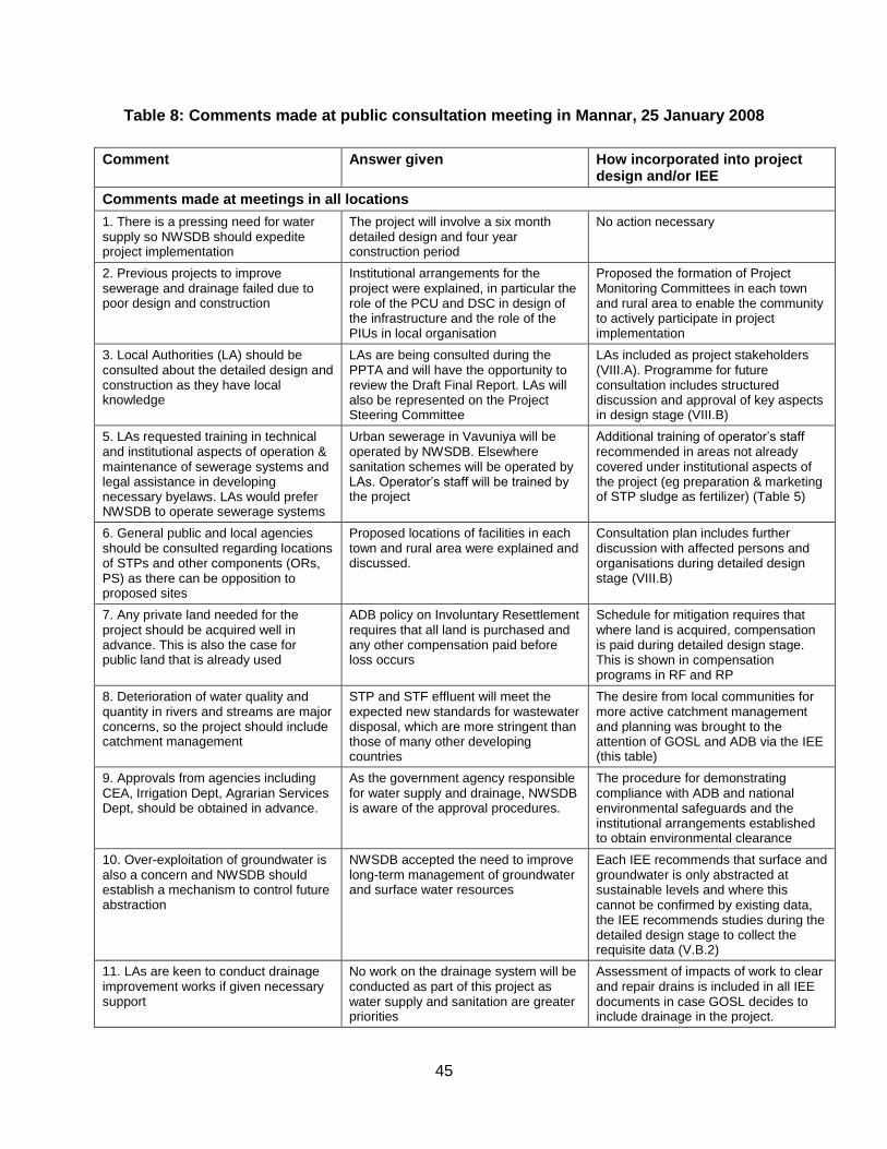
45
Table 8: Comments made at public consultation meeting in Mannar, 25 January 2008
Comment Answer given How incorporated into project design and/or IEE
Comments made at meetings in all locations
1. There is a pressing need for water supply so NWSDB should expedite project implementation
The project will involve a six month detailed design and four year construction period
No action necessary
2. Previous projects to improve sewerage and drainage failed due to poor design and construction
Institutional arrangements for the project were explained, in particular the role of the PCU and DSC in design of the infrastructure and the role of the PIUs in local organisation
Proposed the formation of Project Monitoring Committees in each town and rural area to enable the community to actively participate in project implementation
3. Local Authorities (LA) should be consulted about the detailed design and construction as they have local knowledge
LAs are being consulted during the PPTA and will have the opportunity to review the Draft Final Report. LAs will also be represented on the Project Steering Committee
LAs included as project stakeholders (VIII.A). Programme for future consultation includes structured discussion and approval of key aspects in design stage (VIII.B)
5. LAs requested training in technical and institutional aspects of operation & maintenance of sewerage systems and legal assistance in developing necessary byelaws. LAs would prefer NWSDB to operate sewerage systems
Urban sewerage in Vavuniya will be operated by NWSDB. Elsewhere sanitation schemes will be operated by LAs. Operator’s staff will be trained by the project
Additional training of operator’s staff recommended in areas not already covered under institutional aspects of the project (eg preparation & marketing of STP sludge as fertilizer) (Table 5)
6. General public and local agencies should be consulted regarding locations of STPs and other components (ORs, PS) as there can be opposition to proposed sites
Proposed locations of facilities in each town and rural area were explained and discussed.
Consultation plan includes further discussion with affected persons and organisations during detailed design stage (VIII.B)
7. Any private land needed for the project should be acquired well in advance. This is also the case for public land that is already used
ADB policy on Involuntary Resettlement requires that all land is purchased and any other compensation paid before loss occurs
Schedule for mitigation requires that where land is acquired, compensation is paid during detailed design stage. This is shown in compensation programs in RF and RP
8. Deterioration of water quality and quantity in rivers and streams are major concerns, so the project should include catchment management
STP and STF effluent will meet the expected new standards for wastewater disposal, which are more stringent than those of many other developing countries
The desire from local communities for more active catchment management and planning was brought to the attention of GOSL and ADB via the IEE (this table)
9. Approvals from agencies including CEA, Irrigation Dept, Agrarian Services Dept, should be obtained in advance.
As the government agency responsible for water supply and drainage, NWSDB is aware of the approval procedures.
The procedure for demonstrating compliance with ADB and national environmental safeguards and the institutional arrangements established to obtain environmental clearance
10. Over-exploitation of groundwater is also a concern and NWSDB should establish a mechanism to control future abstraction
NWSDB accepted the need to improve long-term management of groundwater and surface water resources
Each IEE recommends that surface and groundwater is only abstracted at sustainable levels and where this cannot be confirmed by existing data, the IEE recommends studies during the detailed design stage to collect the requisite data (V.B.2)
11. LAs are keen to conduct drainage improvement works if given necessary support
No work on the drainage system will be conducted as part of this project as water supply and sanitation are greater priorities
Assessment of impacts of work to clear and repair drains is included in all IEE documents in case GOSL decides to include drainage in the project.
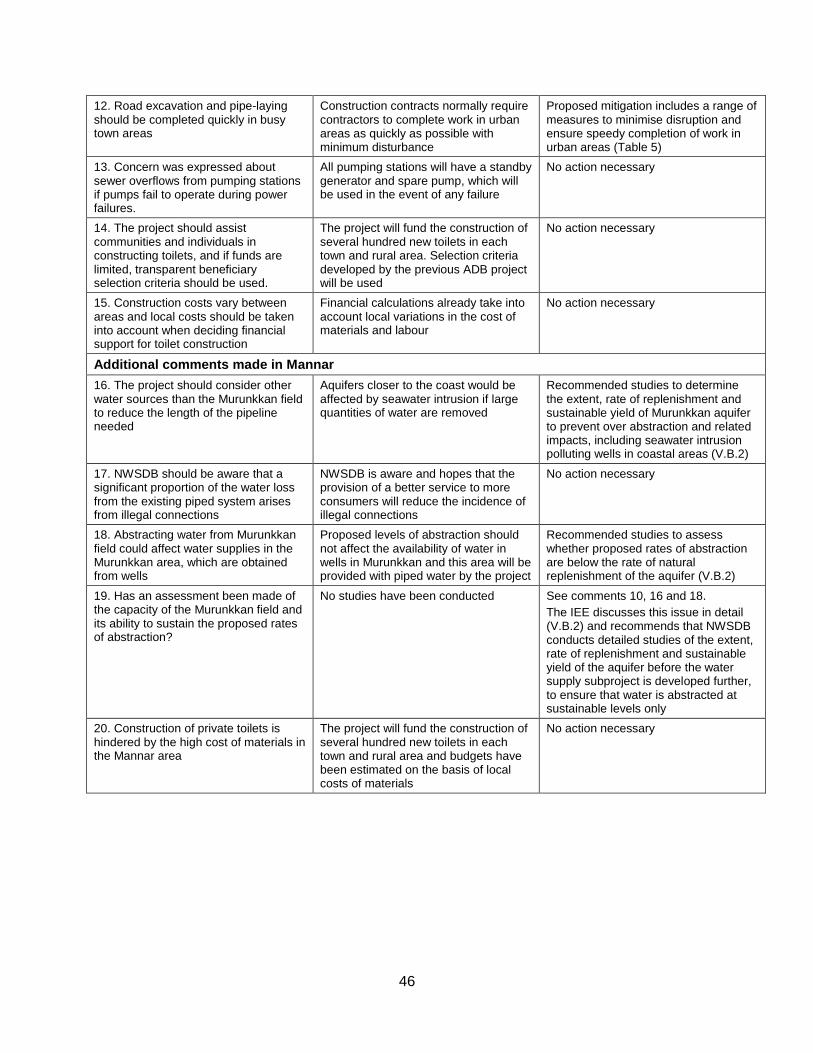
46
12. Road excavation and pipe-laying should be completed quickly in busy town areas
Construction contracts normally require contractors to complete work in urban areas as quickly as possible with minimum disturbance
Proposed mitigation includes a range of measures to minimise disruption and ensure speedy completion of work in urban areas (Table 5)
13. Concern was expressed about sewer overflows from pumping stations if pumps fail to operate during power failures.
All pumping stations will have a standby generator and spare pump, which will be used in the event of any failure
No action necessary
14. The project should assist communities and individuals in constructing toilets, and if funds are limited, transparent beneficiary selection criteria should be used.
The project will fund the construction of several hundred new toilets in each town and rural area. Selection criteria developed by the previous ADB project will be used
No action necessary
15. Construction costs vary between areas and local costs should be taken into account when deciding financial support for toilet construction
Financial calculations already take into account local variations in the cost of materials and labour
No action necessary
Additional comments made in Mannar
16. The project should consider other water sources than the Murunkkan field to reduce the length of the pipeline needed
Aquifers closer to the coast would be affected by seawater intrusion if large quantities of water are removed
Recommended studies to determine the extent, rate of replenishment and sustainable yield of Murunkkan aquifer to prevent over abstraction and related impacts, including seawater intrusion polluting wells in coastal areas (V.B.2)
17. NWSDB should be aware that a significant proportion of the water loss from the existing piped system arises from illegal connections
NWSDB is aware and hopes that the provision of a better service to more consumers will reduce the incidence of illegal connections
No action necessary
18. Abstracting water from Murunkkan field could affect water supplies in the Murunkkan area, which are obtained from wells
Proposed levels of abstraction should not affect the availability of water in wells in Murunkkan and this area will be provided with piped water by the project
Recommended studies to assess whether proposed rates of abstraction are below the rate of natural replenishment of the aquifer (V.B.2)
19. Has an assessment been made of the capacity of the Murunkkan field and its ability to sustain the proposed rates of abstraction?
No studies have been conducted See comments 10, 16 and 18.
The IEE discusses this issue in detail (V.B.2) and recommends that NWSDB conducts detailed studies of the extent, rate of replenishment and sustainable yield of the aquifer before the water supply subproject is developed further, to ensure that water is abstracted at sustainable levels only
20. Construction of private toilets is hindered by the high cost of materials in the Mannar area
The project will fund the construction of several hundred new toilets in each town and rural area and budgets have been estimated on the basis of local costs of materials
No action necessary

47
C. Future consultation and disclosure
4. NWSDB will extend and expand the consultation and disclosure process significantly during implementation of DZUWSSP. They will appoint an experienced NGO to handle this key aspect of the programme, who will conduct a wide range of activities in all towns and rural areas, to ensure that the needs and concerns of stakeholders are registered, and are addressed in project design, construction or operation where appropriate. The program of activities will be developed during the detailed design stage, and is likely to include the following: Consultation during detailed design:
Focus-group discussions with affected persons and other stakeholders (including women’s groups, NGOs and CBOs) to hear their views and concerns, so that these can be addressed in subproject design where necessary;
Structured consultation meetings with the institutional stakeholders (government bodies and NGOs) to discuss and approve key aspects of the project.
Consultation during construction:
Public meetings with affected communities to discuss and plan work programmes and allow issues to be raised and addressed once construction has started;
Smaller-scale meetings to discuss and plan construction work with individual communities to reduce disturbance and other impacts, and provide a mechanism through which stakeholders can participate in subproject monitoring and evaluation;
Project disclosure:
Public information campaigns (via newspapers, posters, etc) to explain the project to the population in each town and prepare them for disruption they may experience once the construction programme is underway;
Public disclosure meetings at key project stages to inform the public of progress and future plans, and to provide copies of summary documents in Sinhalese, Tamil and English;
Formal disclosure of completed project reports by making copies available at NWSDB offices in each town, informing the public of their availability, and providing a mechanism through which comments can be made.
48
IX. FINDINGS AND RECOMMENDATIONS
A. Findings
1. The process described in this document has assessed the environmental impacts of all elements of the infrastructure proposed under the Mannar water supply and sanitation subprojects. Potential negative impacts were identified in relation to design, location, construction and operation of the subprojects, and mitigation measures have been developed to reduce negative impacts to acceptable levels. These were discussed with specialists responsible for the engineering aspects, and as a result some measures have already been included in the outline designs for the infrastructure. These include:
Locating water supply pipelines in the RoW alongside existing roads, to avoid the need to acquire land or relocate people;
Locating pipelines beneath the road surface in certain narrower streets to avoid demolishing structures that have been built in the RoW (parts of houses or shops).
2. This means that the number of impacts and their significance have already been reduced by amending the design. 3. Changes have also been made to the location of elements of the subprojects to further reduce impacts. These include:
Locating facilities (overhead reservoirs, ground tanks, etc) on government-owned land to avoid the need for land acquisition and relocation of people;
4. Regardless of these and various other actions taken during the IEE process and in developing the subprojects, there will still be impacts on the environment when the infrastructure is built and when it is operating. This is mainly because of the invasive nature of excavation, and because the water supply network is located in a town, some parts of which are densely populated. Because of these and other factors the most significant impacts are on the physical environment and the human environment. 5. During the construction phase, impacts mainly arise from the need to dispose of large quantities of waste soil and import a similar amount of sand to support the water pipes in the trenches; and from the disturbance of residents, business and traffic by the construction work in the town. These are common impacts of construction in urban areas, and there are well developed methods for their mitigation. These include:
Finding beneficial uses for waste material; Covering soil and sand during transportation and when stored on site; Planning work to minimise disruption of traffic and communities; Providing temporary structures to maintain access across trenches where required.
6. Although there will be no need to acquire land or relocated people, roadside businesses may lose some income as access will be difficult for customers when water pipes are installed nearby. ADB policy on Involuntary Resettlement requires that no-one should be worse off as a result of an ADB-funded project, so a Resettlement Plan and Framework were prepared to examine these issues. This establishes that businesses will be compensated in cash for any income they lose. 7. There were limited opportunities to provide environmental enhancements, but certain measures were included. For example it is proposed that the project will:
49
Employ people from nearby communities in the construction workforce and to
maintain and operate the new facilities, to provide them with an economic gain;
8. These and the other mitigation and enhancement measures are summarised in Error! Reference source not found., which also shows the location of the impact, the body responsible for the mitigation, and the programme for its implementation. 9. Operation and maintenance of the water supply infrastructure will be the responsibility of NWSDB. Most elements should operate with routine maintenance, which should not affect the environment. Network leaks will be repaired from time to time, but impacts will be less than those of the construction period as the work will be infrequent, affecting small areas only. Maintenance at the other sites will involve routine checking of components and replacement of parts where necessary. Work will be conducted according to O&M procedures developed in the detailed design stage. 10. There is a risk that proposed groundwater abstraction could deplete the wellfield leading to surface subsidence, seawater intrusion and other impacts, because no data are available on the extent, yield and recharge of the Murunkkan aquifer. It is imperative that such data are collected before the subproject is developed further so that sustainable abstraction can be planned, or the scheme is redesigned with lower rates of abstraction and a supplementary water source if necessary. A one-year survey should be conducted of the discharge from boreholes at various locations, beginning as soon as possible. 11. There are also no data on the quality of water in the aquifer and as the subproject proposes treatment by basic chlorination only there is a risk to human health from the consumption of contaminated water, given the extent to which chemical fertilizers are applied to irrigated fields, and the lack of sewerage in the area. It is therefore very important that the quality of water in the aquifer is investigated in detail, so that the project can be redesigned to include further treatment if necessary, or can be abandoned if data show that water cannot be treated to acceptable standards. 12. MUC should also establish an emergency procedure to recycle the effluent through the ponds for further treatment if it fails to meet national wastewater discharge standards. Designs should be amended to provide the necessary pumps and pipe-work. 13. If groundwater is abstracted sustainably and the water provided is of an acceptable quality, then the main impacts of the operating water supply and sanitation systems should be beneficial. Around 55% of the citizens of Mannar will be provided with a constant supply of better quality water; and septic tanks in the town will be emptied around once per year, reducing the leaks and foul odours emanating from overloaded tanks at present. A public education programme will be implemented to raise awareness of sanitation issues, so the improvements in municipal services and sanitary practices should raise the quality of life and deliver major improvements in individual and public health. This should then lead to economic gains as people will be away from work less and will spend less on healthcare, so their incomes should increase. 14. Error! Reference source not found. also assesses the effectiveness of each mitigation measure in reducing each impact to an acceptable level. This is shown as the level of significance of the residual impact (remaining after the mitigation is applied). This shows that all impacts will be rendered at least neutral (successfully mitigated), and that certain measures will produce a benefit (in addition to the major benefits provided by the operating schemes). 15. Mitigation will be assured by a program of environmental monitoring conducted during both construction and operation to ensure that all measures are provided as intended, and to determine whether the environment is protected as envisaged. This will include observations on and off site, document checks, and interviews with workers and beneficiaries, and any requirements for remedial action will be reported to the PCU. There will also be longer-term
50
surveys to monitor certain aspects, including the expected improvements in the quality of domestic water and the health of the population. 16. Finally, stakeholders were involved in developing the IEE through both face-to-face discussions on site and a large public meeting held in the town, after which views expressed were incorporated into the IEE and the planning and development of the project. The IEE will be made available in the local language at public locations in the town and the summary will be disclosed to a wider audience via the ADB website. The consultation process will be continued and expanded during project implementation, when a nationally-recognised NGO will be appointed to handle this key element to ensure that stakeholders are fully engaged in the project and have the opportunity to participate in its development and implementation.
B. Recommendations
17. There are two straightforward but essential recommendations that need to be followed to ensure that the environmental impacts of the project are successfully mitigated. These are that NWSDB should ensure that:
All mitigation, compensation and enhancement measures proposed in this IEE report (Error! Reference source not found.) and in the Resettlement Framework for the DZUWSSP are implemented in full, as described in these two documents;
The Environmental Monitoring Plan proposed in this report and the internal and external monitoring proposed in the Resettlement Framework are also implemented in full.
51
X. CONCLUSIONS
1. The environmental impacts of the proposed improvements in water supply and sanitation infrastructure in Mannar have been assessed by the Initial Environmental Examination reported in this document, conducted according to ADB guidelines. Issues related to Involuntary Resettlement were assessed by a parallel process of resettlement planning and will be compensated by measures set out in detail in the Resettlement Framework for the project. These measures were integrated into the IEE and are summarised in this report. 2. Providing the mitigation, compensation and enhancement measures recommended in the IEE are implemented in full, most of the potential negative impacts should be successfully avoided or reduced to acceptable levels. There should also be some small additional benefits from recommended mitigation and enhancement measures, and major improvements in quality of life and individual and public health once the schemes are in operation. 3. There are however uncertainties in the analysis, relating to:
The extent of the aquifer and its capacity to provide the design demand of water without being depleted over the long term; and
The quality of water in the aquifer and the suitability of the proposed treatment method (involving chlorination only) to provide water of the legally required standard.
4. These issues are explained in detail in Paragraphs 143-146 above, and measures are proposed that, if implemented thoroughly, should enable a conclusion to be reached as to whether the water supply subproject can proceed as presently designed, or whether the scheme should be redesigned to use an alternative water source and/or more extensive treatment.
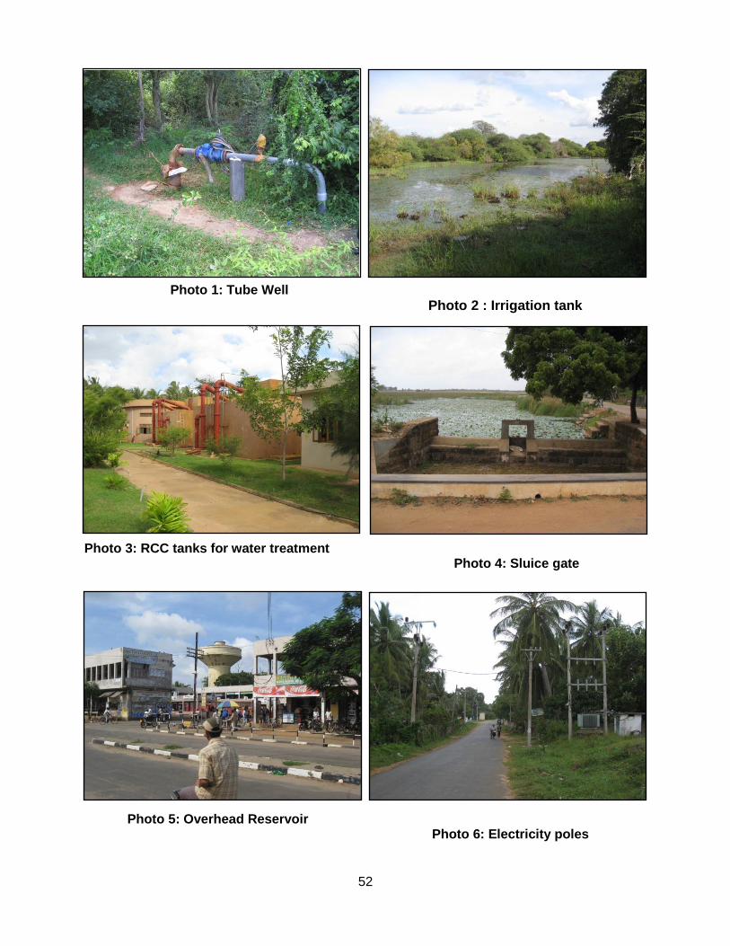
52
Photo 1: Tube Well
Photo 2 : Irrigation tank
Photo 3: RCC tanks for water treatment
Photo 4: Sluice gate
Photo 5: Overhead Reservoir Photo 6: Electricity poles
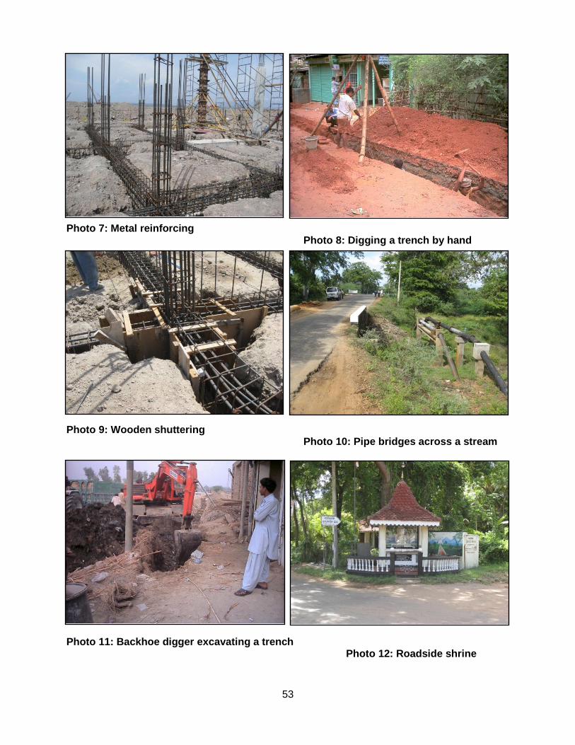
53
Photo 7: Metal reinforcing
Photo 8: Digging a trench by hand
Photo 9: Wooden shuttering Photo 10: Pipe bridges across a stream
Photo 11: Backhoe digger excavating a trench Photo 12: Roadside shrine

54
APPENDICES

55
Appendix 1 CURRENT SRI LANKAN DRINKING WATER STANDARDS (1996)
Characteristic Maximum Desirable
Level
Maximum Permissible
Level
Test Method
(See Clause 5 of published standards)
Technique
Physical
Colour 5 units 30 units 1 Colorimetry - tristimulus filter method
Colorimetry - visual comparison method
Colorimetry - spectrophotometric method
Odour Unobjectionable Unobjectionable Sensory evaluation
Taste Unobjectionable Unobjectionable Sensory evaluation
Turbidity 2 Jackson Turbidity Units
8 Jackson Turbidity Units
11 Visual method - Candle Turbidimeter
Chemical
pH range 7.0 - 8.5 6.5 - 9.0 1
2
Electrometry - pllinter with glass electrodes
Colorimetry
Electrical Conductivity
750 µs/cm 3,500 µs/cm 1 Conductimetry
Chloride (as Cl) 200 mg/l 1,200 mg/l 1 Titrimetry - silver nitrate method
Titrimetry - mercuric nitrate method
Free residual Chlorine (C2)
- 0.2 mg/l 1 Colorimetry - DPD Colorimetric method
Alkalinity (as CaCO3)
200 mg/l 400 mg/l 1
2
Titrimetry - visual titration
Titrimetry - electrometric titration
Free ammonia - 0.06 mg/l Appendix B
1, 2
Colorimetry - nesslarization
Colorimetry - phenate method
Anionic detergents
0.2 mg/l 1 mg/l 1 Colorimetry - methylene blue method
Phenolic compounds
0.001 mg/l 0.002 mg/l 1 Colorimetry - chloroform extraction method
Grease and oil - 1.0 mg/l 1 Gravimetric method
Calcium (as Ca) 100 mg/l 240 mg/l 1
1
Atomic absorption spectrophotometry
Titrimetry - EDTA titrimetric method
Magnesium (as Mg)
Not > 30 mg/l if there are 250
mg/l sulphate; if there is less
sulphate, Mg up to 150 mg/l may
be allowed
140 mg/l 1
1
Atomic absorption spectrophotometry
Titrimetry - magnesium by calculation (EDTA calcium and hardness titration)
Albuminoid ammonia
0.15 mg/l Appendix B Colorimetry - nesslarization
Nitrate (as N) 10 mg/l 1
2
Ultraviolet spectrophotometry
Colorimetry - bruoine method
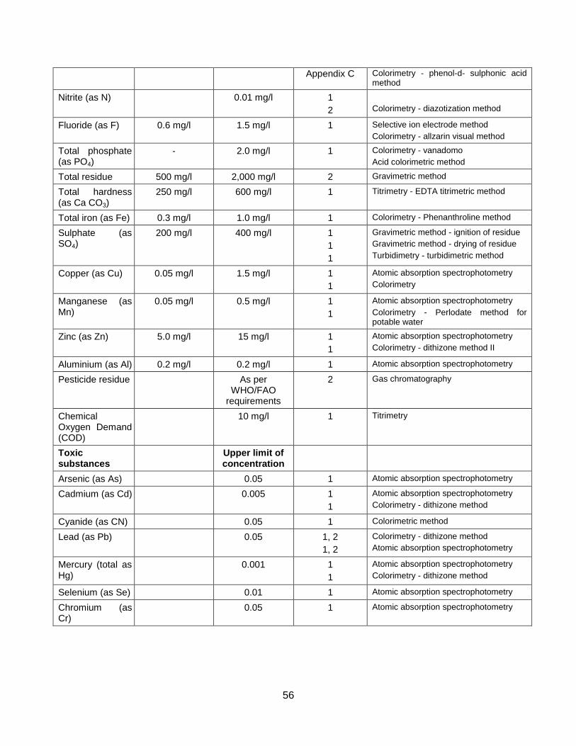
56
Appendix C Colorimetry - phenol-d- sulphonic acid method
Nitrite (as N) 0.01 mg/l 1
2
Colorimetry - diazotization method
Fluoride (as F) 0.6 mg/l 1.5 mg/l 1 Selective ion electrode method
Colorimetry - allzarin visual method
Total phosphate (as PO4)
- 2.0 mg/l 1 Colorimetry - vanadomo
Acid colorimetric method
Total residue 500 mg/l 2,000 mg/l 2 Gravimetric method
Total hardness (as Ca CO3)
250 mg/l 600 mg/l 1 Titrimetry - EDTA titrimetric method
Total iron (as Fe) 0.3 mg/l 1.0 mg/l 1 Colorimetry - Phenanthroline method
Sulphate (as SO4)
200 mg/l 400 mg/l 1
1
1
Gravimetric method - ignition of residue
Gravimetric method - drying of residue
Turbidimetry - turbidimetric method
Copper (as Cu) 0.05 mg/l 1.5 mg/l 1
1
Atomic absorption spectrophotometry
Colorimetry
Manganese (as Mn)
0.05 mg/l 0.5 mg/l 1
1
Atomic absorption spectrophotometry
Colorimetry - Perlodate method for potable water
Zinc (as Zn) 5.0 mg/l 15 mg/l 1
1
Atomic absorption spectrophotometry
Colorimetry - dithizone method II
Aluminium (as Al) 0.2 mg/l 0.2 mg/l 1 Atomic absorption spectrophotometry
Pesticide residue As per WHO/FAO
requirements
2 Gas chromatography
Chemical Oxygen Demand (COD)
10 mg/l 1 Titrimetry
Toxic substances
Upper limit of concentration
Arsenic (as As) 0.05 1 Atomic absorption spectrophotometry
Cadmium (as Cd) 0.005 1
1
Atomic absorption spectrophotometry
Colorimetry - dithizone method
Cyanide (as CN) 0.05 1 Colorimetric method
Lead (as Pb) 0.05 1, 2
1, 2
Colorimetry - dithizone method
Atomic absorption spectrophotometry
Mercury (total as Hg)
0.001 1
1
Atomic absorption spectrophotometry
Colorimetry - dithizone method
Selenium (as Se) 0.01 1 Atomic absorption spectrophotometry
Chromium (as Cr)
0.05 1 Atomic absorption spectrophotometry
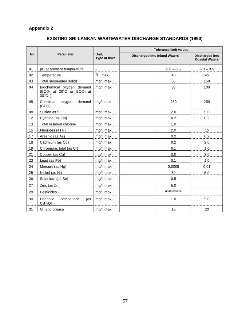
57
Appendix 2
EXISTING SRI LANKAN WASTEWATER DISCHARGE STANDARDS (1990)
No
Parameter
Unit, Type of limit
Tolerance limit values
Discharged into Inland Waters Discharged into Coastal Waters
01 pH at ambient temperature - 6.0 – 8.5 6.0 – 8.5
02 Temperature oC, max. 40 45
03 Total suspended solids mg/l, max. 50 150
04 Biochemical oxygen demand (BOD5 at 20
oC or BOD3 at
30oC )
mg/l, max. 30 100
05 Chemical oxygen demand (COD)
mg/l, max. 250 250
08 Sulfide as S mg/l, max. 2.0 5.0
12 Cyanide (as CN) mg/l, max. 0.2 0.2
13 Total residual chlorine mg/l, max. 1.0
15 Fluorides (as F) mg/l, max. 2.0 15
17 Arsenic (as As) mg/l, max. 0.2 0.2
18 Cadmium (as Cd) mg/l, max. 0.2 2.0
19 Chromium, total (as Cr) mg/l, max. 0.1 1.0
21 Copper (as Cu) mg/l, max. 3.0 3.0
23 Lead (as Pb) mg/l, max. 0.1 1.0
24 Mercury (as Hg) mg/l, max. 0.0005 0.01
25 Nickel (as Ni) mg/l, max. 30 5.0
26 Selenium (as Se) mg/l, max. 0.5
27 Zinc (as Zn) mg/l, max. 5.0
28 Pesticides mg/l, max. undetectable
30 Phenolic compounds (as C6H5OH)
mg/l, max. 1.0 5.0
31 Oil and grease mg/l, max. 10 20
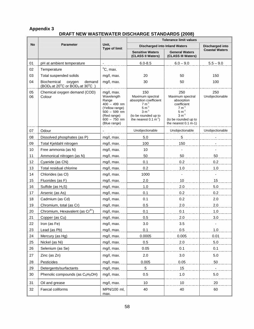
58
Appendix 3 DRAFT NEW WASTEWATER DISCHARGE STANDARDS (2008)
No
Parameter
Unit, Type of limit
Tolerance limit values
Discharged into Inland Waters Discharged into Coastal Waters
Sensitive Waters (CLASS II Waters)
General Waters (CLASS III Waters)
01 pH at ambient temperature - 6.0-8.5 6.0 – 9.0 5.5 – 9.0
02 Temperature oC, max.
03 Total suspended solids mg/l, max. 20 50 150
04 Biochemical oxygen demand (BOD5 at 20
oC or BOD3 at 30
oC )
mg/l, max. 30 50 100
05 Chemical oxygen demand (COD) mg/l, max. 150 250 250
06 Colour Wavelength Range 400 – 499 nm (Yellow range) 500 – 599 nm (Red range) 600 – 750 nm (Blue range)
Maximum spectral absorption coefficient
7 m-1
5 m-1
3 m-1
(to be rounded up to the nearest 0.1 m
-1)
Maximum spectral absorption coefficient
7 m-1
5 m-1
3 m-1
(to be rounded up to the nearest 0.1 m-1)
Unobjectionable
07 Odour - Unobjectionable Unobjectionable Unobjectionable
08 Dissolved phosphates (as P) mg/l, max. 5.0 5 -
09 Total Kjeldahl nitrogen mg/l, max. 100 150 -
10 Free ammonia (as N) mg/l, max. 10 - -
11 Ammonical nitrogen (as N) mg/l, max. 50 50 50
12 Cyanide (as CN) mg/l, max. 0.1 0.2 0.2
13 Total residual chlorine mg/l, max. 0.2 1.0 1.0
14 Chlorides (as Cl) mg/l, max. 1000 - -
15 Fluorides (as F) mg/l, max. 2.0 10 15
16 Sulfide (as H2S) mg/l, max. 1.0 2.0 5.0
17 Arsenic (as As) mg/l, max. 0.1 0.2 0.2
18 Cadmium (as Cd) mg/l, max. 0.1 0.2 2.0
19 Chromium, total (as Cr) mg/l, max. 0.5 2.0 2.0
20 Chromium, Hexavalent (as Cr6+
) mg/l, max. 0.1 0.1 1.0
21 Copper (as Cu) mg/l, max. 0.5 2.0 3.0
22 Iron (as Fe) mg/l, max. 3.0 3.5 -
23 Lead (as Pb) mg/l, max. 0.1 0.5 1.0
24 Mercury (as Hg) mg/l, max. 0.0005 0.005 0.01
25 Nickel (as Ni) mg/l, max. 0.5 2.0 5.0
26 Selenium (as Se) mg/l, max. 0.05 0.1 0.1
27 Zinc (as Zn) mg/l, max. 2.0 3.0 5.0
28 Pesticides mg/l, max. 0.005
0.05
50
29 Detergents/surfactants mg/l, max. 5 15 -
30 Phenolic compounds (as C6H5OH) mg/l, max. 0.5 1.0 5.0
31 Oil and grease mg/l, max. 10 10 20
32 Faecal coliforms MPN/100 ml, max.
40 40 60
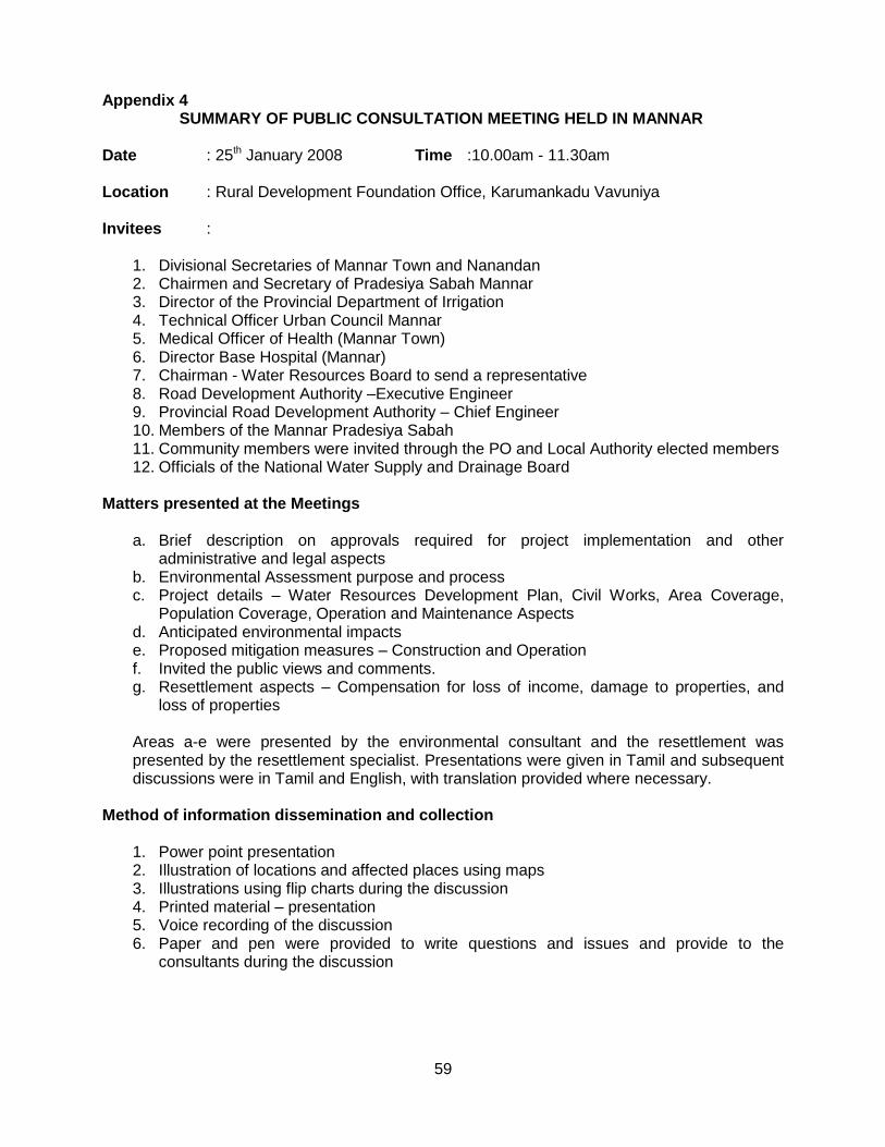
59
Appendix 4 SUMMARY OF PUBLIC CONSULTATION MEETING HELD IN MANNAR
Date : 25th January 2008 Time :10.00am - 11.30am Location : Rural Development Foundation Office, Karumankadu Vavuniya Invitees :
1. Divisional Secretaries of Mannar Town and Nanandan 2. Chairmen and Secretary of Pradesiya Sabah Mannar 3. Director of the Provincial Department of Irrigation 4. Technical Officer Urban Council Mannar 5. Medical Officer of Health (Mannar Town) 6. Director Base Hospital (Mannar) 7. Chairman - Water Resources Board to send a representative 8. Road Development Authority –Executive Engineer 9. Provincial Road Development Authority – Chief Engineer 10. Members of the Mannar Pradesiya Sabah 11. Community members were invited through the PO and Local Authority elected members 12. Officials of the National Water Supply and Drainage Board
Matters presented at the Meetings
a. Brief description on approvals required for project implementation and other administrative and legal aspects
b. Environmental Assessment purpose and process c. Project details – Water Resources Development Plan, Civil Works, Area Coverage,
Population Coverage, Operation and Maintenance Aspects d. Anticipated environmental impacts e. Proposed mitigation measures – Construction and Operation f. Invited the public views and comments. g. Resettlement aspects – Compensation for loss of income, damage to properties, and
loss of properties Areas a-e were presented by the environmental consultant and the resettlement was presented by the resettlement specialist. Presentations were given in Tamil and subsequent discussions were in Tamil and English, with translation provided where necessary.
Method of information dissemination and collection 1. Power point presentation 2. Illustration of locations and affected places using maps 3. Illustrations using flip charts during the discussion 4. Printed material – presentation 5. Voice recording of the discussion 6. Paper and pen were provided to write questions and issues and provide to the
consultants during the discussion
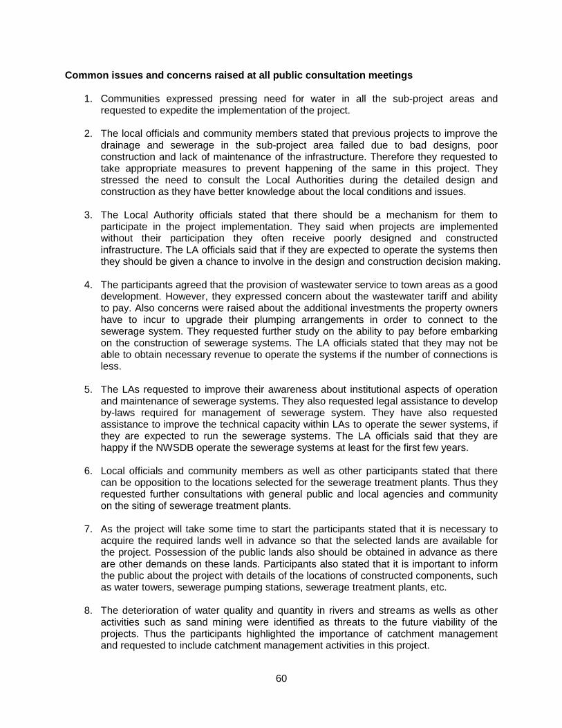
60
Common issues and concerns raised at all public consultation meetings
1. Communities expressed pressing need for water in all the sub-project areas and requested to expedite the implementation of the project.
2. The local officials and community members stated that previous projects to improve the
drainage and sewerage in the sub-project area failed due to bad designs, poor construction and lack of maintenance of the infrastructure. Therefore they requested to take appropriate measures to prevent happening of the same in this project. They stressed the need to consult the Local Authorities during the detailed design and construction as they have better knowledge about the local conditions and issues.
3. The Local Authority officials stated that there should be a mechanism for them to
participate in the project implementation. They said when projects are implemented without their participation they often receive poorly designed and constructed infrastructure. The LA officials said that if they are expected to operate the systems then they should be given a chance to involve in the design and construction decision making.
4. The participants agreed that the provision of wastewater service to town areas as a good
development. However, they expressed concern about the wastewater tariff and ability to pay. Also concerns were raised about the additional investments the property owners have to incur to upgrade their plumping arrangements in order to connect to the sewerage system. They requested further study on the ability to pay before embarking on the construction of sewerage systems. The LA officials stated that they may not be able to obtain necessary revenue to operate the systems if the number of connections is less.
5. The LAs requested to improve their awareness about institutional aspects of operation
and maintenance of sewerage systems. They also requested legal assistance to develop by-laws required for management of sewerage system. They have also requested assistance to improve the technical capacity within LAs to operate the sewer systems, if they are expected to run the sewerage systems. The LA officials said that they are happy if the NWSDB operate the sewerage systems at least for the first few years.
6. Local officials and community members as well as other participants stated that there
can be opposition to the locations selected for the sewerage treatment plants. Thus they requested further consultations with general public and local agencies and community on the siting of sewerage treatment plants.
7. As the project will take some time to start the participants stated that it is necessary to
acquire the required lands well in advance so that the selected lands are available for the project. Possession of the public lands also should be obtained in advance as there are other demands on these lands. Participants also stated that it is important to inform the public about the project with details of the locations of constructed components, such as water towers, sewerage pumping stations, sewerage treatment plants, etc.
8. The deterioration of water quality and quantity in rivers and streams as wells as other
activities such as sand mining were identified as threats to the future viability of the projects. Thus the participants highlighted the importance of catchment management and requested to include catchment management activities in this project.
61
9. The importance of obtaining the approval from necessary agencies well in advance was
highlighted. These include: environmental agencies, Irrigation Department and Provincial Irrigation Department, Agrarian Services Department.
10. Over exploitation of the ground water resources was also cited as a threat. Participants
stated the need to establish a mechanism for controlling the future ground water extraction in the well fields.
11. The Local Authorities expressed their willingness to carry out the drainage improvement
works in the town areas, if they are allowed to do so.
12. It was requested to complete the road excavation and pipe laying work in busy town areas as soon as possible.
13. Concern was expressed about sewer overflows from pumping stations, if pumps fail to
operate and during power failures.
14. Establish a procedure for providing assistance for toilet construction. Decide the beneficiary selection criteria for assistance for toilet construction If the funds available is limited to provide for all those who request for such assistance.
15. When deciding the financial support for toilets it is necessary to consider the
construction material cost that prevails in the respective areas. Specific issues raised at the meeting in Mannar
1. Requested to consider other alternative water resources to Murunkan basin as the pipe line is too long.
2. Inform the need to prevent illegal tapping from the transmission line. 3. It was stated that Murunkan area also needs water and extracting water from Murunkan
well field to Mannar town can create problems in the future for people in Murunkan area. 4. Asked whether an assessment was made on the groundwater basins to determine the
capacity of the basins and yield from typical wells. 5. High material cost affects the construction of private toilets. As a result unit cost of a
toilet is very high in this area.
62
Addendum 1
Committee for Grievance Redress and Environment Monitoring
1. In absence of such provisions, affected parties/persons (AP) will seek solutions outside
the project which may lead to a number of adverse consequences. It is necessary to include
grievance redress provisions for the people adversely affected (or about to be affected) by the
development of sub projects because such people should have provisions to forward their
grievances by seeking solutions.
2. Environmental Monitoring Committees (EMC) are already proposed to discuss the critical
environmental issues and thereby find solutions in some sub projects. Facility for Grievance
Redressing shall be incorporated to the proposed EMCs because all regional level key officials
will become the members of such EMCs and will be functioning as Grievance Redress and
Environment Monitoring Committee (GREMC). New GREMCs shall be formed for the sub-
projects where EMCs have not been proposed.
3. The GREMC comprises with responsible officers of following agencies and headed by the
Provincial Environmental Authority or Central Environmental Authority (which is functioning in
the area concern) jointly with the divisional secretary. The secretary to the committee and the
convener shall be the project manager of the NWSDB.
1. Provincial Environmental Authority/Central Environmental Authority (Regional office)
2. Project Manager of the sub project
3. Urban Council/ Municipal Council
4. Divisional Secretariat
5. Agrarian Service Department
6. Provincial Irrigation Department / Central Irrigation Department.
7. Representative of the contractor
8. Representative of the consultant to the project
9. Any other officers by considering the need
63
4. If APs are not satisfied about the decision of the GREMC, the matter should be referred to
the District Secretary who will make the final decision. The District Secretary may appoint a
committee to find the observations. The GREMC is effective with the commencement of the
construction and shall meet once in six weeks during the construction period. During the
operational phase, the committee shall meet once in three months for two years and if necessary
thereafter. If there are critical issues, the committee shall meet by fixing a convenient date.
During the operational phase, Regional Manager (O&M) of the NWSDB shall represent the
NWSDB.
5. This should be published in all three languages by displaying notices in the notice boards
of all member offices and other public offices such as Grama Niladhari (Village Head) office,
post office etc. to make aware the public.
Initial Environmental Examination Report
This report has been submitted to ADB by the Ministry of Water Supply and Drainage and is made publicly available in accordance with ADB’s public communications policy (2005). It does not necessarily reflect the views of ADB.
Project Number: 37381-013 September 2012
Sri Lanka: DRY ZONE URBAN WATER AND SANITATION PROJECT - for Mannar Septage Treatment Plant
Prepared by Project Management Unit for
Dry Zone Urban Water and Sanitation Project,
Colombo, Sri Lanka.
For Water Supply and Drainage Board Ministry of Water Supply and Drainage, Sri Lanka.
i
Project Implementation Agency: National Water Supply and Drainage Board Funding Agency: Asian Development Bank Project Number: 4853-SRI
Sri Lanka: Dry Zone Urban Water and Sanitation
Project (DZUWSP)
INITIAL ENVIRONMENTAL EXAMINATION:
SEPTAGE TREATMENT PLANT FOR MANNAR
MAIN TEXT
JULY, 2012
i
TABLE OF CONTENTS
TABLE OF CONTENTS ................................................................................................................ i ABBREVIATIONS ....................................................................................................................... vi EXECUTIVE SUMMARY .............................................................................................................. 1 1 INTRODUCTION ................................................................................................................ 3
1.1 Project Name .................................................................................................................. 3 1.2 Details of the Project Developer ..................................................................................... 3 1.3 Key Information on the Project ....................................................................................... 4 1.4 Ownership of the Project Site ......................................................................................... 4 1.5 Project and Study Background ....................................................................................... 4 1.6 Purpose of the Initial Environmental Examination (IEE) ................................................. 5 1.7 Extent and the Scope of the IEE Study .......................................................................... 5
1.7.1 Government Policy/Status Regarding the Project ................................................... 5 1.7.2 Applicable Laws, Regulations, Standards and Requirements ................................. 6 1.7.3 Approvals Needed for the Proposed Development ................................................. 7 1.7.4 Conditions Laid Down by the Government Agencies .............................................. 7 1.7.5 Checklist on Sensitive Areas ................................................................................... 7
2 DESCRIPTION OF THE PROJECT AND ALTERNATIVES CONSIDERED .................... 9 2.1 Aim and Scope of the Proposed Project ......................................................................... 9
2.1.1 Project Main Objectives ........................................................................................... 9 2.1.2 Main Beneficiaries ................................................................................................... 9 2.1.3 Socio-Economic Effects .......................................................................................... 9 2.1.4 Description of the Project ........................................................................................ 9 2.1.5 Project Components ................................................................................................ 9 2.1.6 Project Layout ......................................................................................................... 9 2.1.7 Operation and Maintenance .................................................................................... 9 2.1.8 Type of Project ...................................................................................................... 11 2.1.9 Category of Project: ............................................................................................... 11 2.1.10 Size or Magnitude of Operation ............................................................................. 11 2.1.11 Justification of the Project ..................................................................................... 11 2.1.12 Project Location ..................................................................................................... 12
2.1.12.1 Treatment Plant Site ...................................................................................... 12 2.1.12.2 Service Area ................................................................................................... 12
2.2 Extent of the Project Area ............................................................................................. 14 2.3 Process Description and Design Details ...................................................................... 14
2.3.1 Brief Description of the Treatment Process ........................................................... 14 2.4 Pre-construction and Construction Activities ................................................................ 16
2.4.1 Pre-construction Works ......................................................................................... 16 2.4.2 Construction works ................................................................................................ 16
2.5 Construction Materials .................................................................................................. 16 2.6 Labour Requirement and Availability ............................................................................ 17
2.6.1 Labour Requirement .............................................................................................. 17 2.6.2 Availability of Labour ............................................................................................. 17
ii
2.7 Infrastructure Facilities ................................................................................................. 17 2.8 Future Additions, Expansions ....................................................................................... 17 2.9 Schedule of Implementation ......................................................................................... 18 2.10 Operation and Maintenance ......................................................................................... 18
2.10.1 Institutional arrangement for operation .................................................................. 18 2.10.2 Operational and Maintenance cost ........................................................................ 18 2.10.3 Capacity to meet the O&M expenditure ................................................................ 19 2.10.4 Septage collection and delivery ............................................................................. 19 2.10.5 Operation and Maintenance of treatment plant ..................................................... 19 2.10.6 Skills requirements ................................................................................................ 19
2.11 Evaluation of Alternatives ............................................................................................. 20 2.11.1 Alternative Technologies ....................................................................................... 20
2.11.1.1 Land Disposal ................................................................................................ 20 2.11.1.2 Disposal at Wastewater Treatment Plant ....................................................... 20 2.11.1.3 Independent Septage Treatment System ...................................................... 20 2.11.1.4 Technology of Choice .................................................................................... 21
2.11.2 Alternative Designs ............................................................................................... 21 2.11.2.1 Lagoons ......................................................................................................... 21 2.11.2.2 Composting .................................................................................................... 21 2.11.2.3 Biological Secondary Treatment Processes .................................................. 22 2.11.2.4 Aerobic Digestion ........................................................................................... 22 2.11.2.5 Anaerobic Digestion ....................................................................................... 22 2.11.2.6 Lime Stabilization ........................................................................................... 23 2.11.2.7 Chlorine Oxidation .......................................................................................... 23 2.11.2.8 Design of Choice ............................................................................................ 23
2.11.3 Alternative Sites .................................................................................................... 23 2.11.3.1 Site 1: Cemetery Site ......................................................................................... 24 2.11.3.2 Site 2: Pappapodai Site ...................................................................................... 25 2.11.3.3 Site 3: Maligathidal Site ...................................................................................... 26 2.11.3.4 Site of Choice ................................................................................................. 27
2.11.4 No Action Alternative ............................................................................................. 28 3 DESCRIPTION OF ENVIRONMENT ............................................................................... 29
3.1 Physical Features ......................................................................................................... 30 3.1.1 Hydrology .............................................................................................................. 30
3.1.1.1 Topography .................................................................................................... 30 3.1.1.2 Surface Water-Bodies in the Project area ...................................................... 30 3.1.1.3 Surface Drainage Pattern ............................................................................... 30 3.1.1.4 Groundwater .................................................................................................. 33 3.1.1.5 List of Existing Irrigation or Drainage / Flood Protection Schemes ................ 33 3.1.1.6 Uses of Water ................................................................................................ 33 3.1.1.7 Water Quality ................................................................................................. 34
3.1.2 Climate and Meteorology ...................................................................................... 34 3.1.2.1 Precipitation Patterns of the Area .................................................................. 34
iii
3.1.2.2 Evaporation .................................................................................................... 34 3.1.2.3 Prevailing Wind Pattern .................................................................................. 34 3.1.2.4 Temperature and Relative Humidity ............................................................... 35
3.1.3 Geological Aspects ................................................................................................ 35 3.1.4 Soils Condition of the Area .................................................................................... 37 3.1.5 Geology and hydro-geology of the area ................................................................ 38 3.1.6 Natural Disasters and Risks .................................................................................. 38 3.1.7 Atmosphere ........................................................................................................... 38
3.1.7.1 Air quality ....................................................................................................... 38 3.1.7.2 Noise .............................................................................................................. 38
3.1.8 Land-use ............................................................................................................... 39 3.1.8.1 Land-use pattern ............................................................................................ 39 3.1.8.2 Trends in land-use pattern ............................................................................. 40
3.2 Ecological Environment ................................................................................................ 41 3.2.1 Description of the Existing Ecosystem Dynamics ................................................. 41 3.2.2 Key Ecological Characteristics .............................................................................. 41
3.2.2.1 Flora and Fauna Observed in the Project Area .............................................. 41 3.3 Socio-Economic Environment ...................................................................................... 43
3.3.1 Social Environment ............................................................................................... 43 3.3.2 Economic Environment ......................................................................................... 50 3.3.3 Land use ................................................................................................................ 51
4 DESCRIPTION OF ANTICIPATED ENVIRONMENTAL IMPACTS ................................ 52 4.1 Construction Phase ...................................................................................................... 52
4.1.1 Impacts of Land Clearing and Development ......................................................... 52 4.1.2 Noise, Vibration and Dust due to Construction Activities ...................................... 52 4.1.3 Transportation of Heavy Vehicles with Filling / Spoil Materials ............................. 53 4.1.4 Air Quality Impacts from Traffic during Transportations ........................................ 53 4.1.5 Impact on Natural Drainage Pattern due to Construction Activities ...................... 53
4.2 Operational Impacts ..................................................................................................... 53 4.2.1 Impacts on Water Resources ................................................................................ 53
4.2.1.1 Impact on adjacent groundwater .................................................................... 54 4.2.1.2 Impact on Flooding ......................................................................................... 54 4.2.1.3 Impact on Irrigation Activities of Surrounding Areas of the Project ................ 54 4.2.1.4 Impact due to tidal effect of the Sea ............................................................... 54
4.2.2 Impacts due to Release of Obnoxious Gases ....................................................... 54 4.2.3 Impact due to Movement of Gully Trucks .............................................................. 55
4.3 Impacts on Ecological Resources (Construction and Operational) .............................. 55 4.3.1 Destruction or Alternation of Habitats .................................................................... 55 4.3.2 Affects on the Prevailing Ecosystem Balance ....................................................... 55 4.3.3 Impacts on Terrestrial and Aquatic Flora and Fauna ............................................ 55 4.3.4 Impacts on Receiving Water Body ........................................................................ 56
4.4 Impacts on Socio-Economic Environment (Construction and Operational) .................. 56 4.4.1 Social Economic Benefits (Health etc) .................................................................. 56
iv
4.4.2 Impact due to Land-use Change ........................................................................... 56 4.4.3 Impact on Land Values .......................................................................................... 57 4.4.4 Impact on Quality of Life ........................................................................................ 57 4.4.5 Employment Opportunities .................................................................................... 57 4.4.6 Resettlement Requirements (if any) ...................................................................... 57 4.4.7 Social Impacts due to Transportation of Septage ................................................. 57
4.5 Any other Impacts ......................................................................................................... 57 4.5.1 Institutional Arrangements for O&M of the Project ................................................ 57
5 PROPPOSED MITIGATORY MEASURES ..................................................................... 58 5.1 Mitigatory Measures Proposed for Constructional Impacts .......................................... 58
5.1.1 Mitigation of Impacts due to Land Clearing and Development .............................. 58 5.1.2 Establishing a Green Belt ...................................................................................... 58 5.1.3 Mitigatory Measures for Noise and Vibration Impacts ........................................... 59 5.1.4 Mitigatory Measures for Impact on Air Quality ...................................................... 60 5.1.5 Mitigatory Measures for Impacts due to Burrow Pits ............................................. 60 5.1.6 Mitigatory Measures for Impacts due to Waste Disposal ...................................... 60 5.1.7 Mitigatory Measures for Impact on Natural Drainage Pattern ............................... 61
5.2 Mitigatory Measures for Operational Impacts ............................................................... 62 5.2.1 Mitigatory Measures for Impacts on Water Resources.......................................... 62 5.2.2 Mitigatory Measures for Impacts due to Release of Obnoxious Gases ................. 63 5.2.3 Mitigatory Measures for Impact due to Movement of Gully Trucks ....................... 63 5.2.4 Sludge Disposal .................................................................................................... 64
6 ENVIRONMENTAL MONITORING PROGRAM .............................................................. 65 6.1 Introduction ................................................................................................................... 65 6.2 Compliance Monitoring ................................................................................................. 65 6.3 Effects Monitoring ......................................................................................................... 65 6.4 Environmental Monitoring Committee (EMC) ............................................................... 66
7 PUBLIC CONSULTATION AND INFORMATION DISCLOSURE ................................... 71 7.1 Methodology Adopted ................................................................................................... 71 7.2 Consultation and Disclosure Events ............................................................................. 71 7.3 Awareness .................................................................................................................... 72 7.4 Reseponse to Public Concerns .................................................................................... 74
8 CONCLUSION ................................................................................................................. 75 8.1 Suitability of the Site ..................................................................................................... 75 8.2 Regulatory Environment ............................................................................................... 75 8.3 Impact on Physical Environment .................................................................................. 75 8.4 Impact on Social Environment ...................................................................................... 75 8.5 Impact on Biological Environment ................................................................................ 76 8.6 Operation of the Plant ................................................................................................... 76 8.7 Overall Findings and Recommendations ...................................................................... 76
v
ANNEXURES
Annexure 1: Terms of Reference
Annexure 2: References
Annexure 3: List of Environmental Study Team Including their Work Allocation
Annexure 4: Survey Plan of the Land
Annexure 5: Approval / Consent Letters
Annexure 6: Septage Treatment Plant Design Drawings
Annexure 7: Photographs of Alternative Site
Annexure 8: Detailed List of Plant Species Recorded at the Project Site and Surroundings
Annexure 9: Detailed List of Animal Species Recorded at the Project Site and
Surroundings
Annexure 10: List of Meetings / Discussions Conducted During IEE Study and Attendance
Lists
Annexure 11: Meeting Minutes of Public Consultation Meeting
vi
ABBREVIATIONS
ADB - Asian Development Bank BOD - Biological Oxygen Demand CBO - Community Based Organizations CCD - Coast Conservation Department CEA - Central Environmental Authority COD - Chemical Oxygen Demand DO - Dissolved Oxygen DSD - Divisional Secretariat Division DZUWSSP - Dry Zone Water Supply and Sanitation Project EIA - Environmental Impact Assessment EMC - Environmental Monitoring Committee EMP - Environmental Monitoring Plan EPL - Environmental Protection License GND - Grama Niladhari Division H&S - Health and Safety HFL - High Flood Level IEE - Initial Environmental Examination LA - Local Authority NEA - National Environmental Act NOx - Oxides of Nitrogen NWS&DB - National Water Supply and Drainage Board O&M - Operation and Maintenance PPTA - Project Preparatory Technical Assistance PS - Pradesiya Sabha SLS - Sri Lanka Standards SOx - Oxides of Sulfur SS - Suspended Solids STP - Septage Treatment Plant ToR - Terms of Reference UDA - Urban Development Authority USEPA - United States Environmental Protection Agency WWTP - Waste Water Treatment Plant
1
EXECUTIVE SUMMARY
Dry zone urban areas in Sri Lanka face acute water shortages during dry period of the year. Proposed Dry Zone Water Supply and Sanitation Project (DZUWSSP) is designed to address this issue for four towns in the dry zone. Project also includes a sanitation component. Under this component development of proper septage disposal facilities and provision of toilets for households without such facilities are planned. Mannar is one of the urban centers included in the DZUWSSP. This Initial Environmental Examination evaluates the environmental impacts of proposed septage treatment facility for Mannar and provide recommendations for environmental impact mitigation. It also includes Environmental Management Plan explaining the implementation and monitoring of environmental actions on impacts mitigation.
This project is not a prescribed project under the National Environmental Act EIA regulation. Thus it does not require EIA/IEE clearance for implementation. However, preparation of EMP is a requirement for the ADB, which is the funding agency. However nature of the project drew the attention of the public. They have expressed their concerns to the authorities during public consultation meetings and also through other channels. As such there is an interest among the district level agencies on the project impacts and their mitigation. Also their agreement to the project will depend on the findings of this IEE.
Project alternatives were studied in detail. Alternatives were considered under three categories: (a) Alternative Methods of Disposal, (b) Alternative Technologies under the chosen method and (c) Alternative Sites. After careful consideration pond based biological treatment of septage was selected as the most appropriate technological choice. Treated effluent leaving the ponds will be discharged to a reed bed. Considering the climatic condition of the area about eight months of year no discharge is expected after allowing for evaporation losses as well as seepage. During the rains there will be overflow from the reed beds which will drain to the sea through the natural drainage system. Choice of pond based system was appropriate considering low operational cost and low technological complexity. Climatic conditions of Sri Lanka suit this treatment method well. Low technological complexity is an important consideration as the plant will be operated and maintained by the Mannar Urban Council (MUC). Several alternative sites were considered before selecting the proposed site at Maligathidal, Manthai West.
There are few drawbacks in terms of site suitability for the proposed project. Key issues are water logging and flooding of the land. However these drawbacks can be overcome by proper planning and design. Given the scarcity of lands suitable for this type of project the choice of site is acceptable. Adequate set back distances is available against key land-use features.
Environmental impacts of the proposed project during construction and operations are not very significant. Construction impacts can be easily managed by adopting good management practices. Operational issues can be addressed through design and operational measures.
Treated effluent can be discharged during the dry months. Major concerns include high water table, water logging and minor flooding. Construction of all weather access road; provision of proper drainage facilities; treated effluent disposal arrangement linked to water table level and flooding; provision of adequate safety against flood damage are included in the mitigation plan. Treatment process allows digestion of anaerobic sludge for one year. This will make sludge stabilized and conditioned for land disposal. The plant design has significantly reduced environmental impacts and the environmental risks due to extreme events. Site ecology is already disturbed and ecologically the site can be considered as not sensitive. There are no major social or resettlement issues. However, project is socially sensitive due to its nature. Direct access to the site is available from the main road (A32 road). Thus gully trucks need not travel through village interior or use village roads. This is a

2
major advantage of the selected site. The setting of the site is such that direct visibility of the system to A32 road users can be fully avoided. Site is cleared of land mines. Opposition from the community towards the project is not expected if it is properly implemented and operated.
It is recommended that the implementation of this project subjected to the implementation of proposed mitigation measures. It is also recommended that the project benefits to be made available to the community living in the project site area through provision of household sanitation support targeting the needy families. Environmental Management Plan (EMP) and monitoring plan are included in the IEE Report to ensure the compliance with the IEE recommendations and for effective monitoring.

3
1 INTRODUCTION
1.1 Project Name
Construction of Septage Treatment Plant (STP) for Mannar under the Dry Zone Urban Water and Sanitation Project (DZUWSSP)
1.2 Details of the Project Developer
Name of the Developer: National Water Supply and Drainage Board (NWS&DB)
Contact Name: Mr. D.B. Gunadasa (Project Manager – Mannar)
Project Office
Address: ADB 5th Project Office
National Water Supply and Drainage Board
No 68, Ebert Lane, Kaldemulla
Moratuwa
Telephone: 011-2635727
077-3649081 (Mobile / Project Manager)
Fax: 011-2605756
E-mail: [email protected]
Site Office
Address: ADB 5th Project Manager’s Office
National Water Supply and Drainage Board
Mannar Road
Vaunia
Telephone: 024-2225828
Fax: 024-2221329
E-mail: [email protected]
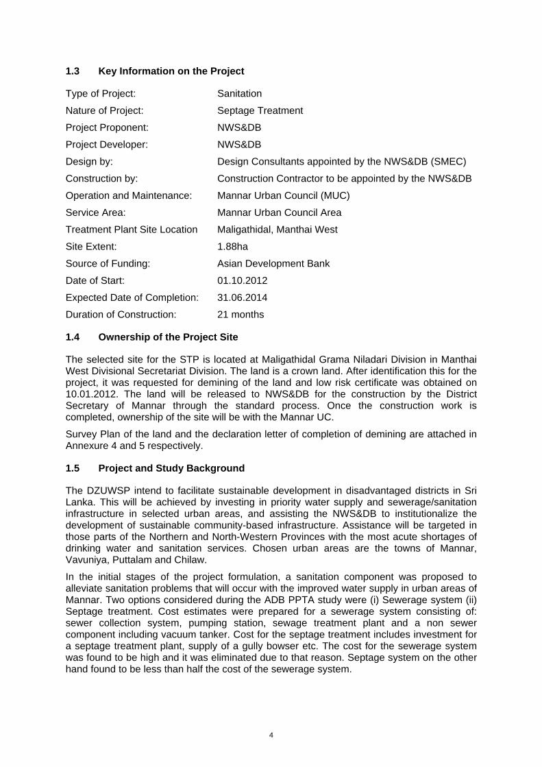
4
1.3 Key Information on the Project
Type of Project: Sanitation
Nature of Project: Septage Treatment
Project Proponent: NWS&DB
Project Developer: NWS&DB
Design by: Design Consultants appointed by the NWS&DB (SMEC)
Construction by: Construction Contractor to be appointed by the NWS&DB
Operation and Maintenance: Mannar Urban Council (MUC)
Service Area: Mannar Urban Council Area
Treatment Plant Site Location Maligathidal, Manthai West
Site Extent: 1.88ha
Source of Funding: Asian Development Bank
Date of Start: 01.10.2012
Expected Date of Completion: 31.06.2014
Duration of Construction: 21 months
1.4 Ownership of the Project Site
The selected site for the STP is located at Maligathidal Grama Niladari Division in Manthai West Divisional Secretariat Division. The land is a crown land. After identification this for the project, it was requested for demining of the land and low risk certificate was obtained on 10.01.2012. The land will be released to NWS&DB for the construction by the District Secretary of Mannar through the standard process. Once the construction work is completed, ownership of the site will be with the Mannar UC.
Survey Plan of the land and the declaration letter of completion of demining are attached in Annexure 4 and 5 respectively.
1.5 Project and Study Background
The DZUWSP intend to facilitate sustainable development in disadvantaged districts in Sri Lanka. This will be achieved by investing in priority water supply and sewerage/sanitation infrastructure in selected urban areas, and assisting the NWS&DB to institutionalize the development of sustainable community-based infrastructure. Assistance will be targeted in those parts of the Northern and North-Western Provinces with the most acute shortages of drinking water and sanitation services. Chosen urban areas are the towns of Mannar, Vavuniya, Puttalam and Chilaw.
In the initial stages of the project formulation, a sanitation component was proposed to alleviate sanitation problems that will occur with the improved water supply in urban areas of Mannar. Two options considered during the ADB PPTA study were (i) Sewerage system (ii) Septage treatment. Cost estimates were prepared for a sewerage system consisting of: sewer collection system, pumping station, sewage treatment plant and a non sewer component including vacuum tanker. Cost for the septage treatment includes investment for a septage treatment plant, supply of a gully bowser etc. The cost for the sewerage system was found to be high and it was eliminated due to that reason. Septage system on the other hand found to be less than half the cost of the sewerage system.
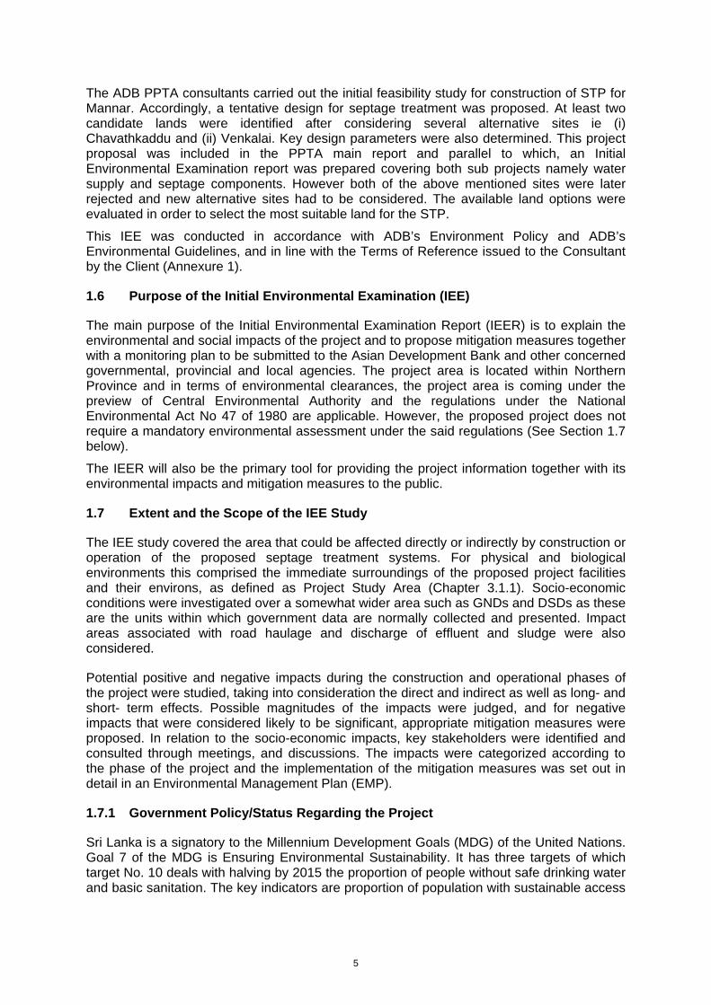
5
The ADB PPTA consultants carried out the initial feasibility study for construction of STP for Mannar. Accordingly, a tentative design for septage treatment was proposed. At least two candidate lands were identified after considering several alternative sites ie (i) Chavathkaddu and (ii) Venkalai. Key design parameters were also determined. This project proposal was included in the PPTA main report and parallel to which, an Initial Environmental Examination report was prepared covering both sub projects namely water supply and septage components. However both of the above mentioned sites were later rejected and new alternative sites had to be considered. The available land options were evaluated in order to select the most suitable land for the STP.
This IEE was conducted in accordance with ADB’s Environment Policy and ADB’s Environmental Guidelines, and in line with the Terms of Reference issued to the Consultant by the Client (Annexure 1).
1.6 Purpose of the Initial Environmental Examination (IEE)
The main purpose of the Initial Environmental Examination Report (IEER) is to explain the environmental and social impacts of the project and to propose mitigation measures together with a monitoring plan to be submitted to the Asian Development Bank and other concerned governmental, provincial and local agencies. The project area is located within Northern Province and in terms of environmental clearances, the project area is coming under the preview of Central Environmental Authority and the regulations under the National Environmental Act No 47 of 1980 are applicable. However, the proposed project does not require a mandatory environmental assessment under the said regulations (See Section 1.7 below).
The IEER will also be the primary tool for providing the project information together with its environmental impacts and mitigation measures to the public.
1.7 Extent and the Scope of the IEE Study
The IEE study covered the area that could be affected directly or indirectly by construction or operation of the proposed septage treatment systems. For physical and biological environments this comprised the immediate surroundings of the proposed project facilities and their environs, as defined as Project Study Area (Chapter 3.1.1). Socio-economic conditions were investigated over a somewhat wider area such as GNDs and DSDs as these are the units within which government data are normally collected and presented. Impact areas associated with road haulage and discharge of effluent and sludge were also considered.
Potential positive and negative impacts during the construction and operational phases of the project were studied, taking into consideration the direct and indirect as well as long- and short- term effects. Possible magnitudes of the impacts were judged, and for negative impacts that were considered likely to be significant, appropriate mitigation measures were proposed. In relation to the socio-economic impacts, key stakeholders were identified and consulted through meetings, and discussions. The impacts were categorized according to the phase of the project and the implementation of the mitigation measures was set out in detail in an Environmental Management Plan (EMP).
1.7.1 Government Policy/Status Regarding the Project
Sri Lanka is a signatory to the Millennium Development Goals (MDG) of the United Nations. Goal 7 of the MDG is Ensuring Environmental Sustainability. It has three targets of which target No. 10 deals with halving by 2015 the proportion of people without safe drinking water and basic sanitation. The key indicators are proportion of population with sustainable access
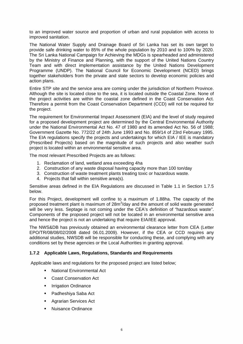
6
to an improved water source and proportion of urban and rural population with access to improved sanitation.
The National Water Supply and Drainage Board of Sri Lanka has set its own target to provide safe drinking water to 85% of the whole population by 2010 and to 100% by 2020. The Sri Lanka National Campaign for Achieving the MDGs is spearheaded and administered by the Ministry of Finance and Planning, with the support of the United Nations Country Team and with direct implementation assistance by the United Nations Development Programme (UNDP). The National Council for Economic Development (NCED) brings together stakeholders from the private and state sectors to develop economic policies and action plans.
Entire STP site and the service area are coming under the jurisdiction of Northern Province. Although the site is located close to the sea, it is located outside the Coastal Zone. None of the project activities are within the coastal zone defined in the Coast Conservation Act. Therefore a permit from the Coast Conservation Department (CCD) will not be required for the project.
The requirement for Environmental Impact Assessment (EIA) and the level of study required for a proposed development project are determined by the Central Environmental Authority under the National Environmental Act No. 47 of 1980 and its amended Act No. 56 of 1988; Government Gazette No. 772/22 of 24th June 1993 and No. 859/14 of 23rd February 1995. The EIA regulations specify the projects and undertakings for which EIA / IEE is mandatory (Prescribed Projects) based on the magnitude of such projects and also weather such project is located within an environmental sensitive area.
The most relevant Prescribed Projects are as follows:
1. Reclamation of land, wetland area exceeding 4ha 2. Construction of any waste disposal having capacity more than 100 ton/day 3. Construction of waste treatment plants treating toxic or hazardous waste. 4. Projects that fall within sensitive area(s).
Sensitive areas defined in the EIA Regulations are discussed in Table 1.1 in Section 1.7.5 below.
For this Project, development will confine to a maximum of 1.88ha. The capacity of the proposed treatment plant is maximum of 28m3/day and the amount of solid waste generated will be very less. Septage is not coming under the CEA’s definition of “hazardous waste”. Components of the proposed project will not be located in an environmental sensitive area and hence the project is not an undertaking that require EIA/IEE approval.
The NWS&DB has previously obtained an environmental clearance letter from CEA (Letter EPO/TR/08/08/02/2008 dated 06.01.2009). However, if the CEA or CCD requires any additional studies, NWSDB will be responsible for conducting these, and complying with any conditions set by these agencies or the Local Authorities in granting approval.
1.7.2 Applicable Laws, Regulations, Standards and Requirements
Applicable laws and regulations for the proposed project are listed below;
National Environmental Act
Coast Conservation Act
Irrigation Ordinance
Padheshiya Saba Act
Agrarian Services Act
Nuisance Ordinance
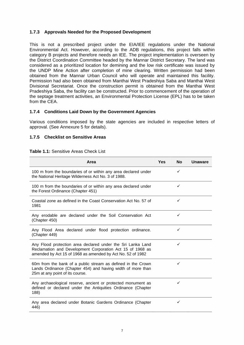
7
1.7.3 Approvals Needed for the Proposed Development
This is not a prescribed project under the EIA/IEE regulations under the National Environmental Act. However, according to the ADB regulations, this project falls within category B projects and therefore needs an IEE. The project implementation is overseen by the District Coordination Committee headed by the Mannar District Secretary. The land was considered as a prioritized location for demining and the low risk certificate was issued by the UNDP Mine Action after completion of mine clearing. Written permission had been obtained from the Mannar Urban Council who will operate and maintained this facility. Permission had also been obtained from Manthai West Pradeshiya Saba and Manthai West Divisional Secretariat. Once the construction permit is obtained from the Manthai West Pradeshiya Saba, the facility can be constructed. Prior to commencement of the operation of the septage treatment activities, an Environmental Protection License (EPL) has to be taken from the CEA.
1.7.4 Conditions Laid Down by the Government Agencies
Various conditions imposed by the state agencies are included in respective letters of approval. (See Annexure 5 for details).
1.7.5 Checklist on Sensitive Areas
Table 1.1: Sensitive Areas Check List
Area Yes No Unaware
100 m from the boundaries of or within any area declared under the National Heritage Wilderness Act No. 3 of 1988.
100 m from the boundaries of or within any area declared under the Forest Ordinance (Chapter 451)
Coastal zone as defined in the Coast Conservation Act No. 57 of 1981
Any erodable are declared under the Soil Conservation Act (Chapter 450)
Any Flood Area declared under flood protection ordinance. (Chapter 449)
Any Flood protection area declared under the Sri Lanka Land Reclamation and Development Corporation Act 15 of 1968 as amended by Act 15 of 1968 as amended by Act No. 52 of 1982
60m from the bank of a public stream as defined in the Crown Lands Ordinance (Chapter 454) and having width of more than 25m at any point of its course.
Any archaeological reserve, ancient or protected monument as defined or declared under the Antiquities Ordinance (Chapter 188)
Any area declared under Botanic Gardens Ordinance (Chapter 446)

8
Within 100m from the boundaries of, or within, any area declared as a Sanctuary under Fauna and Flora Protection Ordinance. (Chapter 469)
100m from the high flood level contour of or within, a public lake as defined in the Crown Lands Ordinance (Chapter 454) including those declared under section 71 of the said Ordinance.
Within a distance of one mile of the boundary of a National Reserve declared under the Fauna and Flora Protection Ordinance.
9
2 DESCRIPTION OF THE PROJECT AND ALTERNATIVES CONSIDERED
2.1 Aim and Scope of the Proposed Project
2.1.1 Project Main Objectives
Provide a sustainable, long-term arrangement for disposal of septage for the Mannar Urban Council (MUC).
2.1.2 Main Beneficiaries
Residences, Commercial Establishments, Institutions located within MUC Area. The MUC will be the main service area of the project and institutionally the MUC is a direct beneficiary of the project
2.1.3 Socio-Economic Effects
The land acquisition for the treatment site has no negative social or economic impact. Land is part of an unused, unproductive land. The land is state owned. Therefore it is a transfer of land between two state agencies without resulting an economic loss as it is not productive at present. Construction work is relatively simple. There will be employment opportunities for unskilled or low skilled workers in the area during construction.
There is no sewerage service in Mannar Urban Area at present. The MUC is providing sanitation services by collection and disposal of septage using gully tankers. The service provided is affected by lack of proper disposal site. New STP will address this drawback and help to improve the urban environment in Mannar. People in Mannar will have significant social and economic benefit due to improved sanitation facilities/service.
The area chosen for the STP construction is not a populated and can be isolated from interfering in to community life and well being through proper planning and design. It is direct access through the main road thus the gully tankers need not take village roads. Therefore significant negative social impacts and public opposition are not expected of the project in the site area.
2.1.4 Description of the Project
Improving the septage disposal services provided by the MUC through: (a) Construction of independent septage treatment facility, and (b) Improving septage collection and transportation capacity with the provision of two gully trucks. Once fully commissioned the plant is capable of receiving 28 m3 of septage daily.
2.1.5 Project Components
STP using waste stabilization pond technology consisting of two anaerobic ponds (for alternative use), facultative pond, maturation pond and a reed bed for polishing purposes. In addition two gully trucks will also be provided to MUC.
2.1.6 Project Layout
See Figure 2.1
2.1.7 Operation and Maintenance
by Mannar Urban Council
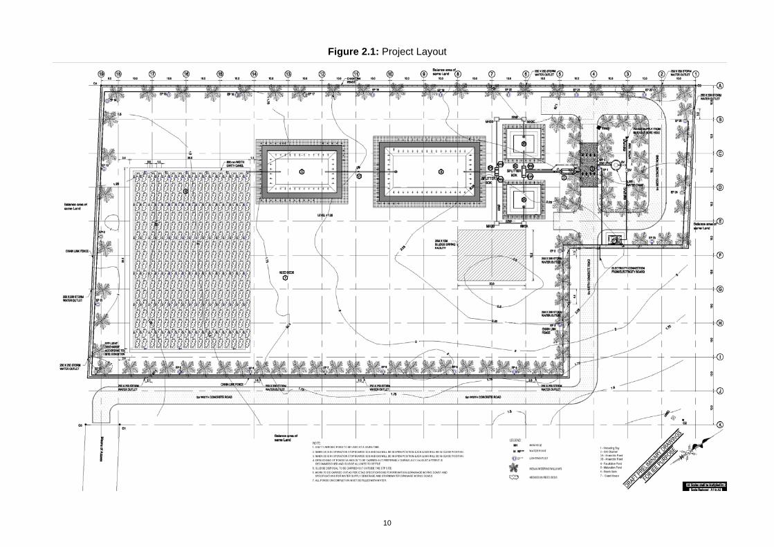
10
Figure 2.1: Project Layout
11
2.1.8 Type of Project
Septage Treatment
2.1.9 Category of Project:
Improvement in Urban Infrastructure in Sanitation; Environmentally the Project is a Category B projects under ADB classification.
2.1.10 Size or Magnitude of Operation
Plant has the capacity to handle 28m3 of septage a day.
Maximum of 2 operators working on daily basis at the treatment plant size; In addition there will be three gully trucks, including the two provided by this project will be operated by the MUC. The total crew manning the gully trucks is 8 (driver + operator). A senior technical officer or public health officer will supervise the operation.
2.1.11 Justification of the Project
With the rapid urbanization and increasing commercial activities, the Mannar Township and its suburbs have become a fast growing centre in the Northern Province. As a result population and building density in the town area is rapidly on the rise. In absence of a sewerage system this town depends on septic tanks and other types of latrines for disposal of sewerage. Emptying of these units from time to time is required for their proper functioning. This is a function that rests with the MUC.
Septage is obnoxious waste carrying pathogenic matter thus needing proper and safe collection, transport and disposal. MUC is currently disposing collected septage in bare lands within the Mannar Island situated outside the MUC area by empting into dug pits and covering it with soil. Land disposal is a safe practice for septage disposal provided soils are of right type, nitrogen build up in the soil is manageable and groundwater pollution is contained. However these conditions are not met in the present practice. Therefore further disposal of septage in this manner is not proper and increasing subjected to public opposition. As such MUC is faced with finding an alternative solution to septage disposal.
The groundwater table in Mannar Island specially within the town area is high. This condition commonly increases the septic tank emptying frequency. Critical issues faced with regard to septage disposal in Mannar are listed below.
1. High groundwater levels during wet season cause soakage systems to fail resulting a higher than usual demand for septic tank emptying. Single gully bowser available to the MUC is grossly inadequate to meet the demand in this period. As a result citizens have to wait long periods to empty their septic tanks.
2. In low density areas it is common that septic tanks/ pits are emptied to dug pits within the same land. Increasing density in the town area and suburbs no longer permit this alternative to be practiced. Thus the demand for gully service is in the rise.
3. As a result of (1) and (2) above, the capacity requirement of septage disposal facility is also on the rise.
Septage disposal commonly depends one of the three technological alternatives. These are: land disposal; disposal at existing sewerage treatment plant; and disposal to independent septage treatment systems. In general the last is the most expensive. Land disposal is the most preferred option in terms of cost. This method of disposal also has environmental and economic advantage under suitable conditions. The critical factor is availability of land.
12
Although many unused lands are situated around Mannar most of them are unavailable for this project due to public opposition. There are other unacceptable due to factors such as high groundwater table, etc. Also Wastewater Treatment plant of sufficient capacity is not available at a reasonable distance. Therefore the two less costly alternatives are not available for Mannar. As such independent septage treatment facility was selected as practical solution.
In the case of independent septage treatment several treatment process streams are available. The proposed treatment process is based on pond system which depends on natural biological digestion / decay process. The treatment method is known for low cost and simple operation among the technologies used for independent treatment facilities. Again the crucial factor is availability of land as this process has high land demand. In this instance the project proponent was able to secure a land of sufficient extent at an acceptable location.
The project also enhances the septage collection capacity of the MUC by providing two vacuum trucks or gully bowsers. This is expected to reduce the waiting time for septic tank emptying. The project is also not unfamiliar to the MUC as they already have one gully bowser and operate a septage land disposal site. Therefore they have the institutional infrastructure to operate the project successfully with additional help to improve the capacity.
2.1.12 Project Location
Mannar is situated on the west coast of the Northern Province of Sri Lanka, 312km north of the national capital Colombo, 111km north-west of the Anuradhapura and 78km south of administrative district capital Jaffna. Mannar town is located on the A14 highway.
2.1.12.1 Treatment Plant Site
The treatment plant is located at Malikathidal GND. The distance from the Mannar town centre is about 10km and the site is situated along the Mannar – Jaffna (A32) main road. The land is located adjacent to the main road and about 200m long internal access road will be developed up to the STP site. The administrative divisions of the STP site are as follows;
I. Local Authority Manthai West Pradeshiya Saba
II. District Secretariat Mannar
III. Provincial Council Northern
IV. Location map Figure 2.2 (prepared using 1:50,000 base map)
2.1.12.2 Service Area
The main service area of the project will be the MUC at the beginning. There are 15 GNDs located within the MUC. Total service area is 27.6km2 with a total population of 25,472. However it is expected that the gradually increasing population in the other LAs such as Manthai West, Mannar, Nanaddan and Musali Pradeshiya Sabas in which the population densities are comparatively low will also benefited from the proposed project. The administrative divisions in which the service area lies are as follows;
I. Local Authority Mannar Urban Council II. District Secretariat Mannar III. Provincial Council Northern IV. Service Area Map Figure 2.3: Service Area and Access Roads.
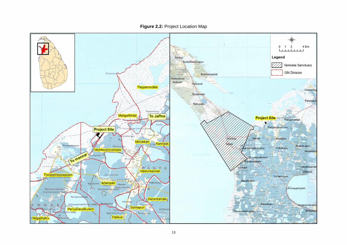
13
Figure 2.2: Project Location Map
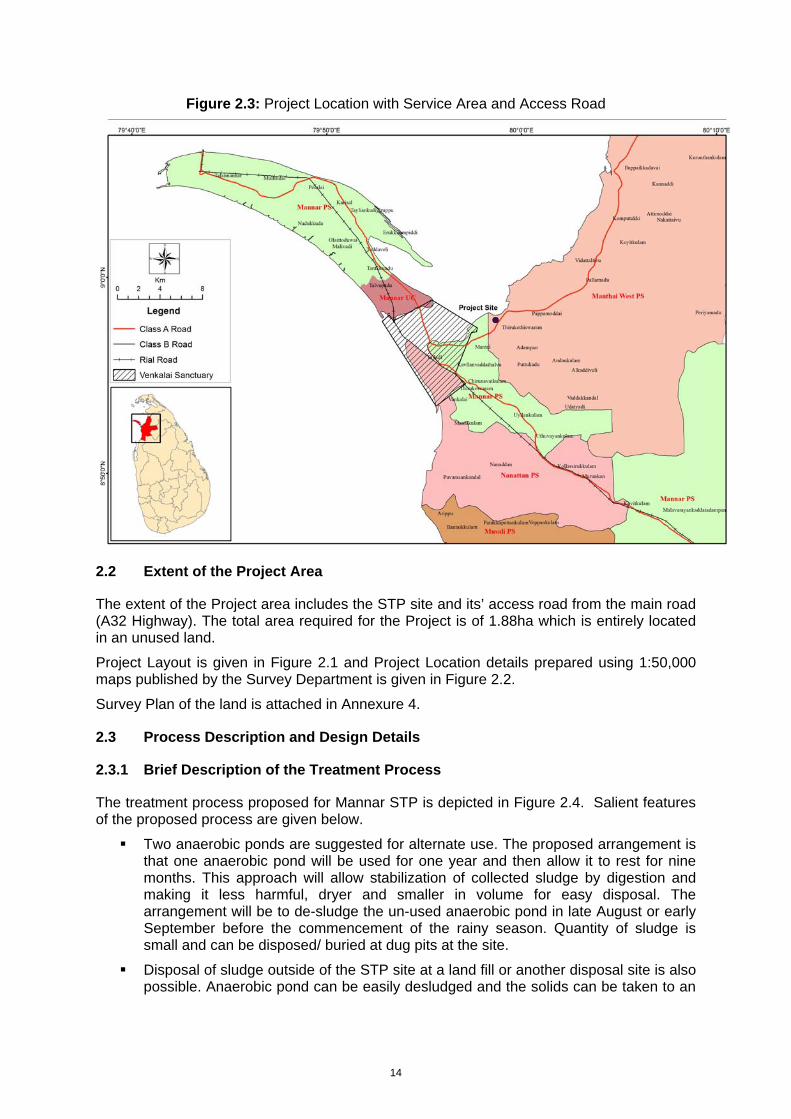
14
Figure 2.3: Project Location with Service Area and Access Road
2.2 Extent of the Project Area
The extent of the Project area includes the STP site and its’ access road from the main road (A32 Highway). The total area required for the Project is of 1.88ha which is entirely located in an unused land.
Project Layout is given in Figure 2.1 and Project Location details prepared using 1:50,000 maps published by the Survey Department is given in Figure 2.2.
Survey Plan of the land is attached in Annexure 4.
2.3 Process Description and Design Details
2.3.1 Brief Description of the Treatment Process
The treatment process proposed for Mannar STP is depicted in Figure 2.4. Salient features of the proposed process are given below.
Two anaerobic ponds are suggested for alternate use. The proposed arrangement is that one anaerobic pond will be used for one year and then allow it to rest for nine months. This approach will allow stabilization of collected sludge by digestion and making it less harmful, dryer and smaller in volume for easy disposal. The arrangement will be to de-sludge the un-used anaerobic pond in late August or early September before the commencement of the rainy season. Quantity of sludge is small and can be disposed/ buried at dug pits at the site.
Disposal of sludge outside of the STP site at a land fill or another disposal site is also possible. Anaerobic pond can be easily desludged and the solids can be taken to an
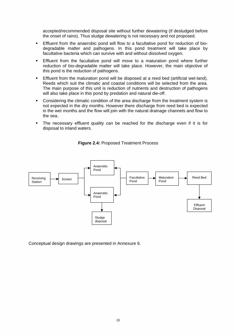
15
accepted/recommended disposal site without further dewatering (if desludged before the onset of rains). Thus sludge dewatering is not necessary and not proposed.
Effluent from the anaerobic pond will flow to a facultative pond for reduction of bio-degradable matter and pathogens. In this pond treatment will take place by facultative bacteria which can survive with and without dissolved oxygen.
Effluent from the facultative pond will move to a maturation pond where further reduction of bio-degradable matter will take place. However, the main objective of this pond is the reduction of pathogens.
Effluent from the maturation pond will be disposed at a reed bed (artificial wet-land). Reeds which suit the climatic and coastal conditions will be selected from the area. The main purpose of this unit is reduction of nutrients and destruction of pathogens will also take place in this pond by predation and natural die-off.
Considering the climatic condition of the area discharge from the treatment system is not expected in the dry months. However there discharge from reed bed is expected in the wet months and the flow will join with the natural drainage channels and flow to the sea.
The necessary effluent quality can be reached for the discharge even if it is for disposal to inland waters.
Figure 2.4: Proposed Treatment Process
Conceptual design drawings are presented in Annexure 6.
Anaerobic Pond
Sludge disposal
Screen Facultative Pond
Anaerobic Pond
Reed Bed Receiving Station
Effluent Disposal
Maturation Pond
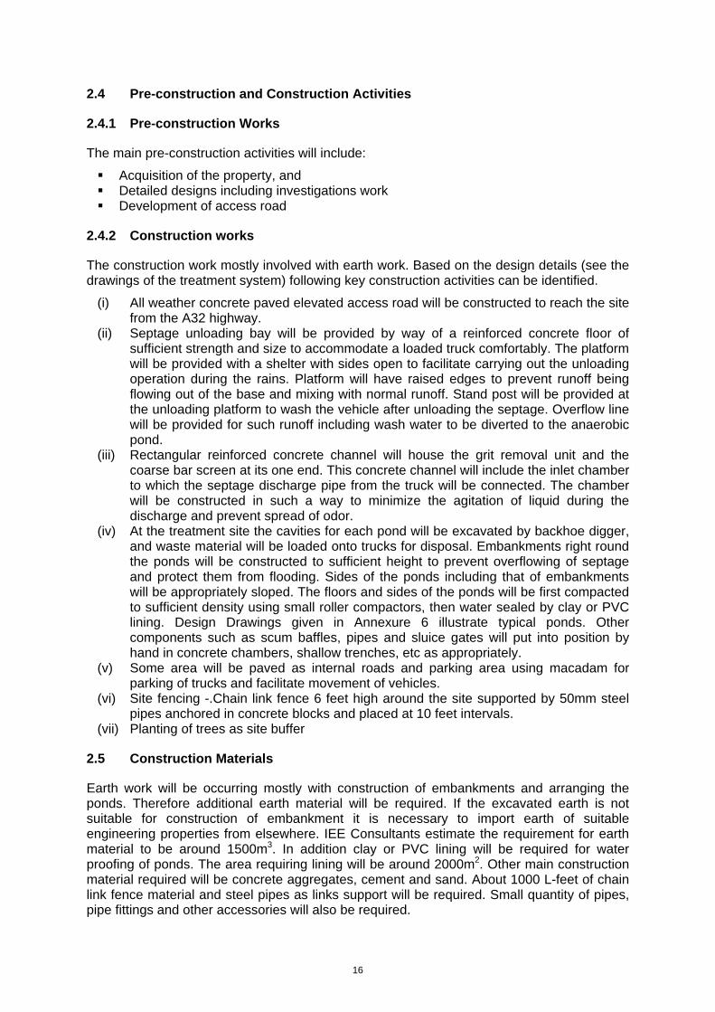
16
2.4 Pre-construction and Construction Activities
2.4.1 Pre-construction Works
The main pre-construction activities will include:
Acquisition of the property, and Detailed designs including investigations work Development of access road
2.4.2 Construction works
The construction work mostly involved with earth work. Based on the design details (see the drawings of the treatment system) following key construction activities can be identified.
(i) All weather concrete paved elevated access road will be constructed to reach the site from the A32 highway.
(ii) Septage unloading bay will be provided by way of a reinforced concrete floor of sufficient strength and size to accommodate a loaded truck comfortably. The platform will be provided with a shelter with sides open to facilitate carrying out the unloading operation during the rains. Platform will have raised edges to prevent runoff being flowing out of the base and mixing with normal runoff. Stand post will be provided at the unloading platform to wash the vehicle after unloading the septage. Overflow line will be provided for such runoff including wash water to be diverted to the anaerobic pond.
(iii) Rectangular reinforced concrete channel will house the grit removal unit and the coarse bar screen at its one end. This concrete channel will include the inlet chamber to which the septage discharge pipe from the truck will be connected. The chamber will be constructed in such a way to minimize the agitation of liquid during the discharge and prevent spread of odor.
(iv) At the treatment site the cavities for each pond will be excavated by backhoe digger, and waste material will be loaded onto trucks for disposal. Embankments right round the ponds will be constructed to sufficient height to prevent overflowing of septage and protect them from flooding. Sides of the ponds including that of embankments will be appropriately sloped. The floors and sides of the ponds will be first compacted to sufficient density using small roller compactors, then water sealed by clay or PVC lining. Design Drawings given in Annexure 6 illustrate typical ponds. Other components such as scum baffles, pipes and sluice gates will put into position by hand in concrete chambers, shallow trenches, etc as appropriately.
(v) Some area will be paved as internal roads and parking area using macadam for parking of trucks and facilitate movement of vehicles.
(vi) Site fencing -.Chain link fence 6 feet high around the site supported by 50mm steel pipes anchored in concrete blocks and placed at 10 feet intervals.
(vii) Planting of trees as site buffer
2.5 Construction Materials
Earth work will be occurring mostly with construction of embankments and arranging the ponds. Therefore additional earth material will be required. If the excavated earth is not suitable for construction of embankment it is necessary to import earth of suitable engineering properties from elsewhere. IEE Consultants estimate the requirement for earth material to be around 1500m3. In addition clay or PVC lining will be required for water proofing of ponds. The area requiring lining will be around 2000m2. Other main construction material required will be concrete aggregates, cement and sand. About 1000 L-feet of chain link fence material and steel pipes as links support will be required. Small quantity of pipes, pipe fittings and other accessories will also be required.
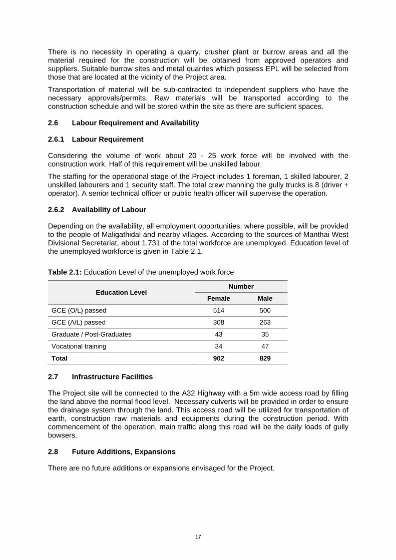
17
There is no necessity in operating a quarry, crusher plant or burrow areas and all the material required for the construction will be obtained from approved operators and suppliers. Suitable burrow sites and metal quarries which possess EPL will be selected from those that are located at the vicinity of the Project area.
Transportation of material will be sub-contracted to independent suppliers who have the necessary approvals/permits. Raw materials will be transported according to the construction schedule and will be stored within the site as there are sufficient spaces.
2.6 Labour Requirement and Availability
2.6.1 Labour Requirement
Considering the volume of work about 20 - 25 work force will be involved with the construction work. Half of this requirement will be unskilled labour.
The staffing for the operational stage of the Project includes 1 foreman, 1 skilled labourer, 2 unskilled labourers and 1 security staff. The total crew manning the gully trucks is 8 (driver + operator). A senior technical officer or public health officer will supervise the operation.
2.6.2 Availability of Labour
Depending on the availability, all employment opportunities, where possible, will be provided to the people of Maligathidal and nearby villages. According to the sources of Manthai West Divisional Secretariat, about 1,731 of the total workforce are unemployed. Education level of the unemployed workforce is given in Table 2.1.
Table 2.1: Education Level of the unemployed work force
Education Level Number
Female Male
GCE (O/L) passed 514 500
GCE (A/L) passed 308 263
Graduate / Post-Graduates 43 35
Vocational training 34 47
Total 902 829
2.7 Infrastructure Facilities
The Project site will be connected to the A32 Highway with a 5m wide access road by filling the land above the normal flood level. Necessary culverts will be provided in order to ensure the drainage system through the land. This access road will be utilized for transportation of earth, construction raw materials and equipments during the construction period. With commencement of the operation, main traffic along this road will be the daily loads of gully bowsers.
2.8 Future Additions, Expansions
There are no future additions or expansions envisaged for the Project.
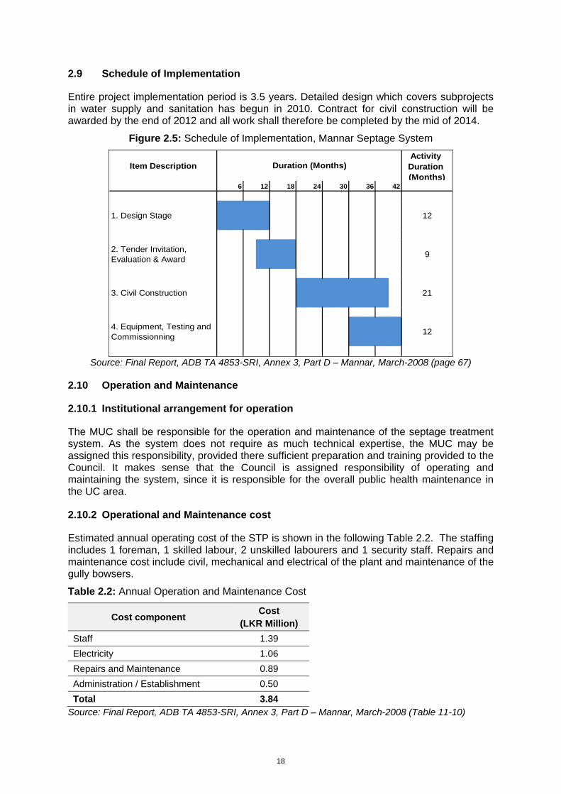
18
2.9 Schedule of Implementation
Entire project implementation period is 3.5 years. Detailed design which covers subprojects in water supply and sanitation has begun in 2010. Contract for civil construction will be awarded by the end of 2012 and all work shall therefore be completed by the mid of 2014.
Figure 2.5: Schedule of Implementation, Mannar Septage System
Item DescriptionActivity Duration (Months)
6 12 18 24 30 36 42
1. Design Stage 12
2. Tender Invitation, Evaluation & Award 9
3. Civil Construction 21
4. Equipment, Testing and Commissionning 12
Duration (Months)
Source: Final Report, ADB TA 4853-SRI, Annex 3, Part D – Mannar, March-2008 (page 67)
2.10 Operation and Maintenance
2.10.1 Institutional arrangement for operation
The MUC shall be responsible for the operation and maintenance of the septage treatment system. As the system does not require as much technical expertise, the MUC may be assigned this responsibility, provided there sufficient preparation and training provided to the Council. It makes sense that the Council is assigned responsibility of operating and maintaining the system, since it is responsible for the overall public health maintenance in the UC area.
2.10.2 Operational and Maintenance cost
Estimated annual operating cost of the STP is shown in the following Table 2.2. The staffing includes 1 foreman, 1 skilled labour, 2 unskilled labourers and 1 security staff. Repairs and maintenance cost include civil, mechanical and electrical of the plant and maintenance of the gully bowsers.
Table 2.2: Annual Operation and Maintenance Cost
Cost component Cost
(LKR Million)
Staff 1.39 Electricity 1.06 Repairs and Maintenance 0.89 Administration / Establishment 0.50 Total 3.84
Source: Final Report, ADB TA 4853-SRI, Annex 3, Part D – Mannar, March-2008 (Table 11-10)
19
2.10.3 Capacity to meet the O&M expenditure
As far as institutional aspects are concerned it is observed that the institutional capacities of the Implementing Agency and the Executing Agency are already in place adequately. The NWS&DB, the Implementing Agency, can handle the project without any difficulty as its exiting institutional strength has the capacity to undertake the project.
Existing institutional capacity of the Executing Agency, the MUC, is also seen adequate to handle the project. Only addition that will be needed is to recruit drivers and helpers for the Gully Bousers to be provided by the project. Apart from this there is no need to increase any cadre in the Urban Council for this purpose.
It is open to recover the costs of operation and maintenance from service fees, but believes that the capital cost of the infrastructure should be made as a grant to the Urban Council. If and when the proposed treatment plant comes into operation, the Public Health Division has to be strengthened by hiring additional expertise, developing the capacities of existing personnel as nobody from among the current staff has the training nor the experience to run a STP.
2.10.4 Septage collection and delivery
Under the project, gully bowsers will be provided to MUC which is responsible for operating the sanitation service. The Council will ensure that the tankers are serviced and repaired to manufacturer’s specifications so that the vehicles have a long working life. They will also assign a team for each gully bowser employed and plan their work schedule, through which all septic tanks in the town are expected to be emptied at least once a year. Each team shall include a driver, 1 inspector/hauler and 1 assistant responsible for the following;
- Inspection to determine septic tank access and condition of tanks
- Pumping, transport and disposal
- Recording of volume and source of septage
2.10.5 Operation and Maintenance of treatment plant
The main requirement for maintaining the septage treatment facility is for the regular removal and disposal of sludge from the drying beds and scum that floats on the liquid fraction and is left behind on the floor of the thickening beds. Sludge is retained in the thickening beds for approximately a month and the drying beds for 10-15 days, after which the scum and sludge are removed from one thickening bed and a pair of drying beds by a small front-end loader and deposited into a truck.
2.10.6 Skills requirements
As described above, nobody from among the current staff of MUC has training or experience in STP and therefore it is suggested that this project should provide MUC with training and assistance in establishing such a system. The staff assigned shall be trained on the job prior to development. After which, they shall receive continuous training to strengthen their expertise in the O&M of the STP.
A unit within the Public Health Division of MUC shall be comprised with the following skills’
- Billing and collection staff
- Inspectors and Haulers
- STP operators
- Sanitary Engineer
20
2.11 Evaluation of Alternatives
2.11.1 Alternative Technologies
Septage disposal commonly depends one of the three technological alternatives. These are: land disposal; disposal at existing sewerage treatment plant; and disposal at independent septage treatment systems.
2.11.1.1 Land Disposal
Land application of septage is the most common means of septage disposal. This is in fact happening at household level where septic tanks are emptied to dug-pits within the same property and backfilled. Most LAs to the knowledge of the consultant depend on land for septage disposal. The advantages of land disposal are: it is simple and economical; low in energy use; and recycle the organic and nutrients to land. This is the method currently practiced by the MUC to dispose septage.
Mannar is situated in an area where there are some opportunities for land disposal. Common requirements for land disposal are: ability to finds land of sufficient extent far from human habitats; suitable soil and groundwater table levels. The loading rates are determined by the nitrogen levels, which in turn is link to nitrogen demand by crops/vegetation. Presence of large unused low productive lands in Mannar generally presents an opportunity for land disposal.
According to the project proponent (NWS&DB) as well as the project beneficiary (MUC), their search for suitable site/land for septage disposal did not materialized. There is an unwillingness to accept septage by communities living in villages outside the Mannar Town. Among the reasons for lack of support are concerns negative publicity, odor and health problems. Septage transportation is also an issue that constraint locations for disposal sites. Septage is an objectionable waste. Transportation through narrow access roads in built up areas also generate community resistance to disposal sites. High water table in most areas of Mannar where land is available is also a reason for difficulties in finding a suitable land. As a result although the project planners preferred land disposal, it had to be abundant due to lack of proper disposal site.
2.11.1.2 Disposal at Wastewater Treatment Plant
The next obvious technological alternative to land disposal is disposal at existing Wastewater Treatment Plants (WWTP). However, disposal of septage creates significant loading (organic loading) related problems in small treatment plants. Furthermore the plants should have proper facilities and arrangement to handles the odor problems. Finally the WWTP if available should be at a reasonable distance from the source to realize the economic rationale of choosing it. There is no WWTP close to Mannar
2.11.1.3 Independent Septage Treatment System
Technologically this is the least preferred option for septage disposal because of cost. They range from lagoons systems to complex mechanical systems that include many unit operations and processes. Treatment need to handle both liquid and solid components of septage. The mechanical systems can be complex in operation and maintenance similar to WWTPs. Lagoons in general is easy to operate and maintain. Despite the cost disadvantage the project proponent selected independent treatment option as other technological alternatives are not viable.
There is number of process design options available for STP. The choice of technology will depend on volume of septage generated; economy of scale; land availability; regulatory requirements, etc. The common process options listed below are discussed in Section 2.11.2.
21
Lagoons
Composting
Biological secondary treatment processes
Aerobic digestion
Anaerobic digestion
Lime stabilization
Chlorine oxidation
There are other supplementary treatment processes which may also be required to be integrated with above main treatment methods. These include:
Conditioning
Dewatering
Disinfection
Odor control
Combining design options listed above is also practiced.
2.11.1.4 Technology of Choice
As explained both land disposal and disposal at existing WWTP are not viable for disposal of septage collected in MUC area. This was despite the fact that those alternatives would cost less. Therefore independent STP was selected as the viable option for Mannar.
2.11.2 Alternative Designs
Designers considered the design options available to them before finalization of the process design. The choice of design process was governed by: low capital and operational cost; ease of operation; and not excessive demand on O&M agency capacity and operator skills. Details are given below.
2.11.2.1 Lagoons
Lagoons are again preferred independent treatment design option when suitable land is available at reasonable cost. Properly designed lagoons are easy to operate and maintain. They perform well and meet the treatment goals consistently. They can be operated year-round and are relatively easy and inexpensive to build and operate and suits the conditions of Sri Lanka.
Lagoons can be built in series where the first lagoon also acts as an anaerobic digester. The other lagoons in the series act as facultative, aerobic/polishing ponds providing further treatment. Effluent shall meet the discharge standards and sludge need to be removed from the lagoons particularly from the first lagoon periodically. With long retention periods good quality effluent is achievable.
The design option considered for Mannar plant is system of lagoons in series. This include anaerobic pond (lagoon) followed by one facultative ponds and one polishing ponds and artificial wetland (reed bed). Anaerobic pond will be de-sludged time to time. Dried sludge will be disposed at landfill.
2.11.2.2 Composting
Composting is another treatment and disposal method used for septage. Separated septage sludge or liquid septage can be composted. The composting of liquid septage is accomplished by adding additional bulking agents (e.g., woodchips, sawdust, bark chips,
22
etc.). This process requires large quantities of bulking agents and generally not recommended if bulking agents are not easily and freely (without cost) accessible. Composting of sludge does require lesser quantity of bulking agents. Where there is a good demand for compost composting can be an attractive option.
Composting was not considered as an alternative in this case. First liquid septage composting is impractical due to demand for large quantity of bulking material. Sludge composting will require unit operation to separate liquid and solid components, composting system for sludge and additional treatment mechanism for liquid portion. Therefore this treatment train is too cumbersome compared to the lagoon option. Thus it is not considered as a suitable method of treatment.
2.11.2.3 Biological Secondary Treatment Processes
Basic composition of septage is similar to domestic sewage although concentration levels are extremely high and highly variable. Thus processes used in treating sewage can be used to the treatment of septage. High variability in waste strength and characteristics may present operational problems for some activated sludge processes. However, extended aeration processes are capable of handling such conditions. Fixed growth biological systems at low loadings are also suited to septage treatment due to their relative ease of operation.
However, these treatment systems are high in construction cost. They also consume large amount of energy and high in operational cost. The O&M agency have sufficient capability to operate the plant. Due to these factors biological secondary treatment was not considered as design option.
2.11.2.4 Aerobic Digestion
Aerobic digestion operates in the endogenous respiration phase. Cell matter is oxidized to carbon dioxide, water, and other inert materials. Compared with anaerobic digestion, aerobic process is easier to operate and maintain. It is lower in capital costs, and produces an odorless, biologically stable residual that dewaters easily.
Major problem associated with aerobic digestion of septage is odor. Form can also be a problem, if detergents are used substantially. Aerobic digestion requires constant monitoring and operator attention. Thus have high demand for operator skills. It is sensitive to toxic substances. This method requires further handling (e.g. dewatering, transportation, etc.) prior to ultimate disposal.
Aerobic digestion is not an attractive design option in this case. This is due to high capital cost, high energy demand, high operating cost, high operator skill requirement, and high O&M agency capacity. Because of these limitations this design option was not considered further.
2.11.2.5 Anaerobic Digestion
Anaerobic digestion is another process that fits for septage treatment. The limitations of anaerobic digestion include its high capital cost (compared with aerobic digestion), very sensitive to reactor environment; needs close monitoring requirements; poor quality supernatant (high oxygen demand and high concentrations of nitrogen and suspended solids), and relatively long detention time required for stabilization. Thus further treatment is required to meet the standards.
Compared to aerobic digestion the anaerobic digestion also has the same limitations and more. Because of this anaerobic digestion was not considered as treatment option.
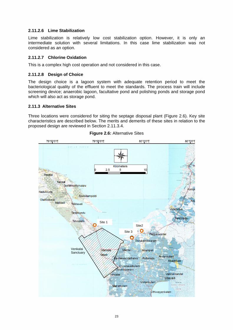
23
2.11.2.6 Lime Stabilization
Lime stabilization is relatively low cost stabilization option. However, it is only an intermediate solution with several limitations. In this case lime stabilization was not considered as an option.
2.11.2.7 Chlorine Oxidation
This is a complex high cost operation and not considered in this case.
2.11.2.8 Design of Choice
The design choice is a lagoon system with adequate retention period to meet the bacteriological quality of the effluent to meet the standards. The process train will include screening device; anaerobic lagoon, facultative pond and polishing ponds and storage pond which will also act as storage pond.
2.11.3 Alternative Sites
Three locations were considered for siting the septage disposal plant (Figure 2.6). Key site characteristics are described below. The merits and demerits of these sites in relation to the proposed design are reviewed in Section 2.11.3.4.
Figure 2.6: Alternative Sites
Site 1
Site 3
Site2
Venkalai Sanctuary
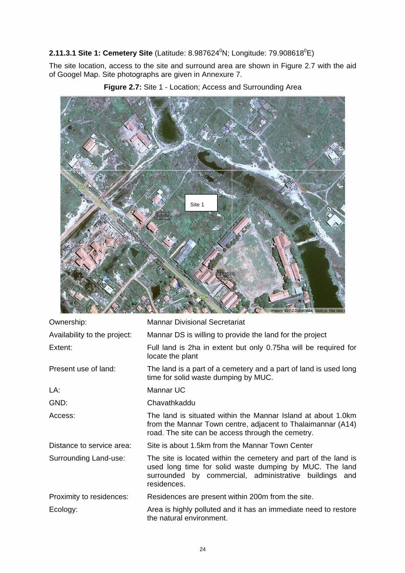
24
2.11.3.1 Site 1: Cemetery Site (Latitude: 8.9876240N; Longitude: 79.9086180E)
The site location, access to the site and surround area are shown in Figure 2.7 with the aid of Googel Map. Site photographs are given in Annexure 7.
Figure 2.7: Site 1 - Location; Access and Surrounding Area
Ownership: Mannar Divisional Secretariat
Availability to the project: Mannar DS is willing to provide the land for the project
Extent: Full land is 2ha in extent but only 0.75ha will be required for locate the plant
Present use of land: The land is a part of a cemetery and a part of land is used long time for solid waste dumping by MUC.
LA: Mannar UC
GND: Chavathkaddu
Access: The land is situated within the Mannar Island at about 1.0km from the Mannar Town centre, adjacent to Thalaimannar (A14) road. The site can be access through the cemetry.
Distance to service area: Site is about 1.5km from the Mannar Town Center
Surrounding Land-use: The site is located within the cemetery and part of the land is used long time for solid waste dumping by MUC. The land surrounded by commercial, administrative buildings and residences.
Proximity to residences: Residences are present within 200m from the site.
Ecology: Area is highly polluted and it has an immediate need to restore the natural environment.
Site 1
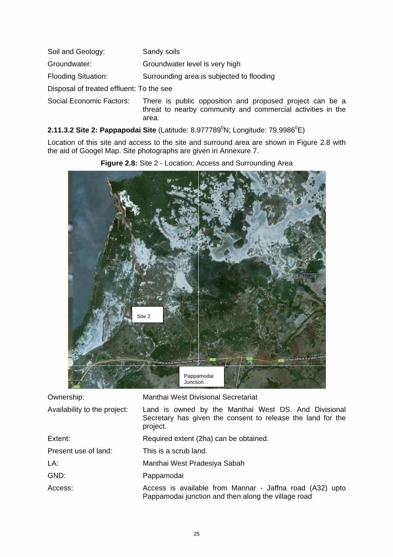
25
Soil and Geology: Sandy soils
Groundwater: Groundwater level is very high
Flooding Situation: Surrounding area is subjected to flooding
Disposal of treated effluent: To the see
Social Economic Factors: There is public opposition and proposed project can be a threat to nearby community and commercial activities in the area.
2.11.3.2 Site 2: Pappapodai Site (Latitude: 8.9777890N; Longitude: 79.99860E)
Location of this site and access to the site and surround area are shown in Figure 2.8 with the aid of Googel Map. Site photographs are given in Annexure 7.
Figure 2.8: Site 2 - Location; Access and Surrounding Area
Ownership: Manthai West Divisional Secretariat
Availability to the project: Land is owned by the Manthai West DS. And Divisional Secretary has given the consent to release the land for the project.
Extent: Required extent (2ha) can be obtained.
Present use of land: This is a scrub land.
LA: Manthai West Pradesiya Sabah
GND: Pappamodai
Access: Access is available from Mannar - Jaffna road (A32) upto Pappamodai junction and then along the village road
Site 2
Pappamodai Junction
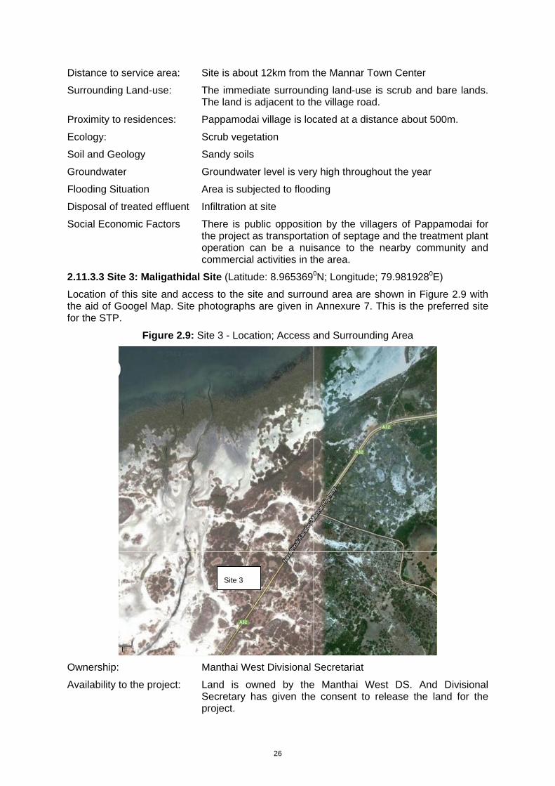
26
Distance to service area: Site is about 12km from the Mannar Town Center
Surrounding Land-use: The immediate surrounding land-use is scrub and bare lands. The land is adjacent to the village road.
Proximity to residences: Pappamodai village is located at a distance about 500m.
Ecology: Scrub vegetation
Soil and Geology Sandy soils
Groundwater Groundwater level is very high throughout the year
Flooding Situation Area is subjected to flooding
Disposal of treated effluent Infiltration at site
Social Economic Factors There is public opposition by the villagers of Pappamodai for the project as transportation of septage and the treatment plant operation can be a nuisance to the nearby community and commercial activities in the area.
2.11.3.3 Site 3: Maligathidal Site (Latitude: 8.9653690N; Longitude; 79.9819280E)
Location of this site and access to the site and surround area are shown in Figure 2.9 with the aid of Googel Map. Site photographs are given in Annexure 7. This is the preferred site for the STP.
Figure 2.9: Site 3 - Location; Access and Surrounding Area
Ownership: Manthai West Divisional Secretariat
Availability to the project: Land is owned by the Manthai West DS. And Divisional Secretary has given the consent to release the land for the project.
Site 3
27
Extent: 1.88ha
Present use of land: This is a scrub land.
LA: Manthai West Pradesiya Sabah
GND: Maligathidal
Access: Access is available from Mannar - Jaffna road (A32)
Distance to service area: Site is about 10km from the Mannar Town Center
Surrounding Land-use: The surrounding land-use is scrub and bare lands. The land is adjacent to the A32 main road.
Proximity to residences: Residences are not located close to the site
Ecology: Scrub vegetation
Soil and Geology Sandy soils
Groundwater Groundwater level is very high throughout the year
Flooding Situation Surrounding area is subjected to flooding but the land is located at higher elevation more than the road level.
Disposal of treated effluent Infiltration to ground thro reed beds and discharge to the nearby surface water body during the rainy season
Social Economic Factors No public opposition on the project as residences are located sufficiently away from the site
2.11.3.4 Site of Choice
All the lands are government owned land and are available for the project purpose through the standard land transfer process. However, the required area is sufficiently available only at Site 2 and as designers has estimated around 1.5ha of land will be required to locate the tanks of the proposed facility.
Groundwater contamination is another major issue with septage lagoon systems. The groundwater table is very high in all three sites. Soil is also sandy in all three sites. Therefore good lining to prevent groundwater contamination is required. Construction cost will be similar for all three sites.
None of the sites require relocation of people. As the Site 1 is located highly populated area in a close proximity to Mannar town centre and public opposition on the project is inevitable. There is public opposition for Site 3 by the villagers of Pappamodai for the project as transportation of septage and the treatment plant operation can be a nuisance to the nearby community and commercial activities in the area.
Once constructed the treatment plant will be away from residences by more than 500m only in Site 3. There are In general reasonable buffer is advocated for all STP due to odor problems as well as aesthetic reasons. This is easily possible in Site 3 compared to other two sites.
Site 3 is also found to be advantageous in terms of access. This site can be accessed from Mannar town along the main Mannar – Jaffna (A32) road. Thus gully tankers need not use narrow village roads, where bad road conditions will cause agitation of tanker contents and release of gases.
Considering the above factors the Site 3 is chosen as the best alternative for locating the proposed plant.
28
2.11.4 No Action Alternative
Septage disposal is a major problem within MUC area. High water-table in most parts of MUC area is the main cause of the problem. The problem is high during rainy season. Therefore having a suitable, safe arrangement for disposal of septage is a must for the MUC. At present septage collected is disposed at unused government lands. Method used is to discharge the septage to dug holes and close it after the truck is emptied. This is safe and acceptable practice provided soil is suitable for such disposal, groundwater table is sufficiently lower and nitrate pollution can be managed. These conditions are not met at present disposal sites. This situation has forced the MUC to look for long-term permanent arrangement.
No actions could lead to unsafe disposal of septage by MUC, if alternate land disposal site is not available. General public will also resort to bad practices for disposal of septage. The result will be negative environmental, pollution and health impacts.
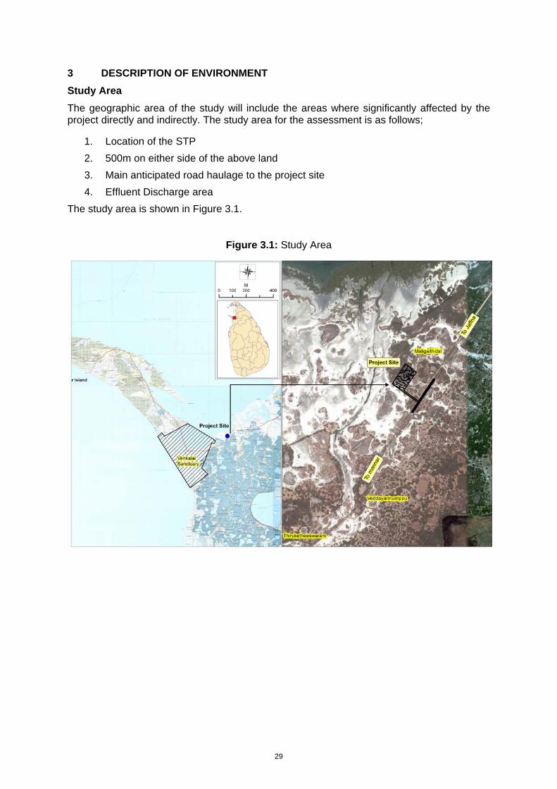
29
3 DESCRIPTION OF ENVIRONMENT
Study Area
The geographic area of the study will include the areas where significantly affected by the project directly and indirectly. The study area for the assessment is as follows;
1. Location of the STP 2. 500m on either side of the above land 3. Main anticipated road haulage to the project site 4. Effluent Discharge area
The study area is shown in Figure 3.1.
Figure 3.1: Study Area
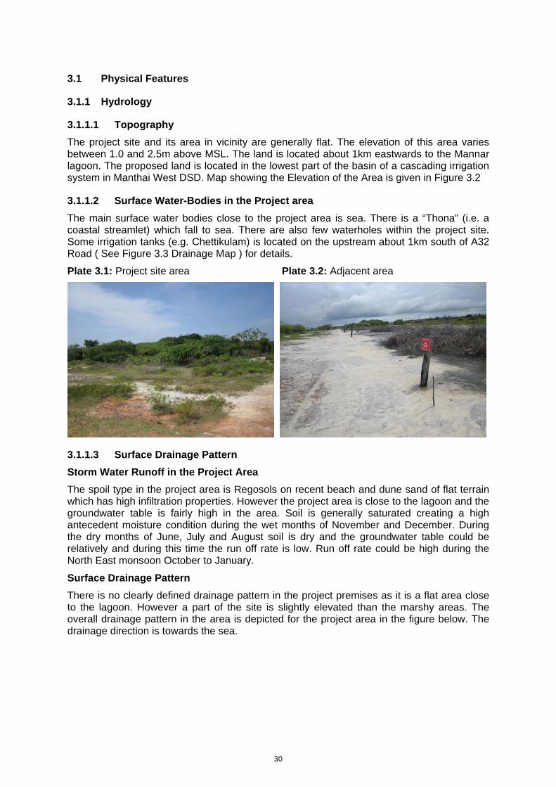
30
3.1 Physical Features
3.1.1 Hydrology
3.1.1.1 Topography
The project site and its area in vicinity are generally flat. The elevation of this area varies between 1.0 and 2.5m above MSL. The land is located about 1km eastwards to the Mannar lagoon. The proposed land is located in the lowest part of the basin of a cascading irrigation system in Manthai West DSD. Map showing the Elevation of the Area is given in Figure 3.2
3.1.1.2 Surface Water-Bodies in the Project area
The main surface water bodies close to the project area is sea. There is a “Thona” (i.e. a coastal streamlet) which fall to sea. There are also few waterholes within the project site. Some irrigation tanks (e.g. Chettikulam) is located on the upstream about 1km south of A32 Road ( See Figure 3.3 Drainage Map ) for details.
Plate 3.1: Project site area Plate 3.2: Adjacent area
3.1.1.3 Surface Drainage Pattern
Storm Water Runoff in the Project Area
The spoil type in the project area is Regosols on recent beach and dune sand of flat terrain which has high infiltration properties. However the project area is close to the lagoon and the groundwater table is fairly high in the area. Soil is generally saturated creating a high antecedent moisture condition during the wet months of November and December. During the dry months of June, July and August soil is dry and the groundwater table could be relatively and during this time the run off rate is low. Run off rate could be high during the North East monsoon October to January.
Surface Drainage Pattern
There is no clearly defined drainage pattern in the project premises as it is a flat area close to the lagoon. However a part of the site is slightly elevated than the marshy areas. The overall drainage pattern in the area is depicted for the project area in the figure below. The drainage direction is towards the sea.
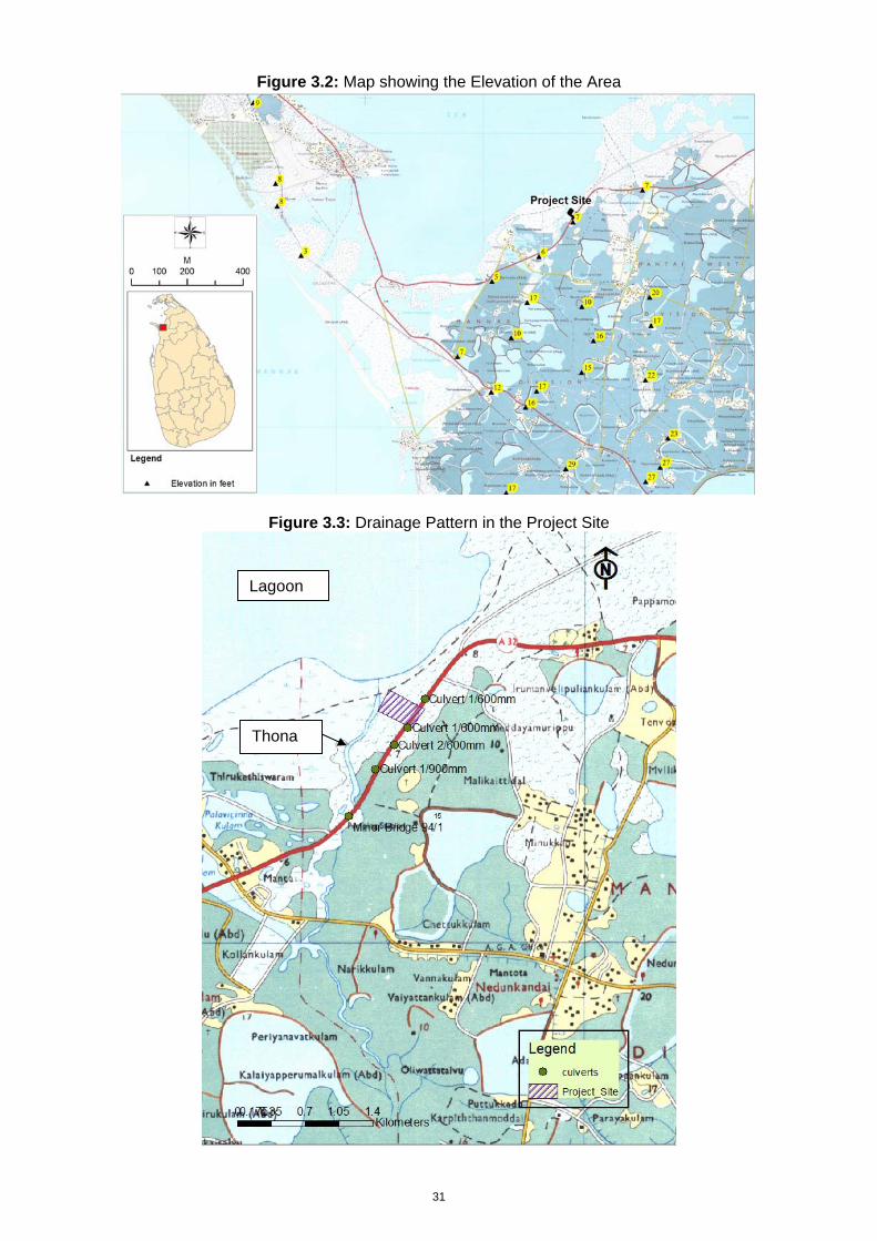
31
Figure 3.2: Map showing the Elevation of the Area
Figure 3.3: Drainage Pattern in the Project Site
Lagoon
Thona
32
Flooding in surrounding area and anticipated levels of flooding; Changes in flooding due to the project
Flooding in the low lying areas usually takes place during the North East monsoon and only a part of the site is subjected to such inundation. According to the drainage map above (Figure 3.3) there are no clearly defined streams or large catchment areas directed towards the project site. There is a catchment area for the “Thona” and part of the project site is in the flood plain of the said thona. There are no clearly defined water paths or large catchment areas for the culvert crossings of A32 road near the project site except for the minor bridge 94/1 which is across the thona. This thona is only active during the monsoon season. Part of the site is in a relatively high ground which is not usually subject to inundation.
High Flood Level (HFL) of the site was determined based on the flood marks at the site. High Flood Level was obtained with respect to the levels of the topographic survey. In addition to the catchment induced water levels the possible water level increase from the sea water level rise was also determined. HFL was taken as the highest water levels from the above two scenarios. Details of the HFL determination are as follows.
HFL Determination for Mannar Septage Plant, Malikathidal
Lowest site level 1 m MSL
Highest site level 2.5 m MSL
Scenario 1 - HFL Owing to Inland Water Flooding
High Flood Level 0.3m above lowest level ( NWS &DB Observations)
HFL 1 1.3 m MSL
HFL 2 1.5 m MSL ( Consultant's Observation)
( Flood water has invaded roughly to the mid site i.e. level 1.5m MSL)
Scenario 2 - HFL Owing to Sea Water Intrusion in Extreme Cases
Maximum spring tide 0.35 m MSL
Wind set up 0.2 m
Wave setup 0.1 m
Cyclone 0.3 m
HFL 3 0.95 m MSL
Say 1 m MSL
Final HFL 1.5 m MSL ( Highest of HFL 1, 2 & 3)
It is also recommended to provide 0.3m or more free board depending on the design of structural elements.
Since half of the site is higher than 2.0m MSL HFL+ FB of 1.8m could be adopted as definitely the plant will be placed on the higher elevation region.
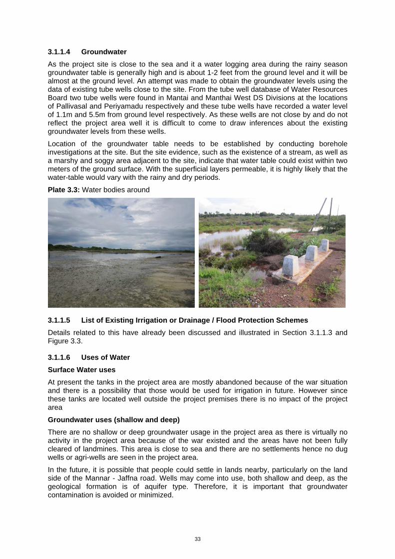
33
3.1.1.4 Groundwater
As the project site is close to the sea and it a water logging area during the rainy season groundwater table is generally high and is about 1-2 feet from the ground level and it will be almost at the ground level. An attempt was made to obtain the groundwater levels using the data of existing tube wells close to the site. From the tube well database of Water Resources Board two tube wells were found in Mantai and Manthai West DS Divisions at the locations of Pallivasal and Periyamadu respectively and these tube wells have recorded a water level of 1.1m and 5.5m from ground level respectively. As these wells are not close by and do not reflect the project area well it is difficult to come to draw inferences about the existing groundwater levels from these wells.
Location of the groundwater table needs to be established by conducting borehole investigations at the site. But the site evidence, such as the existence of a stream, as well as a marshy and soggy area adjacent to the site, indicate that water table could exist within two meters of the ground surface. With the superficial layers permeable, it is highly likely that the water-table would vary with the rainy and dry periods.
Plate 3.3: Water bodies around
3.1.1.5 List of Existing Irrigation or Drainage / Flood Protection Schemes
Details related to this have already been discussed and illustrated in Section 3.1.1.3 and Figure 3.3.
3.1.1.6 Uses of Water
Surface Water uses
At present the tanks in the project area are mostly abandoned because of the war situation and there is a possibility that those would be used for irrigation in future. However since these tanks are located well outside the project premises there is no impact of the project area
Groundwater uses (shallow and deep)
There are no shallow or deep groundwater usage in the project area as there is virtually no activity in the project area because of the war existed and the areas have not been fully cleared of landmines. This area is close to sea and there are no settlements hence no dug wells or agri-wells are seen in the project area.
In the future, it is possible that people could settle in lands nearby, particularly on the land side of the Mannar - Jaffna road. Wells may come into use, both shallow and deep, as the geological formation is of aquifer type. Therefore, it is important that groundwater contamination is avoided or minimized.
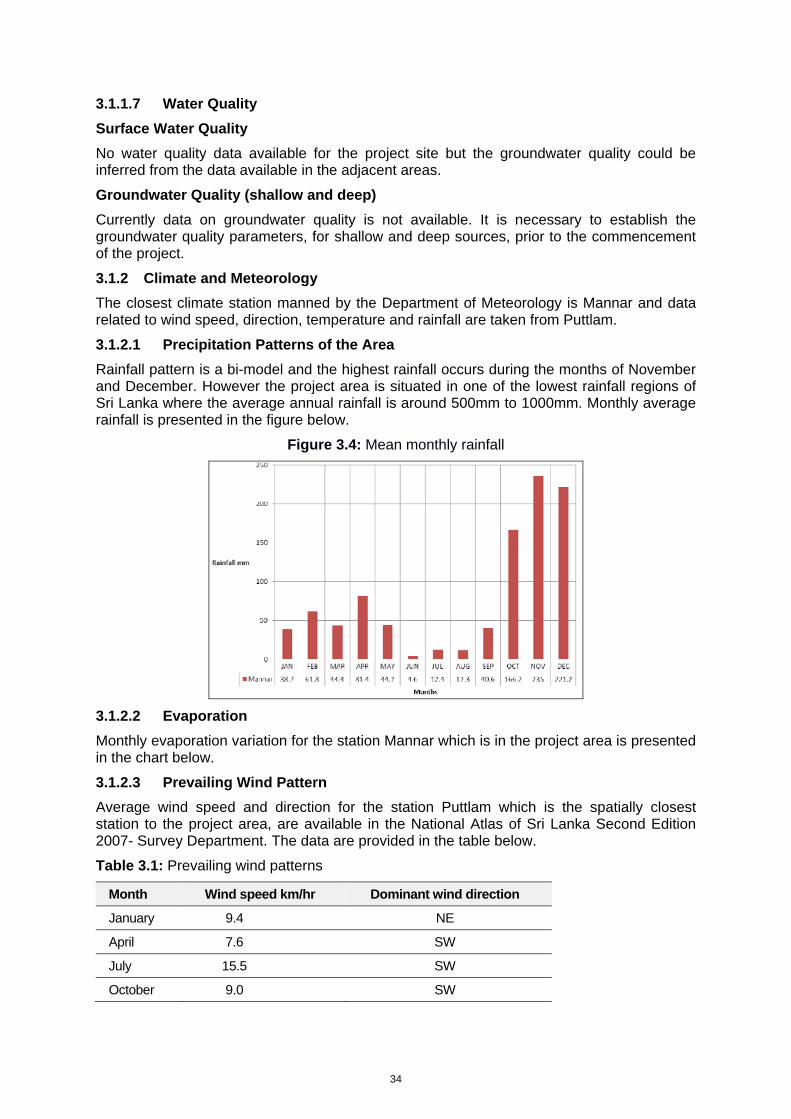
34
3.1.1.7 Water Quality
Surface Water Quality
No water quality data available for the project site but the groundwater quality could be inferred from the data available in the adjacent areas.
Groundwater Quality (shallow and deep)
Currently data on groundwater quality is not available. It is necessary to establish the groundwater quality parameters, for shallow and deep sources, prior to the commencement of the project.
3.1.2 Climate and Meteorology
The closest climate station manned by the Department of Meteorology is Mannar and data related to wind speed, direction, temperature and rainfall are taken from Puttlam.
3.1.2.1 Precipitation Patterns of the Area
Rainfall pattern is a bi-model and the highest rainfall occurs during the months of November and December. However the project area is situated in one of the lowest rainfall regions of Sri Lanka where the average annual rainfall is around 500mm to 1000mm. Monthly average rainfall is presented in the figure below.
Figure 3.4: Mean monthly rainfall
3.1.2.2 Evaporation
Monthly evaporation variation for the station Mannar which is in the project area is presented in the chart below.
3.1.2.3 Prevailing Wind Pattern
Average wind speed and direction for the station Puttlam which is the spatially closest station to the project area, are available in the National Atlas of Sri Lanka Second Edition 2007- Survey Department. The data are provided in the table below.
Table 3.1: Prevailing wind patterns
Month Wind speed km/hr Dominant wind direction
January 9.4 NE
April 7.6 SW
July 15.5 SW
October 9.0 SW
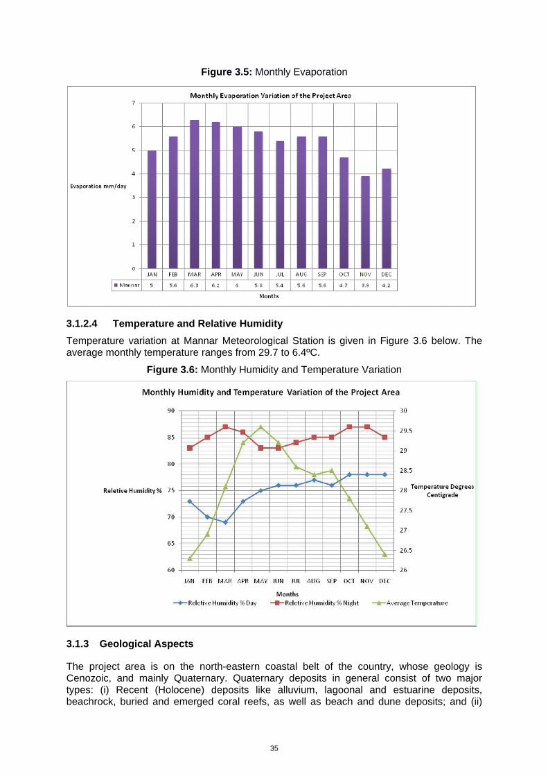
35
Figure 3.5: Monthly Evaporation
3.1.2.4 Temperature and Relative Humidity
Temperature variation at Mannar Meteorological Station is given in Figure 3.6 below. The average monthly temperature ranges from 29.7 to 6.4ºC.
Figure 3.6: Monthly Humidity and Temperature Variation
3.1.3 Geological Aspects
The project area is on the north-eastern coastal belt of the country, whose geology is Cenozoic, and mainly Quaternary. Quaternary deposits in general consist of two major types: (i) Recent (Holocene) deposits like alluvium, lagoonal and estuarine deposits, beachrock, buried and emerged coral reefs, as well as beach and dune deposits; and (ii)
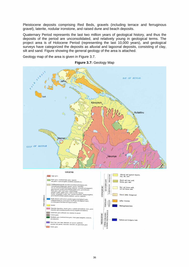
36
Pleistocene deposits comprising Red Beds, gravels (including terrace and ferruginous gravel), laterite, nodular ironstone, and raised dune and beach deposits.
Quaternary Period represents the last two million years of geological history, and thus the deposits of the period are unconsolidated, and relatively young in geological terms. The project area is of Holocene Period (representing the last 10,000 years), and geological surveys have categorized the deposits as alluvial and lagoonal deposits, consisting of clay, silt and sand. Figure showing the general geology of the area is attached.
Geology map of the area is given in Figure 3.7.
Figure 3.7: Geology Map
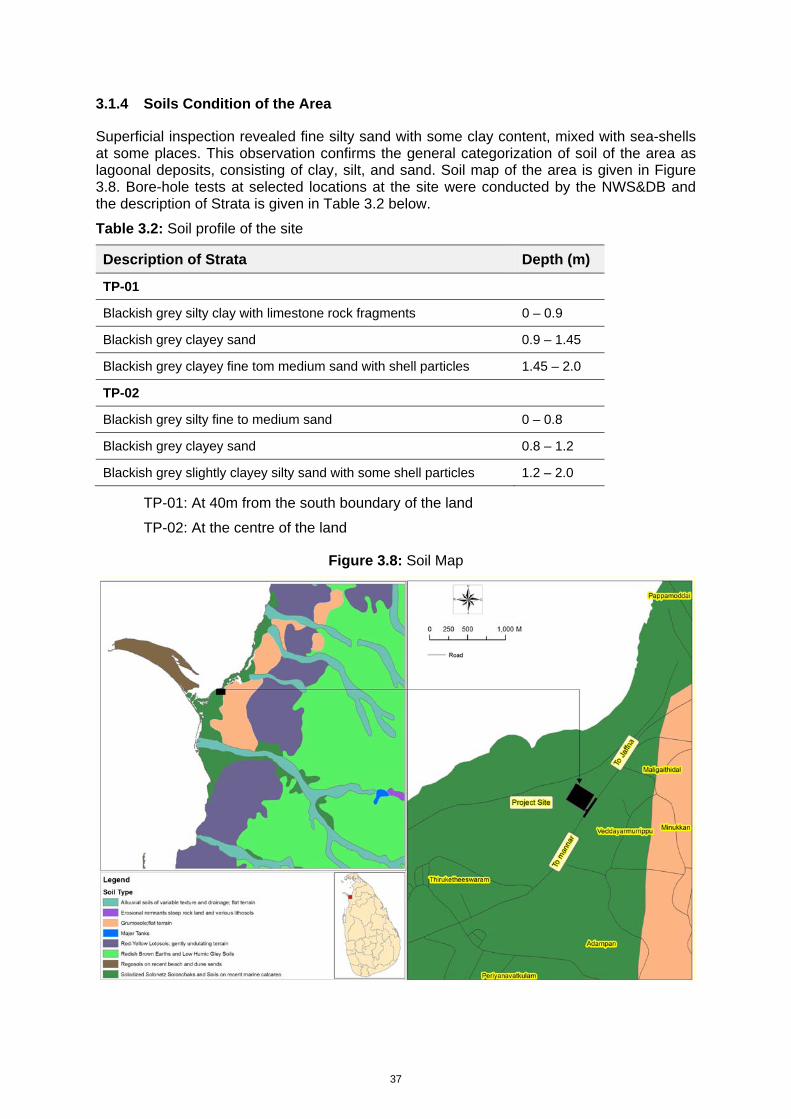
37
3.1.4 Soils Condition of the Area
Superficial inspection revealed fine silty sand with some clay content, mixed with sea-shells at some places. This observation confirms the general categorization of soil of the area as lagoonal deposits, consisting of clay, silt, and sand. Soil map of the area is given in Figure 3.8. Bore-hole tests at selected locations at the site were conducted by the NWS&DB and the description of Strata is given in Table 3.2 below.
Table 3.2: Soil profile of the site
Description of Strata Depth (m)
TP-01
Blackish grey silty clay with limestone rock fragments 0 – 0.9
Blackish grey clayey sand 0.9 – 1.45
Blackish grey clayey fine tom medium sand with shell particles 1.45 – 2.0
TP-02
Blackish grey silty fine to medium sand 0 – 0.8
Blackish grey clayey sand 0.8 – 1.2
Blackish grey slightly clayey silty sand with some shell particles 1.2 – 2.0
TP-01: At 40m from the south boundary of the land
TP-02: At the centre of the land
Figure 3.8: Soil Map
38
3.1.5 Geology and hydro-geology of the area
Geology of the area consist of formations during the Holocene period, which are generally unconsolidated material consisting of clay, silt, and sand. Bore-hole data obtained previously in Mannar area indicate sand, silt, clay and various mixtures of those at the surface underlain by highly fractured limestone; rock level at which limestone was found in Mannar varied, but was in general at a depth of 8m or more. Similar conditions can be expected at the site. There was no evidence of wells in the vicinity of the site, but military personnel involved in de-mining work mentioned that water could be found at the depth of approximately two meters. There was a stream with slow moving water, as well as a marshy and soggy area adjacent to the site, indicating that water table could exist at shallow depth, less than two meters from the ground surface. The superficial deposits, as well as the underlying limestone, can be considered as quite permeable, and therefore can be categorized as possible aquifers.
3.1.6 Natural Disasters and Risks
The vulnerability of the site to intense storms and associated wind cannot be ruled out. During heavy rains the spill water from upstream tanks flows through the area and the low lands of the project area are subjected to inundation. However the inundation does not remain for a longer period. Although the area is subjected to inundation every year during the North East monsoon there is no historical evidence to show that flooding has taken place in the area at disastrous levels.
Because of its location on the west coast, Mannar was largely unaffected by the Asian tsunami of December 2004, which caused such extensive damage on the east coast of Sri Lanka. The area is not seismically active. Past disaster incidents from 1980 to date were obtained from the Disaster Management Center’s database. Number of events recorded in Mannar and Manthai West DSDs are given in the following Table 3.3.
Table 3.3: Natural Disasters Recorded in DSDs
Disaster category No of Events
Manthai West DSD Mannar DSD Mannar District
Floods 11 64 151 Cyclones - - - Gale - 1 1 Strong Wind - - 4 Drought 1 1 1
3.1.7 Atmosphere
3.1.7.1 Air quality
No data are available on air quality in or around Mannar, although the absence of heavy industry in the town should ensure that air quality is reasonably good. Exhaust emissions from vehicles might increase the levels of carbon monoxide and certain other pollutants such as SOx, NOx and hydrocarbons but the coastal location means that winds are relatively strong, which would ensure effective dispersion.
3.1.7.2 Noise
The proposed treatment plant site is located in a unpopulated area where surrounded by A32 highway near the Mannar lagoon and the observed noise level is fairly low.

39
3.1.8 Land-use
3.1.8.1 Land-use pattern
Main beneficiaries of the proposed project will be the households in the Mannar Urban Council area in the beginning. However, it is expected to extend the facility to all the Pradeshiya Sabha areas within the District of Mannar, later. Therefore, land use pattern of the District of Mannar, in a broader context, will be discussed in this report and detailed analysis will be focused on the land use pattern of the Mannar Town DS / AGA Division, as the MUC area falls within this DS / AGA Division. Since the Septage Treatment Plant will be located in the Malikathidal GN Division of Manthai West DS Division, the land use pattern of this DS Division will also be discussed in detail. Land use pattern of the area is given in Figure 3.9.
The District of Mannar covers a land area of 2002.7km2. There are five (05) DS/AGA Divisions in the District and a total of 153 Graman Niladhari Divisions (GN Divisions) coming under these five DS / AGA Divisions
Mannar Town DS Division covers an area of 226.88 km2. In analysing the land use pattern of the DS Division, significance of Paddy cultivation can be highlighted. The total asweddumized area of paddy has been recorded as 2770ha. Out of the total asweddumized area of paddy, 2075 ha are cultivated under major irrigation schemes while 307 ha are under minor irrigation schemes. The extent under rain fed paddy cultivation has been recorded as 388 ha. A large area of land is covered by highland crops which account for 1,589 ha.
Among the highland crops, Chilli, Red Onion, Green Gram, Cowpea, Groundnut, Maize, Manioc and Sweet Potato are grown in small land parcels. Vegetable cultivation is also popular in the DS Division. Commonly grown vegetables are, Brinjal, Tomato, Capcium, Okra, Long Bean, Beetroot, Bitter Gourd, Snake Gourd and Pumpkin.
A fair extent of land has been used for cultivation of different kinds of fruits. Mango, Papaw, Banana and pomegranate are the most popular varieties of fruits grown in the DS Division.
Home gardening does not seem prominent in the area. Only 1585 home garden units covering 110 ha of land have been identified in the Mannar Town DS/AGA Division.
Significantly large extents of land are used for perennial crops. Among the perennial crops in the DS/AGA Division, most significant varieties are Palmyrah and Coconut. The total area under Palmyrah has been recorded as 3,360ha. The area covered under Coconut accounts for 2,010ha. Other noticeable perennial crop in the DS Division is Cashew which accounts for 200 ha.
Since the proposed Septage Treatment Plant to be located in the Malikathidal GN Division coming under the Manthai West DS/AGA Division, it was considered appropriate to study the land use pattern of this /AGA Division as well.
Manthai West DS/AGA Division covers an area of 658.90 km2 or 51,282 ha of land. In this DS/AGA Division Paddy farming is more prominent. The total land area under paddy cultivation has been recorded as 6,035 ha. Out of the total extent under paddy cultivation 4,150ha are irrigated by major irrigation schemes while 1,400ha are irrigated from minor irrigation schemes. Rain fed paddy cultivation accounts for 535ha.
The total land area under highland crops in the DS Division is 804 ha. Among the highland crops, Chilli, Red Onion, Green Gram, Cowpea, Groundnut, Maize, Manioc and Sweet Potato are popular among the farmers. The vegetable cultivation does not play a significant role in the economy. Commonly grown vegetables are, Brinjal, Tomato, Capsicum, Okra, Long Bean, Beetroot, Bitter Gourd, Snake Gourd and Pumpkin.
The extent of land under fruit cultivation in Manthai West DS Division is fairly large. Banana, Mango and Papaw are the most popular varieties. Home gardens are spread over a land area of 31.5 ha consisting of 510 units.
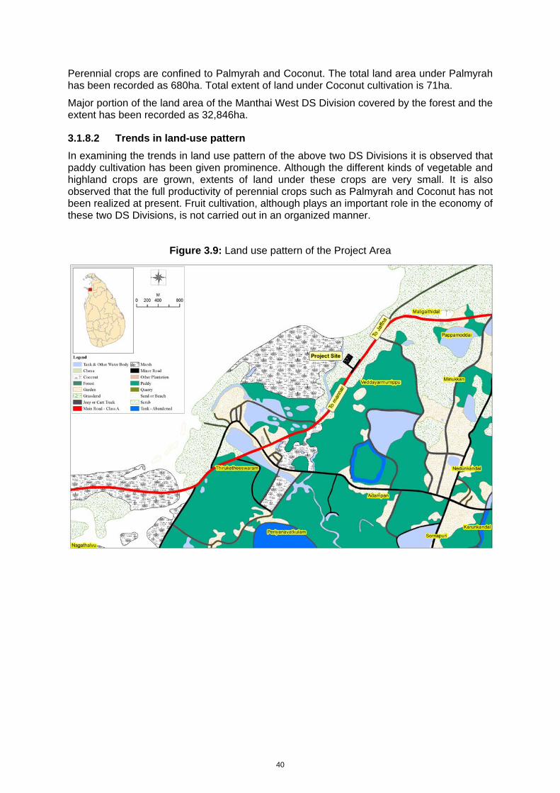
40
Perennial crops are confined to Palmyrah and Coconut. The total land area under Palmyrah has been recorded as 680ha. Total extent of land under Coconut cultivation is 71ha.
Major portion of the land area of the Manthai West DS Division covered by the forest and the extent has been recorded as 32,846ha.
3.1.8.2 Trends in land-use pattern
In examining the trends in land use pattern of the above two DS Divisions it is observed that paddy cultivation has been given prominence. Although the different kinds of vegetable and highland crops are grown, extents of land under these crops are very small. It is also observed that the full productivity of perennial crops such as Palmyrah and Coconut has not been realized at present. Fruit cultivation, although plays an important role in the economy of these two DS Divisions, is not carried out in an organized manner.
Figure 3.9: Land use pattern of the Project Area
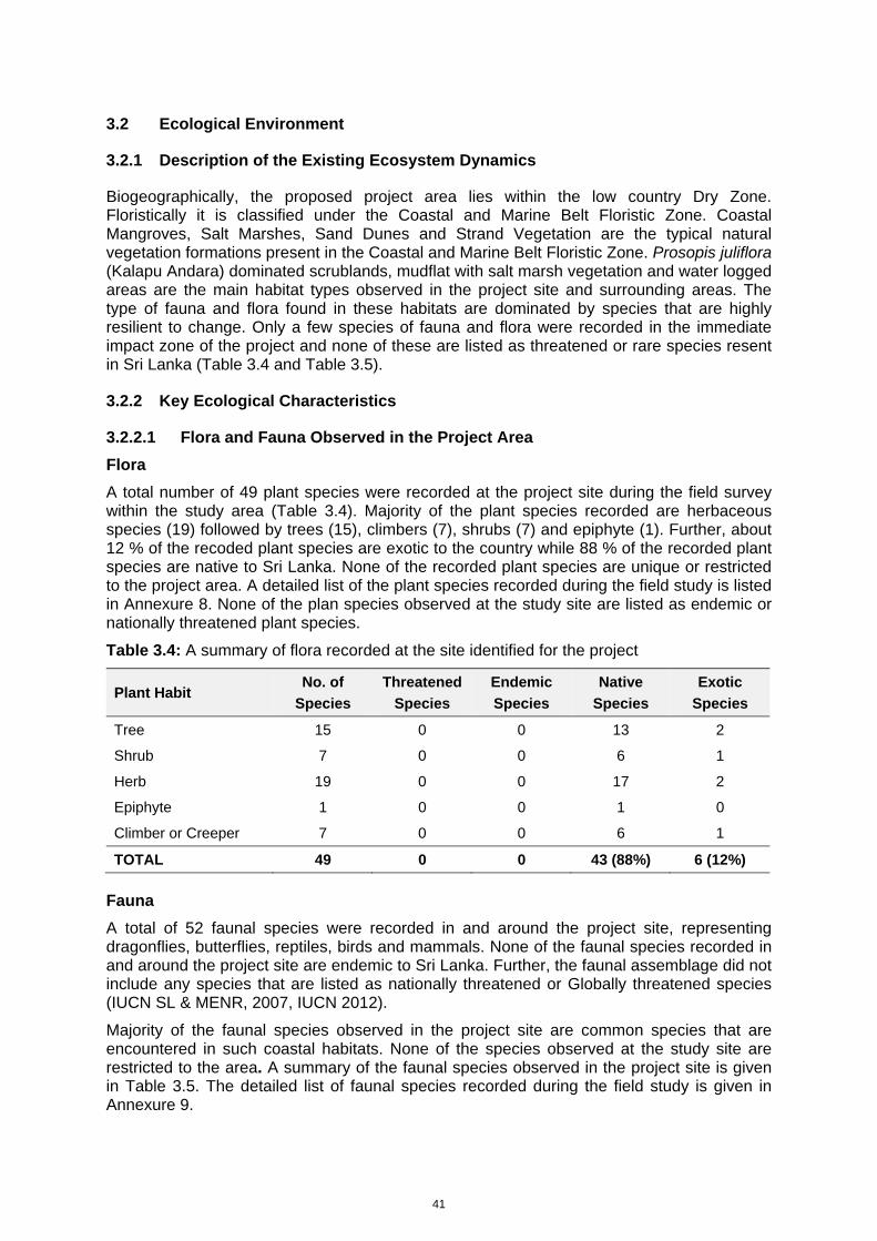
41
3.2 Ecological Environment
3.2.1 Description of the Existing Ecosystem Dynamics
Biogeographically, the proposed project area lies within the low country Dry Zone. Floristically it is classified under the Coastal and Marine Belt Floristic Zone. Coastal Mangroves, Salt Marshes, Sand Dunes and Strand Vegetation are the typical natural vegetation formations present in the Coastal and Marine Belt Floristic Zone. Prosopis juliflora (Kalapu Andara) dominated scrublands, mudflat with salt marsh vegetation and water logged areas are the main habitat types observed in the project site and surrounding areas. The type of fauna and flora found in these habitats are dominated by species that are highly resilient to change. Only a few species of fauna and flora were recorded in the immediate impact zone of the project and none of these are listed as threatened or rare species resent in Sri Lanka (Table 3.4 and Table 3.5).
3.2.2 Key Ecological Characteristics
3.2.2.1 Flora and Fauna Observed in the Project Area
Flora
A total number of 49 plant species were recorded at the project site during the field survey within the study area (Table 3.4). Majority of the plant species recorded are herbaceous species (19) followed by trees (15), climbers (7), shrubs (7) and epiphyte (1). Further, about 12 % of the recoded plant species are exotic to the country while 88 % of the recorded plant species are native to Sri Lanka. None of the recorded plant species are unique or restricted to the project area. A detailed list of the plant species recorded during the field study is listed in Annexure 8. None of the plan species observed at the study site are listed as endemic or nationally threatened plant species.
Table 3.4: A summary of flora recorded at the site identified for the project
Plant Habit No. of
Species
Threatened
Species
Endemic
Species
Native
Species
Exotic
Species
Tree 15 0 0 13 2
Shrub 7 0 0 6 1
Herb 19 0 0 17 2
Epiphyte 1 0 0 1 0
Climber or Creeper 7 0 0 6 1
TOTAL 49 0 0 43 (88%) 6 (12%)
Fauna
A total of 52 faunal species were recorded in and around the project site, representing dragonflies, butterflies, reptiles, birds and mammals. None of the faunal species recorded in and around the project site are endemic to Sri Lanka. Further, the faunal assemblage did not include any species that are listed as nationally threatened or Globally threatened species (IUCN SL & MENR, 2007, IUCN 2012).
Majority of the faunal species observed in the project site are common species that are encountered in such coastal habitats. None of the species observed at the study site are restricted to the area. A summary of the faunal species observed in the project site is given in Table 3.5. The detailed list of faunal species recorded during the field study is given in Annexure 9.
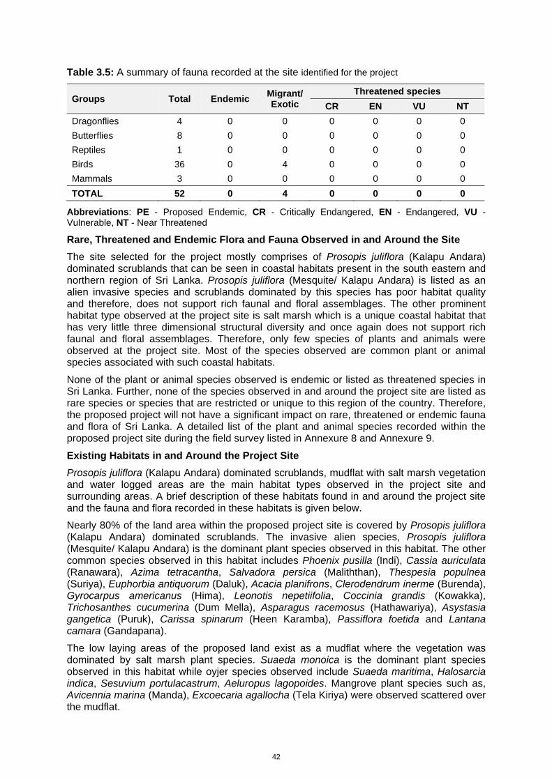
42
Table 3.5: A summary of fauna recorded at the site identified for the project
Groups Total Endemic Migrant/ Exotic
Threatened species
CR EN VU NT
Dragonflies 4 0 0 0 0 0 0 Butterflies 8 0 0 0 0 0 0 Reptiles 1 0 0 0 0 0 0 Birds 36 0 4 0 0 0 0 Mammals 3 0 0 0 0 0 0 TOTAL 52 0 4 0 0 0 0
Abbreviations: PE - Proposed Endemic, CR - Critically Endangered, EN - Endangered, VU - Vulnerable, NT - Near Threatened
Rare, Threatened and Endemic Flora and Fauna Observed in and Around the Site
The site selected for the project mostly comprises of Prosopis juliflora (Kalapu Andara) dominated scrublands that can be seen in coastal habitats present in the south eastern and northern region of Sri Lanka. Prosopis juliflora (Mesquite/ Kalapu Andara) is listed as an alien invasive species and scrublands dominated by this species has poor habitat quality and therefore, does not support rich faunal and floral assemblages. The other prominent habitat type observed at the project site is salt marsh which is a unique coastal habitat that has very little three dimensional structural diversity and once again does not support rich faunal and floral assemblages. Therefore, only few species of plants and animals were observed at the project site. Most of the species observed are common plant or animal species associated with such coastal habitats.
None of the plant or animal species observed is endemic or listed as threatened species in Sri Lanka. Further, none of the species observed in and around the project site are listed as rare species or species that are restricted or unique to this region of the country. Therefore, the proposed project will not have a significant impact on rare, threatened or endemic fauna and flora of Sri Lanka. A detailed list of the plant and animal species recorded within the proposed project site during the field survey listed in Annexure 8 and Annexure 9.
Existing Habitats in and Around the Project Site
Prosopis juliflora (Kalapu Andara) dominated scrublands, mudflat with salt marsh vegetation and water logged areas are the main habitat types observed in the project site and surrounding areas. A brief description of these habitats found in and around the project site and the fauna and flora recorded in these habitats is given below.
Nearly 80% of the land area within the proposed project site is covered by Prosopis juliflora (Kalapu Andara) dominated scrublands. The invasive alien species, Prosopis juliflora (Mesquite/ Kalapu Andara) is the dominant plant species observed in this habitat. The other common species observed in this habitat includes Phoenix pusilla (Indi), Cassia auriculata (Ranawara), Azima tetracantha, Salvadora persica (Maliththan), Thespesia populnea (Suriya), Euphorbia antiquorum (Daluk), Acacia planifrons, Clerodendrum inerme (Burenda), Gyrocarpus americanus (Hima), Leonotis nepetiifolia, Coccinia grandis (Kowakka), Trichosanthes cucumerina (Dum Mella), Asparagus racemosus (Hathawariya), Asystasia gangetica (Puruk), Carissa spinarum (Heen Karamba), Passiflora foetida and Lantana camara (Gandapana).
The low laying areas of the proposed land exist as a mudflat where the vegetation was dominated by salt marsh plant species. Suaeda monoica is the dominant plant species observed in this habitat while oyjer species observed include Suaeda maritima, Halosarcia indica, Sesuvium portulacastrum, Aeluropus lagopoides. Mangrove plant species such as, Avicennia marina (Manda), Excoecaria agallocha (Tela Kiriya) were observed scattered over the mudflat.
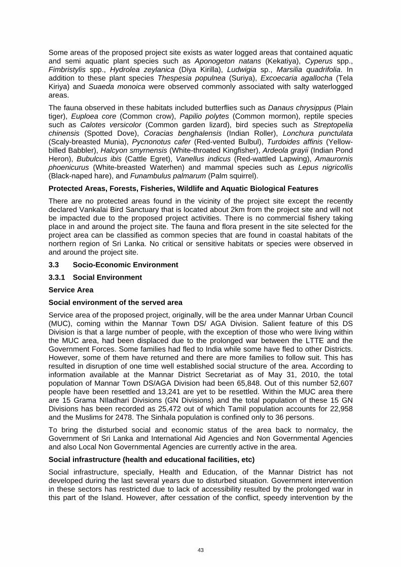
43
Some areas of the proposed project site exists as water logged areas that contained aquatic and semi aquatic plant species such as Aponogeton natans (Kekatiya), Cyperus spp., Fimbristylis spp., Hydrolea zeylanica (Diya Kirilla), Ludwigia sp., Marsilia quadrifolia. In addition to these plant species Thespesia populnea (Suriya), Excoecaria agallocha (Tela Kiriya) and Suaeda monoica were observed commonly associated with salty waterlogged areas.
The fauna observed in these habitats included butterflies such as Danaus chrysippus (Plain tiger), Euploea core (Common crow), Papilio polytes (Common mormon), reptile species such as Calotes versicolor (Common garden lizard), bird species such as Streptopelia chinensis (Spotted Dove), Coracias benghalensis (Indian Roller), Lonchura punctulata (Scaly-breasted Munia), Pycnonotus cafer (Red-vented Bulbul), Turdoides affinis (Yellow-billed Babbler), Halcyon smyrnensis (White-throated Kingfisher), Ardeola grayii (Indian Pond Heron), Bubulcus ibis (Cattle Egret), Vanellus indicus (Red-wattled Lapwing), Amaurornis phoenicurus (White-breasted Waterhen) and mammal species such as Lepus nigricollis (Black-naped hare), and Funambulus palmarum (Palm squirrel).
Protected Areas, Forests, Fisheries, Wildlife and Aquatic Biological Features
There are no protected areas found in the vicinity of the project site except the recently declared Vankalai Bird Sanctuary that is located about 2km from the project site and will not be impacted due to the proposed project activities. There is no commercial fishery taking place in and around the project site. The fauna and flora present in the site selected for the project area can be classified as common species that are found in coastal habitats of the northern region of Sri Lanka. No critical or sensitive habitats or species were observed in and around the project site.
3.3 Socio-Economic Environment
3.3.1 Social Environment
Service Area
Social environment of the served area
Service area of the proposed project, originally, will be the area under Mannar Urban Council (MUC), coming within the Mannar Town DS/ AGA Division. Salient feature of this DS Division is that a large number of people, with the exception of those who were living within the MUC area, had been displaced due to the prolonged war between the LTTE and the Government Forces. Some families had fled to India while some have fled to other Districts. However, some of them have returned and there are more families to follow suit. This has resulted in disruption of one time well established social structure of the area. According to information available at the Mannar District Secretariat as of May 31, 2010, the total population of Mannar Town DS/AGA Division had been 65,848. Out of this number 52,607 people have been resettled and 13,241 are yet to be resettled. Within the MUC area there are 15 Grama NIladhari Divisions (GN Divisions) and the total population of these 15 GN Divisions has been recorded as 25,472 out of which Tamil population accounts for 22,958 and the Muslims for 2478. The Sinhala population is confined only to 36 persons.
To bring the disturbed social and economic status of the area back to normalcy, the Government of Sri Lanka and International Aid Agencies and Non Governmental Agencies and also Local Non Governmental Agencies are currently active in the area.
Social infrastructure (health and educational facilities, etc)
Social infrastructure, specially, Health and Education, of the Mannar District has not developed during the last several years due to disturbed situation. Government intervention in these sectors has restricted due to lack of accessibility resulted by the prolonged war in this part of the Island. However, after cessation of the conflict, speedy intervention by the
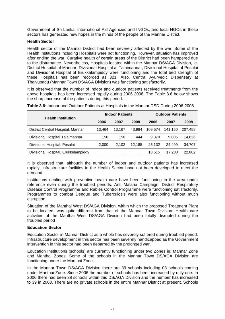
44
Government of Sri Lanka, International Aid Agencies and INGOs, and local NGOs in these sectors has generated new hopes in the minds of the people of the Mannar District.
Health Sector
Health sector of the Mannar District had been severely affected by the war. Some of the Health Institutions including Hospitals were not functioning. However, situation has improved after ending the war. Curative health of certain areas of the District had been hampered due to the disturbance. Nevertheless, Hospitals located within the Mannar DS/AGA Division, ie. District Hospital of Mannar, Divisional Hospital at Talaimannar, Divisional Hospital of Pesalai and Divisional Hospital of Erukkalampiddy were functioning and the total bed strength of these Hospitals has been recorded as 321. Also, Central Ayurvedic Dispensary at Thalvupadu (Mannar Town DS/AGA Division) was functioning satisfactorily.
It is observed that the number of indoor and outdoor patients received treatments from the above hospitals has been increased rapidly during 2006 2008. The Table 3.6 below shows the sharp increase of the patients during this period.
Table 3.6: Indoor and Outdoor Patients at Hospitals in the Mannar DSD During 2006-2008
Health Institution Indoor Patients Outdoor Patients
2006 2007 2008 2006 2007 2008
District Central Hospital, Mannar 13,464 13,167 43,984 109,574 141,150 207,458
Divisional Hospital Talaimannar 150 150 444 9,370 9,005 14,626
Divisional Hospital, Pesalai 2,000 2,102 12,185 25,132 24,499 34,707
Divisional Hospital, Erukkulampiddy _ _ _ 18,515 17,288 22,802
It is observed that, although the number of indoor and outdoor patients has increased rapidly, infrastructure facilities in the Health Sector have not been developed to meet the demand.
Institutions dealing with preventive health care have been functioning in the area under reference even during the troubled periods. Anti Malaria Campaign, District Respiratory Disease Control Programme and Rabies Control Programme were functioning satisfactorily. Programmes to combat Dengue and Tuberculosis were also functioning without much disruption.
Situation of the Manthai West DS/AGA Division, within which the proposed Treatment Plant to be located, was quite different from that of the Mannar Town Division. Health care activities of the Manthai West DS/AGA Division had been totally disrupted during the troubled period
Education Sector
Education Sector in Mannar District as a whole has severely suffered during troubled period. Infrastructure development in this sector has been severely handicapped as the Government intervention in this sector had been debarred by the prolonged war.
Education Institutions (schools) are currently functioning under two Zones ie; Mannar Zone and Manthai Zones. Some of the schools in the Mannar Town DS/AGA Division are functioning under the Manthai Zone.
In the Mannar Town DS/AGA Division there are 39 schools including 03 schools coming under Manthai Zone. Since 2006 the number of schools has been increased by only one. In 2006 there had been 38 schools within this DS/AGA Division and the number has increased to 39 in 2008. There are no private schools in the entire Mannar District at present. Schools
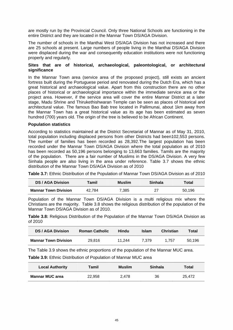
45
are mostly run by the Provincial Council. Only three National Schools are functioning in the entire District and they are located in the Mannar Town DS/AGA Division.
The number of schools in the Manthai West DS/AGA Division has not increased and there are 25 schools at present. Large numbers of people living in the Manthai DS/AGA Division were displaced during the war and consequently education institutions were not functioning properly and regularly.
Sites that are of historical, archaeological, paleontological, or architectural significance
In the Mannar Town area (service area of the proposed project), still exists an ancient fortress built during the Portuguese period and renovated during the Dutch Era, which has a great historical and archaeological value. Apart from this construction there are no other places of historical or archaeological importance within the immediate service area or the project area. However, if the service area will cover the entire Mannar District at a later stage, Madu Shrine and Thirukethishwaran Temple can be seen as places of historical and architectural value. The famous Bao Bab tree located in Pallimunai, about 1km away from the Mannar Town has a great historical value as its age has been estimated as seven hundred (700) years old. The origin of the tree is believed to be African Continent.
Population statistics
According to statistics maintained at the District Secretariat of Mannar as of May 31, 2010, total population including displaced persons from other Districts had been102,553 persons. The number of families has been recorded as 28,392.The largest population has been recorded under the Mannar Town DS/AGA Division where the total population as of 2010 has been recorded as 50,196 persons belonging to 13,663 families. Tamils are the majority of the population. There are a fair number of Muslims in the DS/AGA Division. A very few Sinhala people are also living in the area under reference. Table 3.7 shows the ethnic distribution of the Mannar Town DS/AGA Division as of 2010
Table 3.7: Ethnic Distribution of the Population of Mannar Town DS/AGA Division as of 2010
DS / AGA Division Tamil Muslim Sinhala Total
Mannar Town Division 42,784 7,385 27 50,196
Population of the Mannar Town DS/AGA Division is a multi religious mix where the Christians are the majority. Table 3.8 shows the religious distribution of the population of the Mannar Town DS/AGA Division as of 2010.
Table 3.8: Religious Distribution of the Population of the Mannar Town DS/AGA Division as of 2010
DS / AGA Division Roman Catholic Hindu Islam Christian Total
Mannar Town Division 29,816 11,244 7,379 1,757 50,196
The Table 3.9 shows the ethnic proportions of the population of the Mannar MUC area.
Table 3.9: Ethnic Distribution of Population of Mannar MUC area
Local Authority Tamil Muslim Sinhala Total
Mannar MUC area 22,958 2,478 36 25,472
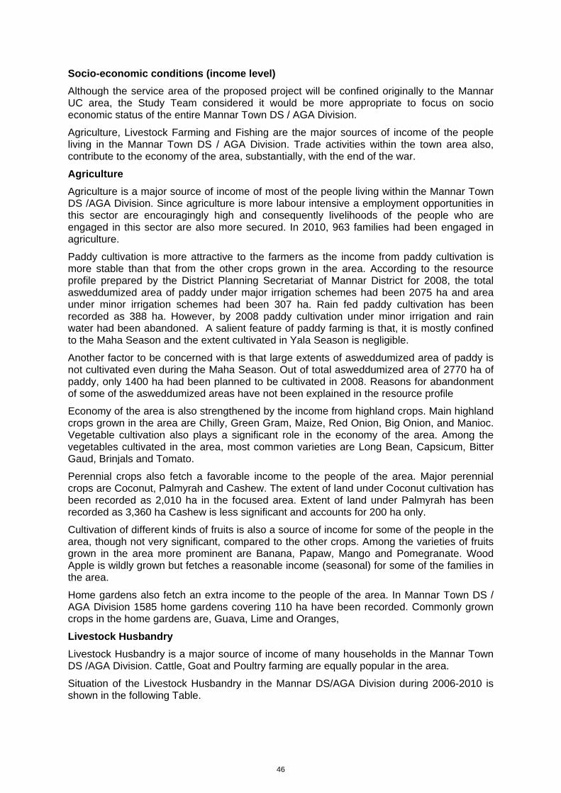
46
Socio-economic conditions (income level)
Although the service area of the proposed project will be confined originally to the Mannar UC area, the Study Team considered it would be more appropriate to focus on socio economic status of the entire Mannar Town DS / AGA Division.
Agriculture, Livestock Farming and Fishing are the major sources of income of the people living in the Mannar Town DS / AGA Division. Trade activities within the town area also, contribute to the economy of the area, substantially, with the end of the war.
Agriculture
Agriculture is a major source of income of most of the people living within the Mannar Town DS /AGA Division. Since agriculture is more labour intensive a employment opportunities in this sector are encouragingly high and consequently livelihoods of the people who are engaged in this sector are also more secured. In 2010, 963 families had been engaged in agriculture.
Paddy cultivation is more attractive to the farmers as the income from paddy cultivation is more stable than that from the other crops grown in the area. According to the resource profile prepared by the District Planning Secretariat of Mannar District for 2008, the total asweddumized area of paddy under major irrigation schemes had been 2075 ha and area under minor irrigation schemes had been 307 ha. Rain fed paddy cultivation has been recorded as 388 ha. However, by 2008 paddy cultivation under minor irrigation and rain water had been abandoned. A salient feature of paddy farming is that, it is mostly confined to the Maha Season and the extent cultivated in Yala Season is negligible.
Another factor to be concerned with is that large extents of asweddumized area of paddy is not cultivated even during the Maha Season. Out of total asweddumized area of 2770 ha of paddy, only 1400 ha had been planned to be cultivated in 2008. Reasons for abandonment of some of the asweddumized areas have not been explained in the resource profile
Economy of the area is also strengthened by the income from highland crops. Main highland crops grown in the area are Chilly, Green Gram, Maize, Red Onion, Big Onion, and Manioc. Vegetable cultivation also plays a significant role in the economy of the area. Among the vegetables cultivated in the area, most common varieties are Long Bean, Capsicum, Bitter Gaud, Brinjals and Tomato.
Perennial crops also fetch a favorable income to the people of the area. Major perennial crops are Coconut, Palmyrah and Cashew. The extent of land under Coconut cultivation has been recorded as 2,010 ha in the focused area. Extent of land under Palmyrah has been recorded as 3,360 ha Cashew is less significant and accounts for 200 ha only.
Cultivation of different kinds of fruits is also a source of income for some of the people in the area, though not very significant, compared to the other crops. Among the varieties of fruits grown in the area more prominent are Banana, Papaw, Mango and Pomegranate. Wood Apple is wildly grown but fetches a reasonable income (seasonal) for some of the families in the area.
Home gardens also fetch an extra income to the people of the area. In Mannar Town DS / AGA Division 1585 home gardens covering 110 ha have been recorded. Commonly grown crops in the home gardens are, Guava, Lime and Oranges,
Livestock Husbandry
Livestock Husbandry is a major source of income of many households in the Mannar Town DS /AGA Division. Cattle, Goat and Poultry farming are equally popular in the area.
Situation of the Livestock Husbandry in the Mannar DS/AGA Division during 2006-2010 is shown in the following Table.
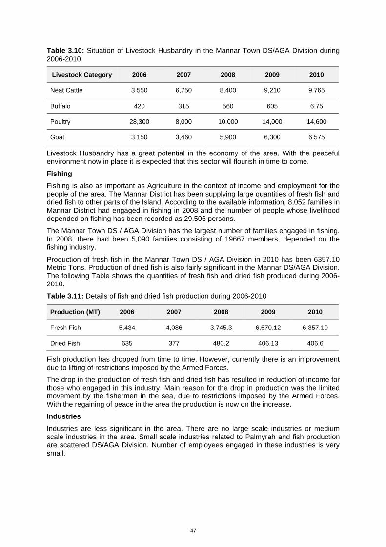
47
Table 3.10: Situation of Livestock Husbandry in the Mannar Town DS/AGA Division during 2006-2010
Livestock Category 2006 2007 2008 2009 2010
Neat Cattle 3,550 6,750 8,400 9,210 9,765
Buffalo 420 315 560 605 6,75
Poultry 28,300 8,000 10,000 14,000 14,600
Goat 3,150 3,460 5,900 6,300 6,575
Livestock Husbandry has a great potential in the economy of the area. With the peaceful environment now in place it is expected that this sector will flourish in time to come.
Fishing
Fishing is also as important as Agriculture in the context of income and employment for the people of the area. The Mannar District has been supplying large quantities of fresh fish and dried fish to other parts of the Island. According to the available information, 8,052 families in Mannar District had engaged in fishing in 2008 and the number of people whose livelihood depended on fishing has been recorded as 29,506 persons.
The Mannar Town DS / AGA Division has the largest number of families engaged in fishing. In 2008, there had been 5,090 families consisting of 19667 members, depended on the fishing industry.
Production of fresh fish in the Mannar Town DS / AGA Division in 2010 has been 6357.10 Metric Tons. Production of dried fish is also fairly significant in the Mannar DS/AGA Division. The following Table shows the quantities of fresh fish and dried fish produced during 2006-2010.
Table 3.11: Details of fish and dried fish production during 2006-2010
Production (MT) 2006 2007 2008 2009 2010
Fresh Fish 5,434 4,086 3,745.3 6,670.12 6,357.10
Dried Fish 635 377 480.2 406.13 406.6
Fish production has dropped from time to time. However, currently there is an improvement due to lifting of restrictions imposed by the Armed Forces.
The drop in the production of fresh fish and dried fish has resulted in reduction of income for those who engaged in this industry. Main reason for the drop in production was the limited movement by the fishermen in the sea, due to restrictions imposed by the Armed Forces. With the regaining of peace in the area the production is now on the increase.
Industries
Industries are less significant in the area. There are no large scale industries or medium scale industries in the area. Small scale industries related to Palmyrah and fish production are scattered DS/AGA Division. Number of employees engaged in these industries is very small.
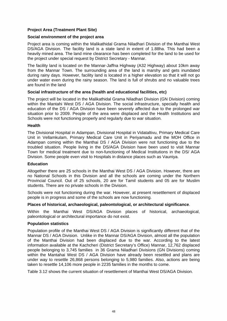
48
Project Area (Treatment Plant Site)
Social environment of the project area
Project area is coming within the Malikathidal Grama Niladhari Division of the Manthai West DS/AGA Division. The facility land is a state land in extent of 1.88ha. This had been a heavily mined area. The land mine clearance has been completed for the land to be used for the project under special request by District Secretary - Mannar.
The facility land is located on the Mannar-Jaffna Highway (A32 Highway) about 10km away from the Mannar Town. The surrounding area of the land is marshy and gets inundated during rainy days. However, facility land is located in a higher elevation so that it will not go under water even during the rainy season. The land is full of shrubs and no valuable trees are found in the land
Social infrastructure of the area (health and educational facilities, etc)
The project will be located in the Malikathidal Grama Niladhari Division (GN Division) coming within the Mantahi West DS / AGA Division. The social infrastructure, specially health and education of the DS / AGA Division have been severely affected due to the prolonged war situation prior to 2009. People of the area were displaced and the Health Institutions and Schools were not functioning properly and regularly due to war situation.
Health
The Divisional Hospital in Adampan, Divisional Hospital in Vidataltivu, Primary Medical Care Unit in Vellamkulam, Primary Medical Care Unit in Periyamadu and the MOH Office in Adampan coming within the Manthai DS / AGA Division were not functioning due to the troubled situation. People living in the DS/AGA Division have been used to visit Mannar Town for medical treatment due to non-functioning of Medical Institutions in the DS/ AGA Division. Some people even visit to Hospitals in distance places such as Vauniya.
Education
Altogether there are 25 schools in the Manthai West DS / AGA Division. However, there are no National Schools in this Division and all the schools are coming under the Northern Provincial Council. Out of 25 schools, 20 are for Tamil students and 05 are for Muslim students. There are no private schools in the Division.
Schools were not functioning during the war. However, at present resettlement of displaced people is in progress and some of the schools are now functioning.
Places of historical, archaeological, paleontological, or architectural significance.
Within the Manthai West DS/AGA Division places of historical, archaeological, paleontological or architectural importance do not exist.
Population statistics
Population profile of the Manthai West DS / AGA Division is significantly different that of the Mannar DS / AGA Division. Unlike in the Mannar DS/AGA Division, almost all the population of the Manthai Division had been displaced due to the war. According to the latest information available at the Kachcheri (District Secretary’s Office) Mannar, 12,762 displaced people belonging to 3,745 families in 36 Grama Niladhari Divisions (GN Divisions) coming within the Mantahai West DS / AGA Division have already been resettled and plans are under way to resettle 26,868 persons belonging to 5,980 families. Also, actions are being taken to resettle 14,106 more people in 2235 families in the months to come.
Table 3.12 shows the current situation of resettlement of Manthai West DS/AGA Division.
49
Table 3.12: Current Situation of Resettlement – Mantahi West DS/ AGA Division
DS/AGA Division
Resettled Planned for Resettlement To be Resettled
Total
Families Members Families Members Families Members
Manthai West 3,745 12,762 5,980 26,868 2,235 14,106 53,736
Malikathidal GN Division
Health and Education of the Malikathidal GN Division had been totally disturbed due to the war and abandonment of the area by the people. However, as of August 31, 2010, a total of 311 people have been resettled with makeshift arrangements. Actions are under way to resettle all displaced families from the Malikathidal GN Division. Education has regained. Health services are also being provided to the resettled people to meet the minimum basic standards for the present. These services will be improved with the achievement of full resettlement in near future.
Socio-economic conditions (income level)
Socio economic conditions of the Manthai West DS / AGA Division, within which the Project will be located (Malikthidal GN Division) are very much similar to those of the Mannar Town DS Division.
The total land area of the Manthai West DS / AGA Division has been recorded as 658.9 km2 equivalent to 51,282 ha A large part of the DS / AGA Division is under forest cover and accounts for 16,987 ha
Agriculture, Livestock Husbandry and Fishing are the major sources of income of the people of the area. Industries do not play any significant role in the economy.
Agriculture
Paddy farming is the most popular agriculture activity, as the income generated from it is more stable and favorable than other modes of agriculture. Paddy farming is more labour intensive and provides employment to large number of people.
According to the records available in the District Secretariat of Mannar, total asweddumized extent of Paddy is 7,854 ha. Out of this extent, 4,793 ha are fed by major irrigation schemes while 1,705 ha are under minor irrigation schemes .The extent under rain fed cultivation accounts for 1,356 ha. However, Paddy farming had come to a standstill during the clash between the LTTE and the Armed Forces, as the people fled the area.
Highland crops, though not very significant in the area under reference, have been a source of income for some of the households. Commonly grown highland crops have been Cow Pea, Ground Nut, Chilly, Maize and Big Onion.
Vegetable cultivation is seen as a supplementary source of income for some of the households. Most popular varieties are, Brinjal, Long Bean, Okra and Capsicum.
Perennial crops are the other significant source of income in the area. Coconut and Palmyrah are the income generating perennial crops observed in the Manthai West DS / AGA Division. Palmyrah palms are spread over a large area of land and are very useful for the people not only as a source of income but also for different other purposes. It has been recorded that there are more than 250,000 Palmyrah palms within the DS / AGA Division.
Fruit cultivation is also an important source of income of the people. Mango, Banana, and Papaw are the most attractive varieties. Wood Apple, collected from the jungle also fetches is also another source of income to the people, although seasonal.
50
Livestock husbandry
According the 2008 data, livestock population of the Manthai West DS/ AGA Division had fairly high. Raring of cattle for milk and meat is seen popular among a large number of households. The recorded number of cattle in different age groups, in 2008 has been 11,206. Goat farming has also been engaged in by a fair number of households as a source of income. Poultry farming for eggs and meat too has contributed to the economy of the area in a substantial proportion.
Fishing industry
The fishing industry has been flourishing in the coastal area of the Manthai West DS/ AGA Division prior to break out of the war. Production of fresh fish and dried fish has been very high. Since the sources of income are limited, many people opted for fishing as their livelihood. In 2006, 1195 families had engaged in fishing This number had dropped down to 1105 families in 2008 and further dropped in 2009 Also, drop in the production of fresh fish and dried fish is observed during last few years attributed mainly to the ban on the night fishing and displacement of people from the area.
Social status
Social status of the area is difficult to measure due to the exodus of people from the area during troubled period. Situation with regard to housing and utilities such as electricity, supply of domestic water and telecommunication, is obscure due to lack of information with the relevant Government Agencies.
However, encouraging news is that resettlement of displaced population is taking place with an appreciable momentum. A fair number of families have been already resettled and plans are underway to complete resettlement. Action has been taken to provide the displaced families with shelter, toilet facilities, domestic water supply and electricity. In addition to the efforts by the Government of Sri Lanka, International Donor Agencies and Non Governmental Agencies (NGOs) are active in the area to provide facilities to the resettled people in their efforts to rebuild their livelihood.
Safety of the site (mine clearance)
The mine clearance has been completed for the total extent where the project expected to be implemented. However the balance portion of the land mine clearance is in progress. Though the mine clearance is totally completed, precautions such as continuous training and awareness has to be taken before the commencement of the contraction work of the Septage Treatment Plant to assure the safety of the workers.
3.3.2 Economic Environment
Industries
Within the project area large scale or medium scale industries are not observed. Mainly cottage industries of small scale related to Palmyrah products can be seen in the Manthai West DS/AGA Division. Other than these small scale industries no other industries of any significant importance exist in the area under reference.
Infrastructure facilities (water supply, sewerage, flood control)
Domestic water supply is not satisfactory. Pipe borne water is a luxury. Water from the NWS&DB is not available in the area. The Pradeshiya Sabas of the area are supplying domestic water by using Bowsers. Some families are using dug wells, mainly for washing purposes.
Sewerage disposal has so far not been a major issue in the area due to thin population and availability of vast area of unutilized land in the DS/AGA Division. When the resettlement of displaced people is completed this issue will have to be addressed.
51
Transportation (roads, harbors and navigation)
Roads
Major roads traverse via the service area are Medawachchiya- Mannar-Talaimannar Road (A14) and the Navatkuly-Kerativu-Mannar Road (A32). There are a number of B grade roads maintained by the Road Development Authority RDA). The road network of the area is generally satisfactory. However, the transport facilities to and within the area do not seem satisfactory as the number of passenger transport vehicle plying is inadequate to meet the demand.
The A32 Road traverse through the Manthai West DS/AGA Division (Project area) Also, Mankulam-Vellankulam Road (B 269) is running via this DS/AGA Division. Therefore, the project area is easily accessed by road. However public transport within the area is not improved after the war.
Harbors
Within the MUC area there is a fishery harbor. Also, at Thalaimannar there is a small fishery harbor but it is not used by the fishermen due to the restrictions imposed by the Armed Forces. Within the project area there are no harbors exist.
Land use (dedicated area uses)
A vast stretch of land in the dedicated area is marshy. There are shrubs in pockets and poodles of water around the shrubs. There are no valuable trees in the dedicated area. No houses or other buildings exist in the area. The land within the dedicated area cannot be used for agriculture or any other productive purpose.
Power sources and transmission
Electricity from the National Grid is the major source of power in the area. Usage of generators is very rare. Although the electricity from the National Grid is available, only the Government Offices and a very few households have been electrified at present. Providing electricity connections to other houses are now in progress.
Agricultural development and tourism facilities
Manthai West DS/AGA Division is predominant an agricultural area. Paddy cultivation is the major agricultural activity irrigated from the water from the Giant’s Tank. The extent cultivated under minor irrigation schemes and rain water is not very significant.
Vegetable cultivation is also carried out in small scale. Fruit cultivation is also carried out but in an unorganized manner.
Due to the war between the Armed Forces and the LTTE, prior to the latter part of 2009, the agricultural activities have got seriously affected. These activities have regained from 2010 but yet to be operated in full swing.
Agricultural activities in the Malikathidal GN Division area has regained only recently. A lot of efforts are needed to bring the agricultural activities back in to full operation
Tourism Faculties
In the dedicated area or the suburban localities no tourist arrivals are observed at present. The area has no any particular attractions for tourists as at present. Therefore, no special facilities are in place to attract the tourists to the area. However, with the regaining of peace in the area and development of newly declared Bird Sanctuary of Vankalai, opportunities for tourism development can be expected.
3.3.3 Land use (dedicated area uses)
Discussed above.
52
4 DESCRIPTION OF ANTICIPATED ENVIRONMENTAL IMPACTS
4.1 Construction Phase
The project is anticipated to involve the construction of different ponds for septage storage and treatment, and the connecting pipelines or channels. All constructions are of the type of shallow foundations, and no usage of groundwater contaminants is forecasted at the construction stage. Therefore, no significant environmental impact is envisaged on the geology, soil and ground water.
4.1.1 Impacts of Land Clearing and Development
Construction of the STP will involve land clearing, excavation, filling, compaction and concreting. Therefore potential physical and other impacts can be expected. However, as these activities will take place within a very small area of about 1ha of scrub land, no major negative impacts will be expected. Only a few shrubs will have to be removed during land clearing.
Excavation of the tank beds and ponds will create substantial amount of spoil material. Although this is not a significant quantity, it adds to the waste burden of the project and considered as significant. Excavated materials need to be stockpiled until either they will be utilized for filling or taken out as an excess material. During the excavation work in the case of raining, there may be temporary blockages of drainage paths and erosion.
It will be necessary to use a large quantity of earth as filling material to achieve the required levels of tanks, bunds and access roads and hence, operation of burrow pit will be necessary. This operation may generate dust and noise due to excavation, loading and transportation of earth. Excavation during rainy period may cause soil erosion, sedimentation outflow and possible slope failures, if not properly planned and operated the burrow area. Since there will be heavy machinery and hauling trucks involved in the operation, the attention should be paid on public safety issues and the traffic control. Magnitude of the impact of land clearing and development will depend on to what extent suitable fill and lining material are available and obtained on-site.
4.1.2 Noise, Vibration and Dust due to Construction Activities
Noise vibration and dust are common construction issues typical to projects of this nature. During the construction period generation of noise would be an inevitable event. Involvement of heavy equipments, machineries, movement of heavy vehicles and presence of large number of workers will be the main sources of noise generation. According to the Schedule III of the National Environmental (Noise Control) Regulations No. 1 of 1996, the permissible noise level at boundaries of the land in which the source noise is located for the construction activities is 75 dB(A) in day time and 50 dB(A) in night time.
However, the noise impacts will not be a significant as no permanent residences surrounding of the site. The main sensitive receptors will be the pedestrians and passengers of A32 road. Vibration is unlikely to be a significant impact.
Noise levels for some of the common types of heavy construction machinery and equipment that are likely to be used for the Project are given in Table 4.1. Potential noise impacts are not difficult to mitigate, by applying the measures as recommended in the Section 5.1.2, and 5.1.3.
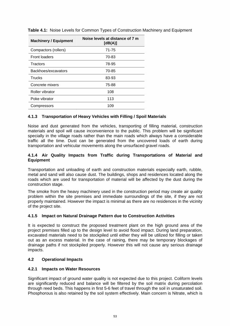
53
Table 4.1: Noise Levels for Common Types of Construction Machinery and Equipment
Machinery / Equipment Noise levels at distance of 7 m
[dB(A)]
Compactors (rollers) 71-75
Front loaders 70-83
Tractors 78-95
Backhoes/excavators 70-85
Trucks 83-93
Concrete mixers 75-88
Roller vibrator 108
Poke vibrator 113
Compressors 109
4.1.3 Transportation of Heavy Vehicles with Filling / Spoil Materials
Noise and dust generated from the vehicles, transporting of filling material, construction materials and spoil will cause inconvenience to the public. This problem will be significant specially in the village roads rather than the main roads which always have a considerable traffic all the time. Dust can be generated from the uncovered loads of earth during transportation and vehicular movements along the unsurfaced gravel roads.
4.1.4 Air Quality Impacts from Traffic during Transportations of Material and Equipment
Transportation and unloading of earth and construction materials especially earth, rubble, metal and sand will also cause dust. The buildings, shops and residences located along the roads which are used for transportation of material will be affected by the dust during the construction stage.
The smoke from the heavy machinery used in the construction period may create air quality problem within the site premises and immediate surroundings of the site, if they are not properly maintained. However the impact is minimal as there are no residences in the vicinity of the project site.
4.1.5 Impact on Natural Drainage Pattern due to Construction Activities
It is expected to construct the proposed treatment plant on the high ground area of the project premises filled up to the design level to avoid flood impact. During land preparation, excavated materials need to be stockpiled until either they will be utilized for filling or taken out as an excess material. In the case of raining, there may be temporary blockages of drainage paths if not stockpiled properly. However this will not cause any serious drainage impacts.
4.2 Operational Impacts
4.2.1 Impacts on Water Resources
Significant impact of ground water quality is not expected due to this project. Coliform levels are significantly reduced and balance will be filtered by the soil matrix during percolation through reed beds. This happens in first 5-6 feet of travel through the soil in unsaturated soil. Phosphorous is also retained by the soil system effectively. Main concern is Nitrate, which is
54
fully soluble in water and increase the Nitrate-N level in the ground water. As the discharge of water from the series of ponds, flows through the reed beds with suitable vegetated grass, quantity of Nitrogen will be taken up by the plants. Also significant quantity of Nitrogen is removed from the wastewater through settling at anaerobic pond and biological actions in facultative and maturation ponds. Therefore the quantity of nitrogen released to the environment is very negligible. Treated effluent is high in Dissolved Oxygen and very low in biodegradable organics thus discharge of treated effluent will not result in soil pollution.
Ponds are lined to prevent seepage of polluted water to the ground. The proposed arrangement for pond construction is proven and effective arrangement meeting the engineering norms. Therefore the high groundwater table is not a deterrent to construction of the proposed system at this site.
4.2.1.1 Impact on adjacent groundwater
The project has a high likelihood of adverse impacts on groundwater due to seepage or leakage from the septage storage and treatment ponds. Any seeping or leaking wastewater can easily reach the groundwater table and mix with the groundwater due to the seemingly significant permeability of the superficial deposits as well as of the underlying limestone. Therefore, it is important to ensure proper sealing of the beds of all ponds and channels with an impermeable barrier to prevent contamination of the groundwater table. The impermeable seal should be long-lasting and flexible, and a combination of appropriate clay layers (of appropriate thickness) with impermeable and tear-resistant geo-textiles can be recommended at the outset.
4.2.1.2 Impact on Flooding
The floods could raise the groundwater level during the heavy rainy seasons and the adjacent areas will become water logged. Floods could inundate some project components and septage could get mixed with lagoon water if adequate mitigation measures are not adopted (i.e. filling the site and locating the facilities on high ground which is usually not flooded). Floods also could cause erosion in the pond bunds. However since the project area is not located in a highly flood sensitive zone such as a river flood plain the flood impacts are medium and they could be mitigated. Locating the infrastructure on the high ground which do not normally inundate will mitigate the flood impact.
4.2.1.3 Impact on Irrigation Activities of Surrounding Areas of the Project
There are no irrigation activities near the project area, However there are some irrigation tanks located on the upstream of the project area about 1km away( e.g. Chettikulam). Hence there could not be any significant impact on irrigation activities.
4.2.1.4 Impact due to tidal effect of the Sea
Tidal effect during the spring ebb tide will be felt in the nearby “Thona”. However at present the drainage path of the “Thona” is not clearly available. Since the tidal effect does not raise the water level inundating the entire tidal flat area which is relatively lower and the tidal water will never invade the high ground area of the site where the proposed STP will be located there will not be any considerable impact.
4.2.2 Impacts due to Release of Obnoxious Gases
Obnoxious gases arise under anaerobic conditions in ponds. However, this problem can be avoided by maintaining loading rates such that top few centimeters under aerobic condition. This is done through the design.
55
In general the release of obnoxious gases takes place in STPs during unloading operations. There are several actions commonly adopted to address this. The design has taken several steps to address this issue. These include;
Shielding of the unloading bay to an extend to prevent odorous gases being blown away by the wind
Hydraulic arrangements that would minimize agitation of sewage during the release to the treatment system
Keeping much of the screen channel close to prevent release of gases to air
4.2.3 Impact due to Movement of Gully Trucks
Noise, Odour and Trafic
Gully trucks will be provided by the Project to MUC, which is responsible for operating the sanitation service. The Council will ensure that the tankers are serviced and repaired to manufacturer’s specifications so that the vehicles have a long working life. They will also employ and train tanker drivers and plan their work schedule, through which all septic tanks in the town are expected to be emptied at least once a year. However, anticipated noise and traffic impact due to movement of Gully trucks will not be significant.
There should also be no major odour problems from the operation of the Gully trucks in the town because any related disturbances will be infrequent and short-lived, and people will tolerate such small-scale disturbance if they are aware that their environment will be improved as a result. Efforts should still be made to avoid affecting socially and culturally important locations (kovils, churches, schools, hospitals, etc) to the extent possible.
There are some risks to workers and the public from the pumping operation to remove material from septic tanks. The Urban Council should therefore protect the health and safety of their workers and the public by ensuring that procedures are properly defined and followed.
4.3 Impacts on Ecological Resources (Construction and Operational)
4.3.1 Destruction or Alternation of Habitats
Prosopis juliflora (Kalapu Andara) dominated scrublands, mudflats with salt marsh vegetation and water logged areas are the main habitat types present in and around the site selected for the project site. Most of the project activities will take place in the Prosopis woodland which is a habitat dominated by an invasive species. Therefore, alteration of this habitat will not result in a significant impact. However, the salt marsh habitat is a unique habitat that should be preserved in its present state. Therefore, it is recommended that minimum disturbance should be affected in this habitat during construction and operational phase of the project.
4.3.2 Affects on the Prevailing Ecosystem Balance
As discussed above the direct impact zone of the project is limited to a small area where the main habitat affected is a woodland dominated by an alien invasive species. The only unique habitat observed on the project site is the salt marsh. Therefore, the project will not have any impact on the ecosystem balance in the area if steps are taken to reduce the impact on the salt marsh ecosystem.
4.3.3 Impacts on Terrestrial and Aquatic Flora and Fauna
The site selected for the project tends to undergo inundation seasonally while some parts of the project site exist as a water logged area. Aquatic and semi aquatic plant species such as Aponogeton natans (Kekatiya), Cyperus sp., Fimbristylis sp., Hydrolea zeylanica (Diya
56
Kirilla), Ludwigia sp., and Marsilia quadrifolia were observed in such water logged areas. Several species of aquatic and semi aquatic fauna were observed in this habitat. The aquatic and terrestrial fauna and flora observed in and around the project site are common plant and animal species that can be commonly observed in coastal habitats that are present at the project site. These species are highly adaptable and can with stand disturbance by man. Further, the project activities are restricted to a small area and there will be no effluent release to the water bodies in the surrounding areas. Therefore, terrestrial and aquatic fauna and flora will not be adversely affected by the proposed project activities.
4.3.4 Impacts on Receiving Water Body
The project does not involve release of any effluents in to the water bodies present around the project site except during rainy season. However there discharge from reed bed is expected during the wet months. The required effluent quality will be reached for the disposal to inland waters. The effluent will discharge to the natural drainage channels where the dilution will be much more than the requirement by regulations and will finally flow to the sea. Therefore, impact on receiving water bodies is not anticipated.
Based on these observations it can be concluded that the proposed project activities will not result in any adverse impacts on the habitats or species present in the direct or indirect impact zone of the selected site for project implementation.
4.4 Impacts on Socio-Economic Environment (Construction and Operational)
4.4.1 Social Economic Benefits (Health etc)
The proposed Septage Treatment Project will bring about many benefits to service area such as improved health conditions, decrease in the water borne diseases due to non contamination of ground water and surface water with the Project.
Currently the septage is carried by the Gully Bowsers and discharged at open places in the coastal lands located in distance places away from the residential houses. This is an unhealthy practice as it can pose threats to the health of the people. Therefore, the proposed project would a blessing to the people living within the service area as it will result in improving their health conditions and social life.
However, in the project area people are not going to receive any social benefits due the project at the beginning as the service of the project will be extended to them after some time. There will not be negative impacts as the human habitats sufficiently away from the site. In addition tree buffer is proposed.
As far as impacts on the economy in the service area and the project area are concerned no significant impacts either positive or negative will be expected. In the service area there will be no change in the land use pattern or the existing economic activities due to the project. In the project area too, there will be no change in the land use pattern due to the project. However, the project area will be benefited economically in a small way during the construction period due to availability of employment for the local people.
4.4.2 Impact due to Land-use Change
The Project will not result in any change in the land use of the area. The total extent of the site would be approximately about 2ha which cannot be used for any other productive purpose. The land is located away from the human settlements. There are no economic activities in and around the project area. As all the measures will be taken to prevent bad odour and an unpleasant view, the presence of the Septage Treatment Plant will not be felt by the passers and/or the people of the area.
In the above circumstances, upward or downward change in the value of the lands in the area will not be anticipated
57
4.4.3 Impact on Land Values
The Project will not result in changes in the land use pattern of the area. Therefore, no impacts on the value of lands will be expected.
4.4.4 Impact on Quality of Life
The quality of life of the service area, with the Project, will improve enormously. Disposal of septage had been a serious problem in the area due to lack of resources for the MUC for timely removal of septage. Also, the high ground water table has aggravated the problem. Due to contamination of water, spread of water borne diseases had been a common phenomenon. The proposed Project will arrest this problem and thereby will improve the health status and quality of life of the people in the MUC area.
4.4.5 Employment Opportunities
During the construction stage, number of employment opportunities will be available for the people of the Project area. Once the construction stage is over a few employment opportunities will be created in the operational stage.
4.4.6 Resettlement Requirements (if any)
Since the proposed Project will be located far away from the human settlements the question of resettlement does not arise.
4.4.7 Social Impacts due to Transportation of Septage
As explained in some of the preceding Paragraphs any negative social impacts will not generate due to transport of septage.
4.5 Any other Impacts
4.5.1 Institutional Arrangements for O&M of the Project
Public Officials and the people of the area have been consulted on the proposed Septage Treatment Plant. Two public meetings were held and the people expressed their concerns at those meetings. The Team of Consultants engaged in the IEE study and the other relevant officials from the NWS&DB, MUC, Pradeshiya Sabhas, District Secretariat and Divisional Secretariat provided a very clear picture on the Project. After a lot of questions and clarifications people were satisfied and convinced with the Project.
In this back ground any social threats against the Project will not be anticipated. Also, no institutional threats are expected in the implementation of the Project.
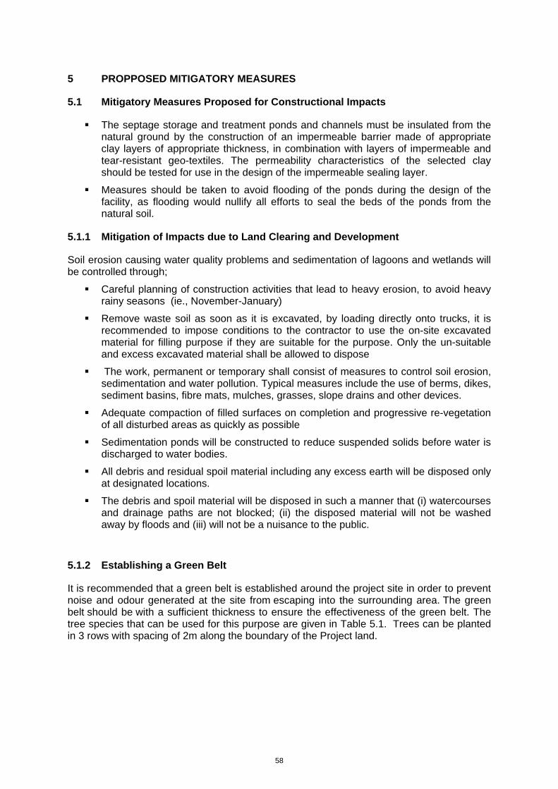
58
5 PROPPOSED MITIGATORY MEASURES
5.1 Mitigatory Measures Proposed for Constructional Impacts
The septage storage and treatment ponds and channels must be insulated from the natural ground by the construction of an impermeable barrier made of appropriate clay layers of appropriate thickness, in combination with layers of impermeable and tear-resistant geo-textiles. The permeability characteristics of the selected clay should be tested for use in the design of the impermeable sealing layer.
Measures should be taken to avoid flooding of the ponds during the design of the facility, as flooding would nullify all efforts to seal the beds of the ponds from the natural soil.
5.1.1 Mitigation of Impacts due to Land Clearing and Development
Soil erosion causing water quality problems and sedimentation of lagoons and wetlands will be controlled through;
Careful planning of construction activities that lead to heavy erosion, to avoid heavy rainy seasons (ie., November-January)
Remove waste soil as soon as it is excavated, by loading directly onto trucks, it is recommended to impose conditions to the contractor to use the on-site excavated material for filling purpose if they are suitable for the purpose. Only the un-suitable and excess excavated material shall be allowed to dispose
The work, permanent or temporary shall consist of measures to control soil erosion, sedimentation and water pollution. Typical measures include the use of berms, dikes, sediment basins, fibre mats, mulches, grasses, slope drains and other devices.
Adequate compaction of filled surfaces on completion and progressive re-vegetation of all disturbed areas as quickly as possible
Sedimentation ponds will be constructed to reduce suspended solids before water is discharged to water bodies.
All debris and residual spoil material including any excess earth will be disposed only at designated locations.
The debris and spoil material will be disposed in such a manner that (i) watercourses and drainage paths are not blocked; (ii) the disposed material will not be washed away by floods and (iii) will not be a nuisance to the public.
5.1.2 Establishing a Green Belt
It is recommended that a green belt is established around the project site in order to prevent noise and odour generated at the site from escaping into the surrounding area. The green belt should be with a sufficient thickness to ensure the effectiveness of the green belt. The tree species that can be used for this purpose are given in Table 5.1. Trees can be planted in 3 rows with spacing of 2m along the boundary of the Project land.
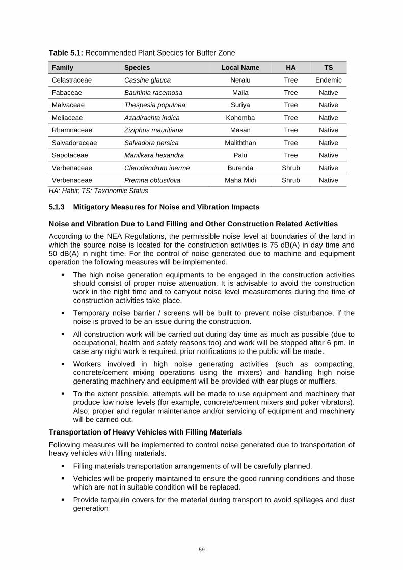
59
Table 5.1: Recommended Plant Species for Buffer Zone
Family Species Local Name HA TS
Celastraceae Cassine glauca Neralu Tree Endemic
Fabaceae Bauhinia racemosa Maila Tree Native
Malvaceae Thespesia populnea Suriya Tree Native
Meliaceae Azadirachta indica Kohomba Tree Native
Rhamnaceae Ziziphus mauritiana Masan Tree Native
Salvadoraceae Salvadora persica Maliththan Tree Native
Sapotaceae Manilkara hexandra Palu Tree Native
Verbenaceae Clerodendrum inerme Burenda Shrub Native
Verbenaceae Premna obtusifolia Maha Midi Shrub Native HA: Habit; TS: Taxonomic Status
5.1.3 Mitigatory Measures for Noise and Vibration Impacts
Noise and Vibration Due to Land Filling and Other Construction Related Activities
According to the NEA Regulations, the permissible noise level at boundaries of the land in which the source noise is located for the construction activities is 75 dB(A) in day time and 50 dB(A) in night time. For the control of noise generated due to machine and equipment operation the following measures will be implemented.
The high noise generation equipments to be engaged in the construction activities should consist of proper noise attenuation. It is advisable to avoid the construction work in the night time and to carryout noise level measurements during the time of construction activities take place.
Temporary noise barrier / screens will be built to prevent noise disturbance, if the noise is proved to be an issue during the construction.
All construction work will be carried out during day time as much as possible (due to occupational, health and safety reasons too) and work will be stopped after 6 pm. In case any night work is required, prior notifications to the public will be made.
Workers involved in high noise generating activities (such as compacting, concrete/cement mixing operations using the mixers) and handling high noise generating machinery and equipment will be provided with ear plugs or mufflers.
To the extent possible, attempts will be made to use equipment and machinery that produce low noise levels (for example, concrete/cement mixers and poker vibrators). Also, proper and regular maintenance and/or servicing of equipment and machinery will be carried out.
Transportation of Heavy Vehicles with Filling Materials
Following measures will be implemented to control noise generated due to transportation of heavy vehicles with filling materials.
Filling materials transportation arrangements of will be carefully planned.
Vehicles will be properly maintained to ensure the good running conditions and those which are not in suitable condition will be replaced.
Provide tarpaulin covers for the material during transport to avoid spillages and dust generation
60
5.1.4 Mitigatory Measures for Impact on Air Quality
Dust emission will be minimized through;
Enclosing or covering the construction site in order to control the dust dispersion.
Protecting stockpiles from water and wind erosion;
Using a water truck for dust suppression on all exposed areas (filling area, roads and spoil banks and burrow pits etc) as required.
Establishing and enforcing vehicle speed limits to minimize dust generation;
Use tarpaulins to cover loose material when transported to and from the site.
Locating stockpiles away from sensitive receptors;
Loaded haul trucks travelling to and from the site having loads leveled to avoid spillage;
Carrying out progressive rehabilitation of cleared land;
Other emissions will be minimized by;
Prohibiting the burning of all forms of waste;
Minimizing of exhaust emissions from construction equipment;
Regular maintenance of all construction machinery and vehicles;
5.1.5 Mitigatory Measures for Impacts due to Burrow Pits
Possible impacts due to operation of burrow sites will be minimized by taking following
actions.
Eligible contractor/s who are operating burrow pits with necessary approvals / permits, will only be selected.
Noise, dust and related safety issues during loading, transportation and unloading will be controlled as stated in Section 5.1.4 and 5.1.6.
5.1.6 Mitigatory Measures for Impacts due to Waste Disposal
Mitigatory measures to arrest those impacts are given bellow.
Construction Waste
System to collect waste cement slurry will be provided to avoid contamination of drainage paths.
Wastewater from washing of equipment used for concrete mixing and transporting of concrete will be disposed safely.
All discarded and used oil and grease will be collected, stored and disposed (reuse / sell).
All potentially water polluting chemicals and oils will be stored (a) at locations sufficiently away from watercourses and storm water drainage paths and (b) in a manner that would minimise chances of spillage.
Minimize the oil and chemical spillages during operation and properly maintain the equipment and machinery.
61
Debris and spoil will be disposed of only to designated places in such a manner that (i) waterways and drainage paths are not blocked, and (ii) the disposed material will not be washed away by heavy storm water flows.
Disposal of debris / unsuitable soil
During Loading / Transportation
Load trucks with soil only to an extent that no spillage will occur while in transportation.
Cover material during transportation.
Loading / transportation / unloading will be scheduled to avoid the possible traffic congestions.
Dump trucks / tractors carrying mud (on tyres and body) to travel in the main public roads is not allowed.
To avoid dust emissions and to ensure the workers and public safety, speed limits will be set.
Stop transportation activities during schools opening and closing times.
At disposal site (Spoil banks)
Select appropriate spoil banks in consultation with Environmental Monitoring Committee (EMC) prior to the commencement of works.
Dispose of soil in a manner that will not wash into watercourses and water-bodies affecting water quality and obstructing flow paths
Restrict the disposal only to the designated area
Install protective measures against sediment transport at the site prior to disposal of soil
Prevent sediment outflow / runoff from the disposal area / embankments by providing drains as applicable. Such out flows will be directed to sediment basins before release if necessary
Prevent disturbing the existing vegetation (if any) in the vicinity of the disposal site
Re-vegetate the embankments and the filled area immediately after the completion of land filling
5.1.7 Mitigatory Measures for Impact on Natural Drainage Pattern
The following mitigatory measures are suggested to mitigate drainage impacts
A peripheral drainage canal should be provided around the site to drain out water to lagoon via the nearby “Thona”
The above “Thona” should be improved to establish drainage connection with the lagoon as appropriate (See Figure 5.1: Site Storm Water Drainage Map)
Sludge ponds should be located on the high ground to avoid water ingress:
- Determined HFL is 1.5m MSL
- It is recommended to provide 0.3m or more free board depending on the design of structural elements.
- Since half of the site is higher than 2.0m MSL, HFL+ FB of 1.8m could be adopted as definitely the plant will be placed on the higher elevation region.
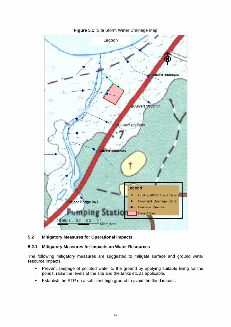
62
Figure 5.1: Site Storm Water Drainage Map
5.2 Mitigatory Measures for Operational Impacts
5.2.1 Mitigatory Measures for Impacts on Water Resources
The following mitigatory measures are suggested to mitigate surface and ground water resource impacts.
Prevent seepage of polluted water to the ground by applying suitable lining for the ponds, raise the levels of the site and the tanks etc as applicable.
Establish the STP on a sufficient high ground to avoid the flood impact.
Lagoon
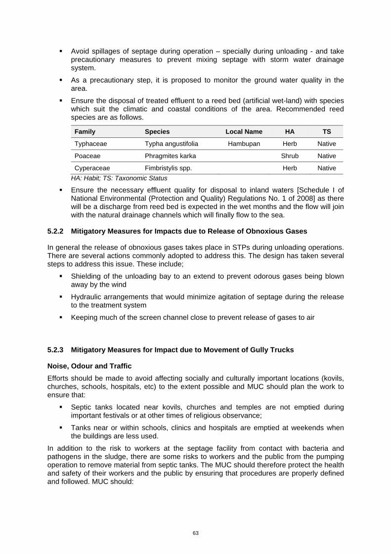
63
Avoid spillages of septage during operation – specially during unloading - and take precautionary measures to prevent mixing septage with storm water drainage system.
As a precautionary step, it is proposed to monitor the ground water quality in the area.
Ensure the disposal of treated effluent to a reed bed (artificial wet-land) with species which suit the climatic and coastal conditions of the area. Recommended reed species are as follows.
Family Species Local Name HA TS
Typhaceae Typha angustifolia Hambupan Herb Native
Poaceae Phragmites karka Shrub Native
Cyperaceae Fimbristylis spp. Herb Native HA: Habit; TS: Taxonomic Status
Ensure the necessary effluent quality for disposal to inland waters [Schedule I of National Environmental (Protection and Quality) Regulations No. 1 of 2008] as there will be a discharge from reed bed is expected in the wet months and the flow will join with the natural drainage channels which will finally flow to the sea.
5.2.2 Mitigatory Measures for Impacts due to Release of Obnoxious Gases
In general the release of obnoxious gases takes place in STPs during unloading operations. There are several actions commonly adopted to address this. The design has taken several steps to address this issue. These include;
Shielding of the unloading bay to an extend to prevent odorous gases being blown away by the wind
Hydraulic arrangements that would minimize agitation of septage during the release to the treatment system
Keeping much of the screen channel close to prevent release of gases to air
5.2.3 Mitigatory Measures for Impact due to Movement of Gully Trucks
Noise, Odour and Traffic
Efforts should be made to avoid affecting socially and culturally important locations (kovils, churches, schools, hospitals, etc) to the extent possible and MUC should plan the work to ensure that:
Septic tanks located near kovils, churches and temples are not emptied during important festivals or at other times of religious observance;
Tanks near or within schools, clinics and hospitals are emptied at weekends when the buildings are less used.
In addition to the risk to workers at the septage facility from contact with bacteria and pathogens in the sludge, there are some risks to workers and the public from the pumping operation to remove material from septic tanks. The MUC should therefore protect the health and safety of their workers and the public by ensuring that procedures are properly defined and followed. MUC should:
64
Prepare O&M manuals describing the procedures that are to be followed by workers in all aspects of the sanitation service, including operation of the tankers and the maintenance work at the septage treatment facility;
Prepare a Health and Safety Plan and ensure that it is operated throughout all work activities;
Provide workers with regular training in the relevant procedures (O&M and H&S);
5.2.4 Sludge Disposal
De-sludging of anaerobic pond not in operation is recommended as annual event. The proposed arrangement is that one of two anaerobic ponds will be used for one year and then allow it to rest for nine months. The sludge in the anaerobic ponds which is allowed for digestion for nearly one year is expected to be stabilized significantly. This approach will allow sufficient stabilization of collected sludge going through digestion and making it less harmful, dryer and smaller in volume for easy disposal.
Stabilized sludge needs to be disposed safely and properly. The arrangement will be to de-sludge the un-used anaerobic pond in late August or early September before the commencement of the rainy season. Quantity of sludge is small and it is recommended that the sludge be disposed at suitable site such as coconut or palmyrah plantation through burial in to dug pits.
65
6 ENVIRONMENTAL MONITORING PROGRAM
6.1 Introduction
It is proposed to implement the environmental monitoring program through an Environmental Management Plan (EMP). The EMP characterizes the proposed mitigation and monitoring actions as a set of tasks. In the EMP the specific responsibilities on task implementation on the project proponent, the contractor(s), and the regulatory agency (agencies) are assigned. These tasks should be implemented within a specified time/period by the agency responsible and as per the specifications set out in the EMP.
The EMP is presented in a format that distinguishes the tasks involved with monitoring of: (a) compliance with environmental mitigation measures and (b) the environmental effects. It is further sub-divided construction and, operational phases.
6.2 Compliance Monitoring
Compliance monitoring has two phases.
1. During construction, all mitigation measures designed to reduce the impact of the construction activities should be monitored and enforced. This responsibility rests mainly with the project proponent and the Consultant. However, provincial environmental agency is expected to carry out their own monitoring
2. During operations, the Environmental Authority shall carry out the compliance monitoring.
The EMP identifies the responsibilities of compliance monitoring. Table 6.1 gives the EMP for compliance monitoring. The recommended activities in the EMP with regard to compliance monitoring, should be included in the specifications and conditions of contract as appropriate. The cost of compliance monitoring is estimated at Rs. 1.5 million over the 21 month construction period. The estimate includes investigation work and studies, payments for committee members, cost of transport and visits made by committee, allowance for secretarial work and documentation and reporting work. The work coming under contractor’s activities and consultant supervision are excluded in the cost estimate. These should be covered in the Bill of Quantities and consultancy fees.
6.3 Effects Monitoring
Effects monitoring evaluates the validity of assessments made in the environmental impact study. It can also determine the effectiveness of the mitigation measures. The effect-monitoring plan includes: parameters for monitoring, duration of monitoring, locations and timing of sampling as well as effect monitoring responsibilities. The cost of effect monitoring includes cost of carrying out tests and investigations, reporting and documentation, allowance for consultancy services. The estimated cost of effect monitoring program is estimated Rs. 1.2 million.
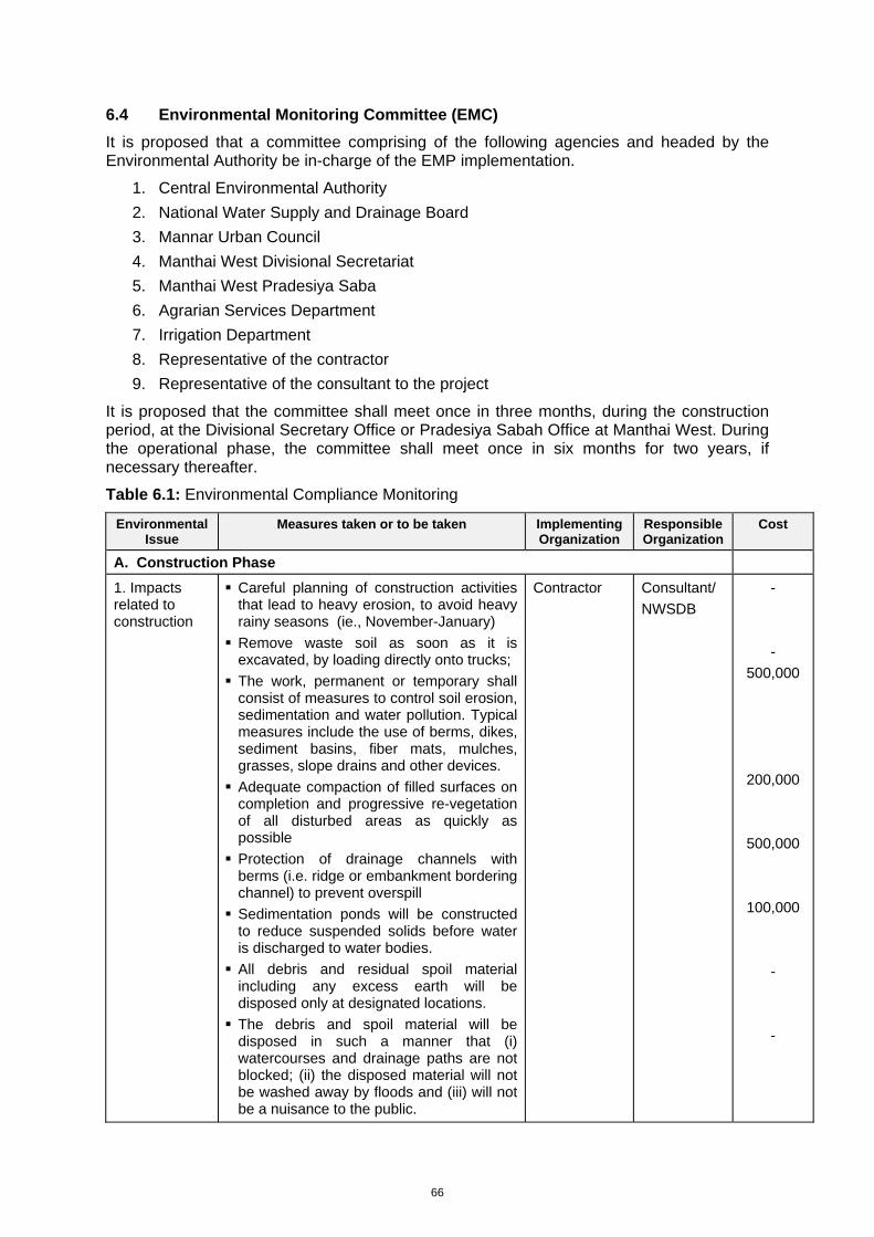
66
6.4 Environmental Monitoring Committee (EMC)
It is proposed that a committee comprising of the following agencies and headed by the Environmental Authority be in-charge of the EMP implementation.
1. Central Environmental Authority 2. National Water Supply and Drainage Board 3. Mannar Urban Council 4. Manthai West Divisional Secretariat 5. Manthai West Pradesiya Saba 6. Agrarian Services Department 7. Irrigation Department 8. Representative of the contractor 9. Representative of the consultant to the project
It is proposed that the committee shall meet once in three months, during the construction period, at the Divisional Secretary Office or Pradesiya Sabah Office at Manthai West. During the operational phase, the committee shall meet once in six months for two years, if necessary thereafter.
Table 6.1: Environmental Compliance Monitoring
Environmental Issue
Measures taken or to be taken Implementing Organization
Responsible Organization
Cost
A. Construction Phase
1. Impacts related to construction
Careful planning of construction activities that lead to heavy erosion, to avoid heavy rainy seasons (ie., November-January)
Remove waste soil as soon as it is excavated, by loading directly onto trucks;
The work, permanent or temporary shall consist of measures to control soil erosion, sedimentation and water pollution. Typical measures include the use of berms, dikes, sediment basins, fiber mats, mulches, grasses, slope drains and other devices.
Adequate compaction of filled surfaces on completion and progressive re-vegetation of all disturbed areas as quickly as possible
Protection of drainage channels with berms (i.e. ridge or embankment bordering channel) to prevent overspill
Sedimentation ponds will be constructed to reduce suspended solids before water is discharged to water bodies.
All debris and residual spoil material including any excess earth will be disposed only at designated locations.
The debris and spoil material will be disposed in such a manner that (i) watercourses and drainage paths are not blocked; (ii) the disposed material will not be washed away by floods and (iii) will not be a nuisance to the public.
Contractor
Consultant/ NWSDB
- -
500,000
200,000
500,000
100,000 - -
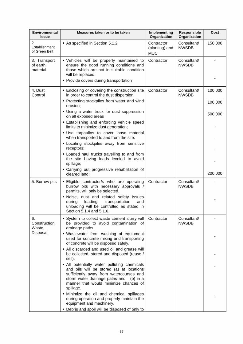
67
Environmental Issue
Measures taken or to be taken Implementing Organization
Responsible Organization
Cost
2. Establishment of Green Belt
As specified in Section 5.1.2 Contractor (planting) and MUC
Consultant/ NWSDB
150,000
3. Transport of earth material
Vehicles will be properly maintained to ensure the good running conditions and those which are not in suitable condition will be replaced.
Provide covers during transportation
Contractor
Consultant/ NWSDB
- -
4. Dust Control
Enclosing or covering the construction site in order to control the dust dispersion.
Protecting stockpiles from water and wind erosion;
Using a water truck for dust suppression on all exposed areas
Establishing and enforcing vehicle speed limits to minimize dust generation;
Use tarpaulins to cover loose material when transported to and from the site.
Locating stockpiles away from sensitive receptors;
Loaded haul trucks travelling to and from the site having loads leveled to avoid spillage;
Carrying out progressive rehabilitation of cleared land;
Contractor
Consultant/ NWSDB
100,000
100,000
500,000 - - - -
200,000
5. Burrow pits Eligible contractor/s who are operating burrow pits with necessary approvals / permits, will only be selected.
Noise, dust and related safety issues during loading, transportation and unloading will be controlled as stated in Section 5.1.4 and 5.1.6.
Contractor
Consultant/ NWSDB
- -
6. Construction Waste Disposal
System to collect waste cement slurry will be provided to avoid contamination of drainage paths.
Wastewater from washing of equipment used for concrete mixing and transporting of concrete will be disposed safely.
All discarded and used oil and grease will be collected, stored and disposed (reuse / sell).
All potentially water polluting chemicals and oils will be stored (a) at locations sufficiently away from watercourses and storm water drainage paths and (b) in a manner that would minimize chances of spillage.
Minimize the oil and chemical spillages during operation and properly maintain the equipment and machinery.
Debris and spoil will be disposed of only to
Contractor
Consultant/ NWSDB
- - - - -

68
Environmental Issue
Measures taken or to be taken Implementing Organization
Responsible Organization
Cost
designated places in such a manner that (i) waterways and drainage paths are not blocked, and (ii) the disposed material will not be washed away by heavy storm water flows.
-
7. Dust and other construction related problems
Water should be sprayed during construction phase, where necessary, to prevent dust.
Vehicles delivering materials should be covered to reduce spills and dust.
Contractor
Consultant/ NWSDB
Cover above
-
8. Drainage issues
A peripheral drainage canal should be provided around the site to drain out water to lagoon via the nearby “Thona”
The above “Thona” should be improved to establish drainage connection with the lagoon as appropriate
Sludge ponds should be located on the high ground to avoid water ingress
Contractor
Consultant/ NWSDB
500,000
9. Noise and vibration
Temporary noise barriers / screens will be placed.
All construction work will be carried out during day time as much as possible and work will be stopped after 6 pm.
Workers involved in high noise generating activities (such as compacting, concrete/cement mixing operations using the mixers) and handling high noise generating machinery and equipment will be provided with ear plugs or mufflers.
To the extent possible, attempts will be made to use equipment and machinery that produce low noise levels Proper and regular maintenance and/or servicing of equipment and machinery will be carried out.
Contractor Consultant/ NWS&DB
300,000 -
50,000 -
B. Operational phase
1. Impacts on Water Resources
Prevent seepage of polluted water to the ground by applying suitable lining for the ponds, raise the levels of the site and the tanks etc as applicable.
Establish the STP on a sufficient high ground to avoid the flood impact.
Avoid spillages of septage during operation – specially during unloading - and take precautionary measures to prevent mixing septage with storm water drainage system.
As a precautionary step, it is proposed to monitor the ground water quality in the area.
Ensure the disposal of treated effluent to a reed bed (artificial wet-land) with species
NWS&DB / MUC
NWS&DB / MUC / Consultant
Included in the
Design
-do-
-do-
-do-
-do-
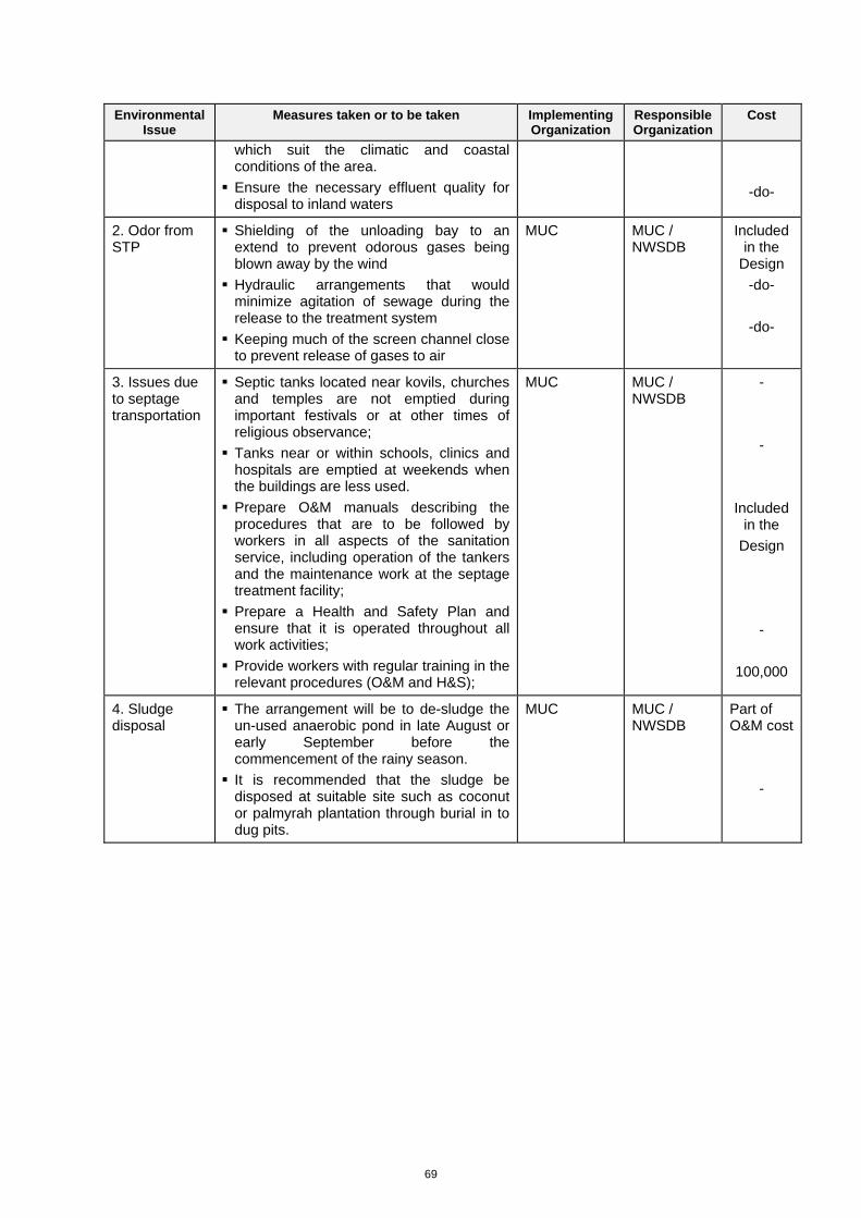
69
Environmental Issue
Measures taken or to be taken Implementing Organization
Responsible Organization
Cost
which suit the climatic and coastal conditions of the area.
Ensure the necessary effluent quality for disposal to inland waters
-do-
2. Odor from STP
Shielding of the unloading bay to an extend to prevent odorous gases being blown away by the wind
Hydraulic arrangements that would minimize agitation of sewage during the release to the treatment system
Keeping much of the screen channel close to prevent release of gases to air
MUC MUC / NWSDB
Included in the
Design -do-
-do-
3. Issues due to septage transportation
Septic tanks located near kovils, churches and temples are not emptied during important festivals or at other times of religious observance;
Tanks near or within schools, clinics and hospitals are emptied at weekends when the buildings are less used.
Prepare O&M manuals describing the procedures that are to be followed by workers in all aspects of the sanitation service, including operation of the tankers and the maintenance work at the septage treatment facility;
Prepare a Health and Safety Plan and ensure that it is operated throughout all work activities;
Provide workers with regular training in the relevant procedures (O&M and H&S);
MUC MUC / NWSDB
- -
Included in the
Design -
100,000
4. Sludge disposal
The arrangement will be to de-sludge the un-used anaerobic pond in late August or early September before the commencement of the rainy season.
It is recommended that the sludge be disposed at suitable site such as coconut or palmyrah plantation through burial in to dug pits.
MUC MUC / NWSDB
Part of O&M cost
-
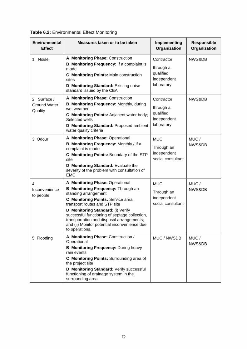
70
Table 6.2: Environmental Effect Monitoring
Environmental Effect
Measures taken or to be taken Implementing Organization
Responsible Organization
1. Noise A Monitoring Phase: Construction B Monitoring Frequency: If a complaint is made C Monitoring Points: Main construction sites D Monitoring Standard: Existing noise standard issued by the CEA
Contractor
through a qualified independent laboratory
NWS&DB
2. Surface / Ground Water Quality
A Monitoring Phase: Construction B Monitoring Frequency: Monthly, during wet weather C Monitoring Points: Adjacent water body; Selected wells D Monitoring Standard: Proposed ambient water quality criteria
Contractor
through a qualified independent laboratory
NWS&DB
3. Odour A Monitoring Phase: Operational B Monitoring Frequency: Monthly / If a complaint is made C Monitoring Points: Boundary of the STP site D Monitoring Standard: Evaluate the severity of the problem with consultation of EMC
MUC
Through an independent social consultant
MUC / NWS&DB
4. Inconvenience to people
A Monitoring Phase: Operational B Monitoring Frequency: Through an standing arrangement C Monitoring Points: Service area, transport routes and STP site D Monitoring Standard: (i) Verify successful functioning of septage collection, transportation and disposal arrangements; and (ii) Monitor potential inconvenience due to operations.
MUC
Through an independent social consultant
MUC / NWS&DB
5. Flooding A Monitoring Phase: Construction / Operational B Monitoring Frequency: During heavy rain events C Monitoring Points: Surrounding area of the project site D Monitoring Standard: Verify successful functioning of drainage system in the surrounding area
MUC / NWSDB MUC / NWS&DB
71
7 PUBLIC CONSULTATION AND INFORMATION DISCLOSURE
One of the main objectives of the IEE is to undertake a full Environmental and Social Impact Assessment of the proposed STP in accordance with national and international standards and practices. Within this context, extensive Public Consultation was carried out according to ADB standards.
This chapter deals with the Public Consultation and Information Disclosure (PCID) plan for the IEE for STP. The PCID plan is designed to outline a plan for consultation which will: provide timely information about the project and potential impacts to people living in project affected communities and other stakeholders provide opportunities to those groups to voice their opinions and concerns in a way which is most appropriate to their circumstances; and provide an opportunity for feedback and discussion with those communities concerning measures proposed.
The PCID presents the plan for public consultation through the project planning, construction, operation and commissioning stages of the project. The PCID is a live document and may be revised over time to reflect information gained through the consultation process.
This chapter outlines consultation undertaken or planned at the local levels to address root level issues relating directly to the STP including:
identification of key stakeholders, and mechanisms for stakeholder feedback and information sharing
a plan for consultation at the local level, starting at the project planning stage, and continuing throughout construction, operation and decommissioning of the STP
process to ensure that issues raised by key stakeholders are addressed in the IEE report as well as in project decision-making and design phase
resources required to implement the plan, and procedures to monitor implementation and
grievance mechanisms for local stakeholders
7.1 Methodology Adopted
As indicated above, the methodology adopted in the IEE study was mainly threefold. Firstly, the IEE team met with all relevant stakeholders and made field visits to study the suitability of the identified lands for location of the STP. In these field visits, the IEE team met individual people to apprise them on the project. Secondly, awareness meetings were held with a selected group of people to create awareness among them and to gather certain vital information relevant to the project. Lastly, a public meeting was held to create awareness about the proposed project among the people of the project area. This meeting was instrumental in exchange of views and opinions of the stakeholders.
7.2 Consultation and Disclosure Events
In the public consultation and information disclosure the IEE team developed a strategy to create awareness among the all relevant stakeholders about the proposed project and to invite their views, opinions and suggestions that may be useful for its implementation. The strategy consisted of meeting with all relevant stakeholders such as the Divisional Secretaries and their staff, chair person and secretaries of the MUC and the MWPS, NWS&DB, MOH, PHI and Grama Niladaries of Maligaithidal, Pappamodai, and Thiruketheeshwaram GN Divisions, members of Executive Committee of the Thriketheeshwaram Temple, members of Rural Developments Society, members of Women Rural Development Society, and members of Fisheries Societies of Thenudaiyan,
72
Maligaithidal, and Pappamodai to gather first hand information on socio economic and cultural situation of the project area and the service area. Also, the IEE team met with the Chairman of the Manthai West Pradheshiya Sabah with a view to apprising him on the proposed project and seeking his views and suggestions.
(The list of meetings conducted by the IEE team with various organizations is given in Annexure 10.)
Later, with a view to getting a wider participation in the process and to enlighten the people of the area, it was planned to conduct a meeting at the office of the AGA, Manthai West on January 30, 20012. As planned, the meeting was held on the appointed date. The IEE team invited the following stakeholders for the meeting;
Officials of the Mannar District Secretariat
Divisional Secretaries of Mannar and Manthai West and relevant officials of these offices
Chair Person of the MUC and the MWPS
Officials from the NWS&DB
Relevant Grama Niladharies
President and the members of the RDS, WRDS, and Fisheries Societies of Maligaithidal, Thenidaiyan, and Pappamodai
People living around the proposed location of the STP
Officials of the demining team of Sri Lanka Forces
At the meeting a few presentations were made. Mrs. Nandini, Chief Engineer of NWS&DB, Vavuniya in her welcome speech enlightened the participants on the proposed Septage Treatment Project. She elaborated on all aspects of the Project. She said that the disposal of septage in Mannar UC area has become a serious problem at present. She explained about the modus operandi of the Project and its benefits to the people.
Dr. Kalinga Pelpola, Design Consultant enlightened the participants on technical aspects of the Project. He reiterated that no harmful effects on the environment or the day today life of the people of the area will be resulted due to the project.
Mr. Anura Ranwala, the Hydrologist involved in the IEE, explained about the environmental assessments and approvals required from the relevant agencies prior to implementation of the Project. He, also, explained about the anticipated environmental impacts and proposed mitigation measures to arrest any negative impacts.
After the presentations, the forum was opened for discussions. In the discussions, several stakeholders expressed their views and opinions. A few of them made valuable suggestions. Full details of the discussions are elaborated in the minutes of the meeting (Annexure 11).
7.3 Awareness
Prior to village-level consultation, representatives of the project proponent and the IEE team met with the District Secretary of Mannar District, Divisional Secretary of Manthai West, and the AGA of the Mannar Division to explain the details of the proposed project and consultation process and to seek their support and cooperation. Also, the IEE team visited the MUC, and MWPS and met with the chairpersons, members, and other officials to enlighten them on the project process. In January 2012, IEE team embarked on a detailed village level consultation, as part of the scoping process
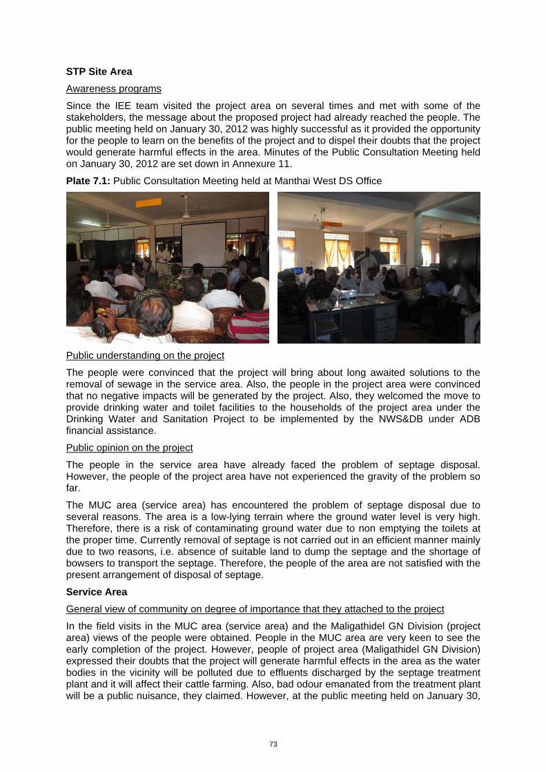
73
STP Site Area
Awareness programs
Since the IEE team visited the project area on several times and met with some of the stakeholders, the message about the proposed project had already reached the people. The public meeting held on January 30, 2012 was highly successful as it provided the opportunity for the people to learn on the benefits of the project and to dispel their doubts that the project would generate harmful effects in the area. Minutes of the Public Consultation Meeting held on January 30, 2012 are set down in Annexure 11.
Plate 7.1: Public Consultation Meeting held at Manthai West DS Office
Public understanding on the project
The people were convinced that the project will bring about long awaited solutions to the removal of sewage in the service area. Also, the people in the project area were convinced that no negative impacts will be generated by the project. Also, they welcomed the move to provide drinking water and toilet facilities to the households of the project area under the Drinking Water and Sanitation Project to be implemented by the NWS&DB under ADB financial assistance.
Public opinion on the project
The people in the service area have already faced the problem of septage disposal. However, the people of the project area have not experienced the gravity of the problem so far.
The MUC area (service area) has encountered the problem of septage disposal due to several reasons. The area is a low-lying terrain where the ground water level is very high. Therefore, there is a risk of contaminating ground water due to non emptying the toilets at the proper time. Currently removal of septage is not carried out in an efficient manner mainly due to two reasons, i.e. absence of suitable land to dump the septage and the shortage of bowsers to transport the septage. Therefore, the people of the area are not satisfied with the present arrangement of disposal of septage.
Service Area
General view of community on degree of importance that they attached to the project
In the field visits in the MUC area (service area) and the Maligathidel GN Division (project area) views of the people were obtained. People in the MUC area are very keen to see the early completion of the project. However, people of project area (Maligathidel GN Division) expressed their doubts that the project will generate harmful effects in the area as the water bodies in the vicinity will be polluted due to effluents discharged by the septage treatment plant and it will affect their cattle farming. Also, bad odour emanated from the treatment plant will be a public nuisance, they claimed. However, at the public meeting held on January 30,
74
2012 at the Manthai West DS Office at which wider stake holder participation took place, the views of the people in the project area on the proposed project were solicited. After a few presentations by the IEE team and the clarifications made by Ms. Nandini, Chief Engineer of the NWS&DB Office in Vavuniya the forum was opened for discussions. At the beginning of the discussion many individuals objected to locating the septage treatment plant at Malgathidel GN Division. However, when the IEE team elaborated on the project, the participants were convinced that the project will not generate any negative impacts on the environment and will not disturb the socio economic activities of the people of the area. The issues discussed at the meeting are set down in the minutes at Appendix 12.
Prevailing situation of handling the septage disposal;
At present, the disposal of septage in the service area (MUC area) is handled by the UC of Mannar. Septage is collected by a gully bowser and disposed to a certain land located not very far from the inhabited area and located adjoining the beach of the Mannar Lagoon. This land is owned by a few private land owners and they have already objected to dumping of septage on their land. The present practice of disposal appears to be unsatisfactory. Also, MUC is unable to meet the demand due to lack of adequate number of gully bowsers and non availability of a land to establish a septage treatment plant.
Public opinion on the prevailing MUC service
People in the service area are not satisfied with the current situation. However, they have no other option but to wait a few days until the gully bowser comes to collect the septage. This has caused enormous difficulties to the people living in the MUC area.. The main reason for the delay in removal of septage is due to lack of adequate number of gully bowsers.
Common impacts due to the prevailing septage disposal methods
When the delays occur in removing the septage not only disturb the day to day life of the people, but also the overflow of septage will cause serious threat to the health and sanitation of the people of the area.
Public opinion on the service fee of the present system
The people of the area are not unhappy about the fee charged for removal of septage. Their major concern is timely removal of this obnoxious sludge.
7.4 Reseponse to Public Concerns
The public consultation shows that the people in the service area are very supportive for the Project and want the project to be implemented as soon as possible. Also, the people in the project area do not object to the project. Their major concerns were contamination of ground water, impacts on the agriculture lands, impacts on livestock grazing land, impacts on the fishing activity in the Mannar Lagoon due to the discharge of effluents to the sea and odour emanated from the treatment plant. When the IEE team consulted them and enlightened them on all the aspects of the project they agreed to extend their cooperation. The IEE team cooperated with the design team to develop the responsive mitigation measures and have been included in the report.
Information Disclosure
IEE report will be disclosed to the public once it is prepared. In view of the difficulty dissemination of information in such a remote area, the IEE team carefully designed a method for information disclosure. The IEE document will be placed in the Manthai west DS Office, and MUC, the places which are easily accessible to the stakeholders.
75
8 CONCLUSION
8.1 Suitability of the Site
Suitability of the site for proposed project was evaluated under siting criteria and minimum distance requirements. There are some issues with respect to these factors. These include all weather access to site, groundwater table, site flooding, proximity wells and nuisance to the public etc. The alternatives were considered on these regards and the selected site is acceptable to IEE consultants. IEE Consultants recommend mitigatory measures are being implemented properly.
8.2 Regulatory Environment
The proposed project does not violate National or Provincial regulations. With implementation of the proposed mitigations, the plant will not create significant environmental risks on the tank.
8.3 Impact on Physical Environment
Significant impacts on physical environment are not expected due to this project. One of the important area regarding the physical environment is drainage. Surrounding area of the site is found to be water logged during rains. These needs to be filled and levels and then proper drainage system for the site as specified in the IEE mitigation measures should be adopted.
The septage storage and treatment ponds and channels must be insulated from the natural ground by the construction of an impermeable barrier made of appropriate clay layers of appropriate thickness, in combination with layers of impermeable and tear-resistant geo-textiles. The permeability characteristics of the selected clay should be tested for use in the design of the impermeable sealing layer.
Measures should be taken to avoid flooding of the ponds during the design of the facility, as flooding would nullify all efforts to seal the beds of the ponds from the natural soil.
Treated effluent will be disposed at a reed bed (artificial wet-land) and hence the project does not involve release of any effluents in to the water bodies present around the project site except during rainy season. However there discharge from reed bed is expected during the wet months. The required effluent quality will be reached for the disposal to inland waters. The effluent will discharge to the natural drainage channels where the dilution will be much more than the requirement by regulations and will finally flow to the sea. Therefore, impact on receiving water bodies is not anticipated.
8.4 Impact on Social Environment
Significant impacts on social environment are not expected although the proposed project is coming under category of project that normally draws social objections. The selected land is in an unpopulated area in Manthai West DSD. No relocation of people or properties is involved. Common issues related to odour, noise, dust traffic etc mitigated through proper designs, best construction practices and well planned operational procedures. A tree planting as vegetative cover/buffer will be established further to the special designs to avoid odor problems. Land values are unlikely to be affected by the proposed project based on the findings of the IEE consultants. Recommendations also include providing social benefits to the project area through support for household sanitation program. IEE include other recommendations to minimize social concerns and make the project acceptable to the community in the project area.
76
8.5 Impact on Biological Environment
Scrublands, mudflat with salt marsh vegetation and water logged areas are the main habitat types observed in the project site and surrounding areas. Based on the IEE study, it can be concluded that the proposed project activities will not result in any adverse impacts on the habitats or species present in the direct or indirect impact zone of the selected site for project implementation. IEE consultants proposed minor recommendations aimed at minimizing the environmental risked on ecology of the area.
8.6 Operation of the Plant
Proposed STP will be operated by MUC. Although the STP is not complex in terms of technology the IEE consultants finds that MUC technical staff is not familiar with STP operation and maintenance. Therefore IEE consultants recommend that NWS&DB to conduct both re-operation and on the job training for MUC operators.
De-sludging of anaerobic pond not in operation is recommended as annual event. This sludge which is allowed for digestion for nearly one year is expected to be stabilized significantly. It needs to be disposed safely and properly. It is recommended that the sludge be disposed at a sanitary land fill or at suitable site as coconut plantation through burial.
8.7 Overall Findings and Recommendations
IEE consultants are of the opinion that this project is a need for the area. IEE consultants agree with the project technology and site although certain concerns remain regarding the site. There are no significant environmental or social issues regarding the project. However, social objections may arise time to time considering the nature of the project. Client should be aware of this and IEE consultants recommend to work closely with the community and ensure that the project area also receive benefits out of this project. Considering these factors IEE consultants recommend project implementation subjected to the mitigation measures proposed in this IEE report. NWS&DB shall provide technical support to MUC through training of operators and trouble shooting and provision of technical advice as required.
Project Implementation Agency: National Water Supply and Drainage Board Funding Agency: Asian Development Bank Project Number: 4853-SRI
Sri Lanka: Dry Zone Urban Water Supply and Sanitation
Project (DZUWSP)
INITIAL ENVIRONMENTAL EXAMINATION:
SEPTAGE TREATMENT PLANT FOR MANNAR
ANNEXURES
JULY, 2012
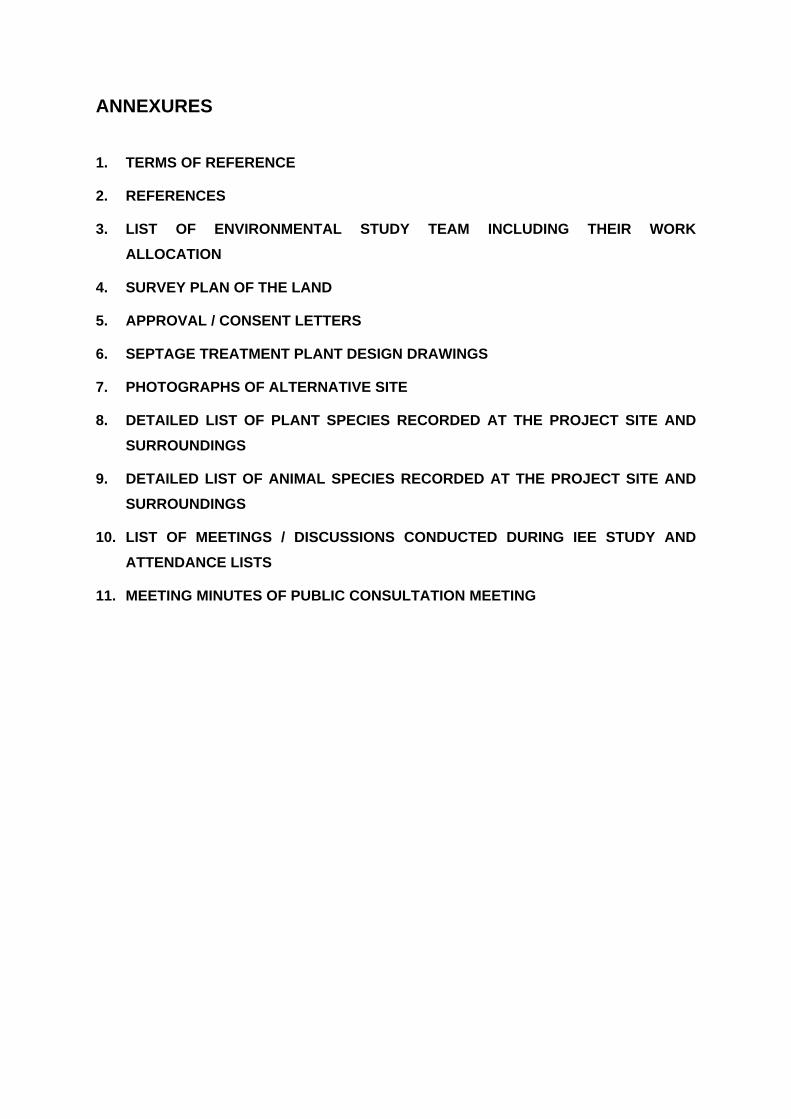
ANNEXURES
1. TERMS OF REFERENCE
2. REFERENCES
3. LIST OF ENVIRONMENTAL STUDY TEAM INCLUDING THEIR WORK
ALLOCATION
4. SURVEY PLAN OF THE LAND
5. APPROVAL / CONSENT LETTERS
6. SEPTAGE TREATMENT PLANT DESIGN DRAWINGS
7. PHOTOGRAPHS OF ALTERNATIVE SITE
8. DETAILED LIST OF PLANT SPECIES RECORDED AT THE PROJECT SITE AND
SURROUNDINGS
9. DETAILED LIST OF ANIMAL SPECIES RECORDED AT THE PROJECT SITE AND
SURROUNDINGS
10. LIST OF MEETINGS / DISCUSSIONS CONDUCTED DURING IEE STUDY AND
ATTENDANCE LISTS
11. MEETING MINUTES OF PUBLIC CONSULTATION MEETING
ANNEXURE 1: TERMS OF REFERENCE
OUTLINE OF THE IEE REPORT
Chapter 1 - Introduction
Chapter 2 - Description of the proposed project and reasonable alternatives
Chapter 3 - Description of the existing environment
Chapter 4 - Description of the anticipated environmental impacts
Chapter 5 - Proposed mitigatory measures
Chapter 6 - Monitoring Programme
Chapter 7 - Public consultation and information disclosure
Chapter 8 - Finding and recommendations
Chapter 9 - Conclusions
ANNEXURES
I Terms of Reference forwarded by the PEA –NWP for Chilaw CEA-NP for Mannar
II Reference and Source of data information
III List of report preparers
IV Complete set of relevant maps, tables, charts, layout plans
CHAPTER 1 - INTRODUCTION
This chapter would normally include the objective of the proposal and should include following.
(i) Purpose of the report, including
Identification of the project and project proponent. Brief description of the nature, size, and location of the project and of its
importance to the country. Any other pertinent background information
(ii) Extent of the IEE study:
Extent and scope of the study magnitude of effort person or agency performing the study and acknowledgement Government policy / status regarding the project Applicable laws, regulations, standards and requirements covering the
proposed project. The necessary approvals needed for the proposed development from involved
agencies. Any conditions laid down by the Government Agencies in getting preliminary
clearance for the project
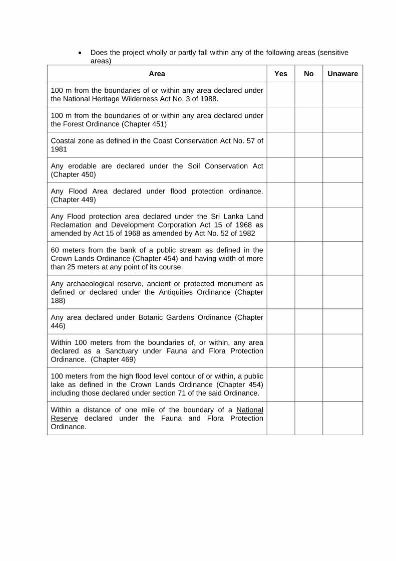
Does the project wholly or partly fall within any of the following areas (sensitive areas)
Area Yes No Unaware
100 m from the boundaries of or within any area declared under the National Heritage Wilderness Act No. 3 of 1988.
100 m from the boundaries of or within any area declared under the Forest Ordinance (Chapter 451)
Coastal zone as defined in the Coast Conservation Act No. 57 of 1981
Any erodable are declared under the Soil Conservation Act (Chapter 450)
Any Flood Area declared under flood protection ordinance. (Chapter 449)
Any Flood protection area declared under the Sri Lanka Land Reclamation and Development Corporation Act 15 of 1968 as amended by Act 15 of 1968 as amended by Act No. 52 of 1982
60 meters from the bank of a public stream as defined in the Crown Lands Ordinance (Chapter 454) and having width of more than 25 meters at any point of its course.
Any archaeological reserve, ancient or protected monument as defined or declared under the Antiquities Ordinance (Chapter 188)
Any area declared under Botanic Gardens Ordinance (Chapter 446)
Within 100 meters from the boundaries of, or within, any area declared as a Sanctuary under Fauna and Flora Protection Ordinance. (Chapter 469)
100 meters from the high flood level contour of or within, a public lake as defined in the Crown Lands Ordinance (Chapter 454) including those declared under section 71 of the said Ordinance.
Within a distance of one mile of the boundary of a National Reserve declared under the Fauna and Flora Protection Ordinance.
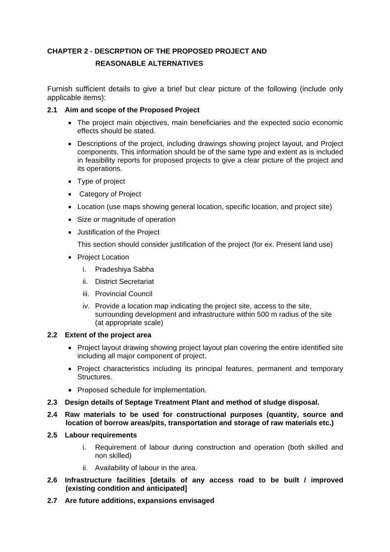
CHAPTER 2 - DESCRPTION OF THE PROPOSED PROJECT AND
REASONABLE ALTERNATIVES
Furnish sufficient details to give a brief but clear picture of the following (include only applicable items): 2.1 Aim and scope of the Proposed Project
The project main objectives, main beneficiaries and the expected socio economic effects should be stated.
Descriptions of the project, including drawings showing project layout, and Project components. This information should be of the same type and extent as is included in feasibility reports for proposed projects to give a clear picture of the project and its operations.
Type of project
Category of Project
Location (use maps showing general location, specific location, and project site)
Size or magnitude of operation
Justification of the Project
This section should consider justification of the project (for ex. Present land use)
Project Location
i. Pradeshiya Sabha
ii. District Secretariat
iii. Provincial Council
iv. Provide a location map indicating the project site, access to the site, surrounding development and infrastructure within 500 m radius of the site (at appropriate scale)
2.2 Extent of the project area
Project layout drawing showing project layout plan covering the entire identified site including all major component of project.
Project characteristics including its principal features, permanent and temporary Structures.
Proposed schedule for implementation. 2.3 Design details of Septage Treatment Plant and method of sludge disposal.
2.4 Raw materials to be used for constructional purposes (quantity, source and location of borrow areas/pits, transportation and storage of raw materials etc.)
2.5 Labour requirements
i. Requirement of labour during construction and operation (both skilled and non skilled)
ii. Availability of labour in the area.
2.6 Infrastructure facilities [details of any access road to be built / improved (existing condition and anticipated]
2.7 Are future additions, expansions envisaged
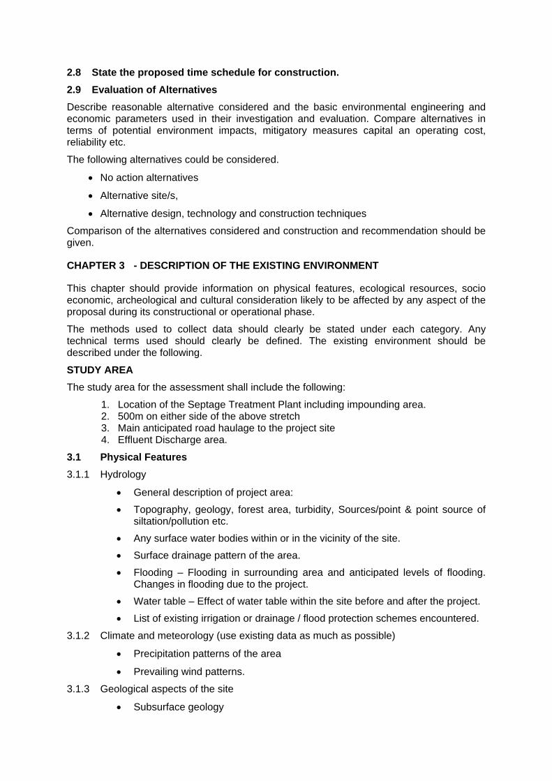
2.8 State the proposed time schedule for construction.
2.9 Evaluation of Alternatives
Describe reasonable alternative considered and the basic environmental engineering and economic parameters used in their investigation and evaluation. Compare alternatives in terms of potential environment impacts, mitigatory measures capital an operating cost, reliability etc.
The following alternatives could be considered.
No action alternatives
Alternative site/s,
Alternative design, technology and construction techniques
Comparison of the alternatives considered and construction and recommendation should be given.
CHAPTER 3 - DESCRIPTION OF THE EXISTING ENVIRONMENT
This chapter should provide information on physical features, ecological resources, socio economic, archeological and cultural consideration likely to be affected by any aspect of the proposal during its constructional or operational phase.
The methods used to collect data should clearly be stated under each category. Any technical terms used should clearly be defined. The existing environment should be described under the following.
STUDY AREA
The study area for the assessment shall include the following:
1. Location of the Septage Treatment Plant including impounding area. 2. 500m on either side of the above stretch 3. Main anticipated road haulage to the project site 4. Effluent Discharge area.
3.1 Physical Features
3.1.1 Hydrology
General description of project area:
Topography, geology, forest area, turbidity, Sources/point & point source of siltation/pollution etc.
Any surface water bodies within or in the vicinity of the site.
Surface drainage pattern of the area.
Flooding – Flooding in surrounding area and anticipated levels of flooding. Changes in flooding due to the project.
Water table – Effect of water table within the site before and after the project.
List of existing irrigation or drainage / flood protection schemes encountered.
3.1.2 Climate and meteorology (use existing data as much as possible)
Precipitation patterns of the area
Prevailing wind patterns.
3.1.3 Geological aspects of the site
Subsurface geology
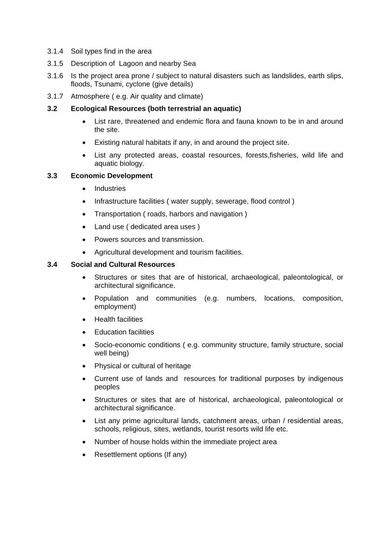
3.1.4 Soil types find in the area
3.1.5 Description of Lagoon and nearby Sea
3.1.6 Is the project area prone / subject to natural disasters such as landslides, earth slips, floods, Tsunami, cyclone (give details)
3.1.7 Atmosphere ( e.g. Air quality and climate)
3.2 Ecological Resources (both terrestrial an aquatic)
List rare, threatened and endemic flora and fauna known to be in and around the site.
Existing natural habitats if any, in and around the project site.
List any protected areas, coastal resources, forests,fisheries, wild life and aquatic biology.
3.3 Economic Development
Industries
Infrastructure facilities ( water supply, sewerage, flood control )
Transportation ( roads, harbors and navigation )
Land use ( dedicated area uses )
Powers sources and transmission.
Agricultural development and tourism facilities.
3.4 Social and Cultural Resources
Structures or sites that are of historical, archaeological, paleontological, or architectural significance.
Population and communities (e.g. numbers, locations, composition, employment)
Health facilities
Education facilities
Socio-economic conditions ( e.g. community structure, family structure, social well being)
Physical or cultural of heritage
Current use of lands and resources for traditional purposes by indigenous peoples
Structures or sites that are of historical, archaeological, paleontological or architectural significance.
List any prime agricultural lands, catchment areas, urban / residential areas, schools, religious, sites, wetlands, tourist resorts wild life etc.
Number of house holds within the immediate project area
Resettlement options (If any)
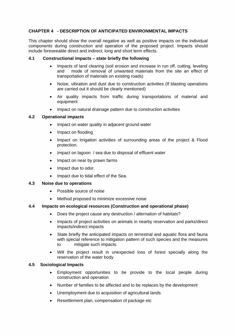
CHAPTER 4 - DESCRIPTION OF ANTICIPATED ENVIRONMENTAL IMPACTS
This chapter should show the overall negative as well as positive impacts on the individual components during construction and operation of the proposed project. Impacts should include foreseeable direct and indirect, long and short term effects.
4.1 Constructional impacts – state briefly the following
Impacts of land clearing (soil erosion and increase in run off, cutting, leveling and mode of removal of unwanted materials from the site an effect of transportation of materials on existing roads)
Noise, vibration and dust due to construction activities (If blasting operations are carried out it should be clearly mentioned)
Air quality impacts from traffic during transportations of material and equipment
Impact on natural drainage pattern due to construction activities
4.2 Operational impacts
Impact on water quality in adjacent ground water
Impact on flooding
Impact on Irrigation activities of surrounding areas of the project & Flood protection.
Impact on lagoon / sea due to disposal of effluent water
Impact on near by prawn farms
Impact due to odor.
Impact due to tidal effect of the Sea.
4.3 Noise due to operations
Possible source of noise
Method proposed to minimize excessive noise
4.4 Impacts on ecological resources (Construction and operational phase)
Does the project cause any destruction / alternation of habitats?
Impacts of project activities on animals in nearby reservation and parks/direct impacts/indirect impacts
State briefly the anticipated impacts on terrestrial and aquatic flora and fauna with special reference to mitigation pattern of such species and the measures to mitigate such impacts.
Will the project result in unexpected loss of forest specially along the reservation of the water body.
4.5 Sociological Impacts
Employment opportunities to be provide to the local people during construction and operation
Number of families to be affected and to be replaces by the development
Unemployment due to acquisition of agricultural lands
Resettlement plan, compensation of package etc
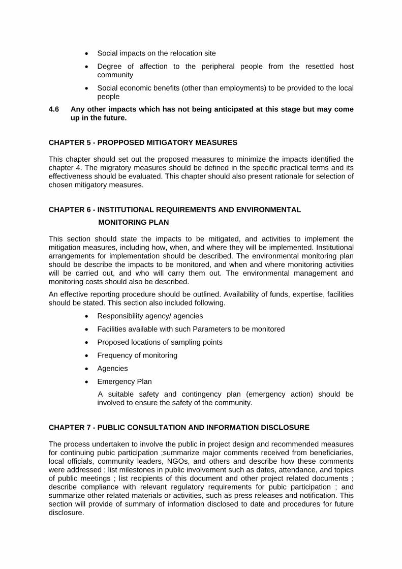
Social impacts on the relocation site
Degree of affection to the peripheral people from the resettled host community
Social economic benefits (other than employments) to be provided to the local people
4.6 Any other impacts which has not being anticipated at this stage but may come up in the future.
CHAPTER 5 - PROPPOSED MITIGATORY MEASURES
This chapter should set out the proposed measures to minimize the impacts identified the chapter 4. The migratory measures should be defined in the specific practical terms and its effectiveness should be evaluated. This chapter should also present rationale for selection of chosen mitigatory measures.
CHAPTER 6 - INSTITUTIONAL REQUIREMENTS AND ENVIRONMENTAL
MONITORING PLAN
This section should state the impacts to be mitigated, and activities to implement the mitigation measures, including how, when, and where they will be implemented. Institutional arrangements for implementation should be described. The environmental monitoring plan should be describe the impacts to be monitored, and when and where monitoring activities will be carried out, and who will carry them out. The environmental management and monitoring costs should also be described.
An effective reporting procedure should be outlined. Availability of funds, expertise, facilities should be stated. This section also included following.
Responsibility agency/ agencies
Facilities available with such Parameters to be monitored
Proposed locations of sampling points
Frequency of monitoring
Agencies
Emergency Plan
A suitable safety and contingency plan (emergency action) should be involved to ensure the safety of the community.
CHAPTER 7 - PUBLIC CONSULTATION AND INFORMATION DISCLOSURE
The process undertaken to involve the public in project design and recommended measures for continuing pubic participation ;summarize major comments received from beneficiaries, local officials, community leaders, NGOs, and others and describe how these comments were addressed ; list milestones in public involvement such as dates, attendance, and topics of public meetings ; list recipients of this document and other project related documents ; describe compliance with relevant regulatory requirements for pubic participation ; and summarize other related materials or activities, such as press releases and notification. This section will provide of summary of information disclosed to date and procedures for future disclosure.
CHAPTER 8 - FINDING AND RECOMMENDATIONS
An evaluation of the screening process and recommendation will be provided whether significant environmental impacts exist needing further detailed study or EIA. If there is no need for further study, the IEE itself, which at times may need to be supplemented by a special study in view of limited but significant impact, becomes the completed environmental assessment for the project and no follow- up EIA will be needed. If an EIA is needed, then this section will include a brief terms of reference ( TOR) for the needed follow – up EIA, including approximate description of works tasks, professional skills required, time required, and estimated costs.
CHAPTER 9 - CONCLUSIONS
In this section should be discussed the results of the IEE and justification, if any of the need for additional study or EIA. If an IEE, or an IEE supplemented by a special study, is sufficient for the project, then the IEE with the recommended institutional and monitoring program becomes the completed EIA. Any programme to improve general environmental conditions can also be stated here.
ANNEXURE 2: REFERENCES
1. National Atlas of Sri Lanka, Survey Department
2. Environmental Atlas of Sri Lanka, Central Environmental Authority, 2005
3. Resource Profile of Divisional Secretariat – Manthai West, 2010
4. Resource Profile of Divisional Secretariat - Mannar, 2010
5. Annex 3 – Urban Water Supply and Sanitation Sub Projects, Part A: Chilaw, Final Report, ADB TA 4853-SRI, Small Town and Rural Arid Areas Water Supply and Sanitation Project, 2008
6. Initial Environmental Examination: Chilaw (Draft), Dry Zone Urban Water Supply and Sanitation Project (DZUWSP), March 2008
7. Safeguard Policy Statement, Asian Development Bank, June 2009
8. Environmental Assessment Guidelines, Asian Development Bank, 2003
9. Guide to Septage Treatment and Disposal, USEPA, September 1994
10. Elements of Environmental Engineering, KN Duggal, S Chand and Co. Ltd., 2008
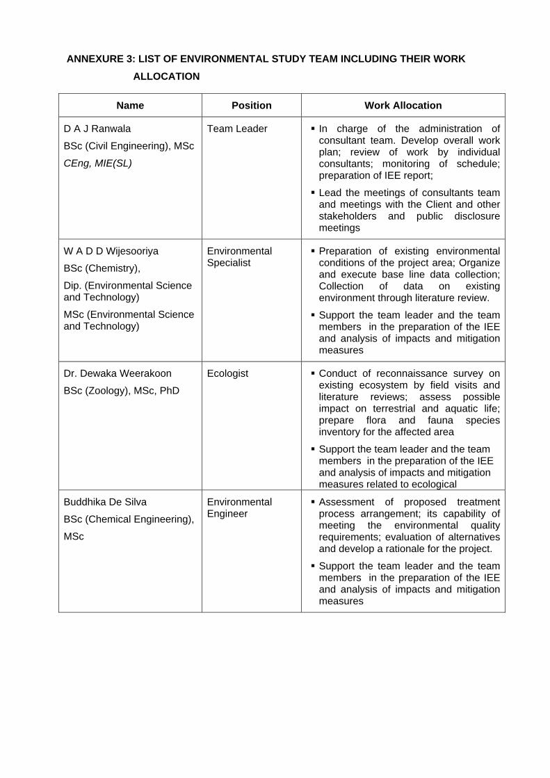
ANNEXURE 3: LIST OF ENVIRONMENTAL STUDY TEAM INCLUDING THEIR WORK
ALLOCATION
Name Position Work Allocation
D A J Ranwala
BSc (Civil Engineering), MSc
CEng, MIE(SL)
Team Leader In charge of the administration of consultant team. Develop overall work plan; review of work by individual consultants; monitoring of schedule; preparation of IEE report;
Lead the meetings of consultants team and meetings with the Client and other stakeholders and public disclosure meetings
W A D D Wijesooriya
BSc (Chemistry),
Dip. (Environmental Science and Technology)
MSc (Environmental Science and Technology)
Environmental Specialist
Preparation of existing environmental conditions of the project area; Organize and execute base line data collection; Collection of data on existing environment through literature review.
Support the team leader and the team members in the preparation of the IEE and analysis of impacts and mitigation measures
Dr. Dewaka Weerakoon
BSc (Zoology), MSc, PhD
Ecologist Conduct of reconnaissance survey on existing ecosystem by field visits and literature reviews; assess possible impact on terrestrial and aquatic life; prepare flora and fauna species inventory for the affected area
Support the team leader and the team members in the preparation of the IEE and analysis of impacts and mitigation measures related to ecological
Buddhika De Silva
BSc (Chemical Engineering),
MSc
Environmental Engineer
Assessment of proposed treatment process arrangement; its capability of meeting the environmental quality requirements; evaluation of alternatives and develop a rationale for the project.
Support the team leader and the team members in the preparation of the IEE and analysis of impacts and mitigation measures
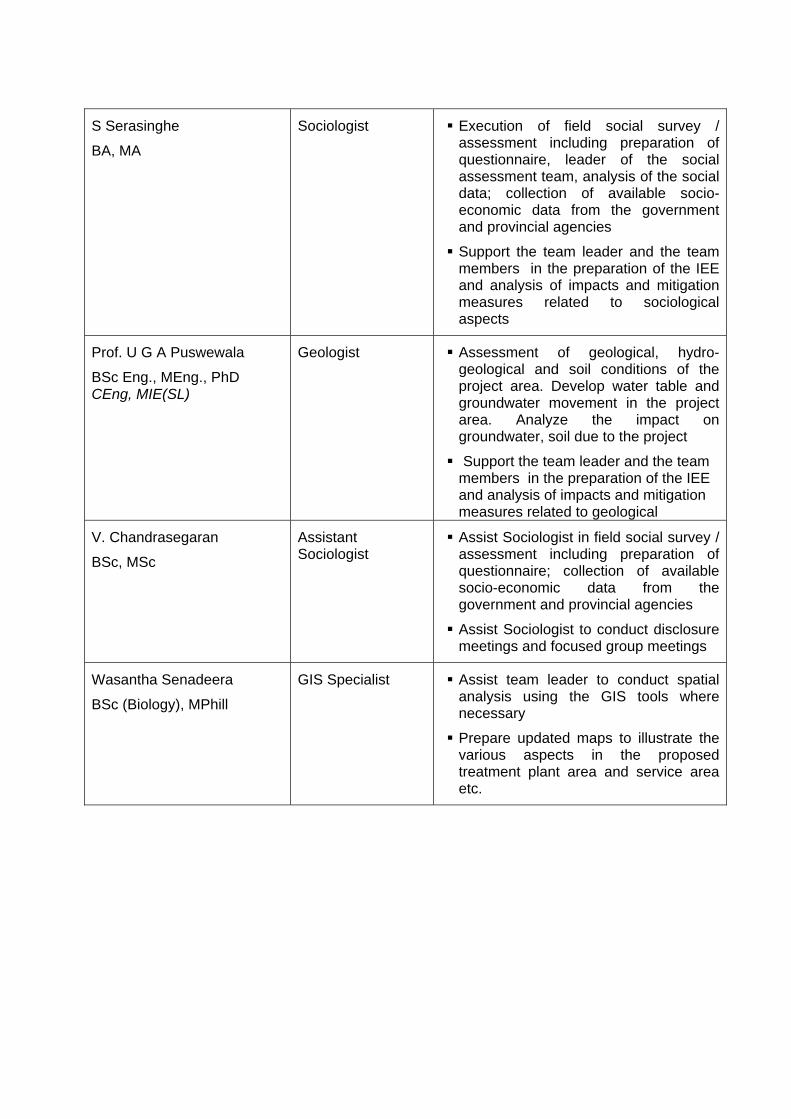
S Serasinghe
BA, MA
Sociologist Execution of field social survey / assessment including preparation of questionnaire, leader of the social assessment team, analysis of the social data; collection of available socio-economic data from the government and provincial agencies
Support the team leader and the team members in the preparation of the IEE and analysis of impacts and mitigation measures related to sociological aspects
Prof. U G A Puswewala
BSc Eng., MEng., PhD CEng, MIE(SL)
Geologist Assessment of geological, hydro-geological and soil conditions of the project area. Develop water table and groundwater movement in the project area. Analyze the impact on groundwater, soil due to the project
Support the team leader and the team members in the preparation of the IEE and analysis of impacts and mitigation measures related to geological
V. Chandrasegaran
BSc, MSc
Assistant Sociologist
Assist Sociologist in field social survey / assessment including preparation of questionnaire; collection of available socio-economic data from the government and provincial agencies
Assist Sociologist to conduct disclosure meetings and focused group meetings
Wasantha Senadeera
BSc (Biology), MPhill
GIS Specialist Assist team leader to conduct spatial analysis using the GIS tools where necessary
Prepare updated maps to illustrate the various aspects in the proposed treatment plant area and service area etc.
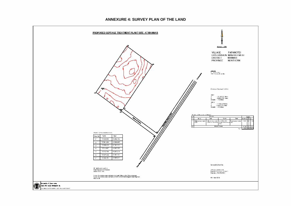
ANNEXURE 4: SURVEY PLAN OF THE LAND
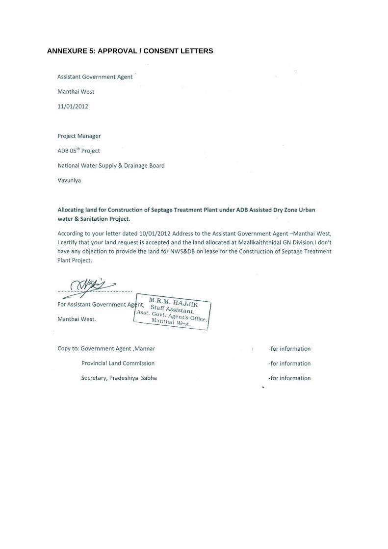
ANNEXURE 5: APPROVAL / CONSENT LETTERS
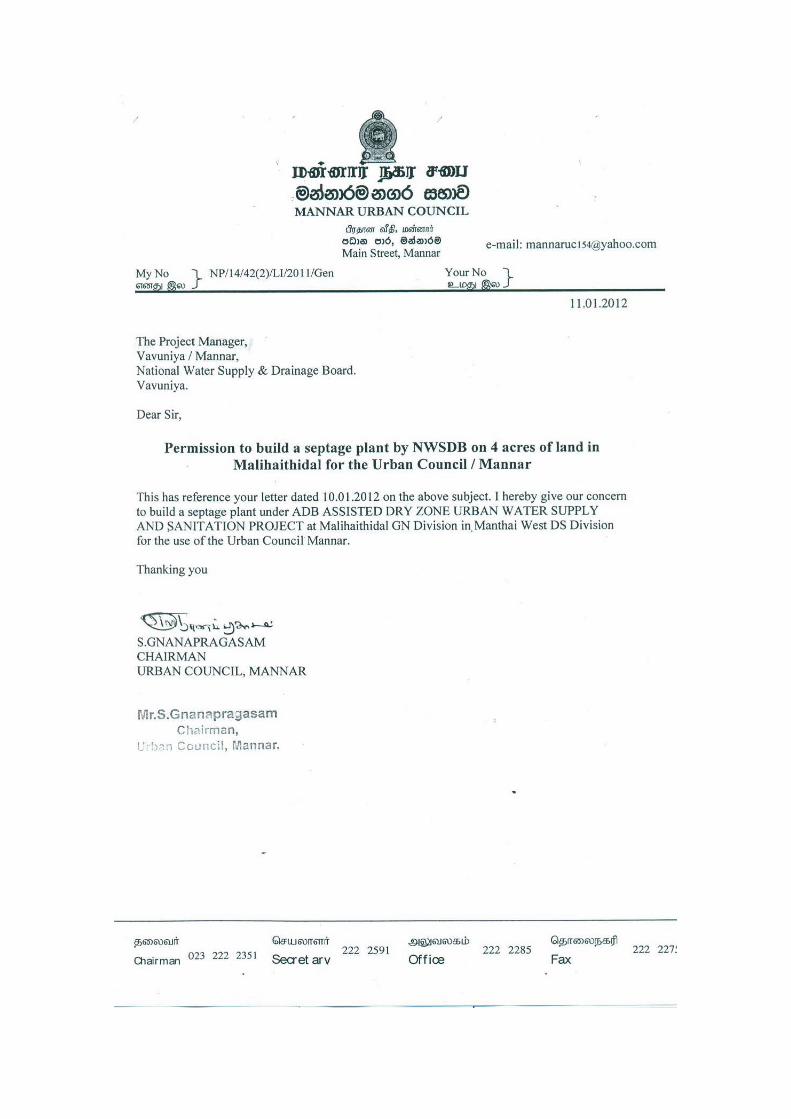
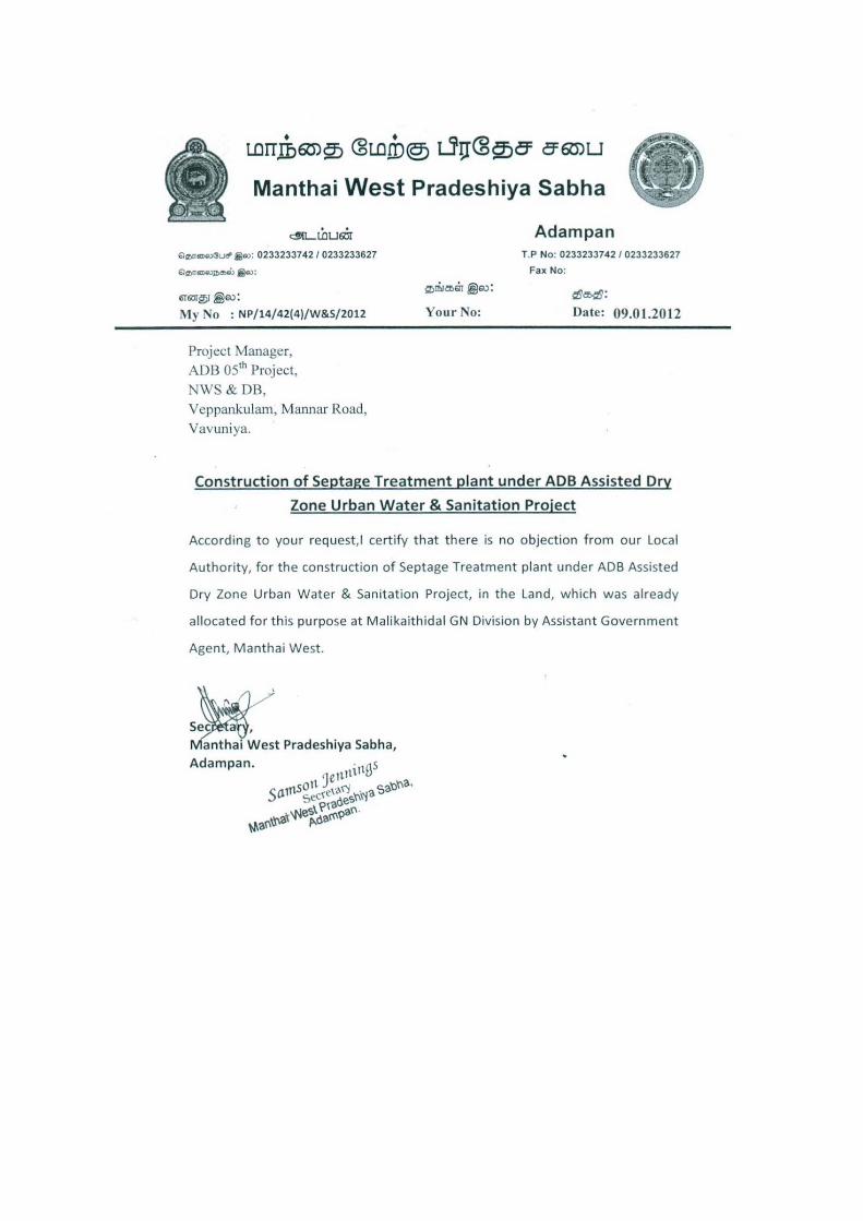
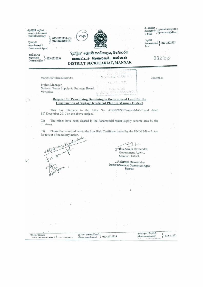
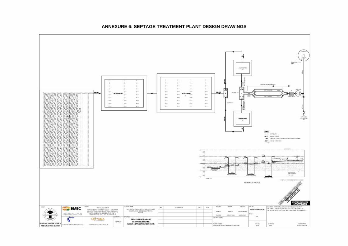
ANNEXURE 6: SEPTAGE TREATMENT PLANT DESIGN DRAWINGS
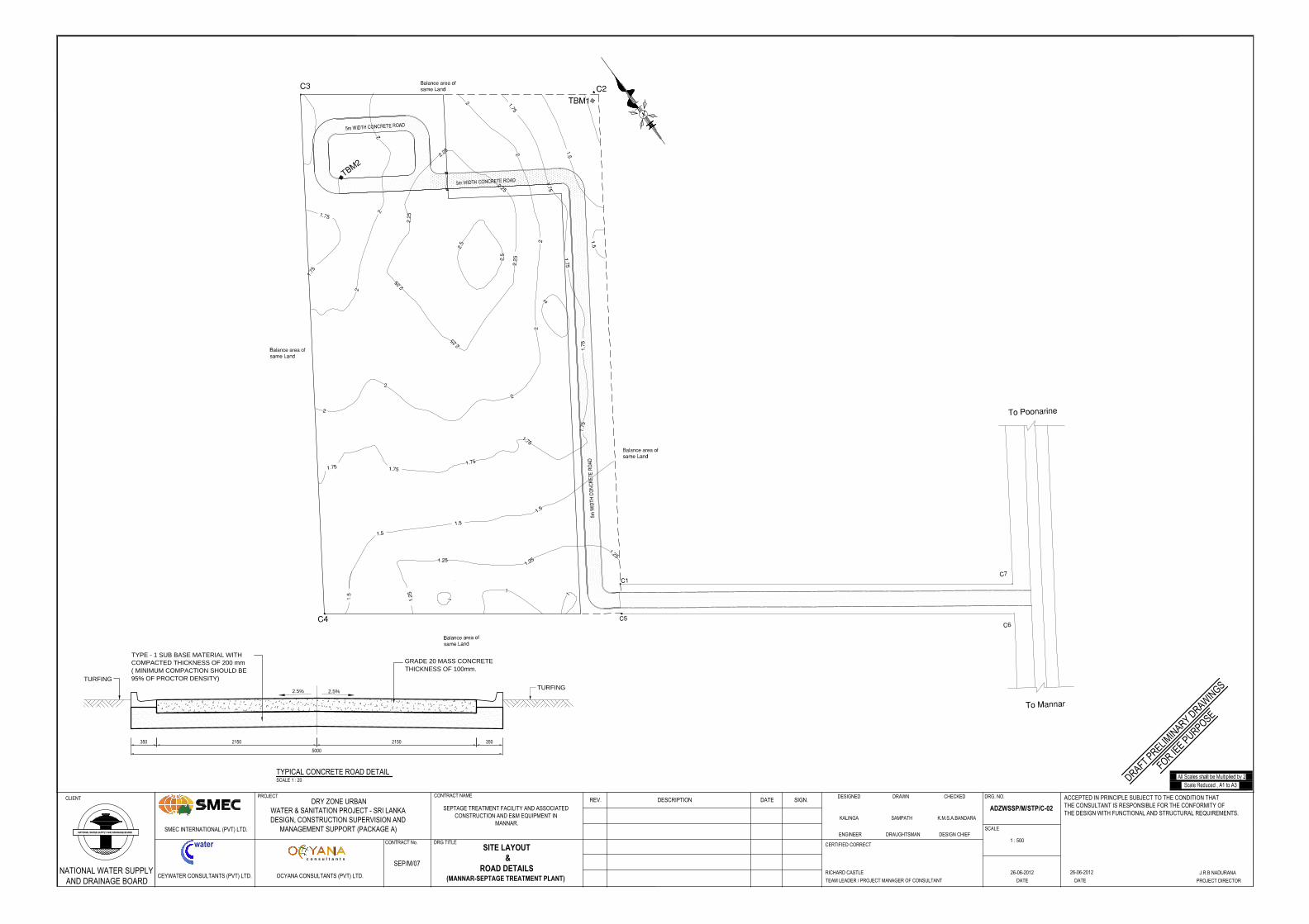
TYPE - 1 SUB BASE MATERIAL WITHCOMPACTED THICKNESS OF 200 mm( MINIMUM COMPACTION SHOULD BE95% OF PROCTOR DENSITY)
GRADE 20 MASS CONCRETETHICKNESS OF 100mm.
2.5% 2.5%
350350
5000
TURFINGTURFING
2150 2150
TYPICAL CONCRETE ROAD DETAILSCALE 1 : 20
CLIENT
water
OCYANA CONSULTANTS (PVT) LTD.CEYWATER CONSULTANTS (PVT) LTD.
SMEC INTERNATIONAL (PVT) LTD.
CONTRACT No.
PROJECTDRY ZONE URBAN
WATER & SANITATION PROJECT - SRI LANKADESIGN, CONSTRUCTION SUPERVISION AND
MANAGEMENT SUPPORT (PACKAGE A)
DRG TITLE
REV. DESCRIPTION DATE SIGN.DESIGNED DRAWN CHECKED
ENGINEER DRAUGHTSMAN DESIGN CHIEF
CERTIFIED CORRECT
TEAM LEADER / PROJECT MANAGER OF CONSULTANT
DRG. NO.
SCALE
1 : 500
DATE DATE
c o n s u l t a n t s
ACCEPTED IN PRINCIPLE SUBJECT TO THE CONDITION THATTHE CONSULTANT IS RESPONSIBLE FOR THE CONFORMITY OFTHE DESIGN WITH FUNCTIONAL AND STRUCTURAL REQUIREMENTS.
PROJECT DIRECTOR
NATIONAL WATER SUPPLYAND DRAINAGE BOARD
CONTRACT NAME
SEP/M/07
SEPTAGE TREATMENT FACILITY AND ASSOCIATEDCONSTRUCTION AND E&M EQUIPMENT IN
MANNAR.K.M.S.A.BANDARAKALINGA SAMPATH
SITE LAYOUT &
ROAD DETAILS(MANNAR-SEPTAGE TREATMENT PLANT)
ADZWSSP/M/STP/C-02
26-06-2012RICHARD CASTLE J.R.B NADURANA26-06-2012
DRAFT PRELIMIN
ARY DRAWIN
GS
FOR IEE PURPOSE
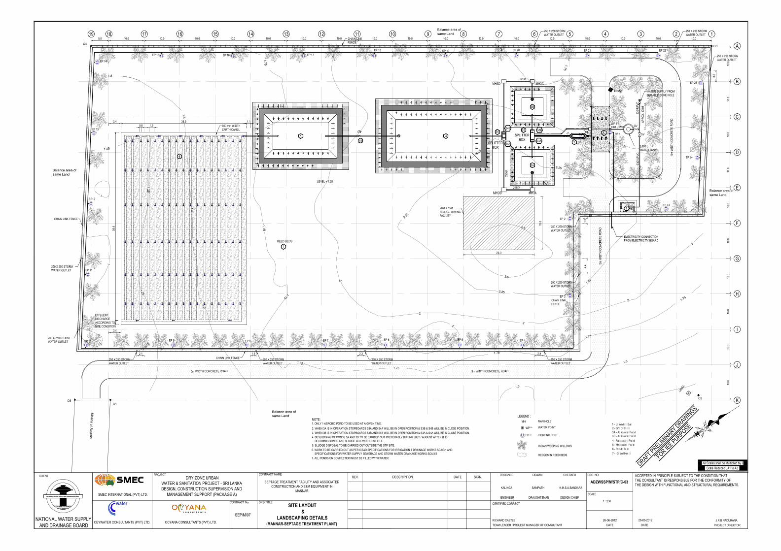
NOTE: 1. ONLY 1 AEROBIC POND TO BE USED AT A GIVEN TIME.
2. WHEN 3A IS IN OPERATION STOPBOARDS S3A AND S4A WILL BE IN OPEN POSITION & S3B & S4B WILL BE IN CLOSE POSITION.3. WHEN 3B IS IN OPERATION STOPBOARDS S3B AND S4B WILL BE IN OPEN POSITION & S3A & S4A WILL BE IN CLOSE POSITION.
5. SLUDGE DISPOSAL TO BE CARRIED OUT OUTSIDE THE STP SITE.
4. DESLUDGING OF PONDS 3A AND 3B TO BE CARRIED OUT PREFERABLY DURING JULY / AUGUST AFTER IT IS DECOMMISSIONED AND SLUDGE ALLOWED TO SETTLE.
6. WORK TO BE CARRIED OUT AS PER ICTAD SPECIFICATIONS FOR IRRIGATION & DRAINAGE WORKS SCA/3/1 AND SPECIFICATIONS FOR WATER SUPPLY SEWERAGE AND STORM WATER DRAINAGE WORKS SCA/3/2
1 - Unloading Bay2 - Grit Channel3A - Anaerobic Pond
4 - Facultative Pond5 - Maturation Pond
7 - Guard House
INDIAN WEEPING WILLOWS
HEDGES IN REED BEDS
LEGEND :
LIGHTING POST
WATER POINT
EP **
MAN HOLE
6 - Reeds Beds
3B - Anaerobic Pond
7. ALL PONDS ON COMPLETION MUST BE FILLED WITH WATER.
CLIENT
water
OCYANA CONSULTANTS (PVT) LTD.CEYWATER CONSULTANTS (PVT) LTD.
SMEC INTERNATIONAL (PVT) LTD.
CONTRACT No.
PROJECTDRY ZONE URBAN
WATER & SANITATION PROJECT - SRI LANKADESIGN, CONSTRUCTION SUPERVISION AND
MANAGEMENT SUPPORT (PACKAGE A)
DRG TITLE
REV. DESCRIPTION DATE SIGN.DESIGNED DRAWN CHECKED
ENGINEER DRAUGHTSMAN DESIGN CHIEF
CERTIFIED CORRECT
TEAM LEADER / PROJECT MANAGER OF CONSULTANT
DRG. NO.
SCALE
1 : 250
DATE DATE
c o n s u l t a n t s
ACCEPTED IN PRINCIPLE SUBJECT TO THE CONDITION THATTHE CONSULTANT IS RESPONSIBLE FOR THE CONFORMITY OFTHE DESIGN WITH FUNCTIONAL AND STRUCTURAL REQUIREMENTS.
PROJECT DIRECTOR
NATIONAL WATER SUPPLYAND DRAINAGE BOARD
CONTRACT NAME
SEP/M/07
SEPTAGE TREATMENT FACILITY AND ASSOCIATEDCONSTRUCTION AND E&M EQUIPMENT IN
MANNAR.K.M.S.A.BANDARAKALINGA SAMPATH
SITE LAYOUT &
LANDSCAPING DETAILS(MANNAR-SEPTAGE TREATMENT PLANT)
ADZWSSP/M/STP/C-03
26-06-2012RICHARD CASTLE J.R.B NADURANA26-06-2012
DRAFT PRELIMIN
ARY DRAWIN
GS
FOR IEE PURPOSE
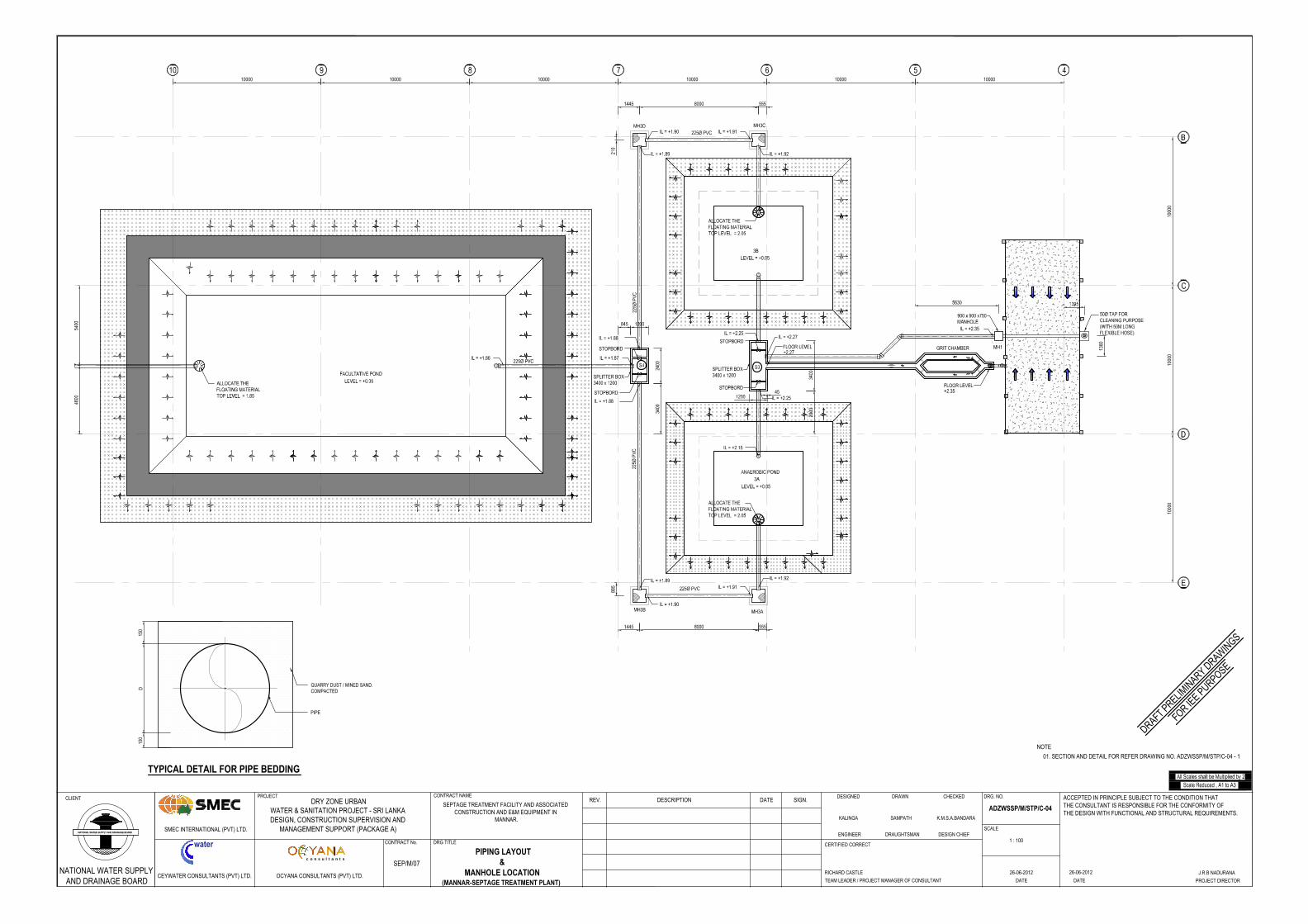
100001000010000100001000010000
1000
010
000
45
01. SECTION AND DETAIL FOR REFER DRAWING NO. ADZWSSP/M/STP/C-04 - 1
NOTE
TYPICAL DETAIL FOR PIPE BEDDING
150
100
QUARRY DUST / MINED SAND.COMPACTEDD
PIPE
CLIENT
water
OCYANA CONSULTANTS (PVT) LTD.CEYWATER CONSULTANTS (PVT) LTD.
SMEC INTERNATIONAL (PVT) LTD.
CONTRACT No.
PROJECTDRY ZONE URBAN
WATER & SANITATION PROJECT - SRI LANKADESIGN, CONSTRUCTION SUPERVISION AND
MANAGEMENT SUPPORT (PACKAGE A)
DRG TITLE
REV. DESCRIPTION DATE SIGN.DESIGNED DRAWN CHECKED
ENGINEER DRAUGHTSMAN DESIGN CHIEF
CERTIFIED CORRECT
TEAM LEADER / PROJECT MANAGER OF CONSULTANT
DRG. NO.
SCALE
1 : 100
DATE DATE
c o n s u l t a n t s
ACCEPTED IN PRINCIPLE SUBJECT TO THE CONDITION THATTHE CONSULTANT IS RESPONSIBLE FOR THE CONFORMITY OFTHE DESIGN WITH FUNCTIONAL AND STRUCTURAL REQUIREMENTS.
PROJECT DIRECTOR
NATIONAL WATER SUPPLYAND DRAINAGE BOARD
CONTRACT NAME
SEP/M/07
SEPTAGE TREATMENT FACILITY AND ASSOCIATEDCONSTRUCTION AND E&M EQUIPMENT IN
MANNAR. K.M.S.A.BANDARAKALINGA SAMPATH
PIPING LAYOUT&
MANHOLE LOCATION(MANNAR-SEPTAGE TREATMENT PLANT)
ADZWSSP/M/STP/C-04
26-06-2012RICHARD CASTLE J.R.B NADURANA26-06-2012
DRAFT PRELIMIN
ARY DRAWIN
GS
FOR IEE PURPOSE
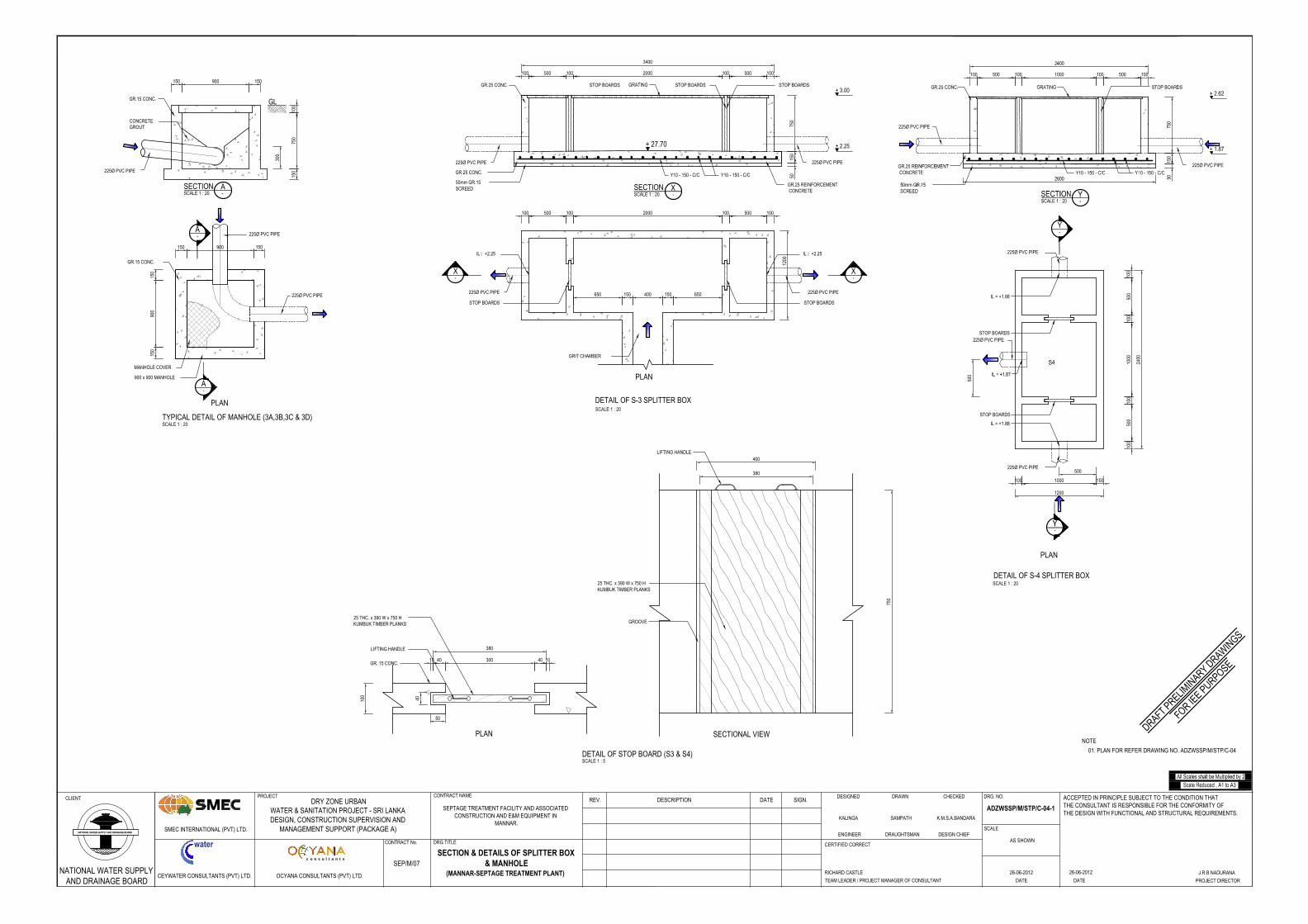
900
GL
150 150
750
100
150
225Ø PVC PIPE
900150 150
150
900
150
225Ø PVC PIPE
MANHOLE COVER
900 x 900 MANHOLE
225Ø PVC PIPE
GR.15 CONC.
GR.15 CONC.
PLAN
TYPICAL DETAIL OF MANHOLE (3A,3B,3C & 3D)SCALE 1 : 20
300
CONCRETEGROUT
A-
A-
SECTION SCALE 1 : 20
A-
DETAIL OF S-3 SPLITTER BOXSCALE 1 : 20
GRIT CHAMBER
STOP BOARDS
225Ø PVC PIPE
225Ø PVC PIPE 225Ø PVC PIPE
225Ø PVC PIPE
STOP BOARDS
STOP BOARDS
500100 100500100 100 2000
650150400150650
PLAN
500 100500100
150
750
3400
100 2000 100
+ 2.25
+ 3.00
IL = +2.25
+ 27.70
IL = +2.25
-X
-X
SECTION SCALE 1 : 20
X-
STOP BOARDSGR.25 CONC.
50
50mm GR.15SCREED
Y10 - 150 - C/CGR.25 CONC.
STOP BOARDS GRATING
Y10 - 150 - C/C
GR.25 REINFORCEMENT CONCRETE
1200
100
750
50
40
GROOVE
LIFTING HANDLE
25 THC. x 390 W x 750 HKUMBUK TIMBER PLANKS
400
380
PLAN SECTIONAL VIEW
DETAIL OF STOP BOARD (S3 & S4)SCALE 1 : 5
300
380
40 104010
LIFTING HANDLE
GR. 15 CONC.
25 THC. x 390 W x 750 HKUMBUK TIMBER PLANKS
2400
1200
S4
1001000100
500
100
500
100
1000
100
500
100
225Ø PVC PIPE
225Ø PVC PIPE
STOP BOARDS
STOP BOARDS
500
DETAIL OF S-4 SPLITTER BOX
PLAN
SCALE 1 : 20
225Ø PVC PIPE
01. PLAN FOR REFER DRAWING NO. ADZWSSP/M/STP/C-04
NOTE
CLIENT
water
OCYANA CONSULTANTS (PVT) LTD.CEYWATER CONSULTANTS (PVT) LTD.
SMEC INTERNATIONAL (PVT) LTD.
CONTRACT No.
PROJECTDRY ZONE URBAN
WATER & SANITATION PROJECT - SRI LANKADESIGN, CONSTRUCTION SUPERVISION AND
MANAGEMENT SUPPORT (PACKAGE A)
DRG TITLE
REV. DESCRIPTION DATE SIGN.DESIGNED DRAWN CHECKED
ENGINEER DRAUGHTSMAN DESIGN CHIEF
CERTIFIED CORRECT
TEAM LEADER / PROJECT MANAGER OF CONSULTANT
DRG. NO.
SCALE
AS SHOWN
DATE DATE
c o n s u l t a n t s
ACCEPTED IN PRINCIPLE SUBJECT TO THE CONDITION THATTHE CONSULTANT IS RESPONSIBLE FOR THE CONFORMITY OFTHE DESIGN WITH FUNCTIONAL AND STRUCTURAL REQUIREMENTS.
PROJECT DIRECTOR
NATIONAL WATER SUPPLYAND DRAINAGE BOARD
CONTRACT NAME
SEP/M/07
SEPTAGE TREATMENT FACILITY AND ASSOCIATEDCONSTRUCTION AND E&M EQUIPMENT IN
MANNAR.K.M.S.A.BANDARAKALINGA SAMPATH
SECTION & DETAILS OF SPLITTER BOX& MANHOLE
(MANNAR-SEPTAGE TREATMENT PLANT)
ADZWSSP/M/STP/C-04-1
26-06-2012RICHARD CASTLE J.R.B NADURANA26-06-2012
DRAFT PRELIMIN
ARY DRAWIN
GS
FOR IEE PURPOSE
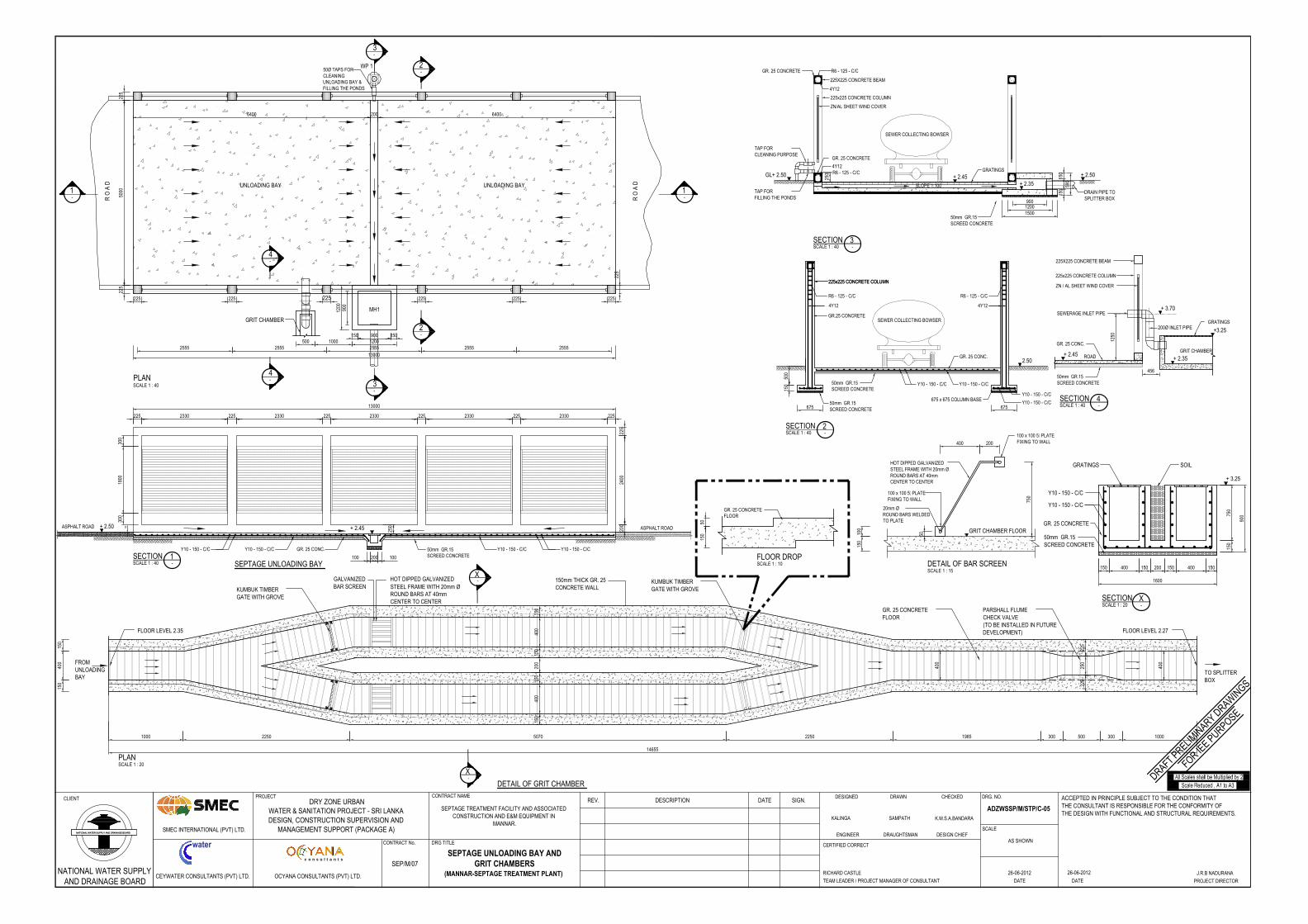
PLANSCALE 1 : 40
UNLOADING BAY UNLOADING BAY
2555 2555 2555 2555 2555
225
225
13000
225
5000
225
225 225 225 225 225
2006400 6400
150 900 1501200
1-
1-
2-
3-
2-
3-
900
1200 MH1
GRIT CHAMBER
4-
4-
1000500
WP 150Ø TAPS FORCLEANINGUNLOADING BAY &FILLING THE PONDS
R O
A D
R O
A D
200
2400
225
225 2330 225 2330 225 2330 225 2330 225 2330 225
100 200 100
13000
SECTION SCALE 1 : 40
1-
+ 2.45+ 2.50
SEPTAGE UNLOADING BAY
1800
300
300
Y10 - 150 - C/CY10 - 150 - C/C50mm GR.15SCREED CONCRETE
Y10 - 150 - C/C Y10 - 150 - C/C GR. 25 CONC.
250ASPHALT ROAD ASPHALT ROAD50
SECTION SCALE 1 : 40
3-
GL+ 2.50 + 2.50
SEWER COLLECTING BOWSER
90012001500
SLOPE 1:100
150
150
GRATINGS
DRAIN PIPE TOSPLITTER BOX
+ 2.45+ 2.35
TAP FORCLEANING PURPOSE
225x225 CONCRETE COLUMN
ZN/AL SHEET WIND COVER
225X225 CONCRETE BEAM
50mm GR.15SCREED CONCRETE
4Y12
R6 - 125 - C/C
4Y12R6 - 125 - C/C
250
GR. 25 CONCRETE
GR. 25 CONCRETE
590
TAP FORFILLING THE PONDS
SECTION SCALE 1 : 40
2-
2.50
SEWER COLLECTING BOWSER
225x225 CONCRETE COLUMN225x225 CONCRETE COLUMN
50mm GR.15SCREED CONCRETE
675
150
50mm GR.15SCREED CONCRETE
500
Y10 - 150 - C/CY10 - 150 - C/C
4Y12
R6 - 125 - C/C
4Y12
R6 - 125 - C/C
Y10 - 150 - C/C
Y10 - 150 - C/C675 x 675 COLUMN BASE
675
GR.25 CONCRETE
GR. 25 CONC.
400
400
400
400
250
1000 2250 5070 2250 1985 300 500 300 1000
150
150
PLAN SCALE 1 : 20
225
225
150
200
150
14655
150
400
150
X-
X
-
KUMBUK TIMBERGATE WITH GROVE
150mm THICK GR. 25CONCRETE WALL
KUMBUK TIMBERGATE WITH GROVE
PARSHALL FLUMECHECK VALVE(TO BE INSTALLED IN FUTUREDEVELOPMENT)
TO SPLITTERBOX
FROMUNLOADINGBAY
DETAIL OF GRIT CHAMBER
GR. 25 CONCRETEFLOOR
HOT DIPPED GALVANIZEDSTEEL FRAME WITH 20mm ØROUND BARS AT 40mmCENTER TO CENTER
GALVANIZEDBAR SCREEN
FLOOR LEVEL 2.35 FLOOR LEVEL 2.27
150 400 150 200 150 400 150
1600
150
750
900
SECTION SCALE 1 : 20
X-
GRATINGS SOIL
Y10 - 150 - C/C
Y10 - 150 - C/C
GR. 25 CONCRETE
50mm GR.15SCREED CONCRETE
+ 3.25
225x225 CONCRETE COLUMN
ZN / AL SHEET WIND COVER
225X225 CONCRETE BEAM
GRATINGS
SEWERAGE INLET PIPE
ROAD
SECTION SCALE 1 : 40
4-
GRIT CHAMBER
1250
456
200Ø INLET PIPE
50mm GR.15SCREED CONCRETE
GR. 25 CONC.
+ 3.70
+ 2.45+ 2.35
+3.25
FLOOR DROPSCALE 1 : 10
150
50
GR. 25 CONCRETEFLOOR
DETAIL OF BAR SCREEN SCALE 1 : 15
GRIT CHAMBER FLOOR
150
100
50
750
200400
HOT DIPPED GALVANIZEDSTEEL FRAME WITH 20mm ØROUND BARS AT 40mmCENTER TO CENTER
100 x 100 5t PLATEFIXING TO WALL
20mm ØROUND BARS WELDEDTO PLATE
100 x 100 5t PLATEFIXING TO WALL
CLIENT
water
OCYANA CONSULTANTS (PVT) LTD.CEYWATER CONSULTANTS (PVT) LTD.
SMEC INTERNATIONAL (PVT) LTD.
CONTRACT No.
PROJECTDRY ZONE URBAN
WATER & SANITATION PROJECT - SRI LANKADESIGN, CONSTRUCTION SUPERVISION AND
MANAGEMENT SUPPORT (PACKAGE A)
DRG TITLE
REV. DESCRIPTION DATE SIGN.DESIGNED DRAWN CHECKED
ENGINEER DRAUGHTSMAN DESIGN CHIEF
CERTIFIED CORRECT
TEAM LEADER / PROJECT MANAGER OF CONSULTANT
DRG. NO.
SCALE
AS SHOWN
DATE DATE
c o n s u l t a n t s
ACCEPTED IN PRINCIPLE SUBJECT TO THE CONDITION THATTHE CONSULTANT IS RESPONSIBLE FOR THE CONFORMITY OFTHE DESIGN WITH FUNCTIONAL AND STRUCTURAL REQUIREMENTS.
PROJECT DIRECTOR
NATIONAL WATER SUPPLYAND DRAINAGE BOARD
CONTRACT NAME
SEP/M/07
SEPTAGE TREATMENT FACILITY AND ASSOCIATEDCONSTRUCTION AND E&M EQUIPMENT IN
MANNAR.K.M.S.A.BANDARAKALINGA SAMPATH
SEPTAGE UNLOADING BAY ANDGRIT CHAMBERS
(MANNAR-SEPTAGE TREATMENT PLANT)
ADZWSSP/M/STP/C-05
26-06-2012RICHARD CASTLE J.R.B NADURANA26-06-2012
DRAFT PRELIMIN
ARY DRAWIN
GS
FOR IEE PURPOSE
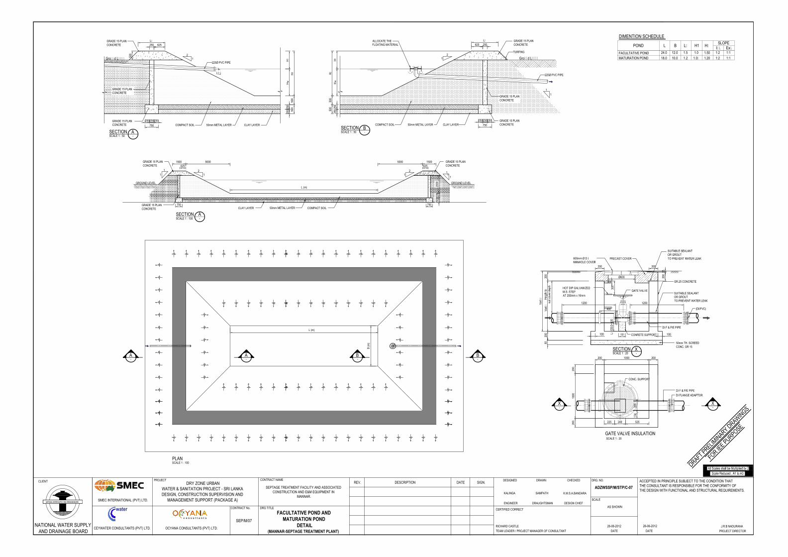
A-
A-
L (m)
B (m
)
PLANSCALE 1 : 100
B-
B-
TYPICAL DETAILS OF PONDS
L (m)
SECTION SCALE 1 : 100
A-
5005
00
1500
2000GROUND LEVEL GROUND LEVEL
21
1
11
1
21
CLAY LAYER COMPACT SOIL
GRADE 15 PLANCONCRETE
GRADE 15 PLANCONCRETE
1
50mm METAL LAYERGRADE 15 PLANCONCRETE
750
5000625
15005000625
750
Lw
500
500
Hw
H1
SECTION SCALE 1 : 50
A-
H2
500
Ground Level2
1
CLAY LAYER
625
COMPACT SOIL
GRADE 15 PLANCONCRETE
225Ø PVC PIPE
250
750
250250250
2502
50
50mm METAL LAYERGRADE 15 PLANCONCRETE
GRADE 15 PLANCONCRETE
POND L B Lw H1SLOPE
Int. Ext.FACULTATIVE POND MATURATION POND
24.0
18.0
12.0
10.0
1.5
1.2
1.0
1.0<
1:2
1:2
1:1
1:1
DIMENTION SCHEDULE
1.20
Hw
1.50
SECTION SCALE 1 : 50
B-
TURFING
500
500
Hw
H1
H2
LwALLOCATE THEFLOATING MATERIAL
21
1
1
Ground Level
COMPACT SOIL CLAY LAYER
625GRADE 15 PLANCONCRETE
225Ø PVC PIPE
250
2502
50
50mm METAL LAYERGRADE 15 PLANCONCRETE
GRADE 15 PLANCONCRETE
750
250250250
Varie
sVarie
s
200
5020
0
CONRETE SUPPORT
50mm TH. SCREEDCONC. GR 15
DI F & P/E PIPE
200 1000 200
200
1000
200
L= O
D/2
+300
SUITABLE SEALANTOR GROUTTO PREVENT WATER LEAK
151
134
225 249 525
GR.25 CONCRETE
X-
GATE VALVE INSULATIONSCALE 1 : 20
SECTION SCALE 1 : 20
X-
CLIENT
water
OCYANA CONSULTANTS (PVT) LTD.CEYWATER CONSULTANTS (PVT) LTD.
SMEC INTERNATIONAL (PVT) LTD.
CONTRACT No.
PROJECTDRY ZONE URBAN
WATER & SANITATION PROJECT - SRI LANKADESIGN, CONSTRUCTION SUPERVISION AND
MANAGEMENT SUPPORT (PACKAGE A)
DRG TITLE
REV. DESCRIPTION DATE SIGN.DESIGNED DRAWN CHECKED
ENGINEER DRAUGHTSMAN DESIGN CHIEF
CERTIFIED CORRECT
TEAM LEADER / PROJECT MANAGER OF CONSULTANT
DRG. NO.
SCALE
AS SHOWN
DATE DATE
c o n s u l t a n t s
ACCEPTED IN PRINCIPLE SUBJECT TO THE CONDITION THATTHE CONSULTANT IS RESPONSIBLE FOR THE CONFORMITY OFTHE DESIGN WITH FUNCTIONAL AND STRUCTURAL REQUIREMENTS.
PROJECT DIRECTOR
NATIONAL WATER SUPPLYAND DRAINAGE BOARD
CONTRACT NAME
SEP/M/07
SEPTAGE TREATMENT FACILITY AND ASSOCIATEDCONSTRUCTION AND E&M EQUIPMENT IN
MANNAR.K.M.S.A.BANDARA
FACULTATIVE POND ANDMATURATION POND
DETAIL(MANNAR-SEPTAGE TREATMENT PLANT)
ADZWSSP/M/STP/C-07KALINGA SAMPATH
26-06-2012RICHARD CASTLE J.R.B NADURANA26-06-2012
DRAFT PRELIMIN
ARY DRAWIN
GS
FOR IEE PURPOSE
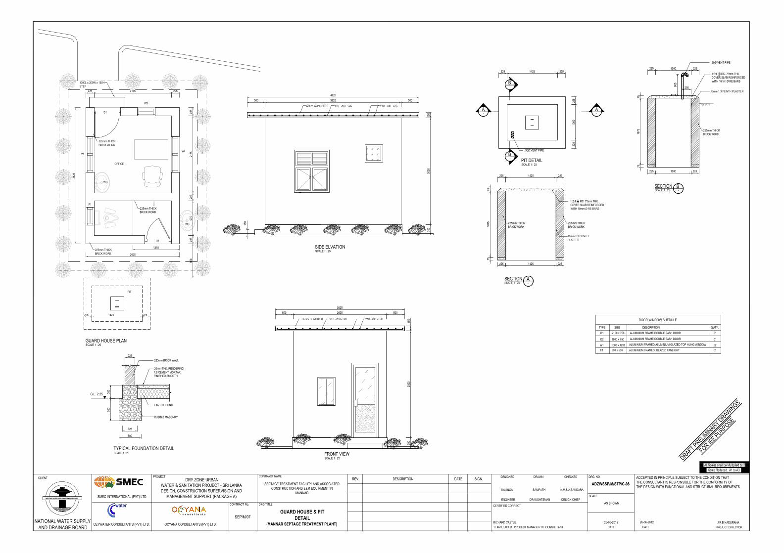
OFFICE
D1
WI
W2
WI
D2
F1
GUARD HOUSE PLANSCALE 1 : 25
SIDE ELVATIONSCALE 1 : 25
FRONT VIEWSCALE 1 : 25
3000
150
3625
3000
150
4825
2175
225
975
225
225
2252175225
3825
2625
1315
960
500 5003825
5002625500
225mm THICKBRICK WORK
225mm THICKBRICK WORK
225mm THICKBRICK WORK
1000L x 300W x 150HSTEP
300
300
150
Y10 - 200 - C/CY10 - 200 - C/C
Y10 - 200 - C/CY10 - 200 - C/C
GR.25 CONCRETE
GR.25 CONCRETE
PIT
2251425225
WB
WB
75
1:2:4 (14) RC. 75mm THK.
COVER SLAB REINFORCEDWITH 10mm Ø RE BARS
225 1000 225
225mm THICKBRICK WORK
225 1000 225
16mm 1:3 PLINTH PLASTER250
50Ø VENT PIPE
600
1875
75
1425
-SECTION BSCALE 1 : 25
225225
1000
PIT DETAILSCALE 1 : 25
75
1:2:4 (14) RC. 75mm THK.
COVER SLAB REINFORCEDWITH 10mm Ø RE BARS
225 1425 225
225mm THICKBRICK WORK
16mm 1:3 PLINTHPLASTER
1875
75
-SECTION ASCALE 1 : 25
225mm THICKBRICK WORK
1425 225225
50Ø VENT PIPE
- -A A
-B
-B
225
225
300
500
G.L. 2.25
20mm THK. RENDERING1:8 CEMENT MORTARFINISHED SMOOTH
500
225
325
RUBBLE MASONRY
EARTH FILLING
225mm BRICK WALL
TYPICAL FOUNDATION DETAILSCALE 1 : 25
DOOR WINDOW SHEDULE
D1 2100 x 750 ALUMINIUM FRAME DOUBLE SASH DOOR 01
F1 500 x 500 ALUMINIUM FRAMED GLAZED FANLIGHT 01
D2 1800 x 750 01
02
ALUMINIUM FRAME DOUBLE SASH DOOR
W1 1000 x 1200 ALUMINIUM FRAMED ALUMINIUM GLAZED TOP HUNG WINDOW
TYPE SIZE DESCRIPTION QUTY.
CLIENT
water
OCYANA CONSULTANTS (PVT) LTD.CEYWATER CONSULTANTS (PVT) LTD.
SMEC INTERNATIONAL (PVT) LTD.
CONTRACT No.
PROJECTDRY ZONE URBAN
WATER & SANITATION PROJECT - SRI LANKADESIGN, CONSTRUCTION SUPERVISION AND
MANAGEMENT SUPPORT (PACKAGE A)
DRG TITLE
REV. DESCRIPTION DATE SIGN.DESIGNED DRAWN CHECKED
ENGINEER DRAUGHTSMAN DESIGN CHIEF
CERTIFIED CORRECT
TEAM LEADER / PROJECT MANAGER OF CONSULTANT
DRG. NO.
SCALE
AS SHOWN
DATE DATE
c o n s u l t a n t s
ACCEPTED IN PRINCIPLE SUBJECT TO THE CONDITION THATTHE CONSULTANT IS RESPONSIBLE FOR THE CONFORMITY OFTHE DESIGN WITH FUNCTIONAL AND STRUCTURAL REQUIREMENTS.
PROJECT DIRECTOR
NATIONAL WATER SUPPLYAND DRAINAGE BOARD
CONTRACT NAME
SEP/M/07
SEPTAGE TREATMENT FACILITY AND ASSOCIATEDCONSTRUCTION AND E&M EQUIPMENT IN
MANNAR.K.M.S.A.BANDARAKALINGA SAMPATH
GUARD HOUSE & PITDETAIL
(MANNAR SEPTAGE TREATMENT PLANT)
ADZWSSP/M/STP/C-08
26-06-2012RICHARD CASTLE J.R.B NADURANA26-06-2012
DRAFT PRELIMIN
ARY DRAWIN
GS
FOR IEE PURPOSE
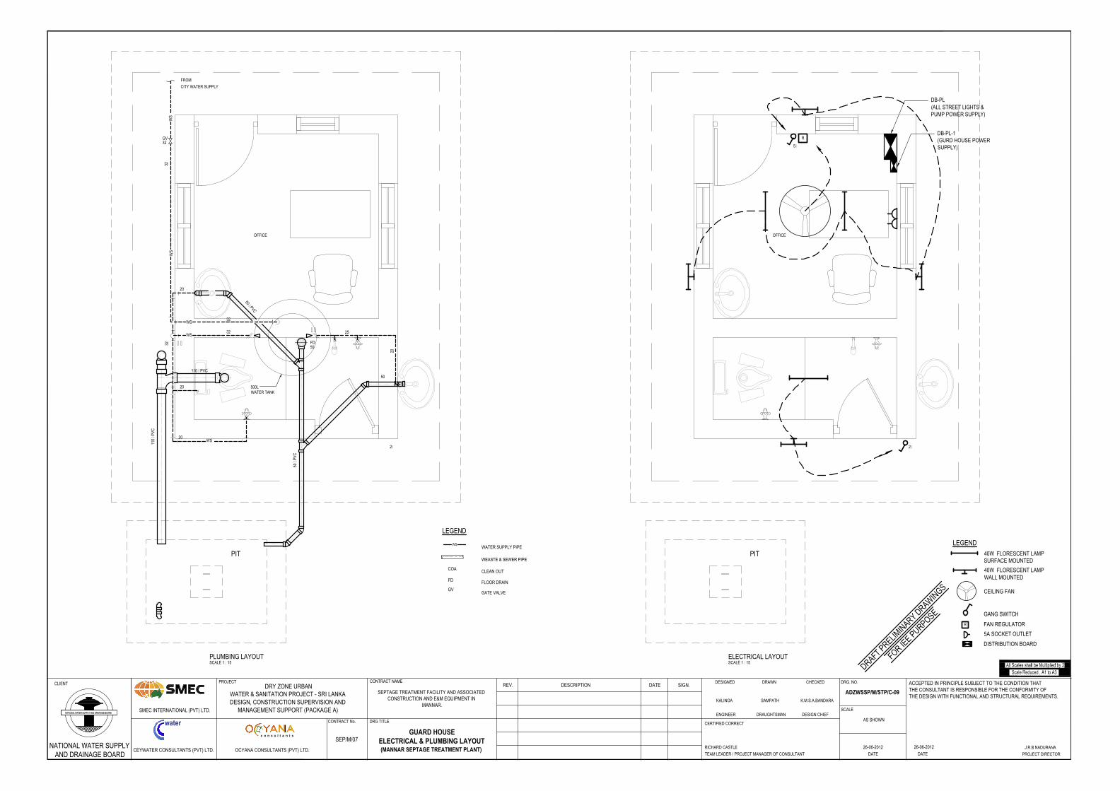
110 uPVC
110
uPVC
OFFICE
3232
20
20
20
25
20
50 uPVC
FD50
50
50 u
PVC
2g
FROM
CITY WATER SUPPLY
WSWATER SUPPLY PIPE
WEASTE & SEWER PIPE
COA CLEAN OUT
FD FLOOR DRAIN
GVGATE VALVE
LEGEND
WS
WS
WS
GV32
PLUMBING LAYOUTSCALE 1 : 15
500LWATER TANK
32WS
WS
##
##32
PIT
OFFICE
5g
R
2g
ELECTRICAL LAYOUTSCALE 1 : 15
LEGEND
40W FLORESCENT LAMPSURFACE MOUNTED
GANG SWITCH
5A SOCKET OUTLET
DB-PL(ALL STREET LIGHTS &PUMP POWER SUPPLY)
DB-PL-1(GURD HOUSE POWERSUPPLY)
CEILING FAN
DISTRIBUTION BOARD
40W FLORESCENT LAMPWALL MOUNTED
R FAN REGULATOR
PIT
CLIENT
water
OCYANA CONSULTANTS (PVT) LTD.CEYWATER CONSULTANTS (PVT) LTD.
SMEC INTERNATIONAL (PVT) LTD.
CONTRACT No.
PROJECTDRY ZONE URBAN
WATER & SANITATION PROJECT - SRI LANKADESIGN, CONSTRUCTION SUPERVISION AND
MANAGEMENT SUPPORT (PACKAGE A)
DRG TITLE
REV. DESCRIPTION DATE SIGN.DESIGNED DRAWN CHECKED
ENGINEER DRAUGHTSMAN DESIGN CHIEF
CERTIFIED CORRECT
TEAM LEADER / PROJECT MANAGER OF CONSULTANT
DRG. NO.
SCALE
AS SHOWN
DATE DATE
c o n s u l t a n t s
ACCEPTED IN PRINCIPLE SUBJECT TO THE CONDITION THATTHE CONSULTANT IS RESPONSIBLE FOR THE CONFORMITY OFTHE DESIGN WITH FUNCTIONAL AND STRUCTURAL REQUIREMENTS.
PROJECT DIRECTOR
NATIONAL WATER SUPPLYAND DRAINAGE BOARD
CONTRACT NAME
SEP/M/07
SEPTAGE TREATMENT FACILITY AND ASSOCIATEDCONSTRUCTION AND E&M EQUIPMENT IN
MANNAR.K.M.S.A.BANDARAKALINGA SAMPATH
GUARD HOUSEELECTRICAL & PLUMBING LAYOUT(MANNAR SEPTAGE TREATMENT PLANT)
ADZWSSP/M/STP/C-09
26-06-2012RICHARD CASTLE J.R.B NADURANA26-06-2012
DRAFT PRELIMIN
ARY DRAWIN
GS
FOR IEE PURPOSE
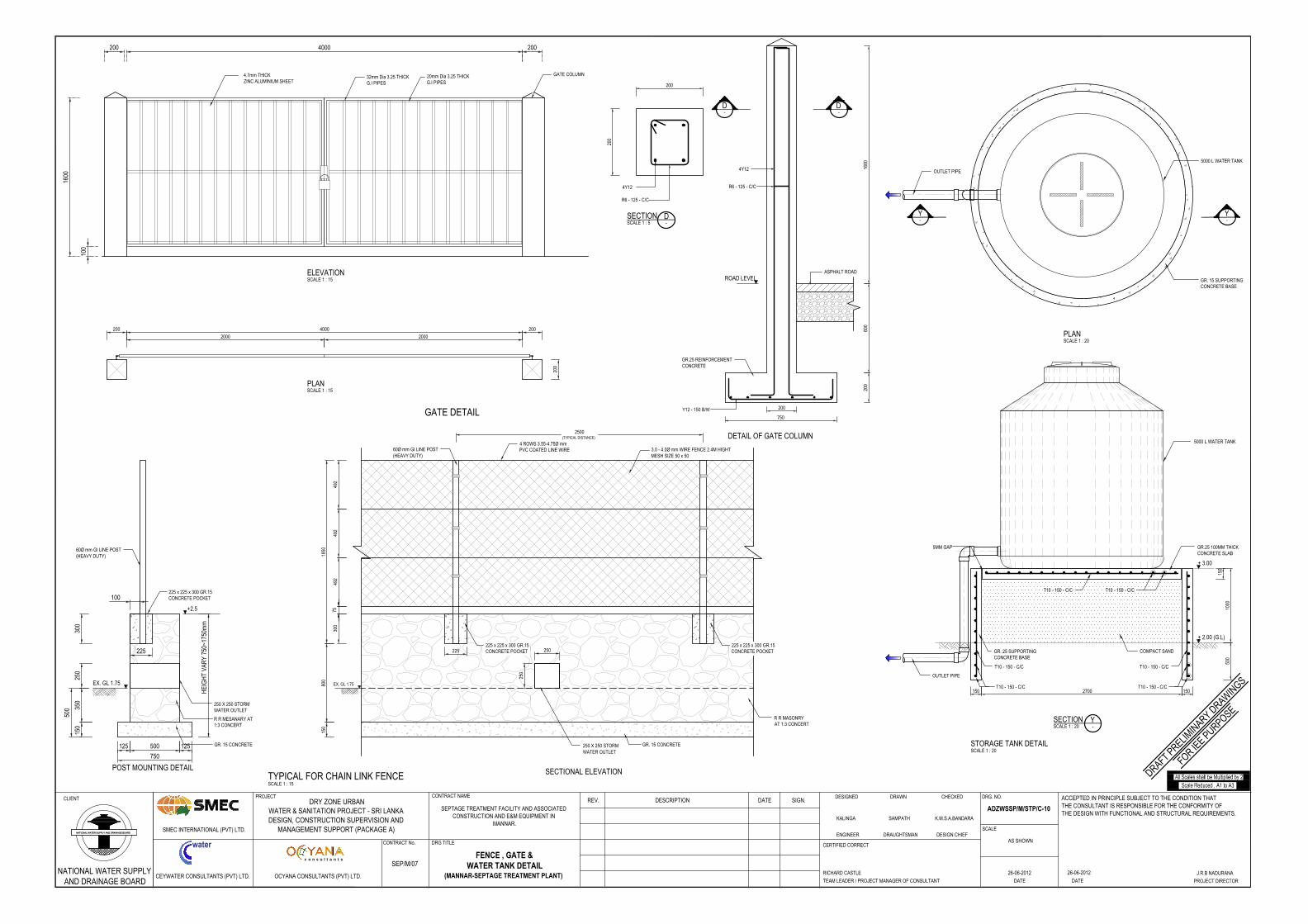
32mm Dia 3.25 THICKG.I PIPES
4.7mm THICKZINC ALUMINIUM SHEET
1600
100
GATE COLUMN
4000
ELEVATIONSCALE 1 : 15
200 4000 200
200
2000 2000
20mm Dia 3.25 THICKG.I PIPES
200 200
PLAN SCALE 1 : 15
GATE DETAIL
200
600
750
200
4Y12
R6 - 125 - C/C
Y12 - 150 B/W
ROAD LEVEL
DETAIL OF GATE COLUMNSCALE 1 : 10
D-
D-
1600
ASPHALT ROAD
GR.25 REINFORCEMENTCONCRETE
R6 - 125 - C/C
4Y12
200
200
SECTION SCALE 1 : 5
D-
800
1850
300
7549
249
249
2
3.0 - 4.0Ø mm WIRE FENCE 2.4M HIGHTMESH SIZE 50 x 50
4 ROWS 3.55-4.75Ø mmPVC COATED LINE WIRE
2500(TYPICAL DISTANCE)
R R MASONRYAT 1:3 CONCERT
TYPICAL FOR CHAIN LINK FENCESCALE 1 : 15
EX. GL 1.75
+2.5
100
500
HEI
GH
T VA
RY
750~
1750
mm
750
POST MOUNTING DETAIL SECTIONAL ELEVATION
R R MESANARY AT1:3 CONCERT
GR. 15 CONCRETE
150
350
300
EX. GL 1.75
150
GR. 15 CONCRETE250 X 250 STORMWATER OUTLET
250
250
60Ø mm GI LINE POST(HEAVY DUTY)
60Ø mm GI LINE POST(HEAVY DUTY)
250 X 250 STORMWATER OUTLET
250
500125 125
225225
225 x 225 x 300 GR.15CONCRETE POCKET
225 x 225 x 300 GR.15CONCRETE POCKET
225 x 225 x 300 GR.15CONCRETE POCKET
PLANSCALE 1 : 20
Y-
Y-
SECTION SCALE 1 : 20
Y-
150
5000 L WATER TANK
5000 L WATER TANK
GR. 15 SUPPORTINGCONCRETE BASE
GR. 25 SUPPORTINGCONCRETE BASE
2700150
COMPACT SAND
+ 2.00 (G.L)
500
1000
+ 3.00
GR.25 100MM THICKCONCRETE SLAB
150
STORAGE TANK DETAILSCALE 1 : 20
OUTLET PIPE
OUTLET PIPE
T10 - 150 - C/C
T10 - 150 - C/C
T10 - 150 - C/C
T10 - 150 - C/C
T10 - 150 - C/CT10 - 150 - C/C
5MM GAP
CLIENT
water
OCYANA CONSULTANTS (PVT) LTD.CEYWATER CONSULTANTS (PVT) LTD.
SMEC INTERNATIONAL (PVT) LTD.
CONTRACT No.
PROJECTDRY ZONE URBAN
WATER & SANITATION PROJECT - SRI LANKADESIGN, CONSTRUCTION SUPERVISION AND
MANAGEMENT SUPPORT (PACKAGE A)
DRG TITLE
REV. DESCRIPTION DATE SIGN.DESIGNED DRAWN CHECKED
ENGINEER DRAUGHTSMAN DESIGN CHIEF
CERTIFIED CORRECT
TEAM LEADER / PROJECT MANAGER OF CONSULTANT
DRG. NO.
SCALE
AS SHOWN
DATE DATE
c o n s u l t a n t s
ACCEPTED IN PRINCIPLE SUBJECT TO THE CONDITION THATTHE CONSULTANT IS RESPONSIBLE FOR THE CONFORMITY OFTHE DESIGN WITH FUNCTIONAL AND STRUCTURAL REQUIREMENTS.
PROJECT DIRECTOR
NATIONAL WATER SUPPLYAND DRAINAGE BOARD
CONTRACT NAME
SEP/M/07
SEPTAGE TREATMENT FACILITY AND ASSOCIATEDCONSTRUCTION AND E&M EQUIPMENT IN
MANNAR.K.M.S.A.BANDARAKALINGA SAMPATH
FENCE , GATE &WATER TANK DETAIL
(MANNAR-SEPTAGE TREATMENT PLANT)
ADZWSSP/M/STP/C-10
26-06-2012RICHARD CASTLE J.R.B NADURANA26-06-2012
DRAFT PRELIMIN
ARY DRAWIN
GS
FOR IEE PURPOSE
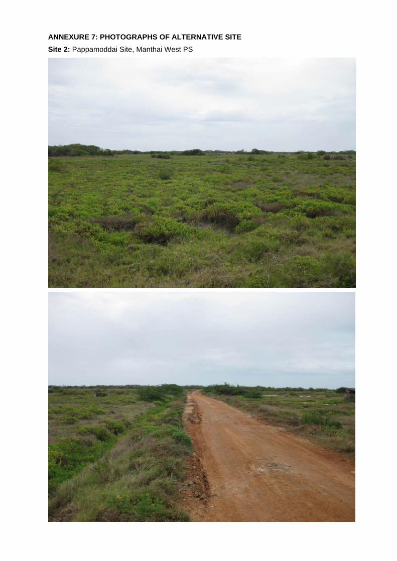
ANNEXURE 7: PHOTOGRAPHS OF ALTERNATIVE SITE
Site 2: Pappamoddai Site, Manthai West PS
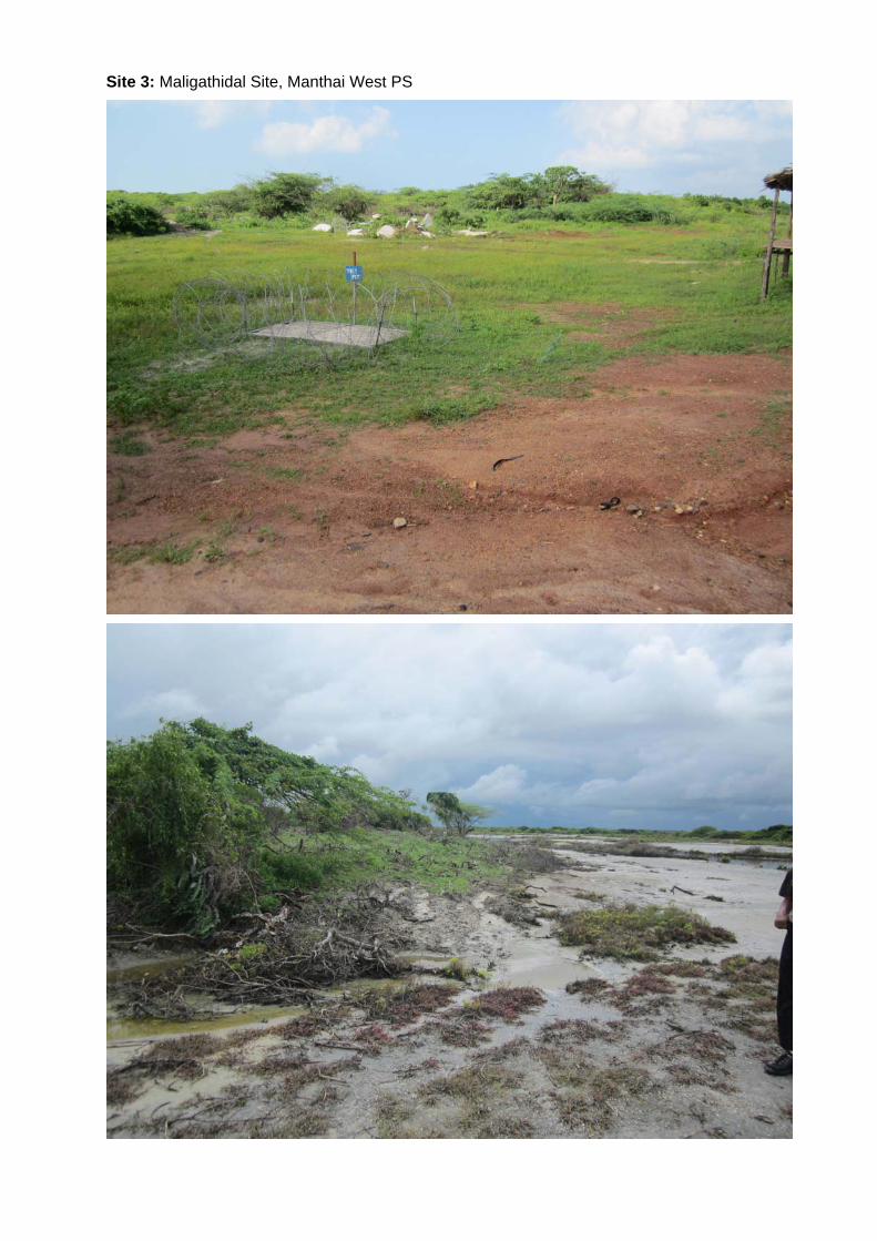
Site 3: Maligathidal Site, Manthai West PS
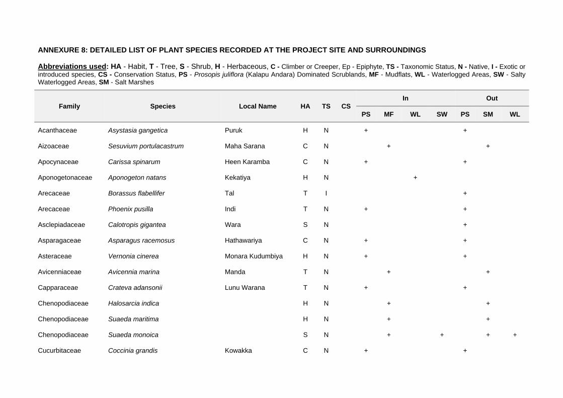
ANNEXURE 8: DETAILED LIST OF PLANT SPECIES RECORDED AT THE PROJECT SITE AND SURROUNDINGS
Abbreviations used: HA - Habit, T - Tree, S - Shrub, H - Herbaceous, C - Climber or Creeper, Ep - Epiphyte, TS - Taxonomic Status, N - Native, I - Exotic or introduced species, CS - Conservation Status, PS - Prosopis juliflora (Kalapu Andara) Dominated Scrublands, MF - Mudflats, WL - Waterlogged Areas, SW - Salty Waterlogged Areas, SM - Salt Marshes
Family Species Local Name HA TS CS In Out
PS MF WL SW PS SM WL
Acanthaceae Asystasia gangetica Puruk H N + +
Aizoaceae Sesuvium portulacastrum Maha Sarana C N + +
Apocynaceae Carissa spinarum Heen Karamba C N + +
Aponogetonaceae Aponogeton natans Kekatiya H N +
Arecaceae Borassus flabellifer Tal T I +
Arecaceae Phoenix pusilla Indi T N + +
Asclepiadaceae Calotropis gigantea Wara S N +
Asparagaceae Asparagus racemosus Hathawariya C N + +
Asteraceae Vernonia cinerea Monara Kudumbiya H N + +
Avicenniaceae Avicennia marina Manda T N + +
Capparaceae Crateva adansonii Lunu Warana T N + +
Chenopodiaceae Halosarcia indica H N + +
Chenopodiaceae Suaeda maritima H N + +
Chenopodiaceae Suaeda monoica S N + + + +
Cucurbitaceae Coccinia grandis Kowakka C N + +
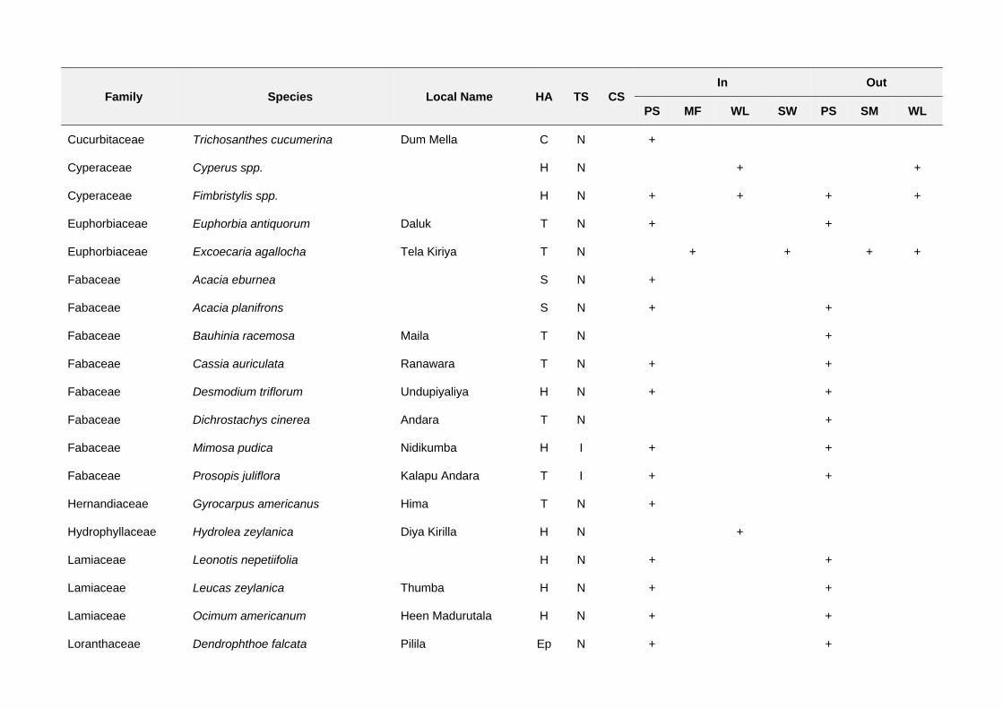
Family Species Local Name HA TS CS In Out
PS MF WL SW PS SM WL
Cucurbitaceae Trichosanthes cucumerina Dum Mella C N +
Cyperaceae Cyperus spp. H N + +
Cyperaceae Fimbristylis spp. H N + + + +
Euphorbiaceae Euphorbia antiquorum Daluk T N + +
Euphorbiaceae Excoecaria agallocha Tela Kiriya T N + + + +
Fabaceae Acacia eburnea S N +
Fabaceae Acacia planifrons S N + +
Fabaceae Bauhinia racemosa Maila T N +
Fabaceae Cassia auriculata Ranawara T N + +
Fabaceae Desmodium triflorum Undupiyaliya H N + +
Fabaceae Dichrostachys cinerea Andara T N +
Fabaceae Mimosa pudica Nidikumba H I + +
Fabaceae Prosopis juliflora Kalapu Andara T I + +
Hernandiaceae Gyrocarpus americanus Hima T N +
Hydrophyllaceae Hydrolea zeylanica Diya Kirilla H N +
Lamiaceae Leonotis nepetiifolia H N + +
Lamiaceae Leucas zeylanica Thumba H N + +
Lamiaceae Ocimum americanum Heen Madurutala H N + +
Loranthaceae Dendrophthoe falcata Pilila Ep N + +
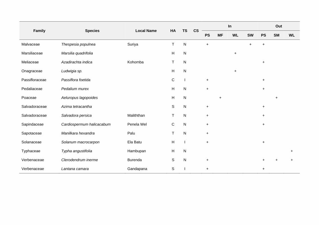
Family Species Local Name HA TS CS In Out
PS MF WL SW PS SM WL
Malvaceae Thespesia populnea Suriya T N + + +
Marsiliaceae Marsilia quadrifolia H N +
Meliaceae Azadirachta indica Kohomba T N +
Onagraceae Ludwigia sp. H N +
Passifloraceae Passiflora foetida C I + +
Pedaliaceae Pedalium murex H N + +
Poaceae Aeluropus lagopoides H N + +
Salvadoraceae Azima tetracantha S N + +
Salvadoraceae Salvadora persica Maliththan T N + +
Sapindaceae Cardiospermum halicacabum Penela Wel C N + +
Sapotaceae Manilkara hexandra Palu T N +
Solanaceae Solanum macrocarpon Ela Batu H I + +
Typhaceae Typha angustifolia Hambupan H N +
Verbenaceae Clerodendrum inerme Burenda S N + + + +
Verbenaceae Lantana camara Gandapana S I + +
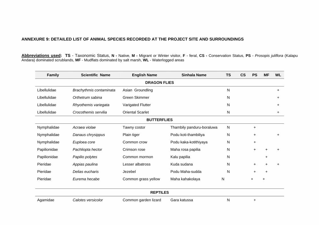
ANNEXURE 9: DETAILED LIST OF ANIMAL SPECIES RECORDED AT THE PROJECT SITE AND SURROUNDINGS
Abbreviations used: TS - Taxonomic Status, N - Native, M - Migrant or Winter visitor, F - feral, CS - Conservation Status, PS - Prosopis juliflora (Kalapu Andara) dominated scrublands, MF - Mudflats dominated by salt marsh, WL - Waterlogged areas
Family Scientific Name English Name Sinhala Name TS CS PS MF WL
DRAGON FLIES
Libellulidae Brachythmis contaminata Asian Groundling N +
Libellulidae Orthetrum sabina Green Skimmer N +
Libellulidae Rhyothemis variegata Varigated Flutter N +
Libellulidae Crocothemis servilia Oriental Scarlet N +
BUTTERFLIES
Nymphalidae Acraea violae Tawny costor Thambily panduru-boraluwa N +
Nymphalidae Danaus chrysippus Plain tiger Podu koti-thambiliya N + +
Nymphalidae Euploea core Common crow Podu kaka-kotithiyaya N +
Papilionidae Pachliopta hector Crimson rose Maha rosa papilia N + + +
Papilionidae Papilio polytes Common mormon Kalu papilia N +
Pieridae Appias paulina Lesser albatross Kuda sudana N + + +
Pieridae Delias eucharis Jezebel Podu Maha-sudda N + +
Pieridae
Eurema hecabe Common grass yellow Maha kahakolaya N + +
REPTILES
Agamidae Calotes versicolor Common garden lizard Gara katussa N +
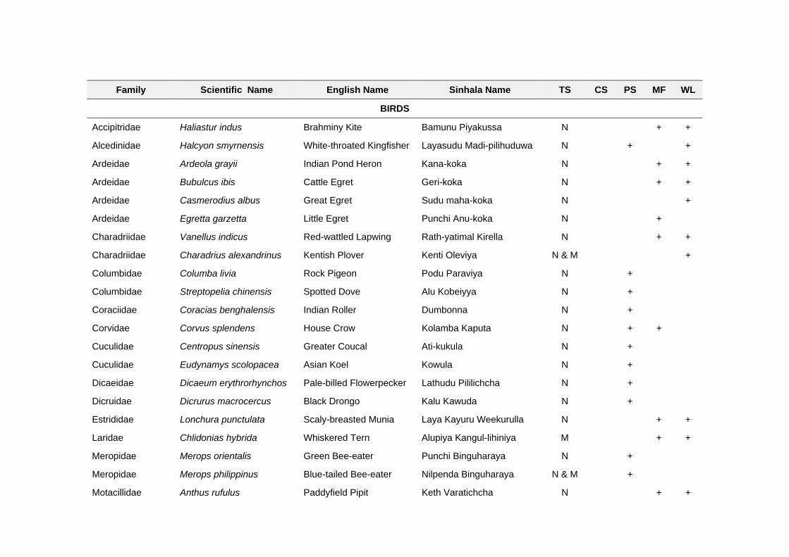
Family Scientific Name English Name Sinhala Name TS CS PS MF WL
BIRDS
Accipitridae Haliastur indus Brahminy Kite Bamunu Piyakussa N + +
Alcedinidae Halcyon smyrnensis White-throated Kingfisher Layasudu Madi-pilihuduwa N + +
Ardeidae Ardeola grayii Indian Pond Heron Kana-koka N + +
Ardeidae Bubulcus ibis Cattle Egret Geri-koka N + +
Ardeidae Casmerodius albus Great Egret Sudu maha-koka N +
Ardeidae Egretta garzetta Little Egret Punchi Anu-koka N +
Charadriidae Vanellus indicus Red-wattled Lapwing Rath-yatimal Kirella N + +
Charadriidae Charadrius alexandrinus Kentish Plover Kenti Oleviya N & M +
Columbidae Columba livia Rock Pigeon Podu Paraviya N +
Columbidae Streptopelia chinensis Spotted Dove Alu Kobeiyya N +
Coraciidae Coracias benghalensis Indian Roller Dumbonna N +
Corvidae Corvus splendens House Crow Kolamba Kaputa N + +
Cuculidae Centropus sinensis Greater Coucal Ati-kukula N +
Cuculidae Eudynamys scolopacea Asian Koel Kowula N +
Dicaeidae Dicaeum erythrorhynchos Pale-billed Flowerpecker Lathudu Pililichcha N +
Dicruidae Dicrurus macrocercus Black Drongo Kalu Kawuda N +
Estrididae Lonchura punctulata Scaly-breasted Munia Laya Kayuru Weekurulla N + +
Laridae Chlidonias hybrida Whiskered Tern Alupiya Kangul-lihiniya M + +
Meropidae Merops orientalis Green Bee-eater Punchi Binguharaya N +
Meropidae Merops philippinus Blue-tailed Bee-eater Nilpenda Binguharaya N & M +
Motacillidae Anthus rufulus Paddyfield Pipit Keth Varatichcha N + +
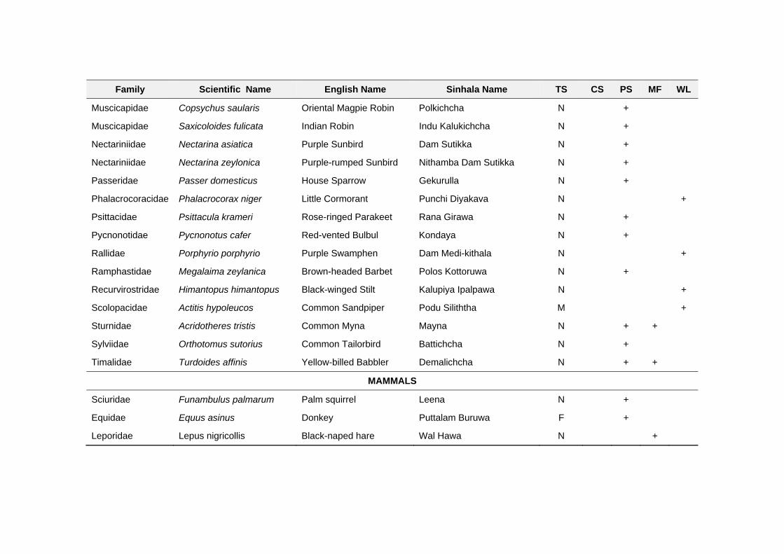
Family Scientific Name English Name Sinhala Name TS CS PS MF WL
Muscicapidae Copsychus saularis Oriental Magpie Robin Polkichcha N +
Muscicapidae Saxicoloides fulicata Indian Robin Indu Kalukichcha N +
Nectariniidae Nectarina asiatica Purple Sunbird Dam Sutikka N +
Nectariniidae Nectarina zeylonica Purple-rumped Sunbird Nithamba Dam Sutikka N +
Passeridae Passer domesticus House Sparrow Gekurulla N +
Phalacrocoracidae Phalacrocorax niger Little Cormorant Punchi Diyakava N +
Psittacidae Psittacula krameri Rose-ringed Parakeet Rana Girawa N +
Pycnonotidae Pycnonotus cafer Red-vented Bulbul Kondaya N +
Rallidae Porphyrio porphyrio Purple Swamphen Dam Medi-kithala N +
Ramphastidae Megalaima zeylanica Brown-headed Barbet Polos Kottoruwa N +
Recurvirostridae Himantopus himantopus Black-winged Stilt Kalupiya Ipalpawa N +
Scolopacidae Actitis hypoleucos Common Sandpiper Podu Siliththa M +
Sturnidae Acridotheres tristis Common Myna Mayna N + +
Sylviidae Orthotomus sutorius Common Tailorbird Battichcha N +
Timalidae Turdoides affinis Yellow-billed Babbler Demalichcha N + +
MAMMALS
Sciuridae Funambulus palmarum Palm squirrel Leena N +
Equidae Equus asinus Donkey Puttalam Buruwa F +
Leporidae Lepus nigricollis Black-naped hare Wal Hawa N +

ANNEXURE 10: LIST OF MEETINGS / DISCUSSIONS CONDUCTED DURING IEE STUDY
List of Meetings / Discussions Conducted by IEE Team
No Date Venue Participants Remarks / Key officials met
1 24.07.2010 Divisional Secretariat, Mannar, Urban Council, Mannar
7 Meeting with government officers – Add.GA, Secretaries of MUC and MWPS, Director Planning – Mannar DS
2 31.08.2010 District Secretariat - Mannar
30 District Coordination Committee Meeting
3 31.10.2010 District secretariat, MUC, MWDS, Disposal Sites, Pappamodai, and Maligaithidal
5 Visited administrative officers and other stakeholders
4 20.07.2011 ADB 5th Project Office, Vavuniya
4 Meeting with PM-Vavuniya
5 26.07.2011 NWS&DB Head Office, Ratmalana
5 Meeting with Sewerage Specialist – NWS&DB
6 08.01.2012 Disposal Site at Maligaithidal
6 Team field visit (Maligaithidal site - after confirmation)
7 09.01.2012 District secretariat, MUC, MWDS, Disposal Sites, Pappamodai, and Maligaithidal
6 Team field visit (Maligaithidal site - after confirmation)
8 30.01.2012 Manthai West DS office 40 Public consultation meeting
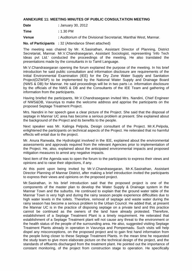
ANNEXURE 11: MEETING MINUTES OF PUBLIC CONSULTATION MEETING
Date : January 30, 2012
Time : 1.30 PM
Venue : Auditorium of the Divisional Secretariat, Manthai West, Mannar.
No. of Participants : 32 (Attendance Sheet attached)
The meeting was chaired by Mr. K.Sasirathan, Assistant Director of Planning, District Secretariat, Mannar. Mr.V.Chandrasegaran, Assistant Sociologist, representing ‘Info Tech Ideas pvt Ltd.’ conducted the proceedings of the meeting. He also translated the presentations made by the consultants in to Tamil Language.
Mr.V.Chandrasegaran opening the forum explained the purpose of the meeting. In his brief introduction he said public consultation and information disclosure are requirements of the Initial Environmental Examination (IEE) for the Dry Zone Water Supply and Sanitation Project(DZWSP) to be implemented by the National Water Supply and Drainage Board (NWS & DB) for Mannar. He said proceedings will be in two parts i.e. information disclosure by the officials of the NWS & DB and the Consultants of the IEE Team and gathering of information from the participants.
Having briefed the participants, Mr.V.Chandrasegaran invited Mrs. Nandini, Chief Engineer of NWS&DB, Vavuniya to make the welcome address and apprise the participants on the proposed Septage Treatment Project.
Mrs. Nandini in her speech gave a clear picture of the Project. She said that the disposal of septage in Mannar UC area has become a serious problem at present. She explained about the background of the Project and its benefits to the people.
Next speaker was Mr. Kalinga Pelpola, Design consultant of the Project. Mr.K.Pelpola, enlightened the participants on technical aspects of the Project. He reiterated that no harmful effects will entail due to the project.
Mr. Anura Ranwala, the Hydrologist involved in the IEE, explained about the environmental assessments and approvals required from the relevant Agencies prior to implementation of the Project. He, also, explained about the anticipated environmental impacts and proposed mitigation measures to arrest any negative impacts.
Next item of the Agenda was to open the forum to the participants to express their views and opinions and to raise their objections, if any.
At this point upon being invited by Mr.V.Chandrasegaran, Mr.K.Sasirathan, Assistant Director Planning of Mannar District, after making a brief introduction invited the participants to express their views and opinions on the proposed project.
Mr.Sasirathan, in his brief introduction said that the proposed project is one of the components of the master plan to develop the Water Supply & Drainage system in the Mannar Town and the suburbs. He continued to explain that the ground water table of the Mannar Town is very high and during the rainy season people experience difficulties due to high water levels in the toilets. Therefore, removal of septage and waste water during the rainy season has become a serious problem to the Urban Council. He added that, at present the Mannar UC is in the practice of disposing septage on a private land and this practice cannot be continued as the owners of the land have already protested. Therefore, establishment of a Septage Treatment Plant is a timely requirement. He reiterated that establishment of a Septage Treatment plant will not cause any threat to the environment or the health status of the people of the surrounding area. He also, suggested visiting Septage Treatment Plants already in operation in Vavuniya and Pompemadu. Such visits will help dispel any misconceptions, on the proposed project and to gain first hand information from the people living closer to these Septage Treatment Plants. In the mean time he requested the study team to give more elaborate picture on the technical design of the project, and the standards of effluents discharged from the treatment plant. He pointed out the importance of constant monitoring, of the project from construction stage to operation. He specifically
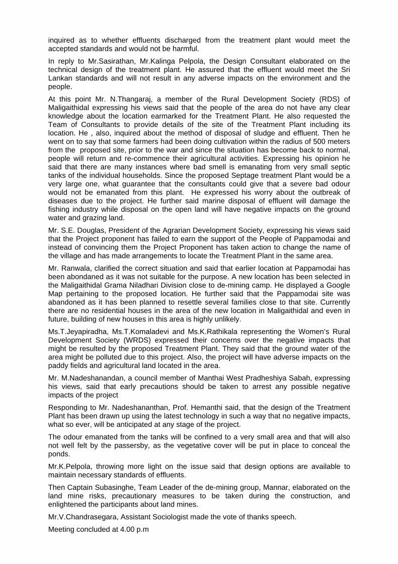
inquired as to whether effluents discharged from the treatment plant would meet the accepted standards and would not be harmful.
In reply to Mr.Sasirathan, Mr.Kalinga Pelpola, the Design Consultant elaborated on the technical design of the treatment plant. He assured that the effluent would meet the Sri Lankan standards and will not result in any adverse impacts on the environment and the people.
At this point Mr. N.Thangaraj, a member of the Rural Development Society (RDS) of Maligaithidal expressing his views said that the people of the area do not have any clear knowledge about the location earmarked for the Treatment Plant. He also requested the Team of Consultants to provide details of the site of the Treatment Plant including its location. He , also, inquired about the method of disposal of sludge and effluent. Then he went on to say that some farmers had been doing cultivation within the radius of 500 meters from the proposed site, prior to the war and since the situation has become back to normal, people will return and re-commence their agricultural activities. Expressing his opinion he said that there are many instances where bad smell is emanating from very small septic tanks of the individual households. Since the proposed Septage treatment Plant would be a very large one, what guarantee that the consultants could give that a severe bad odour would not be emanated from this plant. He expressed his worry about the outbreak of diseases due to the project. He further said marine disposal of effluent will damage the fishing industry while disposal on the open land will have negative impacts on the ground water and grazing land.
Mr. S.E. Douglas, President of the Agrarian Development Society, expressing his views said that the Project proponent has failed to earn the support of the People of Pappamodai and instead of convincing them the Project Proponent has taken action to change the name of the village and has made arrangements to locate the Treatment Plant in the same area.
Mr. Ranwala, clarified the correct situation and said that earlier location at Pappamodai has been abondaned as it was not suitable for the purpose. A new location has been selected in the Maligaithidal Grama Niladhari Division close to de-mining camp. He displayed a Google Map pertaining to the proposed location. He further said that the Pappamodai site was abandoned as it has been planned to resettle several families close to that site. Currently there are no residential houses in the area of the new location in Maligaithidal and even in future, building of new houses in this area is highly unlikely.
Ms.T.Jeyapiradha, Ms.T.Komaladevi and Ms.K.Rathikala representing the Women’s Rural Development Society (WRDS) expressed their concerns over the negative impacts that might be resulted by the proposed Treatment Plant. They said that the ground water of the area might be polluted due to this project. Also, the project will have adverse impacts on the paddy fields and agricultural land located in the area.
Mr. M.Nadeshanandan, a council member of Manthai West Pradheshiya Sabah, expressing his views, said that early precautions should be taken to arrest any possible negative impacts of the project
Responding to Mr. Nadeshananthan, Prof. Hemanthi said, that the design of the Treatment Plant has been drawn up using the latest technology in such a way that no negative impacts, what so ever, will be anticipated at any stage of the project.
The odour emanated from the tanks will be confined to a very small area and that will also not well felt by the passersby, as the vegetative cover will be put in place to conceal the ponds.
Mr.K.Pelpola, throwing more light on the issue said that design options are available to maintain necessary standards of effluents.
Then Captain Subasinghe, Team Leader of the de-mining group, Mannar, elaborated on the land mine risks, precautionary measures to be taken during the construction, and enlightened the participants about land mines.
Mr.V.Chandrasegara, Assistant Sociologist made the vote of thanks speech.
Meeting concluded at 4.00 p.m
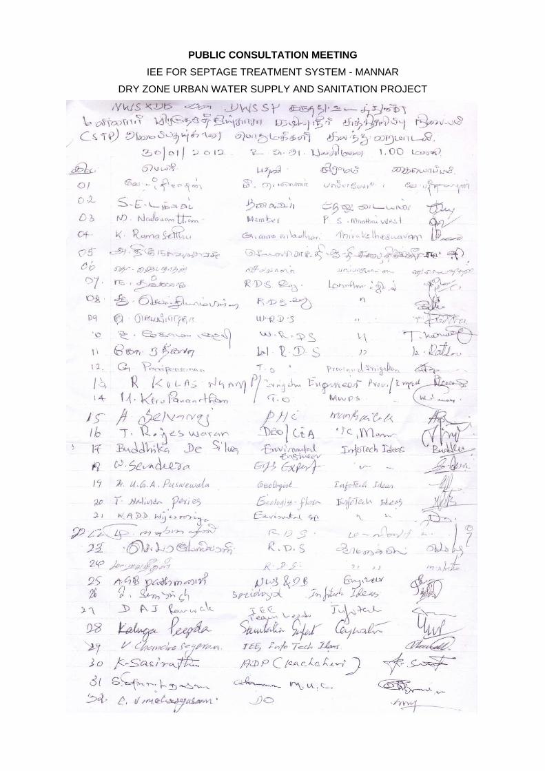
PUBLIC CONSULTATION MEETING
IEE FOR SEPTAGE TREATMENT SYSTEM - MANNAR
DRY ZONE URBAN WATER SUPPLY AND SANITATION PROJECT

Addendum 1
Committee for Grievance Redress and Environment Monitoring
In absence of such provisions, affected parties/persons (AP) will seek solutions outside the
project which may lead to a number of adverse consequences. It is necessary to include
grievance redress provisions for the people adversely affected (or about to be affected) by the
development of sub projects because such people should have provisions to forward their
grievances by seeking solutions. Environmental Monitoring Committees (EMC) are already
proposed to discuss the critical environmental issues and thereby find solutions in some sub
projects. Facility for Grievance Redressing shall be incorporated to the proposed EMCs because
all regional level key officials will become the members of such EMCs and will be functioning
as Grievance Redress and Environment Monitoring Committee (GREMC). New GREMCs shall
be formed for the sub-projects where EMCs have not been proposed.
The GREMC comprises with responsible officers of following agencies and headed by the
Provincial Environmental Authority or Central Environmental Authority (which is functioning in
the area concern) jointly with the divisional secretary. The secretary to the committee and the
convener shall be the project manager of the NWSDB.
1. Provincial Environmental Authority/Central Environmental Authority (Regional office)
2. Project Manager of the sub project
3. Urban Council/ Municipal Council
4. Divisional Secretariat
5. Agrarian Service Department
6. Provincial Irrigation Department / Central Irrigation Department.
7. Representative of the contractor
8. Representative of the consultant to the project
9. Any other officers by considering the need
If APs are not satisfied about the decision of the GREMC, the matter should be referred to the
District Secretary who will make the final decision. The District Secretary may appoint a
committee to find the observations. The GREMC is effective with the commencement of the
construction and shall meet once in six weeks during the construction period. During the
operational phase, the committee shall meet once in three months for two years and if necessary
thereafter. If there are critical issues, the committee shall meet by fixing a convenient date.

During the operational phase, Regional Manager (O&M) of the NWSDB shall represent the
NWSDB.
This should be published in all three languages by displaying notices in the notice boards of all
member offices and other public offices such as Grama Niladhari (Village Head) office, post
office etc. to make aware the public.
Project Implementation Agency: National Water Supply & Drainage Board
Funding Agency: Asian Development Bank
Project Number: 37381
Sri Lanka: Dry Zone Urban Areas Water Distribution and Sanitation Project (DZUWSSP) INITIAL ENVIRONMENTAL EXAMINATION: VAVUNIYA NOVEMBER 2012
1
CONTENTS
I. INTRODUCTION .................................................................................................................................. 6
A. Purpose of the report ............................................................................................................................ 6
B. Extent of IEE study ............................................................................................................................... 6
II. DESCRIPTION OF THE PROJECT..................................................................................................... 1
A. Type, Category and Need ..................................................................................................................... 1
B. Location, Size and Implementation Schedule ...................................................................................... 1
C. Description of the Sub-projects ............................................................................................................. 2
III. DESCRIPTION OF THE ENVIRONMENT ......................................................................................... 12
A. Physical Resources ............................................................................................................................ 12
B. Ecological Resources ......................................................................................................................... 17
C. Economic Development ...................................................................................................................... 18
D. Social and Cultural Resources ........................................................................................................... 21
IV. ENVIRONMENTAL IMPACTS AND MITIGATION: CONSTRUCTION PHASE ............................... 23
A. Screening out areas of no significant impact ...................................................................................... 23
B. Augmentation of Water Supply and Treatment .................................................................................. 24
C. Improving the Water Supply Network ................................................................................................. 26
D. Sanitation ............................................................................................................................................ 30
V. ENVIRONMENTAL IMPACTS AND MITIGATION: OPERATIONAL PHASE.................................. 33
A. Screening out areas of no significant impact ...................................................................................... 33
B. Water Supply ...................................................................................................................................... 33
C. Sanitation ............................................................................................................................................ 36
VI. ENVIRONMENTAL IMPACTS AND MITIGATION: LOCATION AND DESIGN ............................... 40
VII. INSTITUTIONAL REQUIREMENTS AND ENVIRONMENTAL MONITORING PLAN ..................... 42
A. Summary of environmental impacts and mitigation measures ........................................................... 42
B. Institutional arrangements for project implementation ........................................................................ 42
2
C. Environmental Monitoring Plan ........................................................................................................... 49
D. Environmental management and monitoring costs ............................................................................ 54
VIII. PUBLIC CONSULTATION AND INFORMATION DISCLOSURE .................................................... 56
A. Project stakeholders ........................................................................................................................... 56
B. Consultation and disclosure to date .................................................................................................... 56
5. Table 9: Comments made at public consultation meeting .................................................................. 57
C. Future consultation and disclosure ..................................................................................................... 58
IX. FINDINGS AND RECOMMENDATIONS ........................................................................................... 60
A. Findings .............................................................................................................................................. 60
B. Recommendations .............................................................................................................................. 62
X. CONCLUSIONS ................................................................................................................................. 63
APPENDIX 1: Environmental Management Plan for Puthunkulam Reservoir………………………………..70
APPENDIX 2: Current Sri Lankan drinking water standards (1996)…………………………………………..73
APPENDIX 3: Existing Sri Lankan wastewater discharge standards (1990)…………………………………75
APPENDIX 4: Draft new wastewater discharge standards (2008)………………………………………….....76
APPENDIX 5: Summary of public consultation meeting held in Vavuniya……………………………………77
Addendum 1…………………………………………………………………………………….80
3
LIST OF TABLES
Table 1: Water supply, sanitation and drainage subprojects proposed in Vavuniya ................................. 5
Table 2: Water quality of Per Aru from a sample taken in October 2007 ................................................. 16
Table 3: General groundwater quality in Vavuniya .................................................................................. 17
Table 4: Fields which have less significant impacts in construction ........................................................ 23
Table 5: Fields which have less significant impacts in operation ............................................................. 33
Table 6: Environmental impacts and mitigation........................................................................................ 43
Table 7: Environmental Monitoring Plan .................................................................................................. 51
Table 8: Environmental management and monitoring costs .................................................................... 55
Table 9: Comments made at public consultation meeting ....................................................................... 57
Table 11: DZUWSSP management and implementation institutions ....................................................... 71
4
FIGURES
Table 1: Water supply, sanitation and drainage subprojects proposed in Vavuniya ................................. 5
Table 2: Water quality of Per Aru from a sample taken in October 2007 ................................................. 16
Table 3: General groundwater quality in Vavuniya .................................................................................. 17
Table 4: Fields which have less significant impacts in construction ........................................................ 23
Table 5: Fields which have less significant impacts in operation ............................................................. 33
Table 6: Environmental impacts and mitigation........................................................................................ 43
Table 7: Environmental Monitoring Plan .................................................................................................. 51
Table 8: Environmental management and monitoring costs .................................................................... 55
Table 9: Comments made at public consultation meeting ....................................................................... 57
Table 11: DZUWSSP management and implementation institutions ....................................................... 71
5
PHOTOGRAPHS
Photo 1: Per Aru river at Puthunkulam ..................................................................................................... 64
Photo 2: RCC tanks for water treatment .................................................................................................. 64
Photo 3: Road from intake to WTP ........................................................................................................... 64
Photo 4: Overhead Reservoir in Vavuniya ............................................................................................... 64
Photo 5: Proposed location of WTP ......................................................................................................... 64
Photo 6: Local roads in Vavuniya ............................................................................................................. 64
Photo 7: Pumping station ......................................................................................................................... 65
Photo 8: Irrigation tank ............................................................................................................................. 65
Photo 9: Proposed site of STP ................................................................................................................. 65
Photo 10: Sluice gate ............................................................................................................................... 65
Photo 11: Scrub woodland in Puthunkulam ............................................................................................. 65
Photo 12: Aquatic vegetation in a tank ..................................................................................................... 65
Photo 13:Riverine forest on the Per Aru ................................................................................................... 66
Photo 14: Fishing in Pawat Kulam ........................................................................................................... 66
Photo 15: Grazing land in Puthunkulam ................................................................................................... 66
Photo 16: Roadside storm drain ............................................................................................................... 66
Photo 17: Electricity poles ........................................................................................................................ 66
Photo 18: Metal reinforcing....................................................................................................................... 66
Photo 19: Road in the centre of Vavuniya ................................................................................................ 67
Photo 20: Wooden shuttering ................................................................................................................... 67
Photo 21: Road in the outskirts of Vavuniya ............................................................................................ 67
Photo 22 : Tube Well ................................................................................................................................ 67
Photo 23:Roadside shrine ........................................................................................................................ 68
Photo 24: Backhoe digger excavating a trench ........................................................................................ 68
Photo 25: Digging a trench by hand ......................................................................................................... 68
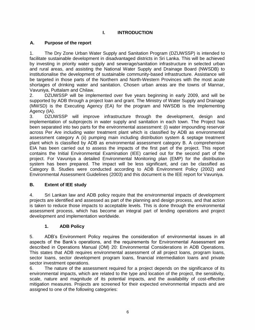
6
I. INTRODUCTION
A. Purpose of the report
1. The Dry Zone Urban Water Supply and Sanitation Program (DZUWSSP) is intended to facilitate sustainable development in disadvantaged districts in Sri Lanka. This will be achieved by investing in priority water supply and sewerage/sanitation infrastructure in selected urban and rural areas, and assisting the National Water Supply and Drainage Board (NWSDB) to institutionalise the development of sustainable community-based infrastructure. Assistance will be targeted in those parts of the Northern and North-Western Provinces with the most acute shortages of drinking water and sanitation. Chosen urban areas are the towns of Mannar, Vavuniya, Puttalam and Chilaw. 2. DZUWSSP will be implemented over five years beginning in early 2009, and will be supported by ADB through a project loan and grant. The Ministry of Water Supply and Drainage (MWSD) is the Executing Agency (EA) for the program and NWSDB is the Implementing Agency (IA). 3. DZUWSSP will improve infrastructure through the development, design and implementation of subprojects in water supply and sanitation in each town. The Project has been separated into two parts for the environmental assessment: (i) water impounding reservoir across Per Are including water treatment plant which is classified by ADB as environmental assessment category A (ii) pumping main including distribution system & septage treatment plant which is classified by ADB as environmental assessment category B. A comprehensive EIA has been carried out to assess the impacts of the first part of the project. This report contains the Initial Environmental Examination (IEE) carried out for the second part of the project. For Vavuniya a detailed Environmental Monitoring plan (EMP) for the distribution system has been prepared. The impact will be less significant, and can be classified as Category B. Studies were conducted according to ADB Environment Policy (2002) and Environmental Assessment Guidelines (2003) and this document is the IEE report for Vavuniya.
B. Extent of IEE study
4. Sri Lankan law and ADB policy require that the environmental impacts of development projects are identified and assessed as part of the planning and design process, and that action is taken to reduce those impacts to acceptable levels. This is done through the environmental assessment process, which has become an integral part of lending operations and project development and implementation worldwide.
1. ADB Policy
5. ADB’s Environment Policy requires the consideration of environmental issues in all aspects of the Bank’s operations, and the requirements for Environmental Assessment are described in Operations Manual (OM) 20: Environmental Considerations in ADB Operations. This states that ADB requires environmental assessment of all project loans, program loans, sector loans, sector development program loans, financial intermediation loans and private sector investment operations. 6. The nature of the assessment required for a project depends on the significance of its environmental impacts, which are related to the type and location of the project, the sensitivity, scale, nature and magnitude of its potential impacts, and the availability of cost-effective mitigation measures. Projects are screened for their expected environmental impacts and are assigned to one of the following categories:
7
Category A: Projects that could have significant environmental impacts. An Environmental Impact Assessment (EIA) is required.
Category B: Projects that could have some adverse environmental impacts, but of less
significance than those for category A. An Initial Environmental Examination (IEE) is required to determine whether significant impacts warranting an EIA are likely. If an EIA is not needed, the IEE is regarded as the final environmental assessment report. A Category B project may be classified as B-sensitive if it involves environmentally sensitive activities1. Such projects require IEE, but have the same requirements for disclosure and Environmental Management Plans as Category A.
Category C: Projects that are unlikely to have adverse environmental impacts. No EIA
or IEE is required, although environmental implications are reviewed. 7. The Project is classified as Category B sensitive and following normal procedure for project loans, one IEE was conducted for each urban area, covering all proposed subprojects in the town. A subproject comprises the infrastructure improvements in a particular sector (water supply or sanitation).
2. National Law
8. The requirement for Environmental Assessment in Sri Lanka is established by the National Environment Act (1981), and the procedures are defined in the EIA Regulations (1993). The regulations specify activities for which environmental assessment is mandatory, and those that could occur within certain DZUWSSP subprojects are as follows:
Groundwater extraction of over 500,000 m3/day2;
A Water Treatment Plant with a capacity of over 500,000 m3/day2;
Projects that involve relocation of more than 100 people; and
Projects that fall within sensitive area(s). 9. Sensitive areas are defined in the EIA Regulations as:
Any erodable area declared under the Soil Conservation Act (1951, 1953);
Any Flood Area declared under the Flood Protection Ordinance (1924, 1955) and any Flood Protection Area declared under the Sri Lanka Land Reclamation and Development Corporation Act (1968, 1982);
Any reservation beyond the Full Supply Level of a reservoir;
Any archaeological reserve, ancient or protected monument as defined or declared under the Antiquities Ordinance (1965);
Any area declared under the Botanic Gardens Ordinance (1928, 1973);
Areas within, or less than 100 m from the boundaries of, any area declared under the National Heritage and Wilderness Act (1988): the Forest Ordinance;
1 A project may be deemed environmentally sensitive by ADB if it is near environmentally sensitive areas, or involves: deforestation
or loss of biodiversity; involuntary resettlement issues; processing, handling and disposal of toxic and hazardous substances; or other environmentally sensitive activities that also may be of concern to a wide group of external stakeholders. 2 The Central Environment Authority is currently considering a proposal to lower these limits to 500 m
3/day.
8
Areas within, or less than 100 m from the boundaries of, any area declared as a Sanctuary under the Fauna and Flora Protection Ordinance (1937);
Areas within, or less than 100 m from the high flood level contour of, a public lake as defined by the Crown Lands Ordinance (1947, 1949, 1956) including those declared under Section 71 of the Ordinance;
Areas 60 m or less from the bank of a public stream as defined in the Crown Lands Ordinance, with a width of more than 25 m at any point.
10. The requirement for EIA and the level of study required are determined by the Central
Environment Authority (CEA) 3 after submission by the proponent of a Project Information
Document (PID), plus supporting information if relevant. There are two possible outcomes: Categorical Exclusion: the activity is not on the list of prescribed projects in the EIA regulations, is not in or near a sensitive area, has not been the subject of public protest, and it is clear from the PID and supporting information that the project will have no significant environmental impacts. Environmental Clearance is granted (with or without conditions) and the project may proceed; All other projects require Environmental Assessment and the CEA or PEA4 establishes a Scoping Committee to decide on the level of study (IEE or EIA) and prepare Terms of Reference (ToR). Alternatively, if the project lies wholly within the jurisdiction of a single Government agency (eg UDA) CEA/PEA may refer the project to this authority (as the Project Approving Agency) to administer the EIA process. A Technical Review Committee reviews the completed IEE or EIA report and recommends whether Environmental Clearance should be granted. The final decision is made by CEA.
11. The urban areas selected under this program have populations of between 40,000 and 120,000, so the infrastructure subprojects are relatively small, and groundwater abstraction and water treatment will not be of the scale quoted in the EIA regulations as requiring environmental assessment. Components will not be located in protected or sensitive areas and no people will be relocated. 12. However the water supply subproject involves the construction of a reservoir across a river to impound water including a water treatment plant at immediate downstream of the dam which is considered as environment category A.
3. Review and Approval Procedure
13. The IEE report and its summary (SIEE) are reviewed by ADB’s Regional Department sector division and Environment and Social Safeguards Division, and by the Executing Agency, and additional comments may be sought from project affected people and other stakeholders. All comments are incorporated in preparing the final documents, which are reviewed by the Executing Agency (EA) and the national environmental protection agency (CEA or NWPEA in this case). The EA then officially submits the IEE and SIEE reports to ADB for consideration by the Board of Directors. The SIEE is to be submitted to the Board atleast120 days before Board
3 In the North-Western Province (which includes Chilaw and Puttalam) the EIA system is established by the North-Western Provincial
Act (1981) and Provincial EIA Regulations (1992, 1998). The system is the same as the national procedure, except for: (i) the North-Western Provincial Environmental Authority (NWPEA) replaces CEA as the competent authority (although projects with trans-regional impacts are referred to CEA and dealt with under the national system); (ii) EIA and IEE reports are made available for public comment (under the national system this is required for EIAs only); (iii) Projects that are the subject of significant public interest or protest can be required to conduct an EIA by the NWPEA Board of Directors, even though this may not be required by the legislation
9
consideration. Completed reports are made available worldwide by ADB, via the depository library system and the ADB website.
4. Scope of Study
14. This is the IEE for the water distribution (excluding water treatment plant) system and septage treatment plant proposed in Vavuniya. It discusses the environmental impacts and mitigation measures relating to the location, design, construction and operation of all physical works proposed under these subprojects. This report describes the environmental impacts and mitigation of all urban and rural subprojects proposed by the Project Preparatory Technical Assistance conducted in 2007-08.
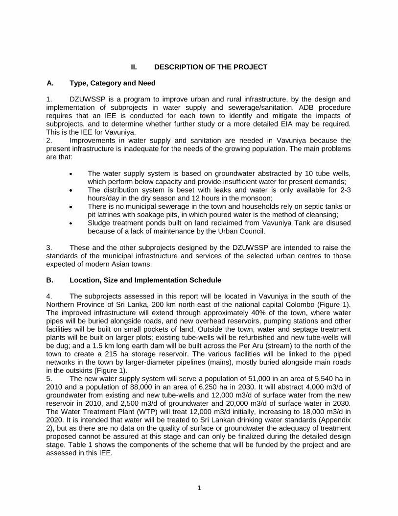
1
II. DESCRIPTION OF THE PROJECT
A. Type, Category and Need
1. DZUWSSP is a program to improve urban and rural infrastructure, by the design and implementation of subprojects in water supply and sewerage/sanitation. ADB procedure requires that an IEE is conducted for each town to identify and mitigate the impacts of subprojects, and to determine whether further study or a more detailed EIA may be required. This is the IEE for Vavuniya. 2. Improvements in water supply and sanitation are needed in Vavuniya because the present infrastructure is inadequate for the needs of the growing population. The main problems are that:
The water supply system is based on groundwater abstracted by 10 tube wells, which perform below capacity and provide insufficient water for present demands;
The distribution system is beset with leaks and water is only available for 2-3 hours/day in the dry season and 12 hours in the monsoon;
There is no municipal sewerage in the town and households rely on septic tanks or pit latrines with soakage pits, in which poured water is the method of cleansing;
Sludge treatment ponds built on land reclaimed from Vavuniya Tank are disused because of a lack of maintenance by the Urban Council.
3. These and the other subprojects designed by the DZUWSSP are intended to raise the standards of the municipal infrastructure and services of the selected urban centres to those expected of modern Asian towns.
B. Location, Size and Implementation Schedule
4. The subprojects assessed in this report will be located in Vavuniya in the south of the Northern Province of Sri Lanka, 200 km north-east of the national capital Colombo (Figure 1). The improved infrastructure will extend through approximately 40% of the town, where water pipes will be buried alongside roads, and new overhead reservoirs, pumping stations and other facilities will be built on small pockets of land. Outside the town, water and septage treatment plants will be built on larger plots; existing tube-wells will be refurbished and new tube-wells will be dug; and a 1.5 km long earth dam will be built across the Per Aru (stream) to the north of the town to create a 215 ha storage reservoir. The various facilities will be linked to the piped networks in the town by larger-diameter pipelines (mains), mostly buried alongside main roads in the outskirts (Figure 1). 5. The new water supply system will serve a population of 51,000 in an area of 5,540 ha in 2010 and a population of 88,000 in an area of 6,250 ha in 2030. It will abstract 4,000 m3/d of groundwater from existing and new tube-wells and 12,000 m3/d of surface water from the new reservoir in 2010, and 2,500 m3/d of groundwater and 20,000 m3/d of surface water in 2030. The Water Treatment Plant (WTP) will treat 12,000 m3/d initially, increasing to 18,000 m3/d in 2020. It is intended that water will be treated to Sri Lankan drinking water standards (Appendix 2), but as there are no data on the quality of surface or groundwater the adequacy of treatment proposed cannot be assured at this stage and can only be finalized during the detailed design stage. Table 1 shows the components of the scheme that will be funded by the project and are assessed in this IEE.
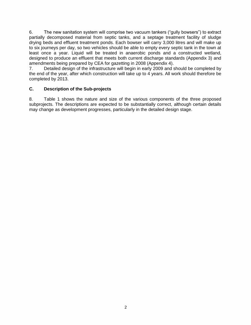
2
6. The new sanitation system will comprise two vacuum tankers (“gully bowsers”) to extract partially decomposed material from septic tanks, and a septage treatment facility of sludge drying beds and effluent treatment ponds. Each bowser will carry 3,000 litres and will make up to six journeys per day, so two vehicles should be able to empty every septic tank in the town at least once a year. Liquid will be treated in anaerobic ponds and a constructed wetland, designed to produce an effluent that meets both current discharge standards (Appendix 3) and amendments being prepared by CEA for gazetting in 2008 (Appendix 4). 7. Detailed design of the infrastructure will begin in early 2009 and should be completed by the end of the year, after which construction will take up to 4 years. All work should therefore be completed by 2013.
C. Description of the Sub-projects
8. Table 1 shows the nature and size of the various components of the three proposed subprojects. The descriptions are expected to be substantially correct, although certain details may change as development progresses, particularly in the detailed design stage.
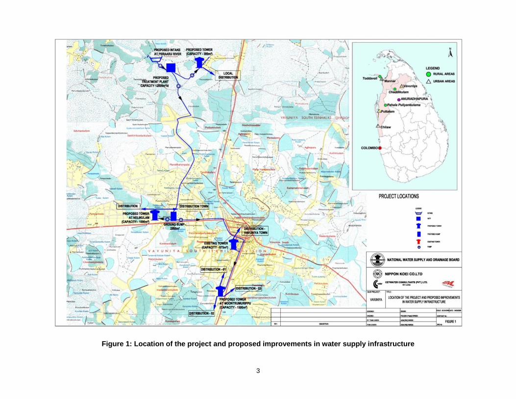
3
Figure 1: Location of the project and proposed improvements in water supply infrastructure
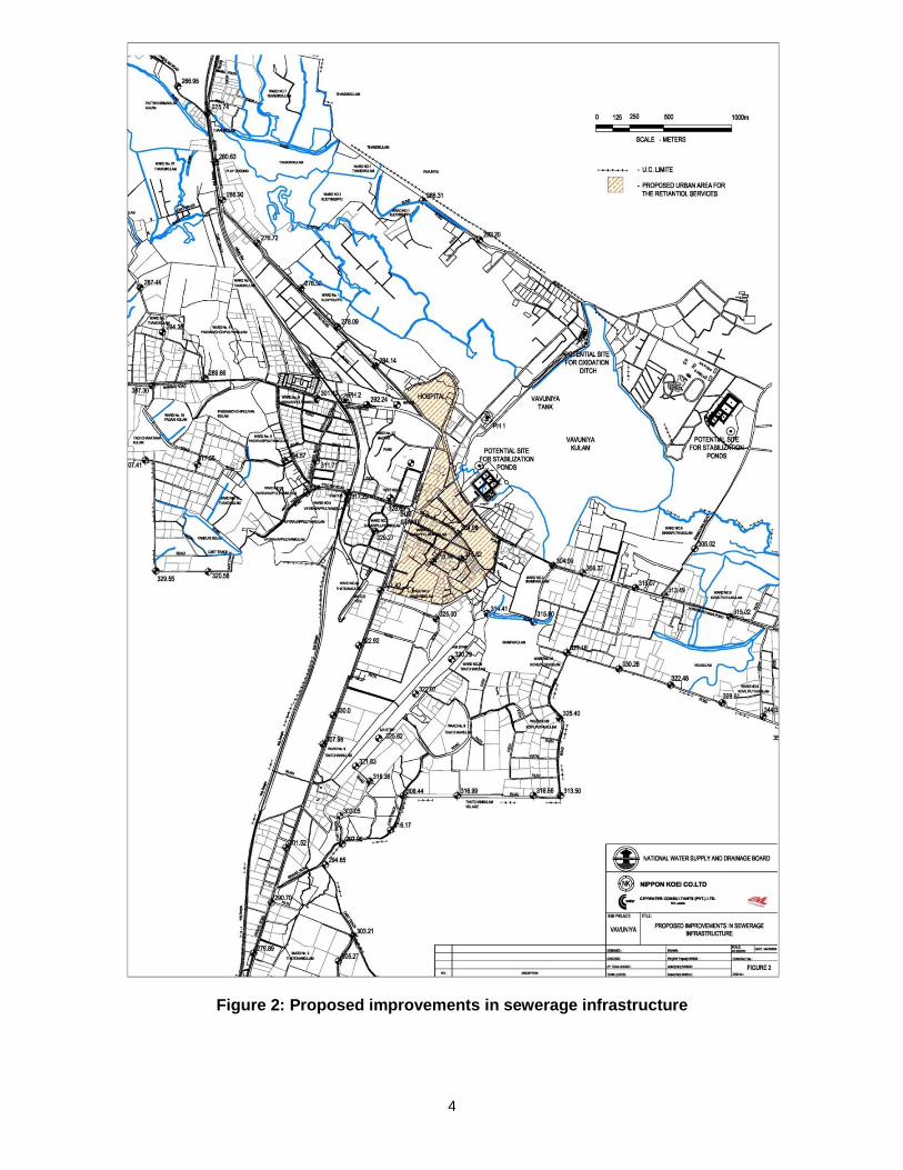
4
Figure 2: Proposed improvements in sewerage infrastructure
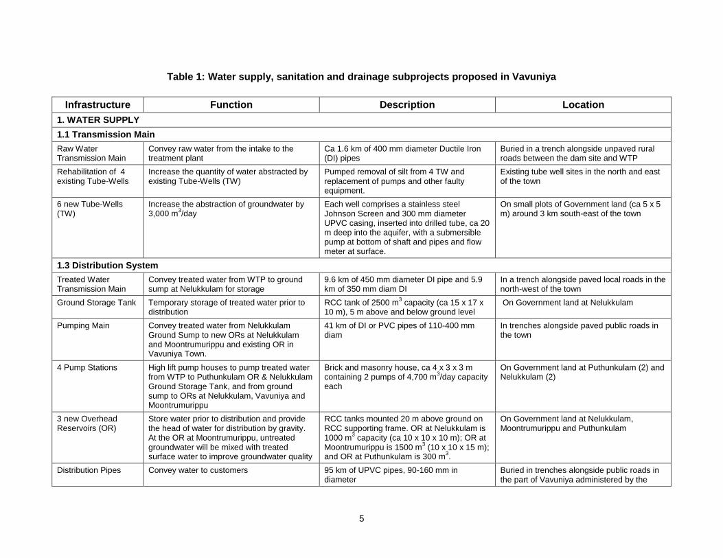
5
Table 1: Water supply, sanitation and drainage subprojects proposed in Vavuniya
Infrastructure Function Description Location
1. WATER SUPPLY
1.1 Transmission Main
Raw Water Transmission Main
Convey raw water from the intake to the treatment plant
Ca 1.6 km of 400 mm diameter Ductile Iron (DI) pipes
Buried in a trench alongside unpaved rural roads between the dam site and WTP
Rehabilitation of 4 existing Tube-Wells
Increase the quantity of water abstracted by existing Tube-Wells (TW)
Pumped removal of silt from 4 TW and replacement of pumps and other faulty equipment.
Existing tube well sites in the north and east of the town
6 new Tube-Wells (TW)
Increase the abstraction of groundwater by 3,000 m
3/day
Each well comprises a stainless steel Johnson Screen and 300 mm diameter UPVC casing, inserted into drilled tube, ca 20 m deep into the aquifer, with a submersible pump at bottom of shaft and pipes and flow meter at surface.
On small plots of Government land (ca 5 x 5 m) around 3 km south-east of the town
1.3 Distribution System
Treated Water Transmission Main
Convey treated water from WTP to ground sump at Nelukkulam for storage
9.6 km of 450 mm diameter DI pipe and 5.9 km of 350 mm diam DI
In a trench alongside paved local roads in the north-west of the town
Ground Storage Tank Temporary storage of treated water prior to distribution
RCC tank of 2500 m3 capacity (ca 15 x 17 x
10 m), 5 m above and below ground level On Government land at Nelukkulam
Pumping Main Convey treated water from Nelukkulam Ground Sump to new ORs at Nelukkulam and Moontrumurippu and existing OR in Vavuniya Town.
41 km of DI or PVC pipes of 110-400 mm diam
In trenches alongside paved public roads in the town
4 Pump Stations High lift pump houses to pump treated water from WTP to Puthunkulam OR & Nelukkulam Ground Storage Tank, and from ground sump to ORs at Nelukkulam, Vavuniya and Moontrumurippu
Brick and masonry house, ca 4 x 3 x 3 m containing 2 pumps of 4,700 m
3/day capacity
each
On Government land at Puthunkulam (2) and Nelukkulam (2)
3 new Overhead Reservoirs (OR)
Store water prior to distribution and provide the head of water for distribution by gravity. At the OR at Moontrumurippu, untreated groundwater will be mixed with treated surface water to improve groundwater quality
RCC tanks mounted 20 m above ground on RCC supporting frame. OR at Nelukkulam is 1000 m
3 capacity (ca 10 x 10 x 10 m); OR at
Moontrumurippu is 1500 m3 (10 x 10 x 15 m);
and OR at Puthunkulam is 300 m3.
On Government land at Nelukkulam, Moontrumurippu and Puthunkulam
Distribution Pipes Convey water to customers 95 km of UPVC pipes, 90-160 mm in diameter
Buried in trenches alongside public roads in the part of Vavuniya administered by the
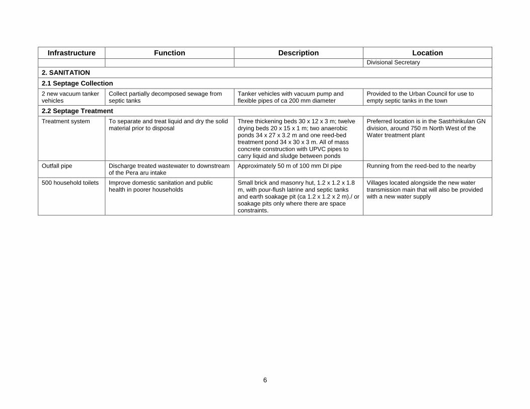
6
Infrastructure Function Description Location
Divisional Secretary
2. SANITATION
2.1 Septage Collection
2 new vacuum tanker vehicles
Collect partially decomposed sewage from septic tanks
Tanker vehicles with vacuum pump and flexible pipes of ca 200 mm diameter
Provided to the Urban Council for use to empty septic tanks in the town
2.2 Septage Treatment
Treatment system To separate and treat liquid and dry the solid material prior to disposal
Three thickening beds 30 x 12 x 3 m; twelve drying beds 20 x 15 x 1 m; two anaerobic ponds 34 x 27 x 3.2 m and one reed-bed treatment pond 34 x 30 x 3 m. All of mass concrete construction with UPVC pipes to carry liquid and sludge between ponds
Preferred location is in the Sastrhirikulan GN division, around 750 m North West of the Water treatment plant
Outfall pipe Discharge treated wastewater to downstream of the Pera aru intake
Approximately 50 m of 100 mm DI pipe Running from the reed-bed to the nearby
500 household toilets Improve domestic sanitation and public health in poorer households
Small brick and masonry hut, 1.2 x 1.2 x 1.8 m, with pour-flush latrine and septic tanks and earth soakage pit (ca 1.2 x 1.2 x 2 m)./ or soakage pits only where there are space constraints.
Villages located alongside the new water transmission main that will also be provided with a new water supply
7
1. Water Supply
9. Table 1 shows that there are three elements to the water supply subproject: supply augmentation, improving water treatment, and improving and expanding the distribution network. 10. Increasing the supply of water will involve expanding the abstraction of groundwater by rehabilitating existing tube-wells and boring new wells; and abstracting surface water from a new reservoir created by constructing a bund across the Per Aru, with an intake structure and a transmission main to convey water to a new treatment plant nearby. 11. The bund across the Per Aru will be located at Puthunkulam, 15 km north of Vavuniya Town (Figure 1, Photo 1). The reservoir will cover an area of 250.5 ha at Full Supply Level (FSL). The earth bund of 5m width is 3 km long will include a radial gated spill way. 12. Groundwater abstraction will be increased by refurbishing four existing tube-wells (TW) at sites in the north and east of the town, and drilling six new wells on small plots of Government land at a wellfield around 3 km south-east of the town. Water from the new wells will be pumped to a new Overhead Reservoir (OR) at Moontrumurippu to the south of the town (Figure 1), where it will be mixed with treated surface water to improve the quality of the groundwater. 13. The new WTP will include an aerator, upflow clarifier with hydraulic flocculator, rapid filter chlorinator and sludge thickener, and will treat up to 12,000 m3/d initially, with provision to upgrade the system to 18,000 m3/d in 2020. The tanks will be approximately 20 x 20 m square and 10 m deep, and will project 5 m above and below the ground surface (Photo 2). A smaller tank of 500 m3 capacity (10 x 10 x 5 m) will be built at the site, for ground storage. There will also be a 5 x 4 x 3 m brick and masonry pump house, containing four pumps of 3,000 m3/d capacity to lift treated water into an Overhead Reservoir at the site for distribution of water locally. 14. Improving the distribution network will involve construction of a ground storage tank and three overhead reservoirs to store water and provide the head required for gravity flow through the system. There will also be a transmission main to convey water to the tank and reservoirs, four pump stations, a pumping main and a distribution network to replace existing leaking pipes and extend the network into new areas. 15. The ground storage tank and one of the overhead tanks will be located on Government land at Nelukkulam in the north-west of the town. Both will be of RCC construction, and the 2,500 m3 tank will measure approximately 15 x 17 x 10 m and will be built with a 5 m depth above and below ground (Photo 2). The Overhead Reservoir (OR) will measure 10 x 10 x 10 m and will be located on RCC supports, 20 m above the ground (Photo 4). Two other ORs will be built, one of larger capacity (1500 m3) at Moontrumurippu to distribute water to the southern part of the town, and one of smaller capacity (300 m3) at Puthunkulam to distribute water to communities in the vicinity of the WTP. An existing 675 m3 OR will continue to provide water to the centre of the town (Figure 1). 16. A 15.5 km treated water transmission main of 350-450 mm diameter Ductile Iron (DI) pipe will carry water from the WTP to the ground tank; and a 41 km pumping main of 110-400 mm diameter DI or UPVC pipes will carry water from the sump to the ORs and from the ORs towards the residential areas. These pipes will be buried in the Right of Way (RoW) alongside paved local roads (Photo 6). Four pump stations will propel the water through the mains and into the tank and ORs, two at the WTP and two at Nelukkulam. These will each consist of small brick and masonry houses, built on government land alongside the other facilities, and will contain two pumps each (Photo 7). The local distribution network will consist of 95 km of UPVC pipes, 90-160 mm in diameter, and will carry water into individual houses. These will be buried in trenches alongside paved local roads in the part of the town administered by the Divisional Secretary.
8
2. Sanitation
17. The Sanitation subproject will consist of two new vacuum tankers to collect partially decomposed sewage from septic tanks in the town, and a facility outside the town to dry the solid material (known as “septage”) and decant and treat the liquid effluent to Sri Lankan discharge standards 18. The vacuum tankers will be procured by the project and provided to Vavuniya Urban Council (VUC), who will be responsible for operating the sanitation component. The vehicles are fitted with vacuum pumps and lengths of flexible hose, which will be used to remove material from the septic tanks. The contents of each tanker will be deposited periodically at the treatment facility. 19. Two locations were considered one in Pompamadu adjacent to the present solid waste disposal site and the other in Sastrikulan. The Pompamadu site is on forestry land and would require clearing of forest land and therefore was not considered further. The preferred location is on Government land in Sasthirikulan GN division. (Site 2 on Figure 2). The facility will consist of a series of ponds and beds, constructed from mass concrete (not RCC), in which the solid and liquid components will be separated and treated. There will be three thickening beds, each 30 x 12 x 3 m, twelve drying beds, each 20 x 15 x 1 m, and pipe-work to convey the sludge from the thickener to the drying beds and the supernatant liquid to anaerobic treatment ponds (Figure 3). There will be three anaerobic ponds in series, each 34 x 27 x 3.2 m, and a concrete wetland pond (34 x 30 x 3 m), planted with reeds, bamboo or grass to absorb organic material, phosphates and nitrates and reduce the water content by evapo-transpiration. The final effluent will be discharged from the reed-bed through a 100 mm diameter pipe downstream of the Peruaru intake. .
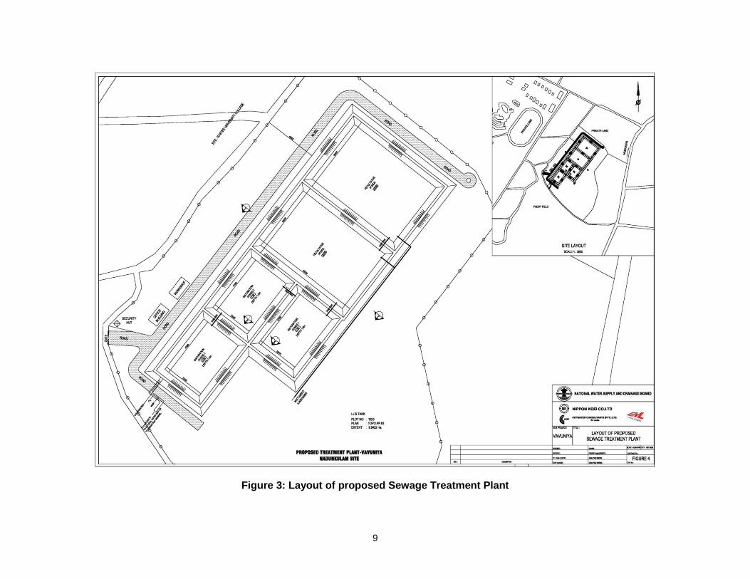
9
Figure 3: Layout of proposed Sewage Treatment Plant
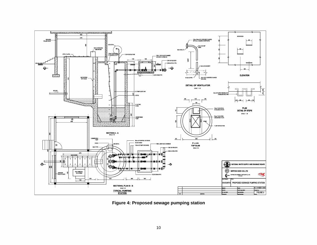
10
Figure 4: Proposed sewage pumping station

11
20. In addition, around 500 pour-flush latrines with septic tanks and soakage pits/or only soakage pits due to space constraints, will be provided in villages alongside the water transmission main, which will be furnished with a water supply as part of the project. Latrines will be located in small brick huts outside existing buildings, and will drain into a soakage pit dug nearby (Figure 4)
12
III. DESCRIPTION OF THE ENVIRONMENT
A. Physical Resources
1. Location
1. Vavuniya is in the south of the Northern Province of Sri Lanka, 50 km north of Anuradhapura and 200 km north-east of the national capital Colombo, on the A9 highway that runs north to Jaffna (Figure 1). It is the most southerly major town in the Northern Province and is regarded as the gateway to the northern Vanni Region. 2. In common with many other towns outside the conflict zone, the population of Vavuniya has increased significantly in recent years because of an influx of Internally Displaced Persons (IDP) moving south into safer areas. Because of this and its strategic location, Vavuniya has become an important administrative and trading centre, despite the dangers presented by the conflict and the security checks applied by Government forces along many of the roads in the area. 3. Vavuniya Town is the administrative capital of Vavuniya district, and is administered by central Government via a Divisional Secretary, and also by three Local Authorities (Vavuniya Urban Council, Vavuniya South Tamil Pradesiya Sabah and Vavuniya North Pradesiya Sabah). The Local Authorities are in turn governed by the Northern Provincial Council and the Commissioner of Local Government (CLG) of the Northern Province. 4. Vavuniya Divisional Secretary Area includes 214 villages in 42 Gramaseva Nildari
Divisions (GND)4. The proposed water supply subproject will cover Vavuniya Town urban area
and the suburbs, comprising 59 villages in 17 GNDs; and the sewerage scheme will cover only the area of high building and population density in the centre of the town.
4 GND is the lowest level of central Government administration, in which the administration is headed by a Gramaseva Nildari (GN).
A GND normally consists of a town and/or several villages, although rarely a GND can comprise a single village or town. Each Divisional Secretary (DS) area comprises a number of GNDs (typically around a hundred), and the DS is normally the main decision-maker, implementing central Government policy.
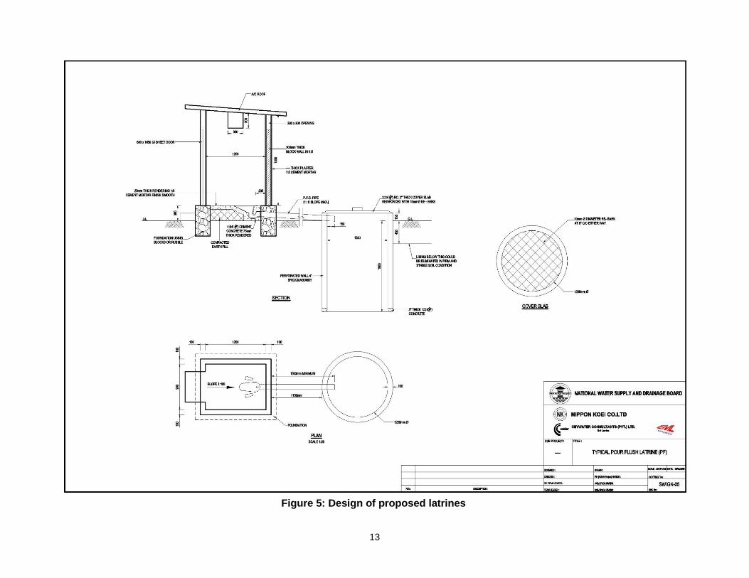
13
Figure 5: Design of proposed latrines
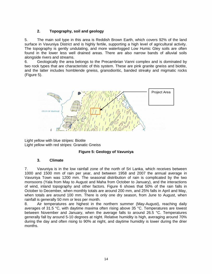
14
2. Topography, soil and geology
5. The main soil type in this area is Reddish Brown Earth, which covers 92% of the land surface in Vavuniya District and is highly fertile, supporting a high level of agricultural activity. The topography is gently undulating, and more waterlogged Low Humic Gley soils are often found in the lower less well drained areas. There are also narrow bands of alluvial soils alongside rivers and streams. 6. Geologically the area belongs to the Precambrian Vanni complex and is dominated by two rock types that are characteristic of this system. These are pink granite gneiss and biotite, and the latter includes homblende gneiss, granodioritic, banded streaky and migmatic rocks (Figure 5). Light yellow with blue stripes: Biotite Light yellow with red stripes: Granatic Gneiss
Figure 5: Geology of Vavuniya
3. Climate
7. Vavuniya is in the low rainfall zone of the north of Sri Lanka, which receives between 1000 and 1500 mm of rain per year, and between 1958 and 2007 the annual average in Vavuniya Town was 1200 mm. The seasonal distribution of rain is complicated by the two monsoons (Yala from May to August and Maha from October to January), and the interactions of wind, inland topography and other factors. Figure 6 shows that 50% of the rain falls in October to December, when monthly totals are around 200 mm, and 25% falls in April and May, when totals are around 100 mm. There is only one dry season, from June to August, when rainfall is generally 50 mm or less per month. 8. Air temperatures are highest in the northern summer (May-August), reaching daily averages of 31.5 °C, with daytime maxima often rising above 35 °C. Temperatures are lowest between November and January, when the average falls to around 26.5 °C. Temperatures generally fall by around 5-10 degrees at night. Relative humidity is high, averaging around 70% during the day and often rising to 90% at night, and daytime humidity is lower during the drier months.
Project Area
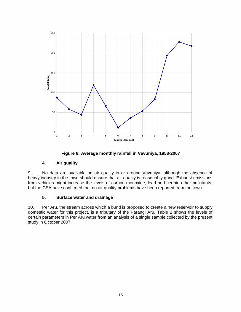
15
Figure 6: Average monthly rainfall in Vavuniya, 1958-2007
4. Air quality
9. No data are available on air quality in or around Vavuniya, although the absence of heavy industry in the town should ensure that air quality is reasonably good. Exhaust emissions from vehicles might increase the levels of carbon monoxide, lead and certain other pollutants, but the CEA have confirmed that no air quality problems have been reported from the town.
5. Surface water and drainage
10. Per Aru, the stream across which a bund is proposed to create a new reservoir to supply domestic water for this project, is a tributary of the Parangi Aru. Table 2 shows the levels of certain parameters in Per Aru water from an analysis of a single sample collected by the present study in October 2007.
0
50
100
150
200
250
1 2 3 4 5 6 7 8 9 10 11 12
Month (Jan-Dec)
Rain
fall (
mm
)
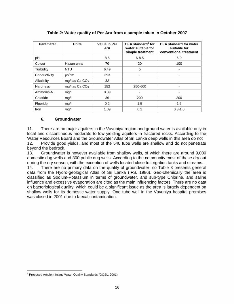
16
Table 2: Water quality of Per Aru from a sample taken in October 2007
Parameter Units Value in Per Aru
CEA standard5 for
water suitable for simple treatment
CEA standard for water suitable for
conventional treatment
pH 8.5 6-8.5 6-9
Colour Hazan units 70 20 100
Turbidity NTU 6.49 5 -
Conductivity µs/cm 393 - -
Alkalinity mg/l as Ca CO3 32 - -
Hardness mg/l as Ca CO3 152 250-600 -
Ammonia-N mg/l 0.39 - -
Chloride mg/l 36 200 200
Fluoride mg/l 0.2 1.5 1.5
Iron mg/l 1.09 0.2 0.3-1.0
6. Groundwater
11. There are no major aquifers in the Vavuniya region and ground water is available only in local and discontinuous moderate to low yielding aquifers in fractured rocks. According to the Water Resources Board and the Groundwater Atlas of Sri Lanka deep wells in this area do not 12. Provide good yields, and most of the 540 tube wells are shallow and do not penetrate beyond the bedrock. 13. Groundwater is however available from shallow wells, of which there are around 9,000 domestic dug wells and 300 public dug wells. According to the community most of these dry out during the dry season, with the exception of wells located close to irrigation tanks and streams. 14. There are no primary data on the quality of groundwater, so Table 3 presents general data from the Hydro-geological Atlas of Sri Lanka (IFS, 1986). Geo-chemically the area is classified as Sodium-Potassium in terms of groundwater, and sub-type Chlorine, and saline influence and excessive evaporation are cited as the main influencing factors. There are no data on bacteriological quality, which could be a significant issue as the area is largely dependent on shallow wells for its domestic water supply. One tube well in the Vavuniya hospital premises was closed in 2001 due to faecal contamination.
5 Proposed Ambient Inland Water Quality Standards (GOSL, 2001)
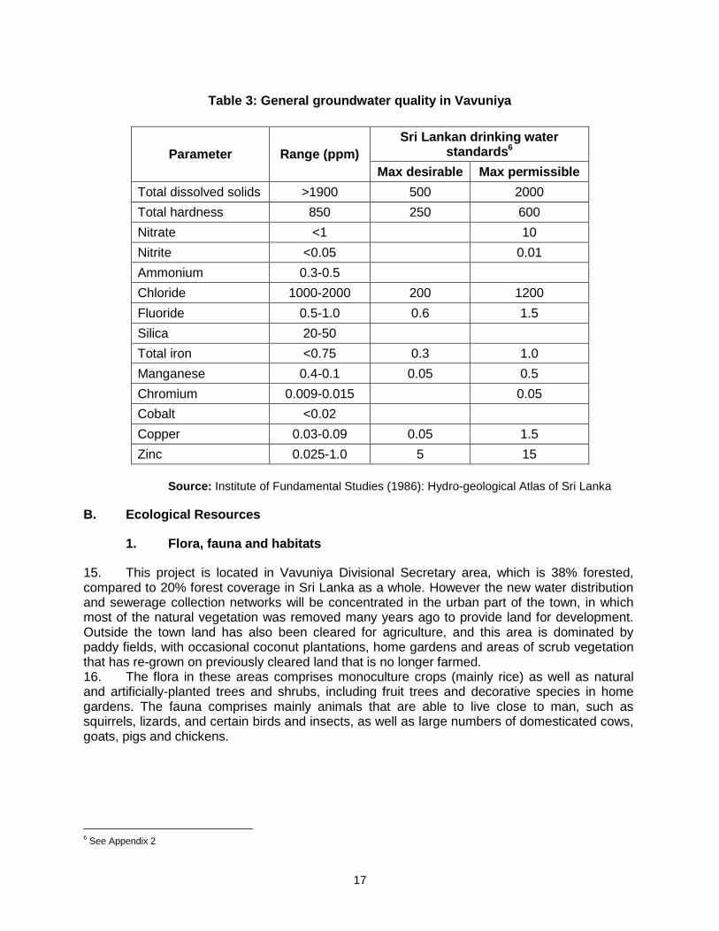
17
Table 3: General groundwater quality in Vavuniya
Parameter Range (ppm)
Sri Lankan drinking water standards6
Max desirable Max permissible
Total dissolved solids >1900 500 2000
Total hardness 850 250 600
Nitrate <1 10
Nitrite <0.05 0.01
Ammonium 0.3-0.5
Chloride 1000-2000 200 1200
Fluoride 0.5-1.0 0.6 1.5
Silica 20-50
Total iron <0.75 0.3 1.0
Manganese 0.4-0.1 0.05 0.5
Chromium 0.009-0.015 0.05
Cobalt <0.02
Copper 0.03-0.09 0.05 1.5
Zinc 0.025-1.0 5 15
Source: Institute of Fundamental Studies (1986): Hydro-geological Atlas of Sri Lanka
B. Ecological Resources
1. Flora, fauna and habitats
15. This project is located in Vavuniya Divisional Secretary area, which is 38% forested, compared to 20% forest coverage in Sri Lanka as a whole. However the new water distribution and sewerage collection networks will be concentrated in the urban part of the town, in which most of the natural vegetation was removed many years ago to provide land for development. Outside the town land has also been cleared for agriculture, and this area is dominated by paddy fields, with occasional coconut plantations, home gardens and areas of scrub vegetation that has re-grown on previously cleared land that is no longer farmed. 16. The flora in these areas comprises monoculture crops (mainly rice) as well as natural and artificially-planted trees and shrubs, including fruit trees and decorative species in home gardens. The fauna comprises mainly animals that are able to live close to man, such as squirrels, lizards, and certain birds and insects, as well as large numbers of domesticated cows, goats, pigs and chickens.
6 See Appendix 2
18
2. Forest
17. The forested areas are of more ecological value, and are generally located some distance from inhabitation. Administratively there are three types of forest: state forests; forest plantations; and forest reserves. In the Vavuniya DS area there are four state forests covering 850 ha and 9000 ha of forest reserves, both of which are managed by the Forest Department. There are also 13,000 ha of natural woodland that is not designated or managed. Depending on their size, location and the extent of disturbance by logging and other activities, these areas may contain a variety of the mammals and other species that are typical of forest habitats in Sri Lanka, including elephant, deer, toque macaques and other monkeys, wild boar, and a variety of birds, reptiles and insects.
4. Wetlands
18. Pawat Kulam is the main reservoir in the area, and there are also a large number of minor irrigation tanks, plus tributaries of the rivers Aruvi Aru, Malwathu Oya and Parangi Aru mentioned above. Most of the tanks support a range of aquatic vegetation, including reeds and water hyacinth, which grow in profusion in some areas, significantly reducing the capacity of the tanks (Photo 12). The tanks also support a range of aquatic fauna including fish, amphibians, birds and insects, and there are active fisheries in the larger tanks (Photo 14). Species include those that occur naturally in the rivers and streams that were dammed to create the tank, plus introduced species such as tilapia and carp.
C. Economic Development
1. Land use
19. The importance of Vavuniya as a trading and administrative centre has increased in recent years because of its strategic location as the most northerly town in the area that is under control of the Government forces. As noted above, the population has increased because of the influx of IDPs from towns and villages in the north. Local markets have expanded as a result, and Vavuniya has become the business hub for the Vanni region, and the main wholesale and retail centre in the Northern Province. 20. Agriculture is the main occupation in the Divisional Secretary area, and covers around 50% of the land, comprising mainly paddy and rain-fed cultivation, plus home gardens and livestock. Almost 40% of the land is forested, and a further 7% is occupied by the various irrigation tanks and other water bodies (Figure 7).
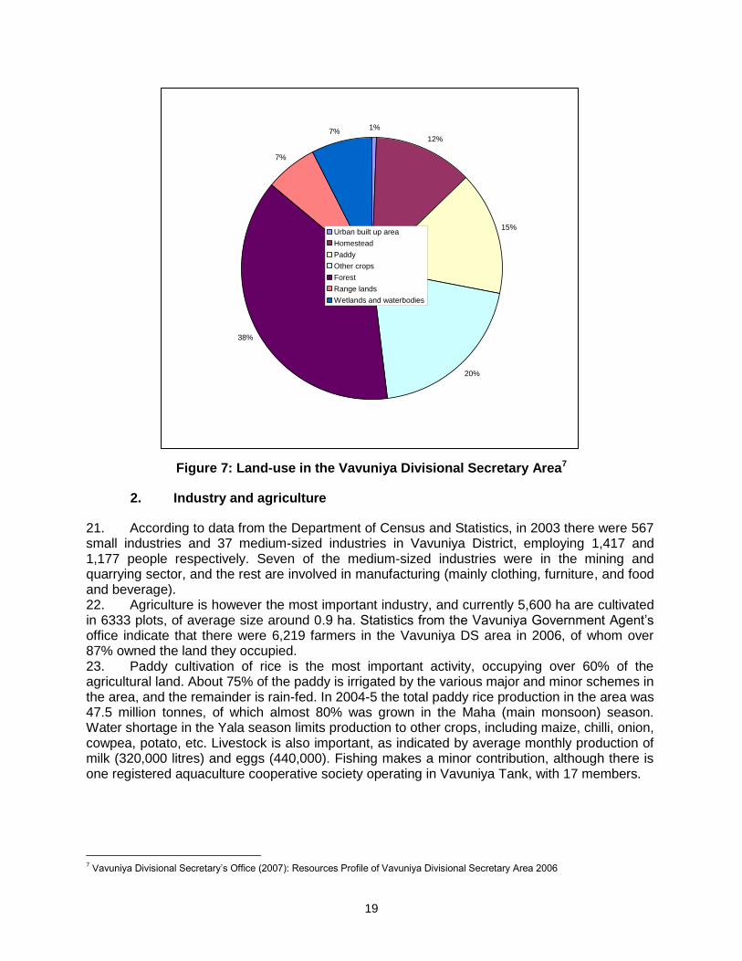
19
Figure 7: Land-use in the Vavuniya Divisional Secretary Area7
2. Industry and agriculture
21. According to data from the Department of Census and Statistics, in 2003 there were 567 small industries and 37 medium-sized industries in Vavuniya District, employing 1,417 and 1,177 people respectively. Seven of the medium-sized industries were in the mining and quarrying sector, and the rest are involved in manufacturing (mainly clothing, furniture, and food and beverage). 22. Agriculture is however the most important industry, and currently 5,600 ha are cultivated in 6333 plots, of average size around 0.9 ha. Statistics from the Vavuniya Government Agent’s office indicate that there were 6,219 farmers in the Vavuniya DS area in 2006, of whom over 87% owned the land they occupied. 23. Paddy cultivation of rice is the most important activity, occupying over 60% of the agricultural land. About 75% of the paddy is irrigated by the various major and minor schemes in the area, and the remainder is rain-fed. In 2004-5 the total paddy rice production in the area was 47.5 million tonnes, of which almost 80% was grown in the Maha (main monsoon) season. Water shortage in the Yala season limits production to other crops, including maize, chilli, onion, cowpea, potato, etc. Livestock is also important, as indicated by average monthly production of milk (320,000 litres) and eggs (440,000). Fishing makes a minor contribution, although there is one registered aquaculture cooperative society operating in Vavuniya Tank, with 17 members.
7 Vavuniya Divisional Secretary’s Office (2007): Resources Profile of Vavuniya Divisional Secretary Area 2006
1%
12%
15%
20%
38%
7%
7%
Urban built up area
Homestead
Paddy
Other crops
Forest
Range lands
Wetlands and waterbodies

20
3. Infrastructure
24. NWSDB provides water through a piped system to most of Vavuniya town and to a limited area outside, extracting groundwater from ten tube-wells in the town. However these operate at less than 80% capacity, producing 590 m3/d instead of the design yield of 750 m3/d, because of sedimentation of the wells and deterioration of the pumps and other equipment. In 2006 there were 1,030 connections, which currently receive a supply for 2-3 hours per day in the dry season and 12 hours in the monsoon. New customers have been awaiting a connection for several years. 25. There is no sewerage system in Vavuniya, where wastewater disposal is through on-site methods, a combination of septic tanks and pour-flush pit latrines. Only around 50% of houses have a private toilet, and the other residents use public toilets or toilets of neighbouring houses. 26. There are open concrete drains alongside roads in most of the urban area (Photo 16), through which storm-water is discharged into Vavuniya Tank. Grey water from domestic washing is also released into drains, most of which are inadequately maintained and clogged with garbage and silt. As a result drains are stagnant and unsanitary, and localised flooding occurs during rain. Sludge treatment ponds built several years ago on land reclaimed from Vavuniya Tank were not maintained by the Urban Council because of land ownership issues and drain water now runs directly into the tank alongside the overgrown ponds. The water is fetid and contaminated with detergents and other waste, and the tank water is heavily polluted as a result. Outside the town drainage is mainly by roadside ditches, irrigation canals and natural streams, and flash-flooding occurs during heavy storms. 27. Solid waste in the town is the responsibility of Vavuniya Urban Council, and disposal is a problem that has become more acute as the population has expanded. Around 12 tonnes of solid waste is produced each day in the Urban Council area, of which around 20% (mainly market waste and tree cuttings) is taken to a composting plant at Veppankulam 2 km away. The remainder is dumped at a site at Rajendrankulam, which is not an engineered landfill, and from where the leachate is said to pollute Rajendrankulam and Pawat Kulam tanks. Solid waste is less of a problem in the rural areas as there is generally enough space for people to bury and/or burn their material. The Pradesiya Sabahs collect waste from the minor rural towns and weekly markets and no problems have been reported with this service. 28. Power in Vavuniya is supplied by the Ceylon Electricity Board via the national grid, for which power is generated by mainly oil-fired thermal stations. Most permanent houses in Vavuniya District have a power supply, and in 2006 there were 20,000 customers, 75% of them domestic. Power is supplied by overhead cables carried on metal and concrete poles, mainly located in public areas alongside roads (Photo 17). The power supply is erratic and there are frequent outages in warmer months, and large fluctuations in voltage
4. Transportation
29. Vavuniya is at the junction of three major trunk roads: the A30/A14 from Mannar on the west coast; the A29/A12 from Trincomalee on the east coast; and the A9 which is the main spine road in the centre of the country, connecting Kandy in the south with Jaffna on the north coast (Figure 1). Transportation links are one of the main reasons for Vavuniya’s strategic importance, and the town is also served by the Colombo-Vavuniya railway, which provides five trains per day and is a vital link with the capital. 30. The national roads are maintained by the Road Development Authority and are generally in good repair. Smaller regionally-important roads are maintained by the Provincial Roads Authority, and the smallest roads between townships and villages in the interior are maintained by local authorities. Most local authority roads are surfaced with gravel and many are in need of repair, whereas most of the larger roads are tarred and in a relatively good condition (Photo 19).
21
31. Buses provide the main mode of transportation, and there are a variety of conveyances and routes in the town and outside to all regional centres and Colombo. Goods are mainly transported by truck. There are large numbers of vehicles in the centre of the town, particularly at road intersections and the main shopping areas, where narrower streets are often congested (Photo 18). There are fewer vehicles in the outskirts, where traffic jams are not a major problem (Photo 20). Motorcycles are the dominant method of personal transportation, and amount to 77% of the 13,000 registered vehicles in Vavuniya District. The importance of motorcycles has increased at the expense of buses, which have been a frequent target of terrorist bombings in recent years.
D. Social and Cultural Resources
1. Demography
32. According to data from the Divisional Secretary’s office, in 2006 the population of the Vavuniya DS area was 115,335, consisting of 59,198 females and 56,117 males, close to the natural 1:1 ratio. A total of 62,098 people live in rural areas at a density of 106 persons/ km2 and 53,237 people live in urban areas at a density of 2,476 persons/km2. The urban density is similar to the figure in large cities like Colombo, and is mainly the result of the influx of IDPs. There are currently 30,998 families in the area, comprising 27,212 Vavuniya residents and 3,567 IDP families (with 10,322 members). 33. There are no data on literacy, but it is likely to be high, given that of the almost 30,000 children that were of school age in 2006, only 17 were not registered as pupils. More than 95% of the residents are Tamil, 3 % are Muslim and Malay, and only 1% are Sinhalese. Most of the Tamils are Hindu, which is therefore the dominant religion, and about 9% of the population is Christian, 3% Muslim, and around 0.7% Buddhist.
2. Socio-Economics
34. Agriculture is the major employer in Vavuniya district, with over 20,000 people engaged in farming, around 7,000 full-time and the remainder gaining seasonal employment, mainly during the planting and harvest seasons. Government is the second largest employer because of the number of line agencies and other offices that are located here, serving the Northern Province. Currently around 5,000 people are employed in the public sector and 4,800 in the private sector, roughly 50% each in trade and industry. The rest of the working population (about 40%) is either unemployed or engaged in casual labour in the town. 35. There are no firm data on housing in Vavuniya, but the availability and condition of houses are known to be significant problems, because of the increase in population and the effects of the civil conflict. There were 27,212 resident families in 2005 and a reported 13,185 houses, which, if correct, would suggest a significant housing deficit. There are no data on numbers of temporary houses, although it is known that many of the IDPs are living in temporary accommodation, or with friends or relatives in the area. Around 50% of houses are reported to have suffered damage from the conflict. There is a significant remediation program underway (the North-East Housing Reconstruction Project), funded by the World Bank, in which 1,300 houses will be rehabilitated in various areas, including 42 villages and 14 GNDs covered by this project. The demand for houses has caused a sharp increase in land prices. 36. There are also no formal data on family income and expenditure, but poverty is only thought to be a problem for certain IDP families. In 2005 there were 3,149 families dependent on some form of livelihood support (mainly the Government-funded Samurdhi poverty-alleviation programme), and there were also 900 disabled persons who were receiving some form of income supplement.
22
3. Health and educational facilities
37. Vavuniya Base Hospital is the most important medical facility in the area and houses 270 beds and a variety of specialist facilities, equipment and personnel. There are also two small private hospitals with 22 beds; and a variety of dispensaries and clinics, either privately-funded or provided by local and national Government. Public health is the responsibility of a Medical Officer of Health (MOH) appointed by the Government, who is assisted by 11 Public Health Inspectors (PHI) and 7 Family Health Nurses. However, only 50% of the posts in the medical service in Vavuniya are filled at the present time. There are no publicly-available data on public health and although statistics on the incidence of disease were requested from the Ministry of Health, no information was provided. 38. Educational facilities are also reasonably good, although as with most other public services, the town is significantly better provided than the rural areas. There are 105 pre-schools in the project area and 40 schools, including four national level schools. There are also a number of non-formal education institutes providing skills training to school leavers in such fields as electronics, construction, computing, accountancy, etc. There is a teachers’ training college with an annual intake of around 260, and a campus of Jaffna University offering degree programmes in 5 areas and an extension programme in English and Computers. There are two other tertiary level institutions: Vavuniya Technical College, which offers 16 programmes with an enrolment of around 400; and Vavuniya Agriculture School with an enrolment of 30.
4. History, culture and tourism
39. Numerous social organisations and NGOs operate in the area, mainly engaged in development work or with the social welfare of the displaced communities. According to the District Secretariat there are currently 30 local NGOs, 12 international NGOs and 5 United Nations agencies working in the district. There are also many village level CBOs, including death donation societies, which support family members at times of bereavement, plus farmers’ organisations, women’s societies, etc. Most of the local NGOs and CBOs assist communities in dealing with health and social issues, and there are some that operate micro-credit schemes to encourage cottage industry 40. Vavuniya is not a major historical town like Anuradhapura 50 km to the south. There are however a number of important buildings, mainly of the Hindu religion, including the Sothida Niliyam and Kandasamy kovils (temples) and the Bhagwan Sri Sathya Seva Centre, which is the ashram of the guru Sai Baba. There are also locations that are important for the other religions, including the Kalavari Mountain Christian Centre, the Grand Jummah Mosque, and the Madukanda Vihara, reputedly the fourth resting place in the journey of the sacred Buddha tooth relic from Mullaittivu to Anuradhapura in the 4th century. There is also an archaeological museum, and visitor centres at Elapparmathankulam and Vavuniya farms. 41. The current conflict precludes the development of a tourism industry, and Vavuniya was in fact not a major tourist destination in previous times and contains none of the requisite facilities, such as international quality hotels, restaurants and other attractions.
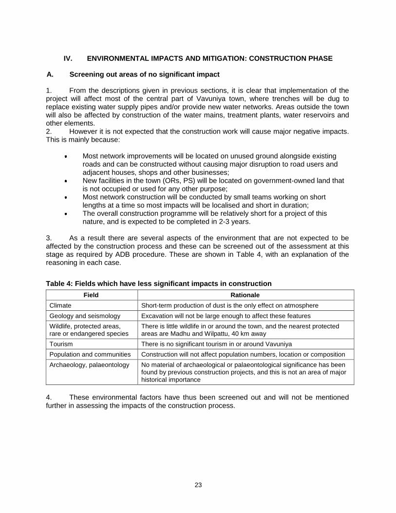
23
IV. ENVIRONMENTAL IMPACTS AND MITIGATION: CONSTRUCTION PHASE
A. Screening out areas of no significant impact
1. From the descriptions given in previous sections, it is clear that implementation of the project will affect most of the central part of Vavuniya town, where trenches will be dug to replace existing water supply pipes and/or provide new water networks. Areas outside the town will also be affected by construction of the water mains, treatment plants, water reservoirs and other elements. 2. However it is not expected that the construction work will cause major negative impacts. This is mainly because:
Most network improvements will be located on unused ground alongside existing roads and can be constructed without causing major disruption to road users and adjacent houses, shops and other businesses;
New facilities in the town (ORs, PS) will be located on government-owned land that is not occupied or used for any other purpose;
Most network construction will be conducted by small teams working on short lengths at a time so most impacts will be localised and short in duration;
The overall construction programme will be relatively short for a project of this nature, and is expected to be completed in 2-3 years.
3. As a result there are several aspects of the environment that are not expected to be affected by the construction process and these can be screened out of the assessment at this stage as required by ADB procedure. These are shown in Table 4, with an explanation of the reasoning in each case.
Table 4: Fields which have less significant impacts in construction
Field Rationale
Climate Short-term production of dust is the only effect on atmosphere
Geology and seismology Excavation will not be large enough to affect these features
Wildlife, protected areas, rare or endangered species
There is little wildlife in or around the town, and the nearest protected areas are Madhu and Wilpattu, 40 km away
Tourism There is no significant tourism in or around Vavuniya
Population and communities Construction will not affect population numbers, location or composition
Archaeology, palaeontology No material of archaeological or palaeontological significance has been found by previous construction projects, and this is not an area of major historical importance
4. These environmental factors have thus been screened out and will not be mentioned further in assessing the impacts of the construction process.
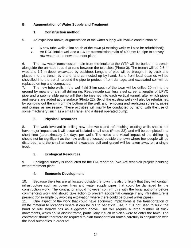
24
B. Augmentation of Water Supply and Treatment
1. Construction method
5. As explained above, augmentation of the water supply will involve construction of:
6 new tube-wells 3 km south of the town (4 existing wells will also be refurbished); An RCC intake well and a 1.6 km transmission main of 400 mm DI pipe to convey
raw water to the new treatment plant. 6. The raw water transmission main from the intake to the WTP will be buried in a trench alongside the unmade road that runs between the two sites (Photo 3). The trench will be 0.6 m wide and 1.7 m deep, excavated by backhoe. Lengths of pipe will be brought in by truck and placed into the trench by crane, and connected up by hand. Sand from local quarries will be shovelled into the trench around the pipe to protect it from damage, and excavated soil will be replaced on top and compacted. 7. The new tube wells in the well-field 3 km south of the town will be drilled 20 m into the ground by means of a small drilling rig. Ready-made stainless steel screens, lengths of UPVC pipe and a submersible pump will then be inserted into each vertical tunnel, after which pipes and meters are added at the surface (Photo 22). Six of the existing wells will also be refurbished, by pumping out the silt from the bottom of the well, and removing and replacing screens, pipes and pumps as necessary. These activities will mainly be conducted by hand, with the use of some machinery, such as a small crane, and a diesel operated pump.
2. Physical Resources
8. The work involved in drilling new tube-wells and refurbishing existing wells should not have major impacts as it will occur at isolated small sites (Photo 22), and will be completed in a short time (approximately 2-4 days per well). The noise and visual impact of the drilling rig should not be significant as the new wells are located outside the town where few people will be disturbed, and the small amount of excavated soil and gravel will be taken away on a single truck.
3. Ecological Resources
9. Ecological survey is conducted for the EIA report on Pwe Are reservoir project including water treatment plant.
4. Economic Development
10. Because the sites are all located outside the town it is also unlikely that they will contain infrastructure such as power lines and water supply pipes that could be damaged by the construction work. The contractor should however confirm this with the local authority before commencing work and should take action to prevent accidental damage if any infrastructure is present (for example by avoiding excavation where there could be buried water pipes). 11. One aspect of the work that could have economic implications is the transportation of waste material to locations where it can be put to beneficial use, if it is not used to build the bund or refill borrow pits as suggested above. This will require a large number of truck movements, which could disrupt traffic, particularly if such vehicles were to enter the town. The contractor should therefore be required to plan transportation routes carefully in conjunction with the local authorities in order to:
25
Prevent heavy vehicles entering the town, and if this cannot be avoided ensure that
vehicles use main roads only, and do not use narrow local roads, except in the immediate vicinity of delivery sites;
Schedule transportation activities to avoid peak traffic periods.
5. Social and Cultural Resources
12. Construction activities inevitably produce noise and dust, and these plus the visual appearance of the site and restrictions in access caused by excavation and the presence of vehicles and machinery, are generally the factors that disturb people who live or work in the vicinity. These should however not be major problems in this case as the facilities are all located in a rural area outside the town, where there are few people living nearby. 13. There are also no socially or culturally important buildings (schools, hospitals, temples, churches, etc) near any of the sites that could be disturbed by construction activities. There are however small religious shrines at various locations elsewhere in the study area (Photo 23) so communities should be consulted during the detailed design stage to ascertain whether there are any sites or artefacts of local significance that could be affected. If this is the case it will be necessary to:
Adjust locations to avoid any especially sensitive sites; Plan work programmes with the community to avoid working during sensitive times
such as religious festivals. 14. The health and safety of workers will be protected by measures included in a Health and Safety Plan, which the contractor will be required to produce and apply. Even though the rural areas are sparsely populated, this should include measures to assure the safety of the public. The plan should thus require:
Exclusion of the public from all sites; Provision/use of appropriate Personal Protective Equipment (PPE) by all workers; Health and Safety Training for all site personnel; Documented procedures to be followed for all site activities; Accident reports and records; Etc.
15. Construction work can provide short-term socio-economic gains for local communities if contractors employ local people in the workforce. To ensure that these benefits are directed to communities that are affected by the work, contractors should be encouraged to employ at least 50% of their workforce from communities in the vicinity of construction sites. This will help to mitigate the impacts of any disturbance as well as creating a positive impression of the project. Building a workforce from mainly local people will also avoid problems that can occur if workers are imported, including social difficulties in the host community and issues of health and sanitation in poorly serviced temporary camps.
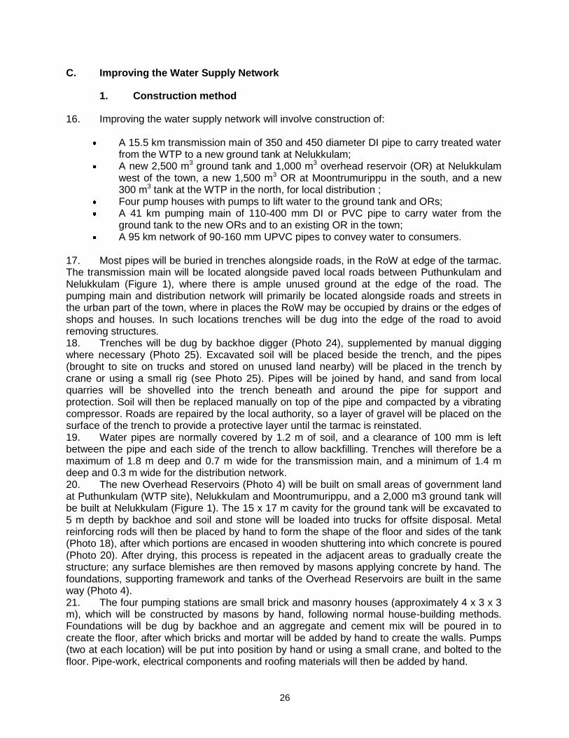
26
C. Improving the Water Supply Network
1. Construction method
16. Improving the water supply network will involve construction of:
A 15.5 km transmission main of 350 and 450 diameter DI pipe to carry treated water from the WTP to a new ground tank at Nelukkulam;
A new 2,500 m3 ground tank and 1,000 m3 overhead reservoir (OR) at Nelukkulam west of the town, a new 1,500 m3 OR at Moontrumurippu in the south, and a new 300 m3 tank at the WTP in the north, for local distribution ;
Four pump houses with pumps to lift water to the ground tank and ORs; A 41 km pumping main of 110-400 mm DI or PVC pipe to carry water from the
ground tank to the new ORs and to an existing OR in the town; A 95 km network of 90-160 mm UPVC pipes to convey water to consumers.
17. Most pipes will be buried in trenches alongside roads, in the RoW at edge of the tarmac. The transmission main will be located alongside paved local roads between Puthunkulam and Nelukkulam (Figure 1), where there is ample unused ground at the edge of the road. The pumping main and distribution network will primarily be located alongside roads and streets in the urban part of the town, where in places the RoW may be occupied by drains or the edges of shops and houses. In such locations trenches will be dug into the edge of the road to avoid removing structures. 18. Trenches will be dug by backhoe digger (Photo 24), supplemented by manual digging where necessary (Photo 25). Excavated soil will be placed beside the trench, and the pipes (brought to site on trucks and stored on unused land nearby) will be placed in the trench by crane or using a small rig (see Photo 25). Pipes will be joined by hand, and sand from local quarries will be shovelled into the trench beneath and around the pipe for support and protection. Soil will then be replaced manually on top of the pipe and compacted by a vibrating compressor. Roads are repaired by the local authority, so a layer of gravel will be placed on the surface of the trench to provide a protective layer until the tarmac is reinstated. 19. Water pipes are normally covered by 1.2 m of soil, and a clearance of 100 mm is left between the pipe and each side of the trench to allow backfilling. Trenches will therefore be a maximum of 1.8 m deep and 0.7 m wide for the transmission main, and a minimum of 1.4 m deep and 0.3 m wide for the distribution network. 20. The new Overhead Reservoirs (Photo 4) will be built on small areas of government land at Puthunkulam (WTP site), Nelukkulam and Moontrumurippu, and a 2,000 m3 ground tank will be built at Nelukkulam (Figure 1). The 15 x 17 m cavity for the ground tank will be excavated to 5 m depth by backhoe and soil and stone will be loaded into trucks for offsite disposal. Metal reinforcing rods will then be placed by hand to form the shape of the floor and sides of the tank (Photo 18), after which portions are encased in wooden shuttering into which concrete is poured (Photo 20). After drying, this process is repeated in the adjacent areas to gradually create the structure; any surface blemishes are then removed by masons applying concrete by hand. The foundations, supporting framework and tanks of the Overhead Reservoirs are built in the same way (Photo 4). 21. The four pumping stations are small brick and masonry houses (approximately 4 x 3 x 3 m), which will be constructed by masons by hand, following normal house-building methods. Foundations will be dug by backhoe and an aggregate and cement mix will be poured in to create the floor, after which bricks and mortar will be added by hand to create the walls. Pumps (two at each location) will be put into position by hand or using a small crane, and bolted to the floor. Pipe-work, electrical components and roofing materials will then be added by hand.

27
2. Physical Resources
22. This work is similar to the source augmentation and water treatment component in that construction will involve quite extensive excavation. However in this case work will be spread over various locations, most of which are in the town, so the nature and significance of the impacts are likely to be different. 23. If average trench dimensions are 1.7 x 0.6 m for the 15.5 km transmission main, 1.6 x 0.5 m for the 41 km pumping main, and 1.4 x 0.3 m for the 95 km distribution network, then trench construction will excavate around 100,000 m3 of material. After construction, approximately 25% of the trench will be occupied by the pipe, 50% by backfilled sand, and 25% by excavated soil replaced on top of the pipe. This means that around 50,000 m3 of sand will be brought to site, 25,000 m3 of soil will be retained for replacement in the trench, and 75,000 m3 of waste material will be left over. This adds significantly to the total waste produced by this subproject, reinforcing the need to limit the amount of material taken for disposal by adopting the same measures as recommended at the other excavation sites. The contractor should therefore:
Re-use as much excavated material in this project as possible; Liaise with the town authorities to find beneficial uses for waste in other projects.
24. This work is also likely to be conducted in the dry season so there is again considerable potential for the production of dust, and in this case impacts will be more significant as the work is located in inhabited areas. Dust should therefore be reduced by:
Removing waste soil as soon as it is excavated by loading directly onto trucks; Covering or watering sand and soil retained on site in dry weather; Using tarpaulins to cover loose material during transportation to and from each site; Planning work carefully to ensure that sand is only brought to site when it is needed.
25. Conducting the work in the dry season should avoid impacts on drainage or surface and groundwater as would occur if rainfall collected in open trenches. The physical impacts of trenching will also be reduced by the method of working, whereby the network improvements will probably be constructed by small teams working on short lengths at a time, so the impacts will be mainly localised and short in duration. Physical impacts are also mainly temporary as trenches will be refilled and compacted after pipes are installed, and any disturbed road surfaces will be repaired.
3. Ecological Resources
26. There are no significant ecological resources in or immediately outside the town, so the network improvements should have no ecological impacts. Roadside trees should however not be removed unnecessarily to build the trenches, and to discourage this and mitigate any such losses, the contractor should be required to plant and maintain two new trees (of the same species) for each one that is removed.
4. Economic Development
27. The trenches for the water pipelines will be located in the RoW of existing roads (either adjacent to the road or beneath the road surface in narrower streets), and the ground tank and ORs will be located on small areas of Government land at Puthunkulam, Nelukkulam and Moontrumurippu. There should therefore be no need to acquire private land for this component,
28
and there should thus be no direct effect on the income or assets of landowners, or the livelihoods of tenants or other land-users. 28. There could be some economic impacts however, if the presence of trenches, excavated material, workers and machinery discourages customers from visiting shops and businesses adjacent to network construction sites, and the businesses lose income as a result. These losses will be short in duration as work at any one site should be completed in a week or less. However the loss of income could be significant for hawkers or small traders and other businesses that exist on low profit margins. These impacts should therefore be mitigated by:
Leaving spaces for access between mounds of excavated soil, and providing footbridges so that pedestrians can cross open trenches;
Increasing the workforce in these areas to ensure that work is completed quickly; Consulting affected businesspeople to inform them in advance when work will occur.
29. ADB policy on Involuntary Resettlement requires that no-one should be worse off as a result of an ADB project, and a Resettlement Framework has been prepared to examine these issues. This establishes that, in addition to the above practical measures to reduce the economic impact of the construction work, owners and/or tenants of affected businesses will also be compensated in cash for any income they lose. 30. Excavation in the town could damage existing infrastructure, in particular storm drains and water supply pipes, both of which are located alongside roads. The local authority should therefore be asked to provide details of the nature and location of all infrastructure in affected areas so that the new and improved networks can be planned to avoid all potential conflicts. 31. Transport is another type of infrastructure that will be affected by some of this work, as in the narrower streets there is not enough space for excavated soil to be piled off the road, and as noted above, trenches will be dug into the road at some locations. Traffic will therefore be disrupted, and in some very narrow streets the whole road may need to be closed for short periods. The contractor should therefore:
Plan this work with the town authorities and police so that work is carried out during periods when traffic is known to be lighter;
Request the provision of alternative routes and effective diversions where needed; Increase the workforce in these areas to complete the work as soon as practicable.
32. This work will inevitably increase the number of heavy vehicles in the town (particularly trucks removing waste and delivering pipes and other materials to site), and this could be a further source of disruption to traffic and other economic activities. This should be mitigated by:
Careful planning of transportation routes with the local authorities to avoid problem areas as much as possible, including narrow streets and congested roads;
Scheduling the transportation of waste to avoid peak traffic periods.
5. Social and Cultural Resources
33. Disturbance of people by the noise, dust and visual intrusion of construction sites, and by access restrictions disrupting normal activities, is much more of a problem in urban areas than at rural sites, because far more people are affected. However this impact should not be greatly significant in this case because:
Impacts will be short-lived as at any one location network construction will be completed in a week at most;
29
People will tolerate this kind of disturbance if they know that their water supply and will be improved as a result;
The centre of Vavuniya is a congested environment that is subject to noise and visual disturbance already (Photo 19), so people are naturally adapted to such conditions.
34. Efforts should still be made to reduce these impacts as far as possible, particularly in residential areas and at sites of social and cultural importance, such as schools, hospitals, temples, mosques and churches. This will require the same kind of measures as recommended above to reduce the physical and economic impacts of this work. The contractor should therefore be required to:
Limit dust by removing waste soil quickly, covering and watering stockpiles of soil and sand, and covering loose material with tarpaulins when carried on trucks;
Increase the workforce in sensitive areas to complete the work quickly; Provide wooden bridges for pedestrians and metal sheets for vehicles to allow
access across open trenches to houses and other buildings where required; Use modern vehicles and machinery with standard adaptations to reduce noise and
exhaust emissions and ensure they are maintained to manufacturers’ specifications; Include residents as key stakeholders in public consultation meetings and inform the
community in advance regarding the nature and duration of work in their vicinity. 35. Protecting the health and safety of workers and the public will be a more significant issue at these sites than in the rural area because of the congested nature of many of the sites, and the presence of greater numbers of people. This will again be covered by the contractor’s Health and Safety Plan, and by the vigilance of the Supervising Consultant (appointed by NWSDB to supervise construction) in ensuring that the provisions in the plan are strictly applied. 36. There would be very significant impacts on people and communities if water supplies were closed down for extended periods when work is conducted on the network. This would be inconvenient in the short term, and there could be health risks if the water supply was unavailable for several successive days or longer. It will therefore be important to take all necessary measures to avoid such a situation. This will require:
Detailed planning of the construction programme to keep the cessation of water supplies to the minimum possible (in both area and duration);
Provision of alternative potable water to affected households and businesses for the duration of the shut-down;
Liaison with affected persons to inform them of any cessation in advance, and to ensure that they are provided with an alternative supply.
37. As in the rural areas there would again be short-term socio-economic benefits if local people were employed in the construction workforce. This would again mitigate some of the effects of disruption and disturbance and avoid the social and environmental problems that may arise when an imported workforce is housed in work-camp accommodation in a host community. The contractor should therefore again be encouraged to employ at least 50% of his labour force from communities in the vicinity of construction sites, including the sites of the overhead reservoirs.
30
D. Sanitation
1. Construction method
38. As explained in previous sections, the sanitation component will involve construction of a septage treatment facility on a 0.75 ha plot of land, and the provision of two vacuum tankers. The preferred location for the septage plant is in Sasthrikulan GN division:
Three thickening beds, each 30 x 12 x 3 m deep; Twelve drying beds, each 20 x 15 x 1 m deep; Three open anaerobic ponds, each 34 x 27 x 3.2 deep; One reed-bed treatment pond, 34 x 30 x 3 m deep; and And outfall pipe which will discharge the treated effluent downstream of the Peraru
intake. 39. Two vacuum tankers of 3,000 litres capacity will also be provided to the Urban Council, which they will use to remove material from septic tanks in the town, and transport it to the septage facility. 40. At the treatment site the cavities for each pond will be excavated by backhoe digger, and waste material will be loaded onto trucks for disposal. The floors of the thickening and drying beds will be adjusted to the required slope by addition and compaction of soil as necessary, and an aggregate and concrete mix will be poured in to the required depth to form the mass concrete floor (Figure 4). The vertical walls of each bed will then be built from bricks, placed by masons by hand, after which a covering of cement mortar will be applied to the floor and sides. 41. The remaining ponds will be excavated with sloping sides, and the floors will be compacted by a small roller vehicle, before a clay or PVC lining is added by hand (the material and source will be determined during the detailed design stage). The same aggregate and concrete mix will then be poured in to form the floor of each tank, and in this case it will also be applied to the sloping sides. A final cement mortar covering will then be applied, again by masons by hand. 42. Sand for the drying beds will be brought to site on a truck and spread across each bed by hand using wheelbarrows and shovels. Other fitments such as scum baffles, pipes and sluice gates will also be brought in on a truck and offloaded and put into position by hand. Some pipes will be laid in shallow trenches, dug to the requisite depth by backhoe. Soil for the wetland bed will also be brought in on a truck and placed into the pond by hand, after which plants of the selected species will be inserted into the soil by hand, at the appropriate density for the calculated volume of effluent
2. Physical Resources
43. Procurement and delivery of the vacuum tankers will not have significant environmental impacts as the process will use only relatively small amounts of oil, fuel, etc, which are of little consequence compared to the very large amounts of these materials that are used in transportation each day in Sri Lanka and elsewhere. Exhaust gases would not be sufficient to produce a noticeable effect on air quality, particularly as the vehicles will be purchased new, and should thus be fitted with the most up-to-date emission reduction devices. 44. Construction of the septage treatment facility involves excavation and the building of structures and will therefore have more noticeable physical and other impacts. However as these will occur at a single small site located in an uninhabited area, they are not expected to be of major significance.
31
45. Excavation of the beds and ponds will create around 12,000 m3 of waste soil and stone. Although this is by no means a major quantity, it adds to the waste burden of the project, which is already considerable. The same measures as recommended for the water supply subproject should therefore be applied to reduce the overall amount of dumping. The contractor should thus be required to:
Re-use as much excavated material in this project as possible (for example topsoil
may be suitable for use in the wetland bed); and Liaise with the town authorities to find beneficial uses for waste in other projects to
the extent possible 46. As at the other sites, the excavation will almost certainly be conducted in the dry season to avoid the difficult conditions that occur during the monsoon, so it is likely that the work will produce a certain amount of dust. The contractor should be required to apply the same measures as at the other excavation sites. These are to:
Remove waste soil as soon as it is excavated, by loading directly onto trucks; Cover or water sand and soil retained on site in dry weather; Use tarpaulins to cover loose material when transported to and from the site.
3. Ecological Resources
47. Some scrub vegetation will be cleared from the site (Photo 9), but this will be from a small area (2.5 ha) that is not protected or of any special interest, so there should not be significant ecological impacts.. The contractor should be required to ensure that:
No toxic materials (fuel, oil, cement, etc) are stored at or near the STP site; The contractor’s Method Statement includes adequate safety measures to prevent
fuel and other spills as a result of accidents.
4. Economic Development
48. The proposed STP site is owned by the Government Agent, so there should be no need to purchase any land for this component and there should thus be no impacts on the income of landowners or tenants from the loss of land, crops or other productive assets. 49. There is no industrial activity at this site, and construction should also not affect agriculture because the STP will be located on farm land. Because the site is located outside the town it is also unlikely that they will contain infrastructure such as power lines and water supply pipes that could be damaged by the construction work. The contractor should however confirm this with the local authority before commencing work and should take action to prevent accidental damage if any infrastructure is present (for example by avoiding excavation where there could be buried water pipes). 50. Transportation could be indirectly affected by the work, if trucks carrying waste material from the site disrupt traffic on the roads in and around the town. This should be reduced by applying the same kind of measures as recommended above, so the contractor should be required to:
Plan transportation routes with the local authority to limit the number of vehicles that enter the town;
Where this cannot be avoided, ensure that heavy vehicles use main roads only and do not use narrow local roads except in the immediate vicinity of delivery sites;
32
Schedule transportation activities to avoid peak traffic periods.
5. Social and Cultural Resources
51. Disturbance of people by the noise, dust and visual intrusion of construction sites, and by access restrictions disrupting normal activities, is much more of a problem in urban areas than at rural sites, because far more people are affected. These impacts can however be reduced quite simply, by adopting the same measures as at construction sites in the town. The contractor should:
Limit dust by removing waste soil quickly, covering and watering any stockpiles of soil and sand, and covering loose material with tarpaulins when carried on trucks;
Increase the workforce to complete this work quickly; Use modern vehicles and machinery with standard adaptations to reduce noise and
exhaust emissions and ensure they are maintained to manufacturers’ specifications; Include residents as key stakeholders in public consultation meetings and inform the
community in advance regarding the nature and duration of work in their vicinity. 52. Toilets in the villages will be located on land owned by the household, outside existing buildings. Septic tanks/Soakage pits (1.2 x 1.2 x 2 m deep) are dug by hand, and the surface is covered with a concrete slab. A brick hut is built nearby, housing a ceramic floor latrine, which is connected to the soakage pit by a short length of UPVC pipe (Figure 5).
33
V. ENVIRONMENTAL IMPACTS AND MITIGATION: OPERATIONAL PHASE
A. Screening out areas of no significant impact
1. The water supply and sanitation infrastructure will require regular maintenance once it is operating, but with a few straightforward precautions most activities can be conducted without major environmental impacts (see below). There are therefore several environmental sectors that should be unaffected once each system begins to function. These are identified in Table 5, with an explanation of the reasoning in each case. These factors are thus screened out of the impact assessment and will not be mentioned further.
Table 5: Fields which have less significant impacts in operation
Field Rationale
Climate, geology, seismology
Operation of water supply, sewerage and drainage infrastructure in a small town should not affect these features
Protected areas The nearest protected areas are Madhu and Wilpattu, 40 km away
Tourism There is no significant tourism in or around Vavuniya
Industry There are no major industries in the town
Archaeology, palaeontology No material of archaeological or palaeontological significance has been found by previous construction projects, and this is not an area of major historical importance
B. Water Supply
1. Operation and Maintenance
2. Operation and maintenance of the impounding reservoir and water treatment plant will be discussed in the EIA report. 3. The main requirement for maintenance of the new water distribution system will be for the detection and repair of leaks. The generally flat topography and the usage of good quality DI or UPVC pipes should mean that pipeline breaks are relatively rare, and that leaks are mainly limited to joints between pipes. These will be repaired in essentially the same way that the pipes were installed. Trenches will be dug to expose the leaking area and the faulty connection will be re-fitted, or the pipe will be removed and replaced if necessary.
2. Physical Resources
4. A sound conclusion cannot be drawn for the proposed increase in groundwater abstraction (by 3,000 m3/day in 2010), because there are no data on the extent of the aquifer or its potential yield, and the wellfield is already exploited by NWSDB for the present Vavuniya water supply scheme. There is therefore a risk that the new abstraction could over-exploit the aquifer, which can cause a number of related impacts, including:
Ground subsidence leading to surface damage, which could cause the collapse of buildings and other structures;
Deteriorating quality of water in the aquifer as any pollutants are diluted by a smaller volume of water;
34
Adverse effects on those who are currently using water from the aquifer sustainably (for example via existing wells).
5. If this element of the water supply scheme is to be pursued it is imperative that a suitable monitoring programme is designed by an experienced hydrogeologist, to collect data from which informed decisions can be made on the appropriate locations of tube wells and levels of sustainable abstraction. Such a programme would involve trial boreholes at various locations to establish the extent and potential yield of the aquifer and monitoring over an extended period to determine rates of natural depletion and replenishment. If the data show that sustainable abstraction is not possible then the scheme would need to be redesigned with lower rates of abstraction and a supplementary water source to make up the shortfall. 6. There are also no data on the quality of water in the aquifer, and only very limited data on the quality of surface water in the Per Aru (Table 2). These are significant omissions, because the system as currently proposed will mix treated surface water with untreated groundwater (in the Moontrumurippu OR) to improve the quality of groundwater before supply to consumers. Given the lack of proper sanitation in the area and the extent to which chemical fertilizers are applied to irrigated fields, groundwater and surface water could both be polluted. Certain potential contaminants (including nitrate, phosphate and organic matter) are not reduced significantly by conventional treatment, so there is a risk that the water supplied could be harmful to human health. 7. The quality of surface water and groundwater must therefore be properly examined and the suitability of the treatment method fully assessed, so that increased levels of treatment can be incorporated if necessary to provide water of the mandatory legal standards (Appendix 2). During the detailed design stage therefore NWSDB should:
Implement a detailed programme to monitor the quality of groundwater at four representative abstraction points every fortnight for a full year;
Monitor the quality of water in the Per Aru every two weeks for a year and examine how water quality may be altered by storage in the reservoir;
On the basis of the data, examine in detail the quality of water that will be produced by the proposed treatment and how this will be affected by mixing with groundwater;
Redesign the subproject with alternative treatment and/or water sources if the study shows that the water produced will not meet Sri Lankan drinking water standards.
8. There are further concerns regarding water quality because at present it is not intended that vegetation will be cleared from the bed of the reservoir prior to inundation. This means that the water will be high in nutrients for some considerable time because these soluble substances will leach out of the inundated soil, and will also be produced in significant quantities from the large amount of vegetation in the reservoir area, which will die and decompose gradually. There
could even be a risk of the water becoming eutrophic8, given the large quantity of vegetation
that is present. Ingesting water that is high in nitrates, phosphates and other organic materials can be harmful to humans, and as noted above these substances are not greatly reduced by proposed methods of treatment. It is imperative therefore that all trees and ground vegetation is removed from the footprint of the reservoir (including roots wherever possible) before the area is inundated.
8 Eutrophication occurs when high levels of plant nutrients (mainly nitrate and phosphate) in the aquatic environment cause
extensive blooms of normally microscopic algae. Populations increase to levels that reduce the penetration of sunlight, causing the algae to die. Oxygen is depleted in the water as the algae decay and the water becomes anoxic. This may then cause the death of fish and other animals. Eutrophication normally occurs where nutrients (from STP effluent or other sources) are discharged into an area of poor circulation, where the nutrients are not dispersed and diluted.
35
9. The physical impacts of operating the remaining elements of the water supply system should be very minor. If trenches are dug to locate and repair leaks or remove and replace lengths of pipe, the work will follow the same procedure as occurred when the infrastructure was improved. In this case soil and backfilled sand will be removed to expose the leaking junction or pipe, and if necessary a new pipe will be brought to site and replaced. The trench will then be refilled and re-compacted. This work should be very infrequent, and will affect individual small locations for short periods only (an average of a few hours for most repairs). Physical impacts will therefore be negligible. Work will not be conducted during rainfall so there will be no effect on drainage, and the removed material will be replaced in the trench so there will be no waste. There should also be no need to cover excavated material to prevent dust as it will have been wetted by the leaking water.
3. Ecological Resources
10. Where structures are built across rivers to impound water for water supply or power generation purposes there are generally concerns regarding ecological impacts. A comprehensive ecological study is carried out for the EIA study.
4. Economic Development
11. 210. There could also be some economic losses in the town if repairs to the water supply network result in any shops losing business if access is difficult for customers whilst the work is carried out. However any losses will be small and short-lived and will probably be at the level of normal business fluctuations, so it should not be necessary to provide compensation. Nevertheless simple steps should be taken to reduce the inconvenience of the works, including:
Informing all residents and businesses about the nature and duration of any work in advance so that they can make preparations if necessary;
Requiring contractors to provide wooden walkways across trenches for pedestrians and metal sheets where vehicle access is required;
Consulting the local police so that work can be planned to avoid traffic disruption as far as possible, and road diversions can be organised if necessary.
12. The improved water supply system will benefit business and residential consumers in the town, but this is unlikely to generate economic gains as there are no industries that are significant water users. There may however be small economic benefits from the expected improvements in the overall health of the community (see below) as fewer working days will be lost through sickness for example, so productivity should increase.
5. Social and Cultural Resources
13. In the town, repairs to the water supply network could cause some temporary disruption of activities at schools, clinics, temples, etc, so the same kinds of precautions as employed during the construction period should be adopted at these locations. These include:
Completing work in these areas quickly; Providing wooden bridges for pedestrians and metal sheets for vehicles to allow
access across open trenches where required; Using modern vehicles and machinery with standard adaptations to reduce noise
and exhaust emissions; Informing residents about the nature and duration of all such work in advance;
36
Avoiding working during sensitive periods, such as times of religious observance. 14. NWSDB will operate the water supply system and they will employ local contractors to conduct network repairs. To protect both workers and the public, contractors should be required to operate the same kinds of Health and Safety procedures as used in the construction phase. This should include measures to keep the public away from locations in which work is being conducted, and the use of appropriate PPE and construction practices by workers. 15. The use of local contractors will provide economic benefits to the companies and the workers they employ. There is however little prospect of directing these benefits to persons affected by any maintenance or repair works as contractors will utilise their existing workforce. To provide at least some economic benefits to affected communities, persons employed at the various facility sites (PS, ORs, WTP) should be residents of the neighbouring area. As noted above the reservoir at Puthunkulam should bring some additional benefit to people living in the vicinity as the increased water area should allow fish populations to expand, so local people will almost certainly develop a capture fishery. They may also introduce popular exploitable species, such as tilapia and carp, which should then increase the economic yield if numbers caught are sufficient to sell in local markets. Communities in the vicinity of the reservoir (in Shastthrikulam GND) will also be provided with piped water by the project, via the Puthunkulam OR (Figure 1). 16. The citizens of the town and the other areas supplied with mains water will be the major beneficiaries of the scheme, as they will be provided with a more regular supply of better quality water. This gives the potential of improving the social capital of these areas, and individual and community health and well-being, providing the improvements in water supply and sewerage are combined with improved sanitary practices. It is very important therefore that the project should fund a campaign of public education to raise awareness of the importance of hand washing, water purification, cleanliness in food preparation, etc. If this is done then the infrastructure and education measures will reduce the incidence of diseases of poor sanitation, such as diarrhoea and dysentery. This should then bring socio-economic benefits as people will spend less on healthcare and lose fewer working days due to illness, so their economic status should improve, as well as their overall health.
C. Sanitation
1. Operation and Maintenance
17. During operation of the new sanitation system, the vacuum tankers provided by the project will collect partially decomposed sewage from septic tanks/soakage pits in Vavuniya town, and deposit it at the septage treatment facility. Here the sludge will gradually flow by gravity from thickening beds to drying beds where it is allowed to dry in the air and sunlight. Supernatant liquid from each bed passes into anaerobic treatment ponds where solid material gradually settles out. The liquid then flows into a reed-bed pond, where any remaining nutrients are absorbed by the plants (normally reeds, bamboo or grass) and most of the water evaporates from the plants by transpiration. The final effluent is expected to be a small quantity that complies with the existing and proposed new effluent disposal standards (Appendix 2 and 3), and will thus be discharged into the Peru aru. 18. The tankers will be provided to Vavuniya Urban Council (VUC), which is responsible for operating the sanitation service. The Council will ensure that the tankers are serviced and repaired to manufacturer’s specifications so that the vehicles have a long working life. They will also employ and train tanker drivers and plan their work schedule, through which all septic tanks in the town are expected to be emptied at least once a year 19. The main requirement for maintaining the septage treatment facility is for the regular removal and disposal of sludge from the drying beds and scum that floats on the liquid fraction
37
and is left behind on the floor of the thickening beds. Sludge is retained in the thickening beds for approximately a month and the drying beds for 10-15 days, after which the scum and sludge are removed from one thickening bed and a pair of drying beds by a small front-end loader and deposited into a truck. The drying process kills enteric bacteria and pathogens so the material is deposited at the municipal solid waste disposal site or may be applied free to coconut plantations if requested by the owner. Once the solid material has been removed the empty tanks are washed clean and inspected, and if necessary the floors and sides are repaired by masons applying fresh concrete by hand 20. Effluent is retained in the anaerobic ponds for 2-3 months, during which time solid material settles on the floor or the tank reducing the BOD of the effluent. These tanks fill very slowly and need emptying only every 5-10 years, when the operation is carried out by front loader as for the drying beds. The plants in the reed-bed system need replacing every few years because younger plants grow faster and absorb more nutrients and water. This is done by hand and the old plants are normally loaded onto a truck and taken to the solid waste disposal site
2. Physical Resources
21. The main risks associated with the servicing and repair of the tanker vehicles are of the pollution of land and water from the inappropriate disposal of spent oil from the engines and other components, and reduced efficiency and increased exhaust emissions if the vehicles are not serviced regularly and parts are not replaced when necessary. VUC should therefore ensure that vehicles are serviced at least twice per year and repaired when necessary, and that the work is conducted by reputable local companies with responsible waste disposal practices that do not cause pollution or other environmental damage 22. The main risks at the septage treatment plant are that workers handling the dried sludge could become infected by enteric bacteria and pathogens if these are not all killed by the drying process, and could then contract intestinal and other diseases. These should not be major risks because: a) most material is already partially decomposed before removal from the septic tanks and will decompose further during the three months in the wet thickening beds; and b) the 10-15 day period in open drying beds should ensure that most bacteria and pathogens are killed by desiccation or exposure to sunlight. Nevertheless, VUC should test the bacterial content of the sludge periodically to assure the health and safety of workers, and should extend the drying period beyond 15 days if necessary to achieve 100% safety 23. The disposal of dried sludge at solid waste dumpsites represents a loss of a valuable resource, as the material is high in organic matter, nitrates and phosphates and is therefore an excellent plant fertilizer. Drying and exposure to sunlight kill enteric bacteria and pathogens, so providing this process is adequate and the absence of harmful microbes is confirmed by regular laboratory testing, then dried sludge can be safely used as a fertilizer in agriculture. The sale of this material to farmers would also provide a means of partial cost-recovery, so VUC should be given training as part of this project and assisted in setting up such a system. This initiative would include:
Training staff in methods of drying and marketing sewage sludge as a fertilizer, and pricing and account-keeping;
A public education programme to raise awareness of farmers of the potential for the safe use of this material in agriculture, and benefits in terms of increased yields;
Regular monitoring and laboratory testing (commissioned by VUC) to ensure that methods and durations of drying remove all harmful bacteria and pathogens; and
A study should also be conducted of the feasibility of transporting dried sludge to the composting plant at Veppankulam to co-compost with other biodegradable material, if this is necessary to make the sludge more attractive to farmers.
38
24. If Sewage Treatment Plants are located in inhabited areas, residents are often concerned about odour and the visual impact of the plant, and this can be even more significant in the case of septage treatment, which liberates more foul odours than conventional treatment. However these should not be major issues in this case as the nearest residents are over 1 km away, from where the odour of the facility should not be detectable. Residents should nevertheless be included in public consultations so that they can be informed of these and other issues and can express their views. 25. Effluents from conventional sewage treatment can have beneficial and detrimental impacts when discharged to the marine environment, depending on the characteristics of the effluent and the receiving body. Effluents that are discharged to a well mixed water body with strong currents or wave action in which the material is quickly diluted and dispersed can be beneficial in providing plant nutrients that promote the growth of seaweeds, seagrass and phytoplankton. 26. In this case the organic content of the effluent will be reduced in the anaerobic treatment ponds, nutrients are absorbed by the plants in the wetland treatment bed, and water is absorbed by the plants and evaporates from the leaves. The effluent should thus be benign in terms of its content and limited in terms of quantity and should thus have no significant impacts on the quality of the receiving waters. 27. Impacts on water quality would be more significant if the septage facility malfunctioned and did not treat the effluent to the standards expected. The system should therefore include an emergency procedure for use if effluent monitoring shows that the legal discharge standards are exceeded (Appendix 3). This should involve:
Shutting off the discharge to the lagoon and recycling the effluent through the anaerobic ponds and wetland bed to improve its quality;
Investigating the reason for the treatment failure and taking remedial action to restore correct functioning;
Resuming discharge only when the effluent complies with the legal standards. 28. Designs should be amended to incorporate emergency pumps if necessary to recycle the effluent, and O&M Manuals should require personnel operating the plant to take the necessary action
3. Ecological Resources
29. The handling of sludge at the septage treatment facility will not have any ecological impacts as it will occur within the confines of the treatment site, on which there are no areas of ecological interest. The disposal of sludge should also not have ecological impacts regardless of whether it is co-composted with municipal solid waste or used as an agricultural fertilizer.
4. Economic Development
30. The routine operation and maintenance work at the septage treatment facility will not have any economic impacts as it will all be conducted within the boundaries of the site and will not affect any outside areas or parties. The operation of the tankers emptying septic tanks in the town could have some economic impacts if their presence were to disrupt traffic and make access to shops difficult. However these impacts will be very short-lived and temporary, given that most septic tanks will be emptied once a year, and that the average time taken to empty a tank is around 30 minutes. It should therefore not be necessary to compensate businesses for any loss of income.
39
31. As noted above there could be economic benefits if the sludge is successfully marketed to local farmers as an agricultural fertilizer, as VUC will gain some income from the sale of the product and farmers should obtain higher yields from fields onto which the material is applied, so their income should increase
5. Social and Cultural Resources
32. The operation of the septage treatment facility should have no impacts on people or locations and facilities of social or cultural importance, because as explained above there are no people living near the site. 33. There should also be no major problems from the operation of the vacuum tankers in the town because any related disturbance will be infrequent and short-lived, and people will tolerate such small-scale disturbance if they are aware that their environment will be improved as a result. Efforts should still be made to avoid affecting socially and culturally important locations (churches, schools, hospitals, etc) to the extent possible and VUC should plan the work to ensure that:
Septic tanks located near churches and temples are not emptied during important festivals or at other times of religious observance;
Tanks near or within schools, clinics and hospitals are emptied at weekends when the buildings are less used.
34. In addition to the risk to workers at the septage facility from contact with bacteria and pathogens in the sludge, there are some risks to workers and the public from the pumping operation to remove material from septic tanks. The Urban Council should therefore protect the health and safety of their workers and the public by ensuring that procedures are properly defined and followed. VUC should:
Prepare O&M manuals describing the procedures that are to be followed by workers in all aspects of the sanitation service, including operation of the tankers and the maintenance work at the septage treatment facility;
Prepare a Health and Safety Plan and ensure that it is operated throughout all work activities;
Provide workers with regular training in the relevant procedures (O&M and H&S); 35. The project should assist and train VUC in preparing and implementing these aspects as necessary. 36. The citizens of the town will be the beneficiaries of the new sanitation service, as septic tanks will be cleared more frequently and effectively than at present, so there should be fewer leaks and foul odours from overflowing and malfunctioning tanks. This should improve the living environment of these areas, and in conjunction with the development of the other infrastructure (in particular water supply), will provide the potential for delivering major improvements in individual and community health and well being. As noted above, this will only occur if the improvements in infrastructure and services are combined with a campaign of public health education (also funded by this project) to raise awareness of the importance of cleanliness, and the links between disease and poor sanitation. If this campaign is widespread and successful then diseases like diarrhoea and dysentery should be reduced. People should then spend less on healthcare and lose fewer working days due to illness, so their economic status should also improve, as well as their overall health
40
VI. ENVIRONMENTAL IMPACTS AND MITIGATION: LOCATION AND DESIGN
1. ADB Environmental Assessment Guidelines require that an IEE should evaluate impacts due to the location, design, construction and operation of the project. Construction and operation are the two activities in which the project interacts physically with the environment, so they are the two activities during which the environmental impacts occur. In assessing the effects of these processes therefore, all potential impacts of the project are identified, and mitigation is devised for any negative impacts. 2. In many environmental assessments there are certain effects that, although they will occur during either the construction or operation stage, should be considered as impacts primarily of the location or design of the project, as they would not occur if an alternative location or design was chosen. For example, if a groundwater resource was depleted by excessive abstraction this would be an impact of both the location and design, because groundwater may not be depleted if the design had used surface water to augment the supply, and the specific aquifer would not have been depleted if the wellfield was located elsewhere. 3. In the case of these subprojects there are few impacts that can clearly be said to result from either the design or location. This is mainly because of the following:
Although there are many different elements to the subprojects, most will involve straightforward construction and low-maintenance operation in an environment that is not especially sensitive, so it is unlikely that there will be major impacts;
Although construction of the water supply network will affect many parts of the town, the way in which they will be built (by small teams completing a short length at a time), means that these larger elements will also have mainly localised impacts;
Most of the impacts are associated with the construction process, and are produced because that process is invasive, involving trenching and other ground disturbance. However the routine nature of the impacts means that most can be easily mitigated.
4. There are however few impacts that would be a result of the design if they were to occur. These are:
i) Depletion of the aquifer from abstraction in excess of levels that are replenished naturally;
ii) Human health problems from consumption of water of unsuitable quality; and iii) Workers at the septage treatment facility contracting diseases from contact with
sludge if the drying process does not kill all bacteria and pathogens.
5. The aquifer would not be depleted if abstraction was maintained at sustainable levels or if an alternative source of water was used; and ingestion of water would not cause health problems if water quality was properly investigated and more extensive treatment provided if necessary. 6. Although many of these impacts could be significant, it should be noted that mitigation has been proposed above, which, if implemented properly, should avoid these impacts or reduce them to acceptable levels. This comprises:
i) Monitoring the extent and yield of the aquifer and planning abstraction at sustainable levels;
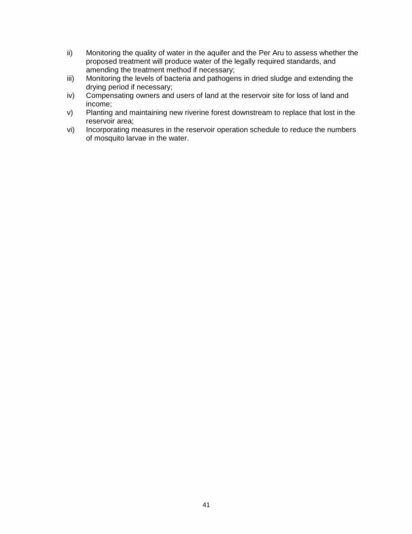
41
ii) Monitoring the quality of water in the aquifer and the Per Aru to assess whether the proposed treatment will produce water of the legally required standards, and amending the treatment method if necessary;
iii) Monitoring the levels of bacteria and pathogens in dried sludge and extending the drying period if necessary;
iv) Compensating owners and users of land at the reservoir site for loss of land and income;
v) Planting and maintaining new riverine forest downstream to replace that lost in the reservoir area;
vi) Incorporating measures in the reservoir operation schedule to reduce the numbers of mosquito larvae in the water.

42
VII. INSTITUTIONAL REQUIREMENTS AND ENVIRONMENTAL MONITORING PLAN
A. Summary of environmental impacts and mitigation measures
1. Table 6 lists the potential adverse impacts of the Vavuniya water supply, sewerage and drainage subprojects and the mitigation proposed to reduce these impacts to acceptable levels. The table also shows how the mitigation will be implemented, who will be responsible, and where and when the mitigation activities will take place. The mitigation programme is shown as the year in which each activity will occur, which relates to the project programme described in previuosly. The final column assesses whether the proposed action will successfully mitigate the impact (shown as 0), and indicates that some of the measures will provide an additional benefit (shown as +).
B. Institutional arrangements for project implementation
2. The main agencies involved in managing and implementing the project (covering both urban and rural components) are as follows: 3. The Ministry of Water Supply and Drainage (MWSD) is the Executing Agency (EA) responsible for management, coordination and execution of all activities funded under the loan; and NWSDB is the Implementing Agency (IA) responsible for supervising construction of the infrastructure and conducting the non-infrastructure elements. 4. NWSDB will establish a Project Coordinating Unit (PCU), at its Head Office in Colombo, responsible for the overall management of the program, and central coordination of the administrative and financial aspects. 5. NWSDB will also establish Project Implementation Units (PIU) in the NWSDB Regional Offices in Puttalam and Vavuniya, to manage implementation of the project in North-Western and Northern Provinces respectively. Each PIU will be headed by the NWSDB Chief Engineer and staffed by NWSDB personnel. 6. The PCU will appoint Design and Supervision Consultants (DSC) who will support the PIUs in designing the infrastructure, managing the tendering of Contractors and supervising the construction process. NGOs will be appointed to manage and implement the public consultation process and conduct public awareness campaigns. 7. Each PIU will appoint Construction Contractors (CC) to build elements of the infrastructure in a particular location. The CCs will be managed by the relevant PIU, and construction will be supervised by the DSC. 8. NWSDB will be assisted by an inter-ministerial Project Steering Committee (PSC), to provide policy guidance and coordination across all locations and subprojects. The PSC will be chaired by the secretary of MWSD, and members will include senior officials from the Ministry of Finance and Planning, NWSDB, Ministry of Local Government, Central Environment Authority; and representatives of provincial governments, local authorities, aid agencies and NGOs. 9. A Project Monitoring Committee (PMC) will be set up in each town and rural area to monitor project implementation at the local level, and will report directly to the PSC.
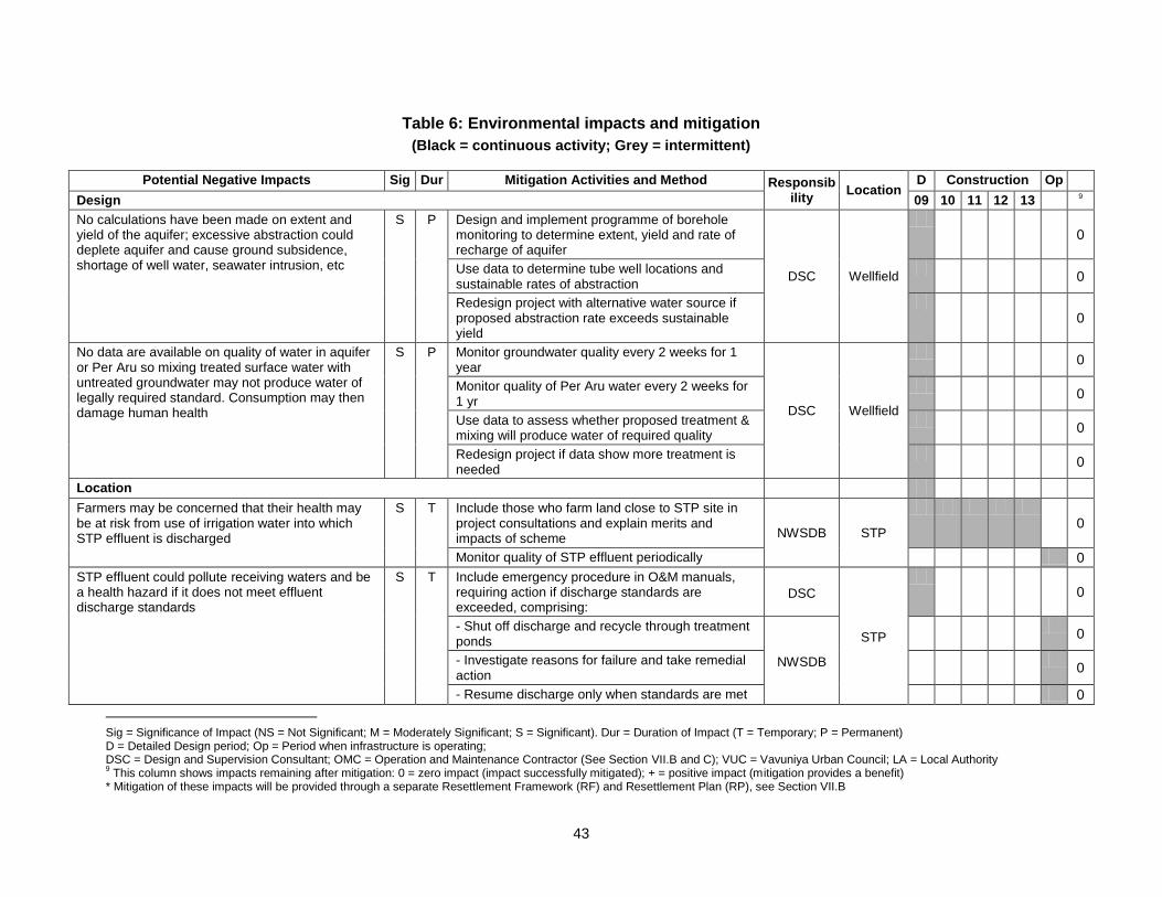
43
Table 6: Environmental impacts and mitigation
(Black = continuous activity; Grey = intermittent)
Potential Negative Impacts Sig Dur Mitigation Activities and Method Responsibility
Location D Construction Op
Design 09 10 11 12 13 9
No calculations have been made on extent and yield of the aquifer; excessive abstraction could deplete aquifer and cause ground subsidence, shortage of well water, seawater intrusion, etc
S P Design and implement programme of borehole monitoring to determine extent, yield and rate of recharge of aquifer
DSC Wellfield
0
Use data to determine tube well locations and sustainable rates of abstraction
0
Redesign project with alternative water source if proposed abstraction rate exceeds sustainable yield
0
No data are available on quality of water in aquifer or Per Aru so mixing treated surface water with untreated groundwater may not produce water of legally required standard. Consumption may then damage human health
S P Monitor groundwater quality every 2 weeks for 1 year
DSC Wellfield
0
Monitor quality of Per Aru water every 2 weeks for 1 yr
0
Use data to assess whether proposed treatment & mixing will produce water of required quality
0
Redesign project if data show more treatment is needed
0
Location
Farmers may be concerned that their health may be at risk from use of irrigation water into which STP effluent is discharged
S T Include those who farm land close to STP site in project consultations and explain merits and impacts of scheme NWSDB STP
0
Monitor quality of STP effluent periodically 0
STP effluent could pollute receiving waters and be a health hazard if it does not meet effluent discharge standards
S T Include emergency procedure in O&M manuals, requiring action if discharge standards are exceeded, comprising:
DSC
STP
0
- Shut off discharge and recycle through treatment ponds
NWSDB
0
- Investigate reasons for failure and take remedial action
0
- Resume discharge only when standards are met 0
Sig = Significance of Impact (NS = Not Significant; M = Moderately Significant; S = Significant). Dur = Duration of Impact (T = Temporary; P = Permanent) D = Detailed Design period; Op = Period when infrastructure is operating; DSC = Design and Supervision Consultant; OMC = Operation and Maintenance Contractor (See Section VII.B and C); VUC = Vavuniya Urban Council; LA = Local Authority 9 This column shows impacts remaining after mitigation: 0 = zero impact (impact successfully mitigated); + = positive impact (mitigation provides a benefit)
* Mitigation of these impacts will be provided through a separate Resettlement Framework (RF) and Resettlement Plan (RP), see Section VII.B

44
Amend design to include recycling pumps and pipe-work
DSC
0
Design and Location
Construction: Augmentation of Water distribution
Excavation could create dust in dry windy weather M T Remove waste soil as soon as it is excavated
Contractor All sites
0
Cover or damp down soil or sand stockpiled on site 0
Plan work to only bring sand to site when needed 0
Dust could be produced when sand/soil is transported
M T Use tarpaulins to cover sand/soil when carried on trucks
Contractor All sites
0
Rainwater could collect in excavated areas M T Conduct all excavation in the dry season Contractor All sites 0
Traffic, people and activities could be disrupted by trucks carrying waste soil or delivering materials to site
M T Plan routes with LA to limit entry of heavy vehicles into town, and avoid narrow streets, congested roads, etc Contractor All sites
0
Plan work to avoid peak traffic periods 0
Shrines or areas of local importance could be damaged
M P Consult community to identify any sensitive areas DSC
(see key) All sites
0
Adjust design to avoid any especially sensitive sites
0
Avoid working at times when sensitive sites may be used
Contractor All sites
0
Workers and the public are at risk from accidents on site
M T Prepare and implement a site Health and Safety Plan that includes measures to:
Contractor All sites
0
- Exclude the public from all construction sites; 0
- Ensure that workers use Personal Protective Equipment
0
- Provide Health & Safety Training for all personnel;
0
- Follow documented procedures for all site activities;
0
- Keep accident reports and records. 0
There will be social and economic benefits if local people are employed in Contractor’s workforce
M T Contractor should employ at least 50% of workforce from communities in vicinity of work sites if possible
Contractor All sites
+
Construction: Water Supply Network
Trench excavation will produce large amounts of waste
M P As above: Re-use waste in this project where feasible
Contractor All sites
+
As above: Find beneficial uses in other projects via LA
+
Excavation and infilling may cause dust in windy M T As above: remove waste soil as soon as it is Contractor All sites 0
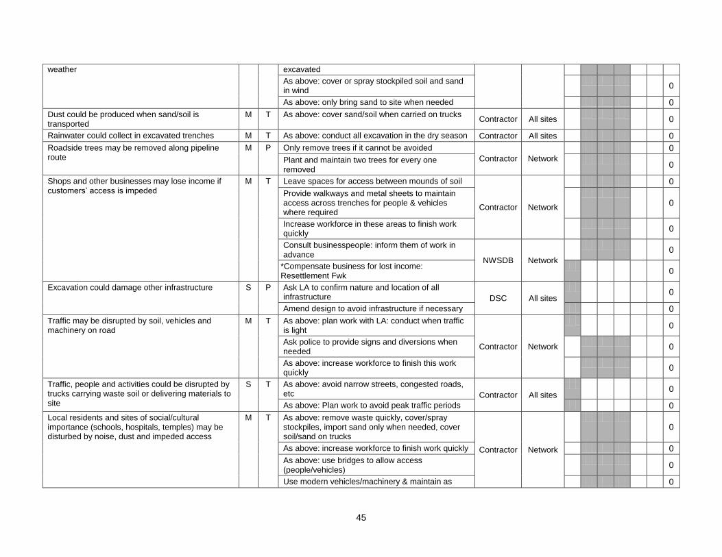
45
weather excavated
As above: cover or spray stockpiled soil and sand in wind
0
As above: only bring sand to site when needed 0
Dust could be produced when sand/soil is transported
M T As above: cover sand/soil when carried on trucks Contractor All sites
0
Rainwater could collect in excavated trenches M T As above: conduct all excavation in the dry season Contractor All sites 0
Roadside trees may be removed along pipeline route
M P Only remove trees if it cannot be avoided
Contractor Network
0
Plant and maintain two trees for every one removed
0
Shops and other businesses may lose income if customers’ access is impeded
M T Leave spaces for access between mounds of soil
Contractor Network
0
Provide walkways and metal sheets to maintain access across trenches for people & vehicles where required
0
Increase workforce in these areas to finish work quickly
0
Consult businesspeople: inform them of work in advance
NWSDB Network
0
*Compensate business for lost income: Resettlement Fwk
0
Excavation could damage other infrastructure S P Ask LA to confirm nature and location of all infrastructure DSC All sites
0
Amend design to avoid infrastructure if necessary 0
Traffic may be disrupted by soil, vehicles and machinery on road
M T As above: plan work with LA: conduct when traffic is light
Contractor Network
0
Ask police to provide signs and diversions when needed
0
As above: increase workforce to finish this work quickly
0
Traffic, people and activities could be disrupted by trucks carrying waste soil or delivering materials to site
S T As above: avoid narrow streets, congested roads, etc Contractor All sites
0
As above: Plan work to avoid peak traffic periods 0
Local residents and sites of social/cultural importance (schools, hospitals, temples) may be disturbed by noise, dust and impeded access
M T As above: remove waste quickly, cover/spray stockpiles, import sand only when needed, cover soil/sand on trucks
Contractor Network
0
As above: increase workforce to finish work quickly 0
As above: use bridges to allow access (people/vehicles)
0
Use modern vehicles/machinery & maintain as 0
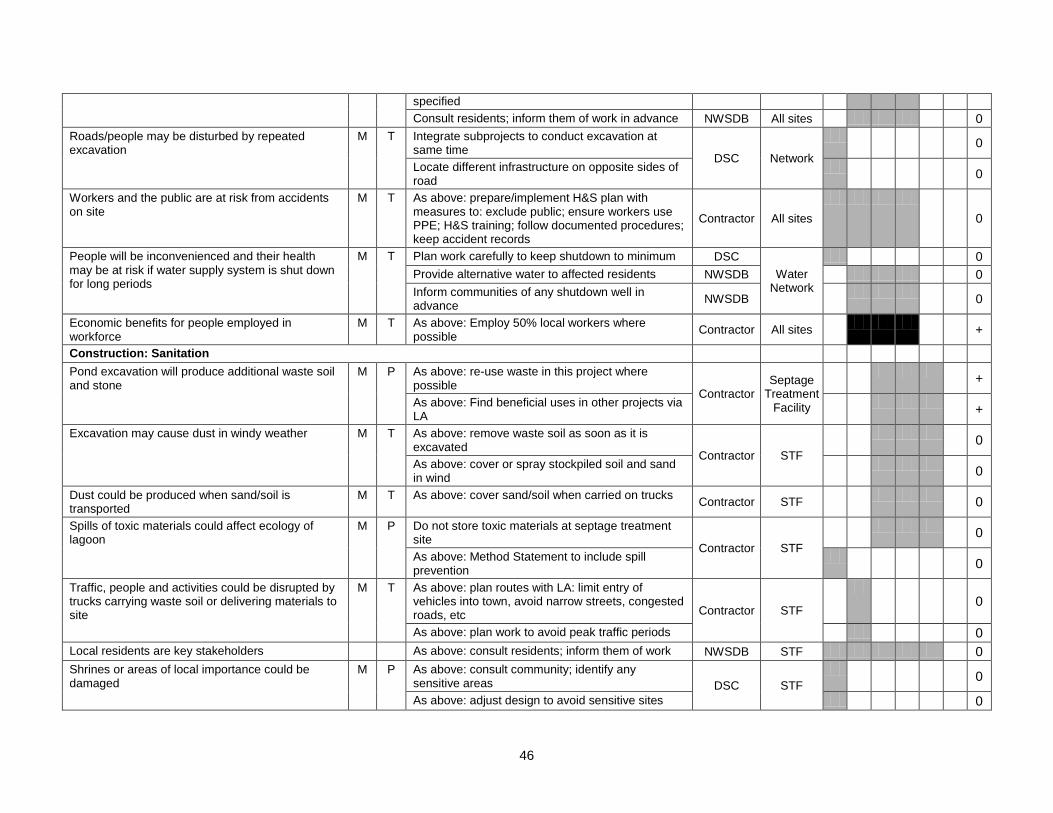
46
specified
Consult residents; inform them of work in advance NWSDB All sites 0
Roads/people may be disturbed by repeated excavation
M T Integrate subprojects to conduct excavation at same time
DSC Network
0
Locate different infrastructure on opposite sides of road
0
Workers and the public are at risk from accidents on site
M T As above: prepare/implement H&S plan with measures to: exclude public; ensure workers use PPE; H&S training; follow documented procedures; keep accident records
Contractor All sites
0
People will be inconvenienced and their health may be at risk if water supply system is shut down for long periods
M T Plan work carefully to keep shutdown to minimum DSC
Water Network
0
Provide alternative water to affected residents NWSDB 0
Inform communities of any shutdown well in advance
NWSDB
0
Economic benefits for people employed in workforce
M T As above: Employ 50% local workers where possible
Contractor All sites
+
Construction: Sanitation
Pond excavation will produce additional waste soil and stone
M P As above: re-use waste in this project where possible
Contractor Septage
Treatment Facility
+
As above: Find beneficial uses in other projects via LA
+
Excavation may cause dust in windy weather M T As above: remove waste soil as soon as it is excavated
Contractor STF
0
As above: cover or spray stockpiled soil and sand in wind
0
Dust could be produced when sand/soil is transported
M T As above: cover sand/soil when carried on trucks Contractor STF
0
Spills of toxic materials could affect ecology of lagoon
M P Do not store toxic materials at septage treatment site
Contractor STF
0
As above: Method Statement to include spill prevention
0
Traffic, people and activities could be disrupted by trucks carrying waste soil or delivering materials to site
M T As above: plan routes with LA: limit entry of vehicles into town, avoid narrow streets, congested roads, etc Contractor STF
0
As above: plan work to avoid peak traffic periods 0
Local residents are key stakeholders As above: consult residents; inform them of work NWSDB STF 0
Shrines or areas of local importance could be damaged
M P As above: consult community; identify any sensitive areas DSC STF
0
As above: adjust design to avoid sensitive sites 0
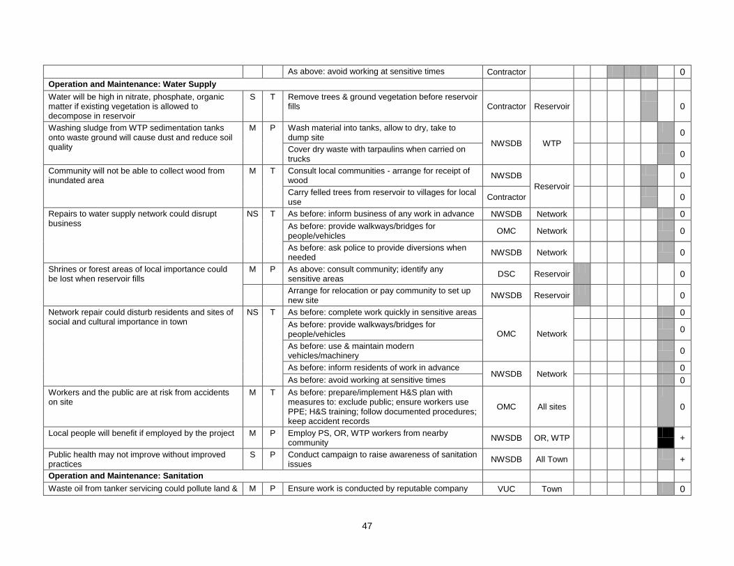
47
As above: avoid working at sensitive times Contractor 0
Operation and Maintenance: Water Supply
Water will be high in nitrate, phosphate, organic matter if existing vegetation is allowed to decompose in reservoir
S T Remove trees & ground vegetation before reservoir fills Contractor Reservoir
0
Washing sludge from WTP sedimentation tanks onto waste ground will cause dust and reduce soil quality
M P Wash material into tanks, allow to dry, take to dump site
NWSDB WTP
0
Cover dry waste with tarpaulins when carried on trucks
0
Community will not be able to collect wood from inundated area
M T Consult local communities - arrange for receipt of wood
NWSDB
Reservoir
0
Carry felled trees from reservoir to villages for local use
Contractor
0
Repairs to water supply network could disrupt business
NS T As before: inform business of any work in advance NWSDB Network 0
As before: provide walkways/bridges for people/vehicles
OMC Network
0
As before: ask police to provide diversions when needed
NWSDB Network
0
Shrines or forest areas of local importance could be lost when reservoir fills
M P As above: consult community; identify any sensitive areas
DSC Reservoir
0
Arrange for relocation or pay community to set up new site
NWSDB Reservoir
0
Network repair could disturb residents and sites of social and cultural importance in town
NS T As before: complete work quickly in sensitive areas
OMC Network
0
As before: provide walkways/bridges for people/vehicles
0
As before: use & maintain modern vehicles/machinery
0
As before: inform residents of work in advance NWSDB Network
0
As before: avoid working at sensitive times 0
Workers and the public are at risk from accidents on site
M T As before: prepare/implement H&S plan with measures to: exclude public; ensure workers use PPE; H&S training; follow documented procedures; keep accident records
OMC All sites
0
Local people will benefit if employed by the project M P Employ PS, OR, WTP workers from nearby community
NWSDB OR, WTP
+
Public health may not improve without improved practices
S P Conduct campaign to raise awareness of sanitation issues
NWSDB All Town
+
Operation and Maintenance: Sanitation
Waste oil from tanker servicing could pollute land & M P Ensure work is conducted by reputable company VUC Town 0
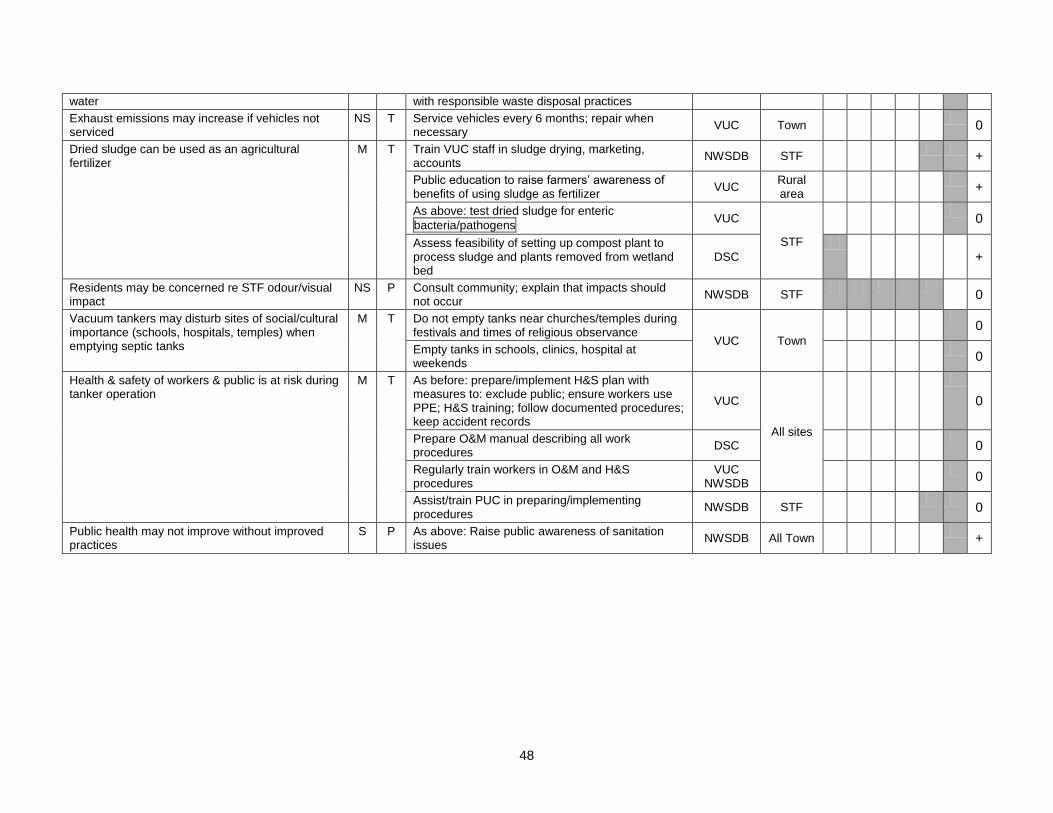
48
water with responsible waste disposal practices
Exhaust emissions may increase if vehicles not serviced
NS T Service vehicles every 6 months; repair when necessary
VUC Town
0
Dried sludge can be used as an agricultural fertilizer
M T Train VUC staff in sludge drying, marketing, accounts
NWSDB STF
+
Public education to raise farmers’ awareness of benefits of using sludge as fertilizer
VUC Rural area
+
As above: test dried sludge for enteric
bacteria/pathogens VUC
STF
0
Assess feasibility of setting up compost plant to process sludge and plants removed from wetland bed
DSC
+
Residents may be concerned re STF odour/visual impact
NS P Consult community; explain that impacts should not occur
NWSDB STF
0
Vacuum tankers may disturb sites of social/cultural importance (schools, hospitals, temples) when emptying septic tanks
M T Do not empty tanks near churches/temples during festivals and times of religious observance
VUC Town
0
Empty tanks in schools, clinics, hospital at weekends
0
Health & safety of workers & public is at risk during tanker operation
M T As before: prepare/implement H&S plan with measures to: exclude public; ensure workers use PPE; H&S training; follow documented procedures; keep accident records
VUC
All sites
0
Prepare O&M manual describing all work procedures
DSC
0
Regularly train workers in O&M and H&S procedures
VUC NWSDB
0
Assist/train PUC in preparing/implementing procedures
NWSDB STF
0
Public health may not improve without improved practices
S P As above: Raise public awareness of sanitation issues
NWSDB All Town
+
49
10. Resettlement issues will be coordinated by a Resettlement Specialist in the PCU, who will ensure consistency across all subprojects. A local Resettlement Specialist will be appointed to each PIU, who will prepare and implement local Resettlement Plans following the Resettlement Framework developed during project preparation. 11. Environmental issues will be coordinated by an Environmental Specialist in the PCU who will ensure that all subprojects comply with ADB and national environmental safeguards. New rural subprojects will be developed during project implementation and their impacts will be assessed by a local Environmental Specialist in each PIU, who will conduct IEE or EIA studies as necessary, following the Environmental Assessment and Review Framework developed during project preparation. Applications for Environmental Clearance will be submitted to CEA, comprising a completed Project Information Document (PID) and a full or simplified IEE as appropriate. In the unlikely event that CEA require further study, this will be conducted by Domestic Environmental Consultants appointed by NWSDB. 12. Each IEE includes an Environmental Monitoring Plan (EnvMP), involving observations and surveys to be conducted during construction and operation to ensure that mitigation measures are provided and that they protect the environment as intended. Construction-phase monitoring is supervised by an Environmental Monitoring Specialist (EMS) who is part of the DSC team. Monitoring during operation will be conducted by consultants appointed by NWSDB. 13. Once the various elements of the infrastructure have been built and commissioned, responsibility for the operation and maintenance of each scheme will be as follows:
Urban water supply: NWSDB; Urban sanitation (Mannar, Puttalam, Vavuniya and Chilaw): Urban Council Public
Health Dept;
C. Environmental Monitoring Plan
14. Table 6 shows that most mitigation activities are the responsibility of the Construction Contractors (CC) employed to build the infrastructure during the construction stage, or the O&M Contractors (OMC) who will be employed to conduct maintenance or repair work when the systems are operating. Responsibility for the relevant measures will be assigned to the Contractors via the contracts through which they are appointed (prepared by the DSC during the detailed design stage), so they will be legally required to take the necessary action. There are also some actions that need to be taken by NWSDB in their role as project proponent, actions related to the design that will be implemented by the DSC, and actions during the operational phase that are the responsibility of NWSDB (water supply) or VUC (sanitation) as the system operators. 15. The DSC Environmental Monitoring Specialist (EMS) is responsible for all construction-phase monitoring and reporting the results and conclusions to the PIU, and will recommend remedial action if measures are not being provided or are not protecting the environment effectively. The EMS may be assisted by other environmental specialists and junior or medium-level engineers who can make many of the routine observations on site. Post-construction monitoring will be conducted by NWSDB, and/or domestic consultants/contractors they appoint. 16. Table 6 shows that most of the mitigation measures are fairly standard methods of minimising disturbance from building in urban areas (maintaining access, planning work to avoid sensitive times, finding uses for waste material, etc), and experienced Contractors should be familiar with most of the requirements. Monitoring of such measures normally involves making observations in the course of site visits, although some require more formal checking of records and other aspects. There will also be some surveys of residents, as most of the measures are aimed at preventing impacts on people and the human environment.
50
17. Table 7 shows the proposed Environmental Monitoring Plan (EnvMP) for the subprojects, which specifies the various monitoring activities to be conducted during all phases. Some of the measures shown in Table 6 have been consolidated to avoid repetition, and there has been some re-ordering to present together those measures that relate to the same activity or site. The EnvMP describes: (i) mitigation measures, (ii) location, (iii) measurement method, (iv) frequency of monitoring and (v) responsibility (for both mitigation and monitoring). It does not show specific parameters to be measured because as indicated above, most measures will be checked by simple observation, by checking of records, or by interviews with residents or workers. 18. The mitigation plan includes several short-term surveys that need to be conducted during the detailed design stage to address various elements of the project that have been planned on the basis of inadequate data, where there is a risk that implementation of the schemes could cause environmental damage. These are:
A hydrogeological survey of the extent, replenishment and yield of the aquifer; A study to plan sustainable groundwater abstraction or to use an alternative source; An assessment of the quality of water likely to be produced by proposed treatment
and redesign of the treatment method if water is unlikely to meet national standards; 19. Qualified domestic consultants and contractors will be appointed by NWSDB to conduct all surveys. The hydrological and water quality surveys of the aquifer and the Per Aru will require a year of data collection each, which should begin as soon as possible; the associated studies of the methods of water abstraction and treatment will then be conducted towards the end of that period. 20. The mitigation plan also recommends longer-term monitoring: to confirm that the drying process removes all enteric bacteria and pathogens from the septic tank sludge; to measure the quality and quantity of treatment plant effluent; and to determine its impact on receiving waters. Given the scale of the investment in providing infrastructure, NWSDB will also wish to conduct surveys during the operational period to ensure the correct
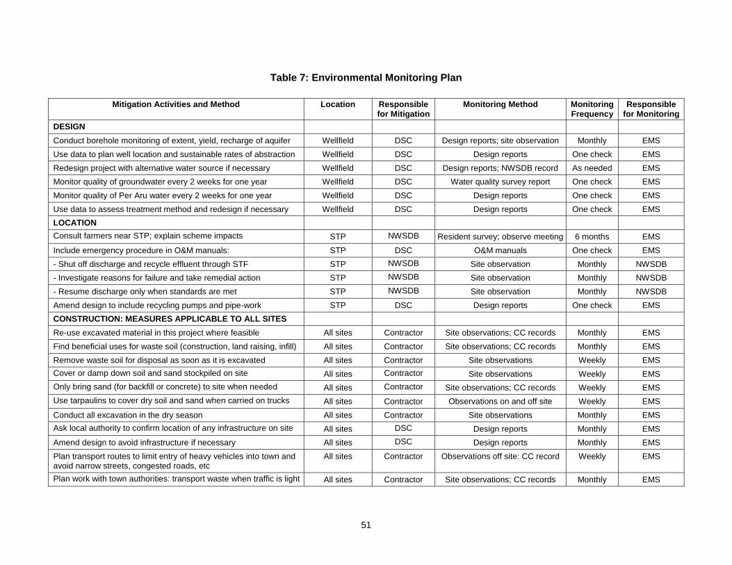
51
Table 7: Environmental Monitoring Plan
Mitigation Activities and Method Location Responsible for Mitigation
Monitoring Method Monitoring Frequency
Responsible for Monitoring
DESIGN
Conduct borehole monitoring of extent, yield, recharge of aquifer Wellfield DSC Design reports; site observation Monthly EMS
Use data to plan well location and sustainable rates of abstraction Wellfield DSC Design reports One check EMS
Redesign project with alternative water source if necessary Wellfield DSC Design reports; NWSDB record As needed EMS
Monitor quality of groundwater every 2 weeks for one year Wellfield DSC Water quality survey report One check EMS
Monitor quality of Per Aru water every 2 weeks for one year Wellfield DSC Design reports One check EMS
Use data to assess treatment method and redesign if necessary Wellfield DSC Design reports One check EMS
LOCATION
Consult farmers near STP; explain scheme impacts STP NWSDB Resident survey; observe meeting 6 months EMS
Include emergency procedure in O&M manuals: STP DSC O&M manuals One check EMS
- Shut off discharge and recycle effluent through STF STP NWSDB Site observation Monthly NWSDB
- Investigate reasons for failure and take remedial action STP NWSDB Site observation Monthly NWSDB
- Resume discharge only when standards are met STP NWSDB Site observation Monthly NWSDB
Amend design to include recycling pumps and pipe-work STP DSC Design reports One check EMS
CONSTRUCTION: MEASURES APPLICABLE TO ALL SITES
Re-use excavated material in this project where feasible All sites Contractor Site observations; CC records Monthly EMS
Find beneficial uses for waste soil (construction, land raising, infill) All sites Contractor Site observations; CC records Monthly EMS
Remove waste soil for disposal as soon as it is excavated All sites Contractor Site observations Weekly EMS
Cover or damp down soil and sand stockpiled on site All sites Contractor Site observations Weekly EMS
Only bring sand (for backfill or concrete) to site when needed All sites Contractor Site observations; CC records Weekly EMS
Use tarpaulins to cover dry soil and sand when carried on trucks All sites Contractor Observations on and off site Weekly EMS
Conduct all excavation in the dry season All sites Contractor Site observations Monthly EMS
Ask local authority to confirm location of any infrastructure on site All sites DSC Design reports Monthly EMS
Amend design to avoid infrastructure if necessary All sites DSC Design reports Monthly EMS
Plan transport routes to limit entry of heavy vehicles into town and avoid narrow streets, congested roads, etc
All sites Contractor Observations off site: CC record Weekly EMS
Plan work with town authorities: transport waste when traffic is light All sites Contractor Site observations; CC records Monthly EMS
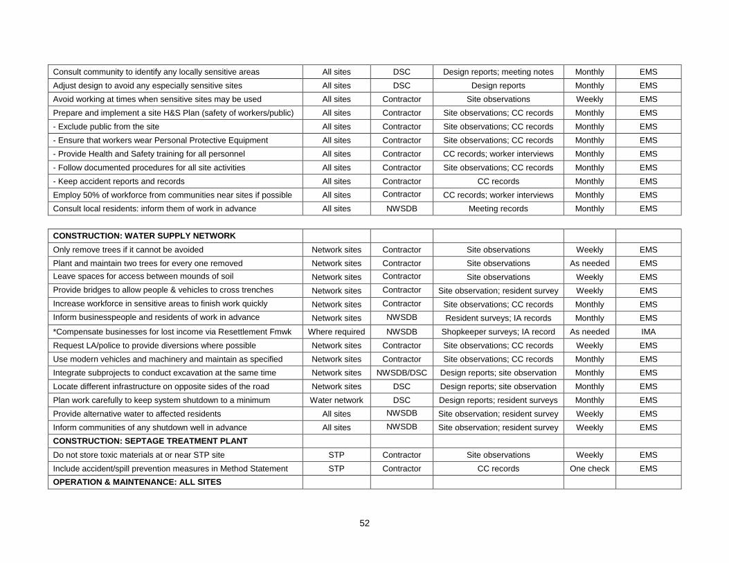
52
Consult community to identify any locally sensitive areas All sites DSC Design reports; meeting notes Monthly EMS
Adjust design to avoid any especially sensitive sites All sites DSC Design reports Monthly EMS
Avoid working at times when sensitive sites may be used All sites Contractor Site observations Weekly EMS
Prepare and implement a site H&S Plan (safety of workers/public) All sites Contractor Site observations; CC records Monthly EMS
- Exclude public from the site All sites Contractor Site observations; CC records Monthly EMS
- Ensure that workers wear Personal Protective Equipment All sites Contractor Site observations; CC records Monthly EMS
- Provide Health and Safety training for all personnel All sites Contractor CC records; worker interviews Monthly EMS
- Follow documented procedures for all site activities All sites Contractor Site observations; CC records Monthly EMS
- Keep accident reports and records All sites Contractor CC records Monthly EMS
Employ 50% of workforce from communities near sites if possible All sites Contractor CC records; worker interviews Monthly EMS
Consult local residents: inform them of work in advance All sites NWSDB Meeting records Monthly EMS
CONSTRUCTION: WATER SUPPLY NETWORK
Only remove trees if it cannot be avoided Network sites Contractor Site observations Weekly EMS
Plant and maintain two trees for every one removed Network sites Contractor Site observations As needed EMS
Leave spaces for access between mounds of soil Network sites Contractor Site observations Weekly EMS
Provide bridges to allow people & vehicles to cross trenches Network sites Contractor Site observation; resident survey Weekly EMS
Increase workforce in sensitive areas to finish work quickly Network sites Contractor Site observations; CC records Monthly EMS
Inform businesspeople and residents of work in advance Network sites NWSDB Resident surveys; IA records Monthly EMS
*Compensate businesses for lost income via Resettlement Fmwk Where required NWSDB Shopkeeper surveys; IA record As needed IMA
Request LA/police to provide diversions where possible Network sites Contractor Site observations; CC records Weekly EMS
Use modern vehicles and machinery and maintain as specified Network sites Contractor Site observations; CC records Monthly EMS
Integrate subprojects to conduct excavation at the same time Network sites NWSDB/DSC Design reports; site observation Monthly EMS
Locate different infrastructure on opposite sides of the road Network sites DSC Design reports; site observation Monthly EMS
Plan work carefully to keep system shutdown to a minimum Water network DSC Design reports; resident surveys Monthly EMS
Provide alternative water to affected residents All sites NWSDB Site observation; resident survey Weekly EMS
Inform communities of any shutdown well in advance All sites NWSDB Site observation; resident survey Weekly EMS
CONSTRUCTION: SEPTAGE TREATMENT PLANT
Do not store toxic materials at or near STP site STP Contractor Site observations Weekly EMS
Include accident/spill prevention measures in Method Statement STP Contractor CC records One check EMS
OPERATION & MAINTENANCE: ALL SITES
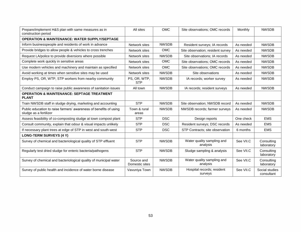
53
Prepare/implement H&S plan with same measures as in construction period
All sites OMC Site observations; OMC records Monthly NWSDB
OPERATION & MAINTENANCE: WATER SUPPLY/SEPTAGE
Inform businesspeople and residents of work in advance Network sites NWSDB Resident surveys; IA records As needed NWSDB
Provide bridges to allow people & vehicles to cross trenches Network sites OMC Site observation; resident survey As needed NWSDB
Request LA/police to provide diversions where possible Network sites NWSDB Site observations; IA records As needed NWSDB
Complete work quickly in sensitive areas Network sites OMC Site observations; OMC records As needed NWSDB
Use modern vehicles and machinery and maintain as specified Network sites OMC Site observations; OMC records As needed NWSDB
Avoid working at times when sensitive sites may be used Network sites NWSDB Site observations As needed NWSDB
Employ PS, OR, WTP, STP workers from nearby community PS, OR, WTP, STP
NWSDB IA records; worker survey As needed NWSDB
Conduct campaign to raise public awareness of sanitation issues All town NWSDB IA records; resident surveys As needed NWSDB
OPERATION & MAINTENANCE: SEPTAGE TREATMENT PLANT
Train NWSDB staff in sludge drying, marketing and accounting STP NWSDB Site observation; NWSDB record As needed NWSDB
Public education to raise farmers’ awareness of benefits of using sludge as a fertilizer
Town & rural areas
NWSDB NWSDB records; farmer surveys As needed NWSDB
Assess feasibility of co-composting sludge at town compost plant STP DSC Design reports One check EMS
Consult community, explain that odour & visual impacts unlikely STP DSC Resident surveys; DSC records As needed EMS
If necessary plant trees at edge of STP in west and south-west STP DSC STP Contracts; site observation 6 months EMS
LONG-TERM SURVEYS (4 Y)
Survey of chemical and bacteriological quality of STP effluent STP NWSDB Water quality sampling and analysis
See VII.C Consulting laboratory
Regularly test dried sludge for enteric bacteria/pathogens STP NWSDB Sludge sampling & analysis See VII.C Consulting laboratory
Survey of chemical and bacteriological quality of municipal water Source and Domestic sites
NWSDB Water quality sampling and analysis
See VII.C Consulting laboratory
Survey of public health and incidence of water borne disease Vavuniya Town NWSDB Hospital records; resident surveys
See VII.C Social studies consultant
54
21. Functioning of the STP, and to confirm the lasting benefits of the schemes. The following aspects will thus be monitored over the long term:
Chemical and bacteriological quality of treated STP effluent; Bacteriological content of dried sewage sludge; Chemical and bacteriological quality of water provided by the municipal system; Health of the population and the prevalence of diseases of poor sanitation.
22. These surveys should be conducted for at least four years. The quality of the sewage sludge and STP effluent will be checked each week for the first three months, then every 6 months for the next 3 ¾ years (20 surveys in total). The other surveys will all require monitoring at six-monthly intervals during the final year of construction (to establish baseline conditions) and during the first three years of operation of each scheme (8 surveys each).
D. Environmental management and monitoring costs
23. Most of the mitigation measures require the contractors to adopt good site practice, which should be part of their normal procedures already, so there are unlikely to be major costs associated with compliance. Regardless of this, any costs of mitigation by the contractors (those employed to construct the infrastructure or the local companies employed to conduct O&M when the system is operating) are included in the budgets for the civil works and do not need to be estimated separately here. Mitigation that is the responsibility of NWSDB will be provided as part of their management of the project, so this also does not need to be duplicated here. Costs of acquiring land and compensating landowners and tenants for the loss of farm income at the reservoir site, and compensating shopkeepers for loss of income during construction in the town (Table 6) are calculated separately in the budgets for the Resettlement Framework and Resettlement Plans so are also excluded from this analysis. 24. The remaining actions in the Environmental Management Plan are:
The environmental monitoring during construction, conducted by the EMS; The long-term post-construction surveys that will be commissioned by NWSDB.
25. These have not been budgeted elsewhere, and their costs are shown in Table 8, with details of the calculations shown in footnotes beneath the table. The figures show that the total cost of environmental management and monitoring for the Vavuniya subprojects (covering design, four years of construction and the first three years of operation) is SLR 9.8 million, ie US$ 91,000, plus the cost of the hydrogeological survey and ground water and surface water quality studies.
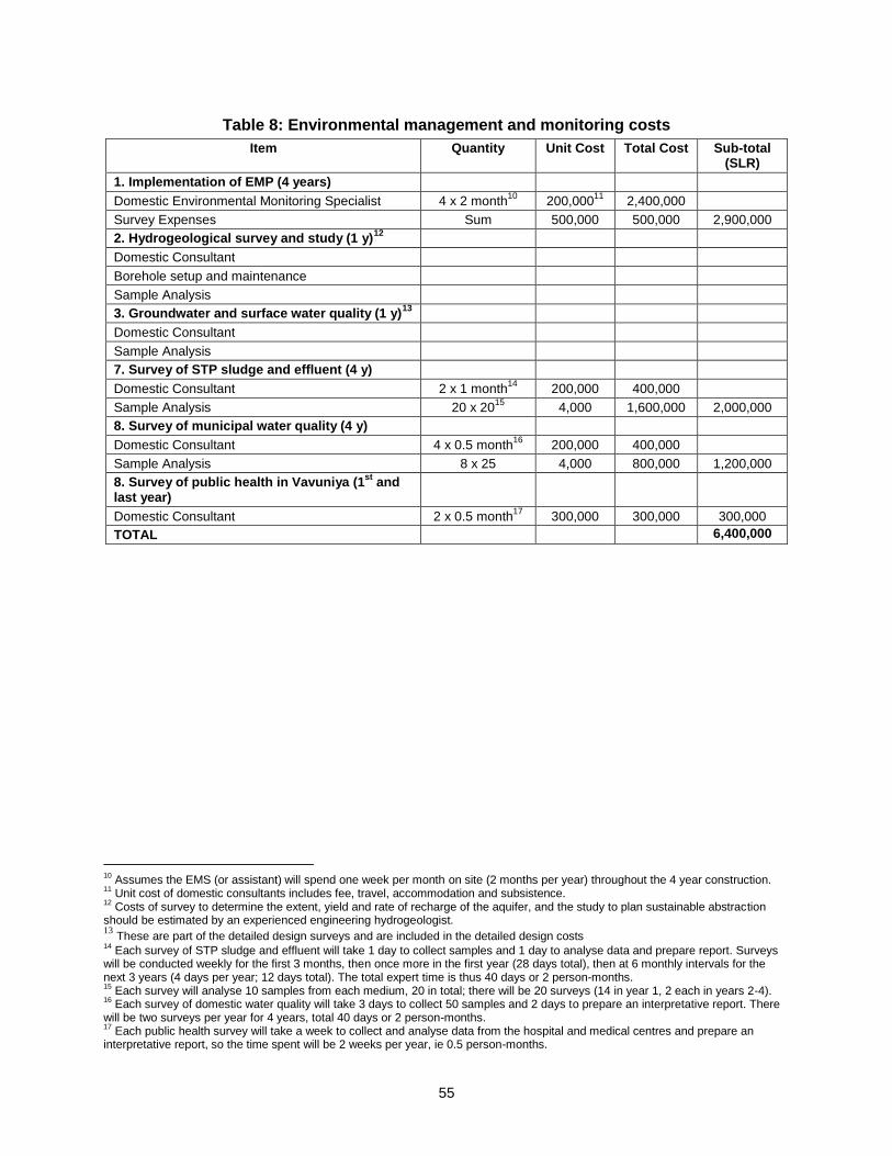
55
Table 8: Environmental management and monitoring costs
Item Quantity Unit Cost Total Cost Sub-total (SLR)
1. Implementation of EMP (4 years)
Domestic Environmental Monitoring Specialist 4 x 2 month10
200,00011
2,400,000
Survey Expenses Sum 500,000 500,000 2,900,000
2. Hydrogeological survey and study (1 y)12
Domestic Consultant
Borehole setup and maintenance
Sample Analysis
3. Groundwater and surface water quality (1 y)13
Domestic Consultant
Sample Analysis
7. Survey of STP sludge and effluent (4 y)
Domestic Consultant 2 x 1 month14
200,000 400,000
Sample Analysis 20 x 2015
4,000 1,600,000 2,000,000
8. Survey of municipal water quality (4 y)
Domestic Consultant 4 x 0.5 month16
200,000 400,000
Sample Analysis 8 x 25 4,000 800,000 1,200,000
8. Survey of public health in Vavuniya (1st
and last year)
Domestic Consultant 2 x 0.5 month17
300,000 300,000 300,000
TOTAL 6,400,000
10
Assumes the EMS (or assistant) will spend one week per month on site (2 months per year) throughout the 4 year construction. 11
Unit cost of domestic consultants includes fee, travel, accommodation and subsistence. 12
Costs of survey to determine the extent, yield and rate of recharge of the aquifer, and the study to plan sustainable abstraction should be estimated by an experienced engineering hydrogeologist. 13
These are part of the detailed design surveys and are included in the detailed design costs 14
Each survey of STP sludge and effluent will take 1 day to collect samples and 1 day to analyse data and prepare report. Surveys will be conducted weekly for the first 3 months, then once more in the first year (28 days total), then at 6 monthly intervals for the next 3 years (4 days per year; 12 days total). The total expert time is thus 40 days or 2 person-months. 15
Each survey will analyse 10 samples from each medium, 20 in total; there will be 20 surveys (14 in year 1, 2 each in years 2-4). 16
Each survey of domestic water quality will take 3 days to collect 50 samples and 2 days to prepare an interpretative report. There will be two surveys per year for 4 years, total 40 days or 2 person-months. 17
Each public health survey will take a week to collect and analyse data from the hospital and medical centres and prepare an interpretative report, so the time spent will be 2 weeks per year, ie 0.5 person-months.
56
VIII. PUBLIC CONSULTATION AND INFORMATION DISCLOSURE
A. Project stakeholders
1. Most of the main stakeholders have already been identified and consulted during preparation of the IEEs, and any others that are identified during project implementation will be brought into the process in the future. Primary stakeholders are:
Residents, shopkeepers and businesspeople who live and work alongside the roads in which network improvements will be provided;
Local communities living in the vicinity of the various facilities (OR, PS, WTP, STP and the water supply reservoir);
Owners and users of land that is acquired for the project (at the reservoir site); 2. Secondary stakeholders are:
MWSD as the Executing Agency and NWSDB as the Implementing Agency; Vavuniya Urban Council as the operator of septage treatment facility; Other government institutions whose remit includes areas or issues affected by the
project (state and local planning authorities; Ministry of Local Government; Department of Public Health Engineering; Central Environment Authority; National, Provincial and Local Roads Authorities; etc);
NGOs and CBOs working in the affected communities; Other community representatives (prominent citizens, religious leaders, elders,
women’s groups); The beneficiary community in general; and The ADB.
B. Consultation and disclosure to date
3. Two forms of public consultation were used during preparation of the IEEs, to discuss the project and involve the community in planning the mitigation measures and developing the Environmental Monitoring Plan. These are:
Public meetings were held in the target towns and villages between December 2007 and January 2008, to which representatives of primary and secondary stakeholders were invited. Attendees were informed about the aim of the relevant subprojects and the benefits they would bring, together with their likely impacts and the ways in which they would be mitigated. Participants were invited to discuss their views and concerns, which were then incorporated into the IEE. Appendix 5 contains a summary of the meeting in Vavuniya and Table 9 summarises the main points made during the discussion;
Ad hoc discussions were also held on site with people and communities who could be affected by the subprojects, so that views could be expressed in a less formal setting. These were also considered in preparing the IEE.
4. NWSDB will disclose the IEEs to the public by providing copies in the local language in the NWSDB office in each town. Disclosure to a wider audience will be achieved by placing the Summary IEE (SIEE) on the ADB website.
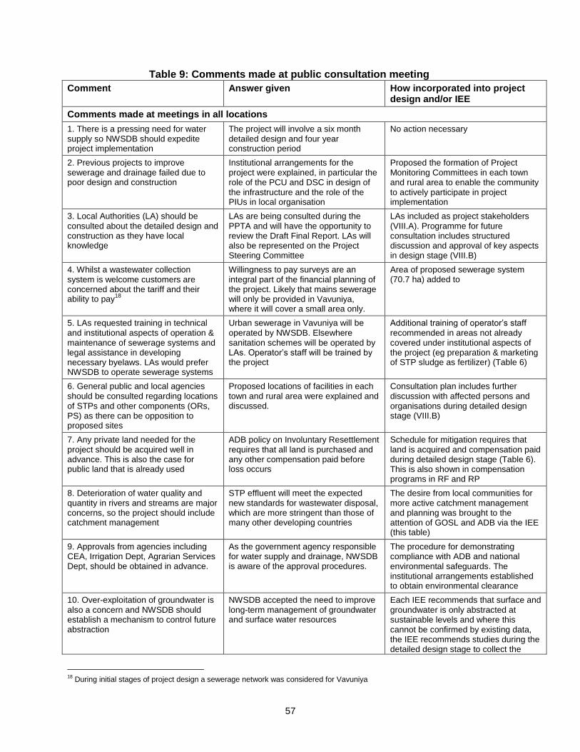
57
Table 9: Comments made at public consultation meeting
Comment Answer given How incorporated into project design and/or IEE
Comments made at meetings in all locations
1. There is a pressing need for water supply so NWSDB should expedite project implementation
The project will involve a six month detailed design and four year construction period
No action necessary
2. Previous projects to improve sewerage and drainage failed due to poor design and construction
Institutional arrangements for the project were explained, in particular the role of the PCU and DSC in design of the infrastructure and the role of the PIUs in local organisation
Proposed the formation of Project Monitoring Committees in each town and rural area to enable the community to actively participate in project implementation
3. Local Authorities (LA) should be consulted about the detailed design and construction as they have local knowledge
LAs are being consulted during the PPTA and will have the opportunity to review the Draft Final Report. LAs will also be represented on the Project Steering Committee
LAs included as project stakeholders (VIII.A). Programme for future consultation includes structured discussion and approval of key aspects in design stage (VIII.B)
4. Whilst a wastewater collection system is welcome customers are concerned about the tariff and their ability to pay
18
Willingness to pay surveys are an integral part of the financial planning of the project. Likely that mains sewerage will only be provided in Vavuniya, where it will cover a small area only.
Area of proposed sewerage system (70.7 ha) added to
5. LAs requested training in technical and institutional aspects of operation & maintenance of sewerage systems and legal assistance in developing necessary byelaws. LAs would prefer NWSDB to operate sewerage systems
Urban sewerage in Vavuniya will be operated by NWSDB. Elsewhere sanitation schemes will be operated by LAs. Operator’s staff will be trained by the project
Additional training of operator’s staff recommended in areas not already covered under institutional aspects of the project (eg preparation & marketing of STP sludge as fertilizer) (Table 6)
6. General public and local agencies should be consulted regarding locations of STPs and other components (ORs, PS) as there can be opposition to proposed sites
Proposed locations of facilities in each town and rural area were explained and discussed.
Consultation plan includes further discussion with affected persons and organisations during detailed design stage (VIII.B)
7. Any private land needed for the project should be acquired well in advance. This is also the case for public land that is already used
ADB policy on Involuntary Resettlement requires that all land is purchased and any other compensation paid before loss occurs
Schedule for mitigation requires that land is acquired and compensation paid during detailed design stage (Table 6). This is also shown in compensation programs in RF and RP
8. Deterioration of water quality and quantity in rivers and streams are major concerns, so the project should include catchment management
STP effluent will meet the expected new standards for wastewater disposal, which are more stringent than those of many other developing countries
The desire from local communities for more active catchment management and planning was brought to the attention of GOSL and ADB via the IEE (this table)
9. Approvals from agencies including CEA, Irrigation Dept, Agrarian Services Dept, should be obtained in advance.
As the government agency responsible for water supply and drainage, NWSDB is aware of the approval procedures.
The procedure for demonstrating compliance with ADB and national environmental safeguards. The institutional arrangements established to obtain environmental clearance
10. Over-exploitation of groundwater is also a concern and NWSDB should establish a mechanism to control future abstraction
NWSDB accepted the need to improve long-term management of groundwater and surface water resources
Each IEE recommends that surface and groundwater is only abstracted at sustainable levels and where this cannot be confirmed by existing data, the IEE recommends studies during the detailed design stage to collect the
18
During initial stages of project design a sewerage network was considered for Vavuniya
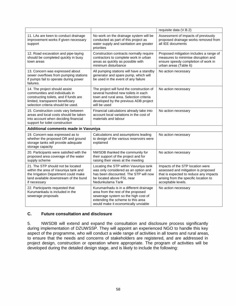
58
requisite data (V.B.2)
11. LAs are keen to conduct drainage improvement works if given necessary support
No work on the drainage system will be conducted as part of this project as water supply and sanitation are greater priorities
Assessment of impacts of previously proposed drainage works removed from all IEE documents
12. Road excavation and pipe-laying should be completed quickly in busy town areas
Construction contracts normally require contractors to complete work in urban areas as quickly as possible with minimum disturbance
Proposed mitigation includes a range of measures to minimise disruption and ensure speedy completion of work in urban areas (Table 6)
13. Concern was expressed about sewer overflows from pumping stations if pumps fail to operate during power failures.
All pumping stations will have a standby generator and spare pump, which will be used in the event of any failure
No action necessary
14. The project should assist communities and individuals in constructing toilets, and if funds are limited, transparent beneficiary selection criteria should be used.
The project will fund the construction of several hundred new toilets in each town and rural area. Selection criteria developed by the previous ADB project will be used
No action necessary
15. Construction costs vary between areas and local costs should be taken into account when deciding financial support for toilet construction
Financial calculations already take into account local variations in the cost of materials and labour
No action necessary
Additional comments made in Vavuniya
19. Concern was expressed as to whether the proposed OR and ground storage tanks will provide adequate storage capacity
Calculations and assumptions leading to design of the various reservoirs were explained
No action necessary
20. Participants were satisfied with the proposed area coverage of the water supply scheme
NWSDB thanked the community for their support of the project and for raising their views at the meeting
No action necessary
21. The STP should not be located within the area of Vavuniya tank and the Irrigation Department could make land available downstream of the bund if necessary
Locating the STP within Vavuniya tank was only considered as an option and has been discounted. The STP will now be located above FSL near Nedunkulama Tank
Impacts of the STP location were assessed and mitigation is proposed that is expected to reduce any impacts arising from the specific location to acceptable levels.
22. Participants requested that Kurumankadu is included in the sewerage proposals
Kurumanhadu is in a different drainage area from the rest of the proposed sewerage system so the high cost of extending the scheme to this area would make it economically unviable
No action necessary
C. Future consultation and disclosure
5. NWSDB will extend and expand the consultation and disclosure process significantly during implementation of DZUWSSP. They will appoint an experienced NGO to handle this key aspect of the programme, who will conduct a wide range of activities in all towns and rural areas, to ensure that the needs and concerns of stakeholders are registered, and are addressed in project design, construction or operation where appropriate. The program of activities will be developed during the detailed design stage, and is likely to include the following:
59
Consultation during detailed design:
Focus-group discussions with affected persons and other stakeholders (including women’s groups, NGOs and CBOs) to hear their views and concerns, so that these can be addressed in subproject design where necessary;
Structured consultation meetings with the institutional stakeholders (government bodies and NGOs) to discuss and approve key aspects of the project.
Consultation during construction:
Public meetings with affected communities to discuss and plan work programmes and allow issues to be raised and addressed once construction has started;
Smaller-scale meetings to discuss and plan construction work with individual communities to reduce disturbance and other impacts, and provide a mechanism through which stakeholders can participate in subproject monitoring and evaluation.
Project disclosure:
Public information campaigns (via newspapers, posters, etc) to explain the project to the population in each town and prepare them for disruption they may experience once the construction programme is underway;
Public disclosure meetings at key project stages to inform the public of progress and future plans, and to provide copies of summary documents in Sinhalese, Tamil and English;
Formal disclosure of completed project reports by making copies available at NWSDB offices in each town, informing the public of their availability, and providing a mechanism through which comments can be made.
60
IX. FINDINGS AND RECOMMENDATIONS
A. Findings
1. The process described in this document has assessed the environmental impacts of all elements of the infrastructure proposed under the Vavuniya water supply, sewerage/sanitation and drainage subprojects. Potential negative impacts were identified in relation to design, location, construction and operation of the subprojects, and mitigation measures have been developed to reduce negative impacts to acceptable levels. These were discussed with specialists responsible for the engineering aspects, and as a result some measures have already been included in the outline designs for the infrastructure. These include:
Locating water supply pipelines in the RoW alongside existing roads, to avoid the need to acquire land or relocate people;
Locating pipelines beneath the road surface in certain narrower streets to avoid demolishing structures that have been built in the RoW (parts of houses or shops).
2. This means that the number of impacts and their significance have already been reduced by amending the design. 3. Changes have also been made to the location of elements of the subprojects to further reduce impacts. These include:
Locating facilities (pump stations, overhead tanks) on government-owned land to avoid the need for land acquisition and relocation of people;
4. Regardless of these and various other actions taken during the IEE process and in developing the subprojects, there will still be impacts on the environment when the infrastructure is built and when it is operating. This is mainly because of the invasive nature of excavation, because the water supply networks are located in a town, and because the water supply scheme includes the creation of a large reservoir. The most significant impacts therefore are on the physical environment, the human environment and ecology. 5. During the construction phase, impacts mainly arise from the need to dispose of large quantities of waste soil and import a similar amount of sand to support the water pipes in the trenches; and from the disturbance of residents, business and traffic by the construction work in the town. These are common impacts of construction in urban areas, and there are well developed methods for their mitigation. These include:
Finding beneficial uses for waste material (for example in refilling borrow pits); Covering soil and sand during transportation and when stored on site; Planning work to minimise disruption of traffic and communities; Providing temporary structures to maintain access across trenches where required; Compensating businesses for lost income if construction makes access difficult for
customers. 6. There were limited opportunities to provide environmental enhancements, but certain measures were included. For example it is proposed that the project will:
Employ people from nearby communities in the construction workforce and to maintain and operate the new facilities, to provide them with an economic gain;
61
Set up a system of marketing sludge from the Septage Treatment Facility to farmers to fertilize their soil and increase yields, and provide a partial cost recovery for NWSDB.
7. These and the other mitigation and enhancement measures are summarised in Table 6, which also shows the location of the impact, the body responsible for the mitigation, and the programme for its implementation. 8. Operation and maintenance of the water supply scheme will be the responsibility of NWSDB. Most elements should operate with routine maintenance, which should not affect the environment. Network leaks will be repaired from time to time, but impacts will be less than those of the construction period as the work will be infrequent, affecting small areas only. Maintenance at the other sites will involve routine checking of components and replacement of parts where necessary. Work will be conducted according to O&M procedures developed in the detailed design stage. 9. There are also no data on the quality of water in the aquifer or the Per Aru, and as the subproject proposes to mix treated surface water with untreated groundwater before supply to the public there is a health risk from consumption of contaminated water, given the usage of chemical fertilizers and the lack of sewerage in the area. The quality of surface- and ground- water should therefore be investigated in detail, so that the level of treatment can be increased if necessary to produce water that complies with national drinking water standards. 10. Vavuniya Urban Council will be responsible for operating the sanitation service, which comprises two vacuum tankers to empty septic tanks and a Septage Treatment Facility (STF). The tankers should operate without significant impacts, providing sensible precautions are taken, such as ensuring the vehicles are serviced regularly and that tanks near churches and temples are not emptied at times of religious observance. The STF should also operate without major impacts, providing it functions as intended. To ensure that this is the case, VUC should regularly monitor:
The quantity and quality of the effluent (against 2008 draft discharge standards); Quality of receiving waters into which effluent will be discharged; and The bacteriological quality of dried sludge to ensure that all enteric bacteria and
pathogens are killed by the drying process. 11. VUC should also establish and emergency procedure to recycle the effluent through the ponds for further treatment if it fails to meet national wastewater discharge standards. Designs should be amended to provide the necessary pumps and pipe-work. 12. If the water provided is of an acceptable quality and abstraction does not deplete the aquifer, the main impacts of the operating water supply and sanitation systems should be beneficial. Around 40% of the citizens of Vavunia will be provided with a constant supply of better quality water; and septic tanks/soakage pits will be emptied around once per year, reducing the overflow and odours emanating from overloaded tanks at present. A public education programme will be implemented to raise awareness of sanitation issues, so the improvements in municipal services and sanitary practices should raise the quality of life and deliver major improvements in individual and public health. This should then lead to economic gains as people will be away from work less and will spend less on healthcare, so their incomes should increase. 13. Table 6 also assesses the effectiveness of each mitigation measure in reducing each impact to an acceptable level. This is shown as the level of significance of the residual impact (remaining after the mitigation is applied). This shows that all impacts will be rendered at least neutral (successfully mitigated), and that certain measures will produce a benefit (in addition to the major benefits provided by the operating schemes).
62
14. Mitigation will be assured by a program of environmental monitoring conducted during both construction and operation to ensure that all measures are provided as intended, and to determine whether the environment is protected as envisaged. This will include observations on and off site, document checks, and interviews with workers and beneficiaries, and any requirements for remedial action will be reported to the PCU. There will also be longer-term surveys to monitor certain aspects, including the expected improvements in the quality of domestic water and the health of the population. A detailed Environmental Management Plan was prepared for the water supply reservoir, to ensure that the more complex mitigation for this environmentally sensitive component is properly implemented and monitored. 15. Finally, stakeholders were involved in developing the IEE through both face-to-face discussions on site and a public meeting held in the town, after which views expressed were incorporated into the IEE and the planning and development of the project. The IEE will be made available in the local language at public locations in the town and the summary will be disclosed to a wider audience via the ADB website. The consultation process will be continued and expanded during project implementation, when a nationally-recognised NGO will be appointed to handle this key element to ensure that stakeholders are fully engaged in the project and have the opportunity to participate in its development and implementation.
B. Recommendations
16. All mitigation, compensation and enhancement measures proposed in this IEE report (Table 6) for the DZUWSSP are implemented in full.
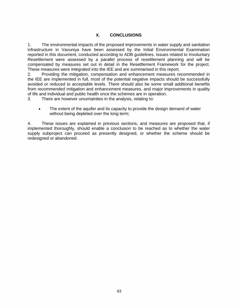
63
X. CONCLUSIONS
1. The environmental impacts of the proposed improvements in water supply and sanitation infrastructure in Vavuniya have been assessed by the Initial Environmental Examination reported in this document, conducted according to ADB guidelines. Issues related to Involuntary Resettlement were assessed by a parallel process of resettlement planning and will be compensated by measures set out in detail in the Resettlement Framework for the project. These measures were integrated into the IEE and are summarised in this report. 2. Providing the mitigation, compensation and enhancement measures recommended in the IEE are implemented in full, most of the potential negative impacts should be successfully avoided or reduced to acceptable levels. There should also be some small additional benefits from recommended mitigation and enhancement measures, and major improvements in quality of life and individual and public health once the schemes are in operation. 3. There are however uncertainties in the analysis, relating to:
The extent of the aquifer and its capacity to provide the design demand of water without being depleted over the long term;
4. These issues are explained in previous sections, and measures are proposed that, if implemented thoroughly, should enable a conclusion to be reached as to whether the water supply subproject can proceed as presently designed, or whether the scheme should be redesigned or abandoned.
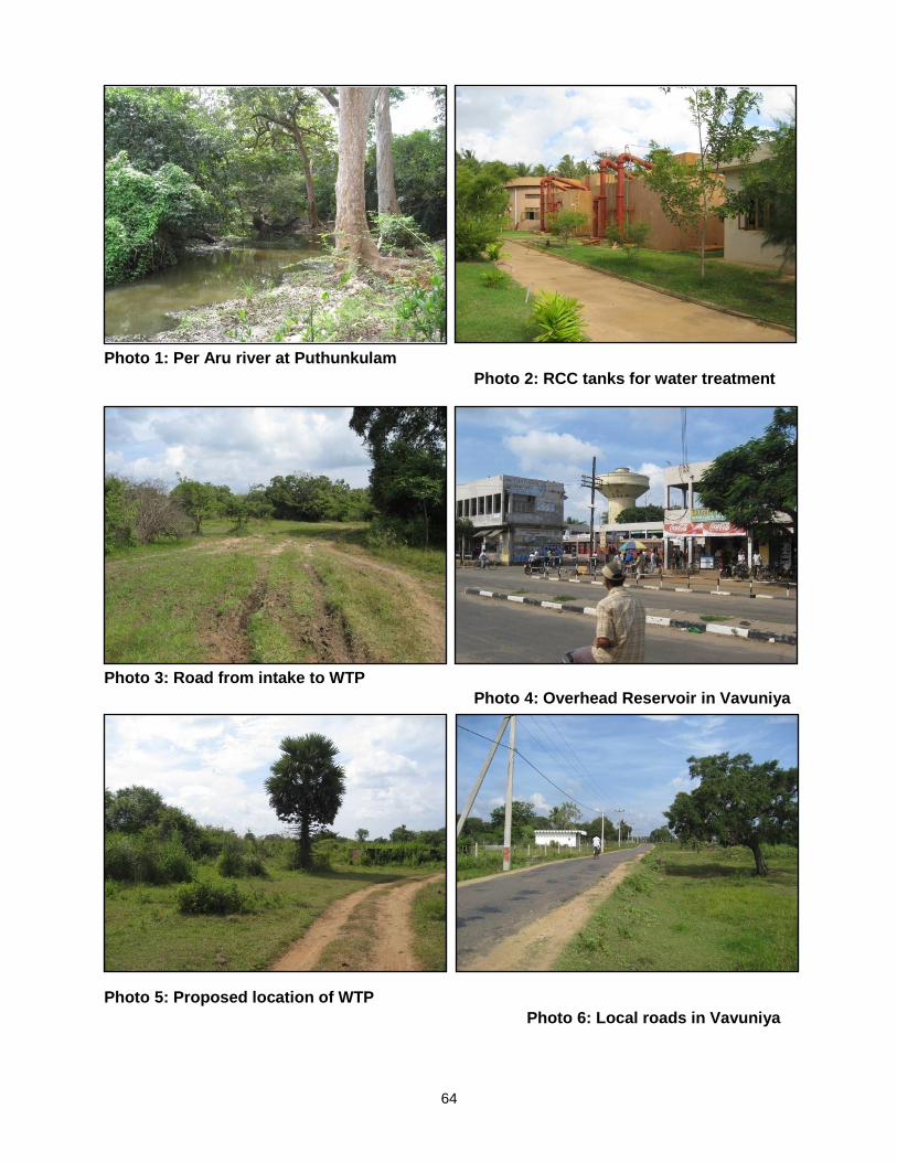
64
Photo 1: Per Aru river at Puthunkulam
Photo 2: RCC tanks for water treatment
Photo 3: Road from intake to WTP
Photo 4: Overhead Reservoir in Vavuniya
Photo 5: Proposed location of WTP
Photo 6: Local roads in Vavuniya
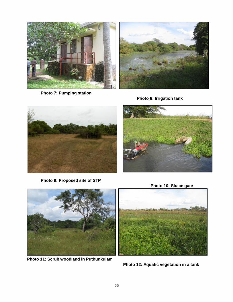
65
Photo 7: Pumping station
Photo 8: Irrigation tank
Photo 9: Proposed site of STP
Photo 10: Sluice gate
Photo 11: Scrub woodland in Puthunkulam
Photo 12: Aquatic vegetation in a tank
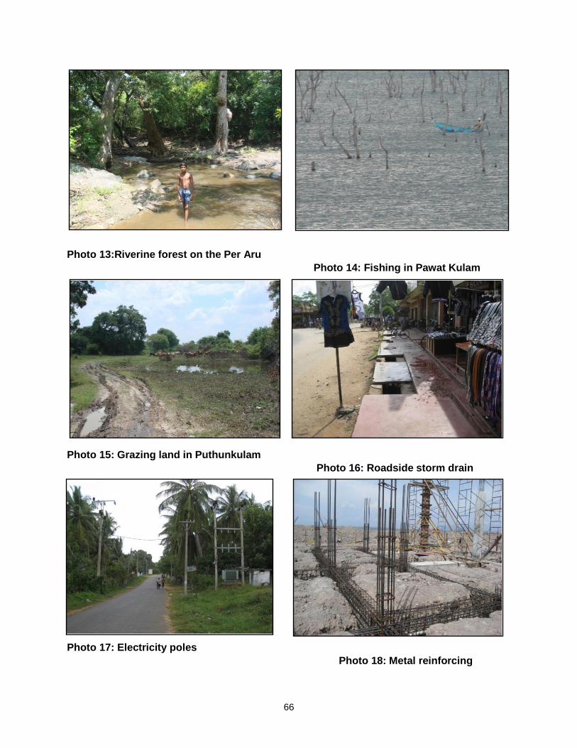
66
Photo 13:Riverine forest on the Per Aru
Photo 14: Fishing in Pawat Kulam
Photo 15: Grazing land in Puthunkulam
Photo 16: Roadside storm drain
Photo 17: Electricity poles
Photo 18: Metal reinforcing
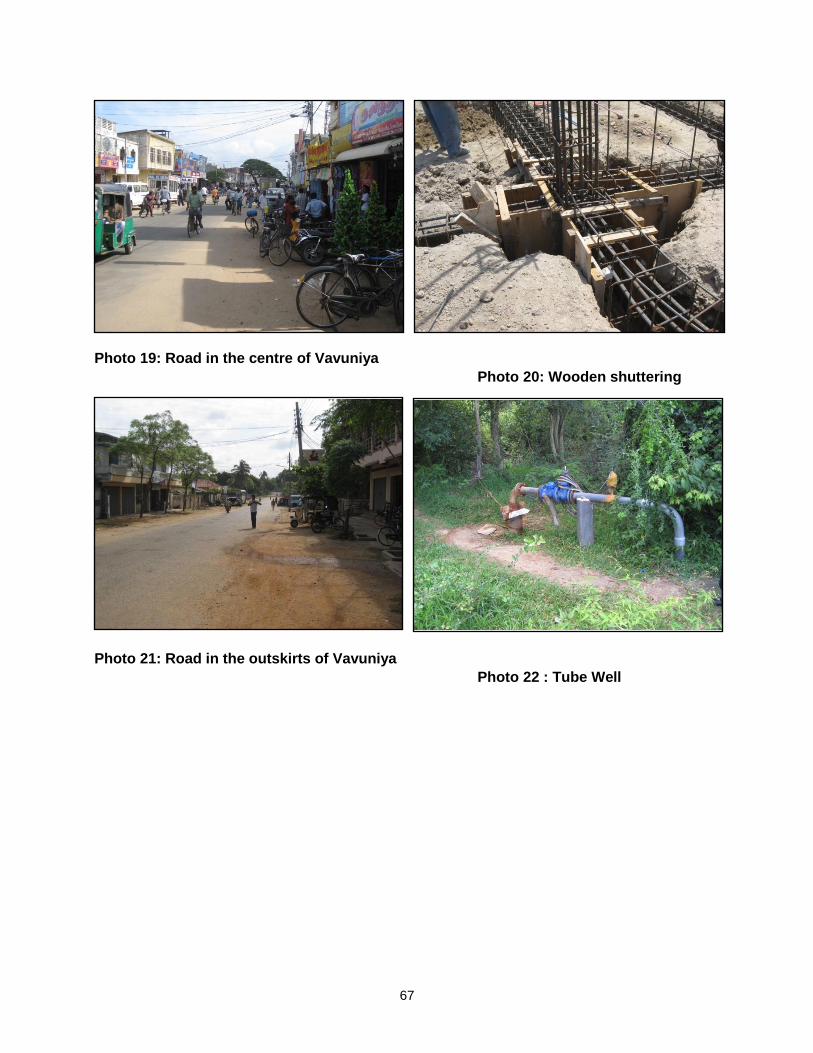
67
Photo 19: Road in the centre of Vavuniya
Photo 20: Wooden shuttering
Photo 21: Road in the outskirts of Vavuniya
Photo 22 : Tube Well
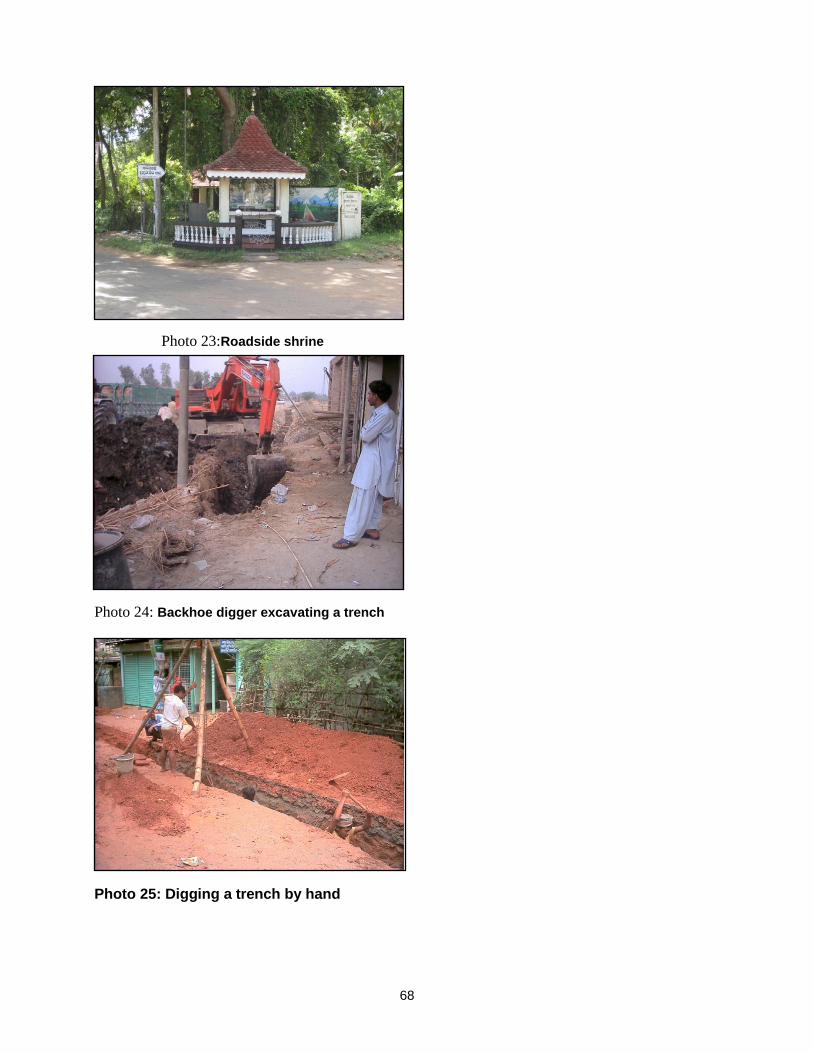
68
Photo 23:Roadside shrine
Photo 24: Backhoe digger excavating a trench
Photo 25: Digging a trench by hand

69
APPENDICES
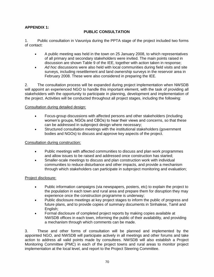
70
APPENDIX 1: PUBLIC CONSULTATION
1. Public consultation in Vavuniya during the PPTA stage of the project included two forms of contact:
A public meeting was held in the town on 25 January 2008, to which representatives of all primary and secondary stakeholders were invited. The main points raised in discussion are shown Table 9 of the IEE, together with action taken in response;
Ad hoc discussions were also held with local communities during field visits and site surveys, including resettlement and land ownership surveys in the reservoir area in February 2008. These were also considered in preparing the IEE.
2. The consultation process will be expanded during project implementation when NWSDB will appoint an experienced NGO to handle this important element, with the task of providing all stakeholders with the opportunity to participate in planning, development and implementation of the project. Activities will be conducted throughout all project stages, including the following: Consultation during detailed design:
Focus-group discussions with affected persons and other stakeholders (including women’s groups, NGOs and CBOs) to hear their views and concerns, so that these can be addressed in subproject design where necessary;
Structured consultation meetings with the institutional stakeholders (government bodies and NGOs) to discuss and approve key aspects of the project.
Consultation during construction:
Public meetings with affected communities to discuss and plan work programmes and allow issues to be raised and addressed once construction has started;
Smaller-scale meetings to discuss and plan construction work with individual communities to reduce disturbance and other impacts, and provide a mechanism through which stakeholders can participate in subproject monitoring and evaluation;
Project disclosure:
Public information campaigns (via newspapers, posters, etc) to explain the project to the population in each town and rural area and prepare them for disruption they may experience once the construction programme is underway;
Public disclosure meetings at key project stages to inform the public of progress and future plans, and to provide copies of summary documents in Sinhalese, Tamil and English;
Formal disclosure of completed project reports by making copies available at NWSDB offices in each town, informing the public of their availability, and providing a mechanism through which comments can be made.
3. These and other forms of consultation will be planned and implemented by the appointed NGO, and NWSDB will participate actively in all meetings and other forums and take action to address all valid points made by consultees. NWSDB will also establish a Project Monitoring Committee (PMC) in each of the project towns and rural areas to monitor project implementation at the local level, and report to the Project Steering Committee.
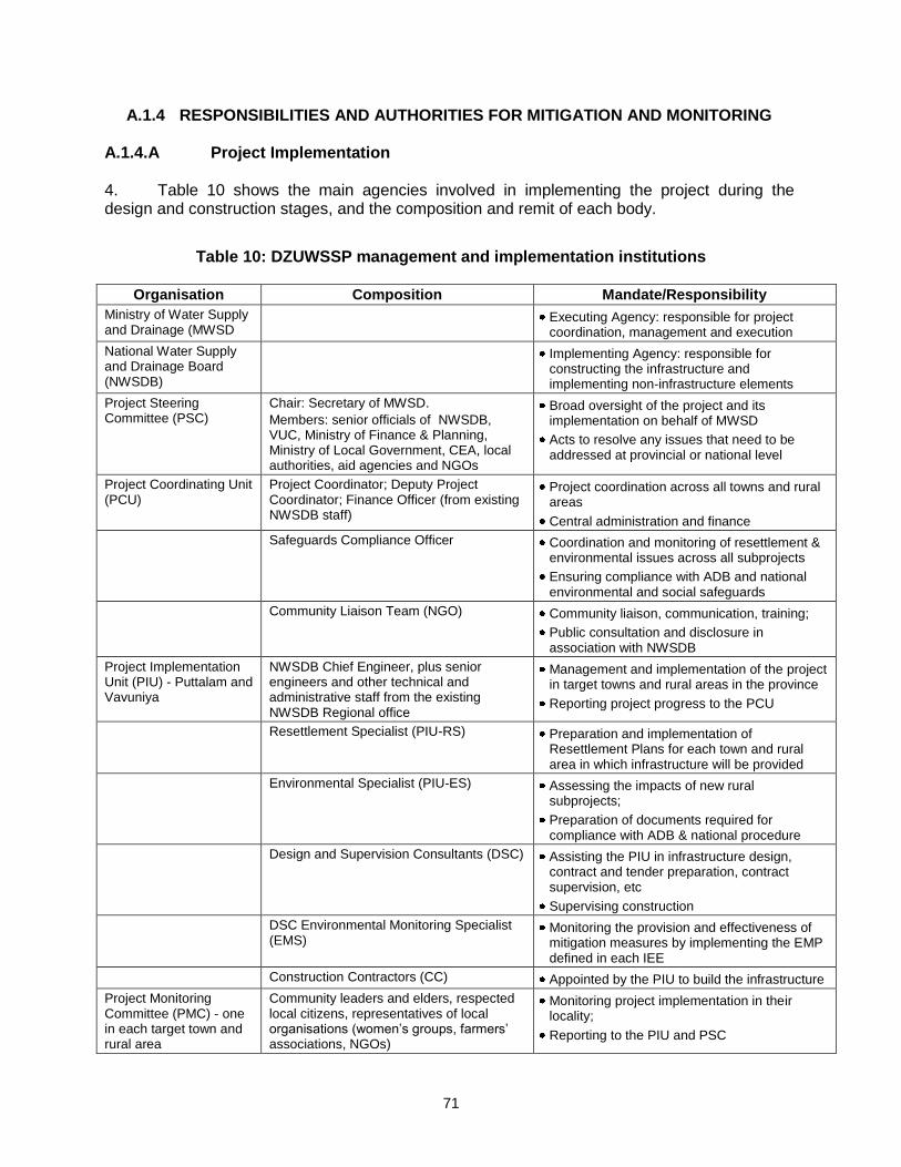
71
A.1.4 RESPONSIBILITIES AND AUTHORITIES FOR MITIGATION AND MONITORING A.1.4.A Project Implementation 4. Table 10 shows the main agencies involved in implementing the project during the design and construction stages, and the composition and remit of each body.
Table 10: DZUWSSP management and implementation institutions
Organisation Composition Mandate/Responsibility
Ministry of Water Supply and Drainage (MWSD
Executing Agency: responsible for project coordination, management and execution
National Water Supply and Drainage Board (NWSDB)
Implementing Agency: responsible for constructing the infrastructure and implementing non-infrastructure elements
Project Steering Committee (PSC)
Chair: Secretary of MWSD.
Members: senior officials of NWSDB, VUC, Ministry of Finance & Planning, Ministry of Local Government, CEA, local authorities, aid agencies and NGOs
Broad oversight of the project and its implementation on behalf of MWSD
Acts to resolve any issues that need to be addressed at provincial or national level
Project Coordinating Unit (PCU)
Project Coordinator; Deputy Project Coordinator; Finance Officer (from existing NWSDB staff)
Project coordination across all towns and rural areas
Central administration and finance
Safeguards Compliance Officer Coordination and monitoring of resettlement & environmental issues across all subprojects
Ensuring compliance with ADB and national environmental and social safeguards
Community Liaison Team (NGO) Community liaison, communication, training;
Public consultation and disclosure in association with NWSDB
Project Implementation Unit (PIU) - Puttalam and Vavuniya
NWSDB Chief Engineer, plus senior engineers and other technical and administrative staff from the existing NWSDB Regional office
Management and implementation of the project in target towns and rural areas in the province
Reporting project progress to the PCU
Resettlement Specialist (PIU-RS) Preparation and implementation of Resettlement Plans for each town and rural area in which infrastructure will be provided
Environmental Specialist (PIU-ES) Assessing the impacts of new rural subprojects;
Preparation of documents required for compliance with ADB & national procedure
Design and Supervision Consultants (DSC) Assisting the PIU in infrastructure design, contract and tender preparation, contract supervision, etc
Supervising construction
DSC Environmental Monitoring Specialist (EMS)
Monitoring the provision and effectiveness of mitigation measures by implementing the EMP defined in each IEE
Construction Contractors (CC) Appointed by the PIU to build the infrastructure
Project Monitoring Committee (PMC) - one in each target town and rural area
Community leaders and elders, respected local citizens, representatives of local organisations (women’s groups, farmers’ associations, NGOs)
Monitoring project implementation in their locality;
Reporting to the PIU and PSC

72
5. Responsibility for operation and maintenance of each scheme will be as follows:
Urban water supply: NWSDB; Urban sanitation (Mannar, Puttalam, Chilaw, and Vavuniya: Urban Council Public
Health Dept; NWSDB is therefore responsible for operation of the Puthunkulam reservoir.
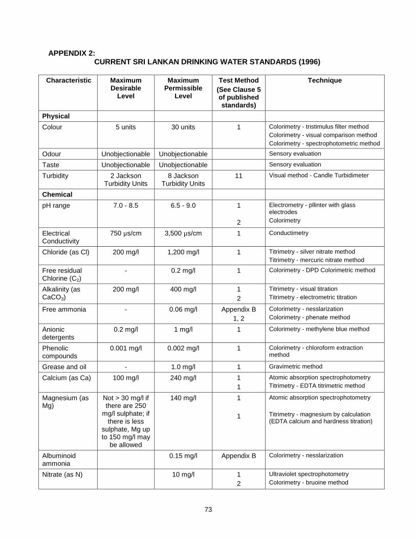
73
APPENDIX 2: CURRENT SRI LANKAN DRINKING WATER STANDARDS (1996)
Characteristic Maximum Desirable
Level
Maximum Permissible
Level
Test Method
(See Clause 5 of published standards)
Technique
Physical
Colour 5 units 30 units 1 Colorimetry - tristimulus filter method
Colorimetry - visual comparison method
Colorimetry - spectrophotometric method
Odour Unobjectionable Unobjectionable Sensory evaluation
Taste Unobjectionable Unobjectionable Sensory evaluation
Turbidity 2 Jackson Turbidity Units
8 Jackson Turbidity Units
11 Visual method - Candle Turbidimeter
Chemical
pH range 7.0 - 8.5 6.5 - 9.0 1
2
Electrometry - pllinter with glass electrodes
Colorimetry
Electrical Conductivity
750 µs/cm 3,500 µs/cm 1 Conductimetry
Chloride (as Cl) 200 mg/l 1,200 mg/l 1 Titrimetry - silver nitrate method
Titrimetry - mercuric nitrate method
Free residual Chlorine (C2)
- 0.2 mg/l 1 Colorimetry - DPD Colorimetric method
Alkalinity (as CaCO3)
200 mg/l 400 mg/l 1
2
Titrimetry - visual titration
Titrimetry - electrometric titration
Free ammonia - 0.06 mg/l Appendix B
1, 2
Colorimetry - nesslarization
Colorimetry - phenate method
Anionic detergents
0.2 mg/l 1 mg/l 1 Colorimetry - methylene blue method
Phenolic compounds
0.001 mg/l 0.002 mg/l 1 Colorimetry - chloroform extraction method
Grease and oil - 1.0 mg/l 1 Gravimetric method
Calcium (as Ca) 100 mg/l 240 mg/l 1
1
Atomic absorption spectrophotometry
Titrimetry - EDTA titrimetric method
Magnesium (as Mg)
Not > 30 mg/l if there are 250
mg/l sulphate; if there is less
sulphate, Mg up to 150 mg/l may
be allowed
140 mg/l 1
1
Atomic absorption spectrophotometry
Titrimetry - magnesium by calculation (EDTA calcium and hardness titration)
Albuminoid ammonia
0.15 mg/l Appendix B Colorimetry - nesslarization
Nitrate (as N) 10 mg/l 1
2
Ultraviolet spectrophotometry
Colorimetry - bruoine method
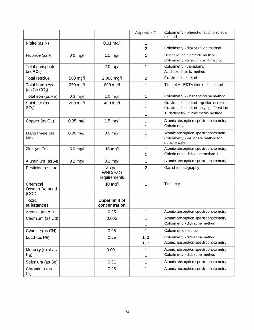
74
Appendix C Colorimetry - phenol-d- sulphonic acid method
Nitrite (as N) 0.01 mg/l 1
2
Colorimetry - diazotization method
Fluoride (as F) 0.6 mg/l 1.5 mg/l 1 Selective ion electrode method
Colorimetry - allzarin visual method
Total phosphate (as PO4)
- 2.0 mg/l 1 Colorimetry - vanadomo
Acid colorimetric method
Total residue 500 mg/l 2,000 mg/l 2 Gravimetric method
Total hardness (as Ca CO3)
250 mg/l 600 mg/l 1 Titrimetry - EDTA titrimetric method
Total iron (as Fe) 0.3 mg/l 1.0 mg/l 1 Colorimetry - Phenanthroline method
Sulphate (as SO4)
200 mg/l 400 mg/l 1
1
1
Gravimetric method - ignition of residue
Gravimetric method - drying of residue
Turbidimetry - turbidimetric method
Copper (as Cu) 0.05 mg/l 1.5 mg/l 1
1
Atomic absorption spectrophotometry
Colorimetry
Manganese (as Mn)
0.05 mg/l 0.5 mg/l 1
1
Atomic absorption spectrophotometry
Colorimetry - Perlodate method for potable water
Zinc (as Zn) 5.0 mg/l 15 mg/l 1
1
Atomic absorption spectrophotometry
Colorimetry - dithizone method II
Aluminium (as Al) 0.2 mg/l 0.2 mg/l 1 Atomic absorption spectrophotometry
Pesticide residue As per WHO/FAO
requirements
2 Gas chromatography
Chemical Oxygen Demand (COD)
10 mg/l 1 Titrimetry
Toxic substances
Upper limit of concentration
Arsenic (as As) 0.05 1 Atomic absorption spectrophotometry
Cadmium (as Cd) 0.005 1
1
Atomic absorption spectrophotometry
Colorimetry - dithizone method
Cyanide (as CN) 0.05 1 Colorimetric method
Lead (as Pb) 0.05 1, 2
1, 2
Colorimetry - dithizone method
Atomic absorption spectrophotometry
Mercury (total as Hg)
0.001 1
1
Atomic absorption spectrophotometry
Colorimetry - dithizone method
Selenium (as Se) 0.01 1 Atomic absorption spectrophotometry
Chromium (as Cr)
0.05 1 Atomic absorption spectrophotometry
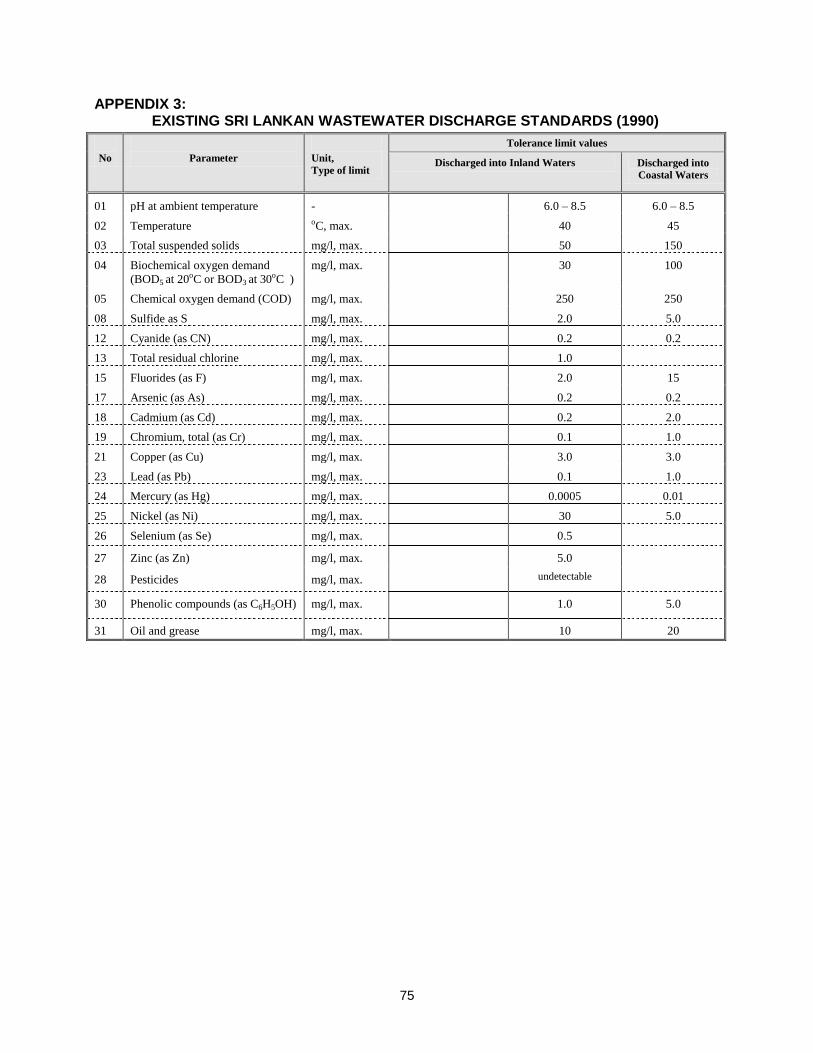
75
APPENDIX 3: EXISTING SRI LANKAN WASTEWATER DISCHARGE STANDARDS (1990)
No
Parameter
Unit,
Type of limit
Tolerance limit values
Discharged into Inland Waters Discharged into
Coastal Waters
01 pH at ambient temperature - 6.0 – 8.5 6.0 – 8.5
02 Temperature oC, max. 40 45
03 Total suspended solids mg/l, max. 50 150
04 Biochemical oxygen demand
(BOD5 at 20oC or BOD3 at 30oC )
mg/l, max. 30 100
05 Chemical oxygen demand (COD) mg/l, max. 250 250
08 Sulfide as S mg/l, max. 2.0 5.0
12 Cyanide (as CN) mg/l, max. 0.2 0.2
13 Total residual chlorine mg/l, max. 1.0
15 Fluorides (as F) mg/l, max. 2.0 15
17 Arsenic (as As) mg/l, max. 0.2 0.2
18 Cadmium (as Cd) mg/l, max. 0.2 2.0
19 Chromium, total (as Cr) mg/l, max. 0.1 1.0
21 Copper (as Cu) mg/l, max. 3.0 3.0
23 Lead (as Pb) mg/l, max. 0.1 1.0
24 Mercury (as Hg) mg/l, max. 0.0005 0.01
25 Nickel (as Ni) mg/l, max. 30 5.0
26 Selenium (as Se) mg/l, max. 0.5
27 Zinc (as Zn) mg/l, max. 5.0
28 Pesticides mg/l, max. undetectable
30 Phenolic compounds (as C6H5OH) mg/l, max. 1.0 5.0
31 Oil and grease mg/l, max. 10 20
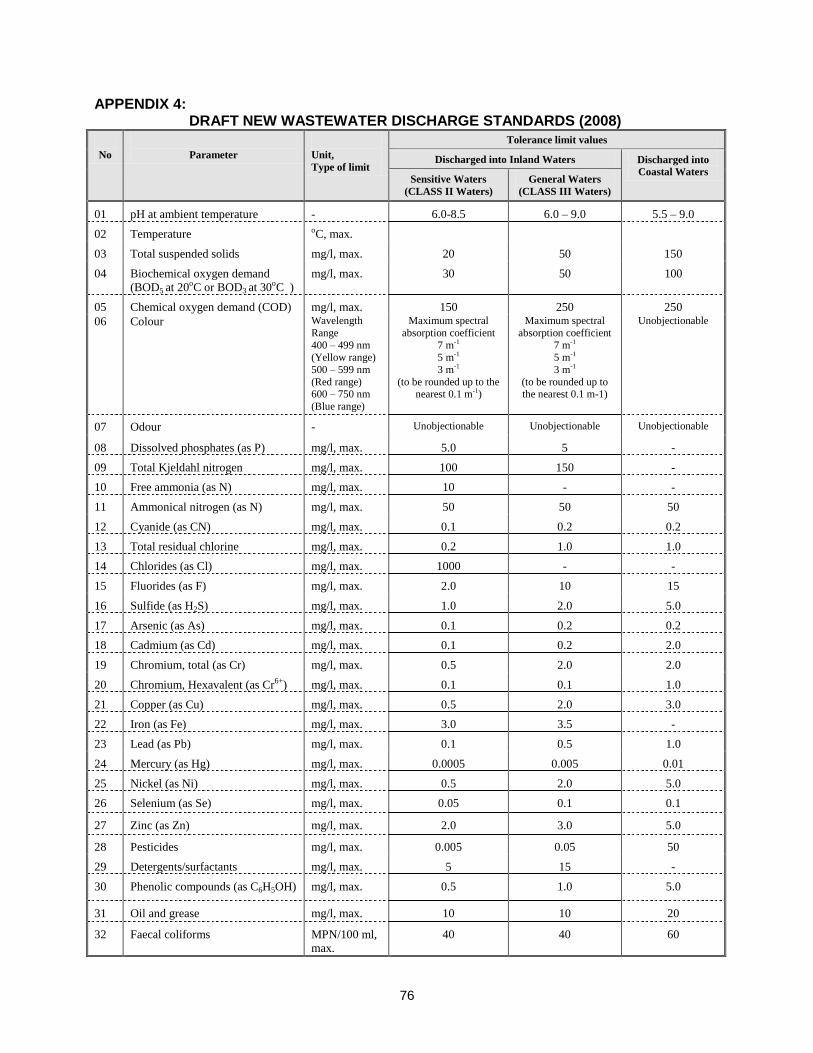
76
APPENDIX 4: DRAFT NEW WASTEWATER DISCHARGE STANDARDS (2008)
No
Parameter
Unit,
Type of limit
Tolerance limit values
Discharged into Inland Waters Discharged into
Coastal Waters Sensitive Waters
(CLASS II Waters)
General Waters
(CLASS III Waters)
01 pH at ambient temperature - 6.0-8.5 6.0 – 9.0 5.5 – 9.0
02 Temperature oC, max.
03 Total suspended solids mg/l, max. 20 50 150
04 Biochemical oxygen demand
(BOD5 at 20oC or BOD3 at 30oC )
mg/l, max. 30 50 100
05 Chemical oxygen demand (COD) mg/l, max. 150 250 250
06 Colour Wavelength
Range
400 – 499 nm
(Yellow range)
500 – 599 nm
(Red range) 600 – 750 nm
(Blue range)
Maximum spectral
absorption coefficient
7 m-1
5 m-1
3 m-1
(to be rounded up to the nearest 0.1 m-1)
Maximum spectral
absorption coefficient
7 m-1
5 m-1
3 m-1
(to be rounded up to the nearest 0.1 m-1)
Unobjectionable
07 Odour - Unobjectionable Unobjectionable Unobjectionable
08 Dissolved phosphates (as P) mg/l, max. 5.0 5 -
09 Total Kjeldahl nitrogen mg/l, max. 100 150 -
10 Free ammonia (as N) mg/l, max. 10 - -
11 Ammonical nitrogen (as N) mg/l, max. 50 50 50
12 Cyanide (as CN) mg/l, max. 0.1 0.2 0.2
13 Total residual chlorine mg/l, max. 0.2 1.0 1.0
14 Chlorides (as Cl) mg/l, max. 1000 - -
15 Fluorides (as F) mg/l, max. 2.0 10 15
16 Sulfide (as H2S) mg/l, max. 1.0 2.0 5.0
17 Arsenic (as As) mg/l, max. 0.1 0.2 0.2
18 Cadmium (as Cd) mg/l, max. 0.1 0.2 2.0
19 Chromium, total (as Cr) mg/l, max. 0.5 2.0 2.0
20 Chromium, Hexavalent (as Cr6+) mg/l, max. 0.1 0.1 1.0
21 Copper (as Cu) mg/l, max. 0.5 2.0 3.0
22 Iron (as Fe) mg/l, max. 3.0 3.5 -
23 Lead (as Pb) mg/l, max. 0.1 0.5 1.0
24 Mercury (as Hg) mg/l, max. 0.0005 0.005 0.01
25 Nickel (as Ni) mg/l, max. 0.5 2.0 5.0
26 Selenium (as Se) mg/l, max. 0.05 0.1 0.1
27 Zinc (as Zn) mg/l, max. 2.0 3.0 5.0
28 Pesticides mg/l, max. 0.005 0.05 50
29 Detergents/surfactants mg/l, max. 5 15 -
30 Phenolic compounds (as C6H5OH) mg/l, max. 0.5 1.0 5.0
31 Oil and grease mg/l, max. 10 10 20
32 Faecal coliforms MPN/100 ml,
max.
40 40 60
77
APPENDIX 5: SUMMARY OF PUBLIC CONSULTATION MEETING HELD IN VAVUNIYA
Date : 25th January 2008 Time : 2.00pm - 3.30pm Location : Rural Development Foundation Office, Karumankadu Vavuniya Invitees :
1. Divisional Secretaries of Vavniya and Vavniya South 2. Chairmen and Secretary of Vavniya Urban Council 3. Director - Department of Irrigation to send a representative 4. Director of the Provincial Department of Irrigation 5. Technical Officer Urban Council Vavniya 6. Medical Officer of Health (Vavniya) 7. Chairman - Water Resources Board to send a representative 8. Road Development Authority –Executive Engineer 9. Provincial Road Development Authority – Chief Engineer 10. Members of the Vavniya Urban Council 11. Representatives of Farmer Association 12. Community members were invited through the PO and Local Authority 13. Officials of the National Water Supply and Drainage Board 14. Mr Wimalachandran - Snr Irrigation Engineer assisting the Project
Matters presented at the Meetings
a. Brief description on approvals required for project implementation and other administrative and legal aspects
b. Environmental Assessment purpose and process c. Project details – Water Resources Development Plan, Civil Works, Area Coverage,
Population Coverage, Operation and Maintenance Aspects d. Anticipated environmental impacts e. Proposed mitigation measures – Construction and Operation f. Invited the public views and comments. g. Resettlement aspects – Compensation for loss of income, damage to properties, and
loss of properties Areas a-e were presented by the environmental consultant and the resettlement was presented by the resettlement specialist. Presentations were given in Tamil and subsequent discussions were in Tamil and English, with translation provided where necessary.
Method of information decimation and collection of information 1. Power point presentation 2. Illustration of locations and affected places using maps 3. Illustrations using flip charts during the discussion 4. Printed material – presentation 5. Voice recording of the discussion 6. Paper and pen were provided to write questions and issues and provide to the
consultants during the discussion
78
Common issues and concerns raised at all public consultation meetings
1. Communities expressed pressing need for water in all the sub-project areas and requested to expedite the implementation of the project.
2. The local officials and community members stated that previous projects to improve the
drainage and sewerage in the sub-project area failed due to bad designs, poor construction and lack of maintenance of the infrastructure. Therefore they requested to take appropriate measures to prevent happening of the same in this project. They stressed the need to consult the Local Authorities during the detailed design and construction as they have better knowledge about the local conditions and issues.
3. The Local Authority officials stated that there should be a mechanism for them to
participate in the project implementation. They said when projects are implemented without their participation they often receive poorly designed and constructed infrastructure. The LA officials said that if they are expected to operate the systems then they should be given a chance to involve in the design and construction decision making.
4. The participants agreed that the provision of wastewater service to town areas as a
good development. However, they expressed concern about the wastewater tariff and ability to pay. Also concerns were raised about the additional investments the property owners have to incur to upgrade their plumping arrangements in order to connect to the sewerage system. They requested further study on the ability to pay before embarking on the construction of sewerage systems. The LA officials stated that they may not be able to obtain necessary revenue to operate the systems if the number of connections is less.
5. The LAs requested to improve their awareness about institutional aspects of operation
and maintenance of sewerage systems. They also requested legal assistance to develop by-laws required for management of sewerage system. They have also requested assistance to improve the technical capacity within LAs to operate the sewer systems, if they are expected to run the sewerage systems. The LA officials said that they are happy if the NWSDB operate the sewerage systems at least for the first few years.
6. Local officials and community members as well as other participants stated that there
can be opposition to the locations selected for the sewerage treatment plants. Thus they requested further consultations with general public and local agencies and community on the siting of sewerage treatment plants.
7. As the project will take some time to start the participants stated that it is necessary to
acquire the required lands well in advance so that the selected lands are available for the project. Possession of the public lands also should be obtained in advance as there are other demands on these lands. Participants also stated that it is important to inform the public about the project with details of the locations of constructed components, such as water towers, sewerage pumping stations, sewerage treatment plants, etc.
8. The deterioration of water quality and quantity in rivers and streams as wells as other
activities such as sand mining were identified as threats to the future viability of the projects. Thus the participants highlighted the importance of catchment management and requested to include catchment management activities in this project.
79
9. The importance of obtaining the approval from necessary agencies well in advance was
highlighted. These include: environmental agencies, Irrigation Department and Provincial Irrigation Department, Agrarian Services Department.
10. Over exploitation of the ground water resources was also cited as a threat. Participants
stated the need to establish a mechanism for controlling the future ground water extraction in the well fields.
11. The Local Authorities expressed their willingness to carry out the drainage improvement
works in the town areas, if they are allowed to do so.
12. It was requested to complete the road excavation and pipe laying work in busy town areas as soon as possible.
13. Concern was expressed about sewer overflows from pumping stations, if pumps fail to
operate and during power failures.
14. Establish a procedure for providing assistance for toilet construction. Decide the beneficiary selection criteria for assistance for toilet construction If the funds available is limited to provide for all those who request for such assistance.
15. When deciding the financial support for toilets it is necessary to consider the
construction material cost that prevails in the respective areas. Specific issues raised at the meeting in Vavuniya
1. Express need to develop attractive compensation package for the farmers who will loose paddy land due to this project. It is stated to develop the compensation package first and then discuss with the farmers.
2. The Provincial Director Irrigation stated that uncultivated public land suitable for paddy
cultivation is available down stream of the inundation area. Thus he said that it may be possible to provide alternative lands to the farmers.
3. Irrigation agencies expressed that farmers may try to obtain excess water from the new
impoundment for agricultural activities. This is a concern for the NWSDB. 4. It was requested to revisit the design in order to determine whether the storage tanks
and overhead tanks provided under the proposed plan is adequate. Some members of the participants had concern over the adequacy of infrastructure. {Mr Sanath Fernando attended this meeting and explained the status}.
5. Participants expressed satisfaction about the area coverage of the Vavniya water supply
scheme. 6. Sewerage treatment system shall not be located within the tank reservation. Irrigation
engineer stated that they can consider granting land below the tank bund if requested. 7. It was requested to include Kurumankadu in the sewerage proposal.
80
Addendum 1
Committee for Grievance Redress and Environment Monitoring
1. In absence of such provisions, affected parties/persons (AP) will seek solutions outside
the project which may lead to a number of adverse consequences. It is necessary to include
grievance redress provisions for the people adversely affected (or about to be affected) by the
development of sub projects because such people should have provisions to forward their
grievances by seeking solutions.
2. Environmental Monitoring Committees (EMC) are already proposed to discuss the critical
environmental issues and thereby find solutions in some sub projects. Facility for Grievance
Redressing shall be incorporated to the proposed EMCs because all regional level key officials
will become the members of such EMCs and will be functioning as Grievance Redress and
Environment Monitoring Committee (GREMC). New GREMCs shall be formed for the sub-
projects where EMCs have not been proposed.
3. The GREMC comprises with responsible officers of following agencies and headed by
the Provincial Environmental Authority or Central Environmental Authority (which is functioning
in the area concern) jointly with the divisional secretary. The secretary to the committee and the
convener shall be the project manager of the NWSDB.
1. Provincial Environmental Authority/Central Environmental Authority (Regional office)
2. Project Manager of the sub project
3. Urban Council/ Municipal Council
4. Divisional Secretariat
5. Agrarian Service Department
6. Provincial Irrigation Department / Central Irrigation Department.
7. Representative of the contractor
8. Representative of the consultant to the project
9. Any other officers by considering the need
4. If APs are not satisfied about the decision of the GREMC, the matter should be referred
to the District Secretary who will make the final decision. The District Secretary may appoint a
committee to find the observations. The GREMC is effective with the commencement of the
construction and shall meet once in six weeks during the construction period. During the
81
operational phase, the committee shall meet once in three months for two years and if
necessary thereafter. If there are critical issues, the committee shall meet by fixing a convenient
date. During the operational phase, Regional Manager (O&M) of the NWSDB shall represent the
NWSDB.
5. This should be published in all three languages by displaying notices in the notice boards
of all member offices and other public offices such as Grama Niladhari (Village Head) office,
post office etc. to make aware the public.