Dry vALvE moDEL f-1
28
TECHNICAL DATA March 28, 2013 Dry 120a DRY VALVE MODEL F-1 The Viking Corporation, 210 N Industrial Park Drive, Hastings MI 49058 Telephone: 269-945-9501 Technical Services: 877-384-5464 Fax: 269-818-1680 Email: [email protected] 1. DESCRIPTION The Viking Model F-1 Dry Pipe Valve is a latching differential valve used to separate the water supply from the dry pipe sprinkler system. The valve combines a positive latching clapper and air plate assembly with a differential air-to-water seat design. The latching clapper and air plate assembly provides a positive mechanical seal for the air pressure in the dry pipe system. The differential design allows an air supply of moderate pressure to control a higher water supply pressure. When the air pressure in the dry pipe system is lowered sufficiently to destroy the pressure differential, the valve opens allowing water to enter the dry pipe system. The valve is also designed to operate a water motor alarm and/or an electric pressure alarm switch. The Viking Model D-2 or E-1 Accelerator can be used to speed the operation of the valve on large capacity systems or where faster action is required. 2. LISTINGS AND APPROVALS cULus Listed: VPZV FM Approved: Dry Pipe Valves NYC Department of Buildings: MEA 89-92-E, Vol. 22 LPCB Approved CE Certified: Standard EN 12259-3, EC-certificate of conformity 0832-CPD-2011 VdS Approved: Certificate G4980057 - 3”, G4960044 - 4”, and G4960055 - 6” 3. TECHNICAL DATA Specifications: Rated to - 175 PSI (12.1 bar) Water Working Pressure. Factory tested hydrostatically - 350 PSI (24.1 bar) with the clapper open. Air pressure to water pressure area differential: Approximately 6 to 1. Color - Red Form No. F_070392 DESCRIPTION NOMINAL SIZE PART NO. FRICTION LOSS* C v FACTOR SHIPPING WEIGHT Flange / Flange Flange Drilling ANSI 3" 09441 3 ft. (0.91 m) 800 130 lbs. (59 kg) ANSI 4" 07628 5 ft. (1.52 m) 821 130 lbs. (59 kg) ANSI 6" 08464 49 ft. (14.9 m) 780 197 lbs. (89 kg) PN10/16 DN80 09969 3 ft. (0.91 m) 800 130 lbs. (59 kg) PN10/16 DN100 08841 5 ft. (1.52 m) 821 130 lbs. (59 kg) PN10/16 DN150 08464 49 ft. (14.9 m) 780 197 lbs. (89 kg) * Expressed in equivalent length of Schedule 40 pipe based on Hazen & Williams formula: C = 120. Table 1 DESCRIPTION NOMINAL SIZE PART NO. FRICTION LOSS* C v FACTOR SHIPPING WEIGHT Flange / Groove Flange Drilling / Pipe O.D. ANSI / 89 mm 3" 09446 3 ft. (0.91 m) 800 125 lbs. (57 kg) ANSI / 114 mm 4" 07627 5 ft. (1.52 m) 821 125 lbs. (57 kg) ANSI / 165 mm 6" 12654 49 ft. (14.9 m) 780 184 lbs. (84 kg) ANSI / 168 mm 6" 08491 49 ft. (14.9 m) 780 184 lbs. (84 kg) PN10/16 / 89 mm DN80 09970 3 ft. (0.91 m) 800 125 lbs. (57 kg) PN10/16 / 114 mm DN100 09538 5 ft. (1.52 m) 821 125 lbs. (57 kg) PN10/16 / 165 mm DN150 12653 49 ft. (14.9 m) 780 184 lbs. (84 kg) PN10/16 / 168 mm DN150 08491 49 ft. (14.9 m) 780 184 lbs. (84 kg) * Expressed in equivalent length of Schedule 40 pipe based on Hazen & Williams formula: C = 120. Viking Technical Data may be found on The Viking Corporation’s Web site at http://www.vikinggroupinc.com. The Web site may include a more recent edition of this Technical Data Page. Q= C v √ ∆P S Q = Flow C v = Flow Factor (GPM/1 PSI ∆P) ∆P = Pressure Loss through Valve S = Specific Gravity of Fluid Revised page replaces page 120a-k, dated February 25, 2011. (Added VdS approvals)
-
Upload
khangminh22 -
Category
Documents
-
view
0 -
download
0
Transcript of Dry vALvE moDEL f-1

TECHNICAL DATA
March 28, 2013 Dry 120a
Dry vALvEmoDEL f-1
The viking Corporation, 210 N Industrial Park Drive, Hastings mI 49058Telephone: 269-945-9501 Technical Services: 877-384-5464 fax: 269-818-1680 Email: [email protected]
1. DESCrIPTIoNThe Viking Model F-1 Dry Pipe Valve is a latching differential valve used to separate the water supply from the dry pipe sprinkler system. The valve combines a positive latching clapper and air plate assembly with a differential air-to-water seat design. The latching clapper and air plate assembly provides a positive mechanical seal for the air pressure in the dry pipe system. The differential design allows an air supply of moderate pressure to control a higher water supply pressure. When the air pressure in the dry pipe system is lowered sufficiently to destroy the pressure differential, the valve opens allowing water to enter the dry pipe system.The valve is also designed to operate a water motor alarm and/or an electric pressure alarm switch. The Viking Model D-2 or E-1 Accelerator can be used to speed the operation of the valve on large capacity systems or where faster action is required.
2. LISTINGS AND APProvALScULus Listed: VPZV
fm Approved: Dry Pipe Valves
NyC Department of Buildings: MEA 89-92-E, Vol. 22
LPCB ApprovedCE Certified: Standard EN 12259-3, EC-certificate of conformity 0832-CPD-2011
vdS Approved: Certificate G4980057 - 3”, G4960044 - 4”, and G4960055 - 6”
3. TECHNICAL DATASpecifications:Rated to - 175 PSI (12.1 bar) Water Working Pressure.Factory tested hydrostatically - 350 PSI (24.1 bar) with the clapper open.Air pressure to water pressure area differential: Approximately 6 to 1.Color - Red
Form No. F_070392
DESCrIPTIoN NomINAL SIzE
PArT No.
frICTIoN LoSS*
Cv fACTor
SHIPPING WEIGHT
flange / flangeFlange Drilling
ANSI 3" 09441 3 ft. (0.91 m) 800 130 lbs.
(59 kg)
ANSI 4" 07628 5 ft.(1.52 m) 821 130 lbs.
(59 kg)
ANSI 6" 08464 49 ft. (14.9 m) 780 197 lbs.
(89 kg)
PN10/16 DN80 09969 3 ft.(0.91 m) 800 130 lbs.
(59 kg)
PN10/16 DN100 08841 5 ft.(1.52 m) 821 130 lbs.
(59 kg)
PN10/16 DN150 08464 49 ft. (14.9 m) 780 197 lbs.
(89 kg)* Expressed in equivalent length of Schedule 40 pipe based on Hazen & Williams
formula: C = 120.
Table 1
DESCrIPTIoN NomINAL SIzE
PArT No.
frICTIoN LoSS*
Cv fACTor
SHIPPING WEIGHT
flange / GrooveFlange Drilling / Pipe O.D.
ANSI / 89 mm 3" 09446 3 ft.(0.91 m) 800 125 lbs.
(57 kg)
ANSI / 114 mm 4" 07627 5 ft.(1.52 m) 821 125 lbs.
(57 kg)
ANSI / 165 mm 6" 12654 49 ft. (14.9 m) 780 184 lbs.
(84 kg)
ANSI / 168 mm 6" 08491 49 ft. (14.9 m) 780 184 lbs.
(84 kg)
PN10/16 / 89 mm DN80 09970 3 ft.(0.91 m) 800 125 lbs.
(57 kg)
PN10/16 / 114 mm DN100 09538 5 ft.(1.52 m) 821 125 lbs.
(57 kg)
PN10/16 / 165 mm DN150 12653 49 ft. (14.9 m) 780 184 lbs.
(84 kg)
PN10/16 / 168 mm DN150 08491 49 ft. (14.9 m) 780 184 lbs.
(84 kg)
* Expressed in equivalent length of Schedule 40 pipe based on Hazen & Williams formula: C = 120.
Viking Technical Data may be found on The Viking Corporation’s Web site at
http://www.vikinggroupinc.com.The Web site may include a more recent
edition of this Technical Data Page.
Q= Cv √ ∆PS
Q = Flow
Cv = Flow Factor (GPM/1 PSI ∆P)
∆P = Pressure Loss through Valve
S = Specific Gravity of Fluid
Revised page replaces page 120a-k, dated February 25, 2011. (Added VdS approvals)

TECHNICAL DATA
March 28, 2013Dry 120b
Dry vALvEmoDEL f-1
The viking Corporation, 210 N Industrial Park Drive, Hastings mI 49058Telephone: 269-945-9501 Technical Services: 877-384-5464 fax: 269-818-1680 Email: [email protected]
material Specifications: Refer to Figure 3.ordering Information:Available Since 1993.Part Numbers - Refer to Table 1.Accessories: Note: When viewing this data page online, blue text represents hyper links and will open the desired data page.
model f Dry valve Conventional Trim Package: For use when the dry valve is used on systems with fresh water supplies.3” Part No. 10158 (galvanized steel)4” Part No.Part No. 08395 (galvanized steel)6” Part No. 09456 (galvanized steel)
model f Dry valve Accessory Package: This package is needed when Viking Trim Packages are not used.Part No. 08397
model D-2 Accelerator:Part No. 09881
model D-2 Accelerator Trim Kit: Package includes trim components and air gauge required to install the Viking Model D-2 Accelerator
Part No. 09730model E-1 Accelerator and model B-1 Anti-flood Assembly Package: Includes Model E-1 Accelerator and Model B-1 Anti-flood Device.
Part No. 08116model E-1 Accelerator Trim Kit: Package includes trim components and air gauge required to install the Viking Model E-1 Accelerator and Model B-1 Anti-flood Device.
Part No. 08264 (galvanized steel) Additional accessories are available and may be required for operation or supervision. Refer to the system description for complete operating trim requirements.
1.•••
2.•
3.•
4.
•5.
•6.
•
Table 2: f-1 Dry valve Accessory Approval Chart
Approval Valve Size
Trim Part. No.
09881 - D-2 Accelerator
08055 - E-1 Accelerator
08061 - B-1 Anti-Flood Device
09391 - B-2 Anti-Flood Device
cULus 3” 10158 X X X4” 08395 X X X6” 09456 X X X
FM 3” 10158 X X X4” 08395 X X X6” 09456 X X X
LPCB 3” LL10158 X X4” LL08395 X X6” LL13583 X X
CE 3” LL10158 X X4” LL08395 X X6” LL13583 X X
VdS 3” LL1070 w/Accelerator X X4” LL1060 w/Accelerator X X6” LL1062 w/Accelerator X X3” LL1069 w/o Accelerator
4” LL1059 w/o Accelerator
6” LL1061 w/o Accelerator

TECHNICAL DATA
March 28, 2013 Dry 120c
Dry vALvEmoDEL f-1
The viking Corporation, 210 N Industrial Park Drive, Hastings mI 49058Telephone: 269-945-9501 Technical Services: 877-384-5464 fax: 269-818-1680 Email: [email protected]
4. INSTALLATIoN For proper operation and approval, the valve must be trimmed in accordance with Viking Model F-1 Dry Valve Trim Charts.The Model F-1 Dry Valve must be installed in the vertical position as shown in Figure 1.Air or nitrogen supply to the dry pipe system must be clean, dry, and oil free.Automatic air supplies must be regulated, restricted, and from a continuous source. A Viking air maintenance device should be installed on each system equipped with an automatic air supply. Never exceed 60 PSI (4.1 bar) pressure in the system piping with the dry valve clapper closed.The dry valve must be installed in an area not subject to freezing temperatures or physical damage. If required, provide a valve house (enclosure) with adequate heat around the dry valve and trim. Freezing temperatures and/or excessive pressure will dam-age the dry valve member assembly. When corrosive atmospheres and/or contaminated water supplies are present, it is the owner’s responsibility to verify compat-ibility with the Model F-1 Dry Valve and associated equipment. Consider installation of the Viking accelerator and anti-flood device. An accelerator (quick opening device) is recommended on all differential dry pipe valves and is required on dry pipe systems of certain capacities. Refer to Installation Standards and Authorities Having Jurisdiction. If an accelerator is to be installed, verify that the appropriate Trim Chart is used. Prior to installing the valve, thoroughly flush the water supply piping to verify that no foreign matter is present.
A. General Installation Instructions1. Verify that necessary Trim Charts and Technical Data for the dry valve and associated equipment are available.2. Remove all plastic thread protectors from the openings of the dry valve.3. Apply a small amount of pipe-joint compound or tape to the external threads of all pipe connections required. Take care not
to allow any compound, tape, or other foreign matter inside any of the nipples or openings of the dry valve or trim compo-nents.
4. Install the Model F-1 Dry Valve and trim piping according to the current Model F-1 Dry Valve Trim Chart provided with the Trim Package and the Viking Engineering and Design Data book. The Model F-1 Dry Valve must be installed in the vertical position.
5. When installing a Viking accelerator and anti-flood device in conjunction with the Model F-1 Dry Valve, refer to the appropri-
1.2.3.4.
5.
6.
7.
8.
figure 2
figure 1 - Take out Dimensions
3” (DN80)
4” (DN100)
6” (DN150)
A 18-1/4” (464)
18-1/4” (464)
20-1/16” (510)
B 7” (178)
7” (178)
7-5/16” (186)
C 16-3/4” (425)
12-1/2” (318)
14” (356)
D 10” (254)
10” (254)
10” (254)
E 11-13/16” (300)
12” (305)
14-3/4” (375)
f 23” (584)
23” (584)
23” (584)
G 34-1/2” (876)
34-1/2” (876)
36” (914)

TECHNICAL DATA
March 28, 2013Dry 120d
Dry vALvEmoDEL f-1
The viking Corporation, 210 N Industrial Park Drive, Hastings mI 49058Telephone: 269-945-9501 Technical Services: 877-384-5464 fax: 269-818-1680 Email: [email protected]
ate Viking E-1 Accelerator Trim Chart provided with the Accelerator Trim Package and the Viking Engineering and Design Data book.
When a Viking accelerator is installed on the Model F-1 Dry Valve, the dry system air supply must be connected as shown on the Model E-1 Accelerator Trim Chart.The Viking external anti-flood device is required when a Viking Model E-1 Accelerator is installed on a dry valve accord-ing to the Model E-1 Accelerator Trim Chart.
Hydrostatic Test:CAUTIoN: THE Dry vALvE CLAPPEr mUST BE LATCHED oPEN DUrING PErformANCE of THE HyDroSTATIC TEST (SEE fIG. 2-A)DO NOT perform a 200 PSI (13.8 bar) hydrostatic system test with the dry valve clapper in the closed (set) position (see Fig. 2-C).Never exceed 60 PSI (4.1 bar) air pressure in the system piping with the dry valve clapper closed.DO NOT expose the Viking accelerator to the hydrostatic test. For warnings and considerations regarding hydrostatic testing of the Viking accelerator and other system components, refer to Technical Data for the equipment used.B. Placing the valve in Service (Refer to Figure 2) When the dry pipe system is ready to be placed in service, verify that all equipment is adequately heated and protected to prevent freezing and physical damage.
1. Verify that the water supply main control valve supplying the dry valve is closed. 2. Open the main drain valve (located on the inlet of the dry valve).3. Drain all water from the dry pipe system. If the system has operated, or if water has entered the system, open all auxiliary
drains and the system test valve. Allow enough time to completely drain the system. Perform steps 4 through 10 to set the dry valve and/or inspect the internal operating parts of the dry valve.
4. Verify that the dry pipe system is not pressurized.5. Use the dry valve reset bar/wrench, part number 02977BM, to loosen and remove hand-hole cover bolts (21). Remove
hand-hole cover (24).CAUTIoN: CLAPPEr Arm ASSEmBLy (8) AND CLAPPEr ASSEmBLy (5) ArE SPrING LoADED To oPEN. NEvEr PLACE HANDS INSIDE THE Dry vALvE If THE CLAPPEr ASSEmBLy IS LATCHED CLoSED.
To release a latched clapper assembly for service: Insert the re-setting tool through the hole-in-hook assembly (15), across the fulcrum cast on top of clapper arm assembly (8) until the re-setting tool contacts the stopping boss on top of clapper arm assembly (8) (see Figure 3).Apply a downward force on the end (outside the valve) of the re-setting tool. Hook assembly (15) will slide toward the hand-hole and off clapper arm assembly (8). Clapper arm assembly (8) and clapper assembly (5) will forcefully open, impact against the latch (2), and latch in the open position.
NoTE: INSPECTIoN AND CLEANING ProCEDUrE STEP 6 BELoW IS CoNSIDErED PArT of THE ANNUAL TrIP TEST.6. Inspect and clean the internal parts of the valve. Give special consideration to the water seat (16), air seat (20) and clapper
rubber (19). Wipe away all contaminants, dirt, and mineral deposits. DO NOT use solvents or abrasives. Operate all parts to test freedom of movement. Renew or replace damaged or worn parts as required.
CAUTIoN: NEvEr APPLy ANy LUBrICANT To SEATS, GASKETS, or ANy INTErNAL oPErATING PArTS of THE Dry vALvE. PETroLEUm BASED GrEASE or oIL WILL DAmAGE rUBBEr ComPoNENTS AND mAy PrEvENT ProPEr oP-ErATIoN of THE Dry vALvE.
7. To set the dry valve clapper (refer to Figures 2 and 3):Raise the latch (2) to release spring-loaded clapper arm assembly (8) from the latched open position. Move the clapper arm assembly (8) down toward the horizontal position (see Figure 2-B).While holding spring loaded clapper arm assembly (8) down, insert the re-setting tool through the hole-in-hook assembly (15), across the fulcrum cast on top of clapper arm assembly (8) until the re-setting tool contacts the stopping boss as shown in Figure 2-C.Apply a sharp upward force at the end of the re-setting tool. Hook assembly (15) will slide forward on the re-setting bar and latch the clapper closed with a positive setting action (see Figure 2-C).
8. Priming water is not required and may not be desirable where clean, good-quality fresh water is not available. If priming water is desired, fill the dry valve with water to the bottom of the hand-hole.
Verify that the intermediate chamber of the dry valve is free of water. No water should flow from the drip check when the plunger is pushed.
9. Visually inspect hand-hole cover gasket (25). Verify that it is in good condition.10. Re-install hand-hole cover (24), gasket (25), and hand-hole cover bolts (21). Tighten the bolts using the dry valve reset
a.
b.
a.
b.
a.b.c.
d.
a.

TECHNICAL DATA
March 28, 2013 Dry 120e
Dry vALvEmoDEL f-1
The viking Corporation, 210 N Industrial Park Drive, Hastings mI 49058Telephone: 269-945-9501 Technical Services: 877-384-5464 fax: 269-818-1680 Email: [email protected]
bar/wrench, part number 02977BM.11. Close all auxiliary drains, the system test valve, and the priming water level test
valve on the dry valve trim. The main drain (located on the inlet of the dry valve) should remain open.
12. If equipped with a Viking accelerator and external anti-flood device: Close the ½” (15 mm) anti-flood isolation valve.Observe the air pressure gauge on top of the accelerator. The gauge must read zero before the accelerator will automatically reset. It may be necessary to loosen, remove, and re-install (use the appropriate wrench) the air gauge to vent trapped air pressure from the upper chamber.
13. Open the dry system air supply and establish desired system pressure. See Table 3 for suggested air pressure to water pressure settings. NEVER EXCEED 60 PSI (4.1 bar) AIR PRESSURE.
14. Verify that the intermediate chamber of the dry valve is free of water. No water should flow from the drip check when the plunger is pushed.
15. If equipped with a Viking accelerator and external anti-flood device: When pressure on the accelerator air pressure gauge equals the system set pressure, OPEN and secure the ½” (15 mm) anti-flood isolation valve.
16. Slowly open the water supply main control valve. 17. When flow is developed from the main drain, CLOSE the main drain valve.18. Fully open the water supply main control valve. 19. Secure all valves in their normal operating position.20. Notify Authorities Having Jurisdiction and those in the affected area that the system is in service.
5. oPErATIoN (Refer to Figure 3)The clapper (5) and air plate (11) assemblies combine to form a floating member assembly. With the clapper assembly (5) latched closed, system air pressure forces the member assembly down, sealing the water seat (16) from the intermediate chamber. When a sprinkler operates, the system air pressure is reduced. When system air pressure is reduced to the differential tripping point of the valve, water supply pressure in the inlet chamber lifts the member assembly off the water seat (16) and flows into the intermediate chamber. As the member assembly continues to rise, the hook assembly (15) is forced against socket set screw (23), which causes the hook assembly (15) to pivot on hook rod (6b) and unlatch the clapper. The clapper is spring loaded and swings to a full-open locked position (see Figure 2-A). When using the optional accelerator, the accelerator senses the system air pressure drop and trips. Upon tripping, the accelerator allows the system air pressure to enter the dry valve intermediate chamber. This immediately destroys the differential causing the member assembly to rise faster.The intermediate chamber is normally at atmospheric pressure and is connected to the alarm line. When the valve trips, the interme-diate chamber and alarm line are pressurized with system water pressure, activating alarms connected to the dry valve trim.
6. INSPECTIoNS, TESTS AND mAINTENANCENoTICE: THE oWNEr IS rESPoNSIBLE for mAINTAINING THE fIrE ProTECTIoN SySTEm AND DEvICES IN ProPEr oPErATING CoNDITIoN.The Viking Model F-1 Dry Valve and trim must be kept free of foreign matter, freezing conditions, corrosive atmospheres, contami-nated water supplies, and any condition that could impair its operation or damage the device.It is imperative that the system be inspected and tested on a regular basis. The frequency of the inspections may vary due to con-taminated water supplies, corrosive water supplies, corrosive atmospheres, as well as the condition of the air supply to the system. For minimum maintenance and inspection requirements, refer to NFPA 25. In addition, the Authority Having Jurisdiction may have additional maintenance, testing, and inspection requirements that must be followed.WArNING: ANy SySTEm mAINTENANCE WHICH INvoLvES PLACING A CoNTroL vALvE or DETECTIoN SySTEm oUT of SErvICE mAy ELImINATE THE fIrE ProTECTIoN CAPABILITIES of THAT SySTEm. PrIor To ProCEEDING, NoTIfy ALL AUTHorITIES HAvING JUrISDICTIoN. CoNSIDErATIoN SHoULD BE GIvEN To EmPLoymENT of A fIrE PATroL IN THE AffECTED ArEAS.
I. INSPECTIoNWeekly inspection is recommended. If the system is equipped with a low air (or nitrogen) alarm, monthly inspections may be adequate.1. Check pressure gauges located on the supply side and system side of the dry valve. Verify that the proper ratio of air (or
nitrogen) pressure to water supply pressure is being maintained (refer to Table 3).
a.b.
Table 3 - Air Pressure Settingsmaximum
Water Pressure
minimum maximum
PSI bar PSI bar PSI bar50 3.45 15 1.03 25 1.7275 5.17 20 1.38 30 2.07
100 6.90 25 1.72 35 2.41125 8.62 30 2.07 45 3.10150 10.34 35 2.41 50 3.45175 12.07 45 3.10 60 4.14

TECHNICAL DATA
March 28, 2013Dry 120f
Dry vALvEmoDEL f-1
The viking Corporation, 210 N Industrial Park Drive, Hastings mI 49058Telephone: 269-945-9501 Technical Services: 877-384-5464 fax: 269-818-1680 Email: [email protected]
2. Verify that the intermediate chamber of the dry valve is free of water. No water should flow from the drip check when the plunger is pushed.
3. If equipped with a Viking accelerator:a. Check the air pressure gauge located on the top of the accelerator. Air pressure in the upper chamber of the accelerator
should equal the pneumatic pressure maintained in the system. NoTE: STANDArD ToLErANCE ALLoWANCE IN PrESSUrE GAUGE CALIBrATIoN mAy rESULT IN A SLIGHT vArIATIoN WHEN PrESSUrE rEADINGS from ANy TWo GAUGES ArE ComPArED. A DIffErENCE IN PrESSUrES oTHEr THAN SLIGHT vArIATIoN DUE To GAUGE CALIBrATIoN ToLErANCE mAy INDICATE mAINTENANCE IS rEqUIrED. rEfEr To TECHNICAL DATA for THE ACCELErATor USED.
b. or dry systems with Viking Accelerators installed according to the Viking Model E-1 Accelerator Trim Chart, verify that the ½” (15 mm) anti-flood isolation valve is OPEN and secured.
4. Verify that the water supply main control valve is open and all trim valves are in their normal operating position.5. Check for signs of mechanical damage and/or corrosive activity. If detected, perform maintenance as required or, if necessary,
replace the device.6. Verify that dry valve and trim are adequately heated and protected from freezing and physical damage.
II. TESTS quarterly Tests A. Water flow Alarm Test
Quarterly testing of water flow alarms is recommended and may be required by the Authority Having Jurisdiction.1. Notify the Authority Having Jurisdiction and those in the area affected by the test.
NoTE: vIKING CoNvENTIoNAL TrIm ProvIDES A CoNNECTIoN for INSTALLATIoN of A NoN-INTErrUPTIBLE PrES-SUrE SWITCH. ALArmS AND/or ELECTrIC PANELS CoNTroLLED By AN ALArm PrESSUrE SWITCH INSTALLED IN THAT CoNNECTIoN CANNoT BE INTErrUPTED. (See Dry Valve Trim Chart.)
2. Fully open the main drain (located on the base of the dry valve) to flush away any accumulation of foreign material.3. Close the main drain.4. To test the local electric alarm (if provided) and/or mechanical water motor gong (if provided), OPEN the alarm test valve
in the dry valve trim.a. Electric alarm pressure switches (if provided) should activate. b. Electric local alarms should be audible. c. The local water motor gong should be audible. d. Verify that (if provided) remote station alarm signals were received.
5. When testing is complete, close the alarm test valve.6. Verify:
a. All local alarms stop sounding and alarm panels (if provided) reset.b. All remote station alarms reset.c. All supply piping to water motor properly drains.
7. Verify that the alarm shut-off valve in the dry valve trim is OPEN, and the alarm test valve is CLOSED.8. Verify that the intermediate chamber of the dry valve is free of water. No water should flow from the drip check when the
plunger is pushed.9. Notify the Authority Having Jurisdiction and those in the affected area that testing is complete.
B. main Drain Test Quarterly performance of the Main Drain Test is recommended and may be required by Authorities Having Jurisdiction to verify integrity of the water supply.
1. Notify the Authority Having Jurisdiction and those in the area affected by the test. 2. Record pressure reading from the water supply pressure gauge.3. Verify that the intermediate chamber of the dry valve is free of water. No water should flow from the drip check when the
plunger is pushed.4. Verify that the dry pipe system is pressurized at or above the minimum pressure recommended in Table 3 for the water
supply pressure available.5. Fully OPEN the main drain located on the base of the dry valve.6. When a full flow is developed from the main drain, record the residual pressure from the water supply pressure gauge.7. When the test is complete, SLOWLY CLOSE the main drain.

TECHNICAL DATA
March 28, 2013 Dry 120g
Dry vALvEmoDEL f-1
The viking Corporation, 210 N Industrial Park Drive, Hastings mI 49058Telephone: 269-945-9501 Technical Services: 877-384-5464 fax: 269-818-1680 Email: [email protected]
8. Compare test results with previous flow information. If deterioration of the water supply is detected, take appropriate steps to restore adequate water supply.
9. Verify that normal water supply pressure and system pneumatic pressure have been restored, and that all alarm devices and valves are secured in normal operating position.
10. Notify the Authority Having Jurisdiction that the test is complete. Record and/or provide notification of test results as required by the Authority Having Jurisdiction.
C. Priming Water Level, and Low Air Alarm Test Quarterly testing is recommended to verify that water is NOT present above the Priming Level Test Valve in the dry valve trim. Quarterly testing of low air alarms is recommended.
1. Notify the Authority Having Jurisdiction and those in the area affected by the test.2. Close the water supply main control valve supplying the dry valve. 3. Open the main drain valve (located on the inlet of the dry valve).
If the dry valve being tested is equipped with a Viking accelerator and external anti-flood device installed according to Viking Model E-1 Accelerator Trim Charts, performing steps 6 or 7 of this test will cause the accelerator to operate. A burst of air from the vent in the bottom of the accelerator will indicate operation of the accelerator. However, with the water supply main control valve CLOSED and the main drain valve OPEN, operation of the accelerator should not trip the dry valve.
6. Dry valve priming water level test:a. Verify that the water supply main control valve is closed and the main drain valve is open.b. Fully open the priming level test valve in the dry valve trim to check for the presence of water. If an accelerator is
installed, this may cause the dry valve to trip. If the presence of water is detected, the system may not have been properly drained. Perform steps 1 through 3, and 11 through 15 of section 4-B PLACING DRY VALVE IN SERVICE, and repeat this dry valve priming water level test.
c. If/when no water is detected and the test is complete, continue to step 8.7. Low Air Alarm Test:
a. Verify that the water supply main control valve is closed and the main drain valve is open.b. Gradually open the priming level test valve in the trim of the dry valve to simulate operation of the dry system. Observe
and record the pressure at which the low air alarm operates.8. Close the priming level test valve.9. If the dry valve being tested is equipped with a Viking accelerator and external anti-flood device:
a. Close the ½” (15 mm) NPT anti-flood isolation valve.NoTE: AIr WILL CoNTINUE To fLoW from THE ACCELErATor AfTEr IT HAS oPErATED UNTIL STEP “B” BELoW IS PErformED.
b. Loosen (use the appropriate wrench), and remove the accelerator air gauge to release pressure from the upper chamber of the accelerator. When the accelerator re-sets, re-install the accelerator air gauge.
10. Perform steps 13 through 20 of section 4-B PLACING DRY VALVE IN SERVICE. TrIP TESTSPartial Flow Trip Tests are conducted with the water supply main control valve partially closed to minimize the amount of water enter-ing the system during the test. Performance of a Partial Flow Trip Test is recommended during warm weather at least annually except when a Full Flow Trip Test is conducted. Partial Flow Trip Tests may verify operation of equipment and devices but do not simulate operation of the system in fire conditions. Full Flow Trip Tests are conducted with the water supply main control valve fully open. The dry valve is operated by opening the system test valve to simulate the opening of a sprinkler in fire conditions. When the dry valve operates, the sprinkler piping will be flooded with water. Performance of a Full Flow Trip Test is recommended during warm weather at least once every three years. More frequent testing may be required by the Authority Having Jurisdiction.A. full flow Trip Test
1. Notify the Authority Having Jurisdiction and those in the area affected by the test.NoTE: ALArmS AND ELECTrIC PANELS CoNTroLLED By AN ALArm PrESSUrE SWITCH INSTALLED IN THE “ELEC-TrIC ALArm PANEL CoNNECTIoN” CANNoT BE INTErrUPTED (SEE Dry vALvE TrIm CArT).
2. Fully open the main drain (located on the base of the dry valve) to flush away any accumulation of foreign material.3. Close the main drain.4. Record water supply pressure and system pneumatic pressure.5. Open the remote system test valve to simulate operation of the dry system. Record:
Elapsed time from opening of the test valve to operation of the dry valve.a.

TECHNICAL DATA
March 28, 2013Dry 120h
Dry vALvEmoDEL f-1
The viking Corporation, 210 N Industrial Park Drive, Hastings mI 49058Telephone: 269-945-9501 Technical Services: 877-384-5464 fax: 269-818-1680 Email: [email protected]
System pressure when the dry valve operated.Elapsed time from opening of the test valve to development of full flow of water from the system test connection. Any other information required by the Authority Having Jurisdiction.
6. Verify that alarms operate properly.7. Allow water to flow from the system test connection until it appears clear and clean.8. When test is complete, close the water supply main control valve.9. Perform steps 1 through 20 of section 4-B PLACING DRY VALVE IN SERVICE.
10. Verify that the water supply main control valve is open, and all other valves are in their normal operating position. If equipped with an external anti-flood device, the ½” anti-flood isolation valve must be OPEN and secured.
B. Partial flow Trip Test1. Notify the Authority Having Jurisdiction and those in the area affected by the test.
NoTE: vIKING CoNvENTIoNAL TrIm ProvIDES A CoNNECTIoN for INSTALLATIoN of A NoN-INTErrUPTIBLE PrES-SUrE SWITCH. ALArmS AND ELECTrIC PANELS CoNTroLLED By AN ALArm PrESSUrE SWITCH INSTALLED IN THE “ELECTrIC ALArm PANEL CoNNECTIoN” CANNoT BE INTErrUPTED (SEE Dry vALvE TrIm CHArT).
2. Record water supply pressure and system pneumatic pressure.3. Fully open the main drain (located on the base of the dry valve) to flush away any accumulation of foreign material.4. CLOSE the water supply main control valve as far as possible while maintaining full flow from the main drain. CLOSE the
main drain.5. Open the priming level test valve to simulate operation of the system.6. Note (for records) water supply pressure and system pneumatic pressure when the dry valve operates.7. CLOSE the water supply main control valve and OPEN the main drain IMMEDIATELY when test is complete. 8. Perform steps 1 through 20 of paragraph 4-B PLACING DRY VALVE IN SERVICE. 9. Verify that the water supply main control valve is open, all other valves are in their normal operating position. If equipped
with an external anti-flood device, the ½” anti-flood isolation valve must be OPEN and secured.III. mAINTENANCE (See Figure 3)WArNING: PrIor To SErvICING INTErNAL oPErATING PArTS of THE Dry vALvE, TAKE THE foLLoWING PrECAU-TIoNS.
1. Close the water supply main control valve, placing the system out of service.2. Open the main drain located in the base of the dry valve.3. Close the air (or nitrogen) supply to the dry system piping.4. Relieve all pressure from the dry system piping. If the system has operated, open all auxiliary drains and the system test
valve to allow the system to drain completely.5. Use dry valve reset bar/wrench part number 02977BM to loosen and remove hand-hole cover bolts (21) and remove hand-dry valve reset bar/wrench part number 02977BM to loosen and remove hand-hole cover bolts (21) and remove hand-to loosen and remove hand-hole cover bolts (21) and remove hand-
hole cover (24).CAUTIoN: CLAPPEr Arm ASSEmBLy (8) AND CLAPPEr ASSEmBLy (5) IS SPrING LoADED To oPEN. NEvEr PLACE HANDS INSIDE THE Dry vALvE If THE CLAPPEr ASSEmBLy IS LATCHED CLoSED.
6. Release latched (set) clapper assembly for service:Insert the re-setting tool through the hole in hook assembly (15), across the cast fulcrum on top of clapper arm assembly (8) until the re-setting tool contacts the stopping boss on top of clapper arm assembly (8).Apply a downward force on the end (outside the valve) of the re-setting tool. Hook assembly (15) will slide toward the hand-hole and off clapper arm assembly (8). The clapper arm assembly (8) and clapper assembly (5) will forcefully open, impact against latch (2), and be trapped in the open position.
CAUTIoN: NEvEr APPLy ANy LUBrICANT To SEATS, GASKETS, or ANy INTErNAL oPErATING PArTS of THE Dry vALvE. PETroLEUm-BASED GrEASE or oIL WILL DAmAGE rUBBEr ComPoNENTS AND mAy PrEvENT ProPEr oP-ErATIoN of THE Dry vALvE.Recommended practice: When performing maintenance inside the dry valve with the clapper in the open position, cover the opening to prevent tools or parts from dropping onto the seat or into the waterway.
7. To Remove Clapper Rubber (19):Use a 9/16” wrench to remove hex-head screw (17) and rubber retainer (18).Remove the clapper rubber (19) for inspection. If the clapper rubber shows signs of wear, such as cracking, cuts, or excessively deep grooves where the rubber contacts the air or water seat, replace the rubber.
8. To Re-install Clapper Rubber (19):Place a new clapper rubber (19), over the center hub of rubber retainer (18).Position retainer (18) (with rubber in place) against clapper assembly (5) as shown in figure 2.
b.c.d.
a.
b.
a.b.
a.b.

TECHNICAL DATA
March 28, 2013 Dry 120i
Dry vALvEmoDEL f-1
The viking Corporation, 210 N Industrial Park Drive, Hastings mI 49058Telephone: 269-945-9501 Technical Services: 877-384-5464 fax: 269-818-1680 Email: [email protected]
Replace and tighten hex-head screw (17). DO NOT over-tighten. 9. To Remove Clapper Assembly (5):
While holding spring loaded clapper arm assembly (8) down, remove a retaining ring (7) from one end of the clapper rod (6a).Release the spring-loaded clapper arm assembly (8) and allow it to latch in the open position.Slide the rod (6a) out of the clapper arm assembly (8) to free the clapper assembly (5).Remove the clapper assembly (5) for inspection or replacement.
10. To Re-install Clapper Assembly (5):Reverse disassembly procedures a through d in step 9 above.
11. To Remove the Latch (2):Remove the ½” NPT pipe plug (4) (outside of the valve) to expose the latch pin (3).While holding the latch (2) with one hand, remove the latch pin (3).Remove the latch (2).
12. To Re-install the Latch (2) and Latch Pin (3), reverse disassembly procedures a through c in step 11 above.The internal member assembly of the dry valve consists of several sub-assemblies. To service these sub-assemblies, it is necessary to disassemble the dry valve.
13. To Disassemble The Dry Valve:Disconnect the trim and remove the valve from the system piping.Use dry valve reset bar/wrench, part number 02977BM, to remove hand-hole cover bolts (21) from the base (22).dry valve reset bar/wrench, part number 02977BM, to remove hand-hole cover bolts (21) from the base (22).to remove hand-hole cover bolts (21) from the base (22).Remove the housing (1) from the base (22). Member assembly components (5-15), and (17-19, 21, 25) are accessible for replacement.When inspection and/or replacement of member assembly components is complete, re-assemble the dry valve.
14. To Re-assemble the Dry Valve:Reverse disassembly procedures a through c in step 13 above.The socket-set screw (23) will need adjustment. After the valve has been completely reassembled, latch the clapper in place. With a 1/4” (6.35 mm) Allen wrench, turn the screw clockwise until it contacts the hook assembly (15). Then, turn the screw one complete turn counter-clockwise. Set the system and trip test the valve to verify proper operation of the valve.
15. To Remove the Hook Assembly (15):Remove a retaining ring (7) from one end of the hook rod (6b).Slide the rod (6b) out of the bushings in the air plate assembly (11) to free the hook assembly (15).Remove the hook assembly (15).
16. To Re-install the Hook Assembly (15):Reverse the disassembly procedures a through c in step 15 above.
17. To Remove the Clapper Arm Assembly (8) and Spring (9):Remove a retaining ring (7) from one end of the clapper arm rod (10).Slide the clapper arm rod (10) out of the bushings in the air plate assembly (11) to free the clapper arm assembly (8), taking care to retrieve the spring (9).Remove the clapper arm assembly (8), and spring (9).
18. To Re-install the Clapper Arm Assembly (8):Reverse disassembly procedures a through c in step 17 above.
19. To remove the Diaphragm (12) and Diaphragm Retainer (13):Use a 9/16” wrench to remove the hex-head screws (14).Remove the diaphragm retainer (13) and diaphragm (12) for replacement. If the diaphragm rubber shows signs of wear, such as cracking or cuts, replace the rubber diaphragm.
20. To Re-install the Diaphragm (12) and Diaphragm Retainer (13):Reverse disassembly procedures a and b in step 19 above. When re-installing the diaphragm retainer (13), cross tighten hex-head screws (14) to 20 ft. lbs. of torque for even com-pression of the diaphragm (12).When assembling the base (22) to the housing (1):i. Invert the housing (1) on a work bench so the holes for the hand-hole cover bolts (21) are facing up.ii. Position the complete member sub-assembly (5-15 & 17-19, 21, 25) with the screw holes in the diaphragm (12),
aligned with the screw holes in the inverted housing (1). Use care to align the screw holes so the hook assembly (15) properly aligns with the set screw (23).
iii. Position the base (22) over the inverted housing (1) with the member assembly (5-15 & 17-19, 21, 25). Align the screw holes so the ½” (15 mm) NPT trim connection in the base (22) aligns with the ½” (15 mm) NPT trim connec-
c.
a.
b.c.d.
a.
a.b.c.
a.b.c.
d.
a.b.
a.b.c.
a.
a.b.
c.
a.
a.b.
a.b.
c.

TECHNICAL DATA
March 28, 2013Dry 120j
Dry vALvEmoDEL f-1
The viking Corporation, 210 N Industrial Park Drive, Hastings mI 49058Telephone: 269-945-9501 Technical Services: 877-384-5464 fax: 269-818-1680 Email: [email protected]
tion in the housing (1).iv. Install the hand-hole cover bolts (21) finger tight only.v. Cross-tighten all hand-hole cover bolts (21), to 90 ft. lbs. of torque to evenly compress the diaphragm (12) and
maintain proper alignment of the member sub-assembly (5-15 & 17-19, 21, 25).
7. AvAILABILITyThe Viking Model F-1 Dry Pipe Valve is available through a network of domestic and international distributors. See the Viking Corp. Web site for closest distributor or contact The Viking Corporation.
8. GUArANTEESFor details of warranty, refer to Viking’s current list price schedule or contact Viking directly.
Table 3 - Troubleshooting GuideCondition: Possible causes: Suggested action:
The valve trips when no sprin-kler has fused
Loss of air pressure in the system
Check the system for leaks and check for proper air supply. A Viking Air Maintenance Device should be installed on each system equipped with an automatic air supply. Consider adding a maintenance air compres-sor.
An extreme pressure surge in the water supply
Increase the air pressure on the system. The maximum limit is 60 PSI (4.1 bar). Note: Increasing system pressure may increase trip time of the dry valve.
Water constantly passing through the drip check when the valve is in the SET posi-tion
Water leaking over the water seat into the intermediate chamber
Inspect and clean the water seat and clapper rubber (see paragraph 4-B Placing the Valve in Service). Consider replacing the clapper rubber. If the water seat has been pitted or damaged by debris, it may be neces-sary to replace the base assembly.
Alarm test valve in the bypass con-nection of the dry valve trim not tight-ly closed
Verify that water is not getting past alarm test valve.
Air constantly passing through the drip check when the valve is in the SET position
Air leaking over the air seat into the intermediate chamber
Inspect and clean the air seat and clapper rubber (see paragraph 4-B Placing the Valve in Service). Consider replacing the clapper rubber. If the air seat has been pitted or damaged by debris, it may be necessary to replace the air plate assembly.
Air leaking past the rubber dia-phragm
Inspect the rubber diaphragm for deterioration. If necessary, replace the diaphragm.
Clapper will not latch
Incorrect resetting tool
Verify that the re-setting tool used is smooth and of the proper strength and diameter* to provide the required force at the appropriate angle to cause the latching hook to slide over the clapper arm when setting the dry valve.
* The Viking re-setting tool is a 3/4” (19 mm) diameter cold rolled steel
bar, chamfered at one end and a standard 15/16” hex-socket on other end (PN 02977BM).
The hook not sliding on the re-setting tool
File or grind the re-setting tool. Remove any rough spots to provide a smooth sliding surface and proper clearance.
Clapper rubber worn Replace the clapper rubber.
Internal parts damaged by accidental application of high pressure Replace the valve member assembly.
The valve latches but will not remain set
Improper resetting procedure See paragraph 4-B Placing the Valve in Service.
Inadequate air supply See paragraph 4-B Placing the Valve in Service.
Air pressure and priming water pass-ing through the intermediate cham-ber and out of the drip check
Clean the air seat and the clapper rubber. Replace the clapper rubber, if worn.

TECHNICAL DATA
March 28, 2013 Dry 120k
Dry vALvEmoDEL f-1
The viking Corporation, 210 N Industrial Park Drive, Hastings mI 49058Telephone: 269-945-9501 Technical Services: 877-384-5464 fax: 269-818-1680 Email: [email protected]
figure 3 - replacements Parts
ITEmNo. 3” & 4” 6” DESCrIPTIoN mATErIAL No. rEq’D
3” & 4” 6”1 -- -- Housing Ductile Iron 65-45-12 1 12 07641 07641 Latch Brass UNS-C84400 1 13 08449 08449 Latch Pin Brass UNS-C36000 1 14 -- -- 1/2” NPT Pipe Plug Steel 1 1
5 * * Clapper Assembly Ductile Iron 65-45-12 1 1(includes bushings) Teflon® Coated Steel 2 2
6a * * Clapper Rod Brass UNS-C36000 1 16b * * Hook Rod Brass UNS-C36000 1 17 * * Retaining Ring Stainless Steel UNS-S15700 6 6
8 * * Clapper Arm Assembly Ductile Iron 65-45-12 1 1(includes bushings) Teflon® Coated Steel 4 4
9 * * Spring Type 302 Stainless Steel Wire 1 110 * * Clapper Arm Rod Brass: UNS-C36000 1 1
11 * * Air Plate Assembly Ductile Iron 65-45-12 1 1(includes bushings) Teflon® Coated Steel 4 4
12 * * Diaphragm Nylon Reinforced Neoprene 1 113 * * Diaphragm Retainer Ductile Iron 65-45-12 1 114 * * 3/8”-16 x 3/4” (19.1 mm) lg. Hex Head Cap Screw Zinc Plated Steel 10 12
15 * * Hook Assembly Ductile Iron 65-45-12 1 1(includes bushings) Teflon® Coated Steel 2 2
16 -- -- Water Seat Brass UNS-C84400 1 117 07932 07932 3/8”-16 x 1/2” (12.7 mm) lg. Hex Head Cap Screw Stainless Steel UNS-S30400 1 118 07659 07659 Rubber Retainer Stainless Steel UNS-S30400 1 119 07651 08487 Clapper Rubber Ethylene Propylene 1 120 * * Air Seat Brass UNS-C84400 1 121 02079A 02079A 5/8”-11 x 2” (50.8 mm) lg. Hex Head Cap Screw Steel 14 1622 -- -- Base Ductile Iron 65-45-12 1 123 08056 08056 1/2”-13 x 1” (25.4 mm) lg. Socket Set Screw Brass UNS-C36000 1 124 05436C 05436C Cover Ductile Iron 65-45-12 1 125 04187B 04187B Cover Gasket EPDM ASTM D-2000 1 126 * * Square Cut Ring EPDM 1 1
--Indicates replacement part not available* Indicates replacement part only available in a Sub-Assembly listed below.
SUB-ASSEmBLIES5-15, 17- 21, 25, 26 14027 14028 Member Assembly Kit
5, 17-19 08324 08490 Clapper Assembly

THIS PAGE INTENTIONALLY
LEFT BLANK
Form No. F_070392 Revised page replaces page 120a-k, dated February 25, 2011. (Added VdS approvals)

TECHNICAL DATA wATEr moTor ALArms
Page 1 of 4
Form No. F_082789 17.05.25 Rev 17.1
The Viking Corporation, 210 N Industrial Park Drive, Hastings mI 49058Telephone: 269-945-9501 Technical services: 877-384-5464 Fax: 269-818-1680 Email: [email protected]
Visit the Viking website for the latest edition of this technical data page www.vikinggroupinc.com.
1. DEsCrIPTIoNThe Viking water motor alarms are mechanical devices actuated by a flow of water. They are designed to sound a continuous alarm while a sprinkler system operates. An alarm is a required component of every sprinkler system having more than 20 sprinklers.A. Features
1. The water motor alarms are tapped 3/4” NPT on the inlet and 1” NPT on the drain outlet.
2. The water motor alarm package includes a drive shaft 16-3/4” (425 mm) long for walls 14” (356 mm) thick or less. A special extension shaft is available for walls up to 30-1/4” (768 mm) thick.
3. The package also includes the required 3/4” (20 mm) NPT strain-er for installation on the alarm line.
4. Rated water working pressures: Model F-2 - 300 PSI (20.7 bar); Model G-2 - 175 PSI (12.1 bar). B. Accessories: (order separately)
1. Extension Mounting Cup: Viking Part Number 05957B, Material: 14-Gauge Cold Rolled Steel, UNS-G10080, coated with black E-coat. The extension mounting cup is required when the wall thickness is less than 3” (76.2 mm). Refer to “INSTALLATION” instructions. See Figure 2.
2. Closure Plate: For use with Model F-2 only, Viking Part Number 05820B, Material: 16-Gauge Galvanized Steel, UNS-G10080. The closure plate is required when the Model F-2 Water Motor Alarm gong is mounted on an irregularly surfaced wall. It serves to prevent birds from entering the inside of the gong. The closure plate also serves as a mounting plate for sheet metal walls. Refer to “INSTALLATION” instructions. See Figure 2.
3. Special Extension Shaft: Viking Part Number 03312B, Material: Stainless Steel, UNS-S30400. The extension shaft is required when the F-2 or G-2 Water Motor Alarm is installed on walls from 14” (356 mm) to 30-1/4” (768 mm) thick.
2. LIsTINGs AND APProVALsmodel F-2:
cULus Listed - VPLX Fm Approved - Water Motor Gongs LPCB Approved CE - Standard EN 12259-4, EC-certificate of conformity 1725-CPD-H0001 New York City Board of standards and Appeals - Calendar No. 219-76-SA
model G-2: Vds CE - Standard EN 12259-4, EC-certificate of conformity 1725-CPD-H0001 The 07862 and 07868 Water Motor Alarms Model F-2 and Model G-2 conform to the provision of EN12259-4 standard.
EN12259-4 approvals are provided by:FM Approvals Ltd. 1 Windsor Dials Windsor, Berkshire, UK. SL4 1 RS Approval Certificate No. issued February 15, 2010.
3. TECHNICAL DATAspecificationsAvailable since 1991Shipping Weight: Model F-2: 11 lbs. (5.0 kg); Model G-2: 13 lbs. (5.9 kg)Model F-2 Water working pressure: Rated to 300 psi (20.7 bar); Model G-2 Water working pressure: 175 psi (12.1 bar)material standards (See Figure 3)Viking E-coat Spec: SPF02 W01ordering Information Model F-2, Viking Part No. 07862 Model G-2, Viking Part No. 07868
4. INsTALLATIoN Locate the water motor on an exterior wall as close as practical to the valve being monitored for water flow. A 3/4” (20 mm) strainer (included) is required on the alarm line as close as possible to the alarm outlet of the valve being monitored for water flow (or outlet of the retard chamber, if used). The location must be easily accessible for cleaning.
Replaces Form F_082789 Rev. 15.1(Revised pressure rating)
TECHNICAL DATA wATEr moTor ALArms
Page 2 of 4
Form No. F_082789 17.05.25 Rev 17.1
The Viking Corporation, 210 N Industrial Park Drive, Hastings mI 49058Telephone: 269-945-9501 Technical services: 877-384-5464 Fax: 269-818-1680 Email: [email protected]
Visit the Viking website for the latest edition of this technical data page www.vikinggroupinc.com.
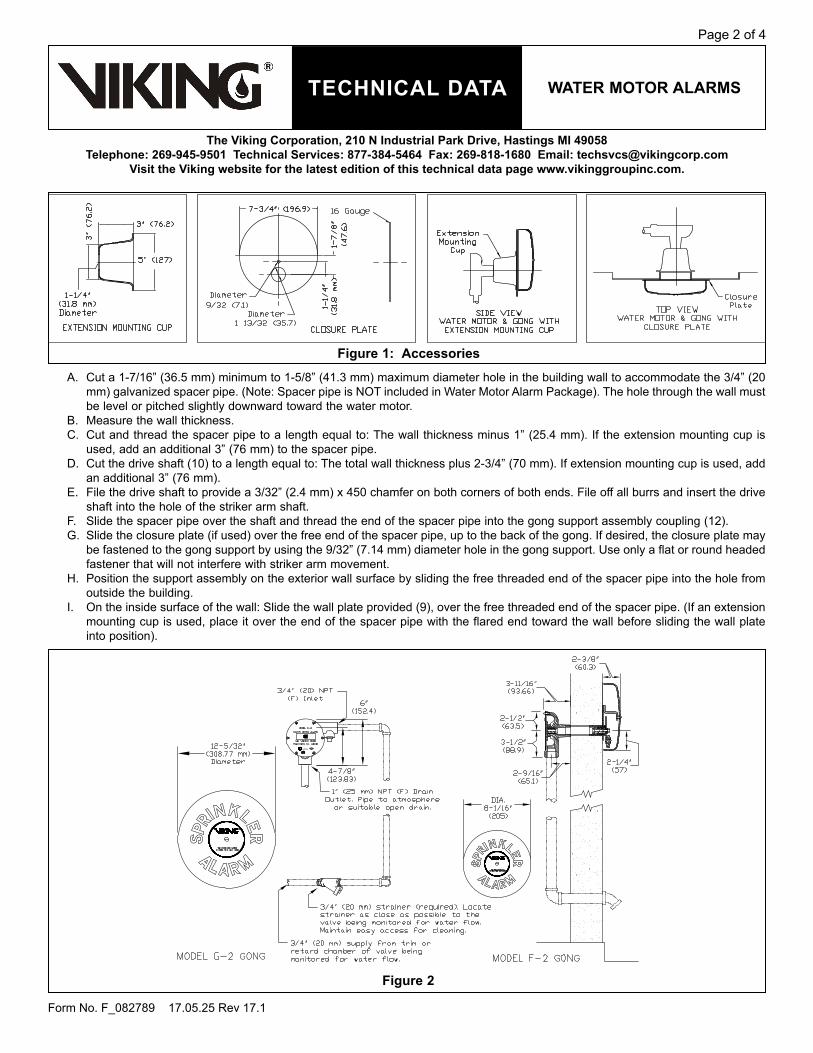
A. Cut a 1-7/16” (36.5 mm) minimum to 1-5/8” (41.3 mm) maximum diameter hole in the building wall to accommodate the 3/4” (20 mm) galvanized spacer pipe. (Note: Spacer pipe is NOT included in Water Motor Alarm Package). The hole through the wall must be level or pitched slightly downward toward the water motor.
B. Measure the wall thickness.C. Cut and thread the spacer pipe to a length equal to: The wall thickness minus 1” (25.4 mm). If the extension mounting cup is
used, add an additional 3” (76 mm) to the spacer pipe.D. Cut the drive shaft (10) to a length equal to: The total wall thickness plus 2-3/4” (70 mm). If extension mounting cup is used, add
an additional 3” (76 mm).E. File the drive shaft to provide a 3/32” (2.4 mm) x 450 chamfer on both corners of both ends. File off all burrs and insert the drive
shaft into the hole of the striker arm shaft.F. Slide the spacer pipe over the shaft and thread the end of the spacer pipe into the gong support assembly coupling (12). G. Slide the closure plate (if used) over the free end of the spacer pipe, up to the back of the gong. If desired, the closure plate may
be fastened to the gong support by using the 9/32” (7.14 mm) diameter hole in the gong support. Use only a flat or round headed fastener that will not interfere with striker arm movement.
H. Position the support assembly on the exterior wall surface by sliding the free threaded end of the spacer pipe into the hole from outside the building.
I. On the inside surface of the wall: Slide the wall plate provided (9), over the free threaded end of the spacer pipe. (If an extension mounting cup is used, place it over the end of the spacer pipe with the flared end toward the wall before sliding the wall plate into position).
Figure 1: Accessories
Figure 2

TECHNICAL DATA wATEr moTor ALArms
Page 3 of 4
Form No. F_082789 17.05.25 Rev 17.1
The Viking Corporation, 210 N Industrial Park Drive, Hastings mI 49058Telephone: 269-945-9501 Technical services: 877-384-5464 Fax: 269-818-1680 Email: [email protected]
Visit the Viking website for the latest edition of this technical data page www.vikinggroupinc.com.
J. Remove the plastic thread protectors from the threaded openings in the body of the water motor. K. Attach the water motor assembly by threading the body (3) onto the free threaded end of the spacer pipe. The chamfered ends
of the drive shaft allow it to slide into position as the water motor body is threaded onto the spacer pipe. When the assembly is properly tightened, the water motor should be positioned with the 1” (25 mm) NPT drain outlet facing downward and the 3/4” (20 mm) NPT alarm line inlet horizontal. See Figures 1 and 3.
L. Attach the gong, the flat washer, and the gong label (16, 17, and 18) to the gong support installed on the exterior surface of the wall, with the 5/16-18 x 12” (13 mm) screw (19). Note: The flat washer must be installed between the gong and the gong support (17).
M. With galvanized, brass, or other approved corrosion-resistant piping, not less than 3/4” (20 mm) diameter, connect the water motor inlet to the alarm outlet of the waterflow detecting device. A 3/4” (20 mm) strainer (included) is required on the alarm line as close as possible to the alarm outlet of the waterflow detecting device (or outlet of the retard chamber if used). The location must be easily accessible for cleaning.
N. The drain outlet of the impeller housing must discharge to an open drain. Care shall be taken to keep the drain line clean at all times. O. Note: A water motor drain line that:
1. Has too many fittings, and/or2. Has a very short length of pipe between the 1” (25 mm) outlet and the first elbow in the water motor drain pipe, and/or 3. Is very long may result in slow drainage and reduced water motor speed. This condition can be remedied by increasing the
drain pipe diameter, increasing the length of pipe to the first elbow, and/or pitching the pipe toward the discharge location.
5. oPErATIoN (See Figure 3)When a sprinkler system is activated, water flows from the alarm outlet of the valve, through the 3/4” (20 mm) strainer and alarm line piping, into the inlet of the water motor. From the 1/8” inlet orifice, the water flows through a nozzle (4), which restricts the flow into a pressurized stream directed onto the impeller (7). Force from the water stream turns the impeller and drive shaft (10), causing the striker arm (20) to rotate. The striker (25) impacts against the gong (16), producing a continuous alarm. A minimum of 5 PSI (.34 bar) is required at the nozzle to cause a continuous alarm. When properly installed, the Model F-2 Water Motor Alarm produces the required 90 decibel output and the Model G-2 produces 100 decibels. After passing through the water motor, the water is discharged through a 1” (25 mm) drain outlet in the bottom of the impeller housing. The discharged water must be piped through the wall to atmosphere or to a suitable open drain.
6. INsPECTIoNs, TEsTs AND mAINTENANCEWeather-resistant materials are used in the construction of the water motor alarm. At regular intervals, examine and test the water motor to ensure that the nozzle and drain line are clean and free of obstruction, and that the alarm functions properly. Also, at regular intervals and before disassembly of the water motor, clean and inspect the alarm line strainer located at the alarm outlet of the water-flow detecting device, or the outlet of the retard chamber, if used. (Note: Some retard chambers may be equipped with a strainer built in). For minimum maintenance and inspection requirements, refer to NFPA 25. In addition, the Authority Having Jurisdiction may have additional maintenance, testing, and inspection requirements that must be followed. Before proceeding with disassembly of the water motor alarm, notify the Authority Having Jurisdiction and occupants of the area covered by the system affected. Take all appropriate precautions. The water motor alarm will be disabled during disassembly.A. water motor Disassembly (See Figure 3)
1. Isolate the water motor alarm by closing the alarm line valve in the trim of the waterflow detecting device. (Refer to appropri-ate technical data for the system used.)
2. Remove pipe plug (5).3. Remove all round head machine screws (1) from the water motor cover.4. Separate the cover (2) and the gasket (6) from the housing (3).5. Remove the impeller (7).6. Inspect and, if necessary, carefully clean the nozzle (4) with a wire or pipe cleaner brush.7. Flush the nozzle way and drain line with water or compressed air.
B. water motor re-Assembly1. Re-install the pipe plug (5).2. Re-install the impeller (7).3. Replace cover gasket (6) and attach cover (2) by using round head machine screws (1).4. Open the alarm line valve.5. Test the water motor alarm.6. When test is complete and water motor alarm operation is satisfactory, place the alarm line valve in the proper “alarm” posi-
tion. Reset and return the affected systems to service.
7. AVAILABILITYViking Water Motor Alarms are available through a network of domestic and international distributors. See the Viking Corp. Web site for closest distributor or contact The Viking Corporation.
8. GUArANTEEsFor details of warranty, refer to Viking’s current list price schedule or contact Viking directly.

TECHNICAL DATA wATEr moTor ALArms
Page 4 of 4
Form No. F_082789 17.05.25 Rev 17.1
The Viking Corporation, 210 N Industrial Park Drive, Hastings mI 49058Telephone: 269-945-9501 Technical services: 877-384-5464 Fax: 269-818-1680 Email: [email protected]
Visit the Viking website for the latest edition of this technical data page www.vikinggroupinc.com.
Figure 3: replacement Parts
ITEm No. PArT NUmBEr DEsCrIPTIoN mATErIAL No.rEQ’DF-2 G-2
1 * * Screw, R. H. Self-tap #10-24 x 3/8” lg. Zinc Plated Steel 62 07867 07870 Cover Steel 13 * * Housing Cast Iron 14 * * Nozzle Brass 15 01925S 01925S 1/2” Pipe Plug Cast Iron 16 02550B 02550B Cover Gasket Cellulose/Nitrile/Glass Blend 17 02547C 02547C Impeller Delrin 18 * * Bearing Brass: Sintered Bronze 19 05603A 05603A Wall Plate Galvanized Steel 110 05604B 05604B Drive Shaft Stainless Steel 111 -- -- 3/4” Pipe (C.O.J.) not furnished Galvanized Steel 112 * * Coupling Brass 113 02556B 02556B Striker Arm Shaft Celcon Glass Filled 114 * * Bearing Brass 115 * * Gong Support Stainless Steel 116 05821C 06508C Gong Aluminum 117 02766A 02766A Flat Washer, 11/32” ID x 11/16” ID x 1/16” Stainless Steel 118 05768A 06505C Gong Label Aluminum (F-2), Vinyl (G-2) 119 -- -- Screw, B.H. Slotted, 5/16-18 x 1/2” lg. Stainless Steel 120 * * Striker Arm Stainless Steel 121 -- -- Flat Washer, 11/32” ID x 11/16” OD x 1/16” Stainless Steel 122 -- -- Screw, H.H. Self-tap 5/16-18 x 1/2” lg. Zinc Plated Steel 123 * * Striker Pin Stainless Steel 124 * * Striker Arm Washer Stainless Steel 125 * * Striker Canvas Phenolic 1
--Indicates replacement part not available *Indicates replacement part only available in a Sub-Assembly listed below
sUB-AssEmBLIEs1-8 07863 07869 Motor Assembly
20, 23-25 02558B 02558B Striker Arm Assembly12-15, 20-25 05606C 06506C Support Assembly
Replaces Form F_082789 Rev. 15.1(Revised pressure rating)

Agency Listings
EPS10-1 and EPS10-2Alarm Pressure Switches
System Sensor EPS10 Series switches are designed for
use in wet, dry, deluge, and pre-action automatic sprinkler
systems to indicate a discharge from a sprinkler.
Features
• Sensitivityadjustmentwheel,nospecialtoolsrequired
• Reinforceddiaphragmresistspressurespikes
• Twoconduitentrances
• Bothone-andtwo-switchmodelsavailable
TheEPS10-1hasasingleSPDTswitchwhiletheEPS10-2modelcontainstwoSPDTswitches.TheEPS10Seriesfeaturesfieldadjustablepressuresensitivitytoprovideanalarmresponsebetween4and20psi.Itisfactorysettorespondat4–8psionrisingorfallingpressure.ThepressureadjustmentwheelrequiresnospecialtoolsanddoesnotaffectswitchsynchronizationontheEPS10-2.TheEPS10SeriesswitchesareNEMA4rated.
0X0A7.AY0D3A3.AY
7770-1209:147
VdSG4020028-27
S739 C5169
Specifications, EPS10-1 and EPS10-2Architectural/Engineering Specifications EPS10-1 (SPDT), EPS10-2 (2/SPDT)
ModelshallbeanEPS10-1orEPS10-2pressuretypewaterflowswitchasmanufacturedbySystemSensorofSt.Charles,IL.Theyshallbeinstalledonthesprinklersystemwithconnectionasshownonthedrawingsand/orasspecifiedherein.Pressureswitchesshallbeofthebellows-activatedtype.Switchesshallhaveamaximumservicepressureratingof300psiandshallbefactoryadjustedtooperateatapressureof4–8psi.Thereshallbeone(1)ortwo(2)SPDTcontactsratedat10.0Amp@125/250VACand2.5Amp@6/12/24VDC.Thecontractorshallfurnishandinstall,whereindicatedontheplans,pressureswitchesaccordingtoappropriateNFPAstandards.Switchesshallbeprovidedwitha½˝NPTmalepressureconnectiontobeconnectedtothealarmcheckvalveofa“wet”sprinklersystem,intotheintermediatechamberofa“dry”system,ortoapre-actionordelugevalve.Theyshallbeactivatedbyanyflowofwaterequaltoorinexcessofthedischargefromonesprinklerhead.Switchesshallprovide1knockouttypeand1openholefor½˝conduitfittingattachmentandagroundscrewprovisionforelectricalgrounding.TheswitchenclosureshallbeweatherproofandcarryaUL4x/NEMA4ratingwhenusedwithproperelectricalfittingsandconduit.Thecovershallincorporatetamper-resistantscrews.TheunitshallbelistedbyUnderwritersLaboratories,Inc.andapprovedbyFactoryMutual.

3825OhioAvenue•St.Charles,IL60174Phone:800-SENSOR2•Fax:630-377-6495
www.systemsensor.com
©2014SystemSensor.Productspecificationssubjecttochangewithoutnotice.Visitsystemsensor.comforcurrentproductinformation,includingthelatestversionofthisdatasheet.
WFDS51702•12/14
Ordering InformationPart No. DescriptionEPS10-1 AlarmWaterflowPressureSwitch,OneSPDT,
4–20PSIEPS10-2 AlarmWaterflowPressureSwitch,TwoSPDT,
4–20PSIEPSA10-1 ULC/CanadianVersionEPSA10-2 ULC/CanadianVersionReplacement PartsS07-66-02 ReplacementTamperScrewsforCoverofEPSWFDW ReplacementTamperProofWrenchforCover
ofEPS546-8000 CoverTamperSwitchforEPSSeries
Typical Sprinkler Applications
ALARMCHECKVALVE
OS & YVALVE
WATERBY-PASSVALVE
LOCAL ALARMSHUT OFFVALVE
RETARD
WATERMOTORGONG
EPS10
ALARMCHECKVALVE
OS & YVALVE
WATERBY-PASSVALVE
LOCAL ALARMSHUT OFFVALVE
RETARD
WATERMOTORGONG
EPS10
DRYPIPEVALVE
OS & YVALVE
WATERBY-PASSVALVE
LOCAL ALARMSHUT OFFVALVE
WATERMOTORGONG
CHECKVALVE
EPS10
WET SYSTEM
WET SYSTEM
DRY SYSTEM
WIRE TO ALARMINDICATING CIRCUITOF FIRE ALARMCONTROL PANEL
WIRE TO ALARMINDICATING CIRCUITOF FIRE ALARMCONTROLPANEL
WIRE TO ALARMINDICATING CIRCUITOF FIRE ALARMCONTROL PANEL
TOSPRINKLERSYSTEM
TOSPRINKLERSYSTEM
TOSPRINKLERSYSTEM
ALARMCHECKVALVE
OS & YVALVE
WATERBY-PASSVALVE
LOCAL ALARMSHUT OFFVALVE
RETARD
WATERMOTORGONG
EPS10
ALARMCHECKVALVE
OS & YVALVE
WATERBY-PASSVALVE
LOCAL ALARMSHUT OFFVALVE
RETARD
WATERMOTORGONG
EPS10
DRYPIPEVALVE
OS & YVALVE
WATERBY-PASSVALVE
LOCAL ALARMSHUT OFFVALVE
WATERMOTORGONG
CHECKVALVE
EPS10
WET SYSTEM
WET SYSTEM
DRY SYSTEM
WIRE TO ALARMINDICATING CIRCUITOF FIRE ALARMCONTROL PANEL
WIRE TO ALARMINDICATING CIRCUITOF FIRE ALARMCONTROLPANEL
WIRE TO ALARMINDICATING CIRCUITOF FIRE ALARMCONTROL PANEL
TOSPRINKLERSYSTEM
TOSPRINKLERSYSTEM
TOSPRINKLERSYSTEM
Pressure Switch Basic Dimensions Electrical Connections
HEXADJUSTMENTSCREW
MAIN ADJUSTMENTWHEEL
41/4˝
51/8˝
LOCKINGSCREW
1/2˝ NPT
COM
AB
GROUNDSCREW(GREEN) SWITCH #2
MODEL EPS10-1
ACOM
BSWITCH AT 0 PSI
SWITCH AT 4-8 PSI (HIGH TRIP PT.)B
COMASWITCH 1
MODEL EPS10-2SWITCHES AT 0 PSI
BCOM
A
BCOM
A
ACOM
B
ACOM
B
BOTH SWITCHES ACTIVATE SIMULTANEOUSLYSW1 SW2
SW1 SW2SWITCHES AT 4-8 PSI (HIGH TRIP PT.)
MODEL EPS10-1
ACOM
BSWITCH AT 0 PSI
SWITCH AT 4-8 PSI (HIGH TRIP PT.)B
COMASWITCH 1
MODEL EPS10-2SWITCHES AT 0 PSI
BCOM
A
BCOM
A
ACOM
B
ACOM
B
BOTH SWITCHES ACTIVATE SIMULTANEOUSLYSW1 SW2
SW1 SW2SWITCHES AT 4-8 PSI (HIGH TRIP PT.)
Specifications, EPS10-1 and EPS10-2 (continued)Physical/Operating Specifications
Maximum Operating Pressure
300psi Operating Temperature Range
Indoororoutdooruse:–40°Fto160°F(–40°Cto71°C)
Maximum Adjustment Pressure Range
4to20psi Cover Tamper Switch ULModels:OptionalP/N546-8000ULCModels:FactoryInstalled
Differential Approximately3psithroughoutrange Enclosure RatedUL4x,NEMA4forindoororoutdooruse
Factory Setting Operatesatrisingpressure4to8psi Shipping Weight 1.2lbs.(.54Kg)Switch Contact Ratings
EPS10-1:OnesetSPDT(FormC)EPS10-2:TwosetsSPDT(FormC)10.0A,½HP@125/250VAC2.5A@6/12/24VDC
Service Use AutomaticSprinkler:NFPA13OneorTwoFamilyDwelling:NFPA13DResidentialOccupanciesupto4Stories:NFPA13RNationalFireAlarmCode:NFPA72
Pressure Connection ½˝NPTmaleglassreinforcednylon Warranty 3yearsDimensions 5.12˝H×3.325˝W×4.250˝L
(13.0cm×8.4cm×10.8cm)

Agency Listings
EPS40-1 and EPS40-2Supervisory Pressure Switches
System Sensor EPS40 Series switches are designed
for use in dry pipe systems or pressure tanks and water
pressure supplies of automatic water control valves.
Features
• Sensitivity adjustment wheel, no special tools required
• Reinforced diaphragm resists pressure spikes
• Two conduit entrances
• Both one- and two-switch models available
The EPS40-1 has a single SPDT switch while the EPS40-2 model contains two SPDT switches. The EPS40 Series features field adjustable pressure sensitivity to provide an alarm response between 10 and 100 psi. All models are factory set for use in a nominal 40 psi system. The EPS40-1 is factory set to respond at 30 psi at decreasing pressure while the EPS40-2 is factory set to respond at 50 psi on rising pressure and 30 psi at decreasing pressure. The pressure adjustment wheel requires no special tools and does not affect switch synchronization on the EPS40-2. The EPS40-1 and EPS40-2 supervisory pressure switches are NEMA 4 rated.
S739
Specifications, EPS40-1 and EPS40-2Architectural/Engineering Specifications EPS40-1 (SPDT), EPS40-2 (2/SPDT)
Model shall be an EPS40-1 or EPS40-2 pressure type waterflow switch as manufactured by System Sensor of St. Charles, IL. They shall be installed on the sprinkler system with connection as shown on the drawings and/or as specified herein. Pressure switches shall be of the bellows-activated type. Switches shall have a maximum service pressure rating of 300 psi and shall be adjustable from 10 – 100 psi. There shall be one (1) or two (2) SPDT contacts rated at 10.0 Amp @ 125/250 VAC and 2.5 Amp @ 6/12/24 VDC. The contractor shall furnish and install, where indicated on the plans, pressure switches according to appropriate NFPA standards. Switches shall be provided with a ½˝ NPT male pressure connection to be connected into the air supply line on the system side of any shut-off valve. Switches shall provide 1 knockout type and 1 open hole for ½˝ conduit fitting attachment and a ground screw provision for electrical grounding.The switch enclosure shall be weatherproof and carry a UL 4x/NEMA 4 rating when used with proper electrical fittings and conduit. The cover shall incorporate tamper-resistant screws. The unit shall be listed by Underwriters Laboratories, Inc., the California State Fire Marshal, MEA, CSFM, LPCB, VdS and approved by Factory Mutual.
0X0A7.AY0D3A3.AY
VdSG4020027 7770-1653:0117
LPCB
LOSSP
RE
VE
NTIO
N CERTIFICATIO
NB
OA
RD
118f/01
C5169

3825 Ohio Avenue • St. Charles, IL 60174 Phone: 800-SENSOR2 • Fax: 630-377-6495
www.systemsensor.com
©2014 System Sensor.Product specifications subject to change without notice. Visit systemsensor.com
for current product information, including the latest version of this data sheet.WFDS51801 • 5/14
Ordering InformationPart No. DescriptionEPS40-1 Low Pressure Supervisory Switch, One SPDT, 10–100 PSIEPS40-2 High/Low Pressure Supervisory Switch, Two SPDT, 10–100 PSIEPSA40-1 Low Pressure Supervisory Switch, One SPDT, 10–100 PSI (ULC Model)EPSA40-2 High/Low Pressure Supervisory Switch, Two SPDT, 10–100 PSI (ULC Model)Replacement PartsS07-66-XX Replacement Tamper Screws for Cover of EPSWFDW Replacement Tamper Proof Wrench for Cover of EPS546-8000 Cover Tamper Switch for EPS Series
Typical Sprinkler Applications
Pressure Switch Basic DimensionsElectrical Connections
HEXADJUSTMENTSCREW
MAIN ADJUSTMENTWHEEL
41/4˝
51/8˝
LOCKINGSCREW
1/2˝ NPT
COM
AB
GROUNDSCREW(GREEN) SWITCH #2
Specifications, EPS40-1 and EPS40-2 (continued)Physical/Operating Specifications
Maximum Operating Pressure
300 psi Operating Temperature Range
Indoor or outdoor use: –40°F to 160°F (–40°C to 71°C)
Maximum Adjustment Pressure Range
10 to 100 psi Cover Tamper Switch UL Models: Optional P/N 546-8000 ULC Models: Factory Installed
Differential Approximately 3 psi @ 10 psi, 6 psi @ 100 psi
Enclosure Rated UL 4x, NEMA 4 for indoor or outdoor use
Factory Setting EPS40-1 operates at decreasing pressure at 30 psiEPS40-2 operates at increasing pressure at 50 psi and decreasing pressure at 30 psi
Shipping Weight 1.2 lbs. (.54 Kg)
Switch Contact Ratings
EPS10-1: One set SPDT (Form C) EPS10-2: Two sets SPDT (Form C) 10.0 A, ½ HP @ 125/250 VAC2.5 A @ 6/12/24 VDC
Service Use Automatic Sprinkler: NFPA 13 One or Two Family Dwelling: NFPA 13D Residential Occupancies up to 4 Stories: NFPA 13R National Fire Alarm Code: NFPA 72
Pressure Connection ½˝ NPT male Warranty 3 yearsDimensions 5.12˝ H × 3.325˝ W × 4.250˝ L (13.0 cm × 8.4 cm × 10.8 cm)
DRYPIPEVALVE
OS & YVALVE
WATERBY-PASS
TESTVALVE
LOCAL ALARMSHUT OFF
VALVE
WATERMOTORGONG
CHECKVALVE
EPS40
CHECKVALVE
AIR LINESHUT-OFFVALVE
INSTALLBLEEDERVALVE FORTESTING
EPS40
DRY SYSTEM
WIRE TO SUPERVISORYCIRCUIT OF FIRE ALARMCONTROL PANEL
WIRE TO ALARMINDICATING CIRCUITOF FIRE ALARMCONTROL PANEL
TOSPRINKLERSYSTEM
MODELS EPS40-1
SWITCH AT 40 P.S.I. (NORMAL)
SWITCH AT 30 P.S.I. (LOW TRIP PT.)B
COMA
ACOM
B
SWITCH 1
SW2SW1
SWITCHES AT 40 P.S.I. (NORMAL)
SWITCHES AT 30 P.S.I. (LOW TRIP PT.)
SW1 SW2
MODELS EPS40-2
SWITCHES AT 50 P.S.I. (HIGH TRIP PT.)
SW1 SW2
BCOM
A
BCOM
A
BCOM
A
ACOM
B
ACOM
B
ACOM
B

air pressure maintenance device
model d-2 tecHnical data
November 25, 2013 Dry Systems 127a
the viking corporation, 210 n industrial park drive, Hastings mi 49058telephone: 269-945-9501 technical services: 877-384-5464 Fax: 269-818-1680 email: [email protected]
1. descriptionThe Viking Model D-2 Air Pressure Maintenance Device is a pressure regulator that automatically reduces the supply air pressure to a preset requirement when connected to a constantly maintained air supply.
2. listinGs and approvalsul listed: VIOT ulc listed: VIOTCFm approved: Pressure Maintenance Devicesnew York city Board of standards and appeals: Calendar No. 219-76-SAvds approved
3. tecHnical dataspecifications:A. Replaceable air filter.B. Ball check to prevent backflow.C. Restriction 1/16” (1.59 mm) to prevent rapid repressurization of a system.D. 1/4” (8 mm) tapped inlet and outlet.E. Minimum Recommended Ambient Temperature: 40 °F (4 °C)material standards: Refer to Figure 2.ordering information:Shipping weight: 3 pounds, 8 ounces (1.59 kg).Available preassembled with bypass trim. Order Viking Part Number 07459 (includes Model D-2 Air Pressure Maintenance Device, Part Number 02280C). See Figure 1.
4. installationThe Viking Model D-2 Air Pressure Maintenance Device regulates and restricts air flow. 1. The air or nitrogen supply provided to the Viking Model D-2 Air Pressure Maintenance
Device must be continuous, clean, dry, and oil free.2. Install the Viking Model D-2 Air Pressure Maintenance Device in the air or nitrogen
supply piping between two valves to allow isolation of the device for maintenance and adjustment. A union should be installed between the outlet of the air pressure maintenance device and the downstream isolation valve for servicing.
3. Bypass piping may be provided to allow initial pressurization of system piping more rapidly than the restricted airflow through the air pressure maintenance device will allow. Bypass trim must include a valve which must be closed for the air pressure maintenance device to function. See Product Note above.
4. The air pressure maintenance device must be located in an area where the mini-mum ambient temperature is 40 °F (4 °C) or higher, and not subject to mechanical damage.
5. Determine the appropriate pressure to be maintained in the system. Refer to System Data and Technical Data for the system and components used.
6. If adjustment is necessary, refer to paragraph 6-A RESETTING.
5. operationAir pressure setting is factory set at 40 psi (2.8 bar) [inlet pressure to 175 psi (12 bar)]. Outlet pressure setting range is 5 to 75 psi (0.34 to 5.2 bar) ±2 psi (0.14 bar). Air pressure setting may be readjusted after installation. See paragraph 6-A, RESETTING. Refer to System Data and Technical Data for the system and components used.
6. inspection, tests and maintenanceThe Viking Model D-2 Air Pressure Maintenance Device should be checked for correct pressure regulation after installation or repair by noting the air pressure reading within the system. If adjustment is necessary, refer to paragraph 6-A RESETTING. The filter should also be inspected and replaced or cleaned as required.
Form No. F_041989 Replaces page 127a-d, dated February 20, 2012.(Added QR Code.).))
Viking Technical Data may be found on The Viking Corporation’s Web site at
http://www.vikinggroupinc.com.The Web site may include a more recent
edition of this Technical Data Page.
Product Note: The Viking ModelD-2 Air Pressure Maintenance Device, preassembled with bypass trim (Viking
Part Number 07459), provides the necessary isolation valves, union, and bypass trim valve. Refer to Figure 1.
Scan with smart phone to access technical and troubleshooting resources.

air pressure maintenance device
model d-2 tecHnical data
November 25, 2013Dry Systems 127b
the viking corporation, 210 n industrial park drive, Hastings mi 49058telephone: 269-945-9501 technical services: 877-384-5464 Fax: 269-818-1680 email: [email protected]
a. resettinG (Refer to Figure 2.) On installation or after repair, adjustment may be necessary.On installation or after repair, adjustment may be necessary.
1. Turn the air supply on and check the downstream pressure for desired reading.2. If adjustment of the downstream pressure is necessary:
a. Turn off the air supply. Relieve air pressure on the system side of the air pressure maintenance device.b. Loosen the lock nut (3). c. Turn the adjusting screw (1) clockwise to increase pressure or counter-clockwise to decrease pressure.d. Tighten the lock nut (3).
B. disassemBlY (Refer to Figure 2.)WarninG: do not disconnect or disassemBle tHe air pressure maintenance device WitHout clos-inG tHe inlet and outlet isolation valves. (reFer to FiGure 1.) caution: sYstem air pressure Will Be trapped BetWeen tHe outlet oF tHe air pressure maintenance device and tHe doWnstream control valve. relieve pressure BeFore proceedinG WitH disassemBlY. 1. Carefully loosen the union between the outlet of the air pressure maintenance device (AMD) and the downstream controlair pressure maintenance device (AMD) and the downstream controlAMD) and the downstream control
valve to relieve pressure.2. To prevent accidental tripping of the system, manually maintain system air pressure at a constant level while the AMD is
out of service. 3. Place the AMD in the upright position and remove the six cover screws (6) using a Phillips head screwdriver.4. Separate the cover (4) from the body (9).5. Remove the spring (11), the spring retainer (5), and diaphragm assembly (7) from the body (9).6. The Schrader valve assembly (8) is now visible inside the body (9).
c. installation oF neW parts and reassemBlY (Refer to Figure 2.)to replace the schrader valve assembly (8) only:1. Use a socket wrench with a 7/16” socket to unthread it from the body (9). Install the new Schrader valve assembly (8) and
tighten with a 7/16” socket. If this is the only part to be replaced, the AMD can now be reassembled.a. Install the diaphragm assembly (7).b. Place the spring retainer (5) in the center of the diaphragm assembly (7).c. Remove the adjustment screw (1) from the cover (4).d. Place the cover (4) onto the body (9).e. Install the six cover screws (6) using a Phillips head screwdriver.f. Place the spring (11) in the center of the cover (4).g. Reinstall the adjustment screw (1).
The AMD is now ready to be tested and installed into the valve trim. Note: When placing system in operation, open the INLET globe valve first!to replace the parts included in the repair Kit:1. Remove the six cover screws (6) from the cover (4) of the AMD using a Phillips head screwdriver.2. Separate the cover (4) from the body (9).3. Remove the spring (2), the spring retainer (5), and the diaphragm assembly (7).4. Rotate the AMD upside down to access the filter cap (18). Remove the filter cap (18) from the valve housing (10) using a
socket wrench with a 1-1/4” socket.5. With the filter (17) exposed, remove the filter seal (16) using a small flathead screwdriver. The filter (17) should now fall
easily out of the filter cap (18).6. Remove the valve housing (10) from the body (9) using a socket wrench with a 1-1/4” socket.7. Install the new valve housing (10) into the body (9).8. While holding the filter cap (18), insert the new filter (17) and new filter cap (18) onto the body (9) and tighten with the 1-1/4”
socket.9. Rotate the AMD back into the upright position. Place the new diaphragm assembly (7) into the body (9).10. Set the spring retainer (5) in the center of the diaphragm assembly (7).11. Unthread the adjustment screw (1) from the cover (4) by hand.12. Place the cover (4) onto the body (9).13. Install the six cover screws (6) using a Phillips head screwdriver.14. Place the spring (11) in the center of the cover (4).15. Reinstall the adjustment screw (1).The AMD is now ready to be tested and installed into the valve trim. Note: When placing system in operation, open the INLET globe valve first!

air pressure maintenance device
model d-2 tecHnical data
November 25, 2013 Dry Systems 127c
the viking corporation, 210 n industrial park drive, Hastings mi 49058telephone: 269-945-9501 technical services: 877-384-5464 Fax: 269-818-1680 email: [email protected]
Figure 1air maintenance device and
preassembled trim with Bypass(viking part number 07459)
7. availaBilitYThe Viking Air Pressure Maintenance Device is available through a network of domestic and international distributors. See the Viking Corp. Web site for closest distributor or contact The Viking Corporation.
8. GuaranteesFor details of warranty, refer to Viking’s current list price schedule or contact Viking directly.

air pressure maintenance device
model d-2 tecHnical data
November 25, 2013Dry Systems 127d
the viking corporation, 210 n industrial park drive, Hastings mi 49058telephone: 269-945-9501 technical services: 877-384-5464 Fax: 269-818-1680 email: [email protected]
Form No. F_041989
A = 4-13/16” (122 mm) ± 1/4” (6.4 mm) depending on pressure settingB = 2-5/32” (54.8 mm)
Figure 2air maintenance device
(viking part number 02280c)
itemno.
partnumBer description material no.
reQ’d1 02273A Adjustment Screw Brass UNS-C36000 12 01791A Spring Stainless Steel UNS-S30200 13 02275A Lock Nut Brass UNS-C36000 14 -- Cover Brass UNS-C83600 15 02276A Spring Retainer Brass UNS-C36000 16 04505A Screw, R.H.P.D. #10-24 x 5/8 Lg. Stainless Steel UNS-S30200 67 01792A Diaphragm Assembly Neoprene ASTM D2000 1
8 06418A Schrader Valve Assembly Brass UNS-C26000, Brass UNS-C36000, Stainless Steel UNS-30200 1
9 -- Body Brass UNS-C83600 110 06425B Valve Housing Brass UNS-C36000 111 02509A Spring Stainless Steel UNS-S30200 112 01803A Ball Stainless Steel UNS-S30200 113 01802A O-Ring Nitrile (Buna-N) 114 01801A Retainer Plate Brass UNS-C26000 115 01307A Retainer, Orifice Plate Brass UNS-C26000 116 02181A Filter Seal Copper UNS-C11000 117 02257A Filter Sintered Bronze 118 02271B Filter Cap Brass UNS-C36000 1
-- Indicates replacement part is not available.
suB-assemBlY6-8, 10-17 12504 Repair Kit
Replaces page 127a-d, dated February 20, 2012.(Added QR Code.).))

TECHNICAL DATA
February 21, 2013 Dry 121a
MoDEL F Dry vALvE TrIM
The viking Corporation, 210 N Industrial Park Drive, Hastings MI 49058Telephone: 269-945-9501 Technical Services: 877-384-5464 Fax: 269-818-1680 Email: [email protected]
Model F Dry valve Trimvalve Size Trim Part Number
3” 101584” 083956” 09456
Standard Trim Sets include galvanized nipples and fittings.
Notes: For use with Trim Chart on Page 121b
General Notes:
Valve must be trimmed as shown. Any deviation from trim size or arrangement may affect the proper operation of the valve.
All pipe, 3/4” (20 mm) and smaller, shall be galvanized steel except when other materials are specified in the Technical Data for the system used.
Dimensions in parentheses are millimeter and may be approximations.
Viking uses ASME fitting designations. Tees shall be called out in the following order: 1 - Largest outlet on run; 2 - Smaller outlet on run; 3 - Branch size.
Note 1: Connection for electric Alarm Pressure Switch to activate electric alarm panels. NOTE: After the Dry Valve trips, supply to this location cannot be shut off until the water supply to the Dry Valve is shut off.
Note 2: Water flow alarm connections: 3/4” (20 mm) NPT for Water Motor Alarm (strainer required) and 1/2” (15 mm) NPT for electric Alarm Pressure Switch to activate electric alarm bells.
Note 3: Recommended location for Air Supervisory Switch. Note 4: 1” (25 mm) NPT connection for sprinkler.Note 5: Locate listed Air Maintenance Device (order separately) as close to this connection as possible. Refer to installation standards.
Recommended location for connection of optional Air Maintenance Compressor.Note 6: Tube must discharge TO OPEN DRAIN. DO NOT crimp or plug tube. Secure tube to 1/2” x 9” nipple below priming water level
test valve with cable tie included in trim kit.
••
••
Form No. F_030693
4” Dry valve Shown
Replaces page 121a-d, dated January 27, 2012.(Updated figures to show D-3 Drip Check Valve)

TECHNICAL DATA
February 21, 2013Dry 121b121b
MoDEL F Dry vALvE TrIM
The viking Corporation, 210 N Industrial Park Drive, Hastings MI 49058Telephone: 269-945-9501 Technical Services: 877-384-5464 Fax: 269-818-1680 Email: [email protected]

TECHNICAL DATA
February 21, 2013 Dry 121c
MoDEL F Dry vALvE TrIM
The viking Corporation, 210 N Industrial Park Drive, Hastings MI 49058Telephone: 269-945-9501 Technical Services: 877-384-5464 Fax: 269-818-1680 Email: [email protected]
A (VALVE TAKE OUT)
CB
E
F (4" & 6" VALVES)
D
F (3" VALVE)
E
F (4" & 6" VALVES)
A (VALVE TAKE OUT)
CB
D
F (3" VALVE)
valve Size A B C D E F3” 18-1/4” (464) 12-3/16” (310) 10-9/16” (268) 19-13/16” (503) 8-1/16” (205) 16-3/4” (425)4” 18-1/4” (464) 13-5/16” (338) 10-1/2” (267) 20-3/4” (527) 8-1/16” (205) 13-5/16” (338)6” 20-1/16” (510) 13-13/16” (351) 10-15/16” (278) 21-7/16” (545) 8-1/16” (205) 13-5/8” (346)
Figure 3 - Dry valve with Conventional Trim with No Accelerator
valve Size A B C D E F3” 18-1/4” (464) 12-3/16” (310) 10-9/16” (268) 34-3/16 (875) 8-1/16” (205) 16-3/4” (425)4” 18-1/4” (464) 13-5/16” (338) 10-15/16” (278) 34-1/4” (870) 8-1/16” (205) 13-5/16” (338)6” 20-1/16” (510) 13-13/16” (351) 10-15/16” (278) 35-1/8” (892) 8-1/16” (205) 13-5/8” (346)
Figure 4 - Dry valve with Conventional Trim with Model D-2 Accelerator

TECHNICAL DATA
February 21, 2013Dry 121d121d
MoDEL F Dry vALvE TrIM
The viking Corporation, 210 N Industrial Park Drive, Hastings MI 49058Telephone: 269-945-9501 Technical Services: 877-384-5464 Fax: 269-818-1680 Email: [email protected]
D
B C
A (VALVE TAKE OUT)
E
F (4" & 6" VALVES)
F (3" VALVE)
valve Size A B C D E F3” 18-1/4” (464) 12-3/16” (310) 10-9/16” (268) 33-1/4” (845) 8-1/16” (205) 16-3/4” (425)4” 18-1/4” (464) 13-5/16” (338) 10-9/16” (268) 33-3/16” (843) 8-1/16” (205) 13-5/16” (338)6” 20-1/16” (510) 13-13/16” (351) 10-15/16” (278) 34-3/16 (875) 8-1/16” (205) 13-5/8” (346)
Figure 5 - Dry valve with Conventional Trim with Model E-1 Accelerator
Form No. F_030693 Replaces page 121a-d, dated January 27, 2012.(Updated figures to show D-3 Drip Check Valve)