Drainage Criteria Manual Vol. 2 | Colorado Springs
71
Drainage Criteria Drainage Criteria Manual Vol. 2 Manual Vol. 2 City of Colorado Springs Engineering Division Stormwater Quality Policies, Procedures and Best Management Practices (BM P s)
-
Upload
khangminh22 -
Category
Documents
-
view
0 -
download
0
Transcript of Drainage Criteria Manual Vol. 2 | Colorado Springs

Drainage Criteria Drainage Criteria
Manual Vol. 2Manual Vol. 2
City of Colorado Springs
Engineering Division
Stormwater Quality Policies, Procedures
and Best Management Practices (BMPs)

Drainage Criteria Manual
Volume 2
May 2014
30 S. Nevada Ave.
Colorado Springs, Colorado 80901
www.springsgov.com
Revised December 2020

May 2014 City of Colorado Springs i-i
Drainage Criteria Manual, Volume 2
Drainage Criteria Manual
Volume 2
Contents
List of Abbreviations and Definitions ........................................................................................... i-1 to i-5
1.0 Stormwater Management and Planning ........................................................................ 1-1 to 1-18
2.0 BMP Selection ................................................................................................................... 2-1 to 2-18
3.0 Calculating the WQCV and Runoff Reduction ............................................................. 3-1 to 3-29
4.0 Treatment BMPs ................................................................................................................ 4-1 to 4-3
5.0 Source Control BMPs .................................................................................................................. 5-1
6.0 BMP Maintenance .............................................................................................................. 6-1 to 6-4
7.0 Construction BMPs .......................................................................................................... 7-1 to 7-44
Control Measures
Volume
Control Measure Selection

i-1 City of Colorado Springs May 2014
Drainage Criteria Manual, Volume 2
List of Abbreviations > Greater Than
< Less Than
ASCE American Society of Civil Engineers
ASTM American Society for Testing and Materials
BOD Biochemical Oxygen Demand
BMPs Best Management Practices
CDPHE Colorado Department of Public Health and Environment
CDPS Colorado Discharge Permit System
cfs Cubic Feet Per Second
COD Chemical Oxygen Demand
CRS Colorado Revised Statutes
CUHP Colorado Urban Hydrograph Procedure
CWC Constructed Wetland Channel
CWCB Colorado Water Conservation Board
CWQCC Colorado Water Quality Control Commission
CWQCD Colorado Water Quality Control Division
DCIA Directly Connected Impervious Areas
DCM Drainage Criteria Manual
DO Dissolved Oxygen
DRCOG Denver Regional Council of Governments
DRURP Denver Regional Urban Runoff Program
EDB Extended Detention Basin
EMC Event Mean Concentration
EPA U.S. Environmental Protection Agency
ET Evapo-transpiration
EURV Excess Urban Runoff Volume
fps Feet per second
ft Feet
FHWA Federal Highway Administration
GB Grass Buffer
GS Grass Swale
H:V Horizontal to Vertical Ratio of a Slope
HSG Hydrologic Soil Group
i Impervious Ratio of a Catchment (Ia/100)
Ia Percent Imperviousness of Catchment
LEED Leadership in Energy and Environmental Design
LID Low Impact Development
MCM Minimum Control Measure
mg/L Milligrams per Liter
μg/L Micrograms per Liter
MDCIA Minimize Directly Connected Impervious Areas
MEP Maximum Extent Practicable
MS4 Municipal Separate Storm Sewer System
MSDS Material Safety Data Sheets
MWCOG Metropolitan Washington Council of Governments
N/A Not applicable

i-2 City of Colorado Springs May 2014
Drainage Criteria Manual, Volume 2
NPDES National Pollution Discharge Elimination System
NPV Net Present Value
NRCS Natural Resources Conservation Services
NTIS National Technical Information Service
NTU Nephelometric turbidity units
NURP Nationwide Urban Runoff Program
NVDPC Northern Virginia District Planning Commission
PA Porous Asphalt
PC Pervious Concrete
PICP Permeable Interlocking Concrete Pavers
PLD Porous Landscape Detention (term replaced by Bioretention in 2010 update)
PPS Pervious Pavement System
ppm Parts Per Million
RP Retention Pond
RPA Receiving Pervious Area
SCS Soil Conservation Service (now the NRCS)
SEWRPC Southeastern Wisconsin Regional Planning Commission
SF Sand Filter Extended Detention
SPA Separate Pervious Area
SWMM Stormwater Management Model (EPA)
SWMP Stormwater Management Plan
TOC Total Organic Carbon
TMDL Total Maximum Daily Load
TP Total Phosphorus
TSS Total Suspended Solids
UDFCD Urban Drainage and Flood Control District
UIA Unconnected Impervious Area
USCC United States Composting Council
USDCM Urban Storm Drainage Criteria Manual
USGS United States Geological Survey
WERF Water Environment Research Foundation
WQCV Water Quality Capture Volume

i-3 City of Colorado Springs May 2014
Drainage Criteria Manual, Volume 2
Definitions Best Management Practices (BMPs) - schedules of activities, prohibitions of practices, maintenance procedures,
and other management practices to prevent or reduce the pollution of State waters. BMPs also include treatment,
operating procedures, and practices to control site runoff, spillage or leaks, waste disposal, or drainage from
material storage. BMPs include structural and nonstructural controls.
City Engineer -the City Engineer or his/her designated representative.
Clean Water Act - the Federal Water Pollution Control Act (33 USC section 1251 et seq.), and any subsequent
amendments.
Construction activity - construction activity refers to ground surface disturbing activities, which include, but are
not limited to, clearing, grading, excavation, demolition, installation of new or improved haul roads and access
roads, staging areas, stockpiling of fill materials, and borrow areas. Construction does not include routine
maintenance to maintain original line and grade, hydraulic capacity, or original purpose of the facility.
Dedicated Asphalt Plants and Concrete Plants - portable asphalt plants and concrete plants that are located on or
adjacent to a construction site and that provide materials only to that specific construction site.
Earth Disturbance/Earth Disturbing Activity - a man-made alteration or disturbance of the ambient land
surface, natural cover or topography of land, including all grading, cut and fill, stockpiling of imported fill,
building, paving, landscaping and other activities which may result in, or contribute to, soil erosion or
sedimentation of the Waters of the State.
Erodibility -the susceptibility of a particular soil type to erosion by water or wind.
Erosion - the wearing away of the land surface by water, wind, ice or other geological agents, including the
detachment and movement of soil or rock fragments by water, wind, ice, gravity, or any combination thereof.
Erosion Control Measures -practices that slow or stop erosion.
Excess Urban Runoff Volume (EURV): EURV represents the difference between the developed and
pre-developed runoff volume for the range of storms that produce runoff from pervious land surfaces (generally
greater than the 2-year event).
Final Stabilization -when all earth disturbing activities at the site have been completed, and uniform vegetative
cover has been established with (for purposes of an Erosion and Stormwater Quality Control Permit) a density of
at least 70 percent of pre-disturbance levels and such cover is capable of adequately controlling soil erosion, as
determined by the City Engineer, or equivalent permanent, physical erosion reduction methods have been
employed. Also includes installation of permanent roads and structural stormwater quality BMPs and removal of
all temporary sediment controls.
Full Spectrum Detention: This practice utilizes capture and slow release of the EURV and better replicates
historic peak discharges for the full range of storm events compared to multi-stage detention practices (per
UDFCD).

i-4 City of Colorado Springs May 2014
Drainage Criteria Manual, Volume 2
Illicit Discharge - any discharge to a Municipal Separate Storm Sewer System (MS4) that is not composed
entirely of stormwater except for sources excluded in City Code.
Larger common plan of development or sale: a site where multiple separate and distinct construction
activities may be taking place at different times on different schedules.
Low Impact Development (LID): LID is a comprehensive land planning and engineering design approach to
managing stormwater runoff with the goal of mimicking the pre-development hydrologic regime. LID
emphasizes conservation of natural features and use of engineered, on-site, small-scale hydrologic controls that
infiltrate, filter, store, evaporate, and detain runoff close to its source. The terms Green Infrastructure and Better
Site Design are sometimes used interchangeably with LID.
LID Practice: LID practices are the individual techniques implemented as part of overall LID development or
integrated into traditional development, including practices such as bioretention, green roofs, permeable
pavements and other infiltration-oriented practices.
Mapping Unit - soil name and symbol given in the NRCS Soil Survey for each soil type. Most areas of the
Colorado Springs metropolitan area are included in a soil survey.
Maximum Extent Practicable (MEP): MEP is the statutory standard that establishes the level of pollutant
reductions that MS4 operators must achieve.Implementation of best management practices designed to control
stormwater runoff from the MS4 is generally the most appropriate and practicable approach for reducing
pollutants to satisfy the technology standard of MEP. This narrative standard does not currently include numeric
effluent limits. Minimizing Directly Connected Impervious Area (MDCIA): MDCIA includes a variety of runoff reduction
strategies based on reducing impervious areas and routing runoff from impervious surfaces over grassy areas to
slow runoff and promote infiltration. The concept of MDCIA has been recommended by UDFCD as a key
technique for reducing runoff peaks and volumes following urbanization. MDCIA is a key component of LID.
Municipal Separate Storm Sewer System (MS4) -a conveyance or system of conveyances (including roads with
drainage systems, municipal streets, catch basins, curbs, gutters, ditches, man-made channels, or storm drains)
owned or operated by a State, city, town, county, or other public body and designed or used for collecting or
conveying stormwater.
NPDES - as authorized by the Clean Water Act (CWA), the National Pollutant Discharge Elimination System
(NPDES) Permit Program controls water pollution by regulating point sources that discharge pollutants into
waters of the United States. Point sources are discrete conveyances such as pipes or man-made ditches.
Permanent -will remain in place for a long period of time (referring to a land-surface cover or erosion and
sediment control measure).
Runoff Coefficient - the fraction of total rainfall that will appear as runoff.
Sedimentation -the process of solid materials, both inorganic (mineral) and organic, coming to rest on the earth's
surface either above or below sea level.

i-5 City of Colorado Springs May 2014
Drainage Criteria Manual, Volume 2
Sediment -particulate solid material, either inorganic or organic, that will settle or be deposited in a liquid under
the force of gravity.
Source Control Measures - practices that control pollutants where they originate and reduce pollutants from
becoming entrained in stormwater
Stormwater - precipitation-induced surface runoff.
Stormwater Management – anything associated with the planning, maintenance, and regulation of facilities
which collect, store, treat or convey stormwater
Structural Controls - include facilities and structures which detain or retain stormwater or provide for infiltration
or evaporation of stormwater, for the purpose of or with the result of water quality enhancement.
Temporary -planned to be removed or inactivated after a period of time (referring to installation of erosion or
sediment control measures, either structural or nonstructural).
Treatment Train – a series of two or more stormwater treatment measures or BMPs
Waters of the State (State Waters) - any and all surface and subsurface waters which are contained in or flow in or
through this State, but does not include waters in sewage systems, waters in treatment works of disposal systems,
waters in potable water distribution systems, and all water withdrawn for use until use and treatment have been
completed. For the purposes of the MS4 permit, State Waters does not include subsurface waters.
Water Quality Capture Volume (WQCV): This volume represents runoff from frequent storm events such as
the 80th percentile storm. The volume varies depending on local rainfall data. Within the Colorado Springs
area, the WQCV is based on runoff from 0.6 inches of precipitation.

May 2014 City of Colorado Springs 1-i Drainage Criteria Manual, Volume 2
Chapter 1 Stormwater Management and Planning Contents 1.0 Overview/Purpose .................................................................................................................................... 1
2.0 Stormwater Quality Management .......................................................................................................... 1
2.1 Environmental Impacts of Runoff ......................................................................................................... 1
2.2 Stormwater Runoff Constituents and Sources ....................................................................................... 2
3.0 Stormwater Permit Regulations ............................................................................................................. 5
3.1 Clean Water Act Basics ......................................................................................................................... 5
3.2 Colorado's Stormwater Permitting Program .......................................................................................... 5
3.3 City of Colorado Springs MS4 Permit ................................................................................................... 6
3.4 Total Maximum Daily Loads and Stormwater Management ................................................................ 7
4.0 Four Step Process to Minimize Adverse Impacts of Urbanization ..................................................... 8
4.1 City of Colorado Springs MS4 Permit and Implementation of the Four-step Process ........................ 14
5.0 Inline Water Quality Facilities ............................................................................................................. 15
6.0 Conclusion .............................................................................................................................................. 16
7.0 References ............................................................................................................................................... 17

Chapter 1 Stormwater Management and Planning
May 2014 City of Colorado Springs 1-1 Drainage Criteria Manual, Volume 2
1.0 Overview/Purpose The Drainage Criteria Manual (DCM) – Volume 2, Stormwater Quality Policies, Procedures and Best Management Practices is meant to provide owners, developers, engineers, and contractors with information they will need to comply with local stormwater quality requirements for drainage planning/design relating to new development/ redevelopment and construction activities. The material in this manual is meant to assist users in determining what requirements apply and what control measures are necessary for a given site. As with any manual, it is impossible to be all-inclusive: addressing every situation. It is the owner’s responsibility to ensure that the work at the site is in compliance with all applicable statutes and ordinances. This manual should be used in addition to other references and personal experience.
This manual covers the following areas:
1. Basics of stormwater quality and regulatory requirements. 2. Requirements and procedures for permanent/treatment stormwater quality control measures in new
developments/significant redevelopments.
The stormwater quality criteria and requirements of this manual are meant to be in addition to the drainage requirements and criteria listed in the Drainage Criteria Manual, Volume 1. If there are any conflicts or discrepancies between the criteria and requirements of this manual and those in the Drainage Criteria Manual, Volume 1, Engineering Criteria Manual or the City Engineering Standard Specifications, the criteria and requirements in this manual take precedence.
The control measures included in the Drainage Criteria Manual, Volume 2 are not meant to be comprehensive. It is anticipated that as time goes on new technologies will be introduced as well as additional refinement of the current technologies. It is expected that the list of control measures will be expanded as time goes on. Should the owner/engineer desire use of other temporary or permanent treatment control measures, it will be necessary to submit information that supports their use and ability to adequately control stormwater quality. These requests will be reviewed on a case-by-case basis and follow procedures found in Chapters 4 and 7.
2.0 Stormwater Quality Management
Most of the public’s concerns with stormwater are usually related to flooding, not water quality. People complain when their basements flood or roads become impassable and the public suffers when severe catastrophic floods cause widespread damage to property and loss of life. Very few people are aware of the water quality impacts that stormwater has on our rivers, streams, or lakes. Stormwater runoff quality can have significant impacts on the receiving waters that affect not only the aquatic ecosystem, but also the quality of our communities. 2.1 Environmental Impacts of Runoff
Stormwater impacts streams by affecting the stream hydrology, stream morphology, water quality and aquatic ecology. The extent of impact is related to the climate, land use, and the measures implemented to address the
Stormwater Management and Planning Chapter 1
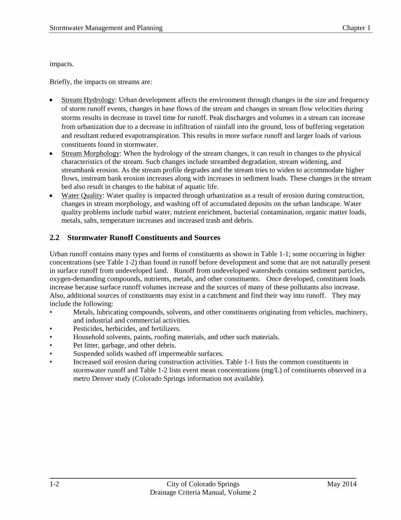
1-2 City of Colorado Springs May 2014 Drainage Criteria Manual, Volume 2
impacts. Briefly, the impacts on streams are: • Stream Hydrology: Urban development affects the environment through changes in the size and frequency
of storm runoff events, changes in base flows of the stream and changes in stream flow velocities during storms results in decrease in travel time for runoff. Peak discharges and volumes in a stream can increase from urbanization due to a decrease in infiltration of rainfall into the ground, loss of buffering vegetation and resultant reduced evapotranspiration. This results in more surface runoff and larger loads of various constituents found in stormwater.
• Stream Morphology: When the hydrology of the stream changes, it can result in changes to the physical characteristics of the stream. Such changes include streambed degradation, stream widening, and streambank erosion. As the stream profile degrades and the stream tries to widen to accommodate higher flows, instream bank erosion increases along with increases in sediment loads. These changes in the stream bed also result in changes to the habitat of aquatic life.
• Water Quality: Water quality is impacted through urbanization as a result of erosion during construction, changes in stream morphology, and washing off of accumulated deposits on the urban landscape. Water quality problems include turbid water, nutrient enrichment, bacterial contamination, organic matter loads, metals, salts, temperature increases and increased trash and debris.
2.2 Stormwater Runoff Constituents and Sources
Urban runoff contains many types and forms of constituents as shown in Table 1-1; some occurring in higher concentrations (see Table 1-2) than found in runoff before development and some that are not naturally present in surface runoff from undeveloped land. Runoff from undeveloped watersheds contains sediment particles, oxygen-demanding compounds, nutrients, metals, and other constituents. Once developed, constituent loads increase because surface runoff volumes increase and the sources of many of these pollutants also increase. Also, additional sources of constituents may exist in a catchment and find their way into runoff. They may include the following: • Metals, lubricating compounds, solvents, and other constituents originating from vehicles, machinery,
and industrial and commercial activities. • Pesticides, herbicides, and fertilizers. • Household solvents, paints, roofing materials, and other such materials. • Pet litter, garbage, and other debris. • Suspended solids washed off impermeable surfaces. • Increased soil erosion during construction activities. Table 1-1 lists the common constituents in
stormwater runoff and Table 1-2 lists event mean concentrations (mg/L) of constituents observed in a metro Denver study (Colorado Springs information not available).

Chapter 1 Stormwater Management and Planning
May 2014 City of Colorado Springs 1-3 Drainage Criteria Manual, Volume 2
Table 1-1. Common Urban Runoff Pollutant Sources
(Adapted form: Horner, R.R., J.J. Skupien, E.H. Livingston and H.E. Shaver. 1994. Fundamentals of Urban Runoff Management: Technical and Intuitional Issues. Washington, DC: Terrene Institute and EPA.)
Pollutant Category Source
Solids Nutrients Pathogens Dissolved Oxygen
Demands Metals Oils Synthetic
Organics
Soil erosion X X X X
Cleared vegetation X X X
Fertilizers X X X
Human waste X X X X
Animal waste X X X X
Vehicle fuels and fluids X X X X X
Fuel combustion X
Vehicle wear X X X
Industrial and household chemicals
X X X X X X
Industrial processes X X X X X X
Paints and preservatives
X X X
Pesticides X X X X
Stormwater facilities w/o proper maintenance1
X X X X X X X

Stormwater Management and Planning Chapter 1
1-4 City of Colorado Springs May 2014 Drainage Criteria Manual, Volume 2
Table 1-2. Event Mean Concentrations (mg/L) of Constituents in Denver Metropolitan Area Runoff
(per DRURP and Phase I Stormwater CDPS Permit Application for Denver, Lakewood and Aurora) (Source: Aurora et al. 1992. Stormwater NPDES Part 2 Permit Application Joint Appendix
and DRCOG 1983. Urban Runoff Quality in the Denver Region.
Constituent Natural Grassland
Commercial Residential Industrial
Total Phosphorus (TP) 0.40 0.42 0.65 0.43
Dissolved or Orthophosphorus (PO4) 0.10 0.15 0.22 0.2
Total Nitrogen (TN) 3.4 3.3 3.4 2.7
Total Kjeldahl Nitrogen (TKN) 2.9 2.3 2.7 1.8
Ammonia Nitrogen (NH3) 0.1 1.5 0.7 1.2
Nitrate + Nitrite Nitrogen (NO3/NO2) 0.50 0.96 0.65 0.91
Lead (Total Recoverable) (Pb) 0.100 0.059 0.053 0.130
Zinc (Total Recoverable) (Zn) 0.10 0.24 0.18 0.52
Copper (Total Recoverable) (Cu) 0.040 0.043 0.029 0.084
Cadmium (Total Recoverable) (Cd) Not
Detected 0.001 Not
Detected 0.003
Chemical Oxygen Demand (COD) 72 173 95 232
Total Organic Carbon (TOC) 26 40 72 22-26
Total Suspended Solids (TSS) 400 225 240 399
Total Dissolved Solids (TDS) 678 129 119 58
Biochemical Oxygen Demand (BOD) 4 33 17 29

Chapter 1 Stormwater Management and Planning
May 2014 City of Colorado Springs 1-5 Drainage Criteria Manual, Volume 2
3.0 Stormwater Permit Regulations 3.1 Clean Water Act Basics
The Federal Water Pollution Control Act of 1972, as amended (33 U.S.C. 1251 et seq.) is commonly known as the Clean Water Act and establishes minimum stormwater management requirements for urbanized areas in the United States. At the federal level, the EPA is responsible for administering and enforcing the requirements of the Clean Water Act. Section 402(p) of the Clean Water Act requires urban and industrial stormwater be controlled through the NPDES permit program. Requirements affect both construction and post-construction phases of development. As a result, urban areas must meet requirements of Municipal Separate Storm Sewer System (MS4) permits, and many industries and institutions such as state departments of transportation must also meet NPDES stormwater permit requirements. MS4 permittees are required to develop a Stormwater Management Program that includes measurable goals and to implement needed stormwater management controls (i.e., control measures). MS4 permittees are also required to assess controls and the effectiveness of their stormwater programs and to reduce the discharge of pollutants to the "maximum extent practicable (MEP)." Although it is not the case for every state, the EPA has delegated Clean Water Act authority to the State of Colorado. The State must meet the minimum requirements of the federal program. 3.2 Colorado's Stormwater Permitting Program
The Colorado Water Quality Control Act (25-8-101 et seq., CRS 1973, as amended) established the Colorado Water Quality Control Commission (CWQCC) within the Colorado Department of Public Health and Environment (CDPHE) to develop water quality regulations and standards, classifications of state waters for designated uses, and water quality control regulations. The Act also established the Colorado Water Quality Control Division (CWQCD) to administer and enforce the Act and administer the discharge permit system, among other responsibilities. Violations of the Act are subject to significant monetary penalties, as well as criminal prosecution in some cases.
Colorado's stormwater management regulations have been implemented in two phases and are included in Regulation No. 61 Colorado Discharge Permit System (CDPS) Regulations (CWQCC 2009). After the 1990 EPA "Phase I" stormwater regulation became effective, Colorado was required to develop a stormwater program that covered specific types of industries and storm sewer systems for municipalities with populations of more than 100,000. Phase I affected the City of Colorado Springs, Denver, Aurora, Lakewood, and the Colorado Department of Transportation (CDOT). Phase 1 requirements included inventory of stormwater outfalls, monitoring and development of municipal stormwater management requirements, as well as other requirements. Construction activities disturbing five or more acres of land were required to obtain construction stormwater discharge permits.
Phase II of Colorado's stormwater program was finalized in March 2001, establishing additional stormwater permitting requirements. Two major changes included regulation of small municipalities (≥ 10,000 and <100,000 population) in urbanized areas and requiring construction permits for sites disturbing one acre or more. The Phase II regulation resulted in a large number of new permit holders including MS4 permits for El Paso County, City of Fountain, Town of Monument, and City of Manitou Springs. In addition, there are also non-standard MS4 permittees that include entities that are not cities or counties. Non-standard MS4 permittees include entities such as Academy School District 20, Widefield School District 3, Pikes Peak Community College, Harrison School District 2, Falcon School District 49, Cheyenne Mountain School District 12, University of Colorado at Colorado Springs, and Colorado Springs School District 11. MS4 permit holders are required to develop, implement, and enforce a CDPS Stormwater Management Program designed

Stormwater Management and Planning Chapter 1
1-6 City of Colorado Springs May 2014 Drainage Criteria Manual, Volume 2
to reduce the discharge of pollutants from the MS4 to the maximum extent practicable, to protect water quality, and to satisfy the appropriate water quality requirements of the Colorado Water Quality Control Act (25-8-101 et seq., C.R.S.) and the Colorado Discharge Permit Regulations (Regulation 61). Non-standard MS4 permittees may elect to comply with their construction program and post-construction program requirements by following the requirements of the City’s or County’s construction and post-construction programs. A written agreement between the City and the holder of a Non-standard MS4 Permit is highly recommended. 3.3 City of Colorado Springs MS4 Permit
Stormwater quality protection is authorized by City Code Chapter 3, Article 8 – Storm Water Quality Management and Discharge Control Code. The City’s MS4 permit is coordinated by the City’s Stormwater Enterprise. The MS4 permit requires that they develop and implement certain programs. There are six programs within the MS4 permit and each program has specific tasks that must be achieved or completed within a given time period. The six programs include the following:
1. Commercial/Residential Management Program
2. Illicit Discharges Management Program
3. Industrial Facilities Program
4. Construction Sites Program
5. Pollution Prevention/Good Housekeeping for Municipal Operations
6. Monitoring Program
As a permittee, the City was required to develop, implement, and enforce a pollutant control program to reduce pollutants in stormwater runoff to their MS4 from construction activities that result in land disturbance of one or more acres, including projects less than one acre that are part of a larger common plan of development or sale, as well as address post-construction runoff. Under the post-construction stormwater management in new development and redevelopment provisions, the MS4 permit requires the permittee to develop, implement, and enforce a program to address stormwater runoff from new development and redevelopment projects that disturb greater than or equal to one acre, including projects less than one acre that are part of a larger common plan of development or sale, that discharge into the MS4. The program must ensure controls are in place that would prevent or minimize water quality impacts. Although MS4 general permits have historically focused on water quality, it is noteworthy that there has been increased emphasis on reducing stormwater runoff through use of Low Impact Development (LID) techniques. The City’s MS4 permit language includes the following:
Implement and document strategies which include the use of structural and/or non-structural control measures appropriate for the community, that address the discharge of pollutants from projects, or that follow principles of low-impact development to mimic natural (i.e., pre-development) hydrologic conditions at sites to minimize the discharge of pollutants and prevent or minimize adverse in-channel impacts associated with increased imperviousness.
Similarly, at the national level, the Energy Independence and Security Act of 2007 (Pub.L. 110-140) includes Section 438, Storm Water Runoff Requirements for Federal Development Projects. This section requires:
…any sponsor of any development or redevelopment project involving a federal facility with a footprint that exceeds 5,000 square feet shall use site planning, design, construction, and maintenance

Chapter 1 Stormwater Management and Planning
May 2014 City of Colorado Springs 1-7 Drainage Criteria Manual, Volume 2
strategies for the property to maintain or restore, to the maximum extent technically feasible, the predevelopment hydrology of the property with regard to the temperature, rate, volume, and duration of flow.
The minimum measures required for development projects to satisfy the City’s MS4 permit requirements are described in Section 4.1 of this chapter.
3.4 Total Maximum Daily Loads and Stormwater Management
Section 303(d) of the Clean Water Act requires states to develop a list of water bodies that are not attaining water quality standards for their designated uses, and to identify relative priorities for addressing the impaired water bodies. States must then develop Total Maximum Daily Loads (TMDLs) to assign allowable pollutant loads to various sources to enable the water body to meet the designated uses established for that water body. Implementation plans to achieve the loads specified under TMDLs commonly rely on control measures to reduce pollutant loads associated with stormwater sources.
In the context of this manual, it is important for designers, planners and other stormwater professionals to understand TMDLs because TMDL provisions can directly affect stormwater permit requirements and control measure selection and design. EPA provides this basic description of TMDLs:
A TMDL is a calculation of the maximum amount of a pollutant that a waterbody can receive and still meet water quality standards, and an allocation of that load among the various sources of that pollutant. Pollutant sources are characterized as either regulated stormwater, sometimes called "point sources" that receive a waste load allocation (WLA), or nonpoint sources that receive a load allocation (LA). Point sources include all sources subject to regulation under the NPDES program (e.g., wastewater treatment facilities, most municipal stormwater discharges and concentrated animal feeding operations). Nonpoint sources include all remaining sources of the pollutant, as well as anthropogenic and natural background sources. TMDLs must also account for seasonal variations in water quality, and include a margin of safety (MOS) to account for uncertainty in predicting how well pollutant reductions will result in meeting water quality standards.
The TMDL calculation is:
TMDL = ΣWLA + ΣLA + MOS Equation 1-1
Where:
ΣWLA = the sum of waste load allocations (point sources),
ΣLA = the sum of load allocations (nonpoint sources and background)
MOS = the margin of safety.
Although states are primarily responsible for developing TMDLs, EPA is required to review and approve or disapprove TMDLs. EPA has developed a basic "TMDL Review Checklist" with the minimum recommended elements that should be present in a TMDL document.
Once EPA approves a TMDL, there are varying degrees of impact to communities involved in the process, generally differentiated among whether point sources or non-point sources of pollution are identified in the TMDL. Permitted stormwater discharges are considered point sources. Essentially, this means that wastewater or stormwater permit requirements consistent with waste load allocations must be implemented and are enforceable under the Clean Water Act through NPDES permits.

Stormwater Management and Planning Chapter 1
1-8 City of Colorado Springs May 2014 Drainage Criteria Manual, Volume 2
If the MS4 permittee discharges into a waterbody with an approved TMDL that includes a pollutant-specific waste load allocation under the TMDL, then the CWQCD can amend the permit to include specific requirements related to that TMDL. For example, the permit may be amended to require specific control measures, and compliance schedules to implement the control measures may be required. Numeric effluent limits may also be incorporated under these provisions. TMDLs can have substantive effects on MS4 permit requirements. As an example, the City and County of Denver's MS4 permit has additional requirements to control E. coli related to the E. coli TMDL approved for the South Platte River (Segment 14). Most stream segments in Colorado Springs are currently listed as impaired for E. coli. Information on 303(d) listings and priorities for TMDL development can be obtained from the EPA and CWQCC websites.
4.0 Four Step Process to Minimize Adverse Impacts of Urbanization The City of Colorado Springs requires the Four Step Process for receiving water protection that focuses on reducing runoff volumes, treating the water quality capture volume (WQCV), stabilizing drainageways, and implementing long-term source controls. The Four Step Process pertains to management of smaller, frequently occurring storm events, as opposed to larger storms for which drainage and flood control infrastructure are sized. Implementation of these four steps helps to achieve stormwater permit requirements. Added benefits of implementing the complete process can include improved site aesthetics through functional landscaping features that also provide water quality benefits. Additionally, volume reduction can decrease required storage volumes, thus increasing developable land. The Four Step Process is applicable to all new and re-development projects with construction activities that disturb 1 acre or greater or that disturb less than 1 acre but are part of a larger common plan of development or sale.
Development is defined as any land disturbing activities.
New development is defined as the development of a previously undeveloped site. Previously undeveloped sites are defined as sites with less than 35% of hard surface coverage in the existing condition.
Redevelopment is defined as the development of a previously developed site. Previously developed sites are defined as sites that are substantially developed with 35% or more of hard surface coverage in the existing condition.
An overview of the Four Step Process follows.
Figure 1-1. The Four Step Process for Stormwater Quality Management

Chapter 1 Stormwater Management and Planning
May 2014 City of Colorado Springs 1-9
Drainage Criteria Manual, Volume 2
Step 1. Employ Runoff Reduction Practices
All land development and re-development activities that disturb 1 acre or more of property either individually or
in aggregate, are required to reduce runoff peaks, volumes, and pollutant loads from urbanizing areas, and to
implement LID strategies, including MDCIA. Runoff reduction estimates based on UDFCD-approved
calculation methods are required for all land development and re-development activities to quantify the volume
reduction achieved. For every site, including those smaller than 1 acre but part of a larger common plan of
development or sale, look for opportunities to route runoff through vegetated areas, where possible by sheet
flow. LID practices reduce unnecessary impervious areas and route runoff from impervious surfaces over
permeable areas to slow runoff (increase time of concentration) and promote infiltration. When LID/MDCIA
techniques are implemented throughout a development, the effective imperviousness is reduced, thereby
potentially reducing sizing requirements for downstream facilities. In addition, any reduction in runoff volume
can be deducted from the required WQCV for the site.
Key LID techniques include:
Conserve Existing Features: During the planning phase of development, identify portions of the site
that add value and should be protected or improved. Such areas may include mature trees, stream
corridors, wetlands, and NRCS Type A/B soils with higher infiltration rates. In order for this step to
provide meaningful benefits over the long-term, natural areas must be protected from compaction during
construction through the use of temporary construction fence or equivalent. In areas where disturbance
cannot practically be avoided, rototilling and soil amendments should be integrated to restore the
infiltration capacity of areas that will be restored with vegetation. Revegetation requirements and
additional guidance on site preparation is found in the DCM, Volume 1, Chapter 14 (Revegetation).
Minimize Impacts: Consider how the site lends itself to the desired development. In some cases,
creative site layout can reduce the extent of paved areas, thereby saving on initial capital cost of
pavement and then saving on pavement maintenance, repair, and replacement over time. Minimize
imperviousness, including constructing streets, driveways, sidewalks and parking lot aisles to the
minimum widths necessary, while still providing for parking, snow management, public safety and fire
access. When soils vary over the site, concentrate new impervious areas over NRCS Type C and D
soils, while preserving NRCS Type A and B soils for landscape areas and other permeable surfaces.
Maintaining natural drainage patterns, implementing sheet flow (as opposed to concentrated flow), and
increasing the number and lengths of flow paths will all reduce the impact of the development.

Stormwater Management and Planning Chapter 1
1-10 City of Colorado Springs May 2014
Drainage Criteria Manual, Volume 2
Differences between LID and Conventional Stormwater Quality Management
Low Impact Development (LID) is a comprehensive land planning and engineering design approach to managing stormwater runoff with a goal of replicating the pre-development hydrologic regime of urban and developing watersheds. Given the increased regulatory emphasis on LID, runoff reduction and mimicking pre-development hydrology, questions may arise related to the differences between conventional stormwater management and LID. For example, Volume 2 has emphasized MDCIA as the first step in stormwater quality planning and has provided guidance on LID techniques such as grass swales, grass buffers, permeable pavement systems, bioretention, and pollution prevention (pollutant source controls). Although these practices are all key components of LID, LID is not limited to a set of practices targeted at promoting infiltration. Key components of LID, in addition to individual BMPs, include practices such as:
An overall site planning approach that promotes conservation design at both the watershed and site levels. This approach to development seeks to "fit" a proposed development to the site, integrating the development with natural features and protecting the site's natural resources. This includes practices such as preservation of natural areas including open space, wetlands, soils with high infiltration potential, and stream buffers. Minimizing unnecessary site disturbances (e.g., grading, compaction) is also emphasized.
A site design philosophy that emphasizes multiple controls distributed throughout a development, as opposed to a central treatment facility.
The use of swales and open vegetated conveyances, as opposed to curb and gutter systems.
Volume reduction as a key hydrologic objective, as opposed to peak flow reduction being the primary hydrologic objective. Volume reduction is emphasized not only to reduce pollutant loading and peak flows, but also to move toward hydrologic regimes with flow durations and frequencies closer to the natural hydrologic regime.
Even with LID practices in place, most sites will also require centralized flood control facilities. In some cases, site constraints may limit the extent to which LID techniques can be implemented, whereas in other cases, developers and engineers may have significant opportunities to integrate LID techniques that may be overlooked due to the routine nature and familiarity of conventional approaches. This manual provides design criteria and guidance for both LID and conventional stormwater quality management, and provides additional facility sizing credits for implementing Step 1, Runoff Reduction, in a more robust manner.

Chapter 1 Stormwater Management and Planning
May 2014 City of Colorado Springs 1-11 Drainage Criteria Manual, Volume 2
Permeable pavement techniques and green roofs are common LID practices that enhance infiltration and reduce the impacts of paved areas and roofs:
o Permeable Pavement: The use of various permeable pavement techniques as alternatives to paved areas can significantly reduce site imperviousness.
o Green Roofs: Green roofs can be used to decrease imperviousness associated with buildings and structures. Benefits of green roofs vary based on design of the roof. Research is underway to assess the effectiveness of green roofs in Colorado's semi-arid climate.
Minimize Directly Connected Impervious Areas (MDCIA): Impervious areas should drain to pervious areas. Use non-hardened drainage conveyances where appropriate. Route downspouts across pervious areas, and incorporate vegetation in areas that generate and convey runoff. Three key control measures include:
o Grass Buffers: Sheet flow over a grass buffer slows runoff, encourages infiltration, and enhances sediment removal, reducing effects of the impervious area.
o Grass Swales: Like grass buffers, use of grass swales instead of hardened channels or storm sewers slows runoff and promotes infiltration, also reducing the effects of imperviousness.
o Bioretention (rain gardens): The use of distributed on-site vegetated features such as rain gardens can help maintain natural drainage patterns by allowing more infiltration onsite. Bioretention can also treat the WQCV, as described in the Four Step Process.
Historically, this critical volume reduction step has been overlooked by planners and engineers, despite WQCV reductions allowed based on MDCIA. In addition to benefiting the environment through reduced hydrologic and water quality impacts, volume reduction measures can also have the added economic benefit to the developer of increasing the area of developable land by reducing required detention volumes and potentially reducing both capital and maintenance costs.
Photograph 1-1. Permeable Pavement. Permeable pavement consists of a permeable pavement layer underlain by gravel and sand layers in most cases. Uses include parking lots and low traffic areas, to accommodate vehicles while facilitating stormwater infiltration near its source. Photo courtesy of Bill Wenk.
Photograph 1-2. Grass Buffer. This roadway provides sheet flow to a grass buffer. The grass buffer provides filtration, infiltration, and settling to reduce runoff pollutants.
Photograph 1-3. Grass Swale. This densely vegetated drainageway is designed with channel geometry that forces the flow to be slow and shallow, facilitating sedimentation while limiting

Stormwater Management and Planning Chapter 1
1-12 City of Colorado Springs May 2014 Drainage Criteria Manual, Volume 2
Step 2. Implement Control Measures That Provide a Water Quality Capture Volume with Slow Release
Step 2 requires the implementation of permanent control measures which seek to address water quality impacts from new development and redevelopment. After volume reduction through Step 1, the remaining runoff must be treated through capture and slow release or infiltration of the WQCV to the maximum extent practicable. If the design engineer proves that 80% of the WQCV is infiltrated in accordance with Step 1, Step 2 requirements are met without additional treatment measures. WQCV facilities may provide both water quality and volume reduction benefits, depending on the control measure selected. This manual provides design guidance for control measures providing treatment of the WQCV, including permeable pavement systems with subsurface storage, bioretention, extended detention basins, sand filters, and constructed wetland ponds. Chapter 3 provides background information on the development of the WQCV as well as a step-by-step procedure to calculate the WQCV. A design spreadsheet for permanent water quality facilities is provided on the City’s website. Final drainage reports must include the Colorado Springs permanent control measures spreadsheet unless a full hydrograph routing analysis is provided.
The control measures for applicable development and redevelopment sites shall be designed in accordance with this Manual and must meet one of the following design standards listed below:
1. WQCV Standard: The control measure is designed to provide treatment and/or infiltration of the WQCV and:
a. 100% of the applicable development site is captured to the maximum extent practicable.
2. Pollutant Removal Standard: The control measure is designed to treat at a minimum the 80th percentile storm event. The control measure shall be designed to treat stormwater runoff in a manner expected to reduce the event mean concentration of total suspended solids (TSS) to a median value of 30 mg/L or less. This standard may not be used on sites where full spectrum detention is required according to DCM Volume 1.
a. 100% of the applicable development site is captured to the maximum extent practicable.
3. Applicable Development Site Draining to a Sub-Regional or Regional WQCV control measure: The sub-regional or regional WQCV control measure must be designed to accept the drainage from the applicable development site in a developed condition and any offsite tributary area in accordance with Chapter 3 Section 3.0. Stormwater from the site must not discharge to a water of the state before being discharged to the sub-regional or regional WQCV control measure. The sub-regional or regional WQCV control measure must meet the design requirements in accordance with this Manual.
4. Applicable Development Site Draining to a Sub-Regional or Regional Inline WQCV Facility: The development site drains to a sub-regional or regional inline WQCV facility meeting all requirements in Chapter 1 Section 5.

Chapter 1 Stormwater Management and Planning
May 2014 City of Colorado Springs 1-13 Drainage Criteria Manual, Volume 2
Step 3. Stabilize Drainageways
Channel stabilization measures that protect open channels from erosion resulting from increases in frequency, duration, rate, and volume of runoff are required as part of the Four Step Process. The construction and operation of a full spectrum detention facility prior to discharge of developed flows does not remove the requirement for channel stabilization.
If a Stormwater Enterprise channel stabilization fee in-lieu program exists for a specific channel segment, developments adjacent to a channel may participate in that program to fulfill the requirements of Step 3.
Developments adjacent to a channel for which improvements are specified in a DBPS are responsible for completing the specified improvements. If the specified improvements constructed previously, adjacent development is not responsible for re-constructing the improvements if the existing improvements are in good condition as determined by SWENT inspection. Adjacent to a channel is defined as the first developable property measured perpendicularly from the channel outwards, regardless of the existing or planned drainage patterns. Dedicating land to the City between the channel and the development area does not relieve this requirement. If specified in a DBPS, improvements are generally considered to be reimbursable according to the fee calculations found in the DBPS. Early coordination with the City is encouraged for improvements which may be reimbursable.
All improvements based on information in a DBPS will be required to follow current criteria while matching the intended function from the DBPS.
If a development is adjacent to a channel where no improvements are specified in a DBPS, improvements are still required as part of Step 3.
Where channel improvements are required, improvements must be constructed or 100% assurances paid prior to building permit issuance. Regardless of the timing of assurances, channel improvements must be constructed prior to issuance of 50% of the building permits for the development.
Downstream impact mitigation and/or channel stabilization may be required due to physical tie-in or hydraulic requirements or if the Stormwater Enterprise Manager deems it appropriate based on site conditions. Where confusion arises, guidance should be sought from the Stormwater Enterprise Manager well in advance of a drainage submittal.
Channel analysis with consideration to velocities, shear stresses, existing vegetation, capacity, geomorphic characteristics, and other appropriate engineering variables may be utilized to prove natural channels will remain stable under post development conditions. The analysis must utilize HEC-RAS or an equivalent software and engineering variables and channel characteristics must meet the requirements of Volume 1 of the DCM. If existing channel conditions are adequately shown to be stable and in compliance with City criteria, no additional channel stabilization will be required, unless specified in an approved DBPS.
The requirements under Step 3 apply only to areas within the City limits.
Many drainageways are included in basin master plans or major drainageway plans that identify needed channel stabilization measures to accommodate developed flows. These measures not only protect infrastructure such as utilities, roads and trails, but are also important to control sediment loading from erosion of the channel itself, which can be a significant source of sediment and associated constituents, such as phosphorus, metals and other naturally occurring constituents. If stream stabilization is implemented early in the development process, it is far more likely that natural drainageway characteristics can be maintained with

Stormwater Management and Planning Chapter 1
1-14 City of Colorado Springs May 2014 Drainage Criteria Manual, Volume 2
the addition of grade control to accommodate future development. Targeted fortification of a relatively stable drainageway is typically much less costly than repairing a degraded channel. The Drainage Criteria Manual, Volume 1 provides requirements for channel stabilization, including stabilized natural channels and several engineered channel approaches. This manual also describes a Constructed Wetland Channel approach, which may provide additional water quality and community benefits. Brief descriptions of these three approaches to stabilized channels include:
Stabilized Natural Channel. Natural drainageways in and adjacent to new developments usually receive increased low flows due to urbanization even when upstream detention storage is provided. Urban development causes channels to become destabilized disturbing riparian vegetation and habitat and transporting sediment downstream. Therefore, some level of stream stabilization is always necessary. Small grade control structures sized for low flows are often an effective means of establishing a mild slope for the main channel and arresting stream degradation. Severe bends or cut banks may also need to be stabilized. When site conditions are suitable Constructed Wetland Channels can be implemented. Wetland bottoms use dense natural vegetation to slow runoff and promote settling and biological uptake. These are particularly beneficial in treatment train approaches where pre-sedimentation occurs upstream of the wetland channel. Such efforts to stabilize a natural waterway enhance aesthetics, riparian and stream habitat, and water quality. Drainageway design should always be completed in accordance with master planning documents when available.
Constructed Natural Channel. When upstream flood flows increase so that channel capacity improvements are needed and sufficient right-of-way is available, constructed natural channels can provide benefits similar to natural channels. These channels provide water quality benefits through infiltration and pollutant uptake through vegetation. Grade control structures in these channels also reduce velocities and prevent bed and bank erosion.
Engineered Channel: Engineered channels may be necessary when the upstream basin has developed without detention storage or when adjacent properties are subject to flooding or erosion. These channels are typically lined with rip-rap or cobblestone and do not enhance infiltration or water quality beyond the reduction of bed and bank erosion.
Step 4. Implement Site Specific and Other Source Control Measures
Site specific needs such as material storage or other site operations require targeted source control measures. This is often the case for new development or significant redevelopment of an industrial or commercial site. Chapter 5 includes information on source control practices such as covering storage/handling areas and spill containment and control. All new and re-development that includes outdoor storage or the potential for the introduction of contaminants to the City’s MS4 shall be required to implement site specific and/or source control measures to protect receiving waters.
4.1 City of Colorado Springs MS4 Permit and Implementation of the Four-step Process
The entire Four-Step Process is required for all land disturbance activities greater than 1 acre or less than an acre if part of a larger common plan of development or sale. Implementing volume reduction methods as described in Step 1 is an effective means of providing water quality treatment and must be implemented and quantified in order to contribute to the requirements described in Step 2. Source controls described in Step 4 may also be required under permits issued by other agencies.

Chapter 1 Stormwater Management and Planning
May 2014 City of Colorado Springs 1-15 Drainage Criteria Manual, Volume 2
5.0 Inline Water Quality Facilities Stormwater from the site may discharge to a water of the state before being discharged to the sub-regional regional inline WQCV facility if the following requirements are met.
• The inline WQCV facility must be sub-regional or regional and publicly maintained according to the City’s permanent control measure operations and maintenance program.
• The inline WQCV facility must be included in a DBPS or MDDP.
• Before discharging to a water of the state, at least 20 percent of the upstream imperviousness of the applicable development site must be disconnected from the storm drainage system and drain through a receiving pervious area control measure comprising a footprint of at least 10 percent of the upstream disconnected impervious area of the applicable development site. The control measure must be designed to meet the requirements contained in this Manual.
• The stream channel between the discharge point of the applicable development site and the inline WQCV facility must be stabilized in accordance with Step 3.
• The inline WQCV facility must be designed and maintained for 100% of the water quality storage volume for the entire tributary area based on future development conditions. This requirement holds even if upstream developments have installed their own onsite WQCV facilities. The only exception to this criterion is when multiple inline regional or sub-regional control measures are constructed in series and a detailed hydrologic model is prepared to show appropriate sizing of each control measure.
• The inline WQCV facility must have capacity to accommodate the drainage from the applicable development site.
• The inline WQCV facility must be designed and built to comply with all assumptions for the development activities planned by the permittee within its drainage area, including the imperviousness of its drainage area and the applicable development site.
• Inline WQCV facilities must be designed and implemented with flood control or water quality as the primary use. Recreational ponds and reservoirs may not be considered inline WQCV facilities. Water bodies listed by name in surface water quality classifications and standards regulations (5 CCR 1002-32 through 5 CCR 1002-38) may not be considered inline WQCV facilities.
• The applicant must demonstrate that no intakes for drinking water use exist and no other beneficial uses are expected to be impacted by pollutant discharges from the development project for the State Water upgradient from the inline WQCV facility.
• If the inline WQCV facility is not yet designed and constructed, then Steps 1-4 of the Four Step Process shall be implemented. Options for provision of control measures to treat the water quality storage volume for the development site include developer participation in the design and construction of the inline WQCV facility, design and construction of an on-site WQCV control measure, or the construction of a temporary control measure. In all cased an adequate facility

Stormwater Management and Planning Chapter 1
1-16 City of Colorado Springs May 2014 Drainage Criteria Manual, Volume 2
must be in place and operating prior to Certificate of Occupancy issuance.
When an inline WQCV facility is selected to treat the water quality storage volume for a development, the remaining three steps in the Four Step Process must still be implemented.
6.0 Conclusion Urban stormwater runoff can have a variety of chemical, biological, and physical effects on receiving waters. As a result, local governments must comply with federal, state and local requirements to minimize adverse impacts both during and following construction. Runoff mitigation measures are based on a Four Step Process focused on reducing runoff volumes, treating the remaining WQCV, stabilizing receiving drainageways and providing targeted source controls for post-construction operations at a site. Stormwater management requirements and objectives should be considered early in the site development process, taking into account a variety of factors, including the effectiveness of the control measure, long-term maintenance requirements, cost and a variety of site-specific conditions. The remainder of this manual provides requirements for selecting, designing, constructing and maintaining stormwater control measures.

Chapter 1 Stormwater Management and Planning
May 2014 City of Colorado Springs 1-17 Drainage Criteria Manual, Volume 2
7.0 References American Society of Civil Engineers and Water Environment Federation. 1992. Design and Construction of
Urban Stormwater Management Systems. ASCE Manual and Reports of Engineering Practice No. 77 and WEF Manual of Practice FD-20. Alexandria, VA: WEF.
Burton, A. and R. Pitt. 2001. Stormwater Effects Handbook: A Toolbox for Watershed Managers, Scientists, and Engineers. Lewis Publishers. http://www.epa.gov/ednnrmrl/publications/books/handbook/index.htm
Center for Watershed Protection Website: http://www.cwp.org
City of Aurora Utilities Department, City of Denver Department of Public Works, City of Lakewood Department of Planning, Permits and Public Works in cooperation with Urban Drainage and Flood Control District. 1992. Stormwater NPDES Part 3 Permit Application Joint Appendix.
Colorado Water Quality Control Division (WQCD) Website: http://www.cdphe.state.co.us/wq
Colorado Water Quality Control Division (WQCD). 2009. Authorization to Discharge under the Colorado Discharge Permit System, Permit No. COS-000001, City and County of Denver MS4 Permit.
Colorado Water Quality Control Commission (WQCC). 2009. Regulation No. 61 Colorado Discharge Permit System (CDPS) Regulations.
Colorado Water Quality Control Division (WQCD). 2008. MS4 General Permit. Permit No. COR-090000. CDPS General Permit, Stormwater Discharges Associated with Municipal Separate Storm Sewer Systems (MS4s), Authorization to Discharge under the Colorado Discharge Permit System.
Debo, T. and A. Reese. 2002. Municipal Stormwater Management. 2nd Edition. Lewis Publishers: Boca Raton, FL.
Denver Regional Council of Governments (DRCOG). 1983. Urban Runoff Quality in the Denver Region. Denver, CO.
Driscoll, E., G. Palhegyi, E. Strecker, and P. Shelley. 1990. Analysis of Storm Event Characteristics for Selected Rainfall Gauges Throughout the United States. Prepared for the U.S. Environmental Protection Agency, Woodward-Clyde Consultants: Oakland, CA.
U.S. Environmental Protection Agency (EPA) Stormwater Program Website: http://cfpub.epa.gov/npdes/home.cfm?program_id=6
U.S. Environmental Protection Agency (EPA). 2009. Federal Register Notice Regarding Stakeholder Input; Stormwater Management Including Discharges from New Development and Redevelopment. Federal Register, Vol. 74, No. 247, 68617-68622.

Stormwater Management and Planning Chapter 1
1-18 City of Colorado Springs May 2014 Drainage Criteria Manual, Volume 2
U.S. Environmental Protection Agency (EPA). 2005. Stormwater Phase II Final Rule: Small Construction Program Overview. Fact Sheet 3.0. Office of Water. http://www.epa.gov/region8/water/stormwater/pdf/fact3-0.pdf
U.S. Environmental Protection Agency (EPA). 1983. Results of the Nationwide Urban Runoff Program, Volume 1 – Final Report. U.S. Environmental Protection Agency, Water Planning Division, Washington D.C.
Horner, R.R., J.J. Skupien, E.H. Livingston and H.E. Shaver. 1994. Fundamental of Urban Runoff Management: Technical and Institutional Issues. Terrene Institute and EPA: Washington D.C.
International Stormwater Best Management Practices Database. www.bmpdatabase.org. Cosponsored by the Water Environmental Research Foundation, American Society of Civil Engineers, Environmental and Water Resources Institute, Federal Highway Administration and U.S. Environmental Protection Agency. Accessed in 2010.
Low Impact Development (LID) Center Website: http://www.lid-stormwater.net/
National Research Council. 2008. Urban Stormwater Management in the United States. National Academies Press. http://www.epa.gov/npdes/pubs/nrc_stormwaterreport.pdf
Oregon State University et al. 2006. Evaluation of Best Management Practices for Highway Runoff Control. Transportation Research Board. NCHRP-565. Corvallis, OR. http://www.trb.org/news/blurb_detail.asp?id=7184
Pitt, R., A. Maestre, H. Hyche, and N. Togawa. 2008. The Updated National Stormwater Quality Database, Version. Proceedings of the Water Environment Federation Technical Exposition and Conference. Chicago, IL.
Pitt, R., A. Maestre, and R. Morquecho. 2004. The National Stormwater Quality Database (NQSD), Version 1.1. University of Alabama: Tuscaloosa, AL.
Roesner, L.A. and B.P. Bledsoe. 2003. Physical Effects of Wet Weather Flows on Aquatic Habitats. Water Environment Research Foundation: Alexandria, VA. Co-published by IA Publishing: United Kingdom.
Shaver, E. R. Horner, J. Skupien, C. May, and G. Ridley. 2007. Fundamental of Urban Runoff Management: Technical and Institutional Issues, Second Edition. U.S. Environmental Protection and North American Lake Management Society.
Urbonas, B. and J. Doerfer. 2003. Some Observations on Atmospheric Dust Fallout in the Denver, Colorado Area of the United States. Flood Hazard News. Urban Drainage and Flood Control District: Denver, CO.

Chapter 1 Stormwater Management and Planning
May 2014 City of Colorado Springs 1-19 Drainage Criteria Manual, Volume 2
Urbonas, B., Guo, J., and L.S. Tucker. 1989. Sizing Capture Volume for Storm Water Quality Enhancement. Flood Hazard News. Urban Drainage and Flood Control District: Denver, CO.
Water Environment Federation and American Society of Civil Engineers. 1998. Urban Runoff Quality Management, WEF Manual of Practice No. 23 and ASCE Manual and Report on Engineering Practice N0; 87. Water Environment Federation (WEF): Alexandria, VA.
Watershed Management Institute. 1997. Operation, Maintenance and Management of Stormwater Management Systems. Watershed Management Institute: Ingleside, MD.
May 2014 City of Colorado Springs 2-i Drainage Criteria Manual, Volume 2
Chapter 2 Control Measure Selection Contents 1.0 Control Measure Selection ............................................................................................................... 1
1.1 Physical Site Characteristics ...................................................................................................................... 1 1.2 Space Constraints ...................................................................................................................................... 2 1.3 Targeted Pollutants and Control Measure Processes ................................................................................. 3 1.4 Storage-Based Versus Conveyance-Based ................................................................................................ 9 1.5 Runoff Reduction ...................................................................................................................................... 9 1.6 Pretreatment ............................................................................................................................................. 10 1.7 Treatment Train ....................................................................................................................................... 10 1.8 Inline Versus Offline Facility Locations ................................................................................................. 11 1.9 Integration with Flood Control ................................................................................................................ 11
1.9.1 Sedimentation Control Measures ................................................................................................. 12 1.9.2 Infiltration/Filtration Control Measures ...................................................................................... 12
1.10 Land Use, Compatibility with Surroundings, and Safety ........................................................................ 12 1.11 Maintenance and Sustainability ............................................................................................................... 13 1.12 Costs ........................................................................................................................................................ 13
2.0 Control Measure Selection Tool ........................................................ Error! Bookmark not defined.
3.0 Life Cycle Cost and Control Measure Performance Tool .......................................................... 14 3.1 Control Measure Whole Life Costs ......................................................................................................... 14 3.2 Control Measure Performance ................................................................................................................. 15 3.3 Cost Effectiveness ................................................................................................................................... 15
4.0 Conclusion ........................................................................................... Error! Bookmark not defined.
5.0 References ....................................................................................................................................... 16
Figures Figure 2-1. Control Measure Decision Tree for Highly Urbanized Sites .................................................. 13 Figure 2-2. Control Measure Decision Tree for Conventional Development Sites ................................... 14 Figure 2-3. Control Measure Decision Tree for Linear Construction in Urbanized Areas ........................ 15
Tables
Table 2-1. Primary, Secondary and Incidental Treatment Process Provided by Control Measures ............ 6 Table 2-2. Control Measure Effluent EMCs (Source: International Stormwater BMP Database,August 2010) ............................................................................................................................................................. 7

Chapter 2 Control Measure Selection
May 2014 City of Colorado Springs 2-1
Drainage Criteria Manual, Volume 2
1.0 Control Measure Selection This chapter provides requirements for selecting control measures for all new development or redevelopment projects for which construction activities disturb greater than or equal to 1 acre, including projects less than 1 acre that are part of a larger common plan of development or sale. These requirements are to be incorporated into qualifying development projects during the planning phase of a project. Control measure selection involves many factors such as physical site characteristics, treatment objectives, aesthetics, safety, maintenance requirements, and cost. Typically, there is not a single answer to the question of which control measure (or control measures) should be selected for a site; there are usually multiple solutions ranging from stand-alone control measures to treatment trains that combine multiple control measures to achieve the water quality objectives. Factors that must be considered when selecting control measures are the focus of this chapter.
1.1 Physical Site Characteristics
The first step in control measure selection is identification of physical characteristics of a site including topography, soils, contributing drainage area, groundwater, baseflows, wetlands, existing drainageways, and development conditions in the tributary watershed (e.g., construction activity). A fundamental concept of Green Infrastructure(GI) is preservation and protection of site features including wetlands, drainageways, soils that are conducive to infiltration, tree canopy, etc., that provide water quality and other benefits. GI stormwater treatment systems are also designed to take advantage of these natural resources. For example, if a portion of a site is known to have soils with high permeability, this area may be well-suited for rain gardens or permeable pavement. Areas of existing wetlands, which would be difficult to develop from a Section 404 permitting perspective, could be considered for polishing of runoff following control measure treatment, providing additional water quality treatment for the site, while at the same time enhancing the existing wetlands with additional water supply in the form of treated runoff.
Some physical site characteristics that provide opportunities for control measures or constrain control measure selection include:
Soils: Soils with good permeability, most typically associated with Hydrologic Soil Groups (HSGs) A and B provide opportunities for infiltration of runoff and are well-suited for infiltration-based control measures such as rain gardens, permeable pavement systems, sand filter, grass swales, and buffers, often without the need for an underdrain system. Even when soil permeability is low, these types of control measures may be feasible if soils are amended to increase permeability or if an underdrain system is used. In some cases, however, soils restrict the use of infiltration based control measures. When soils with moderate to high swell potential are present, infiltration should be avoided to minimize damage to adjacent structures due to water-induced swelling. In some cases, infiltration based designs can still be used if an impermeable liner and underdrain system are included in the design; however, when the risk of damage to adjacent infrastructure is high, infiltration based control measures may not be appropriate. In all cases, consult with a geotechnical engineer when designing infiltration control measures near structures. Consultation with a geotechnical engineer is necessary for evaluating the suitability of soils for different control measure types and establishing minimum distances between infiltration control measures and structures.
Watershed Size: The contributing drainage area is an important consideration both on the site level and at the regional level. On the site level, there is a practical minimum size for certain control measures, largely related to the ability to drain the WQCV over the required drain time. For example, it is technically possible to size the WQCV for an extended detention basin for a half-acre site;
Control Measure Selection Chapter 2
May 2014 City of Colorado Springs 2-2 Drainage Criteria Manual, Volume 2
however, designing a functional outlet to release the WQCV over a 40-hour drain time is practically impossible due to the very small orifices that would be required. For this size watershed, a filtering control measure, such as a rain garden, would be more appropriate. Because of their tendency for excessive clogging, extended detention basins (EDBs) are not approved for use for sites containing less than two impervious acres.
At the other end of the spectrum, there must be a limit on the maximum drainage area for a sub-regional facility to ensure adequate treatment of rainfall events that may produce runoff from only a portion of the area draining to the control measure. If the overall drainage area is too large, events that produce runoff from only a portion of the contributing area will pass through the control measure outlet (sized for the full drainage area) without adequate residence time in the control measure.
Groundwater: Shallow groundwater on a site presents challenges for control measures that rely on infiltration and for control measures that are intended to be dry between storm events. Shallow groundwater may limit the ability to infiltrate runoff or result in unwanted groundwater storage in areas intended for storage of the WQCV (e.g., porous sub-base of a permeable pavement system or in the bottom of an otherwise dry facility such as an extended detention basin). Conversely, for some types of control measures such as wetland channels or constructed wetland basins, groundwater can be beneficial by providing saturation of the root zone and/or a source of baseflow. Groundwater quality protection is an issue that should be considered for infiltration-based control measures. Infiltration control measures may not be appropriate for land uses that involve storage or use of materials that have the potential to contaminate groundwater underlying a site (i.e., "hot spot" runoff from fueling stations, materials storage areas, etc.). If groundwater or soil contamination exists on a site and it will not be remediated or removed as a part of construction, it may be necessary to avoid infiltration-based control measures or use a durable liner to prevent infiltration into contaminated areas. Design of stormwater facilities shall evaluate the potential impacts of groundwater. Investigations shall be performed to determine the potential impacts, and the results used to design stormwater facilities that function well with the site’s groundwater status.
Base Flows: Base flows are necessary for the success of some control measures such as constructed wetland ponds, retention ponds and wetland channels. Without baseflows, these control measures will become dry and unable to support wetland vegetation. For these control measures, a hydrologic budget, which accounts for the water inflow, outflow and storage shall be evaluated. Water rights are also required for these types of control measures in Colorado.
Watershed Development Activities (or otherwise erosive conditions): When development in the watershed is phased or when erosive conditions such as steep slopes, sparse vegetation, and sandy soils exist in the watershed, a treatment train approach is encouraged. Control measures that utilize filtration should be protected until the upstream watershed is completely stabilized. When naturally erosive conditions exist in the developed watershed, pretreatment measures designed to capture sediment are highly recommended. The designer shall consider existing, interim and future conditions to select the most appropriate control measures.
1.2 Space Constraints
Space constraints are frequently cited as feasibility issues for control measures, especially for high-density, setback to setback development and redevelopment sites. In some cases, constraints due to space limitations arise because adequate spaces for control measures are not considered early enough in the planning process. This is most common when a site plan for new or re-development is developed and control measures are squeezed into the remaining spaces. The most effective and integrated control measure designs begin by determining areas of a site that are best suited for control measures (e.g.,

Chapter 2 Control Measure Selection
May 2014 City of Colorado Springs 2-3
Drainage Criteria Manual, Volume 2
natural low areas, areas with well-drained soils) and then designing the layout of roads, buildings, and other site features around the existing drainage and stormwater resources of the site. Allocating a small amount of land to water quality infrastructure during early planning stages will result in better integration of water quality facilities with other site features. The Four Step Process is still required for sites with space constraints as applicable according to Chapter 1.
1.3 Targeted Pollutants and Control Measure Processes
Control measures have the ability to remove pollutants from runoff through a variety of physical, chemical and biological processes. The processes associated with a control measure dictate which pollutants the control measure will be effective at controlling. Primary processes include peak attenuation, sedimentation, filtration, straining, adsorption/absorption, biological uptake and hydrologic processes including infiltration and evapotranspiration. For many sites, a primary goal of control measures is to remove gross solids, suspended sediment and associated particulate fractions of pollutants from runoff. Processes including straining, sedimentation, and infiltration/filtration are effective for addressing these pollutants. When dissolved pollutants are targeted, other processes including adsorption/absorption and biological uptake are necessary. These processes are generally sensitive to media composition and contact time, oxidation/reduction potential, pH and other factors. In addition to pollutant removal capabilities, many control measures offer channel stability benefits in the form of reduced runoff volume and/or reduced peak flow rates for frequently occurring events. Brief descriptions of several key processes, generally categorized according to hydrologic and pollutant removal functions are listed below:
Hydrologic Processes
1. Flow Attenuation: Control measures that capture and slowly release the WQCV help to reduce peak discharges. In addition to slowing runoff, volume reduction may also be provided to varying extents in control measures providing the WQCV.
2. Infiltration: Control measures that infiltrate runoff reduce both runoff peaks and surface runoff volumes. The extent to which runoff is reduced depends on a variety of factors such as whether the control measure is equipped with an underdrain and the characteristics and long-term condition of the infiltrating media. Examples of infiltrating control measures include (unlined) sand filters, bioretention and permeable pavements. Water quality treatment processes associated with infiltration can include filtration and sorption.
3. Evapotranspiration: Runoff can be reduced through the combined effects of evaporation and transpiration in vegetated control measures. Plants extract water from soils in the root zone and transpire it to the atmosphere. Evapotranspiration is the hydrologic process provided by vegetated control measures, whereas biological uptake may help to reduce pollutants in runoff.
Pollutant Removal/Treatment Processes
1. Sedimentation: Gravitational separation of particulates from urban runoff, or sedimentation, is a key treatment process by control measures that capture and slowly release runoff. Settling velocities are a function of characteristics such as particle size, shape, density, fluid density, and viscosity. Smaller particles under 60 microns in size (fine silts and clays) (Stahre and Urbonas, 1990) can account for approximately 80% of the metals in stormwater attached or adsorbed along with other contaminants and can require long periods of time to settle out of suspension. Extended detention allows smaller particles to agglomerate into larger ones (Randall et al, 1982), and for some of the dissolved and

Control Measure Selection Chapter 2
May 2014 City of Colorado Springs 2-4 Drainage Criteria Manual, Volume 2
liquid state pollutants to adsorb to suspended particles, thus removing a larger proportion of them through sedimentation. Sedimentation is the primary pollutant removal mechanism for many treatment control measures including extended detention basins, retention ponds, and constructed wetland basins.
2. Straining: Straining is physical removal or retention of particulates from runoff as it passes through a control measure. For example, grass swales and grass buffers provide straining of sediment and coarse solids in runoff. Straining can be characterized as coarse filtration.
3. Filtration: Filtration removes particles as water flows through media (often sand or engineered soils). A wide variety of physical and chemical mechanisms may occur along with filtration, depending on the filter media. Metcalf and Eddy (2003) describe processes associated with filtration as including straining, sedimentation, impaction, interception, adhesion, flocculation, chemical adsorption, physical adsorption, and biological growth. Filtration is a primary treatment process provided by infiltration control measures. Particulates are removed at the ground surface and upper soil horizon by filtration, while soluble constituents can be absorbed into the soil, at least in part, as the runoff infiltrates into the ground. Site-specific soil characteristics, such as permeability, cation exchange potential, and depth to groundwater or bedrock are important characteristics to consider for filtration (and infiltration) control measures. Examples of filtering control measures include sand filters, bioretention, and permeable pavements with a sand filter layer.
4. Adsorption/Absorption: In the context of control measures, sorption processes describe the interaction of waterborne constituents with surrounding materials (e.g., soil, water). Absorption is the incorporation of a substance in one state into another of a different state (e.g., liquids being absorbed by a solid). Adsorption is the physical adherence or bonding of ions and molecules onto the surface of another molecule. Many factors such as pH, temperature and ionic state affect the chemical equilibrium in control measures and the extent to which these processes provide pollutant removal. Sorption processes often play primary roles in control measures such as constructed wetland basins, retention ponds, and bioretention systems. Opportunities may exist to optimize performance of control measures through the use of engineered media or chemical addition to enhance sorption processes.
5. Biological Uptake: Biological uptake and storage processes include the assimilation of organic and inorganic constituents by plants and microbes. Plants and microbes require soluble and dissolved constituents such as nutrients and minerals for growth. These constituents are ingested or taken up from the water column or growing medium (soil) and concentrated through bacterial action, phytoplankton growth, and other biochemical processes. In some instances, plants can be harvested to remove the constituents permanently. In addition, certain biological activities can reduce toxicity of some pollutants and/or possible adverse effects on higher aquatic species. Unfortunately, not much is understood yet about how biological uptake or activity interacts with stormwater during the relatively brief periods it is in contact with the biological media in most control measures, with the possible exception of retention ponds between storm events (Hartigan, 1989). Bioretention, constructed wetlands, and retention ponds are all examples of control measures that provide biological uptake.
Table 2-1 lists processes that are associated with control measures in this manual.
When selecting control measures, it is important to have realistic expectations of effluent pollutant concentrations. The International Stormwater BMP Database provides control measure performance information that is updated periodically and summarized in Table 2-2. Control measures also provide varying degrees of volume reduction benefits. Both pollutant concentration reduction and volume

Chapter 2 Control Measure Selection
May 2014 City of Colorado Springs 2-5
Drainage Criteria Manual, Volume 2
reduction are key components in the whole life cycle cost tool BMP-REALCOST.xls (Roesner and Olson 2009) discussed later in this chapter.
It is critical to recognize that for control measures to function effectively, meet performance expectations, and provide for public safety, control measures must:
1. Be designed according to DCM, Volume 2 criteria, taking into account site-specific conditions (e.g., high groundwater, expansive clays and long-term availability of water).
2. Be constructed as designed. This is important for all control measures, but appears to be particularly critical for permeable pavements, rain gardens and infiltration-oriented facilities.
3. Be properly maintained to function as designed. Although all control measures require maintenance, infiltration-oriented facilities are particularly susceptible to clogging without proper maintenance. Maintenance is not only essential for proper functioning, but also for aesthetic and safety reasons. Inspection of facilities is an important step to identify and plan for needed maintenance.
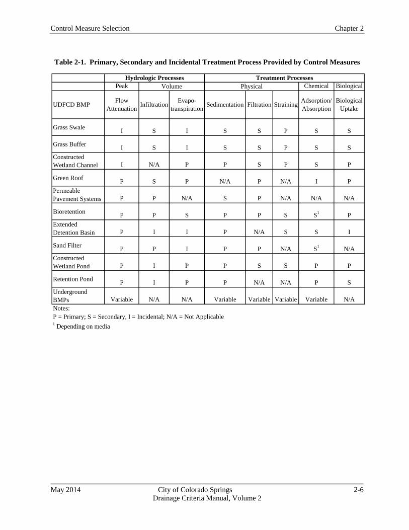
Control Measure Selection Chapter 2
May 2014 City of Colorado Springs 2-6 Drainage Criteria Manual, Volume 2
Table 2-1. Primary, Secondary and Incidental Treatment Process Provided by Control Measures
Peak Chemical Biological
Grass Swale I S I S S P S S
Grass Buffer I S I S S P S SConstructed Wetland Channel I N/A P P S P S P
Green Roof P S P N/A P N/A I PPermeable Pavement Systems P P N/A S P N/A N/A N/A
Bioretention P P S P P S S1 PExtended Detention Basin P I I P N/A S S I
Sand Filter P P I P P N/A S1 N/AConstructed Wetland Pond P I P P S S P P
Retention Pond P I P P N/A N/A P SUnderground BMPs Variable N/A N/A Variable Variable Variable Variable N/ANotes:P = Primary; S = Secondary, I = Incidental; N/A = Not Applicable1 Depending on media
Hydrologic Processes Treatment ProcessesVolume Physical
UDFCD BMP Adsorption/ Absorption
Biological Uptake
Flow Attenuation StrainingFiltrationSedimentationEvapo-
transpirationInfiltration
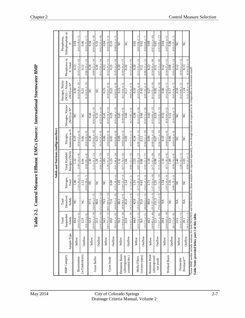
Chapter 2 Control Measure Selection
May 2014 City of Colorado Springs 2-7
Drainage Criteria Manual, Volume 2
BM
P C
ateg
ory
Sam
ple
Type
Tota
l Su
spen
ded
Solid
s
Tota
l D
isso
lved
So
lids
Nitr
ogen
, To
tal
Tota
l Kje
ldah
l N
itrog
en (T
KN
)N
itrog
en,
Am
mon
ia a
s NN
itrog
en, N
itrat
e (N
O3)
as N
*
Nitr
ogen
, Nitr
ite
(NO
2) +
Nitr
ate
(NO
3) a
s N*
Phos
phor
us a
s P,
Tot
al
Phos
phor
us,
Orth
opho
spha
te a
s P
44.6
NC
1.46
1.22
0.19
NC
0.30
0.13
0.04
(41.
8-53
.3, n
= 6)
(1.2
4-1.
63, n
= 7)
(1.0
0-1.
33, n
= 8)
(0.1
6-0.
23, n
= 8)
(0.2
5-0.
38, n
= 10
)(0
.12-
0.17
, n=
12)
(0.0
1-0.
10, n
= 7)
12.9
NC
1.15
0.94
0.06
NC
0.21
0.13
0.06
(6.8
-17.
3, n
= 6)
(0.9
2-2.
98, n
= 7)
(0.6
0-2.
09, n
= 8)
(0.0
5-0.
38, n
= 8)
(0.1
4-0.
29, n
= 10
)(0
.08-
0.19
, n=
12)
(0.0
3-0.
33, n
= 7)
52.3
57.5
NC
1.40
0.38
0.44
NC
0.18
0.04
(50.
0-63
.3, n
= 14
)(3
2.0-
89.3
, n=
12)
(1.1
5-2.
10, n
= 13
)(0
.23-
0.64
, n=
10)
(0.4
2-0.
92, n
= 13
)(0
.09-
0.25
, n=
14)
(0.0
3-0.
06, n
= 10
)22
.388
.0N
C1.
200.
250.
33N
C0.
300.
10(1
5.0-
28.3
, n=
14)
(73.
3-11
0.0,
n=
12)
(0.9
5-1.
50, n
= 13
)(0
.13-
0.36
, n=
9)(0
.23-
0.78
, n=
13)
(0.1
1-0.
56, n
= 14
)(0
.05-
0.29
, n=
10)
54.5
79.5
NC
1.83
0.06
0.41
0.25
0.22
0.04
(30.
5-76
.5, n
= 15
)(6
4.2-
100.
1, n
= 12
)(1
.40-
2.11
, n=
12)
(0.0
2-0.
09, n
= 4)
(0.2
3-0.
78, n
= 12
)(0
.19-
0.37
, n=
4)(0
.13-
0.29
, n=
15)
(0.0
3-0.
04, n
= 3)
18.0
71.0
0.60
1.23
0.05
0.29
0.22
0.23
0.10
(8.9
-39.
5, n
= 19
)(3
4.9-
85.0
, n=
10)
(0.5
5-1.
34, n
= 6)
(0.4
1-1.
48, n
= 16
)(0
.03-
0.06
, n=
8)(0
.21-
0.66
, n=
15)
(0.1
8-0.
31, n
= 8)
(0.1
9-0.
31, n
= 19
)(0
.08-
0.12
, n=
7)
59.5
88.5
1.05
1.32
0.08
0.45
0.23
0.20
NC
(17.
8-83
.8, n
= 18
)(8
5.0-
98.8
, n=
6)(1
.04-
1.25
, n=
3)(0
.77-
1.70
, n=
10)
(0.0
4-0.
10, n
= 5)
(0.3
0-0.
90, n
= 8)
(0.1
7-0.
50, n
= 5)
(0.1
8-0.
30, n
= 17
)22
.085
.02.
541.
660.
090.
400.
170.
20N
C(1
1.6-
28.5
, n=
20)
(54.
3-11
3.5,
n=
6)(1
.7-2
.69,
n=
3)(0
.86-
1.95
, n=
10)
(0.0
7-0.
10, n
= 5)
(0.2
7-0.
85, n
= 8)
(0.0
8-0.
43, n
= 6)
(0.1
3-0.
26, n
= 18
)
44.0
42.0
1.51
1.53
0.34
0.38
0.33
0.20
0.02
(32.
0-75
.0, n
= 21
)(2
8.4-
59.0
, n=
13)
(0.7
3-1.
80, n
= 5)
(0.8
7-2.
00, n
= 17
)(0
.08-
1.12
, n=
11)
(0.2
3-0.
57, n
= 16
)(0
.23-
0.51
, n=
6)(0
.13-
0.33
, n=
21)
(0.0
2-0.
06, n
= 7)
8.0
55.0
0.63
0.80
0.11
0.66
0.43
0.11
0.02
(5.0
-17.
0, n
= 21
)(4
6.0-
62.0
, n=
13)
(0.4
3-1.
41, n
= 4)
(0.5
0-1.
22, n
= 17
)(0
.04-
0.15
, n=
10)
(0.3
9-0.
73, n
= 16
)(0
.05-
1.00
, n=
5)(0
.06-
0.15
, n=
21)
(0.0
2-0.
06, n
= 7)
44.5
89.0
1.71
1.18
0.09
0.43
0.27
0.23
0.09
(24.
0-88
.3, n
= 40
)(5
9.3-
127.
5, n
= 9)
(1.0
7-2.
36, n
= 19
)(0
.77-
1.42
, n=
28)
(0.0
4-0.
15, n
= 23
)(0
.32-
0.69
, n=
15)
(0.1
1-0.
55, n
= 24
)(0
.14-
0.39
, n=
38)
(0.0
7-0.
21, n
= 26
)12
.115
1.3
1.31
0.99
0.07
0.19
0.05
0.11
0.05
(7.9
-19.
7, n
= 40
)(7
0.8-
182.
0, n
= 9)
(1.0
1-1.
54, n
= 19
)(0
.76-
1.29
, n=
30)
(0.0
4-0.
17, n
= 24
)(0
.13-
0.26
, n=
15)
(0.0
2-0.
20, n
= 24
)(0
.07-
0.19
, n=
40)
(0.0
2-0.
08, n
= 27
)
39.6
NA
1.54
1.10
0.10
0.32
0.46
0.12
0.04
(24.
0-56
.8, n
= 14
)(1
.07-
2.16
, n=
6)(0
.77-
1.30
, n=
4)(0
.04-
0.13
, n=
8)(0
.32-
0.44
, n=
5)(0
.11-
0.63
, n=
7)(0
.14-
0.27
, n=
11)
(0.0
7-0.
13, n
= 5)
12.0
NC
1.16
1.00
0.06
0.12
0.17
0.08
0.06
(8.5
-17.
5, n
= 16
)(0
.98-
1.39
, n=
6)(0
.90-
1.14
, n=
8)(0
.04-
0.10
, n=
8)(0
.10-
0.16
, n=
7)(0
.05-
0.34
, n=
7)(0
.05-
0.14
, n=
13)
(0.0
2-0.
25, n
= 7)
23.5
NA
NC
2.40
NC
NC
0.59
0.12
NC
(16.
0-45
.3, n
= 5
)(1
.80-
3.30
, n =
3)
(0.2
7-0.
80, n
= 5
)(0
.10-
0.13
, n =
5)
29.1
NA
NC
1.05
NC
NC
1.24
0.13
NC
(16.
3-34
.0, n
= 7
)(0
.90-
1.33
, n =
7)
(1.2
1-1.
39, n
= 4
)(0
.10-
0.19
, n =
5)
*Som
e B
MP
stud
ies i
nclu
de a
naly
ses f
or b
oth
NO
2/N
O3
and
NO
3; th
eref
ore,
thes
e an
alyt
es a
re re
porte
d se
para
tely
, eve
n th
ough
resu
lts a
re e
xpec
ted
to b
e co
mpa
rabl
e in
stor
mw
ater
runo
ff.
Solid
s and
Nut
rien
ts (m
illig
ram
s/lit
er)
Bio
rete
ntio
n (w
/Und
erdr
ain)
Inflo
w
Out
flow
Gra
ss B
uffe
rIn
flow
Out
flow
Gra
ss S
wal
eIn
flow
Out
flow
Det
entio
n B
asin
(a
bove
grou
nd
exte
nded
det
.)
Inflo
w
Out
flow
Med
ia F
ilter
s (v
ario
us ty
pes)
Inflo
w
Out
flow
Perm
eabl
e Pa
vem
ent*
*
Inflo
w
Out
flow
Tab
le N
otes
pro
vide
d be
low
par
t 2 o
f thi
s tab
le.
Ret
entio
n Po
nd
(abo
vegr
ound
w
et p
ond)
Inflo
w
Out
flow
Wet
land
Bas
inIn
flow
Out
flow
Tab
le 2
-2.
Con
trol
Mea
sure
Eff
luen
t E
MC
s (So
urce
: In
tern
atio
nal S
torm
wat
er B
MP

Control Measure Selection Chapter 2
May 2014 City of Colorado Springs 2-8 Drainage Criteria Manual, Volume 2
BM
P C
ateg
ory
Sam
ple
Type
Ars
enic
, D
iss.
Ars
enic
, To
tal
Cad
miu
m,
Dis
s.C
adm
ium
, To
tal
Chr
omiu
m,
Dis
s.C
hrom
ium
, To
tal
Cop
per,
Dis
s.C
oppe
r, To
tal
Lead
, D
iss.
Lead
, To
tal
Nic
kel,
Dis
s.N
icke
l, To
tal
Zinc
, D
iss.
Zinc
, To
tal
NA
NC
NC
NC
NC
NC
NC
19.5
NC
NC
NC
NC
NC
68.0
(15.
3-35
.8, n
= 3)
(51-
68.5
, n=
5)N
AN
CN
CN
CN
CN
CN
C10
.0N
CN
CN
CN
CN
C8.
5(7
.3-1
6.8,
n=
3)(5
.0-3
5.0,
n=
5)
0.8
1.1
0.2
0.4
2.4
4.9
12.9
21.2
0.9
11.0
2.9
4.8
37.8
100.
5(0
.5-1
.2, n
= 12
)(0
.9-2
.3, n
= 12
)(0
.1-0
.2, n
= 12
)(0
.3-0
.8, n
= 12
)(1
.1-4
.5, n
= 12
)(2
.9-7
.4, n
= 13
)(6
.8-1
7.3,
n=
12)
(15.
0-41
.0, n
= 13
)(0
.5-2
.0, n
= 12
)(6
-35,
n=
13)
(1.1
-3.2
, n=
12)
(3.4
-8.4
, n=
12)
(12.
8-70
, n=
12)
(53.
0-24
5.0,
n=
13)
1.2
2.0
0.1
0.2
2.3
2.9
7.1
8.3
0.5
3.2
2.1
2.6
19.8
25.5
(0.5
-2.4
, n=
12)
(0.7
-3.0
, n=
12)
(0.1
-0.2
, n=
12)
(0.1
-0.2
, n=
12)
(1.0
-3.8
, n=
12)
(2.0
-5.5
, n=
13)
(4.8
-11.
6, n
= 12
)(6
.4-1
2.5,
n=
13)
(0.5
-1.3
, n=
12)
(1.8
-6.0
, n=
13)
(2.0
-2.3
, n=
12)
(2.2
-3.2
, n=
12)
(10.
7-24
.3, n
= 12
)(1
5.0-
57.9
, n=
13)
0.6
1.7
0.3
0.5
2.2
6.1
10.6
33.0
1.4
21.6
5.1
8.7
40.3
149.
5(0
.5-2
.2, n
= 9)
(1.6
-2.7
, n=
9)(0
.1-0
.4, n
= 13
)(0
.4-0
.9, n
= 14
)(1
.1-3
.3, n
= 7)
(3.6
-8.3
, n=
7)(8
.1-1
5.0,
n=
13)
(26-
34, n
= 13
)(0
.6-6
.7, n
= 13
)(1
2.5-
46.4
, n=
14)
(4.5
-6.6
, n=
6)(7
-12.
5, n
= 6)
(35.
3-10
9.0,
n=
13)
(43.
8-24
4.3,
n=
15)
0.6
1.2
0.2
0.3
1.1
3.5
8.6
14.0
1.0
10.5
2.0
4.0
22.6
55.0
(0.6
-1.2
, n=
8)(0
.9-1
.7, n
= 8)
(0.1
-0.2
, n=
12)
(0.2
-0.4
, n=
13)
(1.0
-3.0
, n=
6)(1
.7-5
.0, n
= 6)
(5.5
-9.7
, n=
13)
(6.7
-18.
5, n
= 17
)(0
.5-4
.1, n
= 13
)(1
.7-1
2.0,
n=
18)
(2.0
-2.3
, n=
5)(3
.1-4
.5, n
= 5)
(20.
1-33
.2, n
= 13
)(2
0.6-
65.4
, n=
19)
1.1
2.1
0.3
0.6
2.6
5.6
5.8
10.0
1.0
10.0
2.9
6.3
16.4
125.
0(0
.9-1
.2, n
= 5)
(1.3
-2.6
, n=
6)(0
.2-0
.4, n
= 8)
(0.3
-1.2
, n=
11)
(2.0
-3.2
, n=
3)(5
.0-6
.5, n
= 6)
(2.6
-11.
8, n
= 8)
(4.8
-33.
5, n
= 11
)(0
.5-1
.4, n
= 8)
(1.5
-41.
0, n
= 11
)(1
.9-3
.9, n
= 4)
(5-9
.4, n
= 5)
(6.1
-53.
5, n
= 8)
(21.
5-22
5.3,
n=
11)
1.2
1.7
0.3
0.4
1.9
2.9
9.0
11.0
1.0
9.5
3.1
4.3
19.0
48.5
(0.9
-1.2
, n=
5)(1
.1-1
.9, n
= 6)
(0.2
-0.4
, n=
9)(0
.2-0
.6, n
= 12
)(1
.7-3
.0, n
= 4)
(1.9
-3.8
, n=
6)(3
.0-1
3.0,
n=
9)(6
.2-2
0.1,
n=
12)
(0.5
-1.3
, n=
9)(1
.3-1
8.6,
n=
12)
(2.0
-3.2
, n=
5)(3
.2-5
.4, n
= 6)
(7.8
-54.
0, n
= 9)
(19.
1-94
.0, n
= 13
)
0.7
1.1
0.2
0.4
1.0
2.1
6.2
13.5
1.1
9.0
2.0
3.9
42.7
86.0
(0.5
-1.1
, n=
12)
(0.6
-1.6
, n=
12)
(0.2
-0.2
, n=
14)
(0.2
-1.0
, n=
17)
(1.0
-1.0
, n=
13)
(1.4
-4.0
, n=
13)
(5.4
-7.4
, n=
13)
(8.8
-16.
4, n
= 18
)(1
.0-2
.0, n
= 14
)(5
.3-2
2.0,
n=
17)
(2.0
-2.7
, n=
13)
(3.3
-4.8
, n=
13)
(28.
5-79
.2, n
= 14
)(5
1.8-
106.
0, n
= 19
)0.
71.
10.
20.
21.
01.
05.
87.
31.
01.
62.
02.
912
.520
.0(0
.6-1
.1, n
= 12
)(0
.7-1
.6, n
= 12
)(0
.2-0
.2, n
= 13
)(0
.1-0
.7, n
= 17
)(1
.0-1
.0, n
= 13
)(1
.0-1
.9, n
= 13
)(3
.1-8
.3, n
= 13
)(4
.3-9
.6, n
= 18
)(1
.0-1
.0, n
= 13
)(1
.0-4
.4, n
= 17
)(2
.0-2
.6, n
= 13
)(2
.0-3
.9, n
= 13
)(6
.7-4
9.0,
n=
13)
(8.6
-35.
0, n
= 19
)
NC
1.0
0.2
1.0
5.9
5.0
7.0
6.3
2.0
9.7
10.0
6.5
30.0
51.8
(1.0
-1.4
, n=
3)(0
.2-0
.4, n
= 3)
(0.3
-2.6
, n=
20)
(1.6
-10.
0, n
= 4)
(3.0
-7.4
, n=
12)
(6.0
-9.5
, n=
7)(4
.3-1
0.6,
n=
26)
(1.0
-5.1
.0, n
= 11
)(4
-28,
n=
33)
(6.2
-10.
0, n
= 3)
(3.6
-9, n
= 8)
(15.
5-42
.6, n
= 8)
(43.
9-78
.1, n
= 32
)
NC
1.0
0.2
0.4
5.5
2.2
5.0
5.4
1.2
4.7
10.0
2.5
12.5
26.0
(0.8
-1.0
, n=
3)(0
.2-0
.4, n
= 3)
(0.2
-2.5
, n=
20)
(1.0
-10.
0, n
= 4)
(1.4
-5.3
, n=
12)
(4.7
-5.8
, n=
7)(3
.0-6
.2, n
= 26
)(1
.0-4
.9, n
= 12
)(1
.6-1
0.0,
n=
33)
(7.2
-10.
0, n
= 3)
(2.0
-5.5
, n=
9)(9
.4-2
8.6,
n=
8)(1
2.0-
37.0
, n=
33)
NA
NA
NC
0.3
NA
NA
NC
10.5
NC
16.0
NA
NA
NC
51.0
(0.3
-0.4
, n=
3)(4
.3-1
5.9,
n=
4)(4
.0-2
3.8,
n=
4)(4
3.9-
120.
8, n
= 7)
NA
NA
0.5
0.3
NA
NA
5.0
4.5
1.0
1.0
NA
NA
11.0
15.0
(0.3
-0.5
, n=
3)(0
.1-0
.5, n
= 5)
(5.0
-5.7
, n=
3)(3
.3-5
.0, n
= 6)
(0.8
-1.0
, n=
3)(1
.0-2
.5, n
= 6)
(11.
0-13
.1, n
= 3)
(5.0
-28.
9, n
= 9)
NA
NC
NC
NA
NC
NC
5.0
7.0
0.1
2.5
NC
NC
25.0
50.0
(2.5
-6.4
, n =
3)(4
.5-1
9.4,
n =
3)
(0.0
3-0.
3, n
= 3
)(1
.3-1
5.1,
n =
3)
(19.
0-27
.5, n
= 3
)(4
5.0-
51.0
, n =
5)
NA
NC
NC
0.3
NC
NC
6.2
9.0
0.3
2.5
NC
NC
14.6
22.0
(0.3
-0.4
, n =
3)(4
.5-6
.4, n
=4)
(3.0
-14.
7, n
= 5
)(0
.04-
0.5,
n =
4)
(1.3
-9.5
, n =
7)
(13.
5-16
.0, n
= 4
)(2
0.0-
31.6
, n =
7)
Tab
le K
ey
Sam
ple
Type
Ana
lyte
52.3
(50-
63.3
, n=
14)
22.3
(15-
28.3
, n=
14)
= In
terq
uarti
le ra
nge,
sam
ple
size
Val
ues b
elow
det
ectio
n lim
its re
plac
ed w
ith 1
/2 o
f det
ectio
n lim
it.
= M
edia
n ou
tflow
val
ue=
Inte
rqua
rtile
rang
e, sa
mpl
e si
ze=
Med
ian
inflo
w v
alue
Des
crip
tion
Inte
rqua
rtile
Ran
ge =
25t
h pe
rcen
tile
to 7
5th
perc
entil
e va
lues
, cal
cula
ted
in E
xcel
, whi
ch u
ses l
inea
r int
erpo
latio
n to
cal
cula
te p
erce
ntile
s. F
or sm
all s
ampl
e si
zes (
parti
cula
rly n
<5),
in
terq
uarti
le v
alue
s may
var
y de
pend
ing
on st
atis
tical
pac
kage
use
d.
NA
= N
ot a
vaila
ble;
stud
ies c
onta
inin
g 3
or m
ore
stor
ms n
ot a
vaila
ble.
NC
= N
ot c
alcu
late
d be
caus
e fe
wer
than
3 B
MP
stud
ies f
or th
is c
ateg
ory.
Thes
e de
scrip
tive
stat
istic
s are
bas
ed o
n di
ffere
nt st
atis
tical
mea
sure
s tha
n th
ose
used
in th
e 20
08 B
MP
Dat
abas
e ta
bula
r sum
mar
y. B
e aw
are
that
resu
lts w
ill v
ary
depe
ndin
g on
whe
ther
a "
BM
P W
eigh
ted"
(on
e m
edia
n or
ave
rage
val
ue re
pres
ents
eac
h B
MP)
or "
Stor
m
Wei
ghte
d" (a
ll st
orm
s for
all
BM
Ps in
clud
ed in
stat
istic
al c
alcu
latio
ns) a
ppro
ach
is u
sed,
as w
ell a
s whe
ther
the
med
ian
or a
noth
er m
easu
re o
f cen
tral t
ende
ncy
is u
sed.
Sev
eral
BM
P D
atab
ase
publ
icat
ions
in 2
010
have
focu
sed
on th
e st
orm
-wei
ghte
d ap
proa
ch, w
hich
may
re
sult
in so
me
diffe
renc
es b
etw
een
this
tabl
e an
d ot
her p
ublis
hed
sum
mar
ies.
Out
flow
Det
entio
n B
asin
(a
bove
grou
nd
exte
nded
det
.)
Inflo
w
Out
flow
Med
ia F
ilter
s (v
ario
us ty
pes)
Gra
ss B
uffe
rIn
flow
Out
flow
Gra
ss S
wal
eIn
flow
Out
flow
Des
crip
tive
stat
istic
s cal
cula
ted
by w
eigh
ting
each
BM
P st
udy
equa
lly.
Each
BM
P st
udy
is re
pres
ente
d by
the
med
ian
anal
yte
valu
e re
porte
d fo
r all
stor
ms m
onito
red
at e
ach
BM
P (i.
e., "
n" =
num
ber o
f BM
P st
udie
s, as
opp
osed
to n
umbe
r of s
torm
eve
nts)
. Dep
endi
ng o
n th
e an
alys
is o
bjec
tives
, res
earc
hers
may
als
o ch
oose
to u
se a
stor
m-w
eigh
ted
anal
ysis
app
roac
h, a
uni
t tre
atm
ent p
roce
ss-b
ased
gro
upin
g of
stud
ies,
or o
ther
scre
enin
g ba
sed
on d
esig
n pa
ram
eter
s and
site
-spe
cific
cha
ract
eris
tics.
Ana
lysi
s bas
ed o
n A
ugus
t 201
0 B
MP
Dat
abas
e, w
hich
con
tain
s sub
stan
tial c
hang
es re
lativ
e to
the
2008
BM
P D
atab
ase.
Mul
tiple
BM
Ps h
ave
been
reca
tego
rized
into
new
BM
P ca
tego
ries;
ther
efor
e, th
e 20
08 a
nd 2
010
data
ana
lysi
s are
not
dire
ctly
com
para
ble
for s
ever
al
BM
P ty
pes.
Th
is ta
ble
cont
ains
des
crip
tive
stat
istic
s onl
y. V
alue
s pre
sent
ed in
this
tabl
e sh
ould
not
be
used
to d
raw
con
clus
ions
rela
ted
to st
atis
tical
ly si
gnifi
cant
diff
eren
ces i
n pe
rfor
man
ce fo
r BM
P ca
tego
ries.
(Hyp
othe
sis t
estin
g fo
r BM
P C
ateg
orie
s is p
rovi
ded
sepa
rate
ly in
oth
er
BM
P D
atab
ase
sum
mar
ies a
vaila
ble
at w
ww
.bm
pdat
abas
e.or
g.)
Out
flow
**Pe
rmea
ble
pave
men
t dat
a sh
ould
be
used
with
cau
tion
due
to li
mite
d nu
mbe
rs o
f BM
P st
udie
s and
smal
l num
bers
of s
torm
eve
nts t
ypic
ally
mon
itore
d at
thes
e si
tes.
"In
flow
" va
lues
are
typi
cally
out
flow
s mon
itore
d at
a re
fere
nce
conv
entio
nal p
avin
g si
te.
Tab
le N
otes
:
Perm
eabl
e Pa
vem
ent*
*
Inflo
w
Out
flow
Inflo
w
Ret
entio
n Po
nd
(abo
vegr
ound
w
et p
ond)
Inflo
w
Out
flow
Wet
land
Bas
inIn
flow
Inflo
w
Out
flow
Met
als (
mic
rogr
ams/
liter
)
Bio
rete
ntio
n (w
/Und
erdr
ain)
Inflo
w
Out
flow

Chapter 2 Control Measure Selection
May 2014 City of Colorado Springs 2-9
Drainage Criteria Manual, Volume 2
1.4 Storage-Based Versus Conveyance-Based
Control measures in this manual generally fall into two categories: 1) storage-based and 2) conveyance-based. Storage-based control measures provide the WQCV and include bioretention/rain gardens, extended detention basins, sand filters, constructed wetland ponds, retention ponds, and permeable pavement systems. Conveyance-based control measures include grass swales, grass buffers, constructed wetlands channels and other control measures that improve quality and reduce runoff but only provide incidental storage. Conveyance-based control measures can be implemented to help achieve objectives in Step 1 of the Four Step Process. Although conveyance control measures do not satisfy Step 2 (providing the WQCV), they can reduce the volume requirements of Step 2. Storage-based control measures are critical for Step 2 of the Four Step Process. Site plans that use a combination of conveyance-based and storage-based control measures can be used to better mimic pre-development hydrology.
1.5 Runoff Reduction
Control measures that promote infiltration or that incorporate evapotranspiration have the potential to reduce the runoff generated. Runoff reduction is a fundamental objective of GI. Runoff reduction has many benefits, both in terms of hydrology and pollution control. While stormwater regulations have traditionally focused on runoff peak flow rates, emerging stormwater regulations require control measures to mimic the pre-development hydrologic budget to minimize effects of hydro-modification. From a pollution perspective, decreased runoff volume translates to decreased pollutant loads. Runoff reduction can have economic benefits, including potential reductions in storage requirements for minor and major events, reduced extent and sizing of conveyance infrastructure, and cost reductions associated with addressing channel stability issues. A computational method for quantifying volume reduction is discussed in detail in Chapter 3.
Infiltration-based control measures can be designed with or without underdrains, depending on soil permeability and other site conditions. The most substantial volume reductions are generally associated with control measures that have permeable sub-soils and allow infiltration to deeper soil strata and eventually groundwater. For control measures that have underdrains, there is still potential for volume reduction although to a lesser degree. As runoff infiltrates through control measure soils to the underdrain, moisture is retained by soils. The moisture eventually evaporates, or is taken up by vegetation, resulting in volume reduction. Runoff that drains from these soils via gravity to the underdrain system behaves like interflow from a hydrologic perspective with a delayed response that reduces peak rates. Although the runoff collected in the underdrain system is ultimately discharged to the surface, on the time scale of a storm event, there are volume reduction benefits.
Although effects of evapotranspiration are inconsequential on the time scale of a storm event, on an annual basis, volume reduction due to evapotranspiration for vegetated control measures such as retention and constructed wetland ponds can be an important component of the hydrologic budget. Between
Hydromodification
The term hydro-modification refers to altered hydrology due to increased imperviousness combined with constructed of conveyance systems (e.g., pipes) that convey stormwater efficiently to receiving waters. Hydromodification produces increased peaks, volume, frequency, and duration of flows, all of which can result in stream degradation, including stream bed down cutting, bank erosion, enlarged channels, and disconnection of streams from the floodplain. These factors lead to loss of stream and riparian habitat, reduced aquatic diversity, and can adversely impact the beneficial uses of our waterways.

Control Measure Selection Chapter 2
May 2014 City of Colorado Springs 2-10 Drainage Criteria Manual, Volume 2
events, evapotranspiration lowers soil moisture content and permanent pool storage, providing additional storage capacity for subsequent events.
Other surface control measures also provide volume reduction through a combination of infiltration, use by the vegetation and evaporation. Runoff reduction provided by a particular control measure type will be influenced by site-specific conditions and control measure design features. National research is ongoing with regard to estimating volume reduction provided by various control measure types. Based on analysis of control measure studies contained in the International Stormwater BMP Database, Geosyntec and WWE (2010) reported that normally-dry vegetated control measures (filter strips, vegetated swales, bioretention, and grass lined detention basins) appear to have substantial potential for runoff volume reduction on a long-term basis, on the order of 30 percent for filter strips and grass-lined detention basins, 40 percent for grass swales, and greater than 50 percent for bioretention with underdrains. Bioretention facilities without underdrains would be expected to provide greater runoff volume reduction.
1.6 Pretreatment
Forebays, as described and designed in the USDCM, are required for extended detention basins, constructed wetland basins, and retention ponds unless a variance request is submitted and approved. The purpose of forebays is to settle out coarse sediment prior to reaching the main body of the facility. During construction, source control including good housekeeping can be more effective than pre-treatment. It is extremely important that high sediment loading be controlled for control measures that rely on infiltration, including permeable pavement systems, rain gardens, and sand filter extended detention basins. These facilities should not be brought on-line until the end of the construction phase when the tributary drainage area has been stabilized with permanent surfaces and landscaping.
1.7 Treatment Train
The term "treatment train" refers to multiple control measures in series (e.g., a disconnected roof downspout draining to a grass swale draining to a constructed wetland basin.) Engineering research over the past decade has demonstrated that treatment trains are one of the most effective methods for management of stormwater quality (WERF 2004). Advantages of treatment trains include:
Multiple processes for pollutant removal: There is no "silver bullet" for a control measure that will address all pollutants of concern as a stand-alone practice. Treatment trains that link together complementary processes expand the range of pollutants that can be treated with a water quality system and increase the overall efficiency of the system for pollutant removal.
Redundancy: Given the natural variability of the volume, rate and quality of stormwater runoff and the variability in control measure performance, using multiple practices in a treatment train can provide more consistent treatment of runoff than a single practice and provide redundancy in the event that one component of a treatment train is not functioning as intended.
Maintenance: Control measures that remove trash, debris, coarse sediments and other gross solids are a common first stage of a treatment train. From a maintenance perspective, this is advantageous since this first stage creates a well-defined, relatively small area that can be cleaned out routinely. Down-gradient components of the treatment train can be maintained less frequently and will benefit from reduced potential for clogging and accumulation of trash and debris.

Chapter 2 Control Measure Selection
May 2014 City of Colorado Springs 2-11
Drainage Criteria Manual, Volume 2
1.8 Inline Versus Offline Facility Locations
The location of WQCV facilities within a development site and watershed requires thought and planning. Ideally this decision-making occurs during a master planning process. Master plans and other reports may depict a recommended approach for implementing WQCV on a watershed basis. Such reports may call for a few large regional WQCV facilities, smaller sub-regional facilities, or an onsite approach. Early in the development process, the developer or owner shall determine if a master planning study has been completed that addresses water quality and follow the plan's recommendations.
When a master plan identifying the type and location of water quality facilities has not been completed, these facilities are required to be implemented on a sub-regional or off-line basis to ensure protection of Waters of the State. Locating control measures offline requires that all onsite catchment areas flow through a control measure prior to combining with flows from the upstream (offsite) watershed. Be aware, when water quality control measures are constructed in "Waters of the State," as identified in an approved DBPS or other master planning document, they must comply with the requirements found in Chapter 1 of this manual.
The maximum watershed recommended for a water quality facility is approximately one square mile.
1.9 Integration with Flood Control
In addition to water quality, most projects will require detention for flood control, whether on-site, or in a sub-regional facility. In many cases, it is efficient to combine flood control and water quality facilities because the land requirements for a combined facility are typically smaller than for two separate facilities. Wherever possible, it is recommended WQCV facilities be incorporated into flood control detention facilities.
Jurisdictions in the Denver area use different approaches for sizing volumes within a combined water quality and quantity detention facility. This varies from requiring no more than the 100-year detention volume, even though the WQCV is incorporated within it, to requiring the 100-year detention volume plus the full WQCV.
The Storage chapter in Volume 1 provides design criteria for sizing detention storage facilities when the WQCV is integrated with flood control storage. Full spectrum detention shows more promise in controlling the peak flow rates in receiving waterways than the multi-stage designs described above. Full spectrum detention not only addresses the WQCV for controlling water quality and runoff from frequently occurring runoff events, but also extends that control for all return periods through the 100-year event and more closely matches historic peak flows downstream and helps to mitigate increases in runoff volume by releasing the excess volume over many hours.
Finally, designers should also be aware that water quality control measures, especially those that promote
When water quality BMPs are constructed in "Waters of the State," they must comply with the requirements found in Chapter 1 of this manual.

Control Measure Selection Chapter 2
May 2014 City of Colorado Springs 2-12 Drainage Criteria Manual, Volume 2
infiltration, could result in volume reductions for flood storage. These volume reductions are most pronounced for frequently occurring events, but even in the major event, some reduction in detention storage volume can be achieved if volume-reduction control measures are widely used on a site. Additional discussion on volume reduction benefits, including a methodology for quantifying effects on detention storage volumes, is provided in Chapter 3.
1.9.1 Sedimentation Control Measures
Combination outlets are relatively straightforward for most control measures in this manual. For control measures that utilize sedimentation (e.g. EDBs, constructed wetland ponds, and retention ponds) see BMP Fact Sheet T-12. This Fact Sheet shows examples and details for combined quality/quantity outlet structures.
1.9.2 Infiltration/Filtration Control Measures
For other types of control measures (e.g. rain gardens, sand filters, permeable pavement systems, and other control measures utilizing processes other than sedimentation), design of a combination outlet structure generally consists of multiple orifices to provide controlled release of WQCV as well as the minor and major storm event. Incorporation of full spectrum detention into these structures requires reservoir routing. The Colorado Springs Permanent Control Measures spreadsheet available on the City website can be used for this design. When incorporating flood control into permeable pavement systems, the design can be simplified when a near 0% slope on the pavement surface can be achieved. The flatter the pavement the fewer structures required. This includes lateral barriers as well as outlet controls since each pavement cell typically requires its own outlet structure. When incorporating flood control into a rain garden, the flood control volume can be placed on top of or downstream of the rain garden. Locating the flood control volume downstream can reduce the total depth of the rain garden, which will result in a more attractive control measure, and also benefit the vegetation in the flood control area because inundation and associated sedimentation will be less frequent, limited to events exceeding the WQCV.
Also note that infiltration tests required for full infiltration treatment control measures need to occur at the location and proposed depth of the control measure and not at other locations on the site because of changing soil types and conditions that could exist at the site. This information must be provided to SWENT.
1.10 Land Use, Compatibility with Surroundings, and Safety
Stormwater quality areas can add interest and diversity to a site, serving multiple purposes in addition to providing water quality functions. Gardens, plazas, rooftops, and even parking lots can become amenities and provide visual interest while performing stormwater quality functions and reinforcing urban design goals for the neighborhood and community. The integration of control measures and associated landforms, walls, landscape, and materials can reflect the standards and patterns of a neighborhood and help to create lively, safe, and pedestrian-oriented districts. The quality and appearance of stormwater quality facilities should reflect the surrounding land use type, the immediate context, and the proximity of the site to important civic spaces. Aesthetics will be a more critical factor in highly visible urban commercial and office areas than at a heavy industrial site. The standard of design and construction should maintain and enhance property values without compromising function (WWE et al. 2004).
Public access to control measures shall be considered from a safety perspective. The highest priority of engineers and public officials is to protect public health, safety, and welfare. Stormwater quality facilities

Chapter 2 Control Measure Selection
May 2014 City of Colorado Springs 2-13
Drainage Criteria Manual, Volume 2
must be designed and maintained in a manner that does not pose health or safety hazards to the public. As an example, steeply sloped and/or walled ponds should be avoided. Where this is not possible, emergency egress, lighting and other safety considerations shall be incorporated. Facilities shall be designed to reduce the likelihood and extent of shallow standing water that can result in mosquito breeding, which can be a nuisance and a public health concern (e.g., West Nile virus). The potential for nuisances, odors and prolonged soggy conditions shall be evaluated for control measures, especially in areas with high pedestrian traffic or visibility.
1.11 Maintenance and Sustainability
Maintenance shall be considered early in the planning and design phase. Even when control measures are thoughtfully designed and properly installed, they can become eyesores, breed mosquitoes, and cease to function if not properly maintained. Control measures can be more effectively maintained when they are designed to allow easy access for inspection and maintenance and to take into consideration factors such as property ownership, easements, visibility from easily accessible points, slope, vehicle access, and other factors. For example, fully consider how and with what equipment control measures will be maintained in the future. Clear, legally-binding written agreements assigning maintenance responsibilities and committing adequate funds for maintenance are also critical (WWE et al. 2004). This is discussed in greater detail in Chapter 6. The right of access to perform emergency repairs/maintenance is required on privately owned and maintained control measures should it become necessary.
Sustainability of control measures is based on a variety of considerations related to how the control measure will perform over time. For example, vegetation choices for control measures determine the extent of supplemental irrigation required. Choosing native or drought-tolerant plants and seed mixes (as recommended in the Revegetation chapter of Volume 1) helps to minimize irrigation requirements following plant establishment. Other sustainability considerations include watershed conditions. For example, in watersheds with ongoing development, clogging of infiltration control measures is a concern. In such cases, a decision must be made regarding either how to protect and maintain infiltration control measures, or whether to allow use of infiltration practices under these conditions.
1.12 Costs
Costs are a fundamental consideration for control measure selection, but often the evaluation of costs during planning and design phases of a project focuses narrowly on up-front, capital costs. A more holistic evaluation of life-cycle costs including operation, maintenance and rehabilitation is prudent and is discussed in greater detail in Section 4 of this chapter. From a municipal perspective, cost considerations are even broader, involving costs associated with off-site infrastructure, channel stabilization and/or rehabilitation, and protection of community resources from effects of runoff from urban areas.

Control Measure Selection Chapter 2
May 2014 City of Colorado Springs 2-14 Drainage Criteria Manual, Volume 2
2.0 Life Cycle Cost and Control Measure Performance Tool The importance of cost effective control measure planning and selection is gaining recognition as agencies responsible for stormwater management programs continue to face stricter regulations and leaner budgets. The goal of the BMP-REALCOST tool is to help select control measures that meet the project objectives at the lowest unit cost, where the project objectives are quantifiable measures such as reducing pollutant loads or runoff to a receiving water. To do so, UDFCD developed an approach that provides estimates for both the whole life costs and performance of control measures. The approach was developed to be most effective at the large-scale, planning phase. However, it can also be applied to smaller scale projects during the design phase, with only minor loss of accuracy. The BMP-REALCOST spreadsheet tool incorporates this approach and requires minimal user inputs in order to enhance its applicability to planning level evaluations. An overview of the general concepts providing the underlying basis of the tool follows.
2.1 Control Measure Whole Life Costs
Whole life costs (also known as life cycle costs) refer to all costs that occur during the economic life of a project. This method of cost estimating has gained popularity in the construction and engineering fields over the past few decades and the American Society of Civil Engineers (ASCE) encourages its use for all civil engineering projects. Generally, the components of the whole life cost for a constructed facility include construction, engineering and permitting, contingency, land acquisition, routine operation and maintenance, and major rehabilitation costs minus salvage value. It is recommended that the cost of administering a stormwater management program also be included as a long-term cost for control measures. Reporting whole life costs in terms of net present value (NPV) is an effective method for comparing mutually exclusive alternatives (Newnan 1996).
To understand the value of using whole life cost estimating, one must first realize how the various costs of projects are generally divided amongst several stakeholders. For example, a developer is typically responsible for paying for the "up front" costs of construction, design, and land acquisition; while a homeowners' association or owner becomes responsible for all costs that occur after construction. Many times, the ratios of these costs are skewed one way or another, with control measures that are less expensive to design and construct having greater long-term costs, and vice versa. This promotes a bias, depending on who is evaluating the control measure cost effectiveness. Whole life cost estimating removes this bias, but successful implementation of the concept requires a cost-sharing approach where the whole life costs are equitably divided amongst all stakeholders.
The methods incorporated into the BMP-REALCOST tool for estimating whole life costs are briefly described below. All cost estimates are considered "order-of-magnitude" approximations. This concept must primarily be relied upon at the planning level.
Construction Costs: Construction costs are estimated using a parametric equation that relates costs to a physical parameter of a control measure; total storage volume (for storage-based control measures), peak flow capacity (for flow-based or conveyance control measures) or surface area (for permeable pavements).
Contingency/Engineering/Administration Costs: The additional costs of designing and permitting a new control measure are estimated as a percentage of the total construction costs. A value of 40% is recommended if no other information is available.

Chapter 2 Control Measure Selection
May 2014 City of Colorado Springs 2-15
Drainage Criteria Manual, Volume 2
Land Costs: The cost of purchasing land for a control measure is estimated using a derived equation that incorporates the number of impervious acres draining to the control measure and the land use designation in which the control measure will be constructed.
Maintenance Costs: Maintenance costs are estimated using a derived equation that relates average annual costs to a physical parameter of the control measure.
Administration Costs: The costs of administering a stormwater management program are estimated as a percentage of the average annual maintenance costs of a control measure. A value of 12% is recommended if no other information is available.
Rehabilitation/Replacement Costs: After some period of time in operation, a control measure will require "major" rehabilitation. The costs of these activities (including any salvage costs or value) are estimated as a percentage of the original construction costs and applied near the end of the facility's design life. The percentages and design lives vary according to the selected control measure.
2.2 Control Measure Performance
The performance of structural control measures can be measured as the reduction in stormwater pollutant loading, runoff volume, and runoff peak flows to the receiving water. It is generally acknowledged that estimating control measure performance on a storm-by-storm basis is unreliable, given the inherent variability of stormwater hydrologic and pollutant build-up/wash off processes. Even if the methods to predict event-based control measure performance were available, the data and computing requirements to do so would likely not be feasible at the planning level. Instead, it is recommended to use an approach that is expected to predict long-term (i.e. average annual) control measure pollutant removal and runoff volume reduction with reasonable accuracy, using control measure performance data reported in the International Stormwater BMP Database (as discussed in Section 1.3).
2.3 Cost Effectiveness
The primary outputs of the BMP-REALCOST tool include net present value (NPV) of the whole life costs of the control measure(s) implemented, the average annual mass of pollutant removed (PR, lbs/year) and the average annual volume of surface runoff reduced (RR, ft3/year). These reported values can then be used to compute a unit cost per lb of pollutant (CP) or cubic feet of runoff (CR) removed over the economic life (n, years) of the control measure using Equations 2-1 and 2-2, respectively.
𝐶𝐶𝑃𝑃 =𝑁𝑁𝑁𝑁𝑁𝑁𝑛𝑛𝑁𝑁𝑅𝑅
Equation 2-1
𝐶𝐶𝑅𝑅 =𝑁𝑁𝑁𝑁𝑁𝑁𝑛𝑛𝑁𝑁𝑅𝑅
Equation 2-2

Control Measure Selection Chapter 2
May 2014 City of Colorado Springs 2-16 Drainage Criteria Manual, Volume 2
3.0 References Geosyntec and Wright Water Engineers, 2010. International Stormwater Best Management Practices
(BMP) Database Technical Summary: Volume Reduction. Prepared for the Water Environment Research Foundation, Federal Highway Administration, and the Environment and Water Resources Institute of the American Society of Civil Engineers.
Hartigan, J.P. 1989. Basis for Design of Wet Detention Basin BMPs. Design of Urban Runoff Quality Controls. Proceedings Engineering Foundation Conference. American Society of Civil Engineers (ASCE): New York, NY.
Metcalf and Eddy, Inc. 2003. Wastewater Engineering, Treatment, Disposal and Reuse. Fourth Edition. Revised by G. Tchobanoglous and F.L. Burton. McGraw Hill: New York, NY.
Newnan, Donald G. 1996. Engineering Economic Analysis. Sixth Edition. Engineering Press: San Jose, CA.
Randall, C.W., K. Ellis, T.J. Grizzard, and W.R. Knocke. 1982. Urban Runoff Pollutant Removal by Sedimentation. Stormwater Detention Facilities. Proceedings of the Engineering Foundation Conference. ASCE: New York, NY.
Roesner, L. and C. Olson. 2009. BMP-REALCOST.xls Spreadsheet Tool. Prepared for Urban Drainage and Flood Control District: Denver, CO.
Stahre, P. and B. Urbonas. 1990. Stormwater Detention for Drainage, Water Quality, and CSO Management. Prentice Hall.
Water Environment Federation (WERF). 2005. Critical Assessment of Stormwater Treatment Controls and Control Selection Issues. 02-SW-01. WERF: Alexandria, VA: IWA Publishing: London.
Wright Water Engineers, Inc., Wenk Associates, Muller Engineering Company, Inc., Matrix Design Group, and Smith Environmental. 2004. City and County of Denver Water Quality Management Plan. Denver, CO

May 2014 City of Colorado Springs 3-i
Drainage Criteria Manual, Volume 2
Chapter 3 Calculating the WQCV and Runoff Reduction Contents 1.0 Introduction ...................................................................................................................................... 1
2.0 Hydrologic Basis of the WQCV ...................................................................................................... 1 2.1 Development of the WQCV ...................................................................................................................... 1 2.2 Optimizing the Capture Volume ............................................................................................................... 3 2.3 Attenuation of the WQCV (Control Measure Drain Time) ....................................................................... 3 2.4 Excess Urban Runoff Volume (EURV) and Full Spectrum Detention ..................................................... 4
3.0 Calculation of the WQCV................................................................................................................ 4
4.0 Quantifying Volume Reduction ...................................................................................................... 7 4.1 Conceptual Model for Volume Reduction Control Measures—Cascading Planes ................................... 7 4.2 Watershed/Master Planning-level Runoff Reduction Method .................................................................. 8 4.3 Site-level Runoff Reduction Methods ....................................................................................................... 9
4.3.1 SWMM Modeling Using Cascading Planes ................................................................................ 10 4.3.2 Runoff Reduction Spreadsheets .................................................................................................. 10
5.0 Conclusion ....................................................................................................................................... 11
6.0 References ....................................................................................................................................... 14
Figures
Figure 3-1. Map of the Average Runoff Producing Storm's Precipitation Depth in the United States ....... 2 Figure 3-2. Water Quality Capture Volume (WQCV) Based on Control Measure Drain Time ................. 6
Tables
Table 3-1. Number of Rainfall Events in the Denver Area ......................................................................... 2 Table 3-2. Drain Time Coefficients for WQCV Calculations ..................................................................... 5

Chapter 3 Calculating the WQCV and Volume Reduction
May 2014 City of Colorado Springs 3-1 Drainage Criteria Manual, Volume 2
1.0 Introduction This chapter presents the hydrologic basis and calculations for the Water Quality Capture Volume (WQCV) and discusses the benefits of attenuating this volume and that of the Excess Urban Runoff Volume (EURV). This chapter also describes various methods for quantifying volume reduction when using LID practices. Use of these methods should begin during the planning phase for preliminary sizing and development of the site layout. The calculations and procedures in this chapter allow the engineer to determine effective impervious area, calculate the WQCV, and more accurately quantify potential volume reduction benefits of control measures.
2.0 Hydrologic Basis of the WQCV
2.1 Development of the WQCV
The purpose of designing control measures based on the WQCV is to improve runoff water quality and reduce hydromodification and the associated impacts on receiving waters Although some control measures can remove pollutants and achieve modest reductions in runoff for frequently occurring events in a "flow through" mode (e.g., grass swales, grass buffers or wetland channels), to address hydrologic effects of urbanization, a control measure must be designed to control runoff, either through storage, infiltration, evapotranspiration or a combination of these processes (e.g., rain gardens, extended detention basins or other storage-based control measures). This section provides a brief background on the development of the WQCV.
The WQCV for the metro Denver area is based on an analysis of rainfall and runoff characteristics for 36 years of record at the Denver Stapleton Rain Gage (1948-1984) conducted by Urbonas, Guo, and Tucker (1989) and documented in Sizing a Capture Volume for Stormwater Quality Enhancement (available at the UDFCD website.) This analysis showed that the average storm for the Denver area, based on a 6-hour separation period, has duration of 11 hours and an average time interval between storms of 11.5 days. However, the great majority of storms are less than 11 hours in duration (i.e., median duration is less than average duration). The average is skewed by a small number of storms with long durations. Table 3-1 summarizes the relationship between total storm depth and the annual number of storms. As the table shows, 61% of the 75 storm events that occur on an average annual basis have less than 0.1 inches of precipitation. These storms produce practically no runoff and therefore have little influence in the development of the WQCV. Storm events between 0.1 and 0.5 inches produce runoff and account for 76% of the remaining storm events (22 of the 29 events that would typically produce runoff on an average annual basis). Urbonas et al. (1989) identified the runoff produced from a precipitation event of 0.6 inches as the target for the WQCV, corresponding to the 80th percentile storm event. The WQCV for a given watershed will vary depending on the imperviousness and the drain time of the control measure, but assuming 0.1 inches of depression storage for impervious areas, the maximum capture volume required is approximately 0.5 inches over the area of the watershed. Urbonas et al. (1989) concluded that if the volume of runoff produced from impervious areas from these storms can be effectively treated and detained, water quality can be significantly improved. For application of this concept at a national level, analysis by Driscoll et al. (1989), as shown in Figure 3-1, regarding average runoff producing events in the U.S. can be used to adjust the WQCV.

Calculating the WQCV and Volume Reduction Chapter 3
3-2 City of Colorado Springs May 2014 Drainage Criteria Manual, Volume 2
Table 3-1. Number of Rainfall Events in the Denver Area
(Adapted from Urbonas et al. 1989)
Total Rainfall Depth
(inches)
Average Annual
Number of Storm Events
Percent of Total Storm Events
Percentile of Runoff-
producing Storms
0.0 to 0.1 46 61.07% 0.00% 0.1 to 0.5 22 29.21% 75.04%
≤ 0.6 69 91.61% 80.00% 0.5 to 1.0 4.7 6.24% 91.07% 1.0 to 1.5 1.5 1.99% 96.19% 1.5 to 2.0 0.6 0.80% 98.23% 2.0 to 3.0 0.3 0.40% 99.26% 3.0 to 4.0 0.19 0.25% 99.90% 4.0 to 5.0 0.028 0.04% 100.00%
> 5.0 0 0.00% 100.00% TOTAL: 75 100% 100%
Figure 3-1. Map of the Average Runoff Producing Storm's Precipitation Depth in the United States In Inches
(Source: Driscoll et.al., 1989)

Chapter 3 Calculating the WQCV and Volume Reduction
May 2014 City of Colorado Springs 3-3 Drainage Criteria Manual, Volume 2
Based on rainfall data collected in the Fountain Creek watershed as described the Fountain Creek Rainfall Characterization Study (Carlton, 2011) a similar analysis was completed. This analysis showed that the rainfall patterns associated with small, frequent events in the Fountain Creek watershed are very similar to those in the metro Denver area. Therefore, the requirements for WQCV used in metro Denver can be applied within the Fountain Creek watershed. The analysis and its results are described in a memorandum by WWE (May, 2012). 2.2 Optimizing the Capture Volume
Optimizing the capture volume is critical. If the capture volume is too small, the effectiveness of the control measure will be reduced due to the frequency of storms exceeding the capacity of the facility and allowing some volume of runoff to bypass treatment. On the other hand, if the capture volume for a control measure that provides treatment through sedimentation is too large, the smaller runoff events may pass too quickly through the facility, without the residence time needed to provide treatment.
Small, frequently occurring storms account for the predominant number of events that result in stormwater runoff from urban catchments. Consequently, these frequent storms also account for a significant portion of the annual pollutant loads. Capture and treatment of the stormwater from these small and frequently occurring storms is required to satisfy the City’s MS4 Permit conditions.
The analysis of precipitation data at the Denver Stapleton Rain Gage revealed a relationship between the percent imperviousness of a watershed and the capture volume needed to significantly reduce stormwater pollutants (Urbonas, Guo, and Tucker, 1990). Subsequent studies (Guo and Urbonas, 1996 and Urbonas, Roesner, and Guo, 1996) of precipitation resulted in a recommendation by the Water Environment Federation and American Society of Civil Engineers (1998) that stormwater quality treatment facilities (i.e., post-construction control measures) be based on the capture and treatment of runoff from storms ranging in size from "mean" to "maximized1" storms. The "mean" and "maximized" storm events represent the 70th and 90th percentile storms, respectively. As a result of these studies, water quality facilities for the Colorado Front Range are recommended to capture and treat the 80th percentile runoff event. Capturing and properly treating this volume should remove between 80 and 90% of the annual TSS load, while doubling the capture volume was estimated to increase the removal rate by only 1 to 2%.
2.3 Attenuation of the WQCV (Control Measure Drain Time)
The WQCV must be released over an extended period to provide effective pollutant removal for post-construction control measures that use sedimentation (i.e., extended detention basin, retention ponds and constructed wetland ponds). A field study of basins with extended detention in the Washington, D.C. area identified an average drain time of 24 hours to be effective for extended detention basins. This generally equates to a 40-hour drain time for the brim-full basin. Retention ponds and constructed wetland basins have reduced drain times (12 hours and 24 hours, respectively) because the hydraulic residence time of the effluent is essentially increased due to the mixing of the inflow with the permanent pool.
When pollutant removal is achieved primarily through filtration, such as in a sand filter or rain garden control measure, an extended drain time is required to promote stability of downstream drainageways. In addition to counteracting hydromodification, attenuation in filtering control measures can also improve
1 The term "maximized storm" refers to the optimization of the storage volume of a BMP. The WQCV for the "maximized" storm represents the point of diminishing returns in terms of the number of storm events and volume of runoff fully treated versus the storage volume provided.

Calculating the WQCV and Volume Reduction Chapter 3
3-4 City of Colorado Springs May 2014 Drainage Criteria Manual, Volume 2
pollutant removal by increasing contact time, which can aid adsorption/absorption processes depending on the media. The minimum required drain time for a post-construction control measure is 12 hours for control measures that do not rely fully or partially on sedimentation for pollutant removal.
2.4 Excess Urban Runoff Volume (EURV) and Full Spectrum Detention
Capture and treatment of the EURV is required as part of the Full Spectrum Detention criteria that is required in accordance with Chapter 3 – Drainage Policies in Volume 1. The EURV represents the difference between the developed and pre-developed runoff volume for the range of storms that produce runoff from pervious land surfaces (generally greater than the 2-year event). The EURV is relatively constant for a given imperviousness over a wide range of storm events. This is a companion concept to the WQCV. The EURV is a greater volume than the WQCV and is detained over a longer time. It typically allows for the recommended drain time of the WQCV and is used to better replicate peak discharge in receiving waters for runoff events exceeding the WQCV. The EURV is associated with Full Spectrum Detention, a simplified sizing method for both water quality and flood control detention. Designing a detention basin to capture the EURV and release it slowly (at a rate similar to WQCV release rates) results in storms smaller than the 2-year event being reduced to flow rates much less than the threshold value for erosion in most drainageways. In addition, by incorporating an outlet structure designed per the criteria in this manual including an orifice or weir that limits 100-year runoff to the allowable release rate, the storms greater than the 2-year event will be reduced to discharge rates and hydrograph shapes that approximate pre-developed conditions. This reduces the likelihood that runoff hydrographs from multiple basins will combine to produce greater peak discharges than pre-developed conditions.
For the EURV and Full Spectrum Detention criteria and requirements, including calculation procedures, please refer to the Storage chapter of Volume 1.
3.0 Calculation of the WQCV The first step in estimating the magnitude of runoff from a site is to estimate the site's total imperviousness. The total imperviousness of a site is the weighted average of individual areas of like imperviousness. For instance, according to the Hydrology chapter of Volume 1 of this manual, paved streets (and parking lots) have an imperviousness of 100%; drives, walks and roofs have an imperviousness of 90%; and lawn areas have an imperviousness of 0%. The total imperviousness of a site can be determined taking an area-weighted average of all of the impervious and pervious areas. These impervious areas are assumed to be directly connected to the receiving systems beyond the site. When measures are implemented to minimize directly connected impervious area (MDCIA), the effects of the total imperviousness on the calculated WQCV can be represented by using an "effective imperviousness". Sections 4 and 5 of this chapter provide guidance, requirements, and examples for calculating effective imperviousness and adjusting the WQCV using this value.
The WQCV is calculated as a function of imperviousness and control measure drain time using Equation 3-1, and as shown in Figure 3-2:
WQCV = 𝑎𝑎(0.91𝐼𝐼3 − 1.19𝐼𝐼2 + 0.78𝐼𝐼) Equation 3-1
Where:
WQCV = Water Quality Capture Volume (watershed inches)

Chapter 3 Calculating the WQCV and Volume Reduction
May 2014 City of Colorado Springs 3-5 Drainage Criteria Manual, Volume 2
a = Coefficient corresponding to WQCV drain time (Table 3-2)
I = Imperviousness (%)
Table 3-2. Drain Time Coefficients for WQCV Calculations
Drain Time (hrs) Coefficient, a 12 hours 0.8 24 hours 0.9 40 hours 1.0
Figure 3-2, which illustrates the relationship between imperviousness and WQCV for various drain times, is appropriate for use in Colorado's high plains near the foothills. For other portions of Colorado or United States, the WQCV obtained from this figure can be adjusted using the following relationships:
WQCVother = 𝑑𝑑6 �WQCV0.43
� Equation 3-2
Where:
WQCV = WQCV calculated using Equation 3-1 or Figure 3-2 (watershed inches)
WQCVother = WQCV outside of Denver region (watershed inches)
d6 = depth of average runoff producing storm from Figure 3-1 (watershed inches)
Once the WQCV in watershed inches is found from Figure 3-2 or using Equation 3-1 and/or 3-2, the required control measure storage volume in acre-feet can be calculated as follows:
𝑉𝑉 = � WQCV
12�𝐴𝐴 Equation 3-3
Where:
V = required storage volume (acre-ft)
A = tributary catchment area upstream (acres)
WQCV = Water Quality Capture Volume (watershed inches)
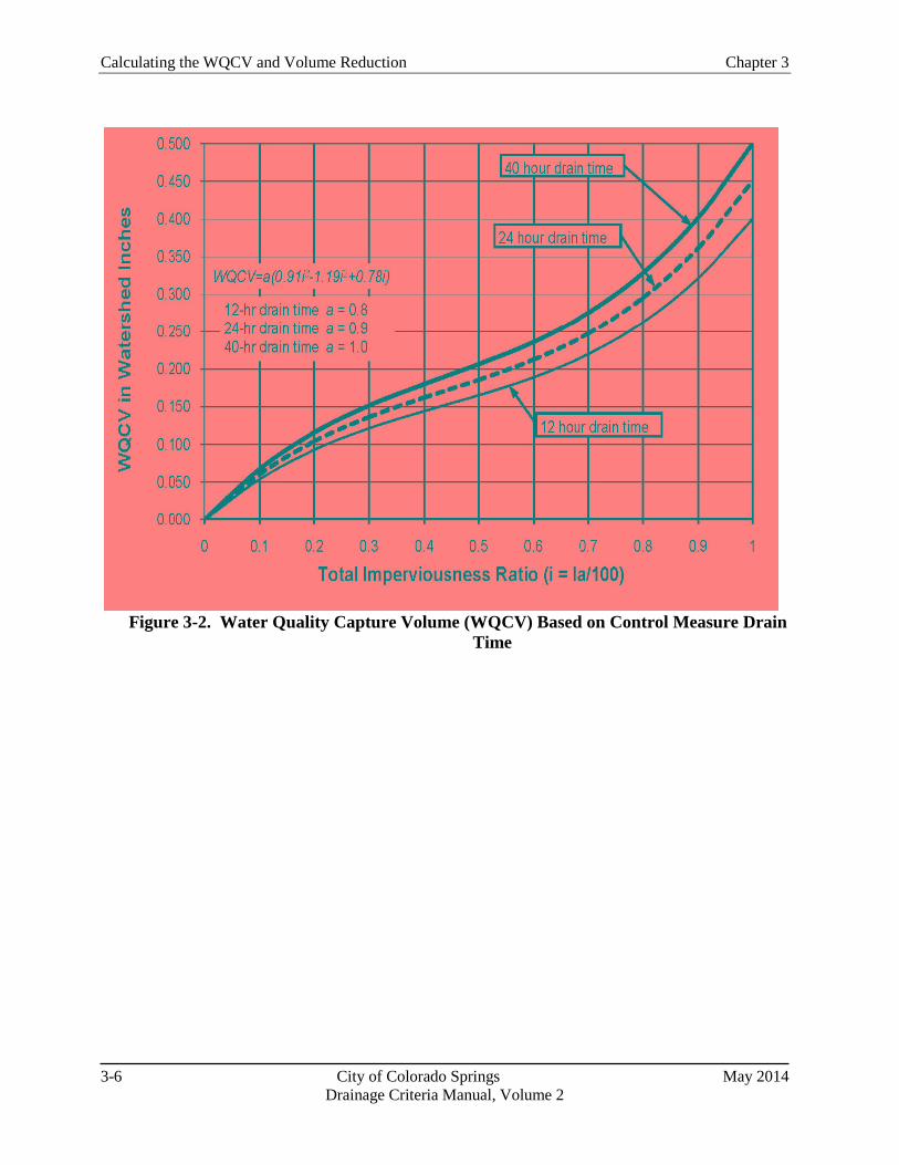
Calculating the WQCV and Volume Reduction Chapter 3
3-6 City of Colorado Springs May 2014 Drainage Criteria Manual, Volume 2
Figure 3-2. Water Quality Capture Volume (WQCV) Based on Control Measure Drain Time

Chapter 3 Calculating the WQCV and Volume Reduction
May 2014 City of Colorado Springs 3-7 Drainage Criteria Manual, Volume 2
4.0 Quantifying Volume Reduction Volume reduction is an important part of the Four Step Process and is fundamental to effective stormwater management. Quantifying volume reduction associated with MDCIA, LID practices and other control measures is important for watershed-level master planning and also for conceptual and final site design. It also allows the engineer to evaluate and compare the benefits of various volume reduction practices. This section describes the conceptual model for evaluating volume reduction and provides tools for quantifying volume reduction using three different approaches, depending on the size of the watershed, complexity of the design, and experience level of the user. In this section, volume reduction is evaluated at the watershed level and at the site level.
4.1 Conceptual Model for Volume Reduction Control Measures—Cascading Planes
The hydrologic response of a watershed during a storm event is characterized by factors including shape, slope, area, imperviousness (connected and disconnected) and other factors (Guo 2006). As previously discussed, total imperviousness of a watershed can be determined by delineating roofs, drives, walks and other impervious areas within a watershed and dividing the sum of these impervious areas by the total watershed area. In the past, total imperviousness was often used for calculation of peak flow rates for design events and storage requirements for water quality and flood control purposes. This is a reasonable approach when much of the impervious area in a watershed is directly connected to the drainage system; however, when the unconnected impervious area in a catchment is significant, using total imperviousness will result in over-calculation of peak flow rates and storage requirements.
To evaluate the effects of MDCIA and other LID practices, UDFCD has performed modeling using SWMM to develop tools for planners and designers, both at the watershed/master planning level where site-specific details have not been well defined, and at the site level, where plans are at more advanced stages. Unlike many conventional stormwater models, SWMM allows for a relatively complex evaluation of flow paths through the on-site stormwater control measure layout. Conceptually, an urban watershed can be divided into four land use areas that drain to the common outfall point as shown in Figure 3-3, including:
Directly Connected Impervious Area (DCIA)
Unconnected Impervious Area (UIA)
Receiving Pervious Area (RPA)
Separate Pervious Area (SPA)
Defining Effective Imperviousness
The concepts discussed in this section are dependent on the concept of effective imperviousness. This term refers to impervious areas that contribute surface runoff to the drainage system. For the purposes of this manual, effective imperviousness includes directly connected impervious area and portions of the unconnected impervious area that also contribute to runoff from a site. For small, frequently occurring events, the effective imperviousness may be equivalent to directly connected impervious area since runoff from unconnected impervious areas may infiltrate into receiving pervious areas; however, for larger events, the effective imperviousness is increased to account for runoff from unconnected impervious areas that exceeds the infiltration capacity of the receiving pervious area. This means that the calculation of effective imperviousness is associated with a specific return period.
Note: Users should be aware that some national engineering literature defines effective imperviousness more narrowly to include only directly connected impervious area.

Calculating the WQCV and Volume Reduction Chapter 3
3-8 City of Colorado Springs May 2014 Drainage Criteria Manual, Volume 2
Figure 3-3. Four Component Land Use
A fundamental concept of LID is to route runoff generated from the UIA onto the RPA to increase infiltration losses. To model the stormwater flows through a LID site, it is necessary to link flows similarly to take into consideration additional depression storage and infiltration losses over the pervious landscape. One of the more recent upgrades to SWMM allows users to model overland flow draining from the upper impervious areas onto a downstream pervious area. As illustrated in Figure 3-3, the effective imperviousness is only associated with the cascading plane from UIA to RPA, while the other two areas, DCIA and SPA, are drained independently.
For a well-designed and properly constructed LID site, the effective imperviousness will be less than the total imperviousness. This difference will be greatest for smaller, more frequently occurring events and less for larger, less-frequent events. Aided by SWMM, effective imperviousness can be determined by a runoff-volume weighting method that accounts for losses along the selected flow paths. When designing a drainage system, design criteria that account for effective imperviousness can potentially reduce stormwater costs by reducing the size of infrastructure to convey and/or store the design stormwater flows and volumes. This chapter presents methods that allow the engineer to convert between total imperviousness and effective imperviousness at both the watershed and site scales.
4.2 Watershed/Master Planning-level Runoff Reduction Method
For watershed-level assessments and master planning, NRCS (TR-55) provides guidance for users to model effects of LID through adjustments to Curve Number for unconnected imperviousness.
Figure 3-4 can be used to estimate composite CNs for unconnected impervious areas. Runoff from these areas is spread over a pervious area as sheet flow. To determine CN when all or part of the impervious area is not directly connected to the drainage system, Figure 3-4 may be used if total imperviousness is less than 30 percent. Otherwise the methods for estimating effective imperviousness described elsewhere in this chapter may be used to estimate composite CNs.
Obtain the composite CN for unconnected impervious areas by entering the right half of Figure 3-4 with the percentage of total impervious area and the ratio of total unconnected impervious area to total impervious area. Then move left to the appropriate pervious CN and read down to find the composite CN. For example, for a 1.2 acre lot with 20 percent total impervious area (75 percent of which is unconnected) and pervious CN of 60, the composite CN from Figure 3-4 is 64. If all of the impervious area is connected, the composite CN would be 68. Figure 3-4 is intended for use at the planning level
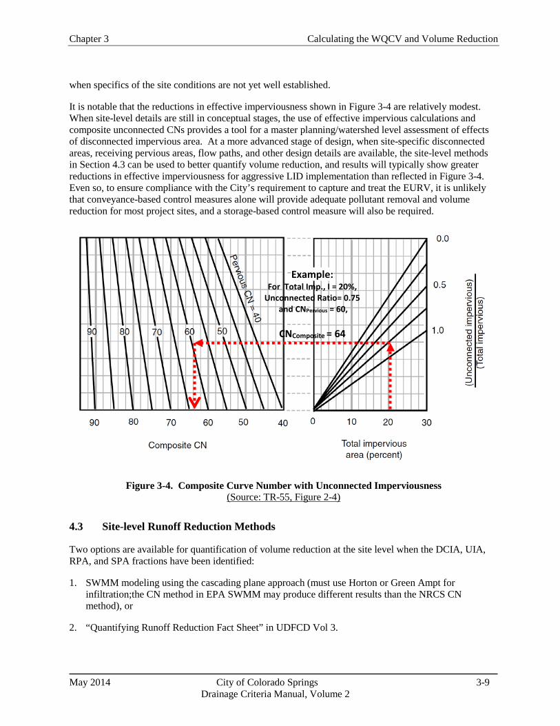
Chapter 3 Calculating the WQCV and Volume Reduction
May 2014 City of Colorado Springs 3-9 Drainage Criteria Manual, Volume 2
when specifics of the site conditions are not yet well established.
It is notable that the reductions in effective imperviousness shown in Figure 3-4 are relatively modest. When site-level details are still in conceptual stages, the use of effective impervious calculations and composite unconnected CNs provides a tool for a master planning/watershed level assessment of effects of disconnected impervious area. At a more advanced stage of design, when site-specific disconnected areas, receiving pervious areas, flow paths, and other design details are available, the site-level methods in Section 4.3 can be used to better quantify volume reduction, and results will typically show greater reductions in effective imperviousness for aggressive LID implementation than reflected in Figure 3-4. Even so, to ensure compliance with the City’s requirement to capture and treat the EURV, it is unlikely that conveyance-based control measures alone will provide adequate pollutant removal and volume reduction for most project sites, and a storage-based control measure will also be required.
Figure 3-4. Composite Curve Number with Unconnected Imperviousness (Source: TR-55, Figure 2-4)
4.3 Site-level Runoff Reduction Methods
Two options are available for quantification of volume reduction at the site level when the DCIA, UIA, RPA, and SPA fractions have been identified:
1. SWMM modeling using the cascading plane approach (must use Horton or Green Ampt for infiltration;the CN method in EPA SWMM may produce different results than the NRCS CN method), or
2. “Quantifying Runoff Reduction Fact Sheet” in UDFCD Vol 3.
Example: For Total Imp., I = 20%,
Unconnected Ratio= 0.75 and CNPervious = 60,
CNComposite = 64

Calculating the WQCV and Volume Reduction Chapter 3
3-10 City of Colorado Springs May 2014 Drainage Criteria Manual, Volume 2
4.3.1 SWMM Modeling Using Cascading Planes
Because of complexities of modeling LID and other control measures using SWMM, the cascading planes alternative for site-level volume reduction analysis is recommended only for experienced users. Guidance for conveyance- and storage-based modeling includes these steps:
1. Each sub-watershed should be conceptualized as shown in Figure 3-3. Two approaches can be used in SWMM to achieve this:
Create two SWMM sub-catchments for each sub-watershed, one with UIA 100% routed to RPA and the other with DCIA and SPA independently routed to the outlet, or
Use a single SWMM sub-catchment to represent the sub-watershed and use the SWMM internal routing option to differentiate between DCIA and UIA. This option should only be used when a large portion of the pervious area on a site is RPA and there is very little SPA since the internal routing does not have the ability to differentiate between SPA and RPA (i.e., the UIA is routed to the entire pervious area, potentially overestimating infiltration losses).
2. Once the subwatershed is set up to represent UIA, DCIA, RPA and SPA in SWMM, the rainfall distribution should be directly input to SWMM.
3. Parameters for infiltration, depression storage and other input parameters should be selected in accordance with the guidance in the Hydrology chapter of Volume 1.
4. For storage-based control measures, there are two options for representing the WQCV:
The pervious area depression storage value for the RPA can be increased to represent the WQCV. This approach is generally applicable to storage-based control measures that promote infiltration such as rain gardens, permeable pavement systems with storage or sand filters. This adjustment should not be used when a storage-based control measure has a well-defined outlet and a stage-storage-discharge relationship that can be entered into SWMM.
The WQCV can be modeled as a storage unit with an outlet in SWMM. This option is preferred for storage-based control measures with well-defined stage-storage-discharge relationships such as extended detention basins.
These guidelines are applicable for EPA SWMM Version 5.0 and all later versions.
4.3.2 Volume Reduction Spreadsheet
Documentation regarding the “Quantifying Runoff Reduction Fact Sheet” is published separately on the UDFCD website.

Chapter 3 Calculating the WQCV and Volume Reduction
May 2014 City of Colorado Springs 3-11 Drainage Criteria Manual, Volume 2
5.0 Conclusion This chapter provides the computational procedures necessary to calculate the WQCV and adjust imperviousness values used in these calculations due to implementation of LID/MDCIA in the tributary watershed. The resulting WQCV can then be combined with control measure specific design criteria in Chapter 4 to complete the control measure design(s). Adjustments to imperviousness and Curve Numbers resulting from these procedures can be used as input into methods for estimating runoff described in the Hydrology chapter of Volume 1 and for sizing storage volumes described in the Storage chapter of Volume 1.

Calculating the WQCV and Volume Reduction Chapter 3
3-12 City of Colorado Springs May 2014 Drainage Criteria Manual, Volume 2
Figu
re 3
-7.
Col
orad
o G
reen
Dev
elop
men
t DC
IA, U
IA, R
PA, a
nd S
PA

Chapter 3 Calculating the WQCV and Volume Reduction
May 2014 City of Colorado Springs 3-13 Drainage Criteria Manual, Volume 2
Figure 3-12. Colorado Green IRF Conveyance-based Lookup
(Sub basin E)

Calculating the WQCV and Volume Reduction Chapter 3
3-14 City of Colorado Springs May 2014 Drainage Criteria Manual, Volume 2
6.0 References Driscoll, E., G. Palhegyi, E. Strecker, and P. Shelley. 1990. Analysis of Storm Event Characteristics for
Selected Rainfall Gauges Throughout the United States. Prepared for the U.S. Environmental Protection Agency (EPA). Woodward-Clyde Consultants: Oakland, CA.
Guo, James C.Y., E. G. Blackler, A. Earles, and Ken Mackenzie. Accepted 2010. Effective Imperviousness as Incentive Index for Stormwater LID Designs. Pending publication in ASCE J. of Environmental Engineering.
Guo, James C.Y. 2006. Urban Hydrology and Hydraulic Design. Water Resources Publications, LLC.: Highlands Ranch, Colorado.
Guo, James C.Y. and Ben Urbonas. 1996. Maximized Detention Volume Determined by Runoff Capture Rate. ASCE Journal of Water Resources Planning and Management, Vol. 122, No 1, January.
Urbonas, B., L. A. Roesner, and C. Y. Guo. 1996. Hydrology for Optimal Sizing of Urban Runoff Treatment Control Systems. Water Quality International. International Association for Water Quality: London, England.
Urbonas B., J. C. Y. Guo, and L. S. Tucker. 1989 updated 1990. Sizing Capture Volume for Stormwater Quality Enhancement. Flood Hazard News. Urban Drainage and Flood Control District: Denver, CO.
Water Environment Federation and American Society of Civil Engineers. 1998. Urban Runoff Quality Management. WEF Manual of Practice No. 23. ASCE Manual and Report on Engineering Practice No. 87.

May 2014 City of Colorado Springs 4-i Drainage Criteria Manual, Volume 2
Chapter 4 Treatment Control Measures Contents 1.0 Overview ........................................................................................................................................... 1
2.0 Definition of New Development and Redevelopment/Control Measure Requirements ............ 1
3.0 Submittals ......................................................................................................................................... 2
4.0 Underground Control Measures ..................................................................................................... 2
5.0 Alternate Control Measures ............................................................................................................ 3
6.0 Fact Sheets ........................................................................................................................................ 3

Chapter 4 Treatment Control Measures
May 2014 City of Colorado Springs 4-1 Drainage Criteria Manual, Volume 2
1.0 Overview This chapter contains guidance and design requirements for structural control measures for new development and significant redevelopment as defined in the following sections. As discussed in Chapter 2, control measures provide treatment through a variety of hydrologic, physical, biological, and chemical processes. The functions provided by control measures may include volume reduction, treatment and slow release of the water quality capture volume (WQCV), and combined water quality/flood detention. Ideally, site designs will include a variety of source control and treatment control measures combined in a "treatment train" that controls pollutants at their sources, reduces runoff, and treats pollutants in runoff. Sites that are well designed for treatment of urban runoff will include all of the steps in the Four Step Process discussed in Chapter 1. The minimum measures required for development projects to satisfy the City’s MS4 permit requirements are described in Section 4.1 of Chapter 1. This chapter hereby incorporates by reference all criteria presented in the current version of the Urban Storm Drainage Criteria Manual (USDCM), Volume 3, Best Management Practices, Chapter 4 Treatment BMPs for purposes of design and implementation, except as modified herein. Detailed descriptions, sizing and design criteria, and design procedures for these control measures are provided in the USDCM, V3 Treatment BMP Fact Sheets.
All new and significant redevelopment with construction activities that disturb equal to or greater than 1 acre, including projects less than one acre that are part of a larger common plan of development or sale must have properly design control measures in accordance with Chapter 1. For basins that have been master planned to include regional or subregional water quality control measures that are designed to treat the WQCV for the entire drainage area upstream, and when the applicant has demonstrated and documented that no intakes for drinking water use exist and no other beneficial uses are expected to be impacted by pollutant discharges from the development project, Steps 1, 3, and 4 will be required to reduce site runoff, stabilize the receiving water drainageway, and implement site specific control measures respectively. New and redevelopment within basins in which regional or sub-regional treatment of the WQCV is not provided must also implement Step 2 of the Four Step Process to ensure treatment of the WQCV for the site.
Modifications to the control measure designs in this manual must be approved through the variance process described in Chapter 1. Modifications will only be approved with proper justification for the design change. This includes documentation showing that the modified design will achieve the same or better water quality benefit as the design shown in the manual. Missing design elements of treatment control measures can only be allowed if other adjustments are made to provide for additional water quality treatment through other measures (for example, treatment train with other onsite control measures).
Alternate control measures may be considered, but they must have equivalent or better functional requirements of the WQCV control measures as to WQCV, design requirements for timed release outlet structures, and drain times (see Section 5 below).
2.0 Definition of New Development and Redevelopment/Control Measure Requirements
The MS4 permit requires that a program must be implemented and enforced by the MS4 permittee to address post-construction stormwater runoff from new development and redevelopment projects for which construction activities disturb greater than or equal to one acre, including projects less than one acre that are part of a larger common plan of development or sale that discharge into the MS4. Chapter 7 further defines a common plan of development.

Treatment Control Measures Chapter 4
May 2014 City of Colorado Springs 4-2 Drainage Criteria Manual, Volume 2
For the purpose of defining when treatment water quality Best Management Practices are required, “New Development and Redevelopment” are defined as: • All sites that include total development/redevelopment areas for which construction activities disturb greater than or equal to one (1) acre, including projects less than one acre that are part of a larger common plan of development or sale that discharge to the MS4. WQCV shall be provided for the total site or individual lots/parcels. Other treatment control measures may also be required as appropriate. • All other sites that do not meet the above requirements may be required to provide treatment water quality control measures, if significant water quality impacts are anticipated or observed as a result of development/redevelopment of the site. 3.0 Submittals The requirements of this chapter shall be incorporated into existing submittals for review and acceptance including Grading and Erosion Control Plan (see Stormwater Construction Manual), Preliminary/Final Drainage Reports (see DCM Volume 1) and construction plans, or as otherwise specified by the MS4 Permittee (in Colorado Springs the Stormwater Enterprise (SWENT) Manager is delegated authority to implement the MS4 permit). It is recommended that discussions and collaboration regarding treatment control measures occur early in each project between the developer’s planner and engineer and SWENT staff.
Also note that infiltration tests required for full infiltration treatment control measures need to occur at the location and proposed depth of the control measure and not at other locations on the site because of changing soil types and conditions that could exist at the site. This information must be provided to SWENT.
4.0 Underground Control Measures As part of the required implementation of the Four Step Process, the use of underground, storage-based control measures is generally prohibited; however, they may be allowed on a case by case basis using the variance procedures described in Volume 1, Chapter 1 of this Manual. Variances for underground storage-based treatment will not be granted for new development sites over 15 acres.
When allowed according to Volume 2, Chapter 1 of this Manual, underground flow-through control measures are authorized as part of the required implementation of the Four Step Process under the following conditions:
• Underground flow-through control measures are allowed at design points with tributary areas less than 15 acres. Multiple underground flow-through control measures may be used to meet this requirement.
• Underground flow-through control measures may be allowed on a case by case basis using the variance procedures described in Volume 1, Chapter 1 of this Manual at design points with larger tributary areas.
Publicly maintained underground control measures may only be installed on behalf of public projects or programs.

Chapter 4 Treatment Control Measures
May 2014 City of Colorado Springs 4-3 Drainage Criteria Manual, Volume 2
For private underground control measures, a recorded maintenance agreement is required. Maintenance agreements for underground storage-based control measures must include an owner acknowledgement regarding specific long-term inspection and maintenance requirements. Inspection and Maintenance plans are required for public underground control measures.
Criteria used to select the appropriate underground control measure is described in the USDCM, V3 Underground BMP Fact Sheet. Permanently installed pumps for stormwater shall not be used.
5.0 Alternate Control Measures Control Measures not included in the USDCM, V3 may show promise but need further independent research to determine their pollutant removal effectiveness in a semiarid climate and to develop cost-effective design criteria to ensure they are properly designed, constructed, and maintained. Alternate Treatment Control Measures may be approved for use through the variance process described in Chapter 1of Volume 1 of this Manual if it can be demonstrated that the proposed control measure meets or exceeds treatment standards for the WQCV or similarly applicable USDCM, V3 Treatment BMPs. Documentation must also include design plans, specifications, and maintenance requirements similar to those provided for the USDCM, V3 Treatment BMPS and stamped/signed by a Colorado Professional Engineer. In all cases the minimum standards of Chapter 1 shall be met.
6.0 Fact Sheets As mentioned above, this chapter incorporates by reference all criteria presented in the current version of the Urban Storm Drainage Criteria Manual (USDCM), Volume 3, Best Management Practices, Chapter 4 Treatment BMPs for purposes of design and implementation. Treatment BMP Fact Sheets are provided in the USDCM, V3.

May 2014 City of Colorado Springs 5-i
Drainage Criteria Manual Volume 2
Chapter 5
Source Control BMPs
Contents
1.0 Introduction ...................................................................................................................................... 1

Chapter 5 Source Control BMPs
May 2014 City of Colorado Springs 5-1
Drainage Criteria Manual, Volume 2
1.0 Introduction
Proactively controlling pollutants at their source is fundamental to effective stormwater quality
management and is part of the Four Step Process outlined in Chapter 1 of this manual. Typically, it is
easier and more cost-effective to prevent stormwater pollution than to remove contaminants after they
have entered the storm sewer system or receiving water. Local governments, industries, businesses and
homeowners all have opportunities to implement source control practices that help prevent pollution. A
good source control BMP is one that is effective at stopping and/or redirecting pollutants prior to entering
the storm sewer system. A source control BMP can be a structural component of a planned site (e.g. a
covered area for material storage) or a procedural BMP. The latter depend on behavior change
accomplished through public education, training and development of standard operating procedures.
Source controls are required for all new and re-development projects as previously defined in this Manual
that include outdoor storage areas for items that could potentially be a source of pollutants in runoff from
the site.
This chapter hereby incorporates by reference guidelines presented in the current version of the Urban
Storm Drainage Criteria Manual (USDCM), Volume 3, Best Management Practices, Chapter 5 Source
Control BMPs. The chapter provides BMP Fact Sheets for common source control practices that can be
integrated into overall stormwater management plans by local governments, industries and businesses.
BMPs applicable to homeowners can also be used for integration into local government public education
and awareness efforts related to stormwater quality.

May 2014 City of Colorado Springs 6-i
Drainage Criteria Manual, Volume 2
Chapter 6
BMP Maintenance
Contents
1.0 Introduction ...................................................................................................................................... 1
2.0 Defining Maintenance Responsibility for Public and Private Facilities ...................................... 1
3.0 Inspection and Maintenance Plan/Maintenance Agreement ........................................................ 2
4.0 Treatment BMP Inspections ........................................................................................................... 3
5.0 Enforcement ...................................................................................................................................... 3
6.0 References ......................................................................................................................................... 4

Chapter 6 BMP Maintenance
May 2014 City of Colorado Springs 6-1
Drainage Criteria Manual, Volume 2
Photograph 6-1. Sediment removal from a forebay at the
regional Shop Creek BMP System (UDFCD photo).
1.0 Introduction
In order for stormwater BMPs to be effective, proper maintenance is essential. Maintenance includes
both routinely scheduled activities, as well as non-routine repairs that may be required after large storms,
or as a result of other unforeseen problems. BMP maintenance is the responsibility of the entity owning
the BMP. Municipal separate storm sewer system (MS4) permittees are required to implement and
enforce a maintenance program that results in maintenance of public and private BMPs. The City of
Colorado Springs, City Engineering Division is the MS4 permittee responsible for ensuring maintenance
of private and public BMPs within the City of Colorado Springs’ boundaries.
This chapter hereby incorporates by reference maintenance guidelines and recommendations presented in
the current version of the Urban Storm Drainage Criteria Manual (USDCM), Volume 3, Best
Management Practices, Chapter 6 BMP Maintenance. However, maintenance requirements documented
in site specific Maintenance Agreements and Inspection and Maintenance Plans take precedence over the
USDCM, Volume 3 recommendations.
BMPs shall be designed with maintenance as one of the key design considerations. Planning-level design
guidance pertaining to maintenance is included in the individual USDCM, Volume 3 Fact Sheets.
2.0 Defining Maintenance Responsibility for Public and Private
Facilities
Identifying who is responsible for maintenance of BMPs and ensuring that an adequate budget is
allocated for maintenance is critical to the long-term success of BMPs. Maintenance responsibility may
be assigned in different ways:
Publically owned regional drainage facilities and BMPs
are typically maintained by the MS4 permittee.
Privately owned BMPs must be maintained by the owner
or contracted by the owner to property managers.
Homeowners’ Associations and Metro Districts may also
be responsible for maintenance of privately owned
residential BMPs.
There are exceptions to the above and these arrangements are
defined in a written agreement with the owner or identified on
plats.
For public facilities, one of the key issues is ensuring that
adequate staff and budget are provided to the department
responsible for maintenance.
For private facilities, such as those owned and maintained by
homeowners’ associations, there is often a lack of understanding of maintenance required for BMPs.
Maintenance plans and agreements must be prepared and submitted as part of the development
review/approval process and be recorded with the property. It is also important to educate the general
public on the purpose and function of stormwater BMPs. This is critical in cases where Low Impact
Development (LID) or other BMPs are distributed throughout multiple parcels in developments.

BMP Maintenance Chapter 6
May 2014 City of Colorado Springs 6-2
Drainage Criteria Manual, Volume 2
3.0 Inspection and Maintenance Plan/Maintenance Agreement
Inspection and Maintenance Plans (IM Plans) are prepared as an appendix to the Final Drainage Report or
as stand-alone documents and developed concurrently with the design of the facility and submitted with
either the Final Drainage Report as an appendix, or the Erosion and Stormwater Quality Control Plan for
approval. IM Plans are required to ensure the continued function of the BMPs as designed and
constructed. Example IM Plans are available online (see the City of Colorado Springs website). IM
Plans have the following key components:
1. A description of the stormwater BMP and inspection and maintenance procedures.
2. Standard Operating Procedures that provide a description of the maintenance requirements and
expected frequency of actions, which can be obtained from discussion within this chapter or may
be available online (see the City of Colorado Springs website). Include instruction on how to
access each component of each BMP and with what equipment. It is important to identify
maintenance requirements related directly to the water quality functions of the BMP and provide
information concerning future site work that could potentially impact the integrity of the BMP.
This is particularly true for vegetated BMPs. For example, the following maintenance
requirements may be important for a rain garden (bioretention):
Provide frequent weed control in the first three years following installation and as needed for
the life of the facility. Weeding should be performed mechanically, either by hand or by
mowing (after establishment of the vegetation).
Remove debris from area and outlet.
Ensure cleanout caps remain watertight.
3. Self-inspection requirements for the responsible parties and inspection forms or checklists
appropriate for the facilities in place at the site.
4. Maintenance forms that can be used by the responsible party to document activities performed.
5. Annual Inspection and Maintenance Reporting forms that are to be used by the responsible party
to document activities and be submitted to the MS4 permittee. The responsible party is required
to keep inspection and maintenance forms and other IM Plan documentation for 3 years. The
responsible party is required to provide records of all maintenance and repairs to the MS4
permittee upon request.
6. As-built drawings that show the BMP as it was constructed.
7. PE Certification for the constructed BMP. Once construction is complete, as-built plan
certification shall be submitted by a Professional Engineer (PE) in the State of Colorado to ensure
that constructed stormwater management practices and conveyance systems comply with the
specifications contained in the approved plans. At a minimum, as-built certification shall include
a set of drawings comparing the approved plans with what was constructed. For public projects, a
certificate of completion may be used as an alternate to the PE certification.
For private BMPs, a Maintenance Agreement is required that binds the owner to perform the requirements
of the IM Plan and documents that the owner is aware of, and will abide by, their maintenance
responsibilities. Unless a treatment BMP is dedicated to and accepted by the MS4 permittee, the

Chapter 6 BMP Maintenance
May 2014 City of Colorado Springs 6-3
Drainage Criteria Manual, Volume 2
responsible party must execute a Maintenance Agreement binding on all subsequent owners of land
served by the BMP. This agreement is a legally recorded document that acts as a property deed
restriction, and therefore, provides for long-term maintenance of treatment BMP. If portions of the land
are sold or otherwise transferred, legally binding arrangements shall be made to pass the inspection and
maintenance responsibility to the appropriate successors in title. The agreement provides that in the event
that maintenance or repair is neglected, or the treatment BMP becomes a danger to public health or safety,
the MS4 permittee has the authority to enter the property, perform the maintenance work required, and to
recover the costs from the owner.
The terms of the Maintenance Agreement shall provide for the MS4 permittee to enter the property at
reasonable times and in a reasonable manner for the purpose of inspection or maintenance and to confirm
the information in the annual inspection report submitted by the responsible party for maintenance. This
includes the right to enter a property when there is a reasonable basis to believe that inspection and
maintenance are not occurring or have not occurred and to enter when necessary to perform maintenance
at the responsible party’s expense. A template of the Maintenance Agreement is available online (City of
Colorado Springs website).
Erosion and Stormwater Quality Plan financial assurances will not be released until the above IM Plan
and Maintenance Agreement requirements have been met and the Maintenance Agreement is recorded.
4.0 Treatment BMP Inspections
Self-Inspections
The responsible party shall perform self-inspections of stormwater BMPs on a periodic basis in
accordance with the approved IM Plan, document the inspection(s), and submit an annual inspection and
maintenance report to the MS4 permittee (the City of Colorado Springs requires the reports be submitted
by May 31 of each year).
MS4 Permittee Inspections
The MS4 permittee will inspect private and public facilities once during the first year of operation and
then once every three (3) to five (5) years, depending on the type of BMP, maintenance history, and other
factors. Facilities will also be inspected by the MS4 permittee once a notice of violation has been issued
for not performing self-inspections. A Notification of Inspection Letter will be sent to the responsible
party to inform them that an inspection is scheduled. The letter will include the date of the inspection,
what to expect, and encourage the completion of routine maintenance actions by the responsible party
prior to the inspection.
5.0 Enforcement
In the event that the self-inspections are not submitted to the MS4 permittee per the required deadline, the
responsible party will be contacted and notified of the missed inspection. The responsible party must
complete the self-inspection and return it by mail to the MS4 permittee within the timeframe identified in
local code or otherwise a notice of violation (NOV) may be issued. Appeals of NOVs can be made using
the process identified in local code.
If deficiencies are noted during the MS4 permittee inspection, the responsible party will be notified of the
issues. The responsible party shall correct the deficiencies within the timeframe specified by local code.
A follow-up inspection will be conducted by the MS4 permittee to verify the repairs. If repairs are not
undertaken or are not found to be done properly, MS4 permittee staff or a hired contractor engaged by the

BMP Maintenance Chapter 6
May 2014 City of Colorado Springs 6-4
Drainage Criteria Manual, Volume 2
Additional References for Stormwater BMP Maintenance
City of Portland, Oregon. 2002. Maintaining Your Stormwater Management Facility: A Handbook
for Private Property Owners. Portland, OR: Bureau of Environmental Services.
http://www.portlandonline.com/Bes/index.cfm?a=54730&c=34980.
Low Impact Development Center. 2003. Low Impact Development Urban Design Tools.
http://www.lid-stormwater.net/bio_maintain.htm; http://www.lid-
stormwater.net/permpavers_maintain.htm
North Carolina State University Cooperative Extension. 2006. Bioretention Performance, Design,
Construction, and Maintenance.
http://www.bae.ncsu.edu/stormwater/PublicationFiles/Bioretention2006.pdf
Santa Clara Valley Urban Runoff Pollution Prevention Program Example BMP Inspection and
Maintenance Checklist. http://www.scvurppp-w2k.com/bmp_om_forms.htm
Southeast Metro Stormwater Authority (SEMSWA) Stormwater Management Facility Operation and
Maintenance (O&M) Manual. www.semswa.org
Watershed Management Institute. 1997. Operation, Maintenance and Management of Stormwater
Management Systems. Ingleside, MD: Watershed Management Institute.
MS4 permittee may enter upon the subject private property and complete the necessary maintenance at
the responsible party’s expense. Recovery of the costs by the MS4 permittee shall follow practices
permitted by local code.
If, during a MS4 permittee inspection, it is noted that the condition of a BMP presents an immediate
danger to the public health or safety due to an unsafe condition or improper maintenance, immediate
action can be taken by the MS4 permittee to protect the public and make the facility safe. Per local code,
any cost incurred by the MS4 permittee is at the responsible party’s expense.
6.0 References
Koski, T. and Skinner, V. 2003. Colorado State University Extension. Fact Sheet no.7.202, Lawn Care.
http://www.ext.colostate.edu/pubs/garden/07202.html.
Law, N.L., K. DiBlasi, and U. Ghosh. 2008. Deriving Reliable Pollutant Removal Rates for Municipal
Street Sweeping and Storm Drain Cleanout Programs in the Chesapeake Bay Basin. Center for
Watershed Protection. Prepared for U.S. EPA Chesapeake Bay Program Grant CB-973222-01:
Ellicott City, MD. www.cpw.org.
Wright Water Engineers, Inc., Wenk Associates, Muller Engineering Company, Inc., Matrix Design
Group, and Smith Environmental. 2004. City and County of Denver Water Quality Management
Plan. Denver, CO