National Competency Standard for Cake Decoration Standard ...
Upload
khangminh22Category
view
1download
0
DEAS 412-2:2018
DRAFT EAST AFRICAN STANDARD
DEAS 412-2:2018- Steel for the reinforcement of concrete —Part 2: Ribbed bars
EAST AFRICAN COMMUNITY
DEAS 412-2:2018
Copyright notice
This EAC document is copyright-protected by EAC. While the reproduction of this document by participants in the EAC standards development process is permitted without prior permission from EAC, neither this document nor any extract from it may be reproduced, stored or transmitted in any form for any other purpose without prior written permission from EAC.
Requests for permission to reproduce this document for the purpose of selling it should be addressed as shown below or to EAC’s member body in the country of the requester:
© East African Community2016 — All rights reserved East African Community P.O.Box 1096 Arusha Tanzania Tel: 255 27 2504253/8 Fax: 255 27 2504481/2504255 E-mail: [email protected]
Web: www.eac-quality.net
Reproduction for sales purposes may be subject to royalty payments or a licensing agreement. Violators may be prosecuted.

DEAS 412-2:2018
Foreword
Development of the East African Standards has been necessitated by the need for harmonizing requirements governing quality of products and services in the East African Community. It is envisaged that through harmonized standardization, trade barriers that are encountered when goods and services are exchanged within the Community will be removed.
In order to achieve this objective, the Community established an East African Standards Committee mandated to develop and issue East African Standards.
The Committee is composed of representatives of the National Standards Bodies in Partner States, together with the representatives from the private sectors and consumer organizations. Draft East African Standards are circulated to stakeholders through the National Standards Bodies in the Partner States. The comments received are discussed and incorporated before finalization of standards, in accordance with the procedures of the Community.
East African Standards are subject to review, to keep pace with technological advances. Users of the East African Standards are therefore expected to ensure that they always have the latest versions of the standards they are implementing.
DEAS 412-2:2018 was prepared by Technical Committee EASC/TC 035 TC Steel and Steel Products
DEAS 412-2:2018
EAST AFRICA DRAFT STANDARD
Steel for the reinforcement of concrete —Part 2: Ribbed bars
1 Scope
This part of East Africa Draft Standard specifies technical requirements for ribbed bars to be used as reinforcement in concrete.
This part of East Africa Draft Standard covers ten steel grades not intended for welding which are B300A- R,
B300B-R, B300C-R, B300D-R, B400A-R, B400B-R, B400C-R, B500A- R, B500B-R and B500C-R, and eleven
steel grades intended for welding which are B300DWR, B350DWR, B400AWR, B400BWR, B400CWR,
B400DWR, B420DWR, B500AWR, B500BWR, B500CWR aB500DWR,B550DWR and B600DWR. The steel
grades are designated with steel names allocated in accordance with ISO/TS 4949. NOTE The first “B” stands for steel for reinforcing concrete. The next 3 digits represent the specified characteristic value of
upper yield strength. The fifth symbol stands for ductility class (4.5). The sixth symbo l relates to welding; “-” means not
intended for welding and “W” means intended for welding. The last “R” stands for ribbed bar.
This part of East Africa Draft Standard covers products delivered in straight lengths.
The production process is at the discretion of the manufacturer.
Ribbed bars produced from finished products, such as plates and railway rails, are excluded.
2 Normative references
The following referenced documents are indispensable for the application of this document. For dated
references, only the edition cited applies. For undated references, the latest edition of the referenced
document (including any amendments) applies. ISO 404, Steel and steel products — General technical delivery requirements
ISO/TS 4949, Steel names based on letter symbols
ISO/TR 9769, Steel and iron — Review of available methods of analysis
ISO 10144, Certification scheme for steel bars and wires for the reinforcement of concrete structures
ISO 14284, Steel and iron — Sampling and preparation of samples for the determination of chemical
composition ISO 15630-1, Steel for the reinforcement and prestressing of concrete — Test methods — Part 1: Reinforcing
bars, wire rod and wire

DEAS 412-2:2018
3 Symbols
The symbols used in this part of East Africa Draft Standard are listed in Table 1.
Table 1 — Symbols
Symbol Unit Description Reference
a mm Rib height 4.10, Clause 6
A5 % Percentage elongation after fracture 8.1, 9.1
Agt % Percentage total elongation at maximum force 8.1, 9.1
An mm2
Nominal cross-sectional area Clause 5, 9.1
c mm Rib spacing 4.11, Clause 6
d mm Nominal diameter of the bar Clause 5, Clause 6, 9.1, 9.2,
9.3, Clause 10, 11.2,
Σfi mm Ribless perimeter 4.12, Clause 6 fk — Required characteristic value 12.3.2.3
fR — Relative rib area 4.9, Clause 6
k, k' — Indices 12.3.2.3.1
mn — Mean value of n individual values 12.3.2.3.1
n — Number of individual values 12.3.2.3.1
ReH N/mm
2 Upper yield strength 8.1
Rm N/mm2
Tensile strength 8.1 R
p0,2 N/mm2
0,2 % proof strength, non-proportional extension 8.1
sn — Standard deviation for n individual values 12.3.2.3.1 x
i — Individual value 12.3.2.3.1
α degree Transverse-rib flank inclination 4.14, Clause 6
β degree Angle between the axis of a transverse rib and the bar axis 4.15, Clause 6
4 Terms and definitions
For the purposes of this document, the following terms and definitions apply.
4.1 cast analysis chemical analysis representative of the cast determined by the manufacturer in accordance with his/her own
procedures
4.2 certification scheme certification system as related to specified products, processes or services to which the same particular
standards and rules, and the same procedure, apply

DEAS 412-2:2018
4.3 characteristic value value having a prescribed probability of not being attained in a hypothetical unlimited test series
NOTE 2 A nominal value is used as the characteristic value in some circumstances.
4.4
core
part of the cross-section of the bar containing neither ribs nor indentations
4.5 ductility class classification of the ductility properties of reinforcing steels based on the value of the ratio of tensile strength to
yield strength, as well as the elongation measured either as Agt or as A5 NOTE See Table 6.
4.6
longitudinal rib uniform continuous rib parallel to the axis of the bar
4.7 nominal cross-sectional area cross-sectional area equivalent to the area of a circular plain bar of the nominal diameter
4.8 product analysis chemical analysis carried out on the product
4.9
relative rib area fR area of the projections of all transverse ribs within a defined length on a plane perpendicular to the
longitudinal axis of the bar, divided by this length and the nominal circumference .
4.10 Rib height a
distance from one point on the rib to the surface of the core, to be measured normal to the axis of the bar NOTE 1 See Figure 2.
DEAS 412-2:2018
4.11 rib spacingc distance between the centres of two consecutive transverse ribs measured parallel to the axis of the bar NOTE 1 See Figure 1.
4.12
ribless perimeterΣfi sum of the distances along the surface of the core between the end of the transverse ribs of adjacent rows
measured as the projection on a plane perpendicular to the axis of the bar 4.13
Transverse rib rib at an angle, either perpendicular or oblique, to the longitudinal axis of the bar
4.14 transverse-rib flank inclinationα angle between the flank of a transverse rib and the core surface of a bar measured perpendicular to the
longitudinal axis of the transverse rib NOTE 1 See Figure 2.
4.15 transverse-rib inclinationβ angle between the rib and the longitudinal axis of the bar NOTE 1 See Figures 1, 3 and 4.
5 Dimensions, mass per unit length and permissible deviations
Dimensions, mass per unit length and permissible deviations are given in Table 2. However, manufacturer and
purchaser may agree on special ordered diameter upon notification to the regulator.

DEAS 412-2:2018
Table 2 — Dimensions, mass per unit length and permissible deviations
Nominal bar Nominal cross- Mass per unit length
diameter a
sectional area b
d An Requirement c
Permissible deviation d
mm mm2
kg/m %
6 28,3 0,222 6
8 50,3 0,395 6
10 78,5 0,617 5
12 113 0,888 5
14 154 1,21 5
16 201 1,58 5
20 314 2,47 5
25 491 3,85 4
28 616 4,84 4
32 804 6,31 4
40 1 257 9,86 4
50 1 964 15,42 4
a Diameters larger than 50 mm should be agreed between the manufacturer and purchaser. The
permissible deviation on such bars shall be ± 4 %.
b An= 0,785 4× d2
c Mass per unit length = 7,85 × 10
−3 × A.
n
d Permissible deviation refers to a single bar.
.
NOTE Common delivery lengths of straight bars are 6 m, 9 m, 12 m and 18 m.
, the permissible deviation on delivery lengths from rolling mill shall be 100
0mm .
6 Requirements for ribs
Ribbed bars shall have transverse ribs. Longitudinal ribs may be present or not.
There shall be at least two rows of transverse ribs equally distributed around the perimeter of the bar. The
transverse ribs within each row shall be distributed uniformly over the entire length of the bar, except in the
area of marking. Ribs shall conform to the requirements in Table 3.

DEAS 412-2:2018
Table 3 — Requirements for ribs
Nominal diameter Ribs of uniform Crescent-shaped ribs
d height
mm
Rib height, a
All 0,05d 0,065d Minimum
Rib spacing, c 6 u d< 10 0,5d u c u 0,7d 0,5d u c u 1,0d
Range d W10 0,5d u c u 0,7d 0,5d u c u 0,8d
Transverse-rib inclination, β All 35° u β u 90° 35° u β u 75°
Transverse-rib flank inclination, α All α W45° α W45°
Ribless perimeter, Σfi All 0,25dπ
Maximum
Requirements for rib parameters may be specified by the relative rib area, by agreement between the
manufacturer and purchaser. Measurement of rib parameters shall be performed in accordance with ISO
15630-1. Dimensions defining the rib geometry in Table 3 are shown in Figures 1 to 4.
When longitudinal ribs are present, their height shall not exceed 0,15d.
Key 1 longitudinal rib 2 transverse rib
Figure 1 — Ribbed bar — Definitions of geometry
Key 1 rib 2 rounded transition
Figure 2 — Rib flank inclination, α, and rib height, a — Section A-A from Figure 1
DEAS 412-2:2018
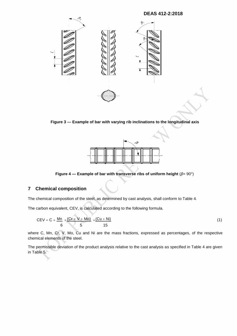
Figure 3 — Example of bar with varying rib inclinations to the longitudinal axis
Figure 4 — Example of bar with transverse ribs of uniform height (β= 90°)
7 Chemical composition
The chemical composition of the steel, as determined by cast analysis, shall conform to Table 4.
The carbon equivalent, CEV, is calculated according to the following formula.
CEV C Mn (Cr V Mo) (Cu Ni) (1)
5 15 6 where C, Mn, Cr, V, Mo, Cu and Ni are the mass fractions, expressed as percentages, of the respective
chemical elements of the steel. The permissible deviation of the product analysis relative to the cast analysis as specified in Table 4 are given
in Table 5.
DEAS 412-2:2018
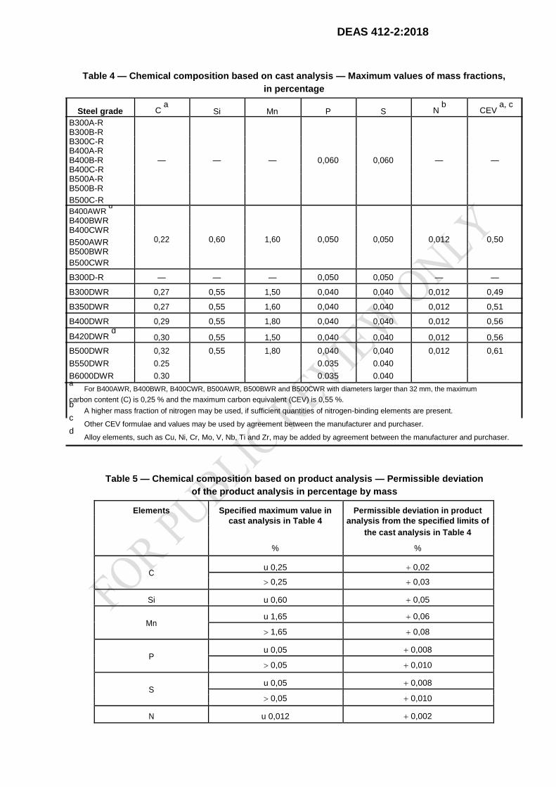
Table 4 — Chemical composition based on cast analysis — Maximum values of mass fractions,
in percentage
Steel grade C a
Si Mn P S N b
CEV a, c
B300A-R B300B-R
B300C-R
B400A-R
B400B-R — — — 0,060 0,060 — — B400C-R
B500A-R
B500B-R
B500C-R
B400AWR d
B400BWR
B400CWR 0,22 0,60 1,60 0,050 0,050 0,012 0,50 B500AWR
B500BWR
B500CWR
B300D-R — — — 0,050 0,050 — —
B300DWR 0,27 0,55 1,50 0,040 0,040 0,012 0,49
B350DWR 0,27 0,55 1,60 0,040 0,040 0,012 0,51
B400DWR 0,29 0,55 1,80 0,040 0,040 0,012 0,56
B420DWR d
0,30 0,55 1,50 0,040 0,040 0,012 0,56
B500DWR 0,32 0,55 1,80 0,040 0,040 0,012 0,61
B550DWR 0.25 0.035 0.040
B6000DWR 0.30 0.035 0.040
a For B400AWR, B400BWR, B400CWR, B500AWR, B500BWR and B500CWR with diameters larger than 32 mm, the maximum
carbon content (C) is 0,25 % and the maximum carbon equivalent (CEV) is 0,55 %. b
A higher mass fraction of nitrogen may be used, if sufficient quantities of nitrogen-binding elements are present. c Other CEV formulae and values may be used by agreement between the manufacturer and purchaser.
d Alloy elements, such as Cu, Ni, Cr, Mo, V, Nb, Ti and Zr, may be added by agreement between the manufacturer and purchaser.
Table 5 — Chemical composition based on product analysis — Permissible deviation
of the product analysis in percentage by mass
Elements Specified maximum value in Permissible deviation in product
cast analysis in Table 4 analysis from the specified limits of
the cast analysis in Table 4
% %
C u 0,25 0,02
0,25 0,03
Si u 0,60 0,05
Mn u 1,65 0,06
1,65 0,08
P u 0,05 0,008
0,05 0,010
S u 0,05 0,008
0,05 0,010
N u 0,012 0,002
DEAS 412-2:2018
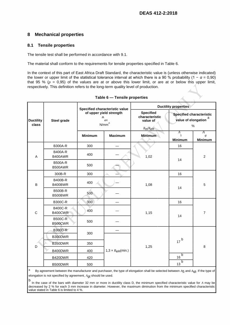
8 Mechanical properties
8.1 Tensile properties
The tensile test shall be performed in accordance with 9.1.
The material shall conform to the requirements for tensile properties specified in Table 6.
In the context of this part of East Africa Draft Standard, the characteristic value is (unless otherwise indicated)
the lower or upper limit of the statistical tolerance interval at which there is a 90 % probability (1 − α = 0,90)
that 95 % (p = 0,95) of the values are at or above this lower limit, or are at or below this upper limit,
respectively. This definition refers to the long-term quality level of production.
Table 6 — Tensile properties
Specified characteristic value
Ductility properties
Specified
of upper yield strength Specified characteristic
characteristic Ductility
ReH value of elongation
a Steel grade value of
class N/mm2
Rm/ReH
%
Minimum Maximum Minimum A
5 A
gt
Minimum Minimum
B300A-R 300 — 16
A
B400A-R 400
—
1,02
2
B400AWR
14
B500A-R 500
—
B500AWR
300B-R 300 — 16
B
B400B-R 400
—
1,08
5
B400BWR
14
B500B-R 500
—
B500BWR
B300C-R 300 — 16
C
B400C-R 400
—
1,15
7
B400CWR
14
B500C-R 500
—
B500CWR
B300D-R 300
—
B300DWR
17 b
D B350DWR 350
1,25
8
1,3 × ReH(min.)
B400DWR 400
B420DWR 420 16 b
B500DWR 500 13 b
a By agreement between the manufacturer and purchaser, the type of elongation shall be selected between A5 and Agt. If the type of
elongation is not specified by agreement, Agt should be used. b
In the case of the bars with diameter 32 mm or more in ductility class D, the minimum specified characteristic value for A may be
decreased by 2 % for each 3 mm increase in diameter. However, the maximum diminution from the minimum specified characteristic value stated in Table 6 is limited to 4 %.
By agreement between the manufacturer and purchaser, the values shown in Table 6 may be used
as specified minimum and/or maximum values.
If a yield phenomenon is not present, the 0,2 % proof strength (Rp0,2) shall be determined.
8.2 Bending properties
If required by the purchaser, the bend test shall be performed in accordance with 9.2. After testing,
the bars shall show neither rupture nor cracks visible to a person of normal or corrected vision.
8.3 Rebending properties after ageing
Regarding fifteen steel grades of B400A-R, B400B-R, B400C-R, B400AWR, B400BWR, B400CWR,
B400DWR, B420DWR, B500A-R, B500B-R, B500C-R, B500AWR, B500BWR, B500CWR and
B500DWR, if required, the rebend test shall be performed in accordance with 9.3. NOTE The rebend test is used to verify the ageing properties of the bent bars.
After testing, the bars shall show neither rupture nor cracks visible to a person of normal or corrected vision.
8.4 Fatigue properties
If required by the purchaser, the manufacturer shall demonstrate the fatigue properties of the product
based on axial-force-controlled fatigue testing in the fluctuating tension range in accordance with 9.4.
The specified number(s) of stress cycles, stress range(s) 2σa and maximum stress(es) σmax shall be
as agreed between the purchaser and manufacturer at the time of enquiry and order.
9 Testing
9.1 Tensile test
The tensile test shall be carried out in accordance with ISO 15630-1.
For the determination of percentage elongation after fracture, A5, the original gauge length shall be 5
times the nominal diameter.
For the determination of percentage total elongation at maximum force, Agt, equidistant marks shall
be made on the free length of the test piece. The distance between the marks shall be 20 mm, 10 mm or 5 mm, depending on the bar diameter.
For determination of tensile properties, the nominal cross-sectional area of the bar shall be used.
9.2 Bend test
The bend test shall be carried out in accordance with ISO 15630-1.
The test piece shall be bent to an angle between 160° and 180° over a mandrel of the diameter
specified in Table 7.
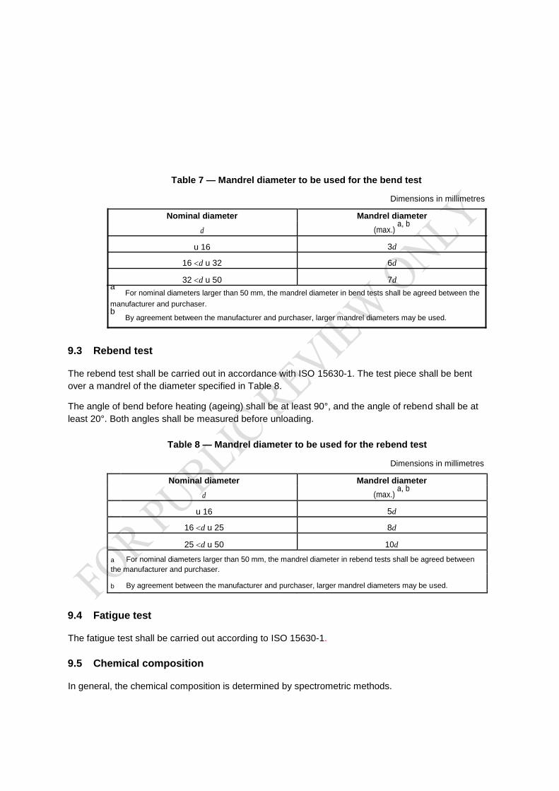
Table 7 — Mandrel diameter to be used for the bend test
Dimensions in millimetres
Nominal diameter Mandrel diameter
d (max.) a, b
u 16 3d
16 d u 32 6d
32 d u 50 7d a
For nominal diameters larger than 50 mm, the mandrel diameter in bend tests shall be agreed between the manufacturer and purchaser. b
By agreement between the manufacturer and purchaser, larger mandrel diameters may be used.
9.3 Rebend test
The rebend test shall be carried out in accordance with ISO 15630-1. The test piece shall be bent
over a mandrel of the diameter specified in Table 8. The angle of bend before heating (ageing) shall be at least 90°, and the angle of rebend shall be at
least 20°. Both angles shall be measured before unloading.
Table 8 — Mandrel diameter to be used for the rebend test
Dimensions in millimetres
Nominal diameter Mandrel diameter
d (max.) a, b
u 16 5d
16 d u 25 8d
25 d u 50 10d
a For nominal diameters larger than 50 mm, the mandrel diameter in rebend tests shall be agreed between
the manufacturer and purchaser.
b By agreement between the manufacturer and purchaser, larger mandrel diameters may be used.
9.4 Fatigue test
The fatigue test shall be carried out according to ISO 15630-1.
9.5 Chemical composition
In general, the chemical composition is determined by spectrometric methods.
10 Designation
Ribbed bars according to this part of East Africa Draft Standard shall be designated in the following order:
a) reinforcing steel; denoted (B)
b) a reference to this part of East Africa Draft Standard (e.i CD/TZ/5:2016);
c) the nominal diameter, in millimetres, according to Table 2;
d) the steel grade.
EXAMPLE Reinforcing steel DEAS 412-2 – 12 B500CWR
11 Marking 11 Marking
Each bar and each bundle shall be legibly and indelibly marked as follows;
Each bar shall be marked shall be marked with manufacturers name or logo, steel grade and nominal
diameter
Each bundle shall be marked with manufacturers name or logo, steel grade, nominal diameter and
batch / cast number
Special orders bars in addition to the above marking shall bear the marking SP
12 Evaluation of conformity
12.1 General
Certification and inspection of reinforcement shall be performed
a) in accordance with a certification scheme monitored by an external body, or
b) according to testing of a specific delivery.
12.2 Certification scheme
In the case of a certification scheme, evaluation of conformity shall be performed in accordance with
ISO 10144.
12.3 Acceptance testing of a specific delivery
12.3.1 General
Provisions regarding the nature, extent and evaluation of acceptance testing on deliveries of
reinforcing steel not subject to a certification scheme are given in 12.3.2 and 12.3.3. Acceptance testing of a specific delivery shall be performed according to 12.3.2.

By agreement between the manufacturer and purchaser, 12.3.3 may be used. 12.3.2 Evaluation of characteristic values
12.3.2.1 Organization
The tests shall be organized and carried out according to an agreement between the purchaser and
manufacturer, taking into consideration the national rules of the receiving country.
12.3.2.2 Extent of sampling and testing
For the purpose of testing, the delivery shall be subdivided into test units with a maximum mass of 50
t, or a fraction thereof. Each test unit shall consist of products of the same steel grade and the same
nominal diameter from the same cast. The manufacturer shall confirm in the test report that all
samples in the test unit originate from the same cast. The chemical composition (cast analysis) shall
be stated in this test report. Test pieces shall be taken from each test unit as follows:
a) two test pieces from various bars for testing the chemical composition (product analysis);
b) a minimum of 15 test pieces (if appropriate, 60 test pieces, see 12.3.2.3.1) from various bars for
testing all other properties specified in this part of East Africa Draft Standard(DEAS 412-2.)
12.3.2.3 Evaluation of the results
12.3.2.3.1 Inspection by variables
For properties which are specified as characteristic values, the following shall be determined:
a) all individual values, xi, of the 15 test pieces (n = 15);
b) the mean value, m15 (for n = 15);
c) the standard deviation, s15 (for n = 15).
The test unit corresponds to the requirements, if the condition stated below is fulfilled for all properties:
m15−2,33× s15Wfk (2)
where
fk is the required characteristic value;
2,33 is the value for the acceptability index, k, for n = 15 for a failure rate of 5 % (p = 0,95) at a probability
of 90 % (1 – α = 0,90).

s = x i− m152
(3) 15
14
If the condition stated above is not fulfilled, the index
k ′ = m
15
−fk (4)
s
15 is determined from the test results available. Where k′W 2, testing can be continued. In this case, 45
further test pieces shall be taken and tested from different bars in the test unit, so that a total of 60
test results are available (n = 60).
The test unit shall be considered to comply with the requirements, if the condition stated below is
fulfilled for all properties:
m 60−1,93× s 60>fk (5) where 1,93 is the value for the acceptability index, k, for n = 60 for a failure rate of 5 % (p = 0,95) at a
probability of 90 % (1 – α = 0,90).
12.3.2.3.2 Inspection by attributes
When testing properties are specified as maximum or minimum values, all results determined on the
15 test pieces shall comply with the requirements of this part of East Africa Draft Standard5. In this
case, the test unit shall be considered to comply with the requirements. The tests may be continued when at most 2 results not conforming to the conditions occur. In this
case, 45 additional test pieces from various bars in the test unit shall be tested, so that a total of 60
test results are available. The test unit complies with the requirements if not more than 2 of the 60
results do not conform to the conditions.
12.3.2.3.3 Chemical composition
Both test pieces shall comply with the requirements in this part of East Africa Draft Standard.
12.3.3 Evaluation of specified minimum/maximum values
Tests shall be carried out according to the following.
a) Bars of the same cast shall constitute one group. For every 50 t or fraction thereof, one tensile
test and one bend/rebend test shall be carried out for each bar diameter. b) Each individual test result shall meet the required values in Table 6, and the required
bending/rebending properties in 8.2 and 8.3. c) One cast analysis shall be carried out for every cast to verify chemical composition (Clause 7).
Samples shall be taken in accordance with ISO 14284. d) If any test result does not meet the requirements, retests may be carried out, according to ISO
404.
e) The manufacturer shall submit a test report stating that the products of the delivery satisfy the
chemical and mechanical properties defined in Clauses 7 and 8, and a confirmation that the other
requirements of this part of East Africa Draft Standard are fulfilled.
12.3.4 Test report
The test report shall contain the following information:
designation of the reinforcing steel in accordance with this part of East Africa Draft Standard a) marking on the reinforcing steel;
b) date of testing;
c) mass of the test unit;
d) test results.
Copyright © 2022 FDOKUMEN