Download - Volgaburmash
45
-
Upload
khangminh22 -
Category
Documents
-
view
0 -
download
0
Transcript of Download - Volgaburmash


Contents
About Company _________________________________________________________________ 2
Innovations _________________________________________________________________________ 8
Quality Management System ____________________________________________ 14
Partnership ________________________________________________________________________20
Products for mining industry _____________________________________________26
Designation ____________________________________________________________________________ 28
Design features ________________________________________________________________________29
IADC classification ____________________________________________________________________30
Product lines ___________________________________________________________________________32
AirPro _______________________________________________________________________________32
AirJet _______________________________________________________________________________33
AirStandart _________________________________________________________________________35
Technical information ________________________________________________________________38
DTH bits _______________________________________________________________________________44
DTH ________________________________________________________________________________44
PDC bits _______________________________________________________________________________45
FastDrillConstruction ________________________________________________________________45
Roller cone bits operating manual _________________________________46
Section 1. Rock failure _________________________________________________________________48
Section 2. Air circulation system _______________________________________________________ 52
Section 3. Drill bits operational guidelines _____________________________________________60
Section 4. Bit wear analysis ____________________________________________________________62
Section 5. Selecting efficient bit designs ______________________________________________ 74
Section 6. Storage and transport ______________________________________________________ 74
Appendices _______________________________________________________________________78
Site ____________________________________________________________________________________84
Contacts ____________________________________________________________________________84

Ab
out
Com
pan
y
Product Catalogue for Mining Industry Product Catalogue for Mining Industry
About CompAny

Ab
out
Com
pan
y
Ab
out
Com
pan
y
4 5
Product Catalogue for Mining Industry Product Catalogue for Mining Industry
and sections of roller cone bits, bodies of PDC bits, tungsten carbide inserts. The Companies carry out continuous technical modernization of production.
Currently, production facilities are equipped with the most advanced multi-axis machining centers, furnaces, heat-treatment machines, welding and hard-facing units purchased from the world’s leading producers.
State of the art equipment enables us to master new bit designs in the shortest time and provides products quality conformance with the international standards.
All products undergo quality control at each manufacturing stage. Since 1997, Volgaburmash, JSC has implemented certified Quality Management System according to ISO standards and API Q1 specification.
Volgaburmash, JSC also has implemented and certified environment management
Volgaburmash, JSC and Uralburmash, JSC are Russian largest manufacturers of advanced high quality rock-cutting tools for oil&gas, mining and construction industries.
The Companies manufacture over 250 standard sizes of mining roller cone bits ranging from 75.0 mm (2-61/64”) to 393.7 mm (15-½”) for compressed-air drilling in various mining and geological conditions and over 1000 roller cone bit designs for oil and gas industry ranging from 95.3 mm (3-3/4”) to 660.4 mm (26”) with milled teeth and tungsten carbide inserts. Also, Volgaburmash, JSC manufactures over 350 designs of PDC bits with matrix or steel bodies for various drilling applications ranging from 83 mm (3-1/4”) to 444.5 mm (17-1/2”), PDC core bits for core drilling and near-bit stabilizers.
Besides, Volgaburmash, JSC and Uralburmash, JSC manufacture components for rock-cutting tools production: forgings
« over 250 stAndArd
sizes of drill bits
for mining industry »
Companies

Ab
out
Com
pan
y
Ab
out
Com
pan
y
6 7
Product Catalogue for Mining Industry Product Catalogue for Mining Industry
system and health and safety management system according to the requirements of ISO 14001:2004 and OHSAS 18001:2007.
Over the years, the Companies’ specialists have developed over 2000 drill bit designs. Many of these design solutions are of international novelty. Their authors and the Companies have obtained more than 300 inventor’s certificates and patents for inventions in Russia and 17 other countries. Over fifteen hundred innovations have been put into production.
Since their foundation, Volgaburmash, JSC and Uralburmash, JSC have produced more than 20 million drill bits for oil and gas and mining industries. The quality of the products and the sales volume make the Companies world’s leading rock-cutting tools manufacturers.
the Companies an excellent opportunity of creating an individual approach to each customer and developing unique drill bit designs for any drilling applications in the shortest time possible.
Rock-cutting tools produced by Volgaburmash, JSC and Uralburmash, JSC are used in the main Russian fields and in more than 40 other countries. Our background of experience, high scientific engineering potential and the team of professionals give
Companies
« the CompAnies hAve
mAnufACtured over 20 million
drill bits »

Ab
out
Com
pan
y
Product Catalogue for Mining Industry Product Catalogue for Mining Industry
innovAtions

Ab
out
Com
pan
y
Ab
out
Com
pan
y
10 11
Product Catalogue for Mining Industry Product Catalogue for Mining Industry
This enables us to shorten lead time for new bit de-signs, improve their efficiency and reliability due to optimizing design and technology parameters at the design stage, as well as provide an opportunity for creating drill bits for specific applications taking into account technological environment and lithology.
Design engineering system incorporates patented research results, math model simulation, select-ing the optimal drill bit design parameters and multifactor analysis of bit test results.
Design engineers have at their disposal a software for automated drawing of a bit profile and bottom-hole coverage pattern, dull bit grading, selection of optimal hydraulics, load balancing for improving bit steerability, as well as field test performance analysis by means of advanced statisti-cal data processing methods.
The base of the Companies’ development is working out and introducing innovation technologies in all aspects of their activities providing high product quality level: in de-sign engineering, manufacturing technology and after-sales service.
Volgaburmash, JSC and Uralburmash, JSC have worked out a successful thorough sys-tem of automated design engineering, tech-nology process planning and engineering evaluation (CAD/CAM/CAE-system) based on the unified environment of Siemens UG NX software system that is widely used by the world’s leading companies.
Innovations
« introduCing innovAtion
teChnologies in All AspeCts »

Ab
out
Com
pan
y
Ab
out
Com
pan
y
12 13
Product Catalogue for Mining Industry Product Catalogue for Mining Industry
Design engineering and product manufacturing are fulfilled accord-ing to an individual arrangement for a particular customer, taking into account customer equipment and field lithology.
Currently, Volgaburmash, JSC and Uralburmash, JSC specialists can design and manufacture drill-ing tools of any complexity and modify bit design depending on the drilling application.
All innovations are targeted at fulfillment of Quality Policy, which means maximum satisfaction of customer’s requirements and expectations and creating their confidence in the Companies’ products.
One of the key objectives of drill bit design is improving bottom-hole cleaning. For this purpose, spe-cialists of design bureau and research department analyze and select optimum quantity and location of nozzles for timely removal of cuttings from bottom-hole, prevention of their re-cutting with the cut-ting structure, ensuring cuttings evacuation from the hole through the annulus, preventing bit balling and providing cooling of the work areas of the cutting structure. Having our proprietary patented technical research and software developments enables us to manufacture highly competitive drill bits modified for customer specific applications.
Continuous monitoring products quality at all stages of their life facilitates operational deci-sion-making related to improvement of design parameters and manufacturing technology.
A team of highly skilled specialists develops and implements innovations in cooperation with sci-entific and research organizations.
Improvement of manufacturing technology in-cludes selecting optimum equipment, optimizing technological processes, the production modes as well as selecting new materials with improved characteristics.
« from sCientifiC reseArCh
results to the mAth model,
mAnufACturing And improvement »
Innovations

Ab
out
Com
pan
y
Product Catalogue for Mining Industry Product Catalogue for Mining Industry
QuAlity mAnAgement system

Ab
out
Com
pan
y
Ab
out
Com
pan
y
16 17
Product Catalogue for Mining Industry Product Catalogue for Mining Industry
A special place in Quality Management System is traditionally and justly held by the quality control of the released products. Highly qualified personnel of Manufacturing Engineering Support and Technical Control Departments, a number of high technology laboratories and services ensure undeviating filling product requirements that have been set before Volgaburmash, JSC and Uralburmash, JSC for many decades.
The main strategic target of Volgaburmash, JSC and Uralburmash, JSC – the quality – regulates all Companies’ processes: management, production and marketing, starting with developing new designs meeting customer requirements and finishing with shipment of manufactured products to customer.
Volgaburmash, JSC and Uralburmash, JSC have implemented, certified and maintain Quality Management System (QMS) that meets the requirements of the International Standards ISO 9001. Besides, for more than 15 years Volgaburmash, JSC has been certified according to API Spec.Q1 standard. Also, the Company has implemented ISO 14001 standards (Environment Management System) and British National Standard BS-OHSAS 18001 (Health and Safety Management System).
Quality management system
« QuAlity guArAntee
in All AspeCts of CompAnies’
ACtivity »

Ab
out
Com
pan
y
Ab
out
Com
pan
y
18 19
Product Catalogue for Mining Industry Product Catalogue for Mining Industry
Advanced and constantly brought up to date equipment of the Companies’ laboratories and services guarantees quality control and assessment level meeting the International Standards as far as design solutions, materials, component parts and manufacturing processes are concerned.
From chemical analysis of highly complex materials, structural study, identification of grade, grain size, plating thickness – to operational control in express laboratories and modification of technology processes of powder metallurgy, industrial rubber articles, chemical and heat treatment of bit component parts – this is by no means the complete list of methods and processes that are successfully carried out for the purposes of product quality control.
« drilling tools of Any Complexity
level, bit designs upgrAding »
Quality management system

Ab
out
Com
pan
y
Product Catalogue for Mining Industry Product Catalogue for Mining Industry
pArtnership

Ab
out
Com
pan
y
Ab
out
Com
pan
y
22 23
Product Catalogue for Mining Industry Product Catalogue for Mining Industry
Partnership
Volgaburmash and Uralburmash special-ists pay special attention to technological development of drilling operations of Rus-sian and foreign mining industry.
We timely offer our customers new design solutions without which production and technological capacity of the most ad-vanced drilling equipment cannot be used efficiently and to the full extent.
Mining companies allocate substantial funds for drilling wells. The possibility of reducing these costs directly depends on the drill bits technical level and perfor-mance results. It is very important for us to provide the customers with the most complete range of tools that enable them to make their drilling processes as efficient and economically viable as possible.
Analysis of the customer information on bit performance enables Volgaburmash and Uralburmash specialists to timely modify de-signs of serial bits to considerably improve the bits performance, as well as develop new innovation designs.
When developing bit designs, our special-ists lay emphasis on improvement of tech-nical and economic indices of their perfor-mance. First of all, it means the increase of ROP and meterage per run due to optimal cutting structure layout and improved du-rability of the bearing assemblies.
« high QuAlity, ACCident-free
And steAdy operAtion »

Ab
out
Com
pan
y
Ab
out
Com
pan
y
24 25
Product Catalogue for Mining Industry Product Catalogue for Mining Industry
Partnership
As the customers mention in their feed-back, the rock bits produced by the Com-panies feature high quality, accident-free and steady operation when drilling in highly water-flooded rocks. That is why they are used for a long time. The Companies constantly improve their technical charac-teristics and implements new designs that helps achieve higher performance results. Volgaburmash, JSC and Uralburmash, JSC keep in touch with their customers.
Working in a close contact with the cus-tomer enables us to better understand the unique features of the production pro-cesses at each field in particular mining and geological applications, identify the “bottleneck” and jointly arrive at a decision for any issue.

Pro
duc
ts
Product Catalogue for Mining Industry Product Catalogue for Mining Industry
produCts for mining industry

Pro
duc
ts
Pro
duc
ts
28 29
Product Catalogue for Mining Industry Product Catalogue for Mining Industry
Designation
Roller-cone bits
250,8 (9 7/8)
Diameter, mm Diameter, in
Design features
Side air-flushing Single gauge
Leg protection with TCI.AirStandart Line.
Leg protection with TCI.AirPro, AirJet Lines.
Leg protection with TCI.AirPro, AirJet Lines.
In a mining roller cone bit, the air flow passes through the bearing for cooling and cleaning the bearings.
There is a valve unit inside the bit
shank. It consists of a seat with
elastic circular ledge, a valve washer,
a cup and a spring. To fix the valve
unit, a snap ring is mounted inside the
pin. To prevent cuttings getting into
bit bearings, filters are located at the
inlet of the cooling system.
The valve unit of a drill bit functions
as follows. While drilling the air flows
into the bit shank, the valve washer
is moved down by the air inside the
shank cavity allowing the air to flow
downhole through the slots in the cup
and through nozzles and bearing air
passages.
Design features
Cuttings protection system in bit bearings
Chisel inserts Conical inserts
Open valve
Other shape inserts
Compressed air
Snap ring
Walve washer Cup
Seat
Compressed air
Compressed air
Spring
Back valve
Changeablenozzle
Cooling and cleaning
AIRP 727
Product line IADC code

Pro
duc
ts
Pro
duc
ts
30 31
Product Catalogue for Mining Industry Product Catalogue for Mining Industry
IADC ClAssIfICAtIon
The classification system of International Association of Drilling Contractors (IADC) is based on the 4-character code describing bit design and rock type for drilling which the bit is designed.
The first three characters are numeric and the fourth character is alphabetic. The sequence of numeric characters means “series – type – bearing / gauge”. The fourth alphabetic character stands for “features available”.
Cutting structure series (1-8)
Х
Cutting structure type (1-4)
Х
Bearing design features (1-7)
Х
Features available (A-Z)
Х
Bearing design [third numeric character]
1 open (non-sealed) bearing
2 open bearing for drilling with air flushing
3 open bearing + tungsten carbide com-pacts on the cone gauge
4 sealed roller bearing
5 sealed roller bearing + tungsten carbide compacts on the cone gauge
6 sealed journal bearing
7 sealed journal bearing + tungsten carbide compacts on the cone gauge
8,9 standby for future use
Cutting structure type [second numeric character]
Each series is divided into 4 types depending on formation hardness.
type 1 refers to bits designed for the softest formation within the series.
type 4 refers to the hardest formation within the series.
Cutting structure series [first numeric character]
Eight categories of cutting structure series correspond to general formation characteristics.
series 1-3 refer to milled teeth bits. series 4-8 refer to tungsten carbide insert bits.
Within steel teeth and insert bit groups formations become harder and more abrasive as the series numbers increase.
A air flushing
B sealed bearing, special seal design for higher RPM
C central nozzle
D special cutting structure minimizing borehole deviation
E extended nozzles
G enhanced shirttail protection with hard-facing or TCI
H bits for horizontal or directional drilling
J jet bits for drilling tangent sections
L leg pads with TCI
M motor application
S standard steel teeth bits
T two-cone bits
W improved cutting structure
X mostly chisel inserts
Y conical inserts
Z other shape inserts
features available [fourth alphabetic character]
16 alphabetic characters are used to indicate special cutting structures, bearings, nozzle configurations and
bit body protection.
Some bit designs may have more than one of optional features. In such a case the most critical feature is
indicated.
Examples of IADC code:212g is a milled teeth bit for drilling medium formations (21), it has an open bearing for drilling with air
flushing (2), enhanced leg and shirttail protection with hard-facing and TCI (g).
742Х is a TCI bit for drilling hard formations (74), it has an open bearing for drilling with air flushing (2), the
inserts are mostly chisel-shaped (x).
Roller cone bits

Pro
duc
ts
Pro
duc
ts
32 33
Product Catalogue for Mining Industry Product Catalogue for Mining Industry
AirProThese premium bits with sealed bearings are designed for drilling blast holes, flushing with air or water-air mixture. The bits of this line use journal bearing. They show high performance due to the seal, high-reliability bearing elements, cutting structure and bit body protection; this allows to achieve high performance results, especially in water-flooded wells.
TCI bit250,8 (9 7/8) Airp727
AirProBit diameter
Standard sizemm in
215,9 8 1/2 AIRP635
228,6 9 AIRP635
233 9 1/5 AIRP727
244,5 9 5/8 AIRP627, AIRP637
250,8 9 7/8 AIRP637, AIRP637, AIRP727, AIRP727
258,0 10 1/6 AIRP637, AIRP727, AIRP727
269,9 10 5/8 AIRP427, AIRP727
311,1 12 1/4 AIRP625, AIRP627, AIRP715, AIRP635
AirJet
TCI bit152,4 (6) AirJ512
These bits with open bearings and side flushing with air or water-air mixture are designed for drilling blast holes. The bits of this line can have either journal bearings (the bits ranging from 5 1/8” to 6 1/4») or roller bearings (the bits ranging from 6 1/4” to 15 1/2”). They show high performance due to high-reliability bearing elements, cutting structure and bit body protection.
Cutting structureThe bits of this line have TCI or milled teeth as their cutting structure. The gauge is protected with TCI.
shirttail and leg protectionDepending on the formations abrasiveness shirttail and leg are hardfaced along the leading edge and protected with TCI.
Product lines
Cutting structureThe bits of this line have TCI as their cutting structure. To improve the protection against gauge loss, there are TCI on the gauge.
lubrication systemBit lubrication system is designed to compensate grease consumption and pressure during long-term operation. It consists of a grease reservoir with a rigidly mounted cap, a flexible diaphragm, a metal canister protecting the diaphragm from breakage, and channels to connect the grease reservoir with friction areas in bearings.
shirttail and leg protectionShirttail and leg are hardfaced along the leading edge and protected with tungsten carbide inserts.
AirJet
Bit diameterStandard size
mm in
75,0 2 61/64 AIRJ542
130,2 5 1/8 AIRJ612
136,5 5 3/8 AIRJ512
149,2 5 7/8 AIRJ512, AIRJ612
152,4 6 AIRJ512, AIRJ612
158,7 6 1/4 AIRJ212, AIRJ612

Pro
duc
ts
Pro
duc
ts
34 35
Product Catalogue for Mining Industry Product Catalogue for Mining Industry
AirJet
Bit diameterStandard size
mm in
171,4 6 3/4 AIRJ122, AIRJ222, AIRJ412, AIRJ512, AIRJ542, AIRJ622, AIRJ632, AIRJ722, AIRJ732, AIRJ832
187,3 7 3/8 AIRJ522
200,0 7 7/8 AIRJ412, AIRJ512, AIRJ532, AIRJ622, AIRJ632, AIRJ722
215,9 8 1/2 AIRJ122, AIRJ321, AIRJ522, AIRJ542, AIRJ612, AIRJ622, AIRJ632
228,6 9 AIRJ412, AIRJ422, AIRJ522, AIRJ612, AIRJ632
233,0 9 1/5 AIRJ522, AIRJ632
244,5 9 5/8 AIRJ422, AIRJ632, AIRJ742, AIRJ832
250,8 9 7/8 AIRJ212, AIRJ412, AIRJ422, AIRJ522, AIRJ622, AIRJ632, AIRJ722, AIRJ742
269,9 10 5/8 AIRJ422, AIRJ432, AIRJ522, AIRJ612, AIRJ622, AIRJ632, AIRJ722
279,4 11 AIRJ622, AIRJ632, AIRJ732
311,1 12 1/4 AIRJ522, AIRJ622, AIRJ632, AIRJ722, AIRJ742
320,0 12 5/8 AIRJ312
349,2 13 3/4 AIRJ522, AIRJ622, AIRJ722
393,7 15 1/2 AIRJ632
Product lines
AirStandartThese bits with open bearings and central flushing with air or water-air mixture are designed for drilling blast holes. The bits of this line can have either journal bearings (the bits ranging from 5 1/8” to 6 1/4”) or roller bearings (the bits ranging from 6 1/4” to 15 1/2”). They show high performance due to high-reliability bearing elements, cutting structure and bit body protection.
TCI bit273,0 (10 3/4) Airs632
Cutting structureThe bits of this line have TCI or milled teeth as their cutting structure. The gauge is protected with TCI.
shirttail and leg protectionDepending on the formations abrasiveness shirttail and leg are hardfaced along the leading edge and protected with TCI.
Airstandart
Bit diameterStandard size
mm in
98,4 3 7/8 AIRS332, AIRS522, AIRS542
101,6 4 AIRS332, AIRS522, AIRS542
104,8 4 1/8 AIRS332, AIRS522, AIRS542
114,3 4 1/2 AIRS112, AIRS122, AIRS222, AIRS322, AIRS332, AIRS522
120,6 4 3/4 AIRS122, AIRS222, AIRS332, AIRS522, AIRS542
127,0 5 AIRS122, AIRS222, AIRS522, AIRS542
130,2 5 1/8 AIRS122, AIRS222, AIRS522, AIRS542, AIRS612
133,4 5 1/4 AIRS122, AIRS222, AIRS512, AIRS522, AIRS542

Pro
duc
ts
Pro
duc
ts
36 37
Product Catalogue for Mining Industry Product Catalogue for Mining Industry
Product lines
Airstandart
Bit diameterStandard size
mm in
136,5 5 3/8 AIRS512, AIRS513
142,9 5 5/8 AIRS542
146,0 5 3/4 AIRS332, AIRS622, AIRS832
149,2 5 7/8 AIRS122, AIRS142, AIRS332, AIRS522, AIRS622
151,0 5 15/16 AIRS322
152,4 6 AIRS142, AIRS332, AIRS522
155,6 6 1/8 AIRS322, AIRS332, AIRS522
158,7 6 1/4 AIRS122, AIRS222, AIRS322
161,0 6 11/32 AIRS322, AIRS742
165,1 6 1/2 AIRS122, AIRS222, AIRS322, AIRS522, AIRS622
190,5 7 1/2 AIRS832
215,9 8 1/2 AIRS122, AIRS322, AIRS522, AIRS622, AIRS632, AIRS742, AIRS832
233,0 9 3/16 AIRS642, AIRS832
244,5 9 5/8 AIRS322, AIRS632, AIRS632, AIRS732, AIRS742, AIRS822, AIRS832
250,8 9 7/8 AIRS542, AIRS542, AIRS632, AIRS632, AIRS642
258,0 10 3/16 AIRS632, AIRS632
269,9 10 5/8 AIRS642, AIRS742, AIRS832
273,0 10 3/4 AIRS622, AIRS632
295,3 11 3/5 AIRS632
technical informationTable K-1
tCI Bits
Bit diameter Bit designation
IADC
Recommended drilling modes
Connecting thread
Weight, kg
Manufac-turer
mm inVolgaburmash /
Uralburmash
GOST 20692- 2003
RPM WOB, kNGOST 50864-
96API 7-2
75,0 2 61/64 AIRJ542 СЗ-ПА 542X 115-60 10-50 N-Rod 2,8 Uralburmash
98,4 3 7/8AIRS522 МЗ-ПА 522X 115-60 10-70 З-66 2 3/8 Reg 3,9 Uralburmash
AIRS542 СЗ-ПА 542X 115-60 10-70 З-66 2 3/8 Reg 4,0 Uralburmash
101,6 4AIRS522 МЗ-ПА 522 115-60 20-70 З-66 2 3/8 Reg 4,0 Uralburmash
AIRS542 СЗ-ПА 542X 115-60 20-70 З-66 2 3/8 Reg 4,0 Uralburmash
104,8 4 1/8AIRS522 МЗ-ПА 522X 115-60 20-70 З-66 2 3/8 Reg 4,1 Uralburmash
AIRS542 СЗ-ПА 542X 115-60 20-70 З-66 2 3/8 Reg 4,3 Uralburmash
114,3 4 1/2 AIRS522 МЗ-ПВ 522X 115-60 20-80 З-66 2 3/8 Reg 5,0 Uralburmash
120,6 4 3/4AIRS522 МЗ-ПВ 522X 115-60 20-80 З-76 2 7/8 Reg 8,5 Uralburmash
AIRS542 СЗ-ПВ 542X 115-60 20-90 З-76 2 7/8 Reg 8,5 Uralburmash
127,0 5AIRS522 МЗ-ПН 522X 115-60 20-90 З-76 2 7/8 Reg 7,0 Uralburmash
AIRS542 СЗ-ПН 542X 115-60 20-90 З-76 2 7/8 Reg 7,0 Uralburmash
130,2 5 1/8
AIRJ612 ТЗ-ПГН 612X 115 - 60 40-110 З-76 2 7/8 Reg 9,7 Volgaburmash
AIRS522 МЗ-ПН 522X 115-60 40-100 З-76 2 7/8 Reg 7,4 Uralburmash
AIRS542 СЗ-ПН 542X 115-60 20-90 З-76 2 7/8 Reg 7,4 Uralburmash
AIRS612 ТЗ-ПН 612X 115 - 60 40-110 З-76 2 7/8 Reg 6,4 Volgaburmash
133,4 5 1/4
AIRS512 МЗ-ПН 512Y 115 - 60 40-110 З-76 2 7/8 Reg 6,6 Volgaburmash
AIRS522 МЗ-ПН 522X 115-60 20-90 З-76 2 7/8 Reg 7,6 Uralburmash
AIRS542 СЗ-ПН 542X 115-60 20-90 З-76 2 7/8 Reg 7,6 Uralburmash
136,5 5 3/8
AIRJ512 МЗ-ПГН 512Y 115 - 60 20-90 З-76 2 7/8 Reg 10,1 Volgaburmash
AIRS512 МЗ-ПН 512Y 115 - 60 20-90 З-76 2 7/8 Reg 7,1 Volgaburmash
AIRS513 МЗ-ЦН 513СY 115 - 60 20-90 З-76 2 7/8 Reg 7,0 Volgaburmash
142,9 5 5/8 AIRS542 СЗ-ПН 542X 115 - 60 20-100 З-88 3 1/2 Reg 8,2 Volgaburmash
146,0 5 3/4
AIRS622 ТЗ-ПВ 622X 115-60 40-120 З-88УК 3 1/2 Reg 10,6 Uralburmash
AIRS832 ОК-ПВ 832Z 115-60 70-150 З-88УК 3 1/2 Reg 13,8 Uralburmash
149,2 5 7/8
AIRJ512 МЗ-ПГН 512Y 115 - 60 20-100 З-88 3 1/2 Reg 14,2 Volgaburmash
AIRJ612 ТЗ-ПГН 612Y 115 - 60 40-120 З-88 3 1/2 Reg 14,5 Volgaburmash
AIRS522 МЗ-ПВ 522X 115-60 20-100 З-88 3 1/2 Reg 11,8 Uralburmash
AIRS622 ТЗ-ПН 622X 115 - 60 40-120 З-88 3 1/2 Reg 11,7 Volgaburmash
152,4 6
AIRJ512 МЗ-ПГН 512Y 115 - 60 20-100 З-88 3 1/2 Reg 16,0 Volgaburmash
AIRJ612 ТЗ-ПГН 612Y 115 - 60 50-130 З-88 3 1/2 Reg 16,2 Volgaburmash
AIRS522 МЗ-ПВ 522X 115-60 20-100 З-88 3 1/2 Reg 12,4 Uralburmash

Pro
duc
ts
Pro
duc
ts
38 39
Product Catalogue for Mining Industry Product Catalogue for Mining Industry
tCI Bits
Bit diameter Bit designation
IADC
Recommended drilling modes
Connecting thread
Weight, kg
Manufac-turer
mm inVolgaburmash /
Uralburmash
GOST 20692- 2003
RPM WOB, kNGOST 50864-
96API 7-2
155,6 6 1/8 AIRS522 МЗ-ПВ 522X 115-60 20-110 З-88 3 1/2 Reg 12,8 Uralburmash
158,7 6 1/4 AIRJ612 ТЗ-ПГВ 612Y 115 - 60 20-110 З-88 3 1/2 Reg 18,4 Volgaburmash
161,0 6 11/32 AIRS742 К-ПВ 742Z 115-60 70-140 З-88 3 1/2 Reg 13,7 Uralburmash
165,1 6 1/2
AIRS522 МЗ-ПВ 522X 115-60 20-110 З-88 3 1/2 Reg 14,5 Uralburmash
AIRS622 ТЗ-ПВ 622X 115-60 40-120 З-88 3 1/2 Reg 17,5 Uralburmash
171,4 6 3/4
AIRJ412 МЗ-ПГВ 412Y 115 - 60 30-120 З-88 3 1/2 Reg 20,8 Volgaburmash
AIRJ512 МЗ-ПГВ 512XY 115 - 60 30-120 З-88 3 1/2 Reg 18,7 Volgaburmash
AIRJ542 СЗ-ПГВ 542X 115-60 80-150 З-88 3 1/2 Reg 24,0 Uralburmash
AIRJ622 ТЗ-ПГВ 622Y 115 - 60 50-140 З-88 3 1/2 Reg 19,0 Volgaburmash
AIRJ632 ТКЗ-ПГВ 632Y 115 - 60 50-140 З-88 3 1/2 Reg 19,0 Volgaburmash
AIRJ722 К-ПГВ 722Y 115 - 60 80-150 З-88 3 1/2 Reg 19,3 Volgaburmash
AIRJ732 К-ПГВ 732Y 115-60 80-150 З-88 3 1/2 Reg 25,0 Uralburmash
AIRJ832 ОК-ПГВ 832Z 115-60 90-170 З-88 3 1/2 Reg 25,5 Uralburmash
187,3 7 3/8 AIRJ522 МЗ-ПГВ 522Y 115 - 60 30-130 З-88 3 1/2 Reg 22,8 Volgaburmash
190,5 7 1/2 AIRS832 ОК-ПВ 832Z 115-60 100-190 З-117 4 1/2 Reg 18,0 Uralburmash
200,0 7 7/8
AIRJ412 МЗ-ПГВ 412Y 115 - 60 30-140 З-117 4 1/2 Reg 31,4 Volgaburmash
AIRJ512 МЗ-ПГВ 512Y 115 - 60 30-140 З-117 4 1/2 Reg 31,5 Volgaburmash
AIRJ532 МЗ-ПГВ 532Y 115 - 60 30-140 З-117 4 1/2 Reg 35,0 Volgaburmash
AIRJ622 ТЗ-ПГВ 622Y 115 - 60 60-170 З-117 4 1/2 Reg 33,0 Volgaburmash
AIRJ632 ТКЗ-ПГВ 632Y 115 - 60 60-170 З-117 4 1/2 Reg 32,4 Volgaburmash
AIRJ722 К-ПГВ 722Y 115 - 60 90-180 З-117 4 1/2 Reg 31,8 Volgaburmash
215,9 8 1/2
AIRJ522 МЗ-ПГВ 522X 115-60 60-180 З-117 4 1/2 Reg 32,5 Uralburmash
AIRJ542 ТЗ-ПГВ 542Y 115 - 60 60-180 З-117 4 1/2 Reg 33,0 Volgaburmash
AIRJ612 ТЗ-ПГВ 612X 115 - 60 60-180 З-117 4 1/2 Reg 34,5 Volgaburmash
AIRJ622 ТЗ-ПГВ 622Y 115 - 60 60-180 З-117 4 1/2 Reg 38,0 Volgaburmash
AIRJ632 ТКЗ-ПГВ 632Y 115 - 60 60-180 З-117 4 1/2 Reg 35,0 Volgaburmash
AIRP635 ТКЗ-ПГВУ 635Y 115 - 60 60-180 З-117 4 1/2 Reg 34,5 Volgaburmash
AIRS522 МЗ-ПВ 522X 115-60 100-190 З-117УК 4 1/2 Reg 27,2 Uralburmash
AIRS622 ТЗ-ПВ 622X 115-60 100-200 З-117УК 4 1/2 Reg 29,3 Uralburmash
AIRS632 ТКЗ-ПВ 632Y 115-60 60-180 З-117УК 4 1/2 Reg 29,3 Uralburmash
AIRS742 К-ПВ 742Y 115-60 100-190 З-117УК 4 1/2 Reg 29,3 Uralburmash
AIRS832 ОК-ПВ 832Z 115-60 110-220 З-117УК 4 1/2 Reg 30,0 Uralburmash
228,6 9
AIRJ412 МЗ-ПГВ 412YР 115 - 60 30-150 З-117 4 1/2 Reg 38,0 Volgaburmash
AIRJ422 МЗ-ПГВ 422Y 115 - 60 60-180 З-117 4 1/2 Reg 38,0 Volgaburmash
AIRJ522 МЗ-ПГВ 522Y 115 - 60 70-190 З-117 4 1/2 Reg 38,0 Volgaburmash
technical information
tCI Bits
Bit diameter Bit designation
IADC
Recommended drilling modes
Connecting thread
Weight, kg
Manufac-turer
mm inVolgaburmash /
Uralburmash
GOST 20692- 2003
RPM WOB, kNGOST 50864-
96API 7-2
228,6 9
AIRJ612 ТЗ-ПГВ 612Y 115 - 60 70-190 З-117 4 1/2 Reg 39,6 Volgaburmash
AIRJ632 ТКЗ-ПГВ 632Y 115 - 60 70-190 З-117 4 1/2 Reg 40,3 Volgaburmash
AIRP635 ТКЗ-ПГВУ 635Y 115 - 60 70-190 З-117 4 1/2 Reg 40,0 Volgaburmash
233,0 9 3/16
AIRJ522 МЗ-ПГВ 522Y 115 - 60 70-190 З-117 4 1/2 Reg 40,5 Volgaburmash
AIRJ632 ТКЗ-ПГВ 632Y 115 - 60 70-190 З-117 4 1/2 Reg 40,5 Volgaburmash
AIRP727 К-ПГАУ 727Y 115 - 60 90-210 З-121УК 4 1/2 Reg 40,0 Volgaburmash
AIRS642 ТКЗ-ПВ 642Y 115-60 70-190 З-121УК 4 1/2 FH 40,0 Uralburmash
AIRS832 ОК-ПВ 832Z 115-60 120-230 З-121УК 4 1/2 FH 40,0 Uralburmash
244,5 9 5/8
AIRJ422 МЗ-ПГВ 422Y 115 - 60 40-150 З-121УК 4 1/2 FH 49,0 Volgaburmash
AIRP627 ТЗ-ПГАУ 627Y 115 - 60 120-220 З-121УК 4 1/2 FH 41,0 Volgaburmash
AIRJ632 ТКЗ-ПГВ 632Y 115 - 60 120-220 З-121УК 4 1/2 FH 41,0 Volgaburmash
AIRP637 ТКЗ-ПГАУ 637Y 115 - 60 120-220 З-121УК 4 1/2 FH 41,0 Volgaburmash
AIRJ742 К-ПГВ 742Y 115 - 60 110-220 З-121УК 4 1/2 FH 43,0 Volgaburmash
AIRJ832 ОК-ПГВ 832Z 115-60 120-240 З-121УК 4 1/2 FH 49,0 Uralburmash
AIRS632 ТКЗ-ПВ 632Y 115-60 70-200 З-121УК 4 1/2 FH 38,6 Uralburmash
AIRS632 ТКЗ-ПВ 632Y 115-60 70-200 З-121УК 4 1/2 FH 38,6 Uralburmash
AIRS732 К-ПВ 732Y 115-60 120-220 З-121УК 4 1/2 FH 39,0 Uralburmash
AIRS742 К-ПВ 742Z 115-60 120-220 З-121УК 4 1/2 FH 45,0 Uralburmash
AIRS822 ОК-ПВ 822Z 115-60 120-240 З-121УК 4 1/2 FH 42,0 Uralburmash
AIRS832 ОК-ПВ 832Z 115-60 120-240 З-121УК 4 1/2 FH 42,0 Uralburmash
250,8 9 7/8
AIRJ412 МЗ-ПГВ 412Y 115 - 60 40-170 З-152 6 5/8 Reg 60,8 Volgaburmash
AIRJ422 МЗ-ПГВ 422Y 115 - 60 40-170 З-152 6 5/8 Reg 58,0 Volgaburmash
AIRJ522 МЗ-ПГВ 522Y 115 - 60 110-230 З-152 6 5/8 Reg 60,8 Volgaburmash
AIRJ622 ТЗ-ПГВ 622Y 115 - 60 80-210 З-152 6 5/8 Reg 62,0 Volgaburmash
AIRJ632 ТКЗ-ПГВ 632Y 115 - 60 80-210 З-152 6 5/8 Reg 63,0 Volgaburmash
AIRP637 ТКЗ-ПГАУ 637Y 115 - 60 150-280 З-121УК 4 1/2 FH 44,0 Volgaburmash
AIRP637 ТКЗ-ПГАУ 637Y 115 - 60 150-280 З-152 6 5/8 Reg 62,0 Volgaburmash
AIRJ722 К-ПГВ 722Y 115 - 60 110-230 З-152 6 5/8 Reg 62,5 Volgaburmash
AIRP727 К-ПГВ 727Y 115 - 60 150-280 З-152 6 5/8 Reg 62,0 Volgaburmash
AIRP727 К-ПГАУ 727Y 115 - 60 150-280 З-121УК 4 1/2 FH 44,0 Volgaburmash
AIRJ742 К-ПГВ 742Y 115 - 60 110-230 З-152 6 5/8 Reg 62,5 Volgaburmash
AIRS542 СЗ-ПВ 542X 115-60 70-200 З-121УК 4 1/2 FH 48,3 Uralburmash
AIRS542 ТЗ-ПВ 542X 115-60 70-200 З-121УК 4 1/2 FH 45,0 Uralburmash
AIRS632 ТКЗ-ПВ 632Y 115-60 80-210 З-152УК 6 5/8 Reg 50,0 Uralburmash
AIRS632 ТКЗ-ПВ 632Y 115-60 80-210 З-121УК 4 1/2 FH 49,0 Uralburmash
AIRS642 ТКЗ-ПВ 642Y 115-60 80-210 З-121УК 4 1/2 FH 49,0 Uralburmash

Pro
duc
ts
Pro
duc
ts
40 41
Product Catalogue for Mining Industry Product Catalogue for Mining Industry
tCI Bits
Bit diameter Bit designation
IADC
Recommended drilling modes
Connecting thread
Weight, kg
Manufac-turer
mm inVolgaburmash /
Uralburmash
GOST 20692- 2003
RPM WOB, kNGOST 50864-
96API 7-2
258,0 10 3/16
AIRP637 ТКЗ-ПГАУ 637Y 115 - 60 150-280 З-152 6 5/8 Reg 62,0 Volgaburmash
AIRP727 К-ПГАУ 727Y 115 - 60 150-280 З-152 6 5/8 Reg 63,0 Volgaburmash
AIRP727 К-ПГАУ 727Y 115 - 60 150-280 З-121УК 4 1/2 FH 45,0 Volgaburmash
AIRS632 ТКЗ-ПВ 632Y 115-60 80-210 З-121УК 4 1/2 FH 47,0 Uralburmash
AIRS632 ТКЗ-ПВ 632Y 115-60 80-210 З-152 6 5/8 Reg 52,0 Uralburmash
269,9 10 5/8
AIRJ422 МЗ-ПГВ 422YGG 115 - 60 40-180 З-152 6 5/8 Reg 71,2 Volgaburmash
AIRP427 МЗ-ПГАУ 427Y 115 - 60 40-180 З-152 6 5/8 Reg 71,0 Volgaburmash
AIRJ432 МЗ-ПГВ 432Y 115 - 60 40-180 З-152 6 5/8 Reg 65,5 Volgaburmash
AIRJ522 МЗ-ПГВ 522Y 115 - 60 40-180 З-152 6 5/8 Reg 78,0 Volgaburmash
AIRJ612 ТЗ-ПГВ 612Y 115 - 60 80-220 З-152 6 5/8 Reg 71,1 Volgaburmash
AIRJ622 ТЗ-ПГВ 622Y 115 - 60 80-220 З-152 6 5/8 Reg 71,1 Volgaburmash
AIRJ632 ТКЗ-ПГВ 632Y 115 - 60 80-22 З-152 6 5/8 Reg 70,0 Volgaburmash
AIRJ722 К-ПГВ 722Y 115 - 60 120-240 З-152 6 5/8 Reg 72,5 Volgaburmash
AIRP727 К-ПГАУ 727Y 115 - 60 120-240 З-152 6 5/8 Reg 72,5 Volgaburmash
AIRS642 ТКЗ-ПВ 642Z 115-60 80-220 З-152УК 6 5/8 Reg 52,4 Uralburmash
AIRS742 К-ПВ 742Y 115-60 120-240 З-152УК 6 5/8 Reg 54,2 Uralburmash
AIRS832 ОК-ПВ 832Z 115-60 130-270 З-152УК 6 5/8 Reg 55,6 Uralburmash
273,0 10 3/4
AIRS622 ТЗ-ПВ 622X 115-60 120-240 З-152УК 6 5/8 Reg 58,0 Uralburmash
AIRS632 ТКЗ-ПВ 632Y 115-60 120-240 З-152УК 6 5/8 Reg 62,0 Uralburmash
279,4 11
AIRJ622 ТЗ-ПГВ 622Y 115 - 60 80-230 З-152 6 5/8 Reg 73,0 Volgaburmash
AIRJ632 ТКЗ-ПГВ 632YGG 115 - 60 80-230 З-152 6 5/8 Reg 73,0 Volgaburmash
AIRJ732 К-ПГВ 732Y 115 - 60 130-250 З-152 6 5/8 Reg 75,6 Volgaburmash
295,3 11 3/5 AIRS632 ТКЗ-ПВ 632Y 115-60 150-300 З-152УК 6 5/8 Reg 86,0 Uralburmash
311,1 12 1/4
AIRJ522 МЗ-ПГВ 522Y 115 - 60 50-210 З-152 6 5/8 Reg 95,3 Volgaburmash
AIRJ622 ТЗ-ПГВ 622Y 115 - 60 90-260 З-152 6 5/8 Reg 97,3 Volgaburmash
AIRP625 ТЗ-ПГВУ 625Y 115 - 60 5-210 З-152 6 5/8 Reg 100,0 Volgaburmash
AIRP627 ТЗ-ПГАУ 627Y 115 - 60 5-210 З-152 6 5/8 Reg 100,0 Volgaburmash
AIRJ632 ТКЗ-ПГВ 632Y 115 - 60 90-260 З-152 6 5/8 Reg 98,3 Volgaburmash
AIRP715 К-ПГВУ 715Y 115 - 60 140-280 З-152 6 5/8 Reg 100,0 Volgaburmash
AIRP635 ТКЗ-ПГВУ 635Y 115 - 60 90-260 З-152 6 5/8 Reg 100,0 Volgaburmash
AIRJ722 К-ПГВ 722Y 115 - 60 140-280 З-152 6 5/8 Reg 100,3 Volgaburmash
AIRJ742 К-ПГВ 742YGG 115 - 60 140-280 З-152 6 5/8 Reg 100,3 Volgaburmash
349,2 13 3/4
AIRJ522 МЗ-ПГВ 522Y 115 - 60 50-240 З-152 6 5/8 Reg 154,0 Volgaburmash
AIRJ622 ТЗ-ПГВ 622Y 115 - 60 100-290 З-152 6 5/8 Reg 154,0 Volgaburmash
AIRJ722 К-ПГВ 722Y 115 - 60 160-310 З-152 6 5/8 Reg 154,0 Volgaburmash
393,7 15 1/2 AIRJ632 ТКЗ-ПГВ 632Y 115 - 60 120-320 З-152 6 5/8 Reg 190,0 Volgaburmash
technical information
steel teeth Bits
Bit diameter Bit designation
IADC
Recommended drilling modes
Connecting thread Weight,
kgManufac-
turermm in
Volgaburmash /Uralburmash
GOST 20692- 2003
RPM WOB, kNГОСТ
50864- 96
API 7-2
98,4 3 7/8 AIRS332 Т-ПА 332 115-60 40-90 З-66 2 3/8 Reg 3,9 Uralburmash
101,6 4 AIRS332 Т-ПА 332 115-60 50-90 З-66 2 3/8 Reg 4,0 Uralburmash
104,8 4 1/8 AIRS332 Т-ПА 332 115-60 50-90 З-66 2 3/8 Reg 4,2 Uralburmash
114,3 4 1/2
AIRS112 М-ПВ 112 115-60 50-90 З-66 2 3/8 Reg 4,9 Uralburmash
AIRS122 М-ПВ 122 115-60 50-90 З-66 2 3/8 Reg 4,9 Uralburmash
AIRS222 С-ПВ 222 115-60 30-90 З-66 2 3/8 Reg 5,0 Uralburmash
AIRS322 Т-ПВ 322 115-60 50-90 З-66 2 3/8 Reg 5,0 Uralburmash
AIRS332 Т-ПВ 332 115-60 50-120 З-66 2 3/8 Reg 5,0 Uralburmash
120,6 4 3/4
AIRS122 М-ПВ 122 115-60 50-90 З-76 2 7/8 Reg 6,6 Uralburmash
AIRS222 С-ПВ 222 115-60 40-90 З-76 2 7/8 Reg 6,6 Uralburmash
AIRS332 Т-ПВ 332 115-60 50-110 З-76 2 7/8 Reg 6,6 Uralburmash
127,0 5AIRS122 М-ПН 122 115-60 20-80 З-76 2 7/8 Reg 10,0 Uralburmash
AIRS222 С-ПН 222 115-60 40-100 З-76 2 7/8 Reg 10,0 Uralburmash
130,2 5 1/8AIRS122 М-ПН 122T 115 - 60 40-110 З-76 2 7/8 Reg 5,6 Volgaburmash
AIRS222 С-ПН 222 115-60 40-100 З-76 2 7/8 Reg 10,2 Uralburmash
133,4 5 1/4AIRS122 М-ПН 122 115-60 20-80 З-76 2 7/8 Reg 10,4 Uralburmash
AIRS222 С-ПН 222 115-60 40-100 З-76 2 7/8 Reg 10,4 Uralburmash
146,0 5 3/4 AIRS332 Т-ПВ 332 115-60 70-120 З-88УК 3 1/2 Reg 10,0 Uralburmash
149,2 5 7/8
AIRS122 М-ПВ 122 115-60 20-90 З-88УК 3 1/2 Reg 11,5 Uralburmash
AIRS142 МС-ПВ 142 115-60 20-110 З-88 3 1/2 Reg 11,5 Uralburmash
AIRS332 Т-ПВ 332 115-60 70-130 З-88 3 1/2 Reg 11,8 Uralburmash
151,0 5 15/16 AIRS322 Т-ПВ 322 115-60 70-130 З-88 3 1/2 Reg 11,3 Uralburmash
152,4 6AIRS142 МС-ПВ 142 115-60 20-110 З-88 3 1/2 Reg 12,0 Uralburmash
AIRS332 Т-ПВ 332 115-60 70-140 З-88 3 1/2 Reg 12,0 Uralburmash
155,6 6 1/8AIRS322 Т-ПВ 322 115-60 70-140 З-88 3 1/2 Reg 12,2 Uralburmash
AIRS332 Т-ПВ 332 115-60 70-140 З-88 3 1/2 Reg 12,2 Uralburmash
158,7 6 1/4
AIRJ212 С-ПГН 212 115 - 60 20-110 З-88 3 1/2 Reg 12,7 Volgaburmash
AIRS122 М-ПВ 122 115-60 20-100 З-88 3 1/2 Reg 13,4 Uralburmash
AIRS222 С-ПВ 222 115-60 50-120 З-88 3 1/2 Reg 13,4 Uralburmash
AIRS322 Т-ПВ 322 115-60 70-130 З-88 3 1/2 Reg 13,4 Uralburmash
161,0 6 11/32 AIRS322 Т-ПВ 322 115-60 70-140 З-88 3 1/2 Reg 12,5 Uralburmash
165,1 6 1/2
AIRS122 М-ПВ 122 115-60 20-100 З-88 3 1/2 Reg 14,0 Uralburmash
AIRS222 С-ПВ 222 115-60 50-120 З-88 3 1/2 Reg 12,6 Uralburmash
AIRS322 Т-ПВ 322 115-60 70-150 З-88 3 1/2 Reg 14,0 Uralburmash
171,4 6 3/4AIRJ122 М-ПГВ 122 115-60 30-100 З-88 3 1/2 Reg 16,5 Uralburmash
AIRJ222 С-ПГВ 222 115-60 30-120 З-88 3 1/2 Reg 16,5 Uralburmash
215,9 8 1/2
AIRJ122 М-ПГВ 122 115 - 60 30-130 З-117 4 1/2 Reg 33,0 Volgaburmash
AIRJ321 Т-ПН 312 115 - 60 60-180 З-117 4 1/2 Reg 34,0 Volgaburmash
AIRS122 М-ПВ 122 115-60 30-130 З-117 4 1/2 Reg 27,2 Uralburmash
AIRS322 Т-ПВ 322 115-60 100-180 З-117 4 1/2 Reg 28,0 Uralburmash
244,5 9 5/8 AIRS322 Т-ПВ 322 115-60 110-200 З-121 4 1/2 FH 39,0 Uralburmash
250,8 9 7/8 AIRJ212 М-ПГВ 212 115 - 60 150-280 З-152 6 5/8 Reg 59,0 Volgaburmash
320,0 12 5/8 AIRJ312 М-ПГВ 312 115 - 60 50-210 З-152 6 5/8 Reg 89,0 Volgaburmash
Table K-2

Pro
duc
ts
Pro
duc
ts
42 43
Product Catalogue for Mining Industry Product Catalogue for Mining Industry
standard nozzle list
Bit diameter, in
Nozzle inner diameter, mm
6 7 8 9 10 11 12 13 14 15 16 17 18 19 20 22 24 25 26 28 30 32
130,2 - 149,2 * * * * * * * * * *
152,4 - 171,4 * * * * * * * * * * *
187,3 - 233,0 * * * * * * * * * * * * * *
244,5 - 393,7 * * * * * * * * * * * * * *
349,2 * * * * * * * * * * * * * * *
* Made of plastic
Table K-3
technical information
torque recommended for thread connections
Bit diameter Connecting thread Recommended torque
mm in API, in GOST, mm Ft-lbs kNm
76,0 3 - 3-42 900 - 1800 1,2 - 2,5
93,0 3 21/32 - 3-50 1500 - 1800 2,1 - 2,4
96,0 -98,0 3 25/32 - 3 55/64 - 3-66 3000 - 3500 4,0 - 4,8
130,2 – 136,5 5 1/8 – 5 3/8 2 7/8 Reg З-76 4500 - 5500 6,0 – 7,5
142,9 – 190,5 5 5/8 – 7 1/2 3 1/2 Reg З-88 7000 - 9000 9,5 – 12,0
200,0 – 233,0 7 7/8 – 9 3/16 4 1/2 Reg З-117 12000 - 16000 16,0 – 22,0
244,5 - 258,0 9 5/8 - 10 5/32 4 1/2 FH З-121 16600 - 21000 22,5 – 28,0
250,8 - 349,2 9 7/8 - 13 3/4 6 5/8 Reg З-152 28000 - 32000 38,0 – 43,0
393,7 15 1/2 7 5/8 Reg З-177 34000 - 40000 46,0 – 54,0
Table K-4

Pro
duc
ts
Pro
duc
ts
44 45
Product Catalogue for Mining Industry Product Catalogue for Mining Industry
DTHDTH bits are designed for drilling blast holes with downhole hammers. Splined joint of the shank increases reliability and joint efficiency, provides quick tool change. The bits cutting structure consists of tungsten carbide spherical or ballistic buttons. Flushing grooves are designed for the most efficient bottom-hole cleaning.
165,1 (6 1/2) DTH-QL6 F2S
DtH
Bit diameter
Designation
Shank Flushing grooves,
pcs. x mm
Weight, kg Manufacturer
mm in Compatible type
Height, mm
152,4 6 DTH-M5 F3S M50 259 3x20 16,1 Volgaburmash
152,4 6 DTH-QL5 C3S QL50 240 3x20 17,9 Volgaburmash
165,1 6 1/2 DTH-QL6C3S QL60 245,9 3x24 23,4 Volgaburmash
165,1 6 1/2 DTH-QL6 F2S QL60 245,9 2x24 23,6 Volgaburmash
171,4 6 3/4 DTH-QL6 F2S QL60 245,9 2x24 24,3 Volgaburmash
203,2 8 DTH-QL6 F2S QL60 245,9 2x24 27,5 Volgaburmash
165,1 (6 1/2)
Bit diameter, mm (in)
QL6 C3S
Shank type
Button shape
Number of ports
Face geometry
DtH Bits
DTH-
Product line
Face geometry:F — flatC — concaveX — convex
Button shape:S — sphericalB — ballistic
FastDrillConstructionFastDrillConstruction bits are used for full diameter drilling of vertical and directional wells and are designed specifically for mining industry. Using wear-resistant PDC cutters multiplies bit life and performance. Flushing through channels directed towards the bottom-hole efficiently cleans the bottom-hole and cools the tool.
76.0 (3) FDC313S
fDC
Bit diameter
Designation
Connecting threadWeight,
kg Manufacturer
mm in GOST API
76 3 FDC313S З-42 - 2 Volgaburmash
93 3 21/32 FDC313S З-50 - 2,8 Volgaburmash
96 3 25/32 FDC313S З-66 2 3/8 Reg 2,8 Volgaburmash
98 3 55/64 FDC313S З-66 2 3/8 Reg 2,9 Volgaburmash
(3)Product line Number of
gauge pads
FDC 3 13 SCutter size
Formation hardness
76Bit diameter, mm (in)
PDC Bits

Op
erat
ing
Man
ual
Product Catalogue for Mining Industry Product Catalogue for Mining Industry
roller Cone bits operAting mAnuAl

Op
erat
ing
Man
ual
Op
erat
ing
Man
ual
48 49
Product Catalogue for Mining IndustryProduct Catalogue for Mining Industry
Efficient rock drilling requires an optimum combination of many factors, one of which is dynamic load or an impact energy applied to the bit cutting structure.
Experiments proved that the depth of cut depends on the load applied to the insert. Figure 1 shows this regularity in a form of a polygonal line with 4 main areas of rock failure (a, b, c, d) under it. Figure 2 illustrates the rock failure patterns in the process of penetration of one insert.
Optimal WOB area
When only a minor impact energy is ap-plied there is only minor fragmentation made by the insert on the rock surface (re-sidual deformation). This results in the rock cracking around the insert contour.
With further increase in impact energy the rock starts chipping away from the insert contour. This is the first stage of rock failure. The force resulting in chipping around the insert contour is called the load of the first stage of rock failure.
The further increase in the impact energy up to the load of the second phase of rock failure results only in an insignificant in-crease in the volume of failure.
When maximum load is applied the volume of destruction increases proportionately. This type of failure is called the second stage of rock failure.
Figure 2 illustrates: 1 Insert-rock contact surface; 2 Rock failure crater; 3 Cutting cross section.
1.2 selecting drilling modes
GOST 20692-2003, strength coefficient as per the scale of professor M. Protodyakonov, drillability category, uniaxial compressive strength, etc.
Experiments proved the relation between the bottom hole penetration δ per one rotation and WOB while drilling with a rock bit. Figure 3 illustrates the relation as a curve. Three main areas of rock failure are shown under it.
Conditions for b, d stage in rock failure (Figure 1) depend on the properties of the rock, WOB, RPM and bottom hole cleaning conditions.
Optimization of drilling parameters is achieved through experimental selection of WOB and RPM. Specifications shown for WOP and RPM of the bit type should not be exceeded. In order to facilitate the most suitable cutting structure selection, please refer to Table R-1 “Rock Classification”. The Table shows a variety of formations and their classification according to IADC code,
Area IThe rock is cut by abrasive wear, micro chipping, crushing and movement of some bottom hole irregularities. This area demonstrates insufficient WOB. ROP is not more than 3m/h.
Area IIFatigue failure, voluminous chipping after several impacts on the same bottom hole area. Very hard formations are mostly drilled in this area. ROP is not more than 10m/h.
Area IIIThis is a bulk failure area where specific power inputs per unit of rock volume are considerably lower than in the first two ar-eas but ROP is higher.
Section 1 – Rock Failure
1.1 Rock failure mechanics
figure. 2
figure. 1Perfect cleaning conditions
Bad cleaning conditions
Good cleaning conditions
figure. 3
Dep
th o
f cu
t,
WOB, P
Area: a
Area: b
Area: c
Area: d
Pen
etra
tio
n p
er o
ne
rota
tio
n,
RO
P/n
WOB/D

Op
erat
ing
Man
ual
Op
erat
ing
Man
ual
50 51
Product Catalogue for Mining IndustryProduct Catalogue for Mining Industry
Rock classificationTable R-1
When RPM is modified, the quantity of insert impacts against the bottom hole per time unit changes. The penetration per one rotation (δ) can be expressed by ROP:
ROP = n •
Figure 4 shows how bit penetration per one rotation (δ) and ROP depend on RPM. With increased RPM in n < n1 section, the values of ROP and δ increase. With increased RPM in n1≤n≤n2 section, δ decreases but ROP keeps growing. With further increase in RPM in n>n3 section, the values of δ and ROP decrease considerably. ROP decreases after the point n3 due to:• Reduced insert-rock interaction time;• Decreased impact energy applied to an insert;• Increased dynamic resistance of the rock drilled due to its plastic properties with little bit penetration per one rotation;• Increased drilling rod vibrations;• Changed mode of the air flow at the bottom hole;• Increased power consumption.
Continuous air flushing while drilling ensures bottom hole clearing, the bit cooling and contributes to the efficient penetration into rock. An optimum ratio of the value of a bit penetration per one rotation δ and ROP on Figure 4 corresponds to bit RPM n opt. A further increase of RPM will result in erosion of the bit cutting structure and bearing with little further increase of ROP.
figure. 4
Pen
etra
tio
n p
er o
ne
rota
tio
n,
RPM (n)
ro
p
optimum
rop

Op
erat
ing
Man
ual
Op
erat
ing
Man
ual
52 53
Product Catalogue for Mining IndustryProduct Catalogue for Mining Industry
1.3 Practical use of test results
2.1 Bottom hole cleaning
1. To ensure efficient cuttings removal from bottom hole to the surface;2. To reduce the erosive wear of cutting structure and bearings by means of efficient bottom hole cleaning.3. To cool the bearing and to keep the bearing clean.
Section 2. Air Circulation System
An optimum air circulation in up-to-date drilling with mining bits comes down to the following tasks:
An efficient bottom hole cleaning objective comes down to obtaining the required annu-lar return velocity.
The maximum ROP is determined experimentally for each bit type and size in given mining and geological applications. Therefore an optimum ratio of WOP and RPM is theoretically achieved when the depth of cut is about 80% of insert protrusion. 20% remain for efficient cuttings removal. In practice the recommended drilling parameters for a particular bit type and size shall be determined using Tables K-1 and K-2. The target is to determine the maximum ROP with the given WOP and RPM. The maximum ROP value will correspond to the optimal WOP and RPM values.
Excessive WOB which makes depth of cut more than 80% results in the following:
• Cuttings will not be completely removed from rock cutting area;
• Rock is milled repeatedly;
• ROP decreases;
• Bit cutting structure and bearing wear intensively;
• Load on the drilling rig rotary head increases.
Actual compressor capacity changes depending on the throttle flap position, wear of the screw pair and the compressor body, altitude above the sea level and manifold leakage. Factors that affect the value of the annular velocity for cuttings removal:• Correlation between the bit diameter and the drill pipe OD;• Drilling rod gauge loss as a result of the wear;• Rock specific strength;• Sizes and shapes of cuttings;• Water in the hole.They can be expressed by the following formula:
Where Q is – air flow, m3/min;v – is desired air velocity, m/sec;It should be noted that:• The air velocity for drilling light weight rock is to be more than 25 m/sec;• The air velocity for drilling heavy weight rock is to be more than 35 m/sec;• The air velocity for drilling heavy weight rock with high water content is to be more than 50 m/sec;db — is Bit diameter, m;dp — is Pipe Diameter, m;
Q = 47 • V • (D2b – D2
p)
The annular return velocity produces a lifting force that ensures cuttings removal. It can be control-led by:• Selection of a compressor and its adjustment to the optimum air capacity;• Selection of the rock bit diameter and drilling rod OD• Selection of replaceable nozzles with optimum flow area and setting them in the bit.

Op
erat
ing
Man
ual
Op
erat
ing
Man
ual
54 55
Product Catalogue for Mining IndustryProduct Catalogue for Mining Industry
2.2 Required drilling rig compressor capacity
The required value of compressor capacity versus air velocity, rock bit diameter and drill rod diame-ter is shown in Table R-2.
The above calculation gives a preliminary estimate of required compressor capacity. The final data can be obtained only after a test drilling.
Table R-2
Bit diameterDrilling rod diameter
Compressor capacity, m3/min for desired air velocity
mm in mm in 25 m/sec 35 m/sec 50 m/sec
76,0 3 60 2 23/64 3 4 5
93,0 3 2/360 2 23/64 6 9 12
65 2 9/16 6 8 11
98,4 3 7/8
60 2 23/64 7 10 14
65 2 9/16 6 9 13
73 2 7/8 5 7 10
114,3 4 1/2
65 2 9/16 10 15 21
73 2 7/8 9 13 18
89 3 1/2 6 8 12
120,6 4 3/4
60 2 23/64 13 18 26
65 2 9/16 12 17 24
73 2 7/8 11 15 22
89 3 1/2 8 11 6
102 4 5 7 10
130,2 5 1/8
73 2 7/8 14 19 27
89 3 1/2 11 15 21
102 4 8 11 15
136,5 5 3/8
73 2 7/8 16 22 31
89 3 1/2 13 18 25
102 4 1/64 10 14 19
139,7 5 1/2
89 3 1/2 14 19 27
102 4 1/64 11 15 21
114 4 31/64 8 12 17
142,9 5 5/8
73 2 7/8 18 25 35
89 3 1/2 15 21 29
102 4 1/64 12 17 24
114 4 31/64 9 13 19
149,2 5 7/8
102 4 1/64 14 19 28
114 4 31/64 11 15 22
127 5 7 10 14
152,4 6
102 4 1/64 15 21 30
114 4 31/64 12 17 24
127 5 8 12 17
158,7 6 1/4
89 3 1/2 20 28 41
102 4 1/64 17 24 35
114 4 31/64 14 20 29
127 5 11 15 21
171,4 6 3/4
102 4 1/64 22 31 45
114 4 31/64 19 27 38
127 5 16 22 31
140 5 33/64 12 16 23
187,3 7 3/8
114 4 31/64 26 36 52
127 5 22 31 45
140 5 33/64 18 26 37
152 5 63/64 14 20 28
159 6 17/64 12 16 23
200,0 7 7/8
140 5 33/64 24 34 48
152 5 63/64 20 28 39
159 6 17/64 17 24 35
168 6 39/64 14 19 27
Bit diameterDrilling rod diameter
Compressor capacity, m3/min for desired air velocity
mm in mm in 25 m/sec 35 m/sec 50 m/sec
215,9 8 1/2
140 5 33/64 32 44 63
152 5 63/64 27 38 55
159 6 17/64 25 35 50
168 6 39/64 21 30 43
228,6 9
168 6 39/64 28 39 56
178 7 24 34 48
180 7 3/32 23 33 47
191 7 33/64 19 26 38
197 7 3/4 16 22 32
233,09
3/16
168 6 39/64 31 43 61
178 7 27 37 53
180 7 3/32 26 36 51
191 7 33/64 21 29 42
197 7 3/4 18 25 36
244,5 9 5/8
178 7 33 46 49
180 7 3/32 32 44 48
191 7 33/64 27 38 41
197 7 3/4 25 34 37
203 8 22 30 33
250,8 9 7/8
178 7 37 51 74
180 7 3/32 36 50 72
191 7 33/64 31 44 62
197 7 3/4 28 40 57
203 8 25 36 51
219 8 5/8 18 25 35
269,910 5/8
203 8 37 52 74
219 8 5/8 29 41 58
229 9 24 34 48
279,4 11
203 8 43 61 86
219 8 5/8 35 50 71
229 9 1/64 30 42 60
295,311 3/5
203 8 54 76 108
219 8 5/8 46 65 92
229 9 1/64 41 57 82
235 9 1/4 38 53 75
311,112 1/4
219 8 5/8 57 80 115
229 9 52 73 105
235 9 1/4 49 68 98
254 10 38 53 76
273 10 3/4 26 37 52
320,012 5/8
229 9 1/64 59 82 118
235 9 1/4 55 78 111
254 10 45 62 89
349,213 3/4
254 10 67 94 135
273 10 3/4 56 78 111
305 12 34 48 68
393,715 1/2
305 12 73 102 145
311 12 1/4 68 96 137
330 13 54 76 108
2.3 nozzles selection
2.4 nozzles replacementNozzles are fixed with a nail. The nail is installed through a hole in the leg and fills in the ring groove made in the nozzle recess of the leg and in the nozzle. Such method is the most reliable and facilitates nozzles replacement. Nozzles replacement procedure:
1. Remove the nail to remove the nozzle
3. Install a new nozzle
2. Remove the nozzle
4. Fix the nozzle with a nail using a hammer
Optimum combination of drilling equipment on a drilling rig (bit diameter, drilling rod diameter, actual compressor capacity) for given mining and geological applications makes it possible to achieve the required annular velocity and satisfactory bottom hole cleaning and cuttings removal.The better are the bottom hole cleaning and cuttings removal, the less is the erosive wear of the cutting structure and the bearing at maximum ROP. However, it is very important to realize that air circulation system is to ensure not only the required annular return velocity but to provide conditions for the best cooling and cleaning the bearing.This problem is solved solely by the choice of bit nozzles diameter, because only nozzles selection makes it possible to gain an air pressure drop in a bit which is required for successful drilling.
Recommended air pressure in a bit is determined in each case experimentally by making measurements with a special pressure gauge. The long-term experience in drilling blast holes reveals that the air pressure in a bit has to be within the range of not less than 0.20 – 0.22 MPa (29.7 – 32.6 psi) and has to match physical and mechanical properties of formations and drilling applications.Failure to observe the recommended values of air pressure in a bit will inevitably result in premature bearing failure.
Op
erat
ing
Man
ual
Op
erat
ing
Man
ual
56 57
Product Catalogue for Mining IndustryProduct Catalogue for Mining Industry
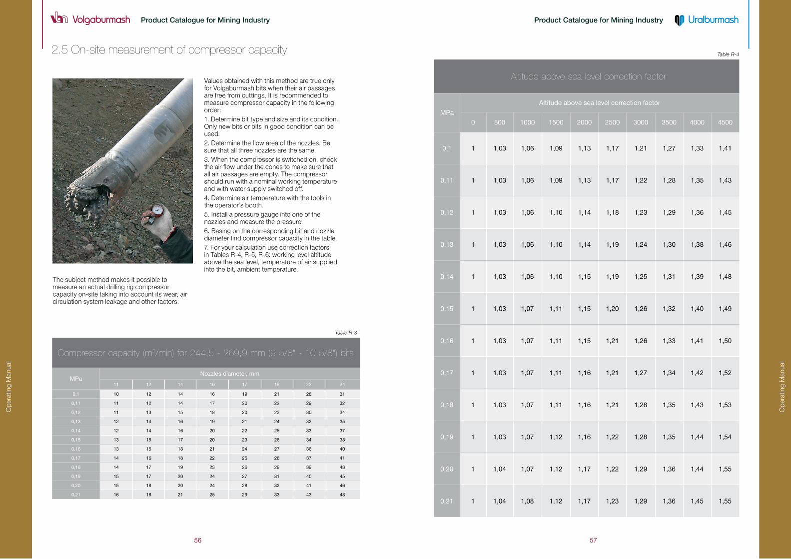
2.5 on-site measurement of compressor capacity
Compressor capacity (m3/min) for 244,5 - 269,9 mm (9 5/8" - 10 5/8") bits
МРаNozzles diameter, mm
11 12 14 16 17 19 22 24
0,1 10 12 14 16 19 21 28 31
0,11 11 12 14 17 20 22 29 32
0,12 11 13 15 18 20 23 30 34
0,13 12 14 16 19 21 24 32 35
0,14 12 14 16 20 22 25 33 37
0,15 13 15 17 20 23 26 34 38
0,16 13 15 18 21 24 27 36 40
0,17 14 16 18 22 25 28 37 41
0,18 14 17 19 23 26 29 39 43
0,19 15 17 20 24 27 31 40 45
0,20 15 18 20 24 28 32 41 46
0,21 16 18 21 25 29 33 43 48
Table R-3
Table R-4
Altitude above sea level correction factor
МРа
Altitude above sea level correction factor
0 500 1000 1500 2000 2500 3000 3500 4000 4500
0,1 1 1,03 1,06 1,09 1,13 1,17 1,21 1,27 1,33 1,41
0,11 1 1,03 1,06 1,09 1,13 1,17 1,22 1,28 1,35 1,43
0,12 1 1,03 1,06 1,10 1,14 1,18 1,23 1,29 1,36 1,45
0,13 1 1,03 1,06 1,10 1,14 1,19 1,24 1,30 1,38 1,46
0,14 1 1,03 1,06 1,10 1,15 1,19 1,25 1,31 1,39 1,48
0,15 1 1,03 1,07 1,11 1,15 1,20 1,26 1,32 1,40 1,49
0,16 1 1,03 1,07 1,11 1,15 1,21 1,26 1,33 1,41 1,50
0,17 1 1,03 1,07 1,11 1,16 1,21 1,27 1,34 1,42 1,52
0,18 1 1,03 1,07 1,11 1,16 1,21 1,28 1,35 1,43 1,53
0,19 1 1,03 1,07 1,12 1,16 1,22 1,28 1,35 1,44 1,54
0,20 1 1,04 1,07 1,12 1,17 1,22 1,29 1,36 1,44 1,55
0,21 1 1,04 1,08 1,12 1,17 1,23 1,29 1,36 1,45 1,55
The subject method makes it possible to measure an actual drilling rig compressor capacity on-site taking into account its wear, air circulation system leakage and other factors.
Values obtained with this method are true only for Volgaburmash bits when their air passages are free from cuttings. It is recommended to measure compressor capacity in the following order:1. Determine bit type and size and its condition. Only new bits or bits in good condition can be used.2. Determine the flow area of the nozzles. Be sure that all three nozzles are the same.3. When the compressor is switched on, check the air flow under the cones to make sure that all air passages are empty. The compressor should run with a nominal working temperature and with water supply switched off.4. Determine air temperature with the tools in the operator’s booth.5. Install a pressure gauge into one of the nozzles and measure the pressure.6. Basing on the corresponding bit and nozzle diameter find compressor capacity in the table.7. For your calculation use correction factors in Tables R-4, R-5, R-6: working level altitude above the sea level, temperature of air supplied into the bit, ambient temperature.

Op
erat
ing
Man
ual
Op
erat
ing
Man
ual
58 59
Product Catalogue for Mining IndustryProduct Catalogue for Mining Industry
Table R-6
Ambient temperature (°C) correction factor
Ambient temperature, °C Factor
� 40 0,80
� 30 0,83
� 20 0,86
� 10 0,90
0 0,93
10 0,97
20 1,00
30 1,03
40 1,07
50 1,10
60 1,14
70 1,17
80 1,20
Table R-5
Bit temperature (°C) correction factor
Temperature in a bit, °C Factor
� 20 1,08
�10 1,06
0 1,04
10 1,02
20 1,00
30 0,98
40 0,97
50 0,95
60 0,94
70 0,92
80 0,91
90 0,90
100 0,89
110 0,87
120 0,86
130 0,85
140 0,84
Example 1:Selection of air circulation parameters for efficient rock bit operation on СБШ-250МНА-32 drilling rig..
Basic data:• 250.8AIRJ742 rock bit;
• Bit nozzles: ø19mm x 3 nozzles;
• Altitude above sea level: 500m;
• Air temperature in bit: +30°C
• Ambient temperature: -10 °C
• Drill rod diameter: 203mm;
• Formations: ferruginous quartzite;
• Holes contain no water.
1. Measure the pressure with the pressure gauge included in the set. 0.18 MPa
2.Table R-3: “244.5 – 269.9”. find the matching compressor capacity based on
the changed pressure (0.18 MPa) and nozzles sizes ( 19mm x 3 nozzles)29 m3/min
3. Table R-4: Find correction factor for the altitude above sea level (500m) 29 х 1,03 = 29,87 m3/min
4. Table R-5: Find correction factor for the air temperature in the bit (+30°C) 29,87 х 0,98 = 29,27 m3/min
5. Table R-6: Find correction factor for the ambient temperature (-10 °C) 29,27 х 0,90 = 26,34 m3/min
6. Actual compressor capacity on СБШ-250МНА-32 drilling rig is 26.34 m3/min.
7.
Based on the Table R-2, we determine that the required air velocity (35 m/sec) is not ensured (with 203 mm drilling rod, the actual compressor capacity of 26.34 m3/min when drilling in heavy formations without water content). However, when the drilling rod is replaced by a 219 mm one, the compressor with 26.34 m3/min capacity supplies the required air velocity (35 m/sec).
8.To extend the bit bearing life, it is required to have pressure in the bit more than 0.2 MPa. Replace the three nozzles by 17.5 mm ones.
9. The second measurement of the pressure in the bit 0.21 MPa
Thus, we have selected nozzles and air velocity required for an efficient bit run.

Op
erat
ing
Man
ual
Op
erat
ing
Man
ual
60 61
Product Catalogue for Mining IndustryProduct Catalogue for Mining Industry
Section 3. Guidelines to rock bit operation
Our recommendations will allow you to obtain good bit performance
Before drilling
While drilling
completeness, reliability of the fixture and state of the relieve valve, availability and size of nozzles, thread connection3.9 Do not make unauthorized changes to the bit design by means of cutting or welding additional parts or removing relieve valve and nozzles.3.10 Flush the drilling assembly with air before screwing on the bit3.11 Avoid impacts or shifts when screwing on the bit3.12 Set the air pressure in the bit not less than 0.2 MPa by means of selecting the nozzles.
3.16 Optimum drilling parameters shall be determined only by experiment. The most critical factor is the maximum ROP3.17 Drill only with the compressor switched on.3.18 Do not apply weight on bit when it does not rotate.3.19 Do not drill when the bit cones are balled up and do not rotate.3.20 Do not drill when the bit air passages are blocked.3.21 Do not complete an old hole with a new bit. It can result in shirttail and hill row inserts cracking and cones jamming.3.22 Carry out tripping and hole conditioning only with the drilling assembly rotating and the compressor on.3.23 Do not use new or test bits to clean out collapsed holes. Always apply a used bit for this purpose.
3.1 Inspect the thread condition of the drill pipe drive rod. If the thread condition is unsatisfactory, the drive rod should be replaced.3.2 Inspect the drilling rod condition. Do not use curved rods or a worn thread.3.3 Inspect the bushings condition. Do not use worn bushings.3.4 Inspect compressor based on the pressure gauge reading on the outlet as compared to its specification data. Adjust the flap position if necessary.3.5 Inspect the air ducts and hoses for leakage. Fix the leakage found in the system.3.6 Inspect the control equipment. Replace faulty equipment.3.7 Inspect hoisting jacks. Do not allow loosing the drilling rig horizontal position while drilling3.8 Inspect the bit condition and
3.13 Fill in the Bit Record Sheet for each bit (Appendix 1).3.14 Break in a new bit for 15 minutes with the drilling rod rotation at 30 RPM and WOB of 10% of the upper limit recommended in the bit specification. Break in a new bit in a new hole (except for the first row holes) with the compressor on.3.15 Smoothly apply the operation parameters recommended in the bit specification. Do not exceed the WOB and RPM indicated in the specification.3.15.1 If with sequential increase in WOB the ROP does not increase or decreases, then the WOB shall be reduced to the earlier registered level at which the maximum ROP was obtained.3.15.2 If the drilling rod starts vibrating, then the bit RPM or WOB shall be reduced to the level at which the vibration stops.
After drilling
3.25 B Before the bit a new hole it should be cleaned and examined.3.26 Use bits till they have obvious failure symptoms:• Locking of bearing at least in one cone;• Big play resulting in cones jamming and interference;• Rollers and balls falling out of at least one of the bearings;• Teeth (inserts) from one cone interfere with other cones;• Excessive wear of the cones cutting structure;• Bit failure (bearing failure, welding seams cracking, cones cracking, etc)
3.30 A rate of bit performance is determined based on “Bit Performance Statistics” for a specific mine by an average performance of not less than 50 bits of the similar size and type and designation with a Report issued.3.31 A report on dull bit performance statistics including meters drilled, hours and ROP is recommended to be delivered to the manufacturer.
3.24 Emergency stop and leaving a bit at the bottom hole with the compressor off may result in plugged bearing and cones jamming. To prevent its early failure, conduct the following control measures:3.24.1 Lift the bit above the bottom hole by 1.5-2 meters with no rotation. Turn on the compressor and flush the bit. While doing so, control the pressure increase in the drilling rig air line with a pressure gauge.3.24.2 Pull the bit out of the hole, clean the bit, check cones rotations manually, turn the compressor on, and visually check flushing air through the cones.3.24.3 You can continue drilling with the bit if the bit examination results are satisfactory for the drilling rig operator.3.24.4 If the bit examination results are not satisfactory for the drilling rig operator, then the bit shall be removed for repair.
3.27 Used bits intended for repair and dril l ing in the wells or for cleaning of choked wells shall be flushed and cleaned from mud, their bearing and thread shall be lubricated. It is not recommended to use new bits in repair operations.3.28 Dull bits intended for scrapping shall be:3.28.1 Examined by the drilling rig operator and registered in the bit registry.3.28.2 Disassembled in order to have a stock of replaceable parts, i.e. relieve valves and nozzles on site.3.29 Drilling report is forwarded to the engineer for registering the bits and analyzing Bit Per formance Statistics (Appendix 2)

Op
erat
ing
Man
ual
Op
erat
ing
Man
ual
62 63
Product Catalogue for Mining IndustryProduct Catalogue for Mining Industry
Section 4. Dull bit analysis
Broken teeth (Bt)
Chipped teeth (Ct)
ExaminationTeeth break flush to cone body.
Causes• Too high RPM.
• Broken, disintegrated formation while drilling or spudding a well.
• Improper bit.
• Alteration of formations including very hard ones.
Recommendation• Reduce the RPM.
• Drill sections interbedded with very hard formations with reduced WOB and RPM.
• Select a bit with the cutting structure features fitting the drilling conditions.
ExaminationChipped tungsten carbide inserts.
Causes• Excessive WOB.• Broken, disintegrated formation while drilling or spudding a well.• Wrong TCI grade.
• Cone interference.
lost teeth (lt)
Worn teeth (Wt)
Recommendation• Revise the drilling applications and WOB.
• Reduce WOB and gradually reduce RPM.
• Select a bit with more wear resistant TCI.
ExaminationTCI fall out of the cone body.
Causes• Metal on the bottom hole.
• Cone erosion.
• A crack in the cone that loosens the grip on
the insert.
• Excessive WOB.
Recommendation• Reduce WOB and RPM –as an option you
can use both actions.
• Select a bit that is more suitable for the
application.
ExaminationInserts wear blunt. Slow penetration rates.
Causes• Excessive WOB.
• Carbide grade does not match the rock properties.
• Formations changed and are interbedded with hard abrasive stringers.
• Excessive RPM.
• This dull characteristic can be considered as a norm if the meterage and durability values are high.

Op
erat
ing
Man
ual
Op
erat
ing
Man
ual
64 65
Product Catalogue for Mining IndustryProduct Catalogue for Mining Industry
Recommendation• Reduce WOB and RPM – as an option you can use both actions.• Select a bit with another shape of inserts and with a more wear resistant carbide grade.• Select a bit that is more suitable for the application.
ExaminationThe gauge inserts are rounded towards the
center of the bit. Slow penetration rates.
Heat checking (HC)
Rounded gauge (RG)
Dull bit analysisCauses• Excessive RPM.• Carbide grade does not match the formation hardness.
Recommendation• Reduce RPM.• Use a bit with a more wear resistant carbide grade.• Use a bit with less offset and a bigger journal angle.
ExaminationInserts are worn mainly on one side. This is a dull characteristic that occurs when the inserts mesh like a gear into the bottom hole formation.
Causes• Improper WOB and RPM
• Improper bit selection
• Changes of the formation.
ExaminationThis is a dull characteristic that occurs when inserts wear in such a way that they retain a sharp crest shape. This proves proper selection of bit and operating parameters.
Recommendation• Adjust WOB and RPM so that the proper rock cutting within a certain period of time is achieved.
• Select a bit better suited for the application or a bit with an irregular skip pitch.
tracking (tR)
self-sharpening wear (ss)
ExaminationInserts surface is worn and looks like a “snake skin”. It often results in inserts breakage.
Causes• Carbide grade does not match the formations drilled.• Inserts are heated by drilling process and at the same time are cooled with water, injected into the well with air and by underground water.
Recommendation• Select a bit with carbide grade less prone to heat checking (higher cobalt content or bigger grain size).• Reduce RPM and water supply.

Op
erat
ing
Man
ual
Op
erat
ing
Man
ual
66 67
Product Catalogue for Mining IndustryProduct Catalogue for Mining Industry
Dull bit analysis
Erosion (ER)
Cracked cone (CC)
ExaminationCone steel erodes away round the inserts and results in loss of inserts. Also, excessive leg erosion can result in loss of inserts on the legs and in shirttail wear, air passage opening and loss of cone.
Causes• High abrasiveness of the formations drilled.• Inadequate air volume flowing through the nozzles.• Wet (from either ground water or excessive water injection) sticky and abrasive formations.
Recommendation• Select WOB and RPM to achieve maximum ROP.• Inspect air supply system for leakage.• If water dust control is used, reduce water supply. Make sure that the nozzles are not plugged.• Inspect cuttings removal efficiency.• Increase nozzle size to reduce air pressure.
ExaminationThe cone cracks either axially or circumferentially.
Causes• Cone steel fatigue.• Cone interference making the cone heat and generate cracks.• Excessive WOB.• Dropped drilling rod.
Recommendation• This dull characteristics can be allowed if the bit is run for a long time.• Reduce WOB.• Review the drilling applications and make sure that the bit drills the bottom hole smoothly with no impacts.• Monitor and control the wear of drilling rod threaded joints.
Cone interference (CI)
lost cone (lC)
ExaminationCones are left at the bottom hole.
Causes• The bit overdrilled the bottom hole.• Bit shock problem.• Bearing failure (all rollers and balls fell out).
Recommendation• Observe instructions in the bit manual.• Monitor and control wear of the drilling rod threaded joints.
ExaminationBearing wear results in the teeth (inserts) of one cone interfering with another cone. It often results in intermittent cone jamming and inserts deterioration and radial cone breakage.
Causes• Excessive WOB resulting in exaggerated bending moment of journals.• Plugged air passages, as a result bearings are not properly cooled.• Insufficient air volume supplied to the bearing.• Running a bit in an under-gauge well.• Rollers and balls fall out of one cone.
Recommendation• Reduce WOB.• Inspect drilling rods condition, their wear and deviation.• Inspect drilling assembly bushings for wear.• Check the back pressure valve availability as well as nozzles availability and proper selection.
Op
erat
ing
Man
ual
Op
erat
ing
Man
ual
68 69
Product Catalogue for Mining IndustryProduct Catalogue for Mining Industry
Dull bit analysis
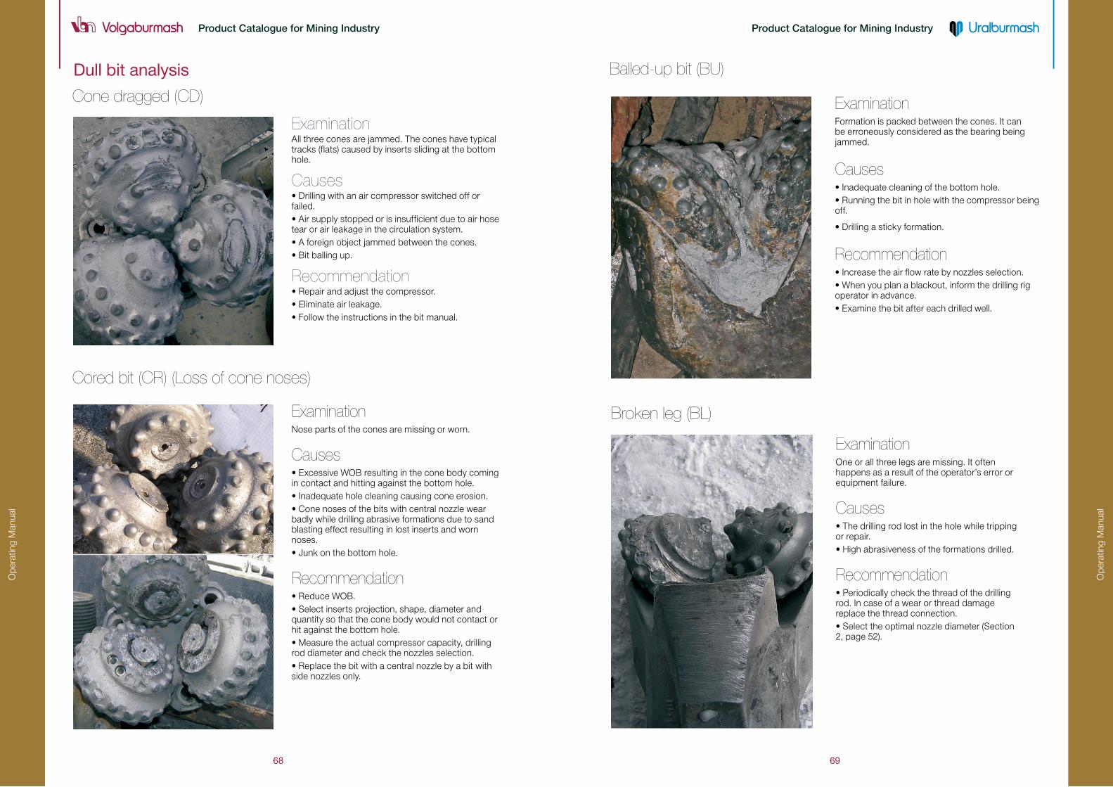
Cone dragged (CD)
Cored bit (CR) (loss of cone noses)
Balled-up bit (BU)
Broken leg (Bl)
ExaminationOne or all three legs are missing. It often happens as a result of the operator’s error or equipment failure.
Causes• The drilling rod lost in the hole while tripping or repair.• High abrasiveness of the formations drilled.
Recommendation• Periodically check the thread of the drilling rod. In case of a wear or thread damage replace the thread connection.• Select the optimal nozzle diameter (Section 2, page 52).
ExaminationAll three cones are jammed. The cones have typical tracks (flats) caused by inserts sliding at the bottom hole.
Causes• Drilling with an air compressor switched off or failed.• Air supply stopped or is insufficient due to air hose tear or air leakage in the circulation system.• A foreign object jammed between the cones.• Bit balling up.
Recommendation• Repair and adjust the compressor.• Eliminate air leakage.• Follow the instructions in the bit manual.
ExaminationNose parts of the cones are missing or worn.
Causes• Excessive WOB resulting in the cone body coming in contact and hitting against the bottom hole.• Inadequate hole cleaning causing cone erosion.• Cone noses of the bits with central nozzle wear badly while drilling abrasive formations due to sand blasting effect resulting in lost inserts and worn noses.• Junk on the bottom hole.
Recommendation• Reduce WOB.• Select inserts projection, shape, diameter and quantity so that the cone body would not contact or hit against the bottom hole.• Measure the actual compressor capacity, drilling rod diameter and check the nozzles selection.• Replace the bit with a central nozzle by a bit with side nozzles only.
ExaminationFormation is packed between the cones. It can be erroneously considered as the bearing being jammed.
Causes• Inadequate cleaning of the bottom hole.• Running the bit in hole with the compressor being off.
• Drilling a sticky formation.
Recommendation• Increase the air flow rate by nozzles selection.• When you plan a blackout, inform the drilling rig operator in advance.• Examine the bit after each drilled well.

Op
erat
ing
Man
ual
Op
erat
ing
Man
ual
70 71
Product Catalogue for Mining IndustryProduct Catalogue for Mining Industry
Plugged nozzle (Pn)
Dull bit analysis • Adjust the compressor, eliminate air leakage, clean the bit from cuttings (nozzles and air passages in the legs).• Flush the drilling rod with air before screwing the bit on.
lost nozzle (ln)
off-center wear (oC)
ExaminationA lost nozzle usually results in a sharp pressure drop and requires an immediate bit pulling out.
Causes• Breaking the rules of nozzle installation.• Mechanical damage of nozzles or their retention system.• Nozzles or their fixture erosion.• Bit balling up.
Recommendation• Examine the bit after each drilled well.
ExaminationExcessive wear of one or two legs (legs, shirttails); of one or two cones (gauge and hill rows), along with bearings failure; cones jammed and balls and rollers lost.
Causes• The drilling rod is bent which results in off-center bit rotation (radial runout).• Hoisting jack has failed.• The bit is screwed to the above bit sub with a warp, the bit thread is damaged.• The thread of the sub (box) is not cut properly, the thrust face of the sub does not thrust against that of the bit.
Recommendation• Check the drilling rod rotation for eccentricity.• Check the bit for damaged thread.• Check and replace the above-bit sub if its thread is damaged.
ExaminationInserts of inner rows are chipped. Between the rows of one cone there are traces of the adjacent cone.
Causes• Well re-drilling with a new bit.• Cleaning out the wells with a new bit.
Recommendation• Use a worn bit to clean out or re-drill a well.• If there are no worn bits, drill a new well adjacent to old one.• Order undersized bits for hole cleaning.• Have a stock of dull bits for well re-drilling or cleaning.
ExaminationA nozzle is plugged with cuttings or rubber hose scraps. The compressor discharges air through the valve. There is a significant erosion of the bit shirttails and legs.
Causes• The bit was left at the bottom hole with air off for work-over and for power transmission line switching.• The bit valve protecting from cuttings failed or is missing.• The compressor failed, the hose fell off.
Recommendation• Use a dull bit for work-over.• When you plan a blackout, inform the drilling rig operator in advance.• Periodically check the relieve valve of the bit, its operability and fixture reliability. Replace the valve if necessary.• Do not use bits that have no valve protection from cuttings.
Pinched bit (PB) (mechanically damaged bit)

Op
erat
ing
Man
ual
Op
erat
ing
Man
ual
72 73
Product Catalogue for Mining IndustryProduct Catalogue for Mining Industry
ExaminationSludge in the bit bearing (it can be erroneously considered as jammed bearing).
Causes• Insufficient compressor capacity.• Improper nozzles selection.• Drilling without the relieve valve.• The bit was left at the bottom hole for a long time with the compressor off.
Recommendation• Select the nozzles according to recommendations.• When you plan a blackout, inform the drilling rig operator in advance.• Run the bit with a relieve valve in place.
ExaminationLeg shirttail protecting the bearing is broken.
Causes• Axial part of the load on the bearing results in the shirttail bearing a part of the load.• Axial runout when the bit rotates.• Erosion weakens the shirttail structure.
Recommendation• Reduce WOB and select a bit with a smaller journal angle and bit axis.• Check the bit for off-center wear and the drilling rod for a bent.• Check the bit thread and the sub thread for damage.• Check the drilling rod, compressor and the air line for leakage.
shirttail damage (sD)
Bearing sludging (Bs)
Play (Pl)
ExaminationPlay.
Causes• Insufficient compressor capacity.
• Improper nozzles selection.
• Roll and ball bearings wear, bearing.
overheating resulting in journal bearing failure.
Recommendation• Repair the compressor or replace it to a
more efficient one.
• Select nozzles according to
recommendations.
• Examine the bit after each drilled well.
Dull bit analysis

Op
erat
ing
Man
ual
Op
erat
ing
Man
ual
74 75
Product Catalogue for Mining IndustryProduct Catalogue for Mining Industry
Section 5. Selection of efficient bit designs
• Mining, geological and technological drilling applications• Rock bit statistics• Dull bit analysis• Cutting structure and design features• Technical and economic indices of bits performance based on test results.If necessary, we can design and manufacture rock bits based on our customer’s specific requirements.
bit specification and design features. Since geology may alter with a mine deepening and widening, it is important to consider the drilling volume as per “Long Term Drilling Operation Plan” (Appendix 3).
a considerable economic effect in drilling using the state-of-the-art bits with old and worn drilling rig. At the same time, it is well possible to reduce drilling expenses by selection of bits efficiency of which would match actual drilling rig technical parameters.
More than 250 bit types and sizes have been developed and can be manufactured for mining companies. It is important to select efficient bit designs for specific mining and geological applications to ensure the best performance (reduced expenses for drilling equipment and drilling operations, increased drilling rigs productivity, reduced time for blast blocks preparation). Our specialists give all recommendations on the optimum bit types and sizes selection and analyze the efficiency of bit runs. Efficient bit selection at each mining company is made based on a complex assessment of:
A critical factor that affects bit performance is the mining and geological applications analysis. Rock properties, namely uniaxial compression strength δ, average formation hardness factor F as per professor Protodyakonov’s scale, alteration, stringers, attitude of beds, water cut, abrasiveness, broken formations, etc. determine rock
Intensive mining complex development is directly related to technical re-equipment and replacement of drilling rigs. Such technical characteristics of drilling rigs as drilling performance, drilling assembly, connecting thread, compressor capacity should match the design features of bits.It is obvious, that it is impossible to achieve
5.1 Mining and geological applications analysis
5.2 technological applications analysis
5.3 Bit performance statistics analysis
The evaluation database for an efficient bit design selection is Rock Bit Performance Statistics Analysis (Appendix 2). Modern drilling companies usually use a few bit types of different man-ufacturers and it is important to make a comparative assessment of their efficiency disregard-ing the bits cost.
If the meterage and ROP of two bits are equal then the bits are equal in their efficiency.
Example 3C and d rock bits comparison assessment with the following statistics
• C rock bit, meterage (hc)=60 meters drilled, hours (tc)=10hrs
• d rock bit, meterage (hd)=60 meters drilled, hours (td)=12hrs
Let’s determine the average rop of C and d bits performance:
Conclusion
Bit C is more efficient than bit d, because hc>hd and ropc>ropd
Example 2A and b rock bits comparison assessment with the following statistics:
• A rock bit, meterage (ha)=60 meters drilled, hours (ta)=10hrs;
• b rock bit, meterage (hb)=40 meters drilled, hours (tb)=8 hrs
Let’s determine the average ROP of A and b bits performance:
Conclusion
Bit A is more efficient than bit b, because ha>hb and ropa>ropb

Op
erat
ing
Man
ual
Op
erat
ing
Man
ual
76 77
Product Catalogue for Mining IndustryProduct Catalogue for Mining Industry
5.4 Dull bit analysis and reasons bit failed
5.5 Bit cutting structure and bearing design features analysis
5.6 Analysis of technical and economic indices of bits perfor-mance based on field test results
important because it is critical to very precisely identify what bit design features are required for the application.
sites and in catalogues with bits specifications. The information contains alphabetic characters as per GOST 20692-2003 and the designation as per IADC code.
After assessment of bits efficiency based on statistics, it is necessary to make a comparative analysis of each bit type dulling and reasons. The analysis results are
As a rule, to select bits for optimization of their design features, drilling specialists in mining companies use bits identification method based on the data provided by manufacturers. It is a list of products at web-
A bit design efficiency is determined based on comparative test results in equal mining and geo-logical conditions. An efficient bit design should be considered the one that ensures the minimum value of operational expenses for drilling one running meter of a hole which is determined by the formula:
6.1 Bits should be stored in a dry and enclosed facility.
6.2 Bits should be stored in cardboard or wooden boxes placed on pallets.
6.3 The transportation should be made either on pallets or in boxes (without pallets).
6.4 The transportation should be made by all modes of transport according to cargo transportation rules for each transportation type provided the cargo is protected from atmospheric precipitations and mechanical damage.
6.5 Storage and transportation of bits in bulks is forbidden.
6.6 Bits shall not hit each other or other solid objects while handling.
6.7 Gloves should be used when handling the bits. 8 1/2» and larger bits shall be handled using mechanic equipment.
6.8 Bits should be stored at drilling rigs in the manufacturer’s package or with their shanks upward and the thread and the relief valve protected by a cap.
Section 6. Bits storage and transportation
, Where :
– cost of one running meter of hole;
– bit cost;
Н – average meterage per bit, m;
– rig cost per one hour of drilling;
– average ROP
Example 4: Calculation of A and B bits efficiency: А и В:
ConclusionUsing bit b gives the company an annual benefit of 2 667 000 RUR as compared with bit A
Indices A bit B bit
Bit cost, RUR 40 000 45 000
Annual scope of drilling, m 300 000
Meterage, m 2 000 2 100
Bit durability, hrs 90 80
ROP, m/h 22,2 26,2
Rig cost/hr, RUR 1 500 1 500
Rig cost/m, RUR 87,56 78,67
Saving per 1 running meter, RUR - 8,89
Annual benefit - 2 667 000
av
av
Selection of efficient bit designs

Ap
pen
dic
es
Product Catalogue for Mining IndustryProduct Catalogue for Mining Industry
AppendiCes
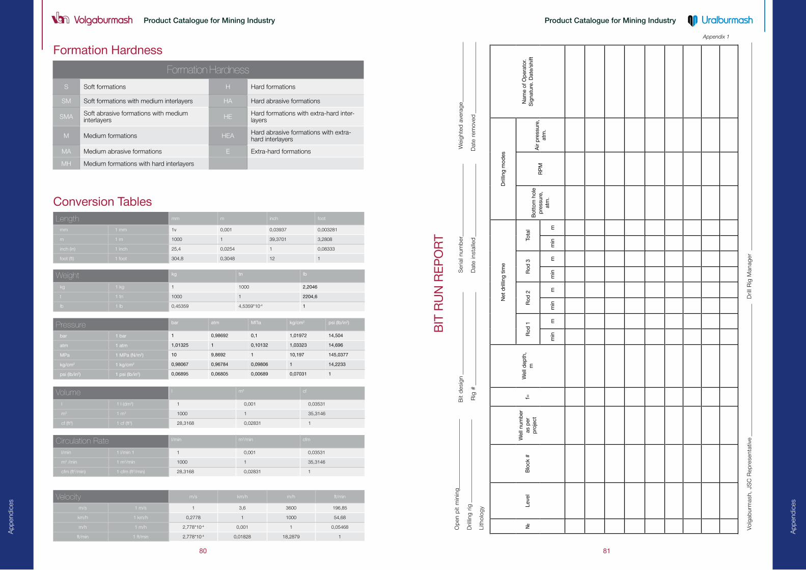
Ap
pen
dic
es
81
Product Catalogue for Mining Industry
80
Ap
pen
dic
es
Product Catalogue for Mining Industry
Conversion Tableslength mm m inch foot
mm 1 mm 1v 0,001 0,03937 0,003281
m 1 m 1000 1 39,3701 3,2808
inch (in) 1 inch 25,4 0,0254 1 0,08333
foot (ft) 1 foot 304,8 0,3048 12 1
Velocity m/s km/h m/h ft/min
m/s 1 m/s 1 3,6 3600 196,85
km/h 1 km/h 0,2778 1 1000 54,68
m/h 1 m/h 2,778*10�4 0,001 1 0,05468
ft/min 1 ft/min 2,778*10�4 0,01828 18,2879 1
Weight kg tn Ib
kg 1 kg 1 1000 2,2046
t 1 tn 1000 1 2204,6
lb 1 lb 0,45359 4,5359*10�4 1
Volume l m3 cf
l 1 l (dm3) 1 0,001 0,03531
m3 1 m3 1000 1 35,3146
cf (ft3) 1 cf (ft3) 28,3168 0,02831 1
Circulation Rate l/min m3/min cfm
l/min 1 l/min 1 1 0,001 0,03531
m3 /min 1 m3/min 1000 1 35,3146
cfm (ft3/min) 1 cfm (ft3/min) 28,3168 0,02831 1
Pressure bar atm МПа kg/cm2 psi (lb/in2)
bar 1 bar 1 0,98692 0,1 1,01972 14,504
atm 1 atm 1,01325 1 0,10132 1,03323 14,696
MPa 1 MPa (N/m2) 10 9,8692 1 10,197 145,0377
kg/cm2 1 kg/cm2 0,98067 0,96784 0,09806 1 14,2233
psi (lb/in2) 1 psi (lb/in2) 0,06895 0,06805 0,00689 0,07031 1
Formation Hardness
formation Hardness
S Soft formations Н Hard formations
SM Soft formations with medium interlayers НА Hard abrasive formations
SMА Soft abrasive formations with medium interlayers НЕ Hard formations with extra-hard inter-
layers
M Medium formations НЕА Hard abrasive formations with extra-hard interlayers
MА Medium abrasive formations Е Extra-hard formations
MH Medium formations with hard interlayers
Appendix 1
BIT
RU
N R
EP
OR
T
№Le
vel
Blo
ck #
Wel
l num
ber
as
per
p
roje
ctf=
Wel
l dep
th,
m
Net
dril
ling
tim
eD
rillin
g m
od
es
Nam
e o
f O
per
ato
r.
Sig
natu
re. D
ate/
shift
Ro
d 1
Ro
d 2
R
od
3To
tal
Bo
tto
m h
ole
p
ress
ure,
at
m.
RP
MA
ir p
ress
ure,
at
m.
min
mm
inm
min
mm
inm
Op
en p
it m
inin
g
Dril
ling
rig
Lith
olo
gy
Bit
des
ign
Rig
#
Ser
ial n
um
ber
Dat
e in
stal
led
W
eig
hte
d a
vera
ge
Dat
e re
mo
ved
Vo
lgab
urm
ash,
JS
C R
epre
senta
tive
Dril
l Rig
Man
ager

Ap
pen
dic
es
83
Product Catalogue for Mining Industry
82
Ap
pen
dic
es
Product Catalogue for Mining Industry
Приложение 2 Приложение 3

84
Каталог продукции для горнодобывающей промышленности
site
Contacts
Volgaburmash, JSCGroznenskaya St. 1, Samara, 443004, Russia
Tel.: +7 (846) 300-8000
Fax: +7 (846) 300-8000
www.vbm.ru
E-mai l: ma i [email protected]
Uralburmash, JSCVolodarskogo St. 10, Verkhniye Sergi, The Sverdlovsk Region, 623070, Russia
Tel.: +7 (34398) 2-42-21
www.vbm.ru
E-mai l: ma i [email protected]
Sales Representative – Samara Drilling Tools, LLC
Groznenskaya St. 1, Samara, 443004, Russia
Tel.: +7 (846) 300-8000
Fax: +7 (846) 300-8000
www.vbm.ru
E-mai l: ma i [email protected]
At our web-site you will find more detailed information about our range of products, drilling modes and operating conditions.In the section “Products for Specific Fields” you can find optimal designs, make selection using filter and then send your request for the necessary products to our specialists.