Download PDF - International Journal of Engineering and ...
11
International Journal of Engineering and Advanced Technology (IJEAT) ISSN: 2249 – 8958, Volume-9 Issue-1, October 2019 3332 Published By: Blue Eyes Intelligence Engineering & Sciences Publication Retrieval Number: A1495109119/2019©BEIESP DOI: 10.35940/ijeat.A1495.109119 Abstract: The vertical growth of multi storied buildings has become requisite considering limitations on housing area and upsurge in population growth. Cities with population density >10000 person/Km2may go for high rise buildings. Multiple cases of foundation failure have been observed around the globe due to incompetent soil, weak foundation, poor building materials, faulty workmanship, excess superimposed loading, want of geotechnical investigations, and failure analysis. The analysis and design of multistoried buildings [minimum G +3]is of demand in urban and economically sound areas. The STAAD. Pro is an efficient tool adhering to IS specifications for design of structures by limit state design to avoid erroneous computations, cumbersome and time consuming processes of manual calculation in India. The software is user interface to visualize, analyze and design structures by radical finite element technique and has dynamic analysis abilities. The present work is a 3-D RCC frame having 4 bays x5m along x-direction and 3 bays x5m in z- direction were taken where each floor has 299 beams and 40umns at different elevations in each floor subjected to dead, live , wind and seismic loads as per Indian beneath different load arrangements, considering structural safety under minimum requirements. The perception levels against vibrations and different foundations against failure (especially pile foundation) is stressed for a safe, comfortable multi storied building in Indian soil. Keywords: Multistoried buildings, STAD Pro, Pile foundation, Load distribution, Wind & Seismic forces I. INTRODUCTION The augmented economy, burgeoning population, fast industrialization, urbanization, Squeeze of dwelling space and advancement in construction technology, has delimited the horizontal growth in construction edges towards fag end of 20th century whereas growth of vertical cities are encouraged for potential urban sprawl. The concrete canyons in urban cluster can be associated as a part of the multistoried buildings. The edifices, like skyscrapers are the indicators of a financial fizz, and exciting building commotion and encouraged urbanization. The developing countries in China, USA, Indonesia, Canada, Europe and India, the high rise buildings (HRB’s) have been encouraged and also constructed Building by Laws 2016 prescribe the maximum elevation of structure which should not exceeding>1.5 times Revised Manuscript Received on October 15, 2019 Suman Kumar Behera, Department Civil Engineering, Centurion University of Technology and Management, Odisha, India. Siba Prasad Mishra, Department Civil Engineering, Centurion University of Technology and Management, Odisha, India. Sagarika Panda, Department Civil Engineering, Centurion University of Technology and Management, Odisha, India. Mohammed Siddique, Department Mathematics, Centurion University of Technology and Management, Odisha, India the width of boulevard near by anterior open places as per provisions of floor area ratio (FAR). A. Indian Urbanization Urban population in India, was 11.4% (1901 census), 28.53% (2001 census), and was 31.16% (2011 census) and 34% as estimated in 2017 according to the World Bank. The cities having population density need high rise buildings and cities like Mumbai, Delhi, Calcutta, Pune, Navi Mumbai, Chennai and other cities whose population density is >10000 urgently need vertical expansion of township as the horizontal growth is a meager chance (Fig 1).According to CTBUH, India, 61 numbers of 150m+ buildings are completed and 62 are under construction in India whereas 300m+ HRB’s are only two which are under construction. These concrete HRB’s has common residential or mixed use functions http://regions .ctbuh.org/india. The skyscrapers are restricted in India due restrictions on floor space index (FSI) and incompetent soil conditions. Fig 1: The major population density cosmopolitan cities (persons /Km 2 ) in cities (2011 census) 0.0 10000.0 20000.0 30000.0 40000.0 50000.0 60000.0 70000.0 80000.0 Nos of people/sq Km High population density cities of India Population density/sq Km major cities India An Autodesk Modeling of Urbanization by Vertical Multistoried Structures over Incompetent Soils Suman Kumar Behera, Siba Prasad Mishra, Sagarika Panda, Mohammed Siddique
-
Upload
khangminh22 -
Category
Documents
-
view
1 -
download
0
Transcript of Download PDF - International Journal of Engineering and ...

International Journal of Engineering and Advanced Technology (IJEAT)
ISSN: 2249 – 8958, Volume-9 Issue-1, October 2019
3332
Published By: Blue Eyes Intelligence Engineering
& Sciences Publication
Retrieval Number: A1495109119/2019©BEIESP
DOI: 10.35940/ijeat.A1495.109119
Abstract: The vertical growth of multi storied buildings has
become requisite considering limitations on housing area and
upsurge in population growth. Cities with population density
>10000 person/Km2may go for high rise buildings. Multiple cases
of foundation failure have been observed around the globe due to
incompetent soil, weak foundation, poor building materials, faulty
workmanship, excess superimposed loading, want of geotechnical
investigations, and failure analysis. The analysis and design of
multistoried buildings [minimum G +3]is of demand in urban and
economically sound areas. The STAAD. Pro is an efficient tool
adhering to IS specifications for design of structures by limit state
design to avoid erroneous computations, cumbersome and time
consuming processes of manual calculation in India. The
software is user interface to visualize, analyze and design
structures by radical finite element technique and has dynamic
analysis abilities. The present work is a 3-D RCC frame having 4
bays x5m along x-direction and 3 bays x5m in z- direction were
taken where each floor has 299 beams and 40umns at different
elevations in each floor subjected to dead, live , wind and seismic
loads as per Indian beneath different load arrangements,
considering structural safety under minimum requirements. The
perception levels against vibrations and different foundations
against failure (especially pile foundation) is stressed for a safe,
comfortable multi storied building in Indian soil.
Keywords: Multistoried buildings, STAD Pro, Pile
foundation, Load distribution, Wind & Seismic forces
I. INTRODUCTION
The augmented economy, burgeoning population, fast
industrialization, urbanization, Squeeze of dwelling space
and advancement in construction technology, has delimited
the horizontal growth in construction edges towards fag end
of 20th century whereas growth of vertical cities are
encouraged for potential urban sprawl. The concrete canyons
in urban cluster can be associated as a part of the multistoried
buildings. The edifices, like skyscrapers are the indicators of
a financial fizz, and exciting building commotion and
encouraged urbanization. The developing countries in China,
USA, Indonesia, Canada, Europe and India, the high rise
buildings (HRB’s) have been encouraged and also
constructed Building by Laws 2016 prescribe the maximum
elevation of structure which should not exceeding>1.5 times
Revised Manuscript Received on October 15, 2019
Suman Kumar Behera, Department Civil Engineering, Centurion
University of Technology and Management, Odisha, India.
Siba Prasad Mishra, Department Civil Engineering, Centurion University of Technology and Management, Odisha, India.
Sagarika Panda, Department Civil Engineering, Centurion University of
Technology and Management, Odisha, India. Mohammed Siddique, Department Mathematics, Centurion University
of Technology and Management, Odisha, India
the width of boulevard near by anterior open places as per
provisions of floor area ratio (FAR).
A. Indian Urbanization
Urban population in India, was 11.4% (1901 census),
28.53% (2001 census), and was 31.16% (2011 census) and
34% as estimated in 2017 according to the World Bank. The
cities having population density need high rise buildings and
cities like Mumbai, Delhi, Calcutta, Pune, Navi Mumbai,
Chennai and other cities whose population density is >10000
urgently need vertical expansion of township as the
horizontal growth is a meager chance (Fig 1).According to
CTBUH, India, 61 numbers of 150m+ buildings are
completed and 62 are under construction in India whereas
300m+ HRB’s are only two which are under construction.
These concrete HRB’s has common residential or mixed use
functions http://regions .ctbuh.org/india. The skyscrapers are
restricted in India due restrictions on floor space index (FSI)
and incompetent soil conditions.
Fig 1: The major population density cosmopolitan
cities (persons /Km2) in cities (2011 census)
0.0
10000.0
20000.0
30000.0
40000.0
50000.0
60000.0
70000.0
80000.0
No
s o
f p
eo
ple
/sq
Km
High population density cities of India
Population density/sq Km major cities India
An Autodesk Modeling of Urbanization by
Vertical Multistoried Structures over
Incompetent Soils
Suman Kumar Behera, Siba Prasad Mishra, Sagarika Panda, Mohammed Siddique

An Autodesk Modeling of Urbanization by Vertical Multistoried Structures over Incompetent Soils
3333
Published By:
Blue Eyes Intelligence Engineering & Sciences Publication
Retrieval Number: A1495109119/2019©BEIESP
DOI: 10.35940/ijeat.A1495.109119
B. High rise building:
A building is a high-rise one which is difficult to evacuate
during fire or any hazardous situation when inaccessible to
fire hose and ladders (firefighting) as per fire & building
norms. The cutoff point worldwide is accepted as about seven
stories and higher (≥22m). CTBUH Height Criteria of High
rise buildings-2017, prescribe (HRB’s) (50m+), Skyscraper
(150m+), Supper tall (300m+), Mega tall (600m+)
http://www.ctbuh.org /High Rise Info/Tallest
Database/Criteria/tabid/446. High rise/ multistoried edifices,
Sky scrapers, like the La Azteca edifice in Mexico, USA, the
Burj-Khalifa mansion, (Dubai, UAE), the Incheon 151
Tower (South Korea) and Jeddah in Saudi Arabia are the
buildings are super tall buildings. The numbers of sky
scrapers (>300m high) in the globe has increased from
15numbers in 1995 to 116 in 2015 and likely to rise ~200 by
2020. The HRB’s >150m+ are in cities like Hong Kong
(355), New York (280), Shenzhen (222), and Dubai (190).
The multistoried buildings such as G + 3 storied have become
common all along the world, in country side, rural and urban
areas. The design of the HRB’s and their foundation
strategies are common problem. The tall buildings are
classified in various countries/ states/ cities are given below
(Table 1).
Table 1: High rise buildings classes in different countries,
https://www.mdpi.com/2075-5309/8/1/7/htm # Name of
the country
Name
assigned
Height in m Reference
1 German
regulation
Tall Building 22m Ross, D.E.,
2004[1]
2
Leicester
City
Council (UK)
Tall building Predominantly
high building
Al-Kodmany
K., 2018[2]
3
Ireland,
Cork City,
2004
Tall building ≥ 10 stories and
higher
Cork City
Council, UK
4
According
to
CTBUH:(Council on
Tall
Buildings and Urban
Habitats)
Tall Building
Sky scraper
Super tall Building
Mega tall
Building
Al-Kodmany
K., 2018[2]
5 ASHRAE: Tall Building ≥50m+ EllisP.G.,et al.,2008[3]
6
Mumbai
Municipal
Corpn. (BMC)
High rise
revised
High rise existing
≥30m (nine
floors)
≥24m (seven floors)
Kavilkar R. &
Patil S.,
2014[4]
7
Ministry of
Urban Dev.
India
(http://moh
ua.gov .in/upload
/uploadfiles
/files/MBBL.pdf)
High rise
building
≥15m high
without stilts
and ≥ 17.5m
of height with
stilts
Model
Building
Bye-Laws
-2016,
MOUD GOI, 2016[1(10)]
The Aires already constructed in India are in the Calcutta city
(42, Kolkata, 268m, total numbers 11), Bombay city
(44numbers): Imperial Tower 1, (256m), and 2 numbers in
New Delhi and one is under construction and to be completed
by 2020 (Supernova Spira at Noida of 300m).
Fig 2: The major high rise buildings >150m in different
countries of the globe, Source
https://en.wikipedia.org/wiki/Listofcities_with_the_mo
st_skyscrapers.
Out of 4838numbers of high rise buildings >150m has
already been constructed 4196 in numbers and under
construction are 642 numbers throughout the globe,. China
has the highest sky scrapers existing are (1838 numbers)
followed by USA (665numbers), UAE (239numbers) and
Japan (214numbers). Major Aires exist in India are in thickly
populated cities like Mumbai (44numbers) and Calcutta
(11numbers)Poulos G. H., 2016[5] Fig -2.
C. Reasons for study:
India has 1.37 billion populations as on date according to
worldpopulationreview.com. The census repositories, the
good and habitable buildings are 50.3%, just livable are
44.5% and old dilapidated but people are living are 5.2%. The
annual population growth 1.02% in the country and migration
of people from rural to urban were 52million in 2001 census
to 78millions as per 2011 census with a rise of migration by
51%. Millions of urban dwellers are either homeless or living
in dilapidated buildings. India’s urge for smart city mission
or housing for all in las 3-4 years as per MOHUA (Min of
Housing & Urban affairs, GOI). Mishra S.P. et al, 2019[6].It
is only possible by constructing vertical cities rather than
horizontal expansions. Under the constraints of rapid growth
of vertical cities, the present study is the design of
multistoried housing compartments, residential buildings and
high rise tall building to the demand for dwelling houses and
roofs for the homeless providing them dynamic effects of
living with comforts of in occupancy in HRB’s such as
thermal, wind induced perceptions, motion sickness, and
seismic vertigo etc.
D. Soil of tall buildings:
Poulos H. G., 2001[7] and 2011[8]recommended
relatively stiff clays, or dense sand is ideal soil for tall
buildings and
uncomplimentary conditions
are loose sand, soft clays,
loose clays, soft compressible
0
500
1000
1500
2000
2500
Au
stra
lia
Can
ada
Ch
ina
Ind
ia
In
don
esia
Jap
an
Mal
aysi
a
Pan
ama
Ph
ilip
pin
es
Sin
gap
ore
Sou
th K
ore
a
Tai
wan
Th
aila
nd
UA
E
UK
Un
ited
Sta
tes N
os
of
bu
ildin
gs >
15
0m
countries
The Major high rise buidlings >150m in
the globe
skyscrapers … skyscrapers …
International Journal of Engineering and Advanced Technology (IJEAT)
ISSN: 2249 – 8958, Volume-9 Issue-1, October 2019
3334
Published By: Blue Eyes Intelligence Engineering
& Sciences Publication
Retrieval Number: A1495109119/2019©BEIESP
DOI: 10.35940/ijeat.A1495.109119
layers, near the surface and profiles of soil sheet undergoing
consolidation, settlements and swelling compressible layers
at shallow depth. Soil properties of multistoried buildings for
foundation should have high shear strength, low
compressibility, low void ratio, high density/unit weight, low
permeability, low atterberg limits (mostly liquid limit). The
available soils in India having above properties are very stiff
clay (not swelling montmorillonite causing buckling), hard
rock, red soil and angular grained soils. The most
disapproving soil for multistoried building foundation is
Black cotton soil, sandy soil, and alluvium. The areas located
for HRB’s in India generally are not suitable, so either deep
(piling), mat/raft foundation, piles with raft or mat
foundations are provided to withstand the high rise building
loads. The soilsare clays and silts (purely cohesive) or sand
and gravels (purely cohesion less) orsandy clay or silty sand
(partly cohesive and partly cohesion less) are the incompetent
type soil.
II. REVIEW OF LITERATURE
The leaning tower of Pisa is tall built building exhibiting
part foundation failure over an incompetent, soil of
geotechnical inadequacy, unevenly distributed load bearing
capacity and poor foundation design Buchanan A et al.,,
2011[9], Allen P T N et al, 2017[10]. The foundation failures
are due to metastable soils and swelling clays in British
Columbia and adjoining provinces. Marshall R.R. 1999[11].
The Pile foundations are preferred where the soils are as
mound, peat, silt deposits, sediments, cohesive soils and are
in flow plastic state, and when the building is subjected to
heavy (dead and live ), concentrated loads as in tall buildings,
dams, bridges and overhead water tanks Kosiakov Egor
2018[12].The IBC (International Building Code-2000) and
NFPA (the Building Construction and Safety Code, 2002),
delineate high-rise buildings are buildings of 23m or higher
from the nethermost level to the highest occupied top story.
The building codes of India, a tall / HRB is one which is 15
meters or more vertically Kavilkar et al 2014[4]. Sancio R. B.
et al., 2004[13]reported about loss of 2627 lives and 5,078
tall buildings (27% of total) stock) were failed or damaged
due to vertical displacement, tilt, and lateral translation over
the ground during 2004 earth quake in Turkey. The weight
of a building escalate non-linearly with growing elevation,
as a result the foundation has to bear the upsurge vertical load
Poulos H. G. et al., 2012[14] .Sze J. W. C., 2015[15]reported
that bored piles or steel H piles of large diameter are best
suited for foundation high rise buildings in Hong Jong. Li
Lianget al, 2016[16], reported about a 13storied building
collapse in Shanghai due to excavation of a 4.6m trench near
the basement garage on 27th June, 2009. Buttling S, et al.,
2018[17], proposed to design the foundation and piles of a
high rise building by using a combination of structural model
and geotech model bearing in mind relative stiffness of soil
and structural movement along each pile and the construction
boom of tall building. Costela D. et al, 2009[18]reported that
pressure coefficients pertaining to Wind “Cp” impacts facade
detailing, building geometry, degree of exposure/sheltering,
speed and direction of wind.
Issues related to HRB Foundations:
The burgeoning population growth and migration to the
urban megacities need vertical extension of buildings so that
the demand for roof over head is possible. HRB’s need a
sound and solid foundation to avoid settlement, failure and
tilts. The major causes for building collapse are incompetent
BC soil (expansive with least bearing capacity and strange
swelling and shrinkage characteristics), loose soil, weak
foundation, poor building materials, faulty workmanship,
excess superimposed loading, want of failure analysis, failed
to transfer loads, old existing structures like water courses,
drains, trenches below foundation, and filled up water bodies,
design error, excess lateral loads due to meteorological
extremes like floods, drag down and heaves, lateral loads (
flood, heavy rain, strong wind and earth quake tremors, land
slide) and unstable slope, improper geo-tech investigation,
unsymmetrical loading, high ground water fluctuation,
incompetent soil and many others, Srivastav A. et al.,
2012[19], Nagarajan D et al., 2014[20], Aruna et al.,
2017[21], Nagarjuna K. et al., 2018[22. The overall
differential settlement of the multi storied buildings urges
structural design of foundation. The issues related to
foundation and design are groupings of vertical, lateral/
moment loading, the harmonic movement of foundation due
to wind and tremor forces. The foundation of HRB’s are
associated with three types of foundation depending upon the
soil and structural loading like Pile foundation, Mat/raft
foundation or the combinations of the two above.
III. METHODOLOGY
The present study is to analyze load calculation manually
and design according to IS code (Limit State Design)for
multistoried building [G +3 (3-D frame)] using STAAD Pro. .
The simple analysis of 2-D frames and their accuracy were
physically tested with software results. The analysis and
design of a set of G + 3 storied building [2-D Frame] were
done under the potential load groupings.RCC framed
structures (3-D)with the orthogonal coordinates of 4 bays of
5m.along x-direction, G 3 floors along y-axis of 3 baysof5m
along z-direction were considered. There were299 beams and
40 columns 40 in each floor. The ground floor is 3.5mhigh.
The succeeding floors are 3.3m high. The dead, live, lateral
and vibration loads or combinations are analyzed by STAAD
Pro software. The variable lateral wind load values were
created according to prevailing intensities of wind at various
elevations (IS 875 -1987) and vibratory seismic load as per IS
1893-2000. The materials of the beams and columns were
followed as per IS code under practice. The post-processing
approach of STAD Pro (towards end of the design and
detailing), BM/ SF values are created and reflected in
diagrams. Checking of deflection of members was conducted
under the assigned loading arrangements. The structural
design is reliant on the adherence of minimum necessities
provided in the IS Codes to have the structural safety of the
Structure. The elements were designed considering Limit
State Technique.
Why STAAD Pro. Software? HRB’s needs rigorous,
repetitive and complex calculations if designed by
conventional manual methods.
But STAAD GUI (graphic user
interface) can analyze and
design all types and individual
An Autodesk Modeling of Urbanization by Vertical Multistoried Structures over Incompetent Soils
3335
Published By:
Blue Eyes Intelligence Engineering & Sciences Publication
Retrieval Number: A1495109119/2019©BEIESP
DOI: 10.35940/ijeat.A1495.109119
members of the structure and give graphical interpretation as
it is versatile, easy, fast, accurate, a true user interface and
finally confirm to IS codes. A 3-D frame structure (SPACE
structure), with loads application along any plane, is
common. Soft ware’s available for design/modeling of
multistoried buildings are STAD foundation, E Tab, 3DS
Max, Civil 3D, AutoCAD with a civil engineering, AutoCAD
(from Auto desk), CATIA (model buildings), Chief
Architect, Revit. BIM, Rhino 6 and Sketch up. STAAD Pro,
a multi- faceted design software that confirms IS codes and
provides a profligate, effective, informal to use and accurate
firm platform for analysis, design various structures (CC,
RCC, Steel, timber, and aluminum) like dams, bridges, high
rise buildings, docks and harbors etc. using information such
as structural loads, geometry, support conditions, stability,
dynamic response, nonlinearity and materials properties.
Design, for the durability, erection and usage must be
accounted as complete amenability with well-defined
standards for ingredients, construction methods,
workmanship, running maintenance and finally the service
usage Saha et al 2016[23], Seva et al., 2017[24].
Setback around HRB’s, India :As per NBC model by
laws-2016 (MBBL-2016)[1(10),the open space is to be left as
setbacks for the multistoried buildings depending upon the
heights are:21m to 30m (10m), 30m to 35 (11m ), 35 to 40
(12m), 40-45 (13m), 45m-50m (14m) and >50mis always
≥16m. The setback areas are to be provided with hard surface
around all sides of the building and should be capable of
bearing load of >45 MT/m2 , to take the loads of firefighting
vehicles. The total elevation of the building shall be< 1.5
times the road width and the adjoining open space around the
multi storied building. The clearance from the power line
medium voltage/ service lines (1.2m to 2.50m), 11KVolts
line (1.2 to 3.7m ), Voltage line >11000V (2.2m to 3.70m),
extra high voltage line >33KV 2.0m. adding 0.3 m. for every
33KV and part.(Model Building Bye-Law, 2016, TCPO)
Human perception levels in HRB’s: The uniqueness by
perception, cognizance or realization between physical and
mental status is the mind-body problem. These Human
problems do respond to motion of the HRB’s due to wind
intensity laterally encountering a building. Human body is
bio dynamic and responsive to body vibration at low
frequencies even within the range of 0.85m/sec2 and within
frequency ranges 0.15 to 1.0Hz.The resonant freq. of RCC
HRB’s are within range 2.2 to 2.9Hz. It is highly essential the
soil frequency must be greater than resonant frequencies. As
per SEVENSK standard (SS-ISO 10137-2008): This
Swedish standard prescribes the perception levels of human
response of the HRB dwellers Farouk Mohamed I, 2016[25],
Halle brand Erik et al., 2016[26].There is noticeable impact
of displacements, speeding up, and resulting forces that
restricts the comfort of residents in HRB’s. There are four the
effects on heel drop and walking activities such as
Imperceptible, Slightly perceptible, distinctly perceptible and
strongly perceptible depending upon thresholds damping
ratios are as follows, Table 2:
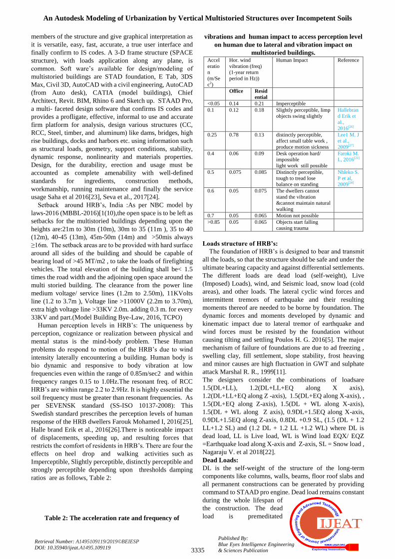
Table 2: The acceleration rate and frequency of
vibrations and human impact to access perception level
on human due to lateral and vibration impact on
multistoried buildings. Accel
eration
(m/Se
c2)
Hor. wind
vibration (freq) (1-year return
period in Hz))
Human Impact Reference
Office Resid
ential
<0.05 0.14 0.21 Imperceptible
0.1 0.12 0.18 Slightly perceptible, limp objects swing slightly
Hallebrand Erik et
al.,
2016[26]
0.25 0.78 0.13 distinctly perceptible, affect small table work ,
produce motion sickness
Lee1 M. J et al.,
2009[27]
0.4 0.06 0.09 Desk operation hard/ impossible
light work still possible
Faroki M. I., 2016[22]
0.5 0.075 0.085 Distinctly perceptible,
tough to tread lose balance on standing
Nhleko S.
P et al, 2009[28]
0.6 0.05 0.075 The dwellers cannot
stand the vibration &cannot maintain natural
walking
0.7 0.05 0.065 Motion not possible
>0.85 0.05 0.065 Objects start falling causing trauma
Loads structure of HRB’s:
The foundation of HRB’s is designed to bear and transmit
all the loads, so that the structure should be safe and under the
ultimate bearing capacity and against differential settlements.
The different loads are dead load (self-weight), Live
(Imposed) Loads), wind, and Seismic load, snow load (cold
areas), and other loads. The lateral cyclic wind forces and
intermittent tremors of earthquake and their resulting
moments thereof are needed to be borne by foundation. The
dynamic forces and moments developed by dynamic and
kinematic impact due to lateral tremor of earthquake and
wind forces must be resisted by the foundation without
causing tilting and settling Poulos H. G. 2016[5]. The major
mechanism of failure of foundations are due to ad freezing ,
swelling clay, fill settlement, slope stability, frost heaving
and minor causes are high fluctuation in GWT and sulphate
attack Marshal R. R., 1999[11].
The designers consider the combinations of loadsare
1.5(DL+LL), 1.2(DL+LL+EQ along X axis),
1.2(DL+LL+EQ along Z -axis), 1.5(DL+EQ along X-axis), ,
1.5(DL+EQ along Z-axis), 1.5(DL + WL along X-axis),
1.5(DL + WL along Z axis), 0.9DL+1.5EQ along X-axis,
0.9DL+1.5EQ along Z-axis, 0.8DL +0.9 SL, (1.5 (DL + 1.2
LL+1.2 SL) and (1.2 DL + 1.2 LL +1.2 WL) where DL is
dead load, LL is Live load, WL is Wind load EQX/ EQZ
=Earthquake load along X-axis and Z-axis, SL = Snow load ,
Nagaraju V. et al 2018[22].
Dead Loads:
DL is the self-weight of the structure of the long-term
components like columns, walls, beams, floor roof slabs and
all permanent constructions can be generated by providing
command to STAAD pro engine. Dead load remains constant
during the whole lifespan of
the construction. The dead
load is premeditated

International Journal of Engineering and Advanced Technology (IJEAT)
ISSN: 2249 – 8958, Volume-9 Issue-1, October 2019
3336
Published By: Blue Eyes Intelligence Engineering
& Sciences Publication
Retrieval Number: A1495109119/2019©BEIESP
DOI: 10.35940/ijeat.A1495.109119
according to the sizes of different members and the unit
weights of the CC and RCC supporters and other materials
used in the structure. The coarse aggregate like black
HGchips, and fine aggregate, fine aggregates like river sand/
crushed stones, can be considered respectively as 24
KN/m2or 25 KN/m2...Slab’s dead load is created by
STAAD.Pro after stipulating the floor thicknesses.
The loads on the floors/ m2 and the IS code provisions to be
followed. Estimation of the load / m2 was done as the weight
of building components. The results of different dead loads
were found are 14.48KN/ m2 [terrace area], 13.5 KN/ m2 [of
a typical floor area], 14.37 KN/ m2 [of 1st floor], Fig -3.
Fig 3: The structure under DL from slab
Fig 4: The structure under live load
Live loads:
The transient load that has quasi-permanent variability
subjected to a structure is called imposed load. Imposed load
is due to projected use or occupancy distributed including
temporary partitions or temporary point loads excluding
lateral loads like Aeolian, flood, seismic, snow, and thermal
expansions and contractions. The imposed loads can bring,
creep and shrink full/partial settlement to the structure. The
accepted values of some important live loads of materials
such as brick masonry as 18.8 KN/m3, stone masonry as
20.4-26.5 kN/m3 and timbers used are5-8 kN/m3.The
minimum values of UDL and concentrated imposed loads for
occupancy are in Table-3 and Fig-4.
Table 3: The occupancy, the minimum design imposed
loads both live and concentrated loads Occupancy Unifo
rmly
distrib
uted
Concentr
ated
Occupant load covered area
(NBC), India
Source
kN/m2
kN kN /100 Km2
Living, Bed, 2 1.8 Residential: 8.00, https:/theconstr
Wash room,
toilet, Kitchen,
dwelling
aged, orphanages
or mental hospitals:13.3
person /100Km2
uctor.org/struct
ural-engg/types-of-loads-on-str
ucture/ 1698/
Hotels,
hostels, hospitals,
Business
buildings
2.5 -
4.0
2.7 -
4.5
Business/small
trades units:10.0
IS 875
(Part-II)-1987
Mercantile,I
ndustrial:Ba
nk, Industries ,hospitals
(OT, X-rays),
class room, reading room,
prayer hall,
health units,
3.0 -
4.5
2.7 -
4.5
Institutional : 6.6
Mercantile:
basement/street floor: 33.3
Subsequent
floors: 16.6
https://theconstr
uctor.org/struct
ural-engg/live-loads-buildings-
floors-structure
s/6993
Assembly: Mercantile,
stores,
buildings, areas,
educational
complexes, Libraries
4.0 - 5.0
3.6 - 4.5
Assembly: temporary
sitting: 166.6
Dance/ dining no sitting floor:66.6
Model Building By-Laws-2016
(NBC)
Educational:
Library store room
6m2
till 2.2m
4.5 Educational: 25.0
Hazardous Industrial: Boiler rooms
&plant rooms,
Assembly & storage
buildings
7.5kN
/m2
5.0 Hazardous
Industries:10.0
Wind Load:
Surface air in motion with respect to the surface of the mother
earth is called wind and is caused by rotation of the globe,
meteorological events and earthly radiation. The wind
usually blow parallel to the ground and vary with height and
considered always horizontal at different levels. The wind
speeds are evaluated by anemometers/anemographs set at the
weather observatories at 10 to 30 m heights above surface.
The foundation of the building should have sufficient bearing
strength as the Aeolian force depends on wind velocity,
topography, elevation, internal pressure of the building
according to the IS 875(Part 3):1987. The risk level,
roughness of the landscape, topography, the volume, size and
the height of the structure are used to find the design of wind
speed (V): (1)
Where = wind velocity designed (m/s) at height z, KI =
Risk Coeff. (Coefficient), K2 =landscape, height and size
factor of the structure and Ks = topography factor. The risk
Coeff. (KI) signifies simple wind speeds for landscape Cat. 2
as appropriate at height 10 m above GL (50 years mean return
period as per IS code).The terrain factor (K2)is selected for
design at different elevations which shall vary depending
upon normal direction of wind of the site given by
meteorological dept. The Ks, the topography factor varies as
per the geographic features like hills, cliffs, valleys and
escarpments, ridges etc. Dalgliesh W. A., et al., 2019[29]
Table -4 and Fig-5, Fig 6 & Fig 7

An Autodesk Modeling of Urbanization by Vertical Multistoried Structures over Incompetent Soils
3337
Published By:
Blue Eyes Intelligence Engineering & Sciences Publication
Retrieval Number: A1495109119/2019©BEIESP
DOI: 10.35940/ijeat.A1495.109119
Fig 5: The lateral wind load intensities
Fig 6: STAAD Pro seismic parameters
Fig 7: STAAD Pro seismic load structure with
combined load distribution levels
Table 4: The wind pressure at various heights according
to design for the proposed G3+ building (created by
STAAD as per IS 875- Part (3), 1987. Height [ht] in (m) Wind speed designed
[Vz] in m/s
Design pressure of wind
[Pz] KN/ m2
Up to 10 57.2 1962.62
10. -15 61.1 2239.9
15-20 63.7 2434.61
20-30 66.95 2689.38
The WL on a building is calculated either building as a
whole, or part (foundation, roofs and walls) along with
individual cladding units (doors, fixtures and glazing).The
designed uniform wind pressure (Pz) = 0.6 〖 V_z〗 ^2,
where Pz( N/m2 ) at elevation Z and Vz(m/sec) till height
upto 30 m as above 30 m the Pw increases. The Wind
Pressure Coefficients (Cp) that effect building geometry,
portico listing, placing, the exposure, shielding, wind speed
and wind direction. The varying pressure coefficients “F”
(ratio of pressure forces to inertial forces) are given for a
building is given as:
(2)
Where Cpe = peripheral pressure coeff.,Cpi= interior
pressure coeff., A = surface area of construction and Pd =
designed airstream pressure considering the average values
of pressure coeff. And shape of the building. The total load is
to be calculated to each critical path from all quadrants
(IS-875, Part 3 -1987)
Seismic Load:
The seismic design constraints are provided altered in
different EQ zones (zone I to zone V), the zone factors are
provided in IS: 1893 -2002 (Part I and part-2) in table-02 and
table -6 in association with IS-13290 (1993) for resisting
moments and the factor for reduction (R) in table -7 of IS
1893 -2002 (part I). The lateral force design is done for the
building partly/whole. Later the lateral force is distributed
floor wise based upon its diaphragm action.
The design seismic base shears (Vb) It is the total design
lateral force along any X, Y and Z direction is calculated as
per different tables in IS:
1893 – 2002:
(3)
Where, Ah = accelerated horizontal spectrum
(
Where, Z = zone factor,
(Table-2), I = occupancy factor (use factor) (Table 6),
R=factor for response reduction which should always be >1,
(Table 7) and Sa/g = Coefficient of av. response acceleration
according to IS: 1893(Part 1)-2002 and W = EQ weight of all
floors (IS: 875- 1987 (part III), 2002). The design for wind
load calculations are not needed for a multistoried building
when earthquake loads exceed the wind loads according to
the same code. The tentative major vibration time of
(natural), (Ta, in sec), of a building eliminating the basement
devoid of bricks in the panels is empirical estimated as:
For buildings (RC framed) 4(a)
For buildings (steel framed) 4(b)
Where, h = height (ht.) of building in m. The accepted value
of Ta (seconds) for all other buildings, is given by:
(5)
Where, h= ht. of the building and d= dimension of the
building base from plinth level, along lateral force direction.
The co-efficient of the EQ zone is given "1893(Part 1)-2002
specs" and the LOAD can be obtained through the command
given to DEFINE 1893. The life period of the structure (T), is
calculated by the Sa/g Program and the seismic base shear
(Vb). The weight W is found
from the weight (wt.) data
provided by DEFINE 1893

International Journal of Engineering and Advanced Technology (IJEAT)
ISSN: 2249 – 8958, Volume-9 Issue-1, October 2019
3338
Published By: Blue Eyes Intelligence Engineering
& Sciences Publication
Retrieval Number: A1495109119/2019©BEIESP
DOI: 10.35940/ijeat.A1495.109119
LOAD command. The overall seismic load (lateral)is then
disseminated by the database at various levels. The elevation
dissemination of EQ forces at different levels are given in
Tab- 5& Fig-7.
Table 5: Elevation distribution of seismic forces to different floor levels of the proposed multistoried building
Floor level Wi (KN) Hi(m) Hi2 Wi hi
2 *10
3 (Wihi
2) /
∑(Wihi2)
Along x direction Along Y direction
Qix Story shear Qiy Story shear
22 4129 73.3 5372.89 22184662.81 .123 426.309 372.15
21 4252 70 4900 20834800 .115 398.58 824 347.95 372.1
20 4252 66.7 4448.89 18916680.28 .105 363.9 1188 317.69 720.1
19 4252 63.4 4019.56 17091169.12 .0949 328.91 1517 272.3 1037
18 4252 60.1 3612.01 15358266.52 .085 294.60 1812 257.18 1310
17 4252 56.8 3226.24 13717972.48 .076 263.41 2075 229.95 1567
16 4252 53.5 2862.25 12170287 .067 232.2 2307 202.7 1797
15 4252 50.2 2520.04 10717972.18 .059 204.48 2512 178.5 1999
14 4252 46.9 2199.61 9352741.72 .0519 179.88 2692 157.03 2178
13 4252 43.6 1900.26 8082881.92 .044 152.50 2844 133.12 2335
12 4252 40.3 1624.09 6905630.68 .0383 132.74 2977 115.88 2468
11 4252 37 1369 5820988 .032 110.90 3110 96.82 2584
10 4252 33.7 1135.69 4828953.88 .0268 92.80 3221 81.08 2665
9 4252 30.4 924.16 3929528.32 .021 72.78 3314 63.53 2729
8 4252 27.1 734.41 3122711.32 .017 58.92 3386 51.43 2780
7 4252 23.8 566.41 2408502.88 .013 45.05 3445 39.33 2831
6 4252 20.5 420.25 1786903 .0099 34.31 3490 29.95 2871
5 4252 17.2 295.84 1257911.68 .0069 23.91 3525 20.87 2901
4 4252 13.9 193.21 821528.92 .0045 15.59 3549 13.61 2922
3 4252 10.6 112.36 477754.72 .0026 9.01 3564 7.866 2935
2 4252 7.3 53.29 226589.08 .00125 4.33 3573 3.782 2943
1 4505 4 16 72080 .0004 1.38 3577 1.210 2947
Total 3579 2948
Dissemination of the Design Force
The VB, (planned base shear) is disseminated along different
floors of the structure as per the expression:
(6)
Where Qi = lateral force at the floori (designed), Wi = EQ wt.
of ith
floor, hi = floors from the base of the ith
floor and, n = the
number of floors. The total VB along any horizontal plane is
disseminated to the vertical components of lateral force
resisting system, assuming the floors as infinitely rigid along
X- plane. If not infinitely rigid then the lateral shear along
every floor is disseminated among vertical components
opposing the lateral forces.
Dynamic Analysis:
Dynamic analysis is required for the design EQ force. The
EQ forces are disseminated at various building elevations and
the resisting elements to various lateral loads used for the
Regular buildings (of ht. > 40m) in EQ zone IV and EQ zone
V. Tall buildings> 90m height can be erected in seismic
Zones II and III. For all buildings not with plan irregularities
(unplanned framed structures of height> 12m in EQ Zones IV
and EQ zone V and those > 40m in height in Zones II and III
must undergo dynamic analysis. For irregular buildings, <40
m high in Zones II and III, the dynamic analysis is not
mandatory, but recommended by two methods (a) Time
History Method or (b) Response Spectrum Method.
STAAD.Pro Operations:
, or fixed. A pinned support considers all forces but shall
not resist any moments. Fixed supports have limitations in all
moving directions. The spring constant for translational and
rotational forces are to be provided by the user of STAAD
programmer. A translational and rotational spring constants
are also to be commanded in Fig 9.
Fig 9: Multistoried Buildings in flexure, shear and both
Load Configuration:
Different loads of Structures are classified as member,
joint, temperature and fixed end member loads. STAAD.Pro
software generates the structural self-weight (dead load), and
transform to uniformly distributed loads (UDL)during
analysis dividing the self-weight along the desired direction.
Joint loads (both forces and moments) are applied to free
joints (along X, Y and Z axis) of a structure. The Positive
(+ve) forces act in the +ve directions of the coordinate and
vice versa. Different Loads acting along any joint are always
additive. The 3-types of member loads are UDL, conc
(concentrated) loads, and linearly variable loads (even
trapezoidal).
UDL act full length or part length of a member. conc. loads
act at a point. The linearly variable loads act over the full
length.. Linear Trapezoidal varying loads are later converted
to UDL and act over the full or part length. A floor (X-Z
plane) may be subjected to UDL whose calculation is
complex and time consuming as
individual load. Hence floor
load is provided as command.
The unit load/ unit square area is

An Autodesk Modeling of Urbanization by Vertical Multistoried Structures over Incompetent Soils
3339
Published By:
Blue Eyes Intelligence Engineering & Sciences Publication
Retrieval Number: A1495109119/2019©BEIESP
DOI: 10.35940/ijeat.A1495.109119
always provided in one-way direction, or loading in 2-way
direction..
Fixed end loads are given by the coordinate system (member
wise) and are in the opposite directions to the actual load.
Axial; shear y; shear z; torsion; moment y, and moment z. are
the six forces provided in the each fixed end.
Design Parameters:
The HRB’s are designed as per IS 13920-2016 and IS:
456-2000. Default parameter values (changed when needed)
have been selected such that they are frequently used for
conventional design requirements by declaring length (mm)
and force (Newton) before concrete design. The column
members in a structure may be square circular or rectangular
whereas the beams are can have square or rectangular or of T
in shape.
Beam and columns Design:
Beams are designed for flexure, shear and torsion to know
the effect of the axial forces. All Beams are loaded as per IS:
13920-2016(restrictions: the member> 200mm and
preferably width/ depth ratio >0.3).However provisions shall
be made as per beam design length exceeding 4mis
unsupported, the minimum column size > 300 mm..
Columns are intended for pivotal or shear powers and biaxial
minutes which might be furnished with longitudinal and
transverse fortification according to IS 456:2000 and IS
13920-2016 when structured by STAAD. The proportion of
the most brief CS territory to the ⊥lr measurement will
ideally be > 0. 5. The support is provided over a given length
L0 from every joint face, to the mid-range, on each side of any
area to avoid occurrence of flexural yielding. The length (L)
should be >large horizontal member in case of yielding
(keeping 1/6th
of clear range of the part, and size should be
450 mm. The dispersing of loops are utilized as unique
limiting support which will not surpass ¼th of least part
measurement and < 75 mm or in excess of 100 mm.
Design for Flexure:
Design is done in HRB’s adhering to IS 456-2000. The
M20 concrete and Fe 415 steel are used as per 13920-2016.
The most extreme steel proportion ρmax < 0.025 where on any
face, at any segment the base pressure steel proportion is
given by
(7)
The +ve steel proportion at any joint face should be equal to
the negative steel at that face. The steel to be provided at the
top and base, at any segment should be equal to ¼ th of the
most extreme -ve steel.
Design for Shear forces and torsion:
The shear force should oppose by vertical bands and the
torsion calculations should follow IS 13920:1993.
Failure constraints:
The 2 major failures are failure due to overstress and
failure by considering stability. The failure depends upon soil
– structure orientation has to be considered depending upon
modulus of elasticity lower sub grade soil when earthquake
intensity is high, Pavan Kumar M et al., 2015[30]. The
procedures adopted while designing are ULS (Ultimate Limit
Stress) to risk foundation failure, SLS (serviceability Limit
stress) to avoid risky differential settlement, and for safety
and stability the combinations of ULS and SLS is adopted.
The allowable stresses being calculated using stability
criteria, Members are well-adjusted to resist the design loads
which should not be > allowable stresses. Selection of the
most economic section is done basing upon criterion of least
weight.. The code checking (IS: 800, 1984)) part of the
program check the stability and strength requirements and
reporting of the critical loading condition is done as per IS-
800, 1984. The detailing necessitates like provision of
stiffeners, and local effects checks such as the buckling of
flange and crippling of webs) are checked,. The permissible
stresses should be chosen as per IS: 800- (1984) and IS:
800-2007 to obtain a stable structure from geotechnical
aspect. In multiple analyses the STAAD allows change of
member properties during a run which indicate versatility of
the engine making some commands active or inactive Fig -9.
Stability Requirements:
Slenderness ratios, the column length to the least radius of
gyration of its CS, (λ) are calculated and checked for all
members by optimized appropriate values. IS: 800
(2007)gives the maximum λ-value of the member which need
to be checked against a value of 180 as maximum and tension
members has value of 400 as maximum.
Deflection Check:
The deflection is checked under the code check and selection
processes of members as per IS code provisions The plan and
the elevation of the G+3 proposed building is shown in fig. 10
and Fig. 11.
Fig 10: Under combination with wind load
Fig 11: Under combination with seismic load
IV. ANALYSIS OF RESULTS
The results obtained after analysis and design of the G + 3
RCC framed building made up of M-30 RCC and Fe 415
steel using STAAD.Pro are as follows:
Considerations: Length:
4bays x 5m =20m, Width =
3bays x 5m =15m, Height 4m

International Journal of Engineering and Advanced Technology (IJEAT)
ISSN: 2249 – 8958, Volume-9 Issue-1, October 2019
3340
Published By: Blue Eyes Intelligence Engineering
& Sciences Publication
Retrieval Number: A1495109119/2019©BEIESP
DOI: 10.35940/ijeat.A1495.109119
+ (3stories x 3.3m) = 13.3m., live load (floor @ 2kN/m2 and
roof load @ 0.75kN/m2, All columns = 0.50m x 0.50 m (after
ground floor) Columns at the ground floor: 0.8m x 0.8 m, All
beams = 0.3 m x 0.5 m, All slabs = 0.20 m thickness, Terrace
= 0.2 m thickness (average). Parapet = 0.10 m thick (RCC).
Fig 3 (a) shows the plan and Fig 3(b) give the elevation of the
designed G+3 storied building.
Load combination:
The structure is analyzed for load blends considering about
all the past burdens in proper proportion. In the primary case
a mix of self-weight, dead load, live burden and wind force is
considered. The combination of wind load and seismic load is
shown in Fig 10(a) and Fig 10(b). The structure was
proposed to be constructed by cement as per IS 12269-2013
code. The parameters, for example, clear cover, (Fy, Fc, etc)
were determined as mentioned.
The member property:
Member property is generated by using STAAD. Fig -4,
with section of beams as (0.5mx 0.3 m) and the columns
0.8 m x 0.8 m at the ground floor and 0.5m x 0.5 m at over
top. The base supports of the structure were assigned as
fixed. The supports were generated using the STAAD
support generator Fig 12.
Fig 12: The generation of member property designed
Pile design and arrangement:
For designing piles the different dimensional values taken
are: Columns: Shap: (rectangular), length along X (Plane):(
0.4 m), width–along Z plane (PW) : 0.3 m,with Pedestals and
Geometrical Data:, Pile Caps: length (PCL) = 2.500 m; width
(PCW) = 1.0 m; Initial Thickness PTI = 0.300 m,
Pile Geometrical Data:
Spacing (Ps) = 1.500m; Edge distance = 0.500m and
diameter (dp) = 0.500 m, and the Pile Capacities: Axial
Capacity (PP)= 550.0 kN; (For pile cap parallel to
X-direction, Mx=0,Fz=0. and for pile cap parallel to Z, Mz =
0,Fx=0).Pile Lateral Capacity: PL = 100.0kN; Uplift
Capacity PU = 300.0 kN, Material Properties; Concrete: f'c =
25000 kN/m2;steel (fy) = 550000 kN/m2;Cover: Clear
Bottom Cover (CCB) = 0.05m;Clear Side Cover (CCS) =
0.05m; Pile in Pile Cap PCP = 0.075 m., Pile Cap:height (H)
= 2.50m, Pile Cap size (in investigated ⊥lr direction) B =
1.0m
Pile cap design calculation:
Pile Reactions: Total number (piles): N = 2, Reaction Pile
Arrangement No. X (m) Y (m) Axial (kN) Lateral (kN) Uplift
(kN) are 1 -0.750, 0 -389.499, 10.869, 0.000, 2, 0.750, 0.000
-370.591, 10.869, 0.00 respectively. Pile Cap Thickness
Check: Calculated Thickness (t) = 0.619 m, Check for
Moment: Critical Load Case: Moment inX1-X1(kNm)
;Moment alongX2-X2 (kNm) 1 -214.221, 0.000 -203.821
respectively. Effective Depth = 0.486m Principal moment
(Mu) = -214.221 kNm, (K ≤ 0.156... hence, safe). Selection
of Reinforcement: Check for One Way Shear; Shear Force in
X1-X1(kNm) ; Moment along X2-X2 (kNm) are -244.605
0.000, 0.000 -232.731 and Total -244.605 -232.731 and
Design One-Way Shear action lengthwise , SOL = 244.6kN ;
V= 503.3 kN/m2,VC1= 380.395 kN/m2 but it is observed
Vc1> V so safe. (Fig 13, Fig 14 and Fig 15.
Fig 13: The positioning of piles
Fig 14: Design Pile Cap P63
Fig15: Design of Pile Cap- 102
Maximum size of steel bars:
The maximum steel bar diameter is 10mm are (db) =
28.651 mm. IS 456 (2000),provide the required length is
1.53m but actual length = 1.000 m so redesigned to have
length >1.53m
Fig 16: The post processing mode in STAAD.Pro
Critical Load Case-102:

An Autodesk Modeling of Urbanization by Vertical Multistoried Structures over Incompetent Soils
3341
Published By:
Blue Eyes Intelligence Engineering & Sciences Publication
Retrieval Number: A1495109119/2019©BEIESP
DOI: 10.35940/ijeat.A1495.109119
Principal moment (Mtl) = -214.221kNm; 0.85, if
fc 4000, then = 0.65, if 4000 < fc 8000 then =
0.85 and if fc > 8000 then redesign. In the present case the
calculated reinforcement (R) = 985.427 mm2as the
R-value<Rmax, R is accepted. Minimum spacing allowed
(Smin) = 1.5 + db = 56.0mm.So selected spacing (S) =
221.0mm, gives Smin S and bar size < selected maximum
bar size (reinforcement accepted).
Fig 17: The bending moment diagram at various
members of the structure
The figure shown in the diagram is the graph for SF and BM
for a beam of the structure for member beam 1196.
Post processing mode: The final design of the structure is in the post processing
mode and is in Fig 16, Fig 17, Fig. 18 and Fig. 19
Fig 18: The graph for SF, shear force
Fig.19:Bending moment (BM) for a beam of the structure
India is lagging for Skyscrapers:
The construction cost of multistoried buildings such as
condominiums, apartments, skyscrapers is too high.For
HRB’s, requirement should have higher floor area (FAR).
The constricted roads cannot accommodate heavy
traffic/vehicles to the tall buildings. India is presently
financially sound and has technical expertise to have super
tall buildings. The risk for HRB construction is of very high
cost and risk of loss to the constructor if the building is
deficient by 3P’s [people (the societal utility), profit
(financial vitality) and planet (the environmental
sustainability)]. More over land norms, government F.A.R
regulation, high seismic activity in some populous areas,
loose soil and groundwater conditions are pulling legs for
high rise buildings. Lack of proper urban planning, wide
streets, adequate transport facilities and adequate technology,
are also causes for India has less numbers of high rise
buildings in comparison to other developing and populous
countries like China, USA,UAE, South Korea and Japan etc.
No specific laws, adequate funding, risk involvement,
technology advancement in construction sector and specific
IS codes for mega tall buildings are the bottlenecks for Aires
structure in India.
V. CONCLUSION
The structure weight along with the upright load to be
bolstered by the building members can be significant. HRB’s
or multi storied structures are regularly delimited by slums/
squat height constructions. Those are exposed to fewer
loadings. There creates differential settlements between the
high-and low height structures which should be regulated.
The lateral forces of strong and gusty wind enhances the
amount of the establishment, mainly on the external exposed
members in the framework to which the design should
consider these wind induced cyclic vertical and parallel
loads. Seismic tremors will instigate extra horizontal loading
to the structure and initiate lateral movements in the
foundation. Inertial forces and moments are formed in the
horizontal/vibrational structural excitation. The ground
developments are necessary to these kinematic powers.
The breeze initiated and seismically instigated lateral
forces are dynamic and their capability to offer ascent to
boom the structure inside which should be evaluated. The
danger of dynamic reverberation relies upon various
components, including the unmatched time of the dynamic
stacking, the normal structural life and the monolithic
property, and damping of HRB’s. The dynamism of the
multistoried structures represents some fascinating basic and
establishment configuration challenges for clumsy soils,
sidelong powers and time of vibration (10 s or more, Richter's
scale > 6 or more). The regular powerful stacking sources,
like flooding, wind action, and tremors have a short lived
impact and have no uniform actions and energization of the
structure through the basic method of vibration. A
comparatively long period of tremors can cause damage to
the buildings constructed over incompetent soils without
proper design procedures, construction technologies and
mostly on a through geo-tech investigation.
REFERENCES
1. Ross, D.E., (2004), HVAC Design Guide for Tall Commercial
Buildings; American Soc. of Heating, Refrigerating and Air-Conditioning Engineers, Inc.: Atlanta, GA, USA,
2. Al-Kodmany, K., (2018), The Sustainability of Tall Building
Developments: A Conceptual

International Journal of Engineering and Advanced Technology (IJEAT)
ISSN: 2249 – 8958, Volume-9 Issue-1, October 2019
3342
Published By: Blue Eyes Intelligence Engineering
& Sciences Publication
Retrieval Number: A1495109119/2019©BEIESP
DOI: 10.35940/ijeat.A1495.109119
Framework, Buildings, Vol-8(1), pp-1-7,
https://doi.org/10.3390/buildings8010007
3. Ellis, P.G., Torcellini, P.A., (2008), Simulating tall buildings using
EnergyPlus. In Proceedings of the 9th Int. IBPSA Conference on Building Simulation, Montreal, QC, Canada, 15–18 August 2008; pp.
279–286
4. Kavilkar, R. and Patil, S.,(2014), Study of High Rise Residential Buildings in Indian Cities (A Case Study –Pune City), IACSIT, Int. Jr.
of Eng. and Tech., Vol. 6 (1), PP- 86-90
5. Poulos, G. Harry, (2016), Tall building foundations, design methods and applications, Springer, oInnov. Infrastructure Solutions,pp- 1:10,
DOI: https://doi.org/10.1007 /s41062-016-0010-2
6. Mishra, S. P., Nayak, S. P., Mishra,Saswat, Siddique, M., Sethi, K. C., (2019), GIS And Auto Desk Modeling For Satellite Cities around
Bhubaneswar, International Journal of Innovative Technology and
Exploring Engineering (IJITEE),Vol-8 (11),PP-297-306 7. Poulos, H. G., (2001), Piled raft foundations—design and applications.
Geotechnique Vol-51(2), PP-95–113
8. Poulo, H. G.,( 2011), The Design of High-Rise Building Foundations, Geotech Hanoi 2 pp-1-12
9. Buchanan, A., Carradine, D., Beattie, G., & Morris, H. (2011).
Performance of houses during the Christchurch earthquake of 22
February 2011.Bulletin of the New Zealand Soc. for Earthquake
Eng.,Vol-44(4),pp- 342-357
10. Allen, P. Tomas, N. II , Ganiron U. T., Jr, Martinez D. T, (2017), Concrete Foundation Systems and Footings, The Scientific World
Journal, Vol- 80, pp-1-17 11. Marshall, R. R.,( 1999), Foundation failures in new residential
construction- Foundation failures, pp-1-11,
http://www.irbnet.de/daten/iconda/CIB2154.pdf 12. Kosiakov E., ( 2018), Foundation calculation for multi-storied
residential buildings, Thesis, Double Degree Programme in Const. and
Civil Eng., Saimaa University of Applied Sc.Tech., Lappeenranta, pp-1-38
13. Sancio, R. B., Bray, J. D., DurgunogluT., AkinOnalp,( 2004),
Performance of buildings over liquefiable ground in Adapazari, Turkey, 2004, 13th World Conference on Earthquake Engineering,
Vancouver, B.C., Canada, August 1-6 2004, Paper No. 935
14. Poulos, H. G., DistMasce, (2012), Foundation Design for Tall Buildings, Geotechnical Special Pub., pp- 1-24, DOI:
10.1061/9780784412138.0028,Conf.: Geo Congress 2012
15. Sze, J. Arup, (2015), Deep foundation for high rise building in
Hongkong, Int. Jour. Of High rise buildings, Vol-4(4), pp-261-270,
http://global.ctbuh.org/resources/ papers/
download/2625-deep-foundations-for-high-rise-buildings-in-hong-kong
16. Li Liang , Chen J, Zhou T. & Liu X., (2016), Simplified algorithms of
the highrise building with the Basement Considering the Restraint of the Backfill Soil Foundation, pp-1-8, 3rd International Conference on
Engineering Technology and Application (ICETA 2016)
17. Buttling, S., Rui Z., (2018), Settlement of a high-rise building under construction – measurement and modelling, Proceedings of the 19th
Int. Conf. on Soil Mechanics and Geotechnical Eng., Seoul 2017,
pp-1815-1818 18. Cóstola, D., Blocken, B., Hensen, J.L.M.,( 2009), Overview of
pressure coefficient data in building energy simulation and airflow
network programs, Building and Environment, pp-1-18, http://www.urbanphysics.net/2009_BAE_DC_BB_JH_Cp_data_Prepr
int.pdf.
19. Srivastava, A., Goya,l C. R., and Jain, A., (2012),Review of causes of foundation failures and their possible preventive and remedial
measures, Conference: 4th KKU – International Engineering
Conference, (KKU-IENC2012)At: Thailand, pp-1-6 20. Aruna, R., Arulselvan, S., (2017), Analysis of Foundation Failure in
Concrete Structure, International Research Journal of Engineering and
Technology (IRJET), Vol-: 04 ( 03), pp-1-4 21. Nagarajan, D, and Premalatha,. K,,(2014).” Investigationof foundation
failure of a Residual Building- A Case Study” International Journal of
Engineering and Application, . 22. Nagarjuna, K., Reddy, S.R.K., (2018), Response of high-rise
buildings, against earthquake forces under different soil conditions,
and wind forces, 2018, Int. Jour. of Innovative Research in Sci., Vol. 7 (5), pp-6273- 6284, DOI:10.15680/IJIRSET.2018.0705220
23. Saha, H. J., Jain, S. K., (2016,rev), Design Example of a Six Storey
Building, Document No. :: IITK-GSD MA -EQ26-V3.0, Final Report, PP- 1-51, A - Earthquake Codes,
24. Seva, D., Chandrashekar, B., Aseem, F.,(2017), Design of Residential Building using Staad Pro, International Journal of Engineering Science
and Computing, pp-15584-15594
25. Farouk, Mohamed I, (2016), Check the comfort of occupants in high
rise building using CFDAin Shams Engineering Jour., Vol 7(3),PP- 953-958,
26. Hallebrand, Erik, Jakobsson, W., (2016), Structural design of
high-rise buildings, Master’s Dissertation, Laund University, Structural Mechanics, division of structural mechanics
isrnlutvdg/tvsm--16/5213--SE (pp-1-127)
27. Lee, M. J.,C,. Ja Ock,, Han, S. W., ( 2004), Acceleration Thresholds of Vertical Floor Vibration According to Human Perception Levels,
https://pdfs.semanticscholar.org/392b/ab6893cf5f467d7e1ce5
b8fc243f24ffbe29 28. Nhleko, S. P., Williams, M.S., Blakeborough, A.,(2009), Vibration
Perception and Comfort Levels for an Audience Occupying a
Grandstand with Perceivable Motion, Proceedings of the IMAC-XXVIIFebruary 9-12, 2009 Orlando, Florida USA, pp-1-12
29. Dalgliesh, W. A., Schriever, W. R., (2019), Wind pressures on
buildings, NRC Publications Archive, National research council, Canada, pp-1-6, https://nrc-publications.canada.
ca/eng/view/accepted/?id=2610d377
30. Pavan, Ku. M., Naidu, G. T.,.Ashok Kumar T., (2015), Effect of soil- structure interaction on high rise r.c regular frame structure with
irregular bays, subjected to seismic load, IJRET: International Journal
of Research in Engineering and Technology, Vol- 04( 10), PP122-130,
@ http://www.ijret.org
31. Phoon, K. K., &Kulhawy, F. H. (1999a). Characterization of
geotechnical variability. Canadian Geotechnical Journal, Vol-36,pp- 612-624.
32. Phoon, K. K., &Kulhawy, F. H. (1999b). Evaluation of geotechnical property variability, Canadian Geotechnical Journal, vol-36,pp-
625-639.
33. Mishra, S. P., (2017), Emerging Construction technology, in Anthropocene epoch, India: The EPSC Panel, International Journal of
Engineering, Science and Mathematics Vol. 6 ( 8), PP- 269-279 ,
34. USACE, (1991). Design of pile foundations. Engineering Manual EM 1110-2-2906, Department of the Army U.S. Army Corps of
Engineers,Washington, DC 20314-1000.
35. Feld, J. & Carper, K. L. (1997). Construction Failure. 2nd edition, John Wiley and Sons, pp-1-528
36. Svinkin, M. R, (2004), Minimizing Construction Vibration Effects, Practice Periodical on Structural Design and Construction, ASCE,
Vol-9(2), PP-108-115. O. Young, “Synthetic structure of industrial
plastics (Book style with paper title and editor),” in Plastics, 2nd ed.
vol. 3, J. Peters, Ed. New York: McGraw-Hill, 1964, pp. 15–64.