Domain Model Evolution in Visual Languages Using Graph Transformations
14
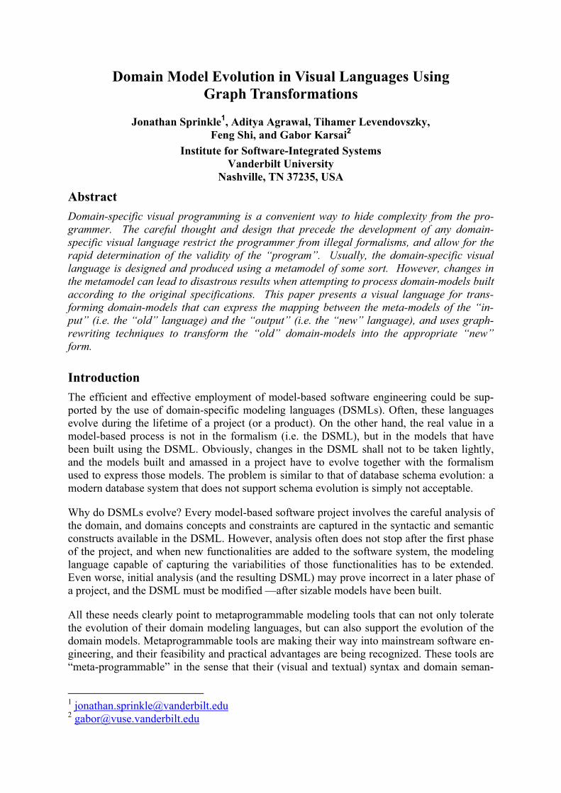
Domain Model Evolution in Visual Languages Using Graph Transformations Jonathan Sprinkle 1 , Aditya Agrawal, Tihamer Levendovszky, Feng Shi, and Gabor Karsai 2 Institute for Software-Integrated Systems Vanderbilt University Nashville, TN 37235, USA Abstract Domain-specific visual programming is a convenient way to hide complexity from the pro- grammer. The careful thought and design that precede the development of any domain- specific visual language restrict the programmer from illegal formalisms, and allow for the rapid determination of the validity of the “program”. Usually, the domain-specific visual language is designed and produced using a metamodel of some sort. However, changes in the metamodel can lead to disastrous results when attempting to process domain-models built according to the original specifications. This paper presents a visual language for trans- forming domain-models that can express the mapping between the meta-models of the “in- put” (i.e. the “old” language) and the “output” (i.e. the “new” language), and uses graph- rewriting techniques to transform the “old” domain-models into the appropriate “new” form. Introduction The efficient and effective employment of model-based software engineering could be sup- ported by the use of domain-specific modeling languages (DSMLs). Often, these languages evolve during the lifetime of a project (or a product). On the other hand, the real value in a model-based process is not in the formalism (i.e. the DSML), but in the models that have been built using the DSML. Obviously, changes in the DSML shall not to be taken lightly, and the models built and amassed in a project have to evolve together with the formalism used to express those models. The problem is similar to that of database schema evolution: a modern database system that does not support schema evolution is simply not acceptable. Why do DSMLs evolve? Every model-based software project involves the careful analysis of the domain, and domains concepts and constraints are captured in the syntactic and semantic constructs available in the DSML. However, analysis often does not stop after the first phase of the project, and when new functionalities are added to the software system, the modeling language capable of capturing the variabilities of those functionalities has to be extended. Even worse, initial analysis (and the resulting DSML) may prove incorrect in a later phase of a project, and the DSML must be modified —after sizable models have been built. All these needs clearly point to metaprogrammable modeling tools that can not only tolerate the evolution of their domain modeling languages, but can also support the evolution of the domain models. Metaprogrammable tools are making their way into mainstream software en- gineering, and their feasibility and practical advantages are being recognized. These tools are “meta-programmable” in the sense that their (visual and textual) syntax and domain seman- 1 [email protected] 2 [email protected]
-
Upload
independent -
Category
Documents
-
view
1 -
download
0
Transcript of Domain Model Evolution in Visual Languages Using Graph Transformations
Domain Model Evolution in Visual Languages Using Graph Transformations
Jonathan Sprinkle1, Aditya Agrawal, Tihamer Levendovszky,
Feng Shi, and Gabor Karsai2 Institute for Software-Integrated Systems
Vanderbilt University Nashville, TN 37235, USA
Abstract Domain-specific visual programming is a convenient way to hide complexity from the pro-grammer. The careful thought and design that precede the development of any domain-specific visual language restrict the programmer from illegal formalisms, and allow for the rapid determination of the validity of the “program”. Usually, the domain-specific visual language is designed and produced using a metamodel of some sort. However, changes in the metamodel can lead to disastrous results when attempting to process domain-models built according to the original specifications. This paper presents a visual language for trans-forming domain-models that can express the mapping between the meta-models of the “in-put” (i.e. the “old” language) and the “output” (i.e. the “new” language), and uses graph-rewriting techniques to transform the “old” domain-models into the appropriate “new” form.
Introduction The efficient and effective employment of model-based software engineering could be sup-ported by the use of domain-specific modeling languages (DSMLs). Often, these languages evolve during the lifetime of a project (or a product). On the other hand, the real value in a model-based process is not in the formalism (i.e. the DSML), but in the models that have been built using the DSML. Obviously, changes in the DSML shall not to be taken lightly, and the models built and amassed in a project have to evolve together with the formalism used to express those models. The problem is similar to that of database schema evolution: a modern database system that does not support schema evolution is simply not acceptable.
Why do DSMLs evolve? Every model-based software project involves the careful analysis of the domain, and domains concepts and constraints are captured in the syntactic and semantic constructs available in the DSML. However, analysis often does not stop after the first phase of the project, and when new functionalities are added to the software system, the modeling language capable of capturing the variabilities of those functionalities has to be extended. Even worse, initial analysis (and the resulting DSML) may prove incorrect in a later phase of a project, and the DSML must be modified —after sizable models have been built.
All these needs clearly point to metaprogrammable modeling tools that can not only tolerate the evolution of their domain modeling languages, but can also support the evolution of the domain models. Metaprogrammable tools are making their way into mainstream software en-gineering, and their feasibility and practical advantages are being recognized. These tools are “meta-programmable” in the sense that their (visual and textual) syntax and domain seman-
tics can be tailored for some specific domain with a reasonable effort. This usually happens through the use of metamodels that are models of modeling languages. Typically metamodels capture (1) static semantics (in the form of an (a) abstract syntax tree with (b) well-formedness rules) and (2) dynamics semantics (in the form of a mapping procedure that maps the abstract syntax of the models into a semantic domain). In past projects we have developed and successfully used a metaprogrammable graphical editor, which used UML class diagrams for (1)(a), OCL for (1)(b), and semi-formally modeled interpreter procedures for (2). How-ever, even in this environment metamodel changes led to a nontrivial domain model migra-tion problem. Obviously, the migration problem can be solved by developing simple transla-tor programs (using procedures or tools like XSL), and can also be automated for simple cases (e.g. attribute or class renaming, etc.), but a more reasoned, well-founded technology is necessary for the general case. This paper introduces such a technology based on the model-ing of the transformation of domain models using graph-rewriting techniques.
Backgrounds Graph grammars and graph rewriting [3][4] have been developed during the last 25+ years as techniques for formal modeling and tools for very high-level programming. Graph grammars are the natural extension of the generative grammars of Chomsky into the domain of graphs. The production rules for (string-) grammars could be generalized into production rules on graphs, which generatively enumerate all the sentences (i.e. the “graphs”) of a graph gram-mar. One can also define replacement rules on strings, which consist of a pattern and a re-placement string. The replacement rule’s pattern is matched against an input string, and the matched sub-string is replaced with the replacement string of the rule. Similarly, string re-writing can be generalized into graph rewriting as follows: a graph rewriting rule consists of a pattern graph and a replacement graph. The application of a graph rewriting rule is similar to the application of a string rewriting rule on strings, only the matching sub-graph is replaced with another graph. For precise details see [3].
Beyond the ground-laying work in the theory of graph grammars and rewriting, the approach has found several applications as well. Graph rewriting has been used in formalizing the se-mantics of StateCharts [8], as well as various concurrency models [3]. Several tools —including full programming environments— have been developed [6][7] that illustrate the practical applicability of the graph rewriting approach. These environments have demon-strated that (1) complex transformations can be expressed in the form of rewriting rules, and (2) graph rewriting rules can be compiled into efficient code. Programming via graph trans-formations has been applied in some domains [4] with reasonable success. In this paper, we argue that the graph transformation techniques offer not only a solid, well-defined foundation for model transformations, but they can be also applied in the practice.
The need for techniques for model transformations has been recently recognized in the UML world. For examples, see [9], [10], [11], [14], and [15]. Model transformation is an essential tool for many applications, including translating abstract design models into concrete imple-mentation models [14], for specification techniques [11], translation of UML into semantic domains [15], and even for the application of design patterns [15]. The new developments in UML (see [12], [13]) emphasize the use of meta-models, and provide solid foundation for the precise specification of semantics. A natural extension of these concepts is to use transforma-tional techniques for translating models into semantic domains: a task for which graph trans-formation techniques are —arguably— well-suited.
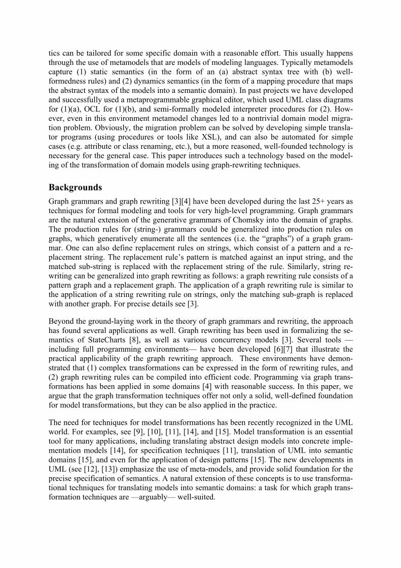
Graph transformations: An approach for evolving domain models The fundamental problem of domain evolution is created by the change in metamodels. Therefore, the two metamodels (also called as paradigms), referred to throughout this paper as the “old” and “new” metamodels, are instrumental in defining the graph transformation on the domain models. The high-level functionality of the domain evolution process is shown in Figure 1. A “model-migration language” (MM) allows the domain developer to create a transformation specification to capture the mapping between the old and new DSMLs. The transformation specification is then used by a graph-rewriting engine to execute the necessary transformations on the domain models (D) so that they will conform to the new DSML.
Figure 1. A specification using the "old" and "new" metamodels can gener-ate a graph transformation for the domain models
Describing the patterns
Figure 2. Metamodel for the hierarchical signal flow paradigm
In this paper, we argue that a visual description for patterns of objects is required. The pat-terns that will be specified are based on metamodels, so it is important to understand the lan-guage of metamodels as it pertains to language development. When a domain-specific visual language is constructed, certain stereotypes are used. In GME [2], a metaprogrammable vis-
ual modeling environment, these stereotypes are Atoms, Models, Connections, Sets, and Ref-erences.
Consider the metamodel shown in Figure 2. The left side of the figure shows classes stereo-typed as Models, which are capable of containment in the visual language. When used, these classes will appear as new language elements named “Base”, “Primitive” and “Compound”. However, they will also retain their seterotypes as well – therefore, a “Base” will be of “Model” type. It is important to realize that the language for describing the patterns will be in terms of these meta-types (such as “Model”), as well as in terms of the instantiation type (e.g., “Base”).
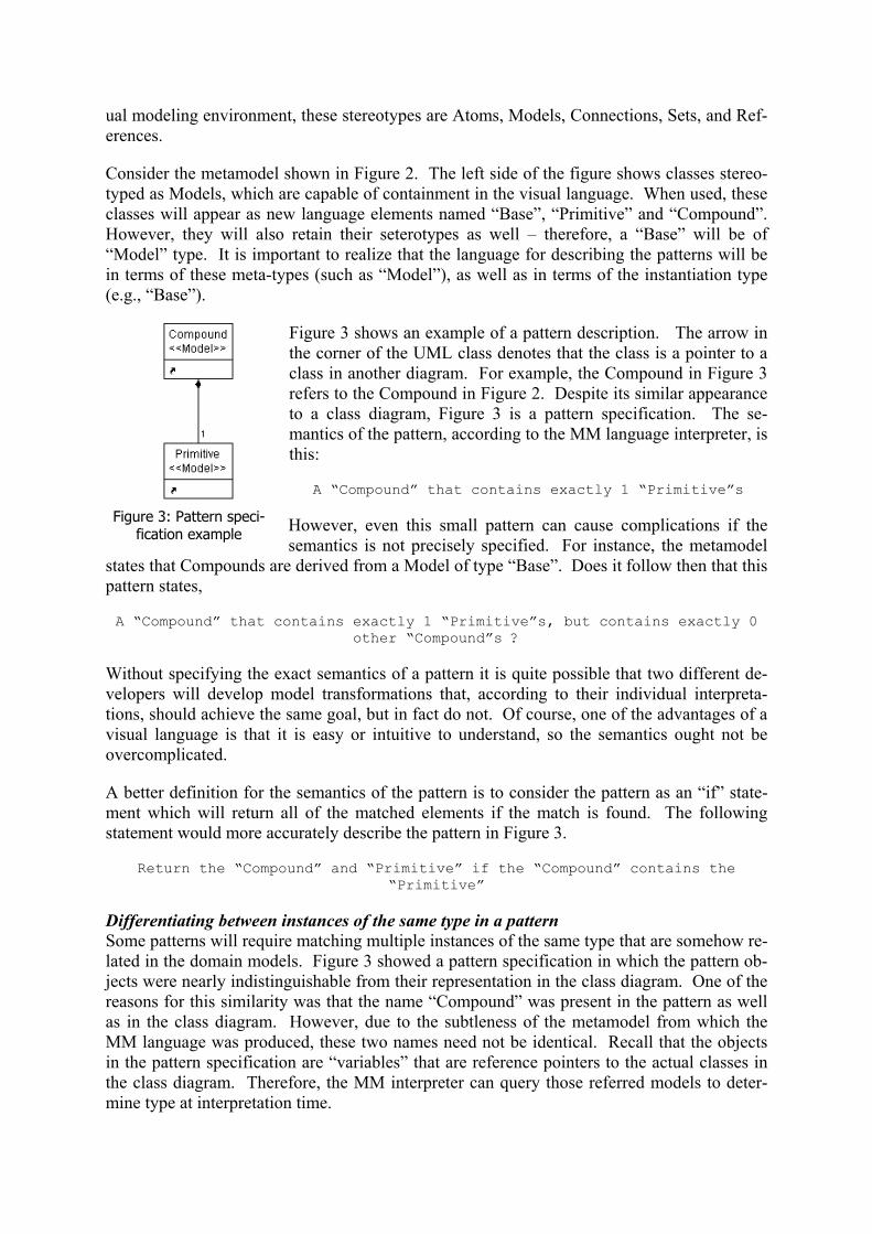
Figure 3 shows an example of a pattern description. The arrow in the corner of the UML class denotes that the class is a pointer to a class in another diagram. For example, the Compound in Figure 3 refers to the Compound in Figure 2. Despite its similar appearance to a class diagram, Figure 3 is a pattern specification. The se-mantics of the pattern, according to the MM language interpreter, is this:
A “Compound” that contains exactly 1 “Primitive”s However, even this small pattern can cause complications if the semantics is not precisely specified. For instance, the metamodel
states that Compounds are derived from a Model of type “Base”. Does it follow then that this pattern states,
Figure 3: Pattern speci-fication example
A “Compound” that contains exactly 1 “Primitive”s, but contains exactly 0 other “Compound”s ?
Without specifying the exact semantics of a pattern it is quite possible that two different de-velopers will develop model transformations that, according to their individual interpreta-tions, should achieve the same goal, but in fact do not. Of course, one of the advantages of a visual language is that it is easy or intuitive to understand, so the semantics ought not be overcomplicated.
A better definition for the semantics of the pattern is to consider the pattern as an “if” state-ment which will return all of the matched elements if the match is found. The following statement would more accurately describe the pattern in Figure 3.
Return the “Compound” and “Primitive” if the “Compound” contains the “Primitive”
Differentiating between instances of the same type in a pattern Some patterns will require matching multiple instances of the same type that are somehow re-lated in the domain models. Figure 3 showed a pattern specification in which the pattern ob-jects were nearly indistinguishable from their representation in the class diagram. One of the reasons for this similarity was that the name “Compound” was present in the pattern as well as in the class diagram. However, due to the subtleness of the metamodel from which the MM language was produced, these two names need not be identical. Recall that the objects in the pattern specification are “variables” that are reference pointers to the actual classes in the class diagram. Therefore, the MM interpreter can query those referred models to deter-mine type at interpretation time.
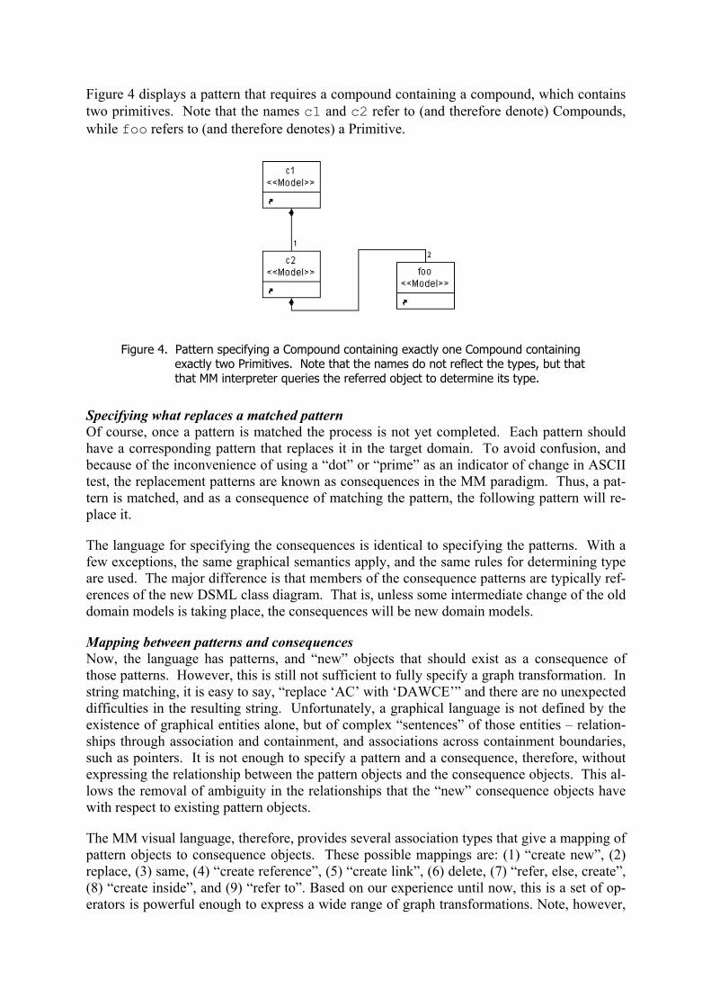
Figure 4 displays a pattern that requires a compound containing a compound, which contains two primitives. Note that the names c1 and c2 refer to (and therefore denote) Compounds, while foo refers to (and therefore denotes) a Primitive.
Figure 4.
Specifying whOf course, onchave a correspbecause of thetest, the replactern is matcheplace it.
The language few exceptionare used. Theerences of the domain model
Mapping betwNow, the langthose patterns.string matchindifficulties in existence of gships through such as pointeexpressing thelows the remowith respect to
The MM visuapattern objectsreplace, (3) sa(8) “create inserators is pow
Pattern specifying a Compound containing exactly one Compound containing exactly two Primitives. Note that the names do not reflect the types, but thatthat MM interpreter queries the referred object to determine its type.
at replaces a matched pattern e a pattern is matched the process is not yet completed. Each pattern should onding pattern that replaces it in the target domain. To avoid confusion, and inconvenience of using a “dot” or “prime” as an indicator of change in ASCII ement patterns are known as consequences in the MM paradigm. Thus, a pat-d, and as a consequence of matching the pattern, the following pattern will re-
for specifying the consequences is identical to specifying the patterns. With a s, the same graphical semantics apply, and the same rules for determining type major difference is that members of the consequence patterns are typically ref-new DSML class diagram. That is, unless some intermediate change of the old s is taking place, the consequences will be new domain models.
een patterns and consequences uage has patterns, and “new” objects that should exist as a consequence of However, this is still not sufficient to fully specify a graph transformation. In g, it is easy to say, “replace ‘AC’ with ‘DAWCE’” and there are no unexpected the resulting string. Unfortunately, a graphical language is not defined by the raphical entities alone, but of complex “sentences” of those entities – relation-association and containment, and associations across containment boundaries, rs. It is not enough to specify a pattern and a consequence, therefore, without relationship between the pattern objects and the consequence objects. This al-val of ambiguity in the relationships that the “new” consequence objects have existing pattern objects.
l language, therefore, provides several association types that give a mapping of to consequence objects. These possible mappings are: (1) “create new”, (2)
me, (4) “create reference”, (5) “create link”, (6) delete, (7) “refer, else, create”, ide”, and (9) “refer to”. Based on our experience until now, this is a set of op-erful enough to express a wide range of graph transformations. Note, however,
that these operators are not suitable for manipulating the attributes of objects; that has to be done in a procedural language (which is more efficient for that, in any case). Usage of these associations will become clearer with an example, so discussion of their semantics and exact syntax is deferred until later in this paper. However, with the knowledge of these mapping connections we are now able to examine the differences in semantics between pattern and consequence objects.
Semantic differences between patterns and consequences Once again, examine Figure 3. This figure was previously used to show a pattern, but con-sider the possible problems if the same semantics were applied to a consequence rather than a pattern. Then, any statement about finding existing models no longer makes sense, especially when the aggregation association exists between the two classes. In the context of the conse-quence of a match, aggregation has another meaning entirely. In fact, the meaning of the ag-gregation connection in a consequence is that the contained consequence should be created inside its parent (the “diamond” role of the connection).
Unfortunately, it is not obvious by just looking at a transformation model to tell whether the patterns specified are consequences or not (or whether the aggregation connections are meant as a consequence or as a pattern). To the MM interpreter, however, the difference is clear, due to the roles of the objects.
Roles of objects Recall that in UML members participating in associations play a role. In the MM meta-model, the pattern and consequence objects (as well as all associations between them) are from the same types of models (i.e., the transformation is described using two metamodels). Roles, then, play an important part in distinguishing between a pattern and a consequence.
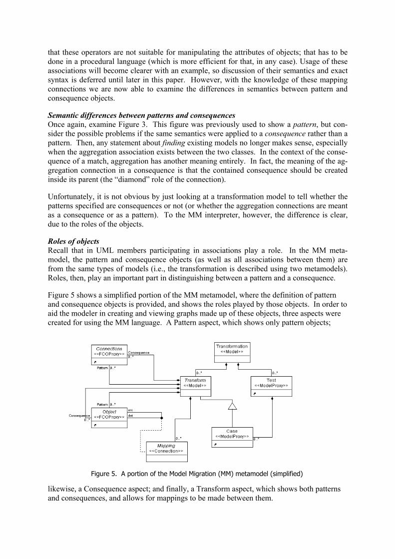
Figure 5 shows a simplified portion of the MM metamodel, where the definition of pattern and consequence objects is provided, and shows the roles played by those objects. In order to aid the modeler in creating and viewing graphs made up of these objects, three aspects were created for using the MM language. A Pattern aspect, which shows only pattern objects;
likewise, a Consequence aspect; and finally, a Transform aspect, which shows both patterns and consequences, and allows for mappings to be made between them.
Figure 5. A portion of the Model Migration (MM) metamodel (simplified)
Ordering transformation execution Now it is possible to specify a transform, and to map pattern objects to consequence objects. It is non-trivial, at least, to create exactly one pattern and its corresponding consequence that will completely transform any set of domain models. Therefore, it is necessary for more than one transform to be created which will aid in the rewriting of the domain model graph. A consequence of having more than one transform in a transformation (i.e., the collection of transforms) is that performing the transforms in different orders could result in ambiguous behavior of the transformation. This requires the capability of ordering the transforms.
The ordering syntax is based on the following principle: completion of a particular transform will result in execution of the next appropriate transform, similarly to a Finite State Machine (FSM). As in any FSM, the ability to perform tests or “case by case” execution is also re-quired (e.g., if this pattern is not located, then a different path should be chosen). This capa-bility is allowed through special transform models, called “Test” and “Case”.
Test and Case models A Test model performs the same function as a “switch” statement in C/C++. Its purpose is to serve as a container for the Case models that are contained within it. The semantics of the Case execution within a switch is that execution does not break if a case is true, but rather continues through all of the cases. Using these semantics, it is possible to compose Tests in such a way that execution does break between cases (left as an exercise to the reader).
A Case model is a Transform model that does not create any new models. It may be made up of either pattern or consequence objects, but cannot create new objects in the new domain. The main purpose of the Case is to determine (at runtime) whether or not certain patterns still exist, and if so then to remove them. Also, the presence of domain models in certain cases may require a different strategy for transformation, and thus would enable the modeler to di-rect the graph-rewriting engine appropriately.
Passing parameters Since locating a maximal sub-graph inside a graph is an NP complete problem, it becomes convenient to pass, as parameters to some degree, elements of the graph to the next trans-form. In this way, it decreases the strain on the graph rewriting engine to repeatedly locate frequently used portions of the graph, as well as allow for full exploration of a particular in-stance, by repeatedly using it for matching patterns.
Any object may be passed as a parameter, regardless of whether it is a pattern or a conse-quence. Parameters may also be passed into Test and Case models.
Supplemental expressions As is the case for most graphical languages, some elements of the language may be expressed graphically, but it is often more convenient (and more appropriate) to express them textually. Also, much of the semantics of a language is contained in textual attributes of visual objects. It is necessary, when performing transformations, that these attributes be correctly trans-formed as well. Again, a textual language (supplemental to the visual language) is appropri-ate here.
There are many options for describing the expressions; one can use OCL (from UML), for in-stance, or expressions defined in a subset of the C language. Currently, we are experimenting with CInt: an interpreted variant of C/C++.

Implementation details Now that the language has been explained, let us examine the implementation details of actu-ally performing the graph transformation. The language was designed using its own syntax and semantics, rather than finding a particular graph rewriting engine (GRE) and modeling its syntax. This is beneficial for two reasons. First, it allows for the customization of the MM language to the MM problem, rather than a graph-rewriting problem. Secondly, it provides an interface for the modular interchange of graph rewriting engines to perform the actual modifications to the domain models.
In order to interface to GREs, then, the MM description (as laid out by the modeler) is en-coded into the language of the GRE. Thus, for each GRE there is one MM interpreter. At this time, a GRE written at ISIS is being used to perform the transforms, but implementation is not limited to this one engine.
Figure 6
. a) Metamodel for the Hierarchical Signal Flowdomain, b) Metamodel for the Flat Signal Flow domain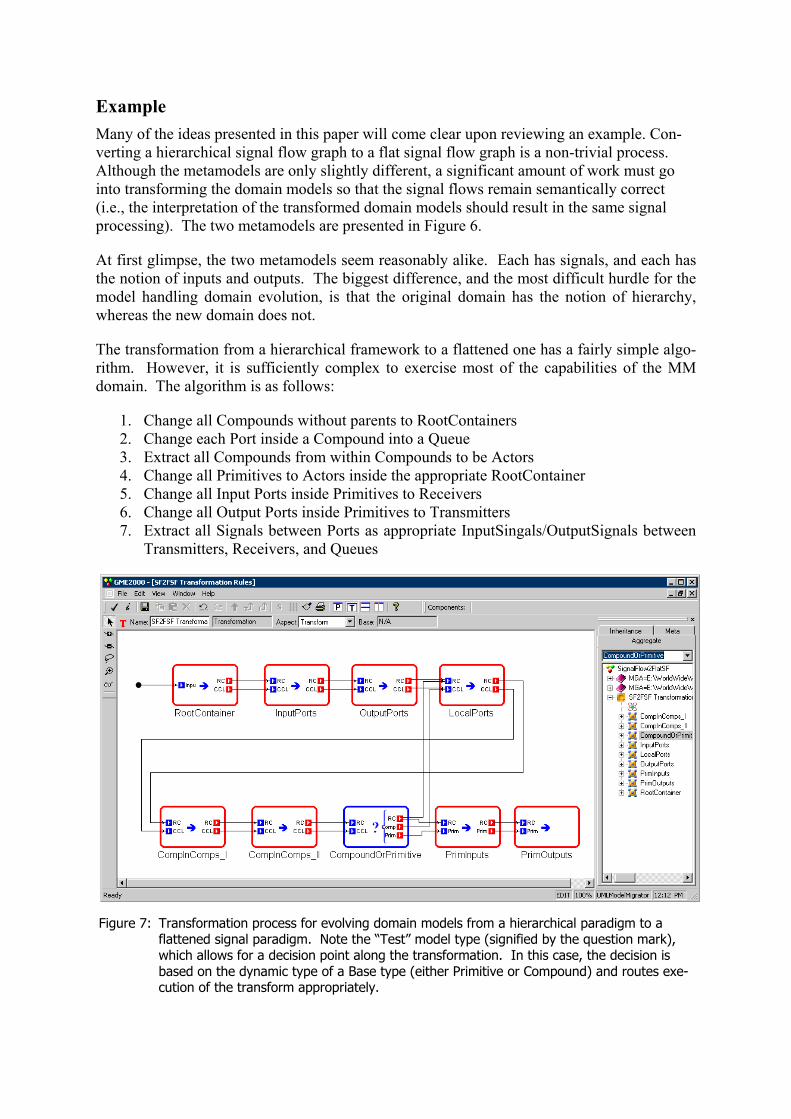
Example Many of the ideas presented in this paper will come clear upon reviewing an example. Con-verting a hierarchical signal flow graph to a flat signal flow graph is a non-trivial process. Although the metamodels are only slightly different, a significant amount of work must go into transforming the domain models so that the signal flows remain semantically correct (i.e., the interpretation of the transformed domain models should result in the same signal processing). The two metamodels are presented in Figure 6.
At first glimpse, the two metamodels seem reasonably alike. Each has signals, and each has the notion of inputs and outputs. The biggest difference, and the most difficult hurdle for the model handling domain evolution, is that the original domain has the notion of hierarchy, whereas the new domain does not.
The transformation from a hierarchical framework to a flattened one has a fairly simple algo-rithm. However, it is sufficiently complex to exercise most of the capabilities of the MM domain. The algorithm is as follows:
1. Change all Compounds without parents to RootContainers 2. Change each Port inside a Compound into a Queue 3. Extract all Compounds from within Compounds to be Actors 4. Change all Primitives to Actors inside the appropriate RootContainer 5. Change all Input Ports inside Primitives to Receivers 6. Change all Output Ports inside Primitives to Transmitters 7. Extract all Signals between Ports as appropriate InputSingals/OutputSignals between
Transmitters, Receivers, and Queues
Figure 7: Transformation process for evolving domain models from a hierarchical paradigm to a flattened signal paradigm. Note the “Test” model type (signified by the question mark), which allows for a decision point along the transformation. In this case, the decision is based on the dynamic type of a Base type (either Primitive or Compound) and routes exe-cution of the transform appropriately.
This process may not seem intuitive, but to the developer of the domain specific languages (Hierarchical and Flat signal flow) the transformation makes sense. In fact, if the models were to be rebuilt by hand, it would probably be in this fashion. The entire process to trans-form the hierarchical domain models to flattened ones is shown in Figure 7.
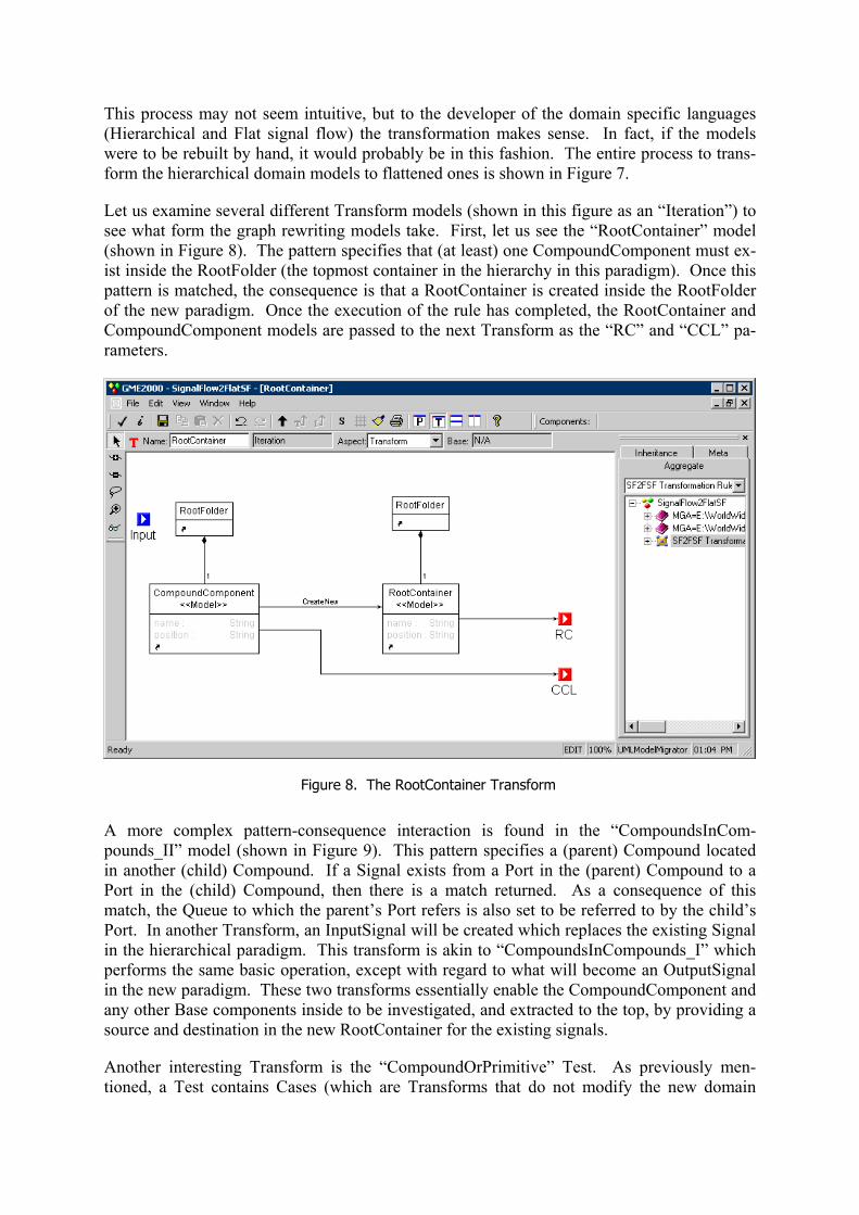
Let us examine several different Transform models (shown in this figure as an “Iteration”) to see what form the graph rewriting models take. First, let us see the “RootContainer” model (shown in Figure 8). The pattern specifies that (at least) one CompoundComponent must ex-ist inside the RootFolder (the topmost container in the hierarchy in this paradigm). Once this pattern is matched, the consequence is that a RootContainer is created inside the RootFolder of the new paradigm. Once the execution of the rule has completed, the RootContainer and CompoundComponent models are passed to the next Transform as the “RC” and “CCL” pa-rameters.
m
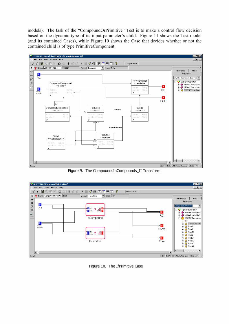
A more complex patternpounds_II” model (shown in another (child) CompouPort in the (child) Compomatch, the Queue to whichPort. In another Transformin the hierarchical paradigmperforms the same basic opin the new paradigm. Thesany other Base componentssource and destination in th
Another interesting Transftioned, a Test contains Ca
Figure 8. The RootContainer Transfor
-consequence interaction is found in the “CompoundsInCom-in Figure 9). This pattern specifies a (parent) Compound located nd. If a Signal exists from a Port in the (parent) Compound to a und, then there is a match returned. As a consequence of this the parent’s Port refers is also set to be referred to by the child’s , an InputSignal will be created which replaces the existing Signal . This transform is akin to “CompoundsInCompounds_I” which eration, except with regard to what will become an OutputSignal e two transforms essentially enable the CompoundComponent and inside to be investigated, and extracted to the top, by providing a e new RootContainer for the existing signals.
orm is the “CompoundOrPrimitive” Test. As previously men-ses (which are Transforms that do not modify the new domain
models). The task of the “CompoundOrPrimitive” Test is to make a control flow decision based on the dynamic type of its input parameter’s child. Figure 11 shows the Test model (and its contained Cases), while Figure 10 shows the Case that decides whether or not the contained child is of type PrimitiveComponent.
m
Figure 9. The CompoundsInCompounds_II Transfore
Figure 10. The IfPrimitive Cas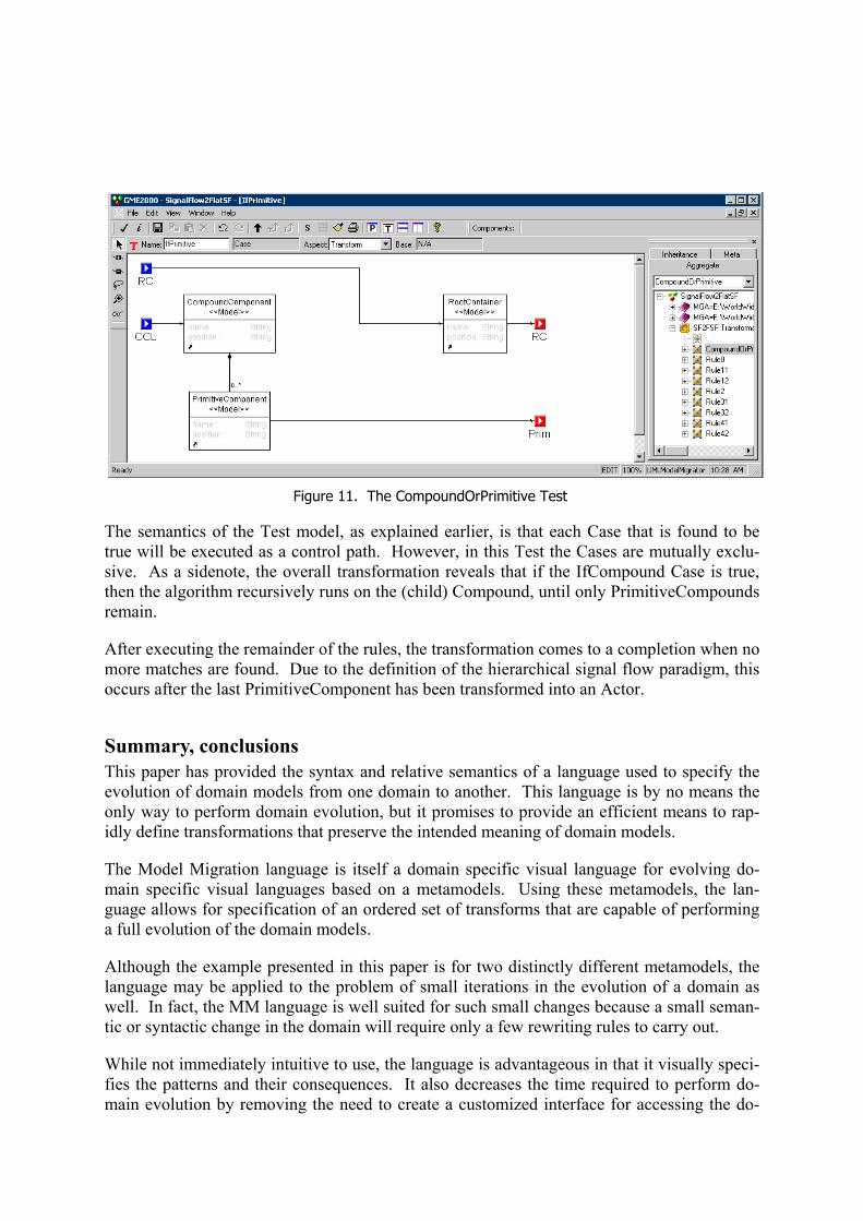
The semantics of the Testrue will be executed as asive. As a sidenote, the othen the algorithm recursiremain.
After executing the remainmore matches are found. occurs after the last Primit
Summary, conclusionThis paper has provided tevolution of domain modeonly way to perform domidly define transformation
The Model Migration lanmain specific visual langguage allows for specificaa full evolution of the dom
Although the example prelanguage may be applied well. In fact, the MM lantic or syntactic change in t
While not immediately infies the patterns and theirmain evolution by removi
Figure 11. The CompoundOrPrimitive Test
t model, as explained earlier, is that each Case that is found to be control path. However, in this Test the Cases are mutually exclu-verall transformation reveals that if the IfCompound Case is true,
vely runs on the (child) Compound, until only PrimitiveCompounds
der of the rules, the transformation comes to a completion when no Due to the definition of the hierarchical signal flow paradigm, this iveComponent has been transformed into an Actor.
s he syntax and relative semantics of a language used to specify the ls from one domain to another. This language is by no means the
ain evolution, but it promises to provide an efficient means to rap-s that preserve the intended meaning of domain models.
guage is itself a domain specific visual language for evolving do-uages based on a metamodels. Using these metamodels, the lan-tion of an ordered set of transforms that are capable of performing ain models.
sented in this paper is for two distinctly different metamodels, the to the problem of small iterations in the evolution of a domain as guage is well suited for such small changes because a small seman-he domain will require only a few rewriting rules to carry out.
tuitive to use, the language is advantageous in that it visually speci- consequences. It also decreases the time required to perform do-ng the need to create a customized interface for accessing the do-
main types (i.e., types, such as “CompoundComponent” or “InputSignal”) and their possible relationships with other domain types. By generating output (in the form of specifications for a graph rewriting engine), a mechanism is provided which will interface with existing or cus-tomizable components that will perform the actual changes to domain models.
The next step in the development of the Model Migration environment is to more formally specify the way in which domains are evolved. The names of types in “old” and “new” metamodels mean nothing to someone who is not a domain expert, which is a clue that the process of evolving domain models is contingent on the differences in constraints, semantics between the “old” and “new” domains, as well as syntax.
Acknowledgement The DARPA/IXO MOBIES program and USAF/AFRL has supported under contract F30602-00-1-0580, in part, the activities described in this paper. Thanks to the thoughtful reviews and comments given by the evaluators in the committee.
References [1] J. Bézivin, “Tooling the MDA framework: a new software maintenance and evolution
scheme proposal” [2] The Generic Modeling Environment (GME 2000),
http://www.isis.vanderbilt.edu/projects/gme/Doc.html [3] Rozenberg,G. (ed.), “Handbook on Graph Grammars and Computing by Graph Trans-
formation: Foundations”, Vol.1-2. World Scientific, Singapore, 1997 [4] Dorothea Blostein, Andy Schürr: Computing with Graphs and Graph Transformations.
Software - Practice and Experience 29(3): 197-217, 1999. [5] U. Aßmann, “How To Uniformly Specify Program Analysis and Transformation”, in:
6th Int. Conf. on Compiler Construction (CC '96), T. Gyimóthy (réd.), Lect. Notes in Comp. Sci., Springer-Verlag, Linköping, Sweden, 1996.
[6] A. Schürr. PROGRES for Beginners. RWTH Aachen, D-52056 Aachen, Germany. [7] Taentzer, G.: AGG: A Tool Enviroment for Algebraic Graph Transformation, in Proc. of
Applications of Graph Transformation with Industrial Relevance, Kerkrade, The Nether-lands, LNCS,Springer, 2000.
[8] Maggiolo-Schettini, A., Peron, A.: Semantics of Full Statecharts Based on Graph Rewriting, Springer LNCS 776, 1994, pp. 265--279.
[9] Milicev, D., "Automatic Model Transformations Using Extended UML Object Diagrams in Modeling Environments," IEEE Transaction on Software Engineering, Vol. 28, No. 4, April 2002, pp. 413-431
[10] Wai-Ming Ho, Jean-Marc Jézéquel, Alain Le Guennec, and François Pennaneac'h.: UMLAUT: an extendible UML transformation framework, in Proc. Automated Software Engineering, ASE'99, Florida, October 1999.
[11] David H. Akehurst: Model translation: A uml-based specification technique and active implementation approach. PhD thesis, Computer Science at Kent University (UK), De-cember 2000.
[12] Tony Clark, Andy Evans, Stuart Kent: Engineering Modelling Languages: A Precise Meta-Modelling Approach. FASE 2002: 159-173
[13] Tony Clark, Andy Evans, Stuart Kent: The Metamodelling Language Calculus: Founda-tion Semantics for UML. FASE 2001: 17-31.
[14] Lemesle, R. Transformation Rules Based on Meta-Modeling EDOC,'98, La Jolla, Cali-fornia, 3-5, November 1998, pp.113-122.
[15] Heckel, R. and Küster, J. and Taentzer, G.: Towards Automatic Translation of UML Models into Semantic Domains, Proc. of APPLIGRAPH Workshop on Applied Graph Transformation (AGT 2002), Grenoble, France, 2002, pp. 11 - 22.
[16] Karsai G.: Tool Support for Design Patterns, New Directions in Software Technology 4 Workshop, December, 2001.