Division B - Notes to Part 9 Housing and Small Buildings (Rev2)
92
Division B: Acceptable Solutions Notes to Part 9 – Housing and Small Buildings Vancouver Building By-law 2019 - Book I (General) Consolidated changes to June 01, 2021 Division B 9-1 Notes to Part 9 Housing and Small Buildings A-9.1.1.1.(1) Application of Part 9 to Seasonally and Intermittently Occupied Buildings. e Building By-law does not provide separate requirements which would apply to seasonally or intermittently occupied buildings. Without compromising the basic health and safety provisions, however, various requirements in Part 9 recognize that leniency may be appropriate in some circumstances. With greater use of “cottages” through the winter months, the proliferation of seasonally occupied multiple-dwelling buildings and the increasing installation of modern conveniences in these buildings, the number and extent of possible exceptions is reduced. Thermal Insulation Article 9.25.2.1. specifies that insulation is to be installed in walls, ceilings and floors which separate heated space from unheated space. Cottages intended for use only in the summer and which, therefore, have no space heating appliances, would not be required to be insulated. Should a heating system be installed at some later date, insulation should also be installed at that time in accordance with Article 9.25.1.1. and the insulation requirements of Part 10. However, if the building were not intended for continuous or regular winter use, it may still be exempted from the remainder of the energy efficiency requirements in Part 10. Air Barrier Systems and Vapour Barriers Articles 9.25.3.1. and 9.25.4.1. require the installation of air barrier systems and vapour barriers only where insulation is installed. Dwellings with no heating system would thus be exempt from these requirements. In some cases, seasonally occupied buildings that are conditioned may be required to conform to the air and vapour barrier requirements of Section 9.25, but not to the air barrier and other requirements of Part 10. Interior Wall and Ceiling Finishes e choice of interior wall and ceiling finishes has implications for fire safety. Where a dwelling is a detached building, there are no fire resistance requirements for the walls or ceilings within the dwelling. e exposed surfaces of walls and ceilings are required to have a flame-spread rating not greater than 150 (Subsection 9.10.17.). ere is, therefore, considerable flexibility, even in continuously occupied dwellings, with respect to the materials used to finish these walls. Except where waterproof finishes are required (Subsection 9.29.2.), ceilings and walls may be left unfinished. Where two units adjoin, however, additional fire resistance requirements may apply to interior loadbearing walls, floors and the shared wall (Article 9.10.8.3., and Subsections 9.10.9. and 9.10.11.). Plumbing and Electrical Facilities Plumbing fixtures are required only where a piped water supply is available (Subsection 9.31.4.), and electrical facilities only where electrical services are available (Article 9.34.1.2.). A-9.3.1.7. Ratio of Water to Cementing Material. While adding water to concrete on site may facilitate its distribution through formwork, this practice can have several undesirable results, such as reduced strength, greater porosity, and more propensity to shrinkage cracking. e ratio of water to cementing material is determined according to weight. For example, using Table 9.3.1.7., the maximum water-cement ratio of 0.45 for a 20 mm coarse aggregate would require 18 kg (or 18 L) of water (1 L of water weighs 1 kg). A-9.3.2.1.(1) Grade Marking of Lumber. Lumber is generally grouped for marketing into the species combinations contained in Table A-9.3.2.1.(1)-A. e maximum allowable spans for those combinations are listed in the span tables for joists, rafters and beams. Some species of lumber are also marketed individually. Since the allowable span for the northern species combination is based on the weakest species in the combination, the use of the span for this combination is permitted for any individual species not included in the Spruce-Pine-Fir, Douglas Fir-Larch and Hemlock-Fir combinations. Facsimiles of typical grade marks of lumber associations and grading agencies accredited by the Canadian Lumber Standards (CLS) Accreditation Board to grade mark lumber in Canada are shown in Table A-9.3.2.1.(1)-B. Accreditation by the CLS Accreditation Board applies to the inspection, grading and grade marking of lumber, including mill supervisory service, in accordance with CSA O141, “Softwood Lumber.” e grade mark of a CLS accredited agency on a piece of lumber indicates its assigned grade, species or species combination, moisture condition at the time of surfacing, the responsible grader or mill of origin and the CLS accredited agency under whose supervision the grading and marking was done. Notes to Part 9
-
Upload
khangminh22 -
Category
Documents
-
view
2 -
download
0
Transcript of Division B - Notes to Part 9 Housing and Small Buildings (Rev2)

Division B: Acceptable Solutions Notes to Part 9 – Housing and Small Buildings
Vancouver Building By-law 2019 - Book I (General) Consolidated changes to June 01, 2021 Division B 9-1
Notes to Part 9 Housing and Small BuildingsA-9.1.1.1.(1) Application of Part 9 to Seasonally and Intermittently Occupied Buildings. The Building By-law does not provide separate requirements which would apply to seasonally or intermittently occupied buildings. Without compromising the basic health and safety provisions, however, various requirements in Part 9 recognize that leniency may be appropriate in some circumstances. With greater use of “cottages” through the winter months, the proliferation of seasonally occupied multiple-dwelling buildings and the increasing installation of modern conveniences in these buildings, the number and extent of possible exceptions is reduced.
Thermal InsulationArticle 9.25.2.1. specifies that insulation is to be installed in walls, ceilings and floors which separate heated space from unheated space. Cottages intended for use only in the summer and which, therefore, have no space heating appliances, would not be required to be insulated. Should a heating system be installed at some later date, insulation should also be installed at that time in accordance with Article 9.25.1.1. and the insulation requirements of Part 10. However, if the building were not intended for continuous or regular winter use, it may still be exempted from the remainder of the energy efficiency requirements in Part 10.
Air Barrier Systems and Vapour BarriersArticles 9.25.3.1. and 9.25.4.1. require the installation of air barrier systems and vapour barriers only where insulation is installed. Dwellings with no heating system would thus be exempt from these requirements. In some cases, seasonally occupied buildings that are conditioned may be required to conform to the air and vapour barrier requirements of Section 9.25, but not to the air barrier and other requirements of Part 10.
Interior Wall and Ceiling FinishesThe choice of interior wall and ceiling finishes has implications for fire safety. Where a dwelling is a detached building, there are no fire resistance requirements for the walls or ceilings within the dwelling. The exposed surfaces of walls and ceilings are required to have a flame-spread rating not greater than 150 (Subsection 9.10.17.). There is, therefore, considerable flexibility, even in continuously occupied dwellings, with respect to the materials used to finish these walls. Except where waterproof finishes are required (Subsection 9.29.2.), ceilings and walls may be left unfinished. Where two units adjoin, however, additional fire resistance requirements may apply to interior loadbearing walls, floors and the shared wall (Article 9.10.8.3., and Subsections 9.10.9. and 9.10.11.).
Plumbing and Electrical FacilitiesPlumbing fixtures are required only where a piped water supply is available (Subsection 9.31.4.), and electrical facilities only where electrical services are available (Article 9.34.1.2.).
A-9.3.1.7. Ratio of Water to Cementing Material. While adding water to concrete on site may facilitate its distribution through formwork, this practice can have several undesirable results, such as reduced strength, greater porosity, and more propensity to shrinkage cracking. The ratio of water to cementing material is determined according to weight. For example, using Table 9.3.1.7., the maximum water-cement ratio of 0.45 for a 20 mm coarse aggregate would require 18 kg (or 18 L) of water (1 L of water weighs 1 kg).
A-9.3.2.1.(1) Grade Marking of Lumber. Lumber is generally grouped for marketing into the species combinations contained in Table A-9.3.2.1.(1)-A. The maximum allowable spans for those combinations are listed in the span tables for joists, rafters and beams. Some species of lumber are also marketed individually. Since the allowable span for the northern species combination is based on the weakest species in the combination, the use of the span for this combination is permitted for any individual species not included in the Spruce-Pine-Fir, Douglas Fir-Larch and Hemlock-Fir combinations.
Facsimiles of typical grade marks of lumber associations and grading agencies accredited by the Canadian Lumber Standards (CLS) Accreditation Board to grade mark lumber in Canada are shown in Table A-9.3.2.1.(1)-B. Accreditation by the CLS Accreditation Board applies to the inspection, grading and grade marking of lumber, including mill supervisory service, in accordance with CSA O141, “Softwood Lumber.”
The grade mark of a CLS accredited agency on a piece of lumber indicates its assigned grade, species or species combination, moisture condition at the time of surfacing, the responsible grader or mill of origin and the CLS accredited agency under whose supervision the grading and marking was done.
Notes to Part 9

Notes to Part 9 – Housing and Small Buildings Division B: Acceptable Solutions
Division B 9-2 Consolidated changes to June 01, 2021 Vancouver Building By-law 2019 - Book I (General)
Table A-9.3.2.1.(1)-ASpecies Designations and Abbreviations
Forming Part of Note A-9.3.2.1.(1)
Commercial Designation of Species or Species Combination Abbreviation Permitted on Grade Stamps Species Included
Douglas Fir – Larch D Fir – L (N) Douglas Fir, Western Larch
Hemlock – Fir Hem – Fir (N) Western Hemlock, Amabilis Fir
Spruce – Pine – Fir S – P – F or Spruce – Pine – Fir White Spruce, Engelmann Spruce, Black Spruce, Red Spruce, Lodgepole Pine,
Jack Pine, Alpine Fir, Balsam Fir
Northern Species North Species Any Canadian softwood covered by the “Standard Grading Rules for
Canadian Lumber”
Canadian lumber is graded to the “Standard Grading Rules for Canadian Lumber,” published by the National Lumber Grades Authority. These rules specify standard grade names and grade name abbreviations for use in grade marks to provide positive identification of lumber grades. In a similar fashion, standard species names or standard species abbreviations, symbols or marks are provided in the rules for use in grade marks.
Grade marks denote the moisture content of lumber at the time of surfacing. “S-Dry” in the mark indicates the lumber was surfaced at a moisture content not exceeding 19%. “MC 15” indicates a moisture content not exceeding 15%. “S-GRN” in the grade mark signifies that the lumber was surfaced at a moisture content higher than 19% at a size to allow for natural shrinkage during seasoning.
Each mill or grader is assigned a permanent number. The point of origin of lumber is identified in the grade mark by use of a mill or grader number or by the mill name or abbreviation. The CLS certified agency under whose supervision the lumber was grade marked is identified in the mark by the registered symbol of the agency.
Table A-9.3.2.1.(1)-BFacsimiles of Grade Marks Used by Canadian Lumber Manufacturing Associations and Agencies
Authorized to Grade Mark Lumber in CanadaForming Part of Note A-9.3.2.1.(1)
Facsimiles of Grade Mark Association or Agency
GG00056B
A.F .P .A. 00 S–P–F KD-HT 1
®
NLGA Alberta Forest Products Association www.albertaforestproducts.ca
GG00062B
®
100 CMSA
No 1 KD-HT
S - P - F NLGA
Canadian Mill Services Association www.canserve.org

Division B: Acceptable Solutions Notes to Part 9 – Housing and Small Buildings
Vancouver Building By-law 2019 - Book I (General) Consolidated changes to June 01, 2021 Division B 9-3
Table A-9.3.2.1.(1)-B (continued)Facsimiles of Grade Marks Used by Canadian Lumber Manufacturing Associations and Agencies
Authorized to Grade Mark Lumber in CanadaForming Part of Note A-9.3.2.1.(1)
Facsimiles of Grade Mark Association or Agency
GG00098A
®
No.1KKD-HTD-HT
DD FIRFIR--LL ((NN))NNLLGAGA
CSI00 Canadian Softwood Inspection Agency Inc.
www.canadiansoftwood.com
GG00058B
2 6®
S -P -F
NLGAKKDD--HTHT 2
Central Forest Products Association Inc. c/o Alberta Forest Products Association www.albertaforestproducts.ca
GG00057B
91S-P-FNLGA
KD-HT
1®
25®
NLGANLGA
KD-HT
D FIRD FIR - - L(N)L(N)
1Council of Forest Industries www.cofi.org
GG00064B
No. 2KKDD--HHTTS - P - F
5
NLGA®
Macdonald Inspection Services Ltd. www.gradestamp.com
MLB
S-P-FNo.1
KD-HT99 NLGA
®
GG00065B
Maritime Lumber Bureau www.mlb.ca

Notes to Part 9 – Housing and Small Buildings Division B: Acceptable Solutions
Division B 9-4 Consolidated changes to June 01, 2021 Vancouver Building By-law 2019 - Book I (General)
Table A-9.3.2.1.(1)-B (continued)Facsimiles of Grade Marks Used by Canadian Lumber Manufacturing Associations and Agencies
Authorized to Grade Mark Lumber in CanadaForming Part of Note A-9.3.2.1.(1)
Facsimiles of Grade Mark Association or Agency
GG00066B
N L G AN L G ASS--PP--FFNO.NO.11000
®
N
LPA KD HTKD HT
Newfoundland & Labrador Lumber Producers’ Association www3.nf.sympatico.ca/nllpa
GG00067B
10 10
NLGA S-GRN
CONST S-P-FNorthwest Territories Forest Industries Association
GG00059B
CLA 100S - P - F1 NLGA KD-HT
®
Ontario Forest Industries Association www.ofia.com
GG00068B
O.L.M.A. 09®
1 1 N L G A
KD-HT S--P--F
Ontario Lumber Manufacturers’ Association (Home of CLA Grading and Inspection) www.olma.ca
GG00069B
NO. 1
0 0 ®
K D - H T S -P -F
NLGA RULES
Pacific Lumber Inspection Bureau www.plib.org
GG00070B
®
477477
S-P-FS-P-F
11KD-HTKD-HT
NLGANLGA
Quebec Forest Industry Council (Conseil de l’industrie forestière du Québec) www.qfic.gc.ca

Division B: Acceptable Solutions Notes to Part 9 – Housing and Small Buildings
Vancouver Building By-law 2019 - Book I (General) Consolidated changes to June 01, 2021 Division B 9-5
A-Table 9.3.2.1. Lumber Grading. To identify board grades, the paragraph number of the NLGA “Standard Grading Rules for Canadian Lumber” under which the lumber is graded must be shown in the grade mark. Paragraph 113 is equivalent to the WWPA “Western Lumber Grading Rules” and paragraph 114 is equivalent to the WCLIB “Standard Grading Rules.” When graded in accordance with WWPA or WCLIB rules, the grade mark will not contain a paragraph number.
A-9.3.2.8.(1) Non-Standard Lumber. NLGA 2014, “Standard Grading Rules for Canadian Lumber,” permits lumber to be dressed to sizes below the standard sizes (38 × 89, 38 × 140, 38 × 184, etc.) provided the grade stamp shows the reduced size. This Sentence permits the use of the span tables for such lumber, provided the size indicated on the stamp is not less than 95% of the corresponding standard size. Allowable spans in the tables must be reduced a full 5% even if the undersize is less than the 5% permitted.
A-9.3.2.9.(1) Protection from Termites.
Manitoba
NorthwestTerritories
Nunavut
Yukon
P.E.I.
EG02049A
BritishColumbia
Quebec
HudsonBay
NewBrunswick
NovaScotia
Newfoundland
Areas in which specificlocations with termiteshave been identified.
Alberta
Saskatchewan
Figure A-9.3.2.9.(1)-A Known termite locations
Note to Figure A-9.3.2.9.(1)-A:(1) Reference: J.K. Mauldin (1982), N.Y. Su (1995), T. Myles (1997).

Notes to Part 9 – Housing and Small Buildings Division B: Acceptable Solutions
Division B 9-6 Consolidated changes to June 01, 2021 Vancouver Building By-law 2019 - Book I (General)
EG02050B
supporting elements visible to permit inspection(1)
clear height of 450 mm betweenstructural wood elements andfinished ground directly below
≥ 450 mm ≥ 450 mm
Figure A-9.3.2.9.(1)-B Clearances under structural wood elements and visibility of supporting elements where required to permit inspection for termite infestation
Note to Figure A-9.3.2.9.(1)-B:(1) For the height of structural wood elements not directly above finished ground, see Article 9.23.2.3.
A-9.3.2.9.(3) Protection of Structural Wood Elements from Moisture and Decay. There are many above-ground, structural wood systems where precipitation is readily trapped or drying is slow, creating conditions conducive to decay. Beams extending beyond roof decks, junctions between deck members, and connections between balcony guards and walls are three examples of elements that can accumulate water when exposed to precipitation if they are not detailed to allow drainage.
A-9.3.2.9.(4) Protection of Retaining Walls and Cribbing from Decay. Retaining walls supporting soil are considered to be structural elements of the building if a line drawn from the outer edge of the footing to the bottom of the exposed face of the retaining wall is greater than 45° to the horizontal. Retaining walls supporting soil may be structural elements of the building if the line described above has a lower slope.
wall�height
< 45˚: retaining wall may be� supporting the building> 45˚: retaining wall is � supporting the building
EG02051A
Figure A-9.3.2.9.(4) Identifying retaining walls that require preservative treatment
Retaining walls that are not critical to the support of building foundations but are greater than 1.2 m in height may pose a danger of sudden collapse to persons adjacent to the wall if the wood is not adequately protected from decay. The height of the retaining wall or cribbing is measured as the vertical difference between the ground levels on each side of the wall.
A-9.4.1.1. Structural Design. Article 9.4.1.1. establishes the principle that the structural members of Part 9 buildings must
• comply with the prescriptive requirements provided in Part 9,• be designed in accordance with accepted good practice, or• be designed in accordance with Part 4 using the loads and limits on deflection and vibration specified in Part 9 or Part 4.
Usually a combination of approaches is used. For example, even if the snow load calculation on a wood roof truss is based on Subsection 9.4.2., the joints must be designed in accordance with Part 4. Wall framing may comply with the prescriptive requirements in Subsections 9.23.3., 9.23.10., 9.23.11. and 9.23.12., while the floor framing may be engineered.
Wood Frame Construction,” requires engineering expertise. The CWC Guide contains alternative solutions and provides information on the applicability of the Part 9 prescriptive structural requirements to further assist designers and building officials to identify the

Division B: Acceptable Solutions Notes to Part 9 – Housing and Small Buildings
Vancouver Building By-law 2019 - Book I (General) Consolidated changes to June 01, 2021 Division B 9-7
appropriate design approach. The need for professional involvement in the structural design of a building, whether to Part 4 or Part 9 requirements or accepted good practice, is defined by provincial and territorial legislation.
A-9.4.2.1.(1) Soft Conversion from Imperial Units. The conversion table at the end of the By-law provides factors for the conversion of millimeters to inches. However, not all metric measurements stated in the By-law are exact conversions. For example, while the dimensions given for wood framing members are the exact dimensions of the milled product – i.e., what is commonly referred to as a “2 × 4” is actually 1.5 in. × 3.5 in., which, in mm, is 38 × 89 – the metric dimensions given for spacing between framing elements are actually soft conversions:
Table A-9.4.2.1.(1) Imperial Unit Exact Metric Conversion Soft Metric Conversion Used in Code
12 in. 305 mm 300 mm16 in. 406 mm 400 mm24 in. 610 mm 600 mm
It remains common construction practice to arrange joists, rafters and studs in 12, 16 or 24 in. increments so as to properly align them with the edges of sheathing materials. It is therefore assumed that structural elements will be spaced according to the actual metric equivalents.
A-9.4.2.2. Application of Simplified Part 9 Snow Loads. The simplified specified snow loads described in Article 9.4.2.2. may be used where the structure is of the configuration that is typical of traditional wood-frame residential construction and its performance. This places limits on the spacing of joists, rafters and trusses, the spans of these members and supporting members, deflection under load, overall dimensions of the roof and the configuration of the roof. It assumes considerable redundancy in the structure.
Because very large buildings may be constructed under Part 9 by constructing firewalls to break up the building area, it is possible to have Part 9 buildings with very large roofs. The simplified specified snow loads may not be used when the total roof area of the overall structure exceeds 4550 m2. Thus, the simplified specified snow load calculation may be used for typical townhouse construction but would not be appropriate for much larger commercial or industrial buildings, for example.
The simplified specified snow loads are also not designed to take into account roof configurations that seriously exacerbate snow accumulation. This does not pertain to typical projections above a sloped roof, such as dormers, nor does it pertain to buildings with higher and lower roofs. Although two-level roofs generally lead to drift loading, smaller light-frame buildings constructed according to Part 9 have not failed under these loads. Consequently, the simplified calculation may be used in these cases. Rather, this limitation on application of the simplified calculation pertains to roofs with high parapets or significant other projections above the roof, such as elevator penthouses, mechanical rooms or larger equipment that would effectively collect snow and preclude its blowing off the roof.
The reference to Article 9.4.3.1. invokes, for roof assemblies other than common lumber trusses, the same performance criteria for deflection.
The specific weight of snow on roofs, g, obtained from measurements at a number of weather stations across Canada varied from about 1.0 to 4.5 kN/m3. An average value for use in design in lieu of better local data is g = 3.0 kN/m3. In some locations the specific weight of snow may be considerably greater than 3.0 kN/m3. Such locations include regions where the maximum snow load on the roof is reached only after contributions from many snowstorms, coastal regions, and regions where winter rains are considerable and where a unit weight as high as 4.0 kN/m3 may be appropriate.
A-9.4.2.3.(1) Accessible Platforms Subject to Snow and Occupancy Loads. Many platforms are subject to both occupancy loads and snow loads. These include balconies, decks, verandas, flat roofs over garages and carports. Where such a platform, or a segregated area of such a platform, serves a single dwelling unit, it must be designed for the greater of either the specified snow load or an occupancy load of 1.9 kPa. Where the platform serves more than one single dwelling unit or an occupancy other than a residential occupancy, higher occupancy loads will apply as specified in Table 4.1.5.3.
A-9.4.2.4.(1) Specified Loads for Attics or Roof Spaces with Limited Accessibility. Typical residential roofs are framed with roof trusses and the ceiling is insulated.
Residential trusses are placed at 600 mm on centre with web members joining top and bottom chords. Lateral web bracing is installed perpendicular to the span of the trusses. As a result, there is limited room for movement inside the attic or roof space or for storage of material. Access hatches are generally built to the minimum acceptable dimensions, further limiting the size of material that can be moved into the attic or roof space.
Notes to Part 9 – Housing and Small Buildings Division B: Acceptable Solutions
Division B 9-8 Consolidated changes to June 01, 2021 Vancouver Building By-law 2019 - Book I (General)
With exposed insulation in the attic or roof space, access is not recommended unless protective clothing and breathing apparatus are worn.
Thus the attic or roof space is recognized as uninhabitable and loading can be based on actual dead load. In emergency situations or for the purpose of inspection, it is possible for a person to access the attic or roof space without over-stressing the truss or causing damaging deflections.
A-Table 9.4.4.1. Classification of Soils. Sand or gravel may be classified by means of a picket test in which a 38 mm by 38 mm picket beveled at the end at 45° to a point is pushed into the soil. Such material is classified as “dense or compact” if a man of average weight cannot push the picket more than 200 mm into the soil and “loose” if the picket penetrates 200 mm or more.
Clay and silt may be classified as “stiff” if it is difficult to indent by thumb pressure, “firm” if it can be indented by moderate thumb pressure, “soft” if it can be easily penetrated by thumb pressure, where this test is carried out on undisturbed soil in the wall of a test pit.
A-9.4.4.4.(1) Soil Movement. In susceptible soils, changes in temperature or moisture content can cause significant expansion and contraction. Soils containing pyrites can expand simply on exposure to air.
Expansion and Contraction due to MoistureClay soils are most prone to expansion and contraction due to moisture. Particularly wet seasons can sufficiently increase the volume of the soil under and around the structure to cause heaving of foundations and floors-on-ground, or cracking of foundation walls. Particularly dry seasons or draw-down of water by fast-growing trees can decrease the volume of the soil supporting foundations and floors-on-ground, thus causing settling.
Frost HeaveFrost heave is probably the most commonly recognized phenomenon related to freezing soil. Frost heave results when moisture in frost-susceptible soil (clay and silt) under the footings freezes and expands. This mechanism is addressed by requirements in Section 9.12. regarding the depth of excavations.
Ice LensesWhen moisture in frost-susceptible soils freezes, it forms an ice lens and reduces the vapour pressure in the soil in the area immediately around the lens. Moisture in the ground redistributes to rebalance the vapour pressures providing more moisture in the area of the ice lens. This moisture freezes to the lens and the cycle repeats itself. As the ice lens grows, it exerts pressure in the direction of heat flow. When lenses form close to foundations and heat flow is toward the foundation – as may be the case with unheated crawl spaces or open concrete block foundations insulated on the interior – the forces may be sufficient to crack the foundation.
AdfreezingIce lenses can adhere themselves to cold foundations. Where heat flow is essentially upward, parallel to the foundation, the pressures exerted will tend to lift the foundation. This may cause differential movement or cracking of the foundation. Heat loss through basement foundations of cast-in-place concrete or concrete block insulated on the exterior appears to be sufficient to prevent adfreezing. Care must be taken where the foundation does not enclose heated space or where open block foundations are insulated on the interior. The installation of semi-rigid glass fibre insulation has demonstrated some effectiveness as a separation layer to absorb the adfreezing forces.
PyritesPyrite is the most common iron disulphide mineral in rock and has been identified in rock of all types and ages. It is most commonly found in metamorphic and sedimentary rock, and especially in coal and shale deposits.
Weathering of pyritic shale is a chemical-microbiological oxidation process that results in volume increases that can heave foundations and floors-on-ground. Concentrations of as little as 0.1% by weight have caused heaving. Weathering can be initiated simply by exposing the pyritic material to air. Thus, building on soils that contain pyrites in concentrations that will cause damage to the building should be avoided, or measures should be taken to remove the material or seal it. Material containing pyrites should not be used for backfill at foundations or for supporting foundations or floors-on-ground.
Where it is not known if the soil or backfill contains pyritic material in a deleterious concentration, a test is available to identify its presence and concentration.

Division B: Acceptable Solutions Notes to Part 9 – Housing and Small Buildings
Vancouver Building By-law 2019 - Book I (General) Consolidated changes to June 01, 2021 Division B 9-9
References:(1) Legget, R.F. and Crawford, C.B. Trees and Buildings. Canadian Building Digest 62, Division of Building Research, National Research Council Canada, Ottawa, 1965.
(2) Hamilton, J.J. Swelling and Shrinking Subsoils. Canadian Building Digest 84, Division of Building Research, National Research Council Canada, Ottawa, 1966.
(3) Hamilton, J.J. Foundations on Swelling and Shrinking Subsoils. Canadian Building Digest 184, Division of Building
Research, National Research Council Canada, Ottawa, 1977.
(4) Penner, W., Eden, W.J., and Gratten-Bellew, P.E. Expansion of Pyritic Shales. Canadian Building Digest 52, Division of Building Research, National Research Council Canada, Ottawa, 1975.
(5) Swinton, M.C., Brown, W.C., and Chown, G.A. Controlling the Transfer of Heat, Air and Moisture through the Building Envelope. Small Buildings – Technology in Transition, Building Science Insight ’90, Institute for Research in Construction, National Research Council Canada, Ottawa, 1990.
A-9.4.4.6. and 9.15.1.1. Loads on Foundations. The prescriptive solutions provided in Part 9 relating to footings and foundation walls only account for the loads imposed by drained earth. Drained earth is assumed to exert a load equivalent to the load that would be exerted by a fluid with a density of 480 kg/m3. The prescriptive solutions do not account for surcharges from saturated soil or additional loads from heavy objects located adjacent to the building. Where such surcharges are expected, the footings and foundation walls must be designed and constructed according to Part 4.
A-9.5.1.2. Combination Rooms. If a room draws natural light and natural ventilation from another area, the opening between the two areas must be large enough to effectively provide sufficient light and air. This is why a minimum opening of 3 m2 is required, or the equivalent of a set of double doors. The effectiveness of the transfer of light and air also depends on the size of the transfer opening in relation to the size of the dependent room; in measuring the area of the wall separating the two areas, the whole wall on the side of the dependent room should be considered, not taking into account offsets that may be in the surface of the wall.
The opening does not necessarily have to be in the form of a doorway; it may be an opening at eye level. However, if the dependent area is a bedroom, provision must be made for the escape window required by Article 9.9.10.1. to fulfill its safety function. This is why a direct passage is required between the bedroom and the other area; the equivalent of at least a doorway is therefore required for direct passage between the two areas.
A-9.5.3.1. Ceiling Heights and Clear Heights. Figure A-9.5.3.1. shows ceiling heights in relation to clear heights and also clear heights over stairs described in Article 9.8.2.2.

Notes to Part 9 – Housing and Small Buildings Division B: Acceptable Solutions
Division B 9-10 Consolidated changes to June 01, 2021 Vancouver Building By-law 2019 - Book I (General)
A-9.5.5.3. Doorways to Rooms with a Bathtub, Shower or Water Closet. If the minimum 860 mm hallway serves more than one room with identical facilities, only one of the rooms is required to have a door not less than 760 mm wide.
If a number of rooms have different facilities, for example, one room has a shower, lavatory and water closet, and another room has a lavatory and water closet, the room with the shower, lavatory and water closet must have the minimum 760 mm wide door.
Where multiple rooms provide the same or similar facilities, one of these rooms must comply with the requirement to have at least one bathtub or shower, one lavatory and one water closet. Where the fixtures are located in two separate rooms served by the same hallway, the requirement for the minimum doorway width would apply to both rooms.
If the minimum 860 mm hallway does not serve any room containing a bathtub, shower and water closet, additional fixtures do not need to be installed.
A-9.6.1.1.(1) Application. The scope of this Section includes glass installed on the interior or on the exterior of a building.
A-9.6.1.2.(2) Mirrored Glass Doors. CAN/CGSB-82.6-M, “Doors, Mirrored Glass, Sliding or Folding, Wardrobe,” covers mirrored glass doors for use on reach-in closets. It specifies that such doors are not to be used for walk-in closets.
A-9.7. Windows, Doors and Skylights. This section applies only to windows, doors and skylights as defined in the scope of the standards referenced in Article 9.7.4.2. Other glazed products, such as site-built windows, curtain walls or sloped glazing, are required to conform to Part 5. It is also permitted for fenestration products within the scope of the NAFS standard to conform to Part 5. This option is typically used for windows and doors that are impractical to subject to the testing requirements of NAFS due to their size or for custom configurations.
A-9.7.3.2.(1)(a) Minimizing Condensation. The total prevention of condensation on the surfaces of fenestration products is difficult to achieve and, depending on the design and construction of the window or door, may not be absolutely necessary.
Clause 9.7.3.2.(1)(a) therefore requires that condensation be minimized, which means that the amount of moisture that condenses on the inside surface of a window, door or skylight, and the frequency at which this occurs, must be limited. The occurrence of such condensation must be sufficiently rare, the accumulation of any water must be sufficiently small, and drying must be sufficiently rapid to prevent the deterioration of moisture-susceptible materials and the growth of fungi.
A-9.7.4. Design and Construction. Garage doors, sloped glazing, curtain walls, storefronts, commercial entrance systems, site-built or site-glazed products, revolving doors, interior windows and doors, storm windows, storm doors, sunrooms and commercial steel doors are not in the scope of NAFS.
All windows, doors and skylights installed to separate conditioned space from unconditioned space or the exterior must also conform to Part 10.
A-9.7.4.2.(1) Standards Referenced for Windows, Doors and Skylights.
GeneralDoors between an unconditioned garage and a dwelling unit are considered to be in scope of the standard referenced in this Sentence. Although the standard refers to windows in “exterior building envelopes”, a note to the definition of “building envelope” clarifies that for the purpose of application of the standard, in some cases a building envelope may consist of two separate walls (such as a wall between garage and dwelling unit as well as the exterior wall of the garage itself ).
A door leading to the exterior from an unconditioned garage is also within scope of the referenced standard, as it is also part of the exterior building envelope. However, because the scope of the Building By-law takes precedence, these doors are not required to conform to “NAFS”. This Subsection of the By-law does not apply to a door separating two unconditioned spaces.
Canadian Requirements in the Harmonized StandardIn addition to referencing the Canadian Supplement, CSA A440S1, “Canadian Supplement to AAMA/WDMA/CSA 101/I.S.2/A440, NAFS – North American Fenestration Standard/Specification for Windows, Doors, and Skylights,” the Harmonized Standard, AAMA/WDMA/CSA 101/I.S.2/A440, “NAFS – North American Fenestration Standard/Specification for Windows, Doors, and Skylights,” contains some Canada-specific test criteria.
Standards Referenced for Excluded ProductsClause 1.1, General, of the Harmonized Standard defines the limits to the application of the standard with respect to various types of fenestration products. A list of exceptions to the application statement identifies a number of standards that apply to

Division B: Acceptable Solutions Notes to Part 9 – Housing and Small Buildings
Vancouver Building By-law 2019 - Book I (General) Consolidated changes to June 01, 2021 Division B 9-11
excluded products. Compliance with those standards is not required by the By-law; the references are provided for information purposes only.
Label Indicating Performance and Compliance with StandardThe Canadian Supplement requires that a product’s performance ratings be indicated on a label according to the designation requirements in the Harmonized Standard and that the label include
• design pressure, where applicable,• negative design pressure, where applicable,• water penetration test pressure, and• the Canadian air infiltration and exfiltration levels.
It should be noted that, for a product to carry a label in Canada, it must meet all of the applicable requirements of both the Harmonized Standard and the Canadian Supplement, including the forced entry requirements.
Water Penetration ResistanceFor the various performance grades listed in the Harmonized Standard, the corresponding water penetration resistance test pressures are a percentage of the design pressure. For R-class products, water penetration resistance test pressures are 15% of design pressure. In Vancouver, driving rain wind pressures (DRWP) have been determined for the locations listed in Appendix C.
These are listed in the Canadian Supplement. The DRWP given in the Canadian Supplement must be used for all products covered in the scope of the Harmonized Standard when used in buildings within the scope of Part 9.
To achieve equivalent levels of water penetration resistance for all locations, the Canadian Supplement includes a provision for calculating specified DRWP at the building site considering building exposure. Specified DRWP values are, in some cases, greater than 15% of design pressure and, in other cases, less than 15% of design pressure. For a fenestration product to comply with the By-law, it must be able to resist the structural and water penetration loads at the building site. Reliance on a percentage of design pressure for water penetration resistance in the selection of an acceptable fenestration product will not always be adequate.
Design pressure values are reported on a secondary designator, which is required by the Canadian Supplement to be affixed to the window.
As an alternative to the above noted provision in the Canadian Supplement for calculating specified DRWP, the Water Resistance values listed in Table C-4 of Appendix C may be used.
Uniform Load Structural TestThe Harmonized Standard specifies that fenestration products be tested at 150% of design pressure for wind (specified wind load) and that skylights and roof windows be tested at 200% of design pressure for snow (specified snow load). With the change in the British Columbia Building Code 2006 to a 1-in-50 return period for wind load, a factor of 1.4 rather than 1.5 is now applied for wind. The Building By-law has traditionally applied a factor of 1.5 rather than 2.0 for snow. Incorporating these lower load factors into the By-law requirements for fenestration would better reflect acceptable minimum performance levels; however, this has not been done in order to avoid adding complexity to the By-law, to recognize the benefits of Canada-US harmonization, and to recognize that differentiation of products that meet the Canadian versus the US requirements would add complexity for manufacturers, designers, specifiers and regulatory officials.
The required design pressure and Performance Grade (PG) rating of doors and windows has been listed for each of the geographic locations found in the Code in Table C-4. These may be used as an alternative to the specified wind load calculations in the Canadian Supplement.
Condensation ResistanceThe Harmonized Standard identifies three test procedures that can be used to determine the condensation resistance of windows and doors. Only the physical test procedure given in CSA A440.2, “Fenestration Energy Performance”, can be used to establish Temperature Index (I) values. Computer simulation tools can also be used to estimate the relative condensation resistance of windows, but these methods employ different expressions of performance known as Condensation Resistance Factors (CR). I and CR values are not interchangeable.
Where removable multiple glazing panels (RMGP) are installed on the inside of a window, care should be taken to hermetically seal the RMGP against the leakage of moisture-laden air from the interior into the cavity on the exterior of the RMGP because the moisture transported by the air could lead to significant condensation on the interior surface of the outside glazing.

Notes to Part 9 – Housing and Small Buildings Division B: Acceptable Solutions
Division B 9-12 Consolidated changes to June 01, 2021 Vancouver Building By-law 2019 - Book I (General)
Basement WindowsClause 12.4.2, Basement Windows, of the Harmonized Standard refers to products that are intended to meet By-law requirements for ventilation and emergency egress. The minimum test size of 800 mm × 360 mm (total area of 0.288 m2) specified in the standard will not provide the minimum openable area required by the By-law for bedrooms (i.e. 0.35 m2 with no dimension less than 380 mm) and the means to provide minimum open area identified in the standard is inconsistent with the requirements of the By-law (See Subsection 9.9.10. for bedroom windows). The minimum test size specified in the standard will also not provide the minimum ventilation area of 0.28 m2 required for non-heating-season natural ventilation (See Article 9.32.2.2.).
Performance of Doors: Limited Water Ingress ControlWhile the control of precipitation ingress is a performance requirement for exterior doors, side-hinged doors can comply with the referenced standard, AAMA/WDMA/CSA 101/I.S.2/A440, “NAFS – North American Fenestration Standard/Specification for Windows, Doors, and Skylights,” when tested at a pressure differential of 0 Pa (0.0 psf ) or higher, but less than the minimum test pressure required for the indicated performance class and performance grade. Such doors are identified with a “Limited Water” (LW) rating on the product label.
Conditions suitable for the installation of an LW rated door are identified in Sentence 9.7.4.2.(2).
A-9.7.4.3.(2) Performance Requirements. If the option of calculating design pressure performance grade and water resistance values using the Canadian Supplement is chosen, the DRWP values in Table A.1 of that standard must be used for all buildings within the scope of Part 9 of the Building By-law. This requirement applies whether the windows, doors and skylights are designed to conform to Article 9.7.4.2. or to Part 5.
A-9.7.5.2.(1) Forced Entry Via Glazing in Doors and Sidelights. There is no mandatory requirement that special glass be used in doors or sidelights, primarily because of cost. It is, however, a common method of forced entry to break glass in doors and sidelights to gain access to door hardware and unlock the door from the inside. Although insulated glass provides increased resistance over single glazing, the highest resistance is provided by laminated glass. Tempered glass, while stronger against static loads, is prone to shattering under high, concentrated impact loads.

Division B: Acceptable Solutions Notes to Part 9 – Housing and Small Buildings
Vancouver Building By-law 2019 - Book I (General) Consolidated changes to June 01, 2021 Division B 9-13
1 x 6 mm laminated gl
1 x 6 mm annealed gla
spacer
EG00315B
Figure A-9.7.5.2.(1) Combined laminated/annealed glazing
Laminated glass is more expensive than annealed glass and must be used in greater thicknesses. Figure A-9.7.5.2.(1) shows an insulated sidelight made of one pane of laminated glass and one pane of annealed glass. This method reduces the cost premium that would result if both panes were laminated.
Consideration should be given to using laminated glazing in doors and accompanying sidelights regulated by Article 9.6.1.3., in windows located within 900 mm of locks in such doors, and in basement windows.
Underwriters’ Laboratories of Canada have produced ULC-S332, “Burglary Resisting Glazing Material,” which provides a test procedure to evaluate the resistance of glazing to attacks by thieves. While it is principally intended for plate glass show windows, it may be of value for residential purposes.
A-9.7.5.2.(6) Door Fasteners. The purpose of the requirement for 30 mm screw penetration into solid wood is to prevent the door from being dislodged from the jamb due to impact forces. It is not the intent to prohibit other types of hinges or strikeplates that are specially designed to provide equal or greater protection.
A-9.7.5.2.(8) Hinged Doors. Methods of satisfying this Sentence include either using non-removable pin hinges or modifying standard hinges by screw fastening a metal pin in a screw hole in one half of the top and bottom hinges. When the door is closed, the projecting portion of the pin engages in the corresponding screw hole in the other half of the hinge and then, even if the hinge pin is taken out, the door cannot be removed.
A-9.7.5.2.(10) & (11) Resistance to Forced Entry. Statistical evidence by Vancouver Police has identified that a frequently exploited point of entry in break-ins exists at the residential entry doors due to inherent weaknesses in wood door frame materials, and the location of strikeplate screws located along the grain and near to the deadbolt throw, which contribute to inability for the frame to resist forced entry.
The installation of a metal frame reinforcement plate (See Figures A-9.7.5.2.(10)-A & -B below) directly attached to the backside of a door frame before installation with increased spacing for the points of attachment would significantly increase the resistance of the door to forced entry. This will result reduced incidence of crime and significantly reduce potential costs to owners.

Notes to Part 9 – Housing and Small Buildings Division B: Acceptable Solutions
Division B 9-14 Consolidated changes to June 01, 2021 Vancouver Building By-law 2019 - Book I (General)
Figure A-9.7.5.2.(10)-A Typical Location of Door Frame Reinforcement
Figure A-9.7.5.2.(10)-B Frame Reinforcement (Example)
A-9.7.5.3.(1) Resistance of Windows to Forced Entry. Although this Sentence only applies to windows within 2 m of adjacent ground level, certain house and site features, such as balconies or canopy roofs, allow for easy access to windows at higher elevations. Consideration should be given to specifying break-in resistant windows in such locations.
This Sentence does not apply to windows that do not serve the interior of the dwelling unit, such as windows to garages, sun rooms or greenhouses, provided connections between these spaces and the dwelling unit are secure.
One method that is often used to improve the resistance of windows to forced entry is the installation of metal “security bars.”
However, while many such installations are effective in increasing resistance to forced entry, they may also reduce or eliminate the usefulness of the window as an exit in case of fire or other emergency that prevents use of the normal building exits. Indeed, unless such devices are easily openable from the inside, their installation in some cases would contravene the requirements of Article 9.9.10.1., which requires every bedroom that does not have an exterior door to have at least one window that is large enough and easy enough to open that it can be used as an exit in case of emergency. Thus an acceptable security bar system should be easy to open from the inside while still providing increased resistance to entry from the outside.
A-9.8.4. Tread Configurations. The By-law distinguishes four principal types of stair treads:
• rectangular treads, which are found in straight flights;• tapered treads, which are found in curved flights, (the term tapered tread also includes winders); and• winders are described in Note A-9.8.4.6.
See Figure A-9.8.4.-A.

Division B: Acceptable Solutions Notes to Part 9 – Housing and Small Buildings
Vancouver Building By-law 2019 - Book I (General) Consolidated changes to June 01, 2021 Division B 9-15
Rectangular treads Tapered treads Winders
EG02055D
30º
30º
45º
Figure A-9.8.4.-A Types of treads
Articles 9.8.4.1. to 9.8.4.8. specify various dimensional limits for steps. Figure A-9.8.4.-B illustrates the elements of a step and how these are to be measured.
EG00689A
tread depth: measured nosing to riser
run: measured
nosing to nosing
rise: measured nosing to nosing
top of nosing with rounded or bevelled edge 6 mm to 14 mm
Figure A-9.8.4.-B Elements of steps and their measurement
A-9.8.4.6. Winders. Where a stair must turn, the safest method of incorporating the turn is to use a landing. Within a dwelling unit, however, where occupants are familiar with their environment, winders are an acceptable method of reducing the amount of floor area devoted to the stair and have not been shown to be more hazardous than a straight run of steps. Nevertheless, care is required to ensure that winders are as safe as possible. Experience has shown that 30° winders are the best compromise and require the least change in the natural gait of the stair user; 45° winders are also acceptable, as they are wider. The By-law permits only these two angles. Although it is normal By-law practice to specify upper and lower limits, in this case it is necessary to limit the winders to specific angles with no tolerance above or below these angles other than normal construction tolerances. One result of this requirement is that winder-type turns in stairs are limited to 30° or 45° (1 winder), 60° (2 winders), or 90° (2 or 3 winders). See Figure A-9.8.4.6.

Notes to Part 9 – Housing and Small Buildings Division B: Acceptable Solutions
Division B 9-16 Consolidated changes to June 01, 2021 Vancouver Building By-law 2019 - Book I (General)
200
200
min255
min
255
Figure A-9.8.4.6. Winders
A-9.8.4.8. Tread Nosings. A sloped or beveled edge on tread nosings will make the tread more visible through light modeling. The sloped portion of the nosing must not be too wide so as to reduce the risk of slipping of the foot. See Figure A-9.8.4.-B.
A-9.8.7.1.(2) Wider Stairs than Required. The intent of Sentence 9.8.7.1.(2) is that handrails be installed in relation to the required stair width only, regardless of the actual width of the stair and ramp. The required handrails are provided along the assumed natural path of travel to, from and within the building.
A-9.8.7.2. Continuity of Handrails. The guidance and support provided by handrails is particularly important at the beginning and end of ramps and flights of stairs and at changes in direction such as at landings and winders.
The intent of the requirement in Sentence (2) for handrails to be continuous throughout the length of the stair is that the handrail be continuous from the bottom riser to the top riser of the stair. (See Figure A-9.8.7.2.)
For stairs or ramps serving a single dwelling unit, the intent of the requirement for handrails to be continuous throughout the length of the flight is that the handrail be continuous from the bottom riser to the top riser of the flight. The required handrail may start back from the bottom riser only if it is supported by a newel post or volute installed on the bottom tread. (See Figure A-9.8.7.2.) With regard to stairs serving a single dwelling unit, the handrail may terminate at landings.
In the case of stairs within dwelling units that incorporate winders, the handrail should be configured so that it will in fact provide guidance and support to the stair user throughout the turn through the winder.

Division B: Acceptable Solutions Notes to Part 9 – Housing and Small Buildings
Vancouver Building By-law 2019 - Book I (General) Consolidated changes to June 01, 2021 Division B 9-17
(b) Stair serving a single dwelling unit or a house with a secondary suite (including their common spaces): handrails continuous through length of flight
winders are part of a stair flight and are not considered a change in direction
See NBC Article 9.8.7.1. to determine the number of handrails required. Some stairs will require only one while some will require two or more.
(a) Stair serving other than a single dwelling unit or a house with a secondary suite (including their common spaces): handrails continuous through length of stair
interruption permitted at door
interruption permitted at door and at newel posts at changes in direction
interruption permitted at landing and at newel posts at changes in direction
minimum extent of handrail where handrail is required
newel post
top top top top
toptoptoptop
OR OR
OR OR
Figure A-9.8.7.2. Continuity of handrails at the top and bottom of stairs and flights
Note to Figure A-9.8.7.2.:(1) See Article 9.8.7.1. to determine the number of handrails required. Some stairs will require only one, while some will require two or more.
To achieve this end, the rail should not extend so far into a hallway as to reduce the clear width of the hallway to less than the required width. Where the stair terminates in a room or other space, likely paths of travel through that room or space should be assessed to ensure that any projection of the handrail beyond the end of the stair will not interfere with pedestrian travel. As extensions of handrails beyond the first and last riser are not required in dwelling units (See Sentence 9.8.7.3.(2)) and as occupants of dwellings are generally familiar with their surroundings, the design of dwellings would not generally be affected by this requirement.
Handrails are also required to terminate in a manner that will not create a safety hazard to blind or visually impaired persons, children whose heads may be at the same height as the end of the rail, or persons wearing loose clothing or carrying items that might catch on the end of the rail. One approach to reducing potential hazards is returning the handrail to a wall, floor or post. Again, within dwelling units, where occupants are generally familiar with their surroundings, returning the handrail to a wall, floor or post may not be necessary. For example, where the handrail is fastened to a wall and does not project past the wall into a hallway or other space, a reasonable degree of safety is assumed to be provided; other alternatives may provide an equivalent level of protection.
A-9.8.7.3.(2) Handrail Extensions. As noted in Note A-9.8.7.2., the guidance and support provided by handrails is particularly important at the beginning and end of ramps and flights of stairs and at changes in direction. The extended handrail provides guidance and allows users to steady themselves upon entering or leaving a ramp or flight of stairs. Such extensions are particularly useful to visually-impaired persons, and persons with physical disabilities or who are encumbered in their use of the stairs or ramp.

Notes to Part 9 – Housing and Small Buildings Division B: Acceptable Solutions
Division B 9-18 Consolidated changes to June 01, 2021 Vancouver Building By-law 2019 - Book I (General)
A-9.8.7.4. Height of Handrails. Figure A-9.8.7.4. illustrates how to measure handrail height.
EG00322B
handrail
verticalmeasurementof height
straight line tangentto tread nosing
Figure A-9.8.7.4. Measuring handrail height
A-9.8.7.5.(2) Handrail Sections. Handrails are intended to provide guidance and support to stair users. To fulfil this intent, handrails must be “graspable.”
The graspable portion of a handrail should allow a person to comfortably and firmly grab hold by allowing their fingers and thumb to curl under part or all of the handrail. Where the configuration or dimensions of the handrail do not allow a person’s fingers and thumb to reach the bottom of it, recesses that are sufficiently wide and deep to accommodate a person’s fingers and thumb must be provided on both sides of the handrail, at the bottom of the graspable portion, which must not have any sharp edges.
A-9.8.7.6.(1) Construction Below Handrails. The By-law allowance for projections below a handrail are intended to accommodate structural supports for the handrails, guards, or other ancillary safety features such as intermediate handrails for children. Such construction may project into the required stair width, but shall not extend more than 100 mm from the top surface of the handrail.
Figure A-9.8.7.6.(1) Construction below handrails
A-9.8.7.7. Attachment of Handrails. Handrails are intended to provide guidance and support to the stair user and to arrest falls. The loads on handrails may therefore be considerable. The attachment of handrails serving a single dwelling unit may be accepted on the basis of experience or structural design.
A-9.8.8.1. Required Guards. The requirements relating to guards stated in Part 9 are based on the premise that, wherever there is a difference in elevation of 600 mm or more between two floors, or between a floor or other surface to which access is provided

Division B: Acceptable Solutions Notes to Part 9 – Housing and Small Buildings
Vancouver Building By-law 2019 - Book I (General) Consolidated changes to June 01, 2021 Division B 9-19
for other than maintenance purposes and the next lower surface, the risk of injury in a fall from the higher surface is sufficient to warrant the installation of some kind of barrier to reduce the chances of such a fall. A wall along the edge of the higher surface will obviously prevent such a fall, provided the wall is sufficiently strong that a person cannot fall through it. Where there is no wall, a guard must be installed. Because guards clearly provide less protection than walls, additional requirements apply to guards to ensure that a minimum level of protection is provided. These relate to the characteristics described in Notes A-9.8.8.3., A-9.8.8.5.(1) and (2), A-9.8.8.5.(3) and A-9.8.8.6.(1).
Examples of such surfaces where the difference in elevation could exceed 600 mm and consequently where guards would be required include, but are not limited to, landings, porches, balconies, mezzanines, galleries, and raised walkways. Especially in exterior settings, surfaces adjacent to walking surfaces, stairs or ramps often are not parallel to the walking surface or the surface of the treads or ramps.
Consequently, the walking surface, stair or ramp may need protection in some locations but not in others. (See Figure A-9.8.8.1.) In some instances, grades are artificially raised close to walking surfaces, stairs or ramps to avoid installing guards. This provides little or no protection for the users. That is why the requirements specify differences in elevation not only immediately adjacent to the construction but also for a distance of 1200 mm from it by requiring that the slope of the ground be within certain limits.
(See Figure A-9.8.8.1.)
600 mm
1 200 mm
slope is greaterthan 1 in 2
EG02058A
handrail required
guard required
Figure A-9.8.8.1. Required locations of guards
A-9.8.8.1.(4) Height of Window Sills above Floors or Ground. The primary intent of the requirement is to minimize
the likelihood of small children falling significant heights from open windows. Reflecting reported cases, the requirement applies only to dwelling units and generally those located on the second floor or higher of residential or mixed use buildings where the windows are essentially free-swinging or free-sliding.
Free-swinging or free-sliding means that a window that has been cracked open can be opened further by simply pushing on the openable part of the window. Care must be taken in selecting windows, as some with special operating hardware can still be opened further by simply pushing on the window.
Casement windows with crank operators would be considered to conform to Clause (4)(b). To provide additional safety, where slightly older children are involved, occupants can easily remove the crank handles from these windows. Awning windows with scissor hardware, however, may not keep the window from swinging open once it is unlatched. Hopper windows would be affected only if an opening is created at the bottom as well as at the top of the window. The requirement will impact primarily on the use of sliding windows which do not incorporate devices in their construction that can be used to limit the openable area of the window.
The 100 mm opening limit is consistent with widths of openings that small children can fall through. It is only invoked, however, where the other dimension of the opening is more than 380 mm. Again, care must be taken in selecting a window. At some position, scissor hardware on an awning window may break up the open area such that there is no unobstructed opening with dimensions greater than 380 mm and 100 mm. At another position, however, though the window is not open much more, the hardware may not adequately break up the opening. The 450 mm height off the floor recognizes that furniture is often placed under windows and small children are often good climbers.
A-9.8.8.1.(9) and (10) Protection Around Swimming Pools. Fences and gates enclosing swimming pools are intended to prevent unsupervised people and especially children from gaining access to a pool. The protective barrier may be located at the property boundary and may comprise building walls, gates and other barriers that meet guard requirements.
A-9.8.8.2. Loads on Guards. Guards must be constructed so as to be strong enough to protect persons from falling under normal use. Many guards installed in dwelling units or on exterior stairs serving one or two dwelling units have demonstrated
Notes to Part 9 – Housing and Small Buildings Division B: Acceptable Solutions
Division B 9-20 Consolidated changes to June 01, 2021 Vancouver Building By-law 2019 - Book I (General)
acceptable performance over time. The loading described in the first row of Table 9.8.8.2. is intended to be consistent with the performance provided by these guards. Examples of guard construction presented in the “2012 Building Code Compendium, Volume 2, Supplementary Standard SB-7, Guards for Housing and Small Buildings” meet the criteria set in the National Building Code for loads on guards, including the more stringent requirements of Sentences 9.8.8.2.(1) and (2).
The load on guards within dwelling units, or on exterior guards serving not more than two dwelling units, is to be imposed over an area of the guard such that, where standard balusters are used and installed at the maximum 100 mm spacing permitted for required guards, 3 balusters will be engaged. Where the balusters are wider, only two may be engaged unless they are spaced closer together. Where the guard is not required, and balusters are installed more than 100 mm apart, fewer balusters may be required to carry the imposed load.
A-9.8.8.3. Minimum Heights. Guard heights are generally based on the waist heights of average persons. Generally, lower heights are permitted in dwelling units because the occupants become familiar with the potential hazards, and situations which lead to pushing and jostling under crowded conditions are less likely to arise.
A-9.8.8.5.(1) and (2) Risk of Falling through Guards. The risk of falling through a guard is especially prevalent for children. Therefore the requirements are stringent for guards in all buildings except industrial buildings, where children are unlikely to be present except under strict supervision.
A-9.8.8.5.(3) Risk of Children Getting Their Head Stuck between Balusters. The requirements to prevent children falling through guards also serve to provide adequate protection against this problem. However, guards are often installed where they are not required by the By-law; i.e., in places where the difference in elevation is less than 600 mm. In these cases, there is no need to require the openings between balusters to be less than 100 mm. However, there is a range of openings between 100 mm and 200 mm in which children can get their head stuck. Therefore, openings in this range are not permitted except in buildings of industrial occupancy, where children are unlikely to be present except under strict supervision.
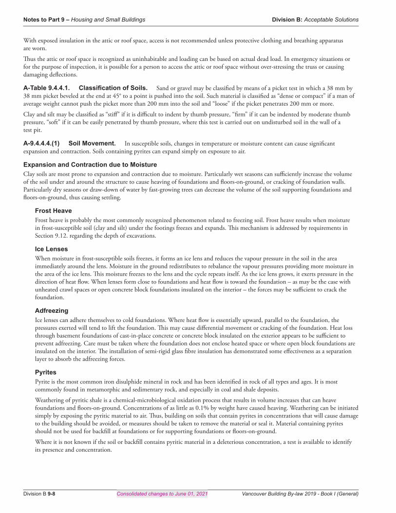
A-9.8.8.6.(1) Configuration of Members, Attachments or Openings in Guards so as to not Facilitate Climbing. Some configurations of members, attachments or openings may be part of a guard design and still comply with Sentence 9.8.8.6.(1). Figures A-9.8.8.6.(1)-A to A-9.8.8.6.(1)-D present a few examples of designs that are considered to not facilitate climbing.
Protrusions that are greater than 450 mm apart horizontally and vertically are considered sufficiently far apart to reduce the likelihood that young children will be able to get a handhold or toehold on the protrusions and climb the guard.
> 450 mm
> 4
50 m
m
900
mm
140
mm
GG00176A
Figure A-9.8.8.6.(1)-A Example of minimum horizontal and vertical clearances between protrusions in guards
Protrusions that present a horizontal offset of 15 mm or less are considered to not provide a sufficient foot purchase to facilitate climbing.

Division B: Acceptable Solutions Notes to Part 9 – Housing and Small Buildings
Vancouver Building By-law 2019 - Book I (General) Consolidated changes to June 01, 2021 Division B 9-21
EG00746A
≤15 mm offset
≤15 mm offset
900
mm
140
mm
Figure A-9.8.8.6.(1)-B Examples of maximum horizontal offset of protrusions in guards
A guard incorporating spaces that are not more than 45 mm wide by 20 mm high is considered to not facilitate climbing because the spaces are too small to provide a toehold.
900
mm
140
mm
≤ 45 mm
≤ 20 mm
GG00178A
Figure A-9.8.8.6.(1)-C Example of a guard with spaces created by the protruding elements that are not more than 45 mm wide and 20 mm high

Notes to Part 9 – Housing and Small Buildings Division B: Acceptable Solutions
Division B 9-22 Consolidated changes to June 01, 2021 Vancouver Building By-law 2019 - Book I (General)
Protrusions that present more than a 2-in-1 slope on the offset are considered to not facilitate climbing because such a slope is considered too steep to provide adequate footing.
> 2
1
GG00179A
900
mm
140
mm
Figure A-9.8.8.6.(1)-D Example of guard protrusions with a slope greater than 2 in 1
A-9.9.4.5.(1) Openings in Exterior Walls of Exits.
• > 3 m horizontally
OR
• opening in building > 2 m
above openings in the exit
³ 135˚
< 135˚
no protection
required
no protection
required
openings within 3 m horizontally and
within 2 m above openings in the exit
< 135˚< 135˚
protection
required
protection
required
EC01221A
Figure A-9.9.4.5.(1) Protection of openings in exterior walls of exits
A-9.9.8.4.(1) Independent and Remote Exits. Subsection 9.9.8. requires that some floor areas have more than one exit.
The intent is to ensure that, if one exit is made untenable or inaccessible by a fire, or its exterior door is blocked by an exterior incident, one or more other exits will be available to permit the occupants to escape. However, if the exits are close together, all exits might be made untenable or inaccessible by the same fire. Sentence 9.9.8.4.(1) therefore requires at least two of the exits to be located remotely from each other. This is not a problem in many buildings falling under Part 9. For instance, apartment buildings usually have exits located at either end of long corridors. However, in other types of buildings (e.g. dormitory and college residence buildings) this

Division B: Acceptable Solutions Notes to Part 9 – Housing and Small Buildings
Vancouver Building By-law 2019 - Book I (General) Consolidated changes to June 01, 2021 Division B 9-23
is often difficult to accomplish and problems arise in interpreting the meaning of the word “remote.” Article 3.4.2.3. is more specific, generally requiring the distance between exits to be one half the diagonal dimension of the floor area or at least 9 m. However, it is felt that such criteria would be too restrictive to impose on the design of all the smaller buildings which come under Part 9. Nevertheless, the exits should be placed as far apart as possible and the Part 3 criteria should be used as a target. Designs in which the exits are so close together that they will obviously both become contaminated in the event of a fire are not acceptable.
A-9.9.10.1.(1) Escape Windows from Bedrooms. Sentence 9.9.10.1.(1) generally requires every bedroom in an unsprinklered suite to have at least one window or door opening to the outside that is large enough and easy enough to open so that it can be used as an exit in the event that a fire prevents use of the building’s normal exits. The minimum unobstructed opening specified for escape windows must be achievable using only the normal window operating procedure. The escape path must not go through nor open onto another room, floor or space.
Where a bedroom is located in an unsprinklered suite in a basement, an escape window or door must be located in the bedroom. It is not sufficient to rely on egress through other basement space to another escape window or door.
Window HeightThe Article does not set a maximum sill height for escape windows; it is therefore possible to install a window or skylight that satisfies the requirements of the Article but defeats the Article’s intent by virtue of being so high that it cannot be reached for exit purposes. It is recommended that the sills of windows intended for use as emergency exits be not higher than 1.5 m above the floor. However, it is sometimes difficult to avoid having a higher sill: on skylights and windows in basement bedrooms for example. In these cases, it is recommended that access to the window be improved by some means such as built-in furniture installed below the window.
EC00319B
Figure A-9.9.10.1.(1) Built-in furniture to improve access to a window
A-9.9.10.1.(2) Bedroom Window Opening Areas and Dimensions. Although the minimum opening dimensions required for height and width are 380 mm, a window opening that is 380 mm by 380 mm would not comply with the minimum area requirements. (See Figure A-9.9.10.1.(2))

Notes to Part 9 – Housing and Small Buildings Division B: Acceptable Solutions
Division B 9-24 Consolidated changes to June 01, 2021 Vancouver Building By-law 2019 - Book I (General)
(a) conform s to opening height and width requirements; does not conform to opening area requirements
(b) and (c) conform to height, width and opening area requirements
380 mm
380 mm
Opening area
0.144 m 2
(a)
380 mm
920 mm Opening
area 0.35 m 2
(b)
EG00318B
592 mm
592 mm
Opening area
0.35 m 2
(c)
Figure A-9.9.10.1.(2) Window opening areas and dimensions
A-9.9.10.1.(3) Window Opening into a Window Well. Sentence 9.9.10.1.(3) specifies that there must be a minimum clearance of 760 mm in front of designated escape windows to allow persons to escape a basement bedroom in an emergency.
This specified minimum clearance is consistent with the minimum required width for means of egress from a floor area (See Article 9.9.5.5.) and the minimum required width for path of travel on exit stairs (See Article 9.9.6.1.). It is considered the smallest acceptable clearance between the escape window and the facing wall of the window well that can accommodate persons trying to escape a bedroom in an emergency given that they are not moving straight through the window but must move outward and up, and must have sufficient space to change body orientation.
Once this clearance is provided, no additional clearance is needed for windows with sliders, casements, or inward-opening awnings. However, for windows with outward-opening awnings, additional clearance is needed to provide the required 760 mm beyond the outer edge of the sash. (See Figure A-9.9.10.1.(3).)
Depending on the likelihood of snow accumulation in the window well, it could be difficult – if not impossible – to escape in an emergency. The window well should be designed to provide sufficient clear space for a person to get out the window and then out the well, taking into account potential snow accumulation.
Hopper windows (bottom-hinged operators) should not be used as escape windows in cases where the occupants would be required to climb over the glass.
EG00688A
760 mm
grade
basement
760 mm
basement
window well
760 mm
window well
grade
window well
grade
basement
Figure A-9.9.10.1.(3) Windows providing a means of escape that open into a window well

Division B: Acceptable Solutions Notes to Part 9 – Housing and Small Buildings
Vancouver Building By-law 2019 - Book I (General) Consolidated changes to June 01, 2021 Division B 9-25
A-9.10.1.4.(1) Commercial Cooking Equipment. Part 6 refers to NFPA 96, “Ventilation Control and Fire Protection of Commercial Cooking Operations,” which in turn references “Commercial Cooking Equipment.” However, the deciding factor as to whether or not NFPA 96 applies is the potential for production of grease-laden vapours and smoke, rather than the type of equipment used. While NFPA 96 does not apply to domestic equipment for normal residential family use, it should apply to domestic equipment used in commercial, industrial, institutional and similar cooking applications where the potential for the production of smoke and grease-laden vapours exceeds that for normal residential family use.
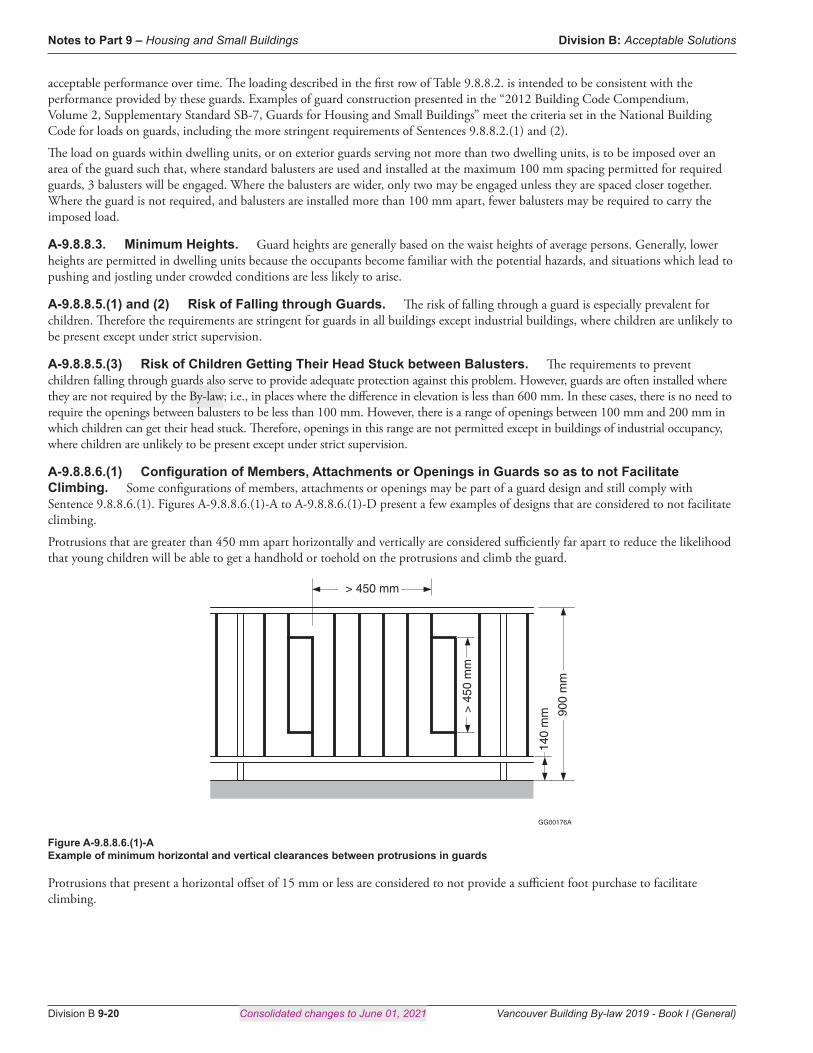
A-9.10.3.1. Fire and Sound Resistance of Building Assemblies. Tables 9.10.3.1.-A and 9.10.3.1.-B have been developed from information gathered from tests. While a large number of the assemblies listed were tested, the fire-resistance and acoustical ratings for others were assigned on the basis of extrapolation of information from tests of similar assemblies. Where there was enough confidence relative to the fire performance of an assembly, the fire-resistance ratings were assigned relative to the commonly used minimum ratings of 30 min, 45 min and 1 h, including a designation of “< 30 min” for assemblies that are known not to meet the minimum 30-minute rating. Where there was not enough comparative information on an assembly to assign to it a rating with confidence, its value in the tables has been left blank (hyphen), indicating that its rating remains to be assessed through another means. Future work is planned to develop much of this additional information.
These tables are provided only for the convenience of By-law users and do not limit the number of assemblies permitted to those in the tables. Assemblies not listed or not given a rating in these tables are equally acceptable provided their fire and sound resistance can be demonstrated to meet the above-noted requirements either on the basis of tests referred to in Article 9.10.3.1. and Subsection 9.11.1. or by using the data in Appendix D, Fire-Performance Ratings. It should be noted, however, that Tables 9.10.3.1.-A and 9.10.3.1.-B are not based on the same assumptions as those used in Appendix D. Assemblies in Tables 9.10.3.1.-A and 9.10.3.1.-B are described
through their generic descriptions and variants and include details given in the notes to the tables. Assumptions for Appendix D include different construction details that must be followed rigorously for the calculated ratings to be expected. These are two different methods of choosing assemblies that meet required fire ratings.
Table 9.10.3.1.-B presents fire-resistance and acoustical ratings for floor, ceiling and roof assemblies. The fire-resistance ratings are appropriate for all assemblies conforming to the construction specifications given in Table 9.10.3.1.-B, including applicable table notes. Acoustical ratings for assemblies decrease with decreasing depth and decreasing separation of the structural members; the values listed for sound transmission class and impact insulation class are suitable for the minimum depth of structural members identified in the description, including applicable table notes, and for structural member spacing of 305 mm o.c., unless other values are explicitly listed for the assembly. Adjustments to the acoustical ratings to allow for the benefit of deeper or more widely spaced structural members are given in Table Notes (9) and (10).
GG00160A
Figure A-9.10.3.1.-A Single layer butt joint details
Notes to Figure A-9.10.3.1.-A:(1) Figure is for illustrative purposes only and is not to scale.(2) The structural member can be any one of the types described in the Table.(3) Adjacent gypsum board butt ends are attached to separate resilient channels using regular Type S screws, located a minimum of 38 mm from
the butt end.
GG00161A
Figure A-9.10.3.1.-B Double layer butt joint details
Notes to Figure A-9.10.3.1.-B:(1) Figure is for illustrative purposes only and is not to scale.(2) The structural member can be any one of the types described in the Table.(3) Base layer butt ends can be attached to a single resilient channel using regular Type S screws.(4) Type G screws measuring a minimum of 32 mm in length and located a minimum of 38 mm from the butt end are used to fasten the butt ends
of the face layer to the base layer.
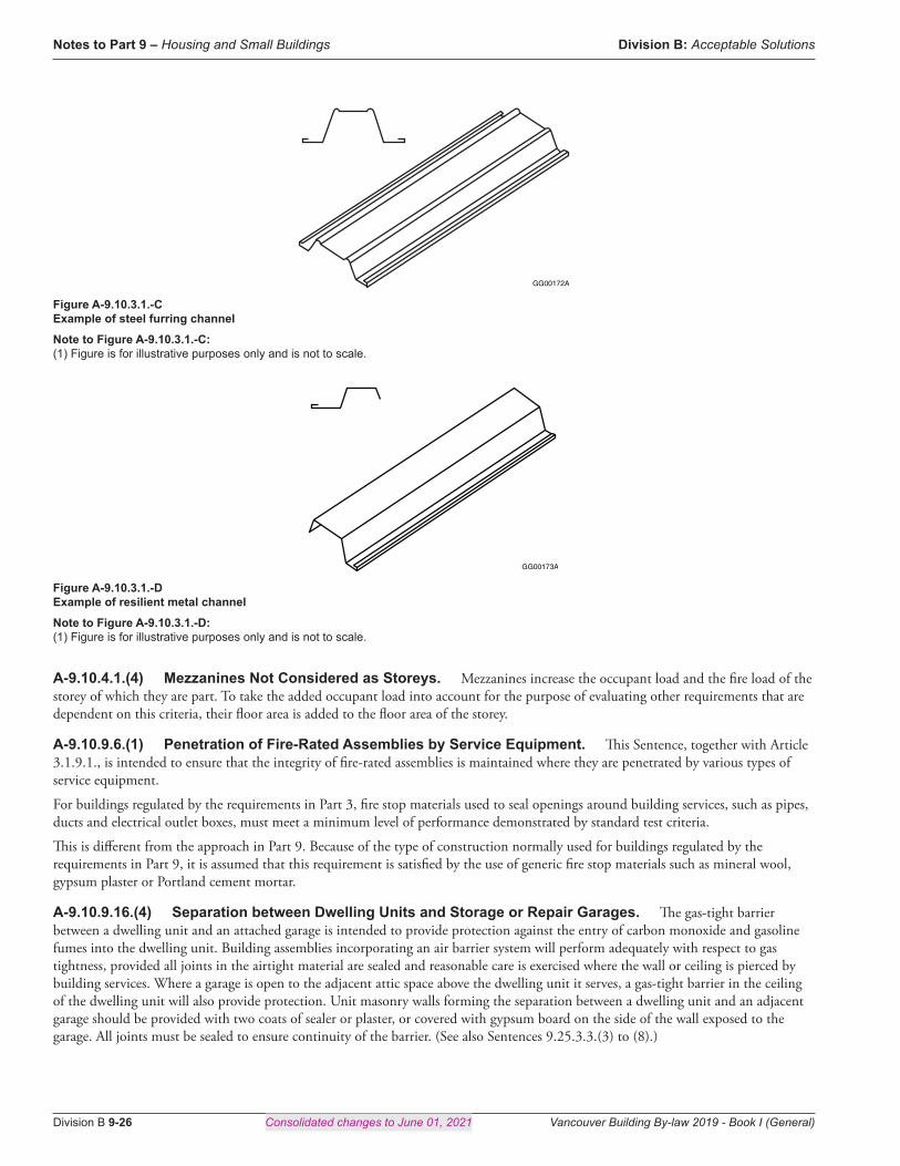
Notes to Part 9 – Housing and Small Buildings Division B: Acceptable Solutions
Division B 9-26 Consolidated changes to June 01, 2021 Vancouver Building By-law 2019 - Book I (General)
GG00172A
Figure A-9.10.3.1.-C Example of steel furring channel
Note to Figure A-9.10.3.1.-C:(1) Figure is for illustrative purposes only and is not to scale.
GG00173A
Figure A-9.10.3.1.-D Example of resilient metal channel
Note to Figure A-9.10.3.1.-D:(1) Figure is for illustrative purposes only and is not to scale.
A-9.10.4.1.(4) Mezzanines Not Considered as Storeys. Mezzanines increase the occupant load and the fire load of the storey of which they are part. To take the added occupant load into account for the purpose of evaluating other requirements that are dependent on this criteria, their floor area is added to the floor area of the storey.
A-9.10.9.6.(1) Penetration of Fire-Rated Assemblies by Service Equipment. This Sentence, together with Article 3.1.9.1., is intended to ensure that the integrity of fire-rated assemblies is maintained where they are penetrated by various types of service equipment.
For buildings regulated by the requirements in Part 3, fire stop materials used to seal openings around building services, such as pipes, ducts and electrical outlet boxes, must meet a minimum level of performance demonstrated by standard test criteria.
This is different from the approach in Part 9. Because of the type of construction normally used for buildings regulated by the requirements in Part 9, it is assumed that this requirement is satisfied by the use of generic fire stop materials such as mineral wool, gypsum plaster or Portland cement mortar.
A-9.10.9.16.(4) Separation between Dwelling Units and Storage or Repair Garages. The gas-tight barrier between a dwelling unit and an attached garage is intended to provide protection against the entry of carbon monoxide and gasoline fumes into the dwelling unit. Building assemblies incorporating an air barrier system will perform adequately with respect to gas tightness, provided all joints in the airtight material are sealed and reasonable care is exercised where the wall or ceiling is pierced by building services. Where a garage is open to the adjacent attic space above the dwelling unit it serves, a gas-tight barrier in the ceiling of the dwelling unit will also provide protection. Unit masonry walls forming the separation between a dwelling unit and an adjacent garage should be provided with two coats of sealer or plaster, or covered with gypsum board on the side of the wall exposed to the garage. All joints must be sealed to ensure continuity of the barrier. (See also Sentences 9.25.3.3.(3) to (8).)

Division B: Acceptable Solutions Notes to Part 9 – Housing and Small Buildings
Vancouver Building By-law 2019 - Book I (General) Consolidated changes to June 01, 2021 Division B 9-27
A-9.10.12.4.(1) Protection of Overhang of Common Roof Space.
1.2 m
1.2 m
area to be protected
2.5 mor less
EC00357B
Figure A-9.10.12.4.(1) Protection of overhang of common roof space
A-9.10.12.4.(3) Protection at Soffits. The materials required by this Sentence to be used as protection for soffit spaces in certain locations do not necessarily have to be the finish materials. They can be installed either behind the finishes chosen for the soffits or in lieu of these.
A-9.10.13.2.(1) Wood Doors in Fire Separations. CAN/ULC-S113, “Wood Core Doors Meeting the Performance Required by CAN/ULC-S104 for Twenty Minute Fire Rated Closure Assemblies,” provides construction details to enable manufacturers to build wood core doors that will provide a 20 min fire-protection rating without the need for testing. The standard requires each door to be marked with
1. the manufacturer’s or vendor’s name or identifying symbol,2. the words “Fire Door,” and3. a reference to the fire-protection rating of 20 min.
A-9.10.14.5.(1) Minor Combustible Cladding Elements. Minor elements of cladding that is required to be noncombustible are permitted to be of combustible material, provided they are distributed over the building face and not concentrated in one area. Examples of minor combustible cladding elements include door and window trim and some decorative elements.
A-9.10.14.5.(7) Permitted Projections. The definition of exposing building face provided in Sentence 1.4.1.2.(1) of Division A refers to “that part of the exterior wall of a building … or, where a building is divided into fire compartments, the exterior wall of a fire compartment …” Because the exposing building face is defined with respect to the exterior wall, projections from exposing building faces are elements that do not incorporate exterior walls. Depending on their specific configurations, examples of constructions that would normally be permitted by Sentence 9.10.14.5.(7) are balconies, platforms, canopies, eave projections and stairs. However, if a balcony, platform or stair is enclosed, its exterior wall would become part of an exposing building face and the construction could not be considered to be a projection from the exposing building face.
A-9.10.14.5.(8) Protection at Projections. Sentence 9.10.14.5.(7) permits certain projections from exposing building faces where the projections do not have exterior walls and thus clearly do not constitute part of the exposing building face.
Sentence 9.10.14.5.(8) refers to other types of projections from the exposing building face, such as those for fireplaces and chimneys.
It is recognized that these types present more vertical surface area compared to platforms, canopies and eave projections, and may be enclosed by constructions that are essentially the same as exterior walls. These constructions, however, do not enclose habitable space, are of limited width and may not extend a full storey in height. Consequently, Sentence (8) allows these projections beyond the exposing building face of buildings identified in Sentence (6), provided additional fire protection is installed on the projection.
Figure A-9.10.14.5.(8) illustrates projections that extend within 1.2 m of the property line where additional protection must be provided. Where a projection extends within 0.6 m of the property line, it must be protected to the same degree as an exposing building face that has a limiting distance of less than 0.6 m. Where a projection extends to less than 1.2 m but not less than 0.6 m of the property line, it must be protected to the same degree as an exposing building face that has a limiting distance of less than 1.2 m.
Protection is also required on the underside of the projection where the projection is more than 0.6 m above finished ground level,

Notes to Part 9 – Housing and Small Buildings Division B: Acceptable Solutions
Division B 9-28 Consolidated changes to June 01, 2021 Vancouver Building By-law 2019 - Book I (General)
measured at the exposing building face.
EG00694D
space enclosed by projection is not habitable space
space enclosed by projection is not habitable space
space enclosed by projection is not habitable space
> 0.6 m
< 1.2 m
Section
PlanPlan
normal cladding-sheathing assemblycladding-sheathing assemblies providing additional fire protection}
< 1.2 m < 1.2 m
Figure A-9.10.14.5.(8) Protection at projections
A-9.10.14.5.(11) and 9.10.15.5.(10) Roof Soffit Projections.
a) Projecting roof soffit not allowed to be constructed(1)
b) Roof soffit must not project to less than 0.45 m from the property line(2)
c) Roof soffit permitted to project up to property line, where it faces a street, lane or public thoroughfare, regardless of the limiting distance(3)
no roof soffits
≥ 0.45 m
LD ≤ 0.45 m LD > 0.45 m
prop
erty
line
cent
re li
ne o
f a s
tree
t, la
ne o
r pu
blic
thor
ough
fare
prop
erty
line
prop
erty
line
EG01393A
LD = limiting distance
Figure A-9.10.14.5.(11) and 9.10.15.5.(10) Roof soffit projections
Notes to Figure A-9.10.14.5.(11) and 9.10.15.5.(10):(1) See Sentences 3.2.3.6.(2), 9.10.14.5.(9) and 9.10.15.5.(8).(2) See Sentences 3.2.3.6.(3), 9.10.14.5.(10) and 9.10.15.5.(9).

Division B: Acceptable Solutions Notes to Part 9 – Housing and Small Buildings
Vancouver Building By-law 2019 - Book I (General) Consolidated changes to June 01, 2021 Division B 9-29
(3) See Sentences 3.2.3.6.(4), 9.10.14.5.(11) and 9.10.15.5.(10).A-9.10.15. Application of Subsection. Subsection 9.10.15. applies to the spatial separation between buildings of residential occupancy where there is no principal dwelling unit ,including its ancillary residential unit, above another dwelling unit. Such buildings include detached houses, semi-detached houses (doubles) and row houses, where there is no dwelling unit above another dwelling unit. The general intent of Vancouver’s expanded spatial separation provisions in Subsection 9.10.15. is that each legal entity is self-contained and should not overlap (and therefore impact) on an adjacent legal entity and creating complex spatial arrangements that are no longer reflective of a traditional house.
A-9.10.15.4.(2) Staggered or Skewed Exposing Building Faces of Houses. Studies at the National Fire Laboratory of the National Research Council have shown that, where an exposing building face is stepped back from the property line or is at an angle to the property line, it is possible to increase the percentage of glazing in those portions of the exposing building face further from the property line without increasing the amount of radiated energy that would reach the property line in the event of a fire in such a building. Figures A-9.10.15.4.(2)-A, A-9.10.15.4.(2)-B and A-9.10.15.4.(2)-C show how Sentences 9.10.15.4.(1) and (2), and 9.10.15.5.(2) and (3) can be applied to exposing building faces that are stepped back from or not parallel to the property line.
The following procedure can be used to establish the maximum permitted area of glazed openings for such facades:
1. Calculate the total area of the exposing building face, i.e. facade of the fire compartment, as described in the definition of exposing building face.
2. Identify the portions into which the exposing building face is to be divided. It can be divided in any number of portions, not necessarily of equal size.
3. Measure the limiting distance for each portion. The limiting distance is measured along a line perpendicular to the wall surface from the point closest to the property line.
4. Establish the line in Table 9.10.15.4. from which the maximum permitted percentage area of unprotected openings will be read. The selection of the line depends on the maximum area of exposing building face for the whole fire compartment, including all portions, as determined in Step 1.
5. On that line, read the maximum percentage area of unprotected openings permitted in each portion of the exposing building face according to the limiting distance for that portion.
6. Calculate the maximum area of unprotected openings permitted in each portion. The area is calculated from the percentage found applied to the area of that portion.
Table 9.10.15.4. is used to read the maximum area of unprotected openings: this means that the opaque portion of doors does not have to be counted as for other types of buildings.
Note that this Note and the Figures do not describe or illustrate maximum permitted concentrated area or spacing of individual unprotected openings, or limits on the location of dividing lines between portions of the exposing building face depending on the location of these openings with respect to interior rooms or spaces. See Sentences 9.10.15.2.(2) and 9.10.15.4.(2) to (4) for the applicable requirements.
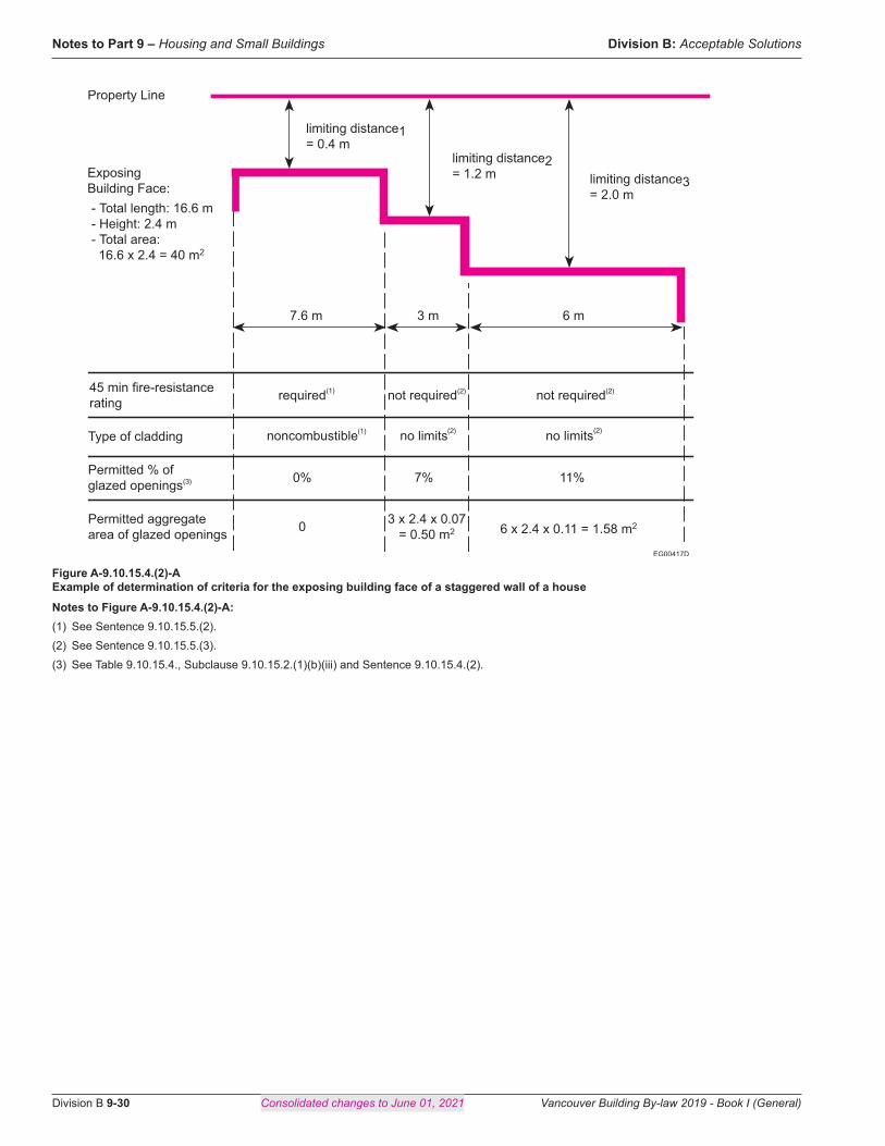
Notes to Part 9 – Housing and Small Buildings Division B: Acceptable Solutions
Division B 9-30 Consolidated changes to June 01, 2021 Vancouver Building By-law 2019 - Book I (General)
noncombustible no limits
0% 7% 1 1 %
7.6 m 6 m 3 m
0
required not required
no limits
not required
3 x 2.4 x 0.07 = 0.50 m 2 6 x 2.4 x 0. 1 1 = 1.58 m 2
EG00417D
Permitted aggregate area of glazed openings
Permitted % of glazed openings
Type of cladding
45 min fire-resistance rating
Property Line
Exposing Building Face: - T otal length: 16.6 m - Height: 2.4 m - T otal area:
16.6 x 2.4 = 40 m 2
limiting distance1 = 0.4 m
limiting distance2 = 1.2 m limiting distance3
= 2.0 m
(1) (2) (2)
(2) (2)
(3)
(1)
Figure A-9.10.15.4.(2)-A Example of determination of criteria for the exposing building face of a staggered wall of a house
Notes to Figure A-9.10.15.4.(2)-A:(1) See Sentence 9.10.15.5.(2).(2) See Sentence 9.10.15.5.(3).(3) See Table 9.10.15.4., Subclause 9.10.15.2.(1)(b)(iii) and Sentence 9.10.15.4.(2).

Division B: Acceptable Solutions Notes to Part 9 – Housing and Small Buildings
Vancouver Building By-law 2019 - Book I (General) Consolidated changes to June 01, 2021 Division B 9-31
required required not required not required not required
no limits no limits no limits noncombustible noncom- bustible
0% 100% 28%9%0%
0 0 5.0 x 2.4 x 0.09 = 1.08 m 2
7.0 x 2.4 x 0.28 = 4.70 m 2
3.0 x 2.4 x 1.0 = 7.2 m 2
EG00378D
Permitted aggregate area of glazed openings
Permitted % of glazed openings
Type of cladding
45 min fire-resistance rating
3.8 m
30°
Property Line
-
Exposing Building Face: - T otal length: 20.8 m - Height: 2.4 m
T otal area: 20.8 x 2.4 = 50 m 2
limiting distance1= 0.5 m
limiting distance2= 0.58 m limiting
distance3= 1.73 m limiting
distance4= 4.62 m
limiting distance5= 8.66 m
5.0 m
7.0 m
3.0 m
2.0 m
(2) (2) (2)
(3)(4)
(1) (1) (2) (2) (2)
(1) (1)
Figure A-9.10.15.4.(2)-B Example of determination of criteria for the exposing building face of a skewed wall of a house with some arbitrary division of the wall
Notes to Figure A-9.10.15.4.(2)-B:(1) See Sentence 9.10.15.5.(2).(2) See Sentence 9.10.15.5.(3).(3) See Table 9.10.15.4., Subclause 9.10.15.2.(1)(b)(iii) and Sentence 9.10.15.4.(2).(4) To simplify the calculations, choose the column for the lesser limiting distance nearest to the actual limiting distance. Interpolation for limiting
distance is also acceptable and may result in a slightly larger permitted area of glazed openings. Interpolation can only be used for limiting distances greater than 1.2 m.

Notes to Part 9 – Housing and Small Buildings Division B: Acceptable Solutions
Division B 9-32 Consolidated changes to June 01, 2021 Vancouver Building By-law 2019 - Book I (General)
required
noncom- bustible
0%
3.8 m 9.0 m
5.0 m 2.0 m
0
0% 7%
0 Permitted aggregate area of glazed openings
Permitted % of glazed openings
Type of cladding
45 min fire-resistance rating
Property Line
Exposing Building Face: - T otal length: 20.8 m - Height: 2.4 m - T otal area: 20.8 x 2.4 = 50 m 2
limiting distance1= 0.54 m
limiting distance2 = 0.62 m
limiting distance4 = 6.4 m
limiting distance5= 9.3 m
limiting distance3 = 1.2 m
required
no limits no limits
not required not required
no limits
not required
9.0 x 2.4 x 0.07 = 1.51 m 2
5.0 x 2.4 x 0.57 = 6.84 m 2
2.0 x 2.4 x 1.0
57%
EG00379D
30°
100%
1.0 m
= 4.8 m2
(2) (2) (2)
(1) (2) (2) (2) (2)
(1)
(3)(4)
noncombustible (2)
Figure A-9.10.15.4.(2)-C Example of determination of criteria for the exposing building face of a skewed wall of a house with a different arbitrary division of the wall
Notes to Figure A-9.10.15.4.(2)-C:(1) See Sentence 9.10.15.5.(2).(2) See Sentence 9.10.15.5.(3).(3) See Table 9.10.15.4., Subclause 9.10.15.2.(1)(b)(iii) and Sentence 9.10.15.4.(2).(4) To simplify the calculations, choose the column for the lesser limiting distance nearest to the actual limiting distance. Interpolation for limiting
distance is also acceptable and may result in a slightly larger permitted area of unprotected openings. Interpolation can only be used for limiting distances greater than 1.2 m.
A-9.10.19.3.(1) Location of Smoke Alarms. There are two important points to bear in mind when considering where to locate smoke alarms in dwelling units:
• The most frequent point of origin for fires in dwelling units is the living area.• The main concern in locating smoke alarms is to provide warning to people asleep in bedrooms.
A smoke alarm located in the living area and wired so as to sound another smoke alarm located near the bedrooms is the ideal solution. However, it is difficult to define exactly what is meant by “living area.” It is felt to be too stringent to require a smoke alarm in every part of a dwelling unit that could conceivably be considered a “living area” (living room, family room, study, etc.). Sentence 9.10.19.3.(1) addresses these issues by requiring at least one smoke alarm on every storey containing a sleeping room. Thus, in a dwelling unit complying with Sentence 9.10.19.3.(1), every living area will probably be located within a reasonable distance of a smoke alarm. Nevertheless, where a choice arises as to where on a storey to locate the required smoke alarm or alarms, one should be located as close as possible to a living area, provided the requirements related to proximity to bedrooms are also satisfied.
A smoke alarm is not required on each level in a split-level dwelling unit as each level does not count as a separate storey. Determine the number of storeys in a split-level dwelling unit and which levels are part of which storey as follows:
1. establish grade, which is the lowest of the average levels of finished ground adjoining each exterior wall of a building;2. identify the first storey, which is the uppermost storey having its floor level not more than 2 m above grade;3. identify the basement, which is the storey or storeys located below the first storey;

Division B: Acceptable Solutions Notes to Part 9 – Housing and Small Buildings
Vancouver Building By-law 2019 - Book I (General) Consolidated changes to June 01, 2021 Division B 9-33
4. identify the second storey and, where applicable, the third storey.
As a minimum, one smoke alarm is required to be installed in each storey, preferably on the upper level of each one. As noted above, however, when the dwelling unit contains more than one sleeping area, an alarm must be installed to serve each area. Where the sleeping areas are on two levels of a single storey in a split-level dwelling unit, an additional smoke alarm must be installed so that both areas are protected. See Figure A-9.10.19.3.(1).
EG00676A
Not more than 2 m
(1)
(1)
(1)
(2)
Grade
Lower 2nd storey (with sleeping area)
Lower 1st storey
Lower basement
Upper 2nd storey (with sleeping area)
Upper 1st storey
Upper basement
= smoke alarm
Figure A-9.10.19.3.(1) Two-storey split-level building
Notes to Figure A-9.10.19.3.(1):(1) One smoke alarm required for each of the basement, first storey and second storey.(2) An additional smoke alarm is required on the lower level of the second storey outside the sleeping rooms.
A-9.10.20.3.(1) Fire Department Access Route Modification. In addition to other considerations taken into account in the planning of fire department access routes, special variations could be permitted for a house or residential building that is protected with an automatic sprinkler system. The sprinkler system must be designed in accordance with the appropriate NFPA standard and there must be assurance that water supply pressure and quantity are unlikely to fail. These considerations could apply to buildings that are located on the sides of hills and are not conveniently accessible by roads designed for firefighting equipment and also to infill housing units that are located behind other buildings on a given property.
A-9.10.22. Clearances from Gas, Propane and Electric Cooktops. CSA C22.1, “Canadian Electrical Code, Part I,” which is adopted by the Electrical Safety Regulation referenced in Article 9.34.1.1., and CSA B149.1, “Natural Gas and Propane Installation Code,” which is adopted by the Gas Safety Regulation referenced in Article 9.10.22.1., address clearances directly above, in front of, behind and beside the appliance. Where side clearances are zero, the standards do not address clearances to building elements located both above the level of the cooktop elements or burners and to the side of the appliance. Through reference to the above noted regulations and their adopted standards, and the requirements in Articles 9.10.22.2. and 9.10.22.3., the British Columbia Building Code addresses all clearances. Where clearances are addressed by the British Columbia Building Code and the above noted regulations and their adopted standards, conformance with all relevant criteria is achieved by compliance with the most stringent criteria.

Notes to Part 9 – Housing and Small Buildings Division B: Acceptable Solutions
Division B 9-34 Consolidated changes to June 01, 2021 Vancouver Building By-law 2019 - Book I (General)
Installation of Microwave Ovens Over CooktopsThe minimum vertical clearances stated in Article 9.10.22.2. apply only to combustible framing, finishes and cabinets. They do not apply to microwave ovens installed over cooktops nor to range hoods. The “Canadian Electrical Code, Part I” requires that microwave ovens comply with CAN/CSA-C22.2 No. 150, “Microwave Ovens.” This standard includes tests to confirm that the appliance will not present a hazard when installed according to the manufacturer’s instructions.
appliance opening
horizontal orvertical clearanceless than 450 mm -protected
EG00380A
vertical clearance 600 mm minimum -protected or noncombustible;750 mm or more - unprotected
horizontal orvertical clearance450 mm or more -unprotected
level of elementsor burners
Figure A-9.10.22. Clearances from cooktops to walls and cabinetry
A-9.11. Sound Transmission.
Airborne SoundAirborne sound is transmitted between adjoining spaces directly through the separating wall, floor and ceiling assemblies and via the junctions between these separating assemblies and the flanking assemblies.
The Sound Transmission Class (STC) rating describes the performance of the separating wall or floor/ceiling assembly, whereas the Apparent Sound Transmission Class (ASTC) takes into consideration the performance of the separating element as well as the flanking transmission paths. Therefore, from the occupants’ point of view, the best indicator of noise protection between two spaces is the ASTC rating.
As a key principle, it is important to follow a “whole-system” approach when designing or constructing assemblies that separate dwelling units because the overall sound performance of walls and floors is also influenced by fire protection measures and the structural design of the assemblies. Likewise, changes to the construction of assemblies to meet sound transmission requirements may have fire and structural implications. Another key principle is that enhancing the performance of the separating element does not automatically enhance the system’s performance.

Division B: Acceptable Solutions Notes to Part 9 – Housing and Small Buildings
Vancouver Building By-law 2019 - Book I (General) Consolidated changes to June 01, 2021 Division B 9-35
For horizontally adjoining spaces, the separating assembly is the intervening wall and the pertinent flanking surfaces include those of the floor, ceiling, and side wall assemblies that have junctions with the separating wall assembly, normally at its four edges. For each of these junctions, there is a set of sound transmission paths. Figure A-9.11.-A illustrates the horizontal sound transmission paths at the junction of a separating wall with flanking floor assemblies.
EG01379A
apparent sound transmission class (ASTC)
direct path (STC)
flanking paths
airborne sound source
flanking floor/ceiling assembly
separating wall assembly
Figure A-9.11.-A Horizontal sound transmission paths at floor/wall junction
For vertically adjoining spaces, the separating assembly is the intervening floor/ceiling and the pertinent flanking surfaces include those of the side wall assemblies in the upper and lower rooms that have junctions with the separating floor/ceiling assembly at its edges, of which there are normally four. For each of these junctions, there is a set of sound transmission paths. Figure A-9.11.-B illustrates the vertical sound transmission paths at the junction of a separating floor/ceiling assembly with two flanking wall assemblies.

Notes to Part 9 – Housing and Small Buildings Division B: Acceptable Solutions
Division B 9-36 Consolidated changes to June 01, 2021 Vancouver Building By-law 2019 - Book I (General)
airborne sound source
direct path (STC)
flanking paths
apparent sound transmission class (ASTC)
EG01380A
separating floor/ceiling assembly
flanking side wall assemblies
Figure A-9.11.-B Vertical sound transmission paths at wall/floor junction
Control of Sound LeaksThe metrics used to characterize the sound transmission performance of assemblies separating dwelling units do not account for the adverse effects of air leaks in those assemblies, which can transfer sound. Sound leaks can occur where a wall meets another wall, the floor, or the ceiling. They can also occur where wall finishes are cut to allow the installation of equipment or services. The following are examples of measures for controlling sound leaks:
• avoid back-to-back electrical outlets or medicine cabinets;• carefully seal cracks or openings so structures are effectively airtight;• apply sealant below the plates in stud walls, between the bottom of gypsum board and the structure behind, around all
penetrations for services and, in general, wherever there is a crack, a hole or the possibility of one developing;• include sound-absorbing material inside the wall if not already required
The reduction of air leakage is also addressed to some extent by the smoke tightness requirements in the By-law.
The calculation of and laboratory testing for STC and ASTC ratings are performed on intact assemblies having no penetrations or doors. When measuring ASTC ratings in the field, openings can be blocked with insulation and drywall.
To verify that the required acoustical performance is being achieved, a field test can be done at an early stage of construction. ASTM E 336, “Measurement of Airborne Sound Attenuation between Rooms in Buildings,” gives a complete measurement. A simpler and less expensive method is presented in ASTM E 597, “Determining a Single Number Rating of Airborne Sound Insulation for Use in Multi-Unit Building Specifications.” The rating derived from this test is usually within 2 points of the STC obtained from ASTM E 336. It is useful for verifying performance and finding problems during construction. Alterations can then be made prior to project completion.
Impact NoiseSection 9.11. has no requirements for the control of impact noise transmission. However, footsteps and other impacts can cause severe annoyance in multifamily residences. Builders concerned about quality and reducing occupant complaints will ensure that floors are designed to minimize impact transmission. A recommended criterion is that bare floors (tested without a carpet) should achieve an impact insulation class (IIC) of 55. Some lightweight floors that satisfy this requirement may still elicit complaints about low frequency impact noise transmission. Adding carpet to a floor will always increase the IIC rating but
Table A-9.11.1.4.-AOptions for the Design and Construction of Junctions and Flanking Surfaces Between Separating Wall Assemblies
in Horizontally Adjoining Spaces for Compliance with Clause 9.11.1.1.(1)(b)

Division B: Acceptable Solutions Notes to Part 9 – Housing and Small Buildings
Vancouver Building By-law 2019 - Book I (General) Consolidated changes to June 01, 2021 Division B 9-37
will not necessarily reduce low frequency noise transmission. Good footstep noise rejection requires fairly heavy floor slabs or floating floors.
The most frequently used test methods for impact noise are ASTM E 492, “Laboratory Measurement of Impact Sound Transmission Through Floor-Ceiling Assemblies Using the Tapping Machine,” and ASTM E 1007, “Field Measurement of Tapping Machine Impact Sound Transmission Through Floor-Ceiling Assemblies and Associated Support Structures.”
Machinery NoiseElevators, garbage chutes, plumbing, fans, and heat pumps are common sources of noise in buildings. To reduce annoyance from these, they should be placed as far as possible from sensitive areas. Vibrating parts should be isolated from the building structure using resilient materials such as neoprene or rubber.
A-9.11.1.3.(2)(b) Control of Airborne Noise in Buildings. Tables 9.10.3.1.-A and 9.10.3.1.-B present separating assemblies that comply with Section 9.11. However, selecting an appropriate separating assembly is only one part of the solution for reducing airborne sound transmission between adjoining spaces: to fully address the sound performance of the whole system, flanking assemblies must be connected to the separating assembly in accordance with Article 9.11.1.4.
A-9.11.1.4. Adjoining Constructions. Tables A-9.11.1.4.-A to A-9.11.1.4.-D present generic options for the design and construction of junctions between separating and flanking assemblies. Constructing according to these options is likely to meet or exceed an ASTC rating of 47. Other designs may be equally acceptable if their sound resistance can be demonstrated to meet the minimum ASTC rating or better on the basis of tests referred to in Article 9.11.1.2., or if they comply with Subsection 5.8.1. However, some caution should be applied when designing solutions that go beyond the options provided in these Tables: for example, adding more material to a wall could negatively impact its sound performance or have no effect at all.
Table A-9.11.1.4.-A presents compliance options for the construction of separating wall assemblies with flanking floor, ceiling and wall assemblies in horizontally adjoining spaces.

Notes to Part 9 – Housing and Small Buildings Division B: Acceptable Solutions
Division B 9-38 Consolidated changes to June 01, 2021 Vancouver Building By-law 2019 - Book I (General)
Table A-9.11.1.4.-A (continued)Options for the Design and Construction of Junctions and Flanking Surfaces Between Separating Wall Assemblies
in Horizontally Adjoining Spaces for Compliance with Clause 9.11.1.1.(1)(b)
Type of Separating Wall Assembly
with STC ≥ 50 from Table 9.10.3.1.-A
Options for Design and Construction of Junctions and Flanking Surfaces(1) to Address Horizontal Sound Transmission Paths
Bottom Junction (between separating wall
and flanking floors)
Top Junction (between separating wall
and flanking ceiling)
Side Junctions (between separating wall
and flanking walls)
Example Showing Side View of Bottom and Top Junctions
EG02087A
ceiling
W12 separating wall
additional material layer over subfloor plus finished flooring with mass per area > 8 kg/m2
Example Showing Plan View of Side Junctions
EG02086A
W12 separating wall
flanking wall

Division B: Acceptable Solutions Notes to Part 9 – Housing and Small Buildings
Vancouver Building By-law 2019 - Book I (General) Consolidated changes to June 01, 2021 Division B 9-39
Table A-9.11.1.4.-A (continued)Options for the Design and Construction of Junctions and Flanking Surfaces Between Separating Wall Assemblies
in Horizontally Adjoining Spaces for Compliance with Clause 9.11.1.1.(1)(b)
Type of Separating Wall Assembly
with STC ≥ 50 from Table 9.10.3.1.-A
Options for Design and Construction of Junctions and Flanking Surfaces(1) to Address Horizontal Sound Transmission Paths
Bottom Junction (between separating wall
and flanking floors)
Top Junction (between separating wall
and flanking ceiling)
Side Junctions (between separating wall
and flanking walls)
W13, W14, W15 • for additional material layer and finished flooring, see Table 9.11.1.4.
• subfloor on both sides of wall is plywood, OSB, waferboard (15.5 mm thick) or tongue and groove lumber (≥ 17 mm thick)
• floor is framed with wood joists, wood I-joists or wood trusses spaced ≥ 400 mm o.c., with or without absorptive material(2) in cavities
• floor joists or trusses are oriented parallel to separating wall (non-loadbearing case) or perpendicular to separating wall but are not continuous across junction (loadbearing case)
• near leaf of separating wall is supported on “designated” joist
• wood joists, wood I-joists or wood trusses are oriented perpendicular or parallel to separating wall, with or without absorptive material(2) in cavities
• joist framing at junction is supported on near leaf of separating wall
• gypsum board ceiling panels end at wall framing and are fastened directly to bottom of ceiling framing or on resilient metal channels(3)
• flanking wall framing is fastened to adjacent leaf of separating wall
• flanking wall is framed with single row of wood studs, staggered studs on a single 38 mm × 140 mm plate, or 2 rows of 38 mm × 89 mm wood studs on separate 38 mm × 89 mm plates, with or without absorptive material(2) in cavities
• gypsum board panels on flanking walls ends or is cut at framing of separating wall and is fastened on resilient metal channels(3) or directly to framing of flanking wall if that framing and any sheathing are not continuous across the junction

Notes to Part 9 – Housing and Small Buildings Division B: Acceptable Solutions
Division B 9-40 Consolidated changes to June 01, 2021 Vancouver Building By-law 2019 - Book I (General)
Table A-9.11.1.4.-A (continued)Options for the Design and Construction of Junctions and Flanking Surfaces Between Separating Wall Assemblies
in Horizontally Adjoining Spaces for Compliance with Clause 9.11.1.1.(1)(b)
Type of Separating Wall Assembly
with STC ≥ 50 from Table 9.10.3.1.-A
Options for Design and Construction of Junctions and Flanking Surfaces(1) to Address Horizontal Sound Transmission Paths
Bottom Junction (between separating wall
and flanking floors)
Top Junction (between separating wall
and flanking ceiling)
Side Junctions (between separating wall
and flanking walls)
Example Showing Side View of Bottom and Top Junctions
EG01366A
ceiling
W13 separating wall
additional material layer over subfloor plus finished flooring with mass per area > 8 kg/m2
Example Showing Plan View of Side Junctions
EG01365A
W13 separating wall
flanking wall
• F1 concrete floor assembly from Table 9.10.3.1.-B with mass per area not less than 300 kg/m2 (e.g. normal-weight concrete with average thickness of 130 mm)
• with or without an additional material layer or finished flooring
• F1 concrete floor assembly from Table 9.10.3.1.-B with mass per area not less than 300 kg/m2 (e.g. normal-weight concrete with average thickness of 130 mm)
• with or without gypsum board ceiling suspended below concrete floor
• flanking wall framing is structurally connected to separating wall and terminates where it butts against framing of separating wall or is continuous across junction
• gypsum board on flanking walls ends or is cut at separating wall and is fastened directly to framing or on resilient metal channels(3)
• flanking wall consists of steel framing (loadbearing or nonloadbearing steel studs) or concrete blocks with mass per area not less than 200 kg/m2 (e.g. normal-weight hollow core concrete block units(4) with a gypsum board lining supported on framing providing a cavity not less than 50 mm deep)
• with or without absorptive material(2) in cavities behind gypsum board of flanking walls

Division B: Acceptable Solutions Notes to Part 9 – Housing and Small Buildings
Vancouver Building By-law 2019 - Book I (General) Consolidated changes to June 01, 2021 Division B 9-41
Table A-9.11.1.4.-A (continued)Options for the Design and Construction of Junctions and Flanking Surfaces Between Separating Wall Assemblies
in Horizontally Adjoining Spaces for Compliance with Clause 9.11.1.1.(1)(b)
Type of Separating Wall Assembly
with STC ≥ 50 from Table 9.10.3.1.-A
Options for Design and Construction of Junctions and Flanking Surfaces(1) to Address Horizontal Sound Transmission Paths
Bottom Junction (between separating wall
and flanking floors)
Top Junction (between separating wall
and flanking ceiling)
Side Junctions (between separating wall
and flanking walls)
Example Showing Side View of Bottom and Top Junctions
EG01370A
B3 separating wall
concrete floor
concrete floor
Examples Showing Plan View of Side Junctions
EG01371A
B3 separating wall
flanking wall
Notes to Table A-9.11.1.4.-A:(1) See also Table A-9.11.1.4.-B.(2) Sound absorptive material is porous (closed-cell foam was not tested) and includes fibre processed from rock, slag, glass or cellulose fibre
with a maximum density of 32 kg/m3. See Notes (5) and (8) of Table 9.10.3.1.-A and Note (5) of Table 9.10.3.1.-B for additional information.(3) Resilient metal channels are formed from steel having a maximum thickness of 0.46 mm (25 gauge) with slits or holes in the single “leg”
between the faces fastened to the framing and to the gypsum board (See Figure A-9.10.3.1.-D). ASTM C 754, “Installation of Steel Framing Members to Receive Screw-Attached Gypsum Panel Products,” describes the installation of resilient metal channels.
(4) Normal-weight concrete block units conforming to CSA A165.1, “Concrete Block Masonry Units,” have aggregate with a density not less than 2 000 kg/m3; 190 mm hollow core units are 53% solid, providing a wall mass per area over 200 kg/m2; 140 mm hollow core units are 75% solid, providing a wall mass per area over 200 kg/m2.
Table A-9.11.1.4.-B presents options for improving the sound performance of separating wall systems beyond that achieved by implementing the options presented in Table A-9.11.1.4.-A. The suggested performance improvement options are listed in order of approximate acoustic priority and are interdependent, i.e., if options at the top of the list are not implemented, then options at the bottom of the list will have much lesser effect.

Notes to Part 9 – Housing and Small Buildings Division B: Acceptable Solutions
Division B 9-42 Consolidated changes to June 01, 2021 Vancouver Building By-law 2019 - Book I (General)
Table A-9.11.1.4.-BOptions for the Construction of a Separating Wall System to Further Improve the Sound Insulation Performance
Achieved with the Options in Table A-9.11.1.4.-A
Type of Separating Wall Assembly with STC ≥ 50 from Table
9.10.3.1.-A
Performance Improvement Options for Junctions Between Separating Walls and Flanking Floor/Ceiling Assemblies
W4, W5, W6, W8, W9, W10, W11, W12
• Increase mass per area of additional material layer and finished flooring over subfloor (e.g. concrete or gypsum concrete topping)
• Choose separating wall assembly with higher STC rating• Orient floor and ceiling joists parallel to separating wall (non-loadbearing case)• Add resilient layer under additional material layer over subfloor or between additional material layer
and finished flooring• Support gypsum board panels of ceiling on resilient metal channels(1)
• Support gypsum board panels of flanking walls on resilient metal channels(1)
W13, W14, W15 • If seismic or other structural requirements permit, choose a fire block detail at floor/wall junction in accordance with Subsection 9.10.16. that does not provide a rigid connection between the two rows of framing of the separating wall (e.g. subfloor not continuous across junction and semi-rigid fibre insulation board filling the gap in accordance with Article 9.10.16.3.). In this case, an additional material layer would not be necessary. Also, choose separating wall assembly with higher STC rating (e.g. more absorptive material(2) in cavities and/or more gypsum board).
• If having a rigid structural connection at the floor/wall junction (such as subfloor continuous across the junction) is required for seismic or other structural reasons, obtain a higher ASTC rating as follows:• Increase combined mass per area of additional material layer over subfloor and finished flooring
(e.g. concrete or gypsum concrete topping)• Choose separating wall assembly with higher STC rating (e.g. more absorptive material(2) and/or
more gypsum board)• Support gypsum board panels of ceiling on resilient metal channels(1)
• Support gypsum board panels of flanking walls on resilient metal channels(1)
• Add resilient layer under additional material layer over subfloor or between additional material layer and finished flooring
S1 to S15 • Choose separating wall assembly with higher STC rating• Increase thickness of concrete floor slab and/or add material layer and finished flooring over subfloor• Add gypsum board ceiling on framing supported under the floor above, with cavity not less than
100 mm deep• Add resilient layer under additional material layer over subfloor or between additional material layer
and finished flooring• Support gypsum board panels of flanking walls on resilient metal channels(1) if steel studs are
loadbearing type
B1 to B10 • Choose separating wall assembly with higher STC rating• Add gypsum board ceiling supported below concrete floor with cavity not less than 100 mm deep and
sound absorptive material(2) in cavity• Increase thickness of concrete floor slab and/or add material layer and finished flooring over subfloor• Add resilient layer under additional material layer over subfloor or between additional material layer
and finished flooring and increase mass per area of additional material layer and finished flooring (e.g. floating concrete or gypsum concrete topping)
• Support gypsum board panels of flanking walls on resilient metal channels(1) if steel studs are loadbearing type
Notes to Table A-9.11.1.4.-B:(1) Resilient metal channels are formed from steel having a maximum thickness of 0.46 mm (25 gauge) with slits or holes in the single “leg”
between the faces fastened to the framing and to the gypsum board (See Figure A-9.10.3.1.-D). ASTM C 754, “Installation of Steel Framing Members to Receive Screw-Attached Gypsum Panel Products,” describes the installation of resilient metal channels.
(2) Sound absorptive material is porous (closed-cell foam was not tested) and includes fibre processed from rock, slag, glass or cellulose fibre with a maximum density of 32 kg/m3. See Notes (5) and (8) of Table 9.10.3.1.-A and Note (5) of Table 9.10.3.1.-B for additional information.

Division B: Acceptable Solutions Notes to Part 9 – Housing and Small Buildings
Vancouver Building By-law 2019 - Book I (General) Consolidated changes to June 01, 2021 Division B 9-43
Table A-9.11.1.4.-C presents compliance options for the construction of separating floor/ceiling assemblies with flanking wall assemblies in vertically adjoining spaces.
Table A-9.11.1.4.-COptions for the Design and Construction of Junctions and Flanking Surfaces Between Separating Floor/Ceiling
Assemblies in Vertically Adjoining Spaces for Compliance with Clause 9.11.1.1.(1)(b)
Type of Separating Floor/Ceiling Assembly with STC ≥ 50 from Table 9.10.3.1.-B
Options for Design and Construction of Junctions and Flanking Surfaces(1) to Address Vertical Sound Transmission Paths
Junctions with Flanking Steel-Framed Walls Junctions with Flanking Concrete Walls
F1 (with or without gypsum board ceiling) • floor ends at flanking wall assembly (T-junction) or extends beyond it (cross-junction)
• steel framing of flanking walls is loadbearing or non-loadbearing, with a single row of steel studs, staggered studs, or 2 rows of studs, with studs spaced not less than 400 mm o.c., with or without absorptive material(2) in cavities
• flanking wall structure is fastened to separating concrete floor but is not continuous across junction
• gypsum board on flanking walls is not continuous across junction and is fastened directly to wall framing or on resilient metal channels(3)
• floor ends at flanking wall assembly (T-junction) or extends beyond it (cross-junction)
• one wythe of concrete blocks with mass per area not less than 200 kg/m2 (e.g. normal-weight hollow core concrete block units(4))
• loadbearing (solid) or non-loadbearing (resilient) junction between top of flanking concrete block wall and floor structure
• gypsum board lining is supported on wood or steel framing providing a cavity not less than 50 mm deep, with or without absorptive material(2) in cavities
• gypsum board on flanking walls is not continuous across junction and is fastened directly to wall framing or on resilient metal channels(3)
Examples Showing Side View of Junctions
EG01372A
S14 wall
F1 separating floor
EG01373A
F1 separating floor
B3 wall
F8 to F38 Junctions with Flanking Loadbearing or Non-Loadbearing Walls• wood studs of flanking wall are 38 mm × 89 mm or 38 mm × 140 mm and spaced
400 mm or 600 mm o.c.
• flanking wall framing consists of single row of wood studs, staggered studs on a single 38 mm × 140 mm plate, or 2 rows of 38 mm × 89 mm wood studs on separate 38 mm × 89 mm plates, with or without absorptive material(2) in wall cavities
• gypsum board on flanking walls ends or is cut near floor framing and is fastened directly to wall framing or supported on resilient metal channels(3)

Notes to Part 9 – Housing and Small Buildings Division B: Acceptable Solutions
Division B 9-44 Consolidated changes to June 01, 2021 Vancouver Building By-law 2019 - Book I (General)
Table A-9.11.1.4.-C (continued)Options for the Design and Construction of Junctions and Flanking Surfaces Between Separating Floor/Ceiling
Assemblies in Vertically Adjoining Spaces for Compliance with Clause 9.11.1.1.(1)(b)Type of Separating Floor/Ceiling Assembly
with STC ≥ 50 from Table 9.10.3.1.-BOptions for Design and Construction of Junctions and Flanking Surfaces(1)
to Address Vertical Sound Transmission Paths
Example Showing Side View of Junctions in Flanking Loadbearing Wall
EG01374A
F8d separating floor
Example Showing Side View of Junctions in Flanking Non-Loadbearing Wall
EG01375A
F8d separating floor
Notes to Table A-9.11.1.4.-C:(1) See also Table A-9.11.1.4.-D.(2) Sound absorptive material is porous (closed-cell foam was not tested) and includes fibre processed from rock, slag, glass or cellulose fibre
with a maximum density of 32 kg/m3. See Notes (5) and (8) of Table 9.10.3.1.-A and Note (5) of Table 9.10.3.1.-B for additional information.(3) Resilient metal channels are formed from steel having a maximum thickness of 0.46 mm (25 gauge) with slits or holes in the single “leg”
between the faces fastened to the framing and to the gypsum board (See Figure A-9.10.3.1.-D). ASTM C 754, “Installation of Steel Framing Members to Receive Screw-Attached Gypsum Panel Products,” describes the installation of resilient metal channels.
(4) Normal-weight concrete block units conforming to CSA A165.1, “Concrete Block Masonry Units,” have aggregate with a density not less than 2000 kg/m3; 190 mm hollow core units are 53% solid, providing a wall mass per area over 200 kg/m2; 140 mm hollow core units are 75% solid, providing a wall mass per area over 200 kg/m2.
Table A-9.11.1.4.-D presents options for improving the sound performance of separating floor/ceiling assemblies beyond that achieved by implementing the options presented in Table A-9.11.1.4.-C. The suggested performance improvement options are listed in order of approximate acoustic priority and are interdependent, i.e., if options at the top of the list are not implemented, then options at the bottom of the list will have much lesser effect.
Table A-9.11.1.4.-DOptions for the Construction of a Separating Floor System to Further Improve the Sound Insulation Performance
Achieved with the Options in Table A-9.11.1.4.C.
Type of Separating Floor Assembly with STC ≥ 50
from Table 9.10.3.1.-B
Performance Improvement Options for Junctions Between Separating Floors and Flanking Wall Assemblies
F1 (with or without gypsum board ceiling)
• Add heavier additional material layer over subfloor and/or resilient layer under additional material layer or between additional material layer and finished flooring
• Add gypsum board ceiling supported at least 100 mm below concrete floor with minimal structural connection (e.g. ceiling framing supported resiliently) and sound absorptive material(1) in cavity
• Support gypsum board of flanking walls of lower room on resilient metal channels(2) (if framed with loadbearing studs)
Table A-9.11.1.4.-D (continued)Options for the Construction of a Separating Floor System to Further Improve the Sound Insulation Performance
Achieved with the Options in Table A-9.11.1.4.C.

Division B: Acceptable Solutions Notes to Part 9 – Housing and Small Buildings
Vancouver Building By-law 2019 - Book I (General) Consolidated changes to June 01, 2021 Division B 9-45
Type of Separating Floor Assembly with STC ≥ 50
from Table 9.10.3.1.-B
Performance Improvement Options for Junctions Between Separating Floors and Flanking Wall Assemblies
F8 to F38 • Add heavier additional material layer over subfloor and/or resilient layer under additional material layer or between additional material layer and finished flooring
• Add more/heavier gypsum board to ceiling and increase spacing of resilient metal channels(2) to 600 mm o.c.
• Support gypsum board of flanking loadbearing walls of lower room on resilient metal channels(2)
• Support gypsum board on flanking non-loadbearing walls of lower room on resilient metal channels(2)
Notes to Table A-9.11.1.4.-D:(1) Sound absorptive material is porous (closed-cell foam was not tested) and includes fibre processed from rock, slag, glass or cellulose fibre
with a maximum density of 32 kg/m3. See Notes (5) and (8) of Table 9.10.3.1.-A and Note (5) of Table 9.10.3.1.-B for additional information.(2) Resilient metal channels are formed from steel having a maximum thickness of 0.46 mm (25 gauge) with slits or holes in the single “leg”
between the faces fastened to the framing and to the gypsum board (See Figure A-9.10.3.1.-D). ASTM C 754, “Installation of Steel Framing Members to Receive Screw-Attached Gypsum Panel Products,” describes the installation of resilient metal channels.
A-Table 9.11.1.4. Floor Treatments. The sound insulation performance of lightweight framed floors can be improved by adding floor treatments, i.e., additional layers of material over the subfloor (e.g. concrete topping, OSB or plywood) and finished flooring or coverings (e.g., carpet, engineered wood). Table A-Table 9.11.1.4. presents the mass per area values based on thickness and density of a number of generic floor treatment materials (the values for proprietary products may be different; consult the manufacturer’s current data sheets for their products’ values).
Table A-9.11.1.4.Mass per Area of Floor Treatment Materials
Floor Treatment Material Thickness, mm Density, kg/m³ Mass per Area, kg/m2
Materials Typically Having a Mass per Area Less Than 8 kg/m2
Medium-density fibreboard (MDF) 2.9-6.1 790-810 2.3-5.0
Plywood – generic softwood 12.5-13.3 450-500 5.6-6.6
15.5-16.3 7.0-8.1
Ceramic tile 8.4 700-1000 5.9-8.4
Materials Typically Having a Mass per Area Greater Than 8 kg/m2 but Less Than 16 kg/m2
Particleboard 11.3-19.2 710-755 8.1-14.5
Medium-density fibreboard (MDF) 13.9-21.1 640-755 8.9-15.9
Oriented strandboard (OSB) 14.3-15.8 600-680 8.6-10.7
17.3-18.8 10.4-12.8
Plywood – generic softwood 25.5 450-500 11.5-13.1
Materials Typically Having a Mass per Area Greater Than 16 kg/m² but Less Than 32 kg/m2
25.0-32.1 640-740 16.0-23.7
Materials Typically Having a Mass per Area Greater Than 32 kg/m2
Concrete 40.0-50.0 2015-2380 80.6-119.0
Gypsum concrete 25.0 1840-1870 46.1-46.7

Notes to Part 9 – Housing and Small Buildings Division B: Acceptable Solutions
Division B 9-46 Consolidated changes to June 01, 2021 Vancouver Building By-law 2019 - Book I (General)
A-Table 9.12.2.2. Minimum Depths of Foundations. The requirements for clay soils or soils not clearly defined are intended to apply to those soils that are subject to significant volume changes with changes in moisture content.
A-9.12.2.2.(2) Depth and Insulation of Foundations.
EC00381A
heat flow
Insulated in a manner that will reduceheat flow to the soil beneath the footings
(b)
heat flow
Insulated in a manner allowing heat flowto the soil beneath the footings
(a)
heat flowheat flow
Figure A-9.12.2.2.(2) Foundation insulation and heat flow to footings
A-9.12.3.3.(1) Deleterious Material in Backfill. The deleterious debris referred to in this provision includes, but is not limited to:
• organic material and other material subject to decomposition and compaction, which could have an adverse effect on grading around the building,
• materials that will off-gas and have the potential to pose a health hazard, and• materials that are incompatible with materials used in the foundations, footings, drainage materials or components, or other
elements of the building whose required performance would be adversely affected.
A-9.13.2.5. Protection of Interior Finishes against Moisture. Excess water from cast-in-place concrete and ground moisture tends to migrate toward interior spaces, particularly in the spring and summer. Where moisture-susceptible materials, such as finishes or wood members, are in contact with the foundation wall, the moisture needs to be controlled by installing a moisture barrier on the interior surface of the foundation wall that extends from the underside of the interior finish up the face of the wall to a point just above the level of the ground outside.

Division B: Acceptable Solutions Notes to Part 9 – Housing and Small Buildings
Vancouver Building By-law 2019 - Book I (General) Consolidated changes to June 01, 2021 Division B 9-47

Notes to Part 9 – Housing and Small Buildings Division B: Acceptable Solutions
Division B 9-48 Consolidated changes to June 01, 2021 Vancouver Building By-law 2019 - Book I (General)
The reason the moisture barrier on the interior surface of the foundation wall must be stopped near ground level is to allow any moisture that finds its way into the finished wall cavity from the interior space (through leaks in the air or vapour barrier) to diffuse to the exterior. If the vapour permeance of dampproofing membranes or coatings exceeds 170 ng/(Pa·s·m2), such moisture barriers may be carried full height; if their vapour permeance is less than that, this moisture risks being trapped on the interior surface of the moisture barriers. The permeance limit corresponds to the lower limit for breather-type membranes, such as asphalt-impregnated sheathing paper.
Some insulation products can also be used to protect interior finishes from the effects of moisture. They have shown acceptable performance when applied over the entire foundation wall because, in this case, they also provide vapour barrier and moisture barrier functions and possibly also the air barrier function. Where a single product provides all these functions, there is no risk of trapping moisture between two functional barriers with low water vapour permeance.
Outdoor air entering a dwelling through above-grade leaks in the building envelope normally improves the indoor air quality in the dwelling by reducing the concentrations of pollutants and water vapour. It is only undesirable because it cannot be controlled. On the other hand, air entering a dwelling through below-grade leaks in the envelope may increase the water vapour content of the indoor air and may also bring in a number of pollutants picked up from the soil. This mixture of air, water vapour and pollutants is sometimes referred to as “soil gas.” One pollutant often found in soil gas is radon.
Sentence 9.13.4.2.(1), which requires the installation of an air barrier system, addresses the protection from all soil gases, while the remainder of Article 9.13.4.2. along with Article 9.13.4.3., which require the provision of the means to depressurize the space between the air barrier system and the ground, specifically address the capability to mitigate high radon concentrations in the future, should this become necessary.
Radon is a colourless, odourless, radioactive gas that occurs naturally as a result of the decay of radium. It is found to varying degrees as a component of soil gas in all regions of Canada and is known to enter dwelling units by infiltration into basements and crawl spaces.
The presence of radon in sufficient quantity can lead to an increased risk of lung cancer.
The potential for high levels of radon infiltration is very difficult to evaluate prior to construction and thus a radon problem may only become apparent once the building is completed and occupied. Therefore various sections of Part 9 require the application of certain radon exclusion measures in all dwellings. These measures are
• low in cost,• difficult to retrofit, and• desirable for other benefits they provide.
The principal method of resisting the ingress of all soil gases, a resistance which is required for all buildings (See Sentence 9.13.4.2.(1)), is to seal the interface between the soil and the occupied space, so far as is reasonably practicable. Sections 9.18. and 9.25. contain requirements for air and soil gas barriers in assemblies in contact with ground, including those in crawl spaces. Providing control joints to reduce cracking of foundation walls and airtight covers for sump pits (See Section 9.14.) are other measures that can help achieve this objective. The requirements provided in Subsection 9.25.3. are explained in Notes A-9.25.3.4. and 9.25.3.6. and A-9.25.3.6.(2) and (3).
The principal method of excluding radon is to ensure that the pressure difference across the ground/space interface is positive (i.e., towards the outside) so that the inward flow of radon through any remaining leaks will be minimized. The requirements provided in Article 9.13.4.3. are explained in Note A-9.13.4.3.
A-9.13.4.2.(3) Exception for Buildings Occupied for a Few Hours a Day. The criterion used by Health Canada to establish the guideline for acceptable radon concentration is the time that occupants spend inside buildings. Health Canada recommends installing a means for the future removal of radon in buildings that are occupied by persons for more than 4 hours per day. Sentence 9.13.4.2.(3) therefore does not apply to buildings or portions of buildings that are intended to be occupied for less than 4 hours a day. Addressing a radon problem in such buildings in the future, should that become necessary, can also be achieved by providing a means for increased ventilation at times when these buildings are occupied.
A-9.13.4.3. Providing Performance Criteria for the Depressurization of the Space Between the Air Barrier System and the Ground Article 9.13.4.3. contains two sets of requirements: Sentence (2) describes the criteria for subfloor depressurization systems using performance-oriented language, while Sentence (3) describes one particular acceptable solution using more prescriptive language. In some cases, subfloor depressurization requires a solution other than the one described in Sentence (3), for example, where compactable fill is installed under slab-on-grade construction.
Division B: Acceptable Solutions Notes to Part 9 – Housing and Small Buildings
Vancouver Building By-law 2019 - Book I (General) Consolidated changes to June 01, 2021 Division B 9-49
Completion of a Subfloor Depressurization SystemThe completion of a subfloor depressurization system may be necessary to reduce the radon concentration to a level below the guideline specified by Health Canada. In this case, to complete the system, the radon vent pipe is mechanically assisted to enable effective depressurization of the space between the air barrier system and the ground. An electrically powered fan is typically installed somewhere along the radon vent pipe.
Further information on protection from radon ingress can be found in the following Health Canada publications:
• “Radon: A Guide for Canadian Homeowners” (CMHC/HC), and• “Guide for Radon Measurements in Residential Dwellings (Homes).”
A-9.13.4.3. Vent Terminals. To prevent soil gases from entering a building through air intakes, windows, and other openings in the building envelope, radon vent pipe terminations should be installed in a similar manner to plumbing vent terminals.
(See A-2.5.6.5.(4) in Appendix A of Division B to Book II of the Code.)
A-9.13.4.3.(2)(b)(i) and (3)(b)(i) Effective Depressurization. To allow effective depressurization of the space between the air barrier system and the ground, the extraction opening (the pipe) should not be blocked and should be arranged such that air can be extracted from the entire space between the air barrier system and the ground. This will ensure that the extraction system can maintain negative pressure underneath the entire floor (or in heated crawl spaces underneath the air barrier system). The arrangement and location of the extraction system inlet(s) may have design implications where the footing layout separates part of the space underneath the floor.
A-9.14.2.1.(2)(a) Insulation Applied to the Exterior of Foundation Walls. In addition to the prevention of heat loss, some types of mineral fibre insulation, such as rigid glass fibre, are installed on the exterior of basement walls for the purpose of moisture control. This is sometimes used instead of crushed rock as a drainage layer between the basement wall and the surrounding soil in order to facilitate the drainage of soil moisture. Water drained by this drainage layer must be carried away from the foundation by the footing drains or the granular drainage layer in order to prevent it from developing hydro-static pressure against the wall. Provision must be made to permit the drainage of this water either by extending the insulation or crushed rock to the drain or by the installation of granular material connecting the two. The installation of such drainage layer does not eliminate the need for normal waterproofing or dampproofing of walls as specified in Section 9.13.
A-9.15.1.1. Application of Footing and Foundation Requirements to Decks and Similar Constructions. Because decks, balconies, verandas and similar platforms support occupancies, they are, by definition, considered as buildings or parts of buildings. Consequently, the requirements in Section 9.15. regarding footings and foundations apply to these constructions.
A-9.15.1.1.(1)(c) and 9.20.1.1.(1)(b) Flat Insulating Concrete Form Walls. Insulating concrete form (ICF) walls are concrete walls that are cast into polystyrene forms, which remain in place after the concrete has cured. Flat ICF walls are solid ICF walls where the concrete is of uniform thickness over the height and width of the wall.
A-9.15.2.4.(1) Preserved Wood Foundations – Design Assumptions. Tabular data and figures in CSA S406, “Permanent Wood Foundations for Housing and Small Buildings,” are based upon the general principles provided in CSA O86, “Engineering Design in Wood,” with the following assumptions:
• soil bearing capacity: 75 kPa or more,• clear spans for floors: 5 000 mm or less,• floor loadings: 1.9 kPa for first floor and suspended floor, and 1.4 kPa for second storey floor,• foundation wall heights: 2 400 mm for slab floor, 3 000 mm for suspended wood floor,• top of granular layer to top of suspended wood floor: 600 mm,• lateral load from soil pressure: equivalent to fluid pressure of 4.7 kPa per metre of depth,• ground snow load: 3 kPa,• basic snow load coefficient: 0.6,• roof loads are carried to the exterior wall,

Notes to Part 9 – Housing and Small Buildings Division B: Acceptable Solutions
Division B 9-50 Consolidated changes to June 01, 2021 Vancouver Building By-law 2019 - Book I (General)
• dead loads:roof 0.50 kPa
floor 0.47 kPa
wall (with siding) 0.32 kPa
wall (with masonry veneer) 1.94 kPa
foundation wall 0.27 kPa
partitions 0.20 kPa
A-9.15.3.4.(2) Footing Sizes. The footing sizes in Table 9.15.3.4. are based on typical construction consisting of a roof, not more than 3 storeys, and centre bearing walls or beams. For this reason, Clause 9.15.3.3.(1)(b) stipulates a maximum supported joist span of 4.9 m.
It has become common to use flat wood trusses or wood I-joists to span greater distances in floors of small buildings. Where these spans exceed 4.9 m, minimum footing sizes may be based on the following method:
(a) Determine for each storey the span of joists that will be supported on a given footing. Sum these lengths (sum1).(b) Determine the product of the number of storeys times 4.9 m (sum2).(c) Determine the ratio of sum1 to sum2.(d) Multiply this ratio by the minimum footing sizes in Table 9.15.3.4. to get the required minimum footing size.Example: A 2-storey house is built using wood I-joists spanning 6 m.
(a) sum1 = 6 + 6 = 12 m(b) sum2 = 4.9 × 2 = 9.8 m(c) ratio sum1/sum2 = 12/9.8 = 1.22(d) required minimum footing size = 1.22 × 350 mm (minimum footing size provided in Table 9.15.3.4.) = 427 mm.
A-9.16.2.1.(1) Drainage Layer Beneath Floors-on-Ground. A drainage layer required by Sentence 9.16.2.1.(1) shall also be gas-permeable and conform to Article 9.13.4.3. in buildings to which that Article applies.
A-9.17.2.2.(2) Lateral Support of Columns. Because the By-law does not provide prescriptive criteria to describe the minimum required lateral support, constructions are limited to those that have demonstrated effective performance over time and those that are designed according to Part 4. Verandas on early 20th century homes provide one example of constructions whose floor and roof are typically tied to the rest of the building to provide effective lateral support. Large decks set on tall columns, however, are likely to require additional lateral support even where they are connected to the building on one side.
A-9.17.3.4. Design of Steel Columns. The permitted live floor loads of 2.4 kPa and the spans described for steel beams, wood beams and floor joists are such that the load on columns could exceed 36 kN, the maximum allowable load on columns prescribed in CAN/CGSB-7.2, “Adjustable Steel Columns.” In the context of Part 9, loads on columns are calculated from the supported area times the live load per unit area, using the supported length of joists and beams. The supported length is half of the joist spans on each side of the beam and half the beam span on each side of the column.
Dead load is not included based on the assumption that the maximum live load will not be applied over the whole floor. Designs according to Part 4 must consider all applied loads.
A-9.18.7.1.(4) Protection of Ground Cover in Warm Air Plenums. The purpose of the requirement is to protect combustible ground cover from smouldering cigarette butts that may drop through air registers. The protective material should extend beyond the opening of the register and have up-turned edges, as a butt may be deflected sideways as it falls.
A-9.19.1.1.(1) Venting of Attic or Roof Spaces. Controlling the flow of moisture by air leakage and vapour diffusion into attic or roof spaces is necessary to limit moisture-induced deterioration. Given that imperfections normally exist in the vapour barriers and air barrier systems, recent research indicates that venting of attic or roof spaces is generally still required. The exception provided in Article 9.19.1.1. recognizes that some specialized ceiling-roof assemblies, such as those used in some factory-built buildings, have, over time, demonstrated that their construction is sufficiently tight to prevent excessive moisture accumulation. In these cases, ventilation would not be required.
Further, the use of spray-in-place foam (SPF) insulation may also be considered sufficiently tight to prevent excessive moisture accumulation provided that acceptable procedures, material requirements, location restraints, installation requirements and inspection documentation has been met. The exception for SPF is for a ‘typical’ indoor environment. The exception shall not be used for high

Division B: Acceptable Solutions Notes to Part 9 – Housing and Small Buildings
Vancouver Building By-law 2019 - Book I (General) Consolidated changes to June 01, 2021 Division B 9-51
humidity interior environments such as ceilings above indoor hot tubs, etc. Caution should also be given to the use of SPF in ceilings above kitchens and bathrooms, where the incorrect use of venting equipment could create high humidity conditions for extended periods of time. For installations where the ceiling-roof assembly has a slope of less than 2-in-12, additional attention should be given to the roof membrane. More frequent monitoring and maintenance is recommended. Where possible, it is recommended that the vapour be allowed to transfer to the top side of the assembly, in other words, consideration should be given for cross ventilation above the roof sheathing.
A-9.19.2.1.(1) Access to Attic or Roof Space. The term “open space” refers to the space between the insulation and the roof sheathing. Sentence 9.19.2.1.(1) requires the installation of an access hatch where the open space in the attic or roof is large enough to allow visual inspection. Although the dimensions of an uninsulated attic or roof space may meet the size that triggers the requirement for an access hatch to be installed, most of that space will actually be filled with insulation and may therefore not be easily inspected, particularly in smaller buildings or under low-sloped roofs.
A-9.20.1.2. Seismic Information. Information on spectral response acceleration values for various locations can be found in Appendix C.
A-9.20.5.1.(1) Masonry Support. Masonry veneer must be supported on a stable structure in order to avoid cracking of the masonry due to differential movement relative to parts of the support. Wood framing is not normally used as a support for the weight of masonry veneer because of its shrinkage characteristics. Where the weight of masonry veneer is supported on a wood structure, as is the case for the preserved wood foundations referred to in Sentence 9.20.5.1.(1) for example, measures must be taken to ensure that any differential movement that may be harmful to the performance of masonry is minimized or accommodated. The general principle stated in Article 9.4.1.1., however, makes it possible to support the weight of masonry veneer on wood framing, provided that engineering design principles prescribed in Part 4 are followed to ensure that the rigidity of the support is compatible with the stiffness of the masonry being supported and that differential movements between the support and masonry are accommodated.
A-9.20.8.5.(1) Projection of Masonry Beyond Supporting Members.
EG00573E
solid masonry
units
projection of masonry veneer ≤ 1/3 of its thickness
Figure A-9.20.8.5.(1) Maximum projection of masonry veneer beyond its support

Notes to Part 9 – Housing and Small Buildings Division B: Acceptable Solutions
Division B 9-52 Consolidated changes to June 01, 2021 Vancouver Building By-law 2019 - Book I (General)
A-9.20.12.2.(2) Corbelling of Masonry Foundation Walls.
inner face ofcavity wall
h
EG00450B
tbrick
≤ h/2 and ≤ tbrick/3
≤ tfoundation/3tfoundation
Figure A-9.20.12.2.(2) Maximum corbel dimensions
A-9.20.13.9.(3) Dampproofing of Masonry Walls. The reason for installing a sheathing membrane behind masonry walls is to prevent rainwater from reaching the interior finish if it should leak past the masonry. The sheathing membrane intercepts the rainwater and leads it to the bottom of the wall where the flashing directs it to the exterior via weep holes. If the insulation is a type that effectively resists the penetration of water, and is installed so that water will not collect behind it, then there is no need for a sheathing membrane. If water that runs down between the masonry and the insulation is able to leak out at the joints in the insulation, such insulation will not act as a substitute for a sheathing membrane. If water cannot leak through the joints in the insulation but collects in cavities between the masonry and insulation, subsequent freezing could damage the wall. Where a sheathing membrane is not used, the adhesive or mortar should therefore be applied to form a continuous bond between the masonry and the insulation. If this is not practicable because of an irregular masonry surface, then a sheathing membrane is necessary.
A-9.21.3.6.(2) Metal Chimney Liners. Under the provisions of Article 1.2.1.1. of Division A, masonry chimneys with metal liners may be permitted to serve solid-fuel-burning appliances if tests show that such liners will provide an equivalent level of safety.

Division B: Acceptable Solutions Notes to Part 9 – Housing and Small Buildings
Vancouver Building By-law 2019 - Book I (General) Consolidated changes to June 01, 2021 Division B 9-53
A-9.21.4.4.(1) Location of Chimney Top.
900 mm min.
900 mm min.
600 mm min.
less than 3 m
600 mm min.3 m
EG00457B
Figure A-9.21.4.4.(1) Vertical and horizontal distances from chimney top to roof
A-9.21.4.5.(2) Lateral Support for Chimneys. Where a chimney is fastened to the house framing with metal anchors, in accordance with CSA A370, “Connectors for Masonry,” it is considered to have adequate lateral support. The portion of the chimney stack above the roof is considered as free standing and may require additional lateral support.
A-9.21.5.1.(1) Clearance from Combustible Materials. For purposes of this Sentence, an exterior chimney can be considered to be one which has at least one surface exposed to the outside atmosphere or unheated space over the majority of its height. All other chimneys should be considered to be interior.
A-9.23.1.1. Constructions Other than Light Wood-Frame Constructions. The prescriptive requirements in Section 9.23. apply only to standard light wood-frame construction. Other constructions, such as post, beam and plank construction, plank frame wall construction, and log construction must be designed in accordance with Part 4.
A-9.23.1.1.(1) Application of Section 9.23. In previous editions of the By-law, Sentence 9.23.1.1.(1) referred to “conventional” wood-frame construction. Over time, conventions have changed and the application of Part 9 has expanded.
The prescriptive requirements provided in Section 9.23. still focus on lumber beams, joists, studs and rafters as the main structural elements of “wood-frame construction.” The requirements recognize – and have recognized for some time – that walls and floors may be supported by components made of material other than lumber; for example, by foundations described in Section 9.15. or by steel beams described in Article 9.23.4.3. These constructions still fall within the general category of wood-frame construction.
With more recent innovations, alternative structural components are being incorporated into wood-frame buildings. Wood I-joists, for example, are very common. Where these components are used in lieu of lumber, the requirements in Section 9.23. that specifically apply to lumber joists do not apply to these components: for example, limits on spans and acceptable locations for notches and holes. However, requirements regarding the fastening of floor sheathing to floor joists still apply, and the use of wood I-joists does not affect the requirements for wall or roof framing. Similarly, if steel floor joists are used in lieu of lumber joists, the requirements regarding wall or roof framing are not affected.
Conversely, Sentence 9.23.1.1.(1) precludes the installation of precast concrete floors on wood-frame walls since these are not “generally comprised of … small repetitive structural members … spaced not more than 600 mm o.c.”

Notes to Part 9 – Housing and Small Buildings Division B: Acceptable Solutions
Division B 9-54 Consolidated changes to June 01, 2021 Vancouver Building By-law 2019 - Book I (General)
Thus, the reference to “engineered components” in Sentence 9.23.1.1.(1) is intended to indicate that, where an engineered product is used in lieu of lumber for one part of the building, this does not preclude the application of the remainder of Section 9.23. to the structure, provided the limits to application with respect to cladding, sheathing or bracing, spacing of framing members, supported loads and maximum spans are respected.
A-9.23.3.1.(2) Alternative Nail Sizes. Where power nails or nails with smaller diameters than that required by Table 9.23.3.4. are used to connect framing, the following equations can be used to determine the required spacing or required number of nails. The maximum spacing can be reduced using the following equation:
where
Sadj = adjusted nail spacing ≥ 20 × nail diameter, Stable = nail spacing required by Table 9.23.3.4., Dred = smaller nail diameter than that required by Table 9.23.3.1., and Dtable = nail diameter required by Table 9.23.3.1.
The number of nails can be increased using the following equation:
where
Nadj = adjusted number of nails, Ntable = number of nails required by Table 9.23.3.4., Dtable = nail diameter required by Table 9.23.3.1., and Dred = smaller nail diameter than required by Table 9.23.3.1.
Note that nails should be spaced sufficiently far apart – preferably no less than 55 mm apart – to avoid splitting of framing lumber.
A-9.23.3.1.(3) Standard for Screws. The requirement that wood screws conform to ASME B18.6.1, “Wood Screws (Inch Series),” is not intended to preclude the use of Robertson head screws. The requirement is intended to specify the mechanical properties of the fastener, not to restrict the means of driving the fastener.
A-9.23.3.3.(1) Prevention of Splitting. Figure A-9.23.3.3.(1) illustrates the intent of the phrase “staggering the nails in the direction of the grain.”
direction of grain
staggered nailing EG01218A
Figure A-9.23.3.3.(1) Staggered nailing
A-Table 9.23.3.5.-B Alternative Nail Sizes. Where power nails or nails having a different diameter than the diameters listed in CSA B111, “Wire Nails, Spikes and Staples,” are used to connect the edges of the wall sheathing to the wall framing of wood-sheathed braced wall panels, the maximum spacing should be as shown in Table A-Table 9.23.3.5.-B.
Table A-Table 9.23.3.5.-BAlternative Nail Diameters and Spacing
Element Nail Diameter, mm(1) Maximum Spacing of Nails Along Edges of Wall Sheathing, mm o.c.
Plywood, OSB or waferboard 2.19-2.52 752.53-2.82 1002.83-3.09 125
>3.09 150

Division B: Acceptable Solutions Notes to Part 9 – Housing and Small Buildings
Vancouver Building By-law 2019 - Book I (General) Consolidated changes to June 01, 2021 Division B 9-55
A-9.23.4.2. Span Tables for Wood Joists, Rafters and Beams. In these span tables the term “rafter” refers to a sloping wood framing member which supports the roof sheathing and encloses an attic space but does not support a ceiling. The term “roof joist” refers to a horizontal or sloping wood framing member that supports the roof sheathing and the ceiling finish but does not enclose an attic space.
Where rafters or roof joists are intended for use in a locality having a higher specified roof snow load than shown in the tables, the maximum member spacing may be calculated as the product of the member spacing and specified snow load shown in the span tables divided by the specified snow load for the locality being considered. The following examples show how this principle can be applied:
(a) For a 3.5 kPa specified snow load, use spans for 2.5 kPa and 600 mm o.c. spacing but space members 400 mm o.c.(b) For a 4.0 kPa specified snow load, use spans for 2.0 kPa and 600 mm o.c. spacing but space members 300 mm o.c.
The maximum spans in the span tables are measured from the inside face or edge of support to the inside face or edge of support.
In the case of sloping roof framing members, the spans are expressed in terms of the horizontal distance between supports rather than the length of the sloping member. The snow loads are also expressed in terms of the horizontal projection of the sloping roof. Spans for odd size lumber may be estimated by straight line interpolation in the tables.
These span tables may be used where members support a uniform live load only. Where the members are required to be designed to support a concentrated load, they must be designed in conformance with Subsection 4.3.1.
Supported joist length in Span Tables 9.23.4.2.-H, 9.23.4.2.-I and 9.23.4.2.-J means half the sum of the joist spans on both sides of the beam. For supported joist lengths between those shown in the tables, straight line interpolation may be used in determining the maximum beam span.
Span Tables 9.23.4.2.-A to 9.23.12.3.-D cover only the most common configurations. Especially in the area of floors, a wide variety of other configurations is possible: glued subfloors, concrete toppings, machine stress rated lumber, etc. The Canadian Wood Council publishes “The Span Book,” a compilation of span tables covering many of these alternative configurations. Although these tables have not been subject to the formal committee review process, the Canadian Wood Council generates, for the CCBFC, all of the By-law’s span tables for wood structural components; thus By-law users can be confident that the alternative span tables in “The Span Book” are consistent with the span tables in the By-law and with relevant By-law requirements.
Spans for wood joists, rafters and beams which fall outside the scope of these tables, including those for U.S. species and individual species not marketed in the commercial species combinations described in the span tables, can be calculated in conformance with CSA O86, “Engineering Design in Wood.”
A-9.23.4.2.(2) Numerical Method to Establish Vibration-Controlled Spans for Wood-Frame Floors. In addition to the normal strength and deflection analyses, the calculations on which the floor joist span tables are based include a method of ensuring that the spans are not so long that floor vibrations could lead to occupants perceiving the floors as too “bouncy” or “springy.” Limiting deflection under the normal uniformly distributed loads to 1/360 of the span does not provide this assurance.
Normally, vibration analysis requires detailed dynamic modelling. However, the calculations for the span tables use the following simplified static analysis method of estimating vibration-acceptable spans:
• The span which will result in a 2 mm deflection of a single joist supporting a 1 kN concentrated midpoint load is calculated.• This span is multiplied by a factor, K, to determine the “vibration-controlled” span for the entire floor system. If this span is
less than the strength- or deflection-controlled span under uniformly distributed load, the vibration-controlled span becomes the maximum span.
• The K factor is determined from the following relationship:
ln (K) � A – B • ln (Si /S184) � G where
A, B = constants, the values of which are determined from Tables A-9.23.4.2.(2)-A or A-9.23.4.2.(2)-B, G = constant, the value of which is determined from Table A-9.23.4.2.(2)-C, Si = span which results in a 2 mm deflection of the joist in question under a 1 kN concentrated
midpoint load, S184 = span which results in a 2 mm deflection of a 38 × 184 mm joist of same species and grade as the
joist in question under a 1 kN concentrated midpoint load.
For a given joist species and grade, the value of K shall not be greater than K3, the value which results in a vibration-controlled span of

Notes to Part 9 – Housing and Small Buildings Division B: Acceptable Solutions
Division B 9-56 Consolidated changes to June 01, 2021 Vancouver Building By-law 2019 - Book I (General)
exactly 3 m. This means that for vibration-controlled spans 3 m or less, K always equals K3, and for vibration-controlled spans greater than 3 m, K is as calculated.
Note that, for a sawn lumber joist, the ratio Si/S184 is equivalent to its depth (mm) divided by 184.
Due to rounding differences, the method, as presented here, might produce results slightly different from those produced by the computer program used to generate the span tables.
Table A-9.23.4.2.(2)-AConstants A and B for Calculating Vibration-Controlled Floor Joist Spans – General Cases
Forming Part of Note A-9.23.4.2.(2)
Subfloor Thickness,
mm
With Strapping(1) With Bridging With Strapping and Bridging
Joist Spacing, mm Joist Spacing, mm Joist Spacing, mm
300 400 600 300 400 600 300 400 600
Constant A
15.5 0.30 0.25 0.20 0.37 0.31 0.25 0.42 0.35 0.28
19.0 0.36 0.30 0.24 0.45 0.37 0.30 0.50 0.42 0.33
Constant B
0.33 0.38 0.41Notes to Table A-9.23.4.2.(2)-A:(1) Gypsum board attached directly to joists can be considered equivalent to strapping.
Table A-9.23.4.2.(2)-BConstants A and B for Calculating Vibration-Controlled Floor Joist Spans – Special Cases
Forming Part of Note A-9.23.4.2.(2)
Subfloor Thickness,
mm
Joists with Ceiling Attached to Wood Furring(1) Joists with Concrete Topping(2)
With Strapping(1) With Bridging With Strapping and Bridging
Joist Spacing, mm Joist Spacing, mm Joist Spacing, mm
300 400 600 300 400 600 300 400 600
Constant A
15.5 0.39 0.33 0.24 0.49 0.44 0.38 0.58 0.51 0.41
19.0 0.42 0.36 0.27 0.51 0.46 0.40 0.62 0.56 0.47
Constant B
0.34 0.37 0.35Notes to Table A-9.23.4.2.(2)-B:(1) Wood furring means 19 × 89 mm boards not more than 600 mm o.c., or 19 × 64 mm boards not more than 300 mm o.c. For all other cases,
see Table A-9.23.4.2.(2)-A.(2) 30 mm to 51 mm normal weight concrete (not less than 20 MPa) placed directly on the subflooring.
Table A-9.23.4.2.(2)-CConstant G for Calculating Vibration-Controlled Floor Joist Spans
Forming Part of Note A-9.23.4.2.(2)
Floor Description Constant G
Floors with nailed(1) subfloor 0.00
Floor with nailed and field-glued(2) subfloor, vibration-controlled span greater than 3 m 0.10
Floor with nailed and field-glued(2) subfloor, vibration-controlled span 3 m or less 0.15Notes to Table A-9.23.4.2.(2)-C:(1) Common wire nails, spiral nails or wood screws can be considered equivalent for this purpose.(2) Subfloor field-glued to floor joists with elastomeric adhesive complying with CAN/CGSB-71.26-M, “Adhesive for Field-Gluing Plywood to
Lumber Framing for Floor Systems.”
Additional background information on this method can be found in the following publications:• Onysko, D.M. “Deflection Serviceability Criteria for Residential Floors.” Project 43-10C-024. Forintek Canada Corp.,

Division B: Acceptable Solutions Notes to Part 9 – Housing and Small Buildings
Vancouver Building By-law 2019 - Book I (General) Consolidated changes to June 01, 2021 Division B 9-57
Ottawa, Canada 1988.• Onysko, D.M. “Performance and Acceptability of Wood Floors – Forintek Studies.” Proceedings of Symposium/Workshop on
Serviceability of Buildings, Ottawa, May 16-18, National Research Council of Canada, Ottawa, 1988.A-9.23.4.3.(1) Maximum Spans for Steel Beams Supporting Floors in Dwellings. A beam may be considered to be laterally supported if wood joists bear on its top flange at intervals of 600 mm or less over its entire length, if all the load being applied to this beam is transmitted through the joists and if 19 mm by 38 mm wood strips in contact with the top flange are nailed on both sides of the beam to the bottom of the joists supported. Other additional methods of positive lateral support are acceptable.
For supported joist lengths intermediate between those in the table, straight line interpolation may be used in determining the maximum beam span.
A-Table 9.23.4.3. Spans for Steel Beams. The spans provided in Table 9.23.4.3. reflect a balance of engineering and acceptable proven performance. The spans have been calculated based on the following assumptions:
• simply supported beam spans• laterally supported top flange• yield strength 350 MPa• deflection limit L/360• live load: first floor = 1.9 kPa; second floor = 1.4 kPa• dead load: 1.5 kPa (0.5 kPa floor + 1.0 kPa partition)
The calculation used to establish the specified maximum beam spans also applies a revised live load reduction factor to account for the lower probability of a full live load being applied over the supported area in Part 9 buildings.
A-9.23.4.4. Concrete Topping. Vibration-controlled spans given in Span Table 9.23.4.2.-B for concrete topping are based on a partial composite action between the concrete, subflooring and joists. Normal weight concrete having a compressive strength of not less than 20 MPa, placed directly on the subflooring, provides extra stiffness and results in increased capacity. The use of a bond breaker between the topping and the subflooring, or the use of lightweight concrete topping limits the composite effects.
Where either a bond breaker or lightweight topping is used, Span Table 9.23.4.2.-A may be used but the additional dead load imposed by the concrete must be considered. The addition of 51 mm of concrete topping can impose an added load of 0.8 to 1.2 kPa, depending on the density of the concrete.
Example
Assumptions:
– basic dead load = 0.5 kPa
– topping dead load = 0.8 kPa
– total dead load = 1.3 kPa
– live load = 1.9 kPa
– vibration limit per Note A-9.23.4.2.(2)
– deflection limit = 1/360
– ceiling attached directly to joists, no bridging
The spacing of joists in the span tables can be conservatively adjusted to allow for the increased load by using the spans in Span Table 9.23.4.2.-A for 600 mm spacing, but spacing the joists 400 mm apart. Similarly, floor beam span tables can be adjusted by using 4.8 m supported length spans for cases where the supported length equals 3.6 m.

Notes to Part 9 – Housing and Small Buildings Division B: Acceptable Solutions
Division B 9-58 Consolidated changes to June 01, 2021 Vancouver Building By-law 2019 - Book I (General)
A-9.23.8.3. Joint Location in Built-Up Beams.
L
4
not more thanone joint per piecein each span
no joints permittedin the end spansin this location
1
1Lcolumn
bearing plateabove column
joints in not morethan half the membersat these locations
2L
L2
4( 150 mm)+–
–( 150 mm)+
EG00908B
Figure A-9.23.8.3. Joint location in built-up beams
A-9.23.10.4.(1) Fingerjoined Lumber. NLGA 2014, “Standard Grading Rules for Canadian Lumber,” referenced in Article 9.3.2.1., refers to two special product standards, SPS-1, “Fingerjoined Structural Lumber,” and SPS-3, “Fingerjoined “Vertical Stud Use Only” Lumber,” produced by NLGA. Material identified as conforming to these standards is considered to meet the requirements in this Sentence for joining with a structural adhesive. Lumber fingerjoined in accordance with SPS-3 should be used as a vertical end-loaded member in compression only, where sustained bending or tension-loading conditions are not present, and where the moisture content of the wood will not exceed 19%. Fingerjoined lumber may not be visually regraded or remanufactured into a higher stress grade even if the quality of the lumber containing fingerjoints would otherwise warrant such regrading.
A-9.23.10.6.(3) Single Studs at Sides of Openings.
���
������������������������ ��
��������������������������������������������������������������� ����������������� �������� ����������������� ��
������������������������������ ��
������ ������������������� ���������������������������������������������� �������������������������������������� ��
��� ��� ���
�����������
Figure A-9.23.10.6.(3)-A Single studs at openings in non-loadbearing interior walls

Division B: Acceptable Solutions Notes to Part 9 – Housing and Small Buildings
Vancouver Building By-law 2019 - Book I (General) Consolidated changes to June 01, 2021 Division B 9-59
Configurations which comply
(a), (b), (c) openings all narrower than and within stud space; no two full stud space width openings in adjacent� stud spaces��
Configurations which do not comply
(a) opening wider than stud space(b) opening narrower than but not within stud space(c) two openings, full stud space width, in adjacent stud spaces
(a) (b) (c)
(a) (b) (c)
EC00296C
Figure A-9.23.10.6.(3)-B Single studs at openings in all other walls
A-9.23.13. Bracing for Resistance to Lateral Loads. Subsection 9.23.14. along with Articles 9.23.3.4., 9.23.3.5., 9.23.6.1., 9.23.9.8., 9.23.15.5., 9.29.5.8., 9.29.5.9., 9.29.6.3. and 9.29.9.3. provide explicit requirements to address resistance to wind and earthquake loads in higher wind and earthquake regions of British Columbia.
Table A-9.23.13.Application of Lateral Load Requirements
Applicable Requirements
Wind (HWP) Earthquake Sa(0.2)Low to
Moderate High Extreme Low to Moderate High Extreme High Extreme
HWP<0.80 kPa
0.80 ≤ HWP < 1.20 kPa
HWP ≥ 1.20 kPa Sa(0.2) ≤ 0.70 0.70 < Sa(0.2)
≤ 1.8Sa(0.2) >
1.80.70 < Sa(0.2)
≤ 1.8Sa(0.2) >
1.8
All Construction All Construction Heavy Construction(1) Light Construction
Design requirements in 9.23.16.2., 9.27., 9.29. X(2) N/A N/A X N/A N/A N/A N/A
Bracing requirements in 9.23.13. X X N/A X X(3)(4) N/A X(4)(5) N/A
Part 4 or CWC Guide X X X X X X X XX = requirements are applicable
Notes to Table A-9.23.13.:(1) See Note A-9.23.13.2.(1)(a)(i).(2) Requirements apply to exterior walls only.(3) Requirements apply where lowest exterior frame walls support not more than one floor.(4) All constructions may include the support of a roof in addition to the stated number of floors.(5) Requirements apply where lowest exterior frame walls support not more than two floors.

Notes to Part 9 – Housing and Small Buildings Division B: Acceptable Solutions
Division B 9-60 Consolidated changes to June 01, 2021 Vancouver Building By-law 2019 - Book I (General)
A-9.23.13.1.Bracing to Resist Lateral Loads in Low Load LocationsOf the 109 locations identified in Appendix C, 68 are locations where the seismic spectral response acceleration, Sa(0.2), is less than or equal to 0.70 and the 1-in-50 hourly wind pressure is less than 0.80 kPa. For buildings in these locations, Sentence 9.23.13.1.(2) requires only that exterior walls be braced using the acceptable materials and fastening specified. There are no spacing or dimension requirements for braced wall panels in these buildings.
Structural Design for Lateral Wind and Earthquake LoadsIn cases where lateral load design is required, CWC 2014, “Engineering Guide for Wood Frame Construction,” provides acceptable engineering solutions as an alternative to Part 4. The CWC Guide also contains alternative solutions and provides information on the applicability of the Part 9 prescriptive structural requirements to further assist designers and building officials to identify the appropriate design approach.
A-9.23.13.2.(1)(a)(i) Heavy Construction. “Heavy construction” refers to buildings with tile roofs, stucco walls or floors with concrete topping, or that are clad with directly-applied heavyweight materials.
Heavyweight construction assemblies increase the lateral load on the structure during an earthquake. Assemblies should be considered as heavyweight where their average dead weight is as follows (an additional partition weight of 0.5 kPa per floor is assumed):
• floor: 0.5 to 1.5 kPa• roof: 0.5 to 1.0 kPa• wall (vertical area): 0.32 to 1.2 kPa
A-9.23.13.4. Braced Wall Bands. Article 9.23.13.4. specifies the required characteristics of braced wall bands and their position in the building. Figures A-9.23.13.4.-A, A-9.23.13.4.-B and A-9.23.13.4.-C illustrate these requirements.
EG00682A
braced wall band braced wall panel
9.23.13.4.(1)(b): braced wall band max. 1.2 m wide
9.23.13.4.(1)(a): braced wall band full storey height
9.23.13.4.(1)(d): braced wall band aligned with braced wall bands on storeys above and below
Figure A-9.23.13.4.-A Braced wall bands in an example building section [Clauses 9.23.13.4.(1)(a), (b) and (d)]

Division B: Acceptable Solutions Notes to Part 9 – Housing and Small Buildings
Vancouver Building By-law 2019 - Book I (General) Consolidated changes to June 01, 2021 Division B 9-61
EG00683A
9.23.13.4.(2): building perimeter
within braced wall bands
9.23.13.4.(1)(c): braced wall bands lap at both ends with another braced wall band so that the centre line of one band extends to the far side of the connecting band
braced wall band
braced wall panel
centre line of band
Figure A-9.23.13.4.-B Lapping bands and building perimeter within braced wall bands [Clause 9.23.13.4.(1)(c) and Sentence 9.23.13.4.(2)]
GG00171A
Figure A-9.23.13.4.-C Braced wall band at change in floor level in split-level buildings [Sentence 9.23.13.4.(3)]
A-Table 9.23.13.5. Spacing of Braced Wall Bands and Braced Wall Panels. Identifying adjacent braced wall bands and determining the spacing of braced wall panels and braced wall bands is not complicated where the building plan is orthogonal or there are parallel braced wall bands: the adjacent braced wall band is the nearest parallel band. Figure Table A-9.23.13.5.-A illustrates spacing.

Notes to Part 9 – Housing and Small Buildings Division B: Acceptable Solutions
Division B 9-62 Consolidated changes to June 01, 2021 Vancouver Building By-law 2019 - Book I (General)
EG00684A
A
braced wall band
centre line of braced wall band
braced wall panel
B
C
A A
C
B
B C
A
Where A = distance between centre lines of adjacent braced wall bands B = distance between panel edges C = distance from end of braced wall band to end of first braced
wall panel
Figure Table A-9.23.13.5.-A Spacing of parallel braced wall bands and spacing of braced wall panels
Identifying and Spacing Adjacent Non-Parallel Braced Wall BandsIdentifying the adjacent braced wall band and the spacing between braced wall bands is more complicated where the building plan is not orthogonal.
Where the plan is triangular, all braced wall bands intersect with the subject braced wall band. The prescriptive requirements in Part 9 do not apply to these cases and the building must be designed according to Part 4 with respect to lateral load resistance.
Where the braced wall bands are not parallel, the adjacent band is identified as follows using Figure Table A-9.23.13.5.-B as an example:
1. Determine the mid-point of the centre line of the subject braced wall band (A);2. Project a perpendicular line from this mid-point (B);3. The first braced wall band encountered is the adjacent braced wall band (C);4. Where the projected line encounters an intersection point between two braced wall bands, either wall band may be
identified as the adjacent braced wall band (complex cases).
The spacing of non-parallel braced wall bands is measured as the greatest distance between the centre lines of the bands.

Division B: Acceptable Solutions Notes to Part 9 – Housing and Small Buildings
Vancouver Building By-law 2019 - Book I (General) Consolidated changes to June 01, 2021 Division B 9-63
EG00685A
braced wall band
centre line of braced wall band
braced wall panel
spacing between adjacent braced wall bands
C
B
A
Simple Cases
spacing between adjacent braced wall bands
A
B
C C
Complex Cases
Figure Table A-9.23.13.5.-B Identification and spacing of adjacent non-parallel braced wall bands
A-9.23.13.5.(2) Perimeter Foundation Walls. Where the perimeter foundation walls in basements and crawl spaces extend from the footings to the underside of the supported floor, these walls perform the same function as braced wall bands with braced wall panels. All other braced wall bands in the basement or crawl space that align with bands with a wood-based bracing material on the upper floors need to be constructed with braced wall panels, which must be made of a wood-based bracing material, masonry or concrete. See Figure A-9.23.13.5.(2).

Notes to Part 9 – Housing and Small Buildings Division B: Acceptable Solutions
Division B 9-64 Consolidated changes to June 01, 2021 Vancouver Building By-law 2019 - Book I (General)
EG00687A
braced wall band
centre line of braced wall band
braced wall panel with gypsum board interior finish providing required bracing
15 m
braced wall panel with OSB, waferboard, plywood or diagonal lumber providing required bracing
10 m
10 m 10 m 5 m
braced wall panels required in one braced wall band in basement
< 15 m
10 m 4 m
braced wall panels not required in braced wall band in basement
> 15 m
10 m 10 m
braced wall panels required in braced wall band in basement
Figure A-9.23.13.5.(2) Braced wall bands in basements or crawl spaces with optional and required braced wall panels

Division B: Acceptable Solutions Notes to Part 9 – Housing and Small Buildings
Vancouver Building By-law 2019 - Book I (General) Consolidated changes to June 01, 2021 Division B 9-65
A-9.23.13.5.(3) Attachment of a Porch Roof to Exterior Wall Framing.
end joists attached to wall studs with 2 x 76 mm nails
roof sheathed with structural wood panel or diagonally sheathed lumber
end joists attached to wall studs with 2 x 76 mm nails
lesser of 3.5 m or 1/2 perpendicular plan dimension
EG00695A
wall studs of the main building’s exterior braced wall band
perpendicular plan dimension
ledger attached to wall studs to resist gravity loads
Figure A-9.23.13.5.(3)-A Framing perpendicular to plane of wall (balloon construction)

Notes to Part 9 – Housing and Small Buildings Division B: Acceptable Solutions
Division B 9-66 Consolidated changes to June 01, 2021 Vancouver Building By-law 2019 - Book I (General)
roof sheathed with structural wood panel or diagonally sheathed lumber
ledger attached to wall studs to support header beam
wall studs of the main building’s exterior braced wall band
perpendicular plan dimension
lesser of 3.5 mor1/2 perpendicular plan dimension
EG00696A
Framing parallel to plane of wall
A-9.23.13.6.(5) and (6) Use of Gypsum Board Interior Finish to Provide Required Bracing. Braced wall panels constructed with gypsum board provide less resistance to lateral loads than panels constructed with OSB, waferboard, plywood or diagonal lumber; Sentence (5) therefore limits the use of gypsum board to interior walls. Sentence (6) further limits its use to provide the required lateral resistance by requiring that walls not more than 15 m apart be constructed with panels made of wood or wood-based sheathing. See Figure A-9.23.13.6.(5) and (6).

Division B: Acceptable Solutions Notes to Part 9 – Housing and Small Buildings
Vancouver Building By-law 2019 - Book I (General) Consolidated changes to June 01, 2021 Division B 9-67
EG00686A
braced wall band
centre line of braced wall band
braced wall panel with gypsum board interior finish providing required bracing
maximum 15 m maximum 15 m maximum 15 m
braced wall panel with OSB, waferboard, plywood or diagonal lumber providing required bracing
Figure A-9.23.13.6.(5) and (6) Braced wall panels constructed of wood-based material
A-9.23.14.11.(2) Wood Roof Truss Connections. Sentence 9.23.14.11.(2) requires that the connections used in wood roof trusses be designed in conformance with Subsection 4.3.1. and Sentence 2.2.1.2.(1) of Division C, which applies to all of Part 4, requires that the designer be a professional engineer or architect skilled in the work concerned. This has the effect of requiring that the trusses themselves be designed by professional engineers or architects. Although this is a departure from the usual practice in Part 9, it is appropriate, since wood roof trusses are complex structures which depend on a number of components (chord members, web members, cross-bracing, connectors) working together to function safely. This complexity precludes the standardization of truss design into tables comprehensive enough to satisfy the variety of roof designs required by the housing industry.
A-9.23.15.2.(4) Water Absorption Test. A method for determining water absorption is described in ASTM D 1037, “Evaluating Properties of Wood-Base Fiber and Particle Panel Materials.” The treatment to reduce water absorption may be considered to be acceptable if a 300 mm × 300 mm sample when treated on all sides and edges does not increase in weight by more than 6% when tested in the horizontal position.
A-9.23.15.4.(2) OSB. CSA O437.0, “OSB and Waferboard,” requires that Type O (aligned or oriented) panels be marked to show the grade and the direction of face alignment.
A-9.24.3.2.(3) Framing Above Doors in Steel Stud Fire Separations.
two screws - one at eachend of header track
gypsum board
2 tracks back to back
gypsum board
door frame
jack stud
EC01219A
Figure A-9.24.3.2.(3) Steel stud header detail
A-9.25.2.2.(2) Flame-Spread Ratings of Insulating Materials. Part 9 has no requirements for flame-spread ratings of insulation materials since these are seldom exposed in parts of buildings where fires are likely to start. Certain of the insulating material standards referenced in Sentence 9.25.2.2.(1) do include flame-spread rating criteria. These are included either because the industry producing the product wishes to demonstrate that their product does not constitute a fire hazard or because the product is regulated

Notes to Part 9 – Housing and Small Buildings Division B: Acceptable Solutions
Division B 9-68 Consolidated changes to June 01, 2021 Vancouver Building By-law 2019 - Book I (General)
by authorities other than building authorities (e.g., “Hazardous Products Act”). However, the Code cannot apply such requirements to some materials and not to others. Hence, these flame-spread rating requirements are excepted in referencing these standards.
A-9.25.2.3.(3) Position of Insulation. For thermal insulation to be effective, it must not be short-circuited by convective airflow through or around the material. If low-density fibrous insulation is installed with an air space on both sides of the insulation, the temperature differential between the warm and cold sides will drive convective airflow around the insulation. If foamed plastic insulation is spot-adhered to a backing wall or adhered in a grid pattern to an air-permeable substrate, and is not sealed at the joints and around the perimeter, air spaces between the insulation and the substrate will interconnect with spaces behind the cladding. Any temperature or air pressure differential across the insulation will again lead to short circuiting of the insulation by airflow. Thermal insulation must therefore be installed in full and continuous contact with the air barrier or another continuous component with low air permeance. (See Note A-9.25.5.1.(1) for examples of low-air-permeance materials.)
A-9.25.2.4.(3) Loose-Fill Insulation in Existing Wood-Frame Walls. The addition of insulation into exterior walls of existing wood-frame buildings increases the likelihood of damage to framing and cladding components as a result of moisture accumulation. Many older homes were constructed with little or no regard for protection from vapour transmission or air leakage from the interior. Adding thermal insulation will substantially reduce the temperature of the siding or sheathing in winter months, possibly leading to condensation of moisture at this location.
Defects in exterior cladding, flashing and caulking could result in rain entering the wall cavity. This moisture, if retained by the added insulation, could initiate the process of decay.
Steps should be taken therefore, to minimize these effects prior to the retrofit of any insulation. Any openings in walls that could permit leakage of interior heated air into the wall cavity should be sealed. The inside surface should be coated with a low-permeability paint to reduce moisture transfer by diffusion. Finally, the exterior siding, flashing and caulking should be checked and repaired if necessary to prevent rain penetration.
A-9.25.2.4.(5) Loose-Fill Insulation in Masonry Walls. Typical masonry cavity wall construction techniques do not lend themselves to the prevention of entry of rainwater into the wall space. For this reason, loose-fill insulation used in such space must be of the water repellent type. A test for water-repellency of loose-fill insulation suitable for installation in masonry cavity walls can be found in ASTM C 516, “Vermiculite Loose Fill Thermal Insulation.”
A-9.25.3.1.(1) Air Barrier Systems for Control of Condensation. The majority of moisture problems resulting from condensation of water vapour in walls and ceiling/attic spaces are caused by the leakage of moist interior heated air into these spaces rather than by the diffusion of water vapour through the building envelope.
Protection against such air leakage must be provided by a system of air-impermeable materials joined with leak-free joints. Generally, air leakage protection can be provided by the use of air-impermeable sheet materials, such as gypsum board or polyethylene of sufficient thickness, when installed with appropriate structural support. However, the integrity of the airtight elements in the air barrier system can be compromised at the joints and here special care must be taken in design and construction to achieve an effective air barrier system.
Although Section 9.25. refers separately to vapour barriers and airtight elements in the air barrier system, these functions in a wall or ceiling assembly of conventional wood-frame construction are often combined as a single membrane that acts as a barrier against moisture diffusion and the movement of interior air into insulated wall or roof cavities. Openings cut through this membrane, such as for electrical boxes, provide opportunities for air leakage into concealed spaces, and special measures must be taken to make such openings as airtight as possible. Attention must also be paid to less obvious leakage paths, such as holes for electric wiring, plumbing installations, wall-ceiling and wall-floor intersections, and gaps created by shrinkage of framing members.
In any case, air leakage must be controlled to a level where the occurrence of condensation will be sufficiently rare, or the quantities accumulated sufficiently small, and drying sufficiently rapid, to avoid material deterioration and the growth of mould and fungi.
Generally the location in a building assembly of the airtight element of the air barrier system is not critical; it can restrict air leakage whether it is located near the outer surface of the assembly, near the inner surface or at some intermediate location. However, if a material chosen to act as an airtight element in the air barrier system also has the characteristics of a vapour barrier (i.e., low permeability to water vapour), its location must be chosen more carefully in order to avoid moisture problems. (See Notes A-9.25.5.1.(1) and A-9.25.4.3.(2).)
In some constructions, an airtight element in the air barrier system is the interior finish, such as gypsum board, which is sealed to framing members and adjacent components by gaskets, caulking, tape or other methods to complete the air barrier system. In such cases, special care in sealing joints in a separate vapour barrier is not critical. This approach often uses no separate vapour barrier but relies on appropriate paint coatings to give the interior finish sufficient resistance to water vapour diffusion that it can provide the required vapour diffusion protection.
The wording in Section 9.25. allows for such innovative techniques, as well as the more traditional approach of using a continuous

Division B: Acceptable Solutions Notes to Part 9 – Housing and Small Buildings
Vancouver Building By-law 2019 - Book I (General) Consolidated changes to June 01, 2021 Division B 9-69
sheet, such as polyethylene, to act as an “air/vapour barrier.”
Further information can be found in CBD 231, “Moisture Problems in Houses” (Canadian Building Digest 231), by A.T. Hansen, which is available from NRC.
A-9.25.3.4. and 9.25.3.6. Air Leakage and Soil Gas Control in Floors-on-ground. The requirement in Sentence 9.25.3.3.(6) regarding the sealing of penetrations of the air barrier also applies to hollow metal and masonry columns penetrating the floor slab. Not only the perimeters but also the centres of such columns must be sealed or blocked.
exterior walldampproofing(bituminous)
flexible sealant
slab dampproofing and soil gas barrier
granular fillEG00419B
Figure A-9.25.3.4. and 9.25.3.6.-A Dampproofing and soil gas control at foundation wall/floor junctions with solid walls
The requirement in Sentence 9.25.3.6.(6) regarding drainage openings in slabs can be satisfied with any of a number of proprietary devices that prevent the entry of radon and other soil gases through floor drains. Some types of floor drains incorporate a trap that is connected to a nearby tap so that the trap is filled every time the tap is used. This is intended to prevent the entry of sewer gas but would be equally effective against the entry of radon and other soil gases.
exterior walldampproofing(bituminous)
parging
flexible sealant
slab dampproofing and soil gas barrier
granular fillEG00419C
Figure A-9.25.3.4. and 9.25.3.6.-B Dampproofing and soil gas control at foundation wall/floor junctions with hollow walls
A-9.25.3.6.(2) and (3) Polyethylene Air Barriers under Floors-on-Ground. Floors-on-ground separating conditioned space from the ground must be constructed to reduce the potential for the entry of air, radon or other soil gases. In most cases, this will be accomplished by placing 0.15 mm polyethylene under the floor.
Finishing a concrete slab placed directly on polyethylene can, in many cases, cause problems for the inexperienced finisher. A rule of finishing, whether concrete is placed on polyethylene or not, is to never finish or “work” the surface of the slab while bleed water is present or before all the bleed water has risen to the surface and evaporated. If finishing operations are performed before all the bleed water has risen and evaporated, surface defects such as blisters, crazing, scaling and dusting can result. In the case of slabs placed directly on polyethylene, the amount of bleed water that may rise to the surface and the time required for it to do so are increased compared to a slab placed on a compacted granular base. Because of the polyethylene, the excess water in the mix from the bottom portion of the slab cannot bleed downward and out of the slab and be absorbed into the granular material below. Therefore, all bleed water, including that from the bottom of the slab, must now rise through the slab to the surface. Quite often in such cases, finishing operations are begun too soon and surface defects result.
One solution that is often suggested is to place a layer of sand between the polyethylene and the concrete. However, this is not an acceptable solution for the following reason: it is unlikely that the polyethylene will survive the slab pouring process entirely intact.
Nevertheless, the polyethylene will still be effective in retarding the flow of soil gas if it is in intimate contact with the concrete; soil gas will only be able to penetrate where a break in the polyethylene coincides with a crack in the concrete. The majority of concrete cracks will probably be underlain by intact polyethylene. On the other hand, if there is an intervening layer of a porous medium, such as sand, soil gas will be able to travel laterally from a break in the polyethylene to the nearest crack in the concrete and the total system will be much less resistant to soil gas penetration.
To reduce and/or control the cracking of concrete slabs, it is necessary to understand the nature and causes of volume changes of

Notes to Part 9 – Housing and Small Buildings Division B: Acceptable Solutions
Division B 9-70 Consolidated changes to June 01, 2021 Vancouver Building By-law 2019 - Book I (General)
concrete and in particular those relating to drying shrinkage. The total amount of water in a mix is by far the largest contributor to the amount of drying shrinkage and resulting potential cracking that may be expected from a given concrete. The less total amount of water in the mix, the less volume change (due to evaporation of water), which means the less drying shrinkage that will occur. To lessen the volume change and potential cracking due to drying shrinkage, a mix with the lowest total amount of water that is practicable should always be used. To lower the water content of a mix, superplasticizers are often added to provide the needed workability of the concrete during the placing operation. Concretes with a high water-to-cementing-materials ratio usually have high water content mixes. They should be avoided to minimize drying shrinkage and cracking of the slab. The water-to-cementing-materials ratio for slabs-on-ground should be no higher than 0.55.
A-9.25.4.2.(2) Normal Conditions. The requirement for a 60 ng/Pa·s·m2 vapour barrier stated in Sentence 9.25.4.2.(1) is based on the assumption that the building assembly is subjected to conditions that are considered normal for typical residential occupancies, and business and personal services occupancies.
However, where the intended use of an occupancy includes facilities or activities that will generate a substantial amount of moisture indoors during the heating season, such as swimming pools, greenhouses, laundromats, and any continuous operation of hot tubs and saunas, the building envelope assemblies would have to demonstrate acceptable performance levels in accordance with the requirements in Part 5.
A-9.25.4.3.(2) Location of Vapour Barriers. Assemblies in which the vapour barrier is located partway through the insulation meet the intent of this Article provided it can be shown that the temperature of the vapour barrier will not fall below the dew point of the heated interior air.
A-9.25.5.1. Location of Low Permeance Materials.
Low Air- and Vapour-Permeance Materials and Implications for Moisture AccumulationThe location in a building assembly of a material with low air permeance is generally not critical; the material can restrict outward movement of indoor air whether it is located near the outer surface of the assembly, near the inner surface, or at some intermediate location, and such restriction of air movement is generally beneficial, whether or not the particular material is designated as part of the air barrier system. However, if such a material also has the characteristics of a vapour barrier (i.e. low permeability to water vapour), its location must be chosen more carefully in order to avoid moisture accumulation.
Any moisture from the indoor air that diffuses through the inner layers of the assembly or is carried by air leakage through those layers may be prevented from diffusing or being transferred through the assembly by a low air- and vapour-permeance material.
This moisture transfer will usually not cause a problem if the material is located where the temperature is above the dew point of the indoor air: the water vapour will remain as vapour, the humidity level in the assembly will come to equilibrium with that of the indoor air, further accumulation of moisture will cease or stabilize at a low rate, and no harm will be done.
But if the low air- and vapour-permeance material is located where the temperature is below the dew point of the air at that location, water vapour will condense and accumulate as water or ice, which will reduce the humidity level and encourage the movement of more water vapour into the assembly. If the temperature remains below the dew point for any length of time, significant moisture could accumulate. When warmer weather returns, the presence of a material with low water vapour permeance can retard drying of the accumulated moisture. Moisture that remains into warmer weather can support the growth of decay organisms.
Due consideration should be given to the properties and location of any material in the building envelope, including paints, liquid-applied or sprayed-on and trowelled-on materials. It is recognized that constructions that include low air- and vapour-permeance materials are acceptable, but only where these materials are not susceptible to damage from moisture or where they can accommodate moisture, for example insulated concrete walls. Further information on the construction of basement walls may be found in “Performance Guidelines for Basement Envelope Systems and Materials,” published by NRC-IRC.
CladdingDifferent cladding materials have different vapour permeances and different degrees of susceptibility to moisture deterioration. They are each installed in different ways that are more or less conducive to the release of moisture that may accumulate on the inner surface. Sheet or panel-type cladding materials, such as metal sheet, have a vapour permeance less than 60 ng/(Pa·s·m2).
Sheet metal cladding that has lock seams also has a low air leakage characteristic and so must be installed outboard of a drained and vented air space. Assemblies clad with standard residential vinyl or metal strip siding do not require additional protection as the joints are not so tight as to prevent the dissipation of moisture.
SheathingLike cladding, sheathing materials have different vapour permeances and different degrees of susceptibility to moisture

Division B: Acceptable Solutions Notes to Part 9 – Housing and Small Buildings
Vancouver Building By-law 2019 - Book I (General) Consolidated changes to June 01, 2021 Division B 9-71
deterioration.
Low-permeance sheathing may serve as the vapour barrier if it can be shown that the temperature of the interior surface of the sheathing will not fall below that at which saturation will occur. This may be the case where insulating sheathing is used.
Thermal InsulationWhere low-permeance foamed plastic is the sole thermal insulation in a building assembly, the temperature of the inner surface of this element will be close to the interior temperature. If the foamed plastic insulation has a permeance below 60 ng/Pa·s·m2, it can fulfill the function of a vapour barrier to control condensation within the assembly due to vapour diffusion. However, where low-permeance thermal insulating sheathing is installed on the outside of an insulated frame wall, the temperature of the inner surface of the insulating sheathing may fall below the dew point; in this case, the function of vapour barrier has to be provided by a separate building element installed on the warm side of the assembly.
Normal ConditionsThe required minimum ratios given in Table 9.25.5.2. are based on the assumption that the building assembly is subjected to conditions that are considered normal for typical residential occupancies, and business and personal services occupancies.
However, where the intended use of an occupancy includes facilities or activities that will generate a substantial amount of moisture indoors during the heating season, such as swimming pools, greenhouses, the operation of a laundromat or any continuous operation of hot tubs and saunas, the building envelope assemblies would have to demonstrate acceptable performance levels in accordance with the requirements in Part 5.
A-9.25.5.1.(1) Air and Vapour Permeance Values. The air leakage characteristics and water vapour permeance values for a number of common materials are given in Table A-9.25.5.1.(1). These values are provided on a generic basis; proprietary products may have values differing somewhat from those in the Table (consult the manufacturers’ current data sheets for their products’ values).
The values quoted are for the material thickness listed. Water vapour permeance is inversely proportional to thickness: therefore, greater thicknesses will have lower water vapour permeance values.
Table A-9.25.5.1.(1)Air and Vapour Permeance Values(1)
Forming Part of Note A-9.25.5.1.(1)
Material Air Leakage Characteristic, L/(s·m2) at 75 Pa(Air Permeance)
Water Vapour Permeance, (Dry Cup) ng/(Pa·s·m2)
Sheet and panel-type materials
12.7-mm gypsum board 0.02 2600
• painted (1 coat primer) negligible 1300
• painted (1 coat primer + 2 coats latex paint) negligible 180
12.7-mm foil-backed gypsum board negligible negligible
12.7-mm gypsum board sheathing 0.0091 1373
6.4-mm plywood 0.0084 23-74
11-mm oriented strandboard 0.0108 44 (range)
12.5-mm cement board 0.147 590
plywood (from 9.5 mm to 18 mm) negligible-0.01 40-57
fibreboard sheathing 0.012 - 1.91 100 - 2900
17-mm wood sheathing high-depends on no. of joints 982
Insulation
27-mm foil-faced polyisocyanurate negligible 4.3
27-mm paper-faced polyisocyanurate negligible 61.1
25-mm extruded polystyrene negligible 23 - 92
25-mm expanded polystyrene (Type 2) 0.0214 86 - 160

Notes to Part 9 – Housing and Small Buildings Division B: Acceptable Solutions
Division B 9-72 Consolidated changes to June 01, 2021 Vancouver Building By-law 2019 - Book I (General)
Table A-9.25.5.1.(1) (continued)Air and Vapour Permeance Values(1)
Forming Part of Note A-9.25.5.1.(1)
Material Air Leakage Characteristic, L/(s·m2) at 75 Pa(Air Permeance)
Water Vapour Permeance, (Dry Cup) ng/(Pa·s·m2)
fibrous insulations very high very high
25-mm polyurethane spray foam – low density 0.011 894 - 3791
25-mm polyurethane spray foam – medium density negligible 96(2)
Membrane-type materials
asphalt-impregnated paper (10 min paper) 0.0673 370
asphalt-impregnated paper (30 min paper) 0.4 650
asphalt-impregnated paper (60 min paper) 0.44 1800
water-resistive barriers (9 materials) negligible - 4.3 30 - 1200
0.15-mm polyethylene negligible 1.6 - 5.8
asphalt-saturated felt (#15) 0.153 290
building paper 0.2706 170 - 1400
spun-bonded polyolefin film (expanded) 0.9593 3646
Other materials
brick (6 materials) negligible 102 - 602
metal negligible negligible
mortar mixes (4 materials) negligible 13 - 690
stucco negligible 75 - 240
50-mm reinforced concrete (density: 2 330 kg/m3) negligible 23Notes to Table A-9.25.5.1.(1):(1) Air leakage and vapour permeance values derived from:
• Bombaru, D., Jutras, R. and Patenaude, A. “Air Permeance of Building Materials.” Summary Report prepared by AIR-INS Inc. for Canada Mortgage and Housing Corporation, Ottawa, 1988. Values indicate properties of tested materials only; values for specific products may vary significantly.
• “Details of Air Barrier Systems for Houses.” Tarion Warranty Corporation (formerly Ontario New Home Warranty Program), Toronto, 1993.• Kumaran, M.K., et al., ASHRAE Research Report 1018 RP, A Thermal and Moisture Transport Property Database for Common Building
and Insulating Materials.• Kumaran, M.K., Lackey, J., Normandin, N., van Reenen, D., Tariku, F., Summary Report from Task 3 of MEWS Project at the Institute for
Research in Construction-Hygrothermal Properties of Several Building Materials, IRC-RR-110, March 2002.• Mukhopadhyaya, P., Kumaran, M.K., et al., Hygrothermal Properties of Exterior Claddings, Sheathings Boards, Membranes and Insulation
Materials for Building Envelope Design, Proceedings of Thermal Perfomance of the Exterior Envelopes of Whole Building X, Clearwater, Florida, December 2-7, 2007, pp. 1-16 (NRCC-50287).
(2) This water vapour permeance value is for a 25-mm-thick core layer of medium-density polyurethane spray foam. When installed in the field, a low permeance resin layer forms where the foam is in contact with the substrate. The water vapour permeance of the installed foam, were it measured including the resin layer, would therefore likely be lower than the value listed in the Table.
A-9.25.5.1.(1)(a)(ii) Reduced Potential for Condensation in the Building Envelope. The requirements in Article 9.25.5.2. aim to reduce the risk of condensation being introduced into wall assemblies due to the water vapour permeance of the outboard materials. Research has confirmed that the reduced condensation potential of exterior continuous insulation with a thermal resistance of at least 0.7 (m2·K)/W and a water vapour permeance between 30 and 1800 ng/(Pa·s·m2) compares to reference assemblies without exterior insulation in a given geographic location and climatic exposure.
A-9.25.5.1.(3) Wood-based Sheathing Materials. Wood-based sheathing materials, such as plywood and OSB, that are not more than 12.5 mm thick are exempt from complying with Sentence 9.25.5.1.(1) because wood has an adaptive vapour permeance based on relative humidity: it has a low vapour permeance in an environment with low relative humidity and a higher vapour permeance in an environment with high relative humidity (See Figure A-9.25.5.1.(3)). This adaptive vapour permeance means that wood-based materials located on the outboard side of an assembly in winter, where the RH is typically 75% or higher, are relatively vapour-open, thus allowing greater vapour movement. The same wood-based material located on the inboard side of an

Division B: Acceptable Solutions Notes to Part 9 – Housing and Small Buildings
Vancouver Building By-law 2019 - Book I (General) Consolidated changes to June 01, 2021 Division B 9-73
assembly, where the RH is typically much lower in winter, has a low vapour permeance, thus mitigating the movement of vapour.
2000
1800
1600
1400
1200
1000
800
600
400
200
00 20 40 60 80 100
Relative humidity, %
Wat
er v
apou
r pe
rmea
nce,
ng/
Pa·
s·m
2
OSB (11 mm thick with a density of 650 kg/m3)
plywood (15 mm thick with a density of 600 kg/m3)
range of extruded polystyrene products (25 mm thick)
EG01392A
Figure A-9.25.5.1.(3) Adaptive water vapour permeance of wood-based sheathing materials
A-9.25.5.2. Assumptions Followed in Developing Table 9.25.5.2. Article 9.25.5.2. specifies that a low air- and vapour-permeance material must be located on the warm face of the assembly, outboard of a vented air space, or within the assembly at a position where its inner surface is likely to be warm enough for most of the heating season such that no significant accumulation of moisture will occur. This last position is defined by the ratio of the thermal resistance values outboard and inboard of the innermost impermeable surface of the material in question.
The design values given in Table 9.25.5.2. are based on the assumption that the building includes a mechanical ventilation system (between 0.3 and 0.5 air changes per hour), a 60 ng/Pa·s·m2 vapour barrier, and an air barrier (values between 0.024 and 0.1 L/sm2 through the assembly were used). The moisture generated by occupants and their use of bathrooms, cleaning, laundry and kitchen appliances was assumed to fall between 7.5 and 11.5 L per day.
It has been demonstrated through modelling under these conditions that assemblies constructed according to the requirements in Table 9.25.5.2. do not lead to moisture accumulation levels that may lead to deterioration as long as the average monthly vapour pressure difference between the exterior and interior sides over the heating season does not increase above 750 Pa, which would translate into an interior relative humidity of 35% in colder climates and 60% in mild climates.
Health Canada recommends an indoor relative humidity between 35% and 50% for healthy conditions. ASHRAE accepts a 30% to 60% range. Environments that are much drier tend to exacerbate respiratory problems and allergies; more humid environments tend to support the spread of microbes, moulds and dust mites, which can adversely affect health.
In most of Canada in the winter, indoor RH is limited by the exterior temperature and the corresponding temperature on the inside of windows. During colder periods, indoor RH higher than 35% will cause significant condensation on windows. When this occurs,

Notes to Part 9 – Housing and Small Buildings Division B: Acceptable Solutions
Division B 9-74 Consolidated changes to June 01, 2021 Vancouver Building By-law 2019 - Book I (General)
occupants are likely to increase the ventilation to remove excess moisture. Although indoor RH may exceed 35% for short periods when the outside temperature is warmer, the criteria provided in Table 9.25.5.2. will still apply. Where higher relative humidities are maintained for extended periods in these colder climates, the ratios listed in the Table may not provide adequate protection.
Some occupancies require that RH be maintained above 35% throughout the year, and some interior spaces support activities such as swimming that create high relative humidities. In these cases, Table 9.25.5.2. cannot be used and the position of the materials must be determined according to Part 5.
It should be noted that Part 9 building envelopes in regions with colder winters have historically performed acceptably when the interior RH does not exceed 35% over most of the heating season. With tighter building envelopes, it is possible to raise interior RH levels above 35%. There is no information, however, on how Part 9 building envelopes will perform when exposed to these higher indoor RH levels for extended periods during the heating season over many years. Operation of the ventilation system, as intended to remove indoor pollutants, will maintain the lower RH levels as necessary.
plane of low air and vapour permeance
air film
13 mm
gypsum board
metal or vinyl siding
insulating
sheathing
glass fibre batt in
89 mm stud cavity
air film
EG00382C
Type 2 vapour
barrier
Ratio = 0.44 1.02 2.31
RSI value T otal RSI value
0.12 0.08 Inboard
2.11
2.31
Outboard 0.03 0.12 0.87
1.02
Figure A-9.25.5.2. Example of a wall section showing thermal resistance inboard and outboard of a plane of low air and vapour permeance
The method of calculating the inboard to outboard thermal resistance ratio is illustrated in Figure A-9.25.5.2. The example wall section shows three planes where low air- and vapour-permeance materials have been installed. A vapour barrier, installed to meet the

Division B: Acceptable Solutions Notes to Part 9 – Housing and Small Buildings
Vancouver Building By-law 2019 - Book I (General) Consolidated changes to June 01, 2021 Division B 9-75
requirements of Subsection 9.25.4., is on the warm side of the insulation consistent with Clause 9.25.5.2.(1)(a) and Sentences 9.25.4.1.(1) and 9.25.4.3.(2). The vinyl siding has an integral drained and vented air space consistent with Clause 9.25.5.2.(1)(c). The position of the interior face of the low-permeance insulating sheathing, however, must be reviewed in terms of its thermal resistance relative to the overall thermal resistance of the wall, and the climate where the building is located.
Comparing the RSI ratio from the example wall section with those in Table 9.25.5.2. indicates that this wall would be acceptable in areas with Celsius degree-day values up to 7999, which includes, for example, Whitehorse, Fort McMurray, Yorkton, Flin Flon, Geraldton, Val-d’Or and Wabush. (Degree-day values for various locations in Canada are provided in Appendix C.)
A similar calculation would indicate that, for a similar assembly with a 140 mm stud cavity filled with an RSI 3.52 batt, the ratio would be 0.28. Thus such a wall could be used in areas with Celsius degree-day values up to 4999, which includes, for example, Cranbrook, Lethbridge, Ottawa, Montreal, Fredericton, Sydney, Charlottetown and St. John’s.
Similarly, if half the thickness of the same low-permeance sheathing were used, the ratio with an 89 mm cavity would be 0.25, permitting its use in areas with Celsius degree-day values up to 4999. The ratio with a 140 mm cavity would be 0.16; thus this assembly could not be used anywhere, since this ratio is below the minimum permitted in Table 9.25.5.2.
Table A-9.25.5.2. shows the minimum thicknesses of low-permeance insulating sheathing necessary to satisfy Article 9.25.5.2. in various degree-day zones for a range of resistivity values of insulating sheathing. These thicknesses are based on the detail shown in Figure A-9.25.5.2. but could also be used with cladding details, such as brick veneer or wood siding, which provide equal or greater outboard thermal resistance.
Table A-9.25.5.2.Minimum Thicknesses of Low-Permeance Insulating Sheathing
Forming Part of Note A-9.25.5.2.
Celsius Heating Degree-days
Min. RSI
Ratio
38x 89 Framing 38 x 140 Framing
Min. Outboard Thermal
Resistance, RSI
Min. Sheathing Thickness, mm Min. Outboard Thermal
Resistance, RSI
Min. Sheathing Thickness, mm
Sheathing Thermal Resistance, RSI/mm Sheathing Thermal Resistance, RSI/mm
0.0300 0.0325 0.0350 0.0400 0.0300 0.0325 0.0350 0.0400
≤4999 0.20 0.46 10 10 9 8 0.72 19 17 16 14
5000 to 5999 0.30 0.69 18 17 16 14 1.07 31 28 26 23
6000 to 6999 0.35 0.81 22 20 19 16 1.25 37 34 32 28
7000 to 7999 0.40 0.92 26 24 22 19 1.43 43 39 37 32
8000 to 8999 0.50 1.16 34 31 29 25 1.79 55 50 47 41
9000 to 9999 0.55 1.27 37 34 32 28 1.97 61 56 52 45
10000 to 10999 0.60 1.39 41 38 35 31 2.15 67 61 57 50
11000 to 11999 0.65 1.50 45 42 39 34 2.33 73 67 62 54
≥12000 0.75 1.73 53 49 45 40 2.69 85 78 72 63References(1) “Exposure Guidelines for Residential Indoor Air Quality,” Environmental Health Directorate, Health Protection Branch, Health Canada, Ottawa,
April 1987 (Revised July 1989).(2) ANSI/ASHRAE 62, “Ventilation for Acceptable Indoor Air Quality.”
A-9.26.1.1.(1) Platforms that Effectively Serve as Roofs. Decks, balconies, exterior walkways and similar exterior surfaces effectively serve as roofs where these platforms do not permit the free drainage of water through the deck. When water is driven by wind across the deck (roof ) surface, it can be driven upward when it encounters an interruption.
A-9.26.2.3.(4) Fasteners for Treated Shingles. Where shingles or shakes have been chemically treated with a preservative or a fire retardant, the fastener should be of a material known to be compatible with the chemicals used in the treatment.
A-9.26.4.1. Junctions between Roofs and Walls or Guards. Drainage of water from decks and other platforms that effectively serve as roofs will be blocked by walls, and blocked or restricted by guards where significant lengths and heights of material are connected to the deck. Without proper flashing at such roof-wall junctions or roof-guard junctions, water will generally leak into the adjoining constructions and can penetrate into supporting constructions below. Exceptions include platforms where waterproof curbs of sufficient height are cast-in or where the deck and wall or guard are unit-formed. In these cases, the monolithic deck-wall or deck-guard junctions will minimize the likelihood of water ingress. (See also Note A-9.26.1.1.(1).)

Notes to Part 9 – Housing and Small Buildings Division B: Acceptable Solutions
Division B 9-76 Consolidated changes to June 01, 2021 Vancouver Building By-law 2019 - Book I (General)
A-9.26.17.1.(1) Installation of Concrete Roof Tiles. Where concrete roof tiles are to be installed, the dead load imposed by this material should be considered in determining the minimum sizes and maximum spans of the supporting roof members.
A-9.26.18.3.(1) Overflow Outlets. Where a roof or balcony is entirely enclosed by parapet walls there is a likelihood of drains becoming obstructed with materials such as leaves falling during heavy autumn rains. It is recommended that a secondary means of drainage such as scuppers be provided. Overflow outlets should be installed in the parapet walls in sufficient number and at an appropriate height to drain the roof or balcony, to avoid water backing up into moisture sensitive assemblies, and to prevent structural collapse from ponding.
A-9.27.1.1.(5) EIFS on Walls with Cold-Formed Steel Stud Framing. While Part 9 permits the installation of exterior insulation finish systems on walls with cold-formed steel stud framing, the design of loadbearing steel walls is outside the scope of Part 9 and is addressed in Part 4 (See Sentence 9.24.1.1.(2)).
A-9.27.2. Required Protection from Precipitation. Part 5 and Part 9 of the NBC recognize that mass walls and face-sealed, concealed barrier and rainscreen assemblies have their place in the Canadian context.
Mass walls are generally constructed of cast-in-place concrete or masonry. Without cladding or surface finish, they can be exposed to precipitation for a significant period before moisture will penetrate from the exterior to the interior. The critical characteristics of these walls are related to thickness, mass, and moisture transfer properties, such as shedding, absorption and moisture diffusivity.
Face-sealed assemblies have only a single plane of protection. Sealant installed between cladding elements and other envelope components is part of the air barrier system and is exposed to the weather. Face-sealed assemblies are appropriate where it can be demonstrated that they will provide acceptable performance with respect to the health and safety of the occupants, the operation of building services and the provision of conditions suitable for the intended occupancy. These assemblies, however, require more intensive, regular and ongoing maintenance, and should only be selected on the basis of life-cycle costing considering the risk of failure and all implications should failure occur. Climate loads such as wind-driven rain, for example, should be considered. Face-sealed assemblies are not recommended where the building owner may not be aware of the maintenance issue or where regular maintenance may be problematic.
Concealed barrier assemblies include both a first and second plane of protection. The first plane comprises the cladding, which is intended to handle the majority of the precipitation load. The second plane of protection is intended to handle any water that penetrates the cladding plane. It allows for the dissipation of this water, primarily by gravity drainage, and provides a barrier to further ingress.
Like concealed barrier assemblies, rainscreen assemblies include both a first and second plane of protection. The first plane comprises the cladding, which is designed and constructed to handle virtually all of the precipitation load. The second plane of protection is designed and constructed to handle only very small quantities of incidental water; composition of the second plane is described in Note A-9.27.3.1. In these assemblies, the air barrier system, which plays a role in controlling precipitation ingress due to air pressure difference, is protected from the elements. (See Figure A-9.27.2.)

Division B: Acceptable Solutions Notes to Part 9 – Housing and Small Buildings
Vancouver Building By-law 2019 - Book I (General) Consolidated changes to June 01, 2021 Division B 9-77
second plane �of protection�(air space and�sheathing�membrane)
inner�boundary of�second plane of�protection
heat, air and�vapour control�elements with�structural elements�and finishes
(a)
second plane�of protection�(insulating�sheathing)
inner�boundary of�second plane of�protection
heat, air and�vapour control�elements with�structural elements�and finishes
(b)
second plane �of protection �(2 layers�of sheathing�membrane)
inner�boundary of�second plane of�protection
heat, air and�vapour control�elements with�structural elements�and finishes
(c)
EC02060A
rain penetration�control elements
rain penetration�control elements
rain penetration�control elements
first plane of�protection�(cladding)
first plane of�protection�(cladding)
first plane of�protection�(composite�cladding)
Figure A-9.27.2. Generic rainscreen assemblies
The cladding assembly described in Sentence 9.27.2.2.(4) is a basic rainscreen assembly. This approach is required for residential buildings where a higher level of ongoing performance is expected without significant maintenance. This approach, however, is recommended in all cases.
The cladding assemblies described in Sentence 9.27.2.2.(5) are also rainscreen assemblies. The assembly described in Clause 9.27.2.2.(1)(c) is again a basic rainscreen assembly. A wall with a capillary break as described in Clause 9.27.2.2.(1)(a) is an open rainscreen assembly. Walls with a capillary break as described in Clause 9.27.2.2.(1)(b) have been referred to as drainscreen assemblies.
A-9.27.2.1.(1) Minimizing Precipitation Ingress. The total prevention of precipitation ingress into wall assemblies is difficult to achieve and, depending on the wall design and construction, may not be absolutely necessary. The amount of moisture that enters a wall, and the frequency with which this occurs, must be limited. The occurrence of ingress must be sufficiently rare, accumulation sufficiently small and drying sufficiently rapid to prevent the deterioration of moisture-susceptible materials and the growth of fungi.
A-9.27.2.2. Required Levels of Protection from Precipitation. Precursors to Part 9 and all editions of the By-law containing a Part 9 applying to housing and small buildings included a performance-based provision requiring that cladding provide protection from the weather for inboard materials. Industry requested that Part 9 provide additional guidance to assist in determining the minimum levels of protection from precipitation to be provided by cladding assemblies. As with all requirements in the the By-law, the new requirements in Article 9.27.2.2. describe the minimum cladding assembly configuration. Designers must still consider local accepted good practice, demonstrated performance and the specific conditions to which a particular wall will be exposed when designing or selecting a cladding assembly.
Capillary BreaksThe properties that are necessary for a material or assembly to provide a capillary break, and quantitative values for those properties, have not been defined. Among the material properties that need to be addressed are water absorption and susceptibility to moisture-related deterioration. Among the assembly characteristics to be considered are bridging of spaces by water droplets,

Notes to Part 9 – Housing and Small Buildings Division B: Acceptable Solutions
Division B 9-78 Consolidated changes to June 01, 2021 Vancouver Building By-law 2019 - Book I (General)
venting and drainage.
Clause 9.27.2.2.(1)(a) describes the capillary break configuration typical of open rainscreen construction. The minimum 9.5 mm will avoid bridging of the space by water droplets and allow some construction tolerance.
Clause 9.27.2.2.(1)(b) describes a variation on the typical open rainscreen configuration. Products used to provide the capillary break include a variety of non-moisture-susceptible, open-mesh materials.
Clause 9.27.2.2.(1)(c) describes a configuration that is typical of that provided by horizontal vinyl and metal siding, without contoured insulating backing. The air space behind the cladding components and the loose installation reduce the likelihood of moisture becoming trapped and promote drying by airflow.
Clause 9.27.2.2.(1)(d) recognizes the demonstrated performance of masonry cavity walls and masonry veneer walls.
Moisture IndexThe moisture index (MI) for a particular location reflects both the wetting and drying characteristics of the climate and depends on
• annual rainfall, and• the temperature and relative humidity of the outdoor ambient air.
MI values are derived from detailed research and calculations.
Due to a lack of definitive data, the MI values identified in Sentence 9.27.2.2.(5), which trigger exceptions to or additional precipitation protection, are based on expert opinion. Designers should consider local experience and demonstrated performance when selecting materials and assemblies for protection from precipitation. For further information on MI, see Appendix C.
A-9.27.3.1. Second Plane of Protection. As specified in Sentence 9.27.3.1.(1), the second plane of protection consists of a drainage plane with an appropriate material serving as the inner boundary and flashing to dissipate rainwater or meltwater to the exterior.
Drainage PlaneExcept for masonry walls, the simplest configuration of a drainage plane is merely a vertical interface between materials that will allow gravity to draw the moisture down to the flashing to allow it to dissipate to the exterior. It does not necessarily need to be constructed as a clear drainage space (air space).
For masonry walls, an open rainscreen assembly is required; that is, an assembly with first and second planes of protection where the drainage plane is constructed as a drained and vented air space. Such construction also constitutes best practice for walls other than masonry walls.
Section 9.20. requires drainage spaces of 25 mm for masonry veneer walls and 50 mm for cavity walls. In other than masonry walls, the drainage space in an open rainscreen assembly should be at least 10 mm deep. Drainage holes must be designed in conjunction with the flashing.
Sheathing MembraneThe sheathing membrane described in Article 9.27.3.2. is not a waterproof material. When installed to serve as the inner boundary of the second plane of protection, and when that plane of protection includes a drainage space at least 9.5 mm deep, the performance of the identified sheathing membrane has been demonstrated to be adequate. This is because the material is expected to have to handle only a very small quantity of water that penetrates the first plane of protection.
If the 9.5 mm drainage space is reduced or interrupted, the drainage capacity and the capillary break provided by the space will be reduced. In these cases, the material selected to serve as the inner boundary may need to be upgraded to provide greater water resistance in order to protect moisture-susceptible materials in the backing wall.
Appropriate Level of ProtectionIt is recognized that many cladding assemblies with no space or with discontinuous space behind the cladding, and with the sheathing membrane material identified in Article 9.27.3.2., have provided acceptable performance with a range of precipitation loads imposed on them. Vinyl and metal strip siding, and shake and shingle cladding, for example, are installed with discontinuous drained spaces, and have demonstrated acceptable performance in most conditions. Lapped wood and composite strip sidings, depending on their profiles, may or may not provide discontinuous spaces, and generally provide little drainage. Cladding assemblies with limited drainage capability that use a sheathing membrane meeting the minimum requirements are not recommended where they may be exposed to high precipitation loads or where the level of protection provided by the cladding is unknown or questionable. Local practice with demonstrated performance should be considered. (See also Article 9.27.2.2. and Note A-9.27.2.2.)

Division B: Acceptable Solutions Notes to Part 9 – Housing and Small Buildings
Vancouver Building By-law 2019 - Book I (General) Consolidated changes to June 01, 2021 Division B 9-79
A-9.27.3.4.(2) Detailing of Joints in Exterior Insulating Sheathing. The shape of a joint is critical to its ability to shed water. Tongue and groove, and lapped joints can shed water if oriented correctly. Butt joints can drain to either side and so should not be used unless they are sealed. However, detailing of joints requires attention not just to the shape of the joint but also to the materials that form the joint. For example, even if properly shaped, the joints in insulating sheathing with an integral sheathing membrane could not be expected to shed water if the insulating material absorbs water, unless the membrane extends through the joints.
A-9.27.3.5.(1) Sheathing Membranes in lieu of Sheathing. Article 9.23.17.1., Required Sheathing, indicates that sheathing must be installed only where the cladding requires intermediate fastening between supports (studs) or where the cladding requires a solid backing. Cladding such as brick or panels would be exempt from this requirement and in these cases a double layer of sheathing membrane would generally be needed. The exception (Article 9.27.3.6.) applies only to those types of cladding that provide a face seal to the weather.
A-9.27.3.6. Sheathing Membrane under Face Sealed Cladding. The purpose of sheathing membrane on walls is to reduce air infiltration and to control the entry of wind-driven rain. Certain types of cladding consisting of very large sheets or panels with well-sealed joints will perform this function, eliminating the need for sheathing membrane. This is true of the metal cladding with lock-seamed joints sometimes used on mobile homes. However, it does not apply to metal or plastic siding applied in narrow strips which is intended to simulate the appearance of lapped wood siding. Such material does not act as a substitute for sheathing membrane since it incorporates provision for venting the wall cavity and has many loosely-fitted joints which cannot be counted on to prevent the entry of wind and rain.
Furthermore, certain types of sheathing systems can perform the function of the sheathing membrane. Where it can be demonstrated that a sheathing material is at least as impervious to air and water penetration as sheathing membrane and that its jointing system results in joints that are at least as impervious to air and water penetration as the material itself, sheathing membrane may be omitted.
A-9.27.3.8.(1) Required Flashing.
Horizontal OffsetsWhere a horizontal offset in the cladding is provided by a single cladding element, there is no joint between the offset and the cladding above. In this case, and provided the cladding material on the offset provides effective protection for the construction below, flashing is not required.
Changes in SubstrateIn certain situations, flashing should be installed at a change of substrate: for example, where stucco cladding is installed on a wood-frame assembly, extending down over a masonry or cast-in-place concrete foundation and applied directly to it. Such an application does not take into account the potential for shrinkage of the wood frame and cuts off the drainage route for moisture that may accumulate behind the stucco on the frame construction.
flashingomitted
required flashing
wood-frame construction
EG02061B
Figure A-9.27.3.8.(1) Flashing at change in substrate

Notes to Part 9 – Housing and Small Buildings Division B: Acceptable Solutions
Division B 9-80 Consolidated changes to June 01, 2021 Vancouver Building By-law 2019 - Book I (General)
A-9.27.3.8.(3) Flashing over Curved-Head Openings. The requirement for flashing over openings depends on the vertical distance from the top of the trim over the opening to the bottom of the eave compared to the horizontal projection of the eave. In the case of curved-head openings, the vertical distance from the top of the trim increases as one moves away from the centre of the opening. For these openings, the top of the trim must be taken as the lowest height before the trim becomes vertical.
(See Figure A-9.27.3.8.(3).)
bottom of eave
vertical distance�from bottom of�eave to top of trimtop of trim for�curved-head�openings
EC02062A
Figure A-9.27.3.8.(3) Flashing over curved-head openings
A-9.27.3.8.(4) Flashing Configuration and Positive Drainage.
Flashing ConfigurationA 6% slope is recognized as the minimum that will provide effective flashing drainage. The 10 mm vertical lap over the building element below and the 5 mm offset are prescribed to reduce transfer by capillarity and surface tension. Figure A-9.27.3.8.(4) illustrates two examples of flashing configurations.
EC02063A
50-mm upstand��
10-mm lap over�element below�
�5-mm offset
�
Figure A-9.27.3.8.(4) Examples of flashing configurations showing upstands, horizontal offsets and vertical laps
Maintaining Positive SlopeSentence 9.27.3.8.(4) requires that the minimum 6% flashing slope remain after expected shrinkage of the building frame. Similarly, Sentence 9.26.3.1.(4) requires that a positive slope remain on roofs and similar constructions after expected shrinkage of the building frame.
For Part 9 wood-frame constructions, expected wood shrinkage can be determined based on the average equilibrium moisture content (MC) of wood, within the building envelope assembly, in various regions of the City (See Table A-9.27.3.8.(4)).

Division B: Acceptable Solutions Notes to Part 9 – Housing and Small Buildings
Vancouver Building By-law 2019 - Book I (General) Consolidated changes to June 01, 2021 Division B 9-81
Table A-9.27.3.8.(4)Equilibrium Moisture Content for Wood
Forming Part of Note A-9.32.3.1.(1)
Regions Equilibrium MC, %(1)
British Columbia and Atlantic Canada 10Ontario and Quebec 8Prairies and the North 7
Notes to Table A-9.27.3.8.(4):(1) CWC 2000, “Wood Reference Handbook.”
For three-storey constructions to which Part 9 applies, cumulative longitudinal shrinkage is negligible. Shrinkage need only be calculated for horizontal framing members using the following formula (from CWC 1997, “Introduction to Wood Building Technology”):
Shrinkage = (total horizontal member height) × (initial MC – equilibrium MC) × (.002)
A-9.27.3.8.(5) Protection against Precipitation Ingress at the Sill-to-Cladding Joint. Many windows are configured in such a way that a line of sealant is the only protection against water ingress at the sill-to-cladding joint – a location that is exposed to all of the water that flows down the window. In the past, many windows were constructed with self-flashing sills – sills that extend beyond the face of the cladding and have a drip on the underside to divert water away from the sill-to-cladding joint. This sill configuration was considered to be accepted good practice and is recognized today as providing a degree of redundancy in precipitation protection.
Self-flashing sills are sills that
• slope toward the exterior where the sills have an upward facing surface that extends beyond the jambs,• where installed over a masonry sill, extend not less than 25 mm beyond the inner face of that sill,• incorporate a drip positioned not less than 5 mm outward from the outer face of the cladding below or not less than 15 mm
beyond the inner edge of a masonry sill, and • terminate at the jambs or, where the face of the jambs is not at least flush with the face of the cladding and the sills extend
beyond the jambs, incorporate end dams sufficiently high to protect against overflow in wind-driven rain conditions.A wind pressure of 10 Pa can raise water 1 mm. Thus, for example, if a window is exposed to a driving rain wind pressure of 200 Pa, end dams should be at least 20 mm high.
25-mm extension beyond inner
face of masonry sill
6% slope
drip positioned 5 mmbeyond cladding or
15 mm beyond innerface of masonry sill
EG02064A
Figure A-9.27.3.8.(5) Examples of configurations of self-flashing sills
A-9.27.4.2.(1) Selection and Installation of Sealants. Analysis of many sealant joint failures indicates that the majority of failures can be attributed to improper joint preparation and deficient installation of the sealant and various joint components.
The following ASTM guidelines describe several aspects that should be considered when applying sealants in unprotected environments to achieve a durable application:
• ASTM C 1193, “Use of Joint Sealants,”• ASTM C 1299, “Selection of Liquid-Applied Sealants,” and• ASTM C 1472, “Calculating Movement and Other Effects When Establishing Sealant Joint Width.”

Notes to Part 9 – Housing and Small Buildings Division B: Acceptable Solutions
Division B 9-82 Consolidated changes to June 01, 2021 Vancouver Building By-law 2019 - Book I (General)
The sealant manufacturer’s literature should always be consulted for recommended procedures and materials.
A-9.27.9.2.(3) Grooves in Hardboard Cladding. Grooves deeper than that specified may be used in thicker cladding providing they do not reduce the thickness to less than the required thickness minus 1.5 mm. Thus for type 1 or 2 cladding, grooves must not reduce the thickness to less than 4.5 mm or 6 mm depending on method of support, or to less than 7.5 mm for type 5 material.
A-9.27.10.2.(2) Thickness of Grade O-2 OSB. In using Table 9.27.8.2. to determine the thickness of Grade O-2 OSB cladding, substitute “face orientation” for “face grain” in the column headings.
A-9.27.11.1.(3) and (4) Material Standards for Aluminum Cladding. Compliance with Sentence 9.27.11.1.(3) and CAN/CGSB-93.2-M, “Prefinished Aluminum Siding, Soffits, and Fascia, for Residential Use,” is required for aluminum siding that is installed in horizontal or vertical strips. Compliance with Sentence 9.27.11.1.(4) and CAN/CGSB-93.1-M, “Sheet, Aluminum Alloy, Prefinished, Residential,” is required for aluminum cladding that is installed in large sheets.
A-9.27.13.1.(1) Geometrically Defined Drainage Cavity. “Geometrically defined drainage cavity” (GDDC) refers to the channels, grooves or profiles cut into the insulation backing of an EIFS panel for the purpose of providing a way for water that gets behind the system to drain out. The channels, grooves or profiles of one panel need to connect to the channels, grooves or profiles of adjacent panels in order for drainage to occur consistently and uniformly across the entire EIFS. While the size of a channel, groove or profile can be verified by inspecting a single panel, the intent of Sentence 9.27.13.1.(1) is that the required drainage capacity be achieved across the entire system.
Additional information on the design and installation of EIFS can be found in
• the “EIFS Practice Manual,” published by the EIFS Council of Canada, and• the manufacturer’s literature.
width of insulated panel
groove widthgroove width
10 mm
∑groove widthinsulated panel width
≥ 13%EG01378A
10 mm
Figure A-9.27.13.1.(1) Geometrically defined drainage cavity
A-9.27.13.2.(2)(a) Substrates for Exterior Insulation Finish Systems. The list of acceptable substrates for each type of EIFS can be found in a system’s respective test report to CAN/ULC-S716.1, “Exterior Insulation and Finish Systems (EIFS) – Materials and Systems”; however, the following substrates are generally considered acceptable:
• minimum 11 mm thick exposure 1 OSB classified as PS2 exterior wall sheathing• minimum 11 mm thick exterior-rated plywood sheathing• minimum 12.7 mm thick exterior gypsum sheathing conforming to ASTM C 1177/C 1177M, “Glass Mat Gypsum Substrate
for Use as Sheathing”• cementitious panels• fibre-cement panels• concrete block• clay masonry• cast-in-place concrete
Note that, in some cases, the list of acceptable substrates may be limited by the EIFS manufacturer.
A-Table 9.28.4.3. Stucco Lath. Paper-backed welded wire lath may also be used on horizontal surfaces provided its characteristics are suitable for such application.
A-9.30.1.2.(1) Water Resistance. In some areas of buildings, water and other substances may frequently be splashed or

Division B: Acceptable Solutions Notes to Part 9 – Housing and Small Buildings
Vancouver Building By-law 2019 - Book I (General) Consolidated changes to June 01, 2021 Division B 9-83
spilled onto the floor. It is preferable, in such areas, that the finish flooring be a type that will not absorb moisture or permit it to pass through; otherwise, both the flooring itself and the subfloor beneath it may deteriorate. Also, particularly in food preparation areas and bathrooms, unsanitary conditions may be created by the absorbed moisture. Where absorbent or permeable flooring materials are used in these areas, they should be installed in such a way that they can be conveniently removed periodically for cleaning or replacement, i.e., they should not be glued or nailed down. Also, if the subfloor is a type that is susceptible to moisture damage (this includes virtually all of the wood-based subfloor materials used in wood-frame construction), it should be protected by an impermeable membrane placed between the finish flooring and the subfloor. The minimum degree of impermeability required by Sentence 9.30.1.2.(1) would be provided by such materials as polyethylene, aluminum foil, and most single-ply roofing membranes (EPDM, PVC).
A-9.31.6.2.(3) Securement of Service Water Heaters.
GC00383A
Figure A-9.31.6.2.(3) Securement of service water heater
Seismic Bracing of Hot Water Tank“Guidelines for Earthquake Bracing of Residential Water Heaters” is available from the California Office of the State Architect and provides more detail and alternate methods of bracing hot water tanks to resist earthquakes.
A-9.32.1.3.(2) Venting of Laundry-Drying Equipment. Sentence 9.32.1.3.(2) applies to the piping and ducting located within the wall assembly and not to the often flexible duct used to connect the appliance to the rigid exhaust vent duct.
A-9.32.3. Heating-Season Mechanical Ventilation. While ventilation strategies can have a significant impact on energy performance, ventilation is primarily a health and safety issue. Inadequate ventilation can lead to mold, high concentrations of CO2, and other indoor air pollutants, which can lead to adverse health outcomes. Previous editions of the Building By-law relied on ventilation through the building envelope in combination with a principal exhaust fan. However, with the increased attention on the continuity of the air barrier system in buildings, builders can no longer rely on uncontrolled ventilation through the building envelope. In most buildings, mechanical systems will be required to provide adequate ventilation for occupants.
As described in Article 9.32.3.3., every dwelling unit must include a principal ventilation system. A principal ventilation system is the combination of an exhaust fan and a supply fan (or passive supply in some instances: see Sentence 9.32.3.4.(6)).
The principal ventilation system exhaust fan is separate from the requirements for a fan in every bathroom and kitchen. While a bathroom fan may be used to satisfy both the requirements for the principal ventilation exhaust fan and the requirements for a bathroom fan, the requirements for each must be met. If the fan provides this combined function of the principal ventilation exhaust fan and the bathroom fan, it will also need to have controls that conform to Sentences 9.32.3.5.(3) and (4). Unlike other bathroom fans, the principal ventilation exhaust fan is required to run continuously and should not have a control switch in a location where it

Notes to Part 9 – Housing and Small Buildings Division B: Acceptable Solutions
Division B 9-84 Consolidated changes to June 01, 2021 Vancouver Building By-law 2019 - Book I (General)
may be turned off inadvertently.
A-9.32.3.4. System Supply Air.
Forced air
heating-
Furnacecabinet
Supply air inlet
No less than 3.0 m* and no greater than 4.5 m (*unless a flow control device is used)
Principalventilation system
exhaust fan see table 9.32.3.5.
Furnace air
return
Provide supply air to each bedroom and
each floor levelwithout a bedroom
Figure A-9.32.3.4.(2) Forced-Air Heating System Supply Air Distribution
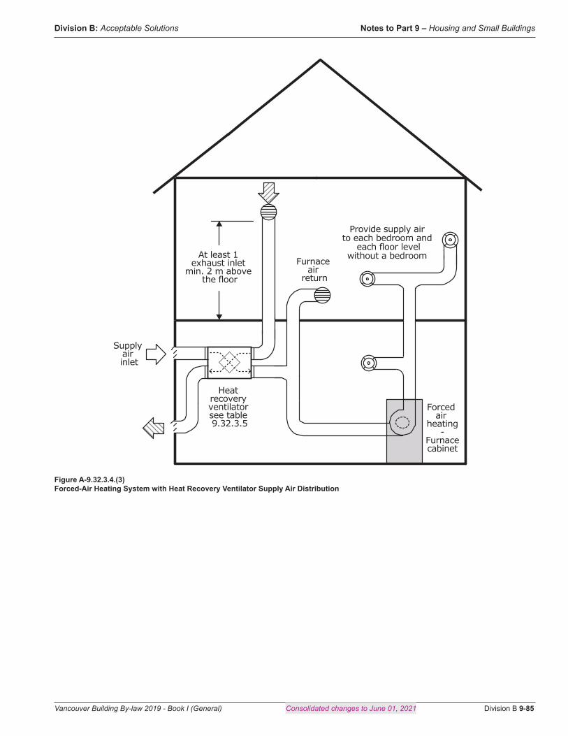
Division B: Acceptable Solutions Notes to Part 9 – Housing and Small Buildings
Vancouver Building By-law 2019 - Book I (General) Consolidated changes to June 01, 2021 Division B 9-85
At least 1 exhaust inlet
min. 2 m above the floor
Furnace air
return
Heat recovery ventilator see table 9.32.3.5
Supply air inlet
Forced air
heating-
Furnacecabinet
Provide supply air to each bedroom and
each floor levelwithout a bedroom
Figure A-9.32.3.4.(3) Forced-Air Heating System with Heat Recovery Ventilator Supply Air Distribution

Notes to Part 9 – Housing and Small Buildings Division B: Acceptable Solutions
Division B 9-86 Consolidated changes to June 01, 2021 Vancouver Building By-law 2019 - Book I (General)
Supply air inlet
Provide supply air to each bedroom and
each floor levelwithout a bedroom
Heat recovery ventilator see table 9.32.3.5
At least 1 exhaust inlet
min. 2 m above the floor
Figure A-9.32.3.4.(4) Heat Recovery Ventilator Supply Air Distribution
Air to a common area
Return air from each bedroom
Used in addition to a principal ventilation system
exhaust fan
Supply air inlet
Figure A-9.32.3.4.(5)(b)(i) Central Recirculation System Supply Air Distribution

Division B: Acceptable Solutions Notes to Part 9 – Housing and Small Buildings
Vancouver Building By-law 2019 - Book I (General) Consolidated changes to June 01, 2021 Division B 9-87
Air from common area
Supply air inlet
Supply air to each bedroom
Used in addition to a principal ventilation system
exhaust fan
Figure A-9.32.3.4.(5)(b)(ii) Central Recirculation System Supply Air Distribution
Supply air inlet
Supply air inlet
Principalventilation system
exhaust fan - see table 9.32.3.5.
At least 1800 mmabove the
floor
Figure 9.32.3.4.(6) Passive Supply Air Distribution
A-9.32.3.4.(6)(a)(ii) Floor Area Calculation for Passive Supply Air Distribution. The floor area to be calculated for Subclause 9.32.3.4.(6)(a)(ii) does not include sun porches, enclosed verandas, vestibules, attached garages, or other spaces that are outside the building envelope and do not require ventilation supply air.
A-9.32.4.1. Naturally Aspirating Fuel-Fired Vented Appliance (NAFFVA). NAFFVA, typically appliances with draft hoods, are subject to back drafting when a negative pressure condition occurs in the dwelling. The following tables describe the conditions under which Sentence 9.32.4.1.(1) applies:

Notes to Part 9 – Housing and Small Buildings Division B: Acceptable Solutions
Division B 9-88 Consolidated changes to June 01, 2021 Vancouver Building By-law 2019 - Book I (General)
Table A-9.32.4.1.(1)-AVent Safety — Natural Gas and Propane
Fuel Type Natural Gas and Propane
Vent Type Power Vent(3) Direct Vent(3) Thermal Buoyancy Chimney(2)
Appliance Type
Furnace Boiler HWT
Fireplace
HWT Fireplace
Heater
Mid-Efficient F/A Furnace or Boiler(5)
Drafthood Boiler HWT(4)
Special Conditions Located in Air-Barriered Room(1)
Classification Non-NAFFVA NAFFVA Non-NAFFVA
9.32.4.1.(1) Applies No Yes NoNotes to Table A-9.32.4.1.(1)A.:(1) Mechanical room must be air-barriered from remainder of house with no access from within house. Room must be lined with panel products
with sealed joints and all pipe and wire penetrations sealed. Effectively, the room must be finished before equipment is installed and holes drilled for pipes and wires. This option is not available for forced air furnaces as it is not possible to effectively seal the ducts.
(2) Thermal buoyancy chimneys must be within the heated envelope of the house to provide acceptable venting performance.(3) Any power vented appliance with pressurized vent (1 pipe) or sealed combustion (2 pipe) or direct vent appliance (fireplace, heater or HWT)
are non-NAFFVA.(4) Mid-efficient (draft induced) appliances are considered NAFFVA with the exception of a boiler or HWT located in an air-barriered room.(5) This category applies only to a) mid-efficient forced air furnaces equipped with induced draft fans and exhaust proving switch, and b) boilers equipped with induced draft fans and exhaust proving switch.
Table A-9.32.4.1.(1)-BVent Safety — Oil and Solid Fuel
Fuel Type Oil Solid
Vent Type Thermal Buoyancy Chimney(2) Direct Vent Thermal Buoyancy Chimney(2) Any
Appliance Type Boiler HWT(4)
F/A Furnace Boiler HWT(3), (4)
F/A Furnace Boiler HWT
Boiler
F/A Furnace Boiler HWT
Fireplace Heat Stove
Outside Boiler
Special Conditions
Located in Air-Barriered
Room(1)
Located in Air-Barriered
Room(1)
Classification Non-NAFFVA NAFFVA Non-NAFFVA Non-NAFFVA NAFFVA(5) N/A
9.32.4.1.(1) Applies No Yes No No Yes(5) No
Notes to Table A-9.32.4.1.(1)B.:(1) Mechanical room must be air-barriered from remainder of house with no access from within house. Room must be lined with panel products
with sealed joints and all pipe and wire penetrations sealed. Effectively, the room must be finished before equipment is installed and holes drilled for pipes and wires. This option is not available for forced air furnaces as it is not possible to effectively seal the ducts.
(2) Thermal buoyancy chimneys must be within the heated envelope of the house to provide acceptable venting performance.(3) Oil-fired HWT, boilers and furnaces equipped with blocked vent switches.(4) Sealed combustion kits can be added to oil-fired appliances but they switch to interior combustion air if intake is blocked and rely on
barometrically dampered thermal buoyancy chimneys so they are considered NAFFVA.(5) Wood-burning appliances certified for use in mobile homes and installed to mobile home installation standards are considered non-NAFFVA
and Sentence 9.32.4.1.(1) does not apply to them.
A-9.32.4.2. Carbon Monoxide Alarms. Carbon monoxide (CO) is a colourless, odourless gas that can build up to lethal concentrations in an enclosed space without the occupants being aware of it. Thus, where an enclosed space incorporates or is near a potential source of CO, it is prudent to provide some means of detecting its presence.
Dwelling units have two common potential sources of CO:
• fuel-fired space- or water-heating equipment within the dwelling unit or in adjacent spaces within the building, and

Division B: Acceptable Solutions Notes to Part 9 – Housing and Small Buildings
Vancouver Building By-law 2019 - Book I (General) Consolidated changes to June 01, 2021 Division B 9-89
• attached storage garages.
Most fuel-fired heating appliances do not normally produce CO and, even if they do, it is normally conveyed outside the building by the appliance’s venting system. Nevertheless, appliances can malfunction and venting systems can fail. Therefore, the provision of appropriately placed CO alarms in the dwelling unit is a relatively low-cost back-up safety measure.
Similarly, although Article 9.10.9.16. requires that the walls and floor/ceiling assemblies separating attached garages from dwelling units incorporate an air barrier system, there have been several instances of CO from garages being drawn into houses, which indicates that a fully gas-tight barrier is difficult to achieve.
When the attached storage garage is located at or below the elevation of the living space, winter season stack action will generate a continuous pressure between the garage and the dwelling unit. This pressure is capable of transferring potentially contaminated air into the house. The use of exhaust fans in the dwelling unit may further increase this risk.
A-9.33.5.3. Design, Construction and Installation Standard for Solid-Fuel-Burning Appliances. CSA B365, “Installation Code for Solid-Fuel-Burning Appliances and Equipment,” is essentially an installation standard, and covers such issues as accessibility, air for combustion and ventilation, chimney and venting, mounting and floor protection, wall and ceiling clearances, installation of ducts, pipes, thimbles and manifolds, and control and safety devices. But the standard also includes a requirement that solid-fuel-burning appliances and equipment satisfy the requirements of one of a series of standards, depending on the appliance or equipment, therefore also making it a design and construction standard. It is required that cooktops and ovens as well as stoves, central furnaces and other space heaters be designed and built in conformity with the relevant referenced standard.
A-9.33.6.13. Return Air System. It is a common practice to introduce outdoor air to the house by means of an outdoor air duct connected to the return air plenum of a forced air furnace. This is an effective method and is a component of one method of satisfying the mechanical ventilation requirements of Subsection 9.32.3. However, some caution is required. If the proportion of cold outside to warm return air is too high, the resulting mixed air temperature could lead to excessive condensation in the furnace heat exchanger and possible premature failure of the heat exchanger. CAN/CSA-F326-M, “Residential Mechanical Ventilation Systems,” requires that this mixed air temperature not be below 15.5°C when the outdoor temperature is at the January 2.5% value. It is also important that the outdoor air and the return air mix thoroughly before reaching the heat exchanger. Note A-9.32.3. provides some guidance on this.
A-9.33.10.2.(1) Factory-Built Chimneys. Under the provisions of Article 1.2.1.1. of Division A, certain solid-fuel-burning appliances may be connected to factory-built chimneys other than those specified in Sentence 9.33.10.2.(1) if tests show that the use of such a chimney will provide an equivalent level of safety.
A-9.34.2. Lighting Outlets. The “Canadian Electrical Code, Part I” which is adopted by the Electrical Safety Regulation, contains requirements relating to lighting that are similar to those in the Building By-law. However, the Electrical Code requirements apply only to residential occupancies, whereas many of the requirements in the Building By-law apply to all Part 9 buildings. Code users must therefore be careful to ensure that all applicable provisions of the Building By-law are followed, irrespective of the limitations in the Electrical Code.
A-9.35.2.2.(1) Garage Floor. Sources of ignition, such as electrical wiring and appliances, can set off an explosion if exposed to gases or vapours such as those that can be released in garages. This provision applies where the frequency and concentration of such releases are low. Where the garage can accommodate more than 3 vehicles, and where wiring is installed within 50 mm of the garage floor, the “Canadian Electrical Code, Part I”, which is adopted by the Electrical Safety Regulation, should be consulted as it specifies more stringent criteria for wiring.The capacity of the garage is based on standard-size passenger vehicles such as cars, mini-vans and sport utility vehicles, and half-ton trucks. In a typical configuration, the capacity of the garage is defined by the width of the garage doors – generally single or double width – which correlates to the number of parking bays.In many constructions, floor areas adjacent to the garage are either above the garage floor level or separated from it by a foundation wall. Where the foundation wall is cast-in-place concrete and rises at least 50 mm above the garage floor, it can serve as the airtight curb. Where the foundation wall is block or preserved wood, extra measures may be needed to provide airtightness. In many instances, the construction will be required to be airtight to conform with Sentence 9.25.3.1.(1), and in any case, must comply with Sentences 9.10.9.16.(4) and (5).Where the space adjacent to the garage is at the same level as the garage, a 50 mm curb or partition is not needed if the wall complies with Sentences 9.10.9.16.(4) and (5), and there is no connecting door. Where there is a connecting door, if the garage is not sloped towards the exterior, it must be raised at least 50 mm off the floor or be installed so it closes against the curb. This requirement does not preclude the installation of a ramp leading from the garage floor up to the door.In some instances, access to the basement is via a stair from the garage. In such cases, a curb must be installed at the edge of the stair

Notes to Part 9 – Housing and Small Buildings Division B: Acceptable Solutions
Division B 9-90 Consolidated changes to June 01, 2021 Vancouver Building By-law 2019 - Book I (General)
well and must be sealed to the foundation wall, curb or partition between the garage and adjacent spaces.See Figure A-9.35.2.2.(1).
GG00529A
Figure A-9.35.2.2.(1) Curb around garage floor at stairs
A-9.37.1.1. Application. The provisions of the Building By-law addressing ancillary residential units are intended to align with Provincial requirements, with minor modification to accommodate the Vancouver development context. Secondary suites, lock-off units, or other forms of housing ancillary to a primary dwelling, are intended to be treated in a uniform fashion, and rely upon a single ownership model in which the principal dwelling unit and ancillary residential unit form a single legal parcel, for which the owner bears the responsibility for the maintenance and safe function of all the contained units. As such, separation requirements normally required between separate suites of residential occupancy are relaxed due to this single ownership relationship.
It is intended that the definition reflects that an ancillary residential unit is an additional dwelling unit of limited size located within a house or row house. Many of the changes in Section 9.37. are premised on the condition of the limited size of the ancillary residential unit, which may directly or indirectly relate to issues such as occupant load, travel distance and egress dimensions.

Division B: Acceptable Solutions Notes to Part 9 – Housing and Small Buildings
Vancouver Building By-law 2019 - Book I (General) Consolidated changes to June 01, 2021 Division B 9-91
The provisions of this By-law address only ancillary residential units in lower density forms of housing which include houses (one and two family dwellings) and row houses in which egress is non-complex, being generally direct to the exterior and at or near grade. Dwelling units that would otherwise meet the definition of ancillary dwelling unit but are in denser or more complex arrangements (such as lock-off units in apartment buildings or strata titled arrangements)should be treated as separate suites of residential occupancy, and therefore comply with the general provisions of Part 3 or Part 9 as applicable.
A-9.37.1.2. Construction Requirements. The requirements of Part 9 of the Building By-law apply to the construction of an ancillary residential unit and the alterations to a building to incorporate an ancillary residential unit, except those specifically referenced in Subsection 9.37.2.
An ancillary residential unit may be constructed in a building that has been in existence for many years that may not comply with current code requirements.
It is not the intent to retroactively apply the current By-law to all existing features in order to permit the construction of an ancillary residential unit in an existing building and the requirements of Part 11 of this By-law may facilitate the construction of such projects.
A-9.37.2.3.(1) Exit Stairs. Existing internal and external stairs that formerly served one dwelling unit may now serve both the existing dwelling unit and the new ancillary residential unit. It is not the intent to apply all current By-law exit stair requirements in order to permit the construction of an ancillary residential unit in an existing building.
A-9.37.2.6. Means of Egress. The additional occupant load created by an ancillary residential unit does not warrant increasing the width of a public corridor, common exit stair or landing used by both dwelling units. The stairs, corridors and landings formerly serving one dwelling unit are likely to be of adequate size to accommodate the occupant load of both suites.
A-9.37.2.8. Openings Near Unenclosed Exit Stairs and Ramps. Unprotected door or window openings in other fire compartments adjacent to exit stairs, ramps and confined paths of travel should be protected from the other suite to provide safe passage to a safe area.
Normally such protection as required by Part 9 would extend both vertically and horizontally beyond the adjacent openings. This is considered excessive due to required fire safety measures and the relatively short travel distances in this type of building. The application of current Part 9 requirements would in many cases require the protection of all openings in entire faces of dwelling units, which could be very restrictive. Authorities should exercise judgment with regard to deciding which openings are close enough to the exit facility to pose a problem during the early stages of a fire and require appropriate opening protection. Those openings that directly pass the means of egress are required to be protected.
A-9.37.2.13. Structural Fire Resistance of Ancillary Residential Units. The provisions of 9.37.2.13. address only the fire-resistive requirements of construction within the ancillary residential unit. The remainder of the requirements of a building, including the need for fire separations that support or separate other floor areas or portions of a building, or of the principal dwelling unit itself, continue to apply.
A-9.37.2.14. Combustible Drain, Waste and Vent Piping. Exposed combustible drain, waste and vent piping that penetrates a fire separation is required to be protected as described. This protection is not required for exposed fixture traps and arms serving fixtures within the suite provided they are not exposed from the underside of a horizontal assembly. The intent is not to require removal of existing combustible piping which, as a result of the creation of an ancillary residential unit , may now be on both sides of a rated fire separation. Rather, the intent is to protect this piping where it is exposed.

Notes to Part 9 – Housing and Small Buildings Division B: Acceptable Solutions
Division B 9-92 Consolidated changes to June 01, 2021 Vancouver Building By-law 2019 - Book I (General)
A-9.37.2.15 Separation of Ancillary Residential Suites. Separations between an ancillary residential unit and its associated principal dwelling unit are not required to be constructed as formal fire separations. Rather, these separations may be constructed with conventional techniques that incorporate low cost materials that will provide a degree of containment for fire, smoke, and sound to the dwelling unit of origin.
Likewise, openings between principal dwelling unit and its contained ancillary residential unit must meet certain minimum construction requirements, but need not be constructed as formal fire separations.
This ‘deemed to comply’ approach replaces the large variety of assemblies that could otherwise be constructed in conformance with Articles 9.10.8.11. and 9.11.1.1. (or their Part 3 and Part 5 equivalents). Where an owner provides assemblies constructed in accordance with the normal residential suite separation requirements, it can readily be seen that the intent of the provisions of 9.37.2.15. have been satisfied.
A-9.37.2.17. Air Ducts and Fire Dampers. In order to prevent the migration of smoke from one suite to another during a fire, heating or ventilation systems incorporating ducts that serve both suites are permitted only if there is a mechanism to prevent smoke being circulated from one unit to the other. It is preferable for the secondary suite to have its own heating system independent of the rest of the building.
Other solutions to providing separate ventilation systems for the dwelling units must address smoke control. Although fire dampers restrict the spread of smoke by automatically closing in the event of a fire, their installation in a ventilation system that serves both dwelling units in a house with a secondary suite is not considered to be an ideal solution because they are very expensive, require regular inspection and maintenance, and must be reset after every activation.
Ventilation for Air Exchange
The provision of a ventilation system for the purpose of maintaining acceptable indoor air quality is a critical health issue. However, Sentence 9.37.2.17.(2) allows exits and public corridors serving ancillary residential units in residential buildings containing not more than 2 principal dwelling units to be unventilated. Lack of active ventilation of these spaces is considered acceptable because occupants do not spend long periods of time there and because exits are somewhat naturally ventilated when doors are opened.
Considering the cost of installing separate ventilation systems, Sentence 9.37.2.17.(2) also exempts ancillary spaces serving ancillary residential units in residential buildings containing not more than 2 principal dwelling units from the requirement to be ventilated, provided that ventilation system supply air is supplied in accordance with Article 9.32.3.4.
A-9.37.2.19. Smoke Alarms. This Article requires an interconnected photoelectric smoke alarm in each suite where fire separations having a fire-resistance rating of 30 min are used. The purpose of these interconnected alarms is to provide early warning to both suites in the event of a fire in one suite. Photoelectric type alarms are required as they are less prone to nuisance false alarms such as can occur during cooking, but careful consideration is still required as to their location.
It is important to note that these alarms are additional to the requirements of Subsection 9.10.19. and that each suite is still required to be provided with alarms in conformance with Subsection 9.10.19.
The additional smoke alarm should not be interconnected to the other smoke alarm(s) located within the same suite.
This additional smoke alarm system is not required when the fire-resistance ratings required in Articles 9.10.9.14. and 9.10.9.15. are not reduced, or when the building is sprinklered.
A-9.37.2.20. Sound Control. Controlling sound transmission between dwelling units is important to the occupants’ health and well-being. Meeting the By-law’s level of sound transmission for ancillary residential units may be difficult and expensive, particularly in an existing building. As there is single ownership of both dwelling units, this requirement is not mandatory, but designers are encouraged to take the subject into consideration where feasible. A somewhat reduced level of performance is acceptable in the case of secondary suites because the occupants of the house containing a secondary suite are only affected by the sound of one other unit and, in many cases, it is the owner of the house who will decide on the desired level of protection. Sound resistance can be improved by selecting furnishings and finishings that absorb sound, such as carpet.
Rev. 12683
Rev. 12683
Rev. 12683