Green maintenance for historic masonry buildings: an emerging concept
Upload
khangminh22Category
view
0download
0
Project for Investigation of Damage Situation of Cultural Heritage in Nepal
2015 Project for International Contribution to Cultural Heritage Protection
Structural Survey of Historic Buildings
October 2016
Tokyo National Research Institute for Cultural Properties

2015 Project for International Contribution to Cultural Heritage Protection:
Project for Investigation of Damage Situation of Cultural Heritage in Nepal
Structural Survey of Historic Buildings
Published in October, 2016
© Japan Center for International Cooperation in Conservation,
Tokyo National Research Institute for Cultural Properties
Address: 13-43, Ueno-Koen, Taitoku, Tokyo- 1108713
Telephone: +81. (0)3.3823.4898
Fax: +81. (0)3. 3823. 4867
Website: http://www.tobunken.go.jp/~kokusen/ENGLISH/center.html
All rights reserved

Masahiko Tomoda
Head of Conservation Design Section
Japan Center for International Cooperation in Conservation
Tokyo National Research Institute for Cultural Properties
This report is the result of an investigation of cultural heritage damage caused by the Gorkha
Earthquake on 25 April 2015. The project was commissioned by the Agency for Cultural Affairs and
implemented by the Tokyo National Research Institute for Cultural Properties (TNRICP).
In this project, investigations were conducted from comprehensive viewpoints including
architectural history, building structure, urban design, conservation and preservation, and intangible
cultural heritage by researchers from Nippon Institute of Technology, the University of Tokyo, Kagawa
University, Tokyo Metropolitan University, Tohoku Institute of Technology, and TNRICP, as well as
outside experts in cultural heritage conservation.
This volume is the result of "Structural Survey of Historic Buildings" conducted at Jaganath
Temple and Gopinath Temple, which are representative multi-tiered towers (Mandir), in Hanuman
Dhoka Durbar Square that was inscribed on the World Heritage List.
Preface


Preface.................................................................................................................... iiiContents................................................................................................................... v1..Survey.Purpose.and.Overview............................................................................... 32..Detailed.Building.Survey2.1..Jagannath.Temple........................................................................................... 72.2..Gopinath.Temple........................................................................................... 132.3..Building.material.and.construction.method.................................................... 183..Earthquake.Damage.3.1..Structure.of.the.multi-tiered.tower................................................................. 233.2..Damage.of.Jagannath.Temple........................................................................ 243.3..Damage.of.Gopinath.Temple.......................................................................... 254..Micro-tremor.Measurement4.1..Jagannath.Temple......................................................................................... 304.2..Gopinath.Temple........................................................................................... 365..Structural.Analysis5.1..Seismic.performance.evaluation..................................................................... 455.2..Seismic.performance.of.Jagannath.Temple..................................................... 475.3..Seismic.performance.of.Gopinath.Temple...................................................... 516..Summary.of.the.result.and.Seismic.Reinforcement.Plan6.1..Summary.of.the.result................................................................................... 576.2..Structural.reinforcement.plan........................................................................ 577...Issues.for.the.Future.Research7.1..Collecting.data.for.analysis............................................................................ 617.2..Structural.tests.on.bricks............................................................................... 617.3..Structural.test.on.timber................................................................................ 64
Appendix.:.The.structual.drawings.of.Jagannath.and.Gopinath.Temples
Attached.DVD:.Results.of.Micro-tremor.measurement....A.1.-.A.16.Jagannath.Temple....A.17-.A.36.Gopinnath.Temple
v
Contents

vi

1. Survey Purpose and Overview


1. Purpose and Overview of the Survey
The devastation caused by the Gorkha Earthquake in Nepal was characterized to some extent
in prior surveys by virious researchers. Referring to information obtained in these prior surveys, this
structural survey focused on identifying earthquake weaknesses in Nepal’s traditional buildings, which
have mainly mixed structures comprised of brick and timber. Both observation and technical analysis
techniques were used. Among the multi-tiered towers (Pagoda, Mandir), which is one of representive
type of historical buildings, Jagannath and Gopinath temples were selected for detailed survey as a typical
example of dvastation. Selected buildings were measured and scaled drawings were created. Details
regarding the point and extent of devastation and the stability and materials (brick and timber) of the
building structure were carefully recorded. Results from this survey should contribute to preservation and
restoration planning.
On the occasion of the field survey, we performed micro-tremor measurement and survey on the
situation of devastation, with the surveys on construction system and building materials, in order to obtain
the information for verifying the structural performance of subject buildings by more accurate structural
analysis model. The selected area of 3D measurement and an example of measurement results are shown
In Fig.1-1 and Fig.1-2.
The survey period, primary activities, and participating investigators were as follows:
Survey periods: 24–31 November 2015 3D and micro-tremor measurements
24–28 December 2015 Building and material survey
Investigators: Koshihara Laboratory, Institute of Industrial Science, the University of Tokyo
Takiyama Laboratory, Tokyo Metropolitan University
Miyamoto Laboratory, Kagawa University
3

Fig.1-1 The selected area for 3D measurement (Red line)(The area inside dotted line includes the rooms that have not researched yet. )(Quoted from Niels Gutschow, ARCHITECTURE OF THE NEWARS: A History of Building Typologoes and Details in Nepal, Volume II The Malla Period, Serindia Publications, Chicago, 2011, p.344 and retouched by the editor.)
Fig.1-2 The selected area for 3D measurement depicted using actual survey results
4

2. Detailed Building Survey


2. Detailed Building Survey
7
The Multi-tiered tower is a common architectural style in Nepal’s temples. For understanding its
features, a detailed survey was conducted at Jagannath and Gopinath Temples that are multi-tiered towers
and suffered typical damage from the Gorkha Earthquake.
2.1. Jagannath Temple
The building description of Jagannath Temple and proposed repairs by「John Sanday,
KATHMANUDU VALLEY: Nepalese historic monuments in need of preservation, Unesco, 1982」 are
followings.
Jagannath: B/K-174
(Two-tiered temple)
Location: Hanuman Dhoka
Constructed: First half of seventeenth century
Renovated: 1938 and 1968
Deity: Vishnu
Religion: Vaishnava
Records: 1633 and 1654
Building description
The temple, which is located just outside the main palace gate at Hanuman Dhoka, is
considered to be one of the best examples in this style. The broad square sanctum base has threefold
doorway openings on all four sides. The intricately carved struts supporting the two roofs display figures
from the Hindu pantheon; at their base are some good samples of erotica. The carving on the doors and
windows is also of good quality. The brickwork beneath many layers of paint is the traditional Telia
brick. At each corner of the upper podium are small two-tiered shrines of similar design. On the eastern
face of the pedestal there is an inscription of Pratap Malla in praise of the goddess Bhawani written in
fourteen different scripts. The temple was built during the reign of King Lakshminarasimha Malla.
Proposed repairs
This is a temple of great importance needing careful cleaning, repair and conservation. Over
the years it has collected several layers of paint and dirt, marring its architectural beauty. A major repair
programme will be necessary. It is likely that some structural consolidation and repair will be required to
the roofs. The roof covering as well as the carvings will require proper chemical treatment.

8
For the Jagannath Temple, structural drawings that included each storey’s the framing plan of
each storey and elevation, an X-Y cross section, brick details, and more were created from the detailed
survey. The basic dimensions of the building and section were also recorded. Table2-1-1 shows the list
of the structural drawings.
Number Name of the drawings Scale Note1 Floor plan of pillars and wall, 1st storey 1:1002 Plan of struts of the 1st tier and joists, 2nd storey 1:100 Position of knee brace in 2nd storey3 Plan of rafters of the 1st tier 1:100 Position of rafter in 2nd storey4 Plan of struts of the 2nd tier and joists, 3rd storey 1:100 Position of knee brace in 3rd storey5 Plan of ridge beams, 3rd storey 1:100 Position of girder in 3rd storey6 Plan of rafters of the 2nd tier 1:100 Position of rafter in 3rd floor7 North elevation 1:100 Keeping the horizontal of 3D scan data8 East elevation 1:100 Keeping the horizontal of 3D scan data9 West elevation 1:100 Keeping the horizontal of 3D scan data10 South elevation 1:100 Keeping the horizontal of 3D scan data11 Section of X (NS) direction 1:100 Drawing podium as horizontal12 Section of Y (EW) direction 1:100 Drawing podium as horizontal13 Size of bricks 1:10
Tab.2-1-1 The list of the structural drawings (Jagannath Temple)

9
<Structure>
Plan of the first storey and section of Jagannath temple are shown in Fig.2-1-1.
There are brickwork walls at outer and inner of the first storey. The dimension of bricks are
W250mm, D160mm, H60mm (glazed) at the outer wall, and W225mm, D110mm, H60mm (unglazed) at
the inner wall (Fig.2-1-2)
The roof truss of the top storey is timber structure, and the roof beams are installed by hollowing
out the brick walls.
Masonry Joint : 10-15mm Masonry Joint : 10-15mm
Outer wall of the first storey(Glazed brick)
Inner wall of the second storey(Unglazed brick)
Fig.2-1-1 Jagannath Temple (Quoted from Niels Gutschow, ARCHITECTURE OF THE NEWARS: A History of Building Typologoes and Details in Nepal, Volume II The Malla Period, Serindia Publications, Chicago, 2011, p.417 and retouched by the editor.)
Fig.2-1-2 Brick size and the location in Jagannath Temple (Detail of bricks)
The 1st storey
The 2nd storey
The 3rd storey
①
②
③
④
⑤⑥
The number of the structural drawings
The 1st tier
The 2nd tier
The Plan of the first storey Section

10
Fig.2-1-3 The list of the structural drawings of Jagannath Temple
01-Floor plan of pillars and wall, 1st storey 02-Plan of struts of the 1st tier and joists, 2nd storey
03-Plan of rafters of the 1st tier
04-Plan of struts of the 2nd tier and joists, 3rd storey
05-Plan of ridge beams, 3rd storey 06-Plan of rafters of the 2nd tier
07-North elevation 08-East elevation 09-West elevation
10-South elevation 11-Section of X (NS) direction 12-Section of Y (EW) direction
13-Size of bricks

11
<Reference materials>
Niels gutschow, ARCHITECTURE OF THE NEWARS :A History of Building Typologoes and
Details in Nepal, Volume II The Malla Period, Serindia Publications, Chicago, 2011
(Quoted from p.414)
History
The inscription on the pedestal of the Caturvyuha (“four kinds of appearances”) Visnu in the
sanctum testifies to the consecration of the image by Mahendramalla in January 1563. The stele, placed
in a large jalahari with its spout facing north, features Vasudeva with club and disk (east, epithet of Krsna
as the son of Vasudeva), Sankarsana with plough (south, also understood as an epithet of Balarama, the
elder brother of Krsna) Pradyumna with bow and arrow (west, son of Krsna), and Aniruddha with shield
and sword (north, Pradyumna’s son).
Very probably, the consecration of the four-fold deity marked the completion of the
construction, which must have been started by King Mahendramalla in 1561 a few months after
ascending the throne. A similar temple with a Caturvyuha Visnu stele was consecrated in 1565 by King
Purandarasimha in Patan, albeit based on a slightly smaller plan.
It is unknown when the identification of the temple with the “four kinds of appearances” of
Visnu received a new layer dominated by Jagannatha, the Lord of the Universe from Puri, the sacred
place that punctuates one of the four cornaers of India, the Cardham. King Sidhinarasimhamalla from
Patan, who had relinquinshed the throne in 1652 to undertake a pilgrimage to Kasi (Benares) was
probably the first to undertake a pilgrimage to Puri in the 1660s, followed by King Jagatprakasamalla
from Bhaktapur in 1670. A painting preserved in the Victoria and Albert Museum in London documents
this visit, stating that the Anandavrata observance was completed during the month of Bhadra (August/
September).
The early temples of Puri were dedicated to Vasudeva, which among the Caturvyuha of Visnu
faced east. Not before the 14th century, Vasudeva was replaced by Hinduised tribal gods, the Wooden
Triad of Jagannatha, Krsna or Visnu as the Lord of the World, in th company of his sister Subhadra
and his elder brother Balabhadra. Jagannatha became the uncontested imperial god (rastradevata) of
the Ganga dynasty of Orissa. With the collapse of the empire, the “Little Kings” of Orissa started to
establish Jagannatha temples from the early 17th century onwards in close neighbourhood to their
palaces. An early identification of the Caturvuha temple in Kathmandu with Jagannatha can be seen
mirroring this trend, which was encouraged by the Pax Britannica after 1803. The early identification
with Jagannatha might have been substantiated by the donation of the four aspects of Visnu worked
in gilt copper repousse which cover the four sides of the stele in the month of Asadha (July), recalling
Jagannatha’s annual ritual journey to Gundica.
The Wooden Triad must have arrived from Orissa some time in the late 18th or even early 19th
century to be somewhat provisionally placed into the eastern doorway of the inner quadrangle of the
temple.

12
The structure
Among the seven early two-tiered temples with an inner ambulatory which date to the 13th
to 16th century, this is only one in Kathmandu to rank among the smallest. Its only rival is in Patan,
the Carnarayana, which is considerably smaller. The quadrangle, the length of which measures 830
centimtres, is raised on an almost two metres high, triple-stepped plinth. The second step extends
diagonally to accommodate four pavilion-like two-tiered temples facing the east-west axis – a pancayana
configuration that added Mahadeva, Ganasa, Surya and Durga to the central representation of Visnu.
The portals with their triple openings have survived almost completely in their original form,
which date to 1563, and are flanked by aedicules. The rympana do not necessarily match the original
structure, of which in the 1934 earthquake only the northern quarter of the upper roof collapsed.
With the placement of the Wooden Triad in the doorway of the inner quadrangle, two walls
must have be added to block the inner ambulatory. Since that time the deities are exclusively (but
at present rarely) accessible from the east, while the central stele featuring the Caturvyuha Visnu is
accessible from the south. Early 19th-century photographs also reveal the blocking of the secondary
doorways of the portals by walls, probably to improve the stability of the structure. The lower roof is
supported by the “24 forms of Visnu” (caturvimsatimurti): with four heads and up to eight arms, the
four chief attributes of the deity can be arranged in 24 different ways, each of them being regarded as a
particular aspect of Visnu.
Two years after the 1934 earthquake the roofs were renewed, the veneer bricks of the ground
floor were relaid up to a height of one metre in lime and brick dust mortar, and above that in mud mortar.
The inner face of the wall was replaced by standardized desiapa with the frog stamped “Sri Tin Juddha
Samser.” The rafters were fixed with a separate wooden bolt and the wooden cornice above the lower
roof partly replaced by one moulded in lime and brick dust mortar. In 1998 part of the roof collapsed
and was hastily renewed with undersized rafters at large intervals. In 2001 the roofs were again renewed
by the Kathmandu Valley Preservation Trust, with rafters measuring the historical standard of 11 x 17
centimetres in section at a spacing of 17 centimetres. Structural details were not changed, but the cornice
replaced in wood and paint removed from all woodwork. The plinth was restored to its original extent,
newly paved, and the steps lined in stone.
13
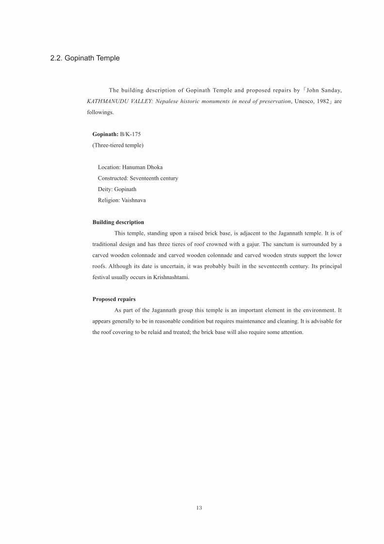
2.2. Gopinath Temple
The building description of Gopinath Temple and proposed repairs by「John Sanday,
KATHMANUDU VALLEY: Nepalese historic monuments in need of preservation, Unesco, 1982」 are
followings.
Gopinath: B/K-175
(Three-tiered temple)
Location: Hanuman Dhoka
Constructed: Seventeenth century
Deity: Gopinath
Religion: Vaishnava
Building description
This temple, standing upon a raised brick base, is adjacent to the Jagannath temple. It is of
traditional design and has three tieres of roof crowned with a gajur. The sanctum is surrounded by a
carved wooden colonnade and carved wooden colonnade and carved wooden struts support the lower
roofs. Although its date is uncertain, it was probably built in the seventeenth century. Its principal
festival usually occurs in Krishnashtami.
Proposed repairs
As part of the Jagannath group this temple is an important element in the environment. It
appears generally to be in reasonable condition but requires maintenance and cleaning. It is advisable for
the roof covering to be relaid and treated; the brick base will also require some attention.
14
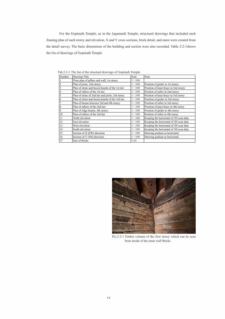
For the Gopinath Temple, as in the Jagannath Temple, structural drawings that included each
framing plan of each storey and elevation, X and Y cross sections, brick detail, and more were created from
the detail survey. The basic dimensions of the building and section were also recorded. Table 2-2-1shows
the list of drawings of Gopinath Temple
Number Drawing Title Scale Note1 Floor plan of pillars and wall, 1st storey 1:1002 Plan of joists, 2nd storey 1:100 Position of girder in 1st storey3 Plan of struts and fascia boards of the 1st tier 1:100 Position of knee brace in 2nd storey4 Plan of rafters of the 1st tier 1:100 Position of rafter in 2nd storey5 Plan of struts of 2nd tier and joists, 3rd storey 1:100 Position of knee brace in 3rd storey6 Plan of struts and fascia boards of the 3rd tier 1:100 Position of girder in 3rd storey7 Plan of beams between 3rd and 4th storey 1:100 Position of rafter in 3rd storey8 Plan of rafters of the 2nd tier 1:100 Position of knee brace in 4th storey9 Plan of ridge beams, 4th storey 1:100 Position of girder in 4th storey10 Plan of rafters of the 3rd tier 1:100 Position of rafter in 4th storey11 North elevation 1:100 Keeping the horizontal of 3D scan data12 East elevation 1:100 Keeping the horizontal of 3D scan data13 West elevation 1:100 Keeping the horizontal of 3D scan data14 South elevation 1:100 Keeping the horizontal of 3D scan data15 Section of X (EW) direction 1:100 Drawing podium as horizontal16 Section of Y (NS) direction 1:100 Drawing podium as horizontal17 Size of bricks 1:10
Tab.2-2-1 The list of the structual drawings of Gopinath Temple
Pic.2-2-1 Timber column of the first storey which can be seen from inside of the inner wall Bricks

15
01-Floor plan of pillars and wall, 1st storey 02-Plan of joists, 2nd storey 03-Plan of struts and fascia boards of the 1st tier
04-Plan of rafters of the 1st tier 005-Plan of struts of 2nd tier and joists, 3rd storey 06-Plan of struts and fascia boards of the 3rd tier
07-Plan of beams between 3rd and 4th storey 08-Plan of rafters of the 2nd tier 09-Plan of ridge beams, 4th storey
10-Plan of rafters of the 3rd tier 11-North elevation 12-East elevation
13-West elevation 14-South elevation 15-Section of X (EW) direction
16-Section of Y (NS) direction 17-Size of bricks
Fig.2-2-1 The list of the structural drawings of Gopinath Temple

16
<Structure>
Plan of the first storey and the section of Gopinath Temple are shown in Fig. 2-2-2.
There are brickwork walls at the outer and inner walls of the first storey. The dimension of brick
is W210mm, D115mm, H55mm (glazed, cuneiformed) at the outer wall, and W225mm, D110mm, H60mm
(unglazed) at the inner wall(Fig.2-2-3). The roof truss of the top storey is timber structure, and the roof
beams are crossed hollowing out the brick walls.
Exterior Interior
Masonry Joint : Nothing Masonry Joint : 10-15mm
Masonry Joint : about 15mm Masonry Joint : 5-10mm Masonry Joint : unidentified
The first storey Exterior(Glazed brick) The first storey Interior(Unglazed brick)
The second storey(Unglazed brick)
The third storey(Unglazed brick)
The third storey (2)(Unglazed brick)
Fig.2-2-2 Gopinath Temple(Quoted from Niels Gutschow, ARCHITECTURE OF THE NEWARS: A History of Building Typologoes and Details in Nepal, Volume II The Malla Period, Serindia Publications, Chicago, 2011, pp.481-482 and retouched by the editor.)
Fig.2-2-3 Brick size and location in Gopinath Temple (Detail of bricks)
The Plan of the first storey Section
The 1st storey
The 2nd storey
The 3rd storey
①②
③
④
⑤⑥⑦
⑧⑨⑩
The 1st tier
The 2nd tier
The 3rd tier
The number of the structural drawings
The 4th storey

17
<Reference materials>
Niels Gutschow, ARCHITECTURE OF THE NEWARS:A History of Building Typologoes and
Details in Nepal, Volume II The Malla Period, Serindia Publications, Chicago, 2011
(Quoted from p.481)
History
Established at the end of the 17th or even early 18th century, this triple-tiered temple with an
ambulatory with twelve pillars represents the most common temple type which evolved from the early
17th century on.
The original Visnu idol has survived; the daily puja is performed by Misra Brahmins from the
neighbouring quarter of Maru.
The temple collapsed in the 1934 earthquake and was subsequently re-erected in a much amended
shape by the overseer and restored to its original shape by the Kathmandu Valley Preservation Trust.
The Structure
The square sanctum on the stepped plinth is accessible from the east across eleven steps,
decorative doors on the other side as well as eight aedicules, columns niches with representations of
the guardians of the directions, thus avoiding a hierarchy among the four sides. Most striking is the
introduction of struts with an interval of blank surface between the presentation of two-handed deities
and caryatid-like supporting apsaras.Across this plain surface spans a decorative bar with kulan pattern,
suggesting the existence of latticework.
After the 1934 earthquake, the ground floor wall was plastered, and the surface of it painted with
a brick pattern. Twenty-two of the old struts were re-used but shortened to rest on a projecting course of
bricks – a configuration which distorted the proportions of the temple considerably. For the surface of
the upper walls maapa were used; the struts supporting the uppermost roof were reused from a collapsed
temple.
In 2003 the Kathmandu Valley Preservation Trust dismantled al the roofs and the brickwork
above the cornice on the top of the lower roof. The pillars, beam and cornice on top were kept in situ, and
the plinths and the wall of the sanctum refaced with veneer bricks (datiapa), leaving the doors in their
fragmented shape without the outer puratva, frame and without the usual widened inner frame. Based on
the evidence of the blank intermediate surface and of 19th century photographs, the original configuration
with latticework and dividing bar was restored. To achieve that, the struts had to be lengthened.

18
2.3. Building material and construction method
2.3.1. Building material
The main materials of buildings are brick and timber.
(1) Brick
Burned brick is used. According to 「Purusottam Dangol, Elements on Nepalese Temple
Architecture, Adroit Publishers, 2007」, major types of bricks are as below.
Ma≂ apa≂ Traditional brick with one end and one edge glazed.
Ba≂ apa≂ Moulded and decorated brick
Kūapa≂ Corner brick
Dachīapa≂ It is both wedged and glazed.
Measurement results of weight, size, and shape of new bricks for repair which is equivalent to
Dachīapa≂ are shown in Table 2-3-1.
Tab.2-3-1 Weight, size and shape of bricks
Pic.2-3-1 Bricks for repairing Pic.2-3-2 Appearance of measurement of weight, size and shape of th bricks
Weight(kgf) − Area (a+b+c+d)/4 Volume DensityA B C D a b c d − mm2 mm cm3 g/cm3
Trapezium 1 2.33 190 130 214 130 47 45 60 58 − 26148 52.5 1373 1.70Trapezium 2 2.078 184 123 204 125 43 46 58 58 − 23857 51.3 1223 1.70Trapezium 3 2.104 188 122 205 122 46 48 58 58 − 23915 52.5 1256 1.68Trapezium 4 2.008 185 124 205 125 45 44 57 56 − 24169 50.5 1221 1.65Trapezium 5 2.334 194 130 212 127 48 50 59 58 − 25657 53.8 1379 1.69Trapezium 6 2.008 188 125 203 123 45 42 55 56 − 23982 49.5 1187 1.69Trapezium 7 2.286 190 128 210 130 47 46 55 56 − 25593 51.0 1305 1.75Trapezium 8 2.062 180 124 205 123 43 40 56 57 − 23633 49.0 1158 1.78Trapezium 9 2.082 180 120 200 126 42 40 55 57 − 22220 48.5 1078 1.93Trapezium 10 2.224 191 126 208 125 45 45 57 57 − 24937 51.0 1272 1.75Trapezium Avera 2.152 187 125.2 206.6 125.6 45.1 44.6 57 57.1 − 24411 51.0 1245 1.73
Size(mm)
AB
C
Da b
cd

19
Pic.2-3-3 The shape of bricks for repairing the damaged temples near Jaganannth Temple
Appearance of brick for repairing ABCD side
C side D side
A side B side

20
(2) Timber
Main tree species are Agrak (Sal) for the structural frame, and Salla (Pine) for the hidden
members.
(3) Material characteristics
Material characteristics which are presumed by former surveys and analyses are shown in
Table2-3-2.
2.3.2. Construction method
The Floor and roof (Horizontal plane):
The floor and roof which have function as horizontal plane are constructed with timber. Timber
member which is orthogonal to the member on the top of the wall is fixed with timber wedge from both
sides.
Variable Burned Brick Mortar WoodMass density 1.8x10³ - 7.0 x 10²
Young’s Modulus(N/m2) 2.7x10⁸ 2.7x10⁸ 6.3 x 10⁸
Poisson’s ratio 0.11 0.25 0.3Tensile strength(N/m2) - 0 1.1 x 10⁸
Shear strength(N/m2) - 9.0 x 10⁴ 9.0 x 10⁶
Friction angle φ - 42.5° 0°Compressive strength (N/m2) - 1.58 x 10⁶ 4.5 x 10⁷
Tab.2-3-2 Material characteristics (Quoted from Disaster Risk Management for the Historic City of Patan, Nepal, R-DMUCH, March 2012, p.98)
Pic.2-3-4 Joint corner between walls and floor (Timber element which is orthogonal to the element on the top of the wall is fixed with the timber wedge from both sides.)

3. Earthquake Damage


3. Earthquake Damage
23
3.1. Structure of the multi-tiered tower
The main structure of multi-tiered tower in the Jagannath and Gopinath Temples were constructed
using brick walls and timber frames. Considering a building’s structure to resist its own weight, those
could be classified into the following three types: (A) buildings primarily constructed with brick walls, (B)
buildings primarily constructed with timber frames, and (C) buildings whose timber frames are built inside
brick walls. Among these classifications, Building type C suffer fewer total building collapses because
the timber frames resist their own weight despite collapse and loss of structural function of the brick
walls, as shown in Pic. 3-1-1. The mixed structural system characteristics of multi-tiered tower of Newar
architecture likely contribute to their superior seismic performance.
Pic.3-1-1 Changu Narayan Temple structure saved from collapse by the timber columns inside of the brick wall

24
3.2. Damage of Jagannath Temple
As shown in Pic. 3-2-1 damage to the Jagannath Temple following the Gorkha Earthquake was
concentrated in the third (top) storey of the building. The shear failure of the brick walls appeared at the
cut-out for the roof beam. The shear failure was concentrated in the joint between bricks; failure of the
brick itself was not observed.
Jagannath Temple was collapsed by Nepal-Bihar earthquake in 1934 and rebuilt.
Pic.3-2-1 Earthquake damage to Jagannath Temple
Third.(top).storey:.Brick.wall.damage Third.(top).storey:.Crack.from.the.cut-out.for.the.beam.(1)
Third.(top).storey:.Crack.from.the.cut-out.for.the.beam.(2)
Second.storey:.Slight.damage.to.inside.and.outside.wall
Second.storey:.Slight.damage.to.inside.wall
First.storey:.Slight.damage First.storey:.Slight.damage Annex.towers:.Heavy.damage
*Nepal–Bihar earthquake “ The 1934 Nepal–Bihar earthquake was one of the worst earthquakes
in the history of Nepal and Bihar, India. This 8.0 magnitude earthquake occurred on 15 January at 2:28PM NST (08:43UTC) and caused widespread damage in northern Bihar and in Nepal.
The epicentre for this event was located in eastern Nepal about 9.5 km (5.9 mi) south of Mount Everest. The areas where the most damage to life and property occurred extended from Purnea in the east to Champaran in the west (a distance of nearly 320 km (200 mi)), and from Kathmandu in the north to Munger in the south (a distance of nearly 465 km (289 mi)). The impact was reported to be felt in Lhasa to Bombay, and from Assam to Punjab. The earthquake was so severe that in Kolkata, around 650 km (404 mi) from epicenter, many buildings were damaged and the tower of St. Paul's Cathedralcollapsed”(Quoted from Wikipedia, https://en.wikipedia.org/wiki/1934_Nepal%E2%80%93Bihar_earthquake, accessed 15 August 2016)
Pic.3-2-2 The Hanuman Dhoka Palace after 1934 Nepal-Bihar earthquake (the temple at rear-right side is Jagannath Temple)
Source: Brahma Shumsher Jung Bahadur Rana, Ratna Pustak Bhandar, The Great Earthquake in Nepal 1934 A.D., Kathmandu, Nepal, 2013

25
3.3. Damage of Gopinath Temple
As shown in Fig. 3-3-1, the Gopinath Temple was supported with a temporary column and
knee brace as an emergency measure against the earthquake damage. The knee brace provided additional
support at the east and south sides of the structure; residual deformation to the east or southeast direction
was likely. As shown in Pic. 3-3-1, structural damage to the Gopinath Temple was concentrated in the first
storey. Primary structural damage included collapsed brick wall joints, peeled inner wall plaster, and fallen
timber beams at the periphery. Conversely, wall damage in the second and third storey was not observed.
Third.storey:.Slight.outer.wall.damage Second.storey:.Slight.inner.wall.damage
First.storey:.Peering.plaster.from.inner.wall.and.damage.at.the.mesonry.joint
First.storey:.Damage.at.the.mesonry.joint.at.outer.wall
Timber.beam.coming.out.from.the.colomn
Pic.3-3-1 Earthquake damage to Gopinath Temple
The 1st storey
The 2nd storey
The 3rd storey
The 4th storey
Fig3-3-1 The supports as an emergency measure implemented to Gopinath Temple


4. Micro-tremor Measurement


4. Micro-tremor Measurement
29
Micro-tremors were measured to identify the natural frequency and vibration mode of each
subject building. Multiple measurements were taken: one on free ground, one on the stepped plinth, and
several inside the buildings. The measurement point on free ground was at the front of the building. The
measurement point on the stepped plinth was intended to detect any vibration amplification by the stepped
plinth structure. Measurement points inside the buildings were at the top of the wall, on the beam, and
on each storey close to a structural wall. The measurements were obtained using a portable vibration
monitoring system (SPC-51) and servo-velocity meters (VSE-15D) produced by Tokyo-Sokushin.
Pic.4-0-1 Portable vibration monitoring system (SPC-51)
Pic.4-0-2 Servo-velocity meters (VSE-15D)

30
4.1. Jagannath Temple
Micro-tremor measurements were performed on Jagannath Temple, as shown in Pic.4-1-1, from 2
to 3 December, 2015. Two horizontal components of vibration were measured at the center of the walls of
each storey.
Measurement case, starting time (in Japan Standard Time), and measuring direction are shown in
Table 4-1-1. 16 cases of measurements were performed.
(a) External appearance (b) Outer corridor at the first storey
(c) Outer corridor at the second storey (d) The third storey
Pic.4-1-1 Jagannath Temple

31
All measurement points are shown in Fig.4-1-1. All measurement points were monitored by
dividing into 16 cases shown above. Multiple measurements were taken: one on free ground, and several
inside the buildings. The measurement point on free ground was at the front of the building, shown in
Pic.4-1-2(a). The measurement point on the stepped plinth was also intended to confirm the amplification
of the vibration by the stepped plinth. Measurement points inside the building were at the top of the wall,
on the beam, and on each floor close to a structural wall. Since it was difficult to put the sensor on the top
of the wall at the top storey, we placed it on the beam beside the wall as shown in Pic.4-1-2(b).
Case Start time(in JST) Direction
1 2nd December, 2015, 21:42:51:00 EW
2 2nd December, 2015, 22:07:03:10 NS
3 2nd December, 2015, 22:22:43:06 NS
4 2nd December, 2015, 22:37:49:00 EW
5 2nd December, 2015, 23:05:22:46 EW
6 3rd December, 2015, 00:12:48:46 EW
7 3rd December, 2015, 00:33:04:00 NS
8 3rd December, 2015, 00:48:29:17 NS
9 3rd December, 2015, 01:14:43:00 NS
10 3rd December, 2015, 01:27:44:00 NS
11 3rd December, 2015, 01:51:57:35 EW
12 3rd December, 2015, 02:02:22:00 EW
13 3rd December, 2015, 02:29:40:39 EW
14 3rd December, 2015, 02:41:10:15 EW
15 3rd December, 2015, 03:05:21:32 NS
16 3rd December, 2015, 03:18:02:13 NS
Tab.4-1-1 Measurement cases, start time and measuring direction
Fig.4-1-1 All measurement points on Jagannath Temple
Floor level of the first storey(Stepped plinth level)
Stepped plinth
(GL )
N
Floor level of the second storey
Floor level of the third storey Beam level of the third storey
32
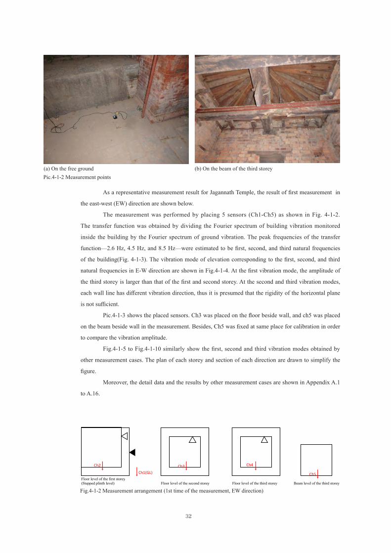
As a representative measurement result for Jagannath Temple, the result of first measurement in
the east-west (EW) direction are shown below.
The measurement was performed by placing 5 sensors (Ch1-Ch5) as shown in Fig. 4-1-2.
The transfer function was obtained by dividing the Fourier spectrum of building vibration monitored
inside the building by the Fourier spectrum of ground vibration. The peak frequencies of the transfer
function—2.6 Hz, 4.5 Hz, and 8.5 Hz—were estimated to be first, second, and third natural frequencies
of the building(Fig. 4-1-3). The vibration mode of elevation corresponding to the first, second, and third
natural frequencies in E-W direction are shown in Fig.4-1-4. At the first vibration mode, the amplitude of
the third storey is larger than that of the first and second storey. At the second and third vibration modes,
each wall line has different vibration direction, thus it is presumed that the rigidity of the horizontal plane
is not sufficient.
Pic.4-1-3 shows the placed sensors. Ch3 was placed on the floor beside wall, and ch5 was placed
on the beam beside wall in the measurement. Besides, Ch5 was fixed at same place for calibration in order
to compare the vibration amplitude.
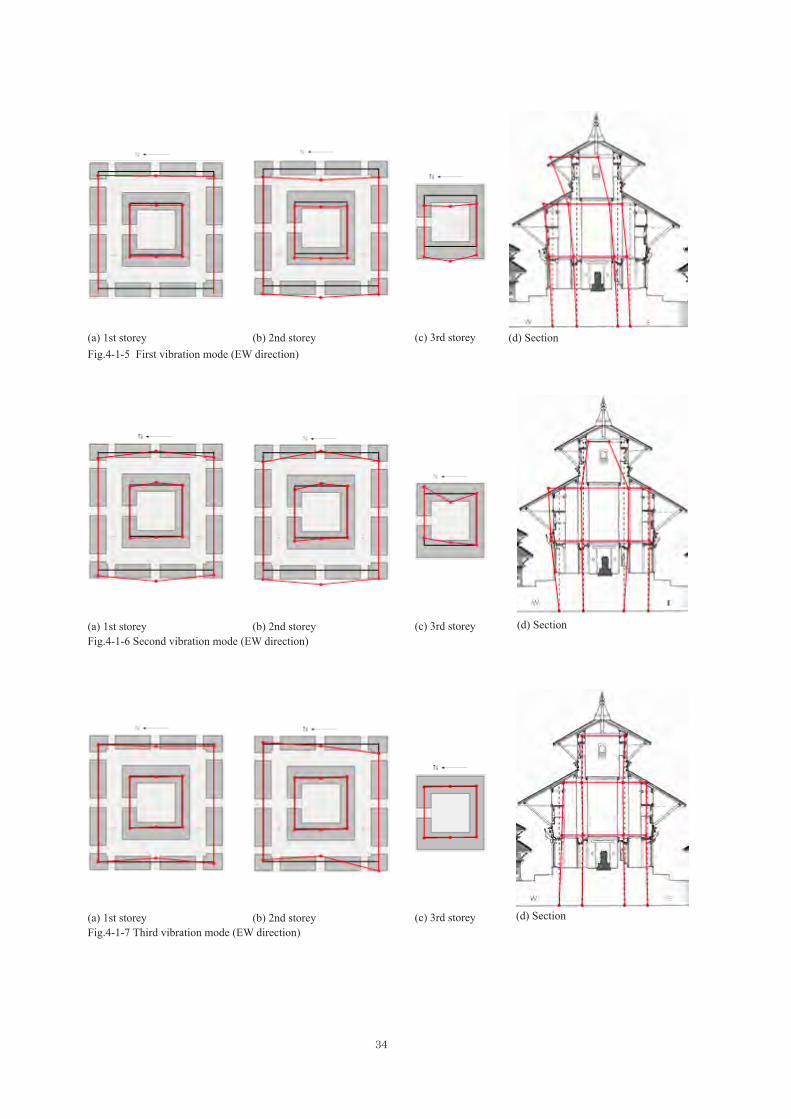
Fig.4-1-5 to Fig.4-1-10 similarly show the first, second and third vibration modes obtained by
other measurement cases. The plan of each storey and section of each direction are drawn to simplify the
figure.
Moreover, the detail data and the results by other measurement cases are shown in Appendix A.1
to A.16.
C h2 Ch1(GL)
Ch3 Ch4
Ch5 Floor level of the first storey(Stepped plinth level) Floor level of the second storey Floor level of the third storey Beam level of the third storey
Fig.4-1-2 Measurement arrangement (1st time of the measurement, EW direction)
(a) On the free ground (b) On the beam of the third storeyPic.4-1-2 Measurement points

33
Fig.4-1-3 Representative fourier amplitude ratio for Jagannath temple (EW direction)
Fig.4-1-4 Representative vibration mode for Jagannath Temple (EW direction)
(a) CH3 (on the first floor) (b) CH5 (on the beam of the third storey )Pic.4-1-3 Placed sensors
First vibration mode Second vibration mode Third vibration mode
34
(a) 1st storey
(a) 1st storey
(a) 1st storey
(b) 2nd storey
(b) 2nd storey
(b) 2nd storey
(c) 3rd storey
(c) 3rd storey
(c) 3rd storey
(d) Section
(d) Section
(d) Section
Fig.4-1-5 First vibration mode (EW direction)
Fig.4-1-6 Second vibration mode (EW direction)
Fig.4-1-7 Third vibration mode (EW direction)

35
(a) 1st storey
(a) 1st storey
(a) 1st storey
(b) 2nd storey
(b) 2nd storey
(b) 2nd storey
(c) 3rd storey
(c) 3rd storey
(c) 3rd storey
(d) Section
(d) Section
(d) Section
Fig.4-1-8 First vibration mode (NS direction)
Fig.4-1-9 Second vibration mode (NS direction)
Fig.4-1-10 Third vibration mode (NS direction)

36
4.2. Gopinath Temple
Micro-tremor measurements were performed on Gopinath Temple, as shown in Pic.4-2-1, from
4 to 5 December, 2015. Two horizontal components of vibration were measured at the top of the walls of
each storey. Measurement case, starting time (in Japan Standard Time) and measuring direction are shown
in Table 4-2-1. 20 cases of measurements were performed, excluding 2 unsuccessful measurements.
(a) Exterior appearance (b) Outer corridor at the second storey
(c) Interior view of the third storey
(d) The fourth storey (Photo taken from the beneath)
Pic.4-2-1 Gopinath Temple

37
Case Start time(in JST) Direction Note
1 4th December, 2015, 23:24:28:14 NS
2 4th December, 2015, 23:41:18:06 EW
3 5th December, 2015, 00:10:25:11 EW
4 5th December, 2015, 00:34:14:58 NS
5 5th December, 2015, 01:12:08:02 NS
6 5th December, 2015, 01:32:11:02 EW
7 5th December, 2015, 01:55:45:03 EW
8 5th December, 2015, 02:12:25:06 NS
9 5th December, 2015, 02:36:22:53 NS
10 5th December, 2015, 02:59:15:54 EW
11 5th December, 2015, 03:58:30:60 EW
12-1 5th December, 2015, 04:18:34:08 NS Failure
12-2 5th December, 2015, 04:33:37:05 NS
13 5th December, 2015, 05:05:24:07 NS
14 5th December, 2015, 05:14:56:04 EW
15 5th December, 2015, 05:29:49:06 EW
16 5th December, 2015, 05:49:47:12 NS
17-1 5th December, 2015, 06:08:50:12 NS Failure
18 5th December, 2015, 06:26:34:05 EW
17-2 5th December, 2015, 06:36:35:04 NS
20 5th December, 2015, 06:49:28:11 NS
19 5th December, 2015, 06:59:04:56 EW
Tab.4-2-1 Measurement cases, starting time and measuring direction

38
All measurement points are shown in Fig.4-2-1. All measurement points were monitored by
dividing into 20 cases shown above. Multiple measurements were taken: one on free ground, and several
inside the buildings. The measurement point on free ground was at the front of the building, shown in
Pic.4-2-2(a). The measurement point on the stepped plinth was also intended to confirm the amplification
of the vibration by the stepped plinth. Measurement points inside the building were at the top of the wall,
on the beam, and on each floor close to a structural wall. Since it was difficult to put the sensor on the top
of the wall at the top storey, we placed it on top of the window sill in the opening as shown in Pic.4-2-2(b).
Fig.4-2-1 All measurement points on Gopinath Temple
(GL)
Stepped plinth
Floor level of the first storey(Stepped plinth level)
Floor level of the second storey
Floor level of the third storey Floor level of the fourth storey Beam level of the fourth storey
(a) On the free ground (b) On the beam of the third storey
Pic.4-2-2 Measurement points

39
As a representative measurement result for Gopinath Temple, the result of first measurement in
the east-west (EW) direction are shown below.
The transfer function, shown in Fig. 4-2-2, was obtained by dividing the Fourier spectrum of
building vibration monitored inside the building by the Fourier spectrum of ground vibration. The peak
frequencies of the transfer function—2.0 Hz, 4.5 Hz, and 7.4 Hz—were estimated to be first, second, and
third natural frequencies of the building.
The vibration mode of elevation obtained by Transfer Function and phase information
corresponding to the first, second and third natural frequencies in EW direction are shown in Fig.4-2-3. At
the first vibration mode, the amplitude of out-of-plane direction on top of inner periphery is large. At the
second and third vibration modes, the amplitude of northern structural plane is large.
Fig.4-2-2 Representative fourier amplitude ratio for Gopinath temple (EW direction)
Fig.4-2-3 Representative vibration mode for Gopinath TempleFirst vibration mode Second vibration mode Third vibration mode

40
(a) Ch4 (On the floor) (b) Ch5 (On the top of the wall)Pic.4-2-3 Placed sensors
Pic.4-2-3 shows the placed sensors. Ch4 was placed on the floor beside wall, and Ch5 was placed
on the on top of the wall in the measurement.
Besides, Ch5 was fixed at same place for calibration in order to compare the vibration amplitude.
Fig.4-2-4 shows the vibration modes obtained by other measurements. The roof shape is removed
to simplify the figure. Since the mode figure is complex and difficult to distinguish, the vibration mode of
inner structural plane, outer structural plane and structural plane of the top storey were drawn dividedly.
Moreover, the detail data and the results by other measurement cases are shown in Appendix A.17
to A.36.

41
Fig.4-2-4 Vibration mode for Gopinath Temple

42

5. Structural Analysis


5. Structural Analysis
45
5.1. Seismic performance evaluation
At the occasion of evaluating the seismic performance of buildings, it is preferable to create a 3D
analysis model using line, surface and joint elements as shown in Fig. 5-1-1. These models can better apply
to the building conditions that may include non-true vertical planes (e.g. a wall is not straight between
upper and lower storeys), insufficient rigidity in horizontal planes (e.g. floor beams and roof trusses are
not sufficient), or unconfirmed rigid floor assumptions. This analysis considered performance against
input earthquake vibration in conjunction with the previously developed mass point model that considers
building weight and height, and previously reported performance results for brick structure (sufficient
original data could not be collected within the scope of this survey). The analysis results were intended to
support future reinforcement of historical buildings in Nepal.
Jagannath Temple Gopinath Temple
Fig.5-1-1 Examples of the 3D analysis model

46
When evaluating seismic performance, an initial parametric study was conducted to determine
appropriate constants and accepted assumptions. The parameter values and assumptions used in this
evaluation were as follows:
・Shear failure of brick itself is rarely observed, brick wall failure typically appears only at the brick
joints.
・The shear strength of mortar joints, Fs, was set as 0.15 N/mm2 or 0.0867 + 0.9σc based on
experimental results reported in 「Disaster Risk Management for the Historic City of Patan, Nepal,
Ritsumeikan University Institute of Disaster Mitigation for Urban Cultural Heritage (Rits-DMUCH)
2012, p.98:Table 5-1-1」.
・If mortar joints fail, the friction force between bricks is the primary resistance. The coefficient of
static friction, μ, was set as 0.5.
Variable Burned Brick Mortar WoodMass density 1.8x10³ - 7.0 x 10²
Young’s Modulus(N/m2) 2.7x10⁸ 2.7x10⁸ 6.3 x 10⁸
Poisson’s ratio 0.11 0.25 0.3Tensile strength(N/m2) - 0 1.1 x 10⁸
Shear strength(N/m2) - 9.0 x 10⁴ 9.0 x 10⁶
Friction angle φ - 42.5° 0°Compressive strength (N/m2) - 1.58 x 10⁶ 4.5 x 10⁷
Tab.5-1-1 Estimated parameters for various material

47
5.2. Seismic performance of Jagannath Temple
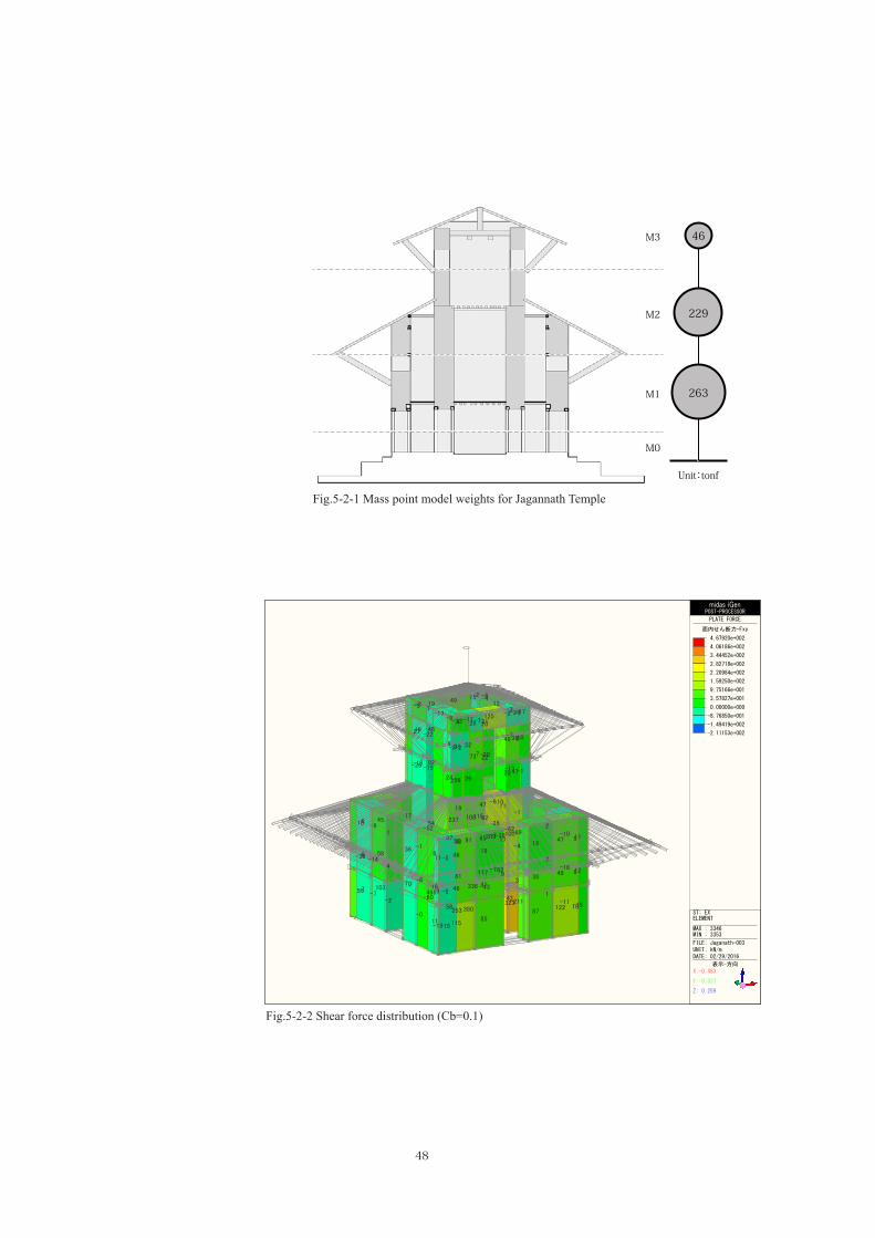
Fig. 5-2-1 shows the weight of each mass point in the Jagannath Temple analysis model. Rooftop
pinnacles, small openings, and wall thickness differences were ignored in the weight calculation. Table
5-2-2 lists the Ai distribution obtained from this weight calculation. Fig. 5-2-2 shows the Ai distribution
when Cb=0.1.
Assuming that the Ai distribution is equal to the acceleration distribution, an input acceleration
of 0.25 G (C1 = 0.25) resulted in an output acceleration at the top storey of 0.482 G. Thus the output
acceleration may exceed 0.5 G, namely the external force may be larger than the friction resistance
between bricks (μ=0.5) at the top storey. This assumption corresponds with the field survey results for the
Jagannath Temple that noted the earthquake damage concentrated at the top storey. A similar tendency is
likely observed for buildings with upper storey walls that continue straight to the first storey.
wi Wi=Σwi αi Ai(kN) (kN) Wi/W 0.1 0.25 0.5 0.1 0.25
M3 454 454 0.086 1.928 0.193 0.482 0.964 87.5 218.7M2 2242 2696 0.511 1.248 0.125 0.312 0.624 336.4 841.0M1 2582 5278 1.000 1.000 0.100 0.250 0.500 527.8 1319.4M0 727 6005 - - - - - - -
Ci QiStorey ofmass
a b t Unit Modulus Mass
(m) (m) (m) (kN/m2) Elements Position Storey (tonf)
Roof of Roof tiles 8.00 8.00 1.00 2.4 1.2 184M3 Roof Truss 8.00 8.00 1.00 0.2 1 13 197
Wall 1.80 13.20 0.60 18 1 257 257 454 46Wall 1.80 13.20 0.60 18 1 257 257
Roof of Roof tiles 13.50 13.50 1.00 2.4 1.2 5254.20 4.20 -1.00 2.4 1.2 -51 474
M2 Roof Truss 13.50 13.50 1.00 0.2 1 364.20 4.20 -1.00 0.2 1 -4 33
Floor Floor beams 4.20 4.20 1.00 0.6 1 11 11Wall Inner 2.50 13.20 0.90 18 1 535
Outer 1.80 28.80 1.00 18 1 933 1468 2242 229Wall Inner 2.50 13.20 0.90 18 1 535
Outer 2.40 28.80 1.00 18 1 1244 1779Floor Floor beams 8.00 8.00 1.00 0.6 1 38 38
M1 Wall 1.25 13.20 0.90 18 1 2671.00 1.10 0.90 18 -4 -71
Wall 1.25 28.80 1.00 18 1 6481.00 1.10 1.00 18 -4 -79 765 2582 263
Wall 1.25 13.20 0.90 18 1 267M0 1.25 1.10 0.90 18 -4 -89
1.25 28.80 1.00 18 1 6481.25 1.10 1.00 18 -4 -99 727 727 74
Total 6005 613
Weight (kN)Storey ofmass point
modelPostion Elements
Inner Opening
Outer Opening
Inner Opening
Outer Opening
Tab.5-2-1 Estimated building weight of Jagannath Temple
Tab.5-2-2 Ai distribution at each storey for Jagannath Temple
48
-7-2
-011
10370
81117 9
3
1-11
11585
87122
-80468
336
56253 380
32343-211
-43
-52
3755 91
209 100
-38
10
12
11
5836
4517
4065 -39
1947 10
-717
-4
-611
-1
7-18
6
2-10
5
4838
4718
4146
1846
9
11
-516
-6
-58
-1
4-14
6
1-9
6
55
62
-13
-1516
-15
7
-7
9273
4628
1949 15
22
-13
20
-7
-412
-3
-15
24
-22
9
7-17
-8
56 262047
31 524936
-33-17 125 -2-27
-18
19
-3
2
-2
-1
10
-17
-20
21
-6
7
-7
2
-26
27
-5
0
-1
-2
4
54237 10811592
26-62
-69
midas iGenPOST-PROCESSOR
PLATE FORCE
面内せん断力-Fxy
4.67920e+002
4.06186e+002
3.44452e+002
2.82718e+002
2.20984e+002
1.59250e+002
9.75166e+001
3.57827e+001
0.00000e+000
-8.76850e+001
-1.49419e+002
-2.11153e+002
ST: EXELEMENT
MAX : 3346MIN : 3353
FILE: Jaganath-003UNIT: kN/mDATE: 02/29/2016
表示-方向X:-0.483
Y:-0.837
Z: 0.259
46
229
263
Unit:tonf
M1
M2
M3
M0
Fig.5-2-1 Mass point model weights for Jagannath Temple
Fig.5-2-2 Shear force distribution (Cb=0.1)

49
Fig. 5-2-3 shows the calculation result for the distribution of compressive force of each wall in
each storey for vertical load. The number in the figure shows the weight at one-fourth of the plan. The
number in the left shows the weight of its story (wj), and right shows the weight which that story sustains
(Σwj).
Fig.5-2-3 Distribution of compressive force for vertical load (Left: wj, Right; Σwj) of Jagannath Temple
Jaganath
(8x8)/4=16.0x3.08=49.3
l=3.3m,t=0.6,h=3.6mx18=128.3
The Third storey
l=7.2m,t=1.0,h=4.2mx18=544.3
(13.5x13.5-5x5)/4=39.3 (2.1x2.1)/4=1.1x3.08=121.1 x0.6=0.67
(5.5x5.5-4x4)/4=3.6x3.08=11.1
l=3.3m,t=0.9,h=5.0mx18=267.3
The Second storey
l=7.2m,t=1.0,h=5.0mx18=648.0
5x5/4=6.3x.6=3.75
(2.1x2.1)/4=1.1(8x8-5x5)/4=9.8 x0.6=0.67
x0.6=5.9l=3.3m,t=0.9,h=5.0mx18=267.3
The First storey
1m
49.3128.3177.6
177.611.10.67
267.3456.7
121.1544.3665.4
665.46485.9
1319.3
456.70.673.75
267.3728.4

50
Table 5-2-3 shows the shear force, assuming elastic response, calculated by area of walls in each
storey, each direction and Ai distribution.
The shearing strength of brick wall is estimated by former experiments as Fs= 0.15 [N/mm2]
when ignoring the compressive force and evaluate only the joint, or Fs= 0.0867+0.9σ [N/mm2] when
concerning the compressive force. It is assumed as μ= 0.5 when not evaluating mortal joints but estimating
friction resistance.
It is confirmed that the shear force does not exceed the allowable shearing stress when Cb= 0.25,
namely the input acceleration on the ground surface = 0.25G.
Concerning the top storey whose damage by the earthquake is heavy, assuming the elastic
response, the shear force on top storey exceeds its allowable shearing stress intensity when the input
acceleration on the ground surface equals to the following value.
Concerning compressive force: 744.5 / 218.5 = 3.40, 0.25 x 3.40 = 0.85 G
Ignoring compressive force: 0.150 / 0.045 = 3.33, 0.25 x 3.33 = 0.83 G
The shear force on the first storey exceeds its allowable shearing stress when the input
acceleration on the ground surface equals to the following value.
Concerning compressive force: 4854.8 / 1319.4 = 3.68, 0.25 x 3.68 = 0.92 G
Ignoring compressive force: 0.150 / 0.096 = 1.56, 0.25 x 1.56 = 0.39 G
In case ignoring the performance of brick joint and concerning friction resistance, it is estimated
that the seismic performance ascends to resist against 0.4G of ground surface acceleration by using
accurate brick joints.
Although the effect of compressive force on allowable shearing stress is large, confirmation of
performance in actual specification is required.
L t Q τ σc With Each wall Each storey(m) (m) (m2) (m2) (kN) (kN) (N/mm2) (N/mm2) 0.0867+0.9σc (kN) (kN)
3.500 0.700 1 2.45 177.6 0.072 0.150 0.152 3723.500 0.700 1 2.45 177.6 0.072 0.150 0.152 3723.500 0.700 1 2.45 177.6 0.072 0.150 0.152 3723.500 0.700 1 2.45 177.6 0.072 0.150 0.152 3727.200 0.850 1 6.12 665.4 0.109 0.150 0.185 11297.200 0.850 1 6.12 665.4 0.109 0.150 0.185 11293.250 1.000 1 3.25 456.7 0.141 0.150 0.213 6933.250 1.000 1 3.25 456.7 0.141 0.150 0.213 6937.250 1.000 1 7.25 665.4 0.092 0.150 0.169 12277.250 1.000 1 7.25 665.4 0.092 0.150 0.169 12273.150 0.850 1 2.68 456.7 0.171 0.150 0.240 6433.150 0.850 1 2.68 456.7 0.171 0.150 0.240 6436.050 0.90 1 5.45 1319.3 0.242 0.150 0.305 16596.050 0.90 1 5.45 1319.3 0.242 0.150 0.305 16592.000 0.70 1 1.40 718.4 0.513 0.150 0.549 7682.000 0.70 1 1.40 718.4 0.513 0.150 0.549 7686.050 0.90 1 5.45 1319.3 0.242 0.150 0.305 16596.050 0.90 1 5.45 1319.3 0.242 0.150 0.305 16592.000 0.70 1 1.40 718.4 0.513 0.150 0.549 7682.000 0.70 1 1.40 718.4 0.513 0.150 0.549 768
4854.8
1st storey
3741.2
13.69NS 1319.4 0.096 4854.8
EW 19.86 841.0 0.042
2nd storey
EW 13.69 1319.4 0.096
NS 18.74 841.0 0.045 3644.5
Allowable shearing stressintensity
Total wallcross-
section area
Verticalload
Shearforce
0.045
Allowable shear forcewith compression
744.5
744.5
4.90
4.90 218.7
218.7 0.045
EW3rd storey
NS
Storey Compressivestress intensity
Shearingstress
intensityCross-
section areaNumberWalllengh Wall thicknessDirection
Withoutcompression
Tab.5-2-3 Shearing stress of walls (Jagannath Temple)

51
5.3. Seismic performance of Gopinath Temple
Fig. 5-3-1 shows the weight of each mass point in Gopinath Temple analysis model. Again,
rooftop pinnacles, small openings, and wall thickness differences were ignored in the weight calculation.
Table 5-3-2 lists the Ai distribution obtained from this weight calculation.
Again assuming that the Ai distribution is equal to the acceleration distribution, an input
acceleration of 0.25 G (C1 = 0.25) resulted in an output acceleration at the top storey of 0.472 G. Output
acceleration may again exceed 0.5 G if the external force is larger than the friction resistance of the brick
wall joints at the top storey.
This assumption corresponds with the field survey results for Gopinath Temple that noted
earthquake damage concentrated at the first storey. A similar tendency is likely observed for buildings with
upper storey walls that do not continue straight to the first storey or with smaller cross-sectional brick wall
areas at the lower storey compared with the upper storey cross-sectional areas.
Tab.5-3-1 Estimated building weight of Gopinath Templea b t Unit Modulus Mass
(m) (m) (m) (kN/m2) Elements Position Storey (tonf)Roof tiles 4.80 4.80 1.00 2.4 1.2 66
Roof Truss 4.80 4.80 1.00 0.2 1 5 71Wall 1.40 5.80 0.50 18 1 73 73 144 15Wall 1.40 5.80 0.50 18 1 73 73
Roof tiles 7.00 7.00 1.00 2.4 1.2 1411.90 1.90 1.00 2.4 -1.2 -10 131
M3 Roof Truss 7.00 7.00 1.00 0.2 1 102.00 2.00 1.00 0.2 -1 -1 9
Floor Floor beams 2.00 2.00 1.00 0.6 1 2 2Wall Inner 0
Outer 1.10 12.00 0.60 18 1 143 143 358 37Wall Inner 0
Outer 1.10 12.00 0.60 18 1 143 143Floor Floor beams 3.60 3.60 1.00 0.6 1 8 8Wall Inner Opening 1.75 12.00 0.60 18 1 227
M2 Outer Opening 0.75 20.40 0.35 18 1 96 323Roof tiles 9.40 9.40 1.00 2.4 1.2 254
3.60 3.60 1.00 2.4 -1.2 -37 217Roof Truss 9.40 9.40 1.00 0.2 1 18
3.60 3.60 1.00 0.2 -1 -3 15 706 72Wall 1.75 12.00 0.60 18 1 227
01.75 20.40 0.35 18 1 225
Roof Truss 8.00 8.00 1.00 0.2 1 135.40 5.40 1.00 0.2 -1 -6 459
M1 Floor 5.60 5.60 1.00 0.6 1 19 19Wall 1.15 12.00 0.60 18 1 149
1.15 4.00 0.60 18.00 -1 -50Outer columns 99 577 59
Wall 1.15 12.00 0.60 18 1 149M0 1.15 4.00 0.60 18.00 -1 -50
Columns inOuter Periphery 99 99 10
Total 1884 192
Inner Opening
Inner Opening
Inner PeripheryOpening
Outer PeripheryOpening
Roof ofLowerFloor
Roof ofLowerFloor
Storey ofmass Position Elements Weight (kN)
M4 Roof ofUpper

52
12 19 111210-0 19
-10 12-102-0 2 0-010
-9 20 154103-0-106156 21 -10
-6
11 -16-163-177 -178 -17 11
-6103-1-106
-2441911-67-10-51945-2
-18 -55 -60-14 -14 -55 -18
5
-5-11 7 -7 11 5
18 -0-188 13 9
9 12 11-21 -1 1400 -0 1
33-34
260260 -33
35254254
126-22
12220-20122
12622
2 9292 2
0 8383 0
22-3131-20
-3120
-2231
midas iGenPOST-PROCESSOR
PLATE FORCE
面内せん断力-Fxy
2.59918e+002
2.20139e+002
1.80361e+002
1.40582e+002
1.00804e+002
6.10250e+001
2.12464e+001
0.00000e+000
-5.83107e+001
-9.80893e+001
-1.37868e+002
-1.77646e+002
ST: EXELEMENT
MAX : 2859MIN : 2983
FILE: Gopinath-003UNIT: kN/mDATE: 02/29/2016
表示-方向X:-0.465
Y:-0.875
Z: 0.131
Storey wi Wi=Σwi αi Ai(kN) (kN) Wi/W 0.1 0.25 0.5 0.1 0.25
M4 144 144 0.081 1.886 0.189 0.472 0.943 27.2 67.9M3 358 502 0.281 1.413 0.141 0.353 0.707 70.9 177.3M2 706 1208 0.677 1.139 0.114 0.285 0.569 137.5 343.8M1 577 1784 1.000 1.000 0.100 0.250 0.500 178.4 446.1M0 99 1884 - - - - - - -
*Building height h; 10.5m, Design first period T; 0.21 [sec.] are assumed for calculation
Ci QiTab.5-3-2 Ai distribution at each storey for Gopinath Temple
Fig.5-3-1 Mass point model weights for Gopinath Temple
Fig.5-3-2 Shear force distribution (Cb=0.1)
15
59
Unit:tonf
M1
M2
M3
M0
M4
72
37

53
Fig. 5-3-3 shows the calculation result for the distribution of compressive force of each wall in
each storey for vertical load. The number in the figure shows the weight at one-fourth of the plan. The
number in the left shows the weight of its story (wj), and right shows the weight which that story sustains
(Σwj).
Fig.5-3-3 Distribution of compressive force for vertical load (Left: wj, Right; Σwj) of Gopinath Temple
Gopinath
Roof5x5/4=6.25x3.08=19.3
Walll=1.55,h=4.6,t=0.45
x18=57.7
The Fourth storey
Roof+Floor7.4x7.4/4=13.7
x3.08=42.2
Walll=3.09,h=2.8,t=0.54
x18=84.1
The Third storey
Wall-1l=5.38,h=2.4,t=0.38
x18=88.3
Roof Floor(10x10-3.8x3.8)/4 2.5x2.5/4
x3.08=65.9 x0.6=0.94
Wall-2l=3.09,h=2.6,t=0.56
x18=95.5
The Second storey
Floor1-1(5.5x5.5-4.65x4.65)/4x0.6=1.3
Floor1-2(4.65x4.65-3.8x3.8)/4x0.6=1.1 Floor2
2.6x2.6/4Wall x0.6=1.1 l=3.1,h=2.2,t=0.9 x18=110.5
The First storey
1m
19.357.776.5
76.542.284.1
202.8
ー88.365.9
154.2
202.80.9495.5
299.2
299.21.11.1
110.5411.9
154.21.3
155.5

54
Table 5-3-3 shows the shear force, assuming elastic response, calculated by area of walls in each
storey, each direction and Ai distribution.
The shearing strength of brick wall is estimated by former experiments as Fs= 0.15 [N/mm2]
when ignoring the compressive force and evaluate only the joint, or Fs= 0.0867+0.9σ [N/mm2] when
concerning the compressive force. It is assumed as μ= 0.5 when not evaluating mortal joints but estimating
friction resistance.
Concerning the top storey whose damage by the earthquake is heavy, assuming the elastic
response, the shear force on top storey exceeds its allowable shearing stress intensity when the input
acceleration on the ground surface equals to the following value.
Concerning compressive force: 1034.0 / 446.1 = 2.32, 0.25 x2.32 = 0.58 G
Ignoring compressive force:0.150 / 0.132 = 1.14, 0.25 x 1.14 = 0.28 G
The shear force on the first storey exceeds its allowable shearing stress when the input
acceleration on the ground surface equals to the following value.
Concerning compressive force: 4854.8 / 1319.4 = 3.68, 0.25 x 3.68 = 0.92 G
Ignoring compressive force: 0.150 / 0.096 = 1.56, 0.25 x 1.56 = 0.39 G
In case ignoring the performance of brick joint and concerning friction resistance, the response
acceleration of the top storey is estimated to be close to 0.5G. Concerning this result, the shear force on top
storey has possibility to exceed its allowable shearing stress when Cb =0.25.
It is demonstrated that using proper brick joints in first and top storey is important for ascending
seismic performance of whole building.
Although the effect of compressive force on allowable shearing stress is large, confirmation of
performance in actual specification is required.
L t Q τ σc With Compression Each wall Each storey(m) (m) (m2) (m2) (kN) (kN) (N/mm2) (N/mm2) 0.0867+0.9σc (kN) (kN)
1.60 0.40 1 0.64 76.5 0.120 0.150 0.194 1241.60 0.40 1 0.64 76.5 0.120 0.150 0.194 1241.60 0.40 1 0.64 76.5 0.120 0.150 0.194 1241.60 0.40 1 0.64 76.5 0.120 0.150 0.194 1243.09 0.54 1 1.67 202.8 0.122 0.150 0.196 3273.09 0.54 1 1.67 202.8 0.122 0.150 0.196 3273.09 0.54 1 1.67 202.8 0.122 0.150 0.196 3273.09 0.54 1 1.67 202.8 0.122 0.150 0.196 3275.38 0.36 1 1.94 154.2 0.080 0.150 0.158 3075.38 0.36 1 1.94 154.2 0.080 0.150 0.158 3073.58 0.66 1 2.36 299.2 0.127 0.150 0.201 4744.16 0.66 1 2.75 299.2 0.109 0.150 0.185 5075.38 0.36 1 1.94 154.2 0.080 0.150 0.158 3075.38 0.36 1 1.94 154.2 0.080 0.150 0.158 3074.16 0.66 1 2.75 299.2 0.109 0.150 0.185 5074.16 0.66 1 2.75 299.2 0.109 0.150 0.185 5072.41 0.70 1 1.69 411.9 0.244 0.150 0.306 5172.41 0.70 1 1.69 411.9 0.244 0.150 0.306 5172.41 0.70 1 1.69 411.9 0.244 0.150 0.306 5172.41 0.70 1 1.69 411.9 0.244 0.150 0.306 517
1st storeyNS 3.37
EW 1.28
2nd storey
3rd storey
4th storeyNS 1.28
446.1 0.132 1034.0
EW
0.053 654.4
1594.9
3.37 446.1 0.132 1034.0
343.8 0.037 1628.1
NS 8.98
654.4
EW 3.34 177.3
Toal wallcross-
section area
Verticalload
Shearforce
67.9 0.053 248.7
67.9 0.053 248.7
Withoutcompression
Storey
343.8 0.038
EW 9.36
NS 3.34 177.3 0.053
Cross-section area
Direction Wall length Wall thickness NumberShearing stress
intensityCompressive
stressAllowable shearing stress
intensityAllowable shear force with
compressive
Tab.5-3-3 Shearing stress of walls (Gopinath Temple)

6. Summary of the result and Seismic Reinforcement Plan


6. Summary of the result and Seismic Reinforcement Plan
57
6.1. Summary of the result
With regard to planning the preservation and restoration plan of historic buildings in Nepal, it is
important to consider the following findings obtained in this structural survey:
・Structural drawings and analysis models for subject buildings can be developed from survey
results that describe building dimensions and construction methods. Structural analysis can be
performed after verifying the material characteristics of brick, mortar, and timber.
・Micro-tremor measurement can be used to estimate the natural frequency and vibration mode of
a subject building.
・Through approximate estimation of seismic performance, brick wall joints can be damaged by an
input acceleration of 0.25 G and the buildings incur concentrated damage either at the top or first
storeys.
Most important for preservation planning and repair is to set realistic performance requirements
(i.e. an acceptable degree of damage from an earthquake) and to regulate the building collapse mode to
the extent possible. Future preservation planning and repair efforts can benefit from development of a
detailed structural analysis model that includes accurate material characteristics. Preliminary assimilation
of a material characteristics database using previously reported results for brick, mortar joints (existing and
fresh), and timber elements (existing and fresh) is required.
6.2. Structural reinforcement plan
It is required to clarify the performance requirements including viewpoint as the followings for
the structural reinforcement plan.
• Performance requirements, such as presumed earthquake, acceptable degree of damage from the
earthquake and regulation of building collapse mode, are required to be set accurately.
• Some local engineers favour collapse mechanisms that allow reuse of bricks, viewing the
removal of mortar and reuse of materials as a superior repair method. For preservation planning
and repair, this requires prediction of the collapse mode of buildings and a method for valuing
the building and its associated structural material.
• Bricks from a collapsed building are not always used to repair the original building. As such,
reuse procedures must be coordinated among multiple projects.

58
Structural reinforcement, attaching importance to the preservation of bricks as shown above, is
required to verify following points.
• To prevent a more devastating collapse, joint failure should precede brick failure. Strength
and compounding adjustments for joint mortar may be required. Adjustments should be made
according to both preservation planning and structural performance considerations.
• Timber frames may prevent total building collapse following brick wall failure. Historical
transition and usage methods must be coordinated.
• Careful documentation of building characteristics and construction methods is important before
and after building collapse. In this survey, the brick and timber-frame systems inside the walls
were difficult to comprehend without detailed information.
Based on this structural survey and the observations noted above, the seismic performance of
Jagannath and Gopinath Temples depends heavily on the performance of the mortar joints in the brick
walls. To prevent a more devastating collapse from failure of the bricks, mortar performance should be
designed to be lower than that of the brick itself to induce collapse from the joint. Further information
is required regarding original timber elements; timber frames help to prevent total building collapse by
resisting their own weight.

7. Issues for the Future Research


7. Issues for the Future Research
61
7.1. Collecting data for analysis
In the present report, we performed structural performance evaluation by abbreviated calculation,
based on collected basic information of structural performance of multi-tiered tower. In order to
comprehend the structural performance of individual buildings, further verification using specific values
by performing detail calculation of building weight and collecting material characteristics of bricks, mortar
joints and brick walls are required. (cf. 7.2. and 7.3.)
Moreover, with regard to restoration, it is required to perform seismic diagnosis to confirm the
structural performance of the buildings before suffering earthquake, and to set performance requirements.
On the occasion of setting performance requirements, presumption of the input seismic motion and degree
of damage are important.
7.2. Structual tests on bricks
In order to comprehend the material characteristics of bricks and brick walls for structural
analysis, it is desirable to perform structural tests below.
(1) Compressive test of bricks and joint mortar
(2) Combined test against vertical and lateral force
(3) Bending test
The structural performance of brick wall is decided mainly by that of brick itself and mortar joint.
Therefore, in order to comprehend the structural performance of building both before and after suffering
earthquake, it is required to understand the performance of both present and new bricks, and both existing
joint and newly filled joint. The examples of specification of joint mortar, specimens and experimental
method are shown below.
Specifications of mortar for mesonry joint in the specimen for the tests
(1) Existing mortar from the damaged structure [Curing Period: 1 month]
(2) Yellow mud (traditional) [Curing Period: 1 month]
(3) Lime Surkhi 1 (Lime: Surkhi (Brick dust): Sand = 1:1:3) [Curing Period: 2 month]
(4) Lime Surkhi 2 (Lime: Surkhi (Brick dust): Sand = 1:1:1) [Curing Period: 2 month]

62
<Method of th structural test>
Compressive test : 3 specimens for each mortar (12 specimens in total)
Fig.7-2-1 Compressive test
Combined test by using Steel Frame: 6 specimens for each mortar (24 specimens in total)
Fig.7-2-2 Combined test
Bending test: 3 specimens for each mortar (12 specimens in total)
Fig.7-2-3 Bending test
Compressive test of mortar: 3 specimens for each mortar (12 specimens in total)
Fig.7-2-4 Compressive test of mortar

63
(1) Loading device 1 (2) Loading device 2Pic.7-2-1 Loading devices

64
7.3. Strucutural Test on timber
The material characteristics of timber are important to comprehend the performance of timber
frame.The following two species are supposed to be used in present buildings including Jagannath and
Gopinath Temples.
Agrak (Sal): Timber for main frame
Salla (Pine): Timber not for structure and design( Using at hidden part)
The material characteristics (shown below) of these species are required to be comprehended.
Young's modulus: E (Compression, Bending, Embedding)
Material strength: F
Density: ρ
Examples of specimens and Testing method and Specimensize are shown below.
・Testing Method:
Bending Test, Compression Test
・Specimen size:
Bending Test: Breadth: 20mm, Depth: 20mm, Length: 450mm
Sustaining span: larger than 18d=360mm
Compression Test: Breadth: 20mm, Depth: 20mm, Length: 150mm
Length: larger than 6d=120mm
Tab.7-2-1 Specimen size for the Structural tests on timber
Breadth: bDepth: dLength: l
Agrak(Sal) Sala(Pine) Agrak(Sal) Sala(Pine)n=10 n=10 n=20 n=20
SpeciesNumber
Compression TestBending Test
Size20mm 20mm20mm 20mm
450mm 150mm

Appendix
The structural drawings
J01~J11 Jagannath Temple G01~G17 Gophinath Temple


The structural drawings of Jagannath Temple
J01:Floor plan of pillars and wall, 1st storey J02:Plan of struts of the 1st tier and joists, 2nd storey J03:Plan of rafters of the 1st tier J04:Plan of struts of the 2nd tier and joists, 3rd storey J05:Plan of ridge beams, 3rd storey J06:Plan of rafters of the 2nd tier J07:North elevation J08:East elevation J09:West elevation J10:South elevation J11:Section of X (NS) direction J12:Section of Y (EW) direction J13:Size of bricks


J01

J02

J03

J04

J05

J06

J07

J08

J09

J10

J11

J12

J13


The structural drawings of Gopinath Temple
G01:Floor plan of pillars and wall, 1st storey G02:Plan of joists, 2nd storey G03:Plan of struts and fascia boards of the 1st tier G04:Plan of rafters of the 1st tier G05:Plan of struts of 2nd tier and joists, 3rd storey G06:Plan of struts and fascia boards of the 3rd tier G07:Plan of beams between 3rd and 4th storey G08:Plan of rafters of the 2nd tier G09:Plan of ridge beams, 4th storey G10:Plan of rafters of the 3rd tier G11:North elevation G12:East elevation G13:West elevation G14:South elevation G15:Section of X (EW) direction G16:Section of Y (NS) direction G17:Size of bricks


G01

G02

G03

G04

G05

G06

G07

G08

G09

G10

G11

G12

G13

G14

G15

G16

G17


Editors
Masahiko Tomoda (Head of Conservation Design Section, TNRICP)
Hiroki Yamada (Associate Fellow, Japan Center for International Cooperation in Conservation, TNRICP)
Assistant editors Sunwook Kim (Research Assistant, Japan Center for International Cooperation in Conservation, TNRICP) Shuhei Matsunaga, Mina Shibata (Assistant, TNRICP)
Authors Mikio Koshihara (Professor, Institute of Industrial Science, The University of Tokyo) Noriko Takiyama (Associate Professor, Fuculty of Urban Environmental Sciences, Tokyo Metropolitan Unversity) Mitsuhiro Miyamoto (Associate Professor, Fuculty of Engineering, Kagawa University) Hiromi Sato (Assistant Professor, Institute of Industrial Sciences, The University of Tokyo)
Cover design Katsura Sato (Former Associate Fellow, Japan Center for International Cooperation in Conservation, TNRICP)

2016
Project for International Contribution to Cultural Heritage Protection
Project for Investigation of Damage Situation of Cultural Heritage in Nepal
Structural Survey of Historic Buildings
Copyright © 2022 FDOKUMEN