Structural timber buildings fire safety in use guidance Volume 6
37
Structural timber buildings fire safety in use guidance Volume 6 - Mass timber structures; Building Regulation compliance B3(1) STA fire safety research and guidance project Version v1.1 October 2020 Image courtesy of KLH
-
Upload
khangminh22 -
Category
Documents
-
view
7 -
download
0
Transcript of Structural timber buildings fire safety in use guidance Volume 6

Structural timber buildings fire safety in use guidance
Volume 6 - Mass timber structures; Building Regulation compliance B3(1)
STA fire safety research and guidance project Version v1.1 October 2020
Image courtesy of KLH
Report made possible with funding from Stora Enso, Binderholz and KLH (images also kindly provided for use)
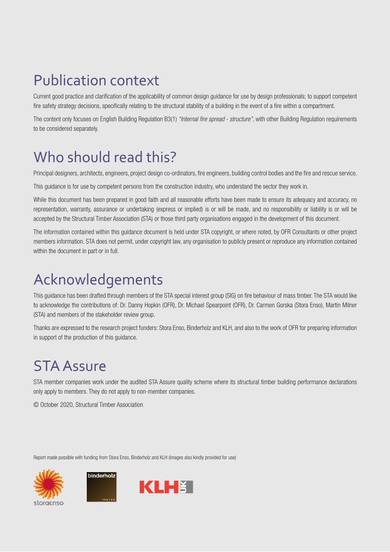
Publication context Current good practice and clarification of the applicability of common design guidance for use by design professionals; to support competent
fire safety strategy decisions, specifically relating to the structural stability of a building in the event of a fire within a compartment.
The content only focuses on English Building Regulation B3(1) “Internal fire spread - structure”, with other Building Regulation requirements
to be considered separately.
Who should read this?Principal designers, architects, engineers, project design co-ordinators, fire engineers, building control bodies and the fire and rescue service.
This guidance is for use by competent persons from the construction industry, who understand the sector they work in.
While this document has been prepared in good faith and all reasonable efforts have been made to ensure its adequacy and accuracy, no
representation, warranty, assurance or undertaking (express or implied) is or will be made, and no responsibility or liability is or will be
accepted by the Structural Timber Association (STA) or those third party organisations engaged in the development of this document.
The information contained within this guidance document is held under STA copyright, or where noted, by OFR Consultants or other project
members information. STA does not permit, under copyright law, any organisation to publicly present or reproduce any information contained
within the document in part or in full.
AcknowledgementsThis guidance has been drafted through members of the STA special interest group (SIG) on fire behaviour of mass timber. The STA would like
to acknowledge the contributions of: Dr. Danny Hopkin (OFR), Dr. Michael Spearpoint (OFR), Dr. Carmen Gorska (Stora Enso), Martin Milner
(STA) and members of the stakeholder review group.
Thanks are expressed to the research project funders: Stora Enso, Binderholz and KLH, and also to the work of OFR for preparing information
in support of the production of this guidance.
STA AssureSTA member companies work under the audited STA Assure quality scheme where its structural timber building performance declarations
only apply to members. They do not apply to non-member companies.
© October 2020, Structural Timber Association
3
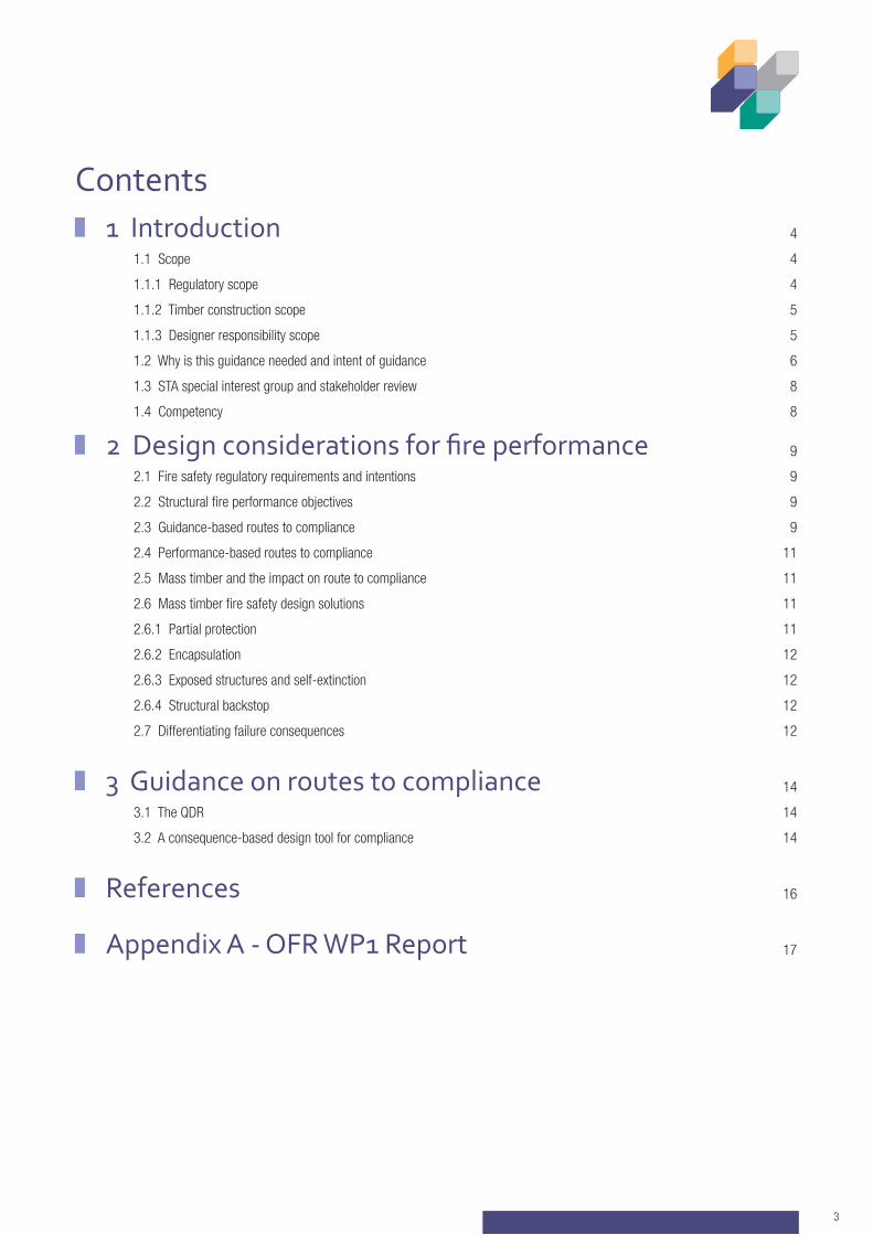
1 Introduction 4
1.1 Scope 4
1.1.1 Regulatory scope 4
1.1.2 Timber construction scope 5
1.1.3 Designer responsibility scope 5
1.2 Why is this guidance needed and intent of guidance 6
1.3 STA special interest group and stakeholder review 8
1.4 Competency 8
2 Design considerations for fire performance 9
2.1 Fire safety regulatory requirements and intentions 9
2.2 Structural fire performance objectives 9
2.3 Guidance-based routes to compliance 9
2.4 Performance-based routes to compliance 11
2.5 Mass timber and the impact on route to compliance 11
2.6 Mass timber fire safety design solutions 11
2.6.1 Partial protection 11
2.6.2 Encapsulation 12
2.6.3 Exposed structures and self-extinction 12
2.6.4 Structural backstop 12
2.7 Differentiating failure consequences 12
3 Guidance on routes to compliance 14
3.1 The QDR 14
3.2 A consequence-based design tool for compliance 14
References 16
Appendix A - OFR WP1 Report 17
Contents
4
1 Introduction This document details compliance routes for structural stability in the event of fire for timber buildings in England as part of the STA’s library
of fire-in-use best practice guidance. The STA library of documentation provides guidance, information and recommendations on system
specifications and good practice principles when using structural timber building methods.
The current guidance is in six volumes:
• Volume 1 - Pattern book of tested systems
• Volume 2 - Cavity barriers and fire stopping
• Volume 3 - Pattern book of proprietary systems (estimated issue 2021)
• Volume 4 - Service penetration detailing (estimated issue 2021)
• Volume 5 - Good practice drylining to structural timber buildings (estimated issue 2021) and
• Volume 6 - Mass timber structures; Building Regulation compliance B3(1) (this document).
The information may require updates and additional documents as regulations change and knowledge develops. Readers are to be aware of
the need to check for updates and use the current issue of guidance from the STA website: www.structuraltimber.co.uk
The work includes key outputs from a mass timber research project, called ‘STA Special Interest Group (SIG) - CLT compartment fire
behaviour’ under the chair of Matthew Linegar of Stora Enso.
1.1 Scope 1.1.1 Regulatory scopeThis guidance is focused on Building Regulation compliance routes for structural stability in the event of fire of mass timber buildings of
differing uses and sizes.
The guidance is concerned with the life safety requirements for buildings constructed in England, as currently defined by the Regulations (Part
B of the Building Regulations 2010, as amended). The scope is Regulation B3 - internal fire spread (structure), specifically, Regulation B3(1)
which concerns the performance of the structural system in the event of fire.
Reference to the regulations in Scotland, Wales and Northern Ireland are intended to follow on in future updates of this guidance. However,
the principles are similar and the findings relevant to each member country of the UK.
Whilst the scope of this document is structural fire performance, mass timber can introduce hazards impacting all parts of a building’s fire
strategy, in particular flame spread across internal surfaces, external fire spread and space separation. The implications of building with mass
timber and allowing it to contribute as a source of fuel should be fully understood by the design team and considered as at the outset of a
project through a qualitative design review (QDR) process, as discussed in Section 3.1.
STRUCTURAL TIMBER BUILDINGS FIRE SAFETY IN USE GUIDANCE VOL 6 - MASS TIMBER STRUCTURES
5
1.1.2 Timber construction scopeMass timber is part of the family of material types that are in the structural timber building systems suite of options. As a building method,
mass timber offers low carbon benefits and forms part of the offsite construction solution for speed, quality and cost-efficiency.
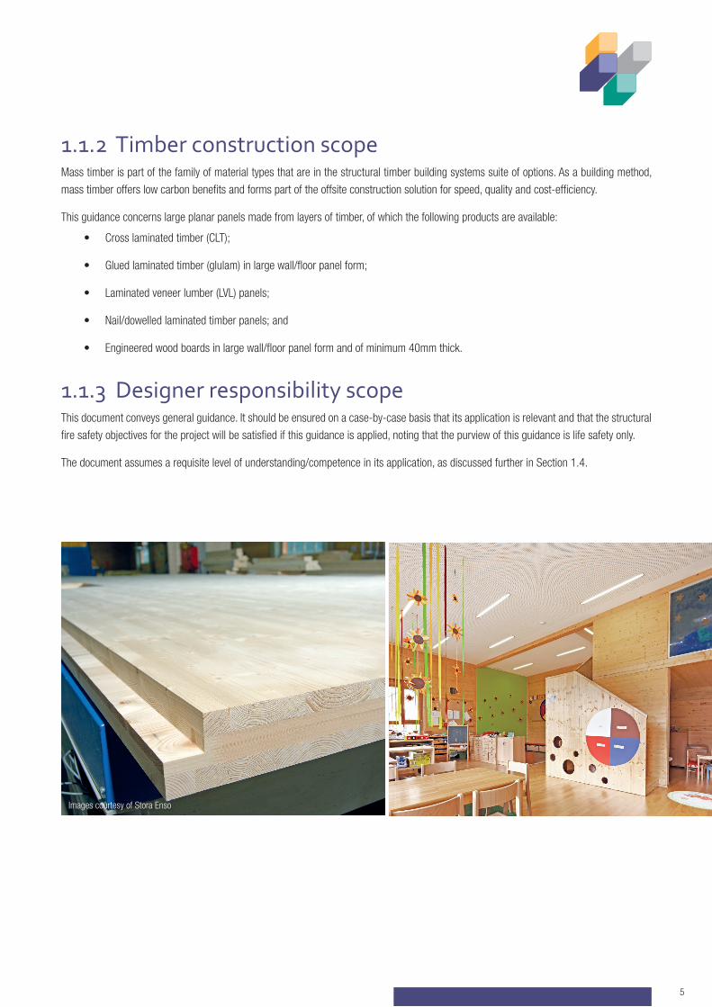
This guidance concerns large planar panels made from layers of timber, of which the following products are available:
• Cross laminated timber (CLT);
• Glued laminated timber (glulam) in large wall/floor panel form;
• Laminated veneer lumber (LVL) panels;
• Nail/dowelled laminated timber panels; and
• Engineered wood boards in large wall/floor panel form and of minimum 40mm thick.
1.1.3 Designer responsibility scopeThis document conveys general guidance. It should be ensured on a case-by-case basis that its application is relevant and that the structural
fire safety objectives for the project will be satisfied if this guidance is applied, noting that the purview of this guidance is life safety only.
The document assumes a requisite level of understanding/competence in its application, as discussed further in Section 1.4.
Images courtesy of Stora Enso
6
Concerning the performance expected of the structure in the event of fire, the Building Regulations in England set out the minimum
expectations under a life safety purview (as discussed in Section 2.1).
For the more common and straightforward building situations, guidance [3], [4] or codes [5], [6] are often applied to satisfy the requirements
of the Building Regulations (see Section 2.3). These guidance documents and codes address structural performance in the event of fire
through the provision of fire resistance to load-bearing elements of structure. Implicitly, the fire resistance paradigm and the guidance
documents/codes that reference fire resistance periods include limitations, which are outlined in the OFR background report included in
Appendix A. Discussions which elaborate on fire resistance, its origin and objectives can be found elsewhere, e.g. refs [7]-[9]
STRUCTURAL TIMBER BUILDINGS FIRE SAFETY IN USE GUIDANCE VOL 6 - MASS TIMBER STRUCTURES
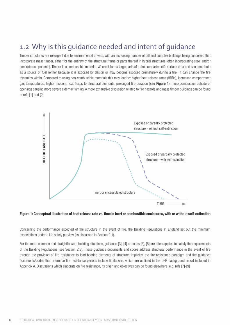
1.2 Why is this guidance needed and intent of guidanceTimber structures are resurgent due to environmental drivers, with an increasing number of tall and complex buildings being conceived that
incorporate mass timber, either for the entirety of the structural frame or parts thereof in hybrid structures (often incorporating steel and/or
concrete components). Timber is a combustible material. Where it forms large parts of a fire compartment’s surface area and can contribute
as a source of fuel (either because it is exposed by design or may become exposed prematurely during a fire), it can change the fire
dynamics within. Compared to using non-combustible materials this may lead to: higher heat release rates (HRRs), increased compartment
gas temperatures, higher incident heat fluxes to structural elements, prolonged fire duration (see Figure 1), more combustion outside of
openings causing more severe external flaming. A more exhaustive discussion related to fire hazards and mass timber buildings can be found
in refs [1] and [2].
Figure 1: Conceptual illustration of heat release rate vs. time in inert or combustible enclosures, with or without self-extinction
Exposed or partially protected
structure - without self-extinction
Exposed or partially protected
structure - with self-extinction
Inert or encapsulated structure
HEAT
REL
EASE
RAT
E
TIME
7
For higher consequence buildings, the affording of fire resistance to elements of structure is a proxy for an objective of the structure having a
reasonable likelihood of surviving the full duration of a fire (burn-out), as discussed in more detail in Section 2.2. Where structural elements
contribute as a source of fuel, the affordance of fire resistance to structural elements does not assure that the structural system will have a
reasonable likelihood of surviving burn-out. By extension, the application of guidance or codes (which include fire resistance recommendations)
does not always assure compliance with the relevant parts of the Building Regulations, with alternative routes to compliance required where
a structure burns but must ultimately survive burn-out (see Section 2.4).
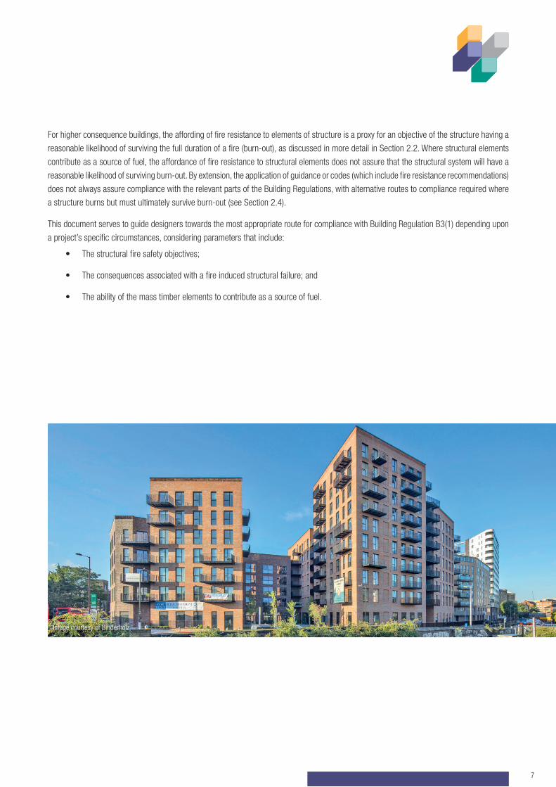
This document serves to guide designers towards the most appropriate route for compliance with Building Regulation B3(1) depending upon
a project’s specific circumstances, considering parameters that include:
• The structural fire safety objectives;
• The consequences associated with a fire induced structural failure; and
• The ability of the mass timber elements to contribute as a source of fuel.
Image courtesy of Binderholz
(CHAIR)
Matthew Linegar
Stora Enso
Martin Milner
STA
Stakeholder ReviewGroup(SRG)
Stakeholder Review Group
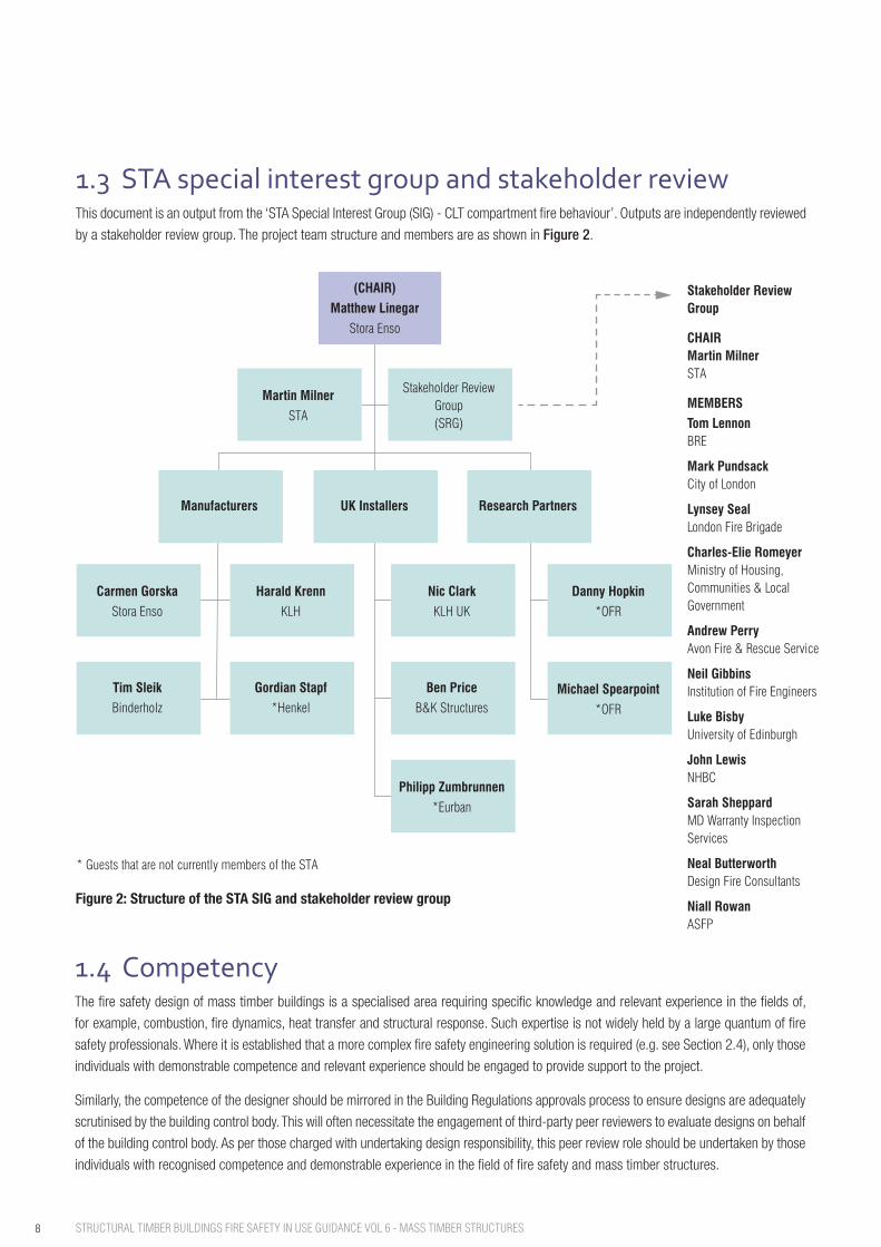
CHAIRMartin MilnerSTA
MEMBERS
Tom LennonBRE
Mark PundsackCity of London
Lynsey SealLondon Fire Brigade
Charles-Elie RomeyerMinistry of Housing, Communities & Local Government
Andrew PerryAvon Fire & Rescue Service
Neil GibbinsInstitution of Fire Engineers
Luke BisbyUniversity of Edinburgh
John LewisNHBC
Sarah SheppardMD Warranty Inspection Services
Neal ButterworthDesign Fire Consultants
Niall RowanASFP
* Guests that are not currently members of the STA
Figure 2: Structure of the STA SIG and stakeholder review group
Manufacturers UK Installers Research Partners
Carmen Gorska
Stora Enso
Harald Krenn
KLH
Nic Clark
KLH UK
Danny Hopkin
*OFR
Michael Spearpoint
*OFR
Tim Sleik
Binderholz
Gordian Stapf
*Henkel
Ben Price
B&K Structures
Philipp Zumbrunnen
*Eurban
8 STRUCTURAL TIMBER BUILDINGS FIRE SAFETY IN USE GUIDANCE VOL 6 - MASS TIMBER STRUCTURES
1.3 STA special interest group and stakeholder reviewThis document is an output from the ‘STA Special Interest Group (SIG) - CLT compartment fire behaviour’. Outputs are independently reviewed
by a stakeholder review group. The project team structure and members are as shown in Figure 2.
Figure 2: Structure of the STA SIG and stakeholder review group
1.4 CompetencyThe fire safety design of mass timber buildings is a specialised area requiring specific knowledge and relevant experience in the fields of,
for example, combustion, fire dynamics, heat transfer and structural response. Such expertise is not widely held by a large quantum of fire
safety professionals. Where it is established that a more complex fire safety engineering solution is required (e.g. see Section 2.4), only those
individuals with demonstrable competence and relevant experience should be engaged to provide support to the project.
Similarly, the competence of the designer should be mirrored in the Building Regulations approvals process to ensure designs are adequately
scrutinised by the building control body. This will often necessitate the engagement of third-party peer reviewers to evaluate designs on behalf
of the building control body. As per those charged with undertaking design responsibility, this peer review role should be undertaken by those
individuals with recognised competence and demonstrable experience in the field of fire safety and mass timber structures.
9
2 Design considerations for fire performance This section introduces the statutory Building Regulation requirements in England with respect to structural performance in the event of fire,
structural fire safety objectives and how they differ depending upon fire induced failure consequences, and the corresponding implications
for the route to Building Regulations compliance for mass timber buildings.
2.1 Fire safety regulatory requirements and intentionsBuilding Regulation B3(1) in England states that:
“The building shall be designed and constructed so that, in the event of fire, its stability will be maintained for a reasonable period.”
The Secretary of State goes on to clarify the intention of the above functional requirement in Approved Document B as:
“For defined periods, loadbearing elements of structure withstand the effects of fire without loss of stability.”
2.2 Structural fire performance objectivesWhilst speaking to periods of time, neither the wording of Regulation B3(1) nor the Secretary of State’s clarified intention in ADB explicitly
define the duration of structural stability required in the event of fire. With reference to the supporting OFR research in Appendix A and parallel
research developments in ref [8], the structural fire safety performance objectives for a building can vary in function of the consequences of fire
induced collapse. For buildings where the failure consequences are less significant, Regulation B3(1) can be interpreted as likely being satisfied
subject to the structure remaining stable for an adequate period to facilitate occupant escape and (predominantly) external fire and rescue
service intervention. For buildings where the failure consequences are more significant (e.g. due to what is considered to be prolonged
evacuation or (predominantly) internal fire and rescue service intervention), Regulation B3(1) is likely satisfied subject to the structure having
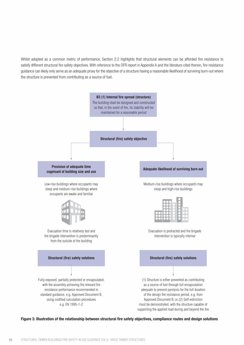
a reasonable likelihood of surviving the full duration of a fire (burn-out). This bifurcation of objectives is illustrated schematically in Figure 3 which goes on to indicate the implications for the compliance route (Section 2.5) and design solutions (Section 2.6).
2.3 Guidance-based routes to complianceFor most common and straightforward building situations, Regulation B3(1) is addressed through the adoption of the statutory guidance in
Approved Document B [3], [4], or similar guidance such as BS 9991 [5] and BS 9999 [6]. Therein, fire resistance ratings are recommended for
elements of structure in function of building size and use. Subsequently, elements are either designed to inherently achieve or are protected
to achieve the recommended fire resistance rating. In the case of mass timber elements, fire resistance would commonly be demonstrated
through the calculation methods in BS EN 1995-1-2 [10] or through appropriate test evidence. Once these ‘fire resisting’ elements are formed
into a structural system, that structural system can be said to satisfy Regulation B3(1).
10 STRUCTURAL TIMBER BUILDINGS FIRE SAFETY IN USE GUIDANCE VOL 6 - MASS TIMBER STRUCTURES
Figure 3: Illustration of the relationship between structural fire safety objectives, compliance routes and design solutions
Whilst adopted as a common metric of performance, Section 2.2 highlights that structural elements can be afforded fire resistance to
satisfy different structural fire safety objectives. With reference to the OFR report in Appendix A and the literature cited therein, fire resistance
guidance can likely only serve as an adequate proxy for the objective of a structure having a reasonable likelihood of surviving burn-out where
the structure is prevented from contributing as a source of fuel.
B3 (1) Internal fire spread (structure)
The building shall be designed and constructedso that, in the event of fire, its stability will be
maintained for a reasonable period
Structural (fire) safety objective
Provision of adequate timecognisant of building size and use
Adequate likelihood of surviving burn-out
Structural (fire) safety solutions Structural (fire) safety solutions
Low-rise buildings where occupants maysleep and medium-rise buildings where
occupants are awake and familiar
Evacuation time is relatively fast andfire brigade intervention is predominantly
from the outside of the building
Fully-exposed, partially protected or encapsulated,with the assembly achieving the relevant fire
resistance performance recommended instandard guidance, e.g. Approved Document B,
using codified calculation procedurese.g. EN 1995-1-2
Medium-rise buildings where occupants maysleep and high-rise buildings
Evacuation is protracted and fire brigadeintervention is typically internal
(1) Structure is either prevented as contributingas a source of fuel through full encapsulation
adequate to prevent pyrolysis for the full durationof the design fire resistance period, e.g. fromApproved Document B; or (2) Self-extinction
must be demonstrated, with the structure capable ofsupporting the applied load during and beyond the fire
11
2.4 Performance-based routes to complianceFollowing statutory guidance (ADB) or similar codes (BS 9991, BS 9999) is not the only means of satisfying the requirements of Part B of the
Building Regulations. Alternative routes exist and these are discussed in greater detail in BS 7974 [11] and the associated suite of Published
Documents (with PD 7974-3 [12] being the most relevant in this case). For some more complex situations, such as those falling outside of
the scope of guidance or codes, alternative fire engineering approaches/solutions may be the only means of demonstrating compliance with
the Building Regulations and this is recognised in ADB.
BS 7974 notes a performance-based approach to design to constitute consideration of the specific fire hazards and their consequences
such that fire safety measures can be introduced, as necessary, to ensure that the functional objectives for the design are met. BS 7974
encourages the inclusion of a qualitative design review (QDR) process, which is discussed further in Section 3.1.
2.5 Mass timber and the impact on route to complianceIt is discussed in Section 1 that combustible structures may increase the severity of fires within building compartments where they are allowed
to contribute as a source of fuel. This has implications for a structure’s stability, affecting failure time and/or its likelihood of surviving burn-out.
The applicability/relevance of a guidance-based route to compliance, therefore, depends upon the structural fire performance objectives (as
discussed in Section 2.2):
• Provision of adequate time: the structure having a reasonable likelihood of surviving the full duration of a fire is not a
prerequisite for compliance with Regulation B3(1). Therefore, following the fire resistance guidance in ADB, for example, can likely
result in an adequate level of safety and compliance with Regulation B3(1) subject to elements being designed appropriately for the
recommended fire resistance rating (e.g. through application of BS EN 1995-1-2 [10]). The design solutions could involve the
structure being fully exposed, partially protected or encapsulated (see Section 2.6);
• An adequate likelihood of surviving burn-out: unless the structure is prevented from contributing as a source of fuel, applying the
fire resistance guidance in, for example, ADB cannot be said to result in a structure that can satisfy Regulation B3(1). Preventing
the structure from contributing as a source of fuel will require encapsulation (see Section 2.6.2). Where the structure is permitted
to become involved as a source of fuel, a performance-based route to compliance is likely the only means of demonstrating
compliance with Regulation B3(1). Therein, it must be demonstrated that the structure can undergo self-extinction and support the
applied load both during and beyond the fire (see Section 2.6.3).
2.6 Mass timber fire safety design solutions 2.6.1 Partial protectionPartial protection implies that the fire resistance classification from BS EN 13501-2 [13] is achieved through a combination of
contributions from the lining (often protection) material and substrate (e.g. sheathing or structural element). In a real fire and where this substrate is
combustible, e.g. a mass timber structural element, this would infer that additional fuel will contribute to the fire beyond that of contents of
the fire compartment at some point (ahead of burn-out). This will alter the fire dynamics within the compartment and will have implications
for the structure’s ability to potentially withstand the full duration (burn-out) of a fire.
12 STRUCTURAL TIMBER BUILDINGS FIRE SAFETY IN USE GUIDANCE VOL 6 - MASS TIMBER STRUCTURES
2.6.2 EncapsulationEncapsulation implies that sufficient protection is provided to the underlying structure/substrate to mitigate the onset of pyrolysis for the full
duration of the relevant fire resistance period. This is commonly addressed through the specification of linings achieving demonstrated k2
classifications per BS EN 13501-2 [13]. Where a lining is specified for the purposes of encapsulation, it should be shown that the interface
temperature between the combustible substrate and lining (and away from fixings) remains below 200°C [14] (indicating the decomposition
of hemicellulose) for the duration of the relevant fire resistance period. For mechanically fixed lining solutions, this is likely demonstrated
through lining systems achieving a k2 class but should be subject to review of the specific product test data and associated thermocouple
readings.
Where encapsulation is adopted as the design solution, further consideration needs to be given to the overall fire strategy’s ‘defence-in-depth’
to assure that premature failure of any protective lining does not lead to disproportionate damage/collapse of the overall structure. This is
particularly relevant when considering Regulation A3, which is discussed further in Section 2.7.
2.6.3 Exposed structures and self-extinctionSelf-extinction concerns the cessation of flaming combustion (in this case) of the structural elements either because they have been
exposed to a fire from the outset, or have become exposed throughout the duration of a fire due to a partial protection solution. Demonstrating
self-extinction is considered a prerequisite for compliance with Regulation B3(1) in cases where the performance objective is an adequate
likelihood of surviving burn-out and encapsulation is not proposed. The demonstration of self-extinction would form part of a performance-
based route to compliance, as discussed in Section 2.4.
2.6.4 Structural backstopIrrespective of the solution outlined in Sections 2.6.1 to 2.6.3, the (residual) structural elements must be capable of supporting the load
either for the duration of the fire resistance period or for the full duration of a fire, as relevant to the route of compliance. This will typically
involve a demonstration that the structure can support the loads for an accidental loading combination, as set out in BS EN 1990 [15] and
BS EN 1991-1-2 [16] (including national application documents, e.g. [17], [18]).
2.7 Differentiating failure consequencesFailure consequences caused by fire drive the structural performance objectives discussed in Section 2.2.
Failure consequences are differentiated in guidance addressing general structural design (Approved Document A - ADA [19]) and fire safety
design (Approved Document B - ADB).
With respect to disproportionate collapse and Regulation A3 (England), places an obligation to ensure: “the building shall be constructed so
that in the event of an accident the building will not suffer collapse to an extent disproportionate to the cause”.
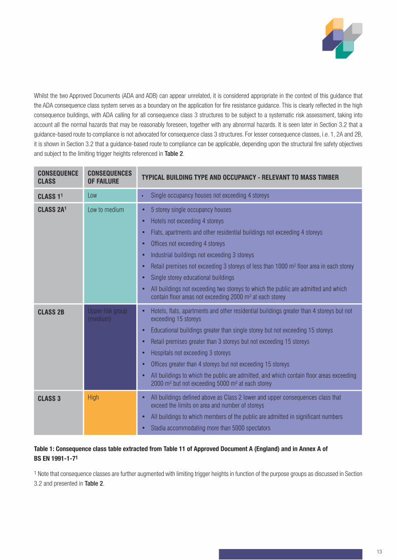
ADA provides guidance for designers by grouping buildings into consequence classes, as reflected in Table 1. When allowing designers to
specify fire resistance to elements of structure, ADB adopts a combination of trigger heights and purpose groups to impose a reducing failure
likelihood with increasing failure consequences.
13
CLASS 11
CONSEQUENCE CLASS
CONSEQUENCES OF FAILURE TYPICAL BUILDING TYPE AND OCCUPANCY - RELEVANT TO MASS TIMBER
Low
CLASS 3 High
CLASS 2A1 Low to medium
CLASS 2B Upper risk group (medium)
• Single occupancy houses not exceeding 4 storeys
• All buildings defined above as Class 2 lower and upper consequences class that exceed the limits on area and number of storeys
• All buildings to which members of the public are admitted in significant numbers
• Stadia accommodating more than 5000 spectators
• 5 storey single occupancy houses
• Hotels not exceeding 4 storeys
• Flats, apartments and other residential buildings not exceeding 4 storeys
• Offices not exceeding 4 storeys
• Industrial buildings not exceeding 3 storeys
• Retail premises not exceeding 3 storeys of less than 1000 m² floor area in each storey
• Single storey educational buildings
• All buildings not exceeding two storeys to which the public are admitted and which contain floor areas not exceeding 2000 m² at each storey
• Hotels, flats, apartments and other residential buildings greater than 4 storeys but not exceeding 15 storeys
• Educational buildings greater than single storey but not exceeding 15 storeys
• Retail premises greater than 3 storeys but not exceeding 15 storeys
• Hospitals not exceeding 3 storeys
• Offices greater than 4 storeys but not exceeding 15 storeys
• All buildings to which the public are admitted, and which contain floor areas exceeding 2000 m² but not exceeding 5000 m² at each storey
Table 1: Consequence class table extracted from Table 11 of Approved Document A (England) and in Annex A of BS EN 1991-1-71
1 Note that consequence classes are further augmented with limiting trigger heights in function of the purpose groups as discussed in Section
3.2 and presented in Table 2.
Whilst the two Approved Documents (ADA and ADB) can appear unrelated, it is considered appropriate in the context of this guidance that
the ADA consequence class system serves as a boundary on the application for fire resistance guidance. This is clearly reflected in the high
consequence buildings, with ADA calling for all consequence class 3 structures to be subject to a systematic risk assessment, taking into
account all the normal hazards that may be reasonably foreseen, together with any abnormal hazards. It is seen later in Section 3.2 that a
guidance-based route to compliance is not advocated for consequence class 3 structures. For lesser consequence classes, i.e. 1, 2A and 2B,
it is shown in Section 3.2 that a guidance-based route to compliance can be applicable, depending upon the structural fire safety objectives
and subject to the limiting trigger heights referenced in Table 2.
14 STRUCTURAL TIMBER BUILDINGS FIRE SAFETY IN USE GUIDANCE VOL 6 - MASS TIMBER STRUCTURES
3 Guidance on routes to compliance The following sections discuss general recommendations in support of ascertaining the most appropriate route to compliance with Regulation
B3(1) for mass timber projects of varying scale and use. It should be applied noting the caveats discussed in Section 1.
3.1 The QDRThe most appropriate route to compliance for a mass timber building project should be reviewed at the inception stage. The STA
promotes the undertaking of a QDR for all projects involving mass timber construction, albeit acknowledges that this may be more formal and
comprehensive for higher consequence versus lesser consequence buildings.
BS 7974 provides a structured process for highlighting and determining fire hazards, fire risks, design actions and mitigation measures. The
QDR will typically involve the following main stages [11]:
a. Review architectural design and selection of materials, including their suitability and fire properties, occupant characteristics and
client requirements;
b. Establish functional objectives for fire;
c. Identify fire hazards and possible consequences;
d. Establish trial fire safety engineering designs;
e. Set acceptance criteria for the designs;
f. Identify the method of analysis;
g. Establish fire scenarios for analysis; and
h. Document outputs of the QDR
3.2 A consequence-based design tool for complianceThe QDR process highlights a need to consider the project objectives, technical design factors, material selection factors and possible fire
induced consequences. Adopting these as a foundation and in cognisance of the underpinning research set out by OFR in Appendix A, a
general consequence-based design tool to assist in identifying the most appropriate route to compliance for a mass timber building project
has been developed and is summarised in Table 2.
Section 2.7 discusses the differences in how structural failure consequences are differentiated with respect to Part A and Part B of the
Building Regulations (and the associated statutory guidance). As a primary reference point, building consequence classes inform the route to
compliance in Table 2. Building consequence classes speak in terms of the number of storeys (ground inclusive). Depending upon the floor
to ceiling height, this can create a range of building heights of nominally the same number of storeys. The background research reported in
Appendix A has highlighted the historical role of trigger heights in differentiating changes in escape duration, operational firefighting practices,
etc., and, thus, structural fire safety objectives. In cognisance of the impact of height on such fire strategy considerations, maximum heights
for guidance-based routes to compliance are imposed in Table 2 (through Note 2) for consequence class 2a structures.
15
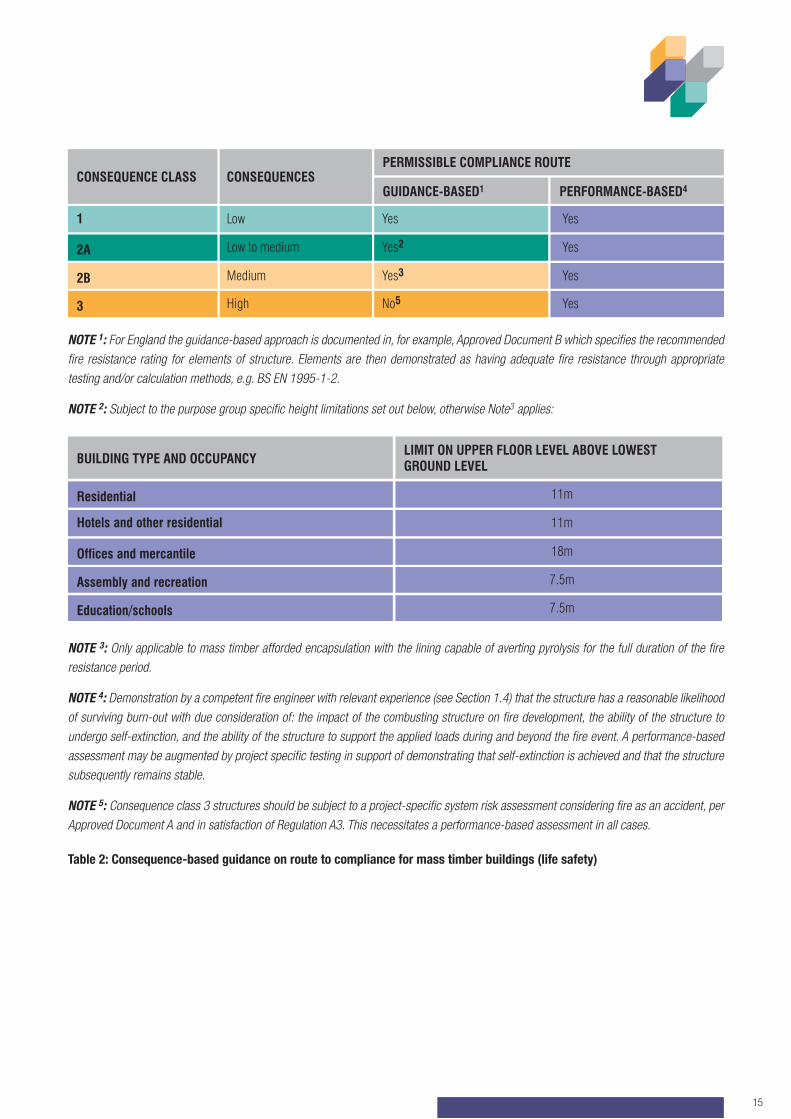
NOTE 1: For England the guidance-based approach is documented in, for example, Approved Document B which specifies the recommended fire resistance rating for elements of structure. Elements are then demonstrated as having adequate fire resistance through appropriate testing and/or calculation methods, e.g. BS EN 1995-1-2.
NOTE 2: Subject to the purpose group specific height limitations set out below, otherwise Note3 applies:
NOTE 3: Only applicable to mass timber afforded encapsulation with the lining capable of averting pyrolysis for the full duration of the fire resistance period.
NOTE 4: Demonstration by a competent fire engineer with relevant experience (see Section 1.4) that the structure has a reasonable likelihood of surviving burn-out with due consideration of: the impact of the combusting structure on fire development, the ability of the structure to undergo self-extinction, and the ability of the structure to support the applied loads during and beyond the fire event. A performance-based assessment may be augmented by project specific testing in support of demonstrating that self-extinction is achieved and that the structure subsequently remains stable.
NOTE 5: Consequence class 3 structures should be subject to a project-specific system risk assessment considering fire as an accident, per Approved Document A and in satisfaction of Regulation A3. This necessitates a performance-based assessment in all cases.
Table 2: Consequence-based guidance on route to compliance for mass timber buildings (life safety)
Residential
BUILDING TYPE AND OCCUPANCYLIMIT ON UPPER FLOOR LEVEL ABOVE LOWEST GROUND LEVEL
Assembly and recreation
Hotels and other residential
Offices and mercantile
11m
Education/schools 7.5m
7.5m
11m
18m
CONSEQUENCE CLASS CONSEQUENCESPERMISSIBLE COMPLIANCE ROUTE
GUIDANCE-BASED1 PERFORMANCE-BASED4
2B Medium
1 Low
NOTE 3: Only applicable to mass timber afforded encapsulation with the lining capable of averting pyrolysis for the full duration of the fire
resistance period.
NOTE 4: Demonstration by a competent fire engineer with relevant experience (see Section 1.4) that the structure has a reasonable likelihood
of surviving burn-out with due consideration of: the impact of the combusting structure on fire development, the ability of the structure to
undergo self-extinction, and the ability of the structure to support the applied loads during and beyond the fire event. A performance-based
assessment may be augmented by project specific testing in support of demonstrating that self-extinction is achieved and that the structure
subsequently remains stable.
NOTE 5: Consequence Class 3 structures should be subject to a project-specific system risk assessment considering fire as an accident,
per Approved Document A and in satisfaction of Regulation A3. This necessitates a performance-based assessment in all cases.
2A Low to medium
3 High No5
Yes3
Yes
Yes2
Yes
Yes
Yes
Yes
16 STRUCTURAL TIMBER BUILDINGS FIRE SAFETY IN USE GUIDANCE VOL 6 - MASS TIMBER STRUCTURES
References[1] Document available on the STA website http://www.structuraltimber.co.uk/sectors/clt-special-interest-group
[2] A. Law and R. M. Hadden, ‘Burnout Means Burnout - SFPE’. https://www.sfpe.org/page/Issue5Feature1
[3] HM Government, ‘The Building Regulations 2010, Approved Document B (Fire Safety) Volume 1 (2019 edition)’, 2019.
[4] HM Government, ‘The Building Regulations 2010, Approved Document B (Fire Safety) Volume 2 (2019 edition, as amended
May 2020)’, 2020.
[5] BSI, ‘BS 9991:2015 Fire safety in the design, management and use of residential buildings. Code of practice’, BSI, London, 2015.
[6] BSI, ‘BS 9999:2017 Fire safety in the design, management and use of buildings. Code of practice’, BSI, London, 2017.
[7] P. Wilkinson, D. Hopkin, and B. McColl, ‘Chapter 12: Fire resistance, structural robustness in fire and fire spread’, in CIBSE Guide E:
Fire safety engineering, 4th ed., Suffolk: The Lavenham Press Ltd, 2019.
[8] A. Law and L. Bisby, ‘The rise and rise of fire resistance’, Fire Saf. J., p. 103188, Jul. 2020, doi: 10.1016/j.firesaf.2020.103188.
[9] J. Gales, C. Maluk, and L. Bisby, ‘Structural fire testing- where are we, how did we get here, and where are we going?’, in 15th
International Conference on Experimental Mechanics: Fire symposium, Porto, 2012, pp. 22-27.
[10] BSI, ‘BS EN 1995-1-2:2004 Eurocode 5. Design of timber structures. General. Structural fire design’, BSI, London, 2004.
[11] BSI, ‘BS 7974:2019 Application of fire safety engineering principles to the design of buildings. Code of practice’, BSI, London, 2019.
[12] BSI, ‘PD 7974-3:2019 Application of fire safety engineering principles to the design of buildings. Structural response to fire and fire
spread beyond the enclosure of origin (Sub-system 3)’, BSI, London, 2019.
[13] BSI, ‘BS EN 13501-2:2016 Fire classification of construction products and building elements.
Classification using data from fire resistance tests, excluding ventilation services’, BSI, London, 2016.
[14] C. Di Blasi, ‘Modeling chemical and physical processes of wood and biomass pyrolysis’, Prog. Energy Combust. Sci., vol. 34,
no. 1, pp. 47-90, Feb. 2008, doi: 10.1016/j.pecs.2006.12.001.
[15] BSI, ‘BS EN 1990:2002+A1:2005 Eurocode. Basis of structural design’, BSI Standards Publication, London, 2005.
[16] BSI, ‘BS EN 1991-1-2:2002 Eurocode 1. Actions on structures. General actions. Actions on structures exposed to fire’, British
Standards Institution, London, 2002.
[17] BSI, ‘NA to BS EN 1991-1-2:2002 UK National Annex to Eurocode 1. Actions on structures. General actions. Actions on
structures exposed to fire’, BSI, London, 2007.
[18] BSI, ‘PD 6688-1-2:2007 Background paper to the UK National Annex to BS EN 1991-1-2’, BSI, London, 2007.
[19] HM Government, ‘The Building Regulations 2010, Approved Document A (Structure)’, London, 2004.
The report follows on from here, within this document,
or can be downloaded from
http://www.structuraltimber.co.uk/sectors/clt-special-interest-group
17
Appendix A - OFR WP1 Report
Compliance roadmap for mass timber projects in England
Regulation B3(1)
Revision: R06Date: 28/09/2020
Project Number: OX19044
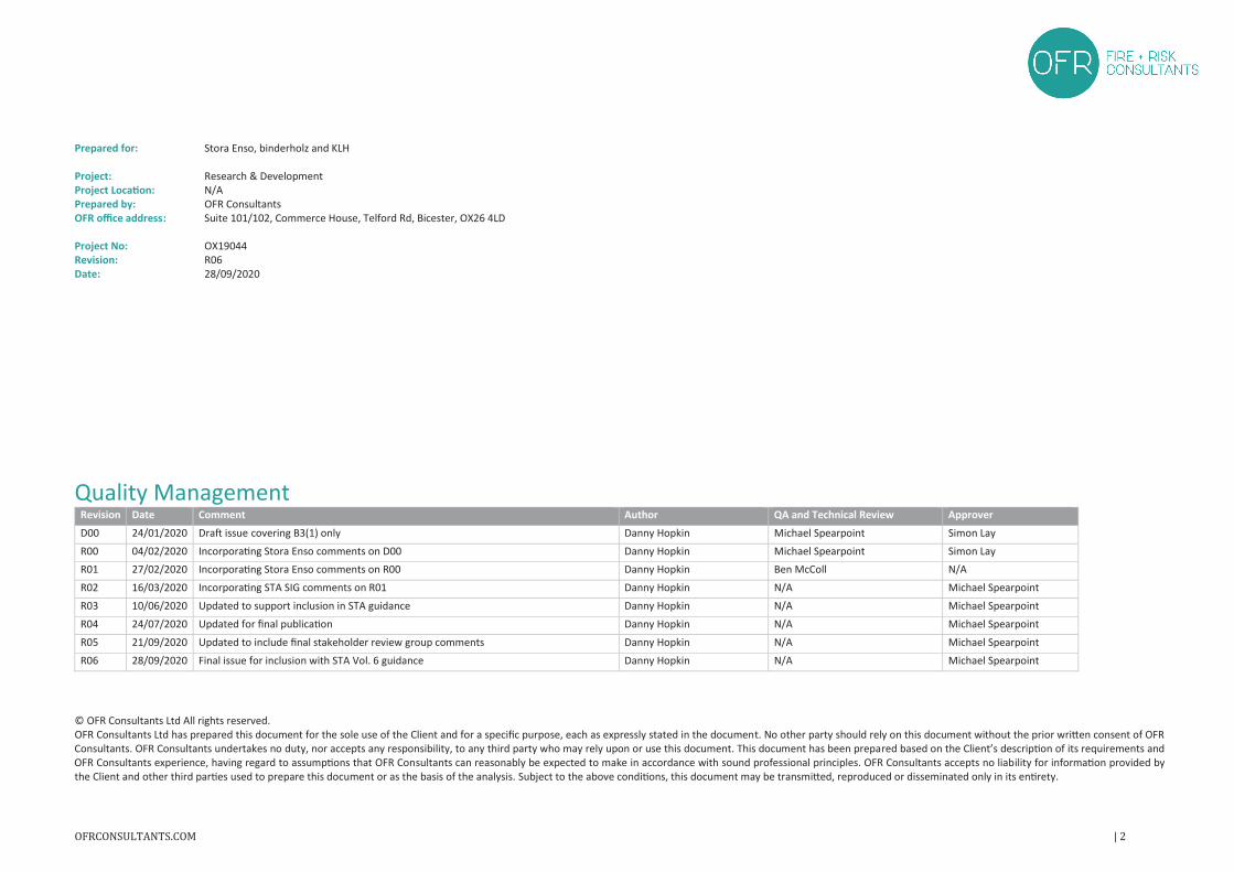
Prepared for: Stora Enso, binderholz and KLH
Project: Research & DevelopmentProject Location: N/APrepared by: OFR ConsultantsOFR office address: Suite 101/102, Commerce House, Telford Rd, Bicester, OX26 4LD
Project No: OX19044Revision: R06Date: 28/09/2020
Quality ManagementRevision Date Comment Author QA and Technical Review Approver
D00 24/01/2020 Draft issue covering B3(1) only Danny Hopkin Michael Spearpoint Simon Lay
R00 04/02/2020 Incorporating Stora Enso comments on D00 Danny Hopkin Michael Spearpoint Simon Lay
R01 27/02/2020 Incorporating Stora Enso comments on R00 Danny Hopkin Ben McColl N/A
R02 16/03/2020 Incorporating STA SIG comments on R01 Danny Hopkin N/A Michael Spearpoint
R03 10/06/2020 Updated to support inclusion in STA guidance Danny Hopkin N/A Michael Spearpoint
R04 24/07/2020 Updated for final publication Danny Hopkin N/A Michael Spearpoint
R05 21/09/2020 Updated to include final stakeholder review group comments Danny Hopkin N/A Michael Spearpoint
R06 28/09/2020 Final issue for inclusion with STA Vol. 6 guidance Danny Hopkin N/A Michael Spearpoint
© OFR Consultants Ltd All rights reserved.OFR Consultants Ltd has prepared this document for the sole use of the Client and for a specific purpose, each as expressly stated in the document. No other party should rely on this document without the prior written consent of OFRConsultants. OFR Consultants undertakes no duty, nor accepts any responsibility, to any third party who may rely upon or use this document. This document has been prepared based on the Client’s description of its requirements andOFR Consultants experience, having regard to assumptions that OFR Consultants can reasonably be expected to make in accordance with sound professional principles. OFR Consultants accepts no liability for information provided bythe Client and other third parties used to prepare this document or as the basis of the analysis. Subject to the above conditions, this document may be transmitted, reproduced or disseminated only in its entirety.
Contents
1 Introduction ........................................................................................................................................................4
1.1 Context........................................................................................................................................................4
1.2 Appointment...............................................................................................................................................4
1.3 Definitions...................................................................................................................................................4
1.4 Relevant legislation.....................................................................................................................................4
1.5 Scope...........................................................................................................................................................5
1.5.1 Types of timber construction within / outside of document scope ...................................................5
1.5.2 Types of buildings within / outside of document scope.....................................................................5
1.6 Application of the compliance roadmap / process.....................................................................................5
1.7 Relationship with guidance and EN 1995-1-2.............................................................................................6
1.8 Competency and peer review.....................................................................................................................6
2 Building Regulation Requirements (England) .....................................................................................................7
2.1 B1 – Means of warning and escape ............................................................................................................7
2.1.1 Functional requirement ......................................................................................................................7
2.1.2 Intention..............................................................................................................................................7
2.2 B2 – Internal fire spread (linings)................................................................................................................7
2.2.1 Functional requirement ......................................................................................................................7
2.2.2 Intention..............................................................................................................................................7
2.3 B3 – Internal fire spread (structure) ...........................................................................................................7
2.3.1 Functional requirement ......................................................................................................................7
2.3.2 Intention..............................................................................................................................................7
2.4 B4 – External fire spread.............................................................................................................................8
2.4.1 Functional requirement ......................................................................................................................8
2.4.2 Intention .............................................................................................................................................8
2.5 B5 – Means of warning and escape ............................................................................................................8
2.5.1 Functional requirement ......................................................................................................................8
2.5.2 Intention .............................................................................................................................................8
2.6 Regulation 7 ................................................................................................................................................9
3 Traditional routes to compliance and potential challenges associated with MTPC.........................................10
3.1 Structural performance in the event of fire..............................................................................................10
3.1.1 Fire resistance periods as a proxy for surviving burnout..................................................................10
3.1.2 Fire resistance periods and objectives – prerequisites.....................................................................10
3.2 Historical review of regulation and guidance – implications for MTPC....................................................12
3.2.1 Fire design guidance & regulation: Fire gradings of buildings – part I .............................................12
3.2.2 Fire design guidance & regulation: The Building Regulations (1965) ...............................................12
3.2.3 Fire design guidance & regulation: The Building Regulations (1985) ...............................................13
3.2.4 Current Regulations, guidance and posited objectives for structural fire performance..................13
4 Compliance flow chart for Building Regulation B3(1).......................................................................................15
5 Example applications ........................................................................................................................................16
5.1 Dwelling-house [red].................................................................................................................................16
5.2 Medium-rise office building [blue] ...........................................................................................................16
5.3 Medium-rise apartment building [black]..................................................................................................16
5.4 Tall office building [green] ........................................................................................................................16
6 References ........................................................................................................................................................19
1 INTRODUCTION
1.1 Context
Mass timber construction has increased in popularity due to environmental drivers, buildability, impact onwellness, etc. Given the declaration of a climate emergency by various jurisdictions [1], the wider adoption of masstimber will be a significant part of construction solutions that seek to reduce impact on climate change in the builtenvironment. Particularly in panelised form, mass timber introduces new fire safety challenges not readilyaddressed within current regulatory and fire guidance paradigms. This document has been prepared to outlinewhat compliance means in an English regulatory fire context and the differing means through which compliancecan / should be demonstrated.
1.2 Appointment
OFR Consultants have been appointed by CLT suppliers Stora Enso, binderholz and KLH to develop a complianceroadmap for mass timber structures in the UK (see scope in Section 1.3), with an emphasis on cross laminatedtimber (CLT) construction. This issue of the roadmap is written to address specific aspects of Part B of the BuildingRegulations 2010 (incorporating amendments to 2019) (defined as “the Regulations” henceforth) for England.Differences exist with regard other UK jurisdictions, which should be addressed in a subsequent update of thisdocument or separate jurisdiction specific roadmaps. This issue focuses only on compliance with requirementB3(1) – “Internal fire spread – structure”, with other Building Regulation requirements to be considered separately(for example, it should be noted that fuel from a combustible structure can burn outside of openings, presentingan external fire spread hazard that should also be adequately addressed).
The roadmap is intended to provide guidance in relation to satisfying life safety requirements (for people withinor the vicinity of a building in the event of fire), with an emphasis on:
� Clarifying the legal requirement (as set out in the Regulations) with respect to the fire performance ofstructures in England (in the first instance);
� Documenting the compliance pathway for mass timber structures in terms of satisfying the requirementsof Part B of the Regulations;
� Outlining what evidence should be provided to support compliance with Part B of Regulations underdiffering circumstances; and
� Clarifying who is ultimately responsible for developing evidence in support of demonstrating compliance with Part B of the Regulations.
In complying with the Regulations, environmental and/or property protection is not assured. Client drivers relatingto such objectives may require considerations beyond the scope of this document, see Section 1.4.
1.3 Definitions
For the purposes of this report, the following definitions apply:
• Building consequence class – building class grouping, differentiated by the consequences of a structuralfailure, as defined in Approved Document A [2]. Note: also referred to as reliability class in ISO 2394 [3];
• Mass timber panelised construction (MTPC) – large planar panels constructed of cross laminated timber(CLT), glue laminated timber (glulam), laminated veneer lumber (LVL), nail laminated timber (NLT), orsimilar;
• Fire resistance – performance of an isolated construction element in a furnace test, relative to specificperformance criteria (integrity, insulation, loadbearing, fire protection) under defined time-temperature
exposure (see: “standard time-temperature curve”) and, where applicable, loading conditions, asdefined in EN 1365-1 [4];
• Reaction-to-fire – response of a product in contributing by its own decomposition to a fire to which it isexposed, under specified conditions;
• Exposed - absence of protection or when protection no longer performs its intended purpose;
• Standard time-temperature curve – the time-temperature heating regime adopted in standard fireresistance testing protocols, i.e. as defined in ISO 834 [5];
• Encapsulation – lining of the mass timber elements such that pyrolysis is mitigated for the full durationof the fire resistance period when subject to the standard time-temperature curve. Achieved byproviding a protective lining capable of averting the onset of pyrolysis (to the extent it may affectenclosure fire development) for the duration of the fire resistance period (Note: the K2 class as defined in BS EN 13501-1 [6] is often adopted as a means of substantiating the performance of a lining with respect to adequately averting pyrolysis. This document does not explicitly advocate its adoption due toongoing debates as to conservatism of the temperature thresholds adopted. It is ultimately theresponsibility of the designer to defend the performance specification for any encapsulation solutions);
• Partial protection – lining of the mass timber elements, where the applied protection material cannotmitigate pyrolysis for the full duration of the fire resistance period when subject to the standard time-temperature curve;
• Purpose group – a classification of a building according to the purpose to which it is intended to be put;
• Auto-extinction – the cessation of combustion (typically, both smouldering and flaming), without activeintervention (e.g. fire fighting);
• Pyrolyse or Pyrolysis – process by which a material or compound decomposes by heat in the absence ofoxygen; and
• The Regulations – the Building Regulations 2010 (incorporating amendments to 2019) as applied tobuilding projects in England.
1.4 Relevant legislation
The compliance roadmap documented herein addresses the requirements set out in the Regulations. It does notaddress other project objectives, e.g. property protection, business continuity, etc., which should be discussedseparately with relevant stakeholders at the outset of a project as part of a qualitative design review (QDR), asdefined in BS 7974 [7].
The choice of MTPC as a structural solution can introduce fire safety challenges during the construction phase.These challenges are not unique to MTPC and apply to all forms of timber construction. The safety of constructionsite staff and those in proximity falls within the remit of several pieces of legislation, e.g.:
• The Construction & Design Management (CDM) Regulations (2015);
• The Fire Safety (Employees’ Capabilities) (England) Regulations (2010); and
• Dangerous Substances and Explosive Regulations (DSEAR).
It is not within the scope of this document to address the hazards and risks associated with timber during theconstruction phase. However, attention is brought to associated guidance, e.g. HSG 168 [8], the STA 16 step plan[9] and the STA guide to separating distances [10].
1.5 Scope
The scope of this document can be split into two areas: (1) the types of timber construction; and (2) the types ofbuildings intended to be covered. In the case of the former, the types of timber construction is wholly consistentwith the draft Building Control Alliance (BCA) technical guidance note (GN) 29 [11].
1.5.1 Types of timber construction within / outside of document scope
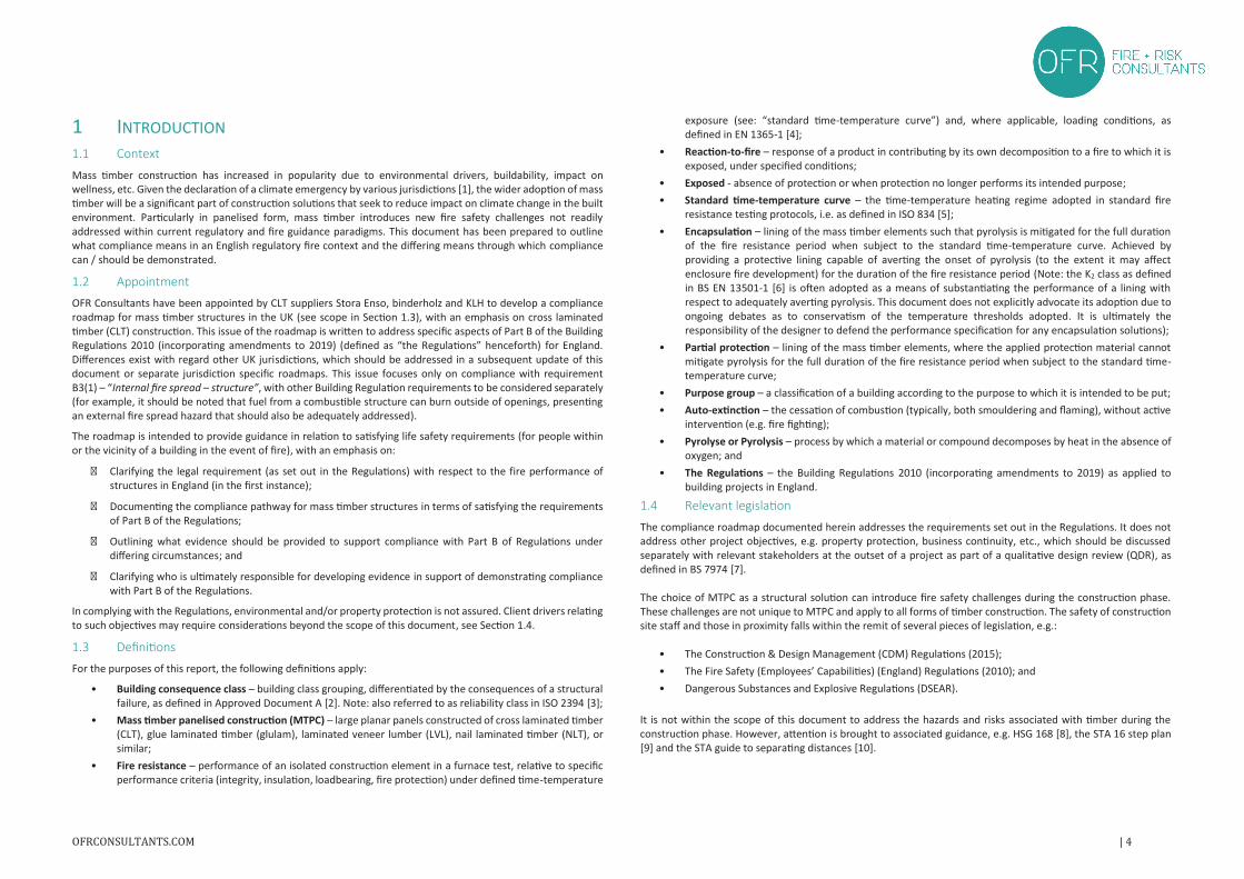
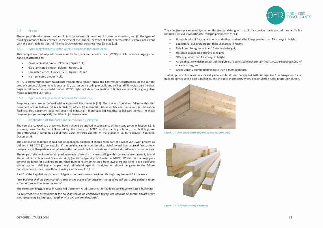
This compliance roadmap addresses mass timber panelised construction (MTPC), which concerns large planar panels constructed of:
• Cross laminated timber (CLT) - see Figure 1-1;
• Glue laminated timber (glulam) - Figure 1-2;
• Laminated veneer lumber (LVL) - Figure 1-3; and
• Nail laminated timber (NLT).
MTPC is differentiated from traditional framed mass timber forms and light timber construction, as the surfacearea of combustible elements is substantial, e.g. an entire ceiling or walls and ceiling. MTPC typical also involvesengineered timber versus solid timber. MTPC might include a combination of timber components, e.g. a glulamframe supporting CLT floors.
1.5.2 Types of buildings within / outside of document scope
Purpose groups are as defined within Approved Document B [12]. The scope of buildings falling within thisdocument are as follows: (a) residential; (b) office; (c) mercantile; (d) assembly and recreation; (e) educationfacilities. This document does not cover: (i) industrial; (ii) storage; (iii) healthcare; (iv) care homes; (v) thosepurpose groups not explicitly identified in (a) to (e) above.
1.6 Application of the compliance roadmap / process
The compliance roadmap presented herein should be applied in cognisance of the scope given in Section 1.5. Itassumes, sans the factors influenced by the choice of MTPC as the framing solution, that buildings arestraightforward / common as it directs users towards aspects of the guidance in, for example, ApprovedDocument B.
The compliance roadmap should not be applied in isolation. It should form part of a wider QDR, with process asdefined in BS 7974 [7], to establish if the building can be considered straightforward from a broad fire strategyperspective, with a particular emphasis on the nature of the fire hazards and the fire induced failure consequences.
The scope of the guidance herein predominantly concerns structures falling within consequence classes 1, 2a and2b, as defined in Approved Document A [2] (i.e. those typically constructed of MTPC). Whilst this roadmap givesgeneral guidance for buildings greater than 18 m in height (measured from lowest ground level to top qualifyingstorey) without defining an upper height threshold, specific consideration should be given to the failureconsequences associated with tall buildings in the event of fire.
Part A of the Regulations places an obligation on the structural engineer through requirement A3 to ensure:
“the building shall be constructed so that in the event of an accident the building will not suffer collapse to anextent disproportionate to the cause”.
The corresponding guidance in Approved Document A [2] states that for building consequence class 3 buildings:
“A systematic risk assessment of the building should be undertaken taking into account all normal hazards thatmay reasonable be foreseen, together with any abnormal hazards”.
This effectively places an obligation on the structural designer to explicitly consider the impact of the specific firehazards from a disproportionate collapse perspective for all:
• Hotels, blocks of flats, apartments and other residential buildings greater than 15 storeys in height;
• Educational buildings greater than 15 storeys in height;
• Retail premises greater than 15 storeys in height;
• Hospitals exceeding 3 storeys in height;
• Offices greater than 15 storeys in height;
• All buildings to which members of the public are admitted which contain floors areas exceeding 5,000 m2
at each storey; and
• Grandstands accommodating more than 5,000 spectators.
That is, generic fire resistance-based guidance should not be applied without significant interrogation for allbuilding consequence class 3 buildings. This includes those cases where encapsulation is the proposed solution.
Figure 1-1 – Cross laminated timber panel (courtesy of Stora Enso)
Figure 1-2 – Glulam (courtesy of binderholz)
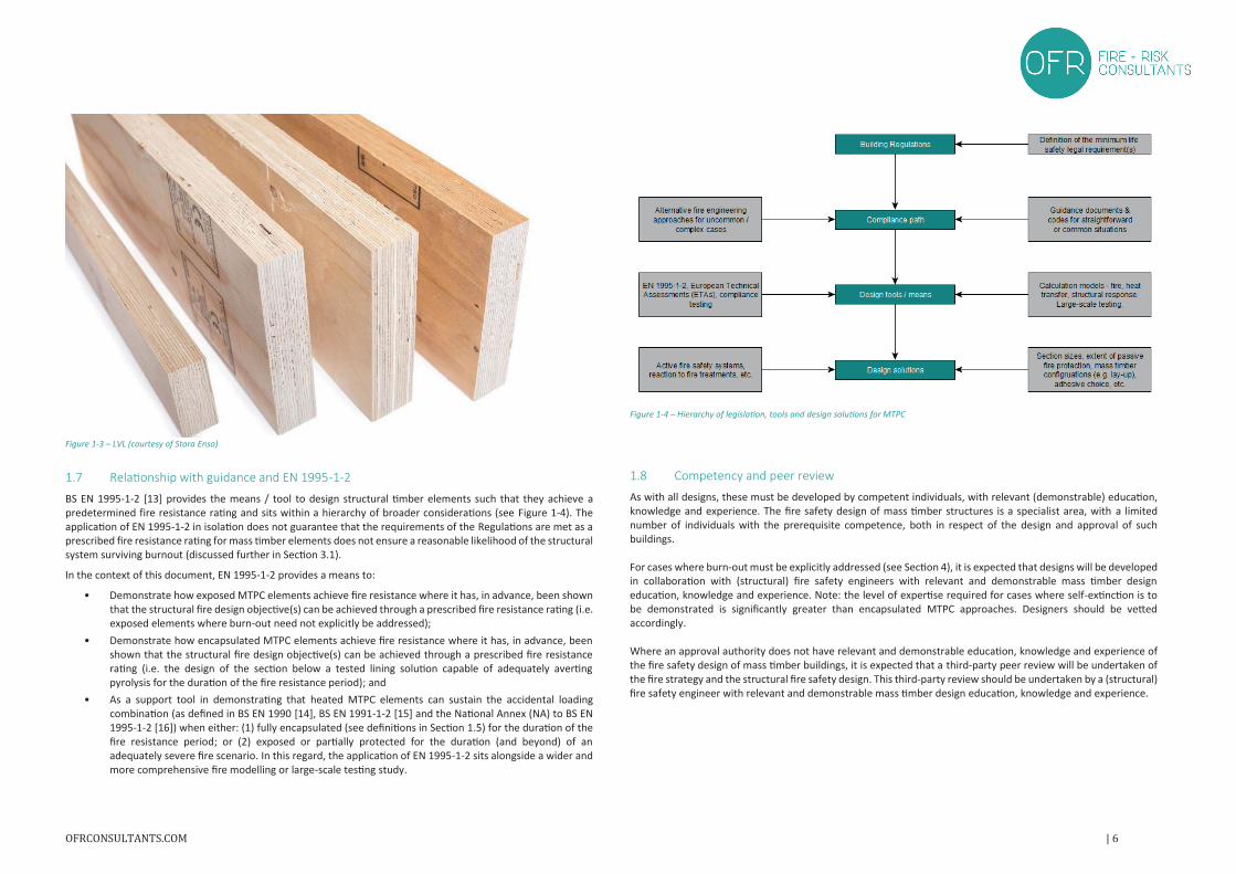
Figure 1-3 – LVL (courtesy of Stora Enso)
1.7 Relationship with guidance and EN 1995-1-2
BS EN 1995-1-2 [13] provides the means / tool to design structural timber elements such that they achieve apredetermined fire resistance rating and sits within a hierarchy of broader considerations (see Figure 1-4). Theapplication of EN 1995-1-2 in isolation does not guarantee that the requirements of the Regulations are met as a prescribed fire resistance rating for mass timber elements does not ensure a reasonable likelihood of the structuralsystem surviving burnout (discussed further in Section 3.1).
In the context of this document, EN 1995-1-2 provides a means to:
• Demonstrate how exposed MTPC elements achieve fire resistance where it has, in advance, been shownthat the structural fire design objective(s) can be achieved through a prescribed fire resistance rating (i.e.exposed elements where burn-out need not explicitly be addressed);
• Demonstrate how encapsulated MTPC elements achieve fire resistance where it has, in advance, beenshown that the structural fire design objective(s) can be achieved through a prescribed fire resistancerating (i.e. the design of the section below a tested lining solution capable of adequately avertingpyrolysis for the duration of the fire resistance period); and
• As a support tool in demonstrating that heated MTPC elements can sustain the accidental loadingcombination (as defined in BS EN 1990 [14], BS EN 1991-1-2 [15] and the National Annex (NA) to BS EN1995-1-2 [16]) when either: (1) fully encapsulated (see definitions in Section 1.5) for the duration of thefire resistance period; or (2) exposed or partially protected for the duration (and beyond) of anadequately severe fire scenario. In this regard, the application of EN 1995-1-2 sits alongside a wider andmore comprehensive fire modelling or large-scale testing study.
Figure 1-4 – Hierarchy of legislation, tools and design solutions for MTPC
1.8 Competency and peer review
As with all designs, these must be developed by competent individuals, with relevant (demonstrable) education,knowledge and experience. The fire safety design of mass timber structures is a specialist area, with a limitednumber of individuals with the prerequisite competence, both in respect of the design and approval of suchbuildings.
For cases where burn-out must be explicitly addressed (see Section 4), it is expected that designs will be developedin collaboration with (structural) fire safety engineers with relevant and demonstrable mass timber designeducation, knowledge and experience. Note: the level of expertise required for cases where self-extinction is tobe demonstrated is significantly greater than encapsulated MTPC approaches. Designers should be vettedaccordingly.
Where an approval authority does not have relevant and demonstrable education, knowledge and experience ofthe fire safety design of mass timber buildings, it is expected that a third-party peer review will be undertaken ofthe fire strategy and the structural fire safety design. This third-party review should be undertaken by a (structural)fire safety engineer with relevant and demonstrable mass timber design education, knowledge and experience.
2 BUILDING REGULATION REQUIREMENTS (ENGLAND)The below sections set out the relevant life safety mandatory requirements with respect to fire for buildingsconstructed in England, as defined by the Regulations. The intentions of the requirements are also clarifiedadopting the wording in Approved Document B [12]. The Regulations constitute multiple functional requirements(i.e. performance-based regulations – B1 to B5), alongside prescriptive requirements (Regulation 7) introducedpost-Grenfell Tower. All must be satisfied and are interrelated, e.g. what constitutes a “reasonable period” underB3(1) is informed by the strategies relating to means of escape (B1), mitigating fire spread (B3 and B4) and firebrigade intervention (B5).
2.1 B1 – Means of warning and escape
2.1.1 Functional requirement
The Building Regulations requirement B1 states:
“The building shall be designed and constructed so that there are appropriate provisions for the early warning offire, and appropriate means of escape in case of fire from the building to a place of safety outside the buildingcapable of being safely and effectively used at all material times.”
2.1.2 Intention
“In the Secretary of State’s view, requirement B1 is met by achieving all of the following.
a) There are sufficient means for giving early warning of fire to people in the building.
b) All people can escape to a place of safety without external assistance.
c) Escape routes are suitably located, sufficient in number and of adequate capacity.
d) Where necessary, escape routes are sufficiently protected from the effects of fire and smoke.
e) Escape routes are adequately lit and exits are suitably signed.
f) There are appropriate provisions to limit the ingress of smoke to the escape routes, or to restrict the spreadof fire and remove smoke.
g) For buildings containing flats, there are appropriate provisions to support a stay put evacuation strategy.
The extent to which any of these measures are necessary is dependent on the use of the building, its size and its height.“
2.2 B2 – Internal fire spread (linings)
2.2.1 Functional requirement
The Building Regulations requirement B2 states:
“(1) To inhibit the spread of fire within the building, the internal linings shall—
a) adequately resist the spread of flame over their surfaces; and
b) have, if ignited, either a rate of heat release or a rate of fire growth, which is reasonable in thecircumstances.
(2) In this paragraph “internal linings” means the materials or products used in lining any partition, wall, ceiling orother internal structure. ”
2.2.2 Intention
“In the Secretary of State’s view, requirement B2 is met by achieving a restricted spread of flame over internal linings. The building fabric should make a limited contribution to fire growth, including a low rate of heat release.
It is particularly important in circulation spaces, where linings may offer the main means by which fire spreads andwhere rapid spread is most likely to prevent occupants from escaping.”
2.3 B3 – Internal fire spread (structure)
2.3.1 Functional requirement
The Building Regulations requirement B3 states:
“(1) The building shall be designed and constructed so that, in the event of fire, its stability will be maintained fora reasonable period
(2) A wall common to two or more buildings shall be designed and constructed so that it adequately resists thespread of fire between those buildings. For the purposes of this sub-paragraph a house in a terrace and a semi-detached house are each to be treated as a separate building.
(3) Where reasonably necessary to inhibit the spread of fire within the building, measures shall be taken, to anextent appropriate to the size and intended use of the building, comprising either or both of the following—
a) sub-division of the building with fire-resisting construction;
b) installation of suitable automatic fire suppression systems.
(4) The building shall be designed and constructed so that the unseen spread of fire and smoke within concealedspaces in its structure and fabric is inhibited.”
2.3.2 Intention
“In the Secretary of State’s view, requirement B3 is met by achieving all of the following.
a) For defined periods, loadbearing elements of structure withstand the effects of fire without loss of stability.
b) Compartmentation of buildings by fire resisting construction elements.
c) Automatic fire suppression is provided where it is necessary.
d) Protection of openings in fire-separating elements to maintain continuity of the fire separation.
e) Inhibition of the unseen spread of fire and smoke in cavities, in order to reduce the risk of structural failureand spread of fire and smoke, where they pose a threat to the safety of people in and around the building.
The extent to which any of these measures are necessary is dependent on the use of the building and, in somecases, its size, and on the location of the elements of construction.”
2.4 B4 – External fire spread
2.4.1 Functional requirement
The Building Regulations requirement B4 states:
“(1) The external walls of the building shall adequately resist the spread of fire over the walls and from one buildingto another, having regard to the height, use and position of the building.
(2) The roof of the building shall adequately resist the spread of fire over the roof and from one building to another,having regard to the use and position of the building.”
2.4.2 Intention
“Resisting fire spread over external walls
The external envelope of a building should not contribute to undue fire spread from one part of a building to anotherpart. This intention can be met by constructing external walls so that both of the following are satisfied.
a) The risk of ignition by an external source to the outside surface of the building and spread of fire over theoutside surface is restricted.
b) The materials used to construct external walls, and attachments to them, and how they are assembled donot contribute to the rate of fire spread up the outside of the building.
The extent to which this is necessary depends on the height and use of the building.
Resisting fire spread from one building to another
The external envelope of a building should not provide a medium for undue fire spread to adjacent buildings or be readily ignited by fires in adjacent buildings. This intention can be met by constructing external walls so that all ofthe following are satisfied.
a) The risk of ignition by an external source to the outside surface of the building is restricted.
b) The amount of thermal radiation that falls on a neighbouring building from window openings and otherunprotected areas in the building on fire is not enough to start a fire in the other building.
c) Flame spread over the roof and/or fire penetration from external sources through the roof is restricted.
The extent to which this is necessary depends on the use of the building and its position in relation to adjacent buildings and therefore the site boundary.”
2.5 B5 – Means of warning and escape
2.5.1 Functional requirement
The Building Regulations requirement B5 states:
“(1) The building shall be designed and constructed so as to provide reasonable facilities to assist fire fighters inthe protection of life.
(2) Reasonable provision shall be made within the site of the building to enable fire appliances to gain access to thebuilding.”
2.5.2 Intention“Provisions covering access and facilities for the fire service are to safeguard the health and safety of people in andaround the building. Their extent depends on the size and use of the building. Most firefighting is carried out withinthe building. In the Secretary of State’s view, requirement B5 is met by achieving all of the following.
a) External access enabling fire appliances to be used near the building.b) Access into and within the building for firefighting personnel to both:
i) search for and rescue peopleii) fight fire.
c) Provision for internal fire facilities for firefighters to complete their tasks.d) Ventilation of heat and smoke from a fire in a basement.
If an alternative approach is taken to providing the means of escape, outside the scope of this approved document,additional provisions for firefighting access may be required. Where deviating from the general guidance, it isadvisable to seek advice from the fire and rescue service as early as possible (even if there is no statutory duty toconsult).”
2.6 Regulation 7
Regulation 7 states:
“(1) Building work shall be carried out—
a) with adequate and proper materials which—
i) are appropriate for the circumstances in which they are used,
ii) are adequately mixed or prepared, and
iii) are applied, used or fixed so as adequately to perform the functions for which they are designed; and
b) in a workmanlike manner.
(2) Subject to paragraph (3), building work shall be carried out so that materials which become part of an externalwall, or specified attachment, of a relevant building are of European Classification A2-s1, d0 or A1, classified inaccordance with BS EN 13501-1:2007+A1:2009 entitled “Fire classification of construction products and buildingelements. Classification using test data from reaction to fire tests” (ISBN 978 0 580 59861 6) published by the BritishStandards Institution on 30th March 2007 and amended in November 2009.
(3) Paragraph (2) does not apply to—
a) cavity trays when used between two leaves of masonry;
b) any part of a roof (other than any part of a roof which falls within paragraph (iv) of regulation 2(6)) if thatpart is connected to an external wall;
c) door frames and doors;
d) electrical installations;
e) insulation and water proofing materials used below ground level;
f) intumescent and fire stopping materials where the inclusion of the materials is necessary to meet therequirements of Part B of Schedule 1;
g) membranes;
h) seals, gaskets, fixings, sealants and backer rods;
i) thermal break materials where the inclusion of the materials is necessary to meet the thermal bridgingrequirements of Part L of Schedule 1; or
j) window frames and glass.
(4) In this regulation—
a. a “relevant building” means a building with a storey (not including roof-top plant areas or any storeyconsisting exclusively of plant rooms) at least 18 metres above ground level and which—
i. contains one or more dwellings;
ii. contains an institution; or
iii. contains a room for residential purposes (excluding any room in a hostel, hotel or boardinghouse); and
b. “above ground level” in relation to a storey means above ground level when measured from the lowestground level adjoining the outside of a building to the top of the floor surface of the storey.
3 TRADITIONAL ROUTES TO COMPLIANCE AND POTENTIAL CHALLENGES
ASSOCIATED WITH MTPCThe choice of MTPC as a structural solution can introduce fire safety challenges beyond those traditionally foreseenby typical routes to compliance, e.g. through the application of standard guidance such as: Approved Document B[12]; BS 9991 [17] and BS 9999 [18].
3.1 Structural performance in the event of fire
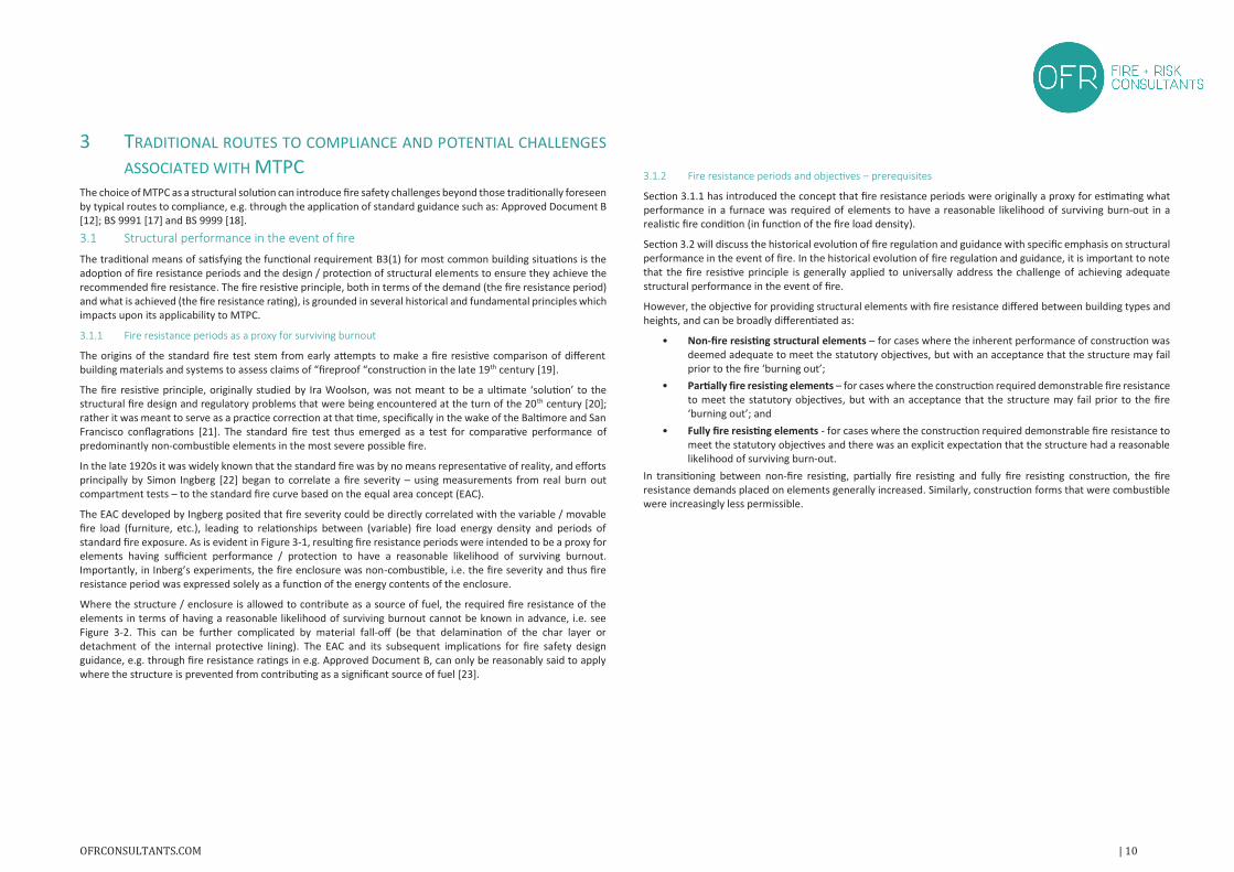
The traditional means of satisfying the functional requirement B3(1) for most common building situations is theadoption of fire resistance periods and the design / protection of structural elements to ensure they achieve therecommended fire resistance. The fire resistive principle, both in terms of the demand (the fire resistance period)and what is achieved (the fire resistance rating), is grounded in several historical and fundamental principles whichimpacts upon its applicability to MTPC.
3.1.1 Fire resistance periods as a proxy for surviving burnout
The origins of the standard fire test stem from early attempts to make a fire resistive comparison of differentbuilding materials and systems to assess claims of “fireproof “construction in the late 19th century [19].
The fire resistive principle, originally studied by Ira Woolson, was not meant to be a ultimate ‘solution’ to thestructural fire design and regulatory problems that were being encountered at the turn of the 20th century [20];rather it was meant to serve as a practice correction at that time, specifically in the wake of the Baltimore and SanFrancisco conflagrations [21]. The standard fire test thus emerged as a test for comparative performance ofpredominantly non-combustible elements in the most severe possible fire.
In the late 1920s it was widely known that the standard fire was by no means representative of reality, and effortsprincipally by Simon Ingberg [22] began to correlate a fire severity – using measurements from real burn outcompartment tests – to the standard fire curve based on the equal area concept (EAC).
The EAC developed by Ingberg posited that fire severity could be directly correlated with the variable / movablefire load (furniture, etc.), leading to relationships between (variable) fire load energy density and periods ofstandard fire exposure. As is evident in Figure 3-1, resulting fire resistance periods were intended to be a proxy forelements having sufficient performance / protection to have a reasonable likelihood of surviving burnout.Importantly, in Inberg’s experiments, the fire enclosure was non-combustible, i.e. the fire severity and thus fireresistance period was expressed solely as a function of the energy contents of the enclosure.
Where the structure / enclosure is allowed to contribute as a source of fuel, the required fire resistance of theelements in terms of having a reasonable likelihood of surviving burnout cannot be known in advance, i.e. seeFigure 3-2. This can be further complicated by material fall-off (be that delamination of the char layer ordetachment of the internal protective lining). The EAC and its subsequent implications for fire safety designguidance, e.g. through fire resistance ratings in e.g. Approved Document B, can only be reasonably said to applywhere the structure is prevented from contributing as a significant source of fuel [23].
3.1.2 Fire resistance periods and objectives – prerequisites
Section 3.1.1 has introduced the concept that fire resistance periods were originally a proxy for estimating whatperformance in a furnace was required of elements to have a reasonable likelihood of surviving burn-out in a realistic fire condition (in function of the fire load density).
Section 3.2 will discuss the historical evolution of fire regulation and guidance with specific emphasis on structuralperformance in the event of fire. In the historical evolution of fire regulation and guidance, it is important to notethat the fire resistive principle is generally applied to universally address the challenge of achieving adequatestructural performance in the event of fire.
However, the objective for providing structural elements with fire resistance differed between building types andheights, and can be broadly differentiated as:
• Non-fire resisting structural elements – for cases where the inherent performance of construction wasdeemed adequate to meet the statutory objectives, but with an acceptance that the structure may failprior to the fire ‘burning out’;
• Partially fire resisting elements – for cases where the construction required demonstrable fire resistanceto meet the statutory objectives, but with an acceptance that the structure may fail prior to the fire‘burning out’; and
• Fully fire resisting elements - for cases where the construction required demonstrable fire resistance tomeet the statutory objectives and there was an explicit expectation that the structure had a reasonablelikelihood of surviving burn-out.
In transitioning between non-fire resisting, partially fire resisting and fully fire resisting construction, the fireresistance demands placed on elements generally increased. Similarly, construction forms that were combustiblewere increasingly less permissible.
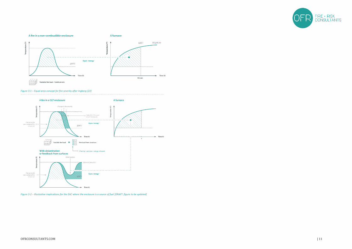
Figure 3-1 – Equal area concept for fire severity after Ingberg [22]
Figure 3-2 – Illustrative implications for the EAC where the enclosure is a source of fuel [DRAFT: figure to be updated]
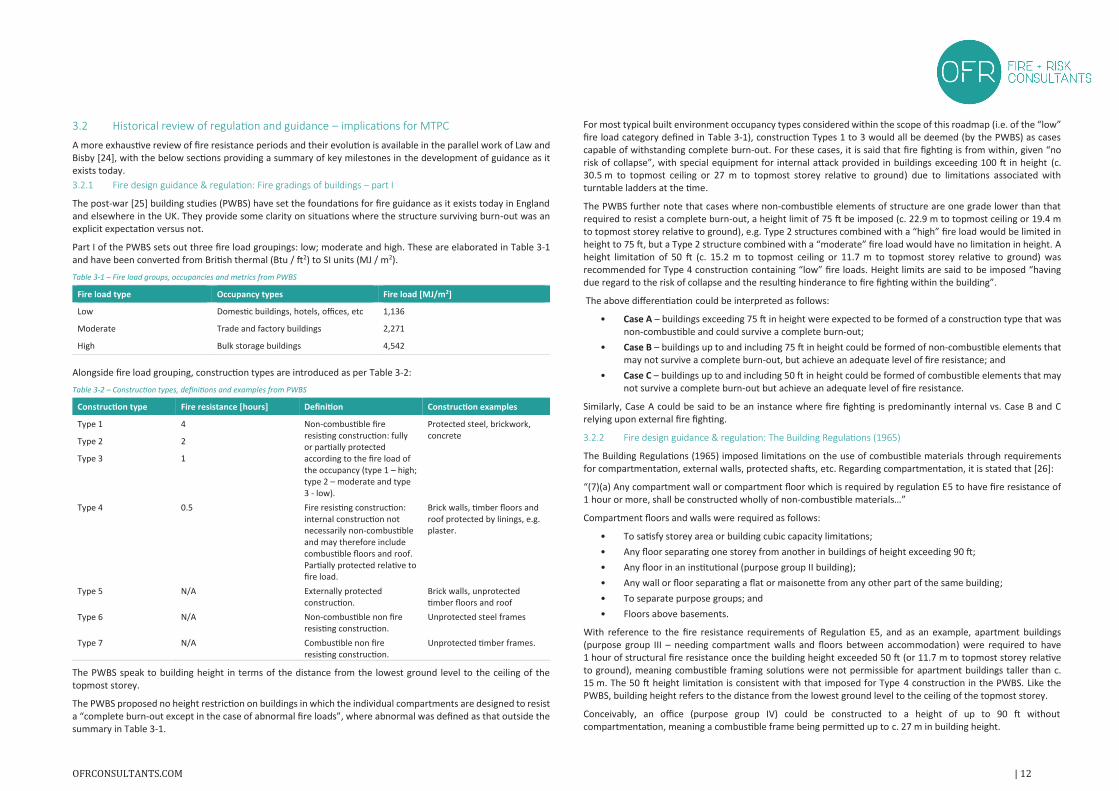
3.2 Historical review of regulation and guidance – implications for MTPC
A more exhaustive review of fire resistance periods and their evolution is available in the parallel work of Law andBisby [24], with the below sections providing a summary of key milestones in the development of guidance as itexists today.3.2.1 Fire design guidance & regulation: Fire gradings of buildings – part I
The post-war [25] building studies (PWBS) have set the foundations for fire guidance as it exists today in Englandand elsewhere in the UK. They provide some clarity on situations where the structure surviving burn-out was anexplicit expectation versus not.
Part I of the PWBS sets out three fire load groupings: low; moderate and high. These are elaborated in Table 3-1and have been converted from British thermal (Btu / ft2) to SI units (MJ / m2).
Table 3-1 – Fire load groups, occupancies and metrics from PWBS
Fire load type Occupancy types Fire load [MJ/m2]
Low Domestic buildings, hotels, offices, etc 1,136
Moderate Trade and factory buildings 2,271
High Bulk storage buildings 4,542
Alongside fire load grouping, construction types are introduced as per Table 3-2:
Table 3-2 – Construction types, definitions and examples from PWBS
Construction type Fire resistance [hours] Definition Construction examples
Type 1 4 Non-combustible fireresisting construction: fully or partially protectedaccording to the fire load ofthe occupancy (type 1 – high; type 2 – moderate and type3 - low).
Protected steel, brickwork,concrete
Type 2 2
Type 3 1
Type 4 0.5 Fire resisting construction: internal construction not necessarily non-combustibleand may therefore includecombustible floors and roof. Partially protected relative tofire load.
Brick walls, timber floors androof protected by linings, e.g. plaster.
Type 5 N/A Externally protectedconstruction.
Brick walls, unprotectedtimber floors and roof
Type 6 N/A Non-combustible non fireresisting construction.
Unprotected steel frames
Type 7 N/A Combustible non fireresisting construction.
Unprotected timber frames.
The PWBS speak to building height in terms of the distance from the lowest ground level to the ceiling of thetopmost storey.
The PWBS proposed no height restriction on buildings in which the individual compartments are designed to resista “complete burn-out except in the case of abnormal fire loads”, where abnormal was defined as that outside thesummary in Table 3-1.
For most typical built environment occupancy types considered within the scope of this roadmap (i.e. of the “low”fire load category defined in Table 3-1), construction Types 1 to 3 would all be deemed (by the PWBS) as casescapable of withstanding complete burn-out. For these cases, it is said that fire fighting is from within, given “norisk of collapse”, with special equipment for internal attack provided in buildings exceeding 100 ft in height (c.30.5 m to topmost ceiling or 27 m to topmost storey relative to ground) due to limitations associated withturntable ladders at the time.
The PWBS further note that cases where non-combustible elements of structure are one grade lower than thatrequired to resist a complete burn-out, a height limit of 75 ft be imposed (c. 22.9 m to topmost ceiling or 19.4 mto topmost storey relative to ground), e.g. Type 2 structures combined with a “high” fire load would be limited inheight to 75 ft, but a Type 2 structure combined with a “moderate” fire load would have no limitation in height. Aheight limitation of 50 ft (c. 15.2 m to topmost ceiling or 11.7 m to topmost storey relative to ground) wasrecommended for Type 4 construction containing “low” fire loads. Height limits are said to be imposed “havingdue regard to the risk of collapse and the resulting hinderance to fire fighting within the building”.
The above differentiation could be interpreted as follows:
• Case A – buildings exceeding 75 ft in height were expected to be formed of a construction type that wasnon-combustible and could survive a complete burn-out;
• Case B – buildings up to and including 75 ft in height could be formed of non-combustible elements thatmay not survive a complete burn-out, but achieve an adequate level of fire resistance; and
• Case C – buildings up to and including 50 ft in height could be formed of combustible elements that maynot survive a complete burn-out but achieve an adequate level of fire resistance.
Similarly, Case A could be said to be an instance where fire fighting is predominantly internal vs. Case B and Crelying upon external fire fighting.
3.2.2 Fire design guidance & regulation: The Building Regulations (1965)
The Building Regulations (1965) imposed limitations on the use of combustible materials through requirementsfor compartmentation, external walls, protected shafts, etc. Regarding compartmentation, it is stated that [26]:
“(7)(a) Any compartment wall or compartment floor which is required by regulation E5 to have fire resistance of1 hour or more, shall be constructed wholly of non-combustible materials…”
Compartment floors and walls were required as follows:
• To satisfy storey area or building cubic capacity limitations;
• Any floor separating one storey from another in buildings of height exceeding 90 ft;
• Any floor in an institutional (purpose group II building);
• Any wall or floor separating a flat or maisonette from any other part of the same building;
• To separate purpose groups; and
• Floors above basements.
With reference to the fire resistance requirements of Regulation E5, and as an example, apartment buildings (purpose group III – needing compartment walls and floors between accommodation) were required to have1 hour of structural fire resistance once the building height exceeded 50 ft (or 11.7 m to topmost storey relativeto ground), meaning combustible framing solutions were not permissible for apartment buildings taller than c.15 m. The 50 ft height limitation is consistent with that imposed for Type 4 construction in the PWBS. Like thePWBS, building height refers to the distance from the lowest ground level to the ceiling of the topmost storey.
Conceivably, an office (purpose group IV) could be constructed to a height of up to 90 ft withoutcompartmentation, meaning a combustible frame being permitted up to c. 27 m in building height.

Unlike the PWBS, the Building Regulations (1965) introduced a form of ‘failure consequence differentiation’,whereby fire resistance requirements varied with building height (25, 50, 90 and + 90 ft) and not solely as a functionof purpose group / fire load.
3.2.3 Fire design guidance & regulation: The Building Regulations (1985)
The Building Regulations (1985) [27] transitioned to performance-based requirements, where no prescriptiverequirements were placed on material choice and / or height. The functional requirement B3. (1) stated:
“The building shall be so constructed that, in the event of fire, its stability will be maintained for a reasonable period.”
That is, if a combustible structure could be shown to remain stable for a “reasonable period”, it would bepermissible.
The guidance to the Building Regulations (1985), i.e. the 1985 edition of Approved Document B [28], recommendedthat any compartment wall or floor requiring 60 min fire resistance should be formed of materials of limitedcombustibility (defined in BS 476-11 [29]), i.e. precluding the use of timber in situations, such as apartmentbuildings greater than 2 storeys in height.
3.2.4 The TF2000 and the emergence of medium and high-rise timber construction
Despite changes to the Building Regulations (i.e. a transition to a performance-based framework), there remainedsome scepticism that combustible structural solutions could satisfy the functional requirements, in particular thoseconcerned with B3 – Internal Fire Spread (Structure). To this end, the Building Research Establishment (BRE) andChiltern International Fire (CIF) embarked on a large-scale experimental programme, named the Timber Frame(TF) 2000 project. It is not the intention to exhaustively discuss the TF2000 project, with more detailed informationavailable via Lennon, et al. [30], and Lennon and Hopkin [31] (with the latter covering a cavity fire incident thatoccurred overnight). However, it is generally accepted that the genesis of the project was to exploit the UK'spotential to become world leader in the provision of medium-rise timber frame buildings [32], and that ultimatelythe conclusions reported opened the door for the medium and high-rise light timber frame buildings witnessedtoday through some assuaging of concerns relating to fire performance and disproportionate collapse.
3.2.5 Current Regulations, guidance and posited objectives for structural fire performance
The Building Regulations (2010, incorporating amendments to 2018) remain performance-based with respect tostructural fire performance [33], with Regulation B3(1) as per the 1985 regulations, with the TF2000 projectproving to be a key enabler of medium and high-rise light timber frame construction.
For most common building situations, compliance with the Regulations can be through the application of Approved Document B (2019, Vol. 1 or 2, as relevant [34] [12]). Therein, and within other recognised codes (e.g. BS 9991, BS9999, etc.) the means of satisfying Regulation B3(1) is by ensuring that structural elements achieve sufficient fireresistance.
Current guidance has been shaped by historical practices, as summarised in Sections 3.1.1 to 3.2.3. From thesepractices, the following factors can be said to have had a significant influence on the (historical) performanceobjectives of structures in the event of fire and today’s guidance:
• Occupant responsiveness – the cognition of alarms and the timeframe in which the occupants are likelyto respond, e.g. sleeping accommodation should be differentiated from non-sleeping accommodation;
• Evacuation mode and time – occupants of buildings may not immediately evacuate or could remain inplace indefinitely. Depending upon building height or complexity, occupants who receive an immediateevacuation signal could have protracted evacuation times. The objectives should be differentiated forbuildings where evacuation is quick vs. protracted;
• Fire brigade intervention strategy – depending upon the height and size of the building, fire brigade intervention might be predominantly from an external location or internal location. In the fire resistanceguidance in the PWBS, a key differentiator in whether a structure was expected to survive burnout vs.be “partially protected” was whether fire fighters needed to commit internally to intervene (which waslikely slower) vs. external intervention.
3.2.5.1 Posited objectives for structural fire design in current guidance
Given the (historical) factors influencing the performance objectives of structures in the event of fire andconsidering fire brigade intervention approaches (and associated guidance), the following simplified objectives inTable 3-3 are proposed as being an adequate means of demonstrating compliance with Regulation B3(1) under differing circumstances (in today’s regulatory environment).
Trigger heights (measured per Figure 3-3) are adopted that conform historically with differentiation in structuresexpected to survive burnout vs. provide some (adequate) level of fire resistance (see Sections 3.1.1 to 3.2.3). Theseheights are adapted to align with current trigger heights given in Approved Document B (2019) [34] [12].
Figure 3-3 – Definition of height as adopted in roadmap (taken from [12])
Section 4 provides a simplified compliance flow chart which seeks to demonstrate, depending upon the building’s purpose group, height and design approach (e.g. exposed vs. encapsulated), how compliance with B3(1) can beachieved. Example applications are summarised in Section 5.
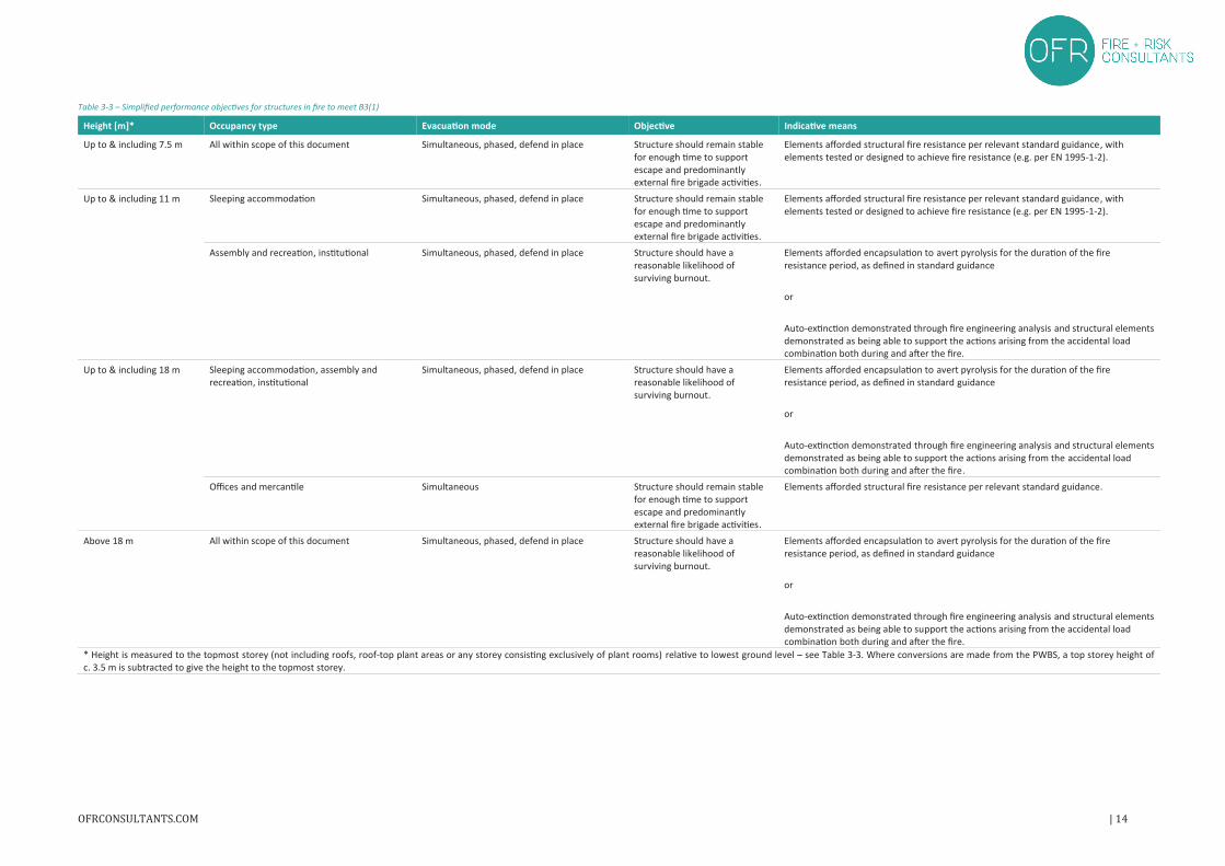
Table 3-3 – Simplified performance objectives for structures in fire to meet B3(1)
Height [m]* Occupancy type Evacuation mode Objective Indicative means
Up to & including 7.5 m All within scope of this document Simultaneous, phased, defend in place Structure should remain stablefor enough time to support escape and predominantlyexternal fire brigade activities.
Elements afforded structural fire resistance per relevant standard guidance, withelements tested or designed to achieve fire resistance (e.g. per EN 1995-1-2).
Up to & including 11 m Sleeping accommodation Simultaneous, phased, defend in place Structure should remain stablefor enough time to support escape and predominantlyexternal fire brigade activities.
Elements afforded structural fire resistance per relevant standard guidance, withelements tested or designed to achieve fire resistance (e.g. per EN 1995-1-2).
Assembly and recreation, institutional Simultaneous, phased, defend in place Structure should have areasonable likelihood ofsurviving burnout.
Elements afforded encapsulation to avert pyrolysis for the duration of the fireresistance period, as defined in standard guidance
or
Auto-extinction demonstrated through fire engineering analysis and structural elementsdemonstrated as being able to support the actions arising from the accidental loadcombination both during and after the fire.
Up to & including 18 m Sleeping accommodation, assembly andrecreation, institutional
Simultaneous, phased, defend in place Structure should have areasonable likelihood ofsurviving burnout.
Elements afforded encapsulation to avert pyrolysis for the duration of the fireresistance period, as defined in standard guidance
or
Auto-extinction demonstrated through fire engineering analysis and structural elementsdemonstrated as being able to support the actions arising from the accidental loadcombination both during and after the fire.
Offices and mercantile Simultaneous Structure should remain stablefor enough time to support escape and predominantlyexternal fire brigade activities.
Elements afforded structural fire resistance per relevant standard guidance.
Above 18 m All within scope of this document Simultaneous, phased, defend in place Structure should have areasonable likelihood ofsurviving burnout.
Elements afforded encapsulation to avert pyrolysis for the duration of the fireresistance period, as defined in standard guidance
or
Auto-extinction demonstrated through fire engineering analysis and structural elementsdemonstrated as being able to support the actions arising from the accidental loadcombination both during and after the fire.
* Height is measured to the topmost storey (not including roofs, roof-top plant areas or any storey consisting exclusively of plant rooms) relative to lowest ground level – see Table 3-3. Where conversions are made from the PWBS, a top storey height ofc. 3.5 m is subtracted to give the height to the topmost storey.
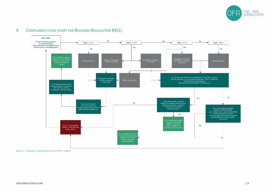
4 COMPLIANCE FLOW CHART FOR BUILDING REGULATION B3(1)
Figure 4-1 – Compliance roadmap flow chart for MTPC in England
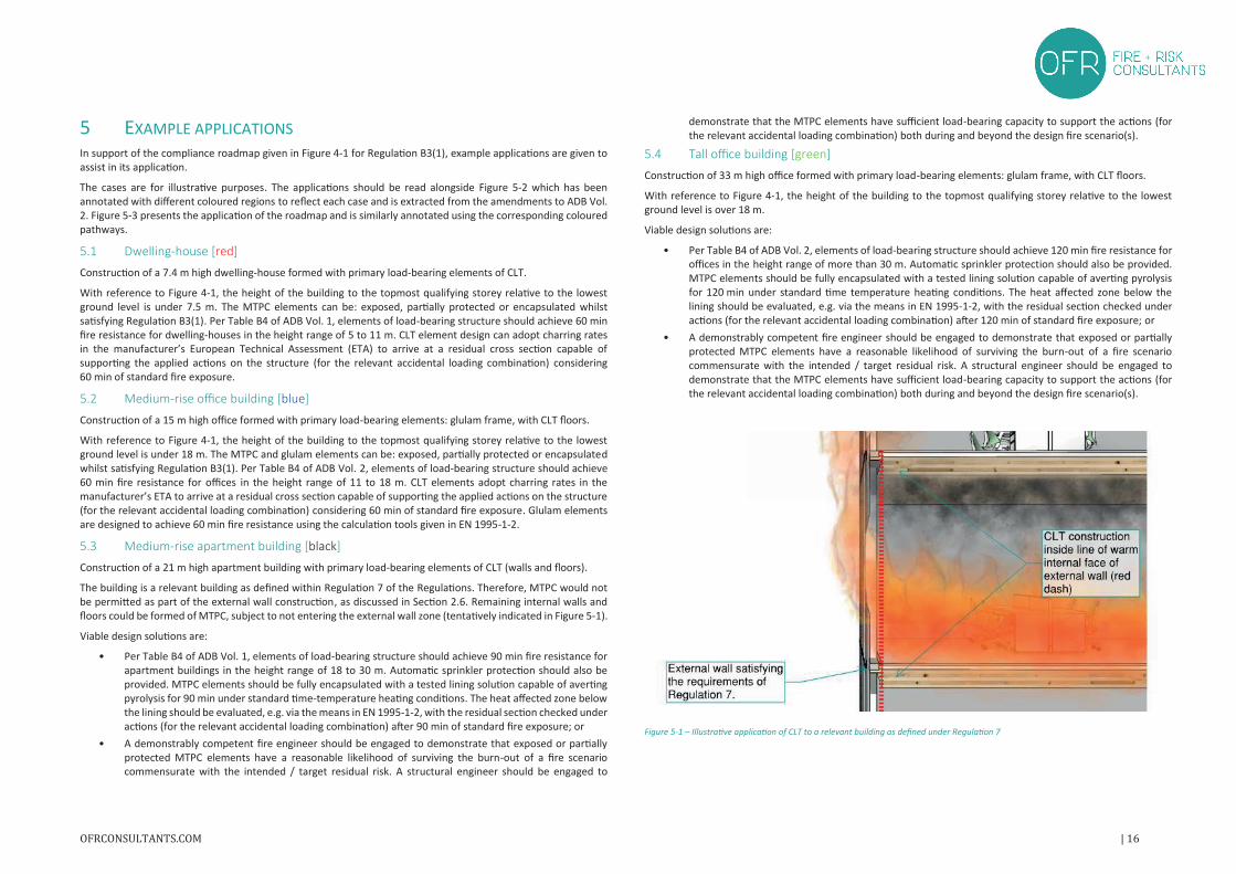
5 EXAMPLE APPLICATIONSIn support of the compliance roadmap given in Figure 4-1 for Regulation B3(1), example applications are given toassist in its application.
The cases are for illustrative purposes. The applications should be read alongside Figure 5-2 which has beenannotated with different coloured regions to reflect each case and is extracted from the amendments to ADB Vol.2. Figure 5-3 presents the application of the roadmap and is similarly annotated using the corresponding colouredpathways.
5.1 Dwelling-house [red]
Construction of a 7.4 m high dwelling-house formed with primary load-bearing elements of CLT.
With reference to Figure 4-1, the height of the building to the topmost qualifying storey relative to the lowestground level is under 7.5 m. The MTPC elements can be: exposed, partially protected or encapsulated whilstsatisfying Regulation B3(1). Per Table B4 of ADB Vol. 1, elements of load-bearing structure should achieve 60 minfire resistance for dwelling-houses in the height range of 5 to 11 m. CLT element design can adopt charring ratesin the manufacturer’s European Technical Assessment (ETA) to arrive at a residual cross section capable ofsupporting the applied actions on the structure (for the relevant accidental loading combination) considering60 min of standard fire exposure.
5.2 Medium-rise office building [blue]
Construction of a 15 m high office formed with primary load-bearing elements: glulam frame, with CLT floors.
With reference to Figure 4-1, the height of the building to the topmost qualifying storey relative to the lowestground level is under 18 m. The MTPC and glulam elements can be: exposed, partially protected or encapsulatedwhilst satisfying Regulation B3(1). Per Table B4 of ADB Vol. 2, elements of load-bearing structure should achieve60 min fire resistance for offices in the height range of 11 to 18 m. CLT elements adopt charring rates in themanufacturer’s ETA to arrive at a residual cross section capable of supporting the applied actions on the structure(for the relevant accidental loading combination) considering 60 min of standard fire exposure. Glulam elementsare designed to achieve 60 min fire resistance using the calculation tools given in EN 1995-1-2.
5.3 Medium-rise apartment building [black]
Construction of a 21 m high apartment building with primary load-bearing elements of CLT (walls and floors).
The building is a relevant building as defined within Regulation 7 of the Regulations. Therefore, MTPC would notbe permitted as part of the external wall construction, as discussed in Section 2.6. Remaining internal walls andfloors could be formed of MTPC, subject to not entering the external wall zone (tentatively indicated in Figure 5-1).
Viable design solutions are:
• Per Table B4 of ADB Vol. 1, elements of load-bearing structure should achieve 90 min fire resistance forapartment buildings in the height range of 18 to 30 m. Automatic sprinkler protection should also beprovided. MTPC elements should be fully encapsulated with a tested lining solution capable of avertingpyrolysis for 90 min under standard time-temperature heating conditions. The heat affected zone belowthe lining should be evaluated, e.g. via the means in EN 1995-1-2, with the residual section checked underactions (for the relevant accidental loading combination) after 90 min of standard fire exposure; or
• A demonstrably competent fire engineer should be engaged to demonstrate that exposed or partiallyprotected MTPC elements have a reasonable likelihood of surviving the burn-out of a fire scenariocommensurate with the intended / target residual risk. A structural engineer should be engaged to
demonstrate that the MTPC elements have sufficient load-bearing capacity to support the actions (forthe relevant accidental loading combination) both during and beyond the design fire scenario(s).
5.4 Tall office building [green]
Construction of 33 m high office formed with primary load-bearing elements: glulam frame, with CLT floors.
With reference to Figure 4-1, the height of the building to the topmost qualifying storey relative to the lowestground level is over 18 m.
Viable design solutions are:
• Per Table B4 of ADB Vol. 2, elements of load-bearing structure should achieve 120 min fire resistance foroffices in the height range of more than 30 m. Automatic sprinkler protection should also be provided.MTPC elements should be fully encapsulated with a tested lining solution capable of averting pyrolysisfor 120 min under standard time temperature heating conditions. The heat affected zone below thelining should be evaluated, e.g. via the means in EN 1995-1-2, with the residual section checked underactions (for the relevant accidental loading combination) after 120 min of standard fire exposure; or
• A demonstrably competent fire engineer should be engaged to demonstrate that exposed or partiallyprotected MTPC elements have a reasonable likelihood of surviving the burn-out of a fire scenariocommensurate with the intended / target residual risk. A structural engineer should be engaged todemonstrate that the MTPC elements have sufficient load-bearing capacity to support the actions (forthe relevant accidental loading combination) both during and beyond the design fire scenario(s).
Figure 5-1 – Illustrative application of CLT to a relevant building as defined under Regulation 7
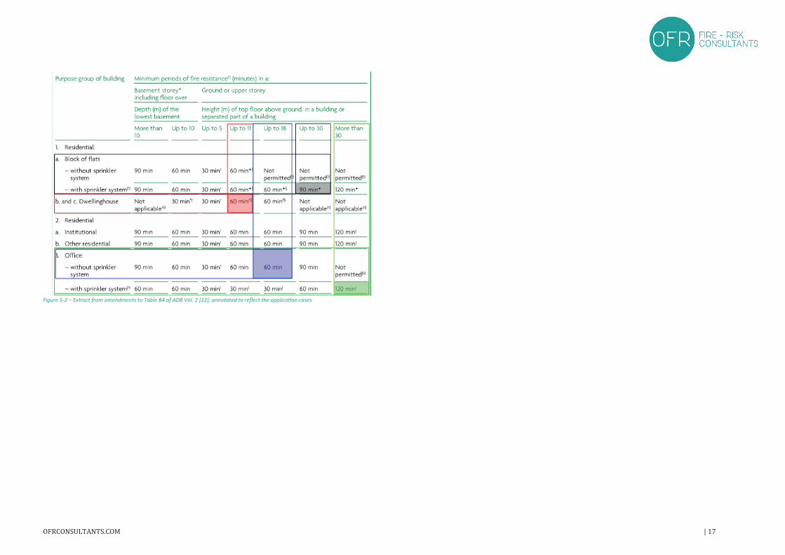
Figure 5-2 – Extract from amendments to Table B4 of ADB Vol. 2 [12], annotated to reflect the application cases
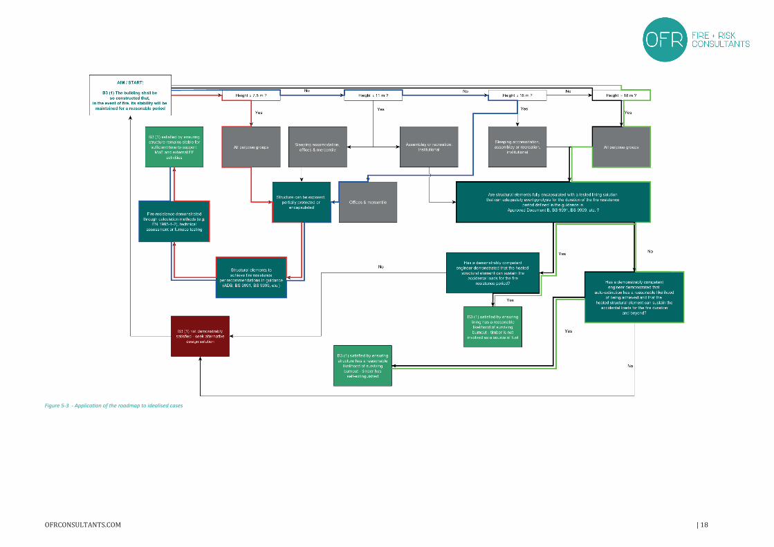
Figure 5-3 - Application of the roadmap to idealised cases
6 REFERENCES[1] M. Aidt, ‘Climate emergency declarations in 1,330 jurisdictions and local governments cover 810 million
citizens’, Climate Emergency Declaration, Jan. 28, 2020. https://climateemergencydeclaration.org/climate-emergency-declarations-cover-15-million-citizens/ (accessed Jan. 31, 2020).
[2] HM Government, ‘The Building Regulations 2010, Approved Document A (Structure)’, London, 2004.[3] International Organization for Standardization, ‘ISO/FDIS 2394:2014 - General principles on reliability for
structures’, ISO, Geneva, 2014.[4] BSI, ‘BS EN 1363-1:2012 Fire resistance tests. General requirements’, BSI, London, 2012.[5] ISO, ‘ISO 834-1:1999 Fire-resistance tests — Elements of building construction — Part 1: General
requirements’, International Organization for Standardization, Geneva, 1999.[6] BSI, ‘BS EN 13501-1:2018 Fire classification of construction products and building elements. Classification
using data from reaction to fire tests’, BSI Standards Publication, London, 2018.[7] BSI, ‘BS 7974:2019 Application of fire safety engineering principles to the design of buildings. Code of practice’,
BSI, London, 2019.[8] Fire safety in construction work: guidance for clients, designers and those managing and carrying out
construction work involving significant fire risks�: 2nd ed.United Kingdom: Health and Safety Executive, 2010.[9] STA, ‘16 steps to fire safety’, Structural Timber Association, London, Version 4.3, 2017.[10]STA, ‘Design guide to separating distances during construction’, Structural Timber Association, London,
Version 3.3, 2017.[11]Building Control Alliance, ‘BCA Technical Guidance Note 29 (Draft)’, London, BCA GN 29, 2019.[12]HM Government, ‘The Building Regulations 2010, Approved Document B (Fire Safety) Volume 2 (2019
edition)’, 2019.[13]BSI, ‘BS EN 1995-1-2:2004 Eurocode 5. Design of timber structures. General. Structural fire design’, BSI,
London, 2004.[14]BSI, ‘BS EN 1990:2002+A1:2005 Eurocode. Basis of structural design’, BSI Standards Publication, London, 2005.[15]BSI, ‘BS EN 1991-1-2:2002 Eurocode 1. Actions on structures. General actions. Actions on structures exposed
to fire’, British Standards Institution, London, 2002.[16]BSI, ‘NA to BS EN 1995-1-2:2004 UK National Annex to Eurocode 5. Design of timber structures. General.
Structural fire design’, BSI, London, 2006.[17]BSI, ‘BS 9991:2015 Fire safety in the design, management and use of residential buildings. Code of practice’,
BSI, London, 2015.[18]BSI, ‘BS 9999:2017 Fire safety in the design, management and use of buildings. Code of practice’, BSI, London,
2017.[19] I. Woolson, ‘Dwelling Houses: A code of Suggestions for constructions and fire protection recommended by
the National Board of Fire Underwriters’, American Institute of Architects, New York, 1916.[20] J. Gales, C. Maluk, and L. Bisby, ‘Structural fire testing- where are we, how did we get here, and where are we
going?’, in 15th International conference on experimental mechanics: Fire symposium, Porto, 2012, pp. 22–27.[21]F. Fitzpatrick and T. Condron, ‘Fire proof construction’, American School of Correspondence, Chicago, 1914.[22]S. Ingberg, ‘Tests of the Severity of Building Fires’, NFPA Quarterly, vol. 22, pp. 43–61, 1928.[23]A. Law and R. M. Hadden, ‘Burnout Means Burnout - SFPE’. https://www.sfpe.org/page/Issue5Feature1
(accessed Oct. 02, 2019).[24]A. Law and L. Bisby, ‘The rise and rise of fire resistance’, Fire Saf. J., p. 103188, Jul. 2020, doi:
10.1016/j.firesaf.2020.103188.[25]Ministry of Works, ‘Fire grading of buildings: Part I. General principles and structural precautions’, His
Majesty’s Stationery Office, Report 20, 1946.
[26]Her Majesty’s Stationery Office, ‘The Building Regulations 1965’, HMSO, London, UK Statutory Instruments1965 No. 1373, 1965.
[27]Department of the Environment and the Welsh Office, ‘The Building Regulations 1985’, 1985.[28]Department of the Environment and the Welsh Office, ‘The Building Regulations 1985 - Approved Document
B’.[29]BSI, ‘BS 476-11:1982 Fire tests on building materials and structures. Method for assessing the heat emission
from building materials’, BSI, London, 1982.[30]T. Lennon, M. Bullock, and V. Enjily, ‘The fire resistance of medium-rise timber frame buildings’, presented at
the WCTE 2000, Vancouver, 2000.[31]T. Lennon and D. Hopkin, ‘Fire performance of new residential buildings’, NHBC Foundation, Milton Keynes,
NF36, 2011.[32] ‘TF 2000 - Timber Frame 2000 project’. https://projects.bre.co.uk/tf2000/ (accessed Jun. 10, 2020).[33]HM Government, ‘The Building Regulations 2010, incorporating 2019 amendments’, Ministry for Housing,
Communities & Local Government, 2019.[34]HM Government, ‘The Building Regulations 2010, Approved Document B (Fire Safety) Volume 1 (2019 edition,
as amended May 2020)’, 2019.

Head officeStructural Timber Association The e-Centre Cooperage Way Alloa FK10 3LP
t: 01259 272140 f: 01259 272141 e: [email protected] w: www.structuraltimber.co.uk