DIVISION 2 SITE WORK 02660 WATER DISTRIBUTION
41
Revised December 2019 PUBLIC WORKS COMMISSION 02660 - 1 OF 12 WATER DISTRIBUTION DIVISION 2 SITE WORK 02660 WATER DISTRIBUTION GENERAL Water lines and all appurtenant items shall be constructed of materials specified and/or as indicated on the approved drawings. The intent and purpose of these specifications is to require a complete and satisfactory installation in every respect and any defects in material or workmanship shall be cause for the replacement and correction of such defect as directed by the Fayetteville Public Works Commission (PWC) at no expense to the Fayetteville Public Works Commission. RELATED SECTIONS A. 02211 – Grading, Utilities B. 02222 – Excavation and Backfilling for Utility Systems C. 02301 – Boring And Jacking (Roadways And Railroads) MATERIALS MANUALLY OPERATED GATE VALVES All manually operated gate valves four (4) inches and larger shall be ductile iron or cast iron body resilient wedge type rated for 250 psig working pressure gate valves and shall conform to American Water Works Association (AWWA) C-509/C-515 and NSF 61. All valves must open counter-clockwise equipped with a two (2) inch square operating nut. The operating nut shall have an arrow cut in the metal, indicating the direction of opening. All valves shall have a non-rising stem. All valves up to and including thirty-six (36) inch diameter shall have triple "O" ring stem seals. The design and machining of valves shall be such as to permit the replacement of the upper two (2) "O" rings without undue leakage while the valve is wide open and in service. The wedge shall be ductile iron encapsulated in nitrile rubber (for four (4) inch through 12 inch) and SBR rubber for 14-inch through 24-inch sizes.. All internal and external surfaces of the valve body and bonnet shall have a fusion bonded epoxy coating complying with ANSI/AWWA C550 applied electrostatically prior to assembly, conforming to AWWA C-550-90. All valves up to and including 36-inch diameter shall have a safe working pressure of 250 psi. Valve connections shall be as required for the piping in which they are installed. Valves shall have a clear waterway equal to the full nominal diameter of the valve. All valves shall be tested for leakage and distortion in strict accordance with the latest revision of AWWA Specification C-500. Gate valves installed in meter vaults shall have a wheel in lieu of a square operating nut and shall also have a non-rising stem. The wheel shall have an arrow cut in the metal indicating the direction of opening. Flanges shall not be buried. An approved pit shall be provided for all flange connections. Resilient seated tapping valves shall be furnished with the tapping flange having a raised face or lip designed to engage the corresponding recess in the tapping sleeve flange in accordance with MSS-SP60.
-
Upload
khangminh22 -
Category
Documents
-
view
0 -
download
0
Transcript of DIVISION 2 SITE WORK 02660 WATER DISTRIBUTION
Revised December 2019
PUBLIC WORKS COMMISSION 02660 - 1 OF 12 WATER DISTRIBUTION
DIVISION 2 SITE WORK 02660 WATER DISTRIBUTION GENERAL Water lines and all appurtenant items shall be constructed of materials specified and/or as indicated on the approved drawings. The intent and purpose of these specifications is to require a complete and satisfactory installation in every respect and any defects in material or workmanship shall be cause for the replacement and correction of such defect as directed by the Fayetteville Public Works Commission (PWC) at no expense to the Fayetteville Public Works Commission. RELATED SECTIONS
A. 02211 – Grading, Utilities B. 02222 – Excavation and Backfilling for Utility Systems C. 02301 – Boring And Jacking (Roadways And Railroads)
MATERIALS MANUALLY OPERATED GATE VALVES All manually operated gate valves four (4) inches and larger shall be ductile iron or cast iron body resilient wedge type rated for 250 psig working pressure gate valves and shall conform to American Water Works Association (AWWA) C-509/C-515 and NSF 61. All valves must open counter-clockwise equipped with a two (2) inch square operating nut. The operating nut shall have an arrow cut in the metal, indicating the direction of opening. All valves shall have a non-rising stem. All valves up to and including thirty-six (36) inch diameter shall have triple "O" ring stem seals. The design and machining of valves shall be such as to permit the replacement of the upper two (2) "O" rings without undue leakage while the valve is wide open and in service. The wedge shall be ductile iron encapsulated in nitrile rubber (for four (4) inch through 12 inch) and SBR rubber for 14-inch through 24-inch sizes.. All internal and external surfaces of the valve body and bonnet shall have a fusion bonded epoxy coating complying with ANSI/AWWA C550 applied electrostatically prior to assembly, conforming to AWWA C-550-90. All valves up to and including 36-inch diameter shall have a safe working pressure of 250 psi. Valve connections shall be as required for the piping in which they are installed. Valves shall have a clear waterway equal to the full nominal diameter of the valve. All valves shall be tested for leakage and distortion in strict accordance with the latest revision of AWWA Specification C-500. Gate valves installed in meter vaults shall have a wheel in lieu of a square operating nut and shall also have a non-rising stem. The wheel shall have an arrow cut in the metal indicating the direction of opening. Flanges shall not be buried. An approved pit shall be provided for all flange connections. Resilient seated tapping valves shall be furnished with the tapping flange having a raised face or lip designed to engage the corresponding recess in the tapping sleeve flange in accordance with MSS-SP60.
Revised December 2019
PUBLIC WORKS COMMISSION 02660 - 2 OF 12 WATER DISTRIBUTION
Tapping valves without the raised face on the tapping flange are not permitted since they do not assure the proper alignment required to prevent damage by a misaligned shell cutter. The interior of the waterway in the body shall be a full opening and capable of passing a full sized shell cutter equal to the nominal diameter of the valve. All valves shall be manufactured in strict accordance with the latest specifications of the American Water Works Association (AWWA). Valves shall be manufactured by: Mueller Company, Clow Corporation, or American Darling Company. Certification shall be furnished to the Fayetteville Public Works Commission by the manufacturer that all valves are in accordance with PWC standards. Where specified on the plans and approved by the Fayetteville Public Works Commission, resilient wedge gate valves may be furnished with spur gearing for valves installed in a vertical position and bevel gearing for valves installed in a horizontal position. All gate valves shall be installed in accordance with PWC standard details. BALL VALVES For all valves smaller than four (4) inches, ball valves shall be used. Ball valves shall be installed in accordance with PWC standard details.
Ball valves shall be all bronze construction, with tee head operator and having a removable disc. Ball valves shall have threaded connections, in accordance with PWC standard details. Ball valves shall be manufactured and tested in accordance with AWWA/ANSI C800. The valve shall be equipped with packing nut, gland, and packing material. Ball valves shall be of an approved type made from approved materials conforming to ASTM Specifications and shall also meet the approval of the Public Works Commission. The turn required to travel from fully closed to fully open on the ball valve shall be 90 degrees. VALVE BOXES Valve boxes shall be "slip-type" made of close-grained, gray cast iron metal painted with a protective asphaltic coating. Construction shall be in three pieces as follows: The lower of base pieces, which shall be flanged at the bottom, the upper part which shall be flanged on the lower end, and of such size as to telescope over the lower part, the upper end being constructed in the form of a socket to receive the cap or cover; and the cover or cap shall have cast on the upper surface, in raised letters, the word "WATER". All valve boxes shall be equal in quality and workmanship to those manufactured by Sigma Corporation (VB-462), Tyler Union (6855 Series), Star Pipe Products (VB-0004), or an approved equal. The valve box shall be installed in accordance with PWC standard details. The valve box shall have a 3/8-inch hole drilled in the upper part four (4) to six (6) inches from the top of the box to accommodate a ¼-inch x 1-1/2-inch galvanized bolt for securing tracer wire. Valve box protector rings shall be installed to protect valve boxes located outside pavement. The ring shall be constructed and installed in accordance with PWC standard details.
Revised December 2019
PUBLIC WORKS COMMISSION 02660 - 3 OF 12 WATER DISTRIBUTION
FIRE HYDRANTS All fire hydrants shall be dry barrel, traffic type and conform to the latest revision of AWWA Specification C-502 except as listed below or as otherwise directed by the Public Works Commission. All working parts shall be bronzed. The size of the fire hydrants (designated by the nominal diameter of the valve opening) shall not be less than four and one-half (4 ½) inches. All hydrants shall be able to deliver a minimum of 1,000 gallons per minute with a friction loss of not more than five (5) pounds per square inch (psi) total head loss through the hydrant. Hydrants shall be of compression type (opening shall be of such design that when the barrel is broken off the hydrant valve will remain closed and reasonably tight against leakage). All hydrants shall be mechanical joint to accommodate the spigot end of six (6) inch Pressure Class 150, AWWA Standard, ductile iron pipe. The installation of the fire hydrant shall be in accordance with PWC standard details. Bosses (6") may be substituted for tees in pipe sizes exceeding 24 inches in diameter, with prior approval from PWC. The boss shall be welded to the bottom of the main to provide effective flushing of the system. All hydrants shall be furnished with two (2) two and one-half (2 ½) inch nozzles and one (1) four and one-half (4 ½) inch pumper nozzle. Outlets shall have American National Standard fire hose coupling thread, in accordance with the City of Fayetteville standard, and shall be provided with nozzle caps securely chained to the body of the hydrant. The base of the hydrant shall have two (2) cast lugs suitable for use in strapping the hydrant to the connecting pipe. The operating nut shall be pentagonal in shape, finished with a slight taper to one and one-half (1 ½) inches from point to flat to conform to the standard wrench used by the Fayetteville Public Works Commission. All hydrants shall open left or counter-clockwise. Hydrants shall be suitable for working pressure of 150 psi and a test pressure of twice the working pressure. Fire hydrants shall be specific models manufactured by Mueller Company (Model Centurian 200), Clow Corporation (Medallion), American Darling (Model Mark 73-1) or approved equal. The interior of the hydrant shoe shall be coated with a four (4) mil thickness FDA approved epoxy coating. COMBINATION AIR VALVES ASSEMBLY Combination air valves shall be of the single housing style that combines the operation features of both an air/vacuum and air release valve. The combination air valve shall have a two (2) inch inlet and one (1) inch outlet connections and an orifice diameter to be determined by the Design Engineer for each project for a maximum working pressure of 300 psi. The assembly shall be equipped with a two (2) inch cut-off valve as shown on the PWC standard detail. The combination air valve body shall be constructed of 316 stainless steel or reinforced nylon with the only exception being the Buna-N Rubber seat and gasket. Valves shall be as manufactured by Crispin (Model UX20), ARI (D-020), or approved equal. Combination air valves shall be installed in accordance with PWC standards. WATER DISTRIBUTION PIPE DUCTILE IRON PIPE All ductile iron pipe shall be designated as “Pressure Class”, unless otherwise specified. The pipe furnished shall have a minimum thickness calculated in accordance with ANSI A 21.50 (AWWA C-150), with a factor of safety of two (2); a working pressure of 150 psi to 350 psi, plus 100 psi water hammer
Revised December 2019
PUBLIC WORKS COMMISSION 02660 - 4 OF 12 WATER DISTRIBUTION
allowance; and AASHTO H-20 live truck load with 2.5 feet of cover. In no case shall “Pressure Class” pipe’s nominal thickness be less than the following:
NOMINAL
SIZE PRESSURE CLASS THICKNESS (In.) 4" 350 0.25 6" 350 0.25 8" 350 0.25 10" 350 0.26 12" 350 0.28 16" 250 0.30 24" 250 0.37 PUSH-ON JOINTS Push-on joints shall be as specified and installed in accordance with AWWA C-600 and shall conform to AWWA Standard C-111. Push on joints, rubber gaskets and lubricant shall conform to ANSI A21.11. Pressure rating shall not be less than 200 psi unless otherwise specified. All ductile iron pipe shall be lined with standard thickness cement mortar lining and asphaltic seal coat in accordance with ANSI A21.4 (AWWA C-104). The pipe shall have an outside asphaltic coating as specified in AWWA Standard C-151. RESTRAINED JOINTS Factory Restrained Joints Factory restrained joint pipe shall be utilized for all pipe greater than 12-inches in diameter, unless otherwise approved by the Fayetteville Public Works Commission. Factory restrained joint pipe shall be furnished for the locations shown on the approved drawings. The pipe, joints, and gaskets shall be in accordance with ANSI/AWWA Standards as specified for ductile iron pipe. Factory restrained joints shall be rated for a working pressure of 350 psi for sizes up to 12-inches and 250 psi for larger sizes. All factory restrained joint pipe shall have the restraints internal to the pipe (i.e., “boltless”). All restrained joint ductile iron pipe and fittings larger than 12-inches shall be as manufactured by U.S. Pipe’s TR-Flex, Griffin Pipe Products SNAP-LOK, American Cast Iron Pipe Company's Flex-Ring Joint, or approved equal. The method of restraining the valves to the factory restrained ductile iron pipe shall be reviewed and approved by PWC on a case by case basis. The valves shall have the same working pressure as the pipe. Flanged Joints Flanges shall be specifically designed for each application. The flange pipe shall be in accordance with ANSI/AWWA C-115/A21.15. Threads for threaded flange pipe shall be in accordance with ANSI B2.1, shop fabricated as outlined by AWWA 115 with serrated faces furnished on the pipe, completely factory installed. Welding of flanges to the body of the pipe will not be acceptable.
Revised December 2019
PUBLIC WORKS COMMISSION 02660 - 5 OF 12 WATER DISTRIBUTION
Ductile iron fittings and flanges shall be in accordance with ANSI/AWWA C-110/A21.10 with a minimum working pressure of 250 psi. Gaskets shall be full faced SBR rubber per ANSI/AWWA C-111/A21.11 with a minimum 1/8 inch thickness. Linings and coatings shall be as previously outlined for all ductile iron pipe and fittings. Mechanical Joints Mechanical joints shall be as specified and installed in accordance with AWWA C-600 and shall conform to AWWA Standard C-111. Mechanical joints shall be of the stuffing box type and shall conform to ANSI A21.11 for four (4) inch pipe through 12-inch pipe. Mechanical joints, rubber gaskets and lubricant shall conform to ANSI A21.11. Pressure rating shall not be less than 200 psi unless otherwise specified. Special accessories such as mechanical joint retainer glands or mega-lugs are acceptable on pipe 12-inches and less in diameter, upon approval from the Fayetteville Public Works Commission. Mega-lug and/or grip-ring restraint mechanisms will not be an acceptable method of restraint for pipe, fitting and/or valves on sizes larger than 12-inches in diameter. For mains larger than 12-inches and at locations specified by the Fayetteville Public Works Commission, factory restrained joints shall be utilized, in accordance with these Specifications. Field Lok Gaskets Special accessories such as US Pipe's Field-LOK gasket, Ford’s Uni-Ring, or Romac’s Grip-Ring are acceptable on pipe 12-inches and less in diameter, upon approval from the Fayetteville Public Works Commission. Mega-lug and/or grip-ring restraint mechanisms will not be an acceptable method of restraint for pipe, fitting and/or valves on sizes larger than 12-inches in diameter. For mains larger than 12-inches and at locations specified by the Fayetteville Public Works Commission, factory restrained joints shall be utilized, in accordance with these Specifications. FITTINGS Mechanical Joint All fittings shall be ductile iron and shall be manufactured in accordance with AWWA Standard C-110 (ANSI A21.11). Compact fittings shall be mechanically restrained, ductile iron in accordance with ANSI A 21.53 (AWWA C-153) for four (4) inch through 12 inch sizes only. Where thrust blocking is utilized, fittings shall be full body ductile iron in accordance with ANSI A 21.53 (AWWA C110). All ductile iron fittings shall be lined with standard thickness cement mortar lining and asphaltic seal coat in accordance with ANSI A21.4 (AWWA C-104). All fittings shall have an outside asphaltic coating as specified in AWWA Standard C-151 and C-110, respectively.
Revised December 2019
PUBLIC WORKS COMMISSION 02660 - 6 OF 12 WATER DISTRIBUTION
Factory Restrained Factory restrained joint fittings shall be utilized for all pipe greater than 12-inches in diameter, unless otherwise approved by the Fayetteville Public Works Commission. Factory restrained joint fittings shall be furnished for the locations shown on the approved drawings. The fittings, joints, and gaskets shall be in accordance with ANSI/AWWA Standards as previously specified for ductile iron pipe. Factory restrained joints shall be rated for a working pressure of 350 psi for sizes up to 12-inches and 250 psi for larger sizes. All factory restrained joint fittings shall have the restraints internal to the fitting (i.e., “boltless”). All fittings shall be compatible with the factory restraint system. All restrained joint ductile iron fittings larger than 12-inches shall be as manufactured by U.S. Pipe’s TR-Flex, Griffin Pipe Products SNAP-LOK, American Cast Iron Pipe Company's Flex-Ring Joint, or approved equal. Bosses Tangential welded on outlets (i.e., bosses) shall only be utilized on pipe 24-inches and larger, as approved by PWC. All bosses shall be factory welded; field fabrication is not allowed. The pipe shall be in accordance with these specifications. Bosses shall be of the size and location indicated on the approved drawings. AERIAL CROSSINGS For aerial crossings, the ductile iron pipe shall be thickness class, as specified on the plans and standard details. All thickness class pipe shall be in accordance with ANSI A21.51 and AWWA C-151, with a minimum working pressure of 200 psi. For aerial crossings which are four (4) inches to 12 inches in diameter, Class 53 manufactured factory restrained joint or Class 53 flanged ductile iron pipe shall be used in accordance with the PWC standard details. No other means of restraint are allowed for aerial crossings. For aerial crossings larger than 12 inches, or as noted specifically on the plans, Class 53 flanged ductile iron pipe shall be used in accordance with the PWC standard details. All aerial crossings shall be designed and installed in accordance with PWC standard details. PIPE IN CASINGS All ductile iron pipe (regardless of diameter) within casings shall be factory restrained, in accordance with these specifications and the applicable PWC standard details. The use of any other restraints (i.e., mega-lugs, grip-rings, etc.) shall not be utilized on pipe within casings. All restrained joint ductile pipe in casings shall be in accordance with the PWC standard details. TRENCHLESS APPLICATIONS All ductile iron pipe (regardless of diameter) utilized for trenchless installations (i.e., horizontal directional drilling, pipe-bursting, etc.) shall be factory restrained, in accordance with these specifications and the
Revised December 2019
PUBLIC WORKS COMMISSION 02660 - 7 OF 12 WATER DISTRIBUTION
applicable specification section for the trenchless technology. The use of any other restraints (i.e., mega-lugs, grip-rings, etc.) shall not be utilized. PVC PIPE Two (2) inch water main pipe shall be manufactured using Grade 1 PVC compound material as defined in ASTM D-1784 and shall be SDR21, pressure class 200 in accordance with ASTM D 2241. Fittings for two (2) PVC pipe shall be solvent weld Schedule 80 PVC. Brass FIP x pack joint for PVC fittings shall be used to transition from PVC to brass. The pipe shall be plainly marked with the manufacturer’s name, size, material (PVC) type and grade or compound, NSF seal, date of manufacture, pressure rating and reference to appropriate product standards. All PVC pipe (4-inches through 12-inches diameter) shall be manufactured using virgin compounds as defined in ASTM D-1784, with a 4,000 psi HDB rating and designated as PVC 1120 to be in strict accordance with AWWA C-900. The pipe shall be Class 150 and conform to the thickness requirements of DR18. The pipe shall be manufactured to withstand 755 psi quick burst pressure tested in accordance with ASTM D-1599 and withstand 500 psi for a minimum of 1,000 hours tested in accordance with ASTM D-1598. The pipe joints shall be of the integral bell type with rubber gaskets and shall conform to the requirements of ASTM D-3139 or ASTM F-477. PVC fittings are not acceptable for water mains four (4) inches or greater. Fittings and specials shall be ductile iron, bell end in accordance with AWWA C-110, 150 psi pressure rating unless otherwise shown or specified. Ductile iron fittings to PVC pipe shall be adequately supported on a firm trench foundation. Ductile iron fittings and specials shall be cement mortar lined (standard thickness) in accordance with ANSI A21.4. Mechanical restraining systems (i.e. mega-lug, grip-ring) shall not be used on PVC pipe. TRACING WIRE For the purpose of locating non-metallic pipes, a continuous "detectable" tracing wire shall be installed. The wire shall be a minimum 12 gauge, single strand, coated copper or copper clad steel wire that is suitable for underground use. Splices shall be accomplished utilizing a corrosion proof wire connector. The connectors shall “lock” the wires in place and contain a dielectric sealant to prevent corrosion. The connector shall be the “Snake Bite” connector manufactured by Copperhead Industries, LLC, or approved equal. The wire shall be buried continuously along the pipe. The wire shall be secured into valve boxes such that a direct/conductive metal detector may be used to trace the pipe location. Bolts shall be used to secure the wire and the attachment location shall be readily available from finished grade without special equipment. POLYETHYLENE PLASTIC WATER TUBING Polyethylene (PE) plastic water tubing shall be installed in accordance with PWC standard details. All services installed in new construction shall be one continuous run of pipe with no splices from the
Revised December 2019
PUBLIC WORKS COMMISSION 02660 - 8 OF 12 WATER DISTRIBUTION
corporation stop to the meter. The PE water tubing shall meet the requirements of ASTM D2737, AWWA C901, and NSF Standards 14 and 61. Pipe dimensions shall meet Iron Pipe Size (IPS) standards. The PE tubing material shall be high density polyethylene conforming to the minimum requirements of cell classification 445574E, as defined and described in ASTM D3350. The resin shall have a material designation code of PE4710 by the Plastic Pipe Institute. The PE water tubing shall be SIDR 7, with a minimum pressure rating of 250 psi. Fittings for the PE water pipe shall be cast brass compression fittings, made to the PE water pipe dimension. All brass fittings shall have a 300 psi minimum pressure rating. For the purpose of locating plastic water services during trenching, a continuous tracing wire shall be installed. The wire shall be a minimum 12 gauge, single strand, coated copper or copper clad steel wire that is suitable for underground use. The wire shall be buried along the water service lateral from the main to the meter box. The wire shall extend a minimum of 12 inches into the meter boxes. COPPER WATER TUBING Copper water tubing shall be installed in accordance with PWC standards. All services installed shall be one continuous run of pipe with no splices from the corporation stop to the meter. Copper water tubing shall be Type K, soft copper manufactured in accordance with ASTM B88. The minimum pressure rating for the copper water pipe shall be 655 psi. Fittings for the copper water pipe shall be brass compression fittings, made to the copper water pipe dimensions. All brass fittings shall have a 300 psi minimum pressure rating. TAPPING SLEEVES Tapping sleeves shall be ductile iron mechanical joint or stainless steel and have a minimum working pressure of 150 psi for all tapping of mains up to and including 24-inch diameter with a branch less than or equal to 12-inches diameter. Branch diameter greater than 12-inches on a 16-inch diameter pipe and larger shall require full body ductile iron mechanical joint tapping sleeve. Ductile iron mechanical joint tapping sleeves shall be as manufactured by Clow, M&H, Mueller, American, or an approved equal and shall be furnished with complete joint accessories. The mechanical joint sleeve shall be compatible with type and class of pipe being tapped. The outlet flange shall be class 125 per ANSI B16.1 compatible with approved tapping valves. Stainless steel tapping sleeves shall be as manufactured by Romac, Smith-Blair, or approved equal, and shall be furnished with all accessories. The sleeve, lugs, bolts and nuts shall be 18-8 type 304 stainless steel, as provided by the manufacturer. The outlet flange shall be ductile iron or stainless steel. The gasket shall be a grid pattern design and shall provide full circumferential sealing around pipe to be tapped. The sleeve shall include a 3/4 NPT test plug. All welds shall be passivated. The outlet flange shall be class D per AWWA C-207-ANSI 150 lb. drilling compatible with approved tapping sleeves.
Revised December 2019
PUBLIC WORKS COMMISSION 02660 - 9 OF 12 WATER DISTRIBUTION
The tapping sleeve and valve shall be in accordance with PWC standard details. All tapping sleeves shall be hydrostatically pressure tested prior to the tap being accomplished. Use of air to complete the pressure test is not acceptable. The tapping sleeve shall be tested to 150 psi. The PWC Project Coordinator shall witness and approve the testing. WATER SERVICE SADDLES All water service saddles for use on two (2) inch PVC shall be one (1) inch brass saddles as manufactured by Ford, McDonald, or Mueller. Water service saddles for one (1) and two (2) inch taps on four (4), six (6), eight (8), 12-inch and larger size PVC and asbestos-cement (AC) and also four (4) inch and larger size iron pipe shall be ductile iron with stainless steel strap(s), bolts, nuts and washers. Ford Models FS 101, FS 202; Romac Models 101S, 202S; or Smith-Blair Model 315.317 shall be used. Stainless steel straps must be pre-formed at the factory to the specified outside diameters of the pipe. Water service saddles with a two (2) inch outlet shall be double strap. Water service saddles for pipe sizes 12-inch through 24-inch shall be double strap. Water service saddles for pipe sizes exceeding 24-inches shall be as specified by the PWC Water Resources Engineering Department. INSTALLATION GENERAL Pipe installation shall be in strict accordance with Specification Section 02222 – Excavation and Backfilling for Utility Systems and as outlined herein. PIPE INSTALLATION Pipe installation shall be in accordance with the manufacturer’s instructions. All pipes and fittings shall be handled to prevent damage to the protective coatings and linings. All dust, dirt, oil, tar, or other foreign matter shall be cleaned from the jointing surfaces, and shall be lubricated with lubricant recommended by the manufacturer. All pipe shall be installed in accordance with the approved drawings and cut sheets, unless otherwise directed by PWC. All dead ends on new mains shall have a two (2) inch blow-off assembly as indicated on the approved drawings. The blow-off assembly shall be in accordance with PWC standard details.
Revised December 2019
PUBLIC WORKS COMMISSION 02660 - 10 OF 12 WATER DISTRIBUTION
For pipe sizes up to 12-inches, mechanical equipment should not be utilized to assemble the pipe. For pipe sizes over 12-inches, mechanical equipment may be utilized, in accordance with the pipe manufacturer’s instructions. Any damage resulting from the use of mechanical equipment shall be replaced as directed by PWC. Adjustments in grade by exerting force on the barrel of the pipe with excavating equipment shall not be allowed. The Contractor shall verify line and grade after assembling each joint. When pipe installation is not in progress, the open ends of the pipe shall be closed by a water tight plug or other means approved by the PWC Project Coordinator. If water is present, the plug shall remain in place until the water is lowered to a level that allows for proper installation. No pipe shall be laid in water or where in the PWC Project Engineer's and/or PWC Project Coordinator’s opinion trench conditions are unsuitable. Every precaution shall be taken to prevent material from entering the pipe while it is being installed. ALIGNMENT AND GRADE The Contractor shall be responsible for installing the pipe and appurtenances to proper line and grade. All ductile iron pipe and fittings shall be installed in accordance with ANSI/AWWA C-110/A21.10. All C-900 pipe shall be installed in accordance with ASTM D-2774. The amount of deflection in the PVC or ductile iron pipe shall not exceed the applicable AWWA standards and the manufacturer’s recommendations. If the required deflection exceeds the specified limitations or as determined by the Public Works Commission, mechanical joint bends shall be utilized. Pipe passing through walls of NCDOT bridges, retaining walls, and other concrete structures shall be factory restrained joint ductile iron and be installed in casings/sleeves in accordance with NCDOT specifications. Annular space between walls and sleeves shall be filled with an approved cement mortar that meets NCDOT specifications. The annular space between the sleeve and the pipe shall be filled with an approved mastic. Pipe passing through the walls of meter vaults, valve pits, and storm drainage structures shall be restrained joint ductile iron, as specified by PWC. Pipe shall be installed in a casing/sleeve if determined to be necessary. Annular space between walls and sleeves shall be filled with an approved cement mortar. Annular space between pipe and sleeves shall be filled with an approved mastic. Proposed conflict boxes with storm and water shall be reviewed by the PWC Water Resources Engineer and approved on a case by case basis. All ductile iron pipe (regardless of diameter) within casings shall be factory restrained, in accordance with these specifications and the applicable PWC standard details. The use of mechanical restraints (i.e., mega-lugs, grip-rings, etc.) shall not be utilized on pipe within casings. When pipe is field cut, the cut end shall be smooth and at right angles to the axis of the pipe. All sharp edges shall be removed. All field cut pipe shall be beveled. The beveled end of PVC pipe shall be removed, when installing into mechanical joint ductile iron fittings.
Revised December 2019
PUBLIC WORKS COMMISSION 02660 - 11 OF 12 WATER DISTRIBUTION
When connecting unlike (class, material, etc.) pipe, an approved PWC fitting shall be used. All pipe shall be installed in accordance with AWWA C-600 or C-605 as applicable, for buried lines and the manufacturer’s recommendations. For mechanical joint pipe and fittings, all nuts shall be torqued to the manufacturer’s recommendations.
Concrete thrust blocking shall be utilized on all PVC water mains. The concrete thrust blocking shall be in accordance with PWC standard details. When thrust blocking is to be utilized, backfilling shall not occur until the concrete has time to set. No hydrostatic pressure testing shall occur until the concrete thrust blocking has cured for a minimum of five (5) calendar days. FIRE HYDRANTS Fire hydrants shall be installed as shown on the approved drawings. Each fire hydrant shall be connected to the main with a six (6) inch branch line and shall have a minimum of 42-inches of cover. Fittings between the valve and fire hydrant may be utilized, with prior approval from PWC. The valve shall be located at the main unless otherwise approved by PWC. Hydrants shall be set plumb with pumper nozzle facing the roadway. The hydrant branch shall not be backfilled until inspected and approved by the PWC Project Coordinator. Fire hydrants shall be installed in accordance with PWC standard details. HYDROSTATIC TESTS All mains and laterals shall be subjected to a hydrostatic pressure test. Each valved section maybe tested individually. The Contractor shall furnish all labor and material, including test pumps, taps, and corporations, necessary to complete the work. Any taps which are not to be utilized shall be killed out at the main. If any taps are to be used for irrigation laterals they shall be installed in accordance with PWC standard details. A PWC Project Coordinator shall be present and observe all valve operation by the Contractor. Under no circumstances shall a Contractor operate any PWC-owned valves unless it is an emergency. The duration of the pressure test shall be at least one hour or longer, as directed by the PWC Project Coordinator. The hydrostatic pressure shall be 200 psi. The pipe to be tested shall be slowly filled with water and the specified test pressure shall be applied. Before applying the specified test pressure, all air shall be expelled from the pipe. If hydrants or blow offs are not located to properly expel the air, taps shall be made as approved by PWC. Damaged or defective materials discovered as a result of the pressure test shall be removed and replaced with new material, and the test shall be repeated until the test results are satisfactory to the Public Works Commission. All replacement, repair or retesting shall be accomplished by the Contractor at no additional cost to the Public Works Commission. All repairs shall be reviewed and approved by PWC prior to backfill. The use of couplings, fittings, sleeves, etc. shall be reviewed and approved by PWC prior to use. The main must successfully pass the hydrostatic test prior to sterilization.
Revised December 2019
PUBLIC WORKS COMMISSION 02660 - 12 OF 12 WATER DISTRIBUTION
STERILIZATION Sterilization shall be in accordance with the requirements of NCDEQ, the North Carolina Rules Governing Public Water Supply, AWWA C651, and AWWA C655 (most recent editions). The Contractor shall furnish all chlorinating equipment, sterilization solution, materials, excavation, barricades, backfilling, and any taps and corporations necessary to complete the work. The Contractor shall fully cooperate with the PWC Project Coordinator, furnish any needed assistance, and schedule the testing. Prior to performing the hydrostatic test, water mains, laterals, and appurtenances shall be flushed to remove air, sediment, contaminants, and/or foreign matter. After completion of a successful hydrostatic test, the water system shall be disinfected by the thorough dispersion of a chlorine solution. The chlorine level shall be between 50 parts per million (ppm) and 100 ppm throughout the water system. In no case shall the chlorine level exceed 300 ppm. If the chlorine level is over 300 ppm, the system shall be completely flushed and re-chlorinated. In no case shall chlorine be introduced into the water system in a dry solid state. The chlorine solution shall remain in contact with the interior surfaces of the water system for a minimum period of 24 hours and shall result in not less than 10 ppm of chlorine throughout the system. Then the water system shall be flushed with water from the existing PWC water system until the chlorine solution is dispelled. The Contractor shall take all necessary measures to prevent downstream erosion caused by flushing the lines. All erosion/damages shall be repaired at no additional expense to the Public Works Commission. All environmental regulations governing the release and/or disposal of chlorinated testing water shall be met by the Contractor. AWWA C655 defines “highly chlorinated” water as water having more than four (4) ppm. Any water with a chlorine level greater than four (4) ppm shall be de-chlorinated by the Contractor prior to being released to the environment. If any disruption to the disinfection process occurs, or if any repair procedure is necessary then the disinfection process shall start over. After disinfection, the water supply shall not be accepted or placed into service until bacteriological tests results or representative water samples analyzed in the Public Works Commission’s laboratory are found to be satisfactory. The disinfection shall be repeated until tests indicate the absence of pollution for at least two (2) full days. The PWC Project Coordinator shall be responsible for taking the sample(s) and transporting them to the PWC laboratory. If the initial sample taken after disinfection and flushing does not indicate that the water main is sterilized, the Contractor shall, in conjunction with the PWC Project Coordinator, flush the lines. Once flushing is complete, another sample will be taken to the Public Works Commission’s laboratory for analysis. Should this second sample also fail to indicate that the main is sterilized; the Contractor shall repeat the disinfection process. This process shall be repeated until the samples are satisfactory. The Contractor shall fully cooperate with the PWC Project Coordinator, furnish any needed assistance, and schedule the testing.
Revised January 2016
PUBLIC WORKS COMMISSION 02730 - 1 OF 14 SANITARY SEWER SYSTEMS
DIVISION 2 SITE WORK 02730 SANITARY SEWER SYSTEMS GENERAL Sanitary sewer lines and all appurtenant items shall be constructed of materials specified or indicated on the drawings. The intent and purpose of these specifications is to require a complete and satisfactory installation in every respect and any defect in material or workmanship shall be cause for the replacement and correction of such defect as directed by the Public Works Commission. RELATED SECTIONS
A. 02211 – Grading, Utilities B. 02222 – Excavation and Backfilling for Utility Systems C. 02732 – Sewage Force Mains
MATERIALS SEWER MAINS Prior to shipment each joint of pipe shall be stamped by an independent testing laboratory, certifying compliance with the specifications stated therein. Pipe sizes indicated shall be understood to be nominal inside diameter of the pipe. All sewer pipe materials shall be either PVC (as specified herein) or ductile iron (as specified herein), unless otherwise approved in writing by the Public Works Commission. Written approval shall be obtained prior to installation. DUCTILE IRON PIPE All ductile iron pipe and fittings shall be in strict accordance with ANSI A21.51 and AWWA C151, Class 50 or Class 51, as applicable, in every respect. The working pressure shall be a minimum of 200 psi. Pipe shall be furnished in 18 or 20-foot lengths. All pipe joints used in open trench construction shall be furnished with "push-on" joints, unless otherwise indicated on the drawings or specified. All joints and fittings shall be in accordance with ANSI A21.11 and AWWA C111. All ductile iron interior surfaces shall be lined with two (2) coats of ceramic epoxy to produce a total minimum dry film thickness of 40 mils (Protecto401 or approved equal). The exterior pipe surfaces shall be protected with asphaltic coating as specified in AWWA C151 and C110. Specifications for the ceramic epoxy can be found in Specification Section 09802. For aerial crossings which are 4 inches through 12 inches in diameter, manufactured restrained joint ductile iron pipe Class 53, or Class 53 flanged ductile iron pipe shall be utilized in accordance with the standard Public Works Commission detail for aerial crossings. Mega-lugs, field-lok, and gripper rings are not an allowable means of restraint for aerial crossings. For aerial crossings larger than 12 inches, or as
Revised January 2016
PUBLIC WORKS COMMISSION 02730 - 2 OF 14 SANITARY SEWER SYSTEMS
noted specifically on the plans, flange joint ductile iron pipe, Class 53, shall be utilized in accordance with the standard Public Works Commission details. The location of flanges shall be specifically designed for each application. The flange pipe shall be in accordance with ANSI/AWWA C-115/A21.15. Threads for threaded flange pipe shall be in accordance with ANSI B2.1, shop fabricated as outlined by AWWA 115 with serrated faces furnished on the pipe, completely factory installed. Welding of flanges to the body of the pipe will not be acceptable. Ductile iron fittings and flanges shall be in accordance with ANSI/AWWA C-110/A21.10 with a minimum working pressure of 250 psi. Gaskets shall be full faced SBR rubber per ANSI/AWWA C-111/A21.11 with a minimum 1/8” thickness. Linings and coatings shall be as outlined for ductile iron pipe. If the Public Works Commission determines that an expansion coupling is required, it shall be installed as indicated on the drawings. The expansion coupling shall not be buried. For subsurface water crossings (i.e., streams, wetlands), restrained joint ductile iron pipe shall be utilized. No mechanical restraint systems (e.g., mega-lugs, field-lok gaskets, etc.) shall be utilized. The pipe shall be installed in a casing, in accordance with the approved Public Works Commission detail, unless otherwise specifically approved by the Public Works Commission. PVC PIPE PVC sewer pipe and fittings 4 inches thru 15 inches shall be in accordance with ASTM D-3034 with a standard dimension ratio (SDR) of 26 for sewer mains and laterals. Larger diameter pipe (18 inches through 27 inches) shall be in accordance with ASTM F-679, with a SDR of 26. Both pipe and fittings shall be made of PVC plastic having a cell classification of 12454 as specified in ASTM D-1784. Pipe joining shall be push on elastomeric gasket joints only and the joints shall be manufactured and assembled in accordance with ASTM D-3212. Elastomeric seals shall meet the requirements of ASTM F-477. The pipe shall be furnished with integral bells and with gaskets that are permanently installed at the factory and in accordance with ASTM D-3212 and contain a steel reinforcing ring. PVC sewer pipe shall be made by continuous extrusion of prime green unplasticized PVC and contain identification markings as required by the applicable ASTM standard. SEWER FITTINGS Ductile Iron Push-on Fittings: Ductile iron sewer fittings on PVC mains shall be deep bell, gasketed joint, and air test rated. Gasket groves shall be machined in the factory. Material shall be ductile iron, in accordance with ASTM A536, Grade 65-45-12 and ASTM F1336. Wall thickness shall meet the requirements of AWWA C153. Gaskets shall have a minimum cross sectional area of 0.20 square inches, and conform to ASTM F477. All ductile iron fittings shall have an interior coating of Protecto 401, or approved equal. All ductile iron fittings on PVC pipe shall provide a flow line that provides a smooth transition between the materials. Ductile iron fittings shall be as manufactured by the Harrington Corporation (Harco), or approved equal. Mechanical Joint Fittings:
Revised January 2016
PUBLIC WORKS COMMISSION 02730 - 3 OF 14 SANITARY SEWER SYSTEMS
Joints shall be installed in accordance with AWWA C-600 and shall conform to AWWA Standard C-111. Mechanical joints shall be of the stuffing box type and shall conform to ANSI A21.11 for four inch (4") pipe and larger. Fittings and specials shall be ductile iron and shall be manufactured in accordance with AWWA Standard C-110 (ANSI A21.11). Compact fittings shall be ductile iron in accordance with ANSI A 21.53 (AWWA C-153) for 4" thru 24" sizes only. Note: mechanical joint wyes are not included in the AWWA C-153 specification. Pressure rating shall be not less than 200 psi unless otherwise specified. All ductile iron fittings shall have an interior coating of Protecto 401, or approved equal. Mechanical joint fittings shall be utilized on ductile iron mains and ductile iron laterals. Mechanical joint fittings shall not be utilized on PVC mains, unless otherwise approved by the Public Works Commission. PVC Fittings: PVC fittings shall be manufactured in accordance with ASTM D-3034, F-1336, and F-679. Molded fittings shall be utilized in sizes from 4” to 8” (or larger, if available). Fabricated fittings shall only be utilized with prior approval from the Public Works Commission. Fabricated fittings are defined as those fittings that are made from pipe or a combination of pipe and molded components. All PVC fittings shall contain identification markings as required by the applicable ASTM standard. All PVC fittings shall be gasketed joint, except as indicated for interior drop structures. Plastic fittings shall be as manufactured by GPK Products, Inc., Plasti-Trends, the Harrington Corporation (Harco), or approved equal. Ductile Iron Pipe Size x SDR26 Transition Adapter: All ductile iron x PVC transition adapters shall be one (1) piece, bell x bell (gasket x gasket). Transition adapters shall range in size from four (4) inches through 12 inches. Transition adapters for pipe larger than 12-inches shall be as specified by the Public Works Commission. All transition adapters shall have a flow way tapered to allow a smooth transition between the ductile iron and PVC. Transition adapters shall be either PVC or ductile iron, in accordance with the following: PVC – All PVC transition fittings shall be made from DR 18 C900 pipe stock. The C900 pipe stock shall meet the requirements of AWWA C900/C905, and have a minimum cell classification of 12454 as defined in ASTM D1784. The wall thickness shall meet or exceed DR 18. PVC transition fittings shall have SBR gaskets in accordance with ASTM F477. All six (6) inch and eight (8) inch adapters shall be molded. Molded fitting joints shall be 235 psi rated, in accordance with ASTM D3139, and shall have SBR rubber gaskets. Four (4) inch, ten (10) inch and 12 inch transition adapters shall have SBR Rieber style gaskets meeting ASTM F477. Joints shall be 235 psi rated, in accordance with ASTM D3139 for the C900 (ductile iron) bell, and in accordance with ASTM D3212 for the sewer (SRD26) bell. Molded C900 bell depths shall comply with AWWA C907. Fabricated (4-inch, 10-inch and 12-inch) bell depths and molded sewer (SDR26) bell depths shall be in accordance with ASTM F1336. PVC transition adapters shall be manufactured by the Harrington Corporation (Harco), GPK Products, or approved equal. Ductile iron – Ductile iron transition fittings shall be deep bell, push-on joint, and air test rated. The ductile iron material shall comply with ASTM A536, Grade 65-45-12 or 80-55-06. The bell depth shall be in accordance with ASTM F1336. Gaskets shall be of SBR rubber, in accordance with ASTM F477. Transition gaskets are not allowed. All ductile iron transition fittings shall have an interior coating of
Revised January 2016
PUBLIC WORKS COMMISSION 02730 - 4 OF 14 SANITARY SEWER SYSTEMS
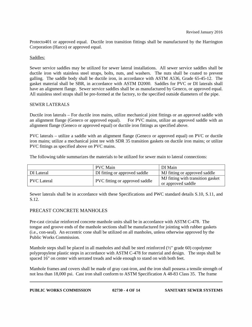
Protecto401 or approved equal. Ductile iron transition fittings shall be manufactured by the Harrington Corporation (Harco) or approved equal. Saddles: Sewer service saddles may be utilized for sewer lateral installations. All sewer service saddles shall be ductile iron with stainless steel straps, bolts, nuts, and washers. The nuts shall be coated to prevent galling. The saddle body shall be ductile iron, in accordance with ASTM A536, Grade 65-45-12. The gasket material shall be SBR, in accordance with ASTM D2000. Saddles for PVC or DI laterals shall have an alignment flange. Sewer service saddles shall be as manufactured by Geneco, or approved equal. All stainless steel straps shall be pre-formed at the factory, to the specified outside diameters of the pipe. SEWER LATERALS Ductile iron laterals – For ductile iron mains, utilize mechanical joint fittings or an approved saddle with an alignment flange (Geneco or approved equal). For PVC mains, utilize an approved saddle with an alignment flange (Geneco or approved equal) or ductile iron fittings as specified above. PVC laterals – utilize a saddle with an alignment flange (Geneco or approved equal) on PVC or ductile iron mains; utilize a mechanical joint tee with SDR 35 transition gaskets on ductile iron mains; or utilize PVC fittings as specified above on PVC mains. The following table summarizes the materials to be utilized for sewer main to lateral connections: PVC Main DI Main DI Lateral DI fitting or approved saddle MJ fitting or approved saddle
PVC Lateral PVC fitting or approved saddle MJ fitting with transition gasket or approved saddle
Sewer laterals shall be in accordance with these Specifications and PWC standard details S.10, S.11, and S.12. PRECAST CONCRETE MANHOLES Pre-cast circular reinforced concrete manhole units shall be in accordance with ASTM C-478. The tongue and groove ends of the manhole sections shall be manufactured for jointing with rubber gaskets (i.e., con-seal). An eccentric cone shall be utilized on all manholes, unless otherwise approved by the Public Works Commission. Manhole steps shall be placed in all manholes and shall be steel reinforced (½" grade 60) copolymer polypropylene plastic steps in accordance with ASTM C-478 for material and design. The steps shall be spaced 16" on center with serrated treads and wide enough to stand on with both feet. Manhole frames and covers shall be made of gray cast-iron, and the iron shall possess a tensile strength of not less than 18,000 psi. Cast iron shall conform to ASTM Specification A 48-83 Class 35. The frame
Revised January 2016
PUBLIC WORKS COMMISSION 02730 - 5 OF 14 SANITARY SEWER SYSTEMS
and cover shall be manufactured by the same manufacturer. All castings shall be in accordance with Public Works Commission standard details. Any defective castings shall be removed and replaced. Any special linings and coatings that are specified for a manhole and installed at the production facility, in the field, or during repairs, shall be applied in accordance with the applicable special coatings specification and the manufacturer’s specifications for that material. Camlock ring and covers shall be in accordance with Public Works Commission standard details. Camlock bolt head shall be compatible with PWC standard tool for turning camlock mechanism. Camlock ring and covers shall be installed as indicated on the drawings, in accordance with PWC standard details. SELECT BEDDING MATERIAL Select bedding material shall be crushed stone (No. 57 or No. 5), in accordance with Public Works Commission standard details. Bedding material shall be provided for all pipe materials. INSTALLATION Pipe installation shall be in strict accordance with Specification Section 02222 – Excavation and Backfilling for Utility Systems and as outlined herein. PIPE LAYING Pipe installation shall be in accordance with the manufacturer’s instructions. Proper equipment shall be utilized to perform the work in a manner satisfactory to PWC. All pipes and fittings shall be carefully lowered into the trench in such a manner to prevent damage to the protective coatings and linings. Under no circumstances shall pipe materials be dropped or dumped into the trench. Pipe shall be carried into position and not dragged. All dust, dirt, oil, tar (other than standard coating), or other foreign matter shall be cleaned from the jointing surfaces, and the gasket, bell, and spigot shall be lubricated with lubricant recommended by the manufacturer. The pipe shall be laid upgrade, beginning at the lower end with the tongue or spigot ends pointing in the direction of the flow to the correct line and grade, unless otherwise approved by PWC. The pipe section to be installed shall be aligned by batter board or laser beam with the last installed pipe section. Mechanical equipment should not be used to assemble the pipe. Pipe shall be assembled in accordance with the pipe manufacturer’s instructions. Any damage resulting from the use of mechanical equipment shall be replaced as directed by PWC. Adjustments in grade by exerting force on the barrel of the pipe with excavating equipment shall not be allowed. The Contractor shall verify line and grade after assembling each joint.
Revised January 2016
PUBLIC WORKS COMMISSION 02730 - 6 OF 14 SANITARY SEWER SYSTEMS
At any time when pipe laying is not in progress, the open ends of the pipe shall be closed by a water tight plug or other means approved by the PWC Project Coordinator. If water is in the trench, the plug shall remain in place until the trench is pumped completely dry. No pipe shall be laid in water or where in the PWC Project Engineer's and/or PWC Project Coordinator’s opinion trench conditions are unsuitable. Every precaution shall be taken to prevent material from entering the pipe while it is being installed. ALIGNMENT AND GRADE All pipe shall be installed to the required lines and grades. Structures shall be installed at the required locations. The lines and grades of the pipe will generally be indicated by stakes parallel to the line of the pipe. The Contractor shall be responsible for installing the pipe to proper line and grade. Pipe shall be visually inspected by shining a light between structures and /or by closed circuit television inspection. Any defects discovered, including poor alignment, shall be corrected as directed by the Public Works Commission. The bottom of the trench shall be excavated to a minimum of four inches (4") below the outside bottom of the pipe being installed to allow adequate placement and compaction of bedding material prior to installation. Select bedding material shall be placed a minimum of four inches (4") and a maximum of six inches (6") under the pipe for full width of the trench and halfway up the pipe on the sides. Bedding material shall be placed in layers not exceeding six inches (6") loose thickness for compacting by vibratory mechanical tamps under the haunches and concurrently on each side of the pipe for the full width of the trench. The final result shall be "Class B" bedding for rigid pipe. If the existing material under the pipe bedding material is unsuitable, the unsuitable material shall be removed and replaced with select bedding material (No. 57 or No. 5 stone), as authorized and approved by the Public Works Commission Project Coordinator. The same material pipe shall be utilized from manhole to manhole, unless otherwise approved by PWC. If the section of pipe between manholes is 250 feet or less, no transitions will be allowed (either all PVC or all ductile iron). Should the length between manholes exceed 250 feet, only one transition will be allowed. Use of a C900 x SDR 26 adaptor shall be used to accomplish the transition. A transition is defined as the use of one C900 x SDR26 adaptor. No more than one (1) adaptor shall be utilized in any given manhole to manhole segment. All manholes shall be constructed to Public Works Commission's standards. Installation shall be in accordance with ASTM C-891 and PWC standards. Manholes shall be constructed of precast reinforced concrete circular sections installed on a base riser section with integral floor and shall be cored to accommodate the various pipe connections, as indicated on the drawings. Pipe connections to a manhole shall be by gasketed flexible watertight connections (boot for small diameter and A Loc for larger diameter pipe) or as approved by the Public Works Commission. The manhole size shall be in accordance with the following table, unless otherwise specified:
Revised January 2016
PUBLIC WORKS COMMISSION 02730 - 7 OF 14 SANITARY SEWER SYSTEMS
Pipe Size Manhole Diameter **
24" and less 48" * 27" - 36" 60" 42" 72"
* Where interior drop structures are required, use 60" diameter as required in the Public Works Commission standard details. ** Where multiple connections or acute angles are required, larger diameter manhole may be required as indicated on the plans. The invert channel shall be constructed of brick and mortar, in accordance with Public Works Commission standard details. Precast inverts are not allowed. The invert channel shall be smooth and semicircular in shape conforming to the inside of the connecting sewer section. Changes in direction of flow shall be made with a smooth curve as large as a radius as the size of the manhole will permit without a decrease in flow velocity. Changes in size and grade of the channel shall be made gradually and evenly. The invert channel walls shall be constructed to three quarters (3/4) of the height of the crown of the outlet sewer and in such a manner not to obstruct maintenance, inspection or flow in the sewers. The inverts shall have a minimum slope of one (1) percent across the bottom of the manhole. A shelf shall be provided on each side of any manhole invert channel. Inverts in manholes with standing water will not be acceptable. The shelf shall be sloped not less than 1:12 (min) and no more than 2:12 (max). The bottom of the boot for the new sewer main or lateral shall be set one inch above existing shelf unless otherwise indicated. When used in a paved street, the ring and cover shall be set in suitable mortar surrounded by a concrete collar in accordance with Public Works Commission standard details. When used in places other than in a paved street, the ring and cover shall be set to the grade shown on the plans or directed by the Public Works Commission. In unpaved areas cam-lock ring and cover shall be used. Camlock ring and cover shall be installed in accordance with Public Works Commission standard details. The interior manhole riser joints, lift holes and grade adjustment rings shall be sealed with non-shrinking mortar to provide a watertight manhole. Lift holes sealed by the manufacturer with plastic caps do not require mortar seal. The hardened mortar shall be smooth to rub with no sharp edges. Use of grade rings with cam-lock ring and cover are not allowed, unless approved by the PWC Project Coordinator. Use of grade rings is not allowed for above grade adjustments. All exterior manhole riser joints, including the joint at the cone, shall be sealed with an external rubber sleeve. The sleeve shall be made of stretchable, self-shrinking rubber, with a minimum thickness of 30 mils. The back side of each wrap shall be coated with a cross-linked reinforced butyl adhesive. The butyl adhesive shall be a non-hardening sealant, with a minimum thickness of 30 mils. The seal shall be designed to stretch around the manhole joint and then overlap to create a fused bond between the rubber and butyl adhesive. The application shall form a continuous rubber seal for the life of the application. The sealing system shall be as manufactured by Concrete Sealants, Inc. (Con-Seal), Sealing Systems, Inc., or approved equal. The wrap shall be a minimum of six (6) inches in width, and shall be centered on the
Revised January 2016
PUBLIC WORKS COMMISSION 02730 - 8 OF 14 SANITARY SEWER SYSTEMS
joint. All manhole joints (including the cone section to the last riser) shall be wrapped and sealed. Care shall be taken to prevent damage to the wrap during backfill operations. The manhole surface shall be prepared in accordance with manufacturer’s specifications, prior to installing the joint wrap. Materials shall not enter the sewer line during construction of the manhole. The manhole shall be kept clean of any and all debris or materials. Any debris or material that entered the manhole shall be immediately removed. This condition shall be maintained until final acceptance of the work. CONNECTION TO EXISTING MANHOLES OR LIFT STATIONS All connections to existing manholes and/or lift stations shall be approved by the Public Works Commission. Where new mains are to be connected to existing active sanitary sewers, the active sewers shall remain in service. Unless otherwise indicated, where new lines are connected into existing manholes, all or such portion of the manhole invert as is necessary shall be removed and a new invert shall be constructed to accommodate both new and existing flows. All work shall conform to the requirements specified for new manholes. The existing structure connection shall be cored and a flexible watertight connection (i.e., boot) installed. The boot shall be installed in accordance with Public Works Commission standard details and requirements. The Contractor shall coordinate and cooperate with the Public Works Commission’s Project Coordinator. PIPE TO MANHOLE CONNECTOR (BOOT) A watertight, flexible pipe-to-manhole connector shall be utilized on all pipe to manhole connections, for both new and existing manholes and pipes, unless otherwise specifically authorized in writing by the Public Works Commission. The connector assembly shall be the sole element to provide a watertight seal of the pipe to the manhole or other structure. The connector shall consist of a rubber gasket, an internal compression sleeve, and one or more external take-up clamps. The connector shall consist of natural or synthetic rubber and Series 300 non-magnetic stainless steel. No plastic components shall be allowed. The rubber gasket shall be constructed of synthetic or natural rubber, and shall meet or exceed the requirements of ASTM C-923. The connector shall have a minimum tensile strength of 1,600 psi. The minimum cross-sectional thickness shall be 0.275 inches. The internal expansion sleeve shall be comprised of Series 300 non-magnetic stainless steel. No welds shall be utilized in its construction. Installation of the connector shall be performed utilizing a calibrated installation tool furnished by the connector manufacturer. Installation shall require no re-tightening after the initial installation. Installation shall be done in accordance with the manufacturer’s instructions. The external compression take-up clamps shall be Series 300 non-magnetic stainless steel. No welds shall be utilized in its construction. The clamps shall be installed utilizing a torque-setting wrench
Revised January 2016
PUBLIC WORKS COMMISSION 02730 - 9 OF 14 SANITARY SEWER SYSTEMS
furnished by the connector manufacturer. Installation shall be done in accordance with the manufacturer’s instructions. The Contractor shall utilize the proper size connector in accordance with the connector manufacturer’s recommendations. All dead-end pipe stubs shall be restrained in accordance with ASTM C-923. The finished connection shall provide a sealing to a minimum of 13 psi, and shall accommodate a minimum pipe deflection of seven (7) degrees without the loss of seal. The pipe to manhole connector shall be PSX: Direct Drive as manufactured by Press-Seal, or approved equal. INSIDE DROP MANHOLE STRUCTURE Inside manhole drop structures shall be constructed and installed in accordance with Public Works Commission standard details. CLEANING Prior to final inspection, all sanitary sewer laterals, mains, and manholes newly installed on the collection system shall be flushed and cleaned. During the flushing operation, the downstream manhole shall be closed with a watertight plug to protect the existing sewer main. All water and debris shall be removed and properly disposed of by the Contractor. This condition shall be maintained until the Public Works Commission issues final acceptance for the project. TESTING Completed sewers shall be tested in accordance with the provisions outlined below. The Contractor shall furnish all equipment, labor, materials, and pay all costs associated with the tests performed. The Contractor shall schedule all testing with the Public Works Commission’s Project Coordinator, a minimum of 48 hours in advance. The Contractor shall cooperate with the Public Works Commission's Project Coordinator and furnish any needed assistance necessary to complete the required testing. For annexation and/or retrofit projects: No testing shall be conducted prior to successful completion of the compaction testing. For all other projects: No testing shall be completed until all utilities are installed, prior to preparation of the road subgrade. The Contractor may elect to perform testing to satisfy them that the sewer utility is installed properly prior to commencing installation of other utilities. However, such testing shall not be construed as acceptance by PWC. The deflection/mandrel test shall not be performed until a minimum of thirty (30) calendar days after backfill operations are completed and the area graded to final contours. In lieu of waiting thirty (30) calendar days, the Contractor has the option to have an independent testing laboratory verify that
Revised January 2016
PUBLIC WORKS COMMISSION 02730 - 10 OF 14 SANITARY SEWER SYSTEMS
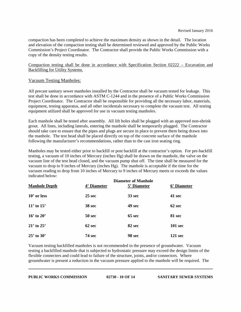
compaction has been completed to achieve the maximum density as shown in the detail. The location and elevation of the compaction testing shall be determined reviewed and approved by the Public Works Commission’s Project Coordinator. The Contractor shall provide the Public Works Commission with a copy of the density testing results. Compaction testing shall be done in accordance with Specification Section 02222 – Excavation and Backfilling for Utility Systems. Vacuum Testing Manholes: All precast sanitary sewer manholes installed by the Contractor shall be vacuum tested for leakage. This test shall be done in accordance with ASTM C-1244 and in the presence of a Public Works Commission Project Coordinator. The Contractor shall be responsible for providing all the necessary labor, materials, equipment, testing apparatus, and all other incidentals necessary to complete the vacuum test. All testing equipment utilized shall be approved for use in vacuum testing manholes. Each manhole shall be tested after assembly. All lift holes shall be plugged with an approved non-shrink grout. All lines, including laterals, entering the manhole shall be temporarily plugged. The Contractor should take care to ensure that the pipes and plugs are secure in place to prevent them being drawn into the manhole. The test head shall be placed directly on top of the concrete surface of the manhole following the manufacturer’s recommendations, rather than to the cast iron seating ring. Manholes may be tested either prior to backfill or post backfill at the contractor’s option. For pre-backfill testing, a vacuum of 10 inches of Mercury (inches Hg) shall be drawn on the manhole, the valve on the vacuum line of the test head closed, and the vacuum pump shut off. The time shall be measured for the vacuum to drop to 9 inches of Mercury (inches Hg). The manhole is acceptable if the time for the vacuum reading to drop from 10 inches of Mercury to 9 inches of Mercury meets or exceeds the values indicated below: Diameter of Manhole Manhole Depth 4’ Diameter 5’ Diameter 6’ Diameter 10’ or less 25 sec 33 sec 41 sec 11’ to 15’ 38 sec 49 sec 62 sec 16’ to 20’ 50 sec 65 sec 81 sec 21’ to 25’ 62 sec 82 sec 101 sec 25’ to 30’ 74 sec 98 sec 121 sec Vacuum testing backfilled manholes is not recommended in the presence of groundwater. Vacuum testing a backfilled manhole that is subjected to hydrostatic pressure may exceed the design limits of the flexible connecters and could lead to failure of the structure, joints, and/or connectors. Where groundwater is present a reduction in the vacuum pressure applied to the manhole will be required. The
Revised January 2016
PUBLIC WORKS COMMISSION 02730 - 11 OF 14 SANITARY SEWER SYSTEMS
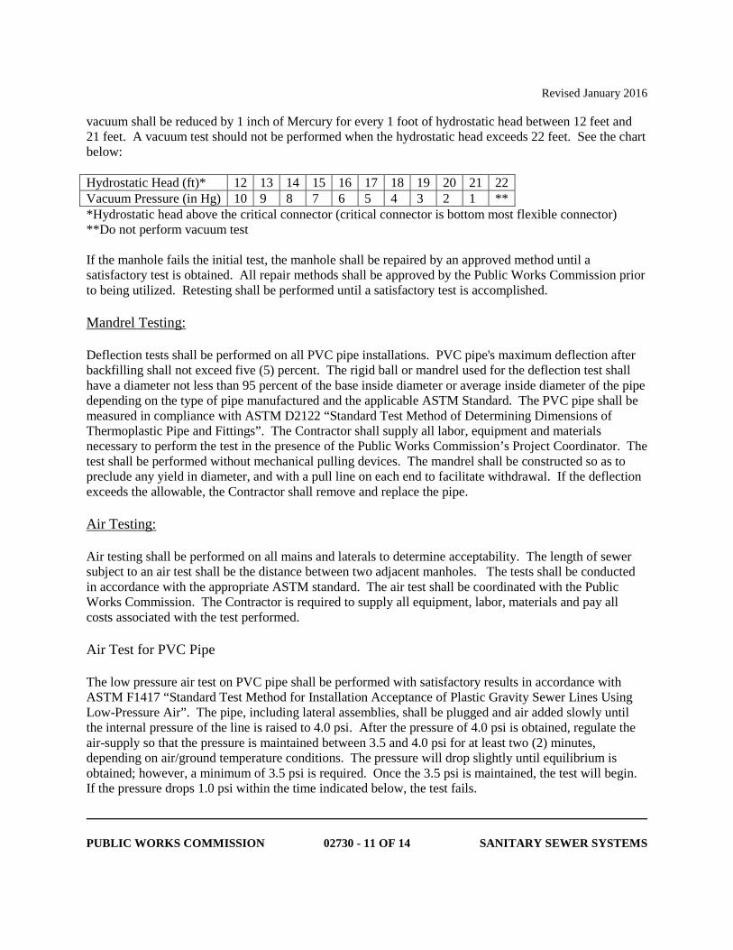
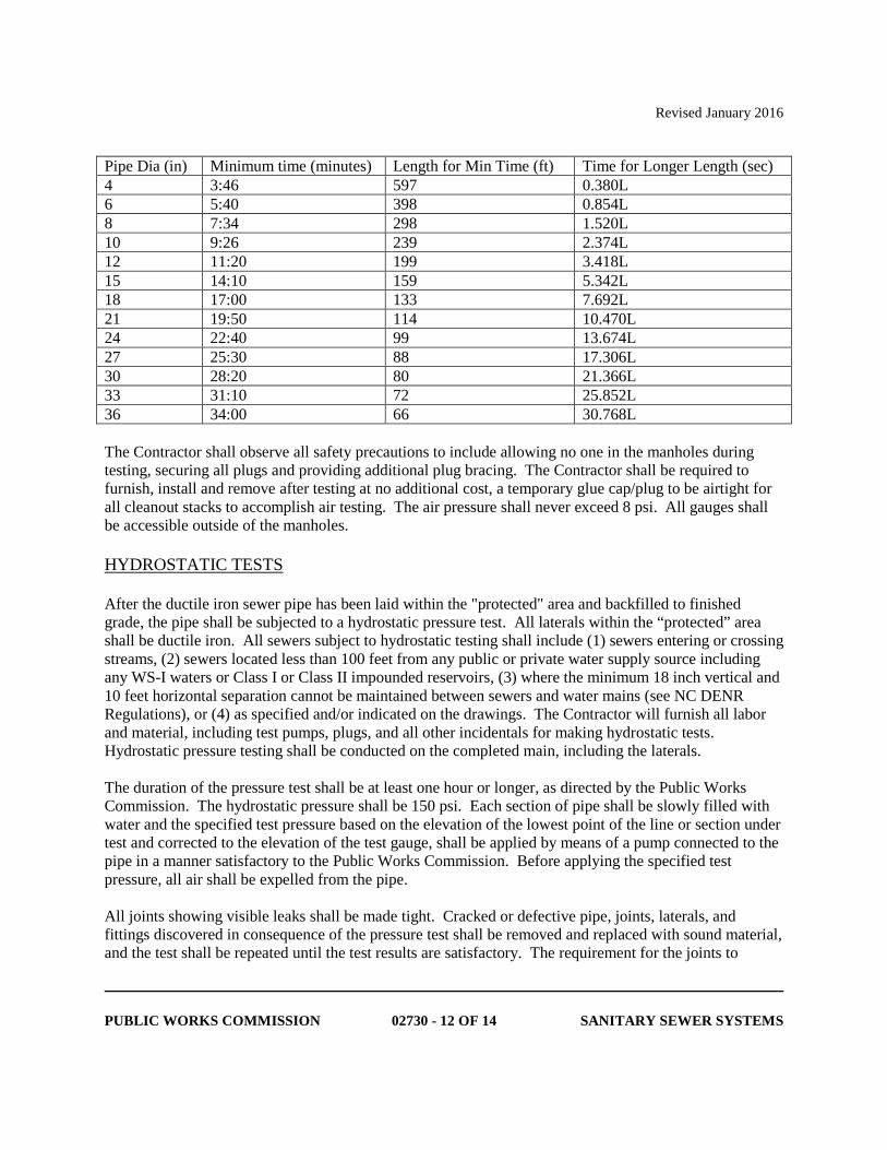
vacuum shall be reduced by 1 inch of Mercury for every 1 foot of hydrostatic head between 12 feet and 21 feet. A vacuum test should not be performed when the hydrostatic head exceeds 22 feet. See the chart below: Hydrostatic Head (ft)* 12 13 14 15 16 17 18 19 20 21 22 Vacuum Pressure (in Hg) 10 9 8 7 6 5 4 3 2 1 ** *Hydrostatic head above the critical connector (critical connector is bottom most flexible connector) **Do not perform vacuum test If the manhole fails the initial test, the manhole shall be repaired by an approved method until a satisfactory test is obtained. All repair methods shall be approved by the Public Works Commission prior to being utilized. Retesting shall be performed until a satisfactory test is accomplished. Mandrel Testing: Deflection tests shall be performed on all PVC pipe installations. PVC pipe's maximum deflection after backfilling shall not exceed five (5) percent. The rigid ball or mandrel used for the deflection test shall have a diameter not less than 95 percent of the base inside diameter or average inside diameter of the pipe depending on the type of pipe manufactured and the applicable ASTM Standard. The PVC pipe shall be measured in compliance with ASTM D2122 “Standard Test Method of Determining Dimensions of Thermoplastic Pipe and Fittings”. The Contractor shall supply all labor, equipment and materials necessary to perform the test in the presence of the Public Works Commission’s Project Coordinator. The test shall be performed without mechanical pulling devices. The mandrel shall be constructed so as to preclude any yield in diameter, and with a pull line on each end to facilitate withdrawal. If the deflection exceeds the allowable, the Contractor shall remove and replace the pipe. Air Testing: Air testing shall be performed on all mains and laterals to determine acceptability. The length of sewer subject to an air test shall be the distance between two adjacent manholes. The tests shall be conducted in accordance with the appropriate ASTM standard. The air test shall be coordinated with the Public Works Commission. The Contractor is required to supply all equipment, labor, materials and pay all costs associated with the test performed. Air Test for PVC Pipe The low pressure air test on PVC pipe shall be performed with satisfactory results in accordance with ASTM F1417 “Standard Test Method for Installation Acceptance of Plastic Gravity Sewer Lines Using Low-Pressure Air”. The pipe, including lateral assemblies, shall be plugged and air added slowly until the internal pressure of the line is raised to 4.0 psi. After the pressure of 4.0 psi is obtained, regulate the air-supply so that the pressure is maintained between 3.5 and 4.0 psi for at least two (2) minutes, depending on air/ground temperature conditions. The pressure will drop slightly until equilibrium is obtained; however, a minimum of 3.5 psi is required. Once the 3.5 psi is maintained, the test will begin. If the pressure drops 1.0 psi within the time indicated below, the test fails.
Revised January 2016
PUBLIC WORKS COMMISSION 02730 - 12 OF 14 SANITARY SEWER SYSTEMS
Pipe Dia (in) Minimum time (minutes) Length for Min Time (ft) Time for Longer Length (sec) 4 3:46 597 0.380L 6 5:40 398 0.854L 8 7:34 298 1.520L 10 9:26 239 2.374L 12 11:20 199 3.418L 15 14:10 159 5.342L 18 17:00 133 7.692L 21 19:50 114 10.470L 24 22:40 99 13.674L 27 25:30 88 17.306L 30 28:20 80 21.366L 33 31:10 72 25.852L 36 34:00 66 30.768L The Contractor shall observe all safety precautions to include allowing no one in the manholes during testing, securing all plugs and providing additional plug bracing. The Contractor shall be required to furnish, install and remove after testing at no additional cost, a temporary glue cap/plug to be airtight for all cleanout stacks to accomplish air testing. The air pressure shall never exceed 8 psi. All gauges shall be accessible outside of the manholes. HYDROSTATIC TESTS After the ductile iron sewer pipe has been laid within the "protected" area and backfilled to finished grade, the pipe shall be subjected to a hydrostatic pressure test. All laterals within the “protected” area shall be ductile iron. All sewers subject to hydrostatic testing shall include (1) sewers entering or crossing streams, (2) sewers located less than 100 feet from any public or private water supply source including any WS-I waters or Class I or Class II impounded reservoirs, (3) where the minimum 18 inch vertical and 10 feet horizontal separation cannot be maintained between sewers and water mains (see NC DENR Regulations), or (4) as specified and/or indicated on the drawings. The Contractor will furnish all labor and material, including test pumps, plugs, and all other incidentals for making hydrostatic tests. Hydrostatic pressure testing shall be conducted on the completed main, including the laterals. The duration of the pressure test shall be at least one hour or longer, as directed by the Public Works Commission. The hydrostatic pressure shall be 150 psi. Each section of pipe shall be slowly filled with water and the specified test pressure based on the elevation of the lowest point of the line or section under test and corrected to the elevation of the test gauge, shall be applied by means of a pump connected to the pipe in a manner satisfactory to the Public Works Commission. Before applying the specified test pressure, all air shall be expelled from the pipe. All joints showing visible leaks shall be made tight. Cracked or defective pipe, joints, laterals, and fittings discovered in consequence of the pressure test shall be removed and replaced with sound material, and the test shall be repeated until the test results are satisfactory. The requirement for the joints to
Revised January 2016
PUBLIC WORKS COMMISSION 02730 - 13 OF 14 SANITARY SEWER SYSTEMS
remain exposed for the hydrostatic test may be waived by the Public Works Commission in certain situations. The test shall be repeated until satisfactory to the Public Works Commission. The results of the pressure tests shall be satisfactory as specified. All replacement, repair, or retesting shall be accomplished by the Contractor. All repairs shall be reviewed and approved by the Public Works Commission prior to backfill. The use of couplings, sleeves, etc. shall be reviewed and approved by the Public Works Commission prior to use.

Revised January 2016
PUBLIC WORKS COMMISSION 02730 - 14 OF 14 SANITARY SEWER SYSTEMS
***THIS PAGE INTENTIONALLY LEFT BLANK***
January 2020
RANKIN STREET DRAINAGE IMPROVEMENTS
FAYETTEVILLE PUBLIC WORKS COMMISSION Pg 1 of 15
DIVISION 1 GENERAL REQUIREMENTS 01000 – SPECIAL CONDITIONS (FAYETTEVILLE PUBLIC WORKS COMMISSION)
GENERAL
These Special Conditions are intended to supplement and amplify the Technical Specifications and other requirements of this Contract regarding the water and sewer utility work. Where any article or item of the Contract Documents is modified or deleted by this document, the remaining unaltered provisions of that article, paragraph, subparagraph, or clause shall remain in effect. In the event of a conflict, these Special Conditions shall take precedence.
1. Summary
This project includes the replacement of existing water and sewer mains, valves, manholes, and appurtenances, to be completed in conjunction with the proposed storm water improvements. All new water and sewer mains shall be ductile iron; new water services shall be copper; and new sewer services shall be ductile iron. Work shall include bypass pumping, re-instatement of existing water and/or sewer laterals, replacement of water and/or sewer mains, post-inspection of the installed mains, restoration, and all other items necessary to provide a complete project.
All work shall be done in accordance with the terms and conditions outlined herein, the Fayetteville Public Works Commission (PWC) “Manual for the Design and Construction of Water and Wastewater System Extensions” (most recent edition), in accordance with the NCDOT Standard Specifications for Roads and Structures (most recent edition), and subject to final approval and acceptance by the Fayetteville Public Works Commission.
2. Fayetteville Public Works Commission Responsibilities
The Fayetteville Public Works Commission is the owner of the water and sewer utilities within the public rights-of-way within the project area. The Fayetteville Public Works Commission will have a Project Coordinator assigned to this project, to observe construction of the water and sewer utilities. All work related to the water and sewer utilities shall be coordinated through the Fayetteville Public Works Commission. The Contractor shall notify the Fayetteville Public Works Commission a minimum of two (2) business days in advance of beginning any construction on the water and/or sewer utilities. Should there be any changes to the design of the water and sewer utilities, such changes shall be approved by the Fayetteville Public Works Commission, in writing, prior to the Contractor proceeding with the proposed revision. The Fayetteville Public Works Commission has sole authority regarding decisions impacting the water and sewer utilities within the project area. The Fayetteville Public Works Commission shall review and approve all requests for payment related to the construction of the water and sewer utilities. The Contractor shall submit all requests for payment in accordance with these Contract Documents.
January 2020
RANKIN STREET DRAINAGE IMPROVEMENTS
FAYETTEVILLE PUBLIC WORKS COMMISSION Pg 2 of 15
3. Resolving Discrepancies
Except as may be otherwise specifically stated in the Contract Documents, the following order of precedence shall be adhered to for resolving any conflict, error, ambiguity, or discrepancy between the provisions of the Contract Documents: 1. Any addendum issued prior to the opening of Bids 2. Section 01000 – Special Conditions 3. Section 01025 – Measurement and Payment 4. Approved Contract Drawings 5. PWC Standard Details 6. PWC Technical Specifications 7. General Conditions of the Contract Documents
4. Customer Service
The Contractor is expected to make every effort to reduce the impact of their operation to PWC’s operation and maintenance of the water and sewer system, and the affected residents within the project area. Full cooperation and coordination with PWC personnel and residents is expected. It is expected that the Contractor will promptly respond to any concerns voiced by residents and/or PWC personnel, and make every effort to resolve them immediately. Providing exemplary customer service shall be incidental to this Contract, and no additional payment will be made for this service.
The Contractor at all times shall conduct the work in such a manner as to ensure the least obstruction to traffic practicable. The convenience of the general public and of the residents and businesses along and adjacent to the Work shall be provided for in a satisfactory manner, consistent with the operation and local conditions. The Contractor shall construct and maintain any necessary ramps, boardwalks, or other means to maintain pedestrian traffic. Costs for such work shall be incidental to the unit prices bid. The Contractor shall at all times cooperate with the public and merchants as affected by the construction operations and shall endeavor to maintain good public relations at all times. The Contractor shall fully coordinate their operations and schedule with the Fayetteville Public Works Commission.
5. Customer Notification
Whenever the property owner’s use of the water and/or sanitary sewer utilities must be interrupted by the Work, the Contractor shall notify the residents well in advance of the interruption. This notification shall be accomplished with door hanger notification cards placed at the addresses of the affected residents. Property owners shall be informed when service interruption takes place and the expected duration. This notice shall be a minimum 48 hours prior to service interruption. The Contractor shall make every effort to minimize inconvenience to the public and property owners.
Service interruptions to residents shall be limited to no more than eight (8) hours at any given time.
The notifications shall describe the work to be undertaken and approximate dates of the work. The notifications shall clearly indicate the dates and times of the work. The text of the notifications shall be approved by the Fayetteville Public Works Commission in advance. The
January 2020
RANKIN STREET DRAINAGE IMPROVEMENTS
FAYETTEVILLE PUBLIC WORKS COMMISSION Pg 3 of 15
Contractor shall notify the PWC Project Coordinator each time such notification is issued to the residents.
6. Guarantee
All water and/or sewer work completed under these Contract Documents shall be guaranteed by the Contractor for a period of one (1) year from the date of final acceptance. During that period, all serious defects discovered in the water and/or sewer work, as determined by the Fayetteville Public Works Commission, shall be removed and replaced in a satisfactory manner by the Contractor at no cost to the Fayetteville Public Works Commission. The Fayetteville Public Works Commission may conduct an independent inspection, at their sole expense, of the completed water and/or sewer work prior to the completion of the one (1) year guarantee period.
Should the Fayetteville Public Works Commission’s inspection determine that the water and/or sewer work is not in accordance with these Contract Documents; the Contractor shall mobilize and make all necessary repairs at no expense to the Fayetteville Public Works Commission. The Contractor will receive written notification from the Fayetteville Public Works Commission, and be allowed the chance to review any available inspection pictures or other documentation. The Contractor shall respond to the Fayetteville Public Works Commission with a plan of action within 30 calendar days of receiving notification. The Contractor shall mobilize and begin to complete the repairs/replacement within 60 calendar days of receiving notification. The Contractor shall:
• Repair such defective land or areas. • Correct such defective Work, or if the defective Work has been rejected by the PWC
Project Engineer, remove it from the project and replace it with Work that is not defective.
• Satisfactorily correct, repair, remove, or replace any damage to other Work, damage to the work of others, and damage to other land or areas.
If the Contractor does not promptly comply with the terms of such instructions, or in an emergency where delay would cause serious risk of loss or damage, the Fayetteville Public Works Commission reserves the right to contract with another party to complete the warranty work, at the sole expense of the Contractor. All claims, costs, losses, and damages (including but not limited to all fees and charges or design professionals, attorneys, and other professionals and all court, arbitration or other dispute resolution costs arising out of or relating to such correction or repair or such removal and replacement of work of others) shall be paid by the Contractor.
The warranty period stated is specifically for the water and/or sewer work installed by the Contractor. Any collateral damage discovered during the warranty period will be investigated and the Contractor will be required to respond if the damage is determined to have occurred during the construction process.
7. Discovery of Defects
The Contractor warrants and guarantees to the Fayetteville Public Works Commission, that all water and/or sewer work will be in accordance with these Contract Documents, will not be defective, and that all materials and equipment used for the work are appropriate for the Project. The Fayetteville Public Works Commission shall provide prompt notice of all defects to Contractor upon discovery. All defective water and/or sewer work, whether or not in place, may be rejected, corrected, or accepted, at the Fayetteville Public Works Commission’s sole discretion.
January 2020
RANKIN STREET DRAINAGE IMPROVEMENTS
FAYETTEVILLE PUBLIC WORKS COMMISSION Pg 4 of 15
The Fayetteville Public Works Commission reserves the right, should an error be discovered in the estimate or conclusive proof of defective work or materials used by or on the part of the Contractor be discovered either before or after the final payment has been made, to claim and remove by process of law such sum or sums as may be sufficient to correct the error or make good the defects in the work and materials.
8. Cleanliness During Construction
The Contractor shall perform a daily clean-up of all dirt, debris, scrap materials and other disposable items resulting from the Contractor’s operations, whether on-site or off-site. The Contractor shall remove all construction equipment, barricades, tools, surplus materials, etc. no longer required at the site. No open accumulation of refuse, surplus or scrap materials will be permitted. Failure of the Contractor to maintain a clean site will be basis for the Fayetteville Public Works Commission to issue a written notice of non-compliance with the Contract. Should that notice to correct not be complied with within twenty-four (24) hours, the Fayetteville Public Works Commission may authorize the cleanup to be performed by others and the costs shall be deducted from monies due the Contractor. The Contractor shall legally dispose off-site all waste materials and other excess materials resulting from construction. No separate payment shall be made for maintaining a clean project site.
The Contractor shall control the dust in all areas of the project limits for the entire duration of construction. Dust control may be accomplished by use of either water or dust control materials, or as directed by the PWC Project Engineer. No separate payment shall be made for dust control.
9. Working Times
The Contractor shall limit their operations to Monday through Friday, between the times of 8:00 am and 5:00 pm, unless otherwise approved by the Fayetteville Public Works Commission. No work is permitted on legal Holidays (to include holiday weekends). No work, unless otherwise required due to an emergency and authorized by the Fayetteville Public Works Commission, shall be performed on weekends or after hours without prior written approval from the Fayetteville Public Works Commission. Requests to work other than regular working hours must be submitted in writing to the Fayetteville Public Works Commission a minimum of two (2) full business days in advance in order to arrange for appropriate personnel to be at the site of the Work. Requests shall only be approved if the Fayetteville Public Works Commission determines that the work is necessary in order to meet the contract completion date. The written request shall include a proposed schedule for the work to be completed.
During the course of construction, it may be necessary to complete portions of the Work outside of the normal working hours, to accommodate the utility owner’s operations, traffic, and/or public convenience. The Contractor, City of Fayetteville, Fayetteville Public Works Commission, and the utility owner will determine an acceptable schedule required for Work during such hours. The costs for such Work shall be considered incidental to the Project and no additional payment will be made.
Legal holidays observed by the Fayetteville Public Works Commission include New Year’s Day, Martin Luther King’s Birthday, Good Friday, Memorial Day, Independence Day, Labor Day, Thanksgiving (2 days), and Christmas (2 days).
January 2020
RANKIN STREET DRAINAGE IMPROVEMENTS
FAYETTEVILLE PUBLIC WORKS COMMISSION Pg 5 of 15
10. Construction Staking
All water and sewer utility construction shall be staked in the field. Cut sheets shall be provided to the Fayetteville Public Works Commission and the Contractor. No construction will be allowed to proceed unless the installation is staked and cut sheets are on site. The Contractor shall maintain cut sheets on the project site at all times, and make them available for inspection by PWC staff.
11. Stored Materials
There will be no payment for stored materials (related to water and sewer utilities) on this project.
12. Materials
All materials to be utilized are to be in new condition. Materials are to be stored in strict accordance with the manufacturer’s directions. Materials are to be of the type and brand specified within these Contract Documents. No alternative or substitute materials shall be considered prior to award of the Contract.
The Contractor shall submit all requests to utilize materials other than specified to the Fayetteville Public Works Commission for review. The Contractor shall be responsible for providing all required documentation necessary for the Fayetteville Public Works Commission to review and make a determination if the substitute material meets the required specification.
The Contractor will be responsible for providing documented proof that the proposed substitution has a proven record of performance when used in the intended application as confirmed by actual field test(s) or by successful installations. The Fayetteville Public Works Commission reserves the right to reject any such proposed changes or substitutions at their sole discretion, and is under no obligation to justify their decision.
13. Equipment
The Contractor shall be equipped with equipment perfectly adaptable for the type of construction required; all such equipment shall be of sufficient capacity to handle the work in an expeditious and safe manner. The Fayetteville Public Works Commission reserves the right to deny the use of inadequate equipment or of equipment not capable of performing the work in an acceptable manner.
With respect to the foregoing, it is the intent of the Fayetteville Public Works Commission to require that the Contractor be equipped to perform the work shown and specified, expeditiously and in accordance with the best modern practice.
14. Warranty Against License Agreements
The Contractor shall warrant to the Fayetteville Public Works Commission that the equipment used on this Contract, where covered by patents or license agreements, is furnished in accordance with such agreements and that the prices included herein cover all applicable royalties and fees in accordance with such license agreements. The Contractor shall defend, indemnify, and hold the Fayetteville Public Works Commission harmless from and against any and all costs, loss, damage, or expense arising out of or in any way connected with any claim of infringement of patent, trademark, or violation of license agreement.
January 2020
RANKIN STREET DRAINAGE IMPROVEMENTS
FAYETTEVILLE PUBLIC WORKS COMMISSION Pg 6 of 15
15. Agreements with Property Owners
Any and all agreements between the Contractor and individual property owners for work, services, rent of staging areas, etc. located outside of any easements or public rights-of way shall not obligate the City of Fayetteville, the Fayetteville Public Works Commission, or the Design Engineer in any manner. Prior to performing any work on private property, which could remotely infer the Contractor acting on behalf of the Fayetteville Public Works Commission, the Contractor shall furnish to the Fayetteville Public Works Commission a signed and witnessed statement executed by the Property Owner acknowledging that the City, the Fayetteville Public Works Commission, and Design Engineer are not liable for any agreements between the Property Owner and the Contractor, and that the Contractor shall hold harmless and defend the City, the Fayetteville Public Works Commission, and the Design Engineer from all claims, damages, etc. Additionally, the Contractor shall have the responsibility to secure any and all agreements with property owners for any actions taken by their Subcontractors.
Prior to release of final payment, the Contractor shall obtain written releases from the property owners for satisfaction, completion, and restoration. Copies of those written releases shall be submitted to Fayetteville Public Works Commission with the final pay application.
The Contractor bears complete responsibility for any damage to private properties outside of the PWC easements and/or rights-of-way.
16. Submittals
The Contractor shall provide submittal information regarding the water and sewer as outlined below. The Contractor shall not perform any portion of the Work requiring submittal and review until the respective submittal has been approved by the Fayetteville Public Works Commission. Work performed prior to review and acceptance shall be at the Contractor’s risk.
The Contractor shall submit to the Fayetteville Public Works Commission three (3) paper copies and one (1) set electronically (as an Adobe pdf) of all required submittal data for review and approval. The Contractor shall furnish, prior to use of the materials, satisfactory written certification of his compliance with the manufacturer’s standards for all materials, conformance with the methods of the manufacturer, and accordance with all standards specified and referenced within these specifications. If requested by the Fayetteville Public Works Commission, the manufacturer of materials, equipment, or product shall submit evidence of having consistently produced materials of satisfactory quality and performance for a period of at least two (2) years.
The Contractor shall provide submittals on the following:
• Contractor’s safety plan, including confined space program • A detailed plan for maintaining sewer service • Contractor personnel emergency contact information • Labor and equipment rates • Sample property owner agreement (if applicable) • Executed property owner agreement (if applicable) • Pre-construction video and pictures • Proposed schedule • Ductile iron pipe materials and fittings (to include sewer laterals, clean-out caps, etc.) • Restrained joint ductile iron pipe and fittings
January 2020
RANKIN STREET DRAINAGE IMPROVEMENTS
FAYETTEVILLE PUBLIC WORKS COMMISSION Pg 7 of 15
• Ductile iron pipe interior coating (for pipe in sewer service) • Fittings for connection to existing water and sewer
All information contained within the submittals shall be in accordance with these Contract Documents. Facsimile (fax) copies of the submittals or re-submittals will not be acceptable.
The Fayetteville Public Works Commission shall review and approve, disapprove, or approve with comment the submittal within 10 business days of receipt. All notifications on the submittals will be provided to the Contractor in writing. The Fayetteville Public Works Commission shall return one (1) marked copy and one (1) electronically (as an Adobe pdf) of the submittals to the Contractor.
The Fayetteville Public Works Commission’s review of the submittals will cover only general conformity to these Contract Documents, external connections, and dimensions which affect the layout. The Fayetteville Public Works Commission’s review does not indicate a thorough review of all dimensions, quantities, and details of the material, equipment, device, or item shown. The Fayetteville Public Works Commission’s review shall not relieve the Contractor of the Contractor’s sole responsibility for errors, omissions, or deviations in the drawings and data, nor of the Contractor’s sole responsibility for compliance with these Contract Documents.
Any need for more than one (1) re-submission, or any other delay in obtaining the Fayetteville Public Works Commission’s review of submittals, will not entitle the Contractor to an extension of the contract duration, unless the delay of the Work is directly caused by a change in the Work authorized by a Change Order or by failure of the Fayetteville Public Works Commission to review any submittal within the submittal review period specified herein and to return the submittal to the Contractor.
17. Limits of Construction
The Contractor shall confine their construction operations to the existing permanent easement or the existing street rights-of-way. The Contractor may use additional area for staging, storage, or other operations, provided that written permission is obtained from the property owner and all disturbed areas are restored to conditions equal or better than existing.
18. Fire Department Coordination
Existing fire hydrants shall be accessible to the Fire Department at all times. If the fire hydrants are in need of replacement, relocation, or connected to a new water main, the Fayetteville Public Works Commission, PWC Project Coordinator, and the appropriate Fire Department shall be notified and coordinated with prior to commencing work. Fire hydrants shall not be removed from service without prior approval of the Fayetteville Public Works Commission.
19. Emergency Response
The Contractor shall maintain a construction crew capable of performing emergency maintenance work 24 hours a day, seven (7) days a week, including all holidays. The Contractor shall furnish phone numbers for at least three (3) individuals in responsible charge (capable of making company binding decisions) to be available 24 hours a day, seven (7) days a week, including holidays. The emergency phone numbers and responsible individual’s names shall be furnished to the Fayetteville Public Works Commission at the pre-construction conference. The Contractor’s designated emergency personnel shall be expected to respond and perform
January 2020
RANKIN STREET DRAINAGE IMPROVEMENTS
FAYETTEVILLE PUBLIC WORKS COMMISSION Pg 8 of 15
emergency maintenance work immediately, in less than two (2) hours, or the work will be performed by others and all associated costs shall be deducted from the Contractor’s payment.
Once on-site, the Contractor shall notify the PWC Dispatcher (910-678-7400) of the problem, the anticipated response time, and the estimated time required to complete the repair work. It is the Contractor’s responsibility to maintain the appropriate repair materials on-site in order to provide an immediate response to the emergency.
20. Construction around Utility Poles and Guy Wires
The Contractor will be required to perform construction work around utility poles and guy wires which may be left in place within the construction limits of the project. The Contractor shall contact the owner of the utility to coordinate securing the poles during construction. It may be necessary for the Contractor to hire an electrical utility contractor to secure poles. All work outlined in this paragraph shall be at no additional cost to the Fayetteville Public Works Commission.
21. Protection of Existing Utilities
The Contractor shall take every precaution to guard against any or all damage to existing structures, pipe lines, and/or equipment of the Fayetteville Public Works Commission. Any damage to existing structures and/or pipe lines shall be the direct responsibility of the Contractor. Damage shall be replaced and/or repaired by the Contractor as directed by the PWC Project Coordinator, or the value of such deducted from any monies due the Contractor under this Contract.
The PWC Project Coordinator shall supervise the Contractor’s operation of all valves, gates, and other equipment. Except in case of emergency, the Contractor shall notify the PWC Project Coordinator a minimum of two (2) business days in advance of the need for operation of valves, gates, and other equipment necessary to allow the work to progress.
The Contractor shall in no case permit the introduction of water from the existing system into any new main without prior approval of the PWC Project Coordinator. The Contractor shall notify the PWC Project Coordinator a minimum of two (2) business days in advance of commencing the connection to an existing main.
The Contractor shall notify the PWC Project Coordinator a minimum of 48 hours in advance to coordinate any proposed service interruption. Note: the scheduling and coordination of a water outage within the PWC system shall be done in accordance with Item 35 of these Special Conditions. If an unscheduled service interruption occurs, the Contractor shall immediately notify the PWC Project Coordinator. The Contractor shall immediately commence repairs as directed by the PWC Project Coordinator.
In any event debris or other items from the Contractor’s operation enters the sanitary sewer system, the Contractor shall immediately contact the PWC Project Coordinator. The Contractor shall then immediately commence efforts to capture that debris at the downstream manholes. The Contractor shall continue to search for and recover any debris until either all debris is captured or instructed otherwise by the Fayetteville Public Works Commission. Any costs incurred by the Fayetteville Public Works Commission to help search for and/or retrieve the debris shall be the responsibility of the Contractor.
During the course of construction, some work will need to be performed during non-normal working hours to accommodate the Fayetteville Public Works Commission’s operations, traffic,
January 2020
RANKIN STREET DRAINAGE IMPROVEMENTS
FAYETTEVILLE PUBLIC WORKS COMMISSION Pg 9 of 15
and/or public convenience. The Contractor and the PWC Project Engineer will determine an acceptable schedule required for work during such hours. The cost of this work shall be included in the base bid.
22. Existing Utilities
The Contractor shall locate existing underground utilities in the areas of work. If utilities are to remain in place, the Contractor shall provide protection during construction operations. Additionally, the Contractor will coordinate with utility companies when working in close proximity to their line/services.
Should uncharted or incorrectly charted piping or other utilities be encountered during excavations, the Contractor shall immediately consult the PWC Project Engineer for directions as how to proceed. The Contractor shall fully cooperate with Owner and utility companies in keeping respective services and facilities in operation.
The Contractor shall adhere to the provisions of the 1985 Underground Damage Prevention Act, North Carolina General Statutes. The Contractor shall contact the NC One Call System for locates prior to beginning work in a particular area. The Contractor shall include the cost of any coordination and cooperation for utilities in his bid.
Actual horizontal and vertical locations have not been verified. As part of the Contract work, the Contractor is required to excavate each utility which may conflict with construction in advance to verify locations. The utilities shall be excavated a minimum of 14 business days in advance of actual installation of new utilities to allow the PWC Project Engineer an opportunity to adjust grades, alignments, etc., to avoid a conflict. Separate payment will not be made to physically verify the utility locations.
If the Contractor fails to schedule locates or perform advance physical locations in advance of the construction and a conflict arises, the Contractor will be required to make corrective measures as instructed by the PWC Project Engineer at the Contractor’s expense. The Contractor’s failure to advance plan (minimum 14 business days) by physically uncovering existing utilities in advance of construction shall not be cause for claim of lost time or for additional compensation. No additional payment will be made for re-mobilization required by the utility locator.
When the Contractor’s controlling operations are halted due to the failure of a utility owner to relocate or adjust a utility after being properly notified by the Contractor, the contract period may be extended by the amount of time the Contractor’s controlling operations have been delayed while awaiting the relocation or adjustment. Contractor shall proceed with work in areas not affected by the relocation or adjustment delay.
The Fayetteville Public Works Commission shall not be liable to the Contractor for any claims, costs, losses, or damages incurred or sustained on or in connection with locating existing underground installations.
23. Crossing Existing or Proposed Utilities
The Contractor shall conduct their operations so that the following requirements are adhered to:
a. Underground telephone, cable TV, and gas utilities or conduit banks shall be crossed maintaining a minimum of 12 inch separation or clearance.
January 2020
RANKIN STREET DRAINAGE IMPROVEMENTS
FAYETTEVILLE PUBLIC WORKS COMMISSION Pg 10 of 15
b. Electrical crossings shall be performed while the conductor is de-energized and at all times in the presence of the utility owner. Electrical crossings shall be in accordance with NESC Requirements. Electrical primary conductor crossings shall be as follows: • Crossing over a conductor, maintain a minimum of 12 inches of undisturbed soil encasing
the conductor. • Crossing under a conductor shall be accomplished by boring, maintaining 12 inches of
undisturbed soil encasing the conductor. No separate payment shall be made for this work.
24. Preconstruction Video
The Contractor shall complete a pre-construction video inspection of the project area, to document pre-existing conditions. The video shall be in a standard digital video file format (i.e., mp4, mpg, or avi) and on a standard portable digital media (i.e., USB Flash Drive, USB Hard Disk Drive, or DVD). The intent of this video is to document the existing project conditions: the driveways; the condition of the curb and gutter, if any; the condition of the road, the condition of the mailboxes, retaining walls, fences and gates, landscaping, any other resident installed improvements; and the condition of the sod. The Contractor shall also include any easement areas, especially those passing through yards, driveways, etc. The video must identify the house number and the street name in the audio track and visually. The Contractor may also include any pre-existing conditions they want brought to the attention of the PWC Project Engineer by including notes and time position on the index sheet. The Contractor can also include still pictures of the areas, for additional documentation. The pre-construction video will be utilized by the Fayetteville Public Works Commission in the resolution of complaints. Therefore, it is in the Contractor’s best interest to ensure that the pre-construction video is comprehensive and covers all areas to be impacted by the Work.
25. Project Schedule
The Contractor shall provide the Fayetteville Public Works Commission a project schedule, in accordance with the requirements of this paragraph. Each week, the Contractor shall provide the Fayetteville Public Works Commission with their schedule for the upcoming week. The Contractor shall contact the PWC Project Coordinator on a daily basis, to confirm their schedule for that day. The Contractor shall immediately notify the Fayetteville Public Works Commission of any deviations to their schedule. Failure to notify the Fayetteville Public Works Commission of any deviations may result in payment being withheld.
26. Replacement of Sewer Services
The Contractor shall replace the existing sewer services as indicated on the Contract Drawings. All new sanitary sewer laterals will be ductile iron pipe, in accordance with PWC standard details S.10 and S.11. The existing laterals are to either be removed and replaced, or abandoned, as indicated on the Contract Drawings and as directed by the Fayetteville Public Works Commission.
The Contractor shall utilize a ductile iron saddle in accordance with PWC requirements, to connect to the new sewer lateral to the existing main. All fittings shall be in accordance with PWC requirements. The Contractor shall be responsible for all necessary fittings to transition from the new connection to the new sewer lateral. All connections to the customer side of the sewer cleanout shall be completed by the Contractor.
January 2020
RANKIN STREET DRAINAGE IMPROVEMENTS
FAYETTEVILLE PUBLIC WORKS COMMISSION Pg 11 of 15
It is noted that some of the existing sewer mains have been lined with a cured-in-place liner. When replacing the existing sewer services on these mains, it will be necessary for the Contractor to install a six (6) inch tap at the existing lateral, and an Inserta-Tee be installed. The lateral shall then be reduced to the standard four (4) inch diameter. Replacement of the sewer lateral includes replacement of the combination, clean-out stack, and re-connection to the existing service. All work shall be done in accordance with PWC standards.
Sewer laterals to be abandoned shall be cut and plugged at the main and at the combination. The combination and cleanout stack shall be removed. The Contractor shall cap both ends of the lateral and the connection at the main, for those mains to be abandoned and grout filled.
All ductile iron pipe, to include laterals and fittings, in sanitary sewer service shall have interior coating of Proecto401 or approved equal. All sewer mains, laterals, combinations, and clean-out stacks shall be ductile iron.
All ductile iron pipe and fittings shall be in accordance with PWC standards.
27. Flow Diversion / Bypass Pumping: The Contractor, when required, shall provide bypass operations for the flow around the section of pipe designated for replacement. The term “bypass operations” shall include maintaining and controlling flow from individual service connections. The bypass shall be made by plugging the line at an upstream manhole and pumping the flow into a downstream manhole or adjacent sewer facilities. The pump and bypass lines shall be of adequate capacity and size to handle the flow. All bypass operations shall be in accordance with PWC Specification Section 02750 – Wastewater Flow Control, and this paragraph. Where discrepancies between the specifications exist, the more stringent shall apply.
Since service connections shall be temporarily disconnected from the main line during construction, the Contractor shall provide equipment to handle the flows and dispose of properly to the downstream manhole or adjacent sewer facilities. Allowing the untreated sewer from the service connections to enter the trench shall not be acceptable. The Contractor shall maintain sewer service to the customers at all times.
28. Replacement of Castings
All existing valve boxes and manhole ring and covers within the area(s) to be re-paved shall be replaced with new castings provided by the Fayetteville Public Works Commission at no cost to the Contractor. The Contractor shall be responsible for exchanging castings at the Fayetteville Public Works Commission facility (1097 Public Works Drive). All castings shall be installed to the finished grade, and shall be in accordance with Fayetteville Public Works Commission standards. The Contractor shall coordinate with the PWC Project Coordinator regarding the exchange of castings. Any debris that falls into a manhole and/or valve box shall be removed immediately.
29. Testing
The Contractor shall coordinate and fully cooperate with the PWC Project Coordinator when scheduling testing. The Contractor shall provide a minimum of two (2) business days notice when scheduling testing with the PWC Project Coordinator. All testing shall be in accordance with PWC technical specifications.
January 2020
RANKIN STREET DRAINAGE IMPROVEMENTS
FAYETTEVILLE PUBLIC WORKS COMMISSION Pg 12 of 15
All manholes (except doghouse manholes), sewer mains, sewer laterals, water mains, and water laterals shall be tested to the satisfaction of the Fayetteville Public Works Commission, prior to being placed into service.
The Contractor shall provide all equipment, materials, personnel, traffic control and all means necessary to perform all testing and inspection at no additional costs to the Fayetteville Public Works Commission. If the same line segment and/or manhole fails the required testing more than two (2) times, the Contractor shall be charged a fee of $100.00 per test, beginning with the third attempt, until a passing test achieved.
30. Water Main
The Contractor shall be responsible to provide all fittings and/or couplings necessary to connect the existing water main pipe to the new ductile iron pipe required within this Project. This work shall be considered an incidental part of construction and will not be paid for directly, as described in the Measurement and Payment section of these Contract Documents.
All ductile iron pipe, valves, and fittings shall be in accordance with PWC standards. All couplings (sleeves) shall be long pattern mechanical joint (minimum 12-inches in length). Sleeves shall be utilized as specified on the Contract Drawings and as directed by the Fayetteville Public Works Commission.
Sleeves on ductile iron mains shall be mechanically restrained (i.e., mega-lugs). Mechanical restraints shall not be utilized on non-ductile iron mains.
All gate valves shall be restrained to the water main, utilizing an approved mechanical restraint system (i.e., mega-lugs). The use of grip-ring restraint systems (i.e., U.S. Pipe’s Field-LOK gasket, Romac’s Grip-Ring) shall not be allowed.
The best available information indicates that the existing water mains are ductile iron and PVC. It is the Contractor’s responsibility to verify all materials and dimensions before beginning work.
31. Ductile Iron Sewer Pipe
All ductile iron pipe, to include laterals and fittings, installed for sanitary sewer service shall have an interior coating of Protecto401 or approved equal. All ductile iron pipe and fittings shall be in accordance with PWC standards. All couplings (sleeves) shall be long pattern mechanical joint (minimum 12-inches in length). Sleeves shall be utilized as specified on the Contract Drawings and as directed by the Fayetteville Public Works Commission.
All sewer laterals, combinations, and clean-out stacks shall be ductile iron.
All connections to the customer side of the clean-out shall be completed by the Contractor.
32. Waste Disposal
The Contractor shall properly dispose of all debris resulting from their operations, in accordance with applicable Federal, State, and local laws, regulations, and rules.
33. Contractor’s Responsibility for Work
Until final acceptance by the Fayetteville Public Works Commission, the project site and all the Work shall be the responsibility of the Contractor. The Contractor shall take every precaution to prevent damage to the project site, Work, and the surrounding areas. It shall be the responsibility of the Contractor to address any damage or injury arising from their direct or indirect performance on this project. The Contractor shall be responsible for maintaining the project site
January 2020
RANKIN STREET DRAINAGE IMPROVEMENTS
FAYETTEVILLE PUBLIC WORKS COMMISSION Pg 13 of 15
at all times, as required by these Contract Documents. The Contractor shall also be responsible for ensuring that the Work is installed and maintained in accordance with these Contract Documents until accepted by the Fayetteville Public Works Commission. This paragraph does not supersede the requirements of the general warranty.
34. Responsibility for Material
All pipe, fittings, manholes, and other materials shall be inspected upon arrival at the job site by a competent superintendent before unloading to insure that the quality of the materials conform to the specifications. All materials shall be subject to inspection by the Fayetteville Public Works Commission. Materials found to be defective shall be clearly marked to assure the necessary repairs are made, if approved by the PWC Project Coordinator. If approved, the material is incorporated in the work or replaced with sound material without additional expense to the Fayetteville Public Works Commission.
35. Water Outages
The Contractor shall schedule a coordination meeting with the Fayetteville Public Works Commission a minimum of three (3) business days prior to any planned water outage. The coordination meeting shall be conducted prior to any notices being issued. Additionally, the Contractor shall locate (vertically and horizontally) any utilities within the work area, in accordance with these Contract Documents. The locations of all utilities within the work area shall be determined prior to the coordination meeting. Any conflicts with the pending work and the existing utilities shall be identified, and a plan for resolving any conflicts shall be presented.
The purpose of this coordination meeting is to ensure that the Contractor has a good understanding of the requirements related to the pending outage, verify that there are no utility conflicts that will prevent the work from being completed, all equipment is in good working order, all equipment is functional, all materials are on site, all necessary tools are on site, discuss any necessary contingency plans, and any other items necessary to ensure that the Fayetteville Public Works Commission has confidence that the work can be accomplished within the given time period. Should, for any reason, the Fayetteville Public Works Commission deem that the Contractor is not prepared for the proposed outage, the outage notifications will not be distributed and the outage shall be postponed a minimum of two (2) weeks. The Fayetteville Public Works Commission will provide written notification to the Contractor of this decision. No additional contract time will be granted for this delay. Should the contract time expire within that two (2) week period, the Fayetteville Public Works Commission reserves the right to assess liquidated damages, as outlined in these Contract Documents.
Once the water outage notifications have been issued, a follow-up coordination meeting with the Fayetteville Public Works Commission shall be held a minimum of 24 hours prior to the scheduled outage. The purpose of this meeting is to verify that the Contractor is prepared to proceed with the outage, and that all equipment, materials, tools, and all other incidentals are on the project site and functioning. If for any reason the Fayetteville Public Works Commission deems that the Contractor is not prepared, the outage shall be postponed and all customers immediately notified of the cancellation. The outage shall be postponed a minimum of two (2) weeks. No additional contract time will be granted for this delay. Should the contract time expire within that two (2) week period, the Fayetteville Public Works Commission reserves the right to assess liquidated damages, as outlined in these Contract Documents.
The Contractor shall complete the required work and restore water service within the given time period for the outage. Should the Contractor fail to complete the work within the allotted time,
January 2020
RANKIN STREET DRAINAGE IMPROVEMENTS
FAYETTEVILLE PUBLIC WORKS COMMISSION Pg 14 of 15
the Fayetteville Public Works Commission shall assess a penalty of $500 per 15-minute interval or any portion thereof until water service is restored. This penalty will be deducted from the Contractor’s pay application or be billed directly to the Contractor. The penalty may be waived for circumstances beyond the Contractor’s control, as deemed by the Fayetteville Public Works Commission. The Fayetteville Public Works Commission reserves the right to cancel or postpone the outage at any given time, for any given reason.
36. Confined Space
Prior to entering manholes or other areas that are defined as confined spaces, the Contractor shall follow all requirements and procedures as outlined by OSHA’s Confined Space Entry requirements. A confined space entry program shall be included as part of the Contractor’s Safety Plan.
37. Excavation
The Contractor shall be responsible for utilizing all measures necessary to comply with the applicable OSHA regulations.
Before excavating, the Contractor shall contact the NC One-Call Center for the location of existing utilities within the project area. Costs of utility repairs, temporary service and other costs resulting from damage to or interruption of utilities, resulting from operations under this contract, shall be done by Contractor at no additional cost to the Fayetteville Public Works Commission.
Prior to excavation, the Contractor shall sawcut and remove asphalt or concrete pavement within the limits of allowable trench width. Where the excavation is within grassed easement areas, the Contractor shall take care to minimize disturbance and/or removal of trees, shrubs, bushes, etc.
38. Final Inspection/Acceptance of Work
When the PWC Project Coordinator deems the project completed and ready for final inspection, the PWC Project Coordinator shall notify the PWC Project Engineer. During the final inspection any items documented shall be compiled in a final punch list and provided to the Contractor within five (5) business days. The Contractor shall be required to complete each item in the final inspection punch list within 30 calendar days of receipt. Failure to complete the punch list in that time may result in liquidated damages being assessed. The project will not be considered complete until all punch list items are completed and accepted, unless otherwise determined by the PWC Project Engineer. All punch list items shall be completed prior to release of final payment. Once the deficiencies have been addressed to the Fayetteville Public Works Commission’s satisfaction, a final acceptance letter will be issued to the Contractor.
Prior to the final inspection, the Contractor shall complete the following:
Water:
• Verify all valves are open. • Verify all valves are accessible and can be opened. • Place a blue paint mark at the curb, indicating the location of the lateral. The paint shall
be heavily applied, so that the paint will last. • Install marking posts (provided by PWC) at all valves outside of pavement. • Complete all restoration. • Complete all required testing.
January 2020
RANKIN STREET DRAINAGE IMPROVEMENTS
FAYETTEVILLE PUBLIC WORKS COMMISSION Pg 15 of 15
Sewer:
• Place a green paint mark at the curb, indicating the location of the lateral. The paint shall be heavily applied, so that the paint will last.
• Verify all plugs have been removed. • Complete all restoration. • Complete all required testing.
No separate payment shall be made for this work.
FINAL COMPLETION DOCUMENTATION
Prior to receiving final payment, the Contractor shall complete and/or provide the following:
• Complete all punch list items to the satisfaction of the PWC Project Engineer; • Satisfactorily resolve all customer complaints and obtain the required releases; • Provide project record drawings; and • Provide project close-out submittals.
39. Record Drawings
Upon completion of the Work, the Contractor shall provide two complete sets of drawings recording all changes to the work to indicate actual installation. Changes shall be noted in legible red letters. These changes shall include but are not limited to the following:
• Change in pipe material • Size, depth, and installed elevations of mains. • Location of valves, laterals, blow-offs, and other appurtenances
Completion of the Contractor’s record drawings is a specific contract requirement, and final payment will not be made until these drawings have been submitted to the PWC Project Engineer in an acceptable form.
*** END OF SECTION ***