Navier-Stokes Flow in Converging-Diverging Distensible Tubes
arX
iv:0
806.
3862
v1 [
cond
-mat
.sup
r-co
n] 2
4 Ju
n 20
08
Diverging Giant Magnetoresistance in the Limit of Infinitely
Conducting Spacer
Soumen Mandal1, R. C. Budhani1,∗ Jiaqing He2, and Y. Zhu2
1Condensed Matter - Low Dimensional Systems laboratory, Department of Physics,
Indian Institute of Technology Kanpur, Kanpur - 208016, India and
2Materials Science Department, Brookhaven National
Laboratory, Upton, New York, 11973, USA
Abstract
The relevance of pair-breaking by exchange and dipolar fields, and by injected spins in a low car-
rier density cuprate Y1−xPrxBa2Cu3O7 sandwiched between two ferromagnetic La2/3Sr1/3MnO3
layers is examined. At low external field (Hext), the system shows a giant magnetoresistance(MR),
which diverges deep in the superconducting state. We establish a distinct dipolar contribution
to MR near the switching field(Hc) of the magnetic layers. At Hext ≫ Hc, a large positive MR,
resulting primarily from the motion of Josephson vortices and pair breaking by the in-plane field,
is seen.
PACS numbers: 74.78.Fk, 74.72.Bk, 75.47.De, 72.25.Mk
Electron transport and magnetic order-
ing in ferromagnet (FM) - superconductor
(SC) heterostructures display a plethora of
novel phenomena[1, 2, 3, 4] which acquire in-
creasing richness in systems where the nature
of the FM and SC orders is exotic. Het-
erostructures of manganites and high tem-
perature superconducting cuprates offer such
systems[5]. The simplest structure which po-
tentially can display some of these phenom-
ena is a trilayer where a SC film is pressed
between two ferromagnetic layers. Interest-
∗Electronic address: [email protected]
ingly, such a system in the normal state of
the SC also constitutes the well-known spin
valve in which two ferromagnetic layers sand-
wich a non-magnetic(NM) metallic spacer[6].
The giant negative magnetoresistance
(MR) seen in FM-NM-FM trilayers and mul-
tilayers is related to asymmetric scattering
of spin-up and spin-down electrons as they
cris-cross the spacer while diffusing along
the plane of the heterostructure[6]. This
flow of spin polarized charges is expected
to change profoundly when the spacer ma-
terial becomes superconducting. Indeed,
1
a large MR has been seen by Pena et.
al[7] in La0.7Ca0.3MnO3 - YBa2Cu3O7 -
La0.7Ca0.3MnO3 trilayers in the narrow su-
perconducting transition region which they
attribute to spin accumulation in YBCO
when the FM layers are coupled antiferro-
magnetically. These spins presumably cause
depairing and hence a large positive MR in
accordance with the spin imbalance theory of
Takahashi, Imamura and Maekawa[8].
In this letter we examine the relevance of
pair breaking by dipolar and exchange fields
and injected spins in a low carrier density
cuprate Y1−xPrxBa2Cu3O7 (YPBCO) which
has insulating c-axis resistivity and hence a
poor spin transmittivity. We further address
the issue of giant MR in La2/3Sr1/3MnO3
- Y1−xPrxBa2Cu3O7- La2/3Sr1/3MnO3 tri-
layers, in three distinctly illuminating ways
which involve; i) current density dependence
of MR over a broad range of temperature be-
low Tc, ii) field dependence of MR when the
magnetizations of La2/3Sr1/3MnO3 (LSMO)
layers ~M1 and ~M2 are parallel and fully sat-
urated and, iii), dependence of MR on the
angle between current and field below and
above the critical temperature (Tc). These
measurements permit disentanglement of the
contributions of flux flow and pair break-
ing effects in YPBCO, and the intrinsic
anisotropic MR of LSMO layers to GMR in
FM-SC-FM trilayers, and establish a fun-
damental theorem which warrants diverg-
ing MR in the limit of infinitely conducting
spacer.
Epitaxial trilayers of LSMO-YPBCO-
LSMO were deposited on (001) SrTiO3. A
multitarget pulsed laser deposition technique
was used to deposit the single layer films
and heterostructures as described in our ear-
lier works [9]. The thickness of each LSMO
layer (dLSMO) was kept constant at 30nm
where as the dY PBCO was varied from 30 to
100nm. The interfacial atomic structure of
the trilayers was examined with high resolu-
tion transmission electron microscopy (TEM)
at Brookhaven National Laboratory.
The high quality of plane LSMO films and
of the films integrated in FM-SC-FM het-
erostructures has been described in our pre-
vious reports[9]. We have also investigated
superconductivity in Y1−xPrxBa2Cu3O7 films
as a function of Pr concentration[10]. As
for single crystals[11], the Tc of the films[10]
also decreases with Pr concentration, and for
x ≥ 0.55, the system has an insulating and
antiferromagnetc (AF) ground state[12]. The
reduction in Tc with x is presumed to be a
consequence of lowering of the hole concen-
tration and their mobility due to the out-of-
plane disorder caused by Pr ions. Here we
concentrate on x = 0.4 film because of its low
carrier density and order parameter phase
stiffness[10], both of which would enhance its
2
susceptibility to pair-breaking by spin polar-
ized carriers injected from the LSMO.
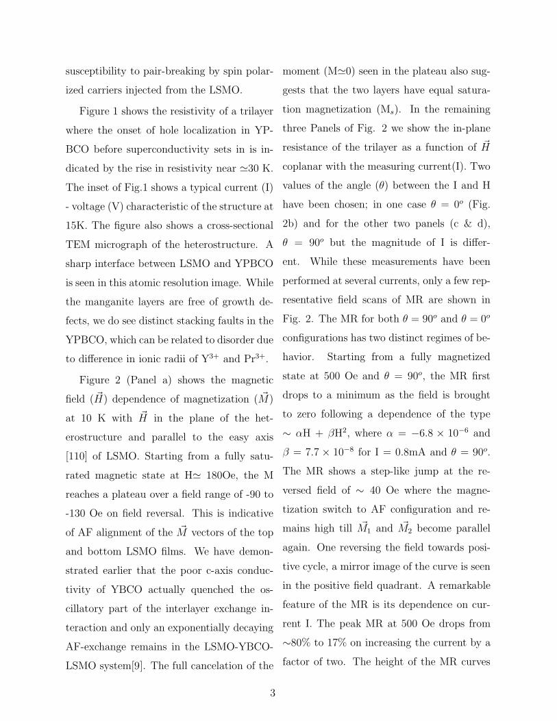
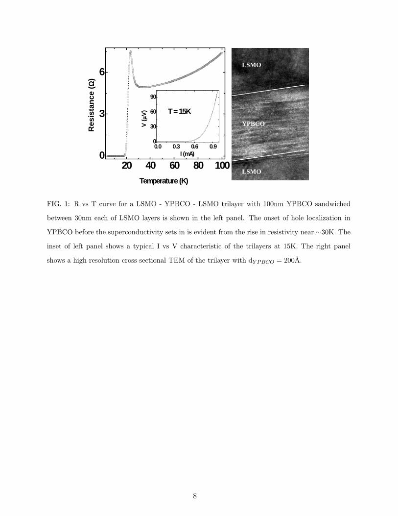
Figure 1 shows the resistivity of a trilayer
where the onset of hole localization in YP-
BCO before superconductivity sets in is in-
dicated by the rise in resistivity near ≃30 K.
The inset of Fig.1 shows a typical current (I)
- voltage (V) characteristic of the structure at
15K. The figure also shows a cross-sectional
TEM micrograph of the heterostructure. A
sharp interface between LSMO and YPBCO
is seen in this atomic resolution image. While
the manganite layers are free of growth de-
fects, we do see distinct stacking faults in the
YPBCO, which can be related to disorder due
to difference in ionic radii of Y3+ and Pr3+.
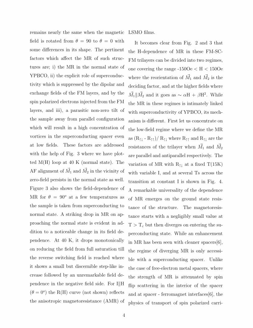
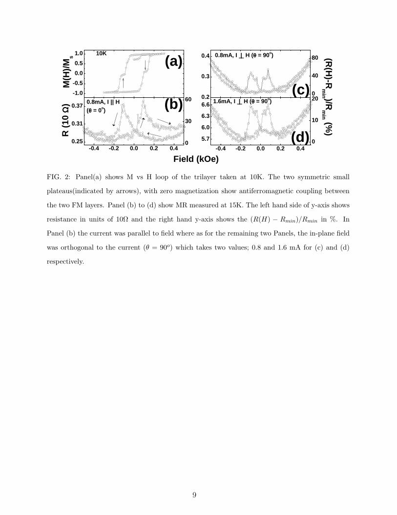
Figure 2 (Panel a) shows the magnetic
field ( ~H) dependence of magnetization ( ~M)
at 10 K with ~H in the plane of the het-
erostructure and parallel to the easy axis
[110] of LSMO. Starting from a fully satu-
rated magnetic state at H≃ 180Oe, the M
reaches a plateau over a field range of -90 to
-130 Oe on field reversal. This is indicative
of AF alignment of the ~M vectors of the top
and bottom LSMO films. We have demon-
strated earlier that the poor c-axis conduc-
tivity of YBCO actually quenched the os-
cillatory part of the interlayer exchange in-
teraction and only an exponentially decaying
AF-exchange remains in the LSMO-YBCO-
LSMO system[9]. The full cancelation of the
moment (M≃0) seen in the plateau also sug-
gests that the two layers have equal satura-
tion magnetization (Ms). In the remaining
three Panels of Fig. 2 we show the in-plane
resistance of the trilayer as a function of ~H
coplanar with the measuring current(I). Two
values of the angle (θ) between the I and H
have been chosen; in one case θ = 0o (Fig.
2b) and for the other two panels (c & d),
θ = 90o but the magnitude of I is differ-
ent. While these measurements have been
performed at several currents, only a few rep-
resentative field scans of MR are shown in
Fig. 2. The MR for both θ = 90o and θ = 0o
configurations has two distinct regimes of be-
havior. Starting from a fully magnetized
state at 500 Oe and θ = 90o, the MR first
drops to a minimum as the field is brought
to zero following a dependence of the type
∼ αH + βH2, where α = −6.8 × 10⁻⁶ and
β = 7.7 × 10⁻⁸ for I = 0.8mA and θ = 90o.
The MR shows a step-like jump at the re-
versed field of ∼ 40 Oe where the magne-
tization switch to AF configuration and re-
mains high till ~M1 and ~M2 become parallel
again. One reversing the field towards posi-
tive cycle, a mirror image of the curve is seen
in the positive field quadrant. A remarkable
feature of the MR is its dependence on cur-
rent I. The peak MR at 500 Oe drops from
∼80% to 17% on increasing the current by a
factor of two. The height of the MR curves
3
remains nearly the same when the magnetic
field is rotated from θ = 90 to θ = 0 with
some differences in its shape. The pertinent
factors which affect the MR of such struc-
tures are; i) the MR in the normal state of
YPBCO, ii) the explicit role of superconduc-
tivity which is suppressed by the dipolar and
exchange fields of the FM layers, and by the
spin polarized electrons injected from the FM
layers, and iii), a parasitic non-zero tilt of
the sample away from parallel configuration
which will result in a high concentration of
vortices in the superconducting spacer even
at low fields. These factors are addressed
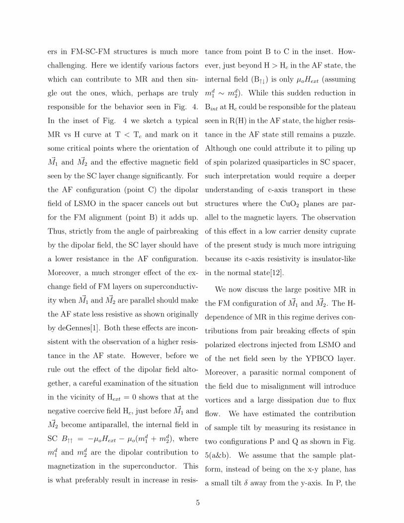
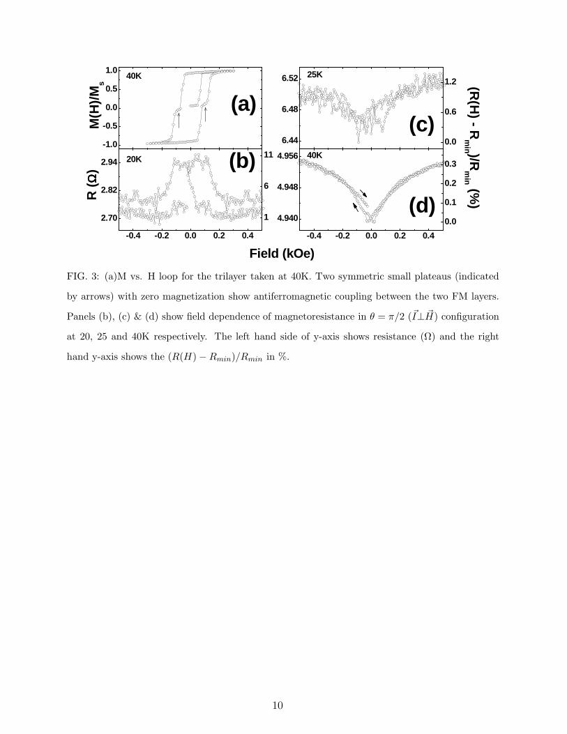
with the help of Fig. 3 where we have plot-
ted M(H) loop at 40 K (normal state). The
AF alignment of ~M1 and ~M2 in the vicinity of
zero-field persists in the normal state as well.
Figure 3 also shows the field-dependence of
MR for θ = 90o at a few temperatures as
the sample is taken from superconducting to
normal state. A striking drop in MR on ap-
proaching the normal state is evident in ad-
dition to a noticeable change in its field de-
pendence. At 40 K, it drops monotonically
on reducing the field from full saturation till
the reverse switching field is reached where
it shows a small but discernible step-like in-
crease followed by an unremarkable field de-
pendence in the negative field side. For I‖H
(θ = 0o) the R(H) curve (not shown) reflects
the anisotropic magnetoresistance (AMR) of
LSMO films.
It becomes clear from Fig. 2 and 3 that
the H-dependence of MR in these FM-SC-
FM trilayers can be divided into two regimes,
one covering the range -150Oe < H < 150Oe
where the reorientation of ~M1 and ~M2 is the
deciding factor, and at the higher fields where
~M1‖ ~M2 and it goes as ∼ αH + βH2. While
the MR in these regimes is intimately linked
with superconductivity of YPBCO, its mech-
anism is different. First let us concentrate on
the low-field regime where we define the MR
as (R↑↓ - R↑↑)/ R↑↓ where R↑↑ and R↑↓ are the
resistances of the trilayer when ~M1 and ~M2
are parallel and antiparallel respectively. The
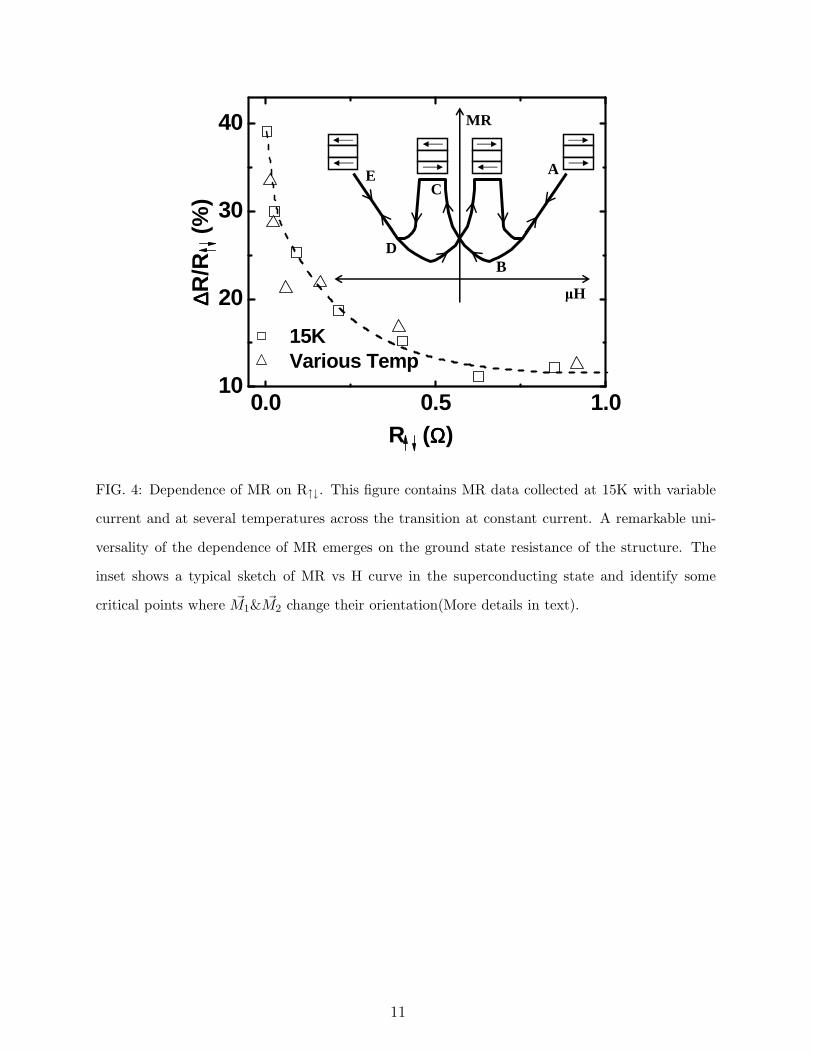
variation of MR with R↑↓ at a fixed T(15K)
with variable I, and at several Ts across the
transition at constant I is shown in Fig. 4.
A remarkable universality of the dependence
of MR emerges on the ground state resis-
tance of the structure. The magnetoresis-
tance starts with a negligibly small value at
T > Tc but then diverges on entering the su-
perconducting state. While an enhancement
in MR has been seen with cleaner spacers[6],
the regime of diverging MR is only accessi-
ble with a superconducting spacer. Unlike
the case of free-electron metal spacers, where
the strength of MR is attenuated by spin
flip scattering in the interior of the spacer
and at spacer - ferromagnet interfaces[6], the
physics of transport of spin polarized carri-
4
ers in FM-SC-FM structures is much more
challenging. Here we identify various factors
which can contribute to MR and then sin-
gle out the ones, which, perhaps are truly
responsible for the behavior seen in Fig. 4.
In the inset of Fig. 4 we sketch a typical
MR vs H curve at T < Tc and mark on it
some critical points where the orientation of
~M1 and ~M2 and the effective magnetic field
seen by the SC layer change significantly. For
the AF configuration (point C) the dipolar
field of LSMO in the spacer cancels out but
for the FM alignment (point B) it adds up.
Thus, strictly from the angle of pairbreaking
by the dipolar field, the SC layer should have
a lower resistance in the AF configuration.
Moreover, a much stronger effect of the ex-
change field of FM layers on superconductiv-
ity when ~M1 and ~M2 are parallel should make
the AF state less resistive as shown originally
by deGennes[1]. Both these effects are incon-
sistent with the observation of a higher resis-
tance in the AF state. However, before we
rule out the effect of the dipolar field alto-
gether, a careful examination of the situation
in the vicinity of Hext = 0 shows that at the
negative coercive field Hc, just before ~M1 and
~M2 become antiparallel, the internal field in
SC B↑↑ = −µoHext − µo(md1 + md
2), where
md1 and md
2 are the dipolar contribution to
magnetization in the superconductor. This
is what preferably result in increase in resis-
tance from point B to C in the inset. How-
ever, just beyond H > Hc in the AF state, the
internal field (B↑↓) is only µoHext (assuming
md1 ∼ md
2). While this sudden reduction in
Bint at Hc could be responsible for the plateau
seen in R(H) in the AF state, the higher resis-
tance in the AF state still remains a puzzle.
Although one could attribute it to piling up
of spin polarized quasiparticles in SC spacer,
such interpretation would require a deeper
understanding of c-axis transport in these
structures where the CuO2 planes are par-
allel to the magnetic layers. The observation
of this effect in a low carrier density cuprate
of the present study is much more intriguing
because its c-axis resistivity is insulator-like
in the normal state[12].
We now discuss the large positive MR in
the FM configuration of ~M1 and ~M2. The H-
dependence of MR in this regime derives con-
tributions from pair breaking effects of spin
polarized electrons injected from LSMO and
of the net field seen by the YPBCO layer.
Moreover, a parasitic normal component of
the field due to misalignment will introduce
vortices and a large dissipation due to flux
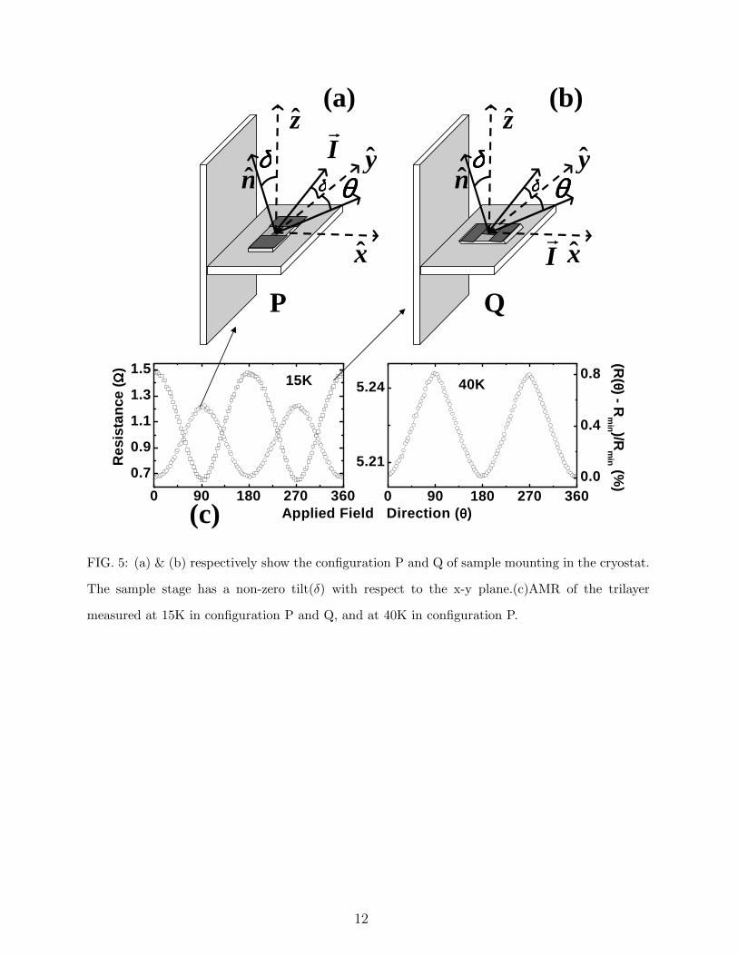
flow. We have estimated the contribution
of sample tilt by measuring its resistance in
two configurations P and Q as shown in Fig.
5(a&b). We assume that the sample plat-
form, instead of being on the x-y plane, has
a small tilt δ away from the y-axis. In P, the
5
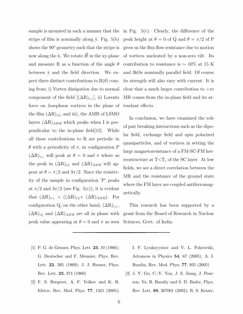
sample is mounted in such a manner that the
stripe of film is nominally along y. Fig. 5(b)
shows the 90o geometry such that the stripe is
now along the x. We rotate ~H in the xy-plane
and measure R as a function of the angle θ
between y and the field direction. We ex-
pect three distinct contributions to R(θ) com-
ing from; i) Vortex dissipation due to normal
component of the field [(∆R)υ⊥], ii) Lorentz
force on Josephson vortices in the plane of
the film (∆R)υ‖, and iii), the AMR of LSMO
layers (∆R)AMR which peaks when I is per-
pendicular to the in-plane field[13]. While
all these contributions to R are periodic in
θ with a periodicity of π, in configuration P
(∆R)υ⊥ will peak at θ = 0 and π where as
the peak in (∆R)υ‖ and (∆R)AMR will ap-
pear at θ = π/2 and 3π/2. Since the resistiv-
ity of the sample in configuration ‘P’ peaks
at π/2 and 3π/2 (see Fig. 5(c)), it is evident
that (∆R)υ⊥ < ((∆R)υ‖+ (∆R)AMR). For
configuration Q, on the other hand, (∆R)υ⊥,
(∆R)υ‖ and (∆R)AMR are all in phase with
peak value appearing at θ = 0 and π as seen
in Fig. 5(c). Clearly, the difference of the
peak height at θ = 0 of Q and θ = π/2 of P
gives us the flux flow resistance due to motion
of vortices nucleated by a non-zero tilt. Its
contribution to resistance is ∼ 10% at 15 K
and 3kOe nominally parallel field. Of course
its strength will also vary with current. It is
clear that a much larger contribution to +ve
MR comes from the in-plane field and its at-
tendant effects.
In conclusion, we have examined the role
of pair breaking interactions such as the dipo-
lar field, exchange field and spin polarized
quasiparticles, and of vortices in setting the
large magnetoresistance of a FM-SC-FM het-
erostructure at T<Tc of the SC layer. At low
fields, we see a direct correlation between the
MR and the resistance of the ground state
where the FM layer are coupled antiferromag-
netically.
This research has been supported by a
grant from the Board of Research in Nuclear
Sciences, Govt. of India.
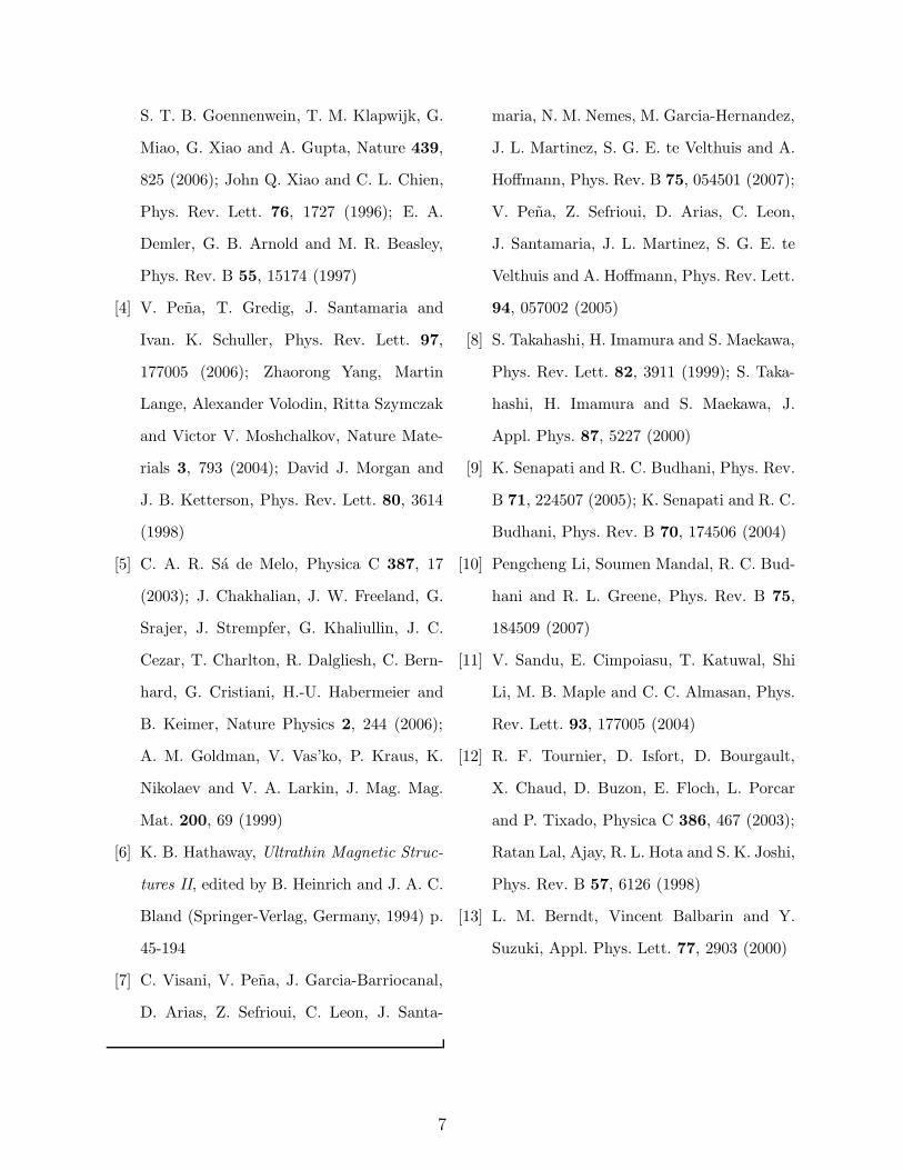
[1] P. G. de Gennes, Phys. Lett. 23, 10 (1966);
G. Deutscher and F. Meunier, Phys. Rev.
Lett. 22, 395 (1969); J. J. Hauser, Phys.
Rev. Lett. 23, 374 (1969)
[2] F. S. Bergeret, A. F. Volkov and K. B.
Efetov, Rev. Mod. Phys. 77, 1321 (2005);
I. F. Lyuksyyutov and V. L. Pokrovski,
Advances in Physics 54, 67 (2005); A. I.
Buzdin, Rev. Mod. Phys. 77, 935 (2005)
[3] J. Y. Gu, C.-Y. You, J. S. Jiang, J. Pear-
son, Ya. B. Bazaliy and S. D. Bader, Phys.
Rev. Lett. 89, 267001 (2002); R. S. Keizer,
6
S. T. B. Goennenwein, T. M. Klapwijk, G.
Miao, G. Xiao and A. Gupta, Nature 439,
825 (2006); John Q. Xiao and C. L. Chien,
Phys. Rev. Lett. 76, 1727 (1996); E. A.
Demler, G. B. Arnold and M. R. Beasley,
Phys. Rev. B 55, 15174 (1997)
[4] V. Pena, T. Gredig, J. Santamaria and
Ivan. K. Schuller, Phys. Rev. Lett. 97,
177005 (2006); Zhaorong Yang, Martin
Lange, Alexander Volodin, Ritta Szymczak
and Victor V. Moshchalkov, Nature Mate-
rials 3, 793 (2004); David J. Morgan and
J. B. Ketterson, Phys. Rev. Lett. 80, 3614
(1998)
[5] C. A. R. Sa de Melo, Physica C 387, 17
(2003); J. Chakhalian, J. W. Freeland, G.
Srajer, J. Strempfer, G. Khaliullin, J. C.
Cezar, T. Charlton, R. Dalgliesh, C. Bern-
hard, G. Cristiani, H.-U. Habermeier and
B. Keimer, Nature Physics 2, 244 (2006);
A. M. Goldman, V. Vas’ko, P. Kraus, K.
Nikolaev and V. A. Larkin, J. Mag. Mag.
Mat. 200, 69 (1999)
[6] K. B. Hathaway, Ultrathin Magnetic Struc-
tures II, edited by B. Heinrich and J. A. C.
Bland (Springer-Verlag, Germany, 1994) p.
45-194
[7] C. Visani, V. Pena, J. Garcia-Barriocanal,
D. Arias, Z. Sefrioui, C. Leon, J. Santa-
maria, N. M. Nemes, M. Garcia-Hernandez,
J. L. Martinez, S. G. E. te Velthuis and A.
Hoffmann, Phys. Rev. B 75, 054501 (2007);
V. Pena, Z. Sefrioui, D. Arias, C. Leon,
J. Santamaria, J. L. Martinez, S. G. E. te
Velthuis and A. Hoffmann, Phys. Rev. Lett.
94, 057002 (2005)
[8] S. Takahashi, H. Imamura and S. Maekawa,
Phys. Rev. Lett. 82, 3911 (1999); S. Taka-
hashi, H. Imamura and S. Maekawa, J.
Appl. Phys. 87, 5227 (2000)
[9] K. Senapati and R. C. Budhani, Phys. Rev.
B 71, 224507 (2005); K. Senapati and R. C.
Budhani, Phys. Rev. B 70, 174506 (2004)
[10] Pengcheng Li, Soumen Mandal, R. C. Bud-
hani and R. L. Greene, Phys. Rev. B 75,
184509 (2007)
[11] V. Sandu, E. Cimpoiasu, T. Katuwal, Shi
Li, M. B. Maple and C. C. Almasan, Phys.
Rev. Lett. 93, 177005 (2004)
[12] R. F. Tournier, D. Isfort, D. Bourgault,
X. Chaud, D. Buzon, E. Floch, L. Porcar
and P. Tixado, Physica C 386, 467 (2003);
Ratan Lal, Ajay, R. L. Hota and S. K. Joshi,
Phys. Rev. B 57, 6126 (1998)
[13] L. M. Berndt, Vincent Balbarin and Y.
Suzuki, Appl. Phys. Lett. 77, 2903 (2000)
7
20 40 60 80 1000
3
6
Res
ista
nce
(ΩΩ ΩΩ
)
Temperature (K)
0.0 0.3 0.6 0.90
30
60
90
I (mA)
V (
µµ µµV) T = 15K
LSMO
LSMO
YPBCO
FIG. 1: R vs T curve for a LSMO - YPBCO - LSMO trilayer with 100nm YPBCO sandwiched
between 30nm each of LSMO layers is shown in the left panel. The onset of hole localization in
YPBCO before the superconductivity sets in is evident from the rise in resistivity near ∼30K. The
inset of left panel shows a typical I vs V characteristic of the trilayers at 15K. The right panel
shows a high resolution cross sectional TEM of the trilayer with dY PBCO = 200A.
8
-0.4 -0.2 0.0 0.2 0.40.25
0.31
0.370.8mA, I || H(θθθθ = 0o)
5.7
6.0
6.3
6.6 1.6mA, I | H (θθθθ = 90o)
0.2
0.3
0.4
0.8mA, I | H (θθθθ = 90o)
0
40
80
0
30
60
-0.4 -0.2 0.0 0.2 0.40
10
20
Field (kOe)
-1.0
-0.5
0.0
0.5
1.0 (R(H
)-Rm
in )/Rm
in (%)R
(10
ΩΩ ΩΩ)
(d)
(c)(b)
M(H
)/M
s
10K
(a)
FIG. 2: Panel(a) shows M vs H loop of the trilayer taken at 10K. The two symmetric small
plateaus(indicated by arrows), with zero magnetization show antiferromagnetic coupling between
the two FM layers. Panel (b) to (d) show MR measured at 15K. The left hand side of y-axis shows
resistance in units of 10Ω and the right hand y-axis shows the (R(H) − Rmin)/Rmin in %. In
Panel (b) the current was parallel to field where as for the remaining two Panels, the in-plane field
was orthogonal to the current (θ = 90o) which takes two values; 0.8 and 1.6 mA for (c) and (d)
respectively.
9
4.940
4.948
4.956 40K
6.44
6.48
6.52 25K
2.70
2.82
2.94
R (
ΩΩ ΩΩ)
20K
-0.4 -0.2 0.0 0.2 0.4
0.0
0.1
0.2
0.3
Field (kOe)
-0.4 -0.2 0.0 0.2 0.4
1
6
11
0.0
0.6
1.2
(d)
(c)
(b)
(R(H
) - Rm
in )/Rm
in (%)
(a)
-1.0
-0.5
0.0
0.5
1.040K
M(H
)/M
s
FIG. 3: (a)M vs. H loop for the trilayer taken at 40K. Two symmetric small plateaus (indicated
by arrows) with zero magnetization show antiferromagnetic coupling between the two FM layers.
Panels (b), (c) & (d) show field dependence of magnetoresistance in θ = π/2 (~I⊥ ~H) configuration
at 20, 25 and 40K respectively. The left hand side of y-axis shows resistance (Ω) and the right
hand y-axis shows the (R(H) − Rmin)/Rmin in %.
10
0.0 0.5 1.010
20
30
40
15K Various Temp
∆∆ ∆∆R/R
(%
)
R (ΩΩΩΩ)
A
B
C
D
E
MR
µH
FIG. 4: Dependence of MR on R↑↓. This figure contains MR data collected at 15K with variable
current and at several temperatures across the transition at constant current. A remarkable uni-
versality of the dependence of MR emerges on the ground state resistance of the structure. The
inset shows a typical sketch of MR vs H curve in the superconducting state and identify some
critical points where ~M1& ~M2 change their orientation(More details in text).
11
z
nδδδδ
δδδδ θθθθy
x
z
nδδδδ
δδδδ θθθθy
xI
0 90 180 270 360
5.21
5.24
40K
0 90 180 270 360
0.7
0.9
1.1
1.3
1.5
(R( θθ θθ) - R
min )/R
min (%
)
15K
Applied Field Direction (θθθθ)
Res
ista
nce
(ΩΩ ΩΩ
)
0.0
0.4
0.8
P Q
(a) (b)
(c)
I
FIG. 5: (a) & (b) respectively show the configuration P and Q of sample mounting in the cryostat.
The sample stage has a non-zero tilt(δ) with respect to the x-y plane.(c)AMR of the trilayer
measured at 15K in configuration P and Q, and at 40K in configuration P.
12
Copyright © 2022 FDOKUMEN