DIN Rail Mounted Accessories Part 1.eps - Electric ...
52
Protect People and Property X-Pole DIN Rail Mounted Accessories Isolators Installation Relays Installation Contactors Staircase Switch Timers Surge Protection Light Intensity Switch Communication / Signaling Transformer
-
Upload
khangminh22 -
Category
Documents
-
view
8 -
download
0
Transcript of DIN Rail Mounted Accessories Part 1.eps - Electric ...

Protect People and Property
X-Pole DIN Rail Mounted AccessoriesIsolatorsInstallation RelaysInstallation Contactors
Staircase SwitchTimersSurge Protection
Light Intensity SwitchCommunication / SignalingTransformer

1874 1886 19111893 19831962 19891984 19991976 1977190819061899 1963 19671934
The power of fusion.
There’s a certain energy at Eaton. It’s the power of uniting some of the world’s most respected names to build a brand you can trust to meet every power management need. The energy created supports our commitment to powering business worldwide.
Eaton is dedicated to ensuring that reliable, efficient and safe power is available when it’s needed most. With unparalleled knowledge of electrical power management across industries, experts at Eaton deliver customized, integrated solutions to solve our customers’ most critical challenges. Eaton.com/SEAsia
All of the above are trademarks of Eaton Corporation or its affiliates. Eaton has a license to use the Westinghouse brand name in Asia Pacific. ©2013 Eaton Corporation.

Contents
2
4
9
14
16
21
24
33
45
46
47
DIN Rail Mounted Accessories. . . . . . . . . . . . . . . . . . . . . . . . . . . . . . . . . . . . . . . . . . . . . . . . . . . . . . . . . . . . . . . . . . . . . . . . . . . . . . . . . .
. . . . . . . . . . . . . . . . . . . . . . . . . . . . . . . . . . . . . . . . . . . . . . . . . . . . . . . . . . . . . . . . . . . . . . . . . . . . . . . . . . . . . . . . . . . . . . . . .
. . . . . . . . . . . . . . . . . . . . . . . . . . . . . . . . . . . . . . . . . . . . . . . . . . . . . . . . . . . . . . . . . . . . . . . . . . . . . . . . . . . . . . . . . . . . . .
. . . . . . . . . . . . . . . . . . . . . . . . . . . . . . . . . . . . . . . . . . . . . . . . . . . . . . . . . . . . . . . . . . . . . . . . . . . . . . . . . . . . . . . . . . . . . . . . . . . . . . . . . . . . . . . . . . . . . . . . . . . . . . . . . . . . . . . . . . . . . . . . . . . . . . . . . . . . . . . . . . . . . . . . . . . . . . . . . . . . . . . . . . . . . . . . . .
. . . . . . . . . . . . . . . . . . . . . . . . . . . . . . . . . . . . . . . . . . . . . . . . . . . . . . . . . . . . . . . . . . . . . . . . . . . . . . . . . . . . . . . . . . . .
. . . . . . . . . . . . . . . . . . . . . . . . . . . . . . . . . . . . . . . . . . . . . . . . . . . . . . . . . . . . . . . . . . . . . . . . . . . . . . . . . . . . . . . . .
. . . . . . . . . . . . . . . . . . . . . . . . . . . . . . . . . . . . . . . . . . . . . . . . . . . . . . . . . . . . . . . . . . . . . . . . . . . . . . . . . . . . . . . . . . . . . . . . .
. . . . . . . . . . . . . . . . . . . . . . . . . . . . . . . . . . . . . . . . . . . . . . . . . . . . . . . . . . . . . . . . . . . . . . . . . . . . . . . . . . . . . . . . .
Main Load Disconnected Switch
Installation Relays
Installation Contactors
Staircase Switch
Timer Analog
Timer Digital
SPD Class B
SPD Class C
Light Intensity Switch
Communication / Signaling
Transformer
. . . . . . . . . . . . . . . . . . . . . . . . . . . . . . . . . . . . . . . . . . . . . . . . . . . . . . . . . . . . . . . . . . . . . . . . . . . . . . . . . . . . .
. . . . . . . . . . . . . . . . . . . . . . . . . . . . . . . . . . . . . . . . . . . . . . . . . . . . . . . . . . . . . . . . . . . . . . . . . . . . . . . . . . . . . . . . . . . . . . . . .

2
Main Load Disconnector Switch (Isolator) IS
Main Load Disconnector Switch
Rated Current (A) Poles Type Designation Article No. Units per package
16 116 216 316 420 120 220 320 425 125 225 325 432 132 232 332 440 140 240 340 463 163 263 363 480 180 280 380 4100 1100 2100 3100 4125 1125 2125 3125 4
021/214526721/61-SI06/15526722/61-SI04/16526723/61-SI03/17526724/61-SI
021/218526721/02-SI06/19526722/02-SI04/10626723/02-SI03/11626724/02-SI
021/212626721/52-SI06/13626722/52-SI04/14626723/52-SI03/15626724/52-SI
021/216626721/23-SI06/17626722/23-SI04/18626723/23-SI03/19626724/23-SI
021/210726721/04-SI06/11726722/04-SI04/12726723/04-SI03/13726724/04-SI
021/214726721/36-SI06/15726722/36-SI04/16726723/36-SI03/17726724/36-SI
021/218726721/08-SI06/19726722/08-SI04/10826723/08-SI03/11826724/08-SI
IS-100/1 276282 12 / 120IS-100/2 276283 1 / 60IS-100/3 276284 1 / 40IS-100/4 276285 1 / 30IS-125/1 276286 12 / 120IS-125/2 276287 1 / 60IS-125/3 276288 1 / 40IS-125/4 276289 1 / 30
Accessories Switching interlock without lockfor Isolators, RCDs, combinedRCD/MCBs, ...Terminal cover
IS/SPE-1TE 101911 5 / 30
Z-IS/AK-1TE 276290 10 / 600
SG10611
SG10711
SG10811
SG10911
SG47812

3
Main Load Disconnector Switch
Main Load Disconnector Switch (Isolator) IS
• Load circuit breaker with isolating function• Design according to IEC/EN 60947-3• Highly wear resistant contacts• Quick make, black toggle• Terminal capacity 50 mm2
• Compatible busbars with switchgear series Xpole by use of the mouth ter-minal in combination with standard fork busbar
Technical DataIS-16 IS-20 IS-25 IS-32 IS-40 IS-63 IS-80 IS-100 IS-125
ElectricalDesign according toRated voltage
zH06/05ycneuqerFRated insulation voltage Ui 690 V~Rated peak withstand voltage Uimp 6 kVPollution degree
IEC/EN 60947-3240/415V
3Rated short-time withstand current Icw 2 kARated short-circuit making capacity Icm 2.8 kARated current
240/415V, AC23ANumber of polesMaximum back-up fuseShort circuit strength - with back-up fuse acc. to the applicable rules
IEC/EN 60947-3
16 A 20 A 25 A 32 A 40 A 63 A 80 A 100 A 125 A1-, 2-, 3-, 4-pole125 A gG
12.5 kA 12.5 kA 12.5 kA 12.5 kA 12.5 kA 12.5 kA 12.5 kA 10 kA 10 kAEndurance
electrical comp. op. cycles ≥3,000 ≥3,000 ≥3,000 ≥3,000 ≥3,000 ≥3,000 ≥3,000 ≥3,000 ≥2,000mechanical comp. op. cycles ≥16,000 ≥16,000 ≥16,000 ≥16,000 ≥16,000 ≥16,000 ≥16,000 ≥16,000 ≥14,000
Mechanical mm54ezisemarF
Device heightDevice width
51706NE/CEIliarNIDnosnoitisopni-kcol2htiwgninetsafkciuqgnitnuoMDegree of protection, built-inTerminal protection
slanimretesoprup-niwTslanimreTTerminal capacity 2
Busbar thicknessFastening torque of terminal screws
80 mm17.5mm/pole
IP40finger and hand touch safe according to BGV A3
2.5 - 50 mm0.8-1.0 mm
2.5 - 5 NmnoitallatsnifonoitisopehtfoevitcepserrinoitcnuF
Dimensions (mm)
Anti-tamperdeviceIS/SPE1TE
Terminal cover capsZ-IS/AK-1TE
Switching interlock IS/SPE-1TE
• Without lock• Also suitable for PFIM, CFI6, PKNM, CKN6
Terminal Cover Caps Z-IS/AK-1TE
• Can be sealed with leads• Modular design, width 1 MU
Connection diagram1-pole 2-pole 3-pole 4-pole

4
Installation Relays
Installation Relays Z-R., Z-TN
Control Voltage/Function/MU Type Designation Article No. Units per package
240 V 50Hz 2NO 1240 V 60Hz 2NO 1240 V 60Hz 2NC 1230 V 50Hz 1NO 1230 V 50Hz 2NO 1230 V 50Hz 4NO 2230 V 50Hz 1NO+1NC 1230 V 50Hz 2NO+2NC 2230 V 50Hz 3NO+1NC 2230 V 50Hz 2NC 1230 V 50Hz 4NC 2230 V 60Hz 2NO 1230 V 60Hz 1NO+1NC 1110 V 50Hz 2NO 1110 V 50Hz 2NO+2NC 2110 V 50Hz 3NO+1NC 2110 V 60Hz 2NO 1110 V DC 2NO 1110 V DC 1NO+1NC 1110 V DC 2NO+2NC 2110 V DC 3NO+1NC 248 V 50Hz 2NO 124 V 50Hz 1NO 124 V 50Hz 2NO 124 V 50Hz 4NO 224 V 50Hz 1NO+1NC 124 V 50Hz 2NO+2NC 224 V 50Hz 3NO+1NC 224 V 50Hz 2NC 124 V 50Hz 4NC 224 V 60Hz 2NO 124 V DC 1NO 124 V DC 2NO 124 V DC 1NO+1NC 124 V DC 2NO+2NC 224 V DC 4NC 212 V 50Hz 1NO 112 V 50Hz 2NO 112 V 50Hz 1NO+1NC 112 V 50Hz 2NO+2NC 212 V 50Hz 3NO+1NC 212 V DC 1NO 112 V DC 2NO 112 V DC 1NO+1NC 112 V DC 2NC 18 V 50Hz 1NO 18 V 50Hz 2NO 18 V 50Hz 1NO+1NC 18 V DC 1NO 18 V DC 2NO 1
Z-R240/SS 285525 2 / 120Z-R241/SS 265166 2 / 120Z-R241/SO 265179 2 / 120Z-R230/S 265149 2 / 120Z-R230/SS 265168 2 / 120Z-R230/4S 265226 1 / 60Z-R230/SO 265181 2 / 120Z-R230/2S2O 265215 1 / 60Z-R230/3S1O 265221 1 / 60Z-R230/OO 265188 2 / 120Z-R230/4O 265228 1 / 60Z-R231/SS 265167 2 / 120Z-R231/SO 265180 2 / 120Z-R110/SS 265170 2 / 120Z-R110/2S2O 265216 1 / 60Z-R110/3S1O 265222 1 / 60Z-R111/SS 265169 2 / 120Z-R109/SS 265171 2 / 120Z-R109/SO 265182 2 / 120Z-R109/2S2O 265217 1 / 60Z-R109/3S1O 265223 1 / 60Z-R48/SS 265172 2 / 120Z-R24/S 265160 2 / 120Z-R24/SS 265173 2 / 120Z-R24/4S 265227 1 / 60Z-R24/SO 265183 2 / 120Z-R24/2S2O 265218 1 / 60Z-R24/3S1O 265224 1 / 60Z-R24/OO 265189 2 / 120Z-R24/4O 265229 1 / 60Z-R25/SS 248368 2 / 120Z-R23/S 265161 2 / 120Z-R23/SS 265174 2 / 120Z-R23/SO 265184 2 / 120Z-R23/2S2O 265219 1 / 60Z-R23/4O 101910 1 / 60Z-R12/S 265162 2 / 120Z-R12/SS 265175 2 / 120Z-R12/SO 265185 2 / 120Z-R12/2S2O 265220 1 / 60Z-R12/3S1O 265225 1 / 60Z-R11/S 265163 2 / 120Z-R11/SS 265176 2 / 120Z-R11/SO 265186 2 / 120Z-R11/OO 290198 2 / 120
021/2461562S/8R-ZZ-R8/SS 265177 2 / 120Z-R8/SO 265187 2 / 120
021/2561562S/7R-ZZ-R7/SS 265178 2 / 120
SG60411
Z-R230/2S2O
Type Z-R• with manual operation• 20 A 250 VAC AC1
SG12211
Z-R12/S

5
Installation Relays
Installation Relays Z-R., Z-TN
Type Z-RE• with LED, without manual operation• 20 A 250 VAC
230 V 50Hz 1NO 1230 V 50Hz 2NO 1230 V 50Hz 1NO+1NC 1230 V 50Hz 2NO+2NC 2230 V 50Hz 3NO+1NC 224 V 50Hz 1NO 124 V 50Hz 2NO 124 V 50Hz 1NO+1NC 124 V 50Hz 2NO+2NC 224 V 50Hz 3NO+1NC 224 V DC 1NO 124 V DC 2NO 124 V DC 1NO+1NC 124 V DC 2NO+2NC 212 V 50Hz 2NO+2NC 212 V 50Hz 3NO+1NC 212 V DC 2NO+2NC 28 V 50Hz 2NO 1
Z-RE230/S 265190 2 / 120Z-RE230/SS 265193 2 / 120Z-RE230/SO 265197 2 / 120Z-RE230/2S2O 265230 1 / 60Z-RE230/3S1O 265235 1 / 60Z-RE24/S 265191 2 / 120Z-RE24/SS 265194 2 / 120Z-RE24/SO 265198 2 / 120Z-RE24/2S2O 265231 1 / 60Z-RE24/3S1O 265236 1 / 60Z-RE23/S 265192 2 / 120Z-RE23/SS 265195 2 / 120Z-RE23/SO 265199 2 / 120Z-RE23/2S2O 265232 1 / 60Z-RE12/2S2O 265233 1 / 60Z-RE12/3S1O 265237 1 / 60Z-RE11/2S2O 265234 1 / 60Z-RE8/SS 265196 2 / 120
SG59411
Type Z-RK• with manual operation and LED• 20 A 250 VAC AC1
230 V 60Hz 2NO 1230 V 60Hz 2NC 1230 V 50Hz 1NO 1230 V 50Hz 2NO 1230 V 50Hz 1NO+1NC 1230 V 50Hz 2NO+2NC 2230 V 50Hz 3NO+1NC 2230 V 50Hz 2NC 1110 V DC 2NO 124 V 50Hz 1NO 124 V 50Hz 2NO 124 V 50Hz 1NO+1NC 124 V 50Hz 2NO+2NC 224 V 50Hz 3NO+1NC 224 V 50Hz 2NC 124 V DC 2NO 124 V DC 1NO+1NC 124 V DC 2NO+2NC 212 V 50Hz 1NO+1NC 112 V 50Hz 2NO+2NC 212 V 50Hz 3NO+1NC 28 V 50Hz 1NO+1NC 1
Z-RK241/SS 265202 2 / 120Z-RK241/SO 265207 2 / 120Z-RK230/S 265200 2 / 120Z-RK230/SS 265203 2 / 120Z-RK230/SO 265208 2 / 120Z-RK230/2S2O 265238 1 / 60Z-RK230/3S1O 265241 1 / 60Z-RK230/OO 265213 2 / 120Z-RK109/SS 265204 2 / 120Z-RK24/S 265201 2 / 120Z-RK24/SS 265205 2 / 120Z-RK24/SO 265209 2 / 120Z-RK24/2S2O 265239 1 / 60Z-RK24/3S1O 265242 1 / 60Z-RK24/OO 265214 2 / 120Z-RK23/SS 265206 2 / 120Z-RK23/SO 265210 2 / 120Z-RK23/2S2O 271464 1 / 60Z-RK12/SO 265211 2 / 120Z-RK12/2S2O 265240 1 / 60Z-RK12/3S1O 265243 1 / 60Z-RK8/SO 265212 2 / 120
Other control voltages, frequencies, and contact functions upon enquiry.
Z-RE24/S
SG59111
Z-RK230/SS
Control Voltage/Function/MU Type Designation Article No. Units per package
Type Z-TN• with manual pre-selection of functions - permanently ON / AUTOM / OFF• 20 A 250 VAC 230 V 50Hz 2NO 1230 V 50Hz 3NO 2230 V 50Hz 4NO 2230 V 50Hz 1NO+1NC 1230 V 50Hz 2NO+2NC 224 V 50Hz 2NO 124 V 50Hz 3NO 224 V 50Hz 4NO 224 V 50Hz 1NO+1NC 1
Z-TN230/SS 265574 2 / 120Z-TN230/3S 265576 1 / 60Z-TN230/4S 265579 1 / 60Z-TN230/1S1O 267975 2 / 120Z-TN230/2S2O 103168 1 / 60Z-TN24/SS 267976 2 / 120Z-TN24/3S 267977 1 / 60Z-TN24/4S 267978 1 / 60Z-TN24/1S1O 267979 2 / 120
SG60111
Z-TN230/3S
SG59711
Z-TN230/SO
6
Installation Relays
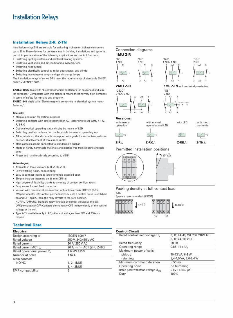
Installation Relays Z-R, Z-TNInstallation relays Z-R are suitable for switching 1-phase or 3-phase consumersup to 20 A. These devices for universal use in building installations and systemspermit implementation of the following applications and control functions: • Switching lighting systems and electrical heating systems• Switching ventilation and air conditioning systems, fans• Switching heat pumps• Switching electrically controlled roller doors/gates, and blinds • Switching incandescent lamps and gas discharge lampsThe installation relays of series Z-R./ meet the requirements of standards EN/IEC60947 and EN/IEC 1095.
EN/IEC 1095 deals with "Electromechanical contactors for household and simi-lar purposes." Compliance with this standard means meeting very high demandsin terms of safety for humans and property. EN/IEC 947 deals with "Electromagnetic contactors in electrical system manu-facturing".
Security:• Manual operation for testing purposes • Switching contacts with safe disconnection AC1 according to EN 60947-4-1 (Z-
R, Z-RK)• Optional optical operating status display by means of LED• Switching position indicated on the front side by manual operating key• All terminals - coil and contacts - equipped with guide for secure terminal con-
nection. Misplacement of wires impossible.• Main contacts can be connected to standard pin busbar• Made of hardly flammable materials and plastics free from chlorine and halo-
gens• Finger and hand touch safe according to VBG4
Advantages:• Available in three versions (Z-R, Z-RK, Z-RE)• Low switching noise, no humming• Easy to connect thanks to large terminals supplied open• Simple snap-on fastening on 35 mm DIN rail• High degree of flexibility thanks to a variety of contact configurations• Easy access for coil feed connection• Version with mechanical pre-selection of functions ON/AUTO/OFF (Z-TN)
ON/permanently ON: Contact permanently ON until a control pulse is switchedon and OFF again. Then, the relay reverts to the AUT position.AUT/AUTOMATIC: Standard relay function by control voltage at the coil.OFF/permanently OFF: Contacts permanently OFF, independently of the controlvoltage at the coil.
• Type Z-TN available only in AC, other coil voltages than 24V and 230V onrequest
Connection diagrams1MU Z-R
”OO“”OS“”SS“”S“1 NO 2 NO 1 NO / 1 NC 2 NC
2MU Z-R 1MU Z-TN (with mechanical pre-selection)
”SS“”O2S2“ON2CN2/ON2
Permitted installation positions
Packing density at full contact loadZ-R./Spacers recommended! (Z-DST)
Versionswith manual with manual with LED with mech.operation operation and LED pre-selection
Technical Data
ElectricalDesign according to IEC/EN 60947
CAV514/042,V052egatlovdetaRCAV052,A02tnerrucdetaR
Rated current AC1 Ie 20 A AC1 (Z-R, Z-RK)Rated operational power Pe 4.6 kW 415 V
4ot1selopforebmuNMain contacts
)UM1(2,1CN/ON3, 4 (2MU)BytilibitapmocRME
Control CircuitRated control feed voltage Us 8, 12, 24, 48, 110, 230, 240 V AC
8, 12, 24, 110 V DCRated frequency 50 HzOperating range 0.85-1.1 x UsMaximum power of coils
W8-6,AV31-01pu-kcipW4,2-0,2,AV0,4-4,3gniniater
Minimum command duration > 50 msgnimmuhonesiongnitarepO
Rated peak withstand voltage Uimp 2 kV (1.2/50 μs)%001ytuD
max30° !

7
Installation Relays
Load CircuitRated operational voltage Ue 1p, 2p: 250VAC;
3p, 4p: 240/415VACMinimum operational voltage Umin 24 V AC/DC (Us 8-110 V)Rated insulation voltage Ui 500 VRated peak withstand voltage Uimp 4 kV (1.2/50 μs)Conventional thermal current Ith 20 A ACRated operational current Ie 20 A ACRated constant current Iu 20 A ACRated current DC
IV42 e 16 AIV84 e 12,5 AIV032 e 1 A
Conditional rated short circuit current Iq 10 kA (with 20 A gL/gG)Duration of bouncing < 10 ms (typ. < 5 ms)
Dimensions (mm)
Technical Data (continued)
UTILISATION CATEGORIES 1MU, 2MU (except3S, 4S)AC-1 *)
Rated operational voltage Ue 250 V ACRated operational current Ie 20 A ACRated operational power AC-1 4000 W (cos φ = 0.8), 5000 VA
AC-3Rated operational voltage Ue 250 V ACRated operational current Ie 8 A ACRated operational power AC-3 900 W (cos φ = 0.45), 2000 VA
AC-5aRated operational voltageUe 250 V ACRated operational current Ie 10 A ACRated operational power AC-5a 1125 W (cos φ = 0.45), 2500 VA
AC-5bRated operational voltage Ue 230 V ACRated operational current Ie 8,8 A ACRated operational power AC-5b 2024 W
AC-7a (according to EN 61095)Rated operational voltage Ue 250 V ACRated operational current Ie 20 A ACRated operational power AC-7a 4000 W (cos φ = 0.8), 5000 VA
UTILISATION CATEGORIES 2MU (3S, 4S)AC-1 *)
Rated operational voltage Ue 240/415 V ACRated operational current Ie 20 A ACRated operational power AC-1 4000 W (cos φ = 0.8), 5000 VA
AC-5bRated operational voltage Ue 230/400 V ACRated operational current Ie 8,8 A ACRated operational power AC-5b 2024 W
AC-7a (according to EN 61095)Rated operational voltage Ue 240/415 V ACRated operational current Ie 20 A ACRated operational power AC-7a 4000 W (cos φ = 0.8), 5000 VA
AC-7b (according to EN 61095)Rated operational voltage Ue 240/415 V ACRated operational current Ie 10 A ACRated operational power AC-7b 1125 W (cos φ = 0.8), 2500 VA
Endurance electrical comp. ≥40x103 operating cyclesmechanical comp. ≥1x10⁶ operating cycles
Mechanical mm54ezisemarFmm09thgieheciveD
)UM1(mm5.71htdiweciveDnogninetsafkciuqgnitnuoM
DIN rail IEC/EN 60715Degree of protection installed device IP20Position of device in use works in any position,
however not hangingUpper and lower terminals lift terminals (captive)Terminal capacity
Contact and coil 0,5 - 10 mm2 one- or more wire0,5 - 6 mm2 fine-wire with wire end sleeve
Temperature range -20°C to +45°CTotal contact gap > 5mm / independent contacts
muimdacniatnoctonseodlairetamtcatnoC
*) suitable for insulation, tested on AC-1
AC-3Rated operational voltage Ue 240/415 V ACRated operational current Ie 8 A ACRated operational power AC-3 900 W (cos φ = 0.45), 2000 VA
AC-5aRated operational voltage Ue 240/415 V ACRated operational current Ie 10 A ACRated operational power AC-5a 1125 W (cos φ = 0.45), 2500 VA

8
Installation Relays
Power Current Capacitor Z-RLamp Types
W A μF
3372,006spmaltnecsednacnI
5590,002negolahegatlov-woL2222,005)V42ro21(spmal4133,057/remrofsnarthtiw1134,0001remrofsnartcinortcele
756,0051578,000233,1003
Fluorescent tubes 11 0,16 1,3 62without compensation 18 0,37 2,7 27or with series comp. 24 0,35 2,5 27
36 0,43 3,4 2458 0,67 5,3 1565 0,67 5,3 1485 0,8 5,3 12
Fluorescent tubes 11 0,07 - 2 x 71lead-lag circuit 18 0,11 - 2 x 45
24 0,14 - 2 x 35
36 0,22 - 2 x 2258 0,35 - 2 x 1465 0,35 - 2 x 1485 0,47 - 2 x 10
Fluorescent tubes 11 0,16 3,0 34with parallel comp. 18 0,37 4,0 26
24 0,35 4,0 26
36 0,43 4,0 2658 0,67 7,0 1465 0,67 7,0 1485 0,8 8,0 13
Fluorescent tubes 18 0,09 - 32with electronic 36 0,16 - 16ballast 58 0,25 - 12
2 x 18 0,17 - 2 x 162 x 36 0,32 - 2 x 82 x 58 0,49 - 2 x 6
max. number of lamps per current path at 230V, 50 Hz

9
Installation Contactors
Installation Contactors Z-SCHUs / In AC1 / Function Type Designation Article No. Units per package
230VAC 25A 2NO230VAC 25A 4NO230VAC 25A 4NC230VAC 25A 3NO+1NC230VAC 25A 2NO+2NC24VAC 25A 4NO24VAC 25A 2NO+2NC230VAC 40A 4NO230VAC 40A 3NO+1NC230VAC 40A 2NO+2NC230VAC 40A 2NO230VAC 63A 4NO230VAC 63A 4NC230VAC 63A 3NO+1NC230VAC 63A 2NO+2NC230VAC 63A 2NO
Z-SCH230/1/25-20 120853 2 / 120Z-SCH230/25-40 248847 1 / 60Z-SCH230/25-04 248848 1 / 60Z-SCH230/25-31 248846 1 / 60Z-SCH230/25-22 248849 1 / 60Z-SCH24/25-40 248851 1 / 60Z-SCH24/25-22 248850 1 / 60Z-SCH230/40-40 248852 1 / 40Z-SCH230/40-31 248854 1 / 40Z-SCH230/40-22 248853 1 / 40Z-SCH230/40-20 248855 1 / 40Z-SCH230/63-40 248856 1 / 40Z-SCH230/63-04 285735 1 / 40Z-SCH230/63-31 248858 1 / 40Z-SCH230/63-22 248857 1 / 40Z-SCH230/63-20 248859 1 / 40
SG84611
Accessories suitable for Z-SCH / CMUCSealing cover (25A)Sealing cover (40, 63A)Auxiliary switch 1NO+1NC *)
Spacer (0.5 MU)Suppressor RC-Combination12-250 VAC
Z-SCHAK-2TE 248860 10Z-SCHAK-3TE 248861 10
3268842CS-Z01949842TSD-Z
Z-RC/230 101428 2 / 120
SG84711
Z-SCH230/25-40
Z-SCH230/63-40
SG84311
Z-SC
Installation Contactors CMUC• Universal Control Voltage Uc AC/DC
Uc / In AC1 / Function Type Designation Article No. Units per package
230V AC/DC 25A 4NO230V AC/DC 25A 4NC230V AC/DC 25A 3NO+1NC230V AC/DC 25A 2NO+2NC24V AC/DC 25A 4NO24V AC/DC 25A 4NC24V AC/DC 25A 3NO+1NC24V AC/DC 25A 2NO+2NC
CMUC230/25-40 137309 1 / 60CMUC230/25-04 137405 1 / 60CMUC230/25-31 137401 1 / 60CMUC230/25-22 137403 1 / 60CMUC24/25-40 137308 1 / 60CMUC24/25-04 137404 1 / 60CMUC24/25-31 137400 1 / 60CMUC24/25-22 137402 1 / 60
SG28812
CMUC230/25-40
Installation Contactors Z-SCH/CMUC
*) NOT suitable for Z-SCH230/1/25-20 (120853)

10
Installation Contactors
Installation Contactors Z-SCH, CMUC
These Installtion Contactors are design to cover all applications in residentialand commercial sites as for as example:• Switching of lighting systems• Switching of electrical heating systems• Switching of ventilation systems• Switching of air conditioning systems and fans• Switching of heat pumps• Switching of roller doors/gates and blinds • etc. etc.
Advantages and Safety:• Front-side switch position indicator• Compact frame• Large terminals• Low switching noise• No humming• High contact force for high switching capacity• Simple snap-on fastening of 35mm DIN rail• Finger and hand touch safe according to VGB 4• Hardly flammable materials and chlorine-free and halogen-free plastics are
used• Z-SCH
Innovative AC magnet system• CMUC
Innovative AC/DC magnet system
These products meets the requirement of the standards IEC/EN 60947-4-1 andIEC/EN 61095
Dimensions (mm)
Connection diagrams”22“”02“”31“
CN2/ON2ON2CN3/ON1
Z-SC1 NO / 1 NC
Permitted Installation Positions
Packing Density at full contact loadZ-SCH / CMUC
Spacers recommended!
”40“”04“”13“CN4ON4CN1/ON3
Z-SCH.../1/25 Z-SCH.../25 Z-SCH.../40, .../63CMUC.../25
Z-SC

11
Installation Contactors
Technical Data of Installation Contactors Z-SCH, CMUC
Values according to IEC 61095, EN 61095, VDE 0660, IEC 60947-4-1, EN 60947-4-1, VDE Z-SCH/25/.. Z-SCH/40/.. Z-SCH/63/.. Z-SCCMUC.../25/
Utilisation category AC1 (e.g. heating system)
Rated operational current In (=Ith)open at 600C A 25 40 63 -
01xStnemelegnihctiwsfoefilecivreS 6 0,1 0,1 0,1 -
Rated operational power AC1220 - 240 V kW 9,5 16 25 -380 - 415 V kW 17 27,5 43 -
5/71001/42001/42001/42Am/VrewopgnihctiwstsewoL
Utilisation category AC3(Switching of 3-phase AC motors)
Rated operational current In A 9 27 30 -
01xStnemelegnihctiwsfoefilecivreS 6 0,15 0,15 0,15 -
Rated power of -85,72,2WkV022srotomCAesahp-3-5,885,2WkV042-032zH06-05
380-415V kW 4 12,5 15 -
Utilisation category DC1(Switching of resistive loads, L/R < 15ms) values for make contacts
1-pole 24V DC A 25 40 63 -48V DC A 22 25 26 -60V DC A 18 19 21 -
110V DC A 5 7 8 -220V DC A 0,5 0,7 0,7 -
-360452ACDV42seiresnielop-248V DC A 25 40 44 -60V DC A 25 33 36 -
110V DC A 16 17 18 -220V DC A 4 5 6 -
-360452ACDV42seiresnielop-348V DC A 25 40 63 -60V DC A 25 40 61 -
110V DC A 25 31 34 -220V DC A 10 15 16 -
-360452ACDV42seiresnielop-448V DC A 25 40 63 -60V DC A 25 40 63 -
110V DC A 25 40 63 -220V DC A 15 20 21 -
Utilisation category DC3 and DC5(Switching of inductive load, L/R < 15ms) values for make contacts
1-pole 24V DC A 15 23 25 -48V DC A 5 10 10 -60V DC A 4 5 5 -
110V DC A 1 1,5 1,5 -220V DC A 0,1 0,3 0,3 -
-540452ACDV42seiresnielop-248V DC A 17 23 25 -60V DC A 13 15 15 -
110V DC A 5 5 5 -220V DC A 0,5 1 1 -
-360452ACDV42seiresnielop-348V DC A 25 40 45 -60V DC A 25 30 30 -
110V DC A 15 15 15 -220V DC A 3 4 4 -
-360452ACDV42seiresnielop-448V DC A 25 40 63 -60V DC A 25 40 63 -
110V DC A 25 40 45 -220V DC A 8 10 10 -
Main Switching Elements (Uimp = 4 kV
Rated insulation voltage Ui V AC 440 440 440 440Rated operational voltage Ue V AC 440 440 440 440
006006006003h/13CA,1CAzycneuqerfgnihctiwselbissimreP01xSecnarudnelacinahceM 6 1 1 1 1

12
Installation Contactors
Z-SCH/25/.. Z-SCH/40/.. Z-SCH/63/.. Z-SCCMUC.../25/
Trip Coil Power
-54-3354-3381-41AVnognihctiwSHCS-ZHolding VA 4,4 - 8,4 7 7 -
W 1,6 - 3,2 2,6 2,6 -CMUC W 3-4
Operating range of trip coils-1,1-58,01,1-58,01,1-58,0)rotcafnoitacilpitlum(egnaregatlovlioC
Pv Power loss 5,0732Whtaptnerrucrep
-6,56,52,5Welop-1ssolrewoP.segvPper device 2-pole W 7,2 8,6 16,6 -
-6,326,112,9Welop-3daoltnerruclanimonta4-pole W 11,2 14,6 30,6 -
Switching noise (on and off)Typical mean values dB 80 78 78 -
Terminal capacity5,2-5,052-5,252-5,201-5,1²mmseriwlarevesroenorotcudnocniaM
fine wires mm² 1,5 - 6 2,5 - 16 2,5 - 16 0,5 - 2,5fine wires with wire end sleeve mm² 1,5 - 6 2,5 - 16 2,5 - 16 0,5 - 1,5
number of conductors per terminal 1 1 1 2
-5,2-57,05,2-57,05,2-57,0²mmseriwlarevesroenolioCfine wires mm² 0,5 - 2,5 0,5 - 2,5 0,5 - 2,5 -
fine wires with wire end sleeve mm² 0,5 - 1,5 0,5 - 1,5 0,5 - 1,5 -number of conductors per terminal 1 1 1 -
Weight kg/unit 0,22 0,36 0,36 0,026
Short circuit protection (main circuit)Maximum nominal current of fuse
-083653A)Gg(Lg)1(epytnoitanidro-oC
Short circuit protection (auxiliary circuit)Maximum nominal current of fusesShort-circuit current 1kA, without fusing
01---A)Gg(Lgstcatnocfo
Switching times at control voltage Us ±10%Make delay ms 9 - 15 11 - 15 11 - 15 -Break delay ms 4 - 8 6 - 13 6 - 13 -
Arc duration ms 10 - 15 10 - 15 10 - 15 -
Technical Data of Installation Contactors Z-SCH, CMUC (continued)
Auxiliary Switching Elements (Uimp = 4 kV)
Rated insulation voltage Ui V AC 440 440 440 440Nominal thermal current = Ith 400C A 25 40 63 10
600C A 25 40 63 6
Utilisation category AC15(Controlling of electromagnetic load)
3---AV042-022lanoitarepodetaRcurrent Ie 380-415V A - - - 2
440V A - - - 1,6
Utilisation category DC13(Controlling of electromagnetic load at DC)
2---AV06-42lanoitarepodetaRcurrent Ie 110V A - - - 0,4per pole 220V A - - - 0,1

13
Installation Contactors
Installation Contactors Z-SCH for Lighting SystemsThe decisive factors are the type, connection and current consumption oflamps during switch-on and in permanent operation. Only 90 % of the con-tinuous current of switching devices should be used in view of higher cur-rent consumption as a result of increases of voltage. The maximum numberof lamps per phase that can be operated by a switching device is dependent
on the nominal current and making current of lamps on the one hand, andon the continuous current and making capacity of the switching devices onthe other. Thus, e.g. in lead-lag circuits, the continuous current of contactorscan be used, while this is not possible in fluorescent tubes with separatecompensation.
Z-SCH/25/.. Z-SCH/40/.. Z-SCH/63/.. Z-SCCMUC.../25/
Utilisation category AC1 Rated operational current IeAC1 A 25 (60°C) 40 (60°C) 63 (60°C) -
Making capacityRoot mean square Ir.m.s. A 200 360 480 -Peak value ISpitze A 280 510 680 -
Utilisation category AC5a Rated operational power (250 V) cosφ0,45 kW 1,3 3,4 5,5 -220-240V~ cosφ0,90 kW 1,2 3,1 5,1 -
DUO kW 3,7 6,3 10 -
Utilisation category AC5b Rated operational power kW 3 5,7 8 -240V~
Incandescent LampsThe incandescent lamp filament has a very low ohmic resistance when it iscold. Therefore, when switching on, there is a high peak current
(up to 20x In).
When switching off, only the nominal current is switched off.
Power Current Z-SCH/25/.. Z-SCH/40/.. Z-SCH/63/.. Z-SCCMUC.../25/
Utilisation category AC5b W A
-921290572,006B5CAspmaltnecsednacnI100 0,45 30 55 77 -200 0,91 15 27 38 -300 1,36 10 19 26 -500 2,27 6 11 16 -1000 4,5 3 6 8 -
-4710112590,002)V42ru21(spmalnegolahegatlovwoL-08054222,005)remrofsnartcinortcelehtiw(remrofsnarthtiw
75 0,33 16 35 54 -100 0,43 12 27 43 -150 0,65 9 19 29 -200 0,87 6 14 23 -300 1,30 4 9 14 -
max. number of lamps per current path at 230V, 50 Hz

14
Staircase Switch
Staircase Switch with switch-off warning and stop function TLegakcaprepstinU.oNelcitrAnoitangiseDepyTnoitcnuF
Staircase switch with switch-off warning and stop function
Staircase switch as TLE, withadditional control input forcentral control, zero-voltageproof
021/2460101ELT
021/2660101KLT
SG07312

15
Staircase Switch
Staircase Switch with switch-off warning and stop function TLE, TLK• Automatic electronic staircase switch• Switch-off warning can be switched off (type TLK)• Subsequent switching is possible, programmable long-time function• Power saving function, low switching noise• Automatic 3-/4 wire circuit recognition• Zero voltage safety thanks to memory function (type TLK)• Central control function (type TLK)• External voltage control input (type TLK)
Technical DataElectrical
CAV032egatlovdeeFRated voltage tolarance -15%, +10%Power consumption 6 VA (0.8 W)
zH36-84ycneuqerfdetaR%001ytuD
sm005emitteseR.nim51-5,0egnartnemtsujdA
Overvoltage category III (in acc. with IEC 60664-1)Rated surge voltage 4 kVOutput
)81-LslanimreT(ON1tcatnoCCAV052egatlovdetaR
A61tnerructnatsnoCSwitch on peak current (20 ms) 80 ASwitching capacity AC 4000 VA / AC1, 384 W / DC
s3</A03tnerrucmumixaMCDV42/1CAV052egatlovgnihctiwS
Minimum switching capacity DC 500 mW)(DELwolleynoitacidnituptuO
Mechanical endurance 30 x 106 switching operationsElectrical endurance (AC1) 10 x 105 switching op. 16A/250V
Control input B1Connection (carrying voltage) Pushbutton T-N (3 wire circuit)
Pushbutton T-L (4 wire circuit)Glow lamps parallel to control keys max. 100 mAOverload protection electronicControl input C1-C2 (Type TLK) 8-230 V AC/DC
Mechanical mm54ezisemarFmm78thgieheciveD
)UM1(mm5.71htdiweciveDnogninetsafkciuqnoitallatsnI
DIN rail IEC/EN 60715Protection class / Polution degree IP20 / 2Type of connection lift terminal acc. to
VBG 4 (PZ1 required)mm4-5.0x1yticapaclanimreT 2
2x 0.5-2,5 mm2
mN1.xameuqrotgninethgiTTemperature range -25°C to +55°COperation position any
Connection diagrams
Dimensions (mm)
LN
L
B1 NN
L
B1
18
18
45
17,5
87
45
TLK
60
17,5
87
TLE
e.g. 3 wire circuit TLE e.g. 4 wire circuit with attic lighting TLK
LN
C1LC2
B1 NN
L
B1
8-230VAC/DC
18
18
.5
TLE
15
TLKt [min.]
t [min.]
0,536
915 2000 W
1000 W
500 W
max. 100 mA
5
10
Functional Description
B1
Rt
Mode
t 2t 3t
>2s <2s >2s <2s
R15s 10s 5s
Mode
R
Automatic timing :
>2s<2s
R
C1-C2
B1
UMode
Mode
<2s >2s >2s
>2s<2s
R
C1-C2
B1
U
<2s >2s >2s
Impulse mode :In the impulse mode each push of the button makes the output relay switchover. In the function the output relay is always open after the feed voltagehas been applied. In the function the relay immediately picks up when thefeed voltage is applied provided that it was closed prior to the power failure.By applying a short voltage pulse (< 2 s) to the additional control input C1-C2the relay R is switched on (central ON).A longer voltage pulse (> 2 s) causes the relay R to switch off (central OFF).
Modes
Automatic timing
Automatic timing with switch-off warning
Permanent light
Off
Impulse relay
Impulse relay, zero-voltage proof
The additional control input permits activating the staircase switch e.g. froman intercom system by means of a voltage from 8 to 230 V AC/DC in the modesand . This input channel permits starting the lighting time, as well as subsequent switching. Switching off (power saving function) and programming of longer lighting periods ("pumping") is not possible via this input channel.
After pushing the button the output relay closes (terminals L-18) and the set time starts to run. If the button is pushed again before the time t has lapsed the time re-starts from zero (subsequent switching function in accordance with EN 60669-2-3). Repeated quick pressing of the pushbutton ("pumping") leads to the addition of 2, 3 or more time intervals up to 60 min. Pushing the button once for a long time (> 2 s) stops the running lighting period, and the relay switches off (power saving function). In the function, the device generates short pulses (flickering) as a switch-of warning (according to DIN 18015-2), 15 s, 10 s, and 5 s prior to switching off.

16
Timer Analog
Drive Program Channels Type Designation Article No. Units per package
Timers Analogue TS...
Quarz Day 1 chan.Synchron. Day 1 chan.Quarz Day 1 chan.Synchron. Day 1 chan.Quarz Week 1 chan.
TSQD1NO 167388 1TSSD1NO 167389 1TSQD1CO 167390 1TSSD1CO 167391 1TSQW1CO 167392 1
SG83911
Timers Analogue SU-TDrive Programme Channels Type Designation Article No. Units per package
AnalogueSynchron. Day 1 chan.Synchron. Day 1 chan.Synchron. Week 1 chan.Quartz Day 1 chan.Quartz Day 1 chan.Quartz Week 1 chan.Quartz Week 2 chan.
SU-TS/TA 111442 1 / 120SU-TS/1W-TA 111443 1 / 40SU-TS/WO 111444 1 / 40SU-TQ/TA 111445 1 / 120SU-TQ/1W-TA 111446 1 / 40SU-TQ/1W-WO 111447 1 / 40SU-TQ/2W-TW 111448 1 / 40
SG12107 SG12407
SU-TQ/TASU-TQ/1W-TA
PHASE OUT TYPE

17
Timer Analog
Analog Time Switches TSQD1NO, TSSD1NO
• 1 MU• 1 Channel• Screw-type terminals• Manual switch with 3 positions: Permanent ON/AUTO/Permanent OFF• Switching status indication• For type TSQD1NO: with power backup (exchangeable NiMH cell)
- quartz-controlled• For type TSSD1NO: Daily program
- Without power backup- 96 switching segments- Mains-synchronized- Shortest switching time: 15 minutes
Technical Data
TSQD1NO TSSD1NO
ElectricalCAV032CAV042–032egatlovgnitarepO
zH05zH06–05ycneuqerFmargorpyliaDmargorpyliaDmargorP
–syad3pukcabrewoPSwitching capacity at 250 V AC, cos φ = 1 16 A 16 ASwitching capacity at 250 V AC, cos φ A4A46.0=
nim51nim51emitgnihctiwstsetrohSnim51yrevEnim51yrevEelbammargorP
Accuracy ≤± 1 s/day (quartz) Mains-synchronizedW9.0W5.0rewopyb-dnatS
Mechanical mm54mm54ezisemarF
mm5.71mm5.71htdiwnoitallatsnIliarNIDliarNIDgnitnuoM
02PI02PInoitcetorpfoeergeD1-03706NEotgnidroccaII1-03706NEot.ccaIIssalcnoitcetorP
C°05+…C°52–C°55+…C°01–erutarepmettneibmAVVkramnoitacifitreC
Connection example
Dimensions (mm)

18
Timer Analog
Analog Time Switches TSQD1CO, TSSD1CO, TSQW1CO
• 3 MUs• 1 Channel• Spring terminals• Pre-selected switching• Manual switch with 3 positions: Permanent ON/AUTO/Permanent OFF• Switching position indication• Type TSQD1CO:
- With power backup (NiMH cell)- Quartz-controlled- Clock-hands for time indication and 12h/24h recognition- Easy correction of spring forward/fall back at daylight-saving start and end
• Type TSQW1CO: - Weekly program- 84 Switching segments- Shortest switching time: 2 hours
• Type TSSD1CO: - Daily program- Without power backup- 96 Switching segments- Shortest switching time: 15 minutes- Clock-hands for time indication and 12h/24h recognition- Easy correction of spring forward/fall back at daylight-saving start and end
Technical DataTSQD1CO TSSD1CO TSQW1CO
ElectricalCAV032–011CAV032–011CAV032–011egatlovgnitarepO
zH06–05zH05zH06–05ycneuqerFmargorpylkeeWmargorpyliaDmargorpyliaDmargorP
,sruoh002–,sruoh002pukcabrewoPsruoh001.xorppasruoh001.xorppa
V011htiwV011htiwSwitching capacity at 250 V AC, cos φ = 1 16 A 16 A 16 ASwitching capacity at 250 V AC, cos φ A4A4A46.0=
h2nim51nim51emitgnihctiwstsetrohSh2yrevEnim51yrevEnim51yrevEelbammargorP
Accuracy ≤± 1 s/day (quartz) Mains-synchronized ≤± 1 s/day (quartz)W5.0W9.0W5.0rewopyb-dnatS
Mechanical mm54mm54ezisemarF
mm5.25mm5.25mm5.25htdiwnoitallatsnIliarNIDliarNIDliarNIDgnitnuoM
02PI02PI02PInoitcetorpfoeergeD1-03706NEotgnidroccaII1-03706NEot.ccaII1-03706NEot.ccaIIssalcnoitcetorP
C°55+…C°02–C°55+…C°02–C°55+…C°02–erutarepmettneibmAVVVkramnoitacifitreC
Connection example
Dimensions (mm)

19
Timer Analog
Analogue Timers SU-T• Design according to EN 60730-1, EN 60730-2-7• Programming by means of switching slides
Technical DataSU-TS/TA SU-TS/1W-TA SU-TS/WO SU-TQ/TA SU-TQ/1W-TA, -WO SU-TQ/2W-TW
GeneralDesign according to EN 60730-1, EN 60730-2-7Rated voltage 230 V AC ± 10 % 230 V AC ± 10 % 230 V AC ± 10 % 230 V AC ± 10 % 230 V AC ± 10 % 230 V AC ± 10 %Rated frequency 50 Hz 50 Hz 45-60 Hz 45-60 Hz 45-60 Hz 45-60 HzPower consumption max. 2.5 VA max. 2.5 VA max. 2.5 VA max. 2.5 VA max. 2.5 VA max. 2.5 VADrive Mains Mains Mains Quartz Quartz QuartzAccuracy at 20°C acc. to mains acc. to mains acc. to mains ≤±1 s/day ≤±1 s/day ≤±1 s/dayPower reserve at 20°C - - - >3 days >3 days >3 daysType of battery - - - NiMH NiMH NiMHOperating cycles >10,000 >10,000 >10,000 >10,000 >10,000 >10,000Degree of protection IP20 IP20 IP20 IP20 IP20 IP20Ambient temperature -25 °C...+50 °C -20 °C...+50 °C -10 °C...+50 °C -10 °C...+50 °C -20 °C...+50 °C -20 °C...+50 °CStorage temperature -25 °C...+50 °C -20 °C...+50 °C -10 °C...+50 °C -10 °C...+50 °C -20 °C...+50 °C -20 °C...+50 °CProtection class (acc. to EN 60 730-1) upon installation II II II II II II
Switching contactsType of switching cont. 1 x NO 1 x CO 1 x NO 1 x NO 1 x CO 2 x COContact material Solid silver Solid silver Solid silver Solid silver Solid silver Solid silverSwitching capacity at 250 V~, cosφ=1 16 A 16 A 16 A 16 A 16 A 16 ASwitching capacity at 250 V~, cosφ=0.6 4 A 4 A 4 A 4 A 4 A 4 A
Programme featuresSwitching period Day Day Week Day Day, Week WeekNumber of channels 1 1 1 1 1 2Shortest switching interval 15 min. 30 min. 2 hours 15 min. 30 min., 4 hours15 min.Max. programme steps in the memory 96 48 84 96 48 32/day
Size & WeightModule units 1 3 1 1 3 3Width 17.5 mm 52.5 mm 17.5 mm 17.5 mm 52.5 mm 52.5 mmHeight 65.5 mm 65.5 mm 65.5 mm 65.5 mm 65.5 mm 66.5 mmLength 90 mm 90 mm 90 mm 90 mm 90 mm 90 mmWeight 80 g 164 g 90 g 80 g 170 g, 172 g 175 g
TerminalsTerminal capacity -fine stranded wire 1.....2.5 mm2 1.....2.5 mm2 1.....2.5 mm2 1.....2.5 mm2 1.....2.5 mm2 1.....2.5 mm2
Terminal capacity - solid wire 1.....4 mm2 1.....4 mm2 1.....4 mm2 1.....4 mm2 1.....4 mm2 1.....4 mm2
Size of terminal screws M3.5 M3.5 M3.5 M3.5 M3.5 M3.5Type of screw head PZ size 1 PZ size 1 PZ size 1 PZ size 1 PZ size 1 PZ size 1Max. torque 2 Nm 2 Nm 2 Nm 2 Nm 2 Nm 2 Nm
Block Diagram
Dimensions (mm)SU-TS/TA, SU-TS/WO, SU-TQ/TA SU-TS/1W-TA, SU-TQ/1W-TA, SU-TQ/1W-WO, SU-TQ/2W-TW

20
Timer Analog
Analog Twilight Switches, for DIN Rail, SRSD1NO, SRSD1COW• Analog twilight switch• External surface or flush-mounted light sensor is incl. in the scope of deli-
very• Indication of the channel and switching status• Brightness level can be continuously adjusted• Type SRSD1NO: fixed switch-on and switch-off delay• Type SRSD1COW: Variable switch-on and switch-off delay
- Spring terminals - Expanded brightness range and variable delay time- Five adjustable brightness ranges for easy setting of the lux value - Zero-cross switching - Permanent OFF and permanent ON function can be set at the potentiome-
ter- Test function
Switching diagramsSRSD1NO SRSD1COW
Technical DataSRSD1NO SRSD1COW
ElectricalCAV042–022CAV042–022egatlovgnitarepO
zH06–05zH06–05ycneuqerF5–2xl001–2ssenthgirbrofegnargnitteS 0000 lx
nim02–0s02yaledno-hctiwStcatnocrevo-egnahCtcatnoc-ekaMepyttcatnoC
VLESrofelbatiuston,eerf-laitnetoPeerf-laitnetoPtuptuohctiwSSwitching capacity at 250 V AC, cos φ = 1 16 A 16 ASwitching capacity with fluorescent lamp load 10 AX 16AX
Am01<–yticapacgnihctiws.niMW0063W0032daolpmaltnecsednacnI
Fluorescent lamp load (VVG - low-loss ballast) 2300 VA 3600 VAnon-compensated/series-compensated/duo switching
,W11x72,W7x43,W11x7,W7x9spmalgnivasygrenE7 x 15 W, 7 x 20 W, 24 x 15 W, 22 x 23 W7 x 23 W
W3.1W8.0rewopyb-dnatS
Mechanical mm54mm54ezisemarFmm45mm5.71htdiwnoitallatsnI
liarNIDliarNIDgnitnuoMIIIIssalcnoitcetorP
C°55+…C°03–C°05+…C°52–erutarepmettneibmAVVkramnoitacifitreC
m001m52rosnesehtothtgnelenil.xaM
Dimensions (mm)SRSD1NO SRSD1COW

21
Timer Digital
Drive Program Channels Type Designation Article No. Units per package
Timers Digital TSDW...
Quartz Week 1 chan.Quartz Week 2 chan.DCF/GPS Week 1 chan.Quartz Week 1 chan.
TSDW1CO 167379 1TSDW2CO 167380 1TSDW1CODG 167382 1TSDW1COMIN 167383 1
SG84011
AccessoriesDCF antenna for timers digi-tal TSDW1CODGGPS antenna with powersupply for TSDW1CODGPC Set + memory card forSRCD1CO, TSDW1CO,TSDW2CO, TSDW1COA,TSDW1CODGMemory card
TSADCF 167384 1
TSAGPSKIT 167385 1
TSAMEMKIT 167386 1
TSAMEM 167387 1
AccessoriesTerminal cover 2MUMounting plate 2MU
Z7-SDM/AK-2TE 850000317 6Z7-SDM/MP-2TE 850000318 24
Digital
Quartz Day 1 chan.Quartz Week 1 chan.Quartz Week 2 chan.
Z-SDM/1K-TA 248210 1 / 60Z-SDM/1K-WO 248211 1 / 60Z-SDM/2K-WO 248212 1 / 60
SG2302
Z-SDM/1K-WO
Drive Program Channels Type Designation Article No. Units per package
Timers Digital Z-SDM
Quartz Week 1 chan. TSDW1COA 167381 1
Astronomical Timer TSDW1COA, SA-TD/1WDrive Programme Channels Type Designation Article No. Units per package
Astronomical, digitalSG84011
PHASE OUT TYPE

22
Timer Digital
Digital Timers Z-SDM• Design according to DIN EN 60730• Digital timers in CMOS-technology• Microprocessor and quartz control• Programming by means of multi-function keys• LCD display• Program data saved in case of power failure• Optionally in each program impulse time (switching interval 1-99 s) or fixed
switching time (shortest switching interval 1 min) are possible• Direct manual switching of relay ON/OFF• Manual switching of relay to permanent operation ON/OFF (holiday operation)• Automatic change to summer/winter time• Automatic leap year adjustment• Terminal covers which can be sealed with leads available as accessories
Technical DataZ-SDM/1K-TA Z-SDM/1K-WO Z-SDM/2K-WO
ElectricalCAV032CAV032CAV032egatlovdetaRzH06/05zH06/05zH06/05ycneuqerfdetaR
soc,Am92noitpmusnoctnerruC � = 0,13 29mA, cos � = 0,13 29mA, cos � = 0,13AV6.6AV6.6AV6.6rewoptnerappA
rAV5.6-rAV5.6-rAV5.6-rewopevitcaeRW9.0W9.0W9.0ssolrewoPOC2OC1OC1)eerf-laitnetop(tcatnocgnihctiwS
Switching capacityV052V052V052egatlovnoitalusnidetaRμA61μA61μA61tnerrucdetaR
soc,W0003daolevitsiseR φ = 1 3000W, cos φ = 1 3000W, cos φ = 1soc,W0001daolpmaltnecsednacnI φ = 1 1000W, cos φ = 1 1000W, cos φ = 1
socCAV052/A2daolevitcudnI φ = 0.6 2A/250VAC cos φ = 0.6 2A/250VAC cos φ = 0.6h052h052h052evreserrewoP
yrettabegarotsHMiNyrettabegarotsHMiNyrettabegarotsHMiNegarotsevreserrewoPMORPEEMORPEEMORPEEybdevasataD
yadreps1.xorppayadreps1.xorppayadreps1.xorppaC°02taycaruccAdnocesehtotetaruccadnocesehtotetaruccadnocesehtotetaruccaycaruccagnihctiwS
zHM867.23zHM867.23zHM867.23ycneuqerfztrauQSwitching pairs freely programmable 20/day 20/week 20/week
s1ro.nim1s1ro.nim1s1ro.nim1lavretnignihctiwS
Mechanical mm54mm54mm54ezisemarFmm09mm09mm09thgieheciveDmm63mm63mm63htdiweciveD
g002g071g071thgieW51706NE/CEIliarNIDnogninetsafkciuqgnitnuoM
04PI04PI04PIni-tliub,noitcetorpfoeergeDslanimrettfilslanimrettfilslanimrettfilslanimretrewoldnareppU
Terminal capacitymm4-5.1eriw-eno 2 1.5-4 mm2 1.5-4 mm2
mm5.2-1eriwenif 2 1-2.5 mm2 1-2.5 mm2
Tightening torque of terminal screws 0.8 Nm 0.8 Nm 0.8 Nm%59<%59<%59<ytidimuhevitalerdettimreP
C°55+ot0C°55+ot0C°55+ot0egnarerutarepmettneibma.mrePDDD03706NEot.ccassalcemalF
Block Diagrama
b
1 2 3
6 7 8
Dimensions (mm)
For wall mounting

23
Timer Digital
Twilight Switch with Timer, for DIN Rail, SRCD1CO• Twilight switch with an integrated weekly timer • Adjustable switch-on and switch-off delay • Brightness levels and switching-delay can separately be set for switch-on
and switch-off • Fixed times for ON and OFF (e.g. interruption during the night)• DuoFix spring terminals • Zero-cross switching to protect the relay contact and the lamp so as to
increase their service life• Interface for the OBELISK top2 memory card (PC programming)• Light sensor included in the scope of delivery • Permanent ON/OFF switching• Test function• Pre-selected switching• Display background lighting• PIN coding • Counter for operating hours • Display of the channel and switching status• Vacation and holiday program with annual function for fixed date and
variable date holidays (e.g. the ones that depend on Easter)• Different rules can be selected for daylight-saving start and end or they can be freely selected • For type SRCD1CO:
- Analog twilight switch - 1 Channel - Analog setting of brightness levels
Switching diagram
Technical DataSRCD1CO
ElectricalCAV042–022egatlovgnitarepO
zH06–05ycneuqerFxl0002–2ssenthgirbrofegnargnitteSnim95–0yaledno-hctiwS
tcatnocrevo-egnahCepyttcatnoCVLESrofelbatiuston,eerf-laitnetoPtuptuohctiwS
Switching capacity at 250 V AC, cos φ = 1 16 ASwitching capacity at 250 V AC, cos φ = 0.6 10 ASwitching capacity with fluorescent lamp load 10 AX
Am01.xorppayticapacgnihctiws.niMW0062daolpmaltnecsednacnI
Fluorescent lamp load (VVG - low-loss ballast) 2300 VAnon-compensated/series-compensated/duo-switching
,W11x81,W7x22pmalgnivasygrenE16 x 15 W, 16 x 20 W, 14 x 23 W
W3.1rewopyb-dnatS
Mechanicalmm54ezisemarF
mm5.25htdiwnoitallatsnIliarNIDgnitnuoM
IIssalcnoitcetorPC°55+…C°03–erutarepmettneibmA
m001rosnesehtothtgnelenil.xaM
Dimensions (mm)

24
SPD Class B
SG50312
SPI-35/440
SPD Class BImpulse Current Iimp (10/350)μs Type Designation Article No. Units per package
Lightning current arresters SPI• No decoupling necessary, if arrester class C with Uc = 460 V are used for combination
35kA L - (PE)N50kA N - PE100kA N - PE
SPI-35/440 263137 6 / 120SPI-50/NPE 263138 2 / 120SPI-100/NPE 263139 1 / 60
Lightning current arrester Sets, Lightning protection classes I, II, III, IVegakcaprepstinU.oNelcitrAnoitangiseDepyTnoitpircseD
TN-C-Set 3-poleTN-S/TT-Set 3+1-pole
SPI-35/440/3 267487 1 / 40SPI-3+1 267488 1 / 20
SG50212
SPD Class B+CImpulse Current Iimp (10/350)μs Type Designation Article No. Units per package
Lightning current arrester - surge arrester SPBT12Complete
12.5kA L - (PE) N100kA N-PE
SPBT12-280/1 158306 12 / 120SPBT12-NPE100 158307 1 / 60
SG27112
SPBT12-280/1
Lead-through terminal for SPISPB-D-125 248145 2 / 120
SPI-3+1
Lightning current arrester - surge arrester SPBT12Insert
12.5kA Insert SPBT12-280 167341 4 / 120

25
SPD Class B
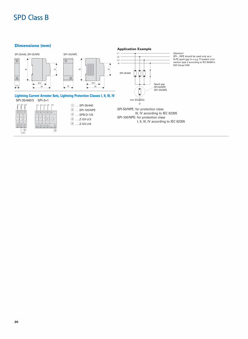
SPD Class B, Lightning Current Arrester SPI• Field of application: For the protection of low voltage distribution systems
against direct lightning stroke into the overhead power supply line or exter-nal lightning protection system (IEC 62305).
• Application according to IEC 60364-5-53 Clause 534• Test class in accordance with IEC 61643-1• SPD-type in accordance with EN 61643-1• Capsuled version: during the discharge process, the device does not issue
any hot ionised gases. Therefore, there is no need for keeping a safety dis-tance to flammable materials.
Technical DataSPI-35/440 SPI-50/NPE SPI-100/NPE
ElectricaldeluspacdeluspacdeluspacngiseD
Responding time tr < 100 ns < 100 ns < 100 nsVoltage protection level Up 1.5 kV 1.5 kV 1.5 kVMaximum continuous operating voltage UC 440 VAC 260 VAC 260 VATemporary overvoltage test value UT CAV0021CAV0021–)sm002(
U)s5( T = UC – –zH06/05zH06/05zH06/05ycneuqerfdetaR
Discharge current (8/20) μs Imax/In 35 kA 50 kA 100 kAImpulse current Iimp (10/350) μs
Ak001Ak05Ak53tnerruckaePsA05sA52sA5.71QegrahC
/Jk503ygrenecificepS Ω 625 kJ/Ω 2500 kJ/ΩInsulation resistance RISO >10 MΩ >10 MΩ >10 MΩFollow current interrupt rating Ifi 3kAr.m.s/260V 500Ar.m.s/260V 100Ar.m.s/260V
1.5kAr.m.s/440V – –Ak52esufpu-kcab.xamtahtgnertstnerructiucric-trohS r.m.s – –
––LgA521esufpu-kcabmumixaMConnection diagram
Mechanical mm54mm54mm54ezisemarFmm09mm09mm09thgieheciveDmm53mm5.71mm5.71htdiweciveD
g023g871g471thgieWUpper and lower lift terminal capacity
mm53-5.0digir 2 0.5 - 35 mm2 10 - 50 mm2
mm52-5.0elbixelf 2 0.5 - 25 mm2 16 - 35 mm2
mN8-6mN5.4-4mN5.4-4swercslanimretfoeuqrotgninethgiT51706NE/CEIliarNIDnogninetsafkciuqgnitnuoM
)04PI(02PI)dellatsni(92506CEIot.ccanoitcetorpfoeergeD/U-VG-Zsrabsub:seirosseccA
%59<ytidimuhriaevitalerdettimrePC°58+otC°04-erutarepmettneibmadettimreP
I
Installation of lightning current arresters upstream of the meter is subject toco-ordination with the relevant power supply company. Installation of an r.m.s.ective protection cascade (SPD classes B, C, D)requires co-ordinated application of the respective protective devices. This isensured by a defined line length between protective devices. When usinglightning current arresters of type SPI in connection with surge arresters SPCwith a maximum continuous operating voltage Uc of 460 V AC, no specificline length or decoupling coils are required.
Practical Hint
T1
26
Dimensions (mm)
SPI-35/440, SPI-50/NPE SPI-100/NPE
Application ExampleAttention!SPI-.../NPE should be used only as a N-PE spark gap in a e.g. TT-system (con-nection type 2 according to IEC 60364-5-534 Clause 534)
Spark gapSPI-50/NPESPI-100/NPE
SPI-35/440
SPI-50/NPE: for protection classIII, IV according to IEC 62305
SPI-100/NPE: for protection classI, II, III, IV according to IEC 62305
SPI-35/440/3 SPI-3+1Lightning Current Arrester Sets, Lightning Protection Classes I, II, III, IV
. . .SPI-35/440
. . .SPI-100/NPE
. . .SPB-D-125
. . .Z-GV-U/3
. . .Z-GV-U/6
SPD Class B

27
SPD Class B+C, Lightning Current Arrester - Surge Arresters SPBT12• Field of application
For the protection of low voltage distribution systems against transientovervoltage caused by direct and indirect lightning stroke and switchingoperations.
• Application according to IEC 60364-5-53 Clause 534• Test class , in accordance with IEC 61643-1• SPD-type , in accordance with EN 61643-11• Lightning protection classes III and IV in accordance with IEC 62305• Busbars ZV-KSBI are available for all customary applications
III
Technical Data001EPN-21TBPS...082-21TBPS
Electrical per pole
sn001<sn52<)sμ/Vk5esiregatlovfoetar(emitgnidnopseRVoltage protection level Up Vk5.1<Vk5.1<
–V059sμ)02/8(Ak5talevelnoitcetorpegatloVMaximum continuous operating voltage UC CAV552CAV082Temporary overvoltage test value UT )sm002(CAV0021)s5(CAV073
zH06/05zH06/05ycneuqerfdetaROpen circuit voltage Uoc Vk02Vk01Nominal discharge current (8/20) μs In Ak001Ak52Maximum discharge current Imax Ak001Ak05Imulse current Iimp (10/350) μs
Ak001Ak5.21tnerruckaePsA05sA52.6QegrahC
/Jk1.93ygrenecificepS Ω 2500 kJ/ΩFollow current interrupt rating Ifi A001– r.m.s
–Gg/LgA061esufpu-kcabmumixaMAk05tnerructiucric-trohsmumixaM r.m.s –
Connection diagram
Mechanicalmm54mm54ezisemarFmm08mm08thgieheciveDmm53mm5.71htdiweciveD
g052g121thgieWC°07+otC°04-C°07+otC°04-erutarepmettneibmadettimreP
04PI04PI)ni-tliub(noitcetorpfoeergeDUpper and lower lift terminal capacity 4 - 25 mm2 4 - 35 mm2
Upper and lower open mouthed terminals mm5.1mm5.1otpussenkcihtrabsubrof
mN3-4.2mN3-4.2swercslanimretfoeuqrotgninethgiT51706NE/CEI51706NE/CEIotgnidroccaliarNIDnogninetsafkciuQ
Accessories: busbars 16 mm2 ...IBSK-VZepyT...IBSK-VZepyT
Block Diagram
T1
Dimensions (mm)
T2
Lightning Current Arrester - Surge Arrester Sets, Lightning Protection Classes III, IVSPBT12-280 SPBT12-NPE100
SPBT12-280/2 SPBT12-280/3 SPBT12-280/4
. . .SPBT12-280
SPD Class B

28
SPD Class B+C, Lightning Current Arrester - Surge Arresters SPBT12-280• Field of application
For the protection of low voltage distribution systems against transientovervoltage caused by direct and indirect lightning stroke and switchingoperations.
• Application according to IEC 60364-5-53 Clause 534• Test class , in accordance with IEC 61643-1• SPD-type , in accordance with EN 61643-11• Lightning protection classes III and IV in accordance with IEC 62305• Busbars ZV-KSBI are available for all customary applications
III
Technical DataSPBT12-280-1+NPE SPBT12-280-3+NPE
Electrical per pole
Responding time (rate of voltage rise 5 kV/μs) L-N / N-PE < 25 ns / < 100 ns < 25 ns / < 100 nsVoltage protection level Up Vk5.1<Vk5.1<EP-N/EP-L/N-LMaximum continuous operating voltage UC L-N / N-PE 280 VAC / 255 VAC 280 VAC / 255 VACTemporary overvoltage test value UT (5 s) L-N / L-PE 348 VAC / 370 VAC 348 VAC / 370 VAC
CAV0021CAV0021EP-N)sm002(zH06/05zH06/05ycneuqerfdetaR
Open circuit voltage Uoc Vk02Vk01Nominal discharge current (8/20) μs In Ak001/Ak52x3Ak001/Ak52EP-N/N-LMaximum discharge current Imax Ak001/Ak05x3Ak001/Ak05EP-N/N-LImulse current Iimp (10/350) μs
Ak001/Ak5.21x3Ak001/Ak5.21EP-N/N-LtnerruckaePsA05sA05QegrahC
/Jk0052ygrenecificepS Ω 2500 kJ/ΩFollow current interrupt rating Ifi N-PE 100 Ar.m.s 100 Ar.m.s
Gg/LgA061Gg/LgA061esufpu-kcabmumixaMAk05tnerructiucric-trohsmumixaM r.m.s 50 kAr.m.s
Connection diagram
Mechanicalmm54mm54ezisemarFmm08mm08thgieheciveD
mm5.78mm5.25htdiweciveDg626g573thgieW
C°07+otC°04-C°07+otC°04-erutarepmettneibmadettimreP04PI04PI)ni-tliub(noitcetorpfoeergeD
Upper and lower lift terminal capacity L, N 4 - 25 mm2 4 - 25 mm2
N, PE 4 - 35 mm2 4 - 35 mm2
Upper and lower open mouthed terminals mm5.1mm5.1otpussenkcihtrabsubrof
mN3-4.2mN3-4.2swercslanimretfoeuqrotgninethgiT51706NE/CEI51706NE/CEIotgnidroccaliarNIDnogninetsafkciuQ
Accessories: busbars 16 mm2 ...IBSK-VZepyT...IBSK-VZepyT
Block Diagram
L
N
PE
T1
Lightning Current Arrester - Surge Arrester Sets, Lightning Protection Classes III, IV
T2
L1
N
PE L2 L3
SPBT12-280-1+NPE SPBT12-280-3+NPE
. . .SPBT12-280
. . .ASAUXSC-SPM
. . .SPI-100/NPE
. . .ASLTT-63SPBT12-280-3+NPE/BB SPBT12-280-1+NPE-AX SPBT12-280-3+NPE-AX
SPD Class B

29
SPD Class B
SPD Class B+C, SP-B+C/
Lightning Current Arrester - Surge Arrester Sets, Lightning Protection Classes I, II, III, IV
• Field of application: For the protection of low voltage distribution systemsagainst direct lightning stroke into the overhead power supply line or exter-nal lightning protection system (IEC 62305) and against indirect lightningstroke and switching operations.
• Application according to IEC 60364-5-53 Clause 534• Test class and in accordance with IEC 61643-1• SPD-type and in accordance with EN 61643-11• Capsuled version: during the discharge process, the device does not issue
any hot ionised gases. Therefore, there is no need for keeping a safety dis-tance to flammable materials.
III
Technical Data1+3/C+B-PS3/C+B-PS
ElectricaldeluspacdeluspacngiseD
Responding time tr sn52<sn52<Voltage protection level Up Vk5.1Vk5.1Maximum continuous operating voltage UC L-(PE)N / N-PE 440 VAC / – 440 VAC / 260 VACTemporary overvoltage test value UT L-(PE)N UT = Uc UT = Uc
)sm002(CAV0021–EP-NzH06/05zH06/05ycneuqerfdetaR
Discharge current (8/20) μs Imax/In Ak001Ak53x3Impulse current Iimp (10/350) μs
Ak001Ak001tnerruckaePsA05sA05QegrahC
/Jk0052ygrenecificepS Ω 2500 kJ/ΩFollow current interrupt rating Ifi L-(PE)N / N-PE
Ak3V062ta rms Ak3–/ rms / 100Arms
Ak5,1V044ta rms / – 1,5kArms / –Ak52esufpu-kcab.xamtahtgnertstnerructiucric-trohS rms 25kArms
LgA521LgA521esufpu-kcabmumixaMConnection diagram
Mechanical mm54mm54ezisemarFmm09mm09thgieheciveDmm461mm011htdiweciveD
g0241g0011thgieWUpper and lower lift terminal capacity
mm53-5.0EP/NEP,N,Ldigir 2 0.5 - 35 mm2 / 10 - 50 mm2
mm52-5.0EP/NEP,N,Lelbixelf 2 0.5 - 25 mm2 / 16 - 35 mm2
mN8-6/mN5.4-4mN5.4-4swercslanimretfoeuqrotgninethgiT51706NE/CEIliarNIDnogninetsafkciuqgnitnuoM
)04PI(02PI)dellatsni(92506CEIot.ccanoitcetorpfoeergeD/U-VG-Zsrabsub:seirosseccA
%59<ytidimuhriaevitalerdettimrePC°07+otC°04-erutarepmettneibmadettimreP
Dimensions (mm)
Installation of lightning current arresters upstream of the meter is subject toco-ordination with the relevant power supply company. Installation of an r.m.s.ective protection cascade (SPD classes B, C, D)requires co-ordinated application of the respective protective devices. This isensured by a defined line length between protective devices. When usinglightning current arresters of type SPI in connection with surge arresters SPCwith a maximum continuous operating voltage Uc of 460 V AC, no specificline length or decoupling coils are required.
Practical Hint
T1 T2
Lightning current arrester - surge arrester
. . .SPI-35/440
. . .SPI-100/NPE for protection class I, II, III, IV
. . .SPC-S-20/460/3
Lead-through terminal
. . .SPB-D-125
Busbar
. . .Z-GV-U/6
. . .Z-GV-U/9
. . .Z-GV-16/3P-3TE/6

30
Busbar Connection Examples according to IEC 60364-5-53 Clause 534SPD Class B SPI B
Lightning current arrester
. . .SPI-35/440
. . .SPI-100/NPE for protection class I, II, III, IV
SPI-50/NPE for protection class III, IV
Lead-through terminal
. . .SPB-D-125
Busbar
. . .Z-GV-U/2
. . .Z-GV-U/3
. . .Z-GV-U/4
. . .Z-GV-U/4 at SPI-100/NPE
Z-GV-U/3 at SPI-50/NPE
. . .Z-GV-U/6 (Z-GV-U/5 at SPI-50/NPE)CT1 . .Connection type 1CT2 . .Connection type 2
3 x 240/415 V AC3 x 230/400 V AC3 x 220/380 V AC
CAV032x3metsyS-TICAV032x3metsyS-TTmetsyS-C-NT
SPI-35/440/3
4 wires 2 wires
SPI-35/440/3
4 wires 3 wires
3 x 240/415 V AC3 x 230/400 V AC3 x 220/380 V AC
CAV004/032x3metsyS-TImetsyS-TTmetsyS-S-NT
SPI-3+1
CT2 CT2
5 wires 3 wires
TN-S-System
CT1 CT1
seriw3seriw5
SPD Class B

31
Busbar Connection Examples according to IEC 60364-5-53 Clause 534SPD Class B+C SPI B SPC C
Lightning current arrester
. . .SPI-35/440
. . .SPI-100/NPE for protection class I, II, III, IV
SPI-50/NPE for protection class III, IV
. . .SPCT2-460/3
Lead-through terminal
. . .SPB-D-125
Busbar
. . .Z-GV-U/6
. . .Z-GV-U/9
. . .Z-GV-16/3P-3TE/6
CT2 . .Connection type 2
3 x 240/415 V AC3 x 230/400 V AC3 x 220/380 V AC
CAV032x3metsyS-TICAV032x3metsyS-TTmetsyS-C-NT
SP-B+C/3
4 wires
SP-B+C/3
4 wires
3 x 240/415 V AC3 x 230/400 V AC3 x 220/380 V AC
CAV004/032x3metsyS-TImetsyS-TTmetsyS-S-NT
SP-B+C/3+1
CT2
5 wires
SPD Class B

32
SPD Class B
Application Examples according to IEC 60364-5-53 Clause 534Lightning current arrester
. . .SPI-35/440
. . .SPI-100/NPE
. . .SPI-50/NPE
Surge arrester
. . .SPCT2-460/3
Lead-through terminal
. . .SPB-D-125
. . .ASLTT-63
Busbar
. . .ZV-KSBI-4TE
Protection Class I, II, III, IV
Protection Class III, IV
Main distribution board
Lightning currentarrester
Sub-distribu-tion board
Main distribution board
Lightning currentarrester
Sub-distribu-tion board
Main distribution board
Lightning currentarrester
Sub-distribu-tion board

33
SPD Class C
SPC-S-20/280/3
SPC-E-280
SPD Class CMax. Cont. Op. Volt. UC In (8/20)μs Type Designation Article No. Units per package
Surge arrester SPC-E75VAC 15kA130VAC 20kA175VAC 20kA280VAC 20kA335VAC 20kA385VAC 20kA460VAC 20kA580VAC 20kAN-PE 260VAC 30kA
SPC-E-75 248148 12 / 120SPC-E-130 248149 12 / 120SPC-E-175 118920 12 / 120SPC-E-280 248150 12 / 120SPC-E-335 248151 12 / 120SPC-E-385 248152 12 / 120SPC-E-460 248153 12 / 120SPC-E-580 248154 12 / 120SPC-E-N/PE 248157 12 / 120
U1302
Plug-in surge arrester SPC-SInsert 1-pole
Insert 75VAC 15kAInsert 130VAC 20kAInsert 175VAC 20kAInsert 280VAC 20kAInsert 335VAC 20kAInsert 385VAC 20kAInsert 460VAC 20kAInsert 580VAC 20kAInsert N-PE 260VAC 30kA
SPC-S-15/75 248158 4 / 120SPC-S-20/130 248159 4 / 120SPC-S-20/175 248160 4 / 120SPC-S-20/280 248161 4 / 120SPC-S-20/335 248162 4 / 120SPC-S-20/385 248163 4 / 120SPC-S-20/460 248164 4 / 120SPC-S-20/580 248165 4 / 120SPC-S-N/PE 248166 4 / 120
Plug-in surge arrester SPC-S, 1- to 4-poleComplete (2- and multi-pole surge arresters are supplied with busbar)
U12021-pole 130VAC 1x20kA1-pole 175VAC 1x20kA2-pole 175VAC 2x20kA1-pole 280VAC 1x20kA2-pole 280VAC 2x20kA3-pole 280VAC 3x20kA4-pole 280VAC 4x20kA1-pole 335VAC 1x20kA2-pole 335VAC 2x20kA3-pole 335VAC 3x20kA4-pole 335VAC 4x20kA1-pole 385VAC 1x20kA2-pole 385VAC 2x20kA3-pole 385VAC 3x20kA4-pole 385VAC 4x20kA1-pole 460VAC 1x20kA2-pole 460VAC 2x20kA3-pole 460VAC 3x20kA4-pole 460VAC 4x20kA1-pole 580VAC 1x20kA1+1p – –3+1p – –3+1p – –
SPC-S-20/130/1 248188 12 / 120SPC-S-20/175/1 248189 12 / 120SPC-S-20/175/2 248190 1 / 60SPC-S-20/280/1 248172 12 / 120SPC-S-20/280/2 248173 1 / 60SPC-S-20/280/3 248174 1 / 40SPC-S-20/280/4 248175 1 / 30SPC-S-20/335/1 248176 12 / 120SPC-S-20/335/2 248177 1 / 60SPC-S-20/335/3 248178 1 / 40SPC-S-20/335/4 248179 1 / 30SPC-S-20/385/1 248180 12 / 120SPC-S-20/385/2 248181 1 / 60SPC-S-20/385/3 248182 1 / 40SPC-S-20/385/4 248183 1 / 30SPC-S-20/460/1 248184 12 / 120SPC-S-20/460/2 248185 1 / 60SPC-S-20/460/3 248186 1 / 40SPC-S-20/460/4 248187 1 / 30SPC-S-20/580/1 248191 12 / 120SPC-S-1+1 248192 1 / 60SPC-S-3+1 248193 1 / 30SPC-S-3+N/PE 115795 1 / 30
Base 1- to 4-poleBase 1-poleBase 1+1 2-poleBase 2-poleBase 3-poleBase 4-poleBase 3+1 4-pole
SPC-S-S1 248167 12 / 120SPC-S-S2-1+1 248201 6 / 60SPC-S-S2 248168 6 / 60SPC-S-S3 248169 4 / 40SPC-S-S4 248170 3 / 30SPC-S-S4-3+1 248171 3 / 30
SG14802
SPC-S-S4-3+1
PHASE OUT TYPE
PHASE OUT TYPE
PHASE OUT TYPE

SPD Class C (continued)Max. Cont. Op. Volt. UC In (8/20)μs Type Designation Article No. Units per package
34
SPD Class C
SPCT2-280/3
Plug-in surge arrester SPCT2Insert 1-pole
Insert 75VAC 20kAInsert 130VAC 20kAInsert 175VAC 20kAInsert 280VAC 20kAInsert 335VAC 20kAInsert 385VAC 20kAInsert 460VAC 20kAInsert 580VAC 20kAInsert 260VAC 30kA
SPCT2-075 167577 4/120 SPCT2-130 167582 4/120 SPCT2-175 167587 4/120 SPCT2-280 167592 4/120 SPCT2-335 167597 4/120 SPCT2-385 167602 4/120 SPCT2-460 167607 4/120 SPCT2-580 167612 4/120 SPCT2-NPE60 167617 4/120
SG13109
Plug-in surge arrester SPCT2, 1- to 4-poleComplete (2- and multi-pole surge arresters are supplied with busbar)
SG50112
1-pole 75VAC 20kA1-pole 130VAC 20kA1-pole 175VAC 20kA1-pole 280VAC 20kA1-pole 335VAC 20kA1-pole 385VAC 20kA1-pole 460VAC 20kA1-pole 580VAC 20kA1+N 260VAC 30kA2-pole 75VAC 2x20kA2-pole 130VAC 2x20kA2-pole 175VAC 2x20kA2-pole 280VAC 2x20kA2-pole 335VAC 2x20kA2-pole 385VAC 2x20kA2-pole 460VAC 2x20kA2-pole 580VAC 2x20kA3-pole 75VAC 3x20kA3-pole 130VAC 3x20kA3-pole 175VAC 3x20kA3-pole 280VAC 3x20kA3-pole 335VAC 3x20kA3-pole 385VAC 3x20kA3-pole 460VAC 3x20kA3-pole 580VAC 3x20kA4-pole 75VAC 4x20kA4-pole 130VAC 4x20kA4-pole 175VAC 4x20kA4-pole 280VAC 4x20kA4-pole 335VAC 4x20kA4-pole 385VAC 4x20kA4-pole 460VAC 4x20kA4-pole 580VAC 4x20kA1+N 280VAC 20kA1+N 335VAC 20kA1+N 385VAC 20kA1+N 460VAC 20kA1+N 580VAC 20kA3+N 280VAC 20kA3+N 335VAC 20kA3+N 385VAC 20kA3+N 460VAC 20kA3+N 580VAC 20kA3+N/BB 280VAC 3x20kA3+N/BB 335VAC 3x20kA3+N/BB 385VAC 3x20kA3+N/BB 460VAC 3x20kA
SPCT2-075/1 167578 12/120 SPCT2-130/1 167583 12/120 SPCT2-175/1 167588 12/120 SPCT2-280/1 167593 12/120 SPCT2-335/1 167598 12/120 SPCT2-385/1 167603 12/120 SPCT2-460/1 167608 12/120 SPCT2-580/1 167613 12/120 SPCT2-NPE60/1 167618 12/120 SPCT2-075/2 167579 1/60 SPCT2-130/2 167584 1/60 SPCT2-175/2 167589 1/60 SPCT2-280/2 167594 1/60 SPCT2-335/2 167599 1/60 SPCT2-385/2 167604 1/60 SPCT2-460/2 167609 1/60 SPCT2-580/2 167614 1/60 SPCT2-075/3 167580 1/40 SPCT2-130/3 167585 1/40 SPCT2-175/3 167590 1/40 SPCT2-280/3 167595 1/40 SPCT2-335/3 167600 1/40 SPCT2-385/3 167605 1/40 SPCT2-460/3 167610 1/40 SPCT2-580/3 167615 1/40 SPCT2-075/4 167581 1/30 SPCT2-130/4 167586 1/30 SPCT2-175/4 167591 1/30 SPCT2-280/4 167596 1/30 SPCT2-335/4 167601 1/30 SPCT2-385/4 167606 1/30 SPCT2-460/4 167611 1/30 SPCT2-580/4 167616 1/30 SPCT2-280-1+NPE 167619 1/60 SPCT2-335-1+NPE 167621 1/60 SPCT2-385-1+NPE 167623 1/60 SPCT2-460-1+NPE 167625 1/60 SPCT2-580-1+NPE 167627 1/60 SPCT2-280-3+NPE 167620 1/30 SPCT2-335-3+NPE 167622 1/30 SPCT2-385-3+NPE 167624 1/30 SPCT2-460-3+NPE 167626 1/30 SPCT2-580-3+NPE 167628 1/30 SPCT2-280-3+NPE/BB 167629 1 SPCT2-335-3+NPE/BB 167630 1 SPCT2-385-3+NPE/BB 167631 1 SPCT2-460-3+NPE/BB 167632 1
SPCT2-280
NEW
NEW

35
SPD Class C
Surge Arrester SetegakcaprepstinU.oNelcitrAnoitangiseDepyTnoitpircseD
SPD Class C, SPCSurge arrester set SPC-S-3+1-SET 248194 1
SG14805
Auxiliary Switchfor SPCT2 ASAUXSC-SPM 131785 8 / 80
SG83311
PHASE OUT TYPE
SPC-S-3+1-SET
NEW
egakcaprepstinU.oNelcitrAnoitangiseDepyTnoitpircseD
Lead-through terminal for SPB, ASLTT-63
ASLTT-63 131784 12 / 120
SG59511

36
SPD Class C, Surge Arresters SPC-E• Field of application
For the protection of low voltage distribution systems against transientovervoltage caused by indirect lightning stroke and switching operations.
• Test class according to IEC 61643-1+A1• SPD-type according to EN 61643-11• Busbars ZV-KSBI are available for all customary applications• Suitable for busbar connection to all Xtra Combinations switchgear
Technical DataSPC-E-75 -130 -175 -280 -335 -385 -460 -580
Electrical
Responding time (rate of voltage rise 5 kV/μs) < 25 ns < 25 ns < 25 ns < 25 ns < 25 ns < 25 ns < 25 ns < 25 nsVoltage protection level at nominal discharge current < 550 V < 800 V < 1kV < 1.4kV < 1.6kV < 1.8kV < 2.2kV < 2.6kVVoltage protection level at 5 kA (8/20) μs 400 V 550 V 700 V 1000 V 1200 V 1350 V 1700 V 2000 VMaximum continuous operating voltage UC 75 VAC 130 VAC 175 VAC 280 VAC 335 VAC 385 VAC 460 VAC 580 VACTemporary overvoltage test value UT (5 s) = Uc = Uc = Uc 350 VAC 415 VAC 415 VAC 580 VAC = Uc
zH06/05zH06/05zH06/05zH06/05zH06/05zH06/05zH06/05zH06/05ycneuqerfdetaRNominal discharge current (8/20) μs In 15 kA 20 kA 20 kA 20 kA 20 kA 20 kA 20 kA 20 kACharge Q at In 0.43 As 0.57 As 0.57 As 0.57 As 0.57 As 0.57 As 0.57 As 0.57 AsSpecific energy at In 3.2 kJ/Ω 5.7 kJ/Ω 5.7 kJ/Ω 5.7 kJ/Ω 5.7 kJ/Ω 5.7 kJ/Ω 5.7 kJ/Ω 5.7 kJ/ΩMaximum discharge current Imax 30 kA 40 kA 40 kA 40 kA 40 kA 40 kA 40 kA 40 kAPermissible back-up fuseMaximum short-circuit current
Connection diagram
Mechanical mm54ezisemarFmm08thgieheciveD
mm5.71htdiweciveDg79thgieW
Permitted ambient temperature -40°C to +70°C04PI)ni-tliub(noitcetorpfoeergeD
Upper and lower lift terminal capacity 4 - 25 mm2
Upper and lower open mouthed terminals mm5.1otpussenkcihtrabsubrof
Tightening torque of terminal screws 2.4 - 3 NmQuick fastening on DIN rail according to IEC/EN 60715Accessories: busbars 16 mm2 Type ZV-KSBI ...
Block Diagram
II
T2
≤125 AgL50 kAr.m.s.
PLHT-C10020 kAr.m.s.
SPD Class C

37
SPD Class C
Technical DataSPC-E-N/PE
Electrical
sn001<)sμ/Vk5esiregatlovfoetar(emitgnidnopseRVoltage protection level at nominal discharge current < 1.0 kVMaximum continuous operating voltage UC 260 VACTemporary overvoltage test value UT CAV0021)sm002(
zH06/05ycneuqerfdetaRNominal discharge current (8/20) μs In 20 kACharge Q at In 0.57 AsSpecific energy at In 5.7 kJ/ΩMaximum discharge current Imax 40 kAFollow current interrupt rating Ifi 100 Ar.m.s
–esufpu-kcabmumixaM–tnerructiucric-trohsmumixaM
Connection diagram
Mechanical mm54ezisemarFmm08thgieheciveD
mm5.71htdiweciveDg79thgieW
C°07+otC°04-erutarepmettneibmadettimreP04PI)ni-tliub(noitcetorpfoeergeD
mm52-4yticapaclanimrettfilrewoldnareppU 2
Upper and lower open mouthed terminals mm5.1otpussenkcihtrabsubrof
mN3-4.2swercslanimretfoeuqrotgninethgiT51706NE/CEIotgnidroccaliarNIDnogninetsafkciuQ
Accessories: busbars 16 mm2 Type ZV-KSBI ...
Dimensions (mm)
Application Examples SPC-E according to IEC 60364-5-53 Clause 534
SPC-E-280 SPC-E-280 SPC-E-460 SPC-E-460SPC-E-280 SPC-E-280SPC-
E-N/PE
Z-D63
SPC-E-
N/PE
Z-D63
SPC-E-
280
G

38
SPD Class C, Plug-in Surge Arresters SPCT2• Field of application:
For the protection of low voltage distribution systems against transientovervoltage caused by indirect lightning stroke and switching operations.
• Test class according to IEC 61643-1+A1• SPD-type according to EN 61643-11• Auxiliary switch SPC-S-HK for remote message transmission can be mount-
ed onto the device• Suitable for busbar connection to all Xtra Combinations switchgear• Busbars ZV-KSBI are available for all customary applications
Technical DataInserts SPCT2-075 SPCT2-130 SPCT2-175 SPCT2-280 SPCT2-335 SPCT2-385 SPCT2-460
Electrical
Mechanical coding x x x x x x xResponding time (rate of voltage rise 5 kV/μs) < 25 ns < 25 ns < 25 ns < 25 ns < 25 ns < 25 ns < 25 nsVoltage protection level at nominal discharge current / Uoc < 550 V < 800 V < 1.0 kV < 1.4 kV < 1.6 kV < 1.8 kV < 2.2 kVVoltage protection level at 5 kA (8/20) μs 400 V 550 V 700 V 1000 V 1200 V 1350 V 1700 VMaximum continuous operating voltage Uc 75 VAC 130 VAC 175 VAC 280 VAC 335 VAC 385 VAC 460 VACTemporary overvoltage test value UT (5 s) = UC = UC = UC 350 VAC 415 VAC 415 VAC 580 VAC
zH06/05zH06/05zH06/05zH06/05zH06/05zH06/05zH06/05ycneuqerfdetaROpen circuit voltage Uoc – – – 10 kV 5 kV – –Nominal discharge current (8/20) μs In 15 kA 20 kA 15 kA 20 kA 20 kA 20 kA 20 kACharge Q at In 0.43 As 0.57 As 0.57 As 0.57 As 0.57 As 0.57 As 0.57 AsSpecific energy at In 3.2 kJ/Ω 5.7 kJ/Ω 5.7 kJ/Ω 5.7 kJ/Ω 5.7 kJ/Ω 5.7 kJ/Ω 5.7 kJ/ΩMaximum discharge current Imax 30 kA 40 kA 40 kA 40 kA 40 kA 40 kA 40 kAFollow current interrupt rating Ifi – – – – – – –Permissible back-up fuseMaximum short-circuit current
Connection diagram
Mechanical mm54ezisemarFmm08thgieheciveD
Device width)UM1(mm5.71elop-1
)UM2(mm53elop-1+1)UM2(mm53elop-2
)UM3(mm5.25elop-3)UM4(mm07elop-1+3)UM4(mm07elop-4
Mechanical codingxelop-1
xyelop-1+1xxelop-2xxxelop-3
xxxyelop-1+3xxxxelop-4
Weight Base 1P, 1+1P, 2P, 3P, 3+1P, 4P 53/120/120/180/240/240 gWeight Complete Devices 1P, 1+1P, 2P, 3P, 3+1P, 4P 110/201/220/330/412/440 g
C°07+otC°04-erutarepmettneibmadettimreP04PI)ni-tliub(noitcetorpfoeergeD
Upper and lower lift terminal capacity 4 - 25 mm2
Upper and lower open mouthed terminals mm5.1otpussenkcihtrabsubrof
Tightening torque of terminal screws 2.4 - 3 NmQuick fastening on DIN rail according to IEC/EN 60715Accessories: busbars 16 mm2 Type ZV-KSBI ...
Symbol
II
T2
≤125 AgL50 kAr.m.s.
PLHT-C10020 kAr.m.s.
SPD Class C

39
SPD Class C
Technical Data
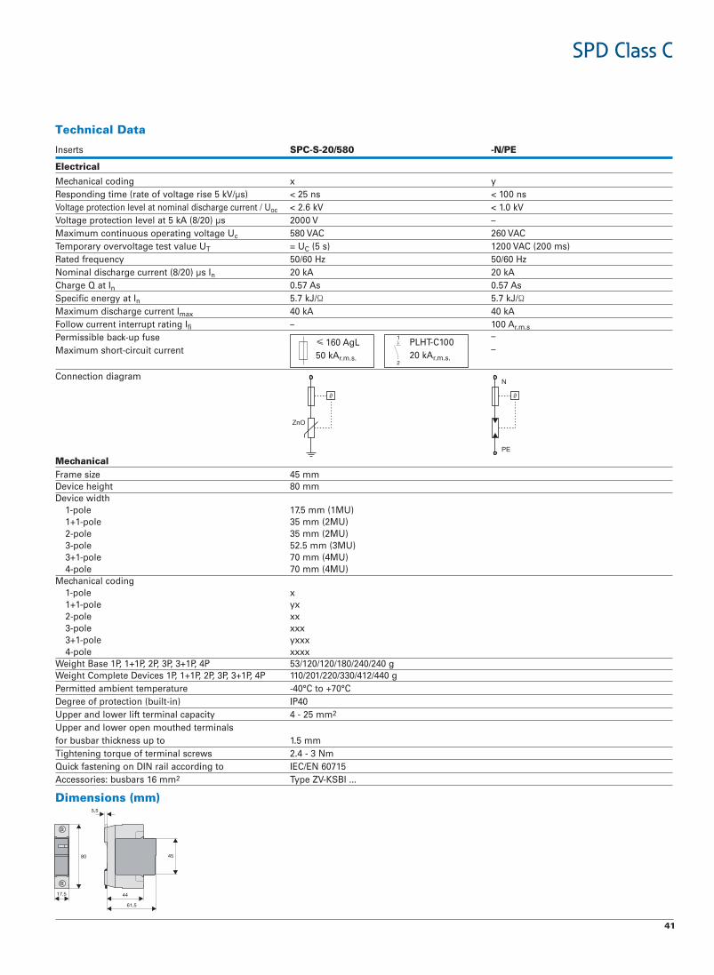
Inserts EPN-2TCPS085-2TCPS
Electrical
yxgnidoclacinahceMsn001<sn52<)sμ/Vk5esiregatlovfoetar(emitgnidnopseR
Voltage protection level at nominal discharge current / Uoc Vk0.1<Vk6.2<–V0002sμ)02/8(Ak5talevelnoitcetorpegatloV
Maximum continuous operating voltage Uc CAV062CAV085Temporary overvoltage test value UT = UC )sm002(CAV0021)s5(
zH06/05zH06/05ycneuqerfdetaRNominal discharge current (8/20) μs In Ak02Ak02Charge Q at In sA75.0sA75.0Specific energy at In 5.7 kJ/Ω 5.7 kJ/ΩMaximum discharge current Imax Ak04Ak04Follow current interrupt rating Ifi A001– r.m.s
Permissible back-up fuse –Maximum short-circuit current –
Connection diagram
Mechanical mm54ezisemarFmm08thgieheciveD
Device width)UM1(mm5.71elop-1
)UM2(mm53elop-1+1)UM2(mm53elop-2
)UM3(mm5.25elop-3)UM4(mm07elop-1+3)UM4(mm07elop-4
Mechanical codingxelop-1
xyelop-1+1xxelop-2xxxelop-3
xxxyelop-1+3xxxxelop-4
Weight Base 1P, 1+1P, 2P, 3P, 3+1P, 4P 53/120/120/180/240/240 gWeight Complete Devices 1P, 1+1P, 2P, 3P, 3+1P, 4P 110/201/220/330/412/440 g
C°07+otC°04-erutarepmettneibmadettimreP04PI)ni-tliub(noitcetorpfoeergeD
Upper and lower lift terminal capacity 4 - 25 mm2
Upper and lower open mouthed terminals mm5.1otpussenkcihtrabsubrof
Tightening torque of terminal screws 2.4 - 3 NmQuick fastening on DIN rail according to IEC/EN 60715Accessories: busbars 16 mm2 Type ZV-KSBI ...
Dimensions (mm)
≤125 AgL50 kAr.m.s.
PLHT-C10020 kAr.m.s.

40
SPD Class C, Plug-in Surge Arresters SPC-S• Field of application:
For the protection of low voltage distribution systems against transientovervoltage caused by indirect lightning stroke and switching operations.
• Test class according to IEC 61643-1+A1• SPD-type according to EN 61643-11• Auxiliary switch SPC-S-HK for remote message transmission can be mount-
ed onto the device• Suitable for busbar connection to all Xtra Combinations switchgear• Busbars ZV-KSBI are available for all customary applications
Technical DataInserts SPC-S-15/75 -20/130 -20/175 -20/280 -20/335 -20/385 -20/460
Electrical
xxxgnidoclacinahceM x x x xResponding time (rate of voltage rise 5 kV/μs) < 25 ns < 25 ns < 25 ns < 25 ns < 25 ns < 25 ns < 25 nsVoltage protection level at nominal discharge current / Uoc < 550 V < 800 V < 1.0 kV < 1.4 kV < 1.6 kV < 1.8 kV < 2.2 kVVoltage protection level at 5 kA (8/20) μs 400 V 550 V 700 V 1000 V 1200 V 1350 V 1700 VMaximum continuous operating voltage Uc 75 VAC 130 VAC 175 VAC 280 VAC 335 VAC 385 VAC 460 VACTemporary overvoltage test value UT (5 s) = UC = UC = UC 350 VAC 415 VAC 415 VAC 580 VAC
zH06/05zH06/05zH06/05zH06/05zH06/05zH06/05zH06/05ycneuqerfdetaROpen circuit voltage Uoc – – – 10 kV 5 kV – –Nominal discharge current (8/20) μs In 15 kA 20 kA 15 kA 20 kA 20 kA 20 kA 20 kACharge Q at In 0.43 As 0.57 As 0.57 As 0.57 As 0.57 As 0.57 As 0.57 AsSpecific energy at In 3.2 kJ/Ω 5.7 kJ/Ω 5.7 kJ/Ω 5.7 kJ/Ω 5.7 kJ/Ω 5.7 kJ/Ω 5.7 kJ/ΩMaximum discharge current Imax 30 kA 40 kA 40 kA 40 kA 40 kA 40 kA 40 kAFollow current interrupt rating Ifi – – – – – – –Permissible back-up fuseMaximum short-circuit current
Connection diagram
Mechanical mm54ezisemarFmm08thgieheciveD
Device width)UM1(mm5.71elop-1
)UM2(mm53elop-1+1)UM2(mm53elop-2
)UM3(mm5.25elop-3)UM4(mm07elop-1+3)UM4(mm07elop-4
Mechanical codingxelop-1
xyelop-1+1xxelop-2xxxelop-3
xxxyelop-1+3xxxxelop-4
Weight Base 1P, 1+1P, 2P, 3P, 3+1P, 4P 53/120/120/180/240/240 gWeight Complete Devices 1P, 1+1P, 2P, 3P, 3+1P, 4P 110/201/220/330/412/440 g
C°07+otC°04-erutarepmettneibmadettimreP04PI)ni-tliub(noitcetorpfoeergeD
Upper and lower lift terminal capacity 4 - 25 mm2
Upper and lower open mouthed terminals mm5.1otpussenkcihtrabsubrof
Tightening torque of terminal screws 2.4 - 3 NmQuick fastening on DIN rail according to IEC/EN 60715Accessories: busbars 16 mm2 Type ZV-KSBI ...
Symbol
II
T2
≤160 AgL50 kAr.m.s.
PLHT-C10020 kAr.m.s.
SPD Class C
41
SPD Class C
Technical Data
Inserts EP/N-085/02-S-CPS
Electrical
yxgnidoclacinahceMsn001<sn52<)sμ/Vk5esiregatlovfoetar(emitgnidnopseR
Voltage protection level at nominal discharge current / Uoc Vk0.1<Vk6.2<–V0002sμ)02/8(Ak5talevelnoitcetorpegatloV
Maximum continuous operating voltage Uc CAV062CAV085Temporary overvoltage test value UT = UC )sm002(CAV0021)s5(
zH06/05zH06/05ycneuqerfdetaRNominal discharge current (8/20) μs In Ak02Ak02Charge Q at In sA75.0sA75.0Specific energy at In 5.7 kJ/Ω 5.7 kJ/ΩMaximum discharge current Imax Ak04Ak04Follow current interrupt rating Ifi A001– r.m.s
Permissible back-up fuse –
Maximum short-circuit current –
Connection diagram
Mechanical mm54ezisemarFmm08thgieheciveD
Device width)UM1(mm5.71elop-1
)UM2(mm53elop-1+1)UM2(mm53elop-2
)UM3(mm5.25elop-3)UM4(mm07elop-1+3)UM4(mm07elop-4
Mechanical codingxelop-1
xyelop-1+1xxelop-2xxxelop-3
xxxyelop-1+3xxxxelop-4
Weight Base 1P, 1+1P, 2P, 3P, 3+1P, 4P 53/120/120/180/240/240 gWeight Complete Devices 1P, 1+1P, 2P, 3P, 3+1P, 4P 110/201/220/330/412/440 g
C°07+otC°04-erutarepmettneibmadettimreP04PI)ni-tliub(noitcetorpfoeergeD
Upper and lower lift terminal capacity 4 - 25 mm2
Upper and lower open mouthed terminals mm5.1otpussenkcihtrabsubrof
Tightening torque of terminal screws 2.4 - 3 NmQuick fastening on DIN rail according to IEC/EN 60715Accessories: busbars 16 mm2 Type ZV-KSBI ...
Dimensions (mm)
≤160 AgL50 kAr.m.s.
PLHT-C10020 kAr.m.s.

42
SPD Class C, Surge Arresters SPCT2-1+NPE, SPCT2-3+NPE• Field of application:
For the protection of low voltage distribution systems against transientovervoltage caused by indirect lightning stroke and switching operations.
• Test class according to IEC 61643-1+A1• SPD-type according to EN 61643-11• Auxiliary switch SPC-S-HK for remote message transmission can be mount-
ed onto the device• Suitable for busbar connection to all Xtra Combinations switchgear• Type SPC-S-3+1:
consists of 1 base SPC-S-S4-3+1, 1 insert SPC-S-N/PE and 3 inserts SPC-S-20/335
• Type SPC-S-1+1:consists of 1 base SPC-S-S2-1+1, 1 insert SPC-S-N/PE and 1 insert SPC-S-20/335
Technical DataSPCT2-1+NPE SPCT2-3+NPE
Electrical
xxxyxygnidoclacinahceMResponding time (rate of voltage rise 5 kV/μs) L-N/N-PE/L-PE < 25ns/< 100ns/< 100ns < 25ns/< 100ns/< 100nsMaximum continuous operating voltage UC L-N/N-PE 335VAC/260VAC 280VAC/260VACTemporary overvoltage test value UT (5 s) L-N 415 VAC 350 VAC
CAV0021CAV0021EP-N)sm002(zH06/05zH06/05ycneuqerfdetaR
Nominal discharge current In L-N/N-PE/L-PE 20 kA (8/20)μs 20 kA (8/20)μsVoltage protection level Up at In L-N/N-PE/L-PE ≤1600V/≤1000V/≤1650V ≤1000V/≤1000V/≤1300VMaximum discharge current Imax L-N/N-PE/L-PE 40 kA (8/20)μs 40 kA (8/20)μsFollow current interrupt rating Ifi N-PE 100 Ar.m.s. 100 Ar.m.s.
Permissible back-up fuseMaximum short-circuit current
Connection diagram
xxxx
yy
Mechanical xxxyxyesabfognidoclacinahceM
mm54mm54ezisemarFmm08mm08thgieheciveDmm07mm53htdiweciveD
g214g102thgieWUpper and lower lift terminal capacity 1 - 25 mm2 1 - 25 mm2
Open-mouthed terminals at both sides for busbar thickness up to 1.5 mm 1.5 mmmN3-4.2mN3-4.2swercslanimretfoeuqrotgninethgiT
C°07+otC°04-C°07+otC°04-erutarepmettneibmadettimreP51706NE/CEIliarNIDnogninetsafkciuqgnitnuoM
04PI04PI)ni-tliub(noitcetorpfoeergeD
II
T2
L3
NN
L2L1
≤125 AgL50 kAr.m.s.
PLHT-C10020 kAr.m.s.
SPD Class C

43
SPD Class C
Dimensions (mm) Application ExamplesSPCT2-1+NPE SPCT2-3+NPE
Application Examples SPCT2 according to IEC 60364-5-53 Clause 534
SPCT2-280/3 SPCT2-280/4
SPCT2-280/3 SPCT2-460/4
SPCT2-460/4 Z-D63
SPCT2-1+NPEG

44
Content• The 3+1 circuit offers a universal solution for surge protection in low volt-
age distribution systems• Suitable for TT- and TN-S systems according to IEC 60364-5-53 Clause 534• Remote message transmission is possibly by mounting auxiliary switch
ASAUXSC-SPM• Busbar connected, minimum installation work required
SPCT2-335-3+NPE/BB- 1 unit SPC-S-3+1 surge arrester- 1 unit ASLTT-63 lead-through terminal- busbar included
Surge Arrester Set SPCT2-335-3+NPE/BB
SPD Class C, SPCT2
Surge Arrester Sets
SPD Class C

45
Light Intensity Switch
Light Intensity Switch for support rail assembly DS-TA, DS-TDSwitching contact / Light intensity Type Designation Article No. Units per package
1NO 2 - 100 Lux1CO 2 - 2000 Lux1CO + watch 2 - 2000 Lux
DS-TA/1S 111451 1 / 40DS-TA/1W 111452 1 / 40DS-TD/1W 111453 1 / 40
AccessoriesSpare Built-in Light SensorSpare External Light Sensor
Z-DS/S-E 111457 1 / 40Z-DS/S-A 111458 1 / 40
SG11807
DS-TA/1S
SG11607
DS-TD/1W
SG47412
Z-DS/S-A
Light Intensity Switch for wall mounting DS-TA, DS-TDSwitching contact / Light intensity Type Designation Article No. Units per package
1NO 5 - 200 Lux1NO 2 - 2000 Lux1NO + watch 2 - 200 Lux
DS-TA/WA 111454 1 / 40DS-TA/VWA 111455 1 / 40DS-TD/WA 111456 1 / 40
SG11107
DS-TA/WA
SG11207
DS-TD/WA
Switching contact / Light intensity Type Designation Article No. Units per package
Light Intensity Switch SR...
1NO 2-100 Lux1NO 2-2000 Lux1NO with timer1CO 2-50000 Lux
SRSD1NO 167375 1SRSW1NO 167376 1SRCD1CO 167377 1SRSD1COW 167378 1
SG84111
PHASE OUT TYPE
PHASE OUT TYPE

46
Communication / Signaling
Signalling Devices: Buzzer Z-SUM, Bell Z-GLOFunction/Rated Voltage (V~) Type Designation Article No. Units per package
Buzzer 230Buzzer 24Buzzer 12Bell 230Bell 24Bell 12
Z-SUM230 270584 2 / 120Z-SUM24 270583 2 / 120Z-SUM12 271087 2 / 120Z-GLO230 270586 2 / 120Z-GLO24 270585 2 / 120Z-GLO12 271088 2 / 120
SG27712
Communication Center Z-CC/2CO• Universal remote monitoring and controlling via SMS based on GSM
2 Change-over contacts Z-CC/2CO 119383 1
egakcaprepstinU.oNelcitrAnoitangiseDepyTnoitpircseD
SG42612
Accessories for Z-CC/2COPower supply unit (24V 0.2A)
Temperature sensor
Patch cord 2.0 m
EASYPOW200 229424 1
Z-CC/2CO-SE 119430 1
DNW-PX/0200/RJ45/RJ45/ 237271 15E/CSUTP/GR/PV
Signalling DevicesAS
Bell 230V ACBell 12V ACBuzzer 230V ACSiren 24V AC/DC
ASBELL230 167393 1ASBELL12 167394 1ASBUZZ230 167395 1ASSIR24 167396 1
Function/Rated Voltage (V~) Type Designation Article No. Units per package
wa_sg04311
ASBELL230
PHASE OUT TYPE
PHASE OUT TYPE

47
Transformers
Transformers 230V, TR-G
2 8 12 4-8-12 1-1-0,672 8 12 4-8-12 2-2-1,53 12-24 2-1
82/10842728/G-RTTR-G3/8 272481 1 / 28TR-G/8-S 272482 1 / 28TR-G3/18 272483 1 / 28TR-G2/24 272484 1 / 20
Bell-Transformers 230V, TR-G.• Type -S with primary switch
MU Sec.-Volt. (V) Sec.-Current (A) Type Designation Article No. Units per package
SG82911
5 12-24 5,2-2,6 TR-G2/63-SF 272485 1 / 12SG42512
Safety-Transformers 230V, TR-G./..-SF.• 100% ED
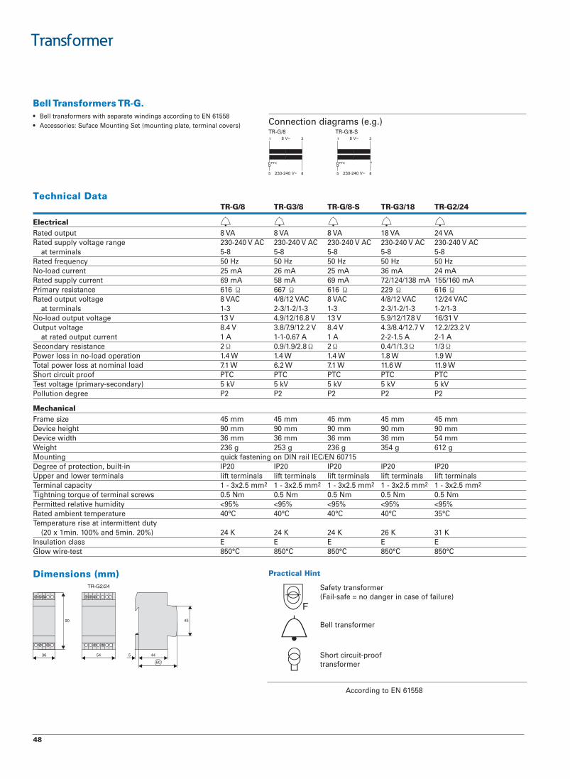
48
Transformer
Bell Transformers TR-G.• Bell transformers with separate windings according to EN 61558• Accessories: Suface Mounting Set (mounting plate, terminal covers)
Technical DataTR-G/8 TR-G3/8 TR-G/8-S TR-G3/18 TR-G2/24
ElectricalAV42AV81AV8AV8AV8tuptuodetaR
CAV042-032CAV042-032CAV042-032CAV042-032CAV042-032egnaregatlovylppusdetaR8-58-58-58-58-5slanimretta
zH05zH05zH05zH05zH05ycneuqerfdetaRAm42Am63Am52Am62Am52tnerrucdaol-oN
Am061/551Am831/421/27Am96Am85Am96tnerrucylppusdetaR616ecnatsiseryramirP Ω 667 Ω 616 Ω 229 Ω 616 Ω
CAV42/21CAV21/8/4CAV8CAV21/8/4CAV8egatlovtuptuodetaR3-1/2-13-1/2-1/3-23-13-1/2-1/3-23-1slanimrettaV13/61V8.71/21/9.5V31V8.61/21/9.4V31egatlovtuptuodaol-oN
V2.32/2.21V7.21/4.8/3.4V4.8V2.21/9.7/8.3V4.8egatlovtuptuOA1-2A5.1-2-2A1A76.0-1-1A1tnerructuptuodetarta
2ecnatsiseryradnoceS Ω 0.9/1.9/2.8 Ω 2Ω 0.4/1/1.3 Ω 1/3ΩW9.1W8.1W4.1W4.1W4.1noitarepodaol-onnissolrewoPW9.11W6.11W1.7W2.6W1.7daollanimontassolrewoplatoT
CTPCTPCTPCTPCTPfoorptiucrictrohSVk5Vk5Vk5Vk5Vk5)yradnoces-yramirp(egatlovtseT
2P2P2P2P2PeergednoitulloP
Mechanical mm54mm54mm54mm54mm54ezisemarFmm09mm09mm09mm09mm09thgieheciveDmm45mm63mm63mm63mm63htdiweciveD
g216g453g632g352g632thgieW51706NE/CEIliarNIDnogninetsafkciuqgnitnuoM
02PI02PI02PI02PI02PIni-tliub,noitcetorpfoeergeDslanimrettfilslanimrettfilslanimrettfilslanimrettfilslanimrettfilslanimretrewoldnareppU
mm5.2x3-1yticapaclanimreT 2 1 - 3x2.5 mm2 1 - 3x2.5 mm2 1 - 3x2.5 mm2 1 - 3x2.5 mm2
Tightning torque of terminal screws 0.5 Nm 0.5 Nm 0.5 Nm 0.5 Nm 0.5 Nm%59<%59<%59<%59<%59<ytidimuhevitalerdettimrePC°53C°04C°04C°04C°04erutarepmettneibmadetaR
Temperature rise at intermittent duty (20 x 1min. 100% and 5min. 20%) 24 K 24 K 24 K 26 K 31 K
EEEEEssalcnoitalusnIC°058C°058C°058C°058C°058tset-eriwwolG
Connection diagrams (e.g.)TR-G/8 TR-G/8-S
Dimensions (mm) Practical Hint
Safety transformer(Fail-safe = no danger in case of failure)
Bell transformer
Short circuit-prooftransformer
According to EN 61558

49
Transformer
Safety Transformers TR-G./..-SF• Safety transformers with separate windings according to EN 61558• Accessories: Suface Mounting Set (mounting plate, terminal covers)
Technical DataTR-G2/24-SF TR-G2/24-SF2 TR-G2/63-SF
ElectricalAV36AV42AV42tuptuodetaR
CAV042-032CAV042-032CAV042-032egnaregatlovylppusdetaR21-721-78-5slanimretta
zH05zH05zH05ycneuqerfdetaRAm06Am85Am22tnerrucdaol-oN
Am043Am531/041Am051/001tnerrucylppusdetaR331ecnatsiseryramirP Ω 92 Ω 41 Ω
CAV42/21CAV42/21CAV21/8egatlovtuptuodetaR4-1/4-13-1/2-13-1/2-1slanimretta (terminal conn.)
V3.72/6.31V8.62/3.31V6.51/9.9egatlovtuptuodaol-oNV1.42/21V8.32/6.11V3.21/2.8egatlovtuptuOA6.2-2.5A1-2A2-2tnerructuptuodetarta
57.0/5.0ecnatsiseryradnoceS Ω 0.45/0.95Ω 0.15/0.6 ΩW1.4W3.4W8.1noitarepodaol-onnissolrewoPW6.91W3.6W4.01daollanimontassolrewoplatoT
%001%001%001ytuD)CTP(yltnerehni)CTP(yltnerehni)CTP(yltnerehnifoorptiucrictrohS
Vk5Vk5Vk5)yradnoces-yramirp(egatlovtseT2P2P2PeergednoitulloP
Mechanical mm54mm54mm54ezisemarFmm09mm09mm09thgieheciveDmm09mm09mm45htdiweciveDg6521g7801g406thgieW
51706NE/CEIliarNIDnogninetsafkciuqgnitnuoM04PI04PI04PIni-tliub,noitcetorpfoeergeD
slanimrettfilslanimrettfilslanimrettfilslanimretrewoldnareppUmm5,2x3-1yticapaclanimreT 2 1 - 3x2,5 mm2 1 - 3x2,5 mm2
mN5,0mN5,0mN5,0swercslanimretfoeuqrotgninthgiT%59<%59<%59<ytidimuhevitalerdettimrePC°52C°53C°52erutarepmettneibmadetaR
Temperature rise at uninterrupted duty 56 K 34 K 51 KFFEssalcnoitalusnI
C°058C°058C°058tset-eriwwolG
Connection diagrams (e.g.)TR-G2/24/SF TR-G2/63-SF
Dimensions (mm) Practical Hint
Safety transformer(Fail-safe = no danger in case of failure)
Bell transformer
Short circuit-prooftransformer
According to EN 61558
= Terminal connection

www.eaton.com/SEAsia
Eaton Industries Pte LtdElectrical Sector 4 Loyang Lane #04-01/02Singapore 508914
Electrical Sector Asia Pacific
No.3, Lane 280, Linhong Road,Changning District, Shanghai
Eaton is a registered trademark of Eaton Corporation.
All other trademarks are property of their respective owners.
© 2013 Eaton CorporationAll Rights ReservedPrinted in SingaporePublication No. SEACA0102004January 2013
Eaton’s electrical business is a global leader with expertise in power distribution and circuit protection; backup power protec-tion; control and automation; lighting and security; structural solutions and wiring devices; solutions for harsh and hazardous environments; and engineering services. Eaton is positioned through its global solutions to answer today’s most critical electrical power management challenges.
Eaton is a diversified power management company providing energy-efficient solutions that help our customers effectively manage electrical, hydraulic and mechanical power. The company is a global technology leader in electrical products, systems and services for power quality, distribution and control, power transmission, lighting and wiring products; hydraulics components, systems and services for industrial and mobile equipment; aerospace fuel, hydraulics and pneumatic systems for commercial and military use; and truck and automotive drivetrain and powertrain systems for performance, fuel economy and safety. Eaton acquired Cooper Industries plc in 2012. Eaton has approximately 100,000 employees and sells products to customers in more than 150 countries. For more information, visit www.eaton.com/SEAsia