DielectricPropertyonDifferent l d AluminumOxideCoatings
25
Dielectric Property on Different l d Aluminum Oxide Coatings Leonid M. Lerner Leonid M. Lerner One Shorr Court One Shorr Court Woonsocket, RI 02895, USA http://www.sanfordprocess.com Twentieth Annual International Anodizing Conference & Exposition October 4 – 6, 2011 • Tempe, Arizona, USA
-
Upload
independent -
Category
Documents
-
view
1 -
download
0
Transcript of DielectricPropertyonDifferent l d AluminumOxideCoatings

Dielectric Property on Different l dAluminum Oxide Coatings
Leonid M. LernerLeonid M. Lerner
One Shorr CourtOne Shorr CourtWoonsocket, RI 02895, USA
http://www.sanfordprocess.com
Twentieth Annual International Anodizing Conference & ExpositionOctober 4 – 6, 2011 • Tempe, Arizona, USA

IntroductionI l t l i h d id• In general, most aluminum hard oxide
coatings demonstrate excellent dielectric properties and good thermaldielectric properties and good thermal
conductivity from DC to GHz (gigahertz 109 Hz) frequencies(gigahertz, 10 Hz) frequencies.
• Typical Uses: high temperature electrical insulators high voltageelectrical insulators, high voltage insulators, electronic substrates,
airspace applications, ballistic armor,airspace applications, ballistic armor, thermometry sensors, instrumentation
parts for thermal property test p p p ymachines, etc.,

Dielectric Strength• All insulating materials fail at some level of
applied voltage, and ‘dielectric strength’ is the voltage a material can withstand before
breakdown occurs. Dielectric strength is measured through the thickness of the material (taking care to avoid surface
effects) and is normally expressed as a voltage gradient (volts per unit length). Note
that the voltage gradient at breakdown is much higher for very thin test pieces
(<100µm thick) than for thicker sections.

Dielectric StrengthTh l f di l t i t th f• The value of dielectric strength for a specimen is also influenced by its
temperature and ambient humidity by anytemperature and ambient humidity, by any voids or foreign materials in the specimen, and by the conditions of test, so that it is
often difficult to compare data from different sources.
An important property of a dielectric is itsAn important property of a dielectric is its ability to support an electrostatic field while
dissipating minimal energy in the form ofdissipating minimal energy in the form of heat. The lower the dielectric loss (the
proportion of energy lost as heat), the more ff i i di l i i leffective is a dielectric material.

Dielectric Strength• Another consideration is the dielectric• Another consideration is the dielectric constant, the extent to which a substance
concentrates the electrostatic lines ofconcentrates the electrostatic lines of flux.
• Substances with a low dielectric constantSubstances with a low dielectric constant include a perfect vacuum, dry air, and
most pure, dry gases such as helium and p , y gnitrogen.
• Materials with moderate dielectric constants include ceramics, distilled water, paper, mica, polyethylene, and
glass. Metal oxides, in general, have high dielectric constants.
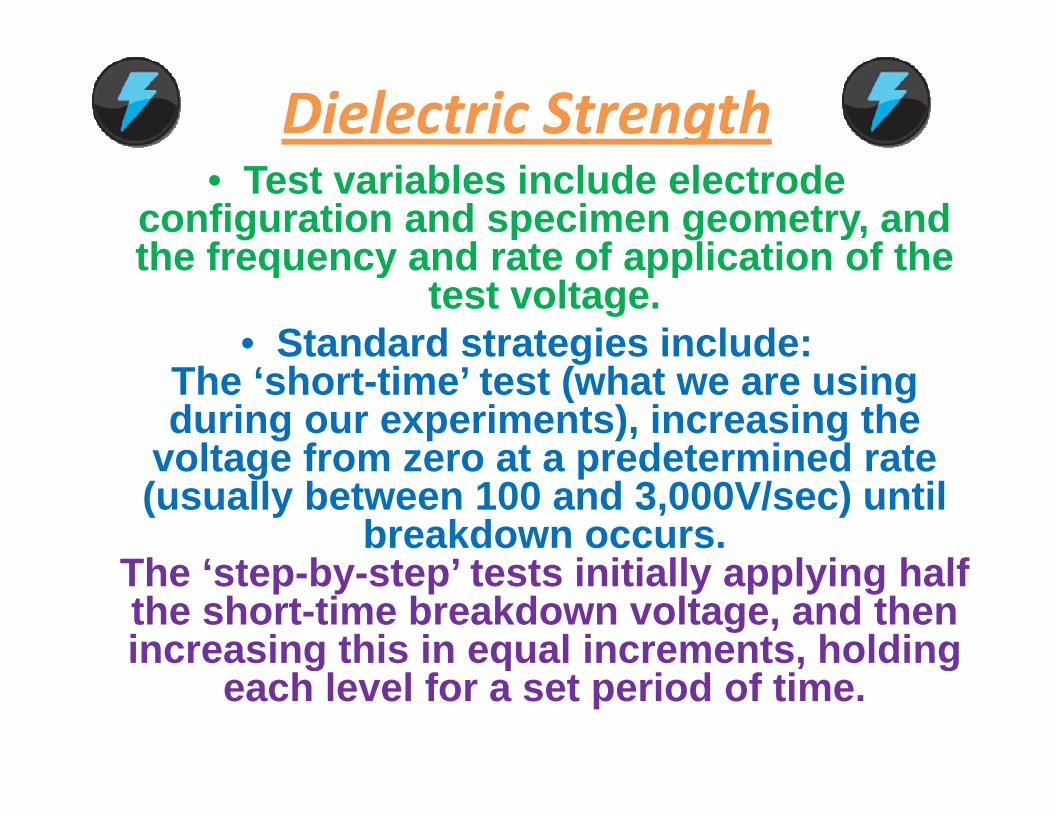
Dielectric Strength• Test variables include electrode
configuration and specimen geometry, and the frequency and rate of application of thethe frequency and rate of application of the
test voltage. • Standard strategies include:Standard strategies include:
The ‘short-time’ test (what we are using during our experiments), increasing the
voltage from zero at a predetermined ratevoltage from zero at a predetermined rate (usually between 100 and 3,000V/sec) until
breakdown occurs.Th ‘ t b t ’ t t i iti ll l i h lfThe ‘step-by-step’ tests initially applying half the short-time breakdown voltage, and then increasing this in equal increments, holding c eas g t s equa c e e ts, o d g
each level for a set period of time.

Dielectric Strength• If the voltage across a dielectric material
becomes too great -- that is, if the electrostatic field becomes too intense theelectrostatic field becomes too intense -- the
material will suddenly begin to conduct current. This phenomenon is called
dielectric breakdown. • In components that use gases or liquids as
the dielectric medium this conditionthe dielectric medium, this condition reverses itself if the voltage decreases
below the critical point. • But in components containing solid dielectrics, dielectric breakdown usually
results in permanent damageresults in permanent damage.

Voltage‐Current Relation Before BreakdownBreakdown
Electrical breakdown in an electric discharge
showing the ribbon-like plasma filaments from aplasma filaments from a
Tesla coil.

Background of Study• The purpose of our study was to identify• The purpose of our study was to identify
different processes and aluminum alloys available on the market for successful creation of aluminum oxide with the best dielectric propertyaluminum oxide with the best dielectric property.
In our studies we employed 5 different power supplies 13 different processes and 7 dissimilar
aluminum alloys The Voltage break downaluminum alloys. The Voltage break down (Dielectric Breakdown Test) was measured with
the help of “Hipot” Tester. • The test voltage is increased until the dielectric
fails, or breaks down, allowing too much current to flow. The dielectric is often destroyed by this y y
test so this test is used on a random sample basis. This test allows designers to estimate the breakdown voltage of a product's design. In our g p g
study it is a best characteristic of dielectric property on aluminum oxide.

“HIPOT” Unit
“+”#2
“ ”#1
+ #2
“-”#1
The result of the DC breakdown voltage represents an average of 6 readings d d t 6 diff t t Th di d l i (1) i ti d irecorded at 6 different spots. The anodized aluminum (1) is negative during
the test. The positive electrode (2) is made from copper with a hemispherical contact area of 5 mm radius.

Conclusions: Aluminum alloy 6061-T6 demonstrated higher level of resistance vs. 2024-T3 & 7075-T6 g
under the same thicknesses and process conditions.

Al2024 T3 Al6061 T6 &Al2024-T3, Al6061-T6 & Al7075-T6 samples used for
measurement of Voltagemeasurement of Voltage Breakdown

Conclusions: Aluminum alloy 6060Conclusions: Aluminum alloy 6060 demonstrated slightly higher level of resistance vs. 1050 under the same thicknesses and process conditions.

Al1050, Al6060 & Al6061-T6 “El t H d C l i ” l d“Electro-Hard-Coloring” samples used for measurement of Voltage Breakdown

Conclusions: Thicker oxide films demonstrate higher resistance on different aluminum alloys.
Al2024-T3, Al5052-H32, Al6061-T6 & 7075-T6 SSM-Q Process samples used for measurement of Voltage Breakdown

Conclusions: Aluminum alloy 1100 demonstrated higher level of resistance vs. 50520-H32 under the same
thicknesses and process conditions.p

Voltage Breakdown Study with Sanford Quantum and SPC#250 Processes
Part # & Process Aluminum Thickness V DC V DC Size ofPart # &rack
Process Name
Aluminum Alloy
Thicknessmil/micron
V DCBreak down
V DCStart leaking
Size of samples
1* SPC #250 5052-H32 1.4/35.0 1800 1600 4”x 4” 2* SPC #250 5052-H32 1.4/35.0 1800 1600 4”x 4”
3** SPC #250 5052-H32 2.2/55.0 2600 2200 4”x 4” 4** SPC #250 5052-H32 2.2/55.0 2500 2200 4”x 4”
5*** SPC #250 1100 Ch 0.7/17.5 1200 1000 2”x 4” 6*** SPC #250 1100 Ch 1.5/37.5 1800 2200 2”x 4”
7**** SPC #250 1100 Ch 0.8/20.0 1600 1200 2”x 4” 8**** SPC #250 1100 Ch 1.7/42.5 2600 2000 2”x 4” 9***** Q ™ 1100 Ch 1 3/32 5 1800 2200 2” 4”9***** Quantum™ 1100 Ch 1.3/32.5 1800 2200 2”x 4”
10***** Quantum™ 1100 Ch 1.3/32.5 1800 2200 2”x 4” 11****** Quantum™ 5052-H32 2.3/57.5 2200 2500 4”x 4” 12****** Quantum™ 5052 H32 2 3/57 5 2400 2600 4”x4”12 Quantum™ 5052-H32 2.3/57.5 2400 2600 4 x4
13^ Quantum™ 5052-H32 1.2/30.0 1600 1400 4”x 4” 14^ Quantum™ 5052-H32 1.0/25.0 1400 1200 4”x 4”
15^^ SPC #250 5052-H32 1.4/35.0 2200 2000 2”x 2” 16^^ SPC #250 5052-H32 1.4/35.0 2400 2200 2”x 2”
17^^^ SPC #250 S+ 1100 Ch 1.9/47.5 2600 2000 4” x 4”18^^^ SPC#250 S+ 1100 Ch 2.0/50.0 2800 2200 4” x 4”

S l f V lt B kd St d ithSamples from Voltage Breakdown Study with Quantum and SPC #250 Processes

# Process Name Aluminum Thickness Volts DC NoteProcess Name Aluminum Alloy
Thicknessmil/micron
Volts DCbreakdown
Note
1 MICRALOX™ 1100 Ch 0.6/15.0 900 S Test 1/22 MICRALOX™ 1100 Ch 0.8/20.0 1000 S Test 1/2MICRALOX 1100 Ch 0.8/20.0 1000 S Test 1/23 MICRALOX™ 1100 Ch 1.1/27.5 1200 S Test 1/24 MICRALOX™ 1100 Ch 1.5/37.5 1400 S Test 1/25 MICRALOX™ 1100 Ch 2.2/55.0 1600 S Test 1/26 MICRALOX™ 6061-T6 1.7/42.5 2300 S Sample
Conclusions: Micralox™ Process demonstrated hi h l l f i t 6061 T6 1100 dhigher level of resistance on 6061-T6 vs.1100 under
the same thicknesses and process conditions.

Samples from different Voltage Breakdown studiesSamples from different Voltage Breakdown studies

Conclusions: Salvage Process demonstrated higher level of resistance with higher thicknesseshigher level of resistance with higher thicknesses of oxide films under the same process conditions.

Part # Process Name Alloy Thickness mil/µ Vdc Breakdown4 Sanford Salvage™ 6061-T6 6.0/150.0 4500
5 Sanford Salvage™ 6061-T6 6.1/152.5 4500
6 Sanford Salvage™ 6061-T6 6.3/157.5 4600g
7 Sanford Salvage™ 6061-T6 6.5/162.5 4700
8 Sanford Salvage™ 6061-T6 4 1/102 5 38008 Sanford Salvage 6061-T6 4.1/102.5 3800
9 Sanford Salvage™ 6061-T6 3.7/92.5 3200
10 S f d S l ™ 6061 T6 3 4/85 0 280010 Sanford Salvage™ 6061-T6 3.4/85.0 2800
11 Sanford Salvage™ 6061-T6 3.4/85.0 3000
12 Sanford Salvage™ 5052-H32 3.8/95.0 3100
13 Sanford Salvage™ 5052-H32 3.6/90.0 3700
All “Salvage” (extra thick coating) samples processed without any seal!

According to some studies, (see article: “Improving the Properties of Hard Anodized 6061‐T6 by Extended Hydrothermal Sealing” by Dr. Arthur Brace – consultant of Weston super Mare England and HansArthur Brace – consultant of Weston‐super‐Mare, England and Hans Sellge V.P. of Semano Inc., USA) dielectric properties of the oxide
coating on aluminum could be significantly improved with hydrothermal sealing post‐treatment. Below see the table (graph 1)
from their article.

General ConclusionsThe test results in Graph 1 show a good
correlation with the results of hydrothermal sealing, confirming that dielectric property
would be higher by conversion of the aluminum oxide film to boehmite.
The thickness of oxide film on different aluminum alloys shows linear improvement in
dielectric property.Also some anodizing processes (Sanford Salvage™, Micralox™ SPC#250, etc.,) can
demonstrate drastic improvement of dielectric property after aluminum anodizing.