Non-Conformance of Existing Pressure Relief Systems With ...
Upload
khangminh22Category
view
1download
0
Document: VISUSCOUT100 Conformance_restructured2.docx
Copyright: © Carl Zeiss Meditec AG, 2014
Page 1 of 32
Revision: 2.0
Revision: 2.0
Date: 2014–04–11
DICOM Conformance Statement
VISUSCOUT 100
Viewing Software
Version 4.02
Carl Zeiss Meditec AG
Göschwitzer Strasse 51-52
07745 Jena
Germany

Document: VISUSCOUT100 Conformance_restructured2.docx
Copyright: © Carl Zeiss Meditec AG, 2014
Page 2 of 32
Revision: 2.0
1 Conformance Statement Overview
VISUSCOUT 100 Viewing Software is an image acquisition modality. Its DICOM functionality allows to query the modality
worklist and archive images.
It supports the following network services:
Table 1. Network Services
Networking SOP Classes
User of
Service
(SCU)
Provider of
Service
(SCP)
Transfer
Ophthalmic Photography 8 Bit Image Storage Yes No
Workflow Management
Modality Worklist Information Model – FIND Yes No
Connectivity Verification
Verification Yes No
The verification function is accessible from application settings where Remote Application Entities are defined. The remaining
DICOM functionality is integrated into the usual workflow.
VISUSCOUT 100 Viewing Software does not support Media Interchange.

Document: VISUSCOUT100 Conformance_restructured2.docx
Copyright: © Carl Zeiss Meditec AG, 2014
Page 3 of 32
Revision: 2.0
2 Table of Contents
1 Conformance Statement Overview ...................................................................................................................... 2 2 Table of Contents .............................................................................................................................................. 3 3 Introduction ..................................................................................................................................................... 5
3.1 Revision History ......................................................................................................................................... 5 3.2 Audience .................................................................................................................................................. 5 3.3 Remarks ................................................................................................................................................... 5 3.4 Definitions and Terms................................................................................................................................. 5 3.5 Abbreviations ............................................................................................................................................ 6 3.6 References ................................................................................................................................................ 7
4 Networking ...................................................................................................................................................... 8 4.1 Implementation Model ................................................................................................................................ 8
4.1.1 Implementation Data Flow ................................................................................................................... 8 4.1.2 Functional Definition of AEs .................................................................................................................. 8
4.1.2.1 Functional Definition of Verification Client Application Entity .............................................................. 8 4.1.2.2 Functional Definition of Storage Client Application Entity ................................................................... 8 4.1.2.3 Functional Definition of Modality Worklist Client Application Entity ...................................................... 8
4.1.3 Sequencing of Real–World Activities ...................................................................................................... 8 4.2 AE Specifications ...................................................................................................................................... 10
4.2.1 Verification Client AE Specification ....................................................................................................... 10 4.2.1.1 SOP Classes ............................................................................................................................... 10 4.2.1.2 Associations Policies .................................................................................................................... 10
4.2.1.2.1 General .............................................................................................................................. 10 4.2.1.2.2 Number of Associations ........................................................................................................ 10 4.2.1.2.3 Asynchronous Nature ........................................................................................................... 10 4.2.1.2.4 Implementation Identifying Information .................................................................................. 10
4.2.1.3 Association Initiation Policy .......................................................................................................... 10 4.2.1.3.1 Activity – Verify DICOM Communication .................................................................................. 10
4.2.1.3.1.1 Description and Sequencing of Activity ............................................................................ 10 4.2.1.3.1.2 Proposed Presentation Contexts ...................................................................................... 11 4.2.1.3.1.3 SOP Specific Conformance for Verification SOP Class ......................................................... 11
4.2.2 Storage Client Application Entity Specification ....................................................................................... 11 4.2.2.1 SOP Classes ............................................................................................................................... 11 4.2.2.2 Associations Policies .................................................................................................................... 11
4.2.2.2.1 General .............................................................................................................................. 11 4.2.2.2.2 Number of Associations ........................................................................................................ 11 4.2.2.2.3 Asynchronous Nature ........................................................................................................... 11 4.2.2.2.4 Implementation Identifying Information .................................................................................. 11
4.2.2.3 Association Initiation Policy .......................................................................................................... 11 4.2.2.3.1 Activity – Send DICOM Instances ........................................................................................... 11
4.2.2.3.1.1 Description and Sequencing of Activity ............................................................................ 11 4.2.2.3.1.2 Proposed Presentation Contexts ...................................................................................... 12 4.2.2.3.1.3 SOP Specific Conformance for Storage SOP Classes ........................................................... 12
4.2.3 Modality Worklist Client Application Entity Specification .......................................................................... 13 4.2.3.1 SOP Classes ............................................................................................................................... 13 4.2.3.2 Associations Policies .................................................................................................................... 13
4.2.3.2.1 General .............................................................................................................................. 13 4.2.3.2.2 Number of Associations ........................................................................................................ 13 4.2.3.2.3 Asynchronous Nature ........................................................................................................... 13 4.2.3.2.4 Implementation Identifying Information .................................................................................. 13
4.2.3.3 Association Initiation Policy .......................................................................................................... 13 4.2.3.3.1 Activity – Query Modality Worklist .......................................................................................... 13
4.2.3.3.1.1 Description and Sequencing of Activity ............................................................................ 13 4.2.3.3.2.2 Proposed Presentation Contexts ...................................................................................... 14 4.2.3.3.2.3 SOP Specific Conformance for Modality Worklist SOP Class ................................................. 14
4.3 Network Interfaces ................................................................................................................................... 16 4.3.1 Physical Network Interface .................................................................................................................. 16 4.3.2 Additional Protocols ............................................................................................................................ 16 4.3.3 IPv4 and IPv6 Support........................................................................................................................ 16
4.4 Configuration ........................................................................................................................................... 16 4.4.1 AE Title/Presentation Address Mapping ................................................................................................. 16
4.4.1.1 Local AE Titles ............................................................................................................................ 16 4.4.1.2 Remote AE Titles ........................................................................................................................ 16
4.4.2 Parameters ....................................................................................................................................... 16 5 Media Interchange ........................................................................................................................................... 18 6 Support of Extended Character Sets ................................................................................................................... 19

Document: VISUSCOUT100 Conformance_restructured2.docx
Copyright: © Carl Zeiss Meditec AG, 2014
Page 4 of 32
Revision: 2.0
7 Security .......................................................................................................................................................... 20 8 Annexes.......................................................................................................................................................... 21
8.1 IOD Contents ........................................................................................................................................... 21 8.1.1 Created SOP Instances ....................................................................................................................... 21
8.1.1.1 Ophthalmic Photography 8–Bit IOD ............................................................................................... 21 8.1.2 Usage of Attributes from Received IODs ............................................................................................... 31 8.1.3 Attribute Mapping .............................................................................................................................. 31 8.1.4 Coerced/Modified Fields ...................................................................................................................... 32
8.2 Data Dictionary of Private Attributes ........................................................................................................... 32 8.3 Coded Terminology and Templates .............................................................................................................. 32 8.4 Greyscale Image Consistency ..................................................................................................................... 32 8.5 Standard Extended / Specialized/ Private SOP Classes ................................................................................... 32 8.6 Private Transfer Syntaxes .......................................................................................................................... 32

Document: VISUSCOUT100 Conformance_restructured2.docx
Copyright: © Carl Zeiss Meditec AG, 2014
Page 5 of 32
Revision: 2.0
3 Introduction
3.1 Revision History
Version Date Author Changes
1.0 Apr 2014 Tomas Burba Initial document
3.2 Audience
This document is intended for the following:
• Potential users
• System integrators of medical equipment
It is assumed that the reader is familiar with the DICOM standard.
3.3 Remarks
DICOM, by itself, does not guarantee interoperability. However, the Conformance Statement facilitates a firstlevel validation
for interoperability between different applications supporting the same DICOM functionality.
This Conformance Statement is not intended to replace validation with other DICOM equipment to ensure proper exchange
of information intended.
The scope of this Conformance Statement is to facilitate communication with other vendors' medical equipment. The
Conformance Statement should be read and understood in conjunction with the DICOM Standard. However, by itself it is
not guaranteed to ensure the desired interoperability and successful interconnectivity with existing DICOM systems.
The user should be aware of the following important issues:
• Test procedures should be defined to validate the desired level of connectivity.
• The DICOM standard will evolve to meet the users' future requirements.
3.4 Definitions and Terms
Informal definitions are provided for the following terms used in this Conformance Statement. The DICOM Standard is the
authoritative source for formal definitions of these terms.
Abstract Syntax
the information agreed to be exchanged between applications, generally equivalent to a Service/Object Pair (SOP)
Class.
Examples: Verification SOP Class, Modality Worklist Information Model Find SOP Class, Ophthalmic Photography
8 Bit Image Storage SOP Class.
Application Entity (AE)
an end point of a DICOM information exchange, including the DICOM network or media interface software; i.e.,
the software that sends or receives DICOM information objects or messages.
Application Entity Title
the externally known name of an Application Entity, used to identify a DICOM application to other DICOM
applications on the network.
Application Context
the specification of the type of communication used between Application Entities.
Example: DICOM network protocol.
Association
a network communication channel set up between Application Entities.
Attribute
a unit of information in an object definition; a data element identified by a tag. The information may be a complex
data structure (Sequence), itself composed of lower level data elements.
Examples: Patient ID (0010,0020), Accession Number (0008,0050), Photometric Interpretation (0028,0004),
Procedure Code Sequence (0008,1032).
Information Object Definition (IOD)
the specified set of Attributes that comprise a type of data object; does not represent a specific instance of the
data object, but rather a class of similar data objects that have the same properties. The Attributes may be

Document: VISUSCOUT100 Conformance_restructured2.docx
Copyright: © Carl Zeiss Meditec AG, 2014
Page 6 of 32
Revision: 2.0
specified as Mandatory (Type 1), Required but possibly unknown (Type 2), or Optional (Type 3), and there may
be conditions associated with the use of an Attribute (Types 1C and 2C).
Examples: MR Image IOD, CT Image IOD, Print Job IOD.
Module
a set of Attributes within an Information Object Definition that are logically related to each other.
Example: Patient Module includes Patient Name, Patient ID, Patient Birth Date, and Patient Sex.
Negotiation
first phase of Association establishment that allows Application Entities to agree on the types of data to be
exchanged and how that data will be encoded.
Presentation Context
the set of DICOM network services used over an Association, as negotiated between Application Entities; includes
Abstract Syntaxes and Transfer Syntaxes.
Protocol Data Unit (PDU)
a packet (piece) of a DICOM message sent across the network. Devices must specify the maximum size packet
they can receive for DICOM messages.
Query Key
A input value for a query process. Query Keys denote the set of DICOM tags that are sent from the SCU to SCP
and thus control the query result.
Service Class Provider (SCP)
role of an Application Entity that provides a DICOM network service; typically, a server that performs operations
requested by another Application Entity (Service Class User).
Examples: Picture Archiving and Communication System (image storage SCP, and image query/retrieve SCP),
Radiology Information System (modality worklist SCP).
Service Class User (SCU)
role of an Application Entity that uses a DICOM network service; typically, a client.
Examples: imaging modality (image storage SCU, and modality worklist SCU), imaging workstation (image
query/retrieve SCU)
Service/Object Pair (SOP) Class
the specification of the network or media transfer (service) of a particular type of data (object); the fundamental
unit of DICOM interoperability specification.
Examples: Ultrasound Image Storage Service, Basic Grayscale Print Management.
Service/Object Pair (SOP) Instance
an information object; a specific occurrence of information exchanged in a SOP Class. Examples: a specific x-ray
image.
Tag
a 32-bit identifier for a data element, represented as a pair of four digit hexadecimal numbers, the “group” and
the “element”. If the “group” number is odd, the tag is for a private (manufacturer-specific) data element.
Examples: (0010,0020) [Patient ID], (07FE,0010) [Pixel Data], (0019,0210) [private data element]
Transfer Syntax
the encoding used for exchange of DICOM information objects and messages.
Examples: JPEG compressed (images), little endian explicit value representation.
Unique Identifier (UID)
a globally unique “dotted decimal” string that identifies a specific object or a class of objects; an ISO-8824 Object
Identifier.
Examples: Study Instance UID, SOP Class UID, SOP Instance UID.
Value Representation (VR)
the format type of an individual DICOM data element, such as text, an integer, a person’s name, or a code.
DICOM information objects can be transmitted with either explicit identification of the type of each data element
(Explicit VR), or without explicit identification (Implicit VR); with Implicit VR, the receiving application must use
a DICOM data dictionary to look up the format of each data element.
3.5 Abbreviations
The following acronyms are used in this document.
• AE — Application Entity
• AET — Application Entity Title
• DICOM — Digital Imaging and Communication in Medicine
• DIMSE — DICOM Message Service Element

Document: VISUSCOUT100 Conformance_restructured2.docx
Copyright: © Carl Zeiss Meditec AG, 2014
Page 7 of 32
Revision: 2.0
• ILE — Implicit VR Little Endian
• ISO — International Standards Organization
• LUT — Look-up Table
• MWL — Modality Worklist
• NEMA — National Electrical Manufacturers Association
• PDU — Protocol Data Unit
• SCP — Storage Class Provider
• SCU — Storage Class User
• SOP — Service Object Pair
• TCP/IP — Transmission Control Protocol/Internet Protocol
• TLS — Transport Layer Security
• UID — Unique Identifier
• VR — Value Representation
3.6 References
NEMA PS3 / ISO 12052, Digital Imaging and Communications in Medicine (DICOM) Standard, National Electrical
Manufacturers Association, Rosslyn, VA, USA (available free at http://medical.nema.org/)

Document: VISUSCOUT100 Conformance_restructured2.docx
Copyright: © Carl Zeiss Meditec AG, 2014
Page 8 of 32
Revision: 2.0
4 Networking
4.1 Implementation Model
VISUSCOUT 100 Viewing Software is a Windows application that captures still images and converts them into DICOM Part
10 compliant files. The application can send these images to remote equipment using the DICOM protocol.
The application uses the DICOM Worklist Management service to populate information in generated DICOM datasets.
It is logically divided into 3 different DICOM Application Entities: Verification Client, Storage Client and Modality Worklist
Client. However all AEs share the same Title.
These Clients are basically modified third–party backends, while the Viewing Software is a front–end. The Storage Client is
a Java Application designed to run on any Java Virtual Machine 1.4 capable Operating System. The Verification and MWL
Clients are monolithic Microsoft Windows PE executable files.
4.1.1 Implementation Data Flow
Figure 1. VISUSCOUT 100 Viewing Software Data Flow Diagram
4.1.2 Functional Definition of AEs
4.1.2.1 Functional Definition of Verification Client Application Entity
The Verification Client Application Entity is a Verification SCU. It connects to the presentation address configured as the
Called Application Entity Title and establishes an Association with Presentation Context of the Verification Service Class. A
message is then shown to the operator detailing whether the association was established successfully or not.
4.1.2.2 Functional Definition of Storage Client Application Entity
The Storage Client Application Entity is a Storage SCU. It connects to the presentation address configured as the Called
Application Entity Title and establishes an Association with Presentation Context of the Storage Service Class. Then it sends
any supported DICOM Instances specified by the operator, over a Storage Request.
4.1.2.3 Functional Definition of Modality Worklist Client Application Entity
The Modality Worklist Client Application Entity connects at the presentation address given as a Called Application Entity
Title. It will propose Associations with Presentation Context for SOP Class of the Modality Worklist Service Class.
When a WORKLIST–FIND request is sent, Modality Worklist Client AE will wait on the same Association for a C–FIND response
and then releasee the Association. The operator is provided with a set of worklist items matching the query request.
4.1.3 Sequencing of Real–World Activities

Document: VISUSCOUT100 Conformance_restructured2.docx
Copyright: © Carl Zeiss Meditec AG, 2014
Page 9 of 32
Revision: 2.0
Figure 2. A typical diagnostic case
Acquire images
The operator uses the camera to image patient's eye(s). Additional imaging modes like red–free or infrared are chosen via
camera menus. The operator can either
• perform the acquisition when the camera operates autonomously, then place the camera on the cradle. The operating
system mounts an external storage device. The application detects it and imports all found images to a new study;
• produce a photo when the camera is already connected to the computer (using a slit lamp adapter etc). The application
imports all newly appeared images (the camera can produce up to four images at once, depending on additional modes
chosen) and adds them to the current study.
The operator is discouraged from imaging more than one patient between imports, as this increases probability of mixing
patients up. It is equally important to remove old images (using a corresponding function on the camera) before imaging a
new patient.
When a new study is created, a new dummy patient is created for it, too.
Query Modality Worklist
After images are imported, the operator adjusts patient's data. In very small clinics the correct data could be obtained
directly by asking the patient for his/her national ID, etc. Then the operator would enter it manually.
In clinics with more developed infrastructure, the operator can search the Modality Worklist for an existing patient. In the
same dialog where patient's data is edited, the operator enters search criteria (date, part of the name, etc) and initiates
the worklist search. A pick–list is updated with results. After double–clicking an entry, patient's data is replaced with its
contents. However, the operator can still adjust the data afterwards. When closing the Set Patient dialog, the operator must
confirm changes.

Document: VISUSCOUT100 Conformance_restructured2.docx
Copyright: © Carl Zeiss Meditec AG, 2014
Page 10 of 32
Revision: 2.0
Store images permanently
The operator decides that patient's data is correct and accesses the "Save" function. Up to this point images in unsaved
studies were in the original JPEG format. Now they all are converted to DICOM and patient data can't be adjusted any more.
Immediately after that, all converted studies are sent to the remote storage if one is configured.
The operator can also repeatedly send a saved study any time.
4.2 AE Specifications
4.2.1 Verification Client AE Specification
4.2.1.1 SOP Classes
VISUSCOUT 100 Viewing Software Verification Client Application Entity provides Standard Conformance to the following
SOP Classes:
Table 2. SOP Classes for Verification Client AE
SOP Class Name SOP Class UID SCU SCP
Verification SOP Class 1.2.840.10008.1.1 Yes No
4.2.1.2 Associations Policies
4.2.1.2.1 General
The Verification Client AE will propose Association Requests for the Verification Service.
The Verification Client AE itself does not accept Associations.
The DICOM standard application context name for DICOM 3.0 is always accepted and proposed:
Table 3. DICOM application context name for Verification Client AE
Application Context Name 1.2.840.10008.3.1.1.1
4.2.1.2.2 Number of Associations
Only a single Association is active at the moment. This is a direct result of the operator pressing a button dedicated to a
particular Remote AE.
4.2.1.2.3 Asynchronous Nature
The Verification Client does not support asynchronous communication (multiple outstanding transactions over a single
Association).
4.2.1.2.4 Implementation Identifying Information
The implementation information for this Application Entity is:
Table 4. DICOM Implementation Class and Version for Verification Client AE
Implementation Class UID 1.2.276.0.75.2.1.70.53666746657461
Implementation Version Name VISUSCOUT100
4.2.1.3 Association Initiation Policy
4.2.1.3.1 Activity – Verify DICOM Communication
4.2.1.3.1.1 Description and Sequencing of Activity
This activity is available as part of the configuration process. When the user has entered Title, IP and Port of a particular
Remote AE (either a Modality Worklist Server or Storage Server), he/she can press a nearby "Echo" button to immediately
verify accesibility of that single AE.
Only the Verification SOP class is proposed. After the Remote AE accepts the association, a C–ECHO message is exchanged.
A pop–up message will appear stating results of the check.

Document: VISUSCOUT100 Conformance_restructured2.docx
Copyright: © Carl Zeiss Meditec AG, 2014
Page 11 of 32
Revision: 2.0
4.2.1.3.1.2 Proposed Presentation Contexts
Table 5. Accepted Presentation Contexts for Verification Client AE
Abstract Syntax Transfer Syntax Role Ext.
Neg. Name UID Name List UID List
Verification SOP Class 1.2.840.10008.1.1 Implicit VR Little
Endian
1.2.840.10008.1.2 SCU None
4.2.1.3.1.3 SOP Specific Conformance for Verification SOP Class
VISUSCOUT 100 Viewing Software Verification Client provides standard conformance to the DICOM Verification Service
Class as a SCU.
4.2.2 Storage Client Application Entity Specification
4.2.2.1 SOP Classes
VISUSCOUT 100 Viewing Software Storage Client Application Entity provides Standard Conformance to the following SOP
Classes:
Table 6. SOP Classes for Storage Client AE
SOP Class Name SOP Class UID SCU SCP
Ophthalmic Photography 8 Bit Image Storage 1.2.840.10008.5.1.4.1.1.77.1.5.1 Yes No
4.2.2.2 Associations Policies
4.2.2.2.1 General
The Storage Client AE proposes Association Requests for the Storage Service.
The Storage Client AE itself does not accept Associations.
The DICOM standard application context name for DICOM 3.0 is always accepted and proposed:
Table 7. DICOM application context name for Storage Client AE
Application Context Name 1.2.840.10008.3.1.1.1
4.2.2.2.2 Number of Associations
Only a single Association is active at the moment. DICOM instances are sent one at a time.
4.2.2.2.3 Asynchronous Nature
The Storage Client does not support asynchronous communication (multiple outstanding transactions over a single
Association).
4.2.2.2.4 Implementation Identifying Information
The implementation information for this Application Entity is:
Table 8. DICOM Implementation Class and Version for Storage Client AE
Implementation Class UID 1.2.276.0.75.2.1.70.53666746657461
Implementation Version Name VISUSCOUT100
4.2.2.3 Association Initiation Policy
4.2.2.3.1 Activity – Send DICOM Instances
4.2.2.3.1.1 Description and Sequencing of Activity
This activity is triggered in the background as part of the permanent conversion of acquired images to the DICOM format
(after which patient data can't be changed any more).

Document: VISUSCOUT100 Conformance_restructured2.docx
Copyright: © Carl Zeiss Meditec AG, 2014
Page 12 of 32
Revision: 2.0
Figure 3. Storing images to Remote AE
There will be no attempt to send the created DICOM instances if the Storage AE Title is not configured in application settings.
4.2.2.3.1.2 Proposed Presentation Contexts
Table 9. Proposed Presentation Contexts for Storage Client AE
Abstract Syntax Transfer Syntax Role Ext.
Neg. Name UID Name List UID List
Ophthalmic Photography 8 Bit Image Storage 1.2.840.10008.5.1.4.1.
1.77.1.5.1
Transfer Syntaxes for Image
Storage Services
SCU None
Table 10. Proposed Transfer Syntaxes for Image Storage Services
Name UID
Implicit VR Little Endian 1 1.2.840.10008.1.2
JPEG Baseline (Process 1) 1.2.840.10008.1.2.4.50
1 ILE is offered due to a corresponding requirement in the DICOM Standard. However, the Storage Client is incapable of
converting between transfer syntaxes. The storage operation will only succeed if the SCP supports JPEG.
4.2.2.3.1.3 SOP Specific Conformance for Storage SOP Classes
The associated Activity with the Storage Client is the storage of medical DICOM data specified by the operator over the
network to the SCP. The Storage Client AE will indicate a failure if it is unable to send the specified instance(s). It always
attempts to send all remaining instances despite of failure with a particular one.
During the Save operation all DICOM instances are created with JPEG Baseline transfer syntax, which corresponds to the
actual image format received from the camera (the JPEG stream is not modified in any way). If the Storage SCP returns
the JPEG context marked as unsupported, then the Client will abort the Association as it does not perform any transfer
syntax conversions, too. Storage SCPs compatible with VISUSCOUT 100 Viewing Software must support JPEG
Baseline (Process 1).
Table 11. Storage Client C-STORE Response Status Handling Behavior
Service
Status
Further Meaning Error
Code
Behavior
Success Success 0000 The Composite SOP Instance was successfully received and stored in the system
repository by the SCP. Send the next instance.
Warning Data Element
Coercion
B000 The SCP has corrected some Data Element(s) to avoid a conflict. Warning
indication message might be copied to the application logs. Assume that the
Instance has been stored successfully and send the next instance.

Document: VISUSCOUT100 Conformance_restructured2.docx
Copyright: © Carl Zeiss Meditec AG, 2014
Page 13 of 32
Revision: 2.0
Elements Discarded B006 Some Data Element(s) were discarded by the SCP. Warning indication message
might be copied to the application logs. Assume that the Instance has been
stored successfully and send the next instance.
Data Set does not
match SOP Class
B007 Assume that the SCP has stored the Instance anyway. Warning indication
message might be copied to the application logs. Send the next instance.
Error Others Others Any unrecognized Error Code is considered an indication that the Instance
wasn't stored. Error indication message might be copied to the application logs
and will be displayed at the end of the operation. Send the next instance.
4.2.3 Modality Worklist Client Application Entity Specification
4.2.3.1 SOP Classes
Table 12. SOP Classes for Modality Worklist Client AE
SOP Class Name SOP Class UID SCU SCP
Modality Worklist Information Model – FIND 1.2.840.10008.5.1.4.31 Yes No
4.2.3.2 Associations Policies
4.2.3.2.1 General
At a command from the operator, the Modality Worklist Client AE attempts to establish an association with the specified
Remote AE. When the association is established, a C–FIND request is made to retrieve a worklist using the defined matching
keys. The Modality Worklist Client waits for any C–FIND response. The established association remains active until a C–
FIND response from the remote AE indicates the end of worklist items, or until a timeout period expires.
The Modality Worklist Client AE itself does not accept Associations.
The DICOM standard application context name for DICOM 3.0 is always accepted and proposed:
Table 13. DICOM application context name for Modality Worklist Client AE
Application Context Name 1.2.840.10008.3.1.1.1
4.2.3.2.2 Number of Associations
Only a single Association is active at the moment. The results are displayed to the operator only after receiving them from
SCP entirely.
4.2.3.2.3 Asynchronous Nature
The Modality Worklist Client does not support asynchronous communication (multiple outstanding transactions over a single
Association).
4.2.3.2.4 Implementation Identifying Information
The implementation information for this Application Entity is:
Table 14. DICOM Implementation Class and Version for Modality Worklist Client AE
Implementation Class UID 1.2.276.0.75.2.1.70.53666746657461
Implementation Version Name VISUSCOUT100
4.2.3.3 Association Initiation Policy
4.2.3.3.1 Activity – Query Modality Worklist
4.2.3.3.1.1 Description and Sequencing of Activity
The Modality Worklist SCU is governed by the "Patient Search" dialog that is opened from the "Study Information" dialog.
The operator can specify date (today by default), Patient ID, Patient Name and Station AE. Wildcards are added implicitly
to the entered Patient Name and Patient ID. A corresponding search is initiated when the operator presses the "Search"
button nearby. After receiving all results, the application updates the pick–list from which an existing patient can be chosen.
The operator can select an entry and press the OK button which closes the dialog, or just double–click on an entry. After
either action is confirmed, Patient ID, Patient Name, Date of Birth, Sex and Referring Physician are copied to the
corresponding entry controls in the parent dialog.

Document: VISUSCOUT100 Conformance_restructured2.docx
Copyright: © Carl Zeiss Meditec AG, 2014
Page 14 of 32
Revision: 2.0
The "Study Information" and, consequently, "Patient Search" dialogs can be opened any time until the study has been
permanently stored (see 4.2.2. Storage Client Application Entity Specification).
Figure 4. Searching in a Modality Worklist
4.2.3.3.2.2 Proposed Presentation Contexts
Table 15. Proposed Presentation Contexts for Modality Worklist Client AE
Abstract Syntax Transfer Syntax Role Ext.
Neg. Name UID Name List UID List
Modality Worklist
Information Model –
FIND
1.2.840.10008.5.1.
4.31
Implicit VR Little Endian 1.2.840.10008.1.2 SCU None
Explicit VR Big Endian 1.2.840.10008.1.2.2
Explicit VR Little Endian 1.2.840.10008.1.2.1
All Transfer Syntaxes are proposed by default.
4.2.3.3.2.3 SOP Specific Conformance for Modality Worklist SOP Class
Table 16. Modality Worklist Client C-STORE Response Status Handling Behavior
Service
Status
Further Meaning Error Code Behavior
Success Matching is complete 0000 This is the last response and the Client will release the
Association after collecting results. Then the pick–list will be
updated.
Pending Matching is continuing FF00 The Client waits for another response.
Table 17. Modality Worklist Client Communication Failure Behavior
Exception Behavior
Association aborted by the SCP or the network layers indicate
communication loss (i.e. low-level TCP/IP socket closure)
Error message might go to the application logs.
The pick–list is is updated with as many entries
as possible.
The attributes listed below might be requested in a query. The corresponding matching keys are empty if the operator
didn't specify a particular value.

Document: VISUSCOUT100 Conformance_restructured2.docx
Copyright: © Carl Zeiss Meditec AG, 2014
Page 15 of 32
Revision: 2.0
Table 18. Modality Worklist C-FIND SCU Supported Elements
Tag VR Attribute Name Query key Displayed
in pick–list
Imported Modifiable
(0008,0050) SH Accession Number — — X —
(0008,0090) PN Referring Physician Name — — X X
(0010,0010) PN Patient's Name P X X X
(0010,0020) LO Patient ID P X X X
(0010,0021) LO Issuer of Patient ID — — X —
(0010,0030) DA Patient's Birth Date — X X X
(0010,1000) LO Other Patient Ids — — X —
(0010,0040) CS Patient's Sex — X X X
(0010,2160) SH Ethnic Group — — X —
(0010,4000) LT Patient Comments — — X —
(0020,000D) UI Study Instance UID — — X —
(0032,1060) LO Requested Procedure Description — — X —
(0032,1064) SQ Requested Procedure Code Sequence
>(0008,0100) SH Code Value — — X —
>(0008,0102) SH Coding Scheme Designator — — X —
>(0008,0103) SH Coding Scheme Version — — X —
>(0008,0104) LO Code Meaning — — X —
(0040,0100) SQ Scheduled Procedure Step Sequence
>(0008,0060) SH Modality F — — —
>(0040,0001) AE Scheduled Station AE Title X — — —
>(0040,0002) DA Scheduled Procedure Step Start Date X — — —
>(0040,0003) TM Scheduled Procedure Step Start Time — — — —
>(0040,0006) PN Scheduled Performing Physician Name — — — —
>(0040,0007) LO Scheduled Procedure Step Description — — X —
>(0040,0008) SQ Scheduled Protocol Code Sequence
>>(0008,0100) SH Code Value — — X —
>>(0008,0102) SH Coding Scheme Designator — — X —
>>(0008,0103) SH Coding Scheme Version — — X —
>>(0008,0104) LO Code Meaning — — X —
>(0040,0009) SH Scheduled Procedure Step ID — — X —
>(0040,0011) SH Scheduled Procedure Step Location — — — —
(0040,1001) SH Requested Procedure ID — — X —
Values for the Query Key column:
X
An exact match by default. Wildcards can be added manually by the operator. The key is only present in the
query if the value is not empty.
P
Always a partial match. The Viewing Software automatically adds a leading and a trailing wildcard. The key is
only present in the query if the value is not empty.
F
The value is fixed (hard–coded string "OP"). The key is always present in the query.

Document: VISUSCOUT100 Conformance_restructured2.docx
Copyright: © Carl Zeiss Meditec AG, 2014
Page 16 of 32
Revision: 2.0
Default value for Patient Name, Patient ID and Scheduled Station AE Title is empty. The Scheduled Procedure Step Start
Date has a default value of today. This field can be disabled altogether with a nearby checkbox, which means "all dates
match".
Values for the Imported column:
X
Imported into the application and might be used in the resulting SOP instances. See also the table in 8.1.3
Attribute Mapping.
Values for the Modifiable column:
X
Copied to the corresponding controls in the "Study Information" dialog. If they are modified, the operator is
offered a choice to dissociate the SOP instance from the worklist altogether; in such a case any imported elements
are replaced with generated values, or are removed.
4.3 Network Interfaces
DICOM Upper Layer over TCP/IP is supported.
4.3.1 Physical Network Interface VISUSCOUT 100 Viewing Software is indifferent to the physical medium over which TCP/IP executes. It inherits the TCP/IP
stack from the operating system or, in case of Storage Client, from Java Runtime Environment.
4.3.2 Additional Protocols No additional protocols are supported.
4.3.3 IPv4 and IPv6 Support Only IPv4 is explicitly supported and was tested.
4.4 Configuration
The application settings dialog can be opened when all other dialogs are closed.
4.4.1 AE Title/Presentation Address Mapping The remote AE Titles and TCP ports are configurable in application settings.
4.4.1.1 Local AE Titles
A single local AE Title is shared among all three AEs and is configurable in application settings.
Table 19. AE Title Configuration Table
Application Entity Default AE Title Default TCP/IP Port
Verification Client
VISUSCOUT100 — Storage Client
Modality Worklist Client
A client chooses any free TCP/IP port offered by the Windows Sockets layer. The IP address is managed by the operating
system and can be configured there.
4.4.1.2 Remote AE Titles
AETs for Storage SCP and MWL SCP are configurable. It's up to the user to ensure that Remote AEs accept the chosen
Calling AE Title.
4.4.2 Parameters VISUSCOUT 100 Viewing Software configuration parameters relevant to DICOM communication are as follows.

Document: VISUSCOUT100 Conformance_restructured2.docx
Copyright: © Carl Zeiss Meditec AG, 2014
Page 17 of 32
Revision: 2.0
Table 20. Configuration Parameter Table
Parameter Configurable
(Yes/No) Default Value
General Parameters
Proposed Called AETs Yes Assigned by
user
Proposed Calling AET Yes VISUSCOUT100
Time–out waiting for TCP/IP connection No no timeout
Time-out waiting for acceptance or rejection Response to an Association Open Request No 30s
Time-out waiting for a DIMSE–RSP No no timeout
Maximum PDU size the AE can receive No 16384
Maximum PDU size the AE can send No 16384
Support for the Basic TLS Secure Transport Connection Profile No Off
Storage Client AE
Pack Command and Data PDVs in one PDU No False
Time–out waiting for TCP/IP connection No 3600s
Time-out waiting for acceptance or rejection Response to an Association Open Request.
(Application Level timeout)
No 3600s
Time-out waiting for a DIMSE–RSP No 3600s
Time-out waiting on an open association for the next message after sending A-RELEASE
RSP or A-ABORT RQ (Closing timeout)
No 3600s

Document: VISUSCOUT100 Conformance_restructured2.docx
Copyright: © Carl Zeiss Meditec AG, 2014
Page 18 of 32
Revision: 2.0
5 Media Interchange VISUSCOUT 100 Viewing Software does not support Media Interchange.

Document: VISUSCOUT100 Conformance_restructured2.docx
Copyright: © Carl Zeiss Meditec AG, 2014
Page 19 of 32
Revision: 2.0
6 Support of Extended Character Sets VISUSCOUT 100 Viewing Software supports ISO_IR 192 (Unicode UTF–8) as an extended character set.
Document: VISUSCOUT100 Conformance_restructured2.docx
Copyright: © Carl Zeiss Meditec AG, 2014
Page 20 of 32
Revision: 2.0
7 Security The DICOM capabilities of the VISUSCOUT 100 Viewing Software do not support any specific security measures.
It is assumed that the Software is used within a secured environment. It is assumed that a secured environment includes
at a minimum:
• firewall or router protections to ensure that the Software only has network access to approved external hosts and services;
• appropriate secure network channels (e.g. such as a Virtual Private Network) for any communication with external hosts
and services outside the locally secured environment.
Other network security procedures such as automated intrusion detection may be appropriate in some environments.
Additional security features may be established by the local security policy and are beyond the scope of this conformance
statement.

Document: VISUSCOUT100 Conformance_restructured2.docx
Copyright: © Carl Zeiss Meditec AG, 2014
Page 21 of 32
Revision: 2.0
8 Annexes
8.1 IOD Contents
8.1.1 Created SOP Instances Abbreviations used for presence of values (PoV):
VNAP
Value Not Always Present (attribute has zero length if no value is present) – Applicable for Type 2, 2C.
ANAP
Attribute is not always present – Applicable for Type 3
ALWAYS
Attribute is always present with a value – Applicable for Type 1
EMPTY
Attribute is sent without a value – Applicable for Type 2
Abbreviations used for sources of data:
USER
Attribute value is generated from user input.
AUTO
Attribute value is generated automatically.
MWL
Attribute value is the same as the value received using a DICOM service such as Modality Worklist, Modality
Performed Procedure Step, etc.
CONFIG
Attribute value is a configurable parameter.
8.1.1.1 Ophthalmic Photography 8–Bit IOD
Table 21. Use of Modules
IE Module Usage
Patient
Patient MANDATORY
Clinical Trial Subject OPTIONAL
Study
General Study MANDATORY
Patient Study OPTIONAL
Clinical Trial Study OPTIONAL
Series
General Series MANDATORY
Ophthalmic Photography Series MANDATORY
Clinical Trial Series OPTIONAL
Frame Of Reference
Synchronization MANDATORY
Equipment
General Equipment MANDATORY
Image
General Image MANDATORY
Image Pixel MANDATORY

Document: VISUSCOUT100 Conformance_restructured2.docx
Copyright: © Carl Zeiss Meditec AG, 2014
Page 22 of 32
Revision: 2.0
Enhanced Contrast/Bolus CONDITIONAL
Cine CONDITIONAL
Multi-Frame MANDATORY
Device OPTIONAL
Acquisition Context OPTIONAL
Ophthalmic Photography Image MANDATORY
Ocular Region Imaged MANDATORY
Ophthalmic Photography Acquisition Parameters MANDATORY
Ophthalmic Photographic Parameters MANDATORY
ICC Profile OPTIONAL
SOP Common MANDATORY
Frame Extraction CONDITIONAL
Table 22. Ophthalmic Photography IOD - Module "Patient"
Tag Type VR Name Description PoV Source
(0010,0010) 2 PN Patient's Name Patient's full name. ALWAYS MWL, USER
(0010,0020) 2 LO Patient ID Primary hospital identification number or
code for the patient. ALWAYS MWL, USER
(0010,0021) 3 LO Issuer of Patient ID Identifier of the Assigning Authority that
issued the Patient ID. ANAP MWL
(0010,0030) 2 DA Patient's Birth Date Birth date of the patient. ALWAYS MWL, USER
(0010,0040) 2 CS Patient's Sex Sex of the named patient. Enumerated
Values: M = male F = female O = other ALWAYS MWL, USER
(0010,1000) 3 LO Other Patient IDs Other identification numbers or codes
used to identify the patient. ANAP MWL
(0010,2160) 3 SH Ethnic Group Ethnic group or race of the patient. ANAP MWL
(0010,4000) 3 LT Patient Comments User-defined additional information about
the patient. ANAP MWL
Table 23. Ophthalmic Photography IOD - Module "General Study"
Tag Type VR Name Description PoV Source
(0020,000D) 1 UI Study Instance UID
Unique identifier for the Study.
“1.2.276.0.75.2.1.70.10.1” extended by machine identifier and time information in unscheduled case. In scheduled case Unique identifier for the Study is copied from MWL (0020,000d).
ALWAYS MWL, AUTO
(0008,0020) 2 DA Study Date Date the Study started. Date, when
procedure step was started. ALWAYS MWL, AUTO
(0008,0030) 2 TM Study Time Time the Study started. Time, when
procedure step was started. ALWAYS MWL, AUTO
(0008,0090) 2 PN Referring Physician's
Name Name of the patient's referring physician. VNAP MWL, USER
(0020,0010) 2 SH Study ID User or equipment generated Study identifier.
ALWAYS MWL, AUTO

Document: VISUSCOUT100 Conformance_restructured2.docx
Copyright: © Carl Zeiss Meditec AG, 2014
Page 23 of 32
Revision: 2.0
In scheduled case the source attribute for this value is Requested Procedure ID In unscheduled case the value is an Equipment generated Study identifier
(0008,1030) 3 LO Study Description
Institution-generated description or classification of the Study (component) performed. In scheduled case the source attribute for this value is Requested Procedure Description. Attribute does not exist in unscheduled case.
ANAP MWL
(0008,0050) 2 SH Accession Number
A RIS generated number that identifies
the order for the Study.
Value does not exist in unscheduled case.
VNAP MWL
>(0008,1032) 3 SQ
Requested Procedure
Code
Sequence
A Sequence that conveys the type of
procedure performed. One or more
Items may be included in this
Sequence.
ANAP MWL
>(0008,0100) 1 SH Code Value See chapter “8.3 Coded Terminology
and Templates” ALWAYS MWL
>(0008,0102) 1 SH Coding Scheme
Designator
See chapter “8.3 Coded Terminology
and Templates” ALWAYS MWL
>(0008,0103) 1C SH Coding Scheme
Version
Required if the value of Coding
Scheme Designator (0008,0102) is
not sufficient to identify the Code
Value (0008,0100) unambiguously.
See chapter “8.3 Coded Terminology
and Templates”
VNAP MWL
>(0008,0104) 1 LO Code Meaning See chapter “8.3 Coded Terminology
and Templates” ALWAYS MWL
Table 24. Ophthalmic Photography IOD - Module "General Series"
Tag Type VR Name Description PoV Source
(0020,000E) 1 UI Series Instance
UID
Unique identifier of the Series.
“1.2.276.0.75.2.1.70.10.2” appended
with machine identifier and time
information
ALWAYS AUTO
(0020,0011) 2 IS Series Number A number that identifies this Series. ALWAYS AUTO
(0008,0021) 3 DA Series Date Date the Series started. ALWAYS AUTO
(0008,0031) 3 TM Series Time Time the Series started. ALWAYS AUTO
(0018,1030) 3 LO Protocol Name
User-defined description of the conditions
under which the Series was performed.
Note: This attribute conveys series-
specific protocol identification and may or
may not be identical to the one presented
in the Performed Protocol Code
Sequence(0040,0260).
In scheduled case: Same value as for
Requested Procedure Description
(0032,1060). Attribute does not exist in
unscheduled case.
ANAP MWL

Document: VISUSCOUT100 Conformance_restructured2.docx
Copyright: © Carl Zeiss Meditec AG, 2014
Page 24 of 32
Revision: 2.0
(0018,0015) 3 CS Body Part
Examined
Text description of the part of the body
examined. See PS 3.16 Annexes on
Correspondence of Anatomic Region
Codes and Body Part Examined for
Humans and for Animals for Defined
Terms Note: Some IODs support the
Anatomic Region Sequence (0008,2218),
which can provide a more comprehensive
mechanism for specifying the body part
being examined.
Always “HEAD”
ALWAYS AUTO
(0040,0275) 3 SQ Request Attributes Sequence
Sequence that contains attributes from
the Imaging Service Request. The
sequence may have one or more Items.
The Request Attributes Sequence is only
included in Scheduled Case. In
unscheduled case it will not be included.
ANAP MWL
>(0040,1001) 1C SH Requested Procedure ID
Identifier that identifies the Requested Procedure in the Imaging Service Request. Required if procedure was scheduled. May be present otherwise. Note: The condition is to allow the contents of this macro to be present (e.g., to convey the reason for the procedure, such as whether a mammogram is for screening or diagnostic purposes) even when the procedure was not formally scheduled and a value for this identifier is unknown, rather than making up a dummy value.
ALWAYS MWL
>(0032,1060) 3 LO
Requested Procedure Description
Institution-generated administrative description or classification of Requested Procedure.
VNAP MWL
>(0040,0009) 1C SH Scheduled
Procedure Step ID
Identifier that identifies the Scheduled Procedure Step. Required if procedure was scheduled. Note: The condition is to allow the contents of this macro to be present (e.g., to convey the reason for the procedure, such as whether a mammogram is for screening or diagnostic purposes) even when the procedure step was not normally scheduled and a value for this identifier is unknown, rather than making up a dummy value.
ALWAYS MWL
>(0040,0007) 3 LO
Scheduled Procedure Step Description
Institution-generated description or classification of the Scheduled Procedure Step to be performed.
VNAP MWL
>(0040,0008) 3 SQ Scheduled Protocol Code Sequence
Sequence describing the Scheduled
Protocol following a specific coding
scheme. This sequence contains one or
more Items.
ANAP MWL
>>(0008,0100) 1 SH Code Value See NEMA PS3.3 Section 8.1. ALWAYS MWL
>>(0008,0102) 1 SH Coding Scheme
Designator See NEMA PS3.3 Section 8.2. ALWAYS MWL
>>(0008,0103) 1C SH Coding Scheme
Version
See NEMA PS3.3 Section 8.2. Required if the value of Coding Scheme Designator (0008,0102) is not sufficient to identify the Code Value (0008,0100) unambiguously. May be present otherwise.
VNAP MWL

Document: VISUSCOUT100 Conformance_restructured2.docx
Copyright: © Carl Zeiss Meditec AG, 2014
Page 25 of 32
Revision: 2.0
>>(0008,0104) 1 LO Code Meaning See NEMA PS3.3 Section 8.3. ALWAYS MWL
Table 25. Ophthalmic Photography IOD - Module "Ophthalmic Photography Series"
Tag Type VR Name Description PoV Source
(0008,0060) 1 CS Modality
Source equipment that produced the
Ophthalmic Photography Series.
Enumerated Value: OP
Always “OP”
ALWAYS AUTO
Table 26. Ophthalmic Photography IOD - Module "Synchronization"
Tag Type VR Name Description PoV Source
(0020,0200) 1 UI Synchronization
Frame of
Reference UID
UID of common synchronization environment.
See C.7.4.2.1.1.
Always “1.2.840.10008.15.1.1” with suffix
generated from timestamp
".YYMMDDHHMMSSmmm".
ALWAYS AUTO
(0018,106A) 1 CS Synchronization
Trigger
Data acquisition synchronization with
external equipment.
Enumerated Values:
SOURCE – this equipment provides
synchronization channel or trigger to other
equipment;
EXTERNAL – this equipment receives
synchronization channel or trigger from
other equipment;
PASSTHRU – this equipment receives
synchronization channel or trigger and
forwards it;
NO TRIGGER – data acquisition not
synchronized by common channel or
trigger.
Always “NO TRIGGER”
ALWAYS AUTO
(0018,1800) 1 CS Acquisition Time
Synchronized
Acquisition DateTime (0008,002A)
synchronized with external time reference.
Enumerated Values: Y, N
See C.7.4.2.1.4.
Always “N”
ALWAYS AUTO
Table 27. Ophthalmic Photography IOD - Module "General Equipment"
Tag Type VR Name Description PoV Source
(0008,0070) 2 LO Manufacturer
Manufacturer of the equipment that produced
the composite instances
Always “Carl Zeiss Meditec”
ALWAYS AUTO
(0008,0080) 3 LO Institution Name
Institution where the equipment that
produced the composite instances is
located.
ANAP CONFIG
(0008,1010) 3 SH Station Name
User defined name identifying the
machine that produced the composite
instances.
ANAP CONFIG
(0008,1090) 3 LO Manufacturer's
Model Name
Manufacturer’s model name of the equipment that produced the composite instances.
ALWAYS AUTO

Document: VISUSCOUT100 Conformance_restructured2.docx
Copyright: © Carl Zeiss Meditec AG, 2014
Page 26 of 32
Revision: 2.0
Always “VISUSCOUT 100 Viewing Software”
(0018,1000) 3 LO Device Serial
Number
Manufacturer’s serial number of the
equipment that produced the composite
instances. Note: This identifier corresponds
to the device that actually created the
images, such as a CR plate reader or a CT
console, and may not be sufficient to identify
all of the equipment in the imaging chain,
such as the generator or gantry or plate.
ALWAYS AUTO
(0018,1020) 3 LO Software
Version(s)
Manufacturer’s designation of software
version of the equipment that produced the
composite instances.
Multi–value attribute with 2 values: version
of camera firmware, version of VISUSCOUT
100. Example: "3.2.7.3585\4.02.1403.0300".
ALWAYS AUTO
Table 28. Ophthalmic Photography IOD - Module "General Image"
Tag Type VR Name Description PoV Source
(0020,0020) 2C CS Patient Orientation
Patient direction of the rows and columns of
the image. Required if image does not
require Image Orientation (Patient)
(0020,0037) and Image Position (Patient)
(0020,0032). May be present otherwise. See
C.7.6.1.1.1 for further explanation. Note:
IOD’s may have attributes other than Patient
Orientation, Image Orientation, or Image
Position (Patient) to describe orientation in
which case this attribute will be zero length.
Always “L\F”
ALWAYS AUTO
(0008,0022) 3 DA Acquisition Date The date the acquisition of data that resulted
in this image started ALWAYS AUTO
(0008,0032) 3 TM Acquisition
Time
The date the acquisition of data that resulted
in this image started ALWAYS AUTO
Table 29. Ophthalmic Photography IOD - Module "Image Pixel"
Tag Type VR Name Description PoV Source
(0028,0010) 1 US Rows Number of rows in the image. ALWAYS AUTO
(0028,0011) 1 US Columns Number of columns in the image ALWAYS AUTO
(0028,0100) 1 US Bits Allocated
Number of bits allocated for each pixel
sample. Each sample shall have the same
number of bits allocated. See PS 3.5 for
further explanation.
Always “8”
ALWAYS AUTO
(0028,0101) 1 US Bits Stored
Number of bits stored for each pixel sample.
Each sample shall have the same number of
bits stored. See PS 3.5 for further
explanation.
Always “8”
ALWAYS AUTO
(0028,0102) 1 US High Bit
Most significant bit for pixel sample data. Each sample shall have the same high bit. See PS 3.5 for further explanation. Always “7”
ALWAYS AUTO

Document: VISUSCOUT100 Conformance_restructured2.docx
Copyright: © Carl Zeiss Meditec AG, 2014
Page 27 of 32
Revision: 2.0
(7FE0,0010) 1C OB Pixel Data
A data stream of the pixel samples that comprise the Image. See C.7.6.3.1.4 for further explanation. Required if Pixel Data Provider URL (0028,7FE0) is not present.
ALWAYS AUTO
Table 30. Ophthalmic Photography IOD - Module "Cine"
Tag Type VR Name Description PoV Source
(0018,1063) 1C DS Frame Time
Nominal time (in msec) per individual frame. See
C.7.6.5.1.1 for further explanation. Required if
Frame Increment Pointer (0028,0009) points to
Frame Time.
Always “0”
ALWAYS AUTO
Table 31. Ophthalmic Photography IOD - Module "Multiframe"
Tag Type VR Name Description PoV Source
(0028,0008) 1 IS Number of
Frames
Number of frames in a Multi-frame Image. See
C.7.6.6.1.1 for further explanation.
Always “1”
ALWAYS AUTO
(0028,0009) 1 AT Frame Increment
Pointer
Contains the Data Element Tag of the attribute that is used as the frame increment in Multi-frame pixel data. See C.7.6.6.1.1 for further explanation. Always “(0018,01063)” for Frame Time
ALWAYS AUTO
Table 32. Ophthalmic Photography IOD - Module "Ophthalmic Photography Image"
Tag Type VR Name Description PoV Source
(0008,0008) 1 CS Image Type
Image identification characteristics. See
C.8.17.2.1.4 for specialization. Multi-value
attribute containing 4 values:
1) Pixel Data Characteristics
“ORIGINAL” for original acquired images.
Always “ORIGINAL”
2) Patient Examination Characteristics.
Always “PRIMARY”
3) Modality Specific Characteristics
Always empty.
4) Implementation specific identifiers
“COLOR”, “REDFREE”, “RED” according to
capture mode (configurable in the camera)
ALWAYS AUTO
(0020,0013) 1 IS Instance Number A number that identifies this image. ALWAYS AUTO
(0028,0002) 1 US Samples per Pixel
Number of samples (planes) in this image.
Enumerated values: 1 or 3. See C.8.17.2.1.2
for further explanation.
“1” for greyscale images
“3” for color images
Always “3”
ALWAYS AUTO

Document: VISUSCOUT100 Conformance_restructured2.docx
Copyright: © Carl Zeiss Meditec AG, 2014
Page 28 of 32
Revision: 2.0
(0028,0004) 1 CS Photometric
Interpretation
Specifies the intended interpretation of the
pixel data. See NEMA PS3.3 Section
C.8.17.2.1.3
“MONOCHROME2” for greyscale images
“YBR_FULL_422” for color images
Always “YBR_FULL_422”
ALWAYS AUTO
(0028,0103) 1 US Pixel
Representation
Data representation of the pixel samples. Each sample shall have the same pixel representation. Enumerated Values: 0000 = unsigned integer 0001 = 2's complement
Always “0”
ALWAYS AUTO
(0028,0006) 1C US Planar
Configuration
Indicates whether the pixel data are sent color-
by-plane or color-by-pixel. Required if Samples
per Pixel (0028,0002) has a value greater than
1. Enumerated value shall be 0 (color-by-
pixel).
Always “0”
ALWAYS AUTO
(0008,0033) 1 TM Content Time The time the image pixel data creation started. ALWAYS AUTO
(0008,0023) 1 DA Content Date The date the image pixel data creation started. ALWAYS AUTO
(0008,002A) 1C DT Acquisition
Datetime
The date and time that the acquisition of data
started. Note: The synchronization of this time
with an external clock is specified in the
synchronization Module in Acquisition Time
Synchronized (0018,1800). Required if Image
Type (0008,0008) Value 1 is ORIGINAL. May
be present otherwise.
ALWAYS AUTO
(0028,2110) 1 CS Lossy Image
Compression
Specifies whether an Image has undergone
lossy compression. Enumerated Values: 00 =
Image has NOT been subjected to lossy
compression. 01 = Image has been subjected
to lossy compression. See C.7.6.1.1.5
“01” if image is compressed
“00” otherwise
Always “01”
ALWAYS AUTO
(0028,2112) 1C DS
Lossy Image
Compression
Ratio
Describes the approximate lossy compression
ratio(s) that have been applied to this image.
See C.7.6.1.1.5 for further explanation. May be
multivalued if successive lossy compression
steps have been applied. Notes: 1. For
example, a compression ratio of 30:1 would be
described in this Attribute with a single value of
30. 2. For historical reasons, the lossy
compression ratio should also be described in
Derivation Description (0008,2111) Required if
Lossy Image Compression (0028,2110) has a
value of "01".
Always “12”
ANAP AUTO
(0028,2114) 1C CS
Lossy Image
Compression
Method
A label for the lossy compression method(s) that have been applied to this image. See C.7.6.1.1.5 for further explanation. May be multivalued if successive lossy compression steps have been applied; the value order shall correspond to the values of Lossy Image Compression Ratio (0028,2112). Required if Lossy Image Compression (0028,2110) has a value of "01". Note: For historical reasons, the
ANAP AUTO

Document: VISUSCOUT100 Conformance_restructured2.docx
Copyright: © Carl Zeiss Meditec AG, 2014
Page 29 of 32
Revision: 2.0
lossy compression method should also be described in Derivation Description (0008,2111). “ISO_10918_1” if image is compressed. Always “ISO_10918_1”
(0028,0301) 1 CS Burned In
Annotation
Indicates whether or not image contains
sufficient burned in annotation to identify the
patient and date the image was acquired.
Enumerated Value: YES NO
“YES” if any identification info is burned in
“NO” otherwise
Always “NO”
ALWAYS AUTO
Table 33. Ophthalmic Photography IOD - Module "Ocular Region Imaged"
Tag Type VR Name Description PoV Source
(0020,0062) 1 CS Image
Laterality
Laterality of object imaged (as described in
Anatomic Region Sequence (0008,2218))
examined. Enumerated Values:
R = right eye
L = left eye
B = both left and right eye
Shall be consistent with any laterality
information contained in Primary Anatomic
Structure Modifier Sequence (0008,2230), if
present.
Note: Laterality (0020,0060) is a Series level
Attribute and must be the same for all Images
in the Series. Since most Ophthalmic
Photographic Image studies contain images of
both eyes, the series level attribute will rarely
be present.
ALWAYS AUTO
(0008,2218) 1 SQ
Anatomic Region
Sequence
Sequence that identifies the anatomic region of
interest in this Instance (i.e. external anatomy, surface anatomy, or general region of the body). Only a single Item shall be permitted in this sequence.
ALWAYS AUTO
>(0008,0100) 1 SH Code Value See NEMA PS3.3 Section 8.1. Always “T-AA000”
ALWAYS AUTO
>(0008,0102) 1 SH Coding Scheme
Designator
See NEMA PS3.3 Section 8.2.
Always “SRT”
ALWAYS AUTO
>(0008,0104) 1 LO Code Meaning
See NEMA PS3.3 Section 8.3. Always “Eye”
ALWAYS AUTO
Table 34. Ophthalmic Photography IOD - Module "Ophthalmic Photography Acquisition Parameters"
Tag Type VR Name Description PoV Source
(0022,0005) 2 CS Patient Eye Movement
Commanded
Enumerated Values: YES NO Always EMPTY
EMPTY AUTO
(0022,001B) 2 SQ Refractive State Sequence
The refractive state of the imaged eye at the time of acquisition. Zero or one Item shall be present. Zero length means the refractive state was not measured. Always zero items
EMPTY AUTO

Document: VISUSCOUT100 Conformance_restructured2.docx
Copyright: © Carl Zeiss Meditec AG, 2014
Page 30 of 32
Revision: 2.0
(0022,000A) 2 FL Emmetropic Magnification
Emmetropic magnification value (dimensionless). Zero length means the emmetropic magnification was not measured. Always EMPTY
EMPTY AUTO
(0022,000B) 2 FL Intra Ocular Pressure
Value of intraocular pressure in mmHg. Zero length means the pressure was not measured. Always EMPTY
EMPTY AUTO
(0022,000D) 2 CS Pupil Dilated
Enumerated Values: YES NO If this tag is empty, no information is available. Always EMPTY
EMPTY AUTO
Table 35. Ophthalmic Photography IOD - Module "Ophthalmic Photographic Parameters"
Tag Type VR Name Description PoV Source
(0022,0015) 1 SQ
Acquisition
Device Type
Code Sequence
Describes the type of acquisition device. A
single item shall be present in the sequence. ALWAYS AUTO
>(0008,0100) 1 SH Code Value
See NEMA PS3.3 Section 8.1.
Always “R-1021B”
ALWAYS AUTO
>(0008,0102) 1 SH Coding Scheme
Designator
See NEMA PS3.3 Section 8.2.
Always “SRT”
ALWAYS AUTO
>(0008,0104) 1 LO Code Meaning
See NEMA PS3.3 Section 8.3.
Always “External Camera”
ALWAYS AUTO
(0022,0016) 2 SQ
Illumination
Type Code
Sequence
Coded value for illumination. Zero or one item
shall be present in the sequence.
Always zero items
EMPTY AUTO
(0022,0017) 2 SQ
Light Path Filter
Type Stack
Code Sequence
Filters used in the light source path. Zero or
more items may be present in the sequence.
Always zero items
EMPTY AUTO
(0022,0018) 2 SQ
Image Path
Filter Type
Stack Code
Sequence
Describes stack of filters used in image path. Zero or more items may be present in the sequence. Always zero items
EMPTY AUTO
(0022,0019) 2 SQ Lenses Code
Sequence
Lenses that were used during the image
acquisition. Zero or more items may be pre
sent in the sequence.
Always zero items
EMPTY AUTO
(0018,7004) 2 CS Detector Type
Type of detector used for creating this image. Defined terms: CCD = Charge Coupled Devices CMOS = Complementary Metal Oxide Semiconductor Always “CMOS”
ALWAYS AUTO
Table 36. Ophthalmic Photography IOD - Module "SOP Common"
Tag Type VR Name Description PoV Source

Document: VISUSCOUT100 Conformance_restructured2.docx
Copyright: © Carl Zeiss Meditec AG, 2014
Page 31 of 32
Revision: 2.0
(0008,0016) 1 UI SOP Class UID
Uniquely identifies the SOP Class. See
C.12.1.1.1 for further explanation. See also PS
3.4.
Always “1.2.840.10008.5.1.4.1.1.77.1.5.1”.
ALWAYS AUTO
(0008,0018) 1 UI SOP Instance
UID
Uniquely identifies the SOP Instance. See
C.12.1.1.1for further explanation. See also PS
3.4.
A constant prefix “1.2.276.0.75.2.1.70.10.3.”
for generated UIDs.
ALWAYS AUTO
(0008,0005) 1C CS Specific
Character Set
Character Set that expands or replaces the
Basic Graphic Set. Required if an expanded or
replacement character set is used. See
C.12.1.1.2 for Defined Terms.
Always “ISO_IR 192” for UTF-8 encoded
Unicode
ALWAYS AUTO
(0008,0012) 3 DA Instance
Creation Date
Date the SOP Instance was created. ALWAYS AUTO
(0008,0013) 3 TM Instance
Creation Time Time the SOP Instance was created. ALWAYS AUTO
8.1.2 Usage of Attributes from Received IODs The usage of attributes of Modality Worklist IODs is described in chapter 4.2.3.3.1 Activity – Query Modality Worklist.
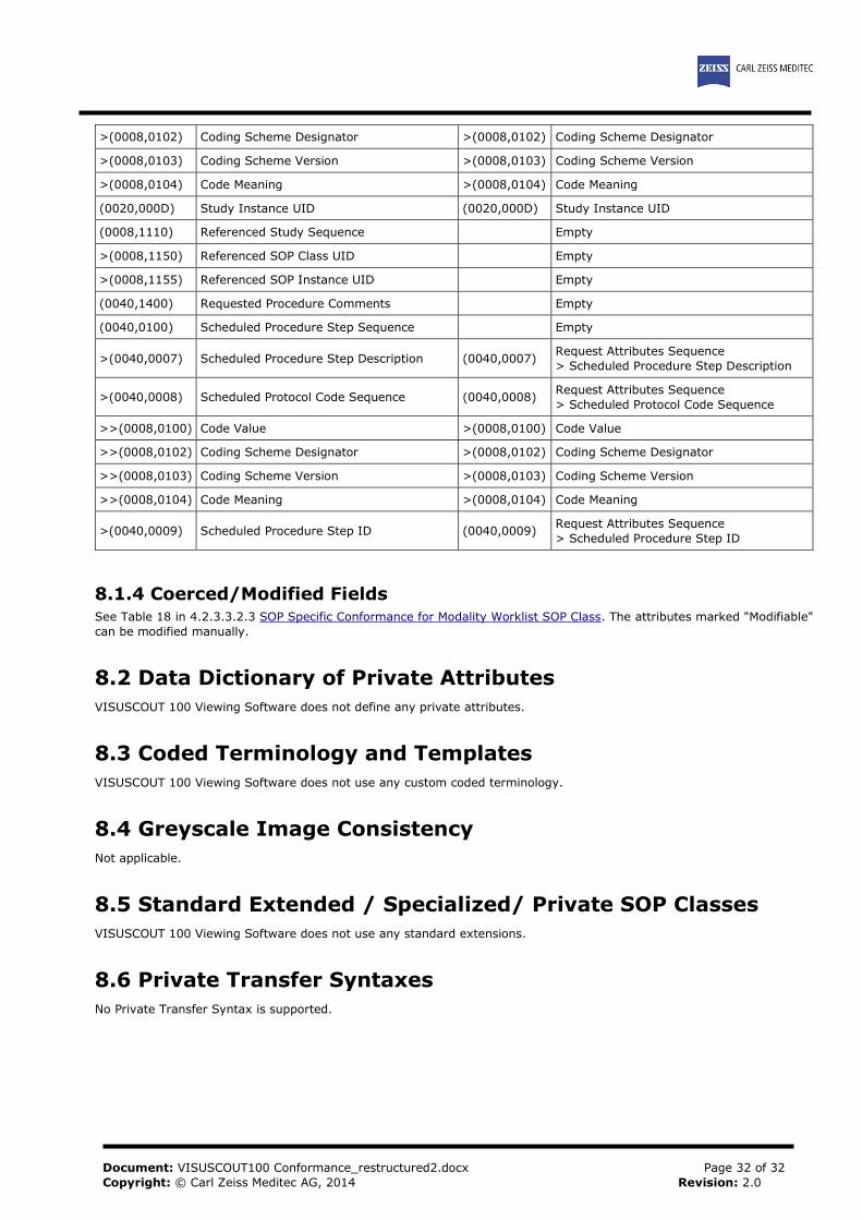
8.1.3 Attribute Mapping The following attributes can be mapped from Modality Worklist to created SOP Instances:
Table 37. Attribute Mapping
MWL Instance IOD
(0010,0010) Patient's Name (0010,0010) Patient's Name
(0010,0020) Patient ID (0010,0020) Patient ID
(0010,0021) Issuer of Patient ID (0010,0021) Issuer of Patient ID
(0010,1000) Other Patient IDs (0010,1000) Other Patient IDs
(0010,0030) Patient's Birth Date (0010,0030) Patient's Birth Date
(0010,0040) Patient's Sex (0010,0040) Patient's Sex
(0010,2160) Ethnic Group (0010,2160) Ethnic Group
(0010,4000) Patient Comments (0010,4000) Patient Comments
(0008,0050) Accession Number (0008,0050) Accession Number
(0008,0090) Referring Physician's Name (0008,0090) Referring Physicians Name
(0040,1001) Requested Procedure ID
(0020,0010) Study ID
(0040,1001) Request Attributes Sequence
> Requested Procedure ID
(0032,1060) Requested Procedure Description
(0008,1030) Study Description
(0032,1060) Request Attributes Sequence
> Requested Procedure Description
(0018,1030) Protocol Name
(0032,1064) Requested Procedure Code Sequence (0008,1032) Procedure Code Sequence
>(0008,0100) Code Value >(0008,0100) Code Value
Document: VISUSCOUT100 Conformance_restructured2.docx
Copyright: © Carl Zeiss Meditec AG, 2014
Page 32 of 32
Revision: 2.0
>(0008,0102) Coding Scheme Designator >(0008,0102) Coding Scheme Designator
>(0008,0103) Coding Scheme Version >(0008,0103) Coding Scheme Version
>(0008,0104) Code Meaning >(0008,0104) Code Meaning
(0020,000D) Study Instance UID (0020,000D) Study Instance UID
(0008,1110) Referenced Study Sequence Empty
>(0008,1150) Referenced SOP Class UID Empty
>(0008,1155) Referenced SOP Instance UID Empty
(0040,1400) Requested Procedure Comments Empty
(0040,0100) Scheduled Procedure Step Sequence Empty
>(0040,0007) Scheduled Procedure Step Description (0040,0007) Request Attributes Sequence
> Scheduled Procedure Step Description
>(0040,0008) Scheduled Protocol Code Sequence (0040,0008) Request Attributes Sequence
> Scheduled Protocol Code Sequence
>>(0008,0100) Code Value >(0008,0100) Code Value
>>(0008,0102) Coding Scheme Designator >(0008,0102) Coding Scheme Designator
>>(0008,0103) Coding Scheme Version >(0008,0103) Coding Scheme Version
>>(0008,0104) Code Meaning >(0008,0104) Code Meaning
>(0040,0009) Scheduled Procedure Step ID (0040,0009) Request Attributes Sequence
> Scheduled Procedure Step ID
8.1.4 Coerced/Modified Fields See Table 18 in 4.2.3.3.2.3 SOP Specific Conformance for Modality Worklist SOP Class. The attributes marked "Modifiable"
can be modified manually.
8.2 Data Dictionary of Private Attributes
VISUSCOUT 100 Viewing Software does not define any private attributes.
8.3 Coded Terminology and Templates
VISUSCOUT 100 Viewing Software does not use any custom coded terminology.
8.4 Greyscale Image Consistency
Not applicable.
8.5 Standard Extended / Specialized/ Private SOP Classes
VISUSCOUT 100 Viewing Software does not use any standard extensions.
8.6 Private Transfer Syntaxes
No Private Transfer Syntax is supported.
Copyright © 2022 FDOKUMEN