Diagnosis of Power Transformer Depending on Dissolved Gas ...
27
Diagnosis of Power Transformer Depending on Dissolved Gas Analysis Done by: Fadi Ahmad Al-Baw Malik Zaher Ali Supervised by: Dr.khalaf Al-Zyoud Presented to Department of Electrical Engineering At Al-Balqa’ Applied University In Partial Fulfillment of the requirements for the Degree of Bachelor of Science in Engineering Technology December,2017
-
Upload
khangminh22 -
Category
Documents
-
view
0 -
download
0
Transcript of Diagnosis of Power Transformer Depending on Dissolved Gas ...
Diagnosis of Power Transformer
Depending on Dissolved Gas Analysis
Done by:
Fadi Ahmad Al-Baw
Malik Zaher Ali
Supervised by:
Dr.khalaf Al-Zyoud
Presented to Department of Electrical Engineering
At Al-Balqa’ Applied University
In Partial Fulfillment of the requirements for the
Degree of Bachelor of Science in Engineering
Technology
December,2017
1
Dissolved Gas Analysis
TABLE OF CONTENTS
LIST OF ABBREVIATIONS………………………….. 4
LIST OF FIGURES…………………………………….. 5
LIST OF TABLES……………………………………... 6
CHAPTER 1 INTRODUCTION
OVERVIEW…………………………………………….. 7
1.1 Introduction…………………………………………. 7
1.2 Motivation………………………………………….. 8
1.3 Thesis main objectives……………………………... 8
1.4 Organization of thesis……………………………… 8
CHAPTER 2 INTRODUCTION TO TRANSFORMER
OVERVIEW……………………………………………. 10
2.1 Introduction………………………………………… 10
2.2 Basic Theory of Transformer………………………. 10
2.3 Use of Power Transformer………………………… 12
2.4 Types of Transformer………………………………. 12
2.5 Insulation materials used in transformers…………… 13
CHAPTER 3 TRANSFORMER OIL
OVERVIEW…………………………………………….. 16
3.1 Introduction of Insulating Oil……………………….. 16
3.2 Types of Transformer Oil…………………………… 16
3.3 Properties of Transformer Insulating Oil…………… 17
2
3.4 Collecting Oil Sample from Oil Immersed Electrical Equipment…. 20
CHAPTER 4 GAS FORMATION IN MINERAL OIL
OVERVIEW……………………………………………………… 21
4.1 Gas Formation in Mineral oil………………………………… 21
4.1.1 Cellulose Decomposition……………………………………………. 21
4.1.2 Oil Decomposition…………………………………………………… 21
4.2 Interpretation of Gas Analysis…………………………………. 22
4.2.1 Thermal faults………………………………………………………….. 22
4.2.2 Electrical faults………………………………………………………… 22
4.3 Literature Review………………………………………………. 23
4.3.1 Total Combustible Gas (TCG)………………………………. 23
4.3.2 Gas Blanket Analysis (GBA)……………………………….. 23
4.3.3 Dissolved Gas Analysis (DGA)…………………………….. 24
4.4 DGA block diagram…………………………………………….. 24
CHAPTER 5 GAS INTERPRETATION TECHNIQUES
OVERVIEW………………………………………………………….. 26
5.1 Block Diagram of DGA Combine Method………………………. 27
5.2 Key Gas Method…………………………………………………. 28
5.2.1 Thermal Faults………………………………………………... 28
5.2.1. I Thermal faults in oil……………………………………………… 28
5.2.1. II. Thermal faults in cellulose…………………………………….... 29
5.2.2 Electrical Faults……………………………………………….. 29
5.2.2. I Corona…………………………………………………………….. 29
5.2.2. II Arcing……………………………………………………………. 30
5.3 Key Gas Method software implementation to MATLAB GUI…... 32
5.4 Result and discussions……………………………………………. 33
CHAPTER 6 RATIO METHODS TO INTERPRETATION OF
DGA
OVERVIEW…………………………………………………………. 34
3
6.1 Rogers Ratio Method…………………………………………….. 35
6.1.1 Introduction………………………………………………………………. 35
6.1.2 Diagnostic Code Representation…………………………………………. 35
6.1.3 Rogers ratio method software implementation to MATLAB GUI………. 37
6.1.4 Result and Discussions…………………………………………………… 38
6.2 IEC Ratio analysis
6.2.1 Introduction……………………………………………………………….. 38
6.2.2 Diagnostic Code Representation………………………………………….. 38
6.2.3 IEC ratio method software implementation to MATLAB GUI…………… 40
6.2.4 Result and Discussions…………………………………………………….. 42
6.3 Doernenburg Ratio Method………………………………………. 42
6.3.1 Introduction………………………………………………………………… 42
6.3.2 Doernenburg ratio software implementation to MATLAB GUI………….. 43
6.3.2.1 Step by Step procedure…………………………………………………... 43
6.3.2.2 Result and Discussions…………………………………………………… 45
CHAPTER 7 DUVAL TRIANGLE METHOD FOR DISSOLVED
GAS ANALYSIS
OVERVIEW…………………………………………………... 46
7.1 Introduction……………………………………………….. 47
7.2 Example of fault zone indication…………………………. 48
7.3 Duval triangle fault zones coordinates……………………. 49
7.4 Software implementation of Duval triangle………………. 53
7.5 Result and Discussions……………………………………. 53
CHAPTER 8 COMBINED DGA METHOD
OVERVIEW…………………………………………………… 54
8.1 Mapping Process Faults to each Diagnostic Method………. 55
8.2 Combined DGA Method…………………………………… 56
8.3 Software implementation to Combined DGA Method……… 57
8.4 Results and discussions……………………………………… 58
CHAPTER 9 CONCLUSION OVERVIEW……………………………………………………… 63
9.1 Conclusion…………………………………………………… 64
……………………………………………………………………………………… 38
4
9.2 Scope for Future…………………………………………….... 64 ➢ REFERENCES………………………………………………………… 65
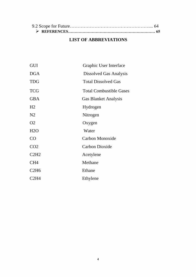
LIST OF ABBREVIATIONS
GUI Graphic User Interface DGA Dissolved Gas Analysis TDG Total Dissolved Gas
TCG Total Combustible Gases GBA Gas Blanket Analysis H2 Hydrogen N2 Nitrogen O2 Oxygen H2O Water CO Carbon Monoxide CO2 Carbon Dioxide C2H2 Acetylene CH4 Methane C2H6 Ethane C2H4 Ethylene
5
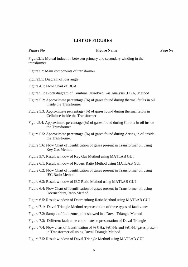
LIST OF FIGURES
Figure No Figure Name Page No
Figure2.1: Mutual induction between primary and secondary winding in the
transformer
Figure2.2: Main components of transformer
Figure3.1: Diagram of loss angle
Figure 4.1: Flow Chart of DGA
Figure 5.1: Block diagram of Combine Dissolved Gas Analysis (DGA) Method
Figure 5.2: Approximate percentage (%) of gases found during thermal faults in oil
inside the Transformer
Figure 5.3: Approximate percentage (%) of gases found during thermal faults in
Cellulose inside the Transformer
Figure5.4: Approximate percentage (%) of gases found during Corona in oil inside
the Transformer
Figure 5.5: Approximate percentage (%) of gases found during Arcing in oil inside
the Transformer
Figure 5.6: Flow Chart of Identification of gases present in Transformer oil using
Key Gas Method
Figure 5.7: Result window of Key Gas Method using MATLAB GUI
Figure 6.1: Result window of Rogers Ratio Method using MATLAB GUI
Figure 6.2: Flow Chart of Identification of gases present in Transformer oil using
IEC Ratio Method
Figure 6.3: Result window of IEC Ratio Method using MATLAB GUI
Figure 6.4: Flow Chart of Identification of gases present in Transformer oil using
Doernenburg Ratio Method
Figure 6.5: Result window of Doernenburg Ratio Method using MATLAB GUI
Figure 7.1: Duval Triangle Method representation of three types of fault zones
Figure 7.2: Sample of fault zone point showed in a Duval Triangle Method
Figure 7.3: Different fault zone coordinates representation of Duval Triangle
Figure 7.4: Flow chart of Identification of % CH4, %C2H4 and %C2H2 gases present
in Transformer oil using Duval Triangle Method
Figure 7.5: Result window of Duval Triangle Method using MATLAB GUI
6
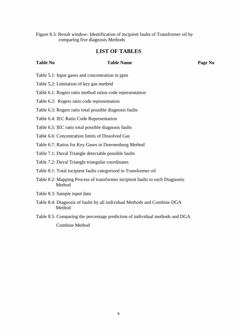
Figure 8.3: Result window- Identification of incipient faults of Transformer oil by
comparing five diagnosis Methods
LIST OF TABLES
Table No Table Name Page No
Table 5.1: Input gases and concentration in ppm
Table 5.2: Limitation of key gas method
Table 6.1: Rogers ratio method ratios code representation
Table 6.2: Rogers ratio code representation
Table 6.3: Rogers ratio total possible diagnosis faults
Table 6.4: IEC Ratio Code Representation
Table 6.5: IEC ratio total possible diagnosis faults
Table 6.6: Concentration limits of Dissolved Gas
Table 6.7: Ratios for Key Gases in Doernenburg Method
Table 7.1: Duval Triangle detectable possible faults
Table 7.2: Duval Triangle triangular coordinates
Table 8.1: Total incipient faults categorized in Transformer oil
Table 8.2: Mapping Process of transformer incipient faults to each Diagnostic Method
Table 8.3: Sample input data
Table 8.4: Diagnosis of faults by all individual Methods and Combine DGA Method
Table 8.5: Comparing the percentage prediction of individual methods and DGA
Combine Method

7
Chapter 1
INTRODUCTION Overview:
Present chapter describes the introduction of project work. Also describes about main
motivation of this work followed by main objectives. This chapter also describes the
organization of thesis.
1.1 Introduction
In entire power transmission network transformer plays an important role, it
transmits the power from one circuit to another circuit. So transformer protection
attains much more attention in order fault free electric supply, maximize
transformer life period and efficiency. Actually mineral oil treats heart of the
transformer, it serves mainly insulation and cooling purpose but among that it is
use to detect the fault gases dissolved in oil. The identification of specific gasses
created in a transformer in administration is regularly the first accessible sign of a
malfunction. If these faults are not correct, transformer may goes to failure. This
is not encourage thing, it may cause to damage entire power transmission and not
economical. Before failure of transformer, detection of fault is better option. So
Dissolved Gas Analysis (DGA) is proved accuracy method to find faults. DGA
mainly involves extracting or stripping of oil from the unit and subject to Gas
Chromatography to extract the dissolved gases from oil [1]. The second step of
DGA is detection of gas concentration levels using suitable methods like Flame
Ionization detector, Thermal conduction detector (FID, TCD) and analyze for
faults by using suitable diagnostic methods to find cause [2].
In this work, the condition based diagnosis system developed to combine five
DGA classical methods-Keys Gas Method, Rogers Ratio Method, IEC Ratio
method, Doernenburg ratio method and Duval triangle method. A feasible
8
MATLAB GUI conferred to give visual display of five methods. The result of
this method shows overall DGA accuracy is more than 90% compared to 80% of
most reliable individual method. DGA helps to diagnosis the present condition of
the high voltage power transformer. Further, this method is also applicable to
other oil filled high voltage power equipment for assessment of its condition
during the operating service period of time.
1.2 Motivation
Dissolved Gas Analysis (DGA) has most proved accuracy method for condition
assessment of power transformer. This gives prior information regarding mineral oil
degradation level and generated dissolved gasses in mineral oil and concentration of
dissolved gases by using Gas Chromatography. Taking the concentration of key
gases (CO, CO2, CH4, C2H6, C2H2, H2 and C2H4) incident faults identified by
various classical techniques gives different conditions for the same sample unit. In
this work considered the point, which discussed in above line and design combine
of all five diagnosis methods for better accuracy results to diagnosis of incipient
faults.
1.3 Thesis Main Objectives
Analyze five classical diagnosis techniques to identify incipient faults in
Transformer oil using 1. Key Gas method, 2. Rogers’s Ratio Method, 3.
Doernenburg Ratio Method, 4. IEC Ratio Method and 5. Duval Triangle
Method
Design combine five diagnosis methods of DGA for condition assessment of Power Transformer
1.4 Organization of Thesis
The entire thesis organization is as follows
Chapter 1: Deals with introduction of entire work follows by motivation and also
discussed about main objectives of this work and finally organization of
thesis are discussed.
Chapter 2: Deals with theory of transformer by talking about working principle of
transformer then follows by use of power transformer and types of
transformer and finally discussed about insulation materials used in
transformer.

9
Chapter 3: Deals with introduction of insulating oil follows by types of transformer
oil and finally discussed about properties of transformer insulating oil.
Chapter 4: Deals with gas formation in mineral oil, degradation level and factors
Effect on mineral oil for dissolved gases. Chapter 5: Deals with DGA interpretation techniques and the block diagram model
design of DGA combined five methods and also it deals with one of the interpretation
Technique -Key gas method.
Chapter 6: Deals with DGA interpretation techniques like Roger’s ratio, IEC ratio,
Doernenburg ratio methods and their codes representation for each method
Chapter 7: Deals with most accuracy DGA interpretation technique Duval’s triangle
method and its zones representation for all type of faults are discussed.
Chapter 8: Deals with mapping process of all type of faults to each diagnostic
method. Finally conclude the type of fault exist by mapping of all faults to common
indication to each method. A feasible GUI conferred to give visual display of five
methods. The result of this method shows overall DGA accuracy is more than 90%
compared to 80% of most reliable individual method. Chapter 9: Deals with the general conclusions of the work done followed by future
scope and references.
10
Chapter 2
INTRODUCTION OF TRANSFORME
Overview:
Present chapter describes the introduction of transformer. . This chapter
also describes the organization of thesis.
2.1 Introduction
2.1.1 Definition of Transformer: Electrical power transformer is a static device which transforms electrical energy
from one circuit to another without any direct electrical connection and with the help
of mutual induction between two windings. It transforms power from one circuit to
another without changing its frequency but may be in different voltage level.
This is a very short and simple definition of transformer, as we will go through this
portion of tutorial related to electrical power transformer, we will understand more
clearly and deeply "what is transformer ?" and basic theory of transformer.
2.1.2 Working Principle of Transformer: The working principle of transformer is very simple. It depends upon Faraday's law of
electromagnetic induction. Actually, mutual induction between two or more winding
is responsible for transformation action in an electrical transformer.
2.1.3 Faraday's Laws of Electromagnetic Induction: According to these Faraday's laws, "Rate of change of flux linkage with respect to
time is directly proportional to the induced EMF in a conductor or coil".
2.2 Basic Theory of Transformer: Say you have one winding which is supplied by an alternating electrical source. The
alternating current through the winding produces a continually changing flux or
alternating flux that surrounds the winding. If any other winding is brought nearer to
the previous one, obviously some portion of this flux will link with the second. As
this flux is continually changing in its amplitude and direction, there must be a change
in flux linkage in the second winding or coil. According to Faraday's law of
electromagnetic induction, there must be an EMF induced in the second. If the circuit
11
of the later winding is closed, there must be a current flowing through it. This is the
simplest form of electrical power transformer and this is the most basic of working
principle of transformer.
For better understanding, we are trying to repeat the above explanation in a more brief
way here. Whenever we apply alternating current to an electric coil, there will be an
alternating flux surrounding that coil. Now if we bring another coil near the first one,
there will be an alternating flux linkage with that second coil. As the flux is
alternating, there will be obviously a rate of change in flux linkage with respect to
time in the second coil. Naturally emf will be induced in it as per Faraday's law of
electromagnetic induction. This is the most basic concept of the theory of transformer.
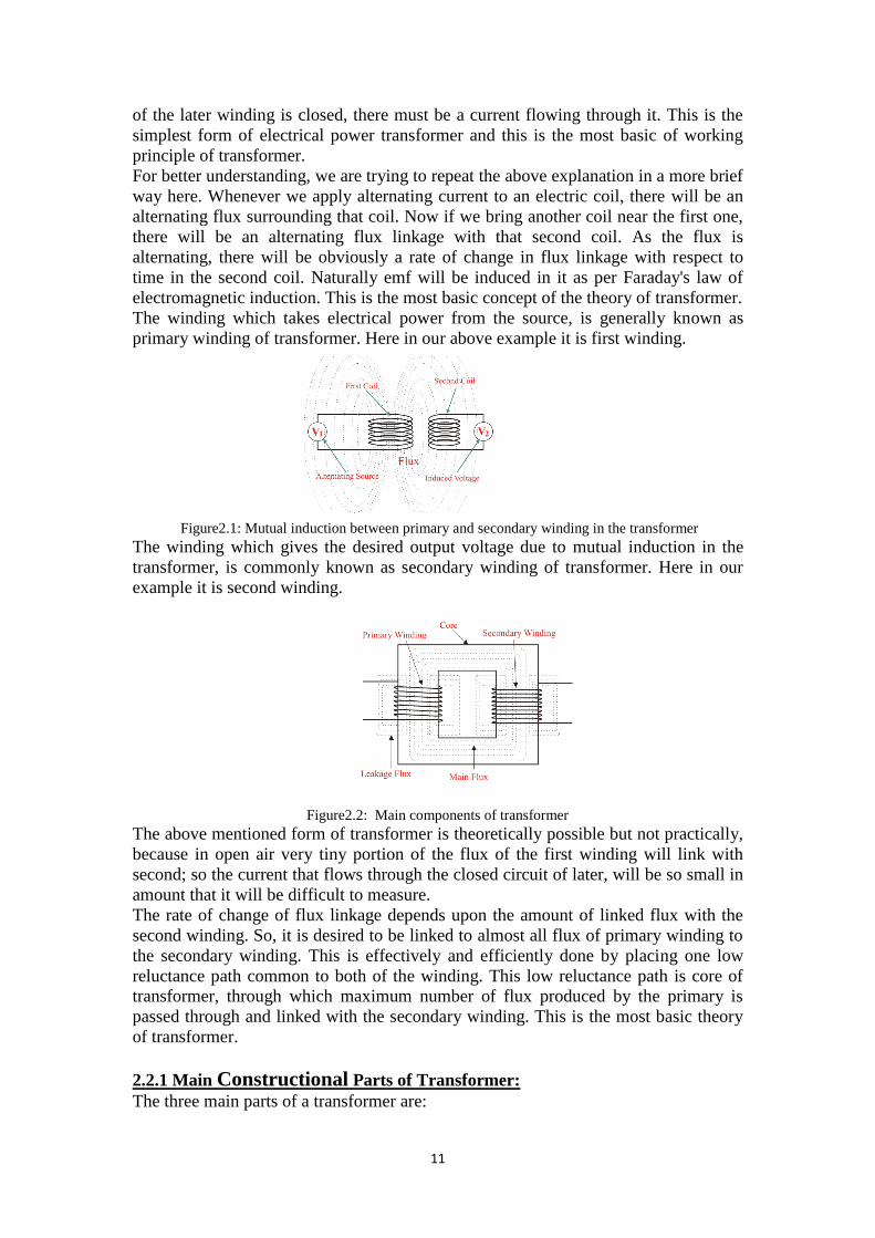
The winding which takes electrical power from the source, is generally known as
primary winding of transformer. Here in our above example it is first winding.
Figure2.1: Mutual induction between primary and secondary winding in the transformer
The winding which gives the desired output voltage due to mutual induction in the
transformer, is commonly known as secondary winding of transformer. Here in our
example it is second winding.
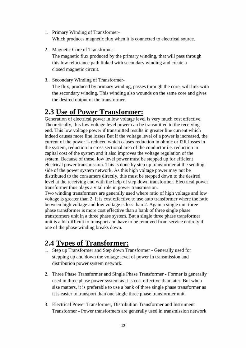
Figure2.2: Main components of transformer
The above mentioned form of transformer is theoretically possible but not practically,
because in open air very tiny portion of the flux of the first winding will link with
second; so the current that flows through the closed circuit of later, will be so small in
amount that it will be difficult to measure.
The rate of change of flux linkage depends upon the amount of linked flux with the
second winding. So, it is desired to be linked to almost all flux of primary winding to
the secondary winding. This is effectively and efficiently done by placing one low
reluctance path common to both of the winding. This low reluctance path is core of
transformer, through which maximum number of flux produced by the primary is
passed through and linked with the secondary winding. This is the most basic theory
of transformer.
2.2.1 Main Constructional Parts of Transformer:
The three main parts of a transformer are:
12
1. Primary Winding of Transformer-
Which produces magnetic flux when it is connected to electrical source.
2. Magnetic Core of Transformer-
The magnetic flux produced by the primary winding, that will pass through
this low reluctance path linked with secondary winding and create a
closed magnetic circuit.
3. Secondary Winding of Transformer-
The flux, produced by primary winding, passes through the core, will link with
the secondary winding. This winding also wounds on the same core and gives
the desired output of the transformer.
2.3 Use of Power Transformer: Generation of electrical power in low voltage level is very much cost effective.
Theoretically, this low voltage level power can be transmitted to the receiving
end. This low voltage power if transmitted results in greater line current which
indeed causes more line losses But if the voltage level of a power is increased, the
current of the power is reduced which causes reduction in ohmic or I2R losses in
the system, reduction in cross sectional area of the conductor i.e. reduction in
capital cost of the system and it also improves the voltage regulation of the
system. Because of these, low level power must be stepped up for efficient
electrical power transmission. This is done by step up transformer at the sending
side of the power system network. As this high voltage power may not be
distributed to the consumers directly, this must be stepped down to the desired
level at the receiving end with the help of step down transformer. Electrical power
transformer thus plays a vital role in power transmission.
Two winding transformers are generally used where ratio of high voltage and low
voltage is greater than 2. It is cost effective to use auto transformer where the ratio
between high voltage and low voltage is less than 2. Again a single unit three
phase transformer is more cost effective than a bank of three single phase
transformers unit in a three phase system. But a single three phase transformer
unit is a bit difficult to transport and have to be removed from service entirely if
one of the phase winding breaks down.
2.4 Types of Transformer: 1. Step up Transformer and Step down Transformer - Generally used for
stepping up and down the voltage level of power in transmission and
distribution power system network.
2. Three Phase Transformer and Single Phase Transformer - Former is generally
used in three phase power system as it is cost effective than later. But when
size matters, it is preferable to use a bank of three single phase transformer as
it is easier to transport than one single three phase transformer unit.
3. Electrical Power Transformer, Distribution Transformer and Instrument
Transformer - Power transformers are generally used in transmission network

13
for stepping up or down the voltage level. It operates mainly during high or
peak loads and has maximum efficiency at or near full load. Distribution
transformer steps down the voltage for distribution purpose to domestic or
commercial users. It has good voltage regulation and operates 24 hrs. A day
with maximum efficiency at 50% of full load. Instrument transformers include
C.T and P.T which are used to reduce high voltages and current to lesser
values which can be measured by conventional instruments.
4. Two Winding Transformer and Auto Transformer - Former is generally used
where ratio between high voltage and low voltage is greater than 2. It is cost
effective to use later where the ratio between high voltage and low voltage is
less than 2.
5. Outdoor Transformer and Indoor Transformer - Transformers that are
designed for installing at outdoor are outdoor transformers and transformers
designed for installing at indoor are indoor transformers.
6. Oil Cooled and Dry Type Transformer - In oil cooled transformer the cooling
medium is transformer oil whereas the dry type transformer is air cooled.
7. Core type, Shell type and Berry type transformer - In core type transformer it
has two vertical legs or limbs with two horizontal sections named yoke. Core
is rectangular in shape with a common magnetic circuit. Cylindrical coils (HV
and LV) are placed on both the limbs.
Shell type transformer: It has a central limb and two outer limbs. Both HV, LV
coils are placed on the central limb. Double magnetic circuit is present.
Berry type transformer: The core looks like spokes of wheels. Tightly fitted
metal sheet tanks are used for housing this type of transformer with
transformer oil filled inside.
2.5 Insulation materials used in transformers: Other than active materials, for example, copper and grain oriented silicon steel, a
large number of ferrous, non-ferrous and insulating materials are used in power
transformers. Optimum utilization of these materials according to their electrical,
mechanical, physical, chemical and thermal characteristics is important for using an
appropriate insulating material. The insulation class of a power transformer is decided
on the test level of which insulation is capable of withstanding.
Transformer insulation is based on basic impulse insulation level together with
voltage rating. Insulating media in up to 11KV transformer is mostly comprised of
paper wrapped around the conductor in transformer coils, mineral oil and pressboard
to insulate the coil from the ground. One basic requirement of all insulating materials
is that they should be compatible with insulating oil and should not react with oil.
14
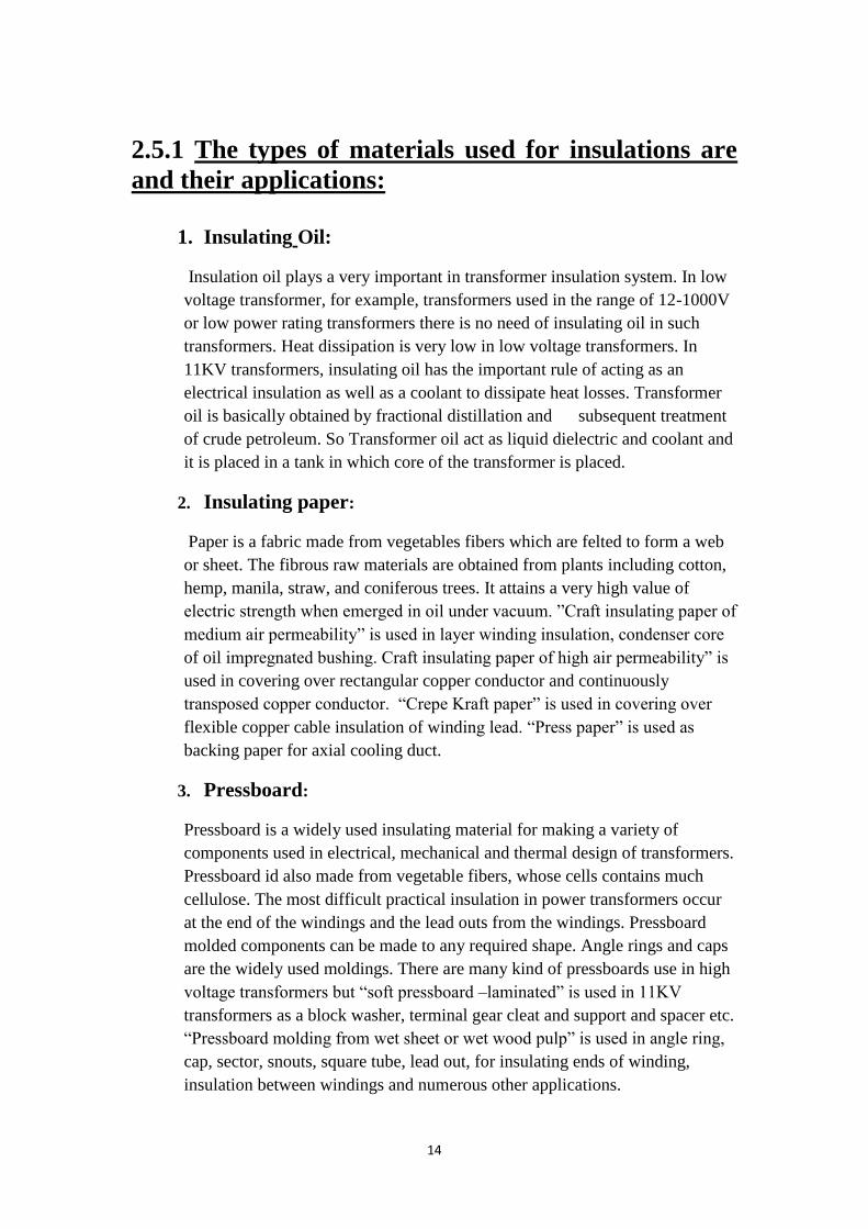
2.5.1 The types of materials used for insulations are
and their applications:
1. Insulating Oil:
Insulation oil plays a very important in transformer insulation system. In low
voltage transformer, for example, transformers used in the range of 12-1000V
or low power rating transformers there is no need of insulating oil in such
transformers. Heat dissipation is very low in low voltage transformers. In
11KV transformers, insulating oil has the important rule of acting as an
electrical insulation as well as a coolant to dissipate heat losses. Transformer
oil is basically obtained by fractional distillation and subsequent treatment
of crude petroleum. So Transformer oil act as liquid dielectric and coolant and
it is placed in a tank in which core of the transformer is placed.
2. Insulating paper:
Paper is a fabric made from vegetables fibers which are felted to form a web
or sheet. The fibrous raw materials are obtained from plants including cotton,
hemp, manila, straw, and coniferous trees. It attains a very high value of
electric strength when emerged in oil under vacuum. ”Craft insulating paper of
medium air permeability” is used in layer winding insulation, condenser core
of oil impregnated bushing. Craft insulating paper of high air permeability” is
used in covering over rectangular copper conductor and continuously
transposed copper conductor. “Crepe Kraft paper” is used in covering over
flexible copper cable insulation of winding lead. “Press paper” is used as
backing paper for axial cooling duct.
3. Pressboard:
Pressboard is a widely used insulating material for making a variety of
components used in electrical, mechanical and thermal design of transformers.
Pressboard id also made from vegetable fibers, whose cells contains much
cellulose. The most difficult practical insulation in power transformers occur
at the end of the windings and the lead outs from the windings. Pressboard
molded components can be made to any required shape. Angle rings and caps
are the widely used moldings. There are many kind of pressboards use in high
voltage transformers but “soft pressboard –laminated” is used in 11KV
transformers as a block washer, terminal gear cleat and support and spacer etc.
“Pressboard molding from wet sheet or wet wood pulp” is used in angle ring,
cap, sector, snouts, square tube, lead out, for insulating ends of winding,
insulation between windings and numerous other applications.

15
4. Wood:
Wood based laminates are manufactured from selected veneers obtained from
various timbers. The veneers are dried and partially or fully impregnated with
natural phenomenon. The areas which required higher mechanical and lower
electric strength, densities laminated wood is used for making a variety of
insulation components like coil clamping ring, cleat, support, core and yoke
etc.
5. Insulated copper conductor for winding:
Different type of insulated copper conductor windings are used in power
transformers for example paper covered rectangular copper conductor, twin
paper covered rectangular copper conductor bunched together, paper covered
continuously transposed copper conductor, twin transposed copper conductor
bunched together, twin rectangular copper bunched together and provided with
a common paper strip between the two conductors and epoxy coated
continuously transposed conductor. These are used to the winding space factor
and mechanical strength of windings.” paper covered rectangular copper
conductor” is used for making different kind of windings. “Paper covered
standard copper cable” is used for making lead and terminal. “Crepe paper
covered flexible copper cable” is used for making lead and terminal required
to be bent to a small radius. “PVC insulated copper cable-single and multi-
core” is used to control wiring in marshaling box, nitrogen, sealing system.
6. Insulating tape:
Insulating tape is used for various taping purposes .For example cotton tape,
cotton newer tape, glass woven tape, woven tape and phenol laminated paper
base sheet. These tapes are used in taping, banding, core bolt insulation, places
where required high strength and in banding of transformer cores.
16
Chapter 3
Transformer Oil
Overview:
Present chapter describes transformer oil. This chapter also describes the
Types of Transformer Oil, Properties of Transformer Insulating Oil and
how Collecting Oil Sample from Oil Immersed Electrical Equipment.
3.1 Introduction of Insulating Oil:
Insulating oil in an electrical power transformer is commonly known as transformer
oil. It is normally obtained by fractional distillation and subsequent treatment of crude
petroleum. That is why this oil is also known as mineral insulating oil. Transformer
oil serves mainly two purposes one it is liquid insulation in electrical power
transformer and two it dissipates heat of the transformer i.e. acts as coolant. In
addition to these, this oil serves other two purposes, it helps to preserve the core and
winding as these are fully immersed inside oil and another important purpose of this
oil is, it prevents direct contact of atmospheric oxygen with cellulose made paper
insulation of windings, which is susceptible to oxidation.
3.2 Types of Transformer Oil:
Generally there are two types of transformer Oil used in transformer:
1. Paraffin based transformer oil
17
2. Naphtha based transformer oil
Naphtha oil is more easily oxidized than Paraffin oil. But oxidation product i.e. sludge
in the naphtha oil is more soluble than Paraffin oil. Thus sludge of naphtha based oil
is not precipitated in bottom of the transformer. Hence it does not obstruct convection
circulation of the oil, means it does not disturb the transformer cooling system. But in
the case of Paraffin oil although oxidation rate is lower than that of Naphtha oil but
the oxidation product or sludge is insoluble and precipitated at bottom of the tank and
obstruct the transformer cooling system. Although Paraffin based oil has above
mentioned disadvantage but still in our country it is generally used because of its easy
availability. Another problem with paraffin based oil is its high pour point due to the
wax content, but this does not affect its use due to warm climate condition of India.
3.3 Properties of Transformer Insulating Oil:
Some specific parameters of insulating oil should be considered to determine the
serviceability of that oil.
Parameters of Transformer Oil:
The parameters of transformer oil are categorized as,
3.3.1 Electrical Parameter of Transformer Oil:
a. Dielectric Strength of Transformer Oil: Dielectric strength of transformer oil is also known as breakdown voltage of
transformer oil or BDV of transformer oil. Break down voltage is measured by
observing at what voltage, sparking strands between two electrodes immerged in the
oil, separated by specific gap. Low value of BDV indicates presence of moisture
content and conducting substances in the oil. For measuring BDV of transformer oil,
portable BDV measuring kit is generally available at site. In this kit, oil is kept in a
pot in which one pair of electrodes are fixed with a gap of 2.5 mm (in some kit it
4mm) between them.
Now slowly rising voltage is applied between the electrodes. Rate of rise of voltage is
generally controlled at 2 KV/s and observe the voltage at which sparking starts
between the electrodes.
That means at which voltage dielectric strength of transformer oil between the
electrodes has been broken down.
Generally this measurement is taken 3 to 6 times in same sample of oil and the
average value of these reading is taken. BDV is important and popular test of
transformer oil, as it is primary indication of health of oil and it can be easily carried
out at site.
Dry and clean oil gives BDV results, better than the oil with moisture content and
other conducting impurities. Minimum breakdown voltage of transformer oil or
dielectric strength of transformer oil at which this oil can safely be used in
transformer, is considered as 30 KV.
18
b. Specific Resistance of Transformer Oil: This is another important property of transformer oil. This is measure of DC
resistance between two opposite sides of one cm3 block of oil. Its unit is taken as
ohm-cm at specific temperature. With increase in temperature the resistivity of oil
decreases rapidly. Just after charging a transformer after long shut down, the
temperature of the oil will be at ambient temperature and during full load the
temperature will be very high and may go up to 90oC at over load condition. So
resistivity of the insulating oil must be high at room temperature and also it should
have good value at high temperature as well. That is why specific resistance or
resistivity of transformer oil should be measured at 27oC as well as 90oC.
Minimum standard specific resistance of transformer oil at 90oC is 35 × 1012 ohm–
cm and at 27oC it is 1500 × 1012 ohm–cm.
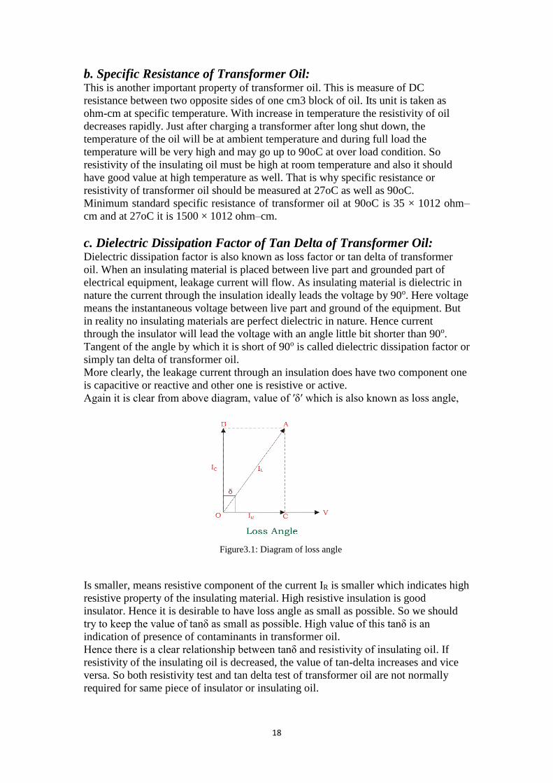
c. Dielectric Dissipation Factor of Tan Delta of Transformer Oil: Dielectric dissipation factor is also known as loss factor or tan delta of transformer
oil. When an insulating material is placed between live part and grounded part of
electrical equipment, leakage current will flow. As insulating material is dielectric in
nature the current through the insulation ideally leads the voltage by 90o. Here voltage
means the instantaneous voltage between live part and ground of the equipment. But
in reality no insulating materials are perfect dielectric in nature. Hence current
through the insulator will lead the voltage with an angle little bit shorter than 90o.
Tangent of the angle by which it is short of 90o is called dielectric dissipation factor or
simply tan delta of transformer oil.
More clearly, the leakage current through an insulation does have two component one
is capacitive or reactive and other one is resistive or active.
Again it is clear from above diagram, value of ′δ′ which is also known as loss angle,
Figure3.1: Diagram of loss angle
Is smaller, means resistive component of the current IR is smaller which indicates high
resistive property of the insulating material. High resistive insulation is good
insulator. Hence it is desirable to have loss angle as small as possible. So we should
try to keep the value of tanδ as small as possible. High value of this tanδ is an
indication of presence of contaminants in transformer oil.
Hence there is a clear relationship between tanδ and resistivity of insulating oil. If
resistivity of the insulating oil is decreased, the value of tan-delta increases and vice
versa. So both resistivity test and tan delta test of transformer oil are not normally
required for same piece of insulator or insulating oil.
19
In one sentence it can be said that, tanδ is measure of imperfection of dielectric nature
of insulation materials like oil.
3.3.2 Chemical Parameters of Transformer Oil a. Water Content in Transformer Oil:
Moisture or water content in transformer oil is highly undesirable as it affects
adversely the dielectric properties of oil. The water content in oil also affects the
paper insulation of the core and winding of transformer. Paper is highly hygroscopic
in nature. Paper absorbs maximum amount of water from oil which affects paper
insulation property as well as reduced its life. But in loaded transformer, oil becomes
hotter, hence the solubility of water in oil increases as a result the paper releases water
and increase the water content in transformer oil. Thus the temperature of the oil at
the time of taking sample for test is very important. During oxidation acid are formed
in the oil the acids give rise the solubility of water in the oil. Acid coupled with water
further decompose the oil forming more acid and water. This rate of degradation of oil
increases. The water content in oil is measured as pm (parts per million units).
Water content in oil is allowed up to 50 ppm as recommended by IS–335(1993). The
accurate measurement of water content at such low levels requires very sophisticated
instrument like Coulometric Karl Fisher Titrator.
b. Acidity of Transformer Oil: Acidity of transformer oil is harmful property. If oil becomes acidic, water content in
the oil becomes more soluble to the oil. Acidity of oil deteriorates the insulation
property of paper insulation of winding. Acidity accelerates thee oxidation process in
the oil. Acid also includes rusting of iron in presence of moisture. The acidity of
transformer oil is measure of its acidic constituents of contaminants. Acidity of oil is
express in mg of KOH required to neutralize the acid present in a gram of oil. This is
also known as neutralization number.
3.3.3 Physical Parameters of Transformer Oil a. Inter Facial Tension of Transformer Oil Inter facial tension between the water and oil interface is the way to measure
molecular attractive force between water and oil. It is measured in Dyne/cm or mili-
Newton/meter. Inter facial tension is exactly useful for determining the presence of
polar contaminants and oil decay products. Good new oil generally exhibits high inter
facial tension. Oil oxidation contaminants lower the IFT.
b. Flash Point of Transformer Oil Flash point of transformer oil is the temperature at which oil gives enough vapors to
produce a flammable mixture with air. This mixture gives momentary flash on
application of flame under standard condition. Flash point is important because it
specifies the chances of fire hazard in the transformer. So it is desirable to have very
high flash point of transformer oil. In general it is more than 140o (>10o).
c. Pour Point of Transformer Oil It is the minimum temperature at which oil just start to flow under standard test
condition. Pour point of transformer oil is an important property mainly at the places
where climate is extremely cold. If the oil temperature falls below the pour point,
transformer oil stops convection flowing and obstruct cooling in transformer. Paraffin
based oil has higher value of pour point, compared to Naphtha based oil, but in India
20
like country, it does not effect, the use of Paraffin oil due tits warm climate condition.
Pour Point of transformer oil mainly depends upon wax content in the oil. As Paraffin
based oil has more wax content, it has higher pour point.
d. Viscosity of Transformer Oil In few wards, viscosity of transformer oil can be said that viscosity is the resistance of
flow, at normal condition. Obviously resistance to flow of transformer oil means
obstruction of convection circulation of oil inside the transformer. A good oil should
have low viscosity so that it offers less resistance to the convectional flow of oil
thereby not affecting the cooling of transformer. Low viscosity of transformer oil is
essential, but it is equally important that, the viscosity of oil should increase as less as
possible with decrease in temperature. Every liquid becomes more viscous if
temperature decreases.
3.4 Collecting Oil Sample from Oil Immersed
Electrical Equipment Process of Collecting Oil from Oil Immersed Electrical Equipment Like Transformer.
We collect oil sample for performing different tests on the oil to determine different
physical, chemical and electrical characteristics of the oil. The sample is the
representative of the oil inside the equipment. That is why; we take special care
during collecting oil sample from the equipment. Otherwise surrounding atmosphere
may affect the characteristics of the oil which may differ the outcome of the tests
form the actual results.
The normal procedures of collecting oil from a transformer or other oil
immersed electrical equipment are given in following points:
1. We should always take at least 1 to 2 liter of oil from bottom valve or oil sample
valve (if available) depending upon the tests to be performed on that sample.
2. We should ensure that sampling is done by well experienced technical personnel.
3. We should not take sample of the oil in rainy, stormy, foggy, and snowy weather
since it can affect the water contaminant of the oil. We should also avoid oil
sampling in high atmospheric humidity for same reason.
4. We should use dry and clean containers preferably made of amber colored glass or
clear glass or seamless stainless steel bottle. We can also use plastic bottle provided
its suitability has been approved.
5. First we should run of some of the oil from oil sampling valve of the equipment to
ensure the removal of any contaminants in the orifice of the valve.
6. Before toping up the bottle, we should rinse the sampling bottle with some oil
7. We should fill the bottle slowly and gently. We should allow the oil to flow against
the wall of the bottle to avoid any formation of air bubble in oil so that no air can be
trapped in the sample.
8. We should fill the bottle up to 95% of its capacity
9. Now we carefully close the bottle.
10. We must avoid any adhesive tape like thing at the cover.
21
11. Now, the bottle must be labeled with
a. Name of the equipment from where sample is collected
b. Rating of the equipment
c. Serial No of the equipment
d. Installed location of the equipment
e. Other identifications of the equipment if required.
f. Temperature of the oil at the time of collection
g. Date of collection
h. Identification of the sampling point (whether it is from top or bottom)
Chapter 4
GAS FORMATION IN MINERAL OIL
Overview:
This chapter mainly describes about literature review of TCG, GBA, DGA methods
for gases identification. This chapter also describes total possible faults produced in
mineral oil due to thermal and electrical degradation. Finally this chapter ends with
block diagram representation of DGA combine design technique.
4.1 Gas Formation in Mineral Oil
The main cause for gas formation in mineral oil is cellulose and oil decomposition.
When this degradation is occurred gases are produced like Carbon Oxides and
Hydrocarbon Molecules.
I. Cellulose Decomposition “Paper” The thermal degradation of cellulose mainly produced carbon oxides (CO,
CO2) and hydrogen or methane (H2, CH4) [2]. Due to thermal degradation in
oil, carbon dioxide produced. The rate at which they are developed depends
exponentially on the temperature and directly on the concentration of material
at that temperature [11].
22
II. Oil decomposition
Mineral transformer oils are combination of hydrocarbon molecules and its
general formulae is CnH2n+2, where n in the reach of 20 to 40. The
deterioration forms for these hydrocarbons in thermal or electrical faults are
more complex. The main reason
For generating the fault gases are breaking of carbon hydrogen and carbon-
carbon bonds. These free radicals can mix with each other to form gases like
hydrogen (H2), methane (CH4) and ethane (C2H6). Further decomposition in
mineral oil develops such as ethylene (C2H4) and acetylene (C2H2) [12].
4.2 Interpretation of Gas Analysis
The main two causes of gas formation within an operating transformer are electrical
and thermal degradations.
I. Thermal Faults
The decomposition of mineral oil from 150°C to 500°C generates low
molecular
weight gases, such as methane (CH4), hydrogen (H2) and low quantity of higher
molecular weight gases like ethane (C2H6), ethylene (C2H4) [18]. If
decomposition of mineral oil increases more than 500°C generates large quantity
of acetylene (C2H2). In
Case of thermal decomposition of paper insulation and other solid insulation
produces carbon dioxide (CO2), carbon monoxide (CO) [11].
II. Electrical faults
Two type of electrical faults are considered
1. Corona (or) Partial Discharge
2. Arcing ( High Energy Discharge)
These faults mainly depend on intensity of energy dissipated per unit time per unit
volume by the fault. Among all faults, most severe fault is arcing by developing
acetylene and less severity fault is corona by producing large quantity of Hydrogen
and Methane but if less severity fault was not correct, it leads to Arcing [14].
1. Corona (or) Partial Discharge

23
a. Partial Discharge means “The dielectric breakdown of some part of
solid (or) liquid when impressed by high voltage”. Here when the
mineral oil of transformer is stressed by high voltage leads to
production of several gases, discharges of cold plasma, bubbles (or)
voids and with possible formation of X-wax in paper [12].
b. The approximate percentage of gases among all dissolved gases when
partial
Discharge occurs is H2=85%-90%, CO2=1%-2%, CO=0.5%-1%,
CH4=6 during partial discharge occurred in oil leads to develop H2 gas
and in cellulose is produce carbon oxides including H2.
2. Arcing
a. Arcing in generally means “the electrical breakdown of a gas that
developing ongoing plasma discharges, resulting current through
normally non-conductive medium such as air” [18]. But in case of
transformer severe energy dissipation
Occurs during arcing and it produces gases in the percentages
approximately H2=35%-40%, C2H2=35%-50% and remaining gases in
very low volume.
b. In any fault associated with paper, produce gases like CO2 and CO in
very large quantity approximately 85%-90%.
%-10%, C2H6=6%-8% and very low quantities of ethylene and
acetylene. Hence,
4.3 Literature Review
4.3 .1 Total Combustible Gases (TCG)
It is the first method proposed to detect the fault gases, the major advantage of this
method is “it will detect fault gases very quickly compare to other methods and it is
applicable to use in the field” [10]. But it has number of disadvantages
1. It can detect only combustible gases like (carbon monoxide, hydrogen,
acetylene, methane and ethylene) and does not indicate non-combustible
gases like (carbon dioxide, oxygen and nitrogen) [3].
24
2. This method is applicable only those have gas blankets and does not
completely oil filled units of conservator type.
3. The most disadvantage of TCG is it can give only one concentration
value of incipient fault and also not clearly identify which gases are
actually present.
4.3.2 Gas Blanket Analysis (GBA)
During this method, the sample of the gas in the space above the oil is analyzed
for its finding the incipient faults [16]. It can detect all of the individual
components like C-H bonds and C-O bonds. However it suffers following
disadvantage.
The gases must be diffuses into the gas blanket only
it is not suitable for field
4.3.3 Dissolved Gas Analysis (DGA) It is the useful informative method for the detection of incipient faults and most used
method now a day. DGA involves following steps [3].
1. Sample of the oil taken from the unit and extract the dissolved gases from
oil.
2. Detect the gas concentrations and analyses by diagnostic methods (Key
Gas and Ratio analysis methods) to find faults.
It is applicable to all type high voltage equipment like the gas blanket analysis
method and it can detect all the combustible and non-combustible gases. The
following are the advantages of DGA [14].
1. Advance warning of developing of faults.
2. Status check on new and aged mineral oil.
3. Convenient online scheduling of repairs.
4. Identifies degradation level before it leads to failure.
5. Monitoring of units under overload case.
6. Checking the improper use of units.
The main advantage of DGA method is “it gives early identification of incipient
faults”.

25
4.4 DGA Block Diagram
The steps involved in DGA is shown in following Figure 2.1
Oil taken from the unit
Extraction of dissolved gases
From the oil
Identification of gas
Concentration levels
Dissolved Gas Analysis (DGA) is
a proved accuracy method to find
faults. DGA mainly involves extracting of oil from the unit and subject to Gas
Chromatography to extract the dissolved gases from oil [6]. The next step of DGA is
detection of gas concentration levels using suitable methods like Flame Ionization
detector, Thermal conduction detector (FID, TCD) and analyze for faults by using
suitable diagnostic methods to find cause. Figure 2.1 indicates the entire process of
DGA [2]. In this work, the condition based diagnosis system developed to combine
five DGA assessment classical techniques-Key Gas Method, IEC Ratio Method,
Rogers Ratio Method, Doernenburg Ratio Method and Duval Triangle Method. A
feasible MATLAB GUI conferred to give visual display of all five Methods at one
window and this result gives cause to incipient faults, which kind of fault exist by
individual method and finally compare all five methods to find exact incipient fault by
taking their percentage. The result of this method shows overall DGA accuracy is
more than 90% compared to 80% of most reliable individual method [7]. DGA helps
Analysis carried out to find the
Type of incipient faults
Figure 4.4: Flow Chart of DGA

26
to diagnosis the present condition of the high voltage power transformer. The main
reason for going combine five methods is “none of the single method is giving all
type of faults i.e. key gas method gives only two type of thermal faults and low
energy discharge type faults by taking key gases, Ratio methods gives high thermal,
partial discharge and arcing but not giving combination of thermal and electrical
faults [10]. In case of Duval triangle method, it gives almost all possible faults except
faults temperature <1500c, if these low temperature faults are not corrected may be it
leads to high temperature faults in future and perhaps increase to arcing also and these
causes high damage to transformer. Normally by taking same sample unit different
diagnosis methods gives different fault conditions, but in case of this combine DGA
method gives result as only one common indication of fault by considering all
individual methods faults. So it is giving prior intimation for occurring faults, hence
by taking remedies for occurring incipient faults life period of power transformer is
increased and failure percentage of transformer also decreased. Further, this method is
also applicable to other oil filled high voltage power equipment for assessment of its
condition during the operating service period of time.