Development of Multilayer Polyelectrolyte Thin-Film Membranes Fabricated by Spin Assisted...
7
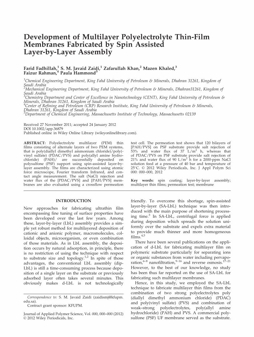
Development of Multilayer Polyelectrolyte Thin-Film Membranes Fabricated by Spin Assisted Layer-by-Layer Assembly Farid Fadhillah, 1 S. M. Javaid Zaidi, 1 Zafarullah Khan, 2 Mazen Khaled, 3 Faizur Rahman, 4 Paula Hammond 5 1 Chemical Engineering Department, King Fahd University of Petroleum & Minerals, Dhahran 31261, Kingdom of Saudi Arabia 2 Mechanical Engineering Department, King Fahd University of Petroleum & Minerals, Dhahran31261, Kingdom of Saudi Arabia 3 Chemistry Department and Center of Excellence in Nanotechnology (CENT), King Fahd University of Petroleum & Minerals, Dhahran 31261, Kingdom of Saudi Arabia 4 Center of Refining and Petroleum (CRP) Research Institute, King Fahd University of Petroleum & Minerals, Dhahran 31261, Kingdom of Saudi Arabia 5 Department of Chemical Engineering, Massachusetts Institute of Technology, Massachusetts 02139 Received 27 November 2011; accepted 24 January 2012 DOI 10.1002/app.36879 Published online in Wiley Online Library (wileyonlinelibrary.com). ABSTRACT: Polyelectrolyte multilayer (PEM) thin films consisting of alternate layers of two PEM systems, that is poly(diallyl dimethyl ammonium chloride)/poly(- vinyl sulfate) (PDAC/PVS) and poly(allyl amine hydro- chloride) (PAH)/ are successfully deposited on polysulfone (PSF) support using spin-assisted layer-by- layer assembly. The films are characterized using atomic force microscope, Fourier transform Infrared, and con- tact angle measurement. The salt (NaCl) rejection and water flux of the [PDAC/PVS] and [PAH/PVS] mem- branes are also evaluated using a crossflow permeation test cell. The permeation test shows that 120 bilayers of [PAH/PVS] on PSF substrate provide salt rejection of 53% and water flux of 37 L/m 2 h, whereas that of PDAC/PVS on PSF substrate provide salt rejection of 21% and water flux of 90 L/m 2 h for a 2000-ppm NaCl solution feed at a pressure of 40 bar and temperature of 25 C. V C 2012 Wiley Periodicals, Inc. J Appl Polym Sci 000: 000–000, 2012 Key words: spin coating; layer-by-layer assembly; multilayer thin films; permeation test; membrane INTRODUCTION New approaches for fabricating ultrathin film encompassing fine tuning of surface properties have been developed over the last few years. Among these, layer-by-layer (LbL) assembly provides a sim- ple yet robust method for multilayered deposition of cationic and anionic polymer, macromolecules, col- loidal objects, microorganism, or even combination of those materials. As in LbL assembly, the deposi- tion occurs by natural adsorption, in principle, there is no restriction of using the technique with respect to substrate size and topology. 1,2 In spite of those advantages, the conventional LbL assembly (dip- LbL) is still a time-consuming process because depo- sition of a single layer on the substrate or previously adsorbed layer often takes several minutes. This obviously makes d-LbL is not technologically friendly. To overcome this shortage, spin-assisted layer-by-layer (SA-LbL) technique was then intro- duced with the main purpose of shortening process- ing time. 3 In SA-LbL, centrifugal force is applied during deposition which spreads the solution uni- formly over the substrate and expels extra material to provide much thinner and more homogeneous films. 4,5 There have been several publications on the appli- cation of d-LbL for fabricating multilayer film on polymeric substrate particularly for separating ions or organic substances from water including pervapo- ration, 6–8 nanofiltration, 9–16 and reverse osmosis. 17–21 However, to the best of our knowledge, no study has been thus far reported on the use of SA-LbL for fabricating such multilayer membranes. Hence, in this study, we employed the SA-LbL technique to fabricate multilayer thin films from the combination of two strong polyelectrolytes poly (diallyl dimethyl ammonium chloride) (PDAC) and poly(vinyl sulfate) (PVS) and combination of weak–strong polyelectrolytes, poly(allyl amine hydrochloride) (PAH) and PVS. A commercial poly- sulfone (PSF) UF membrane served as the substrate. Correspondence to: S. M. Javaid Zaidi (zaidismj@kfupm. edu.sa). Contract grant sponsor: KFUPM. Journal of Applied Polymer Science, Vol. 000, 000–000 (2012) V C 2012 Wiley Periodicals, Inc.
Transcript of Development of Multilayer Polyelectrolyte Thin-Film Membranes Fabricated by Spin Assisted...
Development of Multilayer Polyelectrolyte Thin-FilmMembranes Fabricated by Spin AssistedLayer-by-Layer Assembly
Farid Fadhillah,1 S. M. Javaid Zaidi,1 Zafarullah Khan,2 Mazen Khaled,3
Faizur Rahman,4 Paula Hammond5
1Chemical Engineering Department, King Fahd University of Petroleum & Minerals, Dhahran 31261, Kingdom ofSaudi Arabia2Mechanical Engineering Department, King Fahd University of Petroleum & Minerals, Dhahran31261, Kingdom ofSaudi Arabia3Chemistry Department and Center of Excellence in Nanotechnology (CENT), King Fahd University of Petroleum &Minerals, Dhahran 31261, Kingdom of Saudi Arabia4Center of Refining and Petroleum (CRP) Research Institute, King Fahd University of Petroleum & Minerals,Dhahran 31261, Kingdom of Saudi Arabia5Department of Chemical Engineering, Massachusetts Institute of Technology, Massachusetts 02139
Received 27 November 2011; accepted 24 January 2012DOI 10.1002/app.36879Published online in Wiley Online Library (wileyonlinelibrary.com).
ABSTRACT: Polyelectrolyte multilayer (PEM) thinfilms consisting of alternate layers of two PEM systems,that is poly(diallyl dimethyl ammonium chloride)/poly(-vinyl sulfate) (PDAC/PVS) and poly(allyl amine hydro-chloride) (PAH)/ are successfully deposited onpolysulfone (PSF) support using spin-assisted layer-by-layer assembly. The films are characterized using atomicforce microscope, Fourier transform Infrared, and con-tact angle measurement. The salt (NaCl) rejection andwater flux of the [PDAC/PVS] and [PAH/PVS] mem-branes are also evaluated using a crossflow permeation
test cell. The permeation test shows that 120 bilayers of[PAH/PVS] on PSF substrate provide salt rejection of53% and water flux of 37 L/m2 h, whereas thatof PDAC/PVS on PSF substrate provide salt rejection of21% and water flux of 90 L/m2 h for a 2000-ppm NaClsolution feed at a pressure of 40 bar and temperature of25�C. VC 2012 Wiley Periodicals, Inc. J Appl Polym Sci000: 000–000, 2012
Key words: spin coating; layer-by-layer assembly;multilayer thin films; permeation test; membrane
INTRODUCTION
New approaches for fabricating ultrathin filmencompassing fine tuning of surface properties havebeen developed over the last few years. Amongthese, layer-by-layer (LbL) assembly provides a sim-ple yet robust method for multilayered deposition ofcationic and anionic polymer, macromolecules, col-loidal objects, microorganism, or even combinationof those materials. As in LbL assembly, the deposi-tion occurs by natural adsorption, in principle, thereis no restriction of using the technique with respectto substrate size and topology.1,2 In spite of thoseadvantages, the conventional LbL assembly (dip-LbL) is still a time-consuming process because depo-sition of a single layer on the substrate or previouslyadsorbed layer often takes several minutes. Thisobviously makes d-LbL is not technologically
friendly. To overcome this shortage, spin-assistedlayer-by-layer (SA-LbL) technique was then intro-duced with the main purpose of shortening process-ing time.3 In SA-LbL, centrifugal force is appliedduring deposition which spreads the solution uni-formly over the substrate and expels extra materialto provide much thinner and more homogeneousfilms.4,5
There have been several publications on the appli-cation of d-LbL for fabricating multilayer film onpolymeric substrate particularly for separating ionsor organic substances from water including pervapo-ration,6–8 nanofiltration,9–16 and reverse osmosis.17–21
However, to the best of our knowledge, no studyhas been thus far reported on the use of SA-LbL forfabricating such multilayer membranes.Hence, in this study, we employed the SA-LbL
technique to fabricate multilayer thin films from thecombination of two strong polyelectrolytes poly(diallyl dimethyl ammonium chloride) (PDAC)and poly(vinyl sulfate) (PVS) and combination ofweak–strong polyelectrolytes, poly(allyl aminehydrochloride) (PAH) and PVS. A commercial poly-sulfone (PSF) UF membrane served as the substrate.
Correspondence to: S. M. Javaid Zaidi ([email protected]).
Contract grant sponsor: KFUPM.
Journal of Applied Polymer Science, Vol. 000, 000–000 (2012)VC 2012 Wiley Periodicals, Inc.
The membrane surface roughness and surface mor-phology, hydrophilicity, and surface functionalitywere characterized by using atomic force microscope(AFM), contact angle (CA) goniometry, and attenu-ated total reflectance (ATR)-Fourier transform Infra-red (FTIR) spectroscopy. Membranes were evaluatedfor their salt rejection and water permeation per-formance using crossflow permeation test cells. Thepermeation test shows that 120 bilayers of [PAH/PVS] on PSF substrate provide salt rejection of 53%and water flux of 37 L/m2 h, whereas that ofPDAC/PVS on PSF substrate provide salt rejectionof 21% and water flux of 90 L/m2 h for a 2000-ppmNaCl solution feed at a pressure of 40 bar and tem-perature of 25�C.
EXPERIMENTAL
Materials
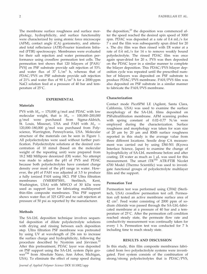
PVS with Mw ¼ 170,000 g/mol and PDAC with lowmolecular weight, that is Mw ¼ 100,000–200,000g/mol were purchased from Sigma-Aldrich,St. Louis, Missouri, USA and PAH with Mw ¼120,000–180,000 g/mol was purchased from Poly-science, Warrington, Pennsylvania, USA. Molecularstructure of the materials can be seen in Figure 1.All polyelectrolytes were used without further puri-fication. Polyelectrolyte solutions at the desired con-centration of 10 mmol (based on the molecularweight of the repeating unit) were prepared from18.2 MX Millipore deionized (DI) water. No attemptwas made to adjust the pH of PVS and PDACbecause both polyelectrolytes have constant chargedensity over most of the pH range in water. How-ever, the pH of PAH was adjusted at 3.5 to producea fully ionized PAH using HCl. PSF Ultra filtrationmembranes (YMERSP3001, Sterlitech, Kent,Washington, USA) with MWCO of 30 kDa wereused as support layer for fabricating multilayeredthin-film composite membranes. This PSF supportshows water flux of 325 GFD and no salt rejection atpressure of 50 psi as reported by the manufacturer.
Methods
The SA-LbL deposition technique involves sequen-tial deposition of dilute polyelectrolyte solutionswith drying and rinsing between each depositionstep. Ultra filtration PSF membrane was pretreatedby using UV at wavelength of 256 nm to increasethe surface charge and hydrophilicity, following theprocedure described by Nystr€om and J€orvinen.22
After this pretreatment, PDAC layer was depositedon PSF support using the SA-LbL system (Spin gro-werTM from Absolute Nano, Ann Arbor, Michigan,USA). To eliminate the effect of ramp speed during
the deposition,23 the deposition was commenced af-ter the speed reached the desired spin speed of 3000rpm. PDAC was deposited at a rate of 0.4 mL/s for7 s and the film was subsequently spun dried for 20s. The dry film was then rinsed with DI water at arate of 0.4 mL/s for 14 s to remove weakly boundpolyelectrolyte. The rinsed PDAC film was onceagain spun-dried for 20 s. PVS was then depositedon the PDAC layer in a similar manner to completethe bilayer deposition. This PDAC/PVS bilayer dep-osition cycle was repeated until the prescribed num-ber of bilayers was deposited on PSF substrate toproduce PDAC/PVS membrane. PAH/PVS film wasalso deposited on PSF substrate in a similar mannerto fabricate the PAH/PVS membrane.
Characterization
Contact mode PicoSPM LE (Agilent, Santa Clara,California, USA) was used to examine the surfacemorphology of the SA-LbL films deposited onPSFultrafiltration membrane. AFM scanning probeswith spring constant of 0.02–0.77 N/m wereemployed during the characterization. Surfaceroughness and morphology was taken for scan sizeof 20 lm by 20 lm and RMS surface roughnessreported in this study is the average value fromthree different locations. Sessile drop CA measure-ment was carried out by using DM-501 (KyowaInterface Science, Japan) to examine the change ofhydrophilicity of SA-LbL membrane before and aftercoating. DI water as much as 1 lL was used for thismeasurement. The smart iTRTM ATR-FTIR Nicolet6700 Model (Thermo Scientific) was used to investi-gate functional groups of polyelectrolyte multilayerfilm and the support.
Permeation Test
Permeation test was performed using CF042 (Sterli-tech, USA) crossflow permeation test cell. Permea-tion cell tested an active membrane surface area of42 cm2. Feed water consisting of 2000 ppm of so-dium chloride was passed through the SA-LbL-fabri-cated membrane at a pressure of 40 bar and a tem-perature of 25�C. After the permeation cell conditionreached steady state, the permeate flow rate andconductivity measurement was continually taken forevery 1 h. Permeation test was conducted for 7 hincluding time to reach steady state.
RESULTS AND DISCUSSION
In this study, thin film composite membranes fabri-cated from two polyelectrolyte systems were investi-gated. First system consists of the combination ofstrong/strong polyelectrolytes that is PDAC/PVS,
2 FADHILLAH ET AL.
Journal of Applied Polymer Science DOI 10.1002/app
whereas the second one consists of weak/strong pol-yelectrolytes PAH/PVS. As is well known, thedegree of dissociation of weak polyelectrolyte ismainly determined by its pH. In the case of PAH, itis reported that PAH with pKa of 8.5 starts gainingprotons at pH lower than 6.24,25 In this study, pH of3.5 was selected for PAH deposition to ensure PAHis in its fully ionized state. Unlike weak polyelectro-lyte, charge density of PDAC and PVS remains con-stant over most of pH range in water. It is reportedthat PDAC has pKb of 11.8,23 whereas PVS has pKa
< 2.26 It is also reported that complex formationfrom PDAC and PVS showed stoichiometric chemis-try, meaning that all potential ionic bonds betweenthe two are most likely formed.27 The PSF UF mem-brane is used here as support because this mem-brane has also been widely used as support in TFCNF/RO membrane and has been known for its out-standing chemical, thermal, and mechanicalstabilities.
SA-LbL assembly produces multilayer thin filmwith different mechanisms from traditional dip-LbLassembly. In the case of dip-LbL, layer is formed bynatural adsorption of polyelectrolytes on the sub-strate or previously adsorbed layers. Initially, thisadsorption form islands of adsorbate on the sub-strates. This initial stages are sometime called induc-tion period. As the number of layer increases, theislands are bridged and connected one another andstart forming bigger islands until all substrate sur-face is covered.28,29 In the case of SA-LbL, forcedadsorption occurs instead of natural adsorptionbecause of applied centrifugal force during the dep-osition. Water molecules that usually screen the
interaction between layers are removed because ofthe centrifugal force. Therefore, SA-LbL assemblyresults in much faster film formation with completesurface coverage over the substrate because no morebarrier between layers.4 The film then builds upbased on the overcharged compensation mechanism.In general, charges of previously adsorbed layermust be compensated by subsequent layer. How-ever, the excess amount of polyelectrolytes isrequired to compensate owing to many other weakerinteractions between previously adsorbed layer andsubsequent layer. This excess amount of polyelectro-lyte in fact results in surface charge reversal frompositive to negative or vice versa.30
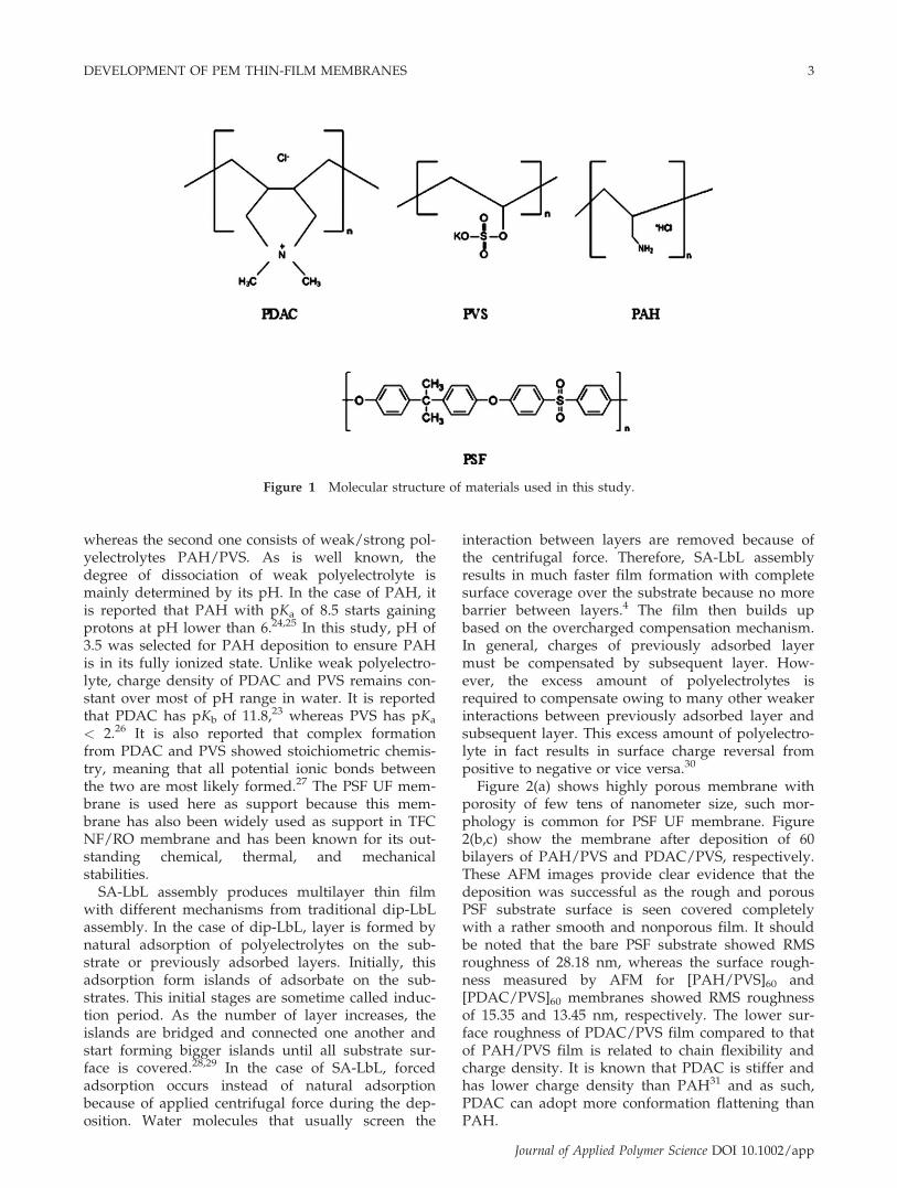
Figure 2(a) shows highly porous membrane withporosity of few tens of nanometer size, such mor-phology is common for PSF UF membrane. Figure2(b,c) show the membrane after deposition of 60bilayers of PAH/PVS and PDAC/PVS, respectively.These AFM images provide clear evidence that thedeposition was successful as the rough and porousPSF substrate surface is seen covered completelywith a rather smooth and nonporous film. It shouldbe noted that the bare PSF substrate showed RMSroughness of 28.18 nm, whereas the surface rough-ness measured by AFM for [PAH/PVS]60 and[PDAC/PVS]60 membranes showed RMS roughnessof 15.35 and 13.45 nm, respectively. The lower sur-face roughness of PDAC/PVS film compared to thatof PAH/PVS film is related to chain flexibility andcharge density. It is known that PDAC is stiffer andhas lower charge density than PAH31 and as such,PDAC can adopt more conformation flattening thanPAH.
Figure 1 Molecular structure of materials used in this study.
DEVELOPMENT OF PEM THIN-FILM MEMBRANES 3
Journal of Applied Polymer Science DOI 10.1002/app
It must be pointed out that although the depositedfilms appear more or less uniform and homogene-ous, few dark spots can still be seen in the depositedfilms as displayed by the AFM images shown in Fig-ure 2(b,c). One may think that the dark spots arepores or defects; however, if it is the case, then theflux will be extremely high and the rejection mustbe extremely low close to the value reported for PSFultrafiltration support (Materials section). Therefore,we believe that the dark spots are just sort of valley
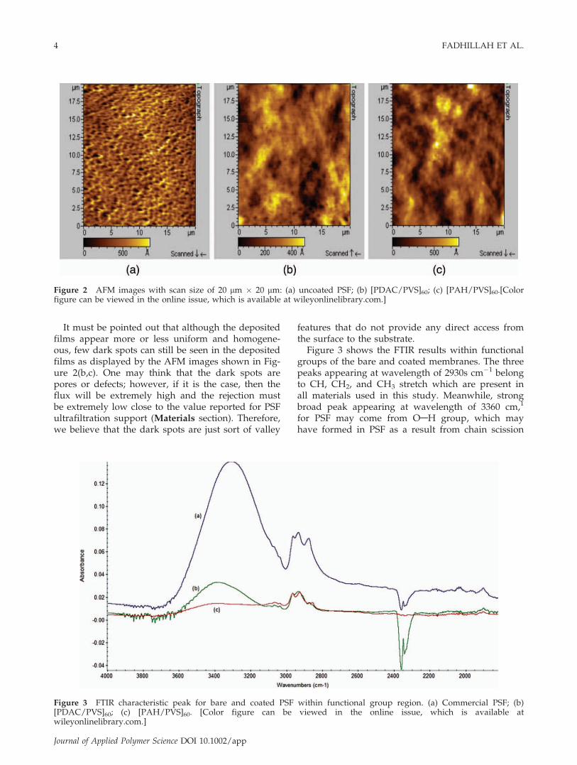
features that do not provide any direct access fromthe surface to the substrate.Figure 3 shows the FTIR results within functional
groups of the bare and coated membranes. The threepeaks appearing at wavelength of 2930s cm�1 belongto CH, CH2, and CH3 stretch which are present inall materials used in this study. Meanwhile, strongbroad peak appearing at wavelength of 3360 cm,1
for PSF may come from OAH group, which mayhave formed in PSF as a result from chain scission
Figure 2 AFM images with scan size of 20 lm � 20 lm: (a) uncoated PSF; (b) [PDAC/PVS]60; (c) [PAH/PVS]60.[Colorfigure can be viewed in the online issue, which is available at wileyonlinelibrary.com.]
Figure 3 FTIR characteristic peak for bare and coated PSF within functional group region. (a) Commercial PSF; (b)[PDAC/PVS]60; (c) [PAH/PVS]60. [Color figure can be viewed in the online issue, which is available atwileyonlinelibrary.com.]
4 FADHILLAH ET AL.
Journal of Applied Polymer Science DOI 10.1002/app
of PSF during UV irradiation.32 Weaker peaksappear at wavelength of almost 3390 cm�1 for[PDAC/PVS]/PSF and [PAH/PVS]/PSF are alsomost likely assigned for OAH.
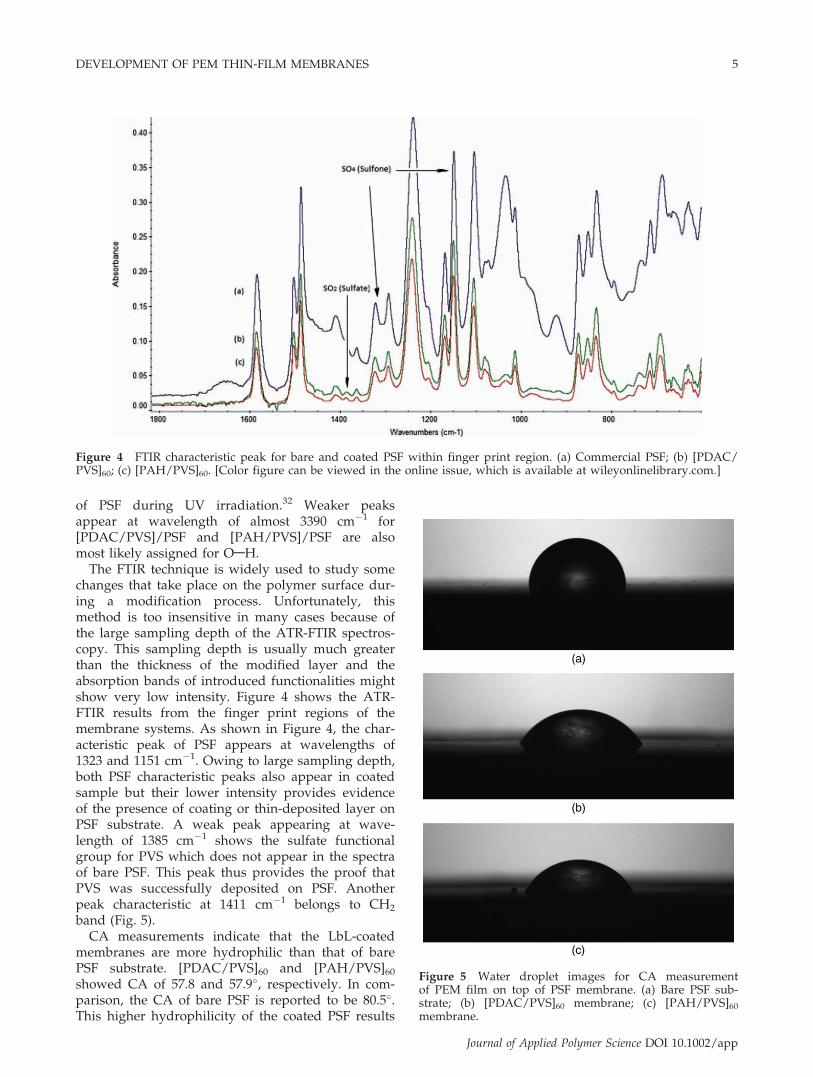
The FTIR technique is widely used to study somechanges that take place on the polymer surface dur-ing a modification process. Unfortunately, thismethod is too insensitive in many cases because ofthe large sampling depth of the ATR-FTIR spectros-copy. This sampling depth is usually much greaterthan the thickness of the modified layer and theabsorption bands of introduced functionalities mightshow very low intensity. Figure 4 shows the ATR-FTIR results from the finger print regions of themembrane systems. As shown in Figure 4, the char-acteristic peak of PSF appears at wavelengths of1323 and 1151 cm�1. Owing to large sampling depth,both PSF characteristic peaks also appear in coatedsample but their lower intensity provides evidenceof the presence of coating or thin-deposited layer onPSF substrate. A weak peak appearing at wave-length of 1385 cm�1 shows the sulfate functionalgroup for PVS which does not appear in the spectraof bare PSF. This peak thus provides the proof thatPVS was successfully deposited on PSF. Anotherpeak characteristic at 1411 cm�1 belongs to CH2
band (Fig. 5).CA measurements indicate that the LbL-coated
membranes are more hydrophilic than that of barePSF substrate. [PDAC/PVS]60 and [PAH/PVS]60showed CA of 57.8 and 57.9�, respectively. In com-parison, the CA of bare PSF is reported to be 80.5�.This higher hydrophilicity of the coated PSF results
Figure 4 FTIR characteristic peak for bare and coated PSF within finger print region. (a) Commercial PSF; (b) [PDAC/PVS]60; (c) [PAH/PVS]60. [Color figure can be viewed in the online issue, which is available at wileyonlinelibrary.com.]
Figure 5 Water droplet images for CA measurementof PEM film on top of PSF membrane. (a) Bare PSF sub-strate; (b) [PDAC/PVS]60 membrane; (c) [PAH/PVS]60membrane.
DEVELOPMENT OF PEM THIN-FILM MEMBRANES 5
Journal of Applied Polymer Science DOI 10.1002/app
from the presence of more hydrophilic PVS as theoutermost layer in the TFC membranes.
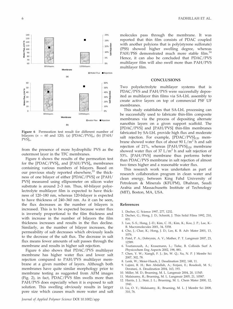
Figure 6 shows the results of the permeation testfor the [PDAC/PVS]n and [PAH/PVS]n membranescontaining various numbers of bilayers. Based onour previous study reported elsewhere,33 the thick-ness of one bilayer of either [PDAC/PVS] or [PAH/PVS] measured using ellipsometer on silicon wafersubstrate is around 2–3 nm. Thus, 60-bilayer polye-lectrolyte multilayer film is expected to have thick-ness of 120–180 nm, whereas 120-bilayer is expectedto have thickness of 240–360 nm. As it can be seen,the flux decreases as the number of bilayers isincreased. This is to be expected because water fluxis inversely proportional to the film thickness andwith increase in the number of bilayers the filmthickness increases and results in the flux decline.Similarly, as the number of bilayer increases, thepermeability of salt decreases which obviously leadsto the decrease of the salt flux. The decrease in saltflux means fewer amounts of salt passes through themembrane and results in higher salt rejection.
Figure 6 also shows that PDAC/PVS multilayermembrane has higher water flux and lower saltrejection compared to PAH/PVS multilayer mem-brane at a given number of layers. Although bothmembranes have quite similar morphology prior tomembrane testing as suggested from AFM images(Fig. 2), in fact, PDAC/PVS film swells more thanPAH/PVS does especially when it is exposed to saltsolution. This swelling obviously results in largerpore size which causes much more water and salt
molecules pass through the membrane. It wasreported that thin film consists of PDAC coupledwith another polyions that is poly(styrene sulfonate)(PSS) showed higher swelling degree, whereasPAH/PSS demonstrated much more stable film.34
Hence, it can also be concluded that PDAC/PVSmultilayer film will also swell more than PAH/PVSmultilayer film.
CONCLUSIONS
Two polyelectrolyte multilayer systems that isPDAC/PVS and PAH/PVS were successfully depos-ited as multilayer thin films via SA-LbL assembly tocreate active layers on top of commercial PSF UFmembranes.This study establishes that SA-LbL processing can
be successfully used to fabricate thin-film compositemembranes via the process of depositing alternatenanothin layers on a given support scaffold. The[PDAC/PVS] and [PAH/PVS] thin-film membranesfabricated by SA-LbL provide high flux and moderatesalt rejection. For example, [PDAC/PVS]120 mem-brane showed water flux of about 90 L/m2 h and saltrejection of 21%, whereas [PAH/PVS]120 membraneshowed water flux of 37 L/m2 h and salt rejection of53%. [PAH/PVS] membrane thus performs betterthan PDAC/PVS membrane in salt rejection of almosttwo times higher and a reasonable water flux.This research work was undertaken as part of
research collaboration program in clean water andclean energy, between King Fahd University ofPetroleum & Minerals (KFUPM), Dhahran, SaudiArabia and Massachusetts Institute of Technology(MIT), Boston, MA, USA.
References
1. Decher, G. Science 1997, 277, 1232.2. Decher, G.; Hong, J. D.; Schmitt, J. Thin Solid Films 1992, 210,
831.3. Lee, S.-S.; Hong, J.-D.; Kim, C. H.; Kim, K.; Koo, J. P.; Lee, K.-
B. Macromolecules 2001, 34, 5358.4. Cho, J.; Char, K.; Hong, J. D.; Lee, K. B. Adv Mater 2001, 13,
1076.5. Patel, P. A.; Dobrynin, A. V.; Mather, P. T. Langmuir 2007, 23,
12589.6. Toutianoush, A.; Krasemann, L.; Tieke, B. Colloids Surf A
Physicochem Eng Aspects 2002, 198, 881.7. Chen, Y. W.; Xiangli, F. J.; Jin, W. Q.; Xu, N. P. J Membr Sci
2007, 302, 78.8. Lenk, W.; Meier-Haack, J. Desalination 2002, 148, 11.9. Lajimi, R. H.; Ben Abdallah, A.; Ferjani, E.; Roudesli, M. S.;
Deratani, A. Desalination 2004, 163, 193.10. Miller, M. D.; Bruening, M. L. Langmuir 2004, 20, 11545.11. Malaisamy, R.; Bruening, M. L. Langmuir 2005, 21, 10587.12. Harris, J. J.; Stair, J. L.; Bruening, M. L. Chem Mater 2000, 12,
1941.13. Lu, O. Y.; Malaisamy, R.; Bruening, M. L. J Membr Sci 2008,
310, 76.
Figure 6 Permeation test result for different number ofbilayers (n ¼ 60 and 120). (a) [PDAC/PVS]n; (b) [PAH/PVS]n.
6 FADHILLAH ET AL.
Journal of Applied Polymer Science DOI 10.1002/app
14. Hong, S. U.; Malaisamy, R.; Bruening, M. L. J Membr Sci 2006,283, 366.
15. Deng, H. Y.; Xu, Y. Y.; Zhu, B. K.; Wei, X. Z.; Liu, F.; Cui, Z.Y. J Membr Sci 2008, 323, 125.
16. Krasemann, L.; Tieke, B. Langmuir 2000, 16, 287.17. Ritcharoen, W.; Supaphol, P.; Pavasant, P. Eur Polym J 2008,
44, 3963.18. Toutianoush, A.; Jin, W. Q.; Deligoz, H.; Tieke, B. Appl Surf
Sci 2005, 246, 437.19. Wang, J. W.; Yao, Y. X.; Yue, Z. R.; Economy, J. J Membr Sci
2009, 337, 200.20. Jin, W. Q.; Toutianoush, A.; Tieke, B. Langmuir 2003, 19,
2550.21. Hoffmann, K.; Tieke, B. J Membr Sci 2009, 341, 261.22. ; J Membr Sci 1987, 60, 275.23. Duarte, G. V.; Ramarao, B. V.; Amidon, T. E. Biores Technol
2010, 101, 8526.
24. Mauser, T.; D�ejugnat, C.; Sukhorukov, G. B. Macromol RapidCommun 2004, 25, 1781.
25. Shiratori, S. S.; Rubner, M. F. Macromolecules 2000, 33, 4213.26. Thompson, R. G. In Colloid-Polymer Interactions; American
Chemical Society, 1993.27. Feng, X.; Leduc, M.; Pelton, R. Colloids Surf A: Physicochem
Eng Aspects 2008, 317, 535.28. Shiro, F.; Seimei, S. Nanotechnology 2005, 16, 1821.29. Tsukruk, V. V.; Bliznyuk, V. N.; Visser, D.; Campbell, A. L.;
Bunning, T. J.; Adams, W. W. Macromolecules 1997, 30, 6615.30. Schlenoff, J. B.; Ly, H.; Li, M. J Am Chem Soc 1998, 120, 7626.31. Caruso, F.; Susha, A. S.; Giersig, M.; M€ohwald, H. Adv Mater
1999, 11, 950.32. Nystr€om, M.; J€arvinen, P. J Membr Sci 1987, 60, 275.33. Fadhillah, F.; Zaidi, S. M. J.; Khan, Z.; Khaled, M. M.;
Hammond, P. T. Desalination Water Treat 2011, 34, 44.34. Dubas, S. T.; Schlenoff, J. B. Langmuir 2001, 17, 7725.
DEVELOPMENT OF PEM THIN-FILM MEMBRANES 7
Journal of Applied Polymer Science DOI 10.1002/app