Development of Engineering Case Studies for Integrating Finite Element Analysis into a Mechanical...
11
Proceedings of the 2005 American Society for Engineering Education Annual Conference & Exposition Copyright ª2005, American Society for Engineering Education Development of Engineering Case Studies for Integrating Finite Element Analysis into a Mechanical Engineering Curriculum Dr. Robert G. Ryan, Dr. Stewart P. Prince California State University, Northridge Abstract The Mechanical Engineering Department at California State University, Northridge uses SolidWorks and related analysis applications such as CosmosWorks and FloWorks as the computational tools of choice for solid modeling (CAD) and finite element analysis (FEA). Originally the use of these tools was concentrated in the senior design capstone course, but one of the Department’s goals is to integrate the use of this software throughout the curriculum. While the addition of new freshman and sophomore design courses have helped to fulfill this mission, some engineering courses have been slow to adopt the use of FEA for solving practical design problems. Barriers for adopting FEA in traditional engineering courses include time constraints related to covering the necessary breadth of material and the learning curve for faculty who are not especially proficient with creating complex assemblies in SolidWorks. An approach for lowering these barriers is to create SolidWorks model files for a number of engineering case studies in a variety of mechanical engineering disciplines. These files and associated documentation are made available to faculty and students to facilitate the assignment of design problems which require the use of FEA for their solution. Use of a Design Table to vary key geometric dimensions by referencing SolidWorks objects via the Applications Programming Interface allows a student to easily create modified parts and analyze the effect of the changes with the appropriate FEA package. This paper describes models that have been created for courses in fluid mechanics and machine design. Emphasis is placed on a specific assignment created for a fluid mechanics course, including a comparison of the results from FloWorks with one-dimensional flow models. A preliminary assessment of the effectiveness of this assignment for demonstrating the role of FEA in analysis and design is also given. Introduction The use of finite element analysis (FEA) tools is a necessary component of today’s undergraduate mechanical engineering programs. This is obvious from the commonplace use of solid modeling and FEA in industry and is articulated in ABET’s definition of learning outcomes related to the use of modern engineering tools. The use of new tools provides opportunities and challenges for engineering educators. The proper role of mathematical software packages in engineering education was discussed by Whiteman and Nygren 1 . Among their conclusions was that the use of software can reduce time spent on computations and thus allow students more time to concentrate on problem formulation and implementation of solutions. However, there is a
Transcript of Development of Engineering Case Studies for Integrating Finite Element Analysis into a Mechanical...
Proceedings of the 2005 American Society for Engineering Education Annual Conference & Exposition Copyright 2005, American Society for Engineering Education
Development of Engineering Case Studies for Integrating Finite Element Analysis into a Mechanical
Engineering Curriculum
Dr. Robert G. Ryan, Dr. Stewart P. Prince
California State University, Northridge
Abstract The Mechanical Engineering Department at California State University, Northridge uses SolidWorks and related analysis applications such as CosmosWorks and FloWorks as the computational tools of choice for solid modeling (CAD) and finite element analysis (FEA). Originally the use of these tools was concentrated in the senior design capstone course, but one of the Department’s goals is to integrate the use of this software throughout the curriculum. While the addition of new freshman and sophomore design courses have helped to fulfill this mission, some engineering courses have been slow to adopt the use of FEA for solving practical design problems. Barriers for adopting FEA in traditional engineering courses include time constraints related to covering the necessary breadth of material and the learning curve for faculty who are not especially proficient with creating complex assemblies in SolidWorks. An approach for lowering these barriers is to create SolidWorks model files for a number of engineering case studies in a variety of mechanical engineering disciplines. These files and associated documentation are made available to faculty and students to facilitate the assignment of design problems which require the use of FEA for their solution. Use of a Design Table to vary key geometric dimensions by referencing SolidWorks objects via the Applications Programming Interface allows a student to easily create modified parts and analyze the effect of the changes with the appropriate FEA package. This paper describes models that have been created for courses in fluid mechanics and machine design. Emphasis is placed on a specific assignment created for a fluid mechanics course, including a comparison of the results from FloWorks with one-dimensional flow models. A preliminary assessment of the effectiveness of this assignment for demonstrating the role of FEA in analysis and design is also given. Introduction The use of finite element analysis (FEA) tools is a necessary component of today’s undergraduate mechanical engineering programs. This is obvious from the commonplace use of solid modeling and FEA in industry and is articulated in ABET’s definition of learning outcomes related to the use of modern engineering tools. The use of new tools provides opportunities and challenges for engineering educators. The proper role of mathematical software packages in engineering education was discussed by Whiteman and Nygren1. Among their conclusions was that the use of software can reduce time spent on computations and thus allow students more time to concentrate on problem formulation and implementation of solutions. However, there is a
Proceedings of the 2005 American Society for Engineering Education Annual Conference & Exposition Copyright 2005, American Society for Engineering Education
“learning curve” associated with CAD/FEA tools, and it must be accommodated appropriately in the undergraduate curriculum. Concern must also be given to the level of students’ mathematical maturity as they begin to master powerful analysis tools. It would appear that many mechanical engineering programs are on a similar path to integrate design and analysis software in their programs, and that the positive aspects outweigh the negatives2. In 2001, the Mechanical Engineering department at California State University, Northridge (CSUN) adopted the SolidWorks family of design and analysis tools as the standard for our curriculum. The most important reasons for this choice was the relative ease of use of the solid modeling CAD package (SolidWorks), and the close integration among the analysis tools (COSMOSWorks, FloWorks, etc.) and the SolidWorks interface. Significant changes to the lower division curriculum were instituted by adding a freshman introduction course specifically tailored for mechanical engineering majors, and establishing two sophomore courses in engineering design. One of the chief purposes of the curriculum changes was to introduce CAD and FEA tools in the first two years of the program so they could be used effectively by students in upper division courses. This goal has not been fully achieved. The effective use of FEA tools in CSUN’s mechanical engineering courses has been slowed by a number of factors. Certainly one factor is the fear that students will tend to ignore classical techniques once they have mastered the analysis software. Another significant problem is the reluctance of senior faculty to learn the software well enough to achieve the necessary comfort level to develop new assignments for their courses which incorporate FEA. Software familiarity is also an issue for part-time faculty, who may be assigned courses just before the semester starts. Clearly another difficulty is the inclusion of a new topic or solution method in courses which already suffer from having to cover too much material in too little time. An approach for overcoming these barriers is to produce engineering “case studies” which are similar to standard engineering analysis/design problems presented in textbooks. SolidWorks model files and associated documentation are created and made available to faculty and students so that the results of an FEA analysis can be generated by users with a minimal amount of time and training. The case studies are designed to require students to solve the problem using two or more approaches, thus providing experience in validating the results produced by an FEA package and an understanding of what an analysis tool can and cannot do. The importance of understanding classical analysis techniques for becoming a “well educated” – as opposed to “well trained” – user of FEA tools was clearly stated by Jolley3 et al. A case study for a machine design course was previously described by Ryan4. FEA results of deflection and critical speed of a simply supported shaft were found to agree well with classical solution techniques as long as the end boundary conditions were carefully defined. Subsequent refinements to this case study include the addition of a “Design Table”, which allows the user to manipulate key geometric dimensions by changing values in the cells of an Excel worksheet. Design Tables are described more fully in a subsequent section.

Proceedings of the 2005 American Society for Engineering Education Annual Conference & Exposition Copyright 2005, American Society for Engineering Education
Problem Definition The focus of this paper is on a case study which was created for a senior level course in fluid dynamics. A major portion of this course is devoted to internal compressible flows. Classical techniques subdivide problems into categories where only one driving force (i.e. area change, friction, heat transfer) for changing flow properties is present:
• Isentropic flow with area change
• Adiabatic flow through constant area duct with friction (Fanno Flow)
• Frictionless flow through constant area duct with heat transfer (Rayleigh flow) Obviously, very few real flow systems are modeled exactly by any of these three classic cases, although exposure to these solutions is critical for understanding the fundamentals of compressible flow and certain non- intuitive behavior such as choking. Some real flows may be modeled by a classical case by making appropriate physical assumptions but most undergraduate students are not sufficiently experienced to follow this approach with confidence. Alternatives to the classical solutions are the numerical integration of the general one-dimensional flow equations, or an FEA tool such as FloWorks. The philosophy behind the design of the case study is to require the student to use all three techniques for solution, and then reach conclusions about the relative merits of each approach. The geometry for the case study was originally inspired by designs for Formula-SAE engine inlet systems created by students in the senior capstone course. In these inlets, a converging section leads to a throat size mandated by SAE rules, and then a diffuser section leads to a manifold. For the pedagogical goals of this assignment, the throat was stretched out into a long constant diameter section, and dimensions were changed to reflect convenient values. A picture of the geometry used is shown in Figure 1.
Figure 1 Flow Geometry Used For Analysis An important aspect of the SolidWorks model definition is the use of a “Design Table”. The Design Table is an Excel worksheet that is linked to objects in the SolidWorks model. In this
Proceedings of the 2005 American Society for Engineering Education Annual Conference & Exposition Copyright 2005, American Society for Engineering Education
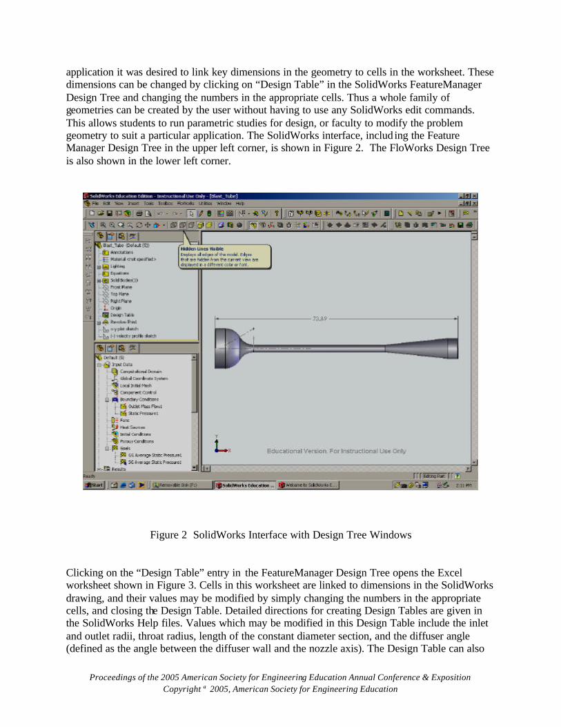
application it was desired to link key dimensions in the geometry to cells in the worksheet. These dimensions can be changed by clicking on “Design Table” in the SolidWorks FeatureManager Design Tree and changing the numbers in the appropriate cells. Thus a whole family of geometries can be created by the user without having to use any SolidWorks edit commands. This allows students to run parametric studies for design, or faculty to modify the problem geometry to suit a particular application. The SolidWorks interface, includ ing the Feature Manager Design Tree in the upper left corner, is shown in Figure 2. The FloWorks Design Tree is also shown in the lower left corner.
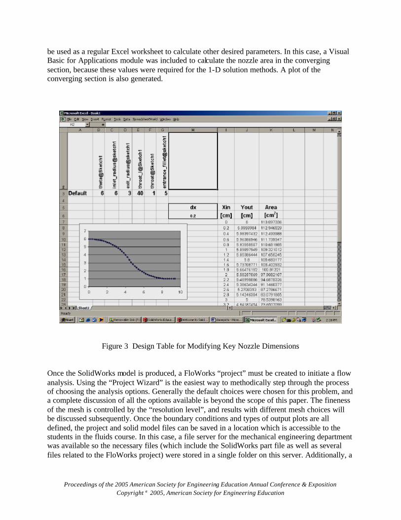
Figure 2 SolidWorks Interface with Design Tree Windows Clicking on the “Design Table” entry in the FeatureManager Design Tree opens the Excel worksheet shown in Figure 3. Cells in this worksheet are linked to dimensions in the SolidWorks drawing, and their values may be modified by simply changing the numbers in the appropriate cells, and closing the Design Table. Detailed directions for creating Design Tables are given in the SolidWorks Help files. Values which may be modified in this Design Table include the inlet and outlet radii, throat radius, length of the constant diameter section, and the diffuser angle (defined as the angle between the diffuser wall and the nozzle axis). The Design Table can also
Proceedings of the 2005 American Society for Engineering Education Annual Conference & Exposition Copyright 2005, American Society for Engineering Education
be used as a regular Excel worksheet to calculate other desired parameters. In this case, a Visual Basic for Applications module was included to calculate the nozzle area in the converging section, because these values were required for the 1-D solution methods. A plot of the converging section is also generated.
Figure 3 Design Table for Modifying Key Nozzle Dimensions
Once the SolidWorks model is produced, a FloWorks “project” must be created to initiate a flow analysis. Using the “Project Wizard” is the easiest way to methodically step through the process of choosing the analysis options. Generally the default choices were chosen for this problem, and a complete discussion of all the options available is beyond the scope of this paper. The fineness of the mesh is controlled by the “resolution level”, and results with different mesh choices will be discussed subsequently. Once the boundary conditions and types of output plots are all defined, the project and solid model files can be saved in a location which is accessible to the students in the fluids course. In this case, a file server for the mechanical engineering department was available so the necessary files (which include the SolidWorks part file as well as several files related to the FloWorks project) were stored in a single folder on this server. Additionally, a
Proceedings of the 2005 American Society for Engineering Education Annual Conference & Exposition Copyright 2005, American Society for Engineering Education
“Read Me” file was included which provided a list of instructions for opening the files and running the analysis. To run the analysis, the students had to copy the folder with the required files onto their local computer, and then open up the SolidWorks part file. The Design Table (accessed by right-clicking in the SolidWorks FeatureManager Design Tree) could be used to change the geometry from the default values (usually to set a different diffuser angle), and the boundary conditions could be checked and changed if necessary by right-clicking on the appropriate icons in the FloWorks Design Tree. Then the student could click Run and wait for the solution to be completed. Depending on the resolution level chosen, the run time could be five minutes (for resolution level 3) or about thirty minutes (for level 5) on a Pentium 4 PC. Once the solver is finished, the creation of output plots is straightforward since the plot types and necessary SolidWorks features were already defined in the project file. FloWorks allows the user to create “X-Y” plots which are based on Excel worksheets, so this data can easily be manipulated and combined with other methods for direct comparison. The goal of the process described above was to make the use of FloWorks as easy as possible for the inexperienced user. Thus a FloWorks solution can be created and analyzed by the students with essentially no training time required in the classroom. It should be noted that a professor could restrict the students’ access to only the SolidWorks part file, and thus require the students to go through the FloWorks project creation process. Alternatively, the students could be asked to start from the beginning and draw the nozzle themselves! Thus professors have a wide range of control to use the case study in a way that is consistent with their learning objectives. Students in the Fall 2004 section of the Fluid Dynamics course were the “test subjects” for the assignment based on this flow geometry model. Flow rate, inlet pressure, and inlet temperature were specified as 0.055 kg/sec, 101.3 kPa, and 293 K, respectively. The flow was assumed to be adiabatic and steady for all cases considered. The key parameters to be found included the Mach number and pressure at the entrance and exit of the constant diameter section, and the pressure at the diffuser exit. The surface roughness was defined to be the value for cast iron, and the length of the constant diameter section was increased to 40 centimeters (corresponding to a L/D ratio of 20) in order to obtain a significant change of Mach number due to the frictional effects. The exit diameter was fixed, but students were assigned different diffuser angles to analyze. The students were asked to solve the flow problem through this nozzle using three methods:
• Classical techniques, by employing Fanno flow equations in the straight sections and isentropic flow equations in the variable area sections
• Numerical integration of the general one-dimensional flow equations (taken from Zucrow
and Hoffman5), using the simple Euler method
• Finite element solution, using FloWorks Each of these methods has potential sources of error. The first two rely on the assumption of one-dimensional flow, and thus are unable to model the boundary layer separation which is likely to

Proceedings of the 2005 American Society for Engineering Education Annual Conference & Exposition Copyright 2005, American Society for Engineering Education
occur at larger diffuser angles. The classical approach requires that friction be ignored along significant lengths of the flow nozzle. The integration using Euler’s method is susceptible to numerical error. The FloWorks solution may be inaccurate for any number of reasons, including the choice of mesh and limitations in the physical models and numerical algorithms which are used. Ultimately a comparison of the results should lead to some important questions – particularly, which method gives the best answer? Sample results are presented in the next section to illustrate the lessons offered by this analysis. Results and Discussion Results for pressure versus axial distance for a diffuser angle of six degrees are shown in Figure 4. The large triangles represent values at critical points in the nozzle found from classical techniques, i.e. isentropic or Fanno flow relations where appropriate. Agreement with values found from numerical integration of the general one dimensional flow equations is excellent. The lesson of this comparison is that flow in short sections of a flow system can be modeled as isentropic and still yield acceptable results. It should be noted that rather small integration steps were required to get good results from the simple Euler algorithm. The students were asked to use this algorithm for its simplicity and easy implementation on an Excel worksheet, and they were advised that a step size on the order of 0.5 centimeter would be sufficient to minimize numerical errors. This advice was based on the author’s intuition and proved to be incorrect, and led to poor agreement in some of the students’ calculations. Future versions of this assignment will employ a better integration algorithm such as modified Euler or Runge-Kutta to avoid this problem.
50
60
70
80
90
100
110
0 10 20 30 40 50 60 70 80
Axial Distance (centimeters)
Pre
ssu
re (k
Pa)
1-D Numerical Solution Classical Solution
FloWorks SolutionResolution = 3
Figure 4 Comparison of Solutions for Pressure (6 degree Diffuser Angle)

Proceedings of the 2005 American Society for Engineering Education Annual Conference & Exposition Copyright 2005, American Society for Engineering Education
Evaluation of the FloWorks solution is a bit more complex. The pressure drop due to friction in the constant diameter section appears to be underestimated by about 25%. Students also found, confirmed by the author’s calculations, that increasing the resolution level to 5 (i.e. making the mesh more fine) tended to significantly increase the pressure drop such that the agreement with other solutions was actually worse. The increase of apparent friction factor as resolution is increased, especially at higher Reynolds number, is consistent with trends noted by Nguyen6 for incompressible flow in straight tubes. More work is required to fully understand these differences. Perhaps the message to students here is that results from software such as FloWorks should not be accepted without skepticism, and comparison with known results is required to develop an understanding of the software’s limitations. The observed differences in pressure recovery in the diffuser section are more consistent with expectations. Losses due to boundary layer separation are not accounted for in the one-dimensional models, and thus a lower pressure recovery is seen in the FloWorks solution. The effect of diffuser angle on the pressure recovery is discussed subsequently.
0
0.1
0.2
0.3
0.4
0.5
0.6
0.7
0 10 20 30 40 50 60 70 80
Axial Distance (centimeters)
Mac
h n
um
ber
1-D Numerical Solution Classical Solution
FloWorks SolutionResolution = 3
Figure 5 Comparison of Solutions for Mach Number (6 degree diffuser angle)
Figure 5 shows the comparison of Mach number values. Agreement among the three methods is reasonable, and again is quite close between the one dimensional models. The maximum Mach number at the end of the constant diameter section found from the FloWorks solution is about
Proceedings of the 2005 American Society for Engineering Education Annual Conference & Exposition Copyright 2005, American Society for Engineering Education
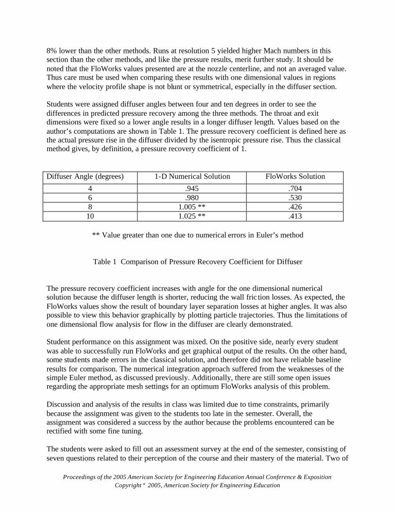
8% lower than the other methods. Runs at resolution 5 yielded higher Mach numbers in this section than the other methods, and like the pressure results, merit further study. It should be noted that the FloWorks values presented are at the nozzle centerline, and not an averaged value. Thus care must be used when comparing these results with one dimensional values in regions where the velocity profile shape is not blunt or symmetrical, especially in the diffuser section. Students were assigned diffuser angles between four and ten degrees in order to see the differences in predicted pressure recovery among the three methods. The throat and exit dimensions were fixed so a lower angle results in a longer diffuser length. Values based on the author’s computations are shown in Table 1. The pressure recovery coefficient is defined here as the actual pressure rise in the diffuser divided by the isentropic pressure rise. Thus the classical method gives, by definition, a pressure recovery coefficient of 1. Diffuser Angle (degrees) 1-D Numerical Solution FloWorks Solution
4 .945 .704 6 .980 .530 8 1.005 ** .426 10 1.025 ** .413
** Value greater than one due to numerical errors in Euler’s method
Table 1 Comparison of Pressure Recovery Coefficient for Diffuser The pressure recovery coefficient increases with angle for the one dimensional numerical solution because the diffuser length is shorter, reducing the wall fric tion losses. As expected, the FloWorks values show the result of boundary layer separation losses at higher angles. It was also possible to view this behavior graphically by plotting particle trajectories. Thus the limitations of one dimensional flow analysis for flow in the diffuser are clearly demonstrated. Student performance on this assignment was mixed. On the positive side, nearly every student was able to successfully run FloWorks and get graphical output of the results. On the other hand, some students made errors in the classical solution, and therefore did not have reliable baseline results for comparison. The numerical integration approach suffered from the weaknesses of the simple Euler method, as discussed previously. Additionally, there are still some open issues regarding the appropriate mesh settings for an optimum FloWorks analysis of this problem. Discussion and analysis of the results in class was limited due to time constraints, primarily because the assignment was given to the students too late in the semester. Overall, the assignment was considered a success by the author because the problems encountered can be rectified with some fine tuning. The students were asked to fill out an assessment survey at the end of the semester, consisting of seven questions related to their perception of the course and their mastery of the material. Two of
Proceedings of the 2005 American Society for Engineering Education Annual Conference & Exposition Copyright 2005, American Society for Engineering Education
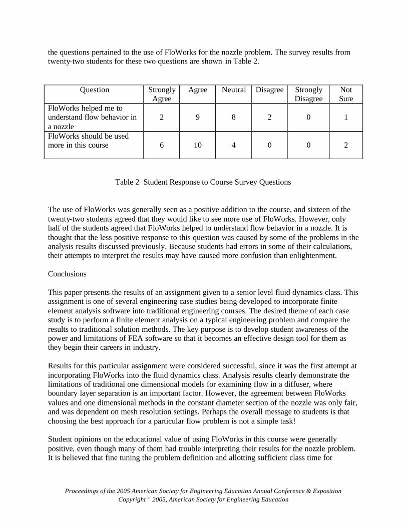
the questions pertained to the use of FloWorks for the nozzle problem. The survey results from twenty-two students for these two questions are shown in Table 2.
Question Strongly Agree
Agree Neutral Disagree Strongly Disagree
Not Sure
FloWorks helped me to understand flow behavior in a nozzle
2
9
8
2
0
1
FloWorks should be used more in this course
6
10
4
0
0
2
Table 2 Student Response to Course Survey Questions
The use of FloWorks was generally seen as a positive addition to the course, and sixteen of the twenty-two students agreed that they would like to see more use of FloWorks. However, only half of the students agreed that FloWorks helped to understand flow behavior in a nozzle. It is thought that the less positive response to this question was caused by some of the problems in the analysis results discussed previously. Because students had errors in some of their calculations, their attempts to interpret the results may have caused more confusion than enlightenment. Conclusions This paper presents the results of an assignment given to a senior level fluid dynamics class. This assignment is one of several engineering case studies being developed to incorporate finite element analysis software into traditional engineering courses. The desired theme of each case study is to perform a finite element analysis on a typical engineering problem and compare the results to traditional solution methods. The key purpose is to develop student awareness of the power and limitations of FEA software so that it becomes an effective design tool for them as they begin their careers in industry. Results for this particular assignment were considered successful, since it was the first attempt at incorporating FloWorks into the fluid dynamics class. Analysis results clearly demonstrate the limitations of traditional one dimensional models for examining flow in a diffuser, where boundary layer separation is an important factor. However, the agreement between FloWorks values and one dimensional methods in the constant diameter section of the nozzle was only fair, and was dependent on mesh resolution settings. Perhaps the overall message to students is that choosing the best approach for a particular flow problem is not a simple task! Student opinions on the educational value of using FloWorks in this course were generally positive, even though many of them had trouble interpreting their results for the nozzle problem. It is believed that fine tuning the problem definition and allotting sufficient class time for

Proceedings of the 2005 American Society for Engineering Education Annual Conference & Exposition Copyright 2005, American Society for Engineering Education
discussion of the results will enhance the educational benefits of using FloWorks in the fluid dynamics course. Bibliography
1. W.E. Whiteman, and K.P. Nygren, “ Achieving the Right Balance: Properly Integrating Mathematical Software Packages into Engineering Education”, Journal of Engineering Education, Vol. 89, No. 3, July 2000
2. P. Smith, R. Pederson, and J. Vennes, “Computational Education within Mechanical Engineering
Programs”, Proceedings of the 2004 ASEE Annual Conference & Exposition, Salt Lake City, Utah, June 2004
3. W.O. Jolley, J.J. Rencis, and H.T. Grandin, Jr., “ A Module for Teaching Fundamentals of Finite Element
Theory and Practice Using Elementary Mechanics of Materials”, Proceedings of the 2003 ASEE Annual Conference & Exposition, Nashville, Tennessee, June 2003
4. R.G. Ryan, “Using a Finite Element Stress Analysis Program to Enhance Learning in a Machine Design
Course”, Proceedings of the 2004 ASEE Annual Conference & Exposition, Salt Lake City, Utah, June 2004
5. M.J. Zucrow and J.D. Hoffman, Gas Dynamics: Volume 1 , John Wiley & Sons, Inc., 1976
6. M.T. Nguyen, “Validation of FloWorks for Internal Flow”, M.S. Project, CSU Northridge, May 2003 ROBERT G. RYAN Robert Ryan received his PhD degree in mechanical engineering from the University of California at Los Angeles. He is currently an Assistant Professor in the Mechanical Engineering Department at California State University, Northridge. He is the coordinator for the department’s Measurements Laboratory and Thermo -fluids Laboratory. STEWART P. PRINCE Stewart Prince received his PhD degree in mechanical engineering from University of Texas, Arlington. He is currently an Associate Professor in the Mechanical Engineering Department at California State University, Northridge. He is the coordinator of the department’s Haas CNC Laboratory.