Development of electrochromic evacuated advanced glazing
13
-
Upload
independent -
Category
Documents
-
view
0 -
download
0
Transcript of Development of electrochromic evacuated advanced glazing

S. Papaefthimiou et al. / Energy and Buildings 38 (2006) 1455–14671456
per year, while the CO2 reduction was estimated at 82 million
tones per year [4].
According to the Environmental Protection Agency [5] an
average household spends over 40% of its annual energy budget
on heating and cooling costs. On the other hand, office
buildings account for about one-third of all the energy used in
the US, a quarter of which is lost through the inefficiency of
standard windows to retain heat in the winter or deflect heat in
the summer. While regular glass can only allow a constant
amount of light, the switchable window can be tuned or
dimmed, controlling the amount of light passing through. An
estimate of the expected savings in heating, lighting and air-
conditioning costs is $ 11–20 billion per year. According to the
EPA, even a $ 7 billion saving would equate to a reduction in
carbon emissions at power generating plants equal to taking
336,000 cars off the road, while the energy savings would be
enough to light every home in New York City.
1.1. Switchable glazing: state-of-the-art
Liquid crystal (LC) glazing operate on the principle of
electrically controlled light scattering. They consist of liquid
crystal droplets surrounded by a polymer mixture sandwiched
between two pieces of conducting glass. When no electricity is
applied the liquid crystal droplets are randomly oriented,
creating an opaque state. When electricity is applied the liquid
crystals align parallel to the electric field and light passes
through, creating a transparent state. The switch between the
two states is nearly instantaneous. LC windows are hazy
because they scatter rather than absorb light, so there is a fog
factor even when the device is in the transparent state. An LC
glass is either clear or opaque with no in-between states, and
merely scatters light rather than blocking it, which limits it to
certain interior privacy applications. Furthermore it requires
constant energy to maintain the clear state, and thus no energy
saving benefits are provided.
Suspended particle (SPD) smart windows are constructed by
using two panes of glass separated by a conductive film with
suspended, light absorbing, microscopic particles. Microscopic
light-absorbing particles are dispersed within a thin film. When
no electrical voltage is applied to the film, these particles absorb
light, making the glass dark. When voltage is applied, the
particles align and allow light to pass through. By simply
adjusting the electrical voltage manually or automatically, the
amount of light passing through the SPD-glass product can be
controlled. One important disadvantage is that electricity is
required to keep the window transparent.
An electrochromic (EC) window is an active solar control
device whose transmittance in the visible and near IR part of the
spectrum can be reversibly modulated by the application of a low
voltage (typically 3–5 V dc). EC windows function as the result
of transport of charged ions (typically Li+) from an ion storage
layer, through an ion conducting layer into an electrochromic
layer. Electrons are also injected from the external circuit into
this layer for charge equilibration, changing its electronic density
and its optical properties, causing it to absorb visible light, the
result of which is the window darkening. To reverse the process,
the voltage is reversed, driving the ions (and electrons) in the
opposite direction, out of the electrochromic layer, through the
ion conducting layer, and back into the ion storage layer. As the
ions migrate out of the electrochromic layer, it brightens (or
‘‘bleaches’’), and the window becomes transparent again.
An EC window has several advantages compared to
conventional shading and solar control devices. It does not
impede visibility through the window as with blinds and
curtains, while it provides glare control and thermal comfort
management. It has no moving parts and as a result, minimum
maintenance costs. It requires a low voltage power supply (it
can even be powered by photovoltaics) and it can be integrated
into the central power management of the building. It has
practically infinite coloration stages. It can block both direct
and diffuse solar radiation, unlike passive shading devices.
Unlike tinted glass it can become transparent during the early
morning and afternoon hours to improve natural lighting
conditions. Furthermore, it has a low energy consumption
(typically 8 W m�2), which is nearly zero when the glazing is
kept at constant conditions. This is due to the very high open
circuit memory of the device [6]. An EC window can out-
perform the best currently available window systems (in most
applications) and has lower annual energy demand than an
opaque insulating wall [7]. The primary energy benefits are:
reduced cooling, heating and ventilation loads and the ability to
displace artificial electric lighting use by managing daylight
admittance. Additionally the architectural and aesthetic appeal
of a dynamic coating that an EC technology offers is difficult to
quantify but it will be a major contributing factor for its
selection for many building applications. Many design
decisions are made not only on the basis of ‘‘payback’’ but
also on the basis of style and appearance.
Several companies worldwide have announced the develop-
ment of commercial EC glazing for architectural applications
during the last years [8–10]. The performance of commercial
devices is limited by several factors: they have rather limited
transmittance modulation (50–15% for EControl by Pilkington,
72–17% for Asahi and 55–8% for SAGEGlass1 [8–12]. Awider
range (e.g. 75–10%) would allow better control of solar gains.
They suffer from defects that form during extended operation:
these can be dark spots or pinholes (up to 3 mm in diameter and as
many as three spots per m2 [6]) that are no longer
electrochromically active, dust and metallic particles (due to
the preparation technique problems) which cause electrical
leakage and hence low production yields [8]. Large area devices
also suffer from uneven coloration and degrade after prolonged
operation (typically 5% degradation in maximum transmittance)
[6,10]. Furthermore, some of them have a limited lifetime: 6000
coloration/bleaching cycles per 5 years for Pilkington EControl
[6], the devices developed by Asahi are designed for a lifetime of
10 years [8], while SAGEGlass1 samples have expected lifetime
of 20–30 years [9]. As these devices have been produced during
the last few years, there are not yet available comprehensive long-
term operational performance data. Worldwide, there is not any
generally accepted standard test procedure for long life testing of
the EC devices or evacuated glazing, due to the inherent
complexity and the many parameters involved [10].
S. Papaefthimiou et al. / Energy and Buildings 38 (2006) 1455–1467 1457
The EC devices fabricated thus far are integrated into
insulating windows that consist of a double glazing called IGUs
(Insulated Glass Units), coated with low emittance (low-e
hereafter) coatings and an argon-filled gap. Such structures
achieve mid-plane thermal transmittance (U-value) of about
1.1 W m�2 K�1. This value can be further reduced with
evacuated double glazing, in conjunction with the EC device
resulting in a 3-glass pane EC evacuated window.
1.2. Evacuated glazing
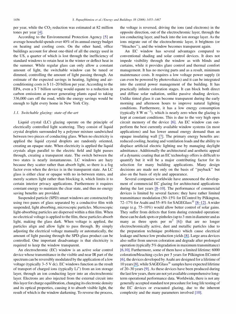
Evacuated glazing consists of two sheets of glass hermetically
sealed around their periphery with a vacuum gap between the
glass sheets. An array of tiny support pillars, typically 0.3–
0.5 mm in diameter, are used to separate the glass panes and
prevent the glass panes from touching due to atmospheric
pressure. Low emittance (low-e) coatings are used on one or both
of the internal glass surfaces to reduce radiative heat transfer
from the inside to the outside of the glazing as seen in Fig. 1.
Evacuated glazing have been fabricated with two sheets of
glass rigidly fused together around their periphery using a solder
glass with a coefficient of thermal expansion that matches that of
the glass sheets to be sealed [13]. The edge seal was made by
heating the entire structure to around 450 8C for 1 h and cooling
slowly to room temperature. Subsequent evacuation of the
window was achieved through a pump-out tube with a typical
internal diameter of 1 mm, attached to one of the glass panes [14],
after which the end was melted and sealed. Attempts to produce
evacuated glazing using high temperature laser based manu-
facturing techniques, were unsuccessful due to out-gassing
resulting from the sealing processes [15]. The use of high
temperature edge sealing techniques for evacuated glazing
restricts the choice of low emittance film, incurs high embodied
energy and precludes the use of tempered glass which would
suffer from loss of temper at 450 8C. A low temperature (less than
200 8C) hermetic seal would negate these issues.
Previous research [16,17] has led to the development of a
patented technique for the fabrication of evacuated glazing at
low temperatures. The technique uses indium or indium alloy as
the edge sealing material applied to the surfaces of the glass
sheets to be bonded together. Indium is a well suited sealing
material as it can be used to join materials with greatly
mismatched coefficients of thermal expansion subject to
thermal cycling and has the ability to ‘‘wet’’ or ‘‘cold weld’’
to metals, glass and ceramics. These characteristics are
fundamental in determining the effectiveness of a seal,
Fig. 1. Schematic representation of an evacuated glazing (not to scale).
allowing it to mould itself to the shape of the materials being
sealed together, thereby eliminating air-paths. Indium’s low
vapour pressure at ambient conditions makes it ideal for
vacuum seals, when the durability conditions to be met are
demanding and current polymer based products are inadequate.
1.3. Electrochromic evacuated windows
The authors of this work have been researching electro-
chromics, evacuated glazing and polymers for more than a
decade. During the last 3 years they have collaborated to
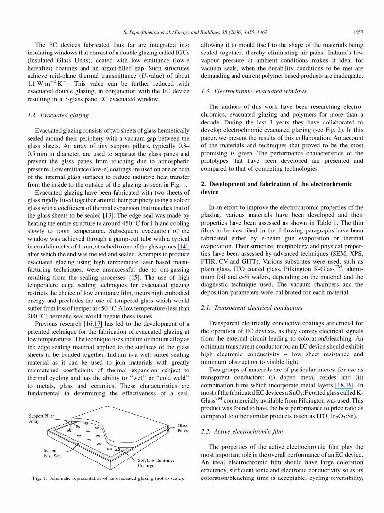
develop electrochromic evacuated glazing (see Fig. 2). In this
paper, we present the results of this collaboration. An account
of the materials and techniques that proved to be the most
promising is given. The performance characteristics of the
prototypes that have been developed are presented and
compared to that of competing technologies.
2. Development and fabrication of the electrochromic
device
In an effort to improve the electrochromic properties of the
glazing, various materials have been developed and their
properties have been assessed as shown in Table 1. The thin
films to be described in the following paragraphs have been
fabricated either by e-beam gun evaporation or thermal
evaporation. Their structure, morphology and physical proper-
ties have been assessed by advanced techniques (SEM, XPS,
FTIR, CV and GITT). Various substrates were used, such as
plain glass, ITO coated glass, Pilkington K-GlassTM, alumi-
nium foil and c-Si wafers, depending on the material and the
diagnostic technique used. The vacuum chambers and the
deposition parameters were calibrated for each material.
2.1. Transparent electrical conductors
Transparent electrically conductive coatings are crucial for
the operation of EC devices, as they convey electrical signals
from the external circuit leading to coloration/bleaching. An
optimum transparent conductor for an EC device should exhibit
high electronic conductivity – low sheet resistance and
minimum obstruction to visible light.
Two groups of materials are of particular interest for use as
transparent conductors: (i) doped metal oxides and (ii)
combination films which incorporate metal layers [18,19]. In
most of the fabricated EC devices a SnO2:F coated glass called K-
GlassTM commercially available from Pilkington was used. This
product was found to have the best performance to price ratio as
compared to other similar products (such as ITO, In2O3:Sn).
2.2. Active electrochromic film
The properties of the active electrochromic film play the
most important role in the overall performance of an EC device.
An ideal electrochromic film should have large coloration
efficiency, sufficient ionic and electronic conductivity so as its
coloration/bleaching time is acceptable, cycling reversibility,
S. Papaefthimiou et al. / Energy and Buildings 38 (2006) 1455–14671458
Fig. 2. Electrochromic evacuated glazing.
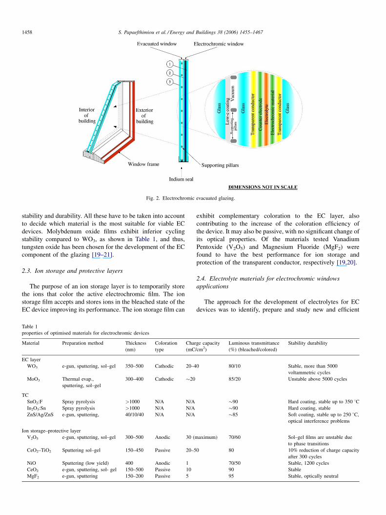
stability and durability. All these have to be taken into account
to decide which material is the most suitable for viable EC
devices. Molybdenum oxide films exhibit inferior cycling
stability compared to WO3, as shown in Table 1, and thus,
tungsten oxide has been chosen for the development of the EC
component of the glazing [19–21].
2.3. Ion storage and protective layers
The purpose of an ion storage layer is to temporarily store
the ions that color the active electrochromic film. The ion
storage film accepts and stores ions in the bleached state of the
EC device improving its performance. The ion storage film can
Table 1
properties of optimised materials for electrochromic devices
Material Preparation method Thickness
(nm)
Coloration
type
Char
(mC
EC layer
WO3 e-gun, sputtering, sol–gel 350–500 Cathodic 20–4
MoO3 Thermal evap.,
sputtering, sol–gel
300–400 Cathodic �20
TC
SnO2:F Spray pyrolysis >1000 N/A N/A
In2O3:Sn Spray pyrolysis >1000 N/A N/A
ZnS/Ag/ZnS e-gun, sputtering, 40/10/40 N/A N/A
Ion storage–protective layer
V2O5 e-gun, sputtering, sol–gel 300–500 Anodic 30 (m
CeO2–TiO2 Sputtering sol–gel 150–450 Passive 20–5
NiO Sputtering (low yield) 400 Anodic 1
CeO2 e-gun, sputtering, sol- gel 150–500 Passive 10
MgF2 e-gun, sputtering 150–200 Passive 5
exhibit complementary coloration to the EC layer, also
contributing to the increase of the coloration efficiency of
the device. It may also be passive, with no significant change of
its optical properties. Of the materials tested Vanadium
Pentoxide (V2O5) and Magnesium Fluoride (MgF2) were
found to have the best performance for ion storage and
protection of the transparent conductor, respectively [19,20].
2.4. Electrolyte materials for electrochromic windows
applications
The approach for the development of electrolytes for EC
devices was to identify, prepare and study new and efficient
ge capacity
/cm2)
Luminous transmittance
(%) (bleached/colored)
Stability durability
0 80/10 Stable, more than 5000
voltammetric cycles
85/20 Unstable above 5000 cycles
�90 Hard coating, stable up to 350 8C�90 Hard coating, stable
�85 Soft coating, stable up to 250 8C,
optical interference problems
aximum) 70/60 Sol–gel films are unstable due
to phase transitions
0 80 10% reduction of charge capacity
after 300 cycles
70/50 Stable, 1200 cycles
90 Stable
95 Stable, optically neutral
S. Papaefthimiou et al. / Energy and Buildings 38 (2006) 1455–1467 1459
polymer based materials. The aim was to optimise parameters
such as the molecular structure of the polymer, salt type and
concentration, and to compare with existing state-of-the-art
materials. A specific aim was to explore how to influence the
performance of the EC devices through a judicious choice of
the electrolyte. Two classes of transparent electrolytes were
focused upon. The first was a conventional, state-of-the-art gel
electrolyte system based on poly(methyl methacrylate)
(PMMA), lithium perchlorate salt (LiClO4) and propylene
carbonate (PC). In the second class of electrolytes we combined
Lewis acidic boron and Lewis basic ethylene glycols in the
molecular structure of the polymer. The latter electrolytes were
expected to favour the lithium transport number and the transfer
of lithium at the interface with the WO3 layer. In the present
work, the electrolyte materials were not only used as ion
conducting materials, but also as the only source of lithium ions
for the electrochromic material during the coloration process.
LiClO4 was used throughout the project because it showed
beneficial properties in terms of solubility, conductivity and
stability, and is relatively inexpensive.
2.4.1. State-of-the-art electrolytes
Electrolytes consisting of LiClO4, PC and PMMA typically
show a high level of ionic conductivity. Liquid electrolytes
were first prepared from PC and LiClO4 to contain 9–11 wt.%
salt. Gel electrolytes were then produced by adding 7 wt.%
PMMA to the liquid electrolytes. The gel electrolytes were
optically clear viscous liquids and reached the highest
conductivities of the present electrolytes, in the range of
3 � 10�3 S/cm at 30 8C.
2.4.2. Preparation and selection of boron-containing
electrolytes
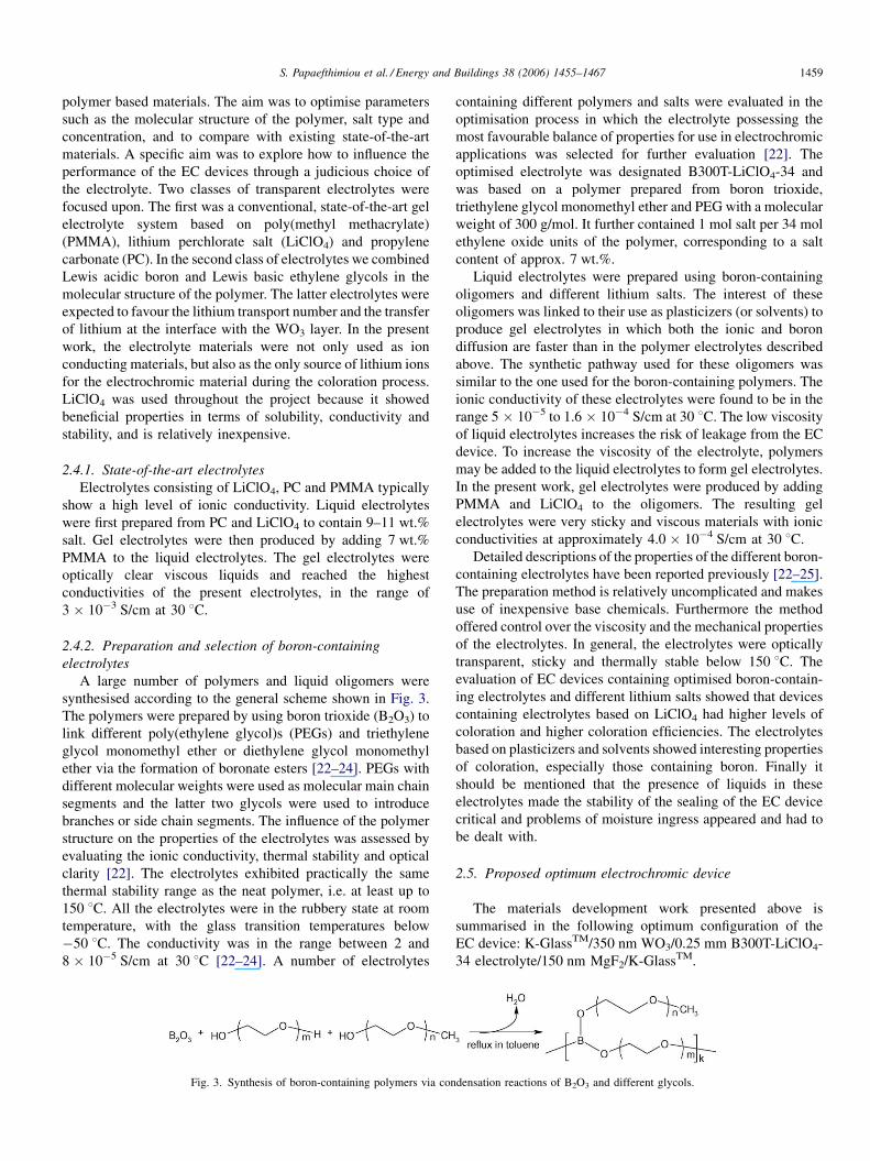
A large number of polymers and liquid oligomers were
synthesised according to the general scheme shown in Fig. 3.
The polymers were prepared by using boron trioxide (B2O3) to
link different poly(ethylene glycol)s (PEGs) and triethylene
glycol monomethyl ether or diethylene glycol monomethyl
ether via the formation of boronate esters [22–24]. PEGs with
different molecular weights were used as molecular main chain
segments and the latter two glycols were used to introduce
branches or side chain segments. The influence of the polymer
structure on the properties of the electrolytes was assessed by
evaluating the ionic conductivity, thermal stability and optical
clarity [22]. The electrolytes exhibited practically the same
thermal stability range as the neat polymer, i.e. at least up to
150 8C. All the electrolytes were in the rubbery state at room
temperature, with the glass transition temperatures below
�50 8C. The conductivity was in the range between 2 and
8 � 10�5 S/cm at 30 8C [22–24]. A number of electrolytes
Fig. 3. Synthesis of boron-containing polymers via con
containing different polymers and salts were evaluated in the
optimisation process in which the electrolyte possessing the
most favourable balance of properties for use in electrochromic
applications was selected for further evaluation [22]. The
optimised electrolyte was designated B300T-LiClO4-34 and
was based on a polymer prepared from boron trioxide,
triethylene glycol monomethyl ether and PEG with a molecular
weight of 300 g/mol. It further contained 1 mol salt per 34 mol
ethylene oxide units of the polymer, corresponding to a salt
content of approx. 7 wt.%.
Liquid electrolytes were prepared using boron-containing
oligomers and different lithium salts. The interest of these
oligomers was linked to their use as plasticizers (or solvents) to
produce gel electrolytes in which both the ionic and boron
diffusion are faster than in the polymer electrolytes described
above. The synthetic pathway used for these oligomers was
similar to the one used for the boron-containing polymers. The
ionic conductivity of these electrolytes were found to be in the
range 5 � 10�5 to 1.6 � 10�4 S/cm at 30 8C. The low viscosity
of liquid electrolytes increases the risk of leakage from the EC
device. To increase the viscosity of the electrolyte, polymers
may be added to the liquid electrolytes to form gel electrolytes.
In the present work, gel electrolytes were produced by adding
PMMA and LiClO4 to the oligomers. The resulting gel
electrolytes were very sticky and viscous materials with ionic
conductivities at approximately 4.0 � 10�4 S/cm at 30 8C.
Detailed descriptions of the properties of the different boron-
containing electrolytes have been reported previously [22–25].
The preparation method is relatively uncomplicated and makes
use of inexpensive base chemicals. Furthermore the method
offered control over the viscosity and the mechanical properties
of the electrolytes. In general, the electrolytes were optically
transparent, sticky and thermally stable below 150 8C. The
evaluation of EC devices containing optimised boron-contain-
ing electrolytes and different lithium salts showed that devices
containing electrolytes based on LiClO4 had higher levels of
coloration and higher coloration efficiencies. The electrolytes
based on plasticizers and solvents showed interesting properties
of coloration, especially those containing boron. Finally it
should be mentioned that the presence of liquids in these
electrolytes made the stability of the sealing of the EC device
critical and problems of moisture ingress appeared and had to
be dealt with.
2.5. Proposed optimum electrochromic device
The materials development work presented above is
summarised in the following optimum configuration of the
EC device: K-GlassTM/350 nm WO3/0.25 mm B300T-LiClO4-
34 electrolyte/150 nm MgF2/K-GlassTM.
densation reactions of B2O3 and different glycols.
S. Papaefthimiou et al. / Energy and Buildings 38 (2006) 1455–14671460
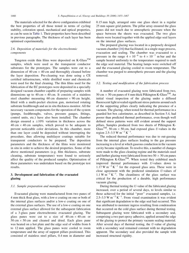
The materials selected for the above configuration exhibited
the best properties of all those tested in terms of cycling
stability, coloration speed, mechanical and optical properties,
as can be seen in Table 1. Their properties have been described
in previous paragraphs. The thickness of each layer has been
optimised experimentally.
2.6. Deposition of materials for the electrochromic
components
Tungsten oxide thin films were deposited on K-GlassTM
samples, which were used as the transparent conductor
substrates for the prototypes. The samples were cut to a
dimension of 40 cm � 40 cm and thoroughly cleaned before
the layer deposition. Pre-cleaning was done using a CE
certified infrastructure, while distilled water and chemicals
were used for the final cleaning. The thin films used for the
fabrication of the EC prototypes were deposited in a specially
designed vacuum chamber capable of preparing samples with
dimensions up to 40 cm � 40 cm. It consists of a stainless
steel chamber measuring 60 cm diameter � 90 cm height,
fitted with a multi-pocket electron gun, motorised rotating
substrate feedthrough and an in situ thickness monitor. All the
necessary vacuum components for the operation of the system
(pumps, feedthroughs, valves, pressure gauges, fittings,
control units, etc.) have also been installed. The chamber
design ensured a �10% variation in thickness across the
40 cm � 40 cm samples, which proved to be adequate to
prevent noticeable color deviations. In this chamber, more
than one layer could be deposited without interrupting the
procedure, thus allowing multilayer coatings suitable for
transparent conductors to be prepared. The deposition
parameters and the thickness of the films were monitored
in situ in order to achieve the desired properties. Some of the
above mentioned parameters (e.g. film thickness, substrate
cleaning, substrate temperature) were found to seriously
affect the quality of the produced samples. Optimisation of
these parameters was undertaken based on the prototype test
results.
3. Development and fabrication of the evacuated
glazing
3.1. Sample preparation and manufacture
Evacuated glazing were manufactured from two panes of
4 mm thick float glass, with a low-e coating on one or both of
the internal glass surfaces and/or a low-e coating on one of
the external glass surfaces. The use of a low-e coating on one
external glass surface allowed for the subsequent fabrication
of a 3-glass pane electrochromic evacuated glazing. The
glass panes were cut to a size of 40 cm � 40 cm or
50 cm � 50 cm and cleaned and dried. Each glass pane
was heated on a hot plate and the edge seal of widths from 6
to 12 mm applied. The glass panes were cooled to room
temperature and the array of support pillars positioned. This
consisted of stainless steel pillars, 0.4 mm in diameter and
0.15 mm high, arranged onto one glass sheet in a regular
25 mm square grid pattern. The pillar array ensured the glass
panes did not touch due to atmospheric pressure when the
space between the sheets was evacuated. The two glass
sheets were located together with the applied edge seal layers
on the internal glass surfaces.
The prepared glazing was located in a purposely designed
vacuum chamber [16] that facilitated, in a single stage process,
evacuation and sealing. The chamber was evacuated to a
pressure in the range 4 � 10�6 to 4 � 10�7 m bar and the
sample heated uniformly to the temperature required to melt
the edge seal material. The heating lamps were switched off
and the evacuated glazing cooled to room temperature. The
chamber was purged to atmospheric pressure and the glazing
removed.
3.2. Testing and modification of the fabrication process
A number of evacuated glazing were fabricated from two,
50 cm � 50 cm panes of 4 mm thick Pilkington K-GlassTM. An
initial visual inspection of the glazing under a diffused
fluorescent light revealed significant stress patterns around each
of the supporting pillars clearly indicating the presence of a
vacuum. The glazing, when tested for thermal performance in a
guarded hot box calorimeter, as described in Section 5.4, had
poorer than predicted thermal performance, even though well
defined stress patterns were still evident around the support
pillars. Samples produced from two sheets of Pilkington K-
GlassTM, 50 cm � 50 cm, had exposed glass U-values in the
region 2.5–3.5 W m�2 K�1.
The reduced thermal performance was due to out-gassing
from the internal glass surfaces leading to the gas pressure
increasing to a level at which gaseous conduction in the vacuum
cavity became significant. To resolve this, a number of changes
were made to the glass cleaning regime and the materials used
and further glazing were fabricated from two 50 � 50 cm panes
of Pilkington K-GlassTM. When tested they exhibited much
improved thermal performance with U-values down to
1.17 W m�2 K�1 for the exposed glass area. These were in
close agreement with the predicted simulation U-values of
1.1 W m�2 K�1. The cleanliness of the glass surface was
critical for the production of a durable, high performance
vacuum glazing.
During thermal testing the U-value of the fabricated glazing
increased, over a period of several days, to levels similar to
those achieved for the initial ‘‘poor’’ evacuated samples, i.e.
2.5–3.5 W m�2 K�1. From visual examination it was evident
that significant degradation to the edge seal had occurred. This
was attributed to moisture ingress resulting from condensation
that occurred on the cold glass surface during thermal testing.
Subsequent glazing were fabricated with a secondary seal,
comprising a two part epoxy adhesive, applied around the edge
of the glazing to protect the primary vacuum sealing material.
After several days of thermal testing, the U-value of glazing
with a secondary seal remained constant with no degradation
apparent. The secondary seal also provided the sample with
increased structural rigidity.

S. Papaefthimiou et al. / Energy and Buildings 38 (2006) 1455–1467 1461
Table 2
Evacuated glazing types manufactured
Glass type (trade name) Sample size (cm) Emissivity of low-e glass Orientation of low-e coating
2 sheets Pilkington K-GlassTM 50 � 50 0.15/0.15 Both K coatings on inside
2 sheets Pilkington K-GlassTM 50 � 50 0.15/0.15 1 K coating inside 1 K coating outside
2 sheets Pilkington K-GlassTM 40 � 40 0.15/0.15 Both K coatings on inside
2 sheets Pilkington K-GlassTM 40 � 40 0.15/0.15 1 K coating inside 1 K coating outside
1 K-GlassTM, 1 Guardian 1.4DT 40 � 40 0.15/0.12 K coating inside 1.4DT inside
1 K-GlassTM, 1 Guardian 1.4DT 40 � 40 0.15/0.12 K coating outside 1.4DT inside
1 K-GlassTM, 1 Pilkington Optitherm 40 � 40 0.15/0.06 K coating outside Optitherm inside
3.3. Support pillar design
Pillars used in the manufacture of the evacuated glazing
were produced from stainless steel by a process of chemical
etching in which a photo negative of an array of pillars was
transferred to a sheet of stainless steel the thickness of the pillar
(0.15 mm) and covered with photo resist. The material
surrounding the pillars was subsequently etched away to half
its thickness on one face, turned over and etched through from
the opposing face to produce the array of pillars. This ensured
that both faces of the pillar were similar in size. Pillars were
manufactured with dimensions ranging from 0.3 to 0.5 mm in
diameter by 0.15 mm high.
3.4. Fabricated evacuated glazing samples
To improve the thermal performance of the electrochromic
evacuated glazing a number of low-e coated glass types were
used. The range of glazing fabricated is summarised in
Table 2. Glazing were manufactured using two panes of
Pilkington K-GlassTM or one pane of Pilkington K-GlassTM
and either one pane of Pilkington OptithermTM or one pane of
Guardian 1.4DT. OptithermTM is classified as a soft low-e
glass with an emissivity of approximately 6% and Guardian
1.4DT is classified as a hard low-e glass with an emissivity of
approximately 12%.
In Table 2, the orientation of the coating refers to whether the
low-e coatings on the two glass panes were both on the internal
vacuum cavity side or whether one coating was on the vacuum
cavity side and one coating was on the external glass surface.
The size of initial evacuated glazing fabricated was
50 cm � 50 cm, this was however reduced to 40 cm � 40 cm
to accommodate the maximum size of fabricated electro-
chromic glazing.
4. Development of the electrochromic evacuated
prototype
4.1. Fabrication of the electrochromic evacuated
prototypes
4.1.1. 4-glass prototypes
At the early stages of the prototype development 4-glass
devices have been fabricated in the following manner. The two
halves which constitute the electrochromic part of the window
(K-GlassTM/WO3 and K-GlassTM) were bonded together by use
of pure silicone sealant, which did not react with the electrolyte.
The cavity formed between the glass panes was filled with the
electrolyte which was inserted through a small entry point
towards one corner of the sample. The edges were sealed
peripherally and tested for leakage before it was fully
functional. Subsequently the evacuated glazing was laminated
to the EC glazing to form a 4-glass electrochromic evacuated
glazing. This method of manufacture facilitated the develop-
ment and fabrication of the evacuated and electrochromic parts
of the prototype in parallel, however with 4-glass panes the
weight and cost of the prototype would be increased and visual
transmittance was reduced.
4.1.2. 3-glass prototypes
For the fabrication of the 3-glass electrochromic evacuated
prototype, the 40 cm � 40 cm K-GlassTM/WO3 part of the EC
window was bonded directly to the completed evacuated
glazing component. For the 3-glass prototype the evacuated
glazing was fabricated with two low-e coated glass panes, one
of which had the low-e coating on its outer surface. This
provided the transparent and electrically conductive layer
required for the electrochromic part of the glazing.
All the problems/defects observed during the fabrication of
the prototypes were addressed successfully (see detailed
Fig. 4).
4.2. Problems/defects of the electrochromic evacuated
prototypes
During fabrication of the electrochromic evacuated proto-
types several problems were encountered which are described
in Fig. 4. Modifications were made to the fabrication process
and the significantly improved prototypes have been prepared.
The most critical problems addressed are:
1. I
nhomogeneous WO3 films: The new vacuum chamber hasbeen designed specifically for the preparation of
40 cm � 40 cm samples, taking into account all the
parameters involved in the deposition process (such as the
source-substrate distance, sample rotation, etc.). Indeed,
examination of the thin films prepared in this chamber has
shown a �10% variation in thickness across the
40 cm � 40 cm samples, which is adequate to prevent the
appearance of noticeable color deviations.
2. W
O3 film detachment due to insufficient cleaning of theglass substrates: The 40 cm � 40 cm samples have been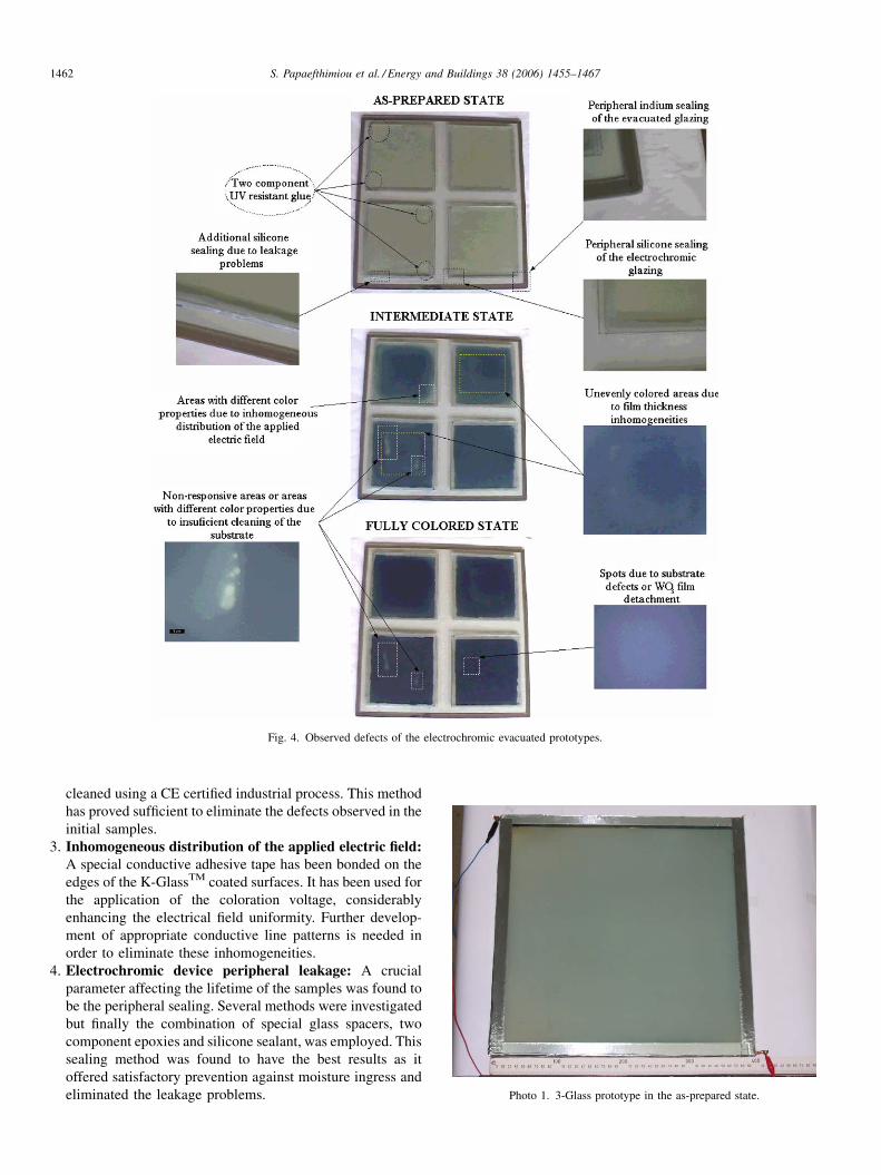
S. Papaefthimiou et al. / Energy and Buildings 38 (2006) 1455–14671462
Fig. 4. Observed defects of the electrochromic evacuated prototypes.
cleaned using a CE certified industrial process. This method
has proved sufficient to eliminate the defects observed in the
initial samples.
3. I
nhomogeneous distribution of the applied electric field:A special conductive adhesive tape has been bonded on theedges of the K-GlassTM coated surfaces. It has been used for
the application of the coloration voltage, considerably
enhancing the electrical field uniformity. Further develop-
ment of appropriate conductive line patterns is needed in
order to eliminate these inhomogeneities.
4. E
Photo 1. 3-Glass prototype in the as-prepared state.
lectrochromic device peripheral leakage: A crucial
parameter affecting the lifetime of the samples was found to
be the peripheral sealing. Several methods were investigated
but finally the combination of special glass spacers, two
component epoxies and silicone sealant, was employed. This
sealing method was found to have the best results as it
offered satisfactory prevention against moisture ingress and
eliminated the leakage problems.
S. Papaefthimiou et al. / Energy and Buildings 38 (2006) 1455–1467 1463
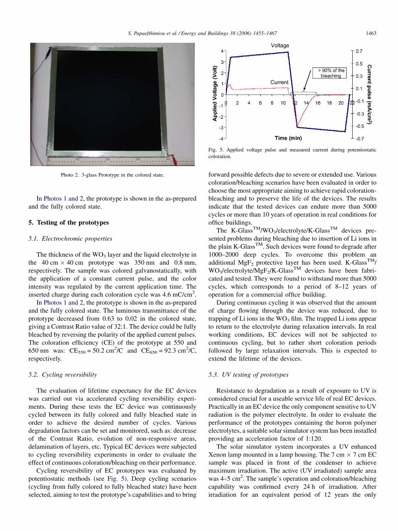
Photo 2. 3-glass Prototype in the colored state.
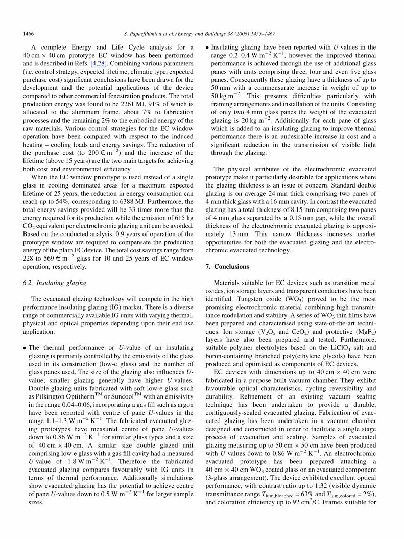
Fig. 5. Applied voltage pulse and measured current during potentiostatic
coloration.
In Photos 1 and 2, the prototype is shown in the as-prepared
and the fully colored state.
5. Testing of the prototypes
5.1. Electrochromic properties
The thickness of the WO3 layer and the liquid electrolyte in
the 40 cm � 40 cm prototype was 350 nm and 0.8 mm,
respectively. The sample was colored galvanostatically, with
the application of a constant current pulse, and the color
intensity was regulated by the current application time. The
inserted charge during each coloration cycle was 4.6 mC/cm2.
In Photos 1 and 2, the prototype is shown in the as-prepared
and the fully colored state. The luminous transmittance of the
prototype decreased from 0.63 to 0.02 in the colored state,
giving a Contrast Ratio value of 32:1. The device could be fully
bleached by reversing the polarity of the applied current pulses.
The coloration efficiency (CE) of the prototype at 550 and
650 nm was: CE550 = 50.2 cm2/C and CE650 = 92.3 cm2/C,
respectively.
5.2. Cycling reversibility
The evaluation of lifetime expectancy for the EC devices
was carried out via accelerated cycling reversibility experi-
ments. During these tests the EC device was continuously
cycled between its fully colored and fully bleached state in
order to achieve the desired number of cycles. Various
degradation factors can be set and monitored, such as: decrease
of the Contrast Ratio, evolution of non-responsive areas,
delamination of layers, etc. Typical EC devices were subjected
to cycling reversibility experiments in order to evaluate the
effect of continuous coloration/bleaching on their performance.
Cycling reversibility of EC prototypes was evaluated by
potentiostatic methods (see Fig. 5). Deep cycling scenarios
(cycling from fully colored to fully bleached state) have been
selected, aiming to test the prototype’s capabilities and to bring
forward possible defects due to severe or extended use. Various
coloration/bleaching scenarios have been evaluated in order to
choose the most appropriate aiming to achieve rapid coloration-
bleaching and to preserve the life of the devices. The results
indicate that the tested devices can endure more than 5000
cycles or more than 10 years of operation in real conditions for
office buildings.
The K-GlassTM/WO3/electrolyte/K-GlassTM devices pre-
sented problems during bleaching due to insertion of Li ions in
the plain K-GlassTM. Such devices were found to degrade after
1000–2000 deep cycles. To overcome this problem an
additional MgF2 protective layer has been used. K-GlassTM/
WO3/electrolyte/MgF2/K-GlassTM devices have been fabri-
cated and tested. They were found to withstand more than 5000
cycles, which corresponds to a period of 8–12 years of
operation for a commercial office building.
During continuous cycling it was observed that the amount
of charge flowing through the device was reduced, due to
trapping of Li ions in the WO3 film. The trapped Li ions appear
to return to the electrolyte during relaxation intervals. In real
working conditions, EC devices will not be subjected to
continuous cycling, but to rather short coloration periods
followed by large relaxation intervals. This is expected to
extend the lifetime of the devices.
5.3. UV testing of prototypes
Resistance to degradation as a result of exposure to UV is
considered crucial for a useable service life of real EC devices.
Practically in an EC device the only component sensitive to UV
radiation is the polymer electrolyte. In order to evaluate the
performance of the prototypes containing the boron polymer
electrolytes, a suitable solar simulator system has been installed
providing an acceleration factor of 1:120.
The solar simulator system incorporates a UV enhanced
Xenon lamp mounted in a lamp housing. The 7 cm � 7 cm EC
sample was placed in front of the condenser to achieve
maximum irradiation. The active (UV irradiated) sample area
was 4–5 cm2. The sample’s operation and coloration/bleaching
capability was confirmed every 24 h of irradiation. After
irradiation for an equivalent period of 12 years the only

S. Papaefthimiou et al. / Energy and Buildings 38 (2006) 1455–14671464
degradation effect observed in some samples was the evolution
of small bubbles, which were attributed mainly to the
evaporation of solvent or gas dissolved in the electrolytes
(nitrogen or argon from the protective atmospheres in the glove
box or during the preparation/synthesis processes). These
bubbles did not affect the performance of the devices.
Furthermore, an improvement in coloration performance was
observed which can be attributed to an alteration in the polymer
electrolyte properties.
5.4. Thermal testing
The guarded hot box calorimeter used for thermal testing
consisted of two chambers separated by a centre mask wall
which contained the evacuated glazing under test. The
calorimeter was fabricated from Styrofoam IB-X (an extruded
polystyrene insulating foam with a thermal conductivity of
0.028 W m�2 K�1) with chamber walls 0.15 m thick and a
mask wall 0.3 m thick. One chamber was chilled to
approximately 5 8C while the control chamber was maintained
at 25–30 8C. The control chamber contained a guard box
manufactured from 0.018 m thick plywood. The guard box
contained a dc heater, air circulation fans and a matt black
copper baffle plate positioned between the heater and the
glazing under test. The control chamber contained an ac heater
and air circulation fans. The chilled chamber contained air
circulation fans and an evaporator coil with a matt black copper
baffle plate positioned between the evaporator coil and the
glazing sample under test. Table 3 shows measured U-values
for a range of fabricated evacuated glazing and electrochromic
evacuated glazing. The effect of the sample size on the
measured U-value can be clearly seen where the exposed glass
U-value increases from 1.17 to 1.35 W m�2 K�1 as the sample
size decreases from 50 cm � 50 cm to 40 cm � 40 cm. The
poorer thermal performance can be attributed to the edge effect
where the increased thermal transmittance through the metal
edge seal increases the thermal transmittance of the glazing
close to the edge of the sample, raising the overall U-value for
the glazing. The influence of the edge effect on the total window
U-value will thus be greater for a smaller sample.
The reduced thermal performance of the electrochromic
evacuated glazing in comparison to the evacuated glazing can
be attributed to the additional glass thickness and the size of the
sample. The EC glazing consisted of an evacuated glazing
manufactured from two panes of 4 mm thick glass with an
Table 3
Thermal performance of evacuated and electrochromic evacuated glazing
Glass type Sample size
(cm)
Mea
valu
2 K glass both K inside 50 � 50 2.38
2 K glass both K inside 40 � 40 3.03
2 K glass 1 K in, 1 K out 40 � 40 4.14
1 K glass, outside 1 Guardian 1.4DT, inside 40 � 40 2.16
1 K glass, outside 1 Optitherm, inside 40 � 40 1.76
Electrochromic evacuated glazing, K-GlassTM & Guardian 40 � 40 2.7
additional 4 mm thick glass sheet laminated to one side by
means of the electrochromic material. This effectively
produced an evacuated glazing with one pane of 4 mm thick
glass and one pane of glass 8–9 mm thick. Simulations have
shown [26] that when the sample size is small (less than
1 m � 1 m) increased glass thickness increases the thermal
conduction through the edge seal and lowers the overall thermal
performance of the glazing system. With an increase in glazing
size the proportional effect of the increased thermal conduction
through the edge seal is reduced by the highly insulating
properties of the evacuated glazing away from the edge seal
region.
5.5. Durability testing of the evacuated glazing
Durability testing of the fabricated evacuated glazing and
electrochromic evacuated glazing prototypes was undertaken in
a purpose built environmental test-rig manufactured from
Styrofoam IB-X. The environmental chamber consisted of two
chambers separated by a central mask wall. When under test the
chambers were clamped together against the central mask wall
with compressible foam attached to the front face of each
chamber wall creating an airtight seal between the mask wall
and the chambers.
One chamber was a control chamber with an inner guard
box and the other was an environmental chamber. The guard
box was manufactured from styrofoam and contained a 90 W
dc heater and a series of dc axial fans which ensured mixing
of the heated air. A matt black copper baffle plate was
positioned in the guard box between the heater and the
glazing sample under test. The control chamber contained an
air-conditioning unit which maintained the temperature at
20 8C when undertaking the transient thermal cycling tests. It
also contained 3, 60 W ac heaters used to maintain a
temperature balance with the guard box during thermal
transmittance testing and a series of ac air circulation fans to
ensure good air mixing.
The environmental chamber contained an evaporator linked
to a chiller which lowered the air temperature to �35 8C. The
chamber contained a 2.4 kW heater and air circulation fans
which heated the chamber to 50 8C. A matt black copper baffle
plate was positioned between the heater/evaporator and the
glazing under test. Type T thermocouple sensors were used to
measure the air temperatures, baffle plate temperatures and
glass surface temperatures.
sured C
e (W m�2 K�1)
Measured U-value
exposed glass (W m�2 K�1)
Measured U-value
centre pane (W m�2 K�1)
1.17 1.06
1.35 1.22
1.42 1.28
1.07 0.96
0.96 0.86
1.31 1.18

S. Papaefthimiou et al. / Energy and Buildings 38 (2006) 1455–1467 1465
Fig. 6. Typical temperatures measured during a thermal test cycle for a
40 cm � 40 cm evacuated glazing constructed from one pane of Pilkington
K-GlassTM and one pane of Pilkington Optitherm.
5.6. Thermal cycling
A 40 cm � 40 cm evacuated glazing fabricated from one
pane of Pilkington K-GlassTM and one pane of Pilkington
Optitherm was located in a uPVC frame and positioned in the
centre mask wall. The temperature in the environmental
chamber was lowered to �35 8C over a period of
approximately 4 h where it remained stable for a further
30 minutes. The temperature was then raised to 50 8C over a
period of approximately 3 h where it remained constant for a
further 30 minutes. This represented one complete 8 h cycle
test. A graphical representation of the temperature profiles in
the chambers and of the glazing surfaces is shown in Fig. 6.
The air temperature in the control chamber was maintained at
approximately 22 8C during the thermal cycling tests. The
temperatures chosen were considered to represent the
extremes to which the glazing would be exposed to under
real environmental conditions. These cycles were repeated to
test the durability of the developed edge seal. After 15 cycles
the U-value of the evacuated glazing was re-calculated, a
decrease in thermal performance of 0.13 W m�2 K�1 was
observed.
5.7. Solar simulator testing
Evacuated glazing samples were tested under radiation from
a solar simulator lamp. The solar simulator used in this work
had a 1200 W OSRAM HMI lamp with a zoom optical system
and uniform focusing, a cooling fan and iris diaphragm. These
lamps are ac-operated discharge lamps in which the luminous
arc burns in a dense vapour atmosphere comprising mercury
and rare earth halides.
An evacuated glazing 40 cm � 40 cm, fabricated from one
pane of Pilkington K-GlassTM and one pane of Pilkington
Optitherm was incorporated in a uPVC frame and secured in the
centre mask wall of the durability test-rig. The wall was sealed
to the environmental chamber and the air temperature in the
chamber was lowered to �25 8C. The lamp was positioned
about 2 m in front of the mask wall and a solar radiation
intensity of 600 W m�2 was used to illuminate a quarter section
of the glazing sample under test, replicating the effect of part
shading of the glazing which could occur in real operational
conditions. After solar radiation testing the sample was re-
tested for thermal transmittance with no degradation in U-value
observed.
6. Comparison with equivalent products
The fabricated prototypes compare favourably with equiva-
lent state-of-the-art devices and products as presented in the
following paragraphs.
6.1. Electrochromic devices
In recent years many laboratories and industrial companies
worldwide have fabricated and tested EC devices suitable for
glazing applications. Indeed, during the period 1998–2004, 40
such devices have been presented in the literature [27], having
the following properties:
� D
imensions: The EC devices presented in the literature haveactive areas varying from 2 to 4800 cm2. However, of the 40
devices reported only five exceed 100 cm2 and of them, only
three exceed 1000 cm2. (the area of the fabricated prototype
is 1600 cm2).
� C
ycling times: The time required for coloration or bleachingof the devices depends on their dimensions. For large devices
(area > 1000 cm2), cycling times exceed 200 s. (the fabri-
cated prototypes can be colored in about 100 s).
� C
ycling durability: This also varies from a few hundredcycles (in the case of most sol–gel devices) to 3 � 105 cycles
for sputtered or e-gun deposited films. Degradation of the
devices is gradual and propagates around defects, pin holes,
etc. It is therefore very important for the devices to be defect-
free and substrates to be thoroughly cleaned prior to film
deposition. The device degradation has been attributed to
environmental exposure (UV radiation, thermal stress) and to
interaction with the atmosphere (photo-induced degradation
in the presence of atmospheric oxygen, moisture ingress,
etc.). The most durable devices have been cycled at low
contrast ratios probably to prolong their life. (the fabricated
prototypes withstand more than 5000 deep cycles, which
corresponds to a period of 8–12 years of operation for a
commercial office building).
� O
ptical properties: Of the 40 devices reviewed, 15 exhibit aTlum value that exceeds 70% in the bleached state. In the
colored state, only 8 devices present Tlum lower than 10%.
The contrast ratio of the vast majority of the devices is about
5:1 or less, and only two of them exceed 10:1. (the fabricated
prototypes have a contrast ratio of 32:1 with Tlum ranging
from 63% to 2%).
The fabricated prototypes compare favourably with the
state-of-the-art electrochromics (as presented above), with
regard to optical properties, coloration times, size and
durability.
S. Papaefthimiou et al. / Energy and Buildings 38 (2006) 1455–14671466
A complete Energy and Life Cycle analysis for a
40 cm � 40 cm prototype EC window has been performed
and is described in Refs. [4,28]. Combining various parameters
(i.e. control strategy, expected lifetime, climatic type, expected
purchase cost) significant conclusions have been drawn for the
development and the potential applications of the device
compared to other commercial fenestration products. The total
production energy was found to be 2261 MJ, 91% of which is
allocated to the aluminum frame, about 7% to fabrication
processes and the remaining 2% to the embodied energy of the
raw materials. Various control strategies for the EC window
operation have been compared with respect to the induced
heating – cooling loads and energy savings. The reduction of
the purchase cost (to 200 s m�2) and the increase of the
lifetime (above 15 years) are the two main targets for achieving
both cost and environmental efficiency.
When the EC window prototype is used instead of a single
glass in cooling dominated areas for a maximum expected
lifetime of 25 years, the reduction in energy consumption can
reach up to 54%, corresponding to 6388 MJ. Furthermore, the
total energy savings provided will be 33 times more than the
energy required for its production while the emission of 615 kg
CO2 equivalent per electrochromic glazing unit can be avoided.
Based on the conducted analysis, 0.9 years of operation of the
prototype window are required to compensate the production
energy of the plain EC device. The total cost savings range from
228 to 569 s m�2 glass for 10 and 25 years of EC window
operation, respectively.
6.2. Insulating glazing
The evacuated glazing technology will compete in the high
performance insulating glazing (IG) market. There is a diverse
range of commercially available IG units with varying thermal,
physical and optical properties depending upon their end use
application.
� T
he thermal performance or U-value of an insulatingglazing is primarily controlled by the emissivity of the glass
used in its construction (low-e glass) and the number of
glass panes used. The size of the glazing also influences U-
value; smaller glazing generally have higher U-values.
Double glazing units fabricated with soft low-e glass such
as Pilkington OptithermTM or SuncoolTM with an emissivity
in the range 0.04–0.06, incorporating a gas fill such as argon
have been reported with centre of pane U-values in the
range 1.1–1.3 W m�2 K�1. The fabricated evacuated glaz-
ing prototypes have measured centre of pane U-values
down to 0.86 W m�2 K�1 for similar glass types and a size
of 40 cm � 40 cm. A similar size double glazed unit
comprising low-e glass with a gas fill cavity had a measured
U-value of 1.8 W m�2 K�1. Therefore the fabricated
evacuated glazing compares favourably with IG units in
terms of thermal performance. Additionally simulations
show evacuated glazing has the potential to achieve centre
of pane U-values down to 0.5 W m�2 K�1 for larger sample
sizes.
� I
nsulating glazing have been reported with U-values in therange 0.2–0.4 W m�2 K�1, however the improved thermal
performance is achieved through the use of additional glass
panes with units comprising three, four and even five glass
panes. Consequently these glazing have a thickness of up to
50 mm with a commensurate increase in weight of up to
50 kg m�2. This presents difficulties particularly with
framing arrangements and installation of the units. Consisting
of only two 4 mm glass panes the weight of the evacuated
glazing is 20 kg m�2. Additionally for each pane of glass
which is added to an insulating glazing to improve thermal
performance there is an undesirable increase in cost and a
significant reduction in the transmission of visible light
through the glazing.
The physical attributes of the electrochromic evacuated
prototype make it particularly desirable for applications where
the glazing thickness is an issue of concern. Standard double
glazing is on average 24 mm thick comprising two panes of
4 mm thick glass with a 16 mm cavity. In contrast the evacuated
glazing has a total thickness of 8.15 mm comprising two panes
of 4 mm glass separated by a 0.15 mm gap, while the overall
thickness of the electrochromic evacuated glazing is approxi-
mately 13 mm. This narrow thickness increases market
opportunities for both the evacuated glazing and the electro-
chromic evacuated technology.
7. Conclusions
Materials suitable for EC devices such as transition metal
oxides, ion storage layers and transparent conductors have been
identified. Tungsten oxide (WO3) proved to be the most
promising electrochromic material combining high transmit-
tance modulation and stability. A series of WO3 thin films have
been prepared and characterised using state-of-the-art techni-
ques. Ion storage (V2O5 and CeO2) and protective (MgF2)
layers have also been prepared and tested. Furthermore,
suitable polymer electrolytes based on the LiClO4 salt and
boron-containing branched poly(ethylene glycols) have been
produced and optimised as components of EC devices.
EC devices with dimensions up to 40 cm � 40 cm were
fabricated in a purpose built vacuum chamber. They exhibit
favourable optical characteristics, cycling reversibility and
durability. Refinement of an existing vacuum sealing
technique has been undertaken to provide a durable,
contiguously-sealed evacuated glazing. Fabrication of evac-
uated glazing has been undertaken in a vacuum chamber
designed and constructed in order to facilitate a single stage
process of evacuation and sealing. Samples of evacuated
glazing measuring up to 50 cm � 50 cm have been produced
with U-values down to 0.86 W m�2 K�1. An electrochromic
evacuated prototype has been prepared attaching a
40 cm � 40 cm WO3 coated glass on an evacuated component
(3-glass arrangement). The device exhibited excellent optical
performance, with contrast ratio up to 1:32 (visible dynamic
transmittance range Tlum,bleached = 63% and Tlum,colored = 2%),
and coloration efficiency up to 92 cm2/C. Frames suitable for

S. Papaefthimiou et al. / Energy and Buildings 38 (2006) 1455–1467 1467
use with electrochromic evacuated glazing have been
designed, manufactured and tested.
The prototypes were tested for durability and performance
by indoor and outdoor experiments. These tests provided
definitive results for the performance and durability of the
devices and have been used as feedback for any necessary
improvements.
Acknowledgement
This work was supported under the EU FP5 project
ELEVAG, contract no. ENK6-CT-2001-00547.
References
[1] G.M. Sottile, 2004 Survey of United States architects on the subject of
switchable glazing, Materials Science and Engineering B 119 (2005) 240–
245.
[2] J. Karlsson, A. Roos, Evaluation of window energy rating models for
different houses and European climates, Solar Energy 76 (2004) 71–77.
[3] M. Sullivan, M. Rubin, S. Selkowitz, Energy performance analysis of
prototype electrochromic windows (1996), LBNL Report 39905.
[4] S. Papaefthimiou, E. Syrrakou, P. Yianoulis, Energy performance assess-
ment of an electrochromic window, Thin Solid Films 502 (2006) 257–264.
[5] Environmental Protection Agency, http://www.epa.gov.
[6] Pilkington EControlTM, Product and Functional description.
[7] S.E. Selkowitz, M. Rubin, E.S. Lee, R. Sullivan, A review of electro-
chromic window performance factors, in: Lawrence Berkeley National
Laboratory, presented at the SPIE International Symposium on Optical
Materials Technology for Solar Energy Conversion XIII, Freiberg, Ger-
many, 1994.
[8] J. Nagai, G.D. Mc Meeking, Y. Saitoh, Durability of electrochromic
glazing, Solar Energy Materials and Solar Cells 56 (1999) 309–319.
[9] SAGE Electrochromics Inc, SAGEGlass1 technical brochure, www.sage-
ec.com.
[10] Pilkington EControlTM, Pilkington Presseinformation PR/15/00, Feburary
16, 2000.
[11] N. Sbar, M. Badding, R. Budziak, K. Cortez, L. Laby, L. Michalski, T.
Ngo, S. Schulz, K. Urbanik, Progress toward durable, cost effective
electrochromic window glazing, Solar Energy Materials and Solar Cells
56 (1999) 321–341.
[12] C.M. Lampert, A. Agrawal, C. Baertlien, J. Nagai, Durability evaluation
of electrochromic devices – an industry perspective, Solar Energy Mate-
rials and Solar Cells 56 (1999) 449–463.
[13] R.E. Collins, T.M. Simko, Current status of the science and technology of
vacuum glazing, Solar Energy 62 (3) (1998) 189–213.
[14] D.A. Clugston, R.E. Collins, Pump down of evacuated glazing, Journal of
Vacuum Science and Technology, Part A (12) (1994) 241–247.
[15] D.K. Benson, L.K. Smith, C.E. Tracy, T. Potter, C. Christensen, D.E.
Soule, ‘‘Vacuum window glazing for energy-efficient buildings’’, Inter-
nal Report SERI/TP-212-3684, 1990, Solar Energy Research Institute
(now National Renewable Energy Laboratory), Golden, Colorado,
USA.
[16] T.J. Hyde, P.W. Griffiths, P.C. Eames, B. Norton, in: Proceedings of the
World Renewable Energy Congress VI, Brighton UK, July 1–7, (2000),
pp. 271–274.
[17] P.W. Griffiths, M. di Leo, P. Cartwright, P.C. Eames, P. Yianoulis, G.
Leftheriotis, B. Norton, Fabrication of evacuated glazing at low tempera-
ture, Solar Energy 63 (4) (1998) 243–249.
[18] G. Leftheriotis, S. Papaefthimiou, P. Yianoulis, Development of multilayer
transparent conductive coatings, Solid State Ionics 136–137 (2000) 655–
661.
[19] S. Papaefthimiou, G. Leftheriotis, P. Yianoulis, Advanced electrochromic
devices based on WO3 thin films, Electrochimica Acta 46 (13–14) (2001)
2145–2150.
[20] S. Papaefthimiou, G. Leftheriotis, P. Yianoulis, Study of electrochromic
cells incorporating WO3, MoO3, WO3-MoO3 and V2O5 coatings, Thin
Solid Films 343–344 (1999) 183–186.
[21] S. Papaefthimiou, G. Leftheriotis, P. Yianoulis, Study of WO3 films with
textured surfaces for improved electrochromic performance, Solid State
Ionics 139 (2001) 135–144.
[22] P.-Y. Pennarun, P. Jannasch, Electrolytes based on LiClO4 and branched
PEG–boronate ester polymers for electrochromics, Solid State Ionics 176
(11–12) (2005) 1103–1112.
[23] P.-Y. Pennarun, P. Jannasch, S. Papaefthimiou, N. Skarpentzos, P. Yia-
noulis, High coloration performance in electrochromic devices assembled
with electrolytes based on a branched boronate ester polymer and Lithium
Perchlorate salt, Thin Solid Films, in press (Available online 6 March
2006).
[24] P.-Y. Pennarun, P. Jannasch, Influence of the alkali metal salt on the
properties of solid electrolytes derived from a Lewis acidic polyether,
Solid State Ionics 176 (23–24) (2005) 1849–1859.
[25] P.-Y. Pennarun, P. Jannasch, S. Papaefthimiou, P. Yianoulis, Electrochro-
mic devices operating with electrolytes based on Boronate-ester com-
pounds various alkali metal salts, Solar Energy Materials and Solar Cells
(submitted for publication).
[26] Y. Fang, P.C. Eames, T.J. Hyde, B. Norton, Effect of glass thickness on the
thermal performance of evacuated glazing, in: Proceedings of the World
Renewable Energy Congress VIII, Denver, Colorado, USA, 2004.
[27] C.G. Granqvist, E. Avendano, A. Azens, Electrochromic coatings and
devices: survey of some recent advances, Thin Solid Films 442 (1–2)
(2003) 201–211.
[28] E. Syrrakou, S. Papaefthimiou, P. Yianoulis, Eco-efficiency evaluation of a
smart window prototype, Science of the Total Environment 359 (2006)
267–282.