
Development of an Electrooculogram-based Human ...
11
International Journal of Innovative Technology and Exploring Engineering (IJITEE) ISSN: 2278-3075, Volume-8 Issue-4S, February 2019 376 Published By: Blue Eyes Intelligence Engineering & Sciences Publication Retrieval Number: DS2893028419/19©BEIESP Abstract: The current study proposes the development of an electrooculogram (EOG)-based human-computer interface (HCI) for hands-free control of assistive devices. A commercially available robotic arm was customized and used as a representative assistive device. The EOG signal was acquired in a laptop using the developed EOG data acquisition module (EOG- DAQ). The acquired EOG signals were classified using a novel dynamic threshold algorithm. The control signals were generated by simultaneous events of hall-effect (HE) sensor activation and eye movement detection. This control mechanism was employed to avoid false activation of the assistive device. The transmission of the control signals to the robotic arm was performed using Xbee communication protocol. The performance of the developed system was evaluated by a customized pick-and-place experiment by 10 human volunteers. All the volunteers were able to perform the tasks successfully. The execution time could be reduced with a short training to the volunteers. Keywords: Electrooculogram (EOG), human-computer interface (HCI), hall-effect (HE) I. INTRODUCTION In the last few decades, robotic arms are being employed to provide assistance to the physically-disabled people and elderly people with reduced physical capabilities [1]. Some of these devices have already been commercialized [2]. However, people suffering from neuromuscular diseases like brainstem stroke, cerebral palsy and spinal cord injur y can’t utilize their arms or hands to interact with such devices using the conventional communication methods [3]. To overcome this problem, many types of advanced alternative controllers or hands-free HCIs have been proposed in the recent years. These alternative controllers enable the neuromuscular disabled patients to interact with the environment. Some of the commonly used such controllers include vision-based, head gesture, hand gesture, speech recognition, sip-and-puff, ultrasonic non-contact head control and biosignal-based HCIs [4]. Among the aforementioned HCIs, the biosignal-based HCIs have gained special attention of the researchers. This is due to the fact that these systems provide improved safety of the users as they employ the features of the biosignals, which are voluntarily produced by the users for the control signal generation. Biosignals are the signals associated with the physiological activity of the human body [5]. The commonly used biosignals for the communication between Revised Manuscript Received on February 05 2019. Biswajeet Champaty, School of Engineering, Ajeenkya DY Patil University, Pune, Maharashtra, India Suraj Nayak, Kunal Pal, Department of Biotechnology and Medical Engineering, NIT Rourkela, Odisha, India the human and the machine include electromyogram (EMG), electroencephalogram (EEG) and EOG [4]. The measurement of the EMG signals can be carried out by performing muscular activity (e.g. movement of the upper and the lower limbs, head, neck and face). EMG signals are the graphical representation of the biopotentials generated by the skeletal muscles [6]. These signals have been studied for controlling rehabilitative devices including prosthetics [7-8] and electric-powered wheelchairs [9-10]. However, they appear as random signals and their analysis is difficult using the conventional signal processing techniques [11]. Also, the patients suffering from severe physical-disabilities such as amyotrophic lateral sclerosis (ALS) and multiple sclerosis find it challenging to use EMG-based HCIs [12]. The EEG signals, which represent the electrical activity occurring within the brain, have also been employed in developing control systems for neuroprosthetics [13-14]. But the analysis of the EEG signals is complicated amongst the three afore-mentioned biosignals. Recently, EOG signal has evolved as a suitable alternative for developing HCIs for the patients with severe physical disabilities. The muscles responsible for the movement of the eyes are not significantly affected with the progression of the neuromuscular diseases [15]. Also, EOG-based HCIs provide less complex architecture with higher accuracy [16- 18]. In recent years, the development of EOG-based assistive devices has attained special attention of the scientific community. Barea et al. (2012) reported the development of an expert EOG-based eye movement detection and codification system (with an error of less than 2 o ) for controlling GUIs, designed to assist people with disability. The system comprised of an EOG signal acquisition system and a module for the processing of the EOG signals in order to generate the control signals. The developed system was tested for numerous applications like word processing, video games and electric wheelchair control [19]. Swami et al. (2014) developed a low-cost EOG acquisition system, empowered with an adaptive algorithm, for the generation of communication signals (e.g. speech/message) using] different combinations of the eye movements. The device was aimed to help the speech-disabled persons (specially, the ALS and the quadriplegia patients) in communicating with the attendants [20]. A novel EOG-based HCI was reported by Ang et al. (2015) for the control of the cursor navigations and actions. Development of an Electrooculogram-based Human-Computer Interface for Hands-Free Control of Assistive Devices Biswajeet Champaty, Suraj Nayak, Kunal Pal
-
Upload
khangminh22 -
Category
Documents
-
view
1 -
download
0
Transcript of Development of an Electrooculogram-based Human ...

International Journal of Innovative Technology and Exploring Engineering (IJITEE)
ISSN: 2278-3075, Volume-8 Issue-4S, February 2019
376
Published By:
Blue Eyes Intelligence Engineering & Sciences Publication Retrieval Number: DS2893028419/19©BEIESP
Abstract: The current study proposes the development of an
electrooculogram (EOG)-based human-computer interface (HCI)
for hands-free control of assistive devices. A commercially
available robotic arm was customized and used as a
representative assistive device. The EOG signal was acquired in a
laptop using the developed EOG data acquisition module (EOG-
DAQ). The acquired EOG signals were classified using a novel
dynamic threshold algorithm. The control signals were generated
by simultaneous events of hall-effect (HE) sensor activation and
eye movement detection. This control mechanism was employed
to avoid false activation of the assistive device. The transmission
of the control signals to the robotic arm was performed using
Xbee communication protocol. The performance of the developed
system was evaluated by a customized pick-and-place experiment
by 10 human volunteers. All the volunteers were able to perform
the tasks successfully. The execution time could be reduced with
a short training to the volunteers.
Keywords: Electrooculogram (EOG), human-computer
interface (HCI), hall-effect (HE)
I. INTRODUCTION
In the last few decades, robotic arms are being employed
to provide assistance to the physically-disabled people and
elderly people with reduced physical capabilities [1]. Some
of these devices have already been commercialized [2].
However, people suffering from neuromuscular diseases like
brainstem stroke, cerebral palsy and spinal cord injury can’t
utilize their arms or hands to interact with such devices
using the conventional communication methods [3]. To
overcome this problem, many types of advanced alternative
controllers or hands-free HCIs have been proposed in the
recent years. These alternative controllers enable the
neuromuscular disabled patients to interact with the
environment. Some of the commonly used such controllers
include vision-based, head gesture, hand gesture, speech
recognition, sip-and-puff, ultrasonic non-contact head
control and biosignal-based HCIs [4]. Among the
aforementioned HCIs, the biosignal-based HCIs have gained
special attention of the researchers. This is due to the fact
that these systems provide improved safety of the users as
they employ the features of the biosignals, which are
voluntarily produced by the users for the control signal
generation. Biosignals are the signals associated with the
physiological activity of the human body [5]. The
commonly used biosignals for the communication between
Revised Manuscript Received on February 05 2019.
Biswajeet Champaty, School of Engineering, Ajeenkya DY Patil
University, Pune, Maharashtra, India
Suraj Nayak, Kunal Pal, Department of Biotechnology and Medical
Engineering, NIT Rourkela, Odisha, India
the human and the machine include electromyogram
(EMG), electroencephalogram (EEG) and EOG [4]. The
measurement of the EMG signals can be carried out by
performing muscular activity (e.g. movement of the upper
and the lower limbs, head, neck and face). EMG signals are
the graphical representation of the biopotentials generated
by the skeletal muscles [6]. These signals have been studied
for controlling rehabilitative devices including prosthetics
[7-8] and electric-powered wheelchairs [9-10]. However,
they appear as random signals and their analysis is difficult
using the conventional signal processing techniques [11].
Also, the patients suffering from severe physical-disabilities
such as amyotrophic lateral sclerosis (ALS) and multiple
sclerosis find it challenging to use EMG-based HCIs [12].
The EEG signals, which represent the electrical activity
occurring within the brain, have also been employed in
developing control systems for neuroprosthetics [13-14].
But the analysis of the EEG signals is complicated amongst
the three afore-mentioned biosignals. Recently, EOG signal
has evolved as a suitable alternative for developing HCIs for
the patients with severe physical disabilities. The muscles
responsible for the movement of the eyes are not
significantly affected with the progression of the
neuromuscular diseases [15]. Also, EOG-based HCIs
provide less complex architecture with higher accuracy [16-
18].
In recent years, the development of EOG-based assistive
devices has attained special attention of the scientific
community. Barea et al. (2012) reported the development of
an expert EOG-based eye movement detection and
codification system (with an error of less than 2o) for
controlling GUIs, designed to assist people with disability.
The system comprised of an EOG signal acquisition system
and a module for the processing of the EOG signals in order
to generate the control signals. The developed system was
tested for numerous applications like word processing, video
games and electric wheelchair control [19]. Swami et al.
(2014) developed a low-cost EOG acquisition system,
empowered with an adaptive algorithm, for the generation of
communication signals (e.g. speech/message) using]
different combinations of the eye movements. The device
was aimed to help the speech-disabled persons (specially,
the ALS and the quadriplegia patients) in communicating
with the attendants [20]. A novel EOG-based HCI was
reported by Ang et al. (2015) for the control of the cursor
navigations and actions.
Development of an Electrooculogram-based
Human-Computer Interface for Hands-Free
Control of Assistive Devices
Biswajeet Champaty, Suraj Nayak, Kunal Pal

Development of an Electrooculogram-based Human-Computer Interface for Hands-Free Control of Assistive Devices
377
Published By:
Blue Eyes Intelligence Engineering
& Sciences Publication Retrieval Number: C2584018319/19©BEIESP
The device acquired the EOG signals, generated during
double eye blink and converted them into a sequence of
commands for controlling the cursor. The testing of the
proposed device on 8 volunteers in the indoor and the
outdoor environment resulted in the average accuracy of
84.42% and 71.51%, respectively [18]. Soltani et al. (2016)
reported the development of an EOG-based wearable HCI
for persons with severe motor disabilities. An adaptive
algorithm was also proposed that can detect the saccadic eye
movements in 8 directions. The performance of the device
was tested using a two-stage typing environment and a
simple computer game. In the typing environment, the eye
movements and blinking could be detected with an average
accuracy of 82.9%. The average typing rate of 4.5 cpm
could be achieved. The device was tested on 6 persons who
were suffering from tetraplegia and significant voice
impairment. The persons were able to play the computer
game with an accuracy up to 83.0% after training [21].
Recently, Tarunkumar et al. (2017) developed an EOG-
based assistive device that can allow the quadriplegic
patients to control the home appliances and alert the
caregivers in case of emergency. The proposed device was
implemented using NI MyRIO device [22]. Many studies
have been performed in the last few years for the
development of EOG-based assistive devices to improve the
independence of the severely disabled people. However,
there is still enough scope for the development of innovative
control mechanisms to improve the efficiency of the EOG-
based assistive devices as many of the proposed devices
don’t provide incredibly high performance efficacy [18, 23].
Taking a note of the above facts, the current study proposes
the development of a novel EOG-based wireless HCI
control system for assistive devices, mainly for pick-and-
place applications. In this study, the EOG signals were
acquired into a laptop and classified using a novel dynamic
threshold comparison algorithm. The successive events of
HE sensor activation and eye movement detection were used
to generate the control signals. This was done in order to
avoid the false activation of the robotic arm control system.
The proposed device is user friendly and can be highly
beneficial for increasing the mobility of the severely motor-
disabled patients.
II. MATERIALS
AD-620 instrumentation amplifier (Analog Devices,
India), NI USB-6008 data acquisition system (National
Instruments, USA), Ag/AgCl disposable electrodes (BPL,
India) with connecting clips, Robotic arm kit (Robomart,
India), Arduino Mega ADK (Arduino, Italy), Arduino Xbee
shield (Arduino, Italy), Xbee S1 transceiver module (Digi
International, USA), L293D (Texas Instruments, USA),
2200 mAh 3 Cell Li-Po battery (Turnigy, India), AH-34
Hall-Effect sensor (Triax Corporation, Japan), joystick
shield V1.A (Funduino, China), Arduino 1.0.5 IDE,
freeware EAGLE PCB Design Software (CadSoft Inc.,
USA) and MATLAB® R2013a (MathWorks, USA) were
employed in this study. A laptop, with processor
specification Intel (R) Core (TM) i7-2600 CPU @ 3.40
GHz, was also used in this study.
III. METHODOLOGY
Informed Consent
10 healthy volunteers aged between 22 and 30 years were
recruited for this study. At the onset of the experiment, the
requirements, the procedure and the duration of the study
were verbally explained to all the volunteers. Prior to the
participation in the experiment, it was made compulsory for
all the volunteers to sign the informed consent form. All the
volunteers had normal auditory and visual perception. None
of the volunteers had any medical history of
neuropsychiatric disorders. The ethical approval for
conducting the experiment was acquired from the institute
ethical clearance committee vide order No.
(NITR/IEC/FORM/2/25/4/11/002; dated 13/12/2013).
EOG Signal Acquisition
A dual channel EOG acquisition system was employed in
this study [24]. The amplification of the EOG signals was
performed using in-house developed dual channel EOG
biopotential amplifier described previously [25]. The EOG
signal acquired from the electrodes placed in the orbital
position was regarded as EOG-V and the EOG signal
acquired from the electrodes placed in the canthai position
was regarded as EOG-H [24]. The amplified signals were
acquired into a computer using NI USB 6009 data
acquisition system. A 5-marker system was developed for
the proper acquisition of the ECG signals [25]. This
arrangement was done so as to accommodate the eye within
2 meter from the marker system, which might produce
important cues that affects the space perception [26]. The
recording of the EOG signals was performed when the
volunteers looked at the markers.
Development of Graphical User Interface (GUI)
A GUI was designed in MATLAB for the real-time EOG
signal acquisition, processing, decision making and
generation of serial control commands. The GUI comprised
of two sections, namely, training panel and testing panel.
The training panel was intended to train the system and the
volunteers, whereas, the testing panel was used for decision
making and generation of the control commands.
The START pushbutton in the training panel was
programmed to initiate the training protocol. This panel also
had other 5 virtual LEDS, namely, UP, DOWN, LEFT,
RIGHT and BLINK, which were intended to provide visual
feedback by changing their background colors during the
training process. Text boxes, placed below each virtual
LED, were used to display the threshold limits after
processing the acquired EOG signals.
The training process was followed by a real-time testing
phase. A set of push buttons, namely, START, STOP and
EXIT were grouped under the testing panel. The START
pushbutton in the testing panel was used to initiate the real-
time acquisition of the EOG signals, processing and
generation of the control commands for manipulating the
robotic arm. The STOP and the EXIT pushbuttons were
used to interrupt the process and to exit from the GUI
window, respectively.
International Journal of Innovative Technology and Exploring Engineering (IJITEE)
ISSN: 2278-3075, Volume-8 Issue-4S, February 2019
378
Published By:
Blue Eyes Intelligence Engineering & Sciences Publication Retrieval Number: DS2893028419/19©BEIESP
Development of a Novel Dynamic Thresholding Control
Logic (DTCL) Algorithm
A novel dynamic threshold control logic (DTCL)-based
decision making algorithm was implemented in MATLAB,
which was operating at the back-end of the GUI. The
execution of the program was associated with specific
pushbuttons in the GUI. The training DTCL-algorithm was
implemented under the callback function for the ‘START’
pushbutton of the training panel. Voice commands like
‘left’, ‘right’, ‘up’, ‘down’ and ‘blink’ were pre-recorded
and were used in the training algorithm. As the ‘START’
pushbutton of the training panel was clicked, the voice
commands were played in the order listed above after a
delay of 3 s. The volunteers had to perform the respective
eye movements within a period of 1.2 s after listening to the
voice commands. The same sequence was repeated for eight
times. The EOG signals were acquired from a dual channel
bioamplifier where the left-right and up-down movements
were recorded through EOG-H and EOG-V channels,
respectively. A 1 s processing window was designed for
signal processing. The sequence of the processes occurring
inside the 1 s window were signal selection (discrimination
of signals acquired from EOG-H and EOG-V channels),
baseline drift removal [27], moving average filtering [28]
and simple averaging. At the end of the signal processing
step, one value was obtained for the EOG signal
corresponding to an eye movement. As each eye movement
was repeated for 8 times, 8 values were obtained for every
type of the eye movement, which were saved in an array of
individual dimension 8 x 1. Except for the array containing
the voluntary eye movement values, the minimum and the
maximum for the other four arrays were calculated. The
dynamic threshold ranges were decided by taking these
minimum and maximum values as the lower and the upper
limits for the respective eye movement. For voluntary blink,
only the minimum value was calculated. This is done due to
the fact that the voluntary blink signal is a strong signal and
the minimum value could represent the voluntary blink
effectively. Similar to the training algorithm, a testing
algorithm was developed to classify various eye movements
in real-time during the testing phase, which again comprised
of the same processing techniques, i.e., signal acquisition,
signal selection, baseline drift removal, moving average
filtering and simple averaging. Finally, the processed EOG
signal values were compared with the dynamic threshold
ranges (set in the training phase) and accordingly
corresponding eye movements were predicted.
Development of Customized Robotic Arm
A wired robotic arm (5 DOF) kit was used as the
representative assistive device. The wired control unit was
replaced with a combinational electronic circuit assembly,
developed using a five-channel motor driver module and an
Arduino Mega ADK prototype board. The motor driver
circuit was designed using the current amplifier (dual half-H
drivers) IC L293D, which was powered from the Arduino
Mega ADK. An Arduino wireless protoshield, carrying a
XBee S1 transceiver, was stacked on the Arduino Mega
ADK to act as the receiver unit. The transmitted serial
control commands were received by this receiver unit.
Development of the Control System
As per the DTCL-based algorithm, all the eye movements
were classified. To avoid unwanted control command
generation a manual switching system was designed on a
hand glove by assembling HE sensor and a high-power tiny
coin magnet. The HE sensor remained deactivated (OFF
state) under normal condition. As the thumb (connected with
magnet) was brought in the vicinity of the index finger
(connected with HE sensor), a magnetic field was induced in
the sensor [25]. This activated the HE sensor (ON state).
The HE sensor was interfaced with the Arduino UNO
microcontroller board powered using a 9 V battery. The
successive events of the activation of the switching device
and the detection of the eye movement generated the control
commands. Once the eye movements were detected, the
program waited for a time period of 1.2 s. If the program
failed to detect a second EOG signal during the window of
1.2 s, the command specific to the first EOG signal was
generated. In the event of detection of two consecutive EOG
signals, specific commands were generated. The commands
generated from the various types of EOG signals, generated
by specific eye movements, were used to perform specific
tasks. The control commands were transmitted to the
receiver end through Xbee wireless communication.
Subsequently, the control commands were received by the
receiver unit, integrated with the customized robotic arm.
The Arduino Mega ADK microcontroller of the receiver
section was programmed to control the movement of the DC
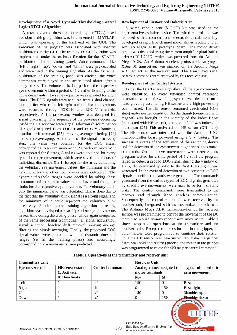
motors to realize various robotic arm movements. Table 1
shows respective operations at the transmitter and the
receiver units. Except the motors located in the gripper, all
other motors were programmed to continue their rotation
until the HE sensor was deactivated. To make the gripper
functions (hold and release) precise, the motor in the gripper
was programmed to rotate for 400 ms per control command.
Table. 1 Operations at the transmitter and receiver unit
Transmitter Unit Receiver Unit
Eye movements HE sensor status
1: Activate,
0: Deactivate
Control commands Analog values assigned to
motor terminals
Types of robotic
arm movement
M+ M-
Left 1 ‘a’ 150 0 Base left
Right 1 ‘b' 0 150 Base right
Up 1 ‘c’ 150 0 Shoulder up
Down 1 ‘d’ 0 150 Shoulder down

Development of an Electrooculogram-based Human-Computer Interface for Hands-Free Control of Assistive Devices
379
Published By:
Blue Eyes Intelligence Engineering
& Sciences Publication Retrieval Number: C2584018319/19©BEIESP
Up-Up # 1 ‘e’ 150 0 Elbow up
Down-Down # 1 ‘f'’ 0 150 Elbow down
Left-Left # 1 ‘g’ 150 0 Wrist up
Right-Right # 1 ‘h’ 0 150 Wrist down
V. Blink 1 ‘i’ 255 0 Hold
V. Blink-V. Blink # 1 ‘j’ 0 255 Release
-- 0 ‘k’ 0 0 Stop
(# Duration between two eye movements is 1.2 s)
Experimental Design for Performance Evaluation
Prior to the performance evaluation of the proposed HCI,
all the volunteers were advised to undergo a training to
avoid false positive or false negative results during the main
experiment. A five LED panel of different colors was
designed for training and verification purpose through visual
feedback (flashing of LED). The conjugate eye movements
were detected by flashing of particular LEDs twice. All the
volunteers were given five chances to flash the LEDs by
performing specific eye movements and voluntary blink.
The training phase was followed by the main experiment
with pick-and-place activity to evaluate the performance of
the proposed EOG-based HCI. 10 volunteers participated in
this study. At the onset of the experiment, all the volunteers
were informed about the training and the testing protocols.
The volunteers were informed about the different types of
intended eye movements (described in Table 1) to operate
the robotic arm. The designed experiment is shown in
Figure 1. The below-mentioned procedure was followed to
carry out the experiment.
a. The start point (‘X’) indicated in Figure 1 was the
point of initiation of the experiment.
b. In step-1, an object located at position A in the
Zone-1 was brought to position A* in the Zone-II.
c. In step-2, an object located at position B in the
Zone-II was brought to position B* in the Zone-III.
d. The robotic arm was brought back to its original
position (as shown in 1) after it released the object at B*.
e. The time lapse after releasing the object at A* and
before holding the object at B in Zone-II was not taken into
account.
Before the starting of the above-mentioned experiment
involving human volunteers, the shortest time required to
perform step-1 and step-2 was computed using joystick
based control of the robotic arm. This shortest time was used
to find out the speed index [29].
Fig. 1 Experimental design for performance evaluation
IV. RESULTS AND DISCUSSION
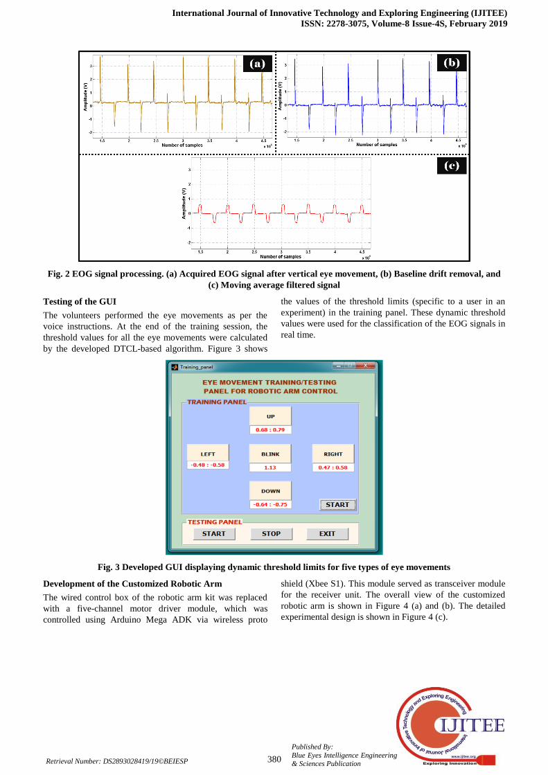
Processing of the EOG Signals
The volunteers were advised to sit comfortably on a chair
and look at the central marker of the 5-marker system. The
EOG signals were acquired when they moved their eyes
towards left, right, up, down, and blinking. The different
processing stages of an EOG signal due to the vertical eye
movement are shown in Figure 2.
International Journal of Innovative Technology and Exploring Engineering (IJITEE)
ISSN: 2278-3075, Volume-8 Issue-4S, February 2019
380
Published By:
Blue Eyes Intelligence Engineering & Sciences Publication Retrieval Number: DS2893028419/19©BEIESP
Fig. 2 EOG signal processing. (a) Acquired EOG signal after vertical eye movement, (b) Baseline drift removal, and
(c) Moving average filtered signal
Testing of the GUI
The volunteers performed the eye movements as per the
voice instructions. At the end of the training session, the
threshold values for all the eye movements were calculated
by the developed DTCL-based algorithm. Figure 3 shows
the values of the threshold limits (specific to a user in an
experiment) in the training panel. These dynamic threshold
values were used for the classification of the EOG signals in
real time.
Fig. 3 Developed GUI displaying dynamic threshold limits for five types of eye movements
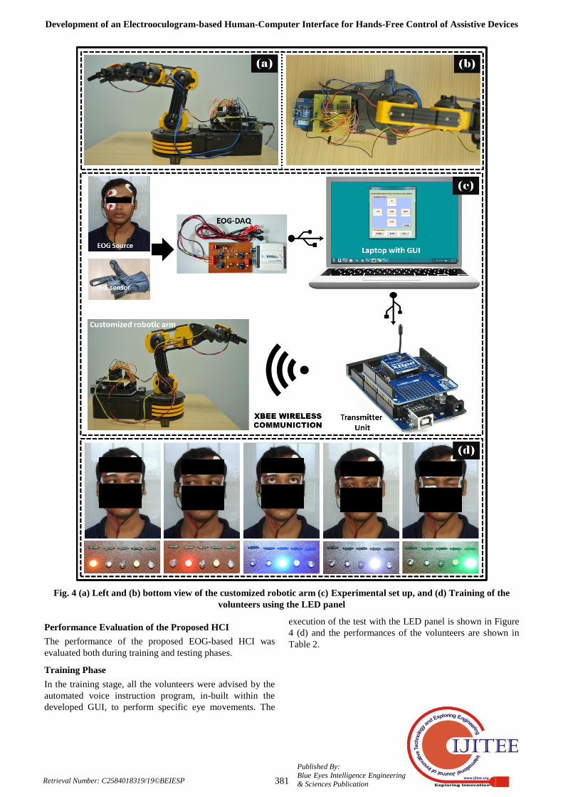
Development of the Customized Robotic Arm
The wired control box of the robotic arm kit was replaced
with a five-channel motor driver module, which was
controlled using Arduino Mega ADK via wireless proto
shield (Xbee S1). This module served as transceiver module
for the receiver unit. The overall view of the customized
robotic arm is shown in Figure 4 (a) and (b). The detailed
experimental design is shown in Figure 4 (c).
Development of an Electrooculogram-based Human-Computer Interface for Hands-Free Control of Assistive Devices
381
Published By:
Blue Eyes Intelligence Engineering
& Sciences Publication Retrieval Number: C2584018319/19©BEIESP
Fig. 4 (a) Left and (b) bottom view of the customized robotic arm (c) Experimental set up, and (d) Training of the
volunteers using the LED panel
Performance Evaluation of the Proposed HCI
The performance of the proposed EOG-based HCI was
evaluated both during training and testing phases.
Training Phase
In the training stage, all the volunteers were advised by the
automated voice instruction program, in-built within the
developed GUI, to perform specific eye movements. The
execution of the test with the LED panel is shown in Figure
4 (d) and the performances of the volunteers are shown in
Table 2.

International Journal of Innovative Technology and Exploring Engineering (IJITEE)
ISSN: 2278-3075, Volume-8 Issue-4S, February 2019
382
Published By:
Blue Eyes Intelligence Engineering & Sciences Publication Retrieval Number: DS2893028419/19©BEIESP
Table. 2 Volunteer performance during training
a = Left eye movement, b = Right eye movement, c = Up eye movement, d = Down eye movement, e = Voluntary blink, f = Left-Left eye movement, g = Right- Right eye movement, h =
Up-Up eye movement, i = Down-Down eye movement, j = Voluntary blink- Voluntary blink, + = True positive
# TEST-1 TEST-2 TEST-3 TEST-4
a b c d e f g h i j a b c d e f g h i j a b c d e F g h i j a b c d e f g h i J
1 + + + + + + + + + + + + + + + + + + + + + + + + + + + + + + + + + + + + + + + +
2 + + + + + + + + - + + + + + + + + + + + + + + + + + + + + + + + + + + + + + + +
3 + + + + + + + + + + + + + + + + + + + + + + + + + + + + + + + + + + + + + + + +
4 + + + + + + + + + + + + - + + + + + + + + + + + - + + + + + + + + + + + + + + +
5 + + + + - + + + + + + + + + + + + + + + + + + + + + + + + + + + + + + + + + + +
6 + + + + + + + + + + + + + + + + + + + + + + + + + + + + + + + + + + + + + + + +
7 + + - + + + + + + + + + + + - + + + + + + + + + + + + + + + + + + + + + + + + +
8 + + + + - + + + + + + + + + + + + + + + + + + + + + + + + + + + + + + + + + + +
9 + + + + + + + + + - + + + + + + + + + + + + + + + + + + + + + + + + + + + + + +
10 + + + + - + + + + + + + + + + + + + + + + + + + + + + + + + + + + + + + + + + +

International Journal of Innovative Technology and Exploring Engineering (IJITEE)
ISSN: 2278-3075, Volume-X, Issue-X
383
Published By:
Blue Eyes Intelligence Engineering
& Sciences Publication Retrieval Number: C2584018319/19©BEIESP
Table 2 shows the generation of true positive and false
negative results. Except the volunteers 1, 3 and 6, all the
volunteers produced false negative results at some point(s)
of the training phase. The reason for the occurrence of these
false negative results have been summarized Table 3.
Table. 3 Elucidation of false negative results
S/N of defaulters Tests Intended eye
movement
Detected eye
movement Reason
2 1 Down-down Down Started from up position instead of center position
4 2 Up Right Diagonal right-up eye movement
3 Voluntary blink Up Normal eye blink
5 1 Voluntary blink Up Normal eye blink
7 1 Up Right Diagonal right-up eye movement
2 Voluntary blink Up Normal eye blink
8 1 Voluntary blink Up Normal eye blink
9 1 Voluntary blink-
Voluntary blink
Voluntary
blink The second blink was normal eye blink
10 1 Voluntary blink Up Normal eye blink
Table 3 elucidates that the false negative results were
mainly observed during test-1 and test-2, except in volunteer
4, where the false negative results were observed during
test-2 and test-3. Later, all the volunteers corrected
themselves in the subsequent tests. The performance of the
volunteers revealed that with a short-term training, optimum
true positive results can be obtained.
Testing Phase
After the training session, all the volunteers were advised
to manipulate the customized robotic arm. All the volunteers
were given four independent consecutive chances to perform
the experiment in the intervals of four minutes. The time
taken for completing the tasks was measured. The time
taken by each volunteer for each test has been tabulated in
Table 4. It also summarizes the total time taken and the
average time taken for each user at each step. The average
completion time for step-1 and step-2 were 01:28 (min:s)
and 01:22 (min:s), respectively. The average total execution
time for the completion of the experiment was 02:51
(min:s). The time lapse between the initiation of the control
signal to the initiation of action by the customized robotic
arm was 1.4 s. The shortest time noted for completing step-1
and step-2 using the joystick based control of the robotic
arm were 01:07 (min:s) and 1:10 (min:s), respectively. Thus,
the minimum total time taken to complete the experiment
was 02:17 (min:s). The reason behind the implementation of
the joystick-based control of the robotic arm for the
computation of the minimum execution time was due to its
fast response to the user input. Further, the ease of
customizability of the joystick interface technology for the
people with special needs was also considered [30].
Subsequently, the percentage speed index was calculated by
equation (i).
During calculation, the minimum time of the ideal test
was considered to be 100% [29].
Percentage speed index= (100 * TTIdeal) / TTIndividual (i)
where,
TTIdeal = Total time in ideal test (2:17 min:s = 137 s)
TTIndividual = Total time in each test (in seconds)
Figure 5 shows the speed index of the tests for all
volunteers. It also illustrates the average time (µ) and
standard deviation (± σ) of the tests.
Table. 4 Performance evaluation
S/N of
Volunteers Tests
Step-1 1:07
(min:s)
Step-2 1:10
(min:s)
TOTAL
2:17 (min:s)
Speed index
(%)
User average
(min:s)
1
1 1:25 1:31 2:56 77.84
2:50 2 1:22 1:26 2:48 81.55
3 1:23 1:28 2:51 80.11
4 1:23 1:24 2:47 82.04
2
1 1:24 1:24 2:48 81.55
2:50 2 1:30 1:27 2:57 77.40
3 1:28 1:21 2:49 81.07
4 1:25 1:24 2:49 81.07
3
1 1:38 1:19 2:57 77.40
2:50 2 1:29 1:19 2:48 81.58
3 1:31 1:20 2:51 80.12
4 1:21 1:23 2:44 83.03

International Journal of Innovative Technology and Exploring Engineering (IJITEE)
ISSN: 2278-3075, Volume-8 Issue-4S, February 2019
384
Published By:
Blue Eyes Intelligence Engineering & Sciences Publication Retrieval Number: DS2893028419/19©BEIESP
4
1 1:27 1:24 2:51 80.12
2:52 2 1:36 1:26 3:02 75.27
3 1:22 1:25 2:47 82.04
4 1:24 1:24 2:48 81.55
5
1 1:22 1:20 2:42 82.53
2:47 2 1:30 1:20 2:50 80.59
3 1:33 1:15 2:48 81.58
4 1:32 1:19 2:51 80.12
6
1 1:49 1:24 3:13 70.98
2:55 2 1:27 1:24 2:51 80.12
3 1:28 1:21 2:49 81.07
4 1:25 1:22 2:47 82.04
7
1 1:25 1:19 2:44 83.54
2:49 2 1:30 1:20 2:50 80.59
3 1:34 1:21 2:55 78.29
4 1:25 1:24 2:49 81.07
8
1 1:44 1:22 3:06 73.65
2:53 2 1:27 1:22 2:49 81.07
3 1:31 1:20 2:51 80.12
4 1:23 1:25 2:48 81.55
9
1 1:40 1:23 3:03 74.86
2:52 2 1:27 1:24 2:51 80.12
3 1:21 1:29 2:50 80.59
4 1:25 1:21 2:46 82.53
10
1 1:29 1:21 2:50 80.59
2:49 2 1:28 1:20 2:48 81.55
3 1:22 1:27 2:49 81.07
4 1:24 1:26 2:50 80.59
AVERAGE 1:28 1:22 2:51 80.11
Fig. 5 Speed test of the volunteers
International Journal of Innovative Technology and Exploring Engineering (IJITEE)
ISSN: 2278-3075, Volume-X, Issue-X
385
Published By:
Blue Eyes Intelligence Engineering
& Sciences Publication Retrieval Number: C2584018319/19©BEIESP
The performances of the volunteers have also been shown
in Figure 5. Many volunteers couldn’t achieve the average
speed index of 80.11% during the initial tests. Later, after
getting accustomed with the experimental design, the
volunteers could successfully beat the average speed index.
This signifies that with a short-term training, the
performance of the users can be improved. Volunteer-4 took
more time in Test-2 due to misjudgment in holding the
target object. Hence, his speed index was reduced. Out of
the four tests, all the volunteers were able to achieve the
average speed index at least in three tests. The success rate
of volunteer-10 in achieving the average speed index was
100%. The overall success rate of achieving the average
speed index was 77.5%, which can be improved further by
providing training to the volunteers on the device.
V. CONCLUSION
An EOG based HCI was designed for wireless control of a
robotic arm for pick-and-place applications. This can be of
great benefit to the severely motor-disabled patients.
Ag/AgCl electrodes were used to acquire the signals. The
EOG signals were acquired using an in-house developed
EOG-DAQ. The signals were processed on a real-time basis
and subsequently classified for decision making in an in-lab
developed MATLAB-based program. The process of
decision making algorithm involved training and testing
phases. A novel DTCL-based algorithm was used to find out
the dynamic threshold ranges for different types of eye
movements and voluntary blink during the training phase. In
the testing phase, the pre-estimated threshold ranges were
used to classify the eye movements in real-time and to
generate control commands. The generation of the control
commands was physically accomplished through successive
events of HE sensor activation and eye movement detection.
The generated control commands were made available to the
transmitter unit for wireless propagation through Xbee
communication. The transmitter unit was developed by
coupling a Xbee S1 transceiver with an Arduino UNO
microcontroller, which was connected to the USB port of
the laptop. At the receiver end, an integrated electronic
module (comprising of an Arduino Mega ADK
microcontroller, Xbee S1 transceiver and motor driver
circuit) was mounted on a customized robotic arm. The
performance of the developed assistive technology was
evaluated by 10 healthy volunteers. The volunteers were
subjected to a realistic experiment, designed in a domestic
context. The results revealed that all the volunteers could
successfully complete the experiment and achieved an
average speed index of completing the experiment with a
success rate of 77.5%. The experiment also suggested that
the execution time can be improved with training. People
with severe neuromotor disorders may use this assistive
technology to improve their quality-of-life, enhance greater
autonomy and reinforce their social inclusion.
REFERENCES
1. W. S. Harwin, et al., "A review of design issues in rehabilitation
robotics with reference to North American research," Rehabilitation
Engineering, IEEE Transactions on, vol. 3, pp. 3-13, 1995.
2. J. R. Hegarty and M. J. Topping, "HANDY 1-A Low-Cost Robotic Aid
to Eating," in Proc. Int'l. Conf. on Rehabilitation Robotics, 1991, pp.
17-25.
3. J. A. Martínez, et al., "Multimodal system based on electrooculography
and voice recognition to control a robot arm," Int. J. Adv. Robotic Syst,
vol. 10, 2013.
4. A. Phinyomark, et al., "A review of control methods for electric power
wheelchairs based on electromyography signals with special emphasis
on pattern recognition," IETE Technical Review, vol. 28, pp. 316-326,
2011.
5. E. McAdams, "Encyclopedia of Medical Devices and Instrumentation,"
ed: John Wiley & Sons, 2006.
6. C. Luca, "Electromyography," Encyclopedia of Medical Devices and
Instrumentation, 2006.
7. K. H. Ha, et al., "Volitional control of a prosthetic knee using surface
electromyography," Biomedical Engineering, IEEE Transactions on,
vol. 58, pp. 144-151, 2011.
8. D. Brunelli, et al., "Low-cost wearable multichannel surface EMG
acquisition for prosthetic hand control," in Advances in Sensors and
Interfaces (IWASI), 2015 6th IEEE International Workshop on, 2015,
pp. 94-99.
9. G. Kucukyildiz, et al., "Real time control of a wheelchair based on
EMG and Kinect for the disabled people," in Medical Technologies
National Conference (TIPTEKNO), 2015, 2015, pp. 1-4.
10. M. L. Guzmán, et al., "Non-conventional Control and Implementation
of an Electric Wheelchair Designed to Climb Up Stairs, Controlled via
Electromyography and Supported by Artificial Neural Network
Processing," in Pattern Recognition, ed: Springer, 2013, pp. 344-353.
11. M. B. I. Reaz, et al., "Techniques of EMG signal analysis: detection,
processing, classification and applications," Biological procedures
online, vol. 8, p. 11, 2006.
12. C. L. Martin, et al., "Gait and balance impairment in early multiple
sclerosis in the absence of clinical disability," Multiple Sclerosis
Journal, vol. 12, pp. 620-628, 2006.
13. A. Ramos-Murguialday, et al., "Proprioceptive feedback and brain
computer interface (BCI) based neuroprostheses," PloS one, vol. 7, p.
e47048, 2012.
14. C.-T. Lin, et al., "EEG-based assessment of driver cognitive responses
in a dynamic virtual-reality driving environment," Biomedical
Engineering, IEEE Transactions on, vol. 54, pp. 1349-1352, 2007.
15. T. Gupta, et al., "A Portable & Cost Effective Human Computer
Interface Device for Disabled," in Communication Systems and
Network Technologies (CSNT), 2015 Fifth International Conference
on, 2015, pp. 1268-1273.
16. B. Champaty, et al., "Development of eog based human machine
interface control system for motorized wheelchair," in Emerging
Research Areas: Magnetics, Machines and Drives (AICERA/iCMMD),
2014 Annual International Conference on, 2014, pp. 1-7.
17. S. Nayak, et al., "Development of an EOG based computer aided
communication support system," in 2015 Annual IEEE India
Conference (INDICON), 2015, pp. 1-6.
18. A. Ang, et al., "A user-friendly wearable single-channel EOG-based
human-computer interface for cursor control," in Neural Engineering
(NER), 2015 7th International IEEE/EMBS Conference on, 2015, pp.
565-568.
19. R. Barea, et al., "EOG-based eye movements codification for human
computer interaction," Expert Systems with Applications, vol. 39, pp.
2677-2683, 2012.
20. P. Swami and T. K. Gandhi, "Assistive communication system for
speech disabled patients based on electro-oculogram character
recognition," in Computing for Sustainable Global Development
(INDIACom), 2014 International Conference on, 2014, pp. 373-376.
21. S. Soltani and A. Mahnam, "A practical efficient human computer
interface based on saccadic eye movements for people with
disabilities," Computers in Biology and Medicine, 2016.
22. S. Tarunkumar, et al., "An assistive device for quadriplegic patients
using NI-MyRIO," Biomedical Engineering: Applications, Basis and
Communications, vol. 29, p. 1750017, 2017.
23. S. Soltani and A. Mahnam, "A practical efficient human computer
interface based on saccadic eye movements for people with
disabilities," Computers in biology and medicine, vol. 70, pp. 163-173,
2016.

International Journal of Innovative Technology and Exploring Engineering (IJITEE)
ISSN: 2278-3075, Volume-8 Issue-4S, February 2019
386
Published By:
Blue Eyes Intelligence Engineering & Sciences Publication Retrieval Number: DS2893028419/19©BEIESP
24. B. Champaty, et al., "Voluntary Blink Controlled Communication
Protocol for Bed-Ridden Patients," in Handbook of Research on
Wireless Sensor Network Trends, Technologies, and Applications, ed:
IGI Global, 2017, pp. 162-195.
25. B. Champaty, et al., "Development of EOG and EMG-Based
Multimodal Assistive Systems," in Medical Imaging in Clinical
Applications, ed: Springer, 2016, pp. 285-310.
26. H. S. Dhillon, et al., "EOG and EMG based virtual keyboard: A brain-
computer interface," in Computer Science and Information
Technology, 2009. ICCSIT 2009. 2nd IEEE International Conference
on, 2009, pp. 259-262.
27. E. Iáñez, et al., "Interface based on electrooculography for velocity
control of a robot arm," Applied Bionics and Biomechanics, vol. 7, pp.
199-207, 2010.
28. K. Kawasaki and T. Tamura, "Automated measurement of the electro-
oculogram for clinical use," Documenta ophthalmologica, vol. 66, pp.
85-94, 1987.
29. E. IáñEz, et al., "Assistive robot application based on an RFID control
architecture and a wireless EOG interface," Robotics and Autonomous
Systems, vol. 60, pp. 1069-1077, 2012.
30. B. E. Dicianno, et al., "Joystick control for powered mobility: Current
state of technology and future directions," Physical Medicine and
Rehabilitation Clinics, vol. 21, pp. 79-86, 2010.