
Acceleration statistics of inertial particles in turbulent flow
Upload
khangminh22Category
view
3download
0
�����������������
Citation: Wu, Y.-C.; Lin, S.-X.; Lin,
J.-Y.; Han, C.-C.; Chang, C.-S.; Jiang,
J.-X. Development of AI Algorithm
for Weight Training Using Inertial
Measurement Units. Appl. Sci. 2022,
12, 1422. https://doi.org/10.3390/
app12031422
Academic Editors: Teen-Hang Meen
and Chun-Yen Chang
Received: 27 November 2021
Accepted: 25 January 2022
Published: 28 January 2022
Publisher’s Note: MDPI stays neutral
with regard to jurisdictional claims in
published maps and institutional affil-
iations.
Copyright: © 2022 by the authors.
Licensee MDPI, Basel, Switzerland.
This article is an open access article
distributed under the terms and
conditions of the Creative Commons
Attribution (CC BY) license (https://
creativecommons.org/licenses/by/
4.0/).
applied sciences
Article
Development of AI Algorithm for Weight Training UsingInertial Measurement UnitsYu-Chi Wu 1,*, Shi-Xin Lin 1, Jing-Yuan Lin 1, Chin-Chuan Han 2, Chao-Shu Chang 3 and Jun-Xian Jiang 1
1 Department of Electrical Engineering, National United University, Maio-Li 360, Taiwan;[email protected] (S.-X.L.); [email protected] (J.-Y.L.); [email protected] (J.-X.J.)
2 Department of Computer Science and Information Engineering, National United University,Maio-Li 360, Taiwan; [email protected]
3 Department of Information Management, National United University, Maio-Li 360, Taiwan;[email protected]
* Correspondence: [email protected]; Tel.: +886-939-967722
Featured Application: Fitness, Weight Training, Medical Rehabilitation, Sport Training, HealthManagement.
Abstract: Thanks to the rapid development of Wearable Fitness Trackers (WFTs) and SmartphonePedometer Apps (SPAs), people are keeping an eye on their health through fitness and heart ratetracking; therefore, home weight training exercises have received a lot of attention lately. A multi-procedure intelligent algorithm for weight training using two inertial measurement units (IMUs) isproposed in this paper. The first procedure is for motion tracking that estimates the arm orientationand calculates the positions of the wrist and elbow. The second procedure is for posture recognitionbased on deep learning, which identifies the type of exercise posture. The final procedure is forexercise prescription variables, which first infers the user’s exercise state based on the results of theprevious two procedures, triggers the corresponding event, and calculates the key indicators of theweight training exercise (exercise prescription variables), including exercise items, repetitions, sets,training capacity, workout capacity, training period, explosive power, etc.). This study integratesthe hardware and software as a complete system. The developed smartphone App is able to receiveheart rate data, to analyze the user’s exercise state, and to calculate the exercise prescription variablesautomatically in real-time. The dashboard in the user interface of the smartphone App can displayexercise information through Unity’s Animation System (avatar) and graphics, and records arestored by the SQLite database. The designed system was proven by two types of experimentalverification tests. The first type is to control a stepper motor to rotate the designed IMU and tocompare the rotation angle obtained from the IMU with the rotation angle of the controlled steppermotor. The average mean absolute error of estimation for 31 repeated experiments is 1.485 degrees.The second type is to use Mediapipe Pose to calculate the position of the wrist and the angles of upperarm and forearm between the Z-axis, and these calculated data are compared with the designedsystem. The root-mean-square (RMS) error of positions of the wrist is 2.43 cm, and the RMS errorsof two angles are 5.654 and 4.385 degrees for upper arm and forearm, respectively. For posturerecognition, 12 participants were divided into training group and test group. Eighty percent and20% of 24,963 samples of 10 participants were used for the training and validation of the LSTMmodel, respectively. Three-thousand-three-hundred-and-fifty-nine samples of two participants wereused to evaluate the performance of the trained LSTM model. The accuracy reached 99%, and F1score was 0.99. When compared with the other LSTM-based variants, the accuracy of one-layerLSTM presented in this paper is still promising. The exercise prescription variables provided bythe presented system are helpful for weight trainers/trainees to closely keep an eye on their fitnessprogress and for improving their health.
Appl. Sci. 2022, 12, 1422. https://doi.org/10.3390/app12031422 https://www.mdpi.com/journal/applsci
Appl. Sci. 2022, 12, 1422 2 of 23
Keywords: inertial measurement unit; 9-DoF sensor; weight training; motion tracking; posturerecognition; machine learning; internet of things
1. Introduction
In recent years, home weight training exercises have received a lot of attention. Wear-able products have also become an important tool to help people improve the quality ofexercise. In terms of exercise data quantification, with the rapid development of WearableFitness Trackers (WFTs) and Smartphone Pedometer Apps (SPAs), people are keeping aneye on their health through heart rate, fitness, and sleep tracking [1].
In 2004, Kong [2] developed an inertial navigation system algorithm based on a low-cost inertial measurement unit to implement a nonlinear data fusion algorithm usinga Distribution Approximation Filter (DAF). Gyroscopes are often used for system posi-tioning in many applications, but gyroscopes generate error drift, a low-frequency driftphenomenon over time [3], which accumulates very large orientation errors over time, sothat an attitude positioning system cannot use only one gyroscope to achieve accurateorientation. The causes of integration drift can be divided into two categories: one is thelinear increase of drift due to the integration of the original offset in the signal, and theother is the integration of noise in the signal [4].
In the long term, both accelerometer and magnetometer have no drift. Inputting theaccelerometer and magnetometer data into Kalman Filter (KF) can compensate the driftof gyroscope, so it can be used to determine the orientation, but both of them have moreobvious short-term noise [5].
Many studies have used data from inertial measurement units (IIMUs) for humanposture recognition using machine learning models. Tahir [6] used a one-dimensionalHadamard wavelet transformation and a feature extraction method based on one-dimensionalLBP (Local binary patterns) to compute valuable eigenvalues in acceleration and angularvelocity signals, and used a sequential minimization algorithm and a stochastic forestmethod to classify activities in the USC-HAD (USC human activity dataset) and IMSB(IM-Sporting Behaviors) datasets. No IMU-based device was presented in this work. EzioPreatoni [7] trained and tested different supervised machine learning models based on14 participants, including k-NN (k-nearest neighbors) algorithm and SVM (Support VectorMachine), using accelerations and angular velocities of one sensor with an highest accuracyof 96.4% and of two sensors with 97.6% accuracy to classify four fitness sports. No exerciseprescription variables, such as exercise sets, training capacity, workout capacity, trainingperiod, explosive power, etc. were considered. Many research papers have combineddata from cell phones and wearable sensors to automatically capture features using deeplearning algorithms, effectively saving manual feature processing [8]. Sui [9] mentioned thatmany papers use IMU data into a CNN (Convolutional Neural Network) to achieve posturerecognition, and he proposed another CNN algorithm to calculate the pace trajectory. Inhis work, the developed IMU device was worn on a shoe for foot motion tracking. Theliterature [10] proposes a real-time segmentation and classification algorithm that canidentify physical exercise and works well in both indoor and outdoor environments. Thisproposed algorithm achieved a 95% classification accuracy for five indoor and outdoorexercises. No exercise prescription variables were considered in [10]. Koskimäki andSiirtola [11] trained a machine learning model with accelerometer data to classify 36 typesof fitness exercises. The data were collected using a GeneActiv 3D accelerometer, whichcan be used as a wrist-worn or be attached with straps to other body locations.
In many cases, IMUs have been used to develop multimodal algorithms, and Haus-berger et al. [12] designed a smart fitness device that uses acceleration and angular velocitysignals read by IMUs to perform automatic motion tracking and analyze weight trainingexercises. Their device was mounted on the dumb bell. The repetitions of dumb bellexercise were detected by a peak/valley detector. Other exercise prescription variables
Appl. Sci. 2022, 12, 1422 3 of 23
were not considered in this work. Seong and Choi [13] used an IMU to implement a newtype of computer interface operating system that performs hand motion tracking and clickgesture recognition algorithms using Euler angles and acceleration data, respectively.
Chen et al. [14] proposed a deep learning framework based on graph convolutionalnetwork (GCN) to predict the position of each joint of human lower limbs during motionin 3D space using signals collected from five IMUs (above the ankles of both feet, abovethe knees of both feet, and at the waist). Abdelhady et al. [15] proposed a system of IMUsin the lower legs, IMUs in the thighs, and pressure sensors in both feet to measure thekinetics and kinematics of the lower limbs. Wang et al. [16] used an IMU on each leg and amotion camera on each calf to estimate the asymmetry of stride length and gait, and theroot mean square error of stride length was 5.4 cm and asymmetry was 3.0% in healthysubjects, while the root mean square error of stride length was 9.6 cm and asymmetry was14.7% in subjects with abnormal gait.
Zou et al. [17] proposed a low-cost smart glove equipped with an inertial unit. Theirsystem could recognize 15 sets of training programs, detect three common nonstandardbehaviors: case 1-the overall speed of a repetition is too fast or too slow, case 2-the speeds ofoutward and backward processes are not balanced, and case 3-the repetitions are not stablewith noticeable shakes. A segmentation process was used in their system to detect the startpoint and end point of each repetition with the help of a double adaptive thresholds-basedmethod. Then the half dynamic time warping (Half-DTW), which is not a deep learningapproach, was proposed to measure the similarity between the unrecognized activitysegmentation data (accelerometer and gyroscope readings) and the activity templates.The Half-DTW requires two steps. First, it applies an outward-backward segmentationoperation to divide a repetition into outward and backward parts through locating theturning point (TP, stage changing point). Second, the Half-DTW applies the correspondingmatching operation and outputs the identified activity type. Several exercise quality indiceswere calculated as well: standard degree and execution duration for the assessment of singlerepetition, and smoothness and continuity for the assessment of group repetitions. Theaverage accuracy using Half-DTW for 15 exercise types is 96.07% with 103.76 ms averagetime delays. Rodriguez et al. [18] presented a wearable device using three inertial unitswith triaxial accelerometers, gyroscopes, and magnetometers to measure the orientationof three sections of the spine for low back pain therapy. By integrating the absolute andrelative orientation from the sensors based on the so-called direction cosine matrix (DCM), itestimates the posture of the back in real-time and uses a fuzzy system to control a vibrationunit to alert the user to correct the posture of his/her back.
From these mentioned literature in the above, most papers focus on recognitionalgorithms for exercises to improve prediction accuracy. The number of sensors used forcollecting data and identifying exercise types is ranging from one to five or even more.Depending on the application purpose, some sensors are attached to lower limbs, and someare attached to arms. However, to the best of the authors’ knowledge, very few papersextend the results of the IMU motion tracking to produce helpful exercise prescriptionvariables for fitness lovers. This paper integrates hardware and software to developan attitude and heading reference system (AHRS) device using only two IMUs (one onthe wrist band and the other in the sleeve near the elbow) and an intelligent algorithmthat performs motion tracking, posture recognition, and calculates exercise prescriptionvariables for weight training. These exercise prescription variables, including exercise items,repetitions, sets, training capacity, workout capacity, and training period, etc., providemeaningful information for weight trainers/trainees. A fitness App with the function ofrecording exercise performance is also developed on the smartphone, so that the userscan check their exercise performance and review the historical exercise records in the userinterface in real time.
Appl. Sci. 2022, 12, 1422 4 of 23
2. Materials and Methods2.1. Overall Study Design
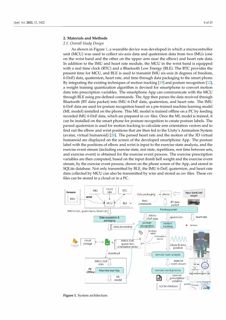
As shown in Figure 1, a wearable device was developed in which a microcontrollerunit (MCU) was used to collect six-axis data and quaternion data from two IMUs (oneon the wrist band and the other on the upper arm near the elbow) and heart rate data.In addition to the IMU and heart rate module, the MCU in the wrist band is equippedwith a real time clock (RTC) and a Bluetooth Low Energy (BLE). The RTC provides thepresent time for MCU, and BLE is used to transmit IMU six-axis (6 degrees of freedom,6-DoF) data, quaternion, heart rate, and time through data packaging to the smart phone.By integrating the existing techniques of motion tracking [19] and posture recognition [12],a weight training quantization algorithm is devised for smartphone to convert motiondata into prescription variables. The smartphone App can communicate with the MCUthrough BLE using pre-defined commands. The App then parses the data received throughBluetooth (BT data packet) into IMU 6-DoF data, quaternion, and heart rate. The IMU6-DoF data are used for posture recognition based on a pre-trained machine learning model(ML model) installed on the phone. This ML model is trained offline on a PC by feedingrecorded IMU 6-DoF data, which are prepared in csv files. Once the ML model is trained, itcan be installed on the smart phone for posture recognition to create posture labels. Theparsed quaternion is used for motion tracking to calculate arm orientation vectors and tofind out the elbow and wrist positions that are then fed to the Unity’s Animation System(avatar, virtual humanoid) [20]. The parsed heart rate and the motion of the 3D virtualhumanoid are displayed on the screen of the developed smartphone App. The posturelabel with the positions of elbow and wrist is input to the exercise state analysis, and theexercise event stream (including exercise state, rest state, repetitions, rest time between sets,and exercise event) is obtained for the exercise event process. The exercise prescriptionvariables are then computed, based on the input dumb bell weight and the exercise eventstream, by the exercise event process, shown on the phone screen of the App, and stored inSQLite database. Not only transmitted by BLE, the IMU 6-DoF, quaternion, and heart ratedata collected by MCU can also be transmitted by wire and stored as csv files. These csvfiles can be stored in a cloud or in a PC.
Figure 1. System architecture.

Appl. Sci. 2022, 12, 1422 5 of 23
The proposed artificial intelligence weight training quantization algorithm convertsthe raw motion data into exercise prescription variables step by step based on mathematicaland physical theories, as shown in Figure 2. This part has two procedures, one for posturerecognition and one for motion tracking using IMU 6-axis data and quaternion data ofthe wrist and the arm to calculate the posture label type and the joint position of the arm.The outputs of the two procedures are fed first to the exercise state analysis for calculatingrepetitions, state, and event, and then to the exercise event process for calculating theexercise prescription variables.
Figure 2. Flowchart of the presented algorithm.
2.2. Motion Tracking Algorithm
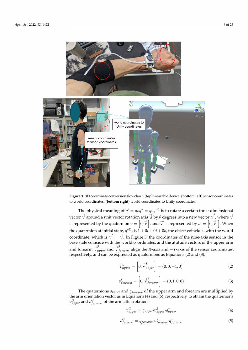
In this paper, we use two nine-axis sensors (Adafruit BNO055 Absolute OrientationSensors), as shown in the top photo of Figure 3, one on the wrist and the other on theupper arm near the elbow (marked by red circles). The bottom left photo shows that thesensor coordinates transformed to world coordinates, and the bottom right photo showsthe world coordinates transformed to Unity coordinates. Once the alignment with theuser’s orientation is done, the Unity would show the same movement as the real persondoes. In the built-in microcontroller of the sensor, a world coordinate with the Y-axis facingthe north pole of the geomagnetic field and the Z-axis perpendicular to the earth planeis defined, and the corresponding quaternion qt = [w, x, y, z] is generated based on thisworld coordinate. qt represents the action of rotating the sensor from the base state to thecurrent position, which can be further expressed as Equation (1).
qt =
[cos(
θ
2
), sin
(θ
2
)→u]
(1)
Appl. Sci. 2022, 12, 1422 6 of 23
Figure 3. 3D coordinate conversion flowchart: (top) wearable device, (bottom left) sensor coordinatesto world coordinates, (bottom right) world coordinates to Unity coordinates.
The physical meaning of v′ = qvq∗ = qvq−1 is to rotate a certain three-dimensional
vector→v around a unit vector rotation axis
→u by θ degrees into a new vector
→v′, where
→v
is represented by the quaternion v =[0,→v], and
→v′
is represented by v′ =[0,→v′]
. When
the quaternion at initial state, q(0), is 1 + 0i + 0j + 0k, the object coincides with the world
coordinate, which is→v′=→v. In Figure 3, the coordinates of the nine-axis sensor in the
base state coincide with the world coordinates, and the attitude vectors of the upper arm
and forearm→v
Supper and
→v
Sf orearm align the X-axis and −Y-axis of the sensor coordinates,
respectively, and can be expressed as quaternions as Equations (2) and (3).
vSupper =
[0,→v
Supper
]= (0, 0,−1, 0) (2)
vSf orearm =
[0,→v
Sf orearm
]= (0, 1, 0, 0) (3)
The quaternions qupper and q f orearm of the upper arm and forearm are multiplied bythe arm orientation vector as in Equations (4) and (5), respectively, to obtain the quaternionsvG
upper and vGf orearm of the arm after rotation.
vGupper = qupper·vS
upper·q∗upper (4)
vGf orearm = q f orearm·vS
f orearm·q∗f orearm (5)
Appl. Sci. 2022, 12, 1422 7 of 23
where vGupper =
[0,→v
Gupper
], vG
f orearm =
[0,→v
Gf orearm
], and the orientation vectors of the arms
in the world coordinates are Equations (6) and (7).
→v
Gupper =
(xG
upper, yGupper, zG
upper
)(6)
→v
Gf orearm =
(xG
f orearm, yGf orearm, zG
f orearm
)(7)
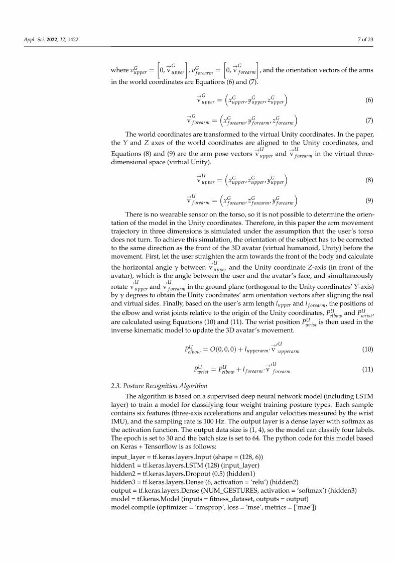
The world coordinates are transformed to the virtual Unity coordinates. In the paper,the Y and Z axes of the world coordinates are aligned to the Unity coordinates, and
Equations (8) and (9) are the arm pose vectors→v
Uupper and
→v
Uf orearm in the virtual three-
dimensional space (virtual Unity).
→v
Uupper =
(xG
upper, zGupper, yG
upper
)(8)
→v
Uf orearm =
(xG
f orearm, zGf orearm, yG
f orearm
)(9)
There is no wearable sensor on the torso, so it is not possible to determine the orien-tation of the model in the Unity coordinates. Therefore, in this paper the arm movementtrajectory in three dimensions is simulated under the assumption that the user’s torsodoes not turn. To achieve this simulation, the orientation of the subject has to be correctedto the same direction as the front of the 3D avatar (virtual humanoid, Unity) before themovement. First, let the user straighten the arm towards the front of the body and calculate
the horizontal angle γ between→v
Uupper and the Unity coordinate Z-axis (in front of the
avatar), which is the angle between the user and the avatar’s face, and simultaneously
rotate→v
Uupper and
→v
Uf orearm in the ground plane (orthogonal to the Unity coordinates’ Y-axis)
by γ degrees to obtain the Unity coordinates’ arm orientation vectors after aligning the realand virtual sides. Finally, based on the user’s arm length lupper and l f orearm, the positions ofthe elbow and wrist joints relative to the origin of the Unity coordinates, PU
elbow and PUwrist,
are calculated using Equations (10) and (11). The wrist position PUwrist is then used in the
inverse kinematic model to update the 3D avatar’s movement.
PUelbow = O(0, 0, 0) + lupperarm·
→v′Uupperarm (10)
PUwrist = PU
elbow + l f orearm·→v′U
f orearm (11)
2.3. Posture Recognition Algorithm
The algorithm is based on a supervised deep neural network model (including LSTMlayer) to train a model for classifying four weight training posture types. Each samplecontains six features (three-axis accelerations and angular velocities measured by the wristIMU), and the sampling rate is 100 Hz. The output layer is a dense layer with softmax asthe activation function. The output data size is (1, 4), so the model can classify four labels.The epoch is set to 30 and the batch size is set to 64. The python code for this model basedon Keras + Tensorflow is as follows:
input_layer = tf.keras.layers.Input (shape = (128, 6))hidden1 = tf.keras.layers.LSTM (128) (input_layer)hidden2 = tf.keras.layers.Dropout (0.5) (hidden1)hidden3 = tf.keras.layers.Dense (6, activation = ‘relu’) (hidden2)output = tf.keras.layers.Dense (NUM_GESTURES, activation = ‘softmax’) (hidden3)model = tf.keras.Model (inputs = fitness_dataset, outputs = output)model.compile (optimizer = ‘rmsprop’, loss = ‘mse’, metrics = [‘mae’])
Appl. Sci. 2022, 12, 1422 8 of 23
history = model.fit (inputs_train, outputs_train, epochs = 30, batch_size = 64, verbose = 0,validation_data = (inputs_validate, outputs_validate))
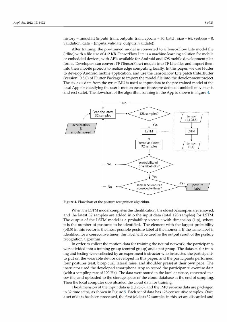
After training, the pre-trained model is converted to a TensorFlow Lite model file(.tflite) with a file size of 412 KB. TensorFlow Lite is a machine-learning solution for mobileor embedded devices, with APIs available for Android and iOS mobile development plat-forms. Developers can convert TF (TensorFlow) models into TF Lite files and import theminto their mobile projects to realize edge computing locally. In this paper, we use Flutterto develop Android mobile application, and use the TensorFlow Lite patch tflite_flutter(version: 0.8.0) of Flutter Package to import the model file into the development project.The six-axis data from the wrist IMU is used as input data to the pre-trained model of thelocal App for classifying the user’s motion posture (three pre-defined dumbbell movementsand rest state). The flowchart of the algorithm running in the App is shown in Figure 4.
Figure 4. Flowchart of the posture recognition algorithm.
When the LSTM model completes the identification, the oldest 32 samples are removed,and the latest 32 samples are added into the input data (total 128 samples) for LSTM.The output of the LSTM model is a probability vector r with dimension (1,p), wherep is the number of postures to be identified. The element with the largest probability(>0.5) in this vector is the most possible posture label at the moment. If the same label isidentified for n consecutive times, this label will be used as the output result of the posturerecognition algorithm.
In order to collect the motion data for training the neural network, the participantswere divided into a training group (control group) and a test group. The datasets for train-ing and testing were collected by an experiment instructor who instructed the participantsto put on the wearable device developed in this paper, and the participants performedfour postures (rest, bicep curl, lateral raise, and shoulder press) at their own pace. Theinstructor used the developed smartphone App to record the participants’ exercise data(with a sampling rate of 100 Hz). The data were stored in the local database, converted to acsv file, and uploaded to the storage space of the cloud database at the end of sampling.Then the local computer downloaded the cloud data for training.
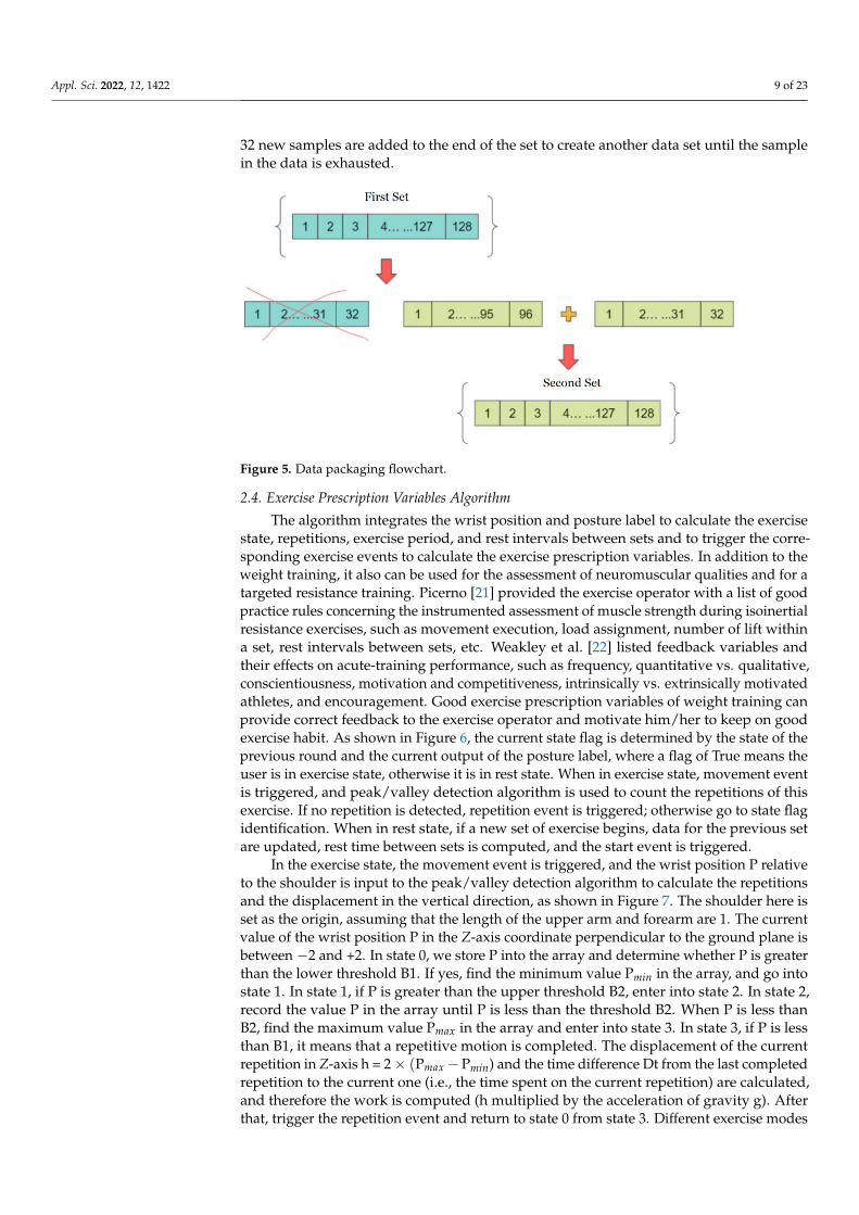
The dimension of the input data is (1,128,6), and the IMU six-axis data are packagedin 32 time steps, as shown in Figure 5. Each set of data has 128 consecutive samples. Oncea set of data has been processed, the first (oldest) 32 samples in this set are discarded and
Appl. Sci. 2022, 12, 1422 9 of 23
32 new samples are added to the end of the set to create another data set until the samplein the data is exhausted.
Figure 5. Data packaging flowchart.
2.4. Exercise Prescription Variables Algorithm
The algorithm integrates the wrist position and posture label to calculate the exercisestate, repetitions, exercise period, and rest intervals between sets and to trigger the corre-sponding exercise events to calculate the exercise prescription variables. In addition to theweight training, it also can be used for the assessment of neuromuscular qualities and for atargeted resistance training. Picerno [21] provided the exercise operator with a list of goodpractice rules concerning the instrumented assessment of muscle strength during isoinertialresistance exercises, such as movement execution, load assignment, number of lift withina set, rest intervals between sets, etc. Weakley et al. [22] listed feedback variables andtheir effects on acute-training performance, such as frequency, quantitative vs. qualitative,conscientiousness, motivation and competitiveness, intrinsically vs. extrinsically motivatedathletes, and encouragement. Good exercise prescription variables of weight training canprovide correct feedback to the exercise operator and motivate him/her to keep on goodexercise habit. As shown in Figure 6, the current state flag is determined by the state of theprevious round and the current output of the posture label, where a flag of True means theuser is in exercise state, otherwise it is in rest state. When in exercise state, movement eventis triggered, and peak/valley detection algorithm is used to count the repetitions of thisexercise. If no repetition is detected, repetition event is triggered; otherwise go to state flagidentification. When in rest state, if a new set of exercise begins, data for the previous setare updated, rest time between sets is computed, and the start event is triggered.
In the exercise state, the movement event is triggered, and the wrist position P relativeto the shoulder is input to the peak/valley detection algorithm to calculate the repetitionsand the displacement in the vertical direction, as shown in Figure 7. The shoulder here isset as the origin, assuming that the length of the upper arm and forearm are 1. The currentvalue of the wrist position P in the Z-axis coordinate perpendicular to the ground plane isbetween −2 and +2. In state 0, we store P into the array and determine whether P is greaterthan the lower threshold B1. If yes, find the minimum value Pmin in the array, and go intostate 1. In state 1, if P is greater than the upper threshold B2, enter into state 2. In state 2,record the value P in the array until P is less than the threshold B2. When P is less thanB2, find the maximum value Pmax in the array and enter into state 3. In state 3, if P is lessthan B1, it means that a repetitive motion is completed. The displacement of the currentrepetition in Z-axis h = 2× (Pmax−Pmin) and the time difference Dt from the last completedrepetition to the current one (i.e., the time spent on the current repetition) are calculated,and therefore the work is computed (h multiplied by the acceleration of gravity g). Afterthat, trigger the repetition event and return to state 0 from state 3. Different exercise modes

Appl. Sci. 2022, 12, 1422 10 of 23
should use different B1 and B2 values, and different users have different thresholds for thesame exercise item. Therefore, the values B1 and B2 should be adjusted according to theuser’s exercise mode and habit. Table 1 shows the thresholds for three exercise modes forone subject.
Figure 6. Flowchart of state analysis.
Figure 7. Peak/valley detection module.
Appl. Sci. 2022, 12, 1422 11 of 23
Table 1. Thresholds for three exercise modes.
Modes
ThresholdsB1 B2
Bicep curl −1.6 −0.15
lateral raise −1.65 −0.55
shoulder press 1 1.65
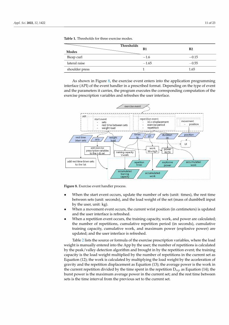
As shown in Figure 8, the exercise event enters into the application programminginterface (API) of the event handler in a prescribed format. Depending on the type of eventand the parameters it carries, the program executes the corresponding computation of theexercise prescription variables and refreshes the user interface.
Figure 8. Exercise event handler process.
• When the start event occurs, update the number of sets (unit: times), the rest timebetween sets (unit: seconds), and the load weight of the set (mass of dumbbell inputby the user, unit: kg).
• When a movement event occurs, the current wrist position (in centimeters) is updatedand the user interface is refreshed.
• When a repetition event occurs, the training capacity, work, and power are calculated;the number of repetitions, cumulative repetition period (in seconds), cumulativetraining capacity, cumulative work, and maximum power (explosive power) areupdated; and the user interface is refreshed.
Table 2 lists the source or formula of the exercise prescription variables, where the loadweight is manually entered into the App by the user; the number of repetitions is calculatedby the peak/valley detection algorithm and brought in by the repetition event; the trainingcapacity is the load weight multiplied by the number of repetitions in the current set asEquation (12); the work is calculated by multiplying the load weight by the acceleration ofgravity and the repetition displacement as Equation (13); the average power is the work inthe current repetition divided by the time spent in the repetition Drep as Equation (14); theburst power is the maximum average power in the current set; and the rest time betweensets is the time interval from the previous set to the current set.
Appl. Sci. 2022, 12, 1422 12 of 23
Table 2. List of exercise prescription variables.
Prescription Variables Source/Equation
weight load mload(kg) data input from App
repetitions Nreps(times) data from repetition event
training capacity Vtra(kg) Vtra = mload × Nreps (12)
work Wrep(J) Wrep = mloadgh (13)
average power Prep(W) Prep = Wrep/Drep (14)
explosive Pmax(W) the maximum Prep of a set
rest time between sets (s) duration from previous set to current set
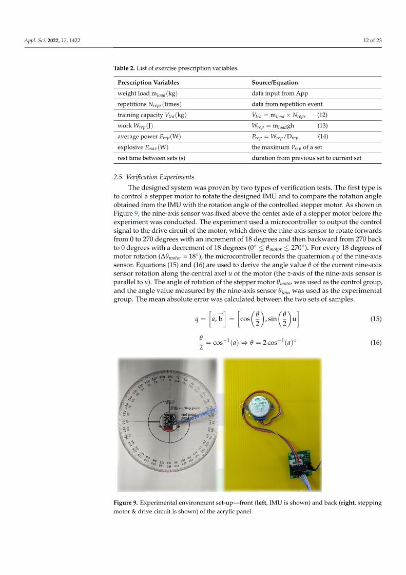
2.5. Verification Experiments
The designed system was proven by two types of verification tests. The first type isto control a stepper motor to rotate the designed IMU and to compare the rotation angleobtained from the IMU with the rotation angle of the controlled stepper motor. As shown inFigure 9, the nine-axis sensor was fixed above the center axle of a stepper motor before theexperiment was conducted. The experiment used a microcontroller to output the controlsignal to the drive circuit of the motor, which drove the nine-axis sensor to rotate forwardsfrom 0 to 270 degrees with an increment of 18 degrees and then backward from 270 backto 0 degrees with a decrement of 18 degrees (0◦ ≤ θmotor ≤ 270◦). For every 18 degrees ofmotor rotation (∆θmotor = 18◦), the microcontroller records the quaternion q of the nine-axissensor. Equations (15) and (16) are used to derive the angle value θ of the current nine-axissensor rotation along the central axel u of the motor (the z-axis of the nine-axis sensor isparallel to u). The angle of rotation of the stepper motor θmotor was used as the control group,and the angle value measured by the nine-axis sensor θimu was used as the experimentalgroup. The mean absolute error was calculated between the two sets of samples.
q =
[a,→b]=
[cos(
θ
2
), sin
(θ
2
)u]
(15)
θ
2= cos−1(a)⇒ θ = 2 cos−1(a)◦ (16)
Figure 9. Experimental environment set-up—front (left, IMU is shown) and back (right, steppingmotor & drive circuit is shown) of the acrylic panel.

Appl. Sci. 2022, 12, 1422 13 of 23
The second type of verification test is to use a camera with an open source opticalhuman body pose estimation system, Mediapipe Pose [23], to calculate the position of thewrist and the angles of upper arm and forearm between the Z-axis, and these calculateddata are compared with the designed system. This is to verify the reliability of the motiontracking algorithm. MediaPipe Pose is a machine learning-based human pose trackingalgorithm that can identify and mark 33 human body feature points from RGB images ofthe whole body, as shown in Figure 10. An experimental environment where a camera isplaced facing a wall with a white board was setup. We connected a camera to the computer;ran the Python script in Anaconda environment, captured the RGB image of the humanbody through the camera; input the image to the Python API provided by MediaPipe Poseto find the left shoulder, left elbow, and left wrist coordinates of the human body (pshoulder,pelbow, and pwrist in Figure 10 [4] at locations 11, 13, and 15); and mark these coordinates onthe original image.
Figure 10. Feature points output map of human from MediaPipe Pose.
In the M system (MediaPipe Pose estimation system), a rectangular coordinate systemis defined and the positions of each feature in the image are denoted as f f eatures, and theleft shoulder, elbow, and wrist are denoted as fshoulder, felbow, and fwrist, respectively. The
two-dimensional unit vectors→v
Mupperarm and
→v
Mf orearm of the forearm and upper arm were
calculated using Equation (17), and the timestamp and arm orientation vector were savedas a csv file in a list at the end of each sampling.
→v
Mupper =
felbow− fshoulder|| felbow− fshoulder ||
→v
Mf orearm = fwrist− felbow
|| fwrist− felbow ||
(17)
In this paper, a new coordinate system will be constructed as the common coordinatesystem between the M system and the presented system, and these two coordinate systemswill be aligned with the new coordinate system, and the M system will be used as a referenceto observe the difference of the motion tracking algorithm of the presented system.
The left shoulder is set as the origin of the new coordinate system Onew(0, 0, 0), andthe arm orientation vectors of the two original coordinate systems are transferred from theold coordinate system to the new coordinate system (the upper arm is denoted as
→v upper
and the lower arm is denoted as→v f orearm), and the relative positions of the elbow and wrist
joints in the new coordinate system, Pelbow and Pwrist, are derived by Equation (18).
Appl. Sci. 2022, 12, 1422 14 of 23
{Pelbow = Onew(0, 0, 0) + lupper·
→v upper
Pwrist = Pelbow + l f orearm·→v f orearm
(18)
The experiment is to use the two-dimensional plane (Y-Z plane) as the reference plane.The camera lens surface is parallel to the Y-Z plane. The subject’s back is against thewall (Y-Z plane). During the experiment, the subject moves the arm in the frontal plane(Y-Z plane), and samples are taken simultaneously by both systems (sampling rate: 30 Hzfor M system and 100 Hz for this system). Time (in ms) is recorded, and
→v upper,
→v f orearm,
Pelbow, Pwrist, α, and β, are calculated, where the angle between the left upper arm vector→v upper and the Z-axis is α, and the angle between the forearm vector
→v f orearm and the Z-axis
is β. The direction from the user’s back to the user’s front is the –X-axis direction in thecommon coordinate system with the vector (−1,0,0).
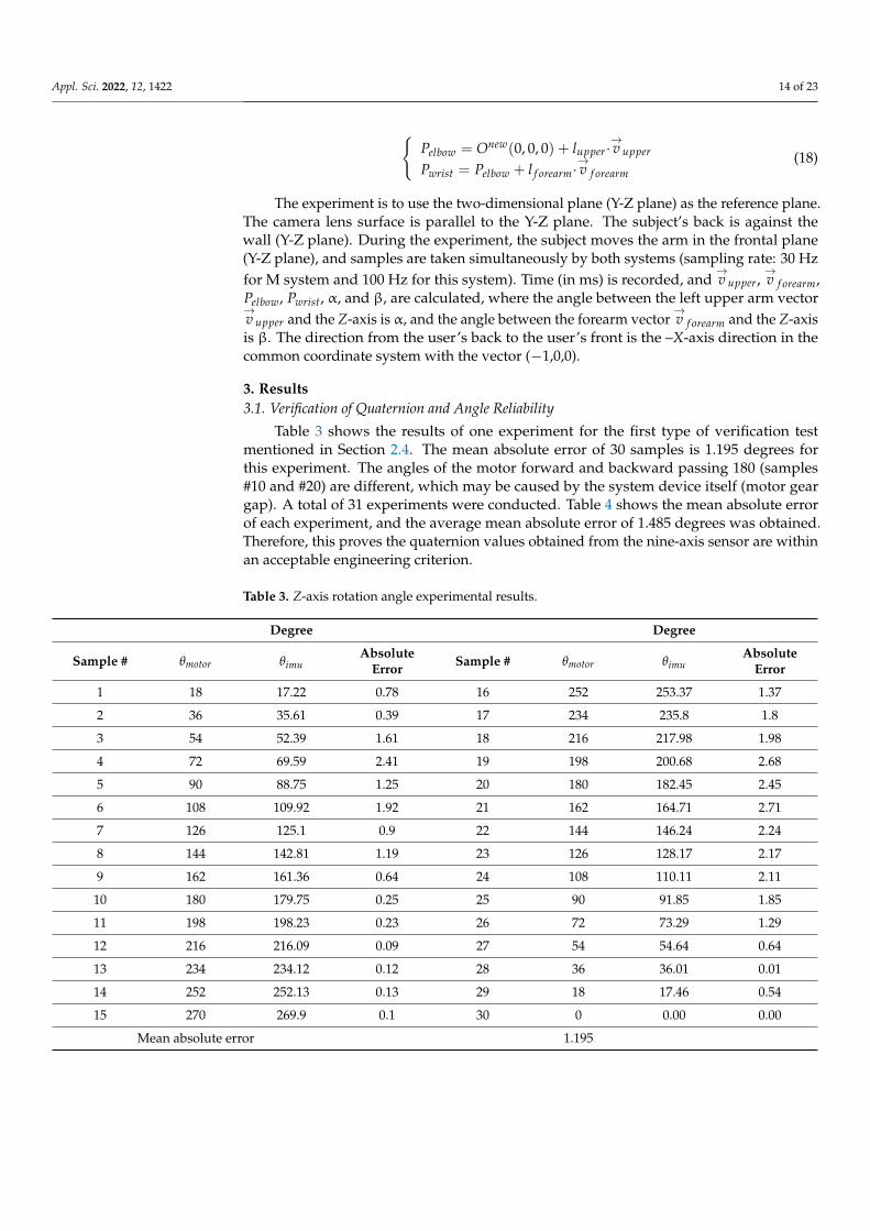
3. Results3.1. Verification of Quaternion and Angle Reliability
Table 3 shows the results of one experiment for the first type of verification testmentioned in Section 2.4. The mean absolute error of 30 samples is 1.195 degrees forthis experiment. The angles of the motor forward and backward passing 180 (samples#10 and #20) are different, which may be caused by the system device itself (motor geargap). A total of 31 experiments were conducted. Table 4 shows the mean absolute errorof each experiment, and the average mean absolute error of 1.485 degrees was obtained.Therefore, this proves the quaternion values obtained from the nine-axis sensor are withinan acceptable engineering criterion.
Table 3. Z-axis rotation angle experimental results.
Degree Degree
Sample # θmotor θimuAbsolute
Error Sample # θmotor θimuAbsolute
Error
1 18 17.22 0.78 16 252 253.37 1.37
2 36 35.61 0.39 17 234 235.8 1.8
3 54 52.39 1.61 18 216 217.98 1.98
4 72 69.59 2.41 19 198 200.68 2.68
5 90 88.75 1.25 20 180 182.45 2.45
6 108 109.92 1.92 21 162 164.71 2.71
7 126 125.1 0.9 22 144 146.24 2.24
8 144 142.81 1.19 23 126 128.17 2.17
9 162 161.36 0.64 24 108 110.11 2.11
10 180 179.75 0.25 25 90 91.85 1.85
11 198 198.23 0.23 26 72 73.29 1.29
12 216 216.09 0.09 27 54 54.64 0.64
13 234 234.12 0.12 28 36 36.01 0.01
14 252 252.13 0.13 29 18 17.46 0.54
15 270 269.9 0.1 30 0 0.00 0.00
Mean absolute error 1.195

Appl. Sci. 2022, 12, 1422 15 of 23
Table 4. The average mean absolute error of the quaternions obtained from the nine-axis sensor.
Degree Degree
Experiment # Mean Absolute Error Experiment # Mean Absolute Error
1 1.195 17 1.629
2 1.325 18 1.402
3 1.153 19 1.560
4 1.352 20 1.522
5 1.339 21 1.495
6 1.487 22 1.769
7 1.366 23 1.677
8 1.314 24 1.666
9 1.245 25 1.939
10 1.399 26 1.545
11 1.398 27 1.569
12 1.524 28 1.558
13 1.708 29 1.569
14 1.512 30 1.588
15 1.513 31 1.512
16 1.193
average mean absolute error 1.485
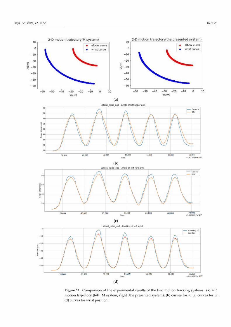
3.2. Motion Tracking Verification
Figure 11 shows the curves of the parameters (Pelbow, Pwrist(z), α, and β of the secondtype verification test mentioned in Section 2.4) obtained from the two systems (M systemand the presented system). These curves show that the movement of the arm is slow,about more than 2 s per one cycle. The purpose for doing this is to eliminate the possibleerror caused by the low sampling rate of Mediapipe Pose. Finally, the root mean squareerrors of three parameters α, β, and Pwrist(z) (the z-coordinate of the wrist joint) betweentwo systems were calculated.
Based on the experiment with six repetitions of lateral raise on the frontal plane, theroot mean square errors between the two systems are 2.434 cm for Pwrist(z), 5.654◦ for α,and 4.385◦ for β.
3.3. Posture Recognition Verification
Ten participants were in the training group, and their motion data were used to trainthe neural network model. Two participants were in the test group, and their data wereused to verify the accuracy of the trained ML model for posture recognition.
Among the data of 10 participants, 80% of the data was used for training (19,970 sam-ples), and the remaining 20% was used for validation (4993 samples). The mean squarederror loss function was used to evaluate the training model at each epoch and update theneural network parameters. Once the model was trained, the data in the test group wereused to verify the accuracy of the posture recognition algorithm. The prediction resultsbased on two participants in the test group (3359 samples) were evaluated using Python’sscikit-learn library, as shown in Table 5. The evaluation metrics include Precision, Recall,and F1-score, and the accuracy is defined as the ratio of correctly predicted samples by thetotal samples. The last column of Table 5 indicates the number of samples for each differentposture. The confusion matrix is shown in Figure 12. The accuracy is 98.96%. Among19,970 samples of training data, there are 9141, 3244, 4122, and 3463 samples for rest (0),bicep curl (1), lateral raise (2), and shoulder press (3), respectively.
Appl. Sci. 2022, 12, 1422 16 of 23
Figure 11. Comparison of the experimental results of the two motion tracking systems. (a) 2-Dmotion trajectory (left: M system, right: the presented system); (b) curves for α; (c) curves for β;(d) curves for wrist position.

Appl. Sci. 2022, 12, 1422 17 of 23
Table 5. Evaluation metrics table of deep learning model.
LabelPerformance Precision Recall F1-Score Data Samples
rest (0) 0.98 1.00 0.99 836
bicep curl (1) 1.00 0.96 0.98 878
lateral raise (2) 1.00 1.00 1.00 778
shoulder press (3) 0.98 1.00 0.99 867
Figure 12. Confusion matrix of test data.
3.4. Results of Exercise Prescription Variables
After establishing a Bluetooth connection, aligning the user’s face with the Unityavatar’s face, and opening the 9-axis feature channel to listen to the notification data fromthe microcontroller, the motion data will be input to the mobile App algorithm to calculatethe position of the elbow and wrist. The arms of the avatar will be synchronized with theuser’s movement as shown in Figure 3.
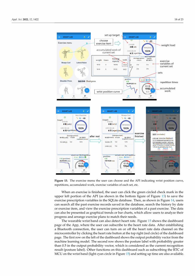
As shown in Figure 13, during the user’s exercise, the App of the exercise prescriptionvariables algorithm can automatically analyze the state, calculate the number of repetitions,identify the exercise modes, and trigger exercise events. When a repetitive event occurs, itcan update each exercise prescription variable in the current set and refresh the interface.When the rest state ends, the next set of exercise starts and the start event is triggered; itcan update the rest time between sets, add a new row (set) of prescription variables, andrefresh the interface. The top figure in Figure 13 shows the exercise menu the user canchoose and the API indicating wrist position curve, repetition times, accumulated work,exercise variables of each set, etc. The bottom figure of Figure 13 shows the changes ofexercise information when a new set of exercise starts or the exercise ends.
Appl. Sci. 2022, 12, 1422 18 of 23
Figure 13. The exercise menu the user can choose and the API indicating wrist position curve,repetitions, accumulated work, exercise variables of each set, etc.
When an exercise is finished, the user can click the green circled check mark in theupper left portion of the API (as shown in the bottom figure of Figure 13) to save theexercise prescription variables in the SQLite database. Then, as shown in Figure 14, userscan search all the past exercise records saved in the database, search the history by dateor exercise item, and view the exercise prescription variables of a past exercise. The datacan also be presented as graphical trends or bar charts, which allow users to analyze theirprogress and arrange exercise plans to match their needs.
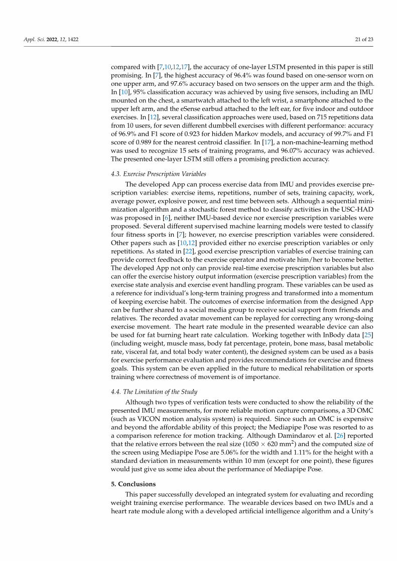
The wearable wrist band can also detect heart rate. Figure 15 shows the dashboardpage of the App, where the user can subscribe to the heart rate data. After establishinga Bluetooth connection, the user can turn on or off the heart rate data channel on themicrocontroller by clicking the heart rate button at the top right (red circle) of the dashboardpage. The first row on the left of the dashboard shows the output probability vector from themachine learning model. The second row shows the posture label with probability greaterthan 0.5 in the output probability vector, which is considered as the current recognitionresult (posture label). Other functions on this dashboard such as subscribing the RTC ofMCU on the wrist band (light cyan circle in Figure 15) and setting up time are also available.
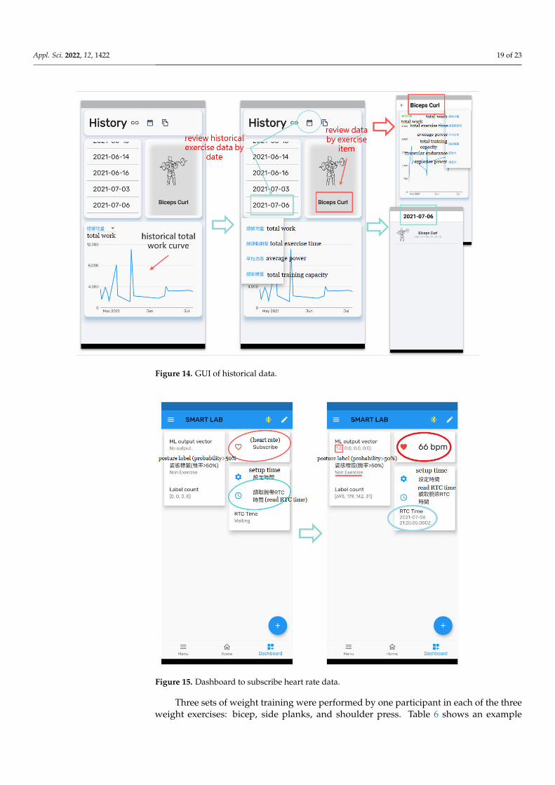
Appl. Sci. 2022, 12, 1422 19 of 23
Figure 14. GUI of historical data.
Figure 15. Dashboard to subscribe heart rate data.
Three sets of weight training were performed by one participant in each of the threeweight exercises: bicep, side planks, and shoulder press. Table 6 shows an example

Appl. Sci. 2022, 12, 1422 20 of 23
of training results, showing the exercise prescription variables and rest periods for abicep curl.
Table 6. Exercise prescription variables for biceps curl.
SetVariables
mload(kg) Nreps Vtra(kg) Wrep(J) Prep(W) Pmax(W)
1 18 8 144 743 37 52
rest 119 (s)
2 18 6 108 645 32 55
rest 108 (s)
3 18 4 72 463 22 39
4. Discussion4.1. Motion Tracking Verification
Two types of verification tests were conducted to show the reliability of the presentedIMU measurements. The rotation angle of the IMU was tested by a controlled steppermotor, and an average mean absolute error of 1.485 degrees was observed. The threeparameters α, β, and Pwrist(z) of the presented system were compared with the M system,and the root mean square errors of 5.654◦, 4.385◦, and 2.434 cm were found, respectively. Amean absolute error of 3.88 cm was reported in [24] in which the wrist positions of elbowflexion-extension (EFE) measured by nine-axis sensors were compared with the opticalmotion capture (OMC) system. These results show that the measurements obtained bothfrom the presented system and from [24] provide an acceptable motion tracking within anengineering standard. The waveforms between the M system and the presented system,as shown in Figure 11, have similar trends. However, there is a slight offset betweenthe angular value and the vertical axis (z-axis), which might be caused by the inherentsensor configuration error. Because the size of each person’s arm is different, when theuser wears sensors on his/her arm, the physical offset occurs. The sensor spindle and thearm orientation vector (
→v upper and
→v f orearm) cannot be perfectly parallel to each other, and
the error of this angle will affect the results of the subsequent computation. The musclechanges in the arm during exercise also cause the IMU data worn on the upper arm todrift dynamically. Moreover, it is still not possible to make the plane of arm movementexactly parallel to the lens surface (the M system is based on a two-dimensional plane),and the arm joint marker point of the M system will have uncontrollable dynamic shiftduring the movement. Therefore, to improve the reliability of the system, we can focus oneliminating the error of the angles α and β. The sensor configuration error can be eliminatedby comparing the developed device with more reliable reference system (e.g., Vicon 3Dmotion capture system) and then calibrating it using computer software to improve themotion tracking algorithm. The experimental results show that there are inherent systemerrors in both systems. Although the experiments have been designed to minimize theimpact of system errors on the experimental results, it is still impossible to completelyeliminate the system errors.
4.2. Posture Recognition Verification
During the course of this study, we found that the developed one-layer LSTM is simplerand more accurate than the other LSTM-based variants: two-layer LSTM, BidirectionalLSTM (one layer and two layers), and Bidirectional LSTM with attention. The presentedone-layer LSTM model was trained by 19,970 samples and validated by 4993 samples.The prediction accuracy of the trained LSTM was based on 3359 samples. An accuracyof 99% was achieved, which is good enough for our weight training posture recognition.On the other hand, the accuracy of two-layer LSTM is 97.02%, the accuracy of one-layerBidirectional LSTM is 97.26%, the accuracy of two-layer of Bidirectional LSTM is 97.37%,and the accuracy of Bidirectional LSTM with Attention is 96.12%. Furthermore, when
Appl. Sci. 2022, 12, 1422 21 of 23
compared with [7,10,12,17], the accuracy of one-layer LSTM presented in this paper is stillpromising. In [7], the highest accuracy of 96.4% was found based on one-sensor worn onone upper arm, and 97.6% accuracy based on two sensors on the upper arm and the thigh.In [10], 95% classification accuracy was achieved by using five sensors, including an IMUmounted on the chest, a smartwatch attached to the left wrist, a smartphone attached to theupper left arm, and the eSense earbud attached to the left ear, for five indoor and outdoorexercises. In [12], several classification approaches were used, based on 715 repetitions datafrom 10 users, for seven different dumbbell exercises with different performance: accuracyof 96.9% and F1 score of 0.923 for hidden Markov models, and accuracy of 99.7% and F1score of 0.989 for the nearest centroid classifier. In [17], a non-machine-learning methodwas used to recognize 15 sets of training programs, and 96.07% accuracy was achieved.The presented one-layer LSTM still offers a promising prediction accuracy.
4.3. Exercise Prescription Variables
The developed App can process exercise data from IMU and provides exercise pre-scription variables: exercise items, repetitions, number of sets, training capacity, work,average power, explosive power, and rest time between sets. Although a sequential mini-mization algorithm and a stochastic forest method to classify activities in the USC-HADwas proposed in [6], neither IMU-based device nor exercise prescription variables wereproposed. Several different supervised machine learning models were tested to classifyfour fitness sports in [7]; however, no exercise prescription variables were considered.Other papers such as [10,12] provided either no exercise prescription variables or onlyrepetitions. As stated in [22], good exercise prescription variables of exercise training canprovide correct feedback to the exercise operator and motivate him/her to become better.The developed App not only can provide real-time exercise prescription variables but alsocan offer the exercise history output information (exercise prescription variables) from theexercise state analysis and exercise event handling program. These variables can be used asa reference for individual’s long-term training progress and transformed into a momentumof keeping exercise habit. The outcomes of exercise information from the designed Appcan be further shared to a social media group to receive social support from friends andrelatives. The recorded avatar movement can be replayed for correcting any wrong-doingexercise movement. The heart rate module in the presented wearable device can alsobe used for fat burning heart rate calculation. Working together with InBody data [25](including weight, muscle mass, body fat percentage, protein, bone mass, basal metabolicrate, visceral fat, and total body water content), the designed system can be used as a basisfor exercise performance evaluation and provides recommendations for exercise and fitnessgoals. This system can be even applied in the future to medical rehabilitation or sportstraining where correctness of movement is of importance.
4.4. The Limitation of the Study
Although two types of verification tests were conducted to show the reliability of thepresented IMU measurements, for more reliable motion capture comparisons, a 3D OMC(such as VICON motion analysis system) is required. Since such an OMC is expensiveand beyond the affordable ability of this project; the Mediapipe Pose was resorted to asa comparison reference for motion tracking. Although Damindarov et al. [26] reportedthat the relative errors between the real size (1050 × 620 mm2) and the computed size ofthe screen using Mediapipe Pose are 5.06% for the width and 1.11% for the height with astandard deviation in measurements within 10 mm (except for one point), these figureswould just give us some idea about the performance of Mediapipe Pose.
5. Conclusions
This paper successfully developed an integrated system for evaluating and recordingweight training exercise performance. The wearable devices based on two IMUs and aheart rate module along with a developed artificial intelligence algorithm and a Unity’s

Appl. Sci. 2022, 12, 1422 22 of 23
Animation System on the smartphone can provide weight-training lovers with helpfulexercise prescription variables that can be used as progressive recommendations to improvethe training effect. A simple yet effective LSTM model for posture recognition is alsopresented, providing a promising accuracy of 99%. The reliability of IMU measurementswas also tested by two types of experiments. Test results show that measurements of theIMU are within the engineering acceptable range.
In the future, the presented system can be extended for lower limb exercises. Itsapplications can also be extended to medical rehabilitation and sports training.
6. Patents
The work presented in this paper will be filed for a patent in Taiwan.
Author Contributions: Conceptualization, Y.-C.W. and S.-X.L.; methodology, Y.-C.W. and S.-X.L.; soft-ware, S.-X.L.; validation, Y.-C.W., S.-X.L., C.-C.H. and C.-S.C.; formal analysis, S.-X.L.; investigation,Y.-C.W. and S.-X.L.; resources, Y.-C.W. and S.-X.L.; data curation, S.-X.L. and J.-X.J.; writing—originaldraft preparation, Y.-C.W. and S.-X.L.; writing—review and editing, Y.-C.W.; visualization, Y.-C.W.and S.-X.L.; supervision, Y.-C.W., J.-Y.L., C.-C.H. and C.-S.C.; project administration, Y.-C.W.; fundingacquisition, Y.-C.W. All authors have read and agreed to the published version of the manuscript.
Funding: This research was funded by the Ministry of Science and Technology, Taiwan, grant number108-2622-E-239-006-CC3.
Institutional Review Board Statement: Not applicable.
Informed Consent Statement: Informed consent was obtained from all subjects involved in the study.
Data Availability Statement: Not applicable.
Conflicts of Interest: The authors declare no conflict of interest. The funders had no role in the designof the study; in the collection, analyses, or interpretation of data; in the writing of the manuscript; orin the decision to publish the results.
References1. Wong, R.; Yang, L.; Szeto, W. Wearable Fitness Trackers and Smartphone Pedometer Apps: Their Effect on Transport Mode Choice
in a Transit-oriented City. Travel Behav. Soc. 2021, 22, 244–251. [CrossRef]2. Kong, X. INS algorithm using quaternion model for low cost IMU. Robot. Auton. Syst. 2004, 46, 221–246. [CrossRef]3. Han, S.; Wang, J. A Novel Method to Integrate IMU and Magnetometers in Attitude and Heading Reference Systems. J. Navig.
2011, 64, 727–738. [CrossRef]4. Manon, K.; Jeroen, D.H.; Thomas, B.S. Using Inertial Sensors for Position and Orientation Estimation. Found. Trends Signal.
Processing 2017, 11, 1–153.5. Bergamini, E.; Ligorio, G.; Summa, A.; Vannozzi, G.; Cappozzo, A.; Sabatini, A.M. Estimating Orientation Using Magnetic and
Inertial Sensors and Different Sensor Fusion Approaches: Accuracy Assessment in Manual and Locomotion Tasks. Sensors 2014,14, 18625–18649. [CrossRef] [PubMed]
6. Tahir, S.B.u.d.; Jalal, A.; Batool, M. Wearable Sensors for Activity Analysis using SMO-based Random Forest over Smart home andSports Datasets. In Proceedings of the International Conference on Advancements in Computational Sciences, Lahor, Pakistan,17–19 February 2020; pp. 1–6.
7. Preatoni, E.; Nodari, S.; Lopomo, N.F. Supervised Machine Learning Applied to Wearable Sensor Data Can Accurately ClassifyFunctional Fitness Exercises Within a Continuous Workout. Front. Bioeng Biotechnol. 2020, 8, 664. [CrossRef] [PubMed]
8. Nwekeab, H.F.; Teh, Y.W.; Al-garadi, M.A.; Alo, U.R. Deep Learning Algorithms for Human Activity Recognition Using Mobileand Wearable Sensor Networks: State of The Art and Research Challenges. Expert Syst. Appl. 2018, 105, 233–261. [CrossRef]
9. Sui, J.D.; Chang, T.S. Deep Gait Tracking With Inertial Measurement Unit. IEEE Sens. Lett. 2019, 3, 7002404. [CrossRef]10. Ishii, S.; Nkurikiyeyezu, K.; Yokokubo, A.; Lopez, Z. ExerSense: Real-Time Physical Exercise Segmentation, Classification, and
Counting Algorithm Using an IMU Sensor. In Activity and Behavior Computing. Smart Innovation, Systems and Technologies; Ahad,M.A.R., Inoue, S., Roggen, D., Fujinami, K., Eds.; Springer: Singapore, 2020; Volume 204. [CrossRef]
11. Koskimäki, H.; Siirtola, P. Recognizing Gym Exercises Using Acceleration Data from Wearable Sensors. In Proceedings of theIEEE Symposium on Computational Intelligence and Data Mining, Orlando, FL, USA, 9–12 December 2014.
12. Hausberger, P.; Fernbach, A.; Kastner, W. IMU-based Smart Fitness Devices for Weight Training. In Proceedings of the AnnualConference of Industrial Electronics Society, Florence, Italy, 23–26 October 2016; pp. 5182–5189.

Appl. Sci. 2022, 12, 1422 23 of 23
13. Seong, J.H.; Choi, Y. Design and Implementation of User Interface through Hand Movement Tracking and Gesture Recognition.In Proceedings of the International Conference on Information and Communication Technology Convergence, Jeju, Korea, 17–19October 2018; pp. 552–555.
14. Chen, Y.L.; Yang, I.J.; Fu, L.C.; Lai, J.S.; Liang, H.W.; Lu, L. IMU-based Estimation of Lower Limb Motion Trajectory with GraphConvolution Network. IEEE Sens. J. 2021, 21, 24549–24557. [CrossRef]
15. Abdelhady, M.; van den Bogert, A.J.; Simon, D. A High-fidelity Wearable System for Measuring Lower-limb Kinetics andKinematics. IEEE Sens. J. 2019, 19, 12482–12493. [CrossRef]
16. Wang, L.; Sun, Y.; Li, Q.; Liu, T. Estimation of Step Length and Gait Asymmetry Using Wearable Inertial Sensors. IEEE Sens. J.2018, 18, 3844–3851. [CrossRef]
17. Zou, Y.; Wang, D.; Hong, S.; Ruby, R.; Zhang, D.; Wu, K. A Low-Cost Smart Glove System for Real-Time Fitness Coaching. IEEEInternet Things J. 2020, 7, 7377–7391. [CrossRef]
18. Rodriguez, A.; Rabunal, J.R.; Pazos, A.; Sotillo, A.R.; Ezquerra, N. Wearable Postural Control System for Low Back Pain Therapy.IEEE Trans. Instrum. Meas. 2021, 70, 4003510. [CrossRef]
19. Pereira, A. 3D Arm Inertial Sensor-Based 3D upper Limb Motion Tracking and Trajectories Reconstruction. 2016. Available online:https://repositorio-aberto.up.pt/bitstream/10216/85094/2/139165.pdf (accessed on 26 June 2021).
20. Unity. 2022. Available online: https://unity.com (accessed on 1 November 2021).21. Picerno, P. Good Practice Rules for the Assessment of the Force-Velocity Relationship in Isoinertial Resistance Exercises. Asian J.
Sports Med. 2017, 8, e15590.22. Weakley, J.; Mann, B.; Banyard, H.; McLaren, S.; Scott, T.; Garcia-Ramos, A. Velocity-Based Training: From Theory to Application.
Strength Cond. J. 2021, 43, 31–49. [CrossRef]23. MediaPipe Pose. 2020. Available online: https://google.github.io/mediapipe/solutions/pose.html (accessed on 27 June 2021).24. Filippeschi, A.; Schmitz, N.; Miezal, M.; Bleser, G.; Ruffaldi, E.; Stricker, D. Survey of Motion Tracking Methods Based on Inertial
Sensors: A Focus on Upper Limb Human Motion. Sensors 2017, 17, 1257. [CrossRef] [PubMed]25. InBody. Available online: https://inbodyusa.com/ (accessed on 27 June 2021).26. Damindarov, R.; Boby, C.A.; Fahim, M.; Klimchik, A.; Matsumaru, T. A depth camera-based system to enable touch-less interaction
using hand gestures. In Proceedings of the International Conference on Nonlinearity, Information and Robotics, Innopolis, Russia,26–29 August 2021.
Copyright © 2022 FDOKUMEN