Development of a pre-knitting friction test method and ... - DIVA
39
Magisterexamen från Institutionen Textilhögskolan, Högskolan i Borås 2001: 1 Development of a pre-knitting friction test method and study of friction and bending of yarns with high stiffness. Namn: Joel Peterson, Ellinor Vegborn
-
Upload
khangminh22 -
Category
Documents
-
view
0 -
download
0
Transcript of Development of a pre-knitting friction test method and ... - DIVA

Magisterexamen från Institutionen Textilhögskolan, Högskolan i Borås 2001: 1
Development of a pre-knitting friction test method and study of friction and bending of yarns with high stiffness.
Namn: Joel Peterson, Ellinor Vegborn

Magisterexamen från Institutionen Textilhögskolan, Högskolan i Borås 2001: 1
INSTITUTIONEN TEXTILHÖGSKOLAN Textilhögskolan i Borås är Sveriges enda textilhögskola och tillhör det fåtal högskolor och universitetsutbildningar i världen som har en egen textilindustriell fullskalemiljö.
Textilhögskolan har laboratorier för undervisning, forskning och utvecklingsarbete inom design och tillverkning. På designutbildningarna har studenterna en egen arbetsplats och har stor tillgång till ateljéer och datorsalar. Den kreativa miljön medför att studenterna ofta utmärker sig både nationellt och internationellt i olika visningar och tävlingar.
Borås har en lång textil tradition och är ett naturligt centrum för produktutveckling, design och handel, vilket gör att studenterna får en bra kontakt med branschfolk.
HÖGSKOLAN I BORÅS Högskolan i Borås är nationellt rekryterande och spelar samtidigt en viktig roll i regionens utveckling. Högskolan i Borås växer och ett spännande campus tar form mitt i stadskärnan. År 2001 studerar 8 500 studenter här.
Högskolan i Borås bedriver utbildning och forskning inom sex huvudområden: Biblioteks- och informationsvetenskap, ekonomi och data, lärarutbildningar och pedagogik, teknik, textil samt vård och omsorg.
Flera av utbildningsprogrammen är unika och studenterna är eftertraktade på arbetsmarknaden. En ny undersökning visar att 95 procent får arbete inom sex månader efter examen inom de områden de utbildats till.
Läs mer på högskolan hemsida: www.hb.se

ABSTRACT Development of a pre-knitting friction test method and study of friction and bending of yarns with high stiffness. Joel Peterson Ellinor Vegborn Knitting is a class of techniques for production of textile fabrics by inter-looping yarns with the use of hooked needles. The new loops are created when the yarns drawn through the previously formed loops. An apparatus for two needles with adjustable geometry resembling the knitting process in weft knitting machines has been constructed and mounted in an ordinary tensile testing machine in order to study stress build-up, fibre damage, needle wear etc. The merits of the knittability test-rig set-up are the possibilities to test the performance of the yarns with the geometry of the machine and to simulate and identify some of the problems that can occur between needles and yarn in the knitting process. Well-defined mechanical conditions with the static pre-load weight and the possibilities to identify the location of the events of damage on the fibres during the testing of the specimens and to do further examination before knitting are some obvious merits. The knittability of some extreme yarns, PET-monofilaments, carbon fibre roving and aramid yarn has been studied with respect to friction and bending stiffness. Friction and bending characteristics exhibit viscoellastic features. The needles have diameters of the same order of magnitude as the diameters of monofilaments for example for use in knitted spacer fabrics and the results of this work illustrate strong influence of the fibre diameter on the knittability.
KEYWORDS: Carbon fibres, PET-fibres, Aramid fibres, Knitting, Spacer fabrics, Testing, Friction, Bending, Flexural rigidity
Joel Peterson Ellinor Vegborn Supervisor: University College Borås Majorsgatan 4A Carl-Håkan Andersson School of Textiles 504 31 Borås IFP Research AB Bryggaregatan 17 43122 Mölndal 501 90 Borås

Preface This thesis is our dissertation work for the Master of Science course in Textile Technology at the School of Textiles, University College of Borås. The project; "Knittability of Fibres with High Stiffness" is a continuation of our supervisor Professor Carl-Håkan Andersson’s work in the area of "Handability of fibres". We want to thank Professor Andersson for good support, clear guidance, and help during the whole process with this work. We are also grateful for the financial support contributed by University College of Borås; School of Textiles and we want to thank our Director at the School of Textiles, Dr. Kenneth Tingsvik, for support and discussions. Many people have been involved in this work and we gratefully acknowledge Mr. Folke Sandvik, Mr. Tommy Martinsson and Mr. Lars Brandin at the Knitting Department at the School of Textiles and Mr. Torbjörn Dartman IFP Research AB, Mölndal and Dr. KarlHeinz Hillermeier and Dr.Peter Schwung Tenax Fasern, Wuppertal, who also supplied the carbon fibres. For the construction and suggestions for modifications of the frictional test-rig, we thank Mr. Stig Peterson, Sätila. Borås in March 2001 Joel Peterson Ellinor Vegborn

Contents 1. Introduction
1.1 Background-------------------------------------------------------------------------------------------- 1 1.2 Aim ---------------------------------------------------------------------------------------------------- 1
2. Theoretical background 2.1 The knitting procsess --------------------------------------------------------------------------------- 2 2.2 Factors that influence the knitting process -------------------------------------------------------- 3 2.3 Spacer fabrics ------------------------------------------------------------------------------------------ 4
3. Bending and friction of filament yarns 3.1 The coefficient of friction---------------------------------------------------------------------------- 5 3.2 Bending------------------------------------------------------------------------------------------------- 5 3.3 Flexural rigidity---------------------------------------------------------------------------------------- 6
4. Experimental procedure 4.1 The tested yarns---------------------------------------------------------------------------------------- 7 4.2 Testing the friction of the fibres--------------------------------------------------------------------- 7 4.3 Testing the flexural rigidity of the fibres----------------------------------------------------------- 10
5. Results 5.1 Introduction-------------------------------------------------------------------------------------------- 12 5.2 Results of friction------------------------------------------------------------------------------------- 12 5.3 Results of flexural rigidity--------------------------------------------------------------------------- 14
6. Discussion 6.1 Analysis of friction----------------------------------------------------------------------------------- 16 6.2 Analysis of flexural rigidity – bending stiffness-------------------------------------------------- 16
6.3 Spacer fabrics - friction and bending--------------------------------------------------------------- 17
7. Conclusions 7.1 Merits--------------------------------------------------------------------------------------------------- 18 7.2 Concluding remarks----------------------------------------------------------------------------------- 18
8. Future work---------------------------------------------------------------------------------------------- 19
9. References-------------------------------------------------------------------------------------------------- 20
Appendix 1: Friction tests------------------------------------------------------------------------------ 21

1
1. INTRODUCTION
1.1 Background Textile mechanical processing as weaving and knitting of fibres and yarns to structures and weaves means a great deal of stress to the fibres and yarns used in the process. The stresses and the strain that yarn and fibres are exposed to in the textile manufacturing process could be of various kind depending of what process the material is passing through. In knitting the yarn exposes to a lot of stress factors on it's way from yarn cone to the needles of the knitting machine to be a ready knitted fabric. Important factors in textile processing and also in knitting are the friction and bending behaviour between yarn and machine elements. All knitters know due to practical experiences that it is difficult to knit with a yarn that does not have the right frictional properties and that is stiff and therefore hard to bend.
1.2 Aim The aim with this work has been to study friction and bending properties of some yarns with high stiffness especially polyester that could be used in knitted structures for example spacer fabrics. The aim has also been to inquire whether if it is possible to determine the knittability of a yarn with tests in an ordinary tensile testing machine of standard type, Instron 1122, equipped with an apparatus with latch needles mounted in the same geometry as in the knitting machine. The method and the fixtures are based on earlier work by Andersson et.al and are adopted for analysis of the stress build up in fibres or yarns on knitting needles in order to study the knitting process of yarns with high stiffness [1,2].

2
2. THEORETICAL BACKGROUND
2.1 The knitting process Knitting is a family of techniques for production of textile fabrics by inter-looping yarns with the use of hooked needles. New loops are created when the yarns are drawn through the previously formed loops. The principles and structures of traditional garment weft knitting are of prehistoric origin and knitting frames and flat bed knitting machinery belong to the industrial revolution. Knitting techniques and machinery are extensively used for the production of textile products for garment and industrial use. Knitting is also gaining importance for composite materials performing [3,4]. In the knitting process do hooked needles pick up yarns and form closed loops. The stability of the loop formation depends on the bending of the fibres and type of friction on the needles during the different stages of the knitting process. The characteristics of the yarn-needle interaction include static friction when the needles draw the yarn into the machine, sliding friction in the loop formation and release after loop formation. This features vital importance for the final product. Basically two principles of knitting are in use [3,4,5]. i) Weft knitting gives structures of for example traditional garments with large deformability suitable for structures taking impact loads ii) Warp knitting gives the traditional tricot structures and the non-crimped insert yarn DOS-fabrics extensively used for composite materials fabrication
Figure 1: Weft knitted loop structure. Figure 2: Warp knitted loop structure.
The knitting process has therefore been studied from first principles using models for friction and bending of fibres on positively curved surfaces and simultaneous plastic deformation. In weft knitting the yarns are introduced into the inter-looped knit-structure perpendicular to the machine direction, i.e. the weft direction. In warp knitting the yarns are introduced into the inter-looped knit-structure parallel to the machine direction. The subsequent knitted structures are thus fundamentally different. Monofilaments and high modulus multifilament yarns known for their high stiffness giving difficulties in knitting process have been studied with respect to: - Static and dynamic friction - Bending radius of the fibre during the process

3
2.2 Factors that influence the knitting process A lot of research has been done over the years about the influence of different parameters and factors between yarn and knitting elements during the knitting process [8]. Important factors in the knitting process in contact between yarn and knitting elements are friction, strength, flexural rigidity, elastic properties of the yarn, velocity of knitting elements and yarn in the knitting zone [9]. Under the dynamic conditions of loop formation in the knitting process according to Amoton's Law of Friction, the yarn tension increases on the yarn supply side of the knitting zone stitch cam and the lowest tension occurs on the yarn on the other side of the knitting cam. μθ
inrun eTTi ×= − Ti = Yarn tension at any point in the knitting zone Trun-in = yarn input tension. µ = Mean coefficient of friction between the knitting elements. θ = The sum of the angles of wrap in radius between the yarn, needles and other elements in contact with the yarn. This is because of that it is easier to “rob back” yarn from the already formed loops than to pull new yarn from the yarn package due to the fact that the tension is higher on this side. The tension on the yarn during knitting is influenced by the number and the angles of yarn wrap between yarn and machine elements and the fact that robbing back can reduce tension in the yarn, Figure 3. Robbing back is the term for the yarn that comes from the already formed loops back into the knitting zone, because the yarn tension is lower on this side and higher on the yarn package side. Research done by Abou-iiana [10], shows that with an increase of input tension Trun-in the position of maximum knitting tension moves towards the yarn supply side and with lower input tension the point of maximum knitting tension lies closer to the knitting point. These factors and the fact that many parameters cooperate and influence each other between yarn and machine elements make knitting a rather complex process. When it comes to producing knitted structures of yarns or monofilament fibres with high stiffness such as carbon, aramid or polyester monofilament, parameters such as friction and flexural rigidity of the yarn are of considerable importance for the knittability of the structure. However a significant problem is that some of these stiff yarns are almost inextensible, which causes tension peaks with breakage of the yarn or single filament in the yarn bundle. . Figure 3. Model of weft-knitted loop formation indicating the mechanism of Robbing-back and the build up in yarn tensions acting on the needles [6].

4
2.3 Spacer fabrics
Figure 4: Spacer fabric. Figure 5: Weft knitted spacer fabric. The possibilities of producing weft knitted spacer fabrics providing high toughness are not very much utilised due to technical difficulties. Spacer fabric is a type of structure with separate textile layers A and B held apart by a spacer yarn C, usually stiff monofilaments, Figure 4-5. The performance of composites with core materials based on woven spacer fabrics has been extensively examined and reviewed by Van Vuure [11]. Monofilaments and high modulus multifilament yarns are known for their stiffness causing difficulties in the knitting process when this type of fabric is produced. Other parameters of significant importance for the knitting ability except the stiffness of the yarn are: yarn count, stitch density, machine gauge and how the spacer yarn is inlaid in the structure. This type of stiff yarns is preferable in spacer fabrics where the fabric surfaces will be separated to get the right properties for the product. The pressure resistance, i.e. the force required to press the two fabric surfaces together, depends on the mass of monofilaments in the spacer fabric in relation to the spacer distance [12]. Spacer fabric can be knitted in various structure combinations on weft knitting machines. Most of the problems when knitting spacer fabric in weft knitting are the inlay of the spacer yarn. This spacer yarn is often a stiff monofilament or multifilament yarn with such properties that it is difficult to knit the yarn in the structure with ordinary loops. Stiff monofilament yarns of synthetic material could be inlayed as tuck stitch in the structure. This means that the latch needle of the machine moves up in half position and the old loop is resting on the opened latch of the needle [7]. In this position, the spacer yarn is inlayed in the hook of the needle by the yarn feeder of the knitting machine.

5
3. BENDING AND FRICTION OF FILAMENT YARNS
3.1 Coefficient of friction The contact stress build-up in textile fibre handling has been modelled using the drive belt formula and the Herz contact stress relations in the form used by Timoshenko and Goodier [2,]. Two assumptions used for the first set of equations are: - R1, the fibre radius is much smaller than R2, the bending radius - R2, the bending radius of the yarn is the same as the radius of the guide or the needle. Analysis of contact stresses between fibres and guides has been based on the drive-belt formula with assumed linear elastic properties, negligible stiffness in bending and large bending radii [1]. The equations used for a first analysis of the frictional stress build-up and evaluation of shear stresses from experimental friction force results are however somewhat idealised. For example the radii of the knitted fibres and the needles may be similar. The stress build up in anisotropic fibres of yielding types is limited, but the tensile force build up can, due to the frictional heating and subsequent wetting and increase in contact surface due to transverse creep, be considerable. Assuming perfect contact, the friction force build-up on a positively curved surface is given by the drive belt formula: F F1 0= exp( )μθ (1) If F0 is the preload force, F1 is the tensile force due to friction andθ is the contact angle. Testing the handleability of a fibre or yarn in a full down-up cycle in a tensile testing machine using a set-up described below, the friction force build-up and the coefficient of friction are given from equation (1) combining the motion down and up [1,2]: μθ2lnln 21 =− FF (2) Where F1 and F2 are the tensile forces due to friction in downward motion and upward motion respectively. With the rig in downward motion, F1, the friction build-up force is added to the pre-load and the reverse in upward motion.
3.2 Bending When bending a fibre, the difference of length, i.e. strain difference between the outer tensile loaded side and the inner compression loaded side of a fibre not changing its cross-sectional shape when bent on a cylinder, is given by:
21
1
21
212lnRR
RRRRR
+≈⎟⎟
⎠
⎞⎜⎜⎝
⎛++
=Δε (3)

6
where R1 is the fibre radius and R2 is the bending radius. The Hookes law relates the stress and strain of a linear elastic material: σ ε= E (4) where σ is the stress, ε is the strain and E is the elastic modulus. For an ideal elastic-plastic material, the stress is limited by the onset of yielding: σ σ= pl (5) where σpl is yield stress. The mechanical behaviour and the mechanisms of damage and fracture are related to the microstructure of the fibre. The modes of deformation and bending behaviour of technical fibres are discussed in [2,13]. Different types of stress build-up due to bending of fibres reflect their mechanical properties, for example: a) linear elastic fibres, such as glass and ceramic fibres b) fibres with almost linear elastic behaviour in tension and yielding in compression, such as aramids c) fibres yielding in tension and compression, such as textile and steel fibres
3.3 Flexural rigidity Flexural rigidity is defined, as the couple required bending the structure (a fibre) to unit curvature. Using textile nomenclature and units, the flexural rigidity can be written [13]:
ρ
ηπ
2
41 ΕΤ
=rigidityflexural (6)
Where η is the shape factor, E is the specific modulus, T is the linear density and ρ is the density of the material. Due to the fact that a change in linear density, T, is changed in square gives this factor a significant influence of the value of flexural rigidity of the yarn. In bending there is also a tensile force component perpendicular to the fibre axis. There will thus be deformations causing changes in the cross-sectional shape of the fibre. For yielding fibres, these changes are also known to depend on the velocity. The flexural rigidity of the monofilament fibres was tested and evaluated using a model and method suggested by Peirce [13]. The flexural rigidity of a yarn is given by the deformation, d, of a loop under an applied force F3. θθπ tan/cos)2(0047,0 2
3 rFFR = (7) rd πθ /493= (8) Where FR is the flexural rigidity, r is radius of the loop, F3 is the force of deflection, θ is the angle of deflection and d is the deflection of the loop.

7
4. EXPERIMENTAL PROCEDURE
4.1 The tested yarns PET- monofilaments, Carbon and Aramid multifilament yarns are known for their high stiffness causing problems in knitting processes. The following yarns were studied: 1. PET monofilament yarns, Reuter Garne GmbH type FF shrunk with diameters of: 0,08 mm, 0,10mm, 0,12mm 0,15mm. 2. Carbon multifilament yarns, Tenax Fibers GmbH type: HMA 750 Tex, high modulus 12000 filament, HTS 800 Tex high tenacity, 12000 filament. Sizing: epoxy. 3. Aramid multifilament yarns, Du Pont, Kevlar fibres. These yarns have been studied with respect to: - Static and dynamic friction on knitting needles - Bending radius of the fibre during the process as a function of load and velocity - Flexural rigidity
4.2 Testing the friction of the fibres The handleability testing is performed in a rig developed for studies of frictional stress build-up in a standard tensile testing machine [2]. Two latch needles of the same type as in a knitting machine are mounted in the rig with the same geometry and motion as in the knitting machine. The total contact angle of the yarn and the needles is set to θ = 210o and the distance between the needles can be adjusted to fit the conditions for knitting machines of different gauge numbers. The motion of the needles is given by the machine when the beam moves up and down and the method can in principle be regarded as a modification of the ASTM standard method for testing of friction between yarn and metal. This kind of set-up makes it possible to use an ordinary tensile testing machine and with the rig simulate and identify some of the problems that could occur between needles and yarn in the knitting process. Well-defined mechanical conditions with the static pre-load weight and the possibilities to identify the location of the events of damage on the fibres during the testing of the specimens are some obvious merits. Needle Yarn Needle Figure 6: Test rig with yarn and needles.

8
15 mm
Needle Needle F0 Figure 7: Test rig for frictional stress build-up. Figure 6-9 illustrates the principle of the set-up for handleability testing with the test rig in a tensile testing machine. Latch needles for weft knitting machines were used. The test of the PET yarns were done with a latch needle of diameter φ = 0.4 mm for a two-bed circular knitting machine with the gauge of E18. Distance between the needles in the rig was 4 mm and the movement of the rig in up and downward motion was 15mm. Pre-load forces F0 were 23mN, 48mN, 78mN, 102mN, 171mN.

9
The tests of the carbon and the aramid multifilament yarns were done with latch needles of the diameter φ = 1.4 mm for a standard type flat knitting machine with the gauge of E4. Distance between the needles in the rig was 4 mm and the movement of the rig in up and downward motion was 15mm. Pre-load forces F0 were: 202mN, 301mN, 407mN, 609mN, 700mN. The needles were mounted in the rig at the same angle and distance as in the knitting machine during the knitting process and the measurements were performed in the speed range of 50 mm/min up to 1000 mm/min. The low speed range was studied for analysis of fundamental mechanisms of friction and loop formation. For PET and carbon yarns the interesting things were the effects of mechanical stresses, surface morphological properties on friction stress build up and tensile strength losses. Contact angle θtop θtop Contact angle Figure 8: Yarn path showing the top angle Figure 9: Yarn path showing the contact angle Evaluation of coefficients of friction was done using equation (2) for the peak values of the measured forces.
ln lnF F1 2 2− = μθ (2)
θ
μ2
lnln 21 FF −= (9)
( )topθπθ −°°
= 1803602 (10)
L (mm) F2 F1 F (N) = F1 och F2,tensile force due to friction Figure 10: Schematic plot of tensile force due to beam movement.

10
4.3 Testing the flexural rigidity of the fibres Flexural rigidity of stiff monofilament fibres and multifilament yarns was tested in a standard tensile machine using a modified version of the method suggested by Peirce [13]. A latch needle was attached vertically to the load cell of the tensile testing machine with the hook in downward direction, Figure 10, and a yarn loop having the same geometry as in the knitting machine was fixed to the travelling beam. The change in the shape of the yarn and the force versus the vertical displacement of the beam were recorded.
Figure 11: Test rig for flexural rigidity. The bending rigidity testing was performed at the speed of 10 mm/min and 100 mm/min and the low speed range was studied in order to have some indications of the velocity dependent mechanisms of bending. The tests of the multi filament yarns were done with the same needle diameter and machine gauge number as in the friction tests.

11
L (mm) tangent for Not full bending around the needles tangent for Full bending around the needles F3 d F (N) Figure 12: Schematic plot of the bending force due to the length of beam movement. Full bending around the needle (F3, d) occurs in the cross section of the two tangents and is used in equation 7. F3 = force due to bending d = length of the motion of the beam Evaluation of flexural rigidity was done from the loop tensile testing recordings using equation (7). The curve exhibits two different types of deformation, Figure 11: Not full bending around the needles and Full bending around the needles. In Not full bending around the needles the yarn is bent around the needle when the beam moves a long distance with relatively low force required. In Full bending around the needle the force increases rapidly in a short beam movement. Two tangents, one on the each side of the deflection of the curve were drawn and the values of the force of deflection, F3 and length of deflection, d at full bending around the needles were measured from the intersection of the lines and used in equation (7).

12
5. RESULTS
5.1 Indroduction The results of the measurements of coefficients of friction and of flexural rigidity are summarised in the plots 1-11 below. The tested carbon fibre yarns were too heavy for the needles used and the runs indicated insufficient stability when running HTS, High Tenacity-yarns and severe fibre damage in the HMA, High Modulus-yarns.
5.2 Results of friction The frictional test rig had to be modified due to different difficulties during the construction of the rig. The trouble was that the load at the end of the yarn began to swing during the test and touched the frame of the test rig and this caused disturbance of the friction test. For fibres with high diameters there was problems when running tests with low loads. The yarn had insufficient contact with the needles especially when the beam in the tensile testing machine changed direction. Another modification that was done was to construct the test rig so it was possible to have the same test rig for tests with needles of different diameters. The loads in the tests were estimated to type and diameter of the yarn and needle diameter. For the PET filament yarn the test was done in yarn diameter 0,08 mm up to 0,15 mm and this is estimated to be the lowest and highest diameter that could be knitted in spacer fabrics of gauge E20 in a circular knitting machine. The results of the friction test of the PET, and Carbon yarns are shown in the plots below. The PET-filament yarn in Plot 1 with diameter 0,08 mm and velocity 50 mm/min shows a slightly increase in coefficient of friction with increasing pre-load up to pre-load 171 mN where the coefficient of friction value are decreasing. This could be explained as an effect of adhesion bonding and stick-slip behaviour between yarn and needle. The curve in Plot 1 shows the results of the coefficient of friction at the velocity of 1000 mm/min at different pre-loads between 23 and 171 mN. The low friction coefficient value at pre-load 23 mN could be explained with insufficient contact between yarn and needle due to high velocity in combination with low pre-load. Plot 2 shows the PET filament yarn with diameter 0,15 mm and here is a significant increase of the coefficient of friction with an increase in pre-load. The pre-loads in the tests are in the range from 23 to 171 mN. These increases of the coefficients of friction are in the same magnitude for velocity 50 mm/min and 1000 mm/min. As shown in Plot 3 the coefficient of friction is decreasing with an increase in fibre diameter and with insufficient pre-load. The bending radii of the fibres are bigger than the radius of the needles and only limited contact is obtained. Plot 1. Coefficient of friction for PET-monofilament fibres with diameter 0,08 mm as a function of pre-load for velocity 50mm/min and 1000 mm/min.
Yarn diameter 0,08 mm
0
0,2
0,4
0,6
23 48 78 102 171
Pre-load mN
Coe
ffici
ent o
f fric
tion
501000

13
Plot 2. Coefficient of friction for PET-monofilament fibres with diameter 0,15 mm as a function of pre-load for velocity 50mm/min and 1000 mm/min.
Plot 3. Coefficient of friction for PET-monofilament fibres as a function of fibre diameter and pre-load for velocity 1000 mm/min. The tests of the carbon and aramid yarns were done with needles with higher diameter then the tests of the PET-yarns due to the fact that also the yarn diameter in the tests were higher. The needles was from a flat knitting machine, gauge E4, with a needle diameter of 1.4 mm. This gauge number was necessary to correspond to the higher value of the yarn diameter of the carbon and aramid yarns in the tests. The courser yarns in these tests also required higher value of the pre-loads, with low values of the pre-load it was high risk for insufficient contact between yarn and needle and the yarn was going out of the needle hooks. The pre-loads in the friction tests were in range 202 up to 700 mN. The results in Plot 4 show an increase of the coefficient of friction with a higher value of the pre-loads. In Plot 5 for carbon fibre HMA-type the coefficient of friction is around 1.0 for most off the pre-loads and velocities, except for the test with pre-load 301 mN where the value of the coefficient of friction is decreasing. For the tests of aramid fibre coefficient of friction is near 1.0 for all velocities and pre-loads, Plot 6.
Plot 4 &5. Coefficient of friction for carbon fibres HTS and HMA as a function of velocity and pre-load.
Polyester PET
00,5
1
0,08 0,12 0,15Fibre diameter mm
Coe
ffici
ent o
f fri
ctio
n 234878102171
Carbonfibre HTS
0
0,5
1
1,5
10 50 200 500 1000Pre-load mN
Coe
ffici
ent o
f fri
ctio
n
202301407609700
Carbonfiber HMA
00,5
11,5
10 50 200 500 1000
Velocity mm/min
Coe
ffici
ent o
f fri
ctio
n 202301407609700
Yarn diameter 0,15 mm
00,20,40,60,8
23 48 78 102 171
Pre-load mN
Coe
ffici
ent o
f fri
ctio
n 501000

14
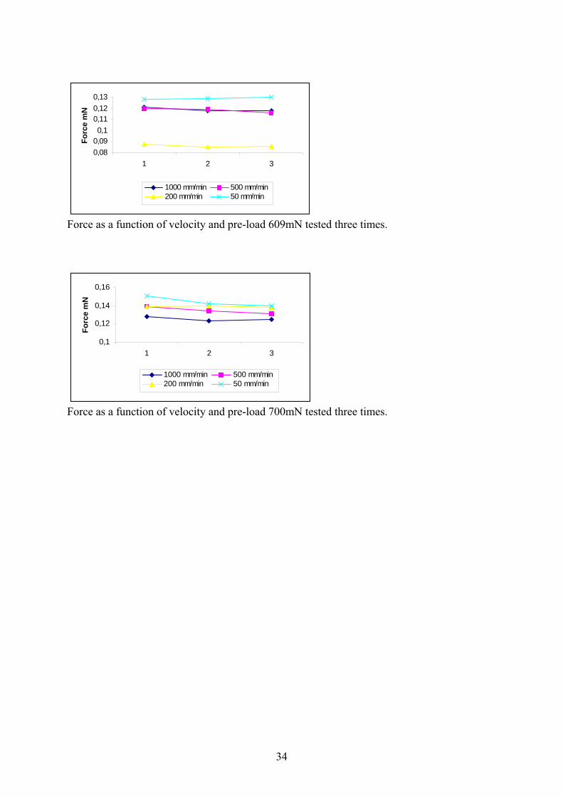
Plot 6. Coefficient of friction for the aramid yarn as a function of velocity and pre-load. The yarns were tested at the same velocity and pre-load 3 times. This had an influence of the sizing of the yarn, which became smoother for each time and the force needed to bend the fibre decreased for, almost, each time. See Appendix 1.
5.3 Results of flexural rigidity The flexural rigidity test was done based on a method from Peirce [13]. The bending force of deflection and the length of deflection was measured and used in the equation for calculation of the Flexural Rigidity. The velocities used in the tests are 10 and 100 mm/min due to the fact that some pre-tests were done with higher velocity and this caused problem. The problem was that the time of the test was too short and therefore difficult to stop manually at the right time before yarn breakage. The results of flexural rigidity for the PET-yarns of diameter 0,08 mm up to 0,15 mm are shown in Plot 7. For velocity 100 mm/min the value of flexural rigidity increases significantly with an increase of fibre diameter. For velocity 10 mm/min the plot shows an increase in flexural rigidity between fibre diameter 0,08 and 0,15 mm in the same magnitude as for the test of velocity 100 mm/min but then decreases significantly between 0,10 and 0,12 mm. In Plot 8 the bending force is shown for fibre diameters between 0,08 up to 0,15 mm. The result shows a significant increase in bending force with an increase of the yarn diameter, for velocity 10 and 100 mm/min.
Plot 7. Flexural rigidity of PET as a function of fibre diameters and velocities 10 and 100 mm/min
Plot 8. Flexural rigidity of PET as a function of fibre diameters and velocities 10 and 100 mm/min The results of the tests of the carbon fibre yarns shows in Plot 9 that the flexural rigidity increases or decreases with the velocity depending if the yarn is of HTS or HMA-type. Tests
Polyester PET
00,20,40,6
0,08 0,1 0,12 0,15
Fibrediameter mm
Flex
ural
rig
idity
N/m
m2
10100
Polyester PET
050
100150
0,08 0,1 0,12 0,15Fibrediameter mm
Bend
ing
forc
e m
N 10100
Aramid fibres Kevlar
0,000,501,001,50
202 301 407 609 700
Pre-load mN
Coe
ffici
ent o
f fri
ctio
n
10502005001000

15
with carbon fibre yarn of HTS-type shows that flexural rigidity decreases with an increase in velocity from 10 to 100 mm/min. Carbon fibre yarn of HMA-type shows an increase in flexural rigidity with an increase of the velocity. Plot 10 shows the bending force at velocity 10 and 100 mm/min. The result shows that the bending force is higher for the HMA-yarn at velocity 100 mm/min than for the HTS-yarn. For velocity 10 mm/min the bending force are almost the same for both types of carbon yarns. The results in Plot 9 and 10 compared with each other shows that an increase in flexural rigidity also causes an increase in the bending force required. The result of the aramid yarn of Kevlar type shows an increase of the flexural rigidity with an increase of the velocity from 10 up to 100 mm/min, Plot 11.
Plot 9. Flexural rigidity of carbon fibres HTS and HMA as a function of velocities 10 and 100 mm/min.
Plot 10. Bending forces of carbon fibres HTS and HMA as a function for velocities 10 and 100 mm/min.
Plot 11. Flexural rigidity of aramid fibres as a function of velocities 10 and 100 mm/min.
Aramid fibres Kevlar
2,98
3
3,02
3,04
10 100
Velocity mm/min
Flex
ural
rigi
dity
N
/mm
2
Kevlar
Carbonfibre HTS and HMA
00,10,20,3
10 100
Velocity mm/min
Flex
ural
rigi
dity
N
/mm
2
HMAHTS
Carbonfibre HTS and HMA
0
50
100
10 100
Velocity mm/min
Ben
ding
forc
e m
N HMAHTS

16
6. DISCUSSION
6.1 Analysis of friction The coefficients of friction of yarns are known to be increasing with increasing load and speed [1,13]. For traditional textile spun or multifilament yarns of low bending stiffness the coefficient of friction is, however, usually higher at low load due to the effects of adhesion bonding [13]. A reversed effect of the load was more pronounced for high velocity, thus indicating lubrication and only partial contact between the fibres and the needles. With sufficient pre-load and velocity, the bending on the needles gives plastic deformation of the fibres. This mechanism absorbs energy. Full contact, plastic deformation and adhesion gives high apparent coefficients of friction. For the PET-monofilament yarns the coefficient of friction is decreasing with an increase in fibre diameter and with insufficient pre-load (plots 1-3). The bending radii of the fibres are bigger than the radius of the needles and only limited contact is obtained. The assumptions of the drive belt based theory are not fulfilled in this case. These measurements, however, provide indications of the velocity and loading dependence of mechanical stresses and friction build-up between yarn and needles. For the carbon yarns HMA and HTS fibres, the coefficient of friction indicates slightly higher values with an increase of velocity (plots 4-5). Some results with the HMA fibre shows a drop in friction coefficient due to insufficient contact between yarn and needles. From a practical point of view, insufficient contact between the needle and the yarn gives insufficient stability of the knitting process. Full contact gives the risk of excessive stress build-up according to the drive belt formula. For the aramid yarn, the friction decreases with increasing pre-load (plot 6) because of the break of the yarn when it bends round the needle. The plots in Appendix 1 show the mean value of the forces, measured in the friction test, as a function of velocity and pre-load of the first, second and third test done with each yarn. For the polyester yarn the force is decreasing significantly between the three tests. The force is decreasing most between the first and the second test of the yarn in most of the plots of the polyester yarns. This could be explained by complete wetting and the fact that the silicon based sizing on the surface of the yarn lubricates the boundary between yarn and needle. The carbon and aramid yarns show different results between the tests than the polyester yarns. In most plots the value of the force is more equal in test one, two and three. There is however some deviation from this but the tendency is that it is a different behaviour then it is for the polyester yarn. This could be explained by the fact that it is completely different type of fibre material but also by the type of sizing that is used of this carbon and aramid yarns. The sizing on the carbon yarns is of "not fully hardened epoxy type" and on the aramid yarn there is "oil type" sizing and this gives less wetting and lubrication between yarn and needle than the silicone based sizing of the polyester yarn.
6.2 Analysis of flexural rigidity – bending stiffness
The bending force and flexural rigidity of the PET-monofilament yarns reflects the square dependence of the diameter. An increase in the fibre diameter of the yarn shows a strong increase in the bending rigidity (plots 7-8). At low velocity, 10 mm/min, flexural rigidity is decreasing with an increase in yarn diameter and could indicate insufficient stability of the initial loops due to stress relaxation. It could also depend on an increase of diameter and bending stiffness because the yarn is difficult to handle in the beginning of the bending test

17
and will not stay in the hook of the needle. The plots of flexural rigidity and bending force for full bending around the needles for carbon fibres reflect the combined effects of the visco elasticity of the sizings and bending stiffness of the fibres (plots 9-10). These systems are designed for compatibility with standard epoxy materials and for performance in weaving, braiding, filament winding and insert warp knitting. Important features provided by the sizing are the integrity of these non-twist yarns and the protection of fibres and machinery against direct contact. The critical bending radius of the high modulus HMA fibres and the needle diameter in the test are very close resulting in some fibre fracture. The calculated values of flexural rigidity do not take the shape factors somewhat deviating from 1 into account. However, the flexural rigidity and the bending force follow the same trends when changing the velocity. The HMA fibres have approximately twice the elastic modulus of the HTS fibres, as seen in the flexural rigidity at 100 mm/min. At low velocity, 10 mm/min, there is probably sliding between the fibres in the HMA yarn, while the fibres in the HTA yarn are sticking together. For aramid the result in plot 11 shows that the flexural rigidity is strong velocity dependent with an increase of the flexural rigidity from velocity 10 mm/min to 100 mm/min. Sliding occur between the fibres in the yarn at the low velocity with decreasing of the shape factor and this results in low flexural rigidity. 6.3 Spacer Fabrics - friction and bending One of the most important problems when it comes to knit Spacer fabrics on weft knitting machines is that the yarn that's produce the separating layer between the two outer layers often consists of a material of high stiffness. This has the consequence that the yarn has a tendency to have in-sufficient contact with the needles during the knitting process. These phenomena we have viewed both on flat and circular knitting machines during knitting. The friction tests in the Instron tensile tester indicate the same thing that we saw on the knitting machines: friction is decreasing with an increase in fibre diameter of the yarn due to in-sufficient contact between yarn and needles. To overcome this problem it’s important to have sufficient tension of the yarn in coming side in the knitting machine. The flexural rigidity tests of the carbon fibres in the yarn shows that the if the bending radius of the yarn fibres and the needle diameter are to close this could result in fibre fracture. This result shows the importance to have the right count of the yarn compared with the diameter of the needles (gauge of the knitting machine) especially when knitting with stiff yarns that often are the case in spacer fabrics. This shows also that one possibility to reduce fibre fracture of the yarn in spacer fabrics is to knit the separating yarn with tuck loops that reduce the bending radius of the yarn.

18
7. CONCLUSIONS
7.1 Merits The merits of the knittability test-rig set-up are the possibilities to test the performance of the yarns with the geometry of the machine using an ordinary tensile testing machine and to simulate and identify some of the problems that could occur between needles and yarn in the knitting process. Well-defined mechanical conditions with the static pre-load weight and the possibilities of identifying the location of the events of damage on the fibres during the testing of the specimens and to do further examination before knitting are some obvious merits.
7.2 Concluding remarks The intention with this work has been to investigate if it is possible to test the knittability of a yarn in an ordinary tensile testing machine. This work shows that it is possible to get important information of yarns frictional and bending behaviour that could be used to form an opinion of a yarns knittability before knitting in the machine and prevent needle breakage and machine disturbance. The new apparatus with two-mounted latch needles has some important benefits for knittability testing of textile fibres. (1) Well-defined mechanical conditions with the static pre-load weight and the possibilities to identify location of events of damage on the fibres during the testing of the specimens and to do further examination before knitting. (2) It is possible to have needles with different diameter that correspond to different gauge number on knitting machines. (3) There are also possible to vary the contact angle between yarn and needle in the apparatus to simulate the conditions on different types of knitting machines. This work shows that with this apparatus used in an ordinary tensile testing machine, it is possible to get important information of the knittability of a yarn. Such information are: (1) Static and dynamic friction between yarn and needles. (2) Flexural rigidity or influence of the fibre diameter in the knitting process. (3) Influence of yarn tension. The results of our work illustrate a strong influence of the fibre diameter and the knittability. The diameter of the needles is similar to that of the monofilaments for example for use in spacer fabrics. The results of this work also shows that it is important to have sufficient yarn tension when the needle draws the yarn in to the knitting zone of the machine. The result of insufficient yarn tension could be insufficient contact between yarn and needles and this could cause difficulties in the knitting process. This effect is more pronounced if the velocity is high.

19
8. FUTURE WORK The aim with this work has been to study friction and bending properties of yarns with high stiffness and to determine the possibility to test yarns knittability before knitting in a tensile testing machine of standard type. This is a wide area to investigate both construction of the test rig, preparation of test methods for both friction and bending tests and also carry out some tests of stiff yarns. This means that this work is just an introduction in handleability of yarns and fibres in the area of knitting technology. There are a lot of possibilities for work to be done in the future in this area. The test apparatus construction and design resulted in a prototype equipped with latch needles of the same type used in the knitting machine. A lot could still be done to find the best and most flexible design to fulfil the requirements for tests with yarns of different material, count and also for the apparatus to be flexible to simulate knitting machines of various gauges and conditions. One problem with the test method of the friction test is that the pre-load weight could swing free during the test and this could probably effect the result negatively. This effect should be further investigated and could result in alternative solutions of this problem. To get a better opinion of the validity of the results of the friction tests in the Instron-tester should be compared with the results done on a knitting machine during knitting. In mechanical testing especially in friction and bending tests an important factor is the effect of hysteresis that could occur during repeated and cycled tests of the yarn. This factor could have a negative effect of the result of the tests and therefor could be the aim of future work in this area.

20
9. REFERENCES 1. Andersson, C-H., (1997), “Analysis of contact stresses due to combined bending and
sliding of high performance fibres”, Mechanics of Composite Materials. 33: 147 – 154.
2. Andersson, C-H., Nilsson, A., Larsson, L-G., Christensson, B., Wickberg, A., (1996), “Handleability, dust and damage of reinforcement fibres”, TEXCOMP - 3, paper 20, Aachen, December.
3. Leong, K.H., Ramakrishna, S., Huang, Z.M., Bibo, G.A.,(2000),”The potential of
knitting for engineering composites – a review”, Composites. A 31: 197-220.
4. Andersson, C-H., (1998), ”Some notes on friction and testing adhesion and bonding of fibres”, J.Mater.Sci.Lett. 17: 1111-1112.
5. Stumpf, H., Mäder, E., Baeten, S., Pisanikovski, T., Zäh, W., Eng, K., Andersson, C-H., Verpoest, I., Schulte, K., (1998), ”New thermoplastic composite preforms based on split-film warp knitting”, Composites. 29A: 1511-1523.
6. Spencer, D.J., (1989), ” Knitting Technology” Second Edition. Pergamon Press: 257-259. 7. Iyer, C., Mammel, B., Schäch, W., (1995), “Circular Knitting”. Bamberg Meisenbach:7-
8. 8. Knapton, J.J.F., Munden, D.L., (1966), Textile Research Journal, Part I, 36: 1072-1081. 9. Lau,K.W., Dias, T., (1994), “Knittability of High-modulus Yarns”, J. Text. Inst. 85, No
2. 10. Abou-iiana, M., (2000),“Fadenzugkrafte beim Stricken mit Relativbewegung“,
Melliand Textilberichte, 9. 11. Van Vuure, A., (1997), “Composite panels based on woven sandwich panel preforms”.
PhD-thesis. Katholeike Universiteit Leuven, Leuven Belgium.
12. Wilkens, C., (1993), “Geraschelte Abstandsgewirke“, Melliand Textilberichte.0: 993-997.
13. Morton, W.E., Hearle, J.W.S., (1975),“Physical properties of textile fibres”, Wm
Heinemann and The Textile Institute, Manchester UK:400-403.

21
APPENDIX 1: Friction tests The plots in Appendix 1 show the mean value of the forces, measured in the friction test, as a function of velocity and pre-load of the first, second and third test done with each yarn for different yarn diameters.
Polyester 0,08 mm
Force as a function of velocity and pre-load 23 mN tested three times.
Force as a function of velocity and pre-load 48 mN tested three times.
Force as a function of velocity and pre-load 78 mN tested three times.
0
0,02
0,04
0,06
0,08
1 2 3
Forc
e m
N
1000 mm/min500 mm/min200 mm/min
0,1
0,12
0,14
0,16
0,18
1 2 3
Forc
e m
N
1000 mm/min500 mm/min200 mm/min50 / i
0,10,150,2
0,250,3
1 2 3
Forc
e m
N
1000 mm/min 500 mm/min200 mm/min 50 mm/min

22
Force as a function of velocity and pre-load 102 mN.
Force as a function of velocity and pre-load 171 mN tested three times.
0,2
0,25
0,3
1 2 3
Forc
e m
N
1000 mm/min 500 mm/min200 mm/min 50 mm/min
0,35
0,4
0,45
1 2 3
Forc
e m
N
1000 mm/min 500 mm/min200 mm/min 50 mm/min

23
Polyester 0,10 mm
Force as a function of velocity and pre-load 23 mN tested three times.
Force as a function of velocity and pre-load 48 mN tested three times.
Force as a function of velocity and pre-load 78 mN tested three times.
0,040,050,060,070,08
1 2 3
Forc
e m
N
1000 mm/min 500 mm/min200 mm/min 50 mm/min
0
0,1
0,2
0,3
1 2 3
Forc
e m
N
1000 mm/min 500 mm/min200 mm/min 50 mm/min
0
0,1
0,2
0,3
1 2 3
Forc
e m
N
1000 mm/min 500 mm/min200 mm/min 50 mm/min

24
Force as a function of velocity and pre-load 102mN tested three times.
Force as a function of velocity and pre-load 171mN tested three times.
0,20,250,3
0,350,4
1 2 3
Forc
e m
N
1000 mm/min 500 mm/min200 mm/min 50 mm/min
0,4
0,45
0,5
1 2 3
Forc
e m
N
1000 mm/min 500 mm/min200 mm/min 50 mm/min

25
Polyester 0,12
Force as a function of velocity and pre-load 23mN tested three times.
Force as a function of velocity and pre-load 48mN tested three times.
Force as a function of velocity and pre-load 78mN tested three times.
0,03
0,04
0,05
0,06
1 2 3
Forc
e m
N
1000 mn/min 500 mm/min200 mm/min 50 mm/min
0,10,12
0,140,160,18
1 2 3
Forc
e m
N
1000 mm/min 500 mm/min200 mm/min 50 mm/min
0,2
0,25
0,3
0,35
1 2 3
Forc
e m
N
1000 mm/min 500 mm/min200 mm/min 50 mm/min

26
Force as a function of velocity and pre-load 102mN tested three times.
Force as a function of velocity and pre-load 171mN tested three times.
0,20,250,3
0,350,4
1 2 3
Forc
e m
N
1000 mm/min 500 mm/min200 mm/min 50 mm/min
0,4
0,5
0,6
0,7
1 2 3
Forc
e m
N
1000 mm/min 500 mm/min200 mm/min 50 mm/min

27
Polyester 0,15mm
Force as a function of velocity and pre-load 23mN tested three times.
Force as a function of velocity and pre-load 48mN tested three times.
Force as a function of velocity and pre-load 78mN tested three times.
0
0,05
0,1
1 2 3
Forc
e m
N
1000 mm/min 500 mm/min200 mm/min 50 mm/min
0,050,1
0,150,2
1 2 3
Forc
e m
N
1000 mm/min 500 mm/min200 mm/min 50 mm/min
0,10,150,2
0,250,3
0,35
1 2 3
Forc
e m
N
1000 mm/min 500 mm/min200 mm/min 50 mm/min

28
Force as a function of velocity and pre-load 102mN tested three times.
Force as a function of velocity and pre-load 171mN tested three times.
0,2
0,25
0,3
0,35
0,4
1 2 3
Forc
e m
N
1000 mm/min 500 mm/min200 mm/min 50 mm/min
0,4
0,5
0,6
0,7
1 2 3
Forc
e m
N
1000 mm/min 500 mm/min200 mm/min 50 mm/min

29
Carbonfibres HTS
Force as a function of velocity and pre-load 202mN tested three times.
Force as a function of velocity and pre-load 301mN tested three times.
Force as a function of velocity and pre-load 407mN tested three times.
1
1,5
2
1 2 3
Forc
e m
N
1000 mm/min 500 mm/min200 mm/min 50 mm/min
0
1
2
3
1 2 3
Forc
e m
N
1000 mm/min 500 mm/min200 mm/min 50 mm/min
2
2,5
3
3,5
1 2 3
Forc
e m
N
1000 mm/min 500 mm/min200 mm/min 50 mm/min

30
Force as a function of velocity and pre-load 609mN tested three times.
Force as a function of velocity and pre-load 700mN tested three times.
2345
1 2 3
Forc
e m
N
1000 mm/min 500 mm/min200 mm/min 50 mm/min
3
3,54
4,5
5
1 2 3
Forc
e m
N
1000 mm/min 500 mm/min200 mm/min 50 mm/min

31
Carbonfibres HMA
Force as a function of velocity and pre-load 202mN tested three times.
Force as a function of velocity and pre-load 301mN tested three times.
Force as a function of velocity and pre-load 407mN tested three times.
0
1
2
3
1 2 3
Forc
e m
N
1000 mm/min 500 mm/min200 mm/min 50 mm/min
1
1,5
2
2,5
1 2 3
Forc
e m
N
1000 mm/min 500 mm/min200 mm/min 50 mm/min
0
1
2
3
1 2 3
Forc
e m
N
1000 mm/min 500 mm/min200 mm/min 50 mm/min
11,5
22,5
3
1 2 3
Forc
e m
N
1000 mm/min 500 mm/min200 mm/min 50 mm/min

32
Force as a function of velocity and pre-load 609mN tested three times.
Force as a function of velocity and pre-load 700mN tested three times.
2
3
4
5
1 2 3
Forc
e m
N
1000 mm/min 500 mm/min200 mm/min 50 mm/min
33,5
44,5
55,5
1 2 3
Forc
e m
N
1000 mm/min 500 mm/min200 mm/min 50 mm/min
2
3
4
5
1 2 3
Forc
e m
N
1000 mm/min 500 mm/min200 mm/min 50 mm/min

33
Aramidfibres Kevlar
Force as a function of velocity and pre-load 202mN tested three times.
Force as a function of velocity and pre-load 301mN.
Force as a function of velocity and pre-load 407mN tested three times.
0,04
0,045
0,05
0,055
1 2 3
Forc
e m
N
1000 mm/min 500 mm/min200 mm/min 50 mm/min
0,060,0650,07
0,0750,08
1 2 3
Forc
e m
N
1000 mm/min 500 mm/min200 mm/min 50 mm/min
0,075
0,08
0,085
0,09
0,095
1 2 3
Forc
e m
N
1000 mm/min 500 mm/min200 mm/min 50 mm/min
34
Force as a function of velocity and pre-load 609mN tested three times.
Force as a function of velocity and pre-load 700mN tested three times.
0,080,090,1
0,110,120,13
1 2 3
Forc
e m
N
1000 mm/min 500 mm/min200 mm/min 50 mm/min
0,1
0,12
0,14
0,16
1 2 3
Forc
e m
N
1000 mm/min 500 mm/min200 mm/min 50 mm/min