Development of a New Marine Exposure Site on the Atlantic North-west Coast of Ireland
13
Dublin Institute of Technology ARROW@DIT Conference Papers School of Civil and Building Services Engineering 2010-09-01 Development of a New Marine Exposure Site on the Atlantic North-west Coast of Ireland Niall Holmes Dublin Institute of Technology, [email protected] L. Basheer Queen's University - Belfast S. Nanukuan Queen's University - Belfast S. Srinivasan Queen's University, Belfast PAM Basheer Queen's University Belfast See next page for additional authors Follow this and additional works at: hp://arrow.dit.ie/engschcivcon Part of the Civil Engineering Commons is Conference Paper is brought to you for free and open access by the School of Civil and Building Services Engineering at ARROW@DIT. It has been accepted for inclusion in Conference Papers by an authorized administrator of ARROW@DIT. For more information, please contact [email protected], [email protected]. is work is licensed under a Creative Commons Aribution- Noncommercial-Share Alike 3.0 License Recommended Citation Holmes, N., Basheer, L., Nanukuan, S., Srinivasan, S., Basheer, P., McCarter, J., Chrisp, M.: Development of a New Marine Exposure Site on the Atlantic North-West Coast of Ireland. BCRI, Cork, Ireland, 2010.
Transcript of Development of a New Marine Exposure Site on the Atlantic North-west Coast of Ireland
Dublin Institute of TechnologyARROW@DIT
Conference Papers School of Civil and Building Services Engineering
2010-09-01
Development of a New Marine Exposure Site onthe Atlantic North-west Coast of IrelandNiall HolmesDublin Institute of Technology, [email protected]
L. BasheerQueen's University - Belfast
S. NanukuttanQueen's University - Belfast
S. SrinivasanQueen's University, Belfast
PAM BasheerQueen's University Belfast
See next page for additional authors
Follow this and additional works at: http://arrow.dit.ie/engschcivconPart of the Civil Engineering Commons
This Conference Paper is brought to you for free and open access by theSchool of Civil and Building Services Engineering at ARROW@DIT. It hasbeen accepted for inclusion in Conference Papers by an authorizedadministrator of ARROW@DIT. For more information, please [email protected], [email protected].
This work is licensed under a Creative Commons Attribution-Noncommercial-Share Alike 3.0 License
Recommended CitationHolmes, N., Basheer, L., Nanukuttan, S., Srinivasan, S., Basheer, P., McCarter, J., Chrisp, M.: Development of a New Marine ExposureSite on the Atlantic North-West Coast of Ireland. BCRI, Cork, Ireland, 2010.

AuthorsNiall Holmes, L. Basheer, S. Nanukuttan, S. Srinivasan, PAM Basheer, J. McCarter, and M. Chrisp
This conference paper is available at ARROW@DIT: http://arrow.dit.ie/engschcivcon/15
N. Holmes, L. Basheer, S. Nanukuttan, S. Srinivasan, PAM Basheer, J.McCarter, & M. Chrisp. - 1 -
DEVELOPMENT OF A NEW MARINE EXPOSURE SITE ON THE ATLANTIC NORTH-WEST COAST OF IRELAND
N. HOLMES1, L. BASHEER1, S. NANUKUTTAN1, S. SRINIVASAN1, PAM
BASHEER1, J. MCCARTER2 & M. CHRISP2 1 School of Planning, Architecture and Civil Engineering, Queen’s University of Belfast,
Northern Ireland 2 School of the Built Environment, Heriot-Watt University, Edinburgh, Scotland
Abstract This paper presents a new marine exposure site being developed on the North-west Atlantic coastline of Ireland in Co. Donegal by the Centre for Built Environment Research at Queen’s University Belfast. The site will initially contain a number of large precast concrete stems, each 1.5m high, 1.5m wide and 1m thick placed on concrete plinths poured in-situ. The concrete stems will be placed at three levels to achieve different exposure conditions outlined in EN 206, namely atmospheric (XS1), a splash or spray zone (XS3) and a tidal zone (XS3) where the stems will be submerged by the incoming tide twice daily. The concrete will consist of different cements and appropriate w/b ratios suitable for this type of exposure. The permeability and diffusion properties will be measured using non-destructive tests developed at Queen’s University Belfast, namely the Autoclam permeability system and the Permit ion migration test. Other tests to measure the corrosion of the embedded rebar will also be undertaken. In order to monitor the internal concrete properties, electrical sensors will be attached to the rebar and embedded in concrete. The information from these sensors will be relayed back to the office using remote wireless technology. Such integrated monitoring systems for concrete structures can reduce assessment and repair costs by continuously profiling the covercrete and corrosion for the ingress of various deleterious substances, such as chlorides, in the reinforcing steel in real-time. This approach permits an informed assessment of the performance of the structure throughout its service life. This site will form part of a world-wide exposure study, including similar sites in Scotland, India and China. Keywords: Exposure Site, EN 206, corrosion, sensors, covercrete, durability 1. Introduction The introduction of EN 206 (BS EN 206, 2000) now permits concrete to be specified in terms of its performance depending on the environment to which it will be exposed. For a concrete structure in or near to the sea, the exposure class in EN 206 which is relevant is XS; corrosion induced by chlorides from sea water. This exposure class is sub-divided into 3 different sub-classes namely, XS1, XS2 and XS3. These exposures define if the concrete will be exposed to airborne salts, but not in direct contact with sea water (XS1), concrete which will be
- 2 - N. Holmes, L. Basheer, S. Nanukuttan, S. Srinivasan, PAM Basheer, J.McCarter, & M. Chrisp.
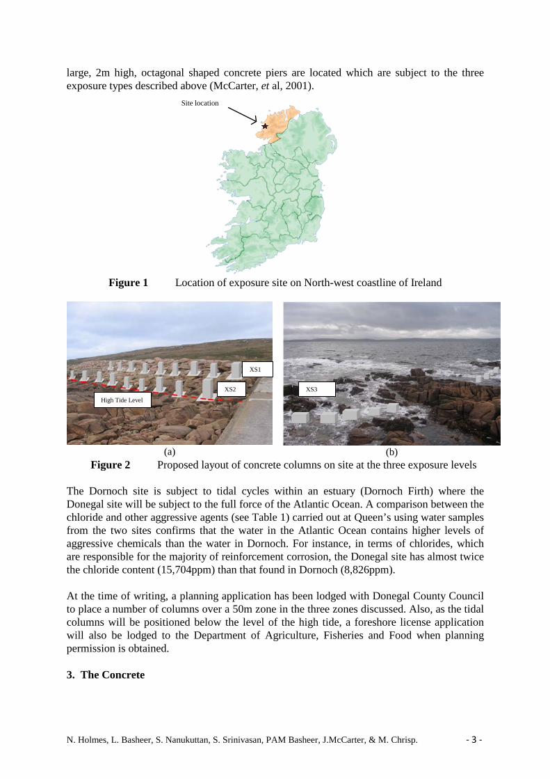
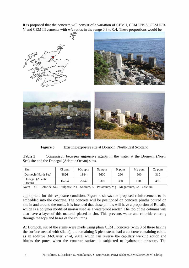
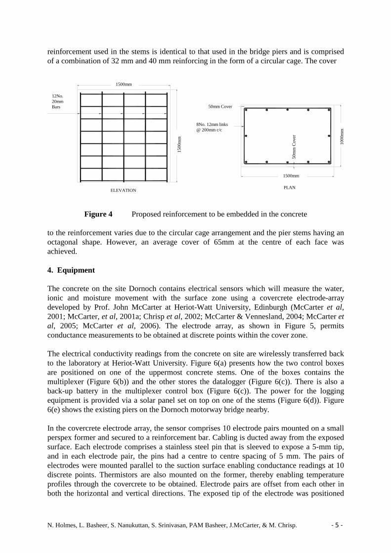
permanently submerged (XS2) and concrete which will be within a tidal zone or subject to sea water splash or spray (XS3). It will now be possible to specify concrete both by the historic prescriptive approach (strength, cement quantity, w/c ratio) and/or by its performance in the field, for instance, in terms of an assigned air permeability, absorption rate or chloride diffusivity rate. The concrete must then meet this specification before it is deemed acceptable. Work is currently underway at QUB, in conjunction with Heriot-Watt University (Edinburgh), as part of a EPSRC funded project, to assess if common testing methods are suitable to determine if these specifications/limits have been achieved (Nanukuttan, 2009; Nanukuttan, 2010). BS 8500 (2006) has prepared prescriptive guidelines, depending on the exposure type, for concrete which, for a particular cover depth, suggests suitable w/c ratios, cement contents (kg/m3) and strength (N/mm2). This publication also provides guidelines on which cement type within EN 197 (BS EN 197, 2000) would be appropriate. For instance, for a structure with an intended working life of 50 years, in exposure type XS3, with a cover of 40 + ∆c, BS 8500 recommends a minimum strength of C35/45, a maximum w/c ratio of 0.40 and a minimum cement content of 380kg/m3. BS 8500 also suggests that cement types CEM II/B-V, CEM III/A, CEM III/B and CEM IV/B-V (EN 197, 2000) would be suitable. However, there is little available data on suitable performance specifications for this, or any other exposure type. The Association Francaise de Genie Civil (AFGC, 2007) has published examples of engineering projects where, along with prescriptive specifications, the concrete has been assigned performance-based guidelines for durability. For example, the Channel-Tunnel project assigned a water permeability for some of the concrete of <10-13 m/sec. The concrete on sections of the Millau Bridge project had a performance specification of 10-17 m2 and 10-12 m2/s for the gas permeability and an apparent chloride diffusivity rate respectively. Therefore, QUB, as part of a world-wide concrete exposure study including similar sites in Scotland, India and China, are in the process of setting up a marine exposure site on the North-West Atlantic coastline of Ireland in Co. Donegal. The performance of different concretes will be assessed using non-destructive methods so that performance specifications can be derived for the XS exposure class. 2. The Site Figure 1 shows the location of the site, near Dungloe, in Co. Donegal. The site is subject to high wave action which will create significant spray as it is situated along a remote section of the Atlantic Ocean coastline. It therefore represents a good test of the concrete that will be located there. The concrete on the site will be placed at three levels (Figure 2) and exposed to three different environments. The uppermost level (Figure 2(a)) will subject the concrete to atmospheric chlorides but not in direct contact with sea water. This represents the XS1 exposure class. The middle level (Figure 2(a)) will expose the concrete to ocean splash or spray, which will be within the XS3 class. The third level (Figure 2(b)) will be within the tidal zone where the concrete will be fully submerged twice daily, representing the XS3 exposure class. Based on a detailed survey of the site, the concrete will be placed at appropriate levels based on mean neap and spring tides. A similar site (Figure 3), which is also part of the world-wide study, has been in place on the North-East of Scotland since 1992. This site, which is on the North Sea coastline at Dornoch was set up by Heriot-Watt University in Edinburgh. On the site, 9
N. Holmes, L. Basheer, S. Nanukuttan, S. Srinivasan, PAM Basheer, J.McCarter, & M. Chrisp. - 3 -
large, 2m high, octagonal shaped concrete piers are located which are subject to the three exposure types described above (McCarter, et al, 2001).
Figure 1 Location of exposure site on North-west coastline of Ireland
(a)
(b)
Figure 2 Proposed layout of concrete columns on site at the three exposure levels The Dornoch site is subject to tidal cycles within an estuary (Dornoch Firth) where the Donegal site will be subject to the full force of the Atlantic Ocean. A comparison between the chloride and other aggressive agents (see Table 1) carried out at Queen’s using water samples from the two sites confirms that the water in the Atlantic Ocean contains higher levels of aggressive chemicals than the water in Dornoch. For instance, in terms of chlorides, which are responsible for the majority of reinforcement corrosion, the Donegal site has almost twice the chloride content (15,704ppm) than that found in Dornoch (8,826ppm). At the time of writing, a planning application has been lodged with Donegal County Council to place a number of columns over a 50m zone in the three zones discussed. Also, as the tidal columns will be positioned below the level of the high tide, a foreshore license application will also be lodged to the Department of Agriculture, Fisheries and Food when planning permission is obtained. 3. The Concrete
Site location
XS1
XS2
High Tide Level
XS3
- 4 - N. Holmes, L. Basheer, S. Nanukuttan, S. Srinivasan, PAM Basheer, J.McCarter, & M. Chrisp.
It is proposed that the concrete will consist of a variation of CEM I, CEM II/B-S, CEM II/B-V and CEM III cements with w/c ratios in the range 0.3 to 0.4. These proportions would be
Figure 3 Existing exposure site at Dornoch, North-East Scotland Table 1 Comparison between aggressive agents in the water at the Dornoch (North Sea) site and the Donegal (Atlantic Ocean) sites.
Site Cl ppm SO4 ppm Na ppm K ppm Mg ppm Ca ppm Dornoch (North Sea) 8826 1384 5600 290 900 310 Donegal (Atlantic Ocean) 15704 2254 9300 360 1800 490
Note: Cl – Chloride, SO4 –Sulphate, Na – Sodium, K – Potassium, Mg – Magnesium, Ca - Calcium appropriate for this exposure condition. Figure 4 shows the proposed reinforcement to be embedded into the concrete. The concrete will be positioned on concrete plinths poured on site in and around the rocks. It is intended that these plinths will have a proportion of Ronafit, which is a polymer modified mortar used as a waterproof render. The top of the columns will also have a layer of this material placed in-situ. This prevents water and chloride entering through the tops and bases of the columns. At Dornoch, six of the stems were made using plain CEM I concrete (with 3 of these having the surface treated with silane); the remaining 3 piers stems had a concrete containing caltite as an additive (McCarter, et al, 2001) which can reverse the capillary wicking action and blocks the pores when the concrete surface is subjected to hydrostatic pressure. The
N. Holmes, L. Basheer, S. Nanukuttan, S. Srinivasan, PAM Basheer, J.McCarter, & M. Chrisp. - 5 -
reinforcement used in the stems is identical to that used in the bridge piers and is comprised of a combination of 32 mm and 40 mm reinforcing in the form of a circular cage. The cover
1500
1500
50mm COVER
50m
m C
OV
ER
12No. 20mm BARS
8No. 12mm LINKS AT 200mm c/c
ELEVATIONPLAN
1000
1500
Figure 4 Proposed reinforcement to be embedded in the concrete
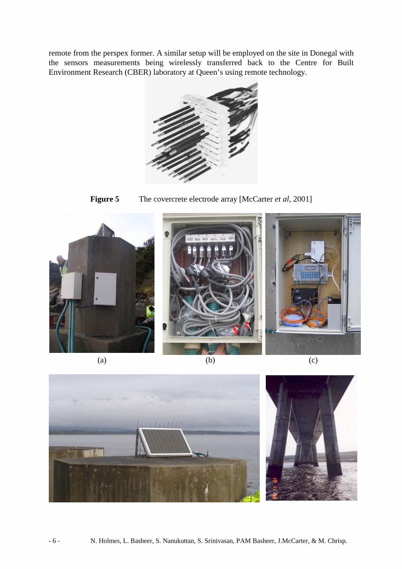
to the reinforcement varies due to the circular cage arrangement and the pier stems having an octagonal shape. However, an average cover of 65mm at the centre of each face was achieved. 4. Equipment The concrete on the site Dornoch contains electrical sensors which will measure the water, ionic and moisture movement with the surface zone using a covercrete electrode-array developed by Prof. John McCarter at Heriot-Watt University, Edinburgh (McCarter et al, 2001; McCarter, et al, 2001a; Chrisp et al, 2002; McCarter & Vennesland, 2004; McCarter et al, 2005; McCarter et al, 2006). The electrode array, as shown in Figure 5, permits conductance measurements to be obtained at discrete points within the cover zone. The electrical conductivity readings from the concrete on site are wirelessly transferred back to the laboratory at Heriot-Watt University. Figure 6(a) presents how the two control boxes are positioned on one of the uppermost concrete stems. One of the boxes contains the multiplexer (Figure 6(b)) and the other stores the datalogger (Figure 6(c)). There is also a back-up battery in the multiplexer control box (Figure 6(c)). The power for the logging equipment is provided via a solar panel set on top on one of the stems (Figure 6(d)). Figure 6(e) shows the existing piers on the Dornoch motorway bridge nearby. In the covercrete electrode array, the sensor comprises 10 electrode pairs mounted on a small perspex former and secured to a reinforcement bar. Cabling is ducted away from the exposed surface. Each electrode comprises a stainless steel pin that is sleeved to expose a 5-mm tip, and in each electrode pair, the pins had a centre to centre spacing of 5 mm. The pairs of electrodes were mounted parallel to the suction surface enabling conductance readings at 10 discrete points. Thermistors are also mounted on the former, thereby enabling temperature profiles through the covercrete to be obtained. Electrode pairs are offset from each other in both the horizontal and vertical directions. The exposed tip of the electrode was positioned
12No. 20mm Bars
1500mm
50mm Cover
8No. 12mm links @ 200mm c/c
1500
mm
50m
m C
over
ELEVATION PLAN
1500mm
1000
mm
- 6 - N. Holmes, L. Basheer, S. Nanukuttan, S. Srinivasan, PAM Basheer, J.McCarter, & M. Chrisp.
remote from the perspex former. A similar setup will be employed on the site in Donegal with the sensors measurements being wirelessly transferred back to the Centre for Built Environment Research (CBER) laboratory at Queen’s using remote technology.
Figure 5 The covercrete electrode array [McCarter et al, 2001]
(a) (b) (c)
N. Holmes, L. Basheer, S. Nanukuttan, S. Srinivasan, PAM Basheer, J.McCarter, & M. Chrisp. - 7 -
(d) (e) Figure 6 Remote monitoring of electrical properties at Dornoch exposure site
This represents the new approach to monitoring so-called ‘smart structures’. The location of these sensors should be where the exposure to chlorides are at their highest, at structurally critical zones and in an area where exposure is not as severe to act as a control. In terms of a marine structure, the critical area will be in the inter-tidal, heavy splash, and, if the structure is close enough, within the range of wind-borne spray. 5. Non-destructive testing of the covercrete transport properties In addition to monitoring the internal electrical conductivity, the covercrete transport properties will be measured using non-destructive tests developed at Queens such as the rate of absorption and the air and water permeability properties using the Autoclam apparatus (Basheer et al, 1994). The Autoclam sorptivity test measures the cumulative inflow of water in the first 15 minutes from a water source of 50mm diameter at an applied pressure of 0.02 bars (approximately 200mm water head). A plot of cumulative volume of water verses square root of time gives a linear relationship and the slope obtained from the graph is reported as a sorptivity index. The Autoclam air permeability test depends on the measurement of pressure decay in a test reservoir mounted on the surface of concrete from a pressure of 0.5 bar over a period of 15 min and plotting the natural logarithm of the pressure against time, yielding a straight line graph. The slope of this graph is reported as the Autoclam air permeability index. The Autoclam water permeability test involves a procedure similar to that used for the Autoclam sorptivity test. The main difference is in the test pressure used, i.e. a pressure of 0.5 bar is used for the Autoclam water permeability test compared to 0.02 bar for the Autoclam sorptivity test. The inflow of water through a test area of 50mm diameter through a surface-mounted ring is measured at this pressure for a period of 15 minutes. From a linear plot of the cumulative inflow verses the square root of time, the slope is determined and reported as the Autoclam water permeability index, in m3/√min. The main advantage of the Autoclam is that it is portable, quick and simple to perform. The chloride diffusion rate will be monitored by the Permit apparatus which is a unique non-destructive test which is capable of determining the chloride migration coefficient of cover concrete. Detailed descriptions of the instrument, test technique and test area preparation are available elsewhere (Basheer et al, 2005; Nanukuttan, et al, 2006). It has been shown that the in situ migration coefficient from the permit ion migration test on different concrete samples correlate well with the conventional lab-based steady state diffusion and migration tests. The main advantage of this test is that it can provide a migration coefficient without having to remove cores from the structure. 6. Anticipated research findings and significance The permeation and migration results from the concrete on this site will be compared with those obtained from laboratory testing in QUB and from the exposure site in Dornoch as part of an existing EPSRC funded project. This will demonstrate the significance of the aggressive agents in the water between the two sites, as shown in Table 1. It is anticipated that the permeation and migration properties of the concrete and the corrosion of the embedded steel
- 8 - N. Holmes, L. Basheer, S. Nanukuttan, S. Srinivasan, PAM Basheer, J.McCarter, & M. Chrisp.
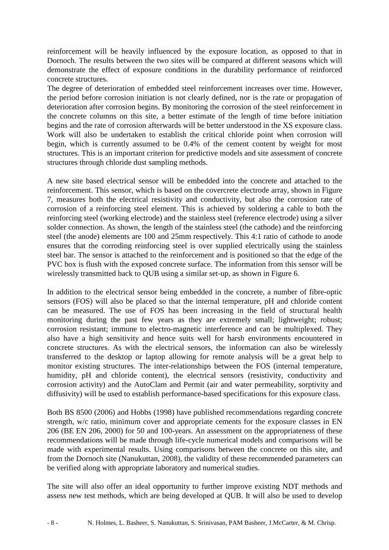
reinforcement will be heavily influenced by the exposure location, as opposed to that in Dornoch. The results between the two sites will be compared at different seasons which will demonstrate the effect of exposure conditions in the durability performance of reinforced concrete structures. The degree of deterioration of embedded steel reinforcement increases over time. However, the period before corrosion initiation is not clearly defined, nor is the rate or propagation of deterioration after corrosion begins. By monitoring the corrosion of the steel reinforcement in the concrete columns on this site, a better estimate of the length of time before initiation begins and the rate of corrosion afterwards will be better understood in the XS exposure class. Work will also be undertaken to establish the critical chloride point when corrosion will begin, which is currently assumed to be 0.4% of the cement content by weight for most structures. This is an important criterion for predictive models and site assessment of concrete structures through chloride dust sampling methods. A new site based electrical sensor will be embedded into the concrete and attached to the reinforcement. This sensor, which is based on the covercrete electrode array, shown in Figure 7, measures both the electrical resistivity and conductivity, but also the corrosion rate of corrosion of a reinforcing steel element. This is achieved by soldering a cable to both the reinforcing steel (working electrode) and the stainless steel (reference electrode) using a silver solder connection. As shown, the length of the stainless steel (the cathode) and the reinforcing steel (the anode) elements are 100 and 25mm respectively. This 4:1 ratio of cathode to anode ensures that the corroding reinforcing steel is over supplied electrically using the stainless steel bar. The sensor is attached to the reinforcement and is positioned so that the edge of the PVC box is flush with the exposed concrete surface. The information from this sensor will be wirelessly transmitted back to QUB using a similar set-up, as shown in Figure 6. In addition to the electrical sensor being embedded in the concrete, a number of fibre-optic sensors (FOS) will also be placed so that the internal temperature, pH and chloride content can be measured. The use of FOS has been increasing in the field of structural health monitoring during the past few years as they are extremely small; lightweight; robust; corrosion resistant; immune to electro-magnetic interference and can be multiplexed. They also have a high sensitivity and hence suits well for harsh environments encountered in concrete structures. As with the electrical sensors, the information can also be wirelessly transferred to the desktop or laptop allowing for remote analysis will be a great help to monitor existing structures. The inter-relationships between the FOS (internal temperature, humidity, pH and chloride content), the electrical sensors (resistivity, conductivity and corrosion activity) and the AutoClam and Permit (air and water permeability, sorptivity and diffusivity) will be used to establish performance-based specifications for this exposure class. Both BS 8500 (2006) and Hobbs (1998) have published recommendations regarding concrete strength, w/c ratio, minimum cover and appropriate cements for the exposure classes in EN 206 (BE EN 206, 2000) for 50 and 100-years. An assessment on the appropriateness of these recommendations will be made through life-cycle numerical models and comparisons will be made with experimental results. Using comparisons between the concrete on this site, and from the Dornoch site (Nanukuttan, 2008), the validity of these recommended parameters can be verified along with appropriate laboratory and numerical studies. The site will also offer an ideal opportunity to further improve existing NDT methods and assess new test methods, which are being developed at QUB. It will also be used to develop
N. Holmes, L. Basheer, S. Nanukuttan, S. Srinivasan, PAM Basheer, J.McCarter, & M. Chrisp. - 9 -
new innovative research proposals on concrete durability on real concrete subject to real exposure conditions. Also, a further possibility is the establishment of relationships between the results from accelerated laboratory corrosion methods (namely, ponding and salt-spray
Figure 7 Electrical sensor, manufactured by Amphora Ltd, to undertake a suite of corrosion measurements including rate of corrosion and resistivity.
methods) and site corrosion test results. In the future, therefore, when new materials are produced it can be confirmed whether these laboratory accelerated corrosion tests can be used to give a quick service life picture of the new materials. 7. Conclusions This paper has presented the setting up of a new marine exposure site on the Co. Donegal Atlantic coastline. A number of concrete columns (1.5m high x 1.5m wide x 1m thick) will be placed on the site where they will be subject to three different exposures within the XS classes in EN206, namely concrete subject to chlorides from airborne salts (XS1), from splash and spray (XS3) and from tidal cycles (XS3). The cement to be used in the concrete columns will consist of CEM I, CEM II/B-S, CEM II/B-V and CEM III/A with w/c or w/b ratios in the range 0.3 – 0.4. These variables are considered appropriate for the three exposure classes above. This work follows on from a similar site developed by Heriot-Watt University at Dornoch in North-East Scotland which has been in place since 1992. The samples here are exposed to an estuary tidal cycle. A review of the level of chlorides, and other contaminants, between the two sites has shown that the chloride level at the Donegal site is almost twice than in the water at Dornoch. The concrete on the new site will be cast with steel reinforcement onto which electrical sensors will be attached. These sensors will measure the conductivity and resistivity as well as the ionic and water movement through the coverzone. Half-cell and LPR measurements will also be undertaken. The results from these internal properties will be relayed back to the office through wireless technology through a remote monitoring station set-up on the site, representing ‘smart-structure’ technology. The transport properties (absorption, air permeability, water permeability and the chloride migration coefficient) in the coverzone will also be measured using the non-destructive AutoClam and Permit apparatus. Along with the electrical properties above, these results will be used to set guidelines for suitable performance specifications for concretes in the XS exposure class described here.
- 10 - N. Holmes, L. Basheer, S. Nanukuttan, S. Srinivasan, PAM Basheer, J.McCarter, & M. Chrisp.
8. References • Association Francaise de Genie Civil (2007) Concrete design for a given structure
service life, Scientific and technical documents • Basheer P. A. M., Long A. E. and Montgomery F. R (1994), ‘The Autoclam – a New
Test for Permeability. Concrete’, Journal of the Concrete Society, July/August, 27–29. • Basheer P. A. M., Andrews R. J., Robinson D. J. and Long A. E. (2005), ‘PERMIT’ Ion
Migration Test for Measuring the Chloride Ion Transport of Concrete on Site, NDT & E International, 38 (3), 219–229.
• BS EN 206 Part 1 (2000), ‘Concrete: Specification, performance, production and conformity’, British Standard Institute.
• BS 8500 (2006) Concrete: Complementary British Standard to BS EN 206-1, British Standard Institute.
• BS EN 197-1 (2000), Cement: Composition, specification and conformity criteria for common cements, British Standard Institute.
• Chrisp T.M., McCarter W.J., Starrs G., Basheer P.A.M. and Blewett J. (2002), ‘Depth related variation in conductivity to study wetting and drying of cover-zone concrete’, Cement and Concrete Composites, No. 24, Vol. 5, 415-427.
• Hobbs, D.W., (1998) ‘Minimum requirements for durable concrete, Carbonation and chloride induced corrosion, freeze-thaw and chemical attack’, BCA.
• McCarter, W. J., Chrisp, T. M. and Basheer, P. A. M. (2001a), ‘Condition profiling of cover zone concrete’, Proc. COST 521 Workshop, Tampere, Finland, 105-109 (ISBN 952 15 0364 2).
• McCarter, W.J., Butler, A., Chrisp, T.M., Emerson, M., Starrs, G. and Blewett, J. (2001) ‘Field trials on covercrete monitoring sensors’, Proceedings of the Institution of Civil Engineers: Structures and Buildings, Vol. 146, No. 3, 295-305.
• McCarter, W. J. and Vennesland, Ø. (2004), ‘Sensor systems for use in reinforced concrete structures’, Construction and Building Materials, 18, 351-358.
• McCarter W.J., Chrisp T.M., Starrs G., Blewett J. and Basheer P.A.M. (2005), ‘Laboratory to field monitoring of cover-zone concrete’, Cement and Concrete Composites, 27, 809-817.
• McCarter, W.J., Finnegan L., Linfoot B.T., Basheer P.A.M. and Chrisp T.M. (2006), ‘Performance of treated and untreated concrete in a marine environment’, Proceedings of the. 7th CANMET/ACI International Conference on Durability of Concrete, SP234-5, 71-86 (ISBN 0 87031 207 3).
• Nanukuttan, S.V., Basheer, PAM., McCarter, W.J., Basheer, L., Holmes, N., Starrs, G and Chrisp, M, (2009) ‘Testing and monitoring concrete using novel methods for predicting their long term behavior’, Concrete Technology Forum organized by the American National Ready Mix Association, Cincinnati, USA, May, CD-ROM.
• Nanukuttan S. V., Basheer P. A. M. and Robinson D. J. (2006), ‘Further Developments of the Permit Ion Migration Test for Determining the Chloride Diffusivity of Concrete’, Structural Faults and Repair 2006, Edinburgh, M. C. Forde (ed.), Vol. CD-ROM, Engineering Technic Press, 2006, June.
• Nanukuttan, S.V., Basheer, P.A.M., Holmes, N., L. Tang, McCarter, J.W. (2010), Use of Performance Specification and Predictive modelling for concretes exposed to a marine environment, Structural Faults & Repair Conference, 15th - 17th June in Edinburgh, CDROM, Pages. 12.
N. Holmes, L. Basheer, S. Nanukuttan, S. Srinivasan, PAM Basheer, J.McCarter, & M. Chrisp. - 11 -
• Nanukuttan S.V., Basheer P.A.M., McCarter W.J., Basheer L. and Robinson D.J. (2008), ‘Full-Scale Marine exposure tests on treated and untreated concrete: initial 7-year results’, ACI Materials Journal, No. 105, Vol. 1, 81-87.