Development of a Livestock Feed Cubing Machine from ...
8
555 Journal of the Nigerian Association of Mathematical Physics Volume 18 (May, 2011), pp 555 – 562 © J. of NAMP Development of a Livestock Feed Cubing Machine from Locally Sourced Materials Oyawale, F. A 1 ., Odior, A. O. 2* Oyetunji O. R. 3 , and Saliu L. 4 1,3,4 Department of Industrial and Production Engineering, University of Ibadan, Nigeria. 2 Department of Production Engineering, University of Benin, Nigeria. Abstract Forage is not available all the year round and even when available, the preparation is usually labour intensive. The objective of this research is to design and fabricate a machine for processing of grass feedstock/cassava using available local material. The machine consists of the shredding and cubing units with a capacity of 7386.67cm 3 and 15547.73cm 3 respectively. The shredding unit has three cutting blades 5mm thick and 360mm long attached to a rotating shaft of 40mm diameter feeding a sieve plate 2mm thick containing 13mm diameter holes. The cubing unit comprises a shaft of 60mm diameter carrying an auger and die plate with 15mm square holes for the extrusion of the cube. The cubes are ejected under pressure using a 5 horse power prime mover. The machine has an average capacity of 120kg per hour for the shredding and the cubing units. The machine was developed using locally sourced materials such as; galvanized sheet metal, thick metal plate and a metal pipe material. Keywords: Cubing Machine, Grass Feedstock, Extrusion, Shredding, Local Material 1 Introduction: The cubing machine converts grass and other non radioactive agricultural waste into small cubes. The cubing process comprises compressing whole grass into compact units by condensing chopped grass, grinding and compressing. It has been utilized extensively in the agricultural industry in the United States of America to process hay into compact high density cubes to reduce storage volume and cost. It is also used to process waste by converting the combustible portion into cubes for incineration for combustion [1, 2]. Cubing provides opportunity for storage of hay/grass, preservation, transportation and distribution in farms and kraals at the time that livestock are kept in enclosures. Most of the imported threshers are very costly and hence beyond the reach of Nigerian small-scale farmers. Some have been found unsuitable for threshing the local varieties [3,4]. Probably, the best known of the early American machines was developed by Hiram and John Pitts of Winthrop which combined the threshing, separating and winnowing processes in a single machine [5]. The threshing machines of the period 1790 - 1840, with it's complex gearing was exceedingly elaborate piece of equipment and could occupy two floors of a barn. The more elaborate it was, the greater it's potential usefulness seems to be and the greater the doubts expressed by some farmers [6]. Researchers continued their work on improving threshing machines until the 'COMBINE' was invented but the needs of the small scale farmers remained unmet. This was because the small holdings do not justify investments in such big machines [7]. If there has to be increased production of livestock feed, farmers have to be provided with the means by which their products can be processed with minimum drudgery and cost and yet achieving good quality products [1]. The cubing machine or thresher can be used for a variety of crops such as cassava, grass and corn. Despite these efforts, rural and poor farmers in Nigeria continue to face challenges in accessing cubing machines because of prohibitive costs of the machines or because the machines are not locally available [4]. There is need therefore to experiment with threshing unit designs that provide lower costs and yet achieving good quality products. The objectives of this research are (i) to source for locally available materials, (ii) design and fabricate a cubing machine for the processing of grass and cassava feedstock using the locally sourced raw materials. 2* Corresponding authors: Odior, A. O.: E-mail: [email protected], Tel. +2348038204274 Journal of the Nigerian Association of Mathematical Physics Volume 18 (May, 2011), 555 – 562
-
Upload
khangminh22 -
Category
Documents
-
view
4 -
download
0
Transcript of Development of a Livestock Feed Cubing Machine from ...

555
Journal of the Nigerian Association of Mathematical Physics Volume 18 (May, 2011), pp 555 – 562
© J. of NAMP Development of a Livestock Feed Cubing Machine from
Locally Sourced Materials
Oyawale, F. A1., Odior, A. O.2* Oyetunji O. R.3, and Saliu L.4
1,3,4Department of Industrial and Production Engineering,
University of Ibadan, Nigeria. 2Department of Production Engineering,
University of Benin, Nigeria.
Abstract Forage is not available all the year round and even when available, the preparation
is usually labour intensive. The objective of this research is to design and fabricate a machine for processing of grass feedstock/cassava using available local material. The machine consists of the shredding and cubing units with a capacity of 7386.67cm3 and 15547.73cm3 respectively. The shredding unit has three cutting blades 5mm thick and 360mm long attached to a rotating shaft of 40mm diameter feeding a sieve plate 2mm thick containing 13mm diameter holes. The cubing unit comprises a shaft of 60mm diameter carrying an auger and die plate with 15mm square holes for the extrusion of the cube. The cubes are ejected under pressure using a 5 horse power prime mover. The machine has an average capacity of 120kg per hour for the shredding and the cubing units. The machine was developed using locally sourced materials such as; galvanized sheet metal, thick metal plate and a metal pipe material.
Keywords: Cubing Machine, Grass Feedstock, Extrusion, Shredding, Local Material
1 Introduction: The cubing machine converts grass and other non radioactive agricultural waste into small cubes. The cubing process comprises compressing whole grass into compact units by condensing chopped grass, grinding and compressing. It has been utilized extensively in the agricultural industry in the United States of America to process hay into compact high density cubes to reduce storage volume and cost. It is also used to process waste by converting the combustible portion into cubes for incineration for combustion [1, 2]. Cubing provides opportunity for storage of hay/grass, preservation, transportation and distribution in farms and kraals at the time that livestock are kept in enclosures. Most of the imported threshers are very costly and hence beyond the reach of Nigerian small-scale farmers. Some have been found unsuitable for threshing the local varieties [3,4].
Probably, the best known of the early American machines was developed by Hiram and John Pitts of Winthrop which combined the threshing, separating and winnowing processes in a single machine [5]. The threshing machines of the period 1790 - 1840, with it's complex gearing was exceedingly elaborate piece of equipment and could occupy two floors of a barn. The more elaborate it was, the greater it's potential usefulness seems to be and the greater the doubts expressed by some farmers [6]. Researchers continued their work on improving threshing machines until the 'COMBINE' was invented but the needs of the small scale farmers remained unmet. This was because the small holdings do not justify investments in such big machines [7]. If there has to be increased production of livestock feed, farmers have to be provided with the means by which their products can be processed with minimum drudgery and cost and yet achieving good quality products [1].
The cubing machine or thresher can be used for a variety of crops such as cassava, grass and corn. Despite these efforts, rural and poor farmers in Nigeria continue to face challenges in accessing cubing machines because of prohibitive costs of the machines or because the machines are not locally available [4]. There is need therefore to experiment with threshing unit designs that provide lower costs and yet achieving good quality products. The objectives of this research are (i) to source for locally available materials, (ii) design and fabricate a cubing machine for the processing of grass and cassava feedstock using the locally sourced raw materials. 2*Corresponding authors: Odior, A. O.: E-mail: [email protected], Tel. +2348038204274
Journal of the Nigerian Association of Mathematical Physics Volume 18 (May, 2011), 555 – 562
556
Development of a Livestock Feed Cubing Machine … Oyawale, Odior, Oyetunji and Saliu J of NAMP Cubing Geometry and Stability Hay pellet products are cylindrical, rectangular or cube shaped patterns with various diameters and dimensions. They are best done at moisture contents less than 20%. Research has shown that forage fibers properly oriented can internally strengthen a compacted product adding to its stability [8]. The geometry of pellet determines the fiber arrangement produced by various shapes. The shapes of pellet may have desirable effect on handling characteristics and forming pressure requirement. According to [9], two major processes - briquetting and pelletizing are used to form compressed shapes. Briquetting is a closed die extrusion process used to produce compact briquette materials, while pelletizing is an open-die extrusion process. Forage under extreme pressure is forced out of a die in an extrusion process and the most common extrusion processes are the ram and the screw types [10, 11].
Machine development Although, numerous cubing machines for different purposes have been produced and marketed, the rural and poor farmers in Nigeria continue to face challenges in accessing cubing machines because the machines are not locally available. The prohibitive costs of imported cubing machines make them unaffordable to the local farmers. The three types of cubing-machines include: roller type, tapered screw and the reciprocating or plunger types. In this design, the tapered screw type was used since it allowed gradual extrusion of the material (grass or cassava).
The machine consists of a feed hopper, an over hanging screw shaft, a barrel housing and an extruder die pipe. The screw shaft is mounted at one end by ball bearings and the other end is over hanging freely. The barrel assembly has been housed over the screw shaft and mounted on a stand. The free end of the screw shaft is tapered to a length of 30 cm and housed inside an extruder pipe of same length. The screw shaft is coupled directly to a reduction gear unit (10:1) and is driven by a 5 hp electric motor.
Feeding
The first important factor in the extruder operation is a stable and consistent introduction of feedstock into the machine. The material is fed into the machine through the feed hopper.
Single screw extruders are generally volumetric feeding types while co-rotating extruders are in general starve fed. This is due to the fact that the conveying capacity of the extruder exceeds the rate at which the material is fed into it.
The Hopper.
The hopper is the component of the machine which receives the materials to be extruded before discharging them into the extruding zone. Extrusion does not take place in the hopper as it is only for the materials intake.
Hopper flow characteristics
The coefficient of mobility (ψ ) is the measure of the degree of force applied for material flow down the hopper. It is
calculated from the expression
ψ = 1
2 2 21 2 2 (1 )i iµ µ µ+ − + (1)
Where ψ = coefficient of mobility
iµ = is the coefficient of internal friction of hopper.
For ease of flow of the material through the opening of the hopper, the size of the opening must be carefully selected to avoid the clogging of the material. The general equation as given by [1] is
dmin = 2To ρ
φk
Sin+1 (2)
where k = opening shape factor. ρ = bulk density of material
To = initial shear stress of the material The hopper side wall slope must be greater than the angle of material friction and is given by
1tan
452
oxφ−
≤ + (3)
Where
φ = angle of internal friction
x = hopper sidewall slope Journal of the Nigerian Association of Mathematical Physics Volume 18 (May, 2011), 555 – 562
557
Development of a Livestock Feed Cubing Machine … Oyawale, Odior, Oyetunji and Saliu J of NAMP
Construction Material
The hopper was fabricated using a locally sourced galvanized sheet metal of 2mm thick. The rotor shafts were designed and constructed from squared hot rolled steel of dimensions 65mm and 45mm, while the shredding chamber was fabricated using locally sourced metal plate of thickness 5mm. The die and sieve were fabricated from 2mm thick metal plate. The cubing chamber was fabricated from a pipe which is 5mm thick with a diameter of 100mm. The compression screw was then fabricated by welding a 10 mm square rod round the shaft to form a thread with decreasing pitch towards the tapered end of the shaft.
Operation of the Machine
The hay/grass is mixed with some water and placed in the hopper of the shredding unit and the power is switched on. The hay/grass is then shredded into the hopper of the cubing unit where it is extruded through the die.
DESIGN CONSIDERATIONS Power Requirement for Shredding Unit
The power required for shredding is given as [12]: Power (P) = Fr. V (4) Where Fr is the total weight of rotating parts. Fr = (Mp + Ms + Mn + Mc + Mf)g (5) Where Mp - mass of pulley
Ms - mass of shaft Mn - mass of bolts used to fasten die Mc - mass of cutter M f - mass of material in the hopper g - acceleration due to gravity
V is the tangential velocity of the rotating parts (m/s) and is given by
V = 60 60
s s e eD x N D x Nπ π= (6)
Where Ns – Rotational speed of shaft rpm Ne – Rotational speed of motor (rpm) Ds – Diameter of pulley on the electric motor shaft De – Diameter of pulley on the cuber machine.
Using a speed ratio 2e s
s e
N D
N D= =
, we have:
smxx
V /67.1460
140020.0 == π
Fr = 169.71N, P = 169.71 x 14.67 = 2488.01 watts (Estimated power)
Nominal power = factorDesign
PowerEstimated (7)
Using a design factor of 0.95
Nominal power = w96.261995.0
01.2488 =
Design power = Nominal power x service factor [12], ∴ Design Power = 2619.96 x 1.2 = 3143.95 watts The design power for the shredding unit is 3.144 Kilowatts. Belt Selection The relationship between the belt tensions T1 and T2 is given as [13]:
2
12
2
fT mve
T mvα− =
− (8)
Where T1 = Initial belt tension T2 = Final belt tension f = coefficient of friction between belt and pulley α = angle of wrap of belt on pulley
Journal of the Nigerian Association of Mathematical Physics Volume 18 (May, 2011), 555 – 562
558
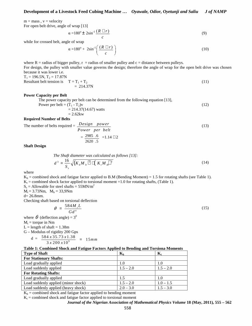
Development of a Livestock Feed Cubing Machine … Oyawale, Odior, Oyetunji and Saliu J of NAMP m = mass , v = velocity For open belt drive, angle of wrap [13]
α =180o ± 2sin-1 ( )R r
c
+ (9)
while for crossed belt, angle of wrap
α =180o + 2sin-1 ( )R r
c
+
(10)
where R = radius of bigger pulley, r = radius of smaller pulley and c = distance between pulleys. For design, the pulley with smaller value governs the design; therefore the angle of wrap for the open belt drive was chosen because it was lower i.e. T1 = 196.5N, T2 = 17.87N Resultant belt tension is T = T1 + T2 (11) = 214.37N
Power Capacity per Belt The power capacity per belt can be determined from the following equation [13], Power per belt = (T1 - T2)v (12) = 214.37(14.67) watts = 2.62kw
Required Number of Belts
The number of belts required = Design power
Power per belt (13)
= 5.2620
6.2985 =1.14 ≅ 2
Shaft Design
The Shaft diameter was calculated as follows [13]:
( ) ( )223 16tbtbb
s
MKMKS
d += (14)
where Kb = combined shock and fatigue factor applied to B.M (Bending Moment) = 1.5 for rotating shafts (see Table 1). K t = combined shock factor applied to torsional moment =1.0 for rotating shafts, (Table 1). Ss = Allowable for steel shafts = 55MN/m2 M t = 3.73Nm, Mb = 33,9Nm d= 26.8mm. Checking shaft based on torsional deflection
584 tu
M L
Gdθ = (15)
where θ (deflection angle) = 30 M t = torque in Nm L = length of shaft = 1.38m G – Modulus of rigidity 200 Gps
d = 9
584 35.73 1.3815
3 200 10
x xm m
x x=
Table 1: Combined Shock and Fatigue Factors Applied to Bending and Torsiona Moments Type of Shaft K b K t For Stationary Shafts: Load gradually applied 1.0 1.0 Load suddenly applied 1.5 – 2.0 1.5 – 2.0 For Rotating Shafts: Load gradually applied 1.5 1.0 Load suddenly applied (minor shock) 1.5 – 2.0 1.0 – 1.5 Load suddenly applied (heavy shock) 2.0 – 3.0 1.5 – 3.0 Kb = combined shock and fatigue factor applied to bending moment Kt = combined shock and fatigue factor applied to torsional moment
Journal of the Nigerian Association of Mathematical Physics Volume 18 (May, 2011), 555 – 562
559
Development of a Livestock Feed Cubing Machine … Oyawale, Odior, Oyetunji and Saliu J of NAMP Design of Shaft for Lateral Rigidity The internal rigidity of the shaft was designed using the permissible lateral deflection of 0.02mm for proper bearing operation and the shaft diameter was obtained by two successive integrations of moment equation [12]:
EI
M
dx
yd b=2
2
(16)
Where Mb = Bending moment E = Modulus of elasticity of the shaft
I= Rectangular moment of the shaft Diameter of shaft was calculated as 41mm based on lateral rigidity. The calculated diameters of shaft for the shredding and cubing unit were 60mm and 40mm respectively. Design of Blade The strength of the blade was determined by modeling the blade as a cantilever beam with a rectangular cross-section under pure bending. The bending stress was determined using bending stress theory [12]
=σ FLC
I (17)
Where σ = Bending stress F = Applied force L = Distance of applied forces C = distance from neutral axis to outer surface I = Rectangular moment of cross section
For a rectangular cross section I = 12
3bt (18)
Where b = breath of the cross section
t = thickness of the cross section
Hence 3
12FLC
btω = (19)
Given F = 2kN, L = 0.15m, c = 0.01m, t = 0.05m, b = 0.2m σ =1.5mPa Selection of Bearing
Using an expected life of 20,000 hours, with a dynamic load factor of 2.0 [12], The radial load T = 2 (T1+ T2) (20) The axial load and radial load is determined by taking moment of forces acting on the shaft. Axial load = 0 while radial load = P = Fr = 0.406 KN Using the SKF 1989 catalogue and basic rating life equation as
Lb = 1000000
60
K
r
r
C
N P
(21)
Lb = basic life rating (hrs) = 20,000hrs Cr = basic dynamic load rating Nr = Operating speed (rpm) = 1400rpm P= equivalent dynamic bearing load = 0.406 KN k = exponent of life equation.
The exponent k is 3 for ball bearings and 10
3 for roller bearings [14].
Journal of the Nigerian Association of Mathematical Physics Volume 18 (May, 2011), 555 – 562

Development of a Livestock Feed Cubing Machine …
Plate 1: The Fabricated Cubing MachinePerformance Tests Performance tests were conducted by shredding two materials: grass and cassava peels using different sieve diameters of the shredding unit and different die diameters of the cubing unit as presented in Tables 2 and 3. From Table 2, it is seen that when the wet grass materials were fed into the cubing machine, there was no shredding and the grass blocked the sieve because they were wet. When dry grass and cassava peels were fed in, they were properly cubed. However, 30 noncubes per minute were produced with the dry grass while 30 uniform cubes per minute were produced with the cassava peels. Table 2: The Shredding of Different MMaterial Shredding Operation
Wet grass Not shredded initially but as the loading increased the sieve was blocked
Dry grass Shredded without blockage
Cassava Peels Shredded without blockage
From Table 3, it is seen that when the sieve diameter of the shredding unit is bigger than the die diameter of the cubing unithere was no formation of cubes. When the sieve diameter of the shredding Table 3: Comparison of Sieve Diameter of Shredding S/No Sieve Diameter of the
Shredding Unit (φ mm) Die Diameter of the Cubing Unit (
1 a 8mm 6mm
b 8mm 8mm
560
Development of a Livestock Feed Cubing Machine … Oyawale, Odior, Oyetunji and Saliu
Plate 1: The Fabricated Cubing Machine
Performance tests were conducted by shredding two materials: grass and cassava peels using different sieve diameters of the unit and different die diameters of the cubing unit as presented in Tables 2 and 3. From Table 2, it is seen that
hen the wet grass materials were fed into the cubing machine, there was no shredding and the grass blocked the sieve When dry grass and cassava peels were fed in, they were properly cubed. However, 30 non
cubes per minute were produced with the dry grass while 30 uniform cubes per minute were produced with the cassava peels.
The Shredding of Different Materials Shredding Rate Cubing Operation
Not shredded initially but as the loading increased the sieve was blocked
- Not cubed because the sieve was blocked
Shredded without blockage 0.85m3 for 30
minutes
Cubed when binder was added
Shredded without blockage 2kg/min Cube formed without the addition of binder.
From Table 3, it is seen that when the sieve diameter of the shredding unit is bigger than the die diameter of the cubing unithere was no formation of cubes. When the sieve diameter of the shredding
Table 3: Comparison of Sieve Diameter of Shredding Unit with Diameter of the Die of the Cubing Unit.Die Diameter of the Cubing Unit (φ mm)
Comment
6mm Little quantity was extruded causing the cube notform.
8mm The quantity extruded increased but cube formation was slow.
Oyawale, Odior, Oyetunji and Saliu J of NAMP
Performance tests were conducted by shredding two materials: grass and cassava peels using different sieve diameters of the unit and different die diameters of the cubing unit as presented in Tables 2 and 3. From Table 2, it is seen that
hen the wet grass materials were fed into the cubing machine, there was no shredding and the grass blocked the sieve When dry grass and cassava peels were fed in, they were properly cubed. However, 30 non-uniform
cubes per minute were produced with the dry grass while 30 uniform cubes per minute were produced with the cassava peels.
Cubing Operation Cubing Rate
Not cubed because the
-
Cubed when binder 30 non-uniform cubes per minute
Cube formed without the addition of binder.
30 cubes per minute
From Table 3, it is seen that when the sieve diameter of the shredding unit is bigger than the die diameter of the cubing unit,
Unit with Diameter of the Die of the Cubing Unit.
Little quantity was extruded causing the cube not to
The quantity extruded increased but cube formation
561
c 8mm 10mm Good quantity was extruded allowing for building up of pressure for the formation of cubes
2 a 10mm 8mm Little quantity was extruded causing the cube not to form
b 10mm 10mm The quantity extruded increases but cube formation was at slow rate.
c 10mm 12mm Good quantity was extruded allowing for building up of pressure for the formation of cubes
3 a 12mm 10mm Little quantity was extruded causing the cube not to form
b 12mm 12mm The quantity extruded increases but cube formation was at slow rate.
c 12mm 14mm Good quantity was extruded allowing for building up of pressure for the formation of cubes
4 a 13mm 12mm Little quantity was extruded causing the cube not to form
b 13mm 13mm The quantity extruded increases but cube formation was at slow rate
c 13mm 14mm Good quantity was extruded allowing for building up of pressure for the formation of cube
d 13m 15mm Good quantity was extruded allowing for building up of pressure for the formation of cubes
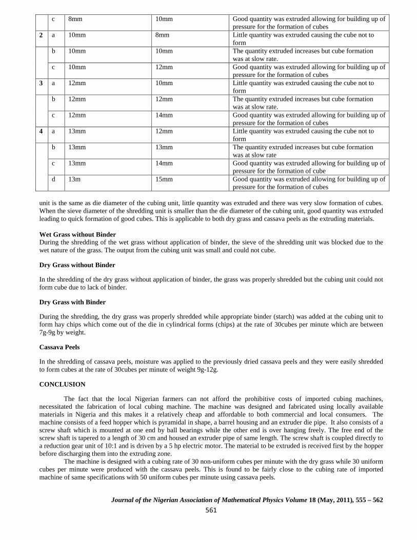
unit is the same as die diameter of the cubing unit, little quantity was extruded and there was very slow formation of cubes. When the sieve diameter of the shredding unit is smaller than the die diameter of the cubing unit, good quantity was extruded leading to quick formation of good cubes. This is applicable to both dry grass and cassava peels as the extruding materials. Wet Grass without Binder During the shredding of the wet grass without application of binder, the sieve of the shredding unit was blocked due to the wet nature of the grass. The output from the cubing unit was small and could not cube.
Dry Grass without Binder
In the shredding of the dry grass without application of binder, the grass was properly shredded but the cubing unit could not form cube due to lack of binder.
Dry Grass with Binder
During the shredding, the dry grass was properly shredded while appropriate binder (starch) was added at the cubing unit to form hay chips which come out of the die in cylindrical forms (chips) at the rate of 30cubes per minute which are between 7g-9g by weight.
Cassava Peels
In the shredding of cassava peels, moisture was applied to the previously dried cassava peels and they were easily shredded to form cubes at the rate of 30cubes per minute of weight 9g-12g.
CONCLUSION
The fact that the local Nigerian farmers can not afford the prohibitive costs of imported cubing machines, necessitated the fabrication of local cubing machine. The machine was designed and fabricated using locally available materials in Nigeria and this makes it a relatively cheap and affordable to both commercial and local consumers. The machine consists of a feed hopper which is pyramidal in shape, a barrel housing and an extruder die pipe. It also consists of a screw shaft which is mounted at one end by ball bearings while the other end is over hanging freely. The free end of the screw shaft is tapered to a length of 30 cm and housed an extruder pipe of same length. The screw shaft is coupled directly to a reduction gear unit of 10:1 and is driven by a 5 hp electric motor. The material to be extruded is received first by the hopper before discharging them into the extruding zone.
The machine is designed with a cubing rate of 30 non-uniform cubes per minute with the dry grass while 30 uniform cubes per minute were produced with the cassava peels. This is found to be fairly close to the cubing rate of imported machine of same specifications with 50 uniform cubes per minute using cassava peels.
Journal of the Nigerian Association of Mathematical Physics Volume 18 (May, 2011), 555 – 562

562
Development of a Livestock Feed Cubing Machine … Oyawale, Odior, Oyetunji and Saliu J of NAMP
REFERENCES
[1] Irtwange, S. V. (2009). Design, fabrication and performance of a motorized cowpea thresher for Nigerian small-scale farmers. African Journal of Agricultural Research , 4 (12): 1383-1391
[2] Butler, J. L. and McColly, H. F. (1959). Factors Affecting the Pelleting of Hay. Journal of Agricultural Engineering. Research. 40(8):442-446
[3] Choudhury MS, Kaul RN (1978). Alvan blanch threshers. Test report No.DAE/78-4. Department of Agricultural Engineering, Institute of Agricultural Research, Zaria, Nigeria.
[4] Adewumi J. K, Olayanju T. M.A and Adewuyi, S.A. (2007b). Support for Small Rice Threshers in Nigeria. Monograph Series # 23. Making Nigerian, Agricultural Markets Work for the Poor. DFID/PrOpCom. SA II Associates LTD/GTE, 40, Mississippi Street, Maitama, Abuja.
[5] Encyclopedia Britannica (1969). William Benton Publisher, Chicago, U.S.A.
[6] Macdonald S (1975). The progress of the early threshing machine. African Journal of Agricultural Research. 23(1): 63-77.
[7] Ige M. T. (1978). Threshing and separation performance of a locally built cowpea thresher. Journal of Agricultural Engineering. Research. (23): 45-51.
[8] Wachendorf, M., Volkers, K. C., Loges, R., Rave, G. and Taube, F. (2006), Performance and environmental effects of forage production on sandy soils. IV. Impact of slurry application, mineral N fertilizer and grass understorey on yield and nitrogen surplus of maize for silage. Journal of Grass and Forage Science, 61: 232–242.
[9] Singley. M.E. (1958) Handling nonfree flowing materials. Agricultural Engineering Journal of ASAE 39(3): 540-542.
[10] Bruhn, H.D (1955): Pelleting Hay and Grain Mixtures. Journal of Agricultural Engineering Research. 16(l):32-45
[11] Gustafson A.S. and Kjelgaard, W.J. (1963). Hay Pellet Geometry and Stability. Journal of Agricultural Engineering. Research. 44(8): 422-425
[12] Bosoi, E.S., Theory, construction & Calculation of agricultural Machines. Published by Amerind Publishing Co. (1987), New Delhi .
[13] Hall, W. C., Ferral. A.W.,Ripper, A.L. (1986), Encyclopedia of food Engineering 2nd edition, AVIPublishing Coy, Inc.WestPort.
[14] Ioannides E., Bergling G. and Gabelli A. “An analytical formulation for the life of rolling bearings.” Acta Polytechnica Scandinavica, ME 137, Espoo (1999).
Journal of the Nigerian Association of Mathematical Physics Volume 18 (May, 2011), 555 – 562