DETAIL PROJECT REPORT - Housing Development ...
351
CLIENT DETAIL PROJECT REPORT Proposed International Standard Cricket Stadium Complex in Maldives COPY-R2 15 TH JANUARY 2020
-
Upload
khangminh22 -
Category
Documents
-
view
0 -
download
0
Transcript of DETAIL PROJECT REPORT - Housing Development ...

CLIENT
DETAIL PROJECT REPORT Proposed International Standard
Cricket Stadium Complex in Maldives COPY-R2
15TH JANUARY 2020

Project Report for Proposed International Standard Cricket Stadium Complex
in Maldives
TABLE OF CONTENTS Chapter 1 Project Intent…………………………………………………………………………………….3-6 Chapter 2 Project Scope……………………………………………………………………………………7-47 Chapter 3 Site Analysis……………………………………………………………………………………48-58 Chapter 4 Design Intent…………………………………………………………………………………...59-78 Chapter 5 Area Statement………………………………………………………………………………....79-81 Chapter 6 Schedule of Finishes…………………………………………………………………………...82-114 Chapter 7 Field of Play………………………………………………………………………………......115-154 Chapter 8 GPON…………………………………………………………………………………………155-159 Chapter 9 Guidelines for Compliance…………………………………………………………………...160-204 Chapter 10 Sustainability…………………………………………………………………………………205-226 Chapter 11 Structure……………………………………………………………………………………...227-271 Chapter 12 MEP………………………………………………………………………………………….272-351 Chapter 13 Bill of Quantities……………………………………………………………………………..352-377 Annexure 1: Drawings & Views

2
PROJECT INTENT
3

Project Report for Proposed International Standard Cricket Stadium Complex
in Maldives
Project Intent
1. Introduction The International Cricket Council elected Maldives to be a member country for T-20 matches, for the purpose of promoting the game in the island nation. This coincides with the aims of the Government to promote the game and develop a 20000 seating capacity, world-class cricket stadium that can be used both locally and to host international T-20 cricketing events. Working towards the above, Housing Development Corporation of Maldives has appointed M/S. Collage Design Pvt. Ltd. on 29th September, 2019 for developing Detail Project Report including Conceptual Programming, Master Planning, Architectural Guidelines and Sports Consultancy for Maldives International Cricket Stadium. 1.1 History of Cricket in Maldives Cricket has a long history in the Maldives. A form of cricket called “Filaagandu Boalha” (Wood plank ball) was introduced to the Maldives around 1880 by a scholar who returned from Ceylon (Sri Lanka). The game was progressively adopted over these years. Formal cricket rules and regulations were first introduced around 1920. The year also marked the formation of the first cricket club in the Maldives, the Male’ Cricket Club. The Cricket Control Board of Maldives (CCBM) was established on 1 January 1983 by the government to promote and develop the game of cricket in the Maldives. The Maldives became a member of the Asian Cricket Council in 1996, and an affiliate member of the International Cricket Council in 1998. The development programme is conducted within an overall vision for the future of the game which was formulated in 1999. In 1999, goals were set and a wide ranging development programme was inaugurated to revive and consolidate the great game of cricket. The Board’s development programme is built around the theme “Cricket for the Year 2000 and Beyond”, which is specifically aimed at introducing cricket to school children with the long term aim of creating a new generation of talented cricketers who will represent the country. The national cricket team began representing Maldives in the Twenty20 early this year, when ICC made the decision to grant the country with full Twenty20 International (T20I) status. On that account, the aim of this project is to nurture a love for cricket amongst all Maldivians. And the government believes that this can be achieved with the help of India.
1.2 Project Description
1.2.1 General The new stadium shall be comparable in all respects with international standard professional contemporary sports stadia recently constructed or under construction, and meet with the requirements of all applicable National Building Codes and Standards as well as the United Kingdom’s Guide to Safety of Sports Grounds (The Green guide) as published by HMSO. The stadium is to be designed as a multi-use stadium capable of hosting National & International T-20 Cricket as well as major concerts, events and ceremonies. The stadium shall meet the requirements of the Governing Bodies of ICC & BCCI to allow national and international events to be staged in the stadium. The seating shall be as close to the playing field as possible, sightlines shall be optimum and viewing unobstructed for sports and other events.
4

Project Report for Proposed International Standard Cricket Stadium Complex
in Maldives
Project Intent
1.2.2 Objectives The stated objectives and goals of the stadium are:
1. To develop a stadium with 20,000 seats for a range of uses including, but not limited to: Crick-et, concerts and other entertainment events. The scope and Master-plan has been developed based on a 20,000 seat stadium.
2. In addition to the standard codes, the stadium shall meet the requirements of the following codes:
x ICC Guidelines for stadium
x BCCI Guidelines for stadium
x Guide to Safety of Sports Grounds (The Green guide)
3. To provide a highly cost effective low maintenance facility.
4. To complement a sports and entertainment precinct that can be used seven days a week by ensuring the stadium integrates with, and makes use of, adjacent civic spaces and commercial and community facilities.
5. Strengthen the national infrastructure capacity in tourism and hospitality business by allowing the nation to host international cricket tournaments and events frequently, i.e. IPL or Asia Cup.
6. To act as a catalyst for complementary development in the surrounding area.
7. To provide a facility that will achieve a 50 year life.
8. To provide a facility that can be utilised all year for a number of events, in order to maximize opportunity for revenue generation and sustainability.
9. To provide an “Iconic” stadium facility that reflects the growth of sports in Maldives and is a showcase for sports and the state both nationally and internationally.
10. To provide a facility that will allow Maldives to effectively compete for international sports events against comparable facilities in Asia.
11. To provide a sustainable development that will enhance public utilisation of facility and ancil-lary structures.
12. That will control and mitigate effects on local communities surrounding the stadium.
13. Roof coverage for 60% of the seats
14. The seating bowl shall be provided to maximise the atmosphere and locate patrons as close as possible to the field of play.
15. The seating bowl shall be column free and allow excellent viewing conditions for sports and events held in the stadium.
In addition to the stated Objectives, it has been the client’s objective to establish the following goals:
1. To create a multi-use, 20,000 seat stadium that maximises atmosphere and intimacy and will enhance the event experience for spectators for all sports.
2. To create a stadium that is internationally recognised as a world-class venue for the showcas-ing of professional sport and entertainment.
3. To develop a proposal that can be constructed within an established construction time and budget.
4. Sufficient entry plaza area to allow for safe entry and egress for the stadium in the event of an emergency.
5. Sufficient infrastructure to allow for safe entry and egress for the site.
5

Project Report for Proposed International Standard Cricket Stadium Complex
in Maldives
Project Intent
6. To provide a design that adheres to the principles of Environmental Sustainable Design with a minimal ecological footprint.
7. To provide an iconic design solution that represents the unique environment of Maldives along with the aspirations of the community, which it serves.
1.2.3 The Project Site
The proposed site is located in Hulhumalé is the first fully-reclaimed, pre-planned city of the country located within 3 kilometers from Malé, the capital city.
PROPOSED SITE
6

PROJECT SCOPE
7

Project Report for Proposed International Standard Cricket Stadium Complex
in Maldives
Project Scope
1. Field of Play
A minimum of 2 emergency vehicle access routes onto the playing field, 6 meter wide and fitted with suita-ble security gates, shall be provided.
1.1 Cricket Ground The ICC minimum standards for new cricket grounds are as follows.
1.1.1 The Field
The playing area shall be a minimum of A= 150 yards (137.16 metres) from boundary to boundary square of the pitch, with the shorter of the two square boundaries being a minimum of B = 65 yards (59.43 metres). The straight boundary at both ends of the pitch shall be a minimum of C = 70 yards (64.00 metres). Distances shall be measured from the centre of the pitch to be used.
CWC 2007 Host Venue election Bid Book
8

Project Report for Proposed International Standard Cricket Stadium Complex
in Maldives
Project Scope
The playing surface shall be natural grass incorporating permanent drainage and irrigation points.. The field and pitch must drain well and the grass be cut short to result in a fast outfield.
1.1.2 The Pitch
Pitches will be orientated north to south. A total of 5 pitches will be provided with the spacing of 3.66 meters between the pitches.
The pitch should have ‘true bounce’ throughout for the duration of the game, and be of reasonable pace. The pitch cover shall be provided to cover all pitches and shall have a raised rim built into its edge, and have 4 discharge outlets at its corners to allow water that collects on the cover during rain to be discharged into the field drainage system. The bowler’s run-ups shall be provided with adequate covers.
1.1.3 Boundary & Moat
The boundary shall be a minimum distance of 3 yards (2.74 m) inside the perimeter fencing, advertising signs, or first obstruction.
ENLARGED PLAN
A continuous Fence / Moat will be provided around the stadium in front of the spectator seating.
It is important under emergency circumstances to allow access across the moat on to the playing area and therefore a method of bridging the ‘gap’ will be incorporated, either on a permanent or temporary basis.
1.2 Turf Protection
Turf protection is to be provided to allow for the change in events from cricket to a concert and back again. Turf protection tiles are used to achieve this change. These tiles are Translucent which allows for photosynthesis to continue and therefore not damaging the turf.
To be considered as additional scope of work. Not to be considered in current scope of work.
9
Project Report for Proposed International Standard Cricket Stadium Complex
in Maldives
Project Scope
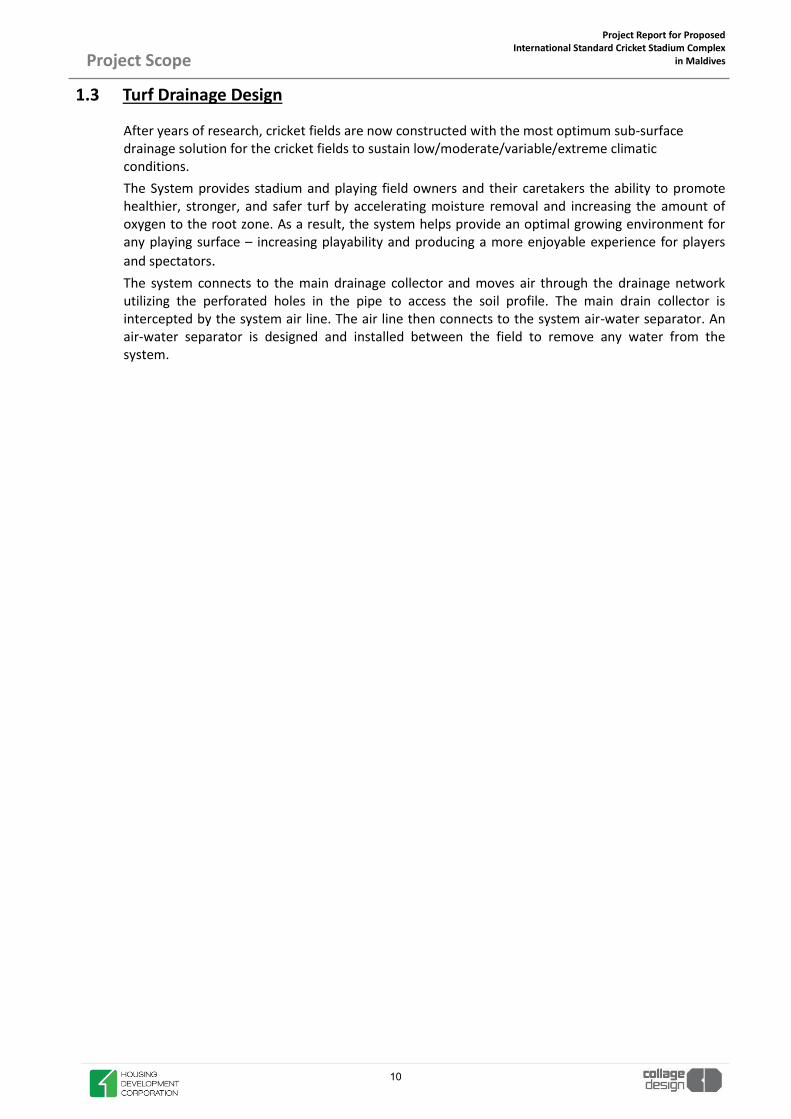
1.3 Turf Drainage Design
After years of research, cricket fields are now constructed with the most optimum sub-surface drainage solution for the cricket fields to sustain low/moderate/variable/extreme climatic conditions. The System provides stadium and playing field owners and their caretakers the ability to promote healthier, stronger, and safer turf by accelerating moisture removal and increasing the amount of oxygen to the root zone. As a result, the system helps provide an optimal growing environment for any playing surface – increasing playability and producing a more enjoyable experience for players and spectators. The system connects to the main drainage collector and moves air through the drainage network utilizing the perforated holes in the pipe to access the soil profile. The main drain collector is intercepted by the system air line. The air line then connects to the system air-water separator. An air-water separator is designed and installed between the field to remove any water from the system.
10

Project Report for Proposed International Standard Cricket Stadium Complex
in Maldives
Project Scope
2. Seating Bowl The total minimum ground spectator capacity upon completion is to be 20,000 seats. The functional requirements are summarised here:
x A variety of seating types will be configured around the circular ground, consisting of a combination of general admission seating, members seating, private boxes, dine & view seating and press seating.
x Seating for people with disabilities will be available within each seating category and distributed at various locations within the seating bowl.
Seating Standards Adopted Modular Seating type is to used. The construction expertise is based on a unique interlocking system; All the components are self-locking and the system needs no bolting, this is a main safety feature as
1. There is no risk of forgetting bolts 2. There is no risk of unbolting due to spectator vibrations
The grandstand metal construction takes into account the soil study, local seismicity and the Maldivian construction code. Tread width
x Lower Bowl – 750 mm x Upper Bowl – 750 mm x Corporate Boxes- 1200 mm
Riser Height
x Maximum riser height – 350 mm Seat spacing
x Lower Bowl – 450 mm x Upper Bowl – 450 mm x Corporate Boxes- 600 mm
Disabled Seating Provision
x Based on Total Capacity - 0.5%, disabled wheelchair positions, plus carer seat adjacent each wheel-chair position
Seat Numbering System
x Each seat to be individually numbered by a vandal-proof proprietary metal numbering system by the seat manufacturer.
x Each row to have luminous Row Numbering system on each aisle Step. Seating
The positioning of vomitories shall facilitate an even evacuation of the bowl in emergencies; so that statutory egress times can be achieved. For all seating tiers, maximum 36 seats per row between gangways shall be adopted.
The stands shall be set out to ensure all parts of the field are visible to all spectators with a maximum gradi-ent of 30 to minimise the potential of vertigo in the spectators.
Sightline Criteria
The sightline from the eye level of every spectator shall not be inferior to the following two criteria as defined below. The eve level is defined as a point 1150 mm above the floor level and 90mm forward of the rear of each seating plat, centered on the seat location.
11

Project Report for Proposed International Standard Cricket Stadium Complex
in Maldives
Project Scope
Sightline Standard 1 The spectator seats should provide a minimum sightline quality of 3½" or 90mm (C90). VIP seating and hospi-tality box seating should provide a minimum sightline quality of 4¾" or 120mm (C120). The focus of the sight line shall be a maximum of 10m inside the boundary on the surface of the playing field for cricket.
Sightline Standard 2 Sightlines shall be uninterrupted by any solid part of any balustrade or balustrade mounted signage panel except as following: Any metal balustrade that interrupts the sightline shall be of “open” construction so that less than 20% of its area presents a solid obstruction when measured normal to the sightline, the remaining 80% being unobstructed. High Ball Criteria A sightline from eye level for all spectators shall have uninterrupted viewing angle of 30 ° to the ground.
12
Project Report for Proposed International Standard Cricket Stadium Complex
in Maldives
Project Scope
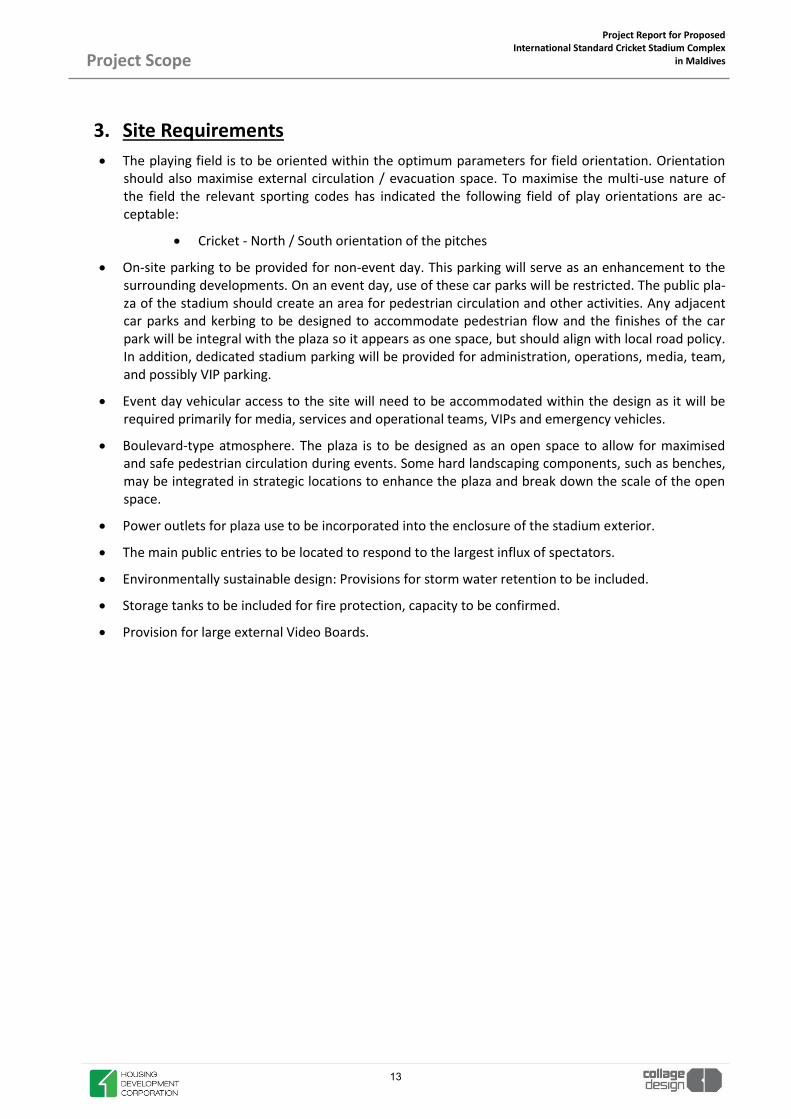
3. Site Requirements x The playing field is to be oriented within the optimum parameters for field orientation. Orientation
should also maximise external circulation / evacuation space. To maximise the multi-use nature of the field the relevant sporting codes has indicated the following field of play orientations are ac-ceptable:
x Cricket - North / South orientation of the pitches
x On-site parking to be provided for non-event day. This parking will serve as an enhancement to the surrounding developments. On an event day, use of these car parks will be restricted. The public pla-za of the stadium should create an area for pedestrian circulation and other activities. Any adjacent car parks and kerbing to be designed to accommodate pedestrian flow and the finishes of the car park will be integral with the plaza so it appears as one space, but should align with local road policy. In addition, dedicated stadium parking will be provided for administration, operations, media, team, and possibly VIP parking.
x Event day vehicular access to the site will need to be accommodated within the design as it will be required primarily for media, services and operational teams, VIPs and emergency vehicles.
x Boulevard-type atmosphere. The plaza is to be designed as an open space to allow for maximised and safe pedestrian circulation during events. Some hard landscaping components, such as benches, may be integrated in strategic locations to enhance the plaza and break down the scale of the open space.
x Power outlets for plaza use to be incorporated into the enclosure of the stadium exterior.
x The main public entries to be located to respond to the largest influx of spectators.
x Environmentally sustainable design: Provisions for storm water retention to be included.
x Storage tanks to be included for fire protection, capacity to be confirmed.
x Provision for large external Video Boards.
13
Project Report for Proposed International Standard Cricket Stadium Complex
in Maldives
Project Scope
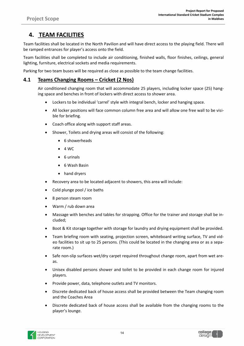
4. TEAM FACILITIES
Team facilities shall be located in the North Pavilion and will have direct access to the playing field. There will be ramped entrances for player’s access onto the field.
Team facilities shall be completed to include air conditioning, finished walls, floor finishes, ceilings, general lighting, furniture, electrical sockets and media requirements.
Parking for two team buses will be required as close as possible to the team change facilities.
4.1 Teams Changing Rooms – Cricket (2 Nos) Air conditioned changing room that will accommodate 25 players, including locker space (25) hang-ing space and benches in front of lockers with direct access to shower area.
x Lockers to be individual ‘carrel’ style with integral bench, locker and hanging space.
x All locker positions will face common column free area and will allow one free wall to be visi-ble for briefing.
x Coach office along with support staff areas.
x Shower, Toilets and drying areas will consist of the following:
x 6 showerheads
x 4 WC
x 6 urinals
x 6 Wash Basin
x hand dryers
x Recovery area to be located adjacent to showers, this area will include:
x Cold plunge pool / ice baths
x 8 person steam room
x Warm / rub down area
x Massage with benches and tables for strapping. Office for the trainer and storage shall be in-cluded;
x Boot & Kit storage together with storage for laundry and drying equipment shall be provided.
x Team briefing room with seating, projection screen, whiteboard writing surface, TV and vid-eo facilities to sit up to 25 persons. (This could be located in the changing area or as a sepa-rate room.)
x Safe non-slip surfaces wet/dry carpet required throughout change room, apart from wet are-as.
x Unisex disabled persons shower and toilet to be provided in each change room for injured players.
x Provide power, data, telephone outlets and TV monitors.
x Discrete dedicated back of house access shall be provided between the Team changing room and the Coaches Area
x Discrete dedicated back of house access shall be available from the changing rooms to the player’s lounge.
14

Project Report for Proposed International Standard Cricket Stadium Complex
in Maldives
Project Scope
x Players dining area will be part of the Locker Space or Lounge Area. Discrete service access from Pantry.
x A Team Doctor’s room shall be provided adjacent to the Changing Room with access to the First Aid Facility.
x Separate Outdoor viewing gallery for both team attached to the Players’ Lounge.
4.2 Umpire / Referee Changing Rooms Air conditioned changing rooms shall be provided for match officials. The room will be located with direct access to the Field of Play.
x Change room for 5 match umpires.
x Provision for double width ‘carrel’ style lockers that will have direct access to shower area and report writing area.
x Safe non-slip surfaces wet/dry carpet will be required throughout change room apart from wet areas.
x Writing area to be located in the room for writing of match reports.
x Provide power, data, telephone outlets and TV monitors.
x Showers, 2 Toilets and drying areas (2 showerheads, 1 hand basins, 1 urinals, and 1 lavato-ries.
x Separate lounge area with attached toilet facility for dining area. Discrete service access from Pantry.
4.3 First Aid Provide an air conditioned first aid treatment suite for use by players (spectators in extreme emer-gencies) as needed on match days. The main first aid suite shall be situated at pitch level on the team changing room side of the service level with direct access to the field through the pitch access vomi-tories for the transfer of injured players by Ambulance. Two ambulance bays shall be located adja-cent to the facility.
This suite shall incorporate the following:
x A screening area at the entry point, large enough for a stretcher
x Lockable medical cabinets for storage of supplies
x Work counter with sink and hot/cold water
x A refrigerator and ice bin
15

Project Report for Proposed International Standard Cricket Stadium Complex
in Maldives
Project Scope
x A unisex disabled toilet room
x Work area for staff
x Stretcher width doors shall be provided from the pitch access vomitories and to the Ambu-lance Parking Bays located in the Service Road.
4.4 Doping Control Room A doping control room shall be provided adjacent to the Team Changing Rooms. The facility will be located away from media accessible areas to provide players privacy.
x Drug testing facilities shall include the following:
x WC and hand basin.
x Small waiting area and Interview Room, with desk and chairs.
x Room to be air conditioned
x Under bench refrigerator
x Space provision will be made to allow for a stretcher bed and curtain to allow for possible blood testing of players.
4.5 Player’s Lounge and Family Room An air conditioned player’s lounge will be shared by all teams, and shall be located in close proximity to the central drop off area for the teams with access to both changing areas.
A serving counter and a finishing kitchen to serve snacks and light meals.
x Lounge chairs and coffee tables
x Provide a disabled/unisex toilet room in this area.
x Provide power, data, telephone outlets and TV monitors.
4.6 Entrance Lobby and Hall of Fame The Main Entrance Lobby to the Players / North Pavilion will include a dedicated display space for trophies and memorabilia.
4.7 Player’s Benches Two team portable benches shall be located with direct access to the centre line Player’s Tunnel to the team changing rooms.
The interchange bench shall include the following:
x The benches shall be enclosed with a glass canopy and walls that will offer protection from the public patrons located behind in the lower tier.
x Players’ benches shall be sized to accommodate 12 persons each.
x Space shall be allowed within the bench area to accommodate players’ kit bags, storage box-es and portable drink / ice boxes.
x There will be a phone link and between this point, the Coaches Box and the changing rooms. Refer to Coaches Boxes for details.
x Internal telephone line between interchange benches to doctor’s room.
x Power and data lines will be provided at these locations.
16

Project Report for Proposed International Standard Cricket Stadium Complex
in Maldives
Project Scope
5. SPECTATOR FACILITIES 5.1 Capacity
The approximate net seating distributions, including wheelchair positions as currently planned are listed in the table below. It is proposed to offer various levels of season ticket and associated amenity packages which will be incorporated into the General Admission and VIP seating configurations.
The following table is based on stadium capacity of 20,000 seats.
Seating Capacity Comments General Admission 14400 Public Seating
VIP Members 4380 Seating for premium members
VVIP Members 1040 Reserved Suite for special invitees Disabled (0.5%) + Companion seating (0.5%) 200 Distributed across all seating categories and
locations. Total 19820
5.1.1 General seating requirements
A variety of seating types will be configured around the playing field, consisting of a combination of general admission seating, reserved seating, corporate seating including corporate boxes and suites, press seating and team seating.
x A variety of seating types will be provided and configured around the circular ground (arena), consisting of a combination of disabled seating, general admission seating, corporate box and dine & view seating.
x Total net capacity of at least 20,000 spectators.
5.1.2 General admission seating
New general admission seating shall meet the following criteria:
x Bucket seats with backs;
x Seats to have a spacing of 450mm minimum when measured centre to centre.
x Lower tier tread width to be 750mm;
x Upper-tier seating shall have a plat width of 750mm;
x Maximum number of seats between aisles shall be 36 and 18 seats where served by a single aisle.
x Removable public seating adjacent to all disabled seating spaces to be provided to allow maximum of 6 disabled spaces in a group. Additional banks of seating to be provided to allow for use in disabled seating space, when disabled spaces are not being used.
5.1.3 Corporate suite seating
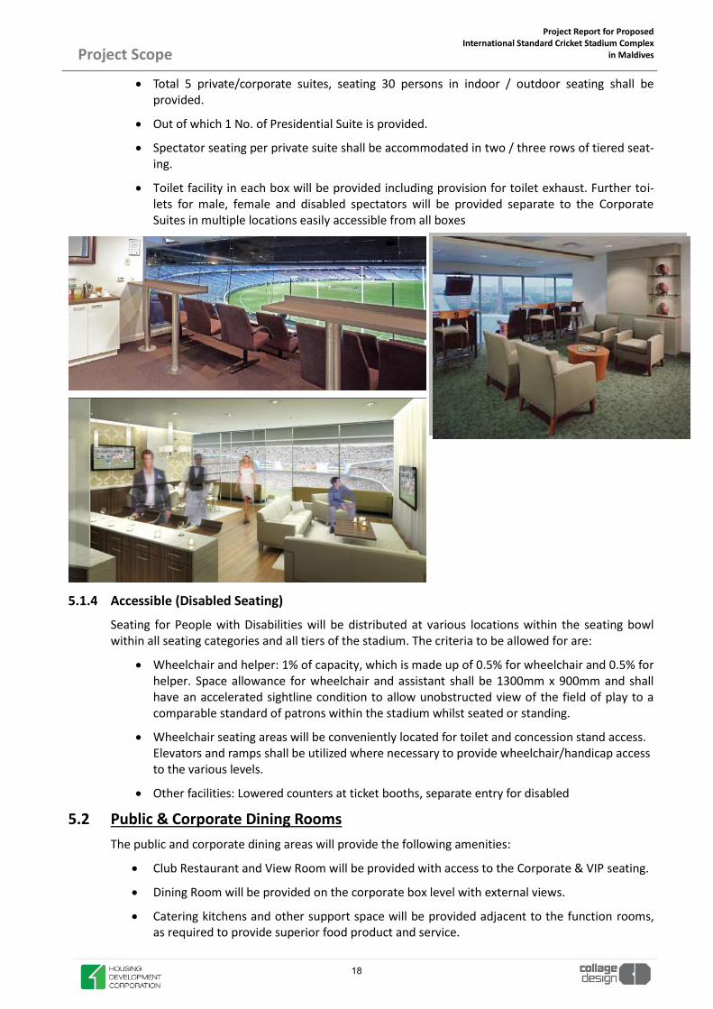
x The term “suite” refers to the enclosed Air Conditioned private hospitality space with fixed pitch view seating in front of the suite glazing. Suites shall be located to allow an excellent viewing angle to the pitch.
x Each suite shall be an enclosed space with direct access to seating located in front of the glazed line with a full width shelf unit positioned at front of suite, under window together with a recessed ceiling for mounting TV monitors above.
17
Project Report for Proposed International Standard Cricket Stadium Complex
in Maldives
Project Scope
x Total 5 private/corporate suites, seating 30 persons in indoor / outdoor seating shall be provided.
x Out of which 1 No. of Presidential Suite is provided.
x Spectator seating per private suite shall be accommodated in two / three rows of tiered seat-ing.
x Toilet facility in each box will be provided including provision for toilet exhaust. Further toi-lets for male, female and disabled spectators will be provided separate to the Corporate Suites in multiple locations easily accessible from all boxes
5.1.4 Accessible (Disabled Seating)
Seating for People with Disabilities will be distributed at various locations within the seating bowl within all seating categories and all tiers of the stadium. The criteria to be allowed for are:
x Wheelchair and helper: 1% of capacity, which is made up of 0.5% for wheelchair and 0.5% for helper. Space allowance for wheelchair and assistant shall be 1300mm x 900mm and shall have an accelerated sightline condition to allow unobstructed view of the field of play to a comparable standard of patrons within the stadium whilst seated or standing.
x Wheelchair seating areas will be conveniently located for toilet and concession stand access. Elevators and ramps shall be utilized where necessary to provide wheelchair/handicap access to the various levels.
x Other facilities: Lowered counters at ticket booths, separate entry for disabled
5.2 Public & Corporate Dining Rooms The public and corporate dining areas will provide the following amenities:
x Club Restaurant and View Room will be provided with access to the Corporate & VIP seating.
x Dining Room will be provided on the corporate box level with external views.
x Catering kitchens and other support space will be provided adjacent to the function rooms, as required to provide superior food product and service.
18

Project Report for Proposed International Standard Cricket Stadium Complex
in Maldives
Project Scope
x All dining rooms and lounges will be air-conditioned.
x Television monitors shall be located throughout the dining rooms and lounge areas.
x Club Restaurant and View Room will also be fitted out with appropriate technologies for PA services and wiring will allow for easy use of plug-in mobile audio visual equipment.
x Dining rooms and Lounges to have either Field view or external view.
x Dining rooms to have separate lockable storage for marketing equipment and audio-visual equipment.
x Toilets to dining rooms will be in close proximity to each dining room.
x Separate chair stores will be provided adjacent to the dining rooms.
5.3 Public Toilet facilities Adequate public toilets shall be provided throughout the stadium evenly distributed off the public concourses located behind the seating tiers.
x The general number of facilities shall be based on the number of spectators per individual fixture. The ratio of spectators to fixtures shall be based on 60 percent male and 40 percent female attendance based on the public capacity of the area of the ground served by the toilets.
x Toilets will be provided containing mirrors, toilet partitions, fixtures, general lighting and ventilation etc.
x Separate disabled toilet rooms will be provided. They will accommodate a wheelchair and include accessible height water closets and grab bars, etc.
x Washrooms will be generally equally distributed in the public concourses and must be of durable construction and easy maintenance.
x Final fixture count to be based upon International Plumbing Code:
Male Toilets Female Toilets
Urinals: Replace 50% of EWC with urinals (Sec 419.2)
WC’s: 1 per 75 for first 1500 and 1 per 120 for remaining
Basins:
1 per 200 persons
WC’s:
1 per 40 for first 1520 and 1 per 60 for remaining
Basins:
1 per 150 persons
x Urinals shall be provided in the male toilets in addition to WC’s. Mirror, hand drying facility, soap dispensers, lavatories, toilet partitions and coat hooks shall also be provided.
x Public toilets shall be served with cold water only.
x Cleaner’s rooms with a service sink and storage shall be provided to service the toilet blocks.
19

Project Report for Proposed International Standard Cricket Stadium Complex
in Maldives
Project Scope
x The detail design of the public toilets shall allow for at least two entrances and preferably a one-way circulation system through the area where possible.
x Toilet blocks will be distributed proportionately around the concourses to minimise travel distances.
x Toilet block entrances and exits to the concourses shall be fitted with lockable gates to allow for their closure when not in use and during non-peak events.
x All toilet fittings shall be durable.
x The PA system will be capable of broadcasting match commentary within the toilet blocks; an override function will enable emergency and information broadcasts and allows for muting to the toilet areas if required.
x All pipework, conduit and flush valves within public toilet blocks are to be concealed.
x Unisex family/PWD toilet rooms will be provided at each concourse level in close proximity to wheelchair platforms. These rooms will house a standard WC pan with horizontal side grab rail and hand wash basin.
x All toilets shall be equipped with general lighting and exhaust.
x Floors are to be graded to floor waste and finished in a non-slip ceramic or vitrified tile over water proof membrane.
x All walls are to be tiled over waterproof membrane including all reveals and end walls.
x All cubicles are to incorporate laminated heavy-duty toilet partitions, vandal proof fittings and concealed vandal proof flush.
x Filtered Drinking Water Facility will be provided with each toilet block as per MNBC norms
5.4 Corporate & VVIP Toilets VVIP Seating / Dining areas and Private Box toilets shall be of a higher quality finish. Fixtures shall, where practicable be provided based on the following:
Male Toilets Female Toilets
Urinals: Replace 50% of EWC with urinals (Sec 419.2)
WC’s: 1 per 75 for first 1500 and 1 per 120 for remaining
Basins:
1 per 200 persons
WC’s:
1 per 40 for first 1520 and 1 per 60 for remaining
Basins:
1 per 150 persons
x Corporate Box and Suite toilets shall have hot and cold-water service
x Appropriate unisex disabled toilet facilities, including grab rails, sinks, etc. shall be provided adjacent to the wheelchair seating areas on the basis of 1 per 10 wheelchair spaces.
x Cleaner’s rooms with a service sink and storage shall be provided to service the toilet blocks.
x All toilet fittings shall be durable.
x The PA system will be capable of broadcasting match commentary within the toilet blocks; an override function will enable emergency and information broadcasts and allows for muting to the toilet areas if required.
x All pipework, conduit and flush valves within public toilet blocks are to be concealed.
x All toilets shall be equipped with general lighting and exhaust.
20

Project Report for Proposed International Standard Cricket Stadium Complex
in Maldives Project Scope
x Floors are to be graded to floor waste and finished in a non-slip ceramic or vitrified tile overwater proof membrane.
x All walls are to be tiled to 2100mm height over waterproof membrane including all revealsand end walls.
x All cubicles are to incorporate laminated heavy-duty toilet partitions, vandal proof fittingsand concealed vandal proof flush.
x Filtered Drinking Water Facility will be provided with each toilet block as per norms
5.5 Prayer Rooms Prayer Rooms are provided at multiple locations throughout the stadium. Prayer room is a quiet location set aside in a busy public place (stadiums, hospital, university, airport, etc.) where people are able to spend time in contemplation or prayer. Many of these spaces are "small, clean and largely unadorned areas".
5.6 Merchandising outlets Merchandising outlets shall be provided at locations within the public concourses.
x All merchandising stands shall be provided with power, telephone, data, drain and waterconnections.
x 1 point of sale per 375 spectators for general seating areas.
x Additional locations will be identified along the concourses for providing temporary kioskswith provision of power, telephone and data.
5.7 Public first aid rooms Satellite first aid stations will be distributed throughout the public concourses. Spectators requiring more extensive treatment and/or x-rays will be evacuated by ambulance to local hospitals.
x All first aid stations will have double leaf doors designed to accommodate stretcher access.
x A priority access route will be identified through the venue, preferably utilising back of houseaccess for transfer of patients from the pitch and public levels.
x All first aid rooms will be accessible to wheelchair users;
x Work counter with sink and hot/cold water, power, data, and telephone outlets to be pro-vided.
x The Main First Aid Room on the service level to be provided with ‘Deluge Shower’ for burnsvictims.
Ablution Facility
21

Project Report for Proposed International Standard Cricket Stadium Complex
in Maldives Project Scope
5.8 Signage/graphics A comprehensive, visible, readable, flexible and effective signage system shall be provided both outside and inside the building. The graphics shall be coordinated with those for the entire complex and provide signing as follows:
x Direction to and identification of Stadium entrances including Gates, ticket booths, turnstilesand special entrances.
x Signage within the Stadium to indicate Levels, Rooms, Aisles, Rows and Seat numbers; to beintegrated with the ticketing and seat numbering system to provide a simple and easilyunderstood method for spectators finding their seats.
x Direction to and identification of toilets, first aid rooms, exits, Police, Security and otherpublic facilities.
x Direction to and identification of vending facilities (merchandising, food and beverage, etc.
x Direction to and identification of all cafes. Dining rooms, function rooms, club rooms and corporate facilities.
x All signage to be provided including all back of house areas, Coaches, Players facilities, Carparks, Kitchens, stores, operations and plant rooms.
x External signage should meet with the local planning authority guidelines.
x Each entry point and exit gate to be named.
x Road markings and signage to be included.
5.9 Match Day Public Information Office Match Day Public Information Office to be provided. It is to be accessible both externally and inter-nally to the ground. This facility will be used for Lost Children, Lost & Found etc. All power, data, and telephone outlets shall be provided.
5.10 Ticketing Windows Ticketing windows will be provided at all Main Gates into site. Non-event day ticket sales will be in the club facility.
5.11 Public Telephones Public telephone booths shall be located on the main concourse adjacent to the entry points. These shall be free standing units and shall be contained within acoustic shrouds at designated locations close to the main entry points.
5.12 TV Monitors Provision of Space and Support for large size Flat Screen TV monitors, including all power, data and MATV cabling requirements should be located in the following locations:
x Throughout the public concourse
x Adjacent to food and beverage concessions.
x Within all Corporate Suites
x Players Areas
22

Project Report for Proposed International Standard Cricket Stadium Complex
in Maldives
Project Scope
6. FOOD AND BEVERAGE CATERING REQUIREMENTS The planning requirements of the Food & Beverage Services shall meet the catering needs of the stadium in an efficient and effective manner. All the different user groups have been identified and their needs have to be incorporated into the detailed design. The different user groups to be considered are as follows:
a) PLAYERS
b) VVIP
c) PRESS
d) BROADCAST
e) CORPORATE SUITES
f) CONCESSION STANDS – GENERAL + VIP
g) EVENT STAFF (TEMPORARY STAFF ON EVENT DAY)
h) SECURITY
The location of the various areas that make up the Catering System shall be carefully considered to ensure easy distribution of food and beverages from loading dock to end-user.
6.1 Food and Beverage Service An efficient and effective system for serving food and beverages to spectators, suites and boxes, hospitality spaces, and athletes is an important component of successful stadium operations.
Concession Stands
x Planning shall be based on “speed line” type service but consideration should be given for “point of sale” service.
x Location of queue lines should be considered when placing concession stands, to minimise congestion in the concourses. A minimum of 2m queue depth is required for each conces-sion, for the full length of the service counter.
x A basic shell space is to be provided, which allows easy conversion from one type operation to another.
x All units will have capability of serving hot beverages and soft drinks throughout every con-cession stand.
x Provision of grease exhaust and grease traps.
x Security/smoke shutters will be provided at each counter front.
x Provision of TV at all concessions, positioned to allow a view by spectators standing in the queue,
x All food and beverage areas will be designed with appropriate hygienic, washable and dura-ble finishes, in accordance with local and national Environmental Health standards.
6.2 Catering Support The main kitchen / kitchens and commissary will be located with immediate access to the loading docks and service lifts and shall be designed to accommodate all match day catering requirements.
x The kitchen and commissary will be located on the service level of the stadium to support concession and catering needs at the point of major usage.
x Deliveries will be made to the loading bay directly adjacent to the Commissary.
23

Project Report for Proposed International Standard Cricket Stadium Complex
in Maldives
Project Scope
x Any goods requiring processing/cooking will be prepared in the main Kitchen before trans-porting to concession stands or hospitality spaces.
x Finish materials will be easy to clean and food acid resistant. Flooring materials will be non-slip with coved skirting; ceiling materials will be moisture resistant.
x Rubbish collection rooms will be distributed around the facility for storage and processing of waste products.
x Storage space throughout will be provided.
6.3 Catering Staff Facilities Space will be provided within the commissary for Catering administrative offices, staff lockers, uni-form distributing, and event-day briefing. Laundry facilities are to be included within the facility. Space will be provided for temporary catering staff in close proximity to the main catering facilities and a briefing room on the service level of the stadium.
24

Project Report for Proposed International Standard Cricket Stadium Complex
in Maldives
Project Scope
7. ENTRANCES AND CIRCULATION
7.1 Entrances / Ticketing & Ticket Booths An efficient and effective control system for access into and exit from the stadium will be provided for all users, including both Event-day and non-Event day times.
x Event-day operations shall provide segregated entry points for general admission spectators, VIPs, staff, media, and players.
x Non-Event day entry points shall anticipate needs of staff, club members, athletes, and gen-eral public.
x Emergency egress routes shall be considered for both Event-day and non-Event day modes.
7.1.1 Turnstiles
Provide provision for a minimum of 1 turnstile for 660 spectators at public entries.
x All turnstiles location will be linked to a central system, linked to display devices in both event and security control rooms.
x Each group of turnstiles will have a gate with a minimum clear width of 1000mm to allow ac-cess by spectators in wheelchairs.
x An exit gate is required at each block of turnstiles to facilitate ejection of unwanted specta-tors.
x A confiscation storeroom will be provided at each block of turnstiles.
x Confiscated item collection rooms with an external counter will be provided, one on each side of the stadium, for fans to collect prohibited items post event.
x Turnstiles will be grouped into 10-15 units to provide 4-6 main entries into the ground dis-tributed around the stadium to provide access to each seating section.
7.1.2 Access and Circulation
A system for the efficient and effective control of access into and out of the Stadium and circulation around the outside and within the Stadium shall be provided for all users. This shall include:
x Controlled access to the building, using tickets or accreditation, at convenient entry points for different user groups;
SPECTATOR PODIUM PLAZA AREA
25

Project Report for Proposed International Standard Cricket Stadium Complex
in Maldives
Project Scope
x An egress system;
x An emergency egress system;
x A turnstile control system for ticket holders;
This system shall include:
x A computer based access control system for staff and accredited visitors;
x Integration of the turnstile control with a separate electronic ticketing system provided by an external agency.
x Barriers shall be located between turnstiles and shall be positioned for entry control.
x Entry plazas shall be designed to accommodate magnetometers and bag search as required for major event overlays.
x Entry plazas shall allow for the safe queuing and entry of patrons and shall avoid excessive congestion around changes of levels and entry turnstiles.
x As a guide an area of 0.35m2 / person shall be allowed for the external plazas located in front of the entry turnstiles.
7.1.3 Corporate and VIP Entrance
A separate entrance lobby is to be provided for the Corporate Suite, Corporate Box, VIP, sponsors and guests on the main public access level and preferable in close proximity to car parking
x Ticketing will be controlled with mobile turnstile or handheld ticket readers at each entry. Provision will be provided for, all power and data cabling as required at entry.
x Lifts at each VIP entry will be provided to serve corporate suites and dining rooms and cater for disabled access to all floor levels.
7.1.4 Players Entrance
x A secure Players’ entry within the building with bus drop-off. This entrance shall be protected from public exposure and shall be able to accommodate at least two team buses parked in front of the Main entry or Secondary entry.
x Direct access from the entrance area to the changing rooms shall be provided.
7.1.5 Staff Entrance
A single entry point will be provided for all event staff and catering staff with direct access to the ex-ternal plaza areas surrounding the stadium. This space shall be adjacent to the events offices and ca-tering offices, including changing rooms, dining room and uniform distribution.
7.1.6 Media Entrance
Media parking to be located as close as possible to the media access/egress point. A lift is to be avail-able for use by the media staff to allow the vertical circulation of media personnel and equipment. All media facilities are to be separated from the public by secure means. All doors into the media ar-eas are to be controlled with electric locks and proximity card readers.
7.2 Access and Egress A public egress system shall be provided so that in emergencies it allows the public to leave the Sta-dium by smooth unimpeded exit routes to adequately lit and clearly indicated assembly points in safe areas. The emergency egress system shall be designed in accordance with the “Guide to Safety at Sports Grounds” (The Green Guide)
26

Project Report for Proposed International Standard Cricket Stadium Complex
in Maldives
Project Scope
x The emergency egress system design will use the “timed exit analysis” method as per the recommendations of the Green Guide.
x All access and circulation areas shall be free from hazards, adequately drained where neces-sary, and slip-resistant. Slip-resistance should be appropriate for the specific areas and com-ply with the standards in both wet and dry conditions.
7.3 Concourses
7.3.1 Public Concourses
The main public concourse shall be located behind all main seating tiers and shall serve directly all vomitories, concessions, and toilets.
The concourses shall be designed to ensure the safe passage of spectators in the event of an emer-gency to appropriate exits. The basis for the width of the concourse shall be as set out in the United Kingdom “Guide to Safety at Sports Grounds” (Green Guide) and in accordance with good interna-tional practice and local and national regulations.
x A minimum area allowance of 0.25sqm per person shall be used when determining the ap-propriate area of the concourse.
x Maximum distance from seating aisle entry to concession / toilets = 40m.
x Concourse widths shall be designed to allow a pleasant spectator experience and shall be wide enough to allow all around circulation as well as emergency egress. Concourse shall be designed to be a part of the safe egress system from the seating bowl to the outside.
x The emergency egress system design will use the “timed exit analysis” method with the adoption of an egress time of 8 minutes from the seating bowl to a free flowing exit system as set out in the Green Guide.
x Concourses will be designed to sustain the point-loading situation typical for heavy equip-ment, such as fork lifts, access equipment, and pallet loaders, without cracking or deflection.
x The concourses shall be designed to enhance the experience of visiting the stadium and shall provide facilities to allow people to congregate and relax prior to and after the match.
x The concourse shall incorporate clear graphics to ensure the orientation and safe passage of patrons.
x Maximum use of daylight shall be made to all concourse areas.
x The public circulation system on the concourses shall facilitate exit along the same path of travel as entry, which reflects the preferred pattern of use by spectators.
x The main entry level pedestrian walkway will encircle the stadium bowl, with all around cir-culations.
x All spectator amenities shall be distributed around the concourse to minimise spectator trav-el distances.
x Concourses shall be designed as low fire risk areas, with all potential risks (e.g. catering and merchandise units) enclosed by fire resistant construction and fitted with automatic fire de-tection system, sprinklers, and/or smoke shutters.
27

Project Report for Proposed International Standard Cricket Stadium Complex
in Maldives
Project Scope
The following provisions will be included in the public concourses:
x TV monitors, will be located so that they are only in direct view of those standing in queue lines at catering units, rather than facing the flow of traffic in the concourse.
x PA system
x Waste Collection system.
7.3.2 Corporate Suite Concourse
Private corridors will provide access to the Suites and Boxes and associated toilet facilities. These corridors shall feature upgraded finishes, similar to the suite finishes.
x These corridors shall include PA, for emergency announcements only.
x Generous reception and meet and greet areas shall be located at the entry points to the cor-porate facilities.
7.4 Passenger Lifts Passenger lifts shall serve all main levels of the stadium. All lifts shall confirm generally to National Building Code and other safety guidelines.
x Lifts shall be designed to be in banks of 2.
x One lift per bank of is to be sized to accommodate handicap facilities.
x Lift lobbies shall be designed to be ‘safe havens’ during emergency for disabled.
x Security / Key switch to all lifts will be required.
x Security camera and access control card reader shall interface with CCTV and security system within each lift.
7.5 Service Elevators Service Elevators will be provided with fully opening doors and durable stainless steel finish. Goods lifts will have a minimum 3500 kg load capacity. Goods lifts required to be close to kitchens, storage and service areas.
7.6 Stairways and Ramps Stairways and ramps will be designed for Emergency Exit in accordance with the Green Guide and the MNBC. Stairways will be distributed throughout the building, from lowest level to the upper floor, al-lowing for both public and service use;
28
Project Report for Proposed International Standard Cricket Stadium Complex
in Maldives
Project Scope
x Stairs are to be divided into channels with a central handrail barrier where widths are in ex-cess of 1800mm.
x Public stairs shall be generally provided with natural ventilation.
x Anti-skid flooring to be provided on stairs and ramps.
x Design for exiting stairs and ramps directly into wide open spaces.
7.7 Field Entrances A minimum of two pitch access points shall be provided from the Service Road to the FOP. These shall provide access for service vehicles, pitch maintenance vehicles and emergency vehicles as well as providing alternate means of egress from the field of play for events where patrons are located on the field (Concerts, Opening Ceremonies etc.).
These access points shall also be designed to assist the natural ventilation of the field to promote healthy grass cultivation.
Pitch access points shall be as follows:
x 2 no. at 6.0 m wide and 4.5m clear head height.
29

Project Report for Proposed International Standard Cricket Stadium Complex
in Maldives
Project Scope
8. PRESS FACILITIES 8.1 Media Access
Media parking is to be provided on the entry level and is to be located as close as possible to the me-dia access/egress point. A lift will be located as close as possible to the media area to allow the verti-cal circulation of media personnel and equipment. All media facilities are to be separated from the public by secure means.
8.2 Written Press Box A written press box shall be provided with a clear elevated view on the field. The permanent Press box meets the following requirements:
x It will be fitted out with continuous rows of work counters and quality mobile adjustable chairs.
x The written press box shall incorporate tiered seating located behind a glass line.
x A minimum allowance of 500mm counter width for each journalist will be provided.
x Double electrical outlets, data, and telephone outlets to each work point.
x All wiring to be provided within cable management system.
x Elevated television monitors recessed into the ceiling above the window at the front of the Press Box shall be provided, with a direct feed from the host broadcaster or scoreboard op-erators, as well as receiving all regular network channels.
x Audio outlets from the interview room between the players rooms so interviews can be heard in the press box.
x Press workroom to be air-conditioned.
x Access to media lounge facilities.
x Operable windows to the pitch will be provided.
x Unobstructed view lines to the pitch and scoreboards will be provided.
8.3 Media Facility – Lounge Provide a lounge area within the press area. This lounge shall be capable of serving food and bever-ages to all written press, TV and radio broadcasters. It may be used as the expansion space for the main press workroom for major events.
This facility shall contain casual sit-down dining tables and chairs for approximately 25 persons;
x Provide Serving Counter within the lounge
x Provide general lighting, air conditioned, plumbing and electrical, telephone and communica-tion services;
x TV monitors to be setup within lounge to view play on ground.
8.4 Toilets The press shall have dedicated male and female toilets adjacent to the media lounge.
8.5 Player Interview/Conference Room A conference & interview room will be provided for interviewing players and coaches in an ‘official’ setting with appropriate lighting, backdrop, air conditioned and adequate space for reporters and cameras. The interview room will be in close proximity to the team change rooms. This room shall be
30

Project Report for Proposed International Standard Cricket Stadium Complex
in Maldives
Project Scope
provided with television cable links, radio broadcasting, television box and links back to all press are-as.
x The interview room will be setup to accommodate 50 seated on tiered seating plus cameras with an elevated platform at the front of the room to contain a desk and chairs for the inter-view subjects.
x Seating for up to 50 journalists. Seating to be provided with a fixed “tablet” on one arm.
x This room to have acoustic treatment to walls and ceiling surfaces to allow for high quality sound transmission for TV and radio broadcast.
x Direct cable connections will be located in the rear of the room for TV and radio broadcast.
x Storage space will be provided within close proximity to the interview room. This is to store equipment.
x TV lighting, ceiling lighting grid and power to be provided.
8.6 Interview Areas at Pitch Level In addition to the main press conference room located in close proximity to the players and media facilities on the service level the following zones shall be provided at pitch level.
x A ‘mixed zone’ shall be provided in the Central Player’s Tunnel. This will be used primarily for international events, where written press journalists can interview players in a spontaneous environment as they leave the changing rooms to enter the players’ lounge following a match.
x The zone shall be able to accommodate a barrier to separate players from journalists.
x Flash interview zone shall be provided in the players’ tunnel to allow primary broadcasters to interview players as they leave the field.
x The Flash Interview area shall be able to accommodate TV crew lights and a sponsor’s logo backdrop.
31

Project Report for Proposed International Standard Cricket Stadium Complex
in Maldives
Project Scope
9. BROADCAST FACILITIES
9.1 Television Broadcasting Box Two television broadcasting booths shall be provided with special acoustic treatment to walls and ceilings. Allow for the maximum flexibility for the producer’s camera positions and presenters back-drop of the arena. Sufficient height shall be provided to ensure adequate lighting positions.
x TV boxes to have flat floor
x Box to include seating space for 5 commentators with counter bench in front of operable windows.
x Centre of box to be set up for use as ‘set’.
x Solid wall to sides with curtain behind which allows camera to film through with the arena as background, no joints in glass panel to centre of box.
x High level of acoustic isolation will be required within box from external noise.
x Direct feed from stats box and interview room to be provided.
x Operable or removable glazing to the right and left-hand side of box to be provided.
x Direct cabling between OB Vans and Broadcast Box and camera positions to be provided.
x TV Broadcast Room will be air conditioned designed to handle additional heat loads from equipment and lighting. Air conditioning equipment and ducts to be acoustically treated to attain required noise control.
9.2 Television Pre / Post Production Studio x The studio shall be sized to accommodate 4 presenters (located at the front of the booth),
camera operators and sound engineers, for a total of 10 persons at one time.
x The front of the booth shall be fixed with anti-reflective glass to allow the presenters to be shot with the pitch as a backdrop.
x These spaces shall be built as shell space only to be fitted out by the TV networks.
9.3 Radio Broadcaster Booths Radio broadcasting booths shall be provided for radio commentators and shall have built-in counters and special acoustic isolation treatment on walls and ceilings to each box. The spaces shall be flexible to accommodate the varying broadcasting media requirements.
x Booth enclosed on all four sides with fully operable windows at the front (pitch side), tiered seating, built-in counter with 4 electrical, 4 data/phone outlets along the front with suitable cable management.
x Sound proof radio booths will be required with the ability to sit four persons in one row across front with clear sightlines to all parts of the ground and scoreboard.
x Space at back of boxes for technical equipment. This is to be housed within a lockable closet with suitable ventilation and cable management access.
x Large bench at rear of box at which a technician can be seated behind commentators to op-erate broadcast equipment.
x Door to box to be glass.
x Operable glazing to field of play.
x Each box to have TV monitors, to be able to be viewed whilst facing the ground.
32

Project Report for Proposed International Standard Cricket Stadium Complex
in Maldives
Project Scope
x Power, data, telephone outlets and to each box shall be provided.
x Direct feed from Stats shall be provided.
x Audio split facility, data cabling required in each radio commentary booth back to interview, change rooms and press areas.
x Radio boxes to back on to media lounge area.
x Radio boxes to be air-conditioned.
x Air conditioning equipment and ducts to be acoustically treated to attain required noise con-trol.
9.4 Third Umpire Room & Scorer Third Umpire Room shall be located at an elevated position with preferential view to pitch and scoreboards.
x Box to include seating space for 3 umpires and 2 statisticians with counter bench in front of operable windows.
x High level of acoustic isolation will be required within box from external noise.
x Direct feed from stats box and interview room to be provided.
x Operable or removable glazing to the right and left-hand side of box to be provided.
x Third Umpire Room will be air conditioned designed to handle additional heat loads from equipment and lighting. Air conditioning equipment and ducts to be acoustically treated to attain required noise control.
9.5 Production Control Room The Production Control Room will be located in the lower level of the building to facilitate ease of movement of Heavy Equipment.
x The room will be a column free space with high ceiling.
x High level of acoustic isolation will be required within room from external noise.
x The room will directly connect to the outdoor Broadcast Compound
x Large Door opening with provision for multiple cable entry provisions.
x PCR will be air conditioned designed to handle additional heat loads from equipment and lighting. Air conditioning equipment and ducts to be acoustically treated to attain required noise control.
x Toilet facilities (Male & female) will be provided in close proximity to the PCR
x Separate Dining Area for 30
9.6 Camera Platforms Final camera positions will be subject to the requirements of individual broadcasters and producers for each particular sport. The camera and cabling requirements positions will be as follows:
Television camera positions shall be located around the ground as per ICC Guidelines. Camera posi-tions to be designed to minimise obscuring sightlines from seating and shall not reduce the spectator capacity of 20,000.
Main Camera platforms will be provided at both ends of the north - south axis of the stadium for Cricket.
33

Project Report for Proposed International Standard Cricket Stadium Complex
in Maldives
Project Scope
9.7 Television Outside Broadcast Vehicle Parking for OB Vans (two OB Vans, one generator van, one 20-foot truck shall be provided within the stadium compound within 100m of the main TV Box and with minimum clearance height 4600mm. Patch room to be provided within the OB Van parking area with direct link to all camera outlets and Broadcast Box and interview rooms.
9.8 Cabling/Service Provisions The cable route from the OB Van compound and parking area into the building will allow for easy ac-cess to cabling routes.
Permanent fibre optic cabling shall be installed to the primary broadcast facilities between Broadcast Room, OB Van Area and all the camera positions.
Outline Technical Plan for Cricket Coverage
34

Project Report for Proposed International Standard Cricket Stadium Complex
in Maldives
Project Scope
10. STADIUM OPERATIONS FACILITIES 10.1 Stadium Management
The stadium management requirements shall be developed further in consultation with the stadium operator as the design progresses. At this feasibility stage the following provisions shall be made:
10.1.1 Stadium Management Offices
Stadium Management offices shall be provided with access to natural light and ventilation. A space allocation shall be made at this stage.
10.1.2 Maintenance Staff Lockers
Locker/shower/toilet rooms for full-time staff, including grounds keeping and maintenance person-nel, will be provided. Separate shower facilities will be required for male and female staff, each with the following provisions:
x (5) full-height lockers, 300mm wide
x shower stalls
x Women: 2 WC’s and 2 wash basins
10.2 Security This brief allows for the inclusion of separate facilities for privately contracted Stadium Security and the Maldives Police, which shall work jointly during events.
Further discussions will be needed to verify appropriate space allocations.
10.2.1 Main Security Office
The main security office suite will be located on the lower level in close proximity to the main entry. It will be used for coordinating security personnel and stewarding operations on event days. It must be able to accommodate all emergency services in case of building evacuation, so all basic facilities within the event control room will be duplicated, in a reduced fashion. It will be located in a different quadrant than the Event Day Command Post. Other requirements for the security offices are as fol-lows:
x Workstations
x A briefing room
x Equipment storage space
x A staff break room
x Unisex/people with disabilities toilet room
10.2.2 Security Help Desks
Security help desks and offices shall be located adjacent to the main entry points.
10.2.3 Police
The main Police office shall be located in an ideal location in discussion with them and the stadium authorities.
35

Project Report for Proposed International Standard Cricket Stadium Complex
in Maldives Project Scope
10.3 Event Storage
10.3.1 Cricket Equipment
x Storage for equipment, including boundary ropes, sight-screens, and balls, will be providedon the Field Level, with direct access to the field.
10.3.2 Entertainment Equipment
x Storage for pre-event and half time entertainment production equipment will be provided inthe service level. This may be a lockable multi-purpose room, or other service level roomsnot required for concert / opening ceremony use.
x On site storage will be required for seats removed to allow for stage set-up.
10.3.3 Rigging Store
Storage for rigging equipment shall be provided within the entertainment equipment stores and main facility workshops.
10.4 Grounds keeping x A large storage area for grounds keeping materials and equipment will be provided. This will
be located adjacent to the pitch, with direct access by grounds keeping vehicles. Other provi-sions to include:
x Overhead doors which lead to pitch access.
x Ventilated area for parking of forklifts, tractors and other motor driven equipment.
x Separate secure chemical storage room.
x Separate drive in bin areas for the storage and separation of pitch material.
x A subair room is provided.
10.5 Janitorial
10.5.1 Central Supply Storage
x A centralised storeroom will be provided on the Service Level for storage of bulk cleaningsupplies.
10.5.2 Cleaner’s Closets
x Each pair of public toilet rooms will have a cleaner’s closet, with a mop sink and space forstoring toilet room supplies.
10.5.3 Rubbish Collection
x Rubbish collection rooms will be distributed on each level for handling of waste collections.
x Refuse Chutes shall be located in fire protected risers adjacent to the service lifts.
x Rubbish compactors shall be located at Lower Level.
x Bins shall be located close to all Food and Beverage outlets and shall accommodate recycling compartments. Bins are to be located in defined locations away from the main con-gestion points in the concourses.
36

Project Report for Proposed International Standard Cricket Stadium Complex
in Maldives
Project Scope
10.5.4 Waste Compactors
x Waste Compactor units shall be located beneath all refuse chutes. A refrigerated compactor area shall be located adjacent to the central kitchen.
10.5.5 Waste Management Office
x A Waste Management office will be located adjacent to the main service drive and in close proximity to the main refuse transfer point.
10.6 Maintenance
10.6.1 Maintenance Storage
x A large storage room will be provided for storage of materials and supplies.
x Caged, locked space within for electrical (15m2), general maintenance (60m2), directional signage (15m2) and banners/flags (15m2).
x The cages will include warehouse-type storage shelving.
x Overhead door access will be provided into this space from the service tunnel.
10.6.2 General Building Storage
x A large storage room will be provided for miscellaneous building storage.
10.7 Building Services Space allocation shall be allowed for the following building services.
x Mechanical
x Electrical
x IT/ Communications
x PA Systems
x Fire
x BMS
x Lifts
Noise generating plant equipment shall be ideally located away from acoustically sensitive areas. Where possible, roof top equipment shall be attenuated and isolated to avoid noise breakout. Con-sideration is being given to utilising the principles of environmentally sustainable design to minimise the use of air conditioning plants.
37

Project Report for Proposed International Standard Cricket Stadium Complex
in Maldives Project Scope
11. STADIUM CLUB FACILITIES11.1 Lounge & Reading Area
The lounge is an integral part of the Club and will be a space directed towards adult use.Provide a dedicated storage room for the lounge. The lounge will possibly include games such as billiards and other table games, darts, and shuffle board. Multiple TV monitors will be included as part of the interior space of the Lounge
11.2 Gymnasium & Fitness Centre The fitness gym is generally separated into individual zones, determined by equipment and exercise types - Stretch area (warm up), cardiovascular area, and Resistance and/or free weights area
The stretch area should be supplied with vinyl covered padded floor matting and wall mounted mir-rors. A wall railing should be provided at a height approximately 1.2m above the floor for support. The Cardiovascular (CV) area should contain fitness machines with integral visual displays and audio output (normally headphones) requiring mains power supply. Power and data should be provided through local inset floor boxes arranged in a grid over the fitness gym area. Resistance Area A minimum of eight to ten pieces of equipment may provide an adequate range of exercises for most users. Mirrors should be provided for users to check their positioning whilst using the equipment. Free Weights Area Dumbbell weights are normally stored on open racks grouped in weight ranges, with additional benches and stands provided for heavier barbell weights. Typically, the heavier weights area should be positioned at the back of the fitness gym space, or provided in a separate area. The free weights area should have two mirrored walls. A chilled drinking water fountain and paper towel dispenser (for wiping down equipment after use) should be provided.
11.2.1 Floors The floor structure must be able to resist high dead loads imposed by the equipment, along with the potential for high live loads from: • Users• Accidental point load impact (e.g. dropping of free weights)• Dynamic effects (harmonic vibration from users on machines)
11.2.2 Walls Finishes should take account of the ease of cleaning and maintenance. Scuffing of walls by moving equipment and users may be a particular issue. Users may also use walls during stretching exercises. Therefore, sharp edges and wall projections should be avoided in these areas. The wall must be able to safely support any wall fixed exercise equipment, weight storage racks & mir-rors. The use of hollow concrete blocks should be avoided. Wall should also be designed to provide ef-fective sound attenuation to minimise the risk of sound transmission to surrounding areas adjacent to the gym.
11.2.3 Mirrors Continuous mirrors should be provided in required zones. The mirrors should be a minimum of 2m high. Mirrors should be securely fixed above skirting level, to avoid impact from loose weights or cleaning equipment. Large continuous mirrors should not be directly fixed to walls but be fixed onto a rigid plywood backing board to avoid distortion. Point fixing mirrors should be avoided. Mirrors should be bonded to their backing board or mounted onto a metal carrier frame.
38

Project Report for Proposed International Standard Cricket Stadium Complex
in Maldives
Project Scope
11.2.4 Ceilings x Fully suspended ceilings with raised (or coffered) feature areas giving extra height needed for
specific equipment. x Support integrated or hanging fixtures e.g. loud speakers, ventilation grilles, lighting. Heavier
fittings e.g. air conditioning units, screens or gantries should be supported from structural points
x Allow easy access to building services located above the ceiling. Gyms are generally highly serviced areas.
x Provide the necessary acoustic performance. A noise level of NR40 should be achieved x Provide the required minimum clear heights above the various fitness gym zones, taking into
account equipment heights and any additional clearance for equipment users.
11.3 Indoor Cricket Academy
x 10 Nos. of Indoor Practice Pitches are provided. x Coach Rooms and Discussion Rooms are provided as part of the academy. x Lockers and changing rooms are provided for the players. x Clear height of 7.5m below light fixtures is to be provided for indoor pitches’ hall
39

Project Report for Proposed International Standard Cricket Stadium Complex
in Maldives
Project Scope
11.4 Multipurpose Hall
x Multipurpose hall is provided for recreation of the club members.
x Billiards, Snookers and table tennis tables are provided along with seating areas. x This can be multi used for Yoga/ Meditation or some other purpose.
40
Project Report for Proposed International Standard Cricket Stadium Complex
in Maldives
Project Scope
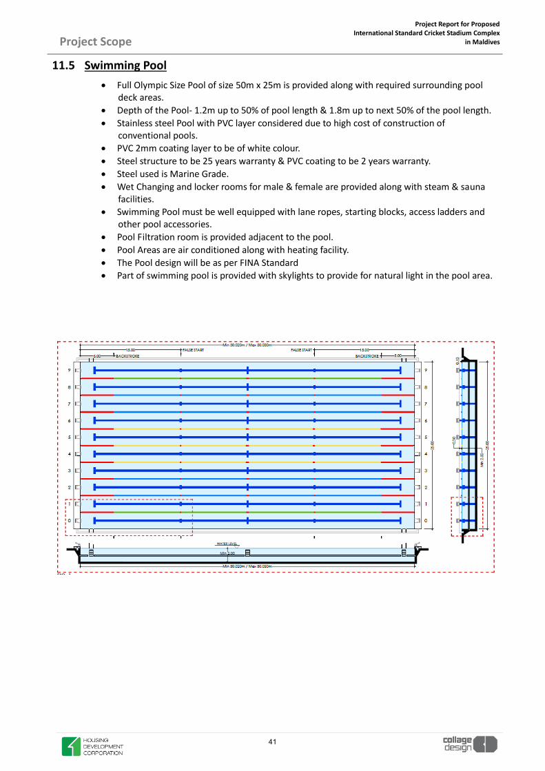
11.5 Swimming Pool x Full Olympic Size Pool of size 50m x 25m is provided along with required surrounding pool
deck areas. x Depth of the Pool- 1.2m up to 50% of pool length & 1.8m up to next 50% of the pool length. x Stainless steel Pool with PVC layer considered due to high cost of construction of
conventional pools. x PVC 2mm coating layer to be of white colour. x Steel structure to be 25 years warranty & PVC coating to be 2 years warranty. x Steel used is Marine Grade. x Wet Changing and locker rooms for male & female are provided along with steam & sauna
facilities. x Swimming Pool must be well equipped with lane ropes, starting blocks, access ladders and
other pool accessories. x Pool Filtration room is provided adjacent to the pool. x Pool Areas are air conditioned along with heating facility. x The Pool design will be as per FINA Standard x Part of swimming pool is provided with skylights to provide for natural light in the pool area.
41

Project Report for Proposed International Standard Cricket Stadium Complex
in Maldives
Project Scope
11.6 Cafeteria
x Cafeteria cum informal seating area is provided in the club area. x This café connects the club and the VIP lobby area in the north.
11.7 Club Changing and Locker Rooms
x Separate sets of locker and changing rooms are provided for the club areas. x One set of Dry Changing and Locker Room for male and female is provided for Indoor Cricket
Academy and Fitness centre. x One set of Wet Changing and Locker Room for male and female is provided for Swimming Pool
and Hydrotherapy.
42

Project Report for Proposed International Standard Cricket Stadium Complex
in Maldives
Project Scope
11.8 Outdoor Courts and Recreational Areas
x 2 Nos. of outdoor Tennis Courts are provided on the Podium to activate it on non match days.
x 6m high Fencing on all sides is to be provided with two access gates for each court. x 2 Nos. of Basketball courts are provided in the public plaza areas along with 4.5m high
fencing on east side (fixed) to be provide with two access gates. x Skate park is also provided and designed to merge with the landscape of the public
plaza areas. x These outdoor courts and skate parks are provided to activate the public areas. x The above areas to be considered for Future development along with development of
public plaza in east (to be developed with Master plan development). x Not to be considered for current scope of work.
43

Project Report for Proposed International Standard Cricket Stadium Complex
in Maldives
Project Scope
12. EXTERNAL FACILITIES 12.1 Pitch
The quality of the turfed playing surface is to be of a standard suitable for national and international sporting events. The pitch is to have irrigation and drainage, covering the full extent of the grassed area. The pitch is to be flat with the surrounding area up to the front row sloped only for drainage.
Details of the pitch drainage & irrigation system will be as per ICC Guidelines
12.2 Scoreboard / Videoboard Provide two video boards which will be located in opposite sides of the stadium and will provide re-play coverage to all patrons. Associated plant and equipment rooms are to be located in close prox-imity to the screens.
12.3 Parking Parking distribution will be as follows:
x Public Parking (Outside the Stadium plot)
x People with disabilities Parking Bays
x Team Parking Bays:
x VVIP Parking
x Media Parking
x Police
x Ambulance
x Provide parking spaces for 3 Broadcast Trucks and 2 Team Coaches.
12.4 Transport A strategy to address pedestrian and public transport routes will be developed in consultation with the traffic consultant and the stakeholders. The preliminary external transportation principles are set out below, but not limited to:
x Integrated Public Transport Strategy
x Car parking restrictions around stadium.
x Dedicated Shuttle Bus Station to serve stadium and promote public transport
x Electrical transport vehicles as Shuttles
x Limited on-site car parking.
x Coach Parking near stadium.
x Pedestrian infrastructure upgrades
x Separation of pedestrians from vehicle movements.
x Upgradation of Infrastructure at Highway junction and secondary roads by the state depart-ments.
44

Project Report for Proposed International Standard Cricket Stadium Complex
in Maldives
Project Scope
12.5 Advertising
Accommodations will be made for several varieties and locations of advertising:
x Pitch fence advertising will be located to suit TV camera positions to maximise exposure. A continuous 900mm high perimeter board zone will be available above the field level without obstructing seated sightline angles. Length of signage boards will allow for access gates to the perimeter for field access and camera positions as required.
x Signage will be accommodated on the fascia of upper deck seating sections The signage pan-els approximately 850mm high by 3 meters wide. Fastening systems shall allow easy remov-ability for sponsorship changes. Signage system will allow the installation of the signage from above.
Electrical power will be provided to the pitch perimeter and elevated signage to allow for the follow-ing advertising systems:
x Tri-vision advertising boards (Sight screen)
x Roller perimeter advertising boards
x Digital (LCD / LED) perimeter advertising boards
x Space allocation for Tri-vision advertising panels shall be made adjacent to the video replay boards.
x Concourse advertising components will be vandal-resistant and powered for back-lighting.
x Provisions shall be made for the fixing of temporary banners, flags, and other large format signage on the external façade of the stadium and the exterior plazas.
x Allowances shall be made on the façade and roof of the building to facilitate the potential signage for a naming rights sponsor.
12.6 Sports Lighting
x Artificial Lighting levels are provided as per ICC standards. x 4 Nos. of Highmast towers are considered. x The highmast towers to be ‘A’ shaped. x LED light fixtures are to be considered. x HD broadcast compatible lux levels of 2500 lux (wicket), 2000 lux (infield) and 1800 lux
(outfield) x Relevant permissions to be taken of Highmast as it is near airport.
12.7 Roof Design The roof should be designed to be an architectural statement that reflects the aspirations of modern de-sign within the Maldives context whilst providing an economical, lightweight structure that covers spec-tators. Careful consideration shall be given to ensuring that the shadow cast by the roof on the field of play is minimised to provide the optimum growing conditions for the natural grass pitch.
x The functional criteria of the roof is summarised as follows:
x Vertical ‘drip line’ cover from the roof will be provided for minimum of 40% of the Total seating. The Stadium shall provide protection from wind, rain and sun to minimise adverse effects for all users.
x To provide an iconic and sculptural form that is identifiable from a distance.
x To produce an elegant, light and efficient structure with combination of Fabric and Metal that offers connectivity to the surrounding environment.
45

Project Report for Proposed International Standard Cricket Stadium Complex
in Maldives
Project Scope
x The roof shall be column free over the seating bowl to ensure no obstructed views from the seat bowl caused by roof supports.
x Solar panels are to be installed in the Metal part of the roof.
12.8 Roof Services and Roof Access The roof will house the following services and access provisions:
x House lighting and Emergency Lighting supported from the circumferential service zone.
x Provision for PA Speakers supported from the circumferential service zone.
x Architectural Lighting
x Lightning protection to be provided.
x Cable trays to be provided for roof services / cables
x Cleaning of the roof will require water hose cocks and water supply, phone outlets and power out-lets. These are to be provided at each access point onto the roof.
x A life safety line no less than 2000mm from all edges is to be provided to all roofs.
12.9 Façade Design x The entries shall be read from the same architectural language with their own individual identity.
x The external façade massing and form shall be designed to mediate between the macro size of the stadium and the context at a human scale.
x The facades shall be designed such that they will maintain a maximum amount of visual transparency through the external envelope when viewed from both sides.
x No reflective or tinted glass shall be used. Clear glass or glass with a similar level of light transmit-tance is acceptable.
x Enhanced solar performance glazing is required to all external glazing to internal air-conditioned spaces.
x The main podium façade is developed on the concept of “The Reef”.
x Glassfibre Reinforced Concrete is to be used for facade.
x The face of the stairs and ramps shall be designed to allow for the addition of large external signage banners.
x The facades shall be designed to achieve a comfortable level of thermal performance to the main serviced elements of the building.
x Facades shall respond to the environmental conditions and relate to their specific orientation.
12.10 Earth Mound Seating x East Side of the stadium has Earth Mound (sloping) Seating acting as an informal spectator viewing
areas. x This mound opens up the stadium bowl from east side towards the ocean. x Two staircases and ramps and provided which leads to the mound seating. x The slope to be provided for the mound should be in accordance to the seating standards as per
Safety Guidelines. x Preparation of mounds of various size and shape by available excavated /supplied earth in layers. x The mound is then finished with natural grass. x The mound has safety height parapet walls on all sides. x To be considered for Future Development (to be developed with Master plan development).
46

Project Report for Proposed International Standard Cricket Stadium Complex
in Maldives
Project Scope
x Not to be considered for current scope of work.
12.11 Amphitheater x Outdoor Amphitheater is provided in the east side plaza area facing the ocean. x It is sloping in opposite direction of the slope of the mound. x Combination of hardscape & green is used for its finish. x To be considered for Future Development (to be developed with Master plan development). x Not to be considered for current scope of work.
12.12 Environmental / ESD Requirements The design and construction of the Stadium will incorporate principles of Ecologically Sustainable Devel-opment. This will appropriately incorporate environmentally responsible materials and processes at the time of design/construction and to reduce energy consumption and adverse effects on the environment in both construction and operation which are financially viable.
47

SITE ANALYSIS
48

Project Report for Proposed International Standard Cricket Stadium Complex
in Maldives
Site Analysis
1. Location
Introduction to Hulhumalé – The City in Isles of Maldives Emerging from beneath the waves, the city of Hulhumalé remains a beacon of development for the Maldives. Hulhumalé is the culmination of the island nation’s efforts to reimagine its focus towards being resilient, economically and With world class infrastructure, Hulhumalé – aims to offer residents, visitors, investors, developers, entrepreneurs and technopreneurs with a global lifestyle. Hulhumalé has been celebrated as a true city for the future, providing them with the perfect platform offering the best solutions to live, work, play and invest. Initiated in 1997, Hulhumalé is the first fully-reclaimed, pre-planned city of the country located within 3 kilometers from Malé, the capital city. Curving a welcoming path for its development in early 2015 Hulhumalé Phase II was reclaimed with the additional 244 hectors. The newly reclaimed addition to the existing conurbation promises diverse development opportunities. Hulhumalé Phase I currently houses 50,000 people with the target population of 80,000 people. With the new developments, Phase II plans a populous of 160,000 people.
Hulhumale, Maldives
49

Project Report for Proposed International Standard Cricket Stadium Complex
in Maldives
Site Analysis
50

Project Report for Proposed International Standard Cricket Stadium Complex
in Maldives
Site Analysis
The proposed site Acres in Hulhumale is of around 21 Acres.
Proposed Site, Hulhumale
21 Acres
N
51

Project Report for Proposed International Standard Cricket Stadium Complex
in Maldives
Site Analysis
52

Project Report for Proposed International Standard Cricket Stadium Complex
in Maldives
Site Analysis
2. Connectivity It is at a distance of about 9Km from the Velana International Airport.
N
PROPOSED SITE
53

Project Report for Proposed International Standard Cricket Stadium Complex
in Maldives
Site Analysis
The proposed site is connected by road on all sides.
21 Acres
N
54

Project Report for Proposed International Standard Cricket Stadium Complex
in Maldives
Site Analysis
3. Land Transport Management System Reference: HDC- Policy Direction Paper- Land Transport Management System, HUlhumale. 3.1 Background The development of Hulhumale` is one of the most ambitious projects undertaken by the government of Maldives. Hulhumale` Phase 1 which began in 1998 consisted of reclaiming 188 hectares of land to cater for a population of 80,000 which eventually was followed by Phase 2 in 2014 with the reclamation of 240 hectares of land to be developed to cater for an additional population of 160,000. Presently Hulhumale` (Phase 1) is home to some 40,000 people with the targeted combined Population for both phases being 240,000. Hulhumalé is being developed as a modern Smart city with a focus on youth, providing opportunities with the necessary infrastructure to encourage creative entrepreneurship. HULHUMALE’ POPULATION PHASE 1 80,000 PHASE 2 160,000 PHASE 1 & 2 240,000 VISITORS 60,000 TOTAL 300,000 CATEGORY NUMBER OF VEHICLE PERCENTAGE CAR 1850 22 % MOTORBIKE 5563 66 % COMMERCIAL 281 3 % INDUSTRIAL 607 7% PUBLIC 108 2% TOTAL 8409 100% Note: these values are excluding visiting vehicle population from male. The percentage is estimated to be additional 25%.
55

Project Report for Proposed International Standard Cricket Stadium Complex
in Maldives
Site Analysis
3.2 ESTIMATED ROAD CARRYING CAPACITY In order to maintain the smooth flow of traffic 10% of road lane length is kept as free space. The remaining 90% is allocated for vehicles according to following ratio.
Existing vehicle ratio in Hulhumale'
Proposed vehicle ratio
Proposed vehicle ratio in Hulhumale Total length of roads (Lane Kilometers) in Hulhumale phase 1 and phase 2 combined is 168 kilometers. Considering each vehicle takes average 1.94 meters of road length (lane meters), 515 vehicles per kilometer is believed to be the maximum carrying capacity for roads. Road length is allocated for these categories according to these lengths.
56

Project Report for Proposed International Standard Cricket Stadium Complex
in Maldives
Site Analysis
Following table shows how vehicle quota of Hulhumale will be distributed according to previously mentioned ratios.
Number of vehicle in each category This will result in one vehicle per every three people (1 car per every 70 people and 1 motorbike for every 4 people) in Hulhumale’ these values will be further divided into subcategories. Vehicle quota for each development should be calculated on this basis. Adequate paid/free visitor parking should be provided in each development to cater its users. 3.3 PARKING SYSTEMS
Parking and Transport related Lands- Hulhumale Pahse 1
57

Project Report for Proposed International Standard Cricket Stadium Complex
in Maldives
Site Analysis
3.4 Hulhumale Transport Master Plan
Land Use and Transport Plan for Phase 1
Land Use and Transport Plan for Phase 2
58

DESIGN INTENT
59

Project Report for Proposed International Standard Cricket Stadium Complex
in Maldives
Design Intent
1. Stadium Design Concept- “ The Reef” The International Cricket Stadium in Hulhumalé will be constructed based on a concept very close to the hearts and minds of all Maldivians, “The Reef”. The Reef is a very clear representation of what it is to be a Maldivian. The Reef is tied to the Maldivian way of life, culture, heritage, food and encompassing love for the Oceans. It also very openly represents the fight against Climate Change. This Façade concept of “The Reef” has been developed based on the initial ideas envisaged by M/s. Arch International in discussion with the Government of Maldives.
The stadium will need to be designed to meet ICC and BCCI standards with the capability of hosting interna-tional cricket tournaments. The design process will follow the best international practices for design and de-livery of world-class sports stadiums. Documents on spectators, teams, official safety, and security will be dis-seminated to all stakeholders for the purpose of seeking thorough consultations on best practices. The design of the stadium will aim to provide spectators with the best experience, i.e. perfect viewing angles, smooth entries and exits. The stadium will also provide State-of-the-Art facilities for players and officials along with spectators. The stadium will be divided in to separate zones that will be secured with appropriate control measures for accessing the stadium. A fence will enclose the outer perimeter of the stadium with clear ‘EXIT’ and ‘ENTRY’ points, designated to handle large crowds. A plan will be established in the future to guide the movement of spectators coming in and out of the stadium. Though seven gates will be constructed for crowd control pur-poses, not all gates will be utilized during all games, unless it is an Emergency. Special ENTRY/EXIT points will be designated for teams, officials, VIPs and VVIPs. Normal spectators will not be allowed to access these special ENTRY/EXIT points. Teams, officials, VIPs and VVIPs will be provided separate ‘Drop-Off’ and ‘Pick-Up’ points. Parking facilities for VIPs and VVIPs will be located close to the VIP lounge and provided for aforementioned persons only. Parking facilities will be kept secure at all times and accessible to authorized persons ONLY. For the purpose of crowd control, no private vehicles, unless provided with special authorization will be al-lowed near or on the stadium premises. All public travel will need to be conducted on public transportation. A location near the stadium will be the designated bus bay, and act as a drop off and pick up point for specta-tors travelling via the bus. Spectators travelling via taxis or personal vehicles will be guided to specific points, from where they will have to walk to the stadium.
60

Project Report for Proposed International Standard Cricket Stadium Complex
in Maldives
Design Intent
Adequate diagrammatic signage will be available around and outside the stadium, to make navigation easy for spectators (including disabled persons) and staff members. The aim of the navigational aids is to make locating facilities easier. This stadium will provide special viewing areas accessible to spectators with disabilities. Such areas will have suitable access and evacuations routes, taking into consideration the specific needs of the spectators con-cerned. The provision of adequate viewing standards is important in ensuring that seated accommodation is both safe and serves its intended purpose. Spectators should have a clear, unrestricted view of the whole pitch. Landscaping plays a very important role in creating an invigorating environment. Flora will be selected based on the local climate and soil conditions. A rainwater harvesting and pumping system will be used to water the grass and recharge the underground water. Public Plaza areas are provided which acts as circulation/ gathering areas for spectators, activated by providing retail and sit out areas.
The site required for the construction of this stadium is approximately a 20 acres land parcel, located in Hulhumalé, Maldives.
Location Plan: Maldives
Hulhumale, Maldives
61

Project Report for Proposed International Standard Cricket Stadium Complex
in Maldives
Design Intent
2. The User Experience- Categories & Amenities
2.1 Players’ Facilities
• 2 SEPARATE LOCKER ROOMS WITH SOUND SEPARATION • LOCKERS, RACKS AND SEATS FOR 25 PLAYERS • SHOWERS & TOILET FACILITIES • TACTICAL DISCUSSION AREA • PHYSIOTHERAPY AREA • PLAYERS’ LOUNGE/ REFRESHMENT AREA • STEAM & SAUNA • ICE BATH • PLAYERS’ VIEWING GALLERY • SEPARATE AREA FOR TECHNICAL PERSONNEL • EASY ACCESS TO PLAYERS BENCHES ON FIELD
PLAYERS’ LOCKER ROOM
62

Project Report for Proposed International Standard Cricket Stadium Complex
in Maldives
Design Intent
2.2 Media Facilities
• ESSENTIAL TO PROVIDE WORLD CLASS FACILITIES • PRESS BOX DESK POSITIONS • PRESS CONFERENCE ROOM CAPACITY • PHOTOGRAPHER WORKING POSITIONS FOR 15 • TV COMMENTARY BOXES FOR 4 • RADIO COMMENTARY BOXES FOR 4 • BROADCAST CONTROL ROOM • BROADCAST PARKING COMPOND • FLASH INTERVIEW AREA CLOSE TO FIELD • POST MATCH PRESENTATION AREA • PITCH SIDE PHOTOGRAPHER AREA FOR 20 • CATERING / HOSPITALITY AREA FOR MEDIA • CAMERA POSITIONS AND GANTRY AROUND STADIUM
WRITTEN PRESS BOX
63

Project Report for Proposed International Standard Cricket Stadium Complex
in Maldives
Design Intent
2.3 VIP Facilities- Lounges & Corporate Boxes
CORPORATE BOX
VIP LOUNGE/ RESTAURANT
64

Project Report for Proposed International Standard Cricket Stadium Complex
in Maldives
Design Intent
2.4 Club Areas- Entrance Lobby
65

Project Report for Proposed International Standard Cricket Stadium Complex
in Maldives
Design Intent
2.5 Spectator Concourse
The Ground level & Podium level is the main Spectator Concourse area where all the spectators enter the seating stand from.
66

Project Report for Proposed International Standard Cricket Stadium Complex
in Maldives
Design Intent
3. The Stadium Roof The proposed stadium has a roof over 40% of the total seating capacity. The Stadium roof design is inspired from the form of a ‘Yacht’. There are two types of roofing material being used for the covering of the roof structural members.
- FABRIC - METAL
67

Project Report for Proposed International Standard Cricket Stadium Complex
in Maldives
Design Intent
STADIUM ROOF- SCHEMATIC
68

Project Report for Proposed International Standard Cricket Stadium Complex
in Maldives
Design Intent
The two different material are used to create a ‘crescent moon’ form of the roof when viewed from top.
Solar Panels are to be installed in the Metal Roof portion. STADIUM- ROOF PLAN
CRESCENT MOON FORM- FABRIC MATERIAL
REMAINING ROOF- METAL with Solar Panels
69

Project Report for Proposed International Standard Cricket Stadium Complex
in Maldives
Design Intent
4. The Stadium Façade- “The Reef”
70

Project Report for Proposed International Standard Cricket Stadium Complex
in Maldives
Design Intent
71

Project Report for Proposed International Standard Cricket Stadium Complex
in Maldives
Design Intent
The Material used for the fins is GRC- Glass Fibre reinforced Concrete. Glass Fibre Reinforced Concrete Glass fiber concretes are mainly used in exterior building façade panels and as architectural precast concrete. The design of glass-fiber-reinforced concrete panels uses a knowledge of its basic properties under tensile, compressive, bending and shear forces, coupled with estimates of behavior under secondary loading effects such as creep, thermal response and moisture movement. Important characteristics of many fiber-reinforced composites are their non-corroding behavior, high damping capacity and low coefficients of thermal expansion. GRC panels, on average, weigh substantially less than pre-cast concrete panels due to their reduced thickness. Their low weight decreases loads superimposed on the building’s structural components making construction of the building frame more economical.
72

Project Report for Proposed International Standard Cricket Stadium Complex
in Maldives
Design Intent
5. Landscape- Podium/ Plaza Areas Landscaping plays a very important role in creating an invigorating environment. Flora will be selected based on the local climate and soil conditions. A master water-tank will be placed at a designated location convenient to groundskeepers, along with a pumping facility that will be used to supply water to various corners of the Complex. A rainwater harvesting and pumping system will be used to water the grass and recharge the underground water.
GROUND FLOOR PLAZA AREA
73

Project Report for Proposed International Standard Cricket Stadium Complex
in Maldives
Design Intent
PODIUM PLAZA AREA
74

Project Report for Proposed International Standard Cricket Stadium Complex
in Maldives
Design Intent
75

Project Report for Proposed International Standard Cricket Stadium Complex
in Maldives
Design Intent
6. Technical Requirements- Emergency Exits
7. Technical Requirements- Security & Crowd Control
76

Project Report for Proposed International Standard Cricket Stadium Complex
in Maldives
Design Intent
Turnstile Access Control System
77

Project Report for Proposed International Standard Cricket Stadium Complex
in Maldives
Design Intent
8. Technical Requirements- Security & Crowd Control
9. Technical Requirements- Sustainability
78

AREA STATEMENT
79

Project Report for Proposed International Standard Cricket Stadium Complex
in Maldives Area Statement
MALDIVES INTERNATIONAL CRICKET STADIUM
SR.NO DESCRIPTION ROOM AREAS
(CARPET, SQ.M) TOTAL AREA (BUA, SQ.M)
A GROUND FLOOR 13776 PLAYERS' & VVIP LOBBY 430 LOBBY 250 SERVICES-02 25 CIRCULATION 400 PLAYERS' DRESSING ROOM-01 450 PLAYERS' DRESSING ROOM-02 450 PRESS CONFERENCE 200 UMPIRES' ROOM 100 DOPING CONTROL ROOM 100 MEDICAL/ FIRST AID ROOM 200 LOBBY 150 KITCHEN/ PANTRY 210 SERVICES-01 100 STADIUM SUPPORT STAFF/ MAINTENANCE ROOM 100 SWIMMING POOL 1400 POOL DECK 1120 DRY CHANGING ROOMS-MALE & FEMALE 420 INDOOR CRICKET NETS 1700 FITNESS CNETRE 350 CAFÉ 610 HEALTH BAR/ LOUNGE 600 CIRCULATION 500 SPECTATOR CONCOURSE 3000 MEDIA LOBBY 190 PRODUCTION CONTROL ROOM 450 SUBAIR ROOM 260 GROUND EQUIPMENT STORE 320 SERVICE/ STORE 480 PRAYER ROOMS (at multiple locations) 150
B PODIUM LEVEL PLAN 13776 LOBBY & CIRCULATION 650 SERVICES-01 50 VIP LOUNGE/ RESTAURANT 1650 CORPORATE BOXES 790 TOILET-01-MALE & FEMALE 60 SERVICES-02 25 TOILETS-02-MALE & FEMALE 60 VIP LOUNGE-SOUTH 1200 SERVICES-03 25 TOILETS-03-MALE & FEMALE 60
80

Project Report for Proposed International Standard Cricket Stadium Complex
in Maldives
Area Statement
TOILETS-04-MALE & FEMALE 60 PODIUM 7940 C FIRST FLOOR 2517 LOBBY & CIRCULATION-SOUTH 450 WRITTEN PRESS 400 TOILETS-MALE & FEMALE 60 CONTROL ROOM 55 COMMENTATOR 55 RADIO 55 TV STUDIO 55 TOTAL 30069
81

2
SCHEDULE OF FINISHES
82

Proj
ect R
epor
t for
Pro
pose
d In
tern
atio
nal C
ricke
t Sta
dium
Com
plex
in
Mal
dive
sDe
sign
Con
cept
s and
Fin
ishe
s
SPAC
ESR
.NO
.SP
ECIF
ICAT
ION
IMAG
E
CEIL
ING
HEI
GHT
PLAY
ERS
&
VVIP
EN
TRAN
CE
LOBB
Y
3000
MM
M
inim
um
WAL
L PA
NEL
ING
FIN
ISHE
D W
ITH
LAM
INAT
E
Tile
FLO
ORI
NG
PRO
POSE
D A
S PE
R LA
YOU
T TO
M
ATCH
GEO
MET
RY O
F SP
ACE
, WIT
H LI
GHT
SHAD
E Ti
le C
LADD
ING
ON
WAL
L TO
EN
HEN
CIN
G TH
E SP
ACE.
SK
IRTI
NG
TO B
E M
ATCH
WIT
H FL
OO
RIN
G
CUST
OM
IZE
LIG
HT A
S PE
R DE
SIGN
RECE
PTIO
N C
OU
NTE
R DE
SK F
INIS
HED
WIT
H DA
RK T
ile .
BALA
NCE
WAL
L AN
D CE
ILIN
G FI
NIS
HED
WIT
H PA
INT.
1 2 3 4 5 6
L.E.
D TV
Plac
es F
or A
rtTh
e w
alls
encl
osin
g th
e Pl
ayer
loun
ge a
nd c
orrid
or
are
the
only
obv
ious
can
dida
tes f
or th
e lo
catin
g of
art
wor
k or
grap
hics
.
AIR
CON
DITI
ON
The
reco
mm
ende
d IL
lum
inan
ce is
150
lux
.LI
GHT
ING
LUX
12M
M T
HK C
LEAR
TO
UG
HEN
ED G
LASS
DO
OR
7 8
83

Proj
ect R
epor
t for
Pro
pose
d In
tern
atio
nal C
ricke
t Sta
dium
Com
plex
in
Mal
dive
sDe
sign
Con
cept
s and
Fin
ishe
s
SPAC
ESR
.NO
.SP
ECIF
ICAT
ION
IMAG
E
CEIL
ING
HEI
GHT
PLAY
ERS
LOU
NGE
3000
MM
Min
imum
W
ALL
PAN
ELIN
GFI
NIS
HED
WIT
H LA
MIN
ATE
Tile
FLO
ORI
NG
PRO
POSE
D A
S PE
R LA
YOU
T TO
M
ATCH
GEO
MET
RY O
F SP
ACE,
IN S
HADE
S AS
PE
R DE
SIGN
BACK
PAI
NTE
D G
LASS
PAN
ELIN
G TO
CRE
ATE
N
ICH
FOR
L.E.
D TV
.
BAR
COU
NTE
R TO
PFI
NIS
HED
WIT
H DA
RK
MAR
BLE
.
BALA
NCE
WAL
L AN
D CE
ILIN
G FI
NIS
HED
WIT
H PA
INT.
1 2 3 4 5 6L.
E.D
TV
Plac
es F
or A
rtTh
e w
alls
are
the
only
obv
ious
can
dida
tes f
or th
e lo
catin
g of
ar
twor
k or
gra
phic
s.
AIR
CON
DITI
ON
84

Proj
ect R
epor
t for
Pro
pose
d In
tern
atio
nal C
ricke
t Sta
dium
Com
plex
in
Mal
dive
sDe
sign
Con
cept
s and
Fin
ishe
s
85

Proj
ect R
epor
t for
Pro
pose
d In
tern
atio
nal C
ricke
t Sta
dium
Com
plex
in
Mal
dive
sDe
sign
Con
cept
s and
Fin
ishe
s
SPAC
ESR
.NO
.SP
ECIF
ICAT
ION
IMAG
E
CEIL
ING
HEI
GHT
PLAY
ERS
LOCK
ER30
00 M
MM
inim
um
LOCK
ER A
ND
SEAT
ING
FIN
ISHE
D W
ITH
LAM
INAT
E
SYN
THET
IC F
LOO
RIN
G P
ROPO
SED
TO
AVO
IDE
DIRE
CT C
ON
TACT
BET
WEE
N P
LAYE
RS S
HOES
AN
D F
LOO
R . F
LOO
RIN
G CO
LOR
IS U
SE T
O
ENHE
NCI
NG
THE
SPA
CE .
SKIR
TIN
G TO
BE
MAT
CH W
ITH
FLO
ORI
NG
BALA
NCE
WAL
L AN
D CE
ILIN
G FI
NIS
HED
WIT
H PA
INT
1 2 3 4
L.E.
D TV
AIR
CON
DITI
ON
Ceili
ngSu
spen
ded
Alum
inum
cei
ling
5
86

Proj
ect R
epor
t for
Pro
pose
d In
tern
atio
nal C
ricke
t Sta
dium
Com
plex
in
Mal
dive
sDe
sign
Con
cept
s and
Fin
ishe
s
SPAC
ESR
.NO
.SP
ECIF
ICAT
ION
IMAG
E
CEIL
ING
HEI
GHT
PLAY
ERS
TOIL
ETS
3600
MM
Min
imum
DO
OR
& B
ASIN
CO
UN
TER
SHU
TTER
FIN
ISHE
DW
ITH
LAM
INAT
E
BASI
N C
OU
NTE
R DE
SK F
INIS
HED
WIT
H DA
RK
GRAN
ITE
CEIL
ING
FIN
ISHE
D W
ITH
PAIN
T
1 2 3 4
TILE
FLO
ORI
NG
PRO
POSE
D A
S PE
R LA
YOU
T TO
M
ATCH
GEO
MET
RY O
F T
OIL
ET S
PACE
, IN
SH
ADES
AS
PER
DESI
GN
Ceili
ngM
oist
ure
resis
tant
susp
ende
d pl
aste
rboa
rd c
eilin
g.A
fulle
r coo
rdin
atio
n of
cei
ling
rece
ssed
ser
vice
s m
ust b
em
ade,
to in
clud
e fin
al p
ositi
ons f
or li
ght f
ittin
gs, a
ir su
pply
an
d ex
trac
t gril
les a
nd sp
rinkl
er h
eads
.
The
reco
mm
ende
d IL
lum
inan
ce is
100
lux
.LI
GHT
ING
LUX
5
87

Proj
ect R
epor
t for
Pro
pose
d In
tern
atio
nal C
ricke
t Sta
dium
Com
plex
in
Mal
dive
sDe
sign
Con
cept
s and
Fin
ishe
s
NO
TE :
The
toile
t par
titio
n sy
stem
s sho
wn
here
are
inte
nded
to o
ffer
gui
danc
e as
toth
e ki
nd o
f fix
ture
s we
prop
ose.
In th
e ev
ent t
hat t
hese
supp
liers
are
not
abl
e to
pro
vide
a si
mila
r ran
ge, t
hen
alte
rnat
ives
shou
ld b
e pu
t for
war
d fo
r clie
nt a
nd d
esig
n te
am a
ppro
val.
88

Proj
ect R
epor
t for
Pro
pose
d In
tern
atio
nal C
ricke
t Sta
dium
Com
plex
in
Mal
dive
sDe
sign
Con
cept
s and
Fin
ishe
s
Glas
s She
lf an
d Br
acke
ts U
nits
Chro
me
Plat
ed B
ottle
Tra
ps
SHO
WER
MIX
TURE
SH
OW
ER M
IXTU
RE
BIB
TAP
SHO
PE D
ISPE
NSE
R
TAP
TOW
EL R
OD
PAPE
R DI
SPEN
SER
89

Proj
ect R
epor
t for
Pro
pose
d In
tern
atio
nal C
ricke
t Sta
dium
Com
plex
in
Mal
dive
sDe
sign
Con
cept
s and
Fin
ishe
s
SPAC
ESR
.NO
.SP
ECIF
ICAT
ION
IMAG
E
CEIL
ING
HEI
GHT
VIP
LOU
NGE
3600
MM
W
ALL
PAN
ELIN
GFI
NIS
HED
WIT
H LA
MIN
ATE
Tile
FLO
ORI
NG
PRO
POSE
D A
S PE
R LA
YOU
T TO
M
ATCH
GEO
MET
RY O
F SP
ACE
, WIT
H DA
RK
SHAD
E W
OO
DEN
FLO
ORI
NG
IN C
ENTE
R T
O
ENHE
NCI
NG
THE
SPAC
E.
SKIR
TIN
G TO
BE
MAT
CH W
ITH
FLO
ORI
NG
BACK
PAI
NTE
D G
LASS
PAN
ELIN
G TO
HI
GHLI
GHT
THE
WAL
L.
BAR
COU
NTE
R DE
SK F
INIS
HED
WIT
H DA
RK
MAR
BLE
BALA
NCE
WAL
L AN
D CE
ILIN
G FI
NIS
HED
WIT
H PA
INT
1 2 3 4 5 6
L.E.
D TV
Plac
es F
or A
rtAl
l Pai
nted
and
pan
elle
d w
alls
are
the
only
obv
ious
ca
ndid
ates
for
the
loca
ting
of a
rtw
ork
or g
raph
ics.
AIR
CON
DITI
ON
Ceili
ngAl
umin
um C
eilin
g
7
90

Proj
ect R
epor
t for
Pro
pose
d In
tern
atio
nal C
ricke
t Sta
dium
Com
plex
in
Mal
dive
sDe
sign
Con
cept
s and
Fin
ishe
s
SPAC
ESR
.NO
.SP
ECIF
ICAT
ION
IMAG
E
CEIL
ING
HEI
GHT
VIP
TOIL
ETS
3600
MM
TO
ILET
DO
OR
& B
ASIN
CO
UN
TER
SHU
TTER
FI
NIS
HED
WIT
H LA
MIN
ATE
BASI
N C
OU
NTE
RFI
NIS
HED
WIT
H DA
RK
GRAN
ITE
CEIL
ING
FIN
ISHE
D W
ITH
PAIN
T
1 2 3 4
TILE
FLO
ORI
NG
PRO
POSE
D A
S PE
R LA
YOU
T TO
M
ATCH
GEO
MET
RY O
F T
OIL
ET S
PACE
, W
ITH
LIGH
T SH
ADE
TILE
CLA
DDIN
G O
N W
ALL
TO
ENHE
NCI
NG
THE
SPAC
E.
Ceili
ngM
oist
ure
resis
tant
susp
ende
d pl
aste
rboa
rd c
eilin
g.A
fulle
r coo
rdin
atio
n of
cei
ling
rece
ssed
ser
vice
s m
ust b
em
ade,
to in
clud
e fin
al p
ositi
ons f
or li
ght f
ittin
gs, a
ir su
pply
an
d ex
trac
t gril
les a
nd sp
rinkl
er h
eads
.
The
reco
mm
ende
d IL
lum
inan
ce is
150
lux
.LI
GHT
ING
LUX
Floo
rAn
ti Sl
ip c
eram
ic ti
les (
mat
t fin
ish)M
W
alls
Cera
mic
tile
fini
sh fu
ll he
ight
to u
nder
side
of
susp
ende
d ce
iling
.
5
91

Proj
ect R
epor
t for
Pro
pose
d In
tern
atio
nal C
ricke
t Sta
dium
Com
plex
in
Mal
dive
sDe
sign
Con
cept
s and
Fin
ishe
s
Chro
me
Plat
ed B
ottle
Tra
psBI
B TA
P
SHO
PE D
ISPE
NSE
R
TAP
TOW
EL R
OD
PAPE
R DI
SPEN
SER
PAPE
R HO
LDER
92

Proj
ect R
epor
t for
Pro
pose
d In
tern
atio
nal C
ricke
t Sta
dium
Com
plex
in
Mal
dive
sDe
sign
Con
cept
s and
Fin
ishe
s
SPAC
ESR
.NO
.SP
ECIF
ICAT
ION
IMAG
E
CEIL
ING
HEI
GHT
CORP
ORA
TE
BOX
3600
MM
W
ALL
PAN
ELIN
GFI
NIS
HED
WIT
H VE
NEE
R M
ALAM
INE
POLI
SHED
Tile
FLO
ORI
NG
PRO
POSE
D A
S PE
R LA
YOU
T TO
M
ATCH
GEO
MET
RY O
F SP
ACE
, WIT
H DA
RK
SHAD
E W
OO
DEN
FLO
ORI
NG
IN C
ENTE
R T
O
ENHE
NCI
NG
THE
SPAC
E.
SKIR
TIN
G TO
BE
MAT
CH W
ITH
FLO
ORI
NG
BACK
PAI
NTE
D G
LASS
PAN
ELIN
G TO
HI
GHLI
GHT
THE
WAL
L
BAR
COU
NTE
R DE
SK F
INIS
HED
WIT
H DA
RK
MAR
BLE
BALA
NCE
WAL
L AN
D CE
ILIN
G FI
NIS
HED
WIT
H PA
INT
1 2 3 4 5 6L.
E.D
TV
Plac
es F
or A
rtTh
e w
alls
are
the
only
obv
ious
can
dida
tes f
or th
e lo
catin
g of
ar
twor
k or
gra
phic
s.
AIR
CON
DITI
ON
93

Proj
ect R
epor
t for
Pro
pose
d In
tern
atio
nal C
ricke
t Sta
dium
Com
plex
in
Mal
dive
sDe
sign
Con
cept
s and
Fin
ishe
s
SPAC
ESR
.NO
.SP
ECIF
ICAT
ION
IMAG
E
CEIL
ING
HEI
GHT
CORP
ORA
TE
BOX
ATTA
CHED
TO
ILET
3600
MM
DO
OR
& B
ASIN
CO
UN
TER
SHU
TTER
FIN
ISHE
DW
ITH
LAM
INAT
E
BASI
N C
OU
NTE
RFI
NIS
HED
WIT
H DA
RK
GRAN
ITE
CEIL
ING
FIN
ISHE
D W
ITH
PAIN
T
1 2 3 4
TILE
FLO
ORI
NG
PRO
POSE
D A
S PE
R LA
YOU
T TO
M
ATCH
GEO
MET
RY O
F T
OIL
ET S
PACE
, W
ITH
LIGH
T SH
ADE
TILE
CLA
DDIN
G O
N W
ALL
TO
ENHE
NCI
NG
THE
SPAC
E.
Ceili
ngM
oist
ure
resis
tant
susp
ende
d pl
aste
rboa
rd c
eilin
g.A
fulle
r coo
rdin
atio
n of
cei
ling
rece
ssed
ser
vice
s m
ust b
em
ade,
to in
clud
e fin
al p
ositi
ons f
or li
ght f
ittin
gs, a
ir su
pply
an
d ex
trac
t gril
les a
nd sp
rinkl
er h
eads
.
Floo
rAn
ti Sl
ip c
eram
ic ti
les (
mat
t fin
ish)
Wal
lsCe
ram
ic ti
le fi
nish
full
heig
ht to
und
ersid
e of
su
spen
ded
ceili
ng.
5
94

Proj
ect R
epor
t for
Pro
pose
d In
tern
atio
nal C
ricke
t Sta
dium
Com
plex
in
Mal
dive
sDe
sign
Con
cept
s and
Fin
ishe
s
SPAC
ESR
.NO
.SP
ECIF
ICAT
ION
IMAG
E
CE
ILIN
G H
EIG
HT
CORP
ORA
TECO
RRID
OR
3600
MM
WAL
L PA
NEL
ING
FIN
ISHE
D W
ITH
LAM
INAT
E
GRA
NIT
E FL
OO
RIN
G P
ROPO
SED
AS
PER
LAYO
UT
TO M
ATCH
CO
RRID
OR
OF
SPAC
E .
SKIR
TIN
G TO
BE
MAT
CH W
ITH
FLO
ORI
NG
CUST
OM
IZE
LIG
HT A
S PE
R DE
SIGN
WIT
H AL
ABES
TER
SHEE
T TO
EN
HEN
CIN
G CE
ILIN
GW
ITH
COVE
LIG
HT
BALA
NCE
WAL
L AN
D CE
ILIN
G FI
NIS
HED
WIT
H PA
INT
1 2 3 4
Plac
es F
or A
rtTh
e w
alls
encl
osin
g th
e co
mbi
ned
lift a
nd se
rvic
e ris
er c
ore
are
the
only
obv
ious
can
dida
tes f
or th
e lo
catin
g of
art
wor
k or
grap
hics
.
AIR
CON
DITI
ON
Ceili
ngSu
spen
ded
Alum
inum
cei
ling.
A fu
ller c
oord
inat
ion
of c
eilin
g re
cess
ed s
ervi
ces
mus
t be
mad
e, to
incl
ude
final
pos
ition
s for
ligh
t fitt
ings
, air
supp
ly
and
extr
act g
rille
s and
sprin
kler
hea
ds.
5
95

Proj
ect R
epor
t for
Pro
pose
d In
tern
atio
nal C
ricke
t Sta
dium
Com
plex
in
Mal
dive
sDe
sign
Con
cept
s and
Fin
ishe
s
SPAC
ESR
.NO
.SP
ECIF
ICAT
ION
IMAG
E
CEIL
ING
HEI
GHT
COM
MEN
TATO
R &
THI
RD
UM
PIRE
0
3600
MM
W
ALL
PAN
ELIN
GFI
NIS
HED
WIT
H LA
MIN
ATE
TILE
FLO
ORI
NG
PRO
POSE
D A
S PE
R LA
YOU
T TO
M
ATCH
GEO
MET
RY O
F SP
ACE
SK
IRTI
NG
TO B
E M
ATCH
WIT
H FL
OO
RIN
G
BACK
PAI
NTE
D G
LASS
PAN
ELIN
G TO
HI
GHLI
GHT
THE
WAL
L
BALA
NCE
WAL
L AN
D CE
ILIN
G FI
NIS
HED
WIT
H PA
INT
1 2 3 4 5 6
L.E.
D TV
Plac
es F
or A
rtTh
e w
alls
are
the
only
obv
ious
can
dida
tes f
or th
e lo
catin
g of
ar
twor
k or
gra
phic
s.
AIR
CON
DITI
ON
COM
MEN
TATO
R DE
SK M
ADE
OF
CORI
AN T
O
MAX
IMU
M W
ORK
ARE
A.
Ceili
ngSu
spen
ded
Alum
inum
cei
ling.
A fu
ller c
oord
inat
ion
of c
eilin
g re
cess
ed s
ervi
ces
mus
t be
mad
e, to
incl
ude
final
pos
ition
s for
ligh
t fitt
ings
, air
supp
ly
and
extr
act g
rille
s and
sprin
kler
hea
ds.
7
96

Proj
ect R
epor
t for
Pro
pose
d In
tern
atio
nal C
ricke
t Sta
dium
Com
plex
in
Mal
dive
sDe
sign
Con
cept
s and
Fin
ishe
s
SPAC
ESR
.NO
.SP
ECIF
ICAT
ION
IMAG
E
REFE
REN
CE E
QU
IPM
ENT
C
EILI
NG
HEI
GHT
FITN
ESS
CNET
RE
4800
MM
DOO
R AN
D W
ALL
PAN
ELIN
G F
INIS
HED
WIT
H LA
MIN
ATE
SYN
THET
IC F
LOO
RIN
G P
ROPO
SED
TO
AVO
IDE
DIRE
CT C
ON
TACT
BET
WEE
N P
LAYE
RS S
HOES
AN
D F
LOO
R . F
LOO
RIN
G CO
LOR
IS U
SE T
O
ENHE
NCI
NG
THE
SPA
CE .
SKIR
TIN
G TO
BE
MAT
CH W
ITH
FLO
ORI
NG
BALA
NCE
WAL
L AN
D CE
ILIN
G FI
NIS
HED
WIT
H PA
INT
1 2 3 4
L.E.
D TV
AIR
CON
DITI
ON
BACK
PAI
NTE
D G
LASS
PAN
ELIN
G TO
HI
GHLI
GHT
THE
WAL
L
Ceili
ngSu
spen
ded
Alum
inum
cei
ling
The
reco
mm
ende
d IL
lum
inan
ce is
bet
wee
n 20
0 -
300
lux
with
a re
com
men
ded
unifo
rmity
ratio
of
0.8.
LIG
HTIN
G LU
X
5 6
97

Proj
ect R
epor
t for
Pro
pose
d In
tern
atio
nal C
ricke
t Sta
dium
Com
plex
in
Mal
dive
sDe
sign
Con
cept
s and
Fin
ishe
s
SPAC
ESR
.NO
.SP
ECIF
ICAT
ION
IMAG
E
CEIL
ING
HEI
GHT
MED
IA
LOBB
Y40
00 M
MM
inim
um
WAL
L PA
NEL
ING
FIN
ISHE
D W
ITH
VEN
EER
MAL
AMIN
E PO
LISH
ED
Tile
FLO
ORI
NG
PRO
POSE
D A
S PE
R LA
YOU
T TO
M
ATCH
GEO
MET
RY O
F SP
ACE
, WIT
H LI
GHT
SHAD
E Ti
le C
LADD
ING
ON
WAL
L TO
EN
HEN
CIN
G TH
E SP
ACE.
SK
IRTI
NG
TO B
E M
ATCH
WIT
H FL
OO
RIN
G
CUST
OM
IZE
LIG
HT A
S PE
R DE
SIGN
WIT
H AL
ABES
TER
SHEE
T TO
EN
HEN
CIN
G CE
ILIN
GW
ITH
COVE
LIG
HT
RECE
PTIO
N C
OU
NTE
R DE
SK F
INIS
HED
WIT
H DA
RK M
ARBL
E
BALA
NCE
WAL
L AN
D CE
ILIN
G FI
NIS
HED
WIT
H PA
INT
1 2 3 4 5 6L.
E.D
TV
Plac
es F
or A
rtTh
e w
alls
encl
osin
g th
e co
mbi
ned
lift a
nd se
rvic
e ris
er c
ore
are
the
only
obv
ious
can
dida
tes f
or th
e lo
catin
g of
art
wor
k or
grap
hics
.
AIR
CON
DITI
ON
The
reco
mm
ende
d IL
lum
inan
ce is
150
lux
.LI
GHT
ING
LUX
98
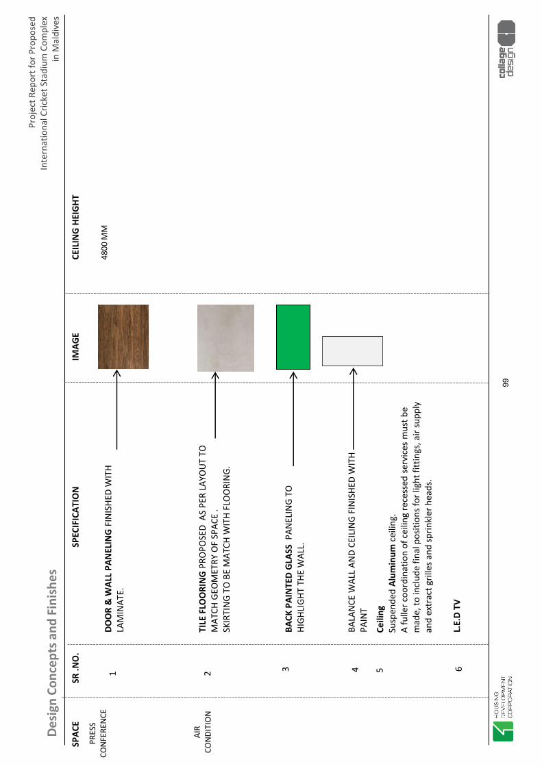
Proj
ect R
epor
t for
Pro
pose
d In
tern
atio
nal C
ricke
t Sta
dium
Com
plex
in
Mal
dive
sDe
sign
Con
cept
s and
Fin
ishe
s
SPAC
ESR
.NO
.SP
ECIF
ICAT
ION
IMAG
E
CEIL
ING
HEI
GHT
PRES
SCO
NFE
REN
CE48
00 M
M
DOO
R &
WAL
L PA
NEL
ING
FIN
ISHE
D W
ITH
LAM
INAT
E.
TILE
FLO
ORI
NG
PRO
POSE
D A
S PE
R LA
YOU
T TO
M
ATCH
GEO
MET
RY O
F SP
ACE
.SK
IRTI
NG
TO B
E M
ATCH
WIT
H FL
OO
RIN
G.
BACK
PAI
NTE
D G
LASS
PAN
ELIN
G TO
HI
GHLI
GHT
THE
WAL
L.
BALA
NCE
WAL
L AN
D CE
ILIN
G FI
NIS
HED
WIT
H PA
INT
1 2 3 4 5
L.E.
D TV
AIR
CON
DITI
ON
Ceili
ngSu
spen
ded
Alum
inum
cei
ling.
A fu
ller c
oord
inat
ion
of c
eilin
g re
cess
ed s
ervi
ces
mus
t be
mad
e, to
incl
ude
final
pos
ition
s for
ligh
t fitt
ings
, air
supp
ly
and
extr
act g
rille
s and
sprin
kler
hea
ds.
6
99

Proj
ect R
epor
t for
Pro
pose
d In
tern
atio
nal C
ricke
t Sta
dium
Com
plex
in
Mal
dive
sDe
sign
Con
cept
s and
Fin
ishe
s
SPAC
ESR
.NO
.SP
ECIF
ICAT
ION
IMAG
E
CEIL
ING
HEI
GHT
MED
IA
FACI
LITI
ES26
00 M
M
DOO
R &
WAL
L PA
NEL
ING
FIN
ISHE
D W
ITH
LAM
INAT
E
TILE
FLO
ORI
NG
PRO
POSE
D A
S PE
R LA
YOU
T TO
M
ATCH
GEO
MET
RY O
F SP
ACE
.
SKIR
TIN
G TO
BE
MAT
CH W
ITH
FLO
ORI
NG
BALA
NCE
WAL
L AN
D CE
ILIN
G F
INIS
HED
WIT
H PA
INT
1 2 3 4 6L.
E.D
TV -
( 32”
)
AIR
CON
DITI
ON
CARP
ET F
LOO
RIN
G IN
WRI
TTEN
PRE
SS S
EATI
NG
AREA
.
Ceili
ngSu
spen
ded
Alum
inum
cei
ling.
A fu
ller c
oord
inat
ion
of c
eilin
g re
cess
ed s
ervi
ces
mus
t be
mad
e, to
incl
ude
final
pos
ition
s for
ligh
t fitt
ings
, air
supp
ly
and
extr
act g
rille
s and
sprin
kler
hea
ds.
5
100

Proj
ect R
epor
t for
Pro
pose
d In
tern
atio
nal C
ricke
t Sta
dium
Com
plex
in
Mal
dive
sDe
sign
Con
cept
s and
Fin
ishe
s
SPAC
ESR
.NO
.SP
ECIF
ICAT
ION
IMAG
E
RAIL
ING
REF
EREN
CE IM
AGE
CE
ILIN
G H
EIG
HT
STAI
RCAS
E
DOO
R FI
NIS
HED
WIT
H LA
MIN
ATE
GRA
NIT
E FL
OO
RIN
G P
ROPO
SED
ON
STA
IRCA
SETR
ADE
AND
RISE
R W
ITH
DARK
AN
D LI
GHT
COM
BIN
ATIO
N.
DARK
GRA
NIT
E SK
IRTI
NG
TO B
E M
ATCH
WIT
H TR
ADE
AND
RISE
R .
BALA
NCE
WAL
L AN
D CE
ILIN
G F
INIS
HED
WIT
H PA
INT
1 2 3
S.S
RAIL
ING
AS
PER
DESI
GN4
101

Proj
ect R
epor
t for
Pro
pose
d In
tern
atio
nal C
ricke
t Sta
dium
Com
plex
in
Mal
dive
sDe
sign
Con
cept
s and
Fin
ishe
s
SPAC
ESR
.NO
.SP
ECIF
ICAT
ION
IMAG
E
CEIL
ING
HEI
GHT
ADM
INIS
TRAT
ION
OFF
ICE
4800
MM
DOO
RS &
WAL
L PA
NEL
ING
FIN
ISHE
D W
ITH
LA
MIN
ATE
BACK
PAI
NTE
D G
LASS
PAN
ELIN
G FO
R W
RITI
NG
BALA
NCE
WAL
L AN
D CE
ILIN
G FI
NIS
HED
WIT
H PA
INT
1 2 3 4 5 7L.
E.D
TV -
( 65”
)
AIR
CON
DITI
ON
Ceili
ngSu
spen
ded
Alum
inum
cei
ling.
A fu
ller c
oord
inat
ion
of c
eilin
g re
cess
ed s
ervi
ces
mus
t be
mad
e, to
incl
ude
final
pos
ition
s for
ligh
t fitt
ings
, air
supp
ly
and
extr
act g
rille
s and
sprin
kler
hea
ds.
TABL
E TO
P FI
NIS
ED W
ITH
CORI
AN W
ITH
S.S
FI
NIS
HED
SKIR
TIN
G
6
TILE
FLO
ORI
NG
PRO
POSE
D A
S PE
R LA
YOU
T TO
M
ATCH
GEO
MET
RY O
F SP
ACE
.
SKIR
TIN
G TO
BE
MAT
CH W
ITH
FLO
ORI
NG
102

Proj
ect R
epor
t for
Pro
pose
d In
tern
atio
nal C
ricke
t Sta
dium
Com
plex
in
Mal
dive
sDe
sign
Con
cept
s and
Fin
ishe
s
SPAC
ESR
.NO
.SP
ECIF
ICAT
ION
IMAG
E
CEIL
ING
HEI
GHT
SWIM
MIN
G60
00 M
M
DOO
R SH
UTT
ER F
INIS
HED
WIT
H LA
MIN
ATE
WAL
L F
INIS
HED
WIT
H KE
MTE
X EX
TERI
OR
PA
INT
1 2 3
STO
NE
FLO
ORI
NG
CO
MBI
NAT
ION
WIT
H LI
GHT
AN
D DA
RK S
HADE
ON
TO
DEC
K AR
EA.
ANTI
SLI
P M
ATT
FIN
ISH
4
L.E.
D TV
SWIM
MIN
G P
OO
L TI
LE
5
103

Proj
ect R
epor
t for
Pro
pose
d In
tern
atio
nal C
ricke
t Sta
dium
Com
plex
in
Mal
dive
sDe
sign
Con
cept
s and
Fin
ishe
s
SPAC
ESR
.NO
.SP
ECIF
ICAT
ION
IMAG
E
CEIL
ING
HEI
GHT
BILL
IARD
S/
SNO
OKE
RS/
TABL
E TA
NN
ISDO
OR
SHU
TTER
& P
ANEL
ING
FIN
ISHE
DW
ITH
LAM
INAT
E
BALA
NCE
WAL
L A
ND
CEIL
ING
FIN
ISHE
D W
ITH
PA
INT
1 2 3
FLO
ORI
NG
MAT
ERIA
L FO
R TA
BLE
TEN
NIS
SYN
THET
IC S
PORT
S FL
OO
RIN
G W
ITH
W
OO
DEN
FLO
ORI
NG
IN C
ERCU
LATI
ON
AR
EA
SKIR
TIN
G TO
BE
MAT
CH W
ITH
FLO
ORI
NG
5
L.E.
D TV
Ceili
ngSu
spen
ded
Alum
inum
cei
ling.
A fu
ller c
oord
inat
ion
of c
eilin
g re
cess
ed s
ervi
ces
mus
t be
mad
e, to
incl
ude
final
pos
ition
s for
ligh
t fitt
ings
, air
supp
ly
and
extr
act g
rille
s and
sprin
kler
hea
ds.
BACK
PAI
NTE
D G
LASS
PAN
ELIN
G TO
HI
GHLI
GHT
THE
WAL
L4 6
AIR
CON
DITI
ON
4800
mm
The
reco
mm
ende
d IL
lum
inan
ce is
bet
wee
n 20
0 -
300.
LIG
HTIN
G LU
X
104

Proj
ect R
epor
t for
Pro
pose
d In
tern
atio
nal C
ricke
t Sta
dium
Com
plex
in
Mal
dive
sDe
sign
Con
cept
s and
Fin
ishe
s
SPAC
ESR
.NO
.SP
ECIF
ICAT
ION
IMAG
E
CEIL
ING
HEI
GHT
PUBL
IC
TOIL
ET
3600
MM
BASI
N C
OU
NTE
R TO
P FI
NIS
HED
WIT
H DA
RK
GRAN
ITE
CEIL
ING
FIN
ISHE
D W
ITH
PAIN
T
1 2 3
TILE
FLO
ORI
NG
PRO
POSE
D A
S PE
R LA
YOU
T TO
M
ATCH
GEO
MET
RY O
F T
OIL
ET S
PACE
, W
ITH
DA
RK S
HADE
CLA
DDIN
G O
N W
ALL
.Fl
oor
Anti
Slip
cer
amic
tile
s (m
att f
inish
)M
Wal
lsCe
ram
ic ti
le fi
nish
full
heig
ht to
und
ersid
e of
su
spen
ded
ceili
ng.
Ceili
ngM
oist
ure
resis
tant
susp
ende
d pl
aste
rboa
rd c
eilin
g.A
fulle
r coo
rdin
atio
n of
cei
ling
rece
ssed
ser
vice
s m
ust b
em
ade,
to in
clud
e fin
al p
ositi
ons f
or li
ght f
ittin
gs, a
ir su
pply
an
d ex
trac
t gril
les a
nd sp
rinkl
er h
eads
.
4
105
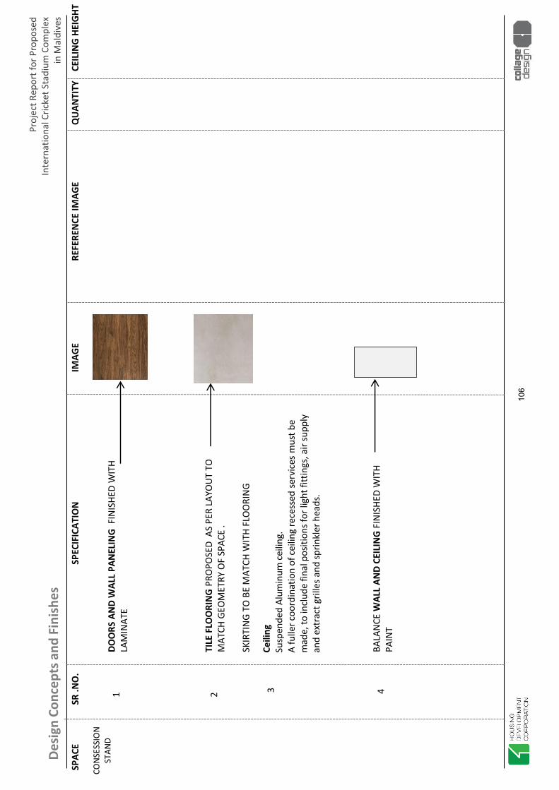
Proj
ect R
epor
t for
Pro
pose
d In
tern
atio
nal C
ricke
t Sta
dium
Com
plex
in
Mal
dive
sDe
sign
Con
cept
s and
Fin
ishe
sSP
ACE
SR .N
O.
SPEC
IFIC
ATIO
NIM
AGE
RE
FERE
NCE
IMAG
E
Q
UAN
TITY
C
EILI
NG
HEI
GHT
CON
SESS
ION
ST
AND
DOO
RS A
ND
WAL
L PA
NEL
ING
FIN
ISHE
D W
ITH
LAM
INAT
E
TILE
FLO
ORI
NG
PRO
POSE
D A
S PE
R LA
YOU
T TO
M
ATCH
GEO
MET
RY O
F SP
ACE
.
SKIR
TIN
G TO
BE
MAT
CH W
ITH
FLO
ORI
NG
BALA
NCE
WAL
L AN
D CE
ILIN
G F
INIS
HED
WIT
H PA
INT
1 2 3 4
Ceili
ngSu
spen
ded
Alum
inum
cei
ling.
A fu
ller c
oord
inat
ion
of c
eilin
g re
cess
ed s
ervi
ces
mus
t be
mad
e, to
incl
ude
final
pos
ition
s for
ligh
t fitt
ings
, air
supp
ly
and
extr
act g
rille
s and
sprin
kler
hea
ds.
106

Proj
ect R
epor
t for
Pro
pose
d In
tern
atio
nal C
ricke
t Sta
dium
Com
plex
in
Mal
dive
sDe
sign
Con
cept
s and
Fin
ishe
s
STAD
IUM
RAI
LIN
G
STAD
IUM
–EX
TERN
AL G
LAZE
D FA
CAD
E
107

Proj
ect R
epor
t for
Pro
pose
d In
tern
atio
nal C
ricke
t Sta
dium
Com
plex
in
Mal
dive
sDe
sign
Con
cept
s and
Fin
ishe
s
STAD
IUM
RAI
LIN
G
STAD
IUM
–EX
TERN
AL FA
ÇAD
E
FAÇA
DE
SCRE
EN
108

Proj
ect R
epor
t for
Pro
pose
d In
tern
atio
nal C
ricke
t Sta
dium
Com
plex
in
Mal
dive
sDe
sign
Con
cept
s and
Fin
ishe
s
STAD
IUM
RAI
LIN
G
STAD
IUM
–EX
TERN
AL L
ANDS
ACPI
NG
& L
IGH
TIN
G
109

Proj
ect R
epor
t for
Pro
pose
d In
tern
atio
nal C
ricke
t Sta
dium
Com
plex
in
Mal
dive
sDe
sign
Con
cept
s and
Fin
ishe
s
STAD
IUM
RAI
LIN
G
STAD
IUM–
EXTE
RNAL
PAV
ING
REF
EREN
CE
GRA
NAM
EX F
LAG
STAM
PCRE
TE F
INIS
HLA
RGE
CON
CRET
E PA
VERS
PAVE
RS L
ANDS
CAPI
NG
EDG
ELA
RGE
SIZE
PAV
ERS
110

Proj
ect R
epor
t for
Pro
pose
d In
tern
atio
nal C
ricke
t Sta
dium
Com
plex
in
Mal
dive
sDe
sign
Con
cept
s and
Fin
ishe
s
STAD
IUM
RAI
LIN
G
STAD
IUM
–RO
OF
WIT
H CO
MBI
NAT
ION
OF
MET
AL &
FABR
IC.
111

Proj
ect R
epor
t for
Pro
pose
d In
tern
atio
nal C
ricke
t Sta
dium
Com
plex
in
Mal
dive
sDe
sign
Con
cept
s and
Fin
ishe
s
STAD
IUM
RAI
LIN
G
STAD
IUM
–RO
OF
DETA
IL
112

Proj
ect R
epor
t for
Pro
pose
d In
tern
atio
nal C
ricke
t Sta
dium
Com
plex
in
Mal
dive
sDe
sign
Con
cept
s and
Fin
ishe
s
STAD
IUM
RAI
LIN
G
STAD
IUM
-BO
WL
RAIL
ING
113

Proj
ect R
epor
t for
Pro
pose
d In
tern
atio
nal C
ricke
t Sta
dium
Com
plex
in
Mal
dive
sDe
sign
Con
cept
s and
Fin
ishe
s
STAD
IUM
RAI
LIN
G
STAD
IUM
–ST
AIRC
ASE
LEAD
ING
TO
PO
DIU
M
114

FIELD OF PLAY
115

Project Report for Proposed International Standard Cricket Stadium Complex
in Maldives
Field of Play
1. Cricket Field of Play
High Performance Sand-based
Natural Grass Cricket Field
With
Turf Conditioning System
116

Project Report for Proposed International Standard Cricket Stadium Complex
in Maldives
Field of Play
Cricket Field of Play
117

Project Report for Proposed International Standard Cricket Stadium Complex
in Maldives
Field of Play
The Key to a successful execution of high-performance cricket field is the contractor working closely with architects, engineers, contractors, and stadium staff to ensure that the drainage system is compatible along with the sub-surface drainage pipe elevations are suitable for optimum operation, all building spec-ifications norms and codes are met, and all necessary utilities are arranged. Contractor to undertake the supervision of entire construction of sub-base and all the system prerequisites in both, on-site as well as off-site capacity. As and when the project is under execution phase, contractor’s representative can be deputed to super-vise the construction of base periodically and for the installation of the system. In addition, a representa-tive will commission each project by performing field tests and training sessions for members of the con-struction or turf management staff. Cricket Ground Construction: - USGA inspired construction profile - This is the most widely accepted international standard for con-struction of high performance natural grass sports surfaces for not just limited to golf, but also for other professional sports including cricket, soccer, baseball, rugby, etc., and is considered to be a cutting-edge method to construct the modern day stadiums across the world. The methodology of profile design is highly researched and involves detailed checking of all materials and specifications at each stage, to give a fail-safe process for installation. This results in a standardized sub-base construction of the outfield that gives a virtual rain-proofing in terms of drainage, and achieves the highest level of perfor-mance criteria for the playing surface. The design and construction involves the following:
� Drainage system designed for the site conditions based on weather data or a perceived need.
� Sub-surface perforated pipe-based system (linked to the sub surface aeration & Water man-agement system) to give a surface that ensures no standing water while it is raining.
� Irrigation system designed for the site conditions and weather data; automatic, computer-controlled pop-up sprinkler system as is installed at all top cricket grounds world-wide.
The root-zone material will be selected indigenously to satisfy the USGA criteria, and the chosen sand and necessary inclusions analysed at a USGA-certified laboratory.
Cricket Outfield & Infield • USGA concept based material selection • Sand based free-draining rootzone • Perfectly graded, firm, consistent and resilient surface
118

Project Report for Proposed International Standard Cricket Stadium Complex
in Maldives
Field of Play
Construction of a well calibrated cricket pitch is a combination of art as well as science. It is essential for the contractor to be knowledgeable as well as experienced in identifying the right mix of design, material, equipments, skilled manpower to achieve flawless pitches for training as well as competitions. Also work along closely with a qualified curator to create a pitch design that would address the following needs: -
9 Performance requirements
9 Stability and resilience for all formats of the game
9 Can be further customised to achieve the desired output
9 Conform to the national as well as international guidelines
9 Soil/material testing, assessment, and selection also considering permeability and drainage as-
pects
9 Well balanced nutrient content and turfing as required
9 Easy to prepare for the season and to maintain post season
Pitch/Wickets Square • Multi-layered high performance pitches – 5 Nos. • Indigenous material composition • Customised ball-surface behaviour
Design & Construction of wickets square
119

Project Report for Proposed International Standard Cricket Stadium Complex
in Maldives
Field of Play
Drainage Design
After years of research, cricket fields are now constructed with the most optimum sub-surface drainage solution for the cricket fields to sustain low/moderate/variable/extreme climatic conditions. All the way from desert-like arid regions to the typical humid, sub-tropical regions, every project has it’s own specific drainage requirement based on the project location. This is a primary factor considered by the field de-signers as a common practice. However, this factor alone cannot determine the drainage design and planning. Regardless of the project location, the game of cricket though, demands a firm and relatively dry play surface during every match. It has great bearing on the surface-ball interaction as well as player perfor-mance. Cricket fields around the world that do not have an efficient subsurface drainage system are also known to have suffered multiple game cancellations or delays. This is exactly where a good drainage de-sign and planning comes into play. This not only provides huge assurance to the stadium owners but also a flexibility to schedule matches at any time of the year. The drainage designs and specifications are derived from knowledge base, best practice methods and proven track record from various grass-based sports facilities previously developed and inspired by the guidelines laid down by entities such as USGA, AASHTO, ASTM, EN, IS standards. The pipe material – DWC and its perforation patterns conform to AASHTO specifications. Volumetric calibrations along with specif-ic design layout determine factors such as area coverage, spacing, outfall, nature of sub-base, diameter requirement to achieve optimum drainage along with other factors.
Drainage Design • Network of sub-surface DWC perforated drainage pipes • Closed-loop system with 150mm to 900mm pipes • Single point discharge with efficient water harvesting
Sub-Surface Drainage System at Cricket Stadium
120
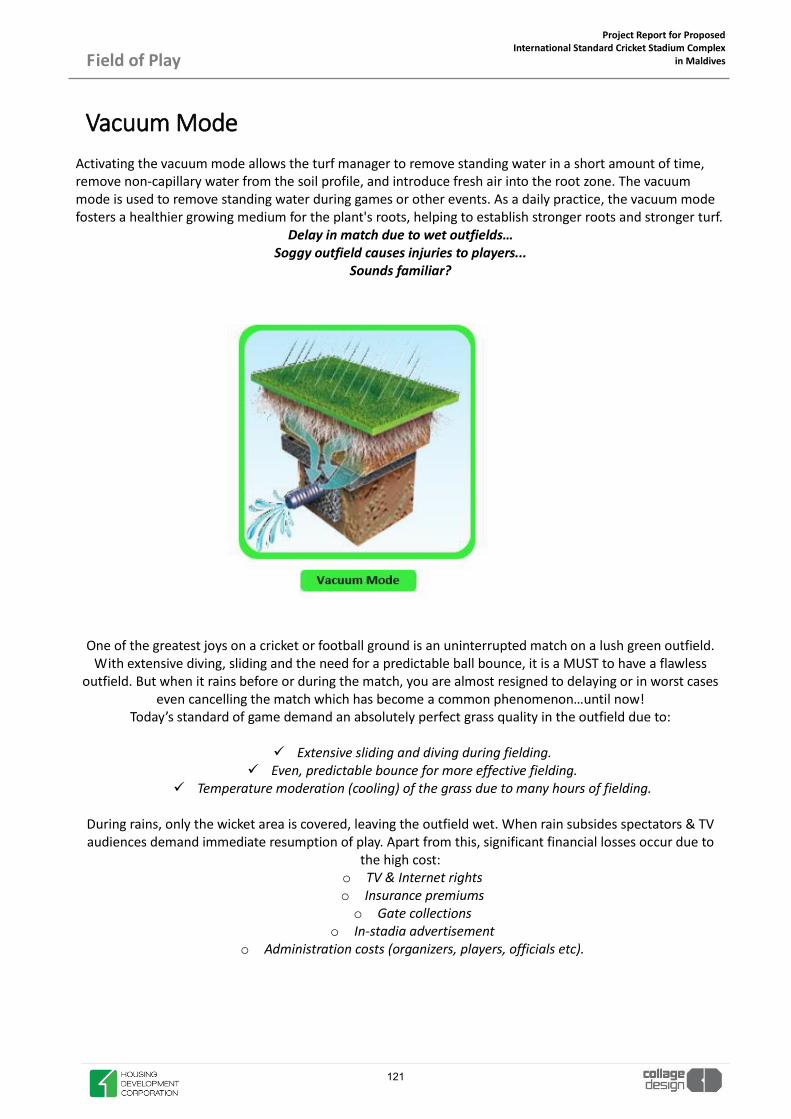
Project Report for Proposed International Standard Cricket Stadium Complex
in Maldives
Field of Play
Activating the vacuum mode allows the turf manager to remove standing water in a short amount of time, remove non-capillary water from the soil profile, and introduce fresh air into the root zone. The vacuum mode is used to remove standing water during games or other events. As a daily practice, the vacuum mode fosters a healthier growing medium for the plant's roots, helping to establish stronger roots and stronger turf.
Delay in match due to wet outfields… Soggy outfield causes injuries to players...
Sounds familiar?
One of the greatest joys on a cricket or football ground is an uninterrupted match on a lush green outfield. With extensive diving, sliding and the need for a predictable ball bounce, it is a MUST to have a flawless
outfield. But when it rains before or during the match, you are almost resigned to delaying or in worst cases even cancelling the match which has become a common phenomenon…until now!
Today’s standard of game demand an absolutely perfect grass quality in the outfield due to:
9 Extensive sliding and diving during fielding. 9 Even, predictable bounce for more effective fielding.
9 Temperature moderation (cooling) of the grass due to many hours of fielding.
During rains, only the wicket area is covered, leaving the outfield wet. When rain subsides spectators & TV audiences demand immediate resumption of play. Apart from this, significant financial losses occur due to
the high cost: o TV & Internet rights o Insurance premiums o Gate collections
o In-stadia advertisement o Administration costs (organizers, players, officials etc).
Vacuum Mode
121
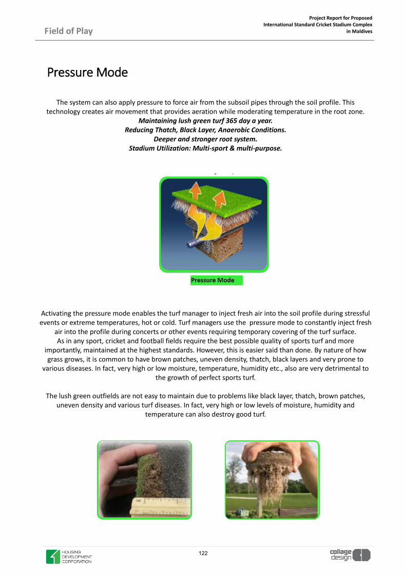
Project Report for Proposed International Standard Cricket Stadium Complex
in Maldives
Field of Play
The system can also apply pressure to force air from the subsoil pipes through the soil profile. This technology creates air movement that provides aeration while moderating temperature in the root zone.
Maintaining lush green turf 365 day a year. Reducing Thatch, Black Layer, Anaerobic Conditions.
Deeper and stronger root system. Stadium Utilization: Multi-sport & multi-purpose.
Activating the pressure mode enables the turf manager to inject fresh air into the soil profile during stressful events or extreme temperatures, hot or cold. Turf managers use the pressure mode to constantly inject fresh
air into the profile during concerts or other events requiring temporary covering of the turf surface. As in any sport, cricket and football fields require the best possible quality of sports turf and more
importantly, maintained at the highest standards. However, this is easier said than done. By nature of how grass grows, it is common to have brown patches, uneven density, thatch, black layers and very prone to
various diseases. In fact, very high or low moisture, temperature, humidity etc., also are very detrimental to the growth of perfect sports turf.
The lush green outfields are not easy to maintain due to problems like black layer, thatch, brown patches,
uneven density and various turf diseases. In fact, very high or low levels of moisture, humidity and temperature can also destroy good turf.
Pressure Mode
122
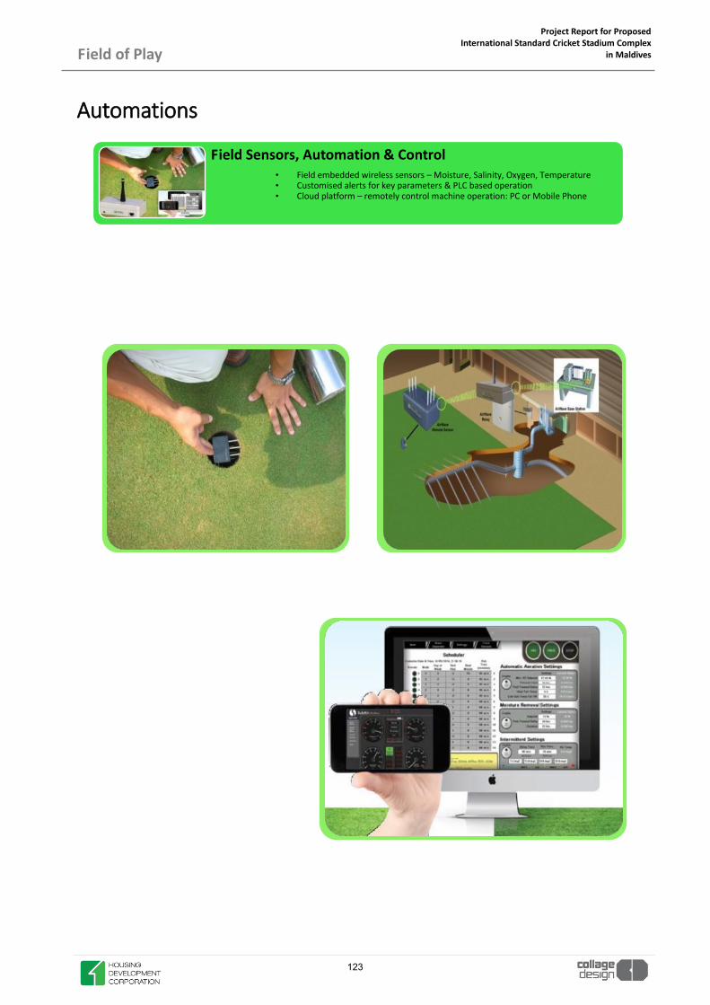
Project Report for Proposed International Standard Cricket Stadium Complex
in Maldives
Field of Play
Automations
Field Sensors, Automation & Control • Field embedded wireless sensors – Moisture, Salinity, Oxygen, Temperature • Customised alerts for key parameters & PLC based operation • Cloud platform – remotely control machine operation: PC or Mobile Phone
123

Project Report for Proposed International Standard Cricket Stadium Complex
in Maldives
Field of Play
Drain Layout & Base Sectional View
124

Project Report for Proposed International Standard Cricket Stadium Complex
in Maldives
Field of Play
Field Irrigation Layout
Field Irrigation System • Computerised automatic ‘Pop-Up’ sprinkler system • Programmable operation to variable irrigation plans and season • Optimisation of water usage and conservation
125

Project Report for Proposed International Standard Cricket Stadium Complex
in Maldives
Field of Play
Example Layout – Medium Range Throw
126

Project Report for Proposed International Standard Cricket Stadium Complex
in Maldives
Field of Play
Contractor to help assess the requirement of necessary surface treatment prior to turf installation. A fu-migation or suitable weed and/or termite control treatment is carried out on need basis to ensure that the base and rootzone is completely free of undesired elements. Further on, installation of the selected turf grass is carried out using the pre-determined method. While seeding or ‘sprigging’ are the most widely adopted methods of planting turf grass, in certain cases, pieces of cultivated sod is used for a relatively quick establishment of the turf surface. This, however large-ly depends on the availability of required turf grown at a nursery located within close proximity to the site location. In case of seeding, purchase of the seeds from a reputable supplier and a certified pedigree varie-ty of seeds, is highly desirable. In case of sprigging, we would typically deploy several quality control measures to ensure that the sprigs are harvested in a systematic manner and are free from weeds or other contaminants. It is also desirable that the location of the turf nursery is within a close proximity of the site location and is harvested, cleaned, transported, checked and planted at site speedily.
Turfing/Grassing
• Tested turf variety selection to suit local climatic conditions and man-agement practices
• Turf establishment programme – Seeding, Sodding or Sprigging tech-niques (as required)
• Turf Reinforcement (Hybrid Turf)
Sprigging outfield manually Grid pattern with 5cm spacing
127

Project Report for Proposed International Standard Cricket Stadium Complex
in Maldives
Field of Play
Benefits of Sub-Surface Aeration & Vacuum Powered Suc-tion
9 No cancellation/ curtailing of matches due to wet/ soggy outfields.
� No revenue loss for advertisers, sponsors, etc.
� Uninterrupted match experience for audience.
9 The system helps achieve optimum aerobic subsurface growing conditions
to make the turf healthier.
9 Faster return on investment and improved financial results for facilities.
9 Fully compatible with the new-age USGA style sand-based outfields, popu-
larly being used in the English and Australian cricket.
9 Provides turf managers more options to overcome their environmental
challenges
9 The system allows the stadium to be used for multi-sport and multi-
purpose activities.
9 Provides oxygen to the turf when it’s covered for several days.
9 Makes the surface safe for players and more enjoyable for spectators.
9 Real time operational information on Temperature, Moisture and Salinity.
9 Automatic alarms and notification of system changes or abnormalities.
128

Project Report for Proposed International Standard Cricket Stadium Complex
in Maldives
Field of Play
Equipment Details
The System iscustom designed to fit the designated room.
129

Project Report for Proposed International Standard Cricket Stadium Complex
in Maldives
Field of Play
Increased Revenue-generation Stream from the Subsurface Drainage System
130

Project Report for Proposed International Standard Cricket Stadium Complex
in Maldives
Field of Play
Hybrid Turf
131

Project Report for Proposed International Standard Cricket Stadium Complex
in Maldives
Field of Play
Hybrid Turf Reinforcement The concept of Hybrid turf began in the 80’s aimed to provide the ad-vantages and comfort of natural grass turf along with the durability and flex-ibility of synthetic turf for training and competition grounds. Artificial turf fibres are injected or ‘stitched’ withinthe rootzone area of a playfield to provide strength and reinforcement to the natural grass roots. The concept of Hybrid turf in cricket is the most cutting-edge solution which has been developed after several years of R&D aimed to address specific challenges related to the management of turf to world-class standards. 9�High-class playing surface of natural grass 9�Creates healthier and deeper grass plant root sys-tem 9�Rootzone is reinforced/ structured 9�Faster recovery of playing surface 9�Optimal drainage capacity 9�Offers additional hours of play per season 9�Consistent playing characteristics guaranteed in all weather conditions 9�Players acquire grip and control and can trust the performance of the surface
132
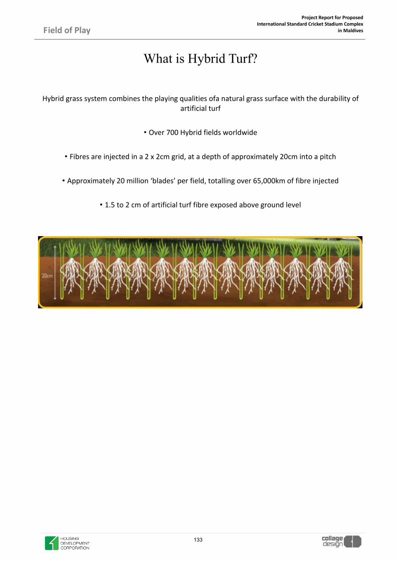
Project Report for Proposed International Standard Cricket Stadium Complex
in Maldives
Field of Play
What is Hybrid Turf?
Hybrid grass system combines the playing qualities ofa natural grass surface with the durability of artificial turf
• Over 700 Hybrid fields worldwide
• Fibres are injected in a 2 x 2cm grid, at a depth of approximately 20cm into a pitch
• Approximately 20 million ‘blades’ per field, totalling over 65,000km of fibre injected
• 1.5 to 2 cm of artificial turf fibre exposed above ground level
133

Project Report for Proposed International Standard Cricket Stadium Complex
in Maldives
Field of Play
Typical Cross-Section of Hybrid Turf Pitch
134

Project Report for Proposed International Standard Cricket Stadium Complex
in Maldives
Field of Play
The Result
High class playing surface of natural grass
• Creates healthier and deeper grass plant root system
• Rootzone is reinforced / structure
• Faster recovery to playing surface
• Optimal drainage capacity
Performance Benefits • Product ensures a level uniform field which is stronger and more sta-ble
• Offers additional hours of play per season compared to natural grass
• Grass surface remains perfect throughout the year, even in highly used areas
• Consistent playing characteristics guaranteed, whatever the weather
• Players acquire grip and control and can trust the performance of the surface
135

Project Report for Proposed International Standard Cricket Stadium Complex
in Maldives
Field of Play
Renowned References 16 Premier League Stadium Pitches
• 14 EFL Stadium Pitches
• 17 UK based Training Ground references
• 5 National Stadium Pitches
136

Project Report for Proposed International Standard Cricket Stadium Complex
in Maldives
Field of Play
TECHNOLOGY: A Hybridpitch is composed of 100% natural grass reinforced with unique synthetic fibres, meticulously installed on the sub-base. 1. High performance polypropylene monofilament fibres (HPF) are produced in-house by a patented method
2. Fibres are injected 18 cm deep, ina grid of approximately 2 cm x 2 cm to provide vertical reinforce-ment throughout the pitch
3. Fibres protrude 1.5-2 cm above the root zone surface.20 million HPF fibres reinforce eve-ry single Hy-bridpitch PRIMARY FUNCTIONS OF THE PITCH ¾�To give stability toa predominately sand-based structure by reinforcing the profile
¾�Provide an anchor around which the grass roots can entwine
¾�Maintain the stability,uniformity and even level of the playing surface
137

Project Report for Proposed International Standard Cricket Stadium Complex
in Maldives
Field of Play
Tailor made Sub-base for Hybrid Grass Before or after injecting artificial fibres
PRODUCTION OF ARTIFICIAL FIBRES Granules Processed into artificial fibres Winded into cones and ready to use
138
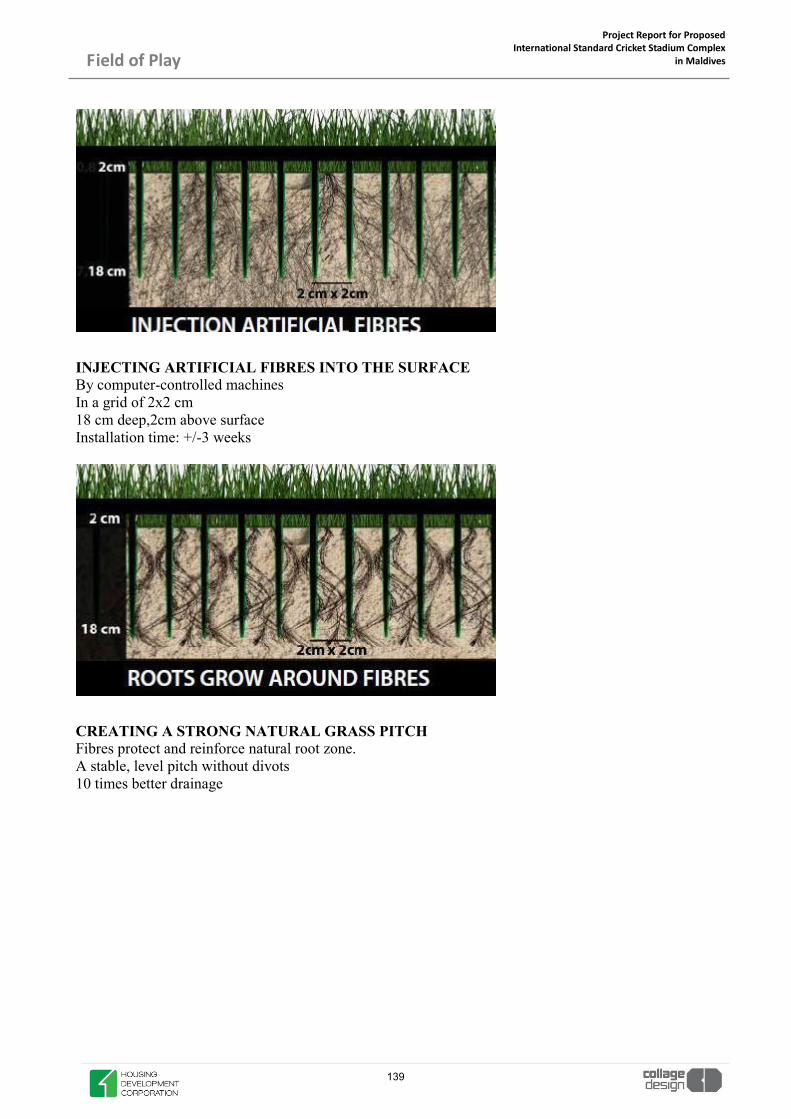
Project Report for Proposed International Standard Cricket Stadium Complex
in Maldives
Field of Play
INJECTING ARTIFICIAL FIBRES INTO THE SURFACE By computer-controlled machines In a grid of 2x2 cm 18 cm deep,2cm above surface Installation time: +/-3 weeks
CREATING A STRONG NATURAL GRASS PITCH Fibres protect and reinforce natural root zone. A stable, level pitch without divots 10 times better drainage
139

Project Report for Proposed International Standard Cricket Stadium Complex
in Maldives
Field of Play
Turf Protection System
140

Project Report for Proposed International Standard Cricket Stadium Complex
in Maldives
Field of Play
Turf Protection System
141

Project Report for Proposed International Standard Cricket Stadium Complex
in Maldives
Field of Play
Sources of Revenue Generation Due To Turf Protection
Weddings
Trade Shows
Music Concerts Opening/Closing Ceremony
Social Gatherings
Public Events
Some Major Stadiums That Use Turf Protection
142

Project Report for Proposed International Standard Cricket Stadium Complex
in Maldives
Field of Play
Dubai Sports City Wembley Stadium
AT&T Park, San Francisco
Old Trafford Emirates Stadium
ANZ Stadium, Sydney
143

Project Report for Proposed International Standard Cricket Stadium Complex
in Maldives
Field of Play
TURF PROTECTION SYSTEM
Turf protection tiles are manufactured from Natural virgin translucent high-density polyethylene which not only gives a product far superior in strength to any of its competitors, it also allows the light to go through the translucent material, therefore allowing photosynthesis to continue. The translucent material also has another huge benefit in that it allows the sunlight to penetrate the tile and draws moisture from the ground, forming a moisture canopy on the underside of the tile. When the sun goes in this moisture condenses and drops back to the ground thus recycling the required water to keep the grass healthy. The turf does not therefore require watering during the period it is covered.
144

Project Report for Proposed International Standard Cricket Stadium Complex
in Maldives Field of Play
FOR VEHICULAR TRAFFIC
The tile is specifically designed for use in Stadiums & large Arenas during concert load-in and load-out. For years Promoters had been looking for the product that would enable them to bring 150 tonne cranes, forklifts and trucks onto the stadium field without causing significant damage. In the past they have used plywood or aluminum panels, with disastrous effect.
The tile which can be laid by hand and is manufactured from translucent high-density polyethylene plastic, incorporating a unique internal ribbing system with neoprene seal that makes it incredibly strong whilst allowing the grass to continue growing normally. The tile utilizes a specially designed bolting system to join the tiles into blocks of 2 prior to leaving the factory. This creates a usable panel area of 2.1m x 1.1m with integrated 10cm overlap incorporating locator bosses for easy fitting, together with an expansion joint.
Each panel of 2 x tiles joins to its adjacent blocks using a special 2-part vertical looking cam that are locked using a long-handled T-Bar.
145

Project Report for Proposed International Standard Cricket Stadium Complex
in Maldives
Field of Play
A) Technical Specifications for Turf Protection System
1) Load Capacities: - a. Point Load – minimum 325 Kg/20m Diameter ; 1470 lbs per inch2 b. Spread Load – minimum 76kN /150mm sq; 3,377kN / m²
2) Material Composition – Virgin High Density Polyethylene. No re-cycled material to be used. 3) UV Stabilisers – 30 years 4) Top Surface – integral non-slip pattern with over lapping panels 5) Certified Fire Retardant Interlocking Tiles B) Technical Specifications for Temporary Drivable Roadway
1) Load Capacities: -
a. Point Load – minimum 1170 Kg/20m Diameter; 5300 lbs per inch2 b. Spread Load – minimum 164kN /150mm sq; 7,288kN / m²
2) Material Composition – Virgin High Density Polyethylene. No re-cycled material to be used. 3) UV Stabilisers – 30 years 4) Top Surface – integral non-slip pattern 5) Certified Fire Retardant Interlocking Tiles 6) Product must have the capability to support a 100 ton crane and fork lifts and have technical
independent testing to prove. 7) Panels must be capable of being installed and removed by two people. 8) Panels must have an overlap and attach together by means of vertical camlocks.
146

Project Report for Proposed International Standard Cricket Stadium Complex
in Maldives
Field of Play
Turf protection tiles are Manufactured from Translucent Virgin High Density Polyethylene (HDPE), that is not only very strong, it also allows sufficient light to pass through to ensure continuous photosynthesis – a MUST for the ultimate protection of the grass!
It incorporates an integral anti-slip top surface with specially designed, raised air holes that allow the turf to breathe but at the same time prevent liquids from penetrating to the turf below.
It has radiussed webbing for maximum strength & patented round feet that lift the tile slightly from the turf thus minimising any ‘cutting’ of the turf.
It has an overlap which, when combined with the factory fitted pins and the locking cams delivers expansion/contraction capability whilst preventing rubbish & non-desirable liquids from passing through to the turf – whether natural or artificial.
147

Project Report for Proposed International Standard Cricket Stadium Complex
in Maldives
Field of Play
Dimensions 1m (39.37”) x 1m(39.37”) x 39mm (1½ ”). Pinned
together in blocks of four at the factory and shipped on pallets. Actual fitted size : 2m x 2m = 4m² (6’ 6” x 6’ 6” = 42.25ft²)
Weight 7.5 kgs per m²/17.5lbs per tile /1.64lbs per ft² Material High molecular weight, high density, polyethylene
with UV stabiliser Method of Manufacture Injection moulded using a blowing agent, which
produces an engineering foam moulding with strength enhancing cellular core
Temperature Range -20ºC to 45ºC (-4ºF to 113ºF) Static Loading Point load 20mm diameter = 418kgs - 1” square =
1,893lbs Spread load 86kN /150mm sq 3,822kN / m² - 70,546lbs / ft² 634,919lbs / yd²
Fire Requirements See separate fire test report Colours Translucent natural material, which allows the pas-
sage of light, ensuring grass growth – without yel-lowing.
Cleaning High pressure cold water spray washer Life Expectancy Guaranteed for 5 years but has a realistic life expec-
tancy of c. 10 years Slip Resistance See separate slip test report
148

Project Report for Proposed International Standard Cricket Stadium Complex
in Maldives
Field of Play
These products are all specifically designed for use in stadiums and arenas to protect their quality turf, so that venues can host vital revenue-generating non-core events. They have borne quality systems that allow facilities to accommodate high profile concerts and other events in quick succession with sporting fixtures, secure in the knowledge that their playing surface is not at risk.
Strategically designed for the protection of ‘quality natu-ral turf’ when continuous photosynthesis and air circula-tion are required. This ensures good grass colour and health, when covered for a number of days for non-sporting events. The top surface has an integrated very efficient anti-slip pattern. The slightly embossed design provides small channels to keep any spilt liquids away from the patrons feet, whilst being shallow enough not to be a trip hazard. Each panel of 4 tiles connects to its adjacent panels by means of patented vertical camlock and bolt systems, which are manufactured from special nylon that is as strong as steel.
Each tile incorporates a 100mm (4 inch) overlap, which is a very effective barrier that stops liquids from penetrating to the turf. This overlap also includes strategically designed ‘location bosses’ that make alignment of tiles for fitting and locking together really simple. Additionally, they act as stabilisers to resist the tiles twisting under duress.
The innovative circular ribbing geometry of combines strength with light weight. The specially designed ribs and patented feet spread the load evenly and any ‘impressions’ on lifting disappear after a short time, or during cutting. This strategically constructed underside provides 33mm ‘head room’ allowing the grass blades to stand erect, preventing excessive stress. It is fitted with 25 x patented circular feet that extend 10mm from the underside of the tile to create an air flow, which reduces disease.
These products are all specifically designed for use in stadiums and arenas to protect their quality turf, so that venues can host vital revenue-generating non-core events. Two people lay a panel of 4 tiles at one time, covering 4.84m² (52ft²). This results in the fastest laying times of any product, which is reflected in substantially reduced labour costs and turnaround times.
149

Project Report for Proposed International Standard Cricket Stadium Complex
in Maldives
Field of Play
Dimensions Physical size: 1.21m (4’) x 1.21m (4') x 38 mm
(1½”). Prior to shipping tiles are bolted in pan-els of 4. The bolted panels are shipped on pal-lets. Each tile has a “Usable” top surface when fitted of 1.21m² (13.02ft²), meaning a panel of 4 measures 4.84m² (52.ft²)
Weight 13kgs per tile (29lbs per tile) or 52kgs per panel of 4 (116lbs)
Material Virgin High Density, Polyethylene with UV stabi-liser (guaranteedfor 30 years)
Method of Manufacture Structural foam Injection moulded using a blowing agent, which produces an engineer-ing foam moulding with strength enhancing cellular core
Temperature Range -20ºC to 45ºC (-4ºF to 113ºF) Static Loading Point load 20mm diameter = 560kgs -1” square
= 2,813lbsSpread load 88kN /150mm sq3,910kN / m² -80,682lbs / ft² 726,147lbs /yd²
Fire Certification UL94HB Colours Translucent natural material, which allows the
passage of light, allowing photosynthesis to continue whilst grass is covered. Colour op-tions are available for artificial turf.
Cleaning High pressure water spray washer Warranty/ Life Expectancy Guaranteed for 5 years but has a realistic life
expectancy of c. 20 years Slip Resistance Integral slip-resistant surface.
150

Project Report for Proposed International Standard Cricket Stadium Complex
in Maldives
Field of Play
SUB SURFACE DRAINAGE AND VACUUM POWERED
SYSTEM The System provides stadium and playing field owners and their caretakers the ability to promote healthier, stronger, and safer turf by accelerating moisture removal and increasing the amount of oxygen to the root zone. As a result, the system helps provide an optimal growing environment for any playing surface – increasing playability and producing a more enjoyable experience for players and spectators.
The system connects to the main drainage collector and moves air through the drainage network utilizing the perforated holes in the pipe to access the soil profile. The main drain collector is intercepted by the system air line. The air line then connects to the system air-water separator. An air-water separator is designed and installed between the field and the SubAir to remove any water from the system.
An “Air-Water chamber” is the convergence point, wherein an “air-water separator” redirects the water to the storm water sewers or to the rain water harvesting tank; and the air is expelled out by the reversing valve of the System.
Air water chamber
151
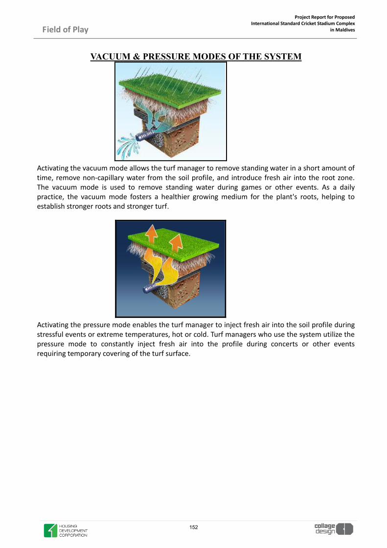
Project Report for Proposed International Standard Cricket Stadium Complex
in Maldives
Field of Play
VACUUM & PRESSURE MODES OF THE SYSTEM
Activating the vacuum mode allows the turf manager to remove standing water in a short amount of time, remove non-capillary water from the soil profile, and introduce fresh air into the root zone. The vacuum mode is used to remove standing water during games or other events. As a daily practice, the vacuum mode fosters a healthier growing medium for the plant's roots, helping to establish stronger roots and stronger turf.
Activating the pressure mode enables the turf manager to inject fresh air into the soil profile during stressful events or extreme temperatures, hot or cold. Turf managers who use the system utilize the pressure mode to constantly inject fresh air into the profile during concerts or other events requiring temporary covering of the turf surface.
152
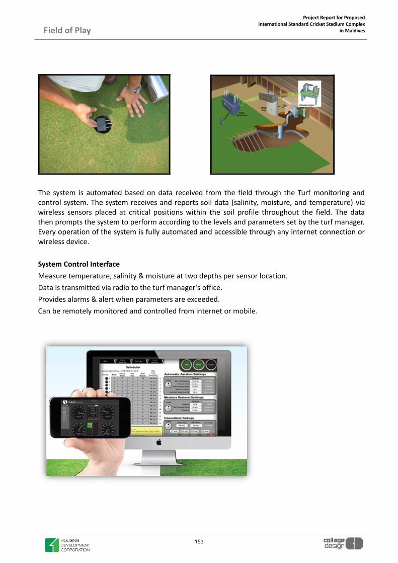
Project Report for Proposed International Standard Cricket Stadium Complex
in Maldives
Field of Play
The system is automated based on data received from the field through the Turf monitoring and control system. The system receives and reports soil data (salinity, moisture, and temperature) via wireless sensors placed at critical positions within the soil profile throughout the field. The data then prompts the system to perform according to the levels and parameters set by the turf manager. Every operation of the system is fully automated and accessible through any internet connection or wireless device. System Control Interface Measure temperature, salinity & moisture at two depths per sensor location. Data is transmitted via radio to the turf manager’s office. Provides alarms & alert when parameters are exceeded. Can be remotely monitored and controlled from internet or mobile.
153

Project Report for Proposed International Standard Cricket Stadium Complex
in Maldives
Field of Play
USGA Compatible Outfield Cross Sections
154

GPON
155
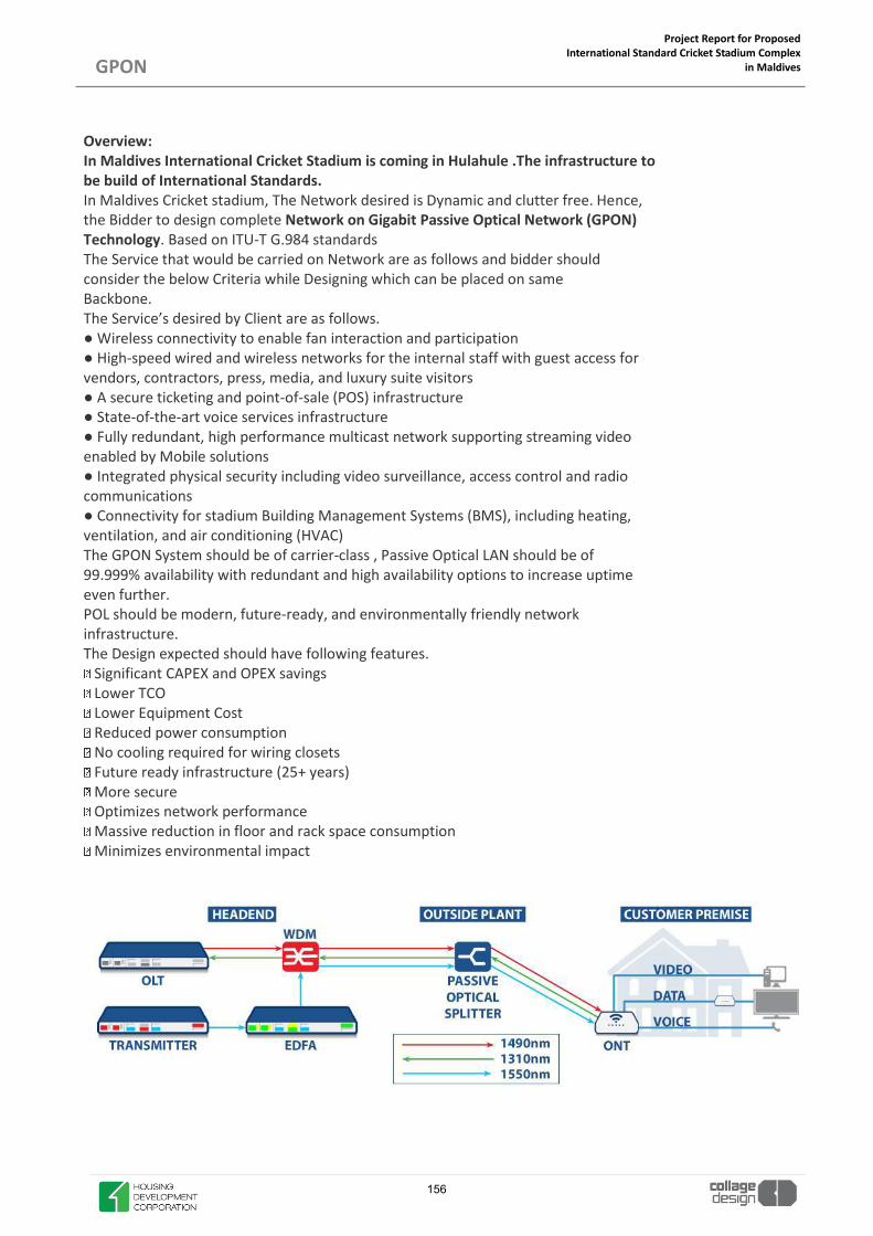
Project Report for Proposed International Standard Cricket Stadium Complex
in Maldives
GPON
Overview: In Maldives International Cricket Stadium is coming in Hulahule .The infrastructure to be build of International Standards. In Maldives Cricket stadium, The Network desired is Dynamic and clutter free. Hence, the Bidder to design complete Network on Gigabit Passive Optical Network (GPON) Technology. Based on ITU-T G.984 standards The Service that would be carried on Network are as follows and bidder should consider the below Criteria while Designing which can be placed on same Backbone. The Service’s desired by Client are as follows. ● Wireless connectivity to enable fan interaction and participation ● High-speed wired and wireless networks for the internal staff with guest access for vendors, contractors, press, media, and luxury suite visitors ● A secure ticketing and point-of-sale (POS) infrastructure ● State-of-the-art voice services infrastructure ● Fully redundant, high performance multicast network supporting streaming video enabled by Mobile solutions ● Integrated physical security including video surveillance, access control and radio communications ● Connectivity for stadium Building Management Systems (BMS), including heating, ventilation, and air conditioning (HVAC) The GPON System should be of carrier-class , Passive Optical LAN should be of 99.999% availability with redundant and high availability options to increase uptime even further. POL should be modern, future-ready, and environmentally friendly network infrastructure. The Design expected should have following features.
Significant CAPEX and OPEX savings Lower TCO Lower Equipment Cost Reduced power consumption No cooling required for wiring closets Future ready infrastructure (25+ years) More secure Optimizes network performance Massive reduction in floor and rack space consumption Minimizes environmental impact
T
156

Project Report for Proposed International Standard Cricket Stadium Complex
in Maldives
GPON
PICAL GPON NETWORK WITH RF OVERLAY
Equipment Details 1. Optical Line Terminal (OLT)
• Number of GPON modules per shelf (2 –16) • Number of GPON ports per module (4) • Number of controller modules for redundancy (1-2) • Number and bandwidth of uplinks (8 X 1 Gbps, 4 X 10 Gbps) • Switching capacity (200 Gbps–2.56 Tbps) • Split Ratio 1:32 • Optical Budget 28 dB • ONTs supported (128 –2048) • Power: AC and DC options.
2. 2> Optical Network Terminal (ONT) • Number and bandwidth of ports (1 –24 10/100/1000 Mbps) • Power: AC, DC, and battery backup • Wall mounting or desk mounting.
3. Fiber & Passive Components • Pre-terminated fiber is preferred • Bend-insensitive fiber eases deployment • Angled Polished Connectors have lower loss • PON devices (Specifically designed for PON) • Passive Optical Splitter • Fiber Distribution Hub (FDH) • Remote Distribution Terminal (RDT) • Fiber Splitter Box (FSB).
4. Passive Optical Splitters. • Distributes the GPON transmission to ONTs • No power or cooling required • Virtually unlimited MTBF • Common sizes: 1X8, 1X16, 1X32, 2X32 • Higher split ratios allow for more ONTs per GPON port • Higher split ratios decrease the available bandwidth per ONT and distance.
5. Fiber Distribution Hub (FDH) • All passive • Houses passive optical splitters • Connects to Rapid Fiber Distribution Terminals • Factory terminated connections • Placed indoors or outdoors • Lockable cabinet
6. Rapid Fiber Distribution Terminal (RDT) • Used to connect FDH to ONT drop cables • Placed in the plenum • Built-in spool with 2 MTP®or MPO terminated 12 count fiber cables • SC/APC connectors are used on ONT drop cables
7. Fiber Splitter Box (FSB) • A mini Fiber Distribution Hub • Useful for lower count locations • Wall mounted.
8. Head end • Centralized equipment for the management and operation of the wireless network. • To handle Access and Distribution layers • To deliver Core intelligence to the Network.
157

Project Report for Proposed International Standard Cricket Stadium Complex
in Maldives
GPON
• Equipment that is going to perform Routing, Authentication, Security and Management functionalities.
9. WIFI • Implements IEEE 802.11ac • Operates at 2,4 and 5 GHz bands • Maximum data rates of 1200 Mbps • Allows using 120º and 30º antennas • Allows PoE/PoE+ (802.3af/at) • Simultaneous dual-band operation with 2x2 MIMO technology for each band and 2 spatial streams • Maximum capacity of 500 users per AP • Allows beamforming • Dynamic polarization feature • Adaptive antenna array feature.
10. AP Controller • Centrally management equipment • APs management (SSID and channel assignation, • QoS, limiting the number of users per AP, etc.) • User authentication (802.1x, RADIUS and captive portal).
Fiber Runs Option for Design
158

Project Report for Proposed International Standard Cricket Stadium Complex
in Maldives
GPON
Fiber Segregation Option for Design
159

GUIDELINES FOR COMPLIANCE
160

Project Report for Proposed International Standard Cricket Stadium Complex
in Maldives
Guidelines for Compliance
NATIONAL & INTERNATIONAL COMPLIANCE
x ICC INTERNATIONAL VENUE STANDARDS x ICC PMOA MINIMUM STANDARDS x GREEN GUIDE TO SAFETY OF SPORTS GROUNDS x MALDIVES NATIONAL BUILDING CODE x MALDIVES SUSTAINABLE DEVELOPMENT GOALS x ACCESSIBILITY- MALCIVES DISABILITY ACT x INTRENATIONAL PLUMBING CODE x HULHUMALE DEVELOPMENT CONTROL GUIDELINES
161

Project Report for Proposed International Standard Cricket Stadium Complex
in Maldives
Guidelines for Compliance
1. ICC INTERNATIONAL VENUE STANDARDS
162

Project Report for Proposed International Standard Cricket Stadium Complex
in Maldives
Guidelines for Compliance
163

Project Report for Proposed International Standard Cricket Stadium Complex
in Maldives
Guidelines for Compliance
164
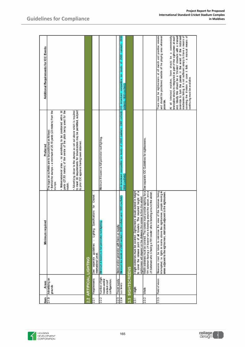
Project Report for Proposed International Standard Cricket Stadium Complex
in Maldives
Guidelines for Compliance
165

Project Report for Proposed International Standard Cricket Stadium Complex
in Maldives
Guidelines for Compliance
166

Project Report for Proposed International Standard Cricket Stadium Complex
in Maldives
Guidelines for Compliance
167

Project Report for Proposed International Standard Cricket Stadium Complex
in Maldives
Guidelines for Compliance
168

Project Report for Proposed International Standard Cricket Stadium Complex
in Maldives
Guidelines for Compliance
169

Project Report for Proposed International Standard Cricket Stadium Complex
in Maldives
Guidelines for Compliance
170

Project Report for Proposed International Standard Cricket Stadium Complex
in Maldives
Guidelines for Compliance
171

Project Report for Proposed International Standard Cricket Stadium Complex
in Maldives
Guidelines for Compliance
172

Project Report for Proposed International Standard Cricket Stadium Complex
in Maldives
Guidelines for Compliance
173

Project Report for Proposed International Standard Cricket Stadium Complex
in Maldives
Guidelines for Compliance
174

Project Report for Proposed International Standard Cricket Stadium Complex
in Maldives
Guidelines for Compliance
175

Project Report for Proposed International Standard Cricket Stadium Complex
in Maldives
Guidelines for Compliance
176

Project Report for Proposed International Standard Cricket Stadium Complex
in Maldives
Guidelines for Compliance
177

Project Report for Proposed International Standard Cricket Stadium Complex
in Maldives
Guidelines for Compliance
178

Project Report for Proposed International Standard Cricket Stadium Complex
in Maldives
Guidelines for Compliance
179

Project Report for Proposed International Standard Cricket Stadium Complex
in Maldives
Guidelines for Compliance
180

Project Report for Proposed International Standard Cricket Stadium Complex
in Maldives
Guidelines for Compliance
181

Project Report for Proposed International Standard Cricket Stadium Complex
in Maldives
Guidelines for Compliance
182

Project Report for Proposed International Standard Cricket Stadium Complex
in Maldives
Guidelines for Compliance
183

Project Report for Proposed International Standard Cricket Stadium Complex
in Maldives
Guidelines for Compliance
184

Project Report for Proposed International Standard Cricket Stadium Complex
in Maldives
Guidelines for Compliance
185

Project Report for Proposed International Standard Cricket Stadium Complex
in Maldives
Guidelines for Compliance
186
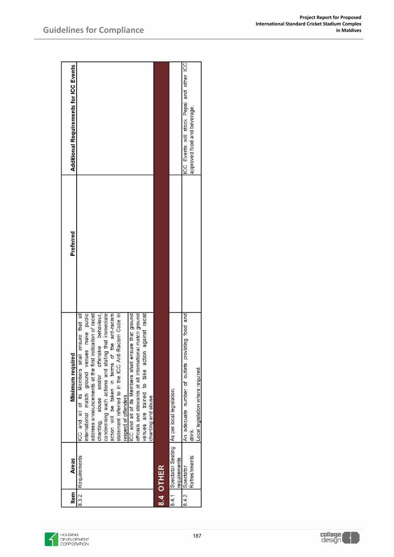
Project Report for Proposed International Standard Cricket Stadium Complex
in Maldives
Guidelines for Compliance
187
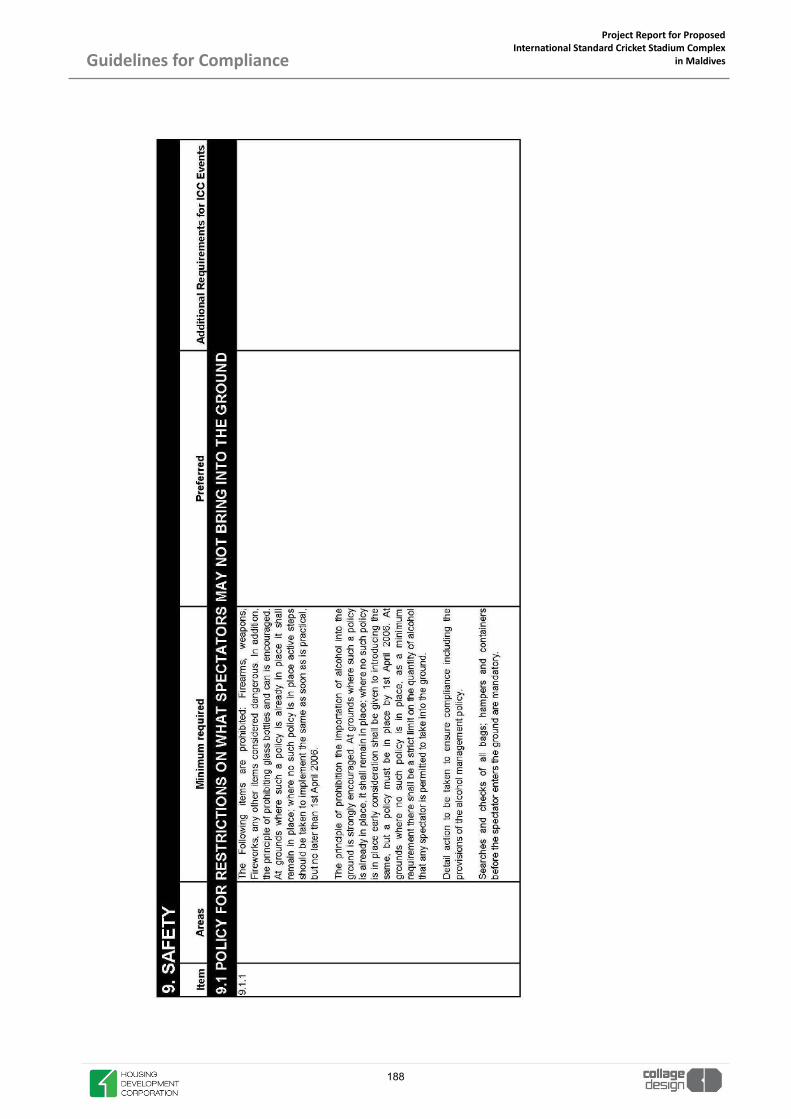
Project Report for Proposed International Standard Cricket Stadium Complex
in Maldives
Guidelines for Compliance
188

Project Report for Proposed International Standard Cricket Stadium Complex
in Maldives
Guidelines for Compliance
189

Project Report for Proposed International Standard Cricket Stadium Complex
in Maldives
Guidelines for Compliance
190

Project Report for Proposed International Standard Cricket Stadium Complex
in Maldives
Guidelines for Compliance
191

Project Report for Proposed International Standard Cricket Stadium Complex
in Maldives
Guidelines for Compliance
192
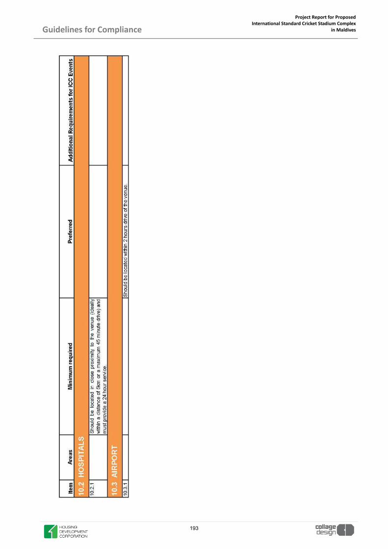
Project Report for Proposed International Standard Cricket Stadium Complex
in Maldives
Guidelines for Compliance
S 193

Project Report for Proposed International Standard Cricket Stadium Complex
in Maldives
Guidelines for Compliance
2. GREEN GUIDE SAFETY OF SPORTS GROUNDS
194

Project Report for Proposed International Standard Cricket Stadium Complex
in Maldives
Guidelines for Compliance
195

Project Report for Proposed International Standard Cricket Stadium Complex
in Maldives
Guidelines for Compliance
196

Project Report for Proposed International Standard Cricket Stadium Complex
in Maldives
Guidelines for Compliance
197

Project Report for Proposed International Standard Cricket Stadium Complex
in Maldives
Guidelines for Compliance
198
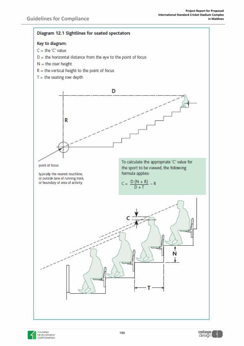
Project Report for Proposed International Standard Cricket Stadium Complex
in Maldives
Guidelines for Compliance
199

Project Report for Proposed International Standard Cricket Stadium Complex
in Maldives
Guidelines for Compliance
200

Project Report for Proposed International Standard Cricket Stadium Complex
in Maldives
Guidelines for Compliance
201

Project Report for Proposed International Standard Cricket Stadium Complex
in Maldives
Guidelines for Compliance
202

Project Report for Proposed International Standard Cricket Stadium Complex
in Maldives
Guidelines for Compliance
203

Project Report for Proposed International Standard Cricket Stadium Complex
in Maldives
Guidelines for Compliance
204

SUSTAINABILITY
205

Project Report for Proposed International Standard Cricket Stadium Complex
in Maldives
Project Scope Sustainability
1. INTRODUCTION BREEAM (Building Research Establishment Environmental Assessment Method) is a sustainability assessment method that is used to masterplan projects, infrastructure and buildings. Launched in 1990, by the Building Research Establishment (BRE) it sets standards for the environmental performance of buildings. Aims of BREEAM is to mitigate the life cycle impacts of buildings on the environment to enable buildings to be recognized according to their environmental benefits to provide a credible, environmental label for buildings to stimulate demand and create value for sustainable buildings, building products and supply chains.
2. Objectives of BREEAM
� To provide market recognition of buildings with a low environmental impact � To ensure best environmental practice is incorporated in the planning, design, construction and
operation of buildings and the wider built environment � To define a robust, cost effective performance standard surpassing that required by regulations � To challenge the market to provide innovative, cost effective solutions that minimize the
environmental impact of buildings � To raise awareness among owners, occupants, designers and operators of the benefits and value of
buildings with a reduced life cycle impact on the environment � To allow organizations to demonstrate progress towards corporate environmental objectives
BREEAM assessment evaluates the procurement, design, construction and operation of a development against a range of targets based on performance benchmarks. It focuses on sustainable value across range of categories:
206

Project Report for Proposed International Standard Cricket Stadium Complex
in Maldives
Project Scope Sustainability
BREEAM measures sustainable value in a series of categories, ranging from energy to ecology. Each of these categories addresses the most influential factors, including low impact design and carbon emissions reduction; design durability and resilience; adaption to climate change; and ecological val-ue and biodiversity protection. Independent licensed assessors carry out an assessment of a scheme and each of the criteria is scored and then multiplied by a weighting.
3. BREEAM Rating Benchmarks There are a number of elements that determine the overall performance of a project assessed using BREEAM; This is followed by a description and methodology for calculating a BREEAM rating benchmarks: Table 1: BREEAM rating benchmarks
BREEAM RATING % SCORE
OUTSTANDING ≥ 85
EXCELLENT ≥ 70
VERY GOOD ≥ 55
GOOD ≥ 45
PASS ≥ 30
UNCLASSIFIED < 30
207
Project Report for Proposed International Standard Cricket Stadium Complex
in Maldives
Project Scope Sustainability
4. BREEAM New Construction Scheme Timing the engagement with and use of the BREEAM New Construction scheme via the BREEAM Assessor is essential for ensuring seamless integration of the methodology in the new-build procurement process. With-out this, the ability to optimize cost-effectively the building's environmental performance and achieve the desired BREEAM rating will be compromised. Appointing a BREEAM Assessor or Accredited Professional early in the project will help in achieving the target rating without undue impacts on the flexibility of design decisions, budgets and potential solutions. Clients can view up-to-date listings of licensed BREEAM New Construction Assessors and BREEAM Accredited Professionals on BREEAM projects:www.breeam.com/projects. It is important to recognize that BREEAM primarily reflects the overall performance of the building rather than just the opportunities or limitations placed on specific stakeholders involved in the procurement process. This means that the client, design team, principal contractor and BREEAM Assessor, as well as other specialist disciplines, have an important role to play throughout the procurement process, if the desired performance level is to be achieved and reflected through the certified BREEAM rating. The onus of orientating the brief towards sustainability needs to come first and foremost from the client. To facilitate this, BRE Global recommends that clients and their project teams engage with a BREEAM Assessor or BREEAM Accredited Professional no later than the Preparation and Brief stage. This will ensure that realis-tic targets are set and can be met, appropriate responsibilities can be defined and understood, and low or no cost solutions to environmental impacts can be sought and applied wherever possible.
208
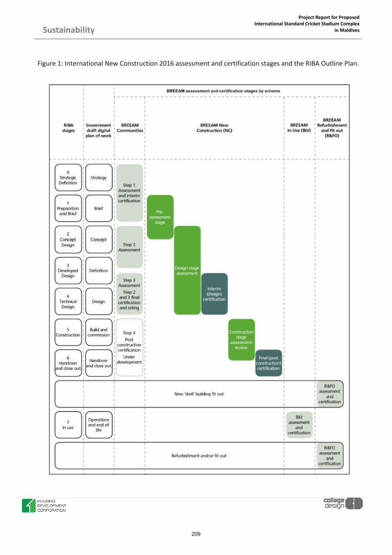
Project Report for Proposed International Standard Cricket Stadium Complex
in Maldives
Project Scope Sustainability
Figure 1: International New Construction 2016 assessment and certification stages and the RIBA Outline Plan.
209

Project Report for Proposed International Standard Cricket Stadium Complex
in Maldives
Project Scope Sustainability
This BREEAM scheme document is a technical document which has been created to:
� Enable qualified and licensed BREEAM Assessors to complete BREEAM assessments and determine a rating
� Enable BRE Global Ltd. to complete quality assurance reviews of a BREEAM Assessor's assessment report, in accordance with the standards to which BRE Global Ltd. is accredited
� Act as an aid for BREEAM Accredited Professionals (AP) to undertake project team facilitation, in terms of defining, monitoring and successfully achieving the desired BREEAM rating
� Act as a reference for clients and members of the project team whose proposed building is being BREEAM assessed.
The scheme document is split into following parts:
1. Introduction to BREEAM 2. Scope of the BREEAM International New Construction 2016 scheme 3. BREEAM rating benchmarks 4. The BREEAM evidential requirements 5. Assessment criteria
The Scope section describes the types of buildings and stages of assessment that this BREEAM Scheme can be applied to. The Scope section can be used by clients and BREEAM Assessors to check whether this is the correct BREEAM Scheme to use for their project. The Scoring and rating section illustrates how a building's assessed performance is measured and rated. It outlines the BREEAM rating level benchmarks, the minimum BREEAM standards for each rating level and the BREEAM environmental section weightings. It also includes a description of the BREEAM assessment issues and 'credits', including BREEAM 'innovation credits', and how performance against these is calculated and expressed as a BREEAM rating. The BREEAM evidential requirements section provides guidance to assessors and project teams on the vari-ous types and forms of evidence required by the BREEAM Assessor to demonstrate compliance with BREEAM criteria. This includes a description of why BREEAM requires an auditable trail of evidence. The Assessment criteria section includes the individual BREEAM assessment issues, categorized in 10 environmental sections. Each issue defines a level of performance against which the assessed building demonstrates compliance in order to achieve a corresponding number of available BREEAM credits. The majority of BREEAM issues and credits are tradable, a project team can pick and choose which to target in order to build their BREEAM performance score and achieve the desired BREEAM rating. Several BREEAM issues have minimum standards, meaning that to achieve a particular BREEAM rating specific credits must be achieved.
210

Project Report for Proposed International Standard Cricket Stadium Complex
in Maldives
Project Scope Sustainability
5. BREEAM Minimum Standards To maintain a flexible system BREEAM adopts a 'balanced scorecard' approach to the assessment and rating of a project. This means that to achieve a particular level of performance the majority of BREEAM credits can be traded, i.e. non-compliance in one area can be offset through compliance in another to achieve the target BREEAM rating. It is important to bear in mind that these are minimum acceptable levels of performance and in that respect they should not necessarily be viewed as levels that are representative of best practice for a BREEAM rating level. To achieve a particular BREEAM rating, the minimum overall percentage score must be achieved and the minimum standards, detailed in Table 2 applicable to that rating level complied with. Table 2: Minimum BREEAM standards by rating level
211

Project Report for Proposed International Standard Cricket Stadium Complex
in Maldives
Project Scope Sustainability
212

Project Report for Proposed International Standard Cricket Stadium Complex
in Maldives
Project Scope Sustainability
6. LOCATION: MALDIVES BREEAM sections and assessment issues Adaptation of weightings for local conditions, the culture, economy, climate and work practices can also affect the development of criteria and the method of assessing certain BREEAM issues. Maldives comes under Precipitation zone 1: corresponds to Köppen’s precipitation regions (fully humid) and (monsoonal).
213

Project Report for Proposed International Standard Cricket Stadium Complex
in Maldives
Project Scope Sustainability
7. CLIMATE ANALYSIS
� The average temperature is ranging from 27 to 30 ºc,
� In winter, the values are between 25 to 27 ºc.
� The relative humidity is about 76 – 81 % during dry periods and
� Wind speed is ranging from 19 to 28
� Pre- dominant wind directions are: W and SW.
� Rainfall is ranging from 160-300 mm monthly & average rainfall is 1900 mm yearly
� The intensity of solar radiation is very high in summer
214

Project Report for Proposed International Standard Cricket Stadium Complex
in Maldives
Project Scope Sustainability
8. ENVIRONMENTAL SECTIONS AND ASSESSMENT ISSUES
8.1 ENERGY � Reduction of energy use and carbon emissions � Energy monitoring � External lighting � Low carbon design � Energy efficient cold storage � Energy efficient transport systems � Energy efficient laboratory systems � Energy efficient equipment � Drying space
215

Project Report for Proposed International Standard Cricket Stadium Complex
in Maldives
Project Scope Sustainability
8.2 LAND USE AND ECOLOGY � Site selection � Ecological value of site and protection of ecological features � Minimizing impact on existing site ecology � Enhancing site ecology � Long term impact on biodiversity
216

Project Report for Proposed International Standard Cricket Stadium Complex
in Maldives
Project Scope Sustainability
8.3 WATER � Water consumption � Water monitoring � Water leak detection � Water efficient equipment
217

Project Report for Proposed International Standard Cricket Stadium Complex
in Maldives
Project Scope Sustainability
8.4 HEALTH AND WELLBEING � Visual comfort � Indoor air quality � Safe containment in laboratories � Thermal comfort � Acoustic performance � Accessibility � Hazards � Private space � Water quality
S
218

Project Report for Proposed International Standard Cricket Stadium Complex
in Maldives
Project Scope Sustainability
8.5 POLLUTION
� Impact of refrigerants � NOx emissions � Surface water run-off � Reduction of night time light pollution � Reduction of noise pollution
219

Project Report for Proposed International Standard Cricket Stadium Complex
in Maldives
Project Scope Sustainability
8.6 TRANSPORT � Public transport accessibility � Proximity to amenities � Alternative modes of transport � Maximum car parking capacity � Travel plan
220

Project Report for Proposed International Standard Cricket Stadium Complex
in Maldives
Project Scope Sustainability
8.7 MATERIALS
� Life cycle impacts � Hard landscaping and boundary protection � Responsible sourcing of materials � Insulation � Designing for durability and resilience � Material efficiency
221

Project Report for Proposed International Standard Cricket Stadium Complex
in Maldives
Project Scope Sustainability
8.8 WASTE � Construction waste management � Recycled aggregates � Operational waste � Speculative floor and ceiling finishes � Adaptation to climate change � Functional adaptability
222

Project Report for Proposed International Standard Cricket Stadium Complex
in Maldives
Project Scope Sustainability
8.9 MANAGEMENT
� Project brief and design � Life cycle cost and service life planning � Responsible construction practices � Commissioning and handover � Aftercare
223

Project Report for Proposed International Standard Cricket Stadium Complex
in Maldives
Project Scope Sustainability
8.10 INNOVATION
BREEAM is rewarding buildings that go beyond best practice in terms of a particular aspect of sustainability, i.e. where the building or its procurement has demonstrated innovation. Awarding credits for innovation en-ables clients and design teams to boost their building’s BREEAM performance and, in addition, helps to sup-port the market for new innovative technologies, and design or construction practices. There are two ways in which BREEAM awards ‘Innovation Credits’ to recognize innovation in building design and procurement. The first is by meeting exemplary performance criteria defined within an existing BREEAM issue, i.e. going beyond the standard BREEAM assessment criteria and therefore best practice. The second route is where an application is made to BRE Global by the registered project’s BREEAM Assessor to have a particular building technology or feature, design or construction method or process recognized as Innovative. If the application is successful and subsequently compliance is verified, an ‘innovation credit’ can be awarded. An additional 1% can be added to a building’s overall score for each innovation credit achieved. The maximum available additional score for ‘Innovation’ is 10%. The building's final BREEAM score will be capped at 100%. Innovation credits can be awarded regardless of the building’s final BREEAM rating.
224

Project Report for Proposed International Standard Cricket Stadium Complex
in Maldives
Project Scope Sustainability
9. BREEAM SCORE AND RATING CALCULATION
SR. NO BREEAM SECTION CREDITS
ACHIEVED CREDITS
AVAILABLE
% OF CRED-ITS
ACHIEVED
SECTION WEIGHTING
(FULLY FITTED)
SECTION SCORE
1 MANAGEMENT 10 21 48% 11% 5%
2 HEALTH AND WELLBEING 12 25 48% 19% 9%
3 ENERGY 15 34 44% 20% 9%
4 TRANSPORT 6 11 55% 6% 3%
5 WATER 5 9 56% 7% 4%
6 MATERIALS 6 12 50% 13% 6%
7 WASTE 6 10 60% 6% 4%
8 LAND USE AND ECOLOGY 5 10 50% 8% 4%
9 POLLUTION 8 13 62% 10% 6%
10 INNOVATION 3 10 30% 10% 3%
TOTAL 53%
BREEAM SECTION CREDITS ACHIEVED
CREDITS AVAILABLE
% OF CREDITS ACHIEVED
SECTION WEIGHTING
(FULLY FITTED)
SECTION SCORE
FINAL BREEAM SCORE 53%
BREEAM RATING GOOD
225

Project Report for Proposed International Standard Cricket Stadium Complex
in Maldives
Project Scope Sustainability
MINIMUM STANDARDS FOR A BREEAM RATING
MINIMUM STANDARDS FOR BREEAM RATING ACHIEVED
MAN 01: SUSTAINABLE PROCUREMENT Y
HEA 01: VISUAL COMFORT Y
HEA 04: WATER QUALITY Y
ENE 02: ENERGY MONITORING Y
WAT 01 - WATER CONSUMPTION Y
WAT 02: WATER MONITORING Y
MAT 03: RESPONSIBLE SOURCING Y
LE 03: MITIGATING ECOLOGICAL IMPACT Y
10. AWARDING BREEAM CREDITS Each category is sub-divided into a range of assessment issues, each with its own aim, target and bench-marks. When a target or benchmark is reached, as determined by the BREEAM assessor, the development or asset score points, called credits. The category score is then calculated according to the number of credits achieved and its category weighting. Once the development has been fully assessed, the final performance rating is determined by the sum of the weighted category scores. Two assessment stages are carried out a design stage assessment which results in an interim certificate, and a post-construction assessment resulting in a final certificate being issued and a rating awarded. The BREEAM rating benchmark levels enable a client or other stakeholder to compare an individual building’s performance with other BREEAM rated buildings and the typical sustainability performance.
226

1
STRUCTURE
227

Project Report for Proposed International Standard Cricket Stadium Complex
in Maldives
Structure
This report covers the basis of structural design for the proposed International Cricket Stadium Complex
in Hulhumale ,Maldives (4° 14’N, 73° 32’E ).
Hulhumale is a reclaimed island ,located at the Northeastern side of Male .It is at a distance of 9km from
Velana International Airport .
Fig 1 : Site Plan
1.2 PROJECT BACKGROUND:-
The Maldives International cricket stadium,spread across 21 acres will have a seating capacity of 20,000.
The main stadium consists of
x North Pavilion
x West Stand
x East Stand
x South Stand
1.0 PROJECT OVERVIEW AND SCOPE: 1.1 DOCUMENT SCOPE:-
228

Project Report for Proposed International Standard Cricket Stadium Complex
in Maldives
Structure
Fig 2 :Stadium Key Plan
Fig 3:Stadium Section
229

Project Report for Proposed International Standard Cricket Stadium Complex
in Maldives
Structure
Fig 4 : Section through North Pavilion (VIP & Players seating )
The stadium has water front to the eastern side and main city access to the western side .The seating bowl has been designed to give the spectators a view of the plaza and water front .
Fig 5 : Stadium View
230
Project Report for Proposed International Standard Cricket Stadium Complex
in Maldives
Structure
1.3 DESIGN & DOCUMENTATION SCOPE:-
Design Scope
Responsible for the structural design of the following buildings from conceptual design through construction documentation:
x Main Stadium
Responsible for the structural design of the following components for the buildings listed below
x Steel and Reinforced Concrete Lateral Load Resisting Systems: lateral moments frames, braced frames, shear walls, diaphragms and collectors, etc
x Roof and Primary Facade Support Structures
Exclusions Specific items not within SACPL’s design scope are as follows: x Modular steel seating units x Temporary Works x Facade and Roof Cladding / Membrane including Sub-frames x Civil Works and Shoring Structures x Miscellaneous steel work (handrails, light poles, etc)
231

Project Report for Proposed International Standard Cricket Stadium Complex
in Maldives
Structure
2.0 STRUCTURAL SYSTEM NARRATIVES:
2.1 MAIN STADIUM:-
The superstructure proposed is in structural steel ,with RCC foundation .Horizontal framing will be in
decking sheet with concrete screed on the top .For seating arrangement ,modular steel seating system
will be used. The proposed structure consists of Ground floor ,Podium floor and first floor . The ground mainly houses
the club and retail areas ,the VIP seating and lounges are situated on the Podium floor ,while
suites,dormitories,corporate box,third umpire box etc are on the first floor .
The stadium roof covers 60% of the seating area.The design is inspired from the form of a yacht .The roof
will be in structural steel .When viewed from the top the roof will resemble a crescent moon .This shape
will be achieved using fabric material .The total height of the main column is around 37m.
The remaining floor heights are as below.
Floor Description Floor Height
Ground 6 m
Podium 4.2 m
First Floor 4.2 m
2.2 EXPANSION JOINTS :-
The main stadium would be divided by four expansion joints.
2.3 FOUNDATIONS :-
Majority of the column foundations would be isolated footing with tie beams, except the main column
foundations, which would be supported by piles, as these columns would be subjected to huge uplift
forces .
2.4 GRAVITY FRAMING SYSTEM :-
The gravity framing in podium and first floor would be structural beam column and decking sheets .The
general seating area would be in modular steel.
232

Project Report for Proposed International Standard Cricket Stadium Complex
in Maldives
Structure
3.0 STRUCTURAL DESIGN CRITERIA:
3.1 STRUCTURAL STANDARDS AND CODES:-
All structural elements are designed in accordance with the applicable requirements and
recommendations of the reference codes and standards. They are regarded as minimum criteria and the
values specified in this document are adopted where these prove more onerous.
Reference Codes & Standards (latest editions and amendments)
BS 8110-1-1997 Structural use of concrete - code of practice for design and construction
BS 8110-2-1985 Structural use of concrete - code of practice for special circumstance
BS 6399-Part1-1996
Loading for buildings -Code of practice for dead and imposed loads
BS 6399-Part2-1997
Loading for buildings -Code of practice for wind loads
BS 6399-Part3-1988
Loading for buildings -Code of practice for imposed roof loads
UBC : 1997 Uniform Building Code- Chapter 16 Structural Design Requirements Earthquake Loads DIV IV.
BS 8004-2015 Code of practice for foundation.
BS 5950-Part1-2000
Structural use of steel work in building -Code of practice for design. Rolled and welded sections.
BS 5950-Part2-2001
Structural use of steel work in building -Specifications for materials,fabrication and erection.Rolled and welded sections.
BS 5950-Part4-1994
Structural use of steel work in building -Code of practice for design of composite slabs with profiled steel sheeting .
BS 5950-Part5-1998
Structural use of steel work in building -Code of practice for design of cold formed thin gauge sections .
BS 5950-Part8-2003
Structural use of steel work in building -Code of practice for fire resistant design.
233

Project Report for Proposed International Standard Cricket Stadium Complex
in Maldives
Structure
3.2 MATERIALS:-
The design of the concrete elements shall comply with BS 8110-1997. Unless noted otherwise concrete is
to be normal-weight, with a typical dry density of 25 KN/m3. The following list shows the 28 day cube
strength (minimum) to be achieved by the concrete for some main structural members:
Element Concrete Grade
Footings/Pile Cap M30 / M40
Pedestal M30 / M40
Screeding on Deck /Grade Slab M25
Tie Beams M30 / M40
PCC M15
Properties of steel reinforcement are to be adopted as per stipulations of the British standards. Only
HYSD bars that are of standard sizes of 8, 10, 12, 16, 20, 25 and 32mm diameter and with grade B500C
with 7.5mm total elongation at maximum force to be used. All other mechanical and chemical
properties are to be in accordance with the code BS 4449:2005.
Structural steel of S355 and S460 shall be used ,confirming to BS 5950-1-2000.
Steel Section Type Material Standards, Properties, Notes
Rolled Shapes ASTM A913 and EN10025-4: 2004 with minimum grade S355 for beams and S460 for columns. HISTAR 355 and 460 preferred material for seismic application
Angles for Trusses & Braces ASTM A36M and EN10025-2: 2004, S275
Miscellaneous Angles ASTM A36M and EN10025-2: 2004, S275
Hollow Structural Sections ASTM A500M Grade B, minimum yield strength 320Mpa for rectangular HSS (SHS and RHS) 345Mpa for circular (CHS), in accordance with EN10210-1: 2006
Connection Materials
Angles ASTM A36M and EN10025-2: 2004, S275
WTs ASTM A992M
Plates ASTM A572M and EN10025-2: 2004, S355
Bolts ASTM A325M or ASTM A490M
Nuts ASTM A563M
Washers ASTM F436M
234

Project Report for Proposed International Standard Cricket Stadium Complex
in Maldives
Structure
Anchor Rods ASTM F1554M Grade 380 Mpa with weldability supplement S1
Headed Studs ATM A108 Grade 1010 through 1020 headed stud type, cold – finished carbon steel, AWS D1.1, type B, 19mm diameter
Weld Electrodes E70XX
Corrosion Protection of Structural Steel
1. Surface Treatment: Abrasive blast cleaning to minimum SA-2½ SIS-055900 near -white blast cleaning.
2. 1st Coat: Sprayed Zn-15 wt.% Al coating should be applied using wire type metal spray guns on the prepared surfaces. Sprayed coating should not be less than DFT >75 µm.
3. 2nd Coat: One coat of Etch Primer (10 µm) followed by One coat of Zinc Chromate Primer not less than DFT >25 µm
4. 3rd Coat: Epoxy high build Micaceous iron oxide coating polyamide cured DFT-110µm (High build MIO).
5. 4th Coat: Acrylic polyurethane finish aliphatic isocyanate cured DFT-30µm in approved colour.
6. Finish Coat: Acrylic polyurethane finish aliphatic isocyanate cured DFT-30µm in approved colour.
3.3.1 DEAD LOAD:-
The dead load comprises of self-weight of the structure and loading due to finishes and floorings etc.
which are permanent in nature. The dead load of self- weight, partitions, ceiling, flooring and façade
etc. are applied as either area loads to slabs or line loads to beams. The following table defines the
minimum superimposed dead loads that are considered for the various elements.
Super imposed Dead Loads BS 648
Item Value
Finishes including service load 0.15 T/m2
Partition wall loads 0.15T/m2
Façade load As per Actual
Concrete (RCC) 2.5T/m3
Fly Ash Brick masonry 1.7 T/m3
Plain concrete 2.4T/m3
3.3 GRAVITY AND MISCELLANEOUS LOADING:-
235

Project Report for Proposed International Standard Cricket Stadium Complex
in Maldives
Structure
Steel 7.85T/m3
Soil Filling 2.0T/m3
Brick Bat filling 2.0T/m3
Partition loads are calculated based on the final layout shown in the Architectural drawing. The loads are
calculated based on the density of the masonry material that is being used for the construction.
3.3.2 LIVE (IMPOSED) LOAD:
Live Loads considered on floor slabs are as per BS 6399-1996. In general, the following live loads are
Considered.
LIVE LOADS BS 6399-1-1996
Floor / Item Load
Assembly with fixed seats 0.4 T/m2
Assembly without fixed seats 0.5T/m2
Kitchen ,laundries 0.3T/m2
Offices for general use 0.25T/m2
Shopping areas 0.4T/m2
Dining rooms,lounges,dressing rooms 0.2T/m2
Gymnasium 0.5T/m2
Corridors,hallways ,stairs 0.5T/m2
Toilets 0.2 T/m2
Single car parks 0.25T/m2
Driveways and Ramps 0.25T/m2
All other loads which are acting on the structure but not mentioned above will be taken and analyzed as
per the governing B.S. Codes.
236

Project Report for Proposed International Standard Cricket Stadium Complex
in Maldives
Structure
LIVE LOAD REDUCTION:-
According to the Indian codes, BS 6399, live load reductions can be considered in the analysis and design.
So this is considered in the analysis and design.
3.4 SEISMIC LOADING AND DESIGN CRITERIA:-
UBC 1997 is used for calculating seismic load and as the basis for seismic load combinations.
SEISMIC LOADS UBC 1997 ( VOLUME 2)
Seismic Parameters Adopted Values Remarks
Seismic Zone 3
Zone Factor Z = 0.3 Table 16-I
Importance factor I=1.0 Special occupancy structure (Table 16-K)
Response Reduction Factor R=4.5 Ordinary Moment resisting frame (Table 16-N)
Soil Type SD where N is 15 to 50 (Table 16-J)
Time Period T T= Cth3/4 H is the height of the building (clause 1630.2.2)
Design Base Shear V=(C v I W)/RT Clause 1630.2.1
237
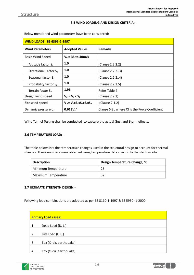
Project Report for Proposed International Standard Cricket Stadium Complex
in Maldives
Structure
3.5 WIND LOADING AND DESIGN CRITERIA:-
Below mentioned wind parameters have been considered:
WIND LOADS BS 6399-2-1997
Wind Parameters Adopted Values Remarks
Basic Wind Speed Vb = 35 to 40m/s
Altitude factor Sa 1.0 (Clause 2.2.2.2)
Directional Factor Sd 1.0 (Clause 2.2.2..3)
Seasonal factor Ss 1.0 (Clause 2.2.2..4)
Probability factor Sp 1.0 (Clause 2.2.2.5)
Terrain factor Sb 1.96 Refer Table 4 Design wind speed Ve = Vs x Sb (Clause 2.2.2)
Site wind speed V s= VbxSaxSdxSsxSp (Clause 2.1.2)
Dynamic pressure qs 0.613Ve2 Clause 6.3 , where Cf is the Force Coefficient
Wind Tunnel Testing shall be conducted to capture the actual Gust and Storm effects.
3.6 TEMPERATURE LOAD:-
The table below lists the temperature changes used in the structural design to account for thermal stresses. These numbers were obtained using temperature data specific to the stadium site.
Description Design Temperature Change, °C
Minimum Temperature 25
Maximum Temperature 32
3.7 ULTIMATE STRENGTH DESIGN:-
Following load combinations are adopted as per BS 8110-1-1997 & BS 5950 -1-2000.
Primary Load cases:
1 Dead Load (D. L.)
2 Live Load (L. L.)
3 Eqx (X- dir. earthquake)
4 Eqy (Y- dir. earthquake)
238

Project Report for Proposed International Standard Cricket Stadium Complex
in Maldives
Structure
5 Wx (X- dir. Wind)
6 Wy (Y- dir. Wind)
7 Temperature Load (T)
Basic Load combinations: Basic Load combinations:
1 1.4 D. L. +1.6 L. L. 17 1.2(D. L. + L. L.- Wy)
2 1.2(D. L. + L. L.+ Eqx) 18 1.4(D. L. + Wx)
3 1.2(D. L. + L. L.+ Eqy) 19 1.4(D. L. + Wy)
4 1.2(D. L. + L. L.- Eqx) 20 1.4(D. L. – Wx)
5 1.2(D. L. + L. L.- Eqy) 21 1.4(D. L. – Wy)
6 1.4(D. L. + Eqx) 22 1D. L. + 1.4Wx
7 1.4(D. L. + Eqy) 23 1D. L. + 1.4Wy
8 1.4(D. L. - Eqx) 24 1D. L. - 1.4Wx
9 1.4(D. L. - Eqy) 25 1D. L. – 1.4Wy
10 1D. L. + 1.4Eqx 26 1.4D.L+1.6L.L+1.2T
11 1D. L. + 1.4Eqy 27 1.4D.L+1.6L.L-1.2T
12 1D. L. - 1.4Eqx
13 1D. L. – 1.4Eqy
14 1.2(D. L. + L. L.+ Wx)
15 1.2(D. L. + L. L.+ Wy)
16 1.2(D. L. + L. L.- Wx)
3.8 SERVICEABILITY DESIGN:-
The limit states of Deflection and Vibration are studied and discussed in this section.
3.8.1 DEFLECTION:- The overall structure and its components tend to have some deflections and or movements when
subjected to lateral loads. This need to be studied and checked against the allowable tolerances, for
which there will not be any problems regarding strength or perception related issues.
The movements can be caused by gravity and lateral loads, long term creep and shrinkage effects,
temperature stresses etc.
The table below gives the global as well as local limits on the deflections, set out by the British
239

Project Report for Proposed International Standard Cricket Stadium Complex
in Maldives
Structure
standards.
Global Displacements
Wind load H/500
Seismic Load H/250
Element Deflections Clause 3.4.6.3 BS 8110-1-1997 (For concrete memebers)
Vertical loads (Gravity) -Short Term L/500 or 2cm
Vertical loads (Gravity) -Long Term L/250
Element Deflections Clause 2.5.2 BS 5950-1-2000 (For steel members)
Cantilevers L/180
Beams carrying plaster L/360
Other beams L/200
Care has taken to ensure that for all the structural elements, the deflection values are well within the
above limits.
3.8.2 VIBRATIONS:-
Floor vibrations generally make people uneasy and create concerns of structural distress. The highest
vibrations are likely to arise from resonant response due to repeated footfalls at a frequency that is
either the same or a multiple of the natural frequency of the floor. To provide the necessary vibration
control, the structural floor system requires to be relatively rigid and of sufficient mass to reduce the
acceleration.
The following limits have to be followed:
240

Project Report for Proposed International Standard Cricket Stadium Complex
in Maldives
Structure
3.9 DURABILITY:-
The concrete durability is affected by the concrete mix and also the exposure condition it is subjected
to. It can be ensured by the proper design of the concrete mix as appropriate for the Environmental
Exposure condition and also by providing sufficient cover to the outermost face of any reinforcement.
The BS 8110-1-1997 lists out the different environmental exposure condition and based on it( Table
3.2 ) this structure falls into the Moderate category.
Based on the requirements of the Fire rating and also for the environmental exposure condition as
listed above, the concrete covers are worked out as below. (Also refer Table 3.3 and 3.4- BS 8110-1-
1997).
Concrete Cover (mm)
Beams 40 Simply supported 30 Continuous Slabs 35 Simply supported 25 Continuous Ribs 45 Simply supported 35 Continuous Columns 40 40mm to the links
Foundations 75mm and 50mm Bottom and side respectively
Vibration Criteria
Walking Excitation: Maximum Peak Acceleration in Concession Areas, Team Store, Concourse Areas (Similar to Shopping Mall) Maximum Peak Acceleration in Press, Conference Centers, Suites, Office Areas
1.5% of g 0.5% of g
Rhythmic Excitation of Rakers Supporting Seating Bowls: Minimum Fundamental Frequency of Rakers Maximum Peak Acceleration
3.5 Hz 5% of g
241

Project Report for Proposed International Standard Cricket Stadium Complex
in Maldives
Structure
3.10 FIRE RATING REQUIREMENTS:-
Fire rating of 3 hours has been assumed for vertical elements and 2 hours for horizontal members.
3.11 GEOTECHNICAL CRITERIA
3.11.1 SOIL PROFILE:
Soil investigation for the project has not been carried out .The below details are based on the soil
report of adjacent site .The soil investigation for the proposed project shall be carried out and
included in the detailed report later .
The sub soil stratum is observed to consist of fine clean gravelly whitish sand up to 2 to 3m, followed
by coral sand with corals and sea shells.
3.11.2 GROUND WATER:
Water table was encountered at a depth of 1.5 m in all the boreholes at the time of investigation
3.11.3 FOUNDATION:- Soil consultant has suggested independent footings or raft as the foundation system. He has
recommended a safe bearing pressure of 16 T/m2 & 20 T/m2 at a depth of about 2m and 3m below
ground level respectively .Alternatively Pile foundations are recommended for larger loads .Pile
diameter of 600mm with capacity of 63.7 Ton is recommended by the soil consultant. Detailed Geo
technical tests like pile load test shall be initiated prior to construction to ascertain the vertical and
uplift capacity.
242

Project Report for Proposed International Standard Cricket Stadium Complex
in Maldives
Structure
INTERLOCKING MODULAR GRANDSTAND SEATING
The construction expertise is based on a unique interlocking system; All the components are self-locking and the system needs no bolting, this is a main safety feature as
1. There is no risk of forgetting bolts 2. There is no risk of unbolting due to spectator vibrations
The grandstand metal construction takes into account the soil study, local seismicity and the Maldivian construction code.
MODULAR GALLERY
243

Project Report for Proposed International Standard Cricket Stadium Complex
in Maldives
Structure
GRANDTSAND SEATING- INTERNATIONAL TEST CERTIFICATE
244

Project Report for Proposed International Standard Cricket Stadium Complex
in Maldives
Structure
245

Project Report for Proposed International Standard Cricket Stadium Complex
in Maldives
Structure
246
Project Report for Proposed International Standard Cricket Stadium Complex
in Maldives
Structure
Bidder Qualification Condition
For Maldives Cricket Stadium, Hulhumale
247
Project Report for Proposed International Standard Cricket Stadium Complex
in Maldives
Structure
Bidder Qualification Condition for International Cricket Stadium in Hulhumale, Maldives
1. General Conditions x JV is allowed and should have maximum of two parties.
x Technical partner in the JV should have minimum scope of 30% of the project value.
2. Technical Qualification x Bidder should have supplied & installed a sub-surface aeration and vacuum
powered drainage system in at least one ICC compliant cricket stadium in South Asia in the last 5 years. Completion letter to be submitted.
x Bidder should have supplied & installed a USGA compliant cricket outfield along with clay pitches in South Asia in last 5 years, which has a proven compatibility with a sub-surface aeration / drainage system.
x Bidder should have supplied & installed at least 1 stadium with galvanized steel interlocking modular galleries (without nuts and bolts) in South Asia in the last 5 years for a seating capacity of minimum 70% of the proposed capacity for this project. Design should be approved by SOCOTEC and manufacturer must have experience of having designed the structure based on Siesmic studies. Completion letter is to be submitted.
x Bidder should have supplied & installed turf protection tiles in a stadium in South Asia in the last 5 years for a minimum area of 5000sqm.
x Bidder should have executed at least 1 International standard sports project in Maldives in the last 5 years.
x Bidder should have experience of supply & installation of High Mast floodlighting in at least one International standard sports stadium in South Asia in the last 5 years.
248

Project Report for Proposed International Standard Cricket Stadium Complex
in Maldives
Structure
x Bidder should have executed at least 1 Indoor Cricket academy of reputed State or National Cricket Associations of a ICC Test playing country in South Asia in last 5 years.
3. Financial Qualification x The bidder should have a minimum average turnover of more than USD 175
million in last 10years.
x Bidder should have a minimum Net worth of USD 50million as per latest Audited Balance sheet. The definition of Net worth as defined in Section 2(57) of the Indian Companies Act 2013.
x Bidder should have a minimum liquid asset (Cash & Cash equivalents) of USD 7 million. The same has to be certified by Charted Accountant.
4. Building & Construction Qualification x Bidder should have minimum accumulated value of similar works in last
10years should be more than USD 70 million (Similar work means any Building work of value more than USD 7 million)
x At least one of the JV partners should have executed the following minimum quantities during the last 10 years in single or different projects either in Government or Private Sector. Group company works will also be considered
PEB works : 1,000 MT with a minimum 20,000sqm surface area of Roof and cladding. Structural Steel : 1,200 MT Piling work : 11,000RM PCC and RCC : 10, 000 Cum
249

Project Report for Proposed International Standard Cricket Stadium Complex
in Maldives
Structure
MODULAR GALLERIES EXPERIENCE REQUIREMENTS
x Manufacturer should have been in the business of modular galleries for a minimum of “10” years.
x Product proposed should be of European or American origin.
x Bidder should have supplied & installed at least 1 stadium with galvanized steel interlocking modular galleries (without nuts and bolts) in South Asia in the last 5 years for a seating capacity of minimum 70% of the proposed capacity for this project. Design should be approved by SOCOTEC and manufacturer must have experience of having designed the structure based on Siesmic studies. Completion letter is to be submitted.
x Product proposed should have all steel components hot dipped galvanised inside out system should have been approved by SOCOTEC, strictly confirming to European or American equivalent
x Gallery system will have to be assembled without any bolts, nuts nor screws, gallery components will have to be inter-locking and should not require any fabrication welding at site
x All steel components will be marked with an irremovable label for traceability in the event of failure. Marking shall include, the manufacturer's code, the reference of the used norm, and year of manufacture.
x Bidder should submit a commitment letter along with the technical bid in it’s name from the
manufacturer of grandstand/modular gallery (pls use either term) along with the technical specifications of the product intended to be supplied.
- International experience with constructions on at least 3 continents - Construction for at least one FIFA competition - Construction for at least 2 UEFA competitions
250

Project Report for Proposed International Standard Cricket Stadium Complex
in Maldives
Structure
STEEL GRANDSTAND REQUIREMENTS Steel grandstands Grandstands will be built with steel components; Steel grandstands will be composed solely of self-locking pieces; no screws nor bolts will be accepted This is a main safety feature as:
1 - there is no risk of forgetting bolts 2 - there is no risk of unbolting due to spectator vibrations
Each component will not weigh more than 40 kg and must be carriable by one worker. The use of cranes will not be permitted for the construction of grandstands. Walking boards will be made of wooden plates The grandstand metal construction must take into account the following:
- soil study
- local seismicity - local construction code
Norm requirements EN Norm The equipment installed must comply with the European standard EN 13200 and companies must provide at the time of their submission a certificate of approval to this standard issued by SOCOTEC. All metal parts (unless otherwise specified) should be hot-dip galvanized according to NFA 91211 norm. Country of origin and Traceability of pieces Country of origin The following will be required to be manufactured totally in Europe or America
- Steel components for grandstands - General public seats - Wooden plates
251

Project Report for Proposed International Standard Cricket Stadium Complex
in Maldives
Structure
Traceability of pieces In compliance with current rules and regulations, all the metal components of the grandstand will be marked with an indelible and permanent process. This ensures traceability in case some elements are defective. This marking is done on the following elements:
- Frames - Risers (elevating elements) - Braces (reinforcing elements) - Support elements onto which seating elements are secured - Guard rails (protection against falls from heights) - Adjustable Plates (jack, lifting Jacks and so on) - Walk planks (flooring and flooring frames)
The marking of pieces is determined as follows
XX Manufacturer Code XX
132 Norm Reference NF EN 13 200-6
6 Class according to
Norm Class 6, bleachers with seating (13 200-6)
18 Fabrication Year 2018
1 Fabrication Batch N°1
252

Project Report for Proposed International Standard Cricket Stadium Complex
in Maldives
Structure
GRANDSTAND COMPONENT REQUIREMENTS Steel components Bleacher steps have a 0.20 m step height. At each level the depth is 0.75 m. Distance between the center of 2 seats : 0.45 m Front and Rear guardrails - Side and rear guardrails must be in compliance with the new European Norm - The height from the seat to the top of the guardrail equals 1.10m - The back guardrails will be as follows and must withstand horizontal forces at 1meter as
specified by the EN 13200 current norm.
Side Guardrails Side guardrails are installed on the lateral side of the grandstand - see illustration below
253

Project Report for Proposed International Standard Cricket Stadium Complex
in Maldives
Structure
Walk Planks and Frames - Dimensions: 0.80x1.80m - weight = 30Kg - thickness: 18 mm in compliance with M3 fire class - walking boards made of birchwood treated against humidity - the walking boards are fully embedded in a metal frame reinforcing the solidity and safety
features and protecting the side of the wood boards. - secure the riser panels into position thus muffling sound in the grandstand, - have anti-skid properties - correspond to the entire width of a level which gives more room and thus more comfort. - Color : brown or grey The design and the sturdiness of these walk planks guarantee the utmost security and the replacement of pieces during the lifetime of the grandstand is not required. Riser Panels Metal riser panels are made of Aluzinc 12/10th sheets: These elements make it possible to block the front gap between each tier and prevent objects from falling through and under the grandstand.
254

Project Report for Proposed International Standard Cricket Stadium Complex
in Maldives
Structure
Anchoring and stabilizing devices The squaring up of frames and risers will be done through the use of braces.
Assembly is done thanks to pre-fabricated self-locking elements which fit into each other. This ensures the utmost security during assembly (no need for screws or bolts). Moreover, braces allow for the squaring up of frames and risers between each walkway, which then ensures the stability of the grandstand lengthwise.
Jacks Anchoring on the ground will be ensured by adjustable jacks (which also allows for levelling off the grandstand in case it is erected on uneven ground, outdoors for instance). On concrete foundation works (slabs, posts or beams), anchoring on the ground will be done on each plate using a 10 x 80, Spit NYL 12 type or related type, anchoring screw. (see below an illustration of anchoring).
Anchoring by Spit or equivalent device.
255

Project Report for Proposed International Standard Cricket Stadium Complex
in Maldives
Structure
Seats for general public
Seats for new grandstand Individual ‘’Stadium’’ M4 type seats Overall Dimension
Width = 40 cm
Depth = 37 cm
Height = 39 cm
Fire resistance : M4
Weight 1.050 Kg
Holes for waterflow
Seats for central grandstand New shells need to be installed; shells will need to be as follows The installation centering length will be 45 cm +/- 2 cm depending on feasibility in the installation location. Individual ‘’Sinel’’ M4 type seats and centering length as recommended by FIFA and UEFA.
Overall Dimension: Width = 40.5 cm
Depth = 37 cm
Height= 40cm
M4 Classification
Weight= 1.25 Kg
8 slits at the bottom of the seat to ensure water discharge
All RAL Color are available (out of fluorescent or metallic colors).
Considering current step heights of central grandstand, seats will need to be raised in order to have
45 cm (+/- 2cm) between ground level and seating level.
256

Project Report for Proposed International Standard Cricket Stadium Complex
in Maldives
Structure
Supports for the seatings
On bleachers, individual seats will be fitted onto individual seat connecting bars placed on metal
rails (see photograph above).
Centering length general public: 45 cm.
Individual seats are secured by screws and hooks. Under no circumstances can these be removed manually without the use of proper tools - see
pictures below.
Tighten on the screws to complete the assembly of the individual seat
Hooks to ensure secure fixation
257

Project Report for Proposed International Standard Cricket Stadium Complex
in Maldives
Structure
All the seating rails are held together by the locking of the step noses into one another. Thus, it is
impossible to remove an element of the bleachers.
WARRANTIES The company must certify a minimum guarantee of 10 years for the steel structure and 5 years for the shells and floors. The cover structure benefiting from a ten-year guarantee.
Positioning and locking of the seating rail the step nose
258

Project Report for Proposed International Standard Cricket Stadium Complex
in Maldives
Structure
MODULAR GRADNSTAND GALVANISING CRITERIA
Norm/ standards to comply with:
x Material to be used: The steel must be suitable for galvanizing; the silicon and phosphorus contents should comply with Class 2 of standard NF A 35-503.
x Specifications and test methods: Hot-dip galvanizing according to standard NF EN ISO 1461: Galvanized coating by immersion (doc attached ISO 1461-V2009)
Tests reports that can be provided:
x Certificate of conformity for galvanizing supplied by the galvanizing company.
x Salt spray test to verify compliance with the Corrosivity level according to NF EN ISO 12944-2: C5-1 E13 for coastal areas
259

Project Report for Proposed International Standard Cricket Stadium Complex
in Maldives
Structure
4.0 Roof Structure- Tensile Roof
Emblematic buildings
The light weight and flexibility of composite membranes offer tremendous freedom of shape for the creation of emblematic buildings. Tensioned roofs are ideal for large span roofs, allowing the transmission of natural light to ensure a pleasant luminous atmosphere.
Solutions for open and closed buildings
Membranes enable the installation of tensile roofs on open structures for sports activities (stadiums, grandstand roofs, etc.), cultural buildings (amphitheaters, etc.) and educational establishments (covered playgrounds for schools, etc.). They enable the creation of roofs or entire envelopes for closed buildings to optimize the transmission of natural light into atriums, shopping malls, sports halls and arenas, airport terminals and stations, etc. They also allow for the implementation of double skin thermal insulation solutions.
Durable materials
A range of high performance composite materials have been developed with lasting mechanical properties and proven aesthetics.
Durability Natural Light Long Spans (Lightweight And
Resistant)
Freedom Of Shape
260

Project Report for Proposed International Standard Cricket Stadium Complex
in Maldives
Structure
Sample Roof Design
261

Project Report for Proposed International Standard Cricket Stadium Complex
in Maldives
Structure
262

Project Report for Proposed International Standard Cricket Stadium Complex
in Maldives
Structure
5.0 High-Mast Lights
263

Project Report for Proposed International Standard Cricket Stadium Complex
in Maldives
Structure
Cricket Stadium Floodlighting
264

Project Report for Proposed International Standard Cricket Stadium Complex
in Maldives
Structure
265

Project Report for Proposed International Standard Cricket Stadium Complex
in Maldives
Structure
Stadium Floodlighting – Example: 4 Point Masts
266

Project Report for Proposed International Standard Cricket Stadium Complex
in Maldives
Structure
6.0 SWIMMING POOL STRUCTURES
267

Project Report for Proposed International Standard Cricket Stadium Complex
in Maldives
Structure
1. POOL TANK MAIN STRUCTURE
Olympic Size Swimming Pool- Option 1
268

Project Report for Proposed International Standard Cricket Stadium Complex
in Maldives
Structure
1.2 RECESSED FOOTREST
Special safety step, integrated into the pool wall construction. Footrest area covered by an anti-slip PVC membrane stripe of contrasting colour, welded during assembly on site. The safety step is mandatory, if required by local safety rules. In any case, if competition pool is destined for public use, it is highly recommended.
Wall integrated safety step, at a depth of 1.2 m 50 m
1.3 RECESSED TREADS STAIR
Special stair, obtained by integrating the steps into the wall panel construction, without protruding into the external swimming lanes. Steps made of black co-polymer, stepping surface with anti-slip surface according to international safety rules. Each stair includes two stainless steel handrails of different height, anchored inside the overflow gutter.
Stairs depth: 1,20 m.
Recessed Treads Stair 6 pc
269

Project Report for Proposed International Standard Cricket Stadium Complex
in Maldives
Structure
1.4 FLOATING LINE ANCHOR – GUTTER INSTALLED Stainless steel anchor for floating lines directly inside the overflow gutter. To be installed on the finished pool. Two plain PVC board glued on both sides of the gutter channel. Polished stainless steel slotted anchor bolted on the two PVC boards. Extension of the floating line with “hammer head” terminal to enter the slot. Plastic covered stainless steel cord to be connected to the line spring (spring not included).
Anchor type: floating line Floating Line Anchor 22 pc
270

Project Report for Proposed International Standard Cricket Stadium Complex
in Maldives
Structure
271

2
MEP
272

Project Report for Proposed International Standard Cricket Stadium Complex
in Maldives MEP
Preamble-
The purpose of this report is to present preliminary design for project. The Proposed Maldives International Cricket Stadium is located at Hulhumale. This development consists of Players Areas, Spectator Stand, Dormitory block, VIP & VVIP Lounge, Swimming pool, Practice Nets, Corporate Boxes and Team Suite.
The objective of this report is to give an overview of MEP Services designed for the proposed Development.
Prior to Setting out for design following objectives have been established for the project.
x Code Compliancex Energy Conservationx Indoor Air Qualityx Fire Safety & Securityx Value Engineering
Our Scope of Work: -
¾ Heat Ventilation Air-conditioning System
¾ Electrical System
¾ Low Voltage, Fire Alarm, Public Address
¾ Public Health Engineering System
¾ Fire Fighting System
¾ Lift/Elevator System
¾ Building Management Systems
Sr. No. Floors Components Area (Sq. Ft)
(Approx.)
1 x Ground Floor Entrance Lobby, shops, player’s room, Press conference, Club Lobby, VVIP lobby, Café, Fitness Centre, Swimming Pool, Indoor Cricket Nets, Health Bar, Doctor’s Room, Treatment Area etc.
1,48,283
2 x Podium Floor VIP Lounge, Corporate Box, VVIP Lounge, Lobby & Circulation etc.
1,48,283
273

Project Report for Proposed International Standard Cricket Stadium Complex
in Maldives
MEP
3 x First Floor Written Press, Boxes, Lobby & Circulation, Dormitory Boys & Girls, Suitex5Nos, Commentator, Studio, Control Room, Radio
27,092
Area and space allocations are as per Latest Architectural Drawings Received.
274

Proj
ect R
epor
t for
Pro
pose
d
Int
erna
tiona
l Sta
ndar
d Cr
icke
t Sta
dium
Com
plex
in
Mal
dive
s
MEP
1.
0 M
EP E
QU
IPM
ENT
CHA
RT: -
SR
.NO
EQU
IPM
ENT
DES
CRIP
TIO
NCA
PACI
TYU
NIT
QU
AN
TITY
LOCA
TIO
NTY
PERE
MA
RKS
1Eq
uipm
ent’
s Fo
r St
adiu
m
1.1
Chill
ers
240
TR3
(2W
+ 1
S)Pl
ant r
oom
Wat
er C
oole
d Sc
rew
Chi
llers
Varia
ble
Prim
ary
syst
em w
ith V
FD
1.2
Cond
ense
r W
ater
Pum
p 90
0G
PM3(
2W +
1S)
Plan
t roo
mH
oriz
onta
l spl
it ca
se/
End
Suct
ion
Cons
tant
Flo
w
1.3
Prim
ary
Chill
ed W
ater
pum
ps
581
GPM
3(2W
+ 1
S)Pl
ant r
oom
Hor
izon
tal s
plit
case
/ En
d Su
ctio
nVa
riabl
e Pr
imar
y sy
stem
with
VFD
1.4
Seco
ndar
y Ch
illed
Wat
er p
umps
58
1G
PM3(
2W +
1S)
Plan
t roo
mH
oriz
onta
l spl
it ca
se/
End
Suct
ion
Varia
ble
Prim
ary
syst
em w
ith V
FD
1.5
Cool
ing
Tow
ers
300
TR3(
2W +
1S)
Indu
ced
Dra
ft
Equi
pmen
t’s
For
Indo
or S
wim
min
g Po
ol1.
6VR
F Sy
stem
80H
P1
Podi
um L
evel
Top
Dis
char
ge
2.0
2.1
Tota
l Dem
and
Load
(kW
)15
40kW
--
-
2.2
Sele
cted
Tra
nsfo
rmer
750
kVA
2G
roun
dD
ry T
ype
Tran
sfor
mer
with
OLT
C
2.3
Sele
cted
DG
s10
00kV
A2
B1 &
LG
Radi
ator
Coo
led
Prim
e Ra
ted
DG
Flu
e G
as to
be
as p
er C
PCB
norm
s or
as
per
loca
l sup
ply
auth
ority
.
3.0
3.1
For
Proj
ect
200
KLD
1U
nder
grou
ndM
BBR
Type
4.0
4.1
Fire
Tan
ks11
1KL
D2
GR
Und
er G
roun
dAs
per
NFP
A 13
4.2
Raw
Wat
er T
anks
160
KLD
2G
RU
nder
Gro
und
4.3
Dom
estic
/Tre
ated
Wat
er T
anks
119
KLD
3G
RU
nder
Gro
und
4.4
Flu
shin
g W
ater
Tan
k (IN
STP
ARE
A)12
6KL
D2
GR
Und
er G
roun
d
4.5
Rai
n W
ater
Tan
k55
0KL
D2
GR
Und
er G
roun
d1.
0 da
y St
orag
e Co
nsid
ered
Ove
rhea
d Fi
re T
ank
4.6
Fire
Tan
k28
KLD
1TE
RRAC
EO
H T
anks
As p
er N
FPA
13
STP
WA
TER
TAN
KS
2.0
days
of d
omes
tic s
tora
ge c
onsi
dere
d
HV
AC
– Ce
ntra
lised
chi
lled
wat
er s
yste
m
Elec
tric
al
275

Project Report for Proposed International Standard Cricket Stadium Complex
in Maldives
MEP
1. HVAC SYSTEM
1.1. Purpose:
The Section outlines HVAC system design parameters, system selections and extent of provisions for the project. The air conditioning will be designed to maintain specified temperature, humidity and supply of outdoor air within occupied spaces. All Air conditioning & Ventilation systems shall be in conformity with the ASHRAE 62.1-2017 for following purpose:
¾ To create a comfortable and safe HVAC environment for the development is a Prime
objective. ¾ To maintain good indoor environment in terms of temperature, humidity and Air
movement & Air Quality. ¾ To create a relatively quiet and low vibration control AC system. ¾ To make the HVAC system energy efficient eco-friendly & easily maintainable.
1.2. Design Strategy & Criteria: -
Relevant Standards:
¾ Indoor Air Quality as per ASHRAE 62.1-2016 ¾ ANSI/ASHRAE/IESNA standard 90.1-2016: Energy standard for buildings ¾ Duct construction standards as per relevant IS Codes and SMACNA ¾ Air filters as per ASHRAE 52.1-1992 and 52.2-2017 ¾ ASHRAE Standard 55: Thermal comfort
1.3. Basis of Design:
1.3.1 Ambient Conditions
a) Outside Condition 31.6qC Dry Bulb (88.88° F DB)
26.8qC Wet Bulb (80.24° F WB)
b) Inside Conditions 23.33qC Dry Bulb (74° F DB)
55% RH
c) Altitude 2 m above mean sea level
0 deg 693’ S, 73 deg 156’ E
276

Project Report for Proposed International Standard Cricket Stadium Complex
in Maldives
MEP 1.3.2 Building data Assumptions:
Building construction data proposed are as follows:
All outer walls: U = 0.36 Btu / HrSq.Ft °F
Roof U = 0.32 Btu / HrSq.Ft °F
Floor U = 0.32 Btu / HrSq.Ft °F
Glass Specifications SHGC 0. 44 U Value = 0.56 Btu/ Hr. Sq. Ft °F
Note: Above design envelop values are assumed for heat load calculation. Glass specification has been assumed due to non-availability of Data. 1.4. LOAD SUMMARY:
Based on the architectural drawings and above considerations we have calculated the air conditioning load floor vise as follows:
Detailed Heat Load Summary Floor Wise: -
The Floor Wise Heat Load Summarize as Follows: -
1 GROUND FLOOR 89,150 368 16,060 1,29,8572 PODIUM FLOOR 45,700 218 8,200 82,9003 FIRST FLOOR 31,060 119 4,100 47,1214 SWIMMING POOL 27,200 63 2,531 25,452
TOTTAL 1,95,500 768 30,891 2,85,330
Dehumidified (CFM)SR.NO FLOOR Area (Sq.Ft) Load (TR) Fresh Air (CFM)
277

Proj
ect R
epor
t for
Pro
pose
d
Int
erna
tiona
l Sta
ndar
d Cr
icke
t Sta
dium
Com
plex
in
Mal
dive
s M
EP
GR
OU
ND
FLO
OR
1G
F_M
EDIA
LO
BBY
11,
743
3536
642
4710
.61,
743
3536
64,
247
10.6
2G
F_PR
OD
. CO
NTR
OL
ROO
M1
4,47
690
716
6840
18.7
14,
476
9071
66,
840
18.7
3G
F_M
ULT
IPU
RPO
SE H
ALL
17,
155
150
1,55
410
163
31.2
7,15
515
01,
554
10,1
6331
.24
GF_
STA
DIU
M S
UPP
ORT
STA
FF1
1,18
430
219
1934
5.5
1,18
430
219
1,93
45.
55
GF_
PRA
YER
ROO
M1
1,06
530
216
1752
5.2
1,06
530
216
1,75
25.
26
GF_
PLA
YERS
'S L
OCK
ER R
OO
OM
x22
1,27
643
289
1769
6.0
2,55
285
579
3,53
811
.97
GF_
COA
CH R
OO
Mx2
220
05
3725
80.
840
010
7451
61.
68
GF_
PHYS
IO R
OO
Mx2
219
25
3625
00.
838
310
7350
01.
69
GF_
PLA
YER'
S LO
UN
GE
x22
850
1713
610
303.
11,
700
3427
22,
060
6.2
10G
F_PL
AYE
R'S
VIEW
ING
GA
LLER
Y x2
290
418
145
3058
6.7
1,80
836
289
6,11
613
.511
GF_
PLA
YER'
S LO
BBY
14,
332
144
1,34
374
9825
.14,
332
144
1,34
37,
498
25.1
12G
F_LO
BBY-
11
1,03
326
256
1503
4.9
1,03
326
256
1,50
34.
913
GF_
FIRS
T A
ID R
OO
M1
529
1292
639
2.0
529
1292
639
2.0
14G
F_D
OCT
OR'
S RO
OM
148
95
5447
41.
348
95
5447
41.
315
GF_
TREA
TMEN
T BE
DS
11,
173
2017
016
854.
51,
173
2017
01,
685
4.5
16G
F_D
OPI
NG
CO
NTR
OL
ROO
M1
545
1083
594
1.8
545
1083
594
1.8
17G
F_SA
MPL
E CO
LLEC
TIO
N1
527
1510
778
92.
452
715
107
789
2.4
18G
F_U
MPI
RE'S
RO
OM
150
610
8066
51.
950
610
8066
51.
919
GF_
PRES
S CO
NFE
REN
CE1
2,22
712
877
441
2415
.22,
227
128
774
4,12
415
.220
GF_
LOBB
Y-2
11,
937
6560
029
8910
.61,
937
6560
02,
989
10.6
21G
F_VV
IP L
OBB
Y &
HA
LL O
F FA
ME
14,
196
8488
192
4823
.84,
196
8488
19,
248
23.8
22G
F_CA
FE1
18,2
8118
32,
468
2098
556
.818
,281
183
2,46
820
,985
56.8
23G
F_FI
TNES
S CE
NTR
E1
3,75
547
460
5851
14.3
3,75
547
460
5,85
114
.324
GF_
IND
OO
R CR
ICKE
T N
ETS
114
,935
124
1,83
018
311
46.7
14,9
3512
41,
830
18,3
1146
.725
GF_
LOCK
ERS
& C
HA
NG
ING
MA
LE1
2,28
146
479
2925
9.2
2,28
146
479
2,92
59.
226
GF_
LOCK
ERS
& C
HA
NG
ING
FEM
ALE
12,
001
4042
025
858.
12,
001
4042
02,
585
8.1
27G
F_CA
FE L
OBB
Y1
6,40
212
01,
284
8757
26.4
6,40
212
01,
284
8,75
726
.429
GF_
PRA
YER
ROO
M1
1,51
730
319
2569
7.3
1,51
730
319
2,56
97.
3
TOTA
L D
HA
. CFM
TOTA
L TR
COO
LIN
G L
OA
D S
UM
MA
RY S
HEE
T
FRES
H A
IR
(CFM
)D
EHU
MID
IFIE
D
AIR
(CF
M)
TRS.
NO
.A
PPLI
CATI
ON
NO
OF
ROO
MS
ARE
A
(sq.
ft)
OCC
UPA
NCY
TOTA
L A
REA
(sq
.ft)
TOTA
L O
CCU
PAN
CYTO
TAL
FRES
HA
IR(C
FM)
278

Proj
ect R
epor
t for
Pro
pose
d
Int
erna
tiona
l Sta
ndar
d Cr
icke
t Sta
dium
Com
plex
in
Mal
dive
s
MEP
POD
IUM
FLO
OR
30PF
_VIP
LO
UN
GE
112
,912
274
2,83
023
774
66.2
12,9
1227
42,
830
23,7
7466
.231
PF_V
IP L
OU
NG
E-1
13,
357
9893
675
4621
.53,
357
9893
67,
546
21.5
32PF
_VVI
P LO
UN
GE
14,
175
112
1,09
057
5819
.74,
175
112
1,09
05,
758
19.7
33PF
_LO
UN
GE
LOBB
Y1
7,87
666
801
8700
21.9
7,87
666
801
8,70
021
.934
PF_A
REA
-11
3,28
240
397
7556
16.8
3,28
240
397
7,55
616
.835
PF_V
IP L
OU
NG
E/RE
STA
URE
NT
16,
262
120
976
1385
133
.56,
262
120
976
13,8
5133
.536
PF_C
ORP
ORA
TE B
OX-
7NO
S7
925
1513
119
244.
66,
478
105
914
13,4
6832
.037
PF_P
RAYE
R RO
OM
11,
367
3425
322
386.
41,
367
3425
32,
238
6.4
TOTA
L D
HA
. CFM
TOTA
L TR
COO
LIN
G L
OA
D S
UM
MA
RY S
HEE
T
FRES
H A
IR
(CFM
)D
EHU
MID
IFIE
D
AIR
(CF
M)
TRS.
NO
.A
PPLI
CATI
ON
NO
OF
ROO
MS
ARE
A
(sq.
ft)
OCC
UPA
NCY
TOTA
L A
REA
(sq
.ft)
TOTA
L O
CCU
PAN
CYTO
TAL
FRES
HA
IR(C
FM)
FIR
ST F
LOO
R38
FF_W
RITT
EN P
RESS
14,
498
112
830
7312
20.8
4,49
811
283
07,
312
20.8
39FF
_PA
SSEG
E A
REA
14,
239
5050
459
8314
.94,
239
5050
45,
983
14.9
40FF
_CO
NTR
OL
ROO
M1
538
1082
1239
2.9
538
1082
1,23
92.
941
FF_C
OM
MEN
TATO
R1
538
1082
1239
2.9
538
1082
1,23
92.
942
FF_T
V ST
UD
IO1
377
1073
1008
2.5
377
1073
1,00
82.
543
FF_R
AD
IO1
377
1073
1139
2.7
377
1073
1,13
92.
744
FF_C
ORP
ORA
TE B
OX-
5NO
S5
925
2015
619
995.
04,
627
100
778
9,99
524
.945
FF_S
CORR
ER1
925
1211
619
794.
592
512
116
1,97
94.
546
FF_T
HIR
D U
MPI
RE1
925
1211
619
794.
592
512
116
1,97
94.
547
FF_S
UIT
E LO
BBY
16,
736
4562
964
8016
.46,
736
4562
96,
480
16.4
48FF
_SU
ITE
1 TO
55
789
467
920
2.1
3,94
420
337
4,60
010
.749
FF_D
ORM
ITO
RY G
IRLS
11,
666
2824
020
845.
91,
666
2824
02,
084
5.9
50FF
_DO
RMIT
ORY
BO
YS1
1,66
628
240
2084
5.9
1,66
628
240
2,08
45.
9
TO
TA
L D
HA
. C
FMT
OT
AL
TR
CO
OLI
NG
LO
AD
SU
MM
AR
Y S
HEE
T
FRES
H A
IR
(CFM
)D
EHU
MID
IFIE
D
AIR
(C
FM)
TR
S.N
O.
AP
PLI
CA
TIO
NN
O O
F R
OO
MS
AR
EA
(sq
.ft)
OC
CU
PA
NC
YT
OT
AL
AR
EA (
sq.f
t)T
OT
AL
OC
CU
PA
NC
YT
OT
AL
FRES
H
AIR
(CFM
)
28G
F_IN
DO
OR
SWIM
MIN
G P
OO
L1
27,1
8012
02,
531
2545
263
.527
,180
120
2,53
125
,452
63.5
279

Project Report for Proposed International Standard Cricket Stadium Complex
in Maldives
MEP
1.5. Proposed HVAC System: -
A central air conditioning system is proposed to be installed for the Proposed Stadium comprising of water cooled Chilling machines along with associated equipment like pumps, Cooling tower , air handling units, fan coil units and ducting/piping with valves, air distribution system with grilles and diffusers, electrical panel, wiring, control wiring and earthing. All motors for air-conditioning system shall be high efficiency IE2/IE4.
The total air-conditioning load of the project is 768.0 TR Except Indoor Swimming Pool.
Considering diversity of 70% the diversified load is 490.0 TR. From the above load summary, it is proposed to install air conditioning system consisting of 3#240 TR Water Cooled Screw chiller (2-Working & 1-Standby). Thus, the proposed system shall provide sufficient capacity to meet peak cooling loads but will also operate efficiently at part-load conditions without excessive spare capacity.
VRF/VRV SYSTEM: -
For the Ground Floor Indoor Swimming Pool Area, we have proposed both Heating & Cooling system. As per the Heat Load estimated the total Tonnage for the Indoor Swimming pool area is 64.0 TR as per DHM CFM. So, we have proposed the VRF System with AHU’s with Both Heating & Cooling Operation.
Merits:
1. VRF system provides superior comfort, energy efficiency, easy design, easy installation & maintenance.
2. Choice of designer indoor units: Different IDU options can be used like Hi-wall unit, cassette unit, concealed unit, ducted, floor mounted, TFA unit and so on. This can help in blending the air conditioning system with the appropriate interior design of the space.
3. Operation is very simple, probably as simple as operating a split air conditioning system and hence no separate manpower is required for operating the system.
4. Individual control for cabin. 5. Use of minimal outdoor units ensures that valuable space is saved. 6. Saving on electricity bills. 7. Compatibility with BMS system. 8. Compatibility with AHU. 9. Minimal noise & vibration. 10. Refrigerant used (R410A) is eco-friendly. 11. Operates in extreme ambient temperature.
The VRF equipment can be switched ON/OFF by end users themselves from their respective locations using simple controllers. The VRF system also has the optional facility to provide a centralized control in addition to operation and control by individual controllers. Such centralized control system can be operated from a convenient location in the Building.
Indoor Units shall be connected to (64.0Tr or 80 HP) with multiple VRF Outdoor Unit for Indoor Swimming pool area, Individual ODU unit capacity will be finalized in detail design stage.
280

Project Report for Proposed International Standard Cricket Stadium Complex
in Maldives
MEP
Fig: - Typical VRF Schematic
Fig: - VRF ODU
CHILLED WATER SYSTEM: -
Performance rating of the Chillers shall be based on the following design parameters: -
Temperature of chilled water entering Chiller : (52.7° F) 11.5° C
Temperature of chilled water leaving Chiller
Temperature of Condenser water entering
Temperature of Condenser water leaving
: (42.8° F) 6° C
(95.0° F) 35.0° C
(87.0° F) 30.5° C
281

Project Report for Proposed International Standard Cricket Stadium Complex
in Maldives
MEP
1.6. Chiller’s (Water Cooled Screw Type): -
The Chilled water system is proposed for Main building. Water-cooled screw chiller utilizes the mechanical refrigeration cycle to produce chilled water, the reject the building heat to the ambient through cooling tower with as water-cooled condensing coil. Chillers are the heart of the chilled water air-conditioning system since they serve the pivotal function of creating the cooling effect required to maintain comfort condition. Each chilling unit would have screw compressor.
Fig: - Water Cooled Screw Chiller
1.6.1. Chilled Water Pumping System: -
The chilled water distribution system shall be Variable flow Primary & Secondary Variable system. 3# 581 USGPM Primary & Secondary Chilled water pumps (2W+1SB), chilled water pumps and HVAC MCC shall be provided in the space designated as HVAC plant room. Chilled water produced shall be pumped through primary chilled water pumps to the main chilled water to the various areas. This arrangement shall ensure optimum distribution of chilled water based on load conditions, thus conserving energy.
The shell of Evaporator shall be of welded steel construction fitted with machined steel tube
sheets on either end. The tube shall be supported in the shell by adequate, stiff supports to eliminate vibration and noise. The tube ends would be mechanically bonded to the tube sheets to prevent leakage of refrigerant gas.
The chiller shall be insulated with 25 mm thick factory installed insulation.
Fouling factor for chiller in FPS unit : 0.0005
282

Project Report for Proposed International Standard Cricket Stadium Complex
in Maldives
MEP
Fig: - Typical Chilled Water Schematic Primary Secondary System
1.6.2. Pumps: - The pumps for primary and Condenser shall be of the centrifugal type. The following table
illustrates the type of centrifugal pump to be used in corresponding applications.
Variable frequency-controlled motors should drive all primary pumps. Pumps shall be designed and guaranteed for continuous or intermittent service when operating at design speed at any point over the full range of the pump curve. This shall be achieved without overheating the motor or bearings, without exceeding the nominal horsepower of its motor and without producing noise audible in any area of the building outside of space in which it is installed. Pumps shall be designed and tested at 1.5 times the scheduled working pressure.
1.6.3. Cooling Tower: -
The cooling towers shall be used in conjunction with water-cooled chillers as a heat rejection system. The cooling towers shall reject the heat collected from the condenser’ side plus the work of compression from the chillers. We have proposed 3 #300 TR Cooling Tower (2-Working + 1-Standby) for entire system.
Description Type of pump Flow rate (GPM) Location Primary Pump Horizontal split case/
End Suction 581
Plant room
Secondary Pump Horizontal split case/ End Suction
581
Condenser pump Horizontal split case/ End Suction
900
283

Project Report for Proposed International Standard Cricket Stadium Complex
in Maldives
MEP There are two common forms used in the HVAC industry for cooling
towers design, induced draft and forced draft. Induced draft towers, should be selected, since they typically use half the fan horsepower forced draft towers use. Cooling tower fans speed control shall be Variable Speed Drives (VFDs) with controls logic to take advantage of the variable speeds as per ASHRAE 90.1-2013.
Fig: - Cooling Tower
1.6.4. Air Handling Units
The Air Handling unit should include Plug or EC construction fan and components such as filter section, pre heat coil, coiling coil, reheat coil, Drain pan,UV Lights,Heat Pipe . These individual components much comply with specifications. Double skin construction air handling units shall be installed. It should consist of the panels of an approved expanded polyurethane foam insulation sandwiched between two galvanized sheet steel panels. The insulation should not be less than 40mm thick and have a mean density of 40/42 kg/m³.
Fig: - Air Handling Units
The panels should be fixed to the frame with stainless steel screws using a nylon bush to bridge the panel sandwich. Each panel to framework joint should be sealed with low density PVC foam gasket.
284

Project Report for Proposed International Standard Cricket Stadium Complex
in Maldives
MEP The panel/gasket/framework assembly should give an air-tight seal. The air leakage from the unit should not be greater than that
specified for the distribution ductwork. The unit should be complete with a base frame fabricated from 2 mm galvanized G.I. sheet with cast aluminium corners. The base frame corners should incorporate a flange and hold to provide the unit with a bolt down position in each corner.
1.6.5. Fan Coil Units
For the Commercial Building -2 shops air-conditioning, the fan coil unit should be of the blow
through type. The fans should be centrifugal, forward curved, double width, galvanised housed, directly connected to extended motor shaft. The motor should be permanent capacitor type, and sealed lubrication. The motor wiring should include a quick disconnect for easy fan board removal. Water coils should be Three-row /four-row types. The required cooling capacity of the fan coil shall be achieved at medium speed. Setting the fan coil to high speed allows quick cool down. Double construction Nitrile rubber insulated drain pan should be included with each fan coil. The fan coil unit valve package must be also installed above an appropriate drain pan. The sound transmission from the FCU at distance of one meter form the grill should be less than 37 NC . All FCU’s/Cassette shall be with DC Technology & UV Lights.
Fig: - Fan Coil Units
1.6.6. Piping
All chilled water pipes shall be mild steel Class ‘C’ (heavy duty) conforming to relevant BIS codes. All jointing in the pipe system shall be by welding. Various type of valves such as butterfly valves, balancing valves and non-return valves shall be provided in water lines.
285

Project Report for Proposed International Standard Cricket Stadium Complex
in Maldives
MEP
Fig: - Mild Steel Pipes
1.6.7. Insulation:
Insulation material for ducts and pipes shall be elastomeric nitrile rubber or cross-linked polyethylene. Other parameters such as thermal conductivity, density and thickness of insulation / cladding shall be indicated in tender specifications. Ducting insulation thickness shall be as per table below.
Ducting position
Thickness for non-coastal places
Thickness for coastal places
SA duct in RA path
13 mm 19 mm
Ducted return air system SA duct: 19 mm RA duct: 13 mm
SA duct: 25 mm RA duct: 19 mm
Both SA & RA exposed
Both 25 mm Both 25 mm
SA duct having open cell nitrile rubber insulation
9 mm 9 mm
Anti-microbial duct insulation material thickness can be 1 mm less than corresponding standard nitrile rubber insulation.
Fig: - Nitrile Rubber Insulation for Ducts Fig: - Nitrile Rubber Insulation for Pipes
286

Project Report for Proposed International Standard Cricket Stadium Complex
in Maldives
MEP Nitrile rubber Piping Insulation thickness shall be as follows:
Pipe nominal bore Thickness. For non-coastal
places Thickness. For coastal
places
15 mm – 25 mm 19 mm 25 mm
32 mm – 80 mm 25 mm 32 mm
100 mm – 400 mm 32 mm 38 mm
Above 400 mm 45 mm 45 mm
Expanded Polystyrene Piping Insulation thickness shall be as follows;
Pipe size (mm Thickness for T F Quality expanded polystyrene mm
10 to 40 25 50 to 150 50
150 to 450 75 Above 450 100
1.7. Ventilation System: -
Ventilation system & ventilation rates are selected in line with ASHRAE 62.1
No stairwell pressurization is proposed as the staircases are external and shall be with openable windows.
VENTILATION AREA VENTILATION ACPH
Toilet 6-10 ACPH
Stores 6 ACPH Electrical Room 15 ACPH
Washing Area, Dry and Wet Garbage 20 ACPH All Plant Room 15 ACPH
STP Room 30 ACPH Kitchen exhaust 45 ACPH
287
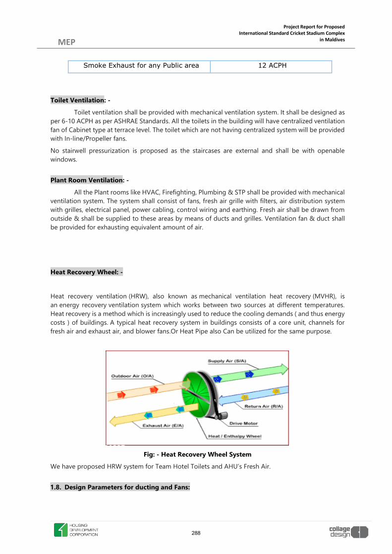
Project Report for Proposed International Standard Cricket Stadium Complex
in Maldives
MEP
Smoke Exhaust for any Public area 12 ACPH
Toilet Ventilation: -
Toilet ventilation shall be provided with mechanical ventilation system. It shall be designed as per 6-10 ACPH as per ASHRAE Standards. All the toilets in the building will have centralized ventilation fan of Cabinet type at terrace level. The toilet which are not having centralized system will be provided with In-line/Propeller fans.
No stairwell pressurization is proposed as the staircases are external and shall be with openable windows.
Plant Room Ventilation: -
All the Plant rooms like HVAC, Firefighting, Plumbing & STP shall be provided with mechanical ventilation system. The system shall consist of fans, fresh air grille with filters, air distribution system with grilles, electrical panel, power cabling, control wiring and earthing. Fresh air shall be drawn from outside & shall be supplied to these areas by means of ducts and grilles. Ventilation fan & duct shall be provided for exhausting equivalent amount of air.
Heat Recovery Wheel: -
Heat recovery ventilation (HRW), also known as mechanical ventilation heat recovery (MVHR), is an energy recovery ventilation system which works between two sources at different temperatures. Heat recovery is a method which is increasingly used to reduce the cooling demands ( and thus energy costs ) of buildings. A typical heat recovery system in buildings consists of a core unit, channels for fresh air and exhaust air, and blower fans.Or Heat Pipe also Can be utilized for the same purpose.
Fig: - Heat Recovery Wheel System
We have proposed HRW system for Team Hotel Toilets and AHU’s Fresh Air.
1.8. Design Parameters for ducting and Fans:
288

Project Report for Proposed International Standard Cricket Stadium Complex
in Maldives
MEP a) Duct design shall be:
Maximum flow velocity in ducts for air conditioning
: 1500 fpm
Maximum flow velocity in ducts for ventilation in pump room, boiler room, generator room, toilet exhaust & Kitchen exhaust.
: 1500 – 2500 FPM
Maximum friction : 0.1-inch WG/100 ft run
b) Ventilation Fan:
Maximum fan outlet velocity for fan up to 450 mm dia : 1800 fpm
Maximum fan outlet velocity for fan above 450 mm dia 2400 fpm
Maximum fan speed for fans up to 450 mm dia : 1440 RPM
Maximum fan speed for fans above 450 mm dia : 1000 RPM
2.0 ELECTRICAL SYSTEM
2.1 Purpose: The section outlines understanding of the power provided by Local power supply company & power supply arrangement to be provided for the different utilities of Maldives International Cricket Stadium premises. The design is to satisfy all requirements given by client & statutory authority guidelines. The design is to provide reliable and safe electrical supply and distribution system which is important for any modern development buildings.
The salient features of design of Electrical system and provision are: ¾ Compliance of codes of practice and statutory requirements. ¾ Easy in operation, control and flexibility. ¾ Energy conservation measures in design.
2.2 Design Strategy & Criteria: -
Relevant Standards:
¾ Maldives Energy Authority ¾ Maldives Building Code ¾ State Electrical Company (STELCO) ¾ International Electrotechnical Commission ¾ National Lighting Code 2010
289

Project Report for Proposed International Standard Cricket Stadium Complex
in Maldives
MEP 2.3 Source of Power Supply: -
GRID POWER
Based on Electrical load, it is recommended that the application for the power is with 11kV supply voltage. The Principal source of electrical power shall be from Local Power Supply Company (STELCO).
The HT Power shall be tapped from nearest EB Substation and HT Cable shall be laid from EB Substation to proposed substation within premises.
Based on Electrical Demand load for entire project, it is suggested to provide Oil cooled type
transformer substation & 1No. of HT Panel. The panel specifications shall be complying to IEC 62271.
The panel shall be with motorized type VCBs, fault passage indicators, communicable port for remote
operation and monitoring system.
HT & LT switchgear protection and tripping system will have 24 volts DC power supply through
dedicated sealed maintenance free battery pack with battery charger.
HT supply from switchyard is proposed through 11 kV earthed HT cable buried directly under ground.
Cable shall be provided with sand filling on all the sides and half round tiles shall be laid over the cable.
H.T meter for the connected load of 2292 KW & Demand load of 1540 KW.
We shall provide Two no. of 750KVA, 11KV/433V Oil Cooled Transformer for the Stadium. Further LT power from this Transformer will be terminated in main LT panel in the proposed electrical room at Ground Level.
The LT power shall subsequently be distributed to utilities such as Stadium Lighting, General Lighting, PHE Pumps, HVAC Equipment’s, Fire pumps, Ground Floor, Podium Level & First Floor etc.
For Shops, we shall be providing LT metering through Floor Panels. Dual Source energy meter shall be provided with BMS compatibility which will record the Energy consumption of Individual shops. DG POWER
Considering the application, the alternate supply source shall be provided for the requirements. So,
100% Power Back-up consider for this project.
The Diesel engines shall be radiator cooled and shall be getting start command during main power
failure. 2Nos. 1000 kVA DG Set with supply voltage of 415V is proposed for the entire project at
Ground level. The DG’s will be housed in acoustically treated enclosures which shall be naturally
ventilated as per the requirement. The exhaust combustion gases will be let out external through
separate stacks at a height as per the Pollution Control Board norms and local approving authority.
290

Project Report for Proposed International Standard Cricket Stadium Complex
in Maldives
MEP The acoustic treatment of the DG enclosure shall be such that the
insertion loss is less than 25 dB(A). Measured at a distance of 1 Meter from external partition. Noise
level from DG sets shall not exceed 75 dB (A) at 1 m distance, during daytime and 70 dB (A) during
nighttime. Also, residential silencer shall be provided for each DG set.
DG sets shall be provided with Considering load listed in load sheet attached. The proposed DG sets
shall be designed at 415 Volt normal voltage level. The electrical changeover shall be planned to
restoring power supply within 15 seconds of disruption (black-out or brown-out) of power.
DG sets shall be running independently as per the load distribution for common load. Out goings from
the DG panel will supply power to the Main LT Panel through DG Synchronizing Panel. The changeover
between Grid Power and Emergency Power will be done by Electrical Interlock. The single common
distribution network will be used for downstream, reducing cost of dual cabling.
The day storage tanks of 990 Liters shall be located near the DG sets. Independent fuel storage tanks
to DG set shall to be provided. Auto start control panel incorporating all safety features shall be
designed, fabricated and wired by the authorized vendor of manufacturer of the DG set.
291
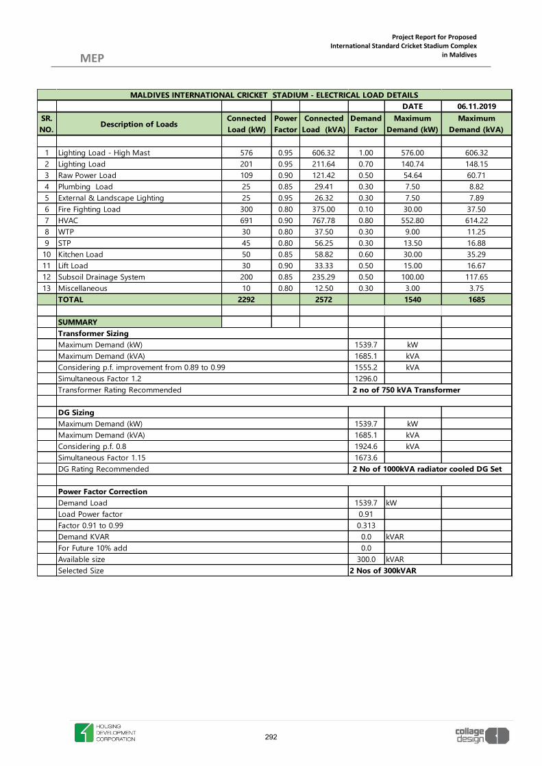
Project Report for Proposed International Standard Cricket Stadium Complex
in Maldives
MEP
DATE 06.11.2019SR. NO. Description of Loads
Connected Load (kW)
Power Factor
Connected Load (kVA)
Demand Factor
Maximum Demand (kW)
Maximum Demand (kVA)
1 Lighting Load - High Mast 576 0.95 606.32 1.00 576.00 606.322 Lighting Load 201 0.95 211.64 0.70 140.74 148.153 Raw Power Load 109 0.90 121.42 0.50 54.64 60.714 Plumbing Load 25 0.85 29.41 0.30 7.50 8.825 External & Landscape Lighting 25 0.95 26.32 0.30 7.50 7.896 Fire Fighting Load 300 0.80 375.00 0.10 30.00 37.507 HVAC 691 0.90 767.78 0.80 552.80 614.228 WTP 30 0.80 37.50 0.30 9.00 11.259 STP 45 0.80 56.25 0.30 13.50 16.88
10 Kitchen Load 50 0.85 58.82 0.60 30.00 35.2911 Lift Load 30 0.90 33.33 0.50 15.00 16.6712 Subsoil Drainage System 200 0.85 235.29 0.50 100.00 117.6513 Miscellaneous 10 0.80 12.50 0.30 3.00 3.75
TOTAL 2292 2572 1540 1685
SUMMARY
1539.7 kW1685.1 kVA1555.2 kVA1296.0
1539.7 kW1685.1 kVA1924.6 kVA1673.62 No of 1000kVA radiator cooled DG Set
1539.7 kW0.910.3130.0 kVAR0.0
300.0 kVAR
Factor 0.91 to 0.99Demand KVARFor Future 10% add
DG Rating Recommended
Maximum Demand (kW)Maximum Demand (kVA)Considering p.f. 0.8Simultaneous Factor 1.15
Demand Load
2 Nos of 300kVAR
MALDIVES INTERNATIONAL CRICKET STADIUM - ELECTRICAL LOAD DETAILS
2 no of 750 kVA Transformer
Maximum Demand (kW)Maximum Demand (kVA)Considering p.f. improvement from 0.89 to 0.99Simultaneous Factor 1.2Transformer Rating Recommended
Transformer Sizing
DG Sizing
Available sizeSelected Size
Power Factor Correction
Load Power factor
292

Project Report for Proposed International Standard Cricket Stadium Complex
in Maldives
MEP 2.4 Source of Power Supply: -
Point of Supply:
The LT power from the transformer will be connected to the Main Panel of the Stadium which will be installed in the LT room. Following are considered as the utility loads of the Stadium & Proposed commercial building.
i. Stadium High Mast Lighting. ii. External Lighting. iii. PHE & Firefighting iv. Equipment load v. HVAC Equipments vi. Proposed Shops vii. Ground Level, Podium Level & First Level
All panel boards and their associated overcurrent devices will be sized for both the normal load current, as well as the maximum available short circuit current.
All standard panel boards will have Aluminium bus bars, a 100% rated neutral bus and a safety ground bus.
Panel boards serving sensitive electronic equipment for harmonics will have 200% rated neutral bus as well as, a safety ground bus.
All panel boards should have at least 30% spare circuit breakers installed. Panel boards will confirm to the relevant International Standards.
The Power panels shall be fabricated from MS sheet steel 16 gauge and shall be of compartmental design. The main supporting framework shall be of angle iron or fabricated by 14 SWG MS Sheet. The panel will be self-supporting design, dust and vermin proof, IP42 and fully inter locked with isolating switches. The panel-mounted switches shall have Interlock defeat for testing and inspection. The board frames will be fabricated using suitable mild steel structural sections or pressed & shaped cold rolled sheet steel of thickness not less than 2.0mm & the frames be enclosed by cold rolled sheet steel of thickness not less than 1.65 mm, smoothly finished, levelled & free from flaws. Doors & covers shall be made of cold rolled sheet steel of thickness not less than 1.65 mm. Stiffeners shall be provided wherever necessary.
The panel shall be powder coated comprising of seven tank pre-treatments, degreasing and de-scaling in sulphuric acid etc. & shall be finished with powder coated paint over two coats of red oxide primer. Powder coating synthetic enamel paint for smooth finish. The color of paint shall be Siemens grey.
The panel shall be designed to facilitate inspection, cleaning and repairs. The clearance between phase to phase and phase to earth or metal parts shall be as per relevant IEC standards.
The metering instruments like voltmeter, ammeter etc. shall be flush mounted and shall be of 0.5 class accuracy. All indication lamps shall be of LED type & all metering should be digital type. All energy meter will be with RS485 port & will have provision to BMS connectivity.
293

Project Report for Proposed International Standard Cricket Stadium Complex
in Maldives
MEP
2.5 Lighting & Raw Power Distribution: -
Lighting & Power DBs will be provided depending on the electrical loads calculated based on no. & type of light fixture. Each DB will have one no of FP MCB as Incomer & three numbers of DP RCCB (30 amps tripping current) as Sub incomer for each Phase. 230 Volts single phase supply will be provided to each fixture. Dedicated feeders will be provided for flood lights. Outdoor / Street lighting shall be as per architecture landscape drawing. These lights shall be controlled through times for a specific time of operation. Following are the area wise illumination level requirement:
Cricket Field 2500Lux Electrical room 300Lux External Areas 50Lux Lift Lobbies 150Lux Restaurant 300Lux Locker Room 250Lux VIP Lobby 300Lux
Toilet 200Lux Lounge 300Lux Dormitory 250Lux
Emergency Lighting: Emergency lights shall be provided to achieve the following minimum coverage.
ELECTRICAL DISTRIBUTION SCHEMATIC
294

Project Report for Proposed International Standard Cricket Stadium Complex
in Maldives
MEP 1. Staircase and 20% lighting in circulation, corridor, lift lobbies, services area etc. and shall be provided through Inverter Supply
having 15 minutes backup.
2. Uninterpreted power supply (UPS) system for all IT, CCTV, Fire alarm, PA, Access, BMS, workstations & USB charging points by centralized system with N configuration with 30 min battery backup.
2.6 AUTOMATIC POWER FACTOR CONTROL:-
Capacitor banks shall be provided at substation level with the APFC Relay for control of power factor. As per regulation, all bulk users are required to maintain power factor of 0.92 lagging and above, failing which stringent penalties are imposed by the power distribution companies. For planning purpose, the power factor correction shall be set for 0.99 lagging.
We have proposed 2 Nos of 300kVAR APFC Panels.
It is recommended to maintain a high-power factor of 0.99 which has the following merits:
a) Utility companies insist that the power factor of the consumers’ load will be maintained at 0.92 as mandatory. If power factor falls below the prescribed limit, a surcharge will be levied on the consumer.
b) With a higher power factor, demand charges will be lower. c) The current flowing through the incoming main cable will get reduced which in turn will reduce
the transmission losses (I2R). d) Utility Power companies will give incentive in the monthly electricity bill if the power factor higher
than 0.95. Every .01 increase over & above 0.95 Power Factor will get 1% discount on the monthly consumption charges. For example, if the power factor is maintained at unity, then there will be 5% discount on the monthly consumption.
2.7 EARTHING:
The Earthing system will be designed as per the guidelines laid down in International Standard & to keep the earth resistance as low as possible.
Distribution earthing shall be carried all along the LT distribution system, or through local earth station and effectively bonding the cables / equipment i.e. Metallic enclosures of Panels, DB’s, Machineries, Motors, metallic frames provided for different equipment supports. The entire network will be designed with GI Strip laid over tray & connected to the provisions for Enclosure earth connectivity will be detailed out in Earthing Schematic drawing. Raw (Body) Earth will be provided by appropriate size of GI wires / GI strips up to Office.
Earthing for light and power points shall be carried out with insulated copper earth wire running throughout the length of circuits and shall be terminated at boxes, fixtures etc. with effective bonding to main earth. The size of earth wire shall be as per IEC standards.
295

Project Report for Proposed International Standard Cricket Stadium Complex
in Maldives
MEP Separate and distinct earth stations and electrodes shall be provided
for UPS System, EPABX and Computers. Resistance for clean earth & for electrical system earth shall be kept below one ohm. Dedicated Earthing will be tapped from the earth pits which will be installed for clean earthing. Two numbers of Chemical type of bore earth pits will be provided with equipotential bonding. The entire network is designed with PVC insulated copper conductor wires laid over tray & terminated at Copper Earth Bus.
Raw Earthing: Four numbers of Raw Earth conductors (for Metallic enclosures of Panels, DB’s, metallic frames provided for different equipment supports) will be provided in main cable tray/trench. The same will be tapped for Floor Panels & will be bonded to Metallic enclosures of Panels, DB’s, metallic frames provided for different equipment supports. The entire network is designed with GI Strip laid over tray & connected to the provisions for Enclosure earth connectivity as detailed out in Earthing Schematic drawing. Four numbers of RAW earth conductor will be provided in main cable tray/trench for
Earthing is being provided. EARTH PIT MATRIX:
Transformer Neutral 2 Nos of Cu Earth Pit Transformer Body 2 Nos of GI Earth Pit DG Neutral 2 Nos of Cu Earth Pit DG Body 2 Nos of GI Earth Pit Lift 2 Nos of GI Earth Pit (Each Lift) All LT Panel 2 Nos of GI Earth Pit LV System 2 Nos of GI Earth Pit
2.8 CABLES & WIRES:
The distribution from inception of power to main panels, sub panels distribution boards, isolators of equipment will be carried out by Aluminium / Copper conductor XLPE insulated FRLS PVC sheathed armoured cables. The minimum size of Aluminium cable will be 10sqmm. These cable terminations will be carried by double compression brass alloy cable glands. Copper conductor cables will be terminated with copper Lugs & Aluminium conductor cables will be terminated with bimetallic lugs.
1. The system of wiring shall consist of PVC insulated FRLS copper conductor wires in metal conduits. Minimum size of copper conductor shall be 2.5 sq.mm for lighting circuits and 4/2.5 sq.mm will be terminated with appropriate types of copper lugs for power. Color code shall be maintained for the entire wiring installation that is Red, Yellow and Blue for the three phases, Black for neutral and Green for Earthing. Besides, ferruling shall be provided for number coding and easy identification for maintenance purposes.
296

Project Report for Proposed International Standard Cricket Stadium Complex
in Maldives
MEP
2.9 LIGHTENING PROTECTION:
Conventional LPS as per IEC 62305-3 is proposed to protect building from lightning strikes.
This part of IEC 62305 deals with the protection, in and around a structure, against physical damage and injury to living beings due to touch and step voltages.
The main and most effective measure for protection of structures against physical damage is considered to be the lightning protection system (LPS). It usually consists of both external and internal lightning protection systems. An external LPS is intended to
x Intercept a lightning flash to the structure (with an air-termination system), x Conduct the lightning current safely towards earth (using a down-conductor system), x Disperse the lightning current into the earth (using an earth-termination system).
An internal LPS prevents dangerous sparking within the structure using either equipotential bonding or a separation distance (and hence electrical insulation) between the external LPS components and other electrically conducting elements internal to the structure. Main protection measures against injury to living beings due to touch and step voltages are intended to:
x Reduce the dangerous current flowing through bodies by insulating exposed conductive parts, and/or by increasing the surface soil resistivity,
x Reduce the occurrence of dangerous touch and step voltages by physical restrictions and/or warning notices. The Vertical air terminal is located at edge or highest point of staircase head room. Number of earth pits considered are as per Type B Earthing System.
Ring earthing to be installed at the depth of 1 meter from the protected structure and laid at the depth of 0.5 meters around the building periphery.
Following are the parts of Conventional Lightning Protection System. x Grid of horizontal conductor above the roof.
x Down Conductors.
x Joints & connectors.
x Testing Joints.
x Earth Termination Network (Peripheral grid around the warehouse building of earth ground conductor).
297

Project Report for Proposed International Standard Cricket Stadium Complex
in Maldives
MEP
2.10 GENERAL: 1. GENERAL:
Following are the general provision made with the Electrical System & Electrical Rooms.
x Shock Treatment chart, first aid box & CO2 Fire extinguisher will be provided in Electrical Room. x Mounting frames will be provided for all Electrical Panels wherever false flooring is provided. x A minimum of 30% spare breakers will be provided on all Panels. x Insulating Rubber Mats will be provided in Front & Back of All Electrical Panels. x All Digital Energy Meters are with Communication protocol for Connectivity with BMS. x Identification of Panel Feeders will be indicated on Aluminum Anodized Label.
2.11 FIRE EXTINGUISHER
The extinguishers shall form as a first aid action against small and incipient stage fire so as to extinguishing of the fire even before it develops into a major hazard. Carbon-di-oxide of 4.5 kg and ABC Type1/2/4/6/9 Kg capacity shall be provided as first aid fire extinguishing appliances. The CO2 Type Extinguisher are Provided in critical rooms whereas ABC type Extinguishers shall be provided in Enclosed type stadium building area (Pavilion block, Office). The extinguisher shall be so distributed over the entire area so that a person has to travel not more than 15 Meters to reach the nearest extinguisher. These shall be placed or hanged on wall in a group on several suitable places. The number of extinguishers shall be calculated as per NBC/TAC/NFPA. All the Extinguishers shall be ISI marked only.
3.0 LOW VOLTAGE SYSTEM (FAS & PAS)
The following systems shall be included in the Extra Low Voltage Systems.
x FIRE DETECTION AND ALARM SYSTEM (FAS) x DIGITAL PUBLIC ADDRESS SYSTEM (PAS) FOR EMERGENCY VOICE ALARM x FIRE DETECTION AND ALARM SYSTEM INCLUDING EMERGENCY PAGING AND VOICE
ALARM, EMERGENCY TELEPHONE AND SMOKE CONTROL SYSTEM 3.1 General Fire detection shall be network fire detection system with distributed voice evacuation system. The network fire alarm system shall consist of all necessary hardware equipment and software programming to perform the following functions. Fire alarm and detection operation Control and monitoring of Elevators, smoke control equipment, Access Control system, and Voice Alarm system etc.
298

Project Report for Proposed International Standard Cricket Stadium Complex
in Maldives
MEP Network fire alarm control panel shall include all features for
standalone FACP’s and shall have network communication capabilities. The material appliances Equipment’s and devices shall be listed by UL 864/FM/EN/54 as part of projected premises signaling system and smoke control system. 3.2 Codes & Listing: The equipment and installation shall comply with the current and latest edition of the following codes and listing: A) National Fire Protection Association (NFPA) - USA: NFPA 72 National Fire Alarm Code NFPA 76 Telecommunication Facilities NFPA 101 Life Safety Code NFPA 90A Air conditioning & ventilation system Listed B) Underwriters Laboratories Inc. (UL) - USA:
UL 268 Smoke Detectors for Fire Protective Signaling Systems UL 864 Control Units for Fire Protective Signaling Systems 9th Edition UL 268A Smoke Detectors for Duct Applications UL 521 Heat Detectors for Fire Protective Signaling Systems UL 464 Audible Signaling Appliances UL 38 Manually Actuated Signaling Boxes UL 346 Water flow Indicators for Fire Protective Signaling Systems UL 1971 Visual Notification Appliances UL 228 Door Holders UL 1481 Power Supply for fire protective signaling system. UL 1711 Amplifiers for Fire Protective Signaling Systems. UL 1635 Digital Alarm Communicator System Units
C) Factory Mutual (FM) Approval ADDENDUMS thereafter in UL Code for Fire Detection (2007). UL 9th Schedule Certification International Standards Organization (ISO) ISO-9000 ISO-9001 European Union (EU) EMC Directive 89/336/ EEC Electromagnetic Compatibility Requirements
LOCAL CODES MALDIVES NATIONAL BUILDING CODES MALDIVES ENERGY AUTHORITY 3.3 Fire Detection and Alarm System
299

Project Report for Proposed International Standard Cricket Stadium Complex
in Maldives
MEP
The fire detection and alarm system control panel shall monitor and display the activation of each device in the system, such as heat detector, smoke detector, multicriteria detector, manual call point, sprinkler water flow switch and sprinkler valve tamper switch or any other input device which may be required. Fire Alarm Panel shall be provided with GUI software for graphics monitoring.
The system shall be of the addressable analog multiplexed type, completely supervised, such that a break in any wire (loop) shall not prevent any device from operating, with multiplexing cabinets installed in appropriate approved locations. The system shall be of the type such that each device connected to the system shall be provided with unique address and separately identified at the Main control panel (MCP). Detectors & devices shall be looped with Class A caballing.
x Common Service Areas at every floor level such as Electrical Rooms, Electrical Substation, AHU rooms, Hub rooms, Servers rooms, Plant rooms will have Multicriteria Detectors.
x Wherever the height is more than 9 m beam detectors to be provided. x Fixed Heat Detectors to be proposed in Kitchen/Pantry Area. x Rate of rise Heat Detectors to be proposed here for Car Park area. x The monitor module shall be provided for interfacing of sprinkler flow switch, tamper switch
on each level. x Control Module for tripping equipment’s such as Lift, Escalators, Access door’s, AHU’s, TFA’s,
Ventilation & Exhaust fans in case of fire. x Separate Control Modules for all Smoke extraction system for Basements Smoke extract fans
etc. x Separate Mimic Panel to be installed at each floor near security desk. x Control Module to open Floor levels Smoke dampers & to start the Smoke Extract fans based
on the cause & effect matrixes per operation requirements. 3.4 Emergency Telephone The emergency telephone system shall provide two-way communications capability between the main control panel and jacks for emergency telephone. The emergency telephone shall be furnished as part of the overall system. Equipment The Main control panel shall be placed in Fire Control Room/IBMS Room in a location at Ground Floor. The location should preferably be in an area readily accessible from the outside, for easy access for fire rescue team. The most preferred location in the main entrance lobby. The exact location shall be approved by the appropriate authorities. The control panel(s) shall be a multi-processor based networked system designed specifically for fire, one-way and two-way emergency audio communications, smoke control, extinguishing agent
300

Project Report for Proposed International Standard Cricket Stadium Complex
in Maldives
MEP releasing system if necessitated, with integration modules for BMS
or any third-party control/annunciation. The control panel shall be UL/FM listed. The control panel shall include all required hardware, software and site-specific system programming to provide a complete and operational system. The control panel(s) shall be designed such that interactions between any applications can be configured and modified. The control panel(s) operational priority shall assure that life safety takes precedence among the activities coordinated by the control panel. The control panel shall include the following capacities: Support up to minimum 125 detectors / 125 Devices per Loop Support up to minimum 2500 analog/addressable points per panel Support network connections up to minimum 64 or other control panels and annunciator. Support multiple digital dialers and modems Support multiple communication ports and protocols Support up to a minimum of 1740 chronological events. The network of control panels shall include the following features: Ability to download all network applications and firmware from the configuration computer from the configuration computer from a single location on the system. Provide electronic addressing of analog/addressable devices. Provide an operator interface control/display that shall annunciate command and control system functions. Provide an internal audible signal with different programmable patters to distinguish between alarm, supervisory, trouble and monitor conditions. Provide a discreet system control switch provided for reset, alarm silence, panel silence, drill switch, previous message switch, next message switch and details switch. Provide system reports that provide detailed description of the status of system parameters for corrective action or for preventative maintenance programs. Reports shall be displayed by the operator interface or capable of being printed on a printer. Provide an authorized operator with the ability to operate or modify system functions like system time, date, passwords, holiday dates, restart the system and clear control panel event history file. Provide an authorized operator to perform test functions within the installed system. The control panel shall contain a standby power supply that automatically supplies electrical energy to the system upon primary power supply failure. The system shall include a charging circuit to automatically maintain the electrical charge of the battery. The control panel shall be provided with all hardware and software compatibility devices for integration with other third-party systems on open platform required for safe functioning and ease of operability for the infrastructure. A Network repeater panel (NRP)/fire workstation shall be installed in main control room or security control room of building, clearly visible to the operators and in an engineering or security area manned 24 hours per day. This remote unit shall repeat all alarm functions displayed at the main control panel. The silencing circuit shall be automatically reset when the fire alarm system is reset. Emergency Telephone System
301

Project Report for Proposed International Standard Cricket Stadium Complex
in Maldives
MEP All remote emergency telephones will communicate with the
emergency telephone control panel at the MCP as follows: The insertion of any telephone handset into its jack will cause the appropriate phone location indicator to flash and a distinctive audible pulsing sound to be heard in the fire command center. The subsequent picking-up of the master phone and operation of that phone selector switch will silence the pulsing tone, cause the phone location. Indicator to stop flashing and remain on and complete the coupling of the remote telephone to the master telephone to provide direct and private communications. Any subsequent insertion of another telephone into its jack on the same circuit will not cause the pulsing tone to reactive if any two-way communication has already been established. Any new telephone handset circuit will cause its discreet indicator to flash until acknowledged by the master telephone or the handset is replaced. The emergency telephone system will provide the capacity to handle simultaneous use of multiple remote phones. All phone jacks shall annunciate and monitor against fault or tampering (i.e. supervised). The removal of all remote telephone handsets from their jacks will cause the restoration of all normal supervisory functions. If any remote phone is removed, then the appropriate phone zone indicator will flash, and the pulsing tone will resume in the fire command centre. Telephone operation and telephone system faults will be stored in system memory and it will be possible to print out these operations on demand. 3.5 Battery Backup Automatic battery charger, 24 volts sealed lead acid batteries sufficient for 48 hours normal working and then be capable of operating the system for 30 Minutes during an emergency condition as per NFPA-72 guidelines. 3.6 Coordination with Other Systems The fire detection and alarms system shall have interface with other building systems, which are described under other sections of the report, as follows: Air-Conditioning (AC) The fan control sequences during alarm conditions shall be determined in conjunction with the air-conditioning system design. Building Automation System (BAS) The life safety system is required to initiate various fan control functions. These functions shall be wired directly from the Life Safety system to the motor controller to achieve the required fan and damper control. These functions shall be properly coordinated with the BAS to be certain that life safety system functions will override control initiated from the BAS control panel.
302

Project Report for Proposed International Standard Cricket Stadium Complex
in Maldives
MEP Sprinkler / Pumps system
The life safety system is required to monitor fire hydrant / sprinkler pump status. The pump controllers shall have the necessary volt free output signals available. Fire sprinkler pump installations have multiple valves in the immediate vicinity of the pump set. Isolation valves are also envisaged to be provided on sprinkler system (zone isolation) and wet riser of hydrant system. Each of these valves shall be provided with a tamper switch. The life safety system shall have provisions for wiring the correct number of tamper switches. The tamper switches at any one pump location shall be arranged to appear as one trouble alarm at the MCP. 3.7 Security System The life safety system is required to open Access Control Door in case of fire. FAS Cables LSZH armoured cables with 2C X 1.5 sq.mm annealed copper conductor having Cross linkable Low smoke zero halogen insulation LSZH for inner and outer sheath. Armoured cables should comply to BS 6387 & BS 7846 (latest edition). Armoured cables should meet fire performance circuit integrity test as per codes. The outer Sheath of cable should be RED in colour. DIGITAL PUBLIC ADDRESS AND BACKGROUND MUSIC SYSTEM The Digital Public Address & Background Music system shall essentially comprise of the following components: Head-end Equipment Distribution Equipment Reception Equipment The Digital Public Address & Background Music system components shall have sufficient capacity to ensure distribution of voice to various areas of the building with equal clarity. This system shall permit one-way communication in the form of emergency announcement from the main control panel to any floor or group of floors simultaneously. The system shall be capable of manual operation or automatic operation initiated by the fire alarm system. Speakers shall be located as required to achieve acceptable audibility in all areas of the building. Communication loops will be supervised “Style 7” (Class “A”) and therefore return to the control panel. All PA system components should be provided with UL / EN listed. The Digital PA System is proposed for following area in entire premises,
303

Project Report for Proposed International Standard Cricket Stadium Complex
in Maldives
MEP 6Watt Speaker Celling/Wall mounted shall be provided at Common
Area such as Lift Lobbies, Electrical Room, Toilets, and Staircase at each floor level will be in Lessor Scope. 6Watt Speaker Celling mounted shall be provided at complete floor common area. 20Watt PA wall mounted weather proof Projector speaker to be proposed here for whole Car Park area. IP based touch screen Common announcement console for all towers will be kept at Main Security control room. PA Graphical station will be at Main Security Control Room. Head End Equipment Head end equipment shall be divided into two elements – source and amplification. Source equipment shall be IP based microphones for public address. Additionally, message/alarm tone generators shall be used for emergency calls / evacuation. The microphones shall be IP based professional grade offering superior performance characterized by high sensitivity, minimum noise distortion and low sensitivity to feed back. These shall be connectable to zone selection consoles, each with its own selectable priority, from which each operator shall send announcement to specific audio zones Distribution Equipment The distribution equipment shall primarily comprise of following equipment’s Digital Voice Controllers (DVC) Digital Audio Amplifiers (DAA) System shall have a Redundant Amplifier for each amplifier bank (N+1) i.e. one Backup for every four amplifier so that when an amplifier fails redundant amplifier takes over automatically speaker lines impedance monitoring, fault logging upto 2048 incidents, Amplifier monitoring, Integration with FACP, 100 priority levels, 7 band parametric equalizer per zone. Completely digital audio transmission. The controller shall have In-built digital message recording and broadcast. System shall have automatic Amplifier Changeover to hot standby amplifier in case of failure of working amplifier with internal relays. Digital signal processing for audio.
304

Project Report for Proposed International Standard Cricket Stadium Complex
in Maldives
MEP
Reception Equipment The reception equipment shall comprise primarily of speakers of varying types depending upon area allocation / usage. Wherever false ceiling exists, the speakers shall be of concealed mounting type with a wide bandwidth. Where false ceiling does not exist, the speakers shall be surface mountable. Type of Speakers used in the Premises; 6 W Ceiling Mounted Speaker with Multi Tapping Feature. 6 W Wall Mounted Box Type Vandal Proof Cabinet speakers with Multi Tapping Feature. 20 W Wall Mounted Box Type Metal Projector Speaker with Multi Tapping Feature. All speakers shall have the inbuilt facility of selectivity of the sound power produced. The P A rack with announcement will be placed in the Each Tower Fire Control Room at ground floor level. PA Cable LSZH armoured cables with 2C X 1.5 sq.mm Shielded Twin Twisted pair annealed copper conductor having Cross linkable Low smoke zero halogen insulation LSZH for inner and outer sheath. Armoured cables should comply to BS 6387 & BS 7846 (latest edition). 3.8 Close Circuit Television (CCTV) monitoring system will be provided in following areas Main Building Spectator Stand External Periphery of Structure All Lobby Car Parking Drop Off CCTV Surveillance The CCTV system, will comprise of following
1) Cameras will be of following type:
i) High speed dome indoor type IP cameras
: All above specified areas, entries, exists.
ii) High speed dome outdoor type IP cameras
: External areas, entries & exits
iii) PTZ cameras – Analogue : Periphery of the building
2) Video recorder along with LCD
3) Storage system
The system will be integrated to a Network Video Recorder (NVR) with a high capacity hard disc
305

Project Report for Proposed International Standard Cricket Stadium Complex
in Maldives
MEP which stores the images in spatial format which cannot be
tampered or modified. This central monitoring system for CCTV surveillance is placed in a security room. All cameras will be connected to Patch panel using Cat 6 cable. 3.9 ACCESS CONTROL SYSTEM
The Access Control system shall be fully integrated and installed as a complete package by the Access/Security Control Contractor. The ACS shall be able to provide for and integrate (as required) the following subsystems:
x Integrated Access Control x Alarm Monitoring x Integrated Digital Video Management (CCTV system) x Interactive Alarm/Facility Graphics Display x Associated Access Control and Alarm Equipment Control x Access Initiated and Event Initiated Control
The Controller shall be based upon a distributed system of fully intelligent, stand-alone controllers, operating in a multi-tasking, multi-user environment on a true peer-to-peer, token passing Local Area Network (LAN). The SMS shall be capable of monitoring, recording, and displaying card access activity and supervised alarm inputs/outputs on a continuous, real time basis. Each installation shall comply with local, state, and federal code requirements as applicable. The system shall be user friendly, providing a user interface that allows for training of non- technical personnel to effectively operate and administer the system.
The ACS shall be designed to provide a centralized location with the ability to monitor, control, view, and communicate from a secure location within a facility or within the facilities or systems network.
System expansion capability: Minimum 100% over specified requirements with no additional software or required software upgrades.
Following spaces shall be provided with Access control system:
1) Main Building Employee Entry & Exits
2) Data Server/HUB Rooms
3) Main HT/LT Electrical Rooms
4) Floor level service Rooms
5) UPS & Battery Rooms
6) IBMS/Security Control Room at Basement floor
7) Main Fire Control Room at ground floor Boom Barrier- Car Parking:
306

Project Report for Proposed International Standard Cricket Stadium Complex
in Maldives
MEP The boom barriers for car park entry - exit with token system etc. all as required will be designed and necessary power provision will be made in electrical design. At the main entrance the system with access through smart card for security provision.
Under Vehicle Scanning System:
UVSS shall be able to capture high resolution, complete and composite underside image of all incoming and outgoing small, medium and large vehicles without the vehicle being required to be stopped. UVSS shall be capable to capture images of a moving vehicle up to the speed of 20Kmph while ensuring that the composite image is dynamically adjusted to the variable speed. The UVSS system shall process the images
from the camera into single view of the undercarriage and display it on the monitor with date and time. The UVSS shall give a real time complete under belly image of vehicles. In case of suspected image, the operator should be able to zoom into any area of the image to take a closer look. The UVSS system must be equipped with camera for reading Number Plate of incoming vehicles. The UVSS shall also have the capability to view composite image and video in Offline mode for all the past recorded images. The UVSS shall be capable of storing at least one month recorded data for all vehicles considering around 100 vehicles movement per day. The UVSS shall have the feature of dynamically and automatically adjusting the brightness and contrast to ensure good quality images in different light conditions. If an unsatisfactory or partial image is captured, then the UVSS system should create an alarm Technical Requirement:
Camera CCD Color Video Camera(s), Auto iris, DSP Illumination White LED Array Video Display 22” LED Monitor Recording Real time video Zoom 4x Control keypad/Mouse
307

Project Report for Proposed International Standard Cricket Stadium Complex
in Maldives
MEP
4.0 PUBLIC HEALTH ENGINEERING SYSTEM
4.1 Purpose: The Section outlines Public Health Engineering system selections and extent of provisions for the project.
4.2 Design Strategy & Criteria:
Relevant Standards:
The plumbing and drainage installation shall be designed to comply with the following ¾ Uniform Plumbing Code ¾ Relevant British Standards ¾ American Society of Plumbing Engineers (ASPE), Design Data Book Volume I to IV
4.3 Design Approach :-
The plumbing design for the development is designed keeping in mind below parameters: -
Adequate and equal pressure of cold water shall be maintained in bathrooms, Toilets and urinals, common toilets and other designated areas. Levels of internal roads / pavements and other services in the area shall be considered while designing sewer and storm water drainage. Water Efficient Plumbing Fixtures Low flow - fixtures shall be considered.
The primary source of water supply is considered from the Municipal authority. In case of non-availability of sufficient water supply for the project Bore well/Tanker water supply should be provided as alternate source of water supply. Water treatment plant is proposed so as to use tanker/bore well water for domestic purpose in case of scarcity.
The underground water tanks capacity shall be of 2 days of requirement. Domestic water supply for Cricket Stadium have been through Hydro-pneumatic system for making water available at residual pressure 1.5 kg/cm² at fixture outlet.
Sewage, drainage collection & conveyance system based on ASPE standards and applicable guidelines for the project.
4.4 Water Demand Calculation: -
Assumption and Consideration for water consumption
Retail /Shops:-
Gross water demand for Fixed Population per = 45 LPCD
1. Net Water Demand For Domestic Use = 25 LPCD 2. Net Water Demand For Flushing Use = 20 LPCD
308
Project Report for Proposed International Standard Cricket Stadium Complex
in Maldives
MEP Staff/Utility Personnel’s :-
Gross water demand for Fixed Population = 45 LPCD
1. Net Water Demand For Domestic Use = 20 LPCD 2. Net Water Demand For Flushing Use = 25 LPCD
Spectator Seating:-
Gross water demand for Football Stadium Seating = 10 LPCD
3. Net Water Demand For Domestic Use = 4 LPCD 4. Net Water Demand For Flushing Use = 6 LPCD
Drivers / Parking:-
Gross water demand for Training Building Population = 15 LPCD
1. Net Water Demand For Domestic Use = 5 LPCD 2. Net Water Demand For Flushing Use = 10 LPCD
Utilities:-
1. Net Water Demand For Irrigation, Landscaping = 5 L/Sq. Mtr 2. Net Water Demand For Field Play Area= 6 L/Sq. Mtr
Assumptions for population
¾ Stadium Seating & other Seatings – As per the occupancy data received from CDPL ¾ Retail – 10 Sq.Mtr /Person
309

Proj
ect R
epor
t for
Pro
pose
d
Int
erna
tiona
l Sta
ndar
d Cr
icke
t Sta
dium
Com
plex
in
Mal
dive
s
MEP
¾
Th
e pr
elim
inar
y co
mpu
tatio
n of
dai
ly w
ater
dem
and
for t
he b
uild
ings
is a
s fo
llow
s:-
Do
mes
tic
Co
ldFl
ush
ing
Do
mes
tic
Co
ldFl
ush
ing
To
tal
AFI
XED
PO
PU
LAT
ION
A.1
STA
DIU
M
1St
adiu
m S
eatin
g (
Incl
udin
g V
IP B
oxe
s,Sp
ecta
tor
Seat
ing
,Sta
ff,C
lub
Off
ices
etc
.)A
s p
er A
rea
Stat
emen
t20
000
46
8000
012
0000
2000
00
2M
ultip
urp
ose
Hal
l66
3A
ssum
ed -
06 S
q.M
tr /
Pers
on
111
2520
2763
2210
4973
Sub
To
tal
for
"A"
(Li
ters
)20
111
8276
312
2210
2049
73
BFL
OA
TIN
G P
OP
ULA
TIO
N1
Tota
l Par
king
As
per
Are
a St
atem
ent
835
1041
583
012
45
2Se
curi
ty G
uard
s/ S
taff
/ U
tility
per
sonn
els
- (
2 Pe
rso
n/Fl
oo
r/Zo
ne)+
(5
Pers
on/
Seat
ing
are
a zo
ne)+
(2
Pers
on/
Entr
y/Ex
it g
ate)
156
2520
3900
3120
7020
Sub
To
tal
for
"B"
(Li
ters
)23
943
1539
5082
65
To
tal
for
"A &
B (
Lite
rs)
To
tal
Occ
up
ancy
4035
087
078
1261
6021
3238
CO
ther
Wat
er U
sag
e
1G
ard
enin
g
6740
067
400
2Ir
rig
atio
n (G
roun
d +
Mo
und
Sea
ting
)84
900
8490
03
Ind
oo
r Sw
imm
ing
Po
ol
a) S
urfa
ce e
vap
ora
tion
( l/
d )
5400
0b
) Ba
ck w
ash
( l/
d )
3333
34
Tota
l Fie
ld O
f Pl
ay A
rea
7410
7410
5Ba
ckw
ash
5000
5000
Sub
To
tal
for
"D"
(Li
ters
)92
333
1597
1016
4710
TOTA
L IN
LIT
ERS
1794
1128
5870
3779
48T
OT
AL
IN
CU
M17
9.00
286.
0037
8.00
FLU
SHIN
G W
AT
ER R
EQU
IREM
ENT
126
RA
W W
AT
ER R
EQU
IREM
ENT
TR
EAT
ED W
AT
ER R
EQU
IREM
ENT
160
179
(134
80)
Sqm
* 5
l/Sq
m
395
*6 l/
Sqm
Ass
umed
1698
0 Sq
m *
5 l/
Sqm
1250
Sq
m*1
.8L*
24hr
s(1
250
Sqm
*1.6
L*10
00*0
.1)/
6
WA
TER
CO
NSU
MP
TIO
N D
ATA
Sr.
No
.C
OM
PO
NEN
T /
HEA
DA
REA
(SQ
.MT
R)
DES
CR
IPT
ION
TO
TA
L O
CC
UP
AN
CY
(N
OS.
)
CR
ITER
IA F
OR
WA
TER
R
EQU
IREM
ENT
WA
TER
REQ
UIR
EMEN
T
(LP
CD
)(L
PD
)
310

Proj
ect R
epor
t for
Pro
pose
d
Int
erna
tiona
l Sta
ndar
d Cr
icke
t Sta
dium
Com
plex
in
Mal
dive
s
MEP
Wat
er S
tora
ge
¾
Und
er G
roun
d W
ater
sto
rage
tank
s pr
opos
ed a
re d
etai
led
belo
w:
The
unde
rgro
und
wat
er ta
nks c
apac
ity sh
all b
e of
2 d
ays o
f dom
estic
& 2
day
of R
aw w
ater
requ
irem
ent.
The
flush
ing
wat
er ta
nk o
f 2 d
ays
stor
age
will
be
loca
ted
in
STP
area
.
WA
TER
STO
RAG
E TA
NKS
SU
MM
ARY
Sr.N
o.D
escr
iptio
nTo
tal C
apac
ity (m
³) p
er
Com
part
men
tN
o. o
f Com
part
men
tsTo
tal C
apac
ity (m
³)
Rem
ark
A.1 1
Fire
Tank
111
2.0
222
As p
er N
FPA-
132
Raw
Wat
er/T
anke
r Wat
er T
ank
160
2.0
320
2 da
ys S
tora
ge3
Dom
estic
Tre
ated
Wat
er T
ank
119
3.0
357
2 da
ys S
tora
ge4
Flush
ing
Wat
er T
ank
(In S
TP A
rea)
126
2.0
252
2 da
ys S
tora
ge5
Rain
Wat
er T
ank
550
2.0
1100
1 da
y St
orag
e
To
tal
1066
2251
Sr.N
o.D
escr
iptio
nCa
paci
ty (m
³) p
er
Com
part
men
tN
o. o
f Com
part
men
tsTo
tal T
ank
Capa
city
(m
³)Re
mar
k
B.1
Ove
rhea
d W
ater
Tan
k 1
Fire
Tank
281.
028
As p
er N
FPA-
13
Unde
r Gro
und
Wat
er T
ank
311

Project Report for Proposed International Standard Cricket Stadium Complex
in Maldives
MEP Water supply required for various purposes are categorized as follows:-
Potable Water:-
It is expected that the daily potable domestic water requirement for the premises / building shall be met through municipal water authority / Borewell tanker at site, Which is stored in underground storage tank. Water quality from tanker water shall be checked & appropriate treatment shall be provided.
Fig:- Water Supply Strategy
Water Storage Sizing: Water storage tank capacities for domestic as well as flushing is proposed with 2 days Storage Capacities for UG Water Tanks. The incoming main from municipality water supply line / tanker shall be led into fire reserve tanks, from where it shall be allowed to overflow in domestic raw water storage tanks; thereafter the water shall be treated and stored in domestic treated water storage tanks & supplied via Hydropneumatics system for domestic & flushing consumptions in sports complex.
Hot Water requirement is considered with centralized hot water system is considered with heat pump for VVIP, VIP, Cricket player rooms etc. Water Purifier with portable RO system has been considered at strategic locations like Corporate boxes, VVIP, VIP & Staff occupancies etc. Filtration room for swimming pool area is considered below swimming pool area. This will be finalized with architects confirmation.
312

Project Report for Proposed International Standard Cricket Stadium Complex
in Maldives
MEP
4.5 Hydro pneumatic System:-
In this system, water supply will be catered by hydro pneumatic system with uniform residual head of 1.5 kg/cm2- 2.1 kg /cm2 at every fixture at topmost level. No OHT requires for domestic & flushing water except fire requirement. Water distribution for domestic water supply for the building has been proposed based on the Buildings and height of the same. It shall be ensured that Pressure reducing valves (PRV) are provided (if required) to limit water distribution pressure to 1.5 – 4.5 Kg/cm². The distribution system will be designed considering domestic & flushing water requirement of units on each floor, frictional losses, static head available and residual head required. Hydraulic design involves optimizing the suitable diameter to get residual pressure at tap point with head loss in transit and static head due to height of building. The pipe sizing shall be based on fixture unit calculation as per ASPE standard. The pipe size of riser shall be restricted to nearest 4” size to optimize on capital cost, and for ease of installation and maintenance. However, the maximum velocity in the water supply piping shall not exceed 2.4 m/second.
Water meters shall be provided in individual commercial shop and stadium area for water consumption recording for efficient monitoring and assessment. Head losses through water meter shall be accounted for in water distributions calculations.
a. Flow : As per Fixture Unit Table
b. Residual Head : Min. 1.5kg/cm2
c. Velocity of flow : Upto 2.4 m/s for cold water & 1.5 m/s for hot
water
d. Pipe Sizing : As per Hazen-Willam’s Formula
313

Project Report for Proposed International Standard Cricket Stadium Complex
in Maldives
MEP
Fig:- Hydro-pneumatic System
All Water Supply piping material proposed is as follows:
i) Cold water (up to 2 inch) : CPVC ( SDR11) ii) Cold water (above 2 inch) : CPVC ( Schedule 40) iii) Hot water (up to2 inch) : CPVC ( Schedule 40) iv)
Hot water (above 2 inch) : CPVC ( Schedule 80)
Valves will be combination of butterfly, ball and Globe valves. The material of the valves will be Gunmetal /Stainless steel/ PVC.
Swimming Pool:- As per the design Olympic size indoor swimming pool is proposed in the Stadium area. We
propose to provide swimming pool recirculation & filtration system. The system shall comprise of balancing tank ,recirculation pumps, filters & salt water chlorination recirculation. Dosing units & ancillaries for the pool.
Flushing Water:-
Flushing water for the Cricket Stadium shall be sourced from the Sewage treatment plant (STP). The treated effluent for flushing shall be obtained after tertiary treatment at STP. The tertiary treatment shall comprise of multi-grade filters, activated carbon filters and ozone treatment unit/ UV Treatment Units. The treated effluent shall be colour-less, odourless and shall be in acceptable chemical / bacteriological parameters as per local pollution control board laws. This treated water will be used for flushing & Irrigation.
Fig:- Flushing Water Usage
314

Project Report for Proposed International Standard Cricket Stadium Complex
in Maldives
MEP
Water Treatment plant: -
Water treatment process will depend on the quality of raw water from various sources viz, bore well, tanker water and municipal water. The treatment shall involve feed water pumps, chlorine dosing, Multimedia filter and Activated carbon filters to reduce the suspended solids and to reduce the turbidity anticipant dosing to prevent scale formation on the membrane surface. Micron cartridge filter prevents the passage of particles to treated water tank. The Treatment system is provided with pump of suitable flow rate, head. The product water is usually taken to a tank & pumped for further use. The bypass drain will be connected to nearby drain. The treatment system is provided with adequate instrumentation & interlocks to ensure smooth operation.
All water used for domestic purpose should meet and exceed WHO potable water quality standards. Water used for flushing should meet the following parameters at the minimum.
TDS <200 ppm TSS < 5 ppm BODS < 5 ppm Hardness < 50 ppm
Water should be colorless (< 1 NTU) and odorless
It is proposed to have 25 Cum/hr of WTP for the project.
Fire Tank-2 111 KL
Raw water Tank-1 160 KL
Treated water Tank -2 119KL
Filter A & B
ACF
Stadium Area pumps
Water from Municipality
Fire Tank-1 111 KL
Raw water Tank-2 160 KL
Softener A& B
Treated water Tank -3 119KL
Commercial Area pumps
Treated water Tank -1 119KL
315

Project Report for Proposed International Standard Cricket Stadium Complex
in Maldives
MEP Fig:- Typical Water Treatment Plant
Water Balance Chart:
CMD CMD CMD
CMD
CMD
CMD
CMDCMD = Cubic Meter per DayNA = Not Applicable
85%
100% 75
AC MAKEUP WATER
WATER BALANCING CHART FOR MALDIVES INTERNATIONAL STADIUM
268 CMD
74 126 67DOMESTIC FLUSHING IRRIGATION
Source- Muncipal/Tanker
WASTE WATER189 CMD
5% 180
95% TREATED WATER
STP CAPACITY200 CMD
TO VESSEL COMPOSTING PLANT
5
BALANCE TO DRAIN MUNICIPAL SEWERAGE
SYSTEM-94
SLUDGE9 CMD
STPBACKWASH
316

Project Report for Proposed International Standard Cricket Stadium Complex
in Maldives MEP
4.6 Drainage System: -
The soil and waste will be through individual pipes & will be carried to the Sewage Treatment plant. The drainage system will be ’’Two Pipe” system. Two pipe drainage system as per ASPE standards shall be connected to soil and waste fixtures separately to have redundancy during maintenance. It shall also allow trap the waste at bottom of the stack from kitchen / washing basins / shower, which is likely to prevent proper flow in horizontal runs. The soil, waste & vent system shall be water tight and gas tight designed to prevent escape of foul gas and odour from various fixtures. All vertical soil and waste stacks for Toilets will be UPVC Pipes. The soil, waste & vent system shall be water tight and gas tight designed to prevent escape of foul gas and odour from various fixtures.
Provision for cleaning and rodding eyes shall be made at strategic locations to allow the system maintenance.
Drainage(Internal/Shaft) : uPVC SWR Type B/RCC NP2 External Seawage & SWD : uPVC SWR Pipes/RCC NP2 Sewage Sump Pump Discharge : uPVC Type A
4.7 Kitchen Gas Piping:
Kitchen gas piping will be provided as per local norms.
4.8 Sewage Treatment Plant: -
We shall provide sewage treatment plant for treatment of sewage & waste water. The treated effluent shall be of a quality suitable for flushing and for landscaping for external areas. We have proposed STP Technology shall be MBBR Type -200 KLD for the Project.
The plant consists of:-
a. Bar screen with grit chamber
b. Collection tank
c. MBBR reactor
d. Tube Settler
e. Clarified Tank
f. Filler feed pumps
g. Pressure Sand Filter
h. Activated Carbon Filter
317

Project Report for Proposed International Standard Cricket Stadium Complex
in Maldives
MEP i. Air Blower
j. Softener
k. Treated Water tank
Parameters V a l u e Before Treatment After Treatment
Ph 7 – 8.5 6.0 - 8.5 BOD 200 – 400 Mg / L Less than 5 Mg/L Suspended Solids 200 - 450 Mg / L Less than 5 Mg/L
COD 600 – 800 Mg / L Less than 30 Mg/L Oil & Grease 50 Mg / L Less than 5 Mg/L Detergents 50 – 100 Mg / L Less than 10 Mg/L
STP TECHNOLOGY COMPARISON:-
1 Type of treatment / Process Fill and Draw regime Continuous Attached growth Treatment2 Suitability/ feasibility ETP/STP STP/first stage treatment in ETP
3
System Description ( component wise)
Primary tmt-sewage collection and pumping- bioreactor-blowers-air distribution grid- -sludge discharge pumps-filter feed pumps-Disinfection-DMF-ACF.
Primary tmt-sewage collection and pumping- MBBR media tank-blowers-air distribution grid- settling tank-sludge removal pumps-filter feed pumps-Disinfection-DMF-ACF. Sludge digester
tank and sludge pumping in to filter press.4 Raw Sewage parameters.5 pH 7 to 7.4 7 to 7.46 TSS, mg/l 200 to 250 200 to 2507 BOD,mg/l 300 to 400 300 to 4008 COD,mg/l 500 to 600 500 to 6009 Treated water parameters10 pH 7 to 7.4 7 to 7.411 TSS, mg/l 10 1012 BOD,mg/l 5 1013 COD,mg/l 50 to 100 50 to 100
14
Note: Output COD is Depends upon the Type of Waste Water and inlet COD parameter
15 Efficiency of the treatment 97% to 98% 92% to 93%
16Sludge handling system requirement
yes, Filter Press yes, Filter Press
17
Advantages Batch process. Suitable for small plant & Big Plants along with Automatic
Operation (PLC Based)
Attached growth process. Compact plant with resistance to shock load. Easy for installation. With Neutralized sludge. Also involved partial
nitrification of wastewater.
18Disadvantage More Power Required, MLSS to be
maintainedInstallation of Air Grid in Reactor Tank is Critical,
In Large Capacity we have go in RCC Tanks
19
Limitations Requires trained site person. Higher capacity sizing of Tertiary treatment.
Poor treated water quality. Comparatively high AMC cost
Poor BOD removal efficiency of the treatment. Frequent clogging of media. Needs higher
aeration capacity.
20Installation Entire Electro-Mechanical erection
take place at site, hence takes more time
Less Time for MS Package System / Electro-Mechanical almost 4-6 weeks
SR.NO Defining Parameters SBR MBBR
318

Project Report for Proposed International Standard Cricket Stadium Complex
in Maldives
MEP
From the above comparison of the SBR & MBBR technology considering the output parameters & easy maintenance & installation we have proposed MBBR type of STP for the project.
21 Equalization NA, Since Single Tank Process min 6 Hrs Retention Time
22Biological Tank min 24 Hrs Retention Time , Plus 30%
more for Sludge Blanketmin 5 Hrs Retention Time
23Secondary Settlers NA, Since Same Tank is also used as
Settling Tankmin 2 hrs Retention Time
24 Filter Feed Tank NA min 1 hrs Retention Time25 Treated water Tank As Per Required As Per Required26 Aerobic Digester NA As per Sludge Digestion Level27 Sand Filter, m3/m2/hr 12 to 15 18 to 15
28Activated Carbon Filter,m3/m2/hr 12 15
29 Softener Input Hardness / OBR Input Hardness / OBR
30Operation Critical and Difficult Easy and System operate on its Known with
Simple Automation31 Trained Manpower Required Not Necessary
32Energy Efficiency Requires High Energy, But Good
Energy can be saved with proper Automation
Energy Efficient System, Good selection of Energy Efficient Equipment required
33Capital cost in for 1070 KLD sewage treatment
1.9 Cr 1.6 Cr
34Operating cost per KLD sewage treatment ( Power, chemicals etc)
Rs : 14 to 15 Rs : 13 to 14
35 Design life 25 to 30 yrs 25 to 30 yrs36 Automation Semi Automatic Not required
37Minimum and maximum capacities Suitable for all size Upto 6 MLD
38Whether trained manpower required.
yes Not compulsory
39Availability of spare components for maintenance
easy easy
MBBR SR.NO Defining Parameters SBR
319

Project Report for Proposed International Standard Cricket Stadium Complex
in Maldives MEP
Process Description
In order to conserve water, sewage treatment plant shall be designed to ensure that treated effluent (water) characteristics are well below the permissible limits, even under varying flow conditions which are typical for such systems. This implies that the selected process shall be able to withstand shock load situations.
MBBR type STP has following advantages:
x The process has long retention time and can absorb shock load situation.x The process produces a well oxidized sludge in small quantities only, which can
be discharged to municipal tankers by sludge transfer pump.
The sewage treatment plant shall be designed for a capacity to handle soil and waste water from the sports complex. Soil & Waste water from the sports complex shall flow into a grit chamber to remove settling grit. Waste water from the toilets, showers etc. shall flow into STP. A bar screen shall be provided at the inlet point in the sump and the waste water will flow through this bar screen into the sump.
NOTE : In order to achieve BOD level of less than 5 Mg/L, Ultrafiltration Membrane System shall be installed after Tertiary Filtration.(If applicable)
The bar screen shall be so designed that it can be cleaned manually from the top of the sump. Two submersible solid handling pumps shall be provided in the sump to pump the collected waste water from equalisation tank to the aeration chamber. Equalisation Tank shall be designed for 16 hrs retention. These pumps shall have the capability to handle effluent with solids upto 40 mm size.. Automatic level controller shall be provided in the sump to turn the pump off at the low water level in the sump and to automatically start the pump when water level is high. In case the water level in the
320

Project Report for Proposed International Standard Cricket Stadium Complex
in Maldives
MEP sump continues to increase (pump out of order), the stand by pump will start and high level alarm shall come on, indicating pump
problem. Submerged air diffusers shall also be provided in the sump to keep the suspended solids in suspension and to prevent the sewage from turning septic.
Waste water from the flow Aeration Tank shall flow into the moving bed Bio reactor tank, where it shall be mixed with activated sludge (Mixed Liquor Suspended Solids).
From the MBBR tank, this mixed liquid shall pass into the secondary clarifier. Through the use of baffles the liquid in the clarified tank shall be maintained in a quiescent condition which shall allow the solids to settle to the bottom for collection. The accumulating solids known as “Sludge” shall be constantly pumped from the clarifier tank bottom to the MBBR tank. This return sludge shall undergo further digestion in the MBBR tank and shall also provide the active organisms needed to digest the incoming raw sewage.
A skimmer system shall be provided at the surface of the secondary classifier to continuously skim the surface and to pump the skimming back into MBBR tank. The `clarifier shall also have an adjustable overflow weir to collect the treated effluent and a scum baffle shall keep any floating matter from passing out with the final treated water.
Treated water from the secondary clarifier shall over flow into adjoining mixing tank where alum shall be added. Mixing shall be provided by air diffusion. From the mixing tank water shall flow by gravity into an adjoining baffled treated water tank shall have volume sufficient to store treated waste water for one day storage.
The Treated water from the source Filtration system shall be collected in a tank near the Ultra filtration System. The water shall be pumped for further treatment.
Ultra Filtration Block:(If Applicable)
We have included an Ultra filtration block in the system. The treated water after passing through the micron filter is passed through the Ultra filtration (Hollow Fine Fibre) block. The UF removes all the suspended matter & organics. Ultra filtration provides macro-molecular separation of particles in the range of 20-1000 Angstrom (up to 0.1 micron) like bacteria, viruses, proteins and large organic molecules, colloidal and particulate matter. High permeability i.e. molecular weight cut-offs of the ultra-filtration membranes and negligible osmotic effects allow the ultra-filtration process operates at relatively at low pressures (1 to 3 bars).
The treated water then stored and reused as makeup water for flushing and for external horticulture. Excess sludge from the bottom of the clarifier shall be passed into an adjoining aerobic digester cum thickener tank. In this tank, sludge shall be aerated. Air shall be shut off periodically and separated water shall be pumped back into the MBBR tank. This way the sludge shall be thickened and its volume reduced. The sludge digester cum thickener tank shall be sized to hold excess sludge production of at least three months Submersible solids handling pump with flexible hose connection shall be supplied to pump the sludge out into municipal tanker on required basis. Filter press shall be provided for sludge treatment.
321

Project Report for Proposed International Standard Cricket Stadium Complex
in Maldives
MEP 4.9 Rain Water Storage
The rain water from the terraces of commercial development ,Corporate box terrace,Suite and Stadium pavilion roof will be directed into the main Rain water tanks, through a holding tank which eliminates the silt and dirt from the first showers. The Surface run-off of Cricket Field and other areas be collected in rain water storage tanks which will be located at different areas so as to minimize the pipe routing & sloping .
We have Proposed #06 numbers 200 Cum rain water storage tank over entire plot areas & these will be used for irrigation purpose. The overflow of the tanks will be collected in sumps & water will be pumped out to sea.
Below mentioned parameters has been considered Considering rainfall intensity 20 mm/hr & the considered run off coefficient for the Terrace is
as below :-
x Concrete roof area 0.9 x Paved podium areas and asphalted roads 0.8 x Unpaved ground 0.3 x Lawns and parks 0.15
4.10 Solid Waste Management :
Waste Characterization
Characteristics of waste refers to those physical and chemical properties that are relevant during collection, storage, treatment and disposal of waste such as density, moisture content, calorific value and chemical composition. In order to plan, design and operate a solid waste management system, a thorough knowledge of the quantity of waste generated as well as their composition and characteristics are essential.
Understanding the physical and chemical properties of waste is the cornerstone upon which subsequent steps of waste management is decided. It is necessary for gauging what risks a waste might pose to surface water, ground water, and air and helps in waste management unit design. A waste characterization begins with an understanding of the various sources that generate waste. Each source will have different characteristics of waste. With the objectives of maximum recovery of useful material and optimisation of waste recycling, the waste expected to be generated in Stadium Project is broadly classified into the following categories:
x Biodegradable waste x Recyclable waste x Miscellaneous waste
Biodegradable waste
The biodegradable waste includes food waste, fruits & vegetable waste, paper & pulp, paper admixture with food waste. Biodegradable waste constitutes high organic matter and is easily decomposable. The primary elemental composition of biodegradable waste comprise of carbon,
322

Project Report for Proposed International Standard Cricket Stadium Complex
in Maldives MEP oxygen, hydrogen, nitrogen etc. This acts as a substrate for micro-
organism to decompose into simpler substances like methane, organic acids, amino acids etc.
Recyclable waste
Recyclable material includes paper, plastic, glass & metals. Paper material includes cardboard, paper grocery bags, fast food bags, department store bags, newspaper, office papers, photocopy and letter paper, paper used in offices. Glass material includes beverage and food containers of fruit juice bottles, peanut butter jars, mayonnaise jars, whole or broken soda, safety glass, and architectural glass are included in this category.
Metal includes tin/steel cans like canned food and beverage containers, non-ferrous metals like clothes hangers, metal pipes, stainless steel cookware, security bars, soda cans; scrap ferrous items and aluminum foil are also included in this category. Plastic includes plastic containers including HDPE containers like milk jugs, water jugs, detergent bottles, toiletries bottles, empty motor oil, empty antifreeze, and other empty vehicle and equipment fluid containers, PETE Containers like soft drink and water bottles, cooking oil containers, plastic food containers such as bottles for salad dressings and vegetable oils, flexible and brittle yogurt cups, syrup bottles, margarine tubs, microwave food trays, clamshell-shaped fast food or muffin containers, and foam egg cartons. Film plastic like plastic garbage bags, food bags, dry cleaning bags, grocery store bags, packaging wrap, and food wrap. Plastic items mainly include auto parts made of plastic attached to metal, plastic bubble packaging, drinking straws, foam drinking cups, produce trays, foam packing blocks, packing plastic, foam plates and bowls, plastic strapping, plastic lids, plastic bottles and new plastic laminate.
Solid waste generation from proposed Stadium:
Currently the per capita generation of solid waste is 0.1 – 0.25 kg/person/day from Commercial and Stadium premises.
Biodegradable Waste 100
Gm/Day/per. (Kg/day)
Non Biodegradable Waste 150
Gm/Day/per. (Kg/day)
Total Garbage 250 Gm/Day/per.(Kg/
day)
A Fixed PopulationStadium
1 Stadium Seating (Including VIP Boxes,Spectator Seating,Staff,Club Offices etc.)
20000 2000 3000 5000
2 Multipurpose Hall 111 11 17 28
Total Consumption for Fixed Population A 20111 2011 3017 5028Total Consumption 20111 2011 3017 5028
ORGANIC WASTE CONSUMPTION
Sr. No. COMPONENT / HEADTOTAL
OCCUPANCY (Nos.)
CRITERIA FOR WASTE REQUIREMENT
323

Project Report for Proposed International Standard Cricket Stadium Complex
in Maldives
MEP We have proposed 2000 Kg/day Organic waste converter for entire Stadium project.
Solid Waste Collection System
x Two separate dust bin would be provided at stadium and Commercial area, etc. x A manual would be provided which would highlight the importance of segregation. x A list would be provided which would highlight about types of waste. This list would
be displayed kitchen or other appropriate locations. x A professional organization would be hired for collection of waste from users and
transferring them to appropriate technology-based treatment options for biodegradable waste.
x Dry waste would be treated using briquetting process. x Recyclable waste would be handled over to recyclers. x The inert waste would be handed over to local authority for secure landfilling. x Organic Waste Composter (OWC) would be installed at the site by the developer for
treatment of biodegradable waste.
Benefits of organic waste converters is converted to Large quantity of solid waste to fertilizer in a very short period. Fertilizers can be sold as compost to farmers.
324

Project Report for Proposed International Standard Cricket Stadium Complex
in Maldives
MEP
5. FIRE FIGHTING & FIRE ALARM SYSTEM
5.1 Purpose :-
The Section outlines Fire & Life Safety system design parameters, system selections and extent of provisions for the project. Fire & Life safety system shall be designed as per relevant standards.
5.2 Design Strategy & Criteria:-
Relevant Standards:
The design and planning of Fire Fighting System shall be done keeping in view the following criteria:
x NFPA 10 Standard for Portable Fire Extinguishers
x NFPA 13 Installation of Sprinkler Systems
x NFPA 14 Standard for the Installation of Standpipe, Hydrant System
x NFPA 20 Standard for the Installation of Centrifugal Fire Pumps
x NFPA 22 Water Tanks for Private Fire Protection
5.3 Basis Of Design:-
Proposed facility shall be classified as a Assembly Building & it indicates that contents are of comparatively Lower Combustibility & Operations conducted herein are of Low Self propagating fire to occur.
325

Proj
ect R
epor
t for
Pro
pose
d
Int
erna
tiona
l Sta
ndar
d Cr
icke
t Sta
dium
Com
plex
in
Mal
dive
s
MEP
5.4
Fire
Pum
ping
Sys
tem
:-
The
Pum
p ca
paci
ties a
re e
stim
ated
as p
er N
FPA
-20:
-
SR. N
O.
DES
CRIP
TIO
N
FLO
W (L
PM)
HEA
D (M
TR)
1 Fi
re S
tand
by D
iese
l Pum
p 37
85
75
2 Fi
re E
lect
ric P
ump
3785
75
4 Fi
re C
omm
on Jo
ckey
Pum
p 18
9 75
5 Bo
oste
r Pum
p 94
6 40
Spri
nkle
r W
ater
Req
uire
men
t(A
)
Sr. n
o.D
escr
iptio
nAr
ea (m
²)Ar
ea (f
t²)
Clas
sific
atio
n as
per
N
FPA
Des
ign
Area
as
per
NFP
A (S
q.m
t)
Des
ign
dens
ity
(mm
/min
)
Lpm
for
Sprin
kler
To
tal L
pm fo
r Sp
rinkl
er
Tim
e co
nsid
erat
ion
for
fire
fight
ing
(min
)Ta
nk
Capa
city
(m³)
1Ar
ea -
Zone
3000
3228
0O
rdin
ary
Haz
ard-
113
96.
184
884
860
51
Hyd
rant
Wat
er R
equi
rem
ent(
B)
Sr. n
o.D
escr
iptio
nAr
ea (m
²)Ar
ea (f
t²)
Clas
sific
atio
n as
per
N
FPA
Des
ign
GPM
as
per
NFP
A
LPM
for
Hyd
rant
(m
m/m
in)
Tota
l Lpm
for
Hyd
rant
Tim
e co
nsid
erat
ion
for
fire
fight
ing
(min
)Ta
nk
Capa
city
(m³)
2Ar
ea -
Zone
3000
3228
0O
rdin
ary
Haz
ard-
175
028
3528
3560
170
Ove
rhea
d Ta
nk W
ater
Req
uire
men
t(C)
Sr. n
o.D
escr
iptio
nAr
ea (m
²)Ar
ea (f
t²)
Clas
sific
atio
n as
per
N
FPA
Des
ign
GPM
as
per
NFP
A
LPM
for
Hyd
rant
(m
m/m
in)
Tota
l Lpm
for
Hyd
rant
Tim
e co
nsid
erat
ion
for
fire
fight
ing
(min
)Ta
nk
Capa
city
(m³)
3Ar
ea -
Zone
Ord
inar
y H
azar
d-1
250
945
945
3028 249
Tota
l
Fire
figh
ting
Wat
er R
equi
rem
ent
-NFP
A 1
3
326

Project Report for Proposed International Standard Cricket Stadium Complex
in Maldives
MEP
Electrical Control Panel for Main Electrical, Booster & Jockey Pump shall be provided in the Pump Room, required separate breaker for booster pump at terrace level.
Fig:- Fire Fighting Pump Room
5.5 Hydrant System:-
The proposed hydrant system shall be designed as per Class III System According to NFPA 14 with a Hydrant valve and First aid Hose Reel System. System shall be designed to provide water flow at minimum residual pressure of 3.5 Kg/cm2 at outlet of most remote hydrant valve and maximum 7.0 Kg/cm2 at any outlet for ease to operate.
Hose connection and hose station shall be unobstructed and shall be located not less than 1.2 m or more than 1.5 m from finished floor level. The Hydrant Piping shall be of G.I. ‘C’ Class (Heavy Duty) or Equivalent Code Approved. The External Hydrant Piping & Wet Riser Piping shall be 150mm dia. The External Underground Piping shall be provided with Anticorrosive Wrapping, the Internal & Exposed Piping shall be Fire Red Oil Painted as per the recommendation of Authorities. Hydrant Points with Hose Housing Boxes having 2 Nos. of Hoses, 1 No. of Branch Pipe shall be located at every 30m distance on the Hydrant Main Ring.
There shall be Fire Brigade Inlet provided at Strategic Location as per Rules in the Yard Hydrant Ring. Isolation Valves at Appropriate Locations shall isolate the Sections of Ring Main as & when
327

Project Report for Proposed International Standard Cricket Stadium Complex
in Maldives
MEP required. 150mm dia. G.I. ‘C’ Class Wet Risers shall be provided at Locations near Every Fire Escape Staircase of the Building. Fixing with
Clamps to M.S. Brackets / Hangers including Inserted Rubber Gaskets, Painting with a coat of Zinc Dichromate Primer and Two Coat of approved Enamel Paint. Pressure Testing of Piping shall be given 13.8 kg/cm² pressures as per NFPA 13.
Fig:- External Yard Hydrant
Single Headed Hydrant Points along with Hose Reels shall be provided at Each Landing Point of the Fire Escape Staircases, Ground Floor to Top Floor of South Pavilion building & commercial buildings. Hose Boxes Housing Hoses and Branch Pipes shall be provided with Each Hydrant Valve. Hose Reel shall have 30m long & 25mm size Rubber Hose with Nozzle and an Isolation Valve. Each Riser shall have Isolation Valve at Ground Level for Isolation Purpose.
Fig:- Internal Hydrant Components
328

Project Report for Proposed International Standard Cricket Stadium Complex
in Maldives
MEP
Fig:- General Yard Hydrant Schematic
The following Fire Brigade Connections shall be provided to augment the facility provided.
Fire Brigade Four Way Breaching Connection to Fire UGT.
Fire Brigade Street Connection to External Ring Main.
Fire Water Draw off Connection.
Fig:- Fire Brigade Connections 5.6 Sprinkler System:-
Automatic sprinkler system shall be provided to the south pavilion building & commercial building. The system shall be suitably zoned for its optimum functional performance. The sprinkler system shall be provided with control valves, flow & tamper switches at suitable location and shall be connected to control module of the fire alarm system for its monitoring and annunciation in case of activation. Sprinkler type along with its bulb rating shall be selected based on the requirement of the space and shall be specified accordingly. Sprinklers shall be Standard response type and have coverage of 21m2& 12m2 for light & ordinary hazards respectively. Upright sprinklers will be provided in all void spaces of 800mm or higher, above false ceiling.
329

Project Report for Proposed International Standard Cricket Stadium Complex
in Maldives MEP ¾ Each sprinkler riser will be 150 �. As per NFPA required single installation valve for 4500 Sq. mtr floor area.
¾ Sprinkler risers & piping shall be heavy quality galvanized. Steel pipes are designed on basisof NFPA13 guidelines.
¾ Sprinkler tap off from riser at each floor will be with flow switch, tamper switch with shut offvalve and valve drain connection.
Fig :- Valve Station Assembly From Main Riser To Floor Header
¾ Operation of sprinkler pumps will be as follows
Pumps Start Stop
Main Electrical Pump Pressure in sprinkler system falls below 1 bar of desired pressure
Manual
Sprinkler Jockey Pressure in sprinkler system falls below 0.35 bar of desired pressure
Auto (desired pressure is achieved)
Common Standby Pump Pressure in sprinkler system falls below 2.5 bar of desired pressure.
Manual
330

Project Report for Proposed International Standard Cricket Stadium Complex
in Maldives
MEP
Fig:- General Sprinkler Schematic
5.7 Fire Extinguisher:-
Portable fire extinguishers of ABC dry chemical powder, Carbon-di-oxide, Water (gas pressure) and foam type shall be provided as first aid fire extinguishing appliances. These extinguishers shall be suitably distributed in the entire public as well as service areas. The appliances shall be so distributed over the entire floor area, that a person is not required to travel more than 15 m to reach the nearest extinguisher. These shall be placed or hanged on wall in a group on several suitable places. Classification of extinguishers shall be as per the following table:
331

Project Report for Proposed International Standard Cricket Stadium Complex
in Maldives
MEP
Class of Fire Description Suitable Type of Appliances
A
Fire in ordinary combustibles (wood, fibres, rubber plastics, paper and the like)
Gas Expelled Water Type
B Fires in flammable liquids, paints, grease, solvents and the like
Chemical extinguishers of carbon dioxide, dry powder type and buckets.
C
Fire in gaseous substances under pressure including liquefied gases (Class C fire-Not Gases but Electrical Equipment)
Chemical extinguishers of carbon dioxide and dry powder type
Further, for rooms containing electrical transformers, switchgears, motors and of electrical apparatus, minimum 2 Nos. dry powder or carbon di oxide type/sand buckets extinguishers shall be additionally provided within 15 m of the apparatus.
332

Project Report for Proposed International Standard Cricket Stadium Complex
in Maldives
MEP
6. LIFTS/ELEVATOR SYSTEM
YSM GENERAL
An efficient and effective vertical transportation system plays an important role in the successful operation of a hotel.
Passenger handling requirements adopted will greatly influence the design and the operation of the system.
6.1 CODES AND STANDARDS
The latest edition of the following statutory codes, regulations and specifications will be complied with:
x BS 5655 : Part 1 to Part 13 Safety rules for the construction and installation of electric lifts, and hydraulic lifts published by the British Standards Institution (BSI)
x EN81 : Part 1 to Part 13 Safety rules for the construction and installation of electric lifts and hydraulic lifts, published by the European Committee for Standardization (CEN)
x BS 7255 BS Code of Practice for Safe Working on lifts, published by the British Standards Institution (BSI)
6.2 DESIGN CRITERIA:-
The design criteria to be adopted will be as follows:
Occupancy Rate - Based on room occupancy
5-minutes (Handling Capacity (Minimum) - 12% to 15%
Average Interval (Maximum) - 40 to 60 seconds
6.3 Elevator Sizes:-
All elevators will have Machine rooms less and will have variable voltage variable frequency drives with microprocessor based control panels. All cars and door finishes will be as per the Architects.
Service elevators will have provision for 20mm granite (subject to Architects approval) and Service elevators will have chequered aluminum flooring.
One elevator shall be designated as Fire lift in each bank. All elevators are proposed with Automatic rescue device (ARD).
There will be a centralized monitoring and display unit in the control room. The other features with the elevators will be Overload protective device which makes the car inoperative when overloaded.
Emergency car lighting shall be through a maintenance free battery complete with rectifier / charger.
333

Project Report for Proposed International Standard Cricket Stadium Complex
in Maldives
MEP
7. BUILDING MANAGEMENT SYSTEM
GENERAL
Building Management System (BMS) has become an essential and vital mean for good estate management of modern building developments.
The system provides effective remote control and monitoring of all building service systems and equipment. It also provides assistance in essential tasks such as energy audit / consumption management, maintenance management of all mechanical and electrical services, failure and other important event records, etc.
Substantial operating cost savings can be possible from optimum energy usage, minimizing equipment failures, minimizing human resources for estate management, etc. All these are expected from the proper implementation and operation of the BMS.
7.1 SCOPE OF WORK
The scope of the BMS installation works will generally consist of the following:
Central equipment comprising dual microcomputer-based server, CRT monitor, keyboard, mouse, back up tape drive, printer and Ethernet switch, mimic panel, etc. located in the Control Room for central monitoring and control purposes
High speed communication link and distributed intelligent field panels with complete integration of local communication loops and Direct Digital Control (DDC) to control and monitor mechanical and electrical systems. Status and fault monitoring, sequenced and scheduled starting and stopping, optimization of plant operation, duty cycling of standby/duty plants, run time totalisation, etc. are some of the typical functions
Interfacing between building mechanical / electrical systems inclusive of security systems, AHU, MV fans, Electrical HV, LV, generator, transformer, lighting timer control, pump control and monitoring, etc.
7.2 SYSTEM DESCRIPTION
GENERAL
The BMS will be designed and configured to perform the following functions:
x Basic status/alarm monitoring
x Analogue parameter monitoring
x Remote/programmed start/stop controls
x Direct Digital Control (DDC) of air-conditioning systems
x Optimization of plant operation to meet demand by matching demand calculation with running capacity
334

Project Report for Proposed International Standard Cricket Stadium Complex
in Maldives MEP x Duty cycling of duty and standby plants and run time
totalisation
x Report generation, alarm, fault and change of status reporting
x Dynamic graphics representing the mechanical and electrical Systems.
In addition, the following software functions will be specified:
x Hot redundancy standby at the CPU level
x Graphics of mechanical/ electrical systems
x Prioritizing of alarm messages to be displayed without affecting the current screencontact
x Multi-tasking, multi user capability for current real time usage
x Real time event based reporting and recording plus alarm management withrelative instruction capability
x Security level access limit
x Help menu for software package to include run time totalisation, time programmeand maintenance management
There will be two printers, one for printing alarm reports; another one is for trend logging.
The main equipment in the Engineers Office and all field panels will be supported up by UPS.
The following systems will be connected to and integrated with the BMS:
x Fire protection and alarm system
x Plumbing and drainage system
x ACMV/HVAC system
x Electrical system
x Security system
x Lift system
7.3 Fire Services System Interface
The system will receive signals from the Fire Services Interfacing Panel and perform the following monitoring functions:
x General fire alarms indication
x “On-off” status indication of fire pump motors
x “Low and high” level alarms for sprinkler/hose reel tanks
Plumbing and Drainage System Interface
335

Project Report for Proposed International Standard Cricket Stadium Complex
in Maldives
MEP x “On-off” status indication of all the pump motors
x “Alarm” indication of all the pump motors
x “Low and high” level alarms of water tanks
x “High level” alarm of sump pits and sewage tanks
7.4 Electrical System Interface
The following monitoring functions will be provided for HV switchboards, transformers and LV switchboard:
x Voltage, current and kW monitoring of main power supply from Power Grid
x “On-off” status indication of all ACBs
x “Trip” alarm of all ACBs
x “Voltage, ampere, kWh” indications for primary all ACBs
x “On-off” status indications and operation time control for all common area lighting distribution boards
x Amp/Volts/kW / Power Factor readings of major switchboard incomers
x Temperature alarm indication for transformer
x Temperature trip indication for transformer
x Centralised standby Generator on / off / alarm status indication
Lighting Control
“On/off” control of public lighting on a predetermined time programme for common areas such as corridors, staircase, external façade, roof, landscape, etc.
Other Functions
All abnormal conditions will be displayed at the monitor and logged by printer with audible alarms inside the FCC
Energy audit of kWh for each building component and entity and other services required by local authority.
7.5 Air Conditioning System Interface
The control system will generally be of Direct Digital Control (DDC) with software and energy management system residing in memory to execute optimum control, monitor and maintain the desired conditions by operating the appropriate actuators and switching devices.
Monitoring Functions
x “On/off” status indications of all AHUs
336

Project Report for Proposed International Standard Cricket Stadium Complex
in Maldives
MEP x “Alarm” indication of all AHUs
x “Totalised run time” indication of all AHUs
x “On/off” status indication of all ventilation fans
x “Alarm” indication of all ventilation fans
x “Totalised run time” indication of all ventilation fans and AHU
x Supply and return air temperature indication of all AHUs. High/low limits can be assigned to each temperature point to alert the operator when these limits are reached
x Filter cleanliness indication for each air handling unit or primary air plant, A/C units serving lift machine rooms and major plant rooms
x AHU/PAU chilled water control valve positions and status
x Chilled water flow rate of all tenant AHU
x Temperatures of chilled water supply from the chilled water plant
x High temperature alarm of transformer rooms, generator rooms, switch rooms and major plant rooms
7.6 Control Functions
x All air handling units and primary air units will be controlled by the BMS. The following functions will be incorporated: -
- ‘Start-stop’ of all handling units
- Variable air volume control (if applicable) of the air handling units
- Supply air temperature reset in response to load variation
- Minimum outside air control
- Early morning cycle
x ON / OFF control of all ventilation fans on an optimised time schedule
x ON / OFF control of air conditioning equipment according to a predetermined time schedule which is adjustable via the BMS
x Secondary chilled water pump ON / OFF and pump speed control
x ON / OFF control of air-to-air heat exchangers
x ON / OFF control of all retail unit FCUs
7.7 Other Functions
x All abnormal conditions will be logged by printer and displayed on the monitor with audible alarms
x During fire situation, ON / OFF control of all related ventilation fans
337

Project Report for Proposed International Standard Cricket Stadium Complex
in Maldives
MEP
9. MEP MAKE LIST: -
HVAC WORKS
Sr.No. Details of equipment/ material Make/Manufacturer
1. Chiller York/Midea/ Trane /Mitsubishi Climaveneta
2. Chilled/ Condenser Pumps Xylem / Armstrong / Grundfos.
3. Cooling Towers Evapco / Nihon Spindale 4. Hot Water Generator Sandhu/ Rapid cool/ KEPL
5. VRV/ VRF Outdoor/ Indoor Units/ Refnet Joints/Remote Controllers
Mitsubishi Electric/ Daikin/ Toshiba/Samsung
6. Humidifier Sandhu/ Rapid cool/ Emerald/ KEPL 7. Air cooled package units Daikin/ Bluestar/HITACHI/CARRIER
8. Air cooled split units Daikin/ Bluestar/HITACHI/CARRIER
9. Air Handling Units with Coils etc.(Eurovent/AHRI Certified)
VTS/ Midea /Greenheck/ Advantek
10 Air washer Greenheck / Advantek/ VTS/Systemair
11 Fan Coil Unit & Cassette Unit Sinko/ Trane /Midea/Kubic
12. Adjustable Frequency Drive/ Automatic AFD Bypass/ Pump Controller/ Differential Pressure Sensor/ Transmitter
Xylem-ITT/Grundfos/Armstrong
13. Air & Dirt Separator/Dirt Separator Spirotech/ Calefi/ Optivent /Spirotherm
14. Centrifugal Fans/Fan section/Plug Fans
Kruger/Greenheck /ALDES/Infineair
15. Axial Flow Fans Kruger / Greenheck/ ALDES/Infineair 16. Scrubber Greenheck/ / Trion/ Espire
17. Inline Fans Kruger / Aldes/ Greenheck/ Infineair
18. Electronic Air Filtration System Honeywell/ Trane/ Trion/Aldes 19. UVGI Alfauv/Sanuvox
20. CO/CO2 sensor Honeywell/Siemens/Omnicron 21. Anchor/Fastener Hilti/ Fisher/ 22. Duct Support Gripple/ GPL/ Easyflex 23. FCU Copper Connection Set/ FCU
Link Belimo/ Oventrop/ Midea/Kubic/Belorex
24. 2-Way Pressure Independent Balancing & Control Valve Siemens/ Belorex / Oventrop /Belimo
338

Project Report for Proposed International Standard Cricket Stadium Complex
in Maldives
MEP
25. Air Distribution (Ducting) GI/GSS Sheets SAIL / TATA Steel/ Jindal-Hissar
26. Aluminium Sheet for Ducts Jindal/ Hindalco/ Indal
27. Filters –Pre/ Fine/ Thermadyne / Spectrum/ Camfil/ American Air Filter
28. Heat Pipe SPC Heat Pipe / American Heat Pipe
29. Pre insulated Ducts Pal/Zeco / ASAWA 30. Duct Dampers/ Grills/Diffuser/ VCD/
Collar Damper etc. Systemair/ Mahdi /Aldes
31. Propeller Fans Systemair/ Mahdi /Aldes 32. Insulation Adhesive Pidilite/ Foster/ CISBOND/ Henkel 33. Protective Coating over
insulation (Lag coating) Pidilite/ Foster/ Idendan/ CISBOND/Paramount
34. Automatic Air Vent Anergy / Rapid Cool/Emerald/CIM
35. Balancing Valves (Water Duty) Advance/ Audco/L&T/Honeywwell/Danfoss/Belimo
36. Ball valves (With & W/o strainers) Audco /Axin/Advance/ L&T
37. Butterfly Valves Kitz / Audco/ L&T
38. CAV Box Trox/ System Air / Ruskin Titus /Honeywell /Johnson’s Control/Belimo
39. Check Valve/Foot Valve/ Sluice Valve/NRV Advance / Audco/ L&T
40. Expansion Tank (closed type) Xylem-ITT/ Armstrong/ Grundfos
41. Factory Fabricated Duct & Flanges
Rolastar / Zeco / Ductofab / Technofab/GPS Spiro
42. Fire Damper Actuator Siemens/Danfoss/Honeywell
43. Fire Dampers / Smoke Dampers (UL 555S Listed for Dynamic Rating)
Trox/ Greenheck /Systemair
44. Flexible Duct Connection Airflow/Pyroguard / Rolastar/ UP Twiga 45. Flexible Pipe Connection Resistoflex/ Easyflex/ Diamond/ Dunlop
46. FRP lining for condenser piping Owen-corning/UP Twiga/Binani
47. GI/ MS Piping (chilled/condenser/drain/hot) Jindal-Hissar/TATA/SAIL
48. Globe/Gate Valve Audco / Advance / Danfoss/L&T/Axin
49. Insulation material
a) Fiber Glass – Aluminium faced Insulation UP Twiga / Owens Corning/Kimmco/K-flex
b) Polyurethane Foam (PUF) Insulation
Styrene Packaging & Insulations/Lloyd Insulations/Supreme
339

Project Report for Proposed International Standard Cricket Stadium Complex
in Maldives
MEP
c) Nitrile Rubber /EPDM Insulation with antimicrobial K-Flex/Aerocell /Armacell
d) XLPE Insulation Supreme/ Vidoflex/ Trocellene/Aeroflux
e) Expanded Insulation
Polystyrene Styrene Packing/Mettur Toshiba/Trocellin/ Thermobreak
Beardsell/
50. Laminar Flow HEPA tent Systemair/TROX/American Air Filter/ Conaire/ Thermadyne/ Airtech
51. Magnehelic Gauges Mitbraus Instruments/ Dwyer / Omicron 52. Paints As per Civil Works Makes 53. Pipe Supports EASYFLEX/Resistoflex/Diamond 54. Pipe Supports-PUF Llyod insulation/ Melanpur/ Beardsell 55. Pressure /Temperature Gauges H.Guru / Feibig / Warree/H.D/BRC 56. Thermostat Honeywell / Johnson / Siemens /Kubic/Midea 57. Purge Valve/ Drain Valve Audco/Advance / Anergy/Zoloto 58. PVC /uPVC pipe Polypack/ Supreme/Astral/Finolex
59. Refrigerant Copper Pipes MANDEV Tubes/Rajco Metal/Mehta Tubes (Max Flow)
60. Room Thermostat Honeywell/ Johnson/ Siemens/ Kubic 61. RP Tissue UP Twiga/ Styrene Packing or equivalent 62. Strip Heater Das Pass/ Escorts/KEPL or equivalent 63. V Belt Dunlop/ Fenner/ Hilton 64. Vacuum Degasser Spirotech/ Optivent/ Calefi/ Comfort/Spirotherm
65. Variable Frequency Drive Siemens/Danfoss/ABB/ Schneider/ L&T 66. Water Flow Switch Honeywell/ Danfoss/ Belimo/ Emerald/ Rapid Cool 67. Pot Strainer Emerald/ VTM/ Rapid Cool 68. Y- Strainer Zoloto/Audco /Emerald/ Advance 69. Motorized Butterfly Valve Honeywell/Belimo/ Siemens 70. Electrical Items As per Approved Makes of Electrical Works
IBMS SYSTEM
S.No. Details material
of equipment/ Make/Manufacturer
1. Standalone DDCs Honeywell / Siemens /Johnson Control/ Schneider Electric
2. Web Based BMS Software with unlimited user license
Honeywell/ Siemens/ Johnson Controls Metasys/ Schneider Electric Struxureware
340

Project Report for Proposed International Standard Cricket Stadium Complex
in Maldives
MEP
3. Web Based Router / Network Area Controller
Honeywell-Comfortpoint/ Siemens Desigo/ Johnson Controls Metasys/ Schneider Struxureware
4. Power & Energy Management Software.
Honeywell/ Siemens/ Johnson Controls/ Schneider Electric
5. Duct Temperature Sensor Honeywell/ Siemens/ Johnson Controls/ Schneider Electric/ Greystone Energy/ Omicron
6. Immersion Temperature Sensor
Honeywell/ Siemens/ Johnson Controls/ Schneider Electric/ Greystone Energy/ Omicron
7. Room Temperature Sensor Honeywell/ Siemens/ Johnson Controls/ Schneider Electric/ Greystone Energy/ Omicron
8. Duct Humidity Sensor Honeywell/ Siemens/ Johnson Controls/ Schneider Electric/ Greystone Energy/ Omicron
9. Room Humidity Sensor Honeywell/ Siemens/ Johnson Controls/ Schneider Electric/ Greystone Energy/ Omicron
10. Flow Meter Schenitech/ Honeywell/ Kampstrup/ Omicron 11. Duct Static Pressure Sensor Honeywell/ Siemens/ Johnson Controls/ Schneider
Electric/ Greystone Energy/ Omicron 12. Water Level Switch Veksler/ Filpro/ Sontay/ Omicron 13. DP Switch – Water Honeywell/ Siemens/ Johnson Controls/ Schneider
Electric/ Greystone Energy/ Omicron 14. DP Switch – Air Honeywell/ Siemens/ Johnson Controls/ Schneider
Electric/ Greystone Energy/ Omicron 15. IAQ Honeywell/ Siemens/ Johnson Controls/ Schneider
Electric/ Greystone Energy/ Omicron 16. Water Flow Switch Honeywell/ Siemens/ Johnson Controls/ Schneider
Electric/ Greystone Energy/ Omicron 17. Pressure Transmitter – Water Honeywell/ Siemens/ Johnson Controls/ Schneider
Electric/ Greystone Energy/ Omicron 18. Current Relay Veris/ Seto/ Mamac/ Omron/ ABB/ Omicron 19. Voltage / Current / Power Factor
Transducer SETO/ ABB/ L&T/ Enercon/ SETCO/ Situ/ Omicron
20. Flame Proof Level Switch / Level Transmitter
Veksler/ Filpro/ Sontay/ Techtrol/ Omicron
21. PH Sensor / TDS Sensor Honeywell/ Hach/ Greisinger/ Shenitech/ Omicron
22. Personal Computer and Servers
HP/ DELL/ LENOVO/ TOSHIBA
23. Colour Monitor DELL (ULTRA SHARP)/ HP (PAVILION)
24. Printer HP/ EPSON/ CANON/ 25. Copper Conductor Control
Cable As per Approved Makes of Electrical Works
341

Project Report for Proposed International Standard Cricket Stadium Complex
in Maldives MEP
26. Communication Cables / Signal Cable
As per Approved Makes of Electrical Works
27. LAN cables for BMS Network As per Approved Makes of Electrical Works
28. PVC Conduits As per Approved Makes of Electrical Works
FIRE FIGHTING WORKS
S.No Details of equipment/ material
Make/Manufacturer
1. Anti-Vibration Mounting & Flexible Connections
Dunlop/Flexionics/Kanwal/Industrial Corporation/Resistoflex
2. Butterfly Valve Zoloto/Audco/Sant/ Advance 3. Cartridge Filter Milton Roy/Grundfos/Big Blue 4. Centralized ROPlant IonExchange/Thermax/ Pentair
5. Check Valve – Dual Plate Zoloto/Audco/Sant/DRP/Advance 6. Conductivity Meter Fox/Rosemount/Aster/Digital 7. Couplings Lovejoy/Dunlop/Burgmann 8. Dosing Pumps Asia LMI/Pulser Feeder/Toschon 9. Fastener Fisher/Hilti/Canon 10. Filter Ion Exchange/ Thermax/Pentair 11. Flow Meter Energy/Honeywell/Cirrus Engineering 12. GI / MS Pipes Tata Steel/Jindal Hissar/SAIL/Prakash surya 13. GI pipes fittings Unik/ New/Zoloto /DRP 14. Forged Brass Ball
Valves GiacominiZoloto/Honeywell
15. HDPE Tanks Sintex/Amitex/Sheetal 16. High Pressure Pumps Grundfos/Xylem - ITT/Willo-Mather Platt 17. Hydro-pneumatic System Grundfos/Xylem-ITT/Willo-Mather Platt 18. LevelController&Indicator
(Water) Omnicron/CirrusEngineering/Technika Techtrol
19. Mechanical Seal Burgmann/Sealol/Dunlop 20. Paints Asian/Berger/ICI/Shalimar Paints 21. pH Meter Fox/Rosemount/Aster/Digital 22. Pipe clamp & supports Intellotech/Euroclamp/Indotech 23. Portable RO Plant Eureka Forbes/ Kent/ AO Smith/ ION Exchange/
Pure-it 24. Pressure Gauge Fiebig/ Emerald/H. Guru/Baumer 25. Pressure Switch Switzer/Honeywell/Indfoss
342

Project Report for Proposed International Standard Cricket Stadium Complex
in Maldives MEP
26. Raw Water Pump Set/ Treated Water pump set/ Drainage Pump Set or any other type of pump sets.
Grundfos/ITT/Willo-Mather Platt
27. Resin Ion Exchange/Thermax/3M/Pentair 28. RO Membrane with Housing Dow/Hydranautics/Tricep/G.E/Mitsubishi
29. Sluice Valves IVC/Kirloskar/ Zoloto 31. SS 316 Pipes Jindal/ Viega/Alfa 32. SS 316 Strainer Normax/Swadeshi/Worth valve 33. SS 316 Valves Audco/ Zoloto /Leader/Walson 34. Welding Rods ADORR/Esab/ Advani/ Victor 35. Y Strainer Emerald/Zoloto /Sant 36. Solar Hot Water System HoneyWell/ Solahart/Inter Solar/ Sol. Power/ TATA Solar
BP 37. Heat Exchanger GEA Eco flex/Alfa Level or equivalent 38. Insulation for Hot Water
Pipes Armacell – Armaflex/Eurobatex – Union Foam K- Flex/ Thermaflex
39. Y Strainer Zoloto/Audco/Sant/DRP/Advance 40. Heat Pump Cristopia, Bluebox, Climaveneta
41. Air Release Valve/Air Cushion Tank
Zoloto/Advance/Leader/Audco/
42. Alarm valve & Hydraulic (Alarm motor with coupling) HD fire protect/ Mather & Platt or Equivalent
43. Alternator Stamford/ Lorey Somer/ Kirloskar/ Toyo Denki
44. Ammeter/ Voltmeter/ PF/ kW/ Hz/ meter /Energy Meter/ Multimeter
As per respective electrical make list
45. Anchor Fastener Fischer / Hilti ,CANNON 46. Battery Exide/ AMCO /Amararaja/ Panasonic 47. Ductile Iron Treaded Fittings
New/Victaulic/Tyco
48. Ductile Iron Grooved Fittings New (JTPR) /Victaulic/Tyco 49. Cable lugs and glands As per electrical make list 50. Cables As per electrical make list
343

Project Report for Proposed International Standard Cricket Stadium Complex
in Maldives
MEP
51. Control / Potential / Current Transformer As per respective electrical make list
52. Deluge valve/ Solenoid valve/ Spray nozzle HD / Tyco/Viking
53. Fire Pumps Mather&Platt(WILO)/Grundfos/Kirloskar/KSB
54. Fire Buckets Safegaurd/Safex/Minimax 55. Fire Extinguisher Safegaurd/Safex/Minimax
56. Fire Hydrant Valves/ Fire RRL Hose Pipes / Fire Hose Reels/ Fire Man’s Axe/ short branch pipe/ 2/ 3/4 FB inlet/ draw Out connection/Hose Box/ Hose reel drum /Nozzle/ blank Caps & Chains / Coupling
Safegaurd/Lifegaurd/Swastik/Minimax
57. Flow switch Potter / Rapid flow/Danfoss/Viking/Belimo/Honeywell
58. Foot Valve (Cast iron/ Gunmetal)
Kirloskar / Zoloto/Advance/L&T
59. Over Load Relays As per electrical make list
60. Pipe coat material (pipe protection)
Pypcoat / Makphalt
61. Pipe Hangers/ Clamps/Supports Chilly/ GMGR /CAMRY/Hilti
62. Power/auxiliary Contactors As per electrical make list
63. Pressure Gauge Fiebig/ H.GURU/HD/BRC
344

Project Report for Proposed International Standard Cricket Stadium Complex
in Maldives
MEP
64. Push Buttons/ Indicating lamps LED
As per respective electrical make list
66. Single Phase Preventer As per electrical make list
67. Solenoid valve/ Spray nozzle HD / Tyco/Danfoss/ Honeywell
68. Sprinkler Heads (Sidewall/ Upright/ Pendant)
Grinnel- Tyco / Viking / HD
69. Steel flexibleextension Safegaurd/Lifegaurd/Swastik/Minimax
70. Vibration Eliminator/ Rubber Bellows
Resistoflex / D’wren / Kanwal
71. Weld Electrodes Advani/ ESAB/ L&T/Victor
PLUMBING WORKS
S.No Details of equipment/material Make/Manufacturer 1. Automatic variable temperature
control / fixed temperature control faucets
Jaquar / AOS-Robo-U-Tec/Euronics
2. Central Control Rain Bird, USA/Toro/Nelson, 3. Cockroach Trap Chilly/ Player/ Camry 4. Ductile Iron Fittings (IS:9523) Electrosteel/Kesoram/Tisco/Jindal 5. Ductile Iron Pipes (IS:8329) Electrosteel/Kesoram/Tisco/Jindal 6. E.P.D.M Gaskets Anand Reddiplex / Enviro Seals / HANU 7. Geyser Spherehot / Racold / Venus 8. Hand Drier Kopal / Utech Systems / Euronics Automat 9. HDPE Pipes / Moulded Fittings Supreme/Finolex/ JainIrrigation/AKG
10. Insulation of Hot water pipes Vidoflex insulation / Kaiflex /Armoflex/Thermaflex 11. Liquid Level Controllers /
Indicators Advance Auto / Sridhan International / Minilec /
Radar / Femac / Switzer / 21st Century 12. Liquid Soap Dispenser Euronics/Utec/Kopal 13 Pipe coat material (pipe
protection) RPG Raychem/Pypkote/Makphalt/Lwl
14. Pipe Fittings: G.I. Unik/Zoloto/New/DRP 15. Pipe:- G.I. Jindal Hissar/ Tata / Prakash Surya/SAIL
345

Project Report for Proposed International Standard Cricket Stadium Complex
in Maldives
MEP
16. Pipes & Fittings: CPVC Finolex/ Astral/AJAY PIPES Ashrivad/ Supreme/AKG 17. Pipes & fittings: uPVC Finolex/ Astral/AJAY PIPES Ashrivad/ Supreme/AKG 18. CI MAIN HOLE COVER AND
GRATING Neco/SIF/Hepco/BIC
19. Hubless CI Pipes & Fittings Neco/SIF/Hepco/BIC 20. Pipes: R.C.C Local ISI Marks 21. Sanitary Fixtures Kohlar/jaguar/Roca 22. CP Brass Fittings & Accessories Kohlar/jaguar/Roca 23. Polyethylene StorageTank Sintex / Supreme / Sheetal 24. Pop up Connecting Assembly Rain Bird/Dura/Lasco, 25. Popup Spray Head Rain Bird/Toro, USA/Nelson, 26. Powder Coating Material pure
Polyester Jotun / Berger / Goodlass Nerolac
26. RQRC Hydrant Harvel/Alprene/Rain Bird, USA 27. RQRC Key Harvel/ Aqua/ Drip& Drip 28. SS Gratings Camry/Chilly 29. Stainless Steel Sink Neelkanth / Nirali / Jayna
30. Air Release Valve Giacomini/Sant/Zoloto 31. Valve: Butterfly / Dual Plate Check
Valve Kitz/Audco /Sant
32. Forged Brass Ball Valve Giacomini/Zoloto/ Sant/ New 33. Pressure Reducing Valves Giacomini/Zoloto/ Sant 34. Valve: Sluice / NRV Kirloskar/IVC/Kilburn /Zoloto/DRP/ Leader / Audco 35. Water Cooler Blue Star/ Voltas/ Usha/ Godrej
36. Water Meter Capstan / Kranti/ Anand/ Kant 37. White Glazed Fire Clay Sink Hindware / Parryware / Cera
ELECTRICAL WORKS
Details of Equipment/ Material
Approved Makes
Internal Electrical Works
1 GI pipes Jindal (Ghaziabad)/Surya/tata/sail
2 M S Conduit AKG/ BEC/ RMCON/JPC PIPES
3 Heavy Duty Accessories for MS Conduit
AKG/ BEC/ RMCON/JPC PIPES
4 PVC Conduit & Accessories Polypack/ BEC/ AKG
346

Project Report for Proposed International Standard Cricket Stadium Complex
in Maldives
MEP
5 Switch Socket Accessories
Legrand (Arteor)/ Schneider (OPAL)/ Crabtree (Athena)/ MK (Blenz)/ Anchor (Vision)/Wipro(palacia)
6 Copper conductor PVC insulated wires (FRLS)
Polycab/Havells/RRKable/KEI/C&S/ Anchor/Rallision/CMI Energy/Batra Hanely
7 Automatic Transfer Switch Socomec/ Caterpillar/ Russelectric/ ASCO
8 MCB/ELCB/RCCB/DB Legrand/ Hager/ Schneider/ Siemens/ABB/C&S
9 Timers & Contactors L&T/Siemens/ Schneider/ABB/C&S
10 MV Contactors/Timer/ Starters L&T/Siemens/ Schneider/ABB/C&S
11 Protective Relays ABB/ Siemens/ L&T/ Schneider/C&S 12 kWh Meters (Electronic
Digital type)/ Multifunction Meter/Ammeter/Voltmeter
Schneider /Neptune/ L&T /Trinity/Rishab
13 LT Cables Universal/Polycab/ Havells/ KEI/ RR Kable/ Batra Hanely/CMI Energy
14 Indication Lamps/Push Button L&T/ BCH/GE 15 Light Fixtures with lamps Bajaj/ Philips/ Wipro/ Havell’s/Lighting Technology 16 Ceiling/Exhaust Fans Crompton Greaves/Orient/ Khaitan/ Usha 17 Cable Tray Slotco/ Profab/MEM/CTM Engineering 18 Polycarbonate Junction Boxes Hensel/ Clipsal/Mennekes 19 Energy Management System Schneider/ ABB/ Siemens 20 Control Cable Universal/Polycab/ Havells/ KEI/ RR Kable/ Batra Hanely 21 Selector Switch Rishab – L&T/ Kaycee/ Siemens/ C&S 22 CT/PT AE/Gilbert / Precise/ C&S/ 23 Aviation Light Bajaj/Wipro/Philips/ Trilux/ Osram 24 Photo Chromatic Switch Bajaj/Wipro/Philips/ Trilux/ Osram 25 Lightning Arrestor DEHN/ Cape/ OBO 26 Surge Arrestor DEHN/ Cape / OBO / ZOTUP 27 Annunciation Panel Crompton/ Schneider/ Kirloskar/ ABB/
Siemens 28 Hybrid APFC Panel L&T/Siemens/Ducati/ Schneider 29 UPS APC(Schneider)/VERTIV /NUMERIC(Legrand) 30 Invertor Luminous/Microtec/Sukam
External Electrical Works 31 HT Panel Boards(OEM Only) Siemens/ ABB/ L&T/ Schneider 32 Transformers (Power) Crompton Greaves /Kirloskar/
Voltamp/Schneider/ABB/Siemens 34 Transformers (Distribution) Crompton Greaves /Kirloskar/ Voltamp/
Schneider/ABB/Siemens 35 Relays ABB/Siemens/ L&T/ Schneider
347

Project Report for Proposed International Standard Cricket Stadium Complex
in Maldives MEP
36 HT XLPE 33 KV Cable Polycab/ Havells/ Universal/ Gloster/ KEI 37 HT Cable Termination/ Jointing Kit Raychem/3M 38 Type Tested Assembly (TTA) Panel ABB/ Schneider/ Siemens/ L&T 39
Sub Panel Boards SPC Electrotech/ Elecmec / Adlec/ Tricolite/Precision system control
40 ACB Schneider/ L&T/ ABB/ Siemens 41 MCCB Schneider/ L&T/ ABB/ Siemens 42 Capacitor L&T/Siemens/Vishey/Epcos/Ducati/Schneid er /Naptune 43 Terminal Blocks BCH/Industrial Control/ L-Mak/ Jainson 44 Change Over Switch L&T/Socomec/Siemens/Emerson
45 Bus Duct/Rising main (Sandwitch) L&T/ Schneider/C&S/ Legrand/Anant power
46 Bus bar Jindal/Indalco/Century
47 PLC Allen Bradley /Siemens/ Schneider
48 Chemical Earthing Vnt/ Terecplus/ Erico
49 Bus Duct/Rising Main L&T/ Schneider/C&S/ Advance
50 SCADA/EMS Schneider/ABB/Siemens/L&T
Low Voltage System
1 Smoke Detectors Notifier/ Simplex/ Siemens /Mircom
2 Heat Detectors Notifier/ Simplex/ Siemens / Mircom
3 Multi Criteria Detectors Notifier/ Simplex/ Siemens / Mircom
4 Control Modules / Monitor Modules / Fault Isolators for addressable
Notifier/ Simplex/ Siemens / Mircom
5 Main Control Panel for addressable Notifier/ Simplex/ Siemens / Mircom
6 Manual Call Stations / Hooters Notifier/ Simplex/ Siemens / Mircom
7 Sealed Maintenance free Batteries Exide/Hitachi/Amaron
8 Monitor Sony/ Samsung/ LG/DELL
LV SYSTEM/ PA SYSTEM/ CCTV SYSTEM/ ACCESS CONTROL SYSTEM/
9 Door controller, Card reader, Biometric reader, Access control, Server software smart card
Honeywell/ UTC/ Bosch/ HID/Lenel
/DDS/Siemens/Schneider 10 E-magnetic Lock Cisa/ Faraday/ Trimec
11 Amplifier JBL/ Honeywell/ Bose/Labgruppen
348

Project Report for Proposed International Standard Cricket Stadium Complex
in Maldives MEP
12 Cat6 wire/ Accessories Legrand/Panduit/simon/R&M/Commscope/ Schneider
13 Panel/ Face Plate Huwauei/ Belder/ Panduit/ Commscope/ Simone/ Legrand/ Schneider
14 CCTV Camera/ DVR/ Central Monitoring Software/ Other Item
Honeywell/ Pelco/ Cisco/ Bosch/ Tyco / Axis
15 CD Player Honeywell/ Pelco/ Cisco/ Bosch/ Tyco / Axis
16 Door Interlocking System NRH/ Eltech/ Avon
17 PA Speaker, Voice Controller, Dragging Starter, Micro Phone
Bosch/ Honeywell/ Bose/JBL/Tannoy
18 RG6, RG11/ Coaxial cables Belden/ Skytone/ Bonton/ Finolex
19 Speaker wire Bonton/ Delton/ Polycab
EPABX AND TELEPHONE SYSTEM
20 Data/ Telephone Cable/ 2/ 4/ 10/ 20/ 50/ 100 pair cable
Delton/ Finolex/ Polycab/ Legrand
21 Digital/ Phones
Analog Phones/ Handset/ IP Betel/ Panasonic/ Siemens/ Alcatel/
22 IPABX Server and gateway Alcatel/ Avaya/ Cisco/ Siemens/NEC
23 MDF/ IDF Krone/ TVS/ Finolex
24 Telephone Tag Block/ Jack Panel/ Face Plate Krone/ Phoenix/ Wago/ Beldon/ Panduit/ Huawei/ Legrand/ Amp
25 Voice Box Krone/ TVS/ Finolex
DATA NETWORKING AND Wi-Fi
26 Active core panels core and Edge switch Cisco/ Juniper/ brocate
27 Enclosure- Distribution rack and server rack Schneider/ Rittal/ Legrand/ APW
28 Ethernet Switch/ Indoor and Outdoor Wi-Fi devices Trans receiver
Cisco/ HP/RUCKUS
29 Router Cisco/ HP/ Juniper
30 Server IBM/ Dell/ HP
31 Fire wall Cisco/ Juniper/ HP/ Fortinet/ Palo Alto
349

Project Report for Proposed International Standard Cricket Stadium Complex
in Maldives MEP
32 Passive commonent cat 6/ Cat 6 A/ Patch Panel/ Patch cord/ I/O/ Optical Fiber Fiber Patch cord / Digital/ LIU/ Adapters/ Connectors.
Amp/ Belden/ Simone/ Schneider/Legrand/Alcatel/Lucent Enterprises
Panduit/
DG & ALLIED WORKS
Details of equipment/ material Approved Makes
1 Diesel Engine Perkins /Cummins/ MTU 2 Alternators Stamford/ Leroy Somer/KEC
3 Anti Vibration Mountings Gerb/ Resistoflex/ Kanwar
4 Battery Prestolite/Exide/ Amco/Standard
5 Battery Charger Chhabi Electric/ Statcon/ AE/Sudhir
6 Contactors/Timer/Starter L&T/ Siemens/ Schneider
7 Indicating lamps/Push Buttons L&T/GE/Siemens/ BCH/Vaishno
8 Relays Alstom/ABB/ Siemens/L&T/Schneider 9 Digital Meters Conzerv/ Neptune/ Secure/HPL/AMTL
10 LT Power/ Control Cables AS PER ELECTRICAL AMKES
11 Termination (Lugs) Commet/Dowell/ Jainson (Glands) Commet/ HMI/ Gripwel
12 Residential Silencer Nelson/ Cummins
13 Temperature Gauges H Guru/ Feibig/EMRALD
14 Insulation UP Twiga/Kimco/ Llyod
15 Current Transformers AE/Gilbert/ Precise/C&S
16 Selector Switches Kaycee/L&T/ Siemens/C&S
17 Vibrator Eliminator Kanwal/Resistoflex 18 19 Synchronization Panel As per electrical Makes 20 Pot-Strainer Emerald/ Sandhu/ Leader 21 Y-Strainer Emerald/ Sandhu/ Leader 22 Motors Kirloskar/ Crompton Greaves/ ABB/
Siemens 23 MS Pipes Jindal (Hissar) Tata/ SAIL
24 Cooling Tower Advance/ Mihir/ Paharpur 25 Pumps Wilo/ Xylem/ Kirloskar/ Grundfos
26 Solar PV Module Microson/ Vikram/Trina/TATA/HAVELLS
SOLAR EDGE/TATA
350

Project Report for Proposed International Standard Cricket Stadium Complex
in Maldives MEP
27 Solar Inverter Delta/ Neowatt/ Schneider/ HAVELLS
SOLAR EDGE 28 DC Cable Universal/ Polycab/ Havells/ Gloster 29 MC4 Connector Synergy / Stellar/ Schneider
351