5. Detail Technical Specification.pdf - UGVCL's
151
Save Energy for Benefit of Self and Nation TENDER NOTICE No:-UGVCL/PROJECT/MSME PARK/UG/82 Technical Specification for TENDER NOTICE No:-UGVCL/PROJECT/MSME PARK/UG/82 Signature of Tenderer Company’s Round Seal Page 1 of 151 Place: Signature of Tenderer Date: Technical Specifications For Project of Under Ground Power Distribution Network at MSME Park, Sanand of Sanand-II SDn under Bavla Division of Sabarmati Circle
-
Upload
khangminh22 -
Category
Documents
-
view
1 -
download
0
Transcript of 5. Detail Technical Specification.pdf - UGVCL's

Save Energy for Benefit of Self and Nation
TENDER NOTICE No:-UGVCL/PROJECT/MSME PARK/UG/82
Technical Specification for TENDER NOTICE No:-UGVCL/PROJECT/MSME PARK/UG/82
Signature of Tenderer Company’s Round Seal Page 1 of 151 Place: Signature of Tenderer Date:
Technical Specifications For
Project of Under Ground Power Distribution Network
at MSME Park, Sanand of Sanand-II SDn under Bavla Division of Sabarmati Circle

Save Energy for Benefit of Self and Nation
TENDER NOTICE No:-UGVCL/PROJECT/MSME PARK/UG/82
Technical Specification for TENDER NOTICE No:-UGVCL/PROJECT/MSME PARK/UG/82
Signature of Tenderer Company’s Round Seal Page 2 of 151 Place: Signature of Tenderer Date:
INDEX
1. 11kV XLPE THREE CORE POWER CABLE
2. HEAT SHRINKABLE TYPE INDOOR & OUTDOOR TERMINATIONS KIT FOR 11kV
CABLE
3. HEAT SHRINKABLE STRAIGHT THROUGH JOINT KIT FOR 11kV CABLE
4. 11 KV MOTORISED RING MAIN UNIT OUTDOOR TYPE
5. 11/0.433kV OUTDOOR TYPE PACKAGED SUBSTATION
6. MAINTENANCE FREE EARTH FOR ELECTRICAL INSTALLATION
7. GI EARTHING STRIPS
8. 1.1kV XLPE INSULATED POWER CABLES
9. JOINTS FOR 1.1kV XLPE ALUMINIUM / COPPER POWER CABLES
10. MINI SECTION PILLAR (MSP)
11. M.S. CHANNEL, ANGLE AND FLAT ETC
12. FRP FENCING
13. DWC HDPE PIPES
14. CIVIL WORKS
15. MATERIALS USED FOR CIVIL WORKS

Save Energy for Benefit of Self and Nation
TENDER NOTICE No:-UGVCL/PROJECT/MSME PARK/UG/82
Technical Specification for TENDER NOTICE No:-UGVCL/PROJECT/MSME PARK/UG/82
Signature of Tenderer Company’s Round Seal Page 3 of 151 Place: Signature of Tenderer Date:
TECHNICAL SPECIFICATION FOR 11kV XLPE THREE CORE POWER CABLE 1 Scope: 1.1. The specification covers design, manufacture, shop testing, packing and delivery of
11kV voltage grade, three core power cable, Aluminum Conductor, Dry gas cured, Flame Retardant , Low Smoke (FRLS) type, XLPE insulated, PVC sheathed, Armoured, screened Power Cables of different sizes generally conforming to latest Standards of IS / IEC / BS or equivalent. These cables shall primarily be designed for effectively earthed neutral system.
1.2. The equipment offered shall be complete with all parts necessary for their effective and trouble-free operation. Such parts will be deemed to be within the scope of the supply irrespective of whether they are specifically indicated in the commercial order or not.
1.3. It is not the intent to specify herein complete details of design and construction. The equipment offered shall conform to the relevant standards and be of high quality, sturdy, robust and of good design and workmanship complete in all respects and capable to perform continuous and satisfactory operations in the actual service conditions at site and shall have sufficiently long life in service as per statutory requirements.
1.4. In these specifications, the design and constructional aspects, including materials and dimensions, will be subject to good engineering practice in conformity with the required quality of the product, and to such tolerances, allowances and requirements for clearances etc. as are necessary by virtue of various stipulations in that respect in the relevant IEC, IS standards and other statutory provisions.
1.5. Tolerances: Tolerances on all the dimensions shall be in accordance with provisions made in the relevant standards. Otherwise the same will be governed by good engineering practice in conformity with required quality of the product.
2 Service Conditions:
Equipment to be supplied against this specification shall be suitable for satisfactory continuous operation under the following tropical conditions. a) Maximum ambient temperature of air: 50˚C b) Maximum temperature of air in shade: 4˚C c) Maximum daily average ambient temperature: 40˚C d) Maximum yearly average ambient temperature: 30˚C e) Relative Humidity: up to 95% f) Average number of thunder storm days per annum: 15 g) Maximum annual Rainfall: 150cm h) Maximum Altitude above mean sea level: 1000Meter i) Maximum Wind Pressure: 150 Kg/cm2 (As per IS 802 latest code) j) Maximum soil temperature at cable depth: 30˚C k) Maximum soil thermal resistively: 150˚C cm/watt

Save Energy for Benefit of Self and Nation
TENDER NOTICE No:-UGVCL/PROJECT/MSME PARK/UG/82
Technical Specification for TENDER NOTICE No:-UGVCL/PROJECT/MSME PARK/UG/82
Signature of Tenderer Company’s Round Seal Page 4 of 151 Place: Signature of Tenderer Date:
3 Technical Parameters: System details:
S.No Description 11kV
i Voltage grade (kV) of Cable 6.35 / 11 kV
ii Core (Nos.) 3
iii System Voltage 11kV
iv Highest Voltage 12kV
v Earthing system Effectively earthed
vi Frequency 50Hz
vii Variation in supply voltage "+6% to -9%
viii Variation in supply frequency ± 3%
ix Max. Conductor temp 90˚C at max. Continuous current
x Max. Permissible short circuit temp.
250˚C for 1 sec
xi Short circuit current
Shall be >28.3KA for 1 sec for 11kV 300sq.mm.
Shall be >22.6KA for 1 sec for 11kV 240sq.mm.
Shall be >17.5KA for 1 sec for 11kV 185sq.mm.
Shall be >9.0KA for 1 sec for 11kV 95sq.mm.
Shall be >6.6KA for 1 sec for 11kV 70sq.mm.
xii Impulse Test Voltage 75kV and as per relevant IS or equivalent
Standards
xiii Max. D.C. resistance Ω /KM As per relevant IS or equivalent Standards
xiv End sealing The cable ends of cable in the wooden drum for
delivery shall be sealed with heat shrinkable caps
Continuous A.C. Current Capacity:
Continuous a.c. current capacity shall be as per Table given below.
Conductor sizes in sq.mm.
Continuous A.C. current capacity in Amps. at maximum conductor temp. of 90˚C.
11kV(E) HT XLPE three core cable
When laid direct in the ground When laid in air
300 sq. mm 365 450
240 sq. mm 315 395
185 sq. mm 275 335
95 sq. mm 190 230
70 sq. mm 160 190

Save Energy for Benefit of Self and Nation
TENDER NOTICE No:-UGVCL/PROJECT/MSME PARK/UG/82
Technical Specification for TENDER NOTICE No:-UGVCL/PROJECT/MSME PARK/UG/82
Signature of Tenderer Company’s Round Seal Page 5 of 151 Place: Signature of Tenderer Date:
4 Applicable Standards:
Title IS Standard IEC / BS
Standard XLPE PVC sheathed cable for working voltages from 3.3 kV up to and including 33kV.
IS 7098 (Part-II) IEC 60502
Conductors for insulated electric cables and flexible cords.
IS: 8130 – 1984 IEC 60228 - 1978 PVC insulation and sheath of electric cables. IS: 5831 – 1984 IEC 60502
Mild steel wires, Formed wires and Tapes for armouring of cables.
IS: 3975 – 1988
Fictitious calculation method for determination of dimensions of protective coverings of cables.
IS :10462 ( Part I) –1983
Code of practice for installation & maintenance of power cables up to & including 33kV rating.
IS : 1255-1983
Method of test for cables IS : 10810
Electro Technical Vocabulary for Electric Cables IS:1885, Part-32
5 General Technical Requirements: 5.1 General:
Three core power cables shall normally be high conductivity, stranded compacted H2/H4 grade aluminium circular shaped conductor as per IS: 8130 - 1984, provided with conductor screening (of extruded semi-conducting cross link material) and shall be insulated with XLPE of natural color. At rated continuous current and under standard conditions of installations the conductor temperature rise shall not exceed 45˚C with an ambient temperature of maximum 45˚C. Outer sheath shall be designed to afford high degree of mechanical protection and shall also be heat, oil, chemical and weather resistant, Common acid, alkalis, FRLS Properties and sealing solution shall not have adverse effect on material of PVC sheath. Cable shall be suitable for lying in covered trenches and / or buried under-ground in outdoor.
5.2 Cable Design & Construction: Conductor: Electrolytic grade aluminum conductor shall be of H2/H4 grade as per clause 3.1of IS 8130/1984 and shall have flexibility class-2 in accordance with clause 5.3 of IS 8130-1984. The shape of conductor shall be geometric, compacted, stranded, and circular. Conductor screen/Shield: The conductor screen shall be as per IS 8130, an extruded layer of black, semi-conducting compound. The allowable operating temperatures of the conductor shield shall be equal to or greater than those of the insulation. The conductor screen shall be extruded in the same operation as the insulation. The semi-conducting screens should be effectively cross linked to achieve 90˚C cable rating. The interface between the extruded conductor screen and insulation shall be free of any voids. The volume resistivity of the screen material shall not exceed 1000 Ωm at 90˚C.

Save Energy for Benefit of Self and Nation
TENDER NOTICE No:-UGVCL/PROJECT/MSME PARK/UG/82
Technical Specification for TENDER NOTICE No:-UGVCL/PROJECT/MSME PARK/UG/82
Signature of Tenderer Company’s Round Seal Page 6 of 151 Place: Signature of Tenderer Date:
The conductor having semi-conducting screen shall ensure perfectly smooth profile & avoid concentration of stress. The conductor screen shall be extruded in the same operation as the insulation. The semi-conducting polymer shall be cross linked. Insulation: The insulating material shall be XLPE cured by dry curing process and applied by true triple extrusion process as per IS-7098 and its latest amendments. The insulation shall be an extrusion of dry/sioplas (chemical curing only) cured thermosetting cross linked poly ethylene material rated for 90˚C continuous operation. The insulating material shall have excellent electrical properties with regard to resistivity, dielectric constant and loss factor and shall have high tensile strength and resistance to abrasion. This shall not deteriorate at elevated temperatures or when immersed in water. The insulation properties shall be stable under thermal conditions arising out of continuous operation at conductor temperature of 90˚C rising momentarily to 250˚C under short circuit conditions. It shall be free from any foreign material orPorosity visible to the unaided eye. The insulation shall be so applied that it fits closely on the conductor and it shall be possible to remove it without damaging the conductor. The extruded XLPE insulation shall be of very high degree of purity. The manufacturer should provide the certification that the XLPE compound used has proven track record. The insulation compound shall be clean with low levels of contamination. The quality of insulation should be good and insulation should not be deteriorated when exposed to the climatic conditions. The thickness of insulation, tolerance on thickness of insulation shall be high standard quality generally confirming to IS: 7098 (Part II) and with any latest amendments. Insulation Screen/ Shield: Extruded Semi-conducting screening and metallic screening of copper tape shall be generally as per IS: 7098 (Part-II) with latest amendments. The semi conducting compound shall be suitable for the operating temperature of the cable and compatible with the insulating material. The insulation screen shall be an extruded layer of black semi-conducting compound and continuously covers the whole area of the insulation. The semiconducting screens should be effectively cross linked to achieve 90˚C cable rating. The contact surface between insulation and insulation screen shall be smooth and free from protrusion and irregularities. The interface between the insulation and insulation screen shall be free of any voids. Insulation screen shall be strippable type. The metallic screen shall consist of a layer of copper tape applied in helical form. Copper Screen withstand capacity shall be capable 1kA per second and its minimum area shall be 2.6sqmm.
Save Energy for Benefit of Self and Nation
TENDER NOTICE No:-UGVCL/PROJECT/MSME PARK/UG/82
Technical Specification for TENDER NOTICE No:-UGVCL/PROJECT/MSME PARK/UG/82
Signature of Tenderer Company’s Round Seal Page 7 of 151 Place: Signature of Tenderer Date:
Filler and Inner-Sheath: The sheath shall be suitable to withstand the site conditions and the desired temperature. It shall be of adequate thickness, consistent quality and free from all defects. The Solid PVC / Solid Polypropylene sheath shall be extruded. The material of fillers and inner-sheath shall be compatible with the temperature ratings of the cable and shall have no deterious effect on any other component of the cable. Central PVC filler shall also, be provided. Fillers and inner sheath should be confirming to IS: 7098 (Part-II) 1985. PVC filler shall be solid type Vulcanized or Unvulacanized rubber or thermoplastic material used for inner sheath shall not harder than compound used for insulation and outer sheath. Thickness of inner sheath shall be follow latest IS edition 7098-II. Binder Tape: Binder tape shall be continuing without break and minimum size of binder tape shall be 50micron. When more layers of binder tapes are applied over the laid up core, the thickness of the tapes shall be constructed as a part of inner sheath. Water soluble tape also be provided between inner sheath and armour for coastal areas. Armoring: Armouring shall be following: (i) Galvanized steel strip (ii) Galvanized Bar The dimensions of steel strips shall be as per latest edition of IS: 3975 – 1979. Armouring shall be applied over the insulation or protective barrier or non-metallic part of insulation screening. Armour wire/formed wire shall be applied as closely as predictable. A binder tape may be applied over the armour. As per IS minimum 90% area of inner sheath covers through armour. Joint in the armour / formed wires shall be made by brazing or welding and the surface irregularities shall be removed. A joint in any wires/formed wire shall be at least 300mm from the nearest formed wires in armour by required nos. of tinned copper wire / formed wire is permissible. Outer sheath: The outer sheath shall consist of extruded tough outer sheath of PVC compound insulation over the armouring. Inner conductor shielding, XLPE insulation and outer shielding shall be extruded in one operation by special process to ensure that the insulation is free from contaminations and voids and perfect bonding of inner & outer shielding with insulation is achieved. The PVC compound for the outer sheath shall conform to type ST-2 of IS: 5831 - 1984 (amended up to date), Outer sheath shall be Flame Retardant, Low smoke (FRLS) type. The color of the outer sheath shall be different according to the different size as Dark Blue for 300sqmm, Dark Green for 240sqmm, Black for 185sqmm and Dark red for 95sqmm & 70sqmm Cable. The cable must meet all the requirements of the IS: 7098 (Part 2) - 1985 amended up to date.

Save Energy for Benefit of Self and Nation
TENDER NOTICE No:-UGVCL/PROJECT/MSME PARK/UG/82
Technical Specification for TENDER NOTICE No:-UGVCL/PROJECT/MSME PARK/UG/82
Signature of Tenderer Company’s Round Seal Page 8 of 151 Place: Signature of Tenderer Date:
Discharge Free Construction: The inner conductor shield, XLPE insulation, and outer insulation shield shall be extruded with a true triple extruder head using a dry cure process and sioplas (chemical curing) process for saline areas. The conductor screen, Insulation and Insulation screen shall all be extruded in single point at one-time process to ensure homogeneity and reduction of voids, in the insulation and the screening system of the cable. Length: The cable shall be supplied in standard drum length of 500 mtrs. +/- 5% tolerance for all the sizes of cable. Over all tolerance in total quantity of ordered cables shall be +/- 2%. Identification Mark: i. The cable drum shall be printed with information as per cl. 21; 2 of IS and ISI
Certification mark. Bidder shall submit Xerox copy of valid ISI Licenses with technical bid.
ii. For identification of cores, colored strip of Red, Yellow and Blue colors shall be used for identification of phases. Following details of identification shall be embossed at intervals of length of one meter of cable outer sheath. (a) Name of manufacturer (b) Year of manufacture (c) ISI Mark (d) Logo (e) Applicable Standards (f) License No. (g) Voltage grade (h) Name of purchaser “DISCOM”. (i) AT NO. (j) Batch NO.
Storage & Handling of Cables
The cable storage and Handling shall be carried out in accordance with IS 1255.
All cables shall be inspected upon receipt at site and checked for any damage during transit. Cable drums shall be stored on a well-drained, hard surface, preferably of concrete, so that the drums do not sink in the ground causing rot and damage to the cable drums.
It should be ensured that both ends of the cable are properly sealed to prevent ingress/absorption of moisture by the insulation.
Protection from rain and sun shall be ensured. Sufficient ventilation between cable drums should be ensured during storage.
The drums shall always be rested on the flanges and not on the flat sides.
Damaged battens of drums etc. should be replaced, if necessary.
When cable drums have to be moved over short distances, they should be rolled in the direction of the arrow, marked on the drum.
For transportation over long distances, the drum should be mounted on cable drum wheels strong enough to carry the weight of the drum and pulled by means of ropes. Alternatively, they may be mounted on a trailer or on a suitable mechanical transport.

Save Energy for Benefit of Self and Nation
TENDER NOTICE No:-UGVCL/PROJECT/MSME PARK/UG/82
Technical Specification for TENDER NOTICE No:-UGVCL/PROJECT/MSME PARK/UG/82
Signature of Tenderer Company’s Round Seal Page 9 of 151 Place: Signature of Tenderer Date:
When unloading cable drums from vehicles, a crane shall preferably be used. Otherwise the drum shall be rolled down carefully on a suitable ramp or rails, where necessary.
While transferring cable from one drum to another, the barrel of the new drum shall have a diameter not less than that of the original drum.
Cable with kinks and straightened kinks or with similar apparent defects like defective armouring etc. Shall be rejected.
5.3 Installation of Cable:
General: The cable laying including necessary termination shall be carried out in accordance with IS 1255. Cables shall be so laid that the maximum bending radius is 20 times the overall diameter for cables above 11kV Voltage level. Trenching:
The detail technical specification of Trench shall be a part of civil works. (i) Width of Trench: - 300/450/600mm (ii) Depth of Trench: - 1200mm.
Laying of Cable
i. At the time of issue of cable for laying, the core shall be tested for continuity and insulation resistance.
ii. Conduct Cable partial discharge test iii. The inter-axial spacing between the cables shall be maintained as per IS to maximize the
cable capacity. iv. The cable drum shall be properly mounted on jacks or on a cable wheel, at a suitable
location, making sure that the spindle, jack etc. shall be strong enough to carry the weight of the drum without failure and that the spindle is horizontal in the bearings so as to prevent the drum creeping to one side while rotating.
v. The cable shall be pulled over rollers in the trench steadily and uniformly without jerks and strains. The entire cable length shall as far as possible be pulled off in one stretch. However, where this is not possible the remainder of the cable may be removed by 'Flaking' i.e. by making one long loop in the reverse direction.
vi. After the cable has been uncoiled and laid into the trench over the rollers, the cable shall be lifted slightly over the rollers beginning from one end by helpers standing about 10 m apart and drawn straight. The cable should then be taken off the rollers by additional helpers lifting the cable and then laid in a reasonably straight line.
vii. When the cable has been properly straightened, the cores shall be tested for continuity and insulation resistance. In case of PVC XLPE cables, suitable moisture seal tape shall be used for this purpose.
viii. At the time of original installation, approximately 3 m of surplus cable shall be left on each end of the cable and on each side of underground joints (Straight through/Tee/Termination) and at entries and places as may be decided by the Engineer-in-Charge. The surplus cable shall be left in the form of a loop. Where there are long runs of cable length 3mtrs. Loose cable to be left at intervals of 100mtrs. Lengths in addition to lose at each bend of cable; if not specified otherwise.
Save Energy for Benefit of Self and Nation
TENDER NOTICE No:-UGVCL/PROJECT/MSME PARK/UG/82
Technical Specification for TENDER NOTICE No:-UGVCL/PROJECT/MSME PARK/UG/82
Signature of Tenderer Company’s Round Seal Page 10 of 151 Place: Signature of Tenderer Date:
Laying in HDPE pipes by HDD/closed ducts:
i. In location such as road crossing, crossing other utilities etc. cables shall be laid in HDPE pipes.
ii. HDPE Pipes shall be used for such purposes. Pipes as required shall be laid along with the civil works and jointed according to the instructions of the Engineer-in-Charge as the case may be. The size of pipe shall be as indicated in the Road Crossing Drawing for Electrical Services.
iii. The pipes on road crossing shall preferably be on the skew to reduce the angle of bends as the cable enters and leaves the crossings. This is particularly important for high voltage cables.
iv. Manholes of adequate size as specified or decided by the Engineer-in-Charge shall be provided to facilitate feeding/drawing in of cables and to provide working space for persons. They shall be covered by suitable manhole covers with frame of proper design.
v. Pipes shall be continuous and clear of debris or concrete before cable is drawn. Sharp edges at ends shall be smoothened to prevent injury to cable insulation or sheathing.
vi. Cable grips/draw wires and winches etc. may be employed for drawing cables through pipes.
6 Tests & Testing Facilities: Type Tests: All the cable sizes i.e. items offered should have been fully type tested as per the relevant standards at any Govt. recognized Laboratory. The bidder shall furnish three sets of type test reports along with the offer. The Type test reports shall not be older than SEVEN years and shall be valid up to the expiry of validity of offer. For any change in design/type, already type tested and the design / type offered against this specification, the purchaser reserves the right to demand reputation of type tests without any extra cost. The purchaser also reserves the right to have tests carried out at his own cost by an independent agency, whenever there is a dispute regarding the quality of supply. The following type test reports shall be furnished with the offer:
(a) Tests on conductor: (i) Tensile test (stranded Conductor) (ii) Resistance test
(b) Tests for armoring strips / wires: (i) Dimensions (ii) Tensile strength and elongation at break (iii) Wrapping test (iv) Resistivity test
(c) Tests for thickness of insulation and sheath.: (d) Physical tests for insulation.:
(i) Tensile strength and elongation at break. (ii) Ageing in air oven (iii) Hot set (iv) Shrinkage test (v) Water absorption
Save Energy for Benefit of Self and Nation
TENDER NOTICE No:-UGVCL/PROJECT/MSME PARK/UG/82
Technical Specification for TENDER NOTICE No:-UGVCL/PROJECT/MSME PARK/UG/82
Signature of Tenderer Company’s Round Seal Page 11 of 151 Place: Signature of Tenderer Date:
(vi) Void and contaminants (vii) Physical Dimension and thickness of insulation
(e) Physical tests on outer sheath: (i) Tensile strength and elongation at break. (ii) Ageing in air oven (iii) Shrinkage test (iv) Hot deformation (v) Bleeding and blooming test (vi) Thermal stability (vii) Loss of Mass (viii) Heat shock test (ix) UV test
(f) Partial discharge test (g) Bending test (h) Dielectric power factor test
i) As a function of voltage ii) As a function of temperature
(i) Insulation resistance test (volume resistivity) (j) Heating cycle test (k) Impulse withstand test (l) High voltage test (m) Flammability test (n) Water tightness test (o) Testing for bonding of conductor screen, insulation and insulation
screen Routine Tests: All the Routine tests as per IS: 7098 (Part 2) - 1985 amended up to date shall be carried out on each and every delivery length of cable. The result should be given in test report. Partial discharge test must be carried out in a fully screened test cell. It is, therefore, absolutely essential that the manufacturer should have the appropriate type of facility to conduct this test which is routine test. Acceptance Tests:
i. All Acceptance tests as per IS:7098 (Part 2) - 1985 as modified up to date including the optional test as per clause no 18.4 and Flammability Test shall be carried out on sample taken from the delivery lot.
ii. The following acceptance tests shall be carried out on the selected samples as per IS: 7098 (Part-II) – 1985.
(a) Annealing test (for copper) (b) Tensile test (for aluminum) (c) Wrapping test (for aluminum) (d) Conductor resistance test. (e) Test for thickness of insulation and sheath (f) Hot set test for insulation (g) Tensile strength and elongation at break test for insulation and sheath. (h) Partial discharge test (for screened cables only) (i) High voltage test for 4 hours (j) Insulation resistance (volume resistivity) test.

Save Energy for Benefit of Self and Nation
TENDER NOTICE No:-UGVCL/PROJECT/MSME PARK/UG/82
Technical Specification for TENDER NOTICE No:-UGVCL/PROJECT/MSME PARK/UG/82
Signature of Tenderer Company’s Round Seal Page 12 of 151 Place: Signature of Tenderer Date:
(k) Copper foil resistivity test (l) Identification of cores, colored strip of Red, Yellow and Blue colors (m) Test for Dimension of insulation (n) Void and contaminants test (o) Measurement of Capacitance
iii. All the acceptance tests shall be carried out by the firm, in the presence of purchaser’s representative at their works. The firm shall give at least 15 days’ advance notice to the purchaser to enable him to depute the engineer for witnessing the tests. The test certificates for acceptance tests witnessed by inspecting officer/ engineer shall be submitted for approval before dispatch of material. Test: The bidder shall have to submit, well in advance, the test certificates for the following routine test for approval prior to inspection of the materials for the complete lot offered for inspection at a time.
a) Partial Discharge Test b) Conductor Resistance Test. c) High Voltage Test.
Stage Inspection:
i. The inspection may be carried out by the purchaser at any stage of manufacture. The successful bidder shall grant free access to the purchaser’s representative at reasonable time, when the work is in progress. Inspection and acceptance, of any cables under this specification by the purchaser, shall not relieve the supplier of his obligation of supplying cable in accordance with the specification and shall not prevent subsequent rejection, if the cables are found defective.
ii. The supplier shall keep the purchaser informed in advance about the program of manufacturing of cables so that arrangement can be made for inspection.
iii. The purchaser reserves the right to insist for witnessing the acceptance / routing tests of the bought out items. Packing and Forwarding:
a) The cable shall be wound on wooden drums as per IS: 10418 – 1972 and packed in drums suitable for vertical / horizontal transport, as the case may be and shall be suitable to withstand rough handling during transport and outer storage. The outer surface of the drum shall be painted with white aluminum paint. Similarly, the inside surface of drum shall have the protective layer of varnish / paint to protect it from white ants.
b) The wooden drums shall be reinforced with steel bends and strips for better protection. c) The ends of the cable shall be sealed by means of non-hygroscopic sealing materials. d) The following information may be stenciled on the drum with either water proof ink or oil
paint: i. Reference of IS / IEC standard. ii. Manufacturer’s name or trademark. iii. Type of cable and voltage grade. iv. No. of cores. v. Nominal cross-sectional area of conductor. vi. Cable code. vii. Length of cable on the drum
Save Energy for Benefit of Self and Nation
TENDER NOTICE No:-UGVCL/PROJECT/MSME PARK/UG/82
Technical Specification for TENDER NOTICE No:-UGVCL/PROJECT/MSME PARK/UG/82
Signature of Tenderer Company’s Round Seal Page 13 of 151 Place: Signature of Tenderer Date:
viii. No. of lengths on the drum (if more than one) ix. Direction of rotation of drum (by means of an arrow) x. Position of outer end of cable xi. Gross weight xii. Country of manufacture xiii. Year of manufacture xiv. Reference of A/T No. & date xv. Property of UGVCL xvi. Name of consignee and the destination.
The drum may also be marked with ISI Certification Mark. Over and above, name plate of aluminum of suitable size and thickness, containing all the above information, shall be fixed on the drum in addition to the painting.
e) The firm shall be responsible for any damage to the cables during transit due to improper and inadequate packing. Wherever necessary, proper arrangement for lifting, such as lifting hooks, shall be provided. Any cable found short inside the packing cases shall be supplied by the supplier, without any extra cost.
f) Each consignment shall be accompanied by a detailed packing list, containing the following information:
i. Name of consignee ii. Details of consignment iii. Destination iv. Total weight of consignment v. Handling and unpacking instruction vi. Bill of materials, indicating contents of each package.
Site Testing:
a) Testing before laying: All cables, before laying, shall be tested with a 2500 / 5000V megger. The cable core shall
be tested for continuity, absence of cross phasing, and insulation resistance from conductors to earth / armour and between conductors.
b) Testing after laying: After laying and jointing, the cable shall be subjected to a 15 minutes pressure test. The
test pressure shall be as per applicable IS. DC pressure testing may normally prefer to AC pressure testing or as per latest IS code.
Drawing & Literature: Contractor shall provide an illustrated literature on the cable, giving technical information, on current ratings, cable constants, short circuit ratings, de-rating factors, for different types of installation, packing date, weights and other relevant information. Completion plan and completion certificate After completion of the work the Contractor shall draw completion plans to a suitable scale in duplicate and frame for installation in switching-stations shall submit to the Construction - Manager. The completion plans shall, inter-alia, give the following details:
i. Layout of cable work ii. Length, size, type and grade of cables. iii. Method of laying i.e. direct in the Trench or in pipes etc. iv. Location of each joint with jointing method followed.

Save Energy for Benefit of Self and Nation
TENDER NOTICE No:-UGVCL/PROJECT/MSME PARK/UG/82
Technical Specification for TENDER NOTICE No:-UGVCL/PROJECT/MSME PARK/UG/82
Signature of Tenderer Company’s Round Seal Page 14 of 151 Place: Signature of Tenderer Date:
7 GTP
S.No
DESCRIPTION
DETAILS
3C X 70 ²MM 3C X 95 ²MM 3C X 185 ²MM 3C X 240 ²MM 3C X 300 ²MM
1 GENERAL
Name of Manufacturer
Voltage Grade 6.35/11kV 6.35/11kV 6.35/11kV 6.35/11kV 6.35/11kV
Standards Applicable IS: 7098 (P-2) IS: 7098 (P-2) IS: 7098 (P-2) IS: 7098 (P-2) IS: 7098 (P-2)
2 CONDUCTOR
Material
Aluminium as per class-2 of
IS: 8130
Aluminium as per class-2 of
IS: 8130
Aluminium as per class-2 of
IS: 8130
Aluminium as per class-2 of
IS: 8130
Aluminium as per class-2 of
IS: 8130
Nominal Cross Sectional Area
70 SQMM 95 SQMM 185 SQMM 240 SQMM 300 SQMM
Shape of conductor
Stranded compacted
circular
Stranded compacted
circular
Stranded compacted
circular
Stranded compacted
circular
Stranded compacted
circular
Nominal Diameter As per IS-8130 As per IS-8130 As per IS-8130 As per IS-8130 As per IS-8130
Max. DC Resistance at 20 Deg.C
0.44 Ohms/km 0.32 Ohms/km 0.164
Ohms/km 0.125
Ohms/km 0.1 Ohms/km
Approx. AC Resistance at 90 Deg.C
0.56 Ohms/km 0.41 Ohms/km 0.21 Ohms/km 0.16 Ohms/km 0.13 Ohms/km
Short Circuit Current for 1 sec
6.6 kA/sec 9 kA/sec 17.5 kA/sec 22.6 kA/sec 28.3 kA/sec
Approx. Reactance at 50 Hz
0.10 Ohms/km 0.095
Ohms/km 0.087
Ohms/km 0.085
Ohms/km 0.082
Ohms/km
Approx. Capacitance at 50 Hz
0.25 uF/km 0.29 uF/km 0.36 uF/km 0.41 uF/km 0.46 uF/km
3 Max CONDUCTOR TEMPERATURE
Rated 90 Degree C 90 Degree C 90 Degree C 90 Degree C 90 Degree C
During short circuit 250 Degree C 250 Degree C 250 Degree C 250 Degree C 250 Degree C
4 CONDUCTOR SCREEN
Material
Extruded semi conducting compound
Extruded semi conducting compound
Extruded semi conducting compound
Extruded semi conducting compound
Extruded semi conducting compound
Thickness (Minimum) As per IS-8130 As per IS-8130 As per IS-8130 As per IS-8130 As per IS-8130
5 INSULATION
Material
XLPE, Confirming to IS: 7098 (P-2)
XLPE, Confirming to IS: 7098 (P-2)
XLPE, Confirming to IS: 7098 (P-2)
XLPE, Confirming to IS: 7098 (P-2)
XLPE, Confirming to IS: 7098 (P-2)
Thickness (Nominal) To be filled by Bidders
6 INSULATION SCREEN
Material
Extruded semi conducting compound
Extruded semi conducting compound
Extruded semi conducting compound
Extruded semi conducting compound
Extruded semi conducting compound
Thickness (Minimum) 0.3mm 0.3mm 0.3mm 0.3mm 0.3mm

Save Energy for Benefit of Self and Nation
TENDER NOTICE No:-UGVCL/PROJECT/MSME PARK/UG/82
Technical Specification for TENDER NOTICE No:-UGVCL/PROJECT/MSME PARK/UG/82
Signature of Tenderer Company’s Round Seal Page 15 of 151 Place: Signature of Tenderer Date:
7 CORE COLOUR
For 3 Cores-Coloured
strips of Red, Yellow & Blue
For 3 Cores-Coloured
strips of Red, Yellow & Blue
For 3 Cores-Coloured
strips of Red, Yellow & Blue
For 3 Cores-Coloured
strips of Red, Yellow & Blue
For 3 Cores-Coloured
strips of Red, Yellow & Blue
8 INNER SHEATH
Material
Extruded PVC "Type ST-2" as per IS: 5831
Extruded PVC "Type ST-2" as per IS: 5831
Extruded PVC "Type ST-2" as per IS: 5831
Extruded PVC "Type ST-2" as per IS: 5831
Extruded PVC "Type ST-2" as per IS: 5831
Thickness (minimum) 0.5mm 0.6 mm 0.7 mm 0.7 mm 0.7 mm
Colour Black Black Black Black Black
9 ARMOUR
Material
Galvanized steel Round
Wire/strip as per IS: 3975
Galvanized steel Round
Wire/strip as per IS: 3975
Galvanized steel Round
Wire/strip as per IS: 3975
Galvanized steel Round
Wire/strip as per IS: 3975
Galvanized steel Round
Wire/strip as per IS: 3975
Nominal Dia. of armour
2.50 mm/4.0(L) *
0.8(T) (Wire-
dia/Strip-thickness)
2.50 mm/4.0(L) *
0.8(T) (Wire-
dia/Strip-thickness)
3.15 mm/4.0(L) *
0.8(T) (Wire-
dia/Strip-thickness)
3.15 mm/4.0(L) *
0.8(T) (Wire-
dia/Strip-thickness)
3.15 mm/4.0(L) *
0.8(T) (Wire-
dia/Strip-thickness)
10 OUTER SHEATH
Material
Extruded PVC "Type ST-2" as per IS: 5831
Extruded PVC "Type ST-2" as per IS: 5831
Extruded PVC "Type ST-2" as per IS: 5831
Extruded PVC "Type ST-2" as per IS: 5831
Extruded PVC "Type ST-2" as per IS: 5831
Thickness (minimum)
2.04 mm / 1.88
(Wire/Strip) or as per IS
2.20 mm / 2.04
(Wire/Strip) or as per IS
2.52 mm / 2.36
(Wire/Strip) or as per IS
2.68 mm / 2.52
(Wire/Strip) or as per IS
2.84 mm / 2.68
(Wire/Strip) or as per IS
Colour
Black or any other color as per required
Black or any other color as per required
Black or any other color as per required
Black or any other color as per required
Black or any other color as per required
11 CABLE DATA
Approximate overall Dia of cable
as per IS as per IS as per IS as per IS as per IS
Tolerance on overall Dia
as per IS as per IS as per IS as per IS as per IS
12 Continuous current rating for cables when laid up
In Buried direct in
Ground @ 30 ⁰C 160 A 190 A 275 A 315 A 365 A
In Air @ 40 ⁰C 190 A 230 A 335 A 395 A 450 A
13 Drum Details In Non-Returnable Wooden Drum as per IS: 10418
Standard Drum Length*
500 mtrs 500 mtrs 500 mtrs 500 mtrs 300 mtrs
Individual drum tolerance
± 5 % ± 5 % ± 5 % ± 5 % ± 5 %
Overall Quantity tolerance
± 2%. ± 2%. ± 2%. ± 2%. ± 2%.
14 Sequential length marking
Shall be provided on outer sheath @ every one mtr
15 Embossing/Printing Manufacturer Name-Cable Electric 11kV (E ), Cable Size, Year of Mfr.

Save Energy for Benefit of Self and Nation
TENDER NOTICE No:-UGVCL/PROJECT/MSME PARK/UG/82
Technical Specification for TENDER NOTICE No:-UGVCL/PROJECT/MSME PARK/UG/82
Signature of Tenderer Company’s Round Seal Page 16 of 151 Place: Signature of Tenderer Date:
HEAT SHRINKABLE TYPE INDOOR & OUTDOOR TERMINATIONS KIT FOR 11kV CABLE 1. Scope: 5.1 This Section of the Specification covers design, manufacturing, testing, packing,
supply & commissioning of heat shrinkable type indoor and outdoor termination kit suitable for 11 kV XLPE cable.
5.2 The equipment offered shall be complete with all parts necessary for their effective and trouble-free operation. Such parts will be deemed to be within the scope of the supply irrespective of whether they are specifically indicated in the commercial order or not.
5.3 It is not the intent to specify herein complete details of design and construction. The equipment offered shall conform to the relevant standards and be of high quality, sturdy, robust and of good design and workmanship complete in all respects and capable to perform continuous and satisfactory operations in the actual service conditions at site and shall have sufficiently long life in service as per statutory requirements.
5.4 In these specifications, the design and constructional aspects, including materials and dimensions, will be subject to good engineering practice in conformity with the required quality of the product, and to such tolerances, allowances and requirements for clearances etc. as are necessary by virtue of various stipulations in that respect in the relevant IEC, IS standards and other statutory provisions.
5.5 Tolerances on all the dimensions shall be in accordance with provisions made in the relevant standards. Otherwise the same will be governed by good engineering practice in conformity with required quality of the product.
2. Service Conditions:
Equipment to be supplied against this specification shall be suitable for satisfactory continuous operation under the following tropical conditions. a) Maximum ambient temperature of air: 50˚C b) Maximum temperature of air in shade: 4˚C c) Maximum daily average ambient temperature: 40˚C d) Maximum yearly average ambient temperature: 30˚C e) Relative Humidity: up to 95% f) Average number of thunder storm days per annum: 15 g) Maximum annual Rainfall: 150cm h) Maximum Altitude above mean sea level: 1000Meter i) Maximum Wind Pressure: 150 Kg/cm2 (As per IS 802 latest code) j) Maximum soil temperature at cable depth: 30˚C k) Maximum soil thermal resistively: 150˚C cm/watt

Save Energy for Benefit of Self and Nation
TENDER NOTICE No:-UGVCL/PROJECT/MSME PARK/UG/82
Technical Specification for TENDER NOTICE No:-UGVCL/PROJECT/MSME PARK/UG/82
Signature of Tenderer Company’s Round Seal Page 17 of 151 Place: Signature of Tenderer Date:
3. Technical Parameters: System details:
S.No Description 11kV
i Voltage grade (kV) of Cable 6.35 / 11 kV
ii Core (Nos.) 3
iii System Voltage 11kV
iv Highest Voltage 12kV
v Earthing system Effectively earthed
vi Frequency 50Hz
vii Variation in supply voltage "+6% to -9%
viii Variation in supply frequency ± 3%
ix A.C. Withstand Voltage (ph/ground) with time duration
35kV, 1min
x Partial discharge at 2Vo < 5pc
xi Impulse Withstand, 1.2/50/Us 75kV
xii Thermal Withstand Short Circuit current 1Sec
As per IS 13573
xiii Dynamic short circuit withstand 2.55 x As per IS 13573
xiv DC Voltage 48kV for 30mins.
xv Materials of the tubing / molded part
Polyolefin
xvi Method of Stress Control High permittivity material
4. Application Standards: -
Title IS Standard IEC Standard
Applicable IS Standard IS 13573
Power cables with extruded insulation and their accessories for rated voltages from 1 kV (Um = 1,2 kV) up to 30 kV (Um = 36 kV) - ALL PARTS
IS 7098 (Part-II) IS 13573,1992
IEC 60502
Heat shrinkable moulded shapes - Part 1: Definitions and general requirements
- IEC 62329-1
Heat-shrinkable moulded shapes - Part 2: Methods of test
- IEC 62329-2

Save Energy for Benefit of Self and Nation
TENDER NOTICE No:-UGVCL/PROJECT/MSME PARK/UG/82
Technical Specification for TENDER NOTICE No:-UGVCL/PROJECT/MSME PARK/UG/82
Signature of Tenderer Company’s Round Seal Page 18 of 151 Place: Signature of Tenderer Date:
5. General Technical Parameters: The purpose of this specification is to specify the performance requirements of termination kits for the use on 50C/S phase system with earthed neutral for working voltage of 11kV. Earthing arrangement shall be as per relevant standard and details of earthing arrangement offered shall be submitted along with the tender.
5.1 The cable termination kit shall be suitable for termination of the cable on indoor switchgear or outdoor installation as per requirement. The type of cable will be XLPE insulated. The cable termination jointing kits shall be as per defined in IEC 62329-1.
5.2 Proper stress control, stress grading and non-tracking arrangement in the termination shall be offered by means of proven methods, details of which shall be elaborated in the offer. Detailed sectional views of the assemblies shall be submitted along with the offer. In case of heat shrinkable cable accessories, stress control tubing, shall have volume resistively of minimum 1, 00, 00,000 Ohms- meter for termination. Also relative permittivity shall be minimum 15.
5.3 Impedance of stress control tubing shall not change over a range of temperature from 0
C to 125C. The impedance also remains constant in spite of the difference in stress, which will exist within the sleeve due to hearting effect within the conductors and the temperature of the environment. Bidder must submit graph-showing effect on the impedance value of stress control humbling due to temperature variations and thermal ageing with his offer.
5.4 In all type of kits offered, the external leakage insulation between high voltage conductor and ground as specified in I.E.E.E. –48, 1975 amended up to date, shall be of non-tracking erosion resistant and weather resistant flexible sleeve.
5.5 The kit offered shall provide for total environmental sealing of the cable crutch and at the lug end.
5.6 Termination system shall be suitable for use with standard aluminum conductor fittings [cable lugs and ferrules] of compressed crimping type.
5.7 The termination kit of heat shrinkable type kit, the joint shall include heat shrinkable duel wall tubing, which shall be insulating from inside and semiconductor from outside.
5.8 Material used for construction of a joint/termination shall perfectly match with the dielectric, chemical and physical characteristics of the associated cable. The material and design concepts shall incorporate a high degree of operating compatibility between the cable and the joints.
5.9 The tenderer shall indicate the required net dimensions of the indoor cable, joints for various cable sizes, in the form of Length X Breadth X Depth in mm.
6. Test & Inspection:
6.1 The termination kits offered shall be fully type tested as per the relevant standards and the test certificates are to be provided.
6.2 The supplier shall carry out all routine tests as stipulated in the relevant standards. 6.3 The termination kits offered shall be fully type tested at CPRI as per the relevant
standards. The vendor shall furnish four sets of the type test reports along with the MQP for getting approval on material before placing purchase order to the manufacturer.
6.4 Type tests shall be carried out as per the test sequence given in I.S.:13573 or VDE-0278 at C.P.R.I. Laboratory as amended from time to time. The test report will have to be submitted for the test carried out.

Save Energy for Benefit of Self and Nation
TENDER NOTICE No:-UGVCL/PROJECT/MSME PARK/UG/82
Technical Specification for TENDER NOTICE No:-UGVCL/PROJECT/MSME PARK/UG/82
Signature of Tenderer Company’s Round Seal Page 19 of 151 Place: Signature of Tenderer Date:
6.5 Test details for Termination Kit should be as follow:
Indoor as per VDE 0278
1. Partial Discharge Test
2. Partial Discharge Test
3. Conductor Resistance Test
4. Partial Discharge Test
5. AC High Voltage Test ( Dry )
6. Tan Delta as a Function of Voltage & Capacitance.
7. Tan Delta as a Function of temperature
8. Impulse with stand test
9. AC Voltage life test with cyclic current loading
10. Partial Discharge Test
11. Tan Delta as a Function of Voltage & capacitance.
12. AC Voltage life test with cyclic current loading
13. Thermal Short circuit test
14. AC Voltage life test with cyclic current loading
15. Partial Discharge Test
16. Conductor Resistance Test
17. Impulse with stand test
18. D.C. High Voltage test
Outdoor Termination VDE 0278
1. Partial Discharge Test
2. Partial Discharge Test
3. Conductor Resistance Test
4. Impact Test
5. Wet power frequency AC High Voltage Test
6. Partial Discharge Test
7. Tan Delta as a Function of Voltage & Capacitance.
8. Tan Delta as a Function of temperature
9. Impulse with stand test
10. AC Voltage life test with cyclic current loading
11. Partial Discharge Test
12. Tan Delta as a Function of Voltage & Capacitance.
13. AC Voltage life test with cyclic current loading
14. Short circuit test
15. AC Voltage life test with cyclic current loading
16. Conductor Resistance Test
17. Impulse with stand test
18. D.C. High Voltage test
19. Dynamic short circuit
20. Impulse with stand test
21. D.C. High Voltage test

Save Energy for Benefit of Self and Nation
TENDER NOTICE No:-UGVCL/PROJECT/MSME PARK/UG/82
Technical Specification for TENDER NOTICE No:-UGVCL/PROJECT/MSME PARK/UG/82
Signature of Tenderer Company’s Round Seal Page 20 of 151 Place: Signature of Tenderer Date:
7. GTP
Sr. No Particulars Unit Guaranteed values.
1 MANUFACTURER
2 APPLICABLESTANDARDS AsperIS:13573
3 GUARANTEED PARTICULARS
3.1
For the nominal (phase to phase) System voltages
Maximum system voltage
KV
KV
11KV
12KV
3.2 A.C. withstand voltage Dry (ph./ground) Time duration
KV Mins
35KV
1Min
A.C. withstand voltage Wet(ph./ground) Time duration
KV Mins
28KV
1Min
3.3 PartialDischargeat2Vo pC <5pC
3.4 Impulsewithstand,1.2/50/Us kV 75KV
3.5
Load cycle Test a) Each Cycle-Heating Duration
Temperature
Cooling Duration
Number of Cycles
b) Continuous phase to ground Voltage Withstand
Hrs. 0C Hrs.
kV
5
100 3
117 2.5Uo
3.6 Leak Tightness 9 Cycles.
3.7 Thermal Withstand Short circuit current 1Sec.
ka As per IS:13573
3.8 Dynamic short circuit Withstand Ka peak 2.55 x Is As per IS:13573
3.9 DC Voltage kV 48kV for 30Mins.
4 KIT PARTICULARS
4.1 Material of the tubing/molded parts Polyolefin
4.2 Method of stress control High permittivity Material.
4.3 Method of environmental seal H.S. Anti-tracking Tubes.
4.4 Allowable Kit storage Temperature 0C Normal Ambient Temperature.
4.5 Shelf life of H.S components Years More than 5 Years.
5 Cable Termination Instruction Manuals
Yes/No Yes

Save Energy for Benefit of Self and Nation
TENDER NOTICE No:-UGVCL/PROJECT/MSME PARK/UG/82
Technical Specification for TENDER NOTICE No:-UGVCL/PROJECT/MSME PARK/UG/82
Signature of Tenderer Company’s Round Seal Page 21 of 151 Place: Signature of Tenderer Date:
HEAT SHRINKABLE STRAIGHT THROUGH JOINT KIT FOR 11kV CABLE
1. Scope:
1.1 This Section of the Specification covers design, manufacturing, testing, packing,
supply & commissioning of heat shrinkable type straight through joint kit suitable for 11 kV XLPE cable.
1.2 The equipment offered shall be complete with all parts necessary for their effective and trouble-free operation. Such parts will be deemed to be within the scope of the supply irrespective of whether they are specifically indicated in the commercial order or not.
1.3 It is not the intent to specify herein complete details of design and construction. The equipment offered shall conform to the relevant standards and be of high quality, sturdy, robust and of good design and workmanship complete in all respects and capable to perform continuous and satisfactory operations in the actual service conditions at site and shall have sufficiently long life in service as per statutory requirements.
1.4 In these specifications, the design and constructional aspects, including materials and dimensions, will be subject to good engineering practice in conformity with the required quality of the product, and to such tolerances, allowances and requirements for clearances etc. as are necessary by virtue of various stipulations in that respect in the relevant IEC, IS standards and other statutory provisions.
1.5 Tolerances on all the dimensions shall be in accordance with provisions made in the relevant standards. Otherwise the same will be governed by good engineering practice in conformity with required quality of the product.
2. Service Conditions:
Equipment to be supplied against this specification shall be suitable for satisfactory continuous operation under the following tropical conditions. a) Maximum ambient temperature of air: 50˚C
b) Maximum temperature of air in shade: 4˚C
c) Maximum daily average ambient temperature: 40˚C
d) Maximum yearly average ambient temperature: 30˚C
e) Relative Humidity: up to 95%
f) Average number of thunder storm days per annum: 15
g) Maximum annual Rainfall: 150cm
h) Maximum Altitude above mean sea level: 1000Meter
i) Maximum Wind Pressure: 150 Kg/cm2 (As per IS 802 latest code)
j) Maximum soil temperature at cable depth: 30˚C
k) Maximum soil thermal resistively: 150˚C cm/watt

Save Energy for Benefit of Self and Nation
TENDER NOTICE No:-UGVCL/PROJECT/MSME PARK/UG/82
Technical Specification for TENDER NOTICE No:-UGVCL/PROJECT/MSME PARK/UG/82
Signature of Tenderer Company’s Round Seal Page 22 of 151 Place: Signature of Tenderer Date:
3. Technical Parameters:
System details:
S.No Description 11kV
i Voltage grade (kV) of Cable 6.35 / 11 kV
ii Core (Nos.) 3
iii System Voltage 11kV
iv Highest Voltage 12kV
v Earthing system Effectively earthed
vi Frequency 50Hz
vii Variation in supply voltage "+6% to -9%
viii Variation in supply frequency ± 3%
ix A.C. Withstand Voltage (ph/ground) with time duration
35kV, 1min
x Partial discharge at 2Vo < 5pc
xi Impulse Withstand, 1.2/50/Us 75kV
xii Thermal Withstand Short Circuit current 1Sec
As per IS 13573
xiii Dynamic short circuit withstand 2.55 x As per IS 13573
xiv DC Voltage 48kV for 30mins.
xv Materials of the tubing / molded part
Polyolefin
xvi Method of Stress Control High permittivity materials
Application Standards: -
Title IS Standard IEC Standard
Applicable IS Standard IS 13573
Power cables with extruded insulation and their accessories for rated voltages from 1 kV (Um = 1,2 kV) up to 30 kV (Um = 36 kV) - ALL PARTS
IS 7098 (Part-II) IS 13573,1992
IEC 60502
Heat shrinkable moulded shapes - Part 1: Definitions and general requirements
- IEC 62329-1
Heat-shrinkable moulded shapes - Part 2: Methods of test
- IEC 62329-2

Save Energy for Benefit of Self and Nation
TENDER NOTICE No:-UGVCL/PROJECT/MSME PARK/UG/82
Technical Specification for TENDER NOTICE No:-UGVCL/PROJECT/MSME PARK/UG/82
Signature of Tenderer Company’s Round Seal Page 23 of 151 Place: Signature of Tenderer Date:
4. General Technical Parameters:
The purpose of this specification is to specify the performance requirements of cable jointing kits for the use on 50C/S phase system with earthed neutral for working voltage of 11kV. Earthing arrangement shall be as per relevant standard and details of earthing arrangement offered shall be submitted along with the tender.
4.1 Proper stress control, stress grading and non-tracking arrangement in the joint shall be offered by means of proven methods, details of which shall be elaborated in the offer. Detailed sectional views of the assemblies shall be submitted along with the offer. In case of heat shrinkable cable accessories, stress control tubing, shall have volume resistively of minimum 1, 00, 00,000 Ohms- meter for straight through joints. Also relative permittivity shall be minimum 15.
4.2 Impedance of stress control tubing shall not change over a range of temperature from
0 C to 125C. The impedance also remains constant in spite of the difference in stress, which will exist within the sleeve due to hearting effect within the conductors and the temperature of the environment. Bidder must submit graph-showing effect on the impedance value of stress control humbling due to temperature variations and thermal ageing with his offer.
4.3 The jointing kit shall be with aluminum crimping type ferrules, semi-conductor self-bonding tape, the self-amalgamating tape [or EPR or equivalent] stress grading pad etc. The straight through joints should be absolutely impervious to the entry or water. The manufacturer shall use the proven technologies and design to ensure a construction, which will prevent entry of water or any other liquid inside the straight through joint and cable. Proven technologies such as resin injection, hydrophobic sealants etc. shall be deployed in the critical areas.
4.4 In all type of jointing kits offered, the external leakage insulation between high voltage conductor and ground as specified in I.E.E.E. –48, 1975 amended up to date, shall be of non-tracking erosion resistant and weather resistant flexible sleeve.
4.5 The kit offered shall provide for total environmental sealing of the cable crutch and at the lug end.
4.6 Jointing system shall be suitable for use with standard aluminum conductor fittings [cable lugs and ferrules] of compressed crimping type.
4.7 For straight through joint the kit shall also include tubular sleeve in line connectors for solder less crimping of cable connector. The connector shall be of aluminum alloy A 6 drop forged type or other equivalent or better material.
4.8 Material used for construction of a joint shall perfectly match with the dielectric, chemical and physical characteristics of the associated cable. The material and design concepts shall incorporate a high degree of operating compatibility between the cable and the joints. The tenderer shall indicate the required net dimensions of the indoor cable, joints for various cable sizes, in the form of Length X Breadth X Depth in mm.
4.9 The kit which requires lesser skill for the cable jointing which can be done in shorter time and guarantee a reliable and long operating life and reduced or no waiting time for erection shall be given preference.

Save Energy for Benefit of Self and Nation
TENDER NOTICE No:-UGVCL/PROJECT/MSME PARK/UG/82
Technical Specification for TENDER NOTICE No:-UGVCL/PROJECT/MSME PARK/UG/82
Signature of Tenderer Company’s Round Seal Page 24 of 151 Place: Signature of Tenderer Date:
5. TEST & INSPECTION: 5.1 The jointing kits offered, shall be fully type tested as per the relevant standards and
the test certificates are to be provided. 5.2 The supplier shall carry out all routine tests as stipulated in the relevant standards. 5.3 The jointing kits offered, shall be fully type tested at CPRI as per the relevant
standards. The vendor shall furnish four sets of the type test reports along with the MQP for getting approval on material before placing purchase order to the manufacturer.
5.4 Type tests shall be carried out as per the test sequence given in I.S.:13573 or VDE-0278 at C.P.R.I. Laboratory as amended from time to time. The test report will have to be submitted for the test carried out.
5.5 Test details for Termination Kit should be as follow:
Joint Kit as per IS 13573
1. Conductor Resistance Test
2. Impact Test
3. AC High Voltage Test ( Dry )
4. Partial Discharge Test
5. Impulse with stand test
6. AC Voltage life test with cyclic current loading
7. Partial Discharge Test
8. AC Voltage life test with cyclic current loading
9. Thermal Short circuit test
10. AC Voltage life test with cyclic current loading
11. Conductor Resistance Test
12. Impulse with stand test
13. D.C. High Voltage test
Save Energy for Benefit of Self and Nation
TENDER NOTICE No:-UGVCL/PROJECT/MSME PARK/UG/82
Technical Specification for TENDER NOTICE No:-UGVCL/PROJECT/MSME PARK/UG/82
Signature of Tenderer Company’s Round Seal Page 25 of 151 Place: Signature of Tenderer Date:
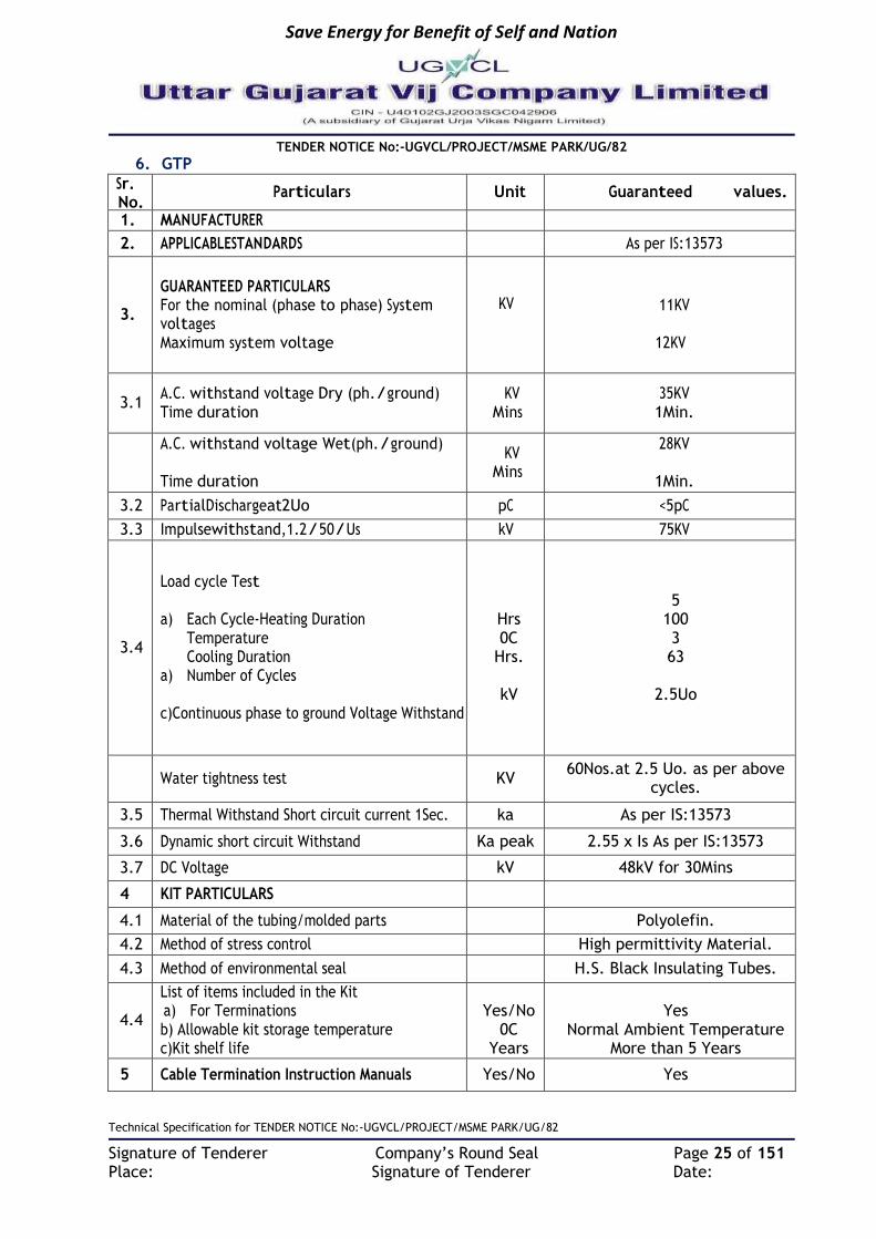
6. GTP
Sr. No.
Particulars Unit Guaranteed values.
1. MANUFACTURER
2. APPLICABLESTANDARDS As per IS:13573
3.
GUARANTEED PARTICULARS For the nominal (phase to phase) System voltages Maximum system voltage
KV
KV
11KV
12KV
3.1 A.C. withstand voltage Dry (ph./ground) Time duration
KV Mins
35KV 1Min.
A.C. withstand voltage Wet(ph./ground) Time duration
KV Mins
28KV
1Min.
3.2 PartialDischargeat2Uo pC <5pC
3.3 Impulsewithstand,1.2/50/Us kV 75KV
3.4
Load cycle Test a) Each Cycle-Heating Duration
Temperature Cooling Duration
a) Number of Cycles
c)Continuous phase to ground Voltage Withstand
Hrs 0C
Hrs.
kV
5 100 3 63
2.5Uo
Water tightness test KV 60Nos.at 2.5 Uo. as per above
cycles.
3.5 Thermal Withstand Short circuit current 1Sec. ka As per IS:13573
3.6 Dynamic short circuit Withstand Ka peak 2.55 x Is As per IS:13573
3.7 DC Voltage kV 48kV for 30Mins
4 KIT PARTICULARS
4.1 Material of the tubing/molded parts Polyolefin.
4.2 Method of stress control High permittivity Material.
4.3 Method of environmental seal H.S. Black Insulating Tubes.
4.4
List of items included in the Kit a) For Terminations b) Allowable kit storage temperature c)Kit shelf life
Yes/No
0C Years
Yes
Normal Ambient Temperature More than 5 Years
5 Cable Termination Instruction Manuals Yes/No Yes

Save Energy for Benefit of Self and Nation
TENDER NOTICE No:-UGVCL/PROJECT/MSME PARK/UG/82
Technical Specification for TENDER NOTICE No:-UGVCL/PROJECT/MSME PARK/UG/82
Signature of Tenderer Company’s Round Seal Page 26 of 151 Place: Signature of Tenderer Date:
TECHNICAL SPECIFICATION FOR 11 KV MOTORISED RING MAIN UNIT OUTDOOR TYPE 1. Scope 1.1 This specification covers Design, Engineering, Manufacture, Assembly, testing,
Inspection, packing of Motorized Ring Main Units with inbuilt FPI (Fully factory integrated & demonstrable at the time of inspection) with all accessories for trouble free and efficient performance and capable of being monitored.
1.2 The RMU to be supplied against this specification are required for vital installations where continuity of service is very important. The design, materials and manufacture of the equipment shall, therefore, be of the highest order to ensure continuous and trouble free service over the years.
1.3 The insulation/dielectric media inside the stainless steel welded tank (Grade SS304 – Non ferrite, Non Magnetic) should be SF6 gas. The RMU should be Modular, extensible type on single sides with provision of attaching/connecting with bus / cable connected site replaceable bushings for additional load break switches and circuit breakers in future whenever required. However, RMU left side is occupied by metering panel and right side is free for extension on vice versa is also possible depending on site condition. RMU shall be front access or access from sides. Bushings shall be replaceable.
1.4 Ring Main Units shall be SCADA compatible for future use. 1.5 Each new RMU shall be equipped with main-line load break switches and a fault passage
indicator (FPI). Furthermore, to protect each of its lateral / transformer feeders, it shall be equipped with a corresponding set of circuit breakers and relay with self-power supply shall be provided for communication purpose. The RMU shall provision for include potential-free contacts and control contacts so as to connect to SCADA/DMS via FRTUs, so as to:
Monitor and control the open/closed status of the RMU circuit breakers and load break switches.
Monitor the local/remote position of RMU motorized (in case if failure of motor) manually-operated switches that can be used to enable and disable remote monitoring.
Monitor the health of the power supply, which will include battery failure and low voltage indications.
Monitor the open/closed status of RMU earthing switches.
Monitor the open/closed status of RMU enclosure doors in case of Hinge doors.
Monitor for low SF6 gas pressure indication.
Monitor for circuit breaker relay operations.
Monitor for indication of main-circuit fault detected by the RMU’s FPI. 1.6 The RMU offered shall be compact, maintenance free, easy to install reliable, safe and
easy to operate and complete with all parts necessary for their effective and trouble-free operation. Such parts will be deemed to be within the scope of the supply irrespective of whether they are specifically indicated in the commercial order or not.
1.7 It is not the intent to specify herein complete details of design and construction. The offered equipment shall conform to the relevant standards and be of high quality, sturdy, robust and of good design and workmanship complete in all respects and capable to perform continuous and satisfactory operations in the actual service conditions at site and shall have sufficiently long life in service as per statutory requirements. In actual practice, notwithstanding any anomalies, discrepancies, omissions, in-completeness, etc. in these specifications, the design and constructional aspects, including materials and dimensions, will be subject to good engineering practice in conformity with the

Save Energy for Benefit of Self and Nation
TENDER NOTICE No:-UGVCL/PROJECT/MSME PARK/UG/82
Technical Specification for TENDER NOTICE No:-UGVCL/PROJECT/MSME PARK/UG/82
Signature of Tenderer Company’s Round Seal Page 27 of 151 Place: Signature of Tenderer Date:
required quality of the product, and to such tolerances, allowances and requirements for clearances etc. as are necessary by virtue of various stipulations in that respect in the relevant Indian Standards, IEC standards, I.E. Rules, I.E. Act and other statutory provisions.
1.8 It shall also encompass all necessary project management, data engineering, acceptance testing, training, documentation, warranty services as efficiently as possible with minimum interruptions of power to Employer / customers.
1.9 Tolerances on all the dimensions shall be in accordance with provisions made in the relevant Indian /IEC standards amended up-to date and in this specification. Otherwise the same will be governed by good engineering practice in conformity with required quality of the product.
1.10 Battery shall be sealed lead acid VRLA or DRY type and shall have minimum life of 5 years at 25º C.
1.11 The successful bidder shall give rigorous training with supplier of RMUs to the engineers and staff for 2 days in attending trouble shooting and maintenance.
2. Service Conditions: Equipment to be supplied against this specification shall be suitable for satisfactory continuous operation under the following tropical conditions.
a) Maximum ambient temperature of air: 50˚C b) Maximum temperature of air in shade: 4˚C c) Maximum daily average ambient temperature: 40˚C d) Maximum yearly average ambient temperature: 30˚C e) Relative Humidity: up to 95% f) Average number of thunder storm days per annum: 15 g) Maximum annual Rainfall: 150cm h) Maximum Altitude above mean sea level: 1000Meter i) Maximum Wind Pressure: 150 Kg/cm2 (As per IS 802 latest code) j) Maximum soil temperature at cable depth: 30˚C k) Maximum soil thermal resistively: 150˚C cm/watt
3. TECHNICAL PARAMETERS:
Sr No Description 11kV RMU
1 Application Three phase - Three wire
2 Rated Voltage 12 kV
3 Service Voltage 11 kV
4 System Frequency 50 Hz
5 SF6 gas at a relative pressure As per IEC 62271-200 & IEC 60694
6 Internal Arc test 20 kA for 1 Sec for tank
7 Lightning Impulse withstand Voltage 75 kV Peak
8 Power Frequency withstand voltage 28 kV rms
9 Rated current of Circuit-breaker 630A
10 Rated Short time current withstand 20 KA for 3 sec
11 Rated Short circuit making current 50 kA
12 Number of operations at rated short circuit current on line switches, earthing switches and CB
5 close for line & earth switches and 20 nos for 11 kV VCB.

Save Energy for Benefit of Self and Nation
TENDER NOTICE No:-UGVCL/PROJECT/MSME PARK/UG/82
Technical Specification for TENDER NOTICE No:-UGVCL/PROJECT/MSME PARK/UG/82
Signature of Tenderer Company’s Round Seal Page 28 of 151 Place: Signature of Tenderer Date:
13 Opening time of breaker (max.) 2.5 cycle
14 Closing time of breaker (max.) 3 cycle
15 Breaker Duty Cycle 0-3min-C0-3min-CO
16 Fault Clearing time 70 millisecond
17 Rated cable charging interrupting current of incomer- Load Break Switch
10A
18 Rated cable charging breaking current of breaker
25A
19 Insulating medium SF6
20 Interrupting medium Vacuum
21 Temperature Rise Maximum permissible temperature rise as per table 3 of IEC 60694.
4. Applicable Standards:
The RMU Switchgear shall comply with the requirements stated in the following standards and specifications amended up to date:
Standard Description
IEC 60529 Classification of degrees of protection provided by enclosures of electrical equipment
IEC 62271-200: 2003 A.C metal-enclosed switchgear and control gear for rated voltages above 1KV and up to and including 72KV
IEC 1330 High voltage/Low voltage prefabricated substations
IEC 62271-1:2007 Common specification for HV switchgear standards
IEC 60265 High-voltage switches-Part 1: Switches for rated voltages above 1kV and less than 52kV
IEC 60801 Monitoring and control
IEC 60185 Current Transformers
IEC 60186 Voltage transformers
BS 159 Busbar
IEC 60137 Bushings
BS 7430 Earthing
IEC 60255 Specification for Static Protective Relays
BS 6231 Wires and wiring
IEC 61000 Electromagnetic compatibility
IEC 60129 Alternating current Disconnector (isolators) and earthing switches
IEC 62271-200 Metal enclosed BS 5311 switchgear
IEC 62271-100 MV AC circuit breaker
IEC 60060-1 I BS 923 High Voltage test technique
IEC 60947-4-1 Control Gears
IEC 60623 Open Ni-Cd prismatic rechargeable cell

Save Energy for Benefit of Self and Nation
TENDER NOTICE No:-UGVCL/PROJECT/MSME PARK/UG/82
Technical Specification for TENDER NOTICE No:-UGVCL/PROJECT/MSME PARK/UG/82
Signature of Tenderer Company’s Round Seal Page 29 of 151 Place: Signature of Tenderer Date:
IEC 60376 Filling of SF6 gas in RMU
5. General Technical Requirement: 5.1 Configuration:
2-Way (CV):11KV Gas (SF6) Insulated RMU with One 630A load break switches and One 630A SF6 Insulated VCB
3-Way (CCC), 11KV Gas (SF6) Insulated RMU with 3 Nos 630A load break switch
3-Way (CVV), 11KV ,Gas (SF6) Insulated RMU with 1 Nos 630A load break switch and 2 Nos. 630 A SF6 Insulated VCB
3-Way (CCV), 11KV, Gas (SF6) Insulated RMU with 2 Nos 630A load break switch and 1No. 630 A SF6 Insulated VCB
4-Way (CCVV), 11 KV Gas (SF6) Insulated RMU with 2 Nos 630A Load break switches and 2 Nos, 630 A SF6 Insulated VCB
4-Way (CCCV), 22 KV Gas (SF6) Insulated RMU with 3 Nos 630A Load break switches and 1 Nos, 630 A SF6 Insulated VCB
4-Way (CCCC), 22 KV Gas (SF6) Insulated RMU with 4 Nos 630A Load break switches
5-Way (CCCVV), 11KV , Gas (SF6) Insulated RMU with 3 Nos 630A load break switch and 2 Nos. 630 A SF6 Insulated VCB
6-Way (CCCVV+V), 11KV Gas (SF6) Insulated RMU with 3 Nos 630A Load break switches and 3 Nos 630 A SF6 Insulated VCB
5.2 RMU Design Features: The RMU are to be designed, manufactured, factory integrated with fault passage indicator, tested and delivered at site. The RMU shall be locally monitorable and/or operable for/to:
The open/close the status of the RMU circuit breakers and load break switches.
The health of the power supply, which will include battery failure and low voltage indications.
The open/closed status of RMU earthing switches.
For low SF6 gas pressure indication.
For circuit breaker relay operations.
For indication of main-circuit fault detected by the RMU's FPI.
5.3 Outdoor Enclosure Features:
The RMUs shall be designed specifically for outdoor installation with ingress protection degree of IP54. They shall also be suitable for conditions in which they will be exposed to heavy industrial pollution, and high levels of airborne dust.
The outer enclosure shall be made of CRCA, 2 mm thick with thick glands plates of 3 mm. The sheet steel and the fabricated parts shall be pretreated using 7 tank process and then coated by layer of zinc phosphate. A finish coat with high scratch resistance epoxy powder finish paint shall be applied over the primer. The coat thickness shall be minimum 100 microns +/- 25 micron.
The equipment in the proposed outdoor RMU shall be coated to meet these climatic conditions. In this respect, standards such as IEC 60870-2-2 covering equipment, systems, operating conditions, and environmental conditions shall apply along with IEC60721, which covers the classification of such conditions. All live parts, high voltage components, excluding the HV cable termination of the switchgear shall be insulated/ protected in SF6 to provide complete proofing against dangers of flashover
Save Energy for Benefit of Self and Nation
TENDER NOTICE No:-UGVCL/PROJECT/MSME PARK/UG/82
Technical Specification for TENDER NOTICE No:-UGVCL/PROJECT/MSME PARK/UG/82
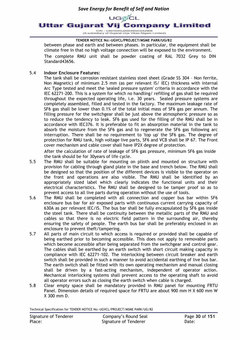
Signature of Tenderer Company’s Round Seal Page 30 of 151 Place: Signature of Tenderer Date:
between phase and earth and between phases. In particular, the equipment shall be climate free in that no high voltage connection will be exposed to the environment.
The complete RMU unit shall be powder coating of RAL 7032 Grey to DIN Standard43656.
5.4 Indoor Enclosure Features:
The tank shall be corrosion resistant stainless steel sheet (Grade SS 304 – Non ferrite, Non Magnetic) of minimum 2.5 mm (as per relevant IS/ IEC) thickness with internal Arc Type tested and meet the 'sealed pressure system' criteria in accordance with the IEC 62271-200. This is a system for which no handling/ refilling of gas shall be required throughout the expected operating life, i.e. 30 years. Sealed pressure systems are completely assembled, filled and tested in the factory. The maximum leakage rate of SF6 gas shall be lower than 0.1% of the total initial mass of SF6 gas per annum. The filling pressure for the switchgear shall be just above the atmospheric pressure so as to reduce the tendency to leak. SF6 gas used for the filling of the RMU shall be in accordance with IEC376. It is preferable to fit an absorption material in the tank to absorb the moisture from the SF6 gas and to regenerate the SF6 gas following arc interruption. There shall be no requirement to 'top up' the SF6 gas. The degree of protection for RMU tank, high voltage live parts, SF6 and VCB shall be IP 67. The Front cover mechanism and cable cover shall have IP2X degree of protection.
After the calculation of rate of leakage of SF6 gas pressure, minimum SF6 gas inside the tank should be for 30years of life cycle.
5.5 The RMU shall be suitable for mounting on plinth and mounted on structure with provision for cabling through gland plate in the base and trench below. The RMU shall be designed so that the position of the different devices is visible to the operator on the front and operations are also visible. The RMU shall be identified by an appropriately sized label which clearly indicates the functional units and their electrical characteristics. The RMU shall be designed to be tamper proof so as to prevent access to all live parts during operation without the use of tools.
5.6 The RMU shall be completed with all connection and copper bus bar within SF6 enclosure bus bar for air exposed parts with continuous current carrying capacity of 630A as per relevant IEC/IS. The bus bar shall be fully encapsulated by SF6 gas inside the steel tank. There shall be continuity between the metallic parts of the RMU and cables so that there is no electric field pattern in the surrounding air, thereby ensuring the safety of people. The earth bus bar shall be preferably enclosed in an enclosure to prevent theft/tampering.
5.7 All parts of main circuit to which access is required or provided shall be capable of being earthed prior to becoming accessible. This does not apply to removable parts which become accessible after being separated from the switchgear and control gear. The cables shall be earthed by an earth switch with short circuit making capacity in compliance with IEC 62271-102. The interlocking between circuit breaker and earth switch shall be provided in such a manner to avoid accidental earthing of live bus bar. The earth switch shall be fitted with its own operating mechanism and manual closing shall be driven by a fast-acting mechanism, independent of operator action. Mechanical interlocking systems shall prevent access to the operating shaft to avoid all operator errors such as closing the earth switch when cable is charged.
5.8 Clear empty space shall be mandatory provided in RMU panel for mounting FRTU Panel. Dimension details of required space for FRTU are about 900 mm H X 600 mm W X 300 mm D.

Save Energy for Benefit of Self and Nation
TENDER NOTICE No:-UGVCL/PROJECT/MSME PARK/UG/82
Technical Specification for TENDER NOTICE No:-UGVCL/PROJECT/MSME PARK/UG/82
Signature of Tenderer Company’s Round Seal Page 31 of 151 Place: Signature of Tenderer Date:
5.9 Normal FRTU load for DCPS will be minimum 25 watts to 80 watts. 230 V AC Supply for charging of FRTU battery should be available. The Aux supply will be taken through the PT provided for metering in RMU. We require 24 V DC. FRTU will require power up to 200 VA depending upon RMU configuration. The PT must have sufficient burden for meeting the aforesaid requirement also for battery charging. The separate transformer must have sufficient capacity for meeting the aforesaid requirement also for battery charging.
5.10 Interconnecting cables, wiring, connectors and terminal blocks:
The interconnecting wires, cables, connectors, terminations and other wiring accessories such as terminal blocks shall be in the scope of the manufacturer. Plug-type/screw type connectors shall be used for all interconnections. Suitable Disconnector type terminal blocks shall be provided for CT circuits. In using a terminal block, no more than two cables or wires shall be connected to any of its individual terminals. Self-extinguishing fireproof vinyl marking strips shall be used to identify all external connection blocks. Marking tags shall be read horizontally. All terminals to which battery or other high voltages are connected shall be provided with fireproof covers. All individual status input, AC voltage input, and control output points shall be isolatable without the need to remove wiring by means of individual terminal blocks of the removable link type. In order to avoid open circuits on the secondary side of CTs, termination blocks with by-pass bridges shall be provided for all AC current inputs
5.11 Suitable fool-proof interlocks shall be provided to the earthing switches to prevent inadvertent or accidental closing when the circuit is live and the concerned Circuit Breaker/Isolator is in its "closed" position. The unit shall be internal arc proof and tested and totally safe for human beings. The release of gas to be from the bottom of the unit, so that, even if the person is operating the unit, opening the cover, the release will be at the bottom. The release in no case should be from any side or top of the unit, as the same is unsafe for the operating personnel/pedestrian or general public. All manual operations shall be carried out on the front of the RMU.
5.12 Isolators/Load Break Switch:
The RMUs shall be equipped with 630Amp fault making/load breaking spring assisted ring switches, each with integral fault making earth switches. The switch shall be naturally interlocked to prevent the main and earth switch being switched "ON" at the same time. The selection of the main and earth switch is made by a lever on the front which is allowed to move only if the main or earth switch is in OFF" position. The Ring switches shall be capable for local manual operation. The load break switch and earthing switch operating mechanism shall have mechanical endurance of at least 1000 operations.
Each INCOMING load break switch will have the following
1. Motor operated 630A Load Break switch and manually operated Earthing Switch with making capacity
2. Cable switch 11 kV, 630 A, 20 kA.
2. Mechanism for manual operation with integrated earthing switch
3. Cable bushing 630 A, standard C bushings.
4. Capacitive voltage indication fixed type- LED display.
5. Fault passage indicator with LED display and reset facility

Save Energy for Benefit of Self and Nation
TENDER NOTICE No:-UGVCL/PROJECT/MSME PARK/UG/82
Technical Specification for TENDER NOTICE No:-UGVCL/PROJECT/MSME PARK/UG/82
Signature of Tenderer Company’s Round Seal Page 32 of 151 Place: Signature of Tenderer Date:
6. Operation counters for each load break switch
7. ON,OFF, EARTH indication on the front mimic of the panel.
8. Cable box for termination of XLPE cable up to 3CX 400 sq. mm.
9. Cable entry bottom.
10. 2NO + 2 NC contacts for load break switch
11. 1NO+1NC contact for Earth switch
12. Local remote control switch for each load break switch
13. Set of Right Angled Cable Boots.
5.13 Vacuum Circuit Breakers
The motorized circuit breakers shall be maintenance free and the position of the power and earthing contacts shall be clearly visible on the front of the RMU through mimic. The position indicator shall provide positive contact indication in accordance with IS 9920. In addition, the manufacturer shall prove the reliability of indication in accordance with IS 9921.
The circuit breakers shall have 2 positions (open / closed) along with earthing switch and shall be constructed in such a way that natural interlocks prevent all unauthorized operations. They shall be fully assembled, tested and inspected in the factory. Breaker operation counter should be provided. An operating mechanism shall be used to manually close the circuit breaker and charge the mechanism in a single movement in manual mode or electrically motor operated. In manual mode the operating mechanism of breaker shall be such that spring charging shall be through the handle and on/ off operation through push button. It shall be fitted with a local system for manual tripping by an integrated push button. There shall be no automatic re-closing. The circuit breaker shall be capable of closing fully and latching against the rated making current. Mechanical indication of the open, closed and earthed positions of the circuit breaker shall be provided.
The circuit breaker shall be associated with an integrated protection unit that will operate without any auxiliary power supply and shall include three toroid current transformers incorporated in the cable chamber as per manufacturer standard type test design. An electronic self-powered relay, a low energy release, and a "fast-on” test receptacle for protection testing (with or without CB tripping). The protection system shall ensure circuit breaker tripping as of a minimum operating current which is the rated current of the underground network to be protected. The CT settings shall be adjustable between 600 to 300/1Amp for feeder and 100-50/1A for distribution transformer, as per the requirement at site. Protection core CT complete details should be furnished (Burden, class, ALF).
In case cables are to be tested with front door open, doors shall have interlocks such that doors can be opened only with earth switch in closed position & a cable test rod shall be provided which can be fixed on the terminations to facilitate testing. Termination boots as approved by the Purchaser's should have a proper opening to facilitate the testing. The opening shall be covered by means of removable protection cap.
In case of front door opened, it shall not be possible to operate the breaker. All panel covers shall be provided with anti-vandal screw bolts so that opening of panel covers is only possible with special tools, which shall be provided by the Bidder. This is required to prevent pilferage. The cable cover door shall be pad lockable and shall be Tamper and Arc proof. Double door arrangement for Outdoor breakers to be

Save Energy for Benefit of Self and Nation
TENDER NOTICE No:-UGVCL/PROJECT/MSME PARK/UG/82
Technical Specification for TENDER NOTICE No:-UGVCL/PROJECT/MSME PARK/UG/82
Signature of Tenderer Company’s Round Seal Page 33 of 151 Place: Signature of Tenderer Date:
provided for additional safety.There shall be provision of hinged doors or bolted type door as per manufacturer standards type tested design. The circuit breaker and earth switch shall be lockable in the open or closed positions by 1 to 3 padlocks. Circuit Breaker shall have mechanical endurance of at least 2000 operations
Each OUTGOING Circuit Breaker will have the following
1. Motor operated 630A SF6 insulated Vacuum circuit breaker and Earthling Switch with making capacity
2. Mechanism for manual operation.
3. Self-Powered protection relay providing over-current & earth fault protection.
4. Ring core current transformers for protection depending upon the transformer ratings 2.5VA, 5P10 for protection
5. Operation counters
6. 4NO+4NC Auxiliary contacts for breaker
7. 2NO+2NC Auxiliary contact for Disconnector
8. 1No+1NC contact for Earth switch
9. Local remote control switch for each breaker
10. Capacitive voltage indication fixed type
11. ON, OFF, Earth indication on mimic and trip indication on relay.
12. Cable box for termination of XLPE cable up to 3RX1CX300 sq. mm.
13. Emergency Trip Push Button. 14. Set of Cable boots.
5.14 Busbars
The three nos of continuous busbars made up of copper within SF6 enclosure bus bar for air exposed parts of rating current 630 A shall be provided. The short time current withstand rating shall be 20 kA for 3 second.
5.15 Current Transformers and potential transformers
3 nos ring type, single core CTs shall be provided in each circuit breaker for protection purpose. The CTs shall conform to IS 2705. The design and construction shall be sufficiently robust to withstand thermal and dynamic stresses during short circuits. Secondary terminals of CTs shall be brought out suitably to a terminal block, which will be easily accessible for testing and terminal connections. The protection CTs shall be Epoxy resin cast with burden 5 VA for feeder and 2.5 VA for transformer and Accuracy class 5P10.
The RMU's other CTs/sensors, i.e., those used by Fault Passage Indicators (FPIs), shall be supplied by the FPI manufacturer. These CTs/sensors shall be an integral part of the FPI’s design to ensure that they properly match the requirements of the FPI.
Appropriate capacity CTs and PTs shall be provided in the RMU for the metering purpose. The meter shall not be in the scope of supplier but the provision and space for installation of the same in future shall be available in the separate enclosure for housing the Battery/ Charger etc.

Save Energy for Benefit of Self and Nation
TENDER NOTICE No:-UGVCL/PROJECT/MSME PARK/UG/82
Technical Specification for TENDER NOTICE No:-UGVCL/PROJECT/MSME PARK/UG/82
Signature of Tenderer Company’s Round Seal Page 34 of 151 Place: Signature of Tenderer Date:
5.16 Protection Relays
The relay shall be provided with Phase protection of Definite time/ IDMT element for over current and earth fault with minimum PSM-0.05,Tsm-0.01 having standard characteristics of Standard Inverse, Very inverse, Extremely Inverse as per IEC 60255-3 standard. The Earth Fault Protection shall be provided of Definite time/ IDMT element having standard characteristics of Standard Inverse, Very inverse, Extremely Inverse as per IEC 60255-3 standard. The "Time Multiplier" with minimum set point of 0.05 TMS shall be available. The breaker shall have the provision of LED indication of Trip on Fault High set (DT) for over current and earth fault-min current setting-0.5 In, minimum Time Delay - 20 milliseconds. The relays shall be suitable numerical relay with necessary elements as per the Purchaser’s approval.
On this basis, the relay as a minimum shall provide:
a) Phase over Current Protection: (50/51)
b) Earth Fault Protection: (50N/51N)
Features and characteristics: The numerical relay shall have the following minimal features and characteristics noting that variations may be acceptable as long as they provide similar or better functionality and/or flexibility:
a) It shall be housed in a flush mounting case and self powered.
b) It shall have 3- phase over-current elements and one earth fault element.
c) IDMT trip current settings shall be 20-200% in steps of 1% for phase over current and 10-80% in steps of 1% for earth fault.
d) Instantaneous trip current settings shall be 100-3000% in steps of 100% for phase over-current and 100- 1200% in steps of 100% for earth fault.
e) Selectable IDMT curves shall be provided to include, for example, Normal Inverse, Very Inverse, Extreme Inverse, Long Time Inverse, and Definite Time. Separate curve settings for phase over-current and earth fault shall be supported.
f) For IDMT delay multiplication, the Time Multiplier Setting (TMS) shall be adjustable from 0.01to 0.1in 0.01 steps.
The relay shall also be provided with:
- Alphanumeric Liquid Crystal Display (LCD)
- Parameter change capability that is password protected
- Capability to record up to 5 of the latest fault records duly time stamped and stored in non-volatile memory for subsequent reading via the above referenced RS485/RS 232 port
5.17 Bushings and cable terminations:
Each cable compartment shall, be provided with three bushings of adequate sizes to terminate the incoming and outgoing cables along with a terminal block (TB) located at convenient accessible location so as to wire all inputs & outputs (lOs) up to the terminal block (TB). The bushings shall be conveniently located for proper bend so as to allow easy working and termination of cables. The cable termination shall be done with Heat shrinkable /Push ON termination method so that adequate clearances are maintained between phases & cable shall be held by HDPE (fire retardant) cleat. The clearance between phase to phase and phase to earth shall be as per IEC 61243- 5

Save Energy for Benefit of Self and Nation
TENDER NOTICE No:-UGVCL/PROJECT/MSME PARK/UG/82
Technical Specification for TENDER NOTICE No:-UGVCL/PROJECT/MSME PARK/UG/82
Signature of Tenderer Company’s Round Seal Page 35 of 151 Place: Signature of Tenderer Date:
amended up to dates. 1 run of up to 3CX400 Sq. mm shall be used for cable termination. All the cable secondary wiring should be routed through marshaling box separately for relay, CT etc. Bimetallic washer for tightening of cable to be provided. RMU bushing shall be female or bus-bar type for cable termination and provision for onsite replacement of bushing should be available.
5.18 Earthing
The RMU outdoor metal enclosed shall be equipped with an earth bus securely fixed along the base of the RMU. Earthing shall be carried out as per attached drawing for maintenance free earthing. The earth bus bar shall be of Gl strip (50sqmmX6) or copper strip (inside the RMU) having equivalent current rating and short circuit rating as per IEC/IS. Provision shall be made on end of RMU for connecting the earth bus to the earth grid by erecting suitable 2 earth pipes of 50mm dia. M.S. rod of 3 meter in Pits. Both the earth pipes are also to be connected in a grid formation.
5.19 Voltage indicator lamps and phase comparators
Each function shall be equipped with a fixed type voltage indicator box on the front to indicate whether or not there is voltage in the cables. The capacitive dividers will supply low voltage power to the lamps. Three inlets can be used to check the synchronization of phases. These devices shall be in compliance with IEC 61958 standard. Voltage indicator lamp shall be operating individually per phase. VDI shall be visible from outside without opening the doors.
5.20 Front cover
The front cover shall provide a clear mimic diagram that indicates the different functions. The position indicators shall give a true reflection of the position of the main contacts. They shall be clearly visible to the operator. The lever operating direction shall be clearly indicated in the mimic diagram. The bidder shall provide a marking plate showing RMU's main electrical characteristics.
5.21 Fault Passage Indicator .
Fault Passage Indicators shall be installed on the Ring Main Unit. This shall facilitate quick detection of faulty cable. The FPI shall be in integral part of one isolator and shall be capable of displaying fault. The fault indication may be on the basis of monitoring fault current through the device. These devices shall be electronic devices with their own energy source and connected to Single 3 phase Split Core CTs (CBCT). These shall be provided with bright LEDs / flag Indicators, which shall be clearly visible in the day time. These shall have the following resetting facilities:
• Manual reset
• Resetting after a set time duration
• Electrically reset from remote with at least 2-spare potential free contacts.
• Resetting on restoration of LV
The unit shall have Short Circuit and Earth fault adjustable to different settings with separate Current transformer. They shall be fully field-programmable and shall have o/c setting 200-1000 A and E/F setting 10-150 A. To restrain operation of fault passage indicators due to inrush / switching current, settings of time delay of 1s-5s shall be available. It shall be possible to Test these indicators at site thru "Test" push button.

Save Energy for Benefit of Self and Nation
TENDER NOTICE No:-UGVCL/PROJECT/MSME PARK/UG/82
Technical Specification for TENDER NOTICE No:-UGVCL/PROJECT/MSME PARK/UG/82
Signature of Tenderer Company’s Round Seal Page 36 of 151 Place: Signature of Tenderer Date:
The conventional practice is to have (N-1) FPI where N is nos. of LBS in a particular configuration of RMU. FPI shall be visible from outside without opening the doors.
5.22 Paint All paint shall be applied on dean dry surfaces under suitable atmospheric conditions by seven tank process and powder coating. The overall paint thickness shall not be less than 100 microns ±25micron as standard. The paint shall not scale off or crinkle or be removed by abrasion during normal handling. The enclosure of the RMU shall be painted with shade Dark Gray i.e. RAL 7032. Sufficient quantity oftouch-up paint shall be furnished for application at site. Paint shall be capable to withstand in saline conditions. Paint shall be capable to withstand in saline conditions.
5.23 Name Plate &Marking
All the components and operating devices of the RMU shall be provided with durable and legible nameplates containing all technical parameters. Name plates shall be suitably embossed with the following information. A Danger plate of appropriate size shall also be provided on the enclosure.
o Manufacturer's Name o Month and year of supply o PO Number o Rated Voltage o System Frequency o RMU Configuration o Rated Short Time Withstand current for 3 sec o Rated Impulse withstand Voltage o Degree of Protection o Type Designation or Serialno. o Year of manufacture o Applicable Rated values o Mass of unit o SF6 gas filling pressure
6. Testing & Inspection 6.1 General:
The specified RMUs shall be subject to type tests, routine tests, and acceptance tests. Where applicable, these tests shall be carried out as per the standards stated in the specification. The type test produced by supplier shall be only from reputed NABL accredited / international / national government approved testing laboratories such as CPRI from India and KEMA, Volta, KERI, CESI, ERDA etc. from remaining part of the globe. Report from any other testing lab mentioned above shall not be accepted. In such a case manufacture has to perform the repeat type test for the RMU form these labs at his own cost. The type test report shall have been conducted during the period not exceeding five (5) years from the date of opening of the bid. In the event of any discrepancy in the test reports i.e. any test report not acceptable or any/ all type tests (including additional type tests, if any) not carried out, same shall be carried out without any cost implication. Prior to acceptance testing, the supplier shall prepare and submit a detailed Manufacturing Quality Plan (MQP) and routine/ inspection test plan for review and approval.

Save Energy for Benefit of Self and Nation
TENDER NOTICE No:-UGVCL/PROJECT/MSME PARK/UG/82
Technical Specification for TENDER NOTICE No:-UGVCL/PROJECT/MSME PARK/UG/82
Signature of Tenderer Company’s Round Seal Page 37 of 151 Place: Signature of Tenderer Date:
Successful bidder has to get approval of drawings. The supplier shall have to offer proto inspection for RMU. The supplier shall have in house testing facility for carrying out proto inspection, lot inspection by the utility at works of supplier. All the equipment used must be up to date and calibrated by reputed agency.
6.2 Type tests: Following shall constitute the type tests: -
a) Short time current withstand test and peak current withstand test. b) Lightening Impulse voltage with-stand test c) Temperature rise test. d) Short Circuit current making and breaking tests. e) Power frequency voltage withstand test (dry). f) Capacitive current switching test confirming to IEC. g) Mechanical operation test. h) Measurement of the resistance of the main circuit. i) Checking of degree of protection of main tank and outer enclosure j) Switch, circuit breaker, earthing switch making capacity. k) Switch, circuit breaker breaking capacity. l) Internal arc withstands. m) Checking of partial discharge on complete unit.
IN ADDITION, FOR SWITCHES, TEST REPORTS ON RATED BREAKING AND MAKING CAPACITY SHALL BE SUPPLIED.
FOR EARTHING SWITCHES, TEST REPORTS ON MAKING CAPACITY, SHORT-TIME WITHSTAND CURRENT AND PEAK SHORT-CIRCUIT CURRENT SHALL BE SUPPLIED.
6.3 Routine tests:
The following routine tests shall be conducted by the manufacturer and the same shall be backed by the factory's quality control department test reports.
a) Conformity with drawings and diagrams, b) Measurement of closing and opening speeds, c) Measurement of operating torque, d) Checking of filling pressure, e) Checking of gas-tightness, f) Dielectric testing and main circuit resistance measurement. g) Power frequency voltage h) Resistance test for the circuit i) Mechanical operation tests.
BIDDERS SHALL CONFIRM THE FOLLOWING ROUTINE TESTS ON EACH RMU SUPPLIED.
a) Micro ohm test (contact Resistance test) for the assembly inside the tank b) Circuit breaker analyzer test so as to ensure the simultaneous closing of allPoles
for VCB. c) SF6 gas leak test d) Partial Discharge test on the complete gas tank so as to be assure of the proper
insulation level and high service life. e) High voltage withstand. f) Secondary test to ensure the proper functioning of the live line indicators, fault
passage indicators and relays.

Save Energy for Benefit of Self and Nation
TENDER NOTICE No:-UGVCL/PROJECT/MSME PARK/UG/82
Technical Specification for TENDER NOTICE No:-UGVCL/PROJECT/MSME PARK/UG/82
Signature of Tenderer Company’s Round Seal Page 38 of 151 Place: Signature of Tenderer Date:
6.4 Acceptance tests: All the tests specified under Routine Test Clause above shall be carried out as acceptance test on random samples as per sampling plan under IEC/15 for each lot.
6.5 DOCUMENTATION and DRAWINGS All drawings shall conform to relevant International Standards Organization (ISO) Specification. All drawings shall be in ink and suitable for microfilming. The tenderer shall submit along with his tender dimensional general arrangement drawings of the equipment’s, illustrative and descriptive literature in triplicate for various items in the RMUs which are all essentially required for future automation.
I. Schematic diagram of the RMU panel II. Instruction manuals III. Catalogues of spares recommended with drawing to indicate each items of
spares IV. List of spares and special tools recommended by the supplier. V. Copies of Type Test Certificates as per latest IS/IEC. VI. Drawings of equipment’s, relays, control wiring circuit, etc. VII. Foundation drawings of RMU so that Utility will planned and carry out civil
works etc. VIII. Dimensional drawings of each material used for item VII. IX. Actual single line diagram of RMU/RMUs with or without Extra combinations
shall be made displayed on the front portion of the RMU so as to carry out the operations easily.
The following should be supplied to each consignee circle/town along with the initial supply of the equipment’s ordered. Copies of printed and bound volumes of operation, maintenance and erection manuals in English along with the copies of approved drawings and type test reports etc. Sets of the manuals as above shall be supplied to the Chief Engineer/Distribution. A soft copy of the all Technical and Drawing furnished in a CD.

Save Energy for Benefit of Self and Nation
TENDER NOTICE No:-UGVCL/PROJECT/MSME PARK/UG/82
Technical Specification for TENDER NOTICE No:-UGVCL/PROJECT/MSME PARK/UG/82
Signature of Tenderer Company’s Round Seal Page 39 of 151 Place: Signature of Tenderer Date:
7. GTP:
Sr. No.
Description UGVCL Requirement
1.0 SWITCHGEAR ASSEMBLY
1.1 Make
1.2 Type Outdoor, 2/3/4/5/6 WAY
1.3 Reference Standard IEC 56, IEC 129,IEC298,
IEC694,IEC 265
1.4 Voltage (Normal/Max.) kV 11kV/12 kV
1.5 Phase (Nos.) 3 nos
1.6 Frequency (HZ) 50 + 3 Hz
1.7 Short Circuit Rating for 3 Sec. (KA) 20 kA
1.8 Insulation Level
a) Impulse withstand (KV peak) 75 kVp
b) 1 Minute 50 Hz. Voltage withstand (KV rms) 28 kV
1.9 Metal Clad Construction Yes
1.10 a) Degree of protection for outer enclosure:
b) Degree of protection for main tank:
IP 54
IP 67
1.11 Switchgear completely wire and tested at factory (yes/No) Yes
2.0 CONSTRUCTION
2.1 Overall Dimensions
A Extensible 2/3/4/5/6 Way RMU
i) Width (W) (mm)
To be filled by Bidders ii) Depth (D) (mm)
iii) Height (mm)
2.2 Overall Weight of Extensible 2/3/4/5/6 Way RMU To be filled by Bidders
3.0 Bus bar
3.1 Make
3.2 Material & Grade Copper
3.3 Reference Standard IEC 129
3.4 a) Cross sectional area (mm2) To be filled by Bidders
3.5 Continuous Current
a) Standard 630 A
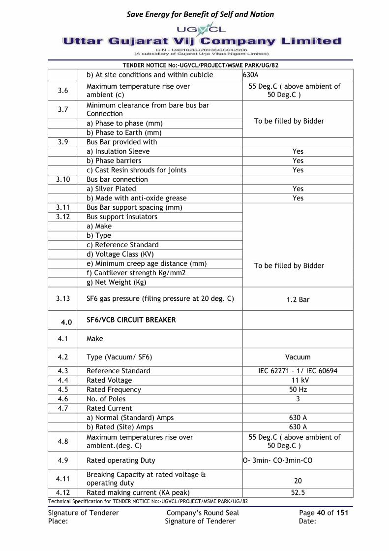
Save Energy for Benefit of Self and Nation
TENDER NOTICE No:-UGVCL/PROJECT/MSME PARK/UG/82
Technical Specification for TENDER NOTICE No:-UGVCL/PROJECT/MSME PARK/UG/82
Signature of Tenderer Company’s Round Seal Page 40 of 151 Place: Signature of Tenderer Date:
b) At site conditions and within cubicle 630A
3.6 Maximum temperature rise over ambient (c)
55 Deg.C ( above ambient of 50 Deg.C )
3.7 Minimum clearance from bare bus bar Connection
To be filled by Bidder a) Phase to phase (mm)
b) Phase to Earth (mm)
3.9 Bus Bar provided with
a) Insulation Sleeve Yes
b) Phase barriers Yes
c) Cast Resin shrouds for joints Yes
3.10 Bus bar connection
a) Silver Plated Yes
b) Made with anti-oxide grease Yes
3.11 Bus Bar support spacing (mm)
To be filled by Bidder
3.12 Bus support insulators
a) Make
b) Type
c) Reference Standard
d) Voltage Class (KV)
e) Minimum creep age distance (mm)
f) Cantilever strength Kg/mm2
g) Net Weight (Kg)
3.13 SF6 gas pressure (filing pressure at 20 deg. C) 1.2 Bar
4.0 SF6/VCB CIRCUIT BREAKER
4.1 Make
4.2 Type (Vacuum/ SF6) Vacuum
4.3 Reference Standard IEC 62271 – 1/ IEC 60694
4.4 Rated Voltage 11 kV
4.5 Rated Frequency 50 Hz
4.6 No. of Poles 3
4.7 Rated Current
a) Normal (Standard) Amps 630 A
b) Rated (Site) Amps 630 A
4.8 Maximum temperatures rise over ambient.(deg. C)
55 Deg.C ( above ambient of 50 Deg.C )
4.9 Rated operating Duty O- 3min- CO-3min-CO
4.11 Breaking Capacity at rated voltage & operating duty 20
4.12 Rated making current (KA peak) 52.5

Save Energy for Benefit of Self and Nation
TENDER NOTICE No:-UGVCL/PROJECT/MSME PARK/UG/82
Technical Specification for TENDER NOTICE No:-UGVCL/PROJECT/MSME PARK/UG/82
Signature of Tenderer Company’s Round Seal Page 41 of 151 Place: Signature of Tenderer Date:
b) Short time current for 3 Sec. (KA rms) 20
4.14 Transient Recovery Voltage
a) Rate of rise (KV/ms) 0.34 KV/micro sec (as
per IEC)
b) Peak Voltage (KV) 23 (35 % DC component)
4.15 Insulation Level
a) Impulse Voltage with stand on 1/50 full wave 75
b) 1 minute 50Hz voltage withstand 28
4.17 Opening time Maximum, No load condition (ms) 40-60
4.18 Opening and closing time under SF6 gas loss or vacuum loss condition (ms) 40-60
4.19 At 100% Breaking capacity
a) Opening time – max (ms) 40-60
b) Arcing time – max (ms) 6-9
c) Total break time (ms) 40-60
4.20 At 60% Breaking capacity
a) Opening time – max (ms) 40-60
b) Arcing time – max (ms) 6-9
c) Total break time (ms) 40-60
4.21 At 30% Breaking capacity
a) Opening time – max (ms) 40-60
b) Arcing time – max (ms) 6-9
c) Total break time (ms) 40-60
4.22 At 10% Breaking capacity
a) Opening time – max (ms) 40-60
b) Arcing time – max (ms) 6-9
c) Total break time (ms) 40-60
4.23 Number of breaks per pole Single
4.24
No of breaker operations permissible without requiring inspection replacement of contacts and other main parts.
a) At 100% rated current 2000 & 40 Nos at 20
kA
4.25 Type of contacts
a) Main Copper chromium, Butt
type
b) Arcing Copper chromium
4.26 Material of contacts
a) Main Copper chromium
b) Arching

Save Energy for Benefit of Self and Nation
TENDER NOTICE No:-UGVCL/PROJECT/MSME PARK/UG/82
Technical Specification for TENDER NOTICE No:-UGVCL/PROJECT/MSME PARK/UG/82
Signature of Tenderer Company’s Round Seal Page 42 of 151 Place: Signature of Tenderer Date:
c) Whether contacts silver plated NA
d) Thickness of silver plating NA
4.27 Operating mechanism- closing
a) Type STORED ENERGY
b) No of breaker operations stored One Tripp free
C) Trip free or fixed trip NA ( Anti reflex on Earthing )
d) Anti pumping features provided
e) Earthing for operating mechanism and metal parts furnished
f) Earth terminal size and material
4.28 Operating mechanism- tripping
a) Type
To be filled by bidder
b) No of breaker operations stored
c) Trip free or fixed trip (V)
d) Anti pumping features provided (%)
e) Earthing for operating mechanism and metal parts furnished
f) Earth terminal size and material
4.29 Spring charging mechanism
2) Make
To be filled by bidder
3) Type
4) Size
5) Rating
4.30
Breaker suitable for capacity switching 4 operating duty 5Max.rating of capacitor bank thatcan be safely controlled
Yes
4.31 Tripping coil
a) Voltage
b) Permissible voltage variation (%)
c) Tripping current at rated voltage (A)
d) Power at rated voltage (W)
e) 2-Over current trip with TLF (5A) and 1-earth fault furnished as specified

Save Energy for Benefit of Self and Nation
TENDER NOTICE No:-UGVCL/PROJECT/MSME PARK/UG/82
Technical Specification for TENDER NOTICE No:-UGVCL/PROJECT/MSME PARK/UG/82
Signature of Tenderer Company’s Round Seal Page 43 of 151 Place: Signature of Tenderer Date:
4.32
Breaker /Accessories such as control switch indication Lamps etc. furnished as specified :(please attach separate sheet giving details of all accessories, inter locks and safety shutters)
a) Mechanical safety Interlock Yes
b) Automatic Safety Interlock No
C) Operational Interlock Yes
d) Emergency manual trip Yes
e) Operation counter Yes
f) Charge /discharge indicator Yes
g) Manual spring charging facility Yes
4.33
Impact load foundation design (to include dead load plus impact value On opening at maximum interrupting rating) (KG)
5.0 Isolators/Load Break Switch
5.1 Make
5.2 Type
5.3 Reference standard IEC129
5.4 Rated voltage (KV) 12
5.5 Rated Frequency HZ 50
5.6 No. Of poles (No) 3
5.7 Rated current
) Normal (Standard) Amps 630
j) Derated (site) Amp 630
5.8 Maximum temperature rise over ambient Deg. C
55 Deg.C ( above ambient of 50 Deg.C )
5.9 Rated operation duty O – 3min-CO-3min-CO
5.10 Rupturing Capacity at rated voltage MVA
5.11 Rated making current KA peak
5.12 Short time current
b) For 3 sec KA rms 20
5.13 Impulse voltage withstands on 1/50 full wave 75
5.14 Maximum over voltage factor when switching off a) Loaded feeder cable
5.15 Operating SF6 Gas pressure

Save Energy for Benefit of Self and Nation
TENDER NOTICE No:-UGVCL/PROJECT/MSME PARK/UG/82
Technical Specification for TENDER NOTICE No:-UGVCL/PROJECT/MSME PARK/UG/82
Signature of Tenderer Company’s Round Seal Page 44 of 151 Place: Signature of Tenderer Date:
5.16 No of isolator operation permissible without requiring inspection, replacement of contacts and other
Yes
main parts At 100% rated current At 100% rated breaking current
5.17
Isolator provided with the following Mechanical safety Mechanical ON, OFF, CABLE EARTH indicators Operation counter Manual spring charging facility
Yes
5.18
Impact load for foundation design (To include dead load plus impact Values on opening at maximum interrupting rating) Kg
6.0 CURRENT TRANSFORMER
6.1 Make
6.2 Type & voltage level Tap wound/11kV
6.3 Reference standard IEC 298
6.4 C.T. ratio as specified To be filled by bidder
6.5 Rated frequency 50
6.7 Class of insulation Class A
6.8 Temperature rises over ambient. Deg. C
To be filled by bidder
6.9 Basic insulation level
6.10 For tripping CT RATIO Class of accuracy
Rated Burden VA
Knee Point Voltage V
Excitation Current at Vk/2 Amps
Rated Saturating Current Amps
Over Current Rating
Continuous % Over Load %
7.0 Cable terminations
7.1 Circuit Breaker
Type
To be filled by bidder
Materials
Dimensions
Size
Height of Cable box from ground Level
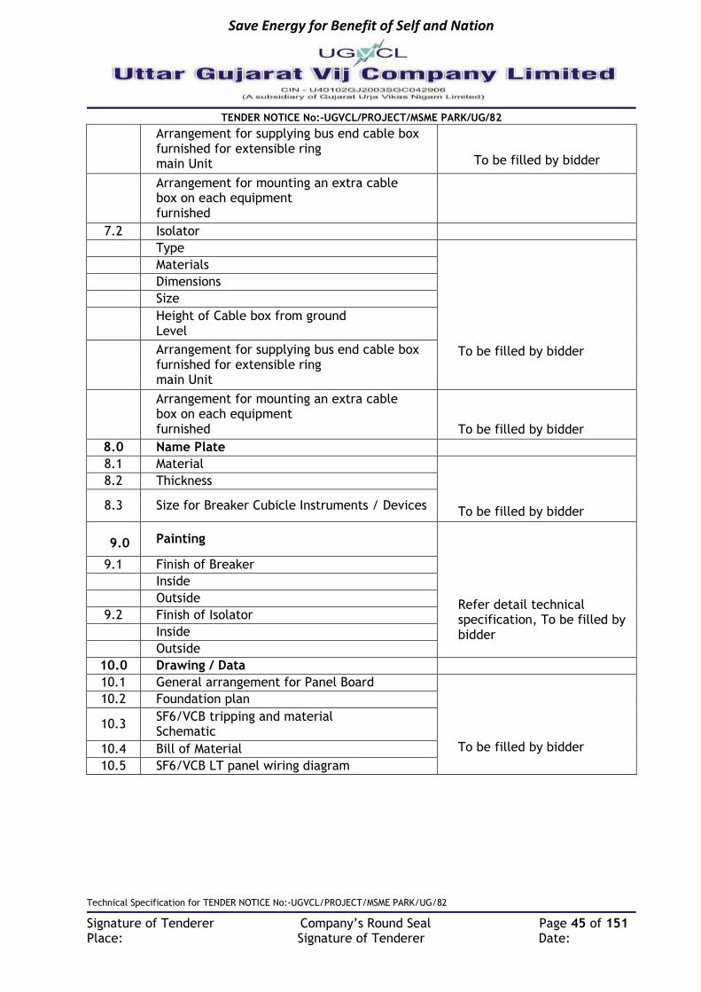
Save Energy for Benefit of Self and Nation
TENDER NOTICE No:-UGVCL/PROJECT/MSME PARK/UG/82
Technical Specification for TENDER NOTICE No:-UGVCL/PROJECT/MSME PARK/UG/82
Signature of Tenderer Company’s Round Seal Page 45 of 151 Place: Signature of Tenderer Date:
Arrangement for supplying bus end cable box furnished for extensible ring main Unit
To be filled by bidder
Arrangement for mounting an extra cable box on each equipment furnished
7.2 Isolator
Type
To be filled by bidder
Materials
Dimensions
Size
Height of Cable box from ground Level
Arrangement for supplying bus end cable box furnished for extensible ring main Unit
Arrangement for mounting an extra cable box on each equipment furnished
To be filled by bidder
8.0 Name Plate
8.1 Material
To be filled by bidder
8.2 Thickness
8.3 Size for Breaker Cubicle Instruments / Devices
9.0 Painting
Refer detail technical specification, To be filled by bidder
9.1 Finish of Breaker
Inside
Outside
9.2 Finish of Isolator
Inside
Outside
10.0 Drawing / Data
10.1 General arrangement for Panel Board
To be filled by bidder
10.2 Foundation plan
10.3 SF6/VCB tripping and material Schematic
10.4 Bill of Material
10.5 SF6/VCB LT panel wiring diagram

Save Energy for Benefit of Self and Nation
TENDER NOTICE No:-UGVCL/PROJECT/MSME PARK/UG/82
Technical Specification for TENDER NOTICE No:-UGVCL/PROJECT/MSME PARK/UG/82
Signature of Tenderer Company’s Round Seal Page 46 of 151 Place: Signature of Tenderer Date:
TECHNICAL SPECIFICATION FOR 11/0.433kV OUTDOOR TYPE PACKAGED SUBSTATION
1. SCOPE
The specification covers design, manufacture and supply at site, installation, testing and commissioning of 11 / 0.433 kV Outdoor Type Package substation complete with all accessories. This specification shall be read in conjunction with the Bill of Quantity (BOQ). Outdoor type package substation shall be designed suitably with facility for internal lighting, earthing, padlocks etc, interconnection between MV switchgear to Transformer MV side using 3core, 11KV XLPE cables & Interconnection between Transformer LV Side to LT switchboard using bus bars. All metallic components shall be earthed to a common earthing point. Cable termination kits for RMU`s will be in the scope of vendor (within enclosure). Each new RMU shall be equipped with main-line load break switches and a fault passage indicator (FPI). Furthermore, to protect each of its lateral / transformer feeders, it shall be equipped with a corresponding set of circuit breakers and relay with self-power supply shall be provided for communication purpose. The RMU shall provision for include potential-free contacts and control contacts so as to connect to SCADA/DMS via FRTUs, so as to:
Monitor and control the open/closed status of the RMU circuit breakers and load break switches.
Monitor the local/remote position of RMU motorized (in case if failure of motor) manually-operated switches that can be used to enable and disable remote monitoring.
Monitor the health of the power supply, which will include battery failure and low voltage indications.
Monitor the open/closed status of RMU earthing switches.
Monitor the open/closed status of RMU enclosure doors in case of Hinge doors.
Monitor for low SF6 gas pressure indication.
Monitor for circuit breaker relay operations.
Monitor for indication of main-circuit fault detected by the RMU’s FPI.
1.1 SERVICE CONDITIONS: Equipment to be supplied against this specification shall be suitable for satisfactory continuous operation under the following tropical conditions.
a) Maximum ambient temperature of air: 50˚C b) Maximum temperature of air in shade: 4˚C c) Maximum daily average ambient temperature: 40˚C d) Maximum yearly average ambient temperature: 30˚C e) Relative Humidity: up to 95% f) Average number of thunder storm days per annum: 15 g) Maximum annual Rainfall: 150cm h) Maximum Altitude above mean sea level: 1000Meter i) Maximum Wind Pressure: 150 Kg/cm2 (As per IS 802 latest code) j) Maximum soil temperature at cable depth: 30˚C k) Maximum soil thermal resistively: 150˚C cm/watt
Save Energy for Benefit of Self and Nation
TENDER NOTICE No:-UGVCL/PROJECT/MSME PARK/UG/82
Technical Specification for TENDER NOTICE No:-UGVCL/PROJECT/MSME PARK/UG/82
Signature of Tenderer Company’s Round Seal Page 47 of 151 Place: Signature of Tenderer Date:
1.2 TECHNICAL PARAMETERS:
1.2.1 Design Criteria
1.2.1.1 Compact Sub-station consisting of 11KV Non-Extensible Motorized SF6 Ring Main Unit with breaker as protection + Transformer + Low Voltage Switchgear + FRTU + HT Meterinb with all connection accessories, fitting & auxiliary equipment in an Enclosure to supply Low-voltage energy from high-voltage system as detailed in this specification. The complete unit shall be installed on a substation plinth (base) as Outdoor substation located at very congested places. No equipment shall be placed outside the CSS enclosure. 11KV Load Break Switch/Isolators controls incoming-outgoing feeder cables of the 11KV distribution system. The Vacuum Circuit Breaker shall be used to control and isolate the 11kV/433V Distribution transformer. The transformer Low Voltage side shall be connected to Low Voltage switchgear. The connection cables to consumer shall be taken out from the Low Voltage switchgear. The main equipment i.e. HT RMU, Transformer & LV Switchgear shall be as of the same make as of the compact substation.
1.2.1.2 The prefabricated- Compact substation shall be designed for a) Compactness, b) fast installation, c) maintenance free operation, d) safety for worker/operator & public.
1.2.1.3 The Switchgear and component thereof shall be capable of withstanding the mechanical and thermal stresses of short circuit listed in ratings and requirements clause without any damage or deterioration of the materials.
1.2.1.4 For continues operation at specified ratings temperature rise of the various switchgear
components shall be limited to permissible values stipulated in the relevant standard and / or this specification.
1.2.1.5 The RMU are to be designed, manufactured, factory integrated with fault passage
indicator, tested and delivered at site. The RMU shall be locally monitorable and/or operable for/to:
The open/close the status of the RMU circuit breakers and load break switches.
The health of the power supply, which will include battery failure and low voltage indications.
The open/closed status of RMU earthing switches.
For low SF6 gas pressure indication.
For circuit breaker relay operations.
For indication of main-circuit fault detected by the RMU's FPI.
1.2.2 Specific Requirement
The main components of a prefabricated- Compact substation are Transformer, High-voltage switchgear-control gear, Low-voltage switchgear-control gear and corresponding interconnections (cable, flexible, bus bars) & auxiliary equipment. The components shall be enclosed, by either common enclosure or by an assembly of enclosure. All the components shall comply with their relevant IEC standards.
Save Energy for Benefit of Self and Nation
TENDER NOTICE No:-UGVCL/PROJECT/MSME PARK/UG/82
Technical Specification for TENDER NOTICE No:-UGVCL/PROJECT/MSME PARK/UG/82
Signature of Tenderer Company’s Round Seal Page 48 of 151 Place: Signature of Tenderer Date:
Ratings:
Description Unit Value
Rated Voltage / Operating Voltage
kV rms. 11
Rated frequency & Number of phases
Hz & nos. 50 & 3
Rated maximum power of Transformer
kVA Refer BOQ
Rated Ingress protection class of Enclosure
IP: IP-23 for Transformer Compartment and
IP:54 for LT & HT Switchgear Compartment.
HV Insulation Level
Rated withstand voltage at power frequency of 50 Hz
kV rms 28
Rated Impulse withstand Voltage kV peak 75
HV Network & Busbar
Rated current Amp 630A
Minimum Rated short time withstand current
kA rms / 3 sec
20 (minimum)
Breaking capacity of Isolators ( rated full load)
A 630A
LV Network As per requirement & Scheduled of items
1.2.3 Outdoor enclosure:
1.2.3.1 The outdoor enclosure shall be made of galvanized Sheet Steel tropicalised to local weather conditions.
1.2.3.2 The enclosure shall be of partially modular design of GI Sheets fastened by riveting. 1.2.3.3 Excessive use of bolts for fastening on the front side of doors shall not be allowed. If
bolting is employed for fastening it should be fastened from the inside of enclosure. This is to avoid corrosion.
1.2.3.4 The thickness of enclosure shall be minimum 1.5mm for non-load bearing members & minimum 2mm for load bearing members.
1.2.3.5 The enclosure shall be powder coated / wet polyurethane paint. 1.2.3.6 The metal base shall ensure rigidity for easy transport & installation. 1.2.3.7 Substation will be used in outdoor application hence to prevent enclosure from
rusting/corrosion, welding should be avoided. 1.2.3.8 The protection degree of the Enclosure shall be IP54 for LT & HT switchgear compartment
& IP23 for Transformer compartment. Proper / adequate ventilation aperture shall be provided for natural ventilation by way of Louvers etc.
1.2.3.9 To avoid the entry of rodent in the transformer compartment, stainless steel mesh should be provided from inner side of louvers.
1.2.3.10 Considering the outdoor application of the substation the doors shall be provided with proper interlocking arrangement for safety of operator and to avoid corrosion door should have stainless steel hinges. Door should be provided with stoppers.
Save Energy for Benefit of Self and Nation
TENDER NOTICE No:-UGVCL/PROJECT/MSME PARK/UG/82
Technical Specification for TENDER NOTICE No:-UGVCL/PROJECT/MSME PARK/UG/82
Signature of Tenderer Company’s Round Seal Page 49 of 151 Place: Signature of Tenderer Date:
1.2.3.11 Interconnection between HT switchgear and transformer shall be using Al. unarmoured XLPE cable and between transformer and LT switchgear shall be using busbar.
1.2.3.12 Internal Fault: Failure within the package substation due either to a defect, an exceptional service conditions or mal-operation may initiate an internal arc. Such an event may lead to the risk of injury, if persons are present. It is desirable that the highest practicable degree of protection to persons shall be provided. The design shall be tested as per IEC 61330 / 62271-202.
1.2.3.13 Type test report of arcing due to internal fault should be submitted with offer. The Package substation shall be tested for internal arc test – AB for 20 kA for 1 Sec (A-Operator, B-Pedestrian).
1.2.3.14 Covers & Doors: Covers & doors are part of the enclosure. When they are closed, they shall provide the degree of protection specified for the enclosure. Ventilation openings shall be so arranged or shielded that same degree of protection as specified for enclosure is obtained. Additional wire mesh may be used with proper Danger board for safety of the operator. All covers, doors or roof shall be provided with locking facility or it shall not be possible to open or remove them before doors used for normal operation have been opened. The doors shall open outward at an angle of at least 900 & be equipped with a device able to maintain them in an open position.
1.2.3.15 Earthing: All metallic components shall be earthed to a common earthing point. It shall be terminated by an adequate terminal intended for connection to the earth system of the installation, by way of flexible jumpers/strips & Lug arrangement. The continuity of the earth system shall be ensured taking into account the thermal & mechanical stresses caused by the current it may have to carry. The components to be connected to the earth system shall include:
a) The enclosure of Compact substation, b) The enclosure of High voltage switchgear & control gear from the terminal
provided for the purpose, c) The metal screen & the high voltage cable earth conductor, d) The transformer tank or metal frame of transformer, e) The frame &/or enclosure of low voltage switchgear,
1.2.3.16 There shall be an arrangement for internal lighting activated by associated switch for HV, Transformer & LV compartments separately.
1.2.3.17 Labels: Labels for warning, manufacturer’s operating instructions etc. shall be durable & clearly legible.
1.2.3.18 Cleaning & Painting: The paints shall be carefully selected to withstand tropical heat and rain. The paint shall not scale off or crinkle or be removed by abrasion due to normal handling.
All paint shall be applied on dean dry surfaces under suitable atmospheric conditions by seven tank process and powder coating. The overall paint thickness shall not be less than 100 microns ±25micron as standard. The paint shall not scale off or crinkle or be removed by abrasion during normal handling. The enclosure of the RMU shall be painted with shade Dark Gray i.e. RAL 7032. Sufficient quantity of touch-up paint shall be furnished for application at site. Paint shall be capable to withstand in saline conditions.
1.3 APPLICABLE STANDARDS:
All equipment and material shall be designed manufactured and tested in accordance with the latest applicable IEC standards. The 11KV Compact Substation Design must be as per IEC 61330. The Compact Sub-station offered shall in general comply with the latest issues including amendments of the following standards.

Save Energy for Benefit of Self and Nation
TENDER NOTICE No:-UGVCL/PROJECT/MSME PARK/UG/82
Technical Specification for TENDER NOTICE No:-UGVCL/PROJECT/MSME PARK/UG/82
Signature of Tenderer Company’s Round Seal Page 50 of 151 Place: Signature of Tenderer Date:
Title Standards
High Voltage Low Voltage Pre-Fabricated Substation
IEC:61330 / IC 62271-202
High Voltage Switches IEC 60265
Metal Enclosed High Voltage Switchgear IEC 60298/ IEC62271-200
High Voltage Switchgear IEC 60694
Low Voltage Switchgear and Control gear IEC 60439
Power Transformers IEC 60076
Distribution Transformer Losses and Impedance IS 1180:2014, Energy Efficient Level-
2
CBIP Manual on transformers IS 2074: Ready mixed paint, air drying red oxide, zinc chrome priming IS 5: Color of ready mix paint IS 2932: Enamel synthetic, exterior a) under coating b) Finishing IS 3347: Dimension of porcelain transformer bushing for use in very heavily polluted atmosphere Indian Electricity Rules: 1956 Indian Electricity Act: 1910 The Electricity Act: 2003 In case of conflict between the above standards and this specification, the requirements of this specification shall prevail. Transformer shall also conform to the provisions of the latest revisions of the Indian Electricity rules and any other statutory regulations currently in force.
1.4 GENERAL TECHNICAL PARAMENTERS:
1.4.1 11KV SF6 RING MAIN UNIT (RMU) This RMU should be complete with all components necessary for its effective and trouble free operation along with associated equipment etc. such components should be deemed to be within the scope of supplier’s supply. The RMU should be fixed type SF-6 insulated, Vacuum circuit breakers with O/C & E/F relay for the protection of the transformer. It should be maintenance free equipment, having stainless steel robotically welded IP67 enclosure. The Ring Main Unit shall have two number Load break switch for incoming circuit & 1 number Circuit Breaker for outgoing cables respectively as per Bill of Quantity (BOQ) & three number Load Break Switch for incoming circuit, spare lag & 1 number of Circuit Breaker for outgoing cables respectively as per Bill of Quantity (BOQ).
1.4.1.1 Codes and Standards The RING MAIN UNIT (RMU) should be designed, manufactured and tested according to the latest version of:

Save Energy for Benefit of Self and Nation
TENDER NOTICE No:-UGVCL/PROJECT/MSME PARK/UG/82
Technical Specification for TENDER NOTICE No:-UGVCL/PROJECT/MSME PARK/UG/82
Signature of Tenderer Company’s Round Seal Page 51 of 151 Place: Signature of Tenderer Date:
IEC 60694 Common specifications for high-voltage switchgear and control gear standards. IEC 60298/ IEC 62271-200: A.C metal-enclosed switchgear and control gear for rated voltages above 1KV and up to and including 72KV and the IEC Codes herein referred. IEC 60129/ IEC 62271-102: Alternating current disconnections (isolators) and earthing switches IEC 60529: Classification of degrees of protection provided by enclosures IEC 60265 High-voltage Switches-Part 1: Switches for rated voltages above 1kV and less than 52 kV IEC 60056: Circuit breakers IEC 60420 High-voltage alternating current switch-fuse combinations IEC 60185 Current transformers IEC 60186 Voltage transformers IEC 60255 Electrical relays Any other codes recognized in the country of origin of equipment might be considered provided that they fully comply with IEC standards. The design of the switchgear should be based on safety to personnel and equipment during operation and maintenance, reliability of service, ease of maintenance, mechanical protection of equipment, interchangeability of equipment and ready addition of future loads.
1.4.1.2 Salient Technical feature of “SF-6 RMU.”
11KV SF6 NON-EXTENSIBLE, Ring Main Unit (RMU) outdoor type but inside the enclosure, comprising of 2 Nos. 630A Load Break Switches, 1No. 630 A Vacuum “T” OFF Circuit Breaker with (3 O/C & 1E/F) Relays. (For outdoor RMU circuit breaker and LBS configuration shall be as per Bill of Quantities). The RMUs shall be motorized operator for LBS & VCB & Can be connected to SCADA / DMS through FRTU terminal.
(a) Load break switch (630A) Load break switch should have the following - Manually operated 11 KV, 630A Load Break switch and Earthing Switch with making capacity - “Live Cable” LED Indicators through Capacitor Voltage Dividers mounted on the bushings. - Mechanical ON/OFF/EARTH Indication - Anti-reflex operating handle - Cable testing possible without disconnection of cables. - Cable boxes suitable for 1 X 3C x 300 sq. mm XLPE Cable with right angle Cable Terminal Protectors. - Cable boxes should be Arc Proof and interlocked with respective Earthing Switches. For safety of operator it should not be possible to open the cable box unless the earth switch is ON. - The ON-OFF operation of the load break switch shall be manually / motorized at local & operated through SCADA from remote.
(b) Circuit Breaker. (630A) Circuit Breaker should have the following: - Manually operated 630 A Vacuum circuit breaker and Earthing Switch with making capacity

Save Energy for Benefit of Self and Nation
TENDER NOTICE No:-UGVCL/PROJECT/MSME PARK/UG/82
Technical Specification for TENDER NOTICE No:-UGVCL/PROJECT/MSME PARK/UG/82
Signature of Tenderer Company’s Round Seal Page 52 of 151 Place: Signature of Tenderer Date:
- Mechanical tripped on fault indicator - Auxiliary contacts 1NO and 1NC - Anti-reflex operating handle - “Live Cable” LED Indicators thru Capacitor Voltage Dividers mounted on the bushings. - 3O/C + 1E/F self-powered relay with Low and High set for Over current and Earth Fault. Relay should have facility to display the maximum loaded phase current also. Relay should have facility to trip the breaker from remote commands without shunt trip coil. - Mechanical ON/OFF/EARTH Indication - The ON-OFF operation of the VCB shall be manually / motorized at local & operated through SCADA from remote.
(c) Metering Module – 1 No. Metering Module should have the following: - Air insulated metering module 11kV, 630A. - Potential Transformer with HT fuse on primary side and MCB on secondary side for protection. - Primary voltage: 11000:V3 V, Secondary voltage: 110:V3 V. - Burden winding 1: 25 VA, Class winding 1: 1.0. - Digital MFM (For VCB Feeder) - Space heater with thermostat. - All parameters should be available at control room through SCADA Following is the list of I/O requirements for RMU modules. Please note that all DIDO should be potential free contacts. a. List of potential free contacts for Isolater (Terminals shall be provided).
a.i. Isolator ON – 02 No & 2 NC
a.ii. Isolator OFF – 02 No. & 2 NC
a.iii. Isolator earth Switch Status (ON/OFF) a.iv. FPI Operated a.v. LOCAL/ REMOTE switch positions
List of commands i. Isolator Close ii. Isolator Open iii. FPI reset
b. List of Potential free contacts for Circuit Breakers / Bus Coupler (Terminals shall be provided) Digital Indications
b.i. Circuit Breaker ON b.ii. Circuit Breaker OFF b.iii. Auto Trip b.iv. LOCAL/ REMOTE switch positions
List of Commands a.i. Circuit Breaker Close a.ii. Circuit Breaker Open
FRTU Details The FRTU Cabinet shall consist of made of 1.5 mm MS Sheet & powder coated enclosure. It shall consist of the following: - Inputs / Output points - Status Inputs

Save Energy for Benefit of Self and Nation
TENDER NOTICE No:-UGVCL/PROJECT/MSME PARK/UG/82
Technical Specification for TENDER NOTICE No:-UGVCL/PROJECT/MSME PARK/UG/82
Signature of Tenderer Company’s Round Seal Page 53 of 151 Place: Signature of Tenderer Date:
- Control inputs - Analog inputs - Programmable control Logic - FRTU data communications.
The same shall be designed /engineered & tested as the manufacturer’s
standard practice The FRTU shall have a reliable DC/AC power supply on 24 V DC or AC power supply, Power pack.
The FRTU shall be provided with an Ethernet modem as per manufacturer’s
standard practice - Should have inbuilt Wi-Fi capability for local operation and maintenance. - Should have Cyber Security Feature. - Should have Programmable Logic support to accommodate automation features. - Should have Embedded Web Server access (for local/remote maintenance)
(d) DIELECTRIC MEDIUM SF6 GAS shall be used for the dielectric medium for 11KV RMU’s in accordance with IEC376. It is preferable to fit an absorption material in the tank to absorb the moisture from the SF6 gas and to regenerate the SF6 gas following arc interruption. The SF6 insulating medium shall be constantly monitored via a temperature compensating gas pressure indicator offering a simple go, no-go indication. The RMU should have provision of Gas filling at site, in case there is some leakage of the gas.
1.4.1.3 GENERAL TECHNICAL REQUIREMENTS Fixed type Vacuum breakers insulated in SF6 gas. It should be maintenance free, having
stainless steel robotically welded enclosure for RMU application. Low gas pressure devices- 1.2 Bar pressure. Live cable indicators- High operator safety. Fully Rated integral earthing switch for Switches and Breakers. Self-powered Microprocessor Based 3O/C + 1E/F self-powered relay with Low and High
set for Over current and Earth Fault - Does not require any external source of power. Units fully SCADA Compatible. Retrofitting at site possible at a later date. Line switches
(Load break switches) as well as T- OFF circuit Breaker can be operated by remote. Cable boxes should be front access and interlocked with earth switch. No rear access
required. Cable testing possible without disconnection of cables. Compact in dimension. Low pressure, sealed for life equipment, Cable earthing switch on all switching device-standard, for operator safety. All live parts should be inside a hermetically sealed Stainless Steel enclosure for RMU. Indoor unit should be classified as sealed pressure system with gas leak rate of less than
0.1% per year requiring no gas filling for 30+ years of functional life.
1.4.1.4 Technical Data a) Ring Main Unit, Electrical data
i. No Rated voltage KV 12KV ii. Power frequency withstand voltage KV 28

Save Energy for Benefit of Self and Nation
TENDER NOTICE No:-UGVCL/PROJECT/MSME PARK/UG/82
Technical Specification for TENDER NOTICE No:-UGVCL/PROJECT/MSME PARK/UG/82
Signature of Tenderer Company’s Round Seal Page 54 of 151 Place: Signature of Tenderer Date:
iii. Impulse withstand voltage KV 75 iv. Rated frequency Hz 50 v. Rated current busbars A 630 vi. Rated current (cable switch) A 630 vii. Rated current (T-off) A 630 viii. Minimum Rated short time current 3 sec. kA 20 ix. Standard to which Switchgear complies IEC/IS x. Number of phases 3 xi. Whether RMU is type tested Yes xii. Whether facility is provided with pressure relief Yes xiii. Insulating gas SF6 xiv. Nominal operating gas pressure 1.2 bar abs. 20° C xv. Expected operating lifetime 30 years xvi. Material used in tank construction Stainless steel sheet xvii. Rated operating sequence of Circuit Breaker O –3min-CO-3min-CO xviii. Total opening time of Circuit Breaker approx. 40-50ms xix. Closing time of Circuit Breaker approx. 30-45ms
1.4.1.5 PANEL(MODULE) DESCRIPTION
a) Incoming cable module It should be consisting of an SF6 cubicle housing a switch disconnector and an earthing switch. Bus bars and all electrical connections are located inside the tank. The operating shafts for the switches should be have rotary seals where they enter the SF6 cubicle. The operating mechanisms should be located outside on the front of the SF6 tank. Cable bushings should be located on the front of the SF6 cubicle in a separate cable compartment. Front covers containing the mimic diagram and having a degree of protection IP2XC close the fronts.
b) The T-off circuit breaker module (630 A) The T-off circuit breaker module should be consisting of an SF6 cubicle housing a Vacuum circuit breaker unit and a disconnector- earthing switch. An integrated relay and related CTs is used for tripping of the circuit breaker. Bus bars and all electrical connections should be located inside the tank. The operating shafts for the switches should be have rotary seals where they enter the SF6 cubicle. The operating mechanisms are located outside on the front of the SF6 tank. Cable bushings should be located on the front of the SF6 cubicle in a separate cable compartment. Front covers containing the mimic diagram having a degree of protection IP2X seal off the fronts. Off load isolator shall be provided after the Vacuum circuit breaker for maintenance purpose.
c) CIRCUIT BREAKERS Vacuum bottles should be use as interrupters of the currents. The circuit breaker main circuit should be connected in series with a three-position disconnector –earthing switch. The operation between circuit breaker and disconnector earthing must be interlocked.
1.4.1.6 OTHER MAIN FEATURES
a) Bus bars Comprising the 3 single phases copper bus bars and the connections to the switch or circuit breaker. The bus bar should be integrated in the cubicle Bus bars should be rated to withstand all dynamic and thermal stresses for the full length of the switchgear. Vaccum circuit breaker must self tripping and have self-powered relay.

Save Energy for Benefit of Self and Nation
TENDER NOTICE No:-UGVCL/PROJECT/MSME PARK/UG/82
Technical Specification for TENDER NOTICE No:-UGVCL/PROJECT/MSME PARK/UG/82
Signature of Tenderer Company’s Round Seal Page 55 of 151 Place: Signature of Tenderer Date:
b) The cable switch It should be a switch-disconnector and earthing switch using SF6 gas as an arc-quenching medium. The switch positions are closed – open – earthed. In the open position the switch satisfies the disconnector requirements.
c) Earthing Switch Earthing switches should be rated equal to the switchgear rating. Earthing switches should be quick make type capable of making Rated Fault Current. Earthing switch should be operated from the front of the cubicle by means of a removable handle.
d) The mechanisms All mechanisms should be situated in the mechanism compartment behind the front covers outside the SF6-tank. The mechanism for the switch and the earthing switch is operating both switches via one common shaft. The mechanism provides independent manual operation for closing and opening of the switch, independent closing of the earthing switch and dependent opening of the earthing switch. The mechanism for the T-off switch and earthing switch is operating both switches via one common shaft. The mechanism has stored spring energy and provide independent manual operation for closing and opening of the switch, independent closing of the earthing switch and dependent opening of the earthing switch. The mechanism for the vacuum circuit breaker (VCB) and disconnector- earthing switch is operating the VCB and the disconnector earthing switch via to separate shafts. The mechanism for the VCB has stored spring energy and provides independent manual operation for closing and opening of the VCB. The mechanism has a relay with related CT’s and/or remote tripping device. The mechanism for the disconnector earthing switch provide independent manual operation for closing and opening of the disconnector, independent closing of the earthing switch and dependent opening of the earthing switch.
e) Front covers The front cover contains the mimic diagram of the main circuit with the position indicators for the switching devices. The voltage indicators are situated on the front panels. Access to the cable bushings is in the lower part of each module.
f) Position indicators The position indicators are visible through the front cover and are directly linked to the operating shaft of the switching devices.
g) Voltage indicator The voltage indicators are situated on the front cover, one for each module, and indicate the voltage condition of each incoming cable. Identification of the phases is achieved with labels L1, L2 and L3 on the front of the voltage indicators. The voltage indicator satisfies the requirements of IEC61243.
h) Cable compartment It should be possible to terminate up to a 1x 3C x300sqmm core HV cables in each cable compartment. The access to the compartment will be possible by removing the cable cover. Cable Compartments of Indoor RMU should be Arc Proof and interlocked with respective Earth Switches. Each module has a separate cable compartment that is segregated from each other by means of a partition wall. A partition wall should be fitted to divide the cable compartment from the rear side of the switchgear. In case of an arc inside the tank, followed by the opening of the pressure relief, the partition wall prevents the hot gases flowing out from the pressure relief to enter the cable compartments. All covers are removable. The ground continuity is achieved when the covers are in place by means of Hinged connections. Interconnection between HT switchgear and transformer shall be using 1Cx3x95 sq.mm Al. unarmoured XLPE Cable.

Save Energy for Benefit of Self and Nation
TENDER NOTICE No:-UGVCL/PROJECT/MSME PARK/UG/82
Technical Specification for TENDER NOTICE No:-UGVCL/PROJECT/MSME PARK/UG/82
Signature of Tenderer Company’s Round Seal Page 56 of 151 Place: Signature of Tenderer Date:
i) Power connection. The cables are installed in the dedicated compartment below the mimic front cover. At the bottom of the cable compartment, an earthing bar system made of copper/GI with a minimum cross section of 120 mm2 should be fitted. In each compartment the earthing bar should be fitted with 4 screws M10. The earthing system is connected to the tank by a copper/GI bar, which rises up to the connecting point of the tank behind the rear partition wall on the middle of the switchgear.
j) INTERLOCKING. The mechanism for the cable switch should be provide a built in interlocking system to prevent operation of the cable-switch when the earthing switch is closed, and to prevent operation of the earthing switch when the switch is in the closed position. The mechanism for the T-off switch should be provide a built in interlocking system to prevent operation of the disconnector-switch when the earthing switch is closed, and to prevent operation of the earthing switch when the disconnector-switch is in the closed position. The mechanism for the VCB and the disconnector-earthing switch should be having a built in interlocking system to prevent operation of the disconnector when the VCB is in the closed position. Further is should not be possible to Open the Cable doors unless the Earthing Switch is Turned ON. In case the Cable door is accidentally left open a positive interlock shall prevent operation of Load Break Switch and Isolators / Breaker from any operation.
k) Current Transformers All current transformers should be complying with IEC 60185. Current transformers should be of dry type, with ratings and ratios as required. Cable current transformers used in circuit breaker modules should be maximum 100mm wide. Current transformers used in metering cubicles should be having dimensions according to DIN 42600, Narrow type. Current transformer shall be placed in the cable covers so that it can be easily replaced at site without removing the bushings.
l) Fault Passage Indicators These shall facilitate quick detection of faulty section of line. The fault indication may be on the basis of monitoring fault current flow through the device. The unit should be self-contained requiring no auxiliary power supply. The FPI shall be integral part of RMU to avoid thefts. The FPI shall have clear display, automatic reset, facility and shall be SCADA compatible.
m) Auxiliaries. The switchgear should be prepared for options like motor operation, auxiliary contacts and short-circuit indicators. Necessary terminal blocks and wiring etc. should be placed behind the front cover of each module.
1.4.1.7 TESTING AND CERTIFICATION.
a) TYPE TESTS.
Units should be type tested in accordance with IEC standards 60056, 60129, 60265, 60298,60420,60529 and 60694. The following type tests should perform on the HT Switchgear and report should submit with offer. - Short time and peak withstand current test - Temperature rise tests - Dielectric tests - Test of apparatus i.e. circuit breaker and earthing switch - Arc fault test - Measurement of resistance of main circuit.

Save Energy for Benefit of Self and Nation
TENDER NOTICE No:-UGVCL/PROJECT/MSME PARK/UG/82
Technical Specification for TENDER NOTICE No:-UGVCL/PROJECT/MSME PARK/UG/82
Signature of Tenderer Company’s Round Seal Page 57 of 151 Place: Signature of Tenderer Date:
- Mechanical endurance test. - Duty cycle test. - Internal arc test for HT chamber. Type test reports for above type shall be submitted with the offer.
b) ROUTINE TESTS. Routine tests should be carried out in accordance with IEC 60298 standards. These tests should be ensuring the reliability of the unit. Below listed test should be performed as routine tests before the delivery of units; - Withstand voltage at power frequency - Measurement of the resistance of the main circuit - Withstand voltage on the auxiliary circuits - Operation of functional locks, interlocks, signalling devices and auxiliary devices - Suitability and correct operation of protections, control instruments and electrical connections of the circuit breaker operating mechanism - Verification of wiring - Visual inspection - Time travel characteristics measurement facility for Breaker should be available with the manufacturer to access the quality of RMU.
1.4.2 Oil Type Distribution Transformer This specification covers the requirements of design, manufacture, testing and supply of 11kV/433V, DYn11 core type double wound with copper conductor oil immersed ONAN cooled distribution transformer complete with all the accessories and fittings for efficient and trouble-free operation. Tapping’s +5% to –5% in steps of 2.5% shall be provided at line end of HV winding. Changing of taps shall be carried out by means of OFF Load Tap Changer. Temperature rise shall be 50/55 deg.C in oil/winding respectively over a maximum ambient of 50°C.
1.4.2.1 Codes and Standards The equipment covered by this specification shall, unless Otherwise stated to be designed, constructed and tested in accordance with latest revisions of relevant Indian standards / IEC publications.
IS 1271 - Classification of Insulating Materials. IS 2026 - Power transformers (part I - V) IS 2099 - Bushing for alternating voltages above 1000 V IS 2705 - Current transformers IS 3202 - Code of practice for climate proofing IS 3639 - Power transformer fittings and accessories IS 4257 - Porcelain bushings for transformers IS 8478 - Application guide for tap-changers
IS 10028 - Code of practice for selection, installation and maintenance of transformers.
IS 1180:2014, Energy Efficient Level-2-Distribution Transformer Losses and Impedance
1.4.2.2 GENERAL TECHNICAL REQUIREMENTS Transformers shall be of the latest design, oil type only.

Save Energy for Benefit of Self and Nation
TENDER NOTICE No:-UGVCL/PROJECT/MSME PARK/UG/82
Technical Specification for TENDER NOTICE No:-UGVCL/PROJECT/MSME PARK/UG/82
Signature of Tenderer Company’s Round Seal Page 58 of 151 Place: Signature of Tenderer Date:
The type of cooling shall be ONAN and the corresponding ratings for each transformer shall be as indicated in the specific requirements.
Each transformer shall be suitable for operation at full rated power on all tapings without exceeding the applicable temperature rise.
It shall be possible to operate the transformer satisfactorily, with the loading guide specified in IS-6600. There shall be no limitations imposed by bushings, tap changers, auxiliary equipment to meet this requirement.
The transformers shall be designed to be capable of with-standing, without injury, the thermal and mechanical effects of short-circuits between phases or between phase and earth at the terminals of any winding with full voltage applied across the other winding for periods given in relevant standards. There shall be no limitations imposed by any part/component of the transformer/off load tap links to meet the short circuit level Specified.
Each transformer shall be designed for minimum no-load and load losses within the economic limit and shall be able to have minimum loss at the rated load condition.
All electrical connections and contacts shall be of ample cross sections for carrying the rated current without excessive heating.
The transformer shall be capable of continuous operation at full load rating under the following conditions.
a) Voltage variation = 10%
b) Frequency variation = 5% c) Combined voltage and frequency variation (Absolute sum) = 10%
1.4.2.3 Technical particulars of transformer
S.NO. DESCRIPTION PARTICULARS
1 Type Three Phase, 50 Hz, Core type, Oil type Transformer
2 Rating ( KVA ) Refer BOQ
3 No load voltage ratio 11 / 0.433 kV
4 Connection HV LV
Delta Star with neutral
5 Vector group Dyn 11
6 Insulation level (KVp/ KVrms) a) HV b) LV
95 28
7 Type of Tap Changer for giving voltage variation to HV
Off Circuit tap links
9 Tapping range +5 % to –5 % in step of 2.5%
9 Temperature rise winding over ambient temperature
90 °C
10 Method of Cooling ONAN
11 Fittings for OIL type
2 Numbers Earthing Terminals, Rating and Diagram Plate, Bi-Directional Rollers, Lifting Lugs, Winding Temp Scanner.
12 Paint Enamel-RAL 7032 (Siemens Grey)

Save Energy for Benefit of Self and Nation
TENDER NOTICE No:-UGVCL/PROJECT/MSME PARK/UG/82
Technical Specification for TENDER NOTICE No:-UGVCL/PROJECT/MSME PARK/UG/82
Signature of Tenderer Company’s Round Seal Page 59 of 151 Place: Signature of Tenderer Date:
1.4.2.4 Specific Requirement:
Voltage Ratio: No load voltage 11000/433 volts within tolerance as stipulated in IS: 2026.
Rating: The transformer shall have a continuous rating as specified at any of the specified tapping position and with the maximum temperature rise specified. The rated KVA shall be the product of the rated voltage in kV, the corresponding rated current and the phase factor 1.73. When the transformer is operated with the rated primary voltage applied to the terminals of the primary winding, the apparent power (kVA) at the terminals of the secondary winding, when carrying the rated secondary current differs from rated kVA by an amount corresponding to the regulation of the transformer and is the product of the actual secondary voltage, the rated secondary current and phase factor 1.73.
System: 11000 volts A.C. supply, on H.V. side and 433 Volts on L.V. side with variations, as per statutory variation governed by relevant Indian Standard and Indian Electricity Rules, 1956 with latest amendments in force. The 11kV neutral and L.V. neutral is earthed solidly at each transformer substation. The transformers will be connected in a system consisting of both overhead and underground mains (both on HV and LV sides)
Temperature Rise: The maximum temperature rise at the specified maximum continuous output shall not exceed 40°C by thermometer in the hottest portion of the oil or 50°C measured by resistance of winding above ambient temperature.
Type of Load: The transformer shall be suitable for carrying load within temperature rise indicated in the Indian Standard specification IS: 6600 ‘Guide for loading of oil immersed Transformer’.
Overloads: The transformers shall be suitable for carrying overload within temperature rise indicated in IS: 6600 ‘Guide for Loading of oil immersed Transformer’
Connections: H.V. Delta and L.V Star connected with neutral brought out on the secondary side for connection to earth; Vector group DYn11 of IS:2026.
Tank The transformer tank and cover shall be fabricated from robust M.S. plate steel without pitting and shall have adequate thickness, with external cooling tubes or radiators. The tank and cover shall be of welded construction. All seams shall be welded and where practicable they shall be double welded. All edges shall be double welded. The tank wall shall be reinforced by stiffener to ensure rigidity, so that it can withstand without any deformation (a) mechanical shock during transportation (b) oil filling. All removable covers shall be provided with weatherproof, hot oil resistant, resilient gaskets. The design shall be such as to prevent any leakage of water into or oil from the tank. The tank shall be subjected to a pressure test of 0.35 kg/cm2 with hot oil for 12 hours when the transformer is complete with all fittings. During the test average oil temperature shall be maintained at 45ºC above Ambient temperature throughout test period by circulating suitable current in HV winding and short circuiting L.V. winding. There shall be no leakage of oil during or after the test. Also there shall be no deflection at all when the pressure is removed. The purchaser’s representative may be present during these tests for which advance intimation shall be given. Otherwise test Certificate for this test shall be produced by the supplier in triplicate before dispatching the units. Air release plugs shall be provided on main tank top cover to cover entire area suitably.

Save Energy for Benefit of Self and Nation
TENDER NOTICE No:-UGVCL/PROJECT/MSME PARK/UG/82
Technical Specification for TENDER NOTICE No:-UGVCL/PROJECT/MSME PARK/UG/82
Signature of Tenderer Company’s Round Seal Page 60 of 151 Place: Signature of Tenderer Date:
Inspection covers shall be provided to facilitate individual inspection, without lifting the tank cover, for the following: a) Connection of primary winding to cable box/disconnection chamber bushings. b) Connection of secondary winding to cable box/disconnection chamber bushings. c) Main tank center for core/winding inspection.
Oil: The necessary quantity of new transformer oil according to IS: 335 shall be supplied
filled in the transformer tank & up to a height above the minimum filling mark of conservator tank. The Supplier shall furnish the relevant technical particulars and test certificates of the oil supplied. An additional 10% of the total quantity of oil required shall be supplied loose along with the transformer.
Leakage of Oil: Suitable approved type of material such as “Neoprene” which has an oil proof agent, as specified in IS: 1866 shall be provided at all joints to prevent leakage of oil during continued operation or during transportation.
Drying-out: The transformer winding shall be thoroughly dried out & kept immersed in oil to avoid any further drying out by the purchaser & to facilitate immediate commissioning of the transformer on receipt.
Clamping of leads: All leads from the coils to the terminals shall be suitably clamped to prevent snagging and fouling with other parts and the tank.
Phase Marking: Phase markings as per IS: 2026 punched on small non-corrosion metallic tags shall be permanently fixed for H.V. just below the cable box or on some suitable removable part of the tank and above L.V. Bushings. Phase markings tags shall be properly fixed with proper alignment.
Core and Coil The core shall be constructed from high grade, cold rolled, non-ageing, low loss, high permeability, grain oriented, cold-rolled grain oriented silicon steel laminations. The transformer shall be so designed as to have minimum humming noise. The percentage harmonic potentials with the maximum flux density under any conditions shall be such that capacitors connected in the system shall not be overloaded. The coils shall be manufactured from electrolytic copper conductor and fully insulated for rated voltage. The winding shall be cross over coil type with minimum 4 coils per phase. Insulating material shall be of proven design. The insulating materials shall be class “A” or above specified as per IS: 1271. Coils shall be so insulated that impulse and power frequency voltage stresses are minimum. The coil assembly shall be supported suitably between adjacent sections by insulating spaces & barriers. Brazing shall be arranged to ensure a free circulation of the coil & to reduce the hot spot of the winding. All leads from the windings to the terminal board and bushings shall be rigidly supported to prevent injury from vibration or short circuit stresses. Guide tube shall be used wherever practicable. The core and coil assembly shall be securely fixed in position so that no shifting or deformation occurs during movement of transformer. The core and coil assembly shall be capable of withstanding without injury, the thermal and mechanical effects of short circuit at the terminals of any winding as per IS:2026.
1.4.2.5 LOSES & LABELING The maximum allowable losses at rated voltage and rated frequency permitted at 75ºC and percentage impedance up to 500 KVA, 11/0.433 KV Transformers shall be as per Level-2 of IS
Save Energy for Benefit of Self and Nation
TENDER NOTICE No:-UGVCL/PROJECT/MSME PARK/UG/82
Technical Specification for TENDER NOTICE No:-UGVCL/PROJECT/MSME PARK/UG/82
Signature of Tenderer Company’s Round Seal Page 61 of 151 Place: Signature of Tenderer Date:
1180 (Part 1) :2014 and Star rating plan as per latest BEE guidelines, whichever applicable. However, rating wise total losses shall be limited to the values as under. Losses of the Transformer should not exceed following values and for transformers having tapings shall be guaranteed at maximum current tap and it should not exceed following values. LOSSES of LABELLED TRANSFORMERS IN WATTS
Item
NON STAR RATED
(LEVEL-2)
NON STAR
RATED
BEE rated Star 1 (Level-2 as per IS 1180 (Part 1) :2014)
Capacity in KVA
5 10 16 25 63 100 200 500
Maximum No Load Losses
15 40 50 60 125 170 270 545
Maximum total losses at 50% loading
35 84 135 190 340 475 780 1510
Maximum *total losses at 100% loading
95 240 440 635 1140 1650 2300 4300
*Total Losses in watt at 100 % loading = No Load losses in watt + Full Load losses in watt at 75 Deg. C Bids with higher losses than above specified values would be treated as non responsive. While in case of tapped transformer, Bids with higher losses than above specified values at maximum current tap, would be treated as non responsive. However, the manufacturer can offer losses lower than above.
NOTE: -Offer without BIS and BEE certification will be out rightly rejected without any correspondence.
1.4.2.6 PAINTING
All steel surfaces shall be thoroughly cleaned by sand blasting or chemical agents as required to produce a smooth surface free of scale, grease and rust
The external surface, after cleaning, shall be given a cost of high quality red oxide or yellow quoted primer, followed by filler coats.
1.4.2.7 Routine Test All Routine Tests in accordance with IEC 60076 / IS 2026 shall be carried out on each transformer.
1.4.3 L.T. Panel a. Nominal voltage: 3 Phase, 415V, 50 Hz b. Neutral: Solidly earthed. c. Incoming/Outgoing: As per BOQ (Space should be available for 5nos 400A MCCB in
Outgoing) d. Multifunction Meter in LV side for metering e. Bus bar connection from transformer to MCCBs f. The provision for solid connection with aluminium strips with heat shrinkable sleeves
from Main L.T Bus bar to each compartment of MCCB so as to enable the executing agency at site for connection with MCCB & when required
g. Cable glands for outgoing feeders

Save Energy for Benefit of Self and Nation
TENDER NOTICE No:-UGVCL/PROJECT/MSME PARK/UG/82
Technical Specification for TENDER NOTICE No:-UGVCL/PROJECT/MSME PARK/UG/82
Signature of Tenderer Company’s Round Seal Page 62 of 151 Place: Signature of Tenderer Date:
h. Earthing: i. Earthing arrangement shall be provided for earthing each cable, PVC cable gland, neutral
busbar, chassis and framework of the cubicle with separate earthing terminals at two ends. The main earthing terminals shall be suitably marked. The earthing terminals shall be of adequate size, protected against corrosion, and readily accessible. These shall be identified by means of sign marked in a legible manner on or adjacent to terminals.
ii. Neutral bus bar strip shall be connected to Earthing terminal with help of GI strip of suitable capacity & nut-bolt arrangement
A. Design and Construction details of Microprocessor based ACB 1. The circuit-breakers must have a rated service voltage of 690 V AC and a rated insulation
voltage of 1000 V. 2. Different versions shall be available with rated ultimate short circuit breaking capacity
(Icu) from 50kA at 415V and shall have rated short circuit service breaking capacity(Ics) equals to Icu.
3. Different versions of circuit-breakers shall be available with rated short-time withstand current (Icw -1 sec) for 50kA for 1sec in category B.
4. It must be possible to supply the circuit-breakers both from the top and bottom terminals without derating their performances and without jeopardizing their functionality.
5. The mechanical life must be at least 12000 operations, without the need for maintenance of the contacts and arcing chambers.
6. The electrical life at a voltage of 440 V AC must be and without the need for maintenance of the contacts and arcing chambers: – at least 9000 operations up to 2000 A – at least 6000 operations up to 3200 A these values are intended to be valid only for CAT B circuit-breakers.
7. The circuit-breaker structure must be made of steel sheet. 8. There must be total segregation between power and front shield, using double insulation
where suitable so as to guarantee maximum operator safety. 9. Total segregation between the phases must be guaranteed for safety reasons. 10. The main contacts must be separate from the arcing contacts in cat. B circuit-breakers
only. 11. It must be possible to inspect easily the arcing chambers easily and to check main contact
wear with the circuit-breaker racked-out, by removing the arcing chambers. 12. All the circuit-breakers in the range have the same height and depth with the aim of
standardizing the supporting structures of the switchgear and the switchgear itself as far as possible.
13. The circuit-breakers must indicate the precise position of the main contacts and the condition of springs charged/discharged on the front, by means of certain and reliable signals.
14. The operating mechanism must be of the stored energy type with operation by means of precharged springs fitted with antipumping device. The springs are charged manually by activating the front lever, or by means of a geared motor, supplied on request.
15. The whole range of air circuit-breakers must be fitted with microprocessor based release.
16. ACBs shall have minimum watt losses in order to restrict temperature rise inside the breaker.
17. Release (Protection functions)
o The release must not require auxiliary power supplies since the power is taken from the current transformers.
o The signals supplied by the release must not operate with power supply supplied by

Save Energy for Benefit of Self and Nation
TENDER NOTICE No:-UGVCL/PROJECT/MSME PARK/UG/82
Technical Specification for TENDER NOTICE No:-UGVCL/PROJECT/MSME PARK/UG/82
Signature of Tenderer Company’s Round Seal Page 63 of 151 Place: Signature of Tenderer Date:
internal batteries. The basic version of the release must provide:
protection against overload with trip with inverse long time delay (L)
protection against instantaneous short-circuit (I)
Selective short-circuit (S)
Earth fault (G)
B. MCCB as required for Outgoing specified in the BOQ.
MCCB along with all accessories shall be capable of performing intended duties under specified conditions. The Contractor shall guarantee the reliability and performance of the individual equipment as well as of the complete system as specified in the bid documents. MCCBs employing world class technology and fully conforms to the latest IS-13947-1&2 / IEC-60947-1&2. Design and Construction details of MCCB 1. Utilization Category of the MCCB shall be ‘B’. 2. MCCB shall be capable of accepting one size higher cable size (Corresponding to rated
current). 3. It shall be a quick make and break device having thermal magnetic release feature. 4. MCCB is envisaged to be installed inside LT Panel. 5. Magnetic release shall have short circuit setting of six times the full load transformer
current. 6. The main MCCB which shall be connected on LT side of DT, closing of MCCB shall be
manually operated. 7. The contacts of MCCB shall be capable to make & break the load current up to 1.5
times the rated current of the DT. 8. Temperature rise at rated load current and maximum ambient temperature shall not
be more than 50°C. 9. MCCB shall be able to perform the test sequence of Open -3 minutes - Close open-3
minutes -Close open. 10. All current carrying parts shall be silver coated. 11. The MCCB shall be air break type and having quick make quick break with trip free
operating mechanism. 12. Operating handle of the MCCB shall be in front and clearly indicate ON / OFF / TRIP
positions.
C. Three Phase Four Wire Energy Meter. Three Phase Four Wire Energy Meter along with all accessories shall be capable of performing intended duties under specified conditions. Three Phase Four Wire Energy Meter employing world class technology and fully conforms to the latest IS-13779.Class of accuracy of the meter shall be 1.
1. Supply System & Supply Variations: Rated voltage (Vref.) : 415 V – Phase to Phase Rated Frequency : 50 Hz Voltage Variations : 70% to 120% of reference Voltage Frequency Variations : 50Hz+/- 5%
2. Power Consumption: Voltage Circuit: The active and apparent power consumption in each voltage circuit including the power supply of meter at reference voltage, reference temperature and reference frequency shall not exceed 1.5 Watt and 8 VA respectively Current Circuit: The apparent power taken by each current circuit at basic current, reference frequency and reference temperature shall not exceed 4 VA.

Save Energy for Benefit of Self and Nation
TENDER NOTICE No:-UGVCL/PROJECT/MSME PARK/UG/82
Technical Specification for TENDER NOTICE No:-UGVCL/PROJECT/MSME PARK/UG/82
Signature of Tenderer Company’s Round Seal Page 64 of 151 Place: Signature of Tenderer Date:
3. General & Constructional Requirements: (i) Meters shall be designed and constructed in such a way so as to avoid causing any danger
during use and under normal conditions. However, the following should be ensured.
a) Personal safety against electric shock b) Personal safety against effects of excessive temperature.
c) Protection against spread of fire d) Protection against penetration of solid objects, dust & water
(ii) The meter shall be designed with application specific integrated circuit and shall be manufactured using SMT (Surface Mount Technology) components. Power supply and voltage divider circuits may be of PTH technology.
(iii) All insulating material used in the construction of meters shall be non-hygroscopic, non-ageing and of tested quality. All parts that are likely to develop corrosion shall be effectively protected against corrosion during operating life by providing suitable protective coating.
(iv) The meter shall conform to the degree of protection IP 51 for protection against ingress of dust, moisture and vermin’s.
(v) The meter shall be capable of providing phase to phase protection upto 450V. (vi) The meter shall be supplied with a transparent extended terminal block cover (ETBC).
The ETBC shall not be easily detachable from the base and preferably be secured to the base using a hinging arrangement.
(vii) The meter-base, meter cover, terminal block and ETBC shall be made of unbreakable, high grade, fire resistant, reinforced, non-flammable, polycarbonate or equivalent high grade engineering plastic.
(viii) The meter cover shall have a fully transparent window. The window shall be of transparent, high grade UV stabilized engineering plastic for easy reading of all the displayed values/parameters, and observation of operation indicator. The window shall preferably be an integral part of meter cover.
(ix) The meter cover shall be sealable to the meter base with at least 2 nos. seals. Also terminal cover shall have provision for sealing with at least one seal.
(x) The terminal block shall be made of high grade non-hygroscopic, fire retardant, low tracking, fire resistant, reinforced poly-carbonate or equivalent high grade engineering plastic with terminal holes of minimum dia 8.5 mm and shall be suitable to accommodate the insulation of the conductors, meeting the requirement of IS 13779 /CBIP technical report-88.
(xi) The manner of fixing the conductors to the terminal block shall ensure adequate and durable contact such that there is no risk of loosening or undue heating. Meter shall have 2 screws in each terminal for effective clamping of cables. Screw connections transmitting contact force and screw fixing which may be loosened and tightened several times during the life of the meter shall be such that the risk of corrosion resulting from contact with any other metal part is minimized. Electrical connections shall be so designed that contact pressure is not transmitted through insulating material. The clearance and creepage distance shall conform to relevant clause of IS13779/CBIP technical report No.88.
(xii) The meter shall be compact in design. The entire construction shall be capable of withstanding stresses likely to occur in actual service and rough handling during transportation. The meter shall be convenient to transport and immune to shock and vibration during transportation and handling.
(xiii) The meter shall have 3 fixing holes, one at top and two at bottom. The top hole shall be such that the holding screw is not accessible to the consumer after fixing the meters. The lower fixing screws shall be provided under the sealable terminal cover.

Save Energy for Benefit of Self and Nation
TENDER NOTICE No:-UGVCL/PROJECT/MSME PARK/UG/82
Technical Specification for TENDER NOTICE No:-UGVCL/PROJECT/MSME PARK/UG/82
Signature of Tenderer Company’s Round Seal Page 65 of 151 Place: Signature of Tenderer Date:
1.5 TESTS 1.5.1 Type Tests:
1) The Compact Substations offered must be type tested as per IEC 61330 / 62271-202. The copy of type test summary should be submitted along with the tender.
2) RMU, Transformer and all the switchgear test will be done as per applicable IS standard.
3) Routine Tests: The routine tests shall be made on each complete prefabricated substation.
a) Voltage tests on auxiliary circuit. b) Functional test. c) Verification of complete wiring.
4) Routine Test Certificates:
Certified reports of all the tests carried out at the works shall be furnished in three
(3) copies for approval of the Owner.
5) Performance Certificate Required: Package Substation Enclosure: Tests to verify the degree of protection. Arcing due to internal fault. Test to prove enclosure class – Temperature rise of the transformer inside the enclosure. Tests to verify the withstand of the enclosure of the prefabricated substation against mechanical stress.
1.6 GTP
S.No. Description Particulars
M.V SECTION
1 SWITCHGEAR ASSEMBLY
1.1 Make
1.2 Type
1.3 Reference Standard
1.4 Voltage (Normal/Max.) kV
1.5 Phase ( Nos. )
1.6 Frequency (Hz)
1.7 Short Circuit Rating
a) Breaking Symmetrical ( kA )
b) Breaking Asymmetrical ( kA )
c) Short time for 1 Sec.
d) Short time for 3 sec.
1.8 Insulation Level
a) Impulse Withstand ( kVpeak )
b) 1 minute 50 Hz. Voltage Withstand ( kVrms )
1.9 Metal Clad Construction Yes/ No
1.10 Degree of protection :
1.11 Switchgear completely wire and tested at factory : Yes/ No
2 CONSTRUCTION
2.1 Overall Dimensions

Save Energy for Benefit of Self and Nation
TENDER NOTICE No:-UGVCL/PROJECT/MSME PARK/UG/82
Technical Specification for TENDER NOTICE No:-UGVCL/PROJECT/MSME PARK/UG/82
Signature of Tenderer Company’s Round Seal Page 66 of 151 Place: Signature of Tenderer Date:
a. Breaker
i) Length ( mm )
ii) Breadth ( mm )
iii) Height ( mm )
b. Isolator
1)Length (mm)
2) breadth (mm)
3) Height (mm)
c. Total Extensible RMU
1) Length (mm)
2) Breadth (mm)
3) Height (mm)
2.2 Weight
a) Breaker ( kg )
b) Isolator ( kg )
c) Complete RMU ( kg )
3 Bus Bar
3.1 Make
3.2 Material & Grade
3.3 Reference Standard
3.4 a) Cross Sectional area ( m m2 )
b) Size ( m m2 )
3.5 Continuous Current
a) Standard
b) At site conditions and within cubicle
3.6 Maximum temperature rise over ambient (c)
3.7. Short time current for 3 Sec. ( KA rms )
3.8 Minimum clearance from bare bus bar connection
a) Phase to phase ( mm )
b) Phase to earth ( mm )
3.9 Bus Bar provided with
a) Insulation Sleeve
b) Phase barriers
c) Cast Resin shrouds for joints
3.10 Bus bar connection
a) Silver Plated
b) Made with anti- oxide grease
3.11 Bus bar support spacing ( mm )
3.12 Bus support insulators
a) Make
b) Type
c) Reference Standard

Save Energy for Benefit of Self and Nation
TENDER NOTICE No:-UGVCL/PROJECT/MSME PARK/UG/82
Technical Specification for TENDER NOTICE No:-UGVCL/PROJECT/MSME PARK/UG/82
Signature of Tenderer Company’s Round Seal Page 67 of 151 Place: Signature of Tenderer Date:
d) Voltage Class ( kV )
e) Minimum Creepage distance ( mm )
f) Cantilever strength Kg/mm2
g) Net Weight ( kG )
4 CIRCUIT BREAKER
4.1. Make
4.2. Type
4.3. Reference Standard
4.4. Rated Voltage
4.5 Rated Frequency
4.6 No. of Poles
4.7 Rated Current
a) Normal (Standard) Amps
b) De-rated (Site) Amps
4.8 Maximum temperature rise over ambient °C
4.9 Rated operating Duty
4.10 Rupturing capacity at rated voltage (MVA)
4.11 Breaking capacity at rated voltage & operating duty
a) Symmetrical ( kA rms )
b) Asymmetrical ( kA rms )
4.12 Rated making Current ( kA peak )
4.13 a) Short time current for 1 sec. (kA rms)
b) Short time current for 3 Sec. ( kA rms )
4.14 Transient Recovery Voltage
a) Rate of rise ( kV/ms )
b) Peak Voltage ( kV )
4.15 Insulation Level
a) Impulse voltage withstand on 1/50 full wave
b) 1 minute 50 Hz. Voltage withstand
4.16 Opening time maximum No load condition ( ms )
4.17 Opening and closing time under loss condition ( ms)
4.18 At 100% Breaking capacity
a) Opening time-Max. ( ms)
b) Arcing time-Max ( ms)
c) Total break time ( ms)
4.19 At 60% breaking capacity
a) Opening time-Max. ( ms)
b) Arcing time-Max. ( ms)
c) Total break time ( ms)
4.20 At 30% breaking capacity ( ms)
a) Opening time-Max. ( ms)
b) Arcing time-Max. ( ms)

Save Energy for Benefit of Self and Nation
TENDER NOTICE No:-UGVCL/PROJECT/MSME PARK/UG/82
Technical Specification for TENDER NOTICE No:-UGVCL/PROJECT/MSME PARK/UG/82
Signature of Tenderer Company’s Round Seal Page 68 of 151 Place: Signature of Tenderer Date:
c) Total break time ( ms)
4.21 At 10% breaking capacity ( ms)
a) Opening time-Max. ( ms)
b) Arcing time-Max. ( ms)
c) Total break time
4.22 a ) Make time (Max) ( ms)
b) Total closing time ( ms)
4.23 Number of breaks per pole
4.24 Total length of breaks per pole ( mm)
4.25 Total length of contact travel ( mm)
4.26 Speed of break (100% short circuit current)
4.27 Rate of contact travel
a) At tripping M/sec.
b) At closing M/sec.
4.28 No. of breaker operations permissible without requiring inspection, replacement of contacts and other main parts.
a) At 100% rated current
b) At 100% rated breaking current
4.29 Type of contacts
a) Main
b) Arcing
4.30 Material of contact
a) Main
b) Arcing
c) Whether contacts silver plated
d) Thickness of silver plating
4.31 Contact pressure at No load (Kg)
4.32 Type of arc control device provided
4.33 Operating mechanism-closing
a) Type
b) No. of breaker operations stored
c) Trip free or fixed trip
d) Anti-pumping features provided
e) Earthing for operating mechanism and metal parts furnished
f) Earth terminal size and material
4.34 Operating mechanism-tripping
a) Type
b) No. of breaker operations stored
c) Trip free or fixed trip ( V )
d) Anti-pumping features provided ( % )

Save Energy for Benefit of Self and Nation
TENDER NOTICE No:-UGVCL/PROJECT/MSME PARK/UG/82
Technical Specification for TENDER NOTICE No:-UGVCL/PROJECT/MSME PARK/UG/82
Signature of Tenderer Company’s Round Seal Page 69 of 151 Place: Signature of Tenderer Date:
e) Earthing for operating mechanism and metal parts furnished
f) Earth terminal size and material
4.35 a) Spring Charging mechanism
b) Make
c) Type
d) Size
e) rating
4.36 Breaker suitable for capacity switching Operating duty Max. rating of capacitor bank that can be safely controlled
4.37 Tripping Coil
a) Voltage
b) Permissible voltage variation ( % )
c) Tripping Current at rated Voltage ( A )
d) Power at rated voltage ( W )
e) 2-Over current trip with 1- earth fault furnished as specified.
4.38
Breaker/Accessories such as control switch indication lamps etc. furnished as specified: (Please attach separate sheet giving details of all accessories, inter locks and safety shutters)
a) Mechanical Safety Interlock
b) Automatic Safety Interlock
c) Operational Interlock
d) Emergency manual trip
e) Operation counter
f) Charge/discharge indicator
g) Manual spring charging facility
4.39 Impact load foundation design (to include dead load plus impact value on opening at maximum interrupting rating) (Kg)
5 Isolators
5.1 Make
5.2 Type
5.3 Reference Standard
5.4 Rated Voltage (KV)
5.5 Rated Frequency Hz
5.6 No. of Poles (No)
5.7 Rated Current Normal (Standard) De-rated (Site) Amp
5.8 Maximum temperature rise over ambient °C
5.9 Rated Operation duty
5.10 Rupturing Capacity at rated voltage MVA

Save Energy for Benefit of Self and Nation
TENDER NOTICE No:-UGVCL/PROJECT/MSME PARK/UG/82
Technical Specification for TENDER NOTICE No:-UGVCL/PROJECT/MSME PARK/UG/82
Signature of Tenderer Company’s Round Seal Page 70 of 151 Place: Signature of Tenderer Date:
5.11 Rated making current KA Peak
5.12 Short time current
a) for 1 Sec KA RMS
b) for 3 Sec KA RMS
5.13 Impulse voltage withstand on 1/50 full wave
b) 1 minute 50 Hz voltage withstand
5.14 Maximum over voltage factor when switching off
a) Loaded feeder cable
5.15 Minimum SF6 Gas pressure required
5.16 No. of isolator operation permissible without requiring inspection, replacement of contacts and other main parts
At 100% rated current
At 100% rated breaking current
5.17 Isolator provided with the following
Mechanical safety
Mechanical ON, OFF , CABLE EARTH indicators
Operation counter
Manual spring charging facility
5.18 Impact load for foundation design (To include dead load plus impact values on opening at maximum interrupting rating) Kg
6 CURRENT TRANSFORMER
6.1 Make
6.2 Type & voltage level
6.3 Reference standard
6.4 C.T. ratio as specified
6.5 Rated frequency
6.6 Short circuit withstand
I) Short time current for 3 Sec. KA RMS
ii) Short time current for 5 Sec. KA RMS
iii. Dynamic current kA peak
6.7 Class of insulation
6.8 Temperature rise over ambient ° C
6.9 Basic insulation level
6.10 For tripping
CT Ratio
Class of accuracy
Rated burden VA
Knee point voltage V
Excitation current at Vk/2 Amps
Rated saturating current Amp

Save Energy for Benefit of Self and Nation
TENDER NOTICE No:-UGVCL/PROJECT/MSME PARK/UG/82
Technical Specification for TENDER NOTICE No:-UGVCL/PROJECT/MSME PARK/UG/82
Signature of Tenderer Company’s Round Seal Page 71 of 151 Place: Signature of Tenderer Date:
Over current rating
Continuous % over load (%)
7 CABLE TERMINATIONS
7.1 Circuit Breaker
Type
Material
Dimensions
Size
Height of cable box from ground level
Arrangement for supplying bus end cable box furnished for extensible ring main unit
Arrangement for mounting an extra cable box on each equipment furnished
7.2 Isolator
Type
Material
Dimensions
Size
Height of cable box from ground level
8 Name Plate
8.1 Material
8.2 Thickness
8.3 Size for
a) Breaker cubicle
b) Instruments/devices
9 Painting
9.1 Finish of Breaker
Inside
Outside
9.2 Finish of Isolator
Inside
Outside
10 No. of Accessories Furnished
a) Earthing Equipment
b) Test Plug
11 TESTS
11.1 Reference Standard
11.2 Routine tests to be performed on switchgear
11.3 Type Tests quoted
12 Drawing/Data
12.1 General arrangement for Panel Board
12.2 Foundation plan

Save Energy for Benefit of Self and Nation
TENDER NOTICE No:-UGVCL/PROJECT/MSME PARK/UG/82
Technical Specification for TENDER NOTICE No:-UGVCL/PROJECT/MSME PARK/UG/82
Signature of Tenderer Company’s Round Seal Page 72 of 151 Place: Signature of Tenderer Date:
12.3 Breaker tripping & material schematic
12.4 Bill of material
12.5 Breaker LT Panel Wiring Diagram
TRANSFORMER SECTION
1 General
1.1 Make
1.2 Type
1.3 Reference Standard
2 Rating
2.1 Rated output with cooling ( kVA )
2.2 Type of cooling
2.3 Rated Voltage (kV)
a) H.V.
b) L.V.
2.4 Rated Current (Amps)
a) H.V.
b) L.V.
2.5 Guaranteed No Load current @ 100% rated voltage
a) H.V.
b) L.V.
2.6 Guaranteed No Load current @ 110% rated voltage
a) H.V.
b) L.V.
2.7 No. of phases
2.8 No. of windings per phase
2.9 Rated Frequency ( Hz )
2.1 Vector Group reference
3 Temperature
3.1 Reference ambient temperature (C )
3.2 a) Temperature rise over reference Ambient
b) Winding by resistance (C)
3.3 Maximum continuous overloading capacity of the transformer without exceeding the specified winding temperature
4 Tappings
4.1 Type
4.2 Capacity
4.3 Range-Steps x % variation
4.4. Taps provided on H.V. windings
4.5 Details of Tappings
Tap Position
1

Save Energy for Benefit of Self and Nation
TENDER NOTICE No:-UGVCL/PROJECT/MSME PARK/UG/82
Technical Specification for TENDER NOTICE No:-UGVCL/PROJECT/MSME PARK/UG/82
Signature of Tenderer Company’s Round Seal Page 73 of 151 Place: Signature of Tenderer Date:
2
3
4
5
4.6 Off load Tap Links
a) Operating Voltage ( kV )
b) Rated Current ( Amp )
c) Type
d) Reference Standard
e) Number of Poles
f) Defined features provided
5 Impedance at principal tap rated current and frequency (%)
5.1 Impedance
5.2 Reactance
5.3 Resistance
5.4. Zero Sequence impedance
a) H.V.
b) L.V.
5.5 Resistance of the winding @ 75 Deg C
a) H.V.
b) L.V.
6 Guaranteed Losses at principal tap full load and 75 Deg C without any positive tolerance
6.1 No load losses (kW)
6.2 Load Losses (kW)
6.3 Total Losses (kW)
6.4 No Load loss at maximum permissible voltage and frequency (approx.) kW.
7 Efficiency
7.1. Efficiency at 75 Deg C and unity power factor (%)
a) at 110% load
b) at 100% load
c) at 80% load
d) at 60% load
e) at 40% load
f) at 20% load
7.2 Efficiency @ 75deg C and 0.8 power factor lag ( % )
a) at 110% load
b) at 100% load
c) at 80% load
d) at 60% load

Save Energy for Benefit of Self and Nation
TENDER NOTICE No:-UGVCL/PROJECT/MSME PARK/UG/82
Technical Specification for TENDER NOTICE No:-UGVCL/PROJECT/MSME PARK/UG/82
Signature of Tenderer Company’s Round Seal Page 74 of 151 Place: Signature of Tenderer Date:
e) at 40% load
f) at 20% load
Maximum efficiency (%)
Load and power factor at which it occurs
8 Regulation
Regulation at full load @75 Deg C
a) at Unity power factor
b) at 0.8 Power factor lagging
Regulation at 110% load @ 75 Deg C
a) at Unity power factor
b) at 0.8 Power factor lagging
9 No. load current (Amps)
At 100% voltage
a) H.V.
b) L.V.
At 110 % voltage
a) H.V.
b) L.V.
10 Maximum flux density (Lines/cm2 )
At 100% rated voltage
At 110% rated voltage
11 Maximum current density Amps/ cm2.
H.V. Winding
L.V. Winding
Withstand time and current as multiple of full load current without injury for (Amps x Sec.)
Three phase dead short circuit at terminal with rated voltage maintained on the other side.
Single phase short circuit at terminal with rated voltage maintained on other side
12 Cooling System (if applicable)
Type of cooling
No. of cooling exhaust fans
Capacity of cooling exhaust fan
13 Core
Type/Core/or shell
Core Material
Thickness of lamination (mm)
Insulation of lamination (mm)
Equivalent cross section area ( mm2 )
14 Coils
14.1 Type of coils

Save Energy for Benefit of Self and Nation
TENDER NOTICE No:-UGVCL/PROJECT/MSME PARK/UG/82
Technical Specification for TENDER NOTICE No:-UGVCL/PROJECT/MSME PARK/UG/82
Signature of Tenderer Company’s Round Seal Page 75 of 151 Place: Signature of Tenderer Date:
a) H.V.
b) L.V.
14.2 Conductor material
Gauge/area of cross section of conductor
a) H.V.
b) L.V.
14.3 Insulating material ( class H/180 Deg C or above )
a) H.V. Turn
b) L.V. Turn
c) L.V. Core
d) H.V – L.V.
14.4 Insulating material thickness (mm)
a) H.V. Turn
b) L.V. Turn
c) L.V. Core
d) H.V – L.V.
15 Minimum design clearance (mm)
H.V. to earth in air
L.V. to earth in air
Between H.V. & L.V. in air
Top Winding and Yoke
Bottom winding and yoke
16 Transformer impulse level (kV)
H.V. Winding
L.V. Winding
17 Bushing
Make
Type
Reference Standard
Voltage Class (kV)
Creepage distance factor (mm/kV)
Weight ( Kg )
Free space required for bushing removal (mm)
18 Terminal connections
H.V
L.V
L.V. Neutral
19 Accessories
Each Transformer furnished with fittings and accessories as per Clause No.5.00.00 (Please attach separate sheet giving details)
20 Overall dimensions
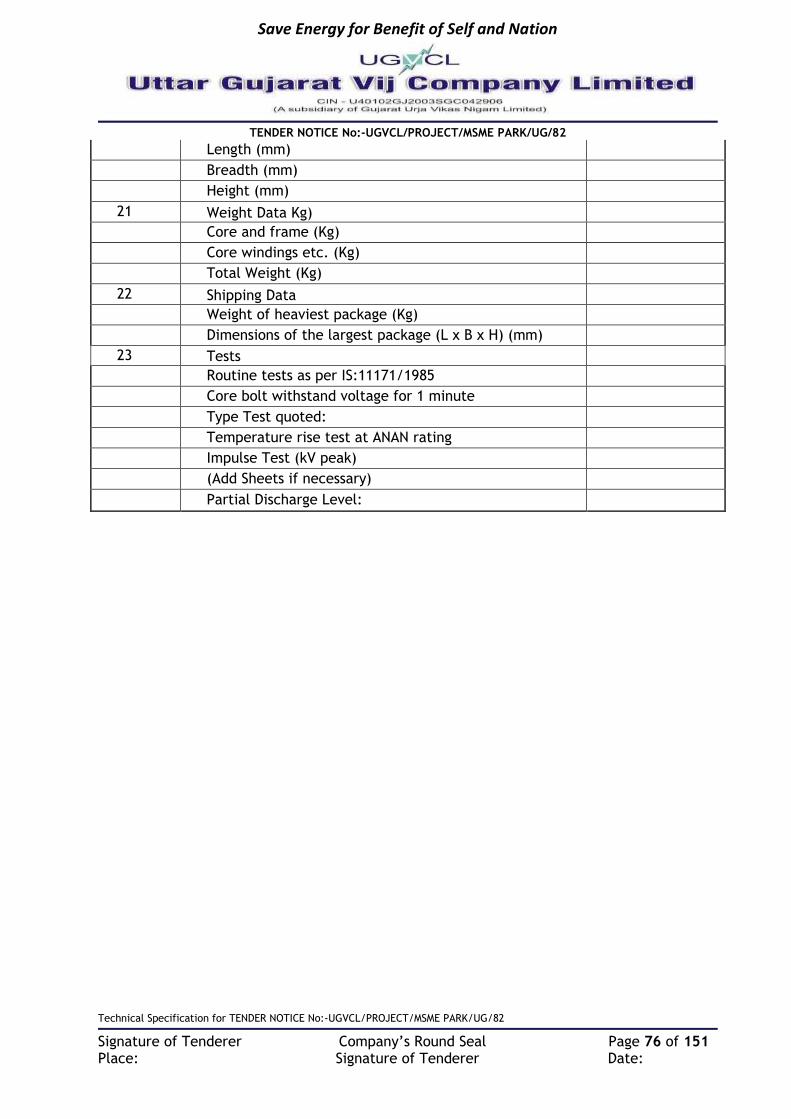
Save Energy for Benefit of Self and Nation
TENDER NOTICE No:-UGVCL/PROJECT/MSME PARK/UG/82
Technical Specification for TENDER NOTICE No:-UGVCL/PROJECT/MSME PARK/UG/82
Signature of Tenderer Company’s Round Seal Page 76 of 151 Place: Signature of Tenderer Date:
Length (mm)
Breadth (mm)
Height (mm)
21 Weight Data Kg)
Core and frame (Kg)
Core windings etc. (Kg)
Total Weight (Kg)
22 Shipping Data
Weight of heaviest package (Kg)
Dimensions of the largest package (L x B x H) (mm)
23 Tests
Routine tests as per IS:11171/1985
Core bolt withstand voltage for 1 minute
Type Test quoted:
Temperature rise test at ANAN rating
Impulse Test (kV peak)
(Add Sheets if necessary)
Partial Discharge Level:

Save Energy for Benefit of Self and Nation
TENDER NOTICE No:-UGVCL/PROJECT/MSME PARK/UG/82
Technical Specification for TENDER NOTICE No:-UGVCL/PROJECT/MSME PARK/UG/82
Signature of Tenderer Company’s Round Seal Page 77 of 151 Place: Signature of Tenderer Date:

Save Energy for Benefit of Self and Nation
TENDER NOTICE No:-UGVCL/PROJECT/MSME PARK/UG/82
Technical Specification for TENDER NOTICE No:-UGVCL/PROJECT/MSME PARK/UG/82
Signature of Tenderer Company’s Round Seal Page 78 of 151 Place: Signature of Tenderer Date:
TECHNICAL SPECIFICATION FOR MAINTENANCE FREE EARTH FOR ELECTRICAL INSTALLATION
1. SCOPE This specification covers supply, installation, connecting, testing & commissioning of Maintenance Free Earthing suitable for Package Substations, distribution transformers, RMU & Feeder Pillars etc. Earthing is essential in any electrical installation to provide safety. The conventional GI pipe earthing system employing charcoal & salts are provided for various applications as per IS:3043. Corrosion of metallic parts is comparatively fast besides maintenance by way of watering of earth pits and chiseling of corrosion prone parts & their replacement requires monitoring which may not always be feasible in certain crowded and inaccessible areas. This specification covers components, enhancing material & jointing used and procedure for constructing the earth pit for maintenance free earthing system to ensure that the resistance to earth is near zero consistent throughout the year.
2. SERVICE CONDITIONS: Equipment to be supplied against this specification shall be suitable for satisfactory continuous operation under the following tropical conditions.
a) Maximum ambient temperature of air: 50˚C b) Maximum temperature of air in shade: 4˚C c) Maximum daily average ambient temperature: 40˚C d) Maximum yearly average ambient temperature: 30˚C e) Relative Humidity: up to 95% f) Average number of thunder storm days per annum: 15 g) Maximum annual Rainfall: 150cm h) Maximum Altitude above mean sea level: 1000Meter i) Maximum Wind Pressure: 150 Kg/cm2 (As per IS 802 latest code) j) Maximum soil temperature at cable depth: 30˚C k) Maximum soil thermal resistively: 150˚C cm/watt
3. APPLICABLE CODES & STANDARDS
a) IEEE 80 :IEEE guide for safety in AC sub-station grounding b) IS : 3043 :Indian standard code of practice for earthing c) IEEE 837 :Standard for qualifying permanent connections used in substation grounding
4. APPLICATION Earthing systems covered in this document shall be for providing effective grounds for
i. Sub-Stations ii. RTUs, supply control posts iii. RMU, Transformer and Generator neutral earths iv. Lightning arrester earths v. Equipment earths including panels vi. In applications for PRS, UTS, FOIS, COIS, ATMs and data processing centre etc.

Save Energy for Benefit of Self and Nation
TENDER NOTICE No:-UGVCL/PROJECT/MSME PARK/UG/82
Technical Specification for TENDER NOTICE No:-UGVCL/PROJECT/MSME PARK/UG/82
Signature of Tenderer Company’s Round Seal Page 79 of 151 Place: Signature of Tenderer Date:
5. GENERAL TECHNICAL REQUIREMENTS:
(II) SELECTION OF EARTHING SYSTEM
Sl. No
Installations/ Current Capacity
IR Value Required
Soil Type/ Resistivity Earth System
1
House hold earthing/ 3kA 8 ohm Normal Soil/ upto 50 ohm-mtr
Single Electrode
Sandy Soil/ between 50 to 2000 ohm-mtr
Single Electrode
Rocky Soil/ More than 2000 ohm-mtr
Multiple Electrodes
2 Commercial premises Office buildings/ 5kA
2 ohm Normal Soil/ upto 50 ohm-mtr
Single Electrode
Sandy Soil/ between 50 to 2000 ohm-mtr
Single Electrode
Rocky Soil/ More than 2000 ohm-mtr
Multiple Electrodes
3 Transformers, substation earthing, LT line equipment/ 15kA
1 - 2 ohm Normal Soil/ upto 50 ohm-mtr
Single Electrode
Sandy Soil/ between 50 to 2000 ohm-mtr
Single Electrode
Rocky Soil/ More than 2000 ohm-mtr
Multiple Electrodes
4 Transformers, substation earthing, HT line equipment/ 40kA
less than 1 ohm
Normal Soil/ upto 50 ohm-mtr
Single Electrode
Sandy Soil/ between 50 to 2000 ohm-mtr
Single Electrode
Rocky Soil/ More than 2000 ohm-mtr
Multiple Electrodes
5 Lightning arresters, extra high current applications
etc./ 50kA
less than 1 ohm
Normal Soil/ upto 50 ohm-mtr
Single Electrode
Sandy Soil/ between 50 to 2000 ohm-mtr
Single Electrode
Rocky Soil/ More than 2000 ohm-mtr
Multiple Electrodes
6 PRS, UTS, RTUs, FOIS, COIS, ATMs and data
processing centre etc./5KA
less than 0.5 ohm
Normal Soil/ upto 50 ohm-mtr
Single Electrode
Sandy Soil/ between 50 to 2000 ohm-mtr
Single Electrode
Rocky Soil/ More than 2000 ohm-mtr
Multiple Electrodes

Save Energy for Benefit of Self and Nation
TENDER NOTICE No:-UGVCL/PROJECT/MSME PARK/UG/82
Technical Specification for TENDER NOTICE No:-UGVCL/PROJECT/MSME PARK/UG/82
Signature of Tenderer Company’s Round Seal Page 80 of 151 Place: Signature of Tenderer Date:
(III) TYPE OF SOILS Soil can be classified in to various types, though based on the size of the particles it contains: Normal soil Black cotton soil, vegetable soil, garden soil, loamy garden, soil shallow black, soil medium black soil, deep black soil and marshy soil etc. having low soil resistivity value (up to 50 ohm-meter) Sandy soil This type has the big particles and the size of the particles does determine the degree of aeration and drainage that the soil allows. It is granular and consists of rock and mineral particles that are very small. Therefore, the texture is gritty and sandy soil is formed by the disintegration and weathering of rocks such as limestone, granite, quartz and shale, thus resulting in over-drainage. It warms very fast in the spring season. Coastal area, silt soil, red sandy soil, sandy clay and coastal alluvium etc having soil resistivity up to 2000 ohm-meter are considered as sandy soil. Rocky soil The area containing rocks, pebbles, uneven hard surface laterite soil, lime stone, sand stone, gravel, granite and chalk etc having soil resistivity more than 2000 ohm-meter is considered as rocky soil. This type of soil does not absorb moisture and are extremely poor conductor.
(IV) LOCATION OF EARTH ELECTRODE
Where there is option, site should be chosen in one of the following types of soil in the order of preference given: -
a. Wet marshy ground; b. Clay, loamy soil, arable land. c. Clay and loam mixed with varying proportions of sand, gravel and stones; d. Damp and wet sand, peat.
Dry sand, gravel chalk, limestone, granite, very stony ground and all locations where virgin rock is very close to the surface should be avoided,
(V) MEASUREMENT OF EARTH ELECTRODE RESISTANCE
The earth resistance shall be measured using fall of potential method as per para 37 of IS:3043.
(VI) EARTHING SYSTEM
The earthing system includes earth electrode, installation of earth electrode in suitable pit size, construction of earth pit with cover for the installation, connection of earth electrode with equipotential earth bus and connection of equipment to equipotential earth bus. Earth electrode The earth electrode is the main component of the earthing system which is in direct contact with the ground and thus provides a means of releasing or collecting any earth leakage currents. The material should have good electrical conductivity and should not corrode in a wide range of soil conditions. For an effective earthing system, two types of earth electrodes can be used as described here:

Save Energy for Benefit of Self and Nation
TENDER NOTICE No:-UGVCL/PROJECT/MSME PARK/UG/82
Technical Specification for TENDER NOTICE No:-UGVCL/PROJECT/MSME PARK/UG/82
Signature of Tenderer Company’s Round Seal Page 81 of 151 Place: Signature of Tenderer Date:
Rod earth electrode
High tensile-low carbon steel rod having diameter not less than 17mm complying with requirements of BS 4360 Grade 43A or EN10025:2-004 S275JR, molecularly bonded by 99.99% pure high conductivity copper on outer surface with copper coating thickness 250 micron or more, Length 3000 mm (minimum). Length of the electrode may be increased in multiple of 1 meter to reduce earth resistance if required. To increase the length, pieces of similar rod shall be either exothermally welded to basic 3-meter electrode or connected using socket of suitable size. These sockets shall also be molecularly bonded by 99.99% pure high conductivity copper on inner & outer surface with copper coating thickness 250 micron or more.
Copper bus bar of size 250 mm x 50mm x 6 mm having electrical conductivity of 101% IACS, minimum 99.9% copper content shall be exothermically welded to rod with 4 holes of 12 mm dia. (2 on each side) for connecting earthing conductor.
Current carrying capacity: The design of the electrode should be such as to have more than 15kA current carrying capacity for 1 second.
Concentric pipe earth electrode:
Primary conductor MS pipe with 25 - 50 mm diameter, class B, ISI mark as per IS-1239, Length 2000 or 3000 mm as per table below current carrying capacity.
Secondary conductor MS pipe with 40-100 mm diameter, class B, ISI mark as per IS-1239, Length 2000 or 3000 mm as per table below current carrying capacity.
Conductive mixture For hermetically filling inside the cavity i.e. between secondary conductor & primary conductor, crystalline compound is to be injected in the electrode assembly. It is a combination of high conductivity metal alloys, copper & aluminum powder, conductive carbon/cement and bonding material etc. mixed in different proportion. The mixture is forced (pressurized) filled inside the earth electrode in the paste form and after solidification of the same, the end caps are welded. The metal alloys shall help in conducting the current and conductive carbon gives anti corrosive property. Bonding material should provide strength to the mixture. Resistivity of the mixture shall be less than 0.2 ohm-meter. Resistivity shall be tested by making a 20cm cube of the material and checking resistance across the opposite face of the cube.
Complete electrode shall be molecularly bonded by 99.99% pure, high conductivity copper on outer surface with copper coating thickness 300 micron or more.
Its surface shall be clean and free from any visible oxide layer or foreign material.
Copper bus bar of size 250 mm x 50mm x 6 mm having electrical conductivity of 101% IACS, minimum 99.9% copper content shall preferably be exothermically welded to earth electrode or connected with the help of two number stainless steel nut bolts of appropriate size having 4 holes of 12 mm dia. (2 on each side) for connecting earthing conductor.

Save Energy for Benefit of Self and Nation
TENDER NOTICE No:-UGVCL/PROJECT/MSME PARK/UG/82
Technical Specification for TENDER NOTICE No:-UGVCL/PROJECT/MSME PARK/UG/82
Signature of Tenderer Company’s Round Seal Page 82 of 151 Place: Signature of Tenderer Date:
Current carrying capacity: The design of the electrode should be such as to have more than following current carrying capacity in kA (for 1 second):
Sl. No
Current Capacity
Primary Conductor diameter
Electrode dimensions (dia. x length)
1 3 kA 25 mm 40 mm x 2000 mm
2 5kA 25 mm 40 mm x 3000 mm
3 15kA 25 mm 50 mm x 3000 mm
4 40kA 40 mm 80 mm x 3000 mm
5 50kA 50 mm 100 mm x 3000 mm
Note: - For more than 50KA applications, multiple electrodes of 50KA capacity shall be installed and connected. Earth enhancement material: Earth enhancement material is a superior conductive material that improves earthing effectiveness, especially in areas of poor conductivity (rocky ground, areas of moisture variation, sandy soils etc.). It may contain conductive cement, graphite, hydrous aluminium silicate, sodium montmorillonite etc and shall not contain bentonite. It improves conductivity of the earth electrode and ground contact area. It shall have following characteristics
i. It should have low resistivity preferably bellow 0.2 Ohm-meters. Resistivity shall be tested by making a 20cm. cube of the material and checking resistance across the opposite face of the cube.
ii. It shall not depend on the continuous presence of water to maintain its conductivity. iii. It should be a little alkaline in nature with pH value >7 but test certificate from NABL
approved laboratory to be provided for the composition so designed. iv. It should have better hygroscopic properties to absorb moisture. It should absorb and
release the moisture in dry weather condition and help in maintaining the moisture around the earth electrode.
v. It should have capacity to retain >10% moisture at 105ºC. Test certificate from NABL approved lab to be submitted for the composition so designed.
vi. It should have water solubility < 5%. Test certificate from NABL approved lab be submitted for the composition so designed.
vii. It should be granular with granule size 0.1 mm to 3 mm. viii. It should be nontoxic, non-reactive, non-explosive & non-corrosive. ix. It shall be thermally stable between -10 degrees centigrade to +60-degree centigrade
ambient temperature.

Save Energy for Benefit of Self and Nation
TENDER NOTICE No:-UGVCL/PROJECT/MSME PARK/UG/82
Technical Specification for TENDER NOTICE No:-UGVCL/PROJECT/MSME PARK/UG/82
Signature of Tenderer Company’s Round Seal Page 83 of 151 Place: Signature of Tenderer Date:
x. It shall not decompose or leach out with time. xi. It shall not pollute the soil or local water table and meets environmental friendly
requirement for landfill. xii. It should expand & swell considerably and removes entrapped air to create strong
connection between earth electrode and soil. xiii. It should be diffusing into soil pores and creates conductive roots enlarging conductive
zone of earth pit. xiv. It shall be permanent & maintenance free and in its “set form”, maintains constant
earth resistance with time. xv. It shall not require periodic charging treatment or replacement. xvi. It shall be suitable for any kind of electrode and all kinds of soils of different
resistivity. xvii. It shall not cause burns, irritation to eye, skin etc. xviii. Minimum quantity of earth enhancement material to be supplied: For 5’ x5’x 10’ earth
pit – Min. 75 kgs per pit for 300mm bore type earth pit – Min 50 kgs per pit xix. The Earth enhancement material shall be supplied in sealed, moisture proof bags.
These bags shall be marked with Manufacturer’s name or trade name, quantity, batch no & date of manufacture.
Backfill material Normally the excavated soil shall be used if it is free from sand, gravel and stones. In case the excavated soil contains sand, gravel and stones these shall be removed by appropriate methods such as hand picking, sieving etc. Small proportion of sand in the soil may be permissible. Material like sand, salt, coke breeze, cinders and ash shall not be used because of its acidic and corrosive nature. If the excavated soil contains sand, gravel and stone in large proportion and it is not feasible to remove these economically, good quality soil from other place may be used for backfilling. While backfilling the soil shall be thoroughly compacted with at least 5 kg compactor. In case the soil is dry, small quantity of water may be sprinkled only to make it moist enough suitable for compacting. Large quantity of water may make the soil muddy which is not suitable for compacting and after drying the soil may contain voids which may permanently increase earth resistance. Equipotential bus & Earthing Conductor
A copper bus bar of size 300mm x 25mm x 6mm to be installed in the equipment room as equipotential bus and must be connected with preferably copper strip of 25mm x 3mm (suitable length) from instrument to the bus bar. The connecting terminal of the earth electrode to the bus bar must be connected by copper strip of 25mm x 3mm (suitable length) buried inside a trench of 300mm width x 600mm depth (from the earth pit to the nearest wall). It shall be duplicated. However, it shall be ensured that only minimum required length is used and any extra length is cut away to keep the earth impedance minimum.
It shall be high conductivity copper having electrical conductivity of 101% IACS i.e. minimum 99.9% copper content The maximum specific resistance of the copper strip earthing conductor shall be 17.241 x 10⁻⁷-ohm cm at 20ºC.
At a temperature of 20ºC, its density shall be 8.89 gm/cm3
Its surface shall be clean and free from any visible oxide layer or foreign materials.
It shall preferably be connected to earth electrode and earth bus bar with the help of exothermic welding or at least two number stainless steel nut bolts of appropriate size.

Save Energy for Benefit of Self and Nation
TENDER NOTICE No:-UGVCL/PROJECT/MSME PARK/UG/82
Technical Specification for TENDER NOTICE No:-UGVCL/PROJECT/MSME PARK/UG/82
Signature of Tenderer Company’s Round Seal Page 84 of 151 Place: Signature of Tenderer Date:
Normally a single length of copper strip shall be used for each duplicate copper strip earthing conductor and no joint should be used. However, in situation requiring greater length one joint in each copper strip shall be permitted. The joints shall be made by exothermic welding of at least 10mm overlapping portion of the strips.
Construction of unit earth.
Make 5ft x 5ft x 10ft earth pit. If it is not possible to make such a pit due to non-availability of clear space at locations like ATM, High mast lighting tower, Passenger information systems, PRS etc. or in rocky soil, min. 300 mm bore up to 10 ft deep can be made using earth auger or any other method. Earth pit larger than specified size can be made, if required.
Sleeve the soil digged and remove the gravels and stones. If soil quality is good (without Murum and rocks) then add some quantity of earth enhancement material in the soil for using as backfill.
If the soil seems unusable (containing large quantity of gravel, stones, murum, sad etc.) then replace the soil with black cotton soil.
Insert the electrode at the centre of the earth pit and arrange to keep it vertical in the pit.
Arrange for adequate quantity of water supply for the earth pit. (Approx. 600 litres)
Fill the pit with the backfill and keep on adding the earth enhancement material surrounding the electrode and simultaneously watering the pit.
With a steel bar or pipe, keep on poking the soil gel and stirring intermittently for removing the air pockets and proper settlement of the pit.
The procedure to be repeated till completion of the filling of the earth pit along with the packing material and sufficient watering adequate ramming.
The pit should be very compactly rammed and watering for 2-3 days and addition of soil if required be done.
Make trench of 600 mm (depth) x 300 mm (wide) from the earth pit to the nearest point of connection.
Construct inspection chamber with cover for the installation.
Measure the earth resistance as per IS 3043:1987 code of practice. Earth resistance value shall be less than 1 ohm in non-rocky/non-sandy surface by single electrode Installation and in rocky surface by multiple electrode installation (not more than three electrodes & its individual earth pits). For earthing purpose, if solid rocky layer is found within 10 feet from ground level while digging the earth pit then it is considered rocky surface. Coastal area, silt soil, red sandy soil and sandy clay are considered as sandy surface.
If required resistance is lower than the resistance of single earth electrode, then multiple earths can be constructed and interconnected.
Construction of ring earth by providing multiple earth pits
Wherever it is not possible to achieve required earth resistance with one earth electrode/pit due to difficult/rocky soil conditions, provision of ring earth consisting of more than one earth pit shall be done. The number of pits required shall be decided based on the resistance achieved for the earth pits already installed. The procedure mentioned above for one earth pit shall be repeated for other earth pits.

Save Energy for Benefit of Self and Nation
TENDER NOTICE No:-UGVCL/PROJECT/MSME PARK/UG/82
Technical Specification for TENDER NOTICE No:-UGVCL/PROJECT/MSME PARK/UG/82
Signature of Tenderer Company’s Round Seal Page 85 of 151 Place: Signature of Tenderer Date:
The distance between two successive earth electrodes shall be min. 3mtrs / length of electrode whichever is higher. and max. up to twice the length of the earth electrode.
These earth pits shall then be inter linked using 25X3 mm copper strip to form a loop preferably using exothermic welding or with the help of at least two number of stainless steel nut bolts of appropriate size.
The interconnecting strip shall be buried no less than 600mm (0.6m) below the ground level. This interconnecting strip shall also be covered with earth enhancing compound.
Inspection chamber
A 300X300X300 mm (inside dimension) concrete box (wall thickness min. 50 mm) with smooth cement plaster finish shall be provided on the top of the pit. A concrete lid 25 to 50 mm. thick, with pulling hooks, painted black shall be provided to cover the earth pit. PVC sleeve of appropriate size shall be provided in concrete wall to take out earthing connections.
The masonry work shall be white washed inside and outside.
Care shall be taken regarding level of the floor surrounding the earth so that the connector is not too deep in the masonry or projecting out of it.
On backside of the cover, date of the testing and average resistance value shall be written with yellow paint on black background.
(VII) MARKING: The marking shall be clear, distinct and visible to the naked eye from a distance of about 1 meter; the size of marking shall be of minimum 25 mm. Following information shall be legibly and indelibly marked on the packed sets:
a. Specification no. b. Name of the manufacturer c. Batch no. & Date of manufacturer d. Current carrying capacity
b. TESTING & COMMISSIONING
Following tests shall be done on one sample-
Testing of copper coating shall be done as described below: - i. The copper coating mentioned in clause 14.5.5.1 shall not be less than the prescribed
thickness at any point and shall comply with the adherence requirement in para (ii) & (iii) below.
ii. Length of the electrode with one end cut to a 45-degree point shall be driven between two steel clamping plates or the jaws of a vise set 0.04 in (1.02 mm) less than the diameter of the electrode, so as to shear off sufficient metal to expose the bond between the copper coating and electrode. Peeling of the coating by the steel plates or the jaws of the vise is acceptable, but there shall be no other evidence of separation of the coating from the metal core.
iii. At room temperature, a length of the electrode is rigidly held in a clamp or vise and the free end is bent by applying a force normal to the electrode at a distance from the clamping device equal to 40 times the diameter. The magnitude of the force and the direction of application of force shall be such that the electrode is permanently

Save Energy for Benefit of Self and Nation
TENDER NOTICE No:-UGVCL/PROJECT/MSME PARK/UG/82
Technical Specification for TENDER NOTICE No:-UGVCL/PROJECT/MSME PARK/UG/82
Signature of Tenderer Company’s Round Seal Page 86 of 151 Place: Signature of Tenderer Date:
bent through a 30-degree angle. While bending of the electrode there shall be no evidence of cracking of the copper coating.
Material composition of rod shall be tested as per standards mentioned in clause no. 14.5.5.1 (Rod Earth Electrode)
MS pipes shall be tested as per IS:1239.
Copper bus bars of shall be tested for percentage of copper as per IS:14644.
Current carrying capacity test on rod electrode shall be done as per clause above.
Corrosion Test: As per IS:2119, salt spray test for analysis of effect of corrosion for the specific electrode shall be done through NABL approved testing lab, preferably for 500 hrs. or more.
Exothermic weld material shall be tested as per provisions of IEEE 837.
Electrical properties test on conductive mixture as per clause above.
Physical, chemical & electrical properties test on earth enhancement material as per clause no. 14.5.5.2.
Toxic content tests for cadmium, lead, mercury, hexavalent chromium, polybrominated biphenyls (PBBs) & polybrominated diphenyl ethers (PBDEs) on conductive mixture & earth enhancement material. Certificates from NABL approved laboratories shall be submitted with test results of above tests. Test certificates shall not be more than three years old. For dimension, weight and specific resistance average of 3 readings shall be taken. Average value shall be within specified limits and individual values shall not go beyond double of tolerances.
ACCEPTANCE TESTS Following shall constitute acceptance tests and shall be done on 100% sample basis for all the tests mentioned below except where otherwise indicated–
a. Physical check for earth electrode as per clause above for rod type electrode and as per clause above for concentric pipe type electrode.
b. Physical check for copper bus bar as per clause above for rod type electrode and as per clause above for concentric pipe type electrode.
c. Dimensional and construction feature tests of inspection chamber d. Earth enhancement material as per clause no. 14.5.5.2 e. Earth resistance measurements as per clause no. 14.5.4.
Rejection: In case the any component tested and inspected in accordance with this specification, fail to pass the tests or comply with the requirement of the specification, another two components from the same lot shall be inspected in accordance with the specification and if one of them also fail to pass the test, the whole lot of that component shall be rejected subject to the discretion of the purchaser or his nominee. INSPECTION: All the gauges/ test & measuring instruments shall be under calibration control at the time of inspection and proof to this office shall be produced. Inspection and testing shall be carried out by the inspecting authority nominated by the purchaser to ensure that all the requirements of this specification are complied with for the acceptance of the materials offered by the supplier for inspection. The purchaser or his nominee shall have right of free

Save Energy for Benefit of Self and Nation
TENDER NOTICE No:-UGVCL/PROJECT/MSME PARK/UG/82
Technical Specification for TENDER NOTICE No:-UGVCL/PROJECT/MSME PARK/UG/82
Signature of Tenderer Company’s Round Seal Page 87 of 151 Place: Signature of Tenderer Date:
access to the works of the manufacturer and to be present at all reasonable times and shall be given facilities by the manufacturer to inspect the manufacturing process at any stage of manufacture. He shall have the right to reject whole or part of any work or material that does not conform to the terms of this specification or any other specification or requirement applicable and may order the same to be removed / replaced or altered at the expense of the manufacturer. All reasonable/complete facilities considered necessary by the inspecting authorities for the inspection shall be supplied by the manufacturer free of cost. The manufacturer shall at his own cost prepare and furnish the necessary test pieces and appliances for such testing as may be carried out at his own premises in accordance with the specification. Failing the existence of facilities at his own premises for the prescribed tests, the manufacturer shall bear the cost of carrying out the tests in an approved laboratory, workshop or test house. COMPLETION REPORT & CERTIFICATION: The last documents for the completion of the procedure will be submission of the work completion report to the engineer in charge. After testing the earth values of the pits and proper recording in presence of engineer in charge, certified grounding self-adhesive certificate shall be provided for all installations and the same will be displayed / pasted at the place of installation. The complete layout with dimensions of the earthing & bonding system shall be submitted by the supplier in appropriate size (in three copies) after commissioning showing commissioning date, earth resistance, specification no. and manufacturer’s name.
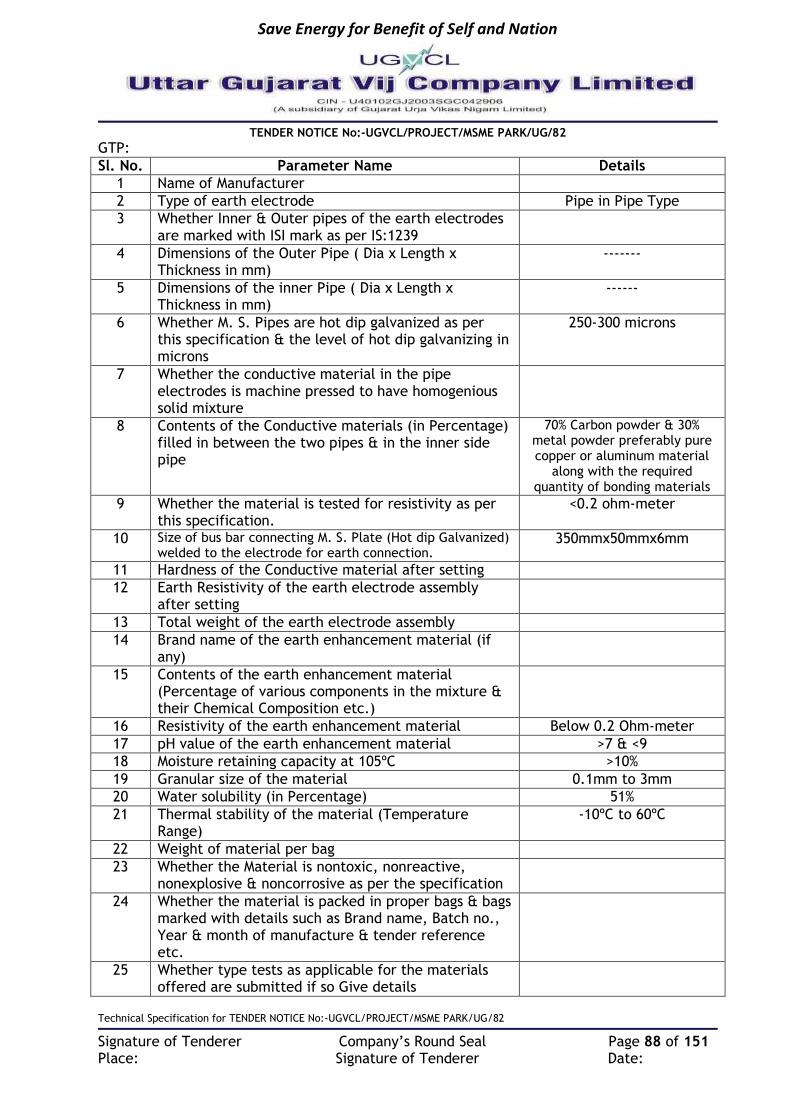
Save Energy for Benefit of Self and Nation
TENDER NOTICE No:-UGVCL/PROJECT/MSME PARK/UG/82
Technical Specification for TENDER NOTICE No:-UGVCL/PROJECT/MSME PARK/UG/82
Signature of Tenderer Company’s Round Seal Page 88 of 151 Place: Signature of Tenderer Date:
GTP:
Sl. No. Parameter Name Details
1 Name of Manufacturer
2 Type of earth electrode Pipe in Pipe Type
3 Whether Inner & Outer pipes of the earth electrodes are marked with ISI mark as per IS:1239
4 Dimensions of the Outer Pipe ( Dia x Length x Thickness in mm)
-------
5 Dimensions of the inner Pipe ( Dia x Length x Thickness in mm)
------
6 Whether M. S. Pipes are hot dip galvanized as per this specification & the level of hot dip galvanizing in microns
250-300 microns
7 Whether the conductive material in the pipe electrodes is machine pressed to have homogenious solid mixture
8 Contents of the Conductive materials (in Percentage) filled in between the two pipes & in the inner side pipe
70% Carbon powder & 30% metal powder preferably pure copper or aluminum material
along with the required quantity of bonding materials
9 Whether the material is tested for resistivity as per this specification.
<0.2 ohm-meter
10 Size of bus bar connecting M. S. Plate (Hot dip Galvanized) welded to the electrode for earth connection.
350mmx50mmx6mm
11 Hardness of the Conductive material after setting
12 Earth Resistivity of the earth electrode assembly after setting
13 Total weight of the earth electrode assembly
14 Brand name of the earth enhancement material (if any)
15 Contents of the earth enhancement material (Percentage of various components in the mixture & their Chemical Composition etc.)
16 Resistivity of the earth enhancement material Below 0.2 Ohm-meter
17 pH value of the earth enhancement material >7 & <9
18 Moisture retaining capacity at 105ºC >10%
19 Granular size of the material 0.1mm to 3mm
20 Water solubility (in Percentage) 51%
21 Thermal stability of the material (Temperature Range)
-10ºC to 60ºC
22 Weight of material per bag
23 Whether the Material is nontoxic, nonreactive, nonexplosive & noncorrosive as per the specification
24 Whether the material is packed in proper bags & bags marked with details such as Brand name, Batch no., Year & month of manufacture & tender reference etc.
25 Whether type tests as applicable for the materials offered are submitted if so Give details

Save Energy for Benefit of Self and Nation
TENDER NOTICE No:-UGVCL/PROJECT/MSME PARK/UG/82
Technical Specification for TENDER NOTICE No:-UGVCL/PROJECT/MSME PARK/UG/82
Signature of Tenderer Company’s Round Seal Page 89 of 151 Place: Signature of Tenderer Date:
TECHNICAL SPECIFICATION OF GI EARTHING STRIPS 1. Scope: This section of the specification covers the supply, erection, testing and commissioning of Galvanizes Iron Earthing Strips for the Distribution Network equipment’s.
2. Applicable Standards: The galvanizing and Testing of materials shall confirm to the latest edition of the following standards except otherwise specified in the specification.
Recommended practice for hot dip galvanized of Iron Earthing Strips
IS: 2629(1966)
Methods of testing weight, thickness & uniformity of coating on hot dip galvanized articles
IS: 2633(1972)
Specification for hot dip galvanized coating on fastness I IS: 5358(1969)
Specification for Electroplating IS:3203
Specification for hot dip Zinc coating on structural & other allied products
IS: 4759(1968)
3. General Technical Requirements: MATERIAL Supplier has to purchase raw materials (MS Flat) as per relevant IS at his own cost. The zinc required for galvanizing shall be quality Zn-98 & shall confirm to IS: 209- 1966 and its latest amendments. The Supplier shall make his own arrangement for procurement before the commissioning of work, sufficient quantity of electrolytic zinc of proper quality for galvanizing. The Supplier shall however, not link the delivery period with the supply of zinc. The DISCOM is at liberty to have sample of zinc used and to test in any laboratory at his own cost and reject the particular supply, is found below standard. All raw materials required for galvanizing etc. and for complete execution of work shall be stocked in adequate quantities by the Supplier to ensure that the progress of work is not hampered. GALVANISING Fully galvanized Iron strips shall be used. Galvanized Iron strips shall confirm to IS: 2629 (1966). The zinc deposition should not be less than 610 grams/meter square of the galvanized surface area of the MS Earthing strips. All galvanized materials shall withstand test as per IS: 2633 (1972). The weight of zinc coating shall determine as per the method stipulated in IS: 2633(1964). The standard length of Galvanized Iron Earthing Strip shall be minimum 7 Mtrs and not exceeding 10 Mtrs.
4. Inspection: The Purchaser reserves the right to inspect the material at the time of tests. All tests shall then be performed in the presence of Inspecting Authority appointed by the Purchaser and the Supplier. The Bidder shall have to give intimation of place and date and time of each test to enable the later to be present to witness the test. All the test results must be recorded in presence of the inspecting authority and no materials shall be dispatched, without having been passed by Purchaser's duly appointed Inspector and specific dispatch instructions in writing from Chief Engineer / Addl. Chief Engineer (Project).

Save Energy for Benefit of Self and Nation
TENDER NOTICE No:-UGVCL/PROJECT/MSME PARK/UG/82
Technical Specification for TENDER NOTICE No:-UGVCL/PROJECT/MSME PARK/UG/82
Signature of Tenderer Company’s Round Seal Page 90 of 151 Place: Signature of Tenderer Date:
5. TESTS The following tests shall be carried out in accordance with IS:280-1978 or the latest version thereof as per sampling criteria stipulated therein:
i) Dimensional check (dia.). ii) Visual inspection regarding freedom from defects. iii) Tensile test iv) Galvanizing/Electroplating test
6. QUALITY ASSURANCE PLAN The bidder shall invariably furnish following information along with his offer, failing which his offer shall be rejected.
I. Statement giving list of raw materials, proposed to be used against this Specification, names of sub suppliers for the raw materials, list of standards according to which the raw materials are tested, list of tests normally carried out on raw materials in presence of Bidder's representative as routine and / or acceptance during processing and on finished goods, copies of test certificates of processing and testing facilities available.
II. List of areas where stage inspections are normally carried out for quality control and details of such tests and inspections.
III. List of testing equipment available with the Bidder for testing. In the case if the Bidder does not possess all the Routine and Acceptance testing facilities the tender will be rejected.
IV. The Purchaser reserves the right for factory inspection to verify the facts quoted in the offer. If any of the facts are found to be misleading or incorrect the offer of that Bidder will be out rightly rejected and he may be black listed.
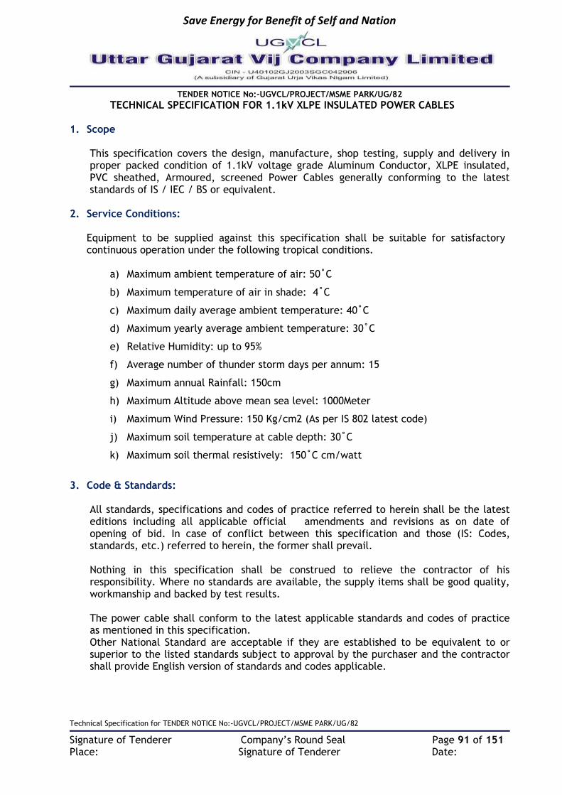
Save Energy for Benefit of Self and Nation
TENDER NOTICE No:-UGVCL/PROJECT/MSME PARK/UG/82
Technical Specification for TENDER NOTICE No:-UGVCL/PROJECT/MSME PARK/UG/82
Signature of Tenderer Company’s Round Seal Page 91 of 151 Place: Signature of Tenderer Date:
TECHNICAL SPECIFICATION FOR 1.1kV XLPE INSULATED POWER CABLES 1. Scope
This specification covers the design, manufacture, shop testing, supply and delivery in proper packed condition of 1.1kV voltage grade Aluminum Conductor, XLPE insulated, PVC sheathed, Armoured, screened Power Cables generally conforming to the latest standards of IS / IEC / BS or equivalent.
2. Service Conditions: Equipment to be supplied against this specification shall be suitable for satisfactory continuous operation under the following tropical conditions.
a) Maximum ambient temperature of air: 50˚C
b) Maximum temperature of air in shade: 4˚C
c) Maximum daily average ambient temperature: 40˚C
d) Maximum yearly average ambient temperature: 30˚C
e) Relative Humidity: up to 95%
f) Average number of thunder storm days per annum: 15
g) Maximum annual Rainfall: 150cm
h) Maximum Altitude above mean sea level: 1000Meter
i) Maximum Wind Pressure: 150 Kg/cm2 (As per IS 802 latest code)
j) Maximum soil temperature at cable depth: 30˚C
k) Maximum soil thermal resistively: 150˚C cm/watt
3. Code & Standards:
All standards, specifications and codes of practice referred to herein shall be the latest editions including all applicable official amendments and revisions as on date of opening of bid. In case of conflict between this specification and those (IS: Codes, standards, etc.) referred to herein, the former shall prevail. Nothing in this specification shall be construed to relieve the contractor of his responsibility. Where no standards are available, the supply items shall be good quality, workmanship and backed by test results. The power cable shall conform to the latest applicable standards and codes of practice as mentioned in this specification. Other National Standard are acceptable if they are established to be equivalent to or superior to the listed standards subject to approval by the purchaser and the contractor shall provide English version of standards and codes applicable.

Save Energy for Benefit of Self and Nation
TENDER NOTICE No:-UGVCL/PROJECT/MSME PARK/UG/82
Technical Specification for TENDER NOTICE No:-UGVCL/PROJECT/MSME PARK/UG/82
Signature of Tenderer Company’s Round Seal Page 92 of 151 Place: Signature of Tenderer Date:
The 1.1kV XLPE power cable shall confirm to the currently applicable standards and codes of practice and reports as mention below table:
S. No.
Title IS Standard IEC / BS Standard
1 Conductors for insulated electric cables and flexible cords.
IS: 8130 – 1984
IEC 60228-1978
2 PVC insulation and sheath of electric cables.
IS: 5831 – 1984
IEC 60502
3 Mild steel wires, Formed wires and Tapes for armouring of cables.
IS: 3975 – 1988
4 Fictitious calculation method for determination of dimensions of protective coverings of cables.
IS :10462 ( Part I) –1983
IEC 60502:1978
5 1.1 KV Grade XLPE insulated cables. IS : 7098 (Part-I)
6 Method of test for cables IS : 10810
7 Code of practice for installation & maintenance of power cables up to & including 11 KV rating.
IS : 1255
8 Drums for electric cables. IS : 10418
9 Electro Technical Vocabulary for Electric Cables
IS:1885, Part-32
4. General Technical Requirements: -
(I) Armoured cables: - 1100 Volts Grade L.T. cable with stranded H2/H4 grade aluminum conductor, XLPE insulated, colour coded, laid up, with fillers and/or binder tape where necessary provided with extruded PVC inner sheath, single galvanized round steel wire / strip armoured and provided with PVC outer sheath. All LT cable shall be conforming to IS : 5831& IS : 8130 (amended up to date) and bearing ISI mark .
(II) Insulation, Inner sheath and Outer sheath: - Insulation, inner sheath and outer sheath shall be applied by separate extrusion. Inner sheath shall be applied by extrusion only. Bedding of PVC tape for inner sheath is not acceptable. The color of the outer sheath shall be different according to the different size of cables and color of outer sheath shall be approved before manufacturing. The quality of insulation should be good and insulation should not be deteriorated when exposed to the climatic conditions. The core insulation shall be with cross linked polyethylene insulating compound applied by extrusion & should be manufactured with Dry/Gas curing process. It shall be free from voids and shall withstand all mechanical and thermal stresses under steady state and transient operating condition. It shall conform to the properties given in Table-1 of IS: 7098(Part-2). The conductor screen, XLPE insulation and insulation screen shall be extruded in one operation by “Triple Extrusion Dry. Cured” process to ensure perfect bonding between the layers. The core identifications shall be colored strips or by printed numerals.
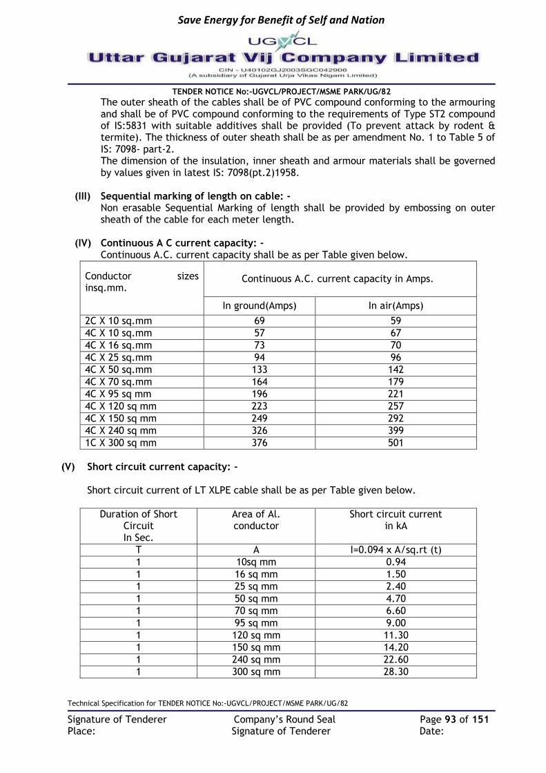
Save Energy for Benefit of Self and Nation
TENDER NOTICE No:-UGVCL/PROJECT/MSME PARK/UG/82
Technical Specification for TENDER NOTICE No:-UGVCL/PROJECT/MSME PARK/UG/82
Signature of Tenderer Company’s Round Seal Page 93 of 151 Place: Signature of Tenderer Date:
The outer sheath of the cables shall be of PVC compound conforming to the armouring and shall be of PVC compound conforming to the requirements of Type ST2 compound of IS:5831 with suitable additives shall be provided (To prevent attack by rodent & termite). The thickness of outer sheath shall be as per amendment No. 1 to Table 5 of IS: 7098- part-2. The dimension of the insulation, inner sheath and armour materials shall be governed by values given in latest IS: 7098(pt.2)1958.
(III) Sequential marking of length on cable: - Non erasable Sequential Marking of length shall be provided by embossing on outer sheath of the cable for each meter length.
(IV) Continuous A C current capacity: - Continuous A.C. current capacity shall be as per Table given below.
Conductor sizes insq.mm.
Continuous A.C. current capacity in Amps.
In ground(Amps) In air(Amps)
2C X 10 sq.mm 69 59
4C X 10 sq.mm 57 67
4C X 16 sq.mm 73 70
4C X 25 sq.mm 94 96
4C X 50 sq.mm 133 142
4C X 70 sq.mm 164 179
4C X 95 sq mm 196 221
4C X 120 sq mm 223 257
4C X 150 sq mm 249 292
4C X 240 sq mm 326 399
1C X 300 sq mm 376 501
(V) Short circuit current capacity: -
Short circuit current of LT XLPE cable shall be as per Table given below.
Duration of Short Circuit In Sec.
Area of Al. conductor
Short circuit current in kA
T A I=0.094 x A/sq.rt (t)
1 10sq mm 0.94
1 16 sq mm 1.50
1 25 sq mm 2.40
1 50 sq mm 4.70
1 70 sq mm 6.60
1 95 sq mm 9.00
1 120 sq mm 11.30
1 150 sq mm 14.20
1 240 sq mm 22.60
1 300 sq mm 28.30

Save Energy for Benefit of Self and Nation
TENDER NOTICE No:-UGVCL/PROJECT/MSME PARK/UG/82
Technical Specification for TENDER NOTICE No:-UGVCL/PROJECT/MSME PARK/UG/82
Signature of Tenderer Company’s Round Seal Page 94 of 151 Place: Signature of Tenderer Date:
(VI) Storage and handling of cables: -
a. All cables shall be inspected upon receipt at site and checked for any damage during transit. Cable drums shall be stored on a well-drained, hard surface, preferably of concrete, so that the drums do not sink in the ground causing rot and damage to the cable drums.
b. During storage periodical rolling of drums once in 3 months done. Rolling shall be done in the direction of the arrow marked on the drum.
c. It should be ensured that both ends of the cable are properly sealed to prevent ingress/absorption of moisture by the insulation.
d. Protection from rain and sun shall be ensured. Sufficient ventilation between cable drums, should be ensured during storage.
e. The drums shall always be rested on the flanges and not on the flat sides. f. Damaged battens of drums etc. should be replaced, if necessary. g. When cable drums have to be moved over short distances, they should be rolled in the
direction of the arrow, marked on the drum. h. For transportation over long distances, the drum should be mounted on cable drum
wheels strong enough to carry the weight of the drum and pulled by means of ropes. Alternatively, they may be mounted on a trailer or on a suitable mechanical transport.
i. When unloading cable drums from vehicles, a crane shall preferably be used. Otherwise the drum shall be rolled down carefully on a suitable ramp or rails, where necessary.
j. While transferring cable from one drum to another, the barrel of the new drum shall have a diameter not less than that of the original drum.
k. The cables shall not be bent sharp to a small radius. The minimum safe bending radius for all types of XLPE cables shall be taken as 12 times the overall diameter of the cable. Wherever practicable, larger radius should be adopted. At joints and terminations, the bending radius of individual cores of a multi core cable shall not be less than 15 times its overall diameter.
l. Cable with kinks and straightened kinks or with similar apparent defects like defective armouring etc. shall be rejected.
m. Cables from the stores shall be supplied by the contractor as per the site requirement in pieces cut in the stores, and further both ends are to be sealed as per Para ‘c’ above.
(VII) Drums
Cables shall be supplied in the drums made from eco-friendly material in the specified length. The Drums shall be strong, weatherproof and non-returnable. The ends of the cable shall be sealed by means of non-hygroscopic sealing material. Applicable Length of Cable/ drum should be as per IS. The cable shall be supplied in standard drum length of 500 mtrs. +/- 5% tolerance for all the sizes of cable except 10 mm2 & 16mm2 size cable. The drum length for 10 mm2 and 16mm2 cable shall be 1000 mtrs. +/- 5%. Over all tolerance in total quantity of ordered cables shall be +/- 2%.
General
All cables shall be suitable for installation in air, conduits, ducts, and open concrete trenches or for direct burial in either wet or dry locations for normal operating conditions.
All cables shall be flexible and easy to bend, pull, handle and install

Save Energy for Benefit of Self and Nation
TENDER NOTICE No:-UGVCL/PROJECT/MSME PARK/UG/82
Technical Specification for TENDER NOTICE No:-UGVCL/PROJECT/MSME PARK/UG/82
Signature of Tenderer Company’s Round Seal Page 95 of 151 Place: Signature of Tenderer Date:
(VIII) Installation (Laying in trench):-
General: The cable installation including necessary termination shall be carried out in accordance with the specifications given herein and IS 1255. Trenching:
The detail technical specification of Trench shall be a part of civil works. (i) Width of Trench: - 300/450/600mm (ii) Depth of Trench: - 1200mm. Laying of Cable in Trench
i. At the time of issue of cable for laying, the cores shall be tested for continuity and insulation resistance.
ii. The inter-axial spacing between the cables shall be maintained as per IS to maximize the cable capacity.
iii. The cable drum shall be properly mounted on jacks or on a cable wheel, at a suitable location, making sure that the spindle, jack etc. shall be strong enough to carry the weight of the drum without failure and that the spindle is horizontal in the bearings so as to prevent the drum creeping to one side while rotating.
iv. The cable shall be pulled over rollers in the trench steadily and uniformly without jerks and strains. The entire cable length shall as far as possible be pulled of in one stretch. However, where this is not possible the remainder of the cable may be removed by 'Flaking' i.e. by making one long loop in the reverse direction.
v. After the cable has been uncoiled and laid into the trench over the rollers, the cable shall be lifted slightly over the rollers beginning from one end by helpers standing about 10 m apart and drawn straight. The cable should then be taken off the rollers by additional helpers lifting the cable and then laid in a reasonably straight line.
vi. When the cable has been properly straightened, the cores shall be tested for continuity and insulation resistance. In case of PVC XLPE cables, suitable moisture seal tape shall be used for this purpose.
Laying in HDPE pipes by HDD/closed ducts: i. In location such as road crossing, crossing other utilities etc. cables shall be laid in
pipes. ii. HDPE Pipes shall be used for such purposes. Pipes as required shall be laid along with
the civil works and jointed according to the instructions of the Engineer-in-Charge as the case may be. The size of pipe shall be as indicated in the Road Crossing Drawing for Electrical Services.
iii. The pipes on road crossing shall preferably be on the skew to reduce the angle of bends as the cable enters and leaves the crossings. This is particularly important for high voltage cables.
iv. Manholes of adequate size as specified or decided by the Engineer-in-Charge shall be provided to facilitate feeding/drawing in of cables and to provide working space for persons. They shall be covered by suitable manhole covers with frame of proper design.
v. Pipes shall be continuous and clear of debris or concrete before cable is drawn. Sharp edges at ends shall be smoothened to prevent injury to cable insulation or sheathing.
5. TEST &INSPECTION: - Cables shall be subjected to routine & acceptance tests in accordance with the IS 1554 (Part – I, in addition to physical, ageing and electrical tests at the Manufacturer’s plant in accordance with applicable standards and will be approved by 3rd party agency.

Save Energy for Benefit of Self and Nation
TENDER NOTICE No:-UGVCL/PROJECT/MSME PARK/UG/82
Technical Specification for TENDER NOTICE No:-UGVCL/PROJECT/MSME PARK/UG/82
Signature of Tenderer Company’s Round Seal Page 96 of 151 Place: Signature of Tenderer Date:
5.1 Type Test: - The successful bidder shall submit the following type test reports conducted on similar equipment’s for approval of owner. a) Annealing test (for copper) b) Tensile Test (for aluminum) c) Conductor resistance test d) Test for Armour wires
e) Test for thickness of insulation check
f) Physical test for insulation g) Physical test for PVC sheath
i. Fire resistance. ii. Cold-impact iii. Bleeding and blooming
h) Partial discharge test i) Bending Test
j) Dielectric power factor tests
k) Heating cycle test l) Impulse withstand test
m) High voltage test (water immersion test) All the following routine / acceptance tests specified in relevant standards shall be witnessed by the owner / consultant.
5.2 Acceptance Test:- a) Conductor resistance test
b) Test for thickness of insulation and sheath
c) Partial discharge test (for screened cables only) d) High voltage test (water immersion test)
e) Annealing test (for copper)
f) Tensile test (for aluminum)
g) Wrapping test (for aluminum)
h) Insulation resistance test 5.3 Routine Test: -
a) Conductor resistance Test
b) Partial discharge test (for screened cable only)
c) High voltage test. 5.4 Test Certificate: -
Three (3) copies of routine / acceptance test certificates shall be produced with the endorsement of the inspecting authority to the purchaser before effecting dispatch.
5.5 PACKING AND MAKING Cables shall be dispatched in non-returnable wooden drums of suitable barrel diameter. Securely battened, with the take-off end fully protected against mechanical damage. The wood used for construction of the drum shall be properly seasoned, sound and free from defects. Wood preservatives shall be applied to the entire drum. Ferrous parts used shall be treated with a suitable rust preventive finish or coating to avoid rusting during transit or storage. On the flange of the drum, necessary information such as project title, manufacturer’s name, type, size, voltage grade of cable, length of cable in meters drum no, cable code, BIS certification mark, gross weight etc. shall be printed. An arrow shall be printed on the drum with suitable instructions to Show the direction of the drum.
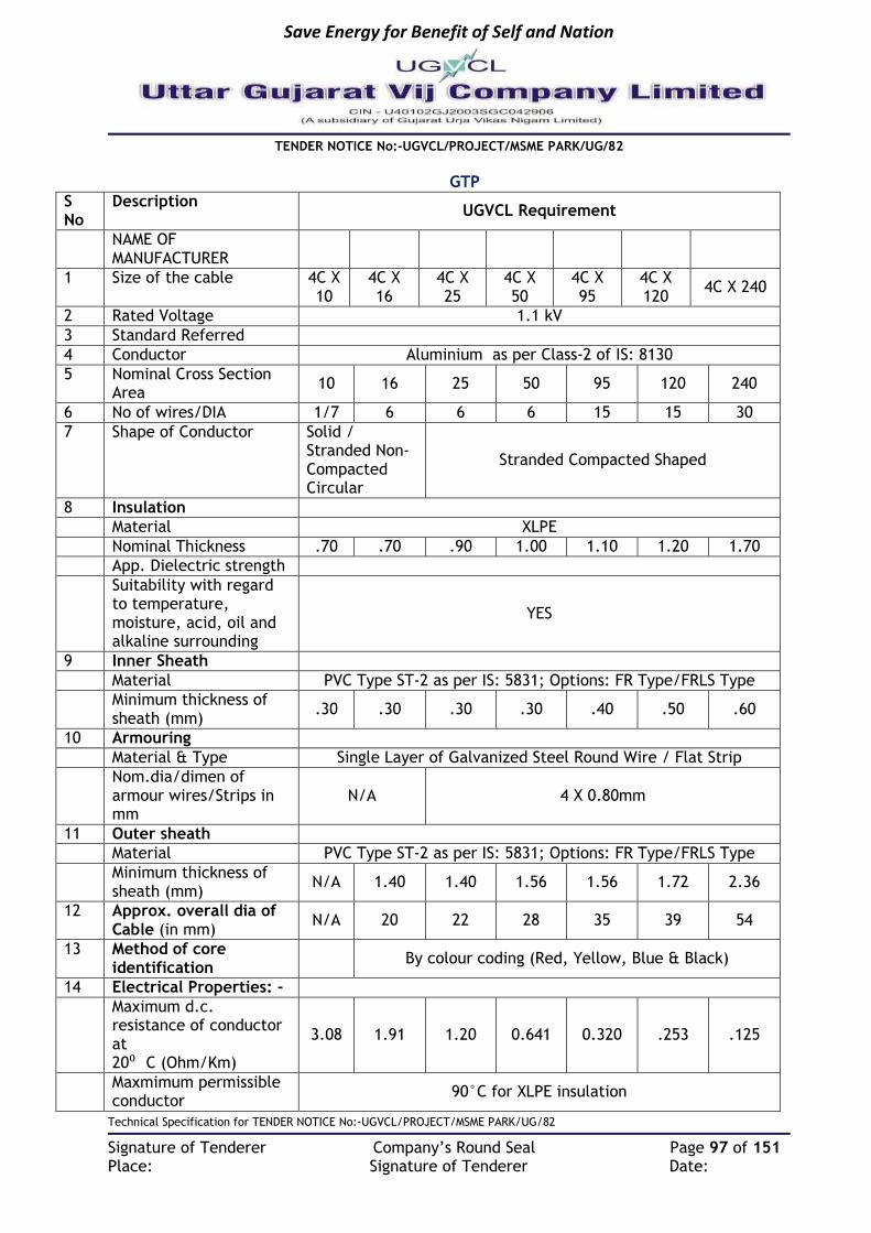
Save Energy for Benefit of Self and Nation
TENDER NOTICE No:-UGVCL/PROJECT/MSME PARK/UG/82
Technical Specification for TENDER NOTICE No:-UGVCL/PROJECT/MSME PARK/UG/82
Signature of Tenderer Company’s Round Seal Page 97 of 151 Place: Signature of Tenderer Date:
GTP
S No
Description UGVCL Requirement
NAME OF MANUFACTURER
1 Size of the cable 4C X 10
4C X 16
4C X 25
4C X 50
4C X 95
4C X 120
4C X 240
2 Rated Voltage 1.1 kV
3 Standard Referred
4 Conductor Aluminium as per Class-2 of IS: 8130
5 Nominal Cross Section Area
10 16 25 50 95 120 240
6 No of wires/DIA 1/7 6 6 6 15 15 30
7 Shape of Conductor Solid / Stranded Non-Compacted Circular
Stranded Compacted Shaped
8 Insulation
Material XLPE
Nominal Thickness .70 .70 .90 1.00 1.10 1.20 1.70
App. Dielectric strength
Suitability with regard to temperature, moisture, acid, oil and alkaline surrounding
YES
9 Inner Sheath
Material PVC Type ST-2 as per IS: 5831; Options: FR Type/FRLS Type
Minimum thickness of sheath (mm)
.30 .30 .30 .30 .40 .50 .60
10 Armouring
Material & Type Single Layer of Galvanized Steel Round Wire / Flat Strip
Nom.dia/dimen of armour wires/Strips in mm
N/A 4 X 0.80mm
11 Outer sheath
Material PVC Type ST-2 as per IS: 5831; Options: FR Type/FRLS Type
Minimum thickness of sheath (mm)
N/A 1.40 1.40 1.56 1.56 1.72 2.36
12 Approx. overall dia of Cable (in mm)
N/A 20 22 28 35 39 54
13 Method of core identification
By colour coding (Red, Yellow, Blue & Black)
14 Electrical Properties: -
Maximum d.c. resistance of conductor at 20⁰ C (Ohm/Km)
3.08 1.91 1.20 0.641 0.320 .253 .125
Maxmimum permissible conductor
90°C for XLPE insulation

Save Energy for Benefit of Self and Nation
TENDER NOTICE No:-UGVCL/PROJECT/MSME PARK/UG/82
Technical Specification for TENDER NOTICE No:-UGVCL/PROJECT/MSME PARK/UG/82
Signature of Tenderer Company’s Round Seal Page 98 of 151 Place: Signature of Tenderer Date:
temperature(°C) under full load
Rated voltage 1.1 kV
Maximum operating voltage
1.1 kV
Permissible voltage variation
±10%
Rated frequency 50HZ
Permitted frequency variation
±5%
Approx. Conductor A.C.Resistance at 90 °C
5.90 2.44 1.54 0.820 0.411 0.325 0.162
Reactance of Cable at 50 Hz (Approx.)
0.16 0.18 0.20 0.24 0.29 0.29 0.31
Normal Current Rating 67 70 96 142 221 257 326
Short Circuit Current Rating for 1 Second Duration in K amps
0.940 1.50 2.35 4.70 9.00 11.30 22.60
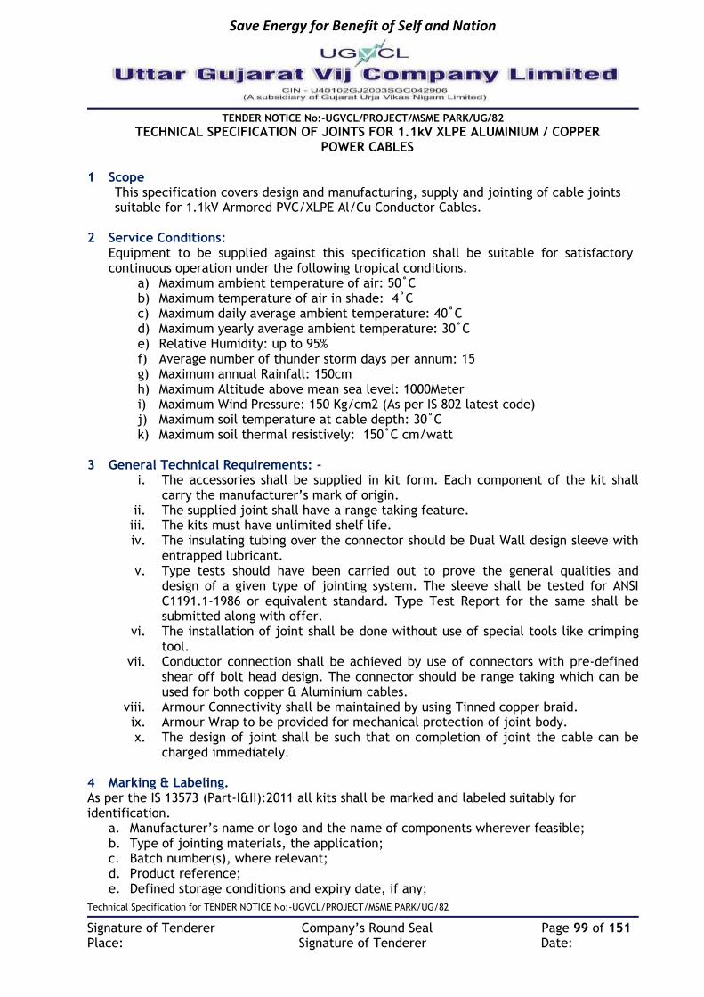
Save Energy for Benefit of Self and Nation
TENDER NOTICE No:-UGVCL/PROJECT/MSME PARK/UG/82
Technical Specification for TENDER NOTICE No:-UGVCL/PROJECT/MSME PARK/UG/82
Signature of Tenderer Company’s Round Seal Page 99 of 151 Place: Signature of Tenderer Date:
TECHNICAL SPECIFICATION OF JOINTS FOR 1.1kV XLPE ALUMINIUM / COPPER POWER CABLES
1 Scope
This specification covers design and manufacturing, supply and jointing of cable joints suitable for 1.1kV Armored PVC/XLPE Al/Cu Conductor Cables.
2 Service Conditions: Equipment to be supplied against this specification shall be suitable for satisfactory continuous operation under the following tropical conditions.
a) Maximum ambient temperature of air: 50˚C b) Maximum temperature of air in shade: 4˚C c) Maximum daily average ambient temperature: 40˚C d) Maximum yearly average ambient temperature: 30˚C e) Relative Humidity: up to 95% f) Average number of thunder storm days per annum: 15 g) Maximum annual Rainfall: 150cm h) Maximum Altitude above mean sea level: 1000Meter i) Maximum Wind Pressure: 150 Kg/cm2 (As per IS 802 latest code) j) Maximum soil temperature at cable depth: 30˚C k) Maximum soil thermal resistively: 150˚C cm/watt
3 General Technical Requirements: -
i. The accessories shall be supplied in kit form. Each component of the kit shall carry the manufacturer’s mark of origin.
ii. The supplied joint shall have a range taking feature. iii. The kits must have unlimited shelf life. iv. The insulating tubing over the connector should be Dual Wall design sleeve with
entrapped lubricant. v. Type tests should have been carried out to prove the general qualities and
design of a given type of jointing system. The sleeve shall be tested for ANSI C1191.1-1986 or equivalent standard. Type Test Report for the same shall be submitted along with offer.
vi. The installation of joint shall be done without use of special tools like crimping tool.
vii. Conductor connection shall be achieved by use of connectors with pre-defined shear off bolt head design. The connector should be range taking which can be used for both copper & Aluminium cables.
viii. Armour Connectivity shall be maintained by using Tinned copper braid. ix. Armour Wrap to be provided for mechanical protection of joint body. x. The design of joint shall be such that on completion of joint the cable can be
charged immediately.
4 Marking & Labeling. As per the IS 13573 (Part-I&II):2011 all kits shall be marked and labeled suitably for identification.
a. Manufacturer’s name or logo and the name of components wherever feasible; b. Type of jointing materials, the application; c. Batch number(s), where relevant; d. Product reference; e. Defined storage conditions and expiry date, if any;

Save Energy for Benefit of Self and Nation
TENDER NOTICE No:-UGVCL/PROJECT/MSME PARK/UG/82
Technical Specification for TENDER NOTICE No:-UGVCL/PROJECT/MSME PARK/UG/82
Signature of Tenderer Company’s Round Seal Page 100 of 151 Place: Signature of Tenderer Date:
f. If relevant, the manufacturing date; g. Health and safety marking and handling instructions, where relevant; and h. Reference to compliance with this standard.
5 Tests (I) TYPE TESTS The Jointing Kit offered, shall be fully type tested at NABL Lab as per the relevant
standards. The tenderer shall furnish the type test reports along with the offer. Offer without Type test reports will not be considered. For any change in the design/type, already type tested and the design/type offered against this specification the purchaser reserved the right to demand repetition of type tests without any extra cost in presence of purchaser’ representative. TYPE TEST SEQUENCE The type test shall be carried out as per the test sequence given in IS 13573/2011(Part –I, II & III)
(II) ACCEPTANCE & ROUTINE TESTS: All acceptance and routine tests as stipulated in the relevant standards shall be
carried out by the supplier in presence of purchaser’s representative. The purchaser reserves the right to insist for witnessing the acceptance/routine testing of the bought-out items.
(III) ADDITIONAL TESTS: Additional test to be carried out in GUVNL’S Lab are Volume Resistivity, B.D.V.,
Tensile & Elongation etc. Supplier may depute his representative for witnessing the test conforming the date from relevant GUVNL’S Lab.
(IV) PRE-DESPATCH INSPECTION All acceptance tests and inspection shall be carried out at the place of manufacturer
unless otherwise specially agreed upon the manufacturer and purchase at the time purchase. Manufacturer shall offer to the inspector representing the purchaser, all the reasonable facilities, free of charge, for inspection and testing to satisfy him that the material is being supplied in accordance with this specification. The GUVNL representative/Engineer attending the above test will carried out testing for suitable number of cable joints/terminations as per sampling procedure laid down in IS:13573(Part-I, II, III):2011 (amended up to date) and issue test certificate approval to the manufacturer and give clearance for dispatch. The cable jointing/termination kit shall be sealed after the inspection.
(V) INSPECTION AFTER RECEIPT AT STORES For Random sample testing (RST) the sample Cable Termination/jointing kit will be
drawn from any one of the store. (VI) DEMONSTRATION & TRANING: The purchaser reserves the right to ask for demonstration of the equipment offered
at the purchaser’s place. The Tenderer shall arrange for demonstration of installation of jointing/termination kits free of cost for giving training to purchaser’s representative to get acquainted with the jointing method. The jointing/termination kit along with required length of the kits to be used for demonstration purpose shall be specified the cable will be provided by the Purchaser.
(VII) GUARANTEE The Kits shall be suitable for storage without deteriorating at a temperature up to
50degree Celsius under normal conditions of storage and shall have unlimited shelf storage life. The tenderer shall guarantee the installed cable accessories for a minimum period of not less than 5 years from the date of installation. The

Save Energy for Benefit of Self and Nation
TENDER NOTICE No:-UGVCL/PROJECT/MSME PARK/UG/82
Technical Specification for TENDER NOTICE No:-UGVCL/PROJECT/MSME PARK/UG/82
Signature of Tenderer Company’s Round Seal Page 101 of 151 Place: Signature of Tenderer Date:
stores/materials found defective within the above guarantee period, shall be replaced by the supplier free of cost within one month of receipt of intimation.
(VIII) QUALITY CONTROL The purchaser has a right to send team of experienced Engineers for assessing the
capability of the firm for manufacturing and testing of Cable jointing kit as per this specification. The purchaser representative should be given all assistances and cooperation for inspection and testing at the bidder’s work.
(IX) QUALITY ASSURANCE PLAN The tendered shall invariably furnish QAP along with his offer, The QAP adopted by
him in the process of manufacturing shall be consist of List of Plant and Machinery available at the manufacturers premises. List of Testing equipment’s available at the manufacturers premises with their calibration schedule.
(X) PACKING The Cable jointing kits shall be suitably packed to avoid damage or disturbance
during transit or handling. Each Cable jointing kits may be suitably packed in the first instance to prevent ingress of moisture and dust and then placed in a cushioned carton of a suitable material to prevent damage due to shocks during transit. The lid of the cartoon may be suitably sealed. A suitable number of sealed cartons may be packed in a case of adequate strength with extra cushioning if considered necessary. The cases may then be properly sealed against accidental opening in transit.
The following information shall be furnished with the consignment: Name of consignee Details of consignment Destination Total Weight of consignment. Sign showing upper / lower side of the crate Sign showing fragility of the material. Handling and unpacking instructions. Bill of Materials indicating contents of each component and spare materials. Installation instructions including drawing or other information specific to the
accessories.

Save Energy for Benefit of Self and Nation
TENDER NOTICE No:-UGVCL/PROJECT/MSME PARK/UG/82
Technical Specification for TENDER NOTICE No:-UGVCL/PROJECT/MSME PARK/UG/82
Signature of Tenderer Company’s Round Seal Page 102 of 151 Place: Signature of Tenderer Date:
6 GTP FOR LT CABLE ACCESSORIES i.e. JOINTS &TERMINATIONS (Heat Shrinkable)
Sr. No.
Particulars GUVNL Requirement Bidder Offer.
1 Manufacturer’ Name& Address
2 Brand Name &Country of Origin
3 Kit Storage Temperature 50°C max
4 Voltage Grade 1.1kv
5 Applicable Standards Indicated in Cl.No.4 of Technical Spec.
6 Material to be used Polymeric Heat shrink tubes.
7 Type of Kit Offered 1)Straight through Joint. 2)Transition joint. 3)Termination joint.
8 Shelf life of components in the kit Unlimited.
9 Time Required for energization after completion of termination/joint.
Immediate.
10 Impulse withstand on Low voltage kits.
As per IS 13573 joints classification for cable size less than50sqmm.it will be 8kv & for cable size more than 50sqmm.it will be 20kv
11 Heating cycle in Air As per IS-13573 part-I See 8.3
12 Heat Cycle in Water(Over sheath damage)
As per IS-13573 part-I See 8.3
13 Insulation resistance(Immersed) As per IS-13573 part-I See 8.4
14 Insulation resistance(Air) As per IS-13573 part-I See 8.4
15 Impact at ambient temp. As per IS-13573 part-I See 8.5
16 AC High voltage withstand(In Air) As per IS-13573 part-I See 8.6
17 AC High voltage withstand(immersed)
As per IS-13573 part-I See 8.6
18 Examination of joint. As per IS-13573 part-I See 8.8
19 Dielectric Strength for insulating Tube.
12kv/mm
20 Dielectric constant for insulating tube
3.5(min)
21 Tensile strength for insulating tube 8N/mm2
22 Ultimate Elongation for insulating tube
200 to 500%
23 Water Absorption for Insulating Tube
0.3%
24 Longitudinal Change for insulating tube
+10%
25 Heat Shock for insulating tube 30min@2000c,
26 Flammability for insulating tube pass
27 Heat Shrink Outer insulating tubes As per specification (clause no.5.01& 5.02)
28 G.I. Wire mesh / Canister As per cable size
29 Red mastic As per cable size
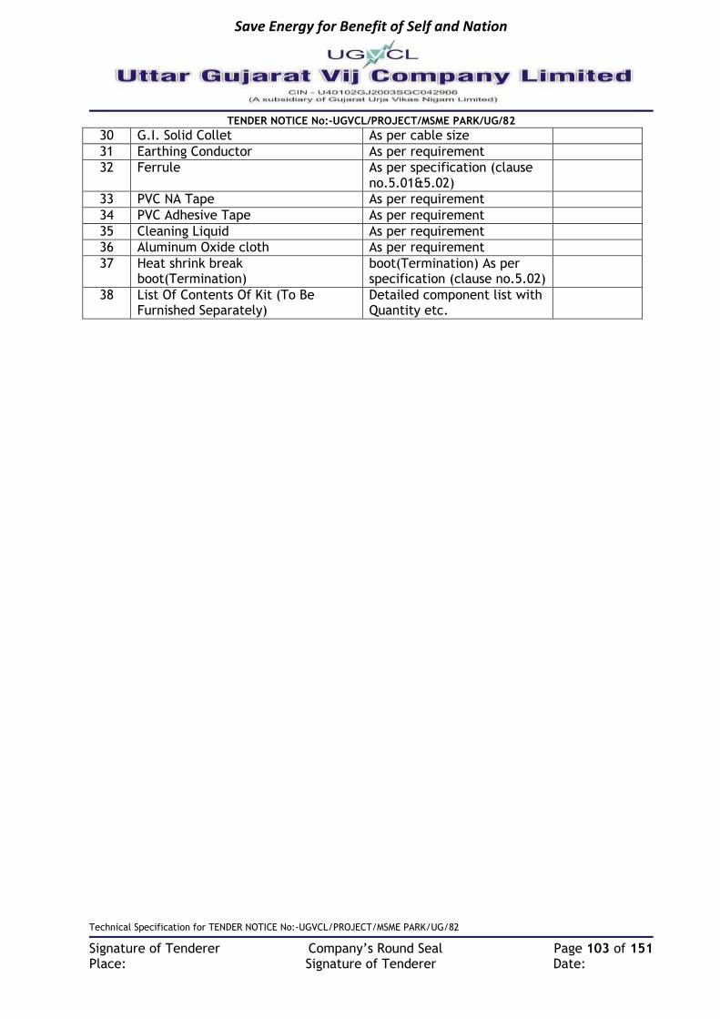
Save Energy for Benefit of Self and Nation
TENDER NOTICE No:-UGVCL/PROJECT/MSME PARK/UG/82
Technical Specification for TENDER NOTICE No:-UGVCL/PROJECT/MSME PARK/UG/82
Signature of Tenderer Company’s Round Seal Page 103 of 151 Place: Signature of Tenderer Date:
30 G.I. Solid Collet As per cable size
31 Earthing Conductor As per requirement
32 Ferrule As per specification (clause no.5.01&5.02)
33 PVC NA Tape As per requirement
34 PVC Adhesive Tape As per requirement
35 Cleaning Liquid As per requirement
36 Aluminum Oxide cloth As per requirement
37 Heat shrink break boot(Termination)
boot(Termination) As per specification (clause no.5.02)
38 List Of Contents Of Kit (To Be Furnished Separately)
Detailed component list with Quantity etc.

Save Energy for Benefit of Self and Nation
TENDER NOTICE No:-UGVCL/PROJECT/MSME PARK/UG/82
Technical Specification for TENDER NOTICE No:-UGVCL/PROJECT/MSME PARK/UG/82
Signature of Tenderer Company’s Round Seal Page 104 of 151 Place: Signature of Tenderer Date:
TECHNICAL SPECIFICATION FOR MINI SECTION PILLAR (MSP)
1 Scope: This specification covers the design, manufacturing and testing of MSP with anti-corrosive, dust proof, rust proof, shock proof, self-extinguishing property, resistant to heat, vermin & water proof, Ultra Violet Stabilized and pilfer resistant made from Thermosetting Plastic i.e. Glass Reinforced Polyester Sheet Moulding Compound (SMC) Confirming to IS: 13410 -1992 and attached technical specification, and IS: 14772-2000 with SMC HRC fuse base confirming to IS:13703/1993 (Pt. I & II amended up to date) and other relevant IS. The equipment offered shall be complete with all parts necessary for their effective and trouble-free outdoor operation. Such parts will be deemed to be within the scope of the supply irrespective of whether they are specifically indicated in the commercial order or not. It is not the intent to specify herein complete details of design and construction. The equipment offered shall conform to the relevant standards and be of high quality, sturdy, robust and of good design and workmanship complete in all respects and capable to perform continuous and satisfactory operations in the actual service conditions at site and shall have sufficiently long life in service as per statutory requirements. In these specifications, the design and constructional aspects, including materials and dimensions, will be subject to good engineering practice in conformity with the required quality of the product, and to such tolerances, allowances and requirements for clearances etc. as are necessary by virtue of various stipulations in that respect in the relevant ISO, IEC, BS, IS standards and other statutory provisions. 2 Service Conditions:
Equipment to be supplied against this specification shall be suitable for satisfactory continuous operation under the following tropical conditions.
a) Maximum ambient temperature of air: 50˚C
b) Maximum temperature of air in shade: 4˚C
c) Maximum daily average ambient temperature: 40˚C
d) Maximum yearly average ambient temperature: 30˚C
e) Relative Humidity: up to 95%
f) Average number of thunder storm days per annum: 15
g) Maximum annual Rainfall: 150cm
h) Maximum Altitude above mean sea level: 1000Meter
i) Maximum Wind Pressure: 150 Kg/cm2 (As per IS 802 latest code)
j) Maximum soil temperature at cable depth: 30˚C
k) Maximum soil thermal resistively: 150˚C cm/watt

Save Energy for Benefit of Self and Nation
TENDER NOTICE No:-UGVCL/PROJECT/MSME PARK/UG/82
Technical Specification for TENDER NOTICE No:-UGVCL/PROJECT/MSME PARK/UG/82
Signature of Tenderer Company’s Round Seal Page 105 of 151 Place: Signature of Tenderer Date:
3 Technical Parameters:
The L.T Feeder Pillar Panel shall be designed as following: -
Sl. No Parameter Value
1 Rated Supply Voltage 433 volts +/-10%
2 Number of Phases & Frequency 3 phase 4W50 Hz
3 Rated Current as per Single line diagram/BOQ
4 Neutral Solidly Grounded
5 Location of panel Outdoor on M.S Channels fixed on
RCC Plinth
6 Thickness of SMC Sheet for cabinet
mm 3.15MM
7 Bus bar material Tinned Cu bus bar
4 Applicable Standards:
All equipment and material shall be designed manufactured and tested in accordance with the latest applicable IEC standard or IS standard except where modified and / or supplemented this specification.
Title IEC Standard IS / Other Standard
Low-voltage switchgear and control gear IEC:60947
(Part-1,2,3) IS: 13947
Low-voltage switchgear and control gear assemblies
IEC:60439 (Part-2) -do-
General Requirements for Enclosures for Accessories for Household and Similar Fixed Electrical Installations
IS 14772
Glass reinforced polyester sheet moulding compounds (SMC)
IS 13410
LV Fuses for voltages not exceeding 1000 V ac or 1500 V dc,
IS 13703
MCBs
IEC 60898 IS: 8828
5 General Technical Requirements:
a) The minimum size of box without rain hood shall be 820(H)x 525(W)x400(D) mm. and
with rain hood shall be 1370(H) x 735 (W) x 516 (D)mm. The thickness of SMC sheet for enclosure and door is minimum 3.15 mm.
b) MSP shall be of Grade S-3 SMC material MSP shall be moulded in a single piece forming the body of the MSP with a cover fitted with base by minimum three nos. concealed stainless steel hinges. The lid/cover shall rest on the collar of the MSP base in such a way that any access from outside is not possible. The stainless steel hinges shall be

Save Energy for Benefit of Self and Nation
TENDER NOTICE No:-UGVCL/PROJECT/MSME PARK/UG/82
Technical Specification for TENDER NOTICE No:-UGVCL/PROJECT/MSME PARK/UG/82
Signature of Tenderer Company’s Round Seal Page 106 of 151 Place: Signature of Tenderer Date:
fitted with the MSP body base and covers rigidly, thereby making the MSP pilfer resistant.
c) The door in closed position should be overlapped in such a manner that no direct entry or access is possible. The MSP shall be closed by minimum two nos hings per door. Minimum 50 mm length of strip having thickness not less than 1.2 mm for holding and locking of the door with body base.
d) The door shall open at 90 degrees (Min.). The top surface of box shall have little tapering shape towards both sides of the distribution box for easy flow of rainwater.
e) Earth bolt of 12 mm diameter X 20 mm. length with 2 nos. nuts, 2 nos. washers and 1 no. spring washer shall be provided. The earthing arrangement shall be of M.S. with Zinc passivation. All corners of the MSP should be round & not pointed ones. All metal parts shall be zinc passivated.
f) The MSP should have one no of 400 Amp three phase and neutral incoming circuit HRC SMC fuse base and appropriate size of lugs filled with 50X6 mm copper bus bar and six (6) nos of outgoing circuit.
g) Anodized aluminum operating instructions in GUJARATI shall be fixed inside the door. The letter should be cleared legible and readable. The letters of the instructions should be of sufficient size to read with normal eye.
h) The MSP should have Bus bar of EC grade tinned copper bus bar duly insulated of size 50x6 mm for all phase and neutral.
6 Tests a) The bidder shall submit type test report for complete FSP as per BS 214/1959 or IS
8623/93 and for box as per IS-14772-2000 & IS: 13410- 1992 from CIPET, Ahmedabad/ERDA, Baroda or NABL accredited lab. for the box as well as TPN switch disconnector fuse & SMC fuse base along with the offer. Type Test Certificate should not be older than 7 years as on the date of tender opening.
b) ROUTINE TEST: Manufacturer has to carryout routine test during production to check the essential requirements that are likely to vary during production. Manufacturer has to keep records of the same and to be produced for verification of inspector when asked at the time of inspection of lot.
c) TYPE TEST (For SMC box): From the offered lot sample may be picked up at discretion of purchaser for type test at CIPET, Ahmedabad/ERDA, Baroda or NABL accredited lab for each lot offer. The charges for the type test shall be borne by bidder. On passing the type test successfully, the lot shall be accepted. In case, the boxes are not confirmed to type test, another sample form the lot shall be selected and the tested again. On receipt of unsatisfactory results, the lot shall be rejected and new lot shall be offered for inspection keeping aside old lot offered and rejected earlier by the Company. However, Company reserves the right to accept the boxes by levying penalty as per description of the company.
d) TYPE TEST (For Isolator/box): Type test reports not more than 7 years old from the date of tender from Government approved and NABL accredited lab.
1) Type Test for complete FSP as per BS214/1959 or IS8623/93. e) ACCEPTANCE TESTS:
The bidder should have all the testing facilities at their works & shall offer testing as under. Following acceptance tests shall be carried out, on 2% of the offered quantity on sample boxes selected at random, while inspecting the lot of materials offered.
Visual examination
Verification of dimensions as per approved drawings.

Save Energy for Benefit of Self and Nation
TENDER NOTICE No:-UGVCL/PROJECT/MSME PARK/UG/82
Technical Specification for TENDER NOTICE No:-UGVCL/PROJECT/MSME PARK/UG/82
Signature of Tenderer Company’s Round Seal Page 107 of 151 Place: Signature of Tenderer Date:
Verification of fittings
HV test at 5.2 (3.5*1.5) KV for Bus bar, 11KV for SMC material of Box.
Insulation resistance test with 2.5KV DC megger of each box.
Temperature rise test in accordance with relevant IS for the rated capacity of Switch disconnector fuse.
Earth continuity checking test.
10 Operations test on SMC HRC fuse base & fuse link. Note: UGVCL reserve the right to select one sample from whole tender quantity and will send Govt. approved/ NABL accredited lab, for complete acceptance test of all material. Cost of the same is to be paid by contractor. 7 Drawing & Calibration of Instrument:
The tenderer shall submit detailed constructional and dimensional drawing of complete FSP details of Units and TPN switch Disconnector fuse, incoming and outgoing circuit, Louvers details, clearance details along with the offer.
(a) The firm has to submit list of testing equipment’s instruments, stating Sr. No., Make, Capacity, date of last calibration along with test certificate of each instrument along with the offer, same is also required to be provided to inspecting officer at the time of prototype inspection as well as regular lots. The calibration shall be either from original manufacturer of the equipment’s / instruments or from Government approved laboratory.
8 Proto Type: The successful tenderer shall have to offer 1 No. Prototype FSP for carrying out tests mentioned at specification clause No. e (acceptance test) at their works or at Government approved Laboratory, where no adequate testing facility is available at firm’s work in presence of UGVCL’s representative. In case of brought out items like SMC HRC Fuse Units, Disconnector switch the same have to be either tested at firm’s work or at the works of original manufacturer or at Government approved / recognized laboratory in case of non-availability of adequate testing facility either at firm’s works of original manufacturer. However, all the testing expenditures of prototype sample testing. Acceptance tests for routine inspection of lots will be borne by the firm only after successful passing of the prototype unit in all the tests and after obtaining the written approved from the competent authority of UGVCL for prototype box and drawing approval, the firm can commence bulk manufacturing of the ordered boxes. The expenses towards prototype test including visit of our Engineers (2 Nos.) other than your works shall be borne by the bidder.
9 Raw Materials: Test certificate for the material used in the lot offered and document for purchase of raw
material should be maintained by manufacturer and produced to inspector as and when required.
10 Facility: The bidder shall have facility to test the box for routine tests and acceptance as per IS – 14772: 2000 and IS – 13410 & UGVCL’s specifications at their works. The bidder has to submit list of Machinery & Equipment / Testing instruments etc. along with the offer.
11 Inspection & Testing: During the inspection manufacturer will offer all facilities to inspector without any charge.
12 Dispatch: The FSP shall be dispatched duly packed so as to ensure that no damage occurs during
transport. 13 Guarantee:
If the goods, stores and equipments found defective due to bad design or workmanship the same should be repaired or replaced free of charge if reported within 24months from the

Save Energy for Benefit of Self and Nation
TENDER NOTICE No:-UGVCL/PROJECT/MSME PARK/UG/82
Technical Specification for TENDER NOTICE No:-UGVCL/PROJECT/MSME PARK/UG/82
Signature of Tenderer Company’s Round Seal Page 108 of 151 Place: Signature of Tenderer Date:
date of commissioning of equipments. Supplier will be responsible for the proper performance of the equipments materials for the respective guarantee period.
14 GTP The vendor shall furnish all necessary guaranteed technical particulars in the prescribed Performa enclosed hereinafter.
Sr. No
Particulars Particulars to be offered by Bidders
1 Name of Trade mark of Manufacturer
2 Type of L.T. piller
3 Rated normal Voltage 3 phase, 440 Volt, 50Hz
4 Material of construction of L.T. Pillar enclosure and doors
Grade S-3 SMC material
5 Thickness of SMC sheet for enclosure 3.15 mm
6 Thickness of SMC sheet for door 3.15 mm
7 Colour of L.T.Piller of enclosure
8 Dimension of cubical without rain hood- width x depth x height mm.
820(H)x 525(W)x400(D) mm minimum
9 Dimension of cubical with Rain hood- width x depth x height of (in mm).
1370(H) x 735 (W) x 516 (D)mm.
10 Fibre glass reinforce Plastic sheet moulding compound
A Material Grade S-3 SMC material (Thermostatic Plastic)
B Grade of Material SMC as per IS -13410-1992
C Grade of material for frame FRP pultruded section as per IS 6746
D Heat deflection temperature (as per IS 13411) min 150o C
E Exposure to flame (ref. std. IS 4249) Self-extinguishing
F Melting point (ref std IS 13360) Does not melt
G Fibre glass reinforcement (Min 20%)
H Density of fibre glass material (450 gm/sq mtr)
I Maximum permissible temperature (≥ 90°C)
J Door material (UV resistance and salty and humid atmosphere)
Grade S-3 SMC material
K Insulation Resistance (As per ASTM D257)
L Specific Gravity as per IS:10192 of SMC material (1:8)
M Dielectric Strength
N Tensile Strength 70MPa
O Cross Breaking Strength as per ASTM D790 (1723 Kg/sq.cm)
P Shear strength as per ASTM D732 (879 Kg/sq.cm)
Q Ball pressure Test as per IS:335
R Water Absorption as per IS:14772
S Mechanical strength as per IS:14772
11 Hinges
a Hinges: Type stainless steel hinges

Save Energy for Benefit of Self and Nation
TENDER NOTICE No:-UGVCL/PROJECT/MSME PARK/UG/82
Technical Specification for TENDER NOTICE No:-UGVCL/PROJECT/MSME PARK/UG/82
Signature of Tenderer Company’s Round Seal Page 109 of 151 Place: Signature of Tenderer Date:
b Hinges: Length 50mm
c Hinges: Thickness of material not less than 1.2 mm
d Hinges: Pin diameter Min 4mm
e Number of hinges per door two
12 Type of locking arrangements “Godrej” type triple position locking arrangement and shall be operational with a common handle from outside the door
13 Number of padlocking arrangements 2 Nos.
14 Size of ventilating louvers with wire mesh Four Louvers (two on each side)
15 Details of painting anti-corrosive high-quality paint
16 Dimension and details of asbestoses sheets Asbestos sheet of at least 6mm thick shall be provided for separation between front and rear compartments
17 Dimension and details of Bakelite sheets at least 50 x 12mm shall be provided to support and take care of weight of cables, jointing etc.
18 Dimension and details of gland plates Suitable no. of detachable gland plates made up of 10 SWG MS sheets/SMC material shall be provided in the cubicle at the bottom
19 Bus Bar, Fuse Base & fuse Link 50 x 6 mm
a Size of bus bar Size of neutral bus bar 50 x 6 mm
b Grade and specification of material of Bus bars
IS: 5082/1998
c Rated normal current of bus bars
d Rated safe temperature of bus bars
e Make and Type of Fuse base assembly
f Grade and specification of material of Fuse base contacts
IS: 13703/1993
g Thickness and dimensions of contacts of fuse base
h Rated normal current of Fuse base
i Rated safe temperature of Fuse base
j Grade and specification of material of Fuse links
IS/IEC 127-2: 1989
k Make and Type of Fuse link
l Rated normal current of Fuse link
m Rated safe temperature of Fuse link
n Grade and specification of material of spring steel round
IS: 6005/1998
o Dimension of steel spring round spring ring shall be made out of at least 6 mm dia
20 Make & Type of bimetallic lugs
21 One Minute P.F Withstand voltage

Save Energy for Benefit of Self and Nation
TENDER NOTICE No:-UGVCL/PROJECT/MSME PARK/UG/82
Technical Specification for TENDER NOTICE No:-UGVCL/PROJECT/MSME PARK/UG/82
Signature of Tenderer Company’s Round Seal Page 110 of 151 Place: Signature of Tenderer Date:
22 Rated short time current
23 Rated temperature rise
24 Size Thickness of Bakelite sheets provided
25 List of tests conducted on similar equipment
26 List of copies of test certificate enclosed

Save Energy for Benefit of Self and Nation
TENDER NOTICE No:-UGVCL/PROJECT/MSME PARK/UG/82
Technical Specification for TENDER NOTICE No:-UGVCL/PROJECT/MSME PARK/UG/82
Signature of Tenderer Company’s Round Seal Page 111 of 151 Place: Signature of Tenderer Date:
TECHNICAL SPECIFICATION M.S. CHANNEL, ANGLE AND FLAT ETC
1 Scope:
This specification covers manufacture, transport to site, insurance, storage, erection and commissioning of different type MS structures required to installation of the RMU & Distribution transformer structure suitable for Underground Distribution System.
2 Applicable Standards: The mild steel shall conform to IS: 2062 grade ‘a’ modified up-to date or equivalent international standard for steel materials, documents for which shall be made available at the time of inspection to the owner’s representative.
3 General Requirements: Material shall be supplied as per the following sizes: Channel ISA Angles and flats confirming (Not re-rolled) of grade “A” E250 (Fe-410WA) should be supplied confirming to IS 2062 / 2011 with latest amendment if any.
4 Galvanization: All above steel members shall be fabricated as per approved drawing having smooth edge, drilled circular/elliptical holes of suitable measurements. All structural steel members and bolts shall be galvanized as per IS:4759 and zinc coating shall not be less than 610gm/sq. meter for all structural steel members. All welds shall be 6mm filled weld unless specified otherwise. All nuts and bolt shall be of property class 5.6 of IS 1367. Plain washers shall be as per IS 2016 and spring washers shall be IS:3063.
5 Tests: All tests will be carried out by representative of owner. All tests and inspection shall be made at the place of manufacturer unless otherwise specially agreed upon by the manufacturer and the owner. The manufacturer shall provide all reasonable facilities, without charge to satisfy him that the material is being supplied in accordance with the specification.

Save Energy for Benefit of Self and Nation
TENDER NOTICE No:-UGVCL/PROJECT/MSME PARK/UG/82
Technical Specification for TENDER NOTICE No:-UGVCL/PROJECT/MSME PARK/UG/82
Signature of Tenderer Company’s Round Seal Page 112 of 151 Place: Signature of Tenderer Date:
TECHNICAL SPECIFICATION FOR FRP FENCING
1 Scope: This specification covers the basic requirement for the complete design, manufacture, fabrication, testing and inspection at manufacturer’s works, packing, supply and Installation of Insulating type FRP Fencing for safety with necessary hardware, accessories, fittings, etc. for Distribution Transformer Stations/RMU/Package Substations.
2 Service Conditions: The equipment to be supplied against this specification shall be suitable for satisfactory continuous operation under the following tropical conditions.
a) Maximum ambient temperature of air: 50˚C b) Maximum temperature of air in shade: 4˚C c) Minimum ambient temperature of air: 3.5˚C d) Maximum daily average ambient temperature: 40˚C e) Maximum yearly average ambient temperature: 30˚C f) Relative Humidity: up to 95% g) Average number of thunder storm days per annum: 15 h) Maximum annual Rainfall: 150cm i) Maximum Altitude above mean sea level: 100Meter j) Maximum Wind Pressure: 150 Kg/cm2 (As per IS 802 latest code) k) Maximum soil temperature at cable depth: 30˚C l) Maximum soil thermal resistively: 150˚C cm/watt m) Iso-ceraunic level (days/year) 50 n) Climate Moderately hot and humid tropical climate, conducive to rust and
Fungus growth.
3 Applicable Standards: All components used in the manufacture of the FRP Fencing shall confirm to the Relevant Indian standard specification and IS-6746 i.e. Unsaturated Polyester Resin System and IS 13410 Glass reinforced Sheet Moulding Compounds (SMC)
4 General Technical Requirements:
(XI) General: - a. The Fencing shall be antistatic and ultra violet resistant. Fencing shall be
manufactured using components made in accordance with IS-6746 and IS 13410. b. FRP Fencing shall be made utilizing FRP Pultruded sections & SMC Pickets. FRP
sections shall be made from an advanced formulation of Thermosetting Polyester Resin with Glass Fiber Reinforcement on state of art electronically controlled pultrusion technology. Manufacturing process shall be pultrusion using automated pultrusionmachines.SMC Pickets from hot press compression moulded SMC confirming to IS 13410
c. FRP Fencing shall be made of FRP and shall be corrosion resistant and fire retardant (Low flammability) in accordance with the latest IS-6746. An additive material shall be mixed with the FRP to make them resistant to ultraviolet light. FRP/SMC Flats may be used as preferred by bidder. Colour shade shall be as approved by UGVCL.
d. The oxygen index shall be minimum 24 as per IS 6746.

Save Energy for Benefit of Self and Nation
TENDER NOTICE No:-UGVCL/PROJECT/MSME PARK/UG/82
Technical Specification for TENDER NOTICE No:-UGVCL/PROJECT/MSME PARK/UG/82
Signature of Tenderer Company’s Round Seal Page 113 of 151 Place: Signature of Tenderer Date:
e. The minimum glass content in the FRP and SMC material shall be 45% and 20% respectively
f. The FRP Fencing shall be free from sharp edges and corners, burns and unevenness. g. FRP fencing shall be supplied in completely knocked down condition and shall be of
ready to use type. The fencing system shall be suitable for onsite fabrication using standard hardware and tools. The fencing shall be supplied as per BOQ agreed between supplier and purchaser.
h. The fencing is constructed utilizing vertical post duly grouted / fitted in ground/on floor. Horizontal rails fitted to sub frame to suite onsite mounting the vertical posts, pickets fitted to rails and gate to facilitate entry and exit restriction within the covered area.
i. FRP Pultruded Sections and SMC pickets shall have following mechanical properties
Sr. No.
Parameter Value for Pultruded Section
Value for SMC Pickets
a) Ultimate tensile strength: 2000-4000Kg/cm² 50 MPa
b) Flexural strength 2000-10000 Kg/ cm² 155 MPa
c) Flexural modulus: 1.5-5x100000 Kg/ cm² N.A.
d) Izod impact: 130Kg/cm/cm of notch 45 KJ/m2
e) Compressive strength: 1500-5000 kg/ cm² N.A.
f) Compressive modulus: 2.5-4.5 kg/ cm² N. A.
g) Bar col thickness: 50- 65 50- 65
h) Water absorption: <=0.6% <=0.25%
i) Glass Content Min. 45% Min. 20%
j) Flammability Low flammability as per IS 6746
k) Flame Spread (Fire propagation Index)
Less Than 15 as per BS 476 (Part 5, 6 & 7)
j. FRP Pultruded Sections and SMC pickets shall have following Electrical Properties.
Sr. No.
Parameter Value for Pultruded Section
Value for SMC Pickets
a) Dielectric Strength Axial 30 – 45 kV / 25 mm 9 kV
b) Dielectric Strength Radial 10-15 kV / 25mm N. A.
c) Arc Resistance > 120 sec > 120 sec
k. FRP Pultruded Sections fencing – Routine & Acceptance Testing Parameter shall
include but not be limited to following: Test for FRP sections
Sr. No. Parameter Value specified
1 Visual As per approved drawing
2 Dimensions As per approved drawing
3 Glass Content Min. 45%
4 Flammability Low flammability as per IS 6746

Save Energy for Benefit of Self and Nation
TENDER NOTICE No:-UGVCL/PROJECT/MSME PARK/UG/82
Technical Specification for TENDER NOTICE No:-UGVCL/PROJECT/MSME PARK/UG/82
Signature of Tenderer Company’s Round Seal Page 114 of 151 Place: Signature of Tenderer Date:
Test for SMC Pickets
Sr. No. Parameter Value specified
1 Visual As per approved drawing
2 Dimensions As per approved drawing
3 Glass Content Min. 20%
4 Flammability Low flammability as per IS 6746
Construction of FRP: -
Vertical Posts: The vertical post shall be made out of FRP Pultruded square hollow section of size 50x50x5 mm. Such posts shall be kept at a distance not exceeding 1000mm c/c except gate opening and shall be grouted in the ground with c.c. of ratio 1:2:4 in the pit of size 300x300x450 mm. The work must be done under Supervision of concerned SDO OR Authorized staff appointed by SDO. The vertical posts shall be supplied with pre-drilled holes so as to accept Sub frame provided using hollow FRP box sections 50x25x5 mm and other accessories for fixing of gates etc. The length of vertical post shall be sufficient to take care of grouting, depth i.e. underground and height of fencing above the ground. Post should be buried in foundation at least 450mm from ground level. Posts at corners and gate openings may be of different size/shape so as to take care of the fencing requirements.
Rails Rails shall be made out of FRP notch bars of 12 mm dia. provided at equal spacing not exceeding200 mm Centre to Centre as shown in drawing. The rails are placed horizontally and height of the 1st rail from the ground as well as gap between the rails shall be maintained as detailed in the approved drawing.
Pickets: Pickets shall be made of flats of size 35x5 mm SMC or FRP provided at equal spacing not exceeding 100 mm Centre to Centre mechanically locked between vertical post as well as top and bottom member of sub frame as shown in the drawing. Pickets shall be pre-drilled to facilitate fixing on the rails. Dimensions of the sections utilized (vertical post, rail, picket), length of those sections (height of fencing), gate openings, corner posts and the perimeter as well as shape of area to be covered by fence shall be as per the drawing and shall be as mutually agreed between the supplier and purchaser by way of issue of approved drawing. The fencing Material of Construction (MOC) shall conform to the IS: 6746 and/ IS 13410 as applicable and the fabricated, installed fencing shall confirm to the approved drawing.
Fencing Gate: Fencing gate should have door with two shutters with one Heavy duty S.S. aldraf of size not less than 16 mm Dia and 350 mm length. Gate is to be provided as per site conditions. General arrangement and layout of fencing is shown in schematic drawing.
Danger Board: Danger Board of size 300X300 mm (1.6 mm thick M.S. Plate) is to be provided on left hand side of fencing with standard drawing as attached herewith. Danger Board should have letter writing pattern and size as per drawing.

Save Energy for Benefit of Self and Nation
TENDER NOTICE No:-UGVCL/PROJECT/MSME PARK/UG/82
Technical Specification for TENDER NOTICE No:-UGVCL/PROJECT/MSME PARK/UG/82
Signature of Tenderer Company’s Round Seal Page 115 of 151 Place: Signature of Tenderer Date:
Other Conditions:
a. At top the whole fencing shall be tied with FRP Angle section 50x50x5 to provide suitable stiffness. Angle section should be openable across gate.
b. Hardware for fixing / assembling shall be of stainless steel. c. Gate should be suitably stiffened to prevent sagging. 3nos. of Hinges of100 mm size
on each door and shall be of heavy duty S.S. and facilitate of outward 180 degree movement of the gate flaps.
d. Left door of gate should be provided with stopper of 300 mm and Dia. Of10 mm at upper and lower part of fencing with proper locking arrangement.
e. Transformer fencing erection should be done according to site situation and as per instruction of engineer in charge of sub division office.
f. Supporting bracing flat size SMC molded / FRP Flat 35 x 5mmandlength300 mm are to be provided in each corner on top and bottom frames of fencing and on each shutter of door.
g. Grouting Roads of M. S. With Dia. of 12mm and 250 mm long at each Vertical Post are to be provided as shown in Drawing.
h. Payment of bill will be based on running meter measured during joint measurement with engineer in charge.
DRAWINGS AND DOCUMENTATION: a) The successful bidder shall submit sketches for each location of the FRP Fencing and
get the same approved at concerned Division office before commencement of supply. The indicative schematic drawing is enclosed herewith.
b) The tenderer shall furnish all details and clarifications required if any for scrutiny and evaluation of the offer.
c) Manufacturing of material to be supplied shall be done strictly as per approved drawing.
d) Approval of drawing shall not absolve the supplier of his liability for ensuring correctness according to applicable standards & regulations.
5 Tests: All the Type Tests shall be carried out from reputed Laboratories which are accredited by the National Board of Testing and Calibration Laboratories (NABL) of Govt. of India or accepted by UGVCL. Test Reports submitted by Labs such as CPRI, ERDA, ERTL, CIPET, Fire Research Laboratory (FRL) of CBRI Roorkee shall be accepted to prove that the FRP Pultruded Sections meet the requirements of specification. Type Test Reports conducted in manufacturers own laboratory and certified by testing institute shall not be acceptable. The FRP Pultruded Sections used in FRP Fencing shall be fully type tested for Mechanical and Electrical Properties. Attested copies of Type Test Reports are to be submitted.
6 Testing & Manufacturing Facilities: a) The Bidder/manufacturer shall have necessary machinery for production of FRP
Pultruded Sections using Automated Pultrusion Machines as well as SMC material and SMC hot press compression molding Machines if SMC is intended to be used for FRP Fencing.
b) Manufacturer should have in house testing facilities for carrying out the routine and acceptance tests. Each Lot dispatched should be tested in house and test report should be submitted to UGVCL.
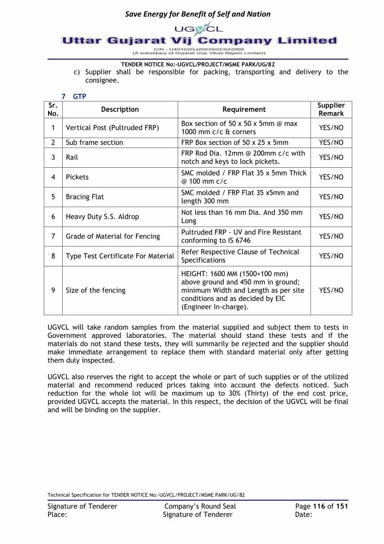
Save Energy for Benefit of Self and Nation
TENDER NOTICE No:-UGVCL/PROJECT/MSME PARK/UG/82
Technical Specification for TENDER NOTICE No:-UGVCL/PROJECT/MSME PARK/UG/82
Signature of Tenderer Company’s Round Seal Page 116 of 151 Place: Signature of Tenderer Date:
c) Supplier shall be responsible for packing, transporting and delivery to the consignee.
7 GTP
Sr. No.
Description Requirement Supplier Remark
1 Vertical Post (Pultruded FRP) Box section of 50 x 50 x 5mm @ max 1000 mm c/c & corners
YES/NO
2 Sub frame section FRP Box section of 50 x 25 x 5mm YES/NO
3 Rail FRP Rod Dia. 12mm @ 200mm c/c with notch and keys to lock pickets.
YES/NO
4 Pickets SMC molded / FRP Flat 35 x 5mm Thick @ 100 mm c/c
YES/NO
5 Bracing Flat SMC molded / FRP Flat 35 x5mm and length 300 mm
YES/NO
6 Heavy Duty S.S. Aldrop Not less than 16 mm Dia. And 350 mm Long
YES/NO
7 Grade of Material for Fencing Pultruded FRP - UV and Fire Resistant conforming to IS 6746
YES/NO
8 Type Test Certificate For Material Refer Respective Clause of Technical Specifications
YES/NO
9 Size of the fencing
HEIGHT: 1600 MM (1500+100 mm) above ground and 450 mm in ground; minimum Width and Length as per site conditions and as decided by EIC (Engineer In-charge).
YES/NO
UGVCL will take random samples from the material supplied and subject them to tests in Government approved laboratories. The material should stand these tests and if the materials do not stand these tests, they will summarily be rejected and the supplier should make immediate arrangement to replace them with standard material only after getting them duly inspected. UGVCL also reserves the right to accept the whole or part of such supplies or of the utilized material and recommend reduced prices taking into account the defects noticed. Such reduction for the whole lot will be maximum up to 30% (Thirty) of the end cost price, provided UGVCL accepts the material. In this respect, the decision of the UGVCL will be final and will be binding on the supplier.

Save Energy for Benefit of Self and Nation
TENDER NOTICE No:-UGVCL/PROJECT/MSME PARK/UG/82
Technical Specification for TENDER NOTICE No:-UGVCL/PROJECT/MSME PARK/UG/82
Signature of Tenderer Company’s Round Seal Page 117 of 151 Place: Signature of Tenderer Date:
TECHNICAL SPECIFICATION FOR DWC HDPE PIPES 1 Scope
This Specification covers design, manufacturing, testing, packing, supply of DWC HDPE Pipe.
2 Service Conditions: Equipment to be supplied against this specification shall be suitable for satisfactory continuous operation under the following tropical conditions.
a) Maximum ambient temperature of air: 50˚C b) Maximum temperature of air in shade: 4˚C c) Maximum daily average ambient temperature: 40˚C d) Maximum yearly average ambient temperature: 30˚C e) Relative Humidity: up to 95% f) Average number of thunder storm days per annum: 15 g) Maximum annual Rainfall: 150cm h) Maximum Altitude above mean sea level: 1000Meter i) Maximum Wind Pressure: 150 Kg/cm2 (As per IS 802 latest code) j) Maximum soil temperature at cable depth: 30˚C k) Maximum soil thermal resistively: 150˚C cm/watt
3 Technical Parameters:
(a) DWC high density Polyethylene pipe shall have corrugation on outer wall but inner wall shall be plain conforming to IS – 14930 Part I and II amended from time to time.
(b) Terminology as defined in IS: 14930shallbefollowed (c) DWC HDPE pipe to be supplied shall be ‘ISI’ marked. (d) Accessories like HDPE snap fit coupler with neoprene ‘O’ ring shall be part of supply
to make the joints water / damp proof.
4 Code & Standards: All standards, specifications and codes of practice referred to herein shall be the latest editions including all applicable official amendments and revisions as on date of opening of bid. In case of conflict between this specification and those (IS: Codes, standards, etc.) referred to herein, the former shall prevail.
a) IS:14930Pt.-I:General requirements of Conduit System for Electrical and Communication installation
b) IS:14930Pt.-II: Particular requirements of Conduit system for Electrical and Communication installation
c) IS: 2530: Method for test for Polyethylene moulding material Sand polyethylene compounds.
d) IS:7328: HDPE materials for moulding and extrusion e) IS:12063 : Classification of degrees of protection provided by Enclosures of
electrical equipment f) ASTMD 1693: Test method for environmental stress–Cracking of ethylene plastics g) ASTMD638:Standard test method for tensile properties of plastic h) ASTMD790: Test method for flexural properties of Un-reinforced and Reinforced
Plastics and Electrical Insulating Materials. i) ASTMD 2240: Standard Test method for Rubber property. j) ASTMD648: Standard Test method for deflection temperature of Plastic under
flexure load in the Edge Wise Position. k) IS:11000(Pt-2):Glow-wire Test and guidance test methods for fire /Sec-1) Hazard
Testing.

Save Energy for Benefit of Self and Nation
TENDER NOTICE No:-UGVCL/PROJECT/MSME PARK/UG/82
Technical Specification for TENDER NOTICE No:-UGVCL/PROJECT/MSME PARK/UG/82
Signature of Tenderer Company’s Round Seal Page 118 of 151 Place: Signature of Tenderer Date:
5 General Requirement: General:
i. The DWC HDPE pipe shall consist of two layers, the outer layer will be corrugated and the inner layer shall be plain and smooth.
ii. DWC HDPE pipe shall be so designed and constructed that in normal use their performance is reliable and without danger to the user or surroundings.
iii. When assembled in accordance with manufacturer’s instruction as part of a conduit system, they shall provide mechanical protection to Signaling Cables’ on tainted therein.
iv. Within the conduit system there shall be nos hardedge, burrs or surface projections which are likely to damage insulated conductors or cables or inflict impure it to the installer or user.
v. The protective properties of the joint between conduit and conduit fittings shall be not less than that declared for the conduit system.
vi. The DWC HDPE pipe and fittings hall withstand and the stresses likely to occur during transport, storage, recommended installed on practice and application.
vii. The DWC HDPE pipe shall be supplied in continuous length in coil for more straight length, suitable for shipping and handling purpose.
viii. For conduit systems that areas assembled by means other than threads, the manufacturer shall indicate whether the system can be disassembled and if, so, how this can be achieved.
REQUIREMENTS OF RAW MATERIALS USED FOR THE DWC HDPE PIPE
i. The base HDPE resin used for the outer and inner layer of the DWCHDPE Pipe shall conform to any designation of IS: 7328or to any equivalent standard meeting the requirements given inTableNo.1, when tested as per the standards given their in. However, the manufacturers shall furnish the designation for the HDPE resin as per IS: 7328 as applicable.
ii. The anti-oxidants used shall be physiologically harmless. iii. None of the additives shall be used separately or together in quantities as to impair
long term physical and chemical properties of the duct. iv. Single pass rework material of the same composition produced from the
manufacturer’s own production may be used and it shall not exceed 10% in any case. v. The raw material used for extrusion shall be dried to bring the moisture content to
less than 0.1%. vi. Suitable UV stabilizers shall be used only for manufacture of the nonblack colored
HDPE duct to protect against UV degradation, when stored in open for minimum 8 months’ period. The purchaser may ask for UV content test. The test result for UV Content test by FTIR method from any recognized laboratory shall be accepted and the Hindered Amine Light Stabilizer shall be minimum 0.15 %. UV Content test need not to be conducted in case of UV Stabilized raw material is used.
REQUIREMENT OF DWC HDPE PIPE i. Visual Requirement: The Pipe shall be checked visually for ensuring good
workmanship that the ducts shall be free from holes, breaks and other defects. The ends shall be cleanly cut and shall be square with axis of the ducts.
ii. Colour: The colour of the pipe viz. Green, Orange, Blue, Yellow, Brown, Violet, Grey and Red. The purchaser shall specify the colour of the duct at the time of ordering.
iii. Dimensions: The dimensions of the DWC HDPE pipe shall be as per requirement / BOQ.

Save Energy for Benefit of Self and Nation
TENDER NOTICE No:-UGVCL/PROJECT/MSME PARK/UG/82
Technical Specification for TENDER NOTICE No:-UGVCL/PROJECT/MSME PARK/UG/82
Signature of Tenderer Company’s Round Seal Page 119 of 151 Place: Signature of Tenderer Date:
iv. Standards Length: Duct up to 50 mm OD nominal size shall be supplied in standard length of 100 mtr. ± 1% or 6 mtr ± 1 % and all other sizes will be supplied in standard length of 6 mtr. ± 1%
v. Compression Strength: The conduit system shall have adequate mechanical strength. Conduits when bent or compressed either during, or after, installation according to manufacturer’s instructions, shall not crack and shall not be deformed to such an extent that introduction of the insulated conductors or cables becomes difficult or that the installed insulated conductors, or cables are likely to be damaged while being drawn in. Compliance may be checked with the application of force which shall be at least 450 N, when reaching the deflection of 5%.
vi. Impact Strength: The conduit system shall have adequate mechanical strength. vii. Conduits when exposed to impact either during, or after, installation according to
manufacturer’s instructions, shall not crack and shall not be deformed to such an extent that introduction of the insulated conductors or cables becomes difficult or that the installed insulated conductors, or cables are likely to be damaged while being drawn in. Compliance may be checked by ensuring there shall be no crack allowing the ingress of light or water between the inside and outside after the test.
viii. Bending Strength: The conduit system shall have adequate mechanical strength. Conduits when bend either during, or after, installation according to manufacturer’s instructions, shall not crack and shall not be deformed to such an extent that introduction of the insulated conductors or cables becomes difficult or that the installed insulated conductors, or cables are likely to be damaged while being drawn in. During the test sample shall not flatten Compliance shall be checked by passing a ball having a diameter equal to 95% minimum inner diameter of the sample declared by the manufacturer, through the sample whilst it is bent around the test apparatus.
ix. Oxidation Induction Test (OIT): The OIT in a qualitative assessment of the level (or degree) of stabilization of material.
x. Resistance to Flame Propagation: Non flame propagating ducts shall have adequate resistance to flame propagation. Samples of DWC HDPE Ducts shall be checked by applying a 1KW flame.
xi. Anti-Rodent Properties: Safety of ducts from the direct attack of subterranean organism anti rodent material is of utmost importance. These ducts shall be evaluated for their safety against rodents before laying them in the fields.
xii. Resistance to External Influences on DWC HDPE Duct Accessories: The accessories in Clause 11.5.4 shall be tested for external influences as per IS-12063 for ingress of dust & ingress of water. DWC Duct systems when assembled in accordance with the manufacturer’s instructions shall have adequate resistance to external influences according to the classification declared by the manufacturer with a requirement of IP 67.
xiii. Marking Identification: The conduit shall be prominently marked at regular intervals along their length of preferably 1m but not longer than 3m using indelible ink with following. Manufacturers name Specification No. Name of the duct with size Lot No. of the Product Date of manufacture Product Length Purchaser’s Name/symbol

Save Energy for Benefit of Self and Nation
TENDER NOTICE No:-UGVCL/PROJECT/MSME PARK/UG/82
Technical Specification for TENDER NOTICE No:-UGVCL/PROJECT/MSME PARK/UG/82
Signature of Tenderer Company’s Round Seal Page 120 of 151 Place: Signature of Tenderer Date:
DWC HDPE PIPE ACCESSORIES
i. The following accessories are required for jointing the ducts and shall be supplied along with the ducts against specific orders. The manufacturers shall provide complete procedure and method for installation of the accessories. The required quantities of accessories are to be mentioned by the purchasing authority in the purchase order.
a. Plastic Coupler: The coupler shall be of Push-fit type with O-ring. It is used for jointing woor more ducts. The design of this shall be simple easy to install and shall provide air tight and water tight joint between the two ducts. The coupler shall insure that the two ducts are butted smoothly without any step formation in the inner surface. The coupler may be straight, bands, T-joints type as per requirements of purchaser.
b. End Cap: This cap made of suitable plastic material shall be fitted on the both ends of duct, coil after manufacturing the duct. This shall avoid entry of dust, mudandra in water in to the duct during the transit &storage.
Selection of pipe for different sizes Cables Following guide of the pipe fill shall be used for sizing the pipe Size:
a. 1 cable in pipe - 53% full b. 2 cable in pipe - 31% full c. 3 or more cables - 43% full d. 4 Multiple cables - 40% full
6 Tests The following tests shall be carried out in accordance with IS or the latest version thereof:
a. TYPE TESTS i) Visual. ii) Requirement of Colour. iii) Dimension iv) Standard Length v) Compression Strength vi) Impact Strength vii) Bending Strength viii) Oxidation Induction Test ix) Resistance to Flame Propagation x) Anti-Rodent xi) Resistance to External influence on DWC HDPE Pipe b. ACCEPTANCE TESTS
The following tests be carried out by the manufacturer after 240 hrs of manufacture: - i) Visual Requirement ii) Requirement of Colour. iii) Dimension iv) Standard Length v) Compression Strength vi) Impact Strength vii) Bending Strength viii) Resistance to Flame Propagation
c. ROUTINETESTS
The following tests be carried out by the manufacturer after 240 hrs of manufacture: -

Save Energy for Benefit of Self and Nation
TENDER NOTICE No:-UGVCL/PROJECT/MSME PARK/UG/82
Technical Specification for TENDER NOTICE No:-UGVCL/PROJECT/MSME PARK/UG/82
Signature of Tenderer Company’s Round Seal Page 121 of 151 Place: Signature of Tenderer Date:
i) Visual Requirement ii) Requirement of Colour. iii) Dimension iv) Standard Length v) Compression Strength vi) Impact Strength vii) Bending Strength viii) Resistance to Flame Propagation
7 Tests Procedure
a) COMPRESSION TEST
i. Conduits are subjected to a compression test as per IS: 14930 (Pt-II). The tests for conduits shall not best rated until 240 hrs after manufacture.
ii. Samples shall be200 ±5mm long.
iii. Before the test the outside and inside diameters of the samples shall be measures described in clause above.
iv. The samples shall be compressed between two flat steel plates having minimum dimensions (100x200x15mm), the length 200mm being along the length of the sample. The sample shall be compressed data rate of 15±0.5mm/min and the load recorded at the vertical deflection equivalent to 5%of the average value of the original inside diameter of the sample.
v. When reaching the deflection of 5 %, the applied force shall be at least 450N
vi. After the test there shall be no crack allowing the ingress of light or water between the inside and the outside.
vii. The deflection is calculated with the inner dia meter but the measurement of the outside diameter may be sufficient. In case of doubt, itwill be necessary to measure the inner diameter.
b) IMPACT TEST
i. Twelve samples of the duct each 200±5mm in length or fittings are subjected to an impact test as per IS: 14930(Pt-II) by means of the apparatus shown Figure-1.
ii. The test apparatus shall be placed on a firm flat surface. The samples shall be conditioned in a cold chamber at a temperature of–5±1°C for 2h. The samples shall be removed from the cold chamber and placed on the vee block holder of the impact tester as shown in figure 1.
iii. The striker shall fall once on each sample. The time between removal of the sample from the cold chamber and completion of impact shall not exceed 10seconds.The impact height and mass shall be as follows.
Nominal Size of Conduit
Mass of Striker (+1%/-0%)kg
Fall Height (+0%/-1%)(mm)
Energy Joules
Upto60 mm 5 300 15
61to90 mm 5 400 20
91to140 mm 5 570 28
Above140mm 5 800 40
iv. The test sample shall be made on the weakest part of the Duct fittings except that it shall not be applied within 5mm of any sample entry. Samples of ducts are tested on the center of their length.
v. After the test, at least in nine of the samples, there shall be no crack allowing the in gress of light or water between the inside and the outside.

Save Energy for Benefit of Self and Nation
TENDER NOTICE No:-UGVCL/PROJECT/MSME PARK/UG/82
Technical Specification for TENDER NOTICE No:-UGVCL/PROJECT/MSME PARK/UG/82
Signature of Tenderer Company’s Round Seal Page 122 of 151 Place: Signature of Tenderer Date:
c) BENDING TEST
i. This test shall be carried out on pliable conduits.
ii. The test is made on six samples having an appropriate length as per IS: 14930 (Pt II). Three samples shall be tested at room temperature; the other three shall be tested at- 5±1°C.For the test at -5°C, the sample shall be conditioned in a cold chamber for 2 hours. The test apparatus as shown in Figure-2 shall allow being the duct with a bending radius equal to the minimum bending radius values specified by the manufacturer. One of the ends soft he samples shall be fixed. The sample is then bent to approximately 90 degrees (right angle) and hold.
iii. During the test, the sample shall not flatten. Compliance shall be checked by passing a ball having diameter equal to 95%minimum inner diameter of the sample declared by the manufacturer, through the sample whilst it is bent around the test apparatus.
d) OXIDATION INDUCTION TEST PROCEDURE
i. A short length of completed duct (approximately 30cm) shall be sealed at the end sand placed in an oven at temperature of 68±1°C for 8 hours. The sample shall then be allowed to cool at room temperature for at least16hrs.The samples shall be clean and dry. The sample shall then be tested by means of a Differential Canning Calorimeter (DSC) or by Differential Thermal Analyzer (DTA).
ii. Instrument Test Procedure:
Cell Cleaning: The cell shall be held at approximately 400°C for 10minutes in Nitrogen. The cell shall be cleaned after standing over night and between testing of different formulations.
Temperature Calibration: This has to be done according to the instrument manual. The temperature scale should be adjusted until the determined melting point of pure Indiummetalis 156.6°C at a heat rate of 5°Cper minute or any other heat rate as indicated in the manual of the equipment is permitted.
Aluminum Pan Preparation: Standard aluminum DSC pans as per ASTMD 4565 are required to hold specimens during testing. A fresh pan shall be used for each test.
Sample preparation: Take the sample weighing about 5mg from the duct conditioned as indicated above. Position the sample in the center of the pan.
Nitrogen Purge: Place the sample pan and reference pan in instrument cell. Flush for 5 minutes with cylinder of nitrogen (99.6%extradrygrade) at 60±10 cc per minute.
Oxidation Test: Rapidly increase the temperature of the sample (20°C/minor greater) from 100°C or lower initial temperature to 199±1°C. After thermal equilibrium is obtained (steady recorder signal) switch to 80±20cc per minute oxygen flow and simultaneously start time-base recording. The oxygen used for the test should be equivalent to or betterthan99.6% extra dry grade.
Induction Period: The oxygen induction point shall be recorded as time zero, and the chart speed shall be sufficient to provide a clearly discernible lop eat the start of the exothermic reaction. The test in the pure dry oxygen atmosphere shall continue until the exothermic peak is produced. The inter section of the tangent of the exothermic sloped line with the extended base line will be drawn. The time from time zero to is inter section point is read from the base line and recorded as the oxidative induction time.
e) RESISTANCET OF LAME PROPAGATION TEST PROCEDURE
i. Samples of DWC HDPE Ducts shall be checked by applying 1KW flame.
ii. As ample of length 675+10 mm is mounted vertically in a rectangular metal enclosure with one open face, as shown in Figure-3-2 in an area substantially free from draughts.

Save Energy for Benefit of Self and Nation
TENDER NOTICE No:-UGVCL/PROJECT/MSME PARK/UG/82
Technical Specification for TENDER NOTICE No:-UGVCL/PROJECT/MSME PARK/UG/82
Signature of Tenderer Company’s Round Seal Page 123 of 151 Place: Signature of Tenderer Date:
The general arrangements is shown in Figure-3 Mounting is by means of two metal clamps approximately 25mm wide spaced 550 +10mm apart and approximately equal distance from the ends of the sample. A steel rod of 16+ 0.1 mm is passed through the sample. It is rigidly and independently mounted and clamped at upper end to maintain the sample in a straight and vertical position. The means of mounting is such as not to obstruct drops from falling on to the tissue paper. A suitable piece of white pine wood board, approximately 10 mm thick, covered with single layer of white is sue paper is positioned on the lower surface of the enclosure.
iii. The assembly of sample, rod and clamping apparatus is mounted vertically in the center of the enclosure, the upper extremity of the lower clampbeing500+10mmabovetheintern allowed surface of the enclosure.
iv. The burner is supported so that its axis is 45+20to the vertical. The flame is applied to the samples that the distance from the top of the burner tube to the sample measured along the axis of the flame is 100+10mm and the axis of the flame intersects with the surface of the samples at a point 100+5 mm from the upper extremity of the lower clamp, and so that the axis of the flame intersects with the axis of the sample.
v. The test is carried out on three samples. During the application of the flame, it shall not be moved except to remove it at the conclusion of the period of the test. After the conclusion of the test and after any burning of the sample has ceased, the surface of the sample is wiped clean by rubbing with a piece of cloth soaked with water.
vi. All three samples shall pass the test. If the sample is not ignited by the flame, it shall be deemed to have passed the test.
If the sample burns, or is consumed without burning, the sample shall be deemed to have passed the test if after burning has ceased, and after the sample has been wiped in accordance with1.3 there is no evidence of burning of charring within 50mm of the lower extremity of the upper and also with in50mm of the upper extremity of the lower clamp.
If the sample burns, it shall be deemed to have failed the test if combustion is still in progress 30seconds after removal of the flame.
If the tissue paper ignites, the sample shall be deemed to have failed the test. For the parts of the same below the burner, the presence of molten material on the internal or external surfaces shall not entail failure if the sample itself is not burned or charred.
vii. Compliance of DWC HDPE Duct fittings is checked by using the glow wire test IS: 11000 (Part2/Sec1). The glow wire shall be applied once to each sample in the most unfavorable position of its intended use, with the surface tested in vertical position, at a temperature of 750oC. The sample is deemed to have passed this test if there is no visible flame or sustained glowing or inflames or glowing extinguishes within 30 soft here moval of the glow wire.
f) ANTI RODENT TEST PROCEDURE: The test against rodent may be conducted as per following procedures: The ducts are to be laid underground in fields and also near urban or rural settlements. Therefore, they should be exposed to 3-4 most predominant rodent species in habiting these locations. The test rodent species may include the lesser bandi cootrat, Bandi cotabengalensis, The Indian gerbils, tatera indica, the soft furred field rats, Millar diamelt ada and the house rats, Rattusrattus. The test ducts should be exposed to the serodent species housed individually in iron mesh cages under laboratory conditions. Only freshly capture rodent are to be utilized for the study. The rodent sare first acclimatized in laboratory cages for7-10 days and then the tests be initiated. For each trial, 3-4 rodents of uniform body

Save Energy for Benefit of Self and Nation
TENDER NOTICE No:-UGVCL/PROJECT/MSME PARK/UG/82
Technical Specification for TENDER NOTICE No:-UGVCL/PROJECT/MSME PARK/UG/82
Signature of Tenderer Company’s Round Seal Page 124 of 151 Place: Signature of Tenderer Date:
weight are to be used for the trial. Two different types of testes may be under taken for all the ducts. Choice Tests: In this trial the ducts of 15-30 cm length (ones ample each of treated and untreated/ control sample) are exposed to the test rodents along with food, thus the roden thada choice between the food and the test duct. This test may be run for longer periods (30-45days). Tap water should be provided adlibitum to the rodents. NO Choice Test: The rodents are exposed to the test ducts only and no food is given to the rodents during the period of trial. The test ducts (one sample each of treated and untreated/control sample) are to the exposed to the test rodents. This trail may be run for 5-7 days depending upon the health status of starved test rodents. Tap water should be providing dad labium other rodents. Observation on tooth marks, rodent behavior toward exposed ducts, and relative extent of damage in treated and untreated samples should be computed for both types of ducts. Health status of test animals in choice and no choice test must also be monitored for their cordanyill effect of exposure of treated/ control ducts on these animals. Number of cases and the extent of rodent bites/scratch marks in control and anti-rodent treated ducts may indicate the relative deterrent/repellent properties of the test ducts.

Save Energy for Benefit of Self and Nation
TENDER NOTICE No:-UGVCL/PROJECT/MSME PARK/UG/82
Technical Specification for TENDER NOTICE No:-UGVCL/PROJECT/MSME PARK/UG/82
Signature of Tenderer Company’s Round Seal Page 125 of 151 Place: Signature of Tenderer Date:
FIGURE- 1 IMPACT APPRATUS
FIGURE- 2

Save Energy for Benefit of Self and Nation
TENDER NOTICE No:-UGVCL/PROJECT/MSME PARK/UG/82
Technical Specification for TENDER NOTICE No:-UGVCL/PROJECT/MSME PARK/UG/82
Signature of Tenderer Company’s Round Seal Page 126 of 151 Place: Signature of Tenderer Date:
BENDINGTESTAPPARATUS
RESISTANCETOFLAMEPROPAGATIONTESTAPPARATUS

Save Energy for Benefit of Self and Nation
TENDER NOTICE No:-UGVCL/PROJECT/MSME PARK/UG/82
Technical Specification for TENDER NOTICE No:-UGVCL/PROJECT/MSME PARK/UG/82
Signature of Tenderer Company’s Round Seal Page 127 of 151 Place: Signature of Tenderer Date:

Save Energy for Benefit of Self and Nation
TENDER NOTICE No:-UGVCL/PROJECT/MSME PARK/UG/82
Technical Specification for TENDER NOTICE No:-UGVCL/PROJECT/MSME PARK/UG/82
Signature of Tenderer Company’s Round Seal Page 128 of 151 Place: Signature of Tenderer Date:
GTP OF HDPE PIPES
SR. DESCRIPTION / PARAMETERS OFFERED BY THE BIDDER
1 Make
2 Applicable Standard
3 Grade
4 Pressure rating (Kg/Sqcm.)
5 Outside Diameter (mm)
6 Inside Diameter (mm)
7 Recommended For (Mention Maximum Armoured cable Type and Size)

Save Energy for Benefit of Self and Nation
TENDER NOTICE No:-UGVCL/PROJECT/MSME PARK/UG/82
Technical Specification for TENDER NOTICE No:-UGVCL/PROJECT/MSME PARK/UG/82
Signature of Tenderer Company’s Round Seal Page 129 of 151 Place: Signature of Tenderer Date:
TECHNICAL SPECIFICATION FOR CIVIL WORKS
1 Cable Trench: Construction of cable trench (Three tier/ Four Tier) as per approved design & Drawing as per directives of Engineer-in-charge with required excavation as per site condition, Base concreting, Providing & laying of reinforcement as per design, concreting of M-20 grade for Pardi & Raft, Pre-cast RCC cover of 75mm thick, fabrication of cable tray as per design with one coat of red oxide and two coats of oil painting to structural steel, two coats of Waterproof cement paint to all inside, outside surfaces of cable trench with top cover. Work to be done as per drawing and PWD specifications. Detail description of major civil work activities involved are as under.
i. Excavation for foundation in Dense or Hard soil up to 1.5 M Depth including sorting out and stacking of useful materials and disposing of the excavated stuff up to 50 meter lead and filling excavated stuff in trenches & besides cable trench in layers not exceeding 20 cm in depth with consolidating/ watering etc. complete.
ii. Providing and laying cement concrete 1:4:8 (1 Cement : 4 coarse sand : 8 Machine crush metal aggregates 40 mm nominal size) and curing complete including cost of form work in Foundation etc. complete.
iii. Providing and laying control cement concrete M200 and curing complete including cost of form work and reinforcement for reinforced cement concrete work in.(A) Raft Foundations, Vertical pardi/wall etc. (Form work of steel sheets to be utilized)
iv. Providing & placing 75mm thick Precast RCC cover of size 1500 X 300mm, made in M-200 cement concrete with necessary reinforcement of 3 Nos. of 10mm TMT bars as main bar and 8mm TMT Distribution bars at 200mm c/c including providing 8mm TMT bars hook for lifting arrangement & curing, finishing all the surfaces etc complete incl. placing in position at site.
v. Providing & fabrication of structural Steel for cable tray incl. cutting, erecting, fixing in position and applying one coat of red oxide & two coats of oil painting in angles, flat and like section etc. complete.
vi. Expansion Joint: Providing & placing 12mm thick pre-moulded asphalt or bitumen cork board filler joint at every 50 Mtr length.
vii. Painting the inside, outside of Cable trench wall including precast cover with two coats of water proofing cement paint.
2 Precast RCC Cable Guard Block Providing & placing precast RCC cable guard blocks for underground cable laying work as per approved drawing made in M-200 concrete for UG cable laying. 1.0 Rmt of cable guard consist of 3 nos. of RCC blocks, having size as stated below (A-type, B-Type, C-Type ), including providing & laying of reinforcement steel as per drawing in all the three blocks including necessary form works of steel sheets, curing, finishing of all the surfaces & placing in the position at site as per drawing & as directed by engineer-in-charge.
A-Type L x W x T = 1000 x 300 x 75 mm (For 01 no. of horizontal RCC block) L x W x T = 1000 x 300 x 75 mm (For 02 no. of vertical RCC block)
B-Type L x W x T = 1000 x 450 x 75 mm (For 01 no. of horizontal RCC block) L x W x T = 1000 x 300 x 75 mm (For 02 no. of vertical RCC block)
C-Type L x W x T = 1000 x 600 x 75 mm (For 01 no. of horizontal RCC block) L x W x T = 1000 x 300 x 75 mm (For 02 no. of vertical RCC block)

Save Energy for Benefit of Self and Nation
TENDER NOTICE No:-UGVCL/PROJECT/MSME PARK/UG/82
Technical Specification for TENDER NOTICE No:-UGVCL/PROJECT/MSME PARK/UG/82
Signature of Tenderer Company’s Round Seal Page 130 of 151 Place: Signature of Tenderer Date:
3 Cable Route Marker
Providing & fixing of route marker of pre-cast RCC block made in M-200 concrete of size 220 x 75 x 800 mm having top width round shape as per drawing, including providing & laying reinforcement steel of 1 no. of 10 mm dia tor steel main bar & 6 no of 8 mm dia tor steel distribution bars as per the drawing including necessary excavation, form works of steel sheets, curing, finishing of all surfaces & placing in position at site including fixing block by providing & laying 75 mm thick PCC (1:4:8) on all vertical sites & bottom of pre-cast RCC blocks as per drawings etc complete.
4 Detail Specification for Civil Work Items
Item No. 1:Excavation for foundation in trenches in ordinary, dense, hard soil, sand, clay, soft murrum up to 1.50 Mt. depth including strutting, shoring wherever necessary and throwing away the extra stuff with in the lead of 500 Mt. radius and its dressing etc. complete as directed by E. I. C.
a) General Any soil which generally require close application of picks or jumpers or scarifies to loosen it, stiff clay, gravel and stone, etc. or organic soil, gravel silt, sand, turf, loam, clay, peat, etc. fall under this category.
b) Clearing the site i. The site on which the structure is to be built shall be cleared, and all obstructions loose
stone, materials, and rubbish of all kind, bush wood and trees shall be removal as directed. The materials so obtained shall be property of the Government and shall be conveyed and stacked as directed within 50 m. lead. The roots of the trees coming in the sides shall be cut and coated with a hot asphalt.
ii. The rate of side clearance is deemed to be included in the rate of earth work for which no extra will be paid.
c) Setting out After clearing the site, the centre lines will be given, by the Engineer-in-Charge. The contractor shall assume full responsibility for alignment, elevation and dimension of each and all parts of the work. Contractor shall supply labours materials, etc., required for setting out the reference marks and bench marks and shall maintain them as long as required and directed.
d) Excavation The excavation in foundation shall be carried out in true line and level and shall have the width and depth as shown in the drawings or as directed. The contractor shall do the necessary shoring and shutting or providing necessary slopes to a safe angle, at his own cost. The payment for such precautionary measures shall be paid separately if not specified. The bottom of the excavated area shall be leveled both longitudinally and transferal as directed by removing and watering as required. No earth filling will be allowed for bringing it to level. If by mistake or any excavation is made deeper or wider than that shown on the plan or directed. The extra depth or width shall be made up with concrete of same proportion as specified for the foundation concrete at the cost of the contractor. The excavation up to 1.5 m depth shall be measured under this item.
e) Disposal of the excavated stuff i. The excavated stuff of the selected type shall be used in filling the trenches and plinth
or leveling the ground in layers including ramming and watering etc. ii. The balance of the excavated quantity shall be removed by the contractor from the site
of work to a place as directed with lead up to 500 M. and all lift.

Save Energy for Benefit of Self and Nation
TENDER NOTICE No:-UGVCL/PROJECT/MSME PARK/UG/82
Technical Specification for TENDER NOTICE No:-UGVCL/PROJECT/MSME PARK/UG/82
Signature of Tenderer Company’s Round Seal Page 131 of 151 Place: Signature of Tenderer Date:
Item No. 2: Filling available excavated earth (Excluding rock) in trenches, plinth sides of foundation etc. in layers not exceeding 20 CM in depth, consolidating each deposited layers by ramming and watering.
a) Workmanship i. The earth to be used for filling shall be free from salts, organic or other foreign matter.
All clots of earth shall be broken. ii. As soon as the work in foundation has been completed and measured the site of
foundation shall cleared of all debris, brick bats, mortar dropping etc., and filled with earth in layers not exceeding 20 cms. Each layer shall be adequately watered, rammed and consolidated before the succeeding layer is laid. The earth shall be rammed with iron rammers where feasible and with the butt ends of crow bars, where rammer cannot be used.
iii. The plinth shall be similarly filled with earth in layers not exceeding 20 cms. adequately watered and consolidated by ramming with iron or wooden rammers. When filling reaches finished level the surface shall be flooded with water for at least 24 hours and allowed to dry and then rammed and consolidated.
iv. The finished level of filling shall be kept to shape intended to be given to floor. v. In case of large heavy duty flooring like factory flooring, the consolidation may be done
by power rollers, where so specified. The extent of consolidation required shall also be as specified.
vi. The excavated stuff of the selected type shall be allowed to be used in filling the trenches and plinth. Under no circumstances black cotton soil be used for filling in the plinth. Item No. 3: Filling in foundation and plinth with murrum or selected soil in layers of 20 CM thickness including watering, ramming and consolidation etc. complete (Yellow earth should be brought by contractor from outside)
a) Materials Murrum shall be clean, of good binding quality, and of approved quality obtained from approved pots / quarries of disintegrated rocks which contain silicon materials and natural mixture of clay of calcareous origin. The size of murrum shall not be more than 20mm.
b) Workmanship The relevant specifications of item No. 2 shall be followed except that murrum or selected soil shall be filled in foundation and plinth in 20 cms. Layers including consolidating, ramming, watering, dressing, etc complete. Item No. 4: Filling in plinth with sand under floors including watering, ramming consolidating and dressing etc. complete.
a) Materials Sand shall conform to M-3.
b) Workmanship The relevant specifications of item No. 2 shall be followed except that sand shall be filled in under floors, including watering, ramming, consolidating and dressing etc. complete. Item No. 5: Brick work using common fly ash / concrete blocks / building bricks having crushing strength not less 35 kg. / sq. cm. in foundation and plinth in cement mortar 1:6 (1 Cement: 6 - Fine sand)
a) Materials

Save Energy for Benefit of Self and Nation
TENDER NOTICE No:-UGVCL/PROJECT/MSME PARK/UG/82
Technical Specification for TENDER NOTICE No:-UGVCL/PROJECT/MSME PARK/UG/82
Signature of Tenderer Company’s Round Seal Page 132 of 151 Place: Signature of Tenderer Date:
Water shall conform to M-1. Cement shall conform to M-2. Sand shall conform to M-3. Cement mortar shall conform to M-5. Brick shall conform to M-8.
b) Workmanship
Proportion: The proportion of the cement mortar shall be 1:6 (1 Cement: 6 fine sand) by volume.
Wetting of bricks: The bricks required for masonry shall be thoroughly wetted with clean water for about two hours before use or as directed. The cessation of bubbles, when the bricks are wetted with water is an indication of thorough wetting of bricks.
Laying: i. Bricks shall be laid in English bond unless directed otherwise. Half or cut bricks shall
not be used except when necessary to complete to bond, closers in such case shall be cut to the required size and used near the ends of walls.
i. A layer of mortar shall be spread on full width for suitable length of the lower course. Each brick shall first be properly bedded and set home by gently tapping with the handle of trowel or wooden mallet. It side face shall be flushed with mortar before the next brick is laid and pressed against it. On completion of course, the vertical joint shall be fully filled from the top with mortar.
ii. The wall shall be taken up truly in plumb. All courses shall be laid truly horizontal and all vertical joints shall be truly vertical. Vertical joints in alternate course shall generally be directly one over the other. The thickness of the brick course shall be kept uniform.
iii. The bricks shall be laid with frog upwards. A set of tools comprising of wooden straight edges, mason’s spirit level, square half meter rub, and pins, string and plumb shall be kept on the site of the work for frequent checking during the progress of work.
iv. Both the faces of the walls of thickness greater than 23 cms shall be kept in proper place. All the connected brickwork shall be kept not more than one meter over the rest of the work. Where this is not possible the work shall be raked back according to bond (and not left toothed) at an angle not steeper than 45 degrees.
v. All fixtures, pipes, outlets of water, holdfasts of doors and windows, etc. which are required to be built in wall shall be embedded in the cement mortar.
Joints i. Bricks shall be so laid that all joints are quite flush with mortar. Thickness of the joint
shall not exceed 12mm. The face joints shall be raked out as directed by raking tool daily during the progress of work, when the mortar is still green so as to provide key for plaster or pointing to be done.
ii. The face of the brick shall be cleaned the very day on which the brick work is laid and all mortar dropping removed.
Curing Green work shall be protected from the rain suitable. Masonry work shall be kept moist on all the faces for a period of seven days. The top of the masonry work shall be kept well wetted at the close of the day.
Preparation of the foundation bed If the foundation is to be laid directly on the excavated bed, the bed shall be leveled, cleaned of all the loose materials, cleaned and wetted before starting masonry. If masonry is to be laid on concrete footing, the top of the concrete shall be cleaned and moistened. The contractor shall obtain the engineer’s approval for the foundation bed, before foundation masonry is started. When pucca flooring is to be provided flush with the top to plinth, the inside plinth offset shall be kept lower than the outside plinth top by the thickness of the flooring.
c) Mode of measurement

Save Energy for Benefit of Self and Nation
TENDER NOTICE No:-UGVCL/PROJECT/MSME PARK/UG/82
Technical Specification for TENDER NOTICE No:-UGVCL/PROJECT/MSME PARK/UG/82
Signature of Tenderer Company’s Round Seal Page 133 of 151 Place: Signature of Tenderer Date:
i. The measurements of this item shall be taken for the brick masonry fully completed in foundation up to plinth. The limiting dimensions not exceeding those shown on the plans or as directed shall be final. Battered, tapered and curved portion shall be measured net.
ii. No deduction shall be made from the quantity of brick work, nor any extra payment made for embedding in masonry or making holes in respect of following items. o End of joints, beams, posts, girders, rafters, purlins, trusses, corbel, steps, etc.
where cross section area does not exceed 500 sq cm. o Opening not exceeding 1000 sq cm. o Wall plates and bed plates, bearing of slabs, and the like whose thickness does not
exceed 10 cm and the bearing does not extended to the full thickness of the wall. o Drainage holes and recesses fro cement concrete blocks to embed hold fasts for
doors, windows etc. o Iron fixtures, pipes up to 300mm dia, hold fasts and doors and windows built into
masonry and pipes, etc. for concealed wiring. o Forming chases of section not exceeding 350 sq. cm. in masonry.
iii. Apertures for fire places shall not be deducted nor shall extra labour required to make splaying of jambs, throttling and making arches over the apertures be paid for separately.
iv. The rate shall be for a unit of one cubic meter. Item No. 6: Providing & laying controlled cement concrete M-200 curing complete for reinforced concrete work in a) Foundation, footings, Bases of columns etc. and Mass concrete, b) Slabs, Landings, shelves, Balconies, Lintels, Beams, Girders, wall and cantilever up to floor two level,
a) Materials Water shall conform to M-1. Cement shall conform to M-3. Sand shall conform to M-6. Grit shall conform to M-8. Graded stone aggregate 20mm nominal size shall conform to M-12.
b) General i. The concrete mix shall be designed by preliminary tests, the proportioning of cement
and aggregates shall be done by weight and necessary precautions shall be taken in the production to ensure that the required work cube strength is attained and maintained. The controlled concrete shall be in grade of M-200 with prefix controlled added to it. The letter ‘M’ refers to mix and numbers specify 28 days works cube compressive strength of 150mm cubes of the mix expressed in Kg/ Cm2
ii. The proportion of cement, sand and coarse aggregates shall be determined by weight. The weigh batching machine shall be used for maintaining proper control over the proportion of aggregates as per mix design. The strength requirements of different grades of concrete shall be as under:
Grade of concrete Compressive strength of 15 cms. cubes in Kg / Cm2 at 28 days, conducted in accordance with IS 516 – 1959.
Preliminary test (min) Work test (min)
M-150 200 150
M-200 260 200
M-250 320 250
M-300 380 300
M-350 440 350
M-400 500 400

Save Energy for Benefit of Self and Nation
TENDER NOTICE No:-UGVCL/PROJECT/MSME PARK/UG/82
Technical Specification for TENDER NOTICE No:-UGVCL/PROJECT/MSME PARK/UG/82
Signature of Tenderer Company’s Round Seal Page 134 of 151 Place: Signature of Tenderer Date:
In all cases, the 28 days compressive strength specified in above table be the criteria for acceptance or rejection of the concrete. Where the strength of a concrete mix as indicated by tests, lies in between the strength of any two grades specified in the above table, such concrete shall be classified in for all purposes as concrete belonging to the lower of the two grades between which its strength lies.
iii. Admixture may be used in concrete only with approval of Engineer – in – Charge based upon the evidence that with the passage of time neither the compressive strength of concrete is reduced nor are other requisite qualities of concrete and steel impaired by the use of such admixture.
c) Workmanship i. The proportions for ingredients chosen shall be such that concrete has adequate
workability for conditions prevailing on the work in question and can be properly compacted with means available except where it can be shown to the satisfaction of the Engineer – in – Charge, that the supply of properly graded aggregate of uniform quality can be maintained till the completion of work. Grading of aggregate shall be controlled by obtaining the coarse aggregates, in different sizes and being in them in the right proportions as required. Aggregate of different sizes shall be stocked in separate stock piles. The required quantity of material shall be stock piled several hours, preferably a day before use. The grading of coarse and fine aggregate shall be checked as frequently as possible, the frequency for a given job being determined by the Engineer – in – Charge to ensure that the suppliers are maintaining the uniform grading as approved for samples used in the preliminary tests.
ii. In proportioning concrete, the quantity of both cement and aggregate shall be determined by weight. Where the weight of cement is determined by accepting the maker’s weight per bag a reasonable number of bags shall be weighed separately to check the net weight. Where the cement is weighed from bulk stocks at site and not by bags, it shall be weighed separately from the aggregates. Water shall either be measured by volume in calibrated tanks or weighed. All measuring equipments shall be maintained in clean, and serviceable condition. Their accuracy shall be periodically checked.
iii. It is most important to keep the specified water cement ratio constant and at its correct value. To this end, moisture content in both fine and coarse aggregates shall be determined by the Engineer – in – Charge, according to the weather conditions. The amount of mixing water shall then be adjusted to compensate for variations in the moisture content. For the determination of moisture content in the aggregates, IS 2389 (Part III) shall be referred to. Suitable adjustments shall also be made in the weights of coarse aggregates due to variation in the moisture content. Minimum quantity of cement to be used in concrete shall not be less than 320 Kg / Cmt.
iv. Mixing
For all work, concrete shall be mixed in a mechanical mixer which along with other accessories shall be kept in first class working condition and so maintained throughout the construction. Measured quantity of aggregate, sand, cement required for each batch shall be poured into the drum of the mechanical mixer while it is continuously running. After about half a minute of dry mixing measured quantity of water required for each batch of concrete mix shall be added gradually and mixing continued for another one and half a minute. Mixing shall be continued till materials are uniformly distributed and uniform colour of the entire mass is obtained and each individual particle of the coarse aggregate shows complete coating of mortar containing its proportionate amount of cement. In no case shall the mixing be done for less than two minutes after all ingredients have been put into the mixer.

Save Energy for Benefit of Self and Nation
TENDER NOTICE No:-UGVCL/PROJECT/MSME PARK/UG/82
Technical Specification for TENDER NOTICE No:-UGVCL/PROJECT/MSME PARK/UG/82
Signature of Tenderer Company’s Round Seal Page 135 of 151 Place: Signature of Tenderer Date:
Mixers which have been out of use for more than 30 minutes shall be thoroughly cleaned before putting in a new batch. Unless otherwise agreed to by the Engineer – in – Charge the first batch of concrete from the mixture shall contain only two thirds of normal quantity of coarse aggregate. Mixing plant shall be thoroughly cleaned before changing from one type of cement to another.
v. Consistency The degree of consistency which shall depend upon the nature of the work and methods of vibration of concrete shall be determined by regular slump tests in accordance with IS 1199 – 1959. The slump of 10 mm to 25 mm shall be adopted when vibrators are used and 80 mm when vibrators are not used.
vi. Inspection
Contractor shall give the Engineer – in – Charge due notice before placing any concrete in the forms to permit him to inspect and accept the false work and forms as to their strength, alignment and general fitness but such inspection shall not reliever the contractor of his responsibility for the safety of men, machinery, materials and for results obtained. Immediately before concreting, all forms shall be thoroughly cleaned.
Centering design and its erection shall be got approved from the Engineer – in – Charge. One carpenter with helper shall invariably be kept present throughout the period of concreting. Movement of labour and other persons shall be totally prohibited for reinforcement laid in position. For access to different parts, suitable mobile platforms shall be provided so that steel reinforcement in position is not disturbed. For ensuring proper cover, mortar blocks of suitable size shall be cast and tied to the reinforcement. Timber, kapachi or metal pieces shall not be used for this purpose.
vii. Transporting and laying
The method of transporting and placing concrete shall be as approved. Concrete shall be so transported and placed that no contamination, segregation or loss of its constituent material takes place. All form work shall be cleaned and made free from standing water, dust, snow or ice immediately before placing of concrete. No concrete shall be placed in any part of the structure until the approval of Engineer – in – Charge has been obtained.
Concreting shall proceed continuously over the area between construction joints. Fresh concrete shall not be placed against concrete which has been in position for more than 30 minutes unless a proper construction joint is formed. Concrete shall be compacted in its final position within 30 minutes of its discharge from the mixer. Except where otherwise agreed to by the Engineer – in – Charge concrete shall be deposited in horizontal layers to a compacted depth of not more than 0.45 metre when internal vibrators are used and not exceeding 0.30 meter in all other cases.
Unless otherwise agreed to by the Engineer – in – Charge, concrete shall not be dropped into place from a height exceeding 2 meters. When trucking or chutes are used they shall be kept close and used in such a way as to avoid segregation. When concreting has to be resumed on a surface which has hardened, it shall be roughened, swept clean, thoroughly wetted and covered with a 13mm thick layer of mortar composed of cement and sand in same ratio as in the concrete mix itself. This 13 mm layer of mortar shall be freshly mixed and placed immediately before placing of new concrete. When concrete has not fully hardened, all laitance shall be removed by scrubbing the wet surface with wire or bristle brushes, care being taken to avoid dislodgement of any particles of coarse aggregate. The surface shall then be thoroughly wetted, all free water removed and then coated with neat cement grout. The first layer of concrete to be placed on this surface shall not exceed
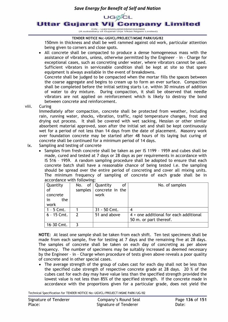
Save Energy for Benefit of Self and Nation
TENDER NOTICE No:-UGVCL/PROJECT/MSME PARK/UG/82
Technical Specification for TENDER NOTICE No:-UGVCL/PROJECT/MSME PARK/UG/82
Signature of Tenderer Company’s Round Seal Page 136 of 151 Place: Signature of Tenderer Date:
150mm in thickness and shall be well rammed against old work, particular attention being given to corners and close spots.
All concrete shall be compacted to produce a dense homogeneous mass with the assistance of vibrators, unless, otherwise permitted by the Engineer – in – Charge for exceptional cases, such as concreting under water, where vibrators cannot be used. Sufficient vibrators in serviceable condition shall be kept at site so that spare equipment is always available in the event of breakdowns. Concrete shall be judged to be compacted when the mortar fills the spaces between the coarse aggregate and begins to cream up to form an ever surface. Compaction shall be completed before the initial setting starts i.e. within 30 minutes of addition of water to dry mixture. During compaction, it shall be observed that needle vibrators are not applied on reinforcement which is likely to destroy the bond between concrete and reinforcement.
viii. Curing Immediately after compaction, concrete shall be protected from weather, including rain, running water, shocks, vibration, traffic, rapid temperature changes, frost and drying out process. It shall be covered with wet sacking, Hessian or other similar absorbent material approved, soon after the initial set and shall be kept continuously wet for a period of not less than 14 days from the date of placement. Masonry work over foundation concrete may be started after 48 hours of its laying but curing of concrete shall be continued for a minimum period of 14 days.
ix. Sampling and testing of concrete
Samples from fresh concrete shall be taken as per IS 1199 – 1959 and cubes shall be made, cured and tested at 7 days or 28 days as per requirements in accordance with IS 516 – 1959. A random sampling procedure shall be adopted to ensure that each concrete batch shall have a reasonable chance of being tested i.e. the sampling should be spread over the entire period of concreting and cover all mixing units. The minimum frequency of sampling of concrete of each grade shall be in accordance with following:
Quantity of concrete in the work
No. of samples
Quantity of concrete in the work
No. of samples
1 – 5 Cmt. 1 31 - 50 Cmt. 4
6 – 15 Cmt. 2 51 and above 4 + one additional for each additional 50 m. or part thereof.
16–30 Cmt. 3
NOTE: At least one sample shall be taken from each shift. Ten test specimens shall be made from each sample, five for testing at 7 days and the remaining five at 28 days. The samples of concrete shall be taken on each day of concreting as per above frequency. The number of specimens may be suitably increased as deemed necessary by the Engineer – in – Charge when procedure of tests given above reveals a poor quality of concrete and in other special cases.
The average strength of the group of cubes cast for each day shall not be less than the specified cube strength of respective concrete grade at 28 days. 20 % of the cubes cast for each day may have value less than the specified strength provided the lowest value is not less than 85% of the specified strength. If the concrete made in accordance with the proportions given for a particular grade, does not yield the

Save Energy for Benefit of Self and Nation
TENDER NOTICE No:-UGVCL/PROJECT/MSME PARK/UG/82
Technical Specification for TENDER NOTICE No:-UGVCL/PROJECT/MSME PARK/UG/82
Signature of Tenderer Company’s Round Seal Page 137 of 151 Place: Signature of Tenderer Date:
specified strength, such concrete shall be classified as belonging to the appropriate lower grade. Concrete made in accordance with the proportions given for a particular grade shall not, however, be placed in a higher grade on the ground that the test strength are higher than the minimum specified.
d) Stripping x. The Engineer – in – Charge shall be informed in advance by the contractor of his
intention to strike the form work. While fixing the time for removal of form work, due consideration shall be given to local conditions, character of the structure, the weather and other condition that influence the setting of concrete and of the materials used in the mix. In normal circumstances (generally where temperatures are above 20° C and where ordinary concrete is used, forms may be struck after expiry of periods specified in item for respective item of form work.
xi. All form work shall be removed without causing any shock or vibration as would damage the concrete. Before the soffit and struts are removed, the concrete surface shall be exposed, where necessary in order to ascertain that the concrete has sufficiently hardened. Centering shall be gradually and uniformly lowered in such a manner as to permit the concrete to take stress due to its own weight uniformly and gradually. Where internal metal ties are permitted, they or their removable parts shall be extracted without causing any damage to the concrete and remaining holes filled with mortar. No permanently embedded metal part shall have less than 25 mm cover to the finished concrete surface. Where it is intended to re-use the form work, it shall be cleaned and made good to the satisfaction of the Engineer – in – Charge. After removal of form work and shuttering, the Executive Engineer shall inspect the work and satisfy by random checks that concrete produced is of good quality.
xii. Immediately after the removal of forms, all exposed bolts etc., passing through the cement concrete member and used for shuttering or any other purpose shall be cut inside the cement concrete member to a depth of at least 25 mm below the surface of the concrete and the resulting holes be filled by cement mortar. All line caused by form joint, all cavities produced by the removal of form ties and all other holes and depressions, honeycomb spots, broken edges or corners and other defects shall be thoroughly cleaned, saturated with water and carefully pointed and rendered true with mortar of cement and fine aggregate mixed in proportions used in the grade of concrete that is being finished and of as dry consistency as is possible to use. Considerable pressure shall be applied in filling and pointing to ensure thorough filling in all voids. Surfaces which are pointed shall be kept moist for a period of 24 hours. If rock pockets / honeycombs in the opinion of the Engineer – in – Charge are of such and extent or character as to effect the strength of the structure materially or to endanger the life of the steel reinforcement, he may declare the concrete defective and require the removal and replacement of the portions of the structure effected. Item No. 7: Providing and laying Thermo Mechanically Treated (TMT bars) steel reinforcement conforming to grade Fe 415 IS : 1786 for RCC work including cutting, bending, hooking and binding the reinforcement with approved quality of binging wire etc., completed as per design. All reinforcement TMT bar specified in item shall confirm to relevant IS standard 1786 for thermo mechanical Tested bars, wherever tested brands to be used, certificate for the same from manufacture shall be submitted. Bars shall be bent as per bar bending schedule supplied with drawing. If bar bending schedule is not supplied contractor shall prepare it and get it approved at the site before cutting for fabrication. Bars shall be clean, free form rust, dust, mud etc. if coils are there, they shall be first straightened. Bars shall be cut according to the cutting

Save Energy for Benefit of Self and Nation
TENDER NOTICE No:-UGVCL/PROJECT/MSME PARK/UG/82
Technical Specification for TENDER NOTICE No:-UGVCL/PROJECT/MSME PARK/UG/82
Signature of Tenderer Company’s Round Seal Page 138 of 151 Place: Signature of Tenderer Date:
length specified/approved by department. Bars shall be bent gradually. Bars having crack or spits shall be rejected. Bars shall be bent cold, unless otherwise specified in case of higher diameter bars. If bar is bend wrongly, it should be straightened and recent such that it do not injure the materials. Laps and splices shall be got approved. They shall be staggered and shall be at location shown / approved. Lapping shall be avoided when full length bars are available. All laps, hooks, bends etc. shall be provided as per IS standards. Reinforcement bars shall be place in position as per drawing or details given. It shall be tied with annealed black wire/G.I. wire of 18 gauge. Blocks, spacers, chairs etc., shall be provided as per IS. 2502 at places instructed. Bars shall be provided with clear cover as shown in drawing or as instructed on site. Cover shall be provided with cement mortar cover block prepared of specified thickness with binding wire embedded to fix cover in position and tie with the reinforcement so that it may not get disturbed. Minimum clear cover shall be less than 13 mm or diameter of bars for slabs. For beam and columns depending on size it shall be 20mm to 25mm. Cover shall be provided depending on structure, weather condition, location of structure etc., as per ISI. After the reinforcement is tied and checked by contractor himself it shall be got checked by client authorized representative and okayed for pouring of concrete. Quantity of reinforcement bars in M.T. embedded in concrete shall be paid. Weight shall be computed on cutting length approved or given multiplied by standard weight of particular diameter of bars as per IS standards. Work shall to be carried out at all levels. “Rate quoted shall inclusive of wastages, cost of binding wire etc., No separate payment will be made for binding wire. However, laps, dowels etc shall be paid as per drawing or as approved. For the purpose of payment, the bar shall be measured correct up to 100 mm length and weight payable worked out at the rate specified below:
1 6 mm x 0.22 Kg / Rmt. 8 20mm x 2.47 Kg / Rmt.
2 8 mm x 0.39 Kg / Rmt. 9 22mm x 2.98 Kg / Rmt.
3 10 mm x 0.62 Kg / Rmt. 10 25mm x 3.85 Kg / Rmt.
4 12 mm x 0.89 Kg / Rmt. 11 28mm x 4.83 Kg / Rmt.
5 14mm x 1.21 Kg / Rmt. 12 32mm x 6.31 Kg / Rmt.
6 16 mm x 1.58 Kg / Rmt. 13 36mm x 7.99 Kg / Rmt.
7 18 mm x 2.00 Kg / Rmt. 14 40mm x 9.86 Kg / Rmt.
Item No. 8: Providing 15 mm. thick cement plaster in single coat in C. M. (1:3) on fair side brick / concrete wall for interior plastering of floor two level including finishing the surfaces with smooth cement finishing, necessary drip moulding, scaffolding, curing with three coats of the white wash or colour wash as directed by E. I. C.
a) Materials Water shall confirm to M-1. The cement mortar of proportion 1:3 shall conform to M-5.
b) Workmanship i. Scaffolding: Wooden ballies, bamboos, planks, trestles and other scaffolding shall be
sound. These shall be properly examined before erection and use. Stage scaffolding shall be provided for ceiling plaster which shall be independent of the walls.
ii. Preparation of back ground:
The surface shall be cleaned of all dust, loose mortar droppings, traces, of algae, efflorescence and other foreign matter by water or by brushing. Smooth surface shall be roughened by wire brushing if it is not hard and by racking if it is hard. In case of

Save Energy for Benefit of Self and Nation
TENDER NOTICE No:-UGVCL/PROJECT/MSME PARK/UG/82
Technical Specification for TENDER NOTICE No:-UGVCL/PROJECT/MSME PARK/UG/82
Signature of Tenderer Company’s Round Seal Page 139 of 151 Place: Signature of Tenderer Date:
concrete surface, if a chemical retardant has been applied to the hard and by racking if it is hard. In case of concrete surface, if a chemical retardant has been applied to the form work, the surface shall be roughened by wire brushing and all the resulting dust and loose particles cleaned off and care shall be taken that none of the retardant is left on the surface. Trimming of projections on brick / concrete surface where necessary shall be carried out to get an even surface.
Raking of joints in case of masonry where necessary shall be allowed to dry out for sufficient period before carrying out the plaster work.
The work shall not be soaked but only damped evenly before applying the plaster. If the surface becomes dry such area shall be moistened again.
For external plaster, the plastering operation shall be started from top floor and carried downwards. For internal plaster, the plastering operations may be started wherever the building frame and cladding work are ready and the temporary supporting ceiling resting on the wall of the floor have been removed. Ceiling plaster shall be completed before starting plaster to walls.
c) Applications of plaster: i. The plaster about 15 x 15 cms shall be first applied horizontally and vertically at not
more than 2 metre intervals over the entire surface to serve as gauge. The surfaces of these gauges shall be truly in plane of the finished plastered surface. The mortar shall then be applied in uniform surface slightly more than the specified thickness, then brought to a true surface by working a wooden straight edge reaching across the gauges with small upward and sideways movement at a time. Finally, the surface shall be finished off true with a trowel or wooden float according as a smooth or a sandy granular texture is required. Excessive trowelling or overworking the float according as a smooth or a sandy granular texture is required. Excessive trowelling or overworking the float shall be avoided. All corners, arises, angles and junctions be truly vertical or horizontal as the case may be and shall be carefully finished. Rounding or chamfering corners, arises, junctions etc. shall be carried out with proper templates to the size required.
ii. Cement plaster shall be used within half an hour after addition of water. Any mortar or plaster which is partially set shall be rejected and removed forthwith from the site.
iii. In suspending the work at the end of the day, the plaster shall be left out clean to the line both horizontally and vertically. When recommencing the plaster, the edges of the old work shall be scraped clean and wetted with cement putty before plaster is applied to the adjacent areas to enable the two to properly join together. Plastering work shall be closed at the end of the day on the body of the wall and nearer than 15cms to any corners or arises. Horizontal joints in plaster work shall not also occur on parapet tops and copings as these invariably lead to leakage. No portion of the surface shall be left out initially to be packed up later on.
iv. Each coat shall be kept damp continuously till the next coat is applied or for a minimum period of 7 days. Moistening shall commence as soon as plaster is hardened sufficiently. Soaking of walls shall be avoided and only as much water as can be readily absorbed shall be used, excessive evaporation on the sunny or windward side of building in hot air or dry weather shall be prevented by hanging matting or gunny bags on the outside of the plaster and keeping them wet. Item No. 9: Providing fabricating & erecting in position M. S. Angle, channels girders etc., for purlins rafters, columns etc., including welding the section as per instruction & drawing making holes & 3 coats of oil painting of approved shade & make etc. complete.
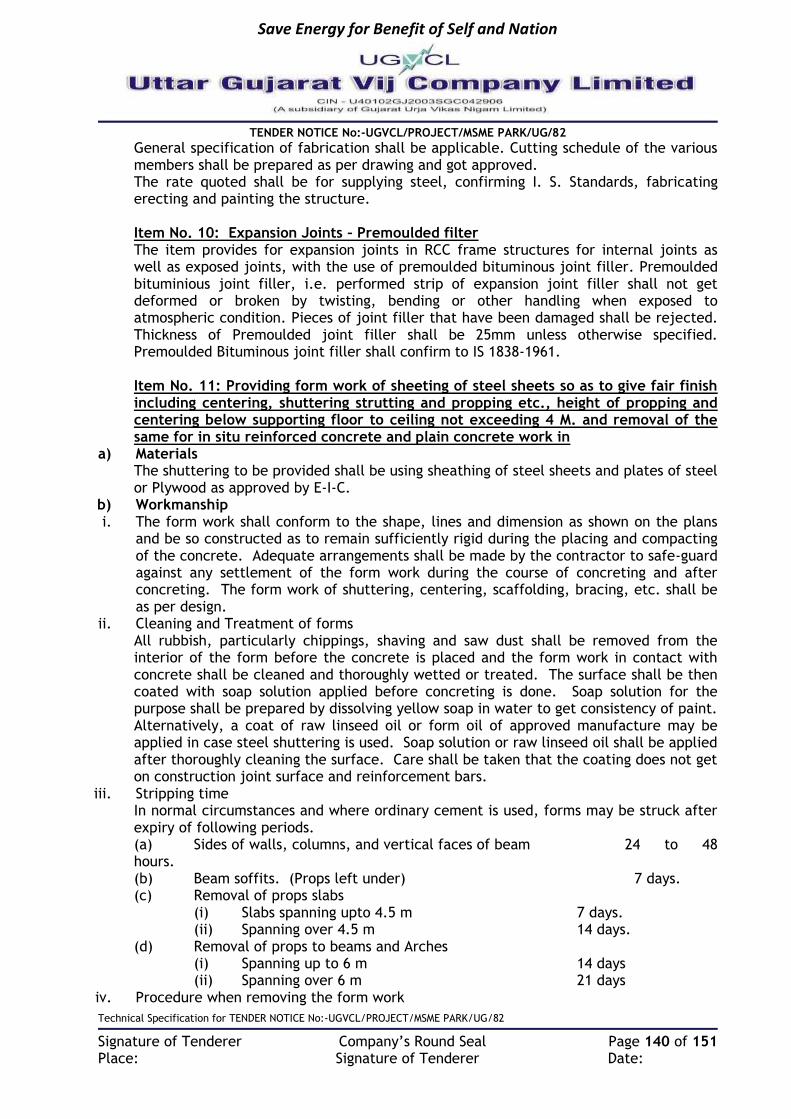
Save Energy for Benefit of Self and Nation
TENDER NOTICE No:-UGVCL/PROJECT/MSME PARK/UG/82
Technical Specification for TENDER NOTICE No:-UGVCL/PROJECT/MSME PARK/UG/82
Signature of Tenderer Company’s Round Seal Page 140 of 151 Place: Signature of Tenderer Date:
General specification of fabrication shall be applicable. Cutting schedule of the various members shall be prepared as per drawing and got approved. The rate quoted shall be for supplying steel, confirming I. S. Standards, fabricating erecting and painting the structure. Item No. 10: Expansion Joints – Premoulded filter The item provides for expansion joints in RCC frame structures for internal joints as well as exposed joints, with the use of premoulded bituminous joint filler. Premoulded bituminious joint filler, i.e. performed strip of expansion joint filler shall not get deformed or broken by twisting, bending or other handling when exposed to atmospheric condition. Pieces of joint filler that have been damaged shall be rejected. Thickness of Premoulded joint filler shall be 25mm unless otherwise specified. Premoulded Bituminous joint filler shall confirm to IS 1838-1961. Item No. 11: Providing form work of sheeting of steel sheets so as to give fair finish including centering, shuttering strutting and propping etc., height of propping and centering below supporting floor to ceiling not exceeding 4 M. and removal of the same for in situ reinforced concrete and plain concrete work in
a) Materials The shuttering to be provided shall be using sheathing of steel sheets and plates of steel or Plywood as approved by E-I-C.
b) Workmanship i. The form work shall conform to the shape, lines and dimension as shown on the plans
and be so constructed as to remain sufficiently rigid during the placing and compacting of the concrete. Adequate arrangements shall be made by the contractor to safe-guard against any settlement of the form work during the course of concreting and after concreting. The form work of shuttering, centering, scaffolding, bracing, etc. shall be as per design.
ii. Cleaning and Treatment of forms All rubbish, particularly chippings, shaving and saw dust shall be removed from the interior of the form before the concrete is placed and the form work in contact with concrete shall be cleaned and thoroughly wetted or treated. The surface shall be then coated with soap solution applied before concreting is done. Soap solution for the purpose shall be prepared by dissolving yellow soap in water to get consistency of paint. Alternatively, a coat of raw linseed oil or form oil of approved manufacture may be applied in case steel shuttering is used. Soap solution or raw linseed oil shall be applied after thoroughly cleaning the surface. Care shall be taken that the coating does not get on construction joint surface and reinforcement bars.
iii. Stripping time In normal circumstances and where ordinary cement is used, forms may be struck after expiry of following periods. (a) Sides of walls, columns, and vertical faces of beam 24 to 48 hours. (b) Beam soffits. (Props left under) 7 days. (c) Removal of props slabs (i) Slabs spanning upto 4.5 m 7 days. (ii) Spanning over 4.5 m 14 days. (d) Removal of props to beams and Arches (i) Spanning up to 6 m 14 days (ii) Spanning over 6 m 21 days
iv. Procedure when removing the form work

Save Energy for Benefit of Self and Nation
TENDER NOTICE No:-UGVCL/PROJECT/MSME PARK/UG/82
Technical Specification for TENDER NOTICE No:-UGVCL/PROJECT/MSME PARK/UG/82
Signature of Tenderer Company’s Round Seal Page 141 of 151 Place: Signature of Tenderer Date:
All form work shall be removed without such shock or vibrations as would damage the reinforced concrete surface. Before the soffit form work and struts are removed, the soffits and the concrete surface shall be exposed where necessary in order to ascertain that the concrete has sufficiently hardened.
v. Centering
The centering to be provided shall be got approved. It shall between sufficiently strong to ensure absolute safety of the form work and concrete work before, during and after pouring concrete. Watch should be kept to see that behaviour of centering and form work is satisfactory during concreting. Erection should also be such that it would allow removal of forms in proper sequence without damaging either the concrete or the forms to be removed.
The props of centering shall be provided on firm foundation or base of sufficient strength to carry the loads without any settlement.
The centering and form work shall be inspected and approved by the Engineer - in - Charge before concreting. But this will not relieve the contractor of his responsibility for strength, adequacy and safety of form work and centering. If there is a failure of form work or centering, contractor shall be responsible for the damages to the work, injury to life and damage to property.
vi. Scaffolding
All scaffolding, hoisting arrangement and ladders, etc. required for the facilitating of concreting shall be provided and removed on completion of work by contractor at his own expense. The scaffolding, hoisting arrangements and ladders etc. shall be strong enough to withstand all live, dead and impact loads expected to act and shall be subject to the approval of the Engineer - in – Charge. However, contractor shall be solely responsible for the safety of the scaffolding, hoisting arrangement, ladders, work and workman etc.
The scaffolding, hoisting arrangements and ladders shall allow easy approach to the work spot and afford easy inspection.
The rate is applicable to all conditions of working and any height. The rate shall include the cost of materials and labour for various operations involved such as: (a) Splayed edges, notching allowance for over laps and passing at angles, battens centering, shuttering, strutting, propping, bolting, nailing, wedging, easing, striking and removal. (b) Filleting to form stop chamfered edges or splayed external angles not exceeding 20mm width to beams, columns and the like. (c) Temporary openings in the forms for pouring concrete, if required, removing rubbish etc. (d) Dressing with oil to prevent adhesion of concrete with shuttering, and (e) Raking or circular cutting.
vii. Re-use Before re-use, all forms shall be inspected by the Engineer - in - Charge and their suitability ascertained. The forms shall be scarred, cleaned, and joints gone over, repaired where required. Inside surface shall be retreated adhesion of concrete. Item No. 12: Providing & applying 2 coats of water proof cement paint of approved brand & manufacture on wall & cable trench cover surfaces after thoroughly brushing the surface to remove all dirt and remains of loose materials. The work should be carried out strictly as per manufacturer's specifications and requirement etc. complete as directed by E. I. C.
a) Materials The water shall confirm to M-1. Cement water proofing shall confirm to IS 5410-1969.

Save Energy for Benefit of Self and Nation
TENDER NOTICE No:-UGVCL/PROJECT/MSME PARK/UG/82
Technical Specification for TENDER NOTICE No:-UGVCL/PROJECT/MSME PARK/UG/82
Signature of Tenderer Company’s Round Seal Page 142 of 151 Place: Signature of Tenderer Date:
b) Workmanship i. Scaffolding
Where scaffolding is required, it shall be erected in such a way that as far as possible no part of scaffolding shall rest against the surface to be distempered. A properly secured and well tied suspended platform (Joola) may be used for distempering. Where ladders are used, pieces of old gunny bags" shall be tied at top and bottom to prevent scratches to the walls and floors. For distempering to ceiling, proper stage scaffolding shall be erected where necessary.
ii. Preparation of surface: The undecorated surface to be water proofing cement painted shall be thoroughly brushed from dust, dirt, grease, mortar dropping and other foreign matter and sand papered smooth. The surface shall be thoroughly wetted with clean water before cement water proofing paint is applied.
iii. Preparation of paint: Portland cement shall be prepared by adding paint powder to water and stirring to obtain a thick paste, which shall then be diluted to a brushable consistency. Generally equal volumes of paint powder and water make a satisfactory paint. In all cases manufacturer’s instructions shall be followed. The paint shall be mixed in such quantities as can used up within an hour of mixing as otherwise the mixture will set and thickness, affecting flowing and finish. The libs of cement paint drums shall be kept tightly when not in use.
iv. Application of Paint:
No painting shall be done when the paint is likely to be exposed to a temperature of below 7° C within 48 hours after application.
When weather conditions are such as to cause damage the work shall be carried out “in the shadow” as far as possible. This helps the proper hardening of the paint film by keeping the surface moist for a longer period.
To maintain the uniform mixture and to prevent segregation, the paint shall be stirred frequently in the bucket.
For undercoated surfaces, the surfaces shall be treated with minimum two coats of water proof cement paint. Not less than 24 hours shall be allowed between two coats. Next coat shall not be started until the preceding coat shall be allowed between two coats. Next coat shall not be started until the preceding coat has become sufficiently hard to resist marking by the brush being used. In not dry weather, the preceding coat shall be allowed between two coats. Next coat shall not be started until the preceding coat has become sufficiently hard to resist marking by the brush being used. In hot dry weather, the preceding coat shall be slightly moistened before applying the subsequent coat.
The finished surface shall be even and uniform in shade, without patches, brush masks, paint drops etc.
The cement paint shall be applied with a brush with relatively short stiff hog or fiber bristles. The paint shall be brushed in uniform thickness and shall be free from excessive heavy brush marks. The lamps shall be well brushed out.
Water proof cement paint shall not be applied on surfaces already treated with white wash color wash, distemper dry or oil bound varnishes, paint etc. It shall not be applied on gypsum, wood and metal surfaces.
v. Curing: Painted surfaces shall be sprinkled with water two or three times a day. This shall be done between coats and for at least two days following the final coat. The curing shall

Save Energy for Benefit of Self and Nation
TENDER NOTICE No:-UGVCL/PROJECT/MSME PARK/UG/82
Technical Specification for TENDER NOTICE No:-UGVCL/PROJECT/MSME PARK/UG/82
Signature of Tenderer Company’s Round Seal Page 143 of 151 Place: Signature of Tenderer Date:
be started as soon as the paint has hardened so as not to be damaged by the sprinkling of water say about 12 hours after the application. Item No. 13: Methods for Laying of Cable The cables shall be laid direct in ground, pipe, closed or open ducts, on cable trays or on surface of wall etc. The method(s) of laying required shall be specified in the Bill of Quantity.
i. Laying direct in ground
General This method shall be adopted where the cable route is through open ground, along roads/lanes, etc. and where no frequent excavations are likely to be encountered and where re-excavation is easily possible without affecting other services.
Trenching a) Width of trench
The width of the trench shall first be determined on the following basis The minimum width of the trench for laying a single cable shall be 35cm Where more than one cable is to be laid in the same trench in horizontal formation,
the width of the trench shall be increased such that the inter-axial spacingbetween the cables, except where otherwise specified, shall be at least 20cm.
There shall be a clearance of at least 15cm between axis of the end cables and the sides of the trench.
b) Depth of trench The depth of the trench shall be determined on the following basis: - Where the cables are laid in a single tier formation, the total depth oftrench shall
not be less than 75cm for cables upto 1.1KV and 1.2m for cables above1.1KV. When more than one tier of cables is unavoidable and vertical formationof laying is
adopted, the depth of the trench in (b) as above shall be increased by 30cm foreach additional tier to be formed.
c) Excavation of trenches The trenches shall be excavated in reasonably straight lines. Wherever there is a
change in the direction, a suitable curvature shall be adopted. Where gradients and changes in depth are unavoidable, these shall be gradual. The bottom of the trench shall be level and free from stones, brick bats etc. The excavation should be done by suitable means-manual or mechanical. The
excavated soil shall be stacked firmly by the side of the trench such that it may not fall back into the trench.
Adequate precautions should be taken not to damage any existing cable(s), pipes or any other such installations in the route during excavation. Wherever trickd, tiles or protective covers or bare cables are encountered, further excavation shall not be carried out without the approval of the Engineer-in-Charge.
Existing property, if any, exposed during trenching shall be temporarily supported adequately as directed by the Engineer-in-Charge. The trenching in such cases shall be done in short lengths, necessary pipes laid for passing cables therein.
It there is any danger of a trench collapsing or endangering adjacent structures, the sides may be left in place when back filling the trench.
Excavation through lawns shall be done in consultation with the Department concerned.
ii. Laying of cable in trench
Sand cushioning a) The trench shall then be provided with a layer of clean, dry sand cushionof not less
than 8cm in depth, before laying the cables therein.

Save Energy for Benefit of Self and Nation
TENDER NOTICE No:-UGVCL/PROJECT/MSME PARK/UG/82
Technical Specification for TENDER NOTICE No:-UGVCL/PROJECT/MSME PARK/UG/82
Signature of Tenderer Company’s Round Seal Page 144 of 151 Place: Signature of Tenderer Date:
b) However, sand cushioning as per (a) above need not be provided for MVcables, where there is no possibility of any mechanical damage to the cables due to heavyor shock loading on the soil above.
c) Sand cushioning as per (a) above shall however be invariably provided inthe case of HV cables.
Testing before laying All the time of issue of cables for laying, the cables shall be tested for continuityand insulation resistance test.
Testing before covering The cables shall be tested for continuity of cores and insulation resistance and the cable length shall be measured, before closing the trench. The cable end shall be sealed /covered.
Sand covering Cables laid in trenches in a single tier formation shall have a covering of dry sand of not less than 17cm above the base cushion of sand before the protective cover is laid. In the case of vertical multi-tier formation, after the first cable has been laid, a sand cushion of 30cm shall be provided over the base cushion before the second tier is laid. If additional tiers are formed, each of the subsequent tiers also shall have a sand cushion of 30cm as stated above. Cables in the top most tiers shall have final sand covering not less than 17cm before the protective cover is laid.
Extra loop cable a) At the time of original installation, approximately 3m of surplus cable shall be left on
each terminal end of the cable and on each side of the underground joints. The surplus cable shall be left in the form of a loop. Where there are long runs of cables such loose cable may be left at suitable intervals as specified by the Engineer-in-Charge.
b) Where it may not be practically possible to provide separation between cables when forming loops of a number of cables as in the case of cables emanating from a substation, measurement shall be made only to the extent of actual volume of excavation, sand filling etc. and paid for accordingly.
Mechanical protection over the covering a) Mechanical protection to cables shall be laid over the covering in accordance with (b)
and (c) below to provide warning to future excavators of the presence of the cable and also to protect the cable against accidental mechanical damage by pick-axe blows etc.
b) Unless otherwise specified, the cables shall be protected by second class brick ofnominal size 22cmX11.4cmX7 cm or locally available size, placed on top of the sand (or, soil as the case may be). The bricks shall be placed breadth-wise for the full length of the cable. Where more than one cable is to be laid in the same trench, this protective covering shall cover all the cables and project at least 5cm over the sides of the end cables.
c) Where bricks are not easily available, or are comparatively costly, there is no objection to use locally available material such as tiles or slates or stone/cement concrete slabs.
Back filling a) The trenches shall be then back-filled with excavated earth, free fromstones or other
sharp ended debris and shall be rammed and watered, if necessary insuccessive layers not exceeding 30cm depth.
b) Unless otherwise specified, a crown of earth not less than 50mm and notexceeding 100mm in the center and tapering towards the sides of the trench shall be leftto allow

Save Energy for Benefit of Self and Nation
TENDER NOTICE No:-UGVCL/PROJECT/MSME PARK/UG/82
Technical Specification for TENDER NOTICE No:-UGVCL/PROJECT/MSME PARK/UG/82
Signature of Tenderer Company’s Round Seal Page 145 of 151 Place: Signature of Tenderer Date:
for subsidence. The crown of the earth however, should not exceed 10 Cms so asnot to be a hazard to vehicular traffic.
c) The temporary re-statements of roadways should be inspected at regularintervals, particularly during wet weather and settlements should be made good by furtherfilling as may be required.
d) After the subsidence has ceased, trenches cut through roadways or otherpaved areas shall be restored to the same density and materials as the surrounding areaand –re-paved in accordance with the relevant building specifications to the satisfactionof the Engineer-in-Charge.
e) Where road beams or lawns have been cut out of necessity, or kerb stonesdisplaced, the same shall be repaired and made good, except for turfing /asphalting, to thesatisfaction of the Engineer-in-Charge and all the surplus earth or rock shall be removedto places as specified.
iii. Laying in pipes / closed ducts a) In locations such as road crossing, entry in to buildings, paved areas etc. cables shall
be laid in pipes or closed ducts. Metallic pipe shall be used as protection pipe for cables fixed on poles of overhead lines.
b) Stone ware pipes, GI, CI or spun reinforced concrete pipes shall be used forcables in general; however only GI pipe shall be used as protection pipe on poles.
c) The size of the pipe shall not be less than 10cm in diameter for a single cable andnot less than 15cm for more than one cable.
d) In the case of new construction, pipes as required (including for anticipated future requirements) shall be laid along with the civil works and jointed according to the CPWD Building Specifications.
e) Pipes shall be continuous and clear of debris or concrete before cables are drawn. Sharp edges if any, at ends shall be smoothened to prevent damage to cable sheathing.
f) These pipes shall be laid directly in ground without any special bed except for SW pipe which shall be laid over 10cm thick cement concrete 1:5:10 (1 cemtnt:5coarsesand:10 graded stone aggregate of 40mm nominal size) bed. No sand cushioning or tiles need be used in such situations.
iv. Road crossings a) The top surface of pipes shall be at a minimum depth of 1m from the pavement level
when laid under roads, pavements etc. b) The pipes shall be laid preferably askew to reduce the angle of bend as the cable
enters and leaves the crossing. This is particularly important for HV cables. c) When pipes are laid cutting an existing road, care shall be taken so that the soil filled
up after laying the pipes is rammed well in layers with watering as required to ensure proper compaction. A crown of earth not exceeding 10cm should be left at the top.
d) The temporary re-instatements of roadways should be inspected at regular intervals, particularly after a rain, and any settlement should be made good by further filling as may be required.
e) After the subsidence has ceases, the top of the filled up trenches in roadways or other paved areas shall be restored to the same density and material as the surrounding area in accordance with the relevant CPWD Building Specifications to the satisfaction of the Engineer-in-Charge.
f) Manholes shall be provided to facilitate feeding/drawing in of cables with sufficient working space for the purpose. They shall be covered by suitable manhole covers. Sizes and other details shall be indicated in the Schedule of work.
v. Cable entry into the building

Save Energy for Benefit of Self and Nation
TENDER NOTICE No:-UGVCL/PROJECT/MSME PARK/UG/82
Technical Specification for TENDER NOTICE No:-UGVCL/PROJECT/MSME PARK/UG/82
Signature of Tenderer Company’s Round Seal Page 146 of 151 Place: Signature of Tenderer Date:
a) Pipes for cable entries to the building shall slope downwards from the building. The pipe sat the building end shall be suitably sealed to avoid entry of water, after the cables are laid.
b) Cable-grip / draw-wires, winches etc. may be employed for drawing cables through pipes / closed ducts.
c) Measurement for drawing/ laying cables in pipes/ closed duct shall be on the basis of the actual length of the pipe / duct for each run of the cable, irrespective of the length of cable drawn through.
All other specification which are not mention here under are as per PWD specifications.

Save Energy for Benefit of Self and Nation
TENDER NOTICE No:-UGVCL/PROJECT/MSME PARK/UG/82
Technical Specification for TENDER NOTICE No:-UGVCL/PROJECT/MSME PARK/UG/82
Signature of Tenderer Company’s Round Seal Page 147 of 151 Place: Signature of Tenderer Date:
TECHNICAL SPECIFICATION OF MATERIALS USED FOR CIVIL WORKS 1. M-1. Water i. Water shall not be salty brackish and shall be clean, reasonably clear and free
objectionable quantities of silt and traces of oil bad injurious alkalis, salts, organic matter and other deleterious material which will either weaken the mortar of concrete or cause efflorescence or attack the steel in R.C.C. Container for transport, storage and handling of water shall be clean. Water shall conform to the standard specified in I.S.456-1978.
ii. If required by the Engineer-in-Charge it shall be tested by comparison with distilled water. Comparison shall be made by means of standard cement tests for soundness time of setting and mortar strength as specified in I.S. 269-1976 Any indication of unsoundness, charge in time of setting by 30 minutes or more or decrease of more than 10 per cent in strength, of mortar prepared with water sample when compared with the results obtained with mortar prepared with distilled water shall be sufficient cause for rejection of water under test.
iii. Water for curing mortar, concrete or masonry should not be too acidic or too alkaline. It shall be free of elements which significantly affect the hydration reaction or otherwise interfere with the hardening of mortar or concrete during curing or those which produce objectionable stains or other unsightly deposits on concrete or mortar surfaces
iv. Hard and bitter water shall not be used for curing. v. Potable water will generally found suitable for curing mortar or concrete.
2. M-2 Cement
Cement shall be ordinary Portland cement as per I.S. 12269: 2013.
3. M-3 Sand i. Sand shall be natural sand, clean, well graded, hard strong, durable and gritty particles
free from injurious amounts of dust, clay kankar nodules, soft or flaky particles shale, alkali salts organic matter, loam, mica or other deleterious substances and shall be got approved from the Engineer-in-Charge. The sand shall not contain more contain more than 8 percent of silt as determined by field test. If necessary, the sand shall be washed to make it clean.
ii. Coarse Sand: The fineness modulus of coarse sand shall not be less than 2.5-and shall not exceed 3.0, The sieve analysis of coarse shall be as under:
I.S Designation Sieve Passing sieve
Percentage by weight Designation
I.S. Sieve percentage weight passing sieve
4.75mm 100 600 Micron
30-100
2.36mm 90 to 100 300 Micron
5-70
1.18mm 70-100 150 Micron
0-50
iii. Fine Sand:
The fineness modulus shall not exceed 1.0. The sieve analysis of fine sand shall be as under:

Save Energy for Benefit of Self and Nation
TENDER NOTICE No:-UGVCL/PROJECT/MSME PARK/UG/82
Technical Specification for TENDER NOTICE No:-UGVCL/PROJECT/MSME PARK/UG/82
Signature of Tenderer Company’s Round Seal Page 148 of 151 Place: Signature of Tenderer Date:
I.S Designation Sieve Passing sieve
Percentage by weight Designation
I.S. Sieve percentage by weight passing sieve
4.75mm 100 600 Micron
40-85
2.36mm 100 300 Micron
5-50
1.18mm 75-100 150 Micron
0-10
4. M-4. Stone Grit i. Grit shall consist of crushed or broken stone and be hard, strong, dense, durable, clean
of proper gradation and free from skin or coating likely to prevent proper adhesion of mortar. Grit shall generally be cubical in shape and as far as possible flakey elongated pieces shall be avoided. It shall generally comply whit the provisions of I.S. 383-1970. Unless special stone of particular quarries is mentioned grit shall be obtained from the best black trap or equivalent hard stone as approved by the Engineer-in-Charge. The grit shall have no deleterious with cement.
ii. The grit shall conform to the following gradation as per sieve analysis:
I.S Designation Sieve Passing sieve
Percentage by weight Designation
I.S. Sieve percentage by weight passing sieve
1250mm 100 % 4.75mm
0-20 %
10.00mm 85-100 % 2.36mm
0-25%
iii. The crushing strength of grit will be such as to allow the concrete in which it used to build-up the specified strength of concrete
iv. The necessary tests for grit shall be carried out as per the requirements of I.S.2386- (parts-l of VIII) 1963, as per instructions of the Engineer-in-Charge. The necessity of test will be decided by the. Engineer-in-Charge.
5. M-5 Cement Mortar i. Water shall conform to specification M-1 Cement: Cement shall conform to
specifications M-3 Sand: Sand shall conform to M-6 ii. Proportion of Mix
Cement and sand shall be mixed to specified proportion, sand being measured by measuring boxes, the proportion of cement will be by volume on the basis of 50 Kg/Bag of cement being equal to 0.0342 Cu.m. The mortar may be hand mixed of machine mixed as directed.
iii. Proportion of Mortar: In hand mixed mortar, cement and sand in the specified proportions shall be thoroughly mixed dry on a clean impervious platform by turning over at least 3 times or more till a homogeneous mixture of uniform colour is obtained. Mixing platform shall be so arranged, that no deleterious extraneous material shall get mixed with mortar or mortar shall flow out. While mixing, the water shall be gradually added and thoroughly mixed to from a stiff plastic mass of uniform colour so that each particle of sand shall be completely covered with a film of wet cement. The water cement ratio shall be adopted as directed. The mortar so prepared shall be used within 30 minutes of adding water. Only such quantity of mortar shall be prepared as can be used within 30 minutes.

Save Energy for Benefit of Self and Nation
TENDER NOTICE No:-UGVCL/PROJECT/MSME PARK/UG/82
Technical Specification for TENDER NOTICE No:-UGVCL/PROJECT/MSME PARK/UG/82
Signature of Tenderer Company’s Round Seal Page 149 of 151 Place: Signature of Tenderer Date:
6. M-6 Stone Coarse Aggregate for Nominal Mix Concrete i. coarse aggregate shall be of machine crushed stone of black trap or equivalent and be
hard, strong, dense, durable, clean and free from skin and coating likely to prevent proper adhesion of mortar.
ii. The aggregate shall generally be cubical in shape. Unless special stones of particular quarries are mentioned aggregates shall be machine crushed from the best black trap or equivalent hard stone as approved. Aggregate shall Have no deleterious reaction with cement. The size of the coarse aggregate for plain cement and ordinary reinforced cement concrete shall generally be as per the table given below However, in case of reinforced cement concrete the maximum limit may be restricted to 6 mm less than the minimum lateral clear distance between bars or 6 mm. less than the cover whichever is smaller TABLE
IS. Sieve
Percentage passing for single
IS. Sieve
Percentage passing for single
Designation Sized aggregates of Nominal size 40mm 20mm 16mm
Designation Sized aggregates of Nominal size 40mm 20mm 16mm
80mm - 12.5mm 0.5 0.20
63mm 100 10 mm 0.5 0.5
40mm 85-100 100 4.75mm
20mm 0.2 85-100 100 2.35 mm
16mm 85-100
Note: This percentage may be varied somewhat by the Engineer-in-Charge when considered necessary for obtaining better density and strength of concrete.
iii. The grading test shall be taken in the beginning and at the change of source of materials. The necessary tests Indicated in IS 383-1970 and 456-1978 shall have to be carried out to ensure the acceptability. The aggregates shall be stored separately and handled in such a manner as to prevent the mixing of different aggregates. If she aggregates are covered with dust, they shall be washed with water to make them clean.
7. M-7 Black Trap or Equivalent Hard Stone Coarse i. Aggregate for Design Mix Concrete Coarse aggregate shall be of machine crushed stone
of black trap or equivalent hard stone and be hard, strong, dense, durable, clean and free from skin and coating likely to prevent proper adhesion of mortar,
ii. The aggregates shall generally-be cubical in shape. Unless special stones of particular quarries are mentioned, aggregates shall be machine crushed from the best, black trap or equivalent hard stones as approved, Aggregate shall have no deleterious with cement.
iii. The necessary tests indicated in IS. 383-1970 and IS.456-1978 shall have to be carried out to ensure the acceptability of the material. If aggregate is covered with dust it shall be washed with water to make it clean.
8. M-8 Brick i. The brick shall be shall be machine moulded and made from suitable fly ash, cement,
lime, gypsum, etc. They shall be free from cracks and nodules of free lime. They shall have smooth rectangular faces with sharp corners and shall be of uniform colour. The bricks shall be moulded with the frog of 100mm x 40 mm and 10mm to 20mm deep on

Save Energy for Benefit of Self and Nation
TENDER NOTICE No:-UGVCL/PROJECT/MSME PARK/UG/82
Technical Specification for TENDER NOTICE No:-UGVCL/PROJECT/MSME PARK/UG/82
Signature of Tenderer Company’s Round Seal Page 150 of 151 Place: Signature of Tenderer Date:
one of its flat sides. The bricks shall not break when thrown on the ground from a height of 600mm.
ii. The size of the modular bricks shall be 190 x 90 x 90 mm. iii. The size of the conventional bricks shall be 225 x 110 x 75mm. iv. Only bricks of one standard size shall be used on one work. The following tolerance
shall be permitted in the conventional size adopted in a particular work. Length +3.0mm, Width + 1.50mm, Height +1.50mm.
v. The crushing strength of the brick shall not be less than 35.0 Kg / Sq cm. The average water absorption shall not be less than 20 per cent by weight. Necessary test for crushing strength and water absorption shall be carried out as per IS 3495: (Part I to Part IV) 1976.
9. M-9. Mild Steel Binding Wire i. The mild steel wire shall be of 1.63 mm. or 1.22 mm. (16 to 18 gauge) diameter and
shall conform to l.S. 280-1972. ii. The use of black wire will be permitted for binding reinforcement bars. It shall be free
from rust, oil paint, grease, loose mill scale or any other undesirable coating which may prevent adhesion of cement mortar.
10. M-10. Structural Steel All structural Steel shall conform to I.S. 226-1985. The steel shall be free from the defects mentioned in I.S. 226-1975 and shall have a smooth finish. The material shall be free from loose mill scale, rust pits or other defects affecting the strength and durability. River bars shall conform to I.S. 1148-1973. When the steel is supplied by the Contractor test certificate of the manufacturers shall be obtained according to I.S. 226-1975 and other relevant Indian. Standards.
11. M-11 Shuttering i. The shuttering shall be either of ply wood planking of appropriate thickness with or
without steel lining or of steel plates stiffened by steel angles. The shuttering shall be supported on battens and beams and props of vertical ballies properly cross braced together so as to make the centering rigid. In places of bulli props, brick pillar of adequate section built in mud mortar may be used.
ii. The form work shall be sufficiently strong and shall have camber, so that it assumes correct shape after deposition of the concrete and shall be able to resist forces caused by vibration of live load of men working over it and other incidental loads associated with it. The shuttering shall have smooth and even surface and its joints shall permit leakage of cement grout.
iii. If at any stage of work during or after placing concrete in the structure, the form work sags or bulges out beyond the required shape of the structure, the concrete shall be removed and work redone with fresh concrete and adequately rigid form work. The complete formwork shall be got inspected by and got approved from the Engineer-in-Charge, before the reinforcement bars are placed in position
iv. The props shall consist to bullies having 100 mm. minimum diameters measured at mid length and 80mm. at thin end shall be placed as per design requirement. These shall rest squarely on wooden sole plates 40 mm. thick and minimum bearing area of 0-10 sq m. laid on sufficiently hard base.
v. Double wedges shall further be provided between the sole plate and the wooden props so as to facilitate tightening and easing of shuttering without jerking the concrete.
vi. The wood used in shuttering shall not be so dry as to absorb water from concrete and swell or bulge nor so green or wet as to shrink after erection. The timber shall be

Save Energy for Benefit of Self and Nation
TENDER NOTICE No:-UGVCL/PROJECT/MSME PARK/UG/82
Technical Specification for TENDER NOTICE No:-UGVCL/PROJECT/MSME PARK/UG/82
Signature of Tenderer Company’s Round Seal Page 151 of 151 Place: Signature of Tenderer Date:
properly sawn and planed on the sides and the surface coming in contact with concrete, Wooden form work with metal sheet lining or steel plates stiffened by steel angles shall be permitted,
vii. As far as practicable, clamps shall be used to hold the forms together and use of nails and spikes avoided.
viii. The surface of timber shuttering that would come in contact with concrete shall be well wetted and coated with soap solution before the concreting is done. Alternatively coat of raw linseed oil or oil of approved manufacture may be applied in place of soap solution. In case of steel shuttering either soap solution or raw linseed oil shall be applied after thoroughly cleaning the surface. Under no circumstances black or burnt oil shall be permitted.
ix. The shuttering for beams and slabs shall have camber of 4 mm. per meter. x. (1in250) or as directed by the Engineer-in-Charge so as to offset the subsequent
deflection. For cantilevers, the camber at free end shall be 1/50 of the projected length or as directed by the Engineer-in-Charge.