DESMI in-line centrifugal pump - PVLN,PVLB,PVLS and PVLJ ...
20
OPERATION AND MAINTENANCE INSTRUCTIONS DESMI in-line centrifugal pump PVLN,PVLB,PVLS and PVLJ DESMI PUMPING TECHNOLOGY A/S Tagholm 1 – DK-9400 Nørresundby – Denmark Tel.: +45 96 32 81 11 Fax: +45 98 17 54 99 E-mail: [email protected] Internet: www.desmi.com Special pump No.................................................. Manual: T1306 Language: English Revision: I(11/20)
-
Upload
khangminh22 -
Category
Documents
-
view
3 -
download
0
Transcript of DESMI in-line centrifugal pump - PVLN,PVLB,PVLS and PVLJ ...

OPERATION AND MAINTENANCE INSTRUCTIONS
DESMI in-line centrifugal pump
PVLN,PVLB,PVLS and PVLJ
DESMI PUMPING TECHNOLOGY A/S Tagholm 1 – DK-9400 Nørresundby – Denmark
Tel.: +45 96 32 81 11
Fax: +45 98 17 54 99 E-mail: [email protected]
Internet: www.desmi.com
Special pump No..................................................
Manual: T1306
Language: English
Revision: I(11/20)

i
Contents
1. PRODUCT DESCRIPTION........................................................................................................................................1
2. TECHNICAL DATA ..................................................................................................................................................1
2.1. TECHNICAL DATA FOR PUMPS WITH ITEM NUMBER PVLNXXXX.XX-0XX ........................................................... 1 2.2. TECHNICAL DATA FOR PUMPS WITH ITEM NUMBER 69 XX XX ........................................................................... 5 2.3. EXPLANATION OF THE TYPE DESIGNATION ........................................................................................................ 5 2.4. 2.4 TECHNICAL DESCRIPTION ............................................................................................................................. 6
3. INSTALLATION ......................................................................................................................................................7
4. TRANSPORT/STORAGE .........................................................................................................................................8
5. START-UP .............................................................................................................................................................8
6. SYSTEM BALANCING .............................................................................................................................................9
7. MAINTENANCE ................................................................................................................................................... 10
8. DISMANTLING .................................................................................................................................................... 10
9. REPAIRS .............................................................................................................................................................. 10
9.1. REPLACING THE IMPELLER (2) .......................................................................................................................... 10 9.2. REPLACING SEAL RINGS (16 AND 17) ................................................................................................................ 10 9.3. REPLACING SHAFT SEAL (22) ............................................................................................................................ 10 9.4. REPLACING BALL BEARINGS IN MOTOR ........................................................................................................... 11
10. TESTING .............................................................................................................................................................. 12
11. EU DECLARATION OF CONFORMITY .................................................................................................................... 14
12. INFORMATION RELEVANT FOR DISASSEMBLY OR DISPOSAL AT END-OF-LIFE ..................................................... 15
13. POSITION NUMBERS – PUMP (SEE NEXT PAGES FOR PVLN1025 & 1040) ............................................................ 15
14. ASSEMBLY DRAWING-PUMP (SEE NEXT PAGES FOR PVLN1025 & 1040) ............................................................. 16
15. POSITION NUMBERS – PVLN1025 & 1040 ........................................................................................................... 17
16. ASSEMBLY DRAWING – PVLN1025 & 1040.......................................................................................................... 18
______________________________________________________________________________ DESMI Pumping Technology A/S P a g e | 1 9400 Nørresundby – Denmark Tel: +45 96 32 81 11 Fax: +45 98 17 54 99
E-mail: [email protected]
www.desmi.com
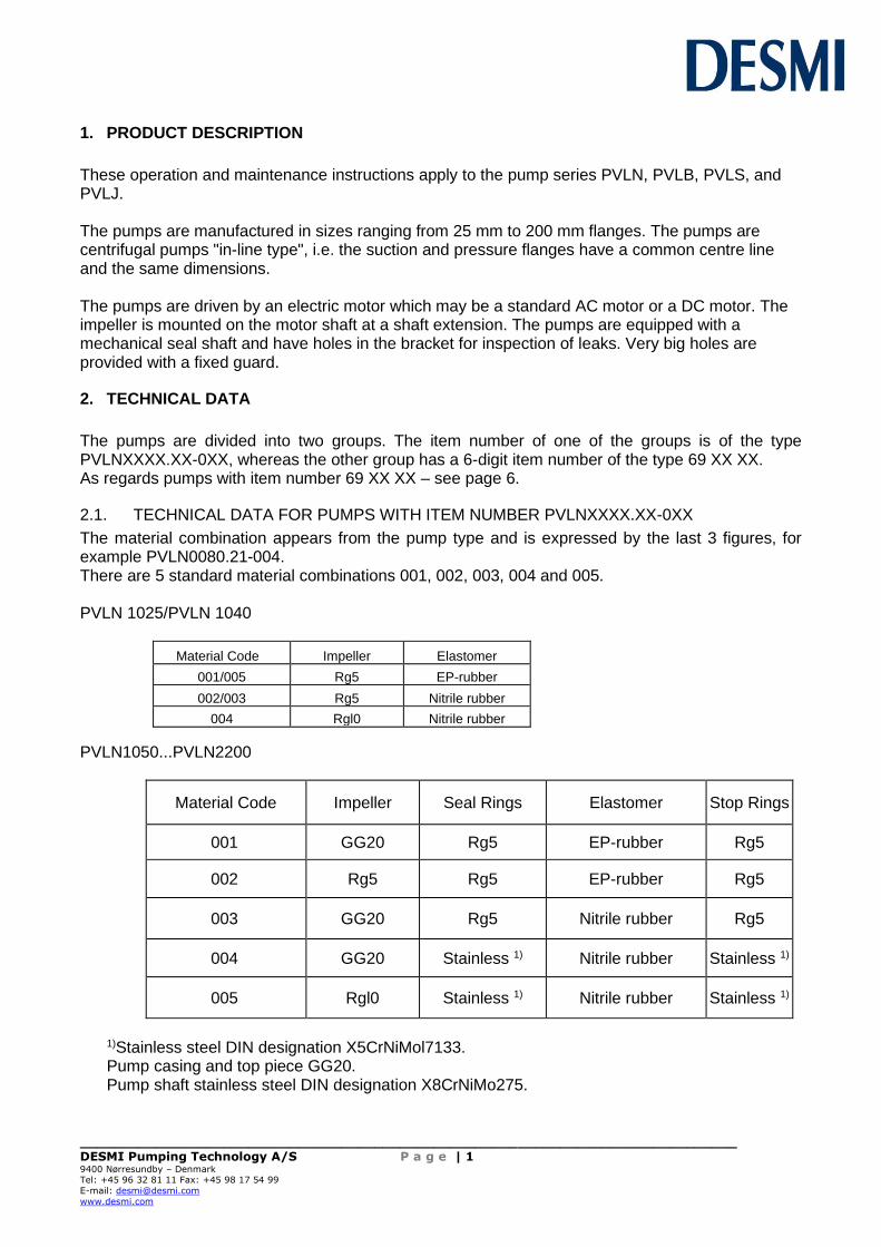
1. PRODUCT DESCRIPTION
These operation and maintenance instructions apply to the pump series PVLN, PVLB, PVLS, and PVLJ. The pumps are manufactured in sizes ranging from 25 mm to 200 mm flanges. The pumps are centrifugal pumps "in-line type", i.e. the suction and pressure flanges have a common centre line and the same dimensions. The pumps are driven by an electric motor which may be a standard AC motor or a DC motor. The impeller is mounted on the motor shaft at a shaft extension. The pumps are equipped with a mechanical seal shaft and have holes in the bracket for inspection of leaks. Very big holes are provided with a fixed guard.
2. TECHNICAL DATA
The pumps are divided into two groups. The item number of one of the groups is of the type PVLNXXXX.XX-0XX, whereas the other group has a 6-digit item number of the type 69 XX XX. As regards pumps with item number 69 XX XX – see page 6.
2.1. TECHNICAL DATA FOR PUMPS WITH ITEM NUMBER PVLNXXXX.XX-0XX
The material combination appears from the pump type and is expressed by the last 3 figures, for example PVLN0080.21-004. There are 5 standard material combinations 001, 002, 003, 004 and 005. PVLN 1025/PVLN 1040
Material Code Impeller Elastomer
001/005 Rg5 EP-rubber
002/003 Rg5 Nitrile rubber
004 Rgl0 Nitrile rubber
PVLN1050...PVLN2200
Material Code Impeller Seal Rings Elastomer Stop Rings
001 GG20 Rg5 EP-rubber Rg5
002 Rg5 Rg5 EP-rubber Rg5
003 GG20 Rg5 Nitrile rubber Rg5
004 GG20 Stainless 1) Nitrile rubber Stainless 1)
005 Rgl0 Stainless 1) Nitrile rubber Stainless 1)
1)Stainless steel DIN designation X5CrNiMol7133. Pump casing and top piece GG20. Pump shaft stainless steel DIN designation X8CrNiMo275.
______________________________________________________________________________ DESMI Pumping Technology A/S P a g e | 2 9400 Nørresundby – Denmark Tel: +45 96 32 81 11 Fax: +45 98 17 54 99
E-mail: [email protected]
www.desmi.com
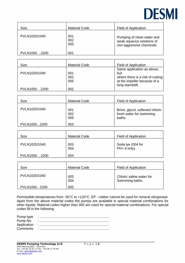
Size Material Code Field of Application
PVLN1025/1040
001 002 005
Pumping of clean water and weak aqueous solutions of non-aggressive chemicals
PVLN1050. ..2200 001
Size Material Code Field of Application
PVLN1025/1040 001
Same application as above, but
002 where there is a risk of rusting 005 at the impeller because of a long standstill.
PVLN1050. ..2200 002
Size Material Code Field of Application
PVLN1025/1040 001
002 005
Brine, glycol, softened chloric fresh water for swimming baths.
PVLN1050...2200 003
Size Material Code Field of Application
PVLN1025/1040
003 004
Soda lye (004 for PH< 9 only).
PVLN1050. ..2200 004
Size Material Code Field of Application
PVLN1025/1040 003
004 Chloric saline water for Swimming baths.
PVLN1050...2200 005
Permissible temperatures from -30°C to +120°C. EP - rubber cannot be used for mineral oils/grease. Apart from the above material codes the pumps are available in special material combinations for other liquids. Material codes higher than 005 are used for special material combinations. For special codes fill in the following: Pump type : ......................................................................... Pump No. : ......................................................................... Application : ......................................................................... Comments : .........................................................................

______________________________________________________________________________ DESMI Pumping Technology A/S P a g e | 3 9400 Nørresundby – Denmark Tel: +45 96 32 81 11 Fax: +45 98 17 54 99
E-mail: [email protected]
www.desmi.com
When using the pump for other media the operator is responsible for checking that the specified materials in the pumps are in order. In case of doubt, contact the supplier. The noise level for the airborne noise appears from the following list. The values indicated are measured as middle values at a distance of l m from the machine surface in free field approx. 1.5 m above the base plate. The sound pressure levels are general directional values which cannot be regarded as guarantee values for each individual pump, as the sound level of a pump is to a large extent dependent on the installation method and the operating conditions. The measuring comprise the pump including the motor. Sound pressure level for the PVLN-pumps:
PVLN Type dB(a) PVLN Type dB(a)
1050.81 40 1100.41 71
1050.61 47 2100.61 64
1050.27 70 2100.41 72
1050.22 78 2125.62 68
1050.21 80 2125.44 74
1065.61 47 2125.43 76
1065.42 53 2125.42 77
1065.41 55 2125.41 78
2065.23 81 2150.82 69
2065.22 83 2150.62 73
1065.21 84 2150.61 74
0080.61 52 2150.43 78
0080.42 56 2150.42 79
0080.41 57 2150.41 80
0080.22 80 2200.82 70
0080.21 81 2200.81 71
2080.42 58 2200.62 74
2080.41 62 2200.61 76
2080.23 40 2200.44 79
2080.22 84 2200.43 80
2080.21 84 2200.42 81
1100.61 58 2200.41 82
Environment: The pumps are as a standard equipped with motors with protection class IP54, which means that the motor is protected against penetrating dust and that water without pressure does not damage the motor. The motors are dimensioned for an ambient temperature of 40°C. Pumps installed in explosive areas must be equipped with explosion-proof motors. The pump capacity is stamped on the name plate.
______________________________________________________________________________ DESMI Pumping Technology A/S P a g e | 4 9400 Nørresundby – Denmark Tel: +45 96 32 81 11 Fax: +45 98 17 54 99
E-mail: [email protected]
www.desmi.com
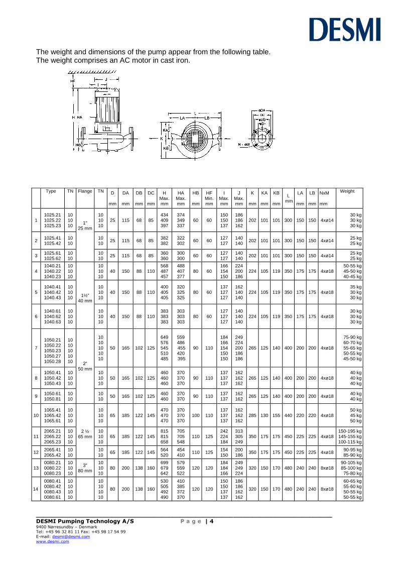
The weight and dimensions of the pump appear from the following table. The weight comprises an AC motor in cast iron.
Type TN Flange TN D
mm
DA
mm
DB
mm
DC
mm
H Max. mm
HA Max. mm
HB
mm
HF Min. mm
I Max. mm
J Max. mm
K
mm
KA
mm
KB
mm
L mm
LA
mm
LB
mm
NxM mm
Weight
1 1025.21 1025.22 1025.23
10 10 10
1" 25 mm
10 10 10
25 115 68 85 434 409 397
374 349 337
60 60 150 150 137
186 186 162
202 101 101 300 150 150 4xø14 30 kg 30 kg 30 kg
2 1025.41 1025.42
10 10
10 10
25 115 68 85 382 382
322 302
60 60 127 127
140 140
202 101 101 300 150 150 4xø14 25 kg 25 kg
3 1025.61 1025.62
10 10
10 10
25 115 68 85 360 360
300 300
60 60 127 127
140 140
202 101 101 300 150 150 4xø14 25 kg 25 kg
4 1040.21 1040.22 1040.23
10 10 10
1½"
40 mm
10 10 10
40 150 88 110 568 487 457
488 407 377
80 60 166 154 150
224 200 186
224 105 119 350 175 175 4xø18 50-55 kg 45-50 kg 40-45 kg
5 1040.41 1040.42 1040.43
10 10 10
10 10 10
40 150 88 110 400 405 405
320 325 325
80 60 137 127 127
162 140 140
224 105 119 350 175 175 4xø18 35 kg 30 kg 30 kg
6 1040.61 1040.62 1040.63
10 10 10
10 10 10
40 150 88 110 383 383 383
303 303 303
80 60 127 127 127
140 140 140
224 105 119 350 175 175 4xø18 30 kg 30 kg 30 kg
7
1050.21 1050.22 1050.23 1050.27 1050.28
10 10 10 10 10 2“
50 mm
10 10 10 10 10
50 165 102 125
649 576 545 510 485
559 486 455 420 395
90 110
184 166 154 150 150
249 224 200 186 186
265 125 140 400 200 200 4xø18
75-90 kg 60-70 kg 55-65 kg 50-55 kg 45-50 kg
8 1050.41 1050.42 1050.43
10 10 10
10 10 10
50 165 102 125 460 460 460
370 370 370
90 110 137 137 137
162 162 162
265 125 140 400 200 200 4xø18 40 kg 40 kg 40 kg
9 1050.61 1050.81
10 10
10 10
50 165 102 125 460 460
370 370
90 110 137 137
162 162
265 125 140 400 200 200 4xø18 40 kg 40 kg
10 1065.41 1065.42 1065.61
10 10 10
2 ½
65 mm
10 10 10
65 185 122 145 470 470 470
370 370 370
100 110 137 137 137
162 162 162
285 130 155 440 220 220 4xø18 50 kg 45 kg 50 kg
11 2065.21 2065.22 2065.23
10 10 10
10 10 10
65 185 122 145 815 815 658
705 705 548
110 125 242 224 184
313 305 249
350 175 175 450 225 225 4xø18 150-195 kg 145-155 kg 100-115 kg
12 2065.41 2065.42
10 10
10 10
65 185 122 145 564 520
454 410
110 125 154 150
200 186
350 175 175 450 225 225 4xø18 90-95 kg 85-90 kg
13 0080.21 0080.22 0080.23
10 10 10
3" 80 mm
10 10 10
80 200 138 160 699 679 642
579 559 522
120 120 184 184 166
249 249 224
320 150 170 480 240 240 8xø18 90-105 kg 85-100 kg 75-80 kg
14
0080.41 0080.42 0080.43 0080.61
10 10 10 10
10 10 10 10
80 200 138 160
530 505 492 490
410 385 372 370
120 120
150 150 137 137
186 186 162 162
320 150 170 480 240 240 8xø18
60-65 kg 55-60 kg 50-55 kg 50-55 kg

______________________________________________________________________________ DESMI Pumping Technology A/S P a g e | 5 9400 Nørresundby – Denmark Tel: +45 96 32 81 11 Fax: +45 98 17 54 99
E-mail: [email protected]
www.desmi.com
Type TN Flange TN D
mm
DA
mm
DB
mm
DC
mm
H Max. mm
HA Max. mm
HB
mm
HF Min. Mm
I Max. mm
J Max. mm
K
mm
KA
mm
KB
mm
L
mm
LA
mm
LB
mm
NxM mm
Weight
15 2080.21 2080.22 2080.23
10 10 10 3"
80 mm
10 10 10
80 200 138 160 882 830 830
752 700 700
130 120 255 242 224
330 313 305
380 175 205 540 260 280 8xø18 180-220 kg 155-200 kg 150-165 kg
16 2080.41 2080.42
10 10
10 10
80 200 138 160 579 579
449 449
130 120 154 154
200 200
380 175 205 540 260 280 8xø18 80-85 kg 75-80 kg
17
1100.41 1100.42 1100.61 1100.81
10 10 10 10
4" 100 mm
10 10 10 10
100 220 158 180
631 600 555 555
486 455 410 410
145 125
166 154 150 150
224 200 186 186
375 170 205 590 270 320 8xø18
90-100 kg 80-90 kg 75-80 kg 75-80 kg
18 2100.41 2100.61
10 10
10 10
100 220 158 180 699 594
559 454
140 125 184 154
249 200
430 195 235 620 300 320 8xø18 115-125 kg
90-95 kg
19
2125.41 2125.42 2125.43 2125.44 2125.45
10 10 10 10 10
5" 125 mm
10 10 10 10 10
125 250 188 210
1035 977 930 822 781
835 777 730 622 581
200 170
255 255 224 205 184
351 330 305 260 249
460 205 255 800 400 400 8xø18
300-315 kg 265-300 kg 240-255 kg 190-210 kg 180-190 kg
20 2125.62 10 10 125 250 188 210 701 501 200 170 166 224 460 205 255 800 400 400 8xø18 165-170 kg
21
2150.41 2150.42 2150.43 2150.44
6 6 6 6 6"
150 mm
10 10 10 10
150 285 212 240
1123 1070 1070 1012
963 910 910 852
160 175
327 261 255 255
392 351 351 330
625 285 340 925 475 450 8xø22
465-490 kg 410-425 kg 395-410 kg 355-390 kg
22 2150.61 2150.62
6 6
10 10
150 285 212 240 960 857
800 697
160 175 224 205
305 260
625 285 340 925 475 450 8xø22 335-350 kg 790-310 kg
23 2150.82 6 10 150 285 212 240 857 697 160 175 205 260 625 285 340 925 475 450 8xø22 290-300 kg
24
2200.41 2200.42 2200.43 2200.44 2200.45
6 6 6 6 6
8" 200 mm
10 10 10 10 10
200 340 268 295
1291 1278 1174 1130 1130
1101 1088 984 940 940
190 190
345 345 327 261 255
442 442 392 351 351
710 310 400 1095 565 530 8xø22
665-730 kg 605-655 kg 550-575 kg 505-520 kg 485-500 kg
25 2200.61 2200.62
6 6
10 10
200 340 268 295 1072 1020
882 830
190 190 255 224
330 305
710 310 400 1095 565 530 8xø22 460-480 kg 440-455 kg
26 2200.81 2200.82 2200.83
6 6 6
10 10 10
200 340 268 295 1020 1020 956
830 830 766
190 190 224 224 205
305 305 260
710 310 400 1095 565 530 8xø22 430-445 kg 415-430 kg 400-410 kg
2.2. TECHNICAL DATA FOR PUMPS WITH ITEM NUMBER 69 XX XX
The pumps are manufactured in various material combinations, which appear from the type designation on the nameplate. See below.
2.3. EXPLANATION OF THE TYPE DESIGNATION
All PVLN pumps are provided with a nameplate. The type designation indicated on the nameplate is built up as follows: PVLNYYXX/MR-Z XX: Pressure branch diameter M: The material combination of the pump R: The assembly combination of the pump Z: Other variants
M may be the following:
A: Casing and shaft seal cover : Cast iron + cast iron alloy. Impeller and sealing rings: Bronze (Rg10) D: Casing and shaft seal cover : Bronze (Rg5). Impeller and sealing rings: Bronze (Rg10) E: Special materials The pumps can be delivered in other material combinations according to agreement with the supplier. R may be the following: 12: ......................................................................... Monobloc, without bearing in the pump

______________________________________________________________________________ DESMI Pumping Technology A/S P a g e | 6 9400 Nørresundby – Denmark Tel: +45 96 32 81 11 Fax: +45 98 17 54 99
E-mail: [email protected]
www.desmi.com
Z may be the following: i : PN16 flanges j : PN25 flanges k : Special flange l : Other shaft seal m : BS flanges n : ANSI flanges o : Shockproof design p : Other design q : JIS flanges Any use of the pump is to be evaluated on the basis of the materials used in the pump. In case of doubt, contact the supplier. Pumps in material combinations A are primarily used for fresh water. Pumps in material combination D are primarily used for seawater. If the pumps are designed for special purposes the following is to be indicated: Pump No. : Pump type : Application : Comment :
2.4. 2.4 TECHNICAL DESCRIPTION
The noise level indicated is the airborne noise including the motor. The noise depends on the motor type supplied, as the noise from the pump can be calculated as the noise level of the motor + 2dB(A). The noise level is for pumps with electric motors. The capacity of the pump appears from the nameplate on the pump. If the pump has been delivered without motor, the pump capacity is to be indicated on the plate when mounting the motor. The permissible loads on the flanges appear from the following table. The values apply to standard pumps in bronze (Rg5) and cast iron (GG20). As to pumps in SG iron (GGG40) the values are to be increased by factor 1.5.
Permissible loads and torques on pump flanges:

______________________________________________________________________________ DESMI Pumping Technology A/S P a g e | 7 9400 Nørresundby – Denmark Tel: +45 96 32 81 11 Fax: +45 98 17 54 99
E-mail: [email protected]
www.desmi.com
Piping
DN
Forces (N) Torques (Nm)
mm
FY
Fz
FX F
My
Mz
Mx M
25 250 320 250 480 300 150 260 420
Horizontal pipeline at right angles to the shaft
40 50 65
400 500 650
500 600 840
400 550 750
750 1000 1340
400 450 510
200 250 310
300 350 380
550 600 700
Suction and pressure
80 800
950
850
1500
550
350
400
750 flanges above level
of installation
100 125
1000 1250
1250 1600
1150 1430
2000 2500
650 830
400 520
500 650
900 1150
150
1500
1900
1700
2950
1000
650
800
1400
200
2000
2520
2200
3920
1330
860
1060
1860
In connection with the permissible loads on the flanges indicated in the above table there is the following limitation:
2
2
.
2
.
+
epermissiblMaxM
calculatedM
epermissiblMaxF
calculatedF
3. INSTALLATION
Insert the pump in the pipeline in the same way as a valve. The pump can be inserted in both horizontal and vertical pipes, but not in a horizontal pipe if the motor is placed below horizontal level. The max. loads on the flanges appear from the technical description. When installing the pump check that it is earthed to avoid an electrical potential in the pump.
At installations pumping hot or very cold liquids the operator must be aware that it is dangerous to touch the pump surface, and he is to take the necessary safety measures.
______________________________________________________________________________ DESMI Pumping Technology A/S P a g e | 8 9400 Nørresundby – Denmark Tel: +45 96 32 81 11 Fax: +45 98 17 54 99
E-mail: [email protected]
www.desmi.com
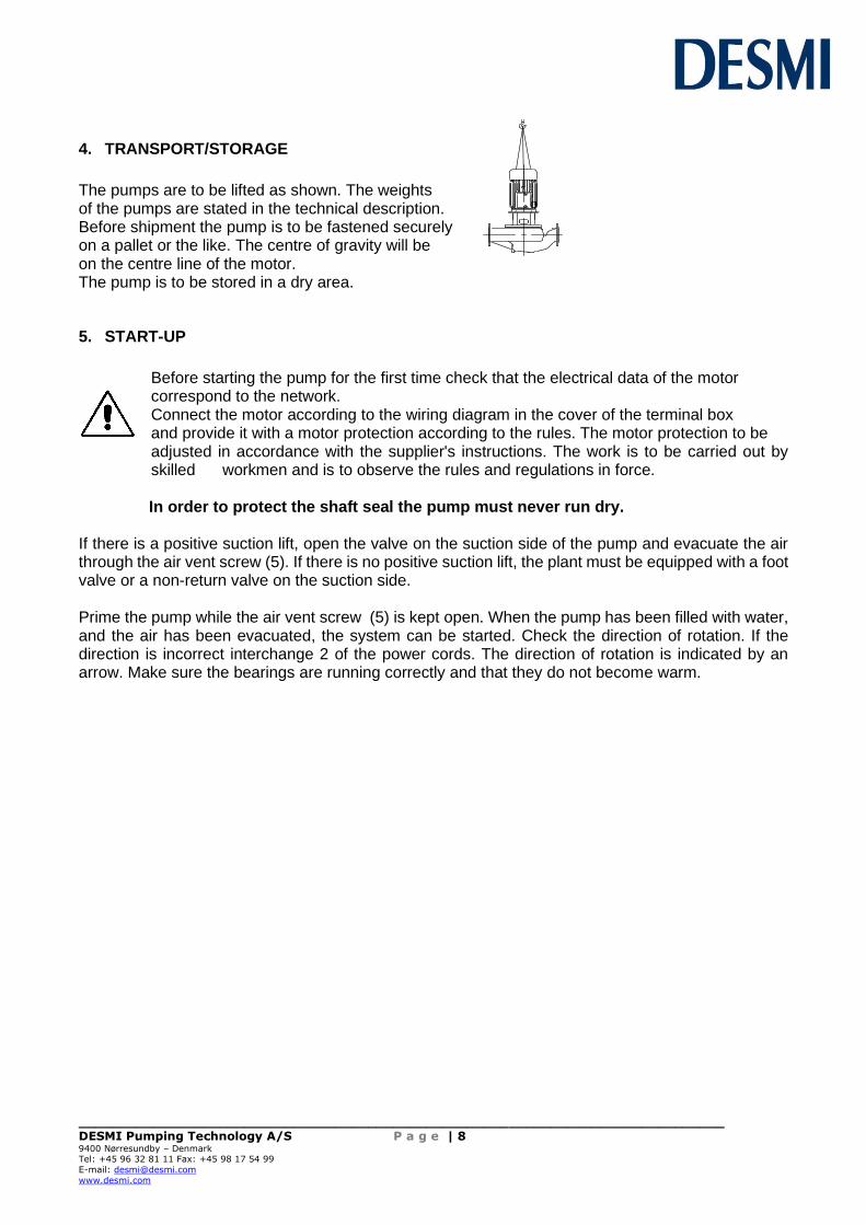
4. TRANSPORT/STORAGE
The pumps are to be lifted as shown. The weights of the pumps are stated in the technical description. Before shipment the pump is to be fastened securely on a pallet or the like. The centre of gravity will be on the centre line of the motor. The pump is to be stored in a dry area.
5. START-UP
Before starting the pump for the first time check that the electrical data of the motor correspond to the network. Connect the motor according to the wiring diagram in the cover of the terminal box and provide it with a motor protection according to the rules. The motor protection to be adjusted in accordance with the supplier's instructions. The work is to be carried out by skilled workmen and is to observe the rules and regulations in force.
In order to protect the shaft seal the pump must never run dry.
If there is a positive suction lift, open the valve on the suction side of the pump and evacuate the air through the air vent screw (5). If there is no positive suction lift, the plant must be equipped with a foot valve or a non-return valve on the suction side. Prime the pump while the air vent screw (5) is kept open. When the pump has been filled with water, and the air has been evacuated, the system can be started. Check the direction of rotation. If the direction is incorrect interchange 2 of the power cords. The direction of rotation is indicated by an arrow. Make sure the bearings are running correctly and that they do not become warm.

______________________________________________________________________________ DESMI Pumping Technology A/S P a g e | 9 9400 Nørresundby – Denmark Tel: +45 96 32 81 11 Fax: +45 98 17 54 99
E-mail: [email protected]
www.desmi.com
6. SYSTEM BALANCING
Adapt pressure and water quantity to the requirements by regulating a valve on the pressure side of the pump - never on the suction side as this may cause cavitation. FAULT
CAUSE
REMEDY
1.Wrong direction of rotation 2. Piping system choked
Change direction of rotation to clockwise when viewed from shaft end Clean or replace
The pump has no or too low capacity
3. The pump is choked 4. Suction line leaks, pump takes air
Clean the pump Find the leakage, repair the fault, non-return valve not submerged
5. Suction lift too high
Check data sheet Q/H curve and NPSH or contact DESMI
6. Pump and piping system wrongly dimensioned
As 5
1. Counter-pressure too low
Insert orifice plate or check valve, contact DESMI
The pump uses too much power
2. The liquid is heavier than water 3. Foreign body in pump
Contact DESMI Dismantle the pump, remove the cause
4. Electric motor is running on 2 phases
Check fuses, cable connection and cable
The pump makes noise
1. Cavitation in pump
Suction lift too high/Suction line wrongly dimensioned/Liquid temperature too high
______________________________________________________________________________ DESMI Pumping Technology A/S P a g e | 10 9400 Nørresundby – Denmark Tel: +45 96 32 81 11 Fax: +45 98 17 54 99
E-mail: [email protected]
www.desmi.com
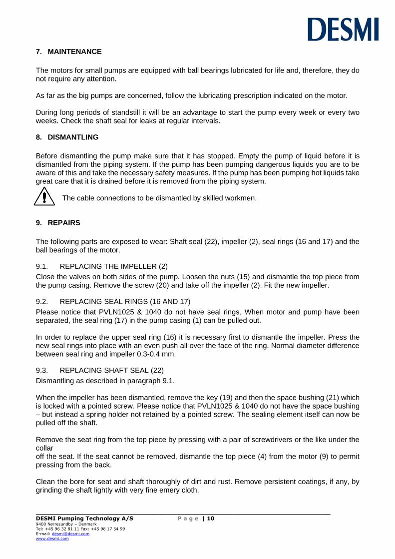
7. MAINTENANCE
The motors for small pumps are equipped with ball bearings lubricated for life and, therefore, they do not require any attention. As far as the big pumps are concerned, follow the lubricating prescription indicated on the motor. During long periods of standstill it will be an advantage to start the pump every week or every two weeks. Check the shaft seal for leaks at regular intervals.
8. DISMANTLING
Before dismantling the pump make sure that it has stopped. Empty the pump of liquid before it is dismantled from the piping system. If the pump has been pumping dangerous liquids you are to be aware of this and take the necessary safety measures. If the pump has been pumping hot liquids take great care that it is drained before it is removed from the piping system. The cable connections to be dismantled by skilled workmen.
9. REPAIRS
The following parts are exposed to wear: Shaft seal (22), impeller (2), seal rings (16 and 17) and the ball bearings of the motor.
9.1. REPLACING THE IMPELLER (2)
Close the valves on both sides of the pump. Loosen the nuts (15) and dismantle the top piece from the pump casing. Remove the screw (20) and take off the impeller (2). Fit the new impeller.
9.2. REPLACING SEAL RINGS (16 AND 17)
Please notice that PVLN1025 & 1040 do not have seal rings. When motor and pump have been separated, the seal ring (17) in the pump casing (1) can be pulled out. In order to replace the upper seal ring (16) it is necessary first to dismantle the impeller. Press the new seal rings into place with an even push all over the face of the ring. Normal diameter difference between seal ring and impeller 0.3-0.4 mm.
9.3. REPLACING SHAFT SEAL (22)
Dismantling as described in paragraph 9.1. When the impeller has been dismantled, remove the key (19) and then the space bushing (21) which is locked with a pointed screw. Please notice that PVLN1025 & 1040 do not have the space bushing – but instead a spring holder not retained by a pointed screw. The sealing element itself can now be pulled off the shaft. Remove the seat ring from the top piece by pressing with a pair of screwdrivers or the like under the collar off the seat. If the seat cannot be removed, dismantle the top piece (4) from the motor (9) to permit pressing from the back. Clean the bore for seat and shaft thoroughly of dirt and rust. Remove persistent coatings, if any, by grinding the shaft lightly with very fine emery cloth.
______________________________________________________________________________ DESMI Pumping Technology A/S P a g e | 11 9400 Nørresundby – Denmark Tel: +45 96 32 81 11 Fax: +45 98 17 54 99
E-mail: [email protected]
www.desmi.com
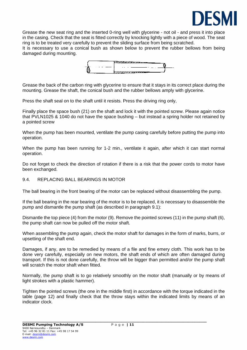
Grease the new seat ring and the inserted 0-ring well with glycerine - not oil - and press it into place in the casing. Check that the seat is fitted correctly by knocking lightly with a piece of wood. The seat ring is to be treated very carefully to prevent the sliding surface from being scratched. It is necessary to use a conical bush as shown below to prevent the rubber bellows from being damaged during mounting.
Grease the back of the carbon ring with glycerine to ensure that it stays in its correct place during the mounting. Grease the shaft, the conical bush and the rubber bellows amply with glycerine. Press the shaft seal on to the shaft until it resists. Press the driving ring only, Finally place the space bush (21) on the shaft and lock it with the pointed screw. Please again notice that PVLN1025 & 1040 do not have the space bushing – but instead a spring holder not retained by a pointed screw When the pump has been mounted, ventilate the pump casing carefully before putting the pump into operation. When the pump has been running for 1-2 min., ventilate it again, after which it can start normal operation. Do not forget to check the direction of rotation if there is a risk that the power cords to motor have been exchanged.
9.4. REPLACING BALL BEARINGS IN MOTOR
The ball bearing in the front bearing of the motor can be replaced without disassembling the pump. If the ball bearing in the rear bearing of the motor is to be replaced, it is necessary to disassemble the pump and dismantle the pump shaft (as described in paragraph 9.1): Dismantle the top piece (4) from the motor (9). Remove the pointed screws (11) in the pump shaft (6), the pump shaft can now be pulled off the motor shaft. When assembling the pump again, check the motor shaft for damages in the form of marks, burrs, or upsetting of the shaft end. Damages, if any, are to be remedied by means of a file and fine emery cloth. This work has to be done very carefully, especially on new motors, the shaft ends of which are often damaged during transport. If this is not done carefully, the throw will be bigger than permitted and/or the pump shaft will scratch the motor shaft when fitted. Normally, the pump shaft is to go relatively smoothly on the motor shaft (manually or by means of light strokes with a plastic hammer). Tighten the pointed screws (the one in the middle first) in accordance with the torque indicated in the table (page 12) and finally check that the throw stays within the indicated limits by means of an indicator clock.

______________________________________________________________________________ DESMI Pumping Technology A/S P a g e | 12 9400 Nørresundby – Denmark Tel: +45 96 32 81 11 Fax: +45 98 17 54 99
E-mail: [email protected]
www.desmi.com
10. TESTING
After each repair check that the motor rotates easily before connecting the current. Also remember to check the direction of rotation and to ventilate the pump.
Pump Type
Puller
M: Tightening
Torque
Max.
Throw
PVLN1025.61/62 PVLN1025.41/42 PVLN1025.21/22/23
4 Nm 4 Nm 6 Nm
60 µm 60 µm 60 µm
PVLN1040.61/62/63 PVLN1040.42/43 PVLN1040.41 PVLN1040.21/22/23
4 Nm 4 Nm 6 Nm 6 Nm
60 µm 60 µm 60 µm 60 µm
PVLN1050.61/81 PVLN1050.41/42/43 PVLN1050.27/28 PVLN1050.22/23 PVLN1050.21
SK 336 SK 336 SK 337 SK 337 SK 338
6 Nm 6 Nm
18 Nm 18 Nm 30 Nm
60 µm 60 µm 60 µm 60 µm 70 µm
PVLN1065.61 PVLN1065.41/42
SK 336 SK 336
6 Nm 6 Nm
60 µm 60 µm
PVLN2065.41/42 PVLN2065.23 PVLN2065.21/22
SK 337 SK 338 SK 338
18 Nm 30 Nm 60 Nm
70 µm 70 µm 70 µm
PVLN0080.43/61 PVLN0080.42 PVLN0080.23/41 PVLN0080.21/22
SK 336 SK 336 SK 337 SK 338
6 Nm
18 Nm 18 Nm 30 Nm
60 µm 60 µm 60 µm 70 µm
______________________________________________________________________________ DESMI Pumping Technology A/S P a g e | 13 9400 Nørresundby – Denmark Tel: +45 96 32 81 11 Fax: +45 98 17 54 99
E-mail: [email protected]
www.desmi.com
Pump Type
Puller
M: Tightening
Torque
Max.
Throw
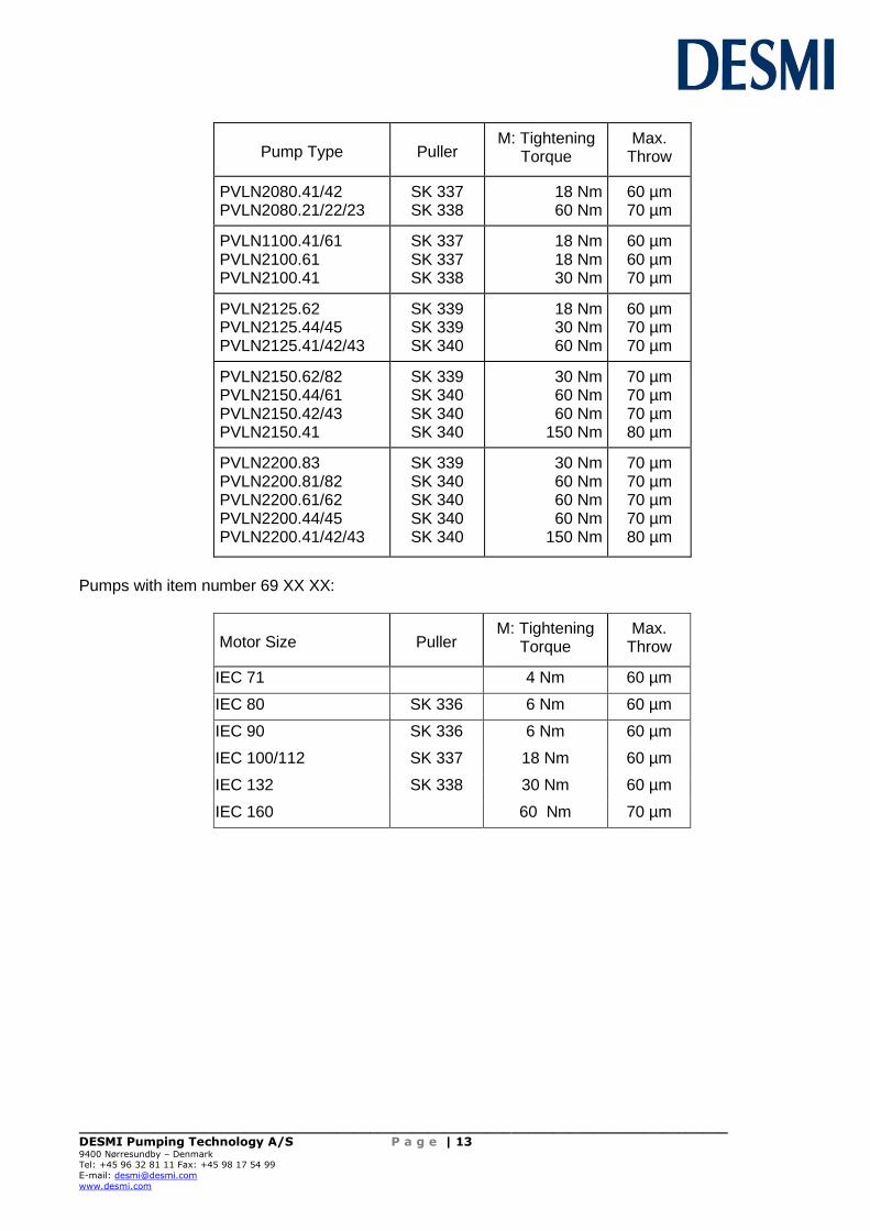
PVLN2080.41/42 PVLN2080.21/22/23
SK 337 SK 338
18 Nm 60 Nm
60 µm 70 µm
PVLN1100.41/61 PVLN2100.61 PVLN2100.41
SK 337 SK 337 SK 338
18 Nm 18 Nm 30 Nm
60 µm 60 µm 70 µm
PVLN2125.62 PVLN2125.44/45 PVLN2125.41/42/43
SK 339 SK 339 SK 340
18 Nm 30 Nm 60 Nm
60 µm 70 µm 70 µm
PVLN2150.62/82 PVLN2150.44/61 PVLN2150.42/43 PVLN2150.41
SK 339 SK 340 SK 340 SK 340
30 Nm 60 Nm 60 Nm
150 Nm
70 µm 70 µm 70 µm 80 µm
PVLN2200.83 PVLN2200.81/82 PVLN2200.61/62 PVLN2200.44/45 PVLN2200.41/42/43
SK 339 SK 340 SK 340 SK 340 SK 340
30 Nm 60 Nm 60 Nm 60 Nm
150 Nm
70 µm 70 µm 70 µm 70 µm 80 µm
Pumps with item number 69 XX XX:
Motor Size
Puller
M: Tightening
Torque
Max.
Throw
IEC 71 4 Nm 60 µm
IEC 80 SK 336 6 Nm 60 µm
IEC 90 SK 336 6 Nm 60 µm
IEC 100/112 SK 337 18 Nm 60 µm
IEC 132 SK 338 30 Nm 60 µm
IEC 160 60 Nm 70 µm

______________________________________________________________________________ DESMI Pumping Technology A/S P a g e | 14 9400 Nørresundby – Denmark Tel: +45 96 32 81 11 Fax: +45 98 17 54 99
E-mail: [email protected]
www.desmi.com
11. EU DECLARATION OF CONFORMITY
DESMI PUMPING TECHNOLOGY A/S, hereby declare that our pumps of the type PVLN, PVLB, PVLS and PVLJ are manufactured in conformity with the following essential safety and health requirements in the COUNCIL DIRECTIVE 2006/42/EC on machines, Annex 1. The following harmonized standards have been used:
EN/ISO 13857:2008 Safety of machinery. Safety distances to prevent danger zones being reached by the upper limbs
EN 809:1998 + A1:2009 Pumps and pump units for liquids – Common safety requirements
EN12162:2001+A1:2009 Liquid pumps – Safety requirements – Procedure for hydrostatic testing
EN 60204-1:2006/A1:2009 Safety of machinery – Electrical equipment of machines (item 4, General requirements)
Pumps delivered by us connected with prime movers are CE-marked and comply with the above requirements. Pumps delivered by us without prime movers (as partly completed machinery) must only be used when the prime mover and the connection between prime mover and pump comply with the above requirements. Nørresundby, March 05 2019
Henrik Mørkholt Sørensen Managing Director DESMI Pumping Technology A/S Tagholm 1 9400 Nørresundby

______________________________________________________________________________ DESMI Pumping Technology A/S P a g e | 15 9400 Nørresundby – Denmark Tel: +45 96 32 81 11 Fax: +45 98 17 54 99
E-mail: [email protected]
www.desmi.com
12. INFORMATION RELEVANT FOR DISASSEMBLY OR DISPOSAL AT END-OF-LIFE
No damage materials are used in DESMI pumps – please refer to DESMI Green Passport (can be sent on request – contact a DESMI sales office) – i.e. common recycling companies can handle the disposal at end-of-life. Alternatively the pump and motor can be returned to DESMI at end-of-life for safe recycling.
13. POSITION NUMBERS – PUMP (see next pages for PVLN1025 & 1040)
POS. BENÆ VNELSE DESIGNATION BEZEICHNUNG
1 Pumpehus Pump casing Pumpengehäuse
2 Løbehjul Impeller Laufrad
3 Pakning Gasket Dichtung
4 Overdel Top piece Zwischengehäuse
5 Udluftningsventil Air vent screw Imbusschraube
6 Aksel Pump shaft Pumpenwelle
7 Akselbøsning Shaft bush Wellenbuchse
8 Aftræ kkerflange Dismantling flange Abziehflansch
9 Motor Motor Motor
10* Skrue Screw Schraube
11 Pinolskrue med krater Pointed screw Gewindestift
14 Pindbolt Stud Spannschraube
15 Møtrik Nut Mutter
16 Slutring, trykside Seal ring, pressure Spaltring druckseitig
17 Slutring, sugeside Seal ring, suction Spaltring saugseitig
18 Aftapningsskrue Drain screw Verschlußschraube
19 Pasfeder Key Passfeder
20 Skrue Screw Schraube
21 Afstandsbøsning Space bushing Abstandsbuchse
22 Mekanisk akseltæ tning Mech. shaft seal Gleitringdichtung
23 Spændeskive Washer plate Federscheibe
* Screw or stud + nut. Pos. No. refers to drawing. When ordering spare parts please state pump number, type number as well as position numbers and designation.

______________________________________________________________________________ DESMI Pumping Technology A/S P a g e | 16 9400 Nørresundby – Denmark Tel: +45 96 32 81 11 Fax: +45 98 17 54 99
E-mail: [email protected]
www.desmi.com
14. Assembly Drawing-Pump (see next pages for PVLN1025 & 1040)
______________________________________________________________________________ DESMI Pumping Technology A/S P a g e | 17 9400 Nørresundby – Denmark Tel: +45 96 32 81 11 Fax: +45 98 17 54 99
E-mail: [email protected]
www.desmi.com
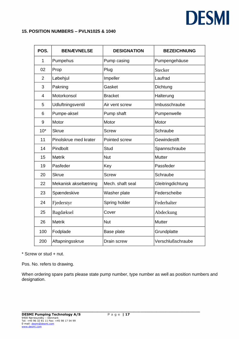
15. POSITION NUMBERS – PVLN1025 & 1040
POS. BENÆ VNELSE DESIGNATION BEZEICHNUNG
1 Pumpehus Pump casing Pumpengehäuse
02 Prop Plug Stecker
2 Løbehjul Impeller Laufrad
3 Pakning Gasket Dichtung
4 Motorkonsol Bracket Halterung
5 Udluftningsventil Air vent screw Imbusschraube
6 Pumpe-aksel Pump shaft Pumpenwelle
9 Motor Motor Motor
10* Skrue Screw Schraube
11 Pinolskrue med krater Pointed screw Gewindestift
14 Pindbolt Stud Spannschraube
15 Møtrik Nut Mutter
19 Pasfeder Key Passfeder
20 Skrue Screw Schraube
22 Mekanisk akseltæ tning Mech. shaft seal Gleitringdichtung
23 Spændeskive Washer plate Federscheibe
24 Fjederstyr
Spring holder Federhalter
25 Bagdæksel
Cover Abdeckung
26 Møtrik Nut Mutter
100 Fodplade Base plate Grundplatte
200 Aftapningsskrue Drain screw Verschlußschraube
* Screw or stud + nut. Pos. No. refers to drawing. When ordering spare parts please state pump number, type number as well as position numbers and designation.

______________________________________________________________________________ DESMI Pumping Technology A/S P a g e | 18 9400 Nørresundby – Denmark Tel: +45 96 32 81 11 Fax: +45 98 17 54 99
E-mail: [email protected]
www.desmi.com
16. Assembly Drawing – PVLN1025 & 1040
Pos. 26 for EL-motor but not B14 flange