Designing Object Oriented Software Applications within the ...
99
Designing Object Oriented Software Applications within the Context of Software Frameworks THESIS Presented in Partial Fulfillment of the Requirements for the Degree Master of Science in the Graduate School of the Ohio State University By Zoya Ali Graduate Program in Computer Science and Engineering The Ohio State University 2011 Master's Examination Committee: Rajiv Ramnath, Advisor Jay Ramanathan
-
Upload
khangminh22 -
Category
Documents
-
view
3 -
download
0
Transcript of Designing Object Oriented Software Applications within the ...

Designing Object Oriented Software Applications within the Context of Software
Frameworks
THESIS
Presented in Partial Fulfillment of the Requirements for the Degree Master of Science in
the Graduate School of the Ohio State University
By
Zoya Ali
Graduate Program in Computer Science and Engineering
The Ohio State University
2011
Master's Examination Committee:
Rajiv Ramnath, Advisor
Jay Ramanathan

Copyright by
Zoya Ali
2011

ii
Abstract
Object-oriented software design and programming is an essential part of a
computer science curriculum. The idea behind object-oriented design is that because
programs are intended to solve problems in the real world, basing software components
on real world entities will make the analysis and design of software easier. In the
existing Computer Science (CS) curricula that we have examined, we have found that
object-oriented concepts are taught with the intent of towards developing software
directly using an object-oriented language – such as C++, Java, or C#. However, most
software of any consequence is rarely developed directly using a programming language.
Most current commercial software is developed using software frameworks, by extending
and customizing the default, generic, functionality that frameworks provide. As a
consequence, we have observed that novice software developers (such as fresh college
graduates) who have been taught object-oriented design, are able to apply good design
principles in theory, but rarely in professional practice, in which they are asked to design
software intended to run inside a software framework, such as .NET, J2EE, or the
Android SDK. In fact, we observe that even software developers, who are not novices,
often abandon good design practices when developing software while using a framework,
and tend to focus their entire energy on simply “making it work”.
In this thesis we attempt to address the above problems. We provide a
methodology to teach object-oriented design and implementation for frameworks. We

iii
have developed and illustrated this approach using examples drawn from real projects.
We show how design patterns can serve as the bridge between the paradigms imposed by
the framework and the ideal, unconstrained design of the system. We show through
evaluation that the students have positive attitudes towards this methodology, and that
designs that have been done by students using this methodology are better than those
done without using the methodology. We also illustrate that the students begin to get
useful insights about the framework itself.

iv
Dedication
To my family and friends

v
Acknowledgment
I would like to thank Dr. Rajiv Ramnath for the direction and support he provided
throughout. He convinced me to pursue a thesis and provided the motivation I needed.
He provided me with the technical support and background knowledge for my research. I
would also like to thank Dr. Jay Ramanathan for all her insights and help she gave for
completion of this thesis. Also would like to thank my friends for their support and help.

vi
Vita
March 2005 ....................................................Seth M.R. Jaipuria School, Lucknow
June 2009 .......................................................B.Tech Computer Science and Engineering,
Uttar Pradesh Technical University
September 2009 to present ............................Graduate Teaching/Research Associate,
Department of Computer Science and
Engineering, The Ohio State University
Fields of Study
Major Field: Computer Science and Engineering

vii
Table of Contents
Abstract ............................................................................................................................... ii
Dedication .......................................................................................................................... iv
Acknowledgments............................................................................................................... v
Vita ..................................................................................................................................... vi
Table of Contents .............................................................................................................. vii
List of Tables ...................................................................................................................... x
List of Figures ................................................................................................................... xii
Chapter 1: Introduction ...................................................................................................... 1
Thesis contributions: ....................................................................................................... 5
Outline of Thesis ............................................................................................................. 5
Chapter 2: Related Work .................................................................................................... 6
2.1 Object Oriented Design ........................................................................................ 6
2.2 Responsibility Driven Design .............................................................................. 7
2.3 Design Patterns ..................................................................................................... 8
2.4 Software Frameworks ........................................................................................ 12

viii
2.5 Problems Related to Design Patterns and Frameworks ..................................... 13
Chapter 3: Methodology ................................................................................................... 16
3.1 Introduction ........................................................................................................ 16
3.2 Problem Statement ............................................................................................. 16
3.3 Solution Approach.............................................................................................. 16
3.4 Best Practices ..................................................................................................... 17
3.5 Steps in the Methodology ................................................................................... 21
3.6 Conclusion .......................................................................................................... 50
Chapter 4: Case Studies .................................................................................................... 52
4.1 Case Studies ....................................................................................................... 52
4.2 Tic Tac Toe Application .................................................................................... 52
4.2.1 Applying Methodology ............................................................................... 53
4.3 Asset Management System ................................................................................ 62
4.3.1 Applying Methodology ............................................................................... 63
4.4 Methodology Analysis ....................................................................................... 75
Chapter 5: Access Control by Enhancing the Expressivity of OWL ................................ 76
5.1 Thesis Statement ................................................................................................ 76
5.2 Thesis Validation................................................................................................ 76
Chapter 6: Conclusion and Future Work .......................................................................... 79

ix
6.1 Conclusion .......................................................................................................... 79
6.2 Future Work ....................................................................................................... 80
References ......................................................................................................................... 81

x
List of Tables
Table 1: Creational Patterns .................................................................................................9
Table 2: Structural Patterns ................................................................................................10
Table 3: Behavioral Patterns ..............................................................................................11
Table 4: Metrics for Application Design ...........................................................................19
Table 5: Quality Attributes ................................................................................................20
Table 6: Layouts in Android Framework...........................................................................34
Table 7: Issues related to Model Component ....................................................................48
Table 8: Problems in initial steps .......................................................................................54
Table 9: Metric evaluation on scale of 0-1 ........................................................................55
Table 10: Nouns and Verbs in Designer‟s Story ...............................................................56
Table 11: Refined list of nouns and verbs .........................................................................56
Table 12: MVC components in the design of the Tic Tac Toe application .......................59
Table 13: Public methods for Activity class ......................................................................60
Table 14: Improved Metrics after Methodology ................................................................62
Table 15: Problems in initial design in Asset management application ............................64
Table 16: Metric evaluation on scale of 0-1 ......................................................................64
Table 17: Nouns and verbs from Designer‟s story ............................................................65
Table 18: Refined list of nouns and verbs .........................................................................66
Table 19: MVC components in the design of the asset management application .............68

xi
Table 20: Issues in View component of application ..........................................................73
Table 21: Metric Evaluation of Final design .....................................................................73

xii
List of Figures
Figure 1: Quality Attribute-Design Properties Relationship ............................................ 21
Figure 2: CRC card ........................................................................................................... 23
Figure 3: CRC card for Furniture class ............................................................................. 23
Figure 4: CRC card for InviteGuests Class...................... Error! Bookmark not defined.3
Figure 5: CRC card for Payment Class .............................. Error! Bookmark not defined.
Figure 6: CRC card for Food Class.................................... Error! Bookmark not defined.
Figure 7: Model-View-Controller Design Pattern ............. Error! Bookmark not defined.
Figure 8: Android Framework .......................................................................................... 28
Figure 9: Factory Method Design Pattern Structure ......................................................... 29
Figure 10: Factory Method Design Pattern as observed in Android Framework ............. 29
Figure 11: Composite Design Pattern Structure ................ Error! Bookmark not defined.
Figure 12: Arrangement of View and ViewGroups in Android ...... Error! Bookmark not
defined.
Figure 13: Observer Design pattern Structure ................... Error! Bookmark not defined.
Figure 14: Model-View-Controller in J2EE Framework .................................................. 39
Figure 15: Web-Tier Controller ....................................... Error! Bookmark not defined.3
Figure 16: A Template sample view .................................. Error! Bookmark not defined.
Figure 17: UML diagram of initial design of Tic Tac Toe Application . Error! Bookmark
not defined.
Figure 18: CRC card for the Game Class ......................................................................... 57
Figure 19: CRC card for GameView Class....................................................................... 57

xiii
Figure 20: CRC card for GameGrid Class ........................................................................ 58
Figure 21: CRC card for GameSession Class ................................................................... 58
Figure 22: UML diagram for initial design....................................................................... 63
Figure 23: CRC card for the TrackAsset class.................................................................. 66
Figure 24: CRC card for the User class ............................................................................ 67
Figure 25: CRC card for the WebInterface class .............................................................. 67
Figure 26: CRC card for the Person class ......................................................................... 67
Figure 27: CRC card for the Administrator class ............................................................. 68
Figure 28: Model-View-Controller Architecture for Asset management system ............. 72
Figure 29: Final design after mapping into the framework using MVC design pattern ... 75

1
Chapter 1: Introduction
Object-oriented concepts have existed for over three decades now [1]. It is an
essential part of computer programming [1]. It has provided great support in
understanding the construct of application design [1] [2]. Object-orientation provides a
basis for designing applications intended to solve problems in the real world. Essentially,
basing software components on real world objects makes software easier to analyze and
design. Further, since the components have been modeled around the real world, they are
not only more likely to be stable but also they are more capable of capturing the evolving
nature of the application components [3]. However, these principles are useful for small
programs written by individuals, but when it comes to applying object-oriented design
techniques in industry-scale projects on domain-specific frameworks (for example an
Enterprise Java application or a mobile application built using the Android framework),
we find that typical OO designs are not directly usable [1] We observe that even software
developers who are not novices, often abandon good design practices when developing
software while using a framework.
The thesis addresses the question: how may an application be designed using
object-oriented principles and techniques when in a framework based (development)
environment?

2
Major problems associated with poor design are [1]:
1. Performance can sometimes degrade when common code is used. This
sometimes occurs when a framework must check for the various scenarios in
which it is used to determine a path of action. It can also occur with generalized
code that is not optimized for a specific situation. Performance degradation,
though, is often offset by the enhanced speed of development and quality of the
final application.
2. Frameworks often require significant education on the part of he developer to be
used efficiently and correctly (i.e. there is a steep learning curve). Therefore
specific frameworks become more valuable to individual programmers when they
are used repeatedly. With each new project using the same framework, the
learning curve becomes less of an issue and productivity increases.
3. Functionality which needs to bypass or work around deficiencies in a framework
can be the cause of severe programming issues. In fact, the effort needed to
implement exceptional functionality in a framework may exceed the cost of
developing the complete application without using the framework in the first
place! Good frameworks provide utility and structure while still leaving enough
flexibility to not get in the way of the programmer. Some frameworks are so rigid
and highly structured that choosing them for an inappropriate project can be
disastrous. This is not the fault of the framework per se; however, some are more
generally suited and flexible than others. This aspect must be carefully considered
while choosing a framework.

3
4. Bugs and security issues in a framework can affect every application using that
framework. Therefore the framework must itself be tested and patched
appropriately in addition to the final software application.
In addition to having to deal with the above, we believe that there is a compelling
need for a middle layer to bridge the gap between the specific application design and the
general features provided by the frameworks. We advocate that design patterns serve as a
means to understand, design and adapt object-oriented designs onto a software
framework.
The methodology we describe in the thesis helps in overcoming the problems
faced by developers when adapting an application design onto the software framework.
In this methodology, we start application design using standard object oriented principles.
In this step we identify key objects in the application with the help of responsibility
driven design principles. We then analyze the identified responsibilities and
collaborations between classes to identify patterns in them. Our next step is to
understand the framework by identifying the design patterns in them and use it to map the
patterns identified in application design.
In general, there are seven types of software frameworks in the information
systems space, as follows [4]:
• Conceptual Frameworks – that specify an overarching architectural model such
as the Zachman Framework;

4
• Application Framework – a skeletal structure for an application solution (such as
WebWork);
• Domain Framework – tailored to specific business sectors, such as IBM
Information Framework (IFW);
• Platform Framework – consisting of a general-purpose programming model and
runtime environment such as .NET and Java EE framework;
• Component Framework – that contain building blocks for an application (such
as Hibernate, iBatis and Cayenne for object-relational mapping);
• Service Framework – consisting of business and technical services model for
service-oriented computing (such as Semantic Web Services Framework);
• Development Framework – a construction foundation to build a rich-client
development tool, typically for IDEs, such as Eclipse, NetBeans, and OSGi.
In this thesis, we examine two kinds of frameworks – the Android Framework
(which is a component based framework) and the Enterprise Java framework - which is a
Platform framework.
Industry projects use these software frameworks for building applications.
Frameworks provide structures intended to be reusable across applications, and therefore
they have a more abstract and general nature than ordinary software [5]. As a
consequence of this generality, their design is more complex, and the construction
process and documentation task of frameworks are more complicated and demanding

5
than for ordinary software development without using a framework. Despite the major
advantages of using a framework in terms of rapid development, it is important to
understand the architecture of framework in order to make proper use of it. We depend on
design patterns to understand the framework and its features. This is useful because not
only does the developer get deeper insight into a particular framework but he or she also
develops a skill to understand the generality and abstraction found in the framework.
Understanding one framework also results in understanding of new frameworks.
The thesis makes the following contributions:
1. It identifies common problems in developing framework-based applications
2. It defines a design-pattern based methodology for understanding frameworks
3. It describes a methodology for mapping an object-oriented application design
onto a framework through identification of object roles and responsibilities within
the application and adapting it to the framework using design patterns
Outline of Thesis
The rest of this thesis is organized as follows. Chapter two provides a brief
discussion of related work. Chapter three explains the various steps of the methodology
and uses case studies to explain them better. Finally, chapter four provides concluding
thoughts and a look at possible future work.

6
Chapter 2: Related Work
The methodology proposed in this thesis uses concepts and best practices, such as
object oriented design and responsibility driven design, during the initial phases to create
an initial application design. It uses design patterns to identify the main functionality of
classes based on their roles and responsibilities. This identification helps in understanding
the mapping of classes in application design onto the framework defined classes and
libraries. The following sections describe these principles and their use in the
methodology.
2.1 OBJECT ORIENTED DESIGN
An object-oriented program (OOP) is viewed as a collection of interacting
objects, as opposed to the conventional model in which a program is seen as a list of tasks
(subroutines) to perform. In OOP, each object is capable of receiving messages,
processing data, and sending messages to other objects. Each object can be viewed as an
independent "machine" with a distinct role or responsibility. The actions or methods on
these objects are closely associated with the object [6] [7].
Objects as a formal concept in programming were introduced in the 1960s in
Simula 67, a major revision of Simula I, a programming language designed for discrete

7
event simulation, created by Ole-Johan Dahl and Kristen Nygaard of the Norwegian
Computing Center in Oslo [8].
Object-oriented programming became the dominant programming methodology
in the early and mid 1990s when programming languages supporting OO techniques
became widely available. These included C++, Delphi, etc. Its acceptance was further
accelerated by the rising popularity of graphical user interfaces, which rely heavily upon
object-oriented programming techniques [9]. An example of a closely related dynamic
Graphical User Interface (GUI) library and an OOP language can be found in the Cocoa
frameworks on Mac OS X, which is written in Objective-C, an object-oriented, dynamic
messaging extension to C based on Smalltalk. OOP toolkits also enhanced the popularity
of event-driven programming (although this concept is not limited to OOP) [10].
2.2 RESPONSIBILITY DRIVEN DESIGN
Responsibility driven design describe how different objects within the application
collaborate with each other to fulfill the larger goals of the application. Responsibility
driven design aims to provide a concrete way to create a community of objects by
assigning specific responsibilities to each, so that the result is collaborative model of the
application [11]. [11] Also describes various tools and techniques to help understand an
application‟s responsibilities with respect to objects and coordinating their performance.
These tools include: „Designer‟s stories‟, Object-role stereotypes, Class-Responsibility-
Collaborator (CRC) cards, Control Center Design, Trust Regions etc.

8
The methodology uses these tools to define roles played by classes in the
application. Designer‟s stories and CRC cards help in identifying the collaboration
between different classes (which helps in identifying design patterns in the later steps of
our methodology). Designer‟s Stories and CRC cards are explained in more detail in
Chapter 3.
2.3 DESIGN PATTERNS
The methodology uses object-oriented design patterns and enterprise design
patterns in order to understand application and framework design.
Design patterns provide a way to identify solutions to commonly occurring
problems. Christopher Alexander described a design pattern as follows: "A pattern
describes a problem which occurs over and over again in our environment, and then
describes the core of the solution to that problem, in such a way that you can use this
solution a million times over, without ever doing it the same way twice" [12].
[13] Describes 23 patterns, which are divided into three categories - creational
patterns, structural patterns and behavioral patterns.
1. Creational patterns: These patterns have to do with class instantiation. They can be
further divided into class-creation patterns and object-creational patterns. While class-
creation patterns use inheritance effectively in the instantiation process, object-creation
patterns use delegation to get the job done. The Table 1 below describes a few of these
patterns.

9
Pattern Description
Abstract Factory Offers the interface for creating a family of related objects, without
explicitly specifying their classes.
Builder Defines an instance for creating an object but letting subclasses
decide which class to instantiate and Allows a finer control over the
construction process.
Factory Method Defines an interface for creating objects, but let subclasses to decide
which class to instantiate and Refers to the newly created object
through a common interface.
Prototype Specify the kinds of objects to create using a prototypical instance,
and create new objects by copying this prototype
Singleton Ensure that only one instance of a class is created and Provide a
global access point to the object.
Pattern Description
Table 1: Creational Patterns
2. Structural Patterns: These concern class and object composition. They use inheritance
to compose interfaces and define ways to compose objects to obtain new functionality.
The Table 2 describes a few of these patterns.

10
Pattern Description
Adapter Convert the interface of a class into another interface clients expect. / Adapter
lets classes work together, that could not otherwise because of incompatible
interfaces.
Bridge Decouples an abstraction from its implementation so that the two can vary
independently.
Composite Compose objects into tree structures to represent part-whole hierarchies. /
Composite lets clients treat individual objects and compositions of objects
uniformly.
Decorator Add additional responsibilities dynamically to an object.
Façade Provides a simplified interface to a large body of code.
Flyweight Use sharing to support a large number of objects that have part of their
internal state in common where the other part of state can vary.
Proxy Provides a placeholder for another object to control access, reduce cost, and
reduce complexity
Table 2: Structural Patterns
3. Behavioral Patterns: They are concerned with communication between objects. The
table 3 below describes a few of these patterns.

11
Pattern Description
Chain of
Responsibility
Delegates commands to a chain of processing objects.
Command Creates objects which encapsulate actions and parameters.
Interpreter Given a language, define a representation for its grammar along
with an interpreter that uses the representation to interpret
sentences in the language.
Iterator Accesses the elements of an object sequentially without exposing
its underlying representation.
Mediator Allows loose coupling between classes by being the only class
that has detailed knowledge of their methods.
Memento provides the ability to restore an object to its previous state
(undo)
Observer Define a one-to-many dependency between objects so that when
one object changes state, all its dependents are notified and
updated automatically.
State Allows an object to alter its behavior when its internal state
changes
Table 3: Behavioral Patterns
Martin Fowler [14] described patterns in enterprise applications. These patterns
help in understanding the application design in the frameworks like Enterprise Java.

12
These applications are data intensive and used for commercial or business purposes.
Martin Fowler has defined patterns to provide a mechanism to handle data intensive
transactions in enterprise applications. Some of the important patterns are:
1. Domain logic patterns: organizes domain logic into components that encapsulate
calculations, validations, and other logic that drives the central functionality of the
application. It includes patterns- Transaction Script, Domain Model and Table
module
2. Web Presentation patterns: organizes the view for the application. It includes
patterns-Model View Controller, Front Controller, Template View, Transform View
and Application Controller.
3. Distribution patterns: helps in handling remote objects distributed across different
processors. It includes patterns- Remote Façade and Data Transfer object.
4. Session state patterns: helps in managing various session states in the application. It
includes patterns- Client session state, server session state and database session state.
2.4 SOFTWARE FRAMEWORKS
The methodology described illustrates the importance of understanding the
framework being used for the application development (in step 4 of the methodology).
The methodology describes the use of design patterns to understand patterns within a
framework. It helps to have basic understanding of frameworks, in order to identify the
different patterns in its design.
13
A software framework provides a generic functionality which the user can modify
based on his application design to develop application specific software. [15].
Frameworks typically provide an application programming interface (API) to develop the
application.
Frameworks characteristics:
1. Inversion of control: The overall flow of control of the application is determined by the
framework.
2. Default behavior: In the absence of developer-written functionality, a framework has a
default behavior.
3. Extensibility: A framework can be extended by the user usually by selectively
overriding or specializing by user code to provide specific functionality.
4. Non-modifiable framework code – the API provided by cannot be modified. The user
must extend it in order to use it.
Applications that use frameworks must conform to the frameworks‟ design and
model of collaboration. [16][17].
2.5 PROBLEMS RELATED TO DESIGN PATTERNS AND FRAMEWORKS
In [18] the authors describe how they have used a course on design patterns to
serve as a bridge to fill the gap in understanding between two areas of computer science
curricula, that is, programming and software engineering. According to the authors,
students learning programming start with learning single object-oriented language and
then deepen their knowledge in other languages, algorithms and data structures. On the

14
other hand software engineering starts with discussing processes and addresses topics like
requirements engineering, software design and software architectures. Design patterns are
on the border of these two areas and can be approached from both sides: either as an
advanced programming course or as an application of software design and micro
architectures. The authors suggest introducing design patterns into an application
gradually by extending the application‟s capabilities with each assignment. It helps in
knowledge consolidation on the practical use of the design patterns as well as broader
understanding of integration of design patterns into larger systems.
The methodology described in the thesis also aims to use design patterns in class
projects as in [18] but it is different in that it also provide initial steps, that is using object
oriented design and responsibility driven design, which lead to the use of design patterns
more easily - as it helps in identifying patterns through object roles and collaborations.
In [19] the authors describe their experiences and problems encountered with the
use of object-oriented frameworks. These problems exist in frameworks because they
have to cover all the concepts in a domain whereas a single application is only concerned
with the concepts mentioned in application requirements. These problems include:
1. Domain analysis: when developing an application for a particular domain (which
includes application requirements and domain concepts to be incorporated), it is
important to determine the right size of the domain, that is how much information and
resources are required for the application implementation. A large size domain would
require considerable expertise in the team. However, a small initial domain would not
be useful if the domain changes in the future.

15
2. Architectural design: deciding on suitable architectural style underlying the
framework based on domain analysis. Domain analysis provides enough information
regarding the resources the application will need. Hence it helps in deciding the
architecture for the application.
3. Framework design: this includes the top-level design of the application within the
framework. Results from this step provide the functionality scope of the application.
It identifies and documents problems and their solutions for future references.
4. Framework implementation: it is concerned with coding of the abstract and concrete
framework classes. It is important to understand the framework structure in order to
properly use them.
5. Framework testing: used to evaluate whether the framework provide the intended
functionality by comparing it against the application functional and non-functional
requirements.
6. Application testing: aimed at deciding whether the application provides the intended
functionality or whether it requires re-implementation of the design.
The methodology described in the thesis uses the above mentioned problems as
requirements for the last step of the methodology, to determine whether the application
design was properly mapped to the framework or not.

16
Chapter 3: Methodology
3.1 INTRODUCTION
We propose a methodology to provide users with good design practices that help
them fit their application design onto a software framework while taking full advantage
of the framework‟s capabilities.
3.2 PROBLEM STATEMENT
We observed that in design practices followed by novice application developers,
there was a lack of good design principles. The symptoms were: an unclear definition of
responsibilities, unclear methods or features, low cohesion within classes and and high
coupling between them, lack of structural simplicity, and lack of abstraction and
encapsulation. This led to poor adaptation onto the framework as well.
3.3 SOLUTION APPROACH
The methodology presents steps using which users can (a) create a good design
and (b) adapt their design to the framework. It describes ways a user can analyze poor
object oriented design using a metric described in Section 3.4. The methodology
describes the use of responsibility driven tools like Designer‟s Stories and CRC cards to

17
identify and design classes that are more cohesive. The methodology describes the use of
design patterns to find solutions to the re-occurring design problems by identifying
patterns based on the responsibilities assigned for each class. This helps in adapting the
application design into the framework more easily.
3.4 BEST PRACTICES
An application design should follow best practices for better implementation. We
describe the following design properties in Table 4 as a metric and define how quality
attributes can be used to measure these properties and influence overall design quality.
[20]
Metric Details Measure
Weighted methods
per class
Average Number of Methods per
Class reflects the degree of
responsibility attributed to a class i.e.,
it is a predictor of how much time
and effort is required to develop and
maintain the class. Used 0.02
weightage on scale of 0-1.
It is an average of the
number of methods
within the classes of the
software system for
which the metrics are
being collected
Coupling between
classes (CBO)
It is the number of classes to which a
class is coupled. High CBO is
Two classes are coupled
when methods declared

18
undesirable. High coupling indicates
fault-proneness. Only methods and
variable references are counted. Used
0.03 weightage on scale of 0-1.
in one class use methods
or instance variables
defined by the other
class.
Lack of cohesion It is a class level design metric.
Disjoint sets are a collection of sets
that do not intersect with each other.
Any two methods in one disjoint set
access at least one common local
instance variable. Used 0.02
weightage on scale of 0-1.
It measures the number
of disjoint sets of local
methods.
Structural
Complexity
Complexity is a measure of the
degree of difficulty in understanding
and comprehending the internal and
external structure of classes and their
relationships.
It is measured by
number of conditional
statements, nested loops
Abstraction Abstraction is a measure of the
generalization-specialization aspect
of the design. Classes in a design
which have one or more descendants
exhibit this property of abstraction.
It is measured by the
average number of
ancestor classes.

19
Encapsulation It hides the internal implementation
details of your class. It helps protect
class from accidently being changed
by other classes.
It can be measured be
number of interfaces
defined and used in
application.
Polymorphism Defining multiple implementation of
an action and select correct
implementation based on surrounding
context.
Measured by number of
classes overridden or
overloaded.
Inheritance Behavior of one class is inherited by
other classes. Used 0.01 weightage
on scale of 0-1.
Measured by number of
classes inherited
Table 4: Metrics for Application Design
QUALITY ATTRIBUTES
The design properties mentioned in Table 4 can be assigned quality attributes in order to
evaluate how these properties contribute to the overall application design. Extensive
review on various object oriented design books and papers [21][22][23][24] was done to
compile the following quality attributes, as shown in Table 5 and how they are used in
evaluating application design.

20
ATTRIBUTES DETAIL MEASURE
Reusability How classes within application can
be reused in other classes through
inheritance.
It is measured by degree of class
cohesiveness and coupling
Flexibility Allows the incorporation of change
in a design. The ability of a design to
be adapted to provide Functionality
related capabilities.
It measured by number of polymorphic
methods, and encapsulation
Functionality The responsibilities assigned to the
classes of design, which are made
available by the classes through their
public interfaces.
Can be measured by structural
complexity, polymorphism,
encapsulation
Extensibility It refers to the presence and usage of
properties in an existing design that
allow for the incorporation of new
requirements in the design.
Measured by degree of inheritance,
polymorphism, cohesiveness, weighted
method per class
Effectiveness The responsibilities assigned to the
classes of design, which are made
available by the classes through
public interfaces.
Measured by degree of abstraction,
encapsulation, inheritance and
polymorphism
Table 5: Quality Attributes

21
Figure 1: Quality Attribute-Design Properties Relationship
3.5 STEPS IN THE METHODOLOGY
Step 1: Identification of problems in initial design
We use above described metrics to analyze the initial design of application. This
is useful in understanding the object-oriented design better and also helps in improving
the design of application.
Step 2: Responsibility Driven Design (RDD) approach
In order to incorporate RDD in application we use two tools, designer‟s stories
and CRC cards. Designer‟s stories are problem write-ups that require a developer to write
a detailed description of the application he or she is building. This would help him to
identify and define appropriate classes and types and designing their collaborations with
respect to the application. A designer‟s story should answer the following questions:
1. What is the application suppose to do?
2. How will it support its users and user interaction?
3. How will it manage its data resources?
22
Nouns and verbs are then identified in the designers‟ story. Once all the nouns and verbs
are identified, they are refined and consolidated based on the following guidelines, in
order to get a finalized list:
1. Remove duplicates in nouns and verbs having the same meaning. For
example, the nouns in a party planner application may be chair, small
chair, table, furniture – all of which can be put in just one class named
furniture.
2. Split nouns and verbs to two if this helps in clarifying the meaning. For
example a party planner application can have the verb MakePayment
which can be split into paymentToCaterers, paymentToOrganizers.
3. Rename nouns for better understanding of their purpose. For example a
nouns such as partyAddress can be renamed to Location
4. Reject nouns and verbs outside the context of the system. For Example a
verb such as callFriends may be excluded.
The final list of nouns serves as the set of candidate classes while verbs serve as
responsibilities.
The use of CRC cards, invented by Ward Cunningham, is a technique for
informally specifying the roles and responsibilities of an object, component or subsystem.
The C stands for Candidate, which can be a component, a class, or an interface that is
shared between multiple classes of objects or components. Nouns from the previous step
form the Candidate classes. R stands for Responsibilities; verbs from previous step are

23
classified as responsibilities in this step, and are implemented as methods in class. The
second C stands for collaborators or helpers that the candidate uses to accomplish its
specific tasks. Following Figure 2 is sample outline of the CRC card.
Candidate Class
Responsibility specifying
classes
Collaborator Classes
Figure 2: CRC card
For example, in the party planner application we may have following CRC cards as
shown in following Figures 3, 4, 5 and 6
Furniture
Lists furniture
Calculate payment
Allows payment
Payment
Figure 3: CRC card for Furniture class
InviteGuests
Lists friends
Send invites
Shows contact info
Contacts
Figure 4: CRC card for InviteGuests Class

24
Payment
Calculates payment Food
Furniture
Figure 5: CRC card for Payment Class
Food
Order food items
Make payment
Get rates of item
Payment
Figure 6: CRC card for Food Class
These steps help the user clearly define the classes and understand their
responsibilities. This step is an important precursor for the next step in the methodology
as it provides a mechanism to map design patterns into the application design by
acknowledging the specific roles of the classes.
Step 3: Identification of design patterns in the application design
A design pattern is a general reusable solution to a commonly occurring problem
in software design. Thus we can use design patterns to identify these problems, which are
associated with designing systems within the context of frameworks and application
25
design. This step in the methodology would help understanding responsibilities identified
in previous steps as roles played by classes and hence help in identifying design patterns
which would satisfy the roles played by classes and help in better understating of the
application design. As described in [13] there are 23 object oriented design patterns
which can be used to identify these roles and provide implementation likewise.
For example, in an online shopping application, components include a Sale
component, which would handle sales transactions (i.e. a connection to a bank or a
financial institution). In the system other components need to track when a sale
transaction takes place. One way to do this is to use a database, which would allow other
components to see updates after a transaction takes place. However this could lead to an
unnecessary load on the database. Another way to implement the tracking of sale
transactions is to let the Sale component notify all the other components after each
transaction. However, this it is not good design either as the Sale component has the
overhead of retaining references to potentially unrelated components. The solution to the
problem is the Observer pattern. This pattern describes a publish-subscribe system, where
a consumer (or observer) becomes a subscriber to specific events posted by the subject.
The sale component can define a listener interface implemented by components
interested in getting information about a sale. Upon a sale transaction, the sale component
will iterate through the listeners and call them. Adding a new subscriber component will
not change the sale component.
Other than the design patterns described in [13] there are other patterns such as
enterprise design patterns [14] and architecture design patterns [25], such as the Model-

26
View-Controller. (MVC) pattern The MVC pattern is useful in applications designed for
interactive and dynamic user interfaces. Based on responsibilities described for each class
in the application design we can identify the classes that play the role of Model, View or
Controller as shown in Figure 6 and as described below:
Model: The model manages the behavior and data of the application domain, responds to
requests for information about its state (usually from the view), and responds to
instructions to change state (usually from the controller).
View: The view manages the display of information.
Controller: The controller interprets the mouse and keyboard inputs from the user,
informing the model and/or the view to change as appropriate.
Figure 7: Model-View-Controller Design Pattern

27
Step 4: Understanding Framework through design patterns
[26] defines a framework as a set of classes that embodies an abstract design for
solutions to a family of related problems. In other words, a framework is a partial design
and implementation for an application in a given problem domain. Our methodology
describes how to use design patterns to understand the framework. The central part of the
framework design comprises both abstract and concrete classes in the domain. The
concrete classes in the framework are intended to be invisible to the framework user (e.g.
a basic data storage class). An abstract class is either intended to be invisible or to be sub-
classed by the framework user. Identifying design pattern depends on these classes are
defined in the framework. The framework design describes the typical software
architecture for applications in the domain.
The Android Framework:
The Android framework is used for developing application for mobile devices such as a
mobile phone or tablet devices. Android consists of a mobile operating system based on
the Linux kernel, with middleware libraries and an API written in C. Application
software runs on an application framework which includes Java compatible libraries
based on Apache Harmony. Figure 8 shows the Android Operating System. Android uses
the Dalvik virtual machine with just-in-time compilation to run compiled Java code [27].
Android applications are therefore written in Java.

28
Figure 8: Android Framework
The Android Framework can be classified as a component framework – one that
provides building blocks for developing and implementing applications which run on the
Android Operating System. Key components in the Android Framework include:
Activity, Services, BroadcastReceiver, ContentProvider and Intent. An Android
application uses these components within each application.
To understand and identify different design patterns within the android framework
we use following object-oriented design patterns:
1. Factory Method
2. Composite
3. Observer

29
Factory Method: It lets class defer instantiation to subclasses. As seen in Figure 9.
Figure 9: Factory Method Design Pattern Structure
We can identify the Factory Method pattern in Android as shown in Figure 10 below:
Figure 10: Factory Method Design Pattern as observed in Android Framework

30
Following code illustrates how the Factory method is used in an Android application.
Composite Pattern: The Composite pattern allows a group of objects to be treated in the
same way as a single instance of an object. As seen in Figure 11.

31
Figure 11: Composite Design Pattern Structure
We can identify the Composite pattern in Android in the manner Views and ViewGroups
are associated, as seen in Figure 12:
Figure 12: Arrangement of View and ViewGroups in Android

32
Observer Pattern: This pattern defines a one-to-many dependency between objects so
that when one object changes state, all its dependents are notified and updated
automatically. Each observer registers with the subject. When a change occurs, the
subject notifies all the observers. Each of the observers is notified in parallel (that is, at
the same time). See Figure 13.
Figure 13: Observer Design pattern Structure
The Observer pattern in the Android Framework can be explained using the
example of a Contacts management application. The two steps of the Observer pattern
can be explained as follows:

33
1. Register Process: In this process, following two repositories are used:
a) Content Service
Class: ContactsProvider, queries the resource using
Here, c is type of AbstractCursor
This type of observer is identified by Uri of resource and maintained by content
service which is more like a event broker.
b) ArrayList
In init() method of CursorAdapter code, there is
c.registerContentObserver(mChangeObserver);
This type of observer is maintained by corresponding cursor.
2. Notify Process: Content providers are expected to notify content resolver that they
have updated the dataset.
Here c is reference to a Cursor object. If the data behind the cursor's position is updated
(Cursor.update*(), Cursor.commitUpdates()), then the given URI will be notified.
Using this approach, we register an observer on Contacts.People.CONTENT_URI, then
when the contacts was changed, we can get a notification.
Model-View-Controller:
In the Android framework the MVC design pattern can be identified as follows:

34
Views:
The Android framework provides its presentation structure through a set of views and
widgets. The View class represents the basic building block for user interface
components by providing base class for widgets, which are used to create interactive UI
components (buttons, text fields, etc.). The View-Group subclass is the base class
for layouts, see Table 6, which are invisible containers that hold other Views (or other
View-Groups) and define their layout properties.
Layout
Linear Layout
Relative Layout
Table Layout
Grid Layout
Tab Layout
List View
Table 6: Layouts in Android Framework
Views usually have an integer id associated with them. These ids are typically assigned in
the layout XML files, and are used to find specific views within the view tree.
For example, in order to define a button, you must define a Button element in the layout
file and assign it a unique ID. See code snippet below:

35
<Button
android:id="@+id/my_button"
android:layout_width="wrap_content"
android:layout_height="wrap_content"
android:text="@string/my_button_text"/>
This Button created in the layout file is accessible from classes (activity) using the code
snippet below:
Button myButton = (Button) findViewById(R.id.my_button);
Model:
In Android, models are not part of the framework. Models have to be
implemented by concrete classes using Java. The SDK provides a mechanism to modify
the model associated with the view. For example, a View may incorporate a button
identified as follows:
Button myButton = (Button) findViewById(R.id.my_button);
With the Android framework providing a method to identify when an action on the
associated View item has taken place.
myButton.setOnClickListener(this);
36
Essentially, the above code is used to make the Activity a listener of the button. The
onClick() method takes a View as a parameter, which is the component that generated the
event. The update() method will be called each time the Model changes, and the Model
will pass a reference to itself as the first parameter.
Controller:
The controller functionality in the Android Framework is delivered through the Activity
Manager that manages the lifecycle of applications and provides a common navigation
back stack. Managing the lifecycle of activities by implementing callback methods is
important for developing better application. The lifecycle of an activity is directly
affected by its association with other activities, its task and back stack [28].
An activity can exist in essentially three states:
Resumed: The activity is in the foreground of the screen and has user focus.
Paused: Another activity is in the foreground and has focus, but this one is still
visible.
Stopped: The activity is completely hidden by another activity. A stopped activity
is also still alive but can be killed by the system when memory is needed
elsewhere.
Implementing the lifecycle callbacks:
When an activity transitions into and out of the different states described above, it is
notified through various callback methods. All of the callback methods are hooks that

37
you can override to do appropriate work when the state of your activity changes. The
following skeleton activity includes each of the fundamental lifecycle methods:
public class ExampleActivity extends Activity {
@Override
public void onCreate(Bundle savedInstanceState) {
super.onCreate(savedInstanceState);
// The activity is being created.
}
@Override
protected void onStart() {
super.onStart();
// The activity is about to become visible.
}
@Override
protected void onResume() {
super.onResume();
// The activity has become visible (it is now "resumed").
}
@Override
protected void onPause() {
super.onPause();
// Another activity is taking focus (this activity is about
to be "paused").
}
@Override
protected void onStop() {
super.onStop();
// The activity is no longer visible (it is now "stopped")
}
@Override
protected void onDestroy() {
super.onDestroy();
// The activity is about to be destroyed.
}
}
As, illustrated in this section, we can use design patterns to understand the Android
framework. Using design patterns for understanding the application design followed by
using design patterns to understand the framework, would also help in using a framework
better.

38
The J2EE Framework
J2EE is a platform-independent, Java-centric environment from Oracle for
developing, building and deploying web-based enterprise applications. The J2EE
platform consists of a set of services, APIs, and protocols that provide the functionality
for developing multi-tiered, web-based applications [29]. Enterprise applications provide
the business logic for an enterprise. They are centrally managed and often interact with
other enterprise software. J2EE provides a way to develop distributed, transactional, and
portable applications that leverage the speed, security, and reliability of server-side
technology. The aim of the Java EE platform is to provide enterprise application
developers with a powerful set of APIs while shortening development time, reducing
application complexity, and improving application performance. [30].
In a J2EE based application, the MVC architecture is used for separating the
business layer functionality represented by JavaBeans or EJBs (the model) from the
presentation layer functionality represented by JSPs (the view) using an intermediate
servlet based controller. A controller accommodates input from various types of clients
including HTTP requests from web clients, WML from wireless clients, and XML-based
documents from suppliers and business partners. For the HTTP Request/Response
paradigm, incoming HTTP requests are routed to a central controller, which in turn
interprets and delegates the request to the appropriate request handlers. This is also
referred to as MVC Type-II (Model 2) Architecture. Figure 14 shows MVC Architecture
in the J2EE framework. Request handlers are hooks into the framework provided to the
developers for implementing request specific logic that interacts with the model.

39
Depending on the outcome of this interaction, the controller can decided the next view
for generating the correct response [31].
Figure 14: Model-View-Controller in J2EE Framework
Controller:
In the J2EE platform, a Front Controller is typically implemented as a servlet. The
sample application's Front Controller servlet handles all HTTP requests. Here the Front
Controller architectural design pattern centralizes an application's request processing and
view selection in a single component. Each type of Web client sends requests to and
receives responses from a single URL, simplifying client development. The Front
Controller receives requests from the client and dispatches them to the application model.
The Front Controller maps incoming requests to operations on the application
model, and selects views based on model and session state. When a controller receives an
HTTP request, it needs to be able to distinguish what application operation is being
requested. There are several ways to indicate to the server which operation to perform.
The more common methods include:

40
Indicate the operation in a hidden form field, which a POST operation delivers to
the controller; for example:
<FORM METHOD="POST" ACTION="http://myServer/myApp/myServlet"> <INPUT TYPE="HIDDEN" NAME="OP" VALUE="createUser"/> <!-- other form contents... --> </FORM>
Indicate the operation in a HTTP GET query string parameter; for example:
http://myHost/myApp/servlets/myServlet?op=createUser
Use a servlet mapping to map all URLs with a particular suffix or base URL to a
specific servlet. A servlet mapping is a deployment descriptor definition that
compares request paths to a pattern and dispatches matching requests to the
corresponding servlet. For example, imagine that a Web application's deployment
descriptor defines the following servlet mapping:
<servlet-mapping>
<servlet-name>myServlet</servlet-name>
<url-pattern>*.do</url-pattern>
</servlet-mapping>
Servlet mappings provide the most flexible way to control where to route URLs based on
patterns in the URLs. Most Web application framework uses servlet mappings to direct
requests to the appropriate front controller for an application.

41
Invoking a Model from the Controller:
To invoke a model from the controller we need to define an Abstract Action Class
and a Concrete subclass. An abstract class Action has a name and a perform method that
executes a model method corresponding to the name. For example, Action's concrete
subclass CreateUserAction has the name "createUser". Its perform method invokes the
model method createUser using parameters extracted from the HTTP request.
A controller servlet maintains a hash map of Action objects, each indexed by its
name. When the servlet loads, the servlet container calls the method init, which fills the
hash map withAction objects that invoke model operations. The hash map key is the
name of the operation. Each time the servlet's service method receives a request, it
identifies the name of the operation to perform, looks up the corresponding Action in the
hash map, and executes it by invoking the Action's perform method. The Action returns a
result object that the servlet uses, along with other data, to decide which view to display
next. When this controller receives a request containing the name createUser, it finds an
instance of CreateUserAction in the hash map. It then invokes the Action's perform
method, which uses the model to create a user.
Managing View from a Controller
The succession of views that a Web application user sees is called screen flow.
Controller controls screen flow by selecting the next view a user sees. Controller
dynamically chooses the "next" screen in response to both user actions and model
operation results.

42
"View" means a Web resource with a URL from which Web content is available.
A view might be a JSP page, a servlet, static content, or some combination of the three,
assembled into a page. Typically, the "next" view to display depends on one or more of:
The current view
The results of any operation on the application model, returned by modelmethod
invocations
Possibly other server-side state, kept in PageContext, ServletRequest,
HttpSession, and ServletContext.
The controller uses this data to determine which view to display next. Controller
displays a view by forwarding the request to a JSP page, servlet, or other component that
renders the view in a format compatible with the client.
For example, a controller can use two components to select and generate views: a
screen flow manager, which selects the next view to display; and a templating service,
which actually generates the view content. The controller uses the screen flow manager to
select a view, and forwards the request to the templating service, which assembles and
delivers a view to the client.

43
Figure 15: Web-Tier Controller
Figure 15 is an object interaction diagram that shows the Web-tier controller interacting
with other Web-tier classes. The diagram shows the following sequence of calls:
1. The controller receives a POST from the client.
2. The controller creates an Action corresponding to the requested operation (as
described in the previous section).
3. The controller calls the Action's perform method.
4. Perform calls a model business method.
5. The controller calls the screen flow manager to select the next view to
display.
6. The screen flow manager determines the next view and returns its name to the
controller.
7. The controller forwards the request to the templating service, which
assembles and delivers the selected view to the client.

44
View:
View components represents the presentation layer in the J2EE framework and is
developed using JSP pages and servlets, along with HTML pages, PDF files, graphics,
etc. JSP pages are best used for generating text-based content, often HTML or XML.
Servlets are most appropriate for generating binary content or content with variable
structure. HTML browsers are very lightweight clients, so the Web tier generates and
often styles dynamic content for browsers.
Application development require common layout. A template is a presentation
component that composes separate subviews into a page with a specific layout. Each sub
view, such as a banner, a navigation bar, or document body content, is a separate
component. Views that share a template have the same layout, because the template
controls the layout. As shown in Figure 16.
Figure 16: A Template sample view

45
Model:
Model represents business data and implements business logic. Many J2EE
applications implement their application models as enterprise beans, which offer
scalability, concurrency, load balancing, automatic resource management, and other
benefits. Simpler J2EE applications may implement the model as a collection of Web-tier
JavaBeans components used directly by JSP pages or servlets. JavaBeans components
provide quick access to data, while enterprise beans provide access to shared business
logic and data.
The Model encapsulates the business objects and API for the application's
functionality. Enterprise beans (and the EJB tier) are the recommended J2EE technology
for implementing these business objects. Enterprise beans are preferred because of the
services provided by the EJB container, particularly for applications that are
transactional, distributed, and potentially scalable, and where security is important.
Simpler applications with fewer needs may be able to provide their own services and may
consider implementing their model as Java objects.
The design of the model of the application considers the issues as shown in Table 7:
ISSUES DETAILS
Keep the functional interface
manageable
The model for most applications consists of many
interacting business objects. As the number of business
objects increases, developers have more difficulty
understanding how they interact. A complex API can
be simplified using two mechanisms--a facade class

46
and a command pattern. A facade coordinates
operations between cooperating classes. It presents a
single interface to the business objects representing the
application model or functionality. A facade
encapsulates and hides the complexity of these
business objects from clients. In addition, because their
implementation details are kept hidden by a facade, the
objects can change without affecting the clients. A
command pattern encapsulates each application
function in a separate class. Each command instance
represents a single request for an application service
along with data necessary to perform the service.
Develop code as components
to promote reuse.
Application development is enhanced when developers
design code to be modular, reusable components, or
promote using off-the-shelf frameworks and
components. Modular components are designed to be
independent from other components; they are only
loosely-coupled to other components. With loose
coupling, changes to components have little or no
impact on other components. Also, modular
components are designed to do only a single function.

47
Single- function components can be easily reused and
they have no extra overhead.
Manage data access for
portability
Data can be stored in several databases or even legacy
system. Each type of data repository may have its own
API. It is best if the application's business objects are
not tightly coupled to a specific data persistence
mechanism, because changing the underlying data
store or database requires changing the data access
logic in the business objects. The application uses
enterprise beans with container-managed persistence
because, with container-managed persistence, the EJB
container handles the data access details. This
decouples access to persistent data from the data's
particular storage mechanism. When the application
uses enterprise beans with bean-managed persistence,
which it must do in certain situations, it then
implements a data access object to achieve the same
decoupling. A data access object encapsulates data
access mechanism details so that these details are kept
separate from business logic
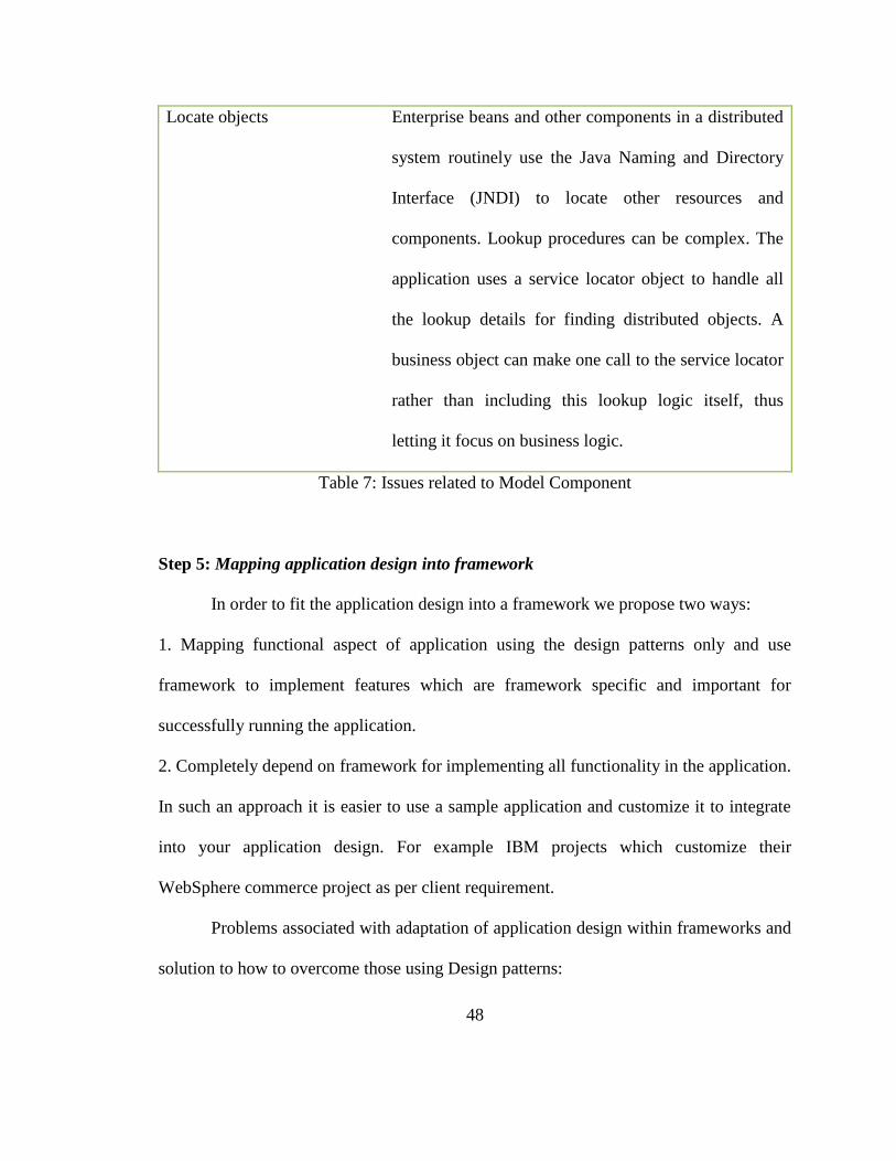
48
Locate objects Enterprise beans and other components in a distributed
system routinely use the Java Naming and Directory
Interface (JNDI) to locate other resources and
components. Lookup procedures can be complex. The
application uses a service locator object to handle all
the lookup details for finding distributed objects. A
business object can make one call to the service locator
rather than including this lookup logic itself, thus
letting it focus on business logic.
Table 7: Issues related to Model Component
Step 5: Mapping application design into framework
In order to fit the application design into a framework we propose two ways:
1. Mapping functional aspect of application using the design patterns only and use
framework to implement features which are framework specific and important for
successfully running the application.
2. Completely depend on framework for implementing all functionality in the application.
In such an approach it is easier to use a sample application and customize it to integrate
into your application design. For example IBM projects which customize their
WebSphere commerce project as per client requirement.
Problems associated with adaptation of application design within frameworks and
solution to how to overcome those using Design patterns:

49
1. Implicit architecture: Most frameworks have an underlying architecture consisting of a
limited number of components that define the main abstractions and their interaction. The
implementation of the framework is often dominated by implementation classes that
provide reuse at the implementation level. Due to this, the architecture of the framework
disappears in the implementation details and is very hard to identify by its users. By using
design patterns we can understand architecture of framework better.
2. Cross-framework dependencies: A typical situation in framework-based application
development is when selecting a class in one class hierarchy limits the selection of
classes to a subset in another class hierarchy. For example, in Android framework when
implementing a ListActivity for list view it is required to use extend the class as
ListAcitvity as instead of Activity and all other submethods comes from the ListActivity.
Such dependencies are not always as obvious as in this case and identifying them requires
considerable understanding of the internal workings of the framework.
3. Framework instantiation: Whenever starting to develop on new framework, requires
considerable effort in understanding the internal framework structure. This problem is
partially caused by the implicit architecture and cross-framework dependencies, but also
due to size of most frameworks and the lack of a clear, well-defined framework interface.
It would be beneficial to provide detailed structure of the architecture.

50
4. Legacy components: Object-oriented frameworks make extensive use of sub-classing
and dynamic binding to achieve flexibility. Despite this flexibility is it often very difficult
to use existing legacy components although the legacy component may represent useful
abstractions in the framework domain. Framework classes often mix domain behavior
with framework specific behavior. Since the legacy component only implements the
domain behavior, it does not fulfill the framework‟s requirements.
5. Framework composition: Frameworks are generally designed to form the reused part
of closed applications, rather than to be components in a larger system. Due to this, the
configuration and interaction interface of frameworks is often not well-defined and
shattered over the framework. Framework composition may suffer from several
problems, related to composition of framework control, legacy components and
framework entities.
3.6 CONCLUSION
The methodology described [section 3.4] guides the developers on how to
productively adapt the generic guidelines as offered by the framework into the specific
functionalities as required in their application. This methodology is intended to help the
students overcome problems like overly complex design, tight coupling, a rigid controller
function and low exploitation of the framework by following and implementing good
design practice and knowledge of design patterns.

51
The methodology encourages the developers to use design patterns as described in
their object-oriented application design and compare their designs to the framework. We
use this comparison as a bridge to map the application design and the framework. This
has two advantages:
1. Results in better design of the application
2. Gives insight to developers on how to approach a new framework and adapt their
application design into it.
As illustrated through the methodology, simply following framework design
would not result in a good application, as it requires compromising and adapting at both
application level and framework level. These compromises allow a developer to come up
with a final application design that is easier to understand, easier to debug, and allows
code to be more maintainable and reusable.

52
Chapter 4: Case Studies
4.1 CASE STUDIES
The case studies in this chapter describe the projects developed using the
methodology described in Chapter 3. These case studies are used to both describe and
evaluate the methodology in more detail. One case-study project was developed as an
example for a book on Android application development by the author of this thesis and
her advisor. The other project was an asset management system developed over duration
of ten weeks by small teams of one to three members in an Enterprise Technology class
(CSE 769). These projects were developed using either the Android SDK or the
Enterprise Java framework. Students were the originators of the class projects.
4.2 TIC TAC TOE APPLICATION
The goal of the application is to implement the Tic Tac Toe game on the
Android platform. The game allows a player to play against the computer automated in
the application. The player can choose to put a cross or nought on the board. The score of
each player is displayed at bottom of the screen. This screen shows the accumulated
scores for the session.

53
4.2.1 APPLYING METHODOLOGY
Step 1: Identification of problems in initial design
The initial design consisted of classes- game, board, symbol and block. The class diagram
for the initial design is shown in Figure 17.
Figure 17: UML diagram of initial design of Tic Tac Toe Application
In the first step of the methodology, the developer implemented the application using her
basic knowledge of the Android framework, and based on the functional requirements of
the application. Metrics were then used to evaluate the initial design. Table 8 shows the
problems encountered in the initial design, followed by Table 9 which shows metrics
used to quantify problems and their impact on the overall design. The metric are
normalized to a scale of 0-1. Also the metric and their product with number of methods
found in class with the problems identified, as described in chapter 3.

54
Class Problems Solution
Game Overloaded class - acts as
controller, model and view.
Single class manages both a
single game as well as a session
consisting of multiple games
Separate the controller part into a separate
class, this help add additional feature like
allowing more players
Need to define a controller for accumulating
scores so that multiple games can be managed
separately from single games.
Board Has coupling between view and
model
Game logic mixed in through
invalidateBlock()
Should only handle the drawing/display of the
board
Remove game logic (i.e. invalidateBlock()
Block 2D matrix for board provides
cell values
Inefficient use of data structure
to record cells used and not used
Need more appropriate data structure for
returning value for specific row and column
Use Grid to store cells which are actually filled
Keep values only when used
Table 8: Problems in initial steps

55
Class WMC Weighted method per class
LCOM Lack of cohesion of methods
CBO Coupling between objects
DIT Depth in tree or inheritance
OTHER Abstraction, polymer phism
Total
Game 8x0.02 2x0.03 5x0.02 1x0.01 0x0.02 0.33
Board 4x0.02 0x0.03 2x0.02 2x0.01 0x0.02 0.14
Block 2x0.02 2x0.03 0x0.02 2x0.01 0x0.02 0.12
Table 9: Metric evaluation of initial design
The aim of the methodology is to bring the total calculated metric value as low as
possible.
Step 2: Responsibility Driven Design of Tic-Tac-Toe
Designer‟s Story: Design Tic Tac Toe game for the Android platform. The Tic Tac Toe
game is a two player game where each player takes turns in marking the space in 3x3
grid with the symbols X and O respectively. The X player usually goes first. The player
who succeeds in placing three respective marks in a horizontal, vertical or diagonal row
wins the game. Scores are accumulated over a session and displayed on screen.
Table 10 lists the nouns and verbs extracted from the Designer‟s story:

56
Nouns Verbs
Game Take turn
Players Mark
Grid Win
Space Play
X Accumulate
O
Symbol
Vertical row
Horizontal row
Diagonal row
Scores
Table 10: Nouns and Verbs in Designer‟s Story
The nouns and verbs identified in Table 9 are now refined by removing duplicates,
combining into one if have same meaning, and combined if have same responsibilities.
Table 11 shows the refined list of noun and verbs which form the candidate classes,
attributes and methods.
Candidate Classes Attributes and Candidate Methods
Game Game, play
GameView Horizontal row, diagonal row, vertical row
GameGrid Symbol, x, o, grid, space
GameSession Scores, take turn, win, accumulate score, decide players
Table 11: Refined list of nouns and verbs

57
The second part of the responsibility driven design step is to illustrate the classes
identified using CRC cards (as shown in Figure 18, 19, 20 and 21). In addition to
capturing the candidate classes, attributes and methods, CRC cards also help identify the
collaborations among these classes. Responsibilities and collaborations help in
identifying the roles played by classes.
Game
Playing
Checking result
GameSesion
GameView
GameGrid
Figure 18: CRC card for the Game Class
GameView
Placing Symbol
Showing Result
Game
Figure 19: CRC card for GameView Class

58
GameGrid
Managing Cell/blocks Game
Figure 20: CRC card for GameGrid Class
GameSession
Player Selection
Accumulate scores
Quitting
Game
GameView
Figure 21: CRC card for GameSession Class
Step 3: Identification of design patterns in the design of the application
This step is aimed at understanding the application design through design patterns. In
order to accomplish the task of identifying patterns in the application design, application
developers need to have basic knowledge of design patterns. In this step, based on the
responsibilities and the collaborations, we extract the Model-View-Controller (MVC
pattern) out of the Game, Game Session, and Game View as shown in Table 12.

59
Classes Responsibilities
Model Game Provides the logic for the game
View GameView, GameGrid GameView provides the view for the
game and GameGrid represents the game
board, and is also responsible for
displaying different symbols.
Controller GameSession Responsible for handling the interaction
from the view to model.
Table 12: Identification of MVC components in the design of the Tic Tac Toe application
Step 4: Understanding the Android framework
This step aims at understanding the Android framework through the design
patterns identified in the application design in Step 3 of the methodology. The idea is to
find in the framework, the patterns identified in the application. For example, the MVC
design pattern was identified in the application design for the Tic Tac Toe application.
Thus, locating where the MVC pattern occurs within the framework serves as a way to
map the application design onto the framework.
The following details where each element of the MVC design pattern occurs in
the Android framework:
Model: Models have no direct support in the Android SDK. In other words, they are
implemented using Plain Old Java Objects. The developer would simply define models
using concrete Java classes.

60
View: The Android framework provides presentation capabilities through Views and
Widgets. The View class represents the basic building block for user interface
components. A View occupies a rectangular area on the screen and is responsible for
drawing and event handling. The View class is the base class for widgets, which are used
to create interactive UI components (buttons, text fields, etc.). The View-Group subclass
is the base class for layouts, which are invisible containers that hold other Views (or other
View-Groups) and define their layout properties.
Controller: In the Android framework, the Activity class serves as a controller for
applications. The Activity provides mechanism to generate and load views. This is shown
in Table 13:
Method Details
onCreateOptionsMenu(Menu menu) Initialize the contents of the
Activity's standard options menu.
onCreateView(String name, Context context, AttributeSet attrs) Standard implementation of
onCreateView(String, Context,
AttributeSet) used when inflating
with the LayoutInflater returned
by getSystemService(String).
onCreatePanelMenu(int featureId, Menu menu) Default implementation of
onCreatePanelMenu(int, Menu)
for activities.
Table 13: Public methods for Activity class

61
Step 5: Mapping application design into framework
In this step, we show how previous steps help in mapping the design of Tic Tac
Toe application into the Android framework. The classes which we define in Step 2 are
defined through MVC design pattern in Step 3 based on their responsibilities. Android
framework components like Layouts and Activity‟s public classes are used to define
Views and Controller respectively while we use plain old java objects for model role. The
Game class in the application is the Model. Here we want to store the data related to
game functionality such as the game state, the player symbol preference, and the progress
of a single game in terms of the number of moves made and remaining. Given that
models in the Android Framework are POJOs, we implement these functionalities in a
concrete class named Game. GameGrid tracks the symbols placed on the board and tracks
the occupancy of the rows and columns. It is a component of Game (i.e. the model).
The GameSession acts as the controller of the application. It is implemented as an
Android activity. That is, it extends the Activity class and uses its public methods like –
onCreateView(), to load the relevant game views. This class integrates the GameView
and GameGrid classes which are responsible for providing the game board and capturing
the user interaction with the board.
GameView is responsible for the view of the application. It presents the Tic-Tac-
Toe board. The code below shows how the Board for the one game session is initialized
using setGameViewComponents(Board theBoard) and how the symbols objects are
instantiated to be used in the game.

62
The mapping used in this application using the methodology described helps
understand the design better as well as overcome the problems described in Step 1 in the
initial design of application and also improve the metric evaluation as seen in Table 14.
Class
WMC Weighted method per class
LCOM Lack of cohesion of methods
CBO Coupling between objects
DIT Depth in tree or inheritance
OTHER Abstraction, polymor-phism
Total
Game
3x0.02 0x0.03 0x0.02 1x0.01 0x0.02 0.07
GameView 4x0.02 0x0.03 0x0.02 2x0.01 0x0.02 0.10
GameGrid 2x0.02 0x0.03 0x0.02 2x0.01 0x0.02 0.06
Table 14: Improved Metrics after Methodology
4.3 ASSET MANAGEMENT SYSTEM
The asset management system is intended to assist an organization manage its
various assets. The system tracks both virtual assets such as software products,
presentation templates, poster templates and physical assets such as Macintosh laptop
computer, projector. Request for these assets come in many forms, from verbal requests
and walk-in requests, to unsolicited emails from unknown persons. It is important for the
organization to handle these requests and manage the life-cycle of these assets efficiently.
A web interface is needed to allow customers to request to borrow an asset more
conveniently. The web interface must also allow administrators to track the location
and/or state of each asset in an easy-to-read manner. Also, the system must email
reminders to lenders when the return date is approaching.

63
4.3.1 APPLYING METHODOLOGY
Step 1: Identification of problems in initial design
This step helps in understanding the initial problems associated with the application
development within the context of a new software framework. The initial design
consisted of classes- Asset, Person, Reminder, Requests. The class diagram for the initial
design is shown in Figure 22. Here the Asset class is responsible for managing the details
related to all the assets managed by the system, the Person class manages users for the
application, the Reminder class is responsible for tracking the return date and reminding
lender about the return of asset, the Request class allows user to view details of assets
available and fill form to request asset.
Figure 22: UML diagram for initial design

64
The Table 15 describes the problems and solution to solve the problems, following Table
16 shows metric used to identify these problems on the scale of 0-1 and their product
with number of methods found in class with the problems identified.
Class Problem Solution
Asset Controller functionalities present in
a model
Should act as model only
Person Incomplete class. Does not capture
all roles.
Should act as the base class for all the
user roles - administrator, lender, student
Reminder Manages check outs, check-ins,
date, etc
Need to define and track asset in different
concrete class
Table 15: Problems in initial design in Asset management application
Class WMC Weighted method per class
LCOM Lack of cohesion of methods
CBO Coupling between objects
DIT Depth in tree or inheritance
OTHER Abstraction, polymer phism
Total
Person 7x0.02 2x0.03 4x0.02 1x0.01 2x0.02 0.33
Asset 8x0.02 1x0.03 2x0.02 2x0.01 1x0.02 0.27
Reminder 8x0.02 2x0.03 3x0.02 3x0.01 3x0.02 0.37
Table 16: Metric evaluation for each class on scale of 0-1
The aim of the methodology is to bring the total calculated metric value as low as
possible.

65
Step 2: Responsibility Driven Design integration
Designer‟s Story: Develop and application to efficiently handle the virtual as well as
hardware assets for an organization. The application should allow user to request an
asset online and system should be able to track each assets, and manage allocation of
these assets by tracking the check-out and check-in of assets. Application should allow an
Administrator to approve or deny any request.
The designer story is used to identify the nouns and verbs in the application as shown in
Table 17 below:
Nouns Verbs
Assets requestAsset
WebInterface Track
Users Check-in
Administrator Check-out
Table 17: Nouns and verbs from Designer‟s story
Table 18 below shows the final classes, attributes and candidate methods after the
refinement by removing duplicates, words having similar meaning, word representing
same functionalities (as described in chapter 3).

66
Classes Attributes and Candidate Methods
Assets Track assets
WebInterface Forms, Acknowledgement
Person Manage users
AdminController Approval
Table 18: Refined list of nouns and verbs
After identifying these classes the second part of the responsibility driven design step is
to illustrate the classes identified in CRC cards as shown in Figure 23, 24, 25 26 and 27;
CRC cards also help identify the responsibilities and collaboration within these classes.
This step helps in identifying the roles played by these classes through their collaboration
and responsibilities.
TrackAsset
Check-in
Check-out
Manage due dates
Record asset information
Users
Administrator
Figure 23: CRC card for the TrackAsset class
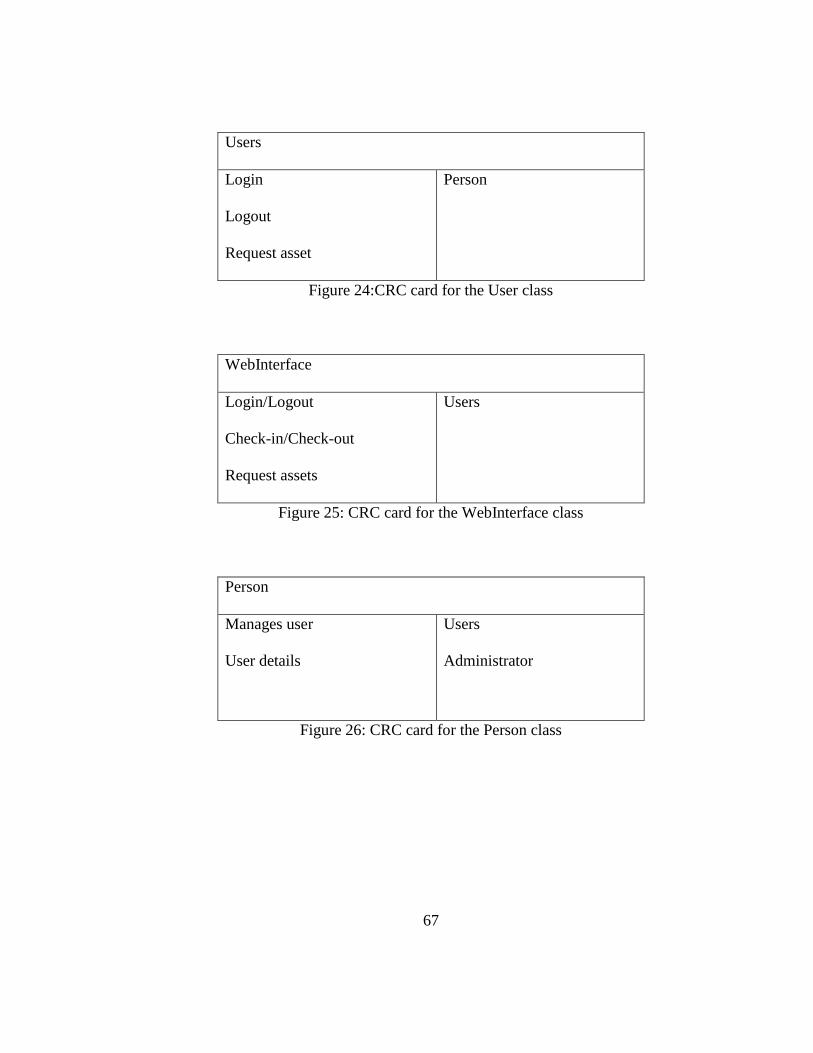
67
Users
Login
Logout
Request asset
Person
Figure 24:CRC card for the User class
WebInterface
Login/Logout
Check-in/Check-out
Request assets
Users
Figure 25: CRC card for the WebInterface class
Person
Manages user
User details
Users
Administrator
Figure 26: CRC card for the Person class

68
Administrator
Approve asset
Manage assets
TrackAsset
Person
Figure 27: CRC card for the Administrator class
Step 3: Identification of design patterns in the application design
Based on the roles of the classes (shown in the previous step) we next identify the classes
that can be categorized as MVC elements – i.e. the model, view and controller - as shown
in Table 19
Element Class/es Responsibilities
Model Asset, trackAsset Helps in manging asset resources
View webInterface Provides the view of the application
Controller AssetManager Manages the view and controller
interaction
Data Transfer Object TrackAsset Helps managing data between software
application and other subsystems, that is,
database and server.
Table 19: MVC components in the design of Asset Management Application

69
Step 4: Understanding the Enterprise Java framework
The architecture for the CETI asset management application's Web site consists of
a set of components divided into model, view, and controller layers. The components in
the controller layer handle client requests as they receive client requests and start the
process of providing the appropriate response. The controller layer components are Event
Controller, Event Factory, Event, EJB Tier Controller, and Command Factory.
The model layer contains the components that handle business logic: Session
Facade, Business Object, and Data Access Object. They extract and formulate the data
required to handle a client request. The Command Handler component includes the
controller and model layer, and serves as a bridge between them. The view layer contains
the components whose job is to format and present a response to the client. It consists of
the following components: Screen View, Composite View, Screen Flow Manager, and
View Helper. Three additional components-Service Locator, Value Object, and Business
Delegate apply the MVC approach in a distributed setting.
Step 5: Mapping the application design to the framework
The next step is to map the application design as described in Steps 2 and 3 and
adapt it into the Enterprise framework as described in Step 4. The application is divided
into two units – the web pages that serve as the front end of the application and the
backend that manages the user accounts, and the tracking of the assets.
When mapping the application design using the MVC design pattern into the
Enterprise framework, it is useful to identify three logical layers, namely, the layer that

70
deals with presentation aspects of the application, the layer that deals with the business
rules and data, and the one that accepts and interprets user requests and controls the
business objects to fulfill these requests.
In the presentation layer behavior changes less frequently, while business layer is
relatively stable. The Web site presents the application's data, that is, the assets catalog,
to the user in response to the user's requests. The Web site's primary responsibilities
include handling user requests, retrieving and displaying asset data, and allowing users to
select, issue, and check out assets.
The next phase of the design process is to partition the application into modules
and objects that address the different functional requirements. The partitioning process
includes deciding how to apportion the application across the different tiers of the
Enterprise platform, which portions of the application need to be distributed, and which
should be implemented for local interaction.
Once the user interface or the view requirements are completed, the application
must also support some security requirements, such as allowing only properly signed-on
users to access certain features while allowing all users free access to other areas of the
site. Once the functional requirements are identified, the application can be divided into
modules based on functionality. Such a separation reduces the dependency between
modules and allows them to be developed independently. In addition, identifying
interfaces between modules enables them to be developed by third-party component
providers.
We can identify three layers in the application design as follows:

71
A control module to create and maintain user account information, which
includes a user identifier, and billing, and contact information. This information is
maintained in a database. The control module also creates and manages the user's
shopping cart and controls the interactions with the user.
A sign-on module to handle the user log-in process and security, such as
verifying a user identifier and password
A product catalog module that returns product information from the catalog
based on a user's search criteria
A customer module that manages a user's purchasing process and maintains
account records for a customer
A messaging module that enables the application to send and receive
asynchronous messages containing purchase orders
Once the application is partitioned into functional modules, the next step is to identify
units of business logic, data, and presentation logic and model them as software objects.
This starts with identifying the options at the highest level, then working down. The
overall design and organization of the Web site follows the Model-View-Controller
architecture, while the internal design of some of its individual components follow
Enterprise Java patterns. The overall application uses the MVC architecture because it
provides a structure for handling complex, presentation-oriented applications.
In the classic MVC architecture, views register themselves with the model for
change notifications. When the model changes, it notifies a view of what changed. In the
application's Web site, the nature of HTTP requires the client view to use a request-

72
response paradigm to interact with the model on the EJB tier. Thus, rather than using
notifications, model changes are reported as a response to the client view.
The application design divides roughly as shown in Figure 28 below. These are no
clear boundaries between model, view, and controller.
Figure 28: Model-View-Controller Architecture for Asset management system
View:
The asset management application uses the Enterprise Java platform technologies
- servlets, Java Servlet Pages (JSP), and XML - for handling user views. The application
uses JSP pages for presentations where the presentation data changes rather than the
structure of the presentation. The application could use servlets for handling application
data. Table 20 illustrates the common issues encountered in the View or presentation
layer of an Enterprise Java application.

73
Issues Solution
Separate presentation logic from
business and control logic
WebInterface class is the view component in the
application. It separates the logic that
implements business rules from logic that
controls the process flow using JSP custom tags
and using JavaBeans to hold data. Servlets act as
controller and helps make it easier to reuse the
presentation logic portion of the JSP page, it is
modular and reusable-it is defined in one place
and used referentially from different JSPs.
Manage page layout Applications usually strive for a common look
and feel, and keeping page layouts similar within
an application is important to establishing such a
look and feel. A templating mechanism, such as
a composite view design pattern is used by the
application, which helps to keep page layout
consistent
Table 20: Issues in View Component of application
Model:
The model portion of the MVC architecture encapsulates the business objects and
API for the application's functionality. The application uses enterprise beans to

74
implement its business logic. Enterprise beans are used because of the services provided
by the EJB container for writing robust applications that are transactional, distributed,
and potentially scalable, and where security is important. Simpler applications with fewer
needs may be able to provide their own services and may consider implementing their
model as Java objects.
Controller:
The controller is executes business logic based on requests and help select the next view
for display. The controller decouples data presentation from business data and logic. The
controller receives HTTP request and performs functions specific to the presentation
(web tier). All user requests are processed at controller which extracts the type of request
and converts it to the appropriate type of event object. This is then passed to backend
controller or the EJB-tier controller; it is implemented as session bean, which matches the
event to the proper command which executes the business logic.
This mapping helps in developing the application which is based on design
patterns and is easy to understand. The Figure 29 shows the final design of application
with classes.

75
Figure 29: Final design of application after mapping into the framework
The final metric evaluation as shown in Table 21 shows the improvement in application
design after applying the methodology.
Class WMC LCOM CBO DIT OTHER Total
Asset 4x0.02 0x0.03 0x0.02 1x0.01 2x0.02 0.11
WebInterface 4x0.02 0x0.03 0x0.02 2x0.01 1x0.02 0.11
trackAsset 4x0.02 0x0.03 0x0.02 3x0.01 1x0.02 0.13
Person 2x0.02 0x0.03 0x0.02 2x0.01 0x0.01 0.06
Table 21: Metric evaluation of Final design
4.4 METHODOLOGY ANALYSIS
The case studies in this chapter showed each step of the methodology and how
they help develop the application. Chapter 5 evaluates the impact of the methodology on
the development and adaptation by the users.

76
Chapter 5: Evaluation
5.1 THESIS STATEMENT
Our goal in this thesis was to introduce a software development methodology to
help software developers adapt their application design to software frameworks while
following good design practices as well as taking advantage of the capabilities in the
framework.
5.2 THESIS VALIDATION
The thesis statement, as stated, was validated through questionnaires answered by
a small group of ten students in the course Applied Enterprise Distributed Computing for
Engineers and Scientists (course number CSE 769). The questionnaire had following
questions:
1. Give a brief description of your project.
2. In the initial phase of your application development you were asked to examine a
„designer‟s story‟ or „project write-up‟ to come up with classes and methods for
your application. Can you describe briefly how you applied this method? Do you
find this method useful? Why (or why not)?
3. How did you use CRC cards in the initial phases of your application
development? Did you find it useful? Why (or why not)?

77
4. What design patterns did you use in your application design phase?
5. The approach used in this class was aimed at designing your application within a
framework by using design patterns as a bridge. How would you rate this in terms
of difficulty level? (high, medium, low)
6. Would you like to use this approach in future application development? Why (or
why not)?
7. Please give us any other comments or thoughts.
Based on the questionnaire responses we observed the following:
• Some students understood the methodology and were willing to use in the future
• Some students understood the initial steps of using Responsibility Driven Design and
were willing to use it in their future projects
• Students with no object oriented programming experience had problems
understanding design patterns
• The MVC pattern was the one most often identified within a framework. Students
stated that it helped them understand the framework, and were willing to use it to
understand other frameworks in future
The case studies in this chapter helped in validating the thesis statement as follows:
Using object oriented design metrics as quality indicators helped in identifying
problems in initial designs. This approach led to ultimately better designed
applications that followed good design practices. OO metrics also helped
developers to better understanding object-oriented principles and related
methodologies such as responsibility-driven design.

78
Understanding frameworks using the approach outlined in this thesis allowed
developers to make best of them. This approach also provided a way to understand
new frameworks, as well as a way of reusing designs across frameworks.
The process of mapping the application design to the framework using design
patterns and roles helped unearth various issues provided a path to overcoming
them.

79
Chapter 6: Conclusion and Future Work
6.1 CONCLUSION
In this thesis, we illustrated how adapting a design to a framework can be a
challenge for novice developers and how design patterns can help in better understanding
of the application design as well as software framework and help in bridging the gap
between the application design and frameworks. This also result in understanding the
code better as well as adapting to new framework is easier. In order to address issues
faced by novice developers (such as undergraduate computer science students) the theis
describes the methodology in five key steps on how to properly adapt the generic
guidelines offered by the framework into the specific functionalities required in an
application. This methodology is intended to help the students overcome problems such
as overly complex designs, tight coupling, and low exploitation of the framework.
In this methodology, we encouraged the students to use design patterns in their
object-oriented application design to map their designs into the framework. This not only
resulted in a better design of the application, but also gave students new insight in how to
approach a new framework and amalgamate their application into it.
Essentially, good design of an application within a framework requires
compromising and adapting both at the application as well as the framework. These
compromises allow a developer to come up with a final application design that is easier
to understand, easier to debug, and allows the code to be more maintainable and reusable.
80
In order to evaluate the effectiveness of this methodology, we developed a set of
case studies and also used questionnaires to get student feedback. The evaluation shows
that the methodology provides users with a helpful software development process to
adapt application design into software frameworks while following good design practices
and taking advantage of the capabilities of the framework.
6.2 FUTURE WORK
This section describes areas of further research that must be pursued in order to
fully validate the models presented in this work.
Metrics: It would be helpful to create a set of metrics that could be used to
quantify the success or failure of the steps in used in the methodology. This would
involve defining user surveys, development time statistics, and performance requirements
that could be used for concrete, quantifiable evaluation. The metrics presented in this
work were too few and mostly qualitative and subjective in nature.
Generalization: We studied this methodology on only the Android and J2EE
frameworks. The generalization of the methodology needs to be validated by applying it
across multiple frameworks.
81
References
[1] Jan Bosch, Peter Molin, Michael Mattsson, and PerOlof Bengtsson. 2000. Object-
oriented framework-based software development: problems and experiences.
ACM Comput. Surv. 32, 1es, Article 3 (March 2000).
[2] Richard Lajoie and Rudolf K. Keller. 1995. Design and Reuse in Object Oriented
frameworks: Patterns, contracts, and Motifs in Concert. ISBN: 9789812831163
1995.
[3] Gamma E., Helm R., Johnson R., Vlissides J.: Design Patterns: Abstraction and
Reuse of Object-Oriented Design; in ECOOP‟93 Conference Proceedings,
Springer Verlag, 1993
[4] Tony C Shan and Winnie W Hua, “Taxonomy of Java Web Application
Frameworks”, e-Business Engineering, 2006. ICEBE'06. IEEE International
Conference, Oct. 2006
[5] Coad P.: Object-Oriented Patterns; in Communications of the ACM, Vol. 33, No.
9, Sept. 1992.

82
[6] Pree W.: Design Patterns for Object-Oriented Software Development;
(preliminary title) to be published by Addison-Wesley/ACM Press, 1994.
[7] J. Bosch, P. Molin, M. Mattsson, PO Bengtsson, „Object-oriented frameworks -
Problems and Experiences,‟submitted, March 1997.
[8] Buschmann, F., Meunier, R., Rohnert, H., Sommerlad, P., and Stal, M. Pattern
Oriented Software Architecture. A System of Patterns. Wiley. 1996.
[9] Learning Cocoa with Objective-C By James Duncan Davidson, Apple Computer,
Inc .
[10] J. Bosch, „Towards Reusable, Composable and Expressive Specification of
Architectural Fragments,‟ submitted,April 1997.
[11] F. Buschmann, C. Jäkel, R. Meunier, H. Rohnert, M.Stahl, Pattern-Oriented
Software Architecture- A System of Patterns, John Wiley & Sons, 1996.
[12] Wirfs-Brock R., Wilkerson B., Wiener L.: Designing Object-Oriented
Software;Prentice Hall, Englewood Cliffs, New Jersey, 1990.

83
[13] Gamma, E., Helm, R., Johnson, R., and Vlissides, J. Design Patterns. Elements of
Reusable Object-Oriented Software, Addison-Wesley, 1994
[14] Software Reuse through Building Blocks by Lenz, M., Schmid, H.A., Wolf, P.F.
at IBM Laboratories
[15] Communication of the ACM, October 1997/Vol.40 No.10 Frameworks comprises
of Components and Patterns by Ralph E. Johnson.
[16] Bushmann, F., Meunier, R., Rohnert, H., Sommerlad, P., and Stal, M. Pattern-
Oriented Software Architecture: A System of Patterns. Wiley, West Sussex,
England, 1996
[17] Design Patterns: Between programming and Software Design by Christopher
Denzler and Dominik Gruntz
[18] Object –Oriented Frameworks- Problems and Experiences by Jan Bosch et. al.
[19] A Validation of Object-Oriented Design Metrics as Quality Indicators by Victor
R. Basili, Fellow, I€€€, Lionel C. Briand, and Walcelio L. Melo, Member, IEEE
Computer Society

84
[20] E. Gamma, R. Helm, R. Johnson, J.O. Vlissides, Design Patterns - Elements of
Reusable Object-Oriented Software, Addison-Wesley, 1994.
[21] J. Bosch, „Towards Reusable, Composable and Expressive Specification of
Architectural Fragments,‟ submitted, April 1997.
[22] Meyers, S., Duby, C. K., and Reiss, S. P. Constraining the Structure and Style of
Object-Oriented Programs. Proceedings of the Workshop on Principles and
Practice of Constraint Programming, April 1993.
[23] A Validation of Object-Oriented Design Metrics as Quality Indicators by Victor
R. Basili, Fellow, I€€€, Lionel C. Briand, and Walcelio L. Melo, Member, IEEE
Computer Society
[24] Alexander M. Ernst. 2008. Enterprise architecture management patterns.
In Proceedings of the 15th Conference on Pattern Languages of Programs (PLoP
'08). ACM, New York, NY, USA, , Article 7 , 20 pages.
[25] R.E. Johnson, B. Foote, „Designing Reusable Classes,‟ Journal of Object-Oriented
Programming, Vol 1, No. 2, June 1988.
[26] J. DiMarzio, Android A Programmers Guide, McGraw-Hill Osborne Media, 2008

85
[27] Developing java web services, Architecting and developing secure web services
using java, by Rakesh Nagappan, Robert Skoczylas, Rima Patel Sriganesh
[28] Sidhant Rajam, Ruth Cortez, Alexander Vazhenin, and Subhash Bhalla. 2010.
Design patterns in enterprise application integration for e-learning arena.
In Proceedings of the 13th International Conference on Humans and
Computers (HC '10), Vitaly V. Klyuev and Michael Cohen (Eds.). University of
Aizu Press, Fukushima-ken, Japan, Japan, 81-88.
[29] Steve MacDonald. 1996. Design patterns in enterprise. In Proceedings of the 1996
conference of the Centre for Advanced Studies on Collaborative
research (CASCON '96), Michael Bauer, Karen Bennet, Morven Gentleman,
Howard Johnson, Kelly Lyons, and Jacob Slonim (Eds.). IBM Press 25-45.