Designing drainage without compromising BS EN 12056
64
25/01/22 CIBSE East Midlands Presented by: Adam James 07969 589275 [email protected] Designing drainage without compromising BS EN 12056
-
Upload
khangminh22 -
Category
Documents
-
view
0 -
download
0
Transcript of Designing drainage without compromising BS EN 12056

25/01/22CIBSE East Midlands
Presented by: Adam James07969 [email protected]
Designing drainage without compromising BS EN 12056
Designing drainage without compromise
Agenda
Introduction to Geberit
The history of UK drainage
Why design with drainage in mind?
Soil and waste system types
Limitations of primary vented stacks
Low litre flushing and it’s affect on UK drainage
Summary Questions

Designing drainage without compromise
Introduction to Geberit

SLIDE 4
28/01/2022
GEBERIT: SOLUTIONS FOR YOUR NEEDS

We invest in ten technology areas
Hydraulics
AcousticsProcessengineering
Fireprotection
Simulations Electronics
Drinking waterhygiene
Statics
Surface technology
Material Science
Designing drainage without compromise
SLIDE 6
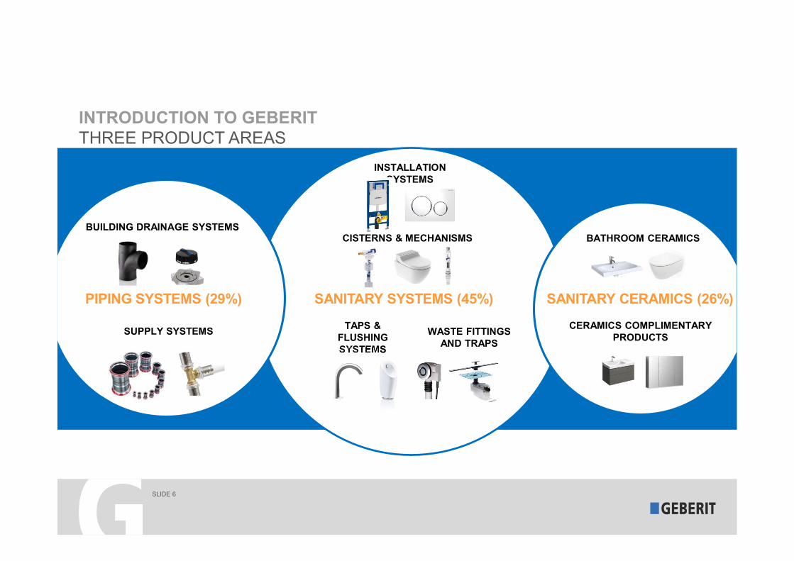
INSTALLATION SYSTEMS
TAPS & FLUSHING SYSTEMS
WASTE FITTINGS AND TRAPS
CISTERNS & MECHANISMS
SANITARY SYSTEMS (45%)
INTRODUCTION TO GEBERITTHREE PRODUCT AREAS
SUPPLY SYSTEMS
BUILDING DRAINAGE SYSTEMS
PIPING SYSTEMS (29%)
CERAMICS COMPLIMENTARY PRODUCTS
BATHROOM CERAMICS
SANITARY CERAMICS (26%)

SLIDE 7
The company: 30 specialised production facilities – close to our key markets
7TH NOVEMBER 2018

Core statements
The European market leader in sanitary technology
Designing drainage without compromise
Powerful brand
Global presence
Outstanding technology
platform
Successful business
model
Excellent focused organic growth

Designing drainage without compromise
Why design with drainage in mind?

Fresh water comes from the pipe…
…Dirty water disappears down the
drain
Designing drainage without compromise

Designing drainage without compromise
Why think about drainage design?
Nobody thinks about drainage design…
…until it becomes a problem

Designing drainage without compromise
The history of UK drainage

What is traditionally used in the UK for drainage?
Cast Iron has been used for drainage since
the 17th century
uPVC drainage was introduced
from the 1960s,
followed by similar systems
such as ABS and PP
HDPE was introduced by Geberit in the
UK in the 1980s
Acoustically optimised
drainage pipe system
launched by Geberit in 1997
Designing drainage without compromise

Designing drainage without compromise
Jointing techniques
Easy to cut and handle
Easy, strong and reliable joints
Electro welded sleeve coupling
Butt weld
Ring seal socket
Expansion socket
Screw-threaded joint
Flange

High Durability
Designing drainage without compromise
Easy to process
Lightweight
Resistant to hot
Chemical resistantFlexible
Resistant to cold
Resistant to abrasion
Impact resistant
Weather proof

Environmental Benefits
• No air pollution in production of pipes
• Reduced transport cost due to weight
• No chemicals used in jointing
• Reduced scrap
• Easily recyclable
HDPE is recommended by Greenpeace as an alternative to traditional drainage materials.
Designing drainage without compromise

Designing drainage without compromise
Soil and waste system types
Designing drainage without compromise
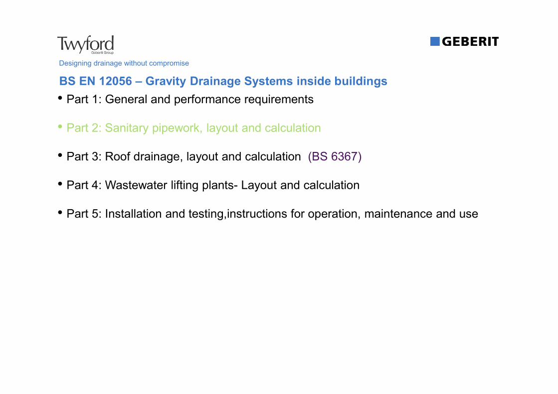
• Part 1: General and performance requirements
• Part 2: Sanitary pipework, layout and calculation
• Part 3: Roof drainage, layout and calculation (BS 6367)
• Part 4: Wastewater lifting plants- Layout and calculation
• Part 5: Installation and testing,instructions for operation, maintenance and use
BS EN 12056 – Gravity Drainage Systems inside buildings

Designing drainage without compromise
Soil and Waste System Types
• Single stack system with partly filled branch discharge pipes.• Sanitary appliances are connected to partly filled branch discharge pipes, are designed with
a filling degree of 0.5 (50%) and are connected to a single discharge stack.
System I (German / Swiss / Austrian Practice)System I (German / Swiss / Austrian Practice)
• Single discharge stack with small bore discharge branch pipes.• Sanitary appliances are connected to small discharge pipes. The small bore discharge pipes
are designed with a filling degree of 0.7 (70%) and are connected to a single discharge stack.
System II (Scandinavian Practice)System II (Scandinavian Practice)
• Single stack system with full bore branch discharge pipes.• Sanitary appliances are connected to full bore discharge pipes. The full bore branch
discharge pipes are designed with a filling degree of 1.0 (100%) and each branch discharge pipe is separately connected to a single discharge stack.
System III (UK Practice)System III (UK Practice)
• Drainage systems type I, II & III may also be divided into black water stack serving WC’s and urinals and a grey water stack serving other appliances.
System IV (French Practice)System IV (French Practice)

Designing drainage without compromise
Five Main Design Criteria - SAGAA
• Pipes will be large enough to carry anticipated dischargeSize
• Foul air must be excluded from entering the building.
• Leakage must be prevented
Airtight & Watertight
• A fall is to be provided on all pipesGradient
• To be provided for testing and maintenanceAccess
• Where sound insulation is requiredAcoustics

Designing drainage without compromise
Sizing - Branches
Sizing of branch and low gradient collector pipework:
40mm wash basin, bidet, drinking fountain.
50mm sink, bath, shower, urinal, sanitary towel macerator.
56mmcombined wastes, disposal unit or dual appliance branch.
110mm WC ( 90mm with 80mm outlet pan).
Houses never need sizing as a single WC requires a 110mm stack but this would also suffice for 50 houses each with one WC.

Designing drainage without compromise
Sizing - Stacks
1Using table 2, select the total number of appliances running into the stack
2Add up the discharge units, DU, for these appliances
BS EN 12056-2 Table 2 - Discharge Units (DU)
ApplianceSystem I System II System III System IV
DU l/s DU l/s DU l/s DU l/s
Wash basin, bidet 0.5 0.3 0.3 0.3
Shower without plug 0.6 0.4 0.4 0.4
Shower with plug 0.8 0.5 1.3 0.5
Single urinal with cistern 0.8 0.5 0.4 0.5
Urinal with flushing valve 0.5 0.3 - 0.3
Slab urinal 0.2* 0.2* 0.2* 0.2*
Bath 0.8 0.6 1.3 0.5
Kitchen sink 0.8 0.6 1.3 0.5
Dishwasher (household) 0.8 0.6 0.2 0.5
Washing machine up to 6kg 0.8 0.6 0.6 0.5
Washing machine up to 12kg 1.5 1.2 1.2 1.0
WC with 4.0 l cistern ** 1.8 ** **
WC with 6.0 l cistern 2.0 1.8 1.2 to 1.7*** 2.0
WC with 7.5 l cistern 2.0 1.8 1.4 to 1.8*** 2.0
WC with 9.0 l cistern 2.5 2.0 1.6 to 2.0*** 2.5
Floor gully DN 50 0.8 0.9 - 0.6
Floor gully DN 70 1.5 0.9 - 1.0
Floor gully DN 100 2.0 1.2 - 1.3
* Per person
** Not permitted
*** Depending upon type (valid for WCs with syphon flush cistern only)
- Not used or no data

3Select the frequency factor for the use of the appliances using table 3
Designing drainage without compromise
Sizing - Stacks
Waste Water flowrate (Qww) is the expected flowrate of waste water in a part or in the whole drainage system where only domestic sanitary appliances are connected to the system
here: Qww = K√∑DU
Qww = Waste water flowrateK = Frequency factor∑DU= Sum of discharge units
4
Work out the waste water flow rate Qww
BS EN 12056-2 Table 3 - Typical frequency factors (K)
Usage of appliances K
Intermittent use, e.g. in dwelling, guesthouse, office 0.5
Frequent use, e.g. in hospital, school, restaurant, hotel 0.7
Congested use, e.g. in toilets and/or showers open to public 1
Special use, e.g. laboratory 1.2

Designing drainage without compromise
Sizing - Stacks
5Use the Qww(litres per second) to size the pipe using table 11.
Hydraulic capacity can be increased with the use of secondary venting - use table 12 in place of 11
Swept entry fittings are used in the UK but there is also a column for sizing square entries.
BS EN 12056-2 Table 11 - Hydraulic capacity (Qmax) and nominal diameter
Stackand
stack vent
System I, II, III, IVQmax (l/s)
DNSquareentries
Sweptentries
60 0.5 0.7
70 1.5 2.0
80* 2.0 2.6
90 2.7 3.5
100** 4.0 5.2
125 5.8 7.6
150 9.5 12.4
200 16.0 21.0
* Minimum size where WCs are connected in system II.
** Minimum size where WCs are connected in system I, III, IV.
BS EN 12056-2 Table 12 - Hydraulic capacity (Qmax) and nominal diameter
Stackand
stack vent
Secondaryvent
System I, II, III, IVQmax (l/s)
DN DNSquareentries
Sweptentries
60 50 0.7 0.9
70 50 2.0 2.6
80* 50 2.6 3.4
90 50 3.5 4.6
100** 50 5.6 7.3
125 70 7.6 10.0
150 80 12.4 18.3
200 100 21.0 27.3
* Minimum size where WCs are connected in system II.
** Minimum size where WCs are connected in system I, III, IV.

Designing drainage without compromise
Sizing - e.g. Football stadium (congested)
Total Discharge Units = 115Total Discharge Units = 115
One hundred WHBs = 100 x 0.3 = 30One hundred WHBs = 100 x 0.3 = 30
Fifty 6-litre WCs = 50 x 1.7 = 85Fifty 6-litre WCs = 50 x 1.7 = 85
BS EN 12056-2 Table 2 - Discharge Units (DU)
ApplianceSystem I System II System III System IV
DU l/s DU l/s DU l/s DU l/s
Wash basin, bidet 0.5 0.3 0.3 0.3
Shower without plug 0.6 0.4 0.4 0.4
Shower with plug 0.8 0.5 1.3 0.5
Single urinal with cistern 0.8 0.5 0.4 0.5
Urinal with flushing valve 0.5 0.3 - 0.3
Slab urinal 0.2* 0.2* 0.2* 0.2*
Bath 0.8 0.6 1.3 0.5
Kitchen sink 0.8 0.6 1.3 0.5
Dishwasher (household) 0.8 0.6 0.2 0.5
Washing machine up to 6kg 0.8 0.6 0.6 0.5
Washing machine up to 12kg 1.5 1.2 1.2 1
WC with 4.0 l cistern ** 1.8 ** **
WC with 6.0 l cistern 2 1.8 1.2 to 1.7*** 2
WC with 7.5 l cistern 2 1.8 1.4 to 1.8*** 2
WC with 9.0 l cistern 2.5 2 1.6 to 2.0*** 2.5
Qww = K√∑DU

Designing drainage without compromise
Sizing - e.g. Football stadium (congested)
Frequency factor = 1.0Frequency factor = 1.0
√115 = 10.7√115 = 10.7
Total Discharge Units = 115Total Discharge Units = 115
One hundred WHBs = 100 x 0.3 = 30One hundred WHBs = 100 x 0.3 = 30
Fifty 6-litre WCs = 50 x 1.7 = 85Fifty 6-litre WCs = 50 x 1.7 = 85
BS EN 12056-2 Table 3 - Typical frequency factors (K)
Usage of appliances K
Intermittent use, e.g. in dwelling, guesthouse, office 0.5
Frequent use, e.g. in hospital, school, restaurant, hotel 0.7
Congested use, e.g. in toilets and/or showers open to public 1.0
Special use, e.g. laboratory 1.2
Qww = K√∑DU

Designing drainage without compromise
Sizing - e.g. Football stadium (congested)
Therefore a 150mm stack is requiredTherefore a 150mm stack is required
Waste Water Flowrate, Qww = 10.7 x 1.0 = 10.7 l/sWaste Water Flowrate, Qww = 10.7 x 1.0 = 10.7 l/s
Frequency factor = 1.0Frequency factor = 1.0
√115 = 10.7√115 = 10.7
Total Discharge Units = 115Total Discharge Units = 115
One hundred WHBs = 100 x 0.3 = 30One hundred WHBs = 100 x 0.3 = 30
Fifty 6-litre WCs = 50 x 1.7 = 85Fifty 6-litre WCs = 50 x 1.7 = 85
BS EN 12056-2 Table 11 - Hydraulic capacity (Qmax) and nominal diameter
Stackand
stack vent
System I, II, III, IVQmax (l/s)
DNSquareentries
Sweptentries
60 0.5 0.7
70 1.5 2.0
80* 2.0 2.6
90 2.7 3.5
100** 4.0 5.2
125 5.8 7.6
150 9.5 12.4
200 16.0 21.0
* Minimum size where WCs are connected in system II.
** Minimum size where WCs are connected in system I, III, IV.
Qww = K√∑DU

Designing drainage without compromise
Five Main Design Criteria - SAGAA
• Pipes will be large enough to carry anticipated dischargeSize
• Foul air must be excluded from entering the building.
• Leakage must be prevented
Airtight & Watertight
• A fall is to be provided on all pipesGradient
• To be provided for testing and maintenanceAccess
• Where sound insulation is requiredAcoustics

Designing drainage without compromise
Air & Watertight – Traps
Depth of Water Seals
Wash basin / bidet 75mm
Bath / Shower 50mm
Sink / Disposal 75mm
WC Pan 50mm
There are some traps on the market for baths and showers with a seal depth of 38mm.

Air & Watertight – Drainage Jointing Methods
Designing drainage without compromise
Butt fusion welding• HDPE
Electrofusion welding• HDPE
Ring seal joints• All systems
Solvent welding• PVC-u
Two part clamps• Cast iron
We would recommend homogeneouswelds for commercial, high rise andindustrial applications

Designing drainage without compromise
Air & Watertight – HDPE Jointing Methods
Easy to cut and handle
Easy, strong and reliable joints
Butt weld
Electro welded sleeve coupling
Ring seal socket
Expansion socket
Screw-threaded joint
Flange

Designing drainage without compromise
Five Main Design Criteria - SAGAA
• Pipes will be large enough to carry anticipated dischargeSize
• Foul air must be excluded from entering the building.• Leakage must be prevented
Airtight & Watertight
• A fall is to be provided on all pipesGradient
• To be provided for testing and maintenanceAccess
• Where sound insulation is requiredAcoustics

• The gradient of a branch discharge pipe should be uniform and adequate to drain the pipe efficiently
• Waste systems• Gradient should be between 1° and 5°
• Max distance of appliance to stack = 3m
• Over 3m access needs to be provided
• Normally 1.25°
• Soil systems• Gradient should be between 1° and 5°
• Normally 2.5°
Designing drainage without compromise
Gradient
(1° = 18mm drop per metre)
(5° = 88mm drop per metre)

Designing drainage without compromise
Five Main Design Criteria - SAGAA
• Pipes will be large enough to carry anticipated dischargeSize
• Foul air must be excluded from entering the building.• Leakage must be prevented
Airtight & Watertight
• A fall is to be provided on all pipesGradient
• To be provided for testing and maintenanceAccess
• Where sound insulation is requiredAcoustics

Designing drainage without compromise
Access
• Sufficient access should be provided to enable all pipework to be tested and maintained
• Access covers, caps etc should be sited to facilitate the insertion of testing equipment and the use of cleaning equipment and /or for the removal of blockages
• Use of equipment should not be impeded by the structure or other services
• Access points should not be located where they will give rise to nuisance or danger if spillage occurs
• Fit access above spill level and extend to the face of a duct or floor level

Designing drainage without compromise
Five Main Design Criteria - SAGAA
• Pipes will be large enough to carry anticipated dischargeSize
• Foul air must be excluded from entering the building.• Leakage must be prevented
Airtight & Watertight
• A fall is to be provided on all pipesGradient
• To be provided for testing and maintenanceAccess
• Where sound insulation is requiredAcoustics
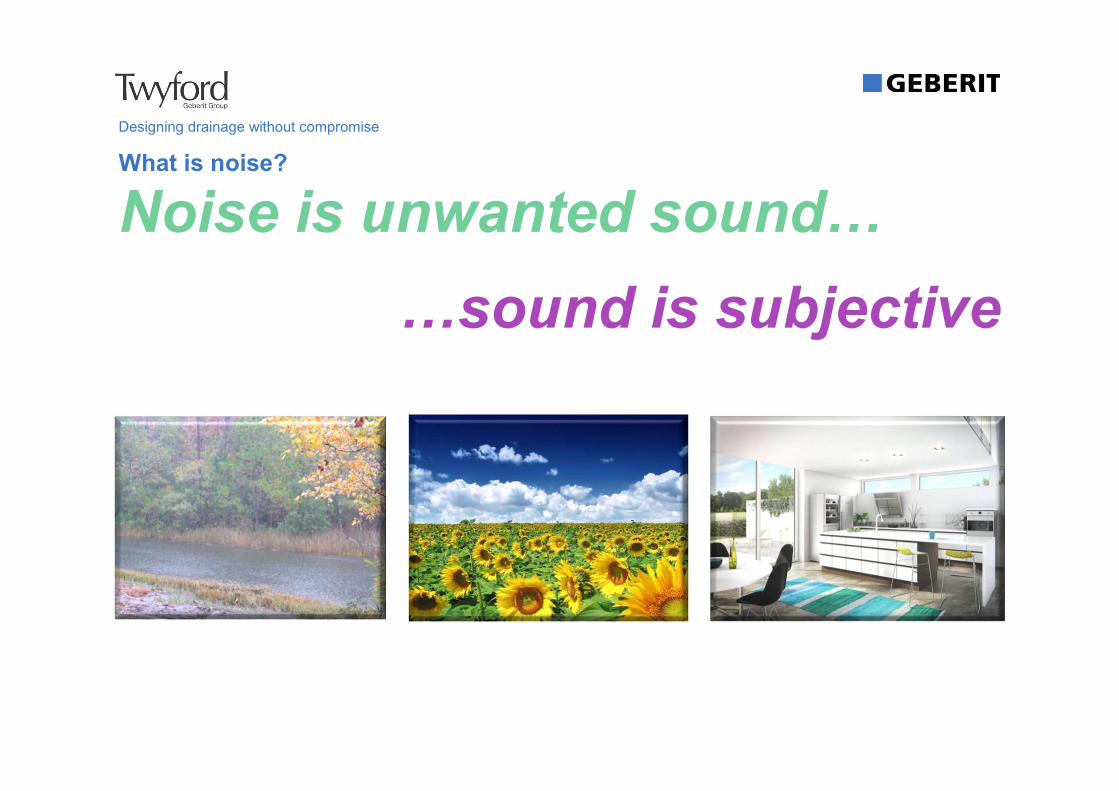
What is noise?
Noise is unwanted sound…
…sound is subjective
Designing drainage without compromise

The annoyance of sanitary noise
90%90% 55%
... don't likewaste water noise.
... have been disturbed by waste
water noise.
... would pay a little more rent to
reduce the noise.
Designing drainage without compromise

Designing drainage without compromise
• Many areas have high requirements for acoustic insulation
• Residential premises
• Office buildings
• Hospitals
• Sanatoriums
• Hotels
• Acoustically designed HDPE can be used in these instances, providing superior sound dampening combined with the material benefits of HDPE…
Acoustic Performance
… but, a holistic approach to sanitary system design is critical to achieve optimal acoustic performance!The noise doesn’t only come from the drainage pipes

Designing drainage without compromise
• The system’s properties are the same as HDPE but with the added benefit of being a denser product thanks to the addition in the mix of 20% ground stone.
• The ribs on the fittings further dampen the transfer of sound at impact areas.
• Pipes, fittings and acoustic brackets available in sizes Ø56mm up to Ø160mm for soil and waste drainage
Silent-db20 – Acoustically Designed HDPE

Designing drainage without compromise
Limitations of Primary Vented Stacks (PVS)

Designing drainage without compromise
Limitations of Primary Vented Stacks (PVS)
• The UK system III allows us to fill our branch discharge pipes 100%
• There are rules governing the length and diameter of branch discharge pipes for a primary vented system
• In the worst case scenario using a primary vented system, traps can be siphoned by the build up of negative pressure in the system as there is only one access point for air. Positive pressure, created at transition areas in the stack can also force foul air out through appliance traps.
• Therefore a primary vented system is only recommended for domestic and light commercial/industrial installations.

Designing drainage without compromise
Table 2 of the UK Building Regulation H shows clearly the diameters and lengths allowed for branch pipes in an primary vented system
Design Guidelines for Branch Pipes (PVS)
WCbath
sink washbasin
Slope 18 to 90 mm/m
Slope 18 to 90 mm/m
3m max for 40mm pipe
4m max for 50mm pipe
3m max for 40mm pipe
4m max for 50mm pipe
1.7m max for 32mm pipe
3m max for 40mm pipe
15m max for single WC
Slope 18 to 90 mm/m
Slope see graph

Designing drainage without compromise
• Self siphonage – Branch pipe fills up causing an area of negative pressure to be left behind in the pipe. This negative pressure acts on the trap once the basin has run empty causing the trap level to fall.
Siphoning Traps
Negative pressurearea
Pipe runningfull
Air passing through trap causesWater loss due to a pumping action
Possible level afterSelf-syphoning
Water level beforedischarging
• Induced siphonage (combined wastes) – Caused when two appliances are connected to the same branch pipe (typically bath and basin). The branch pipe connected to the stack fills up and the water flowing from the bath past the basin sets up a venturiwhich causes negative pressure in the basin pipe acting on the basin trap.

Designing drainage without compromise
Solution to Siphoning Traps
• Increase the pipe size immediately after the trap
• Ensure the pipe length between end appliance and pipe is less than 1.7m when the slope is less than 1.25 degrees
• Use resealing or Anti-vacuum traps
• Fit an air admittance valve (this has limitations)
• Fully vent the system (the preferred and best solution)
• Use a sovent fitting
Designing drainage without compromise
• The head of the drain should always vent to atmosphere
• A ratio of 9:1 max should be used
• Not suitable over 5 storeys (some AAV’s claim 10)
• Will only deal with negative pressure!
• Should never be used outside
Rules for Using Air Admittance Valves (AAV)

Designing drainage without compromise
• Positive pressure is created within a soil and waste system at offset areas and at base of stack bends.
• A PVS can dissipate this air surcharge in domestic and light commercial installations but heavy utilisation of this installation could cause the traps to be blown
• For base of stack bends strict rules govern the diameter of the bend and connection distances from the bend to the first appliance.
Offsets and Base of Stack Bends

Designing drainage without compromise
• Minimum connection distance L• Up to 3 Floors 450mm
• Up to 5 Floors 740mm
• Above 5 Floors 1 Floor
• Minimum radius R = 200mm
• At least Double the Pipe Diameter
• Movie to highlight positive pressure effects…
Base of Stack Bends
Preferred Method

49
Designing drainage without compromise
Prevention of Crossflow
• WC Waste to Waste Crossflow• With large branches, there is a no
connection zone on the opposing
side of the stack for smaller branches.
• The branch should be connected at or
above the centre line level of the large
branch or at least 200mm below it.
• Alternatively the small branch should
be a right angles or less to the large
branch.
Branch75-150mm
No connection zone
90º
90º
No connection zone

50
Designing drainage without compromise
Prevention of Crossflow
• Waste to Waste Crossflow• With small branches, the no
connection zone is dependent on the
stack diameter, D.
• Alternatively the second branch
should be a right angles or less to the
first.
90º
90º
Branch≤63mm
No connection zone
No connection zone
D
Stack Diameter, DNo connection zone
(mm)
75 90
100 110
125 210
150 250

Designing drainage without compromise
Low volume flushing and it’s effect on UK drainage

52
Designing drainage without compromise
History of water consumption for WC’s
Less water requires more expertise in planning & installation of drainage systems
1905 1952 1964 1970 1996 2008 ????
Wooden cistern Phoenix
Firstplastic cistern
Concealedplastic cistern
Stop and go Dual flush 4.5 l flush
12 l 9 l 6 l 4.5 l ? l

Designing drainage without compromise
Low volume flushing and its effect on UK drainage
• Trending towards lower litre WC flushing to reduce water consumption.
• Building Regulations Part H:
• Only makes provision for major flush volumes of 5 litres or more.
• States that consideration to increased risk of blockages should be given where
major flush is less than 5 litres.

Designing drainage without compromise
Low volume flushing and its effect on UK drainage
• UK design to BS EN 12056 doesn’t currently make any provision for lower volume flushing requirements.
• The UK’s default System III allows for full bore discharge pipes and a filling degree of 1.0 (100%).
• Currently BS EN 12056 only permits System II for a WC with 4 litre flush.

Low volume flushing and its effect on UK drainage
Appropriate size of discharge pipe is crucial for a good self-cleaning of the system.
Filling ratio h/d of horizontal pipes
Air
h/d 0.5 – 0.8
Sufficient flow
h
d
h
h/d below 0.5
Insufficient flow
Air
d
h/d above 0.8
No air = Siphonic
h
d
Air

Filling-ratio between a dia. 110 and 90 mm pipe with 4.5 l
Low volume flushing and its effect on UK drainage
DN 100
30%DN 90
50%
Smaller pipe allows better filling ratio

Low volume flushing and its effect on UK drainage
Slope in the pipes
Insufficient slope<1°
Regular slope 1.25 - 2.5°(Min. 1° - max. 5°)
Filling ratio high,no self-cleaning
Good filling ratio Water discharges too quickly
Excessive slope>5°
The horizontal pipes have to be installed with a regular slope. The slope for pipes must be planned and installed with special care.

6 l 4.5 l
Decision factors Standard solution
- Green Building (LEED, BREEAM, etc.)- Local authorities- Planner/Consultant- Owner/End-user- Facility Management
Cistern Factory setting Manual adjustment
Ceramic Standard ceramic 4.5 l certified ceramic
Drainage system
DN100 DN 90 or DN100
Low volume flushing and its effect on UK drainage
Key determining factors – 6l or 4.5l flush
DN 9050%
DN 10050%
Based on :- Slope- Offsets- Amount of bends- Distance WC to stack- Pipe layout
(e.g. cast in concrete)

Low volume flushing and its effect on UK drainage
Conclusion 4.5 l flush
DN 100
30%DN 90
50%
Less water requires more expertise in planning & installation of drainage systems
Oversized systems may be vulnerable for blockages
A better solution for low volume flushing

Low litre flushing and its effect on UK drainage (video)

Designing drainage without compromise
Summary

Designing drainage without compromise
No body cares about drainage… until it becomes a problem1
Summary
HDPE provides a great drainage solution2
BS EN 12056-2 sets out layout principles of gravity drainage 3
Limitations to the use of primary vented stacks6
Important to equalise positive & negative pressure fluctuations7
Avoidance of cross-flow8
Four potential system types, UK default is System III.4
Five design criteria - SAGAA5
Trend towards lower volume WC flushing9
Low litre flushing needs special consideration at the design stage10

Dedicated to Specification
• Geberit Sales Ltd has a range of RIBA and CIBSE approved CPD’s:• Creating the ideal washroom environment
• Bathroom design behind the wall
• Designing drainage without compromise BS EN 12056
• Embedding acoustics into design
• Siphonic rainwater systems
Designing drainage without compromise

Designing drainage without compromise
Clean disposal.
Thank youAny questions?
Water, simply connected.
Geberit Sales LtdGeberit House, Academy Drive, Warwick CV34 6QZTel: 01926 516800 www.geberit.co.uk