DESIGN TECHNIQUE OF HIGH-QUALITY FULL-RANGE FLIGHT CONTROL SYSTEMS
13
DESIGN TECHNIQUE OF HIGH-QUALITY FULL-RANGE FLIGHT CONTROL SYSTEMS V.G. Borisov, G.N. Nachinkina, B.V. Pavlov, A.M. Shevchenko Trapeznikov Institute of Control Sciences of RAS 65, Profsoyuznaya, Moscow, 117997, Russia Fax: 8-495-334-90-39, e-mail: [email protected] Abstract Flight conditions of modern aircrafts differ widely and consequently the aerodynamic characteristics of the aircrafts vary significantly. This paper describes the through technique of designing of flight control systems for aircrafts with essentially nonlinear characteristics. The technique includes new theoretical results and their practical realization as part of the multifunctional semi-natural stand. New results are the energy approach to flight control and the original version of modal synthesis. The stand make possible to carry out optimization of system parameters, its verification and flight control system testing with pilot in the loop. The technique’s efficiency was demonstrated with a full nonlinear model of the high-speed maneuverable aircraft. Modeling showed invariance of handling qualities in a wide range of flight conditions. Keywords: flight control, energy control system, modal method, handling qualities, modeling, multifunctional stand. 1. Introduction The creation of high-quality flight control systems has taken place throughout the history of aircraft evolution and continues up to this day. The process of designing and preflight tryout of flight control systems consists of following conditional stages: − Analysis of static and dynamic properties of the object; − Synthesis of control; − Modeling tests and estimation of aircraft performance; − System tests at the flight simulator with the pilot in a control contour. Each stage was usually carried out by different systems project teams often separated territorially, on different engineering tools. Such organizational management has resulted in unjustified material expenditure and the long lead time of system engineering. Analytical studies of modern/state-of-the-art and promising technological levels [1] have reflected the conservatism or backwardness of this level. Scientific achievements were often ignored in consequent/current projects. The aim of this work is development of the through technology of control systems designing. According to this approach all stages of researches, designing and debugging are made by means of uniform computer technology, on the same equipment. Original scientific components of offered technology are the energy approach to motion control in space [2, 3, 4] and the special version of modal synthesis of regulators with required quality [5, 6]. This work was supported in part by Russian Foundation for Basic Research, Project 09-08-00313-a
-
Upload
independent -
Category
Documents
-
view
4 -
download
0
Transcript of DESIGN TECHNIQUE OF HIGH-QUALITY FULL-RANGE FLIGHT CONTROL SYSTEMS
DESIGN TECHNIQUE OF HIGH-QUALITY FULL-RANGE FLIGHT CONTROL SYSTEMS
V.G. Borisov, G.N. Nachinkina, B.V. Pavlov, A.M. Shevchenko
Trapeznikov Institute of Control Sciences of RAS 65, Profsoyuznaya, Moscow, 117997, Russia
Fax: 8-495-334-90-39, e-mail: [email protected]
Abstract Flight conditions of modern aircrafts differ widely and consequently the aerodynamic characteristics of the aircrafts vary significantly. This paper describes the through technique of designing of flight control systems for aircrafts with essentially nonlinear characteristics. The technique includes new theoretical results and their practical realization as part of the multifunctional semi-natural stand. New results are the energy approach to flight control and the original version of modal synthesis. The stand make possible to carry out optimization of system parameters, its verification and flight control system testing with pilot in the loop. The technique’s efficiency was demonstrated with a full nonlinear model of the high-speed maneuverable aircraft. Modeling showed invariance of handling qualities in a wide range of flight conditions. Keywords: flight control, energy control system, modal method, handling qualities, modeling, multifunctional stand.
1. Introduction The creation of high-quality flight control systems has taken place throughout the history of aircraft evolution and continues up to this day. The process of designing and preflight tryout of flight control systems consists of following conditional stages:
− Analysis of static and dynamic properties of the object; − Synthesis of control; − Modeling tests and estimation of aircraft performance; − System tests at the flight simulator with the pilot in a control contour.
Each stage was usually carried out by different systems project teams often separated territorially, on different engineering tools. Such organizational management has resulted in unjustified material expenditure and the long lead time of system engineering. Analytical studies of modern/state-of-the-art and promising technological levels [1] have reflected the conservatism or backwardness of this level. Scientific achievements were often ignored in consequent/current projects. The aim of this work is development of the through technology of control systems designing. According to this approach all stages of researches, designing and debugging are made by means of uniform computer technology, on the same equipment. Original scientific components of offered technology are the energy approach to motion control in space [2, 3, 4] and the special version of modal synthesis of regulators with required quality [5, 6]. This work was supported in part by Russian Foundation for Basic Research, Project 09-08-00313-a
There is a wide variety of flight control concepts. From the very beginning of aviation the main controlled state variables were flight altitude and airspeed. It was quite natural that elevator deflection (δe) and power lever angle (PLA) were used as control variables. With progress in the theory and practice of automatic flight control the burden of manual control was transferred to the autopilot and the autothrottle. Such channel division was somewhat advantageous for formal description of vehicle motion by a differential equation system. The classical motion equations were also divided into the dynamic and kinematic equations. That is how the conventional two-channel structure of flight control system in the longitudinal plane has formed in aviation. Such channel separation has the following serious operational shortcomings: − Control in any channel results in a coupled response in the other channel;
− Constraints of control power in one channel are disregarded in the other channel. This sometimes results in the stalling or loss of height and therefore collision with the ground;
− Aircraft response in automatic mode is not adequate to the manner of an expert pilot and Attempts to decouple the channels and ensure higher transient quality result in unwarranted cross-couplings in the system. These and some other disadvantages of conventional approaches to flight control systems have fueled the search for new ways to satisfy the ever-growing requirements for flight control quality.
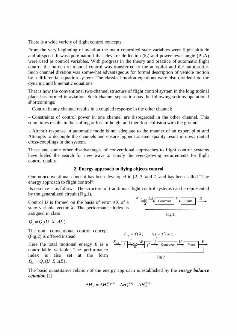
2. Energy approach to flying objects control One nonconventional concept has been developed in [2, 3, and 7] and has been called “The energy approach to flight control”. Its essence is as follows. The structure of traditional flight control systems can be represented by the generalized circuit (Fig.1).
Control U is formed on the basis of error ∆X of a state variable vector X. The performance index is assigned in class
( , , )x xQ Q U X ΔX= .
The non conventional control concept (Fig.2) is offered instead. Here the total motional energy E is a controllable variable. The performance index is also set at the form
( , , )E EQ Q U E ΔE= .
The basic quantitative relation of the energy approach is established by the energy balance equation [2]
Engine Drag WindE E E EH H H H∆ = ∆ − ∆ − ∆
refXControler Plant
X∆ U X
Fig.1.
Fig.2.
( )=refE f X
E∆ U E
*( )X f E∆ = ∆
f *frefXPlantControler
This equation is written in the form of specific energy deviations (.) (.)EH E mg∆ = ∆ . Terms in
the right side are normalized engine work, aerodynamic force work, and wind work, accordingly. Integral expressions for each term have been received [2, 3]. The left-hand side is the increment of specific energy:
2
1
.t
aE a
t
VH V dtg
θ
∆ = +
∫
Obviously the first term on the right side is the work of the propulsive force, which we call the specific work of the engine:
2
1
cost
EngineE a nr
t
H V P dtα∆ = ⋅ ⋅∫ .
The second term expresses the expenditure of energy for overcoming the harmful drag: 2
1
tDragE a nr
t
H V D dt∆ = ⋅ ⋅∫ .
The third term describes the work of wind: 2
1
tWindE a w
t
H V f dt∆ = ⋅ ⋅∫ .
Here Va is the airspeed; Pnr is the normalised thrust; Dnr is the normalized drag force.
yxw
WWfg V
≅ − is called the wind factor; Wx and Wy are horizontal and vertical wind
components. The energy balance equation reflects interconnections of all energy sources and consumers in system «aircraft — power-plant — environment». PI-algorithms of engine thrust and elevator control are received from the energy balance equation
P I
e e P I
P V h V hk k dt,mg g V g V
V h V hk k k dt,g V g V
δ
∆ ∆ ∆= + + +
∆ ∆
∆ = − + −
∫
∫
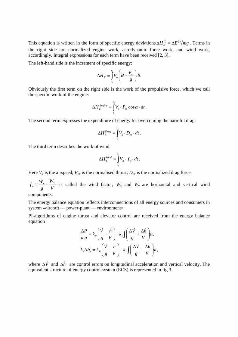
where V∆ and h∆ are control errors on longitudinal acceleration and vertical velocity. The equivalent structure of energy control system (ECS) is represented in fig.3.
The ECS showed excellent handling quality of transport aircrafts at landing approach under strong atmospheric perturbation, engine failures, abrupt glides, etc [4]. In all situations the structure and coefficients of the ECS remained fixed for aircrafts of different classes. Foreign researchers have made similar analyses [8, 9]. The advantages of the energy control system (ECS) were best demonstrated during landing approach through the zone of severe wind disturbances. For this purpose the windshear that caused the crash of the L-1011 jet at the Dallas airport (USA) in 1985 was simulated. ECS has counteracted catastrophic wind disturbances and confidently has steered the aircraft to the runway as can be seen in fig.4. However, the system with fixed coefficients cannot provide acceptable control quality for maneuverable high-speed aircrafts over the whole flight envelope. Therefore, adjustment of ECS parameters is needed. This paper develops a version of a modal synthesis method in order to find the optimum coefficients.
3. Modal synthesis problem Modal methods have become widespread in questions of control systems design with specific quality and stability requirements. Methods of synthesis of single-loop control systems are the most developed and covered in the literature [10, 11, and 12)]. In the field of multi-loop systems the papers [13, 14] are well known. In particular, Ackermann's formula [14] gives the formal solution of the pole placement problem according to the requirements of quality and stability. This design method includes a matrix rising to (n-1)th power, which in turn demands its good conditionality. In [15] the solution of the feedback matrix is found at the form of product of the eigenvector
Generalized Object
refθ
mg
∫ Kih
KpV
Kph
KiV
-
∫-
- -
nx ref
=
x
Vng
θ = yVV
Power plant
Elevator
Airc
raft
δe
X
P
Fig.3. The structure of energy control system
Fig.4. Modeling landing approach in catastrophic windshear
With the standard flight control system. Errors are ± 60m. Crash
With the ECS. Errors are ±5m
Reference glide path
Altit
ude,
m
Distance to runway threshold, m
matrix and some matrix possessing rather formal properties. In this paper the control weighting matrix is proposed for elimination of solution multiplicity in the case of incomplete control vector. Quality and stability of the closed control system are defined by its eigenvalues. Suppose that the desirable set of eigenvalues is known a priori. The only required though insufficient condition is stability of the closed-loop system. The multivariable control system is considered as
( ) ( ) ( ) ,= +x t Ax t Bu t
where n nA R ×∈ is the plant matrix, 1nx R ×∈ is the state vector, n mB R ×∈ is the control matrix, 1mu R ×∈ is the control vector.
Let the pair of matrix (A B) be controllable. The problem is to find the control low of the form u Kx= , that the closed-loop system
( )x A BK x = + , (1) has a desirable set of eigenvalues. Here m nK R ×∈ is the required feedback matrix.
4. Problem solution
Let the desirable spectrum 1{ ,..., }nλ λ∗ ∗ ∗Λ = of the closed-loop system matrix A+BK not contains multiple eigenvalues. The desirable spectrum ∗Λ is achieved by a modal method by constructing the required matrix K.
Let 1{ ,..., }nV V V= be a set of eigenvectors of the closed-loop system matrix A+BK.
The matrix K in (1) is not unique for m> 1 as the spectrum correction can be achieved by various separate components of a control vector ui or their linear combinations. The control as the sum of weighted modal controls is offered in [5]
1.
n
i ii
u Kx q K x=
= = ∑
In other words the structure of matrix K becomes as follows
1.
n
i ii
K q K=
= ∑ (2)
Here 1miq R ×∈ , 1,i n= is assigned weight vector of a mode iλ∗ ; 1 n
iK R ×∈ , 1,i m= is required coefficient vector of a mode iλ∗ where the additional imposed conditions
0 for j iK V i j= ≠ (3) provide independence of mode control. The equation for defining the closed-loop system (1) eigenvector Vi is
( ) .i i i i iV A BK V AV BKVλ∗ = + = + (4) Equation (4) having in view of (2) can be written as:
1.
n
i i i j j ij
V AV B q K Vλ∗
=
= + ∑ (5)
From (5) together with (3) it follows that:
i i i i i iV AV Bq K Vλ∗ = + (6) and
1( ) .i n i i i iV I A Bq K Vλ∗ −= − Multiplication of both sides of the equation by Ki from the left gives:
1( ) .i i i n i i i iK V K I A Bq K Vλ∗ −= − Note that i iK V is scalar and it is possible to reduce the equation to
11 ( ) .i n i iK I A Bqλ∗ −= − Multiplying j-th eigenvector Vj by Ki from left we receive
1( ) 0.i j i n j j j jK V K I A Bq K Vλ∗ −= − = It is possible to reduce by scalar KjVj as above
10 ( ) .i n j jK I A Bqλ∗ −= − The system of n linear equations is received for definition Ki
1
1
1 ( )0 ( )
λ
λ
∗ −
∗ −
= −
= − ≠i n i i
i n j j
K I A Bq for i=j (one equation),K I A Bq for i j (n-1 equations).
(7)
Taking into account that i iK V is a scalar, define eigenvectors iV as 1( ) i n i iV I A Bqλ∗ −= − (8)
and then the system of linear equations (7) becomes
10
i i
i j
K V for i=j (one equation),K V for i j (n-1 equations).
=
= ≠ (9)
In expression (9) all variables are defined; therefore all eigenvectors iV can be determined.
Let us denote the matrix of eigenvectors by V
1( )nV V V= . Multiplying the row-vector iK by the matrix V from right and using constraints (9) the following expression can be written
(0 1 0)i iK V = . Hence it is follows that
1(0 1 0) .i iK V −= (10) Substitute (10) in (2):
1
1(0 0) .
n
ii
K q V −
=
=
∑ (11)
Define the weight matrix Q as m n
1( ), Q R . nQ q q ×= ∈ Then (11) can be written
1.K QV −= Elements qi of the matrix Q are assigned so that their relative values would reflect a degree of influence of any control on each of plant controllable coordinate. As can be seen this algorithm provides a solution for feedback matrix in the explicit form per one computing cycle. The control vector is more convenient for writing partly through derivatives. For this purpose the following procedure is offered. The matrix С is introduced according to request of matrix pair (A С) observability
.y Cx= Usually the matrix С assigns controllable coordinates The following relation is obvious
.0
x A B xy C u
=
(12)
Matrixes B and С should be the same dimension. Let us consider a block matrix
.0
A BC
(13)
Provided that the block matrix (13) is invertible, let us write its inverse of the form 1
11 12
21 22
0
P PA BP PC
− =
.
Having in view (12) we get
[ ] [ ] 11 12
21 22
0 0P Px x
u Kx K Ku P P y
= = =
;
and finally 11 12u KP x KP y= + .
The resulting expression shows that the control u can be calculated as a function of derivatives x and measured coordinates y.
5. Design of the optimum flight control system The approval of a modal method has been carried out during designing the flight control system of the hypothetical high-speed maneuverable aircraft. The problem to provide equally high handling qualities over the whole operational area has been set. An aperiodic type reaction with duration no more than 30 s was assumed for reference transient on airspeed and height. Formally these system requirements were set by values of low-frequency roots. The linearized model contained three low-frequency roots. Values -0.5, -
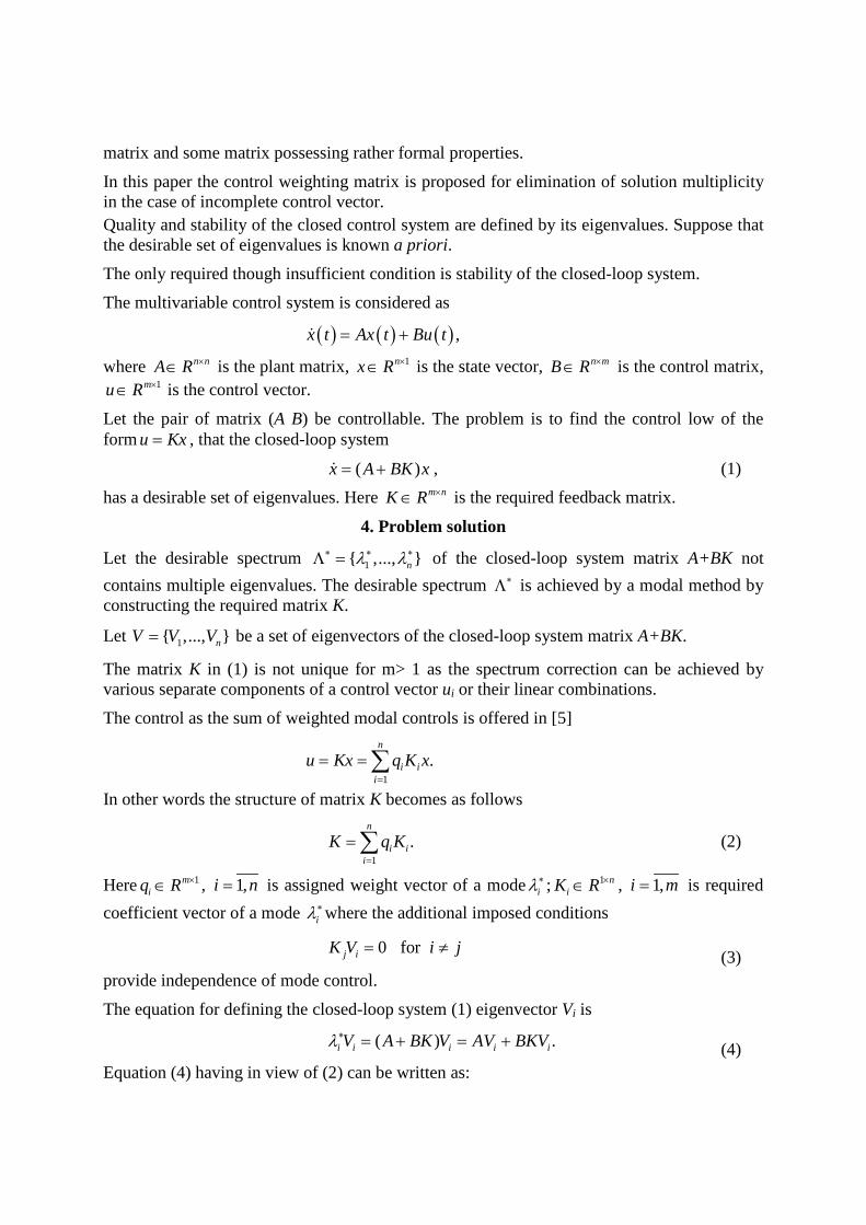
0.6, and -0.7 were assigned to them. The invariability of these roots was achieved due to adjusted feedback coefficients Kij. The ECS structure with a modal correction loop is shown in fig.5.
Fig.5. The structure of energy control system with modal correction
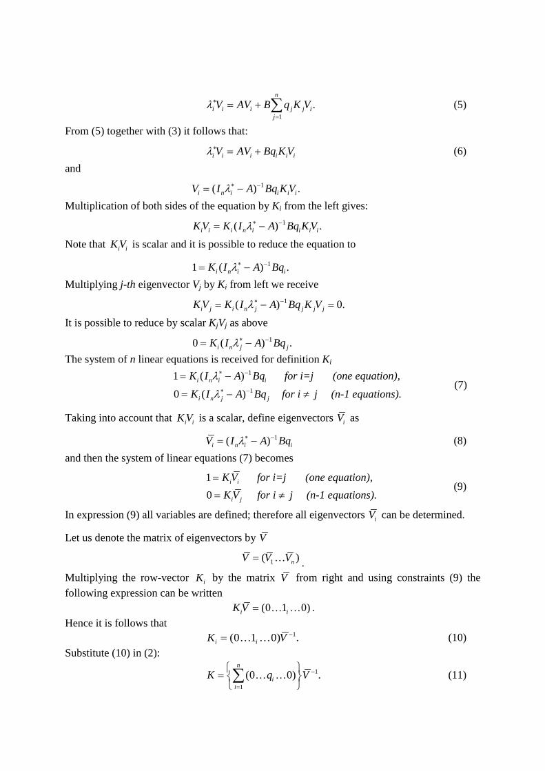
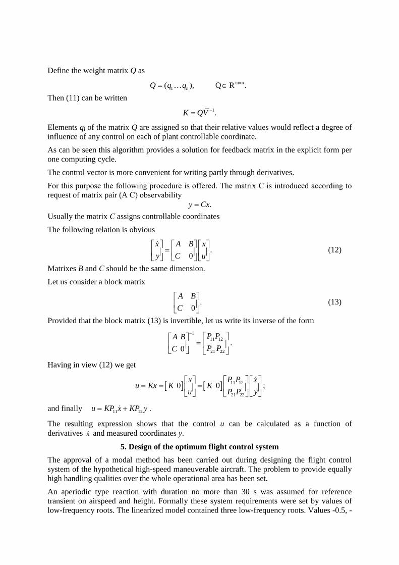
To establish the range of possible coefficients Kij, their values were calculated along some specific trajectories over the whole operational area. The flight envelope and trajectories are shown in fig.6 in −H M coordinates.
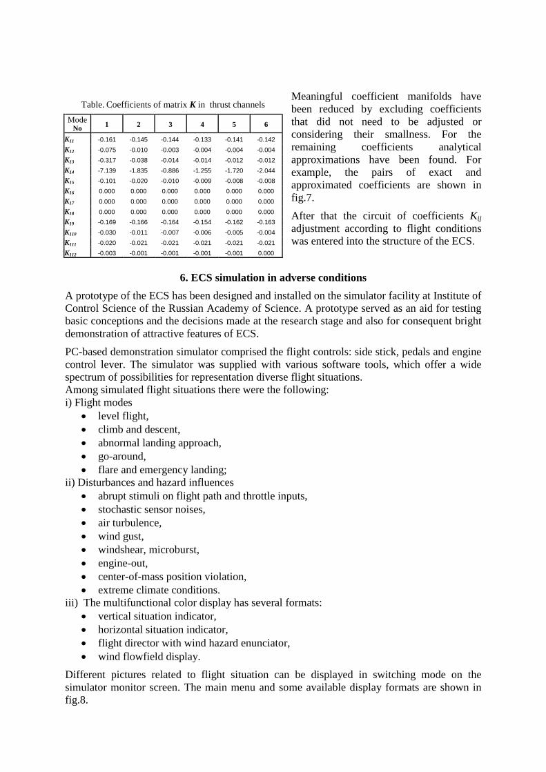
Some points have been chosen along all trajectories. Feedback coefficients in each point have been calculated by a modal method for thrust and trajectory channels. Coefficients K1j in thrust channel for six flight modes along 2nd trajectory are shown in the table. As is seen the change range of some coefficients is very wide.
K22(Q,M) 1= 117,5497QM
K̂22
4
10,0007M
=−
K15(H,M) =−K̂15 M 410,0007
Fig.7. Approximation of discrete functions by analytical ones
Fig.6. Investigated flight envelope.
20,0
15,0
10,0
5,0
0,0 Mach number М0,5 1,0 1,5 2,0 2,5
Alti
tude
H, k
m
2
1
3
Meaningful coefficient manifolds have been reduced by excluding coefficients that did not need to be adjusted or considering their smallness. For the remaining coefficients analytical approximations have been found. For example, the pairs of exact and approximated coefficients are shown in fig.7. After that the circuit of coefficients Kij adjustment according to flight conditions was entered into the structure of the ECS.
6. ECS simulation in adverse conditions A prototype of the ECS has been designed and installed on the simulator facility at Institute of Control Science of the Russian Academy of Science. A prototype served as an aid for testing basic conceptions and the decisions made at the research stage and also for consequent bright demonstration of attractive features of ECS. PC-based demonstration simulator comprised the flight controls: side stick, pedals and engine control lever. The simulator was supplied with various software tools, which offer a wide spectrum of possibilities for representation diverse flight situations. Among simulated flight situations there were the following: i) Flight modes
• level flight, • climb and descent, • abnormal landing approach, • go-around, • flare and emergency landing;
ii) Disturbances and hazard influences • abrupt stimuli on flight path and throttle inputs, • stochastic sensor noises, • air turbulence, • wind gust, • windshear, microburst, • engine-out, • center-of-mass position violation, • extreme climate conditions.
iii) The multifunctional color display has several formats: • vertical situation indicator, • horizontal situation indicator, • flight director with wind hazard enunciator, • wind flowfield display.
Different pictures related to flight situation can be displayed in switching mode on the simulator monitor screen. The main menu and some available display formats are shown in fig.8.
Table. Coefficients of matrix K in thrust channels Mode
No 1 2 3 4 5 6
K11 -0.161 -0.145 -0.144 -0.133 -0.141 -0.142 K12 -0.075 -0.010 -0.003 -0.004 -0.004 -0.004 K13 -0.317 -0.038 -0.014 -0.014 -0.012 -0.012 K14 -7.139 -1.835 -0.886 -1.255 -1.720 -2.044 K15 -0.101 -0.020 -0.010 -0.009 -0.008 -0.008 K16 0.000 0.000 0.000 0.000 0.000 0.000 K17 0.000 0.000 0.000 0.000 0.000 0.000 K18 0.000 0.000 0.000 0.000 0.000 0.000 K19 -0.169 -0.166 -0.164 -0.154 -0.162 -0.163 K110 -0.030 -0.011 -0.007 -0.006 -0.005 -0.004 K111 -0.020 -0.021 -0.021 -0.021 -0.021 -0.021 K112 -0.003 -0.001 -0.001 -0.001 -0.001 0.000
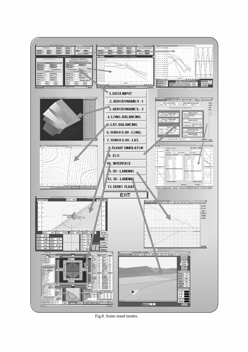
Fig.8. Some stand modes.
Experiments have been carried out with a full nonlinear model of the TU-154M [4] passenger liner. At first the ECS prototype was tested at landing configuration in the glide path mode. There were facilities for flight simulation under various atmospheric disturbances, nonstandard situations, engine failures, sensor noise and other unfavorable factors. Many diverse situations have been modeled including strong wind gusts, hard turbulence, abnormal deep glide path, engine-out and the most dangerous one – a microburst encounter. The results of statistical modeling of near 2 millions landing approach have confidently proved the advantages of ECS.
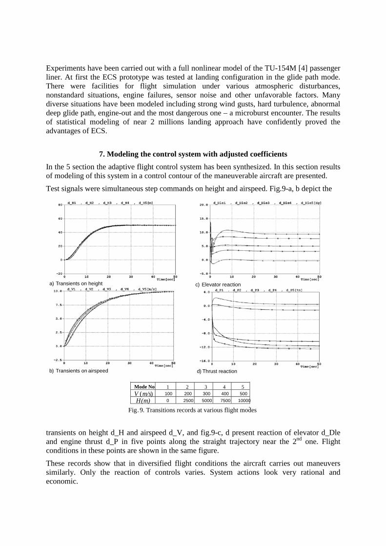
7. Modeling the control system with adjusted coefficients In the 5 section the adaptive flight control system has been synthesized. In this section results of modeling of this system in a control contour of the maneuverable aircraft are presented. Test signals were simultaneous step commands on height and airspeed. Fig.9-a, b depict the
transients on height d_H and airspeed d_V, and fig.9-c, d present reaction of elevator d_Dle and engine thrust d_P in five points along the straight trajectory near the 2nd one. Flight conditions in these points are shown in the same figure. These records show that in diversified flight conditions the aircraft carries out maneuvers similarly. Only the reaction of controls varies. System actions look very rational and economic.
.
d) Thrust reaction
Mode No 1 2 3 4 5 V (m/s) 100 200 300 400 500 H (m) 0 2500 5000 7500 10000
a) Transients on height c) Elevator reaction
b) Transients on airspeed
Transitions records at various flight modesFig. 9.
It is the energy approach that specifies this system property. And behavior invariance with respect to aircraft parameters variation is provided by adjustment of control system coefficients.
8. Conclusions The technique of high-quality flight control systems design is developed. The basic structural concept is the energy approach. The rational structure of the energy control system (ECS) is received on its basis. The ECS has shown excellent handling qualities of transport aircrafts at landing approach in diversified conditions. However, the system with fixed coefficients could not provide acceptable control quality of maneuverable high-speed aircrafts over the operational area. Therefore parameter adjustment was required for using the ECS over the whole flight envelope. The version of a modal method for calculation of the feedback coefficients matrix has been developed. The control on each mode as the sum of available controls with weighting coefficients is offered for solution ambiguity eliminating. Synthesis of the flight control system for a high-speed maneuverable aircraft has been carried out. Optimal feedback coefficients in discrete points of operational area have been found. The coefficients adjustment circuit has been introduced into the system structure. Modeling of the ECS with adjusted parameters has shown that transients had retained invariant in diversified flight conditions and had been practically identical at speed from 100 up to 500 m/s and altitude from 0 up to 10,000m.
References 1. Advanced Guidance and Control—Operational and Safety Benefits (2008). Final
report DOT/FAA/AR-08/27 Air Traffic Organization Operations Planning Office of Aviation Research and Development Washington, DC 20591, June 2008.
2. Borisov V.G., Nachinkina G.N., Shevchenko A.M. Energy approach to flight control. // “Automation and remote control”, vol.60, 1999, №6, pp.805-813.
3. A.P. Kurdjukov, G.N. Natchinkina, A.M. Shevtchenko. Energy approach to flight control. // AIAA Guidance Navigation and Control Conf., AIAA Paper 98-4211, Boston, MA. Aug 98.
4. Pavlov B.V., Shevchenko A.M., Nachinkina G.N. Energy approach to flight control system design. // “Actual Problems of Aviation and Aerospace”, vol.8, 2(16), 2003, pp. 24-43.
5. Borisov V.G., Diligensky S.N., Efremov A.Yu. Synthesis of invariant control systems using eigenstructures. // “Automation and Remote Control”, vol.51, 1990, No.7, Part.1, pp.853-866.
6. Borisov V.G., Nachinkina G.N.and Shevchenko A.M. Modal method of optimization of energy flight control system of flying vehicles. // “Control Sciences”, 2008, No. 6, pp.74-80 .
7. A.A. Lambregts. Vertical flight path and speed control autopilot design using total energy principles. // AIAA Paper 83-2239CP, 1983.
8. R. Akmeliawati, I. Mareels. Nonlinear energy-based control method for landing autopilot. // Proc. 15th Triennial World Congr. of IFAC (b'02, Barcelona.
9. Ch. Voth, Uy-Loi Ly. Design of a total energy control autopilot using constrained parameter optimization. // J. of Guidance, Control and Dynamics, vol. 14, No.5, pp.927-935.
10. C. Doll, J.F. Magni and Y. Le. Gorrec. A modal multi-model approach. Robust flight control : A design challenge. // “Lecture Notes in Control and Information Sciences”, vol. 224, 1997.
11. Tutikov, V.V., Tararykin, S.V., Varkov, E.A. Assurance of static accuracy of modal control systems with polynomial regulators. // “Pribory i sistemy”. (2). 2004. pp. 1-4. In Russian.
12. Dylevsky, A.V. and Lozgachev, G.I. Synthesis of Linear Control Systems with a Given Characteristic Polynomial.// “Proceedings of the Russian Academy of Sciences. Theory and control systems”. (4). 2003. pp. 17-20. In Russian.
13. J. Ackermann. Sampled-data control systems. // Berlin, Germany: Springer-Verlag, 1985.
14. J. Ackermann. Multi-model approaches to robust control system design. Multi-model approaches to robust control system design. // “Lecture Notes in Control and Information Sciences”, v.70.-1985. pp. 108-130.
15. Akunov, T.A., Ushakov, A.V. Synthesis of Systems of Guaranteed Modal Stability. // “Proceedings of the Russian Academy of Sciences. Theory and control systems”. (4). 2003. pp. 9-16. In Russian.
Boris V. Pavlov, doctor of engineering science, professor, chief research scientist of Trapeznikov Institute of Control Sciences of RAS. The main of scientific interest domain: direct adaptive control systems, motion control and navigation of flying vehicles, onboard information and control systems. Andrey M. Shevchenko, candidate of engineering sciences, honorary degree of senior scientist, research manager of Trapeznikov Institute of Control Sciences of RAS. Area of scientific interest: moving vehicles control theory, digital control systems, modeling of flight control systems. Vladimir G. Borisov, candidate of engineering sciences, honorary degree of senior scientist, research manager of Trapeznikov Institute of Control Sciences of RAS. Area of scientific interest: designing of adaptive control systems, theory of modal synthesis, and methods of identification of moving objects parameters. Galina N. Nachinkina, scientist of Trapeznikov Institute of Control Sciences of RAS. Area of scientific interest: research of moving vehicles control, modeling of flight control systems.