Product Range - Bonfiglioli
52
MOBILITY & WIND INDUSTRIES Product Range O&K Antriebstechnik
-
Upload
khangminh22 -
Category
Documents
-
view
3 -
download
0
Transcript of Product Range - Bonfiglioli

MOBILITY & WIND INDUSTRIES
ProductRange
O&K Antriebstechnik


O&K Antriebstechnik 3
The widest range of final drives on the market
O&K Antriebstechnik
With over 140 years of history, O&K Antriebstechnik is a centre of engineering excellence, recognized worldwide for high quality products for applications in the mining, construction and marine & offshore industries.
Acquired by Bonfiglioli Group in 2016, this leading brand develops, manufactures and offers a full range of final drives such as slew drives, travel drives, winch drives and cutter drives.
The origins of the company date back to the founders, Benno Orenstein and Arthur Koppel, who at the end of the 19th century began – in the middle of the Ruhr – to develop railway systems for foundries and mines. Gradually, O&K became the benchmark for heavy-duty machines and the best-known brand in the world for the design and manufacture of excavators and mining shovels.
Today, O&K is recognized for its solid expertise, its capacity to adapt the design of its products depending on customers’ requirements and the high technological standards of development.
Winch drives FW series
Other drives FTU seriesJack-Up series
Cutter drives FA series
Travel drives F seriesFP seriesFK seriesFR series
Slew drives S series
O&K Antriebstechnik provides solutions for:
CONSTRUCTION
MARINE & OFFSHORE
MINING

4
Travel drives
Gear ratios• 19 ... 305
Standard features• Compact structure• High performance• 3-7 Planetary wheels per stage• Notchless ground tooth root• Different ratios• Integrated disc-brake
Special executions on request• Mechanical disconnect device• Low and high temperature version
Torque (kNm)
HYDRAULIC SOLUTIONS
The F Series is perfectly suited to any crawler and milling machine. Thanks to compact, rugged design, high torque and load capabilities, these solutions are the best possible option for thes machines. All units are available with a fail-safe parking brake and for most cartridge type fixed or variable systems. Different disengagement systems are available on demand for all the sizes.
F SeriesSmall final drives
Stated torques are peak values for short duration.
3020
13F13AFD20F30

5O&K Antriebstechnik
D3
D2
D1
L4
L9L8
L7L3L2
L1R2R1
D6
D5
D4
D9
D8
D7
L6L5
1) 2-stage 2) Other ratios on demand 3) Optional brake torques 4) Without Hydraulic motor
Type Ratio 2
Capacity of BearingWeight 4
Multi-disk brake
C-dynamic Co-static Lockingtorque
Releasepressure min.
Hydraulic motorplug in fixed
Plug-invariable
i kN kN kg Nm bar ccm ccm
F13A 93 (41)1-108-122-140-178-229 132 255 50 200 17 28-30-32 28-45
FD20 81-90-101-137-171-228 194/194 325/315 72 300 16 28-30-32 28-45
F30 61 (19)1-66 (32)1-81-90-101-114-121-137-171-228-305 132/194 255/325 94 300 (255; 400)3 16 (16; 22)3 28-30-32-40-
45-56-60-63 28-45-55-60
Type L1 L2 L3 L4 L5 L6 L7 L8 L9 R1 R2 D1 D2 D3 D4 D5 D6 D7 D8 D9 Qty.D8/D9
F13A 10 30 72 13.5 15 16 255 28 79 0.6 0.6 190 230 256 216 220 260 290 M16x2 M16x2 12/8
FD20 10 41 75 15 28 25 300 15.3 86.3 2.5 2.5 240 275 304 250 270 305 335 M16x2 M16x2 18/18
F30 13 25/22 75 15 29 25 323/320 28.5 89 2.5 2.5 240 275 304 269 270 305 335 M16x2 M16x2 18/18
Overall dimensions and technical data

6
Travel drives
Gear ratios• 14 ... 409
Standard features• Compact structure• High performance• 3-7 Planetary wheels per stage• Notchless ground tooth root• Different ratios• Integrated disc-brake
Special executions on request• Mechanical disconnect device• Low and high temperature version
Torque (kNm)
HYDRAULIC SOLUTIONS
The F Series is perfectly suited to any crawler and milling machine. Thanks to compact, rugged design, high torque and load capabilities, these solutions are the best possible option for thes machines. All units are available with a fail-safe parking brake and for most cartridge type fixed or variable systems. Different disengagement systems are available on demand for all the sizes.
F SeriesMedium final drives
Stated torques are peak values for short duration.
100100
4040
5555
8055
80
F40F40AF55F55AF55BF80F80XRF100F100XR

7O&K Antriebstechnik
D3
D2
D1
L4
L9L8
L7L3L2
L1R2R1
D6
D5
D4
D9
D8
D7
L6L5
1) 2-stage 2) Other ratios on demand 3) Optional brake torques 4) Without Hydraulic motor
Type L1 L2 L3 L4 L5 L6 L7 L8 L9 R1 R2 D1 D2 D3 D4 D5 D6 D7 D8 D9 Qty.D8/D9
F40 16 16 91 21 34 26 338 38 100 2.5 2.5 240 285 320 294 295 335 370 M20x1.5 M20x1.5 20/20
F40A 13 35 91 21 34 26 357 38 100 2.5 2.5 270 310 345 294 295 335 370 M20x1.5 M20x1.5 16/20
F55 12 25 110 24 36 30 413 64 113 1 2.5 280 325 360 340 350 400 435 M20x1.5 M20x1.5 24/20
F55A 20 30 91 24 36 30 399 45 113 4 2.5 240 285 320 340 350 40 435 M20x1.5 M20x1.5 20/20
F55B 12 37 110 24 36 30 425 64 113 1 2.5 290 335 370 340 350 400 435 M20x1.5 M20x1.5 20/20
F80 20 35 90 22 37 24 415 34 123 4 2.5 330 370 410 374 400 450 490 M24x2 M24x2 20/20
F80XR 20 35 90 22 37 23 414.5 68.5 123 4 2.5 330 370 410 374 400 450 490 M20x1.5 M20x1.5 20/20
F100 35/37 35/37 165 28 53 43 461/463 32 139 10 (12)/60 5 390 460 500 407 408 460 500 M24x2 M24x2 30/24
F100XR 22 35 148 29 53 30 463 32 139 2.5 2.5 380 430 480 407 430 480 500 M24x3 M24x3 20/20
Type Ratio 2
Capacity of BearingWeight 4
Park Brake Hydraulic Motor
C-dynamic Co-static Lockingtorque
Releasepressure min.
Plug-infixed
Plug-invariable
i kN kN kg Nm bar ccm ccm
F40 61 (19)1-66 (22)1-81 (32)1-85-101-110-
117-124-142-181-222-266-409
224 405 115 420 18 40-45-56-60-63 55-60
F40A 224 405 123 420 18 80-90 80
F5563 (16)1-68 (19)1-
87 (22)1-94 (32)1-103-117-124-137-148-
185
224 405 165 420 (390; 500)3 15 (15; 21)3 80-90 80
F55A 224 405 177 420 (390; 500)3 15 (15; 21)3 40-45-56-60-63 55-60
F55B 224 405 181 420 (390; 500)3 15 (15; 21)3 - 107-110
F80 61 (19)1-81 (32)1-101-114-121-137-147-171-187-206-228
300 570 230 600 (375; 550; 1000)3 18 (18; 19; 28)3 80-90-107-110-125-160-18080-107-110-160
F80XR 300 570 240 600 18 80-90-107-110-160-180
F100 14-26-77 (21)1-84 (22)1-95 (32)1-121-142-
175-192-226
498 1,010 330 600 (900)3 15 (13)3
107-125-160-180 107-110-160F100XR 498 1,010 341 600 15
Overall dimensions and technical data

8
Travel drives
Gear ratios• 14 ... 1784
Standard features• Compact structure• High performance• 3-7 Planetary wheels per stage• Notchless ground tooth root• Different ratios• Integrated disc-brake• Different hydraulic motors
Special executions on request• Mechanical disconnect device• Low and high temperature version
Torque (kNm)
HYDRAULIC SOLUTIONS
The F Series is perfectly suited to any crawler and milling machine. Thanks to compact, rugged design, high torque and load capabilities, these solutions are the best possible option for thes machines. All units are available with a fail-safe parking brake and for most cartridge type fixed or variable systems. Different disengagement systems are available on demand for all the sizes.
F SeriesLarge final drives
Stated torques are peak values for short duration.
560
130130
180180
220220
260280
340
420360
440
F130F130XRF180F180XRF220F220XBRF260F280F340F360F420F440F560

9O&K Antriebstechnik
1) 2-stage on demand2) Other ratios on demand
3) Optional brake torques 4) ST= Standard CC= Crawler Crane
5) Without hydraulic motor6) In combination with input bevel drive
D3
D2 D1
D4
D6
D5
D7
D8 D9
R1 R2
L2
L1L4 L5
L6L10
L8 L9
L3L7
L8
D6
D8
D3
D2 D1
D5
D7
D9
R1 R2
L10L2
L1L4
L9
L3L7
L6
L12L11
Standard input version - ST Crawler crane version - CC
Overall dimensions and technical data | F130 ... F180XR
Type L1 L2 L3 L4 L5 L6 L7 L8 L9 L10 L11 L12 R1 R2 D1 D2 D3 D4 D5 D6 D7 D8 D9 Qty.D8/D9
F130 ST 45 45 190 35 58 45 530 50.5 147 – – – 25 4 390 500 550 449 450 500 550 M24x2 M24x2 32/32
F130XR ST 20 70 165 35 58 45 532 25 147 – – – 1.2 1.2 420 460 500 449 460 500 540 M24x3 M18x1.5 24/36
F180ST 30 30 168 40 56 21.5 534.5 50.3 141.4 – – – 4 3 450 510 560 528 535 600 650 M24x2 M27x2 30/30
CC 25 30 171 80 - 86 564.5 80.3 141.4 – 35 81.5 4 5 340 400 444 – 445 495 528 M33x1.5 M27x2 24/30
F180XR ST 30 30 168 40 56 21.5 534.5 50.3 141.4 – – – 4 3 450 510 560 528 535 600 650 M24x2 M24x2 30/30
Type Ratio 2 Version 4
Capacity of BearingWeight 5
Park Brake Hydraulic Motor
C-dynamic Co-static Lockingtorque
Releasepressure min.
Plug-infixed
Plug-invariable
i kN kN kg Nm bar ccm ccm
F13016-22-43-55-69 (14)1-81 (18)1-85 (21)1-95 (26)1-115-123-141-159-167-180-206
ST 523 980 452 750 19
107-125-160-180 107-160
F130XR 81-85-115-159-167-180-206 ST - - 465 750 19
F18023-206-221-255-281-
(412)6-(618)6-(824)6
ST 787 1,650 636 1375 (800)3 35 (35)3 160-180 160
CC 787 1,650 636 1375 (800)3 35 (35)3 180 -
F180XR ST 787 1,650 636 1375 (800)3 35 (35)3 160-180 -

10
Travel drivesOverall dimensions and technical data | F220 ... F280
1) 2-stage on demand2) Other ratios on demand
3) Optional brake torques 4) ST= Standard CC= Crawler Crane
5) Without hydraulic motor6) In combination with input bevel drive
D3
D2 D1
D4
D6
D5
D7
D8 D9
R1 R2
L2
L1L4 L5
L6L10
L8 L9
L3L7
L8
D6
D8
D3
D2 D1
D5
D7
D9
R1 R2
L10L2
L1L4
L9
L3L7
L6
L12L11
Standard input version - ST Crawler crane version - CC
Type L1 L2 L3 L4 L5 L6 L7 L8 L9 L10 L11 L12 R1 R2 D1 D2 D3 D4 D5 D6 D7 D8 D9 Qty.D8/D9
F220ST 18 52 166.5 40 61 35 580.5 16 187.5 – – – 35°/16/16 4 460 600 650 540 542 600 650 M24x2 M24x2 38/38
CC 21 25 165.5 54 – 106.5 631.5 42 189.5 – 54 75 – 4 428 474 521 – 523 570 608 M30x2 M24x1.5 30/36
F220XBR ST 52 52 170 40 40 50 580.5 16 187.5 – – – 2.5 – 460 600 650 538 610 680 735 M30x3.5 M30x3.5 30/24
F260ST 21 45 170 40 48 60 579 18.5 189.5 – – – 2 – 460 520 570 608 610 680 735 M30x2 33 24/24
CC 21 25 165.5 54 – 106.5 631.5 42 189.5 – 54 75 – 4 428 474 521 – 523 570 608 M30x2 M24x1.5 30/36
F280 ST 52 125 125 40 65 45 627 89.3 180.4 – – – 18°/50/5 4 530 630 685 608 610 685 740 M30x3.5 M30x3.5 28/28
Type Ratio 2 Version 4
Capacity of BearingWeight 5
Park Brake Hydraulic Motor
C-dynamic Co-static Lockingtorque
Releasepressure min.
Plug-infixed
Plug-invariable
i kN kN kg Nm bar ccm ccm
F22069-97 (298)6-119 (372)6-120 (572)6-190 (744)6-
248 (805)6-290-344-345
ST 765 1,660 740 1,200 15 107-180 160-200-215-250-280
CC 750 1,560 895 1,000 15 107-180 160
F220XBR 97-119-190-248-290-345 ST - - 800 1,200 15 107-180 160-200-215-250-280
F26069-97-147-168-245-251-344-345-(670)6-
(1115)6-(1784)6
ST 750 1,560 865 1,000 15 - 355-250
CC 750 1,560 895 1,000 15 - 160
F280 19-201 ST 1,180 2,600 1,037 1,650 15 - 250

11O&K Antriebstechnik
* Park brake integrated in hydraulic motor1) 2-stage on demand2) Other ratios on demand
3) Optional brake torques 4) ST= Standard CC= Crawler Crane5) Without hydraulic motor
6) In combination with input bevel drive
Overall dimensions and technical data | F340 ... F560
D3
D2 D1
D4
D6
D5
D7
D8 D9
R1 R2
L2
L1L4 L5
L6L10
L8 L9
L3L7
L8
D6
D8
D3
D2 D1
D5
D7
D9
R1 R2
L10L2
L1L4
L9
L3L7
L6
L12L11
Standard input version - ST Crawler crane version - CC
Type L1 L2 L3 L4 L5 L6 L7 L8 L9 L10 L11 L12 R1 R2 D1 D2 D3 D4 D5 D6 D7 D8 D9 Qty.D8/D9
F340 100 100 130 40 60 80 697,5 75 214,8 - - - 18°/100/16 10 580 680 735 649,5 650 720 775 M30x3,5 M30x3,5 30/30
F360 100 100 130 40 60 80 658 25 215 - - - 18°/100/16 10 580 680 735 649 650 720 775 M30x3.5 M30x3.5 30/30
F420 60 132 130 40 60 80 1026 43.5 210.7 - - - 10 10 660 744 795 670 674 744 795 M30x2 M30x2 42/42
F440 40 43 255 40 25 25 820 80 213 - 40 70 4 4 450 515 569 669 570 620 670 M36x3 M30x3 30/30
F560 40 43 255 45 45 120 831.5 80 213 - 45 70 4 4 450 515 569 763 570 620 670 M36x1.5 M30x1.5 29/42
Type Ratio 2 Version 4
Capacity of BearingWeight 5
Park Brake Hydraulic Motor
C-dynamic Co-static Lockingtorque
Releasepressure min.
Plug-infixed
Plug-invariable
i kN kN kg Nm bar ccm ccm
F340 257 ST 1,040 2,450 976 1,700 12 - -
F36025-94 (385)6-128 (446)6-161
(670)6-168 (848)6-186 (1115)6-223 (1784)6-242-257-283-339-343-490
ST 1,040 2,450 1,080 1,700 12 355 355
F420 259 ST 1,120 2,555 1,500 1,000 18 - (2x) 160
F440 310-352-414-555-637-(445)6-(528)6-(705)6 CC 1,040 2,450 1,300 1700 (1000)* 15 (7.8)* - 250-160
F560 250-357-388-739-(887)6 CC 1,040 2,450 2,000 900 13 - 160

12
Travel drives
Gear ratios• 23 ... 989
Standard features• Compact structure• High performance• 3-7 Planetary wheels per stage• Notchless ground tooth root• Different ratios• Integrated disc-brake• Suitable for various hydraulic motors
Special executions on request• Mechanical disconnect device• Low and high temperature version
Torque (kNm)
HYDRAULIC SOLUTIONS
The F Series is perfectly suited to any crawler and milling machine. Thanks to compact, rugged design, high torque and load capabilities, these solutions are the best possible option for thes machines. All units are available with a fail-safe parking brake and for most cartridge type fixed or variable systems. Different disengagement systems are available on demand for all the sizes.
F SeriesXLarge final drives
Stated torques are peak values for short duration.
650620
700700750
2,916
1,100800
1,3001,800
2,0002,200
F620F650F700F700AF750F800F1100F1300F1800F2000F2200F3000

13O&K Antriebstechnik
*Park brake integrated in hydraulic motor1) Other ratios on demand
2) ST= Standard CC= Crawler Crane3) Without hydraulic motor
D3
D2 D1
D4
D6
D5
D7
D8 D9
R1 R2
L2
L1L4 L5
L6L10
L8 L9
L3L7
L8
D6
D8
D3
D2 D1
D5
D7
D9
R1 R2
L10L2
L1L4
L9
L3L7
L6
L12L11
Standard input version - ST Crawler crane version - CC
Overall dimensions and technical data | F620 ... F700A
Type L1 L2 L3 L4 L5 L6 L7 L8 L9 L10 L11 L12 R1 R2 D1 D2 D3 D4 D5 D6 D7 D8 D9 Qty.D8/D9
F620ST 50 57.5 245 52.5 53 75 1232 38 287 341 – – 4 – 730 810 880 880 885 965 1020 M30x2 M30x2 41/48
CC 30 33 405 96 – 306 1159 99 287 352.8 50 65 4 5 668 726 779 – 782 830 880 M36x1.5 M30x1.5 30/45
F650 CC 40 43 255 89 – 117 846.5 133 213 – 45 70 4 4 450 515 563 – 570 620 763 M36x1.5 M30x1.5 29/42
F700 CC 30 33 405 96 – 306 1283.5 99 287 352.8 50 65 4 5 668 726 779 – 780 850 900 M36x1.5 M36x1.5 30/45
F700A CC 30 33 405 96 – 306 1372.5 99 287 474.8 50 65 4 5 668 726 779 – 780 850 900 M36x1.5 M36x1.5 30/45
Type Ratio 1 Version 2
Capacity of BearingWeight 3
Park Brake Hydraulic Motor
C-dynamic Co-static Lockingtorque
Releasepressure min.
Plug-infixed
Plug-invariable
i kN kN kg Nm bar ccm ccm
F620 30-249-293-328-462
ST 1,320 3,150 2,897 1,200 28 (2x) 250-(1x) 500 (2x) 250-(2x) 280-(1x) 500
CC 1,320 3,150 2,897 1,200 28 (2x) 200-(2x) 160 (2x) 160
F650 380-682 CC 1,040 2,450 1,660 1,150 17 - (2x) 215
F700 377 CC 1,320 3,150 3,350 1,200 28 (2x) 250 (2x) 250-(2x) 280
F700A 648 CC 1,320 3,150 3,350 1,200 28 - (2x) 160
14
* Park brake integrated in hydraulic motor1) Other ratios on demand
2) ST= Standard CC= Crawler Crane3) Without hydraulic motor
D3
D2 D1
D4
D6
D5
D7
D8 D9
R1 R2
L2
L1L4 L5
L6L10
L8 L9
L3L7
L8
D6
D8
D3
D2 D1
D5
D7
D9
R1 R2
L10L2
L1L4
L9
L3L7
L6
L12L11
Standard input version - ST Crawler crane version - CC
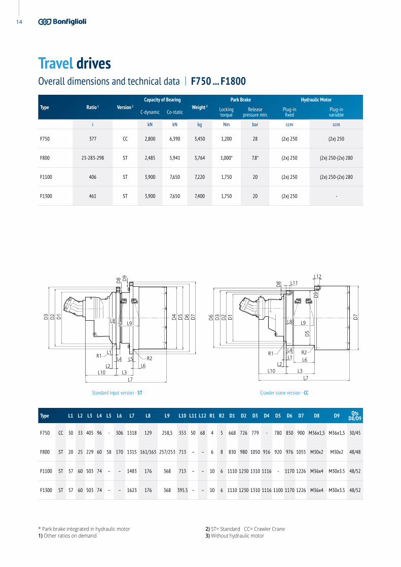
Overall dimensions and technical data | F750 ... F1800
Type Ratio 1 Version 2
Capacity of BearingWeight 3
Park Brake Hydraulic Motor
C-dynamic Co-static Lockingtorque
Releasepressure min.
Plug-infixed
Plug-invariable
i kN kN kg Nm bar ccm ccm
F750 377 CC 2,800 6,390 3,450 1,200 28 (2x) 250 (2x) 250
F800 23-283-298 ST 2,485 5,941 3,764 1,000* 7.8* (2x) 250 (2x) 250-(2x) 280
F1100 406 ST 3,900 7,650 7,220 1,750 20 (2x) 250 (2x) 250-(2x) 280
F1300 461 ST 3,900 7,650 7,400 1,750 20 (2x) 250 -
Type L1 L2 L3 L4 L5 L6 L7 L8 L9 L10 L11 L12 R1 R2 D1 D2 D3 D4 D5 D6 D7 D8 D9 Qty.D8/D9
F750 CC 30 33 405 96 - 306 1318 129 258,5 353 50 68 4 5 668 726 779 - 780 850 900 M36x1,5 M36x1,5 30/45
F800 ST 20 25 229 60 58 170 1315 161/163 257/253 713 – – 6 8 830 980 1050 916 920 976 1055 M30x2 M30x2 48/48
F1100 ST 57 60 503 74 – – 1483 176 368 713 – – 10 6 1110 1230 1310 1116 - 1170 1226 M36x4 M30x3.5 48/52
F1300 ST 57 60 503 74 – – 1623 176 368 395.5 – – 10 6 1110 1230 1310 1116 1100 1170 1226 M36x4 M30x3.5 48/52
Travel drives

15O&K Antriebstechnik
* Park brake integrated in hydraulic motor1) Other ratios on demand
2) ST= Standard CC= Crawler Crane3) Without hydraulic motor
D3
D2 D1
D4
D6
D5
D7
D8 D9
R1 R2
L2
L1L4 L5
L6L10
L8 L9
L3L7
L8
D6
D8
D3
D2 D1
D5
D7
D9
R1 R2
L10L2
L1L4
L9
L3L7
L6
L12L11
Standard input version - ST Crawler crane version - CC
Overall dimensions and technical data | F1800 ... F3000
Type Ratio 1 Version 2
Capacity of BearingWeight 3
Park Brake Hydraulic Motor
C-dynamic Co-static Lockingtorque
Releasepressure min.
Plug-infixed
Plug-invariable
i kN kN kg Nm bar ccm ccm
F1800 656-744ST 3,900 7,650 7,500 1,200 28 - (2x) 250-(2x) 280
CC 3,900 7,650 9,000 1,200 28 (2x) 250 (2x) 250-(2x) 280
F2000 516 - 989ST 5,100 11,600 10,700 2,300 22 - (2x) 250 - (2x) 355
CC 3,900 7,650 9,000 1,200 28 - (2x) 355
F2200 552-989ST 5,100 11,600 10,736 2,300 22 (2x) 355 (2x) 355
CC 3,900 7,650 9,000 1,200 28 (2x) 250 (2x) 250-(2x) 280
F3000 699 ST 6,110 11,900 11,500 1,700 12 - (2x) 250-(2x) 280
Type L1 L2 L3 L4 L5 L6 L7 L8 L9 L10 L11 L12 R1 R2 D1 D2 D3 D4 D5 D6 D7 D8 D9 Qty.D8/D9
F1800ST 54 60 310 74 107 191.5 1839.5 176 368 615.5 – – 10 10 1110 1230 1310 1224 1250 1350 1430 M36x1.5 M42x2 48/40
CC 55 60 478 158 – 239 1785.5 171 375 602.5 50 90 4 6 785 851 923 – 935 1016 1224 M42x2 M42x2 40/40
F2000ST 70 70 343 80 100 80 1846 217 376 591 - - 10 10 1288 1400 1500 1224 1230 1320 1400 M42x3 M42x3 50/48
CC 60 60 478 159 - 239 1956,5 171 375 626 - - 4 6 785 858 930 1224 935 1016 1224 M48x2 M48x2 36/36
F2200ST 60 70 343 80 100 80 1846 217 376 591 - - 10 10 1288 1400 1500 1224 1230 1320 1400 M42x3 M42x3 50/48
CC 55 60 478 158 - 239 1956,5 171 375 626 55 93 4 6 785 858 930 - 935 1016 1224 M48x2 M48x2 36/36
F3000 ST 60 70 343 80 100 80 2000 217 376 606 - - 10 10 1288 1400 1500 1224 1230 1320 1400 M42x3 M42x3 50/48

16
Travel drives
Gear ratios• 248 ... 825
Standard features• Compact structure• High performance• 3-7 Planetary wheels per stage• Notchless ground tooth root• Different ratios• Integrated disc-brake
Special executions on request• Mechanical disconnect device• Low and high temperature version
Torque (kNm)
HYDRAULIC SOLUTIONS
The FP Series are perfectly suitable with any crawler, large excavators and crushers. Thanks to compact, rugged design, high torque and load capabilities, these solutions are the best possible option for the machine. All units are available with a fail-safe parking brake. Different disengagement systems are available on demand for all the sizes.
FP SeriesFinal drives angular input
Stated torques are peak values for short duration.
1,100
130100
180220
440360
560900
FP100FP130FP180FP220FP360FP440FP560FP900FP1100

17O&K Antriebstechnik
1) Other ratios on demand2) ST= Standard CC= Crawler Crane
3) Optional brake torques4) Other dimensions optional
D3
D8
L14L15
L7
L13 L2 L3L1
L4
L8 L9
R1 R2L5 L6
D2
D1
D4
D6
D5
D7
D9
D7D6
R1
L14 L7L15
L3
L6
L9
L12L11
L8
L4 R2
L2L13
L1
D3
D2
D1
D5
D8
D9
Standard input version - ST Crawler crane version - CC
Overall dimensions and technical data
Type L1 L2 L3 L4 L5 L6 L7 L8 L9 L10 L11 L12 L134 L144 L154 L164 L174 R1 R2 D1 D2 D3 D4 D5 D6 D7 D8 D9 Qty.D8/D9 D104 D10 Key4
FP100 35 65 165 28 53 43 463 32 139 – – – 115 215 678 60 215 12/60 5 390 460 500 407 408 460 500 M24x2 M24x2 30/24 40 DIN6885(A12x8x50)FP130 45 45 190 35 58 45 530 50.5 147 – – – 311 411 941 60 215 25 4 390 500 550 449 450 500 550 M24x2 M24x2 32/32 40
FP180 30 30 168 40 56 21.5 534.5 50.3 141.4 – – – 437.5 542.5 1077 75 265 4 3 450 510 560 528 535 600 650 M24x2 M27x2 20/30 50 DIN6885 (A14x9x70)
FP220 18 52 166.5 40 61 35 580.5 16 187.5 – – – 448 593 1173.5 85 300 35°/16/16 4 460 600 650 540 542 600 650 M24x2 M24x2 38/38 55 DIN6885 (A16x10x80)
FP360 100 100 130 40 60 60 657.5 25 215 – – – 380 545 1202.5 110 387 18°/100/16 10 580 680 735 649.5 650 720 775 M30x3.5 M30x3.5 30/30 60 DIN6885 (A18x11x100)
FP440 40 43 255 40 – 120 814 80 213 – 40 70 255 400 1214 85 300 4 4 450 515 569 – 570 620 670 M36x1.5 M30x2 29/42 55 DIN6885 (A16x10x80)
FP560 40 43 255 45 – 120 831.5 80 213 – 45 70 857 1104 1935.5 160 570 4 4 450 515 569 – 570 620 763 M36x1.5 M30x1.5 29/42 90 DIN6885(A25x14x150)FP900 30 33 405 96 – 306 965 129 258.5 – 50 68 612 859 1824 120 540 4 5 668 726 779 – 780 850 900 M36x1.5 M36x1.5 30/45 75
FP1100 54 60 503 74 – 326 1429 179 368 – – – – – – – – 4 5 1110 1230 1310 1116 1100 1170 1226 M36 M30 48/52 60 DIN6885 (A18x11x100)
Type Ratio 1 Version 2
Capacity of BearingWeight
Park Brake Optional
C-dynamic Co-static Locking torque 3 Releasepressure min.
i kN kN kg Nm bar
FP100 426 ST 498 1,010 410 600 15
FP130 825 ST 523 980 452 750 19
FP180 412 ST 787 1,650 757 1,375 35
FP220 248 ST 765 1,660 915 1,200 15
FP360 446 ST 1,040 2,450 1,065 1,700 12
FP440 528 CC 1,040 2,450 1,300 1,700 15
FP560 450 CC 1,040 2,450 2,222 900 13
FP900 406 CC 2,800 6,390 3,750 - -
FP1100 1,088 ST 3,900 7,650 7,684 - -

18
The F Series is perfectly suited to any crawler and milling machine. Thanks to compact, rugged design, high torque and load capabilities, these solutions are the best possible option for thes machines. All units are available with a fail-safe parking brake and for most cartridge type fixed or variable systems. Different disengagement systems are available on demand for all the sizes.
Planetary gearbox withintegrated kit motor
Travel drives
Gear ratios• 45.2
Features• Integrated hydraulic motor• 2 – Stage planetary drive• 2 – Speed hydraulic motor• Counterbalance travel valve• High pressure relief valves• 2 – Speed shift function by external pilot control• Automatically release park brake
Torque (kNm)
HYDRAULIC SOLUTIONS
45under development
under developmentunder developmentunder development
F30KF45KF55KF80KF100K

19O&K Antriebstechnik
DRAIN PORT DR2SIZE 1/2" BSP
D3
D2
D1
D10
D8
D5 D
4
L10L7
L6L3L2
L1 L4 L5
D9
D6
D7
L8 L9
R1R2
HIGH PRESSURE PORT ASIZE 1 BSP
DRAIN PORT DR1SIZE 1/2" BSP
HIGH PRESSURE PORT BSIZE 1" BSP
Type RatioCapacity of Bearing
WeightPark Brake Hydraulic Motor
C-dynamic Co-static Lockingtorque
Automaticrelease
Variabledisplacement
Max.pressure
Max.pump flow
Pilotpressure
i kN kN kg Nm ccm bar L/min bar
F45K 45.2 215 291 296 400 - 175 max / 99 min 350 240 10-40
Type L1 L2 L3 L4 L5 L6 L7 L8 L9 L10 R1 R2 D1 D2 D3 D4 D5 D6 D7 D8 D9 Qty.D8/D9 D10
F45K 20 34 98.5 34 39 20 404 6 213 523 1 2.5 300 340 370 400 402 440 370 M16x2 M16x2 30/30 249
Note: size of high pressure ports A and B optionally PF1`` or SAE 1``
Overall dimensions and technical data

20
Travel drives
Output torque max.• 40000 Nm
Input speed max.• 3500 rpm
Applicable hydraulic motors• Bosch-Rexroth: A6VE55 ~ 107 range• Linde: HMV 55 ~ 75 range• Sauer danfoss: 51C 060 ~ 080 range
Technical features• Two gear shifting transmission• Wet disc clutch unit• Power shift capability• Hydraulic controlled shifting• Integrated park & emergency brake• Optional cooling flow to input stage and clutch unit• Different hydraulic motors• Wide variety of ratio combinations
Ratio combinations
HYDRAULIC SOLUTIONS
The F Series is perfectly suited to any crawler and milling machine. Thanks to compact, rugged design, high torque and load capabilities, these solutions are the best possible option for thes machines. All units are available with a fail-safe parking brake and for most cartridge type fixed or variable systems. Different disengagement systems are available on demand for all the sizes.
F SeriesFinal Drives 2 - Speed
Project related installation drawings can be available on request.Dimensions and technical data are subject to change due to continuous product development
Shifting stageversions
Shifting stageratio ISS
1 5.77
2 5.42
3 4.87*
4 4.44
5 4.26
6 3.81
Main stageversions
Shifting stageratio IMS
A 19.25
B 26*
C 32.14
Brake torque at input shaft Nm 600
Brake torque at output min. Nm 40,000
Clutch operating pressure bar 40 ~ 60
Oil quantity l 3.3
Weight kg 186
All ratios ISS combinable with all ratios IMSFinal ratio if = ISS*IMS* Preferred ratios

21O&K Antriebstechnik
“A”= 94 for hydraulic motors:Sauer 51C080 D3
Linde HMV75Rexroth A6VE80
“A”= 124 for hydraulic motors:Sauer 51C110Rexroth A6VE107
M20x1.5
Ø37
5
Ø29
6
Ø30
0
4540
60∞
193 (Base of bearing)
20391“A”30
15 7.537
Ø35
0
Ø43
5
Ø30
4
bearing center line
16 studs or 16 boress
Total Static load rating
Co=670 [kN]Dynamic load rating
C=395 [kN]
R137.5
R131
.5
Ø340
M20 2 holes
M20 16 holes
224
44
22.5°
57°
Hydraulic motor screwengagement depth 22
1
2
3 4
5 6
1. Oil filling plug M22×1.5
2. Oil draining plug M22×1.5
3. Low speed clutch port R1/4"G acc. DIN3852 “X”
4. High speed clutch port R1/4"G acc. DIN3852 “X”
5. Flushing oil input port M22×1.5 DIN3852 “X”
6. Flushing oil output port M22×1.5 DIN3852 “X”
Port Pressure Function
3 40 bar Small clutch piston pressurized T/M ratio lowgear
4 40 bar Large clutch piston pressurized T/M ratio highgear
3 & 4 0 bar Large & small clutch engaged, T/M in park break position
Overall dimensions and technical data

22
Travel drives
Gear ratios• 28 ... 34
Standard features• Compact structure• High performance• 3-7 Planetary wheels per stage• Notchless ground tooth root• Different ratios• Integrated disc-brake
Special executions on request• Mechanical disconnect device
Max. torque (kNm)
HYDRAULIC SOLUTIONS
The FR Series is the best solution when designing large wheeled off-road machinery. With a compact design, high torque and load capacities, a negative multi-disk parking brake and an optional disengagement device to tow the vehicle in an emergency, these solutions precisely match the application requirements.
FR SeriesWheel Drives
6040
20FR20FR40FR60
Nominal torque (kNm)
Stated torques are peak values for short duration.
3023
16FR20FR40FR60

23O&K Antriebstechnik
1) Other ratios on demand2) Other hydraulic motors on request
3) Without hydraulic motor4) Multi-disk brake
D6
D7
D5
D4
D2
D1
D9
D8
D3
L10
L8 L9
L6
R2R1
L1L2
L5L4L5
L7
L6
D6
D5
D4
D8
D9
D2
D1
D3
D7
L1L2
L4L3
L5
L7
L6
Version A Version B
Overall dimensions and technical data
Type Ratio 1 VersionCapacity of Bearing
Weight 3Input
torquemax.
Hydraulic Motor 2
(Variable)
Operating pressure
max.
Service brake 4 Park Brake 4
C-dynamic Co-static Pressuremax.
Lockingtorque dyn.
Locking torque max. stat.
Release pressure max.
Release pressure max.
i kN kN kg Nm ccm bar bar Nm Nm bar bar
FR20 28-34 A 194 325 129 560 80 (105) 420 100 9,500 24,480 80 40
FR40 30-32 B 300 560 173 715 107 (-) 420 110 13,000 23,000 80 40
FR60 29-34 A 352 735 500 1,066 160 (-) 420 90 28,000 30,000 60 25
Type L1 L2 L3 L4 L5 L6 L7 L8 L9 L10 R1 R2 D1 D2 D3 D4 D5 D6 D7 D8 D9
FR20 318 141 – 9 7 50 177.5 58 110 29 – – 335 280.8 f7 375 270 f8 315 380 10xM24x2 10xM22x1.5 279.5
FR40 441 135.7 52.7 80 43 63 225 80 105 32 5 1 425 371-0.2 465 290 f8 367 405 M24(6x) M20(4x) 18xM22x1.5 340
FR60 520 270 – 10 7 60 240 156 173 37 – 1.6 425 375 f8 559 290 f8 330 554 10xM24x2 24xM22x1.5 356

24
Slew drives
Gear ratios• 23 ... 187
Standard features• Compact structure• High performance• Notchless ground tooth root• Integrated disc-brake• Suitable for various hydraulic motors
Torque (kNm)
HYDRAULIC SOLUTIONS
The Bonfiglioli S series provides the safest and most effective solution for cranes, excavators and forestry machines. Its compact design allows it to perfectly fit cranes, excavators and special equipment where installation space is limited.
S Series
Stated torques are peak values for short duration.
130
75.5
1013.3
2017.5
303435
4054
6062
90
S5S7S10S13S17S20S30S34S35S40S54S60S62S90S130

25O&K Antriebstechnik
1) Other ratios on demand2) Other hydraulic motors on request
3) Output Pinion execution acc. to requirement4) Optional
D5
D3
D4
D1
D2
L1L3L4
eL5B
L2
z/m
R1
Overall dimensions and technical data | S5 ... S17
Type L1 L2 L3 L4 L5 D1 D2 D3 D4 e R1
S5 60 262 31 40 302 175 260 288 12x17.5 – 6
S7 60 296 31 40.5 336.5 230 285 322 12x17.5 – 6
S10 60 306.5-314 36 50 356.5-364 250 305 335 18x17.5 – 4
S13 71 340 30(50)4 55(75)4 395(415)4 275 335 370 20x17.5 1 4
S17 86 355 50.5 55 410 275 335 370 20x17.5 – 4
Type Ratio 1 Hydraulic motors 2
Multi-disc brakeOutput pinion 3
Weightwithout Motor
(appr.)Braking torque
Release pressure min.
i ccw Nm bar z/m - B - D5 kg
S5 25-33 28-30-32 310 1410/10
95130
10/1079
130
11/1079
143
14/869
134
15/6.3577
112- - 68
S7 23-27-33 45-56-63 475 1410/11
79141
12/1079
151
13/1079
158
13/1098
155- - - 98
S10 24-27-31-36 45-56-63-80-90 475 1412/12
90184
13/1085
158
13/1094.5155
13/10100158
13/12110190
13/1290
195- 108-123
S13 36 56-63-80-90 740 1810/14
99181
11/1499
198
12/1299
184
13/1288
195
13/124
1104
1904
14/12110199
14/12110201
147
S17 33 80-90 890 1811/14109198
11/16109220
12/12104184
13/124
1104
1904
13/14122221
14/16150273
- 168

26
1) Other ratios on demand2) Other hydraulic motors on request
3) Output Pinion execution acc. to requirement
D5
D3
D4
D1
D2
L1L3L4
eL5B
L2
z/m
R1
Slew drivesOverall dimensions and technical data | S20 ... S40
Type L1 L2 L3 L4 L5 D1 D2 D3 D4 e R1
S20 57 403 16 252 775 280 350 380 18 – –
S30 332 737 33 65 802 350 415 450 24x22 – 1.6
S34 332 785 33 65 808 350 415 450 24x22 – 1.6
S35 239 653 30 91 744 400 460 500 24x26 2 10
S40 64 625 16 245 721 282 375 410 18 – –
Type Ratio 1 Hydraulic motors 2
Multi-disc brakeOutput pinion 3
Weightwithout Motor
(appr.)Braking torque
Release pressure min.
i ccw Nm bar z/m - B - D5 kg
S20 103-79 45 553 1813/16120249
- - - - - - 260
S30 45 125 1,030 1812/16154243
- - - - - - 540
S34 45 160 1,030 1812/16154243
- - - - - - 480
S35 35 180 1,030 1812/18160274
- - - - - - 528
S40 62 90 574 1812/16100235
- - - - - - 274

27O&K Antriebstechnik
1) Other ratios on demand2) Other hydraulic motors on request
3) Output Pinion execution acc. to requirement4) Hydraulic motor connection on demand
D5
D3
D4
D1
D2
L1L3L4
eL5B
L2
z/m
R1
Overall dimensions and technical data | S54 ... S130
Type L1 L2 L3 L4 L5 D1 D2 D3 D4 e R1
S54 610 780 40 87 917 460 520 562 24x26 – –
S60 – 830 40 132 962 460 520 562 26 – –
S62 60 735 20 28 763 – – – – – –
S90 80 730 173 199 929 500 640 690 18x30 – –
S130 578 622 95 160 1012 630 675 715 34x26 – –
Type Ratio 1 Hydraulic motors 2
Multi-disc brakeOutput pinion 3
Weightwithout Motor
(appr.)Braking torque
Release pressure min.
i ccw Nm bar z/m - B - D5 kg
S54 48 180-200 1,200 3813/22230357
12/20188301
- - - - - 867
S60 62 80 1,200 3813/22228356
- - - - - -
S62 187 80 533 1814/20160335
- - - - - - 564
S90 39 355-200 3,000 14 16/24
182464
16/22177422
- - - - - 1,225
S130 67 Electric4 2,300 22.513/30230480
- - - - - - 2,276

28
Cutter drives
Gear ratios• 16 ... 26
Standard features• Compact structure• High performance• Notchless ground tooth root• Different ratios• Integrated disc-brake• Suitable for various hydraulic motors
Cutting torque (kNm)
HYDRAULIC SOLUTIONS
Dual stage planetary drive units with integrated pulley support, designed for cold planers, milling machines and surface mining machines with engine power from 80 to 1200kW and different rotor widths. The offset input option ensures higher machine productivity due to the increased cutting depth. The shiftable 2 speed solution allows two possible cutting speeds with huge benefits in terms of machine performance.
FA SeriesMedium cutter drives
32
128.5
1623
FA30FA40FA55FA80FA100
Input power (kW)
300
11080
150220
FA30FA40FA55FA80FA100

29O&K Antriebstechnik
1) Other ratios on demand 2) ST - Standard Input / MI - Mechanical Input (Hydraulic Motor)
D3
D2
D1D3
D2
D1
D10
D11
D12 D4
D6
D7D4
D6
D7
D13
D8 D
9
D5
L7
L3
L4L4
L7L3
L5 L6L5 L6
L9L8
D5
L9L8
L11
D8 D
9
L11
L1
L2
L1
L2
L10
Standard input version - ST Mechanical input version - MI
Overall dimensions and technical data
Type L1 L2 L3 L4 L5 L6 L7 L8 L9 L10 L11 R1 R2 D1 D2 D3 D4 D5 D6 D7 D8 D9 Qty.D8/D9 D10 D11 D12 D13 Qty.
D13
FA30 ST 13 25 75 15 29 25 278.5 28 89 – 15 2.5 2.5 – – – 269 270 305 335 M16x2 17.5 18/18 – – – – –
FA40ST 12 35 91 21 34 26 327 38 100 – 21 2.5 2.5 270 310 345 294 295 335 370 M20x1.5 17.5 16/20 – – – – –
MI 10 10 125 55 32 26 631.5 72 100 402 55 1 2.5 270 310 360 294 295 335 370 M20x1.5 17.5 16/20 138 110 80 M16x2 6
FA55ST 12 25 110 24 34 30 374 64 113 – 24 1 2.5 280 325 360 329 350 400 435 M20x1.5 22 24/20 – – – – –
MI 18 18 136 50 34 30 688.5 90 113 421 50 1 2.5 280 325 360 329 350 400 435 M20x1.5 22 24/20 138 110 80 M16x2 6
FA80 ST 20 35 90 22 35 24 414.5 34 123 – 22 4 2.5 330 370 410 374 400 450 490 M24x2 25 20/20 – – – – –
FA100ST 35 35 165 28 51 43 461 32 139 – 28 12/60 5 390 460 500 407 408 460 502 M24x2 26 30/24 – – – – –
MI 8 8 182 28 40 43 843.5 27 138 540 28 1.6 2.5 325 380 415 407 408 460 502 M20x2.5 26 12/12 165 130 85 M16x2 8
Type Ratio 1 Version 2
Capacity of BearingWeight
C-dynamic Co-static
i kN kN kg
FA30 19-22 ST 132/194 255/325 86
FA40 19ST 224 405 122
MI 224 405 172
FA55 16-19-22ST 224 405 163
MI 224 405 223
FA80 19 ST 300 570 223
FA100 14-21-22-26ST 498 1,010 330
MI 498 1,010 360

30
Cutter drives
Gear ratios• 14 ... 26
Standard features• Compact structure• High performance• Notchless ground tooth root• Different ratios• Integrated disc-brake• Suitable for various hydraulic motors
Cutting torque (kNm)
HYDRAULIC SOLUTIONS
Dual stage planetary drive units with integrated pulley support, designed for cold planers, milling machines and surface mining machines with engine power from 80 to 1200kW and different rotor widths. The offset input option ensures higher machine productivity due to the increased cutting depth. The shiftable 2 speed solution allows two possible cutting speeds with huge benefits in terms of machine performance.
FA SeriesLarge cutter drives
Input power (kW)
115
4738
5284
FA130FA180FA200FA360FA800
1,200
450400
550880
FA130FA180FA200FA360FA800

31O&K Antriebstechnik
1) Other ratios on demand2) ST - Standard Input / MI - Mechanical Input (Hydraulic Motor)
3) Special bearing
D3
D2
D1D3
D2
D1
D10
D11
D12 D4
D6
D7D4
D6
D7
D13
D8 D
9
D5
L7
L3
L4L4
L7L3
L5 L6L5 L6
L9L8
D5
L9L8
L11
D8 D
9
L11
L1
L2
L1
L2
L10
Standard input version - ST Mechanical input version - MI
Overall dimensions and technical data
Type L1 L2 L3 L4 L5 L6 L7 L8 L9 L10 L11 R1 R2 D1 D2 D3 D4 D5 D6 D7 D8 D9 Qty.D8/D9 D10 D11 D12 D13 Qty.
D13
FA30ST 18 20 215 78 57 45 530 81.4 139.2 – 37 2 2 325 380 430 449 450 500 540 M30x3.5 26 12/24 – – – – –
MI 18 20 215 78 57 45 913 81.4 139.2 585 37 2 2 325 380 430 449 450 500 540 M30x3.5 26 12/24 165 130 85 k6 M16x2 8
FA40 MI 20 20 173.5 80 56 21,5 913 81 140 576 30 2 2 325 380 – 528 529 565 – M30 M16 12/30 – – – – –
FA55ST 20 25 160 102 58 22 603.5 75.8 149.4 – 37 2 2 323.8 381 482 540 605 635 663 M30x2 18 12/24 – – – – –
MI 20 25 160 102 58 22 890.5 75.8 149.4 438 37 2 2 323.8 381 482 540 605 635 663 M30x2 18 12/24 165 130 85 k6 M16x2 8
FA80 ST 35 100 130 40 60 80.5 657.5 75.1 214.8 – 40 18°/100/16 10 580 680 735 649.5 650 720 775 M30x3.5 M30x3.5 30/30 – – – – –
FA100 ST 20 25 229 60 95 89 981 (3) (3) – 60 6 8 830 980 1050 930 1040 1250 1329 M30x2 M30x2 48/48 – – – – –
Type Ratio 1 Version 2
Capacity of BearingWeight
C-dynamic Co-static
i kN kN kg
FA130 14-18-21-22-26ST 750 1,290 426
MI 750 1,290 490
FA180 23 MI 755 1,339 637
FA200 20-24ST 787 1,650 710
MI 787 1,650 718
FA360 25 ST 1,040 2,450 1,145
FA800 24 ST 4,300 9,650 4,223

32
Cutter drives
Gear ratios• 13 ... 22
Standard features• Two speed shifting transmission• Main drive from proven cutter standard range (FA130/FA200)• Hydraulic shifting unit for gear change• Cutter main drive & shifting unit modular concept for easy manteinance
Cutting torque (kNm)
HYDRAULIC SOLUTIONS
Dual stage planetary drive units with integrated pulley support, designed for cold planers, milling machines and surface mining machines with engine power from 80 to 1200kW and different rotor widths. The offset input option ensures higher machine productivity due to the increased cutting depth. The shiftable 2 speed solution allows two possible cutting speeds with huge benefits in terms of machine performance.
FA SeriesCutter Drives 2-Speed
4738FA130-2S
FA200-2S
Input power (kW)
540400FA130-2S
FA200-2S

33O&K Antriebstechnik
D9
D7
D4
D6
D5
L5 L6
L3L10
L7
L1
L8
L9
L4
D14
R1
D1
D8
L11
L2
D12
D11
D13
D2
D3
D10
AB
C
Overall dimensions and technical data
Type L1 L2 L3 L4 L5 L6 L7optional
L8 L9 L10 L11 R1 R2
FA130 - 2S 207.65 25 822.2 413 57 45 1418 1442.5 688.6 139.2 822.2 40 2
FA200 - 2S 207.65 25 807.2 413 32 25 1378 1402.5 683 149.4 1025 40 2
Type D1 D2 D3 D4 D5 D6 D7 D8 Qty.D8 D9 Qty.
D9 D10 D10optional
D11 D11optional
D12 D12optional
D13 D13optional
Qty.D13
FA130 - 2S 264.265 342.9 393 449 450 500 540 1.25-7 UNC 12 26 24 228.6 196.85 140 158.75 140 120.7 5/8-11 UNC STUD 5/8-11 UNF 8
FA200 - 2S 264.265 342.9 393 533.5 590.8 641.35 679.32 1.25-7 UNC 12 19.84 20 228.6 196.85 140 158.75 140 120.7 5/8-11 UNC STUD 5/8-11 UNF 8
Type Version Ratio VersionCapacity of Bearing
WeightShifting pressure
C-dynamic Co-static Min. Max.
i kN kN kg bar bar
FA130 - 2S1 21-13.67
ccw 750 1,290 900 35 502 22.235-18.01
FA200 - 2S1 19.877-13
ccw 787 1,650 1,050 35 502 21.05-17.05
A. Flushing port oil inB. Shifting port 50 barC. Flushing port oil out

34
Hoisting Slewing BoomActivation
TrolleyTravelling
CraneTravelling
Erection cranes M 2 - M 3 M 2 - M 3 M 1 - M 2 M 1 - M 2 M 2 - M 3
Loading bridges hook M 5 - M 6 M 4 — M 4 - M 5 M 5 - M 6
Loading bridges grab ormagnet M 7 - M 8 M 6 — M 6 - M 7 M 7 - M 8
Workshop cranes M 6 M 4 — M 4 M 5
Overhead travelling cranes,ram cranes, scrap yard cranes
grab ormagnet M 8 M 6 — M 6 - M 7 M 7 - M 8
Unloading bridges, container gantry cranes
hook or spreader M 6 - M 7 M 5 - M 6 M 3 - M 4 M 6 - M 7 M 4 - M 5
Other gantry cranes (with trolley and/or live ring) hook M 4 - M 5 M 4 - M 5 — M 4 - M 5 M 4 - M 5
Unloading bridges, container gantry cranes (with trolley and/or live ring)
grab ormagnet M 8 M 5 - M 6 M 3 - M 4 M 7 - M 8 M 4 - M 5
Berth cranes, shipyard cranes,dismantling cranes hook M 5 - M 6 M 4 - M 5 M 4 - M 5 M 4 - M 5 M 5 - M 6
Dockside cranes (slewable, gantry type, ...), floating cranes, floating sheerlegs hook M 6 - M 7 M 5 - M 6 M 5 - M 6 — M 3 - M 4
Dockside cranes (slewable, gantry type, ...), floating cranes, floating sheerlegs
grab ormagnet M 7 - M 8 M 6 - M 7 M 6 - M 7 — M 4 - M 5
Floating cranes and floating sheerlegs forvery high loads (normally above 100 t) M 3 - M 4 M 3 - M 4 M 3 - M 4 — —
Shipboard cranes hook M 4 M 3 - M 4 M 3 - M 4 M 2 M 3
Shipboard cranes grab ormagnet M 5 - M 6 M 3 - M 4 M 3 - M 4 M 4 - M 5 M 3 - M 4
Tower cranes for construction sites M 4 M 5 M 4 M 3 M 3
Derrick tower gantry M 2 - M 3 M 1 - M 2 M 1 - M 2 — —
Railroad cranes, approved for service in trains M 3 - M 4 M 2 - M 3 M 2 - M 3 — —
Vehicle-mounted cranes hook M 3 - M 4 M 2 - M 3 M 2 - M 3 — —
Winch drivesClassification of crane

35O&K Antriebstechnik
T2 T3 T4 T5 T6 T7 T8
Average usage per day [h] 0.25 - 0.5 0.5 - 1 1 - 2 2 - 4 4 - 8 8 - 16 about 16
Total service life [h] 400 - 800 800 - 1600 1600 - 3200 3200 - 6300 6300 - 12500 12500 - 25000 25000 - 50000
Duty cycle load class Machine class & torque conversion factor K
L1 light M 11.24
M 21.24
M 31.11
M 41.11
M 50.95
M 60.91
M 70.85
L2 medium M 21.24
M 31.24
M 41.08
M 51
M 60.87
M 70.80
M 80.67
L3 heavy M 30.98
M 40.95
M 50.91
M 60.80
M 70.71
M 80.59
M 80.56
L4 extremely heavy M 40.80
M 50.75
M 60.71
M 70.63
M 80.56
M 80.5
M 80.44
Torque conversion factors kaccording to FEM 1.001 3rd edition, Section 1
Definition of Nominal Torque TNom• Drum output speed 25 rpm• FEM class M5 / T5 / L2
Torque calculation Teff for alternative FEM – class• Teff = K × TNom
• K: torque conversion factor
Additional check - conditions1. For all machine classes > M5 (M6-M8): to be checked, whether drum output
speed 25rpm must be reduced. Refer to Bonfiglioli Sales or Application engineering.
2. Brake torque safety must be checked upon formula:
> 1.6V=TBrake x i
Teff
TBrake: brake torque at drive input i: drive ratio If brake safety < 1.6 refer to Bonfiglioli Sales or Application engineering.

36
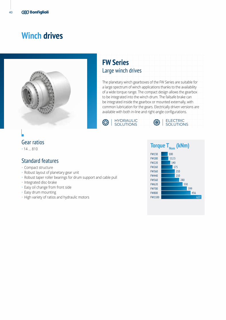
Winch drives
Gear ratios• 19 ... 409
Standard features• Compact structure• Robust layout of planetary gear unit• Robust taper roller bearings for drum support and cable pull• Integrated disc-brake• Easy oil change from front side• Easy drum mounting• High variety of ratios and hydraulic motors
Torque TNom (kNm)
The planetary winch gearboxes of the FW Series are suitable for a large spectrum of winch applications thanks to the availability of a wide torque range. The compact design allows the gearbox to be integrated into the winch drum. The failsafe brake can be integrated inside the gearbox or mounted externally, with common lubrication for the gears. Electrically driven versions are available with both in-line and right-angle configurations.
FW SeriesSmall winch drives
HYDRAULIC SOLUTIONS
ELECTRIC SOLUTIONS
2020
7.255.4
17.6
FW10FW13FW30FW40FW40A

37O&K Antriebstechnik
Overall dimensions and technical data
Type L1 L2 L3 L4 L5 L6 L7 L8 L9 R1 R2 D1 D2 D3 D4 D5 D6 D7 D8 D9Vers. A
D9Vers. B
Qty.D8/D9
FW10 10 30 72 13.5 15 16 230 28 79 0.6 0.6 190 230 256 216 220 260 290 M16x2 M16x2 17 12/8
FW13 10 30 72 13.5 15 16 255 28 79 0.6 0.6 190 230 256 216 220 260 290 M16x2 M16x2 17 12/8
FW30 13 25/22 75 15 29 25 323/320 28.5 89 2.5 2.5 240 275 304 269 270 305 335 M16x2 M16x2 17 18/18
FW40 16 16 91 21 34 26 338 38 100 2.5 2.5 240 285 320 294 295 335 370 M16x1.5 M16x1.5 17.5 20/20
FW40A 13 35 91 21 34 26 357 38 100 2.5 2.5 270 310 345 294 295 335 370 M16x1.5 M16x1.5 17.5 16/20
D1
D2D
3
D6
D7
L2
R1
R2
L7
L8
Z
L9
D4
L3
D9
D9
D8
L4
D5
Detail ZFlange version A
Flange version B
L5 L6
1) Other ratios on demand
Type Ratio 1 Max Rope Pull Output Torque Peak
i ton Nm
FW10 35-51 2..4 10.000
FW13 93-108-122-140-178-229 4..6 13.000
FW30 19-32-61-66-81-90-101-114-121-137-171-228-305 6..8 30.000
FW40 19-22-32-61-66-81-85-101-110-117-124-142-181-222-266-409 8..10 40.000

38
Winch drives
Gear ratios• 14 ... 228
Standard features• Compact structure• Robust layout of planetary gear unit• Robust taper roller bearings for drum support and cable pull• Integrated disc-brake• Easy oil change from front side• Easy drum mounting• High variety of ratios and hydraulic motors
Torque TNom (kNm)
The planetary winch gearboxes of the FW Series are suitable for a large spectrum of winch applications thanks to the availability of a wide torque range. The compact design allows the gearbox to be integrated into the winch drum. The failsafe brake can be integrated inside the gearbox or mounted externally, with common lubrication for the gears. Electrically driven versions are available with both in-line and right-angle configurations.
FW SeriesMedium winch drives
HYDRAULIC SOLUTIONS
ELECTRIC SOLUTIONS
70
25.425.4
25.442.8
FW55FW55AFW55BFW80FW100

39O&K Antriebstechnik
Overall dimensions and technical data
Type L1 L2 L3 L4 L5 L6 L7 L8 L9 R1 R2 D1 D2 D3 D4 D5 D6 D7 D8 D9Vers. A
D9Vers. B
Qty.D8/D9
FW55 12 25 110 24 36 30 413 64 113 1 2.5 280 325 360 340 350 400 435 M20x1.5 M20x1.5 22 24/20
FW55A 20 30 91 24 36 30 399 45 113 4 2.5 240 285 320 340 350 400 435 M20x1.5 M20x1.5 22 20/20
FW55B 12 37 110 24 36 30 425 64 113 1 2.5 290 335 370 340 350 400 435 M20x1.5 M20x1.5 22 20/20
FW80 20 35 90 22 37 24 415 34 123 4 2.5 330 370 410 374 400 450 490 M24x2 M24x2 26 20/20
FW100 35/37 35/37 165 28 53 43 461/463 32 139 10 (12)/60 5 390 460 500 407 408 460 500 M24x2 M24x2 26 30/24
1) Other ratios on demand
Type Ratio 1 Max Rope Pull Output Torque Peak
i ton Nm
FW55 16-19-22-32-63-68-87-94-103-117-124-137-148-185 10..12 55.000
FW80 19-32-61-81-101-114-121-137-147-171-187-206-228 12..16 80.000
FW100 14-21-22-26-32-77-84-95-121-142-175-192-226 16..24 10.000
D1
D2D
3
D6
D7
L2
R1
R2
L7
L8
Z
L9
D4
L3
D9
D9
D8
L4
D5
Detail ZFlange version A
Flange version B
L5 L6
40
Winch drives
Gear ratios• 14 ... 810
Standard features• Compact structure• Robust layout of planetary gear unit• Robust taper roller bearings for drum support and cable pull• Integrated disc-brake• Easy oil change from front side• Easy drum mounting• High variety of ratios and hydraulic motors
Torque TNom (kNm)
The planetary winch gearboxes of the FW Series are suitable for a large spectrum of winch applications thanks to the availability of a wide torque range. The compact design allows the gearbox to be integrated into the winch drum. The failsafe brake can be integrated inside the gearbox or mounted externally, with common lubrication for the gears. Electrically driven versions are available with both in-line and right-angle configurations.
FW SeriesLarge winch drives
HYDRAULIC SOLUTIONS
ELECTRIC SOLUTIONS
627
210175
210280
330399
456
140
100112.5
FW130FW180FW220FW260FW360FW440FW560FW620FW700FW800FW1100

41O&K Antriebstechnik
1) Other ratios on demand
D1
D2D
3
D6
D7
L2
R1
R2
L7
L8
Z
L9
D4
L3
D9
D9
D8
L4
D5
Detail ZFlange version A
Flange version B
L5 L6
Overall dimensions and technical data
Type L1 L2 L3 L4 L5 L6 L7 L8 L9 R1 R2 D1 D2 D3 D4 D5 D6 D7 D8 D9Vers. A
D9Vers. B
Qty.D8/D9
FW130 45 45 190 35 58 45 530 50.5 147 25 4 390 500 550 449 450 500 550 M24x2 M24x2 26 32/32
FW180 30 30 168 40 56 21.5 534.5 50.3 141.4 4 3 450 510 560 528 535 600 650 M24x2 M24x2 26 30/30
FW220 18 52 166.5 40 61 35 580.5 16 187.5 35°/16/16 4 460 600 650 540 542 600 650 M24x2 M24x2 26 38/38
FW260 21 45 170 40 48 60 579 18.5 189.5 2 – 460 520 570 608 610 680 735 M30x2 M30x2 32 24/24
FW360 100 100 130 40 60 80 658 -25 215 18°/100/16 10 580 680 735 649 650 720 775 M30x3.5 M30x3.5 32 30/30
FW440 40 43 255 40 25 25 820 80 213 4 4 450 515 569 669 570 620 670 M36x3 M30x3 32 30/30
FW560 40 43 255 45 45 120 831.5 80 213 4 4 450 515 569 763 570 620 670 M36x1.5 M30x1.5 32 29/42
FW620 30 33 405 96 – 306 1159 99 287 4 5 668 726 779 – 782 830 880 M36x1.5 M30x2 32 30/45
FW700 30 33 405 96 – 306 1283.5 99 287 4 5 668 726 779 – 780 850 900 M36x1.5 M36x1.5 38 30/45
FW700A 30 33 405 96 – 306 1372.5 99 287 4 5 668 726 779 – 780 850 900 M36x1.5 M36x1.5 38 30/45
FW800 20 25 229 60 58 170 1315 161/163 257/253 6 8 830 980 1050 916 920 976 1055 M30x2 M30x2 32 48/48
FW1100 57 60 503 74 – – 1483 176 368 10 6 1110 1230 1310 1116 - 1170 1226 M36x4 M30x3.5 32 48/52
Type Ratio 1 Max Rope Pull Output Torque Peak
i ton Nm
FW130 14-18-21-22-43-55-70-81-85-95-115-123-141-159-167-180-206 24..32 13.000
FW180 23-206-222-256-281 32..34 180.000
FW220 69-97-120-165-191-248-290-345-810 34..40 220.000
FW260 69-97-148-168-243-251-345 40..46 260.000
FW360 25-94-128-160-168-186-223-242-257-283-340-343-490 46..52 360.000
FW440 310-352-415-555-637 52..54 440.000
FW560 250-357-388-519-739 54..65 560.000
FW620 30-250-293-328-495 65..70 620.000
FW700 377-648 70..76 700.000
FW800 23-283-298 76..88 800.000
FW1100 404-406 88..104 1.100.000

42
Machine weight tons Winch Drive
Up to 15 FW13
15–20 FW30
20–28 FW30
28–33 FW40
33–40 FW40
40–50 FW55
50–70 FW80
70–80 FW130
80–100 FW130
100–120 FW180
120–150 FW180
150–180 FW220
180–200 FW620
200–300 FW1100
Winch drivesWinch system for vertical drills with external or internal brake

O&K Antriebstechnik 43
Winch drives
General requierements• Planetary drive• Winch drum• Dynamic safety brake & elastic couplings• Winch drum support / Torque arm• Motor support for IEC electric motor
Winch system for harbour cranes
F560TPS F260TPS
Ratio gearbox (-) 38.462 36
Nominal load t 50 32
FEM – CLASS (-) M8 - T9 M8 - T7
Requested lifetime according FEM h 50000 25000
Drum winding diameter mm 950 725
Rope diameter mm 38 29
Nominal torque Nm 129941 65166
Max rope speed (empty) m/min 140 120
Max torque (grab bulk mode) Nm 253700 155800
Max drum speed (grab bulk mode) U/min 14 23,7
Max torque (cargo mode) Nm 259900 130300
Max drum speed (cargo mode) U/min 36.9 35.2

44
Other drives
Gear ratios• 19.8 ... 1500
Standard features• Compact structure• High performance• 3–7 Planetary wheels per stage• Notchless ground tooth root• Different ratios• Different input options• Different output options• Optional integrated disc-brake
Special executions on request• Water jacket • Oil & air cooling system• Safety clutch
Torque (kNm)
The FTU Series are perfectly suited to tunnel boring machines and large mining equipment. Robust, powerful and durable these drives are matching all the requirements of this specific application.
FTU SeriesTorque units and tunneling drives
HYDRAULIC SOLUTIONS
280260
3000
800620
13002200
FTU260FTU280FTU620FTU800FTU1300FTU2200FTU3000

45O&K Antriebstechnik
1) Input options: Hydraulic Motor Electric Motor Angular / Bevel Gear Spline Shaft Spline Hollow Shaft Hollow Shaft Shrink Disk Key Shaft Flange
2) Output options: Spline Shaft Spline Hollow Shaft Hollow Shaft Shrink Disk Key Shaft Flange
3) Depending on ratio and input/output option
Overall dimensions and technical data
Main Output Section Ratio Section Input Section
Input Optionssee remark (1)
Output Options see remark (2)
D2
D3
D4
D1
D5
D6L4L1
L2 L3
L7
L5 L6
Type L1 L2 L3 L4 L5 L6 L7 D1 D2 D3 D4 D5 D6 Qty.D6
FTU260 15 340 650 65 (3) (3) 990 630 690 750 660 (3) 26 36
FTU280 31 646 365 60 (3) (3) 1011 630 770 820 600 (3) 26 36
FTU620 60 95 640 54 (3) (3) (3) 895 1000 1060 885 (3) 33 36
FTU800 65 100 730 58 (3) (3) (3) 955 1010 1090 920 (3) 33 48
FTU1300 80 110 938 75 (3) (3) (3) 1240 1330 1430 1224 (3) 45 52
FTU2200 125 142.5 1112 100 (3) (3) (3) 1340 1440 1540 1216 (3) 45 48
FTU3000 125 142.5 1112 80 (3) (3) (3) 1340 1440 1540 1216 (3) 45 48
Type Ratio - Range Input options Output options
(-)
FTU260 52 ... 1,500 (1) (2)
FTU280 57 ... 1,500 (1) (2)
FTU620 24 ... 1,500 (1) (2)
FTU800 24.5 ... 1,500 (1) (2)
FTU1300 34.7 ... 1,500 (1) (2)
FTU2200 19.8 ... 1,500 (1) (2)
FTU3000 19.8 ... 1,500 (1) (2)

46
Other drives
Max. jacking load• 560 metric tons / 600 short tons / 1,230 Kips
Max. holding torque• Up to 2,400 kNm
Max. storm holding torque• Up to 2,900 kNm
Applicable motors• Piston hydraulic motors• Electric motors IEC
Max jacking (kNm)
The specific design of the O&K Jack-up Series has been assessed by ABS to work in lifting and lowering legs and hulls of drilling and service jack up rigs, lift boats and windmill installation vessels. Units can be in-line or have a drop box for offsetting the motor installation. They can be electrically or hydraulically driven, with or without a negative parking brake. These jack-up drives can deliver integrated pinions from m50 to m100 and lantern pieces with integrated torque arm for easy installation. Units have class approval from ABS and DNV GL, and full 3.2 certification of the load-bearing parts of the gear transmission with full traceability from raw material to final machined component.
Jack-up drives
1900JD2400
HYDRAULIC SOLUTIONS ELECTRIC SOLUTIONS

47O&K Antriebstechnik
ø145
0 ø1
230
ø101
5
ø45
48 BOHRUNGEN HOLES7.5° x 48 = 360°
ø135
0
ø126
0
ø399
.77
8
80
701.5
80
2971.4 1360
343.5310320
ø450
48 BOHRUNGEN HOLES7.5° x 48 = 360°
8
ø450
ø126
0 ø145
0 ø1
230
ø135
0
701.5
80
437.5
1729
80
ø45
Overall dimensions and technical data

48
TrencherExcavator travel drive CE
Excavator weight tons Track Drive Slew Drive
6–8 F10 S5
8–10 F13 S5
10–12 FD20 S5
12–18 F30 S7
18–22 F40 S10
22–28 F55 S13
28–35 F80 S17
35–50 F100 S30
50–70 F130 S30
70–90 F180 S34
Excavator travel drive mining
Excavator weight tons Track Drive Slew Drive
50–70 F130 S30
70–90 F180 S34
90–120 F220 S54 (1x)
120–150 F280 S54 (1x)
150–180 F360 S54 (2x)
180–220 F420 S54 (2x)
220–300 F620 S54 (3x)
300–400 F800 S54 (3x)
400–500 F1100 S54 (4x)
500–600 F1300 S54 (4x)
600–800 F1800 S54 (5x)
800–1000 F2200 S54 (6x)
1200–1400 F3000 S130 (4x)
Crawler crane
Crane lifting capacity tons Travel Drive Winch Drive
40 F80 (2x) FW80
80 F100 (2x) FW80
100 F130 (2x) FW100
130 F180 (2x) FW100
160 F260 (2x) FW130
250 F440 (2x) FW130
300 F560 (2x) FW180
350 F620 (2x) FW220
400 F650 (2x) FW220
600 F700 (2x) FW220
600 F740 (2x) FW260
800 F560 (4x) FW260
1200 F750 (4x) FW220 (2x)
2500 F1800 (4x) FW220 (2x)
4000 F2200 (4x) FW360 (2x)
Machine weight tons Track Drive
20–30 F55
30–40 F80
40–50 F100
50–80 F130
80–100 F180
100–120 F220
120–150 F280
150–180 F360
Crusher / Screener
Machine weight tons Track Drive
20–30 F30
30–40 F40
40–50 F55
50–70 F80
70–90 F100
90–110 F130
Towing tractors
Maximum output torque Wheel Drives Aircraft weight
19 FR20 160 ton
23 FR40 300 ton
30 FR60 600 ton
Matching products/applications charts

49O&K Antriebstechnik
Road Milling Machine / Surface Mining Machine - by input power
Input power kW Cutter Drive Cutting Torque
80 FA30 8.5 kNm
110 FA40 12 kNm
150 FA55 16 kNm
220 FA80 23 kNm
300 FA100 32 kNm
400 FA130 38 kNm
500 FA200 47 kNm
880 FA360 84 kNm
1200 FA800 115 kNm
Drilling Rigs
Machine weight tons Track Drive Slew Drive Winch Drive
Up to 15 FD20 S5 FW13
15–20 F30 S7 FW30
20–28 F40 S10 FW30
28–33 F40 S13 FW40
33–40 F55 S17 FW40
40–50 F80 S20 FW55
50–70 F100 S30 FW80
70–80 F100 S30 FW130
80–100 F130 S20 (2x) FW130
100–120 F180 S20 (2x) FW180
120–150 F220 S54 FW180
150–180 F280 S20 (3x) FW220
180–200 F360 S20 (3x) FW620
200–300 F620 S54 (3x) FW1100
Excavator Travel Compact Drives
Machine weight tons Track Drive
14–18 F30K
18–22 F45K
22–28 F55K
28–35 F80K
35–50 F100K
Paver
Machine weight tons Track Drive
Up to 10 FD20
10–14 F30
14–20 F40
20–24 F55
24–33 F80
Road Milling Machine / Surface Mining Machine - by weight
Machine weight tons Track Drive
5–8 F10
8–25 F30
25–36 F55
36–45 F80
Soil Compactor
Machine weight tons Drum Drive
2.5–5 n.a.
5–7 F10
7–9 FD20
9–12 F30
12–16 F40
16–18 F55
18–20 F80
20–25 F100
Vibrating Tandem Roller
Machine weight tons Track Drive
1–1.5 n.a.
1.5–2.5 n.a.
2.5–5 n.a.
5–7.5 F10
7.5–12 FD20
12–13 F30
13–15 F40
15–17 F55
17–20 F80
Matching products/applications charts

50
Global Presence
We Are a Global CompanyThanks to an international network of sales branches and closely interconnecting production plants, we can guarantee the same high standards of Bonfi glioli quality anywhere at any given time. Aware that our direct presence in local markets is the key to long-lasting success, our family includes 20 sales branches, 15 production plants and more than 500 distributors around the world.
Our organization is always close by, off ering complete and effi cient solutions and supporting our customers with dedicated services, such as co-engineering or after-sales assistance.
Bonfi glioli is a market force with a presence spanning 22 countries on 5 continents. Our organization makes the most of geographic proximity to off er complete solutions combining effi ciency and competence.
4000EMPLOYEES
550DISTRIBUTORS
15PLANTS
20BRANCHES
80COUNTRIES
OK_
CAT_
RAN
GE_
STD
_EN
G_R
03_2

Bonfi glioli Worldwide Locations
AustraliaBonfi glioli Transmission (Aust.) Pty Ltd2, Cox Place Glendenning NSW 2761Locked Bag 1000 Plumpton NSW 2761Tel. +61 2 8811 8000
New ZealandBonfi glioli Transmission (Aust.) Pty Ltd88 Hastie Avenue, Mangere Bridge,2022 AucklandPO Box 11795, EllerslieTel. +64 09 634 6441
SingaporeBonfi glioli South East Asia Pte Ltd8 Boon Lay Way, #04-09,8@ Tadehub 21, Singapore 609964Tel. +65 6268 9869
SlovakiaBonfi glioli Slovakia s.r.o.Robotnícka 2129Považská Bystrica, 01701 SlovakiaTel. +421 42 430 75 64
South AfricaBonfi glioli South Africa Pty Ltd.55 Galaxy Avenue, Linbro Business Park,Sandton, Johannesburg2090 South AfricaTel. +27 11 608 2030
United KingdomBonfi glioli UK Ltd.Unit 1 Calver Quay, Calver Road, WinwickWarrington, Cheshire - WA2 8UDTel. +44 1925 852667
SpainTecnotrans Bonfi glioli S.APol. Ind. Zona Franca, Sector C,Calle F, nº 6 - 08040 BarcelonaTel. +34 93 447 84 00
USABonfi glioli USA Inc.3541 Hargrave DriveHebron, Kentucky 41048Tel. +1 859 334 3333
TurkeyBonfi glioli Turkey JscAtatürk Organize Sanayi Bölgesi,10007 Sk. No. 30Atatürk Organize Sanayi Bölgesi,35620 Çiğli - IzmirTel. +90 0 232 328 22 77
VietnamBonfi glioli Vietnam Ltd.Lot C-9D-CN My Phuoc Industrial Park 3Ben Cat - Binh Duong ProvinceTel. +84 650 3577411
IndiaBonfi glioli Transmission Pvt. Ltd.Mobility & Wind IndustriesAC 7 - AC 11 Sidco Industrial EstateThirumudivakkam Chennai - 600 044Tel. +91 844 844 8649
Discrete Manufacturing &Process Industries - Motion & RoboticsSurvey No. 528/1Perambakkam High Road Mannur Village,Sriperumbudur Taluk Chennai - 602 105Tel. +91 844 844 8649
Discrete Manufacturing &Process IndustriesPlot No.A-9/5, Phase IV MIDC Chakan,Village Nighoje Pune - 410 501Tel. +91 844 844 8649
ItalyBonfi glioli Riduttori S.p.A.Discrete Manufacturing &Process IndustriesVia Cav. Clementino Bonfi glioli, 140012 Calderara di RenoTel. +39 051 6473111
Mobility & Wind IndustriesVia Enrico Mattei, 12 Z.I. Villa Selva47100 ForlìTel. +39 0543 789111
Discrete Manufacturing &Process IndustriesVia Sandro Pertini lotto 7b20080 CarpianoTel. +39 02985081
Motion & RoboticsVia Unione 49 - 38068 RoveretoTel. +39 0464 443435/36
BrazilBonfi glioli Redutores do Brasil LtdaTravessa Cláudio Armando 171 - Bloco 3CEP 09861-730 - Bairro AssunçãoSão Bernardo do Campo - São PauloTel. +55 11 4344 2322
ChinaBonfi glioli Drives (Shanghai) Co. Ltd.#68, Hui-Lian Road, QingPu District, 201707 ShanghaiTel. +86 21 6700 2000
FranceBonfi glioli Transmission s.a.14 Rue Eugène PottierZone Industrielle de Moimont II95670 Marly la VilleTel. +33 1 34474510
GermanyBonfi glioli Deutschland GmbHSperberweg 12 - 41468 NeussTel. +49 0 2131 2988 0
Bonfi glioli Vectron GmbHEuropark Fichtenhain B6 - 47807 KrefeldTel. +49 0 2151 8396 0
O&K Antriebstechnik GmbHRuhrallee 8-12 - 45525 HattingenTel. +49 0 2324 2050 1
PRODUCTION
ASSEMBLY
SALES
SERVICE

Agriculture & Forestry 1
HEADQUARTERSBonfi glioli S.p.ARegistered offi ce: Via Cav. Clementino Bonfi glioli, 140012 Calderara di Reno - Bologna (Italy)Tel. +39 051 6473111Head offi ce: Via Isonzo, 65/67/6940033 Casalecchio di Reno - Bologna (Italy)
We have a relentless commitment to excellence,innovation & sustainability. Our team creates, distributes and services world-class power transmission & drive solutions to keep the world in motion.