Design philosophy dikes and revetments
39
DESIGN PHILOSOPHY AND METHODOLOGY FOR DIKES AND REVETMENTS Krystian W. Pilarczyk CONTENTS INTRODUCTION DESIGN PHILOSOPHY AND METHODOLOGY Design Philosophy Design Methodology BOUNDARY CONDITIONS AND INTERACTIONS Boundary Conditions Processes and Interactions Effect of Dikes and Seawalls on the Beach DESIGN OF DIKES AND SLOPING SEAWALLS Structural Aspects and Design Checklist Slope Protection (Revetments) Examples
Transcript of Design philosophy dikes and revetments

DESIGN PHILOSOPHY AND METHODOLOGY
FOR DIKES AND REVETMENTS
Krystian W. Pilarczyk
CONTENTS
INTRODUCTION
DESIGN PHILOSOPHY AND METHODOLOGY
Design Philosophy
Design Methodology
BOUNDARY CONDITIONS AND INTERACTIONS
Boundary Conditions
Processes and Interactions
Effect of Dikes and Seawalls on the Beach
DESIGN OF DIKES AND SLOPING SEAWALLS
Structural Aspects and Design Checklist
Slope Protection (Revetments)
Examples

2

1
DESIGN PHILOSOPHY AND METHODOLOGY FOR DIKES AND REVETMENTS
Introduction
The low-lying countries as the Netherlands are strongly dependent on good (safe) sea
defences (sea-dikes and/or dunes). In the past the design of dikes and revetments was mostly
based on rather vague experience than on the general valid calculation methods. The increased
demand for reliable design methods for protective structures has resulted in increased research
in this field and, as a result, in preparing a set of design guidelines for design and maintenance
of dikes, seawalls, revetments and other coastal structures.
Seadikes/Seawalls are only one option for coastal defence and must be considered in
conjunction with or as an alternative to beach management and other options. These structures
are built to protect upland areas (incl. land reclamation) when resources become endangered by
erosion or inundation due to storm surges, waves and wave overtopping. The proper (reliable)
design of these structures is of major importance. All coastal protection systems have advanta-
ges and disadvantages which should be recognized before the choice is made.
The Dutch general design/safety philosophy and the principles of functional and technical
design of these structures are discussed. Design methods concerning the geometrical design
(shape/height of dikes), as well as stability criteria for slope protection (various types of
revetments) and for protection against overtopping are included. The Dutch experience can be
of value for solving similar problems elsewhere.
For a treatment of these matters in greater depth the reader is referred to the original reports and
publications.
Design Philosophy and Methodology
Design philosophy
Natural/artificial dunes and dikes are functioning to protect upland (population and
economical values) against erosion or inundation due to storm surges. The main purposeof a
dike or seawall is to fix the land and sea boundary, and it is not intended to protect either the
beach fronting it or adjoining, unprotected beaches. Thus, seawalls neither promote accretion
nor reduce the regional trend of the coast to erode, but are constructed for protection of upland
under extreme conditions. Dikes are one of various forms of coastal protection which may be
used singularly or in combination with other methods.
There is still much misunderstanding on the use of dikes and seawalls and their possible
disadvantages related to the disturbance of the natural coastal processes and even acceleration of
beach erosion. However, it should be said that in many cases when the upland becomes
endangered by inundation (as in The Netherlands) or by high-rate erosion (possible increase of
sea-level rise) leading to high economical or ecological losses, whether one likes it or not, the
dike or seawall can even be a 'must' for survival. The proper coastal strategy to be followed
should always be based on the total balance of the possible effects of the counter measures for

2
the coast considered, including the economical effects or possibilities. It is an 'engineering-art' to
minimize the negative effects of the solution chosen (Kraus and Pilkey, 1988).
Absolute safety against storm surges is nearly impossible to realize. Therefore, it is much
better to speak about the probability of failure of a certain defence system. To apply this
method, all possible causes of failure have to be analysed and consequences determined. This
method is actually under development in the Netherlands for dike and dune design. The "fault
tree" is a good tool for this aim (Fig. 1). In Figure 1 all possible modes of failure of elements can
eventually lead to the failure of a dike section and to inundation. They can also influence the
behavior of the revetment even if properly designed.
Although all categories of events, that may cause the inundation of a polder, are equally
important for the overall safety, the engineer's responsibility is mainly limited to the technical
and structural aspects. In the case of the sea-dike the following main events can be
distinguished (Figure 2):
- overflow or overtopping of the dike
- erosion of the outer slope or loss of stability of the revetment
- instability of the inner slope leading to progressive failure
- instability of the foundation and internal erosion (i.e. piping)
- instability of the whole dike
Figure 1 Simplified fault tree for a dike
3
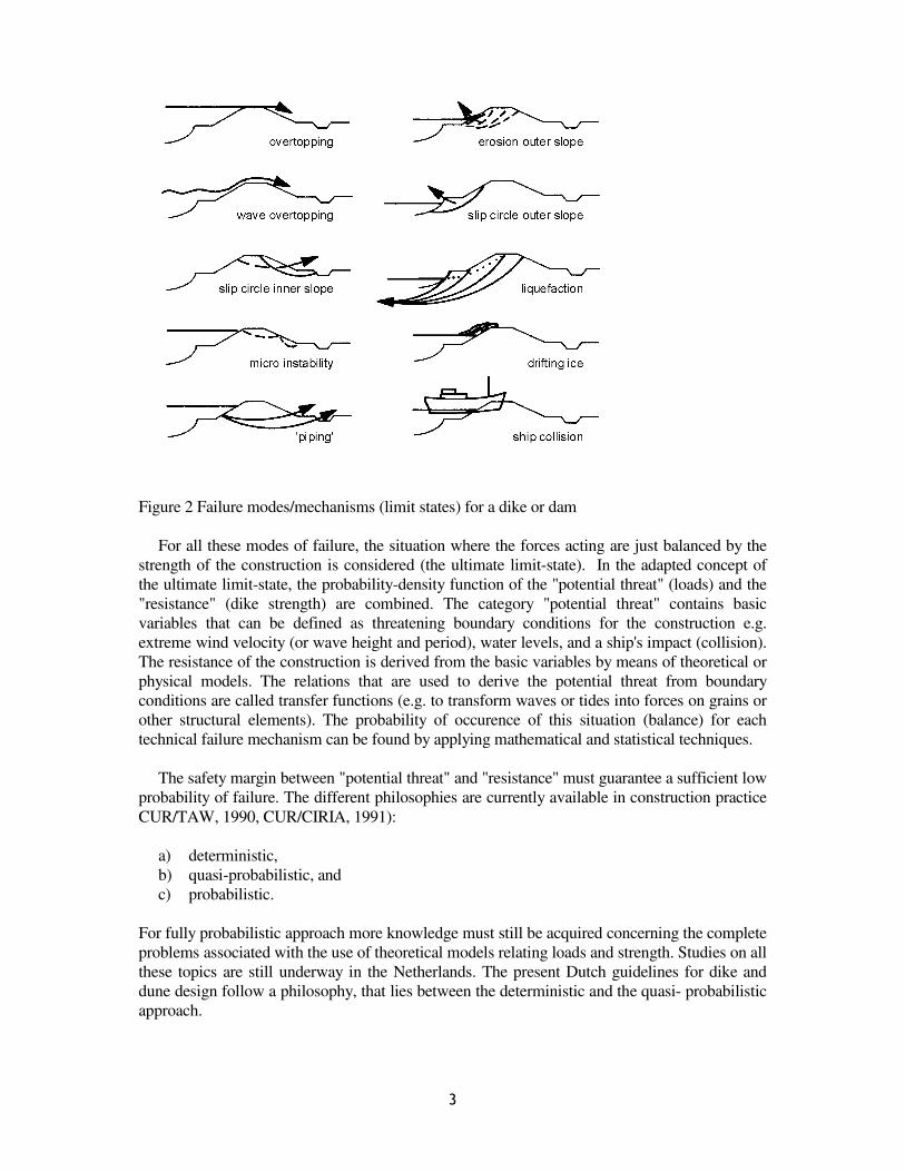
Figure 2 Failure modes/mechanisms (limit states) for a dike or dam
For all these modes of failure, the situation where the forces acting are just balanced by the
strength of the construction is considered (the ultimate limit-state). In the adapted concept of
the ultimate limit-state, the probability-density function of the "potential threat" (loads) and the
"resistance" (dike strength) are combined. The category "potential threat" contains basic
variables that can be defined as threatening boundary conditions for the construction e.g.
extreme wind velocity (or wave height and period), water levels, and a ship's impact (collision).
The resistance of the construction is derived from the basic variables by means of theoretical or
physical models. The relations that are used to derive the potential threat from boundary
conditions are called transfer functions (e.g. to transform waves or tides into forces on grains or
other structural elements). The probability of occurence of this situation (balance) for each
technical failure mechanism can be found by applying mathematical and statistical techniques.
The safety margin between "potential threat" and "resistance" must guarantee a sufficient low
probability of failure. The different philosophies are currently available in construction practice
CUR/TAW, 1990, CUR/CIRIA, 1991):
a) deterministic,
b) quasi-probabilistic, and
c) probabilistic.
For fully probabilistic approach more knowledge must still be acquired concerning the complete
problems associated with the use of theoretical models relating loads and strength. Studies on all
these topics are still underway in the Netherlands. The present Dutch guidelines for dike and
dune design follow a philosophy, that lies between the deterministic and the quasi- probabilistic
approach.

4
The ultimate potential threat for the Dutch dikes is derived from extreme storm surge levels
with a very low probability of exceedance (I% per century for sea-dikes and 10% for river dikes)
and equated with the average resistance of the dike without any apparent safety margin. Besides
the ultimate limit-state, there are situations, where the ever continuing presence of a (frequent)
load causes a deterioration of constructional resistance in time, without any imminence of
failure (e.g. fatigue of concrete and steel, creep of erosion of clay under the revetment, clogging
or ultra violet deterioration of geotextile (U.V.), corrosion of cabling, unequal settlements of
deformations, etc.). However, this deterioration of constructional resistance can cause an
unexpected failure in extreme conditions. These are, so called, the serviceability- and fatigue
limit states which can also be considered as inspection and maintenance criteria.
As already mentioned, the fully probabilistic approach for dikes based on the limit-state
concept is rather cumbersome because a theoretical description for various failure modes is not
yet available. To overcome this problem a scheme to simulate nearly all possible combinations
of natural boundary conditions in a scale model of the construction and to correlate the damage
done to the boundary conditions can be developed (black box approach).
The ultimate potential threat for the Dutch sea defences is derived from extreme storm surge
levels with a very low probability of exceedance (1% per century for sea-dikes and dunes) and
equated with the average resistance of the dike (or dune). Under these ultimate load conditions,
probability of failure of the dike (seawall) should not exceed 10%.
The probabilistic approach to sea defences as developed in the Netherlands is treated ex-
tensively in CUR/TAW-report (1990).
Taking knowledge of these recent developments can be rather profitable for each country,
especially for estimation of possible risks involved in the realized projects and for finding the
optimum between the risks and the investment.
Design methodology
When designing coastal structures, the following aspects have to be considered:
* the function of the structure
* the physical environment
* the construction method
* operation and maintenance
The main stages which can be identified during the design process are shown in Figure 3.
The designer should be aware of the possible constructional and maintenance constrains
(Pilarczyk, 1990, 1998).
Based on the main functional objectives of the coastal structure a set of technical
requirements has to be assessed. When designing a dike/seawall, the following requirements to
be met can be formulated:
1. the structure should offer the required extent of protection against flooding at an acceptable
risk,
2. events at the dike/seawall should be interpreted with a regional perspective of the coast,
3. it must be possible to manage and maintain the structure,
4. requirements resulting from landscape, recreational and ecological viewpoints should also
be met when possible,
5. the construction cost should be minimized to an acceptable/responsible level,
6. legal restrictions

5
Figure 3 Design methodology
Elaboration of these points depends on specific local circumstances as a type of upland
(low-land or not) and its development (economical value), availability of equipment, manpower
and materials, etc. The high dikes/seawalls are needed for protection of low-lands against
inundation while lower seawalls are often sufficient in other cases. The cost of construction and
maintenance is generally a controlling factor in determining the type of structure to be used. The
starting points for the design should be carefully examined in cooperation with the client or
future manager of the project.
In this Chapter it is further assumed that the decision based on the conceptual and
functional design is in favour of sloping dike.
Boundary Conditions and Interactions
Boundary Conditions
Assessment of the existing situation. A lot of relevant information for a seawall/dike design
can be drawn from files and existing maps. In addition to this, a field reconnaissance and a land
survey are indispensable, as well as photographic recording of the characteristic points in the
area. Special attention should be paid to the position of the beach and/or onshore profiles, and
the morphology of the area considered (eroding/ accreting coast). The composition of the
existing dike body and the geologic structure of the subsoil are also very important. When these
data are not available, the soil investigation should be considered (soundings, borings etc.). The
more detailed information on these subjects can be found in TAW/CUR (1990).

6
Hydraulic boundary conditions. In view of the function of (coastal) water defences the loads
will be mostly due to the actions of long and/or short waves. In broad outline the following
wave phenomena can be distinguished:
(a) low-frequency water level changes, such as flood waves, tidal waves, wind set-up gradients
and seiches (Fig. 4);
(b) wind waves and swell;
(c) ship's waves in navigable waterways.
These water level variations strongly influence the area which needs to be protected with
hard revetment. The flow diagram on determination of hydraulic boundary conditions is given
in Figure 8.
Water level variations on canals and water-storage channels are comparatively small;
probably only caused by lock-water, seepage, drainage and wind effects. Water levels on lakes
can vary as a result of wind set-up, inflow or outflow of water, and evaporation. Water levels in
a reservoir can change markedly due to filling or emptying, but rainfall and wind set-up can also
play a role.
Water levels on a river are determined by the river's discharge regime, and in addition for
the lower reaches (estuaries) by tides and also wind-set-up. For a coastal defence embankment
water levels are governed by tides and winds. The most complex situation occurs at coastal
shores, where water level fluctuations can assume many forms.
Figure 4 Flow diagram on hydraulic boundary conditions
A lot of relevant information for seawall design can be drawn from files and existing maps.
In addition to this, a field reconnaissance and a land survey are indispensable, as well as
photographic recording of the characteristic points in the area. Special attention should be paid

7
to the position of the beach and/or onshore profiles, and the morphology of the area considered
(eroding/accreting coast?). The specification of environmental parameters are given in CIRIA
(1986). The prediction methods related to hydraulic boundary conditions can be found in SPM
(1984).
Geotechnical conditions. For major structures a good geological analysis, based on the overall
geological structures of the country, is of the utmost importance for an understanding of the
geophysical and geohydrological conditions. The most important geological aspects are:
- geological stratification, formation and history
- groundwater regime
- seismicity
The main questions which a geotechnical investigation has to answer are:
- what kind of soil is found and at what depth, i.e. soft soils such as sand, clay and peat or
hard soils such as limestone and calcareous sandstone, or very hard soils such as quartzite
and basalt,
- what are the mechanical properties of the various soils with respect to their strength and
deformation characteristics,
- is the soil fissured or weathered,
- will the soil degrade in (short) time.
The first step is to organize and design site investigations. The field program forming part of the
site investigation is complemented by laboratory testing and geotechnical calculations. The last
and perhaps most difficult step is the integration of the result of the investigations and structural
design, resulting in the final foundation design.
At the set-up and organization of the soil-investigation program the geotechnical engineers
is confronted with the following questions:
- which soil data have to be collected,
- at what locations (number and depths),
- which site-investigation techniques and laboratory test should be performed,
- when is the programme to be carried out and,
- who will take care of the contracting work in the field, the laboratory tests and the
interpretation of the results.
The answer of these questions will depend among others on:
- the boundary conditions stipulated by the client (time and money schedule);
- the knowledge, judgment and experience of the geotechnical engineer;
- the availability of existing data, for example topographical, geological and geotechnical
maps;
- the phase of the design: for a preliminary design only global information over a wide area is
needed to recognize the main geotechnical problems; in the final design phase or during the
construction period detailed information on engineering soil parameters is needed;
- the type of geotechnical failure mechanisms involved;
- the availability and restrictions (including the terrain accessibility) of the investigation tools
and the quality of the personnel to handle these tools.
A high quality investigation must be economically efficient in the sense that the cost of the
investigation must be money well spent. The investigator must be able to justify each and every
item in the site investigation in terms of the value of that item in building up the geotechnical

8
model. The investigator should be able to show good and sufficient reason for undertaking each
part of the investigation.
It is emphasized that there is no standard form of site investigation for a particular engineering
work. Each site investigation should be regarded as a completely new venture. Several
standardized investigation techniques have, however, been developed, of which the geological
and geotechnical engineer can make use for obtaining the relevant data for his basic calculations
and design criteria. Four types of site investigation methods can be listed:
a) geophysical measurements from the soil surface,
b) penetration tests, such as cone penetration and standard penetration tests,
c) borings, including sampling and installation of observation wells, and
d) specific measurements, such as plate loading tests and nuclear density measurements.
Construction materials. A large number of materials may be used in various forms in the
construction of seawalls and dikes. These can be: sand, gravel, quarry rock, industrial
waste-products (slags, minestone, silex from cement industry), clay, timber, concrete, asphalt,
geotextile, etc. (see also Figure 7). All these materials have to fulfil some structural and
environmental specifications that mostly are regulated by the national standards. The useful
informations can be found in various handbooks and guidelines reports (TAW/CUR, 1984,
1990, TAW, 1998, CIRIA 1986, PIANC 1987a, CUR/CIRIA, 1991, CUR/TAW, 1995,
RWS/CUR, 1995).
Processes and Interactions
Loading zones. The degree of wave attack on a dike or other defence structure during a storm
surge depends on the angle of attack of the storm, the duration and strength of the wind, the
extent of the water surface fronting the sea-wall and the bottom topography of the area involved.
For coastal areas there is a correlation between the water level (tide plus wind set-up) and the
height of the waves, because wind set-up and waves are both caused by wind. Therefore, the
joined frequency distribution of water levels and waves seems to be the most appropriate for the
design purposes (also from the economical point of view). For sea-walls in the tidal region,
fronting deep water, the following approximate zones can be distinguished (Figure 5):
I the zone permanently submerged (not present in the case of a high level "foreshore");
II the zone between MLW and MHW; the ever-present wave-loading of low intensity is of
importance for the long-term behaviour of structure;
III the zone between MHW and the design level, this zone can be heavily attacked by waves
but the frequency of such attack reduces as one goes higher up the slope;
IV the zone above design level, where there should only be wave run- up.
A bank slope revetment in principle functions no differently under normal circumstances
than under extreme conditions. The accent is, however, more on the persistent character of the
wave-attack rather than on its size. The quality of the sea-ward slope can, prior to the occurrence
of the extreme situation, already be damaged during relatively normal conditions to such a
degree that its strength is no longer sufficient to provide protection during the extreme storm.
The division of the slope into loading zones has not only direct connection with the safety
against failure of the revetment and the dike as a whole, but also with different application of
materials and execution- and maintenance methods for each zone.

9
.
Figure 5 Definition of dike components and loading zones on a dike

10
Figure 6 Wave interaction with structure and breaker types on a slope
Figure 7 Example of dike protection (Oester dam, The Netherlands)
Alternatives have to be generated during the conceptual, preliminary and detailed design
phase in order to select a most suitable design. It is emphasized that for each design phase these
alternatives should be evaluated at a comparable level of detail. The same applies to the
construction alternatives, which may have a great influence on the total structure costs.

11
Wave-structure interaction. The interaction between waves and slopes is dependent on the
local wave height and period, the external structure geometry (water depth at the toe), slope
with/without berm, the crest elevation and the internal structural geometry (types, size and
grading of revetments and secondary layers). The type of structure wave interaction is defined
by the surf similarity parameter (or breaker parameter) which is defined as (see also Figure 6):
s/ tan= opopαξ (1)
with:
ξop
= breaker parameter
α = slope angle
sop = = gT
H22
p
sπwave steepness
Tp = wave period, peak period of the wave spectrum
Hs = significant wave height, being the average value of the highest 1/3 part of
the wave heights. This Hs is the significant wave height at the toe of the struc-
ture.
The wave steepness is a fictitious or computation quantity, especially meant to describe the
influence of a wave period. This quantity is fictitious as the wave height at the location of the
toe is related to the wave length in deep water ( π2 / Tg 2p 1).
Several wave periods can be taken from a spectrum, among them the peak period Tp, the
mean period Tm (computed from the spectrum or the time signal) and the significant period
T1/3. Applicable here is that the ratio Tp/Tm mostly lies between 1.1 and 1.25 and that Tp and T1/3
are virtually equal.
With ξop
2 < 2 - 2.5 the waves break on the slope. This is mostly the case with slopes of 1:3
or milder. For larger values of ξop
3 the waves do not break on the slope any longer. In that case
the slopes are often steeper than 1:3 and/or the waves are characterized by a smaller wave
steepness (for example swell).
For large values of the wave length or for large values of α (steep slopes), the wave behaves
like a long wave, which reflects against the structure without breaking - a so called surging
wave. For shorter waves and medium slopes waves will short and break, causing plunging
breakers forξop
4values in the range of 1 to 2.5. This figure is common along the Dutch coast
with slope angles of 1 to 3 to 1 to 5, wave periods 6 to 8 s and wave heights of 3 to 5 m. For
mild slopes wave breaking becomes a more continuous process, resulting in a more gradual
dissipation of wave energy. This type of breaking is called "spilling". For the design of
structures, surging and plunging breaker are of main importance. The area which suffers from
wave-loading is bounded by the higher up- rush and the lowest downrush point. Obviously this
zone is varying with the tide.
No reliable formula are available to predict the maximum velocities during uprush and
downrush. For surging and spilling breaker, numerical solutions have been obtained, which are,
however, not yet operational. As first approximation, the maximum velocity, Umax, on a smooth
slope can be computed by the following formula:

12
Umax = a √(gHs) ξbop (2)
where: Hs = significant wave height, g = gravity, a = coefficient equal to about 1 to 1.5 for
irregular waves and b = exponent equal roughly to 0.5.
Load-strength concept. Once the hydraulic design conditions have been established, actual
design loads have to be formulated. For a given structure many different modes of failure may
be distinguished, each with a different critical loading condition. Schematically, this is shown in
Figure 2. For the dike as a whole, instability may occur due to failure of subsoil, front or rear
slope. Each of these failure modes may be induced by geotechnical or hydrodynamical
phenomena. The present section is restricted to the stability of the front slope, moreover only
instability as a result of hydrodynamical processes is taken into account.
Starting with the hydraulic input (waves, water levels) and the description of the structure,
external pressures on the seaward slope are determined. Together with the internal
characteristics of the structure (porosity of revetment and secondary layers) these pressures
result in an internal flow field with corresponding internal pressures. The resultant load on the
revetment has to be compared with the structural strength, which can be mobilized to resist
these loads. If this strength is inadequate the revetment will deform and may ultimately fail
(Figure 8).
Figure 8 System approach. Transfer functions
The phenomena which may be relevant can be divided roughly according to the three
components of the system: water, soil and structure. The interaction between these components
can be described using three Transfer Functions (see Figure 8):
I. The Transfer Function from the overall hydraulic conditions, e.g. wave height H, mean
current velocity U, to the hydraulic conditions along the external surface, i.e. the boundary
between free water and the protection or soil, e.g. external pressure P.
II. The Transfer Function from the hydraulic conditions along the external surface to those along

13
the internal surface, i.e. the boundary between protection and soil. The hydraulic conditions
along the internal surface can be described as the internal pressure P.
III. The structural response of the protection to the loads along both surfaces.
Information about these functions can be obtained by means of measurements in nature and
(scale) model tests. If quantitative knowledge of the physical phenomena involved is available,
or if there is enough to hand experience then mathematical models or empirical formulae
containing information are formulated and referred to as "models". All three Transfer Functions
can be described in one model, or individually in three separate models, depending on the type
of structure and the loading. The distinction between the three functions here mainly serves as a
framework to describe the different phenomena that are important for the modelling.
In many cases, the various processes cannot be described as yet. Therefore a "black box"
approach is followed in which the relation between critical strength parameters, structural
characteristics and hydraulic parameters are obtained empirically.
Effect of Dikes and Seawalls on the Beach
A seawall forms a peculiar protection solution. It prevents further erosion of
the coastline (it fixes the land-water line) but does not stop the physical processes which cause
the erosion (a gradient in the longshore transport and the offshore transport). Therefore, it does
not stop the erosion of the inshore zone, and probably even increases it through reflection of the
incoming waves. Very often the local solution by a seawall leads to the displacement and
expansion of the problem downcoast (Figure 9a). On an originally eroding coast, the erosion in
front of a seawall can even lead to undermining the seawall or dikes, and often additional
measures are needed (i.e. heavy toe protection and/or groins in front of a seawall) to prevent this
(Figure 9b). The maintenance cost of this protection can be, therefore, sometimes very high.
This stresses the need for proper studies before the decision to construct a seawall will be taken.
In general can be stated that the coasts protected by a seawall will only have a beach in front of
this wall if sufficient sand supply is available. This happens where no erosion takes place under
normal circumstances. The seawall or dike is constructed then, for protection under extreme
conditions. However, it is possible that even under these circumstances wave reflection causes
so much erosion in front of the seawall that the beach will not be restored. Therefore, seawalls
are generally not a very feasible solution, but under special circumstances, such as along
strongly curved and heavily eroding coasts, they can be the only possibility. By locating the
defence line sufficiently landward from the eroding coast the possibility can be created for
observing the natural developments and preparing additional measures if necessary. To
minimize the effect of extra scouring due to reflection of waves the slope of seawalls or dikes
should be not more than 1 on 3. That is one of the reasons that the Dutch dikes have mostly
slope 1 on 4 or even milder. Also wave energy absorbing revetments as, for example, rubble
structures, will diminish the reflection and thus, the scouring intensity.
As a result of common controversy on the use of seawalls for coastal protection, the Coastal
Sediments'87 conference had as a theme "The Effects of Seawalls on the Coast". The results of
this conference have been evaluated and presented in a separate issue (Kraus et al., 1988). The
final conclusions are summarized below.

14
Figure 9(a) Plan view of potential impacts of seawalls (Kraus et al, 1988)
Figure 9(b) Profile view of potential impacts of seawalls (Kraus et al, 1988)
The majority of quantitative-type laboratory and field studies indicates that seawalls neither
accelerate nor enhance long-term erosion of beaches, and no systematic difference in post-storm
recovery of beaches with and without seawalls was found if there was ample sediment or a wide
surf zone existed. If beaches are deficient in sediment or if sea (or lake) level is rising at the site,
erosion is more likely to occur at armored beaches as compared to unarmored beaches. The

15
magnitude of the change does not appear to be extremely greater than the variability of change
in the natural, unarmored beach system. However, the armoring can cause localized additional
storm scour, both in front of and at the ends of the armoring. More study is needed to refine and
quantify these conclusions, as well as determine their limit of applicability. In order to better
utilize seawalls as an important instrument for shore stabilization, it is recommended that an
effort be made to review historical data on shoreline position, beach profile, and littoral
processes in the vicinity of existing seawalls, and to initiate comprehensive monitoring
programs. Finally, the researcher should attempt to purge all preconceptions and biases in
dealing with this controversial subject with the goal of defining and interpreting processes and
responses at the study site within the context of that site.
It can be stated that the results of the evaluation of this conference agree firmly with the
conclusions drawn by Dean (1986). Dean's final conclusions are cited below:
"Uncertainties resulting from a lack of definitive information has led to considerable speculation
and claims regarding the adverse effects to coastal armoring on the adjacent shorelines.
Employing sound principles and laboratory and field data, an attempt is made to evaluate the
potential adverse effects of armoring. It is concluded that:
1. There are not factual data to support claims the armoring causes: profile steepening,
increased longshore transport, transport of sand to a substantial distance offshore, or
delayed post-storm recovery.
2. The interaction of an armored segment of shoreline with the littoral system is more of a
"geometric" or "kinematic" interaction as contrasted to a "dynamic" interaction. The
interaction depends on the amount of sand in the system vis-a-vis the equilibrium beach
profile for the prevailing tide and wave conditions.
3. Armoring can cause localized additional storm scour, both in front of and at the ends of the
armoring. A simple sediment supply-demand argument is proposed to explain the scour.
A methodology is presented to quantify the potential adverse effects of an armoring installation
and appropriate periodic sand additions proposed as a means of mitigation to elevate the
installation to one of neutral impact on the adjacent shoreline".
Design of dikes and sloping seawalls
Structural aspects and design checklist
The selection of the structural concept depends on the function, the local environmental
conditions and the constructional constraints. The governing criteria are the technical and
economic feasibility for the project under consideration.
The function of the seawall is mainly to protect the hinterland against the adverse effect of
high-water and waves. If high-water protection is required the structure should have a height
well above the maximum level of wave-uprush during storm surge. This normally calls for high
crest elevation (TAW, 1990). If, however, some overtopping is allowed in view of the character
of the hinterland, the design requirement is formulated in terms of the allowable amount of
overtopping. Obviously crest-elevation can be reduced considerably in this case. A basic input
to the effective planning and designing of any protection scheme is a reliable set of statistics
which describe the physical environment against which such protection is necessary. The
principal items under consideration are: bathymetry, climate, water levels, wind and wave

16
climate, coastal processes (sediment transport), geotechnical data, construction constraints etc.
The geologic structure of the subsoil is also very important (settlement!). When these data are
not available the soil mechanical investigation should be considered (soundings, borings etc.).
Primarily the requirement is for long term data (water-levels, winds, waves etc.), much of which
is readily obtainable from various national data banks, international specialistic organisations
(i.e. World Meteorological Organisation), publications, and local authorities.
In the past only local usage and experience have determined the selection of the type and
dimensions of the coastal protection. Often designs were conservative and too costly or were
inadequate. The technical feasibility and dimensioning of coastal structures can be actually
determined on the more founded basis and supported by a better experience than in the past.
Often, however, the solution being considered should still to be tested in a scale model, since no
generally accepted design rules exist for all possible solutions and circumstances.
The most critical structural design elements are a stability of cover-layer inc. splash-area,
secure foundation to minimize settlement and toe protection to prevent undermining. All of
these have a potential of failure of coastal structures. The checklist of the usual steps needed to
develop an adequate structure design is given below:
a) Formulate functional requirements,
b) Prepare alternative solutions,
c) Select suitable solution,
d) Determine the water level range for the site,
e) Determine the wave heights and (eventual) currents,
f) Detect suitable structure configurations (geometry),
g) Review the possible failure mechanisms,
h) Select a suitable armor alternatives and armor units size,
i) Design the filter and underlayers,
j) Determine the potential run-up to set the crest elevation,
k) Determine the amount of overtopping expected for low structures,
l) Design the toe protection, transitions and crest protection,
m) Design under drainage features if they are required,
n) Provide for local surface run-off and overtopping run-off, and make any
required provisions for other drainage facilities such as culverts and ditches,
o) Consider end conditions to avoid failure due to flanking,
p) Provide for firm compaction of all fill and backfill materials. This requirements should be
included on the plans and in the specifications, and due allowance for compaction must be
made in the cost estimate,
q) Make final check of your design,
r) Develop cost estimate for each alternative,
s) Select the final design, and
t) Prepare specifications for materials and execution incl. quality control.
The existing design rules for some (selected) structural elements (shape, height, cover-layer
etc.) are being briefly reviewed in the subsequent sections. For detail engineering
(dimensioning) the "Coastal Protection" (Pilarczyk, 1990), PIANC (1992), The Manual on Rock
(CUR/CIRIA 1991), SPM (1984) and CUR/TAW (1995), can be of use.

17
The design of coastal protection is not a simple matter. In all cases, experience and sound
engineering judgment play an important role in applying these design rules, or else
mathematical or physical testing can provide an optimum solution.
Geometrical design of dikes
Selection of the structural concept depends on the function, the local environmental conditions
and the constructional constraints. The governing criteria are the technical and economic
feasibility for the project under consideration.
The function of the dike/seawall is mainly to protect the hinterland against the adverse effect
of high-water and waves. If high-water protection is required, the structure should have a height
well above the maximum level of wave-uprush during storm surges (Figure 10). This normally
calls for high crest elevation (TAW, 1990). If, however, some, overtopping is allowed in view
of the character of the hinterland, the design requirement is formulated in terms of the allowable
amount of overtopping. Obviously crest-elevation can be reduced considerably in this case.
The shape of the cross-sectional profile of a dike/seawall is an influence on the distribution of
wave forces, and thus, also influences the choice of material (type of protective units and their
dimensions) suitable for slope protection (revetment), and the height of structure. The gradient
of the slope must not be so steep that the whole slope of the revetment can lose stability
(through sliding). This criterion gives, therefore, the maximum slope angle. More gentle (flatter)
slopes lead to a reduced wave-force on the revetment and less wave run-up; wave energy is
dissipated over a greater length. A similar effect can be obtained by applying a berm (trapezoi-
dal profile). By using the wave run-up approach for calculation of the crest height of a
trapezoidal profile of a dike/seawall for different slope gradients, the minimum volume of the
embankment can be obtained (see Figure 11). However, this does not necessarily imply that
minimum earth-volume coincides with minimum costs. An expensive part of the embankment
comprises the revetment, and the slope area increases as the slope angle decreases. Careful at-
tention is needed however, because the revetment costs are not always independent of the slope
angle, e.g. for steep slopes heavy protection is needed while for mild slopes the (cheaper)
alternative solutions (i.e., sand-mattesses, grass-mats etc.) can often provide sufficient
protection.
Another point of economic optimization can be the available space for dike/seawall construction
of improvement. All these factors should be taken into account optimizing the structure slope.
The common Dutch practice is to apply a slope 1 on 3 on the inner slope and between 1 on 3
and 1 on 5 on the outer (seaward) slope. These mild slopes also minimize the scour at the toe of
a dike (lower reflection). The minimum crest width is 2 m.
Present practice for obtaining a substantial reduction in wave run-up is to place the outer berm
at (or close to) design water level. If the berm lies too much below that level, the highest storm
flood waves would not break beneath the berm, and the run-up will be inadequately affected,
thus providing relatively heavy wave loading on the upper slope. However, the optimum
distribution of wave forces is obtained when the (relatively small) berm is about 0.5 to 1 wave-
height below the design water level. In such a case, the whole slope can be protected with the
same (relatively small) units. When the berm is equal or somewhat higher than the design water
level, the waves will always break on a lower slope. In this case, the lower slope needs much
heavier protection (but along a shorter length) than the upper slope (very often a grass-mat is
sufficient). An important function of the berm can also be its use as an access road for
maintenance or even for permanent use (promenade etc.).
The above discussion indicates that the proper choice of the shape is a very important step in the
design of a dike/seawall. Mostly it is an iterative procedure.

18
Figure 10 Determination of crest height
It was decided in the Netherlands to base the design of all sea dikes fundamentally on a
water level with a probability of exceedance of 10-4
per annum. In the Netherlands the wind set-
up is mostly incorporated in the estimated storm-surge level. If this is not a case, the wind set-up
should be calculated separately and added to the design water level. Besides the design flood
level, several other elements also play a role in determining the design crest level of a dike
(Figure 10):
- Wave run-up (2% of exceedance is applied in the Netherlands) depending on wave height and
period, angle of approach, roughness and permeability of the slope, and profile shape,
- An extra margin to the dike height to take into account seiches (oscillations) and gust bumps
(single waves resulting from a sudden violent rush of wind); this margin in the Netherlands
varies (depends on location) from 0 to 3 m for the seiches and 0 to 0.5 m for the gust
bumps.
- A change in chart datum (NAP) or a rise in the mean sea level in the Netherlands: till now
assumed roughly 0.25 m per century, in the future ~0.6 m per century (see Rijkswaterstaat,
1990),
- Settlement of the subsoil and the dike-body during its life time.
The combination of all the factors mentioned above defines the free-board on the dike (called in
Dutch as wake-height). The recommended minimum freeboard is 0.5 m.
Wave Run-up
The effective run-up (Run), on a slope can be defined as:
- for ξop < 2 to 2.5 (breaking waves)
Ru2/Hs = (1.5 to 1.75)(γf γb γβ γh) ξop = ( 1.5 to 1.75) γ ξop (3)
- with a maximum for ξop > 2 to 2.5

19
Ru2/Hs = (3.0 to 3.5)
where:
Run = run-up level exceeded by n% of waves (a vertical height above SWL),
n = index of exceedance percentage; in this case n=2
γ = total reduction factor, and γf γb γβ γh= reduction factors due to slope roughness, berm,
oblique wave attack and for depth limited wave attack, respectively.
Note: for actual relationships/values of γ-factors look to the Guide on Wave Runup and
Overtopping (2002) on www.tawinfo.nl .
The lower numerical values (1.5 and 3.0) represents the average values while the higher values
(1.75 and 3.5) represent the upper envelope of actual spreading in test results. These lower
values can be used in probabilistic calculations. For practical (deterministic) applications the
values 1.6 and 3.2 are recommended.
The surf-similarity parameter (ξop) is defined by:
αα
ξ tanT )H(
1.25 =
)L/H(
tan = p
sps
p (4)
where:
Hs = significant wave height at the toe of the structure,
Tp = peak period, and α = angle of slope
An example of possible variation of a crest-height as a function of a dike- or a seawall-shape is
given in Figure 11.
Figure 11 Example of dike calculation (alternatives); Hs= 4.7 m(depth limited), Tp= 8.5 sec,
berm reduction γb= 0.7 for ctgα= 4 and B= 4 Hs

20
In the case of low-crest elevation (overtopping allowed) the design requirement is formulated
in terms of the allowable amount of overtopping and the necessary protection of the splash-
area (dimensions of units, length). The method of calculation of overtopping discharge can be
found in Pilarczyk (1990, 1998), SPM (1984), PIANC (1991/92), and other specialistic
literature. However, the most actual approach for wave overtopping at dikes (research
commissioned by the Rijkswaterstaat) is recently presented by Van der Meer (1993, 2002).
Slope Protection (Revetments)
General considerations. In the past only local usage and experience have determined the
selection of the type and dimensions of the coastal protection. Often designs were conservative
and too costly or were inadequate. The technical feasibility and dimensioning of coastal
structures can be actually determined on a more founded basis and supported by a better
experience than in the past. Often, however, the solution being considered should still be tested
in a scale model since no generally accepted design rules exist for all possible solutions and
circumstances.
The types of revetments which are presently being studied are shown in table 2. In this
figure the critical modes of failure, the corresponding determinant loads and the required
strength are summarized qualitatively.
Classical slope revetments may be divided in different categories e.g.:
- Natural material (sand, clay and grass)
- Protected by loose units (gravel, rip-rap)
- Protected by interlocking units (concrete blocks and mats)
- Protected by concrete and asphalt slabs.
In this order the resistance of the protection is derived from friction, cohesion, weight of the
units, friction between the units, interlocking and mechanical strength. As a result of the
difference of strength properties, critical loading conditions are also different. Maximum
velocities will be determined for clay/grass dikes and gravel/ rip-rap, as they cause displacement
of the material while uplift pressures and impacts, however, are of more importance for paved
revetments and slabs, as they tend to lift the protection. As these phenomena vary both in space
and in time, critical loading conditions vary both with respect to the position along the slope and
the time during the passage of a wave. Instability for grass/clay and gravel/rip-rap will occur
around the water level, where velocities are highest during up and down rush. Moreover, wave
impacts are more intense in the area just below the still water level.
Instability of paved revetments without too much interlock occurs at the pink of maximum
down rush, where uplift forces are higher, just before the arrival of the next wave front. If the
protection is pervious uplift forces are strongly reduced. Instability will have occurred due to the
combined effect of uplift- and impact forces, just after wave breaking. Concrete slabs and
asphalt will mainly respond to uplift forces at maximum loads are distributed more evenly over
a layer area, thus causing a higher resistance against uplift, compared with loose block
pavement.
Stability (or threshold conditions) for loose materials, from sand to rock, is investigated
rather extensively, and the proper design criteria are available. However, the stability of
randomly dumped quarried rock can often be substantially improved by taking special measures

21
(= composite systems, i.e., grouting, pitched stone, mattresses, etc.). On the other hand there are
a number of protective systems related to artificial materials such as concrete (i.e., block-mats)
and asphalt. Also grassmats serve as slope protection. For most of these systems it is possible to
give some rough, indicative stability criteria which allow the engineer to make a comparison
with a random placed rock, and thus, to make a proper choice of protection. The following
systems will be considered: riprap, placed and/or pitched blocks/stones, grouted (bound) stones,
bituminous systems, gabions/stone mattresses, fabric containers (bags, mats), and clay/ grass-
mats.
Because of the great variety of the possible composition of protective systems it is not
possible to present a generally valid stability formulation for all these systems. Therefore, only
some principles and examples will be given in a general sub-section on stability criteria for
wave attack
General overview on stability criteria for wave attack. The general empirical (approximate)
formula derived by Pilarczyk (1990) and supported by large scale tests is:
b
p
u
m
s
D
H
ξα
φψcos
⋅⋅≤⋅∆
(5)
or
5.0
50,
cos
p
u
nm
s
D
H
ξα
φψ ⋅⋅≤⋅∆
= F cosα/ξp0.5
ops op
= tan
H / Lξ
α
in which:
ψu = system-determined (empirical) stability upgrading factor (ψu = 1.0 for riprap as a
reference and ψu ≥ 1 for other revetment systems) [-],
φ = stability factor or stability function for incipient of motion, defined at ξp = 1 [-],
Hs = significant wave height [m],
Tp = peak wave period [s],
Lo = wave length [m]; Lo = π2/gT2
p5
D = specific size or thickness of protection unit [m],
α = slope angle [°],
∆m = relative density of a system-unit [-],
b = exponent related to the interaction process between waves and revetment type
(roughness, porosity/permeability etc.), 0.5 ≤ b ≤ 1. For rough and permeable
revetments as riprap, b = 0.5. For smooth and less permeable placed-block revetments it
can be closed to b = 1. The value b = 2/3 can be treated as a common representative
value for other systems (i.e. more open blocks and block-mats, mattresses of special
design etc.).
D and ∆m are defined for specific systems such as:
• rock ; D = Dn = (M50/ρs)1/3
and ∆m = ∆ = (ρs-ρw)/ρw
• blocks ; D = thickness of block and ∆m = ∆
• mattresses; D = d = average thickness of mattress and ∆m = (1-n)∆, where n = bulk-
porosity of fill material and ∆ = relative density of fill material. For common quarry stone (1-n)

22
∆ ≈ 1.
The formula is applicable till ξp = 3 (breaking waves); for ξp > 3, the sizes calculated at ξp = 3
can still be applied.
The wave attack on a slope can be roughly transformed into the maximum velocity
component on a slope during run-up and run-down, Umax, by using the following formula:
Umax = p √(g Hs ξp) (for irregular waves and smooth slopes p = 1.5)
Stability factor φ for loosely aggregates can be more generally defined using the Van der Meer’s
formula (1984), namely:
φ = 6.2 Pb0.18
(Sb2 /N)
0.1 (for ξ < 3, breaking waves
where: Pb = permeability of the core material (i.e. Pb = 0.5 for breakwaters and 0.1 for
revetments), Sb = damage number and N = number of waves.
In the case of relatively impermeable core (i.e., sand or clay, Pb = 0.1, and limited number of
waves (N ≈ 3000)) the following indicative φ-values for rock can be determined:
φ = 2.0 for rest of stones (lower stability limit),
φ = 2.25 average value for incipient motion (motion 1 to 3 stones over the width of slope
equal to Dn),
φ = 3.0 as a first approximation for maximum tolerable damage for 2-layer system on granular
filter (damage-depth less or equal to 2Dn); φ = 3 can also be applied for incipient
motion of rock placed on permeable core (rockfill core or thick granular filter).
The φ-value equal to 2.25 will be used as a reference value for the stability comparison with
other alternative systems. The difference with stability of rock due to the improving measures
will be expressed by the upgrading of the factor ψu.
Figure 12 Design elements of revetments

23
The important difference between the loose rock and the alternative systems concerns the
behaviour of the systems after the initiated movement (damage). Due to the self-healing effect
of the loose rock a certain displacement of rock units can be often accepted (up to φ ≤ 3). In the
case of alternative systems, i.e., block revetment, the initial damage (i.e. removing of one block)
can easily lead to a progressive damage; there is no reserve-stability.

24
Table 1 Indicative categories for protective systems

25
The comparison of stability of various systems (parameter ψu), the necessary parameters for
calculation purposes, and other structural requirements and design rules concerning revetments
are given by Pilarczyk (1990, 1998), and are summarized in Table 1 where, for comparison of
all these systems, the stability of dumped rock will serve as a reference.
Stability of placed block revetments (incl. geotechnical aspects) is treated more extensively
in a separate sub-section due to the fact that these systems were actualy investigated more in
depth in the Netherlands. Moreover, these informations are also of use for other revetment
systems.
Comment for users
* block revetments and block-mats
The use of ψu -values higher than 2.5 is not advised except when supported by mathematical
models and/or large-scale tests incorporating geotechnical stability. For older revetments some
increase of stability is often observed due to the increase of natural friction and/or interlocking.
However, permeability may decrease which acts adversely.
The edges of the adjacent block-mats, if not properly connected to each other, should be treated
as free blocks (ψu = 1.33 to 1.50). For slopes steeper than 1 on 3 the geotechnical (in-)stability
(i.e. sliding) can be a decisive factor and it should be examined properly. In the case of toplayer
placed directly on (compacted-)sandy subsoil and geotextile the impinging wave height should
not be more than 1.5 m because of danger of local profile deformation and/or liquefaction. It
should be noted that for practical reasons the minimum thickness of loose blocks is about 0.10
m and for blocks grouted with granular material and blockmats is 0.08 m. More sophisticated
approach to stability aspects of these systems can be found in the guidelines on dimensioning of
block revetments (CUR/TAW, 1994).
* grouted stone
Surface grouting is not advised in the case of high permeable sublayers. Creating of the
completely impermeable surface should be avoided because it may introduce extra lift forces
(blasting effect). In the case of pattern grouting about 50 to 70% of the total
surface is filled. The upgrading factor is very dependent on the execution and care must be taken
to ensure that the grout does not remain in the surface of the stone-layer only, or sags completely
through the layers. In the area of high wave impact, the grouted lumps themselves can be split
by dynamic actions, therefore this type of construction should be applied up to H = 3 m
(frequent loading) and H < 4 m (less frequent loading). In the later case, for safety reasons, it is
recommended to use of three layers of broken stone. If a lump of grouted stones is split and
washed away, the third layer will still protect the core since it is held by the overlying grouted
lumps.
* bituminous systems
In the case of open stone asphalt on sand asphalt filter, the thickness of the system may be
defined as the total thickness of both layers. For the edges of all bituminous systems the ψu = 2
should be applied. Because of possibility of liquefaction, the open stone asphalt on geotex- tile
and sand is recommended only up to H = 2 m. For H > 2 m the sandbitumen filter under the
toplayer of open stone-asphalt is recom- mended. Due to the limited resistance of open
stone-asphalt against surface erosion (max. velocity, u = 7 m/s) this system can be applied up to

26
H = 3 m, and, for a less frequent wave loading, up to H = 4 m. For practical reasons, the
minimum thickness of open stone asphalt is 0.08 m if prefabricated and 0.10 m if placed insitu.
However, the more common thickness are respectively 0.10 and 0.15 m. Bituminous
plate-systems (especially impermeable ones) should also be examined concerning the allowable
stresses and strains (bending mo- ments) and the uplift criterion. The calculation methods can be
found in (TAW, 1985). The example of thickness of various asphalt revetments related to the
allowable stresses is given below for compacted sandbed with slope 1 on 3:
Hs (m) asphalt concrete open stone asphalt sand asphalt
2 0.10 m 0.20 m 0.40 m
3 0.20 m 0.40 m 0.80 m
4 0.30 m 0.65 m
5 0.40 m
In general, the resistance of the sand-asphalt is limited to the velocity of 3 m/s and the wave
height of 1.5 m (or H < 2 for less frequent loading). Currents are not usually a determining load
in the design of asphalt concrete.
* gabion baskets and mattresses
The primarily requirement is that the gabion or mattress of thickness "d" will be stable as a
unit. The thickness of the mattress can be related to the stone size D . In most cases it is
sufficient to use two layers of stone in a mattress (d = 1.8 D ) and the upgrading factor can be
recommended in the range 2 < ψu < 3 (max). The secondary requirement is that the movement
of stones in the basket should not be too high because of the possible deformation of baskets
and the loading on the mesh-wires. To avoid the situation that the basket of a required thickness
"d" will be filled by too fine material, the second criterion, related to D , have been formulated.
The choice of ψu = 2 to 2.5 related to D means, that the level of loading of the individual
stones in the basket will be limited roughly to twice the loading at the incipient motion
conditions. Thus: D (dynamic stable) when ψu ≤ 2.5, and d (stable) when d ≥ 1.8 D .
In more than 2-layer systems it is preferably to use a finer stone below the toplayers (i.e. up
to 1/5 D ) to create a better filter function and to diminish the hydraulic gradients at the surface
of subsoil. The formulations for gabions and mattresses are only valid for waves with a height
up to H = 1.5 m, or for less frequent waves up to H = 2.0 m. In either case it is important that
both the subsoil and the stone infill are adequately compacted. When the current exceeds 3 m/s
or the wave height exceeds 1 m then a fine granular sublayer (about 0.2 m thick) should be
incorporated. In other cases it is satisfactory to place the mattress directly onto the geotextile and
compacted subsoil. For practical reasons, the minimum thickness of mattresses is 0.15 m.
* fabric and other containers
The stability criterion for fabric mattresses of thickness "d" filled with sand, sandcement or
other materials attacked by waves is derived from some (limited) tests and recent knowledge of
revetment principles. The value of upgrading factor (ψu) depends on the ratio of the
permeabilities of the mattress and the subsoil, P :
. for P < 1 : ψu = 1.0 (less permeable mattresses)
. for P = 1 : ψu = 1.5
. for P >> 1 (i.e. > 2): ψu = 1.75 ÷ 2 (permeable mattresses of special design).

27
The permeability of the mattress should be treated as an integrated permeability of all the
components i.e. geotextile container and fill-material together. For wave heights 1 m < H < 2 m
and a sandy subsoil special measures against sliding and/or liquefaction should be taken: extra
compaction, extra thickness (50 to 100%), eventually a fine granular sublayer 0.2 m thick (broad
graded) etc. In the case of permeable mattresses (i.e. gravel-fill) on sandy subsoil the underneath
part of the container should be preferably made of the sand-tight geotextile (filter function). For
slopes steeper than 1 on 3, to avoid sliding, special attention should be paid to the anchoring at
the top of the mattress and to the adequate toe support. Special measures should be taking
concerning the transitions (avoid exposed edges), scour protection at the toe and the protection
in the splash area due to the overtopping. Sand-mattresses, even properly compacted, are very
susceptible to deformation. Therefore, their permanent use should be limited to relatively mild
wave attack (H < 1.5 m). In general, the use of fabric containers of various (specific) design
exposed to wave height higher than 2 m and application of ψu-values different from above
mentioned is only responsible when supported by the large-scale or prototype tests, including
geotechnical stability. For practical reasons, the minimum thickness of fabric
containers/mattresses is 0.15 m. For promoting vegetation through the geotextile mattress the
sand and/ or fine gravel, mixed with cohesive additives and seed, are very suitable as fill
material.
More actual informations on design of various geotextile systems can be found in Pilarczyk
(2000).
* grassmats
Some of the existing dikes along the Wadden Sea (northern part of the Netherlands) still
need reinforcement as these do not yet meet the specific safety requirements. One of the options
for reinforcement is a slope protection of grass on a bed of clay, rather than stone, concrete or
asphaltic protection. This option is feasible because vast mud-flats (high foreshore) and
grasslands stretch away on the seaside of the existing dikes and are inundated only during storm
surges. Moreover, the wave action in the Wadden Sea is much reduced by a row of barrier
islands. Due to these factors the design wave height does not exceed 2 m. The Delft Hydraulic
Laboratory was commissioned to access the stability of such a grass dike by means of a full
scale model study which was an absolute requirement as grass cannot be scaled down (Seijffert
and Philipse, 1990). The investigations have been performed. In the Delta Flume, a five metre
wide section of the grass dike was reproduced on full scale. The model consisted of a sand core
covered with a clay layer on a slope 1 on 8. Sods of grass with the depth of the roots of
approximately 40 cm were laid on top of the clay layer (the grass was taken from an existing
dike that was reinforced ten years ago). During the tests, the wave heights and periods and water
levels (tidal cycles) were varied continuously according to predetermined boundary conditions
during the design storm surge. The maximum H was equal to 1.85 m with T = 5.6 sec.
(plunging breaker falling on a water cushion). The measured maximum velocity on the slope
(1:8) was about 2 m/s. After 30 hours of continuous random wave attack the condition of the
grass dike was still exceptional well. The surface erosion speed of clay protected by grass was
not more than 1 mm per hour. In a number of additional tests, the durability of the grass and the
enlargement of holes, previously dug in the grass, were studied. Although wave action
considerably enlarged some of these holes, the residual strength of the dike was such that its
collapse was for from imminence (Delft Hydraulics Laboratory, 1984). The second investigation
was carried out in a large (site) flume on slope 1 on 4. Special equipment was used to simulate
the run-up and run-down velocities on this slope. Two qualitatively different grass- mats on clay
were used. The grass-mats were tested with the average velocity of 2 m/s (average over 40 hours

28
of test) and the thickness of a water layer of about 0.6 m. The maximum velocity was about 4
m/s. Erosion speed of the clay surface was 1 to 2 mm per hour up to 20 hours depending on
quality of grass-mat. After 20 hours of loading the erosion speed started to grow much
progressively for a bad quality grass-mat. Similar process took place for a good quality
grass-mat but after 40 hours of loading. The detailed information on the results and grass-mat
specification can be found in (Delft Hydraulics Laboratory, 1984b).
Some additional information on resistance of unprotected clay-surface (slope 1 on 3.5) were
obtained during the investigation carried out for the Eastern Scheldt dikes. Also in this case two
qualitatively different clays were used (fat and lean clay). The surging- breaker conditions were
applied to eliminate the effect of wave impact (H = 1.05 m, T = 12 s, max. velocity 3 m/s). The
erosion on the upper part of slope was for both clay-types the same and equal to about 2 - 3 cm
after about 5 hours of loading. After the same time, the erosion below S.W.L. was about 7 cm
for a good clay, while for a lean clay a cavity of about 0.4 m depth was created. This latest
probably because of the local non-homogeneity of clay. Also during this investigation a number
of additional tests on the erosion of different sublayers (incl. clay) at locally damaged top layers
(some protective units were removed) were performed. All the tests mentioned above indicated
that the strength of the grass slopes is strongly affected by the quality of clay and the condition
of grass and its rooting.
Recently, new large scale tests on overtopping and erosion of grass dike with slope 1 on 4
were performed in the Delta-Flume of Delft Hydraulics (Meijer and Verheij, 1994, Smith et al,
1994). This investigation has resulted in preparing a new set of stability criteria for design of
grass-mats on dikes. Distinguish has been made between the stability due to direct impact of
breaking waves and the erosion-rate due to the run-up and overtopping. The final formulation of
both criteria is actually underway.
Some additional information on this subject can be found in (CIRIA, 1976, 1987), TAW
(1990), and Pilarczyk (1998, 2000).
Stability Criteria for Current Attack.
Coastal morphology, scour process and, in some cases, stability of protective units (slope and/or
bottom protection) are or can be influenced not only by waves but also by currents and
combination of waves and currents. The currents can be of various origin, namely wave induced
currents, tidal currents, ship induced currents, natural currents (i.e. in the mouth of the rivers).
Information hereabout can be found in Pilarczyk (1990, 1998, 2000) and CUR/RWS (1995).
Optimization of slope stability
The wave forces on a plane (continuous) slope are distributed rather unequally (the high wave-
impact area near the water level, the intermediate uprush area and the low-attacked area beneath
the point of breaking). The wave action on relatively fine materials indicates that nature tries to
distribute the forces equally to provide equilibrium S-slopes. The same principle can be applied
in designing the shape of seawalls and dikes leading to application of smaller protective units
than in the case of a plane slope.
For practical reasons the 'optional' shape will be schematized to a trapezoidal profile. By
selection of a proper position of a berm below the design water level and a proper width of a
berm, the wave forces will be distributed in such a uniform way that the same material can be

29
used along the whole profile. In this case the increase of stability (50% or more) can be realized
by a berm with a width equal to 0.15 times wave length and situated (0.5 - 1.0) times wave
height below design water level. Based on the results of various studies, the indicative design
guidelines have been prepared for riprap bermed slopes and toe-protection (Pilarczyk, 1990 and
CUR/CIRIA, 1991).
Applying this concept stability of protection should also be verified at water levels lower
than the design one.
Final note: the approach to stability of revetments as discussed above is intended only as a first
(quick) estimation for comparison of various alternatives. The detailed design should take place
according to the design lines discussed in specific lectures of this course or based on the actual
technical documents.
References
1. Agema, J., 1982, "30 Years of development of the design criteria for flood protection and
water-control works", Proc. of Delta Barrier Symposium, Rotterdam.
2. Bakker, K.J. and Meijers, P., 1988, "Stability against sliding of flexible revetments", Int.
Symp. on Modelling Soil-Water-Structure Interactions, Delft, Publ. A. Balkema.
3. Barrett, M.G. et al., 1989, "Coastal Management", Proceedings Conference on Coastal
Management, 9-11 May 1989, Bournemouth, U.K.
4. Bezuijen, A., Klein Breteler, M., Burger, A.M., 1990, "Placed block revetments", Coastal
Protection (Chapter 8), Pilarczyk (ed.), Balkema, Rotterdam. ISBN 906191 1273.
5. Burger, A.M., M. Klein Breteler, L. Banach, A. Bezuyen and K.W. Pilarczyk, 1990,
"Analytical design formulas for relatively closed block revetments", Journal of Waterway,
Port, Coastal and Ocean Eng. ASCE, vol. 116 no. 5 Sept/Oct. 1990
6. CIRIA, 1976, "A guide to the use of grass in hydraulic engineering practice", Construction
Industry Research and Information Association (CIRIA), Report 71, London.
7. CIRIA, 1986a, "Sea Walls; A literature Review", Construction Industry Research and
Information Association (CIRIA) and Hydraulics Research Wallingford, London.
8. CIRIA, 1986b, "Sea Walls; Survey of performance and design practice", CIRIA, Technical
Note 125, London, England.
9. CIRIA, 1987a, "Design of reinforced grass waterways", Construction Industry Research
and Information Association (CIRIA), Report 116, London.
10. CIRIA, 1987b, "Reinforcement of steep grassed waterways", CIRIA, technical note 120.
11. CUR/RWS, 1987, "Manual on artificial beach nourishment", Centre for Civil Engineering
Research and Codes (CUR)/Rijkswaterstaat (RWS), Report 130, P.O.Box 420, 2800 AK
Gouda, The Netherlands.
12. CUR/TAW, 1989, "Guide to the assesment of the safety of dunes as a sea defence", Centre
for Civil Engineering Research and Codes/Technical Advisory Committee on Water
Defences (TAW), Report 140, Gouda, Netherlands.
13. CUR/TAW, 1989, "Guide to concrete dike revetments", CUR, Report 119, Gouda.
14. CUR, 1990, "Periodical judgement on the strength of dikes" (in Dutch), part 1 "methodolo-
gy" and parts 2 to 5 "case studies", CUR, Gouda, The Netherlands.
15. CUR/CIRIA, 1991, "Manual on use of rock in coastal engineering", Centre for Civil
Engineering Research and Codes (CUR), Gouda, The Netherlands.
16. CUR, 1992, "Artificial sand fills in water", CUR, Report 152, Gouda, Netherlands.
17. CUR, 1993, "Filters in Hydraulic Engineering", Report no. 161, Civil Engineering
Research and Codes (CUR), Gouda, The Netherlands.
18. CUR/TAW, 1994, "Design manual for pitched slope protection", Report no. 155, Centre

30
for Civil Engineering Research and Codes (CUR), P.O. Box 420, 2800 AK Gouda, NL.
19. CUR/RWS, 1995, Manual on use of rock in hydraulic engineering, CUR, Gouda.
20. Dean, R., 1986, "Coastal Armoring: effects, principles and mitigations", 20th Coastal
Engineering Conference, Taipei, Taiwan.
21. De Waal, J.P. and Van der Meer, J.W., 1992, "Wave runup and overtopping at coastal
structures", ASCE, Proc. 23rd ICCE, Venice, Italy.
22. Fakuda,N., Uno, T. and Irie, J., 1974, "Field observations of wave overtopping of wave
absorbing revetment", Coastal Engineering in Japan, Vol. 17; 117-128.
23. Führböter, A., Sparboom, U. and Witte, H.H., 1989, "Groβer Wellenkanal Hannover:
Versuchsergebnisse über den Wellenauflauf auf glatten und rauhen Deichböschungen met
der Neigung 1:6", Die Küβte. Archive for Research and Technology on the North Sea and
Baltic Coast.
24. Government of the Netherlands, 1989, "Law on Flood Control" (in Dutch), Draft 1989,
Dutch Ministry of Transport, Public Works and Water Management, The Hague, The
Netherlands.
25. Hales, L.Z. and J.R. Houston, 1983, "Erosion control of scour during construction",
Technical Report HL-80-3, Rep.4, U.S.Army, Vicksburg.
26. Hoekstra, A. and Pilarczyk, K.W., 1992, "Coastal Engineering Design Codes in The
Netherlands", Coastal Engineering Practice '92, ASCE Conference, Long Beach, CA,
USA.
27. Klein Breteler, M. and A. Bezuijen, 1991, "Simplified design method for block revet-
ments", Proceedings of Coastal Structures and Breakwaters Conference, London 1991,
Thomas Telford London.
28. Klein Breteler, M., G. Smith and K.W. Pilarczyk, 1994, "Performance of geotextiles on
clay, silt and fine sand in bed and bank protection structures", 5th Int. Conf. on Geotextiles,
Singapore.
29. Knauss, J. 1979, "Computation of maximum discharge at overflow rock-fill dams", 13th
Congr. des Grands Barrages, New Delhi, Q50, R.9.
30. Kraus, N.C. and O.H. Pilkey, eds., 1988, "The effect of seawalls on the beach", Journal of
Coastal Research, Special issue no. 4.
31. Meer, J.W. van der, 1990, "Static and dynamic stability of loose materials", in 'Coastal
Protection' (Pilarczyk, ed.), Balkema Publ., Rotterdam.
32. Meer, J.W. van der and J.P.F.M. Janssen, 1994, "Wave run-up and wave overtopping at
dikes and revetments", Delft Hydraulics Publications, no. 485, (comm. by Technical
Advisory Committee on Water Defences), Delft.
33. Meijer, D.G. and H. Verheij, 1994, "Grass dikes - analysis of measurements from large
scale tests", Delft Hydraulics, draft report Q1584 (in Dutch).
34. Owen, M.W., 1980, "Design of seawalls allowing for wave overtopping", Report No. EX
924, Hydraulics Research, Wallingford, UK.
35. PIANC 1992, "Guidelines for the design and construction of flexible revetments incorpor-
ating geotextiles in marine environment", PIANC, Suppl. to Bulletin 78/79, Brussels
36. Pilarczyk, K.W. et al, 1987, "Application of some waste materials in hydraulic engineer-
ing", 2nd European Conference on Environmental Technology, Amsterdam, The Nether-
lands.
37. Pilarczyk, K.W. ed., 1990, "Coastal Protection", Balkema Publ., Rotterdam.
38. Pilarczyk, K.W., M. Klein Breteler and A. Bezuijen, 1995, "Wave forces and Structural
Response of Placed Block Revetments on Inclined Structures", in Wave Forces on Inclined
and Vertical Wall Structures (Demirbilek and Kobayashi eds.), ASCE, New York.
39. Pilarczyk, K.W. and R.B. Zeidler, 1996, Offshore breakwaters and shore evolution control,

31
A.A. Balkema (publisher), Rotterdam.
40. Pilarczyk, K.W., 1998, Dikes and Revetments, A.A. Balkema (publisher), Rotterdam.
41. Pilarczyk, K.W., 2000, Geosynthetics and Geosystems in Hydraulic and Coastal
Engineering, A.A. Balkema (publisher), Rotterdam.
42. Quelerij, L. de and Hijum, E. van, 1990, "Maintenance and monitoring of water retaining
structures", Coastal Protection (Pilarczyk, ed.), pp.369 - 401, 1990, Balkema, Rotterdam,
The Netherlands.
43. Quelerij, L. de, E. van Hijum and K. Pilarczyk, 1991, "Performance assessement and
maintenance of coastal defences", Proc. of Coastal structures and breakwaters'91,
Thomas Telford (Publ.), London.
44. RWS/TAW, 1985, "Guide on the use of asfalt in hydraulic engineering", Rijkswaterstaat
Communications, no. 37.
45. RWS (Rijkswaterstaat), 1987, "The Closure of Tidal Basins; closing of estuaries, tidal
inlets and dike breaches", published by the Delft University Press, Delft, The Netherlands.
46. RWS (Rijkswaterstaat), 1990, "A new coastal defence policy for The Netherlands",
Rijkswaterstaat, Tidal Water Division, The Hague.
47. RWS, 1994, "DESIGN PLAN OOSTERSCHELDE STORM-SURGE BARRIER: Overall
Design and Design Philosophy", Ministry of Transport, Public Works and Water Manage-
ment, Rijkswaterstaat (RWS), (A.A. Balkema, Publ.), the Netherlands.
48. Seijffert, J.W. and L. Philipse, 1990, " Resistance of Grassmat to Wave Attack", Proc. of
Inter. Conference on Coastal Engineering, Delft, NL.
49. Smith, G.M., J.W.W. Seijffert and J.W. van der Meer, 1994, "Erosion and Overtopping of
a Grass Dike Large Scale Model Tests", Proc. 24th Inter. Conference on Coastal
Engineering, Kobe, Japan.
50. SPM, 1984, "Shore Protection Manual", U.S. Army Corps of Engineers, Vicksburg.
51. TAW, 1974, " Wave run-up and overtopping", Technical Advisory Committee on Water
Defences in The Netherlands, Government Publishing Office, The Hague, The Nether-
lands.
52. TAW, 1990, "Probabilistic design of flood defences", Technical Advisory Committee on
Water Defences (TAW), Published by the Centre for Civil Engineering Research and
Codes (CUR), Report 141, Gouda, Netherlands.
53. TAW, 1991, "Guidelines on design of river dikes", Technical Advisory Committee on
Water Defences (TAW), Published by the Centre for Civil Engineering Research and
Codes (CUR), Gouda, The Netherlands.
54. TAW, 1995, "Guidelines on clay specifications'(in Dutch), Technical Advisory Committee
on Water Defences (TAW)/Rijkswaterstaat, Delft, the Netherlands.
55. Van Santvoort, G., 1994, "Geotextiles and Geomembranes in Civil Engineering", revised
edition, A.A. Balkema, Rotterdam.
NB. Actual publications can be found on the website: http://www.tawinfo.nl (English,
Publications downloads)

32
Calculation Examples
Short reminder of relationships for incipien of motion

33
Note: in stability calculations below, using Chinese version of Isbash formula, ‘C’ is a
stability coefficient (not Chezy !!)

34
Example current attack:

35
Wave and Current attack; calculation example Wave attack
ξ
25.2
50
=∆ n
s
D
H where
L
H s
αξ
tan=
Riprap on filter and geotextile on clay or sand Input data: Hs = 1.0 m (significant wave height) Tp = 4.0 s (top period of waves) Tm = 3.5 s (average wave period); (Tm » Tp/1.15 = 4/1.15 = 3.5) S = 2 (damage factor in formula Van der Meer; S=2 means nearly no damage for given wave conditions) golfcondities) N = 5000 (number of waves in formula Van der Meer)
ρs = 2600 kg/m3 (volumetric density of rock)
ρw = 1000 kg/m3 (volumetric density of water)
m = cotα = 2.5 (slope gradient) P = 0.10 (type of sublayer: thin filter layer with clay or sand beneth) H2%/Hs = 1.4 Stability of riprap protection can be calculated according to the simplified Pilarczyk’s formula as:
ξ
αψ
b
op
u
s =
D
H cosΦ
∆6
or, applying for riprap: b =0.5, ψu=1 and Φ=2.25,
=Φ∆
=αψ
ξ
cos50
u
ops
n
HD m
H ops42.0
93.06.125.2
21
cos25.2==
∆ α
ξ
where 2
25
15.2
1tan===
op
s
op
L
H
αξ
A riprap slope kan also be calculated using formula by Van der Meer or with his PC programma Breakwat. In the programma we choose "stability formula for rock" and after that "M50 required average mass of rock". On the monitor we get a screen for input data (wave conditions, slope, etc.). The result of the Van der Meer/Breakwat calculation is: M50 = 181 kg (mass of stones of which 50% is smaller) Dn50 = 0.41 m nominal diameter = cube size of stone (m); Dn50 = (M50/ρs)
1/3 Dn50 is the size of a cube with a mass of M50. The average stone diameter (from the sieve) is somewhat larger: D50 = Dn50/0.84 = 0.41/0.84 = 0.49 m.

36
Stone class 60 - 300 kg satisfies this requirement. The thickness of a two-layer system will be: 1.5 Dn50 (minimum)< t < 2 Dn50, say 0.75 to 1 m. Onder such coarse top layer a finer granular sublayer (filter layer) should be placed. This granular layer will protect the geotextile during dumping of stones, and also provides better (rough) contact (better stability against sliding), than in the case of top layer directly on geotextile. The filter layer must satisfy : Dn50F = Dn50A/4.5 thickness of layer: Dn50A/2 with: Dn50F = nominal diameter of filter stones (cube size with mass of M50f) Dn50A = nominal diameter of top layer (cube size with mass of M50) In this example, filter can be defined as: Dn50F = Dn50A/4.5 = 0.41/4.5 = 0.091 m (cube size)) Df50 = Dn50/0.84 = 0.091/0.84 = 0.11 m (average diameter from the sieve) layer thickness: Dn50A/2 = 0.41/2 = 0.2 m Subsoil and the choice of geotextile: 1) Subsoil consists of a stable clay with the following specifications: 45% is smaller than 2 mm Db40 < 60 µm
Db60 = 15 µm Db90 = 80 µm dry unit weight (or density): 13 kN/m3 wet unit weight (or density): 18 kN/m3 plasticity index: 53% cohesion: 7 kPa For a stable clay with Db40 < 60 mm and dynamic loading (waves) the requirement for a geotextile is: O90 < Db90 . Choose geotextile with opening: 50µm < O90 < 80µm. This choice is based on, so-called, geometrically closed approach. The recent model investigations with geotextile on clay have provided information on critical hydraulic gradients for clay protected by geotextile, namely:
55 = 050350
0340 =
Dn
0340 = i 2
f2cr .
..
..
15•
icr = 0.034/(n
2 Df15) =0.034/(0.352 0.05) = 5.5
where n is the porosity of the filter layer (assumed 35%) and Df15 is the grain size of the granular material on the geotextile (assumed 0.05m). This allowable critical gradient is very large. There is no exact method available for calculation of hydraulic gradient in a rock structure. However, one may imagine that the impact of waves with a height of about 1m on the rock surface of about 1m thick will be highly damped before it reaches the clay underlayer. At the surface, it is possible that high hydraulic gradients are present (i >> 3), but one may expect that this gradients will diminish at least to a level of 2 (or less) at the clay surface. But this magnitude of gradients is much lower than the critical value (=5.5). Therefore, one may conclude that even geometrically open geotextiles with O90 < 0.3 mm can be applied in this case (= can provide an adequate protection for clay sublayer).

37
That means that in the discussed case we may choose geotextile with opening between 0.1 and 0.2 mm. Such larger opening will provide better opportunity for dewatering of the (overpressured) saturated clay and minimize the danger of clogging.
2) Subsoil consists of sand with following specifications: Db10=0.095mm, Db50=0.15mm, Db60=0.16mm, Db90=0.25mm, Cu =D60/D10= 1.7, and permeability soil kb=10
-4m/s: Calculate: kg (geotextile)> 10 kb(soil), thus kg > 10
-3m/s O90 < Db90(soil), thus 0.15mm< O90 < 0.25mm Finally, one may choose, for example, geotextile F180 (Nicolon) with specification: O90 = 0.180 mm kg = 50 mm/s = 5 10-2m/s Tg(thickness)= 0.7 mm