Design of the Data Description Language Processor
216
University of Pennsylvania University of Pennsylvania ScholarlyCommons ScholarlyCommons Technical Reports (CIS) Department of Computer & Information Science December 1971 Design of the Data Description Language Processor Design of the Data Description Language Processor Andrew French University of Pennsylvania Jesus A. Ramirez University of Pennsylvania Harold Solow University of Pennsylvania Noah S. Prywes University of Pennsylvania, [email protected] Follow this and additional works at: https://repository.upenn.edu/cis_reports Recommended Citation Recommended Citation Andrew French, Jesus A. Ramirez, Harold Solow, and Noah S. Prywes, "Design of the Data Description Language Processor", . December 1971. University of Pennsylvania Department of Computer and Information Science Technical Report No. MS-CIS-72-19. This paper is posted at ScholarlyCommons. https://repository.upenn.edu/cis_reports/830 For more information, please contact [email protected].
-
Upload
khangminh22 -
Category
Documents
-
view
0 -
download
0
Transcript of Design of the Data Description Language Processor

University of Pennsylvania University of Pennsylvania
ScholarlyCommons ScholarlyCommons
Technical Reports (CIS) Department of Computer & Information Science
December 1971
Design of the Data Description Language Processor Design of the Data Description Language Processor
Andrew French University of Pennsylvania
Jesus A. Ramirez University of Pennsylvania
Harold Solow University of Pennsylvania
Noah S. Prywes University of Pennsylvania, [email protected]
Follow this and additional works at: https://repository.upenn.edu/cis_reports
Recommended Citation Recommended Citation Andrew French, Jesus A. Ramirez, Harold Solow, and Noah S. Prywes, "Design of the Data Description Language Processor", . December 1971.
University of Pennsylvania Department of Computer and Information Science Technical Report No. MS-CIS-72-19.
This paper is posted at ScholarlyCommons. https://repository.upenn.edu/cis_reports/830 For more information, please contact [email protected].

Design of the Data Description Language Processor Design of the Data Description Language Processor
Abstract Abstract The Data Description Language (DDL) is a language for describing the structure of data, and expressing transformations that are to be performed on that data. The DDL Processor is a set of computer programs which interprets DDL statements and generates a computer program to perform the specified transformations. Together the DDL and its Processor provide a utility which can be used to perform jobs such as creating new data bases, reorganizing or extracting data from existing data bases, moving data to different storage devices, interfacing files between different programming languages, or between different operating systems.
This report documents the design of the DDL Processor. Special features of the design include the use of special purpose internal languages, compiler-compiler techniques, bootstrapping methods, and a descriptor tree which aids in the parsing of input data.
Comments Comments University of Pennsylvania Department of Computer and Information Science Technical Report No. MS-CIS-72-19.
This technical report is available at ScholarlyCommons: https://repository.upenn.edu/cis_reports/830

Universi ty of Pennsylvania THE MOORE SCHOOL OF ELECTRICAL ENGINEERING
ANNUAL REPORT
DESIGN OF THE DA'I11.
DESCRIPTLON LANGUAGE PROCESSOR
by A. French J. Ramirez H . Solow N. S. Prywes
Project Supervisor Noah S. Prywes
December 1971
Prepared f o r the Office of Naval Research
Information Systems Arlington, Va . 22217
under
Contract ~00014-67-A-0216-0007 Project No. 049-272
Reproduction i n whole o r i n p a r t i s permitted fo r any purpose of the United S t a t e s Government.
Moore School Report No. 72-19

Secunty C l a s s i f ~ r a t t o n
DOCUMENT CONTROL DATA - R & D ( ~ r r ~ r r t y c lassrfrrat ,on 01 trt le, body o f abslroct and rndexrtlg annotation muat be entered when tlle overalrrepoci is rlassiJied~
1 O R I G I N A T I N G A C T I V I T Y (Corpora t eaufhw)
University of Pennsylvania The Moore ~ c h o o l of E lec t r ica l Engineering Philadelphia, Pa. 19104
28. R E P O R T S E C U R I T Y C L A S S I F I C A T I O N
UNCIASS IFIED 2b. G R O U P
------ 1 FIT u o a r T I r E
DESIGN OF THE DATA DESCRIPTION LANGUAGE PROCXSSOR
-- n L>CSSRIPTIIIF NOTES ( T y p e o f report and.inclusrve d a l e s )
Annual Report 5 AU T v O R t S ) (Firs t name, m ~ d d l e ~ n i t i a l , lest name)
Andrew French, Jesus A. Ramirez, Harold Solow
6 R E P O R T D A T E
December, 1971 8a. C S N T q E C T O R G R A N T NO.
~00014-67-A-0216-0007 b. P R O J E C T NO
NR 049-272 c.
d .
7a. T O T A L N O O F P A G E S I7b. N O . OF R E F S
211 9 9a. O R I G I N A T O R ' S R E P O R T N U M B E R I S 1
Moore School Report No. 72-19
sb. OTHER REPORT N O ~ S ) (Any other nun- thet mey be e s s i a e d this report)
I 0 D I S T R I B U T I O N S T A T E M E N T
Reproduction i n whole or i n pa r t i s permitted f o r any purpose of the United States Government.
1 1 S U P P L E M E N T A R Y N O T E S 12. S P O N S O R I N G M I L I T A R Y A C T I V I T Y
Office of Naval Research Information Systems
Arlington, Virginia 22217 13 A B S T R A C T
The Data Description Language (DDL) i s a language f o r describing the s tmc tu re of data, and expressing transformations t h a t a r e t o be performed on t h a t data. m e DDL Processor i s a s e t of computer programs which in te rpre t s DDL statements and generates a computer program t o perform the specified transformations. Together the DDL and i t s Processor provide a u t i l i t y which can be used t o perform jobs such a s creating new data bases, reorganizing or extract ing data from exis t ing data bases, moving data t o d i f fe ren t storage devices, interfacing f i l e s between d i f fe ren t pro- gramming languages, or between d i f fe ren t operating systems.
This report documents the design of the DDL Processor. Special features of: the design include the use of special purpose in te rna l languages, compiler-compiler techniques, bootstrapping methods, and a descriptor t r e e which a ids i n the parsing of input data.
~ R M 1473.+ (PAGE 1 ) DD I N O Y 6 5
S / N 01 01 -807-661 1 Security Classification A-31404
Page
1. Introduction 1
1.1 Background of Project
1.2 Summary of Capabilities of the Data Description Language Processor
1.3 Important Features of the Design
1.4 Selection of Computer and Programming Language 9
1 . Selection of a Subset of DDL for Implementation 9
1.6 Organization of the Report 11
2. Overall Description of the Design of the DDL Processor 15
2.1 The DDL Compiler-Generator 16
2.2 The DDL Compiler 20
2.3 Tne Data Conversion Processor
2.4 Summary of Languages Used in the DDL Processor System
3. The DDL Compiler Generator
3.1 Compiler-Compilers 28
3.2 The DDL Compiler Generator 29
3.3 Description of the Meta-Language (EBW) 31
3.4 The Syntactic Analysis Program Generator (SAPG) 36
3.5 The Code Generation Program Generator (I-J Translator) 40
3.6 DDL Compiler Generator Logic Flow 42
4. The DDL Compiler 44
4.1 The Syntactic Analysis Program (SAP) 44
4.2 Code Generation Program (CGP) 49
4.3 Syntactic arid Semantic Supporting Subroutines 59
4.4 The J-K Translator 61
4.5 The K- Interpreter 61

W3LE OF CONTENTS (continued)
5. The Data Conversion Processor
5 .1 Loading Data
5.2 Thrget Data Space Allocation and Data Movement
5.3 Data Output
5.4 Data Conversion Processor - Supporting Subroutines 6. ~ - ~ a n g
6.1 Where I-Lang is Used
6.2 I-~ang Statements
6.3 EBNF Description of I-Lang
6.4 I-~ang Sample Program
6.5 I- J Translator Implementat ion
7. J-Lang
7.1 Structure of the Language
7.2 Example of Coding
7.3 The J-K Translator
8. K-Lang
8.1 The K-Machine
8.2 Instruction orm mat
8.3 Machine Operations
8.4 Subroutine Linkage
Bibliography
Page
64
64
66
67
68
70
71
71
78
80
85
88
88
91
92
101
10 1
102
105
108
111

TABLE OF CONTENTS (continued)
Page
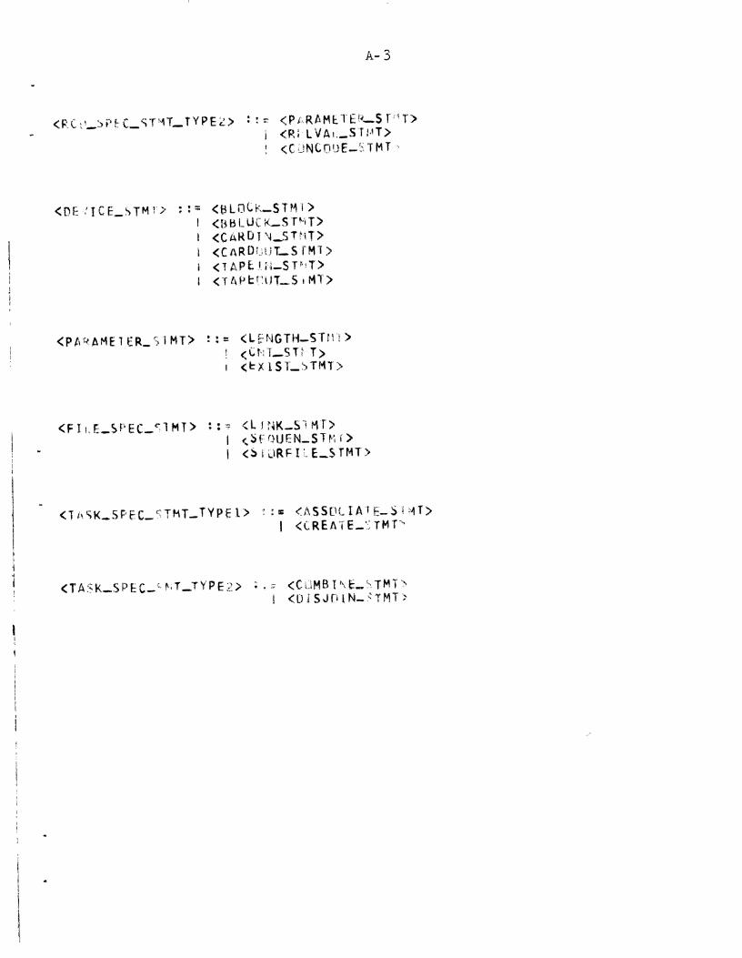
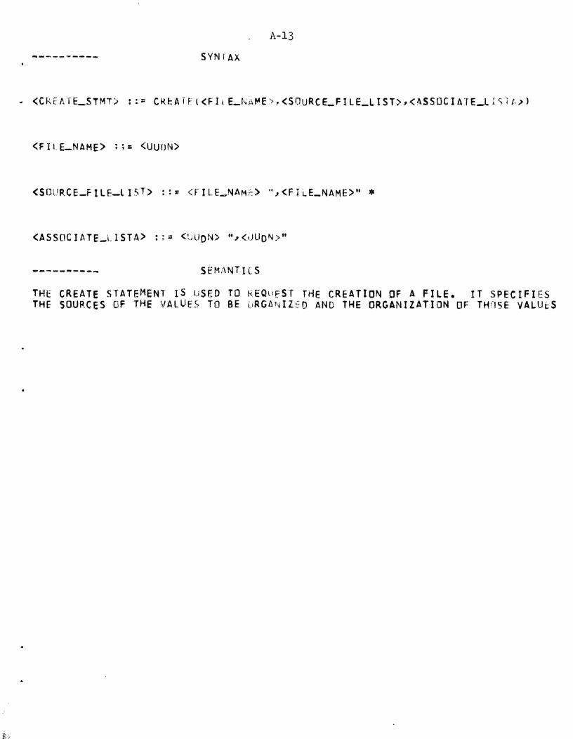
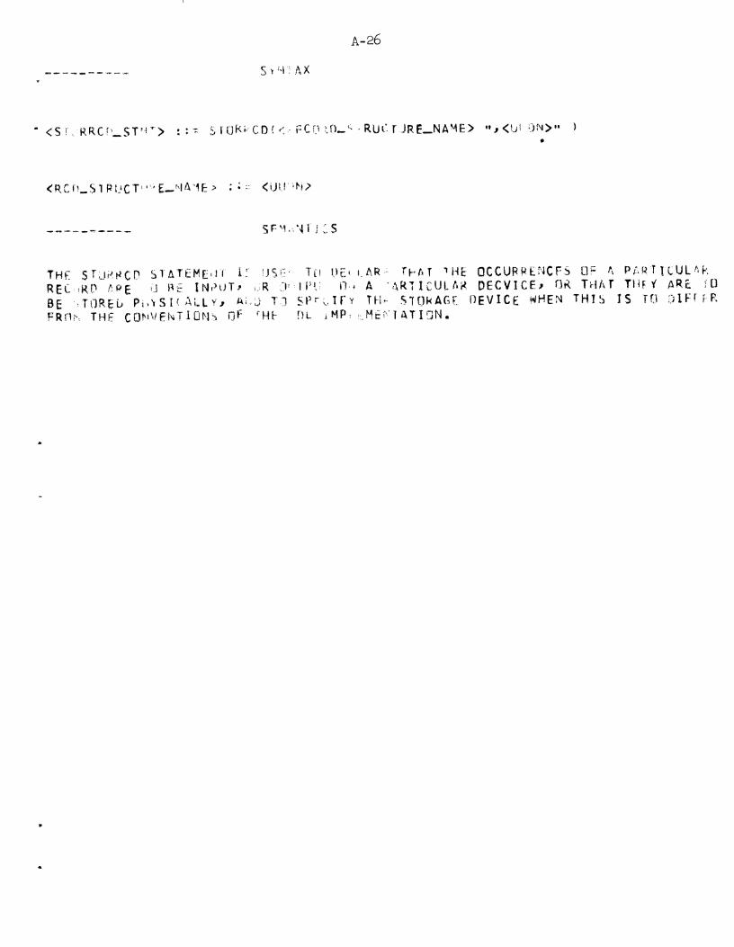
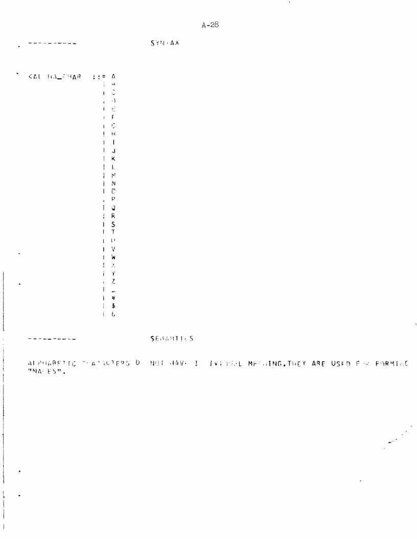
Appendix A: Syntax Description of DDL Described i n EBNF A - 1
Appendix B: EBW with Subroutine Cal ls B - 1
Appendix C: Symbol Table C - 1
Pa r t I Algorithm t o Encode and Decode Three 8- it Characters i n 16 B i t s C-6
Par t I1 Search Tree Algorithm c-7
Par t I11 I n s e r t New Entry c-9
Appendix D: Data Table
Par t I Data Table Formats
Appendix E: The SAPG (syn tac t i c Analysis Program ene era tor) 2-1
Par t I PASS 1 E-1
Pa r t IA LEXEBNF E- 5
Par t I1 PASS 2 E-12
P a r t I11 PASS 3 E-14
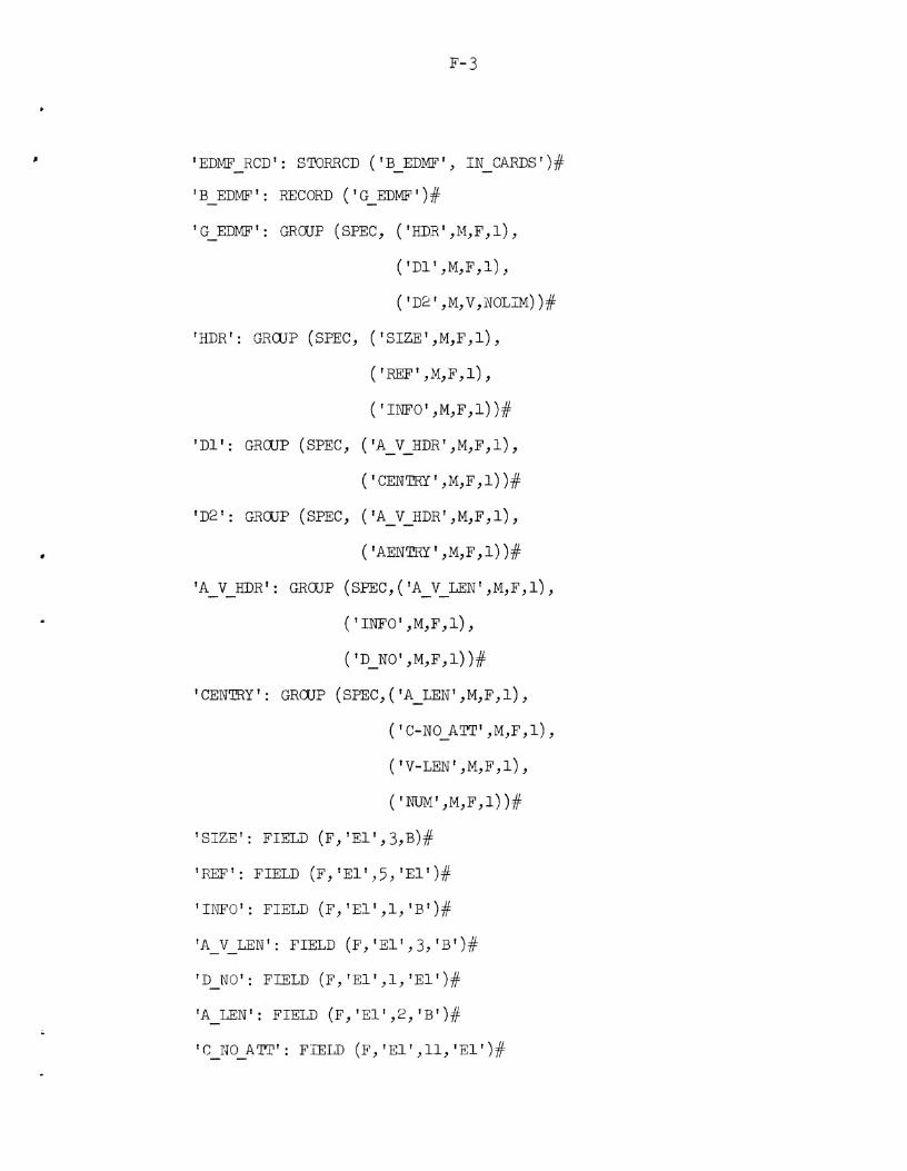
Appendix F: Implementation Example F-1
iii

LIST OF
Figure 1-1
Figure 1-2
Figure 2-1
Figure 2-2
Figure 2-3
Figure 2-4
Figure 2-5
Figure 2-6
Figure 3-1
Figure 3-2
Figure 3- 3
Figure 3-4
Figure 3-5
Figure 4-1
Figure 4-2
Figure 4-3
Figure 4-4
Figure 4-5
Figure 5 -1
Figure 7-1
Figure 8-1
Comparison of DDL Processor and Compiler-Compiler System Designs
Successive In te rpre ta t ion of the Macro Language I-Lang
DDL-Proces sor System
Generating a Translator From I-Lang t o J-Lang
Generation of the DDL Compiler
Compilation of a DDL Program
B e c u t i o n of a Data Conversion Program
Overview of DDL Compiler and Data Conversion Processor
A Compiler- Compiler
The DDL Compiler Generator
Creation of the Syntact ic Analysis Program Generator (SAPG)
Creation of t h e I-J Translator
DDL Compiler-Generator Logic Flow
The DDL Compiler
Phase 1 of t he DDL Compiler
Phase 2 of t he DDL Compiler
AFCB and ADB's f o r Create Statement
Overview of AFCB's and ADB's f o r Create Statement
The Data Conversion Processor
K-Lang Operand Address Generation
Machine Ins t ruc t ion F o m t

1. INTRODUC'ITON
1.1 Background of Project
This repor t documents the design of a Data Description Language
(DDL) Processor. It has been prepared with support by the Office of Naval
Research, Information Systems Program, under Contract ~00014-67-A-0216-0007.
This repor t concludes Phase 1 of a two phase p ro jec t . Phase 2 of t h i s
p ro jec t w i l l cons i s t of the implementation of the DDL Processor i n accor-
dance with the design i n t h i s repor t .
The need f o r an e f f i c i e n t method of converting data f o r use with
d i f fe ren t programs or d i f f e r en t computers has been long recognized by
t he Navy a s wel l a s the l a rge r community of EDP users . Presently, a
use r can organize data by e i t h e r wr i t ing h i s own spec ia l software or
by using the data descr ip t ion f a c i l i t i e s contained i n t he programming
languages, operating systems and data management systems ava i lab le f o r a
pa r t i cu l a r computer. Data organized i n t h i s way of ten cannot be d i r e c t l y
used on a d i f fe ren t computer i n s t a l l a t i o n due t o incompat ibi l i t ies of
software and hardware. I n many cases, the organization of t h i s data
cannot be communicated e f fec t ive ly t o another use r because t he data
organizations a r e impl ic i t i n the programs or software used. I n some
cases, the only way t o interchange data i s t o wr i t e a spec ia l conversion
program. This can require considerable e f f o r t , due t o such problems
a s d i f fe ren t word and character organization and machine word s izes .
There a r e two main approaches t o the solut ion of t he Data
Conversion problem. One consis ts of building t he capab i l i ty of converting

da t a from ex te rna l sources and formats i n t o spec i f i c data management
systems o r programming languages. This capab i l i ty i s then l imi ted t o the
spec i f i c computer system and data management system or programming
language where it has been incorporated. The other approach which i s
considered f ea s ib l e i s t o develop a new "Ut i l i t y " which w i l l convert
data between programs and/or computer systems. I t s power, then, w i l l
be general and not l imi ted t o a spec i f i c programming o r computer system.
Our design i s based on t h i s second approach.
The Data Def ini t ion Language Processor reported here i s a separate
and d i s t i n c t development from the Data Management System. While it can
communicate and prepare information f o r t he l a t t e r , it performs such
functions a s a separate processor. The existence of a Data Description
Language Processor i n respective computer systems w i l l f a c i l i t a t e
communications and exchange of data between computer systems and computer
programs, and across computer language ba r r i e r s .
The f irst s t ep i n the development of DDL was t o consider how it
would be used and what f a c i l i t i e s should be included i n it. The research
toward t h i s end s t a r t e d under the current contract e a r l y i n 1970 and
culminated i n two repor ts . The f i r s t - "A Manual with Examples f o r the
Data Description Language" by Diane P. Smith, Apr i l 1971 [~Mll spec i f i e s
and describes the usage of DDL. The second repor t , a l s o by Diane P.
Smith - "Ar? Approach t o Data Description and Conversion," November 1971
[S@] presents extensive research t h a t const i tu ted the ba s i s f o r the DDL
described i n the Apr i l 1971 repor t . These two repor t s present and J u s t i f y
a highly comprehensive language i n t o which a r e incorporated a l l the usefu l
c apab i l i t i e s discovered by our research t o da te .

The next s t ep was t o implement a processor f o r DDL. The recognit ion
of the need f o r such a processor was made a t approximately t he same
time i n a Tentative Specif ic Operational Requirement 31-47 issued by t he
Navy. A proposal f o r a two-phase design and implementation p ro jec t
was submitted t o the Office of Naval Research on March 31, 1971 and
work on Phase 1 s t a r t e d i n Ju ly 1, 1971. 'This repor t represents the
culmination of Phase 1.
The design of the DDL processor a s reported here, and the subsequent
implementation, have research and experimental aspects . They employ
s t a t e of t he a r t techniques and several new approaches t o achieve machine
and operating system independence and t o provide f o r the adap tab i l i ty
of the Data Description Language Processor t o new user environments.
1 . 2 Summary of Capabi l i t ies of the Data Description Language Processor
The DDL processor is designed t o s a t i s f y two requirements of data
interchange : (1) data (organization) de f i n i t i on and (2) data t r an s l a t i on .
The f i r s t s t ep toward simplifying data interchange is t o make data and
i t s organization e x p l i c i t and independent of machines and t h e i r processors.
This can be done by using a language f o r describing data (separate from
the language used t o process t h a t data) . The second s t ep cons i s t s of
developing a processor f o r in te rp re t ing t he descr ip t ion and t r an s l a t i ng
t he data t o a format appropriate f o r the executing machine. The DDL
Language [ s M ~ , SM21 provides t he descr ip t ive language. The DDL pro-
cessor described i n t h i s repor t i s a s e t of computer programs which
w i l l perform the i n t e rp r e t a t i on and t rans la t ion . It i n t e r p r e t s data
de f in i t ions and data t r an s l a t i on commands, produces a computer program

t o perform the required data conversion and then executes t h i s program,
thereby doing t he data conversion speci f ied .
The capab i l i t i e s of DDL a r e summarized below.
1 . 2 . 1 In te r fac ing F i l e s with Different Programs and Programming Languages
Frequently f i l e s created by one program cannot be processed by
another program o r by another program i n a d i f f e r en t programming language. v
With the DDL processor, the f i l e s can be converted i n t o a s t ruc tu re
which can be processed by the other program. I n t h i s manner f i l e s can
be in terfaced across programming languages.
* 1.2 .2 In te r fac ing F i l e s with Different Operating Systems and Different
Data Management Systems
F i l e s created under one operating system o r data management system
cannot, i n general , be processed under a d i f f e r en t operating system o r
data management system. With DDL, t he conversion of f i l e s f o r processing
by other operating systems o r data management systems can be achieved.
* 1 .2 .3 In te r fac ing F i l e s with New Computers
Increased requirements and new technology require t he phasing out
of o ld computers and t h e i r replacement by new computers. DDL would
enable f i l e s t o be prepared f o r t r a n s f e r from t h e o ld computer t o t he
new.
1 .2 4 In tegrat ion of F i l e s
Fragmentation of information i n numerous f i l e s f requent ly causes
great d i f f i c u l t i e s i n use and considerable ineff ic iency i n processing.
A DDL w i l l provide the capabi l i ty t o in tegra te many f i l e s i n t o one.
* These f a c i l i t i e s a r e not p a r t of the subset being implemented now. See m b l e 1-1 f o r d e t a i l s .

1 .2 .5 Extraction of Data From F i l e s
I f only a small amount of data i n a f i l e i s used by a program,
it i s o f ten f a r more e f f i c i e n t t o c rea te a smaller f i l e consis t ing only
of the use fu l data . DDL descr ip t ions allow the c rea t ion of many f i l e s
from one f i l e
1 . 2 . 6 Creation of dew Data Bases
The combination of t he above two capab i l i t i e s allows t he t rans-
l a t i n g of one s e t of f i l e s i n t o another s e t of f i l e s .
;y. 1 .2 .7 In te r fac ing F i l e s t o Use New Devices
Advances of technology introduce new input/output devices which
enhance t he t o t a l cos t ef fect iveness of the e n t i r e computer system. The
change of such input/output devices can be f a c i l i t a t e d by the DDL process-
ing of the f i l e s from the old devices t o t he new ones.
1 . 2 8% Improving U t i l i z a t i on of Computers o r Storage . A fu r t he r appl ica t ion i s i n t he design and operation of data
and data management systems. For example, a DDL can be used t o c rea te
new data s t ruc tu res which can then improve computer o r storage u t i l i z a t i o n .
l . 2 . g A Language f o r Communication Between Humans About Data
One important appl ica t ion of a DDL i s a s means of communication
between humans. For example, using a DDL a designer of a data base can
describe precise ly t o an appl ica t ions programmer the exact s t ruc tu re of
t he data the programmer wants t o use. J u s t a s BNF lNA11 i s now used t o
describe the syntax of a language so can a DDL be used t o describe data
s t ruc tu res .

1 . 3 Important Features of t he Design
The DDL Processor system cons i s t s of th ree major pa r t s . The
f i r s t p a r t uses syntax and semantic de f in i t ions t o generate t he second
p a r t - the DDL Compiler. The DDL Compiler formats and t r a n s l a t e s DDL
Data Def ini t ion Statements and produces a computer program which w i l l
do the data base convergion. The t h i r d pa r t of t he processor ac tua l ly
processes the source data base and produces a s an output the t a rge t
da ta base. This th ree pa r t s t r uc tu r e i s i l l u s t r a t e d i n Fig . l - l a .
Changes i n the de f i n i t i on of DDL w i l l occur only infrequently
a f t e r an i n i t i a l language development phase and t h e compiler generator
f a c i l i t y i s primari ly intended f o r DDL language development (although
it i s very l ielpful i n t r an s f e r r i ng t he DDL system t o a new computer).
Because one of the DDL Processor Implementation design goals i s maximum
ea r ly feedback about design decisions, a subset of the language was
selected, and the remaining components w i l l cons t i tu te l a t e r addi t ions t o
DDL. These w i l l cause addi t ions t o syntax and s t r uc tu r e t ab l e s .
Changes i n t he def in i t ion of a pa r t i cu l a r data base t o which t he data
conversion processor i s applied w i l l occur more f requent ly . For
instance, one may wish t o change def in i t ions t h a t a r e used i n the conver-
s ion of data between data management systems, o r between computer systems.
In t h i s case only the sequence of DDL statements would be changed and the
DDL Compiler would be used t o create a new Data Conversion Processor.
If the descr ip t ion of the data t o be converted does not change
the DDL Compiler need not be used, tile previously created Data Conversion
Processor may be used again.

There a r e two fea tu res i n the Design which a r e of spec ia l
i n t e r e s t .
(1) The app l ica t ion of t he Concept of a Compiler-Compiler t o the
DDL Processor.
This i s i l l u s t r a t e d i n Fig . 1-1 where the design of the DDL Processor
i s shown on t he l e f t ( ~ i g . l - l a ) a s compared t o a design of a Compiler
Compiler system as shown on the r i g h t ( ~ i g . l - l b ) .
Note t h a t the input i s shown a s hor izonta l l i n e s and output i s
shown a s v e r t i c a l l i ne s , thus the output of the DDL Compiler-Generator
is not t he input t o the DDL Compiler; it is, ra the r , t h e DDL Compiler
i t s e l f .
The Data Def ini t ion ( i n DDL) of a Data Base i s considered analogous
t o the users source statements which a r e input t o t he compiler. The Data
Conversion Processor i s the analogue of t he u se r s ' object program, output
from t h e compiler.
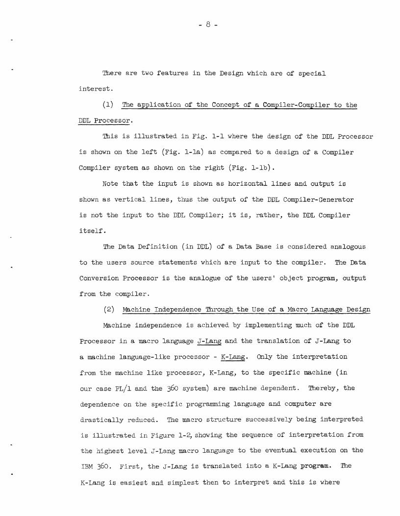
( 2 ) Machine Independence Through t h e Use of a Macro Language Design
Machine independence i s achieved by implementing much of t he DDL
Processor i n a macro language J-Lang and t he t r an s l a t i on of J-Lang t o
a machine language-like processor - K-Lang. Only the in te rpre ta t ion
from the machine l i k e processor, K-Lang, t o the spec i f i c machine ( i n
our case P L / ~ and the 360 system) a r e machine dependent. Thereby, the
dependence on the spec i f i c programming language and computer a r e
d r a s t i c a l l y reduced. The macro s t ruc tu re successively being in te rpre ted
i s i l l u s t r a t e d i n Figure 1-2, showing the sequence of i n t e rp r e t a t i on from
the highest l e v e l J-Lang macro language t o t he eventual execution on t he
IBM 360. F i r s t , the J-Lang i s t r an s l a t ed i n t o a K-Lang program. The
K-Lang i s ea s i e s t and simplest then t o i n t e rp r e t and t h i s is where

dependence on a spec i f i c language and spec i f i c computer system i s made;
K-Lang i s in te rpre ted using a P L / ~ program (which has been t r an s l a t ed
i n t o assembly language code) and thus the K-Lang machine i s simulated
on t he IBM 360.
1 . 4 Select ion of Computer and Programming Language
7 3 0 computer systems avai lable a t the Universi ty of Pennsylvania
t h a t could s a t i s f y requirements were evaluated, the RCA Spectra 70146
Time Sharing System, and the IBM 360175 operating under O S / ~ ~ O . The
RCA system includes support f o r ALGOL, COBOL, FOR!I!RAN, SNOBOL, and
Assembler languages. The IBM system supports these and a l s o P L / ~ ,
APL, LISP, GPSS and GASP. Since both systems meet t he hardware and
operating system requirements, t he programming language was the determinant.
Assembly language programming was unsat is factory because of programming
costs , lack of mchine independence, and poor readab i l i ty . P L / ~ was
considered,by f a r , t h e bes t , e spec ia l ly i n t he area of memory a l loca t ion ,
and data management commands. The IBM 360 computer system was se lected
because of PL/1 a v a i l a b i l i t y .
1 . 5 Select ion of a Subset of DDL f o r Implementation
The repor t s by Diane P. Smith [ s M ~ , ~ I showed t h a t a model f o r
data descr ip t ion can be divided i n t o th ree l a rge ly independent l eve l s ,
namely :
1) the record,
2) f i l e and
3) storage l eve l s .
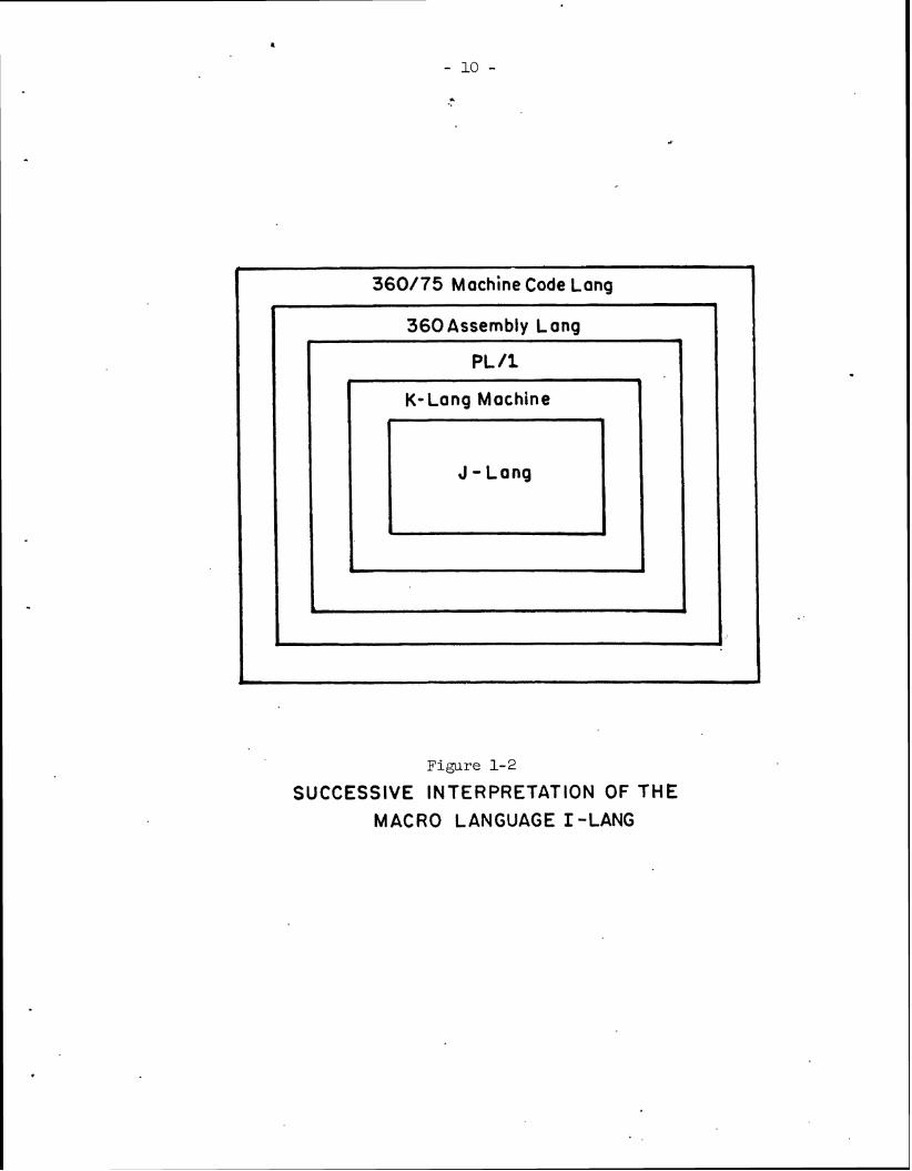
Figure 1-2
SUCCESSIVE INTERPRETATION OF THE MACRO LANGUAGE I -LAN6
4
1
360175 Machine Code Long &
i
360 Assembly Long
&
I
P L 11
*
+ K- Long Machine
J -Long
0
J

Using these statements it w i l l be possible t o
(a) Accurately describe t he s t ruc tu re of da ta . (This i s
valuable during system design, and implementation,
a s wel l a s f o r l a t e r documentation.)
(b) In te r face f i l e s with d i f f e r en t programs and programing
languages. (using t he DDL t o reformat f i l e s before
program execution. )
(c) In tegra te and ex t r ac t data i n ex i s t i ng f i l e s , producing
new f i l e s . (The "ex i s t ing f i l e " might be j u s t a deck of
cards, o r unformatted tape records.)
The subset se lected f o r t h i s implementation w i l l support the
record and par t of the f i l e l e v e l de f in i t ions . It w i l l not include
t he storage s t ruc tu re descr ip t ion f a c i l i t i e s . Ins tead the standard
data access methods of the implementation operating system w i l l be
used t o s t o r e data on devices. The statements which a r e supported by
t he f i r s t implementation and those statements which w i l l be implemented
l a t e r , a r e shown i n Table 1-1.
1.6 Organization of the Report
This sect ion (Section 1) has responded t o a number of questions
t h a t were l e f t open, and resolved during the design phase. These
consisted of se lec t ion of a computer system f o r the i n i t i a l implementation -
t h e IBM 360 Mod 75 (soon t o be exchanged f o r IBM 370 Mod 165) a t the
Universi ty of Pennsylvania Computer Center was selected; se lec t ion of
a programming language f o r implementation of t h e DDL Processor - P L / ~

Table 1-1 DDL Statements For I n i t i a l and Later Implementation
----- - - - - - - -
TYPE NITIAL IMP~NTATION S'IYITEMENT ---_---__...s-.-._ I ._- _.. "-_- I IArnR -.-
DESCRIBE RECORD CHAR CRI'IMESSAGE
FIELD LOGRCD
i
I GROUP C ONC ODE
I REC ORD
i I
f SET b
1 CRI'IIEX I
I C R I 'IIERION 1 S TORRCD i
I i
I RPLVAL d I I CONSTANT
1 I BBLOCX !fJlPEWT
i ONC CODE (DELIM and FILLER options 1 only)
1 I CARDIN DISKIN
i DEVICE
I CARDOUT : DISKOUT
----- - ---. -- -- .- BLOCK TAPEIN
~ P E I N (NO a ssoc ia t ion l i s t rrYIN
I option, no header o r t r a i l e r 1
and only "SPEC" order) i TTYOUT
i , ?Awmd LENGTH 1 1 ! 1
! j CNT i i i I
EXIST i --I----- .- . -....--- ' .--. .. . ... .-.... ,....,...*- L -.-.--.--

Table 1-1 (continued)
T- -. -- - ---. --- '- - .. .
/ I N I T I A L IMPLZDENTATION S'IY1TEMENT LATER ' ""-. "- .- - c - - - . . - - - - - - . . _--. . -.-_-.._- - .....,..-.--I**. "..--L-Y ----. ---..+ ! i I t
/DESCRIBE FILE I LINK (only sequent ia l lirks) OCC i ' SEQUEN
I i A L L N C
I i ST0RFIL;E S@EOCC
1 ! LINK L $ 1 INVLINK
I I i EMBED ! 1 t I i I DIREC
-----------A
i LOGFILE r------- --
ASSOCIATE a PROGDATA i I 1
COMBINE INTERFACE ,
CREAW PARAMPROG I
D I S J O I N I M'I!FCND _ )
_ I

was selected; and f i n a l l y select ion of a subset of the commands
described i n the DDL manual (April 1971) [~Mll, t h a t w i l l be implemented
i n the i n i t i a l versions of the system. In the select ions made and a s
well as i n the design, the experimental nature of the project a s well
a s the need t o provide a system a s independent as possible of a specif ic
environment were stressed.
Section 2 provides an overview of the design of the processor.
Section 3 describes the Compiler-Generator. Section 4 describes the
DDL compiler. Section 5 describes the Data Conversion Processor. m e
remainder of the report (sections 6, 7, 8) a r e a specif icat ion of the
three in te rna l languages used i n the system ( I -~ang , J-Lang, and K - ~ a n g ) .
A l i s t of references and appendices conclude t h i s report .

2 . OVERALL DESCRIPTION OF TEE DESIGN OF 'ME DDL PROCESSOR
The "DDL Processor System" i s ac tua l l y th ree processors ( i . e .
s e t s of computer programs) . .The f i r s t i s the DDL Compiler Generator,
the second i s t he DDL Compiler, and t he t h i r d i s the Data Conversion
Processor (see F ig . 1-1). When the term DDL Processor i s used, it
. r e f e r s t o the l a t t e r two processors - the DDL Compiler and t he Data
Conversion Processor.
An analogy with ex i s t ing computer programming systems was made
i n Fig . 1-1; the Data Conversion Processor corresponds t o an executable
user program, t he DDL compiler corresponds t o a Cobol, For t ran o r P L / ~
compiler, and the DDL Compiler Generator corresponds t o a Compiler-
Compiler which i s used t o produce t he Cobol, Fortran o r P L / ~ compiler.
The re la t ionsh ips between and the use of t he th ree processors i n t he DDL
systems i s read i ly seen from the analogy. The Data Conversion Processor
i s t h e program which reads data from ex i s t i ng f i l e s and produces new
f i l e s . Like most data processing programs, each Data Conversion Processor
i s designed f o r a spec i f i c function, (e .g . conversion of f i l e s i n format
A t o f i l e s i n format B ) . To a i d i n t he generation of Data Conversion
Processors, t he r e i s the DDL Compiler.
To produce a Data Conversion Processor one wr i t es a Data Def ini t ion
(a s e r i e s of statements i n t he DDL language) f o r each of t he source and
t a r g e t f i l e s . These statements a r e read by t he DDL Compiler, which
produces a new Data Conversion processor. It i s important t o note t ha t ,
j u s t a s it i s not necessary t o compile a Cobol program each time it i s

used, it i s not necessary t o c rea te a new Data Conversion Processor
each time it i s used. Only when t he functions of the processor change
i s t h a t required.
The DDL Compiler, and the Data Conversion Processors produced by
it, a r e t h e components of the DDL Processor System t h a t most users w i l l
need, The other component, the DDL Compiler Generator, i s t he s e t of
programs used t o c rea te the DDL Compiler. The "Generator" i s a very
valuable t o o l i n the development of the DDL Compiler, and i s equally
valuable i n enhancing and modifying t he Compiler. But jus t a s the average
user does not o f ten modify h i s Cobol compiler, he would not often modify
h i s DDL Compiler.
An overview of the DDL Processor System i s shown i n Figure 2-1.
Each processor i s surrounded by a broken l i n e . Programs a r e shown i n
rectangles, input/output a r e shown i n trapezoids. When t h e output i s a
program double l i n e s a r e used t o show the des t ina t ion of t he output.
The following paragraphs describe each of t he th ree components of the DDL
Processor System.
2 .1 The DDL Compiler-Generator
The DDL Compiler-Generator i s composed of th ree p a r t s - the Syntactic
Analysis Program Generator, t he I-J Translator (see Fig . 2-2), and the
J-K Translator. The re la t ionsh ip of these th ree i s shown i n Figure 2-3.
The f i rs t par t of t he Compiler Generator i s the Syntact ic Analysis
Program Generator. The input t o the Syntactic Analysis Program Generator
i s a syntax descr ip t ion coded i n Extended Backus-Naur Form (EBNF).


SYNTAX S P E C I F I C A T I O N o f the I - L a n g
( E B N F )
S Y N T A C T I C ANALYSIS PROGRAM GENERATOR
f - L a n g SY N T A C T l C A N A L Y S I S PROGRAM
( J- L a n g )
T R A N S L A T O R
t I - L o n g S Y N T A C T I C
A N A L Y S I S PROGRAM ( K - L a n g )
I I I I I I I I I
' I I
I - J T R A N S L A T O R
I I
G E N E R A T O R
----- I I

ANALYSIS PROGRAM PROGRAM
-- - - _ . - -
Figure 2-3 Generation of the DDL Compiler
-
SYNTAX SPEC IFlCATl ON o f DDL ( E B N F )
r - - I
-- - - 7' v v
I I
SYNTACTIC ANALYSIS PROGRAM GENERATOR
(PL 11)
I 1
K- INTERPRETER
I - J TRANSLATOR
I I 1 DDL SYNTACTIC
I- Long SYNTACTIC
S N TACTIC 8
/- -.
ANALYSIS PROGRAM
(K-Long)
I
SEMANTIC ** SUPPORTING
SUBROUTINES ( P L / I ) I
( P L I I )
I (J -Long) T
DDL CODE GENERA I
I PROGRAM
I I ( J - Long) 1 I I'
I v 1 J-K TRANSLATOR
1 I I I I
I D D L COMPILER GENERATOR
I L - - - - - - - - - - - - - - - - - J
I I

(EBNF nota t ion w i l l be described i n Section 3.2.) The Syntactic Analysis
Program Generator produces a program which i s t he Syntax Analysis phase
of the DDL Compiler. The second p a r t of the Compiler Generator i s the
I-J Translator. Its input i s the Code Generation logic , wr i t t en i n I-Lang.
The I-J Translator then produces a program which contains t he bas ic code
generation log ic used i n t he DDL Compiler.
The output of the Syntactic Analysis Program Generator and t he I-J
Translator a r e J-Lang programs. The t h i r d major component of the DDL
Compiler Generator, the J - K Translator, i s used t o t r a n s l a t e these J-Lang
programs t o K-Lang programs, which a r e then su i t ab le f o r in te rp re t ive
execution.
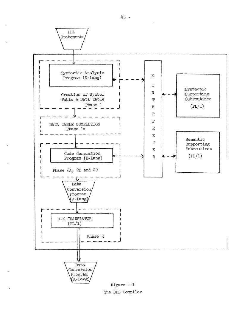
2 . 2 The DDL Compiler
An overview of the DDL Compiler i s shown i n Figure 2-4. The DDL
Compiler contains f i v e major pa r t s : (1) a Syntactic Analysis Program (SAP),
(2) a Code Generation Program (CGP), (3) a s e r i e s of supporting subrou-
t i ne s , (4) an i n t e rp r e t e r , (5 ) a J - K Translator.
The function of t he SAP i s t o perform the syntax ana lys i s on t he
DDL statements. The function of CGP i s t o generate t he Data Conversion
Program ( i n an an^). Since both SAP and CGP a r e i n K-Lang, t he K-Inter-
p r e t e r i s used t o execute them ( t he K-Interpreter l og i ca l l y converts t he
IBM 360 machine i n t o t he K-machine). The J - K Translator accepts a s
input the J-Lang code produced by CGP and produces t he Data Conversion
Program i n K-Lang.


The supporting subroutines a r e a s e t of functions used during
Syntax Analysis and i n Code Generation; these subroutines, a s well a s
the K-Interpteter , and t h e J - K Translator a r e wr i t t en i n P L / ~ .
Phase 1 of the compilation process i s the execution of the Syntactic
Analysis Program, with i t s supporting subroutines. Phase 1A includes most
of t h e Semantic In te rpre ta t ion logic; it completes the i n t e rna l t ab l e s
which w i l l be used i n Phase 2 (Code ene era ti on). Phase 3 of compilation
i s the execution of t he J-K Translator; t h i s produces t h e machine-level
language (K-~ang ) hhich i s t he output of the DDL compiler - namely, t h e
Data Conversion Processor.
2 .3 The Data Conversion Processor
The Data Conversion Processor i s a s e t of K-Lang programs and
data which was produced by t he code generation log ic of the DDL compiler.
It i s composed of
(a) a Data Conversion Program
(b) a Data Structure t o perform t h e data conversion,
(c ) an in te rpre te r , and
(d) a s e t of Run Time Supporting Subroutines.
The Data Structure i s a network of threaded lists. The nodes a r e
data descr iptor en t r i es ; they a r e used by t he Data Conversion Program t o
a i d i n parsing t h e source data, and t o format t he output data . Because
the Data Conversion Program i s encoded i n K-Lang, it must be in te rpre t ive ly
executed by a K-Interpteter . The other components of t he Data Conversion
Processor, t he Run Time Supporting Subroutines, perform functions such
a s record l e v e l input-output, main memory a l locat ion, character s e t con-
version, extension or t runcat ion of f i e ld s , and data type conversion.
An overview of the Data Conversion Processor i s shown i n Figure 2-5.

PROGRAM
DATA CONVERSION PROCESSOR L - - - - - - - - - -
r - - - ' - - \Jf 1
Figure 2-5
Execution of a Data Conversion Program
I r D D L DATA CONVER SlON PROGRAM
( K - ~ a n g ) . I - 4
I I , I -
I -. -
*
K- INTERPRETER
I I I -
( P L / i I I
I b - I I I I I I I
RUN TIME SUPPORTING SUBROUTINES
( P L / i )
I I

Figure 2-6 shows a simplified view of the flow in the DDL
compiler and Data Conversion Processor. The K-Interpreter and supporting
subroutines have been omitted to allow the logical flow of control and
data to be seen more easily. Note that the Code Generation Program of
the DDL Compiler produces both a network of data descriptors and a Data
Movement Program. These two become the Data Conversion Processor. During
the execution of the Data Conversion Processor the data descriptor network
is used to parse the input data and act as a framework which the Data
Movement Program uses to construct the output data files.
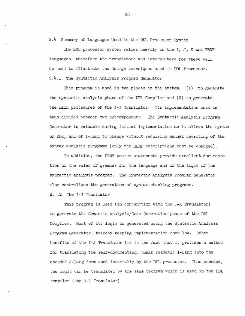
2.4 Summary of Languages Used i n the DDL Processor System
The DDL processor system r e l i e s heavily on t h e I, J, K and EBNF
languages; therefore the t r an s l a to r s and i n t e rp r e t e r s f o r these w i l l
be used t o i l l u s t r a t e t he design techniques used i n DDL Processor.
2.4.1 The Syntactic Analysis Program Generator
This program i s used i n two places i n the system: (1) t o generate
the syntact ic analys is phase of the DDL Compiler and (2) t o generate
t he main procedures of the I-J Translator. Its implementation cost is
thus divided between two subcomponents. The Syntactic Analysis Pragram
Generator i s valuable during i n i t i a l implementation a s it allows the syntax
of DDL, and of I-Lang t o change without requiring manual rewrit ing of the
syntax analys is programs (only the EBNF descr ip t ions must be changed).
I n addit iob, the EBNF source statements provide excel lent documenta-
t i o n of the ru l e s of grammar f o r the language and of t h e l og i c of the
syntact ic ana lys i s program. The Syntactic Analysis Program Generator
a l s o cen t ra l i zes the generation of syntax-checking programs.
2.4.2 The I-J Translator
This program is used ( i n conjunction with the J - K Translator)
t o generate the Semantic ~ n a l ~ s i s / ~ o d e Generation phase of the DDL
Compiler. Most of i t s logic i s generated using t h e Syntactic Analysis
Program Generator, thereby keeping implementation cost low. Other
benef i ts of t he I-J Translator l i e i n t he f a c t t h a t it provides a method
f o r t r an s l a t i ng t he self-documenting, human readable I-Lang i n t o t he
encoded J-Lang form used i n t e rna l l y by the DDL processor. Thus encoded,
t he log ic can be t r an s l a t ed by the same program which i s used i n the DDL
compiler ( t he J - K Transla tor) .

2.4.3 The J - K Translator
It i s used i n th ree places i n the system: (1) it forms the
t h i r d phase of t he DDL Compiler, (2) it i s used a t the end of the
Compiler Generator program which produces t he Semantic ~ n a l ~ s i s / ~ o d e
Generation log ic , (3) it i s used a t the end of t he Compiler Generator
program which produces t he Syntactic Analysis Program. Although it i s
not a simple program, i t s cost i s d i s t r i bu t ed over th ree important a reas
of DDL implementation. The J - K Translator performs - a l l t he K-Lang
generation done by the DDL Processor. Any extensions t o the K-Lang a f fec t
only it and t he K-Interpreter . Together with the K-Interpteter , it provides
t he ba s i s f o r t he machine independence of t he DDL Processor.
2.4.4 The K-Interpteter
This program simulates t h e K-machine. It i s used t o "execute"
t he DDL compiler, and the program which t he compiler produces - the
Data Conversion Processor. It decodes machine-level ins t ruc t ions and
performs t he elementary commands indicated by them. It is t he primary
method used t o achieve machine independence. Because it operates
i n t e rp r e t a t i ve ly it provides an excel lent place i n which t o place debugging
too l s , program performance monitors, and use r data v a l i d i t y t e s t s .

3. THE DDL COMPILER GENERATOR
3.1 Compiler-Compilers
One of the main problems i n using computers i s t h a t of effective
programming. An important advance was made with the introduction of
mechanical t rans la tors a s an a i d i n preparing programs. An easy t o
use a r t i f i c i a l language was developed and a t rans la tor wri t ten t o trans-
l a t e t h a t language in to a machine language. I n i t i a l l y these t rans la tors
were handwritten i n an "ad-hoc" manner f o r a par t icu la r machine and
language. But using the theory of automata and formal l i ngu i s t i c s
a s too ls compiler wri ters were able t o develop be t t e r techniques f o r
t rans la tor construction. An important s tep was the development of a
formal language i n which t o describe the syntax of a programing language.
The def in i t ion of the ALGOL syntax L N A ~ ] was an ear ly and success-
f u l attempt t o describe programming languages i n a formal way. The
automatic construction of compilers i s based on such a formalization.
The following excerpt from a paper by J. A. Feldman on FSL (Formal
Semantic I,anguage) [ ~ e 11 out l ines the basic method and should serve
a s an adequate introduction t o our discussion of compiler-compilers.
When a compiler f o r some language, C f , i s required,
the following s teps a r e taken. F i r s t the formal syntax P
of x , expressed i n a syntactic metalanguage, is fed
in to the syntax loader. This program builds tab les which
w i l l control the recognition and parsing of programs i n
-4 the language . Then the semantics of , writ ten i n a
semantic metalanguage, i s fed i n t o the semantic loader. This
program builds another table , t h i s one containing a descrip-
t i o n of the meaning of statements i n 2 . Finally, everything
- 28 -

t o the l e f t of the double l i n e [in Fig. 3-11 i s
discarded leaving a compiler f o r 2 . The resul t ing compiler i s a table-driven t rans la tor . The
compiler kernel includes Input-Output, code generation routines and
other f a c i l i t i e s used by a l l t rans la tors . Examples of t h i s type may
be found i n the work of P. Ingerman CIN 11; W. M. McKeeman, J. J . Horning,
D. B. Wortman [MC 11; Feldman [ ~ e 11; Brooker and Morris [ ~ r 11.
3.2 The DDL Compiler Generator
The correspondence between the compiler-compiler described by
Feldman [ ~ e 11 and the DDL Compiler Generator i s given i n the following
sentences:
a) The metalanguage used t o express the formal syntax (of DDL)
i s EBW (see Section 3.3) . b) The Syntax Loader i s the (SAPG) Syntactic Analysis Program
Generator, i.e., the EBNF of DDL i s fed in to the SAPG.
This program produces the SAP (syntact ic Analysis program)
which w i l l control the recognition and parsing of programs
i n the language DDL.
c) The semantic* metalanguage i s the I-Lang (see Section 6 ) .
d) The Semantic Loader corresponds t o the (CGPG) Code Generation
Program Generator (or I-J Translator) . The Code Generation
logic ( i n I -~ang) i s fed in to the CGPG. This t rans la tor
produces the CGP (code Generation program) which w i l l control
code generation.

Source Code in
Figure 3-1
A Compiler-Compiler
This figure appears in [ ~ e 11.
Compiler
Kernel
Machine r7

e) The compiler kernel corresponds t o the s e t of Syntactic and
Semantic supporting subroutines.
The corresponding diagram f o r t he DDL Compiler Generator i s shown
i n Figure 3-2. Everytlling t o t he l e f t of t he double l i n e i n Figure 3-2
i s discarded leaving a compiler f o r DDL.
I n t he next sect ion a descr ip t ion of the ~~ metalanguage i s
presented. In the following ones the descr ip t ion of each of t he com-
ponents of the DDL Compiler Generator i s presented.
3.3 Description of the Metalanguage (EBNF)
The formal syntax of the DDL language w i l l be described with the
a i d of a metal inguis t ic formulae Extended BNF (EBNF) .+ The i n t e rp r e t a t i on
of t h e bas ic EBNF i s be s t explained by an example.
1 < CRITERION STPIT > : : = C R I E R I O N (< CRITERION MP NAME >" ;
< RPLVAL STMT >" )
1 < IUDN > "OF c REF NAME >"
t A complete descr ip t ion of the Syntax of DDL i s presented i n Appendix A.

Machine $, Figure 3-2
The DDL Compiler Generator

Sequences of characters enclosed i n the bracket < > represent
BNF metalinguist ic var iables whose values a r e sequences of symbols. The
marks : := and 1 ( the l a t t e r meaning OR) a r e BW metalinguist ic symbols.
The extension of BNF (EBIVF) i s through use of double quotes " and * a s
a l s o metalinguist ic symbols. Double quotes a r e used t o indicate t h a t the
item enclosed by these symbols may appear zero o r one times i n t he
"object" formulae. If the close quotes a r e followed by *, t h e symbols
may appear zero o r more times.t Any mark i n a formula, which is not a
var iable or a connective, denotes i t s e l f (o r the c l a s s of marks which
a r e similar t o i t ) . Juxtaposit ion of marks and/or var iables i n a formula
s i gn i f i e s juxtaposit ion of the sequences denoted.
Therefore the above formulae (1 through 8) gives a ru l e f o r t h e
formation of:
< CRITERION SlMT >, i n l i n e 1. It indicates t h a t t he < C R I ~ R I O N S'IMT >
begins with t he keyword CRITERION, followed by "(", followed by some value
of t he var iable < CRITERION MP NAME >, and t h a t ;< RPLVAL S?MT > may
appear zero o r one times, f i n a l l y " ) " must appear.
< C R I E R I O N MP NAME >, i n l i n e 2. It ind ica tes t h a t the variable
< CRITERION EXP NAME > w i l l take some value of the variable < TJUDN >.
< RPLVAL S'PMT >, i n l i n e 3. It indicates t h a t t he < RPLVAL S9MT >
begins with t h e keyword RPLVAL, followed by "(", followed by some value
of < DAm NAME: >, followed by the separator "," followed by some value
of the variable < REP VAL >, followed by " ) " .
< DAm NAME >, i n l i n e 4. It indicates t h a t < DA'B NAME > w i l l
take some value of t h e var iable < REF NAME >.
f To allow nested quotes, the following conventions f o r preparation of source input cards were adopted:
punch a i n the column preceding an open quote; punch a [:g{ i n the column following a close quote.

< REP VAL >, i n l i n e 5 . It ind ica tes t h a t < REP VAL > w i l l
e i t h e r be (1) some value of t he var iable < REF NAME > o r (2) some
value of the var iable < CONSTRNT S'IMT >.
< REF NAME >, i n l i n e 6. It ind ica tes t h a t < REF NAME > w i l l
e i t h e r be (1) some value of the var iable < UUDN >, and that the keyword
OF followed by some value of t h e var iable < REF NAME > (note here the
r i g h t recursion of t he production) may occur zero o r one times, o r (2)
some value of the var iable < IUND >, and t h a t the keyword OF followed
by some value of the var iable < REF NAME > may occur zero o r more times.
< UUDN >, i n l i n e 7. It ind ica tes t h a t < W D N > w i l l take some
value of the var iable < ALPHA CHAR > followed by the occurrence of zero
o r more times of the value of the var iable < SINGLE STRING >. ( ~ o t e
t h e use of t he meta l inguis t ic symbol * t o achieve r i g h t repe t i t ion . )
< SINGLE STRING > i n l i n e 8. It ind ica tes t h a t < SINGLE STRING >
w i l l e i t h e r be (1) some value of the va r iab le <ALPHA CHAR > o r (2) some
value of t he va r iab le c DECIMAL DIGIT >.
The above descr ip t ion of EBNF i s su f f i c i en t f o r t h e syntax
descr ip t ion of DDL (see Appendix A ) , but t o allow the subroutine c a l l
speci f ica t ion permitted by t he SAPG, EBNF must be f u r t h e r extended. This
i s described i n t he next paragraph.
3.3.1 Extended BNF with Subroutine Cal ls e
The extensions t o EBNF allow semantics t o be added t o the syntact ic
descr ip t ion. They permit the spec i f i ca t ion of subroutines which w i l l be
executed during syn tac t i c analys is , and thus simplify t h e machine-
a s s i s t e d program generation of t he SAP. The programmer provides a non-
procedural descr ip t ion of t he language as input and then receives procedural
l og i c (a ~ rogram) which w i l l perform syntax-checking of t h e language he

described. The program (SAP) w i l l a l s o contain c a l l s t o t he subroutines
* which produce t he Symbol Table and Data Bibles. The SAP i s produced
i n J-Lang by t he SAPG.
An example of an EBNF statement with subroutine c a l l s is :
< item 1 > : : = < name > / SUB^/ : (< p a r t 1 >//" ,/.SEW/ < p a r t 2 >//I!*)
This statement means :
To t e s t f o r (recognize) a syntact ic u n i t ( o r token) ca l l ed "item l",
f i r s t see if the current pointer i n t he input s t r i n g po in t s t o the start
of a s t r i n g which s a t i s f i e s the syntact ic de f i n i t i on of "name". (DO t h i s
by ca l l i ng a recognizer routine.) I f t h e recognizer e x i t s f a l s e go t o
a system rout ine ca l l ed .FAIL (see Section 4.3.3 f o r a discussion of t h i s
rou t ine ) . I f < name > was recognized, then c a l l .SUBl. Upon re tu rn from
t h i s rout ine check t h a t the next token i n the input is a ":". If not,
c a l l .FAIL. Similar ly check the next two tokens i n the input s t r ing ,
i . e . , fo rH("and < p a r t 1>. I f they a r e recognized then c a l l .VCALL
( t h i s i s indicated by //) , .VCALL pops the "subroutine vector stack"
( see Sect. 4.3.2 f o r the discussion of t h i s rout ine) and gives control t o
the rout ine whose address was on top of t he stack. Af te r re turning from
t h a t subroutine t he syn tac t i c analyzer t e s t s f o r t he next token, but
f a i l u r e t o f i n d a match does not cause a c a l l t o .FAIL, because the token
i s the f i r s t element i n an opt ional group a s indicated by the " symbol.
( ~ o t e t h a t quotes surround the opt ional group.) I n t h i s case f a i l u r e
causes the scan t o skip t o the f i r s t token a f t e r the " o r "* ind ica t ing
end of opt ional group. This token i s " )" i n t h i s case? If t h e ","
* See Section 4. and 4. f o r a desc r ip t ion of t he Symbol Table and Data Tkble respectively.
3 When references a r e made t o punctuation marks i n t he t e x t they w i l l be enclosed i n double quotes.

was found a c a l l i s made t o .SETP2, then a t e s t i s made f o r t he token
< pa r t 2 >. I f t h i s f a i l s , then .FAIL i s cal led . ( ~ o t e t h a t only i f the
f i r s t item of a n opt ional group i s present then a l l o ther items i n the
group must be present . ) Af te r successfully recognizing < p a r t 2 >, a
c a l l i s made t o the vector subroutine .VCALL. Af te r re turn , the syntax
analyzer repeats the check f o r the "," before /. SETPP/. This loop of
t e s t i n g f o r t he opt ional p a r t i s s ign i f i ed by t h e * following the If
(c lose quotes) . I f no * was present the scan would have proceeded t o
t h e next token, ") " . Eventually the loop w i l l terminate when a , " i s
not found.
There a r e three other points which should be mentioned with respect
t o EBNF syntax.
(1) subroutine c a l l s may appear anywhere except between
< and >.
(2) an EBNF statement l i n e may be nothing more than subroutine
c a l l s .
(3) opt ional pa r t s may be nested without l i m i t .
3.4 The Syntactic Analysis Program Generator (SAPG)
The SAPG w i l l be hand coded i n P L / ~ ; it cons i s t s of three phases
o r passes. An overview of the creat ion of t he SAPG i s shown i n Figure
3-30
3.4.1 Pass 1 (The alg;rithm i s given i n Appendix E, Par t I .)
Pass 1 of the SAPG reads t he EBNF source statements ( ~ r o d u c t i o n s )
and encodes them i n t o a t ab l e ca l l ed the Encoded Table.

- - -. .- .-.
Program Generator, i n P L / ~ I'
Figure 3-3
Creation of the Syntactic Analysis Program Generator ( SAPG)
Lexical un i t s of each production a re encoded i n the Encoded Table
which i s organized by production. The un i t s a r e typed as: (a) terminal
symbols, (b) subroutine c a l l s or (c) non-terminal symbols. The en t r i e s
f o r each l ex i ca l un i t a r e ac tua l ly pointers t o tab les containing the
types l i s t e d above, one t ab l e f o r each type. The non-terminal symbols
a r e fur ther divided in to two tables . Non-terminals appearing on the l e f t
side of a production a re kept i n the Symbol Table. Non-terminals appear-
ing on the r i gh t side of a production a re placed i n a work t ab l e f o r
use i n Pass 2. A l l the symbols within a t ab l e a r e unique. (This i s
done t o conserve storage i n the Encoded Table, since the same entry i n
tab les may be referred by d i f fe ren t en t r i e s i n the Encoded Table.) Each
production thus far found acceptable i s saved i n the Encoded Table f o r
processing by Pass 2 of the W G .
The symbol table,consists of a l l non-terminal symbols appearing
a s the l e f t pa r t of a production, i . e . , appearing t o the l e f t of the meta-
l i ngu i s t i c symbol "::=". These symbols a r e the syntactic un i t s of the
language being defined. A subroutine (.ENTSYM) searches the symbol

t a b l e f o r t he current symbol. I f it already appears i n t he t ab le , an
ambiguity i s present i n t he language, and t he e n t i r e production i s
flagged and r e j e c t e d . I f an entry i s not found, a new en t ry i s created
f o r t he symbol. (~ i e j ec t ed productions a r e noted, but not analyzed
during t he second pass of the SAPG.)
The production is a l s o checked t o see i f it i s "singular". A
s ingular production i s a production of the form < item 1 > ::= < item 2 >.
This type of production e f f ec t i ve ly equates < item 1 > and < item 2 >.
< item 2 > may be subs t i tu ted f o r < item 1 > i n any production which con-
t a i n s < item 1 >. Doing so el iminates unnecessary intermediate l eve l s
of the language spec i f i ca t ion . (This subs t i tu t ion w i l l be done i n t e rna l l y
by t h e SAPG. The l i s t i n g of t he source statements produced by t h e SAPG
w i l l be an exact copy of t he source statements, along with diagnostic
information.) Singular productions a r e flagged f o r Pass 2 of the SAPG,
so t h a t a l l poss ible intermediate l eve l s may be el iminated.
Detailed scanning of the EBW source statements i s accomplished
by a l e x i c a l rout ine (.LEXEBTJF). See Appendix E, Par t u s rout ine
re tu rns t o t he SAPG the next l e x i c a l u n i t i n t he input stream a s wel l
a s an indicat ion of t h e beginning of a new production. (A l e x i c a l u n i t
i s a meta l inguis t ic symbol, a non-terminal symbol ( i . e . , a s t r i n g of
characters beginning with It<" and ending with ">"), a separator ( i . e . , a
character such a s ",", : ( I t , 'I)", It;"), o r a terminal symbol ( i . e . , any
s t r i n g of characters which does not include a meta l inguis t ic symbol,
a non-terminal symbol, a separator, o r embedded blanks) . ) The l e x i c a l
rout ine inputs source records a s necessary t o f u l f i l l the requests of t he
SAPG f o r a new l e x i c a l u n i t .
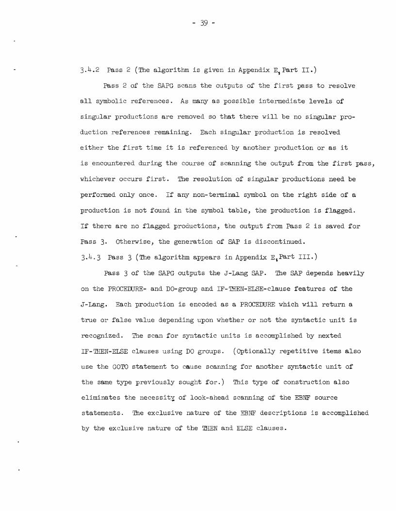
3.4.2 Pass 2 ÿ he algorithm i s given i n Appendix E, Par t 11 .)
Pass 2 of the SAPG scans the outputs of the f i r s t pass t o resolve
a l l symbolic references. A s many a s possible intermediate l eve l s of
s ingular productions a r e removed so t h a t there w i l l be no s ingular pro-
duction references remaining. Each singular production i s resolved
e i t h e r t he f i r s t time it i s referenced by another production o r a s it
i s encountered during t he course of scanning t he output from the f i rs t pass,
whichever occurs f i r s t . The resolut ion of s ingular productions need be
performed only once. If any non-terminal symbol on t he r i g h t s ide of a
production i s not found i n t he symbol t ab le , the production i s flagged.
If there a r e no flagged productions, the output from Pass 2 i s saved f o r
Pass 3. Otherwise, the generation of SAP i s discontinued.
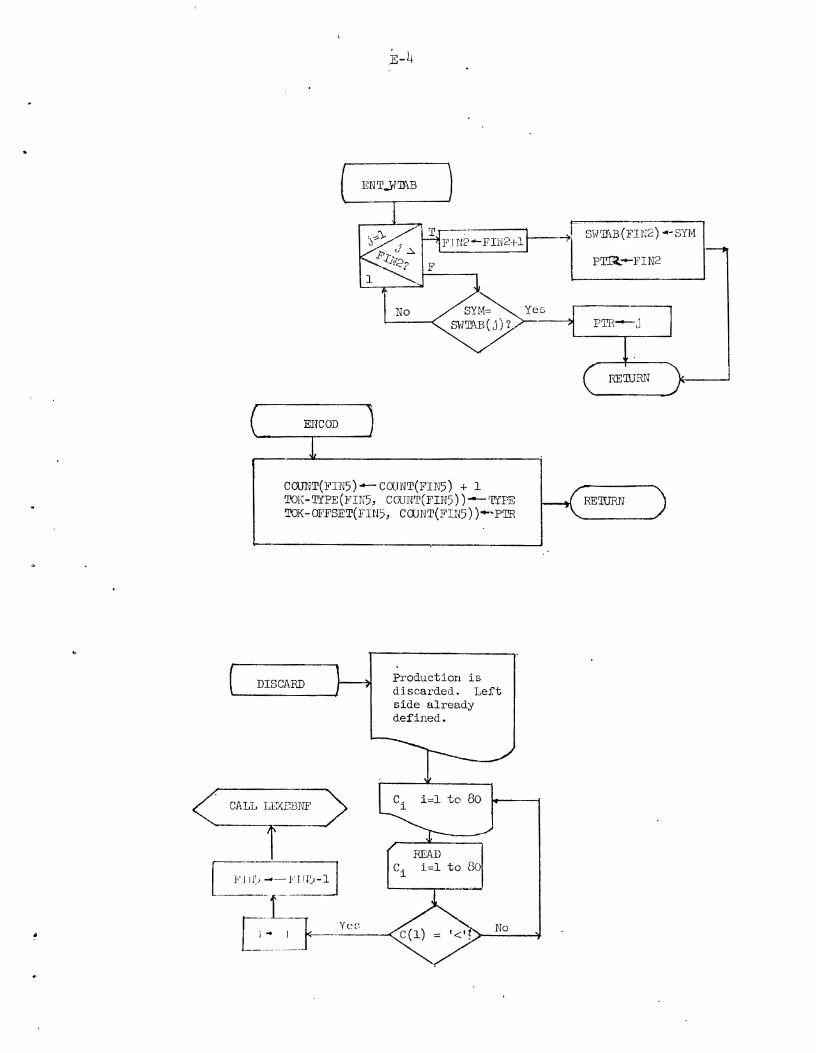
3.4.3 Pass 3 (The algorithm appears i n Appendix E, Par t I11 .)
Pass 3 of the SAPG outputs the J-Lang SAP. The SAP depends heavily
on the PROCEDURE- and DO-group and IF-?HEN-ELSE-clause fea tu res of the
J-Lang. Each production i s encoded a s a PROCEDURE which w i l l r e tu rn a
t r u e o r f a l s e value depending upon whether o r not the syn tac t i c u n i t i s
recognized. The scan f o r syntact ic u n i t s i s accomplished by nexted
IF-THEN-ELSE clauses using DO groups. (G-ptionally r epe t i t i ve items a l s o
use t he GOT0 statement t o cause scanning f o r another syntact ic u n i t of
t he same type previously sought f o r . ) This type of construction a l s o
el iminates the n e c e s s i t ~ of look-ahead scanning of the EBNF source
statements. The exclusive nature of the EBNF descr ip t ions i s accomplished
by t he exclusive nature of t he ETEN and ELSE clauses.

Pass 3 of t h e SAPG operates i n an e r ro r f r e e environment s ince
it i s not ca l l ed by Pass 2 unless no e r r o r s have been detected. Thus
no code w i l l be generated f o r detectable erroneous language spec i f i ca t ions .
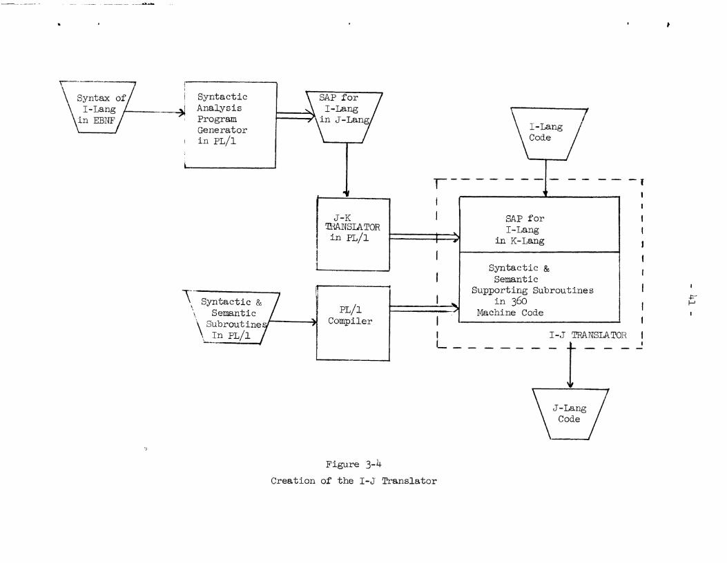
3.5 The Code Gene r a t ion Program Generator (I- J Translator)
The I-J Translator i s composed of t he SAP f o r I-Lang and a s e t of
syn tac t i c and semantic supporting rout ines . The SAP f o r I-Lang i s produced
using the SAPG described above ( sec t ion 3 .4) . The syntax desc r ip t ion of
I-Lang expressed i n EBNF i s f ed t o the SAPG; the r e s u l t i s the SAP f o r
I-Lang. The I-Lang SAP performs syntax-checking of t h e I-Lang and,
because of t he subroutine c a l l s embedded i n it, w i l l produce the i n t e rna l
symbol and data t ab l e s . The syntact ic and semantic supporting subroutines
a r e a l s o used t o help perform the syntax ana lys i s and t o transform t h e
I-Lang statements t o J-Lang statements. For a descr ip t ion of the I-Lang
see Sect ion 6 and f o r J-Lang see Section 7.
Because t h e output of the SAPG ( the SAP f o r I - ~ a n g ) i s i n J-Lang,
it must be t r an s l a t ed from J-Lang i n t o K-Lang ( f o r a desc r ip t ion of K-Lang
see Section 8) . To perform t h i s t r an s l a t i on t he J - K Translator w i l l be
used ( t he descr ip t ion of t h e J-K t r an s l a t i on i s given i n Section 4 .4 ) .
The J-K t r a n s l a t o r w i l l not perform any syn tac t i c ana lys i s here since
J-Lang was produced by t h e SAPG and it need not be checked. An overview
of the creat ion of the I-J Translator i s shown i n Figure 3-4.
Because the J-Lang i s i n a one-to-one correspondence wi&h the I-Lang,
l i t t l e semantic and code generation i s required and t he majori ty of t h e
log ic i n t he I-J Translator i s f o r J-Lang syntax checking.

This completes t he descr ipt ion of the SAPG and t he I-J Translator.
I n the sect ion t ha t follows a l l t h e components of the DDL Compiler Generator
a r e joined and t he descr ipt ion of t he overa l l log ic of the DDL Compiler
Generator i s given.
3.6 DDL compiler-enerator Logic low
An overa l l descr ipt ion of t he components of the DDL Compiler-Generator
i s given i n Figure 3-5. The DDL Compiler Generator accepts a s input t h e
EBNF descr ipt ion of DDL and t he Code Generation log ic i n I-Lang and
produces the DDL-SAP and t he DDL-CGP respectively.
3.6.1 Creation of the SAP f o r DDL
To produce t he SAP f o r DDL a syntax specif icat ion of DDL described
i n EBNF i s fed t o t he SPG, t he output i s the SAP f o r DDL i n J-Lang.
This output is then fed t o the J - K Translator and t he r e s u l t i s the SAP
f o r DDL i n K-Lang. The flow is shown i n the l e f t pa r t of Figure 3-5.
3.6.2 Creation of t he CGP f o r DDL
The Code Generation Program f o r DDL w i l l be produced i n t he follow-
ing way: The Code Generation log ic coded i n I-Lang i s f e d t o t he I-J
Translator, which w i l l output the CGP f o r DDL i n J-Lang. Because t he
SAP ( a component of the I-J Translator) i s i n K-Lang t h e program w i l l be
in te rpre t ive ly executed using the K-Interpreter. (For a descr ipt ion of
t h e K-Interpreter see Section 4.5.) After t he CGP i n J-Lang has been
produced it w i l l be f ed t o the J b K Translator, which t r ans l a t e s t h e CGP
i n t o K-Lang. The flow i s shown i n the r i gh t pa r t of Figure 3-5.

of DDL ( E B N F )
CODE GENERATION
\::!f::/
DDL SYNTACTIC D D L CODE GENERATION
ANALYSIS PROGRAM \ -(Kiongl / \ !:f:y /
r ------ - -- - - - - - -, I
SYNTACTIC ANALYSIS
1 I I - J TRANSLATOR
PROGRAM GENERATOR i
Figure 3-5
DDL Compiler-Generator Logic Flow
I I L- Long SN TACTIC ( P L 11) SYNTACTIC t3 , K-INTERPRETER
I 1 ANALYSIS cr ::E",:ENG ' ' -b
SUBROUTINES I DDL sYNTAct l c (K- Long) [PL/I) I I ANALYSIS PROGRAM
(J -Long) I
v I I I DDL CODE GENERA
1 PROGRAM (J-Long)
1 1
v I J - K TRANSLATOR
I I
( P L / 1 ) I I I
I D D L COMPILER GENERATOR
1 J
(PL / 1) I

4. THE DDL COMPILER
The DDL Compiler i s generated using t he DDL Compiler Generator.
It i s used t o t r a n s l a t e DDL source statements i n t o a Data Conversion
Program i n K-Lang ( t he object language of the K - ~ a c h i n e ) . It does
t he t r an s l a t i on us ing the Syntactic Analysis Program and the Code
Generation Program. Since both the SAP and CGP a r e i n K-Lang, we
need a K-Interpreter t o execute them. And since the code produced
by CGP i s i n J-Lang we need t o t r a n s l a t e it t o K-Lang. Therefore, the
DDL compiler a s a whole w i l l consis t of:
( a ) The Syntactic Analysis Program (SAP)
(b) The Code Generation Program (CGP)
(c ) A s e t of Syntactic and Semantic supporting subroutines
(d) The J - K Translator
(e) The K-Interpreter
An overview of the DDL Compiler i s shown i n Figure 4-1.
4 . 1 The Syntact ic Analysis Program (SAP)
The Syntact ic Analysis Program i s created using t he SAPG and
J-K Translators. The main funct ion of t h i s program i s t o perform syntax
ana lys i s of the DDL-source statements, and the c rea t ion of the symbol
and Data Ilables. See Figure 4-2.
The Syntax Analysis, Phase 1 of the DDL Compiler, i s controlled
by t he SAP. A statement w i l l be scanned, using t he subroutine LEX,
which re tu rns t he next syntact ic u n i t present i n t he source statement;
each syntact ic u n i t i s then examined according t o t he log ic i n t he SAP.
Conversion na"B Figure 4-1
The DDL Compiler
During t h i s process syntact ic supporting rout ines w i l l be cal led t o
capture syntact ic information, and t o produce e r ro r diagnostics ( i f
necessary). I f a correct syntact ic un i t i s recognized, a c a l l t o
semantic supporting subroutines i s made, resu l t ing i n one o r more e n t r i e s
being made i n the Symbol Table (see Appendix C) and/or Data Wble (see
Appendix D ) . Analysis of C R I W statements w i l l cause t h e output of
encoded s t r i ngs which a r e used i n Phase 2 (code ene era ti on). Discovery
of a syntax e r r o r w i l l cause control t o be returned t o ca l l i ng subroutines
with a code describing the e r ro r and a pointer t o the l a s t Symbol Table
en t ry used ( these items w i l l be used i n producing e r ro r messages).
Section 4.1.1 and 4.1.2 describe t he two main data s t ruc tures which
a r e created by the syntact ic supporting subroutines during Phase 1 of
compilation.
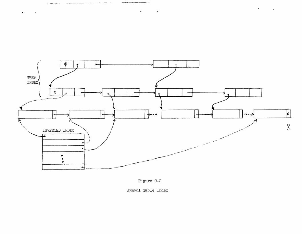
4.1.1 Symbol 'Pable
The Symbol m b l e i s created during t he f i r s t phase of compilation.
The symbol t ab l e i s a doubly-chained balanced t r e e with f i l i a l s e t s i ze
ranging between 3 and 6 (see Appendix c ) . Memory i s a l located a s it i s
required. Each node i s composed of th ree pointers:
1 ) a pointer t o the key ( t he keys a r e i n separate storage area) ;
2) a pointer t o the f i r s t member of t he f i l i a l s e t of which t h i s
node i s a parent;
3) a pointer t o the next member of the f i l i a l s e t of which t h i s
node i s a member.

Data Table
Completion
- .." - - > . - - - - --- --.
I- - - - - - - - - - - - -
-"- - --
- - _ _ - _ - - 1
(TO Phase 2,''.
i I I - 0- I
I Syntactic Analysis
I I
of DDL Statements and 1 I I
creation of the I 1 symbol and I I Data Tbbles. I I 1 I
: I
I I I I
\ L , , ,,-, - ,,, - - - ,--- - - ---
1 I Phase 1A
I
Figure 4-2
Phase 1 of the DDL Compiler
c . - - - c ,---, I --, , ,,, ,,-

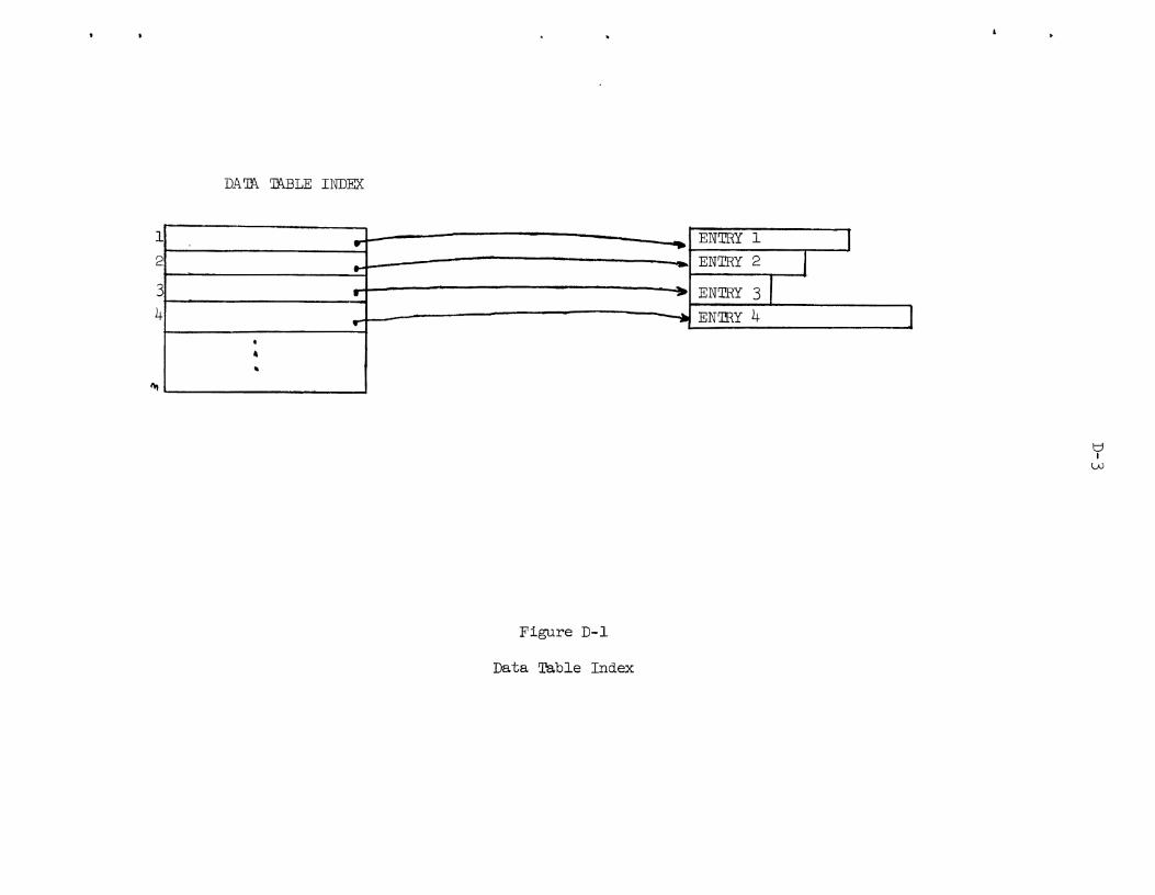
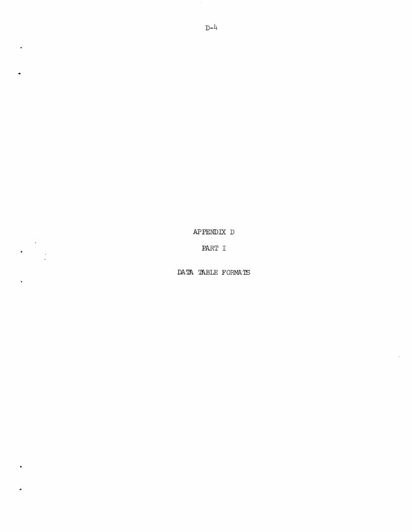
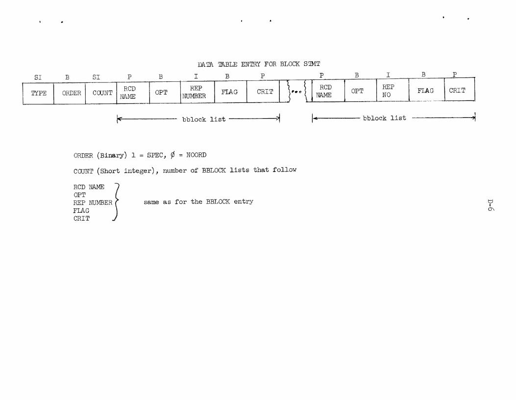
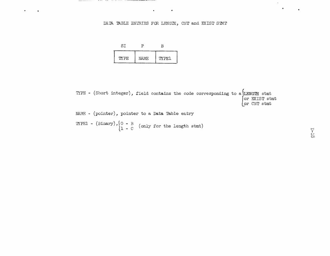
4.1.2 Data Table
The Data Table contains information which describes the "data"
associated with each symbol i n the Symbol Table. This "data" may be
pa r t of the source or t a rge t f i l e s , may describe one of the f i l e s , or
may be a procedure which uses the f i l e data t o enhance the f i l e descrip-
t ions (e.g., a linkage c r i t e r ion statement).
Many Data Table en t r i e s point t o other en t r i e s t o which they a r e
re la ted . Some rela t ionships a r e "subordinate member of a group", and
"supporting descriptionf ' . These re la t ionships play a very important
ro l e i n determining which of several items with iden t ica l simple names
i s the correct reference.
4.1.3 Phase 1A - Data 'Pdble Completion
When the supporting subroutines of phase 1 create the Data
Table en t r i e s (and the encoded t e x t of the CRIEX statement), a l l
symbolic names a r e converted t o symbol tab le entry numbers. One function
of phase 1A i s t o change the symbol tab le entry numbers i n t o data t ab l e
entry numbers. A second function i s t o i n se r t the "father" pointers in to
f i e l d and group en t r i e s . A t h i r d function i s va l id i ty checking on the
references - fo r example checking t o see t ha t a l l members of a group
a r e groups or f i e l d s . These three functions a r e done concurrently. A t
the end of phase lA the symbol t ab l e (with i t s two index s t ructures)
i s no longer needed and the space it occupies i s made available f o r use
i n phase 2. The processing of phase 1A i s described i n more d e t a i l
below.

4.1.3.1 Processing Logic
Using the Data Table entry index, the data tab le en t r i e s a r e pro-
cessed sequentially. F i r s t the type of entry i s determined (see Appendix
D l f o r the description of the encoding used). Using logic specific t o
the entry type, each pointer parameter i s located and, using the Symbol
Table (inverted) index, the symbol table data pointer entry i s obtained.
The Data Table entry number contained i n t h i s entry replaces the symbol
tab le entry number a s the pointer parameter. I f the entry i s a Field or
a Group the "most recent fa ther" entry i s moved from the Symbol Thble
entry f o r t h i s Field or Group, t o the "sup" (superior) pointer of the entry.
m e reason f o r the delay i n f i l l i n g t h i s f i e l d i s that there may be
more than one Group t o which t h i s F ie ld or Group belongs. I f t h i s i s
the case and i f then there is the poss ib i l i ty tha t one or more groups,
which declare t h i s Field t o be a member of them, may be discovered a f t e r
the Field i s defined. The best s t ra tegy i s t o wait u n t i l a l l groups
a r e known before f i l l i n g i n t he "most recent fa ther" pointer.
After the pointer parameters a r e changed they a r e used t o access
the associated data tab le entry and the "type" f i e l d of t h a t entry i s
t es ted f o r acceptabi l i ty a s a parameter. For example, the pointer found
a s a c r i t e r ion name i n a Record entry must point t o a data tab le entry
which describes a c r i t e r ion statement. I f the pointer parameter i s now
pointing a t a function description it i s assumed t h a t the function w i l l
re turn an integer, and a t e s t i s made t o see if an integer i s permitted.
(some typ ica l functions a r e LENG'M and CNT.)
4.2 Code Generation Program (CGP)
The second phase (see Figure 4-3) of the DDL compiler has three
important functions:

Output
\ Data Figure 4-3
Phase '2 of the DDL Compiler

(1) it c rea tes the Active F i l e Control Blocks (AFcB) and
the Auxil iary Descriptor Blocks (ADB) required f o r execu-
t i o n of the CREATE statement. (phase 2A)
(2) using t h e data s t ruc tu re created i n (1) it generates J-Lang
code t o load data i n t o main memory and execute the CREATE
statement. (phase 2 ~ )
(3) it generates J-Lang code f o r the procedural statements
of DDL (cRITEX, RPVAL) . (phase 2 ~ )
The next sect ions describe the implementation of these th ree
functions.
4.2.1 The Active F i l e Control Block (AFCB)
The format of the AFCB i s shown i n Figure 4-4. There i s one
AFCB f o r each f i l e which w i l l be used i n t h e execution of a CREATE
statement. The primary funct ion of the AFCB i s t o point t o records from
the f i l e which a r e current ly i n core. The number of these records i s
qu i t e small - usual ly j u s t t h e number of d i f fe ren t record occurrences
concurrently required i n the evaluation of t he c r i t e r i o n statements f o r
the l inkage speci f ied f o r t he f i l e . The following paragraphs describe
the f i e l d s of the AFCB.
The "pointer t o Data Table Entry f o r the STORFILE descript ion" i s
t he data t a b l e en t ry number of t he en t ry which contains the descr ip t ion
of t h e f i l e s t r uc tu r e . The f i r s t "pointer t o t h e Data Table Entry f o r
Linkage descript ion" contains the data t a b l e en t ry number f o r t he SEQUEN
statement which governs t he physical order of t he records i n t h i s f i l e .
Through the pointers i n these l inkage statements one f i n d s the c r i t e r i o n
expressions t h a t a r e used i n the creat ion of t h e l inkage.

AFCB and A D B ' s f o r C r e a t e Statement
Create statement File l i s t
Target Source
' Active F i l e Control Block
Auxil iary Descriptor Block
la Active 3
I F i l e Control Block
To %ble Entry f o r SZ%UE;.I S t x f i l e Descr. Record items 3ntry T, --
Pointer t o Data Relat ive Address Address of Data , %ble Entry f o r of next l ink ,ge a Linkage - *- ---.- - - --- - -
Pointer t o ADB of Record S ---
1 , ! 1 I t , t I rn
I I I t ! I I t " X1 I I ~ n & A ~ o f ~ S o c i a t ed
I i tem >>LY< L i 2 1-y
Pointer t o Data ' Relat ive Address Pointer t o ADB Descriptor To DIFEC A Table Entry I of next l inkage 31ock f o r
1 or 3 3 E I ) d f o r Linkage Descr. / Description , G:-cup Pointer t o ADB Entr-f i
pointer t o ADB of Eiecord S I -
.f- -
1
Other Linkage descr ip t ions
0 .ri \5/
I
Block f o r Group Slack f o r
Figure k-4

The " re la t ive address of next linkage description" i s the address
of the next "pointer t o data table entry f o r linkage description". The
address i s r e l a t i ve t o the s t a r t of the AFCB. It i s necessary because
the ADB pointers which follow (and w i l l be explained next) a r e variable
i n number. The ADB pointers point t o the ADB's associated with the core
resident records, symbolically cal led S (source), T ( ta rge t ) , X 1 , X2 ,
e t c . These symbolic names a r e those used i n the CRI'IZM statements. They
r e fe r t o d i f fe ren t record occurrences a t d i f fe ren t times during processing.
The next group of f i e l d s of the AFCB i s a repe t i t ion of the format
jus t described. These f i e l d s point t o the DIREC o r EMBED statements
specified by the STORFILE statement. The ADB pointers f o r the S, T,
X , e tc . records a r e f o r use i n processing the CRITEX statements associated
with these linkages.
4.2.2 The Auxiliary Descriptor Block (ADB)
The ADB1s (see Figure 4-5) a r e used t o hold core address of the
record and the data descriptive information (e.g., length, repe t i t ion
count, e tc . ) which var ies with each occurrence of the record. This
information cannot be stored i n the Data Table entry because there may
be two o r more occurrences of the record i n core concurrently, f o r example,
source and ta rge t of records used i n linkage, or multiple occurrences of
a repeating group.
The "data t ab l e entry pointer" i s used t o f i n d the symbolic name of
the record (or group or f i e l d ) and the fixed descriptive data (e.g., CONCODE
statements, c r i t e r ion statements, and possibly repe t i t ion number, order,
e t c . ) . For in te rna l use, the data tab le entry number i s the "name" of a
record, group or f i e l d . Therefore when searches a r e being made f o r names


( f o r example, i n t he c rea t ion of the assoc ia te l i n k s described below)
t h e "name" i s present i n t he ADB.
m e "Rel. address of Assoc. items" i s the ADB r e l a t i v e address
of the s t a r t of t he "TYPEt1 bytes. This i s necessary because the number
of data descr ip tors i s var iable . m e "address of data" i s the core
address of the s t a r t of t he data described by t he ADB. ( ~ o t e - t h i s i s
not f i l l e d i n u n t i l execution time.) The data desc r ip to rs a r e t h e items
which would be i n t he data t ab l e en t ry except t h a t they vary with each
occurrence of t he record. I n these cases t he data t ab l e en t ry contains
a pointer t o t he procedure which obtains the value t o be placed i n t h e
da ta descr ip tor . After code-generation f o r the data loading code t he
da ta t a b l e w i l l contain the number of t he descr ip tor i n t he ADE where
t he value w i l l be s tored.
Each "TYPE" f i e l d describes the sequent ia l ly corresponding "pointer
t o ADB of associa ted item". The meaning of type i s shown i n the following
t a b l e :
m e Meaning - - -- - --- " "
1
Pointer t o "fa ther" ( t he group which contains ' i t h i s item) 1 i I
i ! I ' 2 i 1 Pointer t o "son" (subdivision of t h i s group)
1 3 Pointer t o next core res iden t member of t h i s repeating group ( o r f i e l d )
!
; 4 Association l i n k 1
4
I- -. - - -+ !The pointers a r e t o ADB ' s.
The associa t ion l i n k corresponds t o the assoc ia te p a i r s i n t he
ASSOCIATE statement speci f ied by t he Cmm statement. Using these l i n k s
t he code generation log ic ( t o be described i n 4.3.3) w i l l c rea te a
procedure which w i l l construct t he t a rge t record from the source records
( see Figure 4-5) . 4.2.2.1 The ADB Hierarchy
This paragraph describes i n more d e t a i l t h e procedure f o r deter-
mining the h ie ra rch ica l s t ruc tu re of the ADB's . It expla ins when an
ADB i s created and how it r e l a t e s t o other ADB's .
The hierarchy i s bas ica l ly a rep l i ca of the s t ruc tu re of t h e
da ta t a b l e s t ruc tu re ( t h a t is, records, groups, and f i e l d s , i n descending
order of scope) . Beyond t he bas ic s t ruc tu re a r e (1) ADB s f o r t h e
"pseudo-variables" (data f i e l d s which r e s u l t from the statements LEN,
CNT and MIST), and (2) ADB' s f o r repeating occurrences of a group o r
f i e l d .
The pseudo-variables a r e constructed by t h e code generation logic ;
they a c t as normal user data f i e l d s except t h a t the data is inse r ted by
the data loading procedure (see Sections 4.2.3 and 5 ) . The ADB's f o r
pseudo-variables a r e l inked only as a r e s u l t of an assoc ia te statement.
There i s no h i e r a r c h i c a l l i n k i n g . Of course, the re may be any number of
references t o t he ADB, through t he data t ab l e , f o r use i n CRITEX expression
evaluation.
When a f i e l d o r group may repeat ADB's a r e created f o r t he number of
occurrences which w i l l be res ident i n main memory concurrently. I f t he
maximum number of occurrences i s f ixed, the ADBrs a r e generated (and
l inked sequential ly) a t code generation time. I f t he number i s var iable ,
the ADBrs a r e s e t up dynamically by log ic i:1 the data loading procedure.

4.2.2.2 Phase 2A Completion Logic
Af te r t he AFCB's and ADB's have been created, and t h e associa t ion
l i n k s from the ASSOCIATE statement have been made, the phase 2 log ic
searches down the " t ree" of A D B t s f o r the t a rge t f i l e , t o f i nd t he f i e l d s
which have no assoc ia t ion l i nks . These e x i s t because some groups a r e
associa ted with other groups, and t he f i r s t pass of assoc ia te linkage
doesn ' t en te r the subordinate f i e l d associa t ion. Once the t r e e has been
completed, code generation can start.
4.2.3 Phase 2B - Code Generation f o r CRFA'CE Statement
Code generation cons i s t s of creat ing an ordered l i s t of bas ic
J-Lang operations and subroutine c a l l s which w i l l load data i n t o main
memory, move each of t he source f i e l d s t o t he associa ted t a r g e t f i e l d ,
and then l i n k t he newly created record i n t o the f i l e which i s being created.
Code generation s t a r t s by creat ing a data loading procedure f o r
each f i l e t o be used. Data Loading i s t he process of l ink ing an input
record t o t he ADB and AFCB, and then executing whatever functions a r e
necessary t o complete the ADB descr ip tors . The generation of t h i s code
requires ge t t i ng the pointers t o funct ions which a r e parameters i n the
Data Table Entry and generating code t o c a l l these funct ions and place t he
returned values i n t he ADB. Now t h e ADB descr ip tor o f f s e t replaces the
funct ion pointer f o r the r e s t of code generation. In cases of var iable
length, o r repeating groups, t he information i n the CONCODE statements
i s used t o generate code t o recognize the end of data f i e l d s . The Data
Loading procedure i s fu r t he r described i n Section 5.

The code generation logic then walks the t r e e of ADB's of the
ta rge t f i l e , generating code t o move each f i e l d from the source t o
the t a rge t . (To f ind the source it uses the association l inks . ) The
operand addresses used i n the generated code a re ind i rec t through the
ADB, not the d i rec t data addresses, which a re assigned a t execution time.
The data descriptions i n the Data tab le en t r i e s indicate where t o generate
code conversion ca l l s , length truncations, e tc . I n cases where the
data tab le indicates t h a t information w i l l be i n the ADB, the code
generation logic generates code t o obtain the values from the ADB descrip-
t o r s a t execution time. I n some cases, code t o move data w i l l not be
necessary because the source data i s i n the proper form f o r inclusion
i n the ta rge t record; a l l t h a t i s necessary i s t o s e t the core address
pointer of the ta rge t f i e l d ADB.
4.2.4 Phase 2C - Code Generation f o r CRITEX
CRITEX statements w i l l be t ransla ted using the technique of
stacking operators and operands on two d i f fe ren t stacks, and generating
code when newly input operator has a precedence lower than the operator
on the operator stack. To generate code the required number of operands
a r e taken off the top of the operand stack and the operator i s taken
off the operator stack. The r e su l t s of the operator a r e assigned a
symbolic location and the symbol used i s placed on the operand stack
i n place of the operands removed. Whenever code has been generated, the
new top of the operator stack i s tes ted against the recent input which
caused the code generation t o begin. I f the operator precedence of the
stack is lower than the input the code generation process i s repeated.
If not the input operator i s stacked. Whenever the top of the operator

s tack contains " ) " immediately followed by " (" , both of these a r e
dele ted. The operator precedence is, from highest t o lowest:
Operator Comment - - -.--- --- 7- -- -- -- - - A - - - - - ---I-"'-------- ---- -- -
( / when it i s the newly input operator o r it i s 1 on t he s tack and being t e s t e d agains t " ) " I
1
NOT
OR AND f ( i when on the s tack and not being compared with " ) " ; I -.--. 1 ... - .... .. . . - .. .. . . .. . . . ..--- ---. .A
4.3 Syntactic and Semantic Supporting Subroutines
A s was s t a t ed before, Syntactic Analysis of Phase 1 of the
compiler is bas ica l ly t he in te rpre t ive execution of t he code generated
by the SAPG ( t he SAP). This code requires many supporting subroutines.
The most important ones a r e discussed below:
a ) Lexical Subroutine
b) The System Vector Subroutine
c) The Syntax Recognition Fa i lu re Subroutine
d) The Semantic Supporting Routines
4 .3 .1 Lexical Subroutine
This subroutine reads DDL source statements and buffers them.
It re tu rns s ingle tokens, when ca l l ed . Tokens a r e of 4 types:
1. names ( s t r i n g s of characters within s ing le quotes)
2. keywords ( s t r i n g s of characters not surrounded by quotes)
3. punctuation marks
4. iiumbers ( s t r i n g s of decimal d i g i t s )

Each c a l l t o .LEX returns a pointer t o the next token, and the token type.
The l ex i ca l processing routine c a l l s a .PRINT routine t o p r in t
the source l i ne , i f t h i s option has been specified. ( ~ r r o r messages
a r e produced by the various syntactic processing "fai lure" routines.
These routines c a l l .PRINT di rec t ly . )
4.3.2 The System Vector Subroutine
There a r e many places i n ' t h e logic of syntactic analysis where
one routine needs t o have control over the succeeding sequence of routines.
I n par t icu la r , t h i s occurs when the succeeding routines w i l l process a
l i s t of parameters, which must occur i n f ixed order. The subroutines
described below help provide t h i s sequencing f a c i l i t y .
A "subroutine vector stack" ( a stack of subroutine addresses) i s
used. By ca l l ing .SEW, addresses a re pushed on the stack. (The
parameters of the .SEW c a l l a r e the addresses, i n the order i n which
the subroutines a r e t o execute.) Each c a l l t o .VCALL causes control t o
be given t o a subroutine whose s t a r t i ng address i s popped off the vector
stack. It i s a CALL .VCALL which i s generated by the SAPG when it detects
// i n the EBNF source statements.
4.3.3 The Syntax Recognition Fai lure Subroutine
The logic f o r syntax recognizer "fai lure" e x i t s a l s o requires the
type of sequence control described i n the preceding paragraph. The stack
used here i s called the " f a i l vector stack". It i s s e t by a c a l l t o
.SEW, the parameters, a s before, a re the addresses t o be stacked; the
order i s the order i n which they a re t o be executed. When .FAIL i s
called, it gives control t o a subroutine whose address i s popped off

the f a i l vector stack. To pop the stack without executing any subroutine,
.Porn i s called. The SAPG automatically generates c a l l s t o .POPF;
they a re executed a f t e r each syntactic item i s correct ly recognized.
The execution of the .POPF a f t e r each syntactic item means t h a t when a
l i s t of f a i l u r e ex i t s i s s e t up, it specif ies an address f o r each syntactic L
item including terminal symbols l i k e ",", ")I1, e tc . For example f o r
the s t r i n g
< name >: (< pa r t 1 >)
there would be 5 f a i l u r e e x i t s specified.
4.3.4 The Semantic Supporting Routines
The Semantic supporting routines a re called by CGP and a r e used
t o create the AFCB1s, ADB1s which help i n the code generation phase.
4.4 The J - K Translator
As mentioned i n the introduction of Section 4, the Code Generation
Program (CGP) produces J-Lang statements; t o t r ans l a t e the J-Lang in to
K-Lang ( the object language of the K-Machine), a J-K Translator i s needed.
A complete description of it i s given i n Section 8, a f t e r the descriptions
of the J- and K-Languages. The overview of the J - K Translator i s shown
i n the f igure below.
\?
atement s TWSLATOR tatementg'
4.5 The K- Interpreter
A machine language in te rpre te r i s a computer program t h a t performs
the inst ruct ions of another program, where the other program i s wri t ten
i n some machine-like language. A machine-like langdage i s a method of
representing inst ruct ions using operation codes, address, e t c .

Machine language in te rpre te rs a r e used chief ly f o r the following /
purposes:
1 ) t o allow the representation of a f a i r l y complicated sequence
of decisions and actions i n a compact, e f f i c i en t manner
without the need t o construct the physical machine (hardware)
which executes these inst ruct ions .
2 ) t o communicate between passes of a multiple pass program
( i . e . , i n a multipass program, the e a r l i e r passes mst
transmit information t o the l a t t e r passes). This informa-
t i o n i s often transmitted most e f f i c i en t ly i n a machine-like
language, a s a s e t of ins t ruct ions f o r the l a t e r pass.
This philosophy of multipass operation may be characterized
a s " te l l ing" the l a t e r pass what t o do, ra ther than simply
presenting it with f a c t s and asking it t o "figure out" what
t o do.
The interpret ive technique has the fur ther advantage of being
r e l a t i ve ly machine-independent - only the in te rpre te r must be rewrit ten
when changing machines. Furthermore, helpful debugging a ids can readi ly
be b u i l t i n t o an interpret ive system. Finally, an in te rpre te r can
usually be wri t ten so t h a t the amount of time spent i n interpreta t ion
of the code i t s e l f and branching t o the appropriate routine i s negligible.
I n t h i s case the machine-like language is the K-Lang, and the K-
Interpreter i s a computer program wri t ten i n P L / ~ , and then t ranslated
(using the P L / ~ compiler) in to 360 machine code. An overview of the