
Design of Bench Tapping Machine
32
College of Engineering Department of Mechanical Engineering Spring 2020-21 Senior Design Project Report Design of Bench Tapping Machine In partial fulfillment of the requirements for the Degree of Bachelor of Science in Mechanical Engineering Team Members Student Name Student ID 1 Saad Alqahtani 201600165 2 Ahmed Alsaud 201602611 3 Ibrahim Alubaidan 201502870 4 Abdulathim Althabit 201502844 5 Hamad Almansour 201602978 Project Advisors: Advisor Name: Muhammad Azhar Ali Khan Co-Advisor Name:
-
Upload
khangminh22 -
Category
Documents
-
view
2 -
download
0
Transcript of Design of Bench Tapping Machine

College of Engineering
Department of Mechanical Engineering
Spring 2020-21
Senior Design Project Report
Design of Bench Tapping Machine
In partial fulfillment of the requirements for the
Degree of Bachelor of Science in Mechanical Engineering
Team Members
Student Name Student ID
1 Saad Alqahtani 201600165
2 Ahmed Alsaud 201602611
3 Ibrahim Alubaidan 201502870
4 Abdulathim Althabit 201502844
5 Hamad Almansour 201602978
Project Advisors:
Advisor Name: Muhammad Azhar Ali Khan
Co-Advisor Name:

2
Abstract
Tapping is a process that is widely used in the field of engineering, it entails cutting of screw
threads onto or into a work-piece. A tap is usually used to cut threads on the female part of
the nut part, for external threads a die is usually used to obtain the desire thread size and
form. This project focuses on the design of a manually operated bench tapping machine, the
main problem that is encountered during tapping process is usually misalignment of threads
which might occur due to inadequate clamping forces and misalignment of tap and work-
piece. This design provides a solution by providing a machine which ensures accurate
alignment of tap and work-piece during the threading process. The machine is composed of
supporting frame and shaft, machine bed, bench holder, spindle shaft and a tab holder, the
combination of these components ensures that a uniform torque is applied to the tap and as a
result the threading process is accurate and precise. The machine also as the flexibility
advantage because it allows for attachment of various tap sizes and work-piece forms and
hence it can be used for numerous applications within a limited space setting. The average
torque on the spindle rod was calculated to be 1.2252Nm which is the average value that an
average human being can produce, this torque can be handled by the spindle shaft material
and hence the machine service life is improved and safety is assured.

3
Acknowledgments
We would like to acknowledge everyone who contributed to our success during our academic
accomplishments. Our professors, who supported and advise us with everything that we need.
Without our professors, we could never have reached this current level of success. Many
thanks all for your unwavering support.

4
List of Acronyms (Symbols) used in the report:
Symbol Definition
𝒕 Time
G Shear Modulus
𝜶 Rotational acceleration
𝜽 Angle of twist
𝝉 Shear stress
L Shaft Length
𝝎 Angular rotation of the shaft
Kg Kilogram
N Newton
T Torque
Nm Newton-Meter
D Diameter
J Polar Moment of Inertia
R Shaft radius
F Applied force
A Cross-sectional area of shaft

5
List of Figures:
Figure 1: Side View ................................................................................................................... 9 Figure 2: Isometric View ......................................................................................................... 10 Figure 3: Top view ................................................................................................................... 10 Figure 4: Electric tapping and drilling machines ..................................................................... 11 Figure 5: Ancient threading process ........................................................................................ 13 Figure 6: Project architecture diagram ..................................................................................... 14 Figure 7: Bench Tapping Machine .......................................................................................... 17 Figure 8: Side view of the Bench Tapping Machine ............................................................... 18 Figure 9: Use of Bench-tapping machine in tapping ............................................................... 21 Figure 10: Manual tapping experimental setup ....................................................................... 22 Figure 11: Manual tapping process .......................................................................................... 22 Figure 12: Aligned and Misaligned threads comparison ......................................................... 23
List of Tables
Table 1: Engineering standards ................................................................................................ 15 Table 2: Cost Evaluation template ........................................................................................... 19 Table 3: Task time duration ..................................................................................................... 24 Table 4: Project bill of material and budget ............................................................................. 26

6
Table of Contents
Abstract ................................................................................................................................... 2
Acknowledgments...................................................................................................................... 3
List of Acronyms (Symbols) used in the report: ........................................................................ 4
List of Figures: ........................................................................................................................... 5
List of Tables ............................................................................................................................. 5
Chapter 1: Introduction .............................................................................................................. 8
1.1 Project Definition ........................................................................................................ 8
1.2 Project Objectives ....................................................................................................... 8
1.3 Project Motivation ....................................................................................................... 9
1.4 Project Specifications .................................................................................................. 9
1.5 Applications .............................................................................................................. 11
Chapter 2: Literature Review ................................................................................................... 12
2.1 Project background .................................................................................................... 12
2.2 Previous Work ........................................................................................................... 12
2.3 Comparative Study .................................................................................................... 13
Chapter 3: System Design ........................................................................................................ 14
3.1 Design Constraints an Design Methodology .................................................................. 14
3.2 Engineering Design Standards ........................................................................................ 15
3.3 Theory and Theoretical calculations ............................................................................... 16
3.4: Product Subsystems and selection of components ........................................................ 17
3.5: Manufacturing and assembly (Implementation) ............................................................ 19
3.6 Economic Evaluation ...................................................................................................... 19
Chapter 4: System Testing and Analysis ................................................................................. 21
4.1 Experimental Setup, Sensors and Data Acquisition System .......................................... 21
4.2 Overall Results, Analysis and Discussion ...................................................................... 22
Chapter 5: Project Management ............................................................................................... 24
5.1 Project Plan ..................................................................................................................... 24
5.2 Team Members Contributions ........................................................................................ 25
5.3 Project Execution and Monitoring .................................................................................. 25
5.4 Decision Making Process and Challenges Faced ........................................................... 25
5.5 Project Bill of Materials and Budget .............................................................................. 26
Chapter 6: Project Analysis ..................................................................................................... 27
6.1 Life-Long Learning ........................................................................................................ 27
6.2 Impact of Engineering Solutions .................................................................................... 27
6.3 Contemporary Issues Addressed .................................................................................... 28
Chapter 7: Conclusion and Future Recommendations............................................................. 29

7
7.1 Conclusion ...................................................................................................................... 29
7.2 Future Recommendations ............................................................................................... 29
References ................................................................................................................................ 30
Appendix A: CAD drawing and Bill of Materials ................................................................... 31
Appendix B: Engineering Standards ........................................................................................ 32

8
Chapter 1: Introduction
1.1 Project Definition
To proceed with the introduction of Bench Tapping Device, we first begin by defining what
is meant by Tapping and why a specific bench-mounted apparatus is needed to properly
execute said process on a work-piece. The tools employed for the formation of internal screw
threads are taps and dies. A joint has both male and female parts which in conjunction form
the mating pair; a tap is usually used to form threads on female portions of a work-piece
whereas a die is used to form threads on male portions of a work-piece.
The process of tapping can be done manually but for it to be accomplished properly we
require a ‘Bench Tapping Device’ to grip the work-piece in the desired place to get the proper
formation of screws. This tapping station equipped with a tapping head allows the formation
of proper angular oriented taps through grasping the tapping shaft in place and ensuring
proper guidance for the tapping head to ensure that tapping goes smoothly, perpendicular
alignment is crucial. Though by use of traditional means, manual tapping can form threads,
they are in most cases improperly aligned. But using a Bench Apparatus, proper alignment is
assured. This alignment must be close to perfection to avoid breaking the tap and producing
reliable threads. Once the initial threads start in the wrong direction, as the thread proceeds
deeper into the work-piece the rest of the threads follow resulting in a much more
pronounced angular misalignment as was present before.
1.2 Project Objectives
Bench Tapping Stations can be employed wherever screw threads are in need to allow usage
of fasteners, but manual tapping faces an abundance of issues some of which are to be
redeemed by inclusion of these possible improvements:
1. Ensure proper alignment (i.e., coaxial and no angular error) between tap and work-
piece via use of several kinds of jigs and fixtures such as a hand-tapper or a tapping
guide. By employing this threads of recurring usage/longer lifetime can be created.
2. Proper disposal of chips to avoid clogging.
3. Mounting of required taps of varying materials depending upon requirements of the
user.
4. Ensure presence of sufficient amount of cutting lubricant to ensure long service life of
taps.
5. Bench tapping device be of a strong structural integrity to allow for longer usage
while having ease of removal of individual modules forming the structure to allow for
easy repairs and replacements.
6. Having minimal frictional losses to ensure that maximum efficiency is retained.
7. Inclusion of a torque limiting feature for sustenance of taps.
8. Zero or Improper float when employed with screw machines (recommended feed 0.1
slower to establish float for 40 tpi or higher and 0.15 slower for 40 tpi or finer)
Other objectives can be included later as the project scope may be subjected to change.

9
1.3 Project Motivation
The motivation for doing this project was primarily to focus on an easier and simpler way of
acquiring precise, accurate and aligned threads using the manual approach. During the first
years of our engineering course we did workshop practice where we focused on thread
cutting process using dies and taps, the process was however not as accurate and precise as
needed, this made us think of simpler and cheaper ways of acquiring perfect internal threads,
the solution was to design a manual bench tapping machine.
1.4 Project Specifications
The machine is a shaft-driven machine that consists of a strong frame to hold the tapping
shaft in place. The shaft is rotated through a smooth bearing mechanism for easy operation
and its tip is fitted with a tap holder. The holder can be mounted with taps as and when
desired. The machine bed consists of a work-piece holder to hold it in place for tapping. This
machine allows for accurate tapping results for perfectly aligned screw threads.
Figure 1: Side View

10
Figure 2: Isometric View
Figure 3: Top view
The key marketing strategies will revolve around it being economic, less power consuming
and delivering perfect threads. The idea behind the novelty here is that it would be operable
under minimum power requirements while at the same time ensuring proper lubrication
throughout. Though being battery and motor operable in the future, it is not employed here;
this project will stick to a manually operated bench tapping machine.

11
Figure 4: Electric tapping and drilling machines [3]
It will also be easier to have it transported from one bench location to another, wherever
thread generation may be needed. With respect to the standards the ones employed here are
ISO Metric Screw Thread Systems similar to those employed in Europe and the rest of the
world excluding North America [3].
For manufacturing, it possible that we may employ shafts of polymers or plastics as a way for
a lighter bench apparatus as well as strain sensors to ensure that the taps do not undergo
higher levels of strain beyond their set limit. The calculation takes a sample from existing
models available and optimizes them where needed.
1.5 Applications
Screw threads have become a part of every extensive machine requiring extensions, fastening
and fittings. These extensions of parts and components are present in a wide range of
instruments to ensure proper grip that can be disconnected and reconnected time and again
depending upon the requirements, such as:
1- Fasteners employing nuts, bolts, and screws in the Locomotive industry for junctions.
2- Components used in the manufacturing of firearms are heavily reliant on thread-based
junctions that are frequently removed and subsequently cleaned for proper
maintenance of said firearms.
3- Used in textile industry for the formation of junctions of specific diameters.
4- Formation of fasteners and fittings used in the connection of Threaded Hoses and
Pipes

12
Chapter 2: Literature Review
2.1 Project background
Although manual tapping is employed depending upon the usage, the risk of human error is
higher compared to most automatic tapping machines. On the other hand, via machine
tapping alongside an arsenal of taps (of varying materials, thread dimensions, and finishes)
the work is faster, accurate, and more reliable though care is to be exercised when it comes to
the lifetime of the equipment as well as that of the taps employed in this process. Wear and
tear of taps either by improper spindle speed, under-or over-feeding the tap causing axial
failure, tap and work-piece misalignment, chip clogging and the absence of proper torque
limitation are some of the problems that still depicts the manual bench tapping process [7].
Also, without the aid of proper taps and dies, termed as chasers, the formation of weaker
threads with poor durability is likely to occur. These threads usually have non-uniform
tolerances and always have loose fittings to their respective female or male components. In
tapping it is important that only the required materials for the formation of threads are
removed and not any more than that otherwise the efficiency of the threads is highly affected,
making the whole mechanism joint more susceptible to failure.
To ensure recurring usage of thread screws the threads must maintain their strength in the
long run with recurring usage without falling prey to breakage, too much material removal
and improper angularity as such even the minutiae of alteration can devastate the joint
strength resulting in unwanted, sudden failures after overtime usage [2].
2.2 Previous Work
Prior to the availability of hand-powered benches, thread cutting operations were carried out
under the supervision of skilled workers that could achieve limited accuracy in their
operations and were dominantly dependent on the workers instead of on the tools.
To further delve into the history of the subject in this matter we must first go into the history
of screws with their design hypothesis dating all the way back to Archimedes’ screw, then
after going through the hands of the great Greek mathematicians and after being implemented
in carpentry industry and also in the advent of machines after the dawn of Industrial
revolution, thereafter lathes came forth and various forms of rolling started to be developed
[2]. During the period between 1760 and 1800, means for proper threaded fastening increased
through various attempts of Standardization. Later, for the rolling of screw threads, the first
patent came about in 1836 by William Keane of Monroe in New York, afterward in the
1940s, the ISO standards came forth for screw threads and by that time numerous methods
for machining threads had become the norm [5].
Now from a few years back, specific hand tapping benches have been made commercially
available for internal thread creation which is useful where hand operations are to be
performed.

13
Figure 5: Ancient threading process [2]
2.3 Comparative Study
Some of the recent studies available are reviews on means of optimizing thread tapping
process and the ways that their improvement can be achieved. As of now there remains
substantial difficulty in having to perform tapping on certain materials such as Titanium
where ultrasonic vibration tapping can be utilized thus reducing the tapping torque
requirements and thus decreasing the likelihood of tap breakage. Punch Tapping is another
hot topic in this regard, this process is mainly employed in threading aluminum and other
light weight alloys work-pieces, punch tapping is utilized in the automotive industry where
with single twisting and exiting motion threads are generated. Currently, only Audi has the
exclusive rights to this technology. There’s also extensive research done with regards to Cast
Iron tapping where varying the cutting speed, and application of cutting fluid and its
application method while monitoring the axial loads can help in analyzing the tapping
process in extensive detail while comparing normal lubrication with minimal quantity (MQF)
methods.

14
Chapter 3: System Design
3.1 Design Constraints an Design Methodology
Figure 6: Project architecture diagram
The main aim of this project was to design a simple machine that will allow for easier and
precise thread cutting on various sizes and geometries of work pieces, the initial stage in the
design process entailed researching on the available types of bench tapping machines and
brainstorming on how to best improve them in order to obtain the best out of the process. A
simple manually operated bench tapping machine was thereafter selected, what followed was
coming up with a Solidworks representation of the machine which helped with the expected
final dimensions of the machine after simulation using the same software. Failure analysis by
application of the expected loads allowed for selection of the best suited materials for the
components and subsystems of the bench tapping machine.
The following are the design constraints for the project;
1) The bench tapping machine and its subsystem and respective components must conform to
the relative engineering standards, considering this is a simple design project the bench
tapping machine is designed to produce the three most common thread forms (inch-based
Unified coarse/fine (UNF/UNC), metric coarse/fine threads and ISO general purpose screw
threads).
2) The next design constraint considered in the design process are the maximum torque and
rotational spindle speed of the shaft connected to the tap. In order to obtain perfect threads on
any work piece, the correct values of applied torque and rotational speed of the shaft must be
adhered to, for a manually operated bench tapping machine, the rotational speed is expected
to be very low and as a result creating a larger torque within the rotating shaft. However a

15
large torque may lead to tap breakage and hence including a torque limiting feature is
necessary.
3) Provision of an efficient lubrication and cooling system is also crucial for effective
functioning of the bench tapping machine, this system includes an appropriate cooling and
lubricating fluid which can be recycled in order to cut down on the machine operation costs.
Since the system is manually operated, it is also advisable for the cutting lubricant to be
applied manually via an appropriately set nozzle which will release the liquid at a desired
flow rate.
4) Alignment of the tap holder and the work piece holder is crucial in order to obtained well
aligned threads on the work piece, this also reduces the probability of tap breakage as thread
cutting is carried on. The holders show provide for clamping and holding of various work
piece geometries as well as various sizes of taps. Another feature that should be included on
the work piece holder is the mechanism for chip removal and also a mechanism for lubricant
drainage and recycling. Chip removal will ensure limited disturbance of the thread cutting
process due to chip clogging within the work piece.
3.2 Engineering Design Standards
These are the engineering standards that relate to these thread forms include:
Table 1: Engineering standards [9]
Standard Name Type
ASME B1.1-2003 (R2018) Unified Inch Screw Threads
(UN and UNR Thread Form)
V Thread Form
ASME B.1.10M-2004
(R2014)
Unified Miniature Screw
Threads
V Thread Form
ASME B.1.13M-2005
(R2015)
Metric Screw Threads: M
Profile
V Thread Form
ASME B.1.15-1995 (R2003) Unified Inch Screw Threads
(UNJ Thread Form)
V Thread Form
ASME B1.21M-1997
(R2013)
Metric Screw Threads-MJ
Profile
V Thread Form
ASTM A400 Standard Practice for Steel
Bars, Selection Guide,
Composition, and
Mechanical Properties
For steel bars manufacturing
process
ASTM A488/A488M A01.18 Standard Practice for Steel
Castings, Welding,
Qualifications of Procedure
and Personnel
For Welding processes
ISO 68-1:1998 ISO general purpose screw
threads-Basic Profile-Part 1:
Metric screw threads
V Thread Form
ISO 68-2:1998 ISO general purpose screw
threads-Basic Profile-Part 2:
Inch screw threads
V Thread Form
ISO 261:1998 ISO general purpose metric
screw threads-General plan
V Thread Form
ISO 262:1998 ISO general purpose metric V Thread Form

16
screw threads-Selected sizes
for screws, bolts and nuts
ISO 724:1993 ISO general purpose metric
screw threads-Basic
dimensions
V Thread Form
ISO 725:2009 ISO inch screw threads V Thread Form 51386
The list above indicates the standards that the produced threads should meet whenever they
are produced by the designed tapping machine. Different types of taps can be fitted to the
bench tapping machine but the main thread form considered in this design is the V Thread
form which can be categorized by the mentioned engineering standards.
3.3 Theory and Theoretical calculations
The bench tapping machine does not include cyclic and bending force analysis, this is mainly
because the machine is manually operated and the shaft rarely receives any repeated loads
during its normal operation. The property that determines tap breakage is mainly torque
which can be calculated by the following expression [3];
Torque required to rotate the shaft is:
𝑇 = 𝐽𝛼 = 𝐽𝜔
𝑡
𝑇 = Torque required to rotate the shaft 𝐽 = Moment of inertia of the shaft 𝛼 = Rotational acceleration of the shaft 𝜔 = Angular rotation (RPM) of the shaft 𝑡 = Time The torsion formula can also be used to calculate the torque transmitted by the spindle shaft
to the tap holder [7]; 𝑇
𝐽=𝜏
𝑟=𝐺𝜃
𝐿
𝑇 = Torque required to rotate the shaft 𝐽 = Moment of inertia of the shaft 𝜏 = Shear stress
𝑟 = Radius of the shaft
𝐺 = Shear Modulus
𝜃 = Angle of twist
𝐿 = Shaft length
Taking the force applied by an average human on the turning pipe to be 350N, we can
calculate the shear stress to be;
𝜏 =𝐹
𝐴
𝐹 = Applied force
𝐴 = Cross-sectional Area of the shaft
𝜏 =350𝑁
𝐴
𝐴 =𝜋
4(14
1000)2
= 1.5394𝑚2
17
Therefore,
𝜏 =350𝑁
1.5394𝑚2= 2.274 × 10⁶𝑃𝑎
But
𝐽 =𝜋
32𝑑4 =
𝜋
32(14
1000)4
= 3.7715 × 10⁻⁹𝑚4
Calculating the torque;
𝑇 =𝜏 × 𝐽
𝑟=(2.274 × 10⁶𝑃𝑎) × 3.7715 × 10⁻⁹𝑚4
71000𝑚
= 1.2252𝑁𝑚
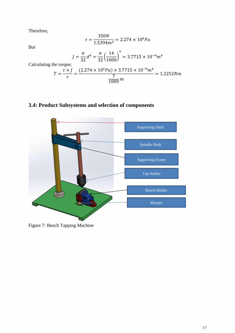
3.4: Product Subsystems and selection of components
Figure 7: Bench Tapping Machine
Mounts
Bench Holder
Tap Holder
Supporting Frame
Spindle Shaft
Supporting Shaft
18
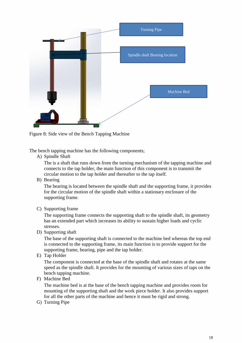
Figure 8: Side view of the Bench Tapping Machine
The bench tapping machine has the following components;
A) Spindle Shaft
The is a shaft that runs down from the turning mechanism of the tapping machine and
connects to the tap holder, the main function of this component is to transmit the
circular motion to the tap holder and thereafter to the tap itself.
B) Bearing
The bearing is located between the spindle shaft and the supporting frame, it provides
for the circular motion of the spindle shaft within a stationary enclosure of the
supporting frame.
C) Supporting frame
The supporting frame connects the supporting shaft to the spindle shaft, its geometry
has an extended part which increases its ability to sustain higher loads and cyclic
stresses.
D) Supporting shaft
The base of the supporting shaft is connected to the machine bed whereas the top end
is connected to the supporting frame, its main function is to provide support for the
supporting frame, bearing, pipe and the tap holder.
E) Tap Holder
The component is connected at the base of the spindle shaft and rotates at the same
speed as the spindle shaft. It provides for the mounting of various sizes of taps on the
bench tapping machine.
F) Machine Bed
The machine bed is at the base of the bench tapping machine and provides room for
mounting of the supporting shaft and the work piece holder. It also provides support
for all the other parts of the machine and hence it must be rigid and strong.
G) Turning Pipe
Spindle shaft Bearing location
Machine Bed
Turning Pipe

19
This allows the spindle shaft to be rotated at a desired speed, provision of the pipes
allows for the circular motion to be obtained via a simple turning of the pipe.
H) Mounts
This includes screws and joints which provides for attachment of various components
into the main parts of the bench tapping machine, they provide a firm and rigid
assembly of subsystems and components into the base of the machine.
I) Bench Holder
The acts as the work piece holder, it has a vice like mechanism which provides for
simpler rigid attachment and detachment work pieces onto the machine bed. It also
has mechanisms for lubricant drainage and chip removal.
3.5: Manufacturing and assembly (Implementation)
Considering that there are four different component materials to be used (cast iron, mild steel,
fiber and gun metal), each component is to be manufactured separately then assembled
together to form the bench tapping machine. The machine bed is the base of the machine and
hence this acts as the initial assembly point, the bench holder and the supporting shaft are
fitted first and ensure they are rigid and strong, the supporting frame, bearing, the spindle
shaft and the turning pipe are fitted next. Finally, the tap holder is fitted to the spindle shaft.
The mountings are then fitted to ensure everything fits perfectly and rigidly. The bearing
selected depends on the internal diameter of the mounting on the supporting frame and also
the external diameter of the spindle shaft. There are various internationally recognized
bearing sizes which mainly depend on the amount and types of loads the bearing will be
subjected to during normal operation. It is important to consider this before making the final
decision of the type and size of bearing to use on this design, since this design does not
include a large amount of loads and it also has a lower rotational speed selecting a bearing to
use is slightly easier.
3.6 Economic Evaluation
The total economic cost of the project includes; cost of buying the equipment needed for the
fabrication of the bench tapping machine, buying various tap sizes, acquiring the lubricant
and coolant, cost of replacing the depleted parts of the machine and wage costs.
Table 2: Cost Evaluation template
Year 0 Year 1 Year 2 Year 3 Year 4 Year 5 Year 6 Year 7 Year 8 Year 9 Year 10
Capital Costs
Equipment 500 500 500 500 500 500 500 500 500 500 500
Construction 1000 50 100 100 100 100 200 200 200 200 200
Total 1500 550 600 600 600 600 700 700 700 700 700
Operating Cost
Energy 0 0 0 0 0 0 0 0 0 0 0
Electricity 0 0 0 0 0 0 0 0 0 0 0
Labour 2500 2500 2500 2500 2500 2500 2500 2500 2500 2500 2500
Insurance 100 100 100 100 100 100 100 100 100 100 100
Taxes 5000 5000 5000 5000 5000 5000 5000 5000 5000 5000 5000
Total 7600 7600 7600 7600 7600 7600 7600 7600 7600 7600 7600

20
Revenues
Product 1 30000 30000 30000 30000 30000 30000 30000 30000 30000 30000 30000
Product 2 15000 15000 15000 15000 15000 15000 15000 15000 15000 15000 15000
Product 3 10000 10000 10000 10000 10000 10000 10000 10000 10000 10000 10000
Total 55000 55000 55000 55000 55000 55000 55000 55000 55000 55000 55000
Profits 45900 46850 46800 46800 46800 46800 45850 45850 45850 45850 45850

21
Chapter 4: System Testing and Analysis
4.1 Experimental Setup, Sensors and Data Acquisition System
In order to perform the system analysis, it is crucial to perform a well suited experiment on
the practical model, or in our case the fabricated machine. The experimental testing allows
for comparison of the fabricated bench tapping machine to other available machines that are
utilized for the tapping process, in our case we chose to compare the use of the bench tapping
machine for thread cutting and the use of conventional manual thread cutting process. The
conventional thread cutting process usually involves the use of dies and taps without the
necessary clamping mechanisms which ensure aligned and accurate threads. In this
experimental test process we utilize the two methods of thread cutting (specifically tapping)
and compare them in relation to; ease of threading, time required to form complete threads,
force requirements and the accuracy/alignment of the end threads. The figure below shows
the experimental setup for testing of the fabricated bench tapping machine;
Figure 9: Use of Bench-tapping machine in tapping
The setup above entailed the use of an appropriate tap size (same for both tests) and ensuring
the work-piece is tightly held on the bench holder. The amount of force required and the ease
of threading is judged by the operator whereas the threads formed can be examined to
determine the accuracy and alignment of threads. For the conventional threading process
(also manual but does not include camping of tap and work-piece) the setup is slightly
different but the experimental procedure is exactly the same as the one mentioned above.

22
Figure 10: Manual tapping experimental setup
Figure 11: Manual tapping process
The manual tapping process entails clamping the work-piece of a normal vice and attaching
the tap to a holder which also acts as the turning mechanism.
4.2 Overall Results, Analysis and Discussion
The results of the two experiments proved that the use of the bench tapping machine highly
improves the tapping process, the first thing to be considered was the ease of the tapping
process; use of the bench tapping machine made the entire tapping process so easy and
simple compare to the manual tapping process which necessitated the need to find a
workshop with a preset clamping mechanism and also the tap holding mechanism for the
bench tapping machine is simpler than the one for manual tapping. The turning force is lower
for the bench tapping machine mainly due to the inclusion of a bearing which makes it easier
to obtain the require tapping force, the risk of tap breakage is also reduced when using the
bench tapping machine [6]. Using the basis of force used by the operator to obtain the need
threads (the operator was required to estimate which experiment required a higher force), it

23
was established that the manual tapping process required a force higher than when the bench
tapping machine was used to obtain the same threads while using the same size and type of
tap.
As for the accuracy and alignment of threads, it was expected that the most advanced tapping
system will produce a superior quality of internal threads and true to this expectation, threads
obtained by use of the bench tapping machine were accurately aligned and with uniform
thread properties such as pitch and thread spacing. Those obtained via the manual tapping
process were slightly misaligned and irregular in shape.
Figure 12: Aligned and Misaligned threads comparison [6]

24
Chapter 5: Project Management
5.1 Project Plan
For any project to be successful there must be a perfect pre-laid plan which will govern how
the entire design, development and execution process is to be done. The initial stage of this
project involved selection of group members (five in total), thereafter the group members met
and came up with a project plan which was to run for a period of around four months. The
group settled on the following breakdown of project tasks;
a) Identification of a problem based on tapping and writing done a working problem
statement and project aims and objectives
b) Coming up with an appropriate project title
c) Formulation of a detailed project introduction and literature review
d) Obtaining design standards and constraints
e) Developing a detailed 3D project model
f) Determining machine dimensions
g) Material selection based on design constraints and cost analysis
h) Component and material sourcing
i) Project fabrication and testing
j) Analysis of test results and discussion
k) Writing a detailed report summarizing the entire project
Time duration of specific tasks
The project duration had limited time running from 4th February to 10th May, this necessitated
the need to squeeze the project tasks within the short period of time and due to this some of
the tasks had to be overlapped. The following task indicates how the tasks were performed
during the entire project;
Table 3: Task time duration
Task February March April May
Task 1 Project title,
problem statement
and project aims
Task 2 Introduction and
Literature review
Task 3 Material Selection and Cost
Analysis
Task 4 3D Modeling and Machine
Fabrication
Task 5 Machine Testing
Task 6 Test result analysis and Discussion
Task 7 Report Writing

25
5.2 Team Members Contributions
During the first team session the members decided that each individual should contribute
fully in most is not all the tasks that were to be undertaken during the project design,
development, fabrication and report writing. However due to the unique experiences and
skills possessed by the different individuals of the team, it seemed more efficient if each
member lead on parts that he/she felt comfortable and well suited for, the following is list
shows which members took charge of the various project tasks;
Team Members Tasks in charge
Member 1 Introduction and Literature Review
Report Writing
Member 2 Material selection
Cost analysis
Determining component dimensions
Member 3 3D model development
Design calculations
Member 4 Problem statement
Project title
Project aims and objectives
Member 5 Project fabrication and testing
Analysis and discussion
5.3 Project Execution and Monitoring
This being a senior project, our team had to be assigned to a specific supervisor who had the
task of monitoring our project progress all through the project duration. After the selection of
our project title and problem statement, we presented it to our supervisor who gave us a green
light to proceed with the project development. Thereafter the project introduction and
literature review based on our project title was developed and presented for approval by the
project advisor; each chapter had to be presented in slides form with the main points clearly
highlighted. Chapter 3 of our project mainly focused on the project design phase, it
comprised of formulation of the design constraints and establishment of the appropriate
engineering standards (both design and manufacturing) that govern the design project. After
obtaining the required spindle shaft torque, it was simpler to obtain the component
dimensions and thereafter to develop a detailed 3D model of the bench tapping machine. The
model was crucial in obtaining a simulation of how the machine will behave when operating
under the expected normal loads during its normal operation. Once established that the loads
are safe, the fabrication process began and thereafter the appropriate tests were performed on
the bench tapping machine in order to compare it to the conventional manual tapping process.
Analysis and discussion of the test results determined that indeed the development and
fabrication of the bench tapping machine provided a cheaper and improved manual tapping
process.
5.4 Decision Making Process and Challenges Faced
From the onset of the project, the team was usually faced with a scenario whereby the
members had several ideas on how to handle issues experienced within the project tasks, and
as a result the group had to develop a system on how the best ideas had to be selected in order
to improve and simplify the entire design process. The initial decision that the team had to

26
make was what project was best suited for us, we eventually settled to design a manual bench
tapping machine which will likely solve the problem of obtaining misaligned threads when
using the available conventional manual tapping techniques. Other decisions that the team
had to make include;
a) Suitable material selection
b) Tests to carry out and analyze
c) Which software to use in the 3D modeling
d) What tasks to allocate to individual members of the team
Challenges Faced
This being a very tough year, the challenges were highly magnified and as a result the project
design, development and fabrications were a bit slow and uncertain at times. But despite
these challenges the project was generally successful. The following are some of the
challenges encountered;
i) Lateness and absenteeism of team members. The project involved numerous tasks
and therefore it was crucial for each member to perform their specific task on time
in order to avoid project stalling and lateness.
ii) COVID-19. This is a global pandemic which has affected our normal activities, as
a team this was the main challenge which piled up on the other small challenges.
Meeting of team members and advisor was restricted due to the protocols imposed
by the government (mainly lockdown), availability of parts was affected to due
closure of some major companies and also the delay of delivery of machine parts
and components.
iii) This being a unique project, settling on the best experimental tests was a problem,
it was hard to determine what specific measurable properties of the bench tapping
machine will provide the needed data in order to plot and compare them to the
available manual tapping techniques.
5.5 Project Bill of Materials and Budget
The table below indicates the quantity and cost of parts ordered from the available suppliers;
Table 4: Project bill of material and budget
Component/ Part Unit Unit Price Total Price
Bench holder 1 $30 $30
Mild steel shaft 600mm $10/300mm $20
Tap holder $50 $50
Fiber (For machine
bed)
250mm*200mm $30 $30
Cast Iron frame 120mm*30mm $20 $20
Bearing 1 $10 $10
Tap 3 $20/unit $60
Mounts 6 $5/unit $30
Turning cost $20
Welding cost $20
Total $290
From the table above it can be seen that the total cost of fabrication amounted to $290 which
was within the pre-set budget of the project. The manufacturing cost included turning the

27
acquired shafts into the desired diameters and also ensuring their surfaces are smooth and soft
enough, welding is necessary in order to make the supporting frame strong enough.
Chapter 6: Project Analysis
6.1 Life-Long Learning
Our project was mainly based on the tapping process and how it can be made simpler and
easier to perform, this project enabled as to acquire the following life-long learning that will
be helpful to us in the future;
a) The use of modeling software in obtaining the 3D model of the bench tapping
machine has enabled as to acquire the much needed knowledge on such software. Our
world is constantly shifting the use of improved technologies to solve life-long issues
and therefore have enough knowledge can be highly advantageous. Our group
members were able to acquire some knowledge on software’s such as CAD, Autodesk
Inventor and Solidworks.
b) Due to the short project duration it was essential for the team to learn on how to make
the most out of a limited time period. This enabled us to manage our time better and
be able to do all the required tasks within this duration of time.
c) Material selection is a crucial design process which ensures the materials selected are
best suited for a particular application while at the same time maintaining the least
possible cost. Our team was able to learn from experience how to best select the
materials within the design constraints while ensuring we are within our project
budget.
d) Since the project was to be done by a group of five individuals, it was crucial for the
team members to learn on how to best relate to each other and also what motivations
can be used to bring the best out of each team member.
e) The project also acted as a refresher on some engineering skills and knowledge which
included welding, turning, tapping process, and a few mathematical calculations.
f) The project was a huge step in applying what we had learnt in class into a real life
problem, and in the end we were able to provide an improved version on a bench
tapping machine which increases the efficiency and effectiveness of the tapping
process.
6.2 Impact of Engineering Solutions
In the beginning of this project our main aim was to design, develop and fabricate a machine
which would improve the manual tapping process, at the end of this project we managed to
improve various parts of the conventional manual tapping process. The engineering
improvements of the tapping process include;
i) The process has been made fast and effective by the use of a bench tapping
machine which is easier and simpler to setup and use for the tapping process.
ii) The threads obtained are accurate and aligned which increases the service life of
the component and also reduces the risk of tap breakage during thread cutting.
iii) Flexibility of the process is also assured by the fitting of a variable tap and bench
holder which can hold different sizes and forms of taps as well as work-pieces.
iv) The operation of the machine has been made safer by ensuring the torque
transmitted within the spindle shaft is within the set range, this also allows the
spindle shaft to have a longer service life [6].

28
v) The use of fiber in the machine bed highly reduces the cost of the machine but at
the same time it makes the machine lighter and can support the maximum amount
of load in the bench tapping machine.
6.3 Contemporary Issues Addressed
The design of the bench tapping machine has addressed the following key issues;
i) Prevents misalignment of threads which is mainly caused by misalignments of the
center of the tap and the center of the work-piece.
ii) Reduction in the risk of tap breakage by ensuring the spindle shaft operates within
the safe torque range
iii) Reduced turning force due to the fitting of a ball bearing between the spindle shaft
and the supporting frame
iv) Providing an inbuilt bench holder which provided for tight holding of the work-
piece during the tapping process

29
Chapter 7: Conclusion and Future Recommendations
7.1 Conclusion
The project aims and objectives were sufficiently achieved and hence the project was
successful; a manually operated bench tapping machine was design, developed, fabricated
and tested. The team also manage to perform other project minor objectives which includes;
development of a 3D model of the bench tapping machine on Solidworks and simulating the
model to determine the safe limits of the machine, material selection for the components and
parts that make up the bench tapping machine, cost analysis and analysis of the experimental
test results obtained. Despite all the challenges faced and the human, technical and
experimental errors that might have been experienced during the project, our team was able
to pull through and develop a machine that’s one of its own unique kind. The machine is able
to produce threads on the internal parts of work-pieces while the operator is using a lower
amount of force compared to when using the conventional method of tapping.
7.2 Future Recommendations
Although the bench tapping machine designed in this project solves most if not all of the
problems which were listed in the problem statement, there is still huge room for improving
this machine is order to obtain the best out of it. The following are the recommendations our
time provided that might help is making it more efficient and productive;
i) Design of an enhanced chip removal system, this will help further prevent chip
clogging and thereby improving the tapping process. Chip clogging also increases
the risk of tap breakage and hence this recommendation will also reduce the risk
of tap breakage
ii) Attachment of a cooling and lubrication system, cooling and lubrication of the tap
during operation reduces friction and rise in temperature and hence it makes the
entire process smooth and efficient. This also highly increases the tool service life
and also helps with chip removal from the work-piece [6].
iii) Automation of the bench tapping machine is also another possibility that will
increase the efficiency and speed of the tapping process. Although the aim of this
project was to save on power, the machine can be designed to consume the least
amount of power while producing more favorable quality of threads in a much
lower amount of time compared to a manual bench tapping machine.

30
References [1]Hand tapping and thread cutting. Canberra: A.G.P.S., 1975.
[2]V. Yaroslavtsev, "Thread cutting using thread taps and with preliminary plastic
deformation of the material of the layer to be cut", Science and Education of
Bauman MSTU, vol. 13, no. 8, 2013. Available: 10.7463/0813.0570897.
[3]Y. Li and S. Zhao, "The Key Technology in Extrusion Tapping of Internal
Thread", Advanced Materials Research, vol. 295-297, pp. 2636-2641,
2011. Available: 10.4028/www.scientific.net/amr.295-297.2636.
[4]"A Portable Thread-Cutting Machine", Scientific American, vol. 83, no. 19, pp. 292-292,
1900. Available: 10.1038/scientificamerican11101900-292b.
[5]"Bench Tapping Machine", Nevon Projects, 2021. [Online]. Available:
https://nevonprojects.com/bench-tapping-machine/. [Accessed: 19- Apr-
2021].
[6]J. Hayashi, K. Okuda and H. Kodama, "A Study on Tool Damage of Threading
Tap in Screw Cutting of Stainless Steel 15-5PH", Key Engineering
Materials, vol. 656-657, pp. 164-167, 2015. Available:
10.4028/www.scientific.net/kem.656-657.164.
[7]R. Bahadure, "Regeneration of Tapping Machine with Effective Utilization", International
Journal for Research in Applied Science and Engineering Technology, vol. 7, no. 3,
pp. 1569-1571, 2019. Available: 10.22214/ijraset.2019.3290.
[8]F. Colvin, Threads and thread cutting. [Place of publication not identified]: Nabu Press,
2012.
[9]Thread forming and thread cutting tapping screws and metallic drive screws (inch series).
New York: American Society of Mechanical Engineers, 1999.

31
Appendix A: CAD drawing and Bill of Materials
Component/ Part Unit Unit Price Total Price
Bench holder 1 $30 $30
Mild steel shaft 600mm $10/300mm $20
Tap holder $50 $50
Fiber (For machine
bed)
250mm*200mm $30 $30
Cast Iron frame 120mm*30mm $20 $20
Bearing 1 $10 $10
Tap 3 $20/unit $60
Mounts 6 $5/unit $30
Turning cost $20
Welding cost $20
Total $290

32
Appendix B: Engineering Standards
Standard Name Type
ASME B1.1-2003 (R2018) Unified Inch Screw Threads
(UN and UNR Thread Form)
V Thread Form
ASME B.1.10M-2004
(R2014)
Unified Miniature Screw
Threads
V Thread Form
ASME B.1.13M-2005
(R2015)
Metric Screw Threads: M
Profile
V Thread Form
ASME B.1.15-1995 (R2003) Unified Inch Screw Threads
(UNJ Thread Form)
V Thread Form
ASME B1.21M-1997
(R2013)
Metric Screw Threads-MJ
Profile
V Thread Form
ASTM A400 Standard Practice for Steel
Bars, Selection Guide,
Composition, and
Mechanical Properties
For steel bars manufacturing
process
ASTM A488/A488M A01.18 Standard Practice for Steel
Castings, Welding,
Qualifications of Procedure
and Personnel
For Welding processes
ISO 68-1:1998 ISO general purpose screw
threads-Basic Profile-Part 1:
Metric screw threads
V Thread Form
ISO 68-2:1998 ISO general purpose screw
threads-Basic Profile-Part 2:
Inch screw threads
V Thread Form
ISO 261:1998 ISO general purpose metric
screw threads-General plan
V Thread Form
ISO 262:1998 ISO general purpose metric
screw threads-Selected sizes
for screws, bolts and nuts
V Thread Form
ISO 724:1993 ISO general purpose metric
screw threads-Basic
dimensions
V Thread Form
ISO 725:2009 ISO inch screw threads V Thread Form 51386