Design and Methods of Construction of a Biomimetic Inspired ...
95
Design and Methods of Construction of a Biomimetic Inspired Carbon Fiber Wing Gonçalo Leça Ramada Martins de Almeida Thesis to obtain the Master of Science Degree in Aerospace Engineering Supervisor(s): Prof. Filipe Cunha Prof. João Oliveira Examination Committee Chairperson: Prof. Fernando José Parracho Lau Supervisor: Prof. Filipe Cunha Members of the Committee: Prof. André Calado Marta December 2019
-
Upload
khangminh22 -
Category
Documents
-
view
3 -
download
0
Transcript of Design and Methods of Construction of a Biomimetic Inspired ...

Design and Methods of Construction of a Biomimetic Inspired Carbon Fiber Wing
Gonçalo Leça Ramada Martins de Almeida
Thesis to obtain the Master of Science Degree in
Aerospace Engineering
Supervisor(s): Prof. Filipe Cunha
Prof. João Oliveira
Examination Committee
Chairperson: Prof. Fernando José Parracho Lau Supervisor: Prof. Filipe Cunha
Members of the Committee: Prof. André Calado Marta
December 2019

ii

iii
Dedicated to my mother, for all the support given.

iv

v
Acknowledgments
I would like to give a special thank you to my family, specially my mother, for all the support through my academic life.
To Miguel Passanha and the MPC Designworks team, for all the knowledge I’ve acquired during my time working there, for what I am deeply grateful.
To professor Filipe Szolnoky Cunha and professor João Oliveira for all the support and guidance for this thesis.

vi

vii
Resumo
Este trabalho aborda o conceito de biomimicry e a implementação de design animal em aeronaves.
Este projecto começa por enumerar e explicar diversos designs encontrados na natureza que poderiam ser uma mais valia na engenharia moderna, mais concretamente, em aplicações na indústria aeronáutica.
Posteriormente é escolhido o conceito das protuberâncias no leading edge duma asa para ser estudado mais aprofundadamente. É projectado em CAD (CATIA V5) o design duma asa em fibra de carbono com um actuador que, quando activado, cria as protuberâncias no bordo de ataque. A asa original é modificada e os diversos componentes e mecanismos necessários para a actuação são adicionados. A asa, assim como os seus principais componentes, é desenvolvida em prepreg de fibra de carbono, com componentes auxiliares em alumínio e termoplástico. É desenvolvida uma asa com um molde estrutural de forma a analisar os seus benefícios estruturais na redução de deformação e afastamento das zonas de concentração de stress do bordo de ataque para a raiz da asa.
O novo e antigo design da asa são sujeitos a análises estructurais, nas quais são aplicadas diversas pressões e cargas distribuídas de modo a avaliar se as modificações efectuadas são viáveis ou estructuralmente prejudiciais. Os resultados de deformação e valores de stress obtidos das forças distribuídas foram essenciais no desenvolvimento dos mecanismos internos de actuação. A partir dos resultados de deformação ficou evidente que seria necessário desenvolver os mecanismos com uma folga entre a Camshaft Actuator, motor elétrico e Actuator Lock de forma a que estes se acomodassem à deformação da asa sobre esforço. Duas forças distribuídas são aplicadas na asa com molde estrutural de forma a recriar situações reais de voo, uma situação comum e uma situação limite.
Por fim, é apresentado os métodos e procedimentos de construção da asa e dos seus componentes. Isto foi realizado usando moldes em resina, gabaridos de corte e colagem e componentes de centramento e fixação.
Palavras-chave: CATIA V5, Fibra de carbon, Análise estrutural, Moldes, Gabaritos de corte e colagem

viii

ix
Abstract
This project focuses on the concept of biomimicry and the implementation of animal
design in aircrafts. It begins by listing and explaining several designs found in nature that could be used to
improve modern engineering, specifically in the aerospace industry. Later, the concept of leading-edge serrations is chosen to be further studied. Using
CATIA V5, the design of a carbon fiber wing is developed containing an actuator that creates the leading edge serrations. The original wing is modified and several components and mechanisms necessary to make it work were added. The wing and all its main components are developed in carbon fiber prepreg with some aluminum and thermoplastic elements. A wing with a structural mould is also developed to assess its benefits in reducing overall deformation and moving stress concentration from the leading edge to the root of the wing.
Both new and original wings are subjected to structural analysis with different pressures and loads and the results were compared to assess if the modifications were viable or would pose a structural risk. The stress and displacement results obtained from the distributed force applied were taken into consideration when developing the internal actuator mechanisms. From the displacement results, it was clear a degree of play should be present in the connections between the Camshaft Actuator, the electric motor and the Actuator Lock for these mechanisms to move with the overall deformation of the wing under load. Two distributed forces are applied to the airfoil with structural mould to represent two flight situations, a typical operation and an extreme situation.
For last, the methods and procedures to construct the wing and all its components in carbon fiber is presented. This is done using resin moulds and CNC Jigs and all the necessary hardware required to center and fix the parts in place.
Keywords: CATIA V5, Carbon fiber prepreg, Structural Analysis, Moulds, CNC Jig

x

xi
Contents
Acknowledgments ................................................................................................................. v
Resumo ................................................................................................................................vii
Abstract ............................................................................................................................... ix
List of Tables ....................................................................................................................... xiii
List of Figures ....................................................................................................................... xv
Nomenclature ................................................................................................................... xviii
Glossary .............................................................................................................................. xix
1. Introduction 1
1.1. Motivation ......................................................................................................................... 1
1.2. Objectives .......................................................................................................................... 1
1.3. Thesis Outline .................................................................................................................... 2
2. Biomimicry 3
2.1. Drag Reduction .................................................................................................................. 3 2.1.1. Fish slime. Lotus leaf. Self-cleaning......................................................................... 4 2.1.2. Skin ripples. Dolphins ............................................................................................... 6 2.1.3. Shark skin. Dermal denticles ................................................................................... 6 2.1.4. Whale protuberances. Tubercles ............................................................................ 8 2.1.5. Tip Morphing. Winglets .......................................................................................... 12
2.2. Types of Wings ................................................................................................................ 13 2.2.1. Elliptical wings ........................................................................................................ 13 2.2.2. High speed wings ................................................................................................... 14 2.2.3. Long gliding wings .................................................................................................. 15 2.2.4. High lift and broad soaring wings.......................................................................... 16
2.3. Concept chosen for development .................................................................................. 17
3. Leading edge serrations applied to a wing 19 3.1. Standard wing specifications .......................................................................................... 19 3.2. Proposed Actuation ........................................................................................................ 21
3.2.1. Types of actuator design ....................................................................................... 22 3.2.2. Chosen actuator Design ......................................................................................... 23
4. CAD Development 25 4.1. Parts Construction .......................................................................................................... 25
4.1.1. Airfoil ....................................................................................................................... 26 4.1.1.1. Pressure Analysis ................................................................................... 27 4.1.1.2. Distributed Force Analysis .................................................................... 36
4.1.2. Camshaft Actuator .................................................................................................. 39 4.1.3. Camshaft Gear Insert .............................................................................................. 40

xii
4.1.4. Actuator Lock and Plastic Insert ............................................................................. 42 4.1.5. Armature and Elastic Membrane ........................................................................... 43 4.1.6. Flaps ......................................................................................................................... 45
4.2. Methods of Construction – Moulds and CNC Jigs ......................................................... 45 4.2.1. Airfoil Mould ........................................................................................................... 47 4.2.2. Camshaft Actuator Jig ............................................................................................. 47 4.2.3. Actuator Lock Mould and CNC Jig .......................................................................... 49 4.2.4. Armature Mould and CNC Jig ................................................................................. 54
5. Conclusion 5.1. Achievements .................................................................................................................. 57 5.2. Future Work .................................................................................................................... 58
Bibliography 59 A 2D Drawings 64

xiii
List of Tables
Table 3.1: AR5 Evolution specs, [26] ................................................................................................. 19 Table 4.1: List of components ........................................................................................................... 26 Table 4.2: Carbon Fiber Prepreg specifications [34] ........................................................................... 26 Table 4.3: Structural Foam Properties [46] ........................................................................................ 34 Table 4.4: Original and Modified wings results comparison ............................................................... 38 Table 4.5: Distributed Force Results F=880N ..................................................................................... 38 Table 4.6: Distributed Force Results F=2450N ................................................................................... 38 Table 4.7: Billet Aluminum specifications [CATIA] .............................................................................. 41 Table 4.8: Gear Formulation [29] ...................................................................................................... 42

xiv

xv
List of Figures Figure 2.1: Boundary layer .................................................................................................................. 3 Figure 2.2: Hydrophobic properties ..................................................................................................... 4 Figure 2.3: Hydrophobic characteristics .............................................................................................. 5 Figure 2.4: Lotus leaf self-cleaning method ......................................................................................... 5 Figure 2.5: Leading edge contamination [32] ....................................................................................... 5 Figure 2.6: Teardrop shape ................................................................................................................. 6 Figure 2.7: Tollmien-Schlichting wave over dolphin skin [11] ............................................................... 6 Figure 2.8: Application of denticles ..................................................................................................... 7 Figure 2.9: Boundary layer separation [10] .......................................................................................... 7 Figure 2.10: Lifted scales ..................................................................................................................... 7 Figure 2.11: Ribbed plate used in Bechert [8] test ............................................................................... 7 Figure 2.12: Application testing of shark skin riblets [20] .................................................................... 8 Figure 2.13: Humpback Whale ............................................................................................................ 9 Figure 2.14: Miklosovic tests [15]; ∆(fin w/protuberances); -(No protuberances) ................................. 9 Figure 2.15: Schematic of serrated leading edge ............................................................................... 10 Figure 2.16: Schematic of vortexes migration .................................................................................... 10 Figure 2.17: Results obtained by Custodio [18] for 8 protuberances and λ=0.25c ............................... 11 Figure 2.18: Results obtained by Custodio [18] for 4 protuberances and λ=0.50c ............................... 11 Figure 2.19: Creation of vortexes ...................................................................................................... 12 Figure 2.20: Winglet in nature........................................................................................................... 12 Figure 2.21: Drag components .......................................................................................................... 12 Figure 2.22: Animals with elliptical wings .......................................................................................... 13 Figure 2.23: Aircrafts with elliptical wings ......................................................................................... 14 Figure 2.24: Birds with high speed wings ........................................................................................... 14 Figure 2.25: Aircrafts with high speed wings ..................................................................................... 14 Figure 2.26: Birds with long gliding wings .......................................................................................... 15 Figure 2.27: Aircrafts with long soaring wings ................................................................................... 15 Figure 2.28: Birds with broad soaring wings ...................................................................................... 16 Figure 2.29: Aircrafts with broad soaring wings ................................................................................. 16 Figure 3.1: Tekever AR5 Evolution, [22] ............................................................................................ 19 Figure 3.2: Airfoil and fin comparison ................................................................................................ 19 Figure 3.3: Aerodynamic coefficients of S4233 at 𝑅𝑒 = 106 .............................................................. 20 Figure 3.4: Type1 actuator design ..................................................................................................... 22 Figure 3.5: Type2 actuator design ..................................................................................................... 22 Figure 3.6: Type3 actuator design ..................................................................................................... 23 Figure 3.7: Actuation area in the UAV, modified from [22] ................................................................ 24 Figure 3.8: Airfoil plotted in CATIA V5 ............................................................................................... 24 Figure 4.1: Modified complete assembly in CATIA V5 ........................................................................ 25 Figure 4.2: Original wing in CATIA V5 ................................................................................................ 26 Figure 4.3: Von Mises stress results for pressure applied to original wing .......................................... 28 Figure 4.4: Translational Displacement Analysis ................................................................................ 29 Figure 4.5: Estimated Local Error Analysis for original wing at P1=100𝑁/𝑚2 ...................................... 30 Figure 4.6: Modified wing in its early stage ....................................................................................... 31 Figure 4.7: Von Mises stress results for pressure applied to modified wing ........................................ 32 Figure 4.8: Translational Displacement Analysis of modified wing ..................................................... 33 Figure 4.9: Estimated Local Error Analysis for modified wing at P1=100𝑁/𝑚2 .................................... 33 Figure 4.10: Airfoil (semitransparent orange) and Interior Structural Mould (white) assembly ........... 34 Figure 4.11: Von Mises stress results for pressure applied to modified wing with structural foam...... 35
xvi
Figure 4.12: Translational Displacement Analysis of pressure applied to modified wing with structural foam ................................................................................................................................................ 35 Figure 4.13: Estimated Local Error Analysis for modified wing w/ structural foam at P1=100𝑁/𝑚2 .... 36 Figure 4.14: Von Mises stress results for distributed force applied to modified wing with structural .. 37 Figure 4.15: Translational Displacement results for distributed force applied to modified wing with structural foam ................................................................................................................................. 37 Figure 4.16: Von Mises stress results for distributed force applied to modified wing with structural foam and a mesh of 5mm ................................................................................................................. 39 Figure 4.17: Camshaft Actuator......................................................................................................... 39 Figure 4.18: 2D Drawing of camshaft actuator................................................................................... 40 Figure 4.19: New and original airfoil comparison ............................................................................... 40 Figure 4.20: Camshaft Gear Insert ..................................................................................................... 40 Figure 4.21: Camshaft Actuator laminated over Gear Insert .............................................................. 41 Figure 4.22: Gear Nomenclature and sketch.12 ................................................................................. 41 Figure 4.23: Example of a 4 key lock Keensert®[36]. .......................................................................... 42 Figure 4.24: Actuator Lock and Airfoil assembly ................................................................................ 43 Figure 4.25: Plastic Insert .................................................................................................................. 43 Figure 4.26: Elastic Membrane .......................................................................................................... 44 Figure 4.27: Armature Assembly ....................................................................................................... 44 Figure 4.28: Flaps.............................................................................................................................. 45 Figure 4.29: Three parts moulding scheme ........................................................................................ 47 Figure 4.30: Interior Mould in white and semitransparent Airfoil ....................................................... 47 Figure 4.31: Rod placed over Camshaft Jig Base, dowels in place ....................................................... 48 Figure 4.32: Camshaft Jig Cover ........................................................................................................ 48 Figure 4.33: Camshaft Jig Cover with cam moulds inside ................................................................... 48 Figure 4.34: Camshaft Jig Assembly with centering dowels and bolts ................................................. 49 Figure 4.35: Lamination over cam moulds ......................................................................................... 49 Figure 4.36: Actuator Lock Draft Analysis .......................................................................................... 50 Figure 4.37: Actuator Lock Moulds .................................................................................................... 51 Figure 4.38: Actuator Lock Mould assembly ...................................................................................... 52 Figure 4.39: Example of extractable dowels ...................................................................................... 52 Figure 4.40: Actuator Lock CNC Jig .................................................................................................... 53 Figure 4.41: Plastic Insert cut-out ...................................................................................................... 53 Figure 4.42: Actuator Lock CNC Jig 3 ................................................................................................. 53 Figure 4.43: Actuator Lock CNC Jig .................................................................................................... 54 Figure 4.44: Armature Mould Assembly ............................................................................................ 54 Figure 4.45: Armature Draft Analysis ................................................................................................. 55 Figure 4.46: Armature CNC Jig........................................................................................................... 55 Figure 4.47: Vacuum mechanisms ..................................................................................................... 56 Figure 4.48: Armature milling............................................................................................................ 56 Figure 4.49: Elastic Membrane application ........................................................................................ 56

xvii
Nomenclature
Greek symbols α Angle
αth Thermal Conductivity
β Angle
δ Circulation Distribution factor
λ Wavelength
Λ Aspect Ratio
𝑣 Kinematic viscosity
ρ Density
σ Stress/Yield Strength
Roman symbols A Amplitude
c Chord length
𝐶𝑑 Drag Coefficient
𝐶𝑙 Lift Coefficient
𝐶𝑚 Moment Coefficient
P Pressure
R Radius
𝑅𝑒 Reynolds Number
sc Scaling Factor
U Speed
Subscripts 𝑋𝑖 Initial Dimension
𝑋𝑓 Final Dimension
𝑆𝑟 Shrinkage Factor
Other ᴓ Diameter

xviii

xix
Glossary
AoA Angle of Attack CAD Computer Aided Design CAM Computer Aided Manufacturing CNC Computer Numerical Control LE Leading Edge MTOW Maximum Take-Off Weight RPA Remotely Piloted Aircraft UAV Unmanned Aerial Vehicle

xx

1
Chapter 1
Introduction 1.1 Motivation
There is an ever-going pursuit of efficiency and innovation in the aerospace industry, whether that might be due to high costs of fuel or simply to reduce operating cost and CO2 emissions. Nature has, for millions of years, perfected biological designs that allow species to proliferate and thrive over the conditions they were given. For this reason, engineers have been looking into nature for inspiration when developing new technology.
Biomimicry is the concept of looking and studying natures design and apply it in engineering. With this in mind, a series of concepts are approached along this thesis with the intention of shedding some light onto several designs found in nature that can improve engineering problems found in today’s industry.
1.2 Objectives
This thesis aims to look at how nature’s design can improve efficiency and break new grounds in the aerospace industry, it does so by using biomimicry, the concept of recreating and improving natural design and apply it to engineering. It approaches several concepts, new and old, of which one is selected for further development.
Some of the concepts approach ways of reducing operation costs and maintenance while others focus on improving aerodynamic capabilities, however, they all have one main objective, the reduction of drag. The concept of hydrophobic surfaces applied to the external surface of a planes wing has the capability of maintaining the leading edge constantly cleaned, removing the need of external cleaners and reducing maintenance. The concept of a shark skin-like surface applied to the external surface of a wing allows for a reduction of drag by up to 1%, which may look a small gain but translates into a significant reduction of operation costs in large fleets of commercial aircrafts.
The selected concept approaches the ability of leading edge protuberances to delay stall conditions due to vortexes created by its hills and valleys. These can be applied when a wing is reaching stall conditions by an electric motor that engages a carbon fiber actuator fitted with cams. The leading edge, once smooth, becomes deformed thanks to the elastic membrane. Within the preliminary designs of actuation, the concept chosen allows for a high degree of versatility of operation and practicality of construction and manufacturing.
This concept of leading edge protuberances allow the aircraft to delay its stall conditions and to be able to apply a higher amount of angle of attack. This represents the capability of steeper climbs and more rapid ascents.

2
The wing chosen for studies is modified to be able to fit the actuators needed to create the leading edge protuberances. This modified wing is subjected to structural analysis with the objective of knowing the amounts of stress capable of withstanding and the type of deformation it will suffer when subjected to flight loads. This is important so that the mechanisms developed in the wing’s interior may remain operative and functional when these deformations occur. The development of the internal actuators and mechanisms where design to move with the wings deformation and retain a certain amount of freedom inside the coupling devices.
Within the construction of the modified wing two objectives were in mind: create a detailed procedure on how to develop and construct carbon fiber components, and to provide future researchers with a template wing onto which studies can be made on how biomimicry inspired leading-edge protuberances benefit post-stall regimes.
1.3 Thesis Outline
This thesis is divided into five chapters. First chapter approaches the author motivation and objectives for this work. The second chapter contains several biomimicry concepts and its applications, as well as studies conducted by other authors explaining how the natural design works and how it can be replicated into engineering. The third chapter is how to implement a previously approached concept into a selected aircraft wing. Chapter four contains the development and analysis of a modular wing that can be used to test leading edge protuberances. It also contains the methods of construction of the proposed wing in carbon fiber, using epoxy resin moulds and jigs. Fifth and final chapter contains the achievements and proposals for further work.

3
Chapter 2 Biomimicry
In the last century humans have achieved exponential developments in technology and science, however, there is still room for improvements. Biomimicry is an approach to innovation that seeks inspiration in nature by emulation its time-tested design. Nature has had millions of years of trials and errors and all the living species today benefit from it, including humans, if we choose to learn from it.
2.1 Drag Reduction
“Biomimicry is looking at how you can use Mother Nature as a measure. It is looking to the biological system and seeing where you can find guidance and inspiration, free from the trappings of civil aeronautical design”.
- David Hills, Airbus senior manager of flight physics research [1]
According to David Hills [1], on today’s commercial airliners, about 40% of drag can be attributed to the turbulent boundary layer – a thin sheet of air just above the aircraft’s skin that crates friction.
Figure 2.1: Boundary layer [1].
This chapter will approach several biological characteristics that could, and some are,
reducing drag coefficients in the aerospace and automotive industry.

4
2.1.1 Fish slime. Lotus leaf. Self-cleaning wings.
Some fish have a coat of slime in their body, this introduces long chain polymers that reduce drag, allowing them to swim faster with less effort. In a study carried out by Moe Wm. Rosen and Neri E. Cornford [6], entitled ‘Fluid friction of the slime of aquatic animals’, several American species of fish were analyzed for their slime content and measured for their friction reduction, some reaching as high as 60% in reduction.
The slime fish secrete through their pores is a combination of polysaccharides, lipids and lipoproteins that enter the boundary layer and fill irregularities of the surface, improving streamlining. Most importantly, the slime has a lower viscosity than the water around the fish, this helps to reduce the frictional shear stresses arising from the “stickiness” or viscosity of water.
Lotus leaves surface have a hierarchically rough structure that discourages wetting, making it very hydrophobic. This surface has uneven heights of papillae that decrease water adhesion due to unfavorable surface interactions between water and leaf. A method of determination of wettability or water repellency is the measurement of the static contact angle by the ‘sessile drop’ method. In a 1997 paper by Neinhuis and Barthlott [14] contact angles measured on the lotus leaf were as high as 160°, far superior than other hydrophobic species with contact angles of only 60°.
(a) Water droplets over papillae [14]. (b) Papillae [14].
(c) Hydrophilic and hydrophobic contact angles, modified from [7].
Figure 2.2: Hydrophobic properties.
Within each papilla are thousands of nanoscopic wax tubules with non-polar methyl
groups (CH3), this also discourage leaf to water interactions due to the polar nature of water.
(a) Wax tubules in papillae [14].

5
(b) Water drops in a lotus leaf [14]. (c) Hydrophobic plant.
Figure 2.3: Hydrophobic characteristics.
These hydrophobic characteristics allow the lotus to clean itself when water falls on
its leaves. The debris are pickup by the rolling droplets and carried away from the plants surface.
Figure 2.4: Lotus leaf self-cleaning method [14].
Application Gliders, due to their non propulsion characteristics, depend heavily on maintaining a
high level of lift with the lowest drag possible. This can be a problem since they usually fly at low altitudes where bugs and dirt deposits on the aircraft surfaces are common. For this reason, they are more susceptible to wing contamination than any other type of aircraft.
Every piece of dirt/bug in the leading-edge creates disturbances in the laminar flow causing early transition to turbulent flow and inducing separation. A technic developed by BWS Pirker & Storka [32] to solve this problem is a ‘bug cleaner’, a mechanical wiper that travels along the leading edge of the wing removing its debris. This increases the aircraft weight and drag and can only be used under certain conditions. Flying at low speeds will not work and flying too fast the wiper can be lost. Only when flying forward at 100-120km/h will this mechanism work.
A different approach to this problem would be the application of a hydrophobic coat on every surface of the aircraft. This would prevent the added weight of a bug cleaner mechanism and its associated drag increase allowing for flow continuity. Like it was seen before for the lotus leaf, a wing surface coated with a hydrophobic material would allow water droplets to agglomerate in spheres and roll off the wing carrying away the surface debris. This technology has been used in some buildings facades to lower the costs of cleaning its windows and could also be applied in gliders and wind turbines to prevent dirt and bug contamination.
Figure 2.5: Leading edge contamination [32].

6
2.1.2 Skin ripples. Dolphins.
In the 1930’s dolphins were thought to possess some mechanism to reduce skin friction drag by maintaining a fully laminar boundary layer along their body. This was known as “Greys Paradox” [2] and has since been refuted as flawed. In fact, most of dolphin’s surface is largely turbulent and the streamlined “teardrop” shape provides most of the drag reduction. Dolphins have a maximum profile thickness at 45% of the body length, and since adverse pressure gradients only occur beyond this point, they can trap boundary layer separation to the back section of the body. The “teardrop” profile has since been used in boat hulls, submarines and low drag automotive concepts.
(a) Dolphin profile. (b) CMC Talbot-Lago T150, 1937 [20].
Figure 2.6: Teardrop shape.
In a 1960 paper published by Kramer M.O. [12] entitled “The dolphin’s secrets” a
scientific study was carried out showing that dolphins can delay the transition to turbulent flow using their soft, compliant skin and thus reducing skin friction drag. The viscoelastic properties of the skin interact with the flow over the body as a viscous damper and absorb energy from pressure oscillations called “Tollmien-Schlichting waves” that force the boundary layer to go turbulent. Dolphins sense these pressure oscillations using canal neuromasts and activate control micro vibrations to produce skin vibrations of up to 5mm amplitude at around 10Hz that destructively interfere with the Tollmien-Schlichting pressure waves. With this method, dolphins can delay the transition to a turbulent boundary layer and prevent boundary layer separation in the back allowing the front to maintain a laminar flow.
Figure 2.7: Tollmien-Schlichting wave over dolphin skin [12].
2.1.3 Shark skin. Dermal denticles.
Shark skin is composed of dermal denticles in an overlapping diamond shape that form grooves and channels that pull water towards the body and then pushes across it. This mechanism not only decreases drag and turbulence but also repels bacteria and other marine organisms from its skin. For this reason, Sappi North America in a collaboration with Sharklet Technologies, Inc developed NeoterixTMST [34], a shark skin inspired surface using
7
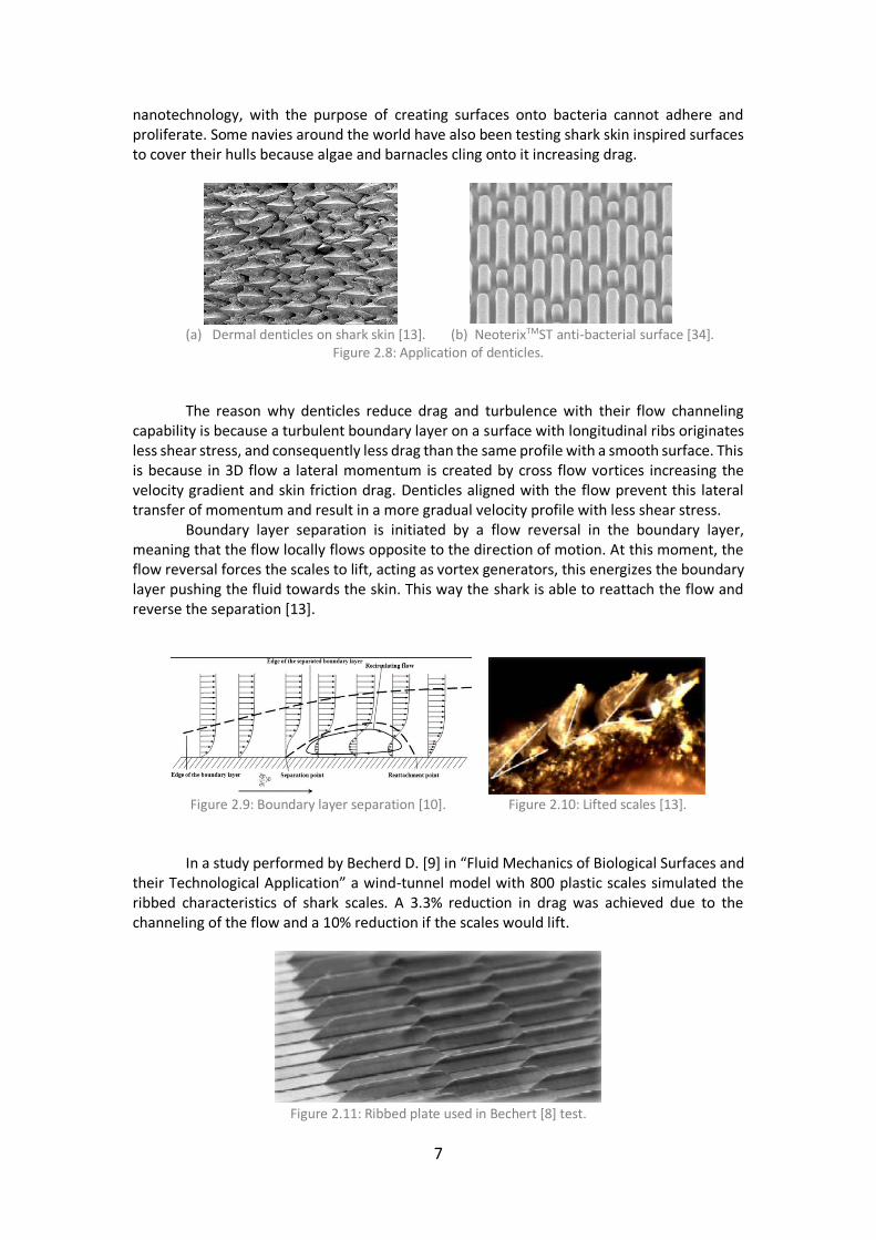
nanotechnology, with the purpose of creating surfaces onto bacteria cannot adhere and proliferate. Some navies around the world have also been testing shark skin inspired surfaces to cover their hulls because algae and barnacles cling onto it increasing drag.
(a) Dermal denticles on shark skin [13]. (b) NeoterixTMST anti-bacterial surface [34].
Figure 2.8: Application of denticles.
The reason why denticles reduce drag and turbulence with their flow channeling capability is because a turbulent boundary layer on a surface with longitudinal ribs originates less shear stress, and consequently less drag than the same profile with a smooth surface. This is because in 3D flow a lateral momentum is created by cross flow vortices increasing the velocity gradient and skin friction drag. Denticles aligned with the flow prevent this lateral transfer of momentum and result in a more gradual velocity profile with less shear stress. Boundary layer separation is initiated by a flow reversal in the boundary layer, meaning that the flow locally flows opposite to the direction of motion. At this moment, the flow reversal forces the scales to lift, acting as vortex generators, this energizes the boundary layer pushing the fluid towards the skin. This way the shark is able to reattach the flow and reverse the separation [13].
Figure 2.9: Boundary layer separation [10]. Figure 2.10: Lifted scales [13].
In a study performed by Becherd D. [9] in “Fluid Mechanics of Biological Surfaces and their Technological Application” a wind-tunnel model with 800 plastic scales simulated the ribbed characteristics of shark scales. A 3.3% reduction in drag was achieved due to the channeling of the flow and a 10% reduction if the scales would lift.
Figure 2.11: Ribbed plate used in Bechert [8] test.

8
Application
In 2013, Lufthansa Technik [23] and Airbus [24] undertook a joint venture research on the effects of shark skin inspired riblets in the wings of two A340-300s. Tests over two years and 12,000 flight hours showed a slim reduction in drag resulting in a fuel consumption reduction by more than 1%. This might not look much, but if applied to an entire fleet, thousands of liters of fuel can be saved as well as a significant reduction in CO2.
The main obstacle for this technology is to achieve an application capable of withstanding the elements and cost efficient. For this reason, a “simultaneous stamp hardening method” was developed by Fraunhofer Institute [25] by transferring the microstructure riblets to the aircraft lacquer. The lacquer is applied using a silicon film with the inverse of the shark skin riblets, it is then cured under ultraviolet light before removing the film.
Figure 2.12: Application testing of shark skin riblets [23].
2.1.4 Whale protuberances. Tubercles.
For several years now, biologists have focused on humpback whales and their fin morphology to explain their far superior maneuverability when compared with other large aquatic animals. An adult whale can be as long as 15m and 30 metric ton yet capable of doing a 360° turn in under 10m radius when hunting. For comparison, the average turning radius of a 4m long vehicle is around 10m.
This maneuverability has been attributed to leading edge protuberances in whales’ fins, in Fish and Battle [15] protuberances were studied and found to be responsible for a passive control of flow and drag reduction. These protuberances vary in amplitude from 2.5 to 12% of chord length and in wavelength from 10 to 50% of chord.

9
(a) Whale fin [21]. (b) Turning radius while hunting [22].
Figure 2.13: Humpback Whale.
In a wind tunnel study conducted by Miklosovic et al. [16] two fin designs were
approached, a typical whale fin with protuberances and one baseline without. The results reported an increase of 6% in maximum lift over the baseline and a 40% increase in stall angle by the fin with protuberances. A decrease in drag was also seen over the AoA range of 10° ≤ α ≤ 18° in the fin with protuberances as well as an increase of lift to drag ratio for α ≤ 10° and α ≥ 12°. Other studies conducted by Stein and Murray [18] using a 2D airfoil show an increase in drag and decrease in lift in a fin with protuberances, at angles of attack between 8° and 10°.
(a) Fin models tested by Miklosovic. (b) Lift coefficient vs angle of attack.
(c) Drag coefficient vs angle of attack. (d) Lift to drag ratio vs angle of attack.
Figure 2.14: Miklosovic tests [16]; ∆(fin w/protuberances); -(No protuberances).
As it can be seen in Figure 2.14 (b), the fin with protuberances, represented by ∆, is able to delay the stall angle from 12° in the baseline to around 17°. Drag also decreases from 10° ≤ α ≤ 18°, this means that the concept of protuberances is advantageous for high angles of attack.

10
Application The serrated effect of a leading edge with protuberances creates a series of valleys and peaks. Because of this, a series of vortexes are created at each peak and travel towards the valley.
Figure 2.15: Schematic of serrated leading edge.
These vortexes create low pressure zones along the foil and are responsible for
generating the added lift in a post-stall regime. However, for a pre-stall regime, these vortexes do not add enough lift to mitigate the
large regions of separation created by the protuberances in the foil surface, for this reason, wings with protuberances show less lift and more drag during this regime.
Low pressure vortexes created at each peak rotate in such a way that they coalesce into the valley, creating a low-pressure zone. This is where separation will first occur.
Figure 2.16: Schematic of vortexes migration.
In Derrick Custodio [19], a comprehensive study of the effect of leading-edge
protuberances in dynamic forces was carried out using several combinations of serrations. These tests were made using 4 and 8 protuberances and several amplitudes for each one of them, from small amplitudes (S), medium (M) to large (L).
(a) Lift coefficient vs angle of attack. (b) Drag coefficient vs angle of attack.

11
(c) Lift coefficient to drag coefficient vs angle of attack. Figure 2.17: Results obtained by Custodio [19] for 8 protuberances and λ=0.25c.
(a) Lift coefficient vs angle of attack. (b) Drag coefficient vs angle of attack.
(c) Lift coefficient to drag coefficient vs angle of attack.
Figure 2.18: Results obtained by Custodio [19] for 4 protuberances and λ=0.50c.
From Figure 2.17 (a) and Figure 2.18 (a), both Cl graphics show an early separation
caused by the induced vortexes created by the protuberances, however this separation is momentary as it quickly reattaches and stabilizes at α≈15°. This means that protuberances are detrimental during standard flight at low angles of attack (pre-stall) but would be advantageous during high angles of attack (heavy banking or rapid ascends), when the baseline airfoil is stalling.
Ideally, to take full advantage of the protuberances, a wing would remain with a baseline airfoil for most of the flight and would activate protuberances once a rapid maneuver (over α≥22°) was necessary. This way, as soon as the baseline airfoil would begin stalling, protuberances would be activated and allow for flow reattachment, gaining a slim margin of lift.

12
The design of the protuberances also contributes for different results, a larger amplitude results in less pre-stall lift and more post-stall lift. This is because larger amplitudes create larger sweep angles on each protuberance edge modifying the vortexes strength, resulting in less suction lift and more vortex lift. Since suction due to flow attachment is more effective in creating lift the overall result is a decrease in lift for pre-stall regime. While during post-stall regimes, vortexes lift increases due to the amplitude, thus creating more lift in this regime.
Application of leading-edge protuberances could benefit aircrafts that require sharp maneuvers and rapid ascents, this includes UAV’s and fighter jets and would likely be useless in commercial aircrafts and gliders. For this reason, in Chapter 3 a modular wing design will be developed onto which studies can be made to further analyze the advantages of protuberances and their feasibility in the aerospace industry.
2.1.5 Tip Morphing. Winglets.
Winglets were first developed by Richard T. Whitcomb in the 1970’s after fuel prices skyrocketed during the 1973 fuel crises. Whitcomb developed this technology by looking at how birds flexed their wing tips during flight.
The high pressure beneath the wing forces the air to flow upwards, towards the low pressure. This causes vortexes that increase the induced drag. Forcing air to flow around the winglet increases the radius of those vortexes which translate into less energetic vortexes easier to dissipate [43]. This reduces the turbulence in the wake of the wing which allows for lower induced drag and for the runway to be cleared of turbulent flow more rapidly. For this reason, winglets are a required specification in high traffic airports, where time between each take-off is kept to a minimum.
Figure 2.19: Creation of vortexes [31]. Figure 2.20: Winglet in nature [31].
Winglets are advantageous at low speeds where induced drag is high. However, they increase parasitic drag and become less necessary at high speeds where this component is more prevalent. Also, they can generate flow separation for high Cl values.
Figure 2.21: Drag components [32].

13
With this in mind, a morphing tip would be the ideal solution. Winglets would be activated during take-off and would retract when parasitic drag overcomes the induced drag.
𝐶𝐷 = 𝐶𝐷𝑝𝑎𝑟𝑎𝑠𝑖𝑡𝑖𝑐 + 𝐶𝐷𝑖 (Eq. 2.1)
𝐶𝐷𝑖 = 𝐶𝐿
2
𝜋𝛬(𝛿 + 1) (Eq. 2.2)
The Total Drag Coefficient 𝐶𝐷, is given by (Eq. 2.1) where 𝐶𝐷𝑝𝑎𝑟𝑎𝑠𝑖𝑡𝑖𝑐 is the Parasitic
Drag Coefficient and 𝐶𝐷𝑖 is the Induced Drag Coefficient, given by (Eq 2.2). Here 𝛬 is the aspect ratio. 𝐶𝐷𝑝𝑟𝑜𝑓𝑖𝑙𝑒 is considered constant along flight velocity.
For an elliptical circulation distribution δ=0.
It can be seen that a more efficient way to reduce induced drag is by increasing wingspan and elongation (Λ), for this reason Boeing is releasing the new 777x with foldable wing tips. Each end folds 3.5m of wing when parking, thus maintaining a wingspan compatible with most gates. When preparing for take-off, the tips unfold and an add 7m of wingspan.
2.2 Types of Wings
Aircraft wings come in many shapes and sizes, and their developers have been looking into nature’s design since the beginning. In this chapter a brief correlation between aircraft wings and their natural counterparts is established. From long slender wings with high aspect ratios, to small stubby wing aircrafts, they can all be traced to a natural design.
2.2.1 Elliptical wings
Elliptical wings can be found in most small birds with high maneuverability. These are some of their main natural characteristics:
• High degree of control and maneuverability in confined spaces.
• Minimized drag for rapid ascend and descend.
• Associated with rapid wing beat in animals.
• Slotted between the primary feather, prevents stall during sharp turns. [50]
• Adapted to low speed flights.
• Frequent landing and take-off.
• Common in small forest and scrub-dwelling birds, such as robins, sparrows, bats, etc.
(a) Sparrow [53]. (b) Bat [53]. (c) Robin [54].
Figure 2.22: Animals with elliptical wings.

14
Elliptical wings can be found in some of the first aircrafts that flew and are still used today due to their practicality and versatility. Their characteristics make it an ideal wing template for high maneuverable planes or short distances commuters such as the Supermarine Spitfire and the VH2 Streamline.
(a) Supermarine Spitfire [55]. (b) VH2 Streamline [56].
Figure 2.23: Aircrafts with elliptical wings.
2.2.2 High speed wings
High speed wings are usually found in prey birds, as these animals require sudden burst of speed to catch prey. These are some of their main natural characteristics:
• Not suited for low speed flights.
• Can be tapered for high speed with low drag and energy consumption.
• Present in long migration birds with long wing bones.
• Adapted to small rapid flaps in birds.
• Present in falcons, swallows, ducks, etc.
(a) Swift and swallow [57]. (b) Falcon [58]. (c) Ducks [59].
Figure 2.24: Birds with high speed wings.
High speed wings are found in more modern and technological advanced aircrafts as
they require powerful engines and complex avionics to operate. These trades make them common in aircraft fighters and fast commuters who require fast flights and rapid changes in direction.
(a) General Dynamics F-111 [60]. (b) McDonnell Douglas F-15 [61].
Figure 2.25: Aircrafts with high speed wings.

15
2.2.3 Long gliding wings
Long gliding wings are easily identified by their long wingspan and short relative chord. Their high aspect ratio increases the lift-to-drag ratio, vastly improving energy efficiency. These are some characteristics:
• High aspect ratio.
• Adapted for high speeds and dynamic soaring.
• Less maneuverable.
• Ideal to glide over large expanses of water using sea winds and thermals.
• Take-off is done into the wind.
• Present in terns, albatrosses, gannets, frigate birds, gulls, etc.
(a) Tern [62]. (b) Albatross [63].
(c) Gannet [64]. (d) Frigate [65].
Figure 2.26: Birds with long gliding wings
These characteristics make the long soaring wings and ideal feature for gliders and
highly efficient commercial aircrafts.
(a) ASM-Flight Carat A [66]. (b) Bombardier D8-Q400 [67].
Figure 2.27: Aircrafts with long soaring wings.

16
2.2.4 High lift and broad soaring wings
This type of wing is present in some of the heaviest and larger prey birds on the planet. These are some of their features:
• Broad and relatively long wings.
• Take-off and landing in confined areas.
• High lift, low speed soaring and slow descents.
• Good maneuverability for tactic soaring in air currents over land.
• Present in prey birds such as vultures, hawks, ospreys, pelicans, eagles, etc.
(a) Turkey vulture [68]. (b) Red-tailed Hawk [69].
(c) American White Pelican [70]. (d) Bald Eagle [71].
Figure 2.28: Birds with broad soaring wings.
These are all great characteristics when design a large plane capable of carrying heavy
weights for long distances such as cargo planes and large commercial aircrafts.
(a) Lockheed C-130 [72]. (b) Airbus A-380 [24].
Figure 2.29: Aircrafts with broad soaring wings.

17
2.3 Concept chosen for development
From the concepts approached in this chapter a selection was made to develop and implement leading edge protuberances inspired from the humpback whales’ fins. The concept of hydrophobic surfaces was interesting from the aerodynamic perspective but would focus more on the chemistry of the product than in aerospace and structural engineering.
The shark skin/dermal denticles is already being implemented by major aircraft carriers and constructors with far more capable ways to ascertain the feasibility and data analysis than the author could ever hope to reach. Plus, this concept would require little to no structural development when compared with other concepts listed.
The winglets are already a common component of today’s aircrafts and its further development would not add much to what is already being applied. With the added fact that, at this point, it would not have an innovator effect nor would break any grounds and would only slightly improve what the industry already has. For these reasons it was also put aside as the concept to develop in this project.
The skin ripples based on dolphins’ skin was an interesting combination of vibration and aerodynamics. But in the end, from the author perspective, the leading edge protuberances seamed to be the best combination of innovation and the engineering field of structures development and CAD development. With the added fact that, at the time, posed the larger amount of room for development and impact.

18

19
Chapter 3 Leading Edge serrations applied to a wing
This chapter approaches the application of leading edge serrations to a selected aircraft, the dynamic characteristics of this aircraft wing are studied in order to create a baseline for further modifications. Several concepts of actuators are also proposed to create the leading edge serration.
3.1 Standard wing specifications
The aircraft chosen to be the focus of this application was the Tekever AR5 Evolution. It’s a medium-altitude and medium-endurance fixed wing RPA, developed by the Portuguese company Tekever for search and rescue missions, surveillance operations, maritime patrol and pollution detection missions.
Figure 3.1: Tekever AR5 Evolution, [26]. Table 3.1: AR5 Evolution specs, [26].
The wing has a simple airfoil (Selig S4233) with a thickness capable to include the mechanisms and actuators inside.
(a) Airfoil: Selig S4233 [51]. (b) Humpback whale fin cross section, [19].
Figure 3.2: Airfoil and fin comparison.
Tekever AR5 Evolution
Wingspan 4.3 m
Length 3 m
Chord 0.4 m
Cruising speed 140 km/h
Max speed 150 km/h
Weight (empty) 100 kg
MTOW 150 kg
Endurance 8 to 12 hours
Range 1400 km

20
For a fixed chord of 𝑐 = 0.4𝑚, a cruising speed of 𝑈 = 140 𝑘𝑚 ℎ⁄ = 38.89 𝑚/𝑠 and
an air kinematic viscosity of 𝑣𝑎𝑖𝑟 = 1.51 × 10⁻⁵𝑚2/𝑠 the Reynolds number can be calculated for a typical operation.
𝑅𝑒 =𝑈∙𝑐
𝑣𝑎𝑖𝑟=
38.89×0.4
1.51×10−5 = 106 (Eq. 3.1)
Once the Reynolds number is known the 𝐶𝑙, 𝐶𝑑 and 𝐶𝑚 can be calculated and plotted
using a simple XFOIL program [51]. For inviscid formulation this method uses a linear-vorticity stream function panel method, the equations are closed with an explicit Kutta condition. A Karman-Tsien compressibility correction is incorporated allowing good compressible predictions in subsonic conditions.
(a) Cl v α. (b) Cd v α.
(c) Cl v Cd. (d) Cl/Cd v α.
(e) Cm v α.
Figure 3.3: Aerodynamic coefficients of S4233 at 𝑅𝑒 = 106.

21
From these results, a maximum of lift coefficient 𝐶𝑙 = 1,4 is obtained at an angle of attack of α=15°. This wing has a high aspect ratio, for this reason the tridimensional effects of tip vortexes are not so significant. Since the wing has no torsion and α is constant along the wingspan then 𝛼𝑒𝑓 is also constant along the wingspan and 𝐶𝐿2𝐷 ≈ 𝐶𝐿3𝐷 = 𝐶𝐿 = 1,4 can be
assumed. The maximum lift extractable from this wing can be calculated from,
𝐿𝑚𝑎𝑥 =1
2𝜌𝑈2𝑆𝐶𝐿 (Eq. 3.2)
Where Lmax is maximum lift, the air density 𝜌 = 1,225𝑘𝑔/𝑚2, 𝑈 = 150 𝑘𝑚 ℎ⁄ =
41,67 𝑚/𝑠 is speed, and wing area 𝑆 = 𝑤𝑖𝑛𝑔𝑠𝑝𝑎𝑛 ∙ 𝑐ℎ𝑜𝑟𝑑 = 4,3 ∙ 0,4 = 1,72𝑚2. Maximum lift obtainable is then 𝐿𝑚𝑎𝑥 = 4898,7𝑁. An aircraft structure is designed to be able to withstand the forces acting upon its
wings and fuselage. For this extreme situation of maximum lift, the load factor is calculated.
𝑛𝑚𝑎𝑥 =𝐿𝑚𝑎𝑥
𝑊 (Eq. 3.3)
Where the weight is 𝑊 = 𝑀𝑇𝑂𝑊 ∙ 𝑔 = 150 ∙ 9,8 = 1470𝑁. The maximum load
factor is then 𝑛𝑚𝑎𝑥 =4898,7
1470= 3,33. This situation is inside the ‘Structural Damage’ realm and
is not advised to be operated in. Less extreme loads are expected for the wing to be operated in. However, because these are the loads experienced in high angles of attack near the stall regime, they do need to be taken in consideration when developing the modified wing.
A more typical operation would be an aircraft traveling at 𝑈 = 25𝑚/𝑠 activating its flaps and reaching a near stall angle of attack of α=15°, resulting in a 𝐶𝑙 = 1,4 a lift of 𝐿 =
1763𝑁 and a load factor of 𝑛𝑡𝑜 =1763
1470= 1,2. At this point, it would be required to activate
the protuberances, allowing for an extension of lift in a stall regime.
In this situation, each wing is experiencing a load of 𝐿 2⁄ = 881,6N, which for a wing
area of 𝑆 2⁄ = 1,722⁄ = 0,86𝑚2 equates to roughly 1000N applied per square meter.
This will be the benchmark for the structural analysis the modified airfoil will be subjected to. Because there is no information on which type of structural members the Tekever wing has inside, the analysis will only be conducted with the exterior airfoil without ribs nor spars. To ensure that even the exterior surface is well designed and capable of withstanding flight loads a factor between 10% to 20% of the loads expected in operation will be applied. The tests will then be conducted with a range of pressures applied (from 𝑃1 =100𝑁/𝑚2 to 𝑃5 = 200𝑁/𝑚2) to analyze where and how the structure will deform, and a distributed force analysis of resultant loads of 𝐹1 = 100𝑁 and 𝐹2 = 200𝑁 to simulate a flight load situation applied to the external structure of the wing with no structural elements.
3.2 Proposed Actuation The protuberances in a leading edge of a wing are not beneficial for most of the time,
during standard flight mode this feature would increase drag and decrease lift for small angles of attack. For this reason, protuberances in the leading edge of a wing should only be activated when needed, during sharp turns or steep climbs.

22
3.2.1 Types of actuator design
Several preliminary designs inspired by whale lumps were developed to suit this momentary actuation, along with several actuation mechanisms.
The first design, type1, consists of a deformable leading edge made of an elastic membrane. This membrane gets deformed by a carbon fiber rod with several protuberances along its longitudinal length, similar in shape and form as a camshaft in an engine. In its OFF position these protuberances are inside and not in contact with the elastic membrane, during this state the wing has its normal shape. In its ON position the actuator rotates 180° along its axis and the protuberances push the elastic membrane outwards creating a serrated effect on the leading edge.
The preliminary designs of this design can be seen in the pictures bellow.
(a) Type1, actuator not engaged. (b) Type1, actuator engaged.
Figure 3.4: Type1 actuator design.
This design has the advantage of being versatile, the actuator is removable, and the aircraft can have a stock of different actuators with different protuberances mounted before each flight. The airflow is continuous as the elastic membrane creates a smooth transition between protuberances. The disadvantage is that the membrane must be durable and elastic at the same time and it will be prone to wear and tear on the leading edge. This design will require an electric motor strong enough to rotate the shaft and light enough not to interfere with the wing center of mass.
The second design, type2, has the same principle as the first but without the elastic component. The protuberances are created by solid movable parts integrated in the wing geometry. The rotation of triangular shaped parts would create the serrated effect in the leading edge of the wing as it can be seen bellow.
(a) Type2, actuator not engaged. (b) Type2, actuator engaged.
Figure 3.5: Type2 actuator design.

23
This design has the advantage of not having elastic components subjected to wear and tear. These protuberances would be developed similarly to flaps making it easy to service. However, to obtain the serrated effect, the actuator must rotate, and thus creating a void in its place where the triangular shaped parts once were. This will interfere with the airflow continuity along the wing. The fluid travelling over the serrated part will meet the low-pressure zone created by the void disrupting its laminar flow, thus increasing drag. This design would imply only one configuration per wing, to change the protuberances geometry (serration frequency/amplitude) would mean to change the entire wing as the new actuator would not fit the old wing. The third and final design, type3, consists of a similar approach as type1 but instead of a camshaft actuator that rotates inside an elastic membrane there are several hydraulic actuators along the leading edge of the wing. These hydraulic pistons would push the elastic membrane outwards creating the protuberances intended.
Figure 3.6: Type3 actuator design.
The advantage of this design is that the hydraulic pistons would have a gradual actuation instead of an ON/OFF configuration thus improving the wings versatility. The disadvantage is that there would be an increased in weight due to having several hydraulic pistons along the leading edge plus the hydraulic lines to feed them.
3.2.2 Chosen actuator design
After evaluating all three types the first one stood out as the best balance between versatility, innovation and feasibility. If designed properly, this configuration would not compromise the wings structural rigidity and would not increase its total weight. The elastic membrane would however pose a complex engineering problem since it would have to endure harsh environments, while maintaining its elasticity and integrity.
As established in Chapter 2, most of the improvements associated with leading edge serrations are due to its effect close to the tip of the wing, and not so important in the root. For this reason, the actuator is mounted from the midpoint of the wingspan up to the tip.

24
Figure 3.7: Actuation area in the UAV, modified from [26].
With from the previously mentioned XFOIL program database it was possible to plot
in CATIA the airfoil and its camber line using 90 points along its 0.4m chord length. To simplify the construction, the wing is assumed to have the same airfoil along its wingspan with no sweep nor tapper.
Figure 3.8: Airfoil plotted in CATIA V5.
The wing will be modified to have eight protuberances with medium size amplitudes.
From the results obtained from the previous studies on leading edge serrations [19], eight protuberances instead of four allows for higher levels of lift in post-stall regimes. It also allows stall to occur later than in the four protuberances concept, this is advantageous in case the actuator engages too soon, while the wing is still in a pre-stall regime. (Figure 2.17 (a) and Figure 2.18 (a)).
Small amplitudes of protuberances have higher values of lift in the beginning of stall but are more erratic and loose lift more quickly. Large amplitudes create less lift in post-stall regimes but maintain those levels for higher angles of attack. For this reason, a compromised between the two (medium size amplitudes) seem to be the ideal set up. (Figure 2.17 (a) and Figure 2.18 (a)).

25
Chapter 4 CAD Development 4.1 Parts Construction
The modified wing is comprised of six carbon fiber components, one thermoplastic support, one aluminum insert and one elastic membrane covering the deformable leading edge. All these components combine, allow the developed wing to create eight protuberances in the leading edge when an electric motor is activated. Bellow, a complete assembly and an exploded view of the components can be seen.
(a) Complete assembly of modified wing.
(b) Exploded view of modified wing.
Figure 4.1: Modified complete assembly in CATIA V5.

26
The components listed above are: Name Material
1 Airfoil Carbon Fiber 2,4mm thickness
2 Camshaft Actuator Carbon Fiber 2,4mm thickness
3 Camshaft Gear Insert Aluminum
4 Actuator Lock Carbon Fiber 2,4mm thickness
5 Plastic Insert Thermoplastic
6 Armature Carbon Fiber 1,5mm thickness
7 Elastic Membrane Elastic component 1,5mm 8 Flaps Carbon Fiber 2,4mm thickness
Table 4.1: Components list.
4.1.1 Airfoil
The airfoil is a single piece made of prepreg carbon fiber with a 2.4mm (0.093’’) thickness and a ±45° twill. This comes in pre-laminated rolls with a shelf life between 6 to 12 months if stored in a freezer or 30 days at room temperature. Prepreg rolls are cut with the same premise as a tailor cuts a roll of hide, the objective being to maximize each roll. The prepreg is then removed of its protective film, much like a sticker, and carefully rolled over the mould. Below are some characteristics of this material.
Carbon Fiber Prepreg Thickness 2.4 mm
Young Modulus 7 ∙ 1010 𝑁/𝑚2
Poisson Ratio 0,1
Density 1600 𝑘𝑔/𝑚3
Yield Strength 1.85 ∙ 109 𝑁/𝑚2
Thermal Expansion 2.1 𝐾−1
Twill +/-45°
Table 4.2: Carbon Fiber Prepreg specifications [34].
The thickness chosen is a structural one, and the material properties make it capable to withstand strong loads. However, because there is no information available of what type of structural components the Tekever wing has, neither spars nor ribs were included into this design.
From the author personal professional experience, some automotive companies develop their moulds as structural, meaning that the wing will be laminated on a foam mould that will not be removed and will stay as a structural component.
Once the airfoil was plotted the original wing from Tekever could be constructed, it can be seen bellow without the winglets and the flaps assembled.
Figure 4.2: Original wing in CATIA V5.

27
4.1.1.1 Pressure Analysis
A brief Von Mises stress analysis was developed for several pressures applied on the wing surface, 100𝑁/𝑚2, 150𝑁/𝑚2, 160𝑁/𝑚2, 170𝑁/𝑚2 and 200𝑁/𝑚2 respectively. By applying a uniform pressure on the airfoil, it is possible to see where the weak points of the structure are, and where it can be improved. As well as where it is more prone to deform. CATIA V5 applies the pressure on the element faces of the selected entity. This analysis is not meant to recreate a real flight situation but to see how the modifications done to the wing will react under the same pressures applied. With this analysis a comparison is made concerning where the concentrated stress areas shift along the airfoil once a large portion of the leading edge is removed on the modified wing. This way, it is possible to understand how much the modified wing would be fragilized comparing with the original wing, and the benefits of incorporating a structural mould in its interior.
(c) P1=100𝑁/𝑚2.
(d) P2=150𝑁/𝑚2.

28
(e) P3=160𝑁/𝑚2.
(f) P4=170𝑁/𝑚2.
(g) P5=200𝑁/𝑚2.
Figure 4.3: Von Mises stress results for pressure applied to original wing.
The material applied to this component was the previously mentioned prepreg carbon
fiber. The analysis was carried out with CATIA’s ‘General Structural Analysis’ module with an OCTREE Tetrahedron Mesh with a size of 25mm and an absolute sag of 20.004mm.
There is a fixed boundary using a ‘Clamp’ constraint applied at the root of the wing, this simulates the attachment of the wing with the body of the aircraft.
For the initial pressure of 100𝑁/𝑚2 very little deformation can be seen as the wing maintains its structural integrity along its length. At a pressure of 150𝑁/𝑚2 some deformation becomes apparent and from 160𝑁/𝑚2 onwards a ‘bubble’ is visible where delamination of

29
the carbon fibers would probably occur if this wing was used with no internal structural elements. The thickness of 2,4mm would not be enough to endure these types of stresses, further development on internal structural reinforcement would be required, weather spars and ribs or simply a structural foam.
Stress concentration can be seen at the leading edge near the root of the wing and where the flaps are mounted, but it is overall well distributed along the wing.
A translational displacement analysis was carried out for P1=100𝑁/𝑚2 and P5=200𝑁/𝑚2. Both pressures show minimal amounts of maximum displacement (x=0.00468mm for P=100𝑁/𝑚2 and x=0.00936mm for P5=200𝑁/𝑚2). Figures below also show that displacement is, obviously, zero at the constraint (fuselage) and increases along its wingspan, with maximum displacement occurring at the tip.
(a) Translational Displacement Analysis, P1=100𝑁/𝑚2
(b) Translational Displacement Analysis, P5=200𝑁/𝑚2.
Figure 4.4: Translational Displacement Analysis.
An error assessment for P1=100𝑁/𝑚2 was conducted to see were the analysis was
more prone to give wrong results. CATIA provides this analysis for the developer to see where the mesh size is not suited and to provide a probability of local error and global error. As expected, due to the tetrahedral shape of the mesh little to no error is obtained on flat surfaces (top and bottom of the airfoil). Local error only starts to occur near the leading edge and trailing edge were the wing folds on itself, this happens because the mesh size of 25mm is too big for the local geometry. Error is still very low, for this reason the mesh size was not reduced as it would increase computer calculation time exponentially. Maximum error is found on the trailing edge of the airfoil, were this project does not focus on.

30
(a) Estimated Local Error along the wing.
(b) Estimated Local Error at the trailing edge.
Figure 4.5: Estimated Local Error Analysis for original wing at P1=100𝑁/𝑚2.
From the original wing several modifications were made at the leading edge and tip
to accommodate the actuator mechanism. The 2,4mm thickness remains the same.
(a) Modified wing.

31
(b) Modified wing (tip).
(c) Hollow interior (root).
Figure 4.6: Modified wing in its early stage.
The same Von Mises stress analysis was carried out for this wing to compare any loss or gain in structural integrity.
(a) P1=100𝑁/𝑚2.
(b) P4=170𝑁/𝑚2.

32
(c) P5=200𝑁/𝑚2.
Figure 4.7: Von Mises stress results for pressure applied to modified wing.
This design concentrates most of the stress near the root and leading edge of the wing. The modified area now handles the stress much better due to its ‘step’ like shape, adding to its structural rigidity. Also, there is minimal increase of displacement compared with the original wing. This is a good thing as some components will have axial movement that require minimum warp to function properly. No potential delamination is visible, even at the highest pressure applied of P5=200𝑁/𝑚2. This analysis was conducted using only the exterior surface of the wing (the carbon fiber part), as a comparison between the previous surface used by Tekever and the new design. This showed that there would be no structural compromise in using this design. However, the wing is still meant to have internal structural components, whether that might be spars and ribs or a structural foam mould.
A displacement analysis for this design was also conducted, using the same pressures as before (P1=100𝑁/𝑚2 and P5=200𝑁/𝑚2).
(a) Translational Displacement for P1=100𝑁/𝑚2.

33
(b) Translational Displacement for P5=200𝑁/𝑚2.
Figure 4.8: Translational Displacement Analysis of modified wing.
Maximum displacement occurs at the same places as before (wing tip) with slightly
higher values. But still no bigger than x=0.0126mm of displacement at the most distorted region for P5=200𝑁/𝑚2. It is interesting to see that in the preliminary wing the displacement had a backward direction, towards the trailing edge. However, in the new design, the distortion has a forward direction, towards the leading edge.
The displacement and visual deformity of the wing in the figures is emphasized and exaggerated with an Amplification Magnitude factor of 68262 for easier visual interpretation. Only numerical values should be considered.
An error assessment using the same conditions than the one in the preliminary wing was done (P1=100𝑁/𝑚2), with similar results obtained. For this new wing, values of estimated local error are identical to the previous test, however, error has significantly decreased at the modified zone (were the actuators will be mounted). Giving assurance to the positive values obtained from the stress and displacement tests.
Figure 4.9: Estimated Local Error Analysis for modified wing at P1=100𝑁/𝑚2.
The modified wing was then assembled in CATIA with an internal structural foam (also
used as mould) in order to conduct the same tests. The foam selected was FV699 sourced from General Electric Plastics [40] due to its flame resistant and lightweight properties when compared with other foams.

34
Figure 4.10: Airfoil (semitransparent orange) and Interior Structural Mould (white) assembly.
Structural Foam FV699
Young Modulus 2,45 ∙ 109 𝑁/𝑚2
Poisson Ratio 0,3
Yield Strength 5 ∙ 107 𝑁/𝑚2 Table 4.3: Structural Foam Properties [46].
The same pressure analysis was conducted with P1=100𝑁/𝑚2 and P5=200𝑁/𝑚2 for a
comparison on how the wing would benefit with an interior structure. The highest concentration of stress is now located closer to the root of the wing, with
maximum values found at the trailing edge. Stress values were significantly reduced when compared with the previous iterations of wings.
(a) P1=100𝑁/𝑚2.

35
(b) P5=200𝑁/𝑚2.
Figure 4.11: Von Mises stress results for pressure applied to modified wing with structural foam
When comparing stress values for P1=100𝑁/𝑚2 with previous iterations it is noted a
reduction in maximum stress of 87,3% between the modified wing with structural foam and the original wing with no internal structure. And a reduction of 86,2% between the modified wing with structural foam and the modified wing with no internal structure. Similar reduction values are obtained for P5=200𝑁/𝑚2. These values can be observed in Table 4.3. A translational displacement analysis was also carried out for this assembly.
(a) Translational Displacement for P1=100𝑁/𝑚2.
(b) Translational Displacement for P5=200𝑁/𝑚2.
Figure 4.12: Translational Displacement Analysis of pressure applied to modified wing with structural foam.
As expected, the displacement values obtained were far smaller than the previous
wing iterations. A maximum displacement, at the leading edge, of x=0,00133mm for P1=100𝑁/𝑚2 and x=0,00266mm for P5=200𝑁/𝑚2 represent a reduction in displacement of

36
78,9% between modified wing with structural foam and no foam. And a 71,6% displacement reduction between modified wing with structural foam and the original wing.
Figure 4.13: Estimated Local Error Analysis for modified wing w/ structural foam at P1=100𝑁/𝑚2.
The local error within this analysis moved away from the leading edge and concentrated at the trailing edge, near the flaps and the wing’s root.
4.1.1.2 Distributed Force Analysis
To conclude this structural analysis a vertical distributed force was applied to the upper surface of the final wing design, CATIA V5 applies this distributed force directly to the nodes of the selected element. The force distribution is nonuniform over the supports, with an effect similar to the use of a smooth coupling. By default, the components of a distributed force are associated with the global rectangular Cartesian axis system. A preliminary upper surface load was chosen, this load will enhance the worst-case scenario, despite not accurately portraying a real situation. Two resultant loads were applied, F1=100𝑁 and F2=200N. The distributed force mimics a uniform force applied to a half wing with a uniform distribution, in a real situation a wing would experience a nonuniform distribution of force. However, this uniform distribution allows the analysis to be more of a ‘worst-case scenario’ as a larger amount of force is applied to the tip of the wing when compared to, for example, an elliptical distribution. This creates larger amounts of moment experienced by the root of the wing and a larger amount of deformation at the tip.
(a) F1=100𝑁.

37
(b) F2=200𝑁.
Figure 4.14: Von Mises stress results for distributed force applied to modified wing with structural foam.
For this case, the visual ‘Amplitude Magnitude’ was reduced to a factor of zero,
meaning that there was no visual distortion/exaggeration. Stress is concentrated at the root of the wing, with maximum values of 7,06 ∙ 105 𝑁/𝑚2 and 1,41 ∙ 106 𝑁/𝑚2 for F1 and F2, respectively. While the displacement results showed maximum distortion at the tip, with maximum values of 0,377mm and 0,755mm for F1 and F2, respectively. The maximum stress obtained for the second force (F2=200N) of 𝜎2 = 1,41 ∙ 106 𝑁/𝑚2 is far from the Yield Strength of both materials. This suggests that the loads applied were very conservative for this situation and that the exterior structure of the wing was capable of withstanding bigger loads than initially assumed. Note that, this analysis is meant to assess loads applied only to the exterior structure, the wing is still meant to have internal structure (ribs and spars).
(a) Translational Displacement for F1=100𝑁.
(b) Translational Displacement for F2=200𝑁.
Figure 4.15: Translational Displacement results for distributed force applied to modified wing with structural foam.

38
An overview of selected results can be seen in the table below,
Original Wing Modified Wing Modified Wing w/
structural foam
Max. Stress (F1=100N)
4,09 ∙ 106 𝑁/𝑚2(at root) 4,22 ∙ 106 𝑁/𝑚2(at root) 7,06 ∙ 105 𝑁/𝑚2(at root)
Max. Stress (F2=200N)
8,17 ∙ 106 𝑁/𝑚2(at root) 8,45 ∙ 106 𝑁/𝑚2(at root) 1,41 ∙ 106 𝑁/𝑚2(at root)
Max. Displacement (F1=100𝑁)
1,62mm (at tip) 1,73mm (at tip) 0,377mm (at tip)
Max. Displacement (F2=200N)
3,25mm (at tip) 3,46mm (at tip) 0,755mm (at tip)
Table 4.4: Original and Modified wings results comparison.
This table compares results with analysis not mentioned before, such as distributed forces F1=100𝑁 and F2=200N applied to the first two iterations of the wing (Original and Modified). As well as their respective displacements when such loads were applied. Note that the displacement is downwards (direction of load applied) with a slight forward component. This forward component is hardly noticeable and does not pose a problem, however, if it did, it could be attenuated by reinforcing the leading edge with a 1.5mm ply of carbon fiber prepreg.
Because the previous forces (F1 and F2) withstood better than previously assumed, a second analysis was conducted to see how the modified wing with structural foam and no internal spars nor ribs would behave under a typical operation and an extreme situation. For this situation the forces are applied in the lower surface with an upward direction, mimicking the lift acting upon the wing.
A typical operation, seen in chapter 3, would have a load factor (n=1,2) with a lift of 𝐿𝑡𝑜 = 1763𝑁. Assuming the lift distribution is rectangular instead of elliptical and
symmetrical to both wings a distributed force of 𝐹𝑡𝑜 = 17632⁄ ≈ 880𝑁 is applied.
While on an extreme situation the maximum load factor (n=3,3) was taken into equation and a maximum lift of 𝐿𝑚𝑎𝑥 = 4898,7𝑁. Again, assuming the lift distribution is rectangular instead of elliptical and symmetrical to both wings a distributed force of 𝐹𝑚𝑎𝑥 =4898,7
2⁄ = 2450𝑁 is applied. The analysis has preliminary mesh of 25mm in size and is
refined to 10m and 5mm. A smaller mesh size would require too much computation effort and time from the machine, becoming prone to crash.
𝑭𝒕𝒐 = 𝟖𝟖𝟎𝑵 Mesh: 25mm Mesh: 10mm Mesh: 5mm
Max. Stress [𝑁/𝑚2] 6,35∙ 106 𝑁/𝑚2 2,29∙ 107 𝑁/𝑚2 5,13∙ 107 𝑁/𝑚2
Max. Displacement (tip) [mm]
3,32mm 5mm 5,51mm
Displacement at Camshaft Gear Insert
[mm] 1,1mm 1,65mm 1,84mm
Table 4.5: Distributed Force Results, F=880N
𝑭𝒎𝒂𝒙 = 𝟐𝟒𝟓𝟎𝑵 Mesh: 25mm Mesh: 10mm Mesh: 5mm
Max. Stress [𝑁/𝑚2] 1,77∙ 107 𝑁/𝑚2 6,25∙ 107 𝑁/𝑚2 1,43∙ 108 𝑁/𝑚2
Max. Displacement (tip) [mm]
9,32mm 13,9mm 15,3mm
Displacement at Camshaft Gear Insert
[mm] 3,32mm 4,59mm 5,1mm
Table 4.6: Distributed Force Results, F=2450N

39
For these forces, the maximum stress concentration is located at the root of the wing,
more specifically in the carbon fiber exterior surface. None of the maximum stress results obtained from these structural analyses ever exceed the carbon fiber yield stress. The Yield Stress of the weakest material (Structural Foam) is 𝜎𝑓𝑜𝑎𝑚 = 5 ∙ 107 𝑁/𝑚2 which is capable of
withstanding the stress experienced in the internal part of the wing made of this material.
Figure 4.16: Von Mises stress results for distributed force applied to modified wing with
structural foam and a mesh of 5mm With this in consideration, it is safe to say that if the wing was constructed using only
the structural foam and no ribs and spars it would still be capable of withstanding the loads applied in flight well inside the elastic deformation zone.
However, there would be an advantage in assembling structural components to the structural foam when considering the distortion experienced at the tip. Or at least, redesign the structure for less displacement in this region. For the maximum load applied there is a displacement of 15,3mm at the tip and 5,1mm at the Camshaft Gear Insert, this is vertical displacement with minimal longitudinal displacement. If the Camshaft Actuator is too stiff and with no bending properties, there is a possibility to jam. For this reason, it’s advisable that this component contains a longitudinal play when assembled as well as a play in the concentric rings it is supported on. This way, it will be able to move with the wings deformation and prevent jamming.
4.1.2 Camshaft Actuator
To make the leading-edge protuberances in the wing a Camshaft Actuator was developed in order to push the elastic membrane outwards, thus obtaining the desired serrated shape. This component consists of a 2.4mm thick carbon fiber rod with several cams laminated along its length.
It rotates along its axis, visible in Figure 4.15 bellow. Each rod is 895mm long and can be fitted with the desired combination of cams for each purpose. More cams increase the serrated frequency and bigger cam lengths equals larger serration amplitude. Once in position it is locked by the Actuator Lock.
Figure 4.17: Camshaft Actuator.

40
(a) Front view. (b) Side view (partial).
Figure 4.18: 2D Drawing of camshaft actuator.
In this application, each cam is 40mm long and 20mm wide, with a R10mm edge fillet on the side to accommodate the elastic membrane without tearing it.
This design will locally increase wing chord on each cam by 14,824mm (0,037c). An amplitude of 7,412mm (0,01853c) in the serrated leading edge with a wavelength of 100mm and a frequency of 8cams per 720mm (11.1cams/m).
(a) Stretched new airfoil in white. (b) New and original airfoil in LE.
Figure 4.19: New and original airfoil comparison.
4.1.3 Camshaft Gear Insert
The Camshaft Gear Insert is the component that makes the connection between the carbon fiber actuator and the electric motor. It’s constructed out of a ᴓ20mm billet aluminum rod with 110mm in length, using a lathe and a CNC machine.
(a) Camshaft Gear Insert sections. (b) Lamination area.
Figure 4.20: Camshaft Gear Insert.

41
Billet Aluminum
Young Modulus 7 ∙ 1010 𝑁/𝑚2 Poisson Ratio 0,346
Density 2710 𝑘𝑔/𝑚3
Yield Strength 9,5 ∙ 107 𝑁/𝑚2 Thermal Expansion 2.36∙ 10−5 𝐾−1
Table 4.7: Billet Aluminum specifications [CATIA]
This component is comprised of three parts, A - long corrugated area where the rod
is laminated, B - smooth middle section that acts as a pivot, and C - geared section where the spur gear of the motor meshes.
After the carbon fiber rod is laminated over section A both components (camshaft actuator and camshaft gear insert) are placed in an autoclave to cure and become permanently bonded. To alleviate adhesive peel delamination due to thermal expansion a hollow interior and a slotted design was incorporated in the lamination section (A). This allows the aluminum to expand and contract with the carbon rod when they are both placed inside the autoclave.
The ridges provide good adhesive bond, since the epoxy is placed in shear instead of peel. Bellow, the assembly of both components can be seen.
Figure 4.21: Camshaft Actuator laminated over Gear Insert.
Section B is to be greased and will rotate inside an aluminum sleeve pre-assembled in the airfoil. This section must be machined in a lathe and smoothened as possible. The geared section C was created with a standard 20° pressure angle. It was developed using a series of formulations in CATIA V5 that interlink all dimensions, if one parameter is changed all the others will follow suit and the component will remain compatible with the spur gear of the electric motor. This allows the developer to change the overall configuration and gear ratios in the Gear Insert without removing the motor spur gear. This set up can be very helpful during testing as the electric motor is assembled inside the wing and not as easy to remove as the camshaft actuator.
(a) Gear Nomenclature [52]. (b) β angle in sketch.12.
Figure 4.22: Gear Nomenclature and sketch.12.

42
Nomenclature Value Formula
Pressure Angle α 20° Vertical Angle β 5,625° 90/N*1deg
Number of teeth N 16 Module m 1,1
Pitch Circle Radius Rp 8,8mm m*N/2 Clearance Circle Radius Rb 8,272mm 0.94*Rp
Addendum Radius Ra 9,9mm Rp+m Dedendum Radius Rd 7,425mm Rp-1.25*m
Face width 20mm Fillet radius 0,429° 0.39*m
Table 4.8: Gear Formulation [35].
Alternately, if a pre laminated carbon fiber rod is easily obtained from a manufacturer,
the gear insert can still be assembled. For this, the operator must ensure that both surfaces are as hydrophilic as possible. Surfaces must be cleaned from any oils they may contain and coated with an adhesive epoxy resin. Camshaft and Gear Insert are placed in a compression machine were the corrugated area (A) is forced through the interior diameter of the Camshaft. For better results and easier assembly, the Gear Insert can be previously stored in a freezer where the low temperatures will make it contract slightly.
4.1.4 Actuator Lock and Plastic Insert
The Actuator Lock is a carbon fiber component that locks the Actuator Camshaft in place, it bolts into the Airfoil via two M8x16 screws and respective Keenserts®[42]. The CAD for fixtures and bolts can be downloaded from the manufacturer Meusburger®[41] website.
The Keenserts®[42] are M8 threaded inserts with 4 key locks made of stainless steel 1.4305. They are set in place during the lamination phase. These can be seen represented in green in Figure 4.22 bellow.
Figure 4.23: Example of a 4 key lock Keensert®[42].

43
Figure 4.24: Actuator Lock and Airfoil assembly.
Figure 4.22 shows the Actuator Lock in brown and a semitransparent Airfoil. Two ᴓ6,5mm holes must be cut for the bolts to get inside the Actuator Lock, this is
not problematic as the winglets will cover them. A dotted line in white can be seen to represent the path they must follow to reach the Keenserts®.
(a) Local assembly. (b) Plastic Insert.
Figure 4.25: Plastic Insert.
The Plastic Insert is a component made of thermoplastic glued to the Actuator Lock
using a CNC Jig. It contains an aluminum ring where the Camshaft Actuator rotates, represented in white in Figure 4.23 (b). This component secures the camshaft in place restricting its longitudinal movement.
4.1.5 Armature and Elastic Membrane
The Elastic Membrane is a flexible component in the leading edge of the wing, this gets deformed when the Actuator Camshaft rotates creating the leading-edge protuberances. It’s vital that the material is flexible enough to be deformed by the actuator yet sturdy enough to keep its integrity and airfoil shape during flight.

44
(a) Elastic Membrane represented in black.
(b) Section view, actuator off. (c) Section view, actuator ON.
Figure 4.26: Elastic Membrane.
The Armature is a thin carbon fiber (1,5mm thick) where the Elastic Membrane is
glued in place, forcing it to maintain the airfoil shape during flight. This gets bolted onto the Airfoil and Actuator Lock using the bolt and Keensert® mechanism previously mentioned. It contains several slots on the leading edge to allow the cams of the Actuator Camshaft to pass through.
(a) Armature represented in pink.
(a) Armature and Actuator Lock. (b) Armature and Gear Insert.
Figure 4.27: Armature Assembly.

45
4.1.6 Flaps
This project did not modify the flaps nor their actuation mechanism, they are meant to be the same as used in the original wing.
(a) Flaps in yellow.
(b) Flap mechanism [26].
Figure 4.28: Flaps.
The original flap design contains an exterior cable system, this allows the flap to be constructed with one single piece of carbon fiber. An interior mould is machined with the shape of the flap and is then laminated over with carbon fiber prepreg. This mould can remain inside or be removed through a hole if a soluble core was chosen.
4.2 Methods of Construction – Moulds and CNC Jigs
Carbon Fiber has been utilized in aerospace and motorsport industries for a few decades now and is only now becoming mainstream in the automotive industry. Because of that it’s still seen as an exotic material and not commonly used on day to day products. However, as all technology does, is starting to trickle down and to appear in high end automotive brands and manufacturers.
There is still a high price to pay for carbon fiber components, however, it is now easily available and not as expensive as it once was. The development of Prepreg Carbon Fiber (sheets of carbon fiber that come in rolls) has allowed small developers to enter the industry and produce components using similar techniques as the ones used in fiber glass for decades.
Prepreg Carbon Fiber consists of pre laminated sheets of carbon fiber embedded in epoxy resin that come in several thicknesses and lengths, depending on the customer needs.
Developers can manufacture carbon fiber parts using resin, aluminum or even carbon fiber moulds and patterns where the sheets of prepreg are laminated.

46
There are plenty of ways to develop moulds and patterns and each company/manufacturer has a set of guidelines on how to do it. There are no universal standardized written rules and most of the processes are still handcrafted. Because of that, some of the procedures I have learned are intellectual property of the company and/or the manufacturers, so all the methods focused on will be adaptations and not a guideline on how the industry works.
Because the moulds are going into an autoclave that functions at high temperatures and pressures it’s important to design it with thermal expansion in consideration. In this case, the moulds are made of resin and a scaling factor of 0.978 was taken into consideration. This allows the carbon fiber part to exit the curing process with the desired shape and size.
The scaling factor depends on the thermal properties of the resin being used and the temperature of the autoclave, for this reason is typically indicated by the manufacturer. It also depends on fiber orientation, in this application the ±45° make the thermal expansion quasi-isotropic and uniform on every direction. However, carbon fiber is an anisotropic material, meaning it will expand or shrink in a certain direction depending on fiber orientation.
Thermal expansion coefficients of carbon fiber are between αth=−0.8 ∙ 10−6 𝐾−1 and αth=2.1 ∙ 10−6 𝐾−1 [37], this means that depending on the type of carbon fiber used, it can shrink or expand inside the autoclave.
Carbon fiber is laminated over a resin (or aluminum) mould at room temperature, the operator then puts the laminated part, along with the mould, inside an autoclave or oven.
Inside, both materials will change in volume, resin will expand and because the prepreg is still pliable and sticking onto the mould surface it will follow the resin expansion. The carbon fiber will then cure and ‘solidify’ inside the autocale with the dimensions it was allowed to acquire. When both parts are removed from the autoclave, the mould will cool down and shrink as it returns to room temperature. The carbon fiber however is already cured and will remain with the dimensions it had inside the autoclave.
Therefore, if a 100mm long part of carbon fiber is needed, a slightly smaller (≈97.8mm) long mould must be used to account for the thermal expansion it will occur inside the autoclave.
The resin shrinkage varies, depending on resin thermal properties, curing time and part volume. For this reason, manufacturers, when working with a new resin can make a quick calculation with a test plaque to decide which scaling factor to use.
A flat mould plaque is machined to be 𝑋𝑖 = 100𝑚𝑚 long, onto which the prepreg is laminated without extending its borders. It is placed on the autoclave and left to cure. Once removed, the final length of the carbon fiber part is measured (for example, 𝑋𝑓 =
102,249𝑚𝑚) 𝑋𝑖 = 𝑋𝑓[1 − 𝑆𝑟] (Eq. 4.1)
where, 𝑋𝑖 is the carbon fiber initial dimension; 𝑋𝑓 is the carbon fiber final dimension (after cure);
𝑆𝑟 is the shrink factor of resin; For these values, a shrinkage factor of 𝑆𝑟 = 0,022 is observed. From which the scaling factor of sc=0.978 can be obtained from bellow.
𝑠𝑐 = [1 − 𝑆𝑟] (Eq. 4.2)

47
4.2.1 Airfoil Mould
In some small wing applications, due to its intricate design, a structural foam can be used has a mould and removed after cure or left inside as a structural component. Structural foam is a manufacturing material with a foamed core and a solid outer skin, it is lightweight and flexible yet stronger and stiffer than polyurethane, polyester or epoxy. It is a composite material produced when a polymer is combined with an inert gas such as nitrogen.
The process of moulding parts from structural foam is similar to reaction injection moulding. Two liquid components (polyol and isocyanate) are mixed together to form a resin that is injected alongside an inert gas into a pre-prepared mould, it then cures due to its chemical reaction. It is also possible to add ribs and spars at this phase.
To allow the airfoil to be made from a single piece, a three-piece mould process was developed (Figure 4.27). Mould A, the Interior Mould, is made of a structural moulding foam where the carbon fiber is laminated over. After, both elements are placed on top of Mould C and enclosed with Mould B, so that the carbon fiber acquires the outside shape it requires. Bolts and dowels between B and C respectively lock and center everything in position and the entire set up is sent to the autoclave to cure.
Figure 4.29: Three parts moulding scheme.
A different way to obtain the Interior Mould would be to use a CNC machine to shape the mould out of a pre cured 2000x400mm rectangular bar of structural foam.
(a) Detail of Interior Mould with run-off area. (b) Interior Mould and semitransparent Airfoil.
Figure 4.30: Interior Mould in white and semitransparent Airfoil.
4.2.2 Camshaft Actuator Jig
As mentioned before, the camshaft rod is laminated over the corrugated part of the Gear Insert. Next step is to glue the cam moulds onto the rod. First, the rod is placed on the

48
Camshaft Jig Base. (Figure 4.29). Both jigs are fixed and centered in place with M8 bolts and dowels.
Figure 4.31: Rod placed over Camshaft Jig Base, dowels in place.
The Camshaft Jig Cover was machined in order to contain 8 slots where the cam
moulds are placed. Marked with A, below
Figure 4.32: Camshaft Jig Cover.
The 8 cam moulds are inserted in the slots of the Camshaft Jig Cover.
Figure 4.33: Camshaft Jig Cover with cam moulds inside.
Epoxy glue is applied on the circular surface of the cam moulds and the Camshaft Jig
Cover is placed in position, on top the Camshaft Jig Base. Eight M8x35 bolts secure both jigs in place.

49
Figure 4.34: Camshaft Jig Assembly with centering dowels and bolts.
After this, the rod, now with the cam moulds glued in place, is removed from the jig
and a 1,5mm thick ply of prepreg is laminated over the cam moulds.
(a) Before lamination. (b) After lamination.
Figure 4.35: Lamination over cam moulds.
4.2.3 Actuator Lock Mould and CNC Jig
First step when developing a mould is to analyze the carbon fiber part and see if it’s possible to laminate it in a one-piece mould. This is done by performing a ‘Draft Analysis’, using the compass the developer can adjust the pulling direction and check if the part has any undercuts. In this case, a two-piece mould must be used as the carbon part is not able to exit a one-piece mould without destroying it. This is shown in Figure 4.34 bellow.

50
Figure 4.36: Actuator Lock Draft Analysis.
In this case the pulling direction is the vertical axis, represented in the figure with an
arrow. The green marks the area where the part leaves the mould with no interference, red marks the area where the part would exit the mould at a 90°angle, meaning it would be scrapping the surface. Blue marks the undercut area, this is where the part would not leave the mould and would be stuck. From this analysis it is evident that a two-piece mould must be used.
Second step is to choose the lamination surface, in this case is the exterior surface. There are two main factors when deciding the lamination surface. One is visibility, the
laminated surface will have a better finish, for this reason, if a part is highly visible and/or aesthetic the surface that is more visible is also the laminated one. Another is dimensioning, the laminated surface will have a known dimension because it was made against the mould, the non-laminated surface will have dimensions that depend on the number of prepreg plies used.
With this surface a preliminary one-piece mould can be created and later divided in two with a split surface. The split surface is created in such a way that the two mould pieces leave the assembly in one or more pulling directions, allowing the laminated carbon fiber inside to be removed. Part of the decision of the split surface is to have two mould pieces that are easy to machine in a CNC and made from resin blocks with standardized dimensions. In this case, the split surface is the airfoil camber line.
To lower cost production when developing moulds it’s important to design them so that a 3 axis CNC machine can be used instead of a more expensive 4 axis. Also, resin blocks come with standard width dimensions (25mm, 50mm, 75mm, etc.), for which the price increases with size. Therefore, it’s important to develop moulds small enough to fit the smallest block possible, while maintaining structural integrity, a runoff area where the excess carbon is laminated and space for centering and bolt fixtures.
In Figure 4.35 (a) bellow, the split surface is seen in a semitransparent yellow and two arrows indicate the moulds pulling directions.

51
(a) Split Surface. (b) Edge of Part and Scribe .
(c) Draft Analysis.
Figure 4.37: Actuator Lock Moulds.
In Figure 4.35 (b) one of the Actuator Moulds is semitransparent allowing to see the
yellow lines, these are called the Edge of Part, where the part ends, and are used in the CAM process as a guideline onto where to cut the excessive carbon fiber. Green is the area where the excess carbon fiber is laminated, this is usually 20mm to 40mm beyond the Edge of Part.
Figure 4.35 (c) shows a draft analysis done to make sure that each part of the mould was possible to CNC machine using a simple 3-axis machine. The milling cutter is represented in grey. Both green and red areas are where a 3-axis CNC machine can reach, for the blue area a 4-axis machine would be require. In this case no blue area exists except for the underneath of the mould, which is not required at this point.
To center and lock both moulds in place a series of M8x40 dowel pins and M8x35 bolts are assembled, these can be seen in Figure 4.36 (a) bellow.
M8x20 and M12x28 dowels are also used to create the side holes of the Actuator Lock. These are placed in the moulds before lamination and removed after the curing process (Figure 4.36 (b)).

52
(a) Bolted Assembly. (b) Detail of dowels inside the Actuator Lock.
Figure 4.38: Actuator Lock Mould assembly.
Figure 4.39: Example of extractable dowels.
Four centering dowels (Figure 4.36 (a)) are placed on four corners for better centering and
five bolts in between, one of the moulds is semitransparent for better visualization. The dowels chosen are extractable with interior screw for removable.
After lamination, the entire assembly is encased in a vacuum bag and sealed. For this reason, the edges of the moulds must be smoothened and rounded to prevent tears in the bag. It is then placed in the autoclave to cure at temperatures between 85°C and 140°C.
The curing cycle of prepreg is typically 8h, after this the parts can be removed from the oven and left to cool for at least 1-2h. Only then can the de-moulding begin. Start by removing the bolts and the mould they were removed from (typically one mould contains all the male bolts and the other all the female). In this case the dowels are aligned with the mould pulling direction, if not, remove the dowels first to prevent a lock out. The carbon part can now be removed from the second mould.
At this point the carbon fiber part is placed in a CNC Jig whose main purpose is to hold the part in position to be cut and to assist the gluing process. A two-piece jig must be used for the same reasons of the mould and the same split surface was used. The same method of centering and locking the two-piece mould is used in this jig.
Bellow in Figure 4.38 the Actuator Lock CNC Jig 1 can be seen in brown, and Actuator Lock CNC Jig 2 in blue.

53
Figure 4.40: Actuator Lock CNC Jig.
A 40° chamfer on top of the jig serves as a clearance feature for the milling machine, represented in grey on the top right corner.
A cut-out between both jig pieces allows the Plastic Insert to be glued in place, as it can be seen in Figure 4.39 bellow. Two female conic centering features are incorporated to ascertain the insert is glued in the correct place, (see capture A in Figure 4.39).
Figure 4.41: Plastic Insert cut-out.
A third Jig element, Actuator Lock CNC Jig 3, contains the Plastic Insert and two male
conic centering features that marry the females. Two bolts are fed through these conic features and lock the Actuator Lock CNC Jig 3 in place.
(a) Jig without Plastic Insert. (b) Jig with Plastic Insert.
Figure 4.42: Actuator Lock CNC Jig 3.
Surface B of the Plastic Insert (Figure 4.40 (b)) is coated with glue, it protrudes by 3mm from the Actuator Lock CNC Jig 3 so that the glue can overflow.
This design took into consideration a 1mm gap where the glue will be between the Plastic Insert and the Actuator Lock.

54
(a) Actuator Lock and Plastic Insert gap. (b) CNC Jig Assembly.
Figure 4.43: Actuator Lock CNC Jig.
4.2.4 Armature Mould and CNC Jig
To construct the Armature a two-piece mould was created. The same principles of dowels and bolts of before were applied. Three M10x32 dowels, one on each end and one in the center, and seven M8x50 bolts lock the moulds in place. The camber line is once again the split surface.
(a) Armature Mould 1 with dowels and bolts array.
(b) Complete Assembly. (c) Detail of dowel and bolt.
Figure 4.44: Armature Mould Assembly.

55
Because of its length, three dowels were used as far apart as possible to ensure the correct fixation between the moulds. A two-piece mould was required because a single piece mould would not allow the carbon fiber part to be extracted without damaging the assembly. This was concluded after a ‘Draft Analysis’. The entire set-up undergoes the same treatment of vacuum bagging and autoclave.
At this point the Armature is placed in a CNC Jig to cut the eight slots and glue the
Elastic Membrane in place. Because the Elastic Membrane is meant to be glued on the exterior surface of the Armature, and to allow the milling drill to cut the slots, an interior jig must be used.
For this case, only the interior surface of the Armature is to be analyzed in the ‘Draft Analysis’ since it’s the one in contact with the jig. In Figure 4.41 bellow, part of the Armature is in undercut, meaning that the bottom right area A, in blue, would not let the Armature be placed on the jig. A two-piece interior jig would not work well due to lack of space, in this situation a compromise had to be done in area A with a relief in the jig, meaning that this area is not supported by the jig.
(a) Draft Analysis, view 1. (b) Draft Analysis, view 2.
Figure 4.45: Armature Draft Analysis.
In order to secure the Armature in place a vacuum jig was developed, this is achieved by incorporating a grid section fed by vacuum lines.
Figure 4.46: Armature CNC Jig.

56
Figure 4.45 (a) shows in detail the orthogonal grid B where the Armature rests on. A ᴓ4mm O-ring is placed in a channel that seals the vacuum, marked with capture A. In Figure 4.45 (b) the vacuum lines are inserted in hole C feeding both sides of the jig.
(a) Grid and channel of jig. (b) Vacuum pipes.
Figure 4.47: Vacuum mechanisms.
Figure 4.46 bellow shows a semitransparent Armature before milling (a) and after milling (b). A small 1mm relief in the jig was done in all eight slots to allow the milling drill to cut the carbon fiber.
(a) Armature before milling. (b) Armature after milling.
Figure 4.48: Armature milling.
After milling, with the Armature still in place, a coat of glue is applied in its exterior surface and the Elastic Membrane is applied.
(a) Before application. (b) After application.
Figure 4.49: Elastic Membrane application.

57
Chapter 5 Conclusion 5.1 Achievements
A carbon fiber wing was developed in order to implement a series of protuberances,
that when activated, would recreate the effect of leading edge protuberances of humpback whales fins. The methods of construction of these mechanisms were developed using moulds and CNC Jigs along with the centering features and fixtures.
The preliminary designs showed some approaches on how to modify the leading edge of a test wing and are all, in their own way, a good start on how to create protuberances. Depending on the application, some might even be more advantageous than the concept selected for development. The type3 (protuberances created by hydraulics), would be the ideal set up if weight was not an issue since it comprises the best qualities in maintaining flow continuity, and versatility in amplitude and frequency modulation. For this reason, it might be the ideal choice to construct and test in a wind tunnel in order to fully exploit all the characteristics of leading edge protuberances.
The proposed actuation is the best and most viable option for preliminary development and construction, it presents a good platform for aerodynamic studies to be carried out in a wind tunnel and test flights.
Stress analysis on concept type1 with internal foam structure showed that the new design would in fact reinforce the wing and make it capable of withstanding the loads applied in flight. It also showed that the components added to create the leading edge serration would not be compromised when loads were applied to the wing. A careful design took in consideration how the wing would deform and thus prevent the actuator mechanisms to lock and jam inside.
From the distributed force tests and displacement analysis it was evident that the wing would tend to deform a considerable amount to risk jamming the interior mechanisms. For this reason, the camshaft actuator was developed in order to be secured in place by two concentric supports, the Plastic Insert with an aluminum ring and the Gear Insert section B. This allows the shaft to be axially constrained, while maintaining a small degree of longitudinal freedom. The shaft is longitudinal constrained by the Plastic Insert, however, a small longitudinal play of 10mm at the gear insert mesh with the electric motor is advised for this component to slide along when the wing is deformed. This is to allow the Camshaft Actuator to move with the deformation of the wing.
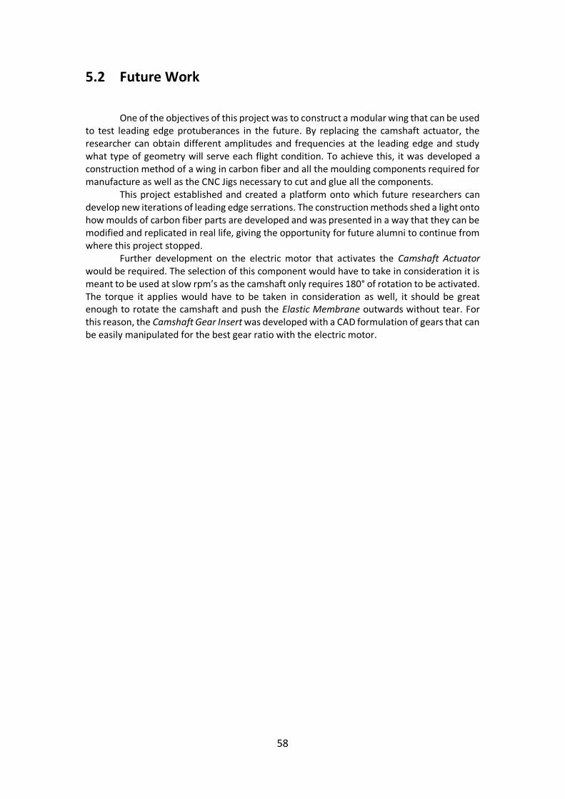
58
5.2 Future Work
One of the objectives of this project was to construct a modular wing that can be used
to test leading edge protuberances in the future. By replacing the camshaft actuator, the researcher can obtain different amplitudes and frequencies at the leading edge and study what type of geometry will serve each flight condition. To achieve this, it was developed a construction method of a wing in carbon fiber and all the moulding components required for manufacture as well as the CNC Jigs necessary to cut and glue all the components.
This project established and created a platform onto which future researchers can develop new iterations of leading edge serrations. The construction methods shed a light onto how moulds of carbon fiber parts are developed and was presented in a way that they can be modified and replicated in real life, giving the opportunity for future alumni to continue from where this project stopped. Further development on the electric motor that activates the Camshaft Actuator would be required. The selection of this component would have to take in consideration it is meant to be used at slow rpm’s as the camshaft only requires 180° of rotation to be activated. The torque it applies would have to be taken in consideration as well, it should be great enough to rotate the camshaft and push the Elastic Membrane outwards without tear. For this reason, the Camshaft Gear Insert was developed with a CAD formulation of gears that can be easily manipulated for the best gear ratio with the electric motor.

59
Bibliography [1][45] Accessed on March 2018, Kerry Reals, FlightGlobal, DVV Media International, London, UK, August 2010 URL https://www.flightglobal.com/news/articles/aircraft-engineers-turn-to-biomimicry-for-greener-de-345833/ [2] Fish, F., The myth and reality of Gray’s paradox: implication of dolphin drag reduction for technology, Bioinspiration & Biomechanics, 1, R17-R25, 2006. [3] Bushnell, D.M. & Moore, K.J., Drag reduction in nature, Annu. Rev. Fluid. Mech., 23, 65-79, 1991. [4] Anderson, E., et al., The boundary layer of swimming fish, The Journal of Experimental Biology, 204, 81-102, 2001. [5] Lang, A., et al., Shark Skin Separation Control Mechanism, Marine Technology Society Journal, 45 (4), 208-2, 2011. [6] Rosen, Moe Wm., Cornford, Neri E., Fluid friction of the slime of aquatic animals, Fleet Engineering Department, November 1970. [7] Nurxat Nuraje, et al., Superhydrophobic electrospun nanofibers, Journal of Materials Chemistry A, 2013. [8] M. O., Kramer, Boundary layer stabilization by distributed damping, J. Am. Soc. Nav. Eng. 72 25–33, 1960. [9] Bechert, D., et al., Fluid Mechanics of Biological Surfaces and their Technological Application, Naturwissenschaften , 87, 157-171,2000. [10] Essapian F. S., Speed-induced skin folds in the bottle-nosed porpoise, Tursiops. truncatus. Breviora Mus. Comp. Zool. 43 1–4, 1995. [11] Zhixia He, Study of the effect of nozzle hole shape on internal flow and spray characteristics, International Communications in Heat and Mass Transfer, December 2015. [12] M. O., Kramer, The dolphins’ secret, New Sci. 7 1118–20, 1960. [13] Lang, A., et al., Bristled shark skin: a microgeometry for boundary layer control, Bioinspration & Biomimetics, 3, 1-9, 2008. [14] Barthlott W, Neinhuis C., Planta. 1997;202:1–8. doi: 10.1007/s004250050096. [15] Fish, F. E. and Battle, J. M., Hydrodynamic Design of the Humpback Whale Flipper, Journal of Morphology, Vol. 225, 1995.

60
[16] Miklosovic, D. S., Murray, M. M., and Howle, L. E, Experimental Evaluation of Sinusoidal Leading Edges, Journal of Aircraft; Engineering Notes, Vol. 44, No. 4, pp. 1404-1407, July/August 2007. [17] Miklosovic, D. S., Murray, M. M., Howle, L. E., and Fish, F. E., Leading-edge Tubercles Delay Stall on Humpback Whale (Megaptera novaeangliae) Flippers, Physics of Fluids, Vol. 16, No. 5, pp. L39-42, May 2004. [18] Murray, M. M., Miklosovic, D. S., Fish, F. E., and Howle, L., Effects of Leading Edge Tubercles on a Representative Whale Flipper Model at Various Sweep Angles, Proceedings of Unmanned Untethered Submersible Technology (UUST), UUST05, Durham, New Hampshire, August 2005. [19] Custodio, Derrick, The effect of Humpback Whale-like Leading Edge Protuberances on Hydrofoil Performance, Worcester Polytechnic Institute, December 2007. [20] Talbot Lago – T150SS ‘Teardrop’ Coupe, Accessed on October 2019, URL https://www.louwmanmuseum.nl/ontdekken/ontdek-de-collectie/talbot-lago-t150-ss-teardrop-coupe-figoni-and-falaschi [21] Humpback whale fin, Accessed October 2019, URL https://asknature.org/strategy/flippers-provide-lift-reduce-drag/ [22] Humpback whale hunting, Accessed October 2019, URL https://cosmosmagazine.com/biology/humpback-whale-hunt-krill-with-bubbles [23] Shark skin application, Accessed on March 2018, Lufthansa Technik, URL http://www.lufthansa-technik.com/. [24] Shark skin application, Accessed on March 2018, Airbus, URL http://www.airbus.com. [25] Shark skin application, Accessed on March 2018, Fraunhofer Institute, URL http://www.fraunhofer.de/en.html. [26][22] AR5 Evolution aircraft specifications, Accessed on March 2018, Tekever, URL http://www.tekever.com. [27] [23] Drela, M., XFOIL: An Analysis and Design System for Low Reynolds Number Airfoils, Conference on Low Reynolds Number Airfoil Aerodynamics, University of Notre Dame, June 1989. [28][24] T.J. Mueller, Low Reynolds Number Aerodynamics, Lecture Notes in Engineering #54, Springer Verlag, 1989. [29][25] Drela, M. and Giles, M.B., Viscous-Inviscid Analysis of Transonic and Low Reynolds Number Airfoils, AIAA Journal, 25(10), pp.1347-1355, October 1987. [30][26] Drela, M., Integral Boundary Layer Formulation for Blunt Trailing Edges, Paper AIAA-89-2166, August 1989.

61
[31] Images of winglets and bird of prey source, Accessed on March 2018, URL https://www.youtube.com/watch?v=FNqXf6t7e-w [32] Drag force vs Flight Velocity graphic/image source, Accessed on September 2019, URL https://en.wikipedia.org/wiki/Parasitic_drag#/media/File:Drag_curves_for_aircraft_in_flight.svg [33][27] Carbon fiber Prepreg, Accessed on August 2019, Rock West Composites, URL http://www.rockwestcomposites.com. [34][28] Carbon fiber Prepreg, Accessed on August 2019, Easy Composites UK, URL http://www.easycomposites.co.uk. [35][29] Gear standardization, Accessed on September 2019, KHK Stock Gears, URL http://www.khkgears.net/new/. [36][30] Gear standardization, Accessed on September 2019, Standard Gears Index, E. Fox Engineers, URL http://www.efox.ie/PDF%20Catalogues/CROSS%20AND%20MORSE/C&M%20StandardGears.pdf. [37][31] Nomenclature, gearing and standardization, Accessed on September 2019, American Standard (ANSI), American Metric Corporation, URL http://www.ametric.com. [38][32] Mechanical cleaner for gliders leading edge, Accessed in March 2018, BWS Pirker & Storka, URL http://www.storka.at/english/bws-flexi-bugwiper/. [39][33] Shark skin surfaces, Accessed on March 2018, Sharklet, URL http://www.sharklet.com. [40][34] Shark skin surfaces, Accessed on March 2018, Sappi North America, URL http://www.prnewswire.com/news/sappi-north-america. [41][35] Fixtures, dowels and bolts CAD, Accessed on September 2019, Meusburger, URL http://www.meusburger.com. [42][36] Keenserts and fixtures, Accessed on September 2019, KVT Solutioneering, URL http://www.kvt-fastening.ch/en/products/brands/keenserts/. [43][37] Ahmed, Ashraf, et al., Study of Thermal Expansion in Carbon Fiber Reinforced Polymer Composites, Proceedings of SAMPE International Symposium. Charleston, SC, 2012. [44][38] Biomimicry concepts, Accessed on March 2018, Biomimicry Institute, URL http://www.biomimicry.org. [45][39] Benyus, Janine M., Biomimicry Innovation Inspired by Nature, Harper Perennial, 2002. [46][40] Resin structural moulds, Accessed on October 2019, GE Plastics, Resin Structural Foam Mould, URL http://www.fmcorp.com/downloads/designguide.pdf.

62
[47][41] Prepreg carbon fiber, Accessed on October 2019, HexForce® Fabric and HexPly® Prepreg Selector Guides for Aerospace and Industrial, URL http://www.hexcel.com/resources/selector-guides.com. [48][42] Mould Foaming, Accessed on October 2019, Dalchem, Moulding and casting supplies, URL http://www.dalchem.com.au/product/polyurethane-foam/flexible-polyurethane-foam.html. [49][43] Brederode, Vasco de, Fundamentos de Aerodinâmica Incompressível, -1ªed., Edição do Autor, Lisboa, 1997 [50][44] Tucker, Vance A., Gliding Birds: Reduction of Induced Drag by Wing Tip Slots Between the Primary Feathers, Department of Zoology, Duke University, Durham, NC 27706, USA, March 1993 [51][46] Airfoil plotter, Accessed on March 2018, XFOIL plotter, URL http://airfoiltools.com/ [52][47] Gearing formulation and standardization, Accessed on September 2019, TechMiny, URL https://techminy.com/gear-types-nomenclature-manufacturing/ [53] Image of sparrow source, Accessed on March 2018, URL https://www.pinterest.com/pin/3096293467271091/ [54] Image of robin bird source, Accessed on October 2019, URL http://www.bbc.com/earth/story/20150230-a-hovering-robin [55] Image of Supermarine Spitfire source, Accessed on October 2019, URL https://www.quora.com/World-War-2-What-was-that-box-under-the-wing-of-some-Supermarine-Spitfire-models [56] Image of VH2 Streamline source, Accessed on October 2019, URL http://www.aircraftstudiodesign.com/blog/category/aircraft-concept-design/ [57] Image of Swift and Swallow source, Accessed on September 2019, URL https://eden.uktv.co.uk/animals/birds/article/swifts-and-swallows/ [58] Image of Falcon source, Accessed on September 2019, URL https://eden.uktv.co.uk/animals/birds/article/peregrine-falcons/ [59] Image of Duck wings source, Accessed on September 2019, URL https://www.hunter-ed.com/wildlife/waterfowl.htm [60] Image of General Dynamics F-111 source, Accessed on September 2019, URL https://wofmd.com/2018/09/07/general-dynamics-f-111g-fb-111/ [61] Image of F-15 source, Accessed on October 2019, URL https://edition.cnn.com/2011/12/29/world/meast/u-s--saudi-fighter-sale/index.html [62] Image of Tern source, Accessed on March 2018, URL https://bioone.org/journals/bulletin-of-the-british-ornithologists-club/volume-138/issue-

63
2/bboc.v138i2.2018.a5/Notable-recent-records-of-terns-gulls-and-skuas-in-southern/10.25226/bboc.v138i2.2018.a5.full [63] Image of Albatross source, Accessed on September 2019, URL https://stillnotfussed.com/the-loneliness-of-the-galapagos-albatross-waiting-for-his-life-long-mate-to-arrive/ [64] Image of Gannet source, Accessed on September 2019, URL https://www.allaboutbirds.org/guide/Northern_Gannet/id [65] Image of Frigate source, Accessed on September 2019, URL https://www.hbw.com/ibc/photo/magnificent-frigatebird-fregata-magnificens/female-flight-1 [66] Image of Carat A source, Accessed on September 2019, URL https://www.pilotmix.com/carat-a [67] Image of Bombardier Q400 source, Accessed on September 2019, URL https://www.aircraftcompare.com/aircraft/bombardier-q400/ [68] Image of Turkey Vulture source, Accessed on September 2019, URL https://en.wikipedia.org/wiki/File:Turkey_Vulture_In_Flight_SoCal_2007.jpg [69] Image of Red-tailed Hawk source, Accessed on September 2019, URL https://ebird.org/species/rethaw [70] Image of American White Pelican source, Accessed on September 2019, URL https://fineartamerica.com/featured/american-white-pelican-wings-marilyn-hunt.html [71] Image of Bald Eagle source, Accessed on September 2019, URL https://www.chesapeakebay.net/S=0/fieldguide/critter/bald_eagle [72] Image of Lockeed Martin C-130 source, Accessed on September 2019, URL https://www.upi.com/Top_News/US/2016/04/19/Deadly-Air-Force-cargo-plane-crash-blamed-on-goggles-case/3631461083418/

64
Appendix A 2D Drawings

65
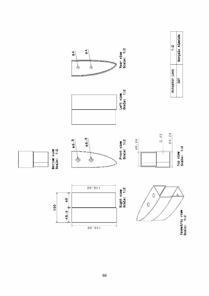
66

67

68

69

70

71

72

73

74

75