Design and Implementation of Audiometric Instrument Based ...
12
Journal of Engineering and Development, Vol. 71, No.7, Mar. 3172, ISSN 7172- 1133 84 Design and Implementation of Audiometric Instrument Based on Microcontroller Lecturer Ali Abdul Elah Noori Assist. Lecturer Malik Bahnam Abbu Samter College of Electrical and Electronics Techniques College of Electrical and Electronics Techniques Foundation of Technical Education, Bagdad, Iraq Foundation of Technical Education, Bagdad, Iraq [email protected] [email protected] Assist. Lecturer Ghaidaa Abdulrahmaan Khalid College of Electrical and Electronics Techniques Commission of Technical Education, Bagdad, Iraq Ghaidaa58@yahoo.com Abstract The aim of this paper is to design and implement an audiometry testing instrument (Audiometer) by using PIC61F588A microcontroller that has the capability to apply an audio sound to the patients’ ear with a frequency range of ( 082Hz to 5KHz) with an intensity ranging from (-62 to 662 dB), and recording the patients’ response through an input device. The instrument hardware was implemented by using a push button switch, headphone circuit, power supplies, two output units using 0 X 61 LCD display and RS030 serial port interface connected with Personal Computer (PC) from through the ports COM6 or COM0 and microcontrollers programmer with its special program (Topwin1). The proposed design of audiometer and simulation results of many cases of hearing states are carried out using ISIS 8 professional simulator and Matlab 0262 environment. Finally, Proton IDE Basic compiler (high level language) is used to write a program which is employed to program microcontroller. Keywords: Audiometry; PIC61F588A Microcontroller. السمع وتنفيذ جهاز مقياسييم تصمعتماد بايقى المسيطر الدق علصة الخييم وتنفيذن هذا البحث هو تصم الهدف م جهاز ا ختبار السمع) السمعمقياس( ييق المسيطر الدقستخدام باPIC61F588A رددات من مدى من الترسال 02Hz-02KHz ردداتذه الت لهستجابتهريض ومعرفة ا الى الم منلجهازلمادي ليم انجز التصمخراج. يل وحدات ا خيق مسيطر دقستخدام باPIC61F588A د, مفاتيح ضغط, واحلسماعة, دائرة اج ؛ عارضةة وحدتين اخرا مجهزات القدرLCD منفذ التوالي و030 RS ربوط مع المسب الشخصيلحا ا(PC) لمنافذل ا من خCOM6 اوCOM0 لخاص ايقة مع برنامجهاجة المسيطرات الدق ومبرم(Topwin1) .
-
Upload
khangminh22 -
Category
Documents
-
view
0 -
download
0
Transcript of Design and Implementation of Audiometric Instrument Based ...

Journal of Engineering and Development, Vol. 71, No.7, Mar. 3172, ISSN 7172- 1133
84
Design and Implementation of Audiometric Instrument
Based on Microcontroller
Lecturer Ali Abdul Elah Noori Assist. Lecturer Malik Bahnam Abbu Samter
College of Electrical and Electronics Techniques College of Electrical and Electronics Techniques
Foundation of Technical Education, Bagdad, Iraq Foundation of Technical Education, Bagdad, Iraq
[email protected] [email protected]
Assist. Lecturer Ghaidaa Abdulrahmaan Khalid
College of Electrical and Electronics Techniques
Commission of Technical Education, Bagdad, Iraq
Abstract
The aim of this paper is to design and implement an audiometry testing instrument
(Audiometer) by using PIC61F588A microcontroller that has the capability to apply an
audio sound to the patients’ ear with a frequency range of (082Hz to 5KHz) with an
intensity ranging from (-62 to 662 dB), and recording the patients’ response through an
input device. The instrument hardware was implemented by using a push button switch,
headphone circuit, power supplies, two output units using 0 X 61 LCD display and RS030
serial port interface connected with Personal Computer (PC) from through the ports COM6
or COM0 and microcontrollers programmer with its special program (Topwin1).
The proposed design of audiometer and simulation results of many cases of hearing
states are carried out using ISIS 8 professional simulator and Matlab 0262 environment.
Finally, Proton IDE Basic compiler (high level language) is used to write a program which
is employed to program microcontroller.
Keywords: Audiometry; PIC61F588A Microcontroller.
على المسيطر الدقيق باالعتمادتصمييم وتنفيذ جهاز مقياس السمع
الخالصة
باستخدام المسيطر الدقيق ي )مقياس السمع(السمع ختبارالاجهاز الهدف من هذا البحث هو تصمييم وتنفيذ
PIC61F588A 02الرسال مدى من الترددات منHz-02KHz من الى المريض ومعرفة استجابته لهذه الترددات
واحد, مفاتيح ضغط, PIC61F588A باستخدام مسيطر دقيق خالل وحدات االخراج. ي نجز التصميم المادي للجهاز
المربوط مع 030RS ومنفذ التوالي LCD مجهزات القدرة وحدتين اخراج ؛ عارضة دائرة السماعة,
ومبرمجة المسيطرات الدقيقة مع برنامجها الخاص COM0او COM6من خالل المنافذ (PC) الحاسب الشخصي
(Topwin1).
Journal of Engineering and Development, Vol. 71, No.7, Mar. 3172, ISSN 7172- 1133
84
ISIS 8 باستخدام المحاكي من حاالت السمع لعدة حاالت ونتائج المحاكاة مقياس السمعلجهاز ي نفذ التصميم المقترح
Professional بيئة برنامج وMatlab0262 . ي ست عمل برنامجProton IDE Basic لغة المستوى العالي( لك تاب ة(
ة م ج المسيطر الدقيق. البرنامج الذي ي ستخدم لب ر
7. Introduction
An audiometer is used to measure the ability of a patient to hear at specific frequencies.
Fundamental to this measurement is pure tone measurement. The audiometer is used to
generate pure tone signals at specific frequencies within the 052 Hz to 8 kHz range. For each
frequency the level of loudness is incremented from soft to loud. The patient is asked at which
point he/she starts to hear the sound, which will then represent the patient’s hearing threshold
at that frequency. The final result is plotted as an audiogram that will be interpreted by
medical professionals to determine proper treatments [1].
The weakest sound heard at a selected frequency is the hearing level in decibels (dB HL)
for that particular frequency. This is a relative value; the intensity reference is 2 dB HL, or
audiometric 2, which corresponds to the average threshold response (for a normal intensity
range of -12 to +05 dB HL) of a group of 18- to 05-year-olds with no otologic pathology. The
sensitivity of the normal ear varies with frequency; therefore, 2 dB HL represents different
levels of sound pressure at different frequencies. (Minus dB HL readings indicate that hearing
sensitivity is greater for that particular frequency than for the average value) [0].
At present, there are various types of audiometer readily available on the market. They
can be different depending on the specifications and features, but generally a dedicated
hardware is needed for high-quality and reliable measurements, resulting in high price. In
terms of research, historically the earlier work focused on hardware implementation, usually
at the integrated circuit (IC) or embedded system levels [3, 4]. Techniques such as direct
digital synthesis (DDS) have been considered [5]. As the availability of good-quality personal
computer expanded, the focus has shifted towards PC-based systems [6]. Some has also
attempted on integrating other hearing loss measurement features into the same device [7, 8,
9]. Finally, remote hearing scanning and active noise control based on PC have introduced in
[1, 12] respectively.
The PIC16F877A microcontroller is manufactured by Microchip [11]. Currently they are
one of the most popular microcontrollers, used in many audio applications [10-14]. This PIC
has chosen to manufacture audiometric test for reasons of generating high precision and
flexible pure-tone signal, digitally programmable, (frequency and amplitude of a waveform
can be easily adjusted without the need to change the hardware components), in addition to;
speed, digital ports ability, memory storage, and number of I/O (input or output) ports. This
proposed system contains on push bottom switches, headphone circuit, display output units
0 LCD design and serial communication design based on PIC16F877A microcontroller.
This paper is organized as follows: The hardware design for audiometric test is first
introduced in Section 0, the software and simulink design is then described in Section 3,

Journal of Engineering and Development, Vol. 71, No.7, Mar. 3172, ISSN 7172- 1133
05
Testing and results are discussed in Section 4, and finally, concluding remarks and
observations are given in Section 5.
3. Hardware Design
The block diagram of the proposed hardware which consists of five basic parts is shown
in Fig. (1).
1. PIC16F877A Microcontroller.
0. Switches selection circuit.
3. Headphone circuit.
4. Output units.
5. Power supplies.
Fig. (7) Block diagram audiometric test based on PIC71F111A microcontroller.
3.7. PIC71F111A Microcontroller
Suitable for various digital applications, the PIC16F877A RISC microcontroller has five
I/O port (33 lines), flash program memory, EEPROM data memory, three
timer an 8 bit timer/counter and 12-bit ADC, at a clock rate of 02MHz, which is obtained by
connecting a crystal oscillator between OSC1 and OSC0 pins with two 00pF capacitors. The
built in power on reset circuitry provides a safe start-up, therefore the Master Clear pin
(MCLR) is connected to reset circuit. The pin diagram of PIC16F84 is shown in Fig. (1) [15].
3.3. Switches Selection and Patient Circuit
The push bottom switches S1 to S8 are connected to microcontroller port B (RB2-RB7)
to select the range of frequencies from 02Hz-02KHz. S9 is connected to pin to reset
the microcontroller and S12 is connected to the pin RD6 to know patient’s response, which is
displayed in LCD or PC as message “The sound is Heard” in addition to light green LED
connected to the pin RD7. The connections of push bottom switches are illustrated in Table
(1).

Journal of Engineering and Development, Vol. 71, No.7, Mar. 3172, ISSN 7172- 1133
05
Table (7) connections of push bottom switches with the PIC71F111A
microcontroller pins.
Switches PIC pin Pin No. Function
S1 RB2 (input pin) 33 Select 052Hz
S0 RB1 (input pin) 34 Select 522Hz
S3 RB0 (input pin) 35 Select 1222Hz
S4 RB3 (input pin) 36 Select 0222Hz
S5 RB4 (input pin) 37 Select 3222Hz
S6 RB5 (input pin) 38 Select 4222Hz
S7 RB6 (input pin) 39 Select 6222Hz
S8 RB7 (input pin) 42 Select 8222Hz
S9 pin 1 Reset circuit
S12 RD6 (input pin) 05 Patient’s response
Green LED RD7 (output pin) 06 Patient’s response
Fig. (3) Pin connection of PIC71F111A.
3.2. Headphone Circuit
The headphone circuit consists of three main parts; RC filtration, attenuation circuit and
audio amplification. The PIC16F877A microcontroller generates a signal with one or two
different frequencies on the specified PIN by using “Freqout” instruction. The generated
signal is a square wave and filtering may be required to obtain a smooth signal and to remove
the quantization noise are the attenuation module and amplification module. The attenuation
circuit is implemented using a 6-stage (- 82, -42, -02, -12, -5, -0.5 dB) logarithm resistive

Journal of Engineering and Development, Vol. 71, No.7, Mar. 3172, ISSN 7172- 1133
05
ladder network to achieve the 102 dB (-12 dB to 112 dB) dynamic range with a step
resolution of 5 dB [8].
Since, the amplitude of the output signal may not be adequate, the audio amplification
module is required to provide sufficient current drive and to match the load resistance of the
audiometric headphone at 37 Ω [8].
3.2. Output Unit
Two output units were used in this paper, LCD and RS030 serial port. The LCD
is alphanumeric display, which is frequently used in microcontroller-based applications. Some
of the advantages of LCDs are their low cost and low power consumption. (SC160C) is one
of the most popular LCD modules used in the industry and also by hobbyists. The circuit
diagram of the LCD and the PIC16F877A microcontroller is shown in Fig. (3) [16]
Fig. (2) circuit diagram between the LCD and the PIC71F111A microcontroller.
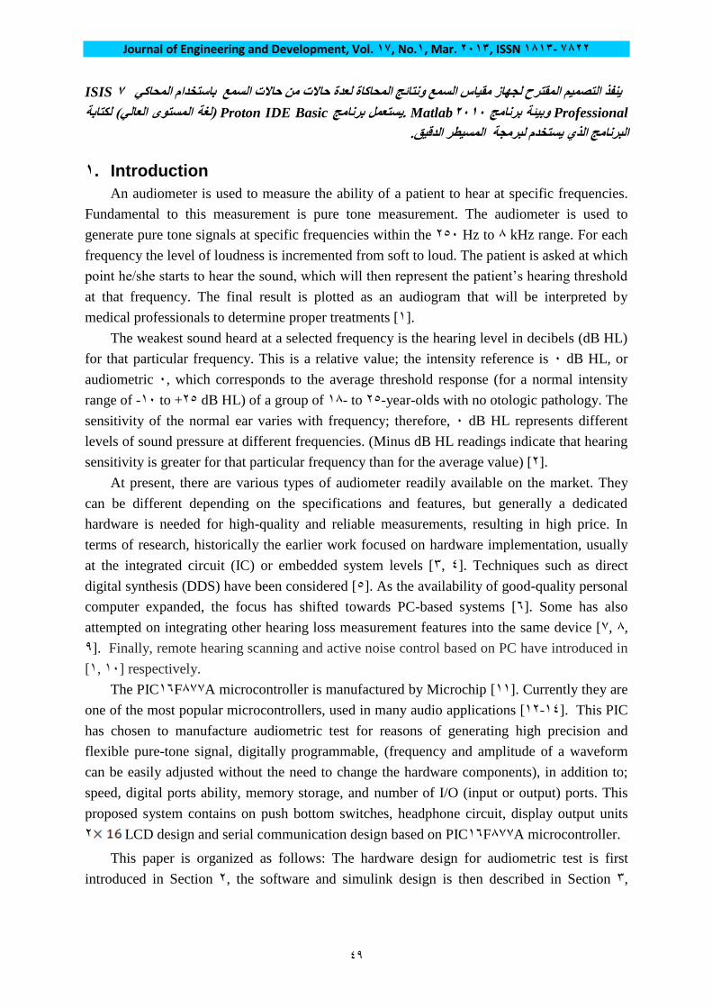
In addition LCD output unit, the RS030 serial port can be connected in this instrument.
The pins RC6 and RC7 of the PIC16F877A are configured as RS030 serial output and input,
respectively. RS030 voltage levels are 10V. Normally RS030 voltage levels are converted
to CMOS levels using RS030-level converter chips, such as the MAX030 .An RS030-level
converter chip converts the 2 to +5 V output from the microcontroller into 10V RS030
levels. Similarly, the RS030-level output from a device is converted into 2 to +5 V suitable
for the microcontroller inputs. MAX030 is a 16-pin IC having dual RS030 transmitters and
receivers. This IC requires external capacitors for its operation to adjust the voltage level
differences between the PC-based logic and the PIC-based logic as shown in Fig. (4) [17].
Journal of Engineering and Development, Vol. 71, No.7, Mar. 3172, ISSN 7172- 1133
05
Fig. (2) MAX323 RS323-level converter.
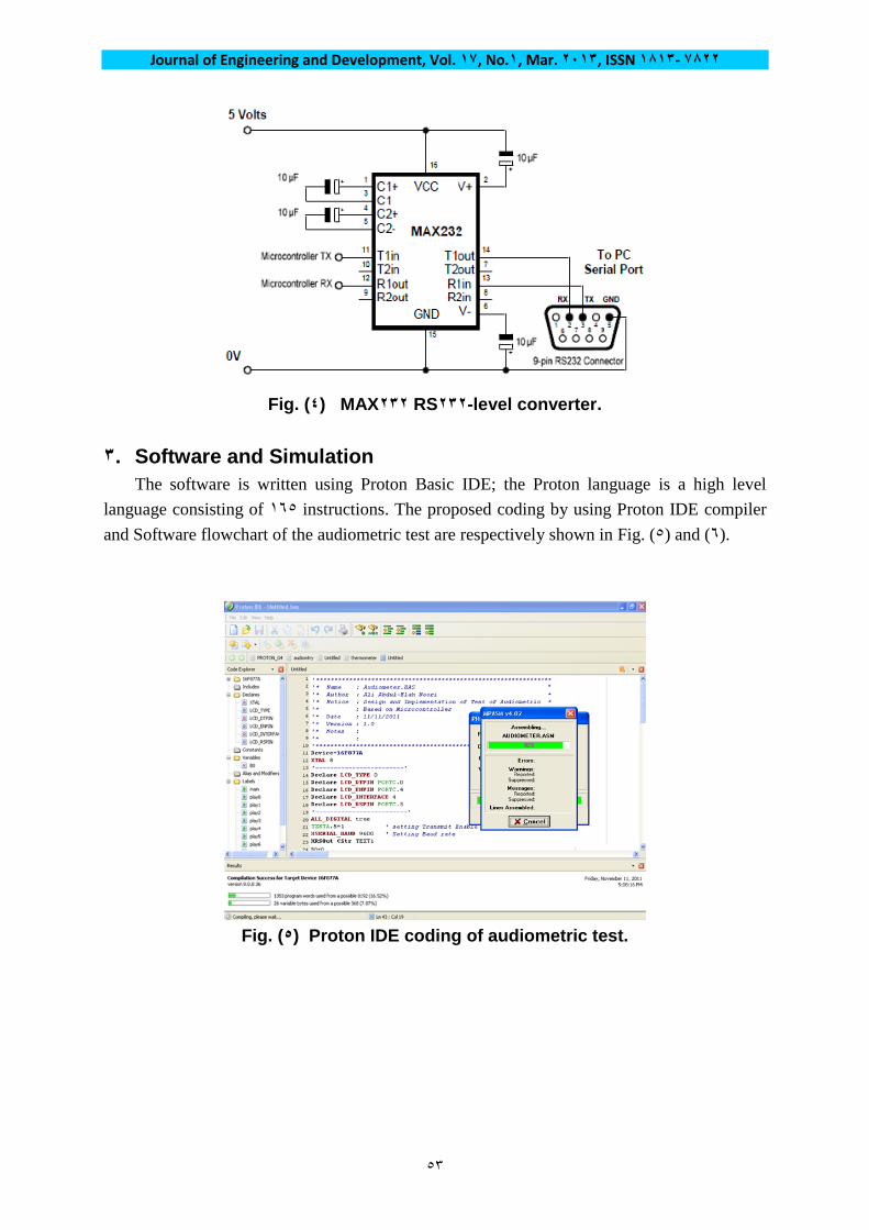
2. Software and Simulation
The software is written using Proton Basic IDE; the Proton language is a high level
language consisting of 165 instructions. The proposed coding by using Proton IDE compiler
and Software flowchart of the audiometric test are respectively shown in Fig. (5) and (6).
Fig. (5) Proton IDE coding of audiometric test.
Journal of Engineering and Development, Vol. 71, No.7, Mar. 3172, ISSN 7172- 1133
08
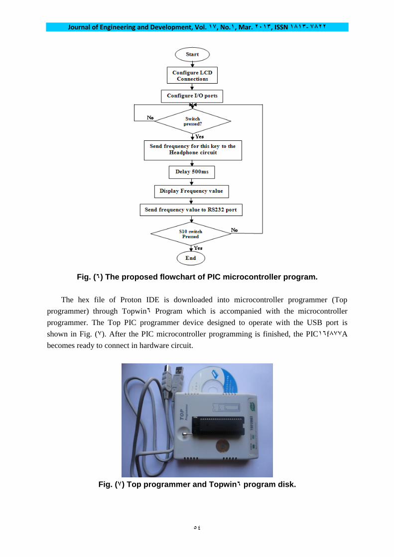
Fig. (1) The proposed flowchart of PIC microcontroller program.
The hex file of Proton IDE is downloaded into microcontroller programmer (Top
programmer) through Topwin6 Program which is accompanied with the microcontroller
programmer. The Top PIC programmer device designed to operate with the USB port is
shown in Fig. (7). After the PIC microcontroller programming is finished, the PIC16f877A
becomes ready to connect in hardware circuit.
Fig. (1) Top programmer and Topwin1 program disk.
Journal of Engineering and Development, Vol. 71, No.7, Mar. 3172, ISSN 7172- 1133
00
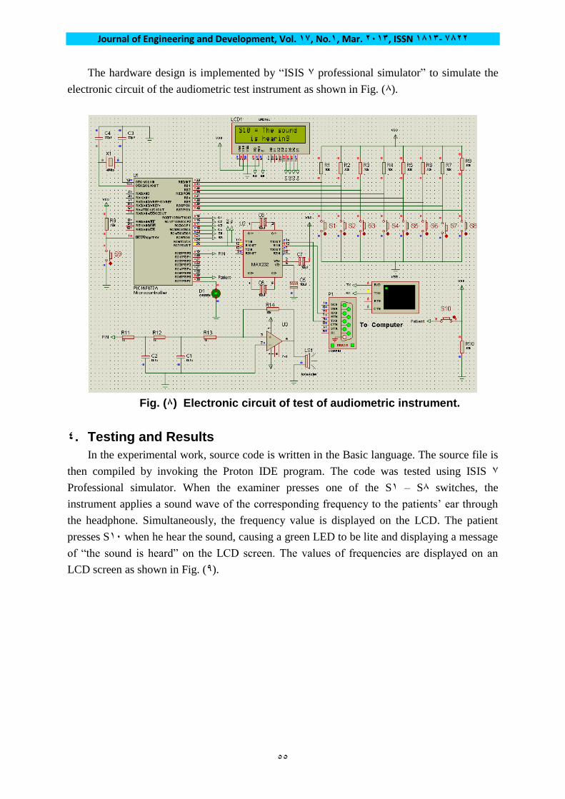
The hardware design is implemented by “ISIS 7 professional simulator” to simulate the
electronic circuit of the audiometric test instrument as shown in Fig. (8).
Fig. (1) Electronic circuit of test of audiometric instrument.
2. Testing and Results
In the experimental work, source code is written in the Basic language. The source file is
then compiled by invoking the Proton IDE program. The code was tested using ISIS 7
Professional simulator. When the examiner presses one of the S1 – S8 switches, the
instrument applies a sound wave of the corresponding frequency to the patients’ ear through
the headphone. Simultaneously, the frequency value is displayed on the LCD. The patient
presses S12 when he hear the sound, causing a green LED to be lite and displaying a message
of “the sound is heard” on the LCD screen. The values of frequencies are displayed on an
LCD screen as shown in Fig. (9).

Journal of Engineering and Development, Vol. 71, No.7, Mar. 3172, ISSN 7172- 1133
05
Fig. (9) Frequencies values display in LCD after pressing on different switches.
In addition LCD output unit, the RS030 serial port can be connected with COM1 or
COM0 in PC to display values of frequencies through “Smarterm terminal emulation
program”. This program can be activated on the PC to communicate with the audiometric
instrument. The frequency range obtained is shown in Fig. (12) when the SmartTerm terminal
emulation program is used.
Fig. (71) Frequencies values display in PC after pressing on different switches
The simulation results of audiometer cases by using the proposed hardware are
implemented in environment of Matlab 0212 program to examine the left and right ear in
different case of hearing as shown in Fig. (11)

Journal of Engineering and Development, Vol. 71, No.7, Mar. 3172, ISSN 7172- 1133
05
(a)
(b)
(c)
(d)
Fig. (77) Haering cases: (a) Normal case, (b) Sensonural hearing loss case,
(c) Conductive hearing loss case, (d) Mixed hearing loss case.

Journal of Engineering and Development, Vol. 71, No.7, Mar. 3172, ISSN 7172- 1133
04
5. Conclusions
Many conclusions can be derived in this paper; the most important results can be
summarized as follows:
a. The audiometric instrument based on PIC microcontroller has been designed and
implemented successfully. The simulation and hardware implementation results have
been presented to verify the feasibility of the system.
b. Using PIC microcontroller unit, the frequency range and amplitude can be easily changed
through programming without further hardware changes or by increasing push bottom
switches connected to PIC microcontroller.
c. The audiometric testing instrument based on PIC microcontroller offers high performance
at low cost, and hence is suitable for commercial and industrial applications.
d. The audiometric testing instrument based on PIC microcontroller is portable and easy to
use.
References
[1] A. Hemakom, A. Noymai, P. Israsena, S. Boonyanukul & C. Chinnarat,” Remote Hearing
Screening As Part of Auditory Telerehabilitation; A Preliminary Report” International
Conference on Virtual Rehabilitation, 07 – 09 June, 0211.
[0] Bulletin, Audiometric Testing: Information for Employers and Workers, Alberta, January
0228. http://industry.alberta.ca/whs-ohs
[3] M. Maloberti, S. Brigati, F. Francesconi, G. Grassi, D. Lissoni, P. Malcovati, A. Nobile,
& Poletti, “An 2.8 m CMOS Mixed Analog Digital Integrated Audiometric System”
Proc. IEEE Solid-State Circuits Conference, , 1998, pp. 116 – 117.
[4] P. Malcovati, “Design of Integrated Circuits for Audiometric Applications”, Proc. IEEE
International Symposium on Circuits and Systems, , 0221, pp. 171 – 174.
[5] H.C. Wu, L.P. Yang, C.H. Chen, S.T. Young, & T.S. Kuo, “A Low-cost Architecture of
Audiometer Based on Direct Digital Synthesizer”, Proceedings of The first Joint
BMES/EMBS Conferences Serving Humanity, Advancing Technology. Vol. 0, Octuber,
1999, pp. 894, 13-16.
[6] C.A. Martinez-Baez, L.F. Borjon, & A. Noyola, “Manual And Automatic Programmable
Audiometer”, Proc. IEEE Inter Conf on Engineering in Medicine and Biology Society,
Vol. 13, 1991 , pp. 1915 – 1916.
[7] K. Kochanek, L. Sliwa, J. Zajac, & H. Skarzynski, “A Universal Computer Audiometer
for Objective Hearing Testing and Screening,” Proc. Medical Measurement and
Applications, pp. 1 – 3, 0227.
[8] S. L. Tan, S. K. Loh, & W. C. Chee, “Speech-Enabled Pure Tone Audiometer”, Proc.
IEEE Intelligent Signal Processing and Communication Systems, pp. 361 – 364, 0227.
[9] Y. Faycal, B. Wahiba, B. Lotfi, B. Ratiba, & A. Benia, “Computer Audiometer for
Hearing Testing”, Proc. Advances in Electronics and Micro-electronics, 0228, pp. 111 –
114.

Journal of Engineering and Development, Vol. 71, No.7, Mar. 3172, ISSN 7172- 1133
04
[12] D. Azeez, M. A. Ali, H, Husain, G. K. Beng, C. Umat & R. Mustafa, “Implementation
of Active Noise Control for Hearing Test Application Using PC” International
Conferernce on Instrumentation, Communication, Information Technology and
Biomedical Enginerring, pp. 1-4, 0229.
[11] Website of Microchip Technology, Inc. http://www.microchip.com/1212/index.htm,
[10] A. Lay-Ekuakille, G. Vendramin1, & A. Trotta, “Design of an Energy Harvesting
Conditioning Unit for Hearing Aids” 32th Annual International IEEE EMBS
Conference, pp. 0312-1013, 02-04 August, 0228
[13] K. R. Kumer, & R. Seetha, “Development of Reciver Stimulator For auditory Prosthesis”
Internation Journal of Computer Science Issues, Vol. 7, No. 3, 0212, pp. 03-09.
[14] Cheng-Yuan Chang & Sheng-Ting Li, “Active Noise Control in Headsets by Using a
Low-Cost Microcontroller” IEEE Transations on Industrial Electronics, Vol. 58, No. 5,
, May 0211, pp. 1936-1940.
[15] A. V. Deshmukh, Microcontrollers Theory And applications, Tata McGraw-Hill, 0225.
[16] I, Dogan, PIC BASIC Projects Using PIC BASIC and PIC BASIC PRO, ELSEVIER,
0226.
[17] S. Lee, Y. Li, & V. Kapila, “Development of a Matlab-Based Graphical User Interface
Environment for PIC Microcontroller Projects” American Society for Engineering
Education Annual Conference & Exposition, S. 0002, 0224.