Design 3 ArchitecturePC - Westmoreland County
330
PROJECT MANUAL April 2017 For WESTMORELAND COUNTY 911 FACILITY HVAC 911 Public Safety Road Greensburg, PA 15601 Design 3 Architecture PC www.d3a.com 300 Oxford Drive, Suite 120 TEL: 412-373-2220 Monroeville, Pennsylvania 15146-2361 FAX: 412-373-4571
-
Upload
khangminh22 -
Category
Documents
-
view
1 -
download
0
Transcript of Design 3 ArchitecturePC - Westmoreland County
PROJECT MANUAL
April 2017
For
WESTMORELAND COUNTY 911 FACILITY
HVAC
911 Public Safety Road Greensburg, PA
15601
Design 3 Architecture PC www.d3a.com300 Oxford Drive, Suite 120 TEL: 412-373-2220 Monroeville, Pennsylvania 15146-2361 FAX: 412-373-4571

(THIS PAGE INTENTIONALLY LEFT BLANK)
Westmoreland County 911 Facility – HVAC D3A Project #2015-46.01 – April 2017 911 Public Safety Road, Greensburg, PA Design 3 Architecture, PC
PROJECT IDENTIFICATION Page 1 of 1
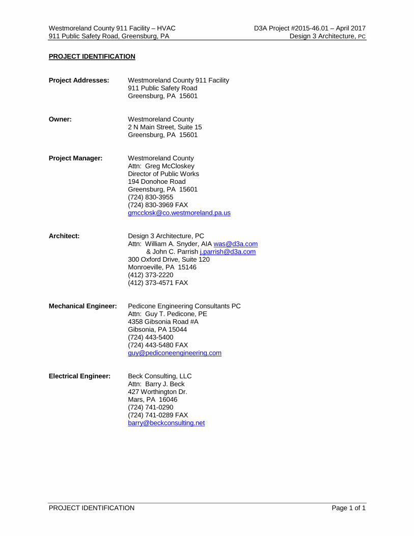
PROJECT IDENTIFICATION
Project Addresses: Westmoreland County 911 Facility 911 Public Safety Road Greensburg, PA 15601 Owner: Westmoreland County 2 N Main Street, Suite 15 Greensburg, PA 15601 Project Manager: Westmoreland County Attn: Greg McCloskey Director of Public Works 194 Donohoe Road Greensburg, PA 15601 (724) 830-3955 (724) 830-3969 FAX [email protected] Architect: Design 3 Architecture, PC Attn: William A. Snyder, AIA [email protected] & John C. Parrish [email protected] 300 Oxford Drive, Suite 120 Monroeville, PA 15146 (412) 373-2220 (412) 373-4571 FAX Mechanical Engineer: Pedicone Engineering Consultants PC Attn: Guy T. Pedicone, PE 4358 Gibsonia Road #A Gibsonia, PA 15044 (724) 443-5400 (724) 443-5480 FAX [email protected] Electrical Engineer: Beck Consulting, LLC Attn: Barry J. Beck 427 Worthington Dr. Mars, PA 16046 (724) 741-0290 (724) 741-0289 FAX [email protected]

(THIS PAGE INTENTIONALLY LEFT BLANK)
Westmoreland County 911 Facility – HVAC D3A Project #2015-46.01 – April 2017 911 Public Safety Road, Greensburg, PA Design 3 Architecture, PC
TABLE OF CONTENTS Page 1 of 3
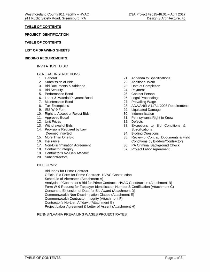
TABLE OF CONTENTS
PROJECT IDENTIFICATION
TABLE OF CONTENTS
LIST OF DRAWING SHEETS
BIDDING REQUIREMENTS:
INVITATION TO BID
GENERAL INSTRUCTIONS 1. General 2. Submission of Bids 3. Bid Documents & Addenda 4. Bid Security 5. Performance Bond 6. Labor & Material Payment Bond 7. Maintenance Bond 8. Tax Exemptions 9. IRS W-9 Form
10. Right to Accept or Reject Bids 11. Approved Equal 12. Unit Prices 13. Withdrawal of Bids 14. Provisions Required by Law
Deemed Inserted 15. More Than One Bid 16. Insurance 17. Non-Discrimination Agreement 18. Contractor Integrity 19. Contractor’s No-Lien Affidavit 20. Subcontractors
21. Addenda to Specifications 22. Additional Work 23. Date of Completion 24. Payment 25. Contact Person 26. Legal Proceedings 27. Prevailing Wage 28. ADA/ANSI A117.1-2003 Requirements 29. Liquidated Damage 30. Indemnification 31. Pennsylvania Right to Know 32. Defects 33. Exceptions to Bid Conditions &
Specifications 34. Bidding Questions 35. Review of Contract Documents & Field
Conditions by Bidders/Contractors 36. PA Criminal Background Check 37. Project Labor Agreement
BID FORMS:
Bid Index for Prime Contract Official Bid Form for Prime Contract: HVAC Construction Schedule of Alternates (Attachment A) Analysis of Contractor’s Bid for Prime Contract: HVAC Construction (Attachment B) Form W-9 Request for Taxpayer Identification Number & Certification (Attachment C) Consent to Extension of Date for Bid Award (Attachment D) Commonwealth Non-Discrimination Clause (Attachment E)
Commonwealth Contractor Integrity (Attachment F) Contractor’s No-Lien Affidavit (Attachment G) Project Labor Agreement & Letter of Assent (Attachment H)
PENNSYLVANIA PREVAILING WAGES PROJECT RATES
Westmoreland County 911 Facility – HVAC D3A Project #2015-46.01 – April 2017 911 Public Safety Road, Greensburg, PA Design 3 Architecture, PC
TABLE OF CONTENTS Page 2 of 3
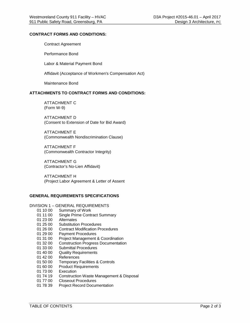
CONTRACT FORMS AND CONDITIONS: Contract Agreement Performance Bond Labor & Material Payment Bond Affidavit (Acceptance of Workmen's Compensation Act) Maintenance Bond ATTACHMENTS TO CONTRACT FORMS AND CONDITIONS: ATTACHMENT C (Form W-9) ATTACHMENT D (Consent to Extension of Date for Bid Award) ATTACHMENT E (Commonwealth Nondiscrimination Clause) ATTACHMENT F (Commonwealth Contractor Integrity) ATTACHMENT G (Contractor’s No-Lien Affidavit) ATTACHMENT H (Project Labor Agreement & Letter of Assent GENERAL REQUIREMENTS SPECIFICATIONS DIVISION 1 – GENERAL REQUIREMENTS 01 10 00 Summary of Work 01 11 00 Single Prime Contract Summary 01 23 00 Alternates 01 25 00 Substitution Procedures 01 26 00 Contract Modification Procedures 01 29 00 Payment Procedures 01 31 00 Project Management & Coordination 01 32 00 Construction Progress Documentation 01 33 00 Submittal Procedures 01 40 00 Quality Requirements 01 42 00 References 01 50 00 Temporary Facilities & Controls 01 60 00 Product Requirements 01 73 00 Execution 01 74 19 Construction Waste Management & Disposal 01 77 00 Closeout Procedures 01 78 39 Project Record Documentation
Westmoreland County 911 Facility – HVAC D3A Project #2015-46.01 – April 2017 911 Public Safety Road, Greensburg, PA Design 3 Architecture, PC
TABLE OF CONTENTS Page 3 of 3
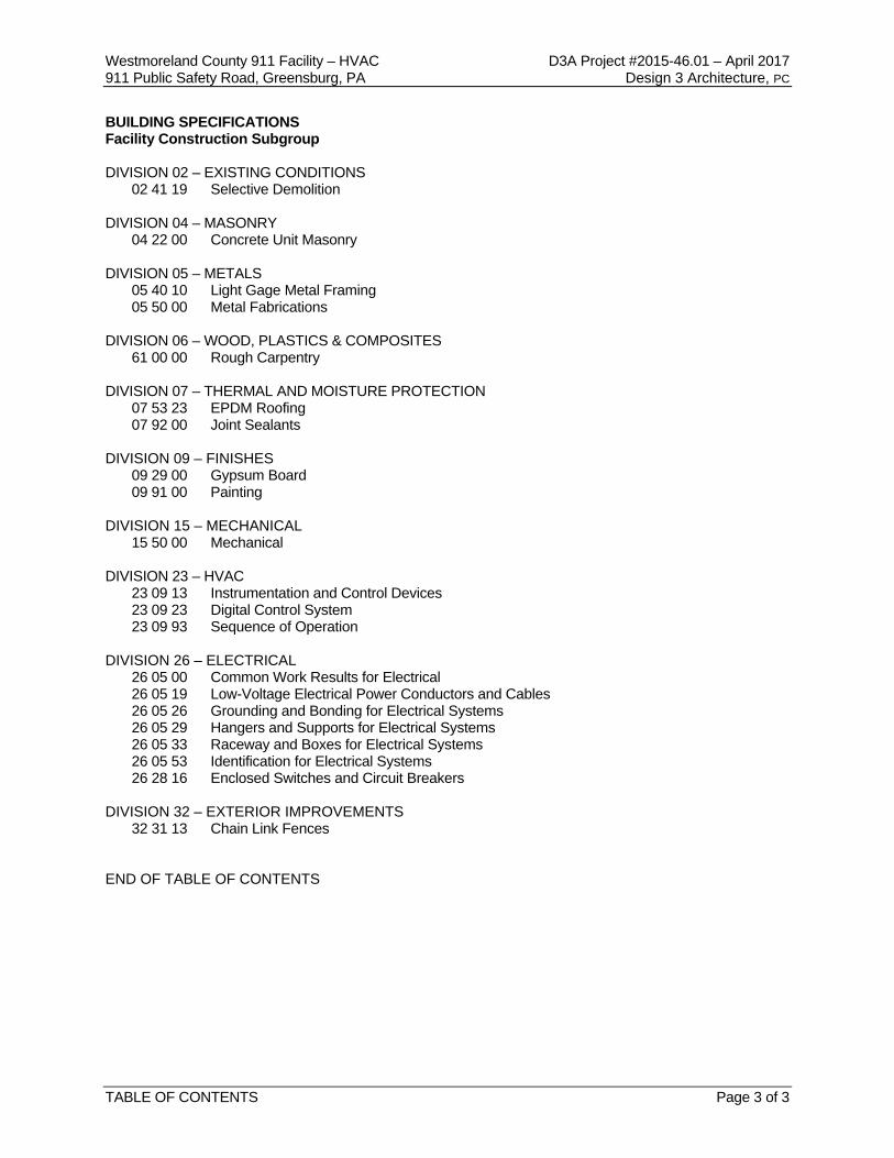
BUILDING SPECIFICATIONS Facility Construction Subgroup DIVISION 02 – EXISTING CONDITIONS 02 41 19 Selective Demolition DIVISION 04 – MASONRY 04 22 00 Concrete Unit Masonry DIVISION 05 – METALS 05 40 10 Light Gage Metal Framing 05 50 00 Metal Fabrications DIVISION 06 – WOOD, PLASTICS & COMPOSITES 61 00 00 Rough Carpentry DIVISION 07 – THERMAL AND MOISTURE PROTECTION 07 53 23 EPDM Roofing 07 92 00 Joint Sealants DIVISION 09 – FINISHES 09 29 00 Gypsum Board 09 91 00 Painting DIVISION 15 – MECHANICAL
15 50 00 Mechanical DIVISION 23 – HVAC
23 09 13 Instrumentation and Control Devices 23 09 23 Digital Control System 23 09 93 Sequence of Operation
DIVISION 26 – ELECTRICAL
26 05 00 Common Work Results for Electrical 26 05 19 Low-Voltage Electrical Power Conductors and Cables 26 05 26 Grounding and Bonding for Electrical Systems 26 05 29 Hangers and Supports for Electrical Systems 26 05 33 Raceway and Boxes for Electrical Systems 26 05 53 Identification for Electrical Systems 26 28 16 Enclosed Switches and Circuit Breakers
DIVISION 32 – EXTERIOR IMPROVEMENTS 32 31 13 Chain Link Fences END OF TABLE OF CONTENTS

(THIS PAGE INTENTIONALLY LEFT BLANK)
Westmoreland County 911 Facility – HVAC D3A Project #2015-46.01 – April 2017 911 Public Safety Road, Greensburg, PA Design 3 Architecture, PC
LIST OF DRAWINGS Page 1 of 1
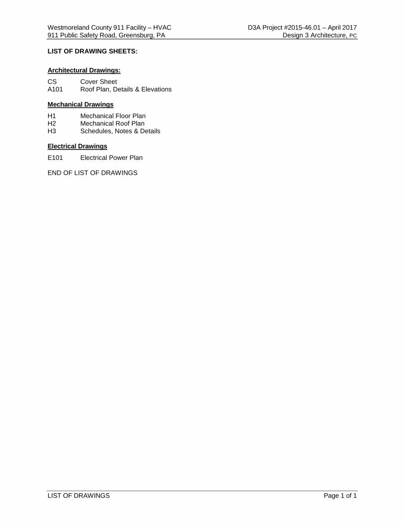
LIST OF DRAWING SHEETS: Architectural Drawings: CS Cover Sheet A101 Roof Plan, Details & Elevations Mechanical Drawings
H1 Mechanical Floor Plan H2 Mechanical Roof Plan H3 Schedules, Notes & Details Electrical Drawings
E101 Electrical Power Plan END OF LIST OF DRAWINGS

(THIS PAGE INTENTIONALLY LEFT BLANK)
Westmoreland County 911 Facility – HVAC D3A Project #2015-46.01 – April 2017 911 Public Safety Road, Greensburg, PA Design 3 Architecture, PC
INVITATION FOR BIDS Page 1 of 2
INVITATION FOR BIDS FOR
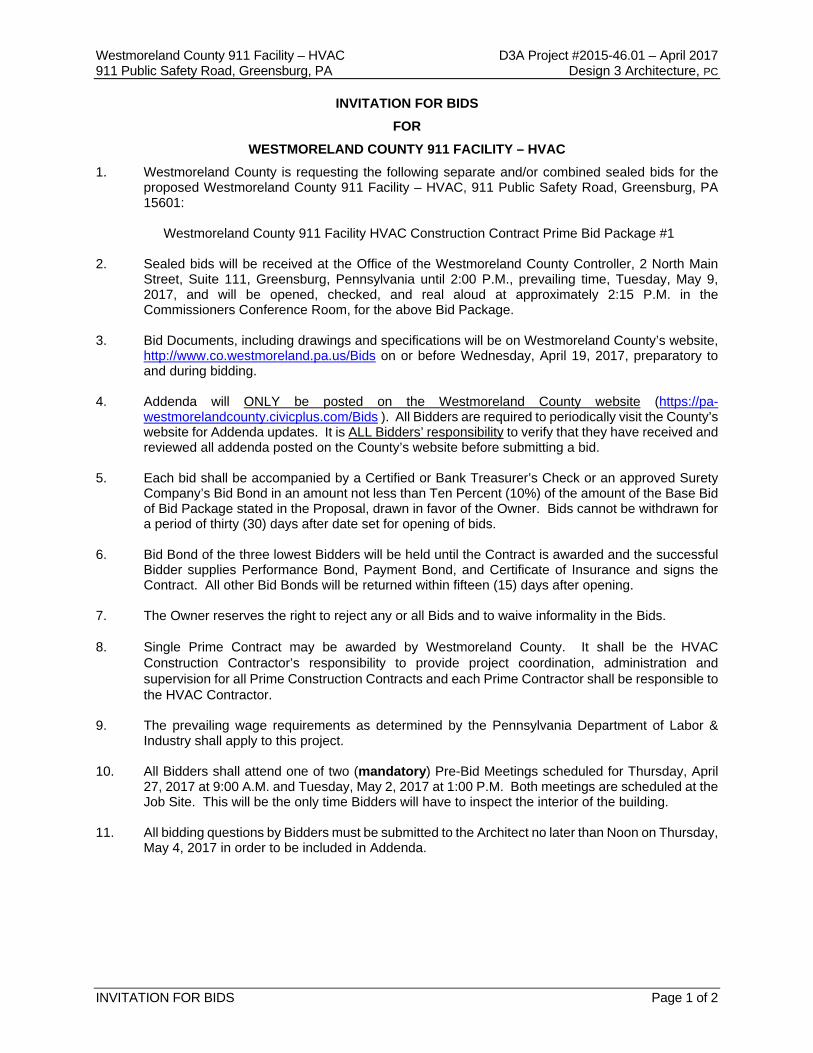
WESTMORELAND COUNTY 911 FACILITY – HVAC 1. Westmoreland County is requesting the following separate and/or combined sealed bids for the
proposed Westmoreland County 911 Facility – HVAC, 911 Public Safety Road, Greensburg, PA 15601:
Westmoreland County 911 Facility HVAC Construction Contract Prime Bid Package #1
2. Sealed bids will be received at the Office of the Westmoreland County Controller, 2 North Main
Street, Suite 111, Greensburg, Pennsylvania until 2:00 P.M., prevailing time, Tuesday, May 9, 2017, and will be opened, checked, and real aloud at approximately 2:15 P.M. in the Commissioners Conference Room, for the above Bid Package.
3. Bid Documents, including drawings and specifications will be on Westmoreland County’s website,
http://www.co.westmoreland.pa.us/Bids on or before Wednesday, April 19, 2017, preparatory to and during bidding.
4. Addenda will ONLY be posted on the Westmoreland County website (https://pa-
westmorelandcounty.civicplus.com/Bids ). All Bidders are required to periodically visit the County’s website for Addenda updates. It is ALL Bidders’ responsibility to verify that they have received and reviewed all addenda posted on the County’s website before submitting a bid.
5. Each bid shall be accompanied by a Certified or Bank Treasurer’s Check or an approved Surety
Company’s Bid Bond in an amount not less than Ten Percent (10%) of the amount of the Base Bid of Bid Package stated in the Proposal, drawn in favor of the Owner. Bids cannot be withdrawn for a period of thirty (30) days after date set for opening of bids.
6. Bid Bond of the three lowest Bidders will be held until the Contract is awarded and the successful
Bidder supplies Performance Bond, Payment Bond, and Certificate of Insurance and signs the Contract. All other Bid Bonds will be returned within fifteen (15) days after opening.
7. The Owner reserves the right to reject any or all Bids and to waive informality in the Bids. 8. Single Prime Contract may be awarded by Westmoreland County. It shall be the HVAC
Construction Contractor’s responsibility to provide project coordination, administration and supervision for all Prime Construction Contracts and each Prime Contractor shall be responsible to the HVAC Contractor.
9. The prevailing wage requirements as determined by the Pennsylvania Department of Labor &
Industry shall apply to this project. 10. All Bidders shall attend one of two (mandatory) Pre-Bid Meetings scheduled for Thursday, April
27, 2017 at 9:00 A.M. and Tuesday, May 2, 2017 at 1:00 P.M. Both meetings are scheduled at the Job Site. This will be the only time Bidders will have to inspect the interior of the building.
11. All bidding questions by Bidders must be submitted to the Architect no later than Noon on Thursday,
May 4, 2017 in order to be included in Addenda.
Westmoreland County 911 Facility – HVAC D3A Project #2015-46.01 – April 2017 911 Public Safety Road, Greensburg, PA Design 3 Architecture, PC
INVITATION FOR BIDS Page 2 of 2
12. Notice is also hereby given that this project is regulated under Executive Order 11246-Equal Employment Opportunity and related contract specifications apply. This Contract is subject to provisions of the prevailing wage requirements as determined by the Pennsylvania Department of Labor and Industry.
13. All Bids must be properly signed and submitted (an original and two copies), in a sealed opaque
envelope plainly marked on the outside with the Bidder’s name and address and the designation:
Westmoreland County 911 Facility HVAC Construction Contract Prime Bid Package #1
This will be a Single Prime Contract Bid (including all labor, material and construction required to complete the project).
14. All Bidders shall verify, before submitting a bid, that they can meet the following requirements:
A. All Bidders, Subcontractor Bidders and their Employees must pass the Pennsylvania
State Police Criminal Background Check in order to work on this Project. No one who does NOT pass this background check can work on this Project.
B. For all Public Works Projects in excess of $25,000.00, the successful Bidder shall be required to strictly follow and comply with all provisions of the Public Works Employment Verification Act 43 PS §167.1 and Pennsylvania Code Regulations at 66.1 – 66.9.
15. Project Labor Agreement: Where required for applicable projects, where the total project cost for
all trades is in excess of $150,000.00, the successful bidder(s), whether or not their individual bid exceeds $150,000.00, shall be required and agrees to execute a Letter of Assent and comply with a Project Labor Agreement, as prepared by the County substantially in the form of Attachment “H”.
Westmoreland County 911 Facility – HVAC D3A Project #2015-46.01 – April 2017 911 Public Safety Road, Greensburg, PA Design 3 Architecture, PC
GENERAL INSTRUCTIONS Page 1 of 5
GENERAL INSTRUCTIONS TO BIDDERS
1. General: Separate and sealed bids for the Office for: Westmoreland County 911 Facility HVAC will
be received at the Office of the County Controller, 2 North Main Street, Suite 111, Greensburg, Pennsylvania 15601 until 2:00 P.M. on Tuesday, May 9, 2017.
LATE BIDS WILL NOT BE ACCEPTED OR CONSIDERED
Bids will be opened and read aloud on Tuesday, May 9, 2017
at approximately 2:15 P.M. A PRE-BID MEETING (Mandatory) WILL BE HELD ON Thursday, April 27, 2017 at 9:00 A.M. and Tuesday, May 2, 2017 at 1:00 P.M. All Bidders shall attend one of these meetings. Both are scheduled at the Job Site, which is located at 911 Public Safety Road, Greensburg, PA 15601, Westmoreland County, PA. This will be the only time Bidders will have to inspect the interior of the building.
All bidding questions by Bidders must be submitted to the Architect no later than Noon on Thursday, May 4, 2017 in order to be included in Addenda.
2. Submission of Bids: An original and two (2) copies of the Official Bid Form must be submitted in a
sealed envelope, and addressed to the Westmoreland County Controller and clearly marked on the outside of the envelope with the Bidder’s name and address and the designation:
Westmoreland County 911 Facility HVAC Construction Contract Prime Bid Package #1 Each Prime Contract Construction Bid will include all labor, material and construction required to complete the project.
No responsibility will be attached to any County representative for premature opening of a bid not properly addressed and identified.
3. Bid Documents: Prior to submitting a Bid, it is the Bidder’s responsibility to visit Westmoreland
County’s website and verify that they have reviewed all Bid documents and Addenda. Addenda will ONLY be posted on the County’s website.
4. Bid Security: Each bid must be accompanied by a certified, good faith check drawn upon a bank authorized to do business in the Commonwealth of Pennsylvania, cashier’s check, or by a bid bond with corporate surety, in the amount of ten percent (10%) of the Base Bid amount. Bid bonds must be signed by an authorized representative of both the bidder and the surety company, and accompanied by a power of attorney authorizing execution of the bond on behalf of the surety company, or the bid will be rejected.
5. Performance Bond: The successful bidder will be required to furnish a bond guaranteeing
performance of the contract, with sufficient surety in the amount of one hundred percent (100%) of the amount of the contract within fifteen (15) days of the date of written notice of award of the contract.
6. Labor and Material Bond: The successful bidder will be required to furnish one hundred (100%) of
the contract amount. Such bond shall be solely for the protection of individuals, firms, corporations, partnerships, and associations supplying labor or materials to the contractor or to any of its sub-contractors in the prosecution of the work provided for in the contract and shall be conditioned for the prompt payment of all such material furnished or labor supplied or performed in the prosecution of the work.
Westmoreland County 911 Facility – HVAC D3A Project #2015-46.01 – April 2017 911 Public Safety Road, Greensburg, PA Design 3 Architecture, PC
GENERAL INSTRUCTIONS Page 2 of 5
7. Maintenance Bond: The successful bidder shall agree for itself, its heirs, executors, administrators, successors, and assigns to maintain all the work done under the contract in good condition for a period of one (1) year from the date of final acceptance of the same, the County being the judge of the condition of the work; and upon the acceptance of the completed work and before the surety which has furnished the Performance Bond is released, the contractor shall furnish a Maintenance Bond of an acceptable surety company in the full amount of the final cost to the County or in a lesser amount if so stipulated elsewhere in the contract documents. NOTE: IF APPLICABLE, FAILURE TO FURNISH SUCH BOND WITHIN THIS TIME PERIOD SHALL, AT THE OPTION OF THE COUNTY, CONSTITUTE GROUNDS TO REVOKE THE BID AWARD AND DECLARE THE BID SECURITY FORFEITED.
8. Tax Exemptions: The County is exempt from all Federal excise and transportation taxes, the
provisions of the Fair Trade law, and the Pennsylvania sales and use tax for purchase of tangible personal property. The registration number with Internal Revenue Service is 25-6001046. No Exemption certificates are required and none will be issued. Nothing in this paragraph is meant to exempt a construction contractor from the payment of sales tax or use tax required to be paid with respect to its purchase or use of tangible personal property used or transferred in connection with the performance of a construction contract. If the County is required by law to pay any excise tax and then seek a refund or credit, the contractor may add the amount of the tax to the bid price as a separate item.
9. IRS W-9 Form: The successful bidder will be required to complete an Internal Revenue Service
Form (W-9) attached hereto as Attachment “C” providing the bidder’s taxpayer identification number and, if applicable, certification regarding backup withholding and submit the completed (W-9) Form along with the executed contract.
10. Right to Accept or Reject Bids: The Westmoreland County Commissioners reserve the right to
waive informalities for the best interest of the County, approve sufficiency of surety and reject any and all bids. Failure of the bidder to sign the bid or have the signature of an authorized agent or representative on the official bid form will be cause for rejection of the bid. Signature must be written in ink; typing or printing is not acceptable. Bidders must include all information required on the Official Bid Form. Failure to comply may be cause for rejection of the bid. Award of the contract will be made at the County’s option to the lowest responsible bidder.
11. Approved Equal (Where Applicable): Whenever a product is defined in this invitation by trade name
and catalogue number of a manufacturer or vendor, the term “or approved equal,” if not inserted therewith shall be implied. Any reference to a particular manufacturer’s product either by trade name or by limited description is solely for the purpose of more clearly indicating the minimum standard of quality desired, except where a no substitution is requested. When a “no substitute” is requested, the County will consider bids for the referenced item only. The term “or approved equal” is defined as meaning any other make which, in the sole opinion of the County, is of such character, quality and performance equivalence as to meet the standard of quality of items specified for which it is to be used equally as well as that specified. The bidder quoting on a commodity other than as specified shall furnish complete identification on the bid proposal of the product he is offering by trade name brand and/or model number. The bidder shall also furnish descriptive literature and date with respect to the alternative commodity he proposed to furnish. Bidders offering an alternate shall also indicate any known specification deviations from the referenced item.
12. Unit Prices: In the event Unit Prices are required, the County reserves the right, should there be
any discrepancy, inconsistency or difference between the Unit Price(s) and Total Price(s), to choose the lowest of the prices listed and the vendor shall be bound to provide the goods and/or services in question at the lower cost. The County reserves the right to award contracts for individual items, groups or combined award as may be in the County’s best interest.
Westmoreland County 911 Facility – HVAC D3A Project #2015-46.01 – April 2017 911 Public Safety Road, Greensburg, PA Design 3 Architecture, PC
GENERAL INSTRUCTIONS Page 3 of 5
13. Withdrawal of Bids: Bids may be withdrawn at any time prior to the designated time of the opening of bids. All bids must be firm for thirty (30) days following the bid opening, and no bids will be permitted to be withdrawn during such period. Bids will be awarded or rejected within thirty (30) days from opening. In the event award of Bid cannot be made within thirty (30) days from date of Bid Opening, bidders will be afforded the opportunity to extend their bid for an additional thirty (30) days by completing and submitting to the County a Consent to Extension of Date for Bid Award Form a copy of which is attached hereto as Attachment “D.”
14. Provisions Required by Law Deemed Inserted: Each and every Provision of law and clause
required by law to be inserted in the Contract for this project will be deemed to be inserted therein and the Contract will be read and enforced as though it were included herein, and if through mistake or otherwise and such provision is not inserted, or is not correctly inserted, then upon the application of either party, the Contract shall forthwith be physically amended to make such insertion.
15. More Than One Bid: If more than one bid is offered by any one bidder, in his own name or in the
name of his agent, partner, or other person, all bids submitted by such bidder shall be rejected (except as permitted and defined under Contingent Bids).
16. Insurance: During the term of this contract, the Contractor shall maintain in effect insurance policies
covering the following:
1) General Liability- $500,000 per person, $1,000,000 per occurrence of personal injury; $2,000,000 per occurrence of property damage and $5,000,000 aggregate property damage.
2) Automobile - $1,000,000. 3) Workmen’s Compensation – In amounts required by law. 4) Special Hazards - if there are special hazards such as blasting (x), and/or collapse
(c), and/or underground (u) hazards performed by any contractor and excluded under his liability insurance contract, the insurance contract shall be endorsed to delete such exclusions, prior to performance of work.
Proof of Insurance must be provided along with Performance Bond.
17. Non-Discrimination Clause: The successful bidder will be required to comply with the terms of the attached Non-Discrimination Clause herein marked Attachment “E.”
18. Contractor Integrity Clause: The successful bidder will be required to comply with the terms of the
attached Contractor Integrity Clause herein marked Attachment “F.” 19. Contractor’s No-Lien Affidavit: The successful bidder shall execute the attached No-Lien Affidavit
herein marked Attachment “G”. 20. Employees & Subcontractors: The County shall have the right to approve employees and
subcontractors prior to the commencement of their work. Any approved employee or subcontractor does not relieve the bidder of full compliance with the specifications. The bidder will be responsible for all work performed under these specifications whether the Bidder performs the work himself or through a subcontractor.
21. Addenda to Specifications: During the bidding period the County may issue written Addenda to
each person, firm or corporation which has secured a copy of these specifications, making changes or corrections to the specifications as issued. Such changes or corrections shall be included in the work and/or materials covered by the bid proposal, and such Addenda shall become part to the specifications and contract. Bidders who secure Bid Specifications via the internet are cautioned to verify if Addenda have been issued by the County prior to submission of bid. The County assumes no responsibility to notify any prospective bidder of Addenda to Bid Specifications that are secured via the internet.
Westmoreland County 911 Facility – HVAC D3A Project #2015-46.01 – April 2017 911 Public Safety Road, Greensburg, PA Design 3 Architecture, PC
GENERAL INSTRUCTIONS Page 4 of 5
22. Additional Work: No additional work shall be done unless agreed to in writing by the County. 23. Date of Completion: All work for this project shall be completed within 130 calendar days of written
notice to proceed. 24. Payment: The County will make payment to the successful Bidder on a monthly basis based upon
the percentage of work completed with a 10% retainage until project is 50% completed and 5% retainage thereafter. Retainage shall be paid within 30 days of written invoice of final completion and acceptance of work.
All invoices are to be submitted to: the Architect’s office: William A. Snyder, AIA
Design 3 Architecture 300 Oxford Drive, Suite 120 Monroeville, PA 15146 25. Contact Person: Any questions regarding this bid should be directed to William A. Snyder, AIA and
John C. Parrish at the Architect’s office, Ph. (412) 373-2220, or e-mail [email protected] and [email protected]
26. Any legal proceedings to enforce the terms of these specifications or any subsequent contract shall
be commenced solely in the Court of Common Pleas of Westmoreland County, Pennsylvania, or with a district justice of the 10th Judicial District of Pennsylvania (Westmoreland County).
27. Prevailing Wage: It is expected that the cost of the project will exceed the threshold limit for wage
determination. Therefore, contractors are expected to use current wage determination in formulating their bids which are attached hereto.
28. A.D.A./ANSI A117.1-2003 Requirements: All contractors, subcontractors and suppliers must
complete their portion of the work so that it fully complies with the current requirements of the American Disabilities Act and ANSI Al 17.1-2003.
29. Liquidated Damage: Should the contractor fail to complete his work before the expiration of the
date set for completion or as provided in the contract documents covering extensions of time, then the Owner may retain the sum of Two Hundred Dollars ($200.00) for each working day thereafter that the work remains uncompleted, which sum is agreed upon as the proper measure of liquidated damages which the Owner will sustain per diem by the failure of the contractor to complete the work at the time stipulated and this sum is not to be construed as in any sense a penalty.
30. Indemnification:
A. The contractor shall indemnify and hold harmless the Owner and Architect from and against all claims, damages, losses and expenses including Attorney's fees arising out of or resulting from the performance of the work, provided that any such claim, damage, loss or expense (a) is attributable to bodily injury, sickness, disease or death, or to injury to or destruction of tangible property (other than the work itself) including the loss of use resulting there from, and (b) is caused in whole or in part by any negligent act or omission of the contractor, any subcontractor, anyone directly or indirectly employed by any of them or anyone for whose acts any of them may be liable, regardless of whether or not it is caused in part by a party indemnified here under.
Westmoreland County 911 Facility – HVAC D3A Project #2015-46.01 – April 2017 911 Public Safety Road, Greensburg, PA Design 3 Architecture, PC
GENERAL INSTRUCTIONS Page 5 of 5
B. In any and all claims against the Owner by any employee of the contractor, any subcontractor, anyone directly or indirectly employed by any of them or anyone for whose acts any of them may be liable, the indemnification obligation under this paragraph shall not be limited in any way by any limitation on the amount or type of damages, compensation or benefits payable by or for the contractor or any subcontractor under Workmen’s Compensation Acts, disability benefit acts or other employee benefit acts.
31. In accordance with Pennsylvania’s “Right to Know” Laws, (Act 3 of 2008; 65 PS 67.101 et seq),
the County may make available for viewing or provide copies of all bids received and all associated contract documents following awarding of same.
32. The submission of a Bid shall constitute and establish the Bidders intent to enter into a binding contract
with Westmoreland County for the goods or services solicited. Additionally, should any bid submitted contain defect(s) that in the County’s opinion, is of a non-material nature, the Bidder agrees that by the submission of a Bid, Bidder will correct any defect(s) upon request of the County.
33. Exceptions: Any exceptions to bid specifications must be attached to the bid. 34. Bidding Questions: Questions by Bidders must be submitted to the Architect no later than Noon on
Thursday, May 4, 2017 in order to be included in Addenda. 35. Review of Contract Documents and Field Conditions by Bidders/Contractors: Drawings, General
Conditions of the Contract, Supplementary General Conditions and Division 1, General Requirements of the Specifications, all apply to the work of individual sections of Divisions 2 through 32 of the Specifications. The Bidder/Contractor shall make certain that all persons required to be involved with work specified in Divisions 2 through 32 have copies of and comply with the provisions of the Conditions and Requirements, and are working from the most current documents related to their scope of work. All Bidders shall review all other Trades’ documents to pick up their related work that may not be indicated on their respective Trade’s documents but must be provided for a complete project. The cost for this work shall be included in their Bid.
36. All Bidders shall verify, before submitting a bid, that they can meet the following requirements:
A. All Bidders, Subcontractor Bidders and their Employees must pass the Pennsylvania
State Police Criminal Background Check in order to work on this Project. No one who does NOT pass this background check can work on this Project.
B. For all Public Works Projects in excess of $25,000.00, the successful Bidder shall be required to strictly follow and comply with all provisions of the Public Works Employment Verification Act 43 PS §167.1 and Pennsylvania Code Regulations at 66.1 – 66.9.
37. Project Labor Agreement & Letter of Assent: Where required for applicable projects, where the
total project cost for all trades is in excess of $150,000.00, the successful bidder(s), whether or not their individual bid exceeds $150,000.00, shall be required and agrees to execute a Letter of Assent and comply with a Project Labor Agreement, as prepared by the County substantially in the form of Attachment “H”.

(THIS PAGE INTENTIONALLY LEFT BLANK)
Westmoreland County 911 Facility – HVAC D3A Project #2015-46.01 – April 2017 911 Public Safety Road, Greensburg, PA Design 3 Architecture, PC
BID FORM INDEX – HVAC CONSTRUCTION PRIME CONTRACT Page H-0
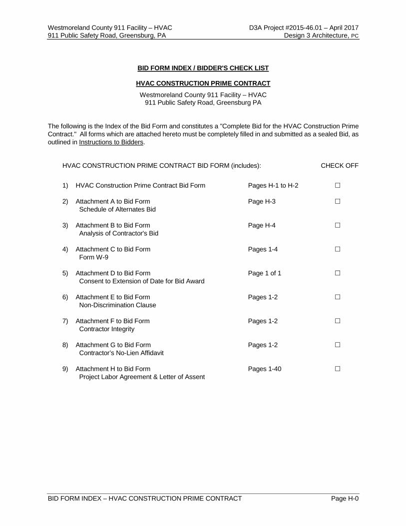
BID FORM INDEX / BIDDER'S CHECK LIST
HVAC CONSTRUCTION PRIME CONTRACT
Westmoreland County 911 Facility – HVAC 911 Public Safety Road, Greensburg PA
The following is the Index of the Bid Form and constitutes a "Complete Bid for the HVAC Construction Prime Contract." All forms which are attached hereto must be completely filled in and submitted as a sealed Bid, as outlined in Instructions to Bidders. HVAC CONSTRUCTION PRIME CONTRACT BID FORM (includes): CHECK OFF
1) HVAC Construction Prime Contract Bid Form Pages H-1 to H-2 2) Attachment A to Bid Form Page H-3 Schedule of Alternates Bid 3) Attachment B to Bid Form Page H-4 Analysis of Contractor's Bid 4) Attachment C to Bid Form Pages 1-4 Form W-9 5) Attachment D to Bid Form Page 1 of 1 Consent to Extension of Date for Bid Award 6) Attachment E to Bid Form Pages 1-2 Non-Discrimination Clause 7) Attachment F to Bid Form Pages 1-2 Contractor Integrity 8) Attachment G to Bid Form Pages 1-2 Contractor’s No-Lien Affidavit 9) Attachment H to Bid Form Pages 1-40 Project Labor Agreement & Letter of Assent

(THIS PAGE INTENTIONALLY LEFT BLANK)
Westmoreland County 911 Facility – HVAC D3A Project #2015-46.01 – April 2017 911 Public Safety Road, Greensburg, PA Design 3 Architecture, PC
BID FORM – HVAC CONSTRUCTION PRIME CONTRACT Page H-1
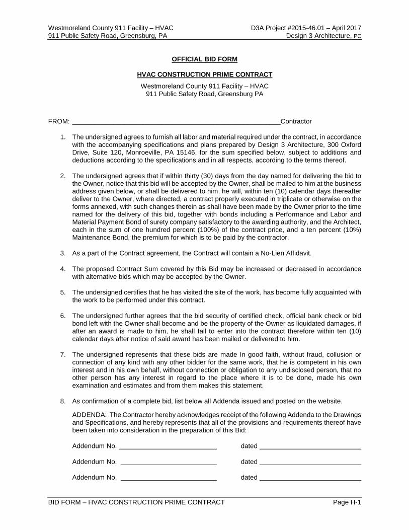
OFFICIAL BID FORM
HVAC CONSTRUCTION PRIME CONTRACT
Westmoreland County 911 Facility – HVAC 911 Public Safety Road, Greensburg PA
FROM: ________________________________________________________Contractor
1. The undersigned agrees to furnish all labor and material required under the contract, in accordance with the accompanying specifications and plans prepared by Design 3 Architecture, 300 Oxford Drive, Suite 120, Monroeville, PA 15146, for the sum specified below, subject to additions and deductions according to the specifications and in all respects, according to the terms thereof.
2. The undersigned agrees that if within thirty (30) days from the day named for delivering the bid to the Owner, notice that this bid will be accepted by the Owner, shall be mailed to him at the business address given below, or shall be delivered to him, he will, within ten (10) calendar days thereafter deliver to the Owner, where directed, a contract properly executed in triplicate or otherwise on the forms annexed, with such changes therein as shall have been made by the Owner prior to the time named for the delivery of this bid, together with bonds including a Performance and Labor and Material Payment Bond of surety company satisfactory to the awarding authority, and the Architect, each in the sum of one hundred percent (100%) of the contract price, and a ten percent (10%) Maintenance Bond, the premium for which is to be paid by the contractor.
3. As a part of the Contract agreement, the Contract will contain a No-Lien Affidavit.
4. The proposed Contract Sum covered by this Bid may be increased or decreased in accordance with alternative bids which may be accepted by the Owner.
5. The undersigned certifies that he has visited the site of the work, has become fully acquainted with the work to be performed under this contract.
6. The undersigned further agrees that the bid security of certified check, official bank check or bid bond left with the Owner shall become and be the property of the Owner as liquidated damages, if after an award is made to him, he shall fail to enter into the contract therefore within ten (10) calendar days after notice of said award has been mailed or delivered to him.
7. The undersigned represents that these bids are made In good faith, without fraud, collusion or connection of any kind with any other bidder for the same work, that he is competent in his own interest and in his own behalf, without connection or obligation to any undisclosed person, that no other person has any interest in regard to the place where it is to be done, made his own examination and estimates and from them makes this statement.
8. As confirmation of a complete bid, list below all Addenda issued and posted on the website.
ADDENDA: The Contractor hereby acknowledges receipt of the following Addenda to the Drawings and Specifications, and hereby represents that all of the provisions and requirements thereof have been taken into consideration in the preparation of this Bid:
Addendum No. dated
Addendum No. dated
Addendum No. dated

(THIS PAGE INTENTIONALLY LEFT BLANK)
Westmoreland County 911 Facility – HVAC D3A Project #2015-46.01 – April 2017 911 Public Safety Road, Greensburg, PA Design 3 Architecture, PC
BID FORM – HVAC CONSTRUCTION PRIME CONTRACT Page H-2
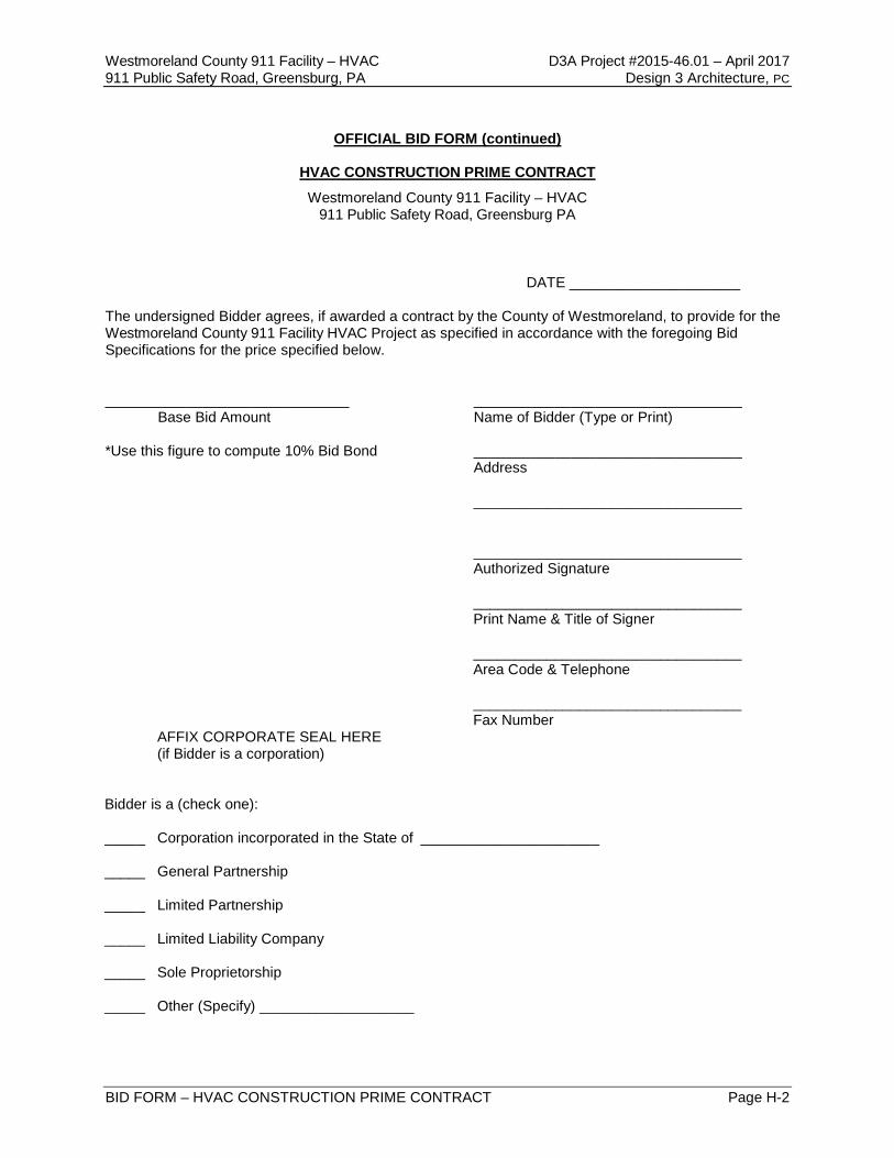
OFFICIAL BID FORM (continued)
HVAC CONSTRUCTION PRIME CONTRACT
Westmoreland County 911 Facility – HVAC 911 Public Safety Road, Greensburg PA
DATE _____________________ The undersigned Bidder agrees, if awarded a contract by the County of Westmoreland, to provide for the Westmoreland County 911 Facility HVAC Project as specified in accordance with the foregoing Bid Specifications for the price specified below. ______________________________ _________________________________ Base Bid Amount Name of Bidder (Type or Print) *Use this figure to compute 10% Bid Bond _________________________________ Address _________________________________ _________________________________ Authorized Signature _________________________________ Print Name & Title of Signer _________________________________ Area Code & Telephone _________________________________ Fax Number AFFIX CORPORATE SEAL HERE (if Bidder is a corporation) Bidder is a (check one): _____ Corporation incorporated in the State of ______________________ _____ General Partnership _____ Limited Partnership _____ Limited Liability Company _____ Sole Proprietorship _____ Other (Specify) ___________________

(THIS PAGE INTENTIONALLY LEFT BLANK)
Westmoreland County 911 Facility – HVAC D3A Project #2015-46.01 – April 2017 911 Public Safety Road, Greensburg, PA Design 3 Architecture, PC
BID FORM – HVAC CONSTRUCTION PRIME CONTRACT Page H-3
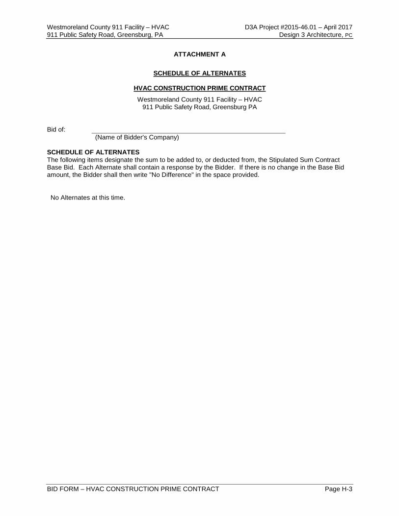
ATTACHMENT A
SCHEDULE OF ALTERNATES
HVAC CONSTRUCTION PRIME CONTRACT
Westmoreland County 911 Facility – HVAC 911 Public Safety Road, Greensburg PA
Bid of:
(Name of Bidder's Company) SCHEDULE OF ALTERNATES The following items designate the sum to be added to, or deducted from, the Stipulated Sum Contract Base Bid. Each Alternate shall contain a response by the Bidder. If there is no change in the Base Bid amount, the Bidder shall then write "No Difference" in the space provided.
No Alternates at this time.

(THIS PAGE INTENTIONALLY LEFT BLANK)
Westmoreland County 911 Facility – HVAC D3A Project #2015-46.01 – April 2017 911 Public Safety Road, Greensburg, PA Design 3 Architecture, PC
BID FORM – HVAC CONSTRUCTION PRIME CONTRACT Page H-4
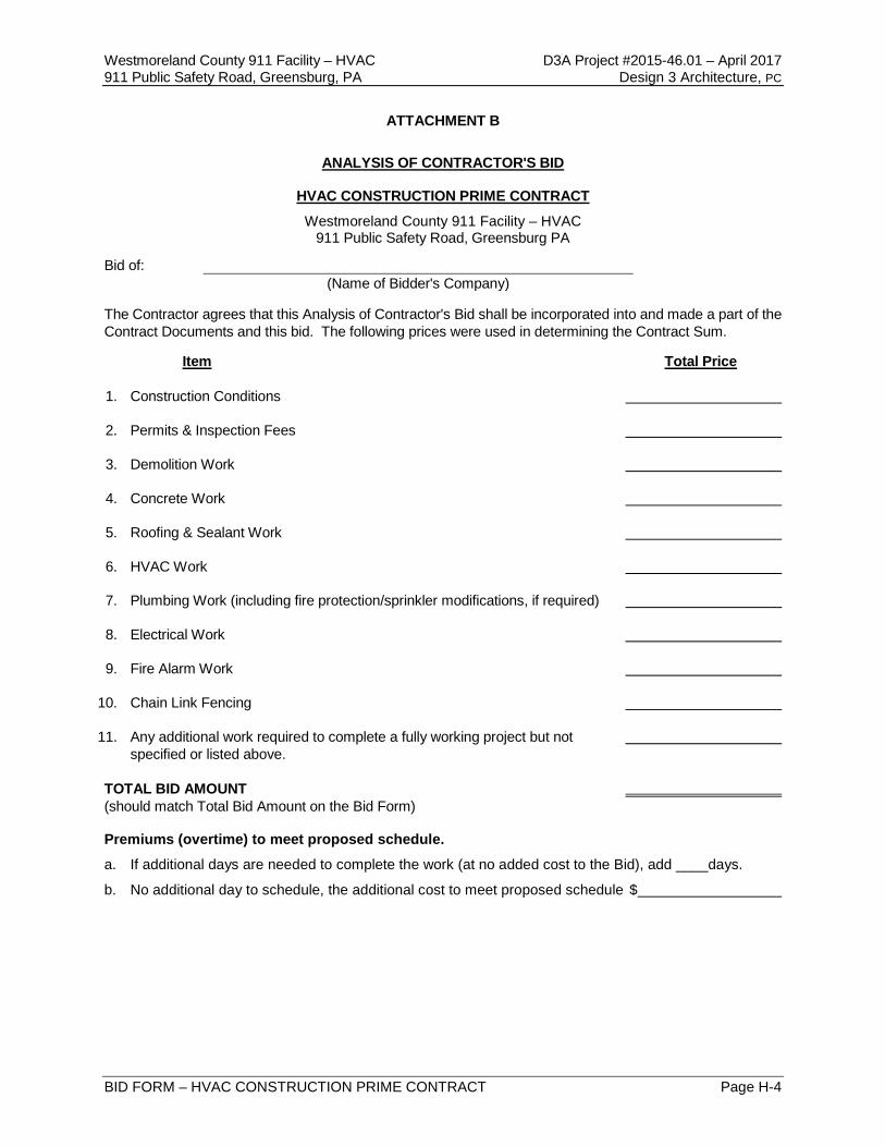
ATTACHMENT B
ANALYSIS OF CONTRACTOR'S BID
HVAC CONSTRUCTION PRIME CONTRACT
Westmoreland County 911 Facility – HVAC 911 Public Safety Road, Greensburg PA
Bid of: (Name of Bidder's Company)
The Contractor agrees that this Analysis of Contractor's Bid shall be incorporated into and made a part of the Contract Documents and this bid. The following prices were used in determining the Contract Sum. Item Total Price
1. Construction Conditions 2. Permits & Inspection Fees 3. Demolition Work 4. Concrete Work
5. Roofing & Sealant Work
6. HVAC Work
7. Plumbing Work (including fire protection/sprinkler modifications, if required)
8. Electrical Work
9. Fire Alarm Work
10. Chain Link Fencing
11. Any additional work required to complete a fully working project but not specified or listed above. TOTAL BID AMOUNT (should match Total Bid Amount on the Bid Form) Premiums (overtime) to meet proposed schedule.
a. If additional days are needed to complete the work (at no added cost to the Bid), add ____days.
b. No additional day to schedule, the additional cost to meet proposed schedule $

(THIS PAGE INTENTIONALLY LEFT BLANK)
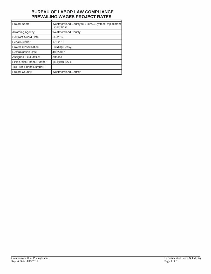
Project Name: Westmoreland County 911 HVAC System ReplacmentFinal Phase
Awarding Agency: Westmoreland County
Contract Award Date: 5/9/2017
Serial Number: 17-02916
Project Classification: Building/Heavy
Determination Date: 4/12/2017
Assigned Field Office: Altoona
Field Office Phone Number: (814)940-6224
Toll Free Phone Number:
Project County: Westmoreland County
BUREAU OF LABOR LAW COMPLIANCEPREVAILING WAGES PROJECT RATES
Commonwealth of Pennsylvania Department of Labor & IndustryReport Date: 4/13/2017 Page 1 of 6
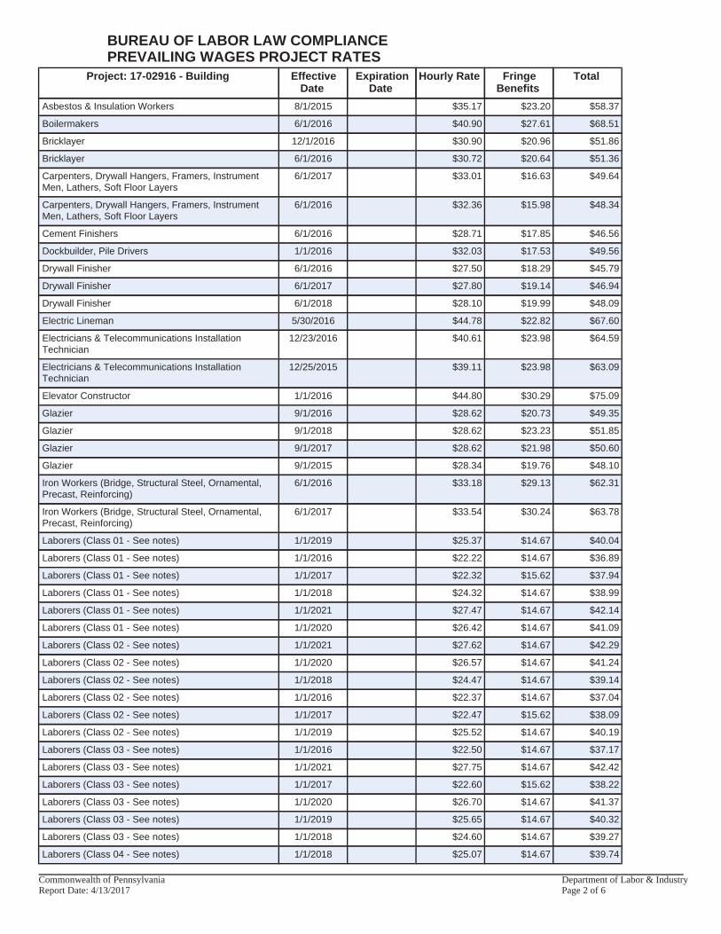
Project: 17-02916 - Building EffectiveDate
ExpirationDate
Hourly Rate FringeBenefits
Total
Asbestos & Insulation Workers 8/1/2015 $35.17 $23.20 $58.37
Boilermakers 6/1/2016 $40.90 $27.61 $68.51
Bricklayer 12/1/2016 $30.90 $20.96 $51.86
Bricklayer 6/1/2016 $30.72 $20.64 $51.36
Carpenters, Drywall Hangers, Framers, InstrumentMen, Lathers, Soft Floor Layers
6/1/2017 $33.01 $16.63 $49.64
Carpenters, Drywall Hangers, Framers, InstrumentMen, Lathers, Soft Floor Layers
6/1/2016 $32.36 $15.98 $48.34
Cement Finishers 6/1/2016 $28.71 $17.85 $46.56
Dockbuilder, Pile Drivers 1/1/2016 $32.03 $17.53 $49.56
Drywall Finisher 6/1/2016 $27.50 $18.29 $45.79
Drywall Finisher 6/1/2017 $27.80 $19.14 $46.94
Drywall Finisher 6/1/2018 $28.10 $19.99 $48.09
Electric Lineman 5/30/2016 $44.78 $22.82 $67.60
Electricians & Telecommunications InstallationTechnician
12/23/2016 $40.61 $23.98 $64.59
Electricians & Telecommunications InstallationTechnician
12/25/2015 $39.11 $23.98 $63.09
Elevator Constructor 1/1/2016 $44.80 $30.29 $75.09
Glazier 9/1/2016 $28.62 $20.73 $49.35
Glazier 9/1/2018 $28.62 $23.23 $51.85
Glazier 9/1/2017 $28.62 $21.98 $50.60
Glazier 9/1/2015 $28.34 $19.76 $48.10
Iron Workers (Bridge, Structural Steel, Ornamental,Precast, Reinforcing)
6/1/2016 $33.18 $29.13 $62.31
Iron Workers (Bridge, Structural Steel, Ornamental,Precast, Reinforcing)
6/1/2017 $33.54 $30.24 $63.78
Laborers (Class 01 - See notes) 1/1/2019 $25.37 $14.67 $40.04
Laborers (Class 01 - See notes) 1/1/2016 $22.22 $14.67 $36.89
Laborers (Class 01 - See notes) 1/1/2017 $22.32 $15.62 $37.94
Laborers (Class 01 - See notes) 1/1/2018 $24.32 $14.67 $38.99
Laborers (Class 01 - See notes) 1/1/2021 $27.47 $14.67 $42.14
Laborers (Class 01 - See notes) 1/1/2020 $26.42 $14.67 $41.09
Laborers (Class 02 - See notes) 1/1/2021 $27.62 $14.67 $42.29
Laborers (Class 02 - See notes) 1/1/2020 $26.57 $14.67 $41.24
Laborers (Class 02 - See notes) 1/1/2018 $24.47 $14.67 $39.14
Laborers (Class 02 - See notes) 1/1/2016 $22.37 $14.67 $37.04
Laborers (Class 02 - See notes) 1/1/2017 $22.47 $15.62 $38.09
Laborers (Class 02 - See notes) 1/1/2019 $25.52 $14.67 $40.19
Laborers (Class 03 - See notes) 1/1/2016 $22.50 $14.67 $37.17
Laborers (Class 03 - See notes) 1/1/2021 $27.75 $14.67 $42.42
Laborers (Class 03 - See notes) 1/1/2017 $22.60 $15.62 $38.22
Laborers (Class 03 - See notes) 1/1/2020 $26.70 $14.67 $41.37
Laborers (Class 03 - See notes) 1/1/2019 $25.65 $14.67 $40.32
Laborers (Class 03 - See notes) 1/1/2018 $24.60 $14.67 $39.27
Laborers (Class 04 - See notes) 1/1/2018 $25.07 $14.67 $39.74
BUREAU OF LABOR LAW COMPLIANCEPREVAILING WAGES PROJECT RATES
Commonwealth of Pennsylvania Department of Labor & IndustryReport Date: 4/13/2017 Page 2 of 6
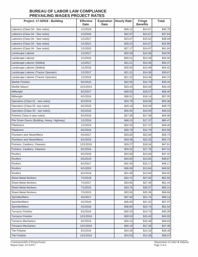
Project: 17-02916 - Building EffectiveDate
ExpirationDate
Hourly Rate FringeBenefits
Total
Laborers (Class 04 - See notes) 1/1/2019 $26.12 $14.67 $40.79
Laborers (Class 04 - See notes) 1/1/2016 $22.97 $14.67 $37.64
Laborers (Class 04 - See notes) 1/1/2017 $23.07 $15.62 $38.69
Laborers (Class 04 - See notes) 1/1/2021 $28.22 $14.67 $42.89
Laborers (Class 04 - See notes) 1/1/2020 $27.17 $14.67 $41.84
Landscape Laborer 1/1/2017 $20.59 $14.36 $34.95
Landscape Laborer 1/1/2016 $20.51 $13.49 $34.00
Landscape Laborer (Skilled) 1/1/2017 $21.01 $14.36 $35.37
Landscape Laborer (Skilled) 1/1/2016 $20.93 $13.49 $34.42
Landscape Laborer (Tractor Operator) 1/1/2017 $21.31 $14.36 $35.67
Landscape Laborer (Tractor Operator) 1/1/2016 $21.23 $13.49 $34.72
Marble Finisher 6/1/2015 $22.55 $12.79 $35.34
Marble Mason 12/1/2014 $19.43 $10.00 $29.43
Millwright 6/1/2017 $39.83 $18.57 $58.40
Millwright 6/1/2016 $38.91 $18.14 $57.05
Operators (Class 01 - see notes) 6/1/2016 $33.79 $19.59 $53.38
Operators (Class 02 -see notes) 6/1/2016 $29.16 $19.59 $48.75
Operators (Class 03 - see notes) 6/1/2016 $26.94 $19.59 $46.53
Painters Class 6 (see notes) 6/1/2016 $27.38 $17.58 $44.96
Pile Driver Divers (Building, Heavy, Highway) 1/1/2016 $48.10 $17.37 $65.47
Piledrivers 1/1/2016 $32.03 $17.37 $49.40
Plasterers 6/1/2016 $28.79 $14.79 $43.58
Plumbers and Steamfitters 6/1/2017 $33.83 $22.90 $56.73
Plumbers and Steamfitters 6/1/2016 $33.48 $22.25 $55.73
Pointers, Caulkers, Cleaners 12/1/2016 $29.27 $18.34 $47.61
Pointers, Caulkers, Cleaners 6/1/2016 $29.25 $17.76 $47.01
Roofers 6/1/2018 $33.58 $13.84 $47.42
Roofers 6/1/2019 $34.83 $13.84 $48.67
Roofers 6/1/2017 $31.00 $15.17 $46.17
Roofers 6/1/2020 $36.08 $13.84 $49.92
Roofers 6/1/2016 $31.08 $13.84 $44.92
Sheet Metal Workers 7/1/2018 $34.72 $27.83 $62.55
Sheet Metal Workers 7/1/2017 $33.95 $27.49 $61.44
Sheet Metal Workers 7/1/2016 $33.76 $26.37 $60.13
Sheet Metal Workers 7/1/2015 $33.50 $25.36 $58.86
Sprinklerfitters 4/1/2017 $37.40 $21.74 $59.14
Sprinklerfitters 4/1/2016 $36.05 $21.02 $57.07
Sprinklerfitters 4/1/2018 $38.80 $22.74 $61.54
Terrazzo Finisher 6/1/2016 $30.33 $14.75 $45.08
Terrazzo Finisher 12/1/2016 $30.53 $15.40 $45.93
Terrazzo Mechanics 6/1/2016 $30.15 $16.48 $46.63
Terrazzo Mechanics 12/1/2016 $30.18 $17.30 $47.48
Tile Finisher 6/1/2016 $24.30 $14.18 $38.48
Tile Finisher 12/1/2016 $24.59 $14.38 $38.97
BUREAU OF LABOR LAW COMPLIANCEPREVAILING WAGES PROJECT RATES
Commonwealth of Pennsylvania Department of Labor & IndustryReport Date: 4/13/2017 Page 3 of 6
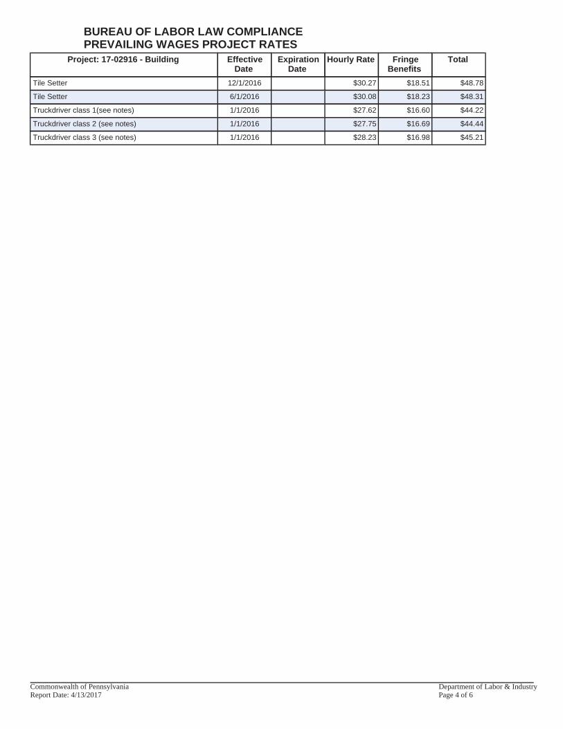
Project: 17-02916 - Building EffectiveDate
ExpirationDate
Hourly Rate FringeBenefits
Total
Tile Setter 12/1/2016 $30.27 $18.51 $48.78
Tile Setter 6/1/2016 $30.08 $18.23 $48.31
Truckdriver class 1(see notes) 1/1/2016 $27.62 $16.60 $44.22
Truckdriver class 2 (see notes) 1/1/2016 $27.75 $16.69 $44.44
Truckdriver class 3 (see notes) 1/1/2016 $28.23 $16.98 $45.21
BUREAU OF LABOR LAW COMPLIANCEPREVAILING WAGES PROJECT RATES
Commonwealth of Pennsylvania Department of Labor & IndustryReport Date: 4/13/2017 Page 4 of 6
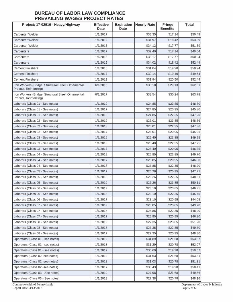
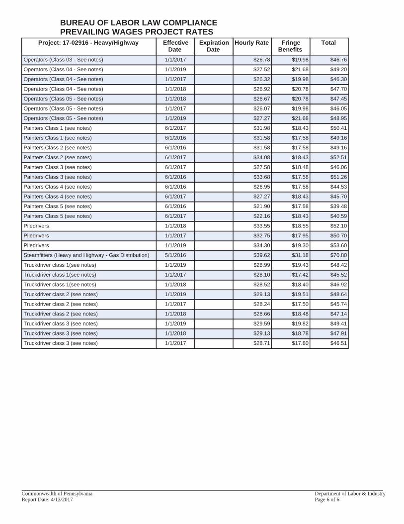
Project: 17-02916 - Heavy/Highway EffectiveDate
ExpirationDate
Hourly Rate FringeBenefits
Total
Carpenter Welder 1/1/2017 $33.35 $17.14 $50.49
Carpenter Welder 1/1/2019 $34.97 $18.42 $53.39
Carpenter Welder 1/1/2018 $34.12 $17.77 $51.89
Carpenters 1/1/2017 $32.40 $17.14 $49.54
Carpenters 1/1/2018 $33.17 $17.77 $50.94
Carpenters 1/1/2019 $34.02 $18.42 $52.44
Cement Finishers 1/1/2018 $31.04 $19.90 $50.94
Cement Finishers 1/1/2017 $30.14 $19.40 $49.54
Cement Finishers 1/1/2019 $31.94 $20.50 $52.44
Iron Workers (Bridge, Structural Steel, Ornamental,Precast, Reinforcing)
6/1/2016 $33.18 $29.13 $62.31
Iron Workers (Bridge, Structural Steel, Ornamental,Precast, Reinforcing)
6/1/2017 $33.54 $30.24 $63.78
Laborers (Class 01 - See notes) 1/1/2019 $24.85 $23.85 $48.70
Laborers (Class 01 - See notes) 1/1/2017 $24.85 $20.95 $45.80
Laborers (Class 01 - See notes) 1/1/2018 $24.85 $22.35 $47.20
Laborers (Class 02 - See notes) 1/1/2019 $25.01 $23.85 $48.86
Laborers (Class 02 - See notes) 1/1/2018 $25.01 $22.35 $47.36
Laborers (Class 02 - See notes) 1/1/2017 $25.01 $20.95 $45.96
Laborers (Class 03 - See notes) 1/1/2019 $25.40 $23.85 $49.25
Laborers (Class 03 - See notes) 1/1/2018 $25.40 $22.35 $47.75
Laborers (Class 03 - See notes) 1/1/2017 $25.40 $20.95 $46.35
Laborers (Class 04 - See notes) 1/1/2019 $25.85 $23.85 $49.70
Laborers (Class 04 - See notes) 1/1/2017 $25.85 $20.95 $46.80
Laborers (Class 04 - See notes) 1/1/2018 $25.85 $22.35 $48.20
Laborers (Class 05 - See notes) 1/1/2017 $26.26 $20.95 $47.21
Laborers (Class 05 - See notes) 1/1/2018 $26.26 $22.35 $48.61
Laborers (Class 05 - See notes) 1/1/2019 $26.26 $23.85 $50.11
Laborers (Class 06 - See notes) 1/1/2019 $23.10 $23.85 $46.95
Laborers (Class 06 - See notes) 1/1/2018 $23.10 $22.35 $45.45
Laborers (Class 06 - See notes) 1/1/2017 $23.10 $20.95 $44.05
Laborers (Class 07 - See notes) 1/1/2019 $25.85 $23.85 $49.70
Laborers (Class 07 - See notes) 1/1/2018 $25.85 $22.35 $48.20
Laborers (Class 07 - See notes) 1/1/2017 $25.85 $20.95 $46.80
Laborers (Class 08 - See notes) 1/1/2019 $27.35 $23.85 $51.20
Laborers (Class 08 - See notes) 1/1/2018 $27.35 $22.35 $49.70
Laborers (Class 08 - See notes) 1/1/2017 $27.35 $20.95 $48.30
Operators (Class 01 - see notes) 1/1/2019 $31.89 $21.68 $53.57
Operators (Class 01 - see notes) 1/1/2018 $31.29 $20.78 $52.07
Operators (Class 01 - see notes) 1/1/2017 $30.69 $19.98 $50.67
Operators (Class 02 -see notes) 1/1/2019 $31.63 $21.68 $53.31
Operators (Class 02 -see notes) 1/1/2018 $31.03 $20.78 $51.81
Operators (Class 02 -see notes) 1/1/2017 $30.43 $19.98 $50.41
Operators (Class 03 - See notes) 1/1/2019 $27.98 $21.68 $49.66
Operators (Class 03 - See notes) 1/1/2018 $27.38 $20.78 $48.16
BUREAU OF LABOR LAW COMPLIANCEPREVAILING WAGES PROJECT RATES
Commonwealth of Pennsylvania Department of Labor & IndustryReport Date: 4/13/2017 Page 5 of 6
Project: 17-02916 - Heavy/Highway EffectiveDate
ExpirationDate
Hourly Rate FringeBenefits
Total
Operators (Class 03 - See notes) 1/1/2017 $26.78 $19.98 $46.76
Operators (Class 04 - See notes) 1/1/2019 $27.52 $21.68 $49.20
Operators (Class 04 - See notes) 1/1/2017 $26.32 $19.98 $46.30
Operators (Class 04 - See notes) 1/1/2018 $26.92 $20.78 $47.70
Operators (Class 05 - See notes) 1/1/2018 $26.67 $20.78 $47.45
Operators (Class 05 - See notes) 1/1/2017 $26.07 $19.98 $46.05
Operators (Class 05 - See notes) 1/1/2019 $27.27 $21.68 $48.95
Painters Class 1 (see notes) 6/1/2017 $31.98 $18.43 $50.41
Painters Class 1 (see notes) 6/1/2016 $31.58 $17.58 $49.16
Painters Class 2 (see notes) 6/1/2016 $31.58 $17.58 $49.16
Painters Class 2 (see notes) 6/1/2017 $34.08 $18.43 $52.51
Painters Class 3 (see notes) 6/1/2017 $27.58 $18.48 $46.06
Painters Class 3 (see notes) 6/1/2016 $33.68 $17.58 $51.26
Painters Class 4 (see notes) 6/1/2016 $26.95 $17.58 $44.53
Painters Class 4 (see notes) 6/1/2017 $27.27 $18.43 $45.70
Painters Class 5 (see notes) 6/1/2016 $21.90 $17.58 $39.48
Painters Class 5 (see notes) 6/1/2017 $22.16 $18.43 $40.59
Piledrivers 1/1/2018 $33.55 $18.55 $52.10
Piledrivers 1/1/2017 $32.75 $17.95 $50.70
Piledrivers 1/1/2019 $34.30 $19.30 $53.60
Steamfitters (Heavy and Highway - Gas Distribution) 5/1/2016 $39.62 $31.18 $70.80
Truckdriver class 1(see notes) 1/1/2019 $28.99 $19.43 $48.42
Truckdriver class 1(see notes) 1/1/2017 $28.10 $17.42 $45.52
Truckdriver class 1(see notes) 1/1/2018 $28.52 $18.40 $46.92
Truckdriver class 2 (see notes) 1/1/2019 $29.13 $19.51 $48.64
Truckdriver class 2 (see notes) 1/1/2017 $28.24 $17.50 $45.74
Truckdriver class 2 (see notes) 1/1/2018 $28.66 $18.48 $47.14
Truckdriver class 3 (see notes) 1/1/2019 $29.59 $19.82 $49.41
Truckdriver class 3 (see notes) 1/1/2018 $29.13 $18.78 $47.91
Truckdriver class 3 (see notes) 1/1/2017 $28.71 $17.80 $46.51
BUREAU OF LABOR LAW COMPLIANCEPREVAILING WAGES PROJECT RATES
Commonwealth of Pennsylvania Department of Labor & IndustryReport Date: 4/13/2017 Page 6 of 6
Westmoreland County 911 Facility – HVAC D3A Project #2015-46.01 – April 2017 911 Public Safety Road, Greensburg, PA Design 3 Architecture, PC
CONTRACT Page 1 of 3
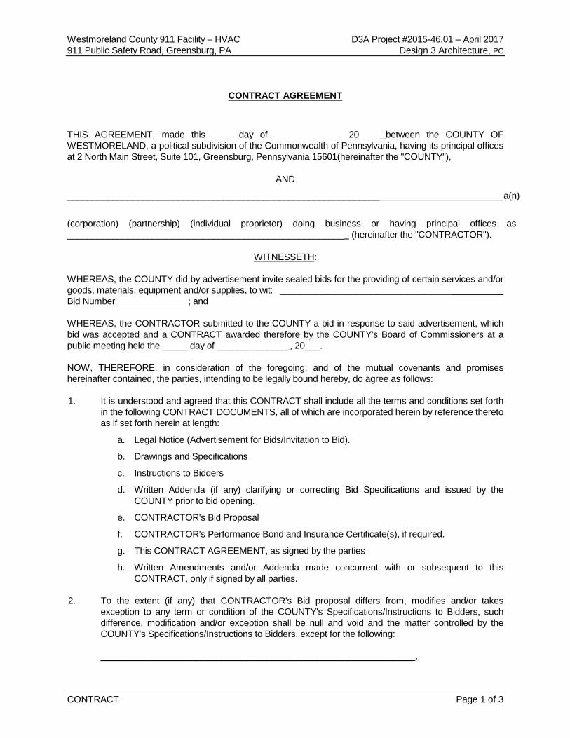
CONTRACT AGREEMENT
THIS AGREEMENT, made this ____ day of _____________, 20____ between the COUNTY OF WESTMORELAND, a political subdivision of the Commonwealth of Pennsylvania, having its principal offices at 2 North Main Street, Suite 101, Greensburg, Pennsylvania 15601(hereinafter the "COUNTY"),
AND
______________________________________________________________ a(n)
(corporation) (partnership) (individual proprietor) doing business or having principal offices as _______________________________________________________ (hereinafter the "CONTRACTOR").
WITNESSETH:
WHEREAS, the COUNTY did by advertisement invite sealed bids for the providing of certain services and/or goods, materials, equipment and/or supplies, to wit: __________________________________ Bid Number ______________; and WHEREAS, the CONTRACTOR submitted to the COUNTY a bid in response to said advertisement, which bid was accepted and a CONTRACT awarded therefore by the COUNTY's Board of Commissioners at a public meeting held the _____ day of ______________ , 20___. NOW, THEREFORE, in consideration of the foregoing, and of the mutual covenants and promises hereinafter contained, the parties, intending to be legally bound hereby, do agree as follows: 1. It is understood and agreed that this CONTRACT shall include all the terms and conditions set forth
in the following CONTRACT DOCUMENTS, all of which are incorporated herein by reference thereto as if set forth herein at length:
a. Legal Notice (Advertisement for Bids/Invitation to Bid).
b. Drawings and Specifications
c. Instructions to Bidders
d. Written Addenda (if any) clarifying or correcting Bid Specifications and issued by the COUNTY prior to bid opening.
e. CONTRACTOR's Bid Proposal
f. CONTRACTOR's Performance Bond and Insurance Certificate(s), if required.
g. This CONTRACT AGREEMENT, as signed by the parties
h. Written Amendments and/or Addenda made concurrent with or subsequent to this CONTRACT, only if signed by all parties.
2. To the extent (if any) that CONTRACTOR's Bid proposal differs from, modifies and/or takes
exception to any term or condition of the COUNTY's Specifications/Instructions to Bidders, such difference, modification and/or exception shall be null and void and the matter controlled by the COUNTY's Specifications/Instructions to Bidders, except for the following:
______________________________________________________________ .

(THIS PAGE INTENTIONALLY LEFT BLANK)
Westmoreland County 911 Facility – HVAC D3A Project #2015-46.01 – April 2017 911 Public Safety Road, Greensburg, PA Design 3 Architecture, PC
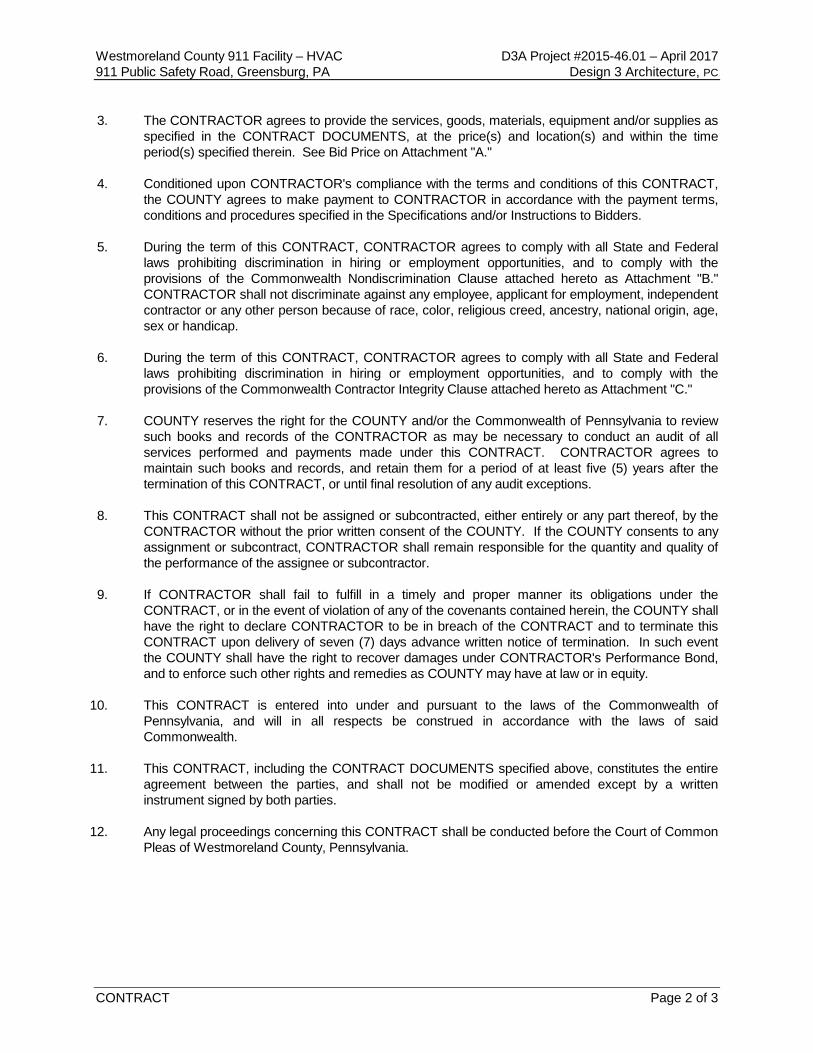
CONTRACT Page 2 of 3
3. The CONTRACTOR agrees to provide the services, goods, materials, equipment and/or supplies as specified in the CONTRACT DOCUMENTS, at the price(s) and location(s) and within the time period(s) specified therein. See Bid Price on Attachment "A."
4. Conditioned upon CONTRACTOR's compliance with the terms and conditions of this CONTRACT, the COUNTY agrees to make payment to CONTRACTOR in accordance with the payment terms, conditions and procedures specified in the Specifications and/or Instructions to Bidders.
5. During the term of this CONTRACT, CONTRACTOR agrees to comply with all State and Federal laws prohibiting discrimination in hiring or employment opportunities, and to comply with the provisions of the Commonwealth Nondiscrimination Clause attached hereto as Attachment "B." CONTRACTOR shall not discriminate against any employee, applicant for employment, independent contractor or any other person because of race, color, religious creed, ancestry, national origin, age, sex or handicap.
6. During the term of this CONTRACT, CONTRACTOR agrees to comply with all State and Federal
laws prohibiting discrimination in hiring or employment opportunities, and to comply with the provisions of the Commonwealth Contractor Integrity Clause attached hereto as Attachment "C."
7. COUNTY reserves the right for the COUNTY and/or the Commonwealth of Pennsylvania to review
such books and records of the CONTRACTOR as may be necessary to conduct an audit of all services performed and payments made under this CONTRACT. CONTRACTOR agrees to maintain such books and records, and retain them for a period of at least five (5) years after the termination of this CONTRACT, or until final resolution of any audit exceptions.
8. This CONTRACT shall not be assigned or subcontracted, either entirely or any part thereof, by the
CONTRACTOR without the prior written consent of the COUNTY. If the COUNTY consents to any assignment or subcontract, CONTRACTOR shall remain responsible for the quantity and quality of the performance of the assignee or subcontractor.
9. If CONTRACTOR shall fail to fulfill in a timely and proper manner its obligations under the
CONTRACT, or in the event of violation of any of the covenants contained herein, the COUNTY shall have the right to declare CONTRACTOR to be in breach of the CONTRACT and to terminate this CONTRACT upon delivery of seven (7) days advance written notice of termination. In such event the COUNTY shall have the right to recover damages under CONTRACTOR's Performance Bond, and to enforce such other rights and remedies as COUNTY may have at law or in equity.
10. This CONTRACT is entered into under and pursuant to the laws of the Commonwealth of
Pennsylvania, and will in all respects be construed in accordance with the laws of said Commonwealth.
11. This CONTRACT, including the CONTRACT DOCUMENTS specified above, constitutes the entire
agreement between the parties, and shall not be modified or amended except by a written instrument signed by both parties.
12. Any legal proceedings concerning this CONTRACT shall be conducted before the Court of Common
Pleas of Westmoreland County, Pennsylvania.

(THIS PAGE INTENTIONALLY LEFT BLANK)
Westmoreland County 911 Facility – HVAC D3A Project #2015-46.01 – April 2017 911 Public Safety Road, Greensburg, PA Design 3 Architecture, PC
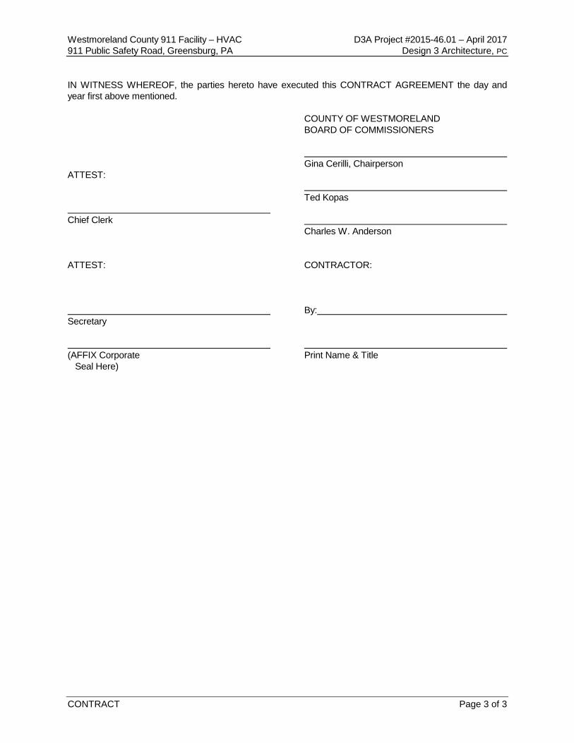
CONTRACT Page 3 of 3
IN WITNESS WHEREOF, the parties hereto have executed this CONTRACT AGREEMENT the day and year first above mentioned. COUNTY OF WESTMORELAND BOARD OF COMMISSIONERS Gina Cerilli, Chairperson ATTEST: Ted Kopas Chief Clerk Charles W. Anderson ATTEST: CONTRACTOR: By: Secretary (AFFIX Corporate Print Name & Title Seal Here)

(THIS PAGE INTENTIONALLY LEFT BLANK)
Westmoreland County 911 Facility – HVAC D3A Project #2015-46.01 – April 2017 911 Public Safety Road, Greensburg, PA Design 3 Architecture, PC
PERFORMANCE BOND Page 1 of 2
PERFORMANCE BOND
KNOW ALL MEN BY THESE PRESENTS: That ________________________________________________________________________________ ____________________________________________________________________________________ (Insert name and address or legal title of the Contractor) As Principal, hereinafter called Contractor, and ____________________________________________________________________________________ ____________________________________________________________________________________ (Insert the name and address or legal title of Surety) As Obligee, hereinafter called Owner, in the amount of
________________________________________________________Dollars ($____________________). For the payment whereof Contractor and Surety bind themselves, their heirs, executors, administrators, successors and assigns, jointly and severally, firmly by these presents. WHEREAS, Contractor has by written agreement dated _________________ entered into a Contract with Owner for
____________________________________________________________________________________ In accordance with drawings and specifications prepared by
____________________________________________________________________________________ (Insert full name and title) Which Contract is by reference made a part hereof, and is hereinafter referred to as the Contract. NOW, THEREFORE, THE CONDITION OF THIS OBLIGATION is such that, if Contractor shall promptly and faithfully perform said Contract, then this obligation shall be null and void; otherwise, it shall remain in full force and effect. The Surety hereby waives notice of any alteration or extension of time made by the Owner. Whenever Contractor shall be, and declared by Owner to be in default under the Contract, the Owner having performed Owner’s obligation hereunder, the Surety may promptly remedy the default, or shall promptly:
1. Complete the Contract in accordance with its terms and conditions, or
2. Obtain a bid or bids for submission to Owner for completing the Contract in accordance with its terms and conditions, and upon determination by Owner and Surety of the lowest responsible Bidder, arrange for a Contract between such Bidder and Owner, and make available as work progresses (even though there should be default or a succession of defaults under the Contract or Contracts of completion arranged under this paragraph) sufficient funds to pay the cost of completion less the balance of the Contract price, but not exceeding, including other costs and damages for which the Surety may be liable hereunder, the amount set forth in the first paragraph hereof. The term “Balance of the Contract price”, as used in this paragraph, shall mean the total amount payable by Owner to Contractor under the Contract and any amendments thereto, less the properly paid by Owner to Contractor.

(THIS PAGE INTENTIONALLY LEFT BLANK)
Westmoreland County 911 Facility – HVAC D3A Project #2015-46.01 – April 2017 911 Public Safety Road, Greensburg, PA Design 3 Architecture, PC
PERFORMANCE BOND Page 2 of 2
Any suit under this Bond must be instituted before the expiration date of two (2) years from this date on which final payment under the Contract falls due. No right of action shall accrue on this Bond to or for the use of any person or corporation other than the Owner named herein or its successors or assigns of the Owner. Signed and sealed this ____________________day of _____________________A.D. 2017. (SEAL) ______________________________________ (Principal) ___________________________________________ ______________________________________ (Title) ___________________________________________ ______________________________________ (Surety) ______________________________________ (Title)

(THIS PAGE INTENTIONALLY LEFT BLANK)
Westmoreland County 911 Facility – HVAC D3A Project #2015-46.01 – April 2017 911 Public Safety Road, Greensburg, PA Design 3 Architecture, PC
LABOR & MATERIAL PAYMENT BOND Page 1 of 2
LABOR & MATERIAL PAYMENT BOND
NOTE: This Bond is issued simultaneously with another Bond in favor of the Owner conditioned for the full and faithful performance of the Contract. KNOW ALL MEN BY THESE PRESENTS: That ________________________________________________________________________________ ____________________________________________________________________________________ (Insert the name and address or legal title of the Contractor) as Principal, hereinafter called Principal, and
____________________________________________________________________________________ (Insert the legal title of Surety) as Surety, hereinafter called Surety, are held and firmly bound unto ____________________________________________________________________________________ ____________________________________________________________________________________ (Insert the name and address or legal title of the Owner) As Obligee, hereinafter called Owner, for the use and benefit of claimants as herein below defined, in the amount of _____________________________________________________________Dollars ($______________), for the payment whereof Principal and Surety bind themselves, their heirs, executors, administrators, successors and assigns, jointly and severally, firmly by these presents. WHEREAS, Principal has by written agreement dated ________________________________________ entered into a Contract with Owner for
____________________________________________________________________________________
____________________________________________________________________________________ In accordance with drawings and specifications prepared by Design 3 Architecture, Monroeville, PA, which Contract is by reference made a part hereof, and is herein-after referred to as the Contract. NOW, THEREFORE, THE CONDITION OF THIS OBLIGATION is such that if the Principal shall promptly make payment to all claimants as hereinafter defined, for all labor and material used or reasonably required for use in the performance of the Contract, then this obligation shall be void; otherwise, it shall remain in full force and effect, subject, however, to the following conditions:
1. A claimant is defined as one having a direct contract with the Principal or with a Subcontractor of the Principal for labor, material, or both, used or reasonably required for use in the performance of the contract, labor, and material being construed to include that part of water, gas, power, light, heat, oil, gasoline, telephone service or rental of equipment directly applicable to the contract.

(THIS PAGE INTENTIONALLY LEFT BLANK)
Westmoreland County 911 Facility – HVAC D3A Project #2015-46.01 – April 2017 911 Public Safety Road, Greensburg, PA Design 3 Architecture, PC
LABOR & MATERIAL PAYMENT BOND Page 2 of 2
2. The above-named Principal and Surety hereby jointly and severally agree with the Owner that every claimant as herein defined, who has not been paid-in-full before the expiration of a period of ninety (90) days after the date on which the last of such claimant’s work or labor was done or performed, or materials were furnished by such claimant, may sue on this bond for the use of such claimant, prosecute the suit to final judgment for such sum or sums as may be justly due claimant, and have execution of thereon. The Owner shall not be liable for the payment of any costs of expenses of any such suit.
3. No suit or action shall be commenced hereunder by any claimant:
a. Unless claimant, other than one having a direct contract with the Principal, shall
have given written notice to any two of the following: the Principal, the Owner or the Surety above-named, within ninety (90) days after such claimant did or performed the last of the work or labor, or furnished the last of the materials for which such claim is made, stating with substantial accuracy the amount claimed and the name of the party to whom the materials were furnished or for whom the work or labor was done or performed. Such notice shall be served by mailing the same by registered mail or certified mail, postage prepaid, in an envelope addressed to the Principal, Owner or Surety, at any place where an office is regularly maintained for the transaction of business, or served in the state in which the aforesaid project is located, save that such service need not be made by public officer.
b. After the expiration of one (1) year following the date on which Principal ceased work on said Contract, it being understood, however, that if any limitations embodied in this bond is prohibited by any law controlling the construction hereof, such limitation shall be deemed to be amended so as to be equal to the minimum period of limitation permitted by such law.
c. Other than in a state court of competent jurisdiction in and for the county or other political subdivision of the state in which the project or any part thereof is situated, or in the United States District Court for the District in which the project, or any part thereof, is situated, and not elsewhere.
4. The amount of this bond shall be reduced by and to the extent of any payment or payments made in good faith hereunder, inclusive of the payment by Surety of Mechanic’s Liens which may be filed on record against such improvement whether or not claim for the amount on such lien be presented under and against this bond.
Signed and sealed this ____________________day of _____________________A.D. 2017. IN THE PRESENCE OF: ______________________________________ (Principal) ______________________________________ (Title) ______________________________________ (Surety) ______________________________________ (Title)

(THIS PAGE INTENTIONALLY LEFT BLANK)
Westmoreland County 911 Facility – HVAC D3A Project #2015-46.01 – April 2017 911 Public Safety Road, Greensburg, PA Design 3 Architecture, PC
AFFIDAVIT Page 1 of 1
AFFIDAVIT ACCEPTING PROVISIONS OF THE WORKMEN'S COMPENSATION ACT STATE OF ___________________________________ COUNTY OF __________________________________ ____________________________________________ being duly sworn (Contractor) he has according to law deposes and says they have accepted the provisions it has of the Workmen's Compensation Act of 1915 of the Commonwealth of has Pennsylvania, with its supplement and amendments, and have insured had his their liability there under in accordance with the terms of said Act its with _______________________________________________________________________________ (INSURING COMPANY) ______________________________________ (Contractor) BY:___________________________________ Sworn to and subscribed before me this _______day of _____________________________________ 2017 A.D. _____________________________________ My Commission Expires : _____________________________________

(THIS PAGE INTENTIONALLY LEFT BLANK)
Westmoreland County 911 Facility – HVAC D3A Project #2015-46.01 – April 2017 911 Public Safety Road, Greensburg, PA Design 3 Architecture, PC
MAINTENANCE BOND Page 1 of 2
MAINTENANCE BOND
KNOW ALL MEN BY THESE PRESENTS, that we,
____________________________________________________________________________________
____________________________________________________________________________________
as Principal, and ______________________________________________________________________
a Corporation organized and existing under the laws of the State of ______________________________,
as Surety, are held and firmly bound unto the County of Westmoreland as Obligee, in the full and just sum of
____________________________________________________________________________ dollars,
($_________________________________) lawful money of the United States of America, to be paid to the
Obligee, or its assigns, (to which payment well and truly to be made and done), we bind ourselves, our heirs,
executors, administrators and successors, jointly and severally, firmly by these presents.
WHEREAS, the above bounden Principal has entered into a contract with the Obligee dated the
________________________ day of _____________________, 2017, for the Westmoreland County 911
Facility HVAC.
WHEREAS, it is one of the conditions of the award of the Obligee pursuant to which said contract has
been entered into, that these presents be executed.
NOW, THEREFORE, the condition of the obligation is: That if the above bounden Principal shall remedy
without cost to the Obligee any defects which may develop during a period of one (1) year from the date of
completion and acceptance of the work performed under said contract, provided such defects are caused
by defective or inferior materials, or workmanship, then this obligation shall be void; otherwise, it shall be
and remain in full force and effect.

(THIS PAGE INTENTIONALLY LEFT BLANK)
Westmoreland County 911 Facility – HVAC D3A Project #2015-46.01 – April 2017 911 Public Safety Road, Greensburg, PA Design 3 Architecture, PC
MAINTENANCE BOND Page 2 of 2
IN WITNESS WHEREOF, the said Principal and Surety have duly executed this Bond under seal this
________________________ day of ____________________________________________, 2017.
________________________________(SEAL)
(Individual Principal Sign Here) In the Presence of: ________________________________(SEAL) _________________________________ ________________________________(SEAL) _________________________________ ________________________________(SEAL) ATTEST: (Corporate Principal Sign Here) _________________________________ ________________________________(SEAL) (Surety Sign Here) _________________________________(SEAL) _________________________________(SEAL) IMPORTANT NOTICE: Surety Companies executing bonds must appear on the Treasury Department's most current list (Circular 570) and be authorized to transact business in the State where the project is located.

(THIS PAGE INTENTIONALLY LEFT BLANK)
Westmoreland County 911 Facility – HVAC D3A Project #2015-46.01 – April 2017 911 Public Safety Road, Greensburg, PA Design 3 Architecture, PC
ATTACHMENT D Page 1 of 1
ATTACHMENT D
CONSENT TO EXTENSION OF DATE FOR BID AWARD
BID TITLE/PROJECT:__________________________________________________________________ BID OPENING DATE:__________________________________________________________________ BIDDER’S NAME:_____________________________________________________________________ BIDDER’S ADDRESS:__________________________________________________________________ ____________________________________________________________________________________ ____________________________________________________________________________________ CURRENT CONTRACT AWARD DEADLINE: ______________________________________ EXTENDED CONTRACT AWARD DEADLINE: ______________________________________ Westmoreland County, Pennsylvania, hereby requests the undersigned Bidder to consent to a thirty (30) day extension of the date for the award of a contract for the above bid/project. According to Section 1802 (e) of the County Code, the contract must be awarded or all bids rejected within ninety (90) days of the opening bids, but thirty (30) day extensions of the date for the contract award may be made by mutual written consent of the County and any Bidder who wishes to remain under consideration for the award. By law, any Bidder who declines to consent to such extension of the date for contract must be excused from consideration for the contract, and such Bidder’s bid security must be released without penalty. The undersigned Bidder wishes to remain under consideration for award of the above contract, and hereby consents to the County’s request for a thirty (30) day extension of the date for the award of a contract for the above bid/project. COUNTY OF WESTMORELAND BIDDER _____________________________________ By: _______________________________ Gina Cerilli, Chairman Date Bidder’s Authorized Signature _____________________________________ _______________________________ Ted Kopas Date Print Name and Title _____________________________________ _______________________________ Charles W. Anderson Date Date Signed by Bidder

(THIS PAGE INTENTIONALLY LEFT BLANK)
Westmoreland County 911 Facility – HVAC D3A Project #2015-46.01 – April 2017 911 Public Safety Road, Greensburg, PA Design 3 Architecture, PC
ATTACHMENT E Page 1 of 2
ATTACHMENT E
COMMONWEALTH NON-DISCRIMINATION CLAUSE
_______________________________________, hereinafter referred to as the Contractor, agrees as follows: 1. Contractor shall not discriminate against any employee, applicant, for employment, independent
contractor, or any other person because of race, color, religious creed, ancestry, national origin, age or sex. Contractor shall take affirmative action to insure that applicants are employed, and that employees or agents are treated during employment, without regard to their race, color, religious creed, ancestry, national origin, age or sex. Such affirmative action shall include, but is not limited to, the following: Employment, upgrading, demotion or transfer; recruitment or recruitment advertising; layoff or termination; rates of pay or other forms of compensation; and selection for training. Contractor shall post in conspicuous places, available to all employees, agents, applicants for employment and other persons, a notice to be provided by the contracting agency setting forth the provisions of the nondiscrimination clause.
2. Contractor shall, in advertisement or requests for employment placed by its or on its behalf, state
that all qualified applicants will receive consideration for employment without regard to race, color, religious creed, ancestry, national origin, age or sex.
3. Contractor shall send each labor union or worker' representative with which it has a collective
bargaining agreement or other contract or understanding, a notice advising said labor union or workers' representative of its commitment to this nondiscrimination clause. Similar notice shall be sent to every other source of recruitment regularly utilized by the Contractor.
4. It shall be no defense to a finding of noncompliance with the Contract Compliance Regulations
Commission or this nondiscrimination clause that Contractor had delegated some of its employment practices to any union, training program, or other source of recruitment which prevents it from meeting its obligations. However, if the evidence indicates that the Contractor was not on notice of the third-party discrimination or made a good faith effort to correct it, such factor shall be considered in mitigation in determining appropriate sanctions.
5. Where the practices of a union or any training program or other source of recruitment will result in
the exclusion of minority group persons, so that the Contractor will be unable to meet its obligations under the Contract Compliance Regulations issued by the Pennsylvania Human Relations Commission or this nondiscrimination clause, Contractor shall then employ and fill vacancies through other nondiscriminatory employment procedures.
6. Contractor shall comply with the Contract Compliance Regulations of the Pennsylvania Human
Relations commission, 16 PA Code Chapter 49 and with all state and federal laws prohibiting discrimination in hiring or employment opportunities. In the event of the Contractor’s noncompliance with the nondiscrimination clause of this CONTRACT may, after hearing and adjudication, be terminated or suspended, in whole or in part, and the Contractor may be declared temporarily ineligible for further contracts and other such sanctions may be imposed and remedies invoked as provided by the Contract Compliance Regulations.
Westmoreland County 911 Facility – HVAC D3A Project #2015-46.01 – April 2017 911 Public Safety Road, Greensburg, PA Design 3 Architecture, PC
ATTACHMENT E Page 2 of 2
ATTACHMENT E (continued)
COMMONWEALTH NON-DISCRIMINATION CLAUSE
7. Contractor shall furnish all necessary employment documents and records to, and permit access
to its books, records and accounts by, the contracting agency, the Office of Administration, Bureau of Affirmative Action, and the Human Relations Commission for purposes of investigation to ascertain compliance with the provisions of the Contract Compliance Regulations, pursuant to 49.35 of this title (relating to information concerning compliance by contractors). If Contractor does not possess documents or records reflecting the necessary information requested, it shall furnish such information on reporting forms supplied by the contracting agency, the Bureau of Affirmative Action or the COMMISSION.
8. Contractor shall actively recruit minority sub-contractors or subcontractors with substantial minority representation among their employees.
9. Contractor shall include the provisions of this nondiscrimination clause in every subcontract, so
that such provisions will be binding upon each subcontractor. 10. The terms used in this nondiscrimination clause shall have the same meaning as in the Contract
Compliance Regulations issued by the Pennsylvania Human Relations Commission, 42 PA Code Chapter 49.
11. Contractor obligations under this clause are limited to the Contractor’s facilities within
Pennsylvania, or, where the CONTRACT is for the purchase of goods manufactured outside of Pennsylvania, the facilities at which such goods are actually produced.
Westmoreland County 911 Facility – HVAC D3A Project #2015-46.01 – April 2017 911 Public Safety Road, Greensburg, PA Design 3 Architecture, PC
ATTACHMENT F Page 1 of 2
ATTACHMENT F
COMMONWEALTH CONTRACTOR INTEGRITY _______________________________, hereinafter referred to as the Contractor, agrees as follows:
1. DEFINITIONS a. "Confidential information" means information that is not public knowledge, or available to
the public on request, disclosure of which would give an unfair, unethical, or illegal advantage to another desiring to contract with the Commonwealth of Pennsylvania or the County of Westmoreland.
b. "Consent" means written permission signed by a duly authorized officer or employee of
the Commonwealth or the County of Westmoreland, provided that where the material facts have been disclosed, in writing, by pre-qualification, bid, proposal, or contractual terms, the RTC shall be deemed to have consented by virtue of execution of this agreement.
c. "Contractor" means the individual or entity that has entered into this agreement with the
County, including directors, officers, partners, managers, key employees, and owners of more than a 5% interest.
d. "Financial Interest" means: (1) ownership of more than 5% interest in any business; or (2) holding a position as an officer, director, trustee, partner, employee, or the
like, or holding any position of management. e. "Gratuity" means any payment of more than nominal monetary value in the form of cash,
travel, entertainment, gifts, meals, lodging, loans, subscriptions, advances, deposits of money, services, employment, or contracts of any kind.
2. The Contractor shall maintain the highest standards of integrity in the performance of this
agreement and shall take no action in violation of State or Federal laws, regulations, or other requirements that govern contracting with the Commonwealth of Pennsylvania and/or the County.
3. The Contractor shall not disclose to others any confidential information gained by virtue of
this agreement. 4. The Contractor shall not, in connection with this or any other agreement with the County or
the Commonwealth of Pennsylvania, directly or indirectly, offer, confer, or agree to confer any pecuniary benefit on anyone as consideration for the decision, opinion, recommendation, vote, other exercise of discretion, or violation of a known legal duty by any officer or employee of the County or the Commonwealth of Pennsylvania.
5. The Contractor shall not, in connection with this or any other agreement with the County or
the Commonwealth, directly or indirectly, offer, give, or agree or promise to give to anyone any gratuity for the benefit of or at the direction or request of any officer or employee of the County or the Commonwealth.
Westmoreland County 911 Facility – HVAC D3A Project #2015-46.01 – April 2017 911 Public Safety Road, Greensburg, PA Design 3 Architecture, PC
ATTACHMENT F Page 2 of 2
ATTACHMENT F (continued)
COMMONWEALTH CONTRACTOR INTEGRITY
6. Except with the consent of the County and the Commonwealth, neither the Contractor nor anyone in privity with the Contractor shall accept or agree to accept from, or give or agree to give to, any person, any gratuity from any person in connection with the performance of work under this agreement except as provided therein.
7. Except with the consent of the County and Commonwealth, the Contractor shall not have a financial interest in any other contractor, subcontractor, or supplier providing services, labor, or material on this project.
8. The Contractor, upon being informed that any violation of these provisions has occurred or
may occur, shall immediately notify the County in writing.
9. The Contractor, by execution of this agreement and by the submission of any bills or invoices for payment pursuant thereto, certifies and represents that the Contractor has not violated any of these provisions.
10. The Contractor shall, upon request of the Office of State Inspector General or County
Controller, reasonably and promptly make available to that office and its representatives, for inspection and copying, all business and financial records of the Contractor of, concerning, and referring to this agreement with the County or which are otherwise relevant to the enforcement of these provisions.
11. For violation of any of the above provisions, the County (or Commonwealth, if applicable)
may terminate this and any other agreement with the Contractor, claim liquidated damages in an amount equal to the value of anything received in breach of these provisions, claim damages for all expenses incurred in obtaining another contractor to complete performance hereunder, and debar and suspend the Contractor from doing business with the County or Commonwealth. These rights and remedies are cumulative, and the use or nonuse of any one shall not preclude the use of all or any other. These rights and remedies are in addition to those the Commonwealth or the County may have under law, statute, regulation, or otherwise.
Westmoreland County 911 Facility – HVAC D3A Project #2015-46.01 – April 2017 911 Public Safety Road, Greensburg, PA Design 3 Architecture, PC
ATTACHMENT G Page 1 of 2
ATTACHMENT G
CONTRACTOR'S NO-LIEN AFFIDAVIT
I ____________________________________________________________________________
(Name and Title) as duly authorized Agent for ______________________________________________
____________________________________________________________________________________
(Contractor) acknowledge that a contract with the County of Westmoreland was entered into on the
_____day of , 2017 for the Westmoreland County 911 Facility HVAC.
I further acknowledge in behalf of the Contractor, that as the aforementioned project serves a
purely public purpose, by law no mechanics lien or any other lien, attachment or encumbrance may be
placed upon any and all buildings and premises owned by Westmoreland County, into or upon which any
work, labor, or materials are furnished under the aforementioned contract.
The Contractor further agrees that it will secure from any and all sub-contractors, materialman,
mechanics, journeyman, laborers or other parties acting in their behalf, whose labor services or materials
will be used for the aforementioned project, a sub-contractor no-lien affidavit substantially in the form of
this Contractor's no-lien affidavit. Upon the request of the Contractor, the County, in its sole and exclusive
discretion may waive the need for the Contractor to secure the sub-contractor no lien affidavit, either in
whole or in part.

(THIS PAGE INTENTIONALLY LEFT BLANK)
Westmoreland County 911 Facility – HVAC D3A Project #2015-46.01 – April 2017 911 Public Safety Road, Greensburg, PA Design 3 Architecture, PC
ATTACHMENT G Page 2 of 2
ATTACHMENT G (continued)
CONTRACTOR'S NO-LIEN AFFIDAVIT
Furthermore, Contractor acknowledges that it has secured a Labor & Materials Bond as required
in the Bid Specifications in the amount of 100% of the Contract price and that copies of the Labor and
Material Bond will be provided to all sub-contractors, materialman, mechanics, journeyman, laborers and
all other parties who will be providing labor or materials in connection with the aforementioned Contract by
the Contractor.
Contractor also acknowledges that all materials used to complete the aforementioned contract will
be absolute and sole property of the Contractor.
Contractor warrants that at the time of the signing of this Affidavit no work or materials of any kind
have been furnished, delivered or ordered in connection with the performance of the aforementioned
contract.
This Affidavit shall be made a part of and incorporated into the aforementioned contract.
WITNESS: Contractor:
_________________________________ ______________________________________
______________________________________
Name and Title ______________________________________ Date

(THIS PAGE INTENTIONALLY LEFT BLANK)
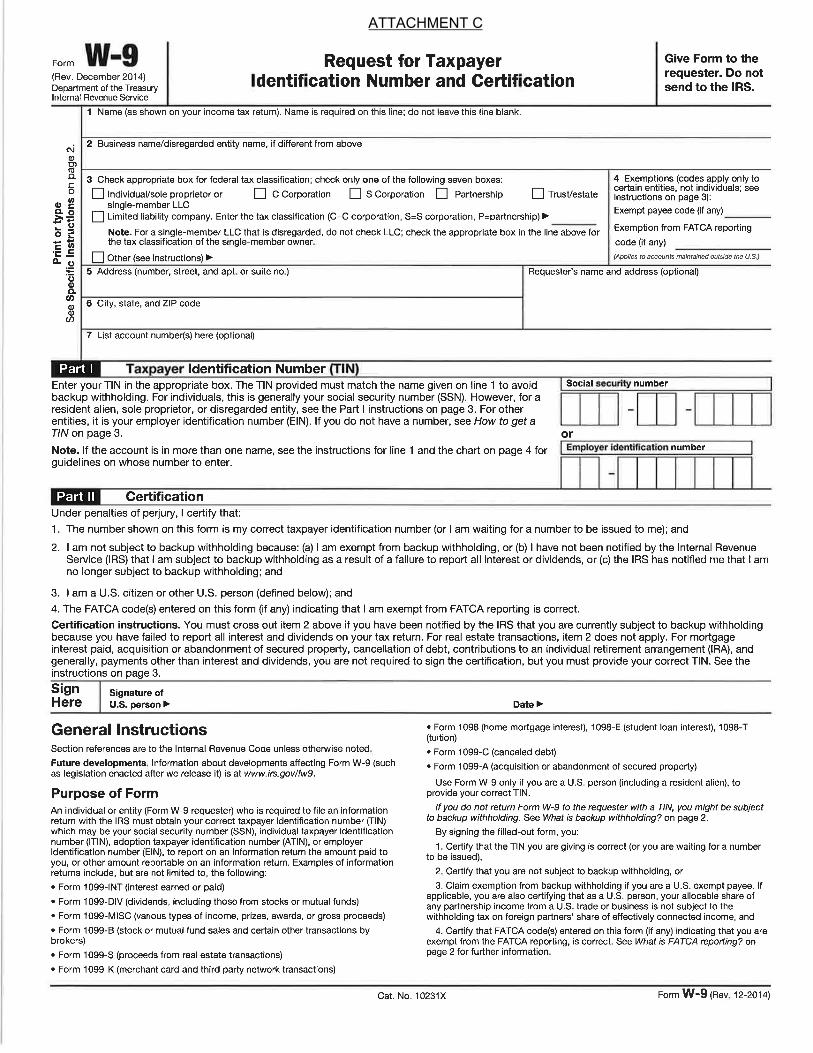
ATTACHMENT C
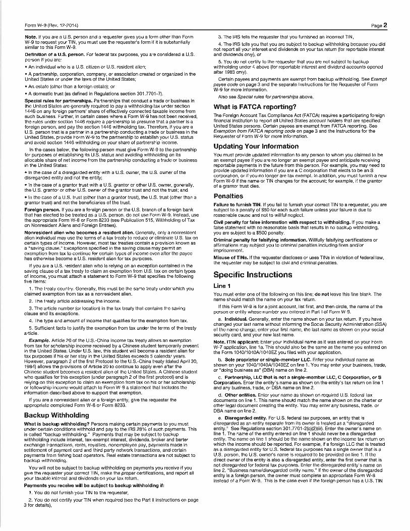
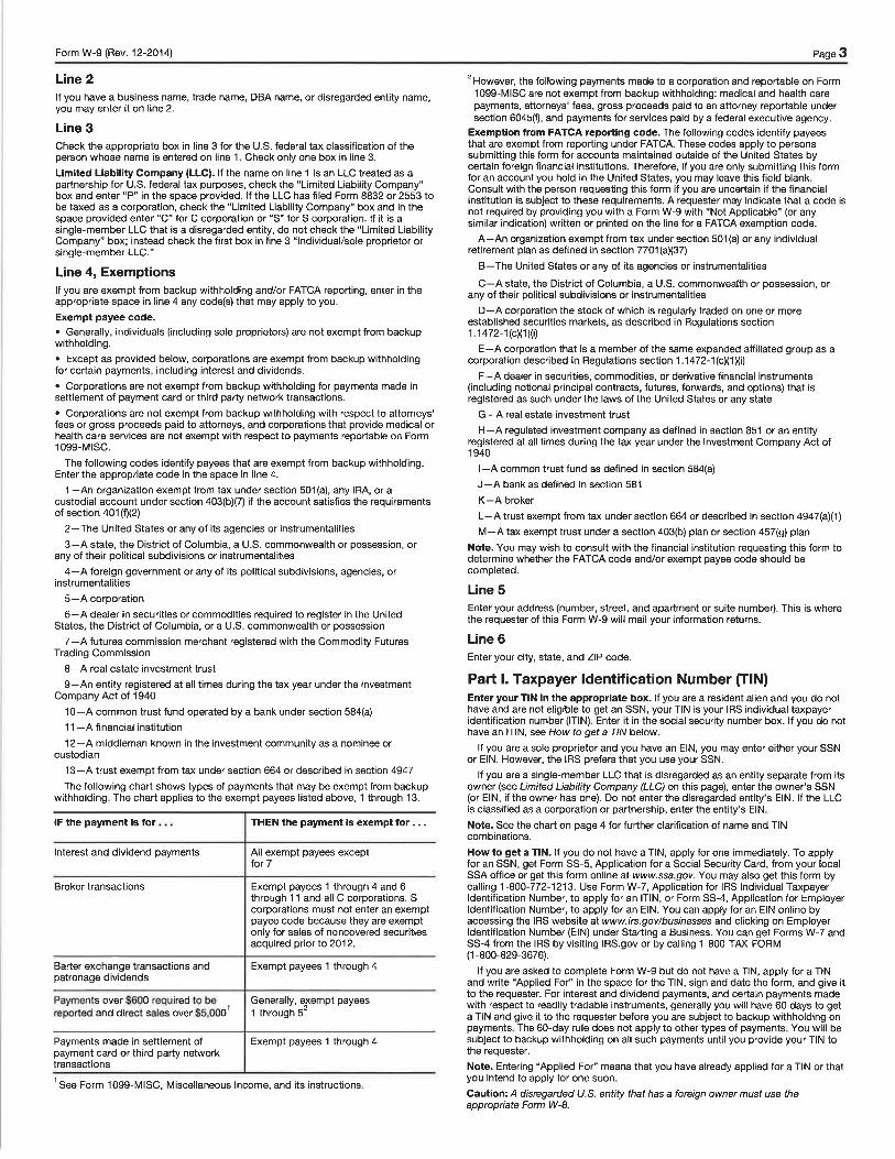
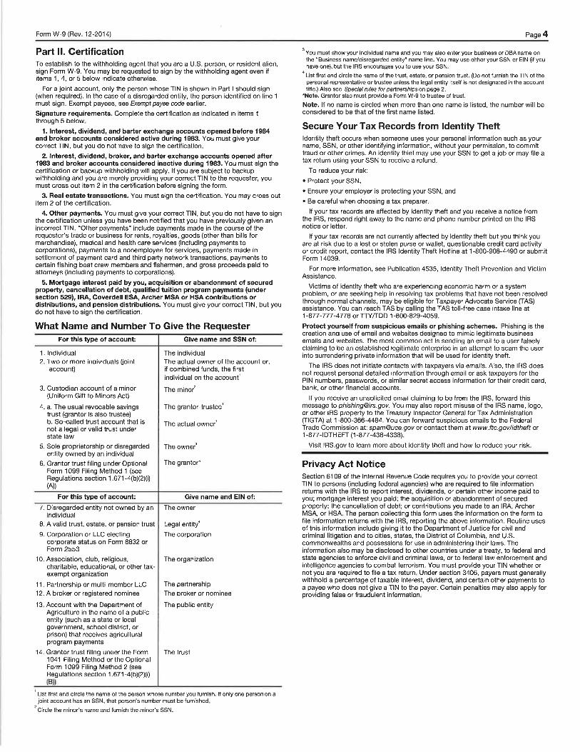
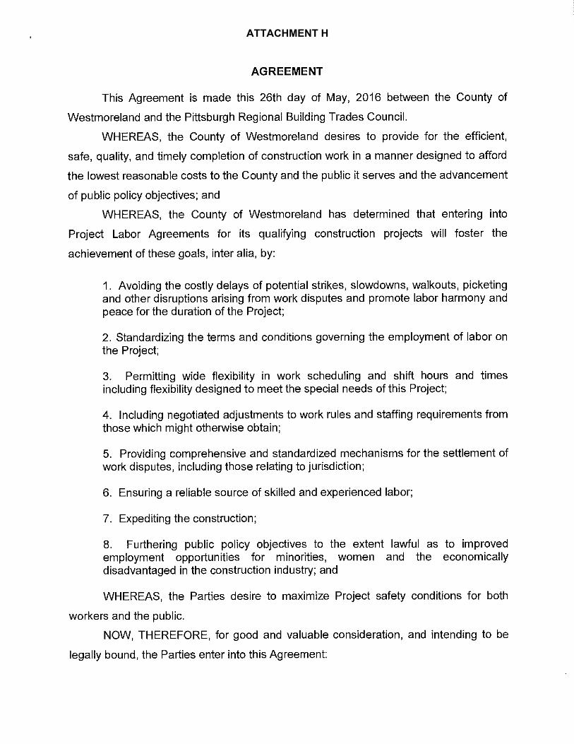
ATTACHMENT H
eDull
Line
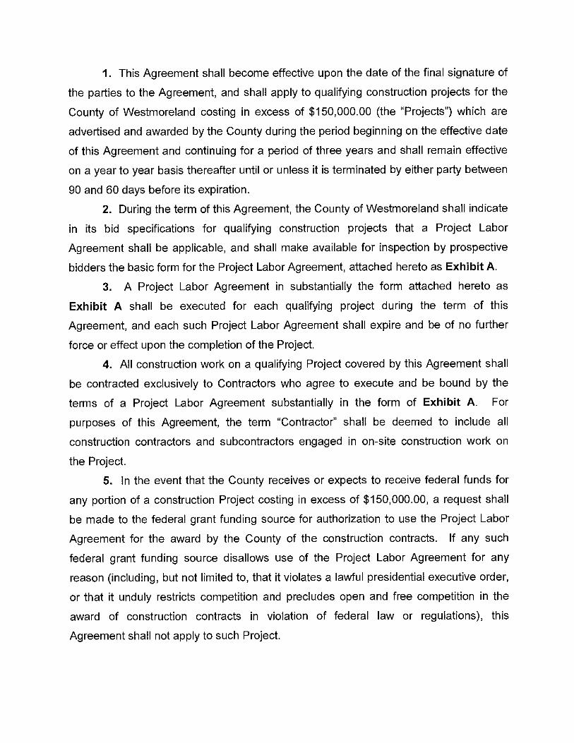
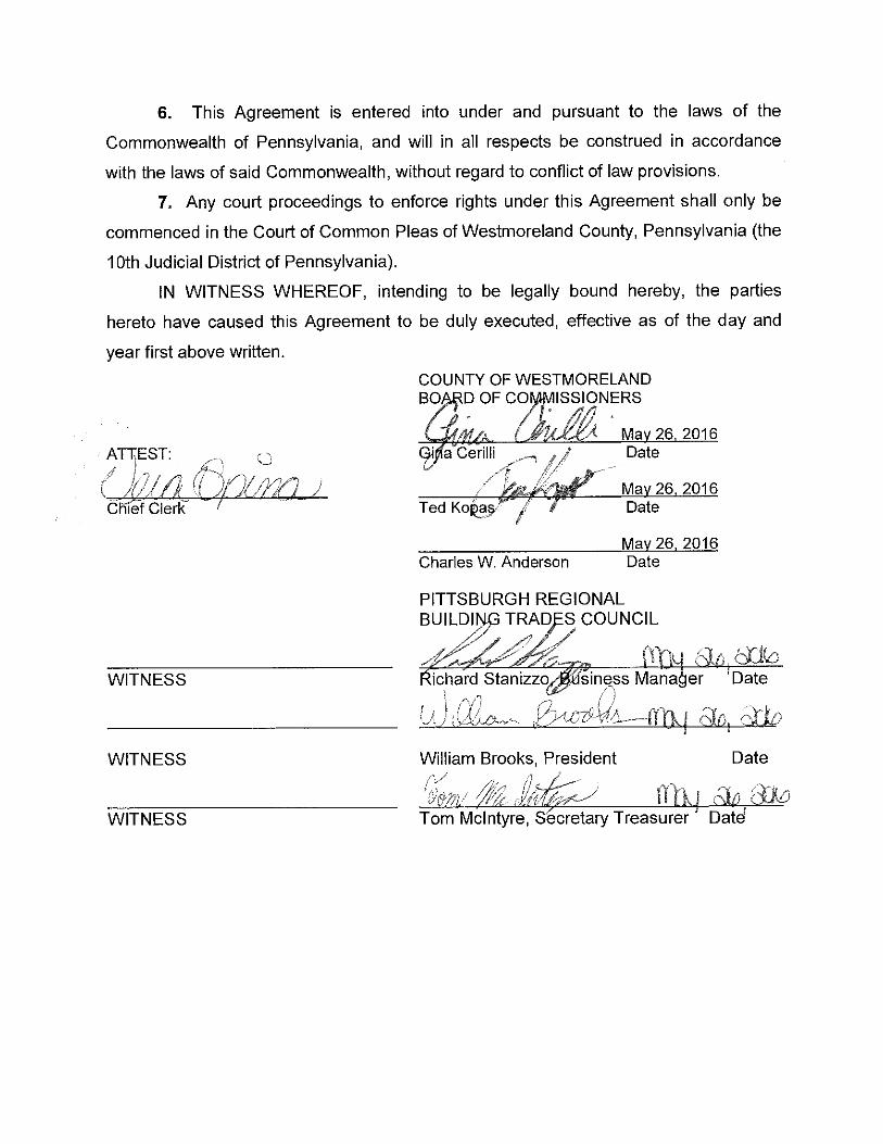

(THIS PAGE INTENTIONALLY LEFT BLANK)

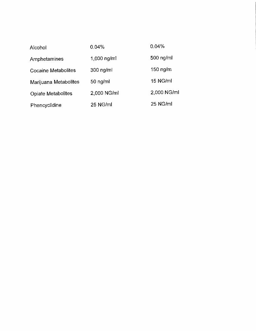

(THIS PAGE INTENTIONALLY LEFT BLANK)
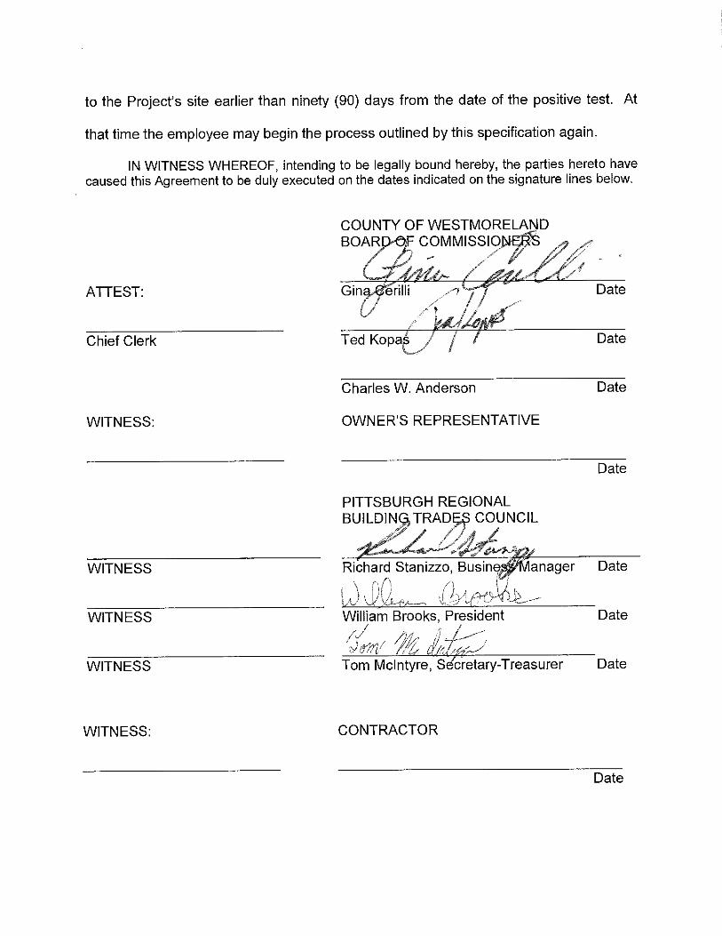

(THIS PAGE INTENTIONALLY LEFT BLANK)

(THIS PAGE INTENTIONALLY LEFT BLANK)
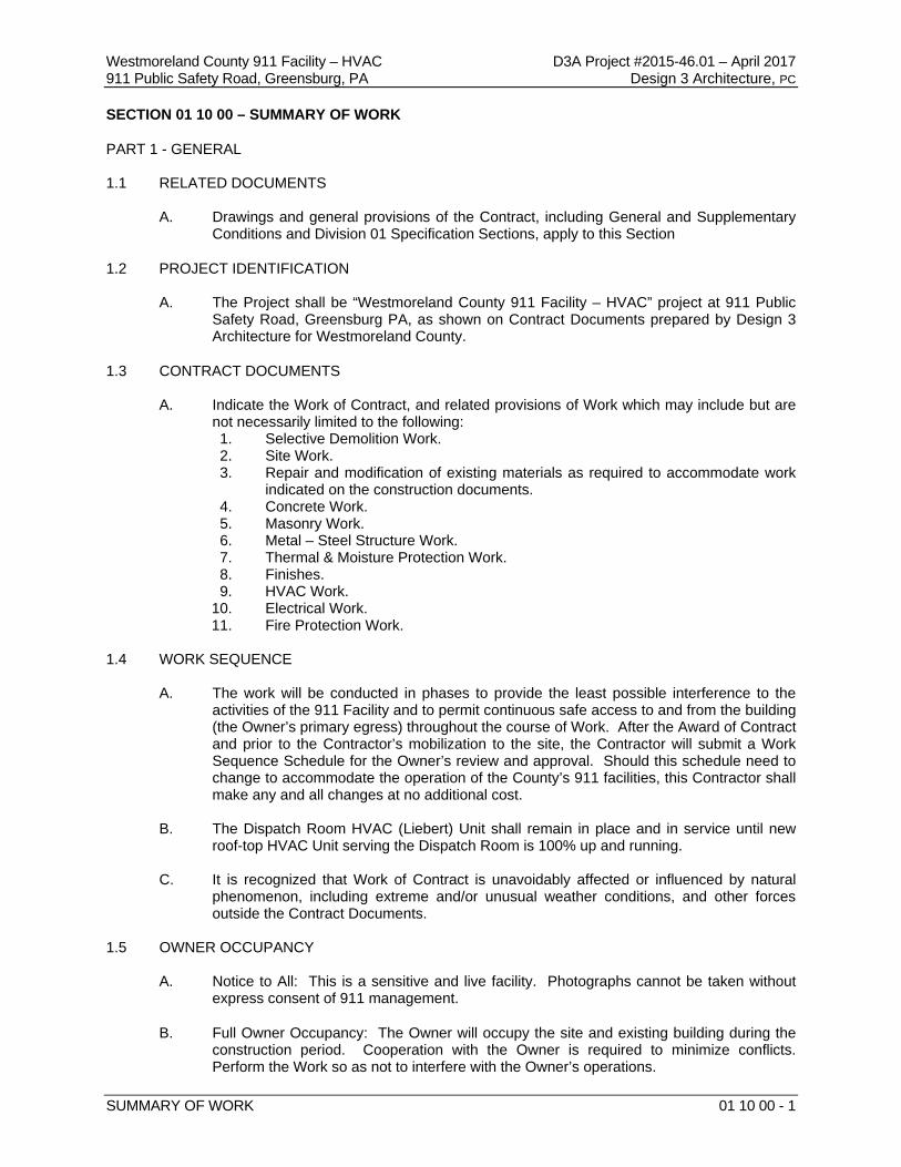
Westmoreland County 911 Facility – HVAC D3A Project #2015-46.01 – April 2017 911 Public Safety Road, Greensburg, PA Design 3 Architecture, PC
SUMMARY OF WORK 01 10 00 - 1
SECTION 01 10 00 – SUMMARY OF WORK
PART 1 - GENERAL 1.1 RELATED DOCUMENTS
A. Drawings and general provisions of the Contract, including General and Supplementary Conditions and Division 01 Specification Sections, apply to this Section
1.2 PROJECT IDENTIFICATION
A. The Project shall be “Westmoreland County 911 Facility – HVAC” project at 911 Public Safety Road, Greensburg PA, as shown on Contract Documents prepared by Design 3 Architecture for Westmoreland County.
1.3 CONTRACT DOCUMENTS
A. Indicate the Work of Contract, and related provisions of Work which may include but are not necessarily limited to the following: 1. Selective Demolition Work. 2. Site Work. 3. Repair and modification of existing materials as required to accommodate work
indicated on the construction documents. 4. Concrete Work. 5. Masonry Work. 6. Metal – Steel Structure Work. 7. Thermal & Moisture Protection Work. 8. Finishes. 9. HVAC Work.
10. Electrical Work. 11. Fire Protection Work.
1.4 WORK SEQUENCE
A. The work will be conducted in phases to provide the least possible interference to the activities of the 911 Facility and to permit continuous safe access to and from the building (the Owner’s primary egress) throughout the course of Work. After the Award of Contract and prior to the Contractor’s mobilization to the site, the Contractor will submit a Work Sequence Schedule for the Owner’s review and approval. Should this schedule need to change to accommodate the operation of the County’s 911 facilities, this Contractor shall make any and all changes at no additional cost.
B. The Dispatch Room HVAC (Liebert) Unit shall remain in place and in service until new
roof-top HVAC Unit serving the Dispatch Room is 100% up and running. C. It is recognized that Work of Contract is unavoidably affected or influenced by natural
phenomenon, including extreme and/or unusual weather conditions, and other forces outside the Contract Documents.
1.5 OWNER OCCUPANCY
A. Notice to All: This is a sensitive and live facility. Photographs cannot be taken without express consent of 911 management.
B. Full Owner Occupancy: The Owner will occupy the site and existing building during the construction period. Cooperation with the Owner is required to minimize conflicts. Perform the Work so as not to interfere with the Owner’s operations.
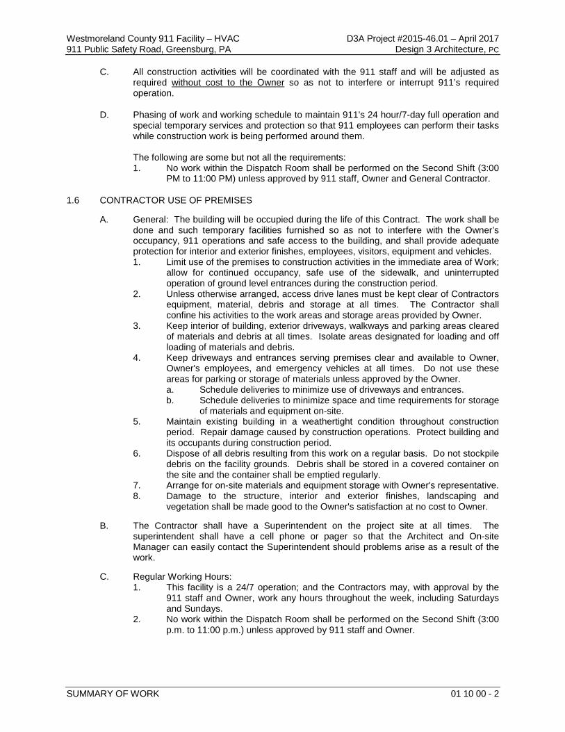
Westmoreland County 911 Facility – HVAC D3A Project #2015-46.01 – April 2017 911 Public Safety Road, Greensburg, PA Design 3 Architecture, PC
SUMMARY OF WORK 01 10 00 - 2
C. All construction activities will be coordinated with the 911 staff and will be adjusted as required without cost to the Owner so as not to interfere or interrupt 911’s required operation.
D. Phasing of work and working schedule to maintain 911’s 24 hour/7-day full operation and special temporary services and protection so that 911 employees can perform their tasks while construction work is being performed around them.
The following are some but not all the requirements: 1. No work within the Dispatch Room shall be performed on the Second Shift (3:00
PM to 11:00 PM) unless approved by 911 staff, Owner and General Contractor.
1.6 CONTRACTOR USE OF PREMISES
A. General: The building will be occupied during the life of this Contract. The work shall be done and such temporary facilities furnished so as not to interfere with the Owner’s occupancy, 911 operations and safe access to the building, and shall provide adequate protection for interior and exterior finishes, employees, visitors, equipment and vehicles. 1. Limit use of the premises to construction activities in the immediate area of Work;
allow for continued occupancy, safe use of the sidewalk, and uninterrupted operation of ground level entrances during the construction period.
2. Unless otherwise arranged, access drive lanes must be kept clear of Contractors equipment, material, debris and storage at all times. The Contractor shall confine his activities to the work areas and storage areas provided by Owner.
3. Keep interior of building, exterior driveways, walkways and parking areas cleared of materials and debris at all times. Isolate areas designated for loading and off loading of materials and debris.
4. Keep driveways and entrances serving premises clear and available to Owner, Owner's employees, and emergency vehicles at all times. Do not use these areas for parking or storage of materials unless approved by the Owner. a. Schedule deliveries to minimize use of driveways and entrances. b. Schedule deliveries to minimize space and time requirements for storage
of materials and equipment on-site. 5. Maintain existing building in a weathertight condition throughout construction
period. Repair damage caused by construction operations. Protect building and its occupants during construction period.
6. Dispose of all debris resulting from this work on a regular basis. Do not stockpile debris on the facility grounds. Debris shall be stored in a covered container on the site and the container shall be emptied regularly.
7. Arrange for on-site materials and equipment storage with Owner's representative. 8. Damage to the structure, interior and exterior finishes, landscaping and
vegetation shall be made good to the Owner's satisfaction at no cost to Owner.
B. The Contractor shall have a Superintendent on the project site at all times. The superintendent shall have a cell phone or pager so that the Architect and On-site Manager can easily contact the Superintendent should problems arise as a result of the work.
C. Regular Working Hours:
1. This facility is a 24/7 operation; and the Contractors may, with approval by the 911 staff and Owner, work any hours throughout the week, including Saturdays and Sundays.
2. No work within the Dispatch Room shall be performed on the Second Shift (3:00 p.m. to 11:00 p.m.) unless approved by 911 staff and Owner.
Westmoreland County 911 Facility – HVAC D3A Project #2015-46.01 – April 2017 911 Public Safety Road, Greensburg, PA Design 3 Architecture, PC
SUMMARY OF WORK 01 10 00 - 3
1.7 OBSERVATION OF THE WORK
A. The Contractor will allow for observation of the work by the Architect throughout the project. Observations will be performed during critical stages of the work (post demo, steel and patch prep, concrete/grout placement, and final inspection).
B. The Contractor shall provide additional safety equipment (hard hats, ear plugs, eye
protection, dust masks, etc.) for use by the Architect, Owner and Property Manager and other parties designated by the Owner during observation of the work.
PART 2 - PRODUCTS Not Applicable. PART 3 - EXECUTION Not Applicable. END OF SECTION 01 10 00 – SUMMARY OF WORK

(THIS PAGE INTENTIONALLY LEFT BLANK)
Westmoreland County 911 Facility – HVAC D3A Project #2015-46.01 – April 2017 911 Public Safety Road, Greensburg, PA Design 3 Architecture, PC
SINGLE PRIME CONTRACT SUMMARY 01 12 00 - 1
SECTION 01 11 00 - SINGLE PRIME CONTRACT SUMMARY
PART 1 - GENERAL
1.1 RELATED DOCUMENTS
A. Drawings and general provisions of the Contract, including General and Supplementary Conditions and Division 01 Specification Sections, apply to this Section.
1.2 SUMMARY
A. Section includes a summary of contract, including responsibilities for coordination and temporary facilities and controls.
B. Specific requirements for work of contract are also indicated in individual Specification Sections and on Drawings.
1.3 PROJECT COORDINATOR
A. The Mechanical Construction Prime Contractor shall be the project coordinator and shall be responsible for coordination between subcontractors.
1.4 COORDINATION ACTIVITIES
A. Coordination activities of Project coordinator include, but are not limited to, the following: 1. Provide overall coordination of the Work. 2. Coordinate shared access to workspaces. 3. Provide overall coordination of temporary facilities and controls. 4. Coordinate, schedule, and approve interruptions of permanent and temporary utilities,
including those necessary to make connections for temporary services. 5. Coordinate construction and operations of the Work with work performed by each
Contract, Owner's construction forces and separate contracts. 6. Prepare coordination drawings in collaboration with each contractor to coordinate work by
more than one contract. 7. Coordinate sequencing and scheduling of the Work. Include the following:
a. Initial Coordination Meeting: At earliest possible date, arrange and conduct a meeting with Contractors for sequencing and coordinating the Work; negotiate reasonable adjustments to schedules.
b. Prepare a combined Contractors' construction schedule for entire Project. Base schedule on preliminary construction schedule. Secure time commitments for performing critical construction activities from contractors. Show activities of each Contract on a separate sheet. Prepare a simplified summary sheet indicating combined construction activities of Contracts. 1) Submit schedules for approval. 2) Distribute copies of approved schedules to Contractors.
8. Coordinate sequence of activities to accommodate tests and inspections, and coordinate schedule of tests and inspections.
9. Locate existing permanent benchmarks, control points, and similar reference points, and establish permanent benchmarks on Project site.
10. Provide progress cleaning of common areas and coordinate progress cleaning of areas or pieces of equipment where more than one Contractor has worked.
11. Coordinate cutting and patching. 12. Coordinate protection of the Work. 13. Coordinate completion of interrelated punch list items.
Westmoreland County 911 Facility – HVAC D3A Project #2015-46.01 – April 2017 911 Public Safety Road, Greensburg, PA Design 3 Architecture, PC
SINGLE PRIME CONTRACT SUMMARY 01 12 00 - 2
14. Coordinate operations with all Construction Contractors so that the operation of the Facility remains operational 24 hours a day, seven days a week, throughout the construction project. a. Coordinate phasing of Work. b. Coordinate Facility’s security operation. c. Coordinate movement of Facility’s required operations. d. Coordinate all required utilities for Facility’s operation.
1.5 GENERAL REQUIREMENTS OF CONTRACTS
A. Extent of Contract: Unless the Agreement contains a more specific description of the Work, requirements indicated on Drawings and in Specification Sections determine which Contract includes a specific element of Project. 1. Unless otherwise indicated, the work described in this Section for each Contract shall be
complete systems and assemblies, including products, components, accessories, and installation required by the Contract Documents.
2. Trenches and other excavation for the work of each Contract shall be the work of each Construction Contractor’s Contract for its own work.
3. Fabrication supports for the work of each Contract shall be the work of each Construction Contractor’s Contract for its own work.
4. Contractors' Preliminary Construction Schedule: Within five working days after preliminary horizontal bar-chart-type construction schedule and preliminary network diagram submittal has been received from Project coordinator, submit a matching preliminary horizontal bar-chart schedule and preliminary network diagram showing construction operations sequenced and coordinated with overall construction.
B. Temporary Facilities and Controls: In addition to specific responsibilities for temporary facilities and controls indicated in this Section and in Division 01 Section "Temporary Facilities and Controls," each Contractor is responsible for the following: 1. Installation, operation, maintenance, and removal of each temporary facility necessary for
its own normal construction activity, and costs and use charges associated with each facility, except as otherwise provided for in this Section.
2. Plug-in electric power cords and extension cords, supplementary plug-in task lighting, and special lighting necessary exclusively for its own activities.
3. Its own telephone service (cell phone). 4. Its own storage and fabrication sheds. 5. Temporary enclosures for its own construction activities. 6. Staging and scaffolding for its own construction activities. 7. Waste disposal facilities, including collection and legal disposal of its own hazardous,
dangerous, unsanitary, or other harmful waste materials. 8. Progress cleaning of work areas affected by its operations on a daily basis. 9. Secure lockup of its own tools, materials, and equipment. 10. Construction aids and miscellaneous services and facilities necessary exclusively for its
own construction activities.
C. Use Charges: Comply with the following: 1. Sewer Service: Include the cost for sewer service use by all parties engaged in
construction activities at Project site in each Construction Contract. 2. Water Service: Include the cost for water service, whether metered or otherwise, for
water used by all entities engaged in construction activities at Project site in each Construction Contract.
3. Electric Power Service: Include the cost for electric power service, whether metered or otherwise, for electricity used by all entities engaged in construction activities at Project site in each Construction Contract.
Westmoreland County 911 Facility – HVAC D3A Project #2015-46.01 – April 2017 911 Public Safety Road, Greensburg, PA Design 3 Architecture, PC
SINGLE PRIME CONTRACT SUMMARY 01 12 00 - 3
PART 2 - PRODUCTS (Not Used)
PART 3 - PRODUCTS (Not Used)
PART 4 - EXECUTION (Not Used)
END OF SECTION 01 12 00

(THIS PAGE INTENTIONALLY LEFT BLANK)
Westmoreland County 911 Facility – HVAC D3A Project #2015-46.01 – April 2017 911 Public Safety Road, Greensburg, PA Design 3 Architecture, PC
ALTERNATES 01 23 00 - 1
SECTION 01 23 00 - ALTERNATES
PART 1 - GENERAL
1.1 RELATED DOCUMENTS
A. Drawings and general provisions of the Contract, including General and Supplementary Conditions and Division 01 Specification Sections, apply to this Section.
1.2 DEFINITIONS
A. Alternate: An amount proposed by bidders and stated on the Bid Form for certain work defined in the Bidding Requirements that may be added to or deducted from the base bid amount if Owner decides to accept a corresponding change either in the amount of construction to be completed or in the products, materials, equipment, systems, or installation methods described in the Contract Documents. 1. Alternates described in this Section are part of the Work only if enumerated in the
Agreement. 2. The cost or credit for each alternate is the net addition to or deduction from the Contract
Sum to incorporate alternate into the Work. No other adjustments are made to the Contract Sum.
1.3 PROCEDURES
A. Coordination: Modify or adjust affected adjacent ++work as necessary to completely integrate work of the alternate into Project. 1. Include as part of each alternate, miscellaneous devices, accessory objects, and similar
items incidental to or required for a complete installation whether or not indicated as part of alternate.
2. Costs listed on Bid Form for each alternate include costs of related coordination, revision, or adjustment.
B. Notification: Immediately following award of the Contract, notify each party involved, in writing, of the status of each alternate. Indicate if alternates have been accepted, rejected, or deferred for later consideration. Include a complete description of negotiated modifications to alternates.
C. Execute accepted alternates under the same conditions as other work of the Contract.
PART 2 - PRODUCTS (not used)
PART 3 - EXECUTION
3.1 SCHEDULE OF ALTERNATES
A. No Alternates at this time.
END OF SECTION 01 23 00 -- ALTERNATES

(THIS PAGE INTENTIONALLY LEFT BLANK)
Westmoreland County 911 Facility – HVAC D3A Project #2015-46.01 – April 2017 911 Public Safety Road, Greensburg, PA Design 3 Architecture, PC
SUBSTITUTION PROCEDURES 01 25 00 - 1
SECTION 01 25 00 - SUBSTITUTION PROCEDURES
PART 1 - GENERAL
1.1 RELATED DOCUMENTS
A. Drawings and general provisions of the Contract, including General and Supplementary Conditions and Division 01 Specification Sections, apply to this Section.
1.2 SUMMARY
A. Section includes administrative and procedural requirements for substitutions.
1.3 DEFINITIONS
A. Substitutions: Changes in products, materials, equipment, and methods of construction from those required by the Contract Documents and proposed by Contractor. 1. Substitutions for Cause: Changes proposed by Contractor that are required due to
changed Project conditions, such as unavailability of product, regulatory changes, or unavailability of required warranty terms.
1.4 SUBMITTALS
A. Substitution Requests: Submit three copies of each request for consideration. Identify product or fabrication or installation method to be replaced. Include Specification Section number, title and Drawing numbers and titles. 1. Substitution Request Form: Use facsimile of form provided in the Project Manual at the
end of this Section. 2. Documentation: Show compliance with requirements for substitutions and the following,
as applicable: a. Statement indicating why specified product or fabrication or installation cannot be
provided, if applicable. b. Coordination information, including a list of changes or modifications needed to
other parts of the Work and to construction performed by Owner and separate contractors, that will be necessary to accommodate proposed substitution.
c. Detailed comparison of significant qualities of proposed substitution with those of the Work specified. Include annotated copy of applicable specification section. Significant qualities may include attributes such as performance, weight, size, durability, visual effect, sustainable design characteristics, warranties, and specific features and requirements indicated. Indicate deviations, if any, from the Work specified.
d. Product Data, including drawings and descriptions of products and fabrication and installation procedures.
e. Samples, where applicable or requested. f. Certificates and qualification data, where applicable or requested. g. List of similar installations for completed projects with project names and
addresses and names and addresses of architects and owners. h. Material test reports from a qualified testing agency indicating and interpreting test
results for compliance with requirements indicated. i. Research reports evidencing compliance with building code in effect for Project,
from ICC-ES. j. Detailed comparison of Contractor's construction schedule using proposed
substitution with products specified for the Work, including effect on the overall Contract Time. If specified product or method of construction cannot be provided within the Contract Time, include letter from manufacturer, on manufacturer's letterhead, stating date of receipt of purchase order, lack of availability, or delays in delivery.
Westmoreland County 911 Facility – HVAC D3A Project #2015-46.01 – April 2017 911 Public Safety Road, Greensburg, PA Design 3 Architecture, PC
SUBSTITUTION PROCEDURES 01 25 00 - 2
k. Cost information, including a proposal of change, if any, in the Contract Sum. l. Contractor's certification that proposed substitution complies with requirements in
the Contract Documents except as indicated in substitution request, is compatible with related materials, and is appropriate for applications indicated.
m. Contractor's waiver of rights to additional payment or time that may subsequently become necessary because of failure of proposed substitution to produce indicated results.
3. Architect's Action: If necessary, Architect will request additional information or documentation for evaluation within seven days of receipt of a request for substitution. Architect will notify Contractor of acceptance or rejection of proposed substitution within 15 days of receipt of request, or seven days of receipt of additional information or documentation, whichever is later. a. Forms of Acceptance: Change Order, Construction Change Directive, or
Architect's Supplemental Instructions for minor changes in the Work. b. Use product specified if Architect does not issue a decision on use of a proposed
substitution within time allocated.
1.5 QUALITY ASSURANCE
A. Compatibility of Substitutions: Investigate and document compatibility of proposed substitution with related products and materials. Engage qualified testing agency to perform compatibility tests recommended by manufacturers.
1.6 PROCEDURES
A. Coordination: Modify or adjust affected work as necessary to integrate work of the approved substitutions.
PART 2 - PRODUCTS
2.1 SUBSTITUTIONS
A. Substitutions for Cause: Submit requests for substitution immediately upon discovery of need for change, but not later than 15 days prior to time required for preparation and review of related submittals. 1. Conditions: Architect will consider Contractor's request for substitution when the
following conditions are satisfied. If the following conditions are not satisfied, Architect will return requests without action, except to record noncompliance with these requirements: a. Requested substitution is consistent with the Contract Documents and will produce
indicated results. b. Substitution request is fully documented and properly submitted. c. Requested substitution will not adversely affect Contractor's construction schedule. d. Requested substitution has received necessary approvals of authorities having
jurisdiction. e. Requested substitution is compatible with other portions of the Work. f. Requested substitution has been coordinated with other portions of the Work. g. Requested substitution provides specified warranty. h. If requested substitution involves more than one contractor, requested substitution
has been coordinated with other portions of the Work, is uniform and consistent, is compatible with other products, and is acceptable to all contractors involved.
B. Substitutions for Convenience: Not allowed, unless otherwise indicated.
PART 3 - EXECUTION (Not Used)
END OF SECTION 01 25 00
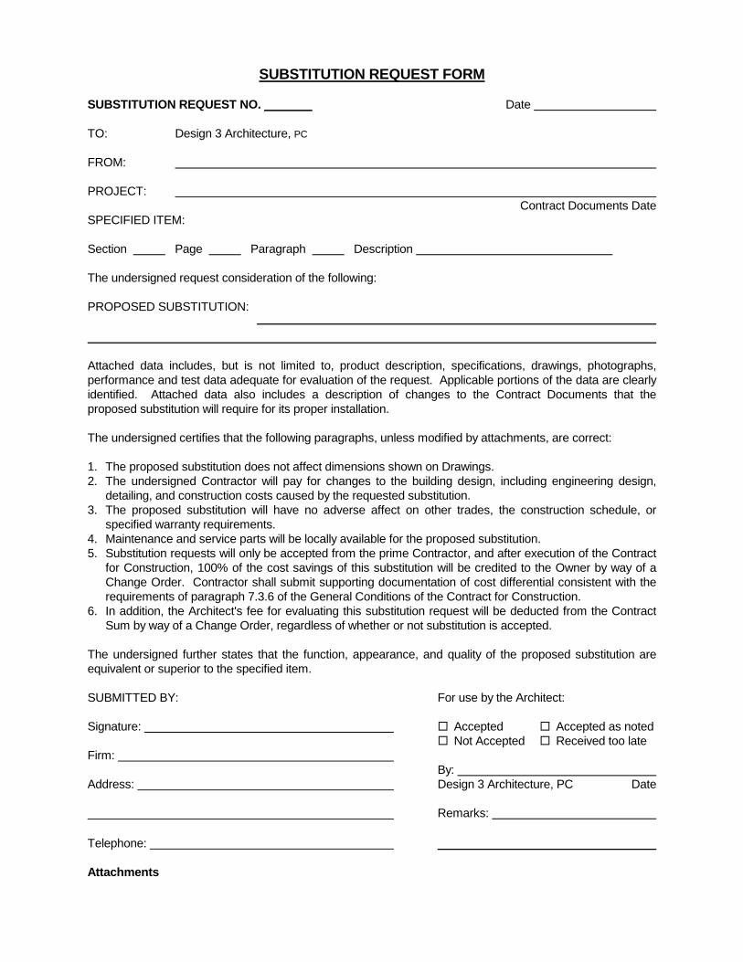
SUBSTITUTION REQUEST FORM SUBSTITUTION REQUEST NO. Date TO: Design 3 Architecture, PC FROM: PROJECT: Contract Documents Date SPECIFIED ITEM: Section Page Paragraph Description The undersigned request consideration of the following: PROPOSED SUBSTITUTION:
Attached data includes, but is not limited to, product description, specifications, drawings, photographs, performance and test data adequate for evaluation of the request. Applicable portions of the data are clearly identified. Attached data also includes a description of changes to the Contract Documents that the proposed substitution will require for its proper installation. The undersigned certifies that the following paragraphs, unless modified by attachments, are correct: 1. The proposed substitution does not affect dimensions shown on Drawings. 2. The undersigned Contractor will pay for changes to the building design, including engineering design,
detailing, and construction costs caused by the requested substitution. 3. The proposed substitution will have no adverse affect on other trades, the construction schedule, or
specified warranty requirements. 4. Maintenance and service parts will be locally available for the proposed substitution. 5. Substitution requests will only be accepted from the prime Contractor, and after execution of the Contract
for Construction, 100% of the cost savings of this substitution will be credited to the Owner by way of a Change Order. Contractor shall submit supporting documentation of cost differential consistent with the requirements of paragraph 7.3.6 of the General Conditions of the Contract for Construction.
6. In addition, the Architect's fee for evaluating this substitution request will be deducted from the Contract Sum by way of a Change Order, regardless of whether or not substitution is accepted.
The undersigned further states that the function, appearance, and quality of the proposed substitution are equivalent or superior to the specified item. SUBMITTED BY: Signature: Firm: Address:
Telephone:
For use by the Architect: Accepted Accepted as noted Not Accepted Received too late By: Design 3 Architecture, PC Date Remarks:
Attachments

(THIS PAGE INTENTIONALLY LEFT BLANK)
Westmoreland County 911 Facility – HVAC D3A Project #2015-46.01 – April 2017 911 Public Safety Road, Greensburg, PA Design 3 Architecture, PC
CONTRACT MODIFICATION PROCEDURES 01 26 00 - 1
SECTION 01 26 00 - CONTRACT MODIFICATION PROCEDURES
PART 1 - GENERAL
1.1 RELATED DOCUMENTS
A. Drawings and general provisions of the Contract, including General and Supplementary Conditions and Division 01 Specification Sections, apply to this Section.
1.2 SUMMARY
A. Section includes administrative and procedural requirements for handling and processing Contract modifications.
1.3 MINOR CHANGES IN THE WORK
A. Architect will issue supplemental instructions authorizing minor changes in the Work, not involving adjustment to the Contract Sum or the Contract Time, on AIA Document G710, "Architect's Supplemental Instructions."
1.4 PROPOSAL REQUESTS
A. Owner-Initiated Proposal Requests: Architect will issue a detailed description of proposed changes in the Work that may require adjustment to the Contract Sum or the Contract Time. If necessary, the description will include supplemental or revised Drawings and Specifications. 1. Proposal Requests issued by Architect are not instructions either to stop work in progress
or to execute the proposed change. 2. Within time specified in Proposal Request or 7 days, when not otherwise specified, after
receipt of Proposal Request, submit a quotation estimating cost adjustments to the Contract Sum and the Contract Time necessary to execute the change. a. Include a list of quantities of products required or eliminated and unit costs, with
total amount of purchases and credits to be made. If requested, furnish survey data to substantiate quantities.
b. Indicate applicable taxes, delivery charges, equipment rental, and amounts of trade discounts.
c. Include costs of labor and supervision directly attributable to the change. d. Include an updated Contractor's construction schedule that indicates the effect of
the change, including, but not limited to, changes in activity duration, start and finish times, and activity relationship. Use available total float before requesting an extension of the Contract Time.
e. Quotation Form: Use CSI Form 13.6B "Proposal Worksheet Summary" and 13.6C "Proposal Worksheet Detail”.
Westmoreland County 911 Facility – HVAC D3A Project #2015-46.01 – April 2017 911 Public Safety Road, Greensburg, PA Design 3 Architecture, PC
CONTRACT MODIFICATION PROCEDURES 01 26 00 - 2
B. Contractor-Initiated Proposals: If latent or changed conditions require modifications to the Contract, Contractor may initiate a claim by submitting a request for a change to Architect. 1. Include a statement outlining reasons for the change and the effect of the change on the
Work. Provide a complete description of the proposed change. Indicate the effect of the proposed change on the Contract Sum and the Contract Time.
2. Include a list of quantities of products required or eliminated and unit costs, with total amount of purchases and credits to be made. If requested, furnish survey data to substantiate quantities.
3. Indicate applicable taxes, delivery charges, equipment rental, and amounts of trade discounts.
4. Include costs of labor and supervision directly attributable to the change. 5. Include an updated Contractor's construction schedule that indicates the effect of the
change, including, but not limited to, changes in activity duration, start and finish times, and activity relationship. Use available total float before requesting an extension of the Contract Time.
6. Comply with requirements in Division 01 Section "Substitution Procedures" if the proposed change requires substitution of one product or system for product or system specified.
1.5 Proposal Request Form: Use CSI Form 13.6A "Change Order Request (Proposal)" with attachments CSI Form 13.6B "Proposal Worksheet Summary" and 13.6C "Proposal Worksheet Detail" CHANGE ORDER PROCEDURES.
A. On Owner's approval of a Proposal Request, Architect will issue a Change Order for signatures of Owner and Contractor on AIA Document G701.
1.6 CONSTRUCTION CHANGE DIRECTIVE
A. Construction Change Directive: Architect may issue a Construction Change Directive on AIA Document G714. Construction Change Directive instructs Contractor to proceed with a change in the Work, for subsequent inclusion in a Change Order. 1. Construction Change Directive contains a complete description of change in the Work. It
also designates method to be followed to determine change in the Contract Sum or the Contract Time.
B. Documentation: Maintain detailed records on a time and material basis of work required by the Construction Change Directive. 1. After completion of change, submit an itemized account and supporting data necessary
to substantiate cost and time adjustments to the Contract.
PART 2 - PRODUCTS (Not Used)
PART 3 - EXECUTION (Not Used)
END OF SECTION 01 26 00
Westmoreland County 911 Facility – HVAC D3A Project #2015-46.01 – April 2017 911 Public Safety Road, Greensburg, PA Design 3 Architecture, PC
PAYMENT PROCEDURES 01 29 00 - 1
SECTION 01 29 00 - PAYMENT PROCEDURES
PART 1 - GENERAL
1.1 RELATED DOCUMENTS
A. Drawings and general provisions of the Contract, including General and Supplementary Conditions and Division 01 Specification Sections, apply to this Section.
1.2 SUMMARY
A. This Section specifies administrative and procedural requirements necessary to prepare and process Applications for Payment.
1.3 DEFINITIONS
A. Schedule of Values: A statement furnished by Contractor allocating portions of the Contract Sum to various portions of the Work and used as the basis for reviewing Contractor's Applications for Payment.
1.4 SCHEDULE OF VALUES
A. Coordination: Coordinate preparation of the schedule of values with preparation of Contractor's construction schedule. Cost-loaded Critical Path Method Schedule may serve to satisfy requirements for the schedule of values. 1. Correlate line items in the schedule of values with other required administrative forms
and schedules, including the following: a. Application for Payment forms with continuation sheets. b. Submittal schedule. c. Items required to be indicated as separate activities in Contractor's construction
schedule. 2. Submit the schedule of values to Architect at earliest possible date but no later than
seven days before the date scheduled for submittal of initial Applications for Payment.
B. Format and Content: Use the Project Manual table of contents as a guide to establish line items for the schedule of values. Provide at least one line item for each Specification Section. 1. Identification: Include the following Project identification on the schedule of values:
a. Project name and location. b. Name of Architect. c. Architect's project number. d. Contractor's name and address. e. Date of submittal.
2. Arrange schedule of values consistent with format of AIA Document G703. 3. Arrange the schedule of values in tabular form with separate columns to indicate the
following for each item listed: a. Related Specification Section or Division. b. Description of the Work. c. Name of subcontractor. d. Change Orders (numbers) that affect value. e. Dollar value of the following, as a percentage of the Contract Sum to nearest one-
hundredth percent, adjusted to total 100 percent. 1) Labor. 2) Materials. 3) Equipment.
Westmoreland County 911 Facility – HVAC D3A Project #2015-46.01 – April 2017 911 Public Safety Road, Greensburg, PA Design 3 Architecture, PC
PAYMENT PROCEDURES 01 29 00 - 2
4. Provide a breakdown of the Contract Sum in enough detail to facilitate continued evaluation of Applications for Payment and progress reports. Coordinate with the Project Manual table of contents. Provide multiple line items for principal subcontract amounts in excess of five percent of Contract Sum. a. Include separate line items under Contractor and principal subcontracts for project
closeout requirements in an amount totaling five percent of the Contract Sum and subcontract amount.
5. Round amounts to nearest whole dollar; total shall equal the Contract Sum. 6. Provide a separate line item in the schedule of values for each part of the Work where
Applications for Payment may include materials or equipment purchased or fabricated and stored, but not yet installed. a. Differentiate between items stored on-site and items stored off-site. If required,
include evidence of insurance. 7. Provide separate line items in the schedule of values for initial cost of materials, for each
subsequent stage of completion, and for total installed value of that part of the Work. 8. Allowances: Provide a separate line item in the schedule of values for each allowance.
Show line-item value of unit-cost allowances, as a product of the unit cost, multiplied by measured quantity. Use information indicated in the Contract Documents to determine quantities.
9. Purchase Contracts: Provide a separate line item in the schedule of values for each purchase contract. Show line-item value of purchase contract. Indicate owner payments or deposits, if any, and balance to be paid by Contractor.
10. Each item in the schedule of values and Applications for Payment shall be complete. Include total cost and proportionate share of general overhead and profit for each item. a. Temporary facilities and other major cost items that are not direct cost of actual
work-in-place may be shown either as separate line items in the schedule of values or distributed as general overhead expense, at Contractor's option.
11. Schedule Updating: Update and resubmit the schedule of values before the next Applications for Payment when Change Orders or Construction Change Directives result in a change in the Contract Sum.
1.5 APPLICATIONS FOR PAYMENT
A. Each Application for Payment shall be consistent with previous applications and payments as certified by Architect and paid for by Owner. 1. Initial Application for Payment, Application for Payment at time of Substantial Completion,
and final Application for Payment involve additional requirements.
B. Payment Application Times: The date for each progress payment is indicated in the Agreement between Owner and Contractor. The period of construction work covered by each Application for Payment is the period indicated in the Agreement.
C. Application for Payment Forms: Use AIA Document G702 and AIA Document G703 as form for Applications for Payment.
D. Application Preparation: Complete every entry on form. Notarize and execute by a person authorized to sign legal documents on behalf of Contractor. Architect will return incomplete applications without action. 1. Entries shall match data on the schedule of values and Contractor's construction
schedule. Use updated schedules if revisions were made. 2. Include amounts for work completed following previous Application for Payment, whether
or not payment has been received. Include only amounts for work completed at time of Application for Payment.
3. Include amounts of Change Orders and Construction Change Directives issued before last day of construction period covered by application.
4. Indicate separate amounts for work being carried out under Owner-requested project acceleration.
Westmoreland County 911 Facility – HVAC D3A Project #2015-46.01 – April 2017 911 Public Safety Road, Greensburg, PA Design 3 Architecture, PC
PAYMENT PROCEDURES 01 29 00 - 3
E. Stored Materials: Include in Application for Payment amounts applied for materials or equipment purchased or fabricated and stored, but not yet installed. Differentiate between items stored on-site and items stored off-site. 1. Provide certificate of insurance, evidence of transfer of title to Owner, and consent of
surety to payment, for stored materials. 2. Provide supporting documentation that verifies amount requested, such as paid invoices.
Match amount requested with amounts indicated on documentation; do not include overhead and profit on stored materials.
3. Provide summary documentation for stored materials indicating the following: a. Materials previously stored and included in previous Applications for Payment. b. Work completed for this Application utilizing previously stored materials. c. Additional materials stored with this Application. d. Total materials remaining stored, including materials with this Application.
F. Transmittal: Submit three signed and notarized original copies of each Application for Payment to Architect by a method ensuring receipt within 24 hours. One copy shall include waivers of lien and similar attachments. 1. Transmit each copy with a transmittal form listing attachments and recording appropriate
information about application.
G. Waivers of Mechanic's Lien: With each Application for Payment, submit waivers of mechanic's liens from subcontractors, sub-subcontractors, and suppliers for construction period covered by the previous application. 1. Submit partial waivers on each item for amount requested in previous application, after
deduction for retainage, on each item. 2. When an application shows completion of an item, submit conditional final or full waivers. 3. Owner reserves the right to designate which entities involved in the Work must submit
waivers. 4. Submit final Application for Payment with or preceded by conditional final waivers from
every entity involved with performance of the Work covered by the application who is lawfully entitled to a lien.
5. Waiver Forms: Submit waivers of lien on forms, executed in a manner acceptable to Owner.
H. Initial Application for Payment: Administrative actions and submittals that must precede or coincide with submittal of first Application for Payment include the following: 1. List of subcontractors. 2. Schedule of values. 3. Contractor's construction schedule (preliminary if not final). 4. Submittal schedule (preliminary if not final). 5. Copies of building permits. 6. Certificates of insurance and insurance policies.
I. Application for Payment at Substantial Completion: After issuing the Certificate of Substantial Completion, submit an Application for Payment showing 100 percent completion for portion of the Work claimed as substantially complete. 1. Include documentation supporting claim that the Work is substantially complete and a
statement showing an accounting of changes to the Contract Sum. 2. This application shall reflect Certificates of Partial Substantial Completion issued
previously for Owner occupancy of designated portions of the Work.
Westmoreland County 911 Facility – HVAC D3A Project #2015-46.01 – April 2017 911 Public Safety Road, Greensburg, PA Design 3 Architecture, PC
PAYMENT PROCEDURES 01 29 00 - 4
J. Final Payment Application: Submit final Application for Payment with releases and supporting documentation not previously submitted and accepted, including, but not limited, to the following: 1. Evidence of completion of Project closeout requirements. 2. Insurance certificates for products and completed operations where required and proof
that taxes, fees, and similar obligations were paid. 3. Updated final statement, accounting for final changes to the Contract Sum. 4. AIA Document G706, "Contractor's Affidavit of Payment of Debts and Claims."
PART 2 - PRODUCTS (Not Used)
PART 3 - EXECUTION (Not Used)
END OF SECTION 01 29 00
Westmoreland County 911 Facility – HVAC D3A Project #2015-46.01 – April 2017 911 Public Safety Road, Greensburg, PA Design 3 Architecture, PC
PROJECT MANAGEMENT AND COORDINATION 01 31 00 - 1
SECTION 01 31 00 - PROJECT MANAGEMENT AND COORDINATION
PART 1 - GENERAL
1.1 RELATED DOCUMENTS
A. Drawings and general provisions of the Contract, including General and Supplementary Conditions and Division 01 Specification Sections, apply to this Section.
1.2 SUMMARY
A. Section includes administrative provisions for coordinating construction operations on Project including, but not limited to, the following: 1. General coordination procedures. 2. Coordination drawings. 3. Requests for Information (RFIs). 4. Project meetings.
B. Each contractor shall participate in coordination requirements. Certain areas of responsibility are assigned to a specific contractor.
1.3 DEFINITIONS
A. RFI: Request from Owner, Architect, or Contractor seeking information required by or clarifications of the Contract Documents.
1.4 INFORMATIONAL SUBMITTALS
A. Subcontract List: Prepare a written summary identifying individuals or firms proposed for each portion of the Work, including those who are to furnish products or equipment fabricated to a special design. Include the following information in tabular form: 1. Name, address, and telephone number of entity performing subcontract or supplying
products. 2. Number and title of related Specification Section(s) covered by subcontract. 3. Drawing number and detail references, as appropriate, covered by subcontract.
B. Key Personnel Names: Within 15 days of starting construction operations, submit a list of key personnel assignments, including superintendent and other personnel in attendance at Project site. Identify individuals and their duties and responsibilities; list addresses and telephone numbers, including home, office, and cellular telephone numbers and e-mail addresses. Provide names, addresses, and telephone numbers of individuals assigned as alternates in the absence of individuals assigned to Project. 1. Post copies of list in project meeting room, in temporary field office, and by each
temporary telephone. Keep list current at all times.
Westmoreland County 911 Facility – HVAC D3A Project #2015-46.01 – April 2017 911 Public Safety Road, Greensburg, PA Design 3 Architecture, PC
PROJECT MANAGEMENT AND COORDINATION 01 31 00 - 2
1.5 GENERAL COORDINATION PROCEDURES
A. Coordination: Coordinate construction operations included in different Sections of the Specifications to ensure efficient and orderly installation of each part of the Work. Coordinate construction operations, included in different Sections that depend on each other for proper installation, connection, and operation. 1. Schedule construction operations in sequence required to obtain the best results where
installation of one part of the Work depends on installation of other components, before or after its own installation.
2. Coordinate installation of different components to ensure maximum performance and accessibility for required maintenance, service, and repair.
3. Make adequate provisions to accommodate items scheduled for later installation.
B. Coordination: Each contractor shall coordinate its construction operations with those of other contractors and entities to ensure efficient and orderly installation of each part of the Work. Each contractor shall coordinate its operations with operations, included in different Sections that depend on each other for proper installation, connection, and operation. 1. Schedule construction operations in sequence required to obtain the best results where
installation of one part of the Work depends on installation of other components, before or after its own installation.
2. Coordinate installation of different components with other contractors to ensure maximum performance and accessibility for required maintenance, service, and repair.
3. Make adequate provisions to accommodate items scheduled for later installation.
C. Prepare memoranda for distribution to each party involved, outlining special procedures required for coordination. Include such items as required notices, reports, and list of attendees at meetings. 1. Prepare similar memoranda for Owner and separate contractors if coordination of their
Work is required.
D. Administrative Procedures: Coordinate scheduling and timing of required administrative procedures with other construction activities and activities of other contractors to avoid conflicts and to ensure orderly progress of the Work. Such administrative activities include, but are not limited to, the following: 1. Preparation of Contractor's construction schedule. 2. Preparation of the schedule of values. 3. Installation and removal of temporary facilities and controls. 4. Delivery and processing of submittals. 5. Progress meetings. 6. Preinstallation conferences. 7. Project closeout activities. 8. Startup and adjustment of systems.
E. Conservation: Coordinate construction activities to ensure that operations are carried out with consideration given to conservation of energy, water, and materials. Coordinate use of temporary utilities to minimize waste.
1.6 REQUESTS FOR INFORMATION (RFIs)
A. General: Immediately on discovery of the need for additional information or interpretation of the Contract Documents, Contractor shall prepare and submit an RFI in the form specified. 1. Architect will return RFIs submitted to Architect by other entities controlled by Contractor
with no response. 2. Coordinate and submit RFIs in a prompt manner so as to avoid delays in Contractor's
work or work of subcontractors.
Westmoreland County 911 Facility – HVAC D3A Project #2015-46.01 – April 2017 911 Public Safety Road, Greensburg, PA Design 3 Architecture, PC
PROJECT MANAGEMENT AND COORDINATION 01 31 00 - 3
B. Content of the RFI: Include a detailed, legible description of item needing information or interpretation and the following: 1. Project name. 2. Project number. 3. Date. 4. Name of Contractor. 5. Name of Architect. 6. RFI number, numbered sequentially. 7. RFI subject. 8. Specification Section number and title and related paragraphs, as appropriate. 9. Drawing number and detail references, as appropriate. 10. Field dimensions and conditions, as appropriate. 11. Contractor's suggested resolution. If Contractor's suggested resolution impacts the
Contract Time or the Contract Sum, Contractor shall state impact in the RFI. 12. Contractor's signature. 13. Attachments: Include sketches, descriptions, measurements, photos, Product Data, Shop
Drawings, coordination drawings, and other information necessary to fully describe items needing interpretation. a. Include dimensions, thicknesses, structural grid references, and details of affected
materials, assemblies, and attachments on attached sketches.
C. Architect's Action: Architect will review each RFI, determine action required, and respond. Allow seven working days for Architect's response for each RFI. RFIs received by Architect after 1:00 p.m. will be considered as received the following working day. 1. The following Contractor-generated RFIs will be returned without action:
a. Requests for approval of submittals. b. Requests for approval of substitutions. c. Requests for approval of Contractor's means and methods. d. Requests for coordination information already indicated in the Contract
Documents. e. Requests for adjustments in the Contract Time or the Contract Sum. f. Requests for interpretation of Architect's actions on submittals. g. Incomplete RFIs or inaccurately prepared RFIs.
2. Architect's action may include a request for additional information, in which case Architect's time for response will date from time of receipt of additional information.
3. Architect's action on RFIs that may result in a change to the Contract Time or the Contract Sum may be eligible for Contractor to submit Change Proposal according to Section 012600 "Contract Modification Procedures." a. If Contractor believes the RFI response warrants change in the Contract Time or
the Contract Sum, notify Architect in writing within 10 days of receipt of the RFI response.
D. RFI Log: Prepare, maintain, and submit a tabular log of RFIs organized by the RFI number. Submit log weekly. Include the following: 1. Project name. 2. Name and address of Contractor. 3. Name and address of Architect. 4. RFI number including RFIs that were returned without action or withdrawn. 5. RFI description. 6. Date the RFI was submitted. 7. Date Architect's response was received.
Westmoreland County 911 Facility – HVAC D3A Project #2015-46.01 – April 2017 911 Public Safety Road, Greensburg, PA Design 3 Architecture, PC
PROJECT MANAGEMENT AND COORDINATION 01 31 00 - 4
E. On receipt of Architect's action, update the RFI log and immediately distribute the RFI response to affected parties. Review response and notify Architect within seven days if Contractor disagrees with response. 1. Identification of related Minor Change in the Work, Construction Change Directive, and
Proposal Request, as appropriate. 2. Identification of related Field Order, Work Change Directive, and Proposal Request, as
appropriate.
1.7 PROJECT MEETINGS
A. General: HVAC Contractor shall schedule and conduct meetings and conferences at Project site unless otherwise indicated. 1. Attendees: Inform participants and others involved, and individuals whose presence is
required, of date and time of each meeting. Notify Owner and Architect of scheduled meeting dates and times.
2. Agenda: Prepare the meeting agenda. Distribute the agenda to all invited attendees. 3. Minutes: Entity responsible for conducting meeting will record significant discussions and
agreements achieved. Distribute the meeting minutes to everyone concerned, including Owner and Architect, within seven days of the meeting.
B. Preconstruction Conference: HVAC Contractor shall schedule and conduct a preconstruction conference before starting construction, at a time convenient to Owner and Architect, but no later than 15 days after execution of the Agreement. 1. Conduct the conference to review responsibilities and personnel assignments. 2. Attendees: Authorized representatives of Owner, Architect, and their consultants;
Contractor and its superintendent; major subcontractors; suppliers; and other concerned parties shall attend the conference. Participants at the conference shall be familiar with Project and authorized to conclude matters relating to the Work.
3. Agenda: Discuss items of significance that could affect progress, including the following: a. Tentative construction schedule. b. Phasing. c. Critical work sequencing and long-lead items. d. Designation of key personnel and their duties. e. Lines of communications. f. Procedures for processing field decisions and Change Orders. g. Procedures for RFIs. h. Procedures for testing and inspecting. i. Procedures for processing Applications for Payment. j. Distribution of the Contract Documents. k. Submittal procedures. l. Preparation of record documents. m. Use of the premises. n. Work restrictions. o. Working hours. p. Owner's occupancy requirements. q. Responsibility for temporary facilities and controls. r. Procedures for moisture and mold control. s. Procedures for disruptions and shutdowns. t. Construction waste management and recycling. u. Parking availability. v. Office, work, and storage areas. w. Equipment deliveries and priorities. x. First aid. y. Security. z. Progress cleaning.
Westmoreland County 911 Facility – HVAC D3A Project #2015-46.01 – April 2017 911 Public Safety Road, Greensburg, PA Design 3 Architecture, PC
PROJECT MANAGEMENT AND COORDINATION 01 31 00 - 5
4. Minutes: Entity responsible for conducting meeting will record and distribute meeting minutes.
C. Preinstallation Conferences: Conduct a preinstallation conference at Project site before each construction activity that requires coordination with other construction. 1. Attendees: Installer and representatives of manufacturers and fabricators involved in or
affected by the installation and its coordination or integration with other materials and installations that have preceded or will follow, shall attend the meeting. Advise Architect of scheduled meeting dates.
2. Agenda: Review progress of other construction activities and preparations for the particular activity under consideration, including requirements for the following: a. Contract Documents. b. Options. c. Related RFIs. d. Related Change Orders. e. Purchases. f. Deliveries. g. Submittals. h. Review of mockups. i. Possible conflicts. j. Compatibility requirements. k. Time schedules. l. Weather limitations. m. Manufacturer's written instructions. n. Warranty requirements. o. Compatibility of materials. p. Acceptability of substrates. q. Temporary facilities and controls. r. Space and access limitations. s. Regulations of authorities having jurisdiction. t. Testing and inspecting requirements. u. Installation procedures. v. Coordination with other work. w. Required performance results. x. Protection of adjacent work. y. Protection of construction and personnel.
3. Record significant conference discussions, agreements, and disagreements, including required corrective measures and actions.
4. Reporting: Distribute minutes of the meeting to each party present and to other parties requiring information.
5. Do not proceed with installation if the conference cannot be successfully concluded. Initiate whatever actions are necessary to resolve impediments to performance of the Work and reconvene the conference at earliest feasible date.
D. Project Closeout Conference: HVAC Contractor shall schedule and conduct a project closeout conference, at a time convenient to Owner and Architect, but no later than 90 days prior to the scheduled date of Substantial Completion. 1. Conduct the conference to review requirements and responsibilities related to Project
closeout. 2. Attendees: Authorized representatives of Owner, Architect, and their consultants;
Contractor and its superintendent; major subcontractors; suppliers; and other concerned parties shall attend the meeting. Participants at the meeting shall be familiar with Project and authorized to conclude matters relating to the Work.
Westmoreland County 911 Facility – HVAC D3A Project #2015-46.01 – April 2017 911 Public Safety Road, Greensburg, PA Design 3 Architecture, PC
PROJECT MANAGEMENT AND COORDINATION 01 31 00 - 6
3. Agenda: Discuss items of significance that could affect or delay Project closeout, including the following: a. Preparation of record documents. b. Procedures required prior to inspection for Substantial Completion and for final
inspection for acceptance. c. Submittal of written warranties. d. Requirements for preparing operations and maintenance data. e. Requirements for delivery of material samples, attic stock, and spare parts. f. Requirements for demonstration and training. g. Preparation of Contractor's punch list. h. Procedures for processing Applications for Payment at Substantial Completion and
for final payment. i. Submittal procedures. j. Coordination of separate contracts. k. Owner's partial occupancy requirements. l. Installation of Owner's furniture, fixtures, and equipment. m. Responsibility for removing temporary facilities and controls.
4. Minutes: Entity conducting meeting will record and distribute meeting minutes.
E. Progress Meetings: HVAC Contractor shall conduct progress meetings at weekly intervals. 1. Coordinate dates of meetings with preparation of payment requests. 2. Attendees: In addition to representatives of Owner and Architect, each contractor,
subcontractor, supplier, and other entity concerned with current progress or involved in planning, coordination, or performance of future activities shall be represented at these meetings. All participants at the meeting shall be familiar with Project and authorized to conclude matters relating to the Work.
3. Agenda: Review and correct or approve minutes of previous progress meeting. Review other items of significance that could affect progress. Include topics for discussion as appropriate to status of Project. a. Contractor's Construction Schedule: Review progress since the last meeting.
Determine whether each activity is on time, ahead of schedule, or behind schedule, in relation to Contractor's construction schedule. Determine how construction behind schedule will be expedited; secure commitments from parties involved to do so. Discuss whether schedule revisions are required to ensure that current and subsequent activities will be completed within the Contract Time. 1) Review schedule for next period.
b. Review present and future needs of each entity present, including the following: 1) Interface requirements. 2) Sequence of operations. 3) Resolution of BIM component conflicts. 4) Status of submittals. 5) Deliveries. 6) Off-site fabrication. 7) Access. 8) Site utilization. 9) Temporary facilities and controls. 10) Progress cleaning. 11) Quality and work standards. 12) Status of correction of deficient items. 13) Field observations. 14) Status of RFIs. 15) Status of proposal requests. 16) Pending changes. 17) Status of Change Orders. 18) Pending claims and disputes. 19) Documentation of information for payment requests.
Westmoreland County 911 Facility – HVAC D3A Project #2015-46.01 – April 2017 911 Public Safety Road, Greensburg, PA Design 3 Architecture, PC
PROJECT MANAGEMENT AND COORDINATION 01 31 00 - 7
4. Minutes: Entity responsible for conducting the meeting will record and distribute the meeting minutes to each party present and to parties requiring information. a. Schedule Updating: Revise Contractor's construction schedule after each progress
meeting where revisions to the schedule have been made or recognized. Issue revised schedule concurrently with the report of each meeting.
PART 2 - PRODUCTS (Not Used)
PART 3 - EXECUTION (Not Used)
END OF SECTION 01 31 00

(THIS PAGE INTENTIONALLY LEFT BLANK)
Design 3 Architecture PC www.d3a.com300 Oxford Drive, Suite 120 William A. Snyder, AIA Monroeville, Pennsylvania 15146-2361 Michael D. Moyta, AIA, CSI (412) 373-2220 FAX (412) 373-4571 Anthony R. Scruppi, AIA
REQUEST FOR INFORMATION
To:
From:
Via FAX: D3A Job No.:
Date Requested: Date Required: Request Description:
Reply: (Please reply in space provided below.)
cc:

(THIS PAGE INTENTIONALLY LEFT BLANK)
(SAMPLE JOB MEETING MINUTES FORMAT) (Name of Project) (Address) Job Meeting # (Date) IN ATTENDANCE: ADDITIONAL DISTRIBUTION: (list persons attending) (non-attendees to receive copies) CERTIFICATION: The contractor's safety inspector, (name) , verified that he had conducted a safety inspection immediately prior to the job meeting; and he certified the safety of the job site. PROGRESS REPORT: A. (This is a status report. These items do not get numbered, but should be B. lettered. Where there is a schedule problem, it should be brought up C. in new business and assigned a number. It will continue on in future D. meetings as old business, until it is resolved and dropped.) OLD BUSINESS: Job Meeting # : (Date) 2. (Indicate any new discussion on these
items. If no new discussion, 4. but item still open, indicate what
action is required and by whom. Drop items which require no further action or discussion.)

(THIS PAGE INTENTIONALLY LEFT BLANK)
(SAMPLE JOB MEETING MINUTES FORMAT continued) (Name of Project) (Address) Job Meeting # Page Two OLD BUSINESS (continued): Job Meeting # : (Date) 5. 9. NEW BUSINESS: 11. (first new item) 12. (next new item) Etc. SCHEDULING: A. Next Meeting: The above is our understanding of discussions reached at the above-referenced meeting. If there are any changes and/or corrections to this report, please notify the writer within three (3) days of receipt. Otherwise, the minutes stand as record. Respectfully submitted, (General Contractor) (Project Manager)

(THIS PAGE INTENTIONALLY LEFT BLANK)
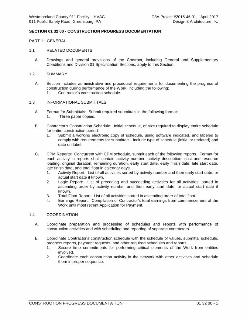
Westmoreland County 911 Facility – HVAC D3A Project #2015-46.01 – April 2017 911 Public Safety Road, Greensburg, PA Design 3 Architecture, PC
CONSTRUCTION PROGRESS DOCUMENTATION 01 32 00 - 1
SECTION 01 32 00 - CONSTRUCTION PROGRESS DOCUMENTATION
PART 1 - GENERAL
1.1 RELATED DOCUMENTS
A. Drawings and general provisions of the Contract, including General and Supplementary Conditions and Division 01 Specification Sections, apply to this Section.
1.2 SUMMARY
A. Section includes administrative and procedural requirements for documenting the progress of construction during performance of the Work, including the following: 1. Contractor's construction schedule.
1.3 INFORMATIONAL SUBMITTALS
A. Format for Submittals: Submit required submittals in the following format: 1. Three paper copies.
B. Contractor's Construction Schedule: Initial schedule, of size required to display entire schedule for entire construction period. 1. Submit a working electronic copy of schedule, using software indicated, and labeled to
comply with requirements for submittals. Include type of schedule (initial or updated) and date on label.
C. CPM Reports: Concurrent with CPM schedule, submit each of the following reports. Format for each activity in reports shall contain activity number, activity description, cost and resource loading, original duration, remaining duration, early start date, early finish date, late start date, late finish date, and total float in calendar days. 1. Activity Report: List of all activities sorted by activity number and then early start date, or
actual start date if known. 2. Logic Report: List of preceding and succeeding activities for all activities, sorted in
ascending order by activity number and then early start date, or actual start date if known.
3. Total Float Report: List of all activities sorted in ascending order of total float. 4. Earnings Report: Compilation of Contractor's total earnings from commencement of the
Work until most recent Application for Payment.
1.4 COORDINATION
A. Coordinate preparation and processing of schedules and reports with performance of construction activities and with scheduling and reporting of separate contractors.
B. Coordinate Contractor's construction schedule with the schedule of values, submittal schedule, progress reports, payment requests, and other required schedules and reports. 1. Secure time commitments for performing critical elements of the Work from entities
involved. 2. Coordinate each construction activity in the network with other activities and schedule
them in proper sequence.
Westmoreland County 911 Facility – HVAC D3A Project #2015-46.01 – April 2017 911 Public Safety Road, Greensburg, PA Design 3 Architecture, PC
CONSTRUCTION PROGRESS DOCUMENTATION 01 32 00 - 2
PART 2 - PRODUCTS
2.1 CONTRACTOR'S CONSTRUCTION SCHEDULE, GENERAL
A. Time Frame: Extend schedule from date established for commencement of the Work to date of Substantial Completion. 1. Contract completion date shall not be changed by submission of a schedule that shows
an early completion date, unless specifically authorized by Change Order.
B. Activities: Treat each story or separate area as a separate numbered activity for each principal element of the Work. Comply with the following: 1. Activity Duration: Define activities so no activity is longer than 20 days, unless
specifically allowed by Architect. 2. Procurement Activities: Include procurement process activities for the following long lead
items and major items, requiring a cycle of more than 60 days, as separate activities in schedule. Procurement cycle activities include, but are not limited to, submittals, approvals, purchasing, fabrication, and delivery.
3. Submittal Review Time: Include review and resubmittal times indicated in Division 01 Section "Submittal Procedures" in schedule. Coordinate submittal review times in Contractor's construction schedule with submittal schedule.
4. Startup and Testing Time: Include not less than 15 days for startup and testing. 5. Substantial Completion: Indicate completion in advance of date established for
Substantial Completion, and allow time for Architect's administrative procedures necessary for certification of Substantial Completion.
6. Punch List and Final Completion: Include not more than 14 days for punch list and final completion.
C. Constraints: Include constraints and work restrictions indicated in the Contract Documents and as follows in schedule, and show how the sequence of the Work is affected. 1. Phasing: Arrange list of activities on schedule by phase. 2. Products Ordered in Advance: Include a separate activity for each product. Include
delivery date indicated in Division 01 Section "Summary." Delivery dates indicated stipulate the earliest possible delivery date.
3. Owner-Furnished Products: Include a separate activity for each product. Include delivery date indicated in Division 01 Section "Summary." Delivery dates indicated stipulate the earliest possible delivery date.
4. Work Stages: Indicate important stages of construction for each major portion of the Work, including, but not limited to, the following: a. Submittals. b. Installation. c. Tests and inspections. d. Startup and placement into final use and operation.
D. Milestones: Include milestones indicated in the Contract Documents in schedule, including, but not limited to, the Notice to Proceed, Substantial Completion, and final completion.
E. Cost Correlation: At the head of schedule, provide a cost correlation line, indicating planned and actual costs. On the line, show dollar volume of the Work performed as of dates used for preparation of payment requests. 1. Refer to Division 01 Section "Payment Procedures" for cost reporting and payment
procedures.
Westmoreland County 911 Facility – HVAC D3A Project #2015-46.01 – April 2017 911 Public Safety Road, Greensburg, PA Design 3 Architecture, PC
CONSTRUCTION PROGRESS DOCUMENTATION 01 32 00 - 3
F. Upcoming Work Summary: Prepare summary report indicating activities scheduled to occur or commence prior to submittal of next schedule update. Summarize the following issues: 1. Unresolved issues. 2. Unanswered RFI’s. 3. Rejected or unreturned submittals. 4. Notations on returned submittals.
G. Recovery Schedule: When periodic update indicates the Work is 14 or more calendar days behind the current approved schedule, submit a separate recovery schedule indicating means by which Contractor intends to regain compliance with the schedule. Indicate changes to working hours, working days, crew sizes, and equipment required to achieve compliance, and date by which recovery will be accomplished.
H. Computer Scheduling Software: Prepare schedules using current version of a program that has been developed specifically to manage construction schedules.
2.2 CONTRACTOR'S CONSTRUCTION SCHEDULE (CPM SCHEDULE)
A. General: Prepare network diagrams using AON (activity-on-node) format.
B. CPM Schedule: Prepare Contractor's construction schedule using a time-scaled CPM network analysis diagram for the Work. 1. Conduct educational workshops to train and inform key Project personnel, including
subcontractors' personnel, in proper methods of providing data and using CPM schedule information.
2. Establish procedures for monitoring and updating CPM schedule and for reporting progress. Coordinate procedures with progress meeting and payment request dates.
3. Use "one workday" as the unit of time for individual activities. Indicate nonworking days and holidays incorporated into the schedule in order to correlate with Contract Time.
C. CPM Schedule Preparation: Prepare a list of all activities required to complete the Work. Using the start-up network diagram, prepare a skeleton network to identify probable critical paths. 1. Activities: Indicate the estimated time duration, sequence requirements, and relationship
of each activity in relation to other activities. Include estimated time frames for the following activities: a. Delivery. b. Installation. c. Punch list and final completion.
2. Critical Path Activities: Identify critical path activities, including those for interim completion dates. Scheduled start and completion dates shall be consistent with Contract milestone dates.
3. Processing: Process data to produce output data on a computer-drawn, time-scaled network. Revise data, reorganize activity sequences, and reproduce as often as necessary to produce the CPM schedule within the limitations of the Contract Time.
4. Format: Mark the critical path. Locate the critical path near center of network; locate paths with most float near the edges. a. Sub-networks on separate sheets are permissible for activities clearly off the
critical path.
D. Contract Modifications: For each proposed contract modification and concurrent with its submission, prepare a time-impact analysis using a network fragment to demonstrate the effect of the proposed change on the overall project schedule.
Westmoreland County 911 Facility – HVAC D3A Project #2015-46.01 – April 2017 911 Public Safety Road, Greensburg, PA Design 3 Architecture, PC
CONSTRUCTION PROGRESS DOCUMENTATION 01 32 00 - 4
E. Initial Issue of Schedule: Prepare initial network diagram from a sorted activity list indicating straight "early start-total float." Identify critical activities. Prepare tabulated reports showing the following: 1. Contractor or subcontractor and the Work or activity. 2. Description of activity. 3. Principal events of activity. 4. Immediate preceding and succeeding activities. 5. Early and late start dates. 6. Early and late finish dates. 7. Activity duration in workdays. 8. Total float or slack time. 9. Average size of workforce. 10. Dollar value of activity (coordinated with the schedule of values).
F. Schedule Updating: Concurrent with making revisions to schedule, prepare tabulated reports showing the following: 1. Identification of activities that have changed. 2. Changes in early and late start dates. 3. Changes in early and late finish dates. 4. Changes in activity durations in workdays. 5. Changes in the critical path. 6. Changes in total float or slack time. 7. Changes in the Contract Time.
PART 3 - EXECUTION
3.1 CONTRACTOR'S CONSTRUCTION SCHEDULE
A. Contractor's Construction Schedule Updating: At monthly intervals, update schedule to reflect actual construction progress and activities. Issue schedule one week before each regularly scheduled progress meeting. 1. Revise schedule immediately after each meeting or other activity where revisions have
been recognized or made. Issue updated schedule concurrently with the report of each such meeting.
2. Include a report with updated schedule that indicates every change, including, but not limited to, changes in logic, durations, actual starts and finishes, and activity durations.
3. As the Work progresses, indicate final completion percentage for each activity.
B. Distribution: Distribute copies of approved schedule to Architect, Owner, separate contractors, testing and inspecting agencies, and other parties identified by Contractor with a need-to-know schedule responsibility. 1. Post copies in Project meeting rooms and temporary field offices. 2. When revisions are made, distribute updated schedules to the same parties and post in
the same locations. Delete parties from distribution when they have completed their assigned portion of the Work and are no longer involved in performance of construction activities.
END OF SECTION 01 32 00
Westmoreland County 911 Facility – HVAC D3A Project #2015-46.01 – April 2017 911 Public Safety Road, Greensburg, PA Design 3 Architecture, PC
SUBMITTAL PROCEDURES 01 33 00 - 1
SECTION 01 33 00 - SUBMITTAL PROCEDURES
PART 1 - GENERAL
1.1 RELATED DOCUMENTS
A. Drawings and general provisions of the Contract, including General and Supplementary Conditions and Division 01 Specification Sections, apply to this Section.
1.2 SUMMARY
A. Section includes requirements for the submittal schedule and administrative and procedural requirements for submitting Shop Drawings, Product Data, Samples, and other submittals.
1.3 DEFINITIONS
A. Action Submittals: Written and graphic information and physical samples that require Architect's responsive action. Action submittals are those submittals indicated in individual Specification Sections as action submittals.
B. Informational Submittals: Written and graphic information and physical samples that do not require Architect's responsive action. Submittals may be rejected for not complying with requirements. Informational submittals are those submittals indicated in individual Specification Sections as informational submittals.
C. File Transfer Protocol (FTP): Communications protocol that enables transfer of files to and from another computer over a network and that serves as the basis for standard Internet protocols. An FTP site is a portion of a network located outside of network firewalls within which internal and external users are able to access files.
D. Portable Document Format (PDF): An open standard file format licensed by Adobe Systems used for representing documents in a device-independent and display resolution-independent fixed-layout document format.
1.4 ACTION SUBMITTALS
A. Submittal Schedule: Submit a schedule of submittals, arranged in chronological order by dates required by construction schedule. Include time required for review, ordering, manufacturing, fabrication, and delivery when establishing dates. Include additional time required for making corrections or modifications to submittals noted by the Architect and additional time for handling and reviewing submittals required by those corrections. 1. Coordinate submittal schedule with list of prime contractors, subcontracts, the schedule
of values, and Contractor's construction schedule.
2. Initial Submittal: Submit concurrently with start-up construction schedule. Include submittals required during the first 60 days of construction. List those submittals required to maintain orderly progress of the Work and those required early because of long lead time for manufacture or fabrication.
3. Final Submittal: Submit concurrently with the first complete submittal of Contractor's construction schedule. a. Submit revised submittal schedule to reflect changes in current status and timing
for submittals.
Westmoreland County 911 Facility – HVAC D3A Project #2015-46.01 – April 2017 911 Public Safety Road, Greensburg, PA Design 3 Architecture, PC
SUBMITTAL PROCEDURES 01 33 00 - 2
4. Format: Arrange the following information in a tabular format: a. Scheduled date for first submittal. b. Specification Section number and title. c. Submittal category: Action, informational. d. Name of subcontractor. e. Description of the Work covered. f. Scheduled date for Architect's final release or approval. g. Scheduled dates for purchasing. h. Scheduled dates for installation. i. Activity or event number.
1.5 SUBMITTAL ADMINISTRATIVE REQUIREMENTS
A. Architect's Digital Data Files: Electronic copies of CAD Drawings of the Contract Drawings will not be provided by Architect for Contractor's use in preparing submittals.
B. Coordination: Coordinate preparation and processing of submittals with all prime contractors’ performance of construction activities. 1. Coordinate each submittal with fabrication, purchasing, testing, delivery, other submittals,
and related activities that require sequential activity. 2. Submit all submittal items required for each Specification Section concurrently unless
partial submittals for portions of the Work are indicated on approved submittal schedule. 3. Submit action submittals and informational submittals required by the same Specification
Section as separate packages under separate transmittals. 4. Coordinate transmittal of different types of submittals for related parts of the Work so
processing will not be delayed because of need to review submittals concurrently for coordination. a. Architect reserves the right to withhold action on a submittal requiring coordination
with other submittals until related submittals are received.
C. Processing Time: Allow time for submittal review, including time for resubmittals, as follows. Time for review shall commence on Architect's receipt of submittal. No extension of the Contract Time will be authorized because of failure to transmit submittals enough in advance of the Work to permit processing, including resubmittals. 1. Initial Review: Allow 10 business days for initial review of each submittal. Allow
additional time if coordination with subsequent submittals is required. Architect will advise Contractor when a submittal being processed must be delayed for coordination.
2. Intermediate Review: If intermediate submittal is necessary, process it in same manner as initial submittal.
3. Resubmittal Review: Allow 10 business days for review of each resubmittal. 4. Sequential Review: Where sequential review of submittals by Architect's consultants,
Owner, or other parties is indicated, allow 21 days for initial review of each submittal. a. Structural Framing. b. Fire Protection c. Plumbing. d. HVAC. e. Electrical.
Westmoreland County 911 Facility – HVAC D3A Project #2015-46.01 – April 2017 911 Public Safety Road, Greensburg, PA Design 3 Architecture, PC
SUBMITTAL PROCEDURES 01 33 00 - 3
D. Identification and Information: Place a permanent label or title block on each paper copy submittal item for identification. 1. Indicate name of firm or entity that prepared each submittal on label or title block.
a. A Project Submittal Cover Sheet form is included at the end of this section for this purpose. Fill in all applicable fields in Submittal Cover Sheet, including Contractor’s Review.
2. Include the following information for processing and recording action taken: a. Project name. b. Date. c. Name of Architect. d. Name of Contractor. e. Name of subcontractor. f. Name of supplier. g. Name of manufacturer. h. Submittal number or other unique identifier, including revision identifier.
1) Submittal number shall use Specification Section number followed by a decimal point and then a sequential number (e.g., 061000.01). Resubmittals shall include an alphabetic suffix after another decimal point (e.g., 061000.01.A).
i. Number and title of appropriate Specification Section. j. Drawing number and detail references, as appropriate.
E. Identification and Information: Identify and incorporate information in each electronic submittal file as follows: 1. Assemble complete submittal package into a single indexed file with links enabling
navigation to each item. 2. Name file with submittal number or other unique identifier, including revision identifier.
a. File name shall use project identifier and Specification Section number followed by a decimal point and then a sequential number (e.g., LNHS-061000.01). Resubmittals shall include an alphabetic suffix after another decimal point (e.g., LNHS-061000.01.A).
3. Provide means for insertion to permanently record Contractor's review and approval markings and action taken by Architect. a. An electronic copy of the Project Submittal Cover Sheet form which is included at
the end of this section for this purpose, will be made available by the Architect. Fill in all applicable fields in Submittal Cover Sheet, including Contractor’s Review.
4. Include the following information on an inserted cover sheet: a. Project name. b. Date. c. Name and address of Architect. d. Name of Contractor. e. Name of firm or entity that prepared submittal. f. Name of subcontractor. g. Name of supplier. h. Name of manufacturer. i. Number and title of appropriate Specification Section. j. Drawing number and detail references, as appropriate. k. Location(s) where product is to be installed, as appropriate. l. Related physical samples submitted directly. m. Other necessary identification.
5. Include the following information as keywords in the electronic file metadata: a. Project name. b. Number and title of appropriate Specification Section. c. Manufacturer name. d. Product name.
Westmoreland County 911 Facility – HVAC D3A Project #2015-46.01 – April 2017 911 Public Safety Road, Greensburg, PA Design 3 Architecture, PC
SUBMITTAL PROCEDURES 01 33 00 - 4
F. Options: Identify options requiring selection by the Architect.
G. Deviations: Identify deviations from the Contract Documents on submittals.
H. Additional Paper Copies: Unless additional copies are required for final submittal, and unless Architect observes noncompliance with provisions in the Contract Documents, initial submittal may serve as final submittal. 1. Submit one copy of submittal to concurrent reviewer in addition to specified number of
copies to Architect.
I. Transmittal: Assemble each submittal individually and appropriately for transmittal and handling. Transmit each submittal using a transmittal form. Architect will return submittals, without review, received from sources other than Contractor. 1. Transmittal Form: Use AIA Document G810, or approved equivalent. 2. On an attached separate sheet, prepared on Contractor's letterhead, record relevant
information, requests for data, revisions other than those requested by Architect on previous submittals, and deviations from requirements in the Contract Documents, including minor variations and limitations. Include same identification information as related submittal.
J. Resubmittals: Make resubmittals in same form and number of copies as initial submittal. 1. Note date and content of previous submittal. 2. Note date and content of revision in label or title block and clearly indicate extent of
revision. 3. Resubmit submittals until they are marked with approval notation from Architect's action
stamp.
K. Distribution: Furnish copies of final submittals to manufacturers, subcontractors, suppliers, fabricators, installers, authorities having jurisdiction, and others as necessary for performance of construction activities. Show distribution on transmittal forms.
L. Use for Construction: Use only final submittals that are marked with approval notation from Architect's action stamp.
PART 2 - PRODUCTS
2.1 SUBMITTAL PROCEDURES
A. General Submittal Procedure Requirements: Prepare and submit submittals required by individual Specification Sections. Types of submittals are indicated in individual Specification Sections. 1. Action Submittals: Submit five paper copies of each submittal, unless otherwise
indicated. Architect will return two copies. 2. Informational Submittals: Submit three paper copies of each submittal, unless otherwise
indicated. Architect will not return copies. 3. Closeout Submittals and Maintenance Material Submittals: Comply with requirements
specified in Division 01 Section "Closeout Procedures." 4. Certificates and Certifications Submittals: Provide a statement that includes signature of
entity responsible for preparing certification. Certificates and certifications shall be signed by an officer or other individual authorized to sign documents on behalf of that entity.
5. Test and Inspection Reports Submittals: Comply with requirements specified in Division 01 Section "Quality Requirements."
Westmoreland County 911 Facility – HVAC D3A Project #2015-46.01 – April 2017 911 Public Safety Road, Greensburg, PA Design 3 Architecture, PC
SUBMITTAL PROCEDURES 01 33 00 - 5
B. Product Data: Collect information into a single submittal for each element of construction and type of product or equipment. 1. If information must be specially prepared for submittal because standard published data
are not suitable for use, submit as Shop Drawings, not as Product Data. 2. Mark each copy of each submittal to show which products and options are applicable. 3. Include the following information, as applicable:
a. Manufacturer's catalog cuts. b. Manufacturer's product specifications. c. Standard color charts. d. Statement of compliance with specified referenced standards. e. Testing by recognized testing agency. f. Application of testing agency labels and seals. g. Notation of coordination requirements.
4. For equipment, include the following in addition to the above, as applicable: a. Clearances required to other construction, if not indicated on accompanying Shop
Drawings. 5. Submit Product Data before or concurrent with Samples. 6. Submit Product Data in one of the following formats:
a. PDF electronic file. b. Five paper copies of Product Data, unless otherwise indicated. Architect will return
two copies.
C. Shop Drawings: Prepare Project-specific information, drawn accurately to scale. Do not base Shop Drawings on reproductions of the Contract Documents or standard printed data. 1. Preparation: Fully illustrate requirements in the Contract Documents. Include the
following information, as applicable: a. Identification of products. b. Schedules. c. Compliance with specified standards. d. Notation of coordination requirements. e. Notation of dimensions established by field measurement. f. Relationship and attachment to adjoining construction clearly indicated. g. Seal and signature of professional engineer if specified.
2. Sheet Size: Except for templates, patterns, and similar full-size drawings, submit Shop Drawings on sheets at least 8-1/2 by 11 inches but no larger than 24 by 36 inches.
3. Submit Shop Drawings in the following format: a. Five opaque copies of each submittal. Architect will retain three copies; remainder
will be returned.
D. Samples: Submit Samples for review of kind, color, pattern, and texture for a check of these characteristics with other elements and for a comparison of these characteristics between submittal and actual component as delivered and installed. 1. Transmit Samples that contain multiple, related components such as accessories
together in one submittal package. 2. Identification: Attach label on unexposed side of Samples that includes the following:
a. Generic description of Sample. b. Product name and name of manufacturer. c. Sample source. d. Number and title of applicable Specification Section.
3. Disposition: Maintain sets of approved Samples at Project site, available for quality-control comparisons throughout the course of construction activity. Sample sets may be used to determine final acceptance of construction associated with each set. a. Samples not incorporated into the Work, or otherwise designated as Owner's
property, are the property of Contractor.
Westmoreland County 911 Facility – HVAC D3A Project #2015-46.01 – April 2017 911 Public Safety Road, Greensburg, PA Design 3 Architecture, PC
SUBMITTAL PROCEDURES 01 33 00 - 6
4. Samples for Initial Selection: Submit manufacturer's color charts consisting of units or sections of units showing the full range of colors, textures, and patterns available. a. Number of Samples: Submit one full set(s) of available choices where color,
pattern, texture, or similar characteristics are required to be selected from manufacturer's product line. Architect will return submittal with options selected.
5. Samples for Verification: Submit full-size units or Samples of size indicated, prepared from same material to be used for the Work, cured and finished in manner specified, and physically identical with material or product proposed for use, and that show full range of color and texture variations expected. Samples include, but are not limited to, the following: partial sections of manufactured or fabricated components; small cuts or containers of materials; complete units of repetitively used materials; swatches showing color, texture, and pattern; color range sets; and components used for independent testing and inspection. a. Number of Samples: Submit three sets of Samples. Architect will retain two
Sample sets; remainder will be returned. 1) Submit a single Sample where assembly details, workmanship, fabrication
techniques, connections, operation, and other similar characteristics are to be demonstrated.
2) If variation in color, pattern, texture, or other characteristic is inherent in material or product represented by a Sample, submit at least three sets of paired units that show approximate limits of variations.
E. Contractor's Construction Schedule: Comply with requirements specified in Division 01 Section "Construction Progress Documentation."
F. Application for Payment: Comply with requirements specified in Division 01 Section "Payment Procedures."
G. Schedule of Values: Comply with requirements specified in Division 01 Section "Payment Procedures."
H. Subcontract List: Prepare a written summary identifying individuals or firms proposed for each portion of the Work, including those who are to furnish products or equipment fabricated to a special design. Include the following information in tabular form: 1. Name, address, and telephone number of entity performing subcontract or supplying
products. 2. Number and title of related Specification Section(s) covered by subcontract. 3. Drawing number and detail references, as appropriate, covered by subcontract. 4. Submit subcontract list in the following format:
a. PDF electronic file.
I. Coordination Drawings: Comply with requirements specified in Division 01 Section "Project Management and Coordination."
J. Qualification Data: Prepare written information that demonstrates capabilities and experience of firm or person. Include lists of completed projects with project names and addresses, contact information of architects and owners, and other information specified.
K. Welding Certificates: Prepare written certification that welding procedures and personnel comply with requirements in the Contract Documents. Submit record of Welding Procedure Specification and Procedure Qualification Record on American Welding Society (AWS) forms. Include names of firms and personnel certified.
L. Manufacturer Certificates: Submit written statements on manufacturer's letterhead certifying that manufacturer complies with requirements in the Contract Documents. Include evidence of manufacturing experience where required.
Westmoreland County 911 Facility – HVAC D3A Project #2015-46.01 – April 2017 911 Public Safety Road, Greensburg, PA Design 3 Architecture, PC
SUBMITTAL PROCEDURES 01 33 00 - 7
M. Product Certificates: Submit written statements on manufacturer's letterhead certifying that product complies with requirements in the Contract Documents.
N. Material Certificates: Submit written statements on manufacturer's letterhead certifying that material complies with requirements in the Contract Documents.
O. Schedule of Tests and Inspections: Comply with requirements specified in Division 01 Section "Quality Requirements."
P. Maintenance Data: Comply with requirements specified in Division 01 Section "Operation and Maintenance Data."
Q. Design Data: Prepare and submit written and graphic information, including, but not limited to, performance and design criteria, list of applicable codes and regulations, and calculations. Include list of assumptions and other performance and design criteria and a summary of loads. Include load diagrams if applicable. Provide name and version of software, if any, used for calculations. Include page numbers.
2.2 DELEGATED-DESIGN SERVICES
A. Performance and Design Criteria: Where professional design services or certifications by a design professional are specifically required of Contractor by the Contract Documents, provide products and systems complying with specific performance and design criteria indicated. 1. If criteria indicated are not sufficient to perform services or certification required, submit a
written request for additional information to Architect.
B. Delegated-Design Services Certification: In addition to Shop Drawings, Product Data, and other required submittals, submit digitally-signed PDF electronic file and three paper copies of certificate, signed and sealed by the responsible design professional, for each product and system specifically assigned to Contractor to be designed or certified by a design professional. 1. Indicate that products and systems comply with performance and design criteria in the
Contract Documents. Include list of codes, loads, and other factors used in performing these services.
PART 3 - EXECUTION
3.1 CONTRACTOR'S REVIEW
A. Action and Informational Submittals: Review each submittal and check for coordination with other Work of the Contract and for compliance with the Contract Documents. Note corrections and field dimensions. Mark with approval stamp before submitting to Architect.
B. Project Closeout and Maintenance/Material Submittals: Refer to requirements in Division 01 Section "Closeout Procedures."
C. Approval Stamp: Stamp each submittal with a uniform, approval stamp. Include Project name and location, submittal number, Specification Section title and number, name of reviewer, date of Contractor's approval, and statement certifying that submittal has been reviewed, checked, and approved for compliance with the Contract Documents.
Westmoreland County 911 Facility – HVAC D3A Project #2015-46.01 – April 2017 911 Public Safety Road, Greensburg, PA Design 3 Architecture, PC
SUBMITTAL PROCEDURES 01 33 00 - 8
3.2 ARCHITECT'S ACTION
A. General: Architect will not review submittals that do not bear Contractor's approval stamp and will return them without action.
B. Action Submittals: Architect will review each submittal, make marks to indicate corrections or modifications required, and return it. Architect will stamp each submittal with an action stamp and will mark stamp appropriately to indicate action.
C. Informational Submittals: Architect will review each submittal and will not return it, or will return it if it does not comply with requirements. Architect will forward each submittal to appropriate party.
D. Partial submittals prepared for a portion of the Work will be reviewed when use of partial submittals has received prior approval from Architect.
E. Incomplete submittals are not acceptable, will be considered nonresponsive, and will be returned without review.
F. Submittals not required by the Contract Documents may not be reviewed and may be discarded.
END OF SECTION 01 33 00
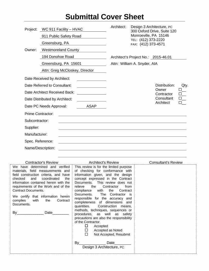
Submittal Cover Sheet
Project: WC 911 Facility – HVAC
911 Public Safety Road
Greensburg, PA
Owner: Westmoreland County
194 Donohoe Road
Greensburg, PA 15601
Attn: Greg McCloskey, Director Date Received by Architect:
Date Referred to Consultant:
Date Architect Received Back:
Date Distributed by Architect:
Date PC Needs Approval: ASAP
Architect: Design 3 Architecture, PC 300 Oxford Drive, Suite 120 Monroeville, PA 15146 TEL: (412) 373-2220 FAX: (412) 373-4571 Architect’s Project No.: 2015-46.01
Attn: William A. Snyder, AIA Distribution: Qty. Owner __ Contractor __ Consultant __ Architect __
Prime Contractor:
Subcontractor:
Supplier:
Manufacturer:
Spec. Reference:
Name/Description:
Contractor's Review Architect's Review Consultant's Review
We have determined and verified materials, field measurements and field construction criteria, and have checked and coordinated the information contained herein with the requirements of the Work and of the Contract Documents.
We certify that information herein complies with the Contract Documents.
By_____________ Date________
This review is for the limited purpose of checking for conformance with information given, and the design concept expressed in the Contract Documents. This review does not relieve the Contractor from compliance with the Contract Documents. The Contractor is responsible for the accuracy and completeness of dimensions and quantities. Construction means, methods, techniques, sequences or procedures, as well as safety precautions are also the responsibility of the Contractor. Accepted Accepted as Noted Not Accepted, Resubmit
By_____________ Date________ Design 3 Architecture, PC

(THIS PAGE INTENTIONALLY LEFT BLANK)
Westmoreland County 911 Facility – HVAC D3A Project #2015-46.01 – April 2017 911 Public Safety Road, Greensburg, PA Design 3 Architecture, PC
QUALITY REQUIREMENTS 01 40 00 - 1
SECTION 01 40 00 - QUALITY REQUIREMENTS
PART 1 - GENERAL
1.1 RELATED DOCUMENTS
A. Drawings and general provisions of the Contract, including General and Supplementary Conditions and Division 01 Specification Sections, apply to this Section.
1.2 SUMMARY
A. Section includes administrative and procedural requirements for quality assurance and quality control.
B. Testing and inspecting services are required to verify compliance with requirements specified or indicated. These services do not relieve Contractor of responsibility for compliance with the Contract Document requirements. 1. Specific quality-assurance and -control requirements for individual construction activities
are specified in the Sections that specify those activities. Requirements in those Sections may also cover production of standard products.
2. Specified tests, inspections, and related actions do not limit Contractor's other quality-assurance and -control procedures that facilitate compliance with the Contract Document requirements.
3. Requirements for Contractor to provide quality-assurance and -control services required by Architect, Owner, or authorities having jurisdiction are not limited by provisions of this Section.
1.3 DEFINITIONS
A. Quality-Assurance Services: Activities, actions, and procedures performed before and during execution of the Work to guard against defects and deficiencies and substantiate that proposed construction will comply with requirements.
B. Quality-Control Services: Tests, inspections, procedures, and related actions during and after execution of the Work to evaluate that actual products incorporated into the Work and completed construction comply with requirements. Services do not include contract enforcement activities performed by Architect.
C. Product Testing: Tests and inspections that are performed by an NRTL, an NVLAP, or a testing agency qualified to conduct product testing and acceptable to authorities having jurisdiction, to establish product performance and compliance with specified requirements.
D. Source Quality-Control Testing: Tests and inspections that are performed at the source, i.e., plant, mill, factory, or shop.
E. Field Quality-Control Testing: Tests and inspections that are performed on-site for installation of the Work and for completed Work.
F. Testing Agency: An entity engaged to perform specific tests, inspections, or both. Testing laboratory shall mean the same as testing agency.
Westmoreland County 911 Facility – HVAC D3A Project #2015-46.01 – April 2017 911 Public Safety Road, Greensburg, PA Design 3 Architecture, PC
QUALITY REQUIREMENTS 01 40 00 - 2
G. Installer/Applicator/Erector: Contractor or another entity engaged by Contractor as an employee, Subcontractor, or Sub-subcontractor, to perform a particular construction operation, including installation, erection, application, and similar operations. 1. Use of trade-specific terminology in referring to a trade or entity does not require that
certain construction activities be performed by accredited or unionized individuals, or that requirements specified apply exclusively to specific trade or trades.
H. Experienced: When used with an entity or individual, "experienced" means having successfully completed a minimum of five previous projects similar in nature, size, and extent to this Project; being familiar with special requirements indicated; and having complied with requirements of authorities having jurisdiction.
1.4 CONFLICTING REQUIREMENTS
A. Referenced Standards: If compliance with two or more standards is specified and the standards establish different or conflicting requirements for minimum quantities or quality levels, comply with the most stringent requirement. Refer conflicting requirements that are different, but apparently equal, to Architect for a decision before proceeding.
B. Minimum Quantity or Quality Levels: The quantity or quality level shown or specified shall be the minimum provided or performed. The actual installation may comply exactly with the minimum quantity or quality specified, or it may exceed the minimum within reasonable limits. To comply with these requirements, indicated numeric values are minimum or maximum, as appropriate, for the context of requirements. Refer uncertainties to Architect for a decision before proceeding.
1.5 INFORMATIONAL SUBMITTALS
A. Testing Agency Qualifications: For testing agencies specified in "Quality Assurance" Article to demonstrate their capabilities and experience. Include proof of qualifications in the form of a recent report on the inspection of the testing agency by a recognized authority.
1.6 REPORTS AND DOCUMENTS
A. Test and Inspection Reports: Prepare and submit certified written reports specified in other Sections. Include the following: 1. Date of issue. 2. Project title and number. 3. Name, address, and telephone number of testing agency. 4. Dates and locations of samples and tests or inspections. 5. Names of individuals making tests and inspections. 6. Description of the Work and test and inspection method. 7. Identification of product and Specification Section. 8. Complete test or inspection data. 9. Test and inspection results and an interpretation of test results. 10. Record of temperature and weather conditions at time of sample taking and testing and
inspecting. 11. Comments or professional opinion on whether tested or inspected Work complies with
the Contract Document requirements. 12. Name and signature of laboratory inspector. 13. Recommendations on retesting and reinspecting.
Westmoreland County 911 Facility – HVAC D3A Project #2015-46.01 – April 2017 911 Public Safety Road, Greensburg, PA Design 3 Architecture, PC
QUALITY REQUIREMENTS 01 40 00 - 3
B. Manufacturer's Technical Representative's Field Reports: Prepare written information documenting manufacturer's technical representative's tests and inspections specified in other Sections. Include the following: 1. Name, address, and telephone number of technical representative making report. 2. Statement on condition of substrates and their acceptability for installation of product. 3. Statement that products at Project site comply with requirements. 4. Summary of installation procedures being followed, whether they comply with
requirements and, if not, what corrective action was taken. 5. Results of operational and other tests and a statement of whether observed performance
complies with requirements. 6. Statement whether conditions, products, and installation will affect warranty. 7. Other required items indicated in individual Specification Sections.
C. Factory-Authorized Service Representative's Reports: Prepare written information documenting manufacturer's factory-authorized service representative's tests and inspections specified in other Sections. Include the following: 1. Name, address, and telephone number of factory-authorized service representative
making report. 2. Statement that equipment complies with requirements. 3. Results of operational and other tests and a statement of whether observed performance
complies with requirements. 4. Statement whether conditions, products, and installation will affect warranty. 5. Other required items indicated in individual Specification Sections.
D. Permits, Licenses, and Certificates: For Owner's records, submit copies of permits, licenses, certifications, inspection reports, releases, jurisdictional settlements, notices, receipts for fee payments, judgments, correspondence, records, and similar documents, established for compliance with standards and regulations bearing on performance of the Work.
1.7 QUALITY ASSURANCE
A. General: Qualifications paragraphs in this article establish the minimum qualification levels required; individual Specification Sections specify additional requirements.
B. Manufacturer Qualifications: A firm experienced in manufacturing products or systems similar to those indicated for this Project and with a record of successful in-service performance, as well as sufficient production capacity to produce required units.
C. Fabricator Qualifications: A firm experienced in producing products similar to those indicated for this Project and with a record of successful in-service performance, as well as sufficient production capacity to produce required units.
D. Installer Qualifications: A firm or individual experienced in installing, erecting, or assembling work similar in material, design, and extent to that indicated for this Project, whose work has resulted in construction with a record of successful in-service performance.
E. Professional Engineer Qualifications: A professional engineer who is legally qualified to practice in jurisdiction where Project is located and who is experienced in providing engineering services of the kind indicated. Engineering services are defined as those performed for installations of the system, assembly, or product that are similar to those indicated for this Project in material, design, and extent.
Westmoreland County 911 Facility – HVAC D3A Project #2015-46.01 – April 2017 911 Public Safety Road, Greensburg, PA Design 3 Architecture, PC
QUALITY REQUIREMENTS 01 40 00 - 4
F. Testing Agency Qualifications: An NRTL, an NVLAP, or an independent agency with the experience and capability to conduct testing and inspecting indicated, as documented according to ASTM E 329; and with additional qualifications specified in individual Sections; and where required by authorities having jurisdiction, that is acceptable to authorities. 1. NRTL: A nationally recognized testing laboratory according to 29 CFR 1910.7. 2. NVLAP: A testing agency accredited according to NIST's National Voluntary Laboratory
Accreditation Program.
G. Manufacturer's Technical Representative Qualifications: An authorized representative of manufacturer who is trained and approved by manufacturer to observe and inspect installation of manufacturer's products that are similar in material, design, and extent to those indicated for this Project.
H. Factory-Authorized Service Representative Qualifications: An authorized representative of manufacturer who is trained and approved by manufacturer to inspect installation of manufacturer's products that are similar in material, design, and extent to those indicated for this Project.
1.8 QUALITY CONTROL
A. Owner Responsibilities: Where quality-control services are indicated as Owner's responsibility, Owner will engage a qualified testing agency to perform these services. 1. Owner will furnish Contractor with names, addresses, and telephone numbers of testing
agencies engaged and a description of types of testing and inspecting they are engaged to perform.
2. Costs for retesting and reinspecting construction that replaces or is necessitated by work that failed to comply with the Contract Documents will be charged to Contractor, and the Contract Sum will be adjusted by Change Order.
B. Contractor Responsibilities: Tests and inspections not explicitly assigned to Owner are Contractor's responsibility. Perform additional quality-control activities required to verify that the Work complies with requirements, whether specified or not. 1. Unless otherwise indicated, provide quality-control services specified and those required
by authorities having jurisdiction. Perform quality-control services required of Contractor by authorities having jurisdiction, whether specified or not.
2. Where services are indicated as Contractor's responsibility, engage a qualified testing agency to perform these quality-control services. a. Contractor shall not employ same entity engaged by Owner, unless agreed to in
writing by Owner. 3. Notify testing agencies at least 24 hours in advance of time when Work that requires
testing or inspecting will be performed. 4. Where quality-control services are indicated as Contractor's responsibility, submit a
certified written report, in duplicate, of each quality-control service. 5. Testing and inspecting requested by Contractor and not required by the Contract
Documents are Contractor's responsibility. 6. Submit additional copies of each written report directly to authorities having jurisdiction,
when they so direct.
C. Manufacturer's Field Services: Where indicated, engage a factory-authorized service representative to inspect field-assembled components and equipment installation, including service connections. Report results in writing as specified in Division 01 Section "Submittal Procedures."
Westmoreland County 911 Facility – HVAC D3A Project #2015-46.01 – April 2017 911 Public Safety Road, Greensburg, PA Design 3 Architecture, PC
QUALITY REQUIREMENTS 01 40 00 - 5
D. Manufacturer's Technical Services: Where indicated, engage a manufacturer's technical representative to observe and inspect the Work. Manufacturer's technical representative's services include participation in preinstallation conferences, examination of substrates and conditions, verification of materials, observation of Installer activities, inspection of completed portions of the Work, and submittal of written reports.
E. Retesting/Reinspecting: Regardless of whether original tests or inspections were Contractor's responsibility, provide quality-control services, including retesting and reinspecting, for construction that replaced Work that failed to comply with the Contract Documents.
F. Testing Agency Responsibilities: Cooperate with Architect and Contractor in performance of duties. Provide qualified personnel to perform required tests and inspections. 1. Notify Architect and Contractor promptly of irregularities or deficiencies observed in the
Work during performance of its services. 2. Determine the location from which test samples will be taken and in which in-situ tests
are conducted. 3. Conduct and interpret tests and inspections and state in each report whether tested and
inspected work complies with or deviates from requirements. 4. Submit a certified written report, in duplicate, of each test, inspection, and similar quality-
control service through Contractor. 5. Do not release, revoke, alter, or increase the Contract Document requirements or
approve or accept any portion of the Work. 6. Do not perform any duties of Contractor.
G. Associated Services: Cooperate with agencies performing required tests, inspections, and similar quality-control services, and provide reasonable auxiliary services as requested. Notify agency sufficiently in advance of operations to permit assignment of personnel. Provide the following: 1. Access to the Work. 2. Incidental labor and facilities necessary to facilitate tests and inspections. 3. Adequate quantities of representative samples of materials that require testing and
inspecting. Assist agency in obtaining samples. 4. Facilities for storage and field curing of test samples. 5. Delivery of samples to testing agencies. 6. Preliminary design mix proposed for use for material mixes that require control by testing
agency. 7. Security and protection for samples and for testing and inspecting equipment at Project site.
H. Coordination: Coordinate sequence of activities to accommodate required quality-assurance and -control services with a minimum of delay and to avoid necessity of removing and replacing construction to accommodate testing and inspecting. 1. Schedule times for tests, inspections, obtaining samples, and similar activities.
1.9 SPECIAL TESTS AND INSPECTIONS
A. Special Tests and Inspections: Owner will engage a qualified testing agency to conduct special tests and inspections required by authorities having jurisdiction as the responsibility of Owner, and as follows: 1. Notifying Architect and Contractor promptly of irregularities and deficiencies observed in
the Work during performance of its services. 2. Submitting a certified written report of each test, inspection, and similar quality-control
service to Architect with copy to Contractor and to authorities having jurisdiction. 3. Submitting a final report of special tests and inspections at Substantial Completion, which
includes a list of unresolved deficiencies. 4. Interpreting tests and inspections and stating in each report whether tested and inspected
work complies with or deviates from the Contract Documents. 5. Retesting and reinspecting corrected work.
Westmoreland County 911 Facility – HVAC D3A Project #2015-46.01 – April 2017 911 Public Safety Road, Greensburg, PA Design 3 Architecture, PC
QUALITY REQUIREMENTS 01 40 00 - 6
PART 2 - PRODUCTS (Not Used)
PART 3 - EXECUTION
3.1 TEST AND INSPECTION LOG
A. Prepare a record of tests and inspections. Include the following: 1. Date test or inspection was conducted. 2. Description of the Work tested or inspected. 3. Date test or inspection results were transmitted to Architect. 4. Identification of testing agency or special inspector conducting test or inspection.
B. Maintain log at Project site. Post changes and modifications as they occur. Provide access to test and inspection log for Architect's reference during normal working hours.
3.2 REPAIR AND PROTECTION
A. General: On completion of testing, inspecting, sample taking, and similar services, repair damaged construction and restore substrates and finishes. 1. Provide materials and comply with installation requirements specified in other
Specification Sections or matching existing substrates and finishes. Restore patched areas and extend restoration into adjoining areas with durable seams that are as invisible as possible. Comply with the Contract Document requirements for cutting and patching in Division 01 Section "Execution."
B. Protect construction exposed by or for quality-control service activities.
C. Repair and protection are Contractor's responsibility, regardless of the assignment of responsibility for quality-control services.
END OF SECTION 01 40 00
Westmoreland County 911 Facility – HVAC D3A Project #2015-46.01 – April 2017 911 Public Safety Road, Greensburg, PA Design 3 Architecture, PC
REFERENCES 01 42 00 - 1
SECTION 01 42 00 - REFERENCES
PART 1 - GENERAL
1.1 DEFINITIONS
A. General: Basic Contract definitions are included in the Conditions of the Contract.
B. "Approved": When used to convey Architect's action on Contractor's submittals, applications, and requests, "approved" is limited to Architect's duties and responsibilities as stated in the Conditions of the Contract.
C. "Directed": A command or instruction by Architect. Other terms including "requested," "authorized," "selected," "required," and "permitted" have the same meaning as "directed."
D. "Indicated": Requirements expressed by graphic representations or in written form on Drawings, in Specifications, and in other Contract Documents. Other terms including "shown," "noted," "scheduled," and "specified" have the same meaning as "indicated."
E. "Regulations": Laws, ordinances, statutes, and lawful orders issued by authorities having jurisdiction, and rules, conventions, and agreements within the construction industry that control performance of the Work.
F. "Furnish": Supply, deliver and unload to Project site, ready for unpacking, assembly, installation, and similar operations.
G. "Install": Operations at Project site including unloading, temporarily storing, unpacking, assembling, erecting, placing, anchoring, applying, working to dimension, finishing, curing, protecting, cleaning, and similar operations.
H. "Provide": Furnish and install, complete and ready for the intended use.
I. "Project Site": Space available for performing construction activities. The extent of Project site is shown on Drawings and may or may not be identical with the description of the land on which Project is to be built.
1.2 INDUSTRY STANDARDS
A. Applicability of Standards: Unless the Contract Documents include more stringent requirements, applicable construction industry standards have the same force and effect as if bound or copied directly into the Contract Documents to the extent referenced. Such standards are made a part of the Contract Documents by reference.
B. Publication Dates: Comply with standards in effect as of date of the Contract Documents unless otherwise indicated.
1.3 ABBREVIATIONS AND ACRONYMS
A. Industry Organizations: Where abbreviations and acronyms are used in Specifications or other Contract Documents, they shall mean the recognized name of the entities indicated in Thomson Gale's "Encyclopedia of Associations" or in Columbia Books' "National Trade & Professional Associations of the U.S."
Westmoreland County 911 Facility – HVAC D3A Project #2015-46.01 – April 2017 911 Public Safety Road, Greensburg, PA Design 3 Architecture, PC
REFERENCES 01 42 00 - 2
B. Code Agencies: Where abbreviations and acronyms are used in Specifications or other Contract Documents, they shall mean the recognized name of the entities in the following list. Names, telephone numbers, and Web sites are subject to change and are believed to be accurate and up-to-date as of the date of the Contract Documents.
IAPMO International Association of Plumbing and Mechanical Officials (909) 472-4100 www.iapmo.org ICC International Code Council (888) 422-7233 www.iccsafe.org ICC-ES ICC Evaluation Service, Inc. (800) 423-6587 www.icc-es.org (562) 699-0543
C. Standards and Regulations: Where abbreviations and acronyms are used in Specifications or other Contract Documents, they shall mean the recognized name of the standards and regulations in the following list. Names, telephone numbers, and Web sites are subject to change and are believed to be accurate and up-to-date as of the date of the Contract Documents.
ADAAG Americans with Disabilities Act (ADA) (800) 872-2253 Architectural Barriers Act (ABA) (202) 272-0080 Accessibility Guidelines for Buildings and Facilities Available from U.S. Access Board www.access-board.gov CFR Code of Federal Regulations (866) 512-1800 Available from Government Printing Office (202) 512-1800 www.gpoaccess.gov/cfr/index.html DOD Department of Defense Military Specifications and Standards (215) 697-2664 Available from Department of Defense Single Stock Point http://dodssp.daps.dla.mil DSCC Defense Supply Center Columbus (See FS) FED-STD Federal Standard (See FS) FS Federal Specification (215) 697-2664 Available from Department of Defense Single Stock Point http://dodssp.daps.dla.mil Available from Defense Standardization Program www.dps.dla.mil Available from General Services Administration (202) 619-8925 www.gsa.gov Available from National Institute of Building Sciences (202) 289-7800 www.wbdg.org/ccb
Westmoreland County 911 Facility – HVAC D3A Project #2015-46.01 – April 2017 911 Public Safety Road, Greensburg, PA Design 3 Architecture, PC
REFERENCES 01 42 00 - 3
FTMS Federal Test Method Standard (See FS) MIL (See MILSPEC) MIL-STD (See MILSPEC) MILSPEC Military Specification and Standards (215) 697-2664 Available from Department of Defense Single Stock Point http://dodssp.daps.dla.mil UFAS Uniform Federal Accessibility Standards (800) 872-2253 Available from Access Board (202) 272-0080 www.access-board.gov
PART 2 - PRODUCTS (Not Used)
PART 3 - EXECUTION (Not Used)
END OF SECTION 01 42 00

(THIS PAGE INTENTIONALLY LEFT BLANK)
Westmoreland County 911 Facility – HVAC D3A Project #2015-46.01 – April 2017 911 Public Safety Road, Greensburg, PA Design 3 Architecture, PC
TEMPORARY FACILITIES AND CONTROLS 01 50 00 - 1
SECTION 01 50 00 - TEMPORARY FACILITIES AND CONTROLS
PART 1 - GENERAL
1.1 RELATED DOCUMENTS
A. Drawings and general provisions of the Contract, including General and Supplementary Conditions and Division 01 Specification Sections, apply to this Section.
1.2 SUMMARY
A. Section includes requirements for temporary utilities, support facilities, and security and protection facilities.
1.3 USE CHARGES
A. General: Installation and removal of and use charges for temporary facilities shall be included in the Contract Sum unless otherwise indicated. Allow other entities to use temporary services and facilities without cost, including, but not limited to, Architect, testing agencies, and authorities having jurisdiction.
B. Sewer Service (if required): Pay sewer-service use charges for sewer usage by all entities for construction operations.
C. Water Service (if required): Pay water-service use charges for water used by all entities for construction operations.
D. Electric Power Service (if required): Pay electric-power-service use charges for electricity used by all entities for construction operations.
1.4 INFORMATIONAL SUBMITTALS
A. Site Plan: Show temporary facilities, utility hookups, staging areas, and parking areas for construction personnel.
B. Erosion- and Sedimentation-Control Plan: Show compliance with requirements of EPA Construction General Permit or authorities having jurisdiction, whichever is more stringent.
C. Fire-Safety Program: Show compliance with requirements of NFPA 241 and authorities having jurisdiction. Indicate Contractor personnel responsible for management of fire-prevention program.
D. Moisture-Protection Plan: Describe procedures and controls for protecting materials and construction from water absorption and damage. 1. Describe delivery, handling, and storage provisions for materials subject to water
absorption or water damage. 2. Indicate procedures for discarding water-damaged materials, protocols for mitigating
water intrusion into completed Work, and replacing water-damaged Work. 3. Indicate sequencing of work that requires water, such as sprayed fire-resistive materials,
plastering, and terrazzo grinding, and describe plans for dealing with water from these operations. Show procedures for verifying that wet construction has dried sufficiently to permit installation of finish materials.
Westmoreland County 911 Facility – HVAC D3A Project #2015-46.01 – April 2017 911 Public Safety Road, Greensburg, PA Design 3 Architecture, PC
TEMPORARY FACILITIES AND CONTROLS 01 50 00 - 2
E. Dust- and HVAC-Control Plan: Submit coordination drawing and narrative that indicates the dust- and HVAC-control measures proposed for use, proposed locations, and proposed time frame for their operation. Identify further options if proposed measures are later determined to be inadequate. Include the following: 1. Locations of dust-control partitions at each phase of work. 2. HVAC system isolation schematic drawing. 3. Location of proposed air-filtration system discharge. 4. Waste handling procedures. 5. Other dust-control measures.
1.5 QUALITY ASSURANCE
A. Electric Service: Comply with NECA, NEMA, and UL standards and regulations for temporary electric service. Install service to comply with NFPA 70.
B. Tests and Inspections: Arrange for authorities having jurisdiction to test and inspect each temporary utility before use. Obtain required certifications and permits.
C. Accessible Temporary Egress: Comply with applicable provisions in the U.S. Architectural & Transportation Barriers Compliance Board's ADA-ABA Accessibility Guidelines and ICC/ANSI A117.1.
1.6 PROJECT CONDITIONS
A. Temporary Use of Permanent Facilities: Engage Installer of each permanent service to assume responsibility for operation, maintenance, and protection of each permanent service during its use as a construction facility before Owner's acceptance, regardless of previously assigned responsibilities.
PART 2 - PRODUCTS
2.1 MATERIALS
A. Chain-Link Fencing: Minimum 2-inch, 0.148-inch-thick, galvanized-steel, chain-link fabric fencing; minimum 6 feet high with galvanized-steel pipe posts; minimum 2-3/8-inch-OD line posts and 2-7/8-inch-OD corner and pull posts.
B. Dust-Control Adhesive-Surface Walk-off Mats: Provide mats minimum 36 by 60 inches.
2.2 TEMPORARY FACILITIES
A. Due to the limited site: Parking, job trailer and storage containers may not be onsite and will be subject to 911’s approval.
B. Field Offices, General (if provided): Prefabricated or mobile units with serviceable finishes, temperature controls, and foundations adequate for normal loading.
C. Common-Use Field Office (if provided): Of sufficient size to accommodate needs of Owner, Architect and construction personnel office activities and to accommodate Project meetings specified in other Division 01 Sections. Keep office clean and orderly. Furnish and equip offices as follows: 1. Furniture required for Project-site documents including file cabinets, plan tables, plan
racks, and bookcases.
Westmoreland County 911 Facility – HVAC D3A Project #2015-46.01 – April 2017 911 Public Safety Road, Greensburg, PA Design 3 Architecture, PC
TEMPORARY FACILITIES AND CONTROLS 01 50 00 - 3
2. Conference room of sufficient size to accommodate meetings of a minimum of 10 individuals. Provide electrical power service and 120-V ac duplex receptacles, with no fewer than one receptacle on each wall. Furnish room with conference table, chairs, and square tack and marker boards.
3. Drinking water and private toilet. 4. Coffee machine and supplies. 5. Heating and cooling equipment necessary to maintain a uniform indoor temperature of 68
to 72 deg F. 6. Lighting fixtures capable of maintaining average illumination of 20 fc at desk height.
D. Storage and Fabrication Sheds (if provided): Provide sheds sized, furnished, and equipped to accommodate materials and equipment for construction operations. 1. Store combustible materials apart from building.
2.3 EQUIPMENT
A. Fire Extinguishers: Portable, UL rated; with class and extinguishing agent as required by locations and classes of fire exposures.
B. HVAC Equipment: Unless Owner authorizes use of permanent HVAC system, provide vented, self-contained, liquid-propane-gas or fuel-oil heaters with individual space thermostatic control. 1. Use of gasoline-burning space heaters, open-flame heaters, or salamander-type heating
units is prohibited. 2. Heating Units: Listed and labeled for type of fuel being consumed, by a qualified testing
agency acceptable to authorities having jurisdiction, and marked for intended location and application.
3. Permanent HVAC System: If Owner authorizes use of permanent HVAC system for temporary use during construction, provide filter with MERV of 8 at each return-air grille in system and remove at end of construction and clean HVAC system as required in Section 017700 "Closeout Procedures".
C. Air-Filtration Units: Primary and secondary HEPA-filter-equipped portable units with four-stage filtration. Provide single switch for emergency shutoff. Configure to run continuously.
PART 3 - EXECUTION
3.1 INSTALLATION, GENERAL
A. Locate facilities where they will serve Project adequately and result in minimum interference with performance of the Work. Relocate and modify facilities as required by progress of the Work. 1. Locate facilities to limit site disturbance as specified in Section 011000 "Summary."
B. Provide each facility ready for use when needed to avoid delay. Do not remove until facilities are no longer needed or are replaced by authorized use of completed permanent facilities. 1. NOTE: Maintain all existing HVAC service to 121 Dispatch Room until new HVAC
system is in place and can be phased in so as to maintain the required environment for the occupants’ electronics and computers.
3.2 TEMPORARY UTILITY INSTALLATION
A. General: Install temporary service or connect to existing service. 1. Arrange with utility company, Owner, and existing users for time when service can be
interrupted, if necessary, to make connections for temporary services.
Westmoreland County 911 Facility – HVAC D3A Project #2015-46.01 – April 2017 911 Public Safety Road, Greensburg, PA Design 3 Architecture, PC
TEMPORARY FACILITIES AND CONTROLS 01 50 00 - 4
B. Sewers and Drainage: Provide temporary utilities to remove effluent lawfully. 1. Connect temporary sewers to municipal system as directed by authorities having
jurisdiction.
C. Water Service: Install water service and distribution piping in sizes and pressures adequate for construction.
D. Water Service: Connect to Owner's existing water service facilities. Clean and maintain water service facilities in a condition acceptable to Owner. At Substantial Completion, restore these facilities to condition existing before initial use.
E. Sanitary Facilities: Provide temporary toilets, wash facilities, and drinking water for use of construction personnel. Comply with requirements of authorities having jurisdiction for type, number, location, operation, and maintenance of fixtures and facilities. 1. Toilets: Use of Owner's existing toilet facilities will be permitted, as long as facilities are
cleaned and maintained in a condition acceptable to Owner. At Substantial Completion, restore these facilities to condition existing before initial use.
F. Heating and Cooling: Provide temporary heating and cooling required by construction activities for curing or drying of completed installations or for protecting installed construction from adverse effects of low temperatures or high humidity. Select equipment that will not have a harmful effect on completed installations or elements being installed. 1. Maintain dust partitions during the Work. Use vacuum collection attachments on dust-
producing equipment. Isolate limited work within occupied areas using portable dust-containment devices.
2. Perform daily construction cleanup and final cleanup using approved, HEPA-filter-equipped vacuum equipment.
G. Ventilation and Humidity Control: Provide temporary ventilation required by construction activities for curing or drying of completed installations or for protecting installed construction from adverse effects of high humidity. Select equipment that will not have a harmful effect on completed installations or elements being installed. Coordinate ventilation requirements to produce ambient condition required and minimize energy consumption. 1. Provide dehumidification systems when required to reduce substrate moisture levels to
level required to allow installation or application of finishes.
H. Electric Power Service: Provide electric power service and distribution system of sufficient size, capacity, and power characteristics required for construction operations. 1. Connect temporary service to Owner's existing power source, as directed by Owner.
I. Lighting: Provide temporary lighting with local switching that provides adequate illumination for construction operations, observations, inspections, and traffic conditions. 1. Install and operate temporary lighting that fulfills security and protection requirements
without operating entire system. 2. Install lighting for Project identification sign.
J. Telephone Service: Provide temporary telephone service in common-use facilities for use by all construction personnel. Install one telephone line(s) for each field office. 1. At each telephone, post a list of important telephone numbers.
a. Police and fire departments. b. Ambulance service. c. Contractor's home office. d. Contractor's emergency after-hours telephone number. e. Architect's office. f. Engineers' offices. g. Owner's office. h. Principal subcontractors' field and home offices.
Westmoreland County 911 Facility – HVAC D3A Project #2015-46.01 – April 2017 911 Public Safety Road, Greensburg, PA Design 3 Architecture, PC
TEMPORARY FACILITIES AND CONTROLS 01 50 00 - 5
2. Provide superintendent with cellular telephone or portable two-way radio for use when away from field office.
K. Electronic Communication Service: Provide a computer in the primary field office adequate for use by Architect and Owner to access Project electronic documents and maintain electronic communications.
3.3 SUPPORT FACILITIES INSTALLATION
A. General: Comply with the following: 1. Provide construction for temporary offices, shops, and sheds located within construction
area or within 30 feet of building lines that is noncombustible according to ASTM E 136. Comply with NFPA 241.
2. Maintain support facilities until Architect schedules Substantial Completion inspection. Remove before Substantial Completion. Personnel remaining after Substantial Completion will be permitted to use permanent facilities, under conditions acceptable to Owner.
B. Traffic Controls: Comply with requirements of authorities having jurisdiction. 1. Protect existing site improvements to remain including curbs, pavement, and utilities. 2. Maintain access for fire-fighting equipment and access to fire hydrants.
C. Parking: Provide temporary parking areas for construction personnel off site.
D. Dewatering Facilities and Drains: Comply with requirements of authorities having jurisdiction. Maintain Project site, excavations, and construction free of water. 1. Dispose of rainwater in a lawful manner that will not result in flooding Project or adjoining
properties or endanger permanent Work or temporary facilities. 2. Remove snow and ice as required to minimize accumulations.
E. Waste Disposal Facilities: Comply with requirements specified in Section 017419 "Construction Waste Management and Disposal."
F. Waste Disposal Facilities: Provide waste-collection containers in sizes adequate to handle waste from construction operations. Comply with requirements of authorities having jurisdiction. Comply with progress cleaning requirements in Section 017300 "Execution."
G. Lifts and Hoists: Provide facilities necessary for hoisting materials and personnel. 1. Truck cranes and similar devices used for hoisting materials are considered "tools and
equipment" and not temporary facilities.
3.4 SECURITY AND PROTECTION FACILITIES INSTALLATION
A. Protection of Existing Facilities: Protect existing vegetation, equipment, structures, utilities, and other improvements at Project site and on adjacent properties, except those indicated to be removed or altered. Repair damage to existing facilities.
B. Environmental Protection: Provide protection, operate temporary facilities, and conduct construction as required to comply with environmental regulations and that minimize possible air, waterway, and subsoil contamination or pollution or other undesirable effects. 1. Comply with work restrictions specified in Section 011000 "Summary."
C. Temporary Erosion and Sedimentation Control: Comply with requirements of EPA Construction General Permit or authorities having jurisdiction, whichever is more stringent. 1. Refer to site and infrastructure specification Sections for additional requirements.
Westmoreland County 911 Facility – HVAC D3A Project #2015-46.01 – April 2017 911 Public Safety Road, Greensburg, PA Design 3 Architecture, PC
TEMPORARY FACILITIES AND CONTROLS 01 50 00 - 6
D. Security Enclosure and Lockup: Install temporary enclosure around partially completed areas of construction. Provide lockable entrances to prevent unauthorized entrance, vandalism, theft, and similar violations of security. Lock entrances at end of each work day.
E. Barricades, Warning Signs, and Lights: Comply with requirements of authorities having jurisdiction for erecting structurally adequate barricades, including warning signs and lighting.
F. Temporary Egress: Maintain temporary egress from existing occupied facilities as indicated and as required by authorities having jurisdiction.
G. Temporary Enclosures: Provide temporary enclosures for protection of construction, in progress and completed, from exposure, foul weather, other construction operations, and similar activities. Provide temporary weathertight enclosure for building exterior. 1. Where heating or cooling is needed and permanent enclosure is incomplete, insulate
temporary enclosures.
H. Temporary Fire Protection: Install and maintain temporary fire-protection facilities of types needed to protect against reasonably predictable and controllable fire losses. Comply with NFPA 241; manage fire-prevention program. 1. Prohibit smoking in construction areas. 2. Supervise welding operations, combustion-type temporary heating units, and similar
sources of fire ignition according to requirements of authorities having jurisdiction. 3. Develop and supervise an overall fire-prevention and -protection program for personnel
at Project site. Review needs with local fire department and establish procedures to be followed. Instruct personnel in methods and procedures. Post warnings and information.
4. Provide temporary standpipes and hoses for fire protection. Hang hoses with a warning sign stating that hoses are for fire-protection purposes only and are not to be removed. Match hose size with outlet size and equip with suitable nozzles.
I. Owner/Employees Protection: Provide temporary scaffolding protection to protect 911 employees occupying and working in the Dispatch Room #121 during construction.
3.5 MOISTURE AND MOLD CONTROL
A. Contractor's Moisture-Protection Plan: Avoid trapping water in finished work. Document visible signs of mold that may appear during construction.
B. Exposed Construction Phase: Before installation of weather barriers, when materials are subject to wetting and exposure and to airborne mold spores, protect as follows: 1. Protect porous materials from water damage. 2. Protect stored and installed material from flowing or standing water. 3. Keep porous and organic materials from coming into prolonged contact with concrete. 4. Remove standing water from decks. 5. Keep deck openings covered or dammed.
C. Partially Enclosed Construction Phase: After installation of weather barriers but before full enclosure and conditioning of building, when installed materials are still subject to infiltration of moisture and ambient mold spores, protect as follows: 1. Do not load or install drywall or other porous materials or components, or items with high
organic content, into partially enclosed building. 2. Keep interior spaces reasonably clean and protected from water damage. 3. Periodically collect and remove waste containing cellulose or other organic matter. 4. Discard or replace water-damaged material. 5. Do not install material that is wet. 6. Discard, replace, or clean stored or installed material that begins to grow mold.
Westmoreland County 911 Facility – HVAC D3A Project #2015-46.01 – April 2017 911 Public Safety Road, Greensburg, PA Design 3 Architecture, PC
TEMPORARY FACILITIES AND CONTROLS 01 50 00 - 7
7. Perform work in a sequence that allows any wet materials adequate time to dry before enclosing the material in drywall or other interior finishes.
D. Controlled Construction Phase of Construction: After completing and sealing of the building enclosure but prior to the full operation of permanent HVAC systems, maintain as follows: 1. Control moisture and humidity inside building by maintaining effective dry-in conditions. 2. Use permanent HVAC system to control humidity. 3. Comply with manufacturer's written instructions for temperature, relative humidity, and
exposure to water limits. a. Hygroscopic materials that may support mold growth, including wood and gypsum-
based products, that become wet during the course of construction and remain wet for 48 hours are considered defective.
b. Measure moisture content of materials that have been exposed to moisture during construction operations or after installation. Record readings beginning at time of exposure and continuing daily for 48 hours. Identify materials containing moisture levels higher than allowed. Report findings in writing to Architect.
c. Remove materials that cannot be completely restored to their manufactured moisture level within 48 hours.
3.6 OPERATION, TERMINATION, AND REMOVAL
A. Supervision: Enforce strict discipline in use of temporary facilities. To minimize waste and abuse, limit availability of temporary facilities to essential and intended uses.
B. Maintenance: Maintain facilities in good operating condition until removal. 1. Maintain operation of temporary enclosures, heating, cooling, humidity control,
ventilation, and similar facilities on a 24-hour basis where required to achieve indicated results and to avoid possibility of damage.
C. Operate Project-identification-sign lighting daily from dusk until 12:00 midnight.
D. Temporary Facility Changeover: Do not change over from using temporary security and protection facilities to permanent facilities until Substantial Completion.
E. Changeover of the HVAC shall be scheduled when temperatures are conducive to maintaining a comfortable work environment. Provide additional HVAC and fans as required to meet this requirement.
Westmoreland County 911 Facility – HVAC D3A Project #2015-46.01 – April 2017 911 Public Safety Road, Greensburg, PA Design 3 Architecture, PC
TEMPORARY FACILITIES AND CONTROLS 01 50 00 - 8
F. Termination and Removal: Remove each temporary facility when need for its service has ended, when it has been replaced by authorized use of a permanent facility, or no later than Substantial Completion. Complete or, if necessary, restore permanent construction that may have been delayed because of interference with temporary facility. Repair damaged Work, clean exposed surfaces, and replace construction that cannot be satisfactorily repaired. 1. Materials and facilities that constitute temporary facilities are property of Contractor.
Owner reserves right to take possession of Project identification signs. 2. Remove temporary roads and paved areas not intended for or acceptable for integration
into permanent construction. Where area is intended for landscape development, remove soil and aggregate fill that do not comply with requirements for fill or subsoil. Remove materials contaminated with road oil, asphalt and other petrochemical compounds, and other substances that might impair growth of plant materials or lawns. Repair or replace street paving, curbs, and sidewalks at temporary entrances, as required by authorities having jurisdiction.
3. At Substantial Completion, repair, renovate, and clean permanent facilities used during construction period. Comply with final cleaning requirements specified in Section 017700 "Closeout Procedures."
END OF SECTION 01 50 00 – TEMPORARY FACILITIES AND CONTROLS
Westmoreland County 911 Facility – HVAC D3A Project #2015-46.01 – April 2017 911 Public Safety Road, Greensburg, PA Design 3 Architecture, PC
PRODUCT REQUIREMENTS 01 60 00 - 1
SECTION 01 60 00 - PRODUCT REQUIREMENTS
PART 1 - GENERAL
1.1 RELATED DOCUMENTS
A. Drawings and general provisions of the Contract, including General and Supplementary Conditions and Division 01 Specification Sections, apply to this Section.
1.2 SUMMARY
A. Section includes administrative and procedural requirements for selection of products for use in Project; product delivery, storage, and handling; manufacturers' standard warranties on products; special warranties; and comparable products.
1.3 DEFINITIONS
A. Products: Items obtained for incorporating into the Work, whether purchased for Project or taken from previously purchased stock. The term "product" includes the terms "material," "equipment," "system," and terms of similar intent. 1. Named Products: Items identified by manufacturer's product name, including make or
model number or other designation shown or listed in manufacturer's published product literature that is current as of date of the Contract Documents.
2. New Products: Items that have not previously been incorporated into another project or facility. Products salvaged or recycled from other projects are not considered new products.
3. Comparable Product: Product that is demonstrated and approved through submittal process to have the indicated qualities related to type, function, dimension, in-service performance, physical properties, appearance, and other characteristics that equal or exceed those of specified product.
B. Basis-of-Design Product Specification: A specification in which a specific manufacturer's product is named, including make or model number or other designation, to establish the significant qualities related to type, function, dimension, in-service performance, physical properties, appearance, and other characteristics for purposes of evaluating comparable products of additional manufacturers equivalence, to be approved by Architect.
1.4 ACTION SUBMITTALS
A. Comparable Product Requests: Submit request for consideration of each comparable product. Identify product or fabrication or installation method to be replaced. Include Specification Section number and title and Drawing numbers and titles. 1. Include data to indicate compliance with the requirements specified in "Comparable
Products" Article. 2. Architect's Action: If necessary, Architect will request additional information or
documentation for evaluation within one week of receipt of a comparable product request. Architect will notify Contractor of approval or rejection of proposed comparable product request within 15 business days of receipt of request, or seven days of receipt of additional information or documentation, whichever is later. a. Form of Approval: As specified in Division 01 Section "Submittal Procedures." b. Use product specified if Architect does not issue a decision on use of a
comparable product request within time allocated.
Westmoreland County 911 Facility – HVAC D3A Project #2015-46.01 – April 2017 911 Public Safety Road, Greensburg, PA Design 3 Architecture, PC
PRODUCT REQUIREMENTS 01 60 00 - 2
1.5 QUALITY ASSURANCE
A. Compatibility of Options: If Contractor is given option of selecting between two or more products for use on Project, select product compatible with products previously selected, even if previously selected products were also options.
1.6 PRODUCT DELIVERY, STORAGE, AND HANDLING
A. Deliver, store, and handle products using means and methods that will prevent damage, deterioration, and loss, including theft and vandalism. Comply with manufacturer's written instructions.
B. Delivery and Handling: 1. Schedule delivery to minimize long-term storage at Project site and to prevent
overcrowding of construction spaces. 2. Coordinate delivery with installation time to ensure minimum holding time for items that
are flammable, hazardous, easily damaged, or sensitive to deterioration, theft, and other losses.
3. Deliver products to Project site in an undamaged condition in manufacturer's original sealed container or other packaging system, complete with labels and instructions for handling, storing, unpacking, protecting, and installing.
4. Inspect products on delivery to determine compliance with the Contract Documents and to determine that products are undamaged and properly protected.
C. Storage: 1. Store products to allow for inspection and measurement of quantity or counting of units. 2. Store materials in a manner that will not endanger Project structure. 3. Store products that are subject to damage by the elements, under cover in a weathertight
enclosure above ground, with ventilation adequate to prevent condensation. 4. Store foam plastic from exposure to sunlight, except to extent necessary for period of
installation and concealment. 5. Comply with product manufacturer's written instructions for temperature, humidity,
ventilation, and weather-protection requirements for storage. 6. Protect stored products from damage and liquids from freezing.
1.7 PRODUCT WARRANTIES
A. Warranties specified in other Sections shall be in addition to, and run concurrent with, other warranties required by the Contract Documents. Manufacturer's disclaimers and limitations on product warranties do not relieve Contractor of obligations under requirements of the Contract Documents. 1. Manufacturer's Warranty: Written warranty furnished by individual manufacturer for a
particular product and specifically endorsed by manufacturer to Owner. 2. Special Warranty: Written warranty required by the Contract Documents to provide
specific rights for Owner. B. Special Warranties: Prepare a written document that contains appropriate terms and
identification, ready for execution. 1. Manufacturer's Standard Form: Modified to include Project-specific information and
properly executed. 2. Refer to Divisions 02 through 49. Sections for specific content requirements and
particular requirements for submitting special warranties.
C. Submittal Time: Comply with requirements in Division 01 Section "Closeout Procedures."
Westmoreland County 911 Facility – HVAC D3A Project #2015-46.01 – April 2017 911 Public Safety Road, Greensburg, PA Design 3 Architecture, PC
PRODUCT REQUIREMENTS 01 60 00 - 3
PART 2 - PRODUCTS
2.1 PRODUCT SELECTION PROCEDURES
A. General Product Requirements: Provide products that comply with the Contract Documents, are undamaged and, unless otherwise indicated, are new at time of installation. 1. Provide products complete with accessories, trim, finish, fasteners, and other items
needed for a complete installation and indicated use and effect. 2. Standard Products: If available, and unless custom products or nonstandard options are
specified, provide standard products of types that have been produced and used successfully in similar situations on other projects.
3. Owner reserves the right to limit selection to products with warranties not in conflict with requirements of the Contract Documents.
4. Where products are accompanied by the term "as selected," Architect will make selection.
5. Descriptive, performance, and reference standard requirements in the Specifications establish salient characteristics of products.
6. Or Equal: For products specified by name and accompanied by the term "or equal," or "or approved equal," or "or approved," comply with requirements in "Comparable Products" Article to obtain approval for use of an unnamed product.
B. Visual Selection Specification: Where Specifications include the phrase "as selected by Architect from manufacturer's full range" or similar phrase, select a product that complies with requirements. Architect will select color, gloss, pattern, density, or texture from manufacturer's product line that includes both standard and premium items.
2.2 COMPARABLE PRODUCTS
A. Conditions for Consideration: Architect will consider Contractor's request for comparable product when the following conditions are satisfied. If the following conditions are not satisfied, Architect may return requests without action, except to record noncompliance with these requirements: 1. Evidence that the proposed product does not require revisions to the Contract
Documents that it is consistent with the Contract Documents and will produce the indicated results, and that it is compatible with other portions of the Work.
2. Detailed comparison of significant qualities of proposed product with those named in the Specifications. Significant qualities include attributes such as performance, weight, size, durability, visual effect, and specific features and requirements indicated.
3. Evidence that proposed product provides specified warranty. 4. List of similar installations for completed projects with project names and addresses and
names and addresses of architects and owners, if requested. 5. Samples, if requested.
PART 3 - EXECUTION (Not Used)
END OF SECTION 01 60 00

(THIS PAGE INTENTIONALLY LEFT BLANK)
Westmoreland County 911 Facility – HVAC D3A Project #2015-46.01 – April 2017 911 Public Safety Road, Greensburg, PA Design 3 Architecture, PC
EXECUTION 01 73 00 - 1
SECTION 01 73 00 - EXECUTION
PART 1 - GENERAL
1.1 RELATED DOCUMENTS
A. Drawings and general provisions of the Contract, including General and Supplementary Conditions and Division 01 Specification Sections, apply to this Section.
1.2 SUMMARY
A. Section includes general administrative and procedural requirements governing execution of the Work including, but not limited to, the following: 1. Installation of the Work. 2. Cutting and patching. 3. Starting and adjusting. 4. Protection of installed construction. 5. Correction of the Work.
1.3 DEFINITIONS
A. Cutting: Removal of in-place construction necessary to permit installation or performance of other work.
B. Patching: Fitting and repair work required to restore construction to original conditions after installation of other work.
1.4 QUALITY ASSURANCE
A. Cutting and Patching: Comply with requirements for and limitations on cutting and patching of construction elements. 1. Structural Elements: When cutting and patching structural elements, notify Architect of
locations and details of cutting and await directions from the Architect before proceeding. Shore, brace, and support structural element during cutting and patching. Do not cut and patch structural elements in a manner that could change their load-carrying capacity or increase deflection
2. Operational Elements: Do not cut and patch operating elements and related components in a manner that results in reducing their capacity to perform as intended or that results in increased maintenance or decreased operational life or safety.
3. Other Construction Elements: Do not cut and patch other construction elements or components in a manner that could change their load-carrying capacity, that results in reducing their capacity to perform as intended, or that results in increased maintenance or decreased operational life or safety.
4. Visual Elements: Do not cut and patch construction in a manner that results in visual evidence of cutting and patching. Do not cut and patch exposed construction in a manner that would, in Architect's opinion, reduce the building's aesthetic qualities. Remove and replace construction that has been cut and patched in a visually unsatisfactory manner.
B. Manufacturer's Installation Instructions: Obtain and maintain on-site manufacturer's written recommendations and instructions for installation of products and equipment.
Westmoreland County 911 Facility – HVAC D3A Project #2015-46.01 – April 2017 911 Public Safety Road, Greensburg, PA Design 3 Architecture, PC
EXECUTION 01 73 00 - 2
1.5 WARRANTY
A. Existing Warranties: Remove, replace, patch, and repair materials and surfaces cut or damaged during installation or cutting and patching operations, by methods and with materials so as not to void existing warranties.
PART 2 - PRODUCTS
2.1 MATERIALS
A. General: Comply with requirements specified in other Sections.
B. In-Place Materials: Use materials for patching identical to in-place materials. For exposed surfaces, use materials that visually match in-place adjacent surfaces to the fullest extent possible. 1. If identical materials are unavailable or cannot be used, use materials that, when
installed, will provide a match acceptable to the Architect for the visual and functional performance of in-place materials.
PART 3 - EXECUTION
3.1 EXAMINATION
A. Existing Conditions: The existence and location of underground and other utilities and construction indicated as existing are not guaranteed. Before beginning sitework, investigate and verify the existence and location of underground utilities, mechanical and electrical systems, and other construction affecting the Work. 1. Before construction, verify the location and invert elevation at points of connection of
sanitary sewer, storm sewer, and water-service piping; underground electrical services, and other utilities.
2. Furnish location data for work related to Project that must be performed by public utilities serving Project site.
B. Examination and Acceptance of Conditions: Before proceeding with each component of the Work, examine substrates, areas, and conditions, with Installer or Applicator present where indicated, for compliance with requirements for installation tolerances and other conditions affecting performance. Record observations. 1. Verify compatibility with and suitability of substrates, including compatibility with existing
finishes or primers. 2. Examine roughing-in for mechanical and electrical systems to verify actual locations of
connections before equipment and fixture installation. 3. Examine walls, floors, and roofs for suitable conditions where products and systems are
to be installed. 4. Proceed with installation only after unsatisfactory conditions have been corrected.
Proceeding with the Work indicates acceptance of surfaces and conditions.
3.2 PREPARATION
A. Existing Utility Information: Furnish information to Owner that is necessary to adjust, move, or relocate existing utility structures, utility poles, lines, services, or other utility appurtenances located in or affected by construction. Coordinate with authorities having jurisdiction.
B. Space Requirements: Verify space requirements and dimensions of items shown diagrammatically on Drawings.
Westmoreland County 911 Facility – HVAC D3A Project #2015-46.01 – April 2017 911 Public Safety Road, Greensburg, PA Design 3 Architecture, PC
EXECUTION 01 73 00 - 3
C. Review of Contract Documents and Field Conditions: Immediately on discovery of the need for clarification of the Contract Documents caused by differing field conditions outside the control of the Contractor, submit a request for information to Architect according to requirements in Division 01 Section "Project Management and Coordination."
D. Surface and Substrate Preparation: Comply with manufacturer's recommendations for preparation of substrates to receive subsequent work.
3.3 INSTALLATION
A. General: Locate the Work and components of the Work accurately, in correct alignment and elevation, as indicated. 1. Make vertical work plumb and make horizontal work level. 2. Where space is limited, install components to maximize space available for maintenance
and ease of removal for replacement. 3. Conceal pipes, ducts, and wiring in finished areas, unless otherwise indicated. 4. Maintain minimum headroom clearance of 90 inches in occupied spaces and 80 inches in
unoccupied spaces.
B. Comply with manufacturer's written instructions and recommendations for installing products in applications indicated.
C. Install products at the time and under conditions that will ensure the best possible results. Maintain conditions required for product performance until Substantial Completion.
D. Conduct construction operations so no part of the Work is subjected to damaging operations or loading in excess of that expected during normal conditions of occupancy.
E. Tools and Equipment: Do not use tools or equipment that produce harmful noise levels.
F. Templates: Obtain and distribute to the parties involved templates for work specified to be factory prepared and field installed. Check Shop Drawings of other work to confirm that adequate provisions are made for locating and installing products to comply with indicated requirements.
G. Attachment: Provide blocking and attachment plates and anchors and fasteners of adequate size and number to securely anchor each component in place, accurately located and aligned with other portions of the Work. Where size and type of attachments are not indicated, verify size and type required for load conditions. 1. Mounting Heights: Where mounting heights are not indicated, mount components at
heights directed by Architect. 2. Allow for building movement, including thermal expansion and contraction. 3. Coordinate installation of anchorages. Furnish setting drawings, templates, and
directions for installing anchorages, including sleeves, concrete inserts, anchor bolts, and items with integral anchors, that are to be embedded in concrete or masonry. Deliver such items to Project site in time for installation.
H. Joints: Make joints of uniform width. Where joint locations in exposed work are not indicated, arrange joints for the best visual effect. Fit exposed connections together to form hairline joints.
I. Hazardous Materials: Use products, cleaners, and installation materials that are not considered hazardous.
Westmoreland County 911 Facility – HVAC D3A Project #2015-46.01 – April 2017 911 Public Safety Road, Greensburg, PA Design 3 Architecture, PC
EXECUTION 01 73 00 - 4
3.4 CUTTING AND PATCHING
A. Cutting and Patching, General: Employ skilled workers to perform cutting and patching. Proceed with cutting and patching at the earliest feasible time, and complete without delay. 1. Cut in-place construction to provide for installation of other components or performance
of other construction, and subsequently patch as required to restore surfaces to their original condition.
B. Temporary Support: Provide temporary support of work to be cut.
C. Protection: Protect in-place construction during cutting and patching to prevent damage. Provide protection from adverse weather conditions for portions of Project that might be exposed during cutting and patching operations.
D. Cutting: Cut in-place construction by sawing, drilling, breaking, chipping, grinding, and similar operations, including excavation, using methods least likely to damage elements retained or adjoining construction. If possible, review proposed procedures with original Installer; comply with original Installer's written recommendations. 1. In general, use hand or small power tools designed for sawing and grinding, not
hammering and chopping. Cut holes and slots neatly to minimum size required, and with minimum disturbance of adjacent surfaces. Temporarily cover openings when not in use.
2. Finished Surfaces: Cut or drill from the exposed or finished side into concealed surfaces. 3. Concrete: Cut using a cutting machine, such as an abrasive saw or a diamond-core drill. 4. Excavating and Backfilling: Comply with requirements in applicable Division 31 Sections
where required by cutting and patching operations. 5. Mechanical and Electrical Services: Cut off pipe or conduit in walls or partitions to be
removed. Cap, valve, or plug and seal remaining portion of pipe or conduit to prevent entrance of moisture or other foreign matter after cutting.
6. Proceed with patching after construction operations requiring cutting are complete.
E. Patching: Patch construction by filling, repairing, refinishing, closing up, and similar operations following performance of other work. Patch with durable seams that are as invisible as practicable. Provide materials and comply with installation requirements specified in other Sections, where applicable. 1. Inspection: Where feasible, test and inspect patched areas after completion to
demonstrate physical integrity of installation. 2. Exposed Finishes: Restore exposed finishes of patched areas and extend finish
restoration into retained adjoining construction in a manner that will minimize evidence of patching and refinishing. a. Clean piping, conduit, and similar features before applying paint or other finishing
materials. b. Restore damaged pipe covering to its original condition.
3. Floors and Walls: Where walls or partitions that are removed extend one finished area into another, patch and repair floor and wall surfaces in the new space. Provide an even surface of uniform finish, color, texture, and appearance. Remove in-place floor and wall coverings and replace with new materials, if necessary, to achieve uniform color and appearance. a. Where patching occurs in a painted surface, prepare substrate and apply primer
and intermediate paint coats appropriate for substrate over the patch, and apply final paint coat over entire unbroken surface containing the patch. Provide additional coats until patch blends with adjacent surfaces.
Westmoreland County 911 Facility – HVAC D3A Project #2015-46.01 – April 2017 911 Public Safety Road, Greensburg, PA Design 3 Architecture, PC
EXECUTION 01 73 00 - 5
4. Exterior Building Enclosure: Patch components in a manner that restores enclosure to a weathertight condition. a. Fasten and flash roof membrane at new penetrations in accordance with "The
NRCA Roofing and Waterproofing Manual", applicable recommendations of ARMA/NRCA's Quality Control Guidelines, and in strict accordance with roofing manufacturer’s guidelines so as to maintain Owner’s warranty.
b. Utilize details indicated, or industry best practices if not indicated, such that alterations match existing conditions and provide equivalent or better performance.
F. Cleaning: Clean areas and spaces where cutting and patching are performed. Remove paint, mortar, oils, putty, and similar materials from adjacent finished surfaces.
3.5 PROGRESS CLEANING
A. General: Clean Project site and work areas daily, including common areas. Enforce requirements strictly. Dispose of materials lawfully. 1. Comply with requirements in NFPA 241 for removal of combustible waste materials and
debris. 2. Do not hold waste materials more than seven days during normal weather or three days if
the temperature is expected to rise above 80 deg F. 3. Containerize hazardous and unsanitary waste materials separately from other waste.
Mark containers appropriately and dispose of legally, according to regulations. a. Utilize containers intended for holding waste materials of type to be stored.
4. Coordinate progress cleaning for joint-use areas where more than one installer has worked.
B. Site: Maintain Project site free of waste materials and debris.
C. Work Areas: Clean areas where work is in progress to the level of cleanliness necessary for proper execution of the Work. 1. Remove liquid spills promptly. 2. Where dust would impair proper execution of the Work, broom-clean or vacuum the
entire work area, as appropriate.
D. Installed Work: Keep installed work clean. Clean installed surfaces according to written instructions of manufacturer or fabricator of product installed, using only cleaning materials specifically recommended. If specific cleaning materials are not recommended, use cleaning materials that are not hazardous to health or property and that will not damage exposed surfaces.
E. Concealed Spaces: Remove debris from concealed spaces before enclosing the space.
F. Exposed Surfaces in Finished Areas: Clean exposed surfaces and protect as necessary to ensure freedom from damage and deterioration at time of Substantial Completion.
G. Waste Disposal: Do not bury or burn waste materials on-site. Do not wash waste materials down sewers or into waterways. Comply with waste disposal requirements in Division 01 Section "Construction Waste Management and Disposal."
H. During handling and installation, clean and protect construction in progress and adjoining materials already in place. Apply protective covering where required to ensure protection from damage or deterioration at Substantial Completion.
Westmoreland County 911 Facility – HVAC D3A Project #2015-46.01 – April 2017 911 Public Safety Road, Greensburg, PA Design 3 Architecture, PC
EXECUTION 01 73 00 - 6
I. Clean and provide maintenance on completed construction as frequently as necessary through the remainder of the construction period. Adjust and lubricate operable components to ensure operability without damaging effects.
J. Limiting Exposures: Supervise construction operations to assure that no part of the construction, completed or in progress, is subject to harmful, dangerous, damaging, or otherwise deleterious exposure during the construction period.
3.6 PROTECTION OF INSTALLED CONSTRUCTION
A. Provide final protection and maintain conditions that ensure installed Work is without damage or deterioration at time of Substantial Completion.
B. Comply with manufacturer's written instructions for temperature and relative humidity.
3.7 CORRECTION OF THE WORK
A. Repair or remove and replace defective construction. Restore damaged substrates and finishes. 1. Repairing includes replacing defective parts, refinishing damaged surfaces, touching up
with matching materials, and properly adjusting operating equipment.
B. Restore permanent facilities used during construction to their specified condition.
C. Remove and replace damaged surfaces that are exposed to view if surfaces cannot be repaired without visible evidence of repair.
D. Repair components that do not operate properly. Remove and replace operating components that cannot be repaired.
E. Remove and replace chipped, scratched, and broken glass or reflective surfaces.
END OF SECTION 01 73 00
Westmoreland County 911 Facility – HVAC D3A Project #2015-46.01 – April 2017 911 Public Safety Road, Greensburg, PA Design 3 Architecture, PC
CONSTRUCTION WASTE MANAGEMENT AND DISPOSAL 01 74 19 - 1
SECTION 01 74 19 - CONSTRUCTION WASTE MANAGEMENT AND DISPOSAL
PART 1 - GENERAL
1.1 RELATED DOCUMENTS
A. Drawings and general provisions of the Contract, including General and Supplementary Conditions and Division 01 Specification Sections, apply to this Section.
1.2 SUMMARY
A. Section includes administrative and procedural requirements for the following: 1. Disposing of nonhazardous demolition and construction waste.
1.3 DEFINITIONS
A. Construction Waste: Building and site improvement materials and other solid waste resulting from construction, remodeling, renovation, or repair operations. Construction waste includes packaging.
B. Demolition Waste: Building and site improvement materials resulting from demolition or selective demolition operations.
C. Disposal: Removal off-site of demolition and construction waste and subsequent sale, recycling, reuse, or deposit in landfill or incinerator acceptable to authorities having jurisdiction.
D. Recycle: Recovery of demolition or construction waste for subsequent processing in preparation for reuse.
E. Salvage: Recovery of demolition or construction waste and subsequent sale or reuse in another facility.
F. Salvage and Reuse: Recovery of demolition or construction waste and subsequent incorporation into the Work.
1.4 QUALITY ASSURANCE
A. Regulatory Requirements: Comply with hauling and disposal regulations of authorities having jurisdiction.
PART 2 - PRODUCTS (Not Used)
PART 3 - EXECUTION
3.1 DISPOSAL OF WASTE
A. General: Except for items or materials to be salvaged, recycled, or otherwise reused, remove waste materials from Project site and legally dispose of them in a landfill or incinerator acceptable to authorities having jurisdiction. 1. Except as otherwise specified, do not allow waste materials that are to be disposed of
accumulate on-site. 2. Remove and transport debris in a manner that will prevent spillage on adjacent surfaces
and areas.
B. Burning: Do not burn waste materials.
C. Disposal: Transport waste materials off Owner's property and legally dispose of them.
END OF SECTION 01 74 19

(THIS PAGE INTENTIONALLY LEFT BLANK)
Westmoreland County 911 Facility – HVAC D3A Project #2015-46.01 – April 2017 911 Public Safety Road, Greensburg, PA Design 3 Architecture, PC
CLOSEOUT PROCEDURES 01 77 00 - 1
SECTION 01 77 00 - CLOSEOUT PROCEDURES
PART 1 - GENERAL
1.1 RELATED DOCUMENTS
A. Drawings and general provisions of the Contract, including General and Supplementary Conditions and Division 01 Specification Sections, apply to this Section.
1.2 SUMMARY
A. Section includes administrative and procedural requirements for contract closeout, including, but not limited to, the following: 1. Substantial Completion procedures. 2. Final completion procedures. 3. Warranties. 4. Final cleaning.
1.3 SUBSTANTIAL COMPLETION
A. Preliminary Procedures: Before requesting inspection for determining date of Substantial Completion, complete the following. List items below that are incomplete with request. 1. Prepare a list of items to be completed and corrected (punch list), the value of items on
the list, and reasons why the Work is not complete. 2. Submit specific warranties, workmanship bonds, maintenance service agreements, final
certifications, and similar documents. 3. Obtain and submit releases permitting Owner unrestricted use of the Work and access to
services and utilities. Include occupancy permits, operating certificates, and similar releases.
4. Prepare and submit Project Record Documents, operation and maintenance manuals, final completion construction photographic documentation, damage or settlement surveys, property surveys, and similar final record information.
5. Deliver tools, spare parts, extra materials, and similar items to location designated by Owner. Label with manufacturer's name and model number where applicable.
6. Make final changeover of permanent locks and deliver keys to Owner. Advise Owner's personnel of changeover in security provisions.
7. Terminate and remove temporary facilities from Project site, along with mockups, construction tools, and similar elements.
8. Complete final cleaning requirements, including touchup painting. 9. Touch up and otherwise repair and restore marred exposed finishes to eliminate visual
defects.
B. Inspection: Submit a written request for inspection for Substantial Completion. On receipt of request, Architect will either proceed with inspection or notify Contractor of unfulfilled requirements. Architect will prepare the Certificate of Substantial Completion after inspection or will notify Contractor of items, either on Contractor's list or additional items identified by Architect, that must be completed or corrected before certificate will be issued. 1. Re-inspection: Request re-inspection when the Work identified in previous inspections
as incomplete is completed or corrected. 2. Results of completed inspection will form the basis of requirements for final completion.
Westmoreland County 911 Facility – HVAC D3A Project #2015-46.01 – April 2017 911 Public Safety Road, Greensburg, PA Design 3 Architecture, PC
CLOSEOUT PROCEDURES 01 77 00 - 2
1.4 FINAL COMPLETION A. Preliminary Procedures: Before requesting final inspection for determining final completion,
complete the following: 1. Submit a final Application for Payment according to Division 01 Section "Payment
Procedures." 2. Instruct Owner's personnel in operation, adjustment, and maintenance of products,
equipment, and systems.
1.5 LIST OF INCOMPLETE ITEMS (PUNCH LIST)
A. Organization of List: Include name and identification of each space and area affected by construction operations for incomplete items and items needing correction including, if necessary, areas disturbed by Contractor that are outside the limits of construction. 1. Organize list of spaces in sequential order, starting with exterior areas first. 2. Organize items applying to each space by major element, including categories for ceiling,
individual walls, floors, equipment, and building systems. 3. Include the following information at the top of each page:
a. Project name. b. Date. c. Name of Contractor. d. Page number.
4. Submit list of incomplete items in the following format: a. PDF (and WORD file) electronic file.
1.6 WARRANTIES
A. Submittal Time: Submit written warranties on request of Architect for designated portions of the Work where commencement of warranties other than date of Substantial Completion is indicated.
B. Organize warranty documents into an orderly sequence based on the table of contents of the Project Manual. 1. Bind warranties and bonds in heavy-duty, three-ring, vinyl-covered, loose-leaf binders,
thickness as necessary to accommodate contents, and sized to receive 8-1/2-by-11-inch paper.
2. Provide heavy paper dividers with plastic-covered tabs for each separate warranty. Mark tab to identify the product or installation. Provide a typed description of the product or installation, including the name of the product and the name, address, and telephone number of Installer.
3. Identify each binder on the front and spine with the typed or printed title "WARRANTIES," Project name, and name of Contractor.
C. Provide additional copies of each warranty to include in operation and maintenance manuals.
PART 2 - PRODUCTS
2.1 MATERIALS
A. Cleaning Agents: Use cleaning materials and agents recommended by manufacturer or fabricator of the surface to be cleaned. Do not use cleaning agents that are potentially hazardous to health or property or that might damage finished surfaces.
Westmoreland County 911 Facility – HVAC D3A Project #2015-46.01 – April 2017 911 Public Safety Road, Greensburg, PA Design 3 Architecture, PC
CLOSEOUT PROCEDURES 01 77 00 - 3
PART 3 - EXECUTION
3.1 FINAL CLEANING
A. General: Perform final cleaning. Conduct cleaning and waste-removal operations to comply with local laws and ordinances and Federal and local environmental and antipollution regulations.
B. Cleaning: Employ experienced workers or professional cleaners for final cleaning. Clean each surface or unit to condition expected in an average commercial building cleaning and maintenance program. Comply with manufacturer's written instructions. 1. Complete the following cleaning operations before requesting inspection for certification
of Substantial Completion for entire Project or for a portion of Project: a. Clean Project site, yard, and grounds, in areas disturbed by construction activities,
including landscape development areas, of rubbish, waste material, litter, and other foreign substances.
b. Sweep paved areas broom clean. Remove petrochemical spills, stains, and other foreign deposits.
c. Remove tools, construction equipment, machinery, and surplus material from Project site.
d. Clean exposed exterior and interior hard-surfaced finishes to a dirt-free condition, free of stains, films, and similar foreign substances. Avoid disturbing natural weathering of exterior surfaces. Restore reflective surfaces to their original condition.
e. Remove debris and surface dust from limited access spaces, including roofs, plenums, shafts, trenches, equipment vaults, manholes, attics, and similar spaces.
f. Vacuum carpet and similar soft surfaces, removing debris and excess nap; shampoo if visible soil or stains remain.
g. Clean transparent materials, including glass in doors and windows. Remove glazing compounds and other noticeable, vision-obscuring materials. Replace chipped or broken glass and other damaged transparent materials
h. Remove labels that are not permanent. i. Touch up and otherwise repair and restore marred, exposed finishes and surfaces.
Replace finishes and surfaces that cannot be satisfactorily repaired or restored or that already show evidence of repair or restoration. 1) Do not paint over "UL" and other required labels and identification, including
mechanical and electrical nameplates. j. Leave Project clean.
C. Construction Waste Disposal: Comply with waste disposal requirements in Division 01 Section "Construction Waste Management and Disposal."
END OF SECTION 01 77 00

(THIS PAGE INTENTIONALLY LEFT BLANK)
Westmoreland County 911 Facility – HVAC D3A Project #2015-46.01 – April 2017 911 Public Safety Road, Greensburg, PA Design 3 Architecture, PC
PROJECT RECORD DOCUMENTS 01 78 39 - 1
SECTION 01 78 39 - PROJECT RECORD DOCUMENTS
PART 1 - GENERAL
1.1 RELATED DOCUMENTS
A. Drawings and general provisions of the Contract, including General and Supplementary Conditions and Division 01 Specification Sections, apply to this Section.
1.2 SUMMARY
A. Section includes administrative and procedural requirements for project record documents, including the following: 1. Record Drawings. 2. Record Product Data.
1.3 CLOSEOUT SUBMITTALS
A. Record Drawings: Comply with the following: 1. Number of Copies: Submit one set(s) of marked-up record prints. 2. Number of Copies: Submit copies of record Drawings as follows:
a. Final Submittal: Submit one paper copy set of marked-up record prints. Print each Drawing, whether or not changes and additional information were recorded.
B. Record Product Data: Submit one paper copy or annotated PDF electronic files and directories of each submittal. 1. Where record Product Data are required as part of operation and maintenance manuals,
submit duplicate marked-up Product Data as a component of manual.
C. Reports: Submit written report indicating items incorporated in Project record documents concurrent with progress of the Work, including modifications, concealed conditions, field changes, product selections, and other notations incorporated.
PART 2 - PRODUCTS
2.1 RECORD DRAWINGS
A. Record Prints: Maintain one set of marked-up paper copies of the Contract Drawings and Shop Drawings. 1. Preparation: Mark record prints to show the actual installation where installation varies
from that shown originally. Require individual or entity who obtained record data, whether individual or entity is Installer, subcontractor, or similar entity, to provide information for preparation of corresponding marked-up record prints. a. Give particular attention to information on concealed elements that would be difficult
to identify or measure and record later. b. Accurately record information in an acceptable drawing technique. c. Record data as soon as possible after obtaining it. d. Record and check the markup before enclosing concealed installations. e. Cross-reference record prints to corresponding archive photographic documentation.
2. Content: Types of items requiring marking include, but are not limited to, the following: a. Dimensional changes to Drawings. b. Revisions to details shown on Drawings. c. Changes made by Change Order or Construction Change Directive. d. Field records for repaired conditions.
3. Mark the Contract Drawings and Shop Drawings completely and accurately. Utilize personnel proficient at recording graphic information in production of marked-up record prints.
Westmoreland County 911 Facility – HVAC D3A Project #2015-46.01 – April 2017 911 Public Safety Road, Greensburg, PA Design 3 Architecture, PC
PROJECT RECORD DOCUMENTS 01 78 39 - 2
4. Mark record sets with erasable, red-colored pencil. Use other colors to distinguish between changes for different categories of the Work at same location.
5. Mark important additional information that was either shown schematically or omitted from original Drawings.
6. Note Construction Change Directive numbers, alternate numbers, Change Order numbers, and similar identification, where applicable.
B. Format: Identify and date each record Drawing; include the designation "PROJECT RECORD DRAWING" in a prominent location. 1. Record Prints: Organize record prints and newly prepared record Drawings into
manageable sets. Bind each set with durable paper cover sheets. Include identification on cover sheets.
2. Identification: As follows: a. Project name. b. Date. c. Designation "PROJECT RECORD DRAWINGS." d. Name of Architect. e. Name of Contractor.
2.2 RECORD PRODUCT DATA
A. Preparation: Mark Product Data to indicate the actual product installation where installation varies substantially from that indicated in Product Data submittal. 1. Give particular attention to information on concealed products and installations that cannot
be readily identified and recorded later. 2. Include significant changes in the product delivered to Project site and changes in
manufacturer's written instructions for installation. 3. Note related Change Orders, record Specifications, and record Drawings where applicable.
B. Format: Submit record Product Data as [annotated PDF electronic file] [paper copy] [scanned PDF electronic file(s) of marked up paper copy of Product Data]. 1. Include record Product Data directory organized by specification section number and title,
electronically linked to each item of record Product Data.
PART 3 - EXECUTION
3.1 RECORDING AND MAINTENANCE
A. Recording: Maintain one copy of each submittal during the construction period for project record document purposes. Post changes and modifications to project record documents as they occur; do not wait until the end of Project.
B. Maintenance of Record Documents and Samples: Store record documents and Samples in the field office apart from the Contract Documents used for construction. Do not use project record documents for construction purposes. Maintain record documents in good order and in a clean, dry, legible condition, protected from deterioration and loss. Provide access to project record documents for Architect's reference during normal working hours.
END OF SECTION 01 78 39
Westmoreland County 911 Facility – HVAC D3A Project #2015-46.01 – April 2017 911 Public Safety Road, Greensburg, PA Design 3 Architecture, PC
SELECTIVE DEMOLITION 02 41 19 - 1
SECTION 02 41 19 - SELECTIVE DEMOLITION
PART 1 - GENERAL
1.1 RELATED DOCUMENTS
A. Drawings and general provisions of the Contract, including General and Supplementary Conditions and Division 01 Specification Sections, apply to this Section.
1.2 SUMMARY
A. Section Includes: 1. Demolition and removal of selected portions of building or structure.
B. Demolition and removal of selected site elements.
1.3 DEFINITIONS
A. Remove: Detach items from existing construction and legally dispose of them off-site unless indicated to be removed and salvaged or removed and reinstalled.
B. Remove and Reinstall: Detach items from existing construction, prepare for reuse, and reinstall where indicated.
C. Existing to Remain: Existing items of construction that are not to be permanently removed and that are not otherwise indicated to be removed, removed and salvaged, or removed and reinstalled.
1.4 MATERIALS OWNERSHIP
A. Unless otherwise indicated, demolition waste becomes property of Contractor.
1.5 INFORMATIONAL SUBMITTALS
A. Proposed Protection Measures: Submit report, including drawings, that indicates the measures proposed for protecting individuals and property, for dust control and, for noise control. Indicate proposed locations and construction of barriers.
1.6 FIELD CONDITIONS
A. Owner will occupy portions of building immediately adjacent to selective demolition area. Conduct selective demolition so Owner's operations will not be disrupted and equipment is protected from damage, including but not limited to dust and water.
B. Conditions existing at time of inspection for bidding purpose will be maintained by Owner as far as practical.
C. Notify Architect of discrepancies between existing conditions and Drawings before proceeding with selective demolition.
D. Hazardous Materials: It is not expected that hazardous materials will be encountered in the Work. 1. If suspected hazardous materials are encountered, do not disturb; immediately notify
Architect and Owner. Hazardous materials will be removed by Owner under a separate contract.
E. Storage or sale of removed items or materials on-site is not permitted.
Westmoreland County 911 Facility – HVAC D3A Project #2015-46.01 – April 2017 911 Public Safety Road, Greensburg, PA Design 3 Architecture, PC
SELECTIVE DEMOLITION 02 41 19 - 2
F. Utility Service: Maintain existing utilities indicated to remain in service and protect them against damage during selective demolition operations. 1. Maintain fire-protection facilities in service during selective demolition operations.
PART 2 - PRODUCTS
2.1 PERFORMANCE REQUIREMENTS
A. Regulatory Requirements: Comply with governing EPA notification regulations before beginning selective demolition. Comply with hauling and disposal regulations of authorities having jurisdiction.
B. Standards: Comply with ANSI/ASSE A10.6 and NFPA 241.
PART 3 - EXECUTION
3.1 EXAMINATION
A. Verify that utilities have been disconnected and capped before starting selective demolition operations.
B. Review record documents of existing construction provided by Owner. Owner does not guarantee that existing conditions are same as those indicated in record documents.
C. Survey existing conditions and correlate with requirements indicated to determine extent of selective demolition required.
D. When unanticipated mechanical, electrical, or structural elements that conflict with intended function or design are encountered, investigate and measure the nature and extent of conflict. Promptly submit a written report to Architect.
E. Survey of Existing Conditions: Record existing conditions by use of preconstruction photographs. 1. Comply with requirements specified in Section 01 32 33 "Photographic Documentation." 2. Inventory and record the condition of items to be removed and salvaged. Provide
photographs of conditions that might be misconstrued as damage caused by salvage operations.
3.2 UTILITY SERVICES AND MECHANICAL/ELECTRICAL SYSTEMS
A. Existing Services/Systems to Remain: Maintain services/systems indicated to remain and protect them against damage. 1. Comply with requirements for existing services/systems interruptions specified in
Section 011000 "Summary of Work" and associated Facility Services specifications.
B. Existing Services/Systems to Be Removed, Relocated, or Abandoned: Locate, identify, disconnect, and seal or cap off indicated utility services and mechanical/electrical systems serving areas to be selectively demolished. 1. Coordinate shut off of services/systems with Owner. 2. If services/systems are required to be removed, relocated, or abandoned, provide
temporary services/systems that bypass area of selective demolition and that maintain continuity of services/systems to other parts of building. a. Equipment to Be Removed and Reinstalled: Disconnect and cap services and
remove, clean, and store equipment; when appropriate, reinstall, reconnect, and make equipment operational.
Westmoreland County 911 Facility – HVAC D3A Project #2015-46.01 – April 2017 911 Public Safety Road, Greensburg, PA Design 3 Architecture, PC
SELECTIVE DEMOLITION 02 41 19 - 3
3.3 PREPARATION
A. Site Access and Temporary Controls: Conduct selective demolition and debris-removal operations to ensure minimum interference with roads, streets, walks, walkways, and other adjacent occupied and used facilities.
B. Temporary Facilities: Provide temporary barricades and other protection required to prevent injury to people and damage to adjacent buildings and facilities to remain. 1. Provide protection to ensure safe passage of people around selective demolition area and
to and from occupied portions of building. 2. Provide temporary weather protection, during interval between selective demolition of
existing construction on exterior surfaces and new construction, to prevent water leakage and damage to structure and interior areas.
3. Protect walls, ceilings, floors, and other existing finish work that are to remain or that are exposed during selective demolition operations.
4. Cover and protect furniture, furnishings, and equipment that have not been removed. 5. Comply with requirements for temporary enclosures, dust control, heating, and cooling
specified in Section 01 50 00 "Temporary Facilities and Controls."
C. Temporary Shoring: Provide and maintain shoring, bracing, and structural supports as required to preserve stability and prevent movement, settlement, or collapse of construction and finishes to remain, and to prevent unexpected or uncontrolled movement or collapse of construction being demolished. 1. Strengthen or add new supports when required during progress of selective demolition.
3.4 SELECTIVE DEMOLITION, GENERAL
A. General: Demolish and remove existing construction only to the extent required by new construction and as indicated. Use methods required to complete the Work within limitations of governing regulations and as follows: 1. Proceed with selective demolition systematically, from higher to lower level. Complete
selective demolition operations above each floor or tier before disturbing supporting members on the next lower level.
2. Neatly cut openings and holes plumb, square, and true to dimensions required. Use cutting methods least likely to damage construction to remain or adjoining construction. Use hand tools or small power tools designed for sawing or grinding, not hammering and chopping, to minimize disturbance of adjacent surfaces. Temporarily cover openings to remain.
3. Cut or drill from the exposed or finished side into concealed surfaces to avoid marring existing finished surfaces.
4. Do not use cutting torches. Dispose of demolished items and materials promptly. Comply with requirements in Section 01 74 19 "Construction Waste Management and Disposal."
B. Removed and Reinstalled Items: 1. Clean and repair items to functional condition adequate for intended reuse. 2. Pack or crate items after cleaning and repairing. Identify contents of containers. 3. Protect items from damage during transport and storage. 4. Reinstall items in locations indicated. Comply with installation requirements for new
materials and equipment. Provide connections, supports, and miscellaneous materials necessary to make item functional for use indicated.
C. Existing Items to Remain: Protect construction indicated to remain against damage and soiling during selective demolition. When permitted by Owner, items may be removed to a suitable, protected storage location during selective demolition and reinstalled in their original locations after selective demolition operations are complete.
Westmoreland County 911 Facility – HVAC D3A Project #2015-46.01 – April 2017 911 Public Safety Road, Greensburg, PA Design 3 Architecture, PC
SELECTIVE DEMOLITION 02 41 19 - 4
3.5 SELECTIVE DEMOLITION PROCEDURES FOR SPECIFIC MATERIALS
A. Concrete: Demolish in small sections. Using power-driven saw, cut concrete to a depth of at least 3/4 inch at junctures with construction to remain. Dislodge concrete from reinforcement at perimeter of areas being demolished, cut reinforcement, and then remove remainder of concrete. Neatly trim openings to dimensions indicated.
B. Masonry: Demolish in small sections. Cut masonry at junctures with construction to remain, using power-driven saw, then remove masonry between saw cuts.
3.6 DISPOSAL OF DEMOLISHED MATERIALS
A. General: Except for items or materials indicated to be reused, salvaged, reinstalled, or otherwise indicated to remain Owner's property, remove demolished materials from Project site and legally dispose of them in an EPA-approved landfill. 1. Do not allow demolished materials to accumulate on-site. 2. Remove and transport debris in a manner that will prevent spillage on adjacent surfaces
and areas. 3. Comply with requirements specified in Section 01 74 19 "Construction Waste Management
and Disposal."
B. Burning: Do not burn demolished materials.
C. Disposal: Transport demolished materials off Owner's property and legally dispose of them.
3.7 CLEANING
A. Clean adjacent structures and improvements of dust, dirt, and debris caused by selective demolition operations. Return adjacent areas to condition existing before selective demolition operations began.
END OF SECTION 02 41 19
Westmoreland County 911 Facility – HVAC D3A Project #2015-46.01 – April 2017 911 Public Safety Road, Greensburg, PA Design 3 Architecture, PC
CONCRETE UNIT MASONRY 04 22 00 - 1
SECTION 04 22 00 - CONCRETE UNIT MASONRY
PART 1 - GENERAL
1.1 RELATED DOCUMENTS
A. Drawings and general provisions of the Contract, including General and Supplementary Conditions and Division 01 Specification Sections, apply to this Section.
1.2 SUMMARY
A. Section Includes: 1. Concrete masonry units. 2. Decorative concrete masonry units.
1.3 DEFINITIONS
A. CMU(s): Concrete masonry unit(s).
B. Reinforced Masonry: Masonry containing reinforcing steel in grouted cells.
1.4 ACTION SUBMITTALS
A. Product Data: For each type of product.
B. Samples: For each type and color of the following: 1. Decorative CMUs. 2. Pigmented mortar.
1.5 INFORMATIONAL SUBMITTALS
A. Material Certificates: For each type and size of product. For masonry units, include data on material properties and material test reports substantiating compliance with requirements.
B. Mix Designs: For each type of mortar and grout. Include description of type and proportions of ingredients. 1. Include test reports for mortar mixes required to comply with property specification. Test
according to ASTM C 109/C 109M for compressive strength, ASTM C 1506 for water retention, and ASTM C 91/C 91M for air content.
2. Include test reports, according to ASTM C 1019, for grout mixes required to comply with compressive strength requirement.
1.6 FIELD CONDITIONS
A. Cold-Weather Requirements: Do not use frozen materials or materials mixed or coated with ice or frost. Do not build on frozen substrates. Remove and replace unit masonry damaged by frost or by freezing conditions. Comply with cold-weather construction requirements contained in TMS 602/ACI 530.1/ASCE 6.
B. Hot-Weather Requirements: Comply with hot-weather construction requirements contained in TMS 602/ACI 530.1/ASCE 6.
Westmoreland County 911 Facility – HVAC D3A Project #2015-46.01 – April 2017 911 Public Safety Road, Greensburg, PA Design 3 Architecture, PC
CONCRETE UNIT MASONRY 04 22 00 - 2
PART 2 - PRODUCTS
2.1 UNIT MASONRY, GENERAL
A. Masonry Standard: Comply with TMS 602/ACI 530.1/ASCE 6, except as modified by requirements in the Contract Documents.
B. Defective Units: Referenced masonry unit standards may allow a certain percentage of units to contain chips, cracks, or other defects exceeding limits stated. Do not use units where such defects are exposed in the completed Work.
2.2 CONCRETE MASONRY UNITS
A. Shapes: Provide shapes indicated and as follows, with exposed surfaces matching exposed faces of adjacent units unless otherwise indicated. 1. Provide special shapes for lintels, corners, jambs, sashes, movement joints, headers,
bonding, and other special conditions.
B. Integral Water Repellent: Provide units made with integral water repellent for exposed units. 1. Manufacturers: Subject to compliance with requirements, provide products by one of the
following: a. BASF Corporation; Construction Systems. b. Euclid Chemical Company (The); an RPM company. c. GCP Applied Technologies Inc. (formerly Grace Construction Products).
C. CMUs: ASTM C 90. 1. Unit Compressive Strength: Provide units with minimum average net-area compressive
strength as indicated. 2. Density Classification: Normal weight unless otherwise indicated.
D. Concrete Building Brick: ASTM C 55. 1. Unit Compressive Strength: Provide units with minimum average net-area compressive
strength as indicated. 2. Density Classification: Normal weight.
E. Decorative CMUs: ASTM C 90. 1. Unit Compressive Strength: Provide units with minimum average net-area compressive
strength as indicated. 2. Density Classification: Normal weight. 3. Pattern and Texture:
a. Standard pattern, split-face and standard finish in colors to match existing. 1) York Building Products architectural masonry colors.
2.3 MORTAR AND GROUT MATERIALS
A. Portland Cement: ASTM C 150/C 150M, Type I or II, except Type III may be used for cold-weather construction. Provide natural color or white cement as required to produce mortar color to match existing.
B. Hydrated Lime: ASTM C 207, Type S.
C. Portland Cement-Lime Mix: Packaged blend of portland cement and hydrated lime containing no other ingredients.
D. Masonry Cement: ASTM C 91/C 91M.
Westmoreland County 911 Facility – HVAC D3A Project #2015-46.01 – April 2017 911 Public Safety Road, Greensburg, PA Design 3 Architecture, PC
CONCRETE UNIT MASONRY 04 22 00 - 3
E. Mortar Pigments: Natural and synthetic iron oxides and chromium oxides, compounded for use in mortar mixes and complying with ASTM C 979/C 979M. Use only pigments with a record of satisfactory performance in masonry mortar.
F. Colored Cement Products: Packaged blend made from portland cement and hydrated lime or masonry cement and mortar pigments, all complying with specified requirements, and containing no other ingredients.
G. Aggregate for Mortar: ASTM C 144. 1. Colored-Mortar Aggregates: Natural sand or crushed stone of color necessary to produce
required mortar color.
H. Aggregate for Grout: ASTM C 404.
I. Cold-Weather Admixture: Nonchloride, noncorrosive, accelerating admixture complying with ASTM C 494/C 494M, Type C, and recommended by manufacturer for use in masonry mortar of composition indicated.
J. Water-Repellent Admixture: Liquid water-repellent mortar admixture intended for use with CMUs containing integral water repellent from same manufacturer. 1. Manufacturers: Subject to compliance with requirements, provide products by one of the
following: a. BASF Corporation - Admixture Systems. b. Euclid Chemical Company (The); an RPM company. c. GCP Applied Technologies Inc. (formerly Grace Construction Products).
K. Water: Potable.
2.4 REINFORCEMENT
A. Uncoated-Steel Reinforcing Bars: ASTM A 615/A 615M or ASTM A 996/A 996M, Grade 60.
B. Reinforcing Bar Positioners: Wire units designed to fit into mortar bed joints spanning masonry unit cells and to hold reinforcing bars in center of cells. Units are formed from 0.148-inch steel wire, hot-dip galvanized after fabrication. Provide units designed for number of bars indicated.
C. Masonry-Joint Reinforcement, General: ASTM A 951/A 951M. 1. Exterior Walls: Hot-dip galvanized carbon steel. 2. Wire Size for Side Rods: 0.187-inch diameter. 3. Wire Size for Cross Rods: 0.187-inch diameter. 4. Spacing of Cross Rods: Not more than 16 inches o.c. 5. Provide in lengths of not less than 10 feet, with prefabricated corner and tee units.
2.5 EMBEDDED FLASHING MATERIALS
A. Through-Wall Penetration Flashing Sleeves: Fabricate with min. 2-inch-high, end dams and 30-degree drip edge extending ½ inch out from wall from the following materials: 1. Stainless-Steel Sheet: ASTM A 240/A 240M, Type 304, dead soft, fully annealed; 2D (dull,
cold rolled) finish; 0.016 inch thick.
B. Flexible Flashing: Use one of the following unless otherwise indicated: 1. Drainage plane flashing; copper core flexible flashing with drainage fabric:
a. Acceptable products: 1) Building Materials West Company; Evacu-Flash. 2) STS Coatings (www.stscoatings.com); Wall Guardian TWF Venting Copper. 3) York Manufacturing, Inc. (www.yorkmfg.com); York® Flash-Vent™.
Westmoreland County 911 Facility – HVAC D3A Project #2015-46.01 – April 2017 911 Public Safety Road, Greensburg, PA Design 3 Architecture, PC
CONCRETE UNIT MASONRY 04 22 00 - 4
b. Product standard of quality: York Manufacturing, Inc.; York® Flash-Vent™. 1) Type:
a) Copper core with polymer fabric non-asphalt adhesive laminated to one copper face and non-woven drainage fabric non-asphalt adhesive laminated to opposing face.
b) Fire rating; ASTM E84: Passes Class A (NFPA 285 requirement). c) Mold and mildew resistant; ASTM D3273.
2) Copper type, ASTM B370-11e1: CDA Alloy 110, 060 temper. 3) Copper weight: Recommended by flashing manufacturer. 4) Fabrics:
a) Polymer fabric; laminated back face copper core with core weight manufacturer identified on product with color coded laminate.
b) Non-woven drainage fabric: Fabric laminated to front face. 5) Size: Manufacturer's standard width rolls.
C. Accessories for Flexible Flashings: Flashing manufacturer's standard products or products recommended by flashing manufacturer for bonding flashing sheets to each other and to substrates. 1. Mastic/sealant:
a. Acceptable products: 1) Prosoco, Inc.; R-Guard Joint and Seam Filler 2) STS Coatings; GreatSeal PE-150. 3) York Manufacturing, Inc.; US100.
b. Characteristics: 1) Type: One part 100% solids, solvent-free formulated silyl-terminated polyether
(STPE), ASTM C920-11, Type S, Grade NS, Class 50. 2) Color: Manufacturer’s standard for unexposed locations.
2. Splice material: Manufacturer’s standard self-adhered metal material; material matching system material.
3. Repair and other materials/accessories: Manufacturer’s standard. 4. Termination bar: Manufacturer's standard 1" wide, minimum by 1/8" thickness, minimum by
continuous length pre-punched domestic manufactured stainless steel bar or composite material bar complete with domestic manufactured stainless steel fasteners.
5. Fasteners: Domestic manufactured fastener types and sizes recommended by flashing manufacturer for intended use.
D. Single-Wythe CMU Flashing and Drainage System: CMU cell flashing pans and interlocking CMU web covers made from UV-resistant, high-density 0.024 inch-thick 3/16 inch–deep squared-channel corrugated polyethylene sheets. Cell flashing pans shall have integral weep spouts designed to be built into mortar bed joints and that extend into the cell to prevent clogging with mortar. Ventilated drainage cavity along plane of interior wall surface shall be created by continuous lapped corrugated sheets fastened to wall behind interior insulation panels. L-shaped, 9 in. wide by 5 in. high, slab edge corrugated flashing weep strips shall be installed at edge of slab. 1. Basis of Design System Products, as manufactured by Masonry Technology Inc.
(mtidry.com): a. Vent Mat™ VM 9025 b. Mortar Belt™ MB 3550 c. Control Cavity™ CC 4800 d. Floor Edging™ FE 8555
E. Adhesives, Primers, and Seam Tapes for Flashings: Flashing manufacturer's standard products or products recommended by flashing manufacturer for bonding flashing sheets to each other and to substrates.
Westmoreland County 911 Facility – HVAC D3A Project #2015-46.01 – April 2017 911 Public Safety Road, Greensburg, PA Design 3 Architecture, PC
CONCRETE UNIT MASONRY 04 22 00 - 5
2.6 MISCELLANEOUS MASONRY ACCESSORIES
A. Preformed Control-Joint Gaskets: Made from styrene-butadiene-rubber compound, complying with ASTM D 2000, Designation M2AA-805 and designed to fit standard sash block and to maintain lateral stability in masonry wall; size and configuration as indicated.
2.7 MORTAR AND GROUT MIXES
A. General: Do not use admixtures, including pigments, air-entraining agents, accelerators, retarders, water-repellent agents, antifreeze compounds, or other admixtures unless otherwise indicated. 1. Do not use calcium chloride in mortar or grout. 2. Use portland cement-lime or masonry cement mortar unless otherwise indicated. 3. Add cold-weather admixture (if used) at same rate for all mortar that will be exposed to
view, regardless of weather conditions, to ensure that mortar color is consistent.
B. Preblended, Dry Mortar Mix: Furnish dry mortar ingredients in form of a preblended mix. Measure quantities by weight to ensure accurate proportions, and thoroughly blend ingredients before delivering to Project site.
C. Mortar for Unit Masonry: Comply with ASTM C 270, Proportion Specification. Provide the following types of mortar for applications stated unless another type is indicated. 1. For masonry below grade or in contact with earth, use Type M. 2. For reinforced masonry, use Type S. 3. For mortar parge coats, use Type S. 4. For exterior, above-grade, load-bearing and nonload-bearing walls and parapet walls; for
interior load-bearing walls; for interior nonload-bearing partitions; and for other applications where another type is not indicated, use Type N.
D. Pigmented Mortar: Use colored cement product or select and proportion pigments with other ingredients to produce color required. Do not add pigments to colored cement products. 1. Pigments shall not exceed 10 percent of portland cement by weight. 2. Pigments shall not exceed 5 percent of masonry cement by weight. 3. Application: Use pigmented mortar for exposed mortar joints with the following units:
a. Decorative CMUs.
E. Grout for Unit Masonry: Comply with ASTM C 476. 1. Use grout of type indicated or, if not otherwise indicated, of type (fine or coarse) that will
comply with TMS 602/ACI 530.1/ASCE 6 for dimensions of grout spaces and pour height. 2. Proportion grout in accordance with ASTM C 476, Table 1 or paragraph 4.2.2 for specified
28-day compressive strength indicated, but not less than 2000 psi. 3. Provide grout with a slump of 8 to 11 inches as measured according to
ASTM C 143/C 143M.
PART 3 - EXECUTION
3.1 INSTALLATION, GENERAL
A. Use full-size units without cutting if possible. If cutting is required to provide a continuous pattern or to fit adjoining construction, cut units with motor-driven saws; provide clean, sharp, unchipped edges. Allow units to dry before laying unless wetting of units is specified. Install cut units with cut surfaces and, where possible, cut edges concealed.

Westmoreland County 911 Facility – HVAC D3A Project #2015-46.01 – April 2017 911 Public Safety Road, Greensburg, PA Design 3 Architecture, PC
CONCRETE UNIT MASONRY 04 22 00 - 6
3.2 TOLERANCES
A. Dimensions and Locations of Elements: 1. For dimensions in cross section or elevation, do not vary by more than plus 1/2 inch or
minus 1/4 inch. 2. For location of elements in plan, do not vary from that indicated by more than plus or minus
1/2 inch. 3. For location of elements in elevation, do not vary from that indicated by more than plus or
minus 1/4 inch in a story height or 1/2-inch total.
B. Lines and Levels: 1. For bed joints and top surfaces of bearing walls, do not vary from level by more than 1/4
inch in 10 feet, or 1/2-inch maximum. 2. For conspicuous horizontal lines, such as lintels, sills, parapets, and reveals, do not vary
from level by more than 1/8 inch in 10 feet, 1/4 inch in 20 feet, or 1/2-inch maximum. 3. For vertical lines and surfaces, do not vary from plumb by more than 1/4 inch in 10 feet,
3/8 inch in 20 feet, or 1/2-inch maximum. 4. For conspicuous vertical lines, such as external corners, door jambs, reveals, and
expansion and control joints, do not vary from plumb by more than 1/8 inch in 10 feet, 1/4 inch in 20 feet, or 1/2-inch maximum.
5. For lines and surfaces, do not vary from straight by more than 1/4 inch in 10 feet, 3/8 inch in 20 feet, or 1/2-inch maximum.
C. Joints: 1. For bed joints, do not vary from thickness indicated by more than plus or minus 1/8 inch,
with a maximum thickness limited to 1/2 inch. 2. For head and collar joints, do not vary from thickness indicated by more than plus 3/8 inch
or minus 1/4 inch. 3. For exposed head joints, do not vary from thickness indicated by more than plus or minus
1/8 inch.
3.3 LAYING MASONRY WALLS
A. Lay out walls in advance for accurate spacing of surface bond patterns with uniform joint thicknesses and for accurate location of openings, movement-type joints, returns, and offsets. Avoid using less-than-half-size units, particularly at corners, jambs, and, where possible, at other locations.
B. Bond Pattern for Exposed Masonry: Unless otherwise indicated, lay exposed masonry in running bond to match existing; do not use units with less-than-nominal 4-inch horizontal face dimensions at corners or jambs.
C. Built-in Work: As construction progresses, build in items specified in this and other Sections. Fill in solidly with masonry around built-in items.
D. Where built-in items are to be embedded in cores of hollow masonry units, place a layer of metal lath, wire mesh, or plastic mesh in the joint below, and rod mortar or grout into core.
E. Fill cores in hollow CMUs with grout 24 inches under bearing plates, beams, lintels, posts, and similar items unless otherwise indicated.
Westmoreland County 911 Facility – HVAC D3A Project #2015-46.01 – April 2017 911 Public Safety Road, Greensburg, PA Design 3 Architecture, PC
CONCRETE UNIT MASONRY 04 22 00 - 7
3.4 MORTAR BEDDING AND JOINTING
A. Lay hollow CMUs as follows: 1. Bed face shells in mortar and make head joints of depth equal to bed joints. 2. Bed webs in mortar in all courses of piers, columns, and pilasters. 3. Bed webs in mortar in grouted masonry, including starting course on footings. 4. Fully bed entire units, including areas under cells, at starting course on footings where cells
are not grouted.
B. Lay solid CMUs with completely filled bed and head joints; butter ends with sufficient mortar to fill head joints and shove into place. Do not deeply furrow bed joints or slush head joints.
C. Tool exposed joints slightly concave when thumbprint hard, using a jointer larger than joint thickness unless otherwise indicated.
3.5 MASONRY-JOINT REINFORCEMENT
A. General: Install entire length of longitudinal side rods in mortar with a minimum cover of 5/8 inch on exterior side of walls, 1/2 inch elsewhere. Lap reinforcement a minimum of 6 inches. 1. Space reinforcement not more than 16 inches o.c. 2. Provide reinforcement not more than 8 inches above and below wall openings and
extending 12 inches beyond openings in addition to continuous reinforcement.
B. Interrupt joint reinforcement at control and expansion joints unless otherwise indicated.
C. Provide continuity at wall intersections by using prefabricated T-shaped units.
D. Provide continuity at corners by using prefabricated L-shaped units.
3.6 FLASHING
A. General: Install embedded flashing at ledges and other obstructions to downward flow of water in wall where indicated.
B. Install embedded flexible flashing in accordance with flashing manufacturer's written instructions and as follows, unless otherwise indicated: 1. Prepare masonry surfaces so they are smooth and free from projections that could
puncture flashing. Where flashing is within mortar joint, place through-wall flashing on sloping bed of mortar and cover with mortar. Before covering with mortar, seal penetrations in flashing with sealant as recommended by flashing manufacturer.
2. Extend flashing 6" minimum, beyond opening, each side without stretching flashing material. Fold flashing ends at end of openings or horizontal flashing terminations to form end dam or use a preformed end dam. a. Splicing material on material width to manufacture wider pieces is prohibited unless
flashing detail requires material wider than normally manufactured. b. Prohibited practice: Bonding or splicing copper or stainless steel to non-woven
drainage fabric or non-woven drainage fabric to non-woven drainage fabric except for splices at material lengths.
3. Jamb Flashing: Extend end dams down vertically, with drainage plane and edges folded out against masonry faces with mastic, to seal insulated wall cavity from opening.
4. Flashing width: Width required to start at the leading edge of the outside face of exterior cladding, extend through to back-up material, rising height required to extend 6" above horizontal plane.
5. Splice end joints by butting them together over the adhesive side of the metal lap tape evenly with at least 2” from each end piece being adhered to the splice tape.
Westmoreland County 911 Facility – HVAC D3A Project #2015-46.01 – April 2017 911 Public Safety Road, Greensburg, PA Design 3 Architecture, PC
CONCRETE UNIT MASONRY 04 22 00 - 8
6. Mark flashing height on back-up substrate using level; apply continuous mastic/sealant bead along mark’s top edge lapping over mark 1"; apply mastic/sealant on entire horizontal lintel, wythe, or exterior wall surface.
7. Apply flashing with drainage fabric surface to outside. 8. Bed flashing into mastic/sealant at vertical and horizontal surfaces; roll into mastic/sealant. 9. Install continuous termination bar to flashing face at flashing top.
a. Steel stud construction: Fasten through substrate material to each stud with flashing manufacturer approved headed fastener.
b. Masonry construction: Fasten to masonry back-up at 16" O.C. with flashing manufacturer approved headed fastener.
10. Inside corners: Folded, not cut; seal, or use manufacturers preformed corner. 11. Outside corners: Make in industry accepted manner using outside corner and splice
material; or, use manufacturer’s standard available outside corners, or use manufacturer preformed corner.
C. Install single-wythe CMU flashing system in bed joints of CMU walls where indicated to comply with manufacturer's written instructions. Install CMU cell pans with upturned edges located below face shells and webs of CMUs above and with weep spouts aligned with face of wall. Install CMU web covers so that they cover upturned edges of CMU cell pans at CMU webs and extend from face shell to face shell. 1. Place within mortar beds on footings, solid courses, bond beams, and where indicated with
continuous belt centered in core, and legs extending to flush with the exterior of the building. Provide waterproofing sealant on mortar bed with min. 1/8 in. per ft. drainage slope under flashing pans.
2. Install mortar drip screen strip continuous between mortar joint beds, centered on wall every 4 courses so as to suspend and trap trash mortar occurring within the cells of CMU.
D. Install wall drainage plane sheets (CC 4800) to the interior of walls with channel pattern running up and down vertically and fabric to create a system that allows moisture to travel out of the wall and down into the gravel drainage course below the slab. 1. Cover entire wall surface, top to bottom, starting sheet coursing at top of wall, with bottom
edge of first course overlapped 1 to 2 inches. Overlap horizontal edges shingle fashion to exterior substrate, with upper sheet lapped behind lower sheets.
2. Mechanically fasten with manufacturer’s recommended corrosion-resistant concrete nails or power fasteners; in a pattern 16 inches on center.
3. Position bottom edge of bottom course of Control Cavity behind vertical leg of Floor Edge Flashing (FE 8555) on top surface of gravel drainage course below slab and vapor barrier, with the horizontal leg extending into past the gravel.
3.7 REINFORCED UNIT MASONRY INSTALLATION
A. Temporary Formwork and Shores: Construct formwork and shores as needed to support reinforced masonry elements during construction. 1. Construct formwork to provide shape, line, and dimensions of completed masonry as
indicated. Make forms sufficiently tight to prevent leakage of mortar and grout. Brace, tie, and support forms to maintain position and shape during construction and curing of reinforced masonry.
2. Do not remove forms and shores until reinforced masonry members have hardened sufficiently to carry their own weight and that of other loads that may be placed on them during construction.
B. Placing Reinforcement: Comply with requirements in TMS 602/ACI 530.1/ASCE 6.
C. Grouting: Do not place grout until entire height of masonry to be grouted has attained enough strength to resist grout pressure. 1. Comply with requirements in TMS 602/ACI 530.1/ASCE 6 for cleanouts and for grout
placement, including minimum grout space and maximum pour height. 2. Limit height of vertical grout pours to not more than 60 inches.
Westmoreland County 911 Facility – HVAC D3A Project #2015-46.01 – April 2017 911 Public Safety Road, Greensburg, PA Design 3 Architecture, PC
CONCRETE UNIT MASONRY 04 22 00 - 9
3.8 REPAIRING, POINTING, AND CLEANING
A. In-Progress Cleaning: Clean unit masonry as work progresses by dry brushing to remove mortar fins and smears before tooling joints.
B. Final Cleaning: After mortar is thoroughly set and cured, clean exposed masonry as follows: 1. Test cleaning methods on sample wall panel; leave one-half of panel uncleaned for
comparison purposes. 2. Clean concrete masonry by applicable cleaning methods indicated in NCMA TEK 8-4A.
3.9 MASONRY WASTE DISPOSAL
A. Masonry Waste Recycling: Return broken CMUs to manufacturer for recycling.
B. Excess Masonry Waste: Remove excess clean masonry waste that cannot be recycled, and other masonry waste, and legally dispose of off Owner's property.
END OF SECTION 04 22 00

(THIS PAGE INTENTIONALLY LEFT BLANK)

Westmoreland County 911 Facility – HVAC D3A Project #2015-46.01 – April 2017 911 Public Safety Road, Greensburg, PA Design 3 Architecture, PC
LIGHT GAGE METAL FRAMING 05 40 10 - 1
SECTION 05 40 10 – LIGHT GAGE METAL FRAMING
PART 1 - GENERAL
1.1 RELATED DOCUMENTS
A. Drawings and general provisions of the Contract, including General and Supplementary Conditions and Division 01 Specification Sections, apply to this Section.
1.2 SUMMARY
A. Extent of lightgage metal framing is shown on drawings. The light gauge framing is to be furnished on a design build basis. The subcontractor is to be responsible for a complete design and build installation that meets all applicable codes.
B. Design Loads: Light gage Metal Framing shall be designed and detailed to support the following loads: 1. Dead Loads: As per plans. 2. Live Load including snow: As per latest IBC Code and listed per plans. 3. Vertical Deflection limited to: l/600. 4. Horizontal Deflection limited to: l/600.
1.3 SUBMITTALS
A. Refer to submittal schedule following Section 013300.
B. Product data and installation instructions for each item of lightgage metal framing and accessories.
C. Shop drawings for fabrication and erection. 1. Include placing drawings for framing members showing size and gage designations,
number, type, location and spacing. Indicate supplemental strapping, bracing, splices, bridging, accessories, and details required for proper installation.
2. Provide shop drawings and attached structural calculations prepared and sealed by a professional engineer registered in the Commonwealth of Pennsylvania.
1.4 QUALITY ASSURANCE
A. Component design: Calculate structural properties of light gauge members in accordance with American Iron and Steel Institute (AISI) "Specification for Design of Cold-Formed Steel Structural Members".
B. Welding: Use qualified welders and comply with American Welding Society (AWS) D1.3, "Structural Welding Code - Sheet Steel".
1.5 DELIVERY, STORAGE, AND HANDLING
A. Deliver materials in manufacturer's original labeled packages, containers, or bundles.
B. Comply with manufacturer's published instructions.
C. Handle and store lightgage metal framing in a manner to avoid deforming members, to avoid excessive stresses and to prevent the reduction of structural performance.
1.6 PROJECT CONDITIONS
A. Coordinate with provisions of Division 1 Section 01200 "Project Meetings".
Westmoreland County 911 Facility – HVAC D3A Project #2015-46.01 – April 2017 911 Public Safety Road, Greensburg, PA Design 3 Architecture, PC
LIGHT GAGE METAL FRAMING 05 40 10 - 2
PART 2 - PRODUCTS
2.1 MANUFACTURERS
A. Manufacturers: Subject to compliance with requirements, provide products of one of the following, or approved equal: 1. Dietrich Industries, Inc. 2. Dale Industries, Inc. 3. Superior Steel Studs, Inc. 4. Marino Industries Corp. 5. USG Industries
2.2 METAL FRAMING
A. System components: Manufacturer's standard light gauge members of type, size, shape, and gage as required. With each type of metal framing required, provide manufacturer's standard steel runners (tracks), blocking, lintels, clip angles, shoes, reinforcements, fasteners, and accessories as recommended by manufacturer for applications indicated, as needed to provide a complete metal framing system.
B. Materials and finishes: 1. For 16-gage and heavier units, fabricate metal framing components of structural quality
steel sheet with a minimum yield point of 40,000 psi; ASTM A 446, A 570, or A 611. 2. Provide galvanized finish to metal framing components complying with ASTM A 525 for
minimum G 60 coating. 3. Finish installation accessories to match main framing components.
C. Fasteners: Provide nuts, bolts, washers, screws, and other fasteners with corrosion-resistant plated finish.
D. Electrodes for Welding: Comply with AWS Code and as recommended by stud manufacturer.
E. Galvanizing Repair: Where galvanized surfaces are welded or damaged, prepare surfaces and repair in accordance with procedures specified in ASTM A 780. Provide ZRC Cold Galvanizing Compound or equal.
2.3 FABRICATION
A. Framing components may be prefabricated into assemblies before erection. Fabricate panels plumb, square, true to line and braced against racking with joints welded. Perform lifting of prefabricated units to prevent damage or distortion.
B. Fabricate assemblies in jig templates to hold members in proper alignment and position and to assure consistent component placement.
C. Fastenings: Attach similar components by welding. Attach dissimilar components by welding, bolting, or screw fasteners, as standard with manufacturer.
D. Wire tying of framing components is not permitted.
E. Fabrication tolerances: Fabricate units to a maximum allowable tolerance variation from plumb, level, and true to line of 1/8" in 10'-0".
Westmoreland County 911 Facility – HVAC D3A Project #2015-46.01 – April 2017 911 Public Safety Road, Greensburg, PA Design 3 Architecture, PC
LIGHT GAGE METAL FRAMING 05 40 10 - 3
PART 3 - EXECUTION
3.1 INSTALLATION
A. Install metal framing systems in accordance with manufacturer's printed or written instructions and recommendations.
B. Runner tracks: Install continuous tracks sized to match studs. Align tracks accurately to layout at base and tops of studs. Secure tracks as recommended by stud manufacturer for type of construction involved, except do not exceed 24" o.c. spacing for nail or power-driven fasteners, or 16" o.c. for other types of attachment. Provide fasteners at corners and ends of tracks.
C. Installation of Wall Studs: Secure studs to top and bottom runner tracks by either welding or screw fastening at both inside and outside flanges.
D. Set studs plumb, except as needed for diagonal bracing or required for non-plumb walls or warped surfaces and similar requirements. Installation of studs shall not restrict control or expansion joint movement.
E. Where stud system abuts structural columns or walls, including masonry walls, anchor ends of stiffeners to supporting structure.
F. Install supplementary framing, blocking and bracing in metal framing system wherever walls or partitions are indicated to support fixtures, equipment, services, casework, heavy trim and furnishings, and similar work requiring attachment to the wall or partition. Where type of supplementary support is not otherwise indicated, comply with stud manufacturer's recommendations and industry standards in each case, considering weight or loading resulting from item supported. Coordinate with requirements of fixtures, equipment, etc. to be supported.
G. Frame wall openings larger than 2'-0" square with double stud at each jamb of frame except where more than 2 are either shown or indicated in manufacturer's instructions. Install runner tracks and jack studs above and below wall openings. Anchor tracks to jamb studs with stud shoes or by welding, and space jack studs same as full-height studs of wall. Secure stud system wall opening frame as required to resist design loads.
H. Install horizontal stiffeners in stud system, spaced (vertical distance) at not more than 54" o.c. Weld at each intersection.
I. Erection tolerances: Bolt or weld wall panels (at both horizontal and vertical junctures) to produce flush, even, true to line joints. 1. Maximum variation in plane and true position between side-by-side prefabricated
assemblies shall not exceed 1/16 inch.
J. Installation of joists: Install level, straight, and plumb, complete with bracing and reinforcing as indicated on drawings. Provide not less than 1-1/2" end bearing minimum. Provide bearing plate at masonry.
K. Reinforce ends with end clips, steel hangers, steel angle clips, steel stud section, end grain wood block, or as otherwise recommended by joist manufacturer.
L. Field painting: Touch-up shop-applied protective coatings damaged during handling and installation. Use compatible primer for prime coated surfaces; use galvanizing repair paint for galvanized surfaces.
END OF SECTION 05 40 10

(THIS PAGE INTENTIONALLY LEFT BLANK)
Westmoreland County 911 Facility – HVAC D3A Project #2015-46.01 – April 2017 911 Public Safety Road, Greensburg, PA Design 3 Architecture, PC
METAL FABRICATIONS 05 50 00 - 1
SECTION 05 50 00 - METAL FABRICATIONS
PART 1 - GENERAL
1.1 RELATED DOCUMENTS
A. Drawings and general provisions of the Contract, including General and Supplementary Conditions and Division 01 Specification Sections, apply to this Section.
1.2 SUMMARY
A. Products furnished, but not installed, under this Section include the following: 1. Loose steel lintels.
1.3 COORDINATION
A. Coordinate installation of metal fabrications that are anchored to or that receive other work. Furnish setting drawings, templates, and directions for installing anchorages, including sleeves, concrete inserts, anchor bolts, and items with integral anchors, that are to be embedded in concrete or masonry. Deliver such items to Project site in time for installation.
1.4 ACTION SUBMITTALS
A. Shop Drawings: Show fabrication and installation details. Include plans, elevations, sections, and details of metal fabrications and their connections. Show anchorage and accessory items. Provide Shop Drawings for the following: 1. Loose steel lintels and frames.
1.5 FIELD CONDITIONS
A. Field Measurements: Verify actual locations of walls and other construction contiguous with metal fabrications by field measurements before fabrication.
PART 2 - PRODUCTS
2.1 METALS
A. Metal Surfaces, General: Provide materials with smooth, flat surfaces unless otherwise indicated. For metal fabrications exposed to view in the completed Work, provide materials without seam marks, roller marks, rolled trade names, or blemishes.
B. Steel Plates, Shapes, and Bars: ASTM A 36/A 36M.
2.2 MISCELLANEOUS MATERIALS
A. Epoxy Zinc-Rich Primer: Complying with MPI#20 and compatible with topcoat.
B. Galvanizing Repair Paint: High-zinc-dust-content paint complying with SSPC-Paint 20 and compatible with paints specified to be used over it.
C. Nonshrink, Nonmetallic Grout: Factory-packaged, nonstaining, noncorrosive, nongaseous grout complying with ASTM C 1107/C 1107M. Provide grout specifically recommended by manufacturer for interior and exterior applications.
Westmoreland County 911 Facility – HVAC D3A Project #2015-46.01 – April 2017 911 Public Safety Road, Greensburg, PA Design 3 Architecture, PC
METAL FABRICATIONS 05 50 00 - 2
2.3 FABRICATION, GENERAL
A. Shop Assembly: Preassemble items in the shop to greatest extent possible. Disassemble units only as necessary for shipping and handling limitations. Use connections that maintain structural value of joined pieces. Clearly mark units for reassembly and coordinated installation.
B. Cut, drill, and punch metals cleanly and accurately. Remove burrs and ease edges to a radius of approximately 1/32 inch unless otherwise indicated. Remove sharp or rough areas on exposed surfaces.
C. Form exposed work with accurate angles and surfaces and straight edges.
D. Where units are indicated to be cast into concrete or built into masonry, equip with integrally welded steel strap anchors, 1/8 by 1-1/2 inches, with a minimum 6-inch embedment and 2-inch hook, not less than 8 inches from ends and corners of units and 24 inches o.c., unless otherwise indicated.
2.4 LOOSE STEEL LINTELS & FRAMES
A. Fabricate loose steel lintels from steel angles and shapes of size indicated for openings and recesses in masonry walls and partitions at locations indicated. Fabricate in single lengths for each opening unless otherwise indicated. Weld adjoining members together to form a single unit where indicated.
B. Size loose lintels to provide bearing length at each side of openings equal to 1/12 of clear span, but not less than 8 inches unless otherwise indicated.
C. Galvanize loose steel lintels located in exterior walls.
2.5 FINISHES, GENERAL
A. Finish metal fabrications after assembly.
2.6 STEEL AND IRON FINISHES
A. Galvanizing: Hot-dip galvanize items as indicated to comply with ASTM A 153/A 153M for steel and iron hardware and with ASTM A 123/A 123M for other steel and iron products.
B. Shop prime iron and steel items not indicated to be galvanized unless they are to be embedded in concrete, sprayed-on fireproofing, or masonry, or unless otherwise indicated. 1. Prepare surfaces to comply with SSPC-SP 6/NACE No. 3, "Commercial Blast Cleaning." 2. Apply zinc-rich primer to comply with SSPC-PA 1, "Paint Application Specification No. 1:
Shop, Field, and Maintenance Painting of Steel," for shop painting.
PART 3 - EXECUTION
3.1 INSTALLATION, GENERAL
A. Cutting, Fitting, and Placement: Perform cutting, drilling, and fitting required for installing metal fabrications. Set metal fabrications accurately in location, alignment, and elevation; with edges and surfaces level, plumb, true, and free of rack; and measured from established lines and levels.
B. Fit exposed connections accurately together to form hairline joints. Weld connections that are not to be left as exposed joints but cannot be shop welded because of shipping size limitations. Do not weld, cut, or abrade surfaces of exterior units that have been hot-dip galvanized after fabrication and are for bolted or screwed field connections.
Westmoreland County 911 Facility – HVAC D3A Project #2015-46.01 – April 2017 911 Public Safety Road, Greensburg, PA Design 3 Architecture, PC
METAL FABRICATIONS 05 50 00 - 3
C. Fastening to In-Place Construction: Provide anchorage devices and fasteners where metal fabrications are required to be fastened to in-place construction. Provide threaded fasteners for use with concrete and masonry inserts, toggle bolts, through bolts, lag screws, wood screws, and other connectors.
D. Provide temporary bracing or anchors in formwork for items that are to be built into concrete, masonry, or similar construction.
3.2 INSTALLING BEARING AND LEVELING PLATES
A. Clean concrete and masonry bearing surfaces of bond-reducing materials, and roughen to improve bond to surfaces. Clean bottom surface of plates.
B. Set bearing and leveling plates on wedges, shims, or leveling nuts. After bearing members have been positioned and plumbed, tighten anchor bolts. Do not remove wedges or shims but, if protruding, cut off flush with edge of bearing plate before packing with nonshrink grout. Pack grout solidly between bearing surfaces and plates to ensure that no voids remain.
3.3 ADJUSTING AND CLEANING
A. Galvanized Surfaces: Clean field welds, bolted connections, and abraded areas and repair galvanizing to comply with ASTM A 780/A 780M.
END OF SECTION 05 50 00

(THIS PAGE INTENTIONALLY LEFT BLANK)
Westmoreland County 911 Facility – HVAC D3A Project #2015-46.01 – April 2017 911 Public Safety Road, Greensburg, PA Design 3 Architecture, PC
ROUGH CARPENTRY 06 10 00 - 1
SECTION 06 10 00 - ROUGH CARPENTRY
PART 1 - GENERAL
1.1 RELATED DOCUMENTS
A. Drawings and general provisions of the Contract, including General and Supplementary Conditions and Division 01 Specification Sections, apply to this Section.
1.2 SUMMARY
A. Section Includes: 1. Wood blocking, grounds, cants, and nailers.
1.3 DEFINITIONS
A. Dimension Lumber: Lumber of 2 inches nominal or greater but less than 5 inches nominal in least dimension.
B. Lumber grading agencies, and the abbreviations used to reference them, include the following: 1. NeLMA: Northeastern Lumber Manufacturers' Association. 2. NLGA: National Lumber Grades Authority. 3. SPIB: The Southern Pine Inspection Bureau. 4. WCLIB: West Coast Lumber Inspection Bureau. 5. WWPA: Western Wood Products Association.
1.4 DELIVERY, STORAGE, AND HANDLING
A. Stack lumber flat with spacers beneath and between each bundle to provide air circulation. Protect lumber from weather by covering with waterproof sheeting, securely anchored. Provide for air circulation around stacks and under coverings.
PART 2 - PRODUCTS
2.1 WOOD PRODUCTS, GENERAL
A. Lumber: DOC PS 20 and applicable rules of grading agencies indicated. If no grading agency is indicated, provide lumber that complies with the applicable rules of any rules-writing agency certified by the ALSC Board of Review. Provide lumber graded by an agency certified by the ALSC Board of Review to inspect and grade lumber under the rules indicated. 1. Factory mark each piece of lumber with grade stamp of grading agency. 2. Where nominal sizes are indicated, provide actual sizes required by DOC PS 20 for
moisture content specified. Where actual sizes are indicated, they are minimum dressed sizes for dry lumber.
3. Provide dressed lumber, S4S, unless otherwise indicated.
B. Maximum Moisture Content of Lumber: 15 percent unless otherwise indicated.
2.2 WOOD-PRESERVATIVE-TREATED LUMBER
A. Preservative Treatment by Pressure Process: AWPA U1; Use Category UC2[ for interior construction not in contact with the ground, Use Category UC3b for exterior construction not in contact with the ground, and Use Category UC4a for items in contact with the ground]. 1. Preservative Chemicals: Acceptable to authorities having jurisdiction and containing no
arsenic or chromium. Do not use inorganic boron (SBX) for sill plates.
Westmoreland County 911 Facility – HVAC D3A Project #2015-46.01 – April 2017 911 Public Safety Road, Greensburg, PA Design 3 Architecture, PC
ROUGH CARPENTRY 06 10 00 - 2
B. Kiln-dry lumber after treatment to a maximum moisture content of 19 percent. Do not use material that is warped or that does not comply with requirements for untreated material.
C. Mark lumber with treatment quality mark of an inspection agency approved by the ALSC Board of Review.
D. Application: Treat items indicated on Drawings, and the following: 1. Wood cants, nailers, curbs, equipment support bases, blocking, stripping, and similar
members in connection with roofing, flashing, vapor barriers, and waterproofing. 2. Wood sills, sleepers, blocking, and similar concealed members in contact with masonry or
concrete.
2.3 MISCELLANEOUS LUMBER
A. General: Provide miscellaneous lumber indicated and lumber for support or attachment of other construction, including blocking and nailers
B. For items of dimension lumber size, provide Standard, Stud, or No. 3 grade lumber of any species.
C. For concealed boards, provide lumber with 19 percent maximum moisture content and any species and grades.
D. For blocking not used for attachment of other construction, Utility, Stud, or No. 3 grade lumber of any species may be used provided that it is cut and selected to eliminate defects that will interfere with its attachment and purpose.
E. For blocking and nailers used for attachment of other construction, select and cut lumber to eliminate knots and other defects that will interfere with attachment of other work.
2.4 FASTENERS
A. General: Provide fasteners of size and type indicated that comply with requirements specified in this article for material and manufacture. 1. Where rough carpentry is exposed to weather, in ground contact, pressure-preservative
treated, or in area of high relative humidity, provide fasteners with hot-dip zinc coating complying with ASTM A 153/A 153M.
B. Nails, Brads, and Staples: ASTM F 1667.
C. Power-Driven Fasteners: NES NER-272.
D. Wood Screws: ASME B18.6.1.
E. Lag Bolts: ASME B18.2.1.
F. Bolts: Steel bolts complying with ASTM A 307, Grade A; with ASTM A 563 hex nuts and, where indicated, flat washers.
G. Expansion Anchors: Anchor bolt and sleeve assembly of material indicated below with capability to sustain, without failure, a load equal to six times the load imposed when installed in unit masonry assemblies and equal to four times the load imposed when installed in concrete as determined by testing per ASTM E 488 conducted by a qualified independent testing and inspecting agency. 1. Material: Stainless steel with bolts and nuts complying with ASTM F 593 and ASTM F 594,
Alloy Group 1 or 2.
Westmoreland County 911 Facility – HVAC D3A Project #2015-46.01 – April 2017 911 Public Safety Road, Greensburg, PA Design 3 Architecture, PC
ROUGH CARPENTRY 06 10 00 - 3
PART 3 - EXECUTION
3.1 INSTALLATION, GENERAL
A. Set rough carpentry to required levels and lines, with members plumb, true to line, cut, and fitted. Fit rough carpentry to other construction; scribe and cope as needed for accurate fit. Locate nailers, blocking, grounds, and similar supports to comply with requirements for attaching other construction.
B. Provide blocking and framing as indicated and as required to support facing materials, fixtures, specialty items, and trim.
C. Sort and select lumber so that natural characteristics will not interfere with installation or with fastening other materials to lumber. Do not use materials with defects that interfere with function of member or pieces that are too small to use with minimum number of joints or optimum joint arrangement.
D. Comply with AWPA M4 for applying field treatment to cut surfaces of preservative-treated lumber. 1. Use copper naphthenate for items not continuously protected from liquid water.
E. Securely attach rough carpentry work to substrate by anchoring and fastening as indicated, complying with the following: 1. NES NER-272 for power-driven fasteners. 2. Table 2304.9.1, "Fastening Schedule," in ICC's International Building Code.
F. Use steel common nails unless otherwise indicated. Select fasteners of size that will not fully penetrate members where opposite side will be exposed to view or will receive finish materials. Make tight connections between members. Install fasteners without splitting wood. Drive nails snug but do not countersink nail heads unless otherwise indicated.
3.2 WOOD GROUND, BLOCKING, AND NAILER INSTALLATION
A. Install where indicated and where required for attaching other work. Form to shapes indicated and cut as required for true line and level of attached work. Coordinate locations with other work involved.
B. Attach items to substrates to support applied loading. Recess bolts and nuts flush with surfaces unless otherwise indicated.
C. Where wood-preservative-treated lumber is installed adjacent to metal decking, install continuous flexible flashing separator between wood and metal decking.
3.3 PROTECTION
A. Protect rough carpentry from weather. If, despite protection, rough carpentry becomes sufficiently wet that moisture content exceeds that specified, apply EPA-registered borate treatment. Apply borate solution by spraying to comply with EPA-registered label.
END OF SECTION 06 10 00

(THIS PAGE INTENTIONALLY LEFT BLANK)
Westmoreland County 911 Facility – HVAC D3A Project #2015-46.01 – April 2017 911 Public Safety Road, Greensburg, PA Design 3 Architecture, PC
ETHYLENE-PROPYLENE-DIENE-MONOMER (EPDM) ROOFING 07 53 23 - 1
SECTION 07 53 23 - ETHYLENE-PROPYLENE-DIENE-MONOMER (EPDM) ROOFING
PART 1 - GENERAL
1.1 RELATED DOCUMENTS
A. Drawings and general provisions of the Contract, including General and Supplementary Conditions and Division 01 Specification Sections, apply to this Section.
1.2 SUMMARY
A. Section Includes: 1. Adhered ethylene-propylene-diene-monomer (EPDM) roofing system. 2. Roof insulation. 3. Pavers.
1.3 DEFINITIONS
A. Roofing Terminology: Definitions in ASTM D 1079 and glossary of NRCA's "The NRCA Roofing and Waterproofing Manual" apply to work of this Section.
1.4 ACTION SUBMITTALS
A. Product Data: For each type of product.
B. Shop Drawings: For roofing system. Include plans, elevations, sections, details, and attachments to other work, including: 1. Base flashings and membrane terminations.
1.5 INFORMATIONAL SUBMITTALS
A. Qualification Data: For Installer and manufacturer.
B. Manufacturer Certificates: Signed by roofing manufacturer certifying that roofing system complies with requirements specified in "Performance Requirements" Article. 1. Submit evidence of complying with performance requirements.
C. Product Test Reports: For components of roofing system, tests performed by manufacturer and witnessed by a qualified testing agency.
D. Research/Evaluation Reports: For components of roofing system, from ICC-ES.
E. Field quality-control reports.
F. Sample Warranties: For manufacturer's special warranties.
1.6 QUALITY ASSURANCE
A. Manufacturer Qualifications: A qualified manufacturer that is UL listed and FM Global approved for roofing system identical to that used for this Project.
B. Installer Qualifications: A qualified firm that is approved, authorized, or licensed by roofing system manufacturer to install manufacturer's product and that is eligible to receive manufacturer's special warranty.
Westmoreland County 911 Facility – HVAC D3A Project #2015-46.01 – April 2017 911 Public Safety Road, Greensburg, PA Design 3 Architecture, PC
ETHYLENE-PROPYLENE-DIENE-MONOMER (EPDM) ROOFING 07 53 23 - 2
1.7 DELIVERY, STORAGE, AND HANDLING
A. Deliver roofing materials to Project site in original containers with seals unbroken and labeled with manufacturer's name, product brand name and type, date of manufacture, approval or listing agency markings, and directions for storing and mixing with other components.
B. Store liquid materials in their original undamaged containers in a clean, dry, protected location and within the temperature range required by roofing system manufacturer. Protect stored liquid material from direct sunlight. 1. Discard and legally dispose of liquid material that cannot be applied within its stated shelf
life.
C. Protect existing roof insulation materials from physical damage and from deterioration by sunlight, moisture, soiling, and other sources.
D. Handle and store roofing materials, and place equipment in a manner to avoid permanent deflection of deck.
1.8 FIELD CONDITIONS
A. Weather Limitations: Proceed with installation only when existing and forecasted weather conditions permit roofing system to be installed according to manufacturer's written instructions and warranty requirements.
1.9 WARRANTY
A. Special Project Warranty: Submit roofing Installer's warranty, on warranty form at end of this Section, signed by Installer, covering Work of this Section, including all components of roofing system such as membrane roofing, base flashing, fasteners, and roof pavers, for the following warranty period: 1. Warranty Period: Two years from date of Substantial Completion.
PART 2 - PRODUCTS
2.1 MANUFACTURERS
A. Source Limitations: Obtain components including roof insulation fasteners, adhesives and pavers for roofing system from same manufacturer as membrane roofing or manufacturer approved by membrane roofing manufacturer.
2.2 PERFORMANCE REQUIREMENTS
A. General Performance: Installed roofing and base flashings shall withstand specified uplift pressures, thermally induced movement, and exposure to weather without failure due to defective manufacture, fabrication, installation, or other defects in construction. Roofing and base flashings shall remain watertight.
B. Material Compatibility: Roofing materials shall be compatible with one another and adjacent materials under conditions of service and application required, as demonstrated by roofing manufacturer based on testing and field experience.
C. FM Global Listing: Roofing, base flashings, and component materials shall comply with requirements in FM Global 4450 or FM Global 4470 as part of a roofing system, and shall be listed in FM Global's "RoofNav" for Class 1 or noncombustible construction, as applicable. Identify materials with FM Global markings. 1. Fire/Windstorm Classification: Class 1A-60. 2. Hail-Resistance Rating: SH.
Westmoreland County 911 Facility – HVAC D3A Project #2015-46.01 – April 2017 911 Public Safety Road, Greensburg, PA Design 3 Architecture, PC
ETHYLENE-PROPYLENE-DIENE-MONOMER (EPDM) ROOFING 07 53 23 - 3
2.3 EPDM ROOFING
A. EPDM: ASTM D 4637, Type I, nonreinforced, uniform, flexible EPDM sheet. 1. Manufacturers: Subject to compliance with requirements, available manufacturers offering
products that may be incorporated into the Work include, but are not limited to the following: a. Carlisle SynTec Incorporated. b. Firestone Building Products. (Basis of Design: RubberGuardTM EPDM SA with
Secure Bond Technology) 2. Thickness: 60 mils, nominal. 3. Exposed Face Color: Black.
2.4 AUXILIARY ROOFING MATERIALS
A. General: Auxiliary materials recommended by roofing system manufacturer for intended use and compatible with roofing. 1. Liquid-type auxiliary materials shall comply with VOC limits of authorities having
jurisdiction.
B. Sheet Flashing: 60-mil-thick EPDM, partially cured or cured, according to application.
C. Self-Adhesive Flashing Membrane: Semi-cured 45 mil EPDM membrane laminated to 35 mil EPDM tape adhesive.
D. Bonding Adhesive: Manufacturer's standard neoprene-based, formulated for compatibility with EPDM membrane and wide variety of substrate materials.
E. Seaming Material: Manufacturer's standard, synthetic-rubber polymer primer and 3-inch-wide minimum, butyl splice tape with release film.
F. Self-Adhesive Lap Splice Tape: 35 mil EPDM-based, formulated for compatibility with EPDM membrane and high-solids primer.
G. Splice Adhesive: Synthetic polymer-based, formulated for compatibility with EPDM membrane and metal surfaces.
H. Lap Sealant: Manufacturer's standard, single-component sealant, colored to match membrane roofing.
I. Water Cutoff Mastic: Manufacturer's standard butyl mastic sealant.
J. Metal Termination Bars: Manufacturer's standard, predrilled stainless-steel or aluminum bars, approximately 1 by 1/8-inch-thick; with anchors.
K. Metal Battens: Manufacturer's standard, aluminum-zinc-alloy-coated or zinc-coated steel sheet, approximately 1 inch wide by 0.05 inch thick, prepunched.
L. Miscellaneous Accessories: Provide pourable sealers, preformed cone and vent sheet flashings, molded pipe boot flashings, preformed inside and outside corner sheet flashings, reinforced EPDM securement strips, T-joint covers, in-seam sealants, termination reglets, cover strips, and other accessories.
2.5 INSULATION ACCESSORIES
A. General: Roof insulation accessories recommended by insulation manufacturer for intended use and compatibility with roofing.
Westmoreland County 911 Facility – HVAC D3A Project #2015-46.01 – April 2017 911 Public Safety Road, Greensburg, PA Design 3 Architecture, PC
ETHYLENE-PROPYLENE-DIENE-MONOMER (EPDM) ROOFING 07 53 23 - 4
B. Fasteners: Factory-coated steel fasteners and metal or plastic plates complying with corrosion-resistance provisions in FM Global 4470, designed for fastening roof insulation to substrate, and acceptable to roofing system manufacturer.
C. Insulation Adhesive: Insulation manufacturer's recommended adhesive formulated to attach roof insulation to substrate or to another insulation layer as follows: 1. Bead-applied, low-rise, one-component or multicomponent urethane adhesive.
D. Protection Mat: Woven or nonwoven polypropylene, polyolefin, or polyester fabric, water permeable and resistant to UV degradation, type and weight as recommended by roofing system manufacturer for application.
2.6 PAVERS
A. Lightweight Roof Pavers: Interlocking, lightweight concrete units; grooved back, with four-way drainage capability; beveled, doweled, or otherwise profiled; and as follows: 1. Manufacturers: Subject to compliance with requirements, available manufacturers offering
products that may be incorporated into the Work include, but are not limited to the following: a. Hanover Architectural Products. (Basis of Design) b. Roofblok Limited. c. Westile Roofing Products.
2. Size: 23 ½ in. by 23 ½ in. by 1 ¼ in.. 3. Weight: 15 lbs. per sq. ft.. 4. Compressive Strength: 2500 psi, minimum. 5. Colors and Textures: Natural color with non-slip Diamond Finish.
PART 3 - EXECUTION
3.1 EXAMINATION
A. Examine substrates, areas, and conditions, with Installer present, for compliance with requirements and other conditions affecting performance of the Work: 1. Verify that roof openings and penetrations are in place, curbs are set and braced, and are
securely clamped in place. 2. Verify that wood blocking, curbs, and nailers are securely anchored to roof deck at
penetrations and terminations and that nailers match thicknesses of insulation.
B. Proceed with installation only after unsatisfactory conditions have been corrected.
3.2 PREPARATION
A. Clean substrate of dust, debris, moisture, and other substances detrimental to roofing installation according to roofing system manufacturer's written instructions. Remove sharp projections.
B. Prevent materials from entering and clogging roof drains and conductors and from spilling or migrating onto surfaces of other construction. Remove roof-drain plugs when no work is taking place or when rain is forecast.
3.3 ROOFING INSTALLATION, GENERAL
A. Install roofing system according to roofing system manufacturer's written instructions.
B. Complete terminations and base flashings and provide temporary seals to prevent water from entering completed sections of roofing system at the end of the workday or when rain is forecast. Remove and discard temporary seals before beginning work on adjoining roofing.
Westmoreland County 911 Facility – HVAC D3A Project #2015-46.01 – April 2017 911 Public Safety Road, Greensburg, PA Design 3 Architecture, PC
ETHYLENE-PROPYLENE-DIENE-MONOMER (EPDM) ROOFING 07 53 23 - 5
C. Install roofing and auxiliary materials to tie in to existing roofing to maintain weathertightness of transition and to not void warranty for existing roofing system.
3.4 ADHERED MEMBRANE ROOFING INSTALLATION
A. Adhere roofing over area to receive roofing according to membrane roofing system manufacturer's written instructions. Unroll membrane roofing and allow to relax before installing.
B. Start installation of roofing in presence of roofing system manufacturer's technical personnel.
C. Accurately align roofing, and maintain uniform side and end laps of minimum dimensions required by manufacturer. Stagger end laps.
D. Repair tears, voids, and lapped seams in roofing that do not comply with requirements.
E. Beginning at low point of roof, place membrane without stretching over substrate and allow to relax at least 30 minutes before attachment or splicing; in colder weather allow for longer relax time.
F. Lay out the membrane pieces so that field and flashing splices are installed to shed water. Apply roofing with side laps shingled with slope of roof deck where possible.
G. Install membrane without wrinkles and without gaps or fishmouths in seams; bond and test seams and laps in accordance with membrane manufacturer's instructions and details.
H. Install membrane adhered to the substrate, with edge securement as specified.
I. Adhered Membrane: Bond membrane sheet to substrate using membrane manufacturer's recommended bonding material, application rate, and procedures.
J. Edge Securement: Secure membrane at all locations where membrane terminates or goes through an angle change greater than 2 in 12 inches using mechanically fastened reinforced perimeter fastening strips, plates, or metal edging as indicated or as recommended by roofing manufacturer. 1. Exceptions: Round pipe penetrations less than 18 inches in diameter and square
penetrations less than 4 inches square. 2. Ensure anchorage of membrane as intended by roofing manufacturer.
K. Install protection mat over roofing, overlapping a minimum of 6 inches. Install an additional protection mat layer at projections, pipes, vents, and drains, overlapping a minimum of 12 inches.
L. Roof-Pavers: Install lightweight roof-paver ballast according to manufacturer's written instructions.
3.5 FLASHING AND ACCESSORIES INSTALLATION
A. Install flashings, including laps, splices, joints, bonding, adhesion, and attachment, as required by membrane manufacturer's recommendations and details.
B. Metal Accessories: Install metal edgings in locations indicated on the drawings, with horizontal leg of edge member over membrane and flashing over metal onto membrane. 1. Follow roofing manufacturer's instructions. 2. Remove protective plastic surface film immediately before installation. 3. Install water block sealant under the membrane anchorage leg. 4. Flash with manufacturer's recommended flashing sheet unless otherwise indicated. 5. Where single application of flashing will not completely cover the metal flange, install
additional piece of flashing to cover the metal edge.
Westmoreland County 911 Facility – HVAC D3A Project #2015-46.01 – April 2017 911 Public Safety Road, Greensburg, PA Design 3 Architecture, PC
ETHYLENE-PROPYLENE-DIENE-MONOMER (EPDM) ROOFING 07 53 23 - 6
C. Flashing at Curbs and Other Vertical and Sloped Surfaces: Install weathertight flashing at all HVAC curbs and other vertical and sloped surfaces that the roofing membrane abuts to; extend flashing at least 8 inches (200 mm) high above membrane surface. 1. Use the longest practical flashing pieces. 2. Evaluate the substrate and overlay and adjust installation procedure in accordance with
membrane manufacturer's recommendations. 3. Complete the splice between flashing and the main roof sheet with specified splice
adhesive before adhering flashing to the vertical surface. 4. Provide termination directly to the vertical substrate as shown on roof drawings.
3.6 PROTECTING AND CLEANING
A. Protect membrane roofing system from damage and wear during remainder of construction period. When remaining construction does not affect or endanger roofing, inspect roofing for deterioration and damage, describing its nature and extent in a written report, with copies to Architect and Owner.
B. Correct deficiencies in or remove membrane roofing system that does not comply with requirements, repair substrates, and repair or reinstall membrane roofing system to a condition free of damage and deterioration at time of Substantial Completion and according to warranty requirements.
C. Clean overspray and spillage from adjacent construction using cleaning agents and procedures recommended by manufacturer of affected construction.
3.7 ROOFING INSTALLER'S WARRANTY
A. WHEREAS _______________________________ of ___________________________, herein called the "Roofing Installer," has performed roofing and associated work ("work") on the following project: 1. Owner: Westmoreland County. 2. Address: 2 N Main Street, Suite 15, Greensburg, PA 15601. 3. Building Name/Type: Westmoreland County 911 Facility. 4. Address: 911 Public Safety Road, Greensburg, PA 15601. 5. Area of Work: HVAC. 6. Acceptance Date: _________________. 7. Warranty Period: Two years. 8. Expiration Date: __________________.
B. AND WHEREAS Roofing Installer has contracted (either directly with Owner or indirectly as a subcontractor) to warrant said work against leaks and faulty or defective materials and workmanship for designated Warranty Period,
C. NOW THEREFORE Roofing Installer hereby warrants, subject to terms and conditions herein set forth, that during Warranty Period he will, at his own cost and expense, make or cause to be made such repairs to or replacements of said work as are necessary to correct faulty and defective work and as are necessary to maintain said work in a watertight condition.
D. This Warranty is made subject to the following terms and conditions: 1. Specifically excluded from this Warranty are damages to work and other parts of the
building, and to building contents, caused by: a. lightning; b. peak gust wind speed exceeding 55 mph; c. fire; d. failure of roofing system substrate, including cracking, settlement, excessive
deflection, deterioration, and decomposition;

Westmoreland County 911 Facility – HVAC D3A Project #2015-46.01 – April 2017 911 Public Safety Road, Greensburg, PA Design 3 Architecture, PC
ETHYLENE-PROPYLENE-DIENE-MONOMER (EPDM) ROOFING 07 53 23 - 7
e. faulty construction of parapet walls, copings, chimneys, skylights, vents, equipment supports, and other edge conditions and penetrations of the work;
f. vapor condensation on bottom of roofing; and g. activity on roofing by others, including construction contractors, maintenance
personnel, other persons, and animals, whether authorized or unauthorized by Owner.
2. When work has been damaged by any of foregoing causes, Warranty shall be null and void until such damage has been repaired by Roofing Installer and until cost and expense thereof have been paid by Owner or by another responsible party so designated.
3. Roofing Installer is responsible for damage to work covered by this Warranty but is not liable for consequential damages to building or building contents resulting from leaks or faults or defects of work.
4. During Warranty Period, if Owner allows alteration of work by anyone other than Roofing Installer, including cutting, patching, and maintenance in connection with penetrations, attachment of other work, and positioning of anything on roof, this Warranty shall become null and void on date of said alterations, but only to the extent said alterations affect work covered by this Warranty. If Owner engages Roofing Installer to perform said alterations, Warranty shall not become null and void unless Roofing Installer, before starting said work, shall have notified Owner in writing, showing reasonable cause for claim, that said alterations would likely damage or deteriorate work, thereby reasonably justifying a limitation or termination of this Warranty.
5. During Warranty Period, if original use of roof is changed and it becomes used for, but was not originally specified for, a promenade, work deck, spray-cooled surface, flooded basin, or other use or service more severe than originally specified, this Warranty shall become null and void on date of said change, but only to the extent said change affects work covered by this Warranty.
6. Owner shall promptly notify Roofing Installer of observed, known, or suspected leaks, defects, or deterioration and shall afford reasonable opportunity for Roofing Installer to inspect work and to examine evidence of such leaks, defects, or deterioration.
7. This Warranty is recognized to be the only warranty of Roofing Installer on said work and shall not operate to restrict or cut off Owner from other remedies and resources lawfully available to Owner in cases of roofing failure. Specifically, this Warranty shall not operate to relieve Roofing Installer of responsibility for performance of original work according to requirements of the Contract Documents, regardless of whether Contract was a contract directly with Owner or a subcontract with Owner's General Contractor.
E. IN WITNESS THEREOF, this instrument has been duly executed this ___________ day of ___________________, ________________. 1. Authorized Signature: _______________________________________. 2. Name: ______________________________________. 3. Title: _______________________________________.
END OF SECTION 07 53 23

(THIS PAGE INTENTIONALLY LEFT BLANK)
Westmoreland County 911 Facility – HVAC D3A Project #2015-46.01 – April 2017 911 Public Safety Road, Greensburg, PA Design 3 Architecture, PC
JOINT SEALANTS 07 92 00 - 1
SECTION 07 92 00 - JOINT SEALANTS
PART 1 - GENERAL
1.1 RELATED DOCUMENTS
A. Drawings and general provisions of the Contract, including General and Supplementary Conditions and Division 01 Specification Sections, apply to this Section.
1.2 SUMMARY
A. Section Includes: 1. Urethane joint sealants. 2. Latex joint sealants. 3. Semi-rigid epoxy joint sealants
1.3 ACTION SUBMITTALS
A. Product Data: For each joint-sealant product indicated.
B. Samples for Initial Selection: Manufacturer's color charts consisting of strips of cured sealants showing the full range of colors available for each product exposed to view.
1.4 QUALITY ASSURANCE
A. Installer Qualifications: Manufacturer's authorized representative who is trained and approved for installation of units required for this Project, with not less than 5 years’ experience in similar installations.
B. Source Limitations: Obtain each kind of joint sealant from single source from single manufacturer.
1.5 PROJECT CONDITIONS
A. Do not proceed with installation of joint sealants under the following conditions: 1. When ambient and substrate temperature conditions are outside limits permitted by joint-
sealant manufacturer or are below 40 deg F. 2. When joint substrates are wet. 3. Where joint widths are less than those allowed by joint-sealant manufacturer for
applications indicated. 4. Where contaminants capable of interfering with adhesion have not yet been removed from
joint substrates.
PART 2 - PRODUCTS
2.1 MATERIALS, GENERAL
A. Compatibility: Provide joint sealants, backings, and other related materials that are compatible with one another and with joint substrates under conditions of service and application, as demonstrated by joint-sealant manufacturer, based on testing and field experience.
B. Colors of Exposed Joint Sealants: As selected by Architect from manufacturer's full range.
Westmoreland County 911 Facility – HVAC D3A Project #2015-46.01 – April 2017 911 Public Safety Road, Greensburg, PA Design 3 Architecture, PC
JOINT SEALANTS 07 92 00 - 2
2.2 URETHANE JOINT SEALANTS
A. Multicomponent, Nonsag, Urethane Joint Sealant: ASTM C 920, Type M, Grade NS, Class 50, for Use NT. 1. Products: Subject to compliance with requirements, available products that may be
incorporated into the Work include, but are not limited to, the following: a. Tremco Incorporated.
1) Product: Dymeric® 240FC
2.3 ACRYLIC JOINT SEALANTS
A. High solids, one-part, solvent based acrylic sealant, TT-S-230, Class B. 1. Products: Subject to compliance with requirements, provide the following, or approved
equal: a. Tremco Incorporated.
1) Product: Mono® 555
2.4 EPOXY JOINT SEALANTS
A. Semi-rigid epoxy joint filler. 1. Products: Subject to compliance with requirements, provide the following, or approved
equal: a. Euclid Chemical Co.
1) Product: Euco 700
2.5 JOINT SEALANT BACKING
A. General: Provide sealant backings of material that are nonstaining; are compatible with joint substrates, sealants, primers, and other joint fillers; and are approved for applications indicated by sealant manufacturer based on field experience and laboratory testing.
B. Cylindrical Sealant Backings: ASTM C 1330, Type C (closed-cell material with a surface skin), and of size and density to control sealant depth and otherwise contribute to producing optimum sealant performance.
2.6 MISCELLANEOUS MATERIALS
A. Primer: Material recommended by joint-sealant manufacturer where required for adhesion of sealant to joint substrates indicated, as determined from preconstruction joint-sealant-substrate tests and field tests.
B. Cleaners for Nonporous Surfaces: Chemical cleaners acceptable to manufacturers of sealants and sealant backing materials, free of oily residues or other substances capable of staining or harming joint substrates and adjacent nonporous surfaces in any way, and formulated to promote optimum adhesion of sealants to joint substrates.
C. Masking Tape: Nonstaining, nonabsorbent material compatible with joint sealants and surfaces adjacent to joints.
PART 3 - EXECUTION
3.1 EXAMINATION
A. Examine joints indicated to receive joint sealants, with Installer present, for compliance with requirements for joint configuration, installation tolerances, and other conditions affecting joint-sealant performance.
B. Proceed with installation only after unsatisfactory conditions have been corrected.
Westmoreland County 911 Facility – HVAC D3A Project #2015-46.01 – April 2017 911 Public Safety Road, Greensburg, PA Design 3 Architecture, PC
JOINT SEALANTS 07 92 00 - 3
3.2 PREPARATION
A. Surface Cleaning of Joints: Clean out joints immediately before installing joint sealants to comply with joint-sealant manufacturer's written instructions and the following requirements: 1. Remove all foreign material from joint substrates that could interfere with adhesion of joint
sealant, including dust, paints (except for permanent, protective coatings tested and approved for sealant adhesion and compatibility by sealant manufacturer), old joint sealants, oil, grease, waterproofing, water repellents, water, surface dirt, and frost.
2. Clean porous joint substrate surfaces by brushing, grinding, mechanical abrading, or a combination of these methods to produce a clean, sound substrate capable of developing optimum bond with joint sealants. Remove loose particles remaining after cleaning operations above by vacuuming or blowing out joints with oil-free compressed air. Porous joint substrates include the following: a. Concrete. b. Masonry.
3. Remove laitance and form-release agents from concrete. 4. Clean nonporous joint substrate surfaces with chemical cleaners or other means that do
not stain, harm substrates, or leave residues capable of interfering with adhesion of joint sealants. Nonporous joint substrates include the following: a. Metal.
B. Joint Priming: Prime joint substrates where recommended by joint-sealant manufacturer or as indicated by preconstruction joint-sealant-substrate tests or prior experience. Apply primer to comply with joint-sealant manufacturer's written instructions. Confine primers to areas of joint-sealant bond; do not allow spillage or migration onto adjoining surfaces.
C. Masking Tape: Use masking tape where required to prevent contact of sealant or primer with adjoining surfaces that otherwise would be permanently stained or damaged by such contact or by cleaning methods required to remove sealant smears. Remove tape immediately after tooling without disturbing joint seal.
3.3 INSTALLATION OF JOINT SEALANTS
A. General: Comply with joint-sealant manufacturer's written installation instructions for products and applications indicated, unless more stringent requirements apply.
B. Sealant Installation Standard: Comply with recommendations in ASTM C 1193 for use of joint sealants as applicable to materials, applications, and conditions indicated.
C. Install sealant backings of kind indicated to support sealants during application and at position required to produce cross-sectional shapes and depths of installed sealants relative to joint widths that allow optimum sealant movement capability. 1. Do not leave gaps between ends of sealant backings. 2. Do not stretch, twist, puncture, or tear sealant backings. 3. Remove absorbent sealant backings that have become wet before sealant application and
replace them with dry materials.
D. Install sealants using proven techniques that comply with the following and at the same time backings are installed: 1. Place sealants so they directly contact and fully wet joint substrates. 2. Completely fill recesses in each joint configuration. 3. Produce uniform, cross-sectional shapes and depths relative to joint widths that allow
optimum sealant movement capability.
Westmoreland County 911 Facility – HVAC D3A Project #2015-46.01 – April 2017 911 Public Safety Road, Greensburg, PA Design 3 Architecture, PC
JOINT SEALANTS 07 92 00 - 4
E. Tooling of Nonsag Sealants: Immediately after sealant application and before skinning or curing begins, tool sealants according to requirements specified in subparagraphs below to form smooth, uniform beads of configuration indicated; to eliminate air pockets; and to ensure contact and adhesion of sealant with sides of joint. 1. Remove excess sealant from surfaces adjacent to joints. 2. Use tooling agents that are approved in writing by sealant manufacturer and that do not
discolor sealants or adjacent surfaces. 3. Provide concave joint profile per Figure 8A in ASTM C 1193, unless otherwise indicated.
a. Use masking tape to protect surfaces adjacent to recessed tooled joints.
3.4 CLEANING
A. Clean off excess sealant or sealant smears adjacent to joints as the Work progresses by methods and with cleaning materials approved in writing by manufacturers of joint sealants and of products in which joints occur.
3.5 PROTECTION
A. Protect joint sealants during and after curing period from contact with contaminating substances and from damage resulting from construction operations or other causes so sealants are without deterioration or damage at time of Substantial Completion. If, despite such protection, damage or deterioration occurs, cut out and remove damaged or deteriorated joint sealants immediately so installations with repaired areas are indistinguishable from original work.
3.6 JOINT-SEALANT SCHEDULE
A. Joint-Sealant Application: Interior isolation and contraction joints in cast-in-place concrete slabs. 1. Semi-Rigid Epoxy Joint Filler: Two component, semi-rigid epoxy. 2. Joint-Sealant Color: As selected by Architect from manufacturer's full range of colors.
B. Joint-Sealant Application: Exterior joints in vertical surfaces and horizontal nontraffic surfaces. 1. Urethane Joint Sealant: Multicomponent, nonsag, Class 50. 2. Joint-Sealant Color: As selected by Architect from manufacturer's full range of colors.
C. Joint-Sealant Application: Interior joints in vertical surfaces and horizontal nontraffic surfaces. 1. Joint Locations:
a. Perimeter joints between interior wall surfaces and frames of interior doors. 2. Joint Sealant: Acrylic based. 3. Joint-Sealant Color: As selected by Architect from manufacturer's full range of colors.
END OF SECTION 07 92 00
Westmoreland County 911 Facility – HVAC D3A Project #2015-46.01 – April 2017 911 Public Safety Road, Greensburg, PA Design 3 Architecture, PC
GYPSUM BOARD 09 29 00 - 1
SECTION 09 29 00 - GYPSUM BOARD
PART 1 - GENERAL
1.1 RELATED DOCUMENTS
A. Drawings and general provisions of the Contract, including General and Supplementary Conditions and Division 01 Specification Sections, apply to this Section.
1.2 SUMMARY
A. This Section includes the following: 1. Interior gypsum board.
1.3 SUBMITTALS
A. Product Data: For each type of product indicated.
1.4 STORAGE AND HANDLING
A. Store materials inside under cover and keep them dry and protected against damage from weather, condensation, direct sunlight, construction traffic, and other causes. Stack panels flat to prevent sagging.
1.5 PROJECT CONDITIONS
A. Environmental Limitations: Comply with ASTM C 840 requirements or gypsum board manufacturer's written recommendations, whichever are more stringent.
B. Do not install interior products until installation areas are enclosed and conditioned.
C. Do not install panels that are wet, those that are moisture damaged, and those that are mold damaged. 1. Indications that panels are wet or moisture damaged include, but are not limited to,
discoloration, sagging, or irregular shape. 2. Indications that panels are mold damaged include, but are not limited to, fuzzy or
splotchy surface contamination and discoloration.
PART 2 - PRODUCTS
2.1 PANELS, GENERAL
A. Size: Provide in maximum lengths and widths available that will minimize joints in each area and that correspond with support system indicated.
2.2 INTERIOR GYPSUM BOARD
A. General: Complying with ASTM C 36/C 36M or ASTM C 1396/C 1396M, as applicable to type of gypsum board indicated and whichever is more stringent. 1. Available Manufacturers: Subject to compliance with requirements, manufacturers
offering products that may be incorporated into the Work include, but are not limited to, the following: a. American Gypsum Co. b. National Gypsum Company. c. USG Corporation.
Westmoreland County 911 Facility – HVAC D3A Project #2015-46.01 – April 2017 911 Public Safety Road, Greensburg, PA Design 3 Architecture, PC
GYPSUM BOARD 09 29 00 - 2
B. Gypsum Wallboard: ASTM C 1396/C 1396M: 1. Thickness: As indicated on Drawings. 2. Long Edges: Tapered.
C. Gypsum Board, Type X: ASTM C 1396/C 1396M: 1. Thickness: As indicated on Drawings... 2. Long Edges: Tapered.
2.3 TRIM ACCESSORIES
A. Interior Trim: ASTM C 1047. 1. Material: Galvanized or aluminum-coated steel sheet, rolled zinc, plastic, or paper-faced
galvanized steel sheet. 2. Shapes:
a. Cornerbead.
2.4 JOINT TREATMENT MATERIALS
A. General: Comply with ASTM C 475/C 475M.
B. Joint Tape: 1. Interior Gypsum Wallboard: Paper. 2. Tile Backing Panels: As recommended by panel manufacturer.
C. Joint Compound for Interior Gypsum Wallboard: For each coat use formulation that is compatible with other compounds applied on previous or for successive coats. 1. Prefilling: At open joints, rounded or beveled panel edges, and damaged surface areas,
use setting-type taping compound. 2. Embedding and First Coat: For embedding tape and first coat on joints, fasteners, and
trim flanges, use setting-type taping compound. a. Use setting-type compound for installing paper-faced metal trim accessories.
3. Fill Coat: For second coat, use setting-type, sandable topping compound. 4. Finish Coat: For third coat, use setting-type, sandable topping drying-type, all-purpose
compound.
D. Joint Compound for Tile Backing Panels: 1. Water-Resistant Gypsum Backing Board: Use setting-type taping compound and setting-
type, sandable topping compound.
2.5 AUXILIARY MATERIALS
A. General: Provide auxiliary materials that comply with referenced installation standards and manufacturer's written recommendations.
B. Laminating Adhesive: Adhesive or joint compound recommended for directly adhering gypsum panels to continuous substrate. 1. Laminating adhesive shall have a VOC content of 50 g/L or less when calculated
according to 40 CFR 59, Subpart D (EPA Method 24).
C. Steel Drill Screws: ASTM C 1002, unless otherwise indicated. 1. Use screws complying with ASTM C 954 for fastening panels to steel members from
0.033 to 0.112 inch thick.
Westmoreland County 911 Facility – HVAC D3A Project #2015-46.01 – April 2017 911 Public Safety Road, Greensburg, PA Design 3 Architecture, PC
GYPSUM BOARD 09 29 00 - 3
PART 3 - EXECUTION
3.1 EXAMINATION
A. Examine areas and substrates, with Installer present, and including welded hollow-metal frames and framing, for compliance with requirements and other conditions affecting performance.
B. Examine panels before installation. Reject panels that are wet, moisture damaged, and mold damaged.
C. Proceed with installation only after unsatisfactory conditions have been corrected.
3.2 APPLYING AND FINISHING PANELS, GENERAL
A. Comply with ASTM C 840.
B. Install panels with face side out. Butt panels together for a light contact at edges and ends with not more than 1/16 inch of open space between panels. Do not force into place.
C. Locate edge and end joints over supports, except in ceiling applications where intermediate supports or gypsum board back-blocking is provided behind end joints. Do not place tapered edges against cut edges or ends. Stagger vertical joints on opposite sides of partitions. Do not make joints other than control joints at corners of framed openings.
D. Form control and expansion joints with space between edges of adjoining gypsum panels.
E. Cover both faces of support framing with gypsum panels in concealed spaces (above ceilings, etc.), except in chases braced internally. 1. Unless concealed application is indicated or required for sound, fire, air, or smoke
ratings, coverage may be accomplished with scraps of not less than 8 sq. ft. in area. 2. Fit gypsum panels around ducts, pipes, and conduits. 3. Where partitions intersect structural members projecting below underside of floor/roof
slabs and decks, cut gypsum panels to fit profile formed by structural members; allow 1/4- to 3/8-inch- wide joints to install sealant.
F. Isolate perimeter of gypsum board applied to non-load-bearing partitions at structural abutments, except floors. Provide 1/4- to 1/2-inch- wide spaces at these locations, and trim edges with edge trim where edges of panels are exposed. Seal joints between edges and abutting structural surfaces with acoustical sealant.
G. Attachment to Steel Framing: Attach panels so leading edge or end of each panel is attached to open (unsupported) edges of stud flanges first.
H. Install sound attenuation blankets before installing gypsum panels, unless blankets are readily installed after panels have been installed on one side.
3.3 APPLYING INTERIOR GYPSUM BOARD
A. Install interior gypsum board in the following locations: 1. Regular Type: As indicated on Drawings. 2. Moisture- and Mold-Resistant Type: All toilet rooms and walls below grade and at all
locations are susceptible to moisture.
Westmoreland County 911 Facility – HVAC D3A Project #2015-46.01 – April 2017 911 Public Safety Road, Greensburg, PA Design 3 Architecture, PC
GYPSUM BOARD 09 29 00 - 4
B. Single-Layer Application: 1. On partitions/walls, apply gypsum panels horizontally (perpendicular to framing), unless
otherwise indicated or required by fire-resistance-rated assembly, and minimize end joints. a. Stagger abutting end joints not less than one framing member in alternate courses
of panels. 2. Fastening Methods: Apply gypsum panels to supports with steel drill screws.
3.4 INSTALLING TRIM ACCESSORIES
A. General: For trim with back flanges intended for fasteners, attach to framing with same fasteners used for panels. Otherwise, attach trim according to manufacturer's written instructions.
B. Interior Trim: Install in the following locations: 1. Cornerbead: Use at outside corners.
3.5 FINISHING GYPSUM BOARD
A. General: Treat gypsum board joints, interior angles, edge trim, control joints, penetrations, fastener heads, surface defects, and elsewhere as required to prepare gypsum board surfaces for decoration. Promptly remove residual joint compound from adjacent surfaces.
B. Prefill open joints and damaged surface areas.
C. Apply joint tape over gypsum board joints, except those with trim having flanges not intended for tape.
D. Gypsum Board Finish Levels: Finish panels to levels indicated below and according to ASTM C 840: 1. Level 4: At panel surfaces that will be exposed to view, unless otherwise indicated.
a. Primer and its application to surfaces are specified in other Division 09 Sections.
3.6 PROTECTION
A. Protect installed products from damage from weather, condensation, direct sunlight, construction, and other causes during remainder of the construction period.
B. Remove and replace panels that are wet, moisture damaged, and mold damaged. 1. Indications that panels are wet or moisture damaged include, but are not limited to,
discoloration, sagging, or irregular shape. 2. Indications that panels are mold damaged include, but are not limited to, fuzzy or
splotchy surface contamination and discoloration. END OF SECTION 09 29 00
Westmoreland County 911 Facility – HVAC D3A Project #2015-46.01 – April 2017 911 Public Safety Road, Greensburg, PA Design 3 Architecture, PC
PAINTING 09 91 00 - 1
SECTION 09 91 00 - PAINTING
PART 1 - GENERAL
1.1 RELATED DOCUMENTS
A. Drawings and general provisions of the Contract, including General and Supplementary Conditions and Division 01 Specification Sections, apply to this Section.
1.2 SUMMARY
A. Section includes surface preparation and the application of paint systems on the following substrates: 1. Interior concrete masonry units. 2. Interior gypsum board. 3. Interior steel trim.
1.3 DEFINITIONS
A. General: Standard coating terms defined in ASTM D 16. 1. Flat refers to a lusterless or matte finish with a gloss range below 15 when measured at an
85-degree meter. 2. Eggshell refers to low-sheen finish with a gloss range between 20 and 35 when measured
at a 60-degree meter. 3. Semi-gloss refers to medium-sheen finish with a gloss range between 35 and 70 when
measured at a 60-degree meter. 4. Full gloss refers to high-sheen finish with a gloss range more than 70 when measured at a
60-degree meter.
1.4 ACTION SUBMITTALS
A. Product Data: For each type of product. Include preparation requirements and application instructions. 1. Samples for Verification: For each type of paint system indicated to match another material
or manufacturer’s reference. Indicate manufacturer’s mix formulas. 2. Label each Sample for location and application area.
B. Product List: For each product indicated, include the following: 1. Cross-reference to paint system and locations of application areas. Use same
designations indicated on Drawings and in schedules.
1.5 MAINTENANCE MATERIAL
A. Leave unused paint materials of products installed at job site for Owner to use for future maintenance. Package containers with protective covering for storage and ensure labels describing contents are legible.
1.6 QUALITY ASSURANCE
A. Installer Qualifications: A firm or individual experienced in applying paints and coatings similar in material, design, and extent to those indicated for this Project, whose work has resulted in applications with a record of successful in-service performance.
Westmoreland County 911 Facility – HVAC D3A Project #2015-46.01 – April 2017 911 Public Safety Road, Greensburg, PA Design 3 Architecture, PC
PAINTING 09 91 00 - 2
1.7 DELIVERY, STORAGE, AND HANDLING
A. Deliver materials to Project site in manufacturer's original, unopened packages and containers bearing manufacturer's name and label
B. Store materials not in use in tightly covered containers in well-ventilated areas with ambient temperatures continuously maintained at not less than 45 deg F. 1. Maintain containers in clean condition, free of foreign materials and residue. 2. Remove rags and waste from storage areas daily.
1.8 FIELD CONDITIONS
A. Maintain environmental conditions (temperature, humidity, and ventilation) within limits recommended by manufacturer for optimum results. Do not install products under environmental conditions outside manufacturer's absolute limits.
B. Apply waterborne paints only when temperatures of surfaces to be painted and surrounding air are between 50 and 90 deg F.
C. Apply solvent-thinned paints only when temperatures of surfaces to be painted and surrounding air are between 45 and 95 deg F.
D. Do not apply paint in snow, rain, fog, or mist; or when relative humidity exceeds 85 percent; or at temperatures less than 5 deg F above the dew point; or to damp or wet surfaces.
E. Painting may continue during inclement weather if surfaces and areas to be painted are enclosed and heated within temperature limits specified by manufacturer during application and drying periods.
PART 2 - PRODUCTS
2.1 MANUFACTURERS
A. Basis-of-Design Products: Subject to compliance with requirements, provide products specified herein by the following manufacturers, or approved equal: 1. Sherwin-Williams Company (The).
2.2 PAINT, GENERAL
A. Material Compatibility: 1. Provide materials for use within each paint system that are compatible with one another
and substrates indicated, under conditions of service and application as demonstrated by manufacturer, based on testing and field experience.
2. For each coat in a paint system, provide products recommended in writing by manufacturers of topcoat for use in paint system and on substrate indicated.
B. Paints and Coatings. 1. Unless otherwise indicated, provide factory-mixed coatings. When required, mix coatings
to correct consistency in accordance with manufacturer's instructions before application. Do not reduce, thin, or dilute coatings or add materials to coatings unless such procedure is specifically described in manufacturer's product instructions.
2. For opaque finishes, tint each coat including primer coat and intermediate coats, one-half shade lighter than succeeding coat, with final finish coat as base color. Or follow manufactures product instructions for optimal color conformance.
Westmoreland County 911 Facility – HVAC D3A Project #2015-46.01 – April 2017 911 Public Safety Road, Greensburg, PA Design 3 Architecture, PC
PAINTING 09 91 00 - 3
C. Primers: Where the manufacturer offers options on primers for a particular substrate, use primer categorized as "best" by the manufacturer.
D. Coating Application Accessories: Provide all primers, sealers, cleaning agents, cleaning cloths, sanding materials, and clean-up materials required, per manufacturer's specifications.
E. Colors: As selected by Architect from manufacturer's full range.
2.3 PAINT SYSTEMS
A. Concrete Unit Masonry: Provide the following finish systems over vertical exposed cast-in-place exterior concrete unit masonry: 1. Latex High Build Coating Systems:
a. 1st Coat: S-W Loxon XP, A24-1400 Series (14-18 mils wet; 6.4-8.3 mils dry). b. 2nd Coat: S-W Loxon XP, A24-1400 Series (14-18 mils wet; 6.4-8.3 mils dry).
B. Gypsum Board: Unless noted otherwise, provide the following finish systems over interior gypsum board surfaces: 1. Acrylic Finish: Two finish coats over a primer.
a. Primer: Sherwin Williams ProMar 200 Zero VOC Interior Latex Primer (B28W02600): Applied at a dry film thickness of not less than 1.0 mil.
b. Finish: Sherwin Williams ProMar 200 Zero VOC Interior Latex Eg-Shel (B20-2600 Series): Applied at a dry film thickness of not less than 1.0 mil.
C. Ferrous Metal: Provide the following finish systems over ferrous metal: 1. Acrylic Enamel Finish: Two finish coats over a primer.
a. Primer: Sherwin Williams ProIndustrial Pro-Cryl Low VOC Universal Primer (B66-310 Series) l: Applied at a dry film thickness of not less than 2.0 mils
b. Finish: Sherwin Williams DTM Acrylic Coating Semi-Gloss (B66-200 Series: Applied at a dry film thickness of not less than 1.0 mil).
PART 3 - EXECUTION
3.1 EXAMINATION
A. Examine substrates and conditions, with Applicator present, for compliance with requirements for maximum moisture content and other conditions affecting performance of the Work.
B. Maximum Moisture Content of Substrates: When measured with an electronic moisture meter as follows: 1. Concrete Unit Masonry: 12 percent. 2. Gypsum Board: 12 percent.
C. Gypsum Board Substrates: Verify that finishing compound is sanded smooth.
D. Verify suitability of substrates, including surface conditions and compatibility with existing finishes and primers.
E. Proceed with coating application only after unsatisfactory conditions have been corrected. 1. If substrate preparation is the responsibility of another installer, notify Architect of
unsatisfactory preparation before proceeding. 2. Application of coating indicates acceptance of surfaces and conditions.
Westmoreland County 911 Facility – HVAC D3A Project #2015-46.01 – April 2017 911 Public Safety Road, Greensburg, PA Design 3 Architecture, PC
PAINTING 09 91 00 - 4
3.2 PREPARATION
A. Comply with manufacturer's written instructions.
B. Remove hardware, covers, plates, and similar items already in place that are removable and are not to be painted. If removal is impractical or impossible because of size or weight of item, provide surface-applied protection before surface preparation and painting. 1. After completing painting operations, use workers skilled in the trades involved to reinstall
items that were removed. Remove surface-applied protection if any.
C. Clean substrates of substances that could impair bond of paints, including dust, dirt, oil, grease, and incompatible paints and encapsulants. 1. Remove incompatible primers and re-prime substrate with compatible primers or apply tie
coat as required to produce paint systems indicated.
D. Concrete Substrates: Remove release agents, curing compounds, efflorescence, and chalk. Do not paint surfaces if moisture content or alkalinity of surfaces to be painted exceeds that permitted in manufacturer's written instructions. 1. Comply with SSPC-SP13 or NACE 6 standards. 2. Concrete and mortar must be cured at least 7 days at 75°F.
E. Shop-Primed Steel Substrates: Clean field welds, bolted connections, and abraded areas of shop paint, and paint exposed areas with the same material as used for shop priming to comply with SSPC-PA 1 for touching up shop-primed surfaces.
3.3 APPLICATION
A. Apply paints according to manufacturer's written instructions and to recommendations in "MPI Manual." 1. Use applicators and techniques suited for paint and substrate indicated. 2. Paint surfaces behind movable equipment and furniture same as similar exposed surfaces.
Before final installation, paint surfaces behind permanently fixed equipment or furniture with prime coat only.
3. Paint front and backsides of access panels, removable or hinged covers, and similar hinged items to match exposed surfaces.
4. Do not paint prefinished items, concealed surfaces, finished metal surfaces, and operating parts.
5. Do not paint over labels of independent testing agencies or equipment name, identification, performance rating, or nomenclature plates.
6. Primers specified in painting schedules may be omitted on items that are factory primed or factory finished if acceptable to topcoat manufacturers.
B. Paint exposed surfaces. If an item or a surface is not specifically mentioned, paint the item or surface the same as similar adjacent materials or surfaces. If a color of finish is not indicated, Architect will select from standard colors and finishes available. 1. Exposed surfaces include areas visible when permanent or built-in fixtures, convector
covers, grilles, covers for finned-tube radiation, and similar components are in place. Extend coatings in these areas, as required, to maintain system integrity and provide desired protection.
C. Tint each undercoat a lighter shade to facilitate identification of each coat if multiple coats of same material are to be applied. Tint undercoats to match color of topcoat, but provide sufficient difference in shade of undercoats to distinguish each separate coat.
D. If undercoats or other conditions show through topcoat, apply additional coats until cured film has a uniform paint finish, color, and appearance.
Westmoreland County 911 Facility – HVAC D3A Project #2015-46.01 – April 2017 911 Public Safety Road, Greensburg, PA Design 3 Architecture, PC
PAINTING 09 91 00 - 5
E. Apply paints to produce surface films without cloudiness, spotting, holidays, laps, brush marks, roller tracking, runs, sags, ropiness, or other surface imperfections. Cut in sharp lines and color breaks.
3.4 FIELD QUALITY CONTROL
A. Dry Film Thickness Testing: At Owner’s request, engage the services of the paint manufacturer’s field representative to inspect and test paint for dry film thickness. 1. Submit manufacturer’s representative’s written report. 2. Contractor shall touch up and restore painted surfaces damaged by testing. 3. If test results show that dry film thickness of applied paint does not comply with paint
manufacturer's written recommendations, Contractor shall apply additional coats as needed to provide dry film thickness that complies with paint manufacturer's written recommendations.
3.5 CLEANING AND PROTECTION
A. At end of each workday, remove rubbish, empty cans, rags, and other discarded materials from Project site.
B. After completing paint application, clean spattered surfaces. Remove spattered paints by washing, scraping, or other methods. Do not scratch or damage adjacent finished surfaces.
C. Protect work of other trades against damage from paint application. Correct damage to work of other trades by cleaning, repairing, replacing, and refinishing, as approved by Architect, and leave in an undamaged condition.
D. At completion of construction activities of other trades, touch up and restore damaged or defaced painted surfaces.
END OF SECTION 09 91 00

(THIS PAGE INTENTIONALLY LEFT BLANK)
Westmoreland County 911 Facility – HVAC D3A Project #2015-46.01 – April 2017 911 Public Safety Road, Greensburg, PA Design 3 Architecture, PC
Mechanical 15 50 00 -1
SECTION 15500 - MECHANICAL PART 1- GENERAL 1.01 SUMMARY A. Section Includes:
1. Mechanical work and controls 2. General Information
B. Related Sections
1. 07270 Firestopping
1.02 QUALITY ASSURANCE A. The General Conditions and all Contract Requirements shall apply with equal force to all
portions of the work and become a part of the Contract. B. Workmen especially trained in each branch of the work or trade shall be employed for the
careful execution of this Contract in all of its phases. Workmanship shall be first class in all respects and meet the approval of the Architect. Any work poorly done must be removed and replaced at once upon condemnation.
1.03 DEFINITIONS A. Where the words, "This Contractor" or "M.C." are used in these Specifications, they shall mean
the Mechanical Contractor. B. E.C. shall mean the Electrical Contractor. C. P.C. shall mean the Plumbing Contractor. D. G.C. shall mean the General Contractor. E. The term “provide” shall mean "furnish and install". F. Any item referred to in the singular number shall include as many of the items required for a
complete job. 1.04 FEES, PERMITS, AND CODES A. This Contractor shall give all requisite notices, obtain and pay for all permits, deposits and fees
necessary for the installation of the work under these Specifications. Two copies of certificates of approval shall be obtained from any department issuing it and shall be turned over to the owner prior to final acceptance of the work.
Westmoreland County 911 Facility – HVAC D3A Project #2015-46.01 – April 2017 911 Public Safety Road, Greensburg, PA Design 3 Architecture, PC
Mechanical 15 50 00 -2
B. Nothing contained in these Specifications or shown on the Drawings shall be construed to conflict with any State or Local Laws, Ordinances, Rules and Regulations; and the work of the Contractor shall comply with the above. Where any part of the work specified or shown on the Drawings, is not in accordance with all applicable laws, ordinances, Regulations and Codes, this Contractor shall make all changes required by the enforcing Authorities. All such changes shall be made in a manner approved by the Architect and shall be made without any further cost to the Owner.
1.05 SCOPE OF WORK A. These Specifications and accompanying Drawings are intended to cover the furnishing of all
labor, materials, equipment and services necessary for the installation of HVAC systems. Small items of material, equipment and appurtenances not mentioned in detail or shown on the Drawings, but necessary for complete and operational systems, shall be furnished and installed by this Contractor without additional charge to the Owner and shall be included under this Contract as the Base Bid:
1. Visit the site and verify all conditions.
2. Obtain all required permits for this work. 3. Provide gas fired heating/electric cooling rooftop units. 4. Provide air distribution systems as shown on the Drawings including grilles, registers,
diffusers, balancing dampers, louvers and fire dampers.
5. Provide insulation and labels as specified. 6. Test water and flush hydronic system. 7. Provide boiler, unistrut stand & pumps. 8. Seal all existing ductwork air tight. 9. Provide gas piping to all new mechanical equipment that is gas-fired.
10. Provide all power wiring. See electrical plans and specification(s). 11. Provide all low voltage controls and control wiring. See control specifications.
12. Furnish line voltage wiring diagrams for all new equipment to the E.C.
13. Provide an air balance of the new systems to the water and air quantities shown on the
Drawings. 14. Perform all work in accordance with the latest standards of:
ASHRAE SMACNA
Westmoreland County 911 Facility – HVAC D3A Project #2015-46.01 – April 2017 911 Public Safety Road, Greensburg, PA Design 3 Architecture, PC
Mechanical 15 50 00 -3
NEC OSHA BOCA National Fire Protection Association Municipal and Local Codes
15. Start, test and balance. 16. Guarantee 17. Clean up 18. Catalog data, operation instructions and maintenance instructions to the Owner
1.06 UTILITIES, AUTHORITIES, FEES A. This Contractor must obtain all required permits, pay for all required fees and schedule all
inspections. 1.07 WORK NOT INCLUDED IN THIS CONTRACT A. Finish patching and associated painting. 1.08 SCHEDULING A. It is imperative that this Contractor coordinates his work with the Architect, General Contractor
and all other trades involved with the installation of his equipment or working in the same building areas in which he is working.
1.09 SHOP DRAWINGS A. This Contractor shall furnish shop drawings to the Architect for approval in accordance with
requirements of Division 1 for the following items:
1. Rooftop units 2. VAV boxes
B. Submittals shall be generated specifically for this job using standard formats and shall meet the requirements of the Architect. Pages showing multiple items shall clearly indicate which items are being submitted.
1.10 SUBSTITUTIONS
Westmoreland County 911 Facility – HVAC D3A Project #2015-46.01 – April 2017 911 Public Safety Road, Greensburg, PA Design 3 Architecture, PC
Mechanical 15 50 00 -4
A. Substitutions of equipment or materials other than those specified must be approved in writing by the Architect. NO SUBSTITUTIONS WILL BE CONSIDERED AFTER BIDDING UNLESS SUBSTANTIAL CREDIT CAN BE OFFERED.
B. Alternate equipment and/or materials must be equal to the quality and performance
specifications of that specified in every respect. C. Substitutions may be requested, provided that the Contractor requests such substitution in
compliance with the Architect's instructions. D. There are certain areas in this work where equipment clearances are critical. Substitutions of
equipment other than that specified must be very carefully checked to assure that no problems will occur due to dimensional differences, connection points, weights, etc. This Contractor shall accept the responsibility and costs if substituted equipment causes interference with other trades or requires engineering or architectural changes or evaluations. He shall submit to The Architect detailed drawings of any substituted piece of equipment showing its installed location and relationship with the structure, piping, ducts, fixtures and other equipment. These drawings shall be submitted and approved in addition to the normal shop drawings and must be approved before the equipment may be ordered.
1.11 DRAWINGS AND FIELD MEASUREMENTS A. All Project drawings and Specifications are hereby made a part of these Specifications. B. It is imperative that this Contractor visit the site and make a careful survey including field
measurements. No extra compensation will be allowed on the account of differences between dimensions and measurements in the field and those indicated on the Drawings. The Drawings are diagrammatic and indicative of the work to be accomplished. The Contractor shall investigate all conditions affecting his work and shall furnish and install all such offsets, fittings, valves, sheet metal work, etc., as may be required to meet conditions at the buildings and to have complete and operating systems without additional cost to the Owner.
1.12 REPAIR AND DAMAGE A. This Contractor shall, at his own expense, make good to the satisfaction of the owner, any
damage to work installed under these Specifications, from action of elements or any other cause prior to acceptance, that results from neglect on the part of the Contractor or his representatives.
1.13 CUTTING AND PATCHING A. This Contractor shall be responsible for all cutting and rough patching required by him for the
proper accomplishment of his work and the installation of piping and all equipment. B. No building structural members shall be cut, drilled or removed nor the building integrity
compromised in any way for the installation of this work. C. Penetrations through rated assemblies shall be firestopped in accordance with Section 07270 to
maintain the required rating.
Westmoreland County 911 Facility – HVAC D3A Project #2015-46.01 – April 2017 911 Public Safety Road, Greensburg, PA Design 3 Architecture, PC
Mechanical 15 50 00 -5
D. Masonry surfaces shall be properly sawcut or core-drilled as required.
1.14 FIRE AND SMOKE SEALS A. Penetrations of fire and smoke rated assemblies shall be made with core drilled holes.
Penetrations shall then be sealed against the passage of smoke and/or fire with UL listed devices having ratings equal to or greater than the UL rating of the fire and/or smoke barrier.
B. Refer to Section 07270 for project information PART 2 - MATERIALS AND EQUIPMENT 2.01 GENERAL A. All material and equipment, except as noted, shall be new and conform to the grade, quality and
standards specified. Equipment shall be installed in accordance with the manufacturer's instructions. This Contractor shall obtain these instructions from the manufacturer and these instructions shall be considered part of these Specifications. Type and capacity shall be as described in these Specifications or shown on the Drawings.
B. This Contractor shall be responsible for all materials, equipment and appurtenances furnished by
him and special care shall be taken to protect all parts thereof from being damaged.
2.02 ROOFTOP UNITS A. Unit is an outdoor rooftop mounted, electrically controlled heating and cooling unit utilizing
a hermetic compressor for cooling duty and gas combustion for heating duty. Supply air shall be discharged vertically, as shown on contract drawings. Standard unit shall include a manual outdoor-air inlet.
B. General: The 48TC unit shall be a factory assembled, single-piece heating and cooling unit.
Contained within the unit enclosure shall be all factory wiring, piping, controls, refrigerant charge (R-410a), and special features required prior to field start-up.
C. Unit Cabinet:
1. Unit cabinet shall be constructed of galvanized steel, bonderized and coated with a prepainted baked enamel finish.
2. Indoor blower compartment interior surfaces shall be insulated with a minimum ½ in. thick fiberglass insulation coated on the air side. Aluminum foil faced fiberglass insulation shall be used in the gas heat compartment.
3. Cabinet panels shall be easily removable for servicing. 4. Filters shall be accessible through an access panel. 5. Holes shall be provided in the base rails for rigging shackles to facilitate overhead
rigging. 6. Unit shall have a factory-installed internal condensate drain connection and a sloped
condensate pan. D. Fans:
1. Indoor blower (evaporator fan): a. Fan shall be belt driven. Belt drive shall include an adjustable pulley.
Westmoreland County 911 Facility – HVAC D3A Project #2015-46.01 – April 2017 911 Public Safety Road, Greensburg, PA Design 3 Architecture, PC
Mechanical 15 50 00 -6
b. Fan wheel shall be made from steel with a corrosion resistant finish. It shall be a dynami-cally balanced, double-inlet type with forward curved blades.
2. Condenser fans shall be of the direct-driven propeller type, with corrosion-resistant blades riveted to corrosion-resistant steel supports. They shall be dynamically balanced and discharge air upwards.
3. Induced-draft blower shall be of the direct-driven, single inlet, forward-curved, centrifugal type. It shall be made from steel with a corrosion-resistant finish and shall be dynamically balanced.
E. Compressor(s):
1. The hermetic compressor shall be internally protected. 2. Factory spring shock mounted and internally springmounted for vibration isolation.
F. Coils:
1. Standard evaporator and condenser coils shall have copper or aluminum plate fins mechanically bonded to seamless internally grooved copper tubes with all joints brazed.
G. Heating Section:
1. Induced-draft combustion type with energy saving direct-spark ignition system and redundant main gas valve.
2. The heat exchanger shall be of the tubular-section type constructed of a minimum of 20-gage steel coated with a nominal 1.2 mil aluminum-silicone alloy for corrosion resistance.
3. Burners shall be of the in-shot type constructed of aluminum-coated steel. 4. All gas piping shall enter the unit at a single location.
H. Refrigerant Components:
Refrigerant circuit components shall include: 1. Fixed orfice feed system. 2. Refrigerant strainers. 3.Service gage connections on suction, discharge and liquid lines.
I. Filter Section:
Standard filter section shall consist of 2-in. thick throwaway fiberglass filters of commercially available sizes.
J. Controls and Safeties:
1. Unit Controls: Unit shall be complete with self-contained low-voltage control circuit protected by an auto-reset device.
2. Safeties:
a. Unit shall incorporate a solid-state compressor lockout which provides reset capability at the space thermostat, should any of the following safety devices trip and shut off compressor.
b. Heating section shall be provided with the following minimum protections: 1) High-temperature limit switch. 2) Induced-draft motor speed sensor. 3) Flame rollout switch. 4) Flame proving controls.
Westmoreland County 911 Facility – HVAC D3A Project #2015-46.01 – April 2017 911 Public Safety Road, Greensburg, PA Design 3 Architecture, PC
Mechanical 15 50 00 -7
5) Redundant gas valve.
K. Operating Characteristics: 1. Unit shall be capable of starting and running at 115°F ambient outdoor temperature per
maximum load criteria of ARI Standard 360. 2. Unit with standard controls will operate in cooling down to an outdoor ambient
temperature of 25°F. L. Electrical Requirements: All unit power wiring shall enter unit cabinet at a single location. M. Motors:
1. All compressor motors shall be of the refrigerant cooled type with thermal and calibrated circuit breaker overload protection. 2. All fan motors shall have permanently lubricated, sealed bearings and inherent automatic-reset ther-mal overload protection or manual reset calibrated circuit breakers.
N. Special Features: 1. Roof Curbs : a. Formed of 18-gage galvanized steel with wood nailer strip and shall be capable of
supporting entire unit weight. b. Permits installing and securing ductwork to curb prior to mounting unit on the curb.
2. Accessory Compressor Cycle Delay: a. Compressor shall be prevented from restarting for a minimum of 5 minutes after shutdown.
3. Winter Start Time-Delay Relay: Used in conjunction with the accessory low-ambient kit or head pressure control device, permits operation in cooling at lower outdoor ambient temperatures.
4. Integrated Economizer: a. Integrated type capable of simultaneous economizer and compressor operation to provide cooling with outdoor air. b. Equipped with low-leakage dampers not to exceed 3% leakage, at 1.0 in. wg pressure differential. c. Capable of introducing up to 100% outdoor air. d. Equipped with dry-bulb temperature control to govern economizer changeover.
5. Barometric Relief Damper Package: a. Package shall include damper, seals, hard-ware, and hoods to relieve excess internal pressure. b. Damper shall close due to gravity upon unit shutdown.
6. Enthalpy Sensor: a. For use with economizer only. b. Capable of comparing heat content (tempera-ture and humidity) of outdoor air and indoor air and controlling economizer cut-in point at the most economical level. NOTE: Two accessory enthalpy sensors are required for differential enthalpy control.
7. Electronic Programmable Thermostat: Capable of using deluxe full-featured electronic thermostat.
8. Humidi-mizer
Westmoreland County 911 Facility – HVAC D3A Project #2015-46.01 – April 2017 911 Public Safety Road, Greensburg, PA Design 3 Architecture, PC
Mechanical 15 50 00 -8
2.03 DAMPERS A. Rectangular volume dampers shall be of steel construction, with opposed blade configuration.
Dampers shall be Model VCD-400 as manufactured by Greenheck in sizes as shown on the Drawings.
B. Round balancing dampers shall be installed as part of the conical takeoffs specified below. 2.04 SHEET METAL DUCTWORK A. This Contractor shall provide all ductwork and ductwork modifications as shown on the
Drawings. All ductwork shall be neat, accurate, mechanically tight and rigidly constructed. The sizes shown on the Drawings for rectangular ducts are free inside dimensions and do not include allowance for liner.
B. All ductwork shall be constructed and installed in accordance the latest editions of the following
SMACNA manuals:
Low Pressure Duct Construction Standards HVAC Systems-Duct Design Flexible Duct Performance Standard Fire Damper and Heat Stop Guide For Air Handling Systems Duct Liner Application Standard And the following NFPA Manuals: Standard 9OA-Installation of Air Conditioning and Ventilating Systems Standard 9OB-Standard for the Installation of Warm Air Heating and Air Conditioning Systems
C. Ducts shall be constructed of new ASTM 527 galvanized steel sheets, G-60 or better, as shown
on the Drawings. Slip & drive and Pittsburgh seam joints shall be sealed with Uni-Grip Duct Sealer as manufactured by United McGill when assembled. Duct tape is not acceptable, caulking joints after assembly is not acceptable.
D. Flex duct shall be constructed of a polyester core with a galvanized wire helix and covered with
2" 3/4 lb. density fiberglass and flame retardant polyolefin vapor barrier. Flex duct shall be Model Type "9" as manufactured by Flexmaster. Flex duct connections shall be secured with "Panduit" type asteners.
E. The total length of flex duct connected to any diffuser shall not exceed five feet. F. All connections from rectangular to round ducts shall be made with Flexmaster or Buckley
bellmouth conical fittings with damper. G. Round duct shall be insulated with 1-1/2” Thermo-Sleeve slip on insulation with vapor barrier. H. All branch ducts and takeoffs shall be equipped with volume dampers with adjustable quadrants.
Westmoreland County 911 Facility – HVAC D3A Project #2015-46.01 – April 2017 911 Public Safety Road, Greensburg, PA Design 3 Architecture, PC
Mechanical 15 50 00 -9
I. All supply, return and outside air ductwork shall be insulated with ductwrap with a reinforced
foil/kraft all service jacket. Installed R value shall not be less than 5.0 for unconditioned spaces and 8.0 for exterior ducts or ducts located within attics. Joints shall be stapled approximately 6" on center with outward clinching staples and sealed with pressure sensitive tape matching the facing. Where ducts are 24" in width or greater, insulation shall be additionally secured with mechanical fasteners such as pins and speed clip washers spaced 18" on center to prevent sagging.
J. Exhaust air ducts in Attics shall be insulated with 1-1/2" thick ductwrap. K. At Contractor's option, ductwork specified to be insulated may be lined in lieu of externally
wrapped. Free area must be maintained and allowances made for liner. Thickness of liner shall be selected to maintain "R" value specified for ductwrap. Liner shall be MYLAR, neoprene-coated fiberglass, meeting requirements of NFPA Bulletins 90A and 90B.
L. All ductwork shall be labeled with Seton Corp. labels per industry standards. 2.05 VIBRATION ISOLATION A. This Contractor shall install all mechanical equipment and ductwork in such a manner as to
minimize the transmission of vibrations and noise to the building structures and spaces. B. All duct connections to mechanical equipment shall be made using flexible connectors. 2.06 PIPING-GENERAL REQUIREMENTS A. The various piping systems shall be installed in general, as shown on the Drawings. Piping shall
be installed so as not to interfere with lighting outlets, conduits, ducts, etc. Piping shall be run concealed in finished portions of the building where possible.
B. Piping shall be cut accurately and shall be worked into place without springing or forcing.
Piping shall be installed to provide for proper drainage and to permit free expansion and contraction without lifting or tilting the connected equipment or causing damage to the structure. All changes in direction shall be made with fittings. All piping shall be thoroughly cleaned before erection.
C. Threaded pipe shall have full cut threads and all pipe shall have burrs removed by reaming.
Screw joints shall be made with a pipe joint compound applied on the male threads only. Pipe joint compound shall be Retorseal No. 5.
D. Pipe, fittings, valves and other piping specialties shall be manufactured in the U.S.A. E. All piping shall be labeled with Seton Corp. labels per industry standards. 2.07 PIPE SUPPORTS
Westmoreland County 911 Facility – HVAC D3A Project #2015-46.01 – April 2017 911 Public Safety Road, Greensburg, PA Design 3 Architecture, PC
Mechanical 15 50 00 -10
A. Piping shall be supported in such a manner as to maintain required pitch and allow for expansion and contraction. All piping shall be supported from the building structure on adjustable type hangers or supports.
B. All hangers shall be complete with adjusting nuts, threaded rods, beam clamps or inserts for
concrete as required and shall be black, galvanized or copper plated to match the supported pipe. Scrap iron, wire or chain hangers will not be permitted.
C. For steel or copper pipe, provide hangers on 10’-0” centers for pipe 1-1/4" and larger and on
8'-0”centers for pipes smaller than 1-1/4". Where concentrated loads of valves or fittings occur, closer spacing may be necessary. Hangers shall be installed not more than 12" from each change in direction of piping.
2.08 SLEEVES AND SUPPORTS A. All piping passing through walls, floors, partitions and ceilings shall be fitted with sleeves.
Sleeves shall be two sizes larger than pipe when uninsulated and large enough to allow for pipe insulation without binding. Each sleeve shall extend through its respective floor, wall, partition or ceiling and shall be cut flush with each surface unless otherwise specified. Where pipe is insulated, the insulation shall be continuous through the sleeve.
B. Sleeves for vertical pipe passing through floors shall be Schedule 40 black steel pipe and shall
extend one inch above the surface of the finished floor and ¼” below the bottom surface. Sleeves for vertical pipe passing through plaster ceilings shall be 22 gauge galvanized steel set flush with the finished ceiling.
C. Sleeves for horizontal pipe passing through interior walls or partitions shall be Sch. 40 black
steel pipe and shall terminate flush with wall finish on both sides. D. At all exposed pipe passing through walls, floors and ceilings in finished areas, attach a heavy
cast brass chromium plated set screw type wall, floor or ceiling plate as required to completely conceal the sleeve. Plates shall be constructed of one piece and shall be attached so that they will stay in place and permit the free expansion and contraction of the piping.
E. Penetrations through rated assemblies shall be properly firestopped in order to maintain the
required-rating. See specification section 07270. F. Sleeves for exterior wall penetrations of refrigerant lines shall be Schedule 40 PVC. 2.09 UNIONS A. This Contractor shall furnish and install all unions shown on the Drawings and/or required.
Unions shall be installed adjacent to all equipment and all other places wherever their presence will facilitate easy removal of equipment, service of equipment or replacement of equipment.
2.10 VALVES-GENERAL A. This Contractor shall provide all valves as shown on the Drawings or as required. Valves may
not be shown in every instance, but whether shown or not, all valves necessary for the proper operation of the systems shall be provided.
Westmoreland County 911 Facility – HVAC D3A Project #2015-46.01 – April 2017 911 Public Safety Road, Greensburg, PA Design 3 Architecture, PC
Mechanical 15 50 00 -11
B. Ball valves shall be bronze body with chromium plated ball, reinforced Teflon seat and seals and
blow-out proof stem, stamped WOG on the body. Valves shall be as manufactured by Apollo. 2.11 GAS PIPING A. This Contractor shall provide new gas piping from taps provided by the P.C. to the new
furnaces. All gas piping shall be of materials approved by and installed in strict compliance with the requirements of the Gas Company, NFPA 54 and all applicable codes.
B. Gas line shall be black steel, Schedule 40, ASTM A53, Grade B. C. The completed gas line shall be tested by the P.C. in accordance with the requirements of the
Gas Company. Any deficiency related to work by the M.C. shall be corrected by the M.C. until such work meets the test requirements.
D. Install a positive shut-off pressure regulator at the furnaces if required to meet the
manufacturer's specification for maximum gas pressure input to the equipment. 2.12 STRUCTURAL SUPPORT A. This Contractor shall provide additional structural support for conduit, ductwork, equipment,
and piping as required to distribute the load upon the building structure without over stressing individual structural members.
2.13 STARTERS, DISCONNECTS AND PHASE PROTECTION A. This Contractor shall furnish starters, contactors and overload heaters for all equipment
provided by him. These devices will be installed by the Electrical Contractor. Unless otherwise supplied by the equipment manufacturer, starters shall be NEMA Type 1, full voltage, Allen-Bradley Bulletin 509 with accessory devices as required or equal as manufactured by Furnas or Siemens. M.C. to furnish starters and contactors for equipment provided by him.
B. The Electrical Contractor shall provide all disconnect switches as required by the N.E.C. unless
such switches as furnished as factory installed components in the equipment furnished by this Contractor. This Contractor shall inform the Electrical Contractor of all disconnect switches required and of the ampacities required.
C. All new three phase equipment shall be equipped with factory or field installed phase lock/phase
reversal protection devices. Devices shall be Time Mark Model 158 or approved equal. Starters shall shut off units in case of phase loss/reversal.
PART 3 - CONTROLS See sections 23 09 13, 23 09 23 and 23 09 93. PART 4 - EXECUTION 4.01 CLEAN UP
Westmoreland County 911 Facility – HVAC D3A Project #2015-46.01 – April 2017 911 Public Safety Road, Greensburg, PA Design 3 Architecture, PC
Mechanical 15 50 00 -12
A. At the completion of the work, this Contractor shall remove all dirt, debris accumulated as a result of his work.
4.02 START UP AND TESTING A. At the completion of the work, this Contractor shall start and test all systems according to the
manufacturer's instructions. B. This Contractor shall operate all systems for a period of forty-eight (48) hours after the
installations have been completed and shall demonstrate to the satisfaction of the Architect that every part of each system is in good operating condition and performing properly.
4.03 AIR BALANCE A. This Contractor shall provide complete certified, testing and balancing of the air distribution
systems and the equipment and apparatus connected thereto. B. The work required herein shall consist of setting volume, flow and speed adjusting facilities
provided or specified for the systems, recording data, making tests and preparing reports, all as hereinafter specified.
C. The work described in this Section shall be performed by Contractor personnel. D. The environmental systems including all equipment, apparatus and distribution systems shall be
tested and balanced in accordance with the NEBB Procedural Standards for Testing, Adjusting and Balancing of Environmental Systems published by NEBB latest edition.
E. All instruments used for measurements shall be accurate, and calibration histories for each
instrument shall be available for examination. Calibration and maintenance of all instruments shall be in accordance with the requirements of NEBB.
F. Accuracy of measurements shall be in accordance with NEBB standards. G. Four copies of the final reports shall be submitted on applicable NEBB Reporting forms for
review. H. Each individual final Reporting Form submitted must bear the signature of the person who
recorded the data. I. Identification of all types of instruments used and their last dates of calibration will be submitted
with the final report. J. This Contractor shall guarantee that all testing and balancing work will be performed in
accordance with NEBB standards. K. If this Contractor fails to perform this phase of the work in accordance with NEBB standards
and procedures, the architect or designated owner's representative may require a NEBB certified balance be provided at no additional cost to the owner.
4.04 SUBMISSION OF DATA
Westmoreland County 911 Facility – HVAC D3A Project #2015-46.01 – April 2017 911 Public Safety Road, Greensburg, PA Design 3 Architecture, PC
Mechanical 15 50 00 -13
A. At the completion of the start-up, testing and balancing, this Contractor shall furnish six copies
of all data obtained to the Architect. After review, the four copies will be returned to be included in the documentation manuals.
4.05 GUARANTEE A. All work and equipment performed and installed under this Contract shall be guaranteed against
defects for a period of one (1) year from the date of acceptance by the Owner. Any replacement or repairs including labor and materials shall be made without cost to the Owner within the guarantee period.
4.06 EQUIPMENT WARRANTIES A. All products provided by this Contractor shall be warranted against defects for a minimum of
one year from the date of the start up of the systems. B. All air conditioning unit compressors shall have a manufacturer's extended warranty for four
years in addition to the above one year warranty. 4.07 DOCUMENTATION A. At the completion of the start-up period this Contractor shall furnish an "Owner's Manual" to the
Architect which shall include: 1. Two sets of as-built drawings including power and control wiring diagrams.
2. Complete manufacturer's operation and maintenance instructions for all equipment and controls furnished by him.
3. Description of the overall operation of the systems installed including the location of all
safety and overload devices and circuit breakers which the Owner can check or operate to prevent nuisance service calls.
4. Recommended service intervals and procedures.
5. Balance reports.
6. Manufacturer's warranties
END OF SECTION 15500

(THIS PAGE INTENTIONALLY LEFT BLANK)
Westmoreland County 911 Facility – HVAC D3A Project #2015-46.01 – April 2017
911 Public Safety Road, Greensburg, PA Design 3 Architecture, PC
INSTRUMENTATION AND CONTROL DEVICES FOR HVAC 230913 - 1
SECTION 230913 INSTRUMENTATION AND CONTROL DEVICES FOR HVAC
PART 1 GENERAL 1.01 SECTION INCLUDES
A. Temperature sensors. B. Automatic dampers. C. Damper operators. D. Room thermostats E. Miscellaneous accessories.
1.02 RELATED REQUIREMENTS (where applicable). A. Section 233300 - Air Duct Accessories: Installation of automatic dampers. B. Section 230923 - Direct-Digital Control System for HVAC. C. Section 230993 - Sequence of Operations for HVAC Controls. D. Section 262717 - Equipment Wiring: Electrical characteristics and wiring connections.
1.03 REFERENCE STANDARDS A. AMCA 500-D - Laboratory Methods for Testing Dampers for Rating; Air Movement and Control
Association International, Inc.; 2012. B. NEMA DC 3 - Residential Controls - Electrical Wall-Mounted Room Thermostats; National
Electrical Manufacturers Association; 2008. C. NFPA 90A - Standard for the Installation of Air-Conditioning and Ventilation Systems; National
Fire Protection Association; 2012. 1.04 ADMINISTRATIVE REQUIREMENTS
A. Pre-installation Meeting: Conduct a pre-installation meeting one week before starting work of this section; require attendance by all affected installers.
B. Sequencing: Ensure that utility connections are achieved in an orderly and expeditious manner. 1.05 SUBMITTALS
A. See Section 013000 - Administrative Requirements, for submittal procedures. B. Product Data: Provide description and engineering data for each control system component.
Include sizing as requested. Provide data for each system component and software module. C. Design Data: Provide design data for sizing and selection of compressor. D. Manufacturer's Instructions: Provide for all manufactured components. E. Project Record Documents: Record actual locations of control components, including panels,
thermostats, and sensors. Accurately record actual location of control components, including panels, thermostats, and sensors. 1. Revise shop drawings to reflect actual installation and operating sequences.
F. Operation and Maintenance Data: Include inspection period, cleaning methods, recommended cleaning materials, and calibration tolerances.
G. Warranty: Submit manufacturer’s warranty and ensure forms have been filled out in Owner s name and registered with manufacturer.
H. Maintenance Materials: Furnish the following for Owner's use in maintenance of project.
Westmoreland County 911 Facility – HVAC D3A Project #2015-46.01 – April 2017
911 Public Safety Road, Greensburg, PA Design 3 Architecture, PC
INSTRUMENTATION AND CONTROL DEVICES FOR HVAC 230913 - 2
1.06 QUALITY ASSURANCE A. Designer Qualifications: Design system under direct supervision of a control system engineer
experienced in design of this work. B. Manufacturer Qualifications: Company specializing in manufacturing the Products specified in
this section with minimum three years documented experience. C. Installer Qualifications: Company specializing in performing the work of this section with
minimum 15 years experience as an authorized installing contractor approved by manufacturer. D. Products Requiring Electrical Connection: Listed and classified by Underwriters Laboratories
Inc., as suitable for the purpose specified and indicated. 1.07 WARRANTY
A. See Section 017800 - Closeout Submittals, for additional warranty requirements. B. Correct defective Work within a one year period after Substantial Completion.
PART 2 PRODUCTS: A. Control systems shall be as manufactured by KMC and as furnished and installed by
Building Control Systems, Inc. Carnegie, PA. 412-279-7774. 2.01 EQUIPMENT - GENERAL
A. Products Requiring Electrical Connection: Listed and classified by Underwriters Laboratories Inc., as suitable for the purpose specified and indicated.
2.02 CONTROL DAMPERS A. Performance: Test in accordance with AMCA 500-D. B. Frames: extruded aluminum no exceptions. C. Blades: aluminum, air foil. D. Blade Seals: Silicon EPDM. E. Jamb Seals: Extruded EPDM. F. Shaft Bearings: Celcon inner bearing and polycarbonate outer bearing (no exceptions) G. Linkage Bearings: Celcon inner bearing and polycarbonate outer bearing.(no exceptions) H. Leakage: Less than one percent based on approach velocity of 2000 ft/min and 4 inches wg. I. Maximum Pressure Differential: 6 inches wg. J. Temperature Limits: -72 to 212 degrees F. K. Dampers are to be made to size without blank-off plates. L. Dampers shall be Tamco 1000 for interior duct work and Tamco BF-9000 for outside air or
exhaust air dampers or equal by Arrow. 2.03 DAMPER OPERATORS
A. General: Provide smooth proportional control with sufficient power for air velocities 20 percent greater than maximum design velocity and to provide tight seal against maximum system pressures. Provide spring return for two position control and for fail safe operation. 1. Provide sufficient number of operators to achieve unrestricted movement throughout
damper range. B. Electric Operators:
1. Spring return or capacitive return, using gear train motors.
Westmoreland County 911 Facility – HVAC D3A Project #2015-46.01 – April 2017
911 Public Safety Road, Greensburg, PA Design 3 Architecture, PC
INSTRUMENTATION AND CONTROL DEVICES FOR HVAC 230913 - 3
2. Position indicators. 3. Position feed back potentiometer. 4. All actuators to be a minimum of 180” /PD.
2.04 INPUT SENSORS A. Temperature Sensors:
1. Use thermistor type temperature sensing elements with characteristics resistant to moisture, vibration, and other conditions consistent with the application without affecting accuracy and life expectancy.
2. Construct with base resistance of 10000 ohms at 70 degrees F. 3. Performance Characteristics:
a. Thermistor: 1) Accuracy (All): Plus/minus 0.36 degrees F minimum. 2) Range: Minus 30 degrees F through 230 degrees F minimum. 3) Heat Dissipation Constant: 2.7 mW per degree C.
c. Duct Temperature Transmitter: 1) Accuracy: 0.10 degree F minimum or plus/minus 0.20 percent of span.
d. Sensing Range: 1) Provide limited range sensors if required to sense the range expected for a
respective point. e. Wire Resistance:
1) Use appropriate wire size to limit temperature offset due to wire resistance to 1.0 degree F or use temperature transmitter when offset is greater than 1.0 degree F due to wire resistance.
2) Compensate for wire resistance in software input definition when feature is available in the DDC controller.
f. Outside Air Sensors: Watertight inlet fitting shielded from direct rays of the sun. h. Room Security Sensors: Stainless steel cover plate with insulated back and security
screws. i. Room Temperature:
1) Construct for surface, wall box, or pendent mounting. 2) Install in corridors or public spaces where shown.
j. Room Temperature Sensors with Integral Digital Display: 1) Construct for surface, wall box, or pendent mounting. 2) Provide a four button keypad with the following capabilities:
(a) Indication of space and outdoor temperatures. (b) Set-point adjustment to accommodate room set-point, DDC Input/Output
Points List, and Sequence of Operation. (c) Display and control box CFM. (d) Manual occupancy override and indication of occupancy status. (e) Display supply air temperature on system on all systems.
k. Temperature Averaging Elements: 1) Use on duct sensors for ductwork 10 sq ft or larger. 2) Use averaging elements where prone to stratification with sensor length 8 ft, 16 ft,
or 24 ft. 3) Provide for all mixed air and heating coil discharge sensors regardless of duct
size L. Product: KMC-BUILDING CONTROL SYSTEMS, INC. 412-279-7774
B. Humidity Sensors: 1. Elements: Accurate within 2 (critical areas or 5 percent full range with linear output.
Westmoreland County 911 Facility – HVAC D3A Project #2015-46.01 – April 2017
911 Public Safety Road, Greensburg, PA Design 3 Architecture, PC
INSTRUMENTATION AND CONTROL DEVICES FOR HVAC 230913 - 4
2. Duct and Outside Air Sensors: With element guard and mounting plate, range of 0 - 100 percent relative humidity.
3. Room humidity sensors can be integrated with the room net-sensor. 4. Sensors to be KMD-1181 netsensors or TH-1000 Series KMC.
C. Static Pressure Sensors in the air handling unit and suction pressures: a. Unidirectional with ranges not exceeding 150 percent of maximum expected
input. b. Temperature compensated with typical thermal error or 0.06 percent of full
scale in temperature range of 40 to 100 degrees F. c. Accuracy: One percent of full scale with repeatability 0.3 percent. d. Output: 0 - 5 vdc with power at 12 to 28 vdc. e. Product: MAMAC, KMC, Setra.
D. Equipment Operation Sensors: 1. Status Inputs for Fans: Differential pressure switch with adjustable range of 0 to 5 inches
wg. 2. Status Inputs for Pumps: Differential pressure switch piped across pump with adjustable
pressure differential range of 8 to 60 psi. 3. Status Inputs for Electric Motors: Current sensing relay with current transformers,
adjustable and set to 175 percent of rated motor current. Carbon Dioxide Sensors:
4. CO2: Provide non-dispersive infrared (NDIR) CO2 sensors with integral transducers and linear output.
a. Linear, CO2 Concentration Range Display: 0 to 2000 ppm. b. Full Scale Accuracy: Plus/minus 100 ppm or plus/minus 5 percent of reading
which ever is higher. c. Maximum Response Time: 1 minute. d. Analog Output: 0-10 VDC. e. Rated Ambient Conditions: f. Air Temperature: Range of 32 to 122 degrees F. g. Relative Humidity: Range of 0 to 95 percent (non-condensing). h. Calibration Characteristics: i. Automatically compensating algorithm for sensor drift due to sensor degradation. j. Maximum Drift: 2 percent. k. User calibration interval of 5 years. l. Construction: m. Sensor Chamber: Non-corrosive material for neutral effect on carbon dioxide
sample. n. Provide duct mounted sensors with duct probe designed to protect sensing
element from dust accumulation and mechanical damage.
2.05 THERMOSTATS A. Electric Room Thermostats:
1. Type: NEMA DC 3, 24 volts, with setback/setup temperature control. 2. Service: cooling only. 3. Covers: Locking with set point adjustment, with thermometer.
B. Line Voltage Thermostats: 1. Integral manual On/Off/Auto selector switch, single or two pole as required. 2. Dead band: Maximum 2 degrees F. 3. Cover: Locking with set point adjustment, with thermometer. 4. Rating: Motor load.
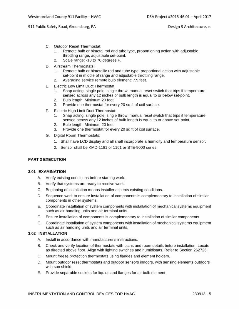
Westmoreland County 911 Facility – HVAC D3A Project #2015-46.01 – April 2017
911 Public Safety Road, Greensburg, PA Design 3 Architecture, PC
INSTRUMENTATION AND CONTROL DEVICES FOR HVAC 230913 - 5
C. Outdoor Reset Thermostat: 1. Remote bulb or bimetal rod and tube type, proportioning action with adjustable
throttling range, adjustable set-point. 2. Scale range: -10 to 70 degrees F.
D. Airstream Thermostats: 1. Remote bulb or bimetallic rod and tube type, proportional action with adjustable
set-point in middle of range and adjustable throttling range. 2. Averaging service remote bulb element: 7.5 feet.
E. Electric Low Limit Duct Thermostat: 1. Snap acting, single pole, single throw, manual reset switch that trips if temperature
sensed across any 12 inches of bulb length is equal to or below set-point, 2. Bulb length: Minimum 20 feet. 3. Provide one thermostat for every 20 sq ft of coil surface.
F. Electric High Limit Duct Thermostat: 1. Snap acting, single pole, single throw, manual reset switch that trips if temperature
sensed across any 12 inches of bulb length is equal to or above set-point, 2. Bulb length: Minimum 20 feet. 3. Provide one thermostat for every 20 sq ft of coil surface.
G. Digital Room Thermostats: 1. Shall have LCD display and all shall incorporate a humidity and temperature sensor. 2. Sensor shall be KMD-1181 or 1161 or STE-9000 series.
PART 3 EXECUTION 3.01 EXAMINATION
A. Verify existing conditions before starting work. B. Verify that systems are ready to receive work. C. Beginning of installation means installer accepts existing conditions. D. Sequence work to ensure installation of components is complementary to installation of similar
components in other systems. E. Coordinate installation of system components with installation of mechanical systems equipment
such as air handling units and air terminal units. F. Ensure installation of components is complementary to installation of similar components. G. Coordinate installation of system components with installation of mechanical systems equipment
such as air handling units and air terminal units. 3.02 INSTALLATION
A. Install in accordance with manufacturer's instructions. B. Check and verify location of thermostats with plans and room details before installation. Locate
as directed above floor. Align with lighting switches and humidistats. Refer to Section 262726. C. Mount freeze protection thermostats using flanges and element holders. D. Mount outdoor reset thermostats and outdoor sensors indoors, with sensing elements outdoors
with sun shield. E. Provide separable sockets for liquids and flanges for air bulb element
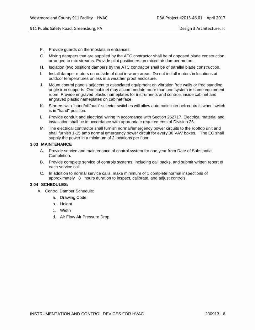
Westmoreland County 911 Facility – HVAC D3A Project #2015-46.01 – April 2017
911 Public Safety Road, Greensburg, PA Design 3 Architecture, PC
INSTRUMENTATION AND CONTROL DEVICES FOR HVAC 230913 - 6
F. Provide guards on thermostats in entrances. G. Mixing dampers that are supplied by the ATC contractor shall be of opposed blade construction
arranged to mix streams. Provide pilot positioners on mixed air damper motors. H. Isolation (two position) dampers by the ATC contractor shall be of parallel blade construction. I. Install damper motors on outside of duct in warm areas. Do not install motors in locations at
outdoor temperatures unless in a weather proof enclosure. J. Mount control panels adjacent to associated equipment on vibration free walls or free standing
angle iron supports. One cabinet may accommodate more than one system in same equipment room. Provide engraved plastic nameplates for instruments and controls inside cabinet and engraved plastic nameplates on cabinet face.
K. Starters with "hand/off/auto" selector switches will allow automatic interlock controls when switch is in "hand" position.
L. Provide conduit and electrical wiring in accordance with Section 262717. Electrical material and installation shall be in accordance with appropriate requirements of Division 26.
M. The electrical contractor shall furnish normal/emergency power circuits to the rooftop unit and shall furnish 1-15 amp normal emergency power circuit for every 30 VAV boxes. The EC shall supply the power in a minimum of 2 locations per floor.
3.03 MAINTENANCE A. Provide service and maintenance of control system for one year from Date of Substantial
Completion. B. Provide complete service of controls systems, including call backs, and submit written report of
each service call. C. In addition to normal service calls, make minimum of 1 complete normal inspections of
approximately 8 hours duration to inspect, calibrate, and adjust controls. 3.04 SCHEDULES:
A. Control Damper Schedule: a. Drawing Code b. Height c. Width d. Air Flow Air Pressure Drop.
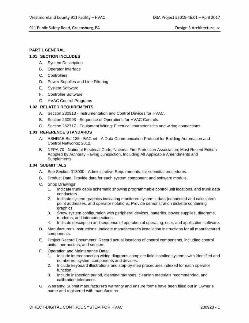
Westmoreland County 911 Facility – HVAC D3A Project #2015-46.01 – April 2017
911 Public Safety Road, Greensburg, PA Design 3 Architecture, PC
DIRECT-DIGITAL CONTROL SYSTEM FOR HVAC 230923 - 1
PART 1 GENERAL 1.01 SECTION INCLUDES
A. System Description B. Operator Interface C. Controllers D. Power Supplies and Line Filtering E. System Software F. Controller Software G. HVAC Control Programs
1.02 RELATED REQUIREMENTS A. Section 230913 - Instrumentation and Control Devices for HVAC. B. Section 230993 - Sequence of Operations for HVAC Controls. C. Section 262717 - Equipment Wiring: Electrical characteristics and wiring connections.
1.03 REFERENCE STANDARDS A. ASHRAE Std 135 - BACnet - A Data Communication Protocol for Building Automation and
Control Networks; 2012. B. NFPA 70 - National Electrical Code; National Fire Protection Association; Most Recent Edition
Adopted by Authority Having Jurisdiction, Including All Applicable Amendments and Supplements.
1.04 SUBMITTALS A. See Section 013000 - Administrative Requirements, for submittal procedures. B. Product Data: Provide data for each system component and software module. C. Shop Drawings:
1. Indicate trunk cable schematic showing programmable control unit locations, and trunk data conductors.
2. Indicate system graphics indicating monitored systems, data (connected and calculated) point addresses, and operator notations. Provide demonstration diskette containing graphics.
3. Show system configuration with peripheral devices, batteries, power supplies, diagrams, modems, and interconnections.
4. Indicate description and sequence of operation of operating, user, and application software. D. Manufacturer's Instructions: Indicate manufacturer's installation instructions for all manufactured
components. E. Project Record Documents: Record actual locations of control components, including control
units, thermostats, and sensors. F. Operation and Maintenance Data:
1. Include interconnection wiring diagrams complete field installed systems with identified and numbered, system components and devices.
2. Include keyboard illustrations and step-by-step procedures indexed for each operator function.
3. Include inspection period, cleaning methods, cleaning materials recommended, and calibration tolerances.
G. Warranty: Submit manufacturer's warranty and ensure forms have been filled out in Owner s name and registered with manufacturer.
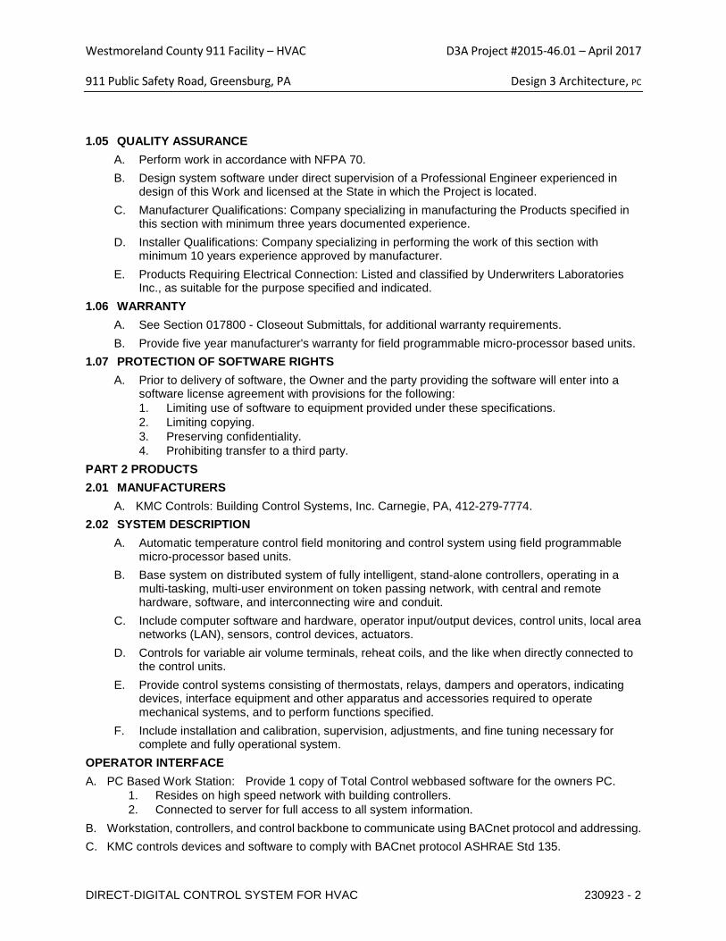
Westmoreland County 911 Facility – HVAC D3A Project #2015-46.01 – April 2017
911 Public Safety Road, Greensburg, PA Design 3 Architecture, PC
DIRECT-DIGITAL CONTROL SYSTEM FOR HVAC 230923 - 2
1.05 QUALITY ASSURANCE A. Perform work in accordance with NFPA 70. B. Design system software under direct supervision of a Professional Engineer experienced in
design of this Work and licensed at the State in which the Project is located. C. Manufacturer Qualifications: Company specializing in manufacturing the Products specified in
this section with minimum three years documented experience. D. Installer Qualifications: Company specializing in performing the work of this section with
minimum 10 years experience approved by manufacturer. E. Products Requiring Electrical Connection: Listed and classified by Underwriters Laboratories
Inc., as suitable for the purpose specified and indicated. 1.06 WARRANTY
A. See Section 017800 - Closeout Submittals, for additional warranty requirements. B. Provide five year manufacturer's warranty for field programmable micro-processor based units.
1.07 PROTECTION OF SOFTWARE RIGHTS A. Prior to delivery of software, the Owner and the party providing the software will enter into a
software license agreement with provisions for the following: 1. Limiting use of software to equipment provided under these specifications. 2. Limiting copying. 3. Preserving confidentiality. 4. Prohibiting transfer to a third party.
PART 2 PRODUCTS 2.01 MANUFACTURERS
A. KMC Controls: Building Control Systems, Inc. Carnegie, PA, 412-279-7774. 2.02 SYSTEM DESCRIPTION
A. Automatic temperature control field monitoring and control system using field programmable micro-processor based units.
B. Base system on distributed system of fully intelligent, stand-alone controllers, operating in a multi-tasking, multi-user environment on token passing network, with central and remote hardware, software, and interconnecting wire and conduit.
C. Include computer software and hardware, operator input/output devices, control units, local area networks (LAN), sensors, control devices, actuators.
D. Controls for variable air volume terminals, reheat coils, and the like when directly connected to the control units.
E. Provide control systems consisting of thermostats, relays, dampers and operators, indicating devices, interface equipment and other apparatus and accessories required to operate mechanical systems, and to perform functions specified.
F. Include installation and calibration, supervision, adjustments, and fine tuning necessary for complete and fully operational system.
OPERATOR INTERFACE A. PC Based Work Station: Provide 1 copy of Total Control webbased software for the owners PC.
1. Resides on high speed network with building controllers. 2. Connected to server for full access to all system information.
B. Workstation, controllers, and control backbone to communicate using BACnet protocol and addressing. C. KMC controls devices and software to comply with BACnet protocol ASHRAE Std 135.
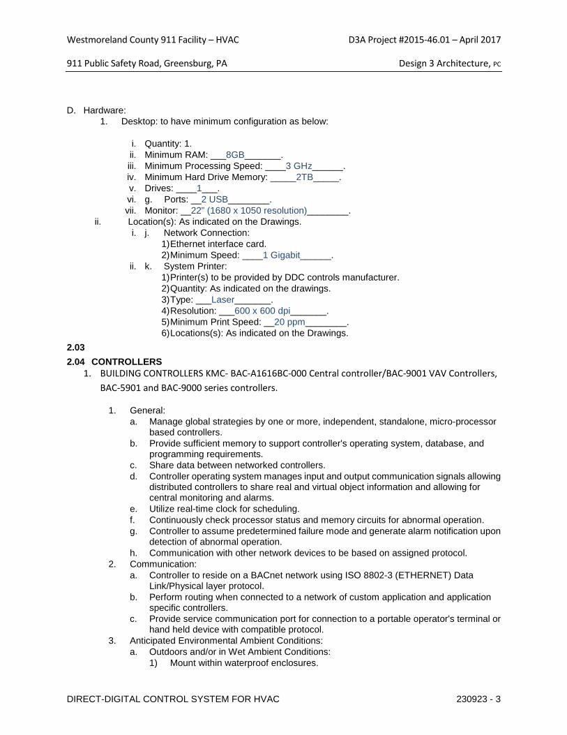
Westmoreland County 911 Facility – HVAC D3A Project #2015-46.01 – April 2017
911 Public Safety Road, Greensburg, PA Design 3 Architecture, PC
DIRECT-DIGITAL CONTROL SYSTEM FOR HVAC 230923 - 3
D. Hardware: 1. Desktop: to have minimum configuration as below:
i. Quantity: 1. ii. Minimum RAM: ___8GB_______. iii. Minimum Processing Speed: ____3 GHz______. iv. Minimum Hard Drive Memory: _____2TB_____. v. Drives: ____1___. vi. g. Ports: __2 USB________. vii. Monitor: __22” (1680 x 1050 resolution)________.
ii. Location(s): As indicated on the Drawings. i. j. Network Connection:
1) Ethernet interface card. 2) Minimum Speed: ____1 Gigabit______.
ii. k. System Printer: 1) Printer(s) to be provided by DDC controls manufacturer. 2) Quantity: As indicated on the drawings. 3) Type: ___Laser_______. 4) Resolution: ___600 x 600 dpi_______. 5) Minimum Print Speed: __20 ppm________. 6) Locations(s): As indicated on the Drawings.
2.03 2.04 CONTROLLERS
1. BUILDING CONTROLLERS KMC- BAC-A1616BC-000 Central controller/BAC-9001 VAV Controllers, BAC-5901 and BAC-9000 series controllers.
1. General: a. Manage global strategies by one or more, independent, standalone, micro-processor
based controllers. b. Provide sufficient memory to support controller's operating system, database, and
programming requirements. c. Share data between networked controllers. d. Controller operating system manages input and output communication signals allowing
distributed controllers to share real and virtual object information and allowing for central monitoring and alarms.
e. Utilize real-time clock for scheduling. f. Continuously check processor status and memory circuits for abnormal operation. g. Controller to assume predetermined failure mode and generate alarm notification upon
detection of abnormal operation. h. Communication with other network devices to be based on assigned protocol.
2. Communication: a. Controller to reside on a BACnet network using ISO 8802-3 (ETHERNET) Data
Link/Physical layer protocol. b. Perform routing when connected to a network of custom application and application
specific controllers. c. Provide service communication port for connection to a portable operator's terminal or
hand held device with compatible protocol. 3. Anticipated Environmental Ambient Conditions:
a. Outdoors and/or in Wet Ambient Conditions: 1) Mount within waterproof enclosures.
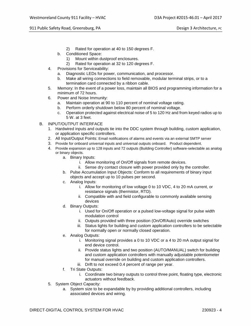
Westmoreland County 911 Facility – HVAC D3A Project #2015-46.01 – April 2017
911 Public Safety Road, Greensburg, PA Design 3 Architecture, PC
DIRECT-DIGITAL CONTROL SYSTEM FOR HVAC 230923 - 4
2) Rated for operation at 40 to 150 degrees F. b. Conditioned Space:
1) Mount within dustproof enclosures. 2) Rated for operation at 32 to 120 degrees F.
4. Provisions for Serviceability: a. Diagnostic LEDs for power, communication, and processor. b. Make all wiring connections to field removable, modular terminal strips, or to a
termination card connected by a ribbon cable. 5. Memory: In the event of a power loss, maintain all BIOS and programming information for a
minimum of 72 hours. 6. Power and Noise Immunity:
a. Maintain operation at 90 to 110 percent of nominal voltage rating. b. Perform orderly shutdown below 80 percent of nominal voltage. c. Operation protected against electrical noise of 5 to 120 Hz and from keyed radios up to
5 W. at 3 feet. B. INPUT/OUTPUT INTERFACE
1. Hardwired inputs and outputs tie into the DDC system through building, custom application, or application specific controllers.
2. All Input/Output Points: Email notifications of alarms and events via an external SMTP server 3. Provide for onboard universal inputs and universal outputs onboard. Product dependent. 4. Provide expansion up to 128 inputs and 72 outputs (Building Controller) software-selectable as analog
or binary objects. a. Binary Inputs:
i. Allow monitoring of On/Off signals from remote devices. ii. Sense dry contact closure with power provided only by the controller.
b. Pulse Accumulation Input Objects: Conform to all requirements of binary input objects and accept up to 10 pulses per second.
c. Analog Inputs: i. Allow for monitoring of low voltage 0 to 10 VDC, 4 to 20 mA current, or
resistance signals (thermistor, RTD). ii. Compatible with and field configurable to commonly available sensing
devices d. Binary Outputs:
i. Used for On/Off operation or a pulsed low-voltage signal for pulse width modulation control
ii. Outputs provided with three position (On/Off/Auto) override switches iii. Status lights for building and custom application controllers to be selectable
for normally open or normally closed operation. e. Analog Outputs:
i. Monitoring signal provides a 0 to 10 VDC or a 4 to 20 mA output signal for end device control.
ii. Provide status lights and two position (AUTO/MANUAL) switch for building and custom application controllers with manually adjustable potentiometer for manual override on building and custom application controllers.
iii. Drift to not exceed 0.4 percent of range per year. f. Tri State Outputs:
i. Coordinate two binary outputs to control three point, floating type, electronic actuators without feedback.
5. System Object Capacity: a. System size to be expandable by by providing additional controllers, including
associated devices and wiring.
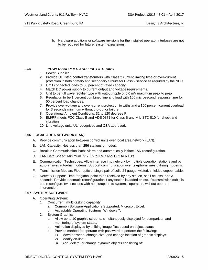
Westmoreland County 911 Facility – HVAC D3A Project #2015-46.01 – April 2017
911 Public Safety Road, Greensburg, PA Design 3 Architecture, PC
DIRECT-DIGITAL CONTROL SYSTEM FOR HVAC 230923 - 5
b. Hardware additions or software revisions for the installed operator interfaces are not to be required for future, system expansions.
2.05 POWER SUPPLIES AND LINE FILTERING 1. Power Supplies: 2. Provide UL listed control transformers with Class 2 current limiting type or over-current
protection in both primary and secondary circuits for Class 2 service as required by the NEC. 3. Limit connected loads to 80 percent of rated capacity. 4. Match DC power supply to current output and voltage requirements. 5. Unit to be full wave rectifier type with output ripple of 5.0 mV maximum peak to peak. 6. Regulation to be 1 percent combined line and load with 100 microsecond response time for
50 percent load changes. 7. Provide over-voltage and over-current protection to withstand a 150 percent current overload
for 3 seconds minimum without trip-out or failure. 8. Operational Ambient Conditions: 32 to 120 degrees F. 9. EM/RF meets FCC Class B and VDE 0871 for Class B and MIL-STD 810 for shock and
vibration. 10. Line voltage units UL recognized and CSA approved.
2.06 LOCAL AREA NETWORK (LAN)
A. Provide communication between control units over local area network (LAN). B. LAN Capacity: Not less than 256 stations or nodes. C. Break in Communication Path: Alarm and automatically initiate LAN reconfiguration. D. LAN Data Speed: Minimum 77.7 Kb to KMC and 19.2 to RTU’s. E. Communication Techniques: Allow interface into network by multiple operation stations and by
auto-answer/auto-dial modems. Support communication over telephone lines utilizing modems. F. Transmission Median: Fiber optic or single pair of solid 24 gauge twisted, shielded copper cable. G. Network Support: Time for global point to be received by any station, shall be less than 3
seconds. Provide automatic reconfiguration if any station is added or lost. If transmission cable is cut, reconfigure two sections with no disruption to system's operation, without operator intervention.
2.07 SYSTEM SOFTWARE A. Operating System:
1. Concurrent, multi-tasking capability. a. Common Software Applications Supported: Microsoft Excel. b. Acceptable Operating Systems: Windows 7.
2. System Graphics: a. Allow up to 10 graphic screens, simultaneously displayed for comparison and
monitoring of system status. b. Animation displayed by shifting image files based on object status. c. Provide method for operator with password to perform the following:
1) Move between, change size, and change location of graphic displays. 2) Modify on-line. 3) Add, delete, or change dynamic objects consisting of:
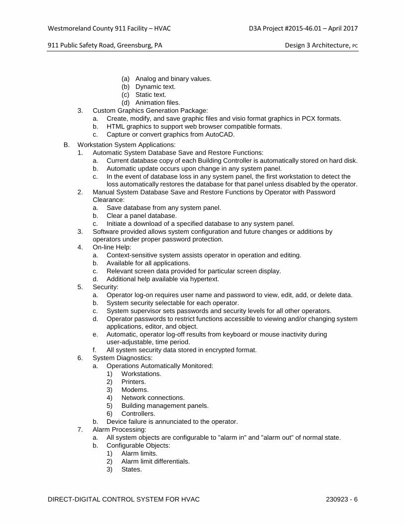
Westmoreland County 911 Facility – HVAC D3A Project #2015-46.01 – April 2017
911 Public Safety Road, Greensburg, PA Design 3 Architecture, PC
DIRECT-DIGITAL CONTROL SYSTEM FOR HVAC 230923 - 6
(a) Analog and binary values. (b) Dynamic text. (c) Static text. (d) Animation files.
3. Custom Graphics Generation Package: a. Create, modify, and save graphic files and visio format graphics in PCX formats. b. HTML graphics to support web browser compatible formats. c. Capture or convert graphics from AutoCAD.
B. Workstation System Applications: 1. Automatic System Database Save and Restore Functions:
a. Current database copy of each Building Controller is automatically stored on hard disk. b. Automatic update occurs upon change in any system panel. c. In the event of database loss in any system panel, the first workstation to detect the
loss automatically restores the database for that panel unless disabled by the operator. 2. Manual System Database Save and Restore Functions by Operator with Password
Clearance: a. Save database from any system panel. b. Clear a panel database. c. Initiate a download of a specified database to any system panel.
3. Software provided allows system configuration and future changes or additions by operators under proper password protection.
4. On-line Help: a. Context-sensitive system assists operator in operation and editing. b. Available for all applications. c. Relevant screen data provided for particular screen display. d. Additional help available via hypertext.
5. Security: a. Operator log-on requires user name and password to view, edit, add, or delete data. b. System security selectable for each operator. c. System supervisor sets passwords and security levels for all other operators. d. Operator passwords to restrict functions accessible to viewing and/or changing system
applications, editor, and object. e. Automatic, operator log-off results from keyboard or mouse inactivity during
user-adjustable, time period. f. All system security data stored in encrypted format.
6. System Diagnostics: a. Operations Automatically Monitored:
1) Workstations. 2) Printers. 3) Modems. 4) Network connections. 5) Building management panels. 6) Controllers.
b. Device failure is annunciated to the operator. 7. Alarm Processing:
a. All system objects are configurable to "alarm in" and "alarm out" of normal state. b. Configurable Objects:
1) Alarm limits. 2) Alarm limit differentials. 3) States.
Westmoreland County 911 Facility – HVAC D3A Project #2015-46.01 – April 2017
911 Public Safety Road, Greensburg, PA Design 3 Architecture, PC
DIRECT-DIGITAL CONTROL SYSTEM FOR HVAC 230923 - 7
4) Reactions for each object. 8. Alarm Messages:
a. Descriptor: English language. b. Recognizable Features:
1) Source. 2) Location. 3) Nature.
9. Configurable Alarm Reactions by Workstation and Time of Day: a. Logging. b. Printing. c. Starting programs. d. Displaying messages. e. Dialing out to remote locations. f. Paging. g. Providing audible annunciation. h. Displaying specific system graphics.
10. Custom Trend Logs: a. Definable for any data object in the system including interval, start time, and stop time. b. Trend Data:
1) Sampled and stored on the building controller panel. 2) Archiving to hard disk. 3) Retrievable for use in reports, spreadsheets and standard database programs. 4) Archival on LAN accessible storage media including hard disk, tape, Raid array
drive, and virtual cloud environment. 5) Protected and encrypted format to prevent manipulation, or editing of historical
data and event logs. 11. Alarm and Event Log:
a. View all system alarms and change of states from any system location. b. Events listed chronologically. c. Operator with proper security acknowledges and clears alarms. d. Alarms not cleared by operator are archived to the workstation hard disk.
12. Object, Property Status and Control: a. Provide a method to view, edit if applicable, the status of any object and property in the
system. b. Status Available by the Following Methods:
1) Menu. 2) Graphics. 3) Custom Programs.
13. Reports and Logs: a. Reporting Package:
1) Allows operator to select, modify, or create reports. 2) Definable as to data content, format, interval, and date. 3) Archived to hard disk.
b. Real-time logs available by type or status such as alarm, lockout, normal, etc. c. Stored on hard disk and readily accessible by standard software applications, including
spreadsheets and word processing. d. Set to be printed on operator command or specific time(s).
14. Reports: a. Standard:
1) Objects with current values.
Westmoreland County 911 Facility – HVAC D3A Project #2015-46.01 – April 2017
911 Public Safety Road, Greensburg, PA Design 3 Architecture, PC
DIRECT-DIGITAL CONTROL SYSTEM FOR HVAC 230923 - 8
2) Current alarms not locked out. 3) Disabled and overridden objects, points and SNVTs. 4) Objects in manual or automatic alarm lockout. 5) Objects in alarm lockout currently in alarm. 6) Logs:
(a) Alarm History. (b) System messages. (c) System events. (d) Trends.
b. Custom: 1) Daily. 2) Weekly. 3) Monthly. 4) Annual. 5) Time and date stamped. 6) Title. 7) Facility name.
c. Tenant Override: 1) Monthly report showing total, requested, after-hours HVAC and lighting services
on a daily basis for each tenant. 2) Annual report showing override usage on a monthly basis.
d. Electrical, Fuel, and Weather: 1) Electrical Meter(s): Where specificed.
(a) Monthly showing daily electrical consumption and peak electrical demand with time and date stamp for each meter.
(b) Annual summary showing monthly electrical consumption and peak demand with time and date stamp for each meter.
2) Fuel Meter(s): Where specified. (a) Monthly showing daily natural gas consumption for each meter. (b) Annual summary showing monthly consumption for each meter.
3) Weather: (a) Monthly showing minimum, maximum, average outdoor air temperature and
heating/cooling degree-days for the month. 2.08 CONTROLLER SOFTWARE
A. All applications reside and operate in the system controllers and editing of all applications occurs at the operator workstation.
B. System Security: 1. User access secured via user passwords and user names. 2. Passwords restrict user to the objects, applications, and system functions as assigned by
the system manager. 3. User Log On/Log Off attempts are recorded. 4. Automatic Log Off occurs following the last keystroke after a user defined delay time.
C. Object or Object Group Scheduling: 1. Weekly Schedules Based on Separate, Daily Schedules:
a. Include start, stop, optimal stop, and night economizer. b. 10 events maximum per schedule. c. Start/stop times adjustable for each group object.
Westmoreland County 911 Facility – HVAC D3A Project #2015-46.01 – April 2017
911 Public Safety Road, Greensburg, PA Design 3 Architecture, PC
DIRECT-DIGITAL CONTROL SYSTEM FOR HVAC 230923 - 9
D. Provide standard application for equipment coordination and grouping based on function and location to be used for scheduling and other applications.
E. Alarms: 1. Binary object is set to alarm based on the operator specified state. 2. Analog object to have high/low alarm limits. 3. All alarming is capable of being automatically and manually disabled. 4. Alarm Reporting:
a. Operator determines action to be taken for alarm event. b. Alarms to be routed to appropriate workstation. c. Reporting Options:
F. Maintenance Management: System monitors equipment status and generates maintenance messages based upon user-designated run-time limits.
G. Sequencing: Application software based upon specified sequences of operation in Section 230993.
H. PID Control Characteristics: .
PART 3 EXECUTION 3.01 EXAMINATION
A. Verify existing conditions before starting work. B. Verify that conditioned power supply is available to the control units and to the operator work
station. Verify that field end devices, wiring, and pneumatic tubing is installed prior to installation proceeding.
3.02 INSTALLATION A. Install control units and other hardware in position on permanent walls where not subject to
excessive vibration. B. Install software in control units and in operator work station. Implement all features of programs to
specified requirements and appropriate to sequence of operation. Refer to Section 230993. C. Provide conduit and electrical wiring in accordance with Section 262717. Electrical material and
installation shall be in accordance with appropriate requirements of Division 26. D. Provide control panels and transformers and install power to the control panels from the power
3.03 MANUFACTURER'S FIELD SERVICES A. Start and commission systems. Allow sufficient time for start-up and commissioning prior to
placing control systems in permanent operation. 3.04 DEMONSTRATION AND INSTRUCTIONS
A. Demonstrate complete and operating system to Owner. 3.05 MAINTENANCE SERVICE
A. Provide service and maintenance of energy management and control systems for one year from Date of Substantial Completion.
B. Provide two complete inspections per year, one in each season, to inspect, calibrate, and adjust controls as required, and submit written reports.
C. Provide complete service of systems, including call backs. Make minimum of _1___ complete normal inspections of approximately __8__ hours duration in addition to normal service calls to inspect, calibrate, and adjust controls, and submit written reports.
Westmoreland County 911 Facility – HVAC D3A Project #2015-46.01 – April 2017
911 Public Safety Road, Greensburg, PA Design 3 Architecture, PC
DIRECT-DIGITAL CONTROL SYSTEM FOR HVAC 230923 - 10
3.06 SCHEDULES A. Input/Output Schedule:
1. Point Description: 2. Digital Input: 3. Digital Output: 4. Analog Input: 5. Analog Output: 6. Alarm:
END OF SECTION
Westmoreland County 911 Facility – HVAC D3A Project #2015-46.01 – April 2017
911 Public Safety Road, Greensburg, PA Design 3 Architecture, PC
SEQUENCE OF OPERATIONS FOR HVAC CONTROLS SECTION 23 09 93 - 1
SECTION 230993 SEQUENCE OF OPERATIONS FOR HVAC CONTROLS PART 1 GENERAL 1.01 SECTION INCLUDES
A. This section defines the manner and method by which controls function. Requirements for each type of control system operation are specified. Equipment, devices, and system components required for control systems are specified in other sections.
B. Sequence of operation for: 1. Heating System 2. Rooftop units. 3. Split systems. 4. VAV boxes. 5. Exhaust fans. 6. Hot water heating system.
1.02 RELATED SECTIONS
A. This section defines the manner and method by which controls function. B. Section 230923 - Direct-Digital Control System for HVAC. C. Section 230913 - Instrumentation and Control Devices for HVAC. D. Section 262717 - Equipment Wiring: Electrical characteristics and wiring connections.
1.03 SUBMITTALS A. This section defines the manner and method by which controls function. Requirements for each
type of control system operation are specified. Equipment, devices, and system components required for control systems are specified in other sections.
B. See Section 013000 - Administrative Requirements, for submittal procedures C. Sequence of Operation Documentation: Submit written sequence of operation for entire HVAC
system and each piece of equipment. 1. Preface: 1 or 2 paragraph overview narrative of the system describing its purpose,
components and function. 2. State each sequence in small segments and give each segment a unique number for
referencing in Functional Test procedures; provide a complete description regardless of the completeness and clarity of the sequences specified in the contract documents.
3. Include at least the following sequences: i. Start-up. ii. Normal operating mode. iii. Unoccupied mode. iv. Shutdown. v. Temperature and pressure control, such as setbacks, setups, resets, etc.
Westmoreland County 911 Facility – HVAC D3A Project #2015-46.01 – April 2017
911 Public Safety Road, Greensburg, PA Design 3 Architecture, PC
SEQUENCE OF OPERATIONS FOR HVAC CONTROLS SECTION 23 09 93 - 2
vi. Detailed sequences for all control strategies, such as economizer control, optimum start/stop, staging, optimization, demand limiting, etc.
vii. Effects of power or equipment failure with all standby component functions viii. Sequences for all alarms and emergency shut downs. ix. Seasonal operational differences and recommendations. x. Interactions and interlocks with other systems.
4. For packaged controlled equipment, include manufacturer's furnished sequence of operation amplified as required to describe the relationship between the packaged controls and the control system, indicating which points are adjustable control points and which points are only monitored.
i. Control System Diagrams: Submit graphic schematic of the control system showing each control component and each component controlled, monitored, or enabled.
ii. Label with settings, adjustable range of control and limits, Include flow diagrams for each control system, graphically depicting control logic.
iii. Include the system and component layout of all equipment that the control system monitors, enables or controls, even if the equipment is primarily controlled by packaged or integral controls.
iv. Include draft copies of graphic displays indicating mechanical system components, control system components, and controlled function status and value.
v. Include all monitoring, control and virtual points specified in elsewhere. vi. Include a key to all abbreviations.
5. Points List: Submit list of all control points indicating at least the following for each point.
i. Name of controlled system. ii. Point abbreviation. iii. Point description; such as dry bulb temperature, airflow, etc. iv. Display unit. v. Control point or set-point (Yes / No); i.e. a point that controls equipment and
can have its set-point changed. vi. Monitoring point (Yes / No); i.e. a point that does not control or contribute to the
control of equipment but is used for operation, maintenance, or performance verification.
vii. Intermediate point (Yes / No); i.e. a point whose value is used to make a calculation which then controls equipment, such as space temperatures that are averaged to a virtual point to control reset.
viii. Calculated point (Yes / No); i.e. a “virtual” point generated from calculations of other point values.
Westmoreland County 911 Facility – HVAC D3A Project #2015-46.01 – April 2017
911 Public Safety Road, Greensburg, PA Design 3 Architecture, PC
SEQUENCE OF OPERATIONS FOR HVAC CONTROLS SECTION 23 09 93 - 3
6. Project Record Documents: Record actual locations of components and set-points of controls, including changes to sequences made after submission of shop drawings.
1.04 QUALITY ASSURANCE A. Design system under direct supervision of a control systems engineer with 5+ years of
experience. 1.05 Alarms:
A. When an alarm is generated an email shall be sent to the ATC contractors email and to email addresses as selected by the owner.
PART 2 PRODUCTS – KMC Products by Building Control Systems Inc. 412-279-7774. PART 3 EXECUTION 3.01 ROOFTOP UNIT 1 and 2 Call Center.
A. All DDC controllers shall have emergency power. B. The units consist of a constant speed supply fan, dx cooling, gas heating and outside air, return
air, exhaust air control dampers. ATC shall furnish supply and return air shut-off dampers and actuators for primary/secondary unit control. The RTU manufacturer shall supply a pre-mounted outside air CFM sensor that will supply a 4/20ma output to the DDC system. The ATC contractor shall furnish and install remote static pressure probes for the relief fan/damper control. The ATC contractor shall furnish supply air/return air shutoff interlock and ends switches for open and closed positions on each damper.
C. The ATC contractor shall furnish and install a control panel for each rooftop unit. The control panel shall be a BACNET panel. The unit manufacturer shall supply a BACNET panel. The unit manufacturer shall supply all software and set-up in order to communicate with the ATC contractor’s BACNET panel. (see points required below). The ATC contractor shall furnish and install the room thermostat. 1 thermostat shall be provided and used by either unit when operational.
D. The system shall operate 24 hours per day. E. Alarms: when an alarm is generated it shall be sent to the owners’ email service and to the
ATC contractors office. F. Provide air flow switches on each unit supply fan, provide supply air temperature sensors and
current switches for the compressors and gas heat to determine operation when commanded on. Provide inputs from the rooftop unit outputs for fan start/stop, compressor start/stop and gas heat control.
G. Primary Secondary: A point on the graphic shall select the primary rooftop unit. If any of the following events occur then the selected primary fan system shall be de-energized and the stand-by rooftop shall be activated. The events are: loss of supply fan air flow for 60 seconds or more, low room air temperature (4 degrees below set-point for 5 minutes or more), high room air temperature (4 degrees above set-point for 10 minutes or more). When any of these
Westmoreland County 911 Facility – HVAC D3A Project #2015-46.01 – April 2017
911 Public Safety Road, Greensburg, PA Design 3 Architecture, PC
SEQUENCE OF OPERATIONS FOR HVAC CONTROLS SECTION 23 09 93 - 4
events occur and alarm shall be sent to the ATC contractor and to the owners selected email. When any unit is selected to operate, the supply air and return air dampers for the selected unit shall open and the supply and return dampers for the non-selected unit shall close. When the damper end switch proves that the dampers are open the supply fan shall energize and the unit shall be placed under control of the wall mounted room thermostat/temperature sensor. If the dampers are commanded open or closed end switches shall verify position, if after a 3 minute delay damper position is not verified an alarm shall be generated. Whenever a unit is activated and alarm shall be generated. The primary air handling unit shall be rotated monthly. 15 minute before rotation and email shall be sent to the owners email service describing the event. After 15 minutes has elapsed the operating RTU shall be de-energized and the non-operating system shall be activated.
H. When any system is activated, the supply and return air damper end switches for that system prove that the dampers are open, the supply fan energizes, the control dampers, the heat and the dx cooling shall be placed under control of a room air temperature control loop to maintain 72 degrees cooling and 70 degrees heating as follows: when the room temperature is below the heating and cooling set-points the outside air dampers shall be at the minimum position, and if the heating loop is calling for heat then the heat is sequentially energized If heat is energized an current switch shall prove operation and if not verified an alarm shall be generated. As the room temperature increases, the heat will de-energize, on a further rise in room temperature above the cooling set point the outside air dampers open and the return dampers closed proportionally. On a further increase in room air temperature the dx cooling shall be sequentially staged. If a compressor is enabled and if a current switch does not prove operation after 60 seconds an alarm shall be generated.
I. The minimum position of the outside air dampers is set to maintain the outside air design CFM by the air balance contractor. The rooftop unit manufacturer will make this BACnet point available to the ATC contractor for the graphical display.
J. On a call for cooling if the internal rooftop unit controller will determine if the total heat of the return is higher than the total heat of the outside air and on a call for cooling, the outside air dampers open to full outside air and the return dampers close. If the mixed air temperature is below 48 degrees then the outside air dampers are modulated closed.
K. A static pressure probe shall be provided in the space this sensor shall be used by the RTU relief pressure control loop to maintain room pressure by modulating the relief dampers and/or fans to maintain .015 inches of WG. (see unit if applicable).
L. The electrical contractor shall provide duct smoke detectors. The ATC contractor shall mount them. The electrical contractor shall provide wiring from the detectors to the fire alarm control panel and provide an interface module to provide fan shut-down of both systems.
M. Low temperature detector shall be provided to de-energize the fan system when the temperature at the detector is below 38 degrees. The detector will be resettable from the
Westmoreland County 911 Facility – HVAC D3A Project #2015-46.01 – April 2017
911 Public Safety Road, Greensburg, PA Design 3 Architecture, PC
SEQUENCE OF OPERATIONS FOR HVAC CONTROLS SECTION 23 09 93 - 5
graphical display. The detector shall be mounted in a non-stratifying area after the mixed air plenum.
N. Emergency power: If normal power is not available a UPS shall keep the ATC control panels on line for 1 hour. If emergency power is available the system shall return to normal
O. Alarms: a. Low supply temperature. b. Low mixed air temperature. c. Supply fan failure. d. Return/exhaust fan failure. (if applicable) e. High supply air temperature. f. Heat failure. g. Compressor failure. h. Supply air damper not open. i. Supply air damper not closed. j. Return air damper not open. k. Return air damper not closed. l. Loss of normal power. m. Fire alarm active. n. Low temperature detector in alarm. o. Unit selection changed.
P. Points: BACNET = RTU to generate. a. Supply Temperature. b. Building static pressure. (If applicable) c. Mixed air temperature. d. Supply Fan status. e. Relief/return fan status. (If applicable) f. Outside air CFM. g. Outside air CFM set-point. h. Outside air temperature. i. Return air temperature. j. Compressor stages. k. Heat capacity. l. Outside air damper position and adjustment. m. Building static pressure set-point adjustment. (If applicable).
Westmoreland County 911 Facility – HVAC D3A Project #2015-46.01 – April 2017
911 Public Safety Road, Greensburg, PA Design 3 Architecture, PC
SEQUENCE OF OPERATIONS FOR HVAC CONTROLS SECTION 23 09 93 - 6
n. Mixed air temperature low limit adjustment. o. Supply air temperature adjustment. p. Safety shutdown. q. System enable/disable. r. Supply air and return air open closed outputs. s. Supply air and return air damper end switch position, 1 for open 1 for close for each
damper. t. Controlled points for:
i. Fan start/stop. ii. Warm up set-point. iii. Room air temperature set-point. (heating and cooling) iv. Outside air damper control. v. Relief static pressure set-point. vi. Damper position
Q. Points by ATC on graphic: a. Unit selection for primary/stand-by. b. Low temperature reset. c. Room air temperature set-point (heating and cooling). d. Minimum OACFM set-point. e. Relief static set-point (if applicable). f. Mixed air low limit set-point. g. Supply air temperature. h. Outside air temperature. i. Return air temperature. j. Alarm shutdown. (generated by unit). k. Supply Fan status. l. Supply and return isolation open and closed damper position.
3.02 ROOFTOP UNIT#3 (ADMINISTRATION).
A. The unit consists of a variable speed supply fan, variable speed relief/return fan, dx cooling, gas heating and outside air, return air and relief air dampers. The mixing box dampers shall be furnished by the air handling unit manufacturer. The rooftop manufacturer shall supply a pre-mounted outside air CFM sensor that will send a 4/20ma output to the DDC system. The ATC contractor shall furnish and install remote static pressure probes for supply fan speed
Westmoreland County 911 Facility – HVAC D3A Project #2015-46.01 – April 2017
911 Public Safety Road, Greensburg, PA Design 3 Architecture, PC
SEQUENCE OF OPERATIONS FOR HVAC CONTROLS SECTION 23 09 93 - 7
control and relief fan/damper control. The ATC contractor shall supply all control components for the unit that may be required to achieve the sequences.
B. The ATC shall provide a remote static pressure probes at 2/3rds the distance from the longest duct run in the supply duct. The probe shall be connected to the static pressure sensor. The sensor shall be used by to control the supply fan VFD to maintain static pressure at 1.5 inches. Upon a fall in static the fan speed increases on a rise in static the fan speed shall decrease. Provide a local static pressure sensor to over-ride the remote static loop if the local static pressure is 4 inches or above to decrease the fan speed.
C. When the supply fan is commanded on, a signal from the VFD shall verify operation. If after 30 seconds operation is not verified > 10 Hz, then an alarm shall be generated.
D. Morning Warm-up: up to 2 hours before the occupied time period and when the outside air temperature is below 55 and if the average room temperature is below 62 the RTU shall be indexed to the morning warmup. When the unit is in morning warm-up mode the outside air dampers shall be closed, and the supply fan shall energize, the gas heat shall energized to supply 95 degree air temperature, the supply fan shall be controlled as described above, and when the supply air temperature is above 75 degrees a HEAT mode signal shall be sent to the VAV boxes. The unit shall remain in this mode until all room temperatures are above 70 degrees or until the time of occupancy is reached. When all room temperatures are above 70 or if the time of occupancy is reached the RTU shall be indexed to the occupied mode.
E. Occupied Mode: During the occupied mode and when flow is proven through the supply fan via the speed reference on the VFD, the control dampers, heat and dx cooling shall be placed under control of a supply air temperature control loop to maintain 55 degrees discharge as follows: When the supply air temperature is below 55 degrees the control dampers close to the minimum position, the heating is energized and the dx cooling is de-energized. When the supply air temperature increases the outside air dampers modulate open and the heating is de-energized, on a further rise in supply air temperature the dx cooling is energized and staged on. When the supply air temperature is below 65 degrees a cool signal is sent to the VAV boxes.
F. When the outside air temperature is above 70 degrees the outside air dampers close to the minimum CFM position. When the outside air temperature is below 68 degrees the dampers are controlled as described above.
G. Un-occupied mode: When any room temperature sensor is below 62 degrees the unit shall energize, the outside air damper shall be closed, the supply fan shall be controlled as described above and the gas heating section shall energized and be controlled to maintain 95 degrees supply air temperature. When the supply air temperature is above 75 degrees then a signal shall be sent to the VAV boxes to index to the heating mode. When all room temperatures are
Westmoreland County 911 Facility – HVAC D3A Project #2015-46.01 – April 2017
911 Public Safety Road, Greensburg, PA Design 3 Architecture, PC
SEQUENCE OF OPERATIONS FOR HVAC CONTROLS SECTION 23 09 93 - 8
above 64 the gas heating shall be de-energized and after a 5 minute delay the supply fan shall de-energize.
H. The minimum position of the outside air dampers is set to maintain the outside air design CFM. I. A static pressure probe shall be provided in the lobby area this sensor shall be used to
modulate the relief air dampers to maintain .015 inches of WG. J. The electrical contractor shall provide duct smoke detectors. The ATC contractor shall mount
them. The electrical contractor shall provide wiring from the detectors to the fire alarm control panel and provide an interface module to provide fan shut-down.
K. Low temperature detector shall be provided to de-energize the fan system when the temperature at the detector is below 38 degrees. The detector will require reset at the graphical display. The detector shall be mounted in a non-stratifying area after the mixed air plenum.
L. Install the RTU provided return air carbon dioxide sensors, the CO2 of the return air shall be maintained at 200 PPM above the CO2 of the outside air by resetting the minimum position set
Westmoreland County 911 Facility – HVAC D3A Project #2015-46.01 – April 2017
911 Public Safety Road, Greensburg, PA Design 3 Architecture, PC
SEQUENCE OF OPERATIONS FOR HVAC CONTROLS SECTION 23 09 93 - 9
point of the outside air dampers. The minimum position shall be maintained about the CFM required to maintain a positive pressure in the facility.
M. Alarms (all alarms sent to the owners’ email and to the ATC email during warranty). The owner shall supply a static IP.
a. Low supply temperature b. Low mixed air temperature c. High CO2 in the return air. d. Low duct static. e. High building static. f. Supply fan failure. g. Return/exhaust fan failure. h. High supply air temperature. i. Heat failure. j. Compressor failure. k. Emergency power is active. l. Fire alarm active. m. Low temperature detector in alarm.
N. Points by ATC or RTU manufacturer.
a. Supply air temperature. b. Outside air CO2. c. Return air CO2. d. Room heating night set-back set-point. e. Mixed air temperature. f. Outside air temperature. g. Return air temperature. h. 2/3rd duct static pressure. i. Lobby static pressure. j. Supply Fan status. k. Outside air CFM. l. Supply fan start/stop. m. Supply fan speed control. n. Outside air/return damper control. o. Relief air damper control.
Westmoreland County 911 Facility – HVAC D3A Project #2015-46.01 – April 2017
911 Public Safety Road, Greensburg, PA Design 3 Architecture, PC
SEQUENCE OF OPERATIONS FOR HVAC CONTROLS SECTION 23 09 93 - 10
p. Compressor(s) start/stop. q. Compressor(s) in alarm. r. Gas heat start/stop. s. Gas heat capacity control. t. Mixed air low limit. u. Low temperature detector. v. Smoke detector input. w. Morning warm-up set-point. x. Minimum OACFM set-point. y. Supply air fan static pressure set-point. z. Relief static set-point.
3.03 VARIABLE AIR VOLUME BOXES
A. The boxes are variable air volume. The ATC contractor shall furnish and install and wire the controller, room thermostat, transformers, supply air temperature sensor and furnish and wire the 3 way control valve for installation by others. Power wiring for the DDC controllers shall be furnished by the ATC contractor. The electrical contractor shall furnish a minimum of 1 30 amp Normal emergency circuit for use by the ATC contractor.
B. The boxes will have modes of control: morning warmup and occupied. a. Morning warmup: When in the un-occupied mode, when the air handling unit supply is
above 75 the box controller shall modulate damper open to AHU air on a fall in room temperature below 70 degrees and modulate the damper closed on a rise in room temperature to 72 degrees.
b. Occupied mode: When the AHU is in the occupied mode and the AHU supply air is below 65 the box will be indexed to the occupied cooling mode. When the box is in the occupied cooling mode and if the room temperature is below the cooling and heating set-points, the reheat control valve modulates to 100% open to coil flow. and the vav box modulates closed towards the minimum design CFM. On an increase in room temperature to the heating set-point the valve closes to coil flow and opens to by-
Westmoreland County 911 Facility – HVAC D3A Project #2015-46.01 – April 2017
911 Public Safety Road, Greensburg, PA Design 3 Architecture, PC
SEQUENCE OF OPERATIONS FOR HVAC CONTROLS SECTION 23 09 93 - 11
pass the coil. On a further rise in temperature above the cooling set-point the box modulates open to the design maximum
a. Points: i. Room temperature. ii. Actuator control. iii. Room set-point. iv. CFM. v. Supply air temperature. vi. CO2. vii. Heating control valve.
b. Alarms: i. Low room temperature. ii. High room temperature. iii. No air flow. iv. Low supply air temperature with valve open.
3.04 EXHAUST FANS.
A. The exhaust fan(s) shall be connected to the DDC panel. When the rooftop or air handling unit is operating in the occupied mode, the exhaust fan energizes. During the un-occupied mode the fan(s) shall be de-energized. Provide current switches on the fans, if the fan is commanded on and after a 30 second delay the fan current is not active then an alarm shall be
Westmoreland County 911 Facility – HVAC D3A Project #2015-46.01 – April 2017
911 Public Safety Road, Greensburg, PA Design 3 Architecture, PC
SEQUENCE OF OPERATIONS FOR HVAC CONTROLS SECTION 23 09 93 - 12
generated. On Exhaust fans with control dampers, the ATC contractor shall provide the interlock wiring for the damper actuator.
B. Provide the following points: a. Fan start/stop. b. Fan status.
3.05 Split systems.
The ATC contractor shall mount and wire the remote controller and provide interlock wiring from the condensing unit to the evaporator. The ATC contractor shall provide a room temperature sensor and a relay to interface with the evaporator alarm contact. A. Provide the following points:
a. Room Temperature. b. Alarm status.
B. Alarms: a. Alarm from evaporator. b. High room temperature >75.
3.06 HOT WATER HEATING SYSTEM
A. The heating system consists of 1 new hot water boiler, 1 primary hot water pump per boiler and two secondary hot water circulating pumps. The system shall operate as follows.
B. A DDC panel shall be located in the boiler equipment room. The panel shall operate the boilers, pumps. The panel shall have a 1 hour UPS and a normal/emergency power circuit.
C. The heating system shall be activated through a seasonal start program in the DDC panel. The seasonal start program shall determine the appropriate outside air temperature and delay the start of the system.
D. The seasonal start program© is based on an annual schedule. When the dates are between October 15 and April 15 and when the outside are temperature is below 65 degrees and if any heating control valve is 25% open or more then the heating system shall be energized 1 hour after these conditions occur and remain in effect. When the outside air temperature is above 75 degrees and all heating valves are closed for 1 hour or more the heating system shall be de-energized. When the dates are between April 16 to October 14 the heating system shall energize when the outside air temperature is below 50 degrees for 4 hours or more. When the outside air temperature is above 80 degrees and if all heating valves are closed for 30 minutes or more the heating system shall be de-energized. If any heating valve is open 25% or more for 10 minutes or more the heating system shall be energized.
E. When the heating system is activated as described above, the boiler water pump shall energize. A differential pressure switch or current sensor shall verify pump operation. If proof of operation is
Westmoreland County 911 Facility – HVAC D3A Project #2015-46.01 – April 2017
911 Public Safety Road, Greensburg, PA Design 3 Architecture, PC
SEQUENCE OF OPERATIONS FOR HVAC CONTROLS SECTION 23 09 93 - 13
not verified after a 30 second time delay, an alarm horn shall sound and a pilot light labeled boiler pump failure shall illuminate at the local control panel.
F. When the heating system is activated as described above, the boiler water secondary pumping system shall energize. The main pump operation shall be rotated weekly. When the system is energized the lead pump shall energize. A differential pressure switch or current sensor shall verify pump operation. If proof of operation is not verified after a 30 second time delay, an alarm horn shall sound and a pilot light labeled Pump (P-X) failure shall illuminate at the local control panel and the lag pump shall energize. A differential pressure switch or current sensor shall verify pump operation. If proof of operation is not verified after a 30 second time delay, an alarm horn shall sound and a pilot light labeled Pump (P-X) failure shall illuminate at the local control panel and the lag pump shall energize. All alarms shall be sent to the ATC contractors office and to the owners’ email service.
G. The existing combustion air damper shall be inspected and any deficiencies will be detailed in writing for review by the owner.
H. When the heating system is active the boiler shall operate to maintain between 135 and 185 degree common supply water temperature by sequencing and modulating the boiler as follows: A Boiler water supply temperature transmitter shall be provided on the leaving side of the boiler. A system return water temperature sensor shall be connected to the DDC panel. When the heating system is activated the heating boiler shall be sequenced to maintain the boiler supply water temperature inversely reset by outside air temperature so that when the outside air temperature is 0 degrees or below the water temperature shall be 185 degrees and 100 degrees when the outside air temperature is 55 or above.
I. A high limit controller shall limit the boiler output to 195 degrees by de-energizing the boiler if the hot water supply temperature is above 195 degrees. The controller shall allow the boiler to operate if the hot water supply temperature is below 190 degrees.
J. Provide break-glass switches where indicated. The switches shall be wired to de-energize the heating boilers and to close a control valve on the domestic hot water gas line when the switches are in an alarm condition.
K. Provide a carbon monoxide sensor and mount the sensor on or adjacent to the control panel. If the CO level is 50 PPM an alarm shall sound at the boiler panel and sent to the email systems. If the CO level rises to 75 PPM the heating systems shall be de-energized and an alarm shall sound
Westmoreland County 911 Facility – HVAC D3A Project #2015-46.01 – April 2017
911 Public Safety Road, Greensburg, PA Design 3 Architecture, PC
SEQUENCE OF OPERATIONS FOR HVAC CONTROLS SECTION 23 09 93 - 14
at the boiler entrance(s). and panel and sent to the owners’ email service.
L. Provide the following alarms: a. Low water supply temperature (10 degrees below set-point after a boiler is energized). b. Pump failure. c. Boiler failure (use a dry contact at the boiler panel. d. Emergency shut down switch in alarm. e. Loss of normal power. f. Loss of emergency power. g. Control valve position below set-point for 5 minutes or more. h. Manual over-ride of any output. i. Carbon monoxide in alarm.
M. Provide the following points:
a. Outside air temperature. b. Outside air CO2. c. Room CO. d. Emergency shut-down switches (1 per any switch). e. Boiler leaving water temperature (each) f. Common water supply temperature after the secondary pump. g. Common water return temperature. h. Boiler normal/alarm status. i. Pump status. j. Pump starts/stop. k. Boiler start/stop. l. Boiler modulation. m. Alarm horn. n. Alarm pilot light.
Westmoreland County 911 Facility – HVAC D3A Project #2015-46.01 – April 2017 911 Public Safety Road, Greensburg, PA Design 3 Architecture, PC
COMMON WORK RESULTS FOR ELECTRICAL 26 05 00 - 1
SECTION 26 05 00 - COMMON WORK RESULTS FOR ELECTRICAL
PART 1 - GENERAL
1.1 RELATED DOCUMENTS
A. Drawings and general provisions of the Contract, including General and Supplementary Conditions and Division 01 Specification Sections, apply to this Section.
1.2 SUMMARY
A. Section Includes: 1. Electrical equipment coordination and installation. 2. Sleeves for raceways and cables. 3. Sleeve seals. 4. Grout. 5. Common electrical installation requirements.
1.3 DEFINITIONS
A. EPDM: Ethylene-propylene-diene terpolymer rubber.
B. NBR: Acrylonitrile-butadiene rubber.
1.4 SUBMITTALS
A. Product Data: For sleeve seals.
1.5 COORDINATION
A. Coordinate arrangement, mounting, and support of electrical equipment: 1. To allow maximum possible headroom unless specific mounting heights that reduce
headroom are indicated. 2. To provide for ease of disconnecting the equipment with minimum interference to other
installations. 3. To allow right of way for piping and conduit installed at required slope. 4. So connecting raceways, cables, wireways, cable trays, and busways will be clear of
obstructions and of the working and access space of other equipment.
B. Coordinate installation of required supporting devices and set sleeves in cast-in-place concrete, masonry walls, and other structural components as they are constructed.
C. Coordinate location of access panels and doors for electrical items that are behind finished surfaces or otherwise concealed.
D. Coordinate sleeve selection and application with selection and application of firestopping.
PART 2 - PRODUCTS
2.1 SLEEVES FOR RACEWAYS AND CABLES
A. Steel Pipe Sleeves: ASTM A 53/A 53M, Type E, Grade B, Schedule 40, galvanized steel, plain ends.
B. Cast-Iron Pipe Sleeves: Cast or fabricated "wall pipe," equivalent to ductile-iron pressure pipe, with plain ends and integral waterstop, unless otherwise indicated.
Westmoreland County 911 Facility – HVAC D3A Project #2015-46.01 – April 2017 911 Public Safety Road, Greensburg, PA Design 3 Architecture, PC
COMMON WORK RESULTS FOR ELECTRICAL 26 05 00 - 2
C. Sleeves for Rectangular Openings: Galvanized sheet steel. 1. Minimum Metal Thickness:
a. For sleeve cross-section rectangle perimeter less than 50 inches and no side more than 16 inches, thickness shall be 0.052 inch.
b. For sleeve cross-section rectangle perimeter equal to, or more than, 50 inches and 1 or more sides equal to, or more than, 16 inches, thickness shall be 0.138 inch.
2.2 SLEEVE SEALS
A. Description: Modular sealing device, designed for field assembly, to fill annular space between sleeve and raceway or cable. 1. Manufacturers: Subject to compliance with requirements, provide products by available
manufacturers offering products that may be incorporated into the Work include, but are not limited to, the following: a. Advance Products & Systems, Inc. b. Calpico, Inc. c. Metraflex Co. d. Pipeline Seal and Insulator, Inc.
2. Sealing Elements: EPDM interlocking links shaped to fit surface of cable or conduit. Include type and number required for material and size of raceway or cable.
3. Pressure Plates: Plastic. Include two for each sealing element. 4. Connecting Bolts and Nuts: Carbon steel with corrosion-resistant coating of length
required to secure pressure plates to sealing elements. Include one for each sealing element.
2.3 GROUT
A. Nonmetallic, Shrinkage-Resistant Grout: ASTM C 1107, factory-packaged, nonmetallic aggregate grout, noncorrosive, nonstaining, mixed with water to consistency suitable for application and a 30-minute working time.
PART 3 - EXECUTION
3.1 COMMON REQUIREMENTS FOR ELECTRICAL INSTALLATION
A. Comply with NECA 1.
B. Measure indicated mounting heights to bottom of unit for suspended items and to center of unit for wall-mounting items.
C. Headroom Maintenance: If mounting heights or other location criteria are not indicated, arrange and install components and equipment to provide maximum possible headroom consistent with these requirements.
D. Equipment: Install to facilitate service, maintenance, and repair or replacement of components of both electrical equipment and other nearby installations. Connect in such a way as to facilitate future disconnecting with minimum interference with other items in the vicinity.
E. Right of Way: Give to piping systems installed at a required slope.
3.2 SLEEVE INSTALLATION FOR ELECTRICAL PENETRATIONS
A. Electrical penetrations occur when raceways, cables, wireways, cable trays, or busways penetrate concrete slabs, concrete or masonry walls, or fire-rated floor and wall assemblies.
B. Concrete Slabs and Walls: Install sleeves for penetrations unless core-drilled holes or formed openings are used. Install sleeves during erection of slabs and walls.
Westmoreland County 911 Facility – HVAC D3A Project #2015-46.01 – April 2017 911 Public Safety Road, Greensburg, PA Design 3 Architecture, PC
COMMON WORK RESULTS FOR ELECTRICAL 26 05 00 - 3
C. Use pipe sleeves unless penetration arrangement requires rectangular sleeved opening.
D. Fire-Rated Assemblies: Install sleeves for penetrations of fire-rated floor and wall assemblies unless openings compatible with firestop system used are fabricated during construction of floor or wall.
E. Cut sleeves to length for mounting flush with both surfaces of walls.
F. Extend sleeves installed in floors 2 inches above finished floor level.
G. Size pipe sleeves to provide 1/4-inch annular clear space between sleeve and raceway or cable, unless indicated otherwise.
H. Seal space outside of sleeves with grout for penetrations of concrete and masonry 1. Promptly pack grout solidly between sleeve and wall so no voids remain. Tool exposed
surfaces smooth; protect grout while curing.
I. Interior Penetrations of Non-Fire-Rated Walls and Floors: Seal annular space between sleeve and raceway or cable, using joint sealant appropriate for size, depth, and location of joint. Comply with requirements in Division 07 Section "Joint Sealants.".
J. Fire-Rated-Assembly Penetrations: Maintain indicated fire rating of walls, partitions, ceilings, and floors at raceway and cable penetrations. Install sleeves and seal raceway and cable penetration sleeves with firestop materials.
K. Roof-Penetration Sleeves: Seal penetration of individual raceways and cables with flexible boot-type flashing units applied in coordination with roofing work.
L. Aboveground, Exterior-Wall Penetrations: Seal penetrations using steel pipe sleeves and mechanical sleeve seals. Select sleeve size to allow for 1-inch annular clear space between pipe and sleeve for installing mechanical sleeve seals.
M. Underground, Exterior-Wall Penetrations: Install cast-iron pipe sleeves. Size sleeves to allow for 1-inch annular clear space between raceway or cable and sleeve for installing mechanical sleeve seals.
3.3 SLEEVE-SEAL INSTALLATION
A. Install to seal exterior wall penetrations.
B. Use type and number of sealing elements recommended by manufacturer for raceway or cable material and size. Position raceway or cable in center of sleeve. Assemble mechanical sleeve seals and install in annular space between raceway or cable and sleeve. Tighten bolts against pressure plates that cause sealing elements to expand and make watertight seal.
3.4 FIRESTOPPING
A. Apply firestopping to penetrations of fire-rated floor and wall assemblies for electrical installations to restore original fire-resistance rating of assembly.
END OF SECTION 26 05 00

(THIS PAGE INTENTIONALLY LEFT BLANK)
Westmoreland County 911 Facility – HVAC D3A Project #2015-46.01 – April 2017 911 Public Safety Road, Greensburg, PA Design 3 Architecture, PC
LOW-VOLTAGE ELECTRICAL POWER CONDUCTORS AND CABLES 26 05 19 - 1
SECTION 26 05 19 - LOW-VOLTAGE ELECTRICAL POWER CONDUCTORS AND CABLES
PART 1 - GENERAL
1.1 RELATED DOCUMENTS
A. Drawings and general provisions of the Contract, including General and Supplementary Conditions and Division 01 Specification Sections, apply to this Section.
1.2 SUMMARY
A. This Section includes the following: 1. Building wires and cables rated 600 V and less. 2. Connectors, splices, and terminations rated 600 V and less. 3. Sleeves and sleeve seals for cables.
1.3 DEFINITIONS
A. EPDM: Ethylene-propylene-diene terpolymer rubber.
B. NBR: Acrylonitrile-butadiene rubber.
1.4 SUBMITTALS
A. Product Data: For each type of product indicated.
B. Qualification Data: For testing agency.
C. Field quality-control test reports.
1.5 COORDINATION
A. Set sleeves in cast-in-place concrete, masonry walls, and other structural components as they are constructed.
PART 2 - PRODUCTS
2.1 CONDUCTORS AND CABLES
A. Manufacturers: Subject to compliance with requirements, provide products by one of the following: 1. Alcan Products Corporation; Alcan Cable Division. 2. American Insulated Wire Corp.; a Leviton Company. 3. General Cable Corporation. 4. Senator Wire & Cable Company. 5. Southwire Company.
B. Copper Conductors: Comply with NEMA WC 70.
C. Conductor Insulation: Comply with NEMA WC 70 for Types THHN-THWN.
D. Multiconductor Cable: Comply with NEMA WC 70 for metal-clad cable, Type MC with ground wire.
Westmoreland County 911 Facility – HVAC D3A Project #2015-46.01 – April 2017 911 Public Safety Road, Greensburg, PA Design 3 Architecture, PC
LOW-VOLTAGE ELECTRICAL POWER CONDUCTORS AND CABLES 26 05 19 - 2
2.2 CONNECTORS AND SPLICES
A. Manufacturers: Subject to compliance with requirements, provide products by one of the following: 1. AFC Cable Systems, Inc. 2. Hubbell Power Systems, Inc. 3. O-Z/Gedney; EGS Electrical Group LLC. 4. 3M; Electrical Products Division. 5. Tyco Electronics Corp.
B. Description: Factory-fabricated connectors and splices of size, ampacity rating, material, type, and class for application and service indicated.
2.3 SLEEVES FOR CABLES
A. Steel Pipe Sleeves: ASTM A 53/A 53M, Type E, Grade B, Schedule 40, galvanized steel, plain ends.
B. Cast-Iron Pipe Sleeves: Cast or fabricated "wall pipe," equivalent to ductile-iron pressure pipe, with plain ends and integral waterstop, unless otherwise indicated.
C. Sleeves for Rectangular Openings: Galvanized sheet steel with minimum 0.052- or 0.138-inch thickness as indicated and of length to suit application.
D. Coordinate sleeve selection and application with selection and application of firestopping.
PART 3 - EXECUTION
3.1 CONDUCTOR MATERIAL APPLICATIONS
A. Feeders: Copper. Solid for No. 10 AWG and smaller; stranded for No. 8 AWG and larger.
B. Branch Circuits: Copper. Solid for No. 10 AWG and smaller; stranded for No. 8 AWG and larger.
3.2 CONDUCTOR INSULATION AND MULTICONDUCTOR CABLE APPLICATIONS AND WIRING METHODS
A. Exposed Branch Circuits, Including in Crawlspaces: Type THHN-THWN, single conductors in raceway.
B. Branch Circuits Concealed in Ceilings, Walls, and Partitions: Metal-clad cable
C. Class 1 Control Circuits: Type THHN-THWN, in raceway.
D. Class 2 Control Circuits: Type THHN-THWN, in raceway.
3.3 INSTALLATION OF CONDUCTORS AND CABLES
A. Conceal cables in finished walls, ceilings, and floors, unless otherwise indicated.
B. Use manufacturer-approved pulling compound or lubricant where necessary; compound used must not deteriorate conductor or insulation. Do not exceed manufacturer's recommended maximum pulling tensions and sidewall pressure values.
C. Use pulling means, including fish tape, cable, rope, and basket-weave wire/cable grips, that will not damage cables or raceway.
Westmoreland County 911 Facility – HVAC D3A Project #2015-46.01 – April 2017 911 Public Safety Road, Greensburg, PA Design 3 Architecture, PC
LOW-VOLTAGE ELECTRICAL POWER CONDUCTORS AND CABLES 26 05 19 - 3
D. Install exposed cables parallel and perpendicular to surfaces of exposed structural members, and follow surface contours where possible.
E. Support cables according to Division 26 Section "Hangers and Supports for Electrical Systems."
F. Identify and color-code conductors and cables according to Division 26 Section "Identification for Electrical Systems."
3.4 CONNECTIONS
A. Tighten electrical connectors and terminals according to manufacturer's published torque-tightening values. If manufacturer's torque values are not indicated, use those specified in UL 486A and UL 486B.
B. Make splices and taps that are compatible with conductor material and that possess equivalent or better mechanical strength and insulation ratings than unspliced conductors.
C. Wiring at Outlets: Install conductor at each outlet, with at least 6 inches of slack.
3.5 SLEEVE INSTALLATION FOR ELECTRICAL PENETRATIONS
A. Coordinate sleeve selection and application with selection and application of firestopping.
B. Concrete Slabs and Walls: Install sleeves for penetrations unless core-drilled holes or formed openings are used. Install sleeves during erection of slabs and walls.
C. Use pipe sleeves unless penetration arrangement requires rectangular sleeved opening.
D. Rectangular Sleeve Minimum Metal Thickness: 1. For sleeve rectangle perimeter less than 50 inches and no side greater than 16 inches,
thickness shall be 0.052 inch. 2. For sleeve rectangle perimeter equal to, or greater than, 50 inches and 1 or more sides
equal to, or greater than, 16 inches, thickness shall be 0.138 inch.
E. Fire-Rated Assemblies: Install sleeves for penetrations of fire-rated floor and wall assemblies unless openings compatible with firestop system used are fabricated during construction of floor or wall.
F. Cut sleeves to length for mounting flush with both wall surfaces.
G. Extend sleeves installed in floors 2 inches above finished floor level.
H. Size pipe sleeves to provide 1/4-inch annular clear space between sleeve and cable.
I. Seal space outside of sleeves with grout for penetrations of concrete and masonry.
J. Interior Penetrations of Non-Fire-Rated Walls and Floors: Seal annular space between sleeve and cable, using joint sealant appropriate for size, depth, and location of joint according to Division 07 Section "Joint Sealants."
K. Fire-Rated-Assembly Penetrations: Maintain indicated fire rating of walls, partitions, ceilings, and floors at cable penetrations. Install sleeves and seal with firestop materials as required to maintain fire rating of wall.
L. Roof-Penetration Sleeves: Seal penetration of individual cables with flexible boot-type flashing units applied in coordination with roofing work.
Westmoreland County 911 Facility – HVAC D3A Project #2015-46.01 – April 2017 911 Public Safety Road, Greensburg, PA Design 3 Architecture, PC
LOW-VOLTAGE ELECTRICAL POWER CONDUCTORS AND CABLES 26 05 19 - 4
M. Aboveground Exterior-Wall Penetrations: Seal penetrations using sleeves and mechanical sleeve seals. Size sleeves to allow for 1-inch annular clear space between pipe and sleeve for installing mechanical sleeve seals.
3.6 SLEEVE-SEAL INSTALLATION
A. Install to seal underground exterior-wall penetrations.
B. Use type and number of sealing elements recommended by manufacturer for cable material and size. Position cable in center of sleeve. Assemble mechanical sleeve seals and install in annular space between cable and sleeve. Tighten bolts against pressure plates that cause sealing elements to expand and make watertight seal.
3.7 FIRESTOPPING
A. Apply firestopping to electrical penetrations of fire-rated floor and wall assemblies to restore original fire-resistance rating of assembly.
END OF SECTION 26 05 19
Westmoreland County 911 Facility – HVAC D3A Project #2015-46.01 – April 2017 911 Public Safety Road, Greensburg, PA Design 3 Architecture, PC
GROUNDING AND BONDING FOR ELECTRICAL SYSTEMS 26 05 26 - 1
SECTION 26 05 26 - GROUNDING AND BONDING FOR ELECTRICAL SYSTEMS
PART 1 - GENERAL
1.1 RELATED DOCUMENTS
A. Drawings and general provisions of Contract, including General and Supplementary Conditions and Division 1 Specification Sections, apply to this Section.
B. This section is a Division 26 Common Work Results for Electrical section, and is a part of each Division 26 section making reference to grounding specified herein.
1.2 SUMMARY
A. This Section includes solid grounding of electrical systems and equipment. It includes basic requirements for grounding for protection of life, equipment, circuits, and systems. Grounding requirements specified in this Section may be supplemented in other sections of these Specifications.
1.3 SUBMITTALS
A. General: Submit the following in accordance with Conditions of Contract and Division 1 Specification Sections. 1. Product data for ground rods, connectors/connection materials, and grounding fittings. 2. Field-testing organization certificate, signed by the Contractor, certifying that the
organization performing field tests complies with the requirements specified in Quality Assurance below.
3. Report of field tests and observations certified by the testing organization.
1.4 QUALITY ASSURANCE
A. Manufacturers: Firms regularly engaged in manufacture of electrical connectors, terminals and fittings of types and ratings required, and ancillary grounding materials, including stranded cable, copper braid and buss, ground rods and plate electrodes, whose products have been in satisfactory use in similar service for not less than 3 years.
B. Installer: Qualified with at least 3 years of successful installation experience on projects with electrical grounding work similar to that required for project.
C. Listing and Labeling: Provide products specified in this Section that are listed and labeled. The terms "listed" and "labeled" shall be defined as they are in the National Electrical Code, Article 100. 1. Listing and Labeling Agency Qualifications: A "Nationally Recognized Testing
Laboratory" (NRTL) as defined in OSHA Regulation 1910.7.
D. Field-Testing Organization Qualifications: To qualify for acceptance, the independent testing organization must demonstrate, based on evaluation of organization-submitted criteria conforming to ASTM E 699, that it has the experience and capability to conduct satisfactorily the testing indicated.
E. Electrical Component Standard: Components and installation shall comply with NFPA 70, "National Electrical Code" (NEC).
F. UL Compliance: Comply with applicable requirements of UL Standards Nos. 467 and 869 pertaining to electrical grounding and bonding.
Westmoreland County 911 Facility – HVAC D3A Project #2015-46.01 – April 2017 911 Public Safety Road, Greensburg, PA Design 3 Architecture, PC
GROUNDING AND BONDING FOR ELECTRICAL SYSTEMS 26 05 26 - 2
G. IEEE Compliance: Comply with applicable requirements of IEEE Standard 142 and 241 pertaining to electrical grounding.
H. For overhead-line construction and medium-voltage underground construction, comply with IEEE C2.
PART 2 - PRODUCTS
2.1 EXOTHERMIC WELDING
A. Manufacturers: Subject to compliance with requirements, provide products by the following: 1. Cadweld. 2. Thermoweld.
B. Exothermic Welded Connections: Provided in kit form and selected for the specific types, sizes, and combinations of conductors and other items to be connected.
C. Field Welding: Comply with AWS Code for procedures, appearance, and quality of welds; and methods used in correcting welding work. Provide welded connections where grounding conductors connect to underground grounding rods/electrodes.
2.2 GROUNDING AND BONDING PRODUCTS
A. Manufacturers: Subject to compliance with requirements, provide products by the following: 1. B-Line Systems Inc. 2. Burndy Corp. 3. Crouse-Hinds Co. 4. Electrical Components Div; Gould Inc. 5. General Electric Supply Co. 6. Ideal Industries, Inc. 7. Thomas and Betts Corp. 8. Western Electric Co.
B. Products: Of types indicated and of sizes and ratings to comply with NEC. Where types, sizes, ratings, and quantities indicated are in excess of NEC requirements, the more stringent requirements and the greater size, rating, and quantity indications govern.
C. Conductor Materials: Copper with 98% conductivity.
2.3 WIRE AND CABLE CONDUCTORS
A. General: Comply with Division 26 Section "Low Voltage Electrical Power Cables."
B. Equipment Grounding Conductor: Green insulated.
C. Grounding Electrode Conductor: Stranded cable.
D. Bare Copper Conductors: Conform to the following: 1. Solid Conductors: ASTM B-3. 2. Assembly of Stranded Conductors: ASTM B-8. 3. Tinned Conductors: ASTM B-33.
E. Underground Conductors: Bare, tinned, stranded, unless otherwise indicated.
Westmoreland County 911 Facility – HVAC D3A Project #2015-46.01 – April 2017 911 Public Safety Road, Greensburg, PA Design 3 Architecture, PC
GROUNDING AND BONDING FOR ELECTRICAL SYSTEMS 26 05 26 - 3
2.4 MISCELLANEOUS CONDUCTORS
A. Ground Buss: Bare annealed copper bars of rectangular cross section.
B. Copper Bonding Conductors: As follows: 1. Bonding Cable: 28 kcmil, 14 strands of No. 17 AWG copper conductor, 1/4” (6.4 mm) in
diameter. 2. Bonding Conductor: No. 4 or No. 6 AWG, stranded copper conductor. 3. Bonding Jumper: Bare copper tape, braided bare copper conductors, terminated with
copper ferrules; 1-5/8” (42 mm) wide and 1/16” (1.5 mm) thick. 4. Tinned Bonding Jumper: Tinned-copper tape, braided copper conductors, terminated
with copper ferrules; 1-5/8” (42 mm) wide and 1/16” (1.5 mm) thick.
C. Braided Bonding Jumpers: Copper tape, braided No. 30 gage bare copper wire, terminated with copper ferrules.
D. Bonding Strap Conductor/Connectors: Soft copper, 0.05” thick and 2” wide, except as indicated.
E. Flexible Jumper Strap: Flexible flat conductor, 480 strands of 30-gage bare copper wire; 3/4" wide, 9-1/2" long; 48,250 cm. Protect braid with copper bolt hole ends with holes sized for 3/8" dia. bolts.
2.5 CONNECTOR PRODUCTS
A. General: Listed and labeled as grounding connectors for the materials used.
B. Pressure Connectors: High-conductivity-plated units.
C. Bolted Clamps: Bolted pressure type connectors, or compression type. Heavy-duty units listed for the application.
D. Aluminum-to-Copper Connections: Bimetallic type, conforming to UL 96, "Lightning Protection Components," or UL 467.
E. Welded Connectors: Exothermic-welded type, in kit form, and selected per manufacturer’s written instructions
2.6 GROUNDING ELECTRODES
A. Ground Rods: Stainless Steel. 1. Size: 3/4” x 10 ft.
B. Signal and Communications: For telephone, alarm, and communication systems provide a #4 AWG minimum green insulated copper conductor in raceway from the grounding electrode system to each terminal cabinet or central equipment location.
C. Bonding Plates, Connectors, Terminals and Clamps: Provide electrical bonding plates, connectors, terminals, lugs and clamps as recommended by bonding plate, connector, terminal and clamp manufacturers for indicated applications.
D. Electrical Grounding Connection Accessories: Provide electrical insulating tape, heat-shrinkable insulating tubing, welding materials, bonding straps, as recommended by accessories manufacturers for type services indicated.
Westmoreland County 911 Facility – HVAC D3A Project #2015-46.01 – April 2017 911 Public Safety Road, Greensburg, PA Design 3 Architecture, PC
GROUNDING AND BONDING FOR ELECTRICAL SYSTEMS 26 05 26 - 4
PART 3 - EXECUTION
3.1 GENERAL
A. Except as otherwise indicated, provide electrical grounding systems indicated; with assembly of materials, including, but not limited to, cables/wires, connectors, terminals (solderless lugs), grounding rods/electrodes and plate electrodes, bonding jumper braid, and additional accessories needed for complete installation. Where more than one type unit meets indicated requirements, selection is Installer's option. Where materials or components are not indicated, provide products complying with NEC, UL, IEEE, and established industry standards for applications indicated.
3.2 INSPECTION
A. Installer must examine areas and conditions under which electrical grounding connections are to be made and notify the Architect in writing of conditions detrimental to proper completion of work. Do not proceed with work until unsatisfactory conditions have been corrected in an acceptable manner.
3.3 APPLICATION
A. Provide electrical grounding systems where shown, in accordance with applicable portions of NEC, with NECA's "Standard of Installation" and in accordance with recognized industry practices to ensure that products comply with requirements and serve intended functions.
B. Provide a green insulated grounding conductor sized in accordance with NEC Table 250-122 in all raceways and cables where the conductor over-current protection is 15 AMPS or larger.
C. Separately derived systems required by NEC to be grounded shall be grounded in accordance with NEC paragraph 250-66.
D. Metal Poles Supporting Outdoor Lighting Fixtures: Ground pole to a grounding electrode as indicated in addition to separate equipment grounding conductor run with supply branch circuit.
E. Equipment Grounding Conductor Terminations: Use bolted pressure clamps.
F. Grounding Bus: Install in IDF and MDF rooms and elsewhere as indicated. 1. Use insulated spacer; space 1” (25.4 mm) from wall and support from wall 6” (150 mm)
above finished floor, unless otherwise indicated.
G. Underground Grounding Conductors: Use tinned copper conductor, No. 2/0 AWG minimum. Bury at least 24” (600 mm) below grade or bury 12” (300 mm) above duct bank when installed as part of the duct bank.
H. Comply with NFPA 70, Article 250, for types, sizes, and quantities of equipment grounding conductors, unless specific types, larger sizes, or more conductors than required by NFPA 70 are indicated.
I. Computer Outlet Circuits: Install insulated equipment grounding conductor in branch-circuit runs from computer-area power panels or power-distribution units.
J. Nonmetallic Raceway: Install an equipment grounding conductor in nonmetallic raceways unless they are designated for telephone or data cables.
Westmoreland County 911 Facility – HVAC D3A Project #2015-46.01 – April 2017 911 Public Safety Road, Greensburg, PA Design 3 Architecture, PC
GROUNDING AND BONDING FOR ELECTRICAL SYSTEMS 26 05 26 - 5
3.4 INSTALLATION
A. General: Ground electrical systems and equipment in accordance with NEC requirements except where the Drawings or Specifications exceed NEC requirements.
B. Coordinate with other electrical work as necessary to interface installation of electrical grounding system with other work.
C. Ground Rods: Locate a minimum of one-rod length from each other and at least the same distance from any other grounding electrode. Interconnect ground rods with bare conductors buried at least 24” below grade. Connect bare-cable ground conductors to ground rods by means of exothermic welds except as otherwise indicated. Make these connections without damaging the copper coating or exposing the steel. Use 3/4” by 10 ft. ground rods except as otherwise indicated. Drive rods until tops are 6” below finished floor or final grade except as otherwise indicated.
D. Metallic Water Service Pipe: Provide insulated copper ground conductors, sized as indicated, from the building main service equipment, or the ground buss, to main metallic water service entrances to the building. Connect ground conductors to the main metallic water service pipes by means of ground clamps. Where a dielectric main water fitting is installed, connect the ground conductor to the street side of the fitting. Do not install a grounding jumper around dielectric fittings.
E. Braided-Type Bonding Jumpers: Install to connect ground clamps on water meter piping to bypass water meters electrically. Use elsewhere for flexible bonding and grounding connections.
F. Route grounding conductors along the shortest and straightest paths possible without obstructing access or placing conductors where they may be subjected to strain, impact, or damage, except as indicated.
G. Bond interior metal piping systems and metal air ducts to equipment ground conductors of pumps, fans, electric heaters, and air cleaners serving individual systems.
H. Bonding Straps and Jumpers: Install so vibration by equipment mounted on vibration isolation hangers and supports is not transmitted to rigidly mounted equipment. Use exothermic-welded connectors for outdoor locations, unless a disconnect-type connection is required; then, use a bolted clamp. Bond straps directly to the basic structure taking care not to penetrate any adjacent parts. Install straps only in locations accessible for maintenance.
I. Bond each above-ground portion of gas piping system upstream from equipment shutoff valve.
3.5 CONNECTIONS
A. General: Make connections in such a manner as to minimize possibility of galvanic action or electrolysis. Select connectors, connection hardware, conductors, and connection methods so metals in direct contact will be galvanically compatible. 1. Use electroplated or hot-tin-coated materials to assure high conductivity and make
contact points closer in order of galvanic series. 2. Make connections with clean bare metal at points of contact. 3. Aluminum to steel connections shall be with stainless steel separators and mechanical
clamps. 4. Aluminum to galvanized steel connections shall be with tin-plated copper jumpers and
mechanical clamps. 5. Coat and seal connections involving dissimilar metals with inert material such as red lead
paint to prevent future penetration of moisture to contact surfaces.
Westmoreland County 911 Facility – HVAC D3A Project #2015-46.01 – April 2017 911 Public Safety Road, Greensburg, PA Design 3 Architecture, PC
GROUNDING AND BONDING FOR ELECTRICAL SYSTEMS 26 05 26 - 6
B. Exothermic Welded Connections: Use for connections to structural steel and for underground connections except those at test wells. Install at connections to ground rods and plate electrodes. Comply with manufacturer's written recommendations. Welds that are puffed up or that show convex surfaces indicating improper cleaning are not acceptable.
C. Terminate insulated equipment grounding conductors for feeders and branch circuits with pressure-type grounding lugs. Where metallic raceways terminate at metallic housings without mechanical and electrical connection to the housing, terminate each conduit with a grounding bushing. Connect grounding bushings with a bare grounding conductor to the ground buss in the housing. Bond electrically non-continuous conduits at both entrances and exits with grounding bushings and bare grounding conductors.
D. Tighten grounding and bonding connectors and terminals, including screws and bolts, in accordance with manufacturer's published torque tightening values for connectors and bolts. Where manufacturer's torqueing requirements are not indicated, tighten connections to comply with torque tightening values specified in UL 486A.
E. Moisture Protection: Where insulated ground conductors are connected to ground rods or ground busses, insulate the entire area of the connection and seal against moisture penetration of the insulation and cable.
3.6 UNDERGROUND DISTRIBUTION SYSTEM GROUNDING
A. Grounding System: Ground non-current-carrying metallic items associated with pad-mounted equipment by connecting them to bare underground cable and grounding electrodes arranged as indicated.
B. Duct Banks: Install a grounding conductor with at least 50% ampacity of the largest phase conductor in the duct bank.
3.7 FIELD QUALITY CONTROL
A. Upon Completion of installation of electrical grounding systems, test ground resistance with ground resistance tester. Where tests show resistance to ground is over 3 ohms, take appropriate action to reduce resistance to 3 ohms, or less, by driving additional ground rods and/or by chemically treating soil encircling ground rod; then retest to demonstrate compliance.
B. Independent Testing Organization: Arrange and pay for the services of a qualified independent electrical testing organization to perform tests described below.
C. Tests: Subject the completed grounding system to a megger test at each location where a maximum ground resistance level is specified, at service disconnect enclosure ground terminal, and at ground test wells. Measure ground resistance without the soil being moistened by any means other than natural precipitation or natural drainage or seepage and without chemical treatment or other artificial means of reducing natural ground resistance. Perform tests by the 2-point method in accordance with Section 9.03 of IEEE 81, "Guide for Measuring Earth Resistivity, Ground Impedance and Earth Surface Potentials of a Grounding System."
D. Ground/resistance maximum values shall be as follows: 1. Equipment rated 500 kVA and less: 10 Ohms. 2. Equipment rated 500 kVA to 1000 kVA: 5 Ohms. 3. Equipment rated over 1000 kVA: 3 Ohms. 4. Pad-mounted equipment: 5 Ohms.
Westmoreland County 911 Facility – HVAC D3A Project #2015-46.01 – April 2017 911 Public Safety Road, Greensburg, PA Design 3 Architecture, PC
GROUNDING AND BONDING FOR ELECTRICAL SYSTEMS 26 05 26 - 7
E. Deficiencies: Where ground resistances exceed specified values, and if directed, modify the grounding system to reduce resistance values. Where measures are directed that exceed those indicated the provisions of the Contract, covering changes will apply.
F. Report: Prepare test reports, certified by the testing organization, of the ground resistance at each test location. Include observations of weather and other phenomena that may affect test results. Describe measures taken to improve test results.
3.8 CLEANING AND ADJUSTING
A. Restore surface features at areas disturbed by excavation and reestablish original grades except as otherwise indicated. Where sod has been removed, replace it as soon as possible after backfilling is completed. Restore areas disturbed by trenching, storing of dirt, cable laying, and other Work to their original condition. Include necessary topsoiling, fertilizing, liming, seeding, sodding, sprigging, or mulching. Restore disturbed paving as indicated.
END OF SECTION 26 05 26

(THIS PAGE INTENTIONALLY LEFT BLANK)
Westmoreland County 911 Facility – HVAC D3A Project #2015-46.01 – April 2017 911 Public Safety Road, Greensburg, PA Design 3 Architecture, PC
HANGERS & SUPPORTS FOR ELECTRICAL SYSTEMS 26 05 29 - 1
SECTION 26 05 29 - HANGERS AND SUPPORTS FOR ELECTRICAL SYSTEMS
PART 1 - GENERAL
1.1 RELATED DOCUMENTS
A. Drawings and general provisions of the Contract, including General and Supplementary Conditions and Division 01 Specification Sections, apply to this Section.
1.2 SUMMARY
A. This Section includes the following: 1. Hangers and supports for electrical equipment and systems. 2. Construction requirements for concrete bases.
1.3 DEFINITIONS
A. EMT: Electrical metallic tubing.
B. IMC: Intermediate metal conduit.
C. RMC: Rigid metal conduit.
1.4 SUBMITTALS
A. Product Data: For the following: 1. Steel slotted support systems. 2. Nonmetallic slotted support systems.
1.5 QUALITY ASSURANCE
A. Welding: Qualify procedures and personnel according to AWS D1.1/D1.1M, "Structural Welding Code - Steel."
B. Comply with NFPA 70.
1.6 COORDINATION
A. Coordinate size and location of concrete bases. Cast anchor-bolt inserts into bases. Concrete, reinforcement, and formwork requirements are specified in Division 03.
B. Coordinate installation of roof curbs, equipment supports, and roof penetrations.
Westmoreland County 911 Facility – HVAC D3A Project #2015-46.01 – April 2017 911 Public Safety Road, Greensburg, PA Design 3 Architecture, PC
HANGERS & SUPPORTS FOR ELECTRICAL SYSTEMS 26 05 29 - 2
PART 2 - PRODUCTS
2.1 SUPPORT, ANCHORAGE, AND ATTACHMENT COMPONENTS
A. Steel Slotted Support Systems: Comply with MFMA-4, factory-fabricated components for field assembly. 1. Manufacturers: Subject to compliance with requirements; provide products by one of the
following: a. Allied Tube & Conduit. b. Cooper B-Line, Inc.; a division of Cooper Industries. c. ERICO International Corporation. d. GS Metals Corp. e. Thomas & Betts Corporation. f. Unistrut; Tyco International, Ltd. g. Wesanco, Inc.
2. Metallic Coatings: Hot-dip galvanized after fabrication and applied according to MFMA-4. 3. Nonmetallic Coatings: Manufacturer's standard PVC, polyurethane, or polyester coating
applied according to MFMA-4. 4. Painted Coatings: Manufacturer's standard painted coating applied according to MFMA-4. 5. Channel Dimensions: Selected for applicable load criteria.
B. Nonmetallic Slotted Support Systems: Structural-grade, factory-formed, glass-fiber-resin channels and angles with 9/16-inch-diameter holes at a maximum of 8 inches o.c., in at least 1 surface. 1. Manufacturers: Subject to compliance with requirements, provide products by one of the
following: a. Allied Tube & Conduit. b. Cooper B-Line, Inc.; a division of Cooper Industries. c. Fabco Plastics Wholesale Limited. d. Seasafe, Inc.
2. Fittings and Accessories: Products of channel and angle manufacturer and designed for use with those items.
3. Fitting and Accessory Materials: Same as channels and angles. 4. Rated Strength: Selected to suit applicable load criteria.
C. Raceway and Cable Supports: As described in NECA 1 and NECA 101.
D. Conduit and Cable Support Devices: Steel hangers, clamps, and associated fittings, designed for types and sizes of raceway or cable to be supported.
E. Support for Conductors in Vertical Conduit: Factory-fabricated assembly consisting of threaded body and insulating wedging plug or plugs for non-armored electrical conductors or cables in riser conduits. Plugs shall have number, size, and shape of conductor gripping pieces as required to suit individual conductors or cables supported. Body shall be malleable iron.
F. Structural Steel for Fabricated Supports and Restraints: ASTM A 36/A 36M, steel plates, shapes, and bars; black and galvanized.
Westmoreland County 911 Facility – HVAC D3A Project #2015-46.01 – April 2017 911 Public Safety Road, Greensburg, PA Design 3 Architecture, PC
HANGERS & SUPPORTS FOR ELECTRICAL SYSTEMS 26 05 29 - 3
G. Mounting, Anchoring, and Attachment Components: Items for fastening electrical items or their supports to building surfaces include the following: 1. Powder-Actuated Fasteners: Threaded-steel stud, for use in hardened portland cement
concrete, steel, or wood, with tension, shear, and pullout capacities appropriate for supported loads and building materials where used. a. Manufacturers: Subject to compliance with requirements, provide products by one
of the following: 1) Hilti Inc. 2) ITW Ramset/Red Head; a division of Illinois Tool Works, Inc. 3) MKT Fastening, LLC. 4) Simpson Strong-Tie Co., Inc.; Masterset Fastening Systems Unit.
2. Mechanical-Expansion Anchors: Insert-wedge-type, [zinc-coated] [stainless] steel, for use in hardened portland cement concrete with tension, shear, and pullout capacities appropriate for supported loads and building materials in which used. a. Manufacturers: Subject to compliance with requirements, provide products by one
of the following: 1) Cooper B-Line, Inc.; a division of Cooper Industries. 2) Empire Tool and Manufacturing Co., Inc. 3) Hilti Inc. 4) ITW Ramset/Red Head; a division of Illinois Tool Works, Inc. 5) MKT Fastening, LLC.
3. Concrete Inserts: Steel or malleable-iron, slotted support system units similar to MSS Type 18; complying with MFMA-4 or MSS SP-58.
4. Clamps for Attachment to Steel Structural Elements: MSS SP-58, type suitable for attached structural element.
5. Through Bolts: Structural type, hex head, and high strength. Comply with ASTM A 325. 6. Toggle Bolts: All-steel springhead type. 7. Hanger Rods: Threaded steel.
2.2 FABRICATED METAL EQUIPMENT SUPPORT ASSEMBLIES
A. Description: Welded or bolted, structural-steel shapes, shop or field fabricated to fit dimensions of supported equipment.
B. Materials: Comply with requirements in Division 05 Section "Metal Fabrications" for steel shapes and plates.
PART 3 - EXECUTION
3.1 APPLICATION
A. Comply with NECA 1 and NECA 101 for application of hangers and supports for electrical equipment and systems except if requirements in this Section are stricter.
B. Maximum Support Spacing and Minimum Hanger Rod Size for Raceway: Space supports for EMT, IMC, and RMC as required by NFPA 70. Minimum rod size shall be 1/4 inch in diameter.
C. Multiple Raceways or Cables: Install trapeze-type supports fabricated with steel slotted support system, sized so capacity can be increased by at least 25 percent in future without exceeding specified design load limits. 1. Secure raceways and cables to these supports with two-bolt conduit clamps.
D. Spring-steel clamps designed for supporting single conduits without bolts may be used for 1-1/2-inch and smaller raceways serving branch circuits and communication systems above suspended ceilings and for fastening raceways to trapeze supports.
Westmoreland County 911 Facility – HVAC D3A Project #2015-46.01 – April 2017 911 Public Safety Road, Greensburg, PA Design 3 Architecture, PC
HANGERS & SUPPORTS FOR ELECTRICAL SYSTEMS 26 05 29 - 4
3.2 SUPPORT INSTALLATION
A. Comply with NECA 1 and NECA 101 for installation requirements except as specified in this Article.
B. Raceway Support Methods: In addition to methods described in NECA 1, EMT may be supported by openings through structure members, as permitted in NFPA 70.
C. Strength of Support Assemblies: Where not indicated, select sizes of components so strength will be adequate to carry present and future static loads within specified loading limits. Minimum static design load used for strength determination shall be weight of supported components plus 200 lb.
D. Mounting and Anchorage of Surface-Mounted Equipment and Components: Anchor and fasten electrical items and their supports to building structural elements by the following methods unless otherwise indicated by code: 1. To Wood: Fasten with lag screws or through bolts. 2. To New Concrete: Bolt to concrete inserts. 3. To Masonry: Approved toggle-type bolts on hollow masonry units and expansion anchor
fasteners on solid masonry units. 4. To Existing Concrete: Expansion anchor fasteners. 5. Instead of expansion anchors, powder-actuated driven threaded studs provided with lock
washers and nuts may be used in existing standard-weight concrete 4 inches thick or greater. Do not use for anchorage to lightweight-aggregate concrete or for slabs less than 4 inches thick.
6. To Steel: Beam clamps (MSS Type 19, 21, 23, 25, or 27) complying with MSS SP-69. 7. To Light Steel: Sheet metal screws. 8. Items Mounted on Hollow Walls and Nonstructural Building Surfaces: Mount cabinets,
panelboards, disconnect switches, control enclosures, pull and junction boxes, transformers, and other devices on slotted-channel racks attached to substrate.
E. Drill holes for expansion anchors in concrete at locations and to depths that avoid reinforcing bars.
3.3 INSTALLATION OF FABRICATED METAL SUPPORTS
A. Comply with installation requirements in Division 05 Section "Metal Fabrications" for site-fabricated metal supports.
B. Cut, fit, and place miscellaneous metal supports accurately in location, alignment, and elevation to support and anchor electrical materials and equipment.
C. Field Welding: Comply with AWS D1.1/D1.1M.
3.4 PAINTING
A. Touchup: Clean field welds and abraded areas of shop paint. Paint exposed areas immediately after erecting hangers and supports. Use same materials as used for shop painting. Comply with SSPC-PA 1 requirements for touching up field-painted surfaces. 1. Apply paint by brush or spray to provide minimum dry film thickness of 2.0 mils.
B. Touchup: Comply with requirements in Division 09 Painting for cleaning and touchup painting of field welds, bolted connections, and abraded areas of shop paint on miscellaneous metal.
C. Galvanized Surfaces: Clean welds, bolted connections, and abraded areas and apply galvanizing-repair paint to comply with ASTM A 780.
END OF SECTION 26 05 29
Westmoreland County 911 Facility – HVAC D3A Project #2015-46.01 – April 2017 911 Public Safety Road, Greensburg, PA Design 3 Architecture, PC
RACEWAY AND BOXES FOR ELECTRICAL SYSTEMS 26 05 33 - 1
SECTION 26 05 33 - RACEWAY AND BOXES FOR ELECTRICAL SYSTEMS
PART 1 - GENERAL
1.1 RELATED DOCUMENTS
A. Drawings and general provisions of the Contract, including General and Supplementary Conditions and Division 01 Specification Sections, apply to this Section.
1.2 SUMMARY
A. This Section includes raceways, fittings, boxes, enclosures, and cabinets for electrical wiring.
1.3 DEFINITIONS
A. EMT: Electrical metallic tubing.
B. ENT: Electrical nonmetallic tubing.
C. EPDM: Ethylene-propylene-diene terpolymer rubber.
D. FMC: Flexible metal conduit.
E. IMC: Intermediate metal conduit.
F. LFMC: Liquidtight flexible metal conduit.
G. LFNC: Liquidtight flexible nonmetallic conduit.
H. NBR: Acrylonitrile-butadiene rubber.
I. RNC: Rigid nonmetallic conduit.
1.4 SUBMITTALS
A. Product Data: For surface raceways, wireways and fittings, floor boxes, hinged-cover enclosures, and cabinets.
B. Shop Drawings: For the following raceway components. Include plans, elevations, sections, details, and attachments to other work. 1. Custom enclosures and cabinets. 2. For handholes and boxes for underground wiring, including the following:
a. Duct entry provisions, including locations and duct sizes. b. Frame and cover design. c. Grounding details. d. Dimensioned locations of cable rack inserts, and pulling-in and lifting irons. e. Joint details.
1.5 QUALITY ASSURANCE
A. Electrical Components, Devices, and Accessories: Listed and labeled as defined in NFPA 70, Article 100, by a testing agency acceptable to authorities having jurisdiction, and marked for intended use.
B. Comply with NFPA 70.
Westmoreland County 911 Facility – HVAC D3A Project #2015-46.01 – April 2017 911 Public Safety Road, Greensburg, PA Design 3 Architecture, PC
RACEWAY AND BOXES FOR ELECTRICAL SYSTEMS 26 05 33 - 2
PART 2 - PRODUCTS
2.1 METAL CONDUIT AND TUBING
A. Manufacturers: Subject to compliance with requirements, provide products by one of the following: 1. AFC Cable Systems, Inc. 2. Alflex Inc. 3. Allied Tube & Conduit; a Tyco International Ltd. Co. 4. Anamet Electrical, Inc.; Anaconda Metal Hose. 5. Electri-Flex Co. 6. Manhattan/CDT/Cole-Flex. 7. Maverick Tube Corporation. 8. O-Z Gedney; a unit of General Signal. 9. Wheatland Tube Company.
B. Rigid Steel Conduit: ANSI C80.1.
C. Aluminum Rigid Conduit: ANSI C80.5.
D. IMC: ANSI C80.6.
E. EMT: ANSI C80.3.
F. FMC: Zinc-coated steel.
G. LFMC: Flexible steel conduit with PVC jacket.
H. Fittings for Conduit (Including all Types and Flexible and Liquidtight), EMT, and Cable: NEMA FB 1; listed for type and size raceway with which used, and for application and environment in which installed. 1. Conduit Fittings for Hazardous (Classified) Locations: Comply with UL 886. 2. Fittings for EMT: Steel type. 3. Coating for Fittings for PVC-Coated Conduit: Minimum thickness, 0.040 inch, with
overlapping sleeves protecting threaded joints.
I. Joint Compound for Rigid Steel Conduit or IMC: Listed for use in cable connector assemblies, and compounded for use to lubricate and protect threaded raceway joints from corrosion and enhance their conductivity.
2.2 NONMETALLIC CONDUIT AND TUBING
A. Manufacturers: Subject to compliance with requirements, provide products by one of the following: 1. AFC Cable Systems, Inc. 2. Anamet Electrical, Inc.; Anaconda Metal Hose. 3. Arnco Corporation. 4. CANTEX Inc. 5. CertainTeed Corp.; Pipe & Plastics Group. 6. Condux International, Inc. 7. ElecSYS, Inc. 8. Electri-Flex Co. 9. Lamson & Sessions; Carlon Electrical Products. 10. Manhattan/CDT/Cole-Flex. 11. RACO; a Hubbell Company. 12. Thomas & Betts Corporation.
Westmoreland County 911 Facility – HVAC D3A Project #2015-46.01 – April 2017 911 Public Safety Road, Greensburg, PA Design 3 Architecture, PC
RACEWAY AND BOXES FOR ELECTRICAL SYSTEMS 26 05 33 - 3
B. ENT: NEMA TC 13.
C. RNC: NEMA TC 2, Type EPC-40-PVC.
D. LFNC: UL 1660.
E. Fittings for ENT and RNC: NEMA TC 3; match to conduit or tubing type and material.
F. Fittings for LFNC: UL 514B.
2.3 NONMETALLIC WIREWAYS
A. Manufacturers: Subject to compliance with requirements, provide products by one of the following: 1. Hoffman. 2. Lamson & Sessions; Carlon Electrical Products.
B. Description: Fiberglass polyester, extruded and fabricated to size and shape indicated, with no holes or knockouts. Cover is gasketed with oil-resistant gasket material and fastened with captive screws treated for corrosion resistance. Connections are flanged, with stainless-steel screws and oil-resistant gaskets.
C. Description: PVC plastic, extruded and fabricated to size and shape indicated, with snap-on cover and mechanically coupled connections with plastic fasteners.
D. Fittings and Accessories: Include couplings, offsets, elbows, expansion joints, adapters, hold-down straps, end caps, and other fittings to match and mate with wireways as required for complete system.
2.4 SURFACE RACEWAYS
A. Surface Nonmetallic Raceways: Two-piece construction, manufactured of rigid PVC with texture and color selected by Architect. 1. Manufacturers: Subject to compliance with requirements, provide products by one of the
following: a. Butler Manufacturing Company; Walker Division. b. Enduro Systems, Inc.; Composite Products Division. c. Hubbell Incorporated; Wiring Device-Kellems Division. d. Lamson & Sessions; Carlon Electrical Products. e. Panduit Corp. f. Walker Systems, Inc.; Wiremold Company (The). g. Wiremold Company (The); Electrical Sales Division.
2.5 BOXES, ENCLOSURES, AND CABINETS
A. Manufacturers: Subject to compliance with requirements, provide products by one of the following: 1. Cooper Crouse-Hinds; Div. of Cooper Industries, Inc. 2. EGS/Appleton Electric. 3. Erickson Electrical Equipment Company. 4. Hoffman. 5. Hubbell Incorporated; Killark Electric Manufacturing Co. Division. 6. O-Z/Gedney; a unit of General Signal. 7. RACO; a Hubbell Company. 8. Robroy Industries, Inc.; Enclosure Division. 9. Scott Fetzer Co.; Adalet Division. 10. Spring City Electrical Manufacturing Company.
Westmoreland County 911 Facility – HVAC D3A Project #2015-46.01 – April 2017 911 Public Safety Road, Greensburg, PA Design 3 Architecture, PC
RACEWAY AND BOXES FOR ELECTRICAL SYSTEMS 26 05 33 - 4
11. Thomas & Betts Corporation. 12. Walker Systems, Inc.; Wiremold Company (The). 13. Woodhead, Daniel Company; Woodhead Industries, Inc. Subsidiary.
B. Sheet Metal Outlet and Device Boxes: NEMA OS 1.
C. Cast-Metal Outlet and Device Boxes: NEMA FB 1, ferrous alloy, Type FD, with gasketed cover.
D. Nonmetallic Outlet and Device Boxes: NEMA OS 2.
E. Nonmetallic Floor Boxes: Nonadjustable, round.
F. Small Sheet Metal Pull and Junction Boxes: NEMA OS 1.
PART 3 - EXECUTION
3.1 RACEWAY APPLICATION
A. Comply with the following indoor applications, unless otherwise indicated: 1. Exposed, Not Subject to Physical Damage: EMT. 2. Exposed, Not Subject to Severe Physical Damage: EMT. 3. Exposed and Subject to Severe Physical Damage: Rigid steel conduit. Includes
raceways in the following locations: a. Loading dock. b. Corridors used for traffic of mechanized carts, forklifts, and pallet-handling units. c. Mechanical rooms.
4. Concealed in Ceilings and Interior Walls and Partitions: EMT. 5. Connection to Vibrating Equipment (Including Transformers and Hydraulic, Pneumatic,
Electric Solenoid, or Motor-Driven Equipment): FMC, except use LFMC in damp or wet locations.
6. Damp or Wet Locations: Rigid steel conduit. 7. Boxes and Enclosures: NEMA 250, Type 1, except use NEMA 250, Type 4, stainless
steel in damp or wet locations.
B. Minimum Raceway Size: 3/4-inch trade size.
C. Raceway Fittings: Compatible with raceways and suitable for use and location. 1. Rigid and Intermediate Steel Conduit: Use threaded rigid steel conduit fittings, unless
otherwise indicated. 2. PVC Externally Coated, Rigid Steel Conduits: Use only fittings listed for use with that
material. Patch and seal all joints, nicks, and scrapes in PVC coating after installing conduits and fittings. Use sealant recommended by fitting manufacturer.
D. Install nonferrous conduit or tubing for circuits operating above 60 Hz. Where aluminum raceways are installed for such circuits and pass through concrete, install in nonmetallic sleeve.
E. Do not install aluminum conduits in contact with concrete.
3.2 INSTALLATION
A. Comply with NECA 1 for installation requirements applicable to products specified in Part 2 except where requirements on Drawings or in this Article are stricter.
B. Keep raceways at least 6 inches away from parallel runs of flues and steam or hot-water pipes. Install horizontal raceway runs above water and steam piping.
C. Complete raceway installation before starting conductor installation.
Westmoreland County 911 Facility – HVAC D3A Project #2015-46.01 – April 2017 911 Public Safety Road, Greensburg, PA Design 3 Architecture, PC
RACEWAY AND BOXES FOR ELECTRICAL SYSTEMS 26 05 33 - 5
D. Support raceways as specified in Division 26 Section "Hangers and Supports for Electrical Systems."
E. Arrange stub-ups so curved portions of bends are not visible above the finished slab.
F. Install no more than the equivalent of three 90-degree bends in any conduit run except for communications conduits, for which fewer bends are allowed.
G. Conceal conduit and EMT within finished walls, ceilings, and floors, unless otherwise indicated.
H. Threaded Conduit Joints, Exposed to Wet, Damp, Corrosive, or Outdoor Conditions: Apply listed compound to threads of raceway and fittings before making up joints. Follow compound manufacturer's written instructions.
I. Raceway Terminations at Locations Subject to Moisture or Vibration: Use insulating bushings to protect conductors, including conductors smaller than No. 4 AWG.
J. Install pull wires in empty raceways. Use polypropylene or monofilament plastic line with not less than 200-lb tensile strength. Leave at least 12 inches of slack at each end of pull wire.
K. Install raceway sealing fittings at suitable, approved, and accessible locations and fill them with listed sealing compound. For concealed raceways, install each fitting in a flush steel box with a blank cover plate having a finish similar to that of adjacent plates or surfaces. Install raceway sealing fittings at the following points: 1. Where conduits pass from warm to cold locations, such as boundaries of refrigerated
spaces. 2. Where otherwise required by NFPA 70.
L. Flexible Conduit Connections: Use maximum of 72 inches of flexible conduit for recessed and semi-recessed lighting fixtures, equipment subject to vibration, noise transmission, or movement; and for transformers and motors. 1. Use LFMC in damp or wet locations subject to severe physical damage. 2. Use LFMC or LFNC in damp or wet locations not subject to severe physical damage.
M. Recessed Boxes in Masonry Walls: Saw-cut opening for box in center of cell of masonry block, and install box flush with surface of wall.
N. Set metal floor boxes level and flush with finished floor surface.
O. Set nonmetallic floor boxes level. Trim after installation to fit flush with finished floor surface.
3.3 SLEEVE INSTALLATION FOR ELECTRICAL PENETRATIONS
A. Coordinate sleeve selection and application with selection and application of firestopping.
B. Concrete Slabs and Walls: Install sleeves for penetrations unless core-drilled holes or formed openings are used. Install sleeves during erection of slabs and walls.
C. Use pipe sleeves unless penetration arrangement requires rectangular sleeved opening.
D. Rectangular Sleeve Minimum Metal Thickness: 1. For sleeve cross-section rectangle perimeter less than 50 inches and no side greater
than 16 inches, thickness shall be 0.052 inch. 2. For sleeve cross-section rectangle perimeter equal to, or greater than, 50 inches and 1 or
more sides equal to, or greater than, 16 inches, thickness shall be 0.138 inch.
Westmoreland County 911 Facility – HVAC D3A Project #2015-46.01 – April 2017 911 Public Safety Road, Greensburg, PA Design 3 Architecture, PC
RACEWAY AND BOXES FOR ELECTRICAL SYSTEMS 26 05 33 - 6
E. Fire-Rated Assemblies: Install sleeves for penetrations of fire-rated floor and wall assemblies unless openings compatible with firestop system used are fabricated during construction of floor or wall.
F. Cut sleeves to length for mounting flush with both surfaces of walls.
G. Extend sleeves installed in floors 2 inches above finished floor level.
H. Size pipe sleeves to provide 1/4-inch annular clear space between sleeve and raceway.
I. Seal space outside of sleeves with grout for penetrations of concrete and masonry.
J. Interior Penetrations of Non-Fire-Rated Walls and Floors: Seal annular space between sleeve and raceway, using joint sealant appropriate for size, depth, and location of joint. Refer to Division 07 Section "Joint Sealants" for materials and installation.
K. Fire-Rated-Assembly Penetrations: Maintain indicated fire rating of walls, partitions, ceilings, and floors at raceway penetrations. Install sleeves and seal with firestop materials.
L. Roof-Penetration Sleeves: Seal penetration of individual raceways with flexible, boot-type flashing units applied in coordination with roofing work.
M. Aboveground, Exterior-Wall Penetrations: Seal penetrations using sleeves and mechanical sleeve seals. Select sleeve size to allow for 1-inch annular clear space between pipe and sleeve for installing mechanical sleeve seals.
3.4 SLEEVE-SEAL INSTALLATION
A. Install to seal underground, exterior wall penetrations.
B. Use type and number of sealing elements recommended by manufacturer for raceway material and size. Position raceway in center of sleeve. Assemble mechanical sleeve seals and install in annular space between raceway and sleeve. Tighten bolts against pressure plates that cause sealing elements to expand and make watertight seal.
3.5 FIRESTOPPING
A. Apply firestopping to electrical penetrations of fire-rated floor and wall assemblies to restore original fire-resistance rating of assembly.
3.6 PROTECTION
A. Provide final protection and maintain conditions that ensure coatings, finishes, and cabinets are without damage or deterioration at time of Substantial Completion. 1. Repair damage to galvanized finishes with zinc-rich paint recommended by
manufacturer. 2. Repair damage to PVC or paint finishes with matching touchup coating recommended by
manufacturer.
END OF 26 05 33
Westmoreland County 911 Facility – HVAC D3A Project #2015-46.01 – April 2017 911 Public Safety Road, Greensburg, PA Design 3 Architecture, PC
IDENTIFICATION FOR ELECTRICAL SYSTEMS 26 05 53 - 1
SECTION 26 05 53 - IDENTIFICATION FOR ELECTRICAL SYSTEMS
PART 1 - GENERAL
1.1 RELATED DOCUMENTS
A. Drawings and general provisions of the Contract, including General and Supplementary Conditions and Division 01 Specification Sections, apply to this Section.
1.2 SUMMARY
A. Section Includes: 1. Identification for raceways. 2. Identification of power and control cables. 3. Identification for conductors. 4. Underground-line warning tape. 5. Warning labels and signs. 6. Instruction signs. 7. Equipment identification labels. 8. Miscellaneous identification products.
1.3 SUBMITTALS
A. Product Data: For each electrical identification product indicated.
B. Samples: For each type of label and sign to illustrate size, colors, lettering style, mounting provisions, and graphic features of identification products.
C. Identification Schedule: An index of nomenclature of electrical equipment and system components used in identification signs and labels.
1.4 QUALITY ASSURANCE
A. Comply with ANSI A13.1 and IEEE C2.
B. Comply with NFPA 70.
C. Comply with 29 CFR 1910.144 and 29 CFR 1910.145.
D. Comply with ANSI Z535.4 for safety signs and labels.
E. Adhesive-attached labeling materials, including label stocks, laminating adhesives, and inks used by label printers, shall comply with UL 969.
1.5 COORDINATION
A. Coordinate identification names, abbreviations, colors, and other features with requirements in other Sections requiring identification applications, Drawings, Shop Drawings, manufacturer's wiring diagrams, and the Operation and Maintenance Manual; and with those required by codes, standards, and 29 CFR 1910.145. Use consistent designations throughout Project.
B. Coordinate installation of identifying devices with completion of covering and painting of surfaces where devices are to be applied.
C. Coordinate installation of identifying devices with location of access panels and doors.
D. Install identifying devices before installing acoustical ceilings and similar concealment.
Westmoreland County 911 Facility – HVAC D3A Project #2015-46.01 – April 2017 911 Public Safety Road, Greensburg, PA Design 3 Architecture, PC
IDENTIFICATION FOR ELECTRICAL SYSTEMS 26 05 53 - 2
PART 2 - PRODUCTS
2.1 POWER RACEWAY IDENTIFICATION MATERIALS
A. Comply with ANSI A13.1 for minimum size of letters for legend and for minimum length of color field for each raceway size.
B. Colors for Raceways Carrying Circuits at 600 V or Less: 1. Black letters on an orange field. 2. Legend: Indicate voltage.
C. Self-Adhesive Vinyl Labels for Raceways Carrying Circuits at 600 V or Less: Preprinted, flexible label laminated with a clear, weather- and chemical-resistant coating and matching wraparound adhesive tape for securing ends of legend label.
D. Snap-Around Labels for Raceways Carrying Circuits at 600 V or Less: Slit, pre-tensioned, flexible, preprinted, color-coded acrylic sleeve, with diameter sized to suit diameter of raceway or cable it identifies and to stay in place by gripping action.
E. Snap-Around, Color-Coding Bands for Raceways Carrying Circuits at 600 V or Less: Slit, pre-tensioned, flexible, solid-colored acrylic sleeve, 2 inches long, with diameter sized to suit diameter of raceway or cable it identifies and to stay in place by gripping action.
F. Metal Tags: Brass or aluminum, 2 by 2 by 0.05 inch, with stamped legend, punched for use with self-locking cable tie fastener.
2.2 ARMORED AND METAL-CLAD CABLE IDENTIFICATION MATERIALS
A. Comply with ANSI A13.1 for minimum size of letters for legend and for minimum length of color field for each raceway and cable size.
B. Colors for Raceways Carrying Circuits at 600 V and Less: 1. Black letters on an orange field. 2. Legend: Indicate voltage.
C. Self-Adhesive Vinyl Labels: Preprinted, flexible label laminated with a clear, weather- and chemical-resistant coating and matching wraparound adhesive tape for securing ends of legend label.
D. Self-Adhesive Vinyl Tape: Colored, heavy duty, waterproof, fade resistant; 2 inches wide; compounded for outdoor use.
2.3 POWER AND CONTROL CABLE IDENTIFICATION MATERIALS
A. Comply with ANSI A13.1 for minimum size of letters for legend and for minimum length of color field for each raceway and cable size.
B. Self-Adhesive Vinyl Labels: Preprinted, flexible label laminated with a clear, weather- and chemical-resistant coating and matching wraparound adhesive tape for securing ends of legend label.
C. Metal Tags: Brass or aluminum, 2 by 2 by 0.05 inch, with stamped legend, punched for use with self-locking cable tie fastener.
Westmoreland County 911 Facility – HVAC D3A Project #2015-46.01 – April 2017 911 Public Safety Road, Greensburg, PA Design 3 Architecture, PC
IDENTIFICATION FOR ELECTRICAL SYSTEMS 26 05 53 - 3
D. Write-On Tags: Polyester tag, 0.010-inch-thick, with corrosion-resistant grommet and cable tie for attachment to conductor or cable. 1. Marker for Tags: Permanent, waterproof, black ink marker recommended by tag
manufacturer. 2. Marker for Tags: Machine-printed, permanent, waterproof, black ink marker
recommended by printer manufacturer.
E. Snap-Around Labels: Slit, pre-tensioned, flexible, preprinted, color-coded acrylic sleeve, with diameter sized to suit diameter of raceway or cable it identifies and to stay in place by gripping action.
F. Snap-Around, Color-Coding Bands: Slit, pre-tensioned, flexible, solid-colored acrylic sleeve, 2 inches long, with diameter sized to suit diameter of raceway or cable it identifies and to stay in place by gripping action.
2.4 CONDUCTOR IDENTIFICATION MATERIALS
A. Color-Coding Conductor Tape: Colored, self-adhesive vinyl tape not less than 3 mils thick by 1 to 2 inches wide.
B. Self-Adhesive Vinyl Labels: Preprinted, flexible label laminated with a clear, weather- and chemical-resistant coating and matching wraparound adhesive tape for securing ends of legend label.
C. Marker Tapes: Vinyl or vinyl-cloth, self-adhesive wraparound type, with circuit identification legend machine printed by thermal transfer or equivalent process. 1.
2.5 WARNING LABELS AND SIGNS
A. Comply with NFPA 70 and 29 CFR 1910.145.
B. Self-Adhesive Warning Labels: Factory-printed, multicolor, pressure-sensitive adhesive labels, configured for display on front cover, door, or other access to equipment unless otherwise indicated.
C. Baked-Enamel Warning Signs: 1. Preprinted aluminum signs, punched or drilled for fasteners, with colors, legend, and size
required for application. 2. 1/4-inch grommets in corners for mounting. 3. Nominal size, 7 by 10 inches.
D. Metal-Backed, Butyrate Warning Signs: 1. Weather-resistant, nonfading, preprinted, cellulose-acetate butyrate signs with 0.0396-
inch galvanized-steel backing; and with colors, legend, and size required for application. 2. 1/4-inch grommets in corners for mounting. 3. Nominal size, 10 by 14 inches.
E. Warning label and sign shall include, but are not limited to, the following legends: 1. Multiple Power Source Warning: "DANGER - ELECTRICAL SHOCK HAZARD -
EQUIPMENT HAS MULTIPLE POWER SOURCES." 2. Workspace Clearance Warning: "WARNING - OSHA REGULATION - AREA IN FRONT
OF ELECTRICAL EQUIPMENT MUST BE KEPT CLEAR FOR 36 INCHES."
Westmoreland County 911 Facility – HVAC D3A Project #2015-46.01 – April 2017 911 Public Safety Road, Greensburg, PA Design 3 Architecture, PC
IDENTIFICATION FOR ELECTRICAL SYSTEMS 26 05 53 - 4
2.6 INSTRUCTION SIGNS
A. Engraved, laminated acrylic or melamine plastic, minimum 1/16-inch thick for signs up to 20 sq. inches and 1/8-inch thick for larger sizes. 1. Engraved legend with black letters on white face. 2. Punched or drilled for mechanical fasteners. 3. Framed with mitered acrylic molding and arranged for attachment at applicable
equipment.
B. Adhesive Film Label: Machine printed, in black, by thermal transfer or equivalent process. Minimum letter height shall be 3/8 inch.
C. Adhesive Film Label with Clear Protective Overlay: Machine printed, in black, by thermal transfer or equivalent process. Minimum letter height shall be 3/8 inch. Overlay shall provide a weatherproof and UV-resistant seal for label.
2.7 EQUIPMENT IDENTIFICATION LABELS
A. Adhesive Film Label: Machine printed, in black, by thermal transfer or equivalent process. Minimum letter height shall be 3/8 inch.
B. Adhesive Film Label with Clear Protective Overlay: Machine printed, in black, by thermal transfer or equivalent process. Minimum letter height shall be 3/8 inch. Overlay shall provide a weatherproof and UV-resistant seal for label.
C. Self-Adhesive, Engraved, Laminated Acrylic or Melamine Label: Adhesive backed, with white letters on a dark-gray background. Minimum letter height shall be 3/8 inch.
D. Engraved, Laminated Acrylic or Melamine Label: Punched or drilled for screw mounting. White letters on a dark-gray background. Minimum letter height shall be 3/8 inch.
2.8 CABLE TIES
A. General-Purpose Cable Ties: Fungus inert, self-extinguishing, one piece, self-locking, Type 6/6 nylon. 1. Minimum Width: 3/16 inch. 2. Tensile Strength at 73 deg F, According to ASTM D 638: 12,000 psi. 3. Temperature Range: Minus 40 to plus 185 deg F. 4. Color: Black except where used for color-coding.
2.9 MISCELLANEOUS IDENTIFICATION PRODUCTS
A. Paint: Comply with requirements in Division 09 painting Sections for paint materials and application requirements. Select paint system applicable for surface material and location (exterior or interior).
B. Fasteners for Labels and Signs: Self-tapping, stainless-steel screws or stainless-steel machine screws with nuts and flat and lock washers.
Westmoreland County 911 Facility – HVAC D3A Project #2015-46.01 – April 2017 911 Public Safety Road, Greensburg, PA Design 3 Architecture, PC
IDENTIFICATION FOR ELECTRICAL SYSTEMS 26 05 53 - 5
PART 3 - EXECUTION
3.1 INSTALLATION
A. Verify identity of each item before installing identification products.
B. Location: Install identification materials and devices at locations for most convenient viewing without interference with operation and maintenance of equipment.
C. Apply identification devices to surfaces that require finish after completing finish work.
D. Self-Adhesive Identification Products: Clean surfaces before application, using materials and methods recommended by manufacturer of identification device.
E. Attach signs and plastic labels that are not self-adhesive type with mechanical fasteners appropriate to the location and substrate.
F. System Identification Color-Coding Bands for Raceways and Cables: Each color-coding band shall completely encircle cable or conduit. Place adjacent bands of two-color markings in contact, side by side. Locate bands at changes in direction, at penetrations of walls and floors, at 50-foot maximum intervals in straight runs, and at 25-foot maximum intervals in congested areas.
G. Aluminum Wraparound Marker Labels and Metal Tags: Secure tight to surface of conductor or cable at a location with high visibility and accessibility.
H. Cable Ties: For attaching tags. Use general-purpose type, except as listed below: 1. Outdoors: UV-stabilized nylon. 2. In Spaces Handling Environmental Air: Plenum rated.
I. Painted Identification: Comply with requirements in Division 09 painting Sections for surface preparation and paint application.
3.2 IDENTIFICATION SCHEDULE
A. Accessible Raceways and Metal-Clad Cables, 600 V or Less, for Service, Feeder, and Branch Circuits More Than 30A: Identify with self-adhesive vinyl label. Install labels at 10-footmaximum intervals.
B. Workspace Indication: Install floor marking tape to show working clearances in the direction of access to live parts. Workspace shall be as required by NFPA 70 and 29 CFR 1926.403 unless otherwise indicated. Do not install at flush-mounted panelboards and similar equipment in finished spaces.
C. Warning Labels for Indoor Cabinets, Boxes, and Enclosures for Power and Lighting: Self-adhesive warning labels. 1. Comply with 29 CFR 1910.145. 2. Identify system voltage with black letters on an orange background. 3. Apply to exterior of door, cover, or other access. 4. For equipment with multiple power or control sources, apply to door or cover of
equipment including, but not limited to, the following: a. Power transfer switches. b. Controls with external control power connections.
Westmoreland County 911 Facility – HVAC D3A Project #2015-46.01 – April 2017 911 Public Safety Road, Greensburg, PA Design 3 Architecture, PC
IDENTIFICATION FOR ELECTRICAL SYSTEMS 26 05 53 - 6
D. Equipment Identification Labels: On each unit of equipment, install unique designation label that is consistent with wiring diagrams, schedules, and the Operation and Maintenance Manual. Apply labels to disconnect switches and protection equipment, central or master units, control panels, control stations, terminal cabinets, and racks of each system. Systems include power, lighting, control, communication, signal, monitoring, and alarm systems unless equipment is provided with its own identification. 1. Labeling Instructions:
a. Indoor Equipment: Adhesive film label. Unless otherwise indicated, provide a single line of text with 1/2-inch-high letters on 1-1/2-inch-high label; where two lines of text are required, use labels 2 inches high.
b. Outdoor Equipment: Engraved, laminated acrylic or melamine label. c. Elevated Components: Increase sizes of labels and letters to those appropriate for
viewing from the floor. d. Unless provided with self-adhesive means of attachment, fasten labels with
appropriate mechanical fasteners that do not change the NEMA or NRTL rating of the enclosure.
2. Equipment to Be Labeled: a. Panelboards: Typewritten directory of circuits in the location provided by
panelboard manufacturer. Panelboard identification shall be laminated acrylic or melamine label.
b. Enclosures and electrical cabinets. c. Access doors and panels for concealed electrical items. d. Enclosed switches. e. Enclosed circuit breakers.
END OF SECTION 26 05 53
Westmoreland County 911 Facility – HVAC D3A Project #2015-46.01 – April 2017 911 Public Safety Road, Greensburg, PA Design 3 Architecture, PC
ENCLOSED SWITCHES AND CIRCUIT BREAKERS 26 28 16 - 1
SECTION 26 28 16 - ENCLOSED SWITCHES AND CIRCUIT BREAKERS
PART 1 - GENERAL
1.1 RELATED DOCUMENTS
A. Drawings and general provisions of the Contract, including General and Supplementary Conditions and other Division 01 Specification Sections, apply to this Section.
1.2 SUMMARY
A. Section Includes: 1. Fusible switches. 2. Non-fusible switches. 3. Receptacle switches. 4. Enclosures.
1.3 DEFINITIONS
A. NC: Normally closed.
B. NO: Normally open.
C. SPDT: Single pole, double throw.
1.4 SUBMITTALS
A. Product Data: For each type of enclosed switch, circuit breaker, accessory, and component indicated. Include dimensioned elevations, sections, weights, and manufacturers' technical data on features, performance, electrical characteristics, ratings, accessories, and finishes. 1. Enclosure types and details for types other than NEMA 250, Type 1. 2. Current and voltage ratings. 3. Short-circuit current ratings (interrupting and withstand, as appropriate). 4. Include evidence of NRTL listing for series rating of installed devices. 5. Detail features, characteristics, ratings, and factory settings of individual overcurrent
protective devices, accessories, and auxiliary components.
B. Shop Drawings: For enclosed switches and circuit breakers. Include plans, elevations, sections, details, and attachments to other work. 1. Wiring Diagrams: For power, signal, and control wiring.
1.5 QUALITY ASSURANCE
A. Electrical Components, Devices, and Accessories: Listed and labeled as defined in NFPA 70, by a qualified testing agency, and marked for intended location and application.
B. Comply with NFPA 70.
1.6 COORDINATION
A. Coordinate layout and installation of switches, circuit breakers, and components with equipment served and adjacent surfaces. Maintain required workspace clearances and required clearances for equipment access doors and panels.
Westmoreland County 911 Facility – HVAC D3A Project #2015-46.01 – April 2017 911 Public Safety Road, Greensburg, PA Design 3 Architecture, PC
ENCLOSED SWITCHES AND CIRCUIT BREAKERS 26 28 16 - 2
PART 2 - PRODUCTS
2.1 FUSIBLE SWITCHES
A. Manufacturers: Subject to compliance with requirements, provide products by one of the following: 1. Eaton Electrical Inc.; Cutler-Hammer Business Unit. 2. General Electric Company; GE Consumer & Industrial - Electrical Distribution. 3. Siemens Energy & Automation, Inc. 4. Square D; a brand of Schneider Electric.
B. Type GD, General Duty, Single Throw, 240-V ac, 800 A and Smaller: UL 98 and NEMA KS 1, horsepower rated, with cartridge fuse interiors to accommodate indicated fuses, lockable handle with capability to accept two padlocks, and interlocked with cover in closed position.
2.2 NONFUSIBLE SWITCHES
A. Manufacturers: Subject to compliance with requirements, provide products by one of the following: 1. Eaton Electrical Inc.; Cutler-Hammer Business Unit. 2. General Electric Company; GE Consumer & Industrial - Electrical Distribution. 3. Siemens Energy & Automation, Inc. 4. Square D; a brand of Schneider Electric.
B. Type GD, General Duty, Single Throw, 600 A and Smaller: UL 98 and NEMA KS 1, horsepower rated, lockable handle with capability to accept two padlocks, and interlocked with cover in closed position.
2.3 ENCLOSURES
A. Enclosed Switches and Circuit Breakers: NEMA AB 1, NEMA KS 1, NEMA 250, and UL 50, to comply with environmental conditions at installed location. 1. Indoor, Dry and Clean Locations: NEMA 250, Type 1. 2. Outdoor Locations: NEMA 250, Type 3R.
PART 3 - EXECUTION
3.1 EXAMINATION
A. Examine elements and surfaces to receive enclosed switches and circuit breakers for compliance with installation tolerances and other conditions affecting performance of the Work.
B. Proceed with installation only after unsatisfactory conditions have been corrected.
3.2 INSTALLATION
A. Install individual wall-mounted switches and circuit breakers with tops at uniform height unless otherwise indicated.
B. Temporary Lifting Provisions: Remove temporary lifting eyes, channels, and brackets and temporary blocking of moving parts from enclosures and components.
C. Install fuses in fusible devices.
D. Comply with NECA 1.
Westmoreland County 911 Facility – HVAC D3A Project #2015-46.01 – April 2017 911 Public Safety Road, Greensburg, PA Design 3 Architecture, PC
ENCLOSED SWITCHES AND CIRCUIT BREAKERS 26 28 16 - 3
3.3 IDENTIFICATION
A. Comply with requirements in Division 26 Section "Identification for Electrical Systems." 1. Identify field-installed conductors, interconnecting wiring, and components; provide
warning signs. 2. Label each enclosure with engraved metal or laminated-plastic nameplate.
3.4 FIELD QUALITY CONTROL
A. Perform tests and inspections. 1. Manufacturer's Field Service: Engage a factory-authorized service representative to
inspect components, assemblies, and equipment installations, including connections, and to assist in testing.
B. Acceptance Testing Preparation: 1. Test insulation resistance for each enclosed switch and circuit breaker, component,
connecting supply, feeder, and control circuit. 2. Test continuity of each circuit.
C. Tests and Inspections: 1. Perform each visual and mechanical inspection and electrical test stated in NETA
Acceptance Testing Specification. Certify compliance with test parameters. 2. Correct malfunctioning units on-site, where possible, and retest to demonstrate
compliance; otherwise, replace with new units and retest. 3. Perform the following infrared scan tests and inspections and prepare reports:
a. Initial Infrared Scanning: After Substantial Completion, but not more than 60 days after Final Acceptance, perform an infrared scan of each enclosed switch and circuit breaker. Remove front panels so joints and connections are accessible to portable scanner.
b. Follow-up Infrared Scanning: Perform an additional follow-up infrared scan of each enclosed switch and circuit breaker 11 months after date of Substantial Completion.
c. Instruments and Equipment: Use an infrared scanning device designed to measure temperature or to detect significant deviations from normal values. Provide calibration record for device.
4. Test and adjust controls, remote monitoring, and safeties. Replace damaged and malfunctioning controls and equipment.
D. Enclosed switches and circuit breakers will be considered defective if they do not pass tests and inspections.
E. Prepare test and inspection reports, including a certified report that identifies enclosed switches and circuit breakers and that describes scanning results. Include notation of deficiencies detected, remedial action taken, and observations after remedial action.
3.5 ADJUSTING
A. Adjust moving parts and operable components to function smoothly, and lubricate as recommended by manufacturer.
B. Set field-adjustable circuit-breaker trip ranges.
END OF SECTION 26 28 16

(THIS PAGE INTENTIONALLY LEFT BLANK)
Westmoreland County 911 Facility – HVAC D3A Project #2015-46.01 – April 2017 911 Public Safety Road, Greensburg, PA Design 3 Architecture, PC
CHAIN LINK FENCES 32 31 13 - 1
SECTION 32 31 13 - CHAIN LINK FENCES
PART 1 - GENERAL
1.1 RELATED DOCUMENTS
A. Drawings and general provisions of the Contract, including General and Supplementary Conditions and Division 01 Specification Sections, apply to this Section.
1.2 SUMMARY
A. Section Includes: 1. Chain-link fences.
1.3 ACTION SUBMITTALS
A. Product Data: For each type of product. 1. Include construction details, material descriptions, dimensions of individual components
and profiles, and finishes for the following: a. Fence posts, rails, and fittings. b. Chain-link fabric, reinforcements, and attachments.
B. Shop Drawings: For each type of fence assembly. 1. Include plans, elevations, sections, details, and attachments to other work. 2. Include accessories, hardware, and operational clearances.
C. frameworks, including analysis data signed and sealed by the qualified professional engineer responsible for their preparation.
1.4 INFORMATIONAL SUBMITTALS
A. Product Test Reports: For framework strength, according to ASTM F 1043, for tests performed by manufacturer and witnessed by a qualified testing agency.
B. Field quality-control reports.
C. Sample Warranty: For special warranty.
1.5 FIELD CONDITIONS
A. Field Measurements: Verify layout information for chain-link fences and shown on Drawings in relation to new and existing structures. Verify dimensions by field measurements.
1.6 WARRANTY
A. Special Warranty: Manufacturer agrees and/or Installer agrees to repair or replace components of chain-link fences and gates that fail in materials or workmanship within specified warranty period. 1. Failures include, but are not limited to, the following:
a. Failure to comply with performance requirements. b. Deterioration of metals, metal finishes, and other materials.
2. Warranty Period: Five years from date of Substantial Completion.
Westmoreland County 911 Facility – HVAC D3A Project #2015-46.01 – April 2017 911 Public Safety Road, Greensburg, PA Design 3 Architecture, PC
CHAIN LINK FENCES 32 31 13 - 2
PART 2 - PRODUCTS
2.1 PERFORMANCE REQUIREMENTS
A. Delegated Design: Engage a qualified professional engineer, as defined in Section 01 40 00 "Quality Requirements," to design chain-link fence frameworks.
B. Structural Performance: Chain-link fence frameworks shall withstand the design wind loads and stresses for fence height(s) and under exposure conditions indicated according to ASCE/SEI 7. 1. Design Wind and Ice falling from Radio Tower Load:
a. Minimum Post Size: Determine according to ASTM F 1043 for post spacing not to exceed 10 feet for Material Group IA, ASTM F 1043, Schedule 40 steel pipe.
b. Minimum Post Size and Maximum Spacing: Determine according to CLFMI WLG 2445, based on mesh size and pattern specified.
C. Lightning Protection System: Maximum resistance-to-ground value of 25 ohms at each grounding location along fence under normal dry conditions.
2.2 CHAIN-LINK FENCE FABRIC
A. General: Provide fabric in one-piece heights measured between top and bottom of outer edge of selvage knuckle or twist according to "CLFMI Product Manual" and requirements indicated below: 1. Fabric Height: As indicated on Drawings. 2. Steel Wire for Fabric: Wire diameter of 0.192 inch.
a. Mesh Size: 1-3/4 inches. b. Zn-5-Al-MM Aluminum-Mischmetal-Coated Fabric: ASTM F 1345, Type III. c. Polymer-Coated Fabric: ASTM F 668, Class 1 over aluminum-coated steel wire.
1) Color: Black, according to ASTM F 934. d. Coat selvage ends of metallic-coated fabric before the weaving process with
manufacturer's standard clear protective coating.
2.3 FENCE FRAMEWORK
A. Posts and Rails: ASTM F 1043 for framework, including rails, braces, and line; terminal; and corner posts. Provide members with minimum dimensions and wall thickness according to ASTM F 1043 based on the following: 1. Fence Height: As indicated on Drawings. 2. Heavy-Industrial-Strength Material: Group IA, round steel pipe, Schedule 40.
a. Line Post: 2.375 inches in diameter. b. End, Corner, and Pull Posts: 2.375 inches in diameter.
3. Horizontal Framework Members: Intermediate top and bottom rails according to ASTM F 1043. a. Top Rail: 2.375 (73 mm) in diameter.
4. Brace Rails: ASTM F 1043. 5. Metallic Coating for Steel Framework:
a. Type A: Not less than minimum 2.0-oz./sq. ft. average zinc coating according to ASTM A 123/A 123M.
6. Polymer coating over metallic coating. a. Color: According to ASTM F 934.
B. Polymer-Coated Steel Wire: 0.177-inch- diameter, tension wire according to ASTM F 1664, Class 1 over aluminum-coated steel wire.
Westmoreland County 911 Facility – HVAC D3A Project #2015-46.01 – April 2017 911 Public Safety Road, Greensburg, PA Design 3 Architecture, PC
CHAIN LINK FENCES 32 31 13 - 3
2.4 FITTINGS
A. Provide fittings according to ASTM F 626.
B. Post Caps: Provide for each post. 1. Provide line post caps with loop to receive tension wire or top rail.
C. Rail and Brace Ends: For each corner, pull, and end post.
D. Rail Fittings: Provide the following: 1. Top Rail Sleeves: Pressed-steel or round-steel tubing not less than 6 inches long. 2. Rail Clamps: Line and corner boulevard clamps for connecting intermediate and bottom
rails to posts.
E. Tension and Brace Bands: Pressed steel.
F. Tension Bars: Steel, length not less than 2 inches shorter than full height of chain-link fabric. Provide one bar for each end post, and two for each corner and pull post, unless fabric is integrally woven into post.
G. Truss Rod Assemblies: Steel, hot-dip galvanized after threading rod and turnbuckle or other means of adjustment.
H. Tie Wires, Clips, and Fasteners: According to ASTM F 626. 1. Standard Round Wire Ties: For attaching chain-link fabric to posts, rails, and frames,
according to the following: a. Hot-Dip Galvanized Steel: 0.106-inch- diameter wire; galvanized coating thickness
matching coating thickness of chain-link fence fabric.
I. Finish: 1. Metallic Coating for Pressed Steel or Cast Iron: Not less than 1.2 oz./sq. ft. of zinc.
a. Polymer coating over metallic coating.
2.5 GROUT AND ANCHORING CEMENT
A. Nonshrink, Nonmetallic Grout: Factory-packaged, nonstaining, noncorrosive, nongaseous grout complying with ASTM C 1107/C 1107M. Provide grout, recommended in writing by manufacturer, for exterior applications.
B. Anchoring Cement: Factory-packaged, nonshrink, nonstaining, hydraulic-controlled expansion cement formulation for mixing with water at Project site to create pourable anchoring, patching, and grouting compound. Provide formulation that is resistant to erosion from water exposure without needing protection by a sealer or waterproof coating, and that is recommended in writing by manufacturer for exterior applications.
2.6 GROUNDING MATERIALS
A. Connectors and Grounding Rods: Listed and labeled for complying with UL 467. 1. Connectors for Below-Grade Use: Exothermic welded type. 2. Grounding Rods: Copper-clad steel, 5/8 by 96 inches.
Westmoreland County 911 Facility – HVAC D3A Project #2015-46.01 – April 2017 911 Public Safety Road, Greensburg, PA Design 3 Architecture, PC
CHAIN LINK FENCES 32 31 13 - 4
PART 3 - EXECUTION
3.1 EXAMINATION
A. Examine areas and conditions, with Installer present, for compliance with requirements for HVAC, roofing work and other conditions affecting performance of the Work. 1. Do not begin installation before final HVAC work is completed unless otherwise permitted
by Architect.
B. Proceed with installation only after unsatisfactory conditions have been corrected.
3.2 PREPARATION
A. Lay out locations of fence lines and terminal posts.
3.3 CHAIN-LINK FENCE INSTALLATION
A. Install chain-link fencing according to ASTM F 567 and more stringent requirements specified. 1. Install fencing on established lines.
B. Post Setting: Set posts with mechanical anchors at indicated spacing into firm, roof pavers. 1. Verify that posts are set plumb, aligned, and at correct height and spacing, and hold in
position during setting with mechanical devices. 2. Set post and bottom rail on top of concrete roof pavers using clamps and anchor bolts, as
indicated on Drawings.
C. Terminal Posts: Install terminal end, corner, and posts according to ASTM F 567 and terminal pull posts at changes in horizontal or vertical alignment, as indicated on Drawings.
D. Line Posts: Space line posts uniformly.
E. Post Bracing and Intermediate Rails: Install according to ASTM F 567, maintaining plumb position and alignment of fence posts. Diagonally brace terminal posts to adjacent line posts with truss rods and turnbuckles. Install braces at end posts and at both sides of corner and pull posts. 1. Locate horizontal braces at mid-height of fabric or higher, on fences with top rail, and at
two-third fabric height on fences without top rail. Install so posts are plumb when diagonal rod is under proper tension.
F. Tension Wire: Install according to ASTM F 567, maintaining plumb position and alignment of fence posts. Pull wire taut, without sags. Fasten fabric to tension wire with 0.120-inch-diameter hog rings of same material and finish as fabric wire, spaced a maximum of 24 inches o.c. Install tension wire in locations indicated before stretching fabric. Provide horizontal tension wire at the following locations: 1. Extended along top of fence fabric. Install top tension wire through post cap loops.
G. Top Rail: Install according to ASTM F 567, maintaining plumb position and alignment of fence posts. Run rail continuously through line post caps, bending to radius for curved runs and terminating into rail end attached to posts or post caps fabricated to receive rail at terminal posts. Provide expansion couplings as recommended in writing by fencing manufacturer.
H. Intermediate and Bottom Rails: Secure to posts with fittings.
I. Chain-Link Fabric: Apply fabric to outside of enclosing framework. Pull fabric taut and tie to posts, rails, and tension wires. Anchor to framework so fabric remains under tension after pulling force is released.
Westmoreland County 911 Facility – HVAC D3A Project #2015-46.01 – April 2017 911 Public Safety Road, Greensburg, PA Design 3 Architecture, PC
CHAIN LINK FENCES 32 31 13 - 5
J. Tension or Stretcher Bars: Thread through fabric and secure to end, corner, pull, and posts, with tension bands spaced not more than 15 inches o.c.
K. Tie Wires: Use wire of proper length to firmly secure fabric to line posts and rails. Attach wire at one end to chain-link fabric, wrap wire around post a minimum of 180 degrees, and attach other end to chain-link fabric according to ASTM F 626. Bend ends of wire to minimize hazard to individuals and clothing. 1. Maximum Spacing: Tie fabric to line posts at 12 inches o.c. and to braces at 24 inches
o.c.
L. Fasteners: Install nuts for tension bands and carriage bolts on the side of fence opposite the fabric side.
3.4 GROUNDING AND BONDING
A. Grounding Method: Tie into existing building location. Connect to fence with No. 6 AWG conductor. Connect conductor to each fence component at grounding location. 1. Make grounding connections to each barbed wire strand with wire-to-wire connectors
designed for this purpose. 2. Make grounding connections to each barbed tape coil with connectors designed for this
purpose.
B. Connections: 1. Make connections with clean, bare metal at points of contact. 2. Make aluminum-to-steel connections with stainless-steel separators and mechanical
clamps. 3. Make aluminum-to-galvanized-steel connections with tin-plated copper jumpers and
mechanical clamps. 4. Make above-grade ground connections with mechanical fasteners. 5. Coat and seal connections having dissimilar metals with inert material to prevent future
penetration of moisture to contact surfaces.
C. Bonding to Lightning Protection System: Ground fence and bond fence grounding conductor to lightning protection down conductor or lightning protection grounding conductor according to NFPA 780.
END OF SECTION 32 31 13

(THIS PAGE INTENTIONALLY LEFT BLANK)