Demonstration of Advanced Emission Controls for Nonroad SI Class II Engines
14
2009-01-1899 Demonstration of Advanced Emission Controls for Nonroad SI Class II Engines Joseph McDonald and Brian Olson U.S. EPA – Office of Transportation and Air Quality Marc Murawski Murawski Engineering Co. ABSTRACT The U.S. Environmental Protection Agency has completed a program to demonstrate the feasibility of using low-cost engine management systems and modern, high-efficiency exhaust catalysts for nonroad spark ignition gasoline Class II engines (sub-19 kW, greater than 225 cc). Low-cost electronic engine management and fuel injection systems originally developed for motor-scooter and small motorcycle applications were installed on two 500cc single-cylinder spark-ignition lawn-and-garden engines. Integrated catalyst-muffler systems were developed for both engines and fuel control was calibrated to achieve emission control goals while maintaining or improving fuel consumption, engine durability and performance. NOx+HC emissions were reduced approximately 75% and brake-specific fuel-consumption improved by 6 to 12%. . INTRODUCTION The U.S. Environmental Protection Agency has developed Phase 3 emission standards for small spark ignition (SI) gasoline engines, including engines in the Class I (nonhandheld, sub-225cc displacement) and Class II (19 kW and below, greater than 225 cc) engine categories. i This paper summarizes initial results of an U.S. EPA program to evaluate the application of low- cost electronic engine management systems (EMS) and advanced exhaust emission control systems to Class II Nonroad SI engines. Class II engines are typically used in lawn tractors, commercial turf equipment, generator sets, pumps and compressors. The goal of this program is to demonstrate safe, effective emissions control systems with the capability of providing 70% or greater reduction in combined emissions of nitric oxides and hydrocarbons (NOx+HC). TEST PROCEDURES TEST ENGINES The engines selected for the initial phase of this test program included Briggs and Stratton 31P777 Intek and Kohler CV490 vertical-shaft engines. Both engines have approximately 0.5-liter cylinder displacement and are produced in high volumes for use in residential lawn tractors and other applications. EPA acquired the engines via the purchase of complete lawn tractors from a local southeastern Michigan retailer. Both engines were available in similar lawn tractor chassis for approximately the same retail price. A summary of the general specifications of the test engines is provided in Table 1. TEST FACILITIES Engine development and emissions measurements were conducted at the EPA National Vehicle and Fuel Emission Laboratory (NVFEL) facilities in Ann Arbor, Michigan. The engines were tested using a low-inertia eddy-current dynamometer configured for vertical operation (Figure 1). Gaseous and particulate matter (PM) emissions sampling and analytical procedures were conducted as per the 40 CFR 1065 regulations. 1 Air-diluted exhaust was sampled from a critical-flow- venturi constant-volume-sampling (CFV-CVS) system operated at a nominal flow of 350 scfm. A Horiba MEXA-7100DEGR gas analytical bench was used for measurement of both heated-continuous-dilute and bag- sampled-dilute gaseous emissions. This gas analytical bench was upgraded to meet the 40 CFR 1065 requirements for dilute gaseous emissions measurements. The exhaust systems were modified immediately downstream of the exhaust port to allow installation of a zirconia universal exhaust gas oxygen sensor for monitoring exhaust-lambda (measured air- fuel ratio normalized by stoichiometric air-fuel ratio) during testing. PM emissions were sampled using a Horiba PM sampling system modified with a heat-traced
-
Upload
independent -
Category
Documents
-
view
4 -
download
0
Transcript of Demonstration of Advanced Emission Controls for Nonroad SI Class II Engines
2009-01-1899
Demonstration of Advanced Emission Controls for Nonroad SI Class II Engines
Joseph McDonald and Brian Olson U.S. EPA – Office of Transportation and Air Quality
Marc Murawski Murawski Engineering Co.
ABSTRACT
The U.S. Environmental Protection Agency has completed a program to demonstrate the feasibility of using low-cost engine management systems and modern, high-efficiency exhaust catalysts for nonroad spark ignition gasoline Class II engines (sub-19 kW, greater than 225 cc). Low-cost electronic engine management and fuel injection systems originally developed for motor-scooter and small motorcycle applications were installed on two 500cc single-cylinder spark-ignition lawn-and-garden engines. Integrated catalyst-muffler systems were developed for both engines and fuel control was calibrated to achieve emission control goals while maintaining or improving fuel consumption, engine durability and performance. NOx+HC emissions were reduced approximately 75% and brake-specific fuel-consumption improved by 6 to 12%. .
INTRODUCTION
The U.S. Environmental Protection Agency has developed Phase 3 emission standards for small spark ignition (SI) gasoline engines, including engines in the Class I (nonhandheld, sub-225cc displacement) and Class II (19 kW and below, greater than 225 cc) engine categories.i This paper summarizes initial results of an U.S. EPA program to evaluate the application of low-cost electronic engine management systems (EMS) and advanced exhaust emission control systems to Class II Nonroad SI engines. Class II engines are typically used in lawn tractors, commercial turf equipment, generator sets, pumps and compressors. The goal of this program is to demonstrate safe, effective emissions control systems with the capability of providing 70% or greater reduction in combined emissions of nitric oxides and hydrocarbons (NOx+HC).
TEST PROCEDURES
TEST ENGINES
The engines selected for the initial phase of this test program included Briggs and Stratton 31P777 Intek and Kohler CV490 vertical-shaft engines. Both engines have approximately 0.5-liter cylinder displacement and are produced in high volumes for use in residential lawn tractors and other applications. EPA acquired the engines via the purchase of complete lawn tractors from a local southeastern Michigan retailer. Both engines were available in similar lawn tractor chassis for approximately the same retail price. A summary of the general specifications of the test engines is provided in Table 1.
TEST FACILITIES
Engine development and emissions measurements were conducted at the EPA National Vehicle and Fuel Emission Laboratory (NVFEL) facilities in Ann Arbor, Michigan. The engines were tested using a low-inertia eddy-current dynamometer configured for vertical operation (Figure 1). Gaseous and particulate matter (PM) emissions sampling and analytical procedures were conducted as per the 40 CFR 1065 regulations.1 Air-diluted exhaust was sampled from a critical-flow-venturi constant-volume-sampling (CFV-CVS) system operated at a nominal flow of 350 scfm. A Horiba MEXA-7100DEGR gas analytical bench was used for measurement of both heated-continuous-dilute and bag-sampled-dilute gaseous emissions. This gas analytical bench was upgraded to meet the 40 CFR 1065 requirements for dilute gaseous emissions measurements. The exhaust systems were modified immediately downstream of the exhaust port to allow installation of a zirconia universal exhaust gas oxygen sensor for monitoring exhaust-lambda (measured air-fuel ratio normalized by stoichiometric air-fuel ratio) during testing. PM emissions were sampled using a Horiba PM sampling system modified with a heat-traced
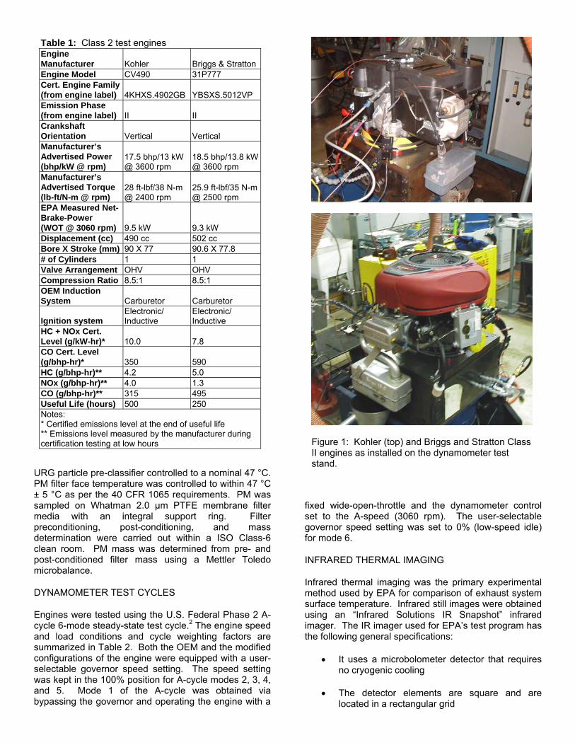
Table 1: Class 2 test engines Engine Manufacturer Kohler Briggs & StrattonEngine Model CV490 31P777 Cert. Engine Family (from engine label) 4KHXS.4902GB YBSXS.5012VP Emission Phase (from engine label) II II Crankshaft Orientation Vertical Vertical Manufacturer’s Advertised Power (bhp/kW @ rpm)
17.5 bhp/13 kW @ 3600 rpm
18.5 bhp/13.8 kW@ 3600 rpm
Manufacturer’s Advertised Torque (lb-ft/N-m @ rpm)
28 ft-lbf/38 N-m @ 2400 rpm
25.9 ft-lbf/35 N-m@ 2500 rpm
EPA Measured Net-Brake-Power (WOT @ 3060 rpm) 9.5 kW 9.3 kW Displacement (cc) 490 cc 502 cc Bore X Stroke (mm) 90 X 77 90.6 X 77.8 # of Cylinders 1 1 Valve Arrangement OHV OHV Compression Ratio 8.5:1 8.5:1 OEM Induction System Carburetor Carburetor
Ignition system Electronic/ Inductive
Electronic/ Inductive
HC + NOx Cert. Level (g/kW-hr)* 10.0 7.8 CO Cert. Level (g/bhp-hr)* 350 590 HC (g/bhp-hr)** 4.2 5.0 NOx (g/bhp-hr)** 4.0 1.3 CO (g/bhp-hr)** 315 495 Useful Life (hours) 500 250 Notes: * Certified emissions level at the end of useful life ** Emissions level measured by the manufacturer during certification testing at low hours
Figure 1: Kohler (top) and Briggs and Stratton Class II engines as installed on the dynamometer test stand.
URG particle pre-classifier controlled to a nominal 47 °C. PM filter face temperature was controlled to within 47 °C ± 5 °C as per the 40 CFR 1065 requirements. PM was sampled on Whatman 2.0 μm PTFE membrane filter media with an integral support ring. Filter preconditioning, post-conditioning, and mass determination were carried out within a ISO Class-6 clean room. PM mass was determined from pre- and post-conditioned filter mass using a Mettler Toledo microbalance.
DYNAMOMETER TEST CYCLES
Engines were tested using the U.S. Federal Phase 2 A-cycle 6-mode steady-state test cycle.2 The engine speed and load conditions and cycle weighting factors are summarized in Table 2. Both the OEM and the modified configurations of the engine were equipped with a user-selectable governor speed setting. The speed setting was kept in the 100% position for A-cycle modes 2, 3, 4, and 5. Mode 1 of the A-cycle was obtained via bypassing the governor and operating the engine with a
fixed wide-open-throttle and the dynamometer control set to the A-speed (3060 rpm). The user-selectable governor speed setting was set to 0% (low-speed idle) for mode 6.
INFRARED THERMAL IMAGING
Infrared thermal imaging was the primary experimental method used by EPA for comparison of exhaust system surface temperature. Infrared still images were obtained using an “Infrared Solutions IR Snapshot” infrared imager. The IR imager used for EPA’s test program has the following general specifications:
• It uses a microbolometer detector that requires no cryogenic cooling
• The detector elements are square and are located in a rectangular grid
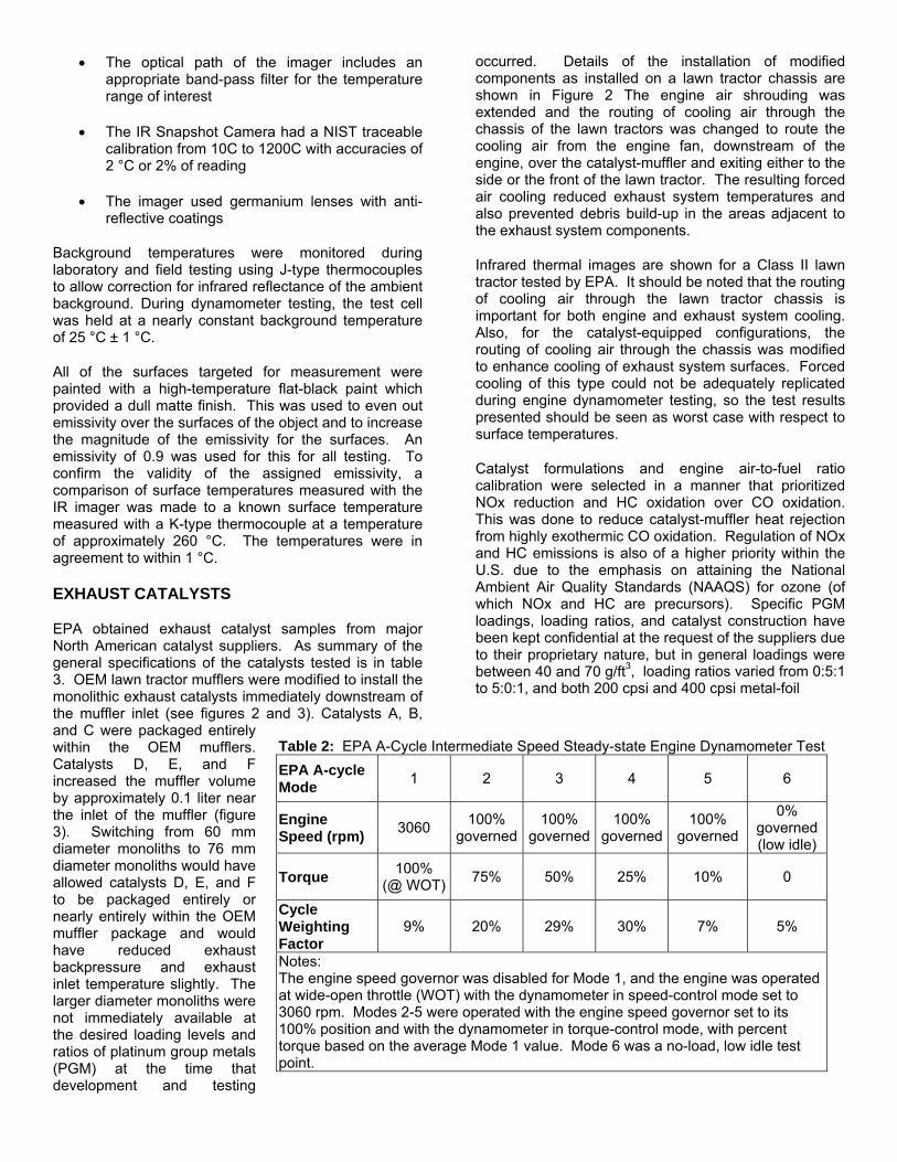
Table 2: EPA A-Cycle Intermediate Speed Steady-state Engine Dynamometer Test EPA A-cycle Mode 1 2 3 4 5 6
Engine Speed (rpm) 3060 100%
governed100%
governed100%
governed 100%
governed
0% governed (low idle)
Torque
• The optical path of the imager includes an appropriate band-pass filter for the temperature range of interest
• The IR Snapshot Camera had a NIST traceable calibration from 10C to 1200C with accuracies of 2 °C or 2% of reading
• The imager used germanium lenses with anti-reflective coatings
Background temperatures were monitored during laboratory and field testing using J-type thermocouples to allow correction for infrared reflectance of the ambient background. During dynamometer testing, the test cell was held at a nearly constant background temperature of 25 °C ± 1 °C.
All of the surfaces targeted for measurement were painted with a high-temperature flat-black paint which provided a dull matte finish. This was used to even out emissivity over the surfaces of the object and to increase the magnitude of the emissivity for the surfaces. An emissivity of 0.9 was used for this for all testing. To confirm the validity of the assigned emissivity, a comparison of surface temperatures measured with the IR imager was made to a known surface temperature measured with a K-type thermocouple at a temperature of approximately 260 °C. The temperatures were in agreement to within 1 °C.
EXHAUST CATALYSTS
100% (@ WOT) 75% 50% 25% 10% 0
Cycle Weighting Factor
9% 20% 29% 30% 7% 5%
Notes: The engine speed governor was disabled for Mode 1, and the engine was operated at wide-open throttle (WOT) with the dynamometer in speed-control mode set to 3060 rpm. Modes 2-5 were operated with the engine speed governor set to its 100% position and with the dynamometer in torque-control mode, with percent torque based on the average Mode 1 value. Mode 6 was a no-load, low idle test point.
EPA obtained exhaust catalyst samples from major North American catalyst suppliers. As summary of the general specifications of the catalysts tested is in table 3. OEM lawn tractor mufflers were modified to install the monolithic exhaust catalysts immediately downstream of the muffler inlet (see figures 2 and 3). Catalysts A, B, and C were packaged entirely within the OEM mufflers. Catalysts D, E, and F increased the muffler volume by approximately 0.1 liter near the inlet of the muffler (figure 3). Switching from 60 mm diameter monoliths to 76 mm diameter monoliths would have allowed catalysts D, E, and F to be packaged entirely or nearly entirely within the OEM muffler package and would have reduced exhaust backpressure and exhaust inlet temperature slightly. The larger diameter monoliths were not immediately available at the desired loading levels and ratios of platinum group metals (PGM) at the time that development and testing
occurred. Details of the installation of modified components as installed on a lawn tractor chassis are shown in Figure 2 The engine air shrouding was extended and the routing of cooling air through the chassis of the lawn tractors was changed to route the cooling air from the engine fan, downstream of the engine, over the catalyst-muffler and exiting either to the side or the front of the lawn tractor. The resulting forced air cooling reduced exhaust system temperatures and also prevented debris build-up in the areas adjacent to the exhaust system components.
Infrared thermal images are shown for a Class II lawn tractor tested by EPA. It should be noted that the routing of cooling air through the lawn tractor chassis is important for both engine and exhaust system cooling. Also, for the catalyst-equipped configurations, the routing of cooling air through the chassis was modified to enhance cooling of exhaust system surfaces. Forced cooling of this type could not be adequately replicated during engine dynamometer testing, so the test results presented should be seen as worst case with respect to surface temperatures.
Catalyst formulations and engine air-to-fuel ratio calibration were selected in a manner that prioritized NOx reduction and HC oxidation over CO oxidation. This was done to reduce catalyst-muffler heat rejection from highly exothermic CO oxidation. Regulation of NOx and HC emissions is also of a higher priority within the U.S. due to the emphasis on attaining the National Ambient Air Quality Standards (NAAQS) for ozone (of which NOx and HC are precursors). Specific PGM loadings, loading ratios, and catalyst construction have been kept confidential at the request of the suppliers due to their proprietary nature, but in general loadings were between 40 and 70 g/ft3, loading ratios varied from 0:5:1 to 5:0:1, and both 200 cpsi and 400 cpsi metal-foil
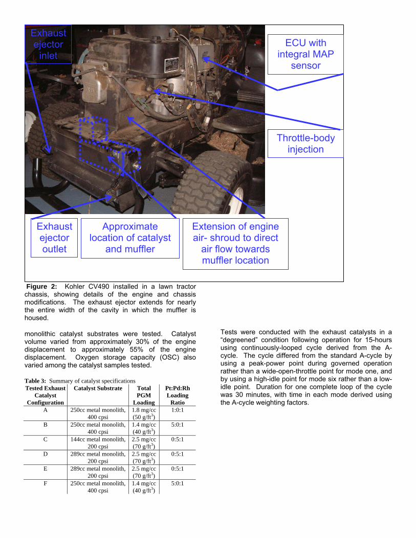
Figure 2: Kohler CV490 installed in a lawn tractor chassis, showing details of the engine and chassis modifications. The exhaust ejector extends for nearly the entire width of the cavity in which the muffler is housed.
monolithic catalyst substrates were tested. Catalyst volume varied from approximately 30% of the engine displacement to approximately 55% of the engine displacement. Oxygen storage capacity (OSC) also varied among the catalyst samples tested.
Table 3: Summary of catalyst specifications Tested Exhaust
Catalyst Configuration
Catalyst Substrate Total PGM
Loading
Pt:Pd:Rh Loading
Ratio A 250cc metal monolith,
400 cpsi 1.8 mg/cc (50 g/ft3)
1:0:1
B 250cc metal monolith, 400 cpsi
1.4 mg/cc (40 g/ft3)
5:0:1
C 144cc metal monolith, 200 cpsi
2.5 mg/cc (70 g/ft3)
0:5:1
D 289cc metal monolith, 200 cpsi
2.5 mg/cc (70 g/ft3)
0:5:1
E 289cc metal monolith, 200 cpsi
2.5 mg/cc (70 g/ft3)
0:5:1
F 250cc metal monolith, 400 cpsi
1.4 mg/cc (40 g/ft3)
5:0:1
Tests were conducted with the exhaust catalysts in a “degreened” condition following operation for 15-hours using continuously-looped cycle derived from the A-cycle. The cycle differed from the standard A-cycle by using a peak-power point during governed operation rather than a wide-open-throttle point for mode one, and by using a high-idle point for mode six rather than a low-idle point. Duration for one complete loop of the cycle was 30 minutes, with time in each mode derived using the A-cycle weighting factors.
Exhaust ejector outlet
Extension of engine air- shroud to direct
air flow towards muffler location
Approximate location of catalyst
and muffler
ECU with integral MAP
sensor
Exhaust ejector
inlet
Throttle-body injection
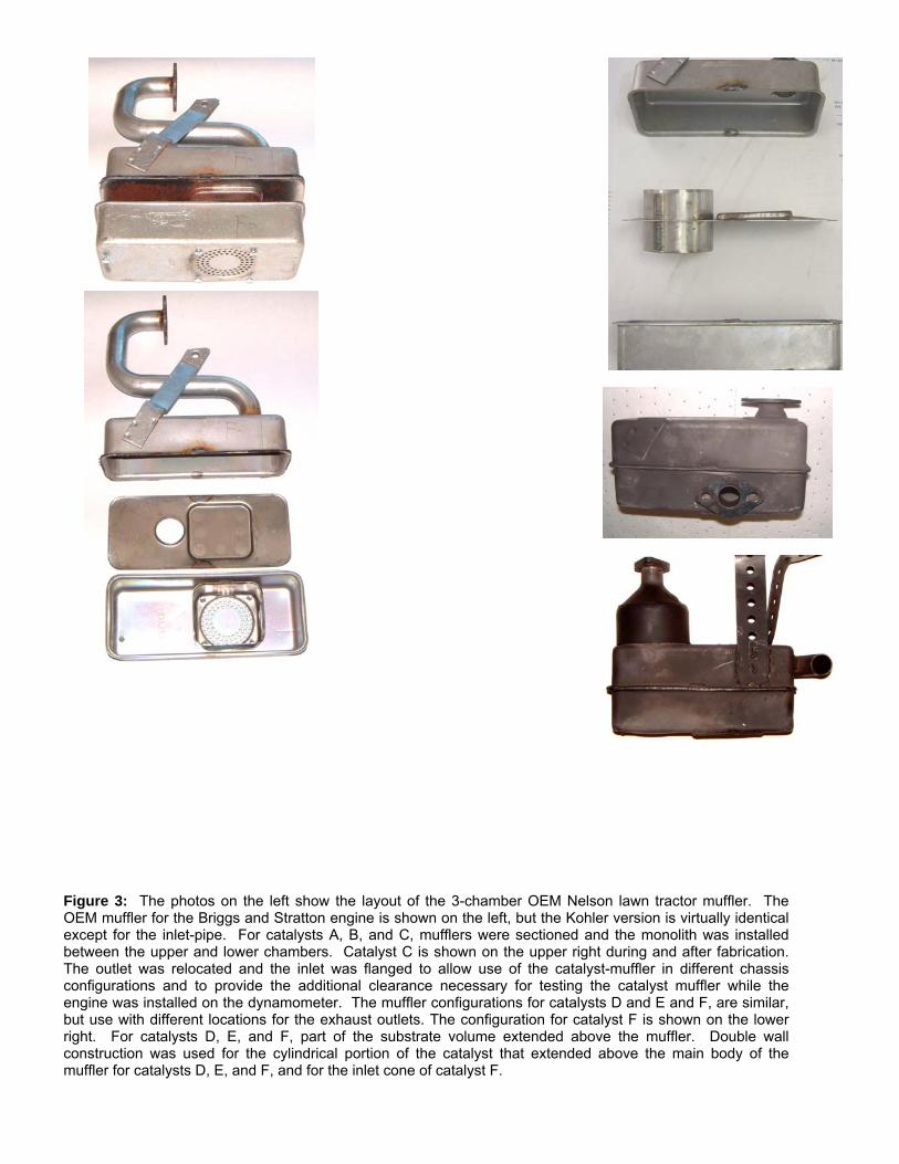
Figure 3: The photos on the left show the layout of the 3-chamber OEM Nelson lawn tractor muffler. The OEM muffler for the Briggs and Stratton engine is shown on the left, but the Kohler version is virtually identical except for the inlet-pipe. For catalysts A, B, and C, mufflers were sectioned and the monolith was installed between the upper and lower chambers. Catalyst C is shown on the upper right during and after fabrication. The outlet was relocated and the inlet was flanged to allow use of the catalyst-muffler in different chassis configurations and to provide the additional clearance necessary for testing the catalyst muffler while the engine was installed on the dynamometer. The muffler configurations for catalysts D and E and F, are similar, but use with different locations for the exhaust outlets. The configuration for catalyst F is shown on the lower right. For catalysts D, E, and F, part of the substrate volume extended above the muffler. Double wall construction was used for the cylindrical portion of the catalyst that extended above the main body of the muffler for catalysts D, E, and F, and for the inlet cone of catalyst F.
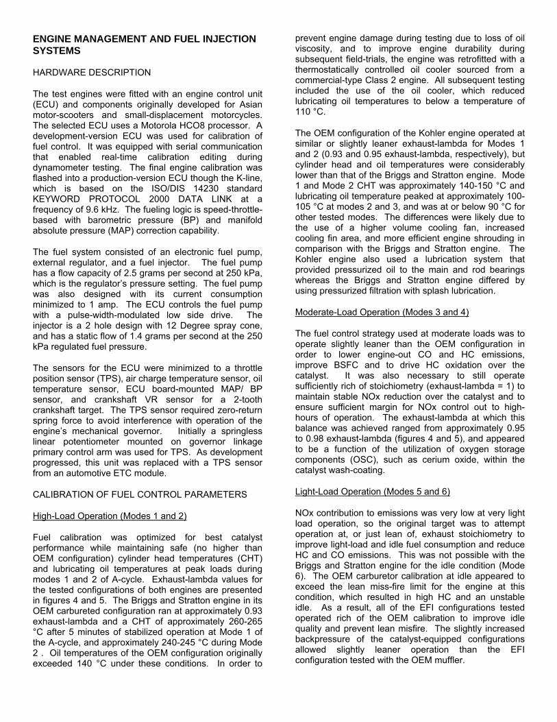
ENGINE MANAGEMENT AND FUEL INJECTION SYSTEMS
HARDWARE DESCRIPTION
The test engines were fitted with an engine control unit (ECU) and components originally developed for Asian motor-scooters and small-displacement motorcycles. The selected ECU uses a Motorola HCO8 processor. A development-version ECU was used for calibration of fuel control. It was equipped with serial communication that enabled real-time calibration editing during dynamometer testing. The final engine calibration was flashed into a production-version ECU though the K-line, which is based on the ISO/DIS 14230 standard KEYWORD PROTOCOL 2000 DATA LINK at a frequency of 9.6 kHz. The fueling logic is speed-throttle-based with barometric pressure (BP) and manifold absolute pressure (MAP) correction capability.
The fuel system consisted of an electronic fuel pump, external regulator, and a fuel injector. The fuel pump has a flow capacity of 2.5 grams per second at 250 kPa, which is the regulator’s pressure setting. The fuel pump was also designed with its current consumption minimized to 1 amp. The ECU controls the fuel pump with a pulse-width-modulated low side drive. The injector is a 2 hole design with 12 Degree spray cone, and has a static flow of 1.4 grams per second at the 250 kPa regulated fuel pressure.
The sensors for the ECU were minimized to a throttle position sensor (TPS), air charge temperature sensor, oil temperature sensor, ECU board-mounted MAP/ BP sensor, and crankshaft VR sensor for a 2-tooth crankshaft target. The TPS sensor required zero-return spring force to avoid interference with operation of the engine’s mechanical governor. Initially a springless linear potentiometer mounted on governor linkage primary control arm was used for TPS. As development progressed, this unit was replaced with a TPS sensor from an automotive ETC module.
CALIBRATION OF FUEL CONTROL PARAMETERS
High-Load Operation (Modes 1 and 2)
Fuel calibration was optimized for best catalyst performance while maintaining safe (no higher than OEM configuration) cylinder head temperatures (CHT) and lubricating oil temperatures at peak loads during modes 1 and 2 of A-cycle. Exhaust-lambda values for the tested configurations of both engines are presented in figures 4 and 5. The Briggs and Stratton engine in its OEM carbureted configuration ran at approximately 0.93 exhaust-lambda and a CHT of approximately 260-265 °C after 5 minutes of stabilized operation at Mode 1 of the A-cycle, and approximately 240-245 °C during Mode 2 . Oil temperatures of the OEM configuration originally exceeded 140 °C under these conditions. In order to
prevent engine damage during testing due to loss of oil viscosity, and to improve engine durability during subsequent field-trials, the engine was retrofitted with a thermostatically controlled oil cooler sourced from a commercial-type Class 2 engine. All subsequent testing included the use of the oil cooler, which reduced lubricating oil temperatures to below a temperature of 110 °C.
The OEM configuration of the Kohler engine operated at similar or slightly leaner exhaust-lambda for Modes 1 and 2 (0.93 and 0.95 exhaust-lambda, respectively), but cylinder head and oil temperatures were considerably lower than that of the Briggs and Stratton engine. Mode 1 and Mode 2 CHT was approximately 140-150 °C and lubricating oil temperature peaked at approximately 100-105 °C at modes 2 and 3, and was at or below 90 °C for other tested modes. The differences were likely due to the use of a higher volume cooling fan, increased cooling fin area, and more efficient engine shrouding in comparison with the Briggs and Stratton engine. The Kohler engine also used a lubrication system that provided pressurized oil to the main and rod bearings whereas the Briggs and Stratton engine differed by using pressurized filtration with splash lubrication.
Moderate-Load Operation (Modes 3 and 4)
The fuel control strategy used at moderate loads was to operate slightly leaner than the OEM configuration in order to lower engine-out CO and HC emissions, improve BSFC and to drive HC oxidation over the catalyst. It was also necessary to still operate sufficiently rich of stoichiometry (exhaust-lambda = 1) to maintain stable NOx reduction over the catalyst and to ensure sufficient margin for NOx control out to high-hours of operation. The exhaust-lambda at which this balance was achieved ranged from approximately 0.95 to 0.98 exhaust-lambda (figures 4 and 5), and appeared to be a function of the utilization of oxygen storage components (OSC), such as cerium oxide, within the catalyst wash-coating.
Light-Load Operation (Modes 5 and 6)
NOx contribution to emissions was very low at very light load operation, so the original target was to attempt operation at, or just lean of, exhaust stoichiometry to improve light-load and idle fuel consumption and reduce HC and CO emissions. This was not possible with the Briggs and Stratton engine for the idle condition (Mode 6). The OEM carburetor calibration at idle appeared to exceed the lean miss-fire limit for the engine at this condition, which resulted in high HC and an unstable idle. As a result, all of the EFI configurations tested operated rich of the OEM calibration to improve idle quality and prevent lean misfire. The slightly increased backpressure of the catalyst-equipped configurations allowed slightly leaner operation than the EFI configuration tested with the OEM muffler.
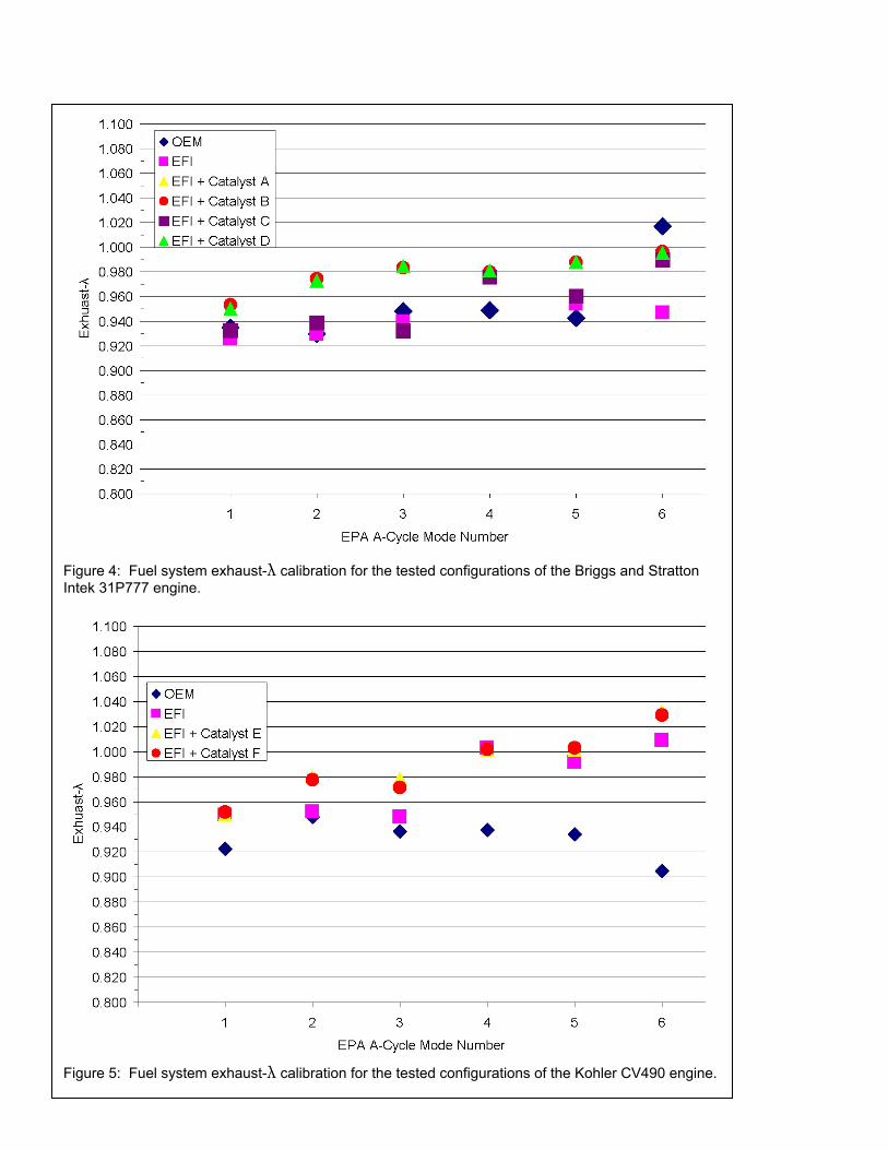
Figure 4: Fuel system exhaust-λ calibration for the tested configurations of the Briggs and Stratton Intek 31P777 engine.
Figure 5: Fuel system exhaust-λ calibration for the tested configurations of the Kohler CV490 engine.
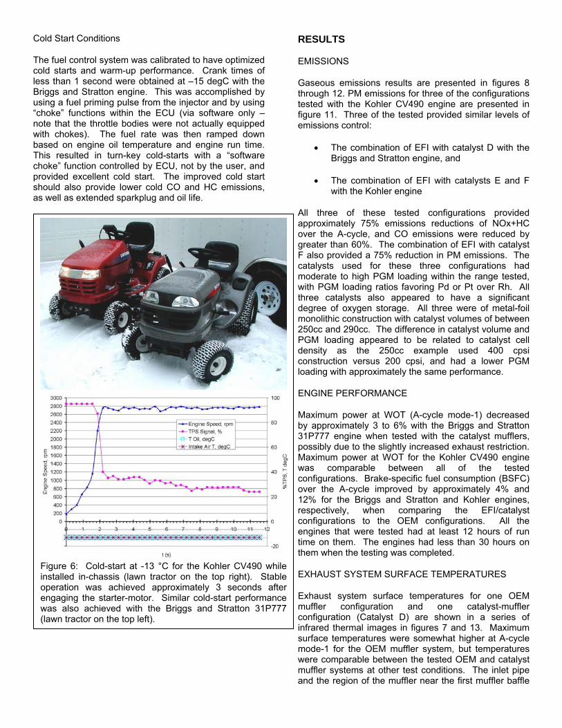
Cold Start Conditions
The fuel control system was calibrated to have optimized cold starts and warm-up performance. Crank times of less than 1 second were obtained at –15 degC with the Briggs and Stratton engine. This was accomplished by using a fuel priming pulse from the injector and by using “choke” functions within the ECU (via software only – note that the throttle bodies were not actually equipped with chokes). The fuel rate was then ramped down based on engine oil temperature and engine run time. This resulted in turn-key cold-starts with a “software choke” function controlled by ECU, not by the user, and provided excellent cold start. The improved cold start should also provide lower cold CO and HC emissions, as well as extended sparkplug and oil life.
RESULTS
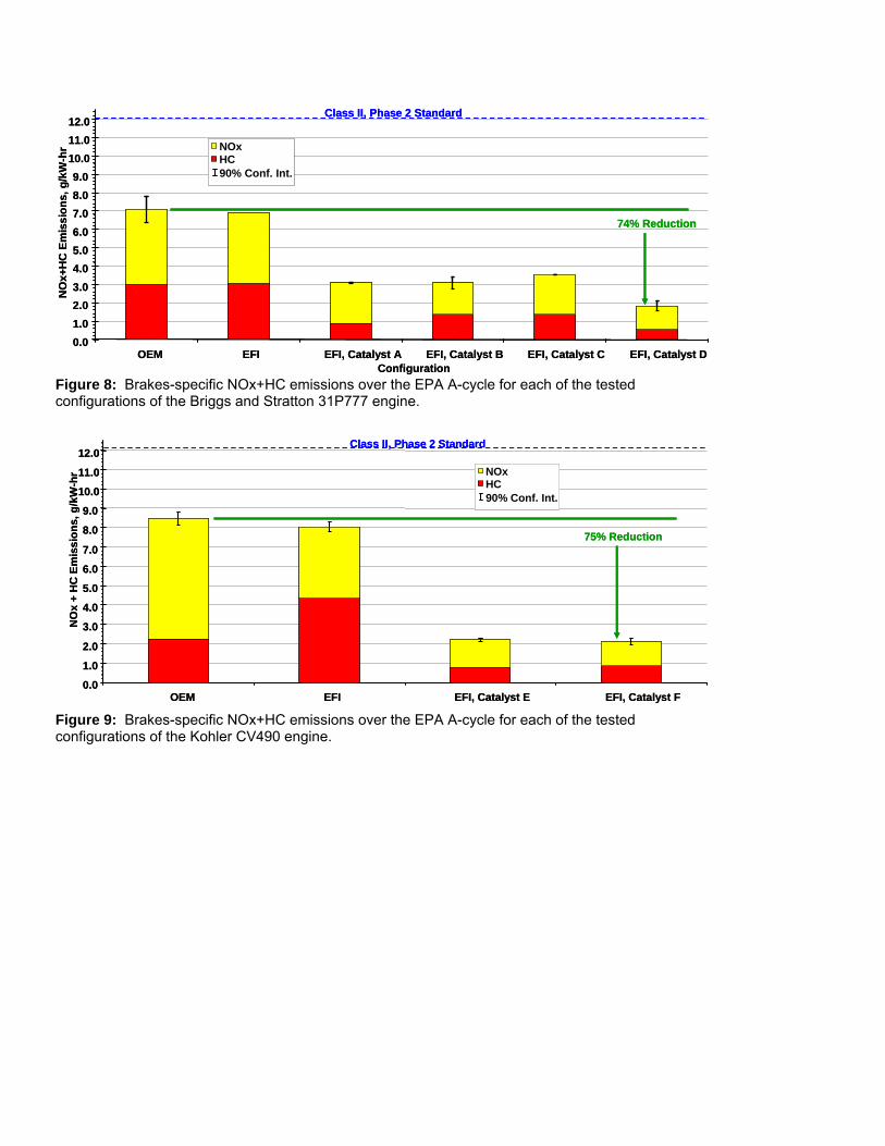
EMISSIONS
Gaseous emissions results are presented in figures 8 through 12. PM emissions for three of the configurations tested with the Kohler CV490 engine are presented in figure 11. Three of the tested provided similar levels of emissions control:
• The combination of EFI with catalyst D with the Briggs and Stratton engine, and
• The combination of EFI with catalysts E and F with the Kohler engine
All three of these tested configurations provided approximately 75% emissions reductions of NOx+HC over the A-cycle, and CO emissions were reduced by greater than 60%. The combination of EFI with catalyst F also provided a 75% reduction in PM emissions. The catalysts used for these three configurations had moderate to high PGM loading within the range tested, with PGM loading ratios favoring Pd or Pt over Rh. All three catalysts also appeared to have a significant degree of oxygen storage. All three were of metal-foil monolithic construction with catalyst volumes of between 250cc and 290cc. The difference in catalyst volume and PGM loading appeared to be related to catalyst cell density as the 250cc example used 400 cpsi construction versus 200 cpsi, and had a lower PGM loading with approximately the same performance.
ENGINE PERFORMANCE
Maximum power at WOT (A-cycle mode-1) decreased by approximately 3 to 6% with the Briggs and Stratton 31P777 engine when tested with the catalyst mufflers, possibly due to the slightly increased exhaust restriction. Maximum power at WOT for the Kohler CV490 engine was comparable between all of the tested configurations. Brake-specific fuel consumption (BSFC) over the A-cycle improved by approximately 4% and 12% for the Briggs and Stratton and Kohler engines, respectively, when comparing the EFI/catalyst configurations to the OEM configurations. All the engines that were tested had at least 12 hours of run time on them. The engines had less than 30 hours on them when the testing was completed.
EXHAUST SYSTEM SURFACE TEMPERATURES
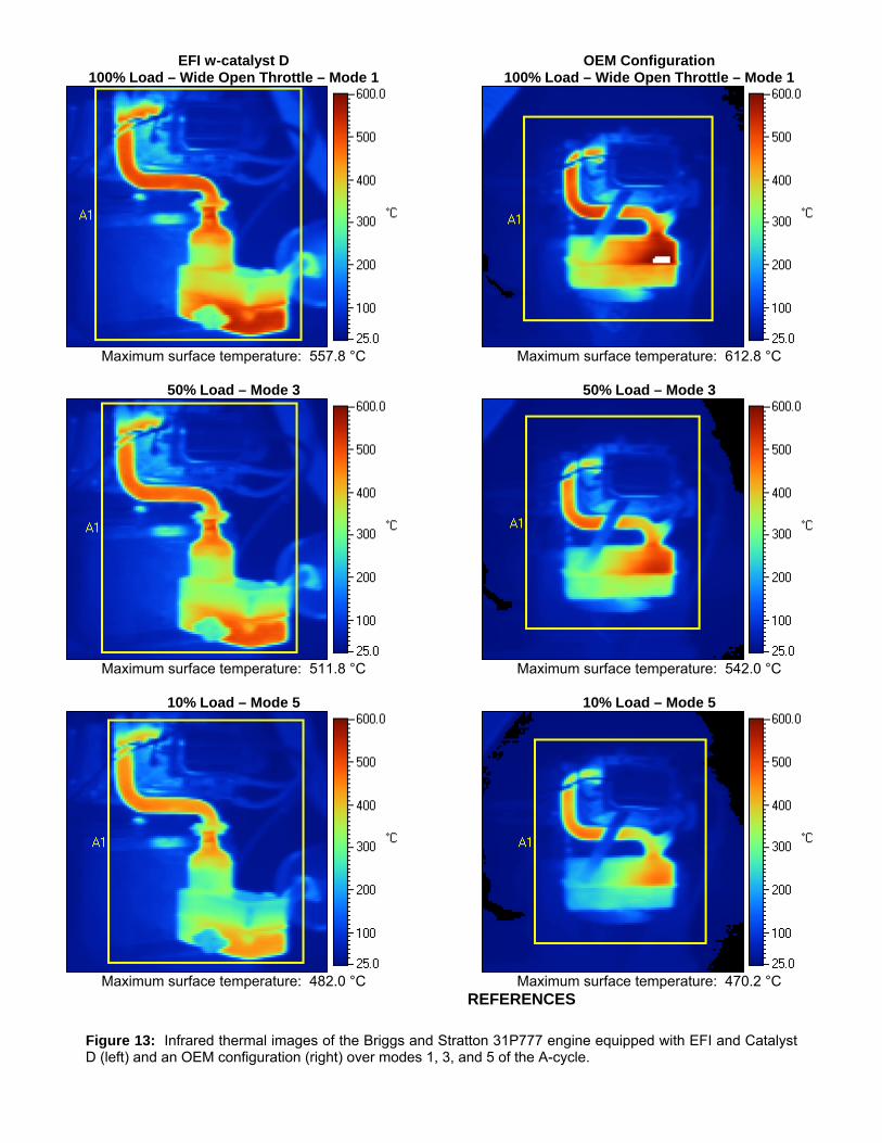
Exhaust system surface temperatures for one OEM muffler configuration and one catalyst-muffler configuration (Catalyst D) are shown in a series of infrared thermal images in figures 7 and 13. Maximum surface temperatures were somewhat higher at A-cycle mode-1 for the OEM muffler system, but temperatures were comparable between the tested OEM and catalyst muffler systems at other test conditions. The inlet pipe and the region of the muffler near the first muffler baffle
Figure 6: Cold-start at -13 °C for the Kohler CV490 while installed in-chassis (lawn tractor on the top right). Stable operation was achieved approximately 3 seconds after engaging the starter-motor. Similar cold-start performance was also achieved with the Briggs and Stratton 31P777 (lawn tractor on the top left).
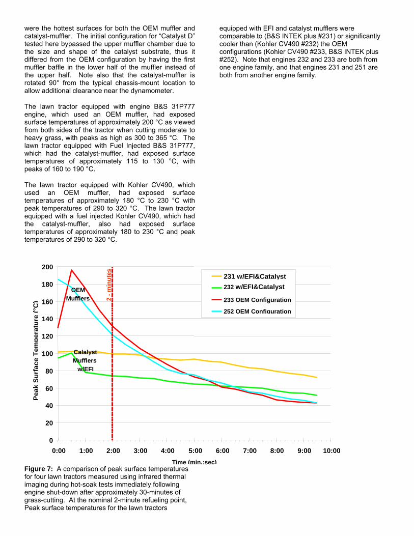
were the hottest surfaces for both the OEM muffler and catalyst-muffler. The initial configuration for “Catalyst D” tested here bypassed the upper muffler chamber due to the size and shape of the catalyst substrate, thus it differed from the OEM configuration by having the first muffler baffle in the lower half of the muffler instead of the upper half. Note also that the catalyst-muffler is rotated 90° from the typical chassis-mount location to allow additional clearance near the dynamometer.
The lawn tractor equipped with engine B&S 31P777 engine, which used an OEM muffler, had exposed surface temperatures of approximately 200 °C as viewed from both sides of the tractor when cutting moderate to heavy grass, with peaks as high as 300 to 365 °C. The lawn tractor equipped with Fuel Injected B&S 31P777, which had the catalyst-muffler, had exposed surface temperatures of approximately 115 to 130 °C, with peaks of 160 to 190 °C.
The lawn tractor equipped with Kohler CV490, which used an OEM muffler, had exposed surface temperatures of approximately 180 °C to 230 °C with peak temperatures of 290 to 320 °C. The lawn tractor equipped with a fuel injected Kohler CV490, which had the catalyst-muffler, also had exposed surface temperatures of approximately 180 to 230 °C and peak temperatures of 290 to 320 °C.
Figure 7: A comparison of peak surface temperatures for four lawn tractors measured using infrared thermal imaging during hot-soak tests immediately following engine shut-down after approximately 30-minutes of grass-cutting. At the nominal 2-minute refueling point, Peak surface temperatures for the lawn tractors
equipped with EFI and catalyst mufflers were comparable to (B&S INTEK plus #231) or significantly cooler than (Kohler CV490 #232) the OEM configurations (Kohler CV490 #233, B&S INTEK plus #252). Note that engines 232 and 233 are both from one engine family, and that engines 231 and 251 are both from another engine family.
0
20
40
60
80
100
120
140
160
180
200
0:00 1:00 2:00 3:00
Peak
Surf
ace
Tem
pera
ture
(°C
)
231 w/EFI&Catalyst232 w/EFI&Catalyst
4:00 5:00 6:00 7:00 8:00 9:00 10:00Time (min.:sec)
233 OEM Configuration 252 OEM Configuration
2 - m
inut
es
OEM Mufflers
Calalyst Mufflers
w/EFI
0.01.02.03.04.05.06.07.08.09.0
10.011.012.0
OEM EFI EFI, Catalyst A EFI, Catalyst B EFI, Catalyst C EFI, Catalyst DConfiguration
NO
x+H
CEm
issi
ons,
g/k
W-h
r
Class II, Phase 2 Standard
NOxHC90% Conf. Int.
74% Reduction
0.01.02.03.04.05.06.07.08.09.0
10.011.012.0
OEM EFI EFI, Catalyst A EFI, Catalyst B EFI, Catalyst C EFI, Catalyst DConfiguration
NO
x+H
CEm
issi
ons,
g/k
W-h
r
Class II, Phase 2 Standard
NOxHC90% Conf. Int.
NOxHC90% Conf. Int.
74% Reduction
Figure 8: Brakes-specific NOx+HC emissions over the EPA A-cycle for each of the tested configurations of the Briggs and Stratton 31P777 engine.
0.0
1.0
2.0
3.0
4.0
5.0
6.0
7.0
8.0
9.0
10.0
11.0
12.0
OEM EFI EFI, Catalyst E EFI, Catalyst F
NO
x +
HC
Em
issi
ons,
g/k
W-h
r
Class II, Phase 2 Standard
NOxHC90% Conf. Int.
75% Reduction
0.0
1.0
2.0
3.0
4.0
5.0
6.0
7.0
8.0
9.0
10.0
11.0
12.0
OEM EFI EFI, Catalyst E EFI, Catalyst F
NO
x +
HC
Em
issi
ons,
g/k
W-h
r
Class II, Phase 2 Standard
NOxHC90% Conf. Int.
NOxHC90% Conf. Int.
75% Reduction
Figure 9: Brakes-specific NOx+HC emissions over the EPA A-cycle for each of the tested configurations of the Kohler CV490 engine.
CONCLUSION
0
50
100
150
200
250
300
350
400
450
500
550
OEM EFI EFI, Catalyst A EFI, Catalyst B EFI, Catalyst C EFI, CatalysConfiguration
CO
Em
issi
ons,
g/k
W-h
r90% Conf. Int.
64% Reductio
0
50
100
150
200
250
300
350
400
450
500
550
OEM EFI EFI, Catalyst A EFI, Catalyst B EFI, Catalyst C EFI, Cataly
90% Conf. Int.
sConfiguration
CO
Em
issi
ons,
g/k
W-h
r
0
50
100
150
200
250
300
350
400
450
500
550
OEM EFI EFI, Catalyst A EFI, Catalyst B EFI, Catalyst C EFI, CatalysConfiguration
CO
Em
issi
ons,
g/k
W-h
r
0
50
100
150
200
250
300
350
400
450
500
550
OEM EFI EFI, Catalyst A EFI, Catalyst B EFI, Catalyst C EFI, Cataly
90% Conf. Int.90% Conf. Int.
Configuration
CO
Em
issi
ons,
g/k
W-h
r
64% Reductio
s
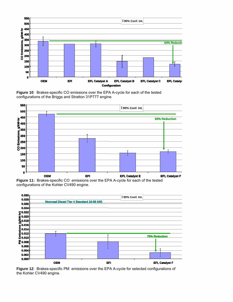
Figure 10: Brakes-specific CO emissions over the EPA A-cycle for each of the tested configurations of the Briggs and Stratton 31P777 engine.
0
50
100
150
200
250
300
350
400
450
500
550
OEM EFI EFI, Catalyst E EFI, Catalyst F
CO
Em
issi
ons,
g/k
W-h
r
90% Conf. Int.
65% Reduction
0
50
100
150
200
250
300
350
400
450
500
550
OEM EFI EFI, Catalyst E EFI, Catalyst F
CO
Em
issi
ons,
g/k
W-h
r
90% Conf. Int.
0
50
100
150
200
250
300
350
400
450
500
550
OEM EFI EFI, Catalyst E EFI, Catalyst F
CO
Em
issi
ons,
g/k
W-h
r
0
50
100
150
200
250
300
350
400
450
500
550
OEM EFI EFI, Catalyst E EFI, Catalyst F
CO
Em
issi
ons,
g/k
W-h
r
90% Conf. Int.90% Conf. Int.
65% Reduction
Figure 11: Brakes-specific CO emissions over the EPA A-cycle for each of the tested configurations of the Kohler CV490 engine.
0.0000.0020.0040.0060.0080.0100.0120.0140.0160.0180.0200.0220.0240.0260.0280.030
OEM EFI EFI, Catalyst F
PM E
mis
sion
s (g
/kW
-hr)
Nonroad Diesel Tier 4 Standard 19-56 kW)90% Conf. Int.
75% Reduction
0.0000.0020.0040.0060.0080.0100.0120.0140.0160.0180.0200.0220.0240.0260.0280.030
OEM EFI EFI, Catalyst F
PM E
mis
sion
s (g
/kW
-hr)
Nonroad Diesel Tier 4 Standard 19-56 kW)
75% Reduction
0.0000.0020.0040.0060.0080.0100.0120.0140.0160.0180.0200.0220.0240.0260.0280.030
OEM EFI EFI, Catalyst F
PM E
mis
sion
s (g
/kW
-hr)
Nonroad Diesel Tier 4 Standard 19-56 kW)
0.0000.0020.0040.0060.0080.0100.0120.0140.0160.0180.0200.0220.0240.0260.0280.030
OEM EFI EFI, Catalyst F
PM E
mis
sion
s (g
/kW
-hr)
90% Conf. Int.90% Conf. Int.Nonroad Diesel Tier 4 Standard 19-56 kW)
75% Reduction
Figure 12: Brakes-specific PM emissions over the EPA A-cycle for selected configurations of the Kohler CV490 engine.
Approximately 75% reductions in NOx+HC and PM emissions are possible using an appropriately designed catalyst-muffler in combination with an open-loop EFI system calibrated rich of stoichiometry at moderate to high loads and near stoichiometry at light load conditions. While similar fuel calibration and emissions results are achievable using carburetor configurations, such passive control systems would not allow for the safe correction for changes in air-to-fuel ratio encountered as the engine accumulates hours in use. Such compensation is possible using electronic engine management via the feed-back provided from the MAP and other sensors and is critical to the safe operation of catalytic exhaust emission controls at this level of control. The reduction in number and size of components and their associated costs made possible by the introduction of electronic engine management to small engines used in other cost-sensitive applications has enabled a level of emission control on small, nonroad SI engines that is now beginning to approach that of light-duty automotive applications.
Infrared thermal image results demonstrate that surface temperatures comparable to today’s noncatalyst OEM systems are possible with appropriate system design and air-to-fuel ratio control.
ACKNOWLEDGMENTS
The authors would like to express their gratitude to the Manufacturer’s of Emission Controls Association (MECA) and their member companies for assistance with catalyst design, obtaining catalyst samples, and obtaining fuel system and engine management system components for this test program. We also wish to thank Timothy E. Davis and Stephen Halfyard for their excellent technician support during system buildup and through long hours of dynamometer testing.
CONTACT
Joseph McDonald U.S. Environmental Protection Agency Office of Transportation and Air Quality 2000 Traverwood Drive Ann Arbor, MI 48105 USA E-mail: [email protected]
EFI w-catalyst D OEM Configuration 100% Load – Wide Open Throttle – Mode 1 100% Load – Wide Open Throttle – Mode 1
Figure 13: Infrared thermal images of the Briggs and Stratton 31P777 engine equipped with EFI and Catalyst D (left) and an OEM configuration (right) over modes 1, 3, and 5 of the A-cycle.
Maximum surface temperature: 557.8 °C
50% Load – Mode 3
Maximum surface temperature: 511.8 °C
10% Load – Mode 5
Maximum surface temperature: 482.0 °C
Maximum surface temperature: 612.8 °C
50% Load – Mode 3
Maximum surface temperature: 542.0 °C
10% Load – Mode 5
Maximum surface temperature: 470.2 °C
REFERENCES

1. Control of Emissions from Nonroad Spark-Ignition Engines and Equipment, U.S. Federal Register, Vol. 72, No. 96 Friday, May 18, 2007 2. EPA Technical Study on the Safety of Emission Controls for Nonroad Spark-Ignition Engines < 50 Horsepower, http://www.epa.gov/otaq/regs/nonroad/equip-ld/phase3/420r06006-rpt-2appdx.pdf